Rosslare AYH6XX0 O2S Smart Card Reader User Manual AY G H6xx0 Installation and
Rosslare Enterprises Ltd O2S Smart Card Reader AY G H6xx0 Installation and
Rosslare >
User Manual
AY-G/H6xx0
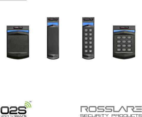
Open to Secure (O2S) Readers
Installation and User Manual
Models:
AY-G6270/G6280
AY-H6270/H6280
AY-G6370/G6380
AY-H6370/H6380
AY-H6270/H6280 AY-G6270/G6280 AY-G6370/G6380 AY-H6370/H6380
Copyright © 2014 by Rosslare. All rights reserved.
This manual and the information contained herein are proprietary to ROSSLARE
ENTERPRISES LIMITED and/or its related companies and/or subsidiaries’
(hereafter: "ROSSLARE"). Only ROSSLARE and its customers have the right to
use the information.
No part of this manual may be re-produced or transmitted in any form or by any
means, electronic or mechanical, for any purpose, without the express written
permission of ROSSLARE.
ROSSLARE owns patents and patent applications, trademarks, copyrights, or
other intellectual property rights covering the subject matter in this manual.
TEXTS, IMAGES, AND ILLUSTRATIONS INCLUDING THEIR ARRANGEMENT IN
THIS DOCUMENT ARE SUBJECT TO THE PROTECTION OF COPYRIGHT LAWS
AND OTHER LEGAL RIGHTS WORLDWIDE. THEIR USE, REPRODUCTION, AND
TRANSMITTAL TO THIRD PARTIES WITHOUT EXPRESS WRITTEN PERMISSION
MAY RESULT IN LEGAL PROCEEDINGS.
The furnishing of this manual to any party does not give that party or any third
party any license to these patents, trademarks, copyrights or other intellectual
property rights, except as expressly provided in any written agreement of
ROSSLARE.
ROSSLARE reserves the right to revise and change this document at any time,
without being obliged to announce such revisions or changes beforehand or
after the fact.

Table of Contents
AY-G/H6xx0 Installation and User Manual iii
Table of Contents
1. Introduction ................................................................ 8
1.1 Key Features ........................................................................... 8
1.2 Box Content ........................................................................... 9
2. Technical Specifications ............................................ 10
3. Mounting ................................................................... 12
4. Wiring Instructions ................................................... 13
5. Reader Operation ...................................................... 15
6. Proximity Operation ................................................. 16
6.1 Supported Credential Technologies ........................................ 16
6.2 Wiegand Output ................................................................... 16
7. Keypad Operation Instructions ................................ 17
7.1 Programming Menu .............................................................. 17
7.2 Entering Programming Mode ................................................. 18
7.3 Exiting Programming Mode ................................................... 18
7.4 Selecting Keypad Transmission Format ................................... 18
7.5 Keypad Transmission Format Option Number ......................... 19
7.5.1 Option 1: Single Key, Wiegand 6-Bit (Rosslare Format) ................. 20
7.5.2 Option 2: Single Key, Wiegand 6-Bit Nibble and Parities ............... 20
7.5.3 Option 3: Single Key, Wiegand 8-Bit Nibbles Complemented ....... 20
7.5.4 Option 4: 4 Keys Binary + Facility Code, Wiegand 26-Bit .............. 21
7.5.5 Option 5: 1 to 5 Keys + Facility Code, Wiegand 26-Bit ................. 21
7.5.6 Option 6: 6 Keys BCD and Parity Bits, Wiegand 26-Bit .................. 22
7.5.7 Option 8: 1 to 8 Keys BCD, Clock & Data ..................................... 23
7.5.8 Option 9: Single Key, Wiegand 4-Bit ............................................. 24

Table of Contents
iv AY-G/H6xx0 Installation and User Manual
7.6 Changing the Programming Code .......................................... 24
7.7 Changing the Facility Code .................................................... 24
7.8 Setting the Backlight Behavior ............................................... 25
7.9 Return to Factory Default Settings .......................................... 26
7.10 Replacing a lost Programming Code ....................................... 26
8. OSDP Operation ......................................................... 27
A. Wiegand Output Formats ......................................... 28
A.1 Rules for Wiegand 26-Bit (26A) .............................................. 29
A.2 Wiegand 38-Bit (38A) ............................................................ 31
B. Limited Warranty ...................................................... 33


List of Tables
vi AY-G/H6xx0 Installation and User Manual
List of Tables
Table 1: Wiring ................................................................................................ 13
Table 2: Reader Programming Menu ............................................................... 17
Table 3: Keypad Transmission Format .............................................................. 19
Table 4: Bit Description Table .......................................................................... 28

Introduction
AY-G/H6xx0 Installation and User Manual vii
Notice and Disclaimer
This manual’s sole purpose is to assist installers and/or users in the safe and
efficient installation and usage of the system and/or product, and/or software
described herein.
BEFORE ATTEMPTING TO INSTALL AND/OR USE THE SYSTEM, THE INSTALLER AND THE
USER MUST READ THIS MANUAL AND BECOME FAMILIAR WITH ALL SAFETY
REQUIREMENTS AND OPERATING PROCEDURES.
The system must not be used for purposes other than those for which it
was designed.
The use of the software associated with the system and/or product, if
applicable, is subject to the terms of the license provided as part of the
purchase documents.
ROSSLARE exclusive warranty and liability is limited to the warranty and
liability statement provided in an appendix at the end of this document.
This manual describes the maximum configuration of the system with the
maximum number of functions, including future options. Therefore, not all
functions described in this manual may be available in the specific system
and/or product configuration you purchased.
Incorrect operation or installation, or failure of the user to effectively
maintain the system, relieves the manufacturer (and seller) from all or any
responsibility for consequent noncompliance, damage, or injury.
The text, images and graphics contained in the manual are for the purpose
of illustration and reference only.
All data contained herein subject to change without prior notice.
In no event shall manufacturer be liable for any special, direct, indirect,
incidental, consequential, exemplary or punitive damages (including,
without limitation, any and all damages from business interruption, loss of
profits or revenue, cost of capital or loss of use of any property or capital or
injury).
All graphics in this manual are for reference only, some deviation between
the image(s) and the actual product may occur.
All wiring diagrams are intended for reference only, the photograph or
graphic of the PCB(s) are intended for clearer illustration and
understanding of the product and may differ from the actual PCB(s).

Introduction
8 AY-G/H6xx0 Installation and User Manual
1. Introduction
The Open to Secure (O2S) family of readers are multi-format
contactless smart card readers for use in access control system
solutions.
The AY-x6x70 readers support reading O2S ID data and the CSN from
MIFARE Plus® and MIFARE® Classic credentials.
The AY-x6x80 readers support reading O2S ID Data and the CSN from
MIFARE® DESFire® EV1 and MIFARE Classic credentials.
O2S ID data is stored in the secure memory of the MIFARE credential.
O2S ID data is AES 128-bit encrypted during transmission to the
reader for MIFARE Plus and DESFire EV1 credentials.
1.1 Key Features
Contactless smart card reader (13.56 MHz)
Meets ISO14443 Type A Standard
AES 128-bit encryption during transmission (MIFARE Plus and
MIFARE DESFire EV1)
Reads O2S ID data from O2S credentials
Reads CSN of non-O2S credentials
Output formats:
Wiegand (outputs per format on the card)
OSDP via RS-485 (selected models)
RGB multi-color light indicator
Blue backlit tact switch keypad
Fully-potted construction for indoor and outdoor use
Optical back tamper sensor with OC output
Two LED control inputs
Buzzer control input
Hold feature (not in standard configuration)

Introduction
AY-G/H6xx0 Installation and User Manual 9
Pigtail or terminal block connectivity
Comes with mounting template for easier installation
Comes with an installation kit that includes a security Trox screw
and a security Torx screw tool.
1.2 Box Content
Before beginning, verify that all of the following is in the box. If
anything is missing, please report the discrepancy to your nearest
Rosslare office.
One O2S reader
Installation kit – Includes two wall plugs, two mounting screws,
security Torx screw, and security Torx screw tool
Installation and operating instructions

Technical Specifications
10 AY-G/H6xx0 Installation and User Manual
2. Technical Specifications
Electrical
Characteristics
AY-G H6xx0
Power Supply Type Linear type (recommended)
Operating Voltage Range 6 to 16 VDC
Current @ 12 V Standby: 85 mA
Maximum: 110 mA
Read Range for G Models* MIFARE Classic: 40 to 45 mm (1.5 to 1.8 in.)
MIFARE Plus: 25 mm (1 in.)
MIFARE DESFire EV1: 25 mm (1 in.)
Read Range for H Models* MIFARE Classic: 40 to 45 mm (1.5 to 1.8 in.)
MIFARE Plus: 30 mm (1.2 in.)
MIFARE DESFire EV1: 30 mm (1.2 in.)
LED Control Input 1** Green LED control, TTL
LED Control Input 2** Red LED control, TTL
Auxiliary Input** Buzzer control, TTL
Auxiliary Output** Tamper output (open collector, active low,
max. sink current 30 mA)
Maximum Cable Distance
to Controller
Wiegand: 150 m (500 ft) with 18-AWG cable
OSDP (RS-485): 1200 m (4,000 ft) with 2x2
18-AWG twisted shielded cable
Environmental Characteristics
Operating Temp. Range -31°C to 63°C (-24°F to 145°F)
Operating Humidity Range 0 to 95% (non-condensing)
Outdoor Usage Weather-resistant, meets IP65, epoxy-potted,
suitable for indoor and outdoor use
* Measured using Rosslare O2S ISO cards. Range also depends on
electrical environment and proximity to metal.
** Standard configuration. Custom configurations are available.

Technical Specifications
AY-G/H6xx0 Installation and User Manual 11
Physical Characteristics
Dimensions of Pigtail
Models
(H x W x D)
AY-G6xx0: 145.3 x 42.0 x 23.0 mm
(5.7 x 1.7 x 0.9 in.)
AY-H6xx0: 120.0 x 80.0 x 23.0 mm
(4.7 x 3.2 x 0.9 in.)
Dimensions of Terminal
Block and OSDP Models
(H x W x D)
AY-G6xx0: 145.3 x 42.0 x 31.0 mm
(5.7 x 1.7 x 1.2 in.)
AY-H6xx0: 120.0 x 80.0 x 31.0 mm
(4.7 x 3.2 x 1.2 in.)
Weight AY-G6xx0: 155 g (5.5 oz)
AY-H6xx0: 217.0 g (7.7 oz)
Mounting
12 AY-G/H6xx0 Installation and User Manual
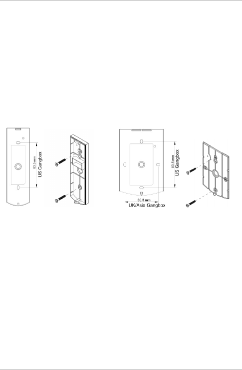
3. Mounting
To mount the units:
1. Determine an approximate location for the reader.
2. Peel off the back of the self-adhesive mounting label template
and place it at the required mounting location.
3. Using the template as a guide, drill two holes (sizes indicated on
the template) used for mounting the back plate onto the surface
(Figure 1).
Figure 1: Mounting
AY-GXXXX
AY-HXXXX
4. Insert a suitable wall plug into each screw hole.
5. Drill a 10-mm (7/16”) hole for the cable.
6. Screw the back plate onto the wall.
7. Connect the reader to the controller (see Chapter 4). A linear
type power supply is recommended.
8. Attach the reader to the back plate and secure the reader to the
back plate with the provided security screw and tools.

Wiring Instructions
AY-G/H6xx0 Installation and User Manual 13
4. Wiring Instructions
The units are supplied with a 10-conductor 18” (46 cm) pigtail or
with 10 terminal blocks.
To connect a pigtail reader to the controller:
1. Prepare the reader cable by cutting its jacket back 3.2 cm (1¼”)
and strip the insulation from the wires 1.3 cm (½").
2. Prepare the controller cable by cutting its jacket back 3.2 cm
(1¼") and strip the insulation from the wires 1.3 cm (½").
3. Splice the reader’s pigtail wires to the corresponding controller
wires (as indicated in Table 1) and cover each joint with insulating
tape.
Table 1: Wiring
Terminals Wire Color Output
1 Red VIN 6 ~ 16 VDC
2 Black Shield/Ground
3 Green Data 0 / Data
4 White Data 1 / Clock
5 Purple Tamper Output
6 Orange Green LED CTL
7 Brown Red LED CTL
8 Yellow Buzzer CTL
9 Blue OSDP* / RS-485-A
10 Gray OSDP* / RS-485-B
*OSDP (selected models)
4. Trim and cover all unused conductors.

Wiring Instructions
14 AY-G/H6xx0 Installation and User Manual
• The individual wires from the reader are color coded according the
Wiegand standard.
• When using a separate power supply for the reader, this supply and
that of the controller must have a common ground.
• The reader’s cable shield wire should be preferably attached to an
earth ground, or a signal ground connection at the panel, or power
supply end of the cable. This configuration is best for shielding the
reader cable from external interference.
To connect a terminal block reader to the controller:
1. Prepare the controller cable by cutting its jacket back 5 cm (2")
and strip the insulation from the wires 1.3 cm (½").
2. Connect the controller cable to the terminals (see Table 1).

Reader Operation
AY-G/H6xx0 Installation and User Manual 15
5. Reader Operation
Once the reader is wired to a power supply and to the controller, you
should test the reader.
To test the reader:
1. Power up the reader.
The beeper sounds three times and the LED turns red, blue, and
green, to indicate that the reader is working properly. The LED
returns to its Standby mode (red for the AY-x6x70 series and blue
for the AY-x6x80 series).
2. Present the appropriate type of proximity card to the reader or
enter a valid keypad entry.
The reader emits a beep (0.5 seconds). The LED changes
momentarily to green and then returns to its Standby mode (red
for the AY-x6x70 series and blue for the AY-x6x80 series).
The reader transmits the card's data or the keypad entry to the
controller for validation.

Proximity Operation
16 AY-G/H6xx0 Installation and User Manual
6. Proximity Operation
6.1 Supported Credential Technologies
O2S readers support reading from the secure memory of the
following credential technologies:
AY-H6x80 and AY-G6x80
MIFARE DESFire EV1 (2K, 4K, 8K)
MIFARE Classic (1K, 4K)
AY-H6x70 and AY-G6x70
MIFARE Plus X (2K, 4K)
MIFARE Plus S (2K, 4K)
MIFARE Classic (1K, 4K)
6.2 Wiegand Output
For O2S credentials, the reader outputs the ID data stored in the
secure memory (sector/file) of the credential. The ID data defines the
output as Wiegand and also determines the bit length of the output.
For example, when reading an O2S 26A format credential, the reader
outputs a Wiegand 26-Bit ID.
For non-O2S credentials, the reader outputs the CSN of the credential
as a Wiegand 32-Bit ID.

Keypad Operation Instructions
AY-G/H6xx0 Installation and User Manual 17
7. Keypad Operation Instructions
This chapter is relevant to models AY-G63x0 and AY-H63x0.
7.1 Programming Menu
Some but not all of the reader options can be programmed using the
unit's keypad driven Programming Menu System. During the unit’s
manufacturing process, certain codes and settings are pre-
programmed. These settings are called the default factory settings.
Table 2 shows the names of all the menus.
Default factory settings are marked by *.
Table 2: Reader Programming Menu
Menu Description Default
1 Selecting Keypad Transmission Format
1 – Single Key, Wiegand 6-Bit (Rosslare Format)
2 – Single Key, Wiegand 6-Bit with Nibble + Parity Bits
3 – Single Key, Wiegand 8-Bit, Nibbles Complemented
4 – 4 Keys Binary + Facility code, Wiegand 26-Bit
5 – 1 to 5 Keys + Facility code, Wiegand 26-Bit
6 – 6 Keys Binary-Coded Decimal (BCD) and Parity Bits,
Wiegand 26-Bit
8 – 1 to 8 Keys BCD, Clock & Data
9 – Single key, Wiegand 4-Bit
*
3 Changing the Programming code 1234
4 Changing the Facility code 0
6 Setting the Backlight
Always off
Always on
10 sec. backlight after key press otherwise off
10 sec. backlight after key press otherwise dimmed
*
0 Return to Factory Default Settings

Keypad Operation Instructions
18 AY-G/H6xx0 Installation and User Manual
7.2 Entering Programming Mode
To reach the Programming Menu System, the unit must first be
placed into Programming mode.
To enter Programming mode:
1. Press # four times.
The yellow LED blinks.
2. Enter your Programming code.
If the Programming code is valid, and the unit is in Programming
mode and the yellow LED is lit.
• The factory 4-digit Programming code is 1234.
• If a Programming code is not entered within 30 seconds, the unit
returns to Standby mode.
7.3 Exiting Programming Mode
To exit Programming mode:
1. Press #.
You hear a buzzing beep. This indicates that the unit has
returned to Standby mode.
Wrong entries may reset the reader back to Standby mode. While
in Programming mode, if no key is pressed for 30 seconds, the
unit exits Programming mode and returns to Standby mode.
7.4 Selecting Keypad Transmission Format
The units have 8 different keypad transmission formats from which to
select.
To select the keypad transmission format:
1. Enter Programming mode.
2. Press 1 to enter Menu 1.
The green LED blinks.

Keypad Operation Instructions
AY-G/H6xx0 Installation and User Manual 19
3. Enter the appropriate option number for the keypad transmission
format that you wish to select (see Table 3).
If an incorrect option number is entered, the reader returns to
Standby mode and the keypad transmission format remains
unchanged.
The system returns to Standby mode.
You hear three beeps and the green LED blinks.
• Only one keypad transmission format can be active at any one time.
• When using the keypad transmission format "1 to 8 keys BCD,
Clock & Data" (Option 8) an additional input is required to specify
the number of keys in the PIN code.
7.5 Keypad Transmission Format Option
Number
See Table 3 to determine the Option Number for the Keypad
Transmission Format you wish to select.
Table 3: Keypad Transmission Format
Keypad Transmission Format Option Number
Single Key, Wiegand 6-Bit (Rosslare Format) 1*
Single Key, Wiegand 6-Bit with Nibble + Parity Bits 2
Single Key, Wiegand 8-Bit, Nibbles Complemented 3
4 Keys Binary + Facility code, Wiegand 26-Bit 4
1 to 5 Keys + Facility code, Wiegand 26-Bit 5
6 Keys BCD and Parity Bits, Wiegand 26-Bit 6
1 to 8 Keys BCD, Clock & Data Single Key 8
Single Key, Wiegand 4-Bit 9
Reader settings are affected by keypad programming settings.
Settings are preset by the last keypad operation.
More information on each of the different keypad transmission
formats is available in the following subsections.

Keypad Operation Instructions
20 AY-G/H6xx0 Installation and User Manual
7.5.1 Option 1: Single Key, Wiegand 6-Bit (Rosslare
Format)
Each key press immediately sends 4 bits with 2 parity bits added –
even parity for the first 3 bits and odd parity for the last 3 bits.
0 = 1 1010 0 ="A" in Hexadecimal 6 = 1 0110 0
1 = 0 0001 0 7 = 1 0111 1
2 = 0 0010 0 8 = 1 1000 1
3 = 0 0011 1 9 = 1 1001 0
4 = 1 0100 1 * = 1 1011 1 ="B" in Hexadecimal
5 = 1 0101 0 # = 0 1100 1 ="C" in Hexadecimal
7.5.2 Option 2: Single Key, Wiegand 6-Bit Nibble and
Parities
Each key press immediately sends 4 bits with 2 parity bits added –
even parity for the first 3 bits and odd parity for the last 3 bits.
0 = 0 0000 1 6 = 1 0110 0
1 = 0 0001 0 7 = 1 0111 1
2 = 0 0010 0 8 = 1 1000 1
3 = 0 0011 1 9 = 1 1001 0
4 = 1 0100 1 * = 1 1010 0 = "A" in Hexadecimal
5 = 1 0101 0 # = 1 1011 1 = "B" in Hexadecimal
7.5.3 Option 3: Single Key, Wiegand 8-Bit Nibbles
Complemented
This options inverts the most significant bits in the message leaving
the least 4 significant bits as BCD representation of the key. The host
system receives an 8-bit message.
0 = 11110000 6 = 10010110
1 = 11100001 7 = 10000111
2 = 11010010 8 = 01111000
3 = 11000011 9 = 01101001
4 = 10110100 * = 01011010 = "A" in Hexadecimal
5 = 10100101 # = 01001011 = "B" in Hexadecimal

Keypad Operation Instructions
AY-G/H6xx0 Installation and User Manual 21
7.5.4 Option 4: 4 Keys Binary + Facility Code,
Wiegand 26-Bit
This option buffers 4 keys and outputs keypad data with a 3-digit
Facility code like a standard 26-bit card output.
The Facility code is set in Programming Menu 4 and can be in the
range 000 to 255. The factory default setting for the Facility code is
000 (see Section 7.7 for more information).
The keypad PIN code is 4 digits in length and can range between
0000 and 9999. On the fourth key press of the 4-digit PIN code, the
data is sent across the Wiegand Data lines as binary data in the same
format as a 26-bit card.
If * or # are pressed during PIN code entry, the keypad clears the PIN
code entry buffer, generates a beep, and is ready to receive a new 4-
digit keypad PIN code.
If the entry of the 4-digit keypad PIN code is disrupted and no number
key is pressed within 5 seconds, the keypad clears the PIN code entry
buffer, generates a beep, and is ready to receive a new 4-digit keypad
PIN code:
(EP) FFFF FFFF AAAA AAAA AAAA AAAA (OP)
Where:
EP = Even parity for first 12 bits
OP = Odd parity for last 12 bits
F = 8-Bit Facility code
A = 16-Bit code generated from keyboard
7.5.5 Option 5: 1 to 5 Keys + Facility Code, Wiegand
26-Bit
Option 5 buffers up to 5 keys and outputs keypad data with a Facility
code like a 26-bit card output.
The Facility code is set in Programming Menu 4 and can be in the
range 000 to 255. The factory default setting for the Facility code is
000 (see Section 7.7 for more information). The keypad PIN code can
be one to five digits in length and can range between 1 and 65,535.

Keypad Operation Instructions
22 AY-G/H6xx0 Installation and User Manual
When entering a keypad PIN code that is less than 5 digits in length, #
must be pressed to signify the end of PIN code entry. For keypad PIN
codes that are 5 digits in length, on the fifth key press of the 5-digit
PIN code, the data is sent across the Wiegand Data lines as binary
data in the same format as a 26-bit card.
If * is pressed during PIN code entry or a PIN code greater than
65,535 is entered, the keypad clears the PIN code entry buffer,
generates a beep and is ready to receive a new 5-digit keypad PIN
code.
If the entry of the 1- to 5-digit keypad PIN code is disrupted and a
number key or # is not pressed within 5 seconds, the keypad clears
the PIN code entry buffer, generates a medium length beep, and is
ready to receive a new 1- to 5-digit keypad PIN code:
(EP) FFFF FFFF AAAA AAAA AAAA AAAA (OP)
Where:
EP = Even parity for first 12 bits
OP = Odd parity for last 12 bits
F = 8-Bit Facility code
A = 16-Bit code generated from keyboard
7.5.6 Option 6: 6 Keys BCD and Parity Bits, Wiegand
26-Bit
This option sends buffer of 6 keys, adds parity, and sends a 26-bit
BCD message. Each key is a four bit equivalent of the decimal
number.
The keypad PIN code must be 6 key presses in length. On the sixth
key press of the 6-digit PIN code, the data is sent across the Wiegand
Data lines as a BCD message.
If the entry of the 6-digit keypad PIN code is disrupted and a number
key or # is not pressed within 5 seconds, the keypad clears the PIN
code entry buffer, generates a medium length beep, and is ready to
receive a new 6-digit keypad PIN code:
(EP) AAAA BBBB CCCC DDDD EEEE FFFF (OP)

Keypad Operation Instructions
AY-G/H6xx0 Installation and User Manual 23
Where:
EP = Even parity for first 12 bits
OP = Odd parity for last 12 bits
A = The first key entered D = Fourth key entered
B = Second key entered E = Fifth key entered
C = Third key entered F = Sixth key entered
7.5.7 Option 8: 1 to 8 Keys BCD, Clock & Data
Option 8 buffers up to 8 keys and outputs keypad data without a
Facility code like standard Clock and Data card output.
The keypad PIN code can be one to eight digits in length. The PIN
code length is selected while programming the reader for Option 8.
The reader transmits the data when it receives the last key press of
the PIN code. The data is sent across the two data output lines as
binary data in Clock & Data format.
If * or # is pressed during PIN code entry, the keypad clears the PIN
code entry buffer, generates a beep, and is ready to receive a new
keypad PIN code.
If the entry of the keypad PIN code is disrupted and a number key or
# is not pressed within 5 seconds, the keypad clears the PIN code
entry buffer, generates a medium length beep, and is ready to receive
a new keypad PIN code.
When using the keypad transmission format "1 to 8 keys BCD,
Clock & Data" (Option 8), an additional input is required to
specify the number of keys in the PIN code.

Keypad Operation Instructions
24 AY-G/H6xx0 Installation and User Manual
7.5.8 Option 9: Single Key, Wiegand 4-Bit
With this option, each key press immediately sends 4 bits of data,
with no parity bits added.
0 = 0000 6 = 0110
1 = 0001 7 = 0111
2 = 0010 8 = 1000
3 = 0011 9 = 1001
4 = 0100 *= 1010 ="A" in Hexadecimal
5 = 0101 #=1011 ="B" in Hexadecimal
7.6 Changing the Programming Code
To change the Programming code:
1. Enter Programming mode.
2. Press 3 to enter Menu 3.
The green LED blinks.
3. Enter the new 4-digit code you wish to set as the Programming
code.
The system returns to Standby mode.
You hear three beeps and the green LED blinks.
• The Programming code cannot be erased; the code 0000 is invalid
and does not erase the Programming code.
•
The factory default 4-digit Programming code is 1234.
7.7 Changing the Facility Code
To change the Facility code:
1. Enter Programming mode.
2. Press 4 to enter Menu 4.
The green LED blinks.
3. Enter the new 3-digit code you wish to set as the Facility code.

Keypad Operation Instructions
AY-G/H6xx0 Installation and User Manual 25
The system returns to Standby mode.
You hear three beeps and the green LED blinks
• The Facility code can be in the range of 000 to 255.
• The default Facility code is 0.
7.8 Setting the Backlight Behavior
To set the backlight behavior:
1. Enter Programming mode.
2. Press 6 to enter Menu 6.
The green LED blinks.
3. Enter one of the following codes:
0 – Always off
1 – Always on
2 – Backlight is off, activates for 10 seconds when a key is
pressed (Mode LED also goes on), after which it dims until off
(Mode LED also goes off)
3 – Backlight is dimmed, activates for 10 seconds when a key
is pressed (Mode LED also goes on), after which it returns to
a dimmed level
The system returns to Standby mode.
You hear three beeps and the green LED blinks

Keypad Operation Instructions
26 AY-G/H6xx0 Installation and User Manual
7.9 Return to Factory Default Settings
You must be very careful before using this command! This
erases the entire memory and returns all codes to their
factory default setting.
To return to factory default settings:
1. Enter Programming mode.
2. Press 0 to enter Menu 0.
The white LED blinks.
3. Enter your Programming code.
If the Programming code is valid, all memory is erased, you hear
three beeps and the controller returns to Standby mode.
If the Programming code is invalid, you hear a long beep and the
controller returns to Standby mode without erasing the memory
of the controller.
7.10 Replacing a lost Programming Code
In the event that the Programming code is forgotten, the unit may be
reprogrammed in the field using the following instructions:
1. Remove power from the reader.
2. Activate tamper by removing the reader from the wall or
removing the reader's case.
3. Apply power to the reader.
4. You now have 10 seconds to enter Programming mode using the
factory default Programming code 1234.

OSDP Operation
AY-G/H6xx0 Installation and User Manual 27
8. OSDP Operation
Rosslare O2S readers that support OSDP operation are compatible
with most OSDP commands. The reader address is set using DIP
switches on the back of the reader.
The DIP switch settings are as follows:
DIP Switch 1
This switch is used to select the reader output (Wiegand or OSDP):
Off = Wiegand
On = OSDP
DIP Switch 2
This switch is used to determine what cards are read:
Off = O2S cards and CSN of non-O2S cards
On = O2S only
DIP Switch 3
This switch is reserved for future use.
DIP Switches 4 to 8
These switches set the address of the reader for OSDP protocol.
DIP Switch 4 is MSB and DIP Switch 8 is LSB. The address is the DIP
switch state +1.
Examples:
All the DIP switches in Off position, state is = 0 => address = 1
All the DIP switches in On position, state is = 0x1F => address =
0x20 = 32
DIP switches 4, 6, 8 in On position and 5, 7 in Off position, state
is = 0x15 => address = 0x16 = 22

Wiegand Output Formats
28 AY-G/H6xx0 Installation and User Manual
A. Wiegand Output Formats
The AY-G/H6xx0 can read all Rosslare O2S cards/tags and outputs card ID data in Wiegand format
according to the number of bits stored in the secured memory area on the card. The readers support
any O2S card from 26-bit to 128-bit.
For more details on supported formats and custom formats, contact your Rosslare Sales
representative.
The following subsections show examples for two of the supported O2S formats:
Wiegand 26-Bit (26A)
Wiegand 38-Bit (38A)
Table 4 is a key to the tables appearing in the subsections below.
Table 4: Bit Description Table
D Card Number
F Facility Code
S Issue Number
E Even Parity Bit
O Odd Parity Bit
Wiegand Output Formats
AY-G/H6xx0 Installation and User Manual 29
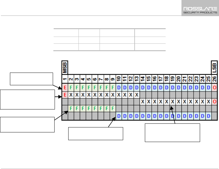
A.1 Rules for Wiegand 26-Bit (26A)
Field ID Data
Facility Code
Parity Bits
# of Bits 16 8 2
Range 65,535 255 N/A
Wiegand 26-Bit
Reader Output
Bit 1 – "E" Even parity of
bits 2 to 13, designated
by "X"
Bit 26 – "O" Odd parity
of bits 14 to 25,
designated by "X"
Bit 2 to 9 – "F" 8-Bit
Facility Code
Bit 10 to 25 – "D" 16-Bit
ID Data
Wiegand Output Formats
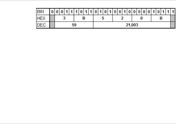
30 AY-G/H6xx0 Installation and User Manual
Example: FC=59, ID=21,003
Wiegand Output Formats
AY-G/H6xx0 Installation and User Manual 31
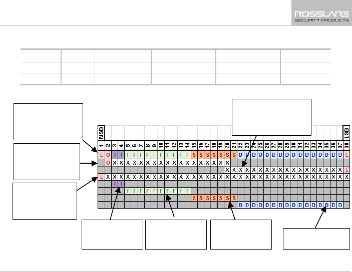
A.2 Wiegand 38-Bit (38A)
Field ID Data
Facility Code
Site Code Issue Number Parity Bits
# of Bits 16 10 7 2 3
Range 65,535 1,023 127 3 N/A
Wiegand 38-Bit
(Rosslare
Proprietary) Reader
Output
Bit 2 – "O" Odd
parity of bits 3 to
20, designated by
Parity Mask "X"
Bit 1 – "E" Even
parity of bits 2 to
38, designated by
Parity Mask "X"
Bit 5 to 14 – "F"
10-Bit Facility
Code
Bit 15 to 21 – "S"
7-Bit Site Code
Bit 22 to 37 – "D"
16-Bit ID Data
Bit 38 – "E" Even
parity of bits 20 to 37,
designated by Parity
Mask "X"
Bit 3 to 4 - "I" 3-
Bit Card Issue
Number
Wiegand Output Formats
32 AY-G/H6xx0 Installation and User Manual
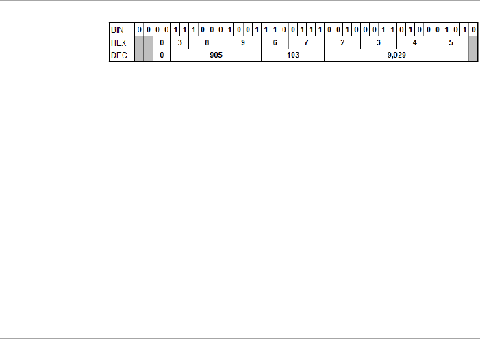
Example: ISSUE No=0, FC=905, Site Code=103, ID=9,029

Limited Warranty
AY-G/H6xx0 Installation and User Manual 33
B. Limited Warranty
The full ROSSLARE Limited Warranty Statement is available in the
Quick Links section on the ROSSLARE website at
www.rosslaresecurity.com.
Rosslare considers any use of this product as agreement to the
Warranty Terms even if you do not review them.
FCC NOTE:
This device complies with Part 15 of the FCC Rules.
Operation is subject to the following two conditions: (1) this device may
not cause harmful interference, and (2) this device must accept any
interference received, including interference that may cause undesired
operation.
THE MANUFACTURER IS NOT RESPONSIBLE FOR ANY RADIO
OR TV INTERFERENCE CAUSED BY UNAUTHORIZED
MODIFICATIONS OR CHANGE TO THIS EQUIPMENT. SUCH
MODIFICATIONS OR CHANGE COULD VOID THE USER’S
AUTHORITY TO OPERATE THE EQUIPMENT.

AY-G6xx0 and
AY-H6xx0
Asia Pacific, Middle
East, Africa
Rosslare Enterprises Ltd.
Kowloon Bay, Hong Kong
Tel: +852-2795-5630
Fax: +852-2795-1508
support.apac@rosslaresecurity.com
United States and
Canada
Rosslare Security Products, Inc.
Southlake, TX, USA
Toll Free: +1-866-632-1101
Local: +1-817-305-0006
Fax: +1-817-305-0069
support.na@rosslaresecurity.com
Europe
Rosslare Israel Ltd.
Rosh HaAyin, Israel
Tel: +972-3-938-6838
Fax: +972-3-938-6830
support.eu@rosslaresecurity.com
Latin America
Rosslare Latin America
Buenos Aires, Argentina
Tel: +54-11-4001-3104
support.la@rosslaresecurity.com
China
Rosslare Electronics (Shenzhen) Ltd.
Shenzhen, China
Tel: +86-755-8610 6842
Fax: +86-755-8610 6101
support.cn@rosslaresecurity.com
India
Rosslare Electronics India Pvt Ltd.
Tel/Fax: +91-20-40147830
Mobile: +91-9975768824
sales.in@rosslaresecurity.com
0706-0960506+02