Rosslare AYU9XXBT Extended Long Range UHF-RFID Reader with Bluetooth BLE-ID User Manual AY U920BT Installation and
Rosslare Enterprises Ltd Extended Long Range UHF-RFID Reader with Bluetooth BLE-ID AY U920BT Installation and
Rosslare >
User Manual
AY-U920BT-US
Extended Long-Range UHF-RFID Reader
with Bluetooth BLE-ID
Installation and User Manual
SMART
Copyright © 2018 by Rosslare. All rights reserved.
This manual and the information contained herein are proprietary to ROSSLARE
ENTERPRISES LIMITED and/or its related companies and/or subsidiaries’ (hereafter:
"ROSSLARE"). Only ROSSLARE and its customers have the right to use the information.
No part of this manual may be re-produced or transmitted in any form or by any means,
electronic or mechanical, for any purpose, without the express written permission of
ROSSLARE.
ROSSLARE owns patents and patent applications, trademarks, copyrights, or other
intellectual property rights covering the subject matter in this manual.
TEXTS, IMAGES, AND ILLUSTRATIONS INCLUDING THEIR ARRANGEMENT IN THIS
DOCUMENT ARE SUBJECT TO THE PROTECTION OF COPYRIGHT LAWS AND OTHER
LEGAL RIGHTS WORLDWIDE. THEIR USE, REPRODUCTION, AND TRANSMITTAL TO THIRD
PARTIES WITHOUT EXPRESS WRITTEN PERMISSION MAY RESULT IN LEGAL
PROCEEDINGS.
The furnishing of this manual to any party does not give that party or any third party any
license to these patents, trademarks, copyrights or other intellectual property rights,
except as expressly provided in any written agreement of ROSSLARE.
ROSSLARE reserves the right to revise and change this document at any time, without
being obliged to announce such revisions or changes beforehand or after the fact.

Table of Contents
iii
Table of Contents
1. Introduction ....................................................................... 7
1.1 Installation Kit ..................................................................................... 7
2. Technical Specifications ................................................... 8
3. Mounting ........................................................................... 9
3.1 General .............................................................................................. 9
3.1.1 1-Shaped Stand Bracket Side-Loaded ........................................................... 9
3.1.2 L-Shaped Stand Bracket Top-Loaded .......................................................... 10
3.1.3 Adjusting the Azimuth Angle of Antenna ................................................... 11
4. Wiring ............................................................................... 12
5. Operation Instructions ................................................... 14
6. APP-x421 Admin App ...................................................... 15
6.1 Opening the App .............................................................................. 15
6.2 Reader Settings ................................................................................. 16
6.3 AY-U920BT Reader Configuration Settings ........................................ 17
6.4 Additional Settings ........................................................................... 18
A. Declaration of Conformity ............................................. 19
B. Radio Equipment Directive (RED) .................................. 20
C. RoHS Directive ................................................................. 21
D. Limited Warranty ............................................................ 22
AY-U920BT-US Installation and User Manual

List of Figures
iv
List of Figures
Figure 1: 1-shaped Stand Bracket Side-Loaded ................................................ 9
Figure 2: L-shaped Stand Bracket Loaded...................................................... 10
Figure 3: Antenna Angle Side View .............................................................. 11
Figure 4: Antenna Angle Top View ............................................................... 11
Figure 5: Wiring Colors................................................................................. 12
AY-U920BT-US Installation and User Manual


Notice and Disclaimer
vi
Notice and Disclaimer
This manual’s sole purpose is to assist installers and/or users in the safe and
efficient installation and usage of the system and/or product, and/or software
described herein.
BEFORE ATTEMPTING TO INSTALL AND/OR USE THE SYSTEM, THE INSTALLER AND
THE USER MUST READ THIS MANUAL AND BECOME FAMILIAR WITH ALL SAFETY
REQUIREMENTS AND OPERATING PROCEDURES.
The system must not be used for purposes other than those for which it
was designed.
The use of the software associated with the system and/or product, if
applicable, is subject to the terms of the license provided as part of the
purchase documents.
ROSSLARE exclusive warranty and liability is limited to the warranty and
liability statement provided in an appendix at the end of this document.
This manual describes the maximum configuration of the system with the
maximum number of functions, including future options. Therefore, not
all functions described in this manual may be available in the specific
system and/or product configuration you purchased.
Incorrect operation or installation, or failure of the user to effectively
maintain the system, relieves the manufacturer (and seller) from all or any
responsibility for consequent noncompliance, damage, or injury.
The text, images and graphics contained in the manual are for the
purpose of illustration and reference only.
All data contained herein subject to change without prior notice.
In no event shall manufacturer be liable for any special, direct, indirect,
incidental, consequential, exemplary or punitive damages (including,
without limitation, any and all damages from business interruption, loss of
profits or revenue, cost of capital or loss of use of any property or capital
or injury).
All wiring diagrams are intended for reference only, the photograph or
graphic of the PCB(s) are intended for clearer illustration and
understanding of the product and may differ from the actual PCB(s).
AY-U920BT-US Installation and User Manual

Introduction
7
1. Introduction
The AY-U920BT is a UHF and Bluetooth reader that is available with versions in
both UHF frequencies (865-868 and 902-928 MHz) and supports Bluetooth
BLE frequencies and protocols. Two associated apps for iOS and Android
smartphones made by Rosslare can be used with the reader – BLE-ID credential
app and BLE-Admin configuration app – for programming operational settings.
The reader is waterproof (IP65) and is suitable for use in a wide range of RFID
applications, such as transport management, vehicle management, car
parking, production process control, and access control.
The reader supports the following functions:
Reading UHF hard credential
Reading BLE soft credential
Transmitting credential ID to the controller
Acting based on controller’s input (allowing access or not)
Self-update
Reconfiguration provided by credential (soft or hard) or by PC SW
The AY-U920BT series includes the following models:
AY-U920BT-US: 902–928 MHz (America)
AY-U920BT-EU: 865–868 MHz (Europe)
1.1 Installation Kit
The AY-U920BT package includes:
1 AY-U920BT reader with a 5 m (16.4 ft) 10-wire cable
1 installation bracket
kit
1 installation and user manual
AY-U920BT-US Installation and User Manual
Technical Specifications
8
2. Technical Specifications
Electrical Characteristics
Operating Voltage Range Typical: 9 to 12 VDC (2 A)
Max: 24 VDC
Input Current
Standby: 0.2 A max
Read: 1.2 A max
Credential Read Distance* 0.5 to 12 m (1.6 to 39.4 ft) (adjustable)
Transmission Protocol Wiegand 26-Bit (default)
Wiegand 32-Bit
Wiegand 34-Bit
Wiegand 40-Bit
Wiegand 56-Bit
Wiegand 64-Bit
OSDP
Custom
Maximum Cable Distance 150 m (492 ft) with 18” AWG cable
Frequency AY-U920BT-US: 902–928 MHz (America)
AY-U920BT-EU: 865–868 MHz (Europe)
Modulation Type ASK
Read Sensitivity Dual polarization read mode
Cards and Tags • EPC GEN2 (ISO18000-6C) Tags
• BLE-ID soft credentials
* Measured using a Rosslare proximity card or equivalent.
Environmental Characteristics
Operating Temp. Range -20°C to 60°C (-4°F to 140°F)
Operating Humidity Range 0 to 95% (non-condensing)
Suitable for outdoor use (IP 54)
Physical Characteristics
Height x Width x Depth 36.5 x 36.5 x 3.2 cm (14.4 x 14.4 x 1.3 in.)
Weight 2.8 kg (6.2 lb)
AY-U920BT-US Installation and User Manual
Mounting
9
3. Mounting
Installing an RFID reader adjacent to metallic surfaces might alter the reader’s
specifications. To diminish this interference, use a plastic spacer when mounting
the reader.
3.1 General
There are two methods that can be used when installing the reader.
1-Shaped Stand Bracket Side-Loaded
L-Shaped Stand Bracket Top-Loaded
Each installation method is selected based on application requirements and
actual location.
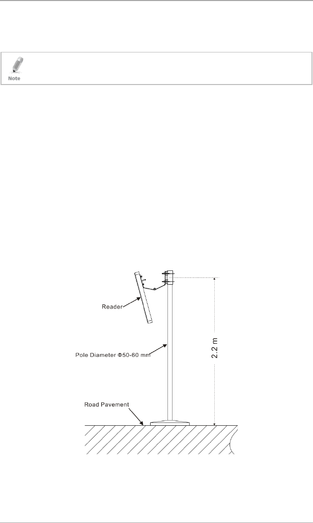
3.1.1 1-Shaped Stand Bracket Side-Loaded
In this method, the stand pole should have a diameter of between 50 and
60 mm (2 to 2.4 in.) and a height of 2.2 m. The pole should be made of
stainless steel with a thickness of at least 1.2 mm (0.05 in.).
Use the bracket contained in the package box to mount the AY-U920BT reader
to the top of the stand pole depending on actual vehicle type (mainly large car
and small car) (Figure 1).
Figure 1: 1-shaped Stand Bracket Side-Loaded
Adjust the height from the center of AY-U920BT reader to lane level to be
around 2.0 m (6.5 ft).
AY-U920BT-US Installation and User Manual
Mounting
10
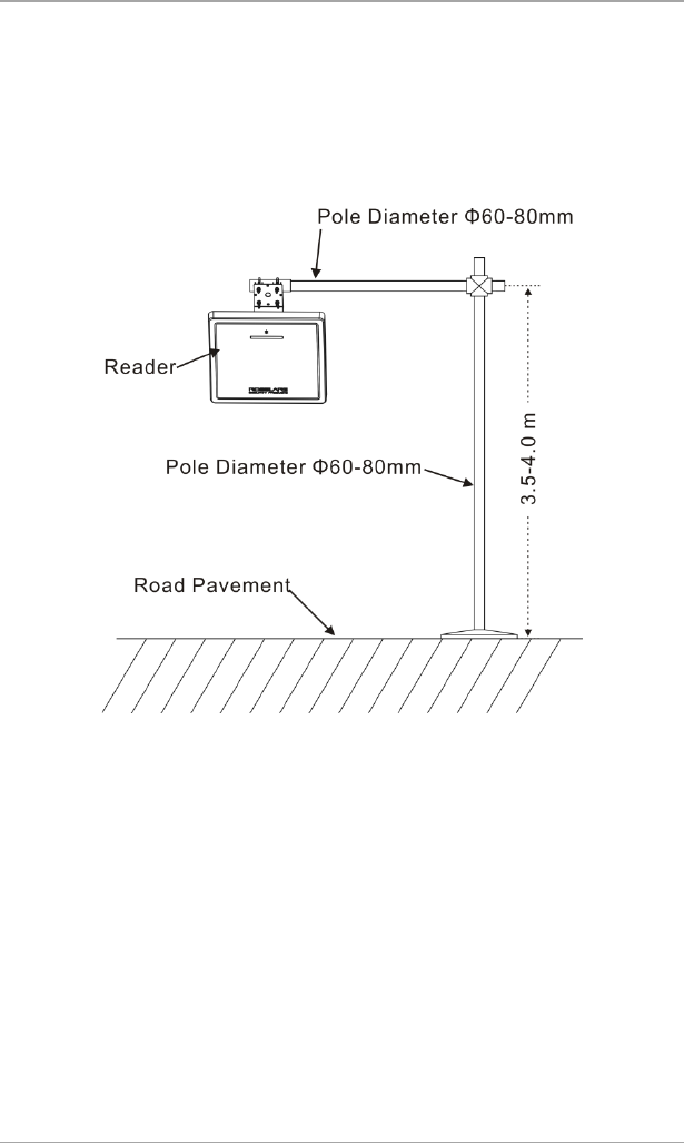
3.1.2 L-Shaped Stand Bracket Top-Loaded
In this method, the L-shaped stand pole should have a diameter of between 60
to 80 mm (2.4 to 3.1 in.) and a height of 4.2 m (13.8 ft). The pole should be
made of stainless steel with the thickness of at least 1.2 mm (0.05 in.).
Use the bracket contained in package box to mount the AY-U920BT reader to
the rail near the center of the lane (Figure 2).
Figure 2: L-shaped Stand Bracket Loaded
Adjust the height between the rail and the ground to between 3.5 to 4.0 m
(11.5 to 13 ft), depending on the height of vehicle.
AY-U920BT-US Installation and User Manual
Mounting
AY-U920BT-US Installation and User Manual 11
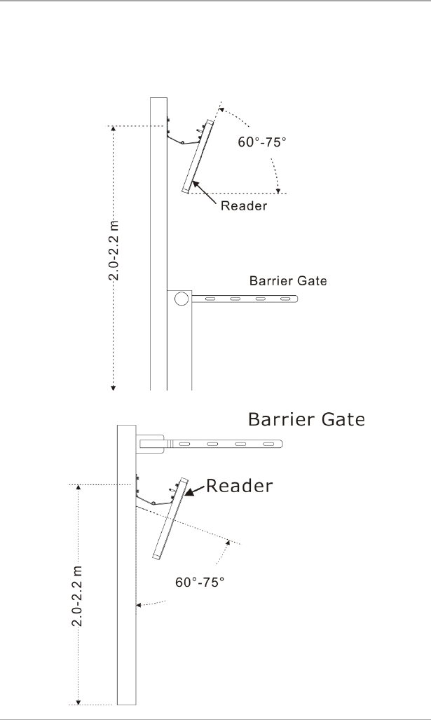
3.1.3 Adjusting the Azimuth Angle of Antenna
The angle of inclination with the ground plane of the antenna should be
approximately 60° to 75° (Figure 3), while the deviation angle of the antenna
should be biased towards the lane direction (Figure 4).
Figure 3: Antenna Angle Side View
Figure 4: Antenna Angle Top View
Wiring
12 AY-U920BT-US Installation and User Manual
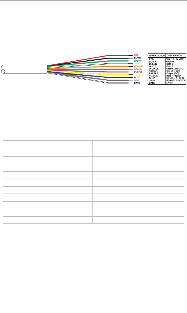
4. Wiring
The units are supplied with a 5 m (16.4 ft) 10-conductor pigtail with exposed
wires coated with solder (see Figure 5).
Figure 5: Wiring Colors
To connect the unit as a reader to an access control unit:
1. Select the appropriate connections according to Table 1.
2. Prepare the controller cable by cutting its jacket back about 3 cm (1¼")
and strip the insulation from the wires about 1.3 cm (½").
3. Splice the reader’s pigtail wires to the corresponding controller wires and
cover each joint with insulating tape.
Table 1: Wiring the Unit as a Reader to a Control Panel
Wire Color Output
Red Power
Black Ground
Green Data 0 / Data / C2
White Data 1 / Clock / C1
Orange Green LED Control
Brown Yellow LED Control
Purple OC Output*
Yellow Hold/Trigger Control
Blue RS-485 - A / OSDP**
Gray RS-485 - B / OSDP**
* for future use
** RS-485 is used for firmware update.

Wiring
AY-U920BT-US Installation and User Manual 13
4. Trim and insulate the ends of all unused conductors individually. Do not
short any unused wires together.
• The individual wires from the reader are color coded according the Wiegand
standard.
• When using a separate power supply for the reader, this supply and that of
the controller must have a common ground.
• The reader’s cable shield wire should be preferably attached to an earth
ground, or a signal ground connection at the panel, or the power supply end
of the cable. This configuration is best for shielding the reader cable from
external interference.

Operation Instructions
14 AY-U920BT-US Installation and User Manual
5. Operation Instructions
After wiring the unit to a controller (POWER, GND, D0, D1), you should test
the reader.
To test the reader:
1. Power up the reader. One beep is emitted and then it begins an auto-
calibration procedure. After 2 seconds, the reader enters working mode.
2. Present the appropriate type of credential to the reader. A short beep is
emitted, indicating that the credential is read properly.
APP-x421 Admin App
AY-U920BT-US Installation and User Manual 15
6. APP-x421 Admin App
The settings for the AY-U920BT reader can be configured using Rosslare’s
APP-x421 Admin app.
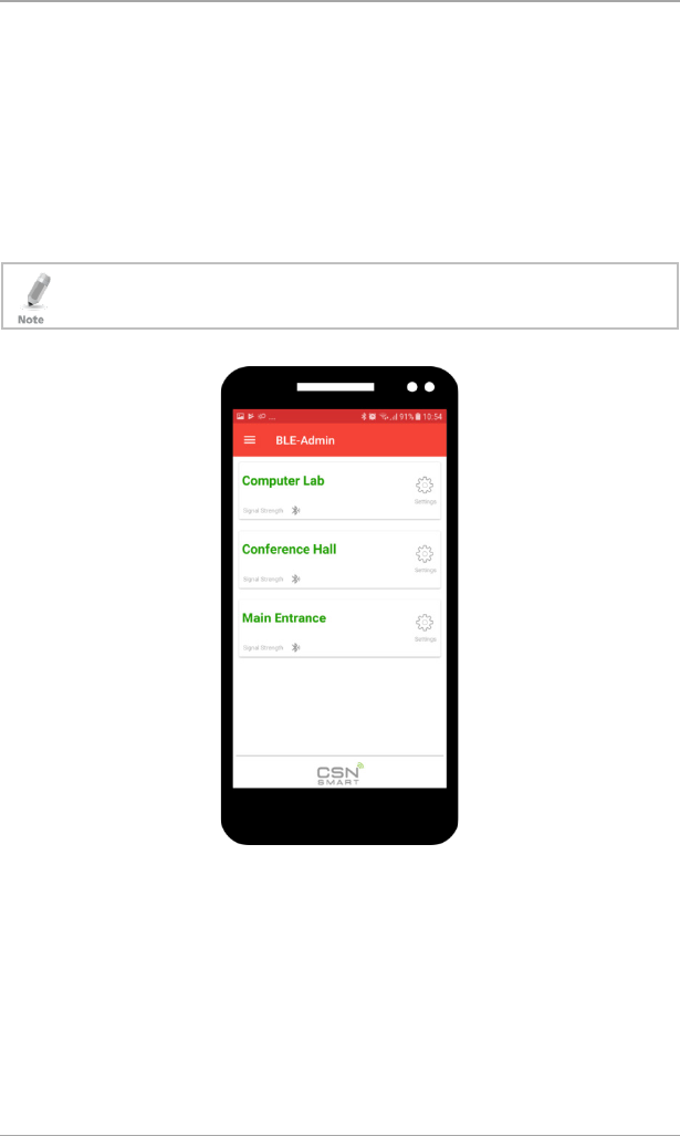
6.1 Opening the App
Download the APP-x421 Admin app for the AY-U920BT reader from Google
Play or the Apple Store, depending on the model of your mobile device.
An Android device should be v5.0 and above and an iOS device should be v8.0
and above.
All relevant readers are displayed.
APP-x421 Admin App
16 AY-U920BT-US Installation and User Manual
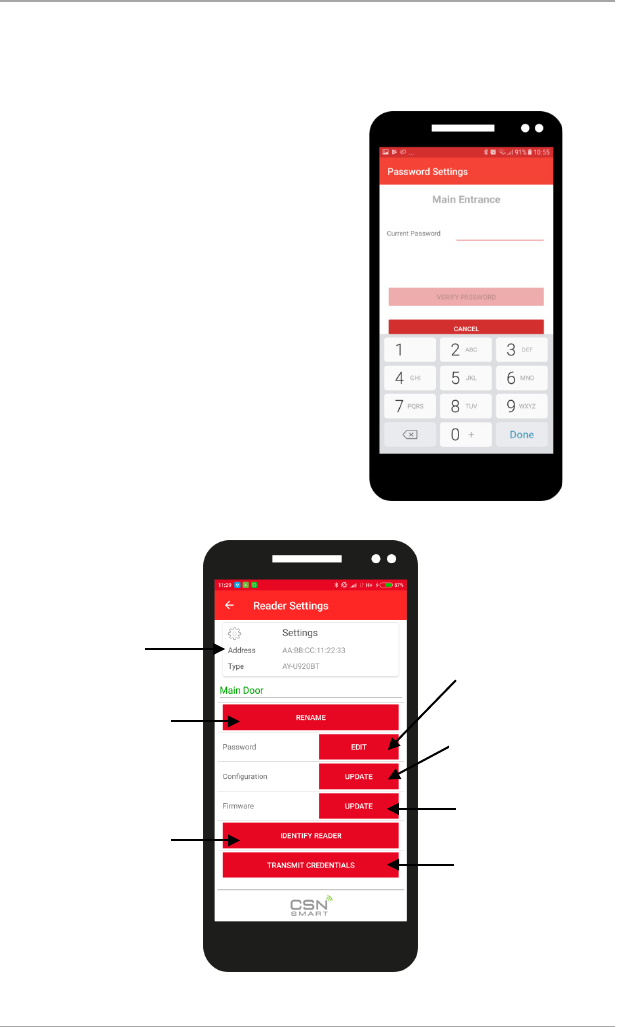
6.2 Reader Settings
Tap the ID of the reader you wish to
configure.
You are asked to enter your
password.
The default password upon initial use
is 12345678.
The Reader Settings screen opens.
Displays the
reader’s type and
MAC address
Tap to rename
the reader
Tap to edit your password
(must be 8 digits)
Tap to update
the firmware
Tap to make the
reader beep so you
can identify it
Tap to view/edit
configuration
Tap to send the
device ID to the
reader to test
access
APP-x421 Admin App
AY-U920BT-US Installation and User Manual 17
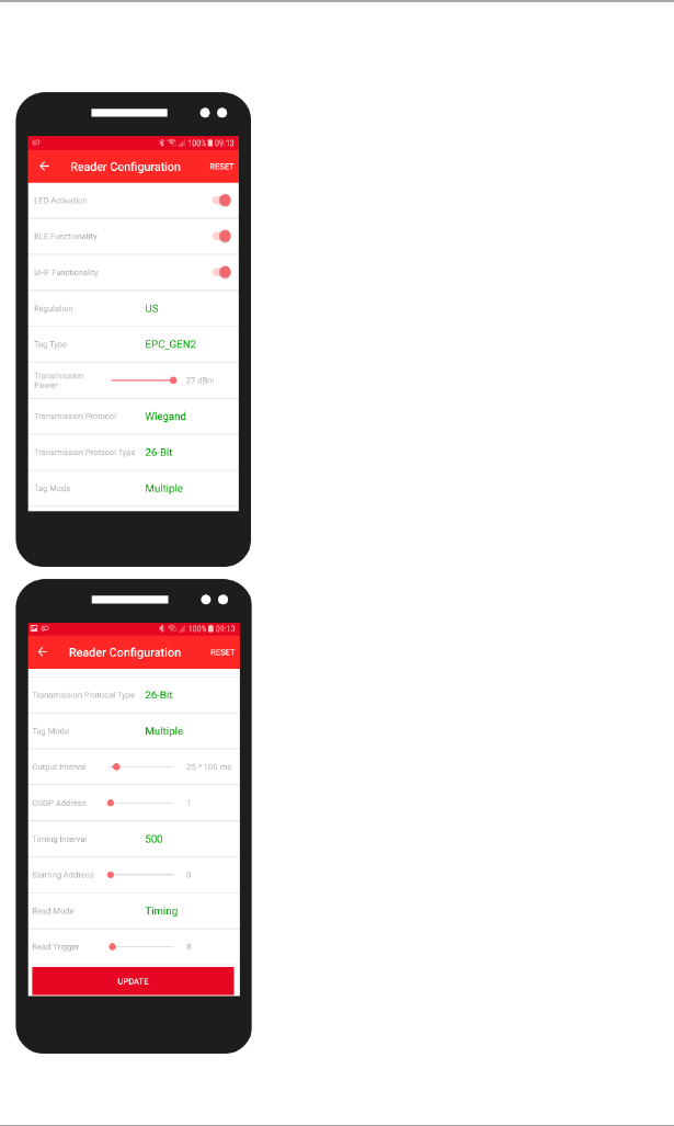
6.3
Set the configuration settings as described below.
LED Activities – Enable or disable LED
activation
BLE Functionality – Enable or disable BLE
communication
UHF Functionality – Enable or disable UHF
communication
Regulation – Select the transmitting
frequency
Tag Type – Select the tag type you wish to
read with the reader
Transition Power – Slide to select the signal
power
Transmission Protocol – Select the protocol
Transmission Protocol Type – Select number
of bits
Tag Mode – Select if reading one tag or
multiple tags
Output Interval – Slide to select the interval
of sending a credential from the reader
OSDP Address – Slide to select the address
of the reader
Timing Interval – Enter the time between
reads
Starting Address – Slide to select the initial
ID bit
Read Mode – Select the read mode
Read Trigger – Slide to select the amount of
time between reading of credentials in the
surrounding
AY-U920BT-US Reader Configuration SettingsAY-U920BT-US Reader Configuration SettingsAY-U920BT-US Reader Configuration Settings
APP-x421 Admin App
18 AY-U920BT-US Installation and User Manual
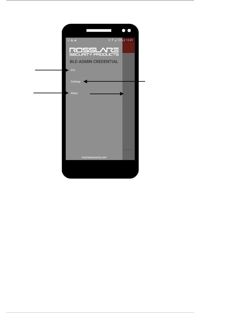
6.4 Additional Settings
If you tap on the 3 lines on the main screen, additional options are available.
Tap to display the BLE
soft credential
Tap to:
Set the reader’s read range
Change the GUI language
Set the automation, which
allows the reader to support
self checkups in specific
chosen intervals
Tap to see the EULA

Declaration of Conformity
19
A. Declaration of Conformity
This device complies with Part 15 of the FCC Rules. Operation is subject to the
following two conditions:
This device may not cause harmful interference.
This device must accept any interference received, including interference
that may cause undesired operation.
Changes or modifications not expressly approved by the party responsible for
compliance could void the user's authority to operate the equipment.
This equipment has been tested and found to comply with the limits for a
Class B digital device, pursuant to part 15 of the FCC Rules. These limits are
designed to provide reasonable protection against harmful interference in a
residential installation.
This equipment generates, uses, and can radiate radio frequency energy and, if
not installed and used in accordance with the instructions, may cause harmful
interference to radio communications. However, there is no guarantee that
interference will not occur in a particular installation. If this equipment does
cause harmful interference to radio or television reception, which can be
determined by turning the equipment off and on, the user is encouraged to try
to correct the interference by one or more of the following measures:
Reorient or relocate the receiving antenna.
Increase the separation between the equipment and receiver.
Connect the equipment into an outlet on a circuit different from that to
which the receiver is connected.
Consult the dealer or an experienced radio/TV technician for help.
AY-U920BT-US Installation and User Manual
FCC Radiation Exposure Statement:
This equipment complies with FCC radiation exposure limits set forth for an uncontrolled
environment .
This transmitter must not be co-located or operating in conjunction with any other antenna
or transmitter.
This equipment should be installed and operated with minimum distance 25cm between the
radiator &you body.

Radio Equipment Directive (RED)
20 AY-U920BT-US Installation and User Manual
B. Radio Equipment Directive (RED)
Under our sole responsibility that the following labeled AY-U920BT is tested to
conform to the EU Radio Equipment Directive – RED 2014/53/EU – in electrical
and electronic equipment.

RoHS Directive
AY-U920BT-US Installation and User Manual 21
C. RoHS Directive
Under our sole responsibility that the following labeled AY-U920BT is tested to
conform to the Restriction of Hazardous Substances (RoHS) directive –
2011/65/EU – in electrical and electronic equipment

Limited Warranty
22 AY-U920BT-US Installation and User Manual
D. Limited Warranty
The full ROSSLARE Limited Warranty Statement is available in the Quick Links
section on the ROSSLARE website at www.rosslaresecurity.com.
Rosslare considers any use of this product as agreement to the Warranty Terms
even if you do not review them.
AY-U920BT-US
0706-0960663+00
Asia Pacific, Middle East,
Africa
Rosslare Enterprises Ltd.
Kowloon Bay, Hong Kong
Tel: +852 2795-5630
Fax: +852 2795-1508
support.apac@rosslaresecurity.com
United States and Canada
Rosslare Security Products, Inc.
Southlake, TX, USA
Toll Free: +1-866-632-1101
Local: +1-817-305-0006
Fax: +1-817-305-0069
support.na@rosslaresecurity.com
Europe
Rosslare Israel Ltd.
22 Ha'Melacha St., P.O.B. 11407
Rosh HaAyin, Israel
Tel: +972 3 938-6838
Fax: +972 3 938-6830
support.eu@rosslaresecurity.com
Latin America
Rosslare Latin America
Buenos Aires, Argentina
Tel: +54-11-4001-3104
support.la@rosslaresecurity.com
China
Rosslare Electronics (Shenzhen) Ltd.
Shenzhen, China
Tel: +86 755 8610 6842
Fax: +86 755 8610 6101
support.cn@rosslaresecurity.com
India
Rosslare Electronics India Pvt Ltd.
Tel/Fax: +91 20 40147830
Mobile: +91 9975768824
sales.in@rosslaresecurity.com
CERT
ISO 9001
ISO 14001