Rosslare AYX25B MIFARE Classic EV1 CSN Readers User Manual new A4
Rosslare Enterprises Ltd MIFARE Classic EV1 CSN Readers new A4
Rosslare >
User Manual
AY-x5B Series
MIFARE Classic® EV1 CSN Readers
Installation Manual
1
1. Introduction
The AY-x5B is a series of RFID proximity card readers to be installed for
use with access control systems.
The AY-x5B series reads the card serial number (CSN) from MIFARE
Classic® EV1 credentials (4 UID and 7 UID) and transmits its data to
the access control system using Wiegand 26-Bit output.
Other Wiegand formats and the Clock & Data format are available as
factory configurable options.
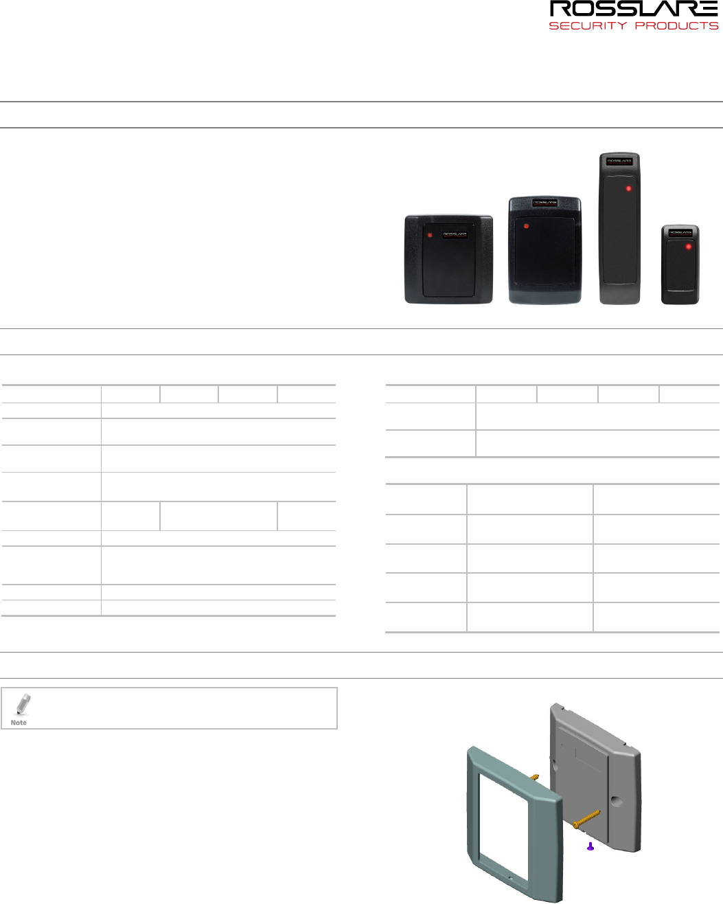
Figure 1: AY-x5B Series
AY-M5B AY-H5B AY-L5B AY-K5B
2. Technical Specifications
2.1 Electrical Characteristics
Specifications AY-M5B AY-H5B AY-L5B AY-K5B
Power Supply Type Linear (recommended)
Operating Voltage
Range
5–16 VDC
Absolute Maximum
(non-operating)
18 VDC
Current @ 12V Standby: 45 mA
Maximum: 100 mA
Max. Read Range* 6.5 cm
(2.6 in.)
7.0 cm
(2.8 in.)
6.0 cm
(2.4 in.)
LED Control Input Dry Contact, N.O.
Maximum Cable
Distance to
Controller
18-AWG: 150 m (500 ft)
20-AWG: 90 m (300 ft)
Frequency 13.56 MHz
Bit Rate 106 KHz
* Measured using a Rosslare MIFARE Classic EV1 card or equivalent. Range also
depends on installation environment, reader voltage, and proximity to metal.
2.2 Environmental Characteristics
Specifications AY-M5B AY-H5B AY-L5B AY-K5B
Operating Temp.
Range
-31°C to 63°C (-25°F to 145°F)
Operating
Humidity Range
0 to 95% (non-condensing)
2.3 Physical Characteristics
Model Dimensions
(H x W x D)
Weight
AY-M5B 89 x 89 x 15 mm
(3.5 x 3.5 x 0.6 in.)
120.3 g
(4.2 oz.)
AY-H5B 110 x 75 x 15 mm
(4.3 x 3.0 x 0.6 in.)
119.9 g
(4.2 oz)
AY-L5B 145 x 43 x 20 mm
(5.7 x 1.7 x 0.8 in.)
115.2 g
(4.1 oz)
AY-K5B 80 x 40 x 12.8 mm
(3.2 x 1.6 x 0.5 in.)
75.5 g
(2.7 oz)
3. Installation
Installation of an RFID reader adjacent to metallic surfaces
might alter the reader’s specifications. To diminish this
interference, use a plastic spacer when mounting the reader.
3.1 Installation Kit
The installation kit consists of the following items to be used during
the installation procedure:
Two pan head mounting screws and screw anchors
3.2 Mounting
Before mounting, you should determine the best location for the
reader.
To mount the reader:
1. Drill two holes for mounting the reader on the wall.
2. Insert a screw anchor into each hole.
3. Drill a 10-mm (7/16”) hole for the cable. If mounting on metal,
place a grommet or electrical tape around the edge of the hole.
4. Remove the screw from the bottom of the unit.
5. Remove the reader's snap-off front cover.
6. Insert the unit’s cable wire into the cable hole and wire the unit as
described in Section 3.3. A linear type power supply is
recommended.
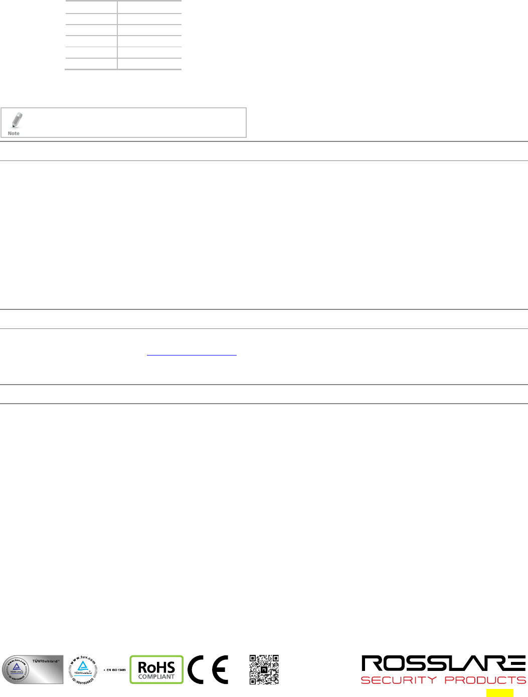
7. Align the two holes of the reader with those drilled in the wall and
firmly attach the reader to the wall with two screws (Figure 2).
Figure 2: Inserting Mounting Screws (similar for all models)
8. Relocate the front cover onto the reader.
9. Secure the front cover with the screw at the bottom of the unit.
2 0706-0960191+00
3.3 Wiring
The AY-x2B is supplied with 5 color-coded wires 25 cm (10 in.) in
length.
To connect the reader to the controller:
1. Select the appropriate connections according to Table 1.
Table 1: Wiring
Wire Color Function
Red VIN 5–16 VDC
Black Ground
Green Data 0
White Data 1
Brown Green LED CTL
2. Connect the wires to the corresponding controller wires and cover
each joint with insulating tape.
3. Trim and cover all unused conductors.
When using a separate power supply for the reader, this supply
and that of the controller must have a common ground
3.4 Operation Instructions
Once the reader is wired to a power supply and to the controller, you
should test the reader.
To test the reader:
1. Power up the reader.
Upon power up, the reader flashes and beeps once during Self-
Test. The LED then turns red indicating the readers has entered
Standby mode.
2. Apply a MIFARE Classic EV1 credential to the reader.
The reader flashes and beeps once indicating the card has been
read successfully.
Declaration of Conformity
FCC ID:GCD-AYX25B
This device complies with Part 15 of the FCC Rules. Operation is
subject to the following two conditions:
This device may not cause harmful interference.
This device must accept any interference received, including
interference that may cause undesired operation.
Changes or modifications not expressly approved by the party
responsible for compliance could void the user's authority to
operate the equipment.
This equipment has been tested and found to comply with the limits
for a Class B digital device, pursuant to part 15 of the FCC Rules. These
limits are designed to provide reasonable protection against harmful
interference in a residential installation.
This equipment generates, uses, and can radiate radio frequency
energy and, if not installed and used in accordance with the
instructions, may cause harmful interference to radio communications.
However, there is no guarantee that interference will not occur in a
particular installation. If this equipment does cause harmful
interference to radio or television reception, which can be determined
by turning the equipment off and on, the user is encouraged to try to
correct the interference by one or more of the following measures:
Reorient or relocate the receiving antenna.
Increase the separation between the equipment and receiver.
Connect the equipment into an outlet on a circuit different from
that to which the receiver is connected.
Consult the dealer or an experienced radio/TV technician for help.
Limited Warranty
The full ROSSLARE Limited Warranty Statement is available in the Quick
Links section on the ROSSLARE website at www.rosslaresecurity.com.
Rosslare considers any use of this product as agreement to the
Warranty Terms even if you do not review them.
Contact Information
United States and Canada
Rosslare Security Products, Inc.
Southlake, TX, USA
Toll Free: +1-866-632-1101
Local: +1-817-305-0006
Fax: +1-817-305-0069
support.na@rosslaresecurity.com
Europe
Rosslare Israel Ltd.
22 Ha'Melacha St., P.O.B. 11407
Rosh HaAyin, Israel
Tel: +972-3-938-6838
Fax: +972-3-938-6830
support.eu@rosslaresecurity.com
Latin America
Rosslare Latin America
Buenos Aires, Argentina
Tel: +54-11-4001-3104
support.la@rosslaresecurity.com
China
Rosslare Electronics (Shenzhen) Ltd.
Shenzhen, China
Tel: +86-755-8610-6842
Fax: +86-755-8610-6101
support.cn@rosslaresecurity.com
Asia Pacific, Middle East, Africa
Rosslare Enterprises Ltd.
Kowloon Bay, Hong Kong
Tel: +852-2795-5630
Fax: +852-2795-1508
support.apac@rosslaresecurity.com
India
Rosslare Electronics India Pvt Ltd.
Tel/Fax: +91-20-40147830
Mobile: +91-9975768824
sales.in@rosslaresecurity.com
CERT
ISO 9001
ISO 14001