Rosslare AYX6255 CSN SELECT Smart Card Readers User Manual A4 1 page
Rosslare Enterprises Ltd CSN SELECT Smart Card Readers A4 1 page
Rosslare >
Contents
- 1. Users Manual
- 2. User Manual
Users Manual
AY-x6255 Family
CSN SELECT Smart Card Readers
Installation and User Manual
1
1. Introduction
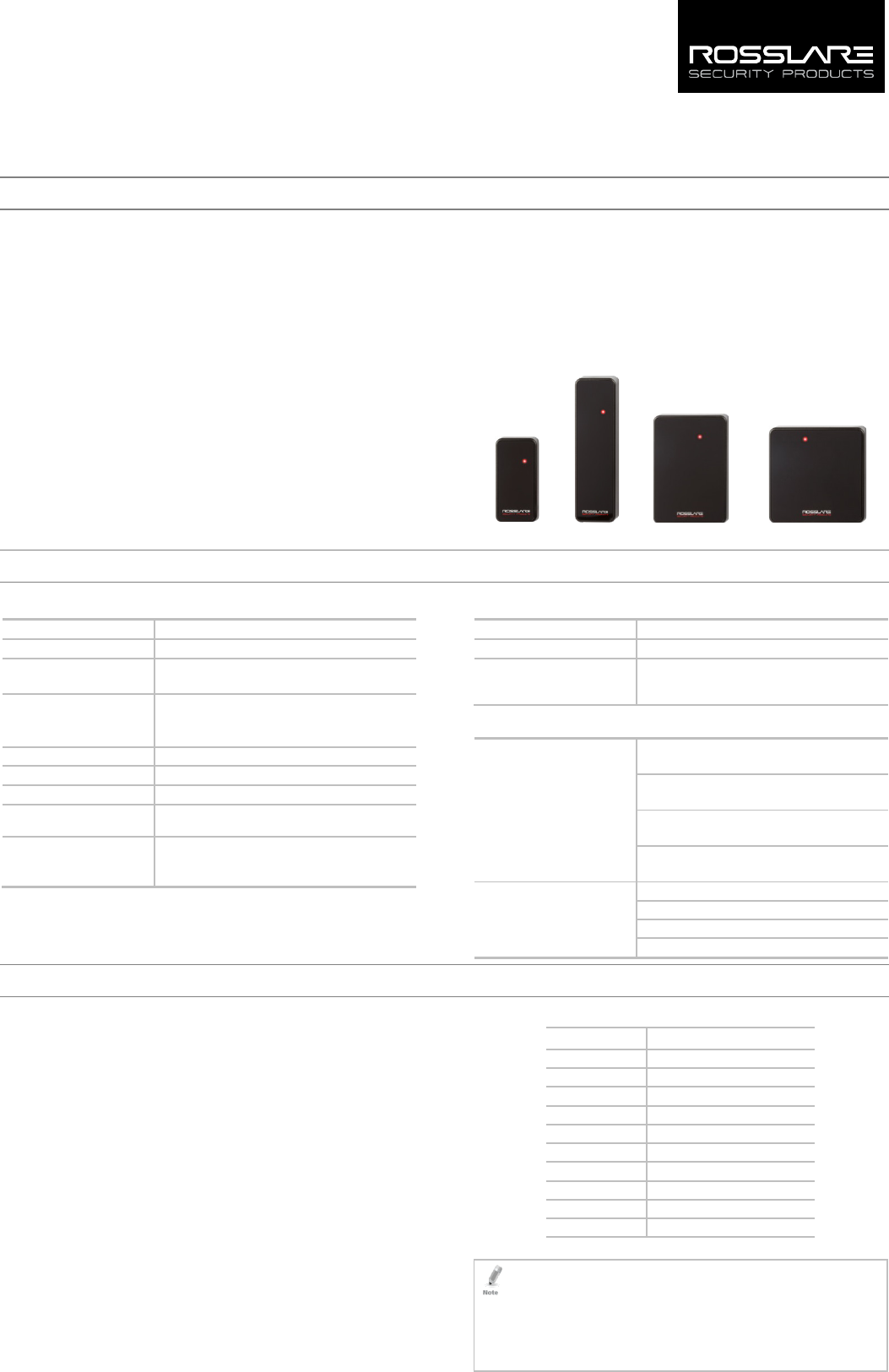
The AY-x6255 is a family of multi-format contactless smart card
readers for use in access control system solutions.
CSN SELECT readers support reading from the secure memory of the
following credential technologies:
MIFARE Ultralight / Ultralight C
MIFARE Classic
MIFARE Plus S / Plus X
MIFARE DESFire EV1
ISO 14443A
ISO 14443B
ISO 15693
iClass
ISO 18092 (NFCIP-1)
FeliCa
1.1 Box Content
Before beginning, verify that all of the following is in the box. If
anything is missing, please report the discrepancy to your nearest
Rosslare office.
One AY-x6255 unit
Installation kit – Includes two wall plugs, two mounting screws,
security Torx screw, and security Torx screw tool
Installation and operating instructions
AY-K6255 AY-L6255 AY-H6255 AY-M6255
2. Technical Specifications
2.1 Electrical Characteristics
Power Supply Type Linear (recommended)
Operating Voltage Range 8 to 16 VDC
Current @ 12 V Standby: 100 mA
Maximum: 120 mA
Read Range* MIFARE Classic EV1: 40 to 45 mm (1.5 to 1.8 in.)
MIFARE Plus: 30 mm (1.2 in.)
MIFARE DESFire EV1: 30 mm (1.2 in.)
LED Control Input 1** Green LED control, TTL
LED Control Input 2** Red LED control, TTL
Auxiliary Input** Buzzer control, TTL
Auxiliary Output** Tamper output (open collector, active low, max.
sink current 30 mA)
Maximum Cable Distance
to Controller
Wiegand: 150 m (500 ft) with 18-AWG cable
OSDP (RS-485): 1200 m (4,000 ft) with 2x2 18-
AWG twisted shielded cable
* Measured using a Rosslare MIFARE card cards. Range also depends on
electrical environment and proximity to metal.
** Standard configuration. Custom configurations are available.
2.2 Environmental Characteristics
Operating Temp. Range -25°C to 65°C (-13°F to 149°F)
Operating Humidity Range 0 to 95% (non-condensing)
Outdoor Usage Weather-resistant, UV-resistant, meets IP65,
epoxy-potted, suitable for indoor and outdoor
use
2.3 Physical Characteristics
Dimensions
(H x W x D)
AY-K6255: 80.5 x 40.5 x 14.7 mm
(3.2 x 1.6 x 0.6 in.)
AY-L6255: 144.9 x 42.9 x 22.1 mm
(5.7 x 1.7 x 0.9 in.)
AY-H6255: 110.7 x 75.0 x 17.1 mm
(4.4 x 3.0 x 0.7 in.)
AY-M6255: 89.5 x 88.9 x 16.8 mm
(3.5 x 3.5 x 0.7 in.)
Weight AY-K6255: 77 g (2.7 oz)
AY-L6255: 126 g (4.4 oz)
AY-H6255: 163 g (5.7 oz)
AY-M6255: 145 g (5.1 oz.)
3. Wiring Instructions
The units are supplied with a 10-conductor 18” (46-cm) pigtail or with
10 terminal blocks.
To connect a pigtail reader to the controller:
1. Prepare the reader cable by cutting its jacket back 3.2 cm (1¼”)
and strip the insulation from the wires 1.3 cm (½").
2. Prepare the controller cable by cutting its jacket back 3.2 cm (1¼")
and strip the insulation from the wires 1.3 cm (½").
3. Splice the reader’s pigtail wires to the corresponding controller
wires (as indicated in Table 1) and cover each joint with insulating
tape.
4. If the tamper output is being utilized, connect the purple wire to
the correct input on the controller.
The LED control may be configured by the factory to function
either as a LED control or as buzzer control. Currently, the auxiliary
input is used as buzzer control and LED Control 1 is used as the
green LED control.
5. Trim and cover all unused conductors.
Table 1: AY-x6255 Wiring
Wire Color Output
Red Power
Black Ground
Green Data 0 / Data
White Data 1 / Clock
Purple Tamper Output
Orange Green LED control
Brown Red LED control
Yellow Buzzer control / Auxiliary input
Blue OSDP-RS-485-A*
Gray OSDP-RS-485-B*
*H and M models only
• The individual wires from the reader are color coded according the
Wiegand standard.
• When using a separate power supply for the reader, this supply and
that of the controller must have a common ground.
• The reader’s cable shield wire should
be preferably attached to an earth
ground, or a signal ground connection at the panel, or power supply
end of the cable.
2
4. OSDP Operation
The K and L models do not currently support OSDP function.
CSN SELECT readers that support OSDP operation are compatible with
most OSDP commands. The reader address is set using DIP switches on
the back of the reader. Release the screw on the back of the reader to
remove the door to access the DIP switches.
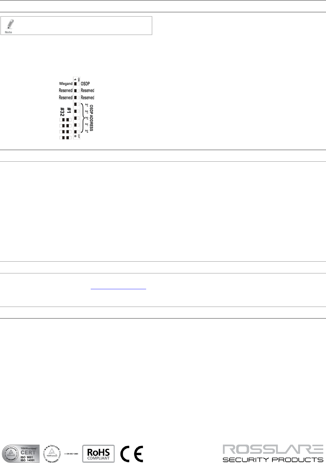
Figure 1 shows the DIP switch settings, which are described below.
Figure 1: DIP Switch Settings
DIP Switch 1
This switch is used to select the reader output (Wiegand or OSDP):
Off = Wiegand
On = OSDP
DIP Switch 2
This switch is reserved for future use.
DIP Switch 3
This switch is reserved for future use.
DIP Switches 4 to 8
These switches set the address of the reader for OSDP protocol.
DIP Switch 4 is MSB and DIP Switch 8 is LSB. The address is the DIP
switch state +1.
Examples:
All the DIP switches in Off position, state is = 0 => address = 1
All the DIP switches in On position, state is = 0x1F => address
= 0x20 = 32
DIP switches 4, 6, 8 in On position and 5, 7 in Off position, state is
= 0x15 => address = 0x16 = 22
Declaration of Conformity
AYMH6255: FCC ID = GCD-AYCX6X55
AYKL6255: FCC ID = GCD-AYX6255
This device complies with Part 15 of the FCC Rules. Operation is
subject to the following two conditions:
This device may not cause harmful interference.
This device must accept any interference received, including
interference that may cause undesired operation.
Changes or modifications not expressly approved by the party
responsible for compliance could void the user's authority to
operate the equipment.
This equipment has been tested and found to comply with the limits
for a Class B digital device, pursuant to part 15 of the FCC Rules. These
limits are designed to provide reasonable protection against harmful
interference in a residential installation.
This equipment generates, uses, and can radiate radio frequency
energy and, if not installed and used in accordance with the
instructions, may cause harmful interference to radio communications.
However, there is no guarantee that interference will not occur in a
particular installation. If this equipment does cause harmful
interference to radio or television reception, which can be determined
by turning the equipment off and on, the user is encouraged to try to
correct the interference by one or more of the following measures:
Reorient or relocate the receiving antenna.
Increase the separation between the equipment and receiver.
Connect the equipment into an outlet on a circuit different from
that to which the receiver is connected.
Consult the dealer or an experienced radio/TV technician for help.
Limited Warranty
The full ROSSLARE Limited Warranty Statement is available in the Quick
Links section on the ROSSLARE website at www.rosslaresecurity.com.
Rosslare considers any use of this product as agreement to the
Warranty Terms even if you do not review them.
Contact Information
United States and Canada
Rosslare Security Products, Inc.
Southlake, TX, USA
Toll Free: +1-866-632-1101
Local: +1-817-305-0006
Fax: +1-817-305-0069
support.na@rosslaresecurity.com
Europe
Rosslare Israel Ltd.
Rosh HaAyin, Israel
Tel: +972-3-938-6838
Fax: +972-3-938-6830
support.eu@rosslaresecurity.com
Latin America
Rosslare Latin America
Buenos Aires, Argentina
Tel: +54-11-4001-3104
support.la@rosslaresecurity.com
China
Rosslare Electronics (Shenzhen) Ltd.
Shenzhen, China
Tel: +86-755-8610-6842
Fax: +86-755-8610-6101
support.cn@rosslaresecurity.com
Asia Pacific, Middle East, Africa
Rosslare Enterprises Ltd.
Kowloon Bay, Hong Kong
Tel: +852-2795-5630
Fax: +852-2795-1508
support.apac@rosslaresecurity.com
India
Rosslare Electronics India Pvt Ltd.
Tel/Fax: +91-20-40147830
Mobile: +91-9975768824
sales.in@rosslaresecurity.com
www.rosslaresecurity.com
0706-0960618+00