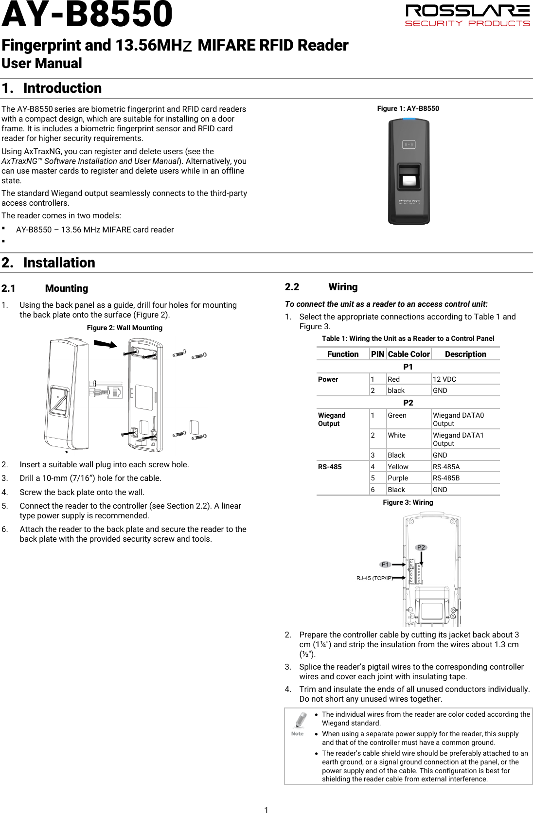
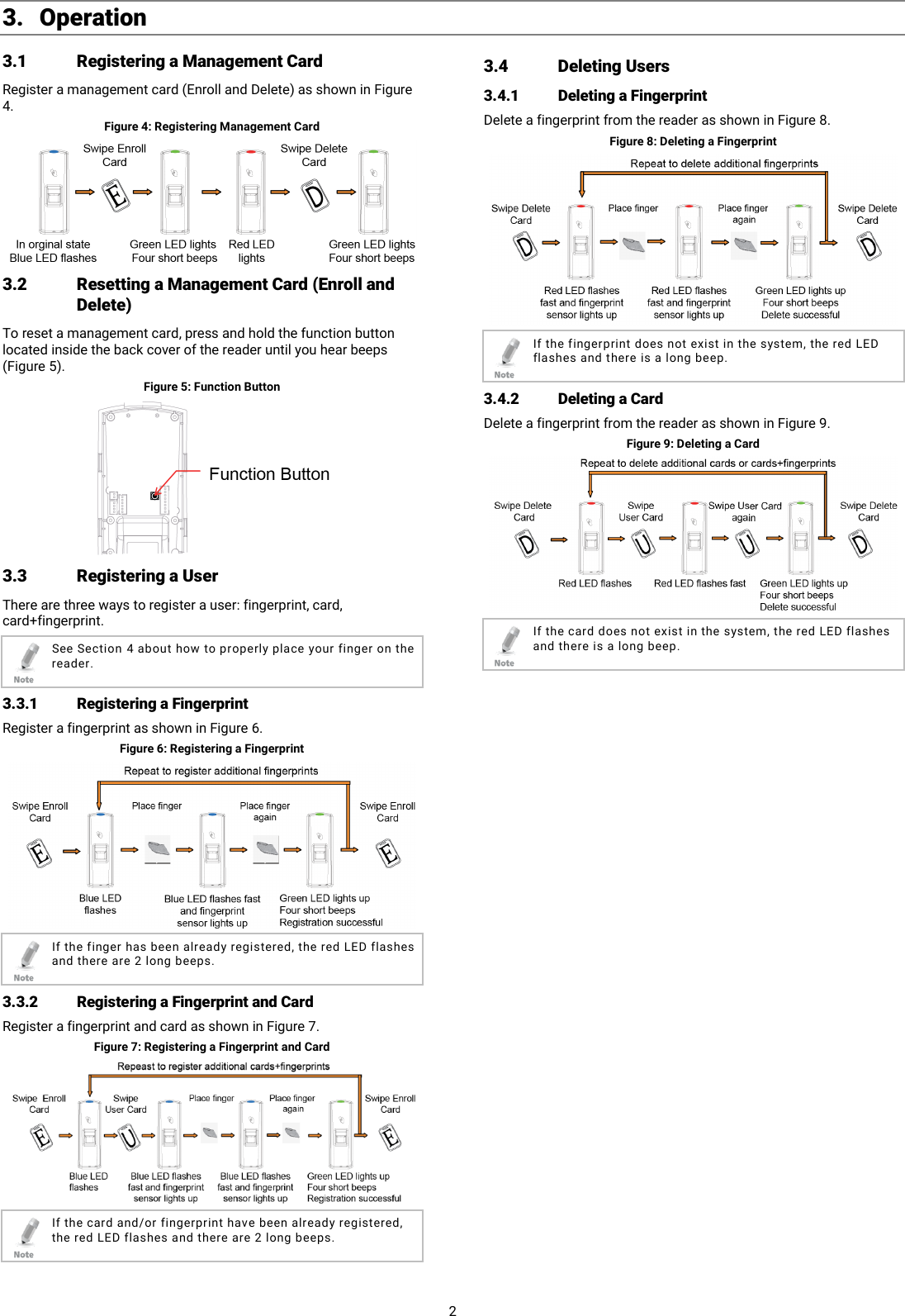
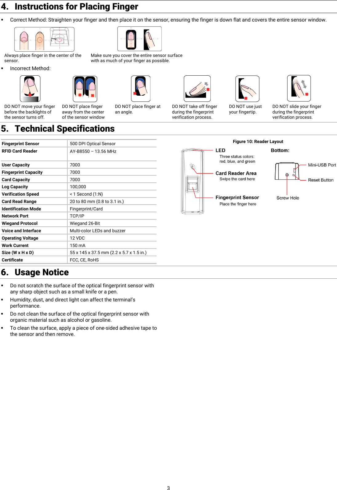
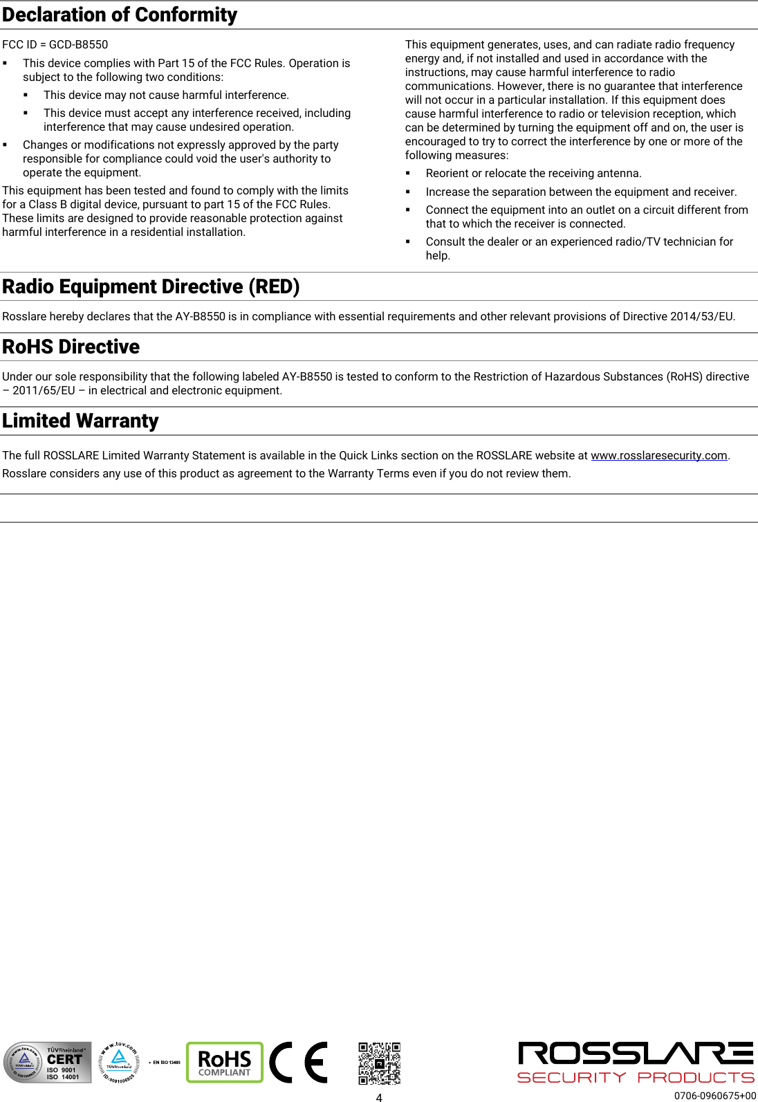
Rosslare B8550 Fingerprint and 13.56MHz MIFARE RFID Reader User Manual A4 1 page

Rosslare Enterprises Ltd Fingerprint and 13.56MHz MIFARE RFID Reader A4 1 page

user manual

AY-B8550   Fingerprint and 13.56MH    MIFARE RFID Reader   User Manual 1 1. Introduction The AY-B8550 series are biometric fingerprint and RFID card readers with a compact design, which are suitable for installing on a door frame. It is includes a biometric fingerprint sensor and RFID card reader for higher security requirements. Using AxTraxNG, you can register and delete users (see the AxTraxNG™ Software Installation and User Manual). Alternatively, you can use master cards to register and delete users while in an offline state. The standard Wiegand output seamlessly connects to the third-party access controllers. The reader comes in two models:   AY-B8550 – 13.56 MHz MIFARE card reader Figure 1: AY-B8550 2. Installation 2.1 Mounting 1. Using the back panel as a guide, drill four holes for mounting the back plate onto the surface (Figure 2). Figure 2: Wall Mounting  2. Insert a suitable wall plug into each screw hole. 3. Drill a 10-mm (7/16”) hole for the cable. 4. Screw the back plate onto the wall. 5. Connect the reader to the controller (see Section  2.2). A linear type power supply is recommended. 6. Attach the reader to the back plate and secure the reader to the back plate with the provided security screw and tools. 2.2 Wiring To connect the unit as a reader to an access control unit: 1. Select the appropriate connections according to Table 1 and Figure 3. Table 1: Wiring the Unit as a Reader to a Control Panel Function PIN Cable Color Description P1 Power 1  Red 12 VDC 2  black GND P2 Wiegand Output 1  Green Wiegand DATA0 Output 2  White Wiegand DATA1 Output 3  Black GND RS-485 4  Yellow RS-485A 5  Purple RS-485B 6  Black GND  Figure 3: Wiring  2. Prepare the controller cable by cutting its jacket back about 3 cm (1¼") and strip the insulation from the wires about 1.3 cm (½"). 3. Splice the reader’s pigtail wires to the corresponding controller wires and cover each joint with insulating tape. 4. Trim and insulate the ends of all unused conductors individually. Do not short any unused wires together.  • The individual wires from the reader are color coded according the Wiegand standard. • When using a separate power supply for the reader, this supply and that of the controller must have a common ground. • The reader’s cable shield wire should be preferably attached to an earth ground, or a signal ground connection at the panel, or the power supply end of the cable. This configuration is best for shielding the reader cable from external interference.  z
 2 3. Operation 3.1 Registering a Management Card Register a management card (Enroll and Delete) as shown in Figure 4. Figure 4: Registering Management Card  3.2 Resetting a Management Card (Enroll and Delete) To reset a management card, press and hold the function button located inside the back cover of the reader until you hear beeps (Figure 5). Figure 5: Function Button  3.3 Registering a User There are three ways to register a user: fingerprint, card, card+fingerprint.  See Section  4 about how to properly place your finger on the reader. 3.3.1 Registering a Fingerprint Register a fingerprint as shown in Figure 6. Figure 6: Registering a Fingerprint   If the finger has been already registered, the red LED flashes and there are 2 long beeps. 3.3.2 Registering a Fingerprint and Card Register a fingerprint and card as shown in Figure 7. Figure 7: Registering a Fingerprint and Card   If the card and/or fingerprint have been already registered, the red LED flashes and there are 2 long beeps. 3.4 Deleting Users 3.4.1 Deleting a Fingerprint Delete a fingerprint from the reader as shown in Figure 8. Figure 8: Deleting a Fingerprint   If the fingerprint does not exist in the system, the red LED flashes and there is a long beep. 3.4.2 Deleting a Card Delete a fingerprint from the reader as shown in Figure 9. Figure 9: Deleting a Card   If the card does not exist in the system, the red LED flashes and there is a long beep.
 3 4. Instructions for Placing Finger  Correct Method: Straighten your finger and then place it on the sensor, ensuring the finger is down flat and covers the entire sensor window.   Always place finger in the center of the sensor. Make sure you cover the entire sensor surface with as much of your finger as possible.  Incorrect Method:         DO NOT move your finger before the backlights of the sensor turns off. DO NOT place finger away from the center of the sensor window DO NOT place finger at an angle. DO NOT take off finger during the fingerprint verification process. DO NOT use just your fingertip. DO NOT slide your finger during the fingerprint verification process. 5. Technical Specifications Fingerprint Sensor 500 DPI Optical Sensor RFID Card Reader AY-B8550 – 13.56 MHz User Capacity 7000 Fingerprint Capacity 7000 Card Capacity 7000 Log Capacity 100,000 Verification Speed < 1 Second (1:N) Card Read Range 20 to 80 mm (0.8 to 3.1 in.) Identification Mode Fingerprint/Card Network Port TCP/IP Wiegand Protocol Wiegand 26-Bit Voice and Interface Multi-color LEDs and buzzer Operating Voltage 12 VDC Work Current 150 mA Size (W x H x D) 55 x 145 x 37.5 mm (2.2 x 5.7 x 1.5 in.) Certificate FCC, CE, RoHS Figure 10: Reader Layout   6. Usage Notice Do not scratch the surface of the optical fingerprint sensor with any sharp object such as a small knife or a pen.  Humidity, dust, and direct light can affect the terminal’s performance.  Do not clean the surface of the optical fingerprint sensor with organic material such as alcohol or gasoline.  To clean the surface, apply a piece of one-sided adhesive tape to the sensor and then remove.
 4  0706-0960675+00 Declaration of ConformityFCC ID = GCD-B8550  This device complies with Part 15 of the FCC Rules. Operation is subject to the following two conditions:  This device may not cause harmful interference.  This device must accept any interference received, including interference that may cause undesired operation.  Changes or modifications not expressly approved by the party responsible for compliance could void the user's authority to operate the equipment. This equipment has been tested and found to comply with the limits for a Class B digital device, pursuant to part 15 of the FCC Rules. These limits are designed to provide reasonable protection against harmful interference in a residential installation. This equipment generates, uses, and can radiate radio frequency energy and, if not installed and used in accordance with the instructions, may cause harmful interference to radio communications. However, there is no guarantee that interference will not occur in a particular installation. If this equipment does cause harmful interference to radio or television reception, which can be determined by turning the equipment off and on, the user is encouraged to try to correct the interference by one or more of the following measures:  Reorient or relocate the receiving antenna.  Increase the separation between the equipment and receiver.  Connect the equipment into an outlet on a circuit different from that to which the receiver is connected.  Consult the dealer or an experienced radio/TV technician for help. Radio Equipment Directive (RED)Rosslare hereby declares that the AY-B8550 is in compliance with essential requirements and other relevant provisions of Directive 2014/53/EU.RoHS DirectiveUnder our sole responsibility that the following labeled AY-B8550 is tested to conform to the Restriction of Hazardous Substances (RoHS) directive – 2011/65/EU – in electrical and electronic equipment.Limited Warranty The full ROSSLARE Limited Warranty Statement is available in the Quick Links section on the ROSSLARE website at www.rosslaresecurity.com. Rosslare considers any use of this product as agreement to the Warranty Terms even if you do not review them.  CERTISO  9001ISO  14001
   This equipment has been tested and found to comply with the limits for a Class B digital device, pursuant to part 15 of the FCC Rules. These limits are designed to provide reasonable protection against harmful interference in a residential installation. This equipment generates, uses and can radiate radio frequency energy and, if not installed and used in accordance with the instructions, may cause harmful interference to radio communications. However, there is no guarantee that interference will not occur in a particular installation. If this equipment does cause harmful interference to radio or television reception, which can be determined by turning the equipment off and on, the user is encouraged to try to correct the interference by one or more of the following measures: Ь  Reorient or relocate the receiving antenna. Ь  Increase the separation between the equipment and receiver. Ь  Connect the equipment into an outlet on a circuit different from that to which the receiver is connected. Ь  Consult the dealer or an experienced radio/TV technician for help.  Caution: Any changes or modifications to this device not explicitly approved by manufacturer could void your authority to operate this equipment.  This device complies with part 15 of the FCC Rules. Operation is subject to the following two conditions: (1) This device may not cause harmful interference, and (2) this device must accept any interference received, including interference that may cause undesired operation.  The device has been evaluated to meet general RF exposure requirement.  Company: U-tec Group Inc.  Address: 44292 Fremont Blvd, Fremont, CA 94538Name: Kevin ZhuPosition: Product Manager Tel: 844-439-8832Fax: 844-439-8832 Email: kevin@u-tec.com  Web: www.u-tec.com

Navigation menu