Rosslare HLX24G Wireless Security Panel User Manual
Rosslare Enterprises Ltd Wireless Security Panel
Rosslare >
User manual
HLX-24
Advanced Wireless Security Panel
Hardware Installation and Programming Manual
Models:
HLX-24
HLX-24IP
Copyright © 2015 by Rosslare. All rights reserved.
This manual and the information contained herein are proprietary to ROSSLARE
ENTERPRISES LIMITED and/or its related companies and/or subsidiaries’ (hereafter:
"ROSSLARE"). Only ROSSLARE and its customers have the right to use the information.
No part of this manual may be re-produced or transmitted in any form or by any means,
electronic or mechanical, for any purpose, without the express written permission of
ROSSLARE.
ROSSLARE owns patents and patent applications, trademarks, copyrights, or other
intellectual property rights covering the subject matter in this manual.
TEXTS, IMAGES, AND ILLUSTRATIONS INCLUDING THEIR ARRANGEMENT IN THIS
DOCUMENT ARE SUBJECT TO THE PROTECTION OF COPYRIGHT LAWS AND OTHER
LEGAL RIGHTS WORLDWIDE. THEIR USE, REPRODUCTION, AND TRANSMITTAL TO THIRD
PARTIES WITHOUT EXPRESS WRITTEN PERMISSION MAY RESULT IN LEGAL
PROCEEDINGS.
The furnishing of this manual to any party does not give that party or any third party any
license to these patents, trademarks, copyrights or other intellectual property rights,
except as expressly provided in any written agreement of ROSSLARE.
ROSSLARE reserves the right to revise and change this document at any time, without
being obliged to announce such revisions or changes beforehand or after the fact.

Table of Contents
HLX-24 Hardware Installation and Programming Manual iii
Table of Contents
1. Introduction ..................................................................... 10
1.1 General ............................................................................................ 10
1.2 Special Features ................................................................................ 10
2. HLX-24 Quick Reference .................................................. 11
2.1 The Panel .......................................................................................... 11
2.2 The Keypad ...................................................................................... 12
2.2.1 Keypad Operated Functions ....................................................................... 13
2.3 Sound Indicators ............................................................................... 14
2.4 LED Indicators ................................................................................... 14
3. Specifications .................................................................. 16
3.1 RF Data............................................................................................. 16
3.2 Environmental Data .......................................................................... 16
3.3 Electrical Data ................................................................................... 16
3.4 Communication ................................................................................ 17
4. Installation ...................................................................... 18
4.1 Unpacking the Equipment................................................................. 18
4.1.1 HLX-24 Package Content ........................................................................... 18
4.2 Supply Power to the Unit .................................................................. 18
4.3 Planning and Programming ............................................................... 18
4.4 Wiring the System ............................................................................ 19
4.5 Connecting the AC Transformer ....................................................... 20
4.6 Connecting to a PC .......................................................................... 20
4.7 Mounting the Back Plate ................................................................... 20
4.7.1 General ..................................................................................................... 20
4.7.2 Required Space ......................................................................................... 21
4.8 Dismounting the Control Panel ......................................................... 22
4.9 Replacing the Backup Batteries ......................................................... 22

Table of Contents
iv HLX-24 Hardware Installation and Programming Manual
5. Programming the HLX-24 ............................................... 23
6. Installer Menu ................................................................. 24
6.1 Change Code ................................................................................... 25
6.2 Zones ............................................................................................... 25
6.3 Enrolling ........................................................................................... 27
6.3.1 Detectors .................................................................................................. 28
6.3.2 Remote Controls (KE-30 RFID Function) ...................................................... 28
6.3.3 RF Siren ..................................................................................................... 29
6.3.4 Keypads .................................................................................................... 29
6.3.5 Repeaters .................................................................................................. 30
6.4 Security ............................................................................................ 30
6.4.1 Exit Delay .................................................................................................. 31
6.4.2 Exit Restart ................................................................................................ 32
6.4.3 Entry Delay ................................................................................................ 32
6.4.4 Auto Arming ............................................................................................. 32
6.4.5 Siren Time ................................................................................................. 33
6.4.6 Siren Mode ............................................................................................... 33
6.4.7 Local Siren ................................................................................................ 33
6.4.8 External Siren ............................................................................................ 33
6.4.9 Supervision Time ....................................................................................... 33
6.4.10 Jamming ................................................................................................... 34
6.4.11 No Activity Time ........................................................................................ 34
6.4.12 Trouble Beeps ........................................................................................... 34
6.4.13 Bypass Option ........................................................................................... 35
6.4.14 Quick Arm ................................................................................................ 35
6.4.15 Arm Instant ............................................................................................... 35
6.4.16 Panic Button .............................................................................................. 36
6.4.17 Duress Code .............................................................................................. 36
6.4.18 Alarm Cancel ............................................................................................ 36
6.4.19 Alarm Abort Time ...................................................................................... 37
6.4.20 Backlight Time ........................................................................................... 37
6.4.21 Hide Display .............................................................................................. 37
6.4.22 Key Beeps ................................................................................................. 38
6.4.23 Select Language ........................................................................................ 38
6.4.24 EN-CENELEC ............................................................................................. 38

Table of Contents
HLX-24 Hardware Installation and Programming Manual v
6.4.25 CP-01 ....................................................................................................... 39
6.5 Communications .............................................................................. 41
6.5.1 System Telephone ..................................................................................... 42
6.5.2 Private Report ............................................................................................ 42
6.5.3 CS Report Setup ........................................................................................ 43
6.5.4 Line Test ................................................................................................... 45
6.5.5 AC Fail Report ........................................................................................... 45
6.5.6 Fax Defeat ................................................................................................. 45
6.5.7 Number of Rings ....................................................................................... 45
6.5.8 Select Region/Country ............................................................................... 46
6.6 Automation ...................................................................................... 46
6.6.1 Keypad Manual ......................................................................................... 46
6.6.2 Set Triggers ............................................................................................... 47
6.7 Messages .......................................................................................... 47
6.7.1 Keypad Mute ............................................................................................ 48
6.7.2 House Name ............................................................................................. 48
6.7.3 Custom Zones ........................................................................................... 48
6.8 Maintenance .................................................................................... 49
6.8.1 Factory Defaults......................................................................................... 49
6.8.2 RF Test ...................................................................................................... 49
6.8.3 Test Indicators ........................................................................................... 50
6.8.4 Sirens Test ................................................................................................. 50
6.8.5 Test Devices .............................................................................................. 50
7. User Menu Structure ....................................................... 51
8. Reading the Event Log ................................................... 53
A. Quick Reference to Installer Menu ................................ 54
B. Quick Reference to User Menu ...................................... 56
C. Sensor Placement and Helpful Reference Tables ........ 57
C.1 Default Zone Descriptions ................................................................. 57
C.2 Custom Zone Descriptions ................................................................ 58
C.3 Detector Deployment Plan ................................................................ 58
C.4 Remote Control ................................................................................ 59

Table of Contents
vi HLX-24 Hardware Installation and Programming Manual
D. Reporting Codes .............................................................. 60
E. GSM Stick Errors .............................................................. 62
F. Settings Requirements for CENELEC ............................. 63
G. Default Parameter Values .............................................. 64
H. Labeling Instructions ...................................................... 69
I. Declaration of Conformity ............................................. 70
J. Limited Warranty ............................................................ 71

List of Figures
HLX-24 Hardware Installation and Programming Manual vii
List of Figures
Figure 1: HLX-24 Panel ................................................................................. 11
Figure 2: HLX-24 Keypad .............................................................................. 12
Figure 3: Panel Wiring .................................................................................. 19
Figure 4: Back Plate Wiring ........................................................................... 20
Figure 5: Back Plate Mounting Holes ............................................................ 21
Figure 6: Backup Batteries ............................................................................ 22

List of Tables
viii HLX-24 Hardware Installation and Programming Manual
List of Tables
Table 1: Control Panel Functions .................................................................. 11
Table 2: Keypad Functions ............................................................................ 12
Table 3: Keypad Operated Functions............................................................. 13
Table 4: Sound Indicators ............................................................................. 14
Table 5: Power LED Indicator ........................................................................ 14
Table 6: Status LED Indicator ........................................................................ 14
Table 7: Keypad Function Indicators ............................................................. 15
Table 8: HLX-24 Connections ....................................................................... 19
Table 9: CP01 Menu..................................................................................... 39
Table 10: Trigger Type and Parameters ......................................................... 47
Table 11: User Menu Structure ..................................................................... 51
Table 12: Installer Menu ............................................................................... 54
Table 13: User Menu .................................................................................... 56
Table 14: List of CID Codes .......................................................................... 60
Table 15: GSM Stick Errors ........................................................................... 62

Notice and Disclaimer
HLX-24 Hardware Installation and Programming Manual ix
Notice and Disclaimer
This manual’s sole purpose is to assist installers and/or users in the safe and
efficient installation and usage of the system and/or product, and/or software
described herein.
BEFORE ATTEMPTING TO INSTALL AND/OR USE THE SYSTEM, THE INSTALLER AND
THE USER MUST READ THIS MANUAL AND BECOME FAMILIAR WITH ALL SAFETY
REQUIREMENTS AND OPERATING PROCEDURES.
The system must not be used for purposes other than those for which it
was designed.
The use of the software associated with the system and/or product, if
applicable, is subject to the terms of the license provided as part of the
purchase documents.
ROSSLARE exclusive warranty and liability is limited to the warranty and
liability statement provided in an appendix at the end of this document.
This manual describes the maximum configuration of the system with the
maximum number of functions, including future options. Therefore, not
all functions described in this manual may be available in the specific
system and/or product configuration you purchased.
Incorrect operation or installation, or failure of the user to effectively
maintain the system, relieves the manufacturer (and seller) from all or any
responsibility for consequent noncompliance, damage, or injury.
The text, images and graphics contained in the manual are for the
purpose of illustration and reference only.
All data contained herein is subject to change without prior notice.
In no event shall manufacturer be liable for any special, direct, indirect,
incidental, consequential, exemplary or punitive damages (including,
without limitation, any and all damages from business interruption, loss of
profits or revenue, cost of capital or loss of use of any property or capital
or injury).
All graphics in this manual are for reference only, some deviation between
the image(s) and the actual product may occur.
All wiring diagrams are intended for reference only, the photograph or
graphic of the PCB(s) are intended for clearer illustration and
understanding of the product and may differ from the actual PCB(s).

Introduction
10 HLX-24 Hardware Installation and Programming Manual
1. Introduction
1.1 General
The HLX-24 panel by Rosslare is the perfect wireless security system for
intrusion protection of the home, or small office providing security monitoring
and VIP Voice messaging.
Users receive the latest RF technology in a wide selection of advanced wireless
sensors and remotes, and benefit from smooth and easy operation of a large
number of security and communication options.
The HLX-24 panel is easy to install and set up via local programming and via
direct or modem connection to a PC running the HLX-24 PC Software.
The panel has two full split reporting features for communicating to central
station for Contact ID and voice enabled event reporting and vocal
communications.
VIP features include option to provide status to the user via telephone and an
option to activate arming options by using DTMF phone communication for up
to three destinations by calling the user when there is an issue.
In addition to the regular version of the HLX-24 control panel, the HLX-24IP
version allows users to control and monitor the status of the panel by using the
HLX-24 mobile application, HomeLogiX™APP from a smartphone. For more
information see the
HLX-24 Mobile Application User Manual
.
1.2 Special Features
24 wireless zones
Supports 8 remote controls, 4 wireless sirens, 4 wireless keypads, and 4
repeaters
Programmable remote control buttons
Interactive telephone voice menu
PGM automation features
Five custom textual zone descriptions
Advanced testing and diagnostics options
Lockout feature upon wrong code entry
Programmable No Activity timer
HLX-24 Quick Reference
HLX-24 Hardware Installation and Programming Manual 11
2. HLX-24 Quick Reference
This chapter describes the control panel and the keypad, as well as the chimes
emitted when the buttons on the keypad are pressed.
2.1 The Panel
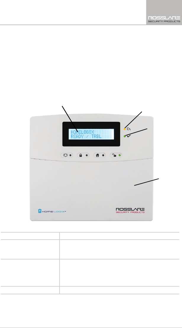
Figure 1 presents the components of the wireless panel.
Figure 1: HLX-24 Panel
Table 1: Control Panel Functions
Display LCD display
Power Indicator Power LED: green
FLASHING when there is an AC power failure and during
Walk Test
Status Indicator Status LED: green On: system armed
Off: system disarmed
Flash: entry and exit delay (according to beep rate)
FLASHING without beeps during Walk Test
Keypad Door Open to access the keypad buttons
Display
Power Indicator
Status Indicator
Keypad Door
HLX-24 Quick Reference
12 HLX-24 Hardware Installation and Programming Manual
2.2 The Keypad
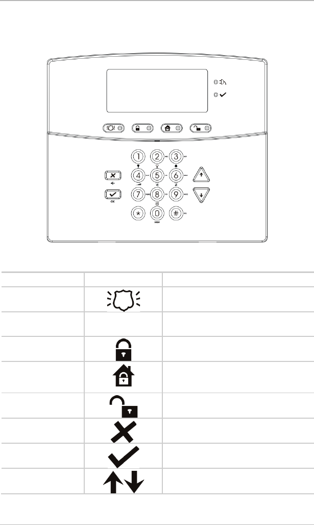
Figure 2 shows the HLX-24 keypad.
Figure 2: HLX-24 Keypad
Table 2 describes the keypad functions:
Table 2: Keypad Functions
Key Icon Function
Panic
When pressed for 3 seconds a standard
panic alarm sounds
Keys 0 – 9 Enters alphanumeric entries
Press 0 to enter a space
Arm Away
Arms all sensors and detectors for use
when there is no one at home/office
Arm Home
Arms all perimeter sensors and detectors
as defined by the installer (for use when
home/office is occupied)
Disarm
Disarms all armed sensors and detectors
ESC/Back
Ignores an entry or moves one level up in
a menu
Enter
Accepts an entry or selection
Up/Down Arrows
Use to navigate between menus
HLX-24 Quick Reference
HLX-24 Hardware Installation and Programming Manual 13
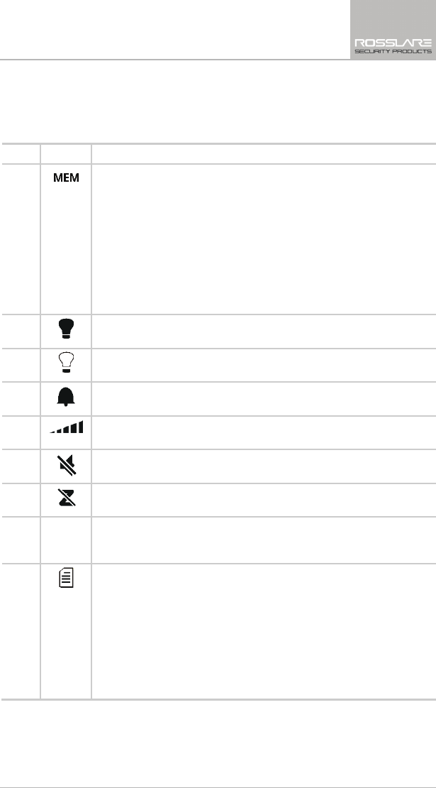
2.2.1 Keypad Operated Functions
When the system is idle, the alphanumeric keys initiate the commands shown
in Table 3.
Table 3: Keypad Operated Functions
Press
Icon To
0 Memory Display
Press once to display the alarms caused during the last arming period
per zone. The first line of the displays shows the alarm memory, and
the second line shows the zone description, event and time. The
display toggles between zone description and the date by pressing
Enter.
Press Menu to display the next alarmed zone.
Press Esc to exit.
Note: When EN-CENELEC standard is enabled, only the master
user can access the memory display.
1 PGM ON
Press once to turn on the PGM.
2 PGM OFF
Press once to turn off the PGM.
3 Chime ON/OFF
Manually toggle the chime on and off
4 Volume
Manually toggle the beep volume level
5
Mute ON/OFF
Manually toggle keypad tone and other sounds on and off
6 Bypass
Enter the User menu Bypass option
7 Record User Message
Record a voice message of up to 15 seconds. Press and hold key 7 for
3 seconds to erase a message.
8 Event Log Display
Press once to display the event log. The first line of the display shows
the event log and the second line shows the zone description (or
system, if a system event is displayed), event date and time. The
display toggles between zone description and the date by pressing
Enter.
Press again or press Menu to display the next event.
Press Esc to exit the menu.
Note that a Master code is required to access this function.
HLX-24 Quick Reference
14 HLX-24 Hardware Installation and Programming Manual
2.3 Sound Indicators
Table 4 presents the sounds emitted by the system and push buttons if
enabled during programming.
Table 4: Sound Indicators
Sound Sounded when
Single beep A key is pressed
Long Beep There is an illegal key entry
Three short beeps An entry is successfully accepted
Four short beeps a
minute
If enabled, on trouble condition
Short beep every
second
An exit/entry delay is activated (beep sounded every 0.5
seconds during last 10 seconds of delay)
Chime When feature is activated (1 chime sounds)
This table does not include actual alarm sounds.
Note that the audible indication of a fire zone differs from that of a normal
intrusion zone.
2.4 LED Indicators
Table 5, Table 6, and Table 7 describe the LED indicators of the various panel
indicators.
Table 5: Power LED Indicator
Power LED
(Red/Green)
Status
Green ON Normal AC mode
FLASHES red every 0.5 seconds AC Failure
Table 6: Status LED Indicator
Status LED
(Red/Green)
Status
Green ON Panel ready
Red ON Panel not ready
Green FLASHES every 1 second Walk Test mode
HLX-24 Quick Reference
HLX-24 Hardware Installation and Programming Manual 15
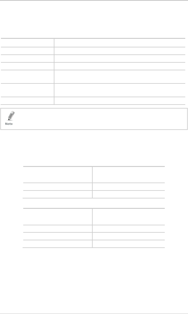
Table 7: Keypad Function Indicators
Panel
Status
Panic
Arm Away
Arm Home
Disarm
Disarm OFF OFF OFF ON
Arm Home OFF OFF ON OFF
Arm Away OFF ON OFF OFF
Arming Home OFF OFF FLASHES every 1
second (until last
10 seconds flashes
every 0.5 seconds)
OFF
Arming Away OFF FLASHES
every 1
second (until
last 10
seconds
flashes every
0.5 seconds)
OFF OFF
Panic ON Previous LED
status
continues
Previous LED status
continues
Previous LED status
continues

Specifications
16 HLX-24 Hardware Installation and Programming Manual
3. Specifications
This chapter provides the various specifications for the HLX-24 control panel.
3.1 RF Data
RF Unit Type Integrated RF transceiver shielded super heterodyne, fixed
frequency
Antenna Type Printed PCB type antenna
Operating
Frequencies
G series – 433.92 MHz
H series – 868.35 MHz
Receiver
Sensitivity
Up to -100 dBm
Transmitter
Power
Up to +10 dBm, less based on country requirements
Range
(open field)
Up to 170 m (558 ft) in open space for detectors, and 110 m (361
ft) for hand-held remote controls
RF Device ID
Coding
Three-bytes non-replicated per sensor type, or multiples of 16
million possible codes, make it almost impossible to have two like
coded transmitters
The HLX-24 system has optimum range if installed according to the
manufacturer’s recommendations, though this range may be affected by radio
noise from high-power nearby sources, or interference with the signal
(blocking) by large metal surfaces, or multiple concrete walls.
3.2 Environmental Data
Operation Temperature Range 0ºC to 40ºC (32ºF to 104ºF)
Storage Temperature Range -25ºC to 70ºC (-13ºF to 158ºF)
Relative Humidity 85% at 30ºC (non-condensing)
Dimensions
(L x W x D)
174 x 152 x 48 mm
(8.5 x 5.7 x 1.9 in.)
Weight 330 g (11.6 oz)
3.3 Electrical Data
Two lines of 16 characters, backlit LCD display
One PGM open collector outputs, 100 mA, PTC protected
Local, 85 dBA siren
220 VAC/50 Hz, 110 VAC/60 Hz (15 VDC, 800 mA) external power supply
Complies with the following standards:
CE, FCC

Specifications
HLX-24 Hardware Installation and Programming Manual 17
Current consumption:
150 mA (standby), 300 mA (max)
Auxiliary power output: 13.8 VDC, 500 mA max
Output voltage range max. 13.8 VDC, minimum 9 VDC
Maximum output pick-to-pick ripple 0.6 Vptp
Maximum auxiliary current output 200 mA – EN50131-6 standard
Battery
Four rechargeable AA type batteries (1800 mAh) are included
3.4 Communication
Frequencies: 433.92 MHz (G) and 868.35 MHz (H)
RF jamming detection (UL/EN selectable)
Proprietary anti-collision RF protocol
Programmable no-activity timer 1–30 minutes, per zone
Two central station numbers and accounts, backup and secondary modes
Reporting protocols: Contact ID
Three private telephone numbers for voice reporting
Local connection (with MD-62) port for local upload/download, and
remote programming by PC software
Built-in telephone dialer and 2400 Baud rate modem
Installation
18 HLX-24 Hardware Installation and Programming Manual
4. Installation
4.1 Unpacking the Equipment
The contents of your package are listed below. First, make sure that all the
items in the kit have been included. If you find that any item is missing, contact
your dealer immediately.
4.1.1 HLX-24 Package Content
HLX-24 unit
Four 1800 mAh AA batteries
Wall adaptor
Installation screw set
4.2 Supply Power to the Unit
It is easier to enroll the ID codes of the transmitting devices to the system
before installation. Power the HLX-24 system using the external power
transformer or from the backup batteries.
To initiate battery power, connect the batteries, connect external power
(transformer), and then disconnect the power to initiate battery power
operation.
4.3 Planning and Programming
Register the location of each detector in the tables provided in Appendix C and
D. Mark the transmitters and detectors accordingly.
To program the system, refer to Chapter 5.
To mount the HLX-24 unit, refer to Section 4.7.
Installation
HLX-24 Hardware Installation and Programming Manual 19
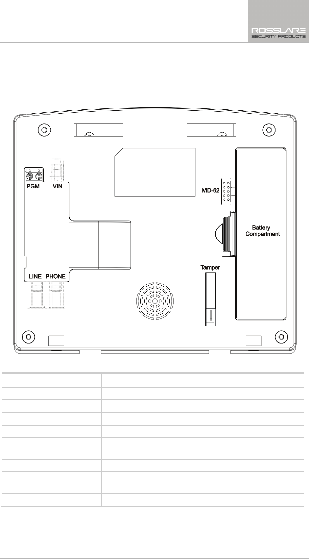
4.4 Wiring the System
Figure 3 shows the various HLX-24 connections, which are described in Table
8.
Figure 3: Panel Wiring
Table 8: HLX-24 Connections
Input Description
PGM Terminal blocks for PGM activation
VIN Input voltage from AC/DC adaptor VIN = 13.8–15
LINE (RJ-11) Telephone line in (from the wall to the system)
PHONE (RJ-11) Telephone line out (from system to telephone device)
MD-62 Connection Socket
Connection socket for 10-pin plug connecting panel to
PC with MD-62
Battery Compartment 4 AA rechargeable batteries
Wall Tamper Switch Tamper switch is pressed when the panel is mounted on
the wall
Ethernet (RJ-45)* Connection to the HomeLogiX™APP server
* HLX-24IP models only
Installation
20 HLX-24 Hardware Installation and Programming Manual
4.5 Connecting the AC Transformer
Complete all the wiring before plugging the transformer in to the AC outlet.
To connect the AC transformer:
1. Attach the transformer and power up the system.
The display shows the HLX-24 logo and the current version.
2. Plug in the transformer.
The power LED on the control panel should light up.
4.6 Connecting to a PC
The control panel can be equipped with an optional MD-62 adaptor for serial
data interchange with a computer.
4.7 Mounting the Back Plate
4.7.1 General
It is important to mount the back plate first before connecting any of
the wiring
to the unit.
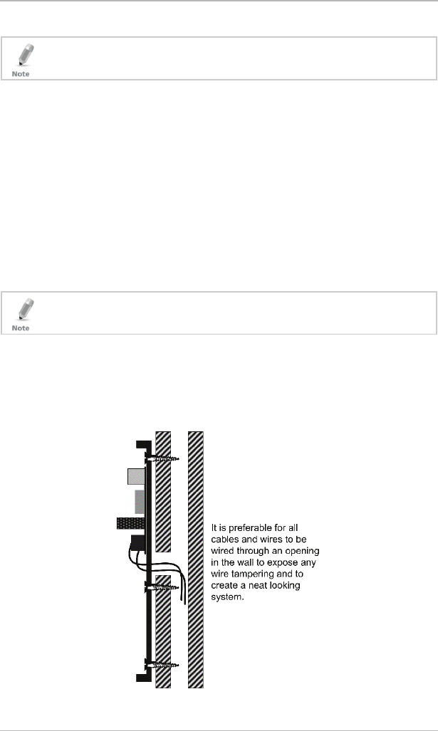
To complete the installation without exposed wires, all the wiring should be
done through the wall. The wiring to the back plate can be done without
having exposed wires by installing the panel on a standard electrical box or
making a hole in the wall for the wiring (Figure 4).
Figure 4: Back Plate Wiring
Installation
HLX-24 Hardware Installation and Programming Manual 21
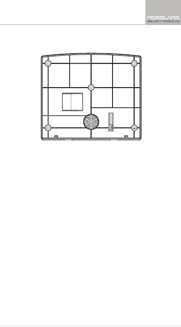
When drilling the hole for the wires, it is recommended to drill the hole in the
marked out areas (Figure 5).
Figure 5: Back Plate Mounting Holes
4.7.2 Required Space
The required space on the wall for the panel is (L) x (H). The hole size for the
wires is 2 x 5 cm (0.8 x 2 in.). This is to be drilled according to the openings on
the back plate.
The optimum viewing angle of the LCD is achieved when the panel is mounted
above the eye level of the user.
Installation
22 HLX-24 Hardware Installation and Programming Manual
4.8 Dismounting the Control Panel
To dismount the control panel:
1. Release HLX-24 from the mounted back plate by unscrewing the bottom
screws and unlocking the locking hooks on the top of the back plate by
lifting them up and out of the recesses on top of the panel.
2. Pull the top of the panel away from the wall to disconnect the connector
to the back plate and then remove the panel from the lower posts of the
back plate.
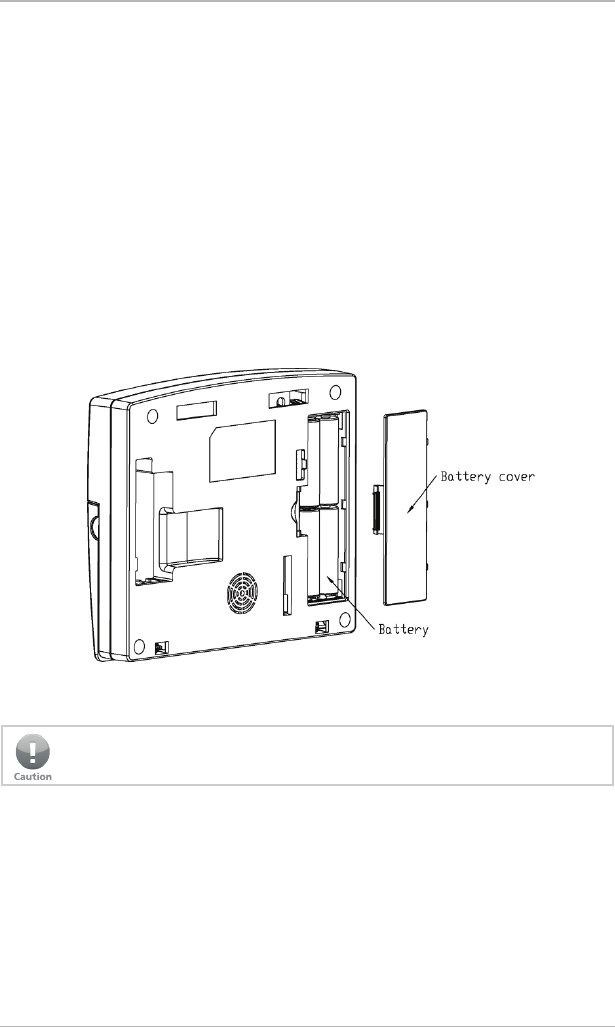
4.9 Replacing the Backup Batteries
To replace the backup batteries:
1. Dismount the panel.
2. Remove the cover of the battery compartment (Figure 6).
Figure 6: Backup Batteries
3. Replace the batteries.
4. Replace the cover.
Do not mix between different rechargeable batteries type and different
charging levels.

Programming the HLX-24
HLX-24 Hardware Installation and Programming Manual 23
5. Programming the HLX-24
We recommend that you program the HLX-24 before installing it. The system
must be connected to the AC power supply for programming; you may also
connect the backup battery at this time.
HLX-24 is provided with two default codes:
Default Installer code: 8888 – Enables you to program HLX-24
Default Master code: 1234 – Enables you to change the Master code and
modify the User and Master options
We recommend that you change the Master and Installer codes after first time
use.
Installer Menu
24 HLX-24 Hardware Installation and Programming Manual
6. Installer Menu
The Installer menu enables access to the following group of options:
Change Code
Zones
Enrolling
Security
Communications
Automation
Messages
Maintenance
Appendix A presents some the features available in the Installer menu and how
to access them.
To access the Installer menu:
1. Press Menu twice to reach the
INSTALLER MENU
option and press Enter.
The default Installer code is 8888.
If a wrong code is entered, the system indicates that an illegal code was
entered and waits once again for the correct code to be entered. After 30
seconds of no entry, the system returns to Normal mode automatically.
The system locks out for 90 seconds after entering 5 wrong codes.
No activity within the menu for 4 minutes causes the system to return to
Normal mode. To return to Normal mode before 4 minutes pass, press
ESC.
2. Once in the
INSTALLER MENU
, use Menu to browse the submenus.
3. Press Enter to access the desired submenu as detailed below.
Some menus can be accessed directly by typing the option number instead of
scrolling the various options.

Installer Menu
HLX-24 Hardware Installation and Programming Manual 25
6.1 Change Code
CHANGE CODE
Zones
Enrolling
Security
Communications
Automation
Messages
Maintenance
This option enables you to change the code with which you enter the system.
The default code is 8888.
To change the Installer code:
1. Press Enter to access the submenu. The first submenu is
CHANGE CODE
.
2. Enter a new 4-digit Installer code.
3. Press Enter to save your new code.
6.2 Zones
Change Code
ZONES
Enrolling
Security
Communications
Automation
Messages
Maintenance
Zone #01–24
Zone Type
Description
Chime
No Activity
Swinger
Zone Cross
Cross Time
Abort Window
This menu allows you to define each of the 24 available zones. You can define
the zone type, description, activity type and its audible chime indication.
To specify zones:
1. Press Enter to access the submenu. The second submenu is
ZONES
.
2. Select the required zone by either browsing all 24 using Menu or by
entering the zone number using the numeric keypad.
3. Once in the desired zone, use Menu to browse the options.

Installer Menu
26 HLX-24 Hardware Installation and Programming Manual
4. Press Enter to access the desired submenu to define several characteristics
as follows:
Zone Type: Select one of the following:
Delay – An opening in this zone is alarmed only after the exit or
entry time has passed
Fire – An opening in this zone causes a fire alarm and is armed
24 hours a day
24H Silent – An opening in this zone causes a silent alarm (no
audible local siren) and is armed 24 hours a day
24H Audible – An opening in this zone causes an audible alarm
and is armed 24 hours a day
No Secure – non-alarm zone – zone can be used for any non-
secured propose
Interior – Zone is bypassed when system is in Arm Home (Stay)
mode
Interior Follow – A non-entry/exit zone, typically an interior zone
located on an entry/exit path, which is treated as an entry/exit
zone during an Entry Delay or Exit Time. An opening in this zone
is alarmed only after the exit or entry time has passed.
Perimeter – Zone is armed both in Arm Home and Arm Away
modes
Description: Select one of 38 fixed descriptions or one of five
editable custom descriptions. HLX-24 enables you to specify five
custom zones (see Section 6.7.3).
For your convenience and better control of the installation, use the
tables provided in Appendix C.
No Activity: Select to enable or disable the no activity time for each
zone. When there is no activity in the specified zone and the system
is disarmed, a silent alarm is sent to the monitoring station. When the
system is armed and there is no activity in the specified zone, an
audible alarm and a report are sent to the monitoring station. By
default the option is disabled.
Swinger: Select the number of repeated opening events from the
zone after which the system ignores the zone. The default setting is 2
zone openings. The zone is restored after a manual system reset or
automatically after a defined number of hours. The default value is 8
hours.
Zone cross: The zone cross option requires an opening of two zones
within a given time period to initiate an Alarm event sequence. This
setting links between the two zones.
Installer Menu
HLX-24 Hardware Installation and Programming Manual 27
• Crossing zones can be of zones with the same type.
• One cross zone gets the mutual zone automatically. Ex zone 1 cross zone 2
then zone 2 automatically cross zone is 1.
Cross Time: Select the time period between two zones defined in
cross mode for alarm event. If one linked zone is opened and the
other linked zone is not opened, a zone cross error is sent to the
monitoring station. The default is 30 seconds.
Abort Window: A period of time after a sensor initiates an alarm
condition that allows the user additional time to disarm the system
before an alarm is transmitted. Select Enabled to allow the zone to
abort an alarm event during the Alarm Abort Window defined in the
system. The default setting is Enabled.
6.3 Enrolling
Change Code
Zones
ENROLLING
Security
Communications
Automation
Messages
Maintenance
Detectors
Remote Controls
Sirens
Keypads
Repeaters
The third submenu is
ENROLLING.
Browse the desired devices listed below to be enrolled using Menu and access
it by pressing Enter:
Detectors
Remote controls
Sirens
Keypads
Repeaters
Installer Menu
28 HLX-24 Hardware Installation and Programming Manual
6.3.1 Detectors
You can enroll up to 24 detectors, one detector per zone, numbered 01
through 24.
To enroll/delete a detector:
1. Select the desired zone by either browsing all 24 zones using Menu or by
entering the zone number using the numeric keypad.
2. Select enrollment method, either Normal or Tamper.
If no detector is associated to the selected zone, the screen shows a
message saying “waiting for detector signal” for 30 seconds.
When browsing the zones, each zone already enrolled indicates "RF
ID code".
3. Press Enter to delete the detector (or ESC to go back).
4. Initiate a transmission from the detector.
In Normal enrollment any transmission is accepted (Alarm, Tamper,
or any other transmission available, see the detector’s manual for
reference).
In Tamper enrollment, only Tamper activation is accepted all other
signals are ignored.
Tamper enrollment is suitable for areas with multiple sensors thus preventing
false enrollment.
5. When the transmission is detected, you are asked to press Enter to store
the detector into the zone.
When enrolling smoke and heat detectors, make sure to select the zone type
“fire”.
If no signal is received with the allocated 30 seconds, the unit returns to
Normal mode.
6.3.2 Remote Controls (KE-30 RFID Function)
You can enroll up to eight remote controls and specify functions for each
button on the remote control. You can also delete enrolled remote controls.
Each proximity card used with the KE-30 keypad is considered a remote control
during enrollment.
To enroll a remote control or a proximity card to be used with the KE-
30 keypad and to specify a function:
1. Select the desired remote control number 01 to 08 by either browsing the
remotes using Menu or by entering the remote number using the
numeric keypad.
2. Enroll the remote control when the
WAITING FOR SIGNAL
message is
displayed, by pressing a button on the remote you wish to enroll or by
passing the proximity card through the KE-30 keypad.

Installer Menu
HLX-24 Hardware Installation and Programming Manual 29
3. When the signal is detected you are asked to press Enter to store and
save your selection.
4. Once the selection is stored, you can then choose to configure each of the
remote control buttons (except the * button that serves as a status
announcement) to behave in one of the following options:
Restore Default (sets the button to its original functionality)
Operate PGM 1
Status Request
5. At any time press ESC to exit the menu.
Once you exit the menu (after saving the enrollment) you cannot change the
button’s behavior, unless you delete the remote and re-enroll it.
To delete a remote control or proximity card:
1. Select the pre-enrolled remote control number 01 to 08 by either
browsing the list of remotes using Menu or by entering the remote
number using the numeric keypad.
You are asked to confirm deletion.
2. Press Enter to delete or ESC to go back.
6.3.3 RF Siren
You can enroll up to four RF sirens. You can choose to remove enrolled sirens.
To enroll/remove an RF siren:
1. Select the required Siren location, #01–04 by either browsing the keys
using Menu or by entering the siren’s number using the numeric keypad.
2. Enroll the RF Siren when the
WAITING FOR SIGNAL
option is displayed by
activating the siren’s tamper.
3. When the signal is detected, you are asked to press Enter to store and
save your selection
If the selected location has a siren enrolled, you are asked whether you
wish to delete it.
4. Press Enter to delete or ESC to go back.
6.3.4 Keypads
You can enroll up to four keypads. You can choose to remove enrolled
keypads.
To enroll/remove a keypad:
1. Select the required keypad location, #01–04 by either browsing the keys
using Menu or by entering the keypad’s number using the numeric
keypad.
2. Enroll the keypad when the
WAITING FOR SIGNAL
option is displayed.
3. When a signal is detected, you are asked to press Enter to store and save
your selection

Installer Menu
30 HLX-24 Hardware Installation and Programming Manual
If the selected location has a keypad enrolled, you are asked whether you
wish to delete it.
4. Press Enter to delete or ESC to go back
6.3.5 Repeaters
You can enroll up to four repeaters. You can choose to remove enrolled
repeaters.
To enroll/remove a repeater:
1. Select the required repeater location, #01–04 by either browsing the keys
using Menu or by entering the repeater’s number using the numeric
keypad.
2. Enroll the repeater when the
WAIT FOR SIGNAL
option is displayed, by
activating the tamper.
3. When the signal is detected, you are asked to press Enter to store and
save your selection
If the selected location has a repeater enrolled, you are asked whether you
wish to delete it.
4. Press Enter to delete or ESC to go back
6.4 Security
The following is a list of the system’s security features.
Change Code
Zones
Enrolling
SECURITY
Communications
Automation
Messages
Maintenance
Exit Delay
Exit Restart
Entry Delay
Auto Arming
Siren Time
Siren Mode
Local Siren
External Siren
Supervision Time
Jamming
No Activity Time
Trouble Beeps
Bypass Option
Quick Arm

Installer Menu
HLX-24 Hardware Installation and Programming Manual 31
Change Code
Zones
Enrolling
SECURITY
Communications
Automation
Messages
Maintenance
Arm Instant
Panic Button
Duress Code
Alarm Cancel
Alarm Abort Time
Backlight Time
Hide Display
Key Beeps
Select Language
EN-CENELEC*
CP01
* The panel is not yet EN-CENELEC standard certified.
The fourth submenu is
SECURITY.
Browse the desired security related settings
as described in the following subsections using Menu. Press Enter to access
the desired submenu.
6.4.1 Exit Delay
An exit delay enables the user to arm the system and exit the site through a
specified door (determined as a delay zone) using a predetermined path after
arming the system, without setting off an alarm.
A progress annunciation of slow-rate warning beeps sound when the system is
armed. The system counts down the last 10 seconds of the delay if the voice
capability is configured; otherwise, the warning beeps are faster. The exit delay
is set at 60 seconds by default.
An Exit Error sequence is initiated if an entry/exit zone is in an opened state at
the instant of exit time expiration or if no delay zone is opened during the exit
time.
An Exit Error process for a delay zone is as follows:
The local alarm immediately sounds.
The annunciator sounds an Entry Delay or an alarm condition.
An Entry Delay is initiated.
If the alarm system is not Disarmed at the end of the Entry Delay, the
Alarm Transmission Sequence is initiated.
The Alarm Transmission includes the alarm and an Exit Error message to
the central station.

Installer Menu
32 HLX-24 Hardware Installation and Programming Manual
The user can use the Silent Exit feature to silence the audible progress
annunciation of the exit delay.
If Silent Exit is active, the Exit Time is doubled for that exit period only but does
not exceed 255 seconds.
To specify the exit delay:
1. Using the numeric keypad, specify the length of time for the exit delay
between 45 and 255 seconds.
2. Press Enter to save your selection.
6.4.2 Exit Restart
When this feature is enabled, an Exit Restart delay occurs on the second zone
opening within the same zone and the Exit Delay time is doubled. If it is
disabled, the same zone may be opened several times while in the Exit Delay
countdown. The default setting is Enabled.
6.4.3 Entry Delay
An entry delay enables the user to enter the site through a specified door
(determined as a delay zone) using a predetermined path, without setting off
an alarm. The entry delay is set at 30 seconds by default.
After entry, the user must disarm the system before the entry delay expires. A
progress annunciation of slow-rate warning beeps sound upon detection of
the specified zone. The system counts down the last 10 seconds of the delay
indication if enabled or the warning beeps become faster.
To modify the entry delay:
1. Using the numeric keypad, specify the length of the entry delay between
30 and 240 seconds.
2. Press Enter to save your selection.
6.4.4 Auto Arming
Auto Arming allows scheduled arming and disarming of the system for all
weekdays at different hours.
To activate auto arm:
1. Using Menu, select the day of the week.
2. Press Enter to confirm.
3. Using Menu, select one of the following options:
Disabled
Arm Home
Arm Away
4. Press Enter to confirm.
5. Using the numeric keys, enter the system arming time (24 hours).
6. Press Enter to confirm the time.

Installer Menu
HLX-24 Hardware Installation and Programming Manual 33
7. Set the Alarm Duration between 1 to 9999 minutes, or enter 0 (zero), to
disable Auto Arm Duration. The panel remains armed until disarmed by an
authorized user.
6.4.5 Siren Time
This specifies the amount of time the siren sounds when an alarm has been set
off. The siren time is set to three minutes by default. This relates to all siren
types, wired, wireless and local.
To specify the siren time:
1. Using the numeric keypad, specify the length of the siren time between
01 and 15 minutes
2. Press Enter to save your selection.
6.4.6 Siren Mode
You can specify whether you want the siren to be activated when armed in
Away mode only or when armed both in away and home arming modes. The
siren mode is set to Away + Home by default. This relates to all siren types,
wired, wireless and local.
To specify the siren mode:
1. Using Menu, select one of the following options: Away or Away +
Home.
2. Press Enter to confirm.
6.4.7 Local Siren
Specifies whether an activated alarm causes an internal siren (emitted from the
system’s speaker) to sound or remain silent. The local siren is enabled by
default.
To set up a local siren:
1. Using Menu, select either Enable or Disable.
2. Press Enter to confirm.
6.4.8 External Siren
Enables or disables the wireless sirens. Wireless sirens are enabled by default.
To set up external wireless sirens:
1. Using Menu, select either Enable or Disable.
2. Press Enter to confirm.
6.4.9 Supervision Time
The supervision time submenu specifies the time limit during which the system
receives supervision reports from specified wireless devices. If a device does not
report in at least once within the specified time limit, the system initiates an
inactivity alert. The default supervision time is set to one hour.
Installer Menu
34 HLX-24 Hardware Installation and Programming Manual
To specify the supervision time:
1. Using Menu, select one of the time limit options, 20 minutes, 1, 2, 4, 6,
8, 16, 24 or 48 hours.
2. Press Enter to confirm.
6.4.10 Jamming
Specifies whether the system detects and reports jamming – interferences of
the radio channel used by the system.
The jamming detection is disabled by default.
To specify jamming detection:
1. Using Menu, select one of the following options:
Disabled: to disable jamming detection
EN enabled: to enable European standard jamming detection
UL enabled: to enable US standard jamming detection
2. Press Enter to confirm.
6.4.11 No Activity Time
Specifies the time limit in which the system should receive a signal from a
sensor used to monitor the activity of sick, elderly or disabled people. If no
device detects and reports movement at least once within the specified time
limit, a “not active alert” sounds and a report is sent to the CMS (if reporting is
enabled). This option is disabled by default.
The behavior of the no activity zone feature varies when in Arm or Disarm
modes:
• When Disarmed – Alert is sent to CMS
• When Armed – An alarm is heard and an alert is sent to CMS
To set the no activity time:
1. Using Menu, select one of the following options:
1, 2, 5, 10, 15, or 30 minutes
Disable the timer
2. Press Enter to confirm.
Required zones’ “No Activity” o
ption should be set to ‘Enabled’ for this security
feature to work.
6.4.12 Trouble Beeps
This parameter determines whether the system emits a “trouble beep”
indicated by a series of four short beeps once a minute for the following
“Trouble” events:
Low battery (detectors and system)
Supervision loss (detectors)
Power (AC) failure (system)

Installer Menu
HLX-24 Hardware Installation and Programming Manual 35
Communication failure (system)
Tamper (system and zones)
RF jamming
The default is set to Disabled.
The HLX-24 allows you to enable the beeps for daytime only 8:00 AM to 8:00
PM.
To specify trouble beeps:
1. Using Menu, choose Disable, Day & Night (enable), or Day Only for
the trouble beeps.
2. Press Enter to confirm.
6.4.13 Bypass Option
Specifies either manual bypassing of individual zones, or enables the system to
forcedly arm open zones when armed. Bypass is turned off by default.
To set bypass:
1. Using Menu, select one of the following options:
Off to set the bypass off
Off/Force allows forced arming (automatic bypass) only
Manual allows manual bypass only
Manual/Force allows both forced arming (automatic bypass) and
manual bypass
2. Press Enter to confirm.
6.4.14 Quick Arm
Enables the user to arm the system without entering a code; Quick Arm is set
to disable by default.
To enable/disable quick arm without a code:
1. Using Menu, select either Enable or Disable.
2. Press Enter to confirm.
To utilize quick arm:
1. Press continuously on the AWAY or HOME keys to arm AWAY or
HOME.
6.4.15 Arm Instant
Enables the user to instantly arm the system by bypassing the Exit Delay; Arm
Instant is set to disable by default.
To enable/disable the Arm Instant option:
1. Using Menu, select either Enable or Disable.
2. Press Enter to confirm.

Installer Menu
36 HLX-24 Hardware Installation and Programming Manual
To utilize Arm Instant:
1. Arm the system using one of the arming options.
2. Once the exit delay countdown initiates, press either the AWAY or
HOME keys once again.
6.4.16 Panic Button
The user can generate an alarm (audible or silent) by pressing continuously on
the emergency button on the control panel. The remote control panic button
must be pressed twice to activate the panic alarm when the CP-01 standard is
enabled (see Section 6.4.25). When CP-01 is disabled, the panic button must
be pressed once. The local emergency button is disabled by default.
To set a panic button:
1. Using Menu, select one of the following options:
Audible: to set an audible panic alarm that transmits a message to
the CMS or private telephone set.
Silent: to set a silent panic alarm that transmits a message to the
CMS or private telephone set, but without a siren
Disabled: to disable the panic alarm button all together
2. Press Enter to confirm.
6.4.17 Duress Code
The system allows you to define a unique duress code, which a user can enter
when forced to disarm the system under duress. The duress code is disabled
when there is no duress code defined in the system. By default, the duress
code option is disabled.
The duress code should NOT be identical to any other existing code.
To change the duress code:
1. Type a new four-digit duress code using the numeric keypad.
2. Press Enter to save your new code.
6.4.18 Alarm Cancel
An Alarm Cancel window is a period of time starting at the end of the alarm
abort window (Section 6.4.19), during which a user can cancel the alarm. The
minimum duration of the window is 5 minutes and the maximum duration is
10 minutes. Setting “0” disables the alarm cancel transmission to the central
station. The Alarm Cancel window applies to all alarms that have been
subjected to the Abort window.
If an alarm had previously been transmitted, an Alarm Cancel event signal is
transmitted if the control panel is disarmed during the Alarm Cancel window.
By default, the Alarm Cancel time is 5 minutes.

Installer Menu
HLX-24 Hardware Installation and Programming Manual 37
For a signal to be sent to the CMS, the Alerts reporting group must be enabled
in Report Options (Section 6.5.3).
To set the Alarm Cancel:
1. Using the numeric keypad, set the alarm cancel time between 01 to 10
minutes or 00 to disable the option.
2. Press Enter to confirm.
6.4.19 Alarm Abort Time
The system sounds a warning, but the central station does not receive
notification of the alarm if the user disarms the system within the specified
alarm abort time. This function applies to interior, perimeter, and 24-hour
zones. The default
Alarm Abort Time
is 30 seconds.
To set the alarm abort time:
1. Using the numeric keypad, set the alarm abort time between 01 to 45
seconds or 00 to disable the option.
2. Press Enter to confirm.
6.4.20 Backlight Time
Specifies the backlight options; by default, the backlight time is set to 15
seconds.
To set the backlight:
1. Using Menu, select one of the following options:
Always: to specify that the keypad and buttons are backlit at all
times.
15 secs: to specify that the keypad and buttons are backlit for up to
15 seconds after last key press.
2. Press Enter to confirm.
6.4.21 Hide Display
Enables you to specify that when armed, the system does not display the
system statuses or other system prompts; by default,
Hide Display
is off.
To display the system status:
1. Using Menu, select one of the following options:
Off to display status and prompts.
On to hide status and prompts.
2. Press Enter to confirm.
Installer Menu
38 HLX-24 Hardware Installation and Programming Manual
6.4.22 Key Beeps
Choose to turn key beeps on to hear a beep on each key press; key beeps is on
by default.
To set the key beeps:
1. Using Menu, select one of the following options:
On to turn the key beeps on
Off to turn the key beeps off
2. Press Enter to confirm.
6.4.23 Select Language
The HLX-24 currently supports English only.
6.4.24 EN-CENELEC
The panel is not yet EN-CENELEC standard certified
The HLX-24 supports CENELEC standard settings. By default, all CENELEC
standard settings are enabled. During the installation process, the installer may
enable or disable each setting according to the local requirements.
The menu includes the following:
Status
Ready Options
Access Level
Event Filter
To set the standard status:
1. Using Menu, select either Enable or Disable.
2. Press Enter to confirm.
Enabling the standard sets all the standard features to default.
Enable state and the event filter is set to 10.
Disabling the standard sets all the standard features to disable state and the
event filter is set to 0.
To set the ready option:
1. Using Menu, select Tamper, Low Battery, AC Fail, Comm Fail, Line
Fail, Panic, or Supervision.
2. Press Enter to choose the submenu.
3. Using Menu, select either Enable or Disable.
4. Press Enter to confirm.
The ready option restricts the relevant parameters so that the system
cannot be armed during the violation of that parameter.

Installer Menu
HLX-24 Hardware Installation and Programming Manual 39
Example: Setting the AC Fail parameter to enable restricts the system
from being armed until the power supply returns.
To set the access level:
1. Using Menu, select Memory Alarm, System Status, or Arm Instant.
2. Press Enter to choose the submenu.
3. Using Menu, select either Enable or Disable.
4. Press Enter to confirm.
The access level options, restricts the information actions to be accessible
to the user by pressing PIN number.
Usually system’s status information is valid to the user by pressing the
Enter key. Setting each parameter to enable, the enter key should be
followed by a PIN code.
To set the event filter:
1. Using the numeric keypad, specify the value for the event filter between 0
and 10 cycles.
2. Press Enter to save your selection.
An event filter enables the user to specify the maximum repetition of a
specific event in a session. A session is a period between each of the
arming and disarming operations.
Setting the event filter to 0 enables specific events to be recorded with no
filtering to the event log.
Setting 0, 1, 2 value in the event filter is not compatible with CENELEC
standard.
6.4.25 CP-01
The panel is not yet CP-01 standard certified
The HLX-24 supports CP-01 standard settings. During the installation process,
the installer may change each setting according to the local requirements.
The menu includes the following:
Table 9: CP01 Menu
Menu Item Description Default Setting
Abort Announce When at least 1 zone is aborted, “ABT”
(abort) is displayed on the LCD once the
system enters Disarm mode.
Enabled
Cancel Announce When Alarm Cancel is transmitted to the
central station, “CNL” (cancel) is
displayed on the LCD once the system
enters Disarm mode.
Enabled

Installer Menu
40 HLX-24 Hardware Installation and Programming Manual
Menu Item Description Default Setting
Fire Verify Double checks the state of the fire
detectors.
When there is a fire sensor alarm signal,
a siren is heard immediately. A 60-
second retard-reset period starts during
which every additional fire alarm signal is
ignored. After this period, an additional
timeout of 60 seconds starts, which is
the confirmation period, during which a
fire sensor alarm signal causes an event
transmission to the monitoring station.
When the confirmation period expires,
the fire zone is automatically restored
and ready for a new fire alarm session.
Disabled
Recent Close Time A Recent Closing transmission is sent if
an alarm occurs within the
programmable time after the Exit Time
passes.
2 minutes
Swinger Time Duration for automatic resetting of
detectors after being ignored by swinger
trips
8 hours
Unvacated Premises Triggers Arm Home (Stay) mode
automatically if the system was armed in
Arm Away mode but there was no
exiting from the premises during exit
delay
Enabled
Squawk Buzzer Determines whether the buzzer sounds
when arming or disarming the panel for
remote operation.
Enabled
Siren Determines whether the siren sounds
when arming or disarming the panel for
remote operation.
Enabled
To set the Abort Annunciation:
1. Using Menu, select either Enabled or Disabled.
2. Press Enter to confirm.
To set the Cancel Annunciation:
1. Using Menu, select either Enabled or Disabled.
2. Press Enter to confirm.
To set the Fire Verification:
1. Using Menu, select either Enabled or Disabled.
2. Press Enter to confirm.

Installer Menu
HLX-24 Hardware Installation and Programming Manual 41
To set the Recent Cl ose Time:
1. Using the numeric keypad, specify the value between 0 and 9.
2. Press Enter to save your selection.
To set the Swinger Time:
1. Using the numeric keypad, specify the value between 0 and 9.
2. Press Enter to save your selection.
To set the Unvacated Premises mode:
1. Using Menu, select either Enabled or Disabled.
2. Press Enter to confirm.
To set the Squawk mode:
1. Using Menu, select either Buzzer or Siren.
2. Select either Enabled or Disabled.
3. Press Enter to confirm.
6.5 Communications
Change Code
Zones
Enrolling
Security
COMMUNICATIONS
Automation
Messages
Maintenance
System Telephone
Private Report
CS Report Setup
Line Test
AC Fail Report
Fax Defeat
Number of Rings
Select Region
The fifth submenu is
Communication
,
which involves the setup of system
communications parameters and settings with the outside world
.
Browse the
desired communication related setting, as described in detail below, using
Menu. Press Enter to access it.

Installer Menu
42 HLX-24 Hardware Installation and Programming Manual
6.5.1 System Telephone
This menu allows you to specify the telephone number used for the ring back
option when calling the system telephone.
To set up the system telephone:
1. Press Enter to access the
Telephone Number
submenu.
2. Using the numeric keypad, enter the system telephone number. Use * to
enter a comma. Use # to delete the last digit.
3. Press Enter to confirm.
When setting up the system telephone, use a comma (,) to indicate a delay
when dialing a number.
6.5.2 Private Report
This menu enables you to set the private telephone report options as detailed
below.
To set up private report:
1. Using Menu, select each of the following submenus and press Enter to
confirm:
a. Set Numbers – Specify the telephone numbers of the subscribers to
which the system reports. You can enter up to three numbers.
i. Using Menu, choose between number 1, 2 or 3 and press
Enter.
ii. Using the numeric keypad, enter the telephone number and
press Enter to confirm. Use * to enter a comma. Use # to delete
the last digit.
b. Report Options – Specify the event groups that are included in a
report.
2. Using Menu, choose the reporting options for each group as desired. The
options are Disable and Enable.
3. Press Enter to confirm. The available reporting groups are:
Alarms (Voice by default)
Troubles (Voice by default)
Alerts
Bypass
Arm/disarm
Restore
4. Press ESC to exit the submenu.

Installer Menu
HLX-24 Hardware Installation and Programming Manual 43
5. Dialing Attempts – Specify the number of cycles the panel goes through
while attempting to connect to a remote private phone, where a cycle
consists of up to 3 different remote private phones. The default is 3
attempts.
a. Using the numeric keypad, enter the dialing attempts value between
1 and 15.
b. Press Enter to save.
6.5.3 CS Report Setup
This menu allows you to set the Central Station (CS) report options.
To set up CS report:
1. Using Menu, select each of the following submenus and press Enter to
confirm:
a. CS Report Method – Specify the reporting method.
i. Using Menu, select one of the following:
o Disable (default)
o Primary Only
o Alternate
o Secondary Only
o Both
ii. Press Enter to confirm.
b. CS Primary – Specify the first telephone number of the first central
station to which the system reports in case of an event as well as the
primary account code and report options. Under this menu, you must
set the following parameters:
Phone Number – The primary CS telephone number
i. Using the numeric keypad, enter the primary CS telephone
number.
ii. Press Enter to confirm. Use * to enter a comma. Use # to
delete the last digit.
For PABX, use the digit followed by * and then the full number.
Account Code – The number that identifies your system to the
central station. The account code range is 0–9, B, C, D, E, and F.
i. Using the alphanumeric keypad, enter a code of four
digits/letters.
ii. Press Enter to confirm.
Report Options – Specify the event groups that are included in
a report.

Installer Menu
44 HLX-24 Hardware Installation and Programming Manual
i. Using Menu, choose the reporting options for each group
as desired. The options are Disable and Enable. The available
reporting groups are:
Alarms
Troubles
Alerts
Bypass
Arm/disarm
Restore
ii. Press Enter to confirm.
iii. Press ESC to exit the submenu.
Ack Timeout – Specify the time that the system has to send a
report event before the report alert is discontinued.
i. Using the alphanumeric keypad, set the value of the Ack
timeout to a value of 10 to 60.
ii. Press Enter to confirm.
Signal Gain – Specify the strength of the DTMF.
i. Using the alphanumeric keypad, set the value of the signal
gain to a value of between 300 and 1200.
ii. Press Enter to confirm.
Call Wait Cancel – Specify whether call waiting interferes in the
event transmission to the central station by dialing *70 and
entering the central station phone number. The default setting is
Disabled.
c. CS Secondary – Specify the secondary Central Station (see CS
Primary above for detailed options and instructions).
d. CS Protocol – Specify the reporting protocol used by the system to
report events to the central stations. Currently only Contact ID is
available.
e. Dialing Attempts – Specify the number of times the system
attempts to dial the primary stations number before attempting to
dial the secondary number. The default is 3 attempts.
i. Using the numeric keypad, enter the dialing attempts value
between 1 and 15.
ii. Press Enter to save.

Installer Menu
HLX-24 Hardware Installation and Programming Manual 45
6.5.4 Line Test
Enables you to specify the time when the phone line and CS reporting are
tested and reported to the central station, as well as the time interval between
each test (periodic reporting).
To set up line test:
1. Using Menu, select one of the two options to define, and press Enter to
confirm:
Repeats – Specify the number of days between tests. The default is
7.
i. Using the numeric keypad, choose 1 to 30 days.
ii. Press Enter to save.
Test_Time – Specify the hour of the day to perform the line test. The
test time is set at 12:00 by default
i. Using the numeric keypad, type the four digits of the desired
hour (24H convention).
ii. Press Enter to save.
6.5.5 AC Fail Report
This option allows you to specify a delay time, before reporting the power
failure to the CS, in which time power may be restored. The time is set to 0
(disabled) by default.
Power (AC) failure is indicated by the Power LED, which flashes green.
To set up AC fail report:
1. Using the numeric keypad, set the time between 1 and 240 minutes, or
set it to 0 to disable the option.
2. Press Enter to confirm and save your selection.
6.5.6 Fax Defeat
When calling the system, fax and answering machines may need to be
overridden. This menu specifies whether to enable or disable this override. By
default, this option is disabled.
To set up Fax Defeat:
1. Using Menu, Enable or Disable the option.
2. Press Enter to confirm.
6.5.7 Number of Rings
Specify the number of rings before the system answers the line. By default, this
option is set to 4 rings.

Installer Menu
46 HLX-24 Hardware Installation and Programming Manual
To specify the number of rings:
1. Using the numeric keypad, set the number of rings to between 1 and 15.
2. Press Enter to confirm.
6.5.8 Select Region/Country
Select the region/country for the telephone line DAA, matching the time set
for the system. By default, this option is set to Other.
To select the region:
1. Use Menu to select one of the available regions.
2. Press Enter to confirm.
6.6 Automation
Change Code
Zones
Enrolling
Security
Communications
AUTOMATION
Messages
Maintenance
Keypad Manual
Set Triggers
The sixth submenu is
Automation
,
which deals with the setup of various home
automation options.
Browse the desired automation related setting, as
described in detail below, using Menu. Press Enter to access it.
6.6.1 Keypad Manual
Enable or disable this option to determine whether the PGM output can be
controlled by numeric keys 1 and 2 of the keypad as described in Section
2.2.1. This option is Enabled by default.
To set up the keypad:
1. Using Menu, Enable or Disable the option.
2. Press Enter to confirm your selection.
Installer Menu
HLX-24 Hardware Installation and Programming Manual 47
6.6.2 Set Triggers
This option enables you to activate the PGM using various events in an
automated fashion. By default, no triggers are set.
To set up triggers:
1. Using Menu, select PGM Trigger and press Enter to confirm.
2. You can select the pulse time and triggers as described below:
a. Pulse time – Set the length of time for the device to stay on when a
pulse type activation is selected. Using the numeric keypad, set the
time from 1 to 99 seconds and press Enter to save.
b. Select the trigger type and parameters according to Table 10. Use
only one trigger for each PGM simultaneously.
Table 10: Trigger Type and Parameters
Trigger PGM Activation
Options
Remarks
Arm Away On, Off, Pulse, Ignore
Arm Home On, Off, Pulse, Ignore
Disarm On, Off, Pulse, Ignore
Alarm Enabled, Disabled Go OFF when alarm stops
Panic Pulse, Ignore
Trouble Pulse, Ignore
AC Loss Enabled, Disabled ON when AC fails, OFF when AC
returns
Exit/Entry Enabled, Disabled Annunciation of exit/entry beeps
of remote sounder
Remote Control On, Off, Pulse, Trouble, Ignore Relates to remote’s panic button
Zone On, Off, Pulse, Trouble, Ignore Relates to zone open or detection
6.7 Messages
Change Code
Zones
Enrolling
Security
Communications
Automation
MESSAGES
Maintenance
Keypad Mute
House Name
Custom Zones

Installer Menu
48 HLX-24 Hardware Installation and Programming Manual
The seventh submenu is
Messages
,
which deals with custom text zone
descriptions. Browse the desired setting, as described in detail below, using
Menu. Press Enter to access it.
6.7.1 Keypad Mute
This option allows you to enable or disable the option to mute all the voice
messages and beeps (except for trouble beeps, forced arming, enrollment and
RF test of wireless devices) by numeric key 5 of the keypad as described in
Section 2.2.1. By default, this option is Disabled.
To set up keypad mute:
1. Using Menu, Enable or Disable the option.
2. Press Enter to confirm your selection.
6.7.2 House Name
This option enables you to type the House Name as defined in the system.
To set up and review the house name:
1. In the
HOUSE NAME
menu, use Menu to locate the ENTER HOUSE NAME
submenu.
a. Press Enter to access the submenu.
Use the alphanumeric keypad to type the desired house name. Use #
to delete the last entered value.
b. Press Enter to confirm.
6.7.3 Custom Zones
Enables you to record and listen to five voice and text custom zones
descriptions and to toggle between them. On each zone, the user can simply
edit the text by typing the keypad buttons. The text is limited to 16 characters.
1. Using Menu, locate the ENTER ZONE NAME submenu.
Press Enter to access the submenu.
Use the alphanumeric keypad to type the desired house name. Use #
to delete the last entered value.
Press Enter to confirm.
2. Repeat steps 1 through 3 for each of the 5 (five) custom zones.
Reset to factory settings does not delete these recordings.

Installer Menu
HLX-24 Hardware Installation and Programming Manual 49
6.8 Maintenance
Change Code
Zones
Enrolling
Security
Communications
Automation
Messages
MAINTENANCE
Factory Default
RF Test
Test Indicators
Test Sirens
Test Devices
The eighth submenu is
Maintenance
,
which describes the various system
maintenance options.
Browse the desired security related setting, as described
in detail below, using Menu. Press Enter to access it.
6.8.1 Factory Defaults
This option allows you to restore the default factory settings for the system.
To restore factory default:
1. Press Enter to enter the submenu. Factory Defaults is the first submenu.
2. Press Enter and choose from the following four options using Menu to
browse:
Regular – CENELEC status disabled: Returns the factory default
settings without CENELEC settings
Cenelec – CENELEC status enabled: Returns the factory default
settings with CENELEC settings
Regular and Delete RF devices – Returns the factory default settings
without CENELEC settings and erases all RF devices previous
identified by the unit
CENELEC and Delete RF devices – Returns the factory default settings
with CENELEC settings and erases all RF devices previous identified by
the unit
3. Press Enter to confirm.
6.8.2 RF Test
RF testing checks the signal strength of all the wireless devices enrolled to the
system. If a weak signal is detected, a repeater may be used to improve the
link quality.
The system saves the most recent set of RF test results for uploading. The
system clears the tests when running another RF test.

Installer Menu
50 HLX-24 Hardware Installation and Programming Manual
To perform the test:
1. Using Menu select the test you wish to perform, and press Enter to
access the test.
2. Activate the RF unit to send a signal to the unit. The results can be
Strong
,
Normal
or
Low
. The available tests are:
Test Detectors (Walk Test) (refer to Table 11)
Test R. Controls
Test R. Siren
Test Keypads
Test Repeaters
To view the results:
1. For each of the tests, you can review the results by pressing Enter and
then either Menu or the alphanumeric keys review all the units.
2. To exit the RF test mode you must press ESC.
6.8.3 Test Indicators
The indicators test checks the two indicator LEDs, power and status, located on
the Panel.
To test the indicators:
After entering this menu, press Enter. The LEDs blink three times.
6.8.4 Sirens Test
This test checks the different available sirens by activating them.
To test the sirens:
1. Select the siren you wish to test:
Local Siren
Wireless siren
Siren 1
Siren 2
Siren 3
Siren 4
2. Press Enter to activate the sounder.
3. Press ESC to stop the siren.
6.8.5 Test Devices
This test checks the PGM connected to the system.
To test the PGM devices:
1. Select the PGM test
2. Press Enter to activate the PGM for three seconds.
User Menu Structure
HLX-24 Hardware Installation and Programming Manual 51
7. User Menu Structure
The user menu enables basic user settings such as Time & Date update and
user codes edit (Table 11).
Table 11: User Menu Structure
Select To
Edit Master Code Change the Master code
User Codes Specify user codes 1 through 20. If the user code exists, you can
edit the code or delete the code.
Authorize Code Specify the code used to configure the system’s settings with the
remote programming software HR-P02.
The default code is 1234.
Silent Exit/Entr Choose between disabling and enabling the progress annunciation
during entry or exit delay.
The default is Disabled.
Set Date & Time Set the time and date, as specified in Date & Time Format.
Date & Time
Format
Specify the format in which the date is specified: 24 hour format
or AM/PM.
Specify the format in which the date is specified: DD-MM-YY or
MM-DD-YY
Zone Bypass Enable if manual bypass has not been set to Off by the installer. It
enables you to bypass and un-bypass selected zones.
Remote controls Enroll remote controls (see Section 6.3.2)
Private Numbers Specify up to three private telephone numbers.
PC Mode Enable or disable PC connection and activity when GSM expansion
is installed; otherwise PC mode is enabled automatically.
User Menu Structure
52 HLX-24 Hardware Installation and Programming Manual
Select To
Walk Test When entering the detector’s Test mode, the red and green LEDs
on the panel flash every second simultaneously, and the display
shows “receiving…”.
If the alert monitoring station reporting options is enabled, an
E607 event is transmitted.
The Walk Test sequence timeout is for 15 minutes. In the last 5
minutes, a squawk is heard every two seconds in addition the
green and red LEDs flash simultaneously to indicate that the
testing period will be terminated in another five minutes.
If the system walk detector test is terminated, an R607 restore
event is transmitted (if enabled).
During the Walk Test, each successful detector violation causes a
squawk and the signal strength is displayed.
In the conclusion of the Walk Test, the installer may browse
through the recorded results by using Menu. Each browsing of a
record is followed by the E613 event transmission with the
relevant zone indication.
For 24-H and fire zones, reporting trouble event E380 is sent to
the monitoring station.
Although the system supports up to twenty users, only one master user has
access to all the settings.
To enter the user menu:
1. Press Menu until the screen displays User.
2. Press Enter.
3. Enter the Master code; the default code is 1234.
The system lockouts for 90 seconds after entering 5 wrong codes.

Reading the Event Log
HLX-24 Hardware Installation and Programming Manual 53
8. Reading the Event Log
The HLX-24 event log stores up to 250 events. When the log is full, the new
incoming event replaces the oldest event.
Events are displayed in a chronological order, and include the date and time of
their occurrence.
To access the Event Log:
1. Access the event log by pressing 8 on the keypad when the system is in
normal mode.
2. To read an event, enter the Master code and press Enter.
3. Browse the even log using Menu or go directly to an event by entering
the event number using the numeric keypad.
4. Press Enter to view the date and time of the occurrence.
In EN-CENELEC standard menu, the event filter may be changed (default=10) so
if an event reoccurs, the system only shows the event the defined number of
times in the event log.
The event registration into log reoccurs after system disarming by the user.

Quick Reference to Installer Menu
54 HLX-24 Hardware Installation and Programming Manual
A. Quick Reference to Installer Menu
To enter the Installer menu, press Menu twice and press Enter. The default
Installer code is 8888.
The available menus are as follows:
Menu Name Menu Number
Change Code 1
Zones 2
Enrolling 3
Security 4
Communications 5
Automation 6
Messages 7
Maintenance 8
Table 12 presents some the features available in the Installer menu and how to
access them.
Table 12: Installer Menu
Feature Menu Programming Location
Exit Time Security Press 4 and Enter. Then press Enter.
Exit Restart Security Press 4 and Enter. Then press 2 and Enter.
Unvacat Premises Security Press 4 and Enter. Press 26 and Enter. Press
Menu until reaching “Unvacat premises” and
press Enter.
Recent Close Time Security/CP01 Press 4 and Enter. Press Menu until reaching
“Recent Close Time”. Enter the desired value
(0–15 minutes).
Entry Delay Security Press 4 and Enter. Then press 3 and Enter.
Remote Arming Enrolling Press 3 and Enter. Press on Menu until
reaching to “Remote controls” and Enter.
Remote Disarming Enrolling Press 3 and Enter. Press on Menu until
reaching to “Remote controls” and Enter.
Abort Window Zones Press 2 and Enter. Select Zone by scrolling
with Menu and Enter. Press Menu until
reaching “Abort Window” and press Enter.
Alarm Abort Time Security Press 4 and Enter. Then press 20 and Enter.
Cancel Window Security Press 4 and Enter. Then press 19 and Enter.
Use of Duress
Feature
Security Press 4 and Enter. Press 18 and Enter. Enter 4
digits that will be used for the user’s under
duress situation.
Duress Code Security Press 4 and Enter. Then press 18 and Enter.
Quick Reference to Installer Menu
HLX-24 Hardware Installation and Programming Manual 55
Feature Menu Programming Location
Cross Zoning Zones Press 2 and Enter. Select a zone by scrolling
with Menu and Enter. Press Menu until
reaching “Zone Cross” and press Enter.
Swinger Zones Press 2 and Enter. Select zone by scrolling with
Menu and Enter. Press Menu until reaching
“Swinger” and press Enter.
Fire Verify Security/CP01 Press 4 and Enter. Press Menu until reaching
“Fire Verify”. Press Menu to toggle between
Enabled and Disabled. Press Enter to select.
Call Waiting Communications
Press 5 and Enter. Press 4 and Enter. Press
Menu until reaching “CS primary” or “CS
secondary” and press Enter. Press on Menu
until reaching “Call Wait Cancel” and press
Enter.
System Test
Maintenance Press 8 and Enter.
Communications Communications
Press 5 and Enter.
Recent Close Time Security Press 4 and Enter. Then press 26 and Enter.
Press Menu until reaching “Recent Close
Time”
and press Enter.
Quick Reference to User Menu
56 HLX-24 Hardware Installation and Programming Manual
B. Quick Reference to User Menu
To enter the User menu, press Menu once and press Enter. The default user
menu code is 1234.
The available menus are as follows:
Menu Name Menu Number
Edit Master Code 1
User Codes 2
Authorize Code 3
Silent Exit/Entr 4
Set Date & Time 5
Date&Time Format 6
Zone Bypass 7
Remote Controls 8
Private Numbers 9
PC Serial Mode 10
Walk Test 11
Table 13 presents some the features available in the User menu and how to
access them.
Table 13: User Menu
Feature Menu Programming Location
Exit Progress
Annunciation
Silent Exit/Entr Press 4 and Enter. Press Menu to toggle
between Enabled and Disabled. Press Enter to
select.
Entry Progress
Annunciation
Silent Exit/Entr Press 4 and Enter. Press Menu to toggle
between Enabled and Disabled. Press Enter to
select.
Sensor Placement and Helpful Reference Tables
HLX-24 Hardware Installation and Programming Manual 57
C. Sensor Placement and Helpful Reference Tables
C.1 Default Zone Descriptions
1 Attic 14 Fire 27 Main Entrance
2 Back Door 15 Front Yard 28 Master Bathroom
3 Back Yard 16 Garage 29 Master Bedroom
4 Basement 17 Garage Door 30 Office
5 Bathroom 18 Gate 31 Storage Room
6 Bedroom 19 Guest Bathroom 32 Store
7 Child’s Room 20 Guest Room 33 Upper Bathroom
8 Closet 21 Hall 34 Upstairs
9 Den 22 Kitchen 35 Vehicle Door
10 Dining Room 23 Laundry Room 36 Walkway
11 Downstairs 24 Library 37 Warehouse
12 Elevator 25 Living Room 38 Yard Door
13 Emergency 26 Lower Bathroom

Sensor Placement and Helpful Reference Tables
58 HLX-24 Hardware Installation and Programming Manual
C.2 Custom Zone Descriptions
Custom Zone Description
Custom #1
Custom #2
Custom #3
Custom #4
Custom #5
C.3 Detector Deployment Plan
Zone
No.
Zone Type Description Chime
Yes/No
No Activity Zone PGM 1 Remarks
1.
2.
3.
4.
5.
6.
7.
8.
9.
10.
11.
12.
13.
14.
Sensor Placement and Helpful Reference Tables
HLX-24 Hardware Installation and Programming Manual 59
Zone
No.
Zone Type Description Chime
Yes/No
No Activity Zone PGM 1 Remarks
15.
16.
17.
18.
19.
20.
21.
22.
23.
24.
C.4 Remote Control
No. Holder Name Normal Operation PGM 1 Status Request
1.
2.
3.
4.
5.
6.
7.
8.

Reporting Codes
60 HLX-24 Hardware Installation and Programming Manual
D. Reporting Codes
Table 14 provides a listing of the codes used to communicate with the CMS.
Table 14: List of CID Codes
Programmable Feature Description CID Code
Burglary Event (Alarm for a zone) E130
Burglary Restore (for a zone) R130
Fire Event (Fire Alarm for a zone) E110
Fire Restore (Fire Alarm for a zone) R110
24 Hour zone Audible Alarm Event E133
24 Hour zone Audible Alarm Restore R133
Wire Sensor Tamper Event (Zone Tamper Alarm) E144
Wire Sensor Tamper Restore (Zone Tamper Alarm) R144
RF Low Battery Event (for RF zone) E384
RF Low Battery Restore (for RF zone) R384
Loss of supervision – RF Alarm Event (for a zone) E381
Loss of supervision – RF Restore (for a zone) R381
Wireless Panic Alarm Event From Remote Control E120
Wireless Panic Alarm Restore From Remote Control R120
Sensor Trouble Event E380
Sensor Trouble Restore R380
Duress Report Event E121
Open Report Event (Disarm) E401
Close Report Event (Arm Away) R401
Partial Close Report Event (Arm Home) R441
Cancel Event (Alarm Cancel Report) E406
Silent Panic From Panel E120
Audible Panic From Panel E120
Illegal Code Alarm E461
Quick Arm R408
Forced Arm R423
Auto Arm R403
Auto Disarm E403
Remote arm/disarm (Disarm) R407
Remote arm/disarm (Arm) E407
RF receiver Jam Detect Event E344
RF receiver Jam Detect Restore R344
Low system battery Event (Panel Low Battery) E302

Reporting Codes
HLX-24 Hardware Installation and Programming Manual 61
Programmable Feature Description CID Code
Low system battery Restore (Panel Low Battery) R302
AC Loss Event (Panel AC Failure) E301
AC Loss Restore (Panel AC Failure) R301
Line Failure E351
Line Restore R351
Zone swinger shutdown E575
Zone swinger restore R575
Inaccurate Time Restore R626
Battery Missing E311
Tamper Event (Panel Tamper) E137
Tamper Restore (Panel Tamper) R137
Fire Zone Trouble Event E373
Fire Zone Trouble Restore R373
Fire Zone Bypass Event E571
Fire Zone Bypass Restore R571
24 H Zone Bypass Event E572
24 H Zone Bypass Restore R572
Burglar Zone Bypass Event E573
Burglar Zone Bypass Restore R573
Grouped Zone Bypass Event E574
Enter Test Mode E607
Exit Test Mode R607
Walk Zone Tested Report Event E613
Periodic Test Report Event E602
Listen in Follow E606
Programming Mode Enter E627
Programming Mode Exit R628
Delete User or Device E306
Panel No Activity Alarm E382
Zone Exit Error E374
Zone Cross Trouble E378
Recent To Close E459
Auto Test E613
*This event is not sent by the panel to the dialer. Listen in Follow code is
produced by the dialer according to current configuration:
2-way voice enable/disable
2-way voice period – therefore there is no index

GSM Stick Errors
62 HLX-24 Hardware Installation and Programming Manual
E. GSM Stick Errors
Table 15 shows a list of possible errors that may appear on the HomeLogiX™
alarm panel related to the GSM stick.
Table 15: GSM Stick Errors
LCD Error Display
Communicator Error
No SIM
SIM request Fail
SIM Not Ready
No Signal (99)
RSSI Length Err
GSM Type Error
SIM Not Register
Settings Requirements for CENELEC
HLX-24 Hardware Installation and Programming Manual 63
F. Settings Requirements for
CENELEC
Quick Arm Enabled
Jamming Enabled
Tamper Enabled
Low Battery Enabled
AC Fail Enabled
Comm Fail Enabled
Line Fail Enabled
Panic Enabled
Supervision Enabled
Memory Alarm Enabled
System Status Enabled
Arm Instant Enabled
Event Filter 3..10

Default Parameter Values
64 HLX-24 Hardware Installation and Programming Manual
G. Default Parameter Values
Description Default Value Range
Zones
Zone 1 Settings
Zone Type Delay
Zone description ATTIC
Chime type No chime
No activity check Disabled
Swinger trips 2 0..6
Cross zone 0 0..24
Cross time (seconds) 30 0..90
Abort time Enabled
Zone 2 Settings
Zone Type Delay
Zone description ATTIC
Chime type No chime
No activity check Disabled
Swinger trips 2 0..6
Cross zone None 0..24
Cross time (seconds) 30 0..90
Abort time Enabled
Zone 3 Settings
Zone Type Perimeter
Zone description ATTIC
Chime type No chime
No activity check Disabled
Swinger trips 2 0..6
Cross zone None 0..24
Cross time (seconds) 30 0..90
Abort time Enabled
Zones 4–40 Settings
Zone type Interior
Zone description ATTIC
Chime type No chime
No activity check Disabled
Swinger trips 2 0..6
Cross zone None 0..24

Default Parameter Values
HLX-24 Hardware Installation and Programming Manual 65
Description Default Value Range
Cross time (seconds) 30 0..90
Abort time Enabled
Security
Exit delay (seconds) 60 45..255
Entry delay (seconds) 30 30..240
Silent exit and entry Disabled
Restart exit Enabled
Auto Arming Sunday–Saturday
Arm mode Disabled
Arm time 00:00
Arming duration (minutes) 0 0..9999
Sirens
Siren time (minutes) 3 01..15
Siren mode Away + Home
Wired siren relay polarity N.O
Internal siren Enabled
Wired siren Enabled
General Security Settings
Supervision time (hours) 24 1..48
Jamming detection Disabled
No activity timer Disabled
Trouble beeps Disabled
Bypass option Off
Quick arm Disabled
Panic button Audible
Duress code
Alarm cancel time (minutes) 5 0 (disable), 5..10
Alarm abort time (seconds) 30 0..45
Backlight time 15 15, Always
Hide display Off
Key beeps On
Instant arm On
Language English
CP-01 Settings
Recent to close time (minutes) 2 0..15
Swinger shutdown time (hours) 8 0..8
Abort annunciation Enabled
Cancel annunciation Enabled

Default Parameter Values
66 HLX-24 Hardware Installation and Programming Manual
Description Default Value Range
Fire verification Disabled
Unvacated premises Enabled
Squawk buzzer Enabled
Squawk siren Enabled
EN CENELEC Setting
Status Disabled
Event filter counter 0 0..10
Access memory Disabled
Access system status Disabled
Access arm instant Disabled
Low battery Disabled
Power fail Disabled
Tamper Disabled
Supervision Disabled
Dialer fail Disabled
Panic Disabled
Communication
Panel phone
GPRS Settings
APN Uinternet
User name
Password
Server IO address 192.168.10.10
Server port number 1545 00000..65535
Listen port number 200 00000..65535
Private Reporting
Private phone 1 number
Private phone 2 number
Private phone 3 number
Alarm reporting Voice alerts
Trouble reporting Voice alerts
Alerts reporting Disabled
Arm/disarm reporting Disabled
Restore reporting Disabled
Bypass reporting Disabled
Dialing attempts 3 1..15
Link type – private phone Call via PSTN

Default Parameter Values
HLX-24 Hardware Installation and Programming Manual 67
Description Default Value Range
Central Station (CS) Settings
Primary CS connection method
Primary Phone number
Primary Account code FFFF
Primary Reporting option Alarms, troubles
Primary Link type PSTN
Primary Acknowledge timeout
(seconds)
30 10..60
Primary Signal gain 1000 300..1200
Primary Call wait cancel Disable
Secondary Account code FFFF
Secondary Reporting option Alarms, troubles
Secondary Link type PSTN
Secondary Acknowledge timeout
(seconds)
30 10..60
Secondary Signal gain 1000 300..1200
Secondary Call wait cancel Disable
Reporting protocol CID
Dialing attempts 3 1..16
Days between tests (days) 7 1..8
Line test time 12:00
AC fail reporting delay (minutes) 0 0..240
Two Way Voice
CS 2WV Disabled
CS 2WV timeout 30 seconds 30 sec,1,2,3,4 min
Miscellaneous
CS/Private 2WV mode Full duplex
Fax defeat Mode Disabled
Number of rings 6 1..9
Country region setting Other
Automation
Panel keypad PGM function Disabled
PGM1
Pulse time (seconds) 5 1..99
Arm away Ignore
Arm home Ignore
Disarm Ignore
Alarm Disabled
Panic Ignore

Default Parameter Values
68 HLX-24 Hardware Installation and Programming Manual
Description Default Value Range
Trouble Ignore
AC loss Disabled
Exit / Enter Enabled
RC 1–8 panic Ignore
Zone 1–24 opened or detected Ignore
PGM2
Pulse time (seconds) 5 1..99
Arm away Ignore
Arm home Ignore
Disarm Ignore
Alarm Disabled
Panic Ignore
Trouble Ignore
AC loss Disabled
Exit/Enter Enabled
RC 1–8 panic Ignore
Zone 1–24 opened or detected Ignore
Options
Panel keypad Mute function Disabled
Custom Zone Description
House name HOMELOGIX
Custom Description 1 CUSTOM #1
Custom Description 2 CUSTOM #2
Custom Description 3 CUSTOM #3
Custom Description 4 CUSTOM #4
Custom Description 5 CUSTOM #5

Labeling Instructions
HLX-24 Hardware Installation and Programming Manual 69
H. Labeling Instructions
See the installation diagram in Section 4.4.
Do not connect to a receptacle controlled by a switch.
This equipment should be installed in accordance with Chapter 2 of the
National Fire Alarm Code, ANSI/NFPA 72, (National Fire Protection
Association, Batterymarch Park, Quincy, MA, 02269). Printed information
describing proper installation, operation, testing, maintenance, evacuation
planning, and repair service is to be provided with this equipment.
Warning: Owner’s instruction notice: ’Not to be removed by anyone
except occupant’.
See Section 3.3 for wired zone inputs specifications.

Declaration of Conformity
70 HLX-24 Hardware Installation and Programming Manual
I. Declaration of Conformity
This equipment has been tested and found to comply with the limits for a
Class B digital device, pursuant to part 15 of the FCC Rules. These limits are
designed to provide reasonable protection against harmful interference in a
residential installation. This equipment generates, uses, and can radiate radio
frequency energy and, if not installed and used in accordance with the
instructions, may cause harmful interference to radio communications.
However, there is no guarantee that interference will not occur in a particular
installation. If this equipment does cause harmful interference to radio or
television reception, which can be determined by turning the equipment off
and on, the user is encouraged to try to correct the interference by one or
more of the following measures:
Reorient or relocate the receiving antenna.
Increase the separation between the equipment and receiver.
Connect the equipment into an outlet on a circuit different from that to
which the receiver is connected.
Consult the dealer or an experienced radio/TV technician for help.

Limited Warranty
HLX-24 Hardware Installation and Programming Manual 71
J. Limited Warranty
The full ROSSLARE Limited Warranty Statement is available in the Quick Links
section on the ROSSLARE website at www.rosslaresecurity.com.
Rosslare considers any use of this product as agreement to the Warranty Terms
even if you do not review them.

HLX-24
0706-0960565+00
Asia Pacific, Middle East,
Africa
Rosslare Enterprises Ltd.
Kowloon Bay, Hong Kong
Tel: +852 2795-5630
Fax: +852 2795-1508
support.apac@rosslaresecurity.com
United States and Canada
Rosslare Security Products, Inc.
Southlake, TX, USA
Toll Free: +1-866-632-1101
Local: +1-817-305-0006
Fax: +1-817-305-0069
support.na@rosslaresecurity.com
Europe
Rosslare Israel Ltd.
Rosh HaAyin, Israel
Tel: +972 3 938-6838
Fax: +972 3 938-6830
support.eu@rosslaresecurity.com
Latin America
Rosslare Latin America
Buenos Aires, Argentina
Tel: +54-11-4001-3104
support.la@rosslaresecurity.com
China
Rosslare Electronics (Shenzhen) Ltd.
Shenzhen, China
Tel: +86 755 8610 6842
Fax: +86 755 8610 6101
support.cn@rosslaresecurity.com
India
Rosslare Electronics India Pvt Ltd.
Tel/Fax: +91 20 40147830
Mobile: +91 9975768824
sales.in@rosslaresecurity.com