Rosslare HLX24TG Advanced Wireless Security Panels User Manual HLX 24
Rosslare Enterprises Ltd Advanced Wireless Security Panels HLX 24
UserManual.wiki
>
Rosslare
>
HLX24TG User Manual
Users Manual
Navigation menu
Upload a User Manual
Namespaces
Wiki Guide
HTML
PDF
Info
Views
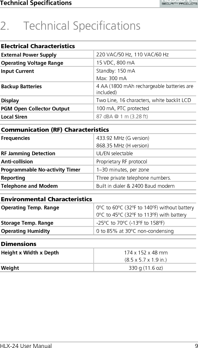
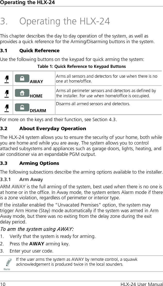
User Manual
Discussion / Help
Navigation