Rosslare MD-W11FGR Wireless access control door interface User Manual MD W11 Installation Manual
Rosslare Enterprises Ltd Wireless access control door interface MD W11 Installation Manual
Rosslare >
manual
Wireless Access Control Door Interface
MD-W11
Installation Manual
November 2010

Introduction
MD-W11 Installation Manual Page 1
Table of Contents
1. Introduction ...................................................................... 2
1.1 Overview .................................................................................... 2
1.2 Features...................................................................................... 3
2. Technical Specifications .................................................... 6
2.1 Electrical Characteristics ............................................................ 6
2.2 Environmental Characteristics ................................................... 7
2.3 Dimensions ................................................................................. 7
2.4 Supported Card Transmission Formats ...................................... 8
2.5 Supported Keypad Transmission Formats .................................. 8
2.6 Available models ....................................................................... 8
3. Installation and Wiring ........................................................ 9
3.1 The Installation Kit ....................................................................... 9
3.2 General Installation Requirements ............................................. 9
3.3 Installing the MD-W11N Unit...................................................... 10
3.4 Wiring the MD-W11N Unit .......................................................... 11
3.5 Installing the MD-W11F Unit ...................................................... 14
3.6 Wiring the MD-W11F Unit .......................................................... 14
3.7 Installing the MD-W11BP Battery Pack ...................................... 16
3.8 Wiring the MD-W11BP Battery Pack .......................................... 16
3.9 Indications on the Near and Far Units ...................................... 17
3.10 Installer Recommendations ..................................................... 17
4. Enrollment ...................................................................... 18
4.1 Enrolling the Units ...................................................................... 18
4.2 Dipswitches .............................................................................. 18
4.2.1. Near and Far Unit Modes ................................................................. 20
5. Operational Information .................................................. 23
Appendix A. Limited Warranty .............................................. 24
Appendix B. Declaration of Conformity ................................. 26
Appendix C. Technical Support ............................................ 27

Introduction
MD-W11 Installation Manual Page 2
1. Introduction
1.1 Overview
Rosslare Enterprises Ltd.’s MD-W11 Wireless Access Control Door
Interface, is a quick, inexpensive solution for connecting remote
door devices, such as readers, locks, and REX Buttons to an
access control unit.
The MD-W11 Wireless Access Control Door Interface consists of
two units per door, one located near the controller (the Near unit)
and the other near the door (the Far unit). The Near unit is
connected to a Rosslare door controller (e.g., AC-215, AC-225, or
AC-525). The Far unit is connected to proximity card readers or
keypads (e.g., AY-K12 and AY-Q64B).
When a card is read or a code is keyed onto the keypad, the Far
unit transmits the information to the Near unit. The Near unit,
attached to the AC-225 or to another controller, determines
whether or not to open the door. The controller then sends the
message to the Near unit, which transmits it to the Far unit, and if
authorized, the door is opened.
Caution:
Changes or modifications to this equipment not expressly
approved by the party responsible for compliance (Rosslare
Ltd.) could void the user’s authority to operate the
equipment.

Introduction
MD-W11 Installation Manual Page 3
1.2 Features
The MD-W11 Wireless Access Control Door Interface includes:
• Bi-directional RF data communication
• Supports PIN codes and card formats, such as Wiegand 26 bit,
32 bit, and PIN code 6 bit (see list of formats on page 8).
• Lock and door relay commands
• Tamper, door monitor, and REX messages between the
controller and the interface unit
• Rolling Code to increase security
• Four different RF channels to prevent collisions
• Built-in charger for up to 12VDC, 7Ah backup battery on the Far
unit
• Transfers proximity card information and LED control, reader
tamper, lock relay commands, REX, and door monitor events
between the coupled units.
• Optional MD-W11BP battery pack housing with space for
12VDC/800mAh, sealed lead-acid battery.
• Suitable for indoor use.
• Available in 869 MHz (H) and 433.92 MHz (G) bands
• The NEAR unit is powered from the controller's power supply. The
FAR unit is powered by a local wall transformer. A built-in
charger provides battery backup.
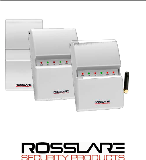
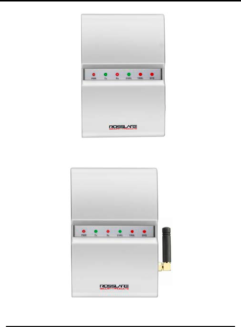
The MD-W11 Wireless Access Control Door Interface is displayed in
Figures 1 and 2.
Introduction
MD-W11 Installation Manual Page 4
Figure 1: MD-W11 Wireless Access Control Door Interface –
Near & Far Unit
Figure 2: MD-W11 Wireless Access Control Door Interface –
G Near Unit (with external Antenna)

Introduction
MD-W11 Installation Manual Page 5
Figure 3: MD-W11 Wireless Access Control Door Interface –
Battery Pack

Technical Specifications
MD-W11 Installation Manual Page 6
2. Technical Specifications
2.1 Electrical Characteristics
Input Voltage:
Far Unit:
Near Unit:
12-24 AC, 15-24V DC.
13.8V DC from the controller's power
supply or wall adapter.
Battery Charger:
12V sealed Lead-Acid, up to 7Ah (Far Unit)
Input Current:
Standby: 70mAh
Max: 160mA
Maximum Range:
(With External
Antenna)
Open field: 300 meters (985 feet)
Range depends on RF related
environmental conditions.
Response time: Up to 500ms with Rosslare’s AC-215
controller and reader.
Response time depends on RF link quality,
number of doors used as well as controller
and reader response time.
Output Relays:
Far Unit:
Near Unit:
One (1) 5A Form C relay
Two (2) 1A Form C relays
Output Types:
Far Unit:
Near Unit:
LED CTRL – open collector
STAM, SPV, LBAT, AC, TMP – open collector
Communications: Bi-directional RF, narrow band. Fast anti-
collision, rolling code protocol with data
protection. Available in 4 bands
(see Dipswitches, on page 18).

Technical Specifications
MD-W11 Installation Manual Page 7
2.1 Electrical Characteristics
Data Transfer:
Reader formats (based on the card and
keypad transmission formats listed below),
Lock commands, REX, Door Monitor, LED
control and reader tamper inputs.
Supervisory &
Alerts: Full supervision over the remote unit. Alert
outputs at the Near unit for supervision
failure, system tamper, reader tamper, low
battery and power failure.
2.2 Environmental Characteristics
Operating Environment:
Indoor Use
Operating Temperature:
-10°C to 50°C (14°F to 122°F)
Operating Humidity:
0 to 95% (Non Condensing)
2.3 Dimensions
Near/Far Units
H x W x D
Battery Pack
H x W x D
13 x 8.7 x 3.2 cm
5.1 x 3.42 x 1.26 inch
12.8 x 6.9 x 3.4 cm
5.04 x 2.72 x 1.34 inch
Weight
Near/Far Units
Battery Pack -
with battery
155 g
5.5 oz
433 g
15.3 oz

Technical Specifications
MD-W11 Installation Manual Page 8
2.4 Supported Card Transmission Formats
• Wiegand 26 bit (default)
• Wiegand 26 bit with facility code output
• Wiegand 32 bit
• Wiegand 32 bit reverse output
• Wiegand 34 bit
• Wiegand 40 bit
2.5 Supported Keypad Transmission Formats
• Single key, 6-bit Wiegand (Rosslare format, default)
• Single key, 6-bit Wiegand with Nibble + Parity bits
• Single key, 8-bit Wiegand, Nibble Complemented
• 4 keys binary, 26 bit Wiegand
• 1 to 5 keys, 26 bit Wiegand
• 6 keys BCD and parity bits, 26 bit Wiegand
2.6 Available models
• MD-W11NHR (869MHz)
• MD-W11FHR (869MHz)
• MD-W11NGR (433MHz)
• MD-W11FGR (433MHz)
• MD-W11BP

Installation and Wiring
MD-W11 Installation Manual Page 9
3. Installation and Wiring
The NEAR and FAR units of the MD-W11 are installed and wired as
explained in this chapter.
3.1 The Installation Kit
The installation kit of the MD-W11 interface includes:
• MD-W11N NEAR Unit:
•
The Near unit sends the Controller the
Proximity card ID or Keypad code as though it were a local
reader. Following controller code/ID verification, the lock relay
receives a command (transmitted to the Far unit) to open the
door.
MD-W11F FAR Unit:
•
The Far unit is connected to a proximity card
reader and/or keypad, and controls the door lock relay.
MD-W11BP Battery Pack: Installing the MD-W11BP Battery
Pack
The Battery Pack is mounted only on
the MD-W11 Far Unit side (See
, on page 16).
The MD-W11N and the MD-W11F are connected to the controller
and the door components (lock, door monitor, reader). Both units
are transceivers: the NEAR unit receives the data transmitted from
the Reader, and sends it to the controller. If authorized, the
controller sends authorization to the NEAR unit, which transmits
authorization to the FAR unit. The FAR unit then opens the door.
The Wireless Access Control Door Interface makes the transfer of
data between the Controller input, the outputs, and the door
components (such as Lock, Reader, Door Monitor, and Exit Button)
transparent, as if the door components were connected directly
to the controller.
3.2 General Installation Requirements
The installation kit includes:
• One drilling template (Label /Sticker)
Installation and Wiring
MD-W11 Installation Manual Page 10
• One Security spline key
• One Security hex screw
• Four mounting screws
• Four wall plugs
• Fixed External antenna (G Model)
3.3 Installing the MD-W11N Unit
The NEAR unit can be connected to a standard Rosslare
controller, such as the AC-225.
Decide where to mount the unit, and install it as follows:
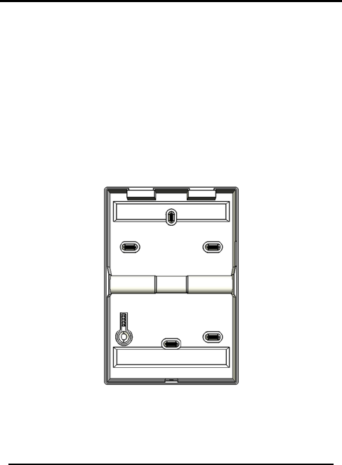
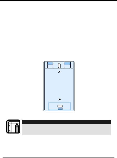
1. Use the spline key to remove the case security screw from the
back of the unit, as shown in Figure 4.
Figure 4: MD-W11 Back Cover
2. Use the drilling template to determine where to drill holes in
the wall.
3. Use the hardware to mount the back plate on the wall.
A

Installation and Wiring
MD-W11 Installation Manual Page 11
Notes:
We highly recommend to use the bottom left mounting hole,
as it used for the purpose of back tamper when a person
attempts to dislodge the unit from the wall. See Figure 4: MD-
W11 Back Cover marked with A
4. Wire the unit as instructed in the chapter on
.
Wiring the MD-
W11N Unit, below, and Figure 5: MD-W11N NEAR Unit Wiring
Diagram, on page 12.
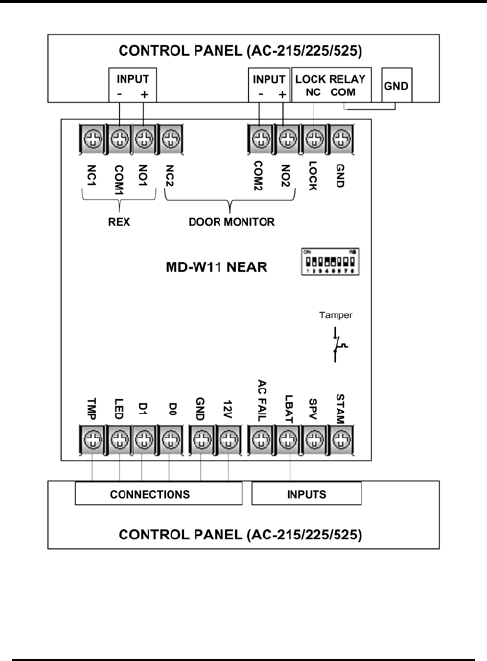
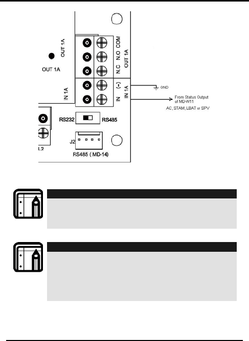
3.4 Wiring the MD-W11N Unit
Wire the following terminals between the Controller's Input and
Output to the MD-W11N Near Unit, as shown in Figure 5:
1. Power supply connection (+12V and GND)
2. System tamper (STAM)
3. Supervision failure (SPV) - Far unit has supervision failure
4. Low battery (LBAT) - Far unit has low battery
5. AC Fail (AC) - Far unit has power failure
6. Data 0 (D0)
7. Data 1 (D1)
8. Reader LED control (LED input)
9. Far Reader Tamper (TMP)
10. Connection for lock (Lock input)
11. Relay 1 REX (output)
12. Relay 2-Door monitor (output)
Notes:
1. System tamper (STAM), Supervision failure (SPV), Low
battery (LBAT), AC Fail (AC) are outputs which can be
connected to any input of AC-225 and in AxTrax this input
should be configured accordingly (using Panel Links).
2. If either the Far reader or the Near reader, or both have
been tampered with,
the STAM status changes, and retains
this status until both readers have been closed.
Installation and Wiring
MD-W11 Installation Manual Page 12
Figure 5: MD-W11N NEAR Unit Wiring Diagram
Installation and Wiring
MD-W11 Installation Manual Page 13
Figure 6: Sample Wiring Detail
Note:
Figure 6 shows sample input connections to any inputs, and
is relevant to: AC-215/225/525.
The relevant input can be configured to result in the required
outcome, using AxTrax and Panel Links.
Note:
1. The connection between the REX Input and Relay 1 is
always COM+ N.O. or COM + N.C. so that only two lines
connect this pair.
2. The connection between the Door Monitor Input and
Relay 2 is always COM+ N.O. or COM + N.C. so that only
two lines connect this pair.

Installation and Wiring
MD-W11 Installation Manual Page 14
3.5 Installing the MD-W11F Unit
The Far unit can be connected to a standard Rosslare reader,
such as the AY-K12. The optional battery box can then be
attached to the wall next to the Far unit.
1. Attach the battery box to the wall with two screws.
2. Insert the wires from the reader and from the battery to the
hole in the side of the Far unit box.
3. Attach the side of the unit box to the wall with four screws.
4. Attach the wires to the PCB.
5. Cover both the battery and the Far unit boxes.
6. Tighten the screws on the bottom of both boxes so that they
remain closed.
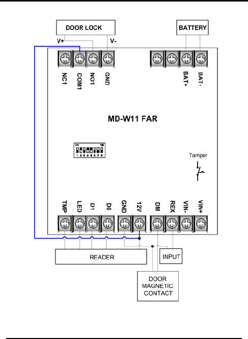
3.6 Wiring the MD-W11F Unit
Wire the following terminals between the Controller's Input and
Output to the MD-W11 Far Unit, as shown in Figure 7: MD-W11N
FAR Unit Wiring Diagram on page 15:
1. 12-24 VAC or 15-24VDC to the VIN+ and VIN-
2. Optional backup battery that connects to BAT+ and BAT-
3. 12V and GND power output for the Reader.
4. Data 0 Wiegand (D0) (input)
5. Data 1 Wiegand (D1) (input)
6. LED - Reader LED control (output)
7. TMP - Input for receiving reader tamper alert
8. Normally Open (NO)/Normally Closed (NC) and COM of 5A
Form C relay to the door’s lock
9. REX - Optional input for Request for Exit
10. DM - Optional input for door monitor contact
Installation and Wiring
MD-W11 Installation Manual Page 15
Figure 7: MD-W11N FAR Unit Wiring Diagram
Installation and Wiring
MD-W11 Installation Manual Page 16
3.7 Installing the MD-W11BP Battery Pack
Only install the MD-W11BP battery pack in the MD-W11 Far Unit.
Decide where to mount the unit, and install the battery pack as
follows:
1. Use the spline key to remove the security screw from the
bottom of the case, and open the unit.
2. Use the drilling template to locate where to drill holes in the
wall.
3. Use the hardware provided to mount the back plate on the
wall.
4. Wire the battery pack as shown in Figure 8.
Figure 8: MD-W11BP Battery Pack
Note:
The battery pack comes with a battery installed. The size of
the case is compatible with Rosslare’s BT-05 12VDC / 800mA
SLA rechargeable battery.
3.8 Wiring the MD-W11BP Battery Pack
In the Far unit only, connect the Red (+) and Black (GND) to
MDW11F Bat (+) and Bat (-).
Installation and Wiring
MD-W11 Installation Manual Page 17
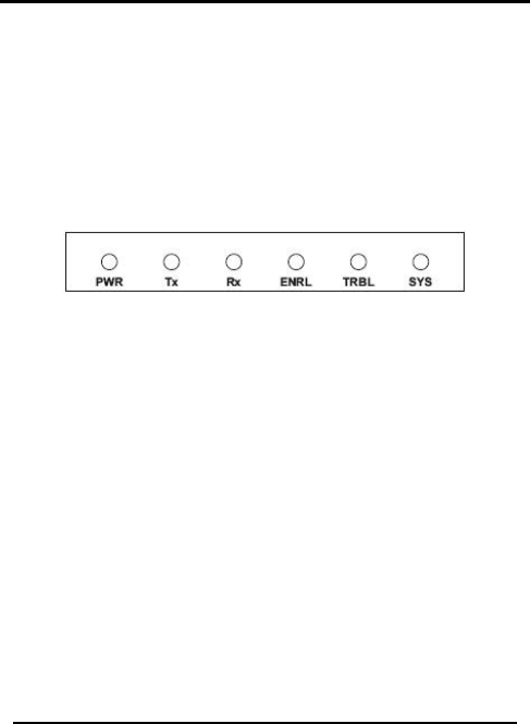
3.9 Indications on the Near and Far Units
Figure 9 shows the six LED’s (which indicate the unit’s current
status) on the display panel of each unit :
1. PWR – Power ON
2. Tx – Sending transmission
3. Rx – Receiving transmission
4. ENRL – Enrolling
5. TRBL – Trouble
6. SYS – System OK
Figure 9: LED Display Panel
3.10 Installer Recommendations
To install the MD-W11 units most efficiently, place the Near and Far
units facing each other, rather than placing them at a 90º angle
to one another.
Both transmission and reception are improved if the Near and Far
units have the same polarity.
In addition:
1. Do not place any of the MD-W11 units next to an air
conditioner, heater, blower, or an engine that generates a
magnetic field.
2. Do not place any unit next to an electronic device that
transmits RF or next to an access control reader or device.
3. Assure that metal fixtures and furnishings (e.g., doors or
closets) are not in line with the Near and Far units.
4. Assure that the Near and Far units are at the same
approximate height, preferably above head level.
Enrollment
MD-W11 Installation Manual Page 18
4. Enrollment
Prevent loss of transmission data by enrolling each pair of Near
and Far units.
4.1 Enrolling the Units
One unit cannot recognize the unique ID of another unit unless
both units are enrolled so that they can work together.
4.2 Dipswitches
The dipswitches on both units are set as follows:
Dipswitches 1-4:
Not used
Must be in the ON position.
Dipswitch 5:
OFF or
ON
Used to set the channel.
Dipswitch 6: OFF or
ON
Used to set the channel.
Dipswitch 7: Enrolling Normal mode – ON
Enrolling mode – OFF
Dipswitch 8:
Not used Must be in the ON position.
Note:
Only handle the Dipswitches when the power is OFF.
Up is ON
Down is OFF
1
2
3
4
5
6
7
8

Enrollment
MD-W11 Installation Manual Page 19
Set the unit channels with Dipswitches 5 and 6.
Dipswitch
5
Dipswitch
6
Channel
H Model
Channel
G Model
ON
ON
869.50 Mhz
433.60 Mhz
ON
OFF
868.45 Mhz
433.40 Mhz
OFF
ON
868.30 Mhz
433.20 Mhz
OFF
OFF
868.15 Mhz
433.00 MHz
Note:
Dipswitches 5 and 6 must be synchronized in the Far and
Near Units.
Choose the same channel for both units.
If the LED’s flash, the dipswitches have not been set properly. In
that case, first re-set the dipswitches, and then power the unit off
and on.
During enrollment, the enrolling LED blinks first, followed by the TX
LED, which blinks when it is transmitting. The enrolling process is
finished when the enrolling LED shines steadily.
After enrolling, return dipswitch 7 to ON (normal mode).
Note:
Only handle the Dipswitches when the power is OFF.

Enrollment
MD-W11 Installation Manual Page 20
4.2.1. Near and Far Unit Modes
The current unit mode is indicated by a steady or blinking LED.
The three modes (Normal, Enrolling, and Trouble) of the NEAR and
FAR units are described in detail below.
The normal mode is “idle,” and the LED’s behave as follows:
Normal Mode:
• PWR - Power ON - steady
• Tx - Sending transmission - blinking when sending
• Rx - Receiving transmission - blinking when receiving
• SYS - System OK – blinking
Note:
If SYS LED is not blinking, it indicates a serious error.
A blinking TRBL indicates that there is trouble. Refer to the Trouble
Mode for a list of possible problems.
The following steps indicate how to set the Enrolling mode (for
retention of transmitted data).
Enrolling Mode:
1. Set Dipswitch 7 on both units (Near and Far) to OFF.
2. Power up both units.
3. PWR IS steady and ENRL IS blinking.
4. The Far unit sends its ID to the Near unit.
5. The Near unit receives an ID and sends it to the Far unit
6. The Far unit receives the Near unit’s ID and ENRL is steady.

Enrollment
MD-W11 Installation Manual Page 21
The MD-W11
Trouble Mode:
FAR module
• Reader tamper
detects the following troubles:
• FAR module tamper
• Low battery
• AC Fail
• RF device Failure / Problem
• Incorrect dipswitch setting
Following detection of any of the said problems or failures, the
FAR module behaves as shown in the following table:
Problem
Activity
Reader tamper
Sends trouble and problem to the
Near
module.
FAR module tamper
Sends trouble and problem to the
Near
module.
Low battery
Sends trouble and problem to the Near
module.
Trouble LED turns on.
AC Fail
Sends trouble and problem to the Near
module.
Trouble LED turns on.
RF device Failure /
Problem
Trouble LED flashes at a fast rate. (after
power on)
Incorrect dipswitch
setting All LEDs flash at a slow rate. (after
power on)

Enrollment
MD-W11 Installation Manual Page 22
The MD-W11 Near module
• NEAR module tamper
detects following troubles:
• Supervision Fail
• RF device Failure / Problem
• Incorrect dipswitch setting
Following detection of any of the said problems or failures, the
NEAR module behaves as shown in the following table:
Problem name
Activity
NEAR module tamper
Activates NEAR units’ tamper output
Supervision Failure
Activates NEAR units’ supervision
output.
Trouble LED turns on.
RF device Failure /
Problem
Trouble LED flashes at a fast rate.
(after power on)
Incorrect dipswitch
setting
All LEDs flash at a slow rate. (after
power on)

Operational Information
MD-W11 Installation Manual Page 23
5. Operational Information
The units should be no more than 300 meters from one another in
an open field.
The Far unit has one dipswitch with eight buttons, the default for
all of which is On. The end-user only uses button #7 to enroll the
Near and Far units. When the user turns button #7 to Off, the Near
unit recognizes the Far unit so the units work with each other.
The Far unit can also be attached to a REX (request for exit)
button, a door monitor to indicate whether a door is open or
closed, and a tamper to check whether the cover was opened.
These indications are transmitted from the Far unit to the Near unit,
which then sends them to the controller.
The proximity reader reads card information, and sends it from the
Far unit to the Near unit and to the controller to determine which
door to open. If applicable, the controller sends authorization to
open the door to the Near unit, which transmits the authorization
to the Far unit, and the door is opened.

Limited Warranty
MD-W11 Installation Manual Page 24
Appendix A. Limited Warranty
ROSSLARE ENTERPRISES LIMITED S (Rosslare) TWO YEARS LIMITED WARRANTY
is applicable worldwide. This warranty supersedes any other warranty. Rosslare's TWO
YEARS LIMITED WARRANTY is subject to the following conditions:
Warranty
Warranty of Rosslare's products extends to the original purchaser (Customer) of the
Rosslare product and is not transferable.
Products Covered By This Warranty and Duration
ROSSLARE ENTERPRISES LTD. AND / ORSUBSIDIARIES (ROSSLARE) warrants that
the MD-W11 Wireless Access Control Door Interface, to be free from defects in materials
and assembly in the course of normal use and service. The warranty period commences
with the date of shipment to the original purchaser and extends for a period of 2 years (24
Months).
Warranty Remedy Coverage
In the event of a breach of warranty, ROSSLARE will credit Customer with the price of the
Product paid by Customer, provided that the warranty claim is delivered to ROSSLARE by
the Customer during the warranty period in accordance with the terms of this warranty.
Unless otherwise requested by ROSSLARE ENTERPRISES LTD. AND / OR
SUBSIDIARIES representative, return of the failed product(s) is not immediately required.
If ROSSLARE has not contacted the Customer within a sixty (60) day holding period
following the delivery of the warranty claim, Customer will not be required to return the
failed product(s). All returned Product(s), as may be requested at ROSSLARE
ENTERPRISES LTD. AND /OR SUBSIDIARY’S sole discretion, shall become the property
of ROSSLARE ENTERPRISES LTD. AND /OR SUBSIDIARIES.
To exercise the warranty, the user must contact Rosslare Enterprises Ltd. to obtain an
RMA number after which, the product must be returned to the Manufacturer freight prepaid
and insured
In the event ROSSLARE chooses to perform a product evaluation within the sixty (60) day
holding period and no defect is found, a minimum US$ 50.00 or equivalent charge will be
applied to each Product for labor required in the evaluation.
Rosslare will repair or replace, at its discretion, any product that under normal conditions
of use and service proves to be defective in material or workmanship. No charge will be
applied for labor or parts with respect to defects covered by this warranty, provided that
the work is done by Rosslare or a Rosslare authorized service center.

Limited Warranty
MD-W11 Installation Manual Page 25
Exclusions and Limitations
ROSSLARE shall not be responsible or liable for any damage or loss resulting from the
operation or performance of any Product or any systems in which a Product is
incorporated. This warranty shall not extend to any ancillary equipment not furnished by
ROSSLARE, which is attached to or used in conjunction with a Product, or to any Product
that is used with any ancillary equipment, which is not furnished by ROSSLARE.
This warranty does not cover expenses incurred in the transportation, freight cost to the
repair center, removal or reinstallation of the product, whether or not proven defective.
Specifically excluded from this warranty are any failures resulting from Customer's
improper testing, operation, installation, or damage resulting from use of the Product in
other than its normal and customary manner, or any maintenance, modification, alteration,
or adjustment or any type of abuse, neglect, accident, misuse, improper operation, normal
wear, defects or damage due to lightning or other electrical discharge. This warranty does
not cover repair or replacement where normal use has exhausted the life of a part or
instrument, or any modification or abuse of, or tampering with, the Product if Product
disassembled or repaired in such a manner as to adversely affect performance or prevent
adequate inspection and testing to verify any warranty claim.
ROSSLARE does not warrant the installation, maintenance, or service of the Product.
Service life of the product is dependent upon the care it receives and the conditions under
which it has to operate.
In no event shall Rosslare be liable for incidental or consequential damages.
Limited Warranty Terms
THIS WARRANTY SETS FORTH THE FULL EXTENT OF ROSSLARE ENTERPRISES LTD. AND
ITS SUBSIDIARIES’ WARRANTY
392BTHE TERMS OF THIS WARRANTY MAY NOT BE VARIED BY ANY PERSON, WHETHER OR
NOT PURPORTING TO REPRESENT OR ACT ON BEHALF OF ROSSLARE.
393BTHIS LIMITED WARRANTY IS PROVIDED IN LIEU OF ALL OTHER WARRANTIES. ALL OTHER
WARRANTIES EXPRESSED OR IMPLIED, INCLUDING WITHOUT LIMITATION, IMPLIED
WARRANTIES OF MERCHANTABILITY AND FITNESS FOR A PARTICULAR PURPOSE, ARE
SPECIFICALLY EXCLUDED.
394BIN NO EVENT SHALL ROSSLARE BE LIABLE FOR DAMAGES IN EXCESS OF THE
PURCHASE PRICE OF THE PRODUCT, OR FOR ANY OTHER INCIDENTAL,
CONSEQUENTIAL OR SPECIAL DAMAGES, INCLUDING BUT NOT LIMITED TO LOSS OF
USE, LOSS OF TIME, COMMERCIAL LOSS, INCONVENIENCE, AND LOSS OF PROFITS,
ARISING OUT OF THE INSTALLATION, USE, OR INABILITY TO USE SUCH PRODUCT, TO
THE FULLEST EXTENT THAT ANY SUCH LOSS OR DAMAGE MAY BE DISCLAIMED BY LAW.
395BTHIS WARRANTY SHALL BECOME NULL AND VOID IN THE EVENT OF A VIOLATION OF THE
PROVISIONS OF THIS LIMITED WARRANTY.

Declaration of Conformity
MD-W11 Installation Manual Page 26
Appendix B. Declaration of Conformity
THIS EQUIPMENT HAS BEEN TESTED AND FOUND TO COMPLY WITH THE LIMITS FOR A
CLASS B DIGITAL DEVICE, PURSUANT TO PART 15 OF THE FCC RULES. THESE LIMITS
ARE DESIGNED TO PROVIDE REASONABLE PROTECTION AGAINST HARMFUL
INTERFERENCE IN A RESIDENTIAL INSTALLATION. THIS EQUIPMENT GENERATES, USES
AND CAN RADIATE RADIO FREQUENCY ENERGY AND, IF NOT INSTALLED AND USED IN
ACCORDANCE WITH THE INSTRUCTIONS, MAY CAUSE HARMFUL INTERFERENCE TO
RADIO COMMUNICATIONS. HOWEVER, THERE IS NO GUARANTEE THAT INTERFERENCE
WILL NOT OCCUR IN A PARTICULAR INSTALLATION. IF THIS EQUIPMENT DOES CAUSE
HARMFUL INTERFERENCE TO RADIO OR TELEVISION RECEPTION, WHICH CAN BE
DETERMINED BY TURNING THE EQUIPMENT OFF AND ON, THE USER IS ENCOURAGED
TO TRY TO CORRECT THE INTERFERENCE BY ONE OR MORE OF THE FOLLOWING
MEASURES:
• Reorient or relocate the receiving antenna.
• Increase the separation between the equipment and receiver.
• Connect the equipment into an outlet on a circuit different from that to
which the receiver is connected.
• Consult the dealer or an experienced radio/TV technician for help.

Technical Support
MD-W11 Installation Manual Page 27
Appendix C. Technical Support
Asia Pacific, Middle East
Rosslare Security Products Headquarters
905-912 Wing Fat Industrial Bldg,
12 Wang Tai Road,
Kowloon Bay Hong Kong
Tel: +852 2795-5630
Fax: +852 2795-1508
E-mail: support.apac@rosslaresecurity.com
United States and Canada
1600 Hart Court, Suite 103
Southlake, TX, USA 76092
Toll Free: +1-866-632-1101
Local: +1-817-305-0006
Fax: +1-817-305-0069
E-mail: support.na@rosslaresecurity.com
Europe, Africa
Global Technical Support & Training Center
HaMelecha 22
Rosh HaAyin, Israel 48091
Tel: +972 3 938-6838
Fax: +972 3 938-6830
E-mail: support.eu@rosslaresecurity.com
South America
Presbitero Actis 555, Oficina 31.
San Isidro. Buenos Aires. Argentina
Tel: +5411-5273-6383
Tel: +305-921-9919
E-mail: support.la@rosslaresecurity.com
Web Site: www.rosslaresecurity.com

0706-0960234+00
www.rosslaresecurity.com