Rosslare SA-01PG Pet immune PIR detector User Manual Installation Manual
Rosslare Enterprises Ltd Pet immune PIR detector Installation Manual
Rosslare >
manual
SA-01P
Installation Instructions
Digital Wireless Pet Immune
Passive Infrared Motion Detector
1
0706-0960212+00
1. Introduction
The SA-01P Digital Wireless Pet Immune Passive Infrared (PIR)
Motion Detector is a high-performance ultra low power
intrusion sensor made with the highest level of SMD
components and microprocessor technologies, making it ideal
for both residential and commercial usage. This unit works with
Rosslare's control panels.
The PIR senses slight motion within a coverage pattern by
detecting infrared energy with a pyroelectric sensor. Serving as
an anti-intrusion sensor, the PIR can monitor open space within
line of sight while ignoring house pets and other small animals,
thus reducing false alarms significantly.
The SA-01P uses a pet lens with fuzzy logic implementing a
special algorithm to improve human detection while at the
same time ignoring pets and other small animals thus reducing
false alarms. It also provides digital temperature compensation
and self-test capability.
For high-security, the SA-01P is supplied with a
back and cover tamper which detects
tampering with the sensor if the case is opened
or an attempt is made to remove it from the wall.
As a wireless device, the SA-01P includes a
supervision mechanism as well as features such
as walk and RF transmission test functions,
movement and speed spectrum analysis, selectable pulse
counting, ultra-bright LED, cover and wall tamper detection,
ultra-low current consumption, APS (Auto Power Save)
technology, and automatic low battery detection. The SA-01P
also has an optional mount bracket.
Caution: Changes or modifications to this equipment
not expressly approved by the party responsible for
compliance (Rosslare Ltd.) could void the user’s
authority to operate the equipment.
2. Technical Specifications
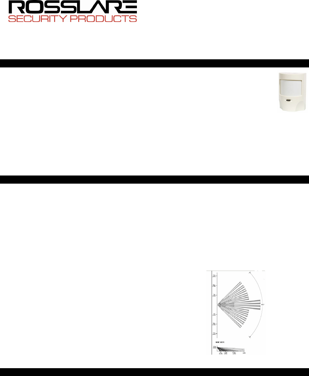
2.1 Optical Characteristics
Lens Type: Pet immune multi-zone, high density polytilan type
Optical Filter: White light protection
Maximum Coverage: 14 x 14 m (45.9 x 45.9 ft) 88°
Vertical Adjustment: By slot (+/- 2°)
2.2 Electrical Characteristics
Battery type: CR123 (3V/1300mAh)
Current consumptions: Standby 15µA, 10mA transmission.
Battery life (nominal): 3 years (150tr/day)
Detector Type: Dual pyro IR element (IR filter 5um÷14um)
Alarm Signaling: Red LED 2 seconds on event transmission:
alarm, tamper, low battery.
Sensitivity: 2 levels fuzzy logic (jumper setting)
Speed Detect: 0.2M/s÷5M/s∆t=1.1°C (0.66 ft/s÷16.4 ft/s∆t=2° F)
Pet Immune: Up to 25Kg.
Temperature Compensation: Digital dual slope (+/- 1°C)
Tamper Switches: Back & cover tamper
Supervisory Signals: Electronic malfunction or temperature out
of range is indicated by a flashing LED.
Arming types: Normal: 2 minutes sleep following last alarm
Dynamic: 2 minutes following last movement
(retriggerable).
Test modes: walk test (no sleep) 1 min, radio test (10
transmission) by push button.
RF Characteristics
RF Frequency: G=433.92MHz and H=868.35MHz
RFI Protection: >20 V/m up to 1000 MHz
2.3 Environmental Characteristics
Operating Environment: Indoor use
Operating Temperature: -10 to 60°C (14 to 140°F)
Operating Humidity: 0 to 95% (non-condensing)
2.4 Physical Characteristics
Dimensions: 90mm x 65mm x 52mm (3.5 in. x 2.5 in. x 2.2 in.)
Weight: 84.2 grams (2.97 oz)
Note: The SA-01P is an indoor PIR, and should not be
used in outdoor applications.
Figure 1: Lens Top and Side View
3. SA-01P General Features
These are the main features of the SA-01P:
• Advanced micro-controller electronics: 10-bit A-to-D and
advanced algorithms for superior movement speed
spectrum analysis.
• Shielded dual-element pyro: Inside a dust-proof chamber
designed to reduce thermal changes and insect
protection.
• Two levels of sensitivity: Normal and harsh environments,
by jumper selection.
• Adjustable height calibration of PCB: The detector may
be adjusted and placed at any height from 1.8 meters to
2.3 meters.
• Back and cover tamper switch: Protection against
opening the cover or wall removal.
• Power saving: Two transmission modes set by jumper.
• Walk and radio tests: Both can be checked quickly, using
LED indication and without opening the case.
• Energy detection system: By using fuzzy logic algorithms,
detection is improved and false alarms are reduced.
• Power level discriminator: Special lens combined with a
power algorithm ignores small to medium sized animals
while maintaining a high level of human detection.
2
0706-0960212+00
• Environment temperature compensation: Maintains
constant detection capability.
• Adaptive filter: Compensates for changes in a detected
object’s speed.
• Continuous monitoring: Sends visual alerts in case of
malfunction (digital and analog) and temperature alerts
if the environment temperature is out of range.
• Silent monitoring: Low battery, tamper, and periodic
beacon
4. Pet Immune Feature
The SP-01P is immune from the following interferences:
• One dog up to 25kg
• Two dogs no more than 20kg each
• Several cats
• Unlimited number of small animals such as hamsters,
birds, rodents, etc.
These are only guide lines, there may be some tolerance
regarding the size and weight of the animals monitored. For
example a short haired, dark colored canine will appear
bigger than a long haired, light colored canine. As a rule of
thumb please add 2-3 kg for each attribute to calculate their
weight when installing the detector.
5. Installation
5.1 False Alarm Reduction Effort
To reduce false alarms caused by detector installation:
• AVOID: Placing the PIR facing windows, or in direct sunlight
as this heat energy can cause false alarms.
• AVOID: Wiring of the SA-01P in such a way that it is parallel
to and sitting close to 110V AC or 220V AC transmission
equipment or mains power line.
• AVOID: Placing near or over heat and air ducts, ovens,
heat sources, radiators, and air conditioners as this may
cause a false detection.
• AVOID: Placing near PL lamps, electrical ballasts, above
cookers, and ovens, and above steam sources.
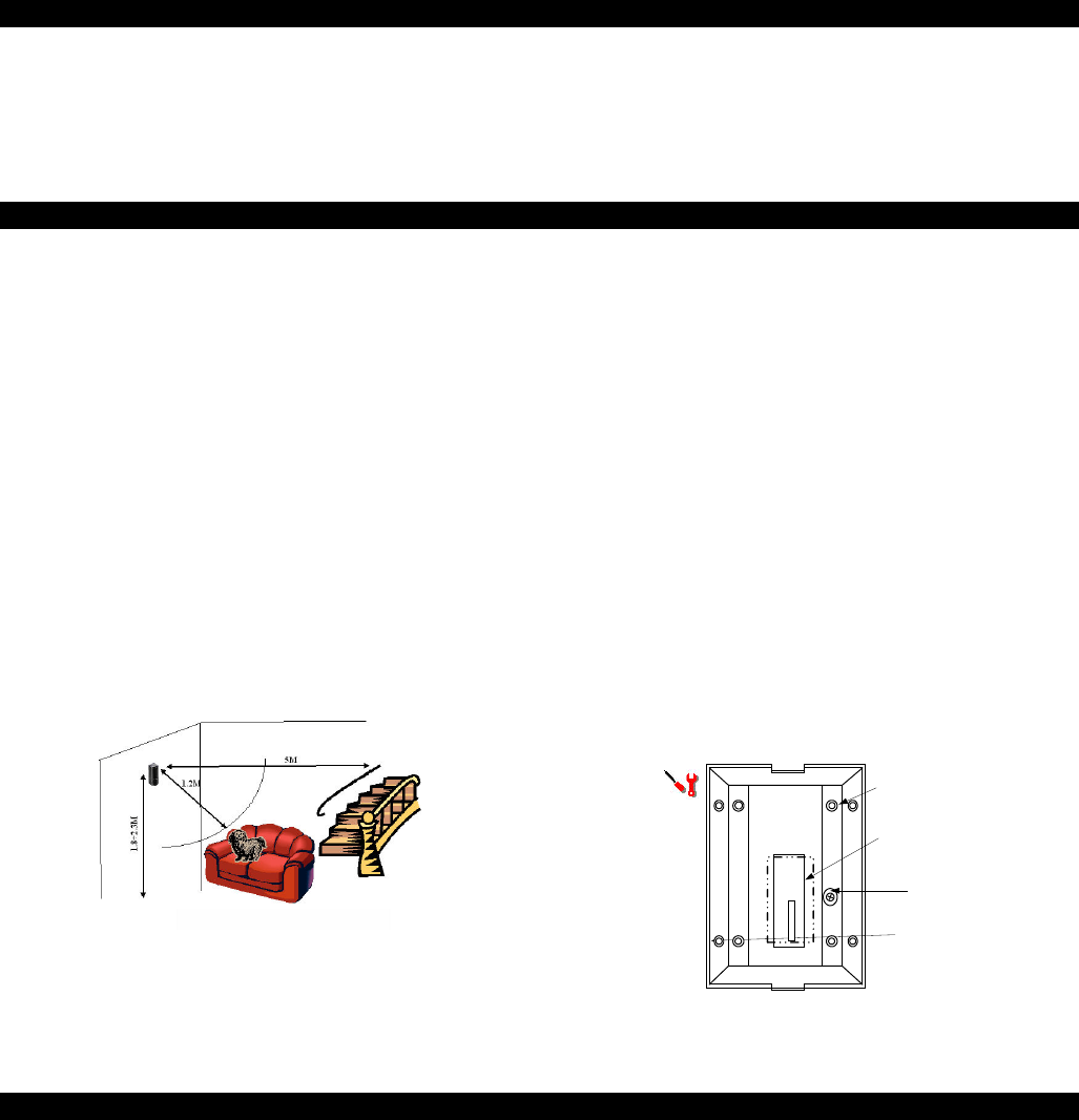
• AVOID: Placing the detector where the house pet can be
within1.2M, like a sofa, and less than 5M from stairs and
such where the animal can climb (see Figure 2).
• NEVER: Touch the pyroelectric sensor on the PCB as this
causes permanent damage and loss of sensitivity.
Important Note: PIR works according to field of view
and cannot detect through walls. Avoid placing near
obstructions such as large plants, curtains, behind open
doors, and continuously moving objects.
Figure 2: SA-01P installation guidelines with pets present
5.2 Selecting the Physical Location
Select the best physical location to install the PIR.
1) Select a corner or a flat wall within a room or hallway
between 1.8 and 2.3M that best matches the criteria in
False Alarm Reduction Effort.
2) Ensure that the PIR is mounted on a non-moving, non-
vibrating surface, or corner of the room.
3) Mount the PIR in the location.
4) After the installation, perform a walk test from the mounting
location to ensure that the sensor pattern can detect
within the coverage area (see Testing the Detector).
5.3 Mounting the PIR
Mount the SA-01P PIR on a flat wall surface or to a corner.
Flat Surface Mounting
To mount the PIR to a flat surface:
1) Remove the PCB from the back case.
2) Remove the knockouts from the back case, labeled “B” by
using a sharp tool or using a nail.
3) Affix the four screws onto the wall.
4) Replace the PCB and tighten the PCB locking screw.
5) Set the jumpers (refer to Jumpers Setting section).
6) Pull out the paper strip located over one battery pole. This
will energize the detector.
7) Replace the top cover of the PIR.
8) The detector goes into test mode indicated by the LED
flashing for about 90 seconds. After a successful test, the
LED goes off. At this stage it is ready for a walk test.
INSIDE THE BACK CASE
A:
KNOCKOUT HOLE
FOR CORNER
MOUNTING
A
A A
A
B B
BB
B:
KNOCKOUT HOLE
FLAT SURFACE
MOUNTING
PHILIPS HEAD
SCREW FOR
LOCKING PCB
ANTIDUST
ADHESIVE
Figure 3: Inside the Plastic Case – Back
6. Jumpers Setting
6.1 Setting the Sensitivity (JP2)
SA-01P has two jumpers, JP1 and JP2, to set the operation
method of the PIR. Insert a jumper to activate the desired
setting.
To prevent false alarms caused by house pets or harsh
environments two sensitivity modes were designated:
• Medium - for normal usage.
• High - for harsh environments and where the total pet’s
weight is more than 25Kg.
To set the jumpers:
• Medium - jumper off
• High - jumper on
6.2 Radio Mode Jumper (JP1)
To save power, the SA-01P goes into sleep mode after
sending an alarm. The time the device will be latent is set by
JP1.
• Normal - (always 2 minutes between alarms) - jumper off.
• Dynamic - (2 minutes retriggered between alarms) -
jumper on.
When the dynamic mode is set, an alarm event will be sent
only if there were 2 minutes of silence prior to the current
3
0706-0960212+00
0
-2
-4
2
4
alarm. This setting is useful for places with a high level of
traffic such as factories.
Normal – JP1 off
Dynamic – JP1 on
6.3 Back and Cover Tamper
There are two kinds of tamper protection in this detector. The
cover tamper protects against the opening of the case and
the back tamper (optional) protects against taking the unit
off the wall. To enable the back tamper, cut the R11 wire.
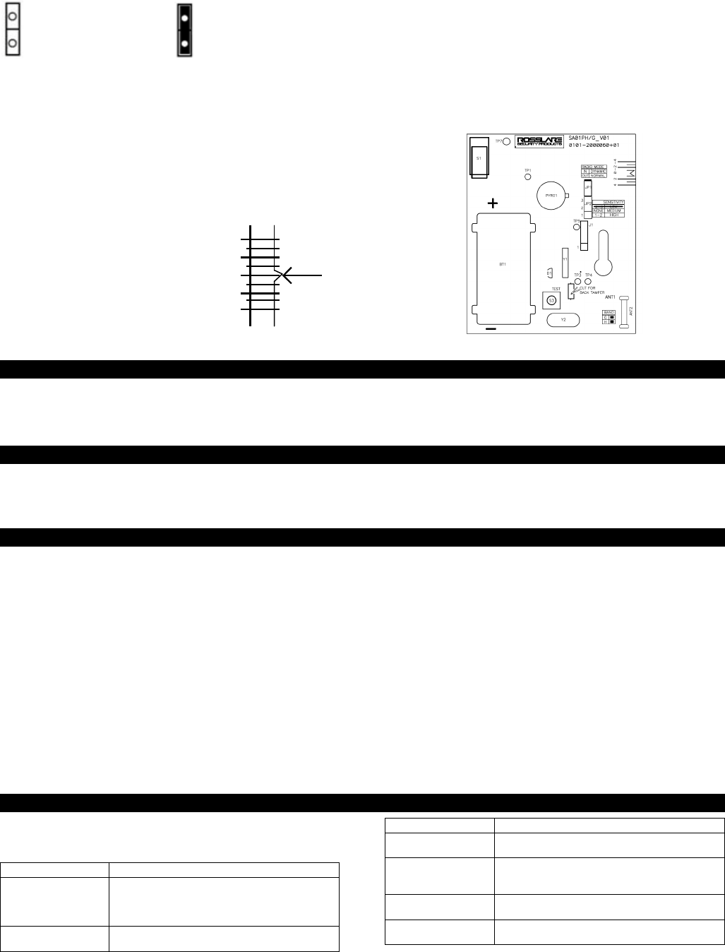
6.4 Vertical Calibration
If the SA-01P PIR is to be mounted at a height above 2.1
meters or below 1.9 meters, calibrate the PCB by moving the
PCB up or down in the PIR housing accordingly before fixing
it. The calibration scale on the PCB and the calibration
marker on the PIR housing will
help you achieve the optimum
calibration setting.
The PCB calibration scale is
located on the top right hand
side of the PCB (left). The
calibration marker is located on
the inside of the PIR housing
(right).
If mounting the PIR above 2.1 meters, move the PCB (+) up in
the PIR housing so that the calibration marker is parallel to a
+ scale (e.g. 2). This will ensure that the detection area is
focused closer to the unit.
If mounting the PIR below 1.9 meters, move the PCB down (-)
in the PIR housing so that the calibration marker is parallel to
a - scale (e.g. -2). This will ensure that the detection area is
focused further from the unit, therefore maximizing detection
range.
Either way, refrain from installing the detector higher than
2.3M or lower than 1.8M since it will reduce efficiency.
Figure 4: Front of PCB
7. Enrolling the detector
After a successful self test, you can enroll the detector to a
specific zone in the alarm system.
The easiest way to do so is to open and close the front tamper.
For specific steps to be followed for the enrollment, refer to the
manual supplied with the alarm panel.
8. Low Battery Supervision
Prior to each RF transmission, the battery voltage is sampled. If
the voltage is low for 3 sequence transmissions, a "low battery"
message is sent with the next transmission. When the battery is
low, the LED is blinks during alarm and tamper events. Once
the battery level returns to the minimum preset value, fault
transmissions cease.
9. Testing the Detector
9.1 Self Check
Perform a self check by pressing the pipe light for less than 3
seconds.
9.2 Walk Test
Evaluate the performance of the detector by executing a 2-
minute walk test.
1) Ensure all of the settings in the PIR are adjusted as
necessary for the location according to the installation
instructions above, and that the PIR case is closed and the
locking screw is firm.
2) Apply power to the unit. The LED flashes on for 2 seconds
and off for 2 seconds for a period of 1 minute. During this
time, all PIR paths are being self tested. After the test is
successful, the LED switches off. At this point a walk test can
be performed.
3) During the walk, test the LED flashes every time the
detector detects motion. There is a two second wait period
before the next detection.
4) It is recommended that the installer test the detection by
going over the protected area and seeing that the
detection pattern is good.
5) The test mode can be entered for a one-minute period, by
depressing S3 from the pipe light for less than three
seconds.
9.3 Radio Test
Evaluate the RF path quality by pressing the pipe light on the
front of the PIR for more than 3 seconds.
The detector will transmit 10 transmissions to the control panel
in 4 second intervals. Refer to the alarm panel manual for RF
quality test.
10. Signaling
The LED on the front of the SA-01P is used to send several
signals to the user. The following table describes the signals
for different activities:
Activity
LED Signal
Warm-Up
The LED flashes on for 2 seconds and off for 2
seconds for a period of 1 minute. If the
warm-up is successful, the LED stops flashing
and the system is ready for detection.
Detect Condition
The LED flashes on for 2 seconds and then turns
off.
Activity
LED Signal
Tamper OPEN/CLOSE The LED flashes on for 2 seconds and then turns
off.
PIR Problem The LED flashes on for 1 second and then off
for 1 second. A PIR check is conducted once
every hour.
Temperature Problem The LED flashes on for 0.5 seconds and then off
for 0.5 seconds.
Low battery The LED flashes rapidly in detect and tamper
events.

4
0706-0960212+00
11. Limited Warranty
ROSSLARE ENTERPRISES LIMITED S (Rosslare) TWO YEAR LIMITED
WARRANTY is applicable worldwide. This warranty supersedes any other
warranty. Rosslare's TWO YEAR LIMITED WARRANTY is subject to the
following conditions:
Warranty
Warranty of Rosslare's products extends to the original purchaser (Customer)
of the Rosslare product and is not transferable.
Products Covered By This Warranty and Duration
ROSSLARE ENTERPRISES LTD. AND / ORSUBSIDIARIES (ROSSLARE)
warrants that the SA-01P Digital wireless PIR, to be free from defects in
materials and assembly in the course of normal use and service. The warranty
period commences with the date of shipment to the original purchaser and
extends for a period of 2 years (24 Months).
Warranty Remedy Coverage
In the event of a breach of warranty, ROSSLARE will credit Customer with the
price of the Product paid by Customer, provided that the warranty claim is
delivered to ROSSLARE by the Customer during the warranty period in
accordance with the terms of this warranty. Unless otherwise requested by
ROSSLARE ENTERPRISES LTD. AND / OR SUBSIDIARIES representative,
return of the failed product(s) is not immediately required.
If ROSSLARE has not contacted the Customer within a sixty (60) day holding
period following the delivery of the warranty claim, Customer will not be
required to return the failed product(s). All returned Product(s), as may be
requested at ROSSLARE ENTERPRISES LTD. AND /OR SUBSIDIARY’S sole
discretion, shall become the property of ROSSLARE ENTERPRISES LTD.
AND /OR SUBSIDIARIES.
To exercise the warranty, the user must contact Rosslare Enterprises Ltd. to
obtain an RMA number after which, the product must be returned to the
Manufacturer freight prepaid and insured
In the event ROSSLARE chooses to perform a product evaluation within the
sixty (60) day holding period and no defect is found, a minimum US$ 50.00 or
equivalent charge will be applied to each Product for labor required in the
evaluation.
Rosslare will repair or replace, at its discretion, any product that under normal
conditions of use and service proves to be defective in material or
workmanship. No charge will be applied for labor or parts with respect to
defects covered by this warranty, provided that the work is done by Rosslare
or a Rosslare authorized service center.
Exclusions and Limitations
ROSSLARE shall not be responsible or liable for any damage or loss resulting
from the operation or performance of any Product or any systems in which a
Product is incorporated. This warranty shall not extend to any ancillary
equipment not furnished by ROSSLARE, which is attached to or used in
conjunction with a Product, nor to any Product that is used with any ancillary
equipment, which is not furnished by ROSSLARE.
This warranty does not cover expenses incurred in the transportation, freight
cost to the repair center, removal or reinstallation of the product, whether or
not proven defective.
Specifically excluded from this warranty are any failures resulting from
Customer's improper testing, operation, installation, or damage resulting from
use of the Product in other than its normal and customary manner, or any
maintenance, modification, alteration, or adjustment or any type of abuse,
neglect, accident, misuse, improper operation, normal wear, defects or
damage due to lightning or other electrical discharge. This warranty does not
cover repair or replacement where normal use has exhausted the life of a part
or instrument, or any modification or abuse of, or tampering with, the Product if
Product disassembled or repaired in such a manner as to adversely affect
performance or prevent adequate inspection and testing to verify any warranty
claim.
ROSSLARE does not warrant the installation, maintenance, or service of the
Product. Service life of the product is dependent upon the care it receives and
the conditions under which it has to operate.
In no event shall Rosslare be liable for incidental or consequential damages.
Limited Warranty Terms
THIS WARRANTY SETS FORTH THE FULL EXTENT OF ROSSLARE ENTERPRISES LTD. AND
IT’S SUBSIDIARY'S WARRANTY
THE TERMS OF THIS WARRANTY MAY NOT BE VARIED BY ANY PERSON, WHETHER OR
NOT PURPORTING TO REPRESENT OR ACT ON BEHALF OF ROSSLARE.
THIS LIMITED WARRANTY IS PROVIDED IN LIEU OF ALL OTHER WARRANTIES. ALL OTHER
WARRANTIES EXPRESSED OR IMPLIED, INCLUDING WITHOUT LIMITATION, IMPLIED
WARRANTIES OF MERCHANTABILITY AND FITNESS FOR A PARTICULAR PURPOSE, ARE
SPECIFICALLY EXCLUDED.
IN NO EVENT SHALL ROSSLARE BE LIABLE FOR DAMAGES IN EXCESS OF THE PURCHASE
PRICE OF THE PRODUCT, OR FOR ANY OTHER INCIDENTAL, CONSEQUENTIAL OR
SPECIAL DAMAGES, INCLUDING BUT NOT LIMITED TO LOSS OF USE, LOSS OF TIME,
COMMERCIAL LOSS, INCONVENIENCE, AND LOSS OF PROFITS, ARISING OUT OF THE
INSTALLATION, USE, OR INABILITY TO USE SUCH PRODUCT, TO THE FULLEST EXTENT
THAT ANY SUCH LOSS OR DAMAGE MAY BE DISCLAIMED BY LAW.
THIS WARRANTY SHALL BECOME NULL AND VOID IN THE EVENT OF A VIOLATION OF THE
PROVISIONS OF THIS LIMITED WARRANTY.
12. Declaration of Conformity
This equipment has been tested and found to comply with the limits for a Class
B digital device, pursuant to part 15 of the FCC Rules. These limits are
designed to provide reasonable protection against harmful interference in a
residential installation. This equipment generates, uses and can radiate radio
frequency energy and, if not installed and used in accordance with the
instructions, may cause harmful interference to radio communications.
However, there is no guarantee that interference will not occur in a particular
installation. If this equipment does cause harmful interference to radio or
television reception, which can be determined by turning the equipment off and
on, the user is encouraged to try to correct the interference by one or more of
the following measures:
• Reorient or relocate the receiving antenna.
• Increase the separation between the equipment and receiver.
• Connect the equipment into an outlet on a circuit different from that to which the receiver
is connected.
• Consult the dealer or an experienced radio/TV technician for help.
This device complies with Part 15 of the FCC Rules.
Operation is subject to the following two conditions:
(1) This device may not cause harmful interference, and
(2) This device must accept any interference received, including interference
that may cause undesired operation
13. Contact information
Asia Pacific, Middle East and Africa
Headquarters:
905-912 Wing Fat Industrial Bldg, 12 Wang Tai Road, Kowloon Bay Hong
Kong
Tel:+852 2795-5630 Fax: +852 2795-1508 E-mail:
support.apac@rosslaresecurity.com
United States and Canada
1600 Hart Court, Suite 103 Southlake, TX, USA 76092
Toll Free:+1-866-632-1101 Local:+1-817-305-0006 Fax: +1-817-305-0069
E-mail: support.na@rosslaresecurity.com
Europe
Global Technical Support & Training Center:
HaMelecha 22 Rosh HaAyin, Israel 48091
Tel: +972 3 938-6838 Fax: +972 3 938-6830 E-mail:
support.eu@rosslaresecurity.com
South America
Presbitero Actis 555, Oficina 31.
San Isidro. Buenos Aires. Argentina
Tel: +5411-5273-6383 Tel: +305-921-9919
E-mail: support.la@rosslaresecurity.com
Web Site: www.rosslaresecurity.com