Rosslare SA-23H WIRELESS REMOTE CONTROL 868.35 MHz User Manual new A4
Rosslare Enterprises Ltd WIRELESS REMOTE CONTROL 868.35 MHz new A4
Rosslare >
User Manual
AY-L23 G/H and SA-23 G/H
Outdoor Long-Range RF Reader and Remote Control May 2013
Installation and Operation Manual
1
1. Introduction
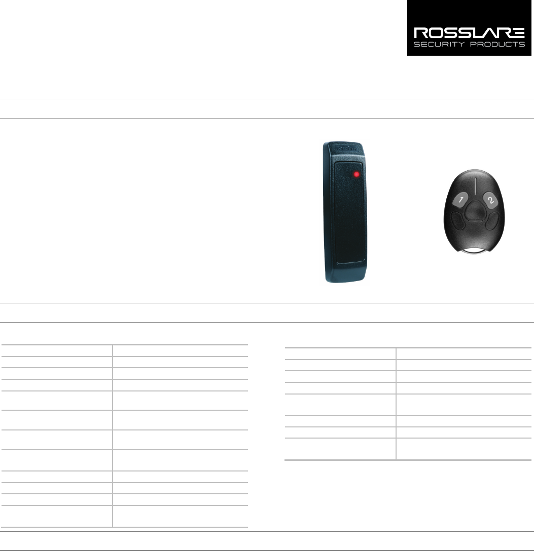
The AYL-23G/H is an outdoor long-range RF reader that acts as a
receiver. It is compatible with Rosslare’s SA-23 wireless remote control
transmitter. The AY-L23 G works with the SA-23 G (433.92 MHz) and
the AY-L23 H works with the SA-23 H (868.35 MHz).
When the AY-L23 receives the a command signal from the SA-23
wireless transmitter, the AY-L23 outputs the ID to A_DATA0,A_DATA1
or B_DATA0,B_DATA1 to the attached controller and controls the
function of the relay (open drain FET) A or B according to the SA-23
remote’s command.
The command signal consists of 3 parts:
ID (in Wiegand format)
ID output to A or B Wiegand Output according to the command in
SA-23
Relay Function A or B according to command in the SA-23
Figure 1: AY-L23 G/H and SA-23 G/H
AY-L23 G/H SA-23 G/H
2. Technical Specifications
2.1 AY-L23 G/H
Input Voltage 7 to 24 VDC
Standby Current 26 mA (12 VDC)
Maximum Operating Current 65 mA (12 VDC)
Relay (FET, Open Drain) Current 200 mA (max voltage 40 V)
Tamper Output Open collector, active Open, max. sink
current is 16 mA
Maximum Cable Distance to
Controller
500 ft. (152.4 m)
Wiegand Output Format
Wiegand xbit (Wiegand xbit<=Wiegand 40-
Bit, decided by remote
Frequencies G: 433.92 MHz
H: 868.35MHz
Read Range
164 ft (50 m)
Operating Temp. Range
-31°C to 63°C (-25°F to 145°F)
Operating Humidity 0 to 95% (non condensing)
Dimensions (L x W x D) 5.7 x 1.7 x 0.8 in.
(145 x 43 x 20 mm)
2.2 SA-23 G/H
Input Voltage 3 V Battery (CR 2450)
Standby Current
< 1 uA
Max Operation Current 10 mA
ID Format Programmed to Wiegand 26-Bit
Frequencies G: 433.92 MHz (ASK)
H: 868.35 MHz (ASK)
Operating Temp. Range -31°C to 63°C (-25°F to 145°F)
Operating Humidity 0 to 95% (non condensing)
Dimensions (L x W x D) 2.28 x 1.61 x 0.53 in.
(58 x 41 x 13.4 mm)
3. Mounting Instructions
Determine an appropriate mounting position for the receiver. Do not
mount the receiver near any source of wireless interference or on any
metal surface.
To mount the receiver:
1. Peel off the back of the self-stick mounting label template included
with the unit and place at the desired mounting position.
2. Using the template as a guide, drill two holes (hole size is indicated
on mounting template) for mounting the receiver to the surface.
3. Drill a 7/16” (10-mm) hole for the cable.
4. Remove the front case from the receiver.
5. Attach the receiver to the controller. (See wiring instructions)
6. Screw the receiver’s rear case onto its mounting location and
return the front case onto the mounted rear case.
The receiver is to be used with control panels whose power supply is
UL Listed Class 2 or equivalent.
2
4. Wiring Instructions
To connect the receiver to the controller:
1. Prepare the receiver cable by cutting the cable jacket back 1¼
inches and strip the wires ½ inch.
2. Prepare the controller cable by cutting the cable jacket back 1¼
inches and strip the wires ½ inch.
3. Splice the receiver’s pigtail wires to the corresponding controller
wires and cover each connection (see Table 1).
• The individual wires coming out of the receiver are color coded
according to the recommended Wiegand standard.
• When using a separate power supply for the receiver, this supply and
the controller’s power supply must have a common ground.
• The cable shield wire on the receiver should be attached to an Earth
ground (best) or signal ground connection at the panel or power
supply end of the cable. This configuration is best for shielding the
receiver cable from external interference.
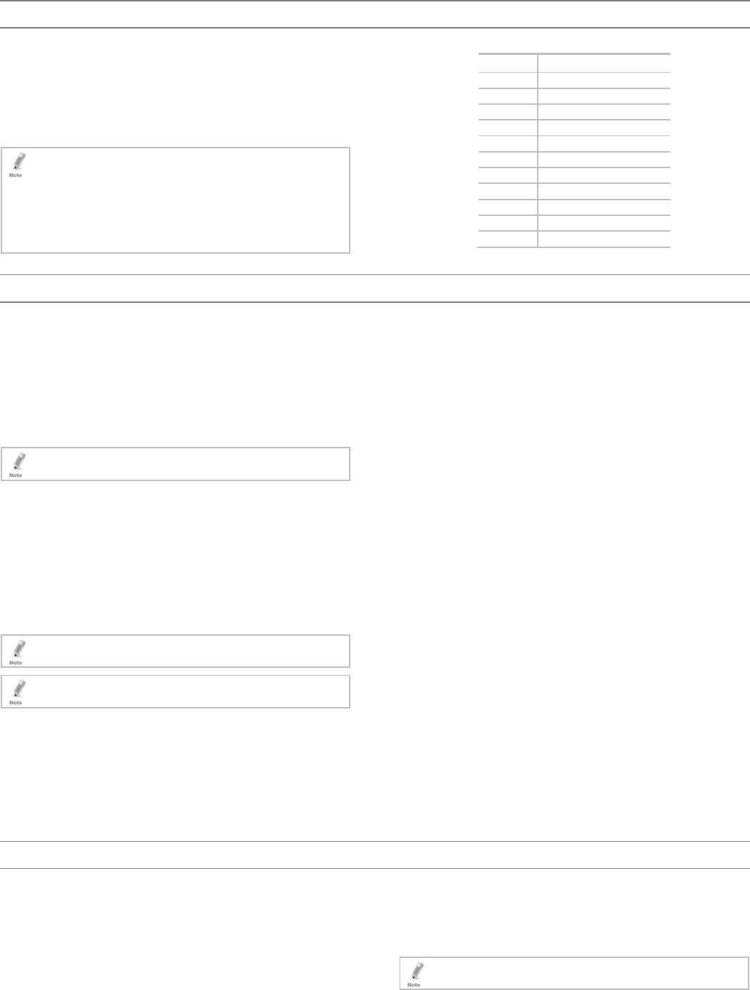
Table 1: Wiring
Color Functionality
Red VIN (7–24 VDC)
Black GND
Dark Green A_Data0
White A_Data1
Orange A_LEDCTL (green LED)
Blue A-OUTPUT (FET, Open Drain)
Light Green B-DATA0
Gray B-DATA1
Brown B_LEDCTL (orange LED)
Yellow B-OUTPUT (FET, Open Drain)
Purple
TAMPER
5. 4BOperation
The AY-L23 works with any SA-23 remote and can operate two
Wiegand data outputs connected to the reader’s inputs at the access
control panel.
5.1 8BReader Mode
When pressing 1 on the SA-23, the AY-L23 sends Wiegand data-A.
The LED changes to green for a short time with a beep.
When pressing 2 on the SA-23, the AY-L23 sends Wiegand data-B. The
LED changes to orange for a short time with a beep.
The AY-L23 LED is red in Operation mode.
5.2 9BController and Reader Mode
The AY-L23 can register up to 48 IDs for an SA-23 remote control and
can operate two OC outputs A/B.
When pressing 1 on the SA-23, the AY-L23 sends Wiegand data-A and
activates out-A for 5 seconds. The LED changes to green for a short
time with a beep.
When pressing 2 on the SA-23, the AY-L23 sends Wiegand data-B and
activates out-B for 5 seconds. The LED changes to orange for a short
time with a beep.
The AY-L23 LED is red in Operation mode.
To activate the relay, the remote button’s ID should be registered
first.
5.3 10BRegistering an ID
To register an ID:
1. Connect the orange and brown wires to GND.
2. Power on at Vin and GND.
After buzzer sounds 3 times, the LED turns green.
The AY-L23 is now in Register mode for 15 seconds.
3. Press 1 on the SA-23 remote.
If the registration is successful, you hear 2 short beeps.
If the ID was previously registered, you hear 2 long beeps.
If the limit of IDs (48) is reached, you hear have 3 long beeps.
4. Press 2 on the SA-23 remote.
If the registration is successful, you hear 2 short beeps.
If the ID was previously registered, you hear 2 long beeps.
If the limit of IDs (48) is reached, you hear have 3 long beeps.
After the time register (10 to 15 seconds), you hear a long beep.
5.4 11BDeleting all IDs
To delete all IDs:
1. Connect the orange wire to GND.
2. Power on at Vin and GND.
After buzzer sounds 3 times, the LED turns orange for 2 seconds
and then turns green.
The AY-L23 is now in Delete mode for 5 seconds.
3. When the LED turns green, disconnect the orange wire from GND.
The LED changes from green to orange.
4. Re-connect the orange wire to GND within 5 seconds.
If all the IDs in reader are deleted successfully, the alarm
sounds 2 times and then you hear 3 short beeps.
If the deletions fails (times out), the reader outputs a long
beep.
6. 5BUsing the SA-23
The AY-L23 G/H is used along with the SA-23 2-button remote control.
The SA-23 remote is programmed to:
Button 1 – Wiegand output to A DATA0/1 with A FET(relay)ON 5S
Button 2 – Wiegand output to B DATA0/1 with B FET(relay)ON 5S
6.1 12BInitial Setup
To set up the remote for use:
1. Install the battery.
The red LED turns on for 1 second, turns off 1 second and then
turns on for 1 second.
2. Check the distance range of the remote:
If the distance is set to long range (70 m), LED flashes on and
off 0.5 seconds 3 times.
If the distance is set to short range (15 m), LED flashes on and
off 0.1 seconds 6 times.
By default, the remote distance is set to 70 m.

3
6.2 Changing the Remote Distance Range
You can set the remote range to either 15 or 70 m.
To set the remote distance:
1. Remove the battery from the remote.
2. Press any button to reset the remote.
Any time you remove the battery from the SA-23, you must reset
the remote control by pressing any key to discharge the internal
capacitors.
3. Install the battery.
4. Press 1 and 2 together before the LED flashes for a second time.
The remote toggles to the other remote distance range.
If the distance is set to long range (70 m), LED flashes on and
off 0.5 seconds 3 times.
If the distance is set to short range (15 m), LED flashes on and
off 0.1 seconds 6 times.
6.3 Changing the ID of Button 2
You can set Button 2 to transmit the same ID as Button 1 or to
transmit a unique ID. By default, Buttons 1 and 2 transmit the same ID
number.
To change the ID of Button 2 to be unique:
1. Remove the battery from the remote.
2. Press any button to reset the remote.
3. Press 2 and install the battery until the red LED flashes quickly 5
times for 0.1 seconds.
2 will now use transmit a unique ID (ID of Button 1 +1)
4. Close the cover.
To change the ID of Button 2 to use ID of Button 1:
1. Remove the battery from the remote.
2. Press any button to reset the remote.
3. Press 1 and install the battery until the red LED flashes quickly 5
times for 0.1 seconds.
Button 2 will now transmit the same ID as Button 1.
4. Close the cover.
Declaration of Conformity
This device complies with Part 15 of the FCC Rules. Operation is
subject to the following two conditions:
This device may not cause harmful interference.
This device must accept any interference received, including
interference that may cause undesired operation.
Changes or modifications not expressly approved by the party
responsible for compliance could void the user's authority to operate
the equipment.
This equipment has been tested and found to comply with the limits
for a Class B digital device, pursuant to part 15 of the FCC Rules. These
limits are designed to provide reasonable protection against harmful
interference in a residential installation.
This equipment generates, uses, and can radiate radio frequency
energy and, if not installed and used in accordance with the
instructions, may cause harmful interference to radio communications.
However, there is no guarantee that interference will not occur in a
particular installation. If this equipment does cause harmful
interference to radio or television reception, which can be determined
by turning the equipment off and on, the user is encouraged to try to
correct the interference by one or more of the following measures:
Reorient or relocate the receiving antenna.
Increase the separation between the equipment and receiver.
Connect the equipment into an outlet on a circuit different from
that to which the receiver is connected.
Consult the dealer or an experienced radio/TV technician for help.

4
Limited Warranty
ROSSLARE ENTERPRISES LIMITED (ROSSLARE) TWO-YEAR LIMITED
WARRANTY is applicable worldwide. This warranty supersedes any
other warranty. ROSSLARE'S TWO-YEAR LIMITED WARRANTY is
subject to the following conditions:
WARRANTY
Warranty of ROSSLARE'S products extends to the original purchaser
(Customer) of the ROSSLARE product and is not transferable.
PRODUCTS COVERED BY THIS WARRANTY AND DURATION
ROSSLARE AND/OR SUBSIDIARIES warrants the AY-L23 G/H Outdoor
Long Range RF Reader and the SA-23 G/H Remote Control to be free
from defects in materials and assembly in the course of normal use and
service. The warranty period commences with the date of shipment to
the original purchaser and extends for a period of 2 years (24 months).
WARRANTY REMEDY COVERAGE
In the event of a breach of warranty, ROSSLARE will credit Customer
with the price of the Product paid by Customer, provided that the
warranty claim is delivered to ROSSLARE by the Customer during the
warranty period in accordance with the terms of this warranty. Unless
otherwise requested by a ROSSLARE representative, return of the failed
product(s) is not immediately required.
If ROSSLARE has not contacted the Customer within a sixty (60) day
holding period following the delivery of the warranty claim, Customer
will not be required to return the failed product(s). All returned
Product(s), as may be requested at ROSSLARE’S sole discretion, shall
become the property of ROSSLARE.
To exercise the warranty, the user must contact ROSSLARE Enterprises
Ltd. to obtain an RMA number after which, the product must be
returned to the Manufacturer freight prepaid and insured.
In the event ROSSLARE chooses to perform a product evaluation within
the sixty (60) day holding period and no defect is found, a minimum
US$ 50.00 or equivalent charge will be applied to each Product for
labor required in the evaluation.
ROSSLARE will repair or replace, at its discretion, any product that
under normal conditions of use and service proves to be defective in
material or workmanship. No charge will be applied for labor or parts
with respect to defects covered by this warranty, provided that the
work is done by ROSSLARE or a ROSSLARE authorized service center.
EXCLUSIONS AND LIMITATIONS
ROSSLARE shall not be responsible or liable for any damage or loss
resulting from the operation or performance of any Product or any
systems in which a Product is incorporated. This warranty shall not
extend to any ancillary equipment not furnished by ROSSLARE, which is
attached to or used in conjunction with a Product, nor to any Product
that is used with any ancillary equipment, which is not furnished by
ROSSLARE.
This warranty does not cover expenses incurred in the transportation,
freight cost to the repair center, removal or reinstallation of the
product, whether or not proven defective.
Specifically excluded from this warranty are any failures resulting from
Customer's improper testing, operation, installation, or damage
resulting from use of the Product in other than its normal and
customary manner, or any maintenance, modification, alteration, or
adjustment or any type of abuse, neglect, accident, misuse, improper
operation, normal wear, defects or damage due to lightning or other
electrical discharge. This warranty does not cover repair or replacement
where normal use has exhausted the life of a part or instrument, or any
modification or abuse of, or tampering with, the Product if Product
disassembled or repaired in such a manner as to adversely affect
performance or prevent adequate inspection and testing to verify any
warranty claim.
ROSSLARE does not warrant the installation, maintenance, or service of
the Product. Service life of the product is dependent upon the care it
receives and the conditions under which it has to operate.
In no event shall ROSSLARE be liable for incidental or consequential
damages.
LIMITED WARRANTY TERMS
THIS WARRANTY SETS FORTH THE FULL EXTENT OF ROSSLARE’S WARRANTY.
THE TERMS OF THIS WARRANTY MAY NOT BE VARIED BY ANY PERSON, WHETHER OR
NOT PURPORTING TO REPRESENT OR ACT ON BEHALF OF ROSSLARE.
THIS LIMITED WARRANTY IS PROVIDED IN LIEU OF ALL OTHER WARRANTIES. ALL
OTHER WARRANTIES EXPRESSED OR IMPLIED, INCLUDING WITHOUT LIMITATION,
IMPLIED WARRANTIES OF MERCHANTABILITY AND FITNESS FOR A PARTICULAR
PURPOSE, ARE SPECIFICALLY EXCLUDED.
IN NO EVENT SHALL ROSSLARE BE LIABLE FOR DAMAGES IN EXCESS OF THE
PURCHASE PRICE OF THE PRODUCT, OR FOR ANY OTHER INCIDENTAL,
CONSEQUENTIAL OR SPECIAL DAMAGES, INCLUDING BUT NOT LIMITED TO LOSS OF
USE, LOSS OF TIME, COMMERCIAL LOSS, INCONVENIENCE, AND LOSS OF PROFITS,
ARISING OUT OF THE INSTALLATION, USE, OR INABILITY TO USE SUCH PRODUCT, TO
THE FULLEST EXTENT THAT ANY SUCH LOSS OR DAMAGE MAY BE DISCLAIMED BY
LAW.
THIS WARRANTY SHALL BECOME NULL AND VOID IN THE EVENT OF A VIOLATION OF
THE PROVISIONS OF THIS LIMITED WARRANTY.
Contact Information
United States and Canada
Rosslare Security Products, Inc.
Southlake, TX, USA
Toll Free: +1-866-632-1101
Local: +1-817-305-0006
Fax: +1-817-305-0069
support.na@rosslaresecurity.com
Europe
Rosslare Israel Ltd.
Rosh HaAyin, Israel
Tel: +972-3-938-6838
Fax: +972-3-938-6830
support.eu@rosslaresecurity.com
Latin America
Rosslare Latin America
Buenos Aires, Argentina
Tel: +54-11-4001-3104
support.la@rosslaresecurity.com
China
Rosslare Electronics (Shenzhen) Ltd.
Shenzhen, China
Tel: +86-755-8610-6842
Fax: +86-755-8610-6101
support.cn@rosslaresecurity.com
Asia Pacific, Middle East, Africa
Rosslare Enterprises Ltd.
Kowloon Bay, Hong Kong
Tel: +852-2795-5630
Fax: +852-2795-1508
support.apac@rosslaresecurity.com
India
Rosslare Electronics India Pvt Ltd.
Tel/Fax: +91-20-40147830
Mobile: +91-9975768824
sales.in@rosslaresecurity.com
www.rosslaresecurity.com
0706-0960503+00