Rosslare SA02G Door / Window detector User Manual Visio SA 02 H Instruction Manual vsd
Rosslare Enterprises Ltd Door / Window detector Visio SA 02 H Instruction Manual vsd
Rosslare >
User Manual
INSTALLATION INSTRUCTIONS
INTRODUCTION (FAQ's)
Q: What is a Magnetic Contact Sensor ?
A: A Magnetic Contact Sensor is a sensor which
detects the opening and closing of doors or
windows protected by the sensor.
Q: What is WIRELESS and how can it benefit me ?
A: Wireless is the use of radio signals to transmit a
signal from any sensor to a security panel,
eliminating the need for setting wire ducts, extra
cabling materials or drilling, saving time and money.
Q: What is SUPERVISOR or SUPERVISED sensor ?
A: A Supervised sensor continuously reports to the
receiver or security panel to confirm status of the
sensor and its presence. If the receiver fails to hear
from a sensor within a pre-programmed time, it
will presume a sensor is missing or malfunctioning
and notify the user. This provides added security.
Q: What is LOW BATT detection ?
A: For all supervised sensors, LOW BATT detection is
when a sensor continuously measures its battery
state and transmits a low battery signal to the
security panel when the battery's voltage drops
below a certain level. This alerts the user in advance
to replace a weak battery.
Q: What is a CASE TAMPER detector?
A: A Case Tamper detector monitors any unauthorized
opening of the unit housing. A signal will be
transmitted to the security panel to notify the user of
such tampering.
Q: What is a BACK TAMPER detector?
A: Once the sensor is mounted and activated, the Back
Tamper detector ensures that the sensor is not
removed or vandalized by detecting any removal of
the unit from a wall or corner. The Back tamper
detector will alert the security panel in such cases.
FEATURES OF SA-02 - Performance
Magnetic Contact Sensor
The SA-02 Supervised Wireless Magnetic Contact
Sensor is a high-performance intrusion sensor
developed with the highest level of technology to make
it ideal for residential and commercial applications.
Following features standard.
Supervisor
Case & Back Tamper Detectors
ASIC and Microprocessor Technology
Up to 3-yr. Battery Life with SPS
Ultra-low Current Consumption
Readily Replaceable 3.6V- 1/2 AA Lithium Battery
SMD Component technology
L.E.D. Test Function
INSTALLATION - Performance Criteria
The SA-02 Magnetic Contact Sensor detects the opening
and closing of doors and windows and transmits this
information to the receiver panel.
- AVOID: Placing the Magnetic Contact Sensor near
strong magnetic or electrical fields other than the
magnet with which it is intended to be used. Otherwise,
performance could be affected and false alarms could
occur.
- AVOID: Mounting on or near large metal surfaces and
multiple concrete/steel walls. This may interfere or block
the wireless signals. Make sure to test the range from
any location by using the RF Test Procedure to ensure
reception.
- IMPORTANT NOTE: Install the Magnetic Contact
Sensor on windows or doors that have firm hinges and
firm locking action to prevent false alarms associated
with wind or bumping.
STEP-1 INSTALLING THE BATTERY (Fig 1)
Use only the specified 3.6 V Lithium Battery.
(See block 22)
1) Unscrew the case locking screw and remove the front
cover. CAUTION Do not touch the magnetic element
or the electronic components inside as this may
cause damage.
2) For a new unit, simply remove the plastic strip
contact breaker. For replacement, remove the battery
by using a small screwdriver. CAUTION: Notice
the polarity. Replace with a fresh battery.
3) Dispose of the old battery properly. Do not
incinerate, heat, disassemble, recharge.
4) To test, press in both the back-tamper and the case-
tamper buttons, or use a magnet to simulate a door
opening and closing. The LED will light to indicate
an RF transmission.
5) Close the front cover and replace the locking screw
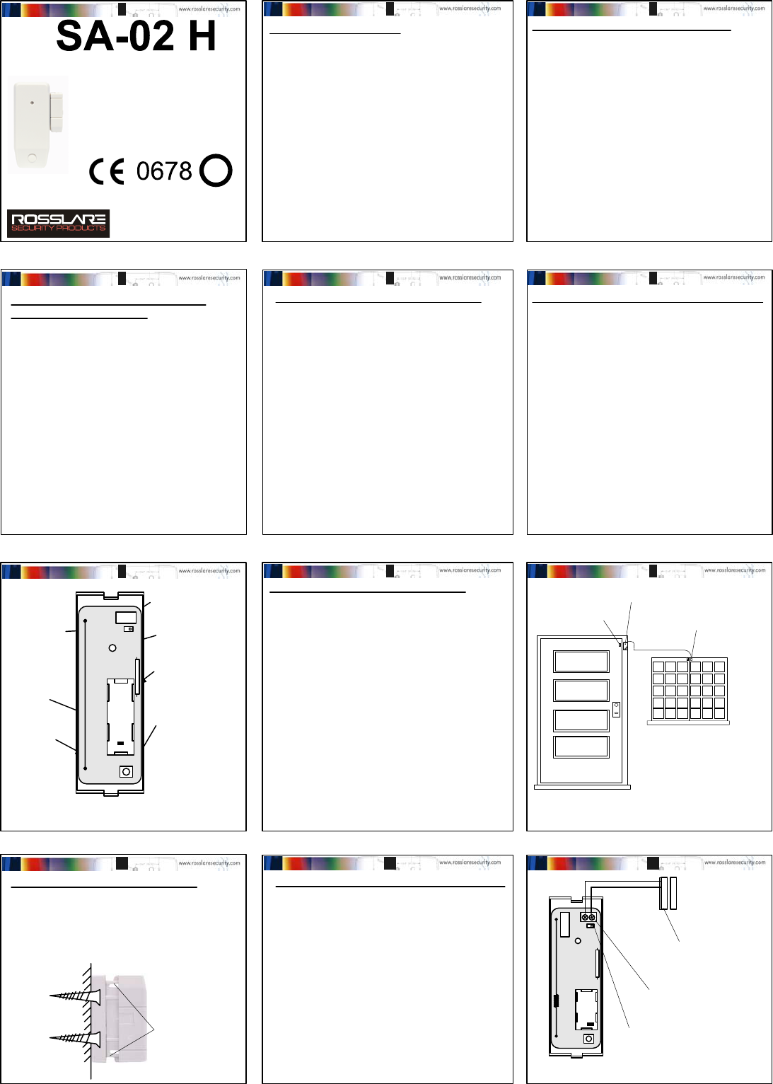
FIG 1: Front of PCB
FRONT OF PCB
BATTERY
HOLDER
TERMINAL BLOCK FOR
WIRED CONTACTS
ANTENNA
RF TRANSMISSION
INDICATION LED
CASE TAMPER
BUTTON
(NORMALLY CLOSED)
MAGNETIC CONTACT
INTERNAL SENSOR
JUMPER FOR
EXTERNAL
SENSOR
STEP-2 SELECTING THE LOCATION
The location and mounting of the SA-02 affects both the
transmission range and wear and tear of the transmitter.
Preferably the transmitter should be installed as close
as possible to the receiver and mounted in a high
location so that the transmission will have less
interference.
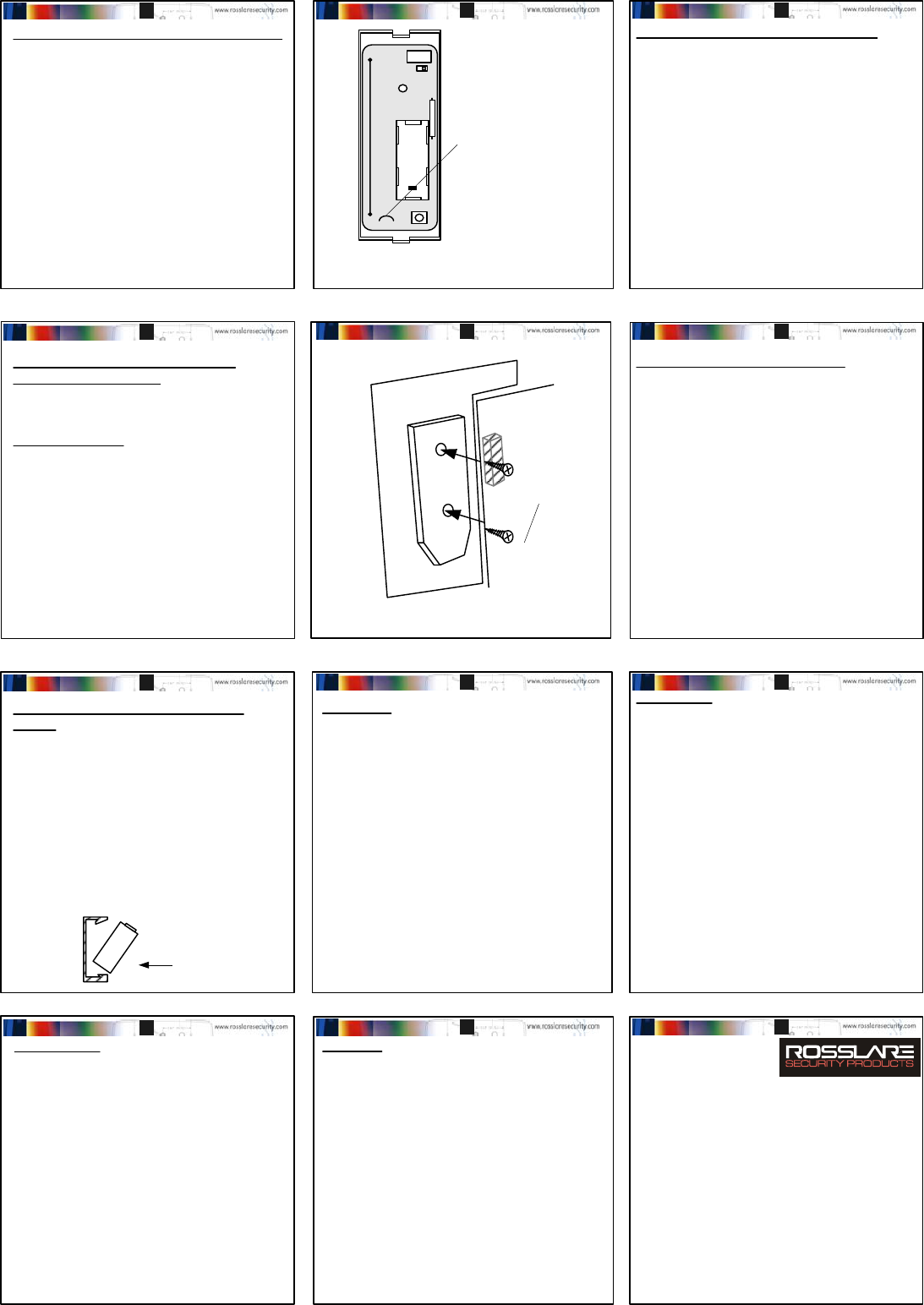
1) Select a DOOR OR WINDOW within a room or hallway
that best matches the criteria in section 5. (Fig 2):
2) Make sure that the Magnetic Contact Sensor will be
mounted on a sturdy, non-vibrating door or
window frame. Note: Following this instruction will
reduce bumping and vibration effects on the
sensor, and will extend the life of the product.
3) Perform the RF Test from the proposed mounting
location to ensure that the sensor can be received.
4) Select the appropriate height for the magnet
assembly that will suit the location of the sensor.
STEP- 4 WIRING THE EXTERNAL SENSOR
When the internal magnetic sensor in the SA-02 is not
applicable, or an additional set of contacts are needed
for the SA-01, the following procedure is required:
The maximum distance that an external contact can be
away from the SA-02 is about 8.5 meters or 25 feet.
1) This step is not necessary unless installing a remote
external magnetic contact sensor with a wire to the
SA-02.
2) Remove the case locking screw and front cover.
3) Connect the external magnet(s) in series to the wired
input terminal block of the magnetic contact sensor.
4) Move the jumper cover to the two right-most pins to
activate the external magnetic contact input.
5) Replace the front cover and locking screw.
Please see FIG 4. FIG 4: Wiring an External Sensor
+
Wired External Magnetic
Contact.
Terminal Block
for External Magnetic
Contact.
Jumper for activating the
external contacts.
STEP-3 SELECT MAGNET HEIGHT
The SA-02 comes equipped with a standard magnet with
adjustable height, suitable for most applications When
there is a special need, select the appropriate height for
the magnet assembly that will suit the location of the
sensor. (FIG 3)
To adjust for a
possible mismatch in
height, between the
door and the frame,
the magnet part has a
mechanism to adjust
it's height. Simply
press on the sides
and adjust the
height.
Mount the Magnet
onto the door
Connect additional
external contacts
by wire to the
SA-02
FIG 2: Selecting a Location
FIG 3: Magnet
Mount the SA-02
onto the stationary
door-frame
12 3
Supervised Wireless Magnetic
Contact Sensor
AND IMPORTANT INFORMATION
9J-REL-001/0706-0670001-00
P/N:
This product may be sold in the following
member states of the European Community:
Austria Germany Norway
Belgium Greece Portugal
Denmark Holland Spain
Finland Ireland Sweden
France Italy United Kingdom
!
45 6
78 9
10 11 12
+
INTRODUCTION (FAQ's) - continued;
SA-02 Instruction Manual - Version 1.0 (Page 1/2)
STEP-6 RADIO TRANSMISSION TEST
This test is used to check the range and the reception of
the sensor to the control panel receiver. If reception is
poor, try to change the location of the Magnetic Contact
Sensor.
1) Ensure that all the settings of the Magnetic Contact
Sensor are adjusted as necessary for the location
according to STEPS 1 to 5, and that the Magnetic
Contact Sensor case is closed, with the locking
screw firmly secured.
2) Hold the sensor close as possible to the
mounting location, and transmit using the magnet.
3) During this mode, each time the LED flashes, the
sensor transmits to the panel. If the panel is armed,
this will cause an alarm. If the panel is in test mode,
then the signal strength can be measured.
4) It is recommended to try several locations until the
best reception is attained.
STEP-7 MOUNTING THE Magnetic
Contact Sensor (FIG 6)
The SA-02 Magnetic Contact Sensor is designed to be
Mounted onto a flat wooden or stucco surface.
Flat Surface Mounting:
1) Remove the PCB from the back case.
1) Remove the knockouts from the back case labeled B
by using a sharp tool or using a nail.
2) Affix the two screws onto the wall, so that the Back
Tamper arm is pressed in.
3) Replace the PCB and tighten the PCB locking screw.
4) Replace the top cover of the Magnetic Contact
Sensor.
Important: When mounting the SA-02 to the surface, it
is important to see that the surface is flush with the back
tamper device.
SPECIFICATIONS
Battery:
Lithium Primary cell.
3.6-volt Lithium 900 mAh
Tadiran / Varta / Tekcell (SB-AA-02)
1/2 AA Size. (Low Battery Signal when V-2.5V)
CAUTION! Dispose of Properly, do not re-charge,
disassemble, heat or incinerate.
Pulse Count: Fixed at single pulse.
Detect Range: Sensitivity of up to 2 cm from magnet.
Operating Temp: - 20oC to +50oC
- 4oF to + 122oF
Operating Humidity: Up to 95% Non-Condensing (max.)
Alarm Transmit: 1 second.
RF Frequency: Available in 433.92 or 868.35 MHz, with 1m Watt
Installation: Indoor
Magnet: Standard magnet with plastic housing and wall spacer,
adjustable height.
Tamper Switch 1: Removal of Magnetic Contact Sensor Front Cover (Protected
by case tamper switch)
Tamper Switch 2: Removal of Magnetic Contact Sensor from the wall or from
corner mount (protected by rear tamper switch)
Supervisor: The supervisory signal is routinely transmitted to the panels
every 20 minutes, advising the Tamper Status,
Battery Status, Event Activation Status to the panel.
Current: Standby - 23uA
Transmit - 5 mA
Size: 87mm (h) x 35mm (w) x 25 mm (d)
(3.5 " x 1 3/8 " x 1 ")
Weight: 37 grams ( 1.30 oz) without battery.
WARRANTY
The Manufacturer's warranty on this product is for a period of one year from the date
of purchase against defects in materials and workmanship. Manufacturer's warranty
hereunder is limited to repair or replacement, at the manufacturer's sole option, if the
product is found to be defective in normal use during the warranty period. The
warranty is given in favour of the original purchase only. Subject to the above
warranty, manufacturer's liability and that of it's distributors, re-sellers and agents and
is wholly limited to the original purchase price and no payment will be made for
related or consequential loss including but not limited to labour costs incurred in
inspection, replacement or repair of defective products. This warranty is given
expressly and in place of all other expressed or implied warranties of merchantibility
and fitness for a particular purpose and this warranty is the only warranty made by the
manufacturer. No agent, representatives or employee of the manufacturer has the
authority to waive, alter or add to the printed provisions of this warranty, to make
representation of warranty not contained herein or to extend this warranty to anyone
other than the original purchaser of the product. The SA-02 Magnetic Contact Sensor
is guaranteed against defects in workmanship and material for a period of 12 (Twelve)
months from date of purchase. Return the faulty product with a dated proof of
purchase to your dealer for replacement.
NOTICE
The SA-02 Magnetic Contact Sensor is designed to send an electronic signal to alarm
control system, should intrusion occur, the warranty does not make the manufacturer
or the distributor of the SA-02 Magnetic Contact Sensor held liable for consequential
damages resulting from any breech of warranty, expressed or implied, applicable to
their use.
FIG 5: Activation of the Back Tamper
STEP-5 ACTIVATING THE BACK TAMPER
Each Magnetic Contact Sensor SA-02 is equipped with
both a Back and Case Tamper detector. The case tamper
detector is always active, however the wall tamper
detector (normally inactive) is optionally activated by
cutting a Jumper.
For additional protection against the theft or removal of
the sensor from the mounting location, the back tamper
can be activated to work in unison with case tamper by
cutting the jumper R18 which is on the top side of the
PCB.
1) Remove the case locking screw and front cover.
Look at the front of the PCB with the antenna
showing (FIG 5)
2) To activate the back tamper switch, locate and cut
the jumper
3) Replace the front cover and locking screw. The Back
tamper will be active.
FIG 6: Mounting the SA-02
Affix the
back case
to the wall
firmly with
two screws
STEP-8 Post-Installation Testing
After mounting the back of the sensor housing to the
window or door frame, it is important to check the
reliability of the RF transmission to the receiver or
security panel.
Perform a range test as indicated in STEP 6.
If the sensor is used with a receiver, check to see that
the receiver is receiving the sensor.
It is suggested that you arm the system and test that the
SA-02 transmits to the desired control panel.
Important: If the back tamper has been activated in
previous steps, check the security panel to ensure that
there is no tamper signal, and that the sensor is properly
installed.
STEP-9 Replacing the Battery in the
SA-02.
Batteries in the SA-02 should be replaced following a
Low Battery indication on the receiver or security panel.
PLEASE: Dispose of the old battery properly, do not re-
charge, disassemble, heat or incinerate.
1) Open the SA-02 sensor, and observe the correct
polarity labeled on the PCB and the holder.
2) Remove the old battery and dispose of it properly.
3) Insert the new battery (Model numbers shown in
specifications below)
+
-
3.6 -volt Lithium 900 mAh
Lithium Primary cell.
3.6-volt Lithium 900 mAh
Tadiran / Varta / Tekcell (SB-AA-02)
1/2 AA Size.
Insert the NEGATIVE ( - )
side of battery first.
CE Notice:
The model SA-02 Wireless Magnetic Contact Sensor
generates and uses radio frequency energy. If not
installed in accordance with the manufacturer's
instructions it may cause interference.
If this equipment causes interference to radio or
television reception-which can be determined by turning
the equipment on and off - the installer is encouraged to
correct the interference by one or more of the following
measures: 1) Reorient the antenna of the radio/
television, 2) Connect the AC transformer to a different
outlet so the control panel or television are on different
branch circuits, 3) Relocate the control panel with
respect to the radio/television.
This device complies with the applicable ETSI/CE rules.
Operation is subject to the following two conditions :
1) This device nay not cause harmful interference, and 2)
this device must accept any interference received,
including interference that may cause undesired
operation.
Important !:
Rosslare radio control panels provide a reliable
communications link and fill an important need in
portable wireless signalling. However, there are some
limitations that must be observed.
For US installations only: The radios are required
to comply with FCC rules and regulations as part
15 devices. As such they have a limited
transmitter power and therefore limited range.
A receiver cannot respond to more than one
transmitted signal at a time and may be blocked
by two simultaneous signals that occur near their
operating frequencies, regardless of the individual
sensor code.
Any changes to this circuit or device may void
FCC compliance.
Infrequently used radio links should be tested
regularly to protect against unintended
interference or fault.
A general knowledge of radio and it's properties
should be gained prior to acting as a wholesale
distributor or dealer, and these facts should be
communicated to the ultimate users.
13 14 15
Door
Frame
B
B
16 17 18
19 20 21
22 23 24
+Jumper wire for activating the
back tamper switch.
Cut the jumper R-18 to activate
the back tamper.
R-18
INTERNATIONAL OFFICES
U.S.A.: Rosslare America Inc.
Westlake, Los Angeles, CA 91632 U.S.A
Tel: (818) 707 2974 Fax: (818) 7070543
Rosslare America Inc.
2001 Reliance, Packway, Suite D
Bedford, Texas 76021 U.S.A
Tel: (817) 685 9100 Fax: (817) 685 9188
Rosslare Powerpath NAPDC.
North America Product Development
22e. Howard St, # 238 Des Plaines, IL60018, U.S.A
Tel: (847) 827 6330 Fax: (847) 8276433
ISRAEL Rosslare Israel Ltd (Center Office)
22 Hamelacha St, PO BOX 11407, Rosh Ha-Ayin, 48091,
Hong Kong: Rosslare Enterprises Ltd.
905-912 Wing Fat Industrial Building
12 Wang Tai Road, Kowloon Bay,
Hong Kong. Tel (852) 2795 5630 Tel (852) 2795 1508
www.rosslaresecurity.com
SA-02 Instruction Manual - Version 1.0 (Page 2/2)