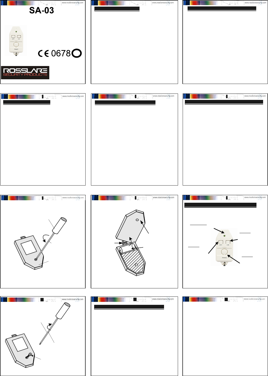
Rosslare SA03G Remote Control 3 Buttons User Manual
Rosslare Enterprises Ltd Remote Control 3 Buttons
Rosslare >
User Manual
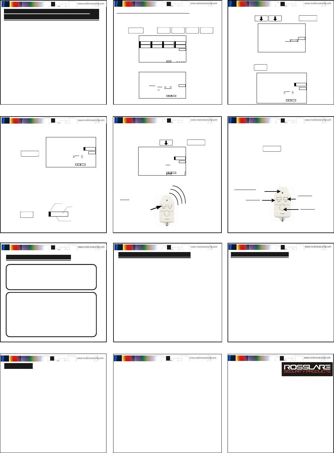
Function:
Disarm Button
for the Security
Panels or Single
Channel
Transmitter
Function:
ARM Button for
the Security
Panels or
Single Channel
Transmitter
LED Function:
LED will flash
when the SA-03 is
transmitting
Function:
Emergency Panic
Button for the
Security Panels or
Single Channel
Transmitter
3-Button Remote Control Transmitter
Q: What is a Transmitter ?
A: A transmitter is an electronic device that uses RF
energy and coded digital messages to control and
communicate commands to other electronic
products.
Q: What is SA-03 WIRELESS REMOTE and how can it
benefit me ?
A: SA-03 allows the user ARM and DISARM a
Security Panel, Access Control Reader, or even turn
on and off the lights and appliances using a
Universal Receiver by the use of RF signal.
Q: What is SUPERVISOR or SUPERVISED sensor ?
A: A Supervised sensor continuously reports to the
receiver or security panel to confirm status of the
sensor and its presence. If the receiver fails to hear
from a sensor within a pre-programmed time, it will
presume a sensor is missing or malfunctioning and
notify the user. This provides added security.
INTRODUCTION (FAQ's) - continued;
OPERATION - GENERAL NOTES
Use only the specified 12 Volt Alkaline Battery.
(Duracell MN-21 or Golden Power GP-23A)
1) Unscrew the case locking screw and remove the
back cover (FIG 1).
2) For a new unit, simply remove the plastic strip
contact breaker. For replacement, remove the battery
by using a small screwdriver (FIG 2).
CAUTION: Notice the polarity of the battery (+) and (-)
must coincide with the markings (+) and (-) on the
plastic and the PCB. Check that the battery is held
securely.
3) Dispose of the old battery properly.
Do not incinerate, heat, disassemble, recharge.
4) To test, press the buttons on the remote control and
see if there is a transmission. The LED will light to
indicate an RF transmission (FIG 3).
5) Close the front cover, by engaging the ridges of the
top case and bottom case near the keychain eye
hole, align and gently press together both covers and
replace the locking screw.
FIG 1: Back of the SA-03 Housing
The SA-03 is a miniature radio transmitter, designed to
send coded RF transmissions to wireless receivers and
control panels. The transmissions are activated by
depressing one of the three pushbuttons on the unit.
The SA-03 can control up to 4 functions when used
with Rosslare’s Wireless Security Control Panels or
Universal RF Receivers. The SA-03 is a battery
operated wireless device using a standard 12 Volt
Alkaline battery. An LED (Light Emitting Diode) lights
during the transmission of the RF signal. Which lights
when the battery voltage exceeds 8 VDC. If the LED
does not light during the transmission, the battery
must be replaced immediately.
SA-03 is a high quality wireless sensor packed with
intelligent wireless and system features such as
compatibility with RF Repeaters. Inside the SA-03 is a
state of the art microprocessor, with ASK RF
transmitter technology, and is encoded with 16 million
factory programmed non-recurring ID codes ensuring
that multiple units can be used on a single system.
Use a small Philips head
screwdriver to remove the screw
on the back of the SA-03
To remove the screw
use an anticlockwise
motion.
After Removing the
screw, remove the
back case and
activate or install the
battery.
PCB
Batt This is the 12 Volt Battery
After Removing the
screw, remove the
back case and
activate or install the
battery.
FIG 2: Replacing the 12 Volt Battery
After activating or replacing the battery in the SA-03,
test the transmitter by pressing each one of the three
buttons to see if there is a transmission.
When pushing one of the transmit buttons, the LED will
flash to indicate a transmission.
FIG 3: Testing the Buttons
Fig 4: Back of the SA-03 Cover
Step 3: ENROLLING TO A RECEIVER
The installation procedure for using the SA-03 remote
control varies from product to product.
Full instructions are printed within the installation
manual each of the receiver panels or controls.
For this instruction manual, the instructions cover only
the SP-06 V Wireless Security Control Panel in 433.92 or
868.35 MHz;
The following pages show the simplified enrollment
procedures for enrolling SA-03 transmitters to
Rosslare’s SP-06 V panel. For full details about the
Wireless Control Panel, please refer to the SP-06 V
Installation and Programming Manual.
AND IMPORTANT INFORMATION
INSTALLATION INSTRUCTIONS
P/N:
To close the
housing,
carefully
Engage the top
and bottom
case by
hooking the
keychain hole
together.
Slowly bring
the top case
and bottom
case together.
Use a small Philips
head screwdriver to
close the SA-03 with
the screw .
Use a clockwise
motion to close the
screw so that it is
snug.
After installing the
battery and testing
the SA-03, close the
case and fasten with
the screw.
9J-REL-001/0706-0670001-00
!
GENERAL DESCRIPTION
INTRODUCTION (FAQ's)
Q: What is LOW BATTERY detection ?
A: For all supervised sensors, LOW BATTERY
detection is when a sensor continuously measures
its battery state and transmits a low battery signal
to the security panel when the battery's voltage
drops below a certain level. This alerts the user in
advance to replace a weak battery.
Q: What is a CASE TAMPER detector?
A: A Case Tamper detector monitors any unauthorized
opening of the unit housing. A signal will be
transmitted to the security panel to notify the user
of such tampering.
Q: What is a BACK TAMPER detector ?
A: Once the sensor is mounted and activated, the Back
Tamper detector ensures that the sensor is not
removed or vandalized by detecting any removal of
the unit from a wall or corner. The Back tamper
detector will alert the security panel in such cases.
The SA-03 remote control is activated by pressing the
buttons on the unit and transmits this information to the
receiver panel.
Since the SA-03 is a portable wireless device and
system reception is dependent upon the conditions of
use as follows:
- AVOID: Placing the SA-03 near strong magnetic or
electrical fields other than the magnet with which it is
intended to be used. Otherwise, performance could be
affected and false alarms could occur.
- AVOID: Using near or behind large metal surfaces and
multiple concrete/steel walls. This may interfere or
block the wireless signals. Make sure to test the range
from the desired location by using the RF Test
Procedure to ensure reception.
- IMPORTANT NOTE: When the battery power has been
depleted, as indicated by a very dim LED, replace the
battery immediately.
STEP-1 BATTERY INSTALLATION (Fig1,2)
STEP-2 TESTING THE TRANSMISSION
The SA-03 in 433.92 or 868.35 MHz frequency is
compatible with a variety of Rosslare's security panels,
universal receiver controls, and system components.
SP-06 V Wireless Security Control Panel,
SA-22 Dual Channel Receiver,
SA-38 Channel Receiver,
AY-L23 Wireless Receiving Wiegand 26, Reader
SA-29 Wireless Repeater with UPS - System Level
and others...
For an updated list please contact your distributor,
dealer or agent.
12 3
45 6
78 9
10 11 12
SA-03 Instruction Manual - Version 1.0 (Page 1/2)
The SA-03 in 433.92 or 868.35 MHz, is compatible with
receivers from Rosslare, including the SP-06 V wireless
security control panel. This is a short enrolling tutorial
for the SP-06 V Panel.
The SA-03 can be installed by enrollment to ZONE 8 of
the SP-06V Panel. Zone 8 can accommodate up to 8
(eight) handheld Remote controls or RF keyboard
transmitters.
SA-03 Remote Control enrolls to any one of the eight
addresses in Zone 8 of the SP-06V Wireless Security
control panel.
When installed onto the SP-06 V panel, the SA-03 will
have one ARM/ PARTIAL ARM, one DISARM and one
PANIC button, active for 24 hours from any mode of the
SP-06V.
Enrolling the SA-03 to Zone 8 of SP-06 V:
1) Using the installer pass code (8888) by pressing the
MENU button and entering the code on the keyboard,
enter the Installer Menu.
You will then enter the installer programming menu
for the SP-06 V control panel
SILENT
PANIC
8
ON
Z
E
Zone
Number
Remote ControlType Display
PANIC = Audiable Pani
c
SILENT = Silent Duress Alarm
Zone Box Status Display
ZONE
= Zone is armed
ZONE
(flashing)= Zone was triggered
LCD Example of ZONE BOX Display
432
5 6 7 8
1
OFFMENU
ESC
SET
INSTALL CODE
MASTER CODE
ZONE
PANIC
MENU
ESC
ENTER
SUPERVISION
MASTER COD E
USER CODE
SET OUTPUT
SIREN TIME
EXIT DELAY
CLOCK
SYSTEM
TEST
PARTIAL
OFF
MODE
SET SIREN
SILENT PANIC
A
CTIVATE
CHIME
CODE
ENTRY DELAY
CLEAR R/ F
A
DD R/F
SET ZONE
TELEPHONE
ZONE
MENU
ESC
NUMBER
ENTRY DELAY
CLEAR R/F
ADD R/F
SET ZONE
ZONE
MENU
ESC
ENTER
ADD R/F
SET ZONE
ZONE
PANIC
8ZONE
CLEAR R/F
Battery: 12-Volt Alkaline Battery /
Use only the specified 12 Volt Alkaline Battery.
(Duracell MN-21 or Golden Power GP-23A) or equivalent.
Operating Temp: -10
oC to +50oC
[14oF to + 122oF]
Operating
Humidity: Up to 95% Non-Condensing (max.)
Alarm Transmit: 500 ms (milliseconds)
RF Frequency: Available in 433.92 or 868.35 MHz
Usage: Carried in pocket, worn as a pendant, for indoor (dry) use only.
Tamper: The SA-03 has no tamper transmission.
Supervisor: The SA-03 is not a supervised transmitter.
Current: Standby - 0 A
Transmit - 17 mA
Size: 76mm (h) x 37mm (w) x 14.5 mm (d)
(3 " x 1.5 " x 0.57 ")
Weight: 28.2 grams including battery.
Color: White
The Manufacturer does not represent that its Product may not be compromised and/or
circumvented, or that the Product will prevent any death, personal and/or bodily injury and/or
damage to property resulting from burglary, robbery, fire or otherwise, or that the Product will
in all case provide adequate warning or protection. User understands that a properly
installed and maintained alarm may only reduce the risks of events such as burglary, robbery
and fire without warning, but is no assurance or a guarantee that such will not occur or that
there will be no death, personal damage and/or damage to property as a result.
The Manufacturer shall have no liability for any death, personal and/or bodily injury
and/or damage to property or other loss whether direct, indirect, incidental,
consequential or otherwise, based on a claim that the Product failed to function.
However, if the Manufacturer is held liable, weather directly or indirectly, for any loss of
damage arising under this limited warranty or otherwise, the Manufacturer’s maximum
liability shall not in any case exceed the purchase price of the Product, which shall be fixed
as liquidated damages and not as a penalty, and shall be the complete and exclusive remedy
against the Manufacturer.
Warning: The user should follow the installation and operation instructions and among other
things test the Product and the whole system at least once a week. For various reasons,
including, but not limited to, changes in environmental conditions, electric or electronic
disruptions and tampering, the Product may not perform as expected. The user is advised to
take all necessary precautions for his/her safety and the protection of his/her property.
&
MENUMENU
88
2) In the INSTALLER MENU, press the down arrow to
select the ZONE menu and press Enter
3) In the ZONE menu, when prompted for the zone
number, press the number 8 to select Zone 8.
&
88 88 88
4) To program operation of the Panic Button Use the
down arrow to select SET ZONE option and Press
Enter.
5) Press the SET key until the zone type shows “PANIC”,
for an audible emergency alarm, to enable the SA-03
to perform a non audible alarm, scroll to “SILENT
PANIC”. Press ENTER to enable your selection of
either PANIC to sound or not to sound an ALARM at
the panel, if the alarm is transmitted from the SA-03
Remote Control.
6) Within the zone 8 menu, use the arrow key to select
ADD RF and press enter, use the arrow key to select
the desired available slots from 8.1 to 8.8, and
press ENTER.
7) When Prompted for RADIO, press any pushbuttons
on the SA-03 to transmit,
MENU
ESC
ENTER
ADD R/F
SET ZONE
ZONE
PANIC
8ZONE
CLEAR R/F
&
ENTERENTER
&
&
88
SETSET
&
ENTERENTER
&
MENU
ESC
ENTER
SET
ADD R/F
ZONE
8
ONZE
PANIC
&
&
ENTERENTER
8) When the control panel receives the coded signal
from the SP-03 V there will be a been and an
indication to press enter on the LCD. Press the
ENTER button on the panel’s keyboard.
9) Once the SA-03 is enrolled onto the SP-06 V control
panel, the remote control may be used to perform 4
Functions, such as ARMING (Full Away Arming all
Zones), PARTIAL ARMING (Part Zones Arming for
Stay), DISARMING, and EMERGENCY PANIC.
Press:
DISARM Button or
any other button to
generate an RF
transmission to
enroll the SA-03 to
the Control Panel.
&
ENTERENTER
Function:
DISARM (Short Press)
Function:
ARM (Short Press)
PARTIAL ARM (Long
Press)
LED Function:
LED will flash when the
SA-03 is transmitting
Function:
PANIC (2 second Press)
! Warning !
Changes or modifications to this equipment not
expressly approved by the party responsible for
compliance (Rosslare Enterprises Ltd.) could void
the user's authority to operate the equipment.
Our wireless systems are very reliable and are tested to
high standards. However, due to their low transmitting
power (required by international standards imitations)
there may be some limitations to be considered:
A. Receivers may be blocked by radio signals occurring
on or near their operating frequencies, regardless of
the ID.
B. A receiver can respond to one transmitted signal at a
time
C. Wireless equipment should be tested regularly (At
least once a week) to determine if there are sources
of interference and protect against faults.
MISCELLANEOUS COMMENTS SA-03 SPECIFICATIONS
Rosslare Enterprises Ltd. And/or its subsidiaries and its affiliates (“the Manufacturer”)
warrants it’s products hereinafter referred to “the Product” or “Products” to be in conformance
with it’s own plans and specifications and to be free of defects in materials and workmanship
under the normal use and service for a period of twelve months from the date of shipment by
the Manufacturer. The Manufacturer’s obligations shall be limited within the warrantee
period at its option to repair or replace the product or any part thereof. The manufacturer
shall not be responsible for dismantling and/or reinstallation charges. To exercise the
warranty the product must be returned to the Manufacturer freight prepaid and insured.
This Warranty does not apply in the following cases: improper installation, misuse,
failure to follow installation and operating instructions, alteration, abuse, accident or
tampering, and repair done by anyone other than the Manufacturer.
This warranty is exclusive and expressly in lieu of al other warranties, obligations or liabilities,
weather written, oral, express or implied, including warranty of merchantability or fitness for a
particular purpose, or otherwise. In no case shall the Manufacturer be liable for any
consequential damages for breach of this warranty or any other warranties whatsoever, as
aforesaid.
This warranty shall not be modified, varied or extended, and the Manufacturer does not
authorize any person to act on it’s behalf in the modification, variation or extension of this
warranty. This warranty shall apply to the Product only. All products, accessories or
attachments of others used in compilation with this product, including batteries, shall be
covered solely by their own warranty, if any. The manufacturer shall not be liable for any
damage or loss whatsoever, weather directly, indirectly, incidentally, consequentially or
otherwise, caused by malfunction of the Product due to products, accessories, or
attachments of others, including batteries, used in conjunction with the Products.
STANDARDS COMPLIANCE
European Standards Compliance:
Meets the requirements of the Harmonized
European Standards for CE Mark.
ETS 301 459
ETS 300 220
Step 4: INSTALLING TO THE SP-06 V
WIRELESS SECURITY CONTROL PANEL
12 14 15
16 17 18
19 20 21
WARRANTY
22 23 24
SA-03 Instruction Manual - Version 1.0 (Page 2/2)
TECHNICAL SUPPORT
U.S.A.: Rosslare Powerpath NAPDC.
North America Product Development
22e. Howard St, # 238 Des Plaines, IL 60018, USA
Tel: (847) 827 6330 Fax: (847) 8276433
Europe: Rosslare Israel Ltd (Center Office)
22 Hamelacha St, PO BOX 11407, Rosh Ha-Ayin, 48091, Israel
Tel (972) 3-938-6838 Fax: (972) 3-938-6830
APAC/ Rosslare Enterprises Ltd.
Middle East: 905-912 Wing Fat Industrial Building
12 Wang Tai Road, Kowloon Bay, Hong Kong.
Tel: (852) 2795 5630 Fax: (852) 2795 1508
E-mail: support@rosslaresecurity.com
www.rosslaresecurity.com