Rothenbuhler Engineering 1668-1 Remote Firing Device User Manual 87887
Rothenbuhler Engineering Company Inc Remote Firing Device 87887
USER MANUAL
REMOTE FIRING DEVICE
OPERATOR'S MANUAL
(DRAFT 10/25/99)
The information contained in this document is subject to change
without notice. In no event shall Rothenbuhler Engineering
Company be liable for errors contained herein or for special,
indirect, or consequential damages or injuries of any nature
resulting from use of information in this document.
ROTHENBUHLER ENGINEERING
P.0. BOX 708
2191 RHODES ROAD
SEDRO WOOLLEY, WA 98284
1668-A16
10/25/99
©1999 Rothenbuhler Engineering
All Rights reserved
RFD OPERATOR MANUAL ii
SPECIAL NOTICE
WARNING TO USERS AND AFFECTED PERSONS
The Remote Firing Device (RFD) is designed to be used in blasting operations.
Explosives used in connection with the RFD may be extremely powerful. Improper use
of explosives with or without the RFD or improper safety precautions taken with respect
to personnel or property may result in death, serious personal injury, or property
damage. Other manufacturers’ equipment that may not be in compliance with
frequency coordination may inadvertently interfere with the operation of the RFD. Be
aware of other operations within the receiving range of the RFD.
The literature accompanying this warning contains information of a general nature for
users of the RFD based upon the Manufacturer’s experience in the design and
manufacture of remote radio frequency devices. In addition, the Manufacturer provides
product literature and technical data sheets periodically which should be consulted for
detailed information on the characteristics, specifications and recommendations for the
RFD. The Manufacturer does not purport to give information or advice on explosives or
their use.
The RFD and related explosive devices are intended for use only by trained
professionals having comprehensive knowledge of the RFD, the explosives being used,
and the application together with all related safety precautions. The Manufacturer of the
RFD is responsible only for the proper performance of the RFD itself and is not
responsible for the performance, safety, or specifications of the explosive used, nor the
suitability of the RFD for any particular purpose other than that expressly described in
the Manufacturer’s literature.
LIMITED WARRANTY
Manufacturer warrants the Model 1668 Remote Firing Device (RFD) to be free of
defects in workmanship or materials for the period of one year from the date of
purchase. In the event any RFD or component thereof is shown to be defective in
workmanship or materials within one year, the system or component will be repaired or
replaced without charge by Manufacturer at Manufacturer’s place of business.
This warranty does not cover damage or injury to equipment resulting from abuse,
neglect, or use in applications other than expressly described by Manufacturer as fit
purposes for the RFD.
This Limited Warranty is given in lieu of all other legal warranties express or implied and
neither Manufacturer nor its representatives shall be liable for any direct, incidental or
consequential loss or damages arising out of any occurrence or accident involving the
use of this product.
RFD OPERATOR MANUAL iii
FCC NOTICE
This device complies with Part 15 of the FCC regulations. Operation is subject to the
following two conditions: (1) That this device may not cause harmful interference, and
(2) this device must accept any interference received, including interference that may
cause undesired operation.
RFD OPERATOR MANUAL iv
TABLE OF CONTENTS
Chapter Page
Special Notice.............................................................................................ii
Warning to Users and Affected Persons .....................................................ii
Limited Warranty ........................................................................................ii
FCC Notice................................................................................................iii
Table of Contents ......................................................................................iv
List of Illustrations..................................................................................... vii
Safety Summary...................................................................................... viii
1. Introduction. ....................................................................................... 1-1
1.1. Purpose. ........................................................................................................1-1
1.2.Explosives Handling Practices. .......................................................................1-1
1.3.Storage and Environmental Conditions. ..........................................................1-1
1.4. Packaging......................................................................................................1-2
1.5. Maintenance. .................................................................................................1-4
2. Introduction to RFD System Components. ......................................... 2-5
2.1. System...........................................................................................................2-5
2.2.Controller Unit. ...............................................................................................2-7
2.3.Controller Unit Switch Operation. ....................................................................2-8
2.4.Controller Unit Display Operation..................................................................2-10
2.5.Detonator Unit..............................................................................................2-12
2.6.Battery Charger Assembly............................................................................2-13
2.7.Antenna Assembly. ......................................................................................2-14
2.8.Carrying Case. .............................................................................................2-15
2.9.Vent operation..............................................................................................2-16
2.10. Antenna / Battery Charger Connector........................................................2-17
2.11. Connector Dust Cover Operation...............................................................2-19
RFD OPERATOR MANUAL v
3. System Specifications. ..................................................................... 3-20
3.1. Radio. ..........................................................................................................3-20
3.2. Physical. ......................................................................................................3-21
3.3. Battery. ........................................................................................................3-21
3.4. Timing..........................................................................................................3-22
3.5.Detonate Output...........................................................................................3-22
3.6.System Identification. ...................................................................................3-23
4. Pre-Operational Procedures............................................................. 4-24
4.1.Physical Inspection.......................................................................................4-24
4.2.Battery Charging. .........................................................................................4-24
4.3.Battery Discharging. .....................................................................................4-25
4.4.Bench Testing The System...........................................................................4-26
5. Operational Procedures. .................................................................. 5-29
5.1.Ready the System at Site. ............................................................................5-29
5.2.Placement of Detonator Units. ......................................................................5-30
5.3. System Operation – Detonator Units Within 1,000 Feet of Controller Unit. .....5-31
5.4. System Operation – Detonator Units More Than 1,000 Feet And Less Than 5
Miles From Controller Unit. .................................................................................5-32
5.5. System Operation – Detonator Units Both Within and In Excess of 1,000 Feet
and Less Than 5 Miles from Controller Unit.........................................................5-34
6. Post Operational Procedures. .......................................................... 6-36
6.1.Securing the System. ...................................................................................6-36
6.2.Physical Inspection.......................................................................................6-36
6.3. Packaging....................................................................................................6-36
6.4.Maintenance & Equipment Storage...............................................................6-36
7. Basic Troubleshooting in the Field.................................................... 7-37
7.1.Detonator Units. ...........................................................................................7-37
7.2.Controller Unit. .............................................................................................7-37
8. Optimizing Range. ........................................................................... 8-38
RFD OPERATOR MANUAL vi
RFD OPERATOR MANUAL vii
LIST OF ILLUSTRATIONS
Figure 1-1 RFD System. ...........................................................................................1-3
Figure 2-1 RFD System. ...........................................................................................2-6
Figure 2-2 Controller Unit..........................................................................................2-7
Figure 2-3 Detonator Unit........................................................................................2-12
Figure 2-4 Battery Charger Assembly......................................................................2-13
Figure 2-5 Antenna Assembly. ................................................................................2-14
Figure 2-6 Carrying Case........................................................................................2-15
Figure 2-7 Vent Operation.......................................................................................2-16
Figure 2-8 Controller Antenna / Battery Charger Connection....................................2-17
Figure 2-9 Detonator Antenna / Battery Charger Connection. ..................................2-18
Figure 2-10 Connector Dust Cover Operation..........................................................2-19
Figure 3-1 Identification Label. ................................................................................3-23
Figure 8-1 Unit Normal Transmission Location. .......................................................8-39
Figure 8-2 Detonator Unit Elevated. ........................................................................8-39
Figure 8-3 Detonator Unit Tilted. .............................................................................8-40
Figure 8-4 Antenna Radiation Pattern .....................................................................8-41

RFD OPERATOR MANUAL viii
SAFETY SUMMARY
The following are WARNINGS and CAUTIONS, contained throughout this manual and
are repeated here for emphasis. All personnel engaged in the handling, firing, and
storage of the system covered in this manual must fully understand these WARNINGS
and CAUTIONS, and procedures by which hazardous conditions are to be reduced or
eliminated. Also listed are general safety precautions that are not related to any specific
procedures and therefore don't appear elsewhere in this publication. These are
recommended precautions that personnel must understand and apply during many
phases of operation and maintenance.
WARNING Never rely on the equipment for your safety.
WARNING Use of this system and its components must be restricted to personnel
qualified and experienced in the field of explosives and detonating devices. Under no
circumstances shall untrained personnel attempt to use this manual as a text for self-
teaching.
WARNING This system and its components should be stored in a secure area with
no access to unauthorized personnel. This system can be used in conjunction with
explosives as a deadly weapon.
WARNING These radios contain batteries. The potential for activation is always
present whether or not antennas are attached to the units.
WARNING Employ standard blasting system safety standards when using this
equipment with explosives.
WARNING Lightning induced energy, caused by electrical storms, can detonate
explosives. In the interest of safety, blasting on land, water and underground should be
suspended and all personnel should be evacuated to a safe distance from the blast
area whenever lightning storms are in the vicinity. Dangerous levels of static electricity
can build up in the atmosphere. These levels can be sufficient to detonate explosives.
WARNING Radio frequency energy of sufficient magnitude can cause blasting
caps to detonate.
WARNING To eliminate long wire runs, and to make the "shoot" from a safe
distance, the Remote Firing Device uses low energy level radio frequency
transmissions.
WARNING The Controller Unit has a 5 watt output power level (5 mile transmit
range). The Controller Unit should be considered DANGEROUS and NEVER be
operated within 100 feet (minimum) of blasting caps, wires connected to blasting caps,
or other electrically initiated explosives devices. Do NOT apply power to the Controller
Unit unless the operator is at least 100 feet from blasting caps, wires connected to
blasting caps, or explosives.

RFD OPERATOR MANUAL ix
WARNING Do not connect a blasting cap to a Detonator Unit unless the green
SAFE light is on, the red ARMED light is off, and the yellow ON/LOW BATT light is on
steady. This indicates there is no voltage on the binding posts, the binding posts are
electically isolated from the firing capacitor, the binding posts are shunted to each other,
and the battery is not low.
WARNING Ensure that blasting caps are not connected to any of the Detonator
Units during bench test.
WARNING This is a sensitive electronic radio system and it may be damaged.
WARNING Detonator Units have been tested and are safe to use near explosives
and blasting caps. The low level of transmit power (less than 100 milliwatts) used by
the Detonator Unit will NOT detonate blasting caps, even if they are directly connected
to the Detonator Unit's antenna terminals. The Detonator Unit transmission range is
limited - approximately 1,000 feet. The Detonator Units will receive and will act upon
commands from the Controller Unit which may be located in the line of site up to 5 miles
away. The controller Unit need not and may not receive verification from a Detonator
Unit which is more than 1,000 feet away.
CAUTION Do not assume the Disarm command has been received by the
Detonator Unit unless DISARMED status is confirmed with a steady DISARMED light
for that Detonator Unit on the Controller Unit display panel. If distance appears to be
the problem, move closer to the Detonator Unit following standard procedures for this
type of situation. The “STATUS” and/or “DISARM” switches may be pressed repeatedly
as the Detonator Unit is approached. Maintain a safe distance from the Detonator Unit.
Do not approach the Detonator Unit until Disarmed status is confirmed with a steady
DISARMED light for that Detonator Unit on the Controller Unit display panel. Under no
conditions should the “FIRE” switch be pressed as the Detonator Unit is approached.
Do not bring the Controller Unit closer than 100 feet to blasting caps, wires connected to
blasting caps, or other explosives.
CAUTION All units must be thouroughly tested and the batteries fully charged
prior to operational use.
CAUTION Unequal air pressure inside the Controller Unit may affect the
operation of membrane switch keypad. Extreme pressure differentials may irreversibly
damage the keypad and/or cases.
CAUTION Vents in all units should be momentarily opened and closed
immediately before use.
CAUTION Do not open a vent if there is water on or near the vent. Take
necessary precautions to ensure water does not enter the vent.
CAUTION Do not use any component that is damaged, suspected of being
damaged, or is not able to operate as designed. The safety of the operation could be
compromised.

RFD OPERATOR MANUAL 1-1
1. INTRODUCTION.
1.1. PURPOSE.
1.1.1. The primary purpose of this manual is to provide descriptive information,
operational information, instructions in assembly, and instructions in testing and
preparation for operational or training use of the Remote Firing Device (RFD).
1.1.2. The Remote Firing Device (RFD) is used to activate electric detonator
devices. The System is strictly an electronic device, containing no explosive. The
Controller Unit shall be operated from 100 feet to five miles from the explosive. The
Detonator Unit shall be placed at the explosive site, with a two-conductor firing line
running to the explosive. The Controller Unit communicates to the Detonator Unit
through a two-way RF transmitter data link, for a line of site distance of 5 miles. The
Detonator Unit can return communication for a distance of 1,000 feet.
1.2. EXPLOSIVES HANDLING PRACTICES.
1.2.1. The transmitting output power of a Detonator Unit is limited to less than 100
milliwatts. The Detonator Unit’s radio frequency power output level is well below the
safe energy limits cited by the IME (Institute for Manufacturers of Explosives) to
detonate a single blasting cap via radio frequency energy. This safe power level has
been established by IME in Pamphlet 20, titled “Safety Guide for the Prevention of
Radio Frequency Radiation Hazards In the Use of Commercial Electric Detonators
(Blasting Caps).”
1.3. STORAGE AND ENVIRONMENTAL CONDITIONS.
1.3.1. The Controller Unit and Detonator Unit have manual operated vents. The
vents should always be CLOSED during air transport, underwater transport, storage
and operational use to prevent moisture intake. The operator should momentarily open
and close the vent after the unit has been subjected to changes in elevation or depth.
This equalizes pressure within the case to the outside environment. DO NOT open the
vent if there is water on or near the vent. Towel dry prior to opening vents. The vents
should be OPEN, when stored in a dry hot environment.
1.3.2. The Controller Unit and Detonator Unit (with vents closed) are airtight to an
altitude of 30,000 feet and watertight to a depth of 100 feet.
1.3.3. The Controller Unit and Detonator Units are shock resistant, drop tested from
5 feet onto concrete.
1.3.4. The battery pack and unit electronics are electrically isolated from the unit
case.

RFD OPERATOR MANUAL 1-2
1.3.5. The Controller Unit and Detonator Unit have a temperature operation from
-22 ºF to +140 ºF.
1.4. PACKAGING.
1.4.1. The RFD Systems are packaged in a hard-shell carrying case. The Controller
Unit and all Detonator Units have an individual cut-out location in the internal packing.
There is a cut-out location in the internal packing for all the Antenna Assemblies.
Provided in Carrying Case Assembly is a cut-out location in the internal packing with the
Battery Charger Assembly. Do not damage or throw away the Carrying case Assembly,
this is used to store and ship the RFD System.
Table 1-1 RFD System
Figure Index No. Description Units Per System
Figure 1-1 1 Controller Unit 1
Figure 1-1 2 Detonator Unit 8
Figure 1-1 3 Battery Charger Assembly 1
Figure 1-1 4 Antenna Assembly 9
Figure 1-1 5 Carrying Case Assembly 1
RFD OPERATOR MANUAL 1-3
Figure 1-1 RFD System.

RFD OPERATOR MANUAL 1-4
1.5. MAINTENANCE.
1.5.1. Periodic maintenance is limited to discharging and charging the battery
packs.
1.5.2. Corrective maintenance shall be accomplished at the Manufacturer or Repair
Depot. Replacement of parts or repair at the user level and field disassembly is not
authorized.
1.5.3. In case of failure of a component of the RFD System, ship the System to the
Repair Depot.

RFD OPERATOR MANUAL 2-5
2. INTRODUCTION TO RFD SYSTEM COMPONENTS.
2.1. SYSTEM.
2.1.1. The RFD is a battery powered, hand held, radio remote controlled system to
be used on land as a primary firing mechanism to detonate explosive charges. The
RFD system consists of a Controller Unit and 8 Detonator Units.
2.1.2. The Controller Unit and Detonator Units in one System will not operate with
Units from another System.
2.1.3. The RFD is transportable over land, underwater to a depth of 100 feet, and in
the air to an altitude of 30,000 feet. The units are shock resistant (5 feet to concrete)
and impervious to static discharge.
2.1.4. The RFD will operate in a temperature range of -22 ºF to + 140 ºF.
2.1.5. The system has two modes of operation; the one-way (out of range) and the
two-way (in range) mode.
2.1.5.1. Range for one-way mode is up to 5 miles in the line of site.
2.1.5.2. Range for two-way mode is up to 1,000 feet in the line of site.
2.1.6. The RFD System consists of the component parts in Table 2-1. The total
system is shown and identified in Figure 2-1.
Table 2-1 RFD System.
Figure Index No. Description Units Per System
Figure 2-1 1 Controller Unit 1
Figure 2-1 2 Detonator Unit 8
Figure 2-1 3 Battery Charger Assembly 1
Figure 2-1 4 Antenna Assembly 9
Figure 2-1 5 Carrying Case Assembly 1
RFD OPERATOR MANUAL 2-6
Figure 2-1 RFD System.
RFD OPERATOR MANUAL 2-7
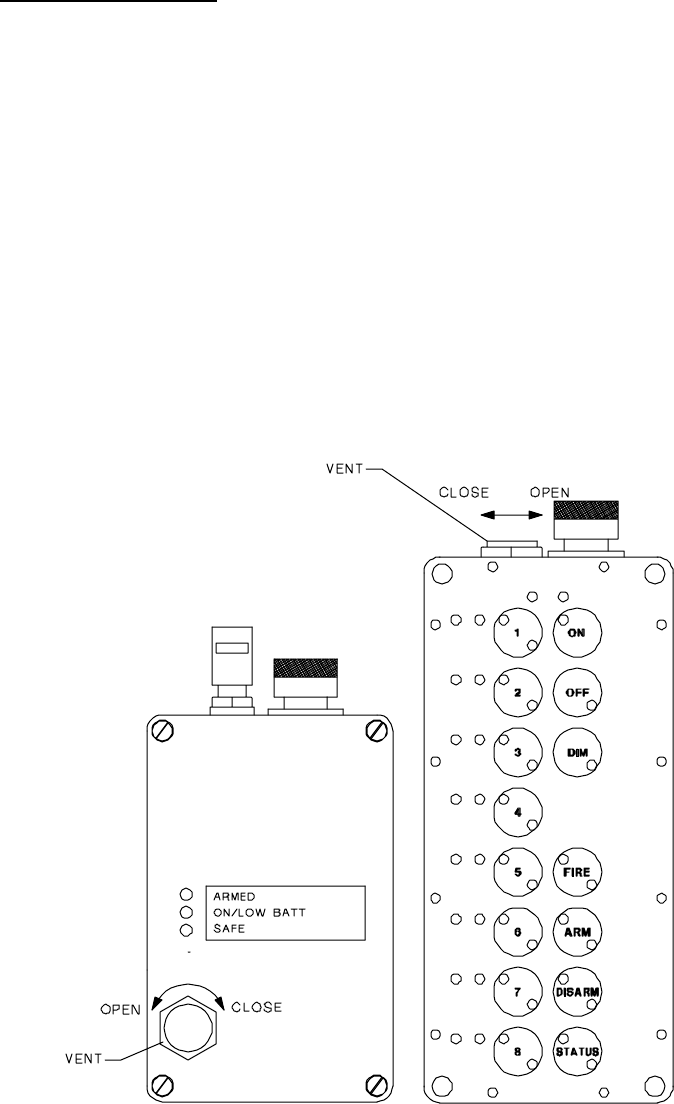
2.2. CONTROLLER UNIT.
2.2.1. Figure 2-2. Provides the physical size, weight, front panel light, and switch
locations on the Controller Unit. The unit is sealed at the Manufacturer or repair depot
and should not be opened during field activity.
Figure 2-2 Controller Unit.

RFD OPERATOR MANUAL 2-8
2.3. CONTROLLER UNIT SWITCH OPERATION.
2.3.1. Unit Power Control. Depress the “ON” switch to turn the power on to the
Controller Unit when the Antenna Assembly is attached. Depress the “OFF” switch to
turn the power off to the Controller Unit. The power is off when the Antenna Assembly
is removed.
2.3.2. Display Panel Light Dimmer Circuit. Depress the “DIM” switch to toggle
the display panel lights dim or bright.
2.3.3. Select Detonator Units. Depress “1” through “8” switches to select
independently the Detonator Units that will communicate with the Controller Unit. Any
combination of the eight Detonator Units may be selected. The yellow SELECT light on
the switch indicates if the Detonator Unit programmed for that switch is selected. Press
the switch again and the yellow SELECT light for that Detonator Unit will be turned off
indicating the Detonator Unit is not selected.
2.3.4. Request Detonator Unit Status. Depress “STATUS” switch to transmit a
status request signal to the selected Detonator Units. The selected Detonator Units will
transmit their current status to the Controller Unit. If none of the Detonator Units are
selected, the Controller Unit will request status from all eight Detonator Units. If the
Controller Unit is within range of the Detonator Unit transmitter, the status of the
selected Detonator Unit will be presented on the display panel with a steady light. If the
Controller Unit is out of range of the Detonator Unit transmitter, the status will be
assumed from the last command sent to that Detonator Unit. In that case the assumed
status of the Detonator Unit will flash on the display panel.
2.3.5. Arm the Detonator Unit. Depress the “ARM” switch for 1/2 second and the
Controller Unit will transmit the Arm command to the selected Detonator Units. The red
ARMED light at the selected Detonator Units will flash on the Controller Unit display
panel until the firing capacitor charging time is completed. The Controller Unit then
requests status of the selected Detonator Units. If the Controller Unit is within range of
the selected Detonator Unit transmitter, the ARMED red light for that Detonator Unit will
be on steady on the Controller Unit display panel. If the Controller Unit is out of range
of the selected Detonator Unit transmitter, the red ARMED light for that Detonator Unit
will continue to flash on the Controller Unit display panel. If the Fire command is not
sent within 60 seconds, the system will disarm automatically.
RFD OPERATOR MANUAL 2-9
2.3.6. Disarm the Detonator Unit. Depress the “DISARM” switch, the Controller
Unit will transmit the Disarm command to selected Detonator Units. Selected Detonator
Units will internally discharge their firing capacitor. Selected Detonator Units that
receive the Disarm command will become Disarmed within 3 seconds of receiving the
command. The green DISARMED light for selected Detonator Units will begin to flash
on the Controller Unit display panel. The Controller Unit will then request status of
selected Detonator Units. If the Controller Unit is within range of the selected Detonator
Unit transmitter, the green DISARMED light for that Detonator Unit will turn to steady on
the Controller Unit display panel. If the Controller Unit is out of range of the selected
Detonator Unit transmitter, the green DISARMED light for that Detonator Unit will
continue to flash on the Controller Unit display panel. If the Fire command is not sent
within 60 seconds of Arming, the system will Disarm automatically.
CAUTION Do not assume the Disarm command has been received by the
Detonator Unit unless DISARMED status is confirmed with a steady DISARMED light
for that Detonator Unit on the Controller Unit display panel. If distance appears to be
the problem, move closer to the Detonator Unit following standard procedures for this
type of situation. The “STATUS” and/or “DISARM” switches may be pressed repeatedly
as the Detonator Unit is approached. Maintain a safe distance from the Detonator Unit.
Do not approach the Detonator Unit until Disarmed status is confirmed with a steady
DISARMED light for that Detonator Unit on the Controller Unit display panel. Under no
conditions should the “FIRE” switch be pressed as the Detonator Unit is approached.
Do not bring the Controller Unit closer than 100 feet to blasting caps, wires connected to
blasting caps, or other explosives.
2.3.7. Activate the Detonator Unit Firing Circuit. Depress the “FIRE” switch for
1/2 second and the Controller Unit will transmit the Fire command to selected Detonator
Units. If the “FIRE” switch is pressed during the firing capacitor charge time, the
Controller Unit will wait until the Detonator Units have had time to fully Arm, and then it
will send the Fire command automatically. The Controller Unit will only transmit the Fire
command to selected Detonator Units whose status is Armed. The selected Detonator
Units will be placed in Fire Mode and discharge the firing capacitor across the binding
posts. The red ARMED light will turn off and the green DISARMED light for each
selected Detonator Unit will begin to flash on the Controller Unit display panel. The
Controller Unit will then request status from the selected Detonator Units. If the
Controller Unit is within range of the selected Detonator Unit transmitter, the
DISARMED green light for that Detonator Unit will turn to steady on the Controller Unit
display panel. If the Controller Unit is out of range of the selected Detonator Unit
transmitter, the green DISARMED light for that Detonator Unit will continue to flash on
the Controller Unit display panel.
2.3.8. Multistage Firing of Detonator Units. Multistage firing provides the ability
to Arm all eight Detonator Units at one time, and select any combination of the
Detonator Units to Fire at different intervals within the 60 second Arm period. The
procedure for multistage firing is :
• Depress “1” though “8” switches.

RFD OPERATOR MANUAL 2-10
• Depress “ARM” switch – all eight Detonator Units will Arm.
• Depress the switches for the Detonator Units that will not be fired initially.
• Depress the “FIRE” switch. Only Detonator Units still selected will Fire.
• Depress the switches for the Detonator Units that were just Fired.
• Depress the switches for Detonator Units to be Fired next.
• Depress the “FIRE” switch. Only Detonator Units still selected will Fire.
• Repeat as necessary. Detonator Units will automatically Disarm if not Fired within
60 seconds of Arming.
2.3.9. Misfires. If a Detonator Unit does not Fire when the Fire command is sent,
repeat Fire sequence up to 3 times. If the Detonator Unit continues not to Fire, then a
thirty-minute wait prior to approaching is mandatory. Follow your standard operating
procedures for misfires.
2.4. CONTROLLER UNIT DISPLAY OPERATION.
2.4.1. Nighttime Panel Switch Locator. There are fourteen red lights used for
backlighting the Controller Unit switches. When the “ON” switch is pressed, the lights
turn on to locate the switch positions.
2.4.2. Display Panel Dimmer Circuit. Pressing “DIM” switch reduces the intensity
of all of the panel display lights except the ON light.
2.4.3. Controller Unit Battery Status. The yellow light at the “ON” switch displays
the Controller Unit battery status. If the Controller Unit Battery is low, the yellow light at
the “ON” switch will flash. Otherwise this light will be on steady.
2.4.4. Detonator Unit Battery Status. The yellow select light at each of the “1”
through “8” switches will indicate the selected Detonator Units’ battery status after a
status request command is issued. If the selected Detonator Unit transmitter is within
range of the Controller Unit and Detonator Unit's battery is low, the yellow select light for
that Detonator Unit will flash. Else, the select light will be on steady.
2.4.5. Detonator Unit Disarmed. A green light next to each of the “1” though “8”
switches is used to indicate when the corresponding Detonator Unit is Disarmed. The
light will be on steady when the Detonator Unit transmitter is within range of the
Controller Unit and it is Disarmed. If the Detonator Unit transmitter is out of range of the
Controller Unit, the light will flash after a Disarm command has been sent.
RFD OPERATOR MANUAL 2-11
2.4.6. Detonator Unit Armed. A red light next to each of the “1” though “8”
switches is used to indicate when the corresponding Detonator Unit is Armed. The
ARMED light for selected Detonator Units will flash after the Arm command is sent to
the selected Detonator Units. The ARMED light will go to steady after the firing
capacitor charge time if the Controller Unit is within range of the selected Detonator
Unit's transmitter. If the Detonator Unit transmitter is out of range of the Controller Unit,
the ARMED light will continue to flash.
2.4.7. Status. A yellow light at the “STATUS” switch lights when the “STATUS”
switch is pressed. The light remains on until the display panel has been updated with
results of the status request. All new commands are blocked while this light is on.
2.4.8. Arm. A yellow light at the “ARM” switch lights when the “ARM” switch is
pressed. This light will stay on for the firing capacitor charge time. Other commands
will not be sent until this light is turned off.
2.4.9. Disarm. A yellow light at the “DISARM” switch lights when the “DISARM”
switch is pressed. This light will stay on until the display panel is updated for the Disarm
command. Other commands will not be sent until this light is turned off.
2.4.10. Fire. A yellow light at the “FIRE” switch lights when the “FIRE” switch is
pressed. This light will stay on until the display panel is updated for the Fire command.
Other commands will not be sent until this light is turned off.
2.4.11. “TX” (Transmit). A red light at the “TX” position lights while Controller Unit is
transmitting.
2.4.12. “CDT” (Receiver). A green light at the “CDT” position lights when the
Controller Unit is receiving status from the Detonator Units. The light will be on
whenever the Controller Unit detects transmissions on its operating frequency.
RFD OPERATOR MANUAL 2-12
2.5. DETONATOR UNIT.
2.5.1. Figure 2-3. Provides the physical size, weight, and front panel lights on the
Detonator Unit. The unit is sealed at the Manufacturer or repair depot and should not
be opened during field activity.
Figure 2-3 Detonator Unit.
RFD OPERATOR MANUAL 2-13
2.6. BATTERY CHARGER ASSEMBLY.
2.6.1. Figure 2-4. Provides the front panel lights, and switch position on the Battery
Charger Assembly. The unit is sealed at the Manufacturer or repair depot and should
not be opened during field activity.
Figure 2-4 Battery Charger Assembly.
RFD OPERATOR MANUAL 2-14
2.7. ANTENNA ASSEMBLY.
2.7.1. Figure 2-5. Provides the physical size, technical requirements and view of
the Antenna Assembly. The power to the Controller Unit and Detonator Unit is
interrupted when the Antenna Assembly is not connected.
Figure 2-5 Antenna Assembly.
RFD OPERATOR MANUAL 2-15
2.8. CARRYING CASE.
2.8.1. Figure 2-6. Provides the physical size of the Carrying Case and a view of the
storage location for System assemblies in the Carrying Case. The Carrying Case has a
pressure equalization vent near the handle. The vent should be opened prior to
opening the Carrying Case. The vent should be kept closed during storage and
shipment.
Figure 2-6 Carrying Case.
RFD OPERATOR MANUAL 2-16
2.9. VENT OPERATION.
2.9.1. Figure 2-7. The Controller Unit and Detonator Unit vents are manual and
relieve internal pressure due to heat and altitude. When the vent is closed, it will not
leak in 100 feet of water or up to 30,000 feet in altitude.
CAUTION Unequal air pressure inside the Controller Unit may affect the operation
of membrane switch keypad. Extreme pressure differentials may irreversibly damage
the keypad and/or cases.
CAUTION Vents in all units should be momentarily opened and closed immediately
before use.
CAUTION Do not open a vent if there is water on or near the vent. Take necessary
precautions to ensure water does not enter the vent.
Figure 2-7 Vent Operation.
RFD OPERATOR MANUAL 2-17
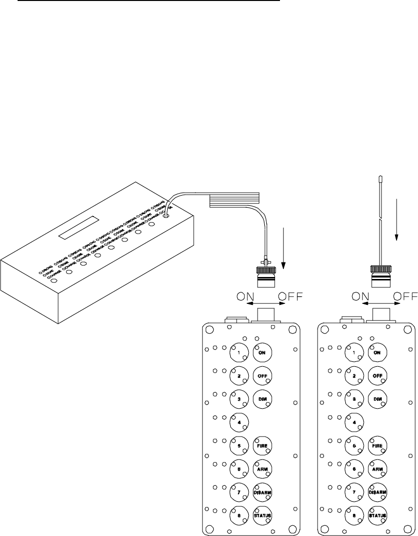
2.10. ANTENNA / BATTERY CHARGER CONNECTOR.
2.10.1. Figure 2-8. & Figure 2-9. The Controller Unit and Detonator Unit antenna /
battery charger connector accommodates the input requirements for both the Antenna
Assembly and the Battery Charger Assembly. The unit electronics and battery pack are
only connected together when the Antenna Assembly is connected to the antenna /
battery charger Connector.
Figure 2-8 Controller Antenna / Battery Charger Connection.
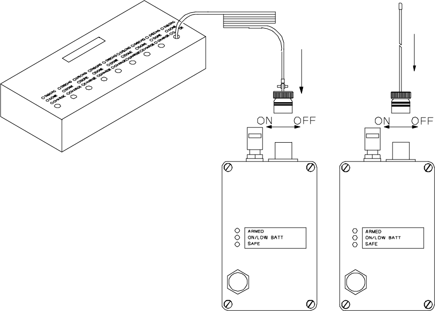
RFD OPERATOR MANUAL 2-18
Figure 2-9 Detonator Antenna / Battery Charger Connection.

RFD OPERATOR MANUAL 2-19
2.11. CONNECTOR DUST COVER OPERATION.
2.11.1. Figure 2-10. The Controller Unit and Detonator Unit antenna / battery charger
connector dust cover protects the connector pins from shorting out and damage when
the Antenna Assembly or Battery Charger Assembly is not connected. The connector
dust cover should be connected to the connector when the connector is not in use.
Figure 2-10 Connector Dust Cover Operation.

RFD OPERATOR MANUAL 3-20
3. SYSTEM SPECIFICATIONS.
3.1. RADIO.
CARRIER
FREQUENCY
135 - 174 MHz * OPERATING
TEMPERATURE
RANGE
-30ºC to 60ºC
-22ºF to 140ºF
FCC Pending <freq. diff. 1300 HZ (±650)
CONTROLLER UNIT DETONATOR UNIT
FREQUENCY
STABILITY
±5PPM OR
(0.00005%)
FREQUENCY
STABILITY
±5PPM OR
(0.00005%)
MODULATION 10K6F2D (AFSK) MODULATION 10K6F2D (AFSK)
TRANSMIT
POWER
5 Watts TRANSMIT
POWER
100 milliwatts
OPERATING
POWER
12 VDC OPERATING
POWER
7.2 VDC
TRANSMISSION
RANGE
5 miles (line-of-
site)**
TRANSMISSION
RANGE
Approximately 1,000
feet
RECEIVER
SENSITIVITY
12 dB Sinad at
0.28uV
RECEIVER
SENSITIVITY
12 dB Sinad at
0.28uV
(*) The Production Unit Frequency Designation will be provided in the contract.
(**) Typical transmission range, based on frequency used and terrain. Frequencies
under 150 MHz typically have a range of at least 4 miles,

RFD OPERATOR MANUAL 3-21
3.2. PHYSICAL.
Controller Unit Detonator Unit
SIZE(w/out
antenna) (in)
8H x 3W x 2.5D SIZE(w/out
antenna)(in)
6H x 3W x 2.5D
SIZE(w/out
antenna) (cm)
20.32H x 7.62W x
6.35D
SIZE(w/out
antenna)(cm)
15.24H x 7.62W x
6.35D
WEIGHT
(w/battery)
2.5 lbs., 1.14 kg WEIGHT
(w/battery)
2 lbs., 0.91 kg
CASE Die cast aluminum CASE Die cast aluminum
COLOR Black COLOR Black
3.3. BATTERY.
Controller Unit Detonator Unit
BATTERY PACK Rechargeable
NiCad
BATTERY PACK Rechargeable NiCad
BATTERY LIFE 6 Hours BATTERY LIFE 24 Hours*
BATTERY
RECHARGE
90 Minutes BATTERY
RECHARGE
90 Minutes
STANDBY
CURRENT
60 milliamps STANDBY
CURRENT
30 milliamps
TRANSMIT
CURRENT
1 Amp TRANSMIT
CURRENT
800 milliamps
(*) At the end of the standby time, the Detonator unit can detonate 5 (2-Ohm) blasting
caps connected in series and attached to 100 feet of wire.

RFD OPERATOR MANUAL 3-22
3.4. TIMING.
Controller Unit ARM time: 1/2 ± 0.1 Seconds
Detonator Unit ARM time: 10 ± 0.1 Seconds
Controller Unit Auto DISARM time: 60 ± 0.1 Seconds
Detonator Unit Auto DISARM time: 60 ± 0.1 Seconds
Controller Unit DISARM time: 3 ± 0.1 Seconds
Detonator Unit DISARM time: 3 ± 0.1 Seconds
Controller Unit FIRE time: 1 ± 0.1 Seconds
Detonator Unit FIRE time:* 20 Milliseconds
*This is the delay after the Detonator Unit receives the command signal from the
Controller Unit to Fire.
3.5. DETONATE OUTPUT.
3.5.1. The Detonator Unit detonation output pulse is from a 3300 microfarad
capacitor charged to 27 volts.
Stored Energy Level: 1 Joule (minimum)
Pulse Voltage Level: 27 VDC (minimum)
Circuit Current Limit:* 0.1 Ohm (maximum)*
*This is the maximum resistance between the firing capacitor and the output terminals.
RFD OPERATOR MANUAL 3-23
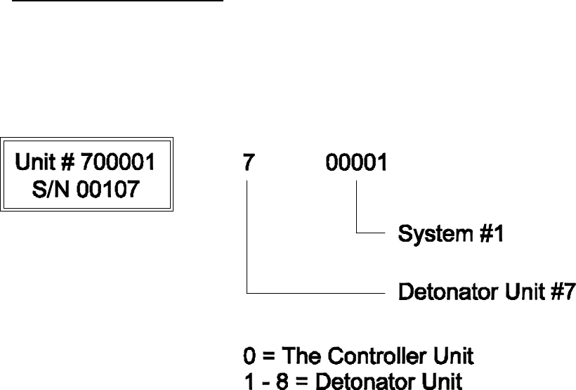
3.6. SYSTEM IDENTIFICATION.
3.6.1. Each Controller Unit and Detonator Unit is marked with an identification label.
Figure 3-1. Shows how the identification label should interpreted. The Controller Unit
will only communicate with Detonator Units from the same System.
Figure 3-1 Identification Label.

RFD OPERATOR MANUAL 4-24
4. PRE-OPERATIONAL PROCEDURES.
4.1. PHYSICAL INSPECTION.
4.1.1. Inspect all components for physical damage.
CAUTION Do not use any component that is damaged, suspected of being
damaged, or is not able to operate as designed. The safety of the operation could be
compromised.
4.1.2. Ensure the antenna / battery charger connector on the Controller Unit and
Detonator Unit is not Damaged.
4.1.3. Remove the antenna / battery charger connector dust cover and ensure the
electrical pin area is clean and free of foreign material. Replace the dust cover.
4.1.4. Ensure the Antenna Assembly whip is not broken and that the whip has not
separated from the sealing compound at the top of the connector.
4.1.5. Ensure that the spring-loaded binding posts on the Detonator Units are not
damaged.
4.1.6. Remove the red dust cover from the Antenna Assembly and ensure that there
is no foreign material in the electrical contact area. Replace the red dust cover.
4.2. BATTERY CHARGING.
4.2.1. The battery packs in the Controller Unit and Detonator Units contain
rechargeable NiCad batteries. The battery packs are recharged through the antenna /
battery charger connector on each unit. Battery packs are not to be removed (case
opened) in the field.
4.2.2. The battery pack in the Controller Unit and Detonator Units should be
charged before the System is used each time. The Battery Charger Assembly will
charge the Controller Unit and Detonator Units in 90 minutes. Each Battery Charger
Assembly has nine independent rapid chargers. Each rapid charger has a CHARGE,
DONE, and DISCHG light. The Battery Charger Assembly has a single “BATTERY
DISCHARGE” switch. The Battery Charger Assembly will discharge all battery packs
connected, when the “BATTERY DISCHARGE” switch is pressed. Complete discharge
of battery packs occurs in approximately 2 hours. Battery capacity will be maintained if
the battery packs are discharged prior to charging.
4.2.3. Turn off the power switch on the Battery Charger Assembly.

RFD OPERATOR MANUAL 4-25
4.2.4. Plug the AC cord into a 110 VAC 60 Hz outlet. The Battery Charger
Assembly will operate from 90-135/180-270 VAC, 47-63 Hz.
4.2.5. Connect each Detonator Unit and the Controller Unit to the Battery Charger
Assembly. The Controller Unit can be connected to any of the nine cables.
4.2.6. Open the vent on each Detonator Unit and the Controller Unit.
4.2.7. Turn on the power switch on the Battery Charger Assembly.
4.2.8. The CHARGE light for each connected unit will flash for approximately 5
seconds. The flashing CHARGE light indicates that rapid charging is pending.
4.2.9. In normal operation, the CHARGE light will be on solid after 5 seconds has
passed. The solid CHARGE light indicates that the battery is being rapid charged.
4.2.10. The battery must be within the temperature range 32 ºF and 104 ºF for rapid
charging to occur. If the battery pack is not within temperature range for rapid charging,
the CHARGE light will continue to flash beyond 5 seconds. While the CHARGE light is
flashing, the battery pack is being slow charged.
4.2.11. If the detected battery voltage is less than 6 volts for Detonator Units and 10
volts for Controller Units, the battery will be slow charged until the voltage is high
enough for rapid charge. If the battery pack is defective and the voltage does not rise to
the correct level, for rapid charge, the Battery Charger Assembly remains in slow
charge mode. In that case the CHARGE light will continue to flash.
4.2.12. When rapid charging terminates, the DONE light will be on steady, and the
CHARGE light will be turned off.
4.2.13. Rapid charging terminates when the charger detects the battery pack is
charged. Rapid charging will also terminate after 90 minutes, or if the battery pack
temperature is out of range.
4.2.14. If a Controller Unit or Detonator Unit is left turned on beyond the low battery
point, the battery pack may not fully charge before the 90 minute rapid charge time limit
expires. In that case, charge the battery pack again.
4.2.15. Close the vent on each Detonator Unit and the Controller Unit
4.3. BATTERY DISCHARGING.
4.3.1. Turn off the power switch on the Battery Charger Assembly.
4.3.2. Plug the AC cord into a 110VAC 60Hz outlet. The Battery Charger Assembly
will operate from 90-135/180-270 VAC, 47-63 Hz.

RFD OPERATOR MANUAL 4-26
4.3.3. Connect each Detonator Unit and the Controller Unit to the Battery Charger
Assembly. The Controller Unit can be connected to any of the nine cables.
4.3.4. Open the vent on each Detonator Unit and the Controller Unit.
4.3.5. Turn on the power switch on the Battery Charger Assembly.
4.3.6. The CHARGE light for each connected unit will flash for approximately 5
seconds. The flashing CHARGE light indicates that rapid charging is pending.
4.3.7. Press the BATTERY DISCHARGE switch. The DISCHG light will be on solid
and the CHARGE light will flash.
4.3.8. After the battery pack has been discharged, the DISCHG light will turn off and
the CHARGE light will be on solid indicating rapid charge mode.
4.3.9. When the battery pack is charged, the DONE light will be on steady, and the
CHARGE light will be turned off.
4.3.10. Close the vent on each Detonator Unit and the Controller Unit.
4.4. BENCH TESTING THE SYSTEM.
WARNING Radio frequency energy of sufficient magnitude can cause blasting caps
to detonate.
4.4.1. The System test must be conducted in an area that is at least 100 feet from
the nearest blasting caps, wires connected to blasting caps, or other explosives.
4.4.2. All RFD System controls are described in detail in section 2.
CAUTION All units must be thouroughly tested and the batteries fully charged prior
to operational use.
WARNING The Controller Unit has a 5 watt output power level (5 mile transmit
range). The Controller Unit should be considered DANGEROUS and NEVER be
operated within 100 feet (minimum) of blasting caps, wires connected to blasting caps,
or other electrically initiated explosives devices. Do NOT apply power to the Controller
Unit unless the operator is at least 100 feet from blasting caps, wires connected to
blasting caps, or explosives.
4.4.3. Install the Antenna Assembly on the antenna / battery charger connector of
the Controller Unit. Ensure the Controller Unit is off.

RFD OPERATOR MANUAL 4-27
4.4.4. Install the Antenna Assemblies on the antenna / battery charger connectors of
the Detonator Units. The ON/LOW BATT and SAFE lights will come on steady. If the
ON/LOW BATT light is flashing, the Detonator Unit has a low battery. Recharge the
battery in accordance with section 4.2.
4.4.5. Turn the Controller Unit on by pressing the “ON” switch for 1 second. A
yellow light located in the upper left quadrant of the “ON” switch will come on steady. If
the yellow light does not come on steady, but flashes, this indicates a low battery for the
Controller Unit. Recharge the battery in accordance with section 4.2.
4.4.6. Press the “STATUS” switch for 1 second. The red TX light on the Controller
Unit will start blinking for approximately 15 seconds. During that time the Controller Unit
is requesting status from the Detonator Units.
4.4.7. When the TX light stops flashing, the green DISARMED light will come on
steady adjacent to the switches numbered “1” through “8”. A steady DISARMED light
indicates that Detonator Unit answered back with its status and it is disarmed. A
flashing DISARMED light indicates the Controller Unit did not receive the Detonator
Unit’s status transmission.
WARNING Ensure that blasting caps are not connected to any of the Detonator
Units during bench test.
4.4.8. Select all of the Detonator Units by pressing switches “1” through “8”. A
yellow light will be lit in each switch to indicate the corresponding Detonator Unit is
selected.
4.4.9. Press the “ARM” switch for ½ second. The red ARMED light for each
selected Detonator Unit will flash on the Controller Unit display panel for approximately
10 seconds and then come on steady. The ARMED light for each selected Detonator
Unit will grow brighter and then stay on steady. The Detonator Units are now Armed.
4.4.10. Observe the Controller Unit and Detonator Units. In approximately 60
seconds the Detonator Units will automatically Disarm. The ARMED lights at the
Controller Unit and Detonator Units should turn off. The DISARMED lights at the
Controller Unit and SAFE lights at the Detonator Units should turn on.
4.4.11. Re-Arm the Detonator Units. Before the 60 second time-out takes place,
press the “DISARM” switch on the Controller Unit. The Controller Unit's ARMED light
will be turned off. The DISARMED lights at the Controller Unit should blink for
approximately 3 seconds and then turn on steady. The ARMED lights at the Detonator
Units will turn off and the Detonator Units’ SAFE lights will turn on.
RFD OPERATOR MANUAL 4-28
4.4.12. Connect a test bulb assembly to the binding posts of each Detonator Unit.
Arm the Detonator Units. Press the “FIRE” switch on the Controller Unit. The test bulb
should flash brightly. The ARMED light will turn off and the SAFE light will turn on at
each Detonator Unit. The displayed status at the Controller Unit will change from
Armed to Disarmed.
4.4.13. Turn off the Controller Unit by pressing the “OFF” switch. Turn off the
Detonator Units by removing their Antenna Assemblies.
4.4.14. The RFD system is now ready to use operationally.

RFD OPERATOR MANUAL 5-29
5. OPERATIONAL PROCEDURES.
WARNING Use of this system and its components must be restricted to personnel
qualified and experienced in the field of explosives and detonating devices. Under no
circumstances shall untrained personnel attempt to use this manual as a text for self-
teaching.
WARNING Employ standard blasting system safety standards when using this
equipment with explosives.
CAUTION All units must be thouroughly tested and the batteries fully charged prior
to operational use.
5.1. READY THE SYSTEM AT SITE.
5.1.1. Detonator Units. Select the number of Detonator Units required for the
operation. Remove the dust cover from the antenna / battery charger connector. Install
the Antenna Assembly on to the antenna / battery charger connector. This will turn on
the Detonator Unit. The yellow ON/LOW BATT light and green SAFE light will be turned
on. The green SAFE light will be on whenever the Detonator Unit is turned on and it is
Disarmed. In the Disarmed state, the firing capacitor charge circuit is disabled, the
binding posts are electrically isolated from the firing capacitor, and the binding posts are
shunted to each other. If the yellow ON/LOW BATT light is flashing, the Detonator Unit
battery is low and should be recharged before use.
WARNING Do not connect a blasting cap to a Detonator Unit unless the green
SAFE light is on, the red ARMED light is off, and the yellow ON/LOW BATT light is on
steady. This indicates there is no voltage on the binding posts, the binding posts are
electically isolated from the firing capacitor, the binding posts are shunted to each other,
and the battery is not low.
5.1.2. Open and close the vent on each Detonator Unit and the Controller Unit to
equalize the case pressure. Unscrew the vent one revolution to open.
5.1.3. Remove the dust cover from the antenna / battery charger connector of the
Controller Unit. Install the Antenna Assembly on to the antenna / battery charger
connector. This will enable the keypad on the Controller Unit.
WARNING The Controller Unit has a 5 watt output power level (5 mile transmit
range). The Controller Unit should be considered DANGEROUS and NEVER be
operated within 100 feet (minimum) of blasting caps, wires connected to blasting caps,
or other electrically initiated explosives devices. Do NOT apply power to the Controller
Unit unless the operator is at least 100 feet from blasting caps, wires connected to
blasting caps, or explosives.

RFD OPERATOR MANUAL 5-30
5.1.4. Press the Controller Unit “ON” switch for one second. The yellow light in the
upper left quadrant of the “ON” switch will come on steady. If the yellow light flashes,
the Controller Unit battery is low and needs charging. Refer to Battery charging section
4.2.
5.1.5. Press the “STATUS” switch on the Controller Unit. The red TX light will flash
for approximately 15 seconds. The green DISARMED light corresponding to each
Detonator Unit will come on steady if the Controller Unit receives a status message from
that Detonator Unit. If the Controller Unit does not receive a status message from a
Detonator Unit, the green DISARMED light for that Detonator Unit will flash on the
Controller Unit display panel.
Note: The Controller Unit battery life is approximately 6 hours when in the “ON”
condition. To conserve battery life, the Controller Unit should be turned off when not
being used.
5.1.6. Turn the Controller Unit “OFF” until Detonator Units are in place and wired to
shoot.
5.2. PLACEMENT OF DETONATOR UNITS.
WARNING Do not connect a blasting cap to a Detonator Unit unless the green
SAFE light is on, the red ARMED light is off, and the yellow ON/LOW BATT light is on
steady. This indicates there is no voltage on the binding posts, the binding posts are
electically isolated from the firing capacitor, the binding posts are shunted to each other,
and the battery is not low.
5.2.1. The range of the RFD is typically 5 miles under most conditions.
5.2.2. Place the Detonator Units with the antenna in a vertical position and free from
obstruction within 100 feet of the shot. Use sandbags or other suitable materials to
protect the Detonator Units from the shot.
5.2.3. Ensure that all Detonator Units indicate a SAFE condition (green light on
steady).
5.2.4. After performing standard demolition circuit checks and before placing initiator
into main charge, depress the two spring-loaded binding posts on the Detonator Unit.
5.2.5. Insert one leg of the demolition wire in each binding post and allow the
binding posts to close on the wire ends.
5.2.6. Ensure the wire is held securely by the binding posts and that the wire ends
are not touching the Detonator Case or each other.
5.2.7. Prepare the shot and return to the safe firing area.

RFD OPERATOR MANUAL 5-31
5.2.8. If all Detonator Units are located within 1,000 feet of the Controller Unit, refer
to section 5.3.
5.2.9. If all Detonator Units are located more than 1,000 feet and less that 5 miles
from the Controller Unit, refer to section 5.4.
5.2.10. If some Detonator Units are located within 1,000 feet of the Controller Unit,
and other Detonator Units are between 1,000 feet and 5 miles from the Controller Unit,
refer to section 5.5.
5.3. SYSTEM OPERATION – DETONATOR UNITS WITHIN 1,000 FEET OF
CONTROLLER UNIT.
Note: If the distance between the Controller Unit and the Detonator Units is in excess
of 1,000 feet, the Detonator Units status transmissions may not be received by the
Controller Unit. The Controller Unit will command the Detonators from a distance up to
5 miles, but the Detonator Status may not be confirmed. The Controller Unit performs
just as it would when it is within 1,000 feet of the Detonator Units. The only difference is
the method the status indications are displayed on the Controller Unit display panel.
The ARMED and DISARMED status lights for out of range Detonator Units will flash on
the Controller Unit display panel to indicate the Controller Unit did not receive a status
message from the Detonator Unit. Once the Detonator Units are set up for the shot, the
operator must assume the Detonator Units have received the command.
5.3.1. Ensure the area is clear.
5.3.2. Turn the Controller Unit on.
5.3.3. Press the “STATUS” switch. The Controller Unit will request status from all
Detonator Units. The red TX light will flash for approximately 15 seconds. The green
DISARMED light on the Controller Unit display panel will come on steady for the
Detonator Units that the Controller Unit receives a Disarmed status message from.
5.3.4. Select the Detonator Units that are to be used in the shot by pressing the
corresponding numbered switches “1” through “8”. Press the numbered switches one at
a time.
System Safety Feature Once Armed, the Detonator Units must be sent a Fire
command within 60 seconds. If the Detonator Units do not receive a Fire command
within 60 seconds of being armed, they will automatically Disarm. The firing capacitor
will be safely internally discharged, the binding posts will remain isolated from the firing
capacitor and the binding posts will remain shunted together.
5.3.5. To Arm the selected Detonator Units, press the “ARM” switch. The red
ARMED light next to each selected Detonator Unit switch will flash for 10 seconds and
then come on steady. The selected Detonator Units are now ARMED!

RFD OPERATOR MANUAL 5-32
5.3.6. To Fire the Detonator Units, press the “FIRE” switch. The operator should get
an indication of shot initiation. The ARMED light will go out and the green DISARMED
light for each selected Detonator Unit will come on solid on the Controller Unit display
panel.
5.3.7. If not all the Detonator Units were selected for the shot, repeat above steps to
initiate the remaining shots.
5.3.8. To Disarm any Detonator Units that have been Armed, select the Detonator
Units and press the “DISARM” switch. All selected Detonator Units will return to the
DISARMED mode in approximately 3 seconds.
CAUTION Do not assume the Disarm command has been received by the
Detonator Unit unless DISARMED status is confirmed with a steady DISARMED light
for that Detonator Unit on the Controller Unit display panel. If distance appears to be
the problem, move closer to the Detonator Unit following standard procedures for this
type of situation. The “STATUS” and/or “DISARM” switches may be pressed repeatedly
as the Detonator Unit is approached. Maintain a safe distance from the Detonator Unit.
Do not approach the Detonator Unit until Disarmed status is confirmed with a steady
DISARMED light for that Detonator Unit on the Controller Unit display panel. Under no
conditions should the “FIRE” switch be pressed as the Detonator Unit is approached.
Do not bring the Controller Unit closer than 100 feet to blasting caps, wires connected to
blasting caps, or other explosives.
5.3.9. Turn off the Controller Unit.
5.3.10. Recover the fielded Detonator Units.
5.3.11. Refer to Post Operational Procedures in chapter 6.
5.4. SYSTEM OPERATION – DETONATOR UNITS MORE THAN 1,000 FEET AND
LESS THAN 5 MILES FROM CONTROLLER UNIT.
Note: If the distance between the Controller Unit and the Detonator Units is in excess
of 1,000 feet, the Detonator Units status transmissions may not be received by the
Controller Unit. The Controller Unit will command the Detonators from a distance up to
5 miles, but the Detonator Status may not be confirmed. The Controller Unit performs
just as it would when it is within 1,000 feet of the Detonator Units. The only difference is
the method the status indications are displayed on the Controller Unit display panel.
The ARMED and DISARMED status lights for out of range Detonator Units will flash on
the Controller Unit display panel to indicate the Controller Unit did not receive a status
message from the Detonator Unit. Once the Detonator Units are set up for the shot, the
operator must assume the Detonator Units have received the command.
5.4.1. Ensure the area is clear.
5.4.2. Turn the Controller Unit on.
RFD OPERATOR MANUAL 5-33
5.4.3. Press the “STATUS” switch. The Controller Unit will request status from all
Detonator Units. The red TX light will flash for approximately 15 seconds. The green
DISARMED light on the Controller Unit display panel will flash for all Detonator Units
that the Controller Unit does not receive a status message from.
5.4.4. Select the Detonator Units that are to be used in the shot by pressing the
corresponding numbered switches “1” through “8”. Press the numbered switches one at
a time.
System Safety Feature Once Armed, the Detonator Units must be sent a Fire
command within 60 seconds. If the Detonator Units do not receive a Fire command
within 60 seconds of being armed, they will automatically Disarm. The firing capacitor
will be safely internally discharged, the binding posts will remain isolated from the firing
capacitor and the binding posts will remain shunted together.
5.4.5. To Arm the selected Detonator Units, press the “ARM” switch. The red
ARMED light next to each selected Detonator Unit switch will flash for 10 seconds, then
come on steady for two seconds, and then continue to flash. The selected Detonator
Units are now assumed to be ARMED!
5.4.6. To Fire the Detonator Units, press the “FIRE” switch. The operator should get
an indication of shot initiation. The ARMED light will go out and the green DISARMED
light for each selected Detonator Unit will flash on the Controller Unit display panel.
5.4.7. If not all the Detonator Units were selected for the shot, repeat above steps to
initiate the remaining shots.
5.4.8. To Disarm any Detonator Units that have been Armed, select the Detonator
Units and press the “DISARM” switch. All selected Detonator Units will return to the
DISARMED mode in approximately 3 seconds.
CAUTION Do not assume the Disarm command has been received by the
Detonator Unit unless DISARMED status is confirmed with a steady DISARMED light
for that Detonator Unit on the Controller Unit display panel. If distance appears to be
the problem, move closer to the Detonator Unit following standard procedures for this
type of situation. The “STATUS” and/or “DISARM” switches may be pressed repeatedly
as the Detonator Unit is approached. Maintain a safe distance from the Detonator Unit.
Do not approach the Detonator Unit until Disarmed status is confirmed with a steady
DISARMED light for that Detonator Unit on the Controller Unit display panel. Under no
conditions should the “FIRE” switch be pressed as the Detonator Unit is approached.
Do not bring the Controller Unit closer than 100 feet to blasting caps, wires connected to
blasting caps, or other explosives.
5.4.9. Turn off the Controller Unit.
5.4.10. Recover the fielded Detonator Units.

RFD OPERATOR MANUAL 5-34
5.4.11. Refer to Post Operational Procedures in chapter 6.
5.5. SYSTEM OPERATION – DETONATOR UNITS BOTH WITHIN AND IN EXCESS
OF 1,000 FEET AND LESS THAN 5 MILES FROM CONTROLLER UNIT.
Note: If the distance between the Controller Unit and the Detonator Units is in excess
of 1,000 feet, the Detonator Units status transmissions may not be received by the
Controller Unit. The Controller Unit will command the Detonators from a distance up to
5 miles, but the Detonator Status may not be confirmed. The Controller Unit performs
just as it would when it is within 1,000 feet of the Detonator Units. The only difference is
the method the status indications are displayed on the Controller Unit display panel.
The ARMED and DISARMED status lights for out of range Detonator Units will flash on
the Controller Unit display panel to indicate the Controller Unit did not receive a status
message from the Detonator Unit. Once the Detonator Units are set up for the shot, the
operator must assume the Detonator Units have received the command.
5.5.1. The RFD will operate in a two-way mode (confirmed communications – range
to 1,000 feet) and one-way mode (unconfirmed communications – range up to 5 miles).
5.5.2. If the Detonators are within 1,000 feet of the Controller Unit, the status of the
Detonator Units (ON/LOW BATT, ARMED, and SAFE) will be displayed with solid lights
on the display panel of the Controller Unit.
5.5.3. If one or more Detonator Units are out of range of the Controller Unit, the
status of these Detonator Units will be assumed and their status lights will flash on the
Controller Unit display panel to indicate unconfirmed status. Accordingly the operator
must assume the following:
• Commands have been received by the Detonator Units.
• The Detonator Unit battery is sufficiently charged to activate the firing circuit.
• A “DISARM” command should not be assumed.
5.5.4. Ensure the area is clear.
5.5.5. Turn the Controller Unit on.
5.5.6. Press the “STATUS” switch. The Controller Unit will request status from all
Detonator Units. The red TX light will flash for approximately 15 seconds. The green
DISARMED light on the Controller Unit display panel will flash for all the Detonator Units
that the Controller Unit does not receive a status message from.
5.5.7. Select the Detonator Units that are to be used in the shot by pressing the
corresponding numbered switches “1” through “8”. Press the numbered switches one at
a time.
RFD OPERATOR MANUAL 5-35
System Safety Feature Once Armed, the Detonator Units must be sent a Fire
command within 60 seconds. If the Detonator Units do not receive a Fire command
within 60 seconds of being armed, they will automatically Disarm. The firing capacitor
will be safely internally discharged, the binding posts will remain isolated from the firing
capacitor and the binding posts will remain shunted together.
5.5.8. To Arm the selected Detonator Units, press the “ARM” switch. The red
ARMED light next to each selected Detonator Unit switch will flash for 10 seconds, and
then come on steady for two seconds. ARMED lights for selected Detonator Units that
the Controller Unit did not receive a status message from will begin to flash again. The
selected Detonator Units are now assumed to be ARMED! For unconfirmed
communications, count to 10 from when the "ARM" switch is pressed and assume the
Detonator Units are Armed.
5.5.9. To Fire the Detonator Units, press the “FIRE” switch. The operator should get
an indication of shot initiation. The ARMED light will go out and the green DISARMED
light for each selected Detonator Unit will flash on the Controller Unit display panel.
5.5.10. If not all the Detonator Units were selected for the shot, repeat above steps to
initiate the remaining shots.
5.5.11. To Disarm any Detonator Units that have been Armed, select Detonator Units
and press the “DISARM” switch. All selected Detonator Units will return to the
DISARMED mode in approximately 3 seconds.
CAUTION Do not assume the Disarm command has been received by the
Detonator Unit unless DISARMED status is confirmed with a steady DISARMED light
for that Detonator Unit on the Controller Unit display panel. If distance appears to be
the problem, move closer to the Detonator Unit following standard procedures for this
type of situation. The “STATUS” and/or “DISARM” switches may be pressed repeatedly
as the Detonator Unit is approached. Maintain a safe distance from the Detonator Unit.
Do not approach the Detonator Unit until Disarmed status is confirmed with a steady
DISARMED light for that Detonator Unit on the Controller Unit display panel. Under no
conditions should the “FIRE” switch be pressed as the Detonator Unit is approached.
Do not bring the Controller Unit closer than 100 feet to blasting caps, wires connected to
blasting caps, or other explosives.
5.5.12. Turn off the Controller Unit.
5.5.13. Recover the fielded Detonator Units.
5.5.14. Refer to Post Operational Procedures in chapter 6.

RFD OPERATOR MANUAL 6-36
6. POST OPERATIONAL PROCEDURES.
6.1. SECURING THE SYSTEM.
6.1.1. Turn the Controller Unit off and remove the Antenna Assembly. This action
disables the Controller Unit.
6.1.2. Replace the dust cover on the antenna / battery charger connector on the
Controller Unit and replace the red plastic cap on the Antenna Assembly.
6.1.3. Remove the Antenna Assemblies from the Detonator Units. This action turns
off the Detonator Units.
6.1.4. Replace the dust cover on the antenna / battery charger connector on the
Detonator Units and replace the red plastic cap on the Antenna Assembly.
6.2. PHYSICAL INSPECTION.
6.2.1. Inspect the Controller Unit and Detonator Units for physical damage.
6.2.2. Inspect the units for dirt or corrosion around/on connector pins and vent.
6.2.3. Replace any unit found to have damage. Return unit to Manufacturer.
6.2.4. Clean units using a soft bristle brush.
6.2.5. If a unit cannot be cleaned by brushing, make sure the vent is closed securely
and wash units in warm soapy water.
6.2.6. Rinse units with clean water and dry thoroughly.
6.2.7. Inspect units for damage. Replace as necessary.
6.3. PACKAGING.
6.3.1. Re-package all components in carrying case.
6.4. MAINTENANCE & EQUIPMENT STORAGE.
6.4.1. Periodic battery charging.
6.4.2. Check for signs of corrosion around and on connector pins.

RFD OPERATOR MANUAL 7-37
7. BASIC TROUBLESHOOTING IN THE FIELD.
7.1. DETONATOR UNITS.
7.1.1. “ON” and “SAFE” lights do not illuminate when the Antenna Assembly is
installed.
a) Check Antenna Assembly and make sure it is seated, “clicks” on to the connector.
b) Recharge the battery.
c) Try a different Antenna Assembly.
7.2. CONTROLLER UNIT.
7.2.1. “ON” Light does not stay on.
a) Check Antenna Assembly and make sure it is seated, “clicks” on to the connector.
b) Press and hold the “ON” switch for 5 seconds.
c) Controller Unit battery needs to be recharged.
7.2.2. Command receipt is not confirmed by Detonator Unit.
a) Detonator Unit is more than 1,000 feet from Controller Unit.
b) If the Detonator Unit is less than 1,000 feet away from the Controller Unit.
Check for damage to Controller Unit Antenna Assembly.
Try a different Antenna Assembly on the Controller Unit.
Move at least 25 feet in any direction and try again.
Reposition the Detonator Unit if:
• The antenna is not positioned vertically.
• The antenna is next to another radio antenna.
• The antenna is surrounded by metallic objects.
• Use optional magnetic mount antenna for improved gain.
c) Check carrier detect light to see if there is interference from another source.
RFD OPERATOR MANUAL 8-38
8. OPTIMIZING RANGE.
8.1.1. When power lines are in the area, the radio transmission distance is reduced.
The System can operate at the following distance, when the Controller Unit is elevated
to a maximum transmission location angle to the Detonator Unit location (see Figure
8-1).
Over Minimum Distance
Open Land or Water with Power Lines 1 Mile
Dense Vegetation without Power Lines 1 Mile
Open Land or Water without Power Lines 5 Miles
RFD OPERATOR MANUAL 8-39
Figure 8-1 Unit Normal Transmission Location.
8.1.2. If the Controller unit and Detonator Unit must be placed in a position other
than location in Figure 8-1, use Figure 8-2 or Figure 8-3. The minimum transmission
will occur when the Controller Unit antenna and the Detonator Unit antenna are placed
in the line of site. The maximum transmission occurs when the line of site lays in a path
of 5 to 25 degrees above Unit top plane perpendicular to the antenna. Both the
Controller Unit antenna and the Detonator Unit Antenna have the same radiant energy
pattern as shown in Figure 8-4.
Figure 8-2 Detonator Unit Elevated.
RFD OPERATOR MANUAL 8-40
Figure 8-3 Detonator Unit Tilted.
RFD OPERATOR MANUAL 8-41
Figure 8-4 Antenna Radiation Pattern