Rothenbuhler Engineering 1669-20 VHF CONTROLLER (TRANSCEIVER) User Manual USERS MANUAL
Rothenbuhler Engineering Company Inc VHF CONTROLLER (TRANSCEIVER) USERS MANUAL
UserManual.wiki
>
Rothenbuhler Engineering
>
1669 20 User Manual
USERS MANUAL
Navigation menu
Upload a User Manual
Namespaces
Wiki Guide
HTML
PDF
Info
Views
User Manual
Discussion / Help
Navigation

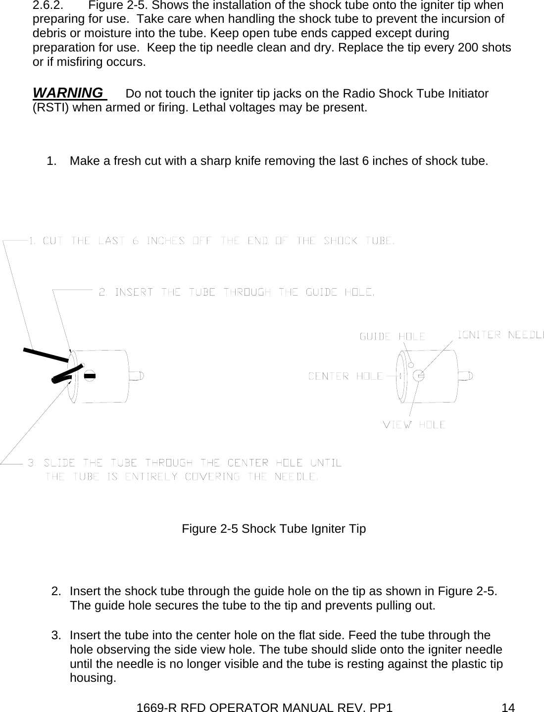
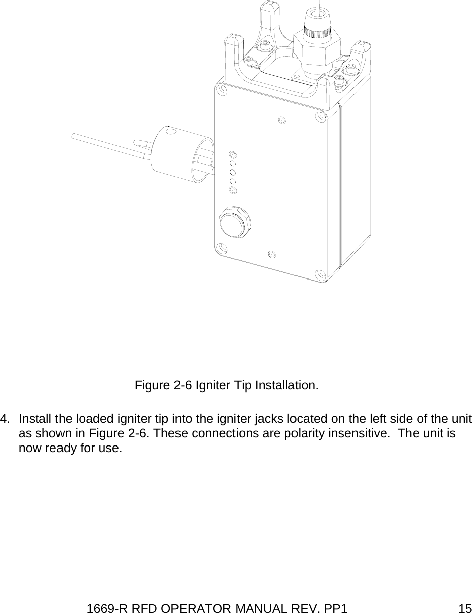
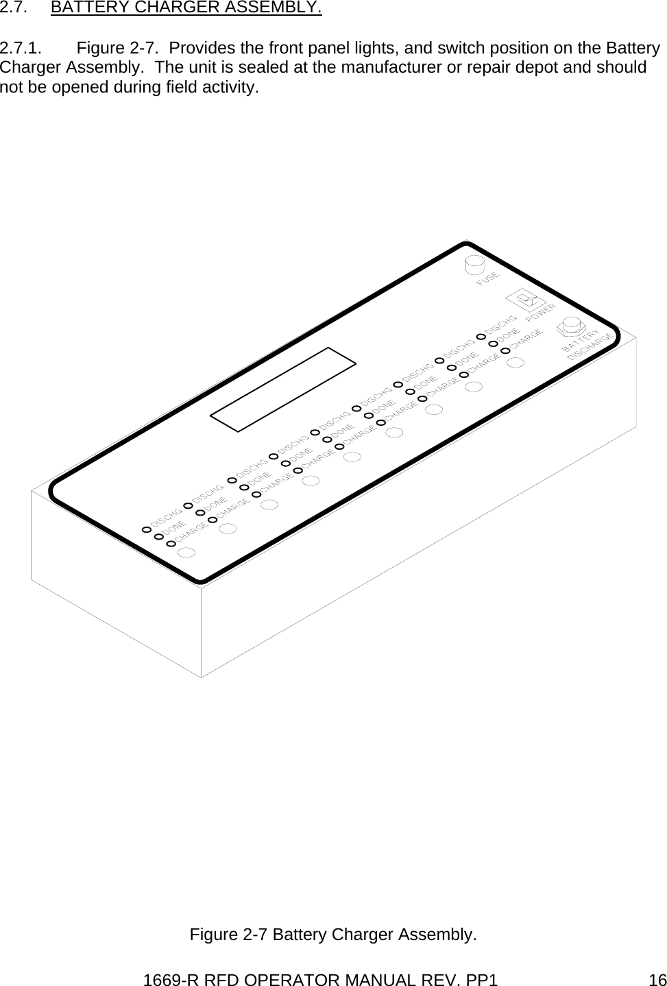
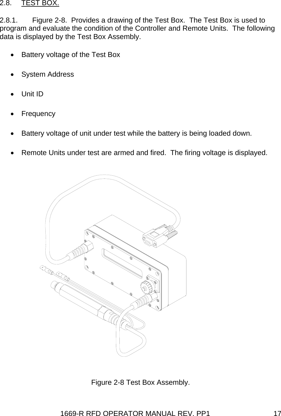
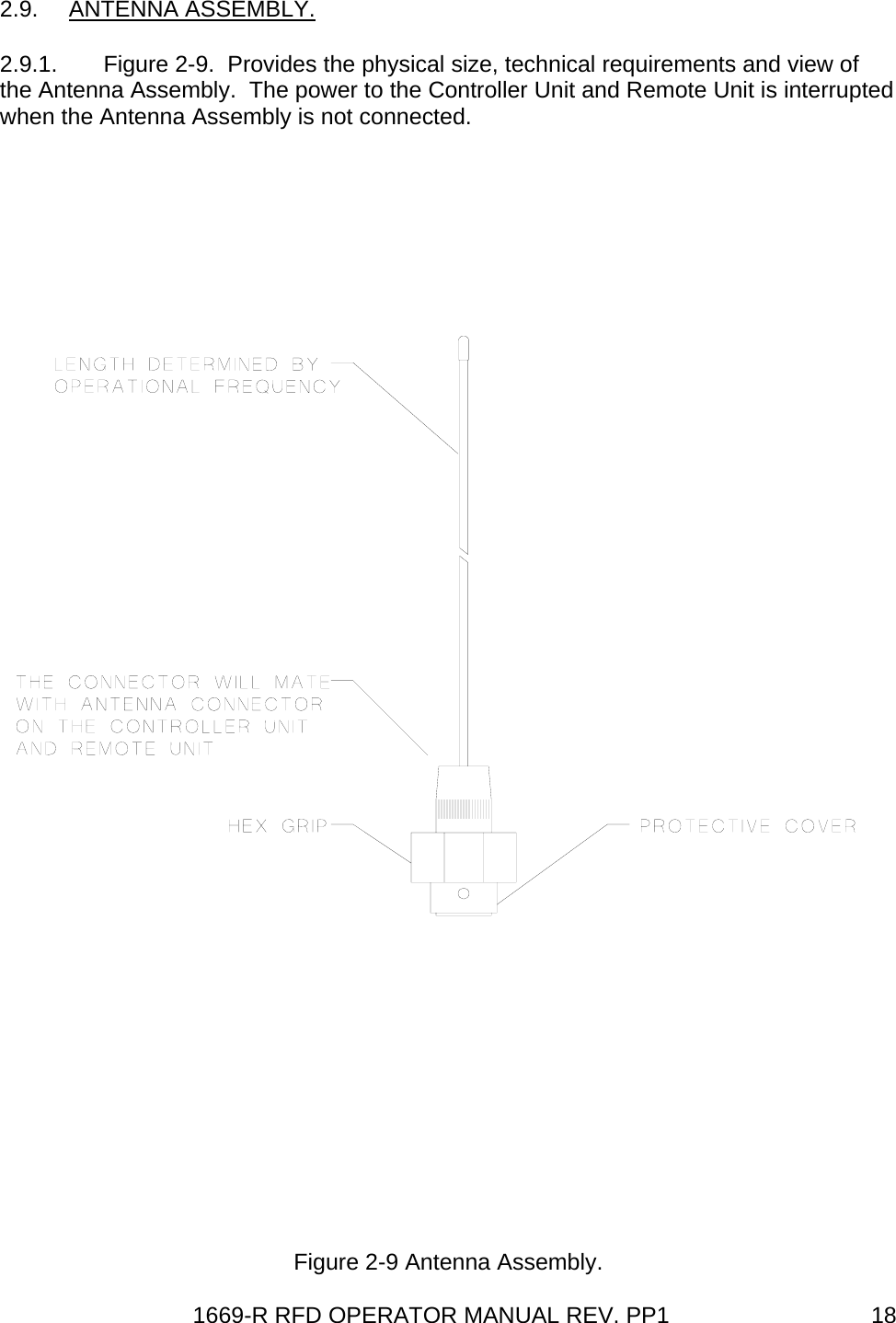
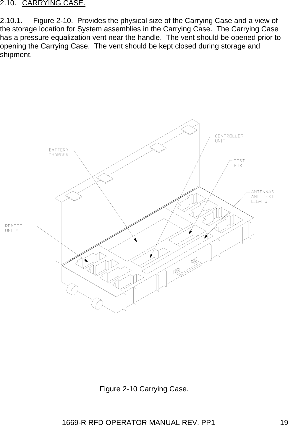
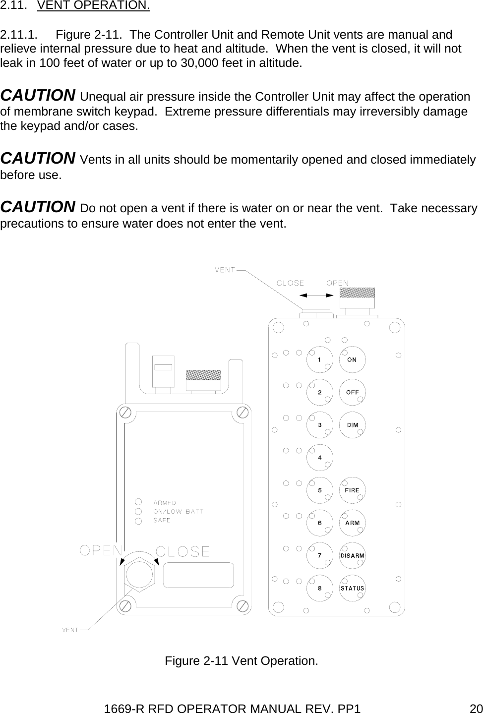
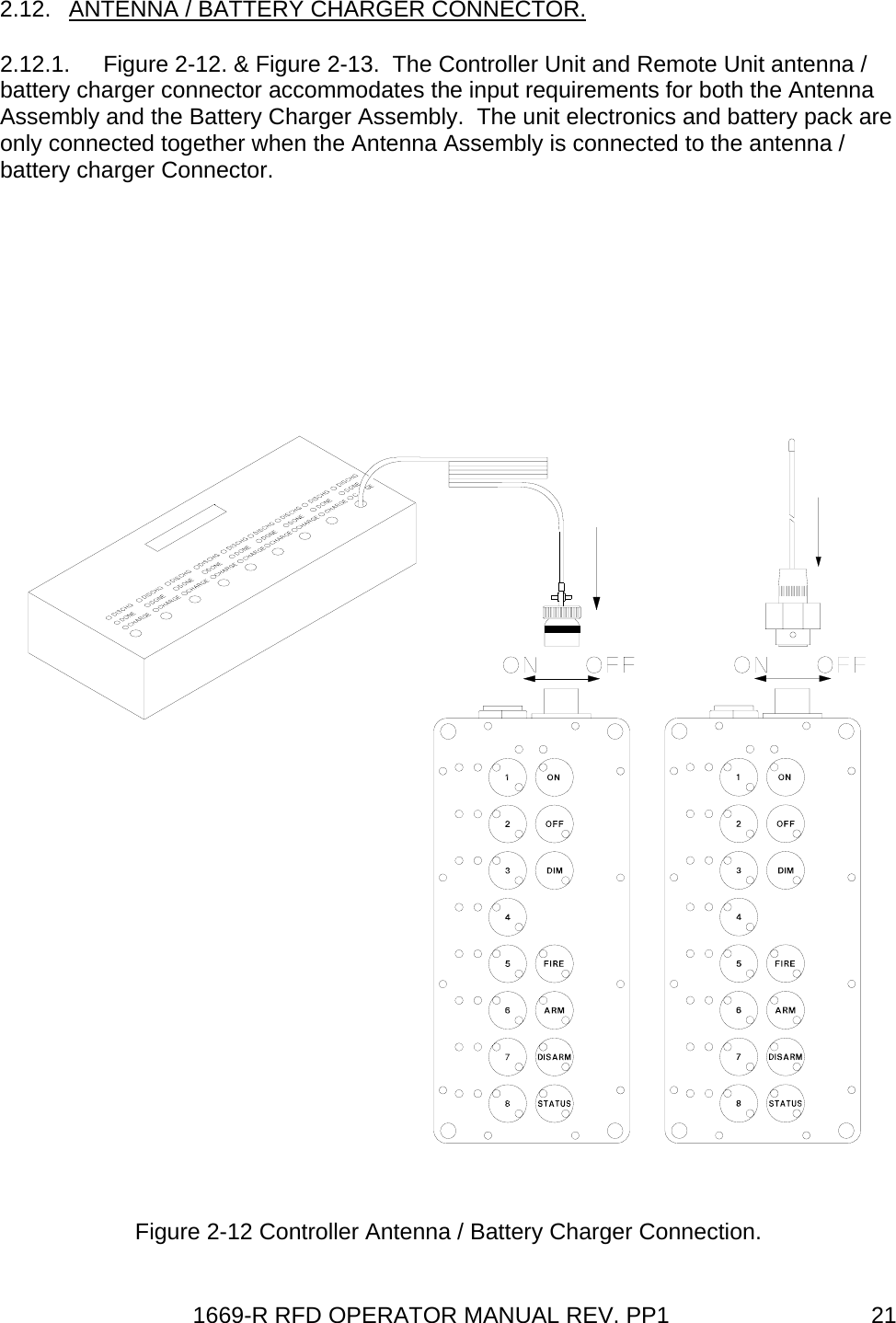
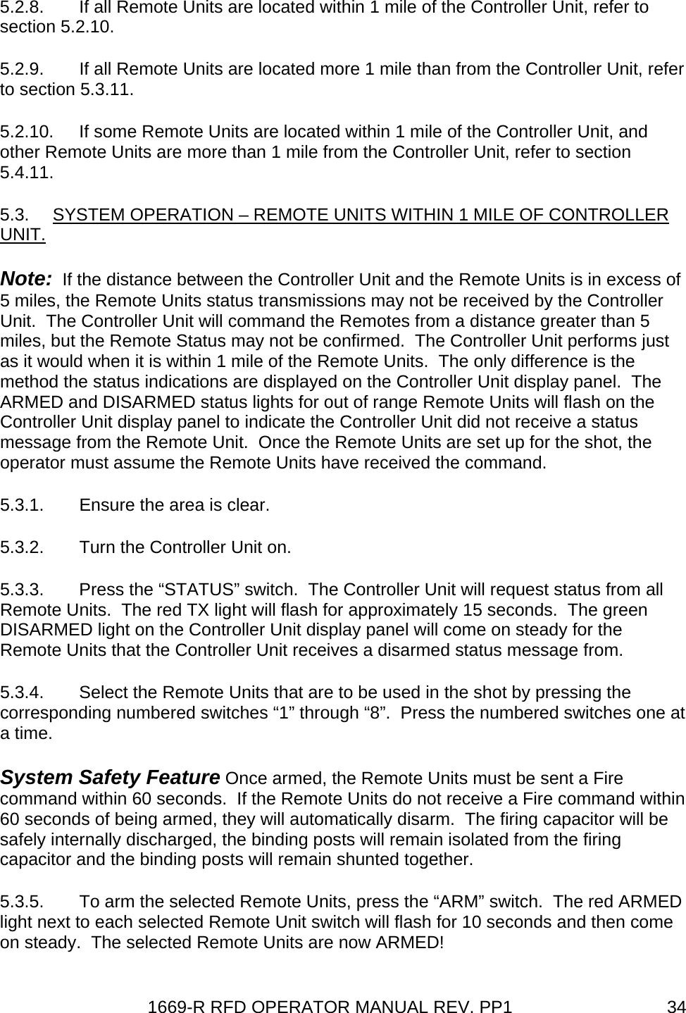
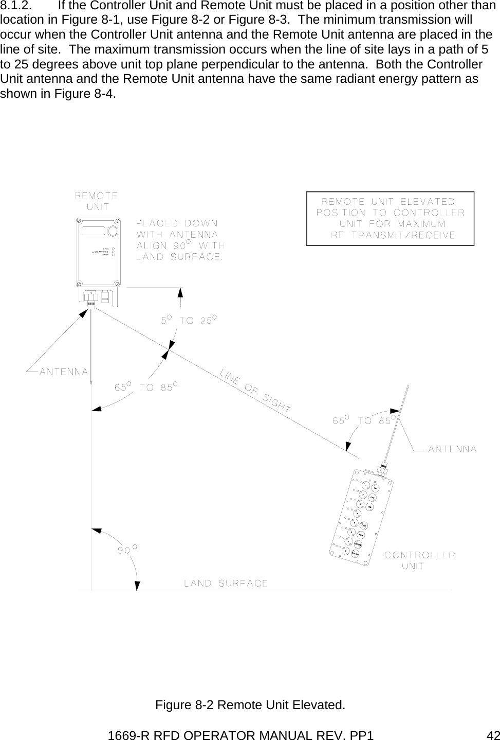
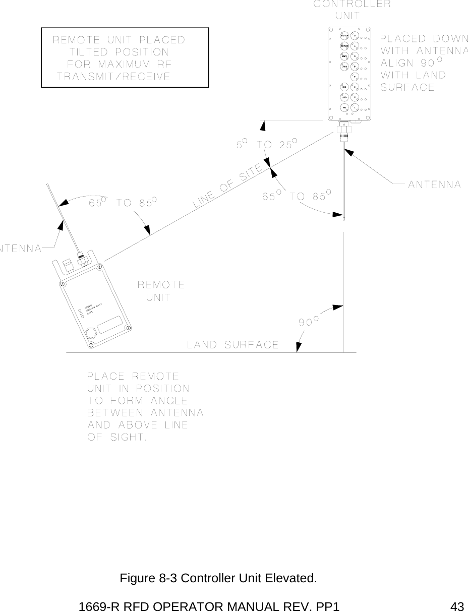
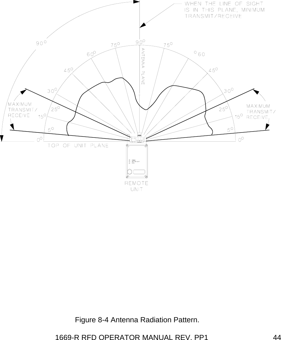
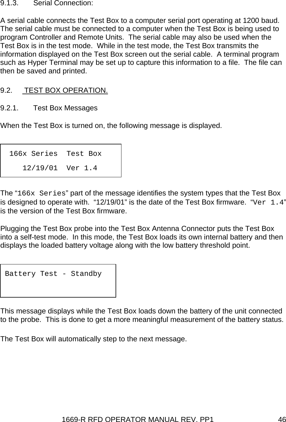
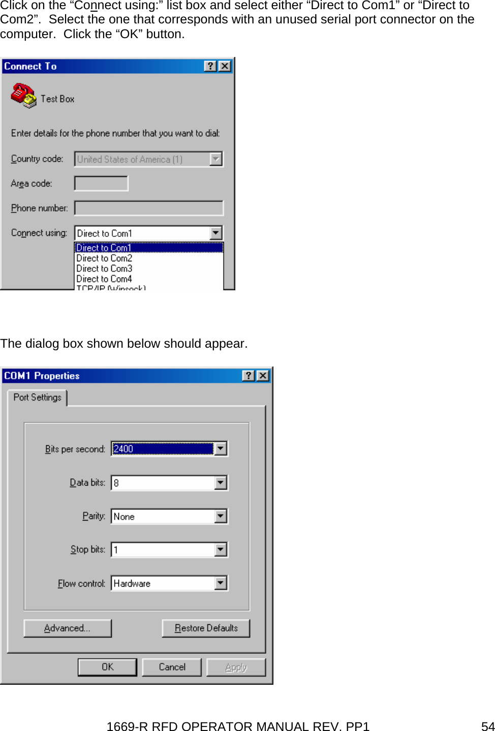
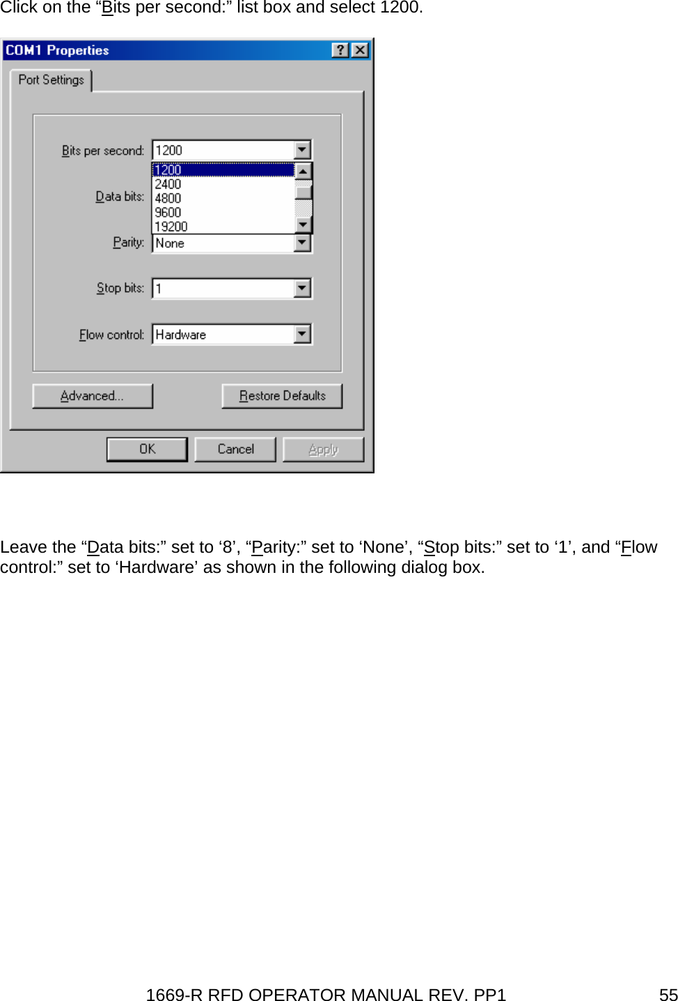
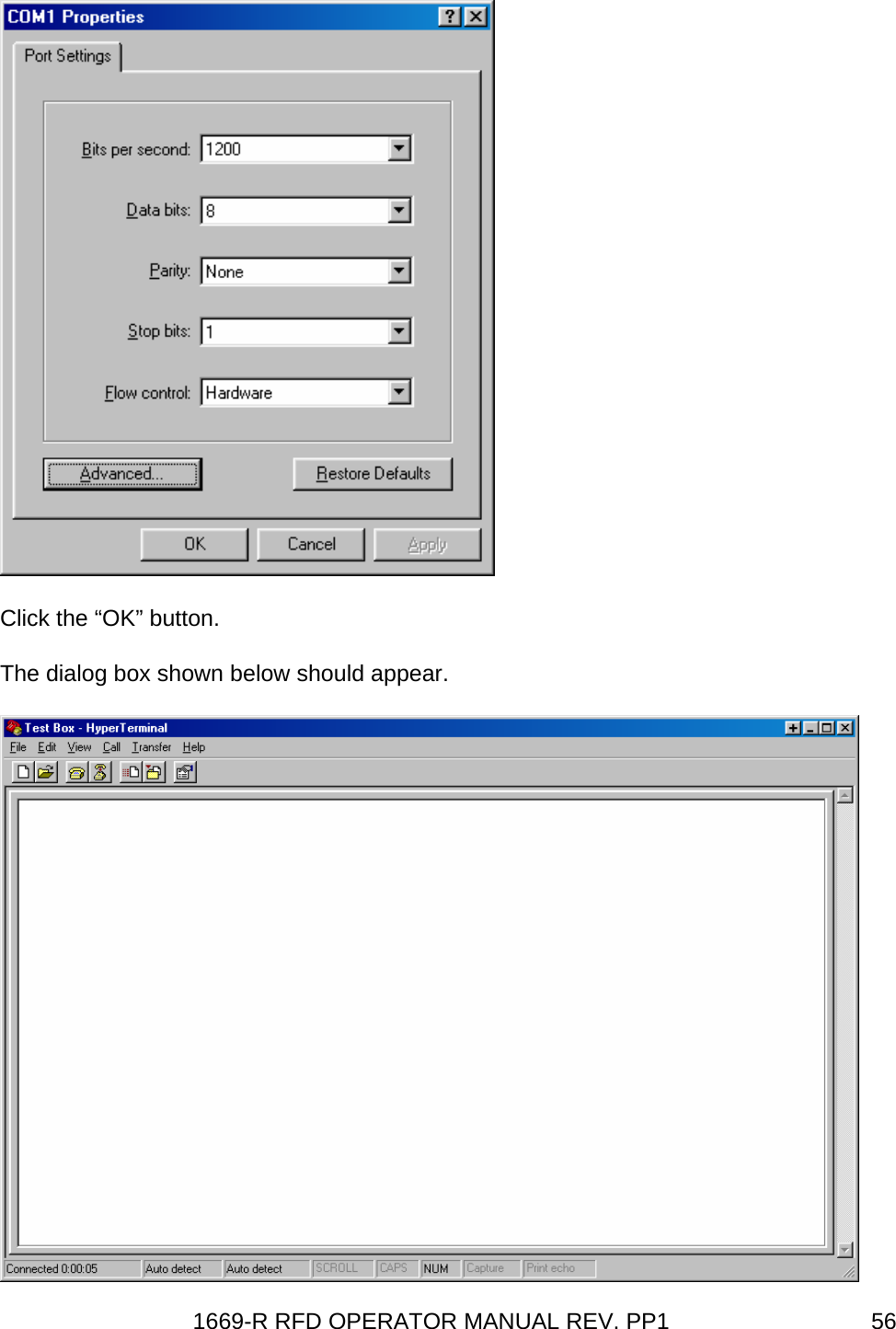
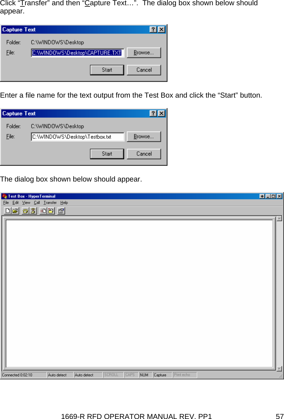
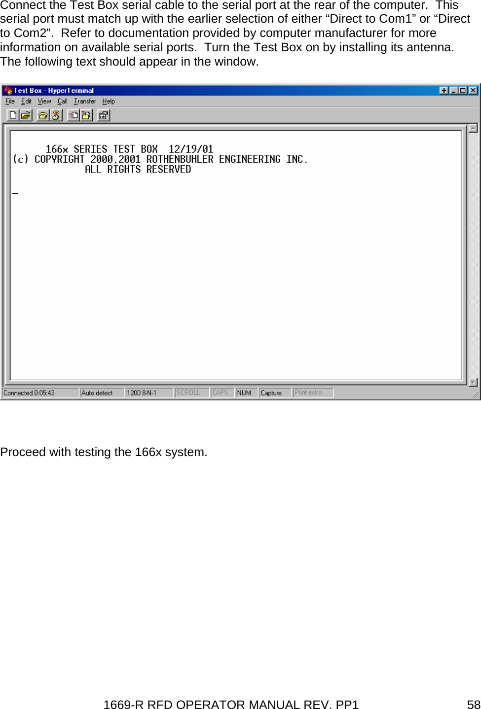
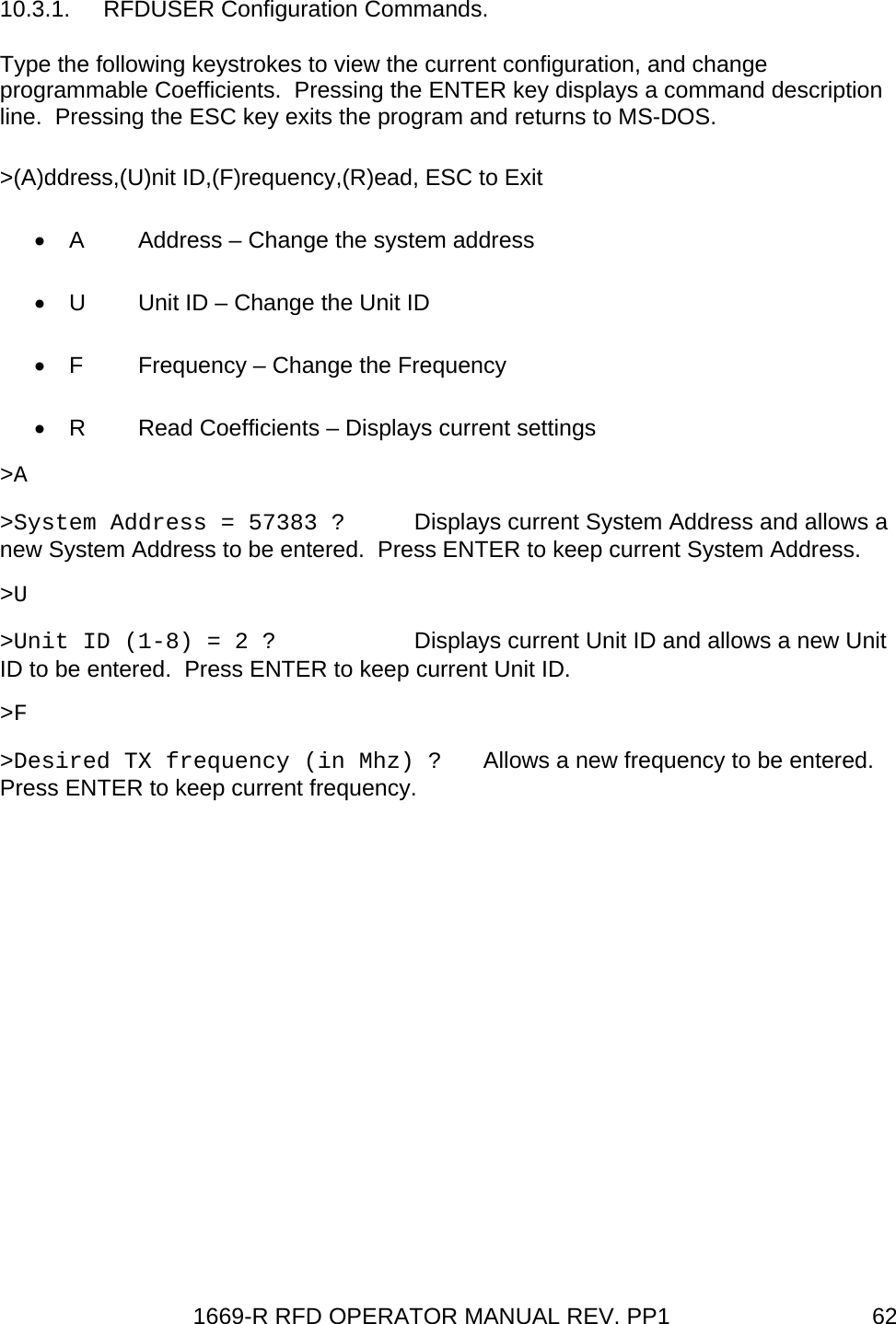
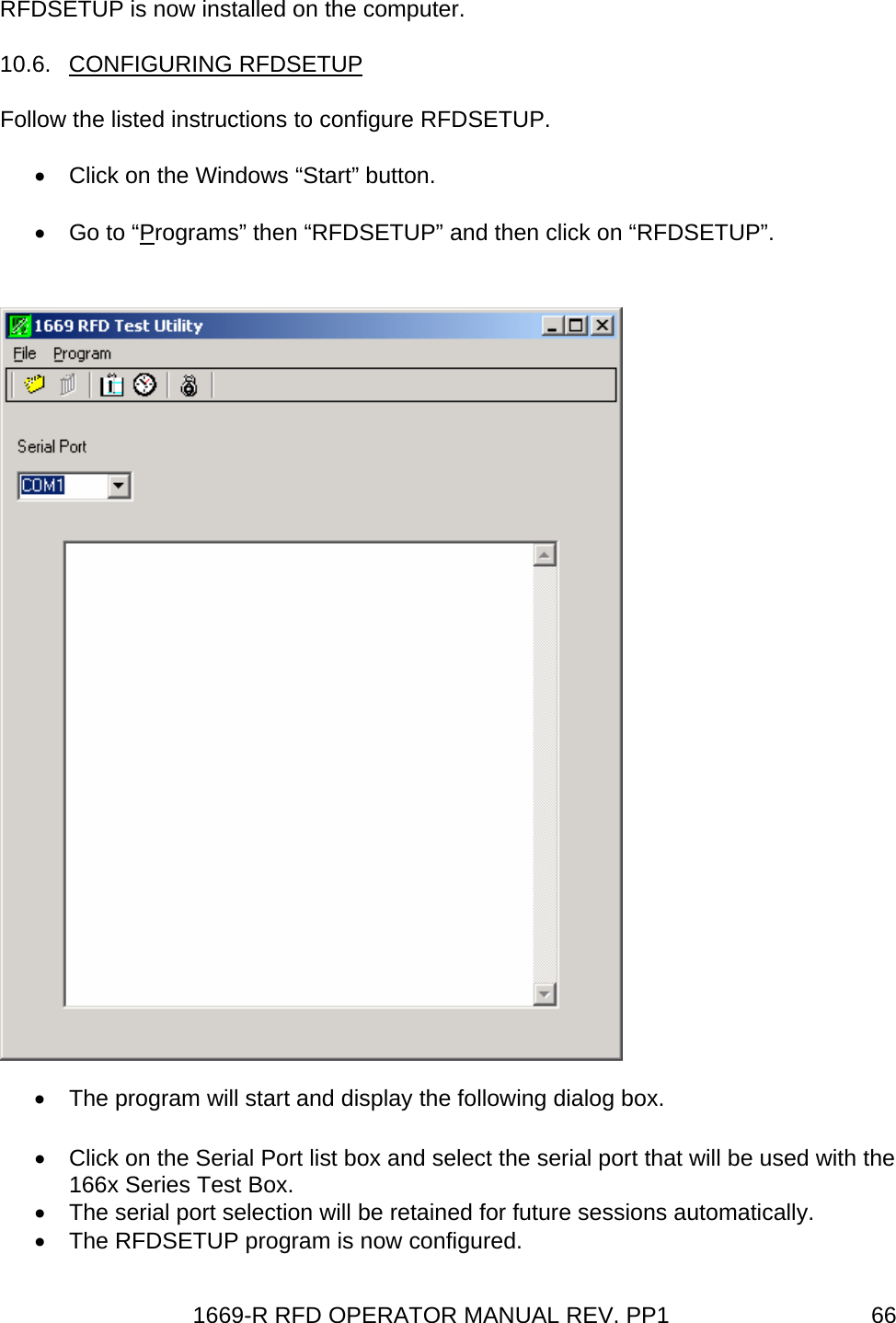
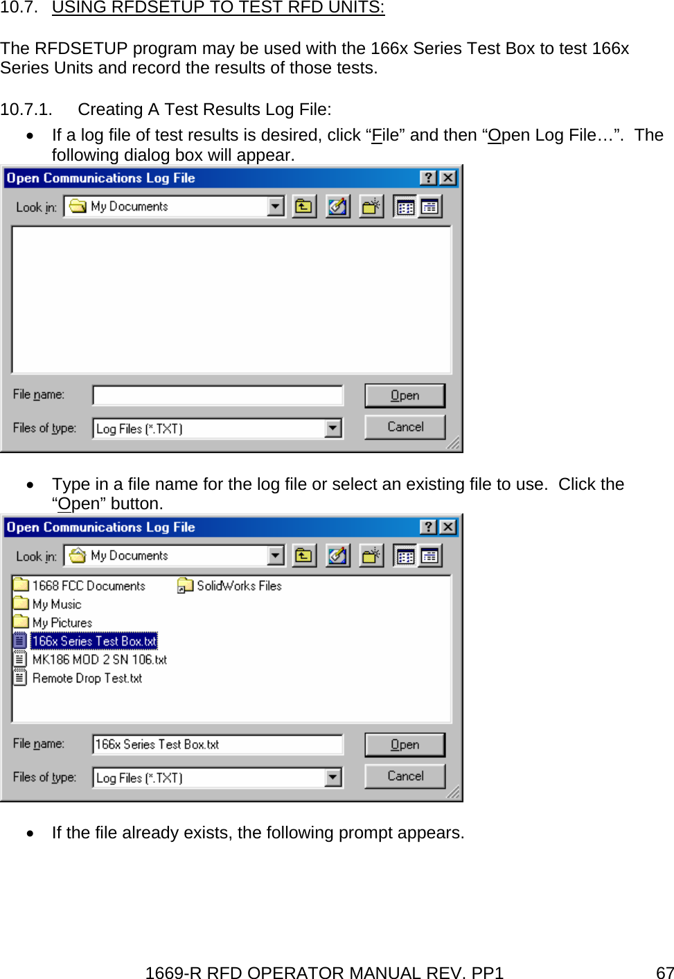
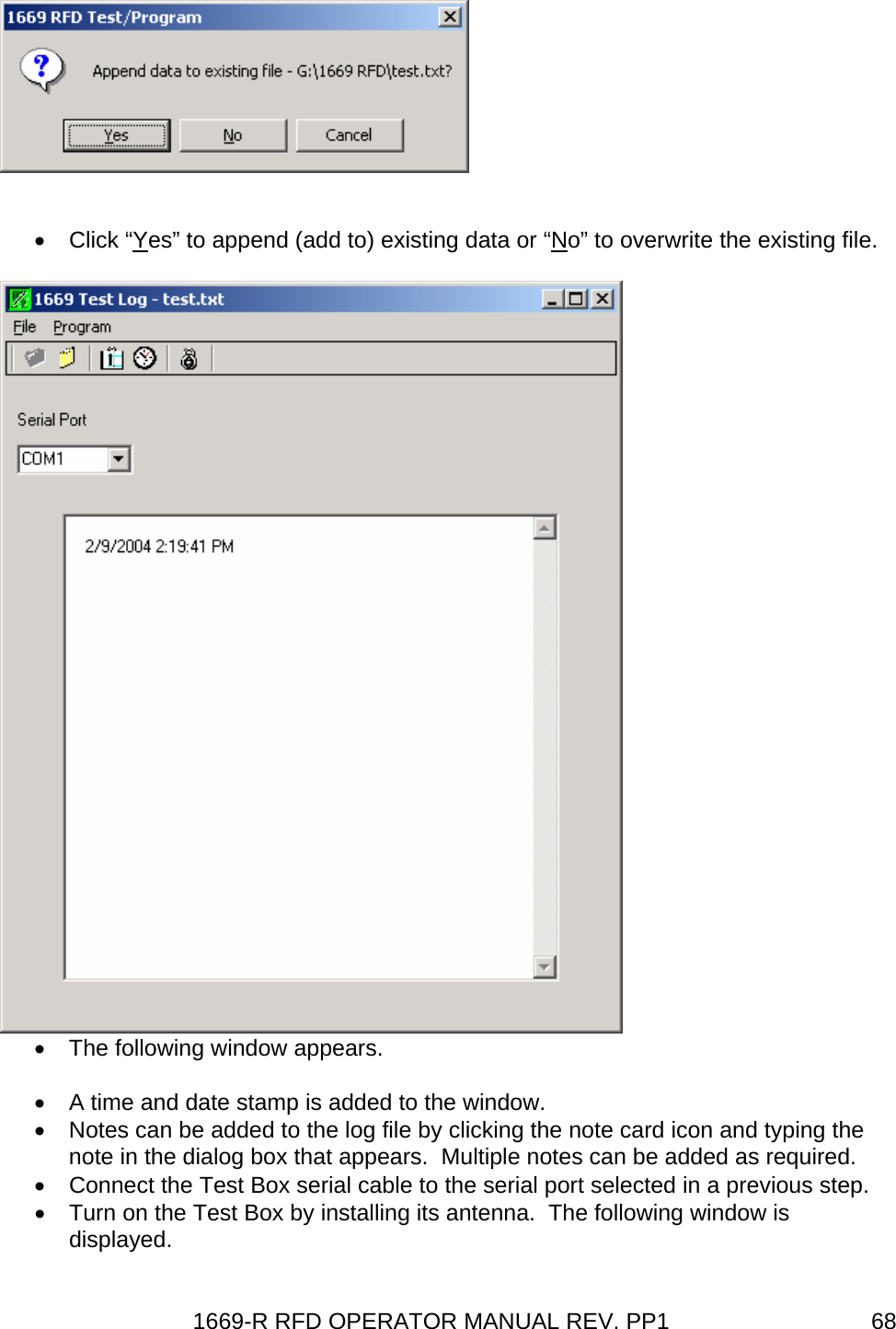
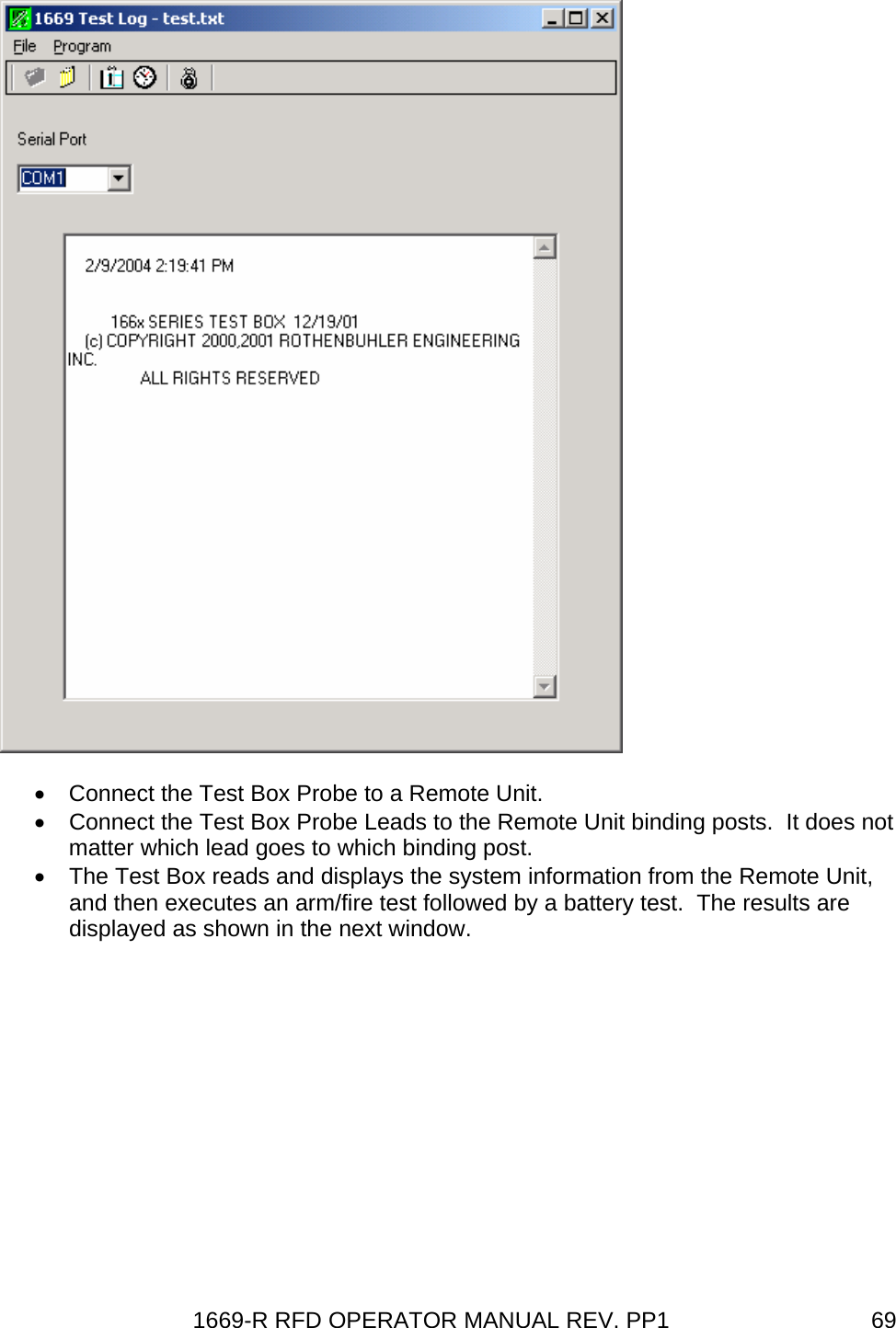
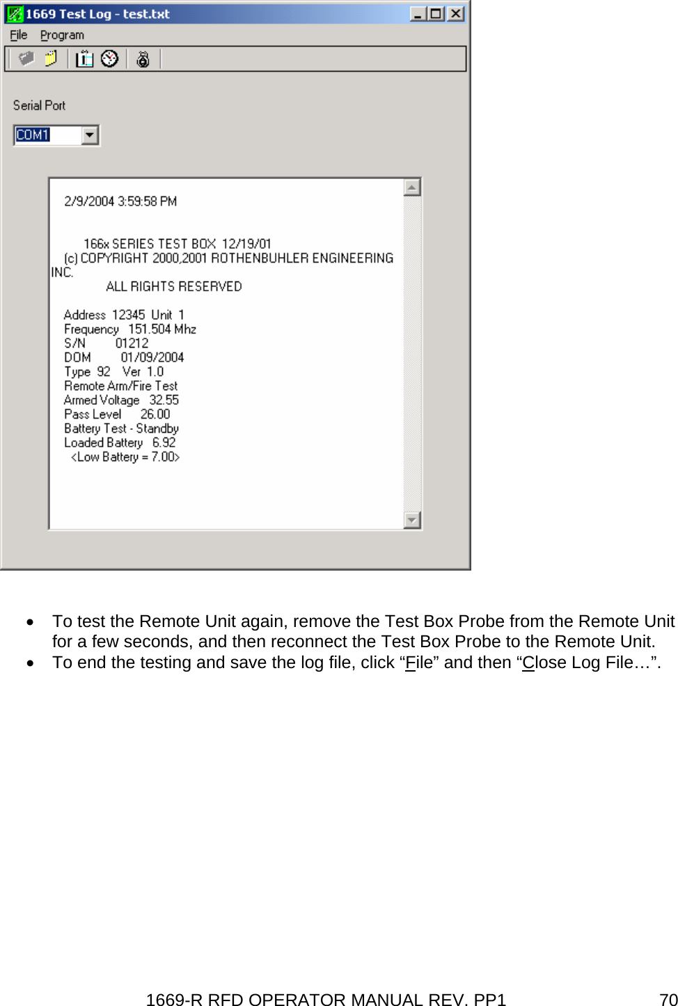
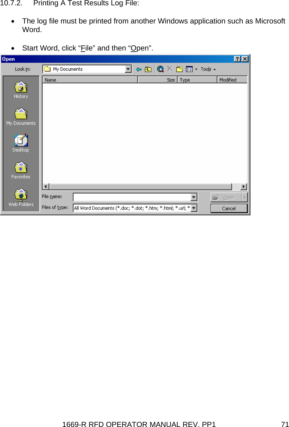
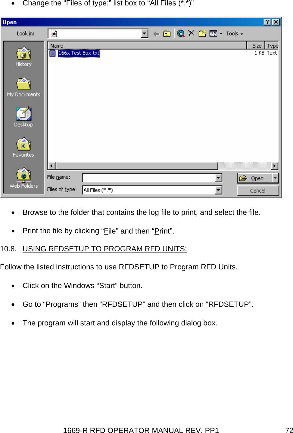
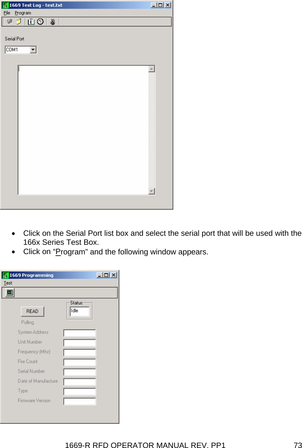
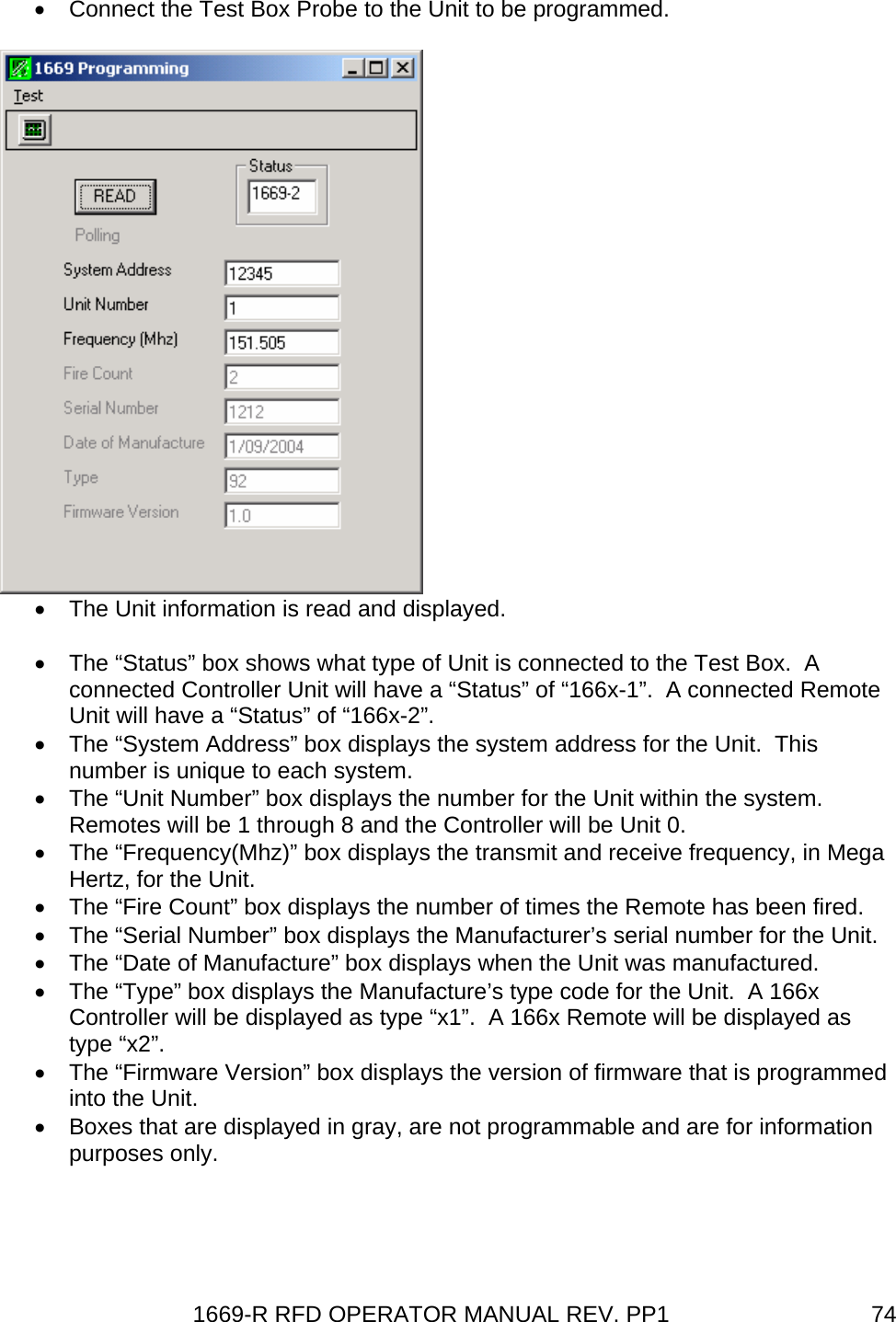
![1669-R RFD OPERATOR MANUAL REV. PP1 6110.3. DOS CONFIGURATION SOFTWARE OPERATION (RFDUSER). The RFDUSER.EXE program is supplied on a 3.5” floppy diskette. The program may be run from the floppy drive, or the program can be copied to a hard drive and run from there. Change directory and or drive to the drive and directory where the RFDUSER.exe program exists. Type RFDUSER in DOS, or double click on RFDUSER from Windows Explorer. The program starts, and the following text is displayed. Type RFDUSER in DOS, or double click on RFDUSER from Windows Explorer. If the serial port address is not 3F8, which is usually the address for serial port 1, type RFDUSER followed by a space and then the address of your serial port. Other common serial port addresses are com 2 = 2F8, com 3 = 3E8, and com 4 2E8. The program starts, and the following text is displayed on the computer screen. The actual values displayed will be dependent on how the unit is currently configured. RFD User Configuration Utility Ver 1.4U 9/08/00 Usage: rfduser [port_addr] Port addr: 3F8 Press ESC key to exit (A)ddress,(U)nit ID,(F)requency,(R)ead, ESC to Exit > The Test Box must be plugged into a serial port on your computer. Install an antenna onto the Test Box to turn it on. – DO NOT connect the Test Box probe to a Controller Unit or Remote Unit yet! The Test Box is then put into the programming mode automatically by the RFDUSER program. The Test Box display will change to the following message. System Configuration In Progress Now plug the Test Box probe into either a Remote Unit or a Controller Unit. The RFDUSER program automatically detects when the probe is connected to a unit to be tested. Note: The Test Box will remain in the programming mode until the ESCAPE key is pressed on the computer keyboard. If the Test Box probe is attached to a Remote Unit or Controller Unit, the Test Box will automatically begin testing that unit when the ESCAPE key is pressed.](https://usermanual.wiki/Rothenbuhler-Engineering/1669-20/User-Guide-765519-Page-70.png)