Rothenbuhler Engineering 1669-3 Model 1669-3, Rule Part 90.203(j)(3) User Manual Exhibit L
Rothenbuhler Engineering Company Inc Model 1669-3, Rule Part 90.203(j)(3) Exhibit L
User Manual
Exhibit L: User Manual
FCC ID: CW21669-3
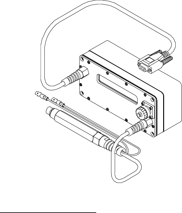
Test Box.
The Test Box allows the user to test Remote and Controller batteries under load
as well as test Remote Arm/Fire functions, and test Remote receivers. The Test
Box also serves as the programming interface between a computer and a RFD
Unit.
Figure 9-1 Test Box.
TEST BOX DESCRIPTIONS.
Antenna / Battery Charger Connector:
The Test Box has an Antenna/Battery Charger connector like the Remotes and
Controller. Installing an antenna from the system onto the antenna connector
turns on the Test Box. The Test Box has an internal battery pack that must be
recharged using the system battery charger.

Probe:
The Test Box has a probe that plugs into the Remote or Controller under test.
The Test box communicates to the Unit under test through the probe and by
using a radio transmitter that is internal to the Test Box. The two leads coming
off the probe are for connecting to the Remote binding posts. The firing voltage
of the Remote will be measured through these connections.
Serial Connection:
A serial cable connects the Test Box to a computer serial port operating at 1200
baud. The serial cable must be connected to a computer when the Test Box is
being used to program Controller and Remote Units. The serial cable may also
be used when the Test Box is in the test mode. While in the test mode, the Test
Box transmits the information displayed on the Test Box screen out the serial
cable. A terminal program such as Hyper Terminal may be set up to capture this
information to a file. The file can then be saved and printed.
TEST BOX OPERATION.
Test Box Messages
When the Test Box is turned on, the following message is displayed.
The “166x Series” part of the message
identifies the system types that the Test Box is designed to operate with.
“12/19/01” is the date of the Test Box firmware. “Ver 1.4” is the version of the
Test Box firmware.
Plugging the Test Box probe into the Test Box Antenna Connector puts the Test
Box into a self-test mode. In this mode, the Test Box loads its own internal
battery and then displays the loaded battery voltage along with the low battery
threshold point.
166x Series Test Box
12/19/01 Ver 1.4
Battery Test - Standby

This message displays while the Test Box loads down the battery of the unit
connected to the probe. This is done to get a more meaningful measurement of
the battery status.
The Test Box will automatically step to the next message.
This message shows the battery voltage for the unit connected to the probe while
the Test Box loads that battery. The Low Battery for the Unit is also displayed.
The Test Box will automatically step to the next message.
This message will be displayed until the
probe is removed from the unit being
tested.
Remote Messages
When the Test Box detects that a Remote Unit is connected to the probe, the
following message will be displayed.
The data displayed will be the actual configuration data from the unit connected
to the probe.
The Test Box will automatically step to the next message.
This message shows the Serial Number, Unit Type, Date of Manufacture, and
Firmware Version of the unit connected to the probe.
Frequency 154.570 Mhz
Address 65324 Unit 2
S/N 12345 Type 82
DOM 08/14/2000 Ver 1.0
Loaded Battery 7.84
Low Battery = 7.00
Testing Completed

The Test Box will automatically step to the next message.
The Test Box will arm and fire a Remote Unit connected to the probe. The two
leads from the probe must be connected to the Remote binding posts for the arm
voltage to be measured. The “015” is the amount of time remaining in the Arm /
Fire test. This number will count down to “000”. The Remote will then be fired.
The Test Box will automatically step to the next message.
This message show the actual armed voltage measured, and the minimum
armed voltage level that is normal.
The Test Box will automatically step to the next message.
This message displays while the Test Box loads down the battery of the unit
connected to the probe. This is done to get a more meaningful measurement of
the battery status.
The Test Box will automatically step to the next message.
Remote Arm/Fire Test
015
Armed Voltage 27.16
Pass Level = 26.00
Battery Test - Standby

This message shows the battery voltage for the unit connected to the probe while
the Test Box loads that battery. The Low Battery for the Unit is also displayed.
The Test Box will automatically step to the next message.
This message will be displayed until the
probe is removed from the Unit being
tested.
Controller Messages
Connect the Test Box probe to the Controller Unit antenna connector. Hold
down the ‘3’ button on the Controller Unit while pressing the ‘ON’ button. This
puts the Controller in the Program/Test mode. When the Test Box detects that a
Controller is connected to the probe, the following message will be displayed.
The data displayed will be the actual configuration data from the unit connected
to the probe.
The Test Box will automatically step to the next message.
Loaded Battery 7.84
Low Battery = 7.00
Testing Completed
Address 65324 Unit 0
Frequency 154.570 Mhz

This message shows the Serial Number, Unit Type, Date of Manufacture, and
Firmware Version of the unit connected to the probe.
The Test Box will automatically step to the next message.
This message displays while the Test Box loads down the battery of the Unit
connected to the probe. This is done to get a more meaningful measurement of
the battery status.
The Test Box will automatically step to the next message.
This message shows the battery voltage for the unit connected to the probe while
the Test Box loads that battery. The Low Battery for the Unit is also displayed.
The Test Box will automatically step to the next message.
This message will be displayed until the
probe is removed from the unit being
tested.
To run the tests again, disconnect and then reconnect the probe to a unit to be
tested.
S/N 12345 Type 81
DOM 08/14/2000 Ver 1.0
Battery Test - Standby
Loaded Battery 12.26
Low Battery = 11.75
Testing Completed