Ruckus Wireless C500 C500 Access Point User Manual C500 Access Point Quick Setup Guide
Ruckus Wireless, Inc. C500 Access Point C500 Access Point Quick Setup Guide
UserManual.wiki
>
Ruckus Wireless
>
C500 User Manual
>
User Manual
Contents
1.
Regulatory Statement User Manual
2.
User Manual
3.
Regulatory Statement
User Manual
Navigation menu
Upload a User Manual
Namespaces
Wiki Guide
HTML
PDF
Info
Views
User Manual
Discussion / Help
Navigation
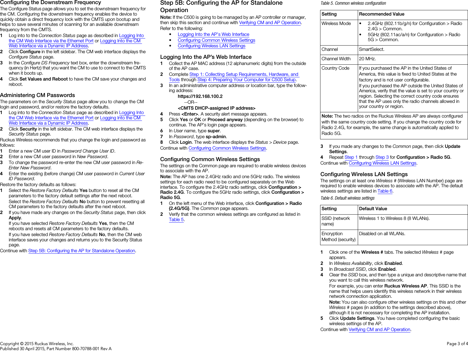
![Copyright © 2015 Ruckus Wireless, Inc.Published 30 April 2015, Part Number 800-70788-001 Rev APage 4 of 4VERIFYING CM AND AP OPERATIONThe cable operator has their own CM and AP acceptance tests. Make sure you verify the C500 operation as defined in the acceptance tests before leaving the installation site. WHAT TO DO NEXTFollowing are some of the post-installation tasks that Ruckus Wireless recommends. Refer to the Ruckus Wireless Indoor Access Point User Guide for more information on configuring and managing the AP.Changing the Administrative PasswordManagement access to the Web interface of the AP is controlled through administrative user name and password. As soon as you complete the AP setup, make sure you log on to the AP’s Web interface and change the default administrative user name and password. This will help prevent unauthorized users from logging in to the AP’s Web interface and changing the AP settings to compromise your network.Configuring the Security SettingsUnlike wired networks, anyone with a compatible wireless adapter can receive wireless data transmissions from your network. To prevent unauthorized users from entering your wireless network and accessing your computers and files, Ruckus Wireless strongly recommends enabling and configuring wireless security on the AP. The AP supports several types of encryption and authentication methods to help prevent unauthorized access to your wireless network.Configuring Advanced Settings and FeaturesThe AP has been configured for basic operation. However, the Ruckus Wireless AP supports many advanced settings and features. Refer to the Ruckus Wireless Indoor Access Point User Guide for instructions on how to configure the advanced setting and feature parameters.Reading Related DocumentationThe latest versions of Ruckus Wireless product documentation are available for download on the Ruckus Wireless Support Web site athttp://support.ruckuswireless.com/documents Online Training ResourcesTo access a variety of online Ruckus Wireless training modules, including free introductory courses to wireless networking essentials, site surveys, and Ruckus Wireless products, visit the Ruckus Wireless Training Portal athttps://training.ruckuswireless.com OPERATING AND TROUBLESHOOTING THE C500This section lists some information that may be useful in operating and troubleshooting the C500. Topics include:•Rebooting and Resetting the C500•How Radio Frequency Scanning Works•Retrieving the CM’s MAC AddressRebooting and Resetting the C500CAUTION: If required, you can reset the C500 to its factory default settings by pressing and holding in the reset button on the back of the C500 for four or more seconds. DO NOT DO THIS UNLESS SO INSTRUCTED. (Doing this resets the C500 IP address to 192.168.100.2 and resets the C500 CM address to 192.168.100.1.)NOTE: After a reset, you can access the internal C500 AP web interface using https://192.168.100.2. Your device must use an unused IP address, with subnet mask 255.255.255.0. The username is super, and the password is sp-admin. How Radio Frequency Scanning Works•DOCSIS Radio Frequency Scanning•EuroDOCSIS Radio Frequency ScanningDOCSIS Radio Frequency ScanningThe following steps describe how a DOCSIS-compliant C500 performs radio frequency scanning:1Looks at the last “known good channel” (repeat this every 64 channel checks).2Checks the sixteen last known frequencies (repeat this every 32 chan-nel checks).3Scans STD standard channels (where the center of the channel is an integer spaced by 6MHz), first [from 93MHz to 999MHz - 152 chan-nels]).4Scans the harmonically related carrier (HRC) channels, which moves the channels 1.25MHz off the standard frequencies so the video carri-ers are all related by 6MHz [from 91.75 to 997.5MHz--152 channels].A complete frequency scan requires approximately 469 channel checks. Since each channel takes about 0.6 seconds, a full scan is done every 281 seconds (a little under five minutes).Note: The scanning of generic DOCSIS channels is required the first time the C500 connects to an MSO. After the initial scan, the C500 is able to retrieve the local country frequency plan without a complete scan during its normal operation.EuroDOCSIS Radio Frequency ScanningThe following steps describe how a EuroDOCSIS-compliant C500 performs radio frequency scanning:1The cable modem scans DS frequencies in descending order in a group of four adjacent frequencies 8 MHz apart. The step between groups is 250kHz.From 122250000 Hz down, the scanning is not done in groups and descends in 250kHz steps to the lowest frequency of 112 MHz.2There is a scan list that keeps the 16 LKFs (Last Known Frequencies). They are re-scanned every 32 channels.3The first entry in the scan list is re-scanned every 64 channels.A complete frequency scan requires approximately 4526 channel checks and lasts approximately 4525 seconds.Retrieving the CM’s MAC AddressThere are some configuration operations that require you to enter the CM’s MAC address. The CM and AP MAC addresses are printed on labels on the outside of the C500. If you cannot find the CM’s MAC address on the C500, you can use the CMTS to retrieve the CM’s MAC address.PHYSICAL INSTALLATION• Place the C500 on a flat surface with feet down for most installations. You will experience the best wireless coverage and throughput when the C500 is mounted upright. Make sure you do not place the C500 on a hot surface or in direct sunlight. • If you are mounting the C500 on a wall or other vertical surface, then refer to the C500 Accessory Bracket Mounting Guide. Make sure you do not mount the C500 on a hot surface or in direct sunlight.](https://usermanual.wiki/Ruckus-Wireless/C500.User-Manual/User-Guide-2672380-Page-4.png)