Ruckus Wireless E510 E510 Access Point User Manual E510 Access Point Quick Setup Guide
Ruckus Wireless, Inc. E510 Access Point E510 Access Point Quick Setup Guide
Contents
User Manual
E510 Access Point
Quick Setup Guide
NOTE: The minimum software revision for the E510 is
ZoneDirector (ZD) 10.1 or later, or SmartZone (SZ) 3.6 or
later, or standalone AP firmware 108.0 or later.
This Quick Setup Guide provides step-by-step instructions on
how to field-install the Ruckus Wireless E510 access point
(AP). For detailed information on planning the installation,
performing a site survey, and operating the E510, refer to the
Ruckus Wireless Outdoor Access Point User Guide
, available
at https://support.ruckuswireless.com.
WARNING! Only trained and qualified personnel should be
allowed to install, replace, or service this equipment.
WARNING! Installation of this equipment must comply with
local and national electrical codes.
CAUTION! Make sure that you form a 80mm - 130mm
(3”-5”) drip loop in any cable that is attached to the AP or
the building. This will prevent water from running along the
cable and entering the AP or the building where the cable
terminates.
CAUTION! Be sure that grounding is available and that it
meets local and national electrical codes. For additional
lightning protection, use lightning rods and lightning
arrestors.
CAUTION! Make sure that proper lightning surge protection
precautions are taken according to local electrical code.
WARNING! Ruckus Wireless strongly recommends that you
wear eye protection before mounting the AP.
This Guide in Other Languages
• 请从以下网站请得请指南的请体中文版 https://
support.ruckuswireless.com.
• Vous trouverez la version française de ce guide à l'adresse
suivante https://support.ruckuswireless.com.
•このガイドの日本語版は https://
support.ruckuswireless.com でご覧ください。
•이 가이드의 한국어 버전은 웹 사이트 (https://
support.ruckuswireless.com) 에서 확인하시기 바랍니다.
• Veja a versão em português (Brasil) deste guia em https://
support.ruckuswireless.com.
• Puede ver la versión en español (América Latina) de esta
guía en https://support.ruckuswireless.com.
Before You Begin
Before deploying Ruckus Wireless products, please check for
the latest software and the release documentation.
• Release Notes and other user documentation are available
at http://support.ruckuswireless.com/documents.
• Software upgrades are available at http://
support.ruckuswireless.com/software.
• Open source information is available at http://
opensource.ruckuswireless.com.
• Software license and limited warranty information are
available at http://support.ruckuswireless.com/warranty.
Before deploying your Ruckus Wireless Access Point, verify
that all items listed in
Package Contents
are included in the
package. If any item is damaged or missing, notify your
authorized Ruckus Wireless sales representative. Also,
make sure that you have the required hardware and tools.
Required Hardware and Tools
• No. 2 Phillips screwdriver
• Small flat-blade screwdriver
• Torque wrench or torque screwdriver with sockets
• Long-nose pliers
• Electrical wire stripping and terminal crimping pliers
• Electric drill with drill bits and customer-supplied wall
anchors, flat washers, and hex nuts for flat-surface mount
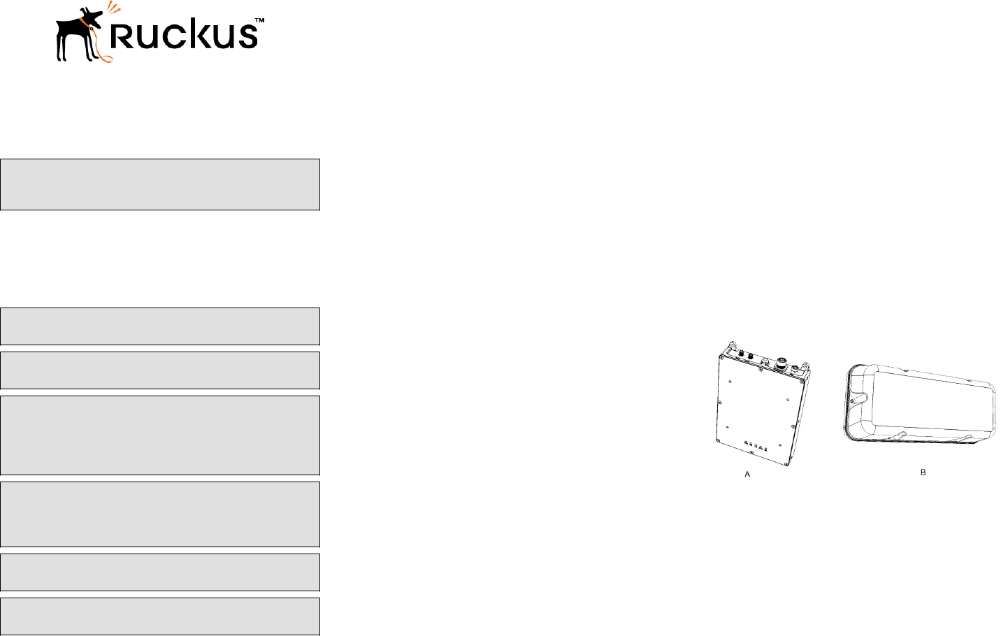
Package Contents
The E510 is a modular outdoor Access Point designed for
deployment scenarios where the antenna structure and
onboard AP intelligence must be physically separated, for
customers that have specific form factor needs such as:
outdoor lighting, railway, street furniture, sports and
entertainment venues, etc.
The E510 AP consists of three main modules:
• Embedded Access Point Module: Consists of the main AP
motherboard with the RF modules and circuitry.
• External Antenna Control Interface and RF cables: Connect
to an external Antenna Module with two RP-SMA
connectors (each dual-band/single chain).
• External Antenna Module: Consists of one vertically
polarized and one horizontally polarized antenna per band.
A complete E510 field installation package includes all of the
following:
• E510 Embedded Access Point Module (A)
• External Antenna Module (B)
• M12 Connector (X-coded, 8 Position, Shielded, Field
Installable)
• M8 Connector (A-coded, 3 Position, Field Installable)
• Service Level Agreement/Limited Warranty Statement
• Declaration of Conformity
• Regulatory Statement
• Ruckus Wireless AP Getting Started Guide
• This Quick Setup Guide
FIGURE 1 E510 Package Contents
Mounting Instructions
Mounting Scenarios
The E510 is designed for embedded mounting into third-party
structures such as light poles, light fixtures, street furniture,
railway carriages and track side installations.
Surface Mounting
The AP Module supports mounting on a flat surface in which
holes can be drilled, for example, with flanges.
The Antenna Module supports mounting on a flat surface in
which holes can be drilled, for example, with flanges or curved
surfaces, with, for example, loops for screw mounting.
Copyright ® 2017 Ruckus Wireless, Inc. Page 1 of 3
Published October 2017, Part Number 800-71577-001 Rev A
Pole Mounting
Both modules support mounting on a poles with a bracket.
DIN Rail Mounting
The AP supports mounting onto DIN Rail brackets.
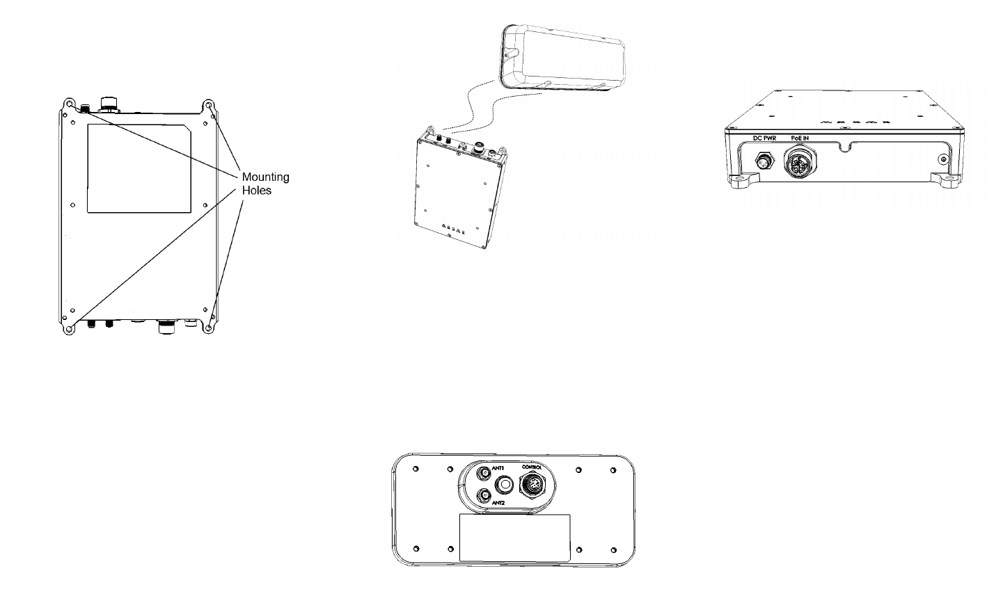
FIGURE 2 E510 Mounting holes
Connecting the AP Module to the Antenna
Module
The E510 has two RP-SMA connectors (Female) on the rear
panel for antenna RF cables to connect with the external
antenna module.
The 2.4 GHz and 5 GHz WLAN RF signals are carried
between the AP module and Antenna module using two SMA
cables. The length of these cables can be up to 3 meters,
which will lead to a loss of about 3dB in the 5GHz band and
2dB in the 2.4GHz band.
The length of cable depends on the needs of the installation,
and cables are therefore purchased separately to suit the
particular deployment.
1. Connect the antenna cables the ANT1 and ANT2
connectors on the AP Module and the Antenna Module
respectively.
FIGURE 3 Connect the AP Module to the Antenna Module
2. Finger tighten the antenna cable connectors.
3. Connect the M12 antenna control cable to the M12
connector (female) on the rear of the AP module.
4. Connect the other end of the M12 antenna control cable
to the M12 connector (male) on the rear of the Antenna
module.
FIGURE 4 E510 Antenna Module - rear panel connectors
Power Input
The E510 can accommodate two sources of power, 802.3af
PoE power or 12V‐48V DC.
The E510 can be powered by 802.3af PoE switch or Ruckus-
supplied PoE injector. Its power draw is within the 802.3af
budget when not supporting a USB dongle.
Alternately, power can be supplied from a DC power source
using the M8 connector on the rear of the product.
When both power sources exist, 12‐48V DC takes priority
over PoE Power.
FIGURE 5 E510 DC power and PoE In ports
Connecting the Ethernet Cable
The E510 has one 10/100/1000 PoE Ethernet port with M12
weatherproof connector.
Connect the Ethernet cable to a 802.3af-compliant PoE
switch or injector to provide both power and network
connectivity.
If PoE power is not used (DC power is used), the AP can
supply power to a USB dongle with a 3W power budget. If a
USB dongle is used, the power budget may exceed the
power draw limits of 802.3af. Thereafter, the AP's ability to
support a USB dongle will be "best effort" if powered by an
802.3af PoE injector or switch.
Factory Reset Button
A waterproof push button on the rear panel performs a soft
reset or, if held in more than five seconds, reset to factory
defaults.
USB Port
E510 has one USB 2.0 port as an M8 IP67 connector
(Female) on the rear of the unit. This port provides both data
connection and a 3W power output for an IoT device such as
a BLE Smart Beacon or Zigbee dongle.
A USB cable with an M8 connector at one end and a USB 2.0
Type-A connector at the other end can be attached to the
female M8 connector on the E510 AP module. The USB cable
length is expected to be approximately 1m (minimum) to 3m
(target). The USB dongle should be field installable and (the
cap/cover) secured via torx or similar screws.
Maximum output power of the USB port is 3W when the AP is
powered via DC power supply, and 0.5W under PoE power.
Copyright ® 2017 Ruckus Wireless, Inc. Page 2 of 3
Published October 2017, Part Number 800-71577-001 Rev A
For More Information
For information on how to configure and manage the AP, refer
to the
Ruckus Wireless Outdoor Access Point User Guide
,
available from https://support.ruckuswireless.com.
Copyright ® 2017 Ruckus Wireless, Inc. Page 3 of 3
Published October 2017, Part Number 800-71577-001 Rev A