Ruckus Wireless H510 H510 Access Point User Manual H500 Quick Setup Guide
Ruckus Wireless, Inc. H510 Access Point H500 Quick Setup Guide
Contents
- 1. Users Manual
- 2. Regulatory Insert
Users Manual

Copyright © 2016 Ruckus Wireless, Inc. Page 1 of 4
Published April 2016, Part Number 800-71206-001 Rev A
H510 Access Point
Quick Setup Guide
This Quick Setup Guide provides step-by-step instructions on how
to set up your Ruckus Wireless H510 Dual Band 802.11ac
Multimedia Wi-Fi Access Point Wall Switch. After completing the
steps described in this guide, you will be able to access the Wi-Fi
Wall Switch and begin providing wired and wireless network
access to users. The rest of this document refers to the H510
Access Point Wall Switch as the H510.
The H510 has many options:
• It can be mounted on a standard USA- or EU-style single-
gang wall outlet box.
• It can be powered by a customer-supplied IEEE 802.3af- or
802.3at-compliant PoE switch or injector, or can be powered
by an optional customer-ordered DC power adapter.
• It has side cutouts for one or two bypass cables. The
mounting bracket has locating hooks to keep the bypass
cables aligned with the cutouts when attaching the H510 to
the mounting base.
• It can have a low-power (0.5W or less) customer-supplied
USB device plugged in. The USB device is very difficult to
remove after the H510 is attached to the mounting base.
ABOUT PERIPHERAL DEVICES
The H510 can supply power to USB devices and PoE-powered
devices, and the power supplied depends on the PoE power
supplied to the H510.
• The USB port is intended for low-power devices such as BLE
(Bluetooth low energy) beacons. The maximum power that the
USB port can supply is 0.5W.
•The LAN1+PoE port is intended for PoE-powered peripheral
devices such as IP telephones.
THIS GUIDE IN OTHER LANGUAGES
•请从以下网站获得该指南的简体中文版
https://support.ruckuswireless.com
• Vous trouverez la version française de ce guide à l'adresse
suivante https://support.ruckuswireless.com
•こ の ガ イ ド の⽇本語版は https://support.ruckuswireless.com
でご覧く ださい
•이 가이드의 한국어 버전은 웹 사이트
(https://support.ruckuswireless.com)에서 확인하시기 바랍니
다
• Veja a versão em português (Brasil) deste guia em
https://support.ruckuswireless.com
• Puede ver la versión en español (América Latina) de esta guía
en https://support.ruckuswireless.com
BEFORE YOU BEGIN
Before deploying Ruckus Wireless products, please check for the
latest software and the release documentation.
• User Guides and Release Notes are available at
http://support.ruckuswireless.com/documents
• Software Upgrades are available at
http://support.ruckuswireless.com/software
• Open Source information is available at
http://opensource.ruckuswireless.com
• Software License and Limited Warranty are available at
http://support.ruckuswireless.com/warranty
PACKAGE CONTENTS
• H510 Access Point Wall Switch
• Mounting bracket
• Two 6mm M3x0.5 thread Torx flat head machine screws
• Two 1” 6-32 thread Phillips pan head machine screws
• Product warranty statement
• Regulatory flyer
• Declaration of Conformity, if required
•This Quick Setup Guide
Note: The H510 requires Ruckus Wireless base image 104.0
firmware or later. Managed H510 deployments require
SmartZone 3.4 or later, or ZoneFlex (ZF) 9.13.1 or later.
H510 Power Options and Available Power Out for PoE Out
and USB
H510 Power Source Power Available for PoE Out
and USB
802.3af PoE 5W total
802.3at PoE 12.95W PoE Out (802.3af
Class 3) and
0.5W USB
DC power adapter (sold
separately)
12.95W PoE Out (802.3af
Class 3) and
0.5W USB
Copyright © 2016 Ruckus Wireless, Inc. Page 2 of 4
Published April 2016, Part Number 800-71206-001 Rev A
STEP 1: COLLECTING TOOLS AND SETUP
REQUIREMENTS
• No. 2 Phillips screwdriver and T10 Torx driver for the mounting
bracket screws
• A standard USA- or EU-style single-gang wall outlet box
• One of the following:
• Customer-supplied IEEE 802.3af/at-compliant PoE switch
and customer-supplied Ethernet cable
• Customer-supplied IEEE 802.3af/at-compliant PoE
injector and customer-supplied Ethernet cable
• Customer-ordered DC power adapter (Ruckus part
number 902-0170-XX10, sold separately)
• An Ethernet cable with or without PoE run through the wall
from your LAN through the wall outlet box
• A computer with an Ethernet port and a wireless card with
customer-supplied Cat 5e or better Ethernet cable
• (optional) One or two separate bypass cables run through the
outlet box
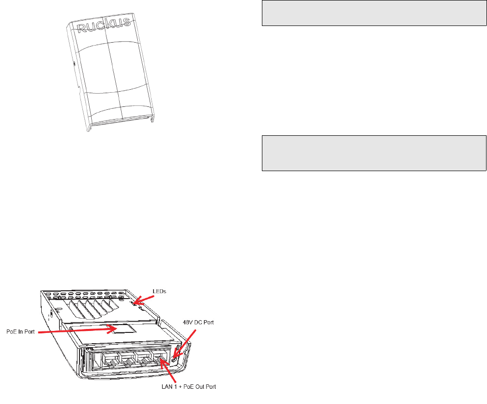
STEP 2: CONNECTING THE COMPUTER TO THE
H510
Figure 1: Front view
1After removing your H510 from its package, place it next to
your computer.
2Using an Ethernet cable, connect your computer’s network
port to the PoE In port on the rear of the H510.
3Using an AC adapter (sold separately), connect the H510
48VDC port to a protected power source.
Alternatively, connect the PoE In port to a PoE injector or PoE
switch for both power and network connections.
4Verify that the PWR LED on the rear of the enclosure is a
steady green.
Figure 2: Rear and bottom view
STEP 3: PREPARING YOUR COMPUTER FOR H510
SETUP
1On your Windows 7 computer, configure your network
adapter from the Local Area Connection settings as follows:
• Start > Control Panel > Network and Sharing
Center > Change Adapter Settings
2Edit the TCP/IPv4 address settings as follows:
• Local Area Connection > Properties > Internet
Protocol Version 4 (TCP/IPv4) > Properties
The Internet Protocol Version 4 (TCP/IPv4) Properties dialog
box appears.
3Select Use the following IP address (if it is not already
selected) and then make the following entries:
•IP address: 192.168.0.22 (or any available address in the
192.168.0.x network, except 192.168.0.1)
•Subnet mask: 255.255.255.0
•Default gateway: 192.168.0.1
Leave the DNS server fields empty.
4Click OK to save your changes.
Your changes are put into effect immediately.
Note: The following procedures assume that Windows 7 is the
operating system. Procedures for other OS’s are similar.
Important! Write down all of the currently active settings so you
can restore your computer to its current configuration later,
when this process is complete.

Copyright © 2016 Ruckus Wireless, Inc. Page 3 of 4
Published April 2016, Part Number 800-71206-001 Rev A
STEP 4: LOGGING INTO THE H510 ACCESS POINT
As specified in Step 3: Preparing Your Computer for H510 Setup,
the H510 should be directly connected to your computer (through
the PoE In Ethernet port on the back of the H510) and powered
on, ready for setup.
1On your computer, open a Web browser window.
2In the browser, type this URL to connect to the H510:
https://192.168.0.1
3Press <Enter> to initiate the connection. When a security alert
dialog box appears, click OK/Yes to proceed.
4When the Ruckus Wireless Admin login page appears, enter
the following:
•Username: super
•Password: sp-admin
5Click Login.
STEP 5: CUSTOMIZING THE WIRELESS SETTINGS
1On the Web interface menu, click Configuration > Radio
2.4G or Configuration > Radio 5G. The Configure >
Wireless > Common page appears.
2Verify that the following options are active:
•Channel: SmartSelect.
•Country Code: If you are not located in the United States
of America, select your current country.
3Click Update Settings if you made any changes.
4Click any of the “Wireless #” (Wireless LAN Number) tabs at
the top of the page.
5In Wireless Availability, click Enabled.
6Delete the text in the SSID field, then type a name for your net-
work that will help your users identify the H510 access point in
their wireless network connection applications.
7Click Update Settings to save your changes.
8Repeat Steps 4-7 for each Wireless # (Wireless LAN Number)
interface that you want to enable.
9Click Logout to exit the Web interface.
10 When the Ruckus Wireless Admin login page reappears, you
can exit your browser.
11 Disconnect the H510 from the computer and from the power
source, and then restore your computer to its original network
connection configuration.
Continue with Step 6: Attaching the Mounting Bracket to an Outlet
Box.
STEP 6: ATTACHING THE MOUNTING BRACKET TO
AN OUTLET BOX
Figure 3: Mounting bracket
1Use either the original wall outlet box screws or the factory-
supplied 1” Phillips pan head machine screws to attach the
H510 mounting bracket to a single-gang wall outlet box.
2Pull the LAN uplink Ethernet cable for the H510 through the
wall outlet box.
3If you are powering the H510 with a customer-ordered DC
power adapter, ensure that the power cable is able to reach
the DC in port without obstructing the AP and preventing the
AP from mounting flush with the wall bracket.
4When you have extra bypass cables (usually one or two) that
are to bypass the H510, pull them through the wall outlet box.
Note: The bypass cables can be Ethernet, coax, or any other
type of cable, as required.
Drape the bypass cables across one or both of the upper
hooks on either side or both sides of the mounting bracket.
Continue with Step 7: Attaching the H510 to the Mounting
Bracket.
Default H510 Access Point Settings (for your reference)
Network Names (SSIDs) Wireless1-Wireless8 (2.4GHz
radio)
Wireless9-Wireless16 (5GHz
radio)
Security (Encryption method) Disabled for each wireless
interface
Default Management IP
Address
192.168.0.1
Optional: In a default H510 configuration, the H510 uses a
DHCP-assigned IP address.
If you anticipate logging into the H510 regularly to perform
monitoring or maintenance once it is in place, then you may want
to consider switching from DHCP and instead assigning a static
IP address to the H510.
A. On the menu, click Configuration > Internet.
B. Click the Static IP option.
C. Fill in the IP Address and Mask fields.
D. Click Update Settings to save your changes.
Note: The H510 mounting bracket has four hooks that face UP.
Make sure that the hooks are facing up when attaching the
mounting bracket to the wall outlet box.
Copyright © 2016 Ruckus Wireless, Inc. Page 4 of 4
Published April 2016, Part Number 800-71206-001 Rev A
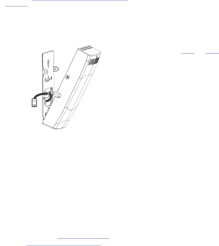
STEP 7: ATTACHING THE H510 TO THE MOUNTING
BRACKET
1Make sure that the mounting bracket is securely fastened as
described in Step 6: Attaching the Mounting Bracket to an
Outlet Box.
2If you have bypass cables (usually one or two, if any), then
make sure that they are draped across one or both of the two
upper hooks on the mounting bracket.
Figure 4: Attaching the H510 to the Mounting Bracket
3If you are installing a customer-supplied USB device (such as
a BLE beacon), then plug it securely into the USB jack on the
bottom of the H510.
4Pull the uplink Ethernet cable from your LAN through the outlet
box, and plug it into the back of the H510.
5The mounting bracket has two lower hooks that fit into slots
on the bottom of the H510. Rest the bottom of the H510 on
those hooks, and then tilt the H510 until it is up against the
mounting bracket.
Note that any optional bypass cable(s) should slide smoothly
into the slots on the sides of the H510.
6Use a T10 Torx driver to screw the factory-supplied Torx flat
head machine screws through the H510 screw holes into the
threaded inserts on the sides of the mounting bracket.
7After the H510 has powered on, it supplies USB power and
PoE Out as described in About Peripheral Devices.
Continue with Step 8: Testing the H510 Operation.
STEP 8: TESTING THE H510 OPERATION
After a short pause to re-establish the Internet connection, you can
test the H510.
1Using any wireless-enabled computer or mobile device,
search for and select the wireless network you previously con-
figured.
2If you can connect, open a browser and navigate to any public
Web site.
3Using any wired computer or other device and an Ethernet
cable, plug into an Ethernet port on the bottom of the H510.
4Open a browser and navigate to any public Web site.
5Repeat Step 3 and Step 4 for the rest of the Ethernet ports on
the bottom of the H510.
6Verify that all connected PoE-powered devices and USB
devices are working correctly.
Congratulations! Your H510 is active and ready for use.