Ruckus Wireless T300 IEEE 802.11ac Access Point User Manual T301n Access Point Mounting Guide
Ruckus Wireless, Inc. IEEE 802.11ac Access Point T301n Access Point Mounting Guide
Contents
- 1. User Manual
- 2. User Guide
- 3. Regulatory Flyer
User Guide

Copyright © 2014 Ruckus Wireless, Inc.
Published April 2014, Part Number 800-70604-001 Rev A Page 1 of 4
T301n Access Point
Mounting Guide
This Mounting Guide provides step-by-step instructions on how
to field-install the Ruckus Wireless T301n 30-Degree Narrow
Sector 802.11ac outdoor access point (AP). Unless specifically
indicated, the rest of this document refers to the T301n as an AP.
For detailed information on planning the installation, pointing the
internal GPS antenna, performing a site survey, preparing the AP
at the depot and shipping to the field, refer to the T301n 802.11ac
Outdoor Access Point Installation Guide. For information on
configuring and operating the AP, refer to the ZoneFlex Outdoor
Access Point User Guide. Both documents are available at
https://support.ruckuswireless.com.
WARNING: Only trained and qualified personnel should be
allowed to install, replace, or service this equipment.
WARNING: Installation of this equipment must comply with local
and national electrical codes.
CAUTION: Make sure that you form a 80mm - 130mm (3”-5”)
drip loop in any cable that is attached to the AP or the building.
This will prevent water from running along the cable and entering
the AP or the building where the cable terminates.
CAUTION: Be sure that grounding is available and that it meets
local and national electrical codes. For additional lightning
protection, use lightning rods and lightning arrestors.
CAUTION: Make sure that proper lightning surge protection
precautions are taken according to local electrical code.
WARNING: Ruckus Wireless strongly recommends that you wear
eye protection before mounting the AP.
BEFORE YOU BEGIN
Before deploying Ruckus Wireless products, please check for the
latest software and the release documentation.
• User Guides and Release Notes are available at
http://support.ruckuswireless.com/documents
• Software Upgrades are available at
http://support.ruckuswireless.com/software
• Open Source information is available at
http://opensource.ruckuswireless.com
• Software License and Limited Warranty available at
http://support.ruckuswireless.com/warranty
REQUIRED HARDWARE AND TOOLS
• Torque wrench or torque screwdriver with sockets and bits
• Wide flat-blade screwdriver
If you are mounting the AP on a flat surface, then you will also
need:
• Customer-supplied wall anchors rated to withstand 128 N or
28.8 lbf (required to withstand wind loads of 266km/h or
165mph)
• Electric drill with drill bits and customer-supplied wall anchors,
flat washers, and hex nuts for flat-surface mount
If you are mounting the AP on a pipe or pole, then you will also
need:
• A 30mm to 60mm (1.18" to 2.36") pipe or pole
• Four factory-supplied steel clamps
PACKAGE CONTENTS
Before deploying your AP in the field, verify that all items listed
below are included in the package. If any item is damaged or
missing, notify your authorized Ruckus Wireless sales
representative. Also, make sure that you have the required
hardware and tools.
• One T301n AP (A in Figure 1); includes one 12mm M6x1 earth
ground screw with split lock and flat washers
• One M25 data cable gland (B in Figure 1)
• One green/yellow earth ground wire with ring terminal (C in
Figure 1)
• One wall- or pole-mount hanger mount (D in Figure 1)
• One extension bracket (E in Figure 1)
• One AP mounting bracket (F in Figure 1)
• Two sets 40mm M8x1.25 hex bolt with split lock and flat
washers (G in Figure 1)
• Four SAE32-sized stainless steel clamps, 2.5-inch diameter
(H in Figure 1)
• Four sets 0.250-28 x 0.625-inch hex bolt with split lock and
flat washers (I in Figure 1)
Figure 1: AP field-installation package contents
The field installation package can also include:
• Service Level Agreement/Limited Warranty Statement
• Regulatory Statement
• Registration card
• Declaration of Conformity, if required
•This Mounting Guide
CAUTION! The minimum software revision for the T301n AP is
ZoneFlex (ZF) 9.8.1, or SmartCell Gateway (SCG) 3.0 or later.
Do not connect the T301n AP to a Ruckus Wireless Controller
with ZF 9.8.0 or earlier, or to SCG 2.x or earlier.
F
GH
EA CB D
I
Copyright © 2014 Ruckus Wireless, Inc.
Published April 2014, Part Number 800-70604-001 Rev A Page 2 of 4
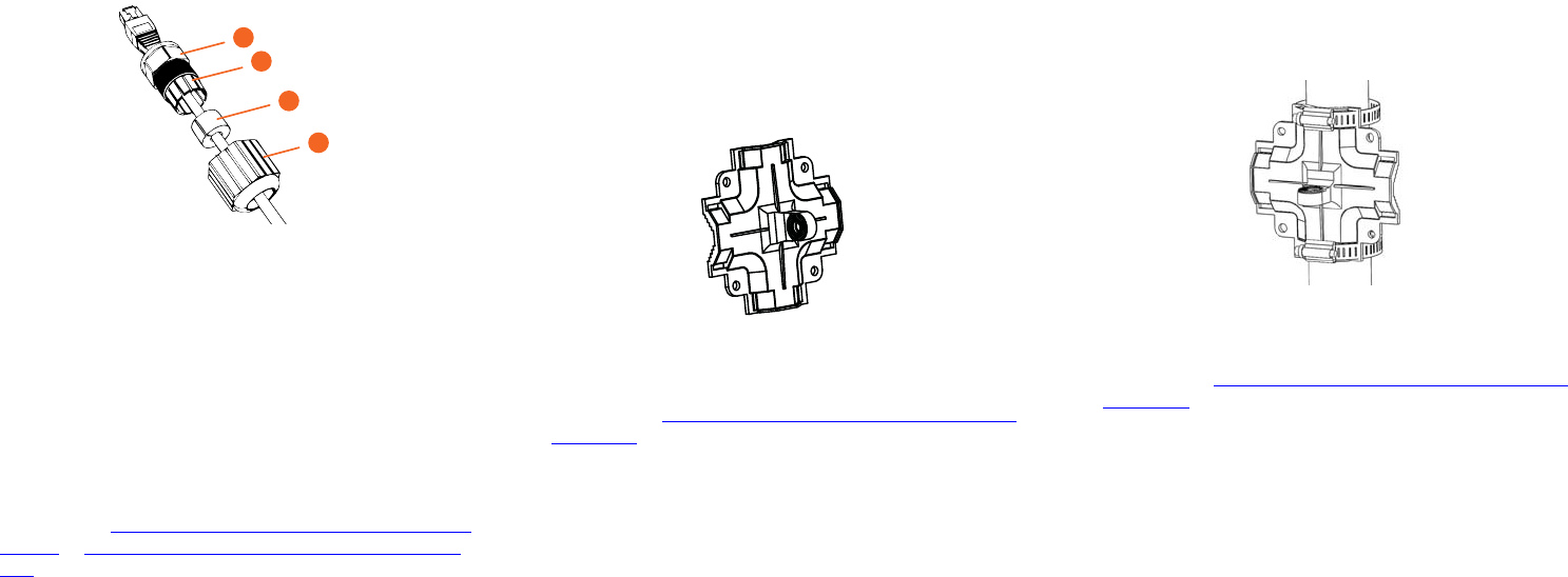
STEP 1: CONNECTING AND SEALING THE RJ-45
CABLE
The AP uses one RJ-45 cable for Power over Ethernet (PoE).
Connect and seal the cable using the M25 data cable gland (B in
Figure 1).
1Feed the end of the RJ-45 cable through the sealing nut (D in
Figure 2), rubber sealing insert (C in Figure 2), clamping ring
assembly (B in Figure 2) and cable gland base (A in Figure 2).
Figure 2: RJ-45 cable and cable gland assembly
2Use a wide flat-blade screwdriver to remove the blanking cap
from the AP.
3Connect the cable to the Ethernet port in the AP.
4Tighten the cable gland base into the AP chassis to 7 N.m or
62 in-lbs.
5Wrap the clamping ring assembly around the rubber sealing
insert. Make sure that the clamping ring assembly fully
encloses the rubber sealing insert.
6Seat the clamping ring assembly and rubber sealing insert in
the cable gland base.
7Hand-tighten the sealing nut.
8Continue with Step 2a: Attaching the Hanger Mount to a Flat
Surface or Step 2b: Attaching the Hanger Mount to a Metal
Pole.
STEP 2A: ATTACHING THE HANGER MOUNT TO A
FLAT SURFACE
1Hold the hanger mount (D in Figure 1) at the location on the
mounting surface where you want to mount the AP. Use the
holes on the hanger mount as a template to mark the
locations of the mounting holes.
2Remove the hanger mount from the mounting surface.
3Drill holes required for the customer-supplied mounting
hardware.
4Attach the hanger mount to the flat surface using the
mounting hardware.
5Using the mounting hardware instructions, tighten the
hardware to secure the hanger mount.
Figure 3: Hanger mount on a flat surface
NOTE: Hanger mount shown attached vertically to allow AP
elevation adjustments. Attach the hanger mount vertically to allow
AP azimuth adjustments.
6Continue with Step 3: Assembling the AP Mounting Bracket
and the AP.
STEP 2B: ATTACHING THE HANGER MOUNT TO A
METAL POLE
1Insert the open end of one steel clamp (H in Figure 1) into the
upper two slots on the hanger mount (D in Figure 1).
2Take the other steel clamp and insert it into the lower two slots
on the hanger mount.
3Use the clamps to attach the hanger mount to the pole (the
clamps can be daisy-chained together to accommodate
larger poles). Tighten the clamps to 3 N.m or 27 in-lbs, or per
manufacturer’s specifications if the supplied clamps are not
used.
Figure 4: Hanger mount on a vertical pole
NOTE: Hanger mount shown attached horizontally to allow AP
azimuth adjustments. Attach the hanger mount vertically to allow
AP elevation adjustments.
4Continue with Step 3: Assembling the AP Mounting Bracket
and the AP.
A
B
C
D
Copyright © 2014 Ruckus Wireless, Inc.
Published April 2014, Part Number 800-70604-001 Rev A Page 3 of 4
STEP 3: ASSEMBLING THE AP MOUNTING BRACKET
AND THE AP
1Place the AP mounting bracket (F in Figure 1) onto the back
side of the AP so that the four screw holes on the bracket
align with the four screw holes on the AP. Make sure that the
longer end of the AP mounting bracket points away from the
AP connector.
Figure 5: Positioning the AP mounting bracket on the AP
2Insert the 0.250-28 bolts (I in Figure 1) with washers into the
screw holes on the AP mounting bracket. Tighten the bolts to
2.5-3.0 N.m or 22-27 in-lbs.
CAUTION: The mounting bolt length is critical. Do not use bolts
longer than the supplied 0.250-28 x 0.625” L parts or the unit may
be damaged.
3Continue with Step 4: Mounting the AP.
STEP 4: MOUNTING THE AP
1Align one of the holes on the extension bracket (E in Figure 1)
with the hole on the hanger mount.
Figure 6: Align the extension bracket hole with the hanger mount hole
2Insert an M8 hex bolt into hole and finger tighten until the bolt
passes through the screw hole on the hanger mount.
Figure 7: Finger-tightened hex bolt
3Align the hole on the mounting bracket with the remaining
hole on the extension bracket.
4Insert an M8 hex bolt into the hole and finger tighten until the
bolt passes through the extension bracket.
Figure 8: AP mounting
5Adjust the azimuth and elevation of the AP as required.
6Using a 13mm wrench, tighten the M8 hex bolts to 13.6 N.m
(10 ft-lbs) so the extension bracket is securely fastened to the
AP mounting bracket and the hanger mount.
7Continue with Step 5: Earth Grounding the AP.
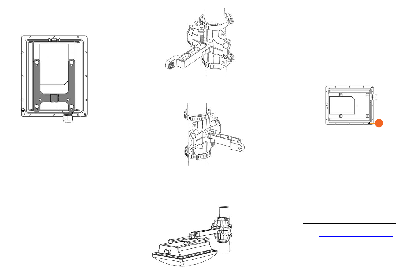
STEP 5: EARTH GROUNDING THE AP
CAUTION: Make sure that earth grounding is available and that it
meets local and national electrical codes. For additional lightning
protection, use lightning rods and lightning arrestors.
NOTE: The color coding of ground wires varies by region. Before
completing this step, check your local wiring standards for
guidance.
• Using the factory-supplied ground wire and ground screw,
connect a good earth ground to the AP chassis ground point
(A in Figure 9).
Figure 9: Connect good earth ground to AP here
Congratulations! You have mounted your T301n access point.
TROUBLESHOOTING
CAUTION: If required, you can reset the AP to its factory default
settings by pressing the reset button located inside the PoE OUT/
RESET port. DO NOT DO THIS UNLESS SO INSTRUCTED.
(Doing this resets the AP IP address to 192.168.0.1.)
NOTE: After a reset, you can access the internal AP web interface
using https://192.168.0.1. Your device must use any
other address from 192.168.0.2 through 192.168.0.254, with
subnet mask 255.255.255.0 and default gateway 192.168.0.1.
The username is super, and the password is sp-admin. Refer
to the T301n 802.11ac Outdoor Access Point Installation Guide
and the ZoneFlex Outdoor Access Point User Guide for
information on configuring and operating the AP. Both documents
are available at https://support.ruckuswireless.com.
A
Copyright © 2014 Ruckus Wireless, Inc.
Published April 2014, Part Number 800-70604-001 Rev A Page 4 of 4