Ruckus Wireless T310 T310 (C/D) Access Point User Manual T310d
Ruckus Wireless, Inc. T310 (C/D) Access Point T310d
UserManual.wiki
>
Ruckus Wireless
>
T310 User Manual
>
T310d User Manual
Contents
1.
Manual Regulatory Statement
2.
T310c User Manual
3.
T310d User Manual
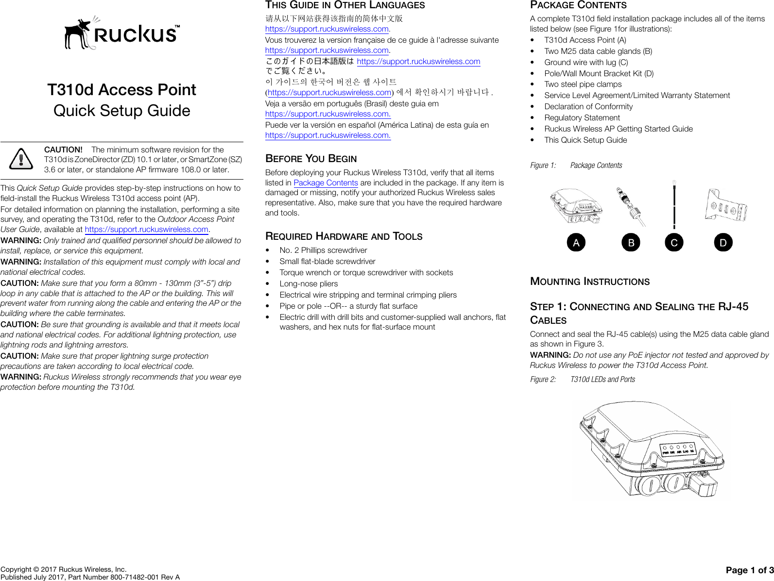
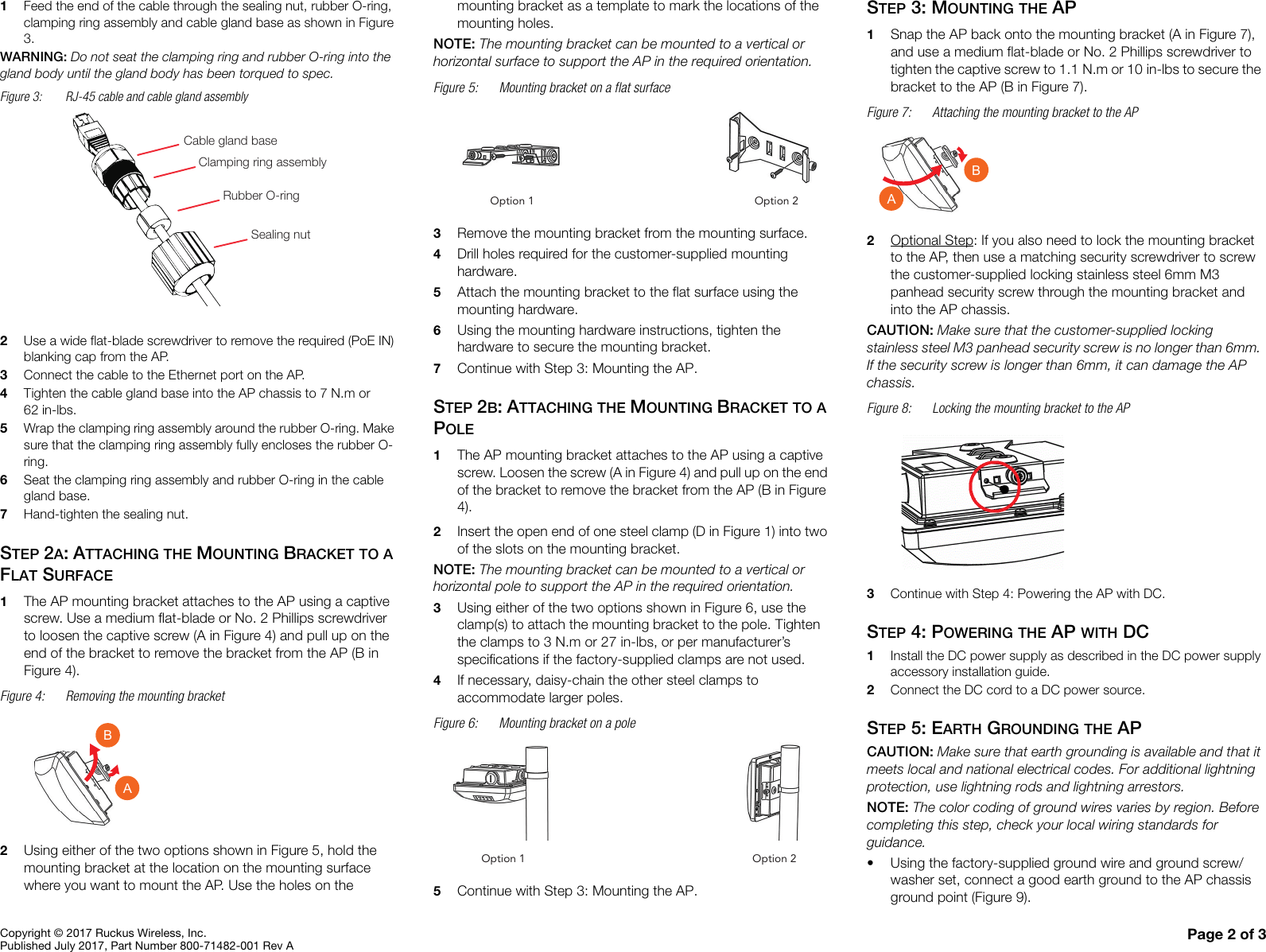
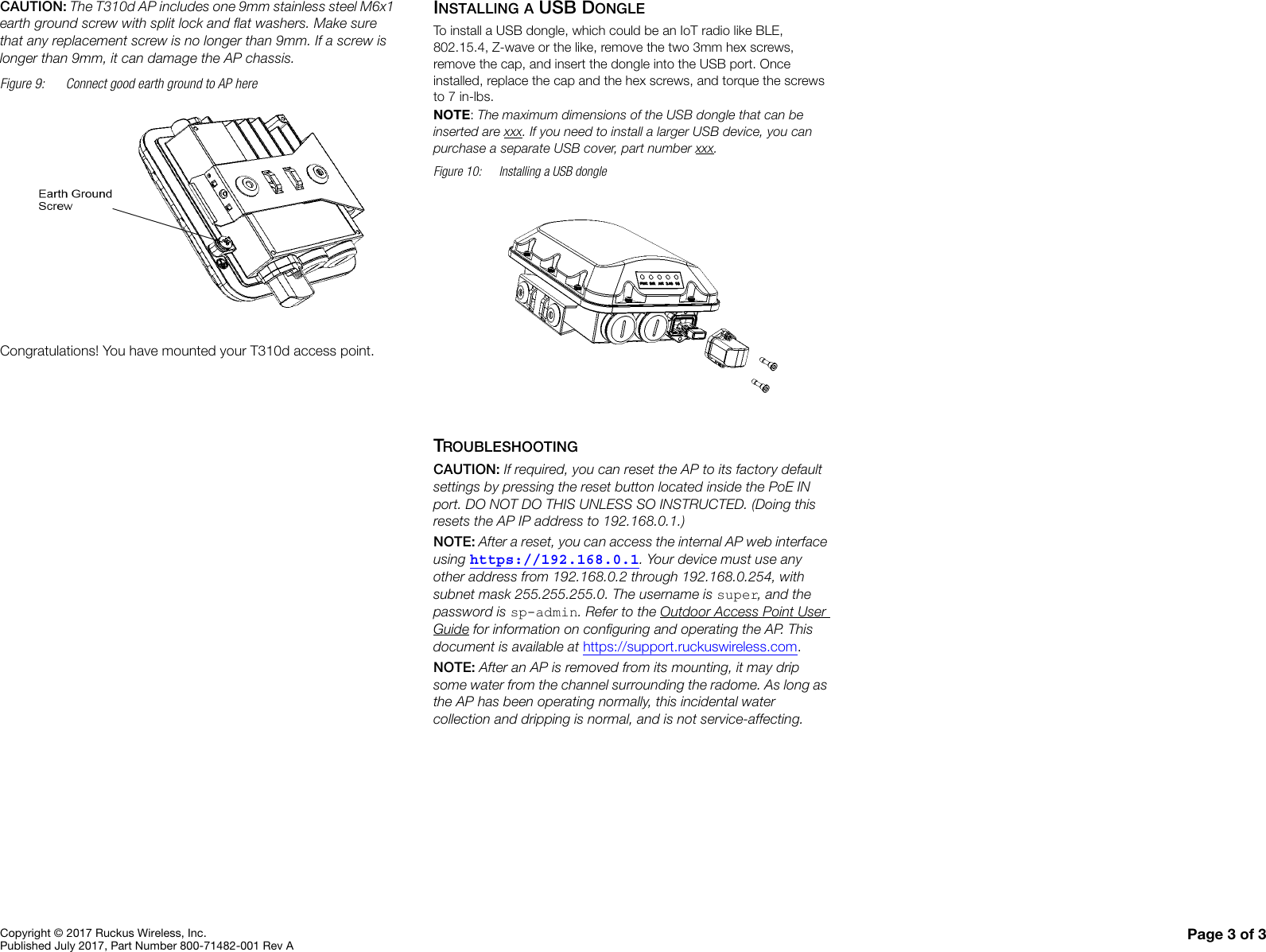
T310d User Manual
Navigation menu
Upload a User Manual
Namespaces
Wiki Guide
HTML
PDF
Info
Views
User Manual
Discussion / Help
Navigation