Ruckus Wireless T310NS T310 (N/S) Access Point User Manual T310s Access Point Quick Setup Guide
Ruckus Wireless, Inc. T310 (N/S) Access Point T310s Access Point Quick Setup Guide
Contents
- 1. Regulatory Statement
- 2. T310N User Manual
- 3. T310S User Manual
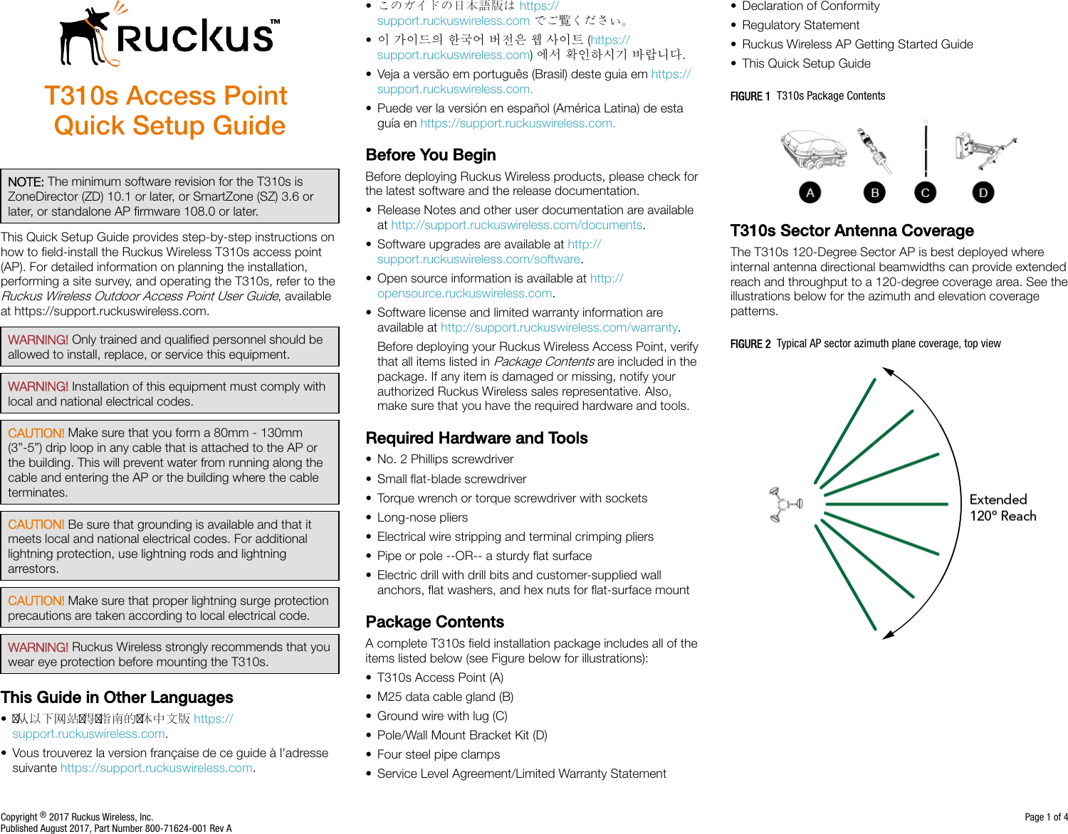
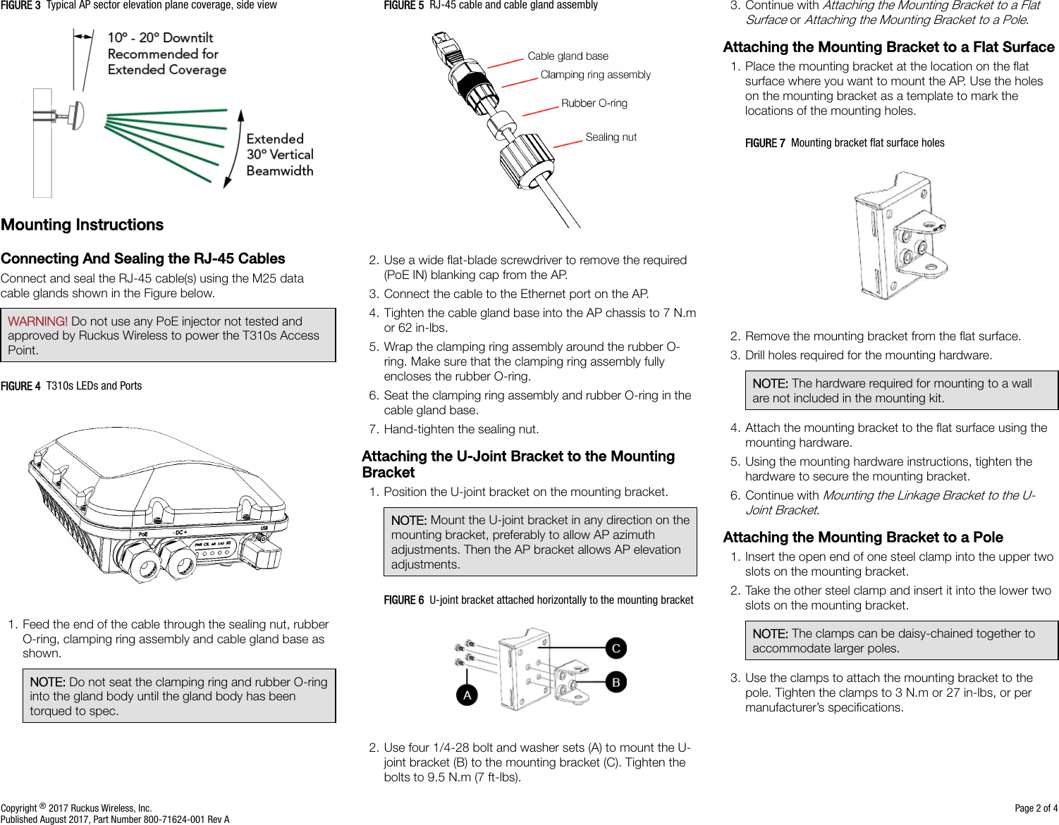
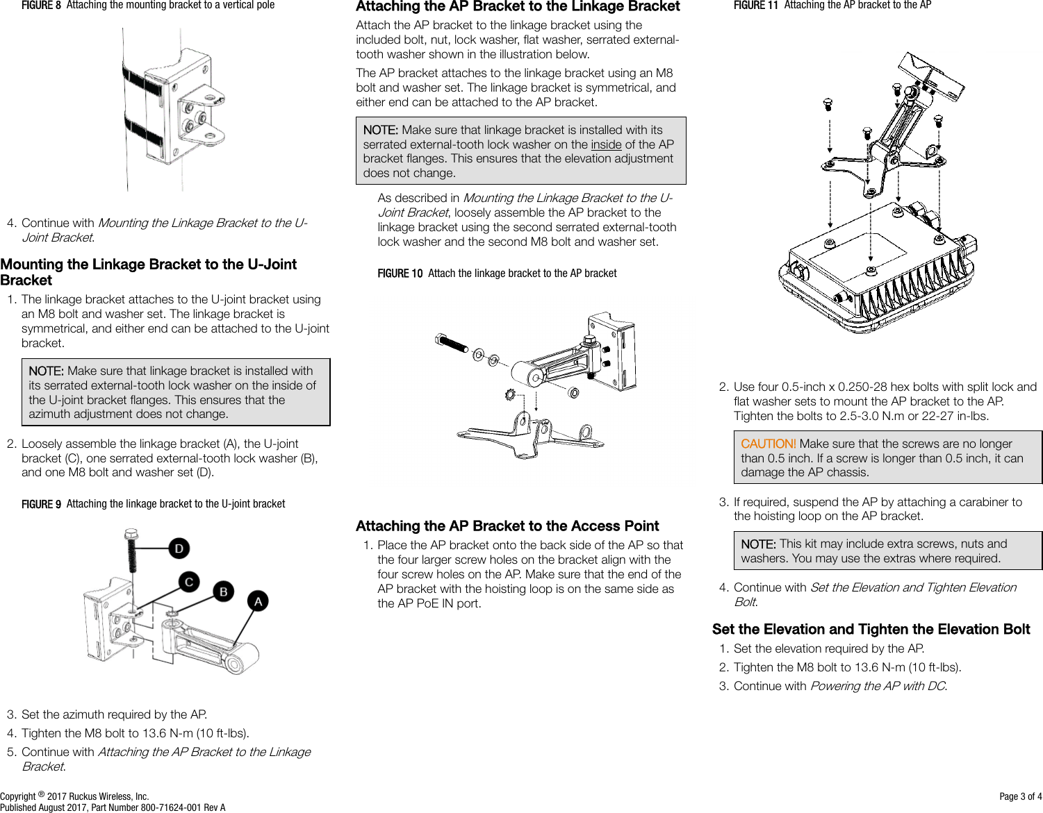
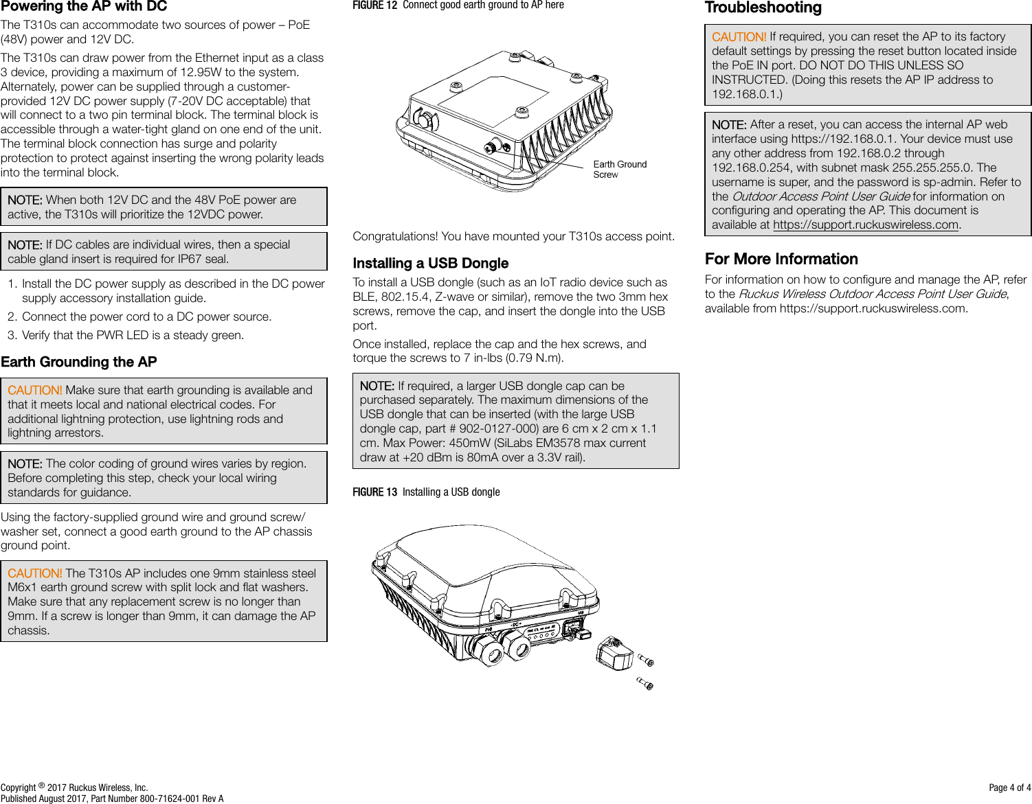
T310S User Manual