Ruckus Wireless T710 ZoneFlex T710 Access Point User Manual SC8800 S Access Point Mounting Guide
Ruckus Wireless, Inc. ZoneFlex T710 Access Point SC8800 S Access Point Mounting Guide
Contents
- 1. Users Manual
- 2. Draft Regulatory Statement
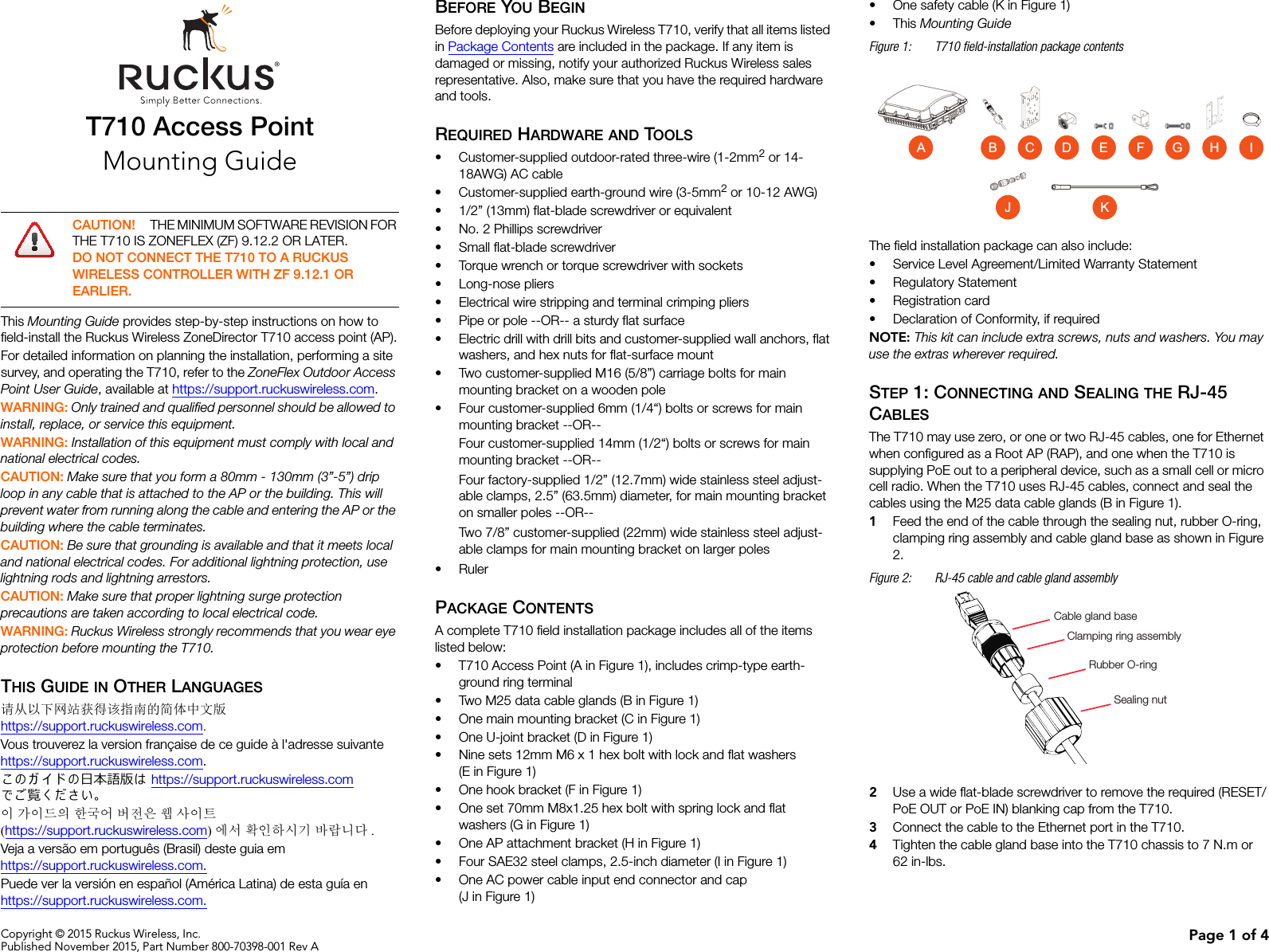
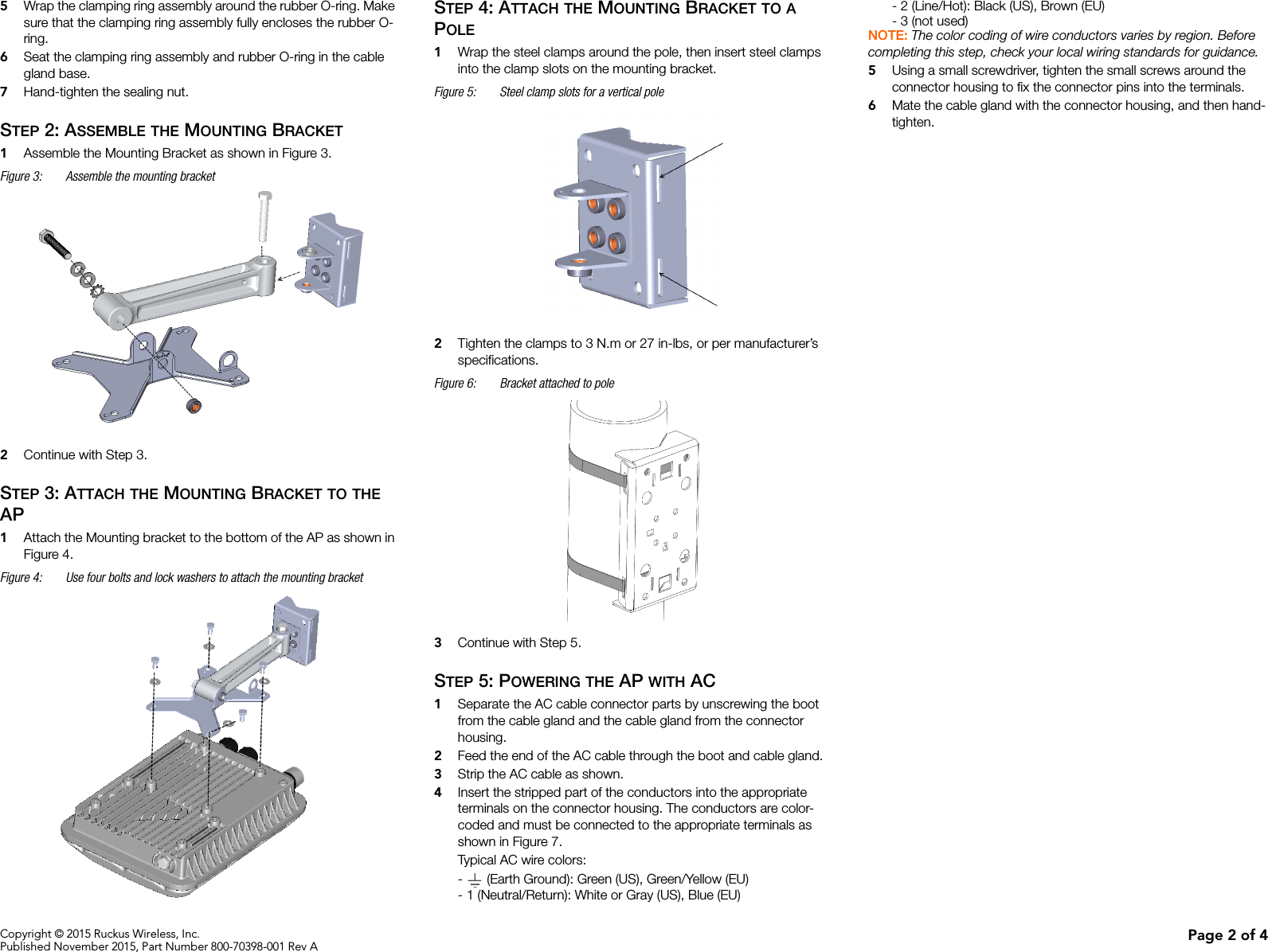
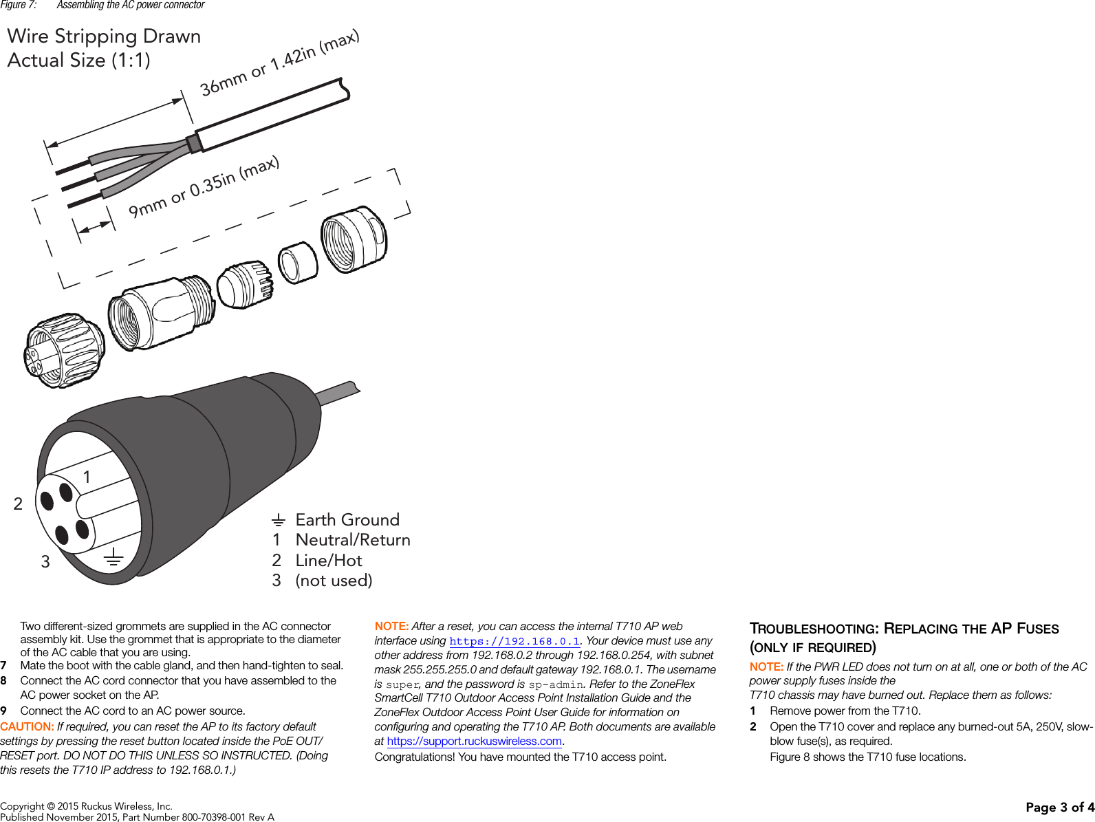
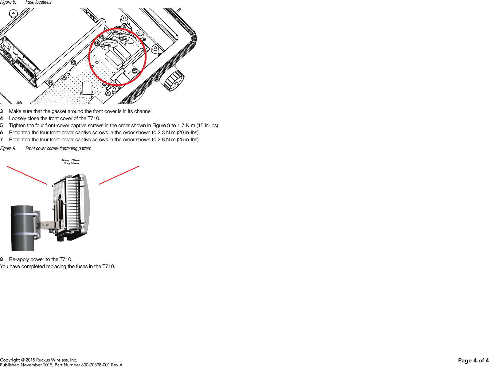
Users Manual