Ruckus Wireless T811CM T811-CM Access Point User Manual
Ruckus Wireless, Inc. T811-CM Access Point
UserManual.wiki
>
Ruckus Wireless
>
T811CM User Manual
>
User Manual
Contents
1.
User Manual
2.
Installation Manual
3.
User Manual Regulatory Statement
4.
Regulatory Insert
User Manual
Navigation menu
Upload a User Manual
Namespaces
Wiki Guide
HTML
PDF
Info
Views
User Manual
Discussion / Help
Navigation


![T811-CM AP Installation Guide, 800-71436-001 Rev A 37 Operating and Troubleshooting the T811-CM How Radio Frequency Scanning Works How Radio Frequency Scanning Works The following steps describe how a DOCSIS-compliant T811-CM performs radio frequency scanning: 1 Looks at the last “known good channel” (repeat this every 64 channel checks). 2 Checks the sixteen last known frequencies (repeat this every 32 channel checks). 3 Scans STD standard channels (where the center of the channel is an integer spaced by 6MHz), first [from 93MHz to 999MHz - 152 channels]). 4 Scans the harmonically related carrier (HRC) channels, which moves the channels 1.25MHz off the standard frequencies so the video carriers are all related by 6MHz [from 91.75 to 997.5MHz- -152 channels]. A complete frequency scan requires approximately 469 channel checks. Since each channel takes about 0.6 seconds, a full scan is done every 281 seconds (a little under 5 minutes). NOTE The scanning of generic DOCSIS channels is required the first time the T811-CM connects to an MSO. After the initial scan, the T811-CM is able to retrieve the local country frequency plan without a complete scan during its normal operation.](https://usermanual.wiki/Ruckus-Wireless/T811CM.User-Manual/User-Guide-3728728-Page-37.png)


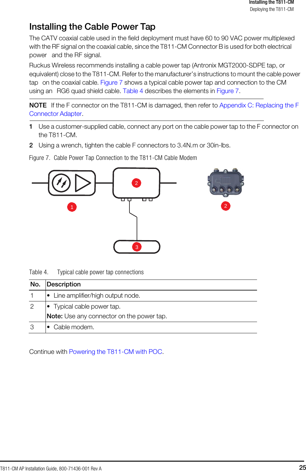
![T811-CM AP Installation Guide, 800-71436-001 Rev A 41 Appendix B: T811-CM Mounting Dimensions and Weight Dimensions Figure 14. T811-CM length--all dimensions in millimeters and [inches] (***XXX*** need new drawings) B](https://usermanual.wiki/Ruckus-Wireless/T811CM.User-Manual/User-Guide-3728728-Page-43.png)
![T811-CM AP Installation Guide, 800-71436-001 Rev A 42 Dimensions Figure 15. T811-CM height and width--all dimensions in millimeters and [inches] (***XXX*** need new drawings)](https://usermanual.wiki/Ruckus-Wireless/T811CM.User-Manual/User-Guide-3728728-Page-44.png)