Ruckus 902 0108 0000 Accessory Bracket Kit Mounting Guide Mg 800 70425 001 Rev B 20150311
902-0108-0000 Accessory Bracket Kit Mounting Guide 902-0108-0000-mg-800-70425-001-revB-20150311
2015-03-17
User Manual: Ruckus 902-0108-0000 Accessory Bracket Kit Mounting Guide
Open the PDF directly: View PDF ![]() .
.
Page Count: 2
Copyright © 2015 Ruckus Wireless, Inc. Page 1 of 2
Published 11 March 2015, Part Number 800-70425-001 Rev B
902-0108-0000 Accessory
Bracket Kit
Mounting Guide
This Mounting Guide provides step-by-step instructions on how
to use the 902-0108-0000 accessory bracket kit to mount the
following Ruckus Wireless access points to a wall, ceiling, utility
box, or pole or truss. The rest of this document refers to these
access points as APs.
• 7352 access point
• 7372 access point
• R500 access point
• R600 access point
•(and others)
The 902-0108-0000 accessory bracket has two studs that mate
with keyholes built into the Ruckus Wireless access points. The
accessory bracket includes a locking tab for a padlock or a
security Torx screw.
Before You Begin
Before deploying Ruckus Wireless products, please check for the
latest software and the release documentation.
• User Guides and Release Notes are available at
http://support.ruckuswireless.com/documents.
• Software Upgrades are available at
http://support.ruckuswireless.com/software.
• Open Source information is available at
http://opensource.ruckuswireless.com.
• Software License and Limited Warranty are available at
http://support.ruckuswireless.com/warranty.
PACKAGE CONTENTS
• One accessory bracket assembly with locking tab
• Four #6 screw and wall anchor sets
• One 6mm long M3x0.5 pan head security Torx stainless steel
screw
• One SAE32-sized stainless steel mounting clamp, 1.5- to 2.5-
inch diameter
•This Mounting Guide
REQUIRED HARDWARE AND TOOLS
• One Ruckus Wireless AP
• No. 2 Phillips screwdriver
• T10 Torx driver
• Drill with 3/16” (4.8mm) drill bit
• Straightened paper clip
Optional Supplies
• If you are mounting the AP on a pipe or pole, then you will also
need a 38.1mm to 63.5mm (1.5" to 2.5") pipe or pole, the
included stainless steel clamp, and hand tools to tighten the
clamp
• If you are planning to secure the AP to the accessory bracket
then you will need a customer-supplied small padlock with a
3.5mm (0.14”) or smaller shackle
MOUNTING OPTIONS
•Secure Wall or Ceiling Mount
•Wall Box Mount
•Pole and Truss Mount
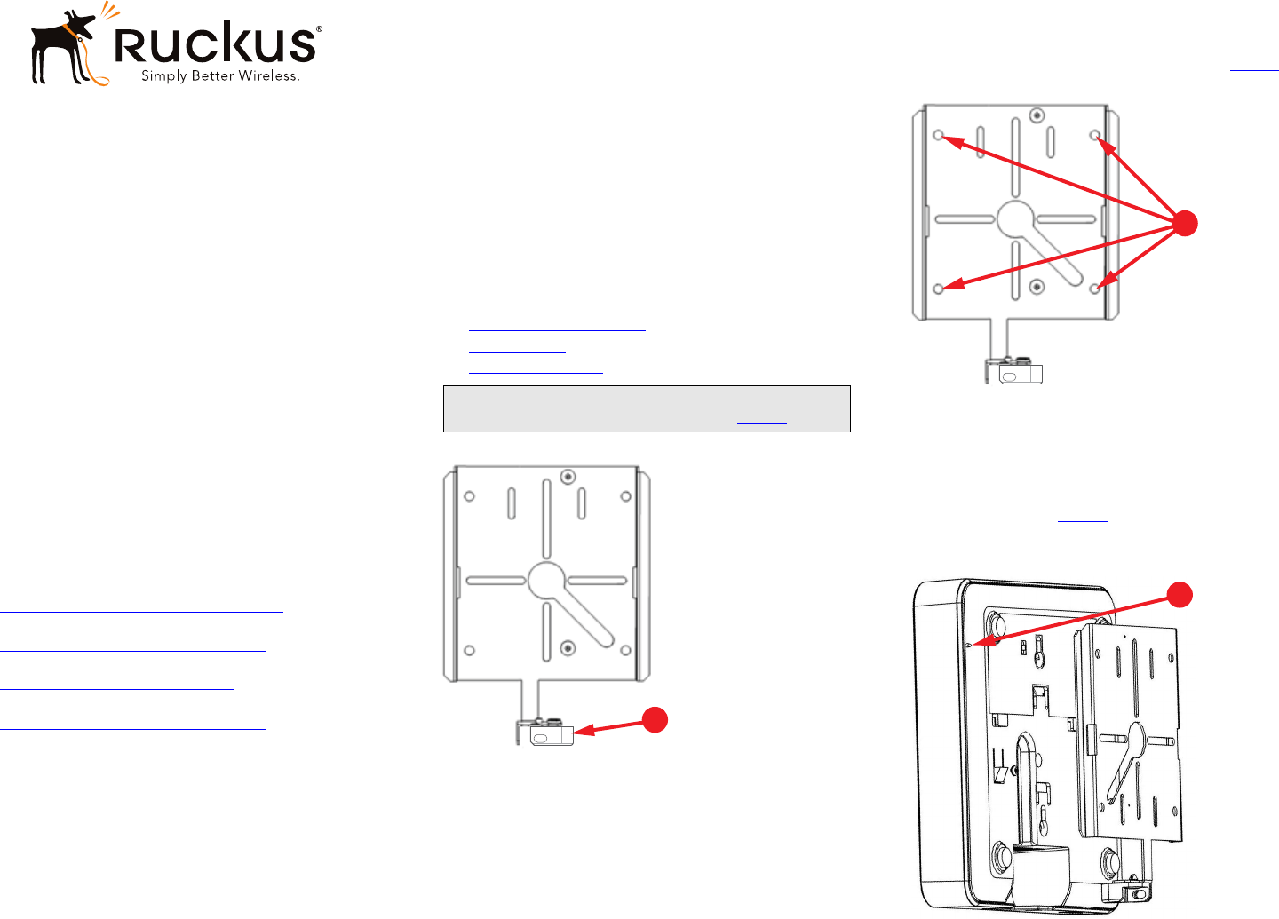
Figure 1. Accessory Bracket with Locking Tab in Unlocked Position
Secure Wall or Ceiling Mount
To mount the bracket to a wall or ceiling surface, use a drill with a
3/16” (4.8mm) drill bit.
1Use the accessory bracket as a template to mark the locations
for drill holes (four mounting hole locations, A in Figure 2).
Figure 2. Accessory Bracket Mounting Holes
2Use a 4.75mm (3/16”) drill bit to drill holes approximately
25mm (1”) deep into the mounting surface.
3Insert the plastic wall anchors.
4Attach the accessory bracket using the #6 screws.
5Insert and hold a straightened paper clip in the hole on the
side of the AP (A in Figure 3) to disengage the AP locking
mechanism.
Figure 3. Attaching a Typical AP to the Accessory Bracket
Note: Before mounting the AP to the bracket, make sure that
the locking tab is in the unlocked position (A in Figure 1).
A
A
A
Copyright © 2015 Ruckus Wireless, Inc. Page 2 of 2
Published 11 March 2015, Part Number 800-70425-001 Rev B
6Slide the AP onto the accessory bracket studs and release the
paper clip to lock the AP to the accessory bracket.
Wall Box Mount
1Remove the wall-plate covering the wall box.
2Feed any in-wall Ethernet or power cables through the hole in
the center of accessory bracket.
3Align the accessory bracket to the wall box using the wall box
mounting pattern (mounting holes, A in Figure 4).
Figure 4. Wall Box Mounting Pattern
4Mount the accessory bracket to the wall box using the original
wall-plate screws.
5Insert and hold a straightened paper clip into the hole on the
side of the AP (A in Figure 3) to disengage the AP locking
mechanism.
6Slide the AP onto the accessory bracket and release the paper
clip to lock the AP to the accessory bracket.
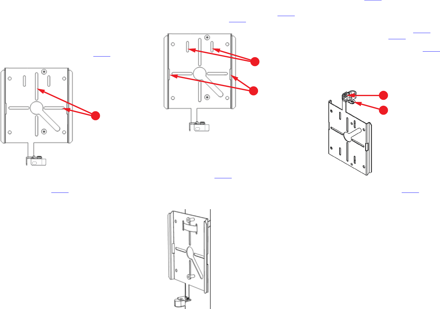
Pole and Truss Mount
1Feed the stainless steel mounting clamp included with the
accessory bracket kit through the pole slots (A in Figure 5) or
the truss mount slots (B in Figure 5) on the accessory bracket.
Figure 5. Pole and Truss Mount Slots
2Wrap mounting clamp around the pole or truss and use com-
mon hand tools to tighten the clamps around the pipe or pole.
3Tighten the clamp screws to secure the accessory bracket to
the pole or truss.
4Insert and hold a straightened paper clip into the hole on the
side of the AP (A in Figure 3) to disengage the AP locking
mechanism.
5Slide the AP onto the accessory bracket and release the paper
clip to lock the AP to the accessory bracket.
Figure 6. Pole Mounting
PHYSICAL SECURITY
The locking tab is provided for physical security. During AP
mounting and removal, the locking tab must be in the unlocked
position (see A in Figure 1).
Note the following options and requirements:
• Once mounted to the accessory bracket, the AP can be
physically secured by rotating the locking tab toward the AP
into the locked position as shown in Figure 7. A padlock can
then be used in slot A in Figure 7 to secure the locking tab in
the locked position. Alternatively, the supplied security Torx
screw can be used in threaded hole B in Figure 7 to block the
locking tab in the locked position.
• If physical security is not required, then the locking tab can be
secured in the unlocked position with the included security
Torx screw.
Figure 7. Locking Tab in Locked Position
• When removing AP, make sure that the locking tab is rotated
away from the AP as shown in Figure 1.
A
A
B
A
B
