Ruckus R500 Quick Setup Guide R610 (QSG) QSG
R610 Quick Setup Guide (QSG) R610-QSG
2017-04-12
User Manual: Ruckus R610 Quick Setup Guide (QSG)
Open the PDF directly: View PDF ![]() .
.
Page Count: 4
- This Guide in Other Languages
- Before You Begin
- Package Contents
- Step 1: Collect Tools and Setup Requirements
- Step 2: Connect the AP to Your Computer
- Step 3: Prepare Your Computer for AP Setup
- Step 4: Log Into the AP
- Step 5: Customize the Wireless Settings
- Step 6: Place the AP in Your Site
- Step 7: Verify the Installation
- For More Information
- (Optional) Mounting Instructions
Copyright © 2016 Ruckus Wireless, Inc. Page 1 of 4
Published September 2016, Part Number 800-71238-001 Rev B
R610 Access Point
Quick Setup Guide
This Quick Setup Guide provides step-by-step instructions
on how to set up your Ruckus Wireless R610 Dual Band
802.11ac Multimedia Wi-Fi Access Point. After completing
the steps described in this Guide, you will be able to place
the Access Point (AP) at your site and provide wireless
network access to users.
THIS GUIDE IN OTHER LANGUAGES
•请从以下网站获得该指南的简体中文版
https://support.ruckuswireless.com.
• Vous trouverez la version française de ce guide à l'adresse
suivante https://support.ruckuswireless.com.
•こ の ガ イ ド の⽇本語版は https://
support.ruckuswireless.com
でご覧く ださい。
•이 가이드의 한국어 버전은 웹 사이트
(https://support.ruckuswireless.com)에서 확인하시기 바
랍니다 .
• Veja a versão em português (Brasil) deste guia em
https://support.ruckuswireless.com.
• Puede ver la versión en español (América Latina) de esta
guía en https://support.ruckuswireless.com.
BEFORE YOU BEGIN
Before deploying Ruckus Wireless products, please check for
the latest software and the release documentation.
• User Guides and Release Notes are available at
http://support.ruckuswireless.com/documents.
• Software Upgrades are available at
http://support.ruckuswireless.com/software.
• Open Source information is available at
http://opensource.ruckuswireless.com.
• Software License and Limited Warranty are available at
http://support.ruckuswireless.com/warranty.
PACKAGE CONTENTS
• R610 Access Point
• One wall-mount anchor kit, including two 1" No. 8 steel pan-
head Phillips sheet metal screws, one 5mm M2.5 x 1.06 Torx
security screw, and wall-mount anchors
• One external T-bar bracket (two unassembled parts)
• One unit removal pin
• Regulatory flyer
• Product warranty statement
• Declaration of Conformity, if required
•This Quick Setup Guide
STEP 1: COLLECT TOOLS AND SETUP REQUIRE-
MENTS
• A computer running Windows 7, 8, 10 or Mac OS X (proce-
dures for other OS’s are similar)
• Two Cat 5e Ethernet cables
• No. 2 Phillips screwdriver and T8 Torx driver for wall mount-
ing anchor kit
• An AC power adapter (sold separately), or
• An 802.3af or 802.3at -compliant Power over Ethernet (PoE)
switch or PoE injector
• When mounting the R610 to a truss or pole, two customer-
supplied cable ties
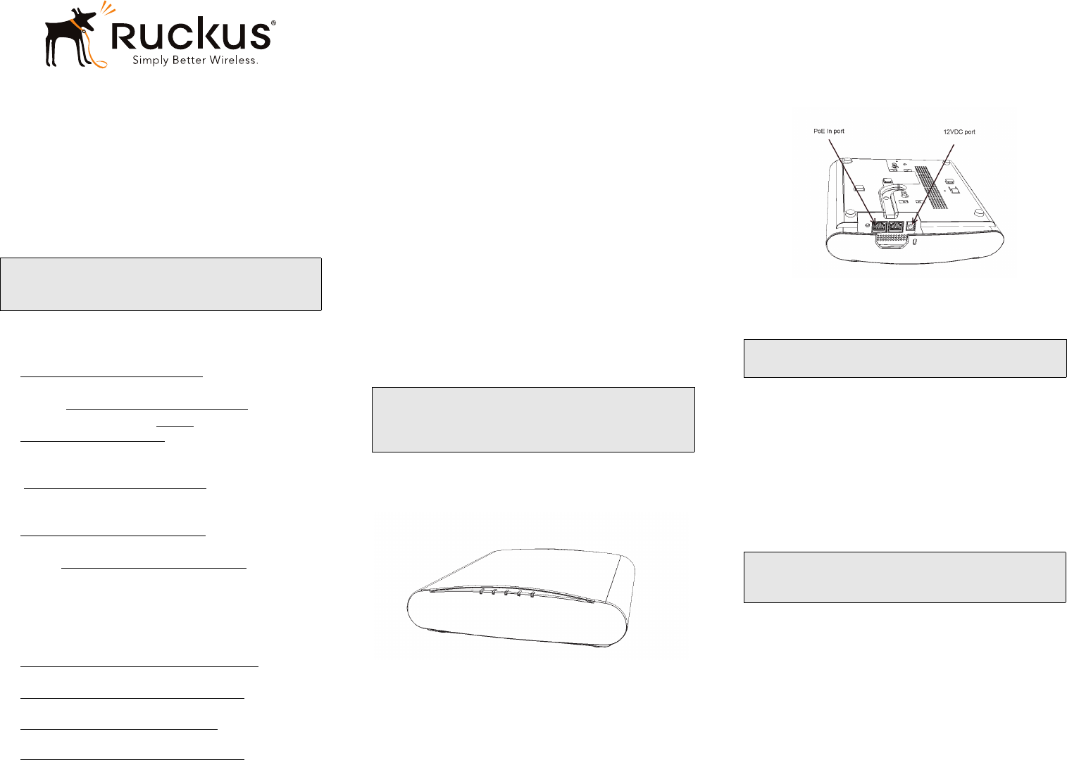
STEP 2: CONNECT THE AP TO YOUR COMPUTER
Figure 1: Top view
1After removing your Ruckus Wireless AP from its pack-
age, place it next to your computer.
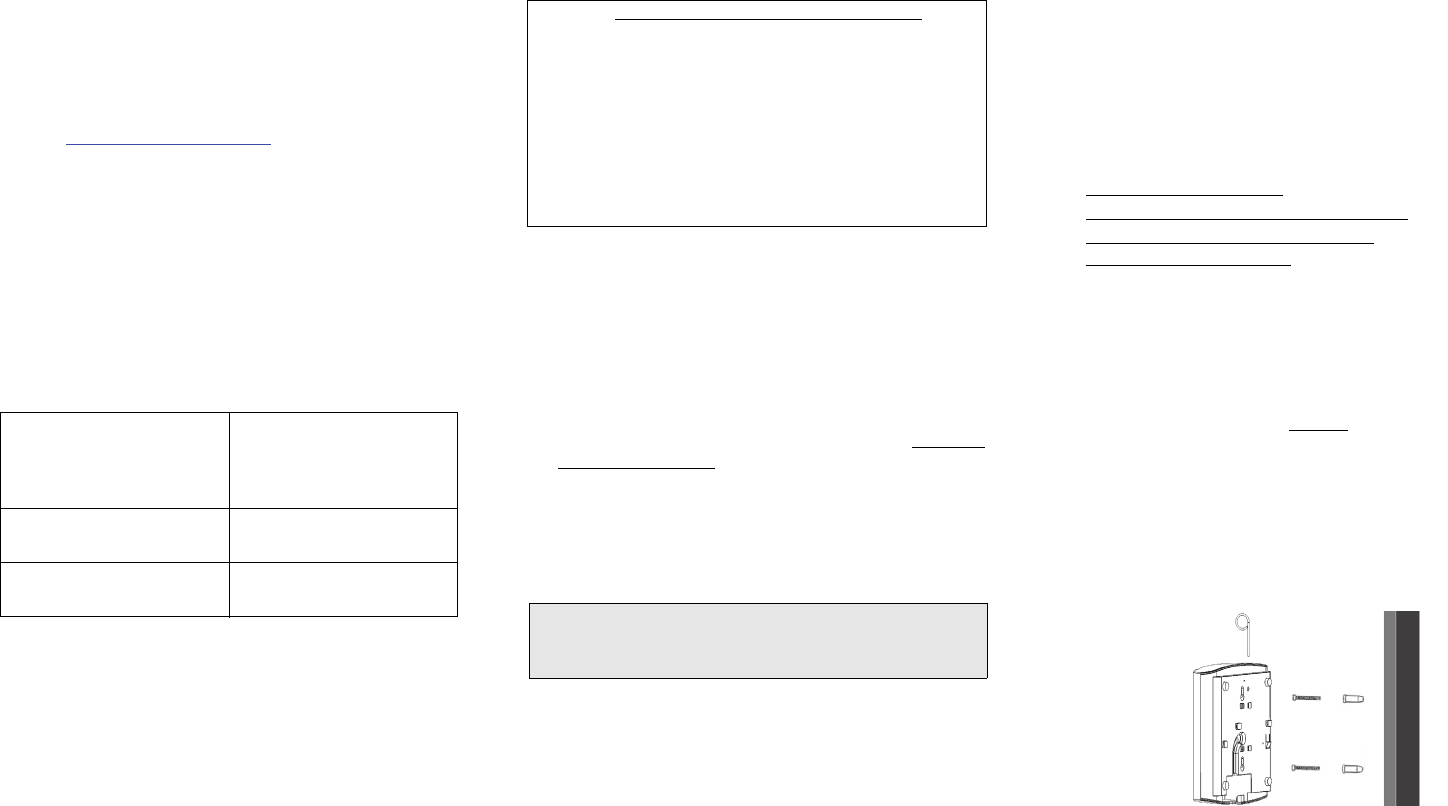
2Using an Ethernet cable, connect your computer’s net-
work port to one of the two ports on the AP.
3Using an AC adapter (sold separately), connect the AP
12VDC port to a protected power source.
Alternatively, connect the PoE port to a PoE injector or
switch for both power and network connections.
4Verify that the Power LED on the external enclosure is a
steady green.
Figure 2: Bottom view
STEP 3: PREPARE YOUR COMPUTER FOR AP
SETUP
1On your Windows 7 computer, configure your network
adapter from the Local Area Connection settings as fol-
lows:
• Start > Control Panel > Network and Internet >
Network and Sharing Center >
Change Adapter Settings
2Edit the TCP/IPv4 address settings as follows:
• Local Area Connection > Properties > Internet
Protocol Version 4 (TCP/IPv4) > Properties
The TCP/IPv4 Properties dialog box appears.
3Select Use the following IP address (if it is not already
selected) and then make the following entries:
•IP address: 192.168.0.22 (or any address in the
192.168.0.x network)
•Subnet mask: 255.255.255.0
•Default gateway: 192.168.0.1
Leave the DNS server fields empty.
4Click OK to save your changes.
Your changes are put into effect immediately.
Note: The R610 requires a minimum of ZoneDirector ver-
sion 9.13.2 or later, or SmartZone firmware version 3.4.1
or later.
IMPORTANT! If the AP is deployed with a ZoneDirector or
SmartZone controller, then refer to the ZoneDirector or
SmartZone Quick Setup Guide and connect the AP to your
local network.
Note: The following procedures assume Windows 7 as the
operating system. Procedures for other OS’s are similar.
Important! Write down all of the currently active settings so
you can restore your computer to its current configuration
later (when this process is complete).
Copyright © 2016 Ruckus Wireless, Inc. Page 2 of 4
Published September 2016, Part Number 800-71238-001 Rev B
STEP 4: LOG INTO THE AP
As specified earlier, the AP should be directly connected to
your computer (through one of the Ethernet ports) and
powered on, ready for setup.
1On your computer, open a Web browser window.
2In the browser, type this URL to connect to the AP:
https://192.168.0.1
3Press <Enter> to initiate the connection. When a secu-
rity alert dialog box appears, click OK/Yes to proceed.
4When the Ruckus Wireless Admin login page appears,
enter the following:
•Username: super
•Password: sp-admin
5Click Login.
STEP 5: CUSTOMIZE THE WIRELESS SETTINGS
1On the Web interface menu, click Configuration >
Radio 2.4G or Configuration > Radio 5G. The
Configure :: Wireless :: Common options appear.
2Verify that the following options are active:
•Channel: SmartSelect
•Country Code: If you are not located in the United
States, select your current country.
3Click Update Settings if you made any changes.
4Click any of the “Wireless #” tabs at the top of the page.
5In Wireless Availability, click Enabled.
6Delete the text in the SSID field, then type a name for
your network that will help your users identify the AP in
their wireless network connection application.
7Click Update Settings to save your changes.
8Repeat Steps 4-7 for each Wireless # interface that you
want to enable.
9Click Logout to exit the Web interface.
10 When the Ruckus Wireless Admin login page reappears,
you can exit your browser.
11 Disconnect the AP from the computer and from the cur-
rent power source, and then restore your computer to its
original network connection configuration.
STEP 6: PLACE THE AP IN YOUR SITE
1Move the AP to its permanent location (accessible to
both power and network connections). Refer to (Optional)
Mounting Instructions for physical installation.
2Use an Ethernet cable to connect the PoE port to the
appropriate device:
• The ISP’s or carrier’s network device
• The Ethernet switch that is connected to the ISP’s or
carrier’s network device
3Connect the AP power adapter (or PoE power supply) to
the AP, then to a convenient power source.
4Verify that the PoE port LED is lit.
After a short pause to re-establish the Internet connection,
you can test the AP.
STEP 7: VERIFY THE INSTALLATION
1Using any wireless-enabled computer or mobile device,
search for and select the wireless network you previously
configured.
2If you can connect, open a browser and link to any public
Web site.
Congratulations! Your wireless network is active and ready
for use.
FOR MORE INFORMATION
You can now use the wireless network to log into the AP’s
Web interface. For information on how to configure the AP,
refer to the Ruckus Wireless ZoneFlex Indoor Access Point
User Guide.
(OPTIONAL) MOUNTING INSTRUCTIONS
The R610 can be mounted to a T-bar, wall or ceiling a using
the enclosed mounting kits. Refer to the following sections:
•Mounting on a Flat Surface
•Mounting on a Recessed Drop-Ceiling T-Bar
•Mounting on a Flush Drop-Ceiling T-Bar
•Mounting on a Truss or Pole
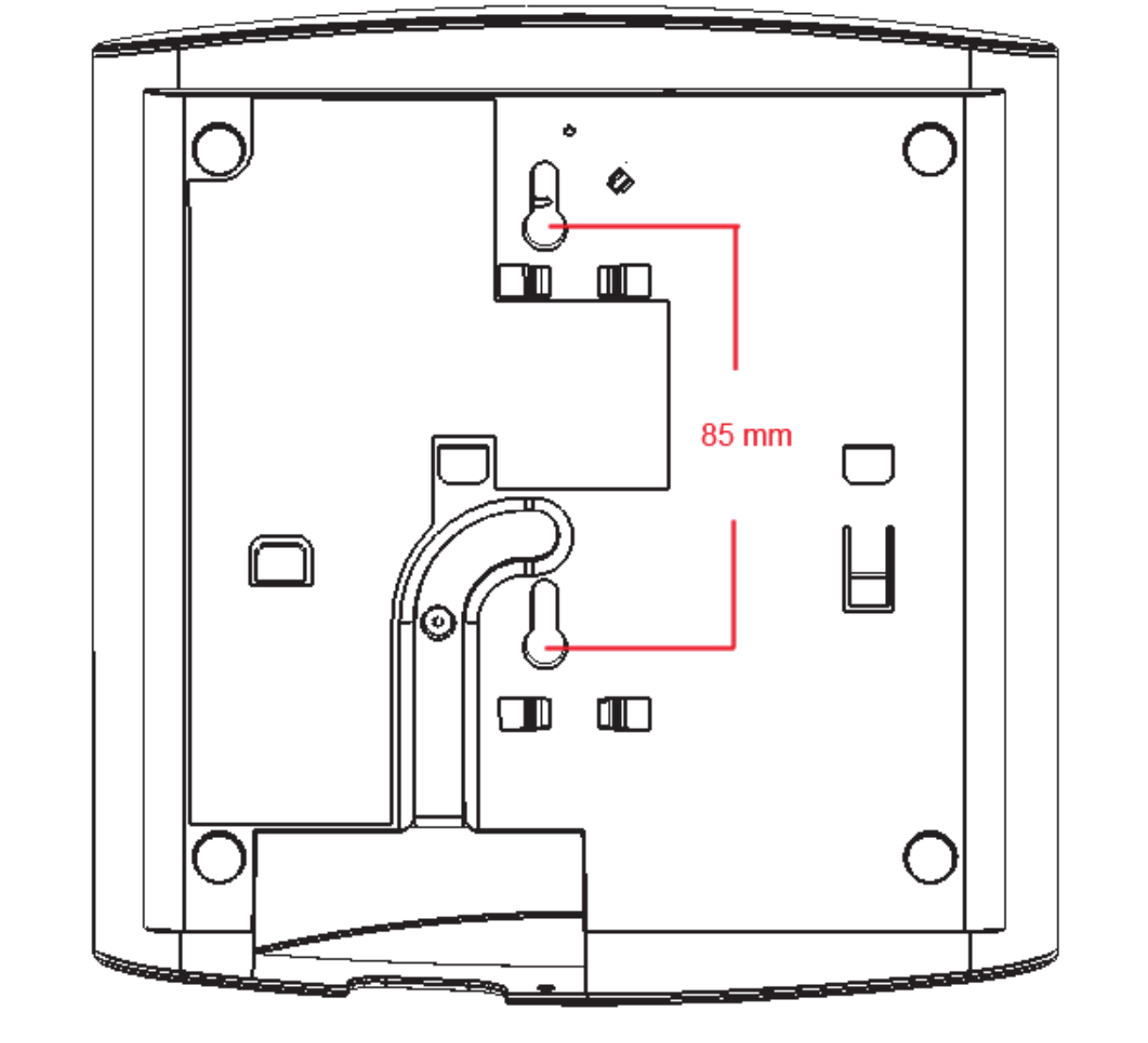
Mounting on a Flat Surface
1Use the Mounting Template on the last page of this
Quick Setup Guide as a template to mark the locations
for drill holes on the mounting surface.
2Use a 5mm drill bit to drill holes approximately 25mm
into the mounting surface (Figure 3).
3Insert the anchors and mounting screws into the mount-
ing surface, leaving approximately 1/4” (6 mm) of the
screw heads protruding for the AP enclosure.
4To remove the AP, insert the unit removal pin into the
hole on the top of the AP to unlock, then push the AP up
to release the AP enclosure from the mounting screws.
Figure 3. Flat surface mounting
Default AP Settings (For Your Reference)
Network Names (SSIDs) Wireless1—Wireless8
(2.4GHz radio)
Wireless9—Wireless16 (5GHz
radio)
Security (Encryption method) Disabled for each wireless
interface
Default Management IP
Address
192.168.0.1
Optional: If You Want To Switch from DHCP (Default):
If you anticipate logging into the AP regularly to perform
monitoring or maintenance once it is in place, you may want
to consider assigning a static IP address to the AP.
In a default AP configuration, the AP uses a DHCP-
assigned IP address.
A. On the menu, click Configuration > Internet.
B. Click the Static IP option.
C. Fill in the IP Address and Mask fields.
D. Click Update Settings to save your changes.
Note: If you will be using PoE, then you will need a Cat 5e
(or better) Ethernet cable to connect the AP to the PoE
injector or switch.
Copyright © 2016 Ruckus Wireless, Inc. Page 3 of 4
Published September 2016, Part Number 800-71238-001 Rev B
Mounting on a Recessed Drop-Ceiling T-Bar
The enclosed T-bar bracket supports mounting to recessed
drop ceiling T-bars.
•Mounting an AP using the External Bracket
•Removing an External Bracket from a T-Bar
•Removing the External Bracket from the AP
Mounting an AP using the External Bracket
1Position the studs on the bottom of the T-bar bracket (B
in Figure 4) in the mounting holes on the R610 enclosure,
and then slide the T-bar bracket until the studs are in the
narrow parts of the R610 mounting keyholes.The mount-
ing bracket locks in place on the AP enclosure.
Figure 4. Attaching the external bracket to the AP
2Attach the locking tab (C in Figure 4) to one side of the T-
bar and the bracket (B in Figure 4) to the other side of the
T- b a r.
3Slide the locking tab (C) into the bracket (B) so that it
locks in place around the T-bar (Figure 5). Make sure that
both clasps are gripping the T-bar.
Figure 5. Attaching the external bracket to the T-bar
Removing an External Bracket from a T-Bar
1Move the ceiling tiles out of the way.
2Slide the locking tab away from the T-bar to release
the AP-bracket assembly from the T-bar.
3The R610-and-T-bar bracket assembly comes away
from the T-bar.
Figure 6. Removing the external bracket from the T-bar
Removing the External Bracket from the AP
1Insert the unit removal pin into the hole on the front
of the AP to unlock the mounting bracket from the AP
enclosure.
2Slide the mounting bracket (Figure 7) toward the
Ethernet ports on the R610 until it detaches from the
R610.
Figure 7. Removing the external bracket from an AP
Mounting on a Flush Drop-Ceiling T-Bar
Mounting an AP using the Integrated T-bar clips
1Orient the AP so that the T-bar is positioned between
the T-bar clips as shown in Figure 8, then rotate the AP
until the third T-bar clip catches the T-bar and the
latch locks the T-bar in place (Figure 9).
Figure 8. Attaching the AP to the T-bar
Figure 9. Locking the AP to the T-bar
2Insert the Torx security screw into the hole near the
latch to lock the AP in place.
Removing an AP Integrated Bracket from a T-Bar
1To remove the AP from a T-bar, first remove the
security screw, then depress the latch while rotating
the AP so that the T-bar clips disengage the T-bar.
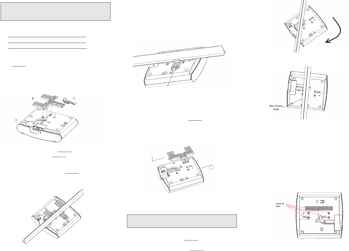
Mounting on a Truss or Pole
1Feed the customer-supplied cable ties through the
four slots on the back of the R610.
Figure 10 Cable tie slots
2Fasten the R610 to the truss or pole using the cable
ties.
Note: This mounting bracket can also be used on a flush
drop-ceiling T-bar, so the four rubber feet on the bottom
of the AP minimize ceiling tile displacement.
Note: The built-in mounting clips on the bottom of the AP
are designed to accommodate 15/16 T-bar widths only.
Copyright © 2016 Ruckus Wireless, Inc.
Published September 2016, Part Number 800-71238-001 Rev B
Mounting Template
(Page 4 of 4)
