Ruckus SCG200 VSZ H And SZ300 Administrator Guide Smart Zone 3.6 (SZ300/SCG200/v SZ H) V SZH 36 20171124
SmartZone 3.6 Administrator Guide (SZ300/SCG200/vSZ-H) Scg200_vSZH_Sz300-36-AdministratorGuide-20171124
2017-11-27
User Manual: Ruckus SmartZone 3.6 Administrator Guide (SZ300/SCG200/vSZ-H)
Open the PDF directly: View PDF ![]() .
.
Page Count: 345 [warning: Documents this large are best viewed by clicking the View PDF Link!]
- SCG200 vSZ-H and SZ300 Administrator Guide
- Preface
- Navigating the Dashboard
- Configuring System Settings
- Configuring General Settings
- Viewing System Settings
- Configuring System Time
- Configuring the Remote Syslog Server
- Configuring SCI Settings
- Setting the Northbound Portal Password
- Enabling Global SNMP Notifications
- Configuring SMTP Server Settings
- Configuring FTP Server Settings
- Configuring the SMS Gateway Server
- Configuring Node Affinity
- Configuring AP Settings
- Viewing the System Cluster Overview
- Working with Maps
- Certificates
- Configuring Templates
- Configuring General Settings
- Working With Access Points
- Understanding the System, Domains, Zones and AP Groups
- Viewing Modes
- AP Status
- Configuring Access Points
- Managing Access Points
- Working with WLANs and WLAN Groups
- Managing Clients
- Working with Wireless Clients
- Working with Wired Clients
- Working with Users and Roles
- Working with Guest Passes
- Working with Dynamic PSKs
- Application Recognition and Control
- Services and Profiles
- Working with Hotspots and Portals
- Configuring Access Control
- Configuring Application Controls
- URL Filtering
- Authentication
- Accounting
- Classifying Rogue Policy
- Bonjour
- Working with Tunnels and Ports
- Managing Core Network Tunnels
- Location Services
- DHCP/NAT
- Working with Reports
- Troubleshooting
- Administering the Controller
- Managing Administrator and Roles
- Backing Up and Restoring Clusters
- Upgrading the Controller
- Managing Licenses
- ZoneDirector to SmartZone Migration
- Monitoring Administrator Activities
- Managing Mobile Virtual Network Operator (MVNO) Accounts
- Managing Events and Alarms
- Diagnostics
- Statistics Files the Controller Exports to an FTP Server
- Ports to Open for AP-SCG/SZ/vSZ/vSZ-D Communication
- SoftGRE Support
- Replacing Hardware Components
- Replacing a Controller Node
- Introduction
- Backing Up and Resorting the Cluster
- Backing Up and Restoring Configuration
- SCG SSID Syntax

Supporting 3.6
CONFIGURATION GUIDE
SCG200 vSZ-H and SZ300 Administrator
Guide
Part Number: 800-71563-001
Publication Date: November 2017
Copyright Notice and Proprietary Information
Copyright 2017 Brocade Communications Systems, Inc. All rights reserved.
No part of this documentation may be used, reproduced, transmitted, or translated, in any form or by any means, electronic, mechanical,
manual, optical, or otherwise, without prior written permission of or as expressly provided by under license from Brocade.
Destination Control Statement
Technical data contained in this publication may be subject to the export control laws of the United States of America. Disclosure to
nationals of other countries contrary to United States law is prohibited. It is the reader’s responsibility to determine the applicable regulations
and to comply with them.
Disclaimer
THIS DOCUMENTATION AND ALL INFORMATION CONTAINED HEREIN (“MATERIAL”) IS PROVIDED FOR GENERAL INFORMATION
PURPOSES ONLY. BROCADE and RUCKUS WIRELESS, INC. AND THEIR LICENSORS MAKE NO WARRANTY OF ANY KIND, EXPRESS
OR IMPLIED, WITH REGARD TO THE MATERIAL, INCLUDING, BUT NOT LIMITED TO, THE IMPLIED WARRANTIES OF
MERCHANTABILITY, NON-INFRINGEMENT AND FITNESS FOR A PARTICULAR PURPOSE, OR THAT THE MATERIAL IS ERROR-FREE,
ACCURATE OR RELIABLE. BROCADE and RUCKUS RESERVE THE RIGHT TO MAKE CHANGES OR UPDATES TO THE MATERIAL AT
ANY TIME.
Limitation of Liability
IN NO EVENT SHALL BROCADE or RUCKUS BE LIABLE FOR ANY DIRECT, INDIRECT, INCIDENTAL, SPECIAL OR CONSEQUENTIAL
DAMAGES, OR DAMAGES FOR LOSS OF PROFITS, REVENUE, DATA OR USE, INCURRED BY YOU OR ANY THIRD PARTY, WHETHER
IN AN ACTION IN CONTRACT OR TORT, ARISING FROM YOUR ACCESS TO, OR USE OF, THE MATERIAL.
Trademarks
Ruckus Wireless, Ruckus, the bark logo, BeamFlex, ChannelFly, Dynamic PSK, FlexMaster, Simply Better Wireless, SmartCell, SmartMesh,
SmartZone, Unleashed, ZoneDirector and ZoneFlex are trademarks of Ruckus Wireless, Inc. in the United States and in other countries.
Brocade, the B-wing symbol, MyBrocade, and ICX are trademarks of Brocade Communications Systems, Inc. in the United States and in
other countries. Other trademarks may belong to third parties.
SCG200 vSZ-H and SZ300 Administrator Guide
2 Part Number: 800-71563-001

Contents
Preface........................................................................................................................................................................................................11
Document conventions........................................................................................................................................................................ 11
Notes, cautions, and warnings......................................................................................................................................................11
Command Syntax Conventions............................................................................................................................................................12
Document feedback.............................................................................................................................................................................12
Ruckus resources................................................................................................................................................................................ 12
Online training resources...................................................................................................................................................................... 13
Contacting Ruckus Technical Support..................................................................................................................................................13
Navigating the Dashboard........................................................................................................................................................................... 15
Setting Up the Controller for the First Time...........................................................................................................................................15
Logging On to the Web Interface..........................................................................................................................................................15
Web Interface Features........................................................................................................................................................................ 16
Changing the Administrator Password................................................................................................................................................. 17
Logging Off the Controller.................................................................................................................................................................... 18
Configuring Global Filters..................................................................................................................................................................... 19
Warnings and Notifications...................................................................................................................................................................20
Warnings...................................................................................................................................................................................... 20
Setting Global Notifications........................................................................................................................................................... 21
Health and Maps..................................................................................................................................................................................21
Understanding Cluster and AP Health Icons..................................................................................................................................22
Customizing Health Status Thresholds..........................................................................................................................................22
Using the Health Dashboard Map................................................................................................................................................. 24
Traffic Analysis......................................................................................................................................................................................29
Configuring Traffic Analysis Display for APs................................................................................................................................... 30
Configuring Traffic Analysis Display for WLANs..............................................................................................................................31
Configuring Traffic Analysis Display for Top Clients........................................................................................................................ 32
Configuring System Settings....................................................................................................................................................................... 33
Configuring General Settings................................................................................................................................................................33
Viewing System Settings...............................................................................................................................................................33
Configuring System Time.............................................................................................................................................................. 34
Configuring the Remote Syslog Server..........................................................................................................................................35
Configuring SCI Settings............................................................................................................................................................... 37
Setting the Northbound Portal Password...................................................................................................................................... 37
Enabling Global SNMP Notifications..............................................................................................................................................37
Configuring SMTP Server Settings................................................................................................................................................ 39
Configuring FTP Server Settings................................................................................................................................................... 40
Configuring the SMS Gateway Server........................................................................................................................................... 41
Configuring Node Affinity...............................................................................................................................................................41
Configuring AP Settings....................................................................................................................................................................... 42
Working with AP Registration Rules.............................................................................................................................................. 42
Creating vSZ-D Zone Affinity......................................................................................................................................................... 43
Tagging Critical APs...................................................................................................................................................................... 44
Configuring the Tunnel UDP Port...................................................................................................................................................44
Setting the Country Code............................................................................................................................................................. 44
Limiting the Number of APs in a Domain or Zone.......................................................................................................................... 45
SCG200 vSZ-H and SZ300 Administrator Guide
Part Number: 800-71563-001 3
Viewing the System Cluster Overview...................................................................................................................................................47
Control Planes and Data Planes....................................................................................................................................................47
Interface and Routing....................................................................................................................................................................48
Displaying the Chassis View of Cluster Nodes...............................................................................................................................49
Enabling Cluster Redundancy....................................................................................................................................................... 49
Configuring the Control Plane....................................................................................................................................................... 51
Configuring the Data Plane........................................................................................................................................................... 55
Monitoring Cluster Settings........................................................................................................................................................... 58
Working with Maps.............................................................................................................................................................................. 59
Importing a Floorplan Map............................................................................................................................................................ 59
Viewing RF Signal Strength........................................................................................................................................................... 62
Monitoring APs Using the Map View............................................................................................................................................. 62
Certificates...........................................................................................................................................................................................63
Importing New Certificates............................................................................................................................................................ 64
Assigning Certificates to Services..................................................................................................................................................64
Generating Certificate Signing Request (CSR)............................................................................................................................... 65
Managing AP Certificates..............................................................................................................................................................66
Importing Trusted CA Certificates..................................................................................................................................................67
Configuring Templates..........................................................................................................................................................................67
Working with Zone Templates....................................................................................................................................................... 67
Working with WLAN Templates..................................................................................................................................................... 72
Working With Access Points........................................................................................................................................................................75
Understanding the System, Domains, Zones and AP Groups...............................................................................................................75
Hierarchy Overview....................................................................................................................................................................... 75
Creating an AP Domain.................................................................................................................................................................76
Working with AP Zones.................................................................................................................................................................76
Working with AP Groups...............................................................................................................................................................83
Monitoring Domains, Zones, and AP Groups................................................................................................................................ 91
Viewing Modes.....................................................................................................................................................................................94
AP Status.............................................................................................................................................................................................94
Configuring Access Points................................................................................................................................................................... 94
Managing Access Points......................................................................................................................................................................97
Overview of Access Point Configuration........................................................................................................................................97
Viewing Managed Access Points.................................................................................................................................................. 98
Downloading the Support Log from an Access Point.................................................................................................................... 98
Provisioning and Swapping Access Points....................................................................................................................................99
Editing Swap Configuration.........................................................................................................................................................100
Monitoring Access Points............................................................................................................................................................101
Working with WLANs and WLAN Groups.................................................................................................................................................. 105
Domains, Zones, AP Groups, and WLANs......................................................................................................................................... 105
Viewing Modes...................................................................................................................................................................................105
Creating a WLAN Domain for an MSP................................................................................................................................................106
WLAN Groups....................................................................................................................................................................................106
Creating a WLAN Group............................................................................................................................................................. 106
Creating a WLAN Configuration..........................................................................................................................................................107
802.11 Fast BSS Transition.........................................................................................................................................................119
802.11w MFP............................................................................................................................................................................. 119
Band Balancing.......................................................................................................................................................................... 119
Bypassing Apple CNA.................................................................................................................................................................119
SCG200 vSZ-H and SZ300 Administrator Guide
4 Part Number: 800-71563-001
Channel Mode............................................................................................................................................................................ 119
Client Admission Control.............................................................................................................................................................120
Client Load Balancing................................................................................................................................................................. 120
Mobility Domain ID...................................................................................................................................................................... 120
Portal-based WLANs.................................................................................................................................................................. 121
Rate Limiting Ranges for Policies................................................................................................................................................ 122
Working with WLAN Schedule Profiles........................................................................................................................................ 122
Managing WLANs.............................................................................................................................................................................. 123
Moving a Single WLAN to a Different WLAN Zone.......................................................................................................................124
Extracting a WLAN Template.......................................................................................................................................................124
Applying a WLAN Template.........................................................................................................................................................125
Triggering a Preferred Node........................................................................................................................................................ 125
Managing Clients.......................................................................................................................................................................................127
Working with Wireless Clients.............................................................................................................................................................127
Viewing a Summary of Wireless Clients.......................................................................................................................................127
Viewing Information about a Wireless Client................................................................................................................................ 128
Deauthorizing a Wireless Client................................................................................................................................................... 129
Blocking a Wireless Client........................................................................................................................................................... 129
Unblocking a Wireless Client....................................................................................................................................................... 129
Disconnecting a Wireless Client.................................................................................................................................................. 130
Working with Wired Clients.................................................................................................................................................................130
Viewing a Summary of Wired Clients...........................................................................................................................................130
Viewing Information about a Wired Client.................................................................................................................................... 130
Deauthorizing a Wired Client....................................................................................................................................................... 131
Working with Users and Roles............................................................................................................................................................131
Creating a User Role...................................................................................................................................................................131
Creating a User Role with Active Directory Authentication........................................................................................................... 132
Creating a User Role with 802.1x Authentication.........................................................................................................................133
Limitations Applying Role Policies to Users................................................................................................................................. 133
Creating a Local User..................................................................................................................................................................134
Creating a Subscription Package................................................................................................................................................ 136
Working with Guest Passes................................................................................................................................................................137
Generating Guest Passes........................................................................................................................................................... 138
Creating a Guest Pass Template................................................................................................................................................. 142
Creating a Guest Instruction SMS Template................................................................................................................................ 143
Exporting the Guest Pass to CSV................................................................................................................................................145
Generating Guest Passes from an Imported CSV........................................................................................................................145
Sending the Guest Pass via Email............................................................................................................................................... 147
Printing the Guest Pass...............................................................................................................................................................148
Sending the Guest Pass via SMS................................................................................................................................................149
Working with Dynamic PSKs.............................................................................................................................................................. 150
Viewing Dynamic PSKs............................................................................................................................................................... 151
Generating Dynamic PSKs..........................................................................................................................................................151
Importing Dynamic PSKs............................................................................................................................................................ 152
Creating an External DPSK Over RADIUS WLAN........................................................................................................................ 154
Application Recognition and Control..........................................................................................................................................................157
Monitoring Applications......................................................................................................................................................................157
Services and Profiles................................................................................................................................................................................. 161
Working with Hotspots and Portals.................................................................................................................................................... 161
SCG200 vSZ-H and SZ300 Administrator Guide
Part Number: 800-71563-001 5
Creating a Guest Access Portal.................................................................................................................................................. 161
Working with Hotspot (WISPr) Services.......................................................................................................................................163
Creating a Web Authentication Portal..........................................................................................................................................166
Creating a WeChat Portal............................................................................................................................................................167
Working with Hotspot 2.0 Services............................................................................................................................................. 169
Creating a UA Blacklist Profile..................................................................................................................................................... 175
Configuring Access Control................................................................................................................................................................177
Creating a User Traffic Profile...................................................................................................................................................... 177
Creating OS Policy Service..........................................................................................................................................................179
VLAN Pooling..............................................................................................................................................................................181
Create Precedence Profile...........................................................................................................................................................183
Creating an L2 Access Control Service....................................................................................................................................... 184
Creating Blocked Clients.............................................................................................................................................................185
Creating a Client Isolation Whitelist..............................................................................................................................................186
Creating Time Schedules............................................................................................................................................................ 187
Creating a DNS Server Profile..................................................................................................................................................... 188
Configuring Application Controls........................................................................................................................................................ 189
Creating an Application Control Policy.........................................................................................................................................190
Implementing an Application Control Policy.................................................................................................................................191
Creating a User Defined Application............................................................................................................................................194
Importing an Application Signature Package............................................................................................................................... 196
URL Filtering...................................................................................................................................................................................... 197
Limitations.................................................................................................................................................................................. 197
Viewing a Summary of URL Filters.............................................................................................................................................. 197
Creating a URL Filtering Policy.................................................................................................................................................... 198
Enabling URL Filtering on the Controller...................................................................................................................................... 201
Enabling URL Filtering in the User Traffic Profile...........................................................................................................................202
Managing URL Filtering Licenses................................................................................................................................................ 203
Authentication.................................................................................................................................................................................... 203
Creating Non-Proxy Authentication AAA servers......................................................................................................................... 203
Creating Proxy AAA Servers........................................................................................................................................................206
Creating Realm Based Authentication Profile...............................................................................................................................213
Accounting.........................................................................................................................................................................................215
Creating Non-Proxy Accounting AAA Servers............................................................................................................................. 215
Creating Proxy Accounting AAA Servers..................................................................................................................................... 216
Creating Realm Based Proxy...................................................................................................................................................... 217
Classifying Rogue Policy.................................................................................................................................................................... 218
Bonjour.............................................................................................................................................................................................. 219
Bonjour Gateway........................................................................................................................................................................ 220
Bonjour Fencing..........................................................................................................................................................................222
Working with Tunnels and Ports......................................................................................................................................................... 225
Creating a Ruckus GRE Profile....................................................................................................................................................225
Creating a Soft GRE Profile......................................................................................................................................................... 226
Creating an IPsec Profile............................................................................................................................................................. 228
Creating an Ethernet Port Profile................................................................................................................................................. 230
Creating a Tunnel DiffServ Profile.................................................................................................................................................233
Communications Assistance for Law Enforcement Act (CALEA)..................................................................................................235
Enabling Flexi VPN......................................................................................................................................................................235
Enabling L3 Roaming Criteria for vDPs........................................................................................................................................236
Enabling Tunnel Encryption......................................................................................................................................................... 238
SCG200 vSZ-H and SZ300 Administrator Guide
6 Part Number: 800-71563-001
Managing Core Network Tunnels........................................................................................................................................................239
Creating Bridge Forwarding Profiles............................................................................................................................................ 239
Creating L2oGRE Forwarding Profiles......................................................................................................................................... 241
Location Services...............................................................................................................................................................................244
DHCP/NAT........................................................................................................................................................................................ 245
AP-based DHCP/NAT.................................................................................................................................................................245
Profile-based DHCP....................................................................................................................................................................245
Profile-based NAT.......................................................................................................................................................................246
Caveats and Limitations..............................................................................................................................................................246
Configuring AP-based DHCP Service Settings............................................................................................................................ 246
Creating an AP DHCP Pool.........................................................................................................................................................251
Creating Profile-based DHCP......................................................................................................................................................253
Creating Profile-based NAT.........................................................................................................................................................255
Working with Reports................................................................................................................................................................................257
Types of Reports................................................................................................................................................................................ 257
Client Number Report................................................................................................................................................................. 257
Continuously Disconnected APs Report......................................................................................................................................257
System Resource Utilization Report............................................................................................................................................ 257
TX/RX Bytes Report....................................................................................................................................................................257
Managing Report Generation............................................................................................................................................................. 257
Creating Reports.........................................................................................................................................................................258
Generating Reports.....................................................................................................................................................................259
Rogue Access Points.........................................................................................................................................................................260
Viewing Rogue Access Points.....................................................................................................................................................260
Marking Rogue Access Points.................................................................................................................................................... 260
Locating a Rogue Access Point.................................................................................................................................................. 261
Historical Client Stats......................................................................................................................................................................... 261
Viewing AP Client Statistics.........................................................................................................................................................261
Ruckus AP Tunnel Stats..................................................................................................................................................................... 262
Viewing Statistics for Ruckus GRE Tunnels................................................................................................................................. 262
Viewing Statistics for SoftGRE Tunnels........................................................................................................................................263
Viewing Statistics for SoftGRE IPsec Tunnels.............................................................................................................................. 264
Core Network Tunnel Stats.................................................................................................................................................................265
Viewing Statistics for SoftGRE Core Network Tunnel................................................................................................................... 265
Troubleshooting.........................................................................................................................................................................................267
Troubleshooting Client Connections................................................................................................................................................... 267
Troubleshooting through Spectrum Analysis.......................................................................................................................................268
Administering the Controller.......................................................................................................................................................................271
Managing Administrator and Roles.....................................................................................................................................................271
Creating User Groups................................................................................................................................................................. 271
Creating Administrator Accounts.................................................................................................................................................272
Creating a RADIUS Server for Administrator Authentication.........................................................................................................273
Enabling the Access Control List.................................................................................................................................................274
Backing Up and Restoring Clusters....................................................................................................................................................275
Creating a Cluster Backup.......................................................................................................................................................... 275
Backing Up and Restoring the Controller's Network Configuration from an FTP Server............................................................... 276
Backing up Cluster Configuration................................................................................................................................................284
Upgrading the Controller.................................................................................................................................................................... 286
Performing the Upgrade..............................................................................................................................................................286
SCG200 vSZ-H and SZ300 Administrator Guide
Part Number: 800-71563-001 7
Uploading an AP Patch File.........................................................................................................................................................287
Verifying the Upgrade..................................................................................................................................................................288
Rolling Back to a Previous Software Version................................................................................................................................288
Upgrading the Data Plane........................................................................................................................................................... 288
Managing Licenses............................................................................................................................................................................ 290
Viewing Installed Licenses...........................................................................................................................................................290
Configuring the License Server....................................................................................................................................................291
Configuring License Bandwidth...................................................................................................................................................292
ZoneDirector to SmartZone Migration.................................................................................................................................................292
Monitoring Administrator Activities......................................................................................................................................................293
Managing Mobile Virtual Network Operator (MVNO) Accounts............................................................................................................294
Managing Events and Alarms.................................................................................................................................................................... 297
Viewing Events...................................................................................................................................................................................297
Sending SNMP Traps and Email Notifications for Events.................................................................................................................... 297
Configuring Event Threshold.............................................................................................................................................................. 298
Configuring Alarms.............................................................................................................................................................................299
Clearing Alarms...........................................................................................................................................................................299
Acknowledging Alarms................................................................................................................................................................299
Applying Filters............................................................................................................................................................................300
Diagnostics............................................................................................................................................................................................... 301
Applying Scripts................................................................................................................................................................................. 301
Applying AP CLI Scripts..................................................................................................................................................................... 301
Viewing and Downloading Logs......................................................................................................................................................... 302
Available System Logs for SCG200, vSZ-H and SZ300...............................................................................................................302
Viewing RADIUS Proxy Settings......................................................................................................................................................... 304
Viewing RADIUS Server Settings........................................................................................................................................................ 304
Viewing DHCP Relay Settings............................................................................................................................................................ 304
Statistics Files the Controller Exports to an FTP Server..............................................................................................................................307
Ports to Open for AP-SCG/SZ/vSZ/vSZ-D Communication....................................................................................................................... 309
SoftGRE Support...................................................................................................................................................................................... 313
Overview of SoftGRE Support............................................................................................................................................................ 313
Supported Deployment Scenario................................................................................................................................................ 313
SoftGRE Packet Format..............................................................................................................................................................314
Configuring And Monitoring AP Zones................................................................................................................................................315
SoftGRE SNMP MIBs.........................................................................................................................................................................316
SoftGRE Events and Alarms...............................................................................................................................................................317
SoftGRE Events.......................................................................................................................................................................... 317
SoftGRE Alarms..........................................................................................................................................................................318
Replacing Hardware Components.............................................................................................................................................................319
Installing or Replacing Hard Disk Drives..............................................................................................................................................319
Ordering a Replacement Hard Disk............................................................................................................................................. 319
Removing the Front Bezel........................................................................................................................................................... 319
Removing an HDD Carrier from the Chassis................................................................................................................................320
Installing a Hard Drive in a Carrier................................................................................................................................................321
Reinstalling the Front Bezel......................................................................................................................................................... 324
Replacing PSUs..........................................................................................................................................................................325
Replacing System Fans...............................................................................................................................................................325
SCG200 vSZ-H and SZ300 Administrator Guide
8 Part Number: 800-71563-001
Replacing a Controller Node......................................................................................................................................................................329
Introduction........................................................................................................................................................................................329
Backing Up and Resorting the Cluster................................................................................................................................................329
Step 1: Backing Up the Cluster from the Web Interface...............................................................................................................329
Step 2: Back Up the Cluster from the Controller CLI................................................................................................................... 329
Step 3: Transfer the Cluster Backup File to an FTP Server...........................................................................................................330
Step 4: Restoring the Cluster Backup to the Controller............................................................................................................... 332
Backing Up and Restoring Configuration............................................................................................................................................335
Backed Up Configuration Information..........................................................................................................................................335
Backing Up Configuration........................................................................................................................................................... 335
Restoring Configuration.............................................................................................................................................................. 336
SCG SSID Syntax......................................................................................................................................................................................341
SSIDs Supported in Release 1.1.x......................................................................................................................................................341
SSIDs Supported in Release 2.1.x......................................................................................................................................................341
SSIDs Supported in Release 2.5.x......................................................................................................................................................342
SSIDs Supported in Release 3.0 and Above.......................................................................................................................................342
ZoneDirector SSID Syntax..................................................................................................................................................................343
SSIDs Supported in Releases 9.8 and 9.7...................................................................................................................................343
Supported SSIDs in ZoneFlex Release 9.6.................................................................................................................................. 343
ZoneFlex AP SSID Syntax.................................................................................................................................................................. 344
Supported SSIDs in Releases 9.8, 9.7, and 9.6...........................................................................................................................344
SCG200 vSZ-H and SZ300 Administrator Guide
Part Number: 800-71563-001 9
SCG200 vSZ-H and SZ300 Administrator Guide
10 Part Number: 800-71563-001
Preface
• Document conventions............................................................................................................................................11
• Command Syntax Conventions............................................................................................................................... 12
• Document feedback................................................................................................................................................12
• Ruckus resources....................................................................................................................................................12
• Online training resources......................................................................................................................................... 13
• Contacting Ruckus Technical Support..................................................................................................................... 13
Document conventions
The following tables list the text and notice conventions that are used throughout this guide.
TABLE 1 Text conventions
Convention Description Example
monospace Represents information as it appears
on screen
[Device name]>
default font bold UI components such as screen or
page names, keyboard keys,
software buttons, and field names
CLI command names and keywords
On the Start menu, click All Programs.
ruckus# show running-cong ap-heartbeat
italics
Publication titles
CLI command modifiers and
variables.
Refer to the
SmartZoneTM (SZ) 100 and Virtual SmartZone Essentials (vSZ-
E) Command Reference
for more information
ap-
mac
Notes, cautions, and warnings
Notes, cautions, and warning statements may be used in this document. They are listed in the order of increasing severity of potential
hazards.
NOTE
A Note provides a tip, guidance, or advice, emphasizes important information, or provides a reference to related information.
CAUTION
A Caution statement alerts you to situations that can be potentially hazardous to you or cause damage to hardware, firmware,
software, or data.
DANGER
A Danger statement indicates conditions or situations that can be potentially lethal or extremely hazardous to you. Safety labels
are also attached directly to products to warn of these conditions or situations.
SCG200 vSZ-H and SZ300 Administrator Guide
Part Number: 800-71563-001 11
Command Syntax Conventions
Bold and italic text identify command syntax components. Delimiters and operators define groupings of parameters and their logical
relationships.
Convention Description
bold text Identifies command names, keywords, and command options.
italic
text Identifies a variable.
[ ] Syntax components displayed within square brackets are optional.
Default responses to system prompts are enclosed in square brackets.
{ x | y | z }A choice of required parameters is enclosed in curly brackets separated by vertical bars. You must select
one of the options.
x | yA vertical bar separates mutually exclusive elements.
< > Nonprinting characters, for example, passwords, are enclosed in angle brackets.
... Repeat the previous element, for example,
member
[
member
...].
\ Indicates a “soft” line break in command examples. If a backslash separates two lines of a command input,
enter the entire command at the prompt without the backslash.
Document feedback
Ruckus is interested in improving its documentation and welcomes your comments and suggestions.
You can email your comments to Ruckus at: docs@ruckuswireless.com
When contacting us, please include the following information:
• Document title and release number
• Document part number (on the cover page)
• Page number (if appropriate)
• For example:
– SmartCell Gateway 200 S2a Interface Reference Guide for SmartZone 3.5.1
– Part number: 800-71306-001
– Page 88
Ruckus resources
Visit the Ruckus website to locate related documentation for your product and additional Ruckus resources.
Release Notes and other user documentation are available at https://support.ruckuswireless.com/documents. You can locate
documentation by product or perform a text search.
White papers, data sheets, and other product documentation are available at www.ruckuswireless.com.
Preface
Command Syntax Conventions
SCG200 vSZ-H and SZ300 Administrator Guide
12 Part Number: 800-71563-001
Online training resources
To access a variety of online Ruckus training modules, including free introductory courses to wireless networking essentials, site surveys,
and Ruckus products, visit the Ruckus Training Portal at:
Go to: https://training.ruckuswireless.com.
Contacting Ruckus Technical Support
As a Ruckus customer, you can contact Ruckus Technical Support 24x7 online or by telephone.
For product support information and the latest information on contacting the Support Team, go to www.ruckuswireless.com and select
Support.
If you have purchased Ruckus product support directly from Ruckus, use one of the following methods to contact the Support Team 24x7.
Online Telephone
Preferred method of contact for non-urgent issues:
• Case management through the https://
support.ruckuswireless.com portal.
• Access links to Knowledge Base, Forum, Technical Documents,
Software Downloads and Licensing tools
Required for Sev 1-Critical and Sev 2-High issues:
• Continental US: 1-855-782-5871
• Canada: 1-855-782-5871
• Europe, Middle East, Africa, and Asia Pacific, toll-free numbers
are available at https://support.ruckuswireless.com/contact-
usand Live Chat is also available.
Preface
Contacting Ruckus Technical Support
SCG200 vSZ-H and SZ300 Administrator Guide
Part Number: 800-71563-001 13
SCG200 vSZ-H and SZ300 Administrator Guide
14 Part Number: 800-71563-001

Navigating the Dashboard
• Setting Up the Controller for the First Time.............................................................................................................. 15
• Logging On to the Web Interface.............................................................................................................................15
• Web Interface Features............................................................................................................................................16
• Changing the Administrator Password.....................................................................................................................17
• Logging Off the Controller........................................................................................................................................18
•Configuring Global Filters.........................................................................................................................................19
• Warnings and Notifications...................................................................................................................................... 20
• Health and Maps.....................................................................................................................................................21
•Traffic Analysis.........................................................................................................................................................29
Setting Up the Controller for the First Time
The controller must first be set up on the network.
NOTE
Setting up the controller is described in the Getting Started Guide or Quick Setup Guide for your controller platform.
For information on how to set up the controller for the first time, including instructions for running and completing the controller's
Setup
Wizard
, see the
Getting Started Guide
or
Quick Setup Guide
for your controller platform.
NOTE
While deploying vSZ, iSCSI must be used for block storage and make the hosts see everything as Direct-attached storage (DAS)
for real-time database access/synchronisation as it requires lower latency and a high number of r/w transactions. Due to higher
r/w latency, SAN and NAS might not be suitable for vSZ deployment.
Some of the new features (for example, location based services, rogue AP detection, force DHCP, and others) that this guide describes may
not be visible on the controller web interface if the AP firmware deployed to the zone you are configuring is earlier than this release. To
ensure that you can view and configure all new features that are available in this release, Ruckus Wireless recommends upgrading the AP
firmware to the latest version.
Logging On to the Web Interface
Before you can log on to the controller web interface, you must have the IP address that you assigned to the Management (Web) interface
when you set up the controller on the network using the Setup Wizard.
Once you have this IP address, you can access the web interface on any computer that can reach the Management (Web) interface on the
IP network.
Follow these steps to log on to the controller web interface.
1. On a computer that is on the same subnet as the Management (Web) interface, start a web browser.
Supported web browsers include:
• Google Chrome 47 and later (recommended)
• Safari 7 and later (Mac OS)
• Mozilla Firefox 44 and later
SCG200 vSZ-H and SZ300 Administrator Guide
Part Number: 800-71563-001 15
• Internet Explorer 11 and later
• Microsoft Edge
2. In the address bar, type the IP address that you assigned to the Management (Web) interface, and then append a colon and 8443
(the controller's management port number) at the end of the address.
For example, if the IP address that you assigned to the Management (Web) interface is 10.10.101.1, then you should enter:
https://10.10.101.1:8443
NOTE
The controller web interface requires an HTTPS connection. You must append https (not http) to the Management
interface IP address to connect to the web interface. If a browser security warning appears, this is because the default
SSL certificate (or security certificate) that the controller is using for HTTPS communication is signed by Ruckus Wireless
and is not recognized by most web browsers.
The controller web interface logon page appears.
3. Log on to the controller web interface using the following logon details:
•User Name: admin
•Password: {the password that you set when you ran the Setup Wizard}
4. Click Log On.
The web interface refreshes, and then displays the Dashboard, which indicates that you have logged on successfully.
Web Interface Features
The web interface is the primary graphical front end for the controller and is the primary interface
You can use it to:
• Manage access points and WLANs
• Create and manage users and roles
• Monitor wireless clients, managed devices, and rogue access points
• View alarms, events, and administrator activity
• Generate reports
• Perform administrative tasks, including backing up and restoring system configuration, upgrading the cluster, downloading
support , performing system diagnostic tests, viewing the status of controller processes, and uploading additional licenses (among
others)
Navigating the Dashboard
Web Interface Features
SCG200 vSZ-H and SZ300 Administrator Guide
16 Part Number: 800-71563-001
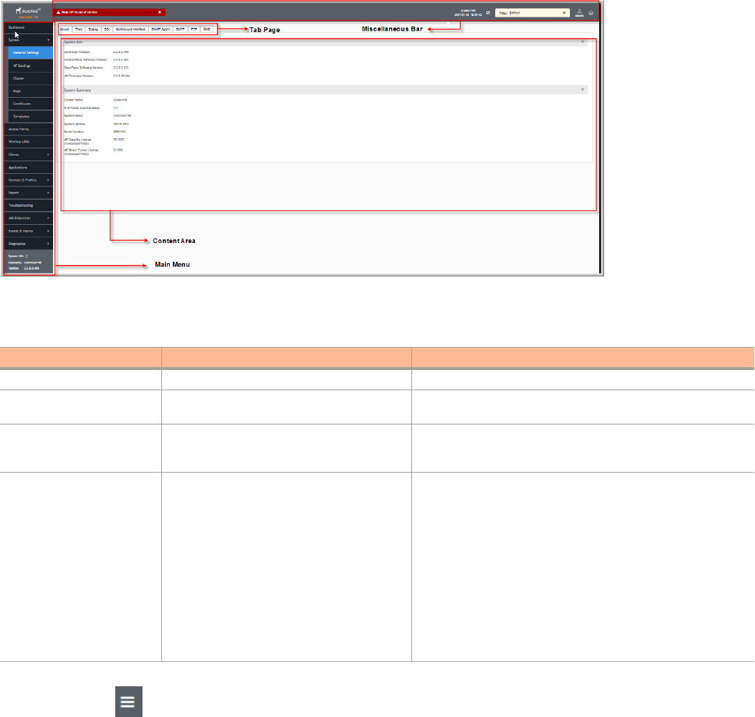
FIGURE 1 Controller Web Interface Features
The following table describes the web interface features.
TABLE 2 Controller Web Interface Features
Feature Description Action
Main Menu Lists the menus for administrative task. Select the required menu and sub-menu.
Tab Page Displays the options specific to the selected
menu.
Select the required tab page.
Content Area Displays tables, forms, and information specific to
the selected menu and tab page.
View the tables, forms and information specific to the selected
menu, sub-menu and tab page. Double-click an object or profile in a
table, for example: a WLAN, to edit the settings.
Header Bar Displays information specific to the web interface. Select the required option (from left to right):
• Warning—Lists the critical issues to be resolved.
• System Date and time—Displays the current system date
and time.
• Refresh—Refreshes the web page.
• Global filter—Allows you to set the preferred system filter.
• My Account link—Allows you to:
– Change password
– Set session preference
– Log off
• Online Help—Allows access to web help.
You can also use the icon to expand and shrink the main menu. Shrinking the main menu increases the size of the content area for
better readability and viewing.
Changing the Administrator Password
Follow these steps to change the administrator password.
1. From the Header bar, click admin and select Change Password. The following window appears.
Navigating the Dashboard
Changing the Administrator Password
SCG200 vSZ-H and SZ300 Administrator Guide
Part Number: 800-71563-001 17
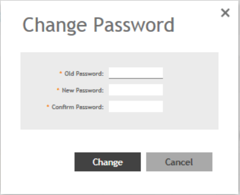
FIGURE 2 Change Password Form
2. Enter:
•Old Password—Your current password.
•New Password—Your new password.
•Confirm Password—Your new password.
3. Click Change, your new password is updated.
Logging Off the Controller
You must be aware of how to log off the controller through CLI and from the web interface.
1. From the Header bar, click admin and select Log off.
The following message appears: Are you sure you want to log off?
2. Click Yes.
The controller logs you off the web interface and the logon page appears.
You have completed logging off the web interface.
You can also use CLI commands to shutdown the controller.
To shutdown the controller gracefully, use the following command: ruckus# shutdown <seconds>, where
seconds
indicates the number of
seconds before controller shutdowns.
To shutdown the controller immediately, use the following command: ruckus# shutdown now. The controller would shutdown in 30
seconds.
Navigating the Dashboard
Logging Off the Controller
SCG200 vSZ-H and SZ300 Administrator Guide
18 Part Number: 800-71563-001
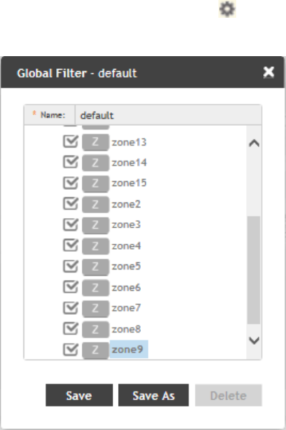
Configuring Global Filters
The Global filter setting allows you to set your preferred system filter.
Global filters allow the administrator to define a system scope or system context that applies to all pages of the system as they navigate to
different menus. For example, if your system includes 5 zones, but you want to view Zone1 and Zone2 only, you can create and apply such
a filter. As you navigate throughout the system, the view will be restricted to show only the data, objects, and profiles contained within
Zones 1 and 2.
To set the global filter:
1. From the Header bar, click Filter setting . The below figure appears.
FIGURE 3 Global Filter Form
2. Select or clear the required system filters and click
•Save—To save the filter settings with the default group.
•Save As—To save the filter settings as a new group. The below figure appears. Enter a new name for the group and click OK.
Navigating the Dashboard
Configuring Global Filters
SCG200 vSZ-H and SZ300 Administrator Guide
Part Number: 800-71563-001 19
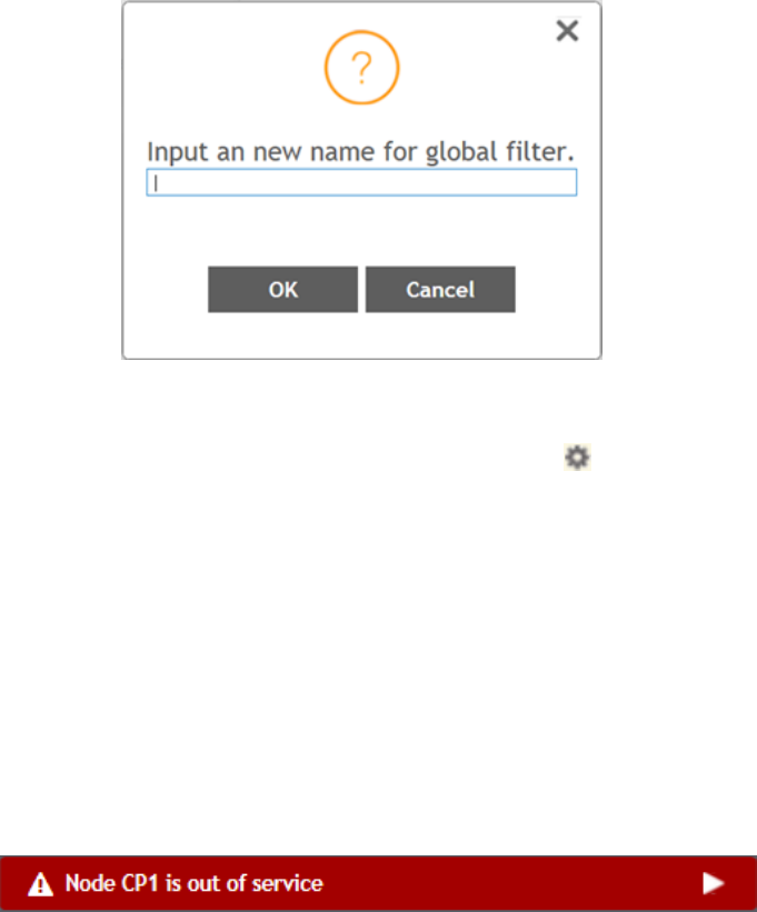
FIGURE 4 New Name Form
NOTE
You can delete the filter setting. To do so, click the Filter setting button. The Global Filter form appears, click Delete.
Warnings and Notifications
This section explains about warnings and notifications.
Warnings
Warnings are displayed in the Miscellaneous bar. They are issues which are critical in nature. Warnings cannot be removed or
acknowledged unless the critical issue is resolved.
FIGURE 5 Sample Warning Message
A list of warning messages that appear are as follows:
• Default 90-day support expiring soon
• System support expiring soon
• System support has expired
• Default 90-day AP license expiring soon
• Default AP license has expired
• Default 90-day RTU license expiring soon
• RTU has expired
• AP Certificate Expiration
• Node Out of Service
• Cluster Out of Service
• VM Resource Mismatch
Navigating the Dashboard
Warnings and Notifications
SCG200 vSZ-H and SZ300 Administrator Guide
20 Part Number: 800-71563-001

• Suggested AP Limit Exceeded
Setting Global Notifications
Notifications are integrated with existing alarms and they are displayed only when a notification alarm exists and which is not acknowledged
by the administrator. Notifications can be viewed from the Content area. Administrators can acknowledge the notification by either:
• Clear the alarm
• Acknowledge the Alarm
Alarm severity are of three types:
• Minor
• Major
• Critical
The adminstrator can change the alarm severity shown on the dashboard. To do so:
1. From the Notifications area, Click the Setting button. The Settings - Global Notification form appears.
2. From the Lowest alarm severity drop-down, select the required severity level.
3. Click OK. Notifications corresponding to the selected alarm severity and severity above it are displayed in the Notification area of
the Dashboard.
Health and Maps
The Health dashboard gives you a very high-level overview of cluster, AP and client information. It also displays a world map view using
Google Maps, which provides a global view of your SmartZone-controlled wireless network deployments.
The status bar at the top of the Health dashboard contains an iconic representation of the total Cluster, AP and Client counts for the entire
system. This information can be filtered to display a single zone, AP group, or venue using the drop-down filter menu. You can also
customize the dashboard layout and threshold settings using the Settings (gear) icon.
For more information on customizing the information displayed on the Health dashboard, see Customizing Health Status Thresholds on
page 22.
Navigating the Dashboard
Health and Maps
SCG200 vSZ-H and SZ300 Administrator Guide
Part Number: 800-71563-001 21
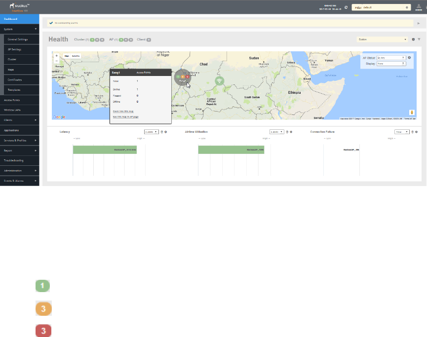
FIGURE 6 Health Workspace area
Understanding Cluster and AP Health Icons
The Health dashboard status bar displays the following Cluster and AP information using three colored icons to denote the number of APs/
clusters currently in that state.
The icons for both Cluster and AP status overviews are represented by the following color coding scheme:
• (Green): Online
• (Orange): Flagged
• (Red): Offline
Online and Offline status are self-explanatory. "Flagged" status is user-defined. You can customize the thresholds at which an AP or cluster
enters "flagged" state using the Settings (gear) icon in the status bar. For more information, see Customizing Health Status Thresholds on
page 22.
Customizing Health Status Thresholds
You can customize the way SmartZone categorizes and displays clusters and APs as "Flagged" in the status bar.
To customize the Health dashboard, click the Settings (gear) icon. In the Settings - Health Dashboard form, click the Cluster Status or AP
Status tab, and configure the following:
•Cluster Status: Configure CPU, hard disk and memory usage percentages above which the cluster will be marked as flagged
status.
•AP Status: Configure the criteria upon which APs will be flagged. For more information, see Customizing AP Flagged Status
Thresholds on page 23.
Navigating the Dashboard
Health and Maps
SCG200 vSZ-H and SZ300 Administrator Guide
22 Part Number: 800-71563-001
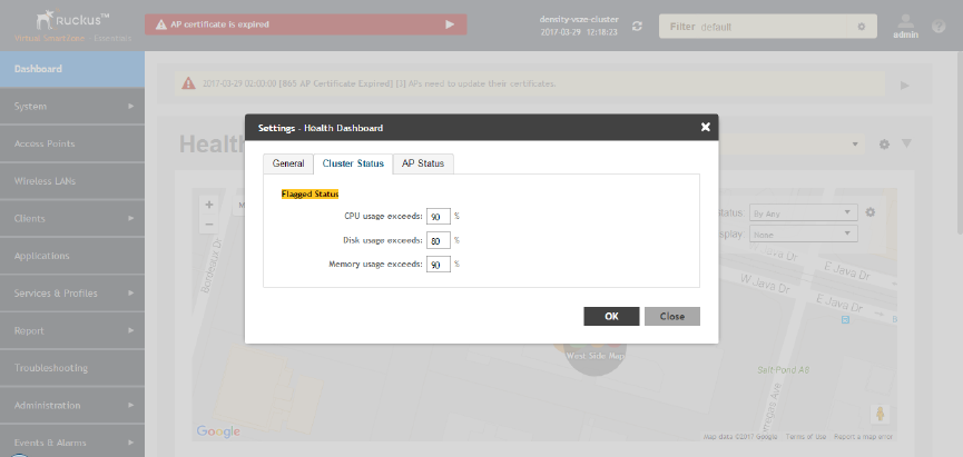
FIGURE 7 Setting Cluster Health Status Thresholds
Customizing AP Flagged Status Thresholds
Use the following procedure to customize when APs will be marked as "flagged" on the Health dashboard status bar.
1. Click the Gear icon on the Health dashboard.
2. The Settings - Health Dashboard form appears. Click the AP Status tab.
3. Select the behavior of flagging policies when applying changes to parent or child groups:
• Apply the change to all child groups
• Apply the change if child group settings already match the parent group
4. Configure thresholds above which APs will be marked as "flagged" for the following criteria:
• Latency
• Airtime Utilization
• Connection Failures
• Total connected clients
5. Configure the radio (2.4 / 5 GHz) from the drop-down menu and select the level (system, zone, AP group) at which you want to
apply the policy, and configure the Sensitivity control for the threshold (Low, Medium, High). Setting the Sensitivity level to Low
means that an AP must remain above the threshold for a longer period of time before it will appear in the flagged category, while a
High sensitivity means that APs will more quickly alternate between flagged and non-flagged status.
Navigating the Dashboard
Health and Maps
SCG200 vSZ-H and SZ300 Administrator Guide
Part Number: 800-71563-001 23
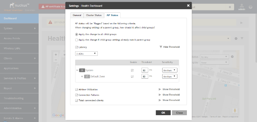
6. Click OK to save your changes.
FIGURE 8 Configuring AP flagged status thresholds
Using the Health Dashboard Map
Use the Google Maps view just as you would normally use Google Maps - including zoom, satellite view, rotate and even street view icons.
You can customize the AP icon information displayed on the map using the tools in the upper-right hand corner.
Use the Settings (gear) icon to configure the information displayed in tooltips when hovering over an AP on the map. You can also change
the view mode altogether, from map view to Groups, Control Planes or Data Planes view mode using the settings menu. Additionally, you
can also select the check-box to show mesh links. These links appear as dotted lines. If you hover over the mesh link on the map, a pop-up
appears displaying more information such as the following:
• Uplink AP: displays the IP address of the uplink AP to which the wireless client sends data
• Downlink AP: displays the IP address of the downlink AP from which data is sent back to the wireless client
• SNR (Uplink): displays the signal-to-noise ratio in the uplink path
• SNR (Downlink): displays the signal-to-noise ratio in the downlink path
• Bytes (Uplink): displays the bytes of data transferred from the client to the uplink AP
• Bytes (Downlink): displays the bytes of data transferred from the downlink AP to the client
• Connected Since: displays the date and time when the mesh connection was established
Bytes (Uplink)
and
Bytes (Downlink)
are aggregate counters for the mesh connection since the start of that mesh connection. If the mesh
link is broken and restarts, the counter restarts. If the mesh AP connects to a different mesh root or uplink, the counter restarts.
Navigating the Dashboard
Health and Maps
SCG200 vSZ-H and SZ300 Administrator Guide
24 Part Number: 800-71563-001
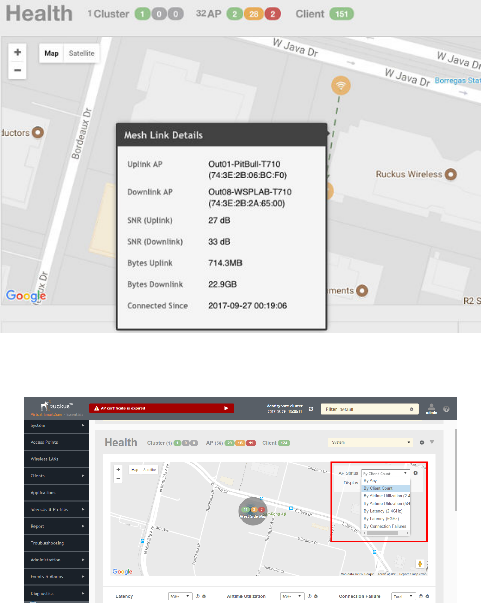
FIGURE 9 Mesh Link Details
You can also select the Google Map API key to use the Maps service with the application.
FIGURE 10 Configuring map settings
Navigating the Dashboard
Health and Maps
SCG200 vSZ-H and SZ300 Administrator Guide
Part Number: 800-71563-001 25
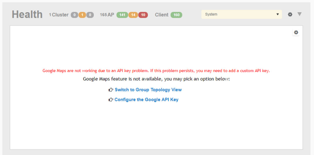
NOTE
In order for your venues to appear on the world map, you must first import a map of your site floorplan.
Configuring the Google Map API Key Behavior
The Google Maps feature in the controller application works based on API interaction between the application and the Maps service hosted
by Google. By default, these APIs are commonly available without the need for an API key but sometimes, you might have to generate a
key.
If Google Maps do not display properly in the absence of an API key, or when the API usage exceeds the daily limit, then an API key needs
to be generated to ensure the map displays all the elements properly.
You would also have to generate an API key if you encounter errors such as
MissingKeyMapError
or
NoApiKeys
.
FIGURE 11 Health dashboard view when API key is not available
Clicking Configure the Google API Key directs you to the Google Map API Key tab, where you can manage the Google Map API Key
behavior.
All administrators of the system can use the same API key, or apply a unique API key per administrator. Allowing an API key per
administrator enables more flexibility when API usage is high, or in circumstances when each tenant must use their own API key.
Follow these steps to configure the Google Map API Key behavior.
Launching the application displays the Dashboard menu, by default.
Navigating the Dashboard
Health and Maps
SCG200 vSZ-H and SZ300 Administrator Guide
26 Part Number: 800-71563-001
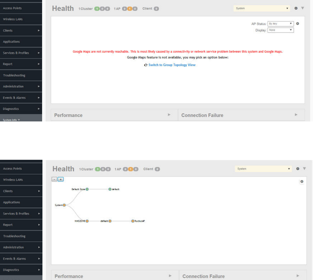
In Health, the map view appears if you are connected to a network. If you are not, then you might see the following screen and would
have to view your network deployment as a topology diagram.
FIGURE 12 No Map View
If you click the Switch to Group Topology View, a topology diagram similar to the following figure is displayed.
FIGURE 13 Topology View
Navigating the Dashboard
Health and Maps
SCG200 vSZ-H and SZ300 Administrator Guide
Part Number: 800-71563-001 27
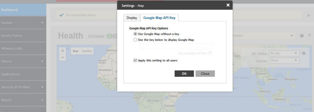
1. From the map view in Health, click the Settings (gear-shaped) icon.
The Settings-Map page appears.
FIGURE 14 Google Map API Key Options
From the Display tab, you can choose the mode in which you want to view your network deployment.
2. Click the Google Map API Key tab.
3. From the Google Map API Key Options, select one of the following:
Option Description
Use Google Map without a
key
Allows you to use the Google map feature without an API key.
Use the key below to display
Google Map
Allows you to enter an API key which you already have to use the Google map feature. If you do
not have a pre-existing API key, you can generate one by following the instructions in the Get a
Google API Key link.
NOTE
The Google API Console is a platform on which you can build, test, and deploy applications. To use Google Maps API,
you must register your application on the Google API Console and generate a Google API key which you can add to the
application. For more information, see https://developers.google.com/maps/documentation/javascript/tutorial
If you already have a Google API Map Key, type the key to establish a connection with Google Maps.
4. Select Apply this setting to all users to apply the configuration settings to all users in the network deployment.
5. Click OK.
You have successfully configured the Google Map API Key options for your network deployment.
Viewing AP Performance
Click the Performance tab to analyze the following parameters:
• Latency - Average time delay between an AP and connected clients.
• Airtime Utilization - Percent of airtime utilized, by radio.
Navigating the Dashboard
Health and Maps
SCG200 vSZ-H and SZ300 Administrator Guide
28 Part Number: 800-71563-001
• Capacity - Measurement of potential data throughput based on the recent air-time efficiency and the performance potential of the
AP and its currently connected clients.
You can view the parameters based on specific:
• Duration: 1 hour, 24 hours, 7 days, and 14 days
• Radio: 2.4 GHz, 5GHz
The parameters are displayed as Graphs and Bar Charts. When you hover over the graph you can view the Date and Time, Median, Likely
Range, Min-Max Range of the parameters. To view specific information on the graph, click and drag the portion. The selected portion would
zoom in. To restore to normal view, click the Reset zoom button.
To display specific information, click the settings button. The Settings - Performance window pops up. In Show top, enter the number of
APs to be analysed and choose the AP identity display.
Viewing AP Connection Failures
Click the Connection Failure tab to analyze the following parameters
• Total - Measurement of unsuccessful connectivity attempts by clients
• Authentication - Measurement of client connection attempts that failed at the 802.11 open authentication stage
• Association - Measurement of client connection attempts that failed at the 802.11 association stage
• EAP - Measurement of client connection attempts that failed during and EAP exchange
• RADIUS - Measurement of RADIUS exchanges that failed due to AAA client/server communication issues or errors
• DHCP - Measurement of failed IP address assignment to client devices
You can view the parameters based on specific:
• Duration: 1 hour, 24 hours, 7 days, and 14 days
• Radio: Total, 2.4 GHz, 5GH
The parameters are displayed as Graphs and Bar Charts. When you hover over the graph you can view the Date and Time, Median, Likely
Range, Min-Max Range of the parameters. To view specific information on the graph, click and drag the portion. The selected portion would
zoom in. To restore to normal view, click the Reset zoom button.
To display specific information, click the Settings button. The Settings - Performance window pops up. In Show top, enter the number of
APs to be analysed and choose the AP identity display.
Traffic Analysis
You can analyze network traffic for APs, WLANs and clients.
From the traffic analysis tab, you can choose to analyze data using the following filters:
•Channel Range
–Total
–2.4GHz
–5GHz
•Throughput
–TX+RX—Number of bytes sent and received
–TX—Number of bytes sent
–RX—Number of bytes received
Navigating the Dashboard
Traffic Analysis
SCG200 vSZ-H and SZ300 Administrator Guide
Part Number: 800-71563-001 29
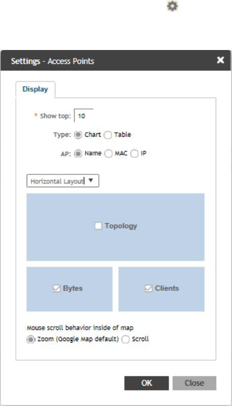
•Group
The parameters are displayed as Graphs and Bar Charts. When you hover over the graph you can view the Date and Time, Median, Likely
Range, Min-Max Range of the parameters. To view specific information on the graph, click and drag the portion. The selected portion would
zoom in. To restore to normal view, click the Reset zoom button.
Configuring Traffic Analysis Display for APs
Using traffic analysis you can measure the total volume of traffic sent or received by an Access Point (AP).
You can view historical and real-time data of the AP. Throughput and the number of clients connected to the AP are displayed in a bar
chart. You must configure the AP settings to view its traffic analysis.
To configure the AP settings:
1. From the Access Points area, click settings . The following window appears.
FIGURE 15 AP Settings Form
2. In Show top, enter the number of APs for which the traffic must be analyzed. Range: 5 through 20.
3. Select the Type of display you want to view. For example, Chart or Table.
Navigating the Dashboard
Traffic Analysis
SCG200 vSZ-H and SZ300 Administrator Guide
30 Part Number: 800-71563-001
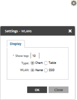
4. Select the required AP identification option to be displayed. For example, Name, MAC or IP.
5. From the drop-down, select the required display layout. For example, Horizontal Layout or Vertical Layout.
6. Select or clear the required options that must be displayed in the Content area.
•Topology—To view the location map.
•Bytes—To view the throughput.
•Clients—To view the client details.
7. Select the following mouse-scroll behavior when you point the mouse over a map:
•Zoom
•Scroll
8. Click OK.
Configuring Traffic Analysis Display for WLANs
Using traffic analysis you can measure the total volume of traffic sent or received by WLANs.
You can view historical and real-time data of the WLANs. Throughput and the number of clients connected to the WLANs are displayed in a
bar chart. You must configure the WLAN settings to view its traffic analysis.
To configure the WLAN settings:
1. From the WLAN area, click settings . The following window appears.
FIGURE 16 WLAN Settings Form
2. In Show top, enter the number of WLANs for which the traffic must be analyzed. Range: 5 through 20.
3. Select the Type of display you want to view. For example, Chart or Table.
4. Select the required WLAN identification option to be displayed. For example, Name or SSID.
5. Click OK.
Navigating the Dashboard
Traffic Analysis
SCG200 vSZ-H and SZ300 Administrator Guide
Part Number: 800-71563-001 31
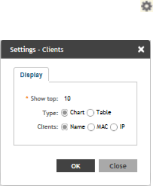
Configuring Traffic Analysis Display for Top Clients
Using traffic analysis you can measure the total volume of traffic sent or received by Clients. You can view historical and real-time data of the
Clients. The chart displays:
• Bytes—Frequency and number of clients connected to the AP
• OS Type—Types of OS the associated clients are using
• Application—Throughput the applications use
You must configure the Client settings to view its traffic analysis.
To configure the Client settings:
•From the Clients area, click settings . Figure 17 appears.
FIGURE 17 Client Setting Form
• In Show top, enter the number of Clients for which the traffic must be analyzed. Range: 5 through 20.
• Select the Type of display you want to view. For example, Chart or Table.
• Select the required Client identification option to be displayed. For example, Name, MAC or IP.
• Click OK.
Navigating the Dashboard
Traffic Analysis
SCG200 vSZ-H and SZ300 Administrator Guide
32 Part Number: 800-71563-001

Configuring System Settings
•Configuring General Settings................................................................................................................................... 33
•Configuring AP Settings...........................................................................................................................................42
• Viewing the System Cluster Overview......................................................................................................................47
• Working with Maps..................................................................................................................................................59
•Certificates.............................................................................................................................................................. 63
•Configuring Templates.............................................................................................................................................67
Configuring General Settings
Viewing System Settings
You can view the system information such as the controller version, firmware version, license information, control and data plane details
from the General Settings tab.
To view the system settings, from the left pane, select System > General Settings > About. The following system information is displayed:
• Controller Version
• Control Plane Software Version
• Data Plane Software Version
• AP Firmware Version (hover over the field to see the firmware type)
• Cluster Name
• Number of Planes
• System Name
• System Uptime
• Serial Number
• AP Capacity License
• AP Direct Tunnel License
SCG200 vSZ-H and SZ300 Administrator Guide
Part Number: 800-71563-001 33
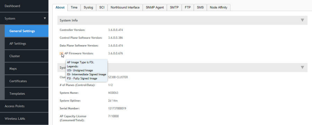
FIGURE 18 General Settings
AP image signing involves digitally signing the Ruckus header and body of the AP firmware, and authenticating the firmware as valid to be
installed on the AP. AP firmware images are available in the following types:
•
USI
: Un-Signed Images which do not have the capability to sign and verify. It only contains a Header and Body. The Body usually
contains both the kernel and file system information.
•
IUI
: Intermediate Signed Image which has the capability to sign and verify, and it allows installation of both signed and unsigned
images.
•
FSI
: Fully Signed Image which only allow Ruckus-signed firmware to be installed on the AP. It does not allow installation of
unsigned or tampered images.
AP image signing is a two step upgrade or downgrade procedure where in the AP firmware can be upgraded from type USI to ISI, ISI to FSI
and vice-versa in the same order.
NOTE
You cannot upgrade an image from USI to FSI as the formats of these images are different. Attempting such an upgrade triggers
an AP image signing failed event.
Configuring System Time
The controller uses an external network time protocol (NTP) server to synchronize the times across cluster nodes and managed access
points.
To edit the system time:
1. Go to System > General Settings > Time.
2. Enter the NTP Server address that you want to use. The default NTP server address is ntp.ruckuswireless.com.
3. Click Sync Server to enable an AP to join the controller and automatically synchronize its time every day.
4. Select the System Time Zone, from the drop-down that you want the controller to use. The default time zone is (GMT +0:00) UTC.
5. Click OK.
Configuring System Settings
Configuring General Settings
SCG200 vSZ-H and SZ300 Administrator Guide
34 Part Number: 800-71563-001

Configuring the Remote Syslog Server
The controller maintains an internal log file of current events and alarms, but this internal log file has a fixed capacity. Configure the log
settings so you can keep copies of the logs that the controller generates.
At a certain point, the controller will start deleting the oldest entries in log file to make room for newer entries. If you want to keep a
permanent record of all alarms and events that the controller generated, you can configure the controller to send the log contents to a
syslog server on the network.
Follow these steps to configure the remote syslog server:
1. Go to System > General Settings > Syslog.
2. Select the Enable logging to remote syslog server check box.
3. Configure the settings as explained in Table 3.
4. Click OK.
TABLE 3 Syslog Server Configuration Settings
Field Description Your Action
Primary Syslog Server Address Indicates the syslog server on the network. 1. Enter the server address.
2. Enter the Port number.
3. Choose the Protocol type.
4. Click Ping Syslog Server. If the syslog
server is reachable, a flashing green
circle and the message Success appears
after the button.
Secondary Syslog Server Address Indicates the backup syslog server on the
network, if any, in case the primary syslog
server is unavailable.
1. Enter the server address.
2. Enter the Port number.
3. Choose the Protocol type.
4. Click Ping Syslog Server. If the syslog
server is reachable, a flashing green
circle and the message Success appears
after the button.
Application Logs Facility Indicates the facility for application logs. 1. Select the option from the drop-down.
Range: 0 through 7.
2. Select one of the following Filter Severity:
a. Emerg
b. Alert
c. Crit
d. Error
e. Warning
f. Notice
g. Info
h. Debug: Default option
Administrator Activity Logs Facility Indicates the facility for administrator logs. 1. Select the option from the drop-down.
Range: 0 through 7.
2. Select one of the following Filter Severity:
a. Emerg
b. Alert
c. Crit
d. Error
Configuring System Settings
Configuring General Settings
SCG200 vSZ-H and SZ300 Administrator Guide
Part Number: 800-71563-001 35

TABLE 3 Syslog Server Configuration Settings (continued)
Field Description Your Action
e. Warning
f. Notice
g. Info
h. Debug: Default option
Other Logs Filter Severity Indicates the facility for comprehensive logs. Select one of the following Filter Severity:
1. Emerg
2. Alert
3. Crit
4. Error
5. Warning
6. Notice
7. Info
8. Debug: Default option
Event Facility Indicates the facility for event logs. Select the option from the drop-down. Range:
0 through 7.
Event Filter Indicates the type of event that must be sent
to the syslog server.
Choose the required option:
•All events — Send all controller events to
the syslog server.
•All events except client association /
disassociation events — Send all
controller events (except client
association and disassociation events) to
the syslog server.
•All events above a severity — Send all
controller events that are above the
event severity to the syslog server.
Event Filter Severity applies to Event Filter >
All events above a severity
Indicates the lowest severity level. Events
above this severity level will be sent to the
syslog server.
Select the option from the drop-down.
1. Critical
2. Major
3. Minor
4. Warning
5. Informational
6. Debug: Default option
Priority Indicates the event severity to syslog priority
mapping in the controller.
Choose the Syslog Priority among Error,
Warning, Info and Debug, for the following
event severities:
•Critical
•Major
•Minor
•Warning
•Informational
•Debug
Configuring System Settings
Configuring General Settings
SCG200 vSZ-H and SZ300 Administrator Guide
36 Part Number: 800-71563-001
Configuring SCI Settings
SmartCell Insight uses data from the controller to analyse performance and generate reports about the WiFi network. Configuring the SCI
settings in the controller enables data transfer from the controller to the SCI server using the MQTT protocol.
Follow these steps to configure the SCI server settings:
1. Go to System > General Settings > SCI.
2. Select the Enable SCI check-box to configure the SCI server settings.
3. Click Create, the Create SCI Profile form appears.
4. Enter the following details:
•Name—Profile name.
•Server Host—IP address to the SCI host server.
•Server Port—Port number over which the SCI server and controller can communicate and transfer data.
•User—Name for the user.
•Password—password for the respective user.
•System ID—ID of the SCI system that should be accessed.
5. Click OK.
NOTE
You can also edit or delete an SCI profile. To do so, select the SCI profile from the list and click Configure or Delete as required.
Setting the Northbound Portal Password
Third-party applications use the northbound portal intrface to authenticate users and to retrieve user information during the UE association.
Follow these steps to configure the northbound portal interface:
1. Go to System > General Settings > Northbound Interface.
2. Select Enable Northbound Interface Support, and enter the User Name and Password.
3. Click OK.
Enabling Global SNMP Notifications
The controller supports the Simple Network Management Protocol (SNMP v2 and v3), which allows you to query controller information,
such as system status, AP list, etc., and to set a number of system settings using a Network Management System (NMS) or SNMP MIB
browser.
You can also enable SNMP traps to receive immediate notifications for possible AP and system issues.
The procedure for enabling the internal SNMP agents depends on whether your network is using SNMPv2 or SNMPv3. SNMPv3 mainly
provides security enhancements over the earlier version, and therefore requires you to enter authorization passwords and encryption
settings, instead of simple clear text community strings.
Both SNMPv2 and SNMPv3 can be enabled at the same time. The SNMPv3 framework provides backward compatibility for SNMPv1 and
SNMPv2c management applications so that existing management applications can still be used to manage the controller with SNMPv3
enabled.
Configuring System Settings
Configuring General Settings
SCG200 vSZ-H and SZ300 Administrator Guide
Part Number: 800-71563-001 37

Configuring SNMP v2 Agent
To configure SNMP v2 Agent settings:
1. Go to System > General Settings > SNMP Agent.
2. Select the Enable SNMP Notifications Globally check box to send out notification messages.
3. To configure the SNMPv2 Agent, click Create and update the details as explained in the following table.
TABLE 4 SNMP v2 Agent Settings
Field Description Your Action
Community Indicates that applications which send SNMP
Get-Requests to the controller (to retrieve
information) will need to send this string along
with the request before they will be allowed
access.
Enter a name.
Privilege Indicates the privileges granted to this
community.
Select the required privileges:
•Read—Privilege only to read.
•Write—Privilege only to read and write.
•Notification—Privilege to:
–Trap—Choose this option to send
SNMP trap notification.
–Inform—Choose this option to send
SNMP notification.
1. Enter the Target IP address.
2. Enter the Target Port number.
3. Click Add.
NOTE
You can also edit or delete an SNMPv2 agent. To do so, select the SNMPv2 agent from the list and click Configure or
Delete respectively.
4. Click OK.
Configuring SNMP v3 Agent
1. Go to System > General Settings > SNMP Agent.
2. Select the Enable SNMP Notifications Globally check box to send out notification messages.
3. To configure the SNMPv3 Agent, click Create and update the details as explained in the follwoing table.
TABLE 5 SNMPv3 Agent Settings
Field Description Your Action
Community Indicates that applications which send SNMP
Get-Requests to the controller (to retrieve
information) will need to send this string along
with the request before they will be allowed
access.
Enter a name.
Authentication Indicates the authentication method. Choose the required option:
•None—Use no authentication.
•SHA—Secure Hash Algorithm, message
hash function with 160-bit output.
1. Enter the Auth Pass Phrase.
Configuring System Settings
Configuring General Settings
SCG200 vSZ-H and SZ300 Administrator Guide
38 Part Number: 800-71563-001

TABLE 5 SNMPv3 Agent Settings (continued)
Field Description Your Action
2. Choose the Privacy option.
–None: Use no privacy method.
–DES: Data Encryption
Standard, data block cipher.
–AES: Advanced Encryption
Standard, data block cipher.
3. Enter a Privacy Phrase, 8 through
32 characters.
•MD5—Message-Digest algorithm 5,
message hash function with 128-bit
output.
1. Enter the Auth Pass Phrase.
2. Choose the Privacy option.
–None: Use no privacy method.
–DES: Data Encryption
Standard, data block cipher.
–AES: Advanced Encryption
Standard, data block cipher.
3. Enter a Privacy Phrase, 8 through
32 characters.
Privilege Indicates the privileges granted to this
community.
Select the required privileges:
•Read—Privilege only to read.
•Write—Privilege only to read and write.
•Notification—Privilege to:
–Trap—Choose this option to send
SNMP trap notification.
–Inform—Choose this option to send
SNMP notification.
1. Enter the Target IP address.
2. Enter the Target Port number.
3. Click Add.
NOTE
You can also edit or delete an SNMPv3 agent. To do so, select the SNMPv3 agent from the list and click Configure or
Delete respectively.
4. Click OK.
Configuring SMTP Server Settings
If you want to receive copies of the reports that the controller generates or to email guest passes to users, you need to configure the SMTP
server settings and the email address from which the controller will send the reports.
Follow these steps to configure the SMTP server settings:
1. Go to System > General Settings > SMTP.
2. Select Enable SMTP Server.
3. Enter the Logon Name or user name provided by your ISP or mail administrator. This might be just the part of your email address
before the @ symbol, or it might be your complete email address. If you are using a free email service (such as Hotmail™ or
Gmail™), you typically have to type your complete email address.
Configuring System Settings
Configuring General Settings
SCG200 vSZ-H and SZ300 Administrator Guide
Part Number: 800-71563-001 39
4. Enter the associated Password.
5. For SMTP Server Host, enter the full name of the server provided by your ISP or mail administrator. Typically, the SMTP server
name is in the format smtp.company.com.
6. For SMTP Server Port, enter the SMTP port number provided by your ISP or mail administrator. Often, the SMTP port number is
25 or 587. The default SMTP port value is 25.
7. For Mail From, enter the source email address from which the controller sends email notifications.
8. For Mail To, enter the recipient email address to which the controller sends alarm messages. You can send alarm messages to a
single email address.
9. Select the Encryption Options, if your mail server uses encryption.
•TLS
•STARTTLS
Check with your ISP or mail administrator for the correct encryption settings that you need to set.
10. Click Test, to verify if the SMTP server settings are correct. The test completed successfully form appears, click OK.
11. Click OK.
Configuring FTP Server Settings
The controller enables you to automatically back up statistics files, reports, and system configuration backups to an external FTP server.
However, before you can do this, you must add at least one FTP server to the controller.
Follow these steps to add an FTP server to which the controller will export data automatically:
1. Go to System > General Settings > FTP.
2. Click Create, the Create FTP Server from appears.
3. Enter an FTP Name that you want to assign to the FTP server that you are adding.
4. Select the required Protocol; FTP or SFTP (Secure FTP) protocol.
5. Enter the FTP Host, IP address of the FTP server.
6. Enter the FTP Port, number. The default FTP port number is 21.
7. Enter a User Name for the FTP account that you want to use.
8. Enter a Password that is associated with the FTP user name.
9. For Remote Directory, enter the remote FTP server path to which data will be exported from the controller. The path must start
with a forward slash (/)
10. To verify that the FTP server settings and logon information are correct, click Test. If the server and logon settings are correct, a
confirmation message stating, "FTP server connection established successfully" appears.
11. Click OK.
NOTE
You can edit or delete an existing FTP setting. To do so, select the FTP setting from the list and click Configure or Delete
respectively.
Configuring System Settings
Configuring General Settings
SCG200 vSZ-H and SZ300 Administrator Guide
40 Part Number: 800-71563-001
Configuring the SMS Gateway Server
You can define the external gateway services used to distribute guest pass credentials to guests.
To configure an external SMS gateway for the controller:
1. Go to System > General Settings > SMS.
2. Select the Enable Twilio SMS Server check box to use an existing Twilio account for SMS delivery.
3. Enter the following Twilio Account Information:
•Server Name
•Account SID
•Auth Token
•From (phone number)
4. Click OK.
Configuring Node Affinity
Node affinity enables administrators to manually configure the controller nodes to which APs will connect.
To do this, set the order of preferred nodes on the node affinity page. Node affinity is implemented at the AP zone level, which means that
all APs that belong to a zone will have the same node affinity settings.
If you want APs that belong to the same zone to connect to the same node whenever possible, you can configure set the preferred node
for a particular zone.
NOTE
An affinity profile defines the order of the nodes to which APs that belong to the same zone will connect.
NOTE
Node affinity is not supported on the vSZ-H and vSZ-D platforms.
Enabling Node Affinity
To enable and configure node affinity:
1. Go to System > General Settings > Node Affinity.
2. Select Enable Node Affinity. Node Affinity Profile appears.
3. To:
• Create an new profile:
1. Click Create, the Create Node Affinity Profile form appears.
2. Enter a Name and Description.
3. In the Node Order list, select the node and click Up or Down to position the node in the required order.
4. Click OK.
• Edit the default profile:
1. Select the profile from the list and click Configure. The Edit Node Affinity Profile form appears.
2. Edit the Name and Description.
3. In the Node Order list, select the node and click Up or Down to position the node in the required order.
Configuring System Settings
Configuring General Settings
SCG200 vSZ-H and SZ300 Administrator Guide
Part Number: 800-71563-001 41
4. Click OK.
NOTE
When you enable node affinity, disable cluster redundancy.
4. To set the number of times an AP will attempt to connect to the preferred node, enter the # of Node Retry for Preferred Node.
The default value is 3 and the accepted range is 1 to 10. If the AP is unable to connect to the preferred node, it will attempt to
connect to the node that is next in the order of node priority.
5. In the Zone Assignment section, set the node affinity profile that you want each zone to use. Select the Zone from the list and click
Assign Profile. The Assign Node Affinity Profile to Selected Zones form appears.
6. Select the Node Affinity Profile from the drop-down and click OK.
7. Click OK.
Disabling Node Affinity
Follow these steps to disable node affinity:
1. From System > General Settings > Node Affinity.
2. Clear the Enable Node Affinity check box.
3. Click OK. You have disabled node affinity.
Configuring AP Settings
Working with AP Registration Rules
Registration rules enable the controller to assign an AP to an AP zone automatically based on the rule that the AP matches.
NOTE
A registration rule is only applied to an AP the first time it joins the controller. If an AP’s MAC address already exists on the
controller database (whether it is in connected on disconnected state and whether it belongs to the Staging Zone or any other
zone), the controller will assign the AP to its last known AP zone.
This section describes the following tasks:
Creating an AP Registration Rule
You must create rules to register an AP.
To create an AP registration rule:
1. Go to System > AP Settings > AP Registration.
2. Click Create, the AP Registration Rule form appears.
3. Enter a Rule Description.
4. Select the Zone Name to which this rule applies.
5. In Rule Type, click the basis upon which you want to create the rule. Options include:
Configuring System Settings
Configuring AP Settings
SCG200 vSZ-H and SZ300 Administrator Guide
42 Part Number: 800-71563-001
NOTE
The format of the IP address or addresses that you need to enter here depends on the AP IP mode that you selected
when you created the AP zone to which this rule will be assigned. If you selected IPv4 Only, enter an IPv4 address. If you
selected IPv6 Only, enter an IPv6 address.
•IP Address Range: If you select this option, enter the From (starting) and To (ending) IP address that you want to use.
•Subnet: If you select this option, enter the IP address and subnet mask pair to use for matching.
•GPS Coordinates: If you select this option, type the GPS coordinates to use for matching. Access points that have been
assigned the same GPS coordinates will be automatically assigned to the AP zone that you will choose in the next step.
You can choose the Rule Type as GPS coordinates, wherein you must provide information about the latitude, longitude and
distance to determine if the AP is within the defined area.
•Provision Tag: If the access points that are joining the controller have been configured with provision tags, click the Provision
Tag option, and then type a tag name in the Provision Tag box. Access points with matching tags will be automatically
assigned to the AP zone that you will choose in the next step.
NOTE
Provision tags can be configured on a per-AP basis from the access point’s command line interface.
6. Click OK.
When the process is complete, the page refreshes, and then registration rule that you created appears on the AP Registration
Rules page.
To create another registration rule, repeat the preceding steps. You can create as many registration rules as you need to manage
the APs on the network.
NOTE
You can also edit, delete or clone an AP registration rule. To do so, select the rule profile from the list and click Configure, Delete
or Clone respectively.
Configuring Registration Rule Priorities
The controller applies registration rules in the same order as they appear in the AP Registration Rules table (highest to lowest priority).
If you want a particular registration rule to have higher priority, you must move it up the table. Once an AP matches a registration rule, the
controller assigns the AP to the zone specified in the rule and stops processing the remaining rules.
Follow these steps to configure the registration rule priorities.
1. Go to System > AP Settings > AP Registration.
2. Select the rule from the list and click.
•Up—To give a rule higher priority, move it up the table
•Down—To give a rule lower priority, move it down the table
3. Click Update Priorities to save your changes.
Creating vSZ-D Zone Affinity
NOTE
(This feature is supported only for vSZ-H controller)
Configuring System Settings
Configuring AP Settings
SCG200 vSZ-H and SZ300 Administrator Guide
Part Number: 800-71563-001 43
To create a zone affinity:
1. Go to System > AP Settings > vSZ-D Zone Affinity.
2. Click Create, the Create New vSZ-D Zone Affinity form appears.
3. Enter a Name and Description for the zone affinity.
4. Click Create, the Add vSZ-D form appears.
5. Choose the zone from the drop-down.
6. Click OK.
NOTE
This feature is applicable only to vSZ-H platform.
Tagging Critical APs
A critical AP is an AP that exceeds the daily traffic threshold (sum of uplink and downlink) data bytes configured on the controller web
interface.
Follow these steps to tag critical APs (APs that exceed the data traffic threshold that you have defined) automatically:
1. Go to System > AP Settings > Critical AP Tagging.
2. Select the Enable Auto Tagging Critical APs check box.
3. For Auto Tagging Rules, select Daily Traffic Bytes Exceeds Threshold.
4. For Rule Threshold:
• In the first box, enter the value that you want to set as the traffic threshold. This value will be applied in conjunction with the
data unit that you select in the second box.
• In the second box, select the data unit for the threshold – MB for megabytes or GB for gigabytes.
5. Click OK.
APs that exceed the daily traffic threshold that you specified will appear highlighted on the Access Points page and the Access Point details
page. Additionally, the controller will send an SNMP trap to alert you that that an AP has been disconnected.
Configuring the Tunnel UDP Port
The tunnel UDP port is used by all GRE+UDP type tunnels.
To configuring the tunnel UDP port:
1. Go to System > AP Settings > Tunnel UDP Port.
2. Enter the Tunnel UDP Port number.
3. Click OK.
Setting the Country Code
Different countries follow different regulations for radio channel usage.
To ensure that the APs use authorized radio channels:
1. Go to System > AP Settings > Country Code.
Configuring System Settings
Configuring AP Settings
SCG200 vSZ-H and SZ300 Administrator Guide
44 Part Number: 800-71563-001
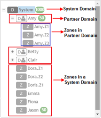
2. Select the Country Code for your location from the drop-down.
3. Click OK.
Limiting the Number of APs in a Domain or Zone
You can limit the number of APs in a Partner-Managed Domain or a Zone. An MSP may have multiple customers each with their own zone
and a number of APs. This feature ensures that their customers do not over-subscribe the licenses that they are entitled. MVNO domains
do not have this option. When an AP joins a zone, where an AP number limitation has been applied to that zone, the controller checks the
current capacity based on zone's limitation and:
• allows the new AP joining if the number of APs connected do not exceed the limit
• denies the new AP joining if there is no capacity in the domain or zone.
A scheduler task in the background periodically checks the AP number limitation against the number of APs connected. To avoid occupying
the license capacity, the APs will be rejected in the following situations:
• If the AP number limitation of a Domain or a Zone is increased or reduced.
• If the license capacity is changed.
The following image gives a clarity on:
• System domain
• Partner domain
• Zones in a System domain
• Zones in a Partner domain
FIGURE 19 System Hierarchy
Limiting the AP count for a Partner Domain or a System Zone
Only super admin of the system domain is privileged to limit the number of APs in a partner domain or a system zone.
To limit the number of AP count for a partner domain or a system zone:
1. Log on to the controller web interface using super admin credentials of the system domain.
Configuring System Settings
Configuring AP Settings
SCG200 vSZ-H and SZ300 Administrator Guide
Part Number: 800-71563-001 45
2. Follow the procedure to limit the number of APs in the partner domain or a zone in system domain:
a) Go to System > AP Settings > AP Number Allocation.
b) For Enable AP Number Allocation, select the Enabled check box and click OK. The Settings bar appears.
c) From the left pane, in the system tree hierarchy, select the partner-managed Domain or Zone for which you want to set the AP
number limit.
d) On the right pane, select Share Mode or enter the Number Limit.
e) Click OK. You have set the AP number limit for the selected Domain or Zone.
Limiting the AP count for a Zone in a Partner Domain
Super Admin of the partner domain have the privilege to configure the zones in that domain.
To limit the number of AP count for a zone in a partner domain:
1. Create a super admin account for the partner domain. Refer, Creating Administrator Accounts on page 272.
2. NOTE
While creating user groups, in step 4 (I) c, for Permission, select Super Admin from the drop-down.
Create a user group and configure the access permissions, resources and administrator account. Refer, Creating User Groups on
page 271.
3. Log on to the controller web interface using the following logon details:
•User Name:
Account Name@Domain
The Account Name that you set when you created the Administrator Account and the Domain for which you created the
Administrator Account. For example: If the partner domain is
TestDomain
and the Account Name is
User
, then the User Name
is
User@TestDomain
•Password : The password that you set when you created the Administrator Account.
4. Follow the procedure to limit the number of APs for a zone in a partner-domain:
a) Go to System > AP Settings > AP Number Allocation.
b) Select the Enable AP Number Allocation check box and click OK. The Settings bar appears.
c) From the left pane, in the system tree hierarchy, select the partner-managed zone for which you want to set the AP number
limit.
d) On the right pane, perform one of the following procedure:
• Select Share Mode
• Enter Number Limit
e) Click OK.
You have set the AP number limit for the selected partner-domain Zone.
Configuring System Settings
Configuring AP Settings
SCG200 vSZ-H and SZ300 Administrator Guide
46 Part Number: 800-71563-001
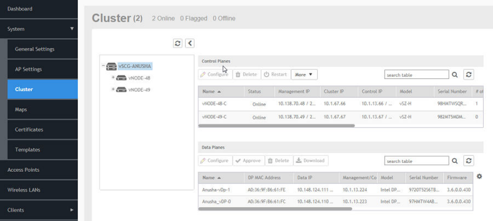
Viewing the System Cluster Overview
The system cluster overview provides summary information of the controller cluster.
To view the cluster settings:
• From the left pane of the application, click System > Cluster. The Cluster page appears.
FIGURE 20 System Cluster Overview
Control Planes and Data Planes
Control planes and data planes are used to control traffic.
The control plane manages and exchanges routing table information. The control plane packets are processed by the router to update the
routing table information. The data plane forwards the traffic along the path according to the logic of the control plane.
You can view historical and real time traffic of the nodes. To view the traffic:
1. From the Controller page, select the node.
2. Click the Traffic & Health from the lower end of the page.
3. Select the option from the drop-down:
•Historical Data, and enter the timeframe for which you want.
•Real Time Data, enter the duration in minutes and click Start.
Figure 21 appears.
Configuring System Settings
Viewing the System Cluster Overview
SCG200 vSZ-H and SZ300 Administrator Guide
Part Number: 800-71563-001 47
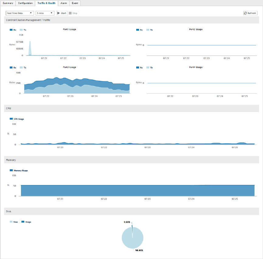
FIGURE 21 Cluster Node Traffic and Health.
Interface and Routing
To configure a cluster node, you must define interface and routing information.
Interface
You can only create one user defined interface, and it must be for a hotspot service and must use the control interface as its physical
interface.The control plane and the UDI must be on different subnets. If the control plane and UDI are on the same subnet, and assigned
with the same IP address, APs will be unable to communicate with the control plane. If the control plane and UDI are on the same subnet
and assigned different IP addresses, hotspot clients will not be redirected to the logon URL for user authentication.
NOTE
The user defined interface (UDI) is unavailable in Virtual SmartZone (High-Scale and Essentials).
Static Routing
Configuring System Settings
Viewing the System Cluster Overview
SCG200 vSZ-H and SZ300 Administrator Guide
48 Part Number: 800-71563-001
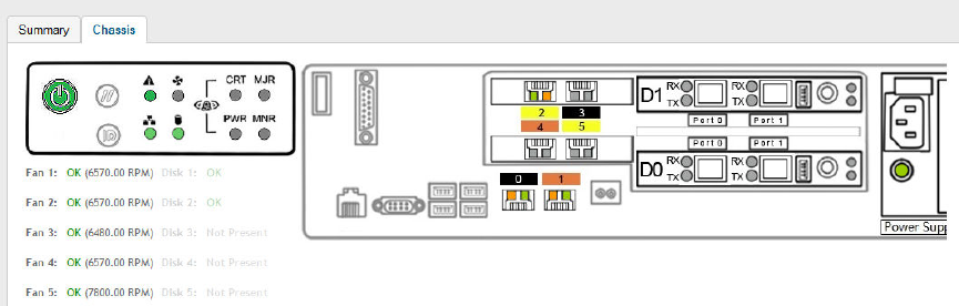
Static routing is used to manually configure routing entry. Static routes are fixed and do not change if the network is changed or
reconfigured. Static routing are usually used to maximize efficiency and to provide backups in the event that dynamic routing information
fails to be exchanged.
Displaying the Chassis View of Cluster Nodes
The chassis view provides a graphical representation of the control panel (on the front panel of the controller), including the LEDs.
Use the LEDs to check the status of the ports and power supplies on the controller. Fan status is also displayed on the chassis view.
To view the chassis of the cluster node:
1. From the Cluster page, select the node.
2. From the lower-left side of the page, click the Chassis tab.
FIGURE 22 Cluster Node Chassis
Enabling Cluster Redundancy
If you have multiple clusters on the network, you can configure cluster redundancy to enable APs managed by a particular cluster to fail
over automatically to another cluster if their parent cluster goes out of service or becomes unavailable.
NOTE
Cluster redundancy is supported only on SZ300 and vSZ-H.
Active and standby cluster require running exactly same model, IP mode, Interface numbers, KSP and with AP patches/firmwares. The
Super admin / System admin, username & password must be the same in the active & standby clusters.
Cluster redundancy can only be enabled on system without authorized external DP. Rehome per domain and zone are not supported. After
disabling cluster HA on a standby cluster, update factory settings manually. Once an Active cluster is set to factory default, it can only be
made an Active cluster again either by restoring the entire cluster or by enabling cluster redundancy again. Once a Standby cluster is set to
factory default, it can only be made as a Standby cluster again either by restoring the cluster or by clicking "Sync Now" on active cluster.
User need to manually sync license on Standby Cluster after it has been set as Standby cluster by active cluster.
Before you configure cluster redundancy, take note of the following:
• Cluster redundancy is disabled by default.
• Only super administrators have the capability to configure the cluster redundancy settings.
Configuring System Settings
Viewing the System Cluster Overview
SCG200 vSZ-H and SZ300 Administrator Guide
Part Number: 800-71563-001 49
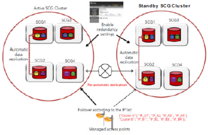
FIGURE 23 Cluster Redundancy
Follow these steps to enable cluster redundancy:
1. Go to System > Cluster. The Cluster page appears.
2. Select the cluster, scroll down and click the Configuration tab.
3. On the right side of the Configuration area, click Configure. The Edit Cluster page appears.
4. In the Cluster Redundancy area, select the Enable Cluster Redundancy check box.
5. By default, the Schedule Configuration Sync option, appears Enable.
6. Select the Sync Time in HH:MM format from the drop-down.
7. In the Backup Cluster area, click Create. The Standby Cluster form appears.
8. Enter the following External Network details:
•Primary Management IP, Port
•Secondary Management IP, Port. This is optional.
9. Click OK. You have enabled cluster redundancy.
NOTE
Once the standby cluster IP / port has been configured, the active cluster starts to sync configuration to the standby cluster.
NOTE
You can also edit the Standby Cluster by selecting Configure from the Edit Cluster page.
How Cluster Redundancy Works
The following simplified scenario describes how cluster redundancy works and how managed APs fail over from one controller cluster to
another.
1. After you enable and configure cluster redundancy on the controller, managed APs will obtain IPs of all nodes in Active cluster as
server list, and all IPs of all nodes in Standby cluster as failover list, which is shown in AP as:
{"Server List":[ "IP_A1", "IP_A2, "IP_A3", "IP_A4"], "Failover List":["IP_B1", "IP_B2, "IP_B3", "IP_B4"]}.
Configuring System Settings
Viewing the System Cluster Overview
SCG200 vSZ-H and SZ300 Administrator Guide
50 Part Number: 800-71563-001
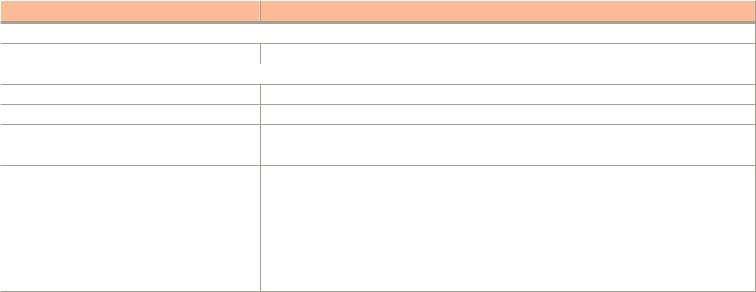
2. If Cluster A goes out of service or becomes unavailable, APs managed by Cluster A will attempt to connect to the IP addresses
(one node at a time) specified for Cluster A.
3. If managed APs are unable to connect to the IP addresses specified for Cluster A, they will attempt to connect to the IP addresses
(one node at a time) specified for Cluster B.
4. If managed APs are able to connect to one of the IP address specified for Cluster B, they fail over to Cluster B. APs will move to
the zone it belongs to when failover.
NOTE
The standby cluster to which APs fail over must have sufficient license seats to accommodate the new APs that it will be
managing. If Standby cluster has insufficient license seats, some APs are unable to get HA license, so can only stay in staging
zone in Standby cluster.
Viewing Cluster Configuration
NOTE
Cluster redundancy is supported only on SZ300 and vSZ-H.
Follow these steps to view the cluster configuration:
1. Go to System > Cluster. The Cluster page appears.
2. Select the cluster, scroll down and click the Configuration tab. You can view the cluster details listed in the following table.
Field Description
Cluster Configuration
IP Support Displays IP support version
Cluster Redundancy
Status Displays the cluster redundancy status.
Cluster Redundant Role Displays the cluster redundancy role.
Active Cluster Displays name and control IPs of active cluster
Standby Cluster Displays name, management IPs, and control IPs of standby cluster
Schedule Configuration Sync • Status-Displays sync status
• System Time Zone-Displays the system time zone set
• Time- Displays the sync time followed everyday
• Last Trigger Time- Displays the date and time the clusters synced last. Applies to both
scheduled sync or manually sync
• Next Trigger Time- Displays the date and time of the next scheduled sync
• Sync Now- Triggers manual configuration sync operation
Configuring the Control Plane
Control Plane configuration includes defining the physical interface, user defined interface and static routes.
To configure a control plane:
1. Go to System > Cluster > Control Planes.
2. Select the control plane from the list and click Configure. The Edit Control Plane Network Settings form appears.
3. Configure the settings as explained in Table 6.
Configuring System Settings
Viewing the System Cluster Overview
SCG200 vSZ-H and SZ300 Administrator Guide
Part Number: 800-71563-001 51

4. Click OK.
NOTE
You must configure the Control interface, IPv4 Cluster interface, andManagement interface to be on three different
subnets. Failure to do so may result in loss of access to the web interface or failure of system functions and services.
TABLE 6 Configuring Control Plane
Field Description Your Action
Physical Interfaces
IPv4-Control Interface Indicates the management and IP control
settings.
Select the IP Mode:
•Static (
recommended
)—To manually
assign an IP address to this interface
manually.
– Enter the IP Address.
– Enter Subnet Mask.
– Enter the Gateway router address.
– Enter Control NAT IP address.
•DHCP—To automatically obtain an IP
address from a DHCP server on the
network.
– Enter Control NAT IP.
IPv4-Cluster Interface Indicates the IPv4 cluster interface settings Select the IP Mode:
•Static (
recommended
)—To manually
assign an IP address to this interface
manually.
– Enter the IP Address.
– Enter Subnet Mask.
– Enter the Gateway router address.
•DHCP—To automatically obtain an IP
address from a DHCP server on the
network.
IPv4-Management Interface Indicates the IPv4 management interface
settings
Select the IP Mode:
•Static (
recommended
)—To manually
assign an IP address to this interface
manually.
– Enter the IP Address.
– Enter Subnet Mask.
– Enter the Gateway router address.
•DHCP—To automatically obtain an IP
address from a DHCP server on the
network.
IPv6-Control Interface (This feature is
supported only for SZ300 controllers)
Indicates the IPv6 control interface settings Select the IP Mode:
•Static (
recommended
)—To manually
assign an IP address to this interface
manually.
– Enter the IPv6 IP Address (global
only) with a prefix length (for
example, 1234::5678:0:C12/123) is
required. Link-local addresses are
unsupported.
Configuring System Settings
Viewing the System Cluster Overview
SCG200 vSZ-H and SZ300 Administrator Guide
52 Part Number: 800-71563-001

TABLE 6 Configuring Control Plane (continued)
Field Description Your Action
– Enter the IPv6 Gateway address
(global or link-local) without a prefix
length. For example,
1234::5678:0:C12 (global address
without a prefix length) and
fe80::5678:0:C12 (link-local
address without a prefix length).
•Auto—To automatically obtain an IP
address from Router Advertisements
(RAs) or from a DHCPv6 server on the
network.
IPv6-Management Interface (This feature is
supported only for SZ300 controllers)
Indicates the IPv6 management interface
settings
Select the IP Mode:
•Static (
recommended
)—To manually
assign an IP address to this interface
manually.
– Enter the IPv6 IP Address (global
only) with a prefix length (for
example, 1234::5678:0:C12/123) is
required. Link-local addresses are
unsupported.
– Enter the IPv6 Gateway address
(global or link-local) without a prefix
length. For example,
1234::5678:0:C12 (global address
without a prefix length) and
fe80::5678:0:C12 (link-local
address without a prefix length).
•Auto—To automatically obtain an IP
address from Router Advertisements
(RAs) or from a DHCPv6 server on the
network.
Access & Core Separation Indicates that the management interface (core
side) to be the system default gateway and
the control interface (access side) to be used
only for access traffic.
Select the Enable check box.
IPv4 Default Gateway & DNS Indicates the IPv4 gateway that you want to
use - Control, Cluster, and Management.
NOTE
When Access & Core Separation
is enabled, the Default Gateway
field is hidden.
1. Default Gateway—Choose the Interface
for which you want to assign the default
gateway setting.
2. Primary DNS Server—Enter the server
details.
3. Secondary DNS Server—Enter the
server details.
IPv6 Default Gateway & DNS (This feature is
supported only for SZ300 controllers)
Indicates the IPv6 gateway that you want to
use - Control, Cluster, and Management.
NOTE
When Access & Core Separation
is enabled, the Default Gateway
field is hidden.
1. Default Gateway—Choose the Interface
for which you want to assign the default
gateway setting.
2. Primary DNS Server—Enter the server
details.
3. Secondary DNS Server—Enter the
server details.
User Defined Interfaces
Configuring System Settings
Viewing the System Cluster Overview
SCG200 vSZ-H and SZ300 Administrator Guide
Part Number: 800-71563-001 53
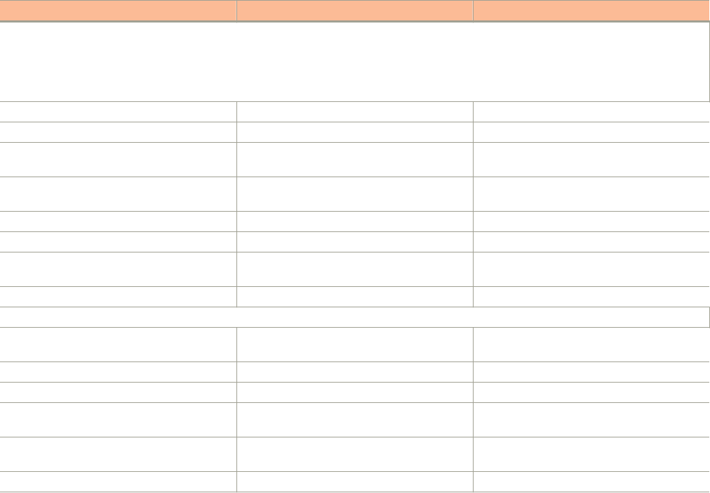
TABLE 6 Configuring Control Plane (continued)
Field Description Your Action
NOTE
The control plane and the UDI must be on different subnets. If the control plane and UDI are on the same subnet, and assigned the
same IP address, APs will be unable to communicate with the control plane. If the control plane and UDI are on the same subnet
and assigned different IP addresses, hotspot clients will not be redirected to the logon URL for user authentication.
Name Indicates the name of the interface. Enter a name.
Physical Interfaces Indicates the physical interface. Select Control Interface.
Service Indicates the service. Select Hotspot, the hotspot must uses the
control interface as its physical interface.
IP Address Indicates the IP address that you want to
assign to this interface.
Enter the IP address.
Subnet Mask Indicates the subnet mask for the IP address. Enter the subnet mask.
Gateway Indicates the IP address of the gateway router. Enter the gateway IP address.
VLAN Indicates the VLAN ID that you want to assign
to this interface.
Enter the VLAN ID.
Add Adds the interface settings. Click Add.
Static Routes
Network Address Indicates the destination IP address of this
route.
Enter the IP address.
Subnet Mask Indicates a subnet mask for the IP address. Enter the subnet mask.
Gateway Indicates the IP address of the gateway router. Enter the IP address of the gateway router.
Interface Indicates the physical interface to use for this
route.
Select the interface.
Metric Represents the number of routers between
the network and the destination.
Enter the number of routers.
Add Adds the static route settings. Click Add.
NOTE
You can also delete or restart a control plane. To do so, select the control plane from the list and click Delete or Restart
respectively.
Rebalancing APs
AP rebalancing helps distribute the AP load across nodes that exist within a cluster.
When a multi-node cluster is upgraded, the node that reboots the last typically does not have any APs associated with it.
When you click Rebalance APs, the following process is triggered:
1. The controller calculates the average AP count based on the number of available control planes and data planes.
2. The controller calculates how many APs and which specific APs must be moved to other nodes to distribute the AP load.
3. The controller regenerates the AP configuration settings based on the calculation result.
4. The web interface displays a message to inform the administrator that the controller has completed its calculations for rebalancing
APs.
5. Each AP that needs to be moved to a different node retrieves the updated AP configuration from the controller, reads the control
planes and data planes to which it must connect, and then connects to them.
Configuring System Settings
Viewing the System Cluster Overview
SCG200 vSZ-H and SZ300 Administrator Guide
54 Part Number: 800-71563-001
When the AP rebalancing process is complete, which typically takes 15 minutes, one of the following events is generated:
•Event 770: Generate ApConfig for plane load rebalance succeeded.
•Event 771: Generate ApConfig for plane load rebalance failed.
NOTE
• APs may recreate the Ruckus-GRE tunnel to a different data plane.
• Devices associated with an AP that uses the Ruckus-GRE tunnel may temporarily lose network connection for a short
period of time (typically, around five minutes) during the AP rebalancing process.
• When node affinity is enabled, AP rebalancing is disallowed on those nodes.
• When data plane grouping is enabled, AP rebalancing is disallowed on those data planes.
• AP rebalancing only supports APs running release 3.2 firmware. APs running on legacy firmware will not be rebalanced.
To rebalance APs across the nodes:
1. Go to System > Cluster > Control Planes > More > Rebalance APs.
FIGURE 24 AP Rebalancing Form
2. Click Yes, the controller rebalances AP connections across the nodes over the next 15 minutes.
NOTE
If you want to repeat this procedure, you must wait 30 minutes before the controller will allow you to rebalance APs
again.
Configuring the Data Plane
By default, the controller sends traffic from its data plane from a single interface.
NOTE
(This feature is supported only in SZ300 and vSZ-H controllers)
If your organization's network requires separation of the access and core traffic, configure access and core separation on the controller.
To configure a data plane:
1. Go to System > Cluster > Data Planes.
Configuring System Settings
Viewing the System Cluster Overview
SCG200 vSZ-H and SZ300 Administrator Guide
Part Number: 800-71563-001 55

2. Select the data plane from the list and click Configure. The Edit Data Plane Network Settings form appears.
3. Configure the settings as explained in Table 7.
4. Click OK.
TABLE 7 Configuring Data Plane
Field Description Your Action
Network
Interface Mode Indicates the traffic direction. Choose the option:
•Single Interface (default)—For the controller to send
traffic from its data plane from a single interface.
•Access and Core Interface—For the controller to
send traffic to the access and core networks
separately.
NOTE
To separate the access and core
networks
– Use static routes, if the data plane is
required to connect to IP addresses
in the core network (for example, for
DHCP relay or L2oGRE termination)
and the destination IP addresses
are not part of the core subnet.
– For SCG-200, there are no
predefined access and core
interfaces. You can use either ports
on the rear panel of the controller to
connect to the access network and
core network.
•Keep original configuration—For the controller to
keep the original manual Data Plane setup.
Network > Primary (Access) Interface
IP Mode Indicates the mode of assigning the IP
address to this interface.
Select the option:
•Static (
recommended
)—To manually assign an IP
address to this interface manually.
– Enter the IP Address.
– Enter Subnet Mask for the IP address.
– Enter the Gateway router address.
– Enter the Primary DNS Server IP address.
– Enter the Secondary DNS Server IP address.
– Enter VLAN ID to tag traffic.
– Enter Data NAT IP address.
•DHCP—To automatically obtain an IP address from a
DHCP server on the network.
– Enter VLAN ID to tag traffic.
– Enter Data NAT IP address.
Network > IPv6 Primary (Access) Interface
IP Mode Indicates the mode of assigning the IP
address to this interface.
Select the option:
•Static (
recommended
)—To manually assign an IP
address to this interface manually.
– Enter the IP Address.
– Enter the Gateway router address.
– Enter the Primary DNS Server IP address.
– Enter the Secondary DNS Server IP address.
Configuring System Settings
Viewing the System Cluster Overview
SCG200 vSZ-H and SZ300 Administrator Guide
56 Part Number: 800-71563-001

TABLE 7 Configuring Data Plane (continued)
Field Description Your Action
•Auto—To automatically obtain an IP address from a
DHCP server on the network.
Network > Secondary (Core) Interface (applicable for Interface Mode: Access and Core Interfaces)
IP Address Indicates the IP address of the core
network interface.
Enter the IP address.
NOTE
The secondary/core interface IP address must be
configured manually; DHCP is unsupported.
Subnet Mask Indicates the IP address of the subnet
mask.
Enter the subnet mask.
VLAN Indicates that the traffic is tagged with a
VLAN ID.
Enter the VLAN ID.
NOTE
If VLANS are configured on both the access and
core networks, the VLAN ID that you enter here
must be different from the one that you entered for
the primary/access interface.
NOTE
You cannot configure the IP address and VLAN
settings for a virtual Data Plane from the Primary
(Access) and Secondary (Core) Interface sections.
Only vSZ-H supports virtual Data Plane.
Disconnect AP when core link down Indicates that the AP is disconnected
secondary core link is down.
Select the check box.
Static Routes
Network Address Indicates the destination IP address of
this route.
Enter the IP address.
Subnet Mask Indicates a subnet mask for the IP
address.
Enter the subnet mask.
Gateway Indicates the IP address of the gateway
router.
Enter the IP address of the gateway router.
Add Adds the static route settings. Click Add.
CALEA Relay
Mark this Data Plane as CALEA Relay (This
feature is supported only for vSZ-E and
vSZ-H controllers)
Indicates that the data plane uses CALEA
relay.
Select the check box.
DHCP Profile
DHCP Profile Indicates the data plane DHCP service
profile.
Choose the DHCP service profile from the drop-down.
NAT Profile
NAT Profile Indicates the data plane NAT service
profile.
Choose the NAT service profile from the drop-down.
Syslog
Enable DHCP syslog Enables syslog to record the DHCP logs. Select the check box.
Enable NAT syslog Enables syslog to record the NAT logs. Select the check box.
Syslog Server IP Indicates the IP address of the remote
syslog server.
Enter the IP address of the remote syslog server.
Configuring System Settings
Viewing the System Cluster Overview
SCG200 vSZ-H and SZ300 Administrator Guide
Part Number: 800-71563-001 57

TABLE 7 Configuring Data Plane (continued)
Field Description Your Action
Syslog Server Port Indicates the port number of the remote
syslog server.
Enter the Port number of the remote syslog server.
NOTE
You can restart a data plane. To do so, select the data plane from the list and click Restart.
Monitoring Cluster Settings
This section provides information on how to view the status of the cluster settings.
You can select the following tabs for more information:
•Summary—Details such as Name, model, IP details, memory usage, disk usage.
•Network Settings—Details such as control interface, cluster interface, management interface, DNS Server, Routes.
•Configuration—Details such as physical interfaces, User defined interfaces, Static Routes Interface.
•Traffic & Health—Details such as CPU usage, memory usage, disk usage, interface, port usage.
•Alarm—Details of alarms generated. You can Clear Alarm or Acknowledge Alarm that are generated.
•Event—Details of events that are genrated.
Clearing or Acknowledging Alarms
You can clear or acknowledge an alarm.
To Clear an alarm:
1. From the Alarm tab, select the alarm form the list.
2. Click Clear Alarm, the Clear Alarm form appears.
3. Enter a comment and click Apply.
To acknowledge an alarm:
1. From the Alarm tab, select the alarm form the list.
2. Click Acknowledge Alarm, the Are you sure you want to acknowledge the selected form appears.
3. Click Yes.
Filtering Events
You can view a list of events by severity or date and time.
To apply filters:
1. From the Event tab, select the icon. The Apply Filters form appears.
2. Select any or both the following criteria:
•Severity: Select the severity level by which you want to filter the list of events.
•Date and Time: Select the events by their Start and End dates.
NOTE
You can filter events that generated in the last seven days.
Configuring System Settings
Viewing the System Cluster Overview
SCG200 vSZ-H and SZ300 Administrator Guide
58 Part Number: 800-71563-001
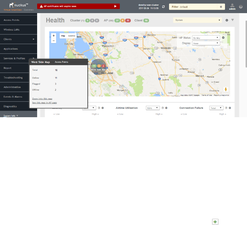
3. Click OK, all the events that meet the filter criteria are displayed on the Event page.
Working with Maps
Importing floorplan maps into SmartZone allows you to further customize the information displayed on the Dashboard and Access Points
pages, and monitor your APs, zones, groups, clients and traffic statistics all within the world map view on the Dashboard.
Additionally, you can use the maps to quickly locate more specific information on a venue or zone, and drag and drop APs onto the floor
plan map to represent their locations in physical space in your venue.
Once a map is imported and GPS coordinates are entered, an icon representing the venue appears on the world map on the Dashboard.
The icon displays the current number of APs (Online, Flagged and Offline). You can hover over the icon for more information.
Double-click the map icon or click Zoom into this map to view the imported map in the Dashboard.
FIGURE 25 Once a floorplan map has been imported (with GPS coordinates), it is displayed on the world map on the Dashboard. Hover over the local map icon for
more information.
Importing a Floorplan Map
SmartZone provides a user-friendly workflow for importing a map of your venue floorplan, placing APs in their respective physical locations
on the map, and scaling the map to match the actual dimensions of your venue.
Floorplan maps allow you to view site/venue/floor-specific details such as:
• AP status, performance, and health conditions
• Client connections to an AP
•Location-specific trouble spots related to AP or client connectivity
To import a floorplan map:
1. Go to System > Maps.
2. From the System tree hierarchy, select the location where you want to create a map and click the add button. The Add Map
form appears.
3. On the Details tab, enter a Name and optionally a Description to identify the map.
Configuring System Settings
Working with Maps
SCG200 vSZ-H and SZ300 Administrator Guide
Part Number: 800-71563-001 59
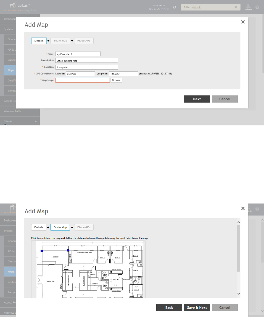
4. Enter a Location for the map. Alternatively, you can choose the location from the auto-completion options. Once you select the
location, the GPS Coordinates are automatically updated.
5. For GPS Coordinates, you can enter the Latitude and Longitude values.
FIGURE 26 The Add Map form
6. To add a Map Image, click Browse and select a site, venue, or floor map in jpg, jpeg, png, bmp or svg file formats.
NOTE
The maximum file size per indoor map is 5MB.
7. Click Next, the Scale Map tab appears.
8. Click two points on the map between which you know the distance. Blue dots appear to show the points you selected.
FIGURE 27 Click two points on the map to define the map's scale
9. Enter the Physical Distance between the two points and select the unit of measurement (mm, cm, m, ft, yard).
10. Click Save & Next. The Place APs tab appears.
Configuring System Settings
Working with Maps
SCG200 vSZ-H and SZ300 Administrator Guide
60 Part Number: 800-71563-001
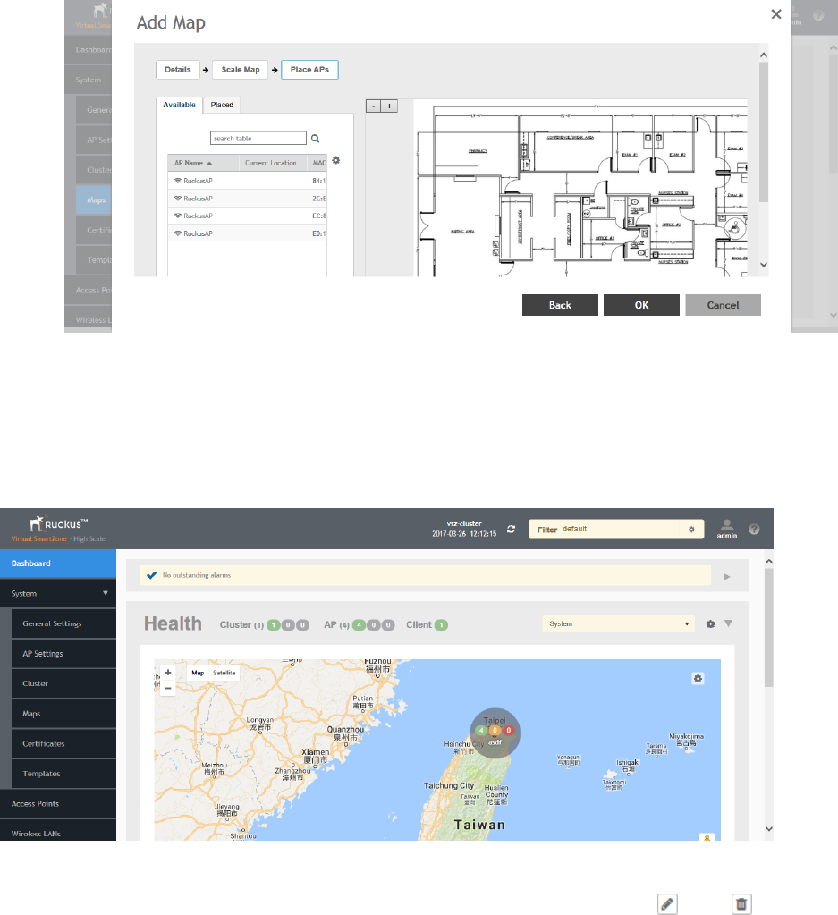
11. From the Available list, drag the APs and place them in their physical locations on the map. Click the Placed tab to see the list of
placed APs.
FIGURE 28 Drag and drop to place APs onto your floorplan
12. Once you are happy with the placement of your APs on the map, click OK to save your map.
Your venue now appears as an icon on the world map on the Dashboard, located at your venue's actual physical location (if you entered
the GPS coordinates correctly). The Dashboard icon that represents your venue provides an overview of the number of APs in the venue
and their status. Hover over the icon to view more details, or click one of the links to zoom in to the venue floorplan map you imported.
FIGURE 29 The imported venue map icon appears at the GPS coordinates you configured
NOTE
You can also edit or delete a map. To do so, select the map from the list and click the Edit or Delete buttons respectively.
Configuring System Settings
Working with Maps
SCG200 vSZ-H and SZ300 Administrator Guide
Part Number: 800-71563-001 61
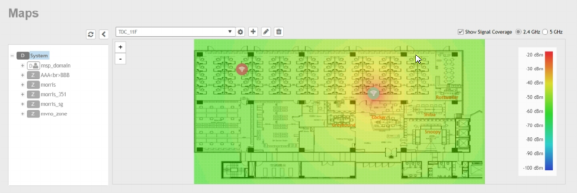
Viewing RF Signal Strength
The heat map helps us identify the RF signal strength in a specific location. It provides heatmaps using actual path loss information from the
environment. You can view indoor floor plan map for an AP.
To view the RF signal strength:
1. Go to System > Maps.
2. From the System tree hierarchy, select the location of the map that you want to view.
3. Select the Show Signal Coverage check box and choose the required RF frequency. For example, 2.4 GHz or 5 GHz. The heat
map is displayed with a color-gradient legend. High signal strength appears in red. The color changes as the signal strength
reduces.
FIGURE 30 RF Coverage Heat Map
Monitoring APs Using the Map View
Use the Map view on the Access Points page to monitor APs in relation to your venue's floorplan.
1. Go to Access Points.
2. In View Mode, click the Map button. The map view is displayed with your placed APs.
Configuring System Settings
Working with Maps
SCG200 vSZ-H and SZ300 Administrator Guide
62 Part Number: 800-71563-001
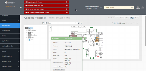
3. Hover over an AP to view the following AP-specific details:
•AP Name: The name of the AP, if configured. If not, the default AP name is "RuckusAP."
•IP Address: The current IPv4 or IPv6 address assigned to the AP.
•Channel: Displays the channel (2.4 GHz / 5 GHz) in use, along with the channel width in parentheses.
•Clients: The number of currently connected wireless clients.
•Traffic: The total traffic volume over the last 1 hour.
•Latency: The average time delay between AP and connected clients.
•Airtime Utilization: Percent of airtime utilized, by radio.
•Connection Failure: Percent of client connection attempt failures.
FIGURE 31 Hover over an AP to view details
4. To view more specific details on the AP, click the See this AP in AP page link.
5. To view the RF signal strength, select the Show Signal Coverage check box and choose the required RF frequency. For example,
2.4 GHz or 5 GHz.
The heat map is displayed with a color-gradient legend. High signal strength appears in red. The color changes as the signal
strength reduces.
Certificates
All the security certificates that the controller uses for its web interface, AP portal, and hotspots are managed from a central storage.
By default, a Ruckus Wireless-signed SSL certificate (or security certificate) exists in the controller. However, because this default certificate
is signed by Ruckus Wireless and is not recognized by most web browsers, a security warning appears whenever you connect to the web
interface or users connect to the AP portal or a hotspot. To prevent these security warnings from appearing, you can import an SSL
certificate that is issued by a recognized certificate authority.
If you are implementing Hotspot 2.0 on the network and you want to support anonymous authentication using OSU Server-Only
Authenticated L2 Encryption Network (OSEN), you will need to import a trust root certificate, server or intermediate certificate and private
key.
Configuring System Settings
Certificates
SCG200 vSZ-H and SZ300 Administrator Guide
Part Number: 800-71563-001 63
Importing New Certificates
When you have an SSL certificate issued by an SSL certificate provider, you can import it into the controller and use it for HTTPS
communication.
To complete this procedure, you will need the following:
• The signed server certificate
• The intermediate CA certificate (at least one)
• The private key file
NOTE
The file size of each signed certificate and intermediate certificate must not exceed 8192 bytes. If a certificate exceeds 8192
bytes, you will be unable to import it into the controller.
Follow these steps to import a signed server certificate:
1. Copy the signed certificate file, intermediate CA certificate file, and private key file to a location (either on the local drive or a
network share) that you can access from the controller web interface.
2. From the application select, System > Certificates > Installed Certs.
3. Click Import, the Import Certificate form appears.
4. Enter a Name to identify the certificate.
5. Enter a Description about the certificate.
6. For Service Certificates, click Browse and select the location where the certificate is saved.
7. For Intermediate CA certificates, click Browse and select the location where the certificate is saved. If you need to upload
additional intermediate CA certificates to establish a chain of trust to the signed certificate, you can select up to four certificates.
8. If you are using this SSL certificate for a Hotspot 2.0 configuration, you must also import a root CA certificate. To import Root CA
Certificate, click Browse and select the location where the certificate is saved.
9. You can import the Private Key file either by
• uploading file—choose Upload and click Browse to select the location.
• using CSR—choose Using CSR and select the CSR that you generated earlier.
10. Enter the Key Passphrase that has been assigned to the private key file.
11. Click OK.
NOTE
You can also edit or delete a certificate by selecting the options Configure or Delete respectively.
Assigning Certificates to Services
You can map certificates to services
To specify the certificate that each secure service will use:
1. From the application select, System > Certificates > Service Certs.
2. Select the certificate that you want to use for each of the following services:
•Management Web—Used by Web UI and Public API traffic.
•AP Portal—Used by Web Auth WLAN and Guest Access WLAN control traffic.
Configuring System Settings
Certificates
SCG200 vSZ-H and SZ300 Administrator Guide
64 Part Number: 800-71563-001
•Hotspot (WISPr)—Used by WISPr WLAN control (Northbound Interface, Captive Portal, and Internal Subscriber Portal) traffic.
•Communicator—Used by AP control traffic.
3. To view the public key, click View Public Key, the Certificate Public Key form appears with the public key.
4. Click OK.
Generating Certificate Signing Request (CSR)
If you do not have an SSL certificate, you will need to create a certificate signing request (CSR) file and send it to an SSL certificate provider
to purchase an SSL certificate.
To create a CSR file:
1. From the application select, System > Certificates > CSR.
2. Click Generate, the Generate CSR form appears.
3. Enter the following details:
•Name—A name for this CSR.
•Description— A short description for this CSR.
•Common Name—A fully qualified domain name of your Web server. This must be an exact match (for example,
www.ruckuswireless.com).
•Email—An email address (for example, joe@ruckuswireless.com).
•Organization—Complete legal name of your organization (for example, Ruckus Wireless, Inc.). Do not abbreviate your
organization name.
•Organization Unit—Name of the division, department, or section in your organization that manages network security (for
example, Network Management).
•Locality/City—City where your organization is legally located (for example, Sunnyvale).
•State/Province—State or province where your organization is legally located (for example, California) Do not abbreviate the
state or province name.
4. Select the Country
5. Click OK, the controller generates the certificate request. When the certificate request file is ready, your web browser automatically
downloads it.
6. Go to the default download folder of your Web browser and locate the certificate request file. The file name is myreq.zip.
7. Use a text editor (for example, Notepad) to open the certificate request file.
8. Go to the website of your preferred SSL certificate provider, and then follow the instructions for purchasing an SSL certificate.
9. When you are prompted for the certificate signing request, copy and paste the entire content of myreq.csr, and then complete the
purchase.
10. After the SSL certificate provider approves your CSR, you will receive the signed certificate via email.
11. Copy the content of the signed certificate, and then paste it into a text file.
12. Save the file.
NOTE
You can also edit, clone, download or delete a CSR by selecting the options Configure, Clone, Download or Delete respectively.
Configuring System Settings
Certificates
SCG200 vSZ-H and SZ300 Administrator Guide
Part Number: 800-71563-001 65
Managing AP Certificates
AP certificates are valid for a period of time and have to be replaced when they expire.
NOTE
Although AP Certificate Expire Check is enabled by default, when an AP with an expired certificate joins the controller, this check
automatically gets disabled. To restore security:
• All APs with expired certificates need to be replaced with a new valid certificate
• Manually enable certificate check using ap-cert-expired-check CLI command in the config mode
You must get AP Certificate Replacement before your AP certificate expires. The system generates an
apCertificateExpireSystem
alarm and
event when an AP certificate expires.
To get an AP Certificate replacement:
1. From the application select, System > Certificates > AP Certificate Replacement.
2. In the AP Request List area, those APs with the Need Export column marked Yes needs certificate replacement. Those marked
with No means that the certificate request has already been exported.
NOTE
Use the Search terms option to look for APs by name, model, serial number, or description.
3. Click Export and select one of the following options:
•Export All APs Certificate Request—Exports the certificates for all the AP
•New APs—Exports the certificates for new APs or APs that need to regenerate their certificates.
NOTE
All exported AP Certificate request (.req) files generated from a cluster include it's name. To manage multiple export
request files, change the file name before uploading it to uniquely identify the file.
For example: cert-scg-cluster5f6433ef-711b-4f44-b38a-ddd485ee2c37-R500.req
4. Login https://support.ruckuswireless.com/ with your credentials.
5. From the right pane go to Tools > Certificate Renewal. The Certificate Renewal Requests page appears.
6. Click Browse to select the .req file exported from Certificate Refresh page.
7. Enter the Email address for communication.
8. Click Upload, you will receive an e-mail acknowledgment from Ruckus Wireless.
9. From the Certificate Renewal Request page, check the Status column of your request. After the request is processed, you will
receive the response from Ruckus Wireless, with a link to the .res response file for Import on the Certificate Refresh page.
10. From the AP Certificate Replacement page of the application, click Import AP certificate Response (.res) file. The Import AP
certificate for replacement form appears.
11. Click Browse and select the file.
12. Click OK.
NOTE
All APs included in the imported response (.res) file reboot after their certificate is refreshed.
Configuring System Settings
Certificates
SCG200 vSZ-H and SZ300 Administrator Guide
66 Part Number: 800-71563-001
13. From the Certificate Status area, check the Status column of the AP. If the status is:
•Updating—Controller is in the process of updating the certificate.
•Update Failed—Controller failed to update the certificate.
NOTE
The AP reports to the controller at 15-minute intervals. As a result, it may take up to 15 minutes for the AP to update its
certificate status on the web interface.
14. Click Reset Update Failed AP, to reset the status of the APs for which certification update failed. The status of the AP will change.
15. Check the Update Stats to know the status of the AP certificates.
16. Once all the APs are updated with the new certificates, manually enable the ap-cert-expired-check CLI command in the
config mode to restore security and reject APs that try to connect with expired certificate
.
Importing Trusted CA Certificates
When a controller receives a server's certificate, it matchs the server's CA against the list of trusted CAs it has. If there is no match, the
controller sends an error.
To import a CA certificate:
1. From the application select, System > Certificates > Trusted CA Certs (Chain).
2. Click Import, the Import CA Certs (Chain) form appears.
3. Enter a Name.
4. Enter a Description of the certificate.
5. For Intermediate CA Certificates, click Browse and select the file. If you need to upload additional intermediate CA certificates to
establish a chain of trust to the signed certificate, you can select up to four certificates.
6. For Root CA Certificate, click Browse and select the file.
7. Click OK.
NOTE
You can also edit or delete a CA certificate by selecting the options Configure or Delete respectively.
Configuring Templates
Working with Zone Templates
In 3.6 SCG200-C is supported. SCG200-C is the SCG200 model without the internal DP functions. If Ruckus GRE tunnel is enabled,
upgrade to SCG200-C is blocked and the following message appears:
There exists a Zone template [TEMPLATE_NAME] with RuckusGRE tunnel is applied
You can create, configure, and clone zone templates
Configuring System Settings
Configuring Templates
SCG200 vSZ-H and SZ300 Administrator Guide
Part Number: 800-71563-001 67

Creating Zone Templates
To create a zone template:
1. From the application select, System > Templates > Zone Templates.
2. Click Create, the Create Zone Template form appears.
3. Enter the template details as explained in Table 8.
4. Click OK.
TABLE 8 Zone Template Details
Field Description Your Action
General Options
Zone Name Indicates a name for the Zone. Enter a name.
Description Indicates a short description. Enter a brief description
AP Firmware Indicates the firmware to which it applies. Select the firmware.
Country Code Indicates the country code to ensure that this
zone uses authorized radio channels.
Select the country code.
Location Indicates generic location. Enter the location.
Location Additional Information Indicates detailed location. Enter additional location information.
GPS Coordinates Indicates the geographical location. Enter the following coordinates in meters or floor:
•Longitude
•Latitude
•Altitude
AP Admin Logon Indicates the admin logon credentials. Enter the Logon ID and Password.
Time Zone Indicates the time zone that applies. Select the option:
•System Defined: Select the time zone.
•User defined:
1. Enter the Time Zone Abbreviation.
2. Choose the GMT Offset time.
3. Select Daylight Saving Time.
AP IP Mode Indicates the IP version that applies. Select the option:
•IPv4 only
•Dual
Cluster Redundancy Provides cluster redundancy option for the zone.
NOTE
Cluster redundancy is supported only
on SZ300 and vSZ-H.
Select the required option:
•Zone Enable
•Zone Disable
Radio Options
Channel Range Indicates that you want to override the 2.4GHz
channel range that has been configured for the
zone.
Select Select Channel Range (2.4G) check boxes for the
channels on which you want the 2.4GHz radios to
operate. Channel options include channels 1 to 11. By
default, all channels are selected.
DFS Channels Allows ZoneFlex APs to use DFS channels. Select the check box.
Channel Range (5G) Indoor Indicates for what channels want the 5GHz radios
to operate.
Select the check boxes.
Channel Range (5G) Outdoor Indicates for what channels want the 5GHz radios
to operate.
Select the check boxes.
Configuring System Settings
Configuring Templates
SCG200 vSZ-H and SZ300 Administrator Guide
68 Part Number: 800-71563-001

TABLE 8 Zone Template Details (continued)
Field Description Your Action
Radio Options b/g/n (2.4 GHz) Indicates the radio option 2.4 GHz configurations. Select the following options:
•Channelization—Set the channel width used
during transmission to either 20 or 40 (MHz),
or select Auto to set it automatic.
•Channel—Select the channel to use for the
b/g/n (2.4GHz) radio, or select Auto to set it
automatic.
•TX Power Adjustment—Select the preferred
TX power, if you want to manually configure
the transmit power on the 2.4GHz radio. By
default, TX power is set to Full/Auto on the
2.4GHz radio.
NOTE
If you choose Min, the transmit
power is set to 0dBm (1mW) per
chain for 11n APs, and 2dBm per
chain for 11ac APs. If you choose
Max, the transmit power is set to
the max allowable value according
to the AP's capability and the
operating country's regulations.
Radio Options a/n/ac (5 GHz) Indicates the radio option 5 GHz configurations. Select the following options:
•Channelization—Set the channel width used
during transmission to either 20, 40, 80,
80+80 or select Auto.
•Channel—For Indoor and Outdoor, select the
channel to use for the a/n/c (5GHz) radio, or
select Auto.
•TX Power Adjustment—Select the preferred
TX power, if you want to manually configure
the transmit power on the 5GHz radio. By
default, TX power is set to Full/Auto on the
5GHz radio.
NOTE
If you choose Min, the transmit
power is set to 0dBm (1mW) per
chain for 11n APs, and 2dBm per
chain for 11ac APs. If you choose
Max, the transmit power is set to
the max allowable value according
to the AP's capability and the
operating country's regulations.
AP GRE Tunnel Options
Tunnel Type Indicates the support for NAT. Select the required option.
GRE Tunnel Profile Indicates the tunnel profile. Select the required option or click Create and enter the
following details:
•Name
•Description
•Ruckus Tunnel Mode
•Tunnel Encryption
•WLAN Interface MTU
Configuring System Settings
Configuring Templates
SCG200 vSZ-H and SZ300 Administrator Guide
Part Number: 800-71563-001 69

TABLE 8 Zone Template Details (continued)
Field Description Your Action
Syslog Options
Enable external syslog server for Aps Indicates if an external syslog server is enabled. Select the check box and update the following details:
•Server Address
•Port
•Facility for Event
•Priority
AP SNMP Options
Enable AP SNMP Indicates if the AP SNMP option is enabled. Select the check box.
SNMPv2 Agent Indicates SNMPv2 Agent is applied. 1. Click Create and enter Community.
2. Select the required Privilege: Read or Write.
3. Click OK.
SNMPv3 Agent Indicates SNMPv3 Agent is applied. 1. Click Create and enter User.
2. Select the required Authentication:
•None
•SHA
1. Enter the Auth Pass Phrase
2. Select the Privacy option. For DES
and AES options, Enter the Privacy
Phrase.
•MD5
1. Enter the Auth Pass Phrase
2. Select the Privacy option. For DES
and AES options, Enter the Privacy
Phrase.
3. Select the required Privilege: Read or Write.
4. Click OK.
Advanced Options
Channel Mode Indicates if location-based service is enabled. Select the check box and choose the option.
Auto Channel Selection Indicates auto-channel settings. Select the required check boxes and choose the option.
Background Scan Runs a background scan. Select the respective check boxes and enter the duration
in seconds.
Smart Monitor Indicates AP interval check and retry threshold
settings.
Select the check box and enter the duration and
threshold.
AP Management VLAN Indicates the AP management VLAN settings. Choose the option. If you select VLAN ID, enter the
VLAN ID that you want to assign (valid range is from 1 to
4094). To keep the same management VLAN ID that has
been configured on the AP, click Keep AP's settings
Rogue AP Detection Indicates rogue AP settings. 1. Select the check box and choose the options:
•Enable events and alarms for all rogue
devices
•Enable events and alarms for only
malicious rogue devices of selected
types and choose the Rogue Type:
–SSID Spoofing
–Same Network
–MAC Spoofing
Configuring System Settings
Configuring Templates
SCG200 vSZ-H and SZ300 Administrator Guide
70 Part Number: 800-71563-001

TABLE 8 Zone Template Details (continued)
Field Description Your Action
• Select the Protect the network from
malicious rogue access points check
box.
DoS Protection Indicates settings for blocking a client. Select the check box and enter the:
• duration in seconds to Block a client for
• number of repeat authentication failures
• duration in seconds to be blocked for every
repeat authentication failures.
Client Load Balancing Balances the number of clients across APs. Select the check box and enter the threshold.
Band Balancing Balances the bandwidth of the clients. Select the check box and enter the percentage.
Location Based Service To disable the LBS service for this AP group, clear
the Enable LBS service check box. To use a
different LBS server for this AP group, select the
Enable LBS service check box, and then select
the LBS server that you want to use from the
drop-down list.
Select the check box and choose the options.
Client Admission Control Indicates the load thresholds on the AP at which
it will stop accepting new clients.
NOTE
Client admission cannot be enabled
when client load balancing or band
balancing is enabled.
Select the Enable check box 2.4 GHz Radio or 5GHz
Radio and update the following details:
•Min Client Count
•Max Radio Load
•Min Client Throughput
AP Reboot Timeout Indicates AP reboot settings. Choose the required option for:
•Reboot AP if it cannot reach default gateway
after
•Reboot AP if it cannot reach the controller
after
NOTE
You can select a zone from the list and edit, clone or delete its template by selecting the options Configure, Clone or Delete
respectively.
Applying Zone Templates
To apply a zone template:
1. From the application select, System > Templates > Zone Templates.
2. From the list, select the zone template that you want to apply and click Apply. The Apply Zone Templates form appears.
3. From Select AP Zone, select the required zone.
4. Click Apply.
Exporting Zone Templates
You can export a zone template.
To export a zone template:
1. From the application select, System > Templates > Zone Templates.
Configuring System Settings
Configuring Templates
SCG200 vSZ-H and SZ300 Administrator Guide
Part Number: 800-71563-001 71
2. Select the zone template that you want to export and click Export Template.
3. A pop-up appears prompting you to Open or Save the zone template file with .bak extension. Click:
•Open—To view the template file
•Save—Select the destination folder where you want to save the template file and then click Open to view it.
Importing Zone Templates
You can import zone templates and upload them to the system.
NOTE
Configuration references to global services or profiles cannot be imported, manually configure it after importing.
To import a zone template:
1. From the application select, System > Templates > Zone Templates.
2. Click Import, the Import Zone Templates form appears.
3. Click Browse and select the template file.
4. Click Upload.
Working with WLAN Templates
In 3.6 SCG200-C is supported. SCG200-C is the SCG200 model without the internal DP functions. If Ruckus GRE tunnel is enabled,
upgrade to SCG200-C is blocked and the following message appears:
There exists a WLAN template [TEMPLATE_NAME] with RuckusGRE tunnel is applied
You can create, configure and clone a WLAN template.
Creating WLAN Templates
To create a WLAN template:
1. From the application select, System > Templates > WLAN Templates.
2. Click Create, the Create WLAN Template form appears.
3. Enter a Template Name.
4. Enter a Description.
5. Select the Template Firmware.
6. Choose the AP IP Mode.
7. Select AP SoftGRE Tunnel to enable all WLANs defined in this template to tunnel traffic to SoftGRE through the AP.
8. Click OK.
NOTE
You can select a WLAN and edit, clone or delete its template by selecting the options Configure, Clone or Delete respectively.
Configuring System Settings
Configuring Templates
SCG200 vSZ-H and SZ300 Administrator Guide
72 Part Number: 800-71563-001
Applying a WLAN Template
To Apply a WLAN template to a zone:
1. From the application select, System > Templates > WLAN Templates.
2. From the list, select the WLAN template that you want to apply and click Apply. The Apply WLAN Template to selected zones form
appears.
3. From Select AP Zone, select the required zone.
4. Click Apply.
Configuring System Settings
Configuring Templates
SCG200 vSZ-H and SZ300 Administrator Guide
Part Number: 800-71563-001 73
SCG200 vSZ-H and SZ300 Administrator Guide
74 Part Number: 800-71563-001
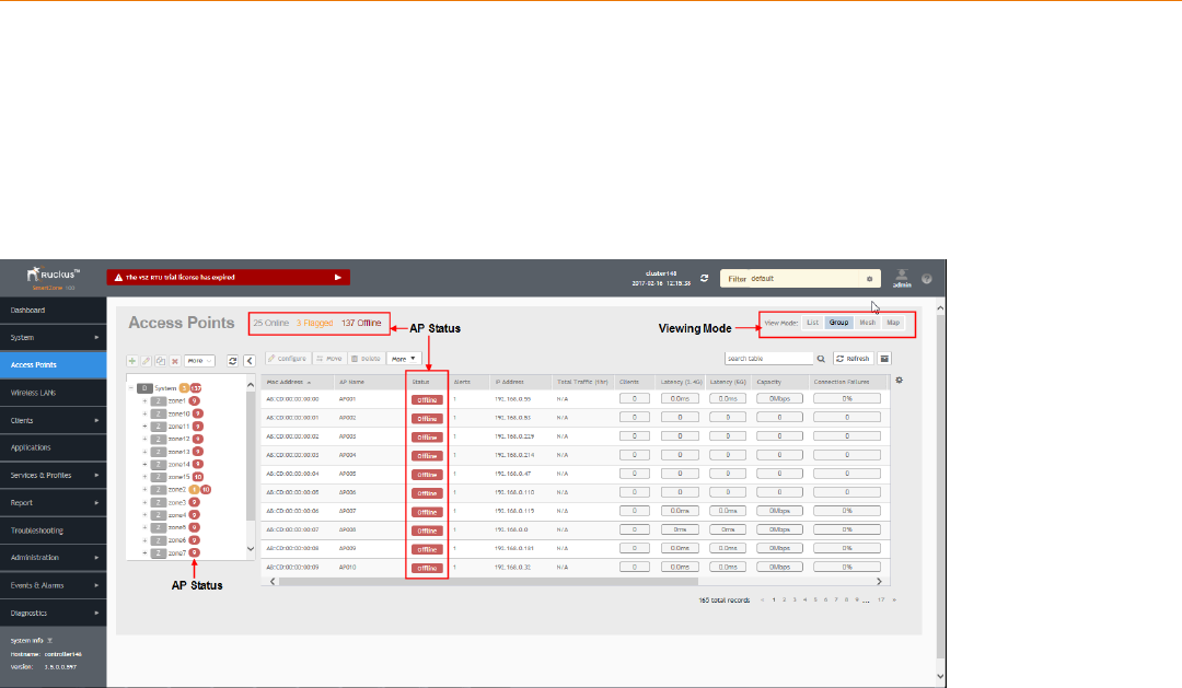
Working With Access Points
• Understanding the System, Domains, Zones and AP Groups.................................................................................. 75
• Viewing Modes........................................................................................................................................................94
• AP Status................................................................................................................................................................94
•Configuring Access Points.......................................................................................................................................94
• Managing Access Points......................................................................................................................................... 97
The following image gives you an understanding of the Access Points home page.
FIGURE 32 Access Points
Understanding the System, Domains, Zones and AP
Groups
Hierarchy Overview
The hierarchy helps in specifying which AP groups or APs provide which WLAN services.
You can virtually split them using the following hierarchy:
• System—Highest order that comprises of multiple zones
• Domains—Broad classification that comprises of multiple Zones.
• Zones—Comprises of multiple AP groups
• AP groups—Comprises of multiple APs
• APs—Individual access points.
SCG200 vSZ-H and SZ300 Administrator Guide
Part Number: 800-71563-001 75

Creating an AP Domain
To create an AP domain:
1. From the System tree hierarchy, select the location where you want to create the domain.
2. Click the Create button, the Create Group form appears.
3. Configure the following details:
a. Enter a Name for the domain.
b. Enter a Description about the domain.
c. By default, the Type selected is Domain.
d. The Parent Group displays the group to which this domain will be tagged.
e. If you want to create a domain to manage MSP-related settings within that domain, in the Managed by Partner field, select
the Enable check box.
4. Click OK.
NOTE
You can also edit, clone and delete an AP Domain by selecting the options Configure , Clone or Delete respectively,
from the Access Points page.
Working with AP Zones
An AP zone functions as a way of grouping Ruckus Wireless APs and applying a particular set of settings (including WLANs and their
settings) to thise group of Ruckus Wireless APs. Each AP zone can include up to 27 WLAN services.
By default, an AP zone named Staging Zone exists. Any AP that registers with the controller that is not assigned a specific zone is
automatically assigned to the Staging Zone. This section describes how to use AP zones to manage devices.
NOTE
When an AP is assigned or moved to the Staging Zone, the cluster name becomes its user name and password after the AP
shows up-to-date state. If you need to log on to the AP, use the cluster name for the user name and password.
Before creating an AP zone, Ruckus Wireless recommends that you first set the default system time zone on the General Settings page.
This will help ensure that each new AP zone will use the correct country. For information on how to set the default system time zone, see
Configuring System Time on page 34.
NOTE
In vSZ-H and SCG200, when the system is upgraded to release 3.5, the new UI and re-architected stats database will prevent the
system from displaying AP and zone stats if the AP/zone is operating on 3.4 or prior releases. In order to make full use of the UI
introduced in 3.5, zones and APs should be updated to 3.5 as well. Operationally, the zones will still work, but stats visibility will
be impacted.
Creating an AP Zone
An AP zone (or zone) functions as a way of grouping Ruckus Wireless APs and applying settings including WLANs to these groups of
Ruckus Wireless APs. Each AP zone can include up to six WLAN services.
To create an AP zone :
1. On the menu, click Access Points. The figure below appears.
Working With Access Points
Understanding the System, Domains, Zones and AP Groups
SCG200 vSZ-H and SZ300 Administrator Guide
76 Part Number: 800-71563-001
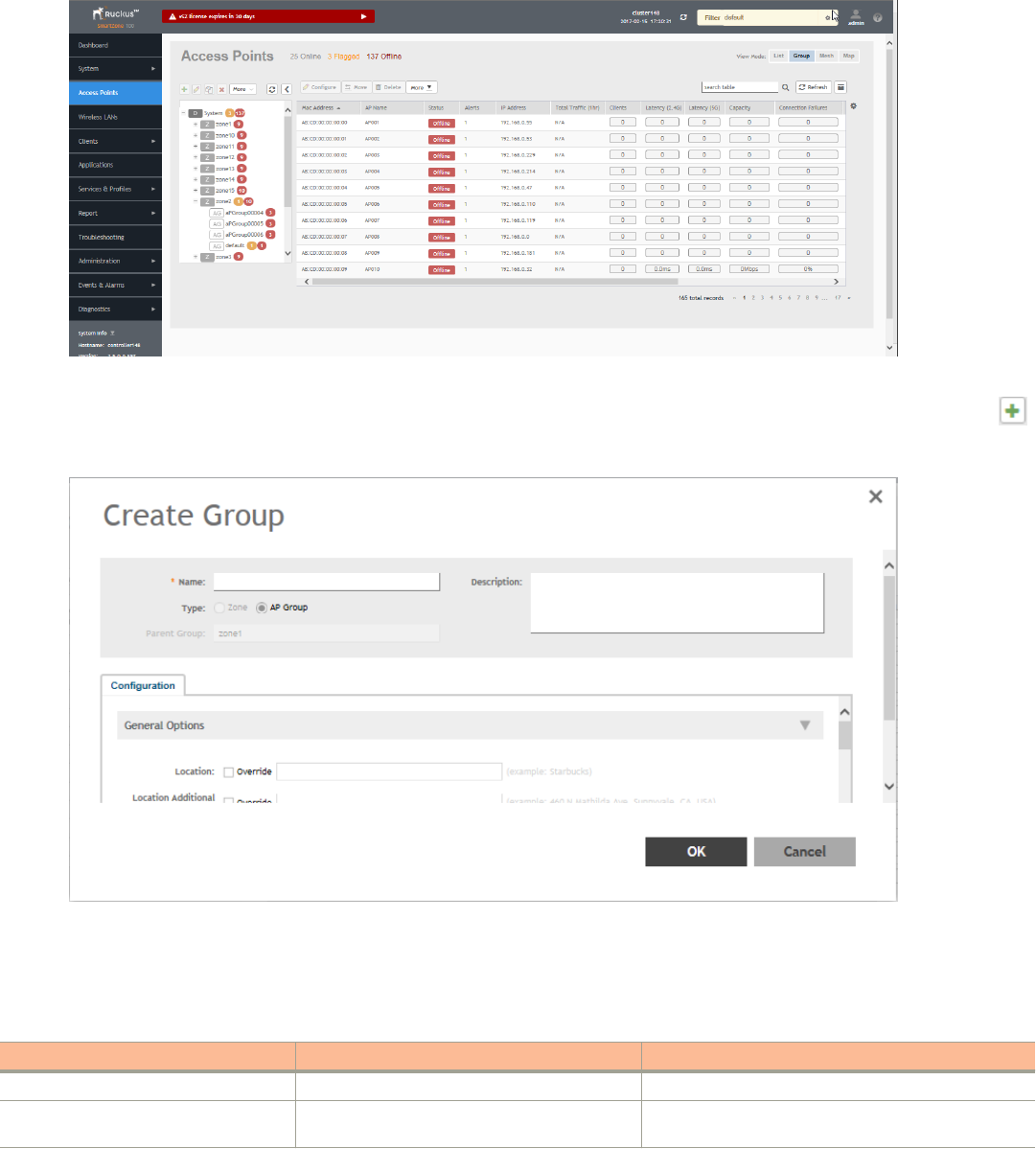
FIGURE 33 Access Points
2. From the System tree, select the location where you want to create the zone (for example, System or Domain), and then click .
FIGURE 34 Create Groups
3. Configure the zone by completing the settings listed in the table below.
4. Click OK.
TABLE 9 AP Zone Details
Field Description Your Action
Name Indicates the name of the zone/AP group. Enter a name.
Description Indicates the short description assigned to the
zone or AP group.
Enter a brief description
Working With Access Points
Understanding the System, Domains, Zones and AP Groups
SCG200 vSZ-H and SZ300 Administrator Guide
Part Number: 800-71563-001 77

TABLE 9 AP Zone Details (continued)
Field Description Your Action
Type Indicates if you are creating a domain, zone or an
AP group.
Appears by default. You can also choose the option.
Parent Group Indicates the parent AP group. Appears by default.
Configuration > General Options
AP Firmware Indicates the firmware to which it applies. Select the firmware.
Country Code Indicates the country code. Using the correct
country code helps ensure that APs use only
authorized radio channels.
Select the country code.
Location Indicates the generic location of the zone. Enter the location.
Location Additional Information Indicates detailed location. Enter additional location information.
GPS Coordinates Indicates the geographical location. Enter the following coordinates:
•Longitude
•Latitude
•Altitude
AP Admin Logon Indicates the admin logon credentials. Enter the Logon ID and Password.
AP Time Zone Indicates the time zone that applies. Select a time zone, and the enter the details as required.
AP IP Mode Indicates the IP version that applies. Select the IP version. IPv6, IPv4 and dual addressing
modes are supported.
Cluster Redundancy Provides cluster redundancy option for the zone.
NOTE
Cluster redundancy is supported only
on SZ300 and vSZ-H.
Select the required option:
•Zone Enable
•Zone Disable
Configuration > Mesh Options
Enable Mesh Networking in this zone Indicates if mesh networking is enabled. Select the check box and enter the following:
•Mesh Name (ESSID)
•Mesh Passphrase
Configuration > Radio Options
Channel Range (2.4G) Indicates that you want to override the 2.4GHz
channel range that has been configured for the
zone to which this AP group belong.
Select Select Channel Range (2.4G) check boxes for the
channels on which you want the 2.4GHz radios of
managed APs to operate. Channel options include
channels 1 to 11. By default, all channels are selected.
DFS Channels Allows ZoneFlex APs to use DFS channels. Select the check box.
Channel Range (5G) Indoor Indicates the channels on the 5GHz radio that
you want managed indoor APs to operate.
Select the check boxes.
Channel Range (5G) Outdoor Indicates the channels on the 5GHz radio that
you want managed outdoor APs to operate.
Select the check boxes.
Radio Options b/g/n (2.4 GHz) Indicates the configuration options for the 2.4
GHz radio.
Select the following options:
•Channelization—Set the channel width used
during transmission to either 20 or 40 (MHz),
or select Auto to set it automatically.
•Channel—Select the channel to use for the
b/g/n (2.4GHz) radio, or select Auto to set it
automatically.
Working With Access Points
Understanding the System, Domains, Zones and AP Groups
SCG200 vSZ-H and SZ300 Administrator Guide
78 Part Number: 800-71563-001

TABLE 9 AP Zone Details (continued)
Field Description Your Action
•TX Power Adjustment—Select the preferred
TX power, if you want to manually configure
the transmit power on the 2.4GHz radio. By
default, TX power is set to Full on the 2.4GHz
radio.
NOTE
If you choose Min, the transmit
power is set to 0dBm (1mW) per
chain for 11n APs, and 2dBm per
chain for 11ac APs. If you choose
Max, the transmit power is set to
the max allowable value according
to the AP's capability and the
operating country's regulations.
Radio Options a/n/ac (5 GHz) Indicates the configuration options for the 5 GHz
radio.
Select the following options:
•Channelization—Set the channel width used
during transmission to either 20, 40, 80,
80+80, 160 (MHz), or select Auto to set it
automatically.
•Channel—For Indoor and Outdoor, select the
channel to use for the a/n/c (5GHz) radio, or
select Auto to set it automatically.
•Secondary Channel (80+80)—For Indoor and
Outdoor, the default secondary channel to use
for the a/n/c (5GHz) radio, is set as Auto.
•TX Power Adjustment—Select the preferred
TX power, if you want to manually configure
the transmit power on the 5GHz radio. By
default, TX power is set to Full on the 5GHz
radio.
NOTE
If you choose Min, the transmit
power is set to 0dBm (1mW) per
chain for 11n APs, and 2dBm per
chain for 11ac APs. If you choose
Max, the transmit power is set to
the max allowable value according
to the AP's capability and the
operating country's regulations.
Configuration > AP GRE Tunnel Options
Tunnel Type Indicates the supported tunnel type (Ruckus
GRE, SoftGRE and SoftGRE+IPsec)
Choose :
•Ruckus GRE and select the GRE Tunnel
Profile.
•SoftGRE and select the GRE Tunnel Profile.
•SoftGRE+IPsec and select the IPSec Tunnel
Profile.
Configuration > Syslog Options
Enable external syslog server for APs Indicates if an external syslog server is enabled. Select the check box and enter the following details:
•Server Address
•Port
•Facility for Event
Working With Access Points
Understanding the System, Domains, Zones and AP Groups
SCG200 vSZ-H and SZ300 Administrator Guide
Part Number: 800-71563-001 79

TABLE 9 AP Zone Details (continued)
Field Description Your Action
•Priority
Configuration > AP SNMP Options
Enable AP SNMP Indicates if the AP SNMP option is enabled. Select the check box.
SNMPv2 Agent Indicates if the SNMPv2 agent is enabled. If the SNMPv2 agent is enabled, configure the
community settings.
1. Click Create and enter Community.
2. Select the required Privilege. If you select
Notification enter the Target IP.
3. Click OK.
SNMPv3 Agent Indicates SNMPv3 Agent is applied. If the SNMPv3 agent is enabled, configure the
community settings.
1. Click Create and enter User.
2. Select the required Authentication.
3. Enter the Auth Pass Phrase.
4. Select the Privacy option.
5. Select the required Privilege. If you select
Notification select the option Trap or Inform
and enter the Target IP and Target Port.
6. Click OK.
Configuration > Advanced Options
Channel Mode Indicates if location-based service is enabled. If
you want to allow indoor APs that belong to this
zone to use wireless channels that are Channel
Mode regulated as indoor-use only.
Select the Allow indoor channels check box.
Auto Channel Selection Indicates auto-channel settings. Select the check box and choose the option.
Background Scan Runs a background scan. Select the respective check boxes and enter the duration
in seconds:
•Background Scanning—Changes the AP
channel if there is interference.
•ChannelFly—Continuously monitors potential
throughput and changes the AP channel to
minimize interference and optimize throughput.
Smart Monitor Indicates AP interval check and retry threshold
settings.
Select the check box and enter the interval and
threshold.
AP Management VLAN Indicates the AP management VLAN settings. Choose the option. Click VLAN ID, and then type the
VLAN ID that you want to assign (valid range is from 1 to
4094). To keep the same management VLAN ID that has
been configured on the AP, click Keep AP's settings
Rogue AP Detection Indicates rogue AP settings. Select the check box and choose the options:
•Enable events and alarms for all rogue devices
•Enable events and alarms for only malicious
rogue devices of selected type and select the
Rogue Type:
–SSID Spoofing
–Same Network
–MAC Spoofing
•Protect the network from malicious rogue
access points.
Working With Access Points
Understanding the System, Domains, Zones and AP Groups
SCG200 vSZ-H and SZ300 Administrator Guide
80 Part Number: 800-71563-001

TABLE 9 AP Zone Details (continued)
Field Description Your Action
DoS Protection Indicates settings for blocking a client. Select the check box and enter the duration in seconds.
Client Load Balancing Balances the number of clients across APs. Select the check box and enter the threshold.
Band Balancing Balances the bandwidth of the clients. You can use the slider to actively control associated
stations to meet certain band distribution requirements
allowing for dynamic band balancing:
• Disable: disables band balancing
• Basic (default): during heavy load conditions,
this option withholds probe and authentication
responses in order to balance clients.
• Proactive: uses the Basic configuration in
addition to actively re-balancing clients.
• Strict: uses the Proactive configuration in
addition to actively re-balancing clients.
Enter the percentage of client load on the 2.4 GHz band.
Location Based Service Indicates that the location based service is
enabled.
• Select the check box and choose the options.
• Click Create, In the Create LBS Server form:
1. Enter the Venue Name.
2. Enter the Server Address.
3. Enter the Port number.
4. Enter the Password.
Client Admission Control Indicates the load thresholds on the AP at which
it will stop accepting new clients.
Select the check box and update the following settings:
•Min Client Count
•Max Radio Load
•Min Client Throughput
Protection Mode Indicates the mechanism to reduce frame
collision.
Choose one of the following options:
• None
• RTS/CTS
• CTS Only
AP Reboot Timeout Indicates the AP reboot settings. Choose the required option for:
•Reboot AP if it cannot reach default gateway
after
•Reboot AP if it cannot reach the controller
after
For SCG200, SZ300 and vSZ-H, you can also migrate the Zone configuration from a regular Domain to a Partner Domain. For more
information, see https://support.ruckuswireless.com/answers/000006414
NOTE
You can also edit, clone or delete an AP Zone by selecting the options Configure , Clone or Delete respectively, from
the Access Points page.
ChannelFly and Background Scanning
SmartZone controllers offer the ChannelFly and Background Scanning automatic channel selection methods for spectrum utilization and
performance optimization. While Background Scanning must be enabled for rogue AP detection, AP location detection and radio power
adjustment, either can be used for automatic channel optimization.
Working With Access Points
Understanding the System, Domains, Zones and AP Groups
SCG200 vSZ-H and SZ300 Administrator Guide
Part Number: 800-71563-001 81
The main difference between ChannelFly and Background Scanning is that ChannelFly determines the optimal channel based on real-time
statistical analysis of actual throughput measurements, while Background Scanning uses channel measurement and other techniques to
estimate the impact of interference on Wi-Fi capacity based on progressive scans of all available channels.
NOTE
If you enable ChannelFly, Background Scanning can still be used for adjusting radio power and rogue detection while ChannelFly
manages the channel assignment. Both cannot be used at the same time for channel management.
Benefits of ChannelFly
With ChannelFly, the AP intelligently samples different channels while using them for service. ChannelFly assesses channel capacity every
15 seconds and changes channel when, based on historical data, a different channel is likely to offer higher capacity than the current
channel. Each AP makes channel decisions based on this historical data and maintains an internal log of channel performance individually.
When ChannelFly changes channels, it utilizes 802.11h channel change announcements to seamlessly change channels with no packet
loss and minimal impact to performance. The 802.11h channel change announcements affect both wireless clients and Ruckus mesh
nodes in the 2.4 GHz and/or 5 GHz bands.
Initially (in the first 30-60 minutes) there will be more frequent channel changes as ChannelFly learns the environment. However, once an AP
has learned about the environment and which channels are most likely to offer the best throughput potential, channel changes will occur
less frequently unless a large measured drop in throughput occurs.
ChannelFly can react to large measured drops in throughput capacity in as little as 15 seconds, while smaller drops in capacity may take
longer to react to.
Disadvantages of ChannelFly
Compared to Background Scanning, ChannelFly takes considerably longer for the network to settle down. If you will be adding and
removing APs to your network frequently, Background Scanning may be preferable. Additionally, if you have clients that do not support the
802.11h standard, ChannelFly may cause significant connectivity issues during the initial capacity assessment stage.
You can enable/disable ChannelFly per band. If you have 2.4 GHz clients that do not support 802.11h, Ruckus recommends disabling
ChannelFly for 2.4 GHz but leaving it enabled for the 5 GHz band.
Background Scanning
Using Background Scanning, SmartZone controllers regularly samples the activity in all Access Points to assess RF usage, to detect rogue
APs and to determine which APs are near each other for mesh optimization. These scans sample one channel at a time in each AP so as
not to interfere with network use. This information is then applied in AP Monitoring and other controller monitoring features. You can, if you
prefer, customize the automatic scanning of RF activity, deactivate it if you feel it's not helpful, or adjust the frequency, if you want scans at
greater or fewer intervals.
NOTE
Background Scanning must be enabled for SmartZone controllers to detect rogue APs on the network.
VLAN Pooling
When Wi-Fi is deployed in a high density environment (such as a stadium) or on a university campus to provide access for students, the
number of IP addresses required for client devices can easily run into several thousands.
Allocating a single large subnet results in a high probability of degraded performance due to factors like broadcast/multicast traffic.
To address this problem, VLAN pooling provides a method by which administrators can deploy pools of multiple VLANs from which clients
are assigned, thereby automatically segmenting large groups of clients into smaller subgroups, even when connected to the same SSID.
As the client device joins the Wi-Fi network, the VLAN is assigned based on a hash of the client’s MAC address (by default).
Working With Access Points
Understanding the System, Domains, Zones and AP Groups
SCG200 vSZ-H and SZ300 Administrator Guide
82 Part Number: 800-71563-001
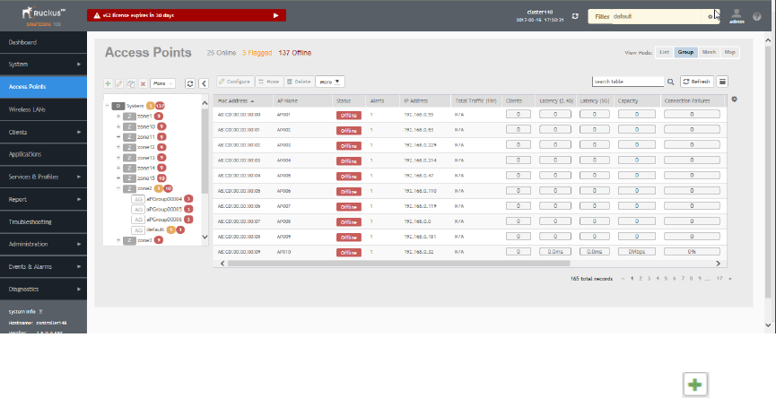
Working with AP Groups
AP (access point) groups can be used to define configuration options and apply them to groups of APs at once, without having to
individually modify each AP’s settings.
For each group, administrators can create a configuration profile that defines the channels, radio settings, Ethernet ports and other
configurable fields for all members of the group or for all APs of a specific model in the group. AP groups are similar to WLAN groups (see
Working with WLAN Groups for more information). While WLAN groups can be used to specify which WLAN services are served by which
APs, AP groups are used for more specific fine-tuning of how the APs themselves behave.
NOTE
AP group configuration settings can be overridden by individual AP settings. For example, if you want to set the transmit power to
a lower setting for only a few specific APs, leave the Tx Power Adjustment at Auto in the AP group configuration page, then go to
the individual AP configuration page (Access Points > Access Points > Edit [AP MAC address]) and set the Tx Power Adjustment
to a lower setting.
Creating an AP Group
Creating an AP group means creating a configuration profile that defines the channels, radio settings, Ethernet ports and other configurable
fields for all members of the group or for all APs of a specific model in the group.
Follow these steps to create an AP group.
1. From the left pane, select Access Points. The below figure appears.
FIGURE 35 Access Point
2. From the System tree hierarchy, select the location (for example: System, Domain, Zone) and click . The following figure
appears.
Working With Access Points
Understanding the System, Domains, Zones and AP Groups
SCG200 vSZ-H and SZ300 Administrator Guide
Part Number: 800-71563-001 83
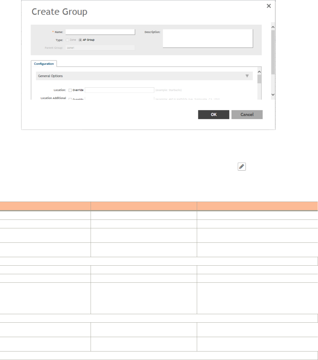
FIGURE 36 Create Groups
3. Enter the details as explained in the following table.
NOTE
You can also edit the configuration of default APs by selecting the AP and clicking the icon.
4. Click OK.
TABLE 10 AP Group Details
Field Description Your Action
Name Indicates a name for the Zone/AP group. Enter a name.
Description Indicates a short description. Enter a brief description
Type Indicates if you are creating a domain, zone or an
AP group.
Appears by default. You can also choose the option.
Parent Group Indicates the parent group that this AP group
belongs.
Appears by default.
Configuration > General Options
Location Indicates generic location. Enter the location.
Location Additional Information Indicates detailed location. Enter additional location information.
GPS Coordinates Indicates the geographical location. Enter the following coordinates in meters or floor:
•Longitude
•Latitude
•Altitude
Configuration > Group Members
Members Displays the list of APs that belong to the group. Select the members from the list and click Move to to
assign them to the required group.
Access Points Displays the list of APs that belong to the zone. Select the Access Points from the list and click Add to
Group.
Configuration > Radio Options
Working With Access Points
Understanding the System, Domains, Zones and AP Groups
SCG200 vSZ-H and SZ300 Administrator Guide
84 Part Number: 800-71563-001

TABLE 10 AP Group Details (continued)
Field Description Your Action
Channel Range (2.4G) Indicates that you want to override the 2.4GHz
channel range that has been configured for the
zone to which this AP group belong.
Select Select Channel Range (2.4G) check boxes for the
channels on which you want the 2.4GHz radios of
managed APs to operate. Channel options include
channels 1 to 11. By default, all channels are selected.
Channel Range (5G) Indoor Indicates for what channels want the 5GHz radios
of managed indoor APs to operate.
Select the check boxes.
Channel Range (5G) Outdoor Indicates for what channels want the 5GHz radios
of managed outdoor APs to operate.
Select the check boxes.
Radio Options b/g/n (2.4 GHz) Indicates the radio option 2.4 GHz configurations. Select the following options:
•Channelization—Set the channel width used
during transmission to either 20 or 40 (MHz),
or select Auto to set it automatically.
•Channel—Select the channel to use for the
b/g/n (2.4GHz) radio, or select Auto to set it
automatically.
•TX Power—Select the preferred TX power, if
you want to manually configure the transmit
power on the 2.4GHz radio. By default, TX
power is set to Full on the 2.4GHz radio
•WLAN Group—Specifies to which WLAN
group this AP group belongs.
Radio Options a/n/ac (5 GHz) Indicates the radio option 5 GHz configurations. Select the following options:
•Channelization—Set the channel width used
during transmission to either 20, 40, 80,
80+80, 160 (MHz), or select Auto to set it
automatically.
•Channel—For Indoor and Outdoor, select the
channel to use for the a/n/c (5GHz) radio, or
select Auto to set it automatically.
•TX Power—Select the preferred TX power, if
you want to manually configure the transmit
power on the 5GHz radio. By default, TX
power is set to Full on the 5GHz radio.
•WLAN Group—Specify to which WLAN group
this AP group belongs.
Configuration > AP SNMP Options
Override zone configuration Indicates that the AP Group configuration
overrides the zone configuration.
Select the check box.
Enable AP SNMP Indicates if the AP SNMP option is enabled. Select the check box.
SNMPv2 Agent Indicates SNMPv2 Agent is applied. 1. Click Create and enter Community.
2. Select the required Privilege. If you select
Notification enter the Target IP.
3. Click OK.
SNMPv3 Agent Indicates SNMPv3 Agent is applied. 1. Click Create and enter User.
2. Select the required Authentication.
3. Enter the Auth Pass Phrase.
4. Select the Privacy option.
5. Select the required Privilege. If you select
Notification select the option Trap or Inform
and enter the Target IP and Target Port.
Working With Access Points
Understanding the System, Domains, Zones and AP Groups
SCG200 vSZ-H and SZ300 Administrator Guide
Part Number: 800-71563-001 85

TABLE 10 AP Group Details (continued)
Field Description Your Action
6. Click OK.
Configuration > Model Specific Options
NOTE
Select the Override check box for that setting, and then configure the setting.
AP Model Indicate the AP model for which you are
configuring.
Select the option.
Status LEDs Disable the status LED on the selected AP model. Select the option.
LLDP Enables the Link Layer Discovery Protocol (LLDP)
on the selected AP model.
Select the option and enter the following details:
•Advertise Interval—Enter the duration in
seconds.
•Hold Time—Enter the duration in seconds.
•Enable Management IP TLV—Select the check
box.
External Antenna (2.4 GHz) Enables the external 2.4 GHz antenna on the
selected AP model.
Select the Enable external antenna check box, and then
set the gain value (between 0 and 90dBi) in the box
provided.
External Antenna (5 GHz) Enables the external 5 GHz antenna on the
selected AP model.
Select the Enable external antenna check box, and then
set the gain value (between 0 and 90dBi) in the box
provided.
Port Settings Indicates the port settings. Select the option and choose the required LAN option.
PoE out port Enables PoE out mode. Select the Enable PoE out ports (specific ZoneFlex AP
models only) check box.
PoE Operating Mode Indicates the PoE operating mode of the selected
AP model
Choose the option.
NOTE
When this option is selected, some AP
features are disabled to reduce power
consumption, such as the USB port and one
of the Ethernet ports.
Internal Heater Enables the heater that is built into the selected
AP model
Select the Enable internal heaters (specific AP models
only) check box.
USB Port Disables the USB port. USB ports are enabled by
default.
Select the Disable USB port check box.
Configuration > Advanced Options
Location Based Service Enables location-based service for the AP group. • Select the Override zone configuration check
box.
• Select the Enable LBS Service check box.
•Select an LBS Server from the drop-down.
Hotspot 2.0 Venue Profile Indicates the hotspot profile that you want to
assign to the group.
Select the required option or click Create and update the
following details:
• Enter the Name.
• Enter the Description.
• Enter the Venue Names.
• Select the Venue Category.
• Select the Type.
• Enter the WLAN Metrics.
Working With Access Points
Understanding the System, Domains, Zones and AP Groups
SCG200 vSZ-H and SZ300 Administrator Guide
86 Part Number: 800-71563-001
TABLE 10 AP Group Details (continued)
Field Description Your Action
AP Management VLAN Indicates the AP management VLAN settings. Choose the option. Click VLAN ID, and then type the
VLAN ID that you want to assign (valid range is from 1 to
4094). To keep the same management VLAN ID that has
been configured on the AP, click Keep AP's settings.
Auto Channel Selection Indicates auto-channel settings. Select the check box and choose the option.
Client Admission Control Indicates the load thresholds on the AP at which
it will stop accepting new clients.
Select the Override check box respective to 2.4 GHz
Radio or 5 GHz Radio and update the following details:
•Enable
NOTE
Client load balancing and band
balancing will be disabled for this
AP group.
•Min Client Count
•Max Radio Load
•Min Client Throughput
Protection Mode Indicates the mechanism to reduce frame
collision.
Choose one of the following options:
• None
• RTS/CTS
• CTS Only
NOTE
You can also edit, clone or delete an AP Group by selecting the options Configure , Clone or Delete respectively, from
the Access Points page.
Configuring Model-Based Settings
If you want to apply a set of settings to all APs of a particular model, use the Model-Based Settings option.
Follow the steps to configure the model based settings.
1. From the left-pane, click Access Points. The Access Points page appears.
2. From the list, select the AP for which you want to apply the model-based settings and click Configure. The Edit AP form appears.
3. Scroll down to Model Specific Options section, and then expand the section.
4. In Model Specific Control, select the Override zone config check box. The settings available for the AP model appear.
5. In the General Options section, configure the following settings:
NOTE
The options that appear in the Model Specific Options section depend on the AP model that you select. Not all the
options described in the table below will appear for every AP model.
Option Description
USB Port To disable the USB port on the selected AP model, select the Disable USB port check box. USB
ports are enabled by default.
Status LEDs To disable the status LED on the selected AP model, select the Disable Status LEDs check box.
Working With Access Points
Understanding the System, Domains, Zones and AP Groups
SCG200 vSZ-H and SZ300 Administrator Guide
Part Number: 800-71563-001 87

Option Description
LLDP To enable the Link Layer Discovery Protocol (LLDP) on the selected AP model, select the Enable
Link Layer Discovery Protocol check box.
• Enter the Advertise Interval duration in seconds
• Enter the Hold Time duration in seconds
• Select the Enable Management IP TLV check box
PoE Operating Mode Select the PoE operating mode of the selected AP model. Available options include Auto (default),
802.3af and 802.3at mode. If 802.3af PoE Operating Mode PoE is selected, this AP model will
operate in 802.3af mode and will consume less power than in 802.3at mode. However, when this
option is selected, some AP features are disabled to reduce power consumption, such as the USB
port and one of the Ethernet ports.
PoE out port To enable the PoE out port on the selected AP model, select the Enable PoE out ports (specific
ZoneFlex AP models only) .
NOTE
If the controller country code is set to United Kingdom, an additional Enable 5.8 GHz
Channels option will be available for outdoor 11n/11ac APs. Enabling this option allows
the use of restricted C-band channels. These channels are disabled by default and
should only be enabled by customers with a valid license to operate on these restricted
channels.
Internal Heater To enable the heater that is built into the selected AP model, select the Enable internal heaters
(specific AP models only) check box.
External Antenna (2.4 GHz) To enable the external 2.4 GHz antenna on the selected AP model, select the Enable external
antenna check box, and then set the gain value (between 0 and 90dBi) in the box provided.
External Antenna (5 GHz) To enable the external 5 GHz antenna on the selected AP model, select the Enable external
antenna check box, and then set the gain value (between 0 and 90dBi) in the box provided.
6. In the Port Settings section, configure the following options for each LAN port.
NOTE
The number of LAN ports that appear in this section correspond to the physical LAN ports that exist on the selected AP
model.
NOTE
When trunk port limitation is enabled, the controller does not validate the port settings configured in the AP or the AP
group with no members.
Option Description
Enable Use this option to enable and disable this LAN port on the selected AP model. By default, this
check box is selected. To disable this LAN port, clear this check box.
Profile Use this option to select the Ethernet port profile that you want this LAN port to use. Two default
Ethernet port profile exist: Default Trunk Port (selected by default) and Default Access Port. If you
created Ethernet port profiles (see Creating an Ethernet Port Profile on page 230), these profiles
will also appear on the drop-down list.
NOTE
If you recently created an Ethernet port profile and it does not appear on the drop-
down menu, click Reload on the drop-down menu to refresh the Ethernet port profile
list.
Overwriter VLAN Select teh checck box and enter:
•Untag ID—Default: 1
•Members—Range: 1 through 4094.
7. Click OK.
Working With Access Points
Understanding the System, Domains, Zones and AP Groups
SCG200 vSZ-H and SZ300 Administrator Guide
88 Part Number: 800-71563-001
Supported LLDP Attributes
The Link Layer Discovery Protocol (LLDP) is a vendor-neutral Layer 2 protocol that allows a network device (for example, a Ruckus Wireless
AP) to advertise its identity and capabilities on the local network.
LLDP information is sent by devices from each of their interfaces at a fixed interval (default is 30 seconds), in the form of an Ethernet frame.
Each LLDP Ethernet frame contains a sequence of type-length-value (TLV) structures starting with Chassis ID, Port ID and Time to Live
(TTL) TLV. Table 2 lists the LLDP attributes supported by the controller.
LLDP information is sent by devices from each of their interfaces at a fixed interval (default is 30 seconds), in the form of an Ethernet frame.
Each LLDP Ethernet frame contains a sequence of type-length-value (TLV) structures starting with Chassis ID, Port ID and Time to Live
(TTL) TLV.The follwoing table lists the LLDP attributes supported by the controller.
Attribute (TLV) Description
Chassis ID Indicates the MAC address of the AP’s br0 interface
Port ID Identifies the port from which the LLDP packet was sent
Time to Live Same as LLDP Hold Time. Indicates the length of time (in seconds) that a receiving device will hold the LLDP
information sent by the selected AP model before discarding it. The default value is 120 seconds.
System Name Indicates the name assigned to the AP. The default name of Ruckus Wireless APs is RuckusAP.
System Description Indicates the AP model plus software version
System Capabilities Indicates the AP’s capabilities (Bridge, WLAN AP, Router, Docsis), and which capabilities are enabled
Management Address Indicates the management IP address of the AP
Port Description Indicates the description of the port in alphanumeric format
Configuring the Port Settings of a Particular AP Model
Use Port Settings in the AP Model-Specific Configuration section to configure the Ethernet ports of a particular AP model.
Follow these steps to configure the port settings of a certain AP model.
1. All ports are enabled by default (the Enable check boxes are all selected). To disable a particular port entirely, clear the Enable
check box next to the port name (LAN1, LAN2, etc.)
2. For any enabled ports, you can choose whether the port will be used as a Trunk Port, Access Port, or General Port.
The following restrictions apply:
• All APs must be configured with at least one Trunk Port.
NOTE
You cannot move an AP model to an AP group and configure the AP model to use a trunk port at the same time, if
general ports are enabled when trunk port limitation is disabled. You must configure the selected AP model to use
at least one trunk port, and then move the AP model to the AP group.
• For single port APs, the single LAN port must be a trunk port and is therefore not configurable.
• For ZoneFlex 7025/7055, the LAN5/Uplink port on the rear of the AP is defined as a Trunk Port and is not configurable. The
four front-facing LAN ports are configurable.
• For all other APs, you can configure each port individually as either a Trunk Port, Access Port, or General Port. See
Designating an Ethernet Port Type on page 90 for more information.
Working With Access Points
Understanding the System, Domains, Zones and AP Groups
SCG200 vSZ-H and SZ300 Administrator Guide
Part Number: 800-71563-001 89
Designating an Ethernet Port Type
Ethernet ports can be configured as access ports, trunk ports, or general ports.
Trunk links are required to pass VLAN information between switches. Access ports provide access to the network and can be configured as
members of specific VLANs, thereby separating the traffic on these ports from traffic on other VLANs. General ports are user-defined ports
that can have any combination of up to 20 VLAN IDs assigned.
For most ZoneFlex APs, you can set which ports you want to be your Access, Trunk and General Ports from the controller web interface, as
long as at least one port on each AP is designated as a Trunk Port.
By default, all ports are enabled as Trunk Ports with Untag VLAN set as 1 (except for ZoneFlex 7025, whose front ports are enabled as
Access Ports by default). If configured as an Access Port, all untagged ingress traffic is the configured Untag VLAN, and all egress traffic is
untagged. If configured as a Trunk Port, all untagged ingress traffic is the configured Untag VLAN (by default, 1), and all VLAN-tagged traffic
on VLANs 1-4094 will be seen when present on the network.
The default Untag VLAN for each port is VLAN 1. Change the Untag VLAN to:
• Segment all ingress traffic on this Access Port to a specific VLAN.
•Redefine the native VLAN on this Trunk Port to match your network configuration.
When trunk port limitation is disabled using the eth-port-validate-one-trunk disable command, validation checks are not performed for the
VLAN members and the AP Management VLAN. If the AP configuration for general ports and access ports does not include a member of
an AP management VLAN, or the VLAN of a WAN interface configured through CLI, the AP will disconnect and the Ethernet port stops
transmitting data. Make sure that you configure the correct VLAN member in the ports (general/access) and the AP management VLAN.
NOTE
Ensure that at least one of the general port VLANs is the same as a Management VLAN of the AP.
Access Ports
Access ports provide access to the network and can be configured as members of a specific VLAN, thereby separating the traffic on these
ports from traffic on other VLANs.
All Access Ports are set to Untag (native) VLAN 1 by default. This means that all Access Ports belong to the native VLAN and are all part of
a single broadcast domain. When untagged frames from a client arrive at an AP’s Access Port, they are given an 802.1Q VLAN header with
1 as their VLAN ID before being passed onto the wired network.
When VLAN 1 traffic arrives destined for the client, the VLAN tag is removed and it is sent as plain (untagged) 802.11 traffic. When any
tagged traffic other than VLAN 1 traffic arrives at the same Access Port, it is dropped rather than forwarded to the client.
To remove ports from the native VLAN and assign them to specific VLANs, select Access Port and enter any valid VLAN ID in the VLAN ID
field (valid VLAN IDs are 2-4094).
The following table describes the behavior of incoming and outgoing traffic for Access Ports with VLANs configured.
TABLE 11 Access Ports with VLANs configured
VLAN Settings Incoming Traffic (from Client) Outgoing Traffic (to Client)
Access Port, Untag VLAN 1 All incoming traffic is native VLAN (VLAN 1). All outgoing traffic on the port is sent untagged.
Access Port, Untag VLAN [2-4094] All incoming traffic is sent to the VLANs specified. Only traffic belonging to the specified VLAN is
forwarded. All other VLAN traffic is dropped.
Working With Access Points
Understanding the System, Domains, Zones and AP Groups
SCG200 vSZ-H and SZ300 Administrator Guide
90 Part Number: 800-71563-001

Trunk Ports
Trunk links are required to pass VLAN information between switches. Trunking is a function that must be enabled on both sides of a link.
If two switches are connected together, for example, both switch ports must be configured as trunk ports.
The trunk port is a member of all the VLANs that exist on the AP/switch and carries traffic for all VLANs between switches.
For a trunk port, the VLAN Untag ID field is used to define the native VLAN - the VLAN into which untagged ingress packets are placed
upon arrival. If your network uses a different VLAN as the native VLAN, configure the AP trunk port’s VLAN Untag ID with the native VLAN
used throughout your network.
General Ports
General ports are user-specified ports that can have any combination of up to 20 VLAN IDs assigned.
General ports function similarly to Trunk ports, except that where Trunk ports pass all VLAN traffic, General ports pass only the VLAN traffic
that is defined by the user.
To configure an AP Ethernet port as a General port, select General Port and enter multiple valid VLAN IDs separated by commas or a range
separated by a hyphen.
NOTE
You must also include the Untag VLAN ID in the Members field when defining the VLANs that a General port will pass. For
example, if you enter 1 as the Untag VLAN ID and want the port to pass traffic on VLANs 200 and 300, you would enter:
1,200,300.
Configuring Client Admission Control
As an administrator, you can help maintain a positive user experience for wireless users on the network by configuring the following client
admission control settings:
• Minimum client count
• Maximum radio load
• Minimum client throughput
Client admission control is implemented on a per radio basis and is supported on 802.11n and 802.11ac APs.
Monitoring Domains, Zones, and AP Groups
When you select a System, Domain, Zone, or AP Group from the hierarchy tree, respective contextual tabs appear at the bottom of the
page.
These tabs are used to monitor the selected group. The following table lists the tabs that appear for System, Domain, Zone, and AP Group.
TABLE 12 System, Domain, Zone, and AP Groups Monitoring Tabs
Tabs Description System Domain Zone AP Groups
General Displays group information Yes Yes Yes Yes
Configuration Displays group configuration information. Yes Yes Yes Yes
Health Displays historical health information. Yes Yes Yes Yes
Traffic Displays historical traffic information. Yes Yes Yes Yes
Alarm Displays alarm information. Yes Yes Yes Yes
Event Displays event information. Yes Yes Yes Yes
Working With Access Points
Understanding the System, Domains, Zones and AP Groups
SCG200 vSZ-H and SZ300 Administrator Guide
Part Number: 800-71563-001 91
TABLE 12 System, Domain, Zone, and AP Groups Monitoring Tabs (continued)
Tabs Description System Domain Zone AP Groups
Clients Displays client information. Yes Yes Yes Yes
WLANs Displays WLAN information. Yes Yes Yes NA
Services Displays information on the list of services. Yes Yes Yes NA
Administrators Displays administrator account information. Yes NA NA NA
Additionally, you can select System, Domain, or Zone and click More to perform the following operations as required:
•Move
•Create New Zone from Template
•Extract Zone Template
•Apply Zone Template
•Change AP Firmware
•Switchover Cluster
•Trigger Preferred Node
Moving an AP Zone Location
Follow these steps to move an AP zone to a different location:
1. From the Access Points page, locate the AP zone that you want to move to a different location.
2. Click Move, the Select Destination Management Domain dialog box appears.
3. Select the destination and click OK, a confirmation dialog box appears.
4. Click Yes, the page refreshes and AP zone is moved to the selected destination.
Creating a New Zone using a Zone Template
Follow these steps to create a new zone using a template:
1. From the Access Points page, locate the zone from where you want to create a new zone.
2. Click More and select Create New Zone from Template, a dialog box appears.
3. In Zone Name, enter a name for the new AP zone.
4. Select the required template from the Template Name drop-down.
5. Click OK. The page refreshes and and the new zone is created.
Extracting a Zone Template
You can extract the current configuration of a zone and save it as a zone template.
Follow these steps to extract the configuration of a zone to a zone template:
1. From the Access Points page, locate the zone from where you want to extract the WLAN template.
2. Click More and select Extract Zone Template, the Extract Zone Template dialog box appears.
3. In Zone Template Name, enter a name for the Template.
4. Click OK, a message appears stating that the zone template was extracted successfully.
Working With Access Points
Understanding the System, Domains, Zones and AP Groups
SCG200 vSZ-H and SZ300 Administrator Guide
92 Part Number: 800-71563-001
5. Click OK. You have completed extracting a zone template.
The extracted Zone template can be viewed under System > Templates > Zone Templates.
Applying a Zone Template
You can apply an AP zone configuration template to a zone.
Follow these steps to apply a zone template:
1. From the Access Points page, locate the zone where you want to apply the zone template.
2. Click More and select Apply Zone Template, the Import Zone Template dialog box appears.
3. From the Select a Zone template drop-down, select the template.
4. Click OK, a confirmation message appears asking to apply the zone template to the AP zone.
5. Click Yes. The zone template was applied successfully.
You have completed applying zone template to the AP zone.
Changing the Zone's AP Firmware Version
The controller supports multiple firmware version. You can manually upgrade or downgrade the zone's AP firmware version.
Follow these steps to change the zone's AP firmware version:
1. From the Access Pointss page, locate the zone for which you want to upgrade the AP firmware version.
2. Click More and select Change AP Firmware, the Change AP Firmware dialog box appears.
3. The Current AP Firmware version is displayed. Select the firmware version you need. If you upgrade to a new firmware, a backup
configuration file will be created. You can use this backup file to downgrade to original firmware.
4. Click Yes, a confirmation message appears stating that the firmware version was updated successfully.
5. Click OK. You have completed upgrading the zone's AP firmware version.
Rehoming Managed APs
Rehoming is the process of returning the APs that have failed over to the standby cluster back to their original cluster (once it becomes
available). Rehoming must be done manually. APs that have failed over will continue to be managed by the failover cluster until you rehome
them.
NOTE
To rehome managed APs, you must enable cluster redundancy so that the APs will continue to be managed by the failover cluster
until you restore them to the original cluster (rehome) manually. See Enabling Cluster Redundancy on page 49.
Rehoming APs must be done on a per-cluster basis. Follow these steps to rehome managed APs to the original cluster.
1. From the Access Points page, select the System to activate rehome operation.
2. Click More and select Rehome Primary Cluster . A confirmation dialog box appears.
3. Click Yes, you have set active cluster to rehome.
Working With Access Points
Understanding the System, Domains, Zones and AP Groups
SCG200 vSZ-H and SZ300 Administrator Guide
Part Number: 800-71563-001 93

Triggering a Preferred Node
You can trigger an AP that belongs to the current zone force go to their preferred node. For this, you must enable Node affinity, which gives
AP the priority of preferred nodes.
Follow these steps to trigger a node:
NOTE
You must enable node affinity before triggering nodes.
1. From the Access Points page, locate the zone.
2. Click More and select Trigger Preferred Node, a confirmation stating that the node has been triggered appears.
3. Click OK. You have triggered the preferred node for the AP.
Viewing Modes
You can view System, Zone, and AP Group-level information by selecting one of the following View Mode options:
•List—Displays the list of all APs irrespective of the Zone or Group they belong.
•Group—Displays the list of APs in a hiearchy format. The is the default viewing mode.
•Mesh—Lists AP details.
•Map—Displays the location map of the APs.
•Zone—Lists zone details.
AP Status
The real-time status of the Access Points are classified as follows:
The status of Access Points can be one of the following:
• Online—Number of Access Points that are online.
• Flagged—Number of Access Points that are flagged.
• Offline—Number of Access Points that are offline.
NOTE
APs that exceed their health threshold and that require your attention are flagged. See Understanding Cluster and AP Health
Icons on page 22.
Configuring Access Points
You can configure an Access Point.
To configure an Access Point:
1. From the list, select the Access Point that you want to configure and click Configure. The Edit AP page appears.
2. Edit the parameters as explained in Table 13.
Working With Access Points
Viewing Modes
SCG200 vSZ-H and SZ300 Administrator Guide
94 Part Number: 800-71563-001

3. Click OK.
NOTE
Select the Override check box if you want to configure new settings.
TABLE 13 Access Point Edit Parameters
Field Description Your Action
AP Configuration > General Options
AP Name Indicates the name of the AP. Enter a name.
Description Gives a short description of the AP. Enter a short description.
Location Indicates generic location. Select the check box and enter the location.
Location Additional Information Indicates specific location. Select the check box and enter the location.
GPS Coordinates Indicates the geographical location. Select the option. For Manual option, enter the
following details:
•Latitude
•Longitude
•Altitude
User Location Information Indicates the demographic information. Enter the Area Code and Cell Identifier.
AP Admin Logon Indicates the admin logon credentials. Select the check box and enter the Logon ID
and Password.
AP Configuration > Radio Options
Channel Range (2.4G) Indicates that you want to override the 2.4GHz
channel range that has been configured for the
zone to which this AP group belong.
Select Select Channel Range (2.4G) check
boxes for the channels on which you want the
2.4GHz radios of managed APs to operate.
Channel options include channels 1 to 11. By
default, all channels are selected.
Channel Range (5G) Indicates that you want to override the 5GHz
channel range that has been configured for the
zone to which this AP group belong.
Select Select Channel Range (5G) check boxes
for the channels on which you want the 5GHz
radios of managed APs to operate.
Radio Options b/g/n (2.4 GHz) Indicates the radio option 2.4 GHz configurations. Select the following options:
•Channelization—Set the channel
width used during transmission to
either 20 or 40 (MHz), or select Auto
to set it automatically.
•Channel—Select the channel to use
for the b/g/n (2.4GHz) radio, or select
Auto to set it automatically.
•TX Power Adjustment—Select the
required option.
•WLAN Group—Select the WLAN
group to which this AP belongs.
•WLAN Services—Select the check
box to enable WLAN services in this
radio.
Radio Options a/n/ac (5 GHz) Indicates the radio option 5 GHz configurations. Select the following options:
•Channelization—Set the channel
width used during transmission to
either 20, 40, 80 (MHz), or select Auto
to set it automatically.
•Channel—Select the channel to use
for the a/n/c (5GHz) radio, or select
Auto to set it automatically.
Working With Access Points
Configuring Access Points
SCG200 vSZ-H and SZ300 Administrator Guide
Part Number: 800-71563-001 95

TABLE 13 Access Point Edit Parameters (continued)
Field Description Your Action
•TX Power Adjustment—Select the
required option.
•WLAN Group—Select the WLAN
group to which this AP belongs.
•WLAN Services—Select the check
box to enable WLAN services in this
radio.
AP Configuration > AP SNMP Options
NOTE
For SCG200 controllers, AP SNMP Option is not supported.
Override zone configuration Allows you to override the existing zone
configuration
Select the check box
Enable AP SNMP Enables you to configure SNMP settings. Select the check box
SNMPv2 Agent Allows you to add users to SNMPv2 Agent. 1. Click Create and enter Community.
2. Select the required Privilege. If you
select Notification enter the Target IP.
3. Click OK.
SNMPv3 Agent Allows you to add users to SNMPv3 Agent. 1. Click Create and enter User.
2. Select the required Authentication.
3. Enter the Auth Pass Phrase.
4. Select the Privacy option.
5. Select the required Privilege. If you
select Notification select the option
Trap or Inform and enter the Target IP.
6. Click OK.
AP Configuration > Model Specific Options
Model Specific Control Indicates that the model overides the AP settings. Select the check box.
USB Port Disables the USB port on the selected AP model. Select the option. USB ports are enabled by
default.
Status LEDs Disable the status LED on the selected AP model. Select the option.
LLDP Enables the Link Layer Discovery Protocol (LLDP)
on the selected AP model.
Select the option and enter the following details:
•Advertise Interval—Enter the duration
in seconds.
•Hold Time—Enter the duration in
seconds.
•Enable Management IP TLV—Select
the check box.
PoE Operating Mode Allows you to operate using PoE mode. Select the option.
Port Settings Indicates the port settings. Select the option and choose the required LAN
option.
AP Configuration > Advanced Options
Network Settings Determines the network settings. Select the IPv4 Settings from the following:
•Static-Enter the IP Address, Network
Mask, Gateway, Primary DNS,
Secondary DNS.
•Dynamic
Working With Access Points
Configuring Access Points
SCG200 vSZ-H and SZ300 Administrator Guide
96 Part Number: 800-71563-001

TABLE 13 Access Point Edit Parameters (continued)
Field Description Your Action
•Keep the AP's Setting
Smart Monitor Indicates AP interval check and retry threshold
settings.
Select the required check boxes.
Syslog Options Determines if external syslog server settings is
applicable.
Select the required check boxes. For Enable
external syslog server option, update the
following information:
•Server Address
•Port
•Facility for Event
•Priority
Hotspot 2.0 version Profile Indicates the hotspot profile that you want to
assign to the group.
Select the required option or click Create and
update the following details:
• Enter the Name.
• Enter the Description.
• Enter the Venue Names.
• Select the Venue Category.
• Select the Type.
• Enter the WLAN Metrics.
AP Management VLAN Indicates the AP management VLAN settings. Select the check box and choose the option.
Auto Channel Selection Indicates auto-channel settings. Select the check box and choose the option.
Client Admission Control Indicates the load thresholds on the AP at which it
will stop accepting new clients.
Select the check boxes and update the following
details:
•Min Client Count
•Max Radio Load
•Min Client Throughput
Swap Configuration
Add Swap-In AP Allows to swap APs. Select the check box and enter the Swap-in AP
MAC details.
NOTE
You can also move the location of an AP or delete an AP. To do so, select the AP from the list and click Move or Delete as
required.
Managing Access Points
Overview of Access Point Configuration
Once you have created registration rules and the AP zones to which joining access points can be assigned automatically, access points will
be able to join or register with the controller automatically.
After an access point registers successfully with the controller, you can update its configuration by following the steps described in this
section.
Working With Access Points
Managing Access Points
SCG200 vSZ-H and SZ300 Administrator Guide
Part Number: 800-71563-001 97
Viewing Managed Access Points
After an access point registers successfully with the controller, it appears on the Access Points page, along with other managed access
points.
Follow these steps to view a list of managed access points.
1. Click Access Points, a list of access points that are being managed by the controller appears on the Access Points page. These
are all the access points that belong to all management domains.
The list of managed access points displays details about each access point, including its:
• AP MAC address
• AP name
• Zone (AP zone)
• Model (AP model)
• AP firmware
• IP address (internal IP address)
• External IP address
• Provision Method
• Provision State
• Administrative Status
• Status
•Configuration Status
• Registered On (date the access point joined the controller network)
• Registration Details
• Registration State
• Actions (actions that you can perform)
NOTE
By default, the Access Points page displays 20 access points per page (although you have the option to display up to
250 access points per page). If the controller is managing more than 20 access points, the pagination links at the
bottom of the page are active. Click these pagination links to view the succeeding pages on which the remaining access
points are listed.
2. To view access points that belong to a particular administration domain, click the name of the administration domain in the domain
tree (on the sidebar).
The page refreshes, and then displays all access points that belong to that management domain.
Downloading the Support Log from an Access Point
If you are experiencing issues with an access point, Ruckus Wireless® Support may request you to download the support log from the
access point.
The support log contains important technical information that may be help Ruckus Wireless® Support troubleshoot the issue with the
access point. Follow these steps to download the support log from an access point.
Working With Access Points
Managing Access Points
SCG200 vSZ-H and SZ300 Administrator Guide
98 Part Number: 800-71563-001
To download a support log from an AP:
• Select the AP and click More > Download Support Log. The following message appears: Do you want to open or save
SupportLog_{random-string}.log.
Save the file and use a text editor (for example, Notepad) to view the contents of the text file. Send the support log file to Ruckus Wireless®
Support, along with your support request.
Provisioning and Swapping Access Points
The controller supports the provisioning and swapping of access points.
As an administrator you can:
• Upload a file containing list of AP and the pre-provisioned configuration data for each AP. The controller processes the file and
provides details on regarding the import results (including a list of failed APs and failure reasons).
• Modify or delete pre-provisioning data if AP does not connect to the controller
• Monitor the status and stage of the pre-provisioned APs
• Manually lock or unlock APs
• Upload a file containing list of AP pairs for swapping. The controller processes the file and provide the detailed import result
(including a list of failed APs and failure reasons).
• Manually enter the AP swap pair
• Delete the swap configuration if AP fails to contact the controller
• Monitor the status and stage of the swapping AP pairs
• Manually swap the APs
Options for Provisioning and Swapping APs
The controller supports the provisioning and swapping of access points.
Use the following buttons on the AP List page to perform the AP provisioning and swapping.
•Import Batch Provisioning APs: Select this option to import the provisioning file. The controller displays the import results. Any
errors that occur during the import process will be listed by the controller.
•Export All Batch Provisioning APs: Select this option to download a CSV file that lists all APs that have been provisioned. The
exported CSV contains the following information:
– AP MAC Address
– Zone Name
– Model
– AP Name
– Description
– Location
– GPS Coordinates
– Logon ID
– Password
– Administrative State
– IP Address
– Network Mask
– Gateway
– Primary DNS
Working With Access Points
Managing Access Points
SCG200 vSZ-H and SZ300 Administrator Guide
Part Number: 800-71563-001 99
– Secondary DNS
– Serial Number
– IPv6 Address
– IPv6 Gateway
– IPv6 Primary DNS
– IPv6 Secondary DNS
NOTE
The exported CSV file for all batch provisioned APs only contains pre-provisioned APs. It does not contain swapping
APs or auto discovered APs.
If no APs have been pre-provisioned, you will still be able to export the CSV file but it will be empty (except for the
column titles).
•Import Swapping APs: Manually trigger the swapping of two APs by clicking the swap action in the row. You can also edit the pre-
provision configuration only if the AP does not connect to the controller. Click the AP MAC address to bring up the configuration
edit form, and then select Pre-provision Configuration.
•Export All Batch Swapping APs: Select this option to download a CSV file that lists all APs that have been swapped. The exported
CSV contains the following information:
– Swap In AP MAC
– Swap In AP Model
– Swap Out AP MAC
NOTE
The exported CSV file for batch swapping APs only contains swapping APs. It does not contain pre-provisioned
APs or auto discovered APs.
Understanding How Swapping Works
The following table lists how the controller handles swapping by detailing each stage. For example, you have entered swap configuration as
Swap In: A and Swap out: B.
TABLE 14 AP swapping stages
Stage State A Stage A State B Stage B
1. Enter data Swapping Not Registered Approved Waiting for swap in AP
registration
2. AP register Swapping Waiting for swapping in Approved Waiting for swapping out
3. User swap Approved Swapped in Swapping Swapped out
4. Second swap Swapping Swapped out and waiting for
swapping in
Approved Swapped in and waiting for
swapping out
Editing Swap Configuration
The controller supports the swapping or replacement of a managed AP with a new AP of the same model. This feature is useful when you
want to avoid service interruption because you need to replace an AP in the field.
By configuring the swap settings, you can easily and automatically export and apply the settings of the old AP to the new AP.
Follow these steps to configure the swap settings of an AP.
1. On the Access Points page, locate the access point whose swap configuration you want to update.
Working With Access Points
Managing Access Points
SCG200 vSZ-H and SZ300 Administrator Guide
100 Part Number: 800-71563-001

2. Click Configure, the Edit AP page appears.
3. Click the Swap Configuration tab.
4. Select the Add Swap-In AP check box.
5. Enter the Swap-In AP MAC address.
6. Click OK.
You have completed editing the swap configuration.
Monitoring Access Points
When you select an AP from the list, contextual tabs appear at the bottom of the page.
The following table helps you to understand the real-time information about the AP.
TABLE 15 Access Point Monitoring Tabs
Tabs Description
General Displays group information
Configuration Displays group configuration information.
Health Displays historical health information.
Traffic Displays historical traffic information.
Alarm Displays alarm information.
Event Displays event information.
Clients Displays client information.
Pool Stats Displays DHCP pool data.
Stats Counter Displays AP statistics that can be exported to CSV format.
Additionally, you can select an AP and click More to perform the following operations as required:
•Select ALL - Selects all the APs in the list.
•Deselect All- Clears all selection from the list.
•Troubleshooting > Client Connection - Connects to client devices and analyze network connection issues in real-time. See,
Troubleshooting Client Connections on page 267
•Troubleshooting > Spectrum Analysis - Troubleshoots issues remotely, identify sources of interferences within the network and
allow administrators access to the RF health of the network environment. See, Troubleshooting through Spectrum Analysis on
page 268
•Restart - Restarts an access point remotely from the web interface.
•Lock - Disables all WLAN services on the AP and disconnect all wireless users associated with those WLAN services temporarily.
•Unlock - Makes all WLAN services available.
•Import Batch Provisioning APs - Import the provisioning file. See, Options for Provisioning and Swapping APs on page 99
•Import Swapping APs - Manually trigger the swapping of two APs by clicking the swap action in the row. See, Options for
Provisioning and Swapping APs on page 99
•Export All Batch Provisioning APs Downloads a CSV file that lists all APs that have been provisioned.. See, Options for
Provisioning and Swapping APs on page 99
•Export All Swapping APs - Downloads a CSV file that lists all APs that have been swapped. See, Options for Provisioning and
Swapping APs on page 99
Working With Access Points
Managing Access Points
SCG200 vSZ-H and SZ300 Administrator Guide
Part Number: 800-71563-001 101
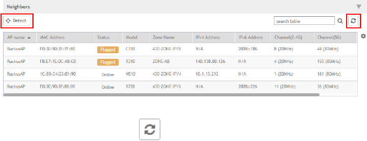
•Download Support Log - Downloads support log.
•Trigger AP Binary Log - Triggers binary log for the selected AP.
•Trigger Preferred Node - Triggers an AP that belongs to the current zone to connect to the preferred node. See Triggering a
Preferred Node on page 94.
•Download CM Support Log - Downloads Cable Momdem support log.
•Restart Cable Modem - Restarts the cable modem. The AP will disconnect from the network for a short period. The AP will
disconnect from the network for a short period.
•Reset Cable Modem - Resets the cable modem.
•Reset Cable Modem to Factory Default - Resets the cable modem to factory default settings.
•Untag Critical APs - Stating APs as non-critical. See, Tagging Critical APs on page 44.
•Swap - Swaps current AP to swap-in AP. See, Editing Swap Configuration on page 100
•Approve - Approves AP and completes registering. See, Working with AP Registration Rules on page 42.
Viewing Neighbor APs in a Non-Mesh Zone
To view neighbor APs in a Non-Mesh zone:
1. From the Access Points page, select an AP from the list which is not assigned to a Staging Zone.
2. Scroll down to the bottom of the page. In the Neighbors area, click Detect.
The list of neighboring APs are displayed in the table.
FIGURE 37 Neighbor APs for a Non-Mesh Zone
3.
To refresh the list, click the Refresh button.
Viewing AP Health Indicators
You can monitor the performance and connection failures of an AP from the Health tab page.
Performance
• Latency - It is the measurement of average delay required t successfuly deliver a Wi-Fi frame.
• Airtime Utilization - It is a measurement of airtime usage on the channel measuring the total percentage of airtime usage on the
channel.
• Capacity - It is a measuement of potential data throughput based on recent airtime efficiency and the performacne potential of the
AP and its currently connected clients.
Working With Access Points
Managing Access Points
SCG200 vSZ-H and SZ300 Administrator Guide
102 Part Number: 800-71563-001

Connection Failure
• Total - It is a measurement of unsuccessful connectivity attempts by clients.
• Authentication - It's a measurement of client connection attempts that failed at the 802.11 open authentication stage.
• Association - It is a measurement of client connection attempts that failed at the 802.11 association stage, which happens before
user/device authentication.
• EAP - It is a measuremmetn of client connection attempts that failed during an EAP exchange.
• RADIUS - It's a measurement of RADIUS exchange failures due to AAA client /server communication.
• DHCP - It's a measurement of failed IP address assignment to client devices.
To customize Health Performance settings:
1. From the Access Points page, select the required AP from the list.
2. Scroll Down and select the Health tab.
3. On the Performance bar, select the Setting icon. The Settings - Performance pop-up appears. Customize the following:
•Show top: Enter the number of performance failures to be displayed.
•Display Channel Change: Select the required options. For example: 2.4G, 5G.
•AP: Choose how the AP details must be displayed. For example: Name, MAC, IP.
4. Click OK.
Performance details of the AP are listed according to the settings.
Viewing AP Traffic Indicators
You can monitor the performance and connection failures of an AP from the Traffic tab page.
You can view:
• Historical or Real Time traffic
• WLAN traffic
Traffic indicators can be filtered based on the following parameters:
• Rate, Packets, Rate
• Total, Downlink-From AP to client, Uplink-From client to AP
To customize Traffic settings:
1. From the Access Points page, select the required AP from the list.
2. Scroll Down and select the Traffic tab.
3. On the respective section bar, select the Settings icon. The Settings - Clients pop-up appears. Customize the following:
•Type: Choose the Display format. For example: Chart, Table.
•Display Channel Change: Select the required options. For example: 2.4G, 5G.
NOTE
This field is available only for the Clients Tab when you select the Display Type as Chart.
•AP: Choose the AP display format. For example: Name, MAC, IP.
4. Click OK.
Performance details of the AP are listed according to the settings.
Working With Access Points
Managing Access Points
SCG200 vSZ-H and SZ300 Administrator Guide
Part Number: 800-71563-001 103
SCG200 vSZ-H and SZ300 Administrator Guide
104 Part Number: 800-71563-001

Working with WLANs and WLAN Groups
• Domains, Zones, AP Groups, and WLANs.............................................................................................................105
• Viewing Modes......................................................................................................................................................105
• Creating a WLAN Domain for an MSP................................................................................................................... 106
• WLAN Groups.......................................................................................................................................................106
• Creating a WLAN Configuration.............................................................................................................................107
• Managing WLANs................................................................................................................................................. 123
Domains, Zones, AP Groups, and WLANs
If your wireless network covers a large physical environment (for example, multi-floor or multi-building office) and you want to manage and
provide different WLAN services to different areas of your environment, you can virtually split them using the following hierarchy:
• Domains—Geographical grouping for regulatory operation.
• Zones—Comprises of multiple WLAN groups
• WLAN Groups—Comprises of multiple WLANs
• WLANs—Wireless network service
NOTE
In vSZ-H and SCG200, when the system is upgraded to release 3.5, the new UI and re-architected stats database will prevent the
system from displaying AP and zone stats if the AP/zone is operating on 3.4 or prior releases. In order to make full use of the UI
introduced in 3.5, zones and APs should be updated to 3.5 as well. Operationally, the zones will still work, but stats visibility will
be impacted.
Viewing Modes
The View Mode on upper-right cornerr of the page provides two options to view the WLANs available in the system:
•List—Displays the list of all WLANs irrespective of the Zone or Group they belong.
•Group—Displays the list of WLANs that belong to a specific Zone or Group.
The following WLAN details can be viewed regardless of the mode selected:
•Name
•Alert
•SSID
•Auth Method
•Encryption Method
•Clients
•Traffic
•VLAN
•Application Recognition
•Tunneled
SCG200 vSZ-H and SZ300 Administrator Guide
Part Number: 800-71563-001 105

Creating a WLAN Domain for an MSP
A Managed Services Provider (MSP) manages and assumes a defined set of responsibility. You can create an MSP managed domain, to
manage all their settings within that domain. You can also limit the number of APs per zone. Refer, Limiting the Number of APs in a Domain
or Zone
on page 45
.
To create a WLAN Domain for an MSP:
1. From the Wireless LANs Page, select System from the tree hierarchy.
2. Click the Create button, the Create Group form appears.
3. Configure the following details:
a. Enter a Name for the domain.
b. Enter a Description about the domain.
c. By default, the Type selected is Domain.
d. The Parent Group displays the group to which this domain will be tagged.
e. In Managed by Partner, select the Enable check box.
4. Click OK. You have created a new WLAN domain. In the left pane, the new MSP domain appears.
WLAN Groups
A WLAN group is a way of specifying which APs or AP groups provide which WLAN services. For example, if your wireless network covers
three floors of a building and you need to provide wireless access to visitors only on the first floor:
1. Create a WLAN service (for example, Guest Only Service) that provides guest-level access only.
2. Create a WLAN group (for example, Guest Only Group), and then assign Guest Only Service (WLAN service) to Guest Only Group
(WLAN group).
3. Assign APs on the 1st Floor (where visitors need wireless access) to your Guest Only Group.
Any wireless client that associates with APs assigned to the Guest Only Group will get the guest-level access privileges defined in your
Guest Only Service. APs on the 2nd and 3rd floors can remain assigned to the default WLAN Group and provide normal-level access.
NOTE
• WLAN groups are configured at the zone level.
• Creating WLAN groups is optional. If you do not need to provide different WLAN services to different areas in your
environment, you do not need to create a WLAN group.
• A default WLAN group called default exists. The first 27 WLANs that you create are automatically assigned to this default
WLAN group.
• A WLAN group can include a maximum of 27 member WLANs. For dual radio APs, each radio can be assigned to only
one WLAN group (single radio APs can be assigned to only one WLAN group).
Creating a WLAN Group
To create a WLAN group:
1. In the Wireless LANs page, from the System tree hierarchy, select the zone where you want to create a WLAN Group.
Working with WLANs and WLAN Groups
Creating a WLAN Domain for an MSP
SCG200 vSZ-H and SZ300 Administrator Guide
106 Part Number: 800-71563-001
2. Click the add button. The Create WLAN Group page appears.
3. Enter a Name and Description for the WLAN group.
4. From the Available WLANs list perform one of the following option:
• select the required WLAN and click the Move button. It will appear in the Selected WLANs list.
•click the add button to create a new WLAN service. The Create WLAN Configuration page appears. Refer Creating a
WLAN Configuration on page 107.
NOTE
To edit or delete a WLAN configuration, select the WLAN from the Available WLANs list and click Configure or
Delete respectively.
5. Click Next, The Create WLAN Group form appears.
6. Click OK.
NOTE
You can also edit, clone, and delete WLAN group by selecting the options Configure , Clone , and Delete respectively,
from the Wireless LANs page.
Creating a WLAN Configuration
To create a WLAN configuration:
1. In the Wireless LANs page, as shown in Figure 38, from the System tree hierarchy, select the Zone where you want to create a
WLAN.
FIGURE 38 Wireless LANs
2. Click Create, Figure 39 appears.
Working with WLANs and WLAN Groups
Creating a WLAN Configuration
SCG200 vSZ-H and SZ300 Administrator Guide
Part Number: 800-71563-001 107
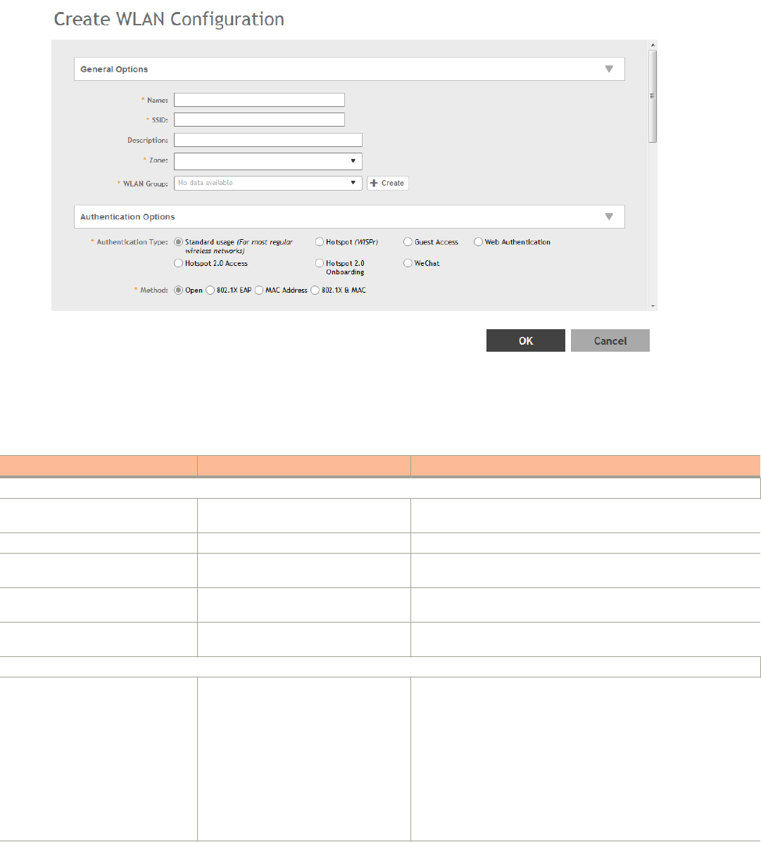
FIGURE 39 Create WLAN Configuration
3. Set the required configurations as explained in Table 16.
4. Click OK.
TABLE 16 WLAN Configurations
Field Description Your Action
General Options
Name Indicates the user-friendly administrative
name for the WLAN.
Enter a name.
SSID Indicates the SSID for the WLAN. Enter the SSID
Description Indicates a user-friendly description of
the WLAN’s settings or function.
Enter a short description.
Zone Indicates the zone to which the WLAN
configuration will applies.
Select the zone to which the WLAN settings apply.
WLAN Groups Indicates the WLAN group(s) to which the
WLAN applies.
Select the WLAN groups to which the WLAN configuration applies..
Authentication Options
Authentication Type Defines the type of authentication flow for
the WLAN.
NOTE
Authentication types such as
WeChat, Web Authentication
and Guest Access are not
supported by APs in IPv6
mode.
Select the required option:
•Standard Usage—This is a regular WLAN suitable for most
wireless networks.
•Hotspot (WISPr)—Click this option if want to use a hotspot
service (use this type for external captive portal workflows)
or WISPr.
NOTE
Hotspot (WISPr) applies to WLAN traffic that is
tunneled and not tunneled.
Working with WLANs and WLAN Groups
Creating a WLAN Configuration
SCG200 vSZ-H and SZ300 Administrator Guide
108 Part Number: 800-71563-001

TABLE 16 WLAN Configurations (continued)
Field Description Your Action
•Guest Access—Click this option if you want guest users to
use this WLAN. After you complete creating this WLAN for
guest access, you can start generating guest passes.
For more information about Hotspot 2.0 online signup, see
the Hotspot 2.0 Reference Guide for this release.
•Web Authentication—Click this option if you want to
require all WLAN users to complete a web-based logon to
this network every time they attempt to connect.
•Hotspot 2.0 Access—Click this option if you want a
Hotspot 2.0 operator profile that you previously created to
use this WLAN. See the Hotspot 2.0 Reference Guide for
this release.
•Hotspot 2.0 Onboarding—Click this option if you want to
use this WLAN for Hotspot 2.0 onboarding. See the
Hotspot 2.0 Reference Guide for this release for more
information. Hotspot 2.0 onboarding allows for Open and
802.1x EAP authentication methods.
•WeChat—Click this option if you want the WLAN usage
through WeChat.
Authentication Options
Method Specifies the authentication mechanism. Select the following option:
•Open (Default)—No authentication mechanism is applied to
connections. If WPA or WPA2 encryption is used, this
implies WPA-PSK authentication.
If you clicked Web Authentication in Authentication Type,
Open is the only available authentication option, even
though PSK-based encryption can be supported.
•802.1x EAP—A very secure authentication/encryption
method that requires a back-end authentication server,
such as a RADIUS server. Your choice mostly depends on
the types of authentication the client devices support and
your local network authentication environment. If you select
Enable RFC Location Delivery Support for Authentication &
Accounting Server, enter the Operator Realm.
Selecting the authentication method as Hotspot (WISPr),
also allows you to select 802.1x EAP as an authentication
option. This enables a two-step authentication method
when shared and pre-authenticated devices are used, or
when user equipment is shared among multiple users. The
device access is successful when both authentication
processes are completed successfully - 802.1x EAP
authentication first, followed by Hotspot (WISPr)
authentication.
•802.1x EAP with MAC address—Selecting this option
indicates that the 802.1x EAP and MAC address
authentication methods must both pass for a user to
successfully authenticate. First, MAC address
authentication is verified, if that passess, 802.1x EAP
authentication is processed. After this two authentication
methods succeed, the user equipment gains access to the
WLAN. Authentication is done by a back-end RADIUS
server.
Working with WLANs and WLAN Groups
Creating a WLAN Configuration
SCG200 vSZ-H and SZ300 Administrator Guide
Part Number: 800-71563-001 109

TABLE 16 WLAN Configurations (continued)
Field Description Your Action
When this authentication method is selected, the MAC
Authentication and MAC Address Format fields will be
shown within the Authentication Options section.
•MAC Address—Authenticate clients by MAC address.
–MAC Authentication—Requires a RADIUS server and
uses the MAC address as the user logon name and
password.
› Select Use user defined text as authentication
password (default is device MAC address) and
enter the format.
–MAC Address Format—Choose the MAC address
format from teh drop-down.
Encryption Options
Method Specifies the encryption method.
WPA and WPA2 are both encryption
methods certified by the Wi-Fi Alliance;
WPA2 with AES is the recommended
encryption method. The Wi-Fi Alliance
will be mandating the removal of WEP
due to its security vulnerabilities, and
Ruckus Wireless recommends against
using WEP, if possible.
Select the option:
•WPA2—Enhanced WPA encryption using AES encryption
algorithm.
1. Choose Algorithm:
–AES:
1. Enter Passphrase.
2. Select or clear Show.
3. Select
› the Enable 802.11 Fast BSS
Transition check box and enter the
Mobility Domain ID.
› the required 802.11w MFP option.
4. Dynamic PSK
›Disable
›Internal
? Enter DPSK Length
? Choose DPSK Type
? Select DPSK Expiration
›External—Enables Authentication
Service
–AUTO:
1. Enter Passphrase.
2. Select or clear Show.
•WPA-Mixed—Allows mixed networks of WPA and WPA2
compliant devices. Use this setting if your network has a
mixture of older clients that only support WPA and TKIP,
and newer client devices that support WPA2 and AES.
1. Choose Algorithm: AES or AUTO.
2. Enter Passphrase.
3. Select or clear Show.
4. Select Enable 802.11 Fast BSS Transition.
5. Enter the Mobility Domain ID.
6. Dynamic PSK
–Disable
–Internal
› Enter DPSK Length
› Choose DPSK Type
› Select DPSK Expiration
Working with WLANs and WLAN Groups
Creating a WLAN Configuration
SCG200 vSZ-H and SZ300 Administrator Guide
110 Part Number: 800-71563-001

TABLE 16 WLAN Configurations (continued)
Field Description Your Action
–External—Enables Authentication Service
•WEP-64 (40 bits)—Provides a lower level of encryption,
and is less secure, using 40-bit WEP encryption.
1. Choose the WEP Key.
2. Enter HEX value.
•WEP-128 (104 bits)—Provides a higher level of encryption
than WEP-64, using a 104-bit key for WEP encryption.
However, WEP is inherently less secure than WPA.
1. Choose the WEP Key.
2. Enter HEX value.
•None
Data Plane Options
Access Network Defines the data plane tunneling
behavior.
In 3.6 SCG200-C is supported. SCG200-
C is the SCG200 model without the
internal DP functions. If Ruckus GRE
tunnel is enabled, upgrade to SCG200-C
is blocked and the following message
appears: There exists a WLAN
[WLAN_NAME] under Zone
[ZONE_NAME] enable RuckusGRE
tunnel
• Select the check box to tunnel the data traffic to a central
data plane.
• Clear the check box if you want APs to perform local
breakouts.
Core Network Defines the network mode. Select the option:
•Bridge
•L2oGRE
vSZ-D DHCP/NAT Enables tunneling option for DHCP/NAT. Select the required check boxes:
•Enable Tunnel NAT
•Enable Tunnel DHCP
RADIUS based DHCP/NAT Enables RADIUS-based DHCP/NAT
settings. DHCP server authorizes remote
clients and allocates addresses based on
replies from a RADIUS server.
Select the required check boxes:
•Enable RADIUS based NAT
•Enable RADIUS based DHCP
Authentication & Accounting Server (for WLAN Authentication Type: Standard usage )
Authentication Server Specifies the server used for
authentication on this network. By
enabling Proxy, authentication requests
will flow through the controller. In a non-
proxy mode, the AP will communicate
directly with the authentication server
without going through the controller.
1. Select the check box.
2. Select the server from the drop-down menu.
3. Select the Enable RFC Location Delivery Support.
Accounting Server Specifies the server used for accounting
messages. By enabling Proxy,
accounting messages are sent by the
controller. In a non-proxy mode, the AP
will communicate accounting messages
directly.
1. Select the check box.
2. Select the server from the drop-down menu.
Hotspot Portal (for WLAN Authentication Type: Hotspot (WisPr))
Hotspot (WISPr) Portal Defines hotspot behavior, like redirects,
session timers, and location information,
among others.
Select the hotspot portal profile that you want this WLAN to use.
Working with WLANs and WLAN Groups
Creating a WLAN Configuration
SCG200 vSZ-H and SZ300 Administrator Guide
Part Number: 800-71563-001 111

TABLE 16 WLAN Configurations (continued)
Field Description Your Action
Bypass CNA Bypasses the Apple CNA feature on iOS
and OS X devices that connect to this
WLAN.
Select the Enable check box.
Authentication Service Indicates the authentication server that
you want to use for this WLAN.
Choose the option. Options include Local DB, Always Accept, and
any AAA servers that you previously added. Select:
•Use Controller as Proxy for the controller to proxy
authentication messages to the AAA server
•Use Realm-based profile to list contents form the realm-
based profile
Accounting Service Indicates the RADIUS Accounting server
that you want to use for this WLAN.
CChoose the option. You must have added a RADIUS Accounting
server previously. Select:
•Use Controller as Proxy for the controller to proxy
authentication messages to the AAA server
•Use Realm-based profile to list contents form the realm-
based profile
Guest Access Portal (for WLAN Authentication Type: Guest Access)
Guest Portal Service Indicates the guest access portal to be
used on this WLAN.
Choose the guest portal service.
Bypass CNA Bypasses the Apple CNA feature on iOS
and OS X devices that connect to this
WLAN.
Select the Enable check box.
Guest Authentication Manages guest authentication. Select:
•Guest to require users to enter their guest pass credentials.
Guest passes are managed directly on the controller.
•Always Accept to allow users without guest credentials to
authentication.
Guest Accounting Indicates the RADIUS Accounting server
that you want to use for this WLAN.
Choose the server. You must have added a RADIUS Accounting
server previously. Additionally, if you want the controller to proxy
accounting messages to the AAA server, select the Use the Controller
as Proxy check box.
Authentication & Accounting Service (for WLAN Authentication Type: Web Authentication)
Web Authentication Portal Indicates the web authentication portal to
use for this WLAN.
Choose the web authentication portal from the drop-down.
Bypass CNA Bypasses the Apple CNA feature on iOS
and OS X devices that connect to this
WLAN.
Select the Enable check box.
Authentication Service Indicates the authentication server that
you want to use for this WLAN.
Choose the option. Options include Local DB, Always Accept, and
any AAA servers that you previously added. Additionally, if you want
the controller to proxy authentication messages to the AAA server,
select the Use the Controller as Proxy check box.
Accounting Service Indicates the RADIUS Accounting server
that you want to use for this WLAN.
Choose the server. You must have added a RADIUS Accounting
server previously. Additionally, if you want the controller to proxy
accounting messages to the AAA server, select the Use the Controller
as Proxy check box.
Hotspot 2.0 Profile (for WLAN Authentication Type: Hotspot 2.0 Access)
Hotspot 2.0 Profile Indicates the profile, which includes
operator and identify provider profiles.
Choose the profile.
Authentication Service (RFC 5580) Supports RFC 5580 location delivery on
the WLAN, which carries location
information in RADIUS exchanges.
Select the check box.
Working with WLANs and WLAN Groups
Creating a WLAN Configuration
SCG200 vSZ-H and SZ300 Administrator Guide
112 Part Number: 800-71563-001

TABLE 16 WLAN Configurations (continued)
Field Description Your Action
Accounting Service (Updates) Indicate the frequency to sends interim
updates.
Configure the account update interval for
accounting servers defined in the
Hotspot 2.0 Identity Provider profile.
Enter the duration in minutes.
Range
: 0 through 1440.
WeChat Portal (for WLAN Authentication Type: WeChat)
WeChat Portal Defines the WeChat authentication URL,
DNAT destination, and other information.
Select a WeChat portal service.
Accounting Server Indicates the RADIUS Accounting server
that you want to use for this WLAN.
Choose the server. You must have added a RADIUS Accounting
server previously. Additionally, if you want the controller to proxy
accounting messages to the AAA server, select the Use the Controller
as Proxy check box.
Forwarding Profile ( for WLAN Usage > Access Network)
Forwarding Policy Defines special data packet handling to
be taken by the data plane when the
traffic is tunneled.
Forwarding Profile is Factory Default. It is disabled.
Options
Wireless Client Isolation Prevents wireless clients from
communicating with each other
Click Enable to prevent wireless clients on the same VLAN/subnet
from communicating with each other.
Isolation Whitelist Defines wired destinations on the local
subnet that can be reached, even if client
isolation is enabled.
Select the option.
NOTE
Isolation Whitelist is not applicable for tunneled WLANs
except in the vSZ-D platform.
Priority Determines high vs low transmit
preference of one WLAN compared to
another. Traffic for high priority WLAN is
always sent before low priority WLANs in
the same QoS category (background,
best effort, video, voice).
Choose the priority:
•High
•Low
RADIUS Option
NAS ID Defines the ID sent to the RADIUS server,
which will identify the AP.
Choose the option:
•WLAN BSSID
•AP MAC
•User-defined
NAS Request Timeout Indicates the duration after which an
expected RADIUS response message is
considered to have failed.
Enter the timeout period (in seconds).
NAS MAX Number of Retries Indicates the maximum number of failed
connection attempts after which the
controller will fail over to the backup
RADIUS server.
Enter the maximum number of failed connection attempts.
NAS Reconnect Primary Indicates the time interval after which the
controller will recheck if the primary
RADIUS server is available when the
controller has failed over to the backup
RADIUS server.
Enter the duration in minutes.
Range
: 1 through 60 minutes. The
default interval is 5 minutes.
Called Station ID Indicates the format for the called station
ID, which is sent to the RADIUS server as
an attribute, and can be used in policy
decision
Select a format:
•WLAN BSSID
•AP MAC
•AP GROUP
Working with WLANs and WLAN Groups
Creating a WLAN Configuration
SCG200 vSZ-H and SZ300 Administrator Guide
Part Number: 800-71563-001 113

TABLE 16 WLAN Configurations (continued)
Field Description Your Action
•NONE
Single Session ID Accounting Enabling this feature allows the APs to
maintain one accounting session for a
client roaming between APs. If the client
roams from one AP to another, the
accounting session ID and stats will be
carried while roaming from one AP to the
other. If the feature is not enabled, the
accounting session ID is re-generated
and stats is also reset, essentially
resetting the accounting session.
Select the Enable check box to use this feature.
NAS IP Indicates the NAS IP address. Select the option:
•Disabled
•SZ Control IP
•SZ Management IP
•User-defined
Advanced Options
User Traffic Profile Defines the traffic policy that will be
applied to users on this WLAN. The
default UTP allows all with no rate limits.
UTPs can define rate limits as well as
L3-7 ACLs and policies.
Select the required option.
L2 Access Control Enables the WLAN to blacklist or whitelist
a specific set of MAC addresses based
on a L2 access control policy.
Select the required option.
OS Policy Enables the WLAN to apply a unique
policy to devices based on OS type. Use
a precedence profile to determine
whether a role-based, AAA-based, or
OS-based policy will take precedence.
Select the required option.
Application Recognition and Control Enables DPI-based L7 application
recognition, and if enabled, an
application control policy. Recognition
and control are performed on the AP.
Select the Enable check box.
URL Filtering Enables URL filtering on the WLAN
controller to block or allow access to
specific web sites or web pages.
Select the Enable check box.
Client Fingerprinting Enables the AP to attempt utilize DHCP
fingerprinting to identify client devices by
their operating system, device type, and
host name.
Select the check box.
Access VLAN Tags the WLAN traffic with a VLAN ID
between 2-4094. By default, all client
traffic will be assigned to the native
(untagged) VLAN on the AP's Ethernet
port, which we represent as VLAN ID 1.
Select the check box and enter the VLAN ID.
Hotspot 2.0 Onboarding Allows devices to connect to a WiFi
network automatically, where in the
service providers engage in roaming
partnerships to provide seamless access
to WiFi networks. The devices are
authenticated using credentials or
certificates.
Select the check box to allow Hotspot 2.0 Onboaring for the WISPr
WLAN.
Working with WLANs and WLAN Groups
Creating a WLAN Configuration
SCG200 vSZ-H and SZ300 Administrator Guide
114 Part Number: 800-71563-001

TABLE 16 WLAN Configurations (continued)
Field Description Your Action
Hide SSID Removes the SSID from beacon frames.
By removing the SSID, in most cases,
clients will not show this SSID in their
scan list unless the device is already
configured to connect. This can simplify
the network decision for an end user.
Select the check box.
Client Load Balancing Disables client load balancing on this
WLAN if the option is selected.
Select the check box to disable client load balancing on this WLAN.
Proxy ARP Enables proxy ARP. When proxy ARP is
enabled on a WLAN, the AP provides
proxy service for stations when receiving
neighbor discovery packets (for example,
ARP request and ICMPv6 Neighbor
Solicit messages), and acts on behalf of
the station in delivering ARP replies.
When the AP receives a broadcast ARP/
Neighbor Solicit request for a known
host, the AP replies on behalf of the host.
If the AP receives a request for an
unknown host, it forwards the request.
Select the check box.
MAX Clients Limits the number of clients that can
associate with this WLAN per AP radio
(default is 100). Every connection attempt
after this max value will not be permitted
to connect.
Enter the number of clients allowed.
802.11d Adds additional regulatory information to
AP beacons and probe responses. This
compliance information provides country-
specific guidance like permitted channels
and transmit power, to ensure that the
devices operate within the legal
boundaries of the country. 11d is helpful
for many devices that cannot
independently determine their operating
country.
Select the check box to enable this option.
802.11k Neighbor Report Enhances roaming by providing a list of
neighbor APs to the client device. APs
build a neighbor AP list via background
scanning, and when the client plans to
roam, it will request this list from the AP.
This list is then used to perform efficient
scanning to find a roaming candidate.
Select the check box.
Force DHCP Requires the clients to obtain a valid IP
address from DHCP within the specified
number of seconds. This prevents clients
configured with a static IP address from
connecting to the WLAN. Additionally, if a
client performs Layer 3 roaming between
different subnets, in some cases the
client sticks to the former IP address.
This mechanism optimizes the roaming
experience by forcing clients to request a
new IP address.
Select the check box.
DHCP Option 82 Enables an AP to encapsulate additional
information (such as VLAN ID, AP name,
SSID and MAC address) into the DHCP
Select the check box.
Working with WLANs and WLAN Groups
Creating a WLAN Configuration
SCG200 vSZ-H and SZ300 Administrator Guide
Part Number: 800-71563-001 115

TABLE 16 WLAN Configurations (continued)
Field Description Your Action
request packets before forwarding them
to the DHCP server. The DHCP server
can then use this information to allocate
an IP address to the client from a
particular DHCP pool based on these
parameters.
DHCP Option 82 Format Enables an AP to encapsulate additional
information (such as VLAN ID, AP name,
SSID and MAC address) into the DHCP
request packets before forwarding them
to the DHCP server. The DHCP server
can then use this information to allocate
an IP address to the client from a
particular DHCP pool based on these
parameters.
Choose the required option:
•Default
•Option-A
•Option-B
DTIM Interval Indicates the frequency at which the
DTIM (Delivery Traffic Indication Message)
will be included in Beacon frames.
Enter the frequency number.
Range: 1 through 255.
Directed MC/BC Threshold Defines the per radio client count at
which an AP stops converting group-
addressed data traffic to unicast.
However, the Directed Threshold logic is
only one part of the access points'
multicast handling logic, which means
there may be other factors that determine
whether a frame is transmitted as unicast
or multicast. APs support a feature called
Directed Multicast (configurable only on
AP CLI, enabled by default), which adds
additional logic to the multicast flow. If
Directed Multicast is disabled, the AP
uses the Directed Threshold as the only
criteria to determine whether to transmit
a multicast packet as unicast. However,
when Directed Multicast is enabled, the
flow is changed. Directed Multicast is a
feature that checks to see if a multicast
packet is well-known or not. For well-
known multicast packets, for example:
Bonjour, uPNP, most IPv6 link- and node-
local, Spectralink, the AP still applies the
directed-threshold logic to determine
conversion to unicast. For non well-
known types, the AP monitors and
maintains a database of client
subscriptions using IGMP and MLD. If
associated clients are subscribed to the
multicast stream, then the AP always
converts these packets to unicast,
regardless of the Directed Threshold
configuration. If there are no clients
subscribed to the multicast stream, the
AP drops these packets. It is important
to be aware of this behavior when
validating multicast operation in a
deployment.
Enter the client count number.
Range: 0 through 128.
Client tx/Rx Statistics Stops the controller from monitoring
traffic statistics for unauthorized clients.
Select the check box.
Working with WLANs and WLAN Groups
Creating a WLAN Configuration
SCG200 vSZ-H and SZ300 Administrator Guide
116 Part Number: 800-71563-001

TABLE 16 WLAN Configurations (continued)
Field Description Your Action
Inactivity Timeout Indicates the duration after which idle
clients will be disconnected.
Enter the duration in seconds.
OFDM Only Disconnects 802.11b devices from the
WLAN and all devices are forced to use
higher data rates for more efficient airtime
usage. This setting only affects the
2.4GHz radio. OFDM is used by
802.11a/g/n/ac, but is not supported by
802.11b.
Select the check box.
BSS Min Rate Forces client devices to both be closer to
the AP and to use higher, more efficient
rates when you increase the BSS min
rate above the default (all rates) setting.
The BSS minimum rate is the lowest data
rate supported on the WLAN. When
OFDM-only is enabled, it takes higher
priority than BSS min rate settings.
Select the option.
Mgmt Tx Rate Sets the transmit rate for management
frames type such as beacon and probes.
Select the value.
Service Schedule Controls when the WLAN service is
active. The purpose of this setting is to
automatically enable or disable a WLAN
based on a pre-determined schedule. By
default, the service is Always On. Always
Off can be checked in order to create a
WLAN and apply it, but prevent it from
advertising until ready. The"specific"
setting allows a configurable schedule
based on time of day and days of the
week.
NOTE
When a service schedule is
created it is saved by the SZ
and AP using the browser's
time zone. When it is
enforced bu the AP, the AP
will enforce it according to
the time zone of the browser
when it was configured.
Choose the option:
•Always On
•Always Off
•Specific and select a schedule profile from the drop-down
list.
Band Balancing Disables band balancing only for this
WLAN, if you select the check box.
Select the Disable band balancing for this WLAN service check box.
Qos Map Set Reprioritizes downlink packets based on
the configured mappings. When an AP
receives a downlink packet, it checks the
existing DSCP (L3 QoS) marking,
compares it to this map set and then
changes the user priority (L2 QoS) values
for transmission by the AP.
To configure this feature, select the User
Priority (UP) from the table (0-7) and
configure the DSCP (0-64) range that will
be mapped to this UP.
Select Enable QOS Map Set.
Working with WLANs and WLAN Groups
Creating a WLAN Configuration
SCG200 vSZ-H and SZ300 Administrator Guide
Part Number: 800-71563-001 117

TABLE 16 WLAN Configurations (continued)
Field Description Your Action
Exceptions can also be added such that
the original DSCP and UP tagging are
preserved the honored by the AP.
SSID Rate Limiting Enforces an aggregate rate limit for all
users of the WLAN. The purpose of this
feature is to prevent the combined
throughput form all users of an SSID from
exceeding this threshold. This feature is
different from per-user rate limiting, which
enforces the same rate limit for each
individual device.
Select Uplink and Downlink check boxes and enter the limiting rate in
mbps respectively.
Range
: 1 mbps through 200 mbps.
DNS Server Profile Allows the AP to inspect DHCP
messages and overwrite the DNS
server(s) with the DNS server configured
in this profile. This allows for policy-based
DNS application in which unique users/
roles should use a different DNS server
than others.
Select a profile from the drop-down menu. Select Disable from the
drop-down menu if you want to disable the DNS Server profile for the
WLAN service.
Precedence Profile Defines the relative policy assignment
priority for some specific settings. For
example, if a WLAN is configured to use
VLAN 10, and a AAA/role policy is
configured for VLAN 20, and a device OS
policy is configured for VLAN 30, and a
user/device connects to the WLAN
matching all of these policies, which
VLAN should be assigned. The
precedence policy determines which
setting takes priority.
Select the option.
CALEA (This feature is supported only
for SZ300 controllers)
Intercepts traffic, a requirement enforced
on some networks by government
agencies. To utilize CALEA, you must
support a vSZ-D and configure the
CALEA settings in the Services & Profiles
> Tunnels & Ports menu.
Select the check box.
Client Flow Data Logging Sends a log message with source MAC,
destination MAC, source IP, destination
IP, source port, destination port, L4
protocol and AP MAC of each packet
session to the external syslog server. This
function is provided by the AP syslog
client (not the SZ's syslog client), which
must be enabled at the zone level in
order to support this client flow logging.
Select the check box to log the client-flow data to the external syslog
server. Then enable AP syslog functionality from the Zone settings.
For SCG200, SZ300 and vSZ-H, you can also migrate the WLAN configuration from a regular Domain to a Partner Domain. For more
information, see https://support.ruckuswireless.com/answers/000006414
NOTE
You can also edit, clone and delete WLANs by selecting the options Configure, Clone and Delete respectively, from the Wireless
LANs page.
Working with WLANs and WLAN Groups
Creating a WLAN Configuration
SCG200 vSZ-H and SZ300 Administrator Guide
118 Part Number: 800-71563-001
802.11 Fast BSS Transition
802.11r Fast BSS Transition is a fast roaming protocol that reduces the number of frame exchanges required for roaming and allows the
clients and APs to reuse the master keys obtained during a prior authentication exchange. 11r is most helpful for 802.1X networks. Client
support is required for 11r to work.
802.11w MFP
802.11w Management Frame Protection provides additional security measures for management frames. Not all client devices support
802.11w.
Check your client devices before enabling 11w. If “Required” is selected, clients must support 11w in order to connect. If “Capable” is
selected, clients with or without 11w should be able to connect. However, note that some clients with poor driver software may have
connection problems even if 11w is set to Capable.
Band Balancing
Band balancing balances the client load on radios by distributing clients between the 2.4 GHz and 5 GHz radios.
This feature is enabled by default and set to a target of 25% of clients connecting to the 2.4 GHz band. To balance the load on a radio, the
AP encourages dual-band clients to connect to the 5 GHz band when the configured percentage threshold is reached.
Bypassing Apple CNA
Some Apple® iOS and OS X® clients include a feature called Captive Network Assistant (CNA), which allows clients to connect to an open
captive portal WLAN without displaying the logon page.
When a client connects to a wireless network, the CNA feature launches a pre-browser login utility and it sends a request to a success
page on the Apple® website. If the success page is returned, the device assumes it has network connectivity and no action is taken.
However, this login utility is not a fully functional browser, and does not support HTML, HTML5, PHP or other embedded video. In some
situations, the ability to skip the login page for open WLANs is a benefit. However, for other guest or public access designs, the lack of
ability to control the entire web authentication process is not desirable.
The controller provides an option to work around the Apple® CNA feature if it is not desirable for your specific deployment. With CNA
bypass enabled, captive portal (web-based authentication) logon must be performed by opening a browser to any unauthenticated page
(HTTP) to get redirected to the logon page.
Channel Mode
Channel mode is a method of statistically picking the most potent channel for an AP.
Some countries restrict certain 5GHz channels to indoor use only. For instance, Germany restricts channels in the 5.15GHz to 5.25GHz
band to indoor use. When ZoneFlex Outdoor APs and Bridges with 5GHz radios (ZoneFlex 7762, 7762-S, 7762-T, 7761-CM and 7731) are
set to a country code where these restrictions apply, the AP or Bridge can no longer be set to an indoor-only channel and will no longer
select from amongst a channel set that includes these indoor-only channels when SmartSelect or Auto Channel selection is used, unless
the administrator configures the AP to allow use of these channels.
For instance, if the AP is installed in a challenging indoor environment (such as a warehouse), the administrator may want to allow the AP to
use an indoor-only channel. These channels can be enabled for use through the AP CLI or the controller web interface.
Working with WLANs and WLAN Groups
Creating a WLAN Configuration
SCG200 vSZ-H and SZ300 Administrator Guide
Part Number: 800-71563-001 119
Client Admission Control
Client admission control allows APs to adaptively allow or deny the association of clients based on the potential throughput of the currently
associated clients. This helps prevent APs from becoming overloaded with clients and improves user experience for wireless users.
As an administrator, you can help maintain a positive user experience for wireless users on the network by configuring the following client
admission control settings:
• Minimum client count
• Maximum radio load
• Minimum client throughput
Client admission control is implemented on a per radio basis and is supported on 802.11n and 802.11ac APs.
Client Load Balancing
Enabling load balancing can improve WLAN performance by helping to spread the wireless client load between nearby access points, so
that one AP does not get overloaded while another sits idle.
The load balancing feature can be controlled from within the controller web interface to balance the number of clients per radio on adjacent
APs.
Adjacent APs are determined by the controller at startup by measuring the RSSI during channel scans. After startup, the controller uses
subsequent scans to update the list of adjacent radios periodically and when a new AP sends its first scan report. When an AP leaves, the
controller immediately updates the list of adjacent radios and refreshes the client limits at each affected AP.
Once the controller is aware of which APs are adjacent to each other, it begins managing the client load by sending the configured client
limits to the APs. These limits are soft values that can be exceeded in several scenarios, including:
• When a client's signal is so weak that it may not be able to support a link with another AP
• When a client's signal is so strong that it really belongs on this AP.
The APs maintain these configured client limits and enforce them once they reach the limits by withholding probe responses and
authentication responses on any radio that has reached its limit.
Key Points About Client Load Balancing
Before you enable load balancing, keep the following considerations in mind:
• The load balancing rules apply only to client devices; the AP always responds to another AP that is attempting to set up or
maintain a mesh network.
• Load balancing does not disassociate clients already connected.
• Load balancing takes action before a client association request, reducing the chance of client misbehavior.
• The process does not require any time-critical interaction between APs and the controller.
• Provides control of adjacent AP distance with safeguards against abandoning clients.
• Can be disabled on a per-WLAN basis. For instance, on a voice WLAN, load balancing may not be desired due to voice roaming
considerations.
• Background scanning must be enabled on the WLAN for load balancing to work.
Mobility Domain ID
A Mobility Domain ID is used by 802.11r to define a scope of the network in which an 11r fast roam is supported. Master keys are shared
within the Mobility Domain, allowing clients to support a fast roam.
Working with WLANs and WLAN Groups
Creating a WLAN Configuration
SCG200 vSZ-H and SZ300 Administrator Guide
120 Part Number: 800-71563-001
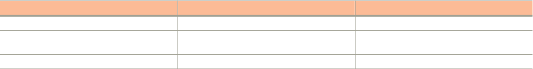
Portal-based WLANs
There are many types of portal-based WLANs and they can be distinguished based on where the user credentials are stored, and where
the portal page is hosted.
TABLE 17 Portal-based WLANs
WLAN Type User Credential Portal on which WLAN is Hosted
Guest Guest passes on the controller AP
Hotspot (WISPr) RADIUS server. LDAP/Active Directory from
SmartZone release 3.2 and later
External portal server or internal portal on the
controller
Web Auth RADIUS/LDAP/Active Directory AP
Guest and WebAuth WLAN portals are hosted on the controller AP with limited customization. WISPr WLANs are usually hosted on external
portal servers providing the flexibility to customize. WISPr WLANs allow for sophisticated customization such as providing a customized
login page which could include locale information, advertisements etc.
WISPr WLANs can also be configured to bypass the authentication portal such that if an end user device’s MAC address (as a credential) is
stored on a RADIUS server, there is no need to redirect the end user to the portal server for authentication.
Characteristics of portal-based WLANs
Portal-based WLANs have the following characteristics:
• WebAuth WLAN
– Does not provide and option to modify the portal (WYSIWYG)
– User authentication is done by the RADIUS server, LDAP and Active Directory
– Allows redirecting user web pages
• Guest WLAN
– Provides and option to modify the portal elements such as the logo, Terms and Conditions, title etc
– User authentication is by using guest passphrases or select the Always Accepted option
– Allows redirecting user web pages
– Does not posses a local database, LDAP, Active Directory or RADIUS server
• Hotspot (WISPr) WLAN
– Internal Portal
› Provides and option to modify the portal elements such as the logo, Terms and Conditions, title etc
› Allows redirecting user web pages
› User authentication is by the local database, LDAP, Active Directory, RADIUS server or rendered by selecting the Always
Accepted option
› Supports the Walled Garden approach to allow user access to specific areas within the network
– External Portal
› Allows customization of the portal pages through external services
› Supports Northbound Portal Interface for authentication
› User authentication is by the local database, LDAP, Active Directory, RADIUS server or rendered by selecting the Always
Accepted option
› Supports the Walled Garden approach to allow user access to specific areas within the network
› Allows redirecting user web pages
Working with WLANs and WLAN Groups
Creating a WLAN Configuration
SCG200 vSZ-H and SZ300 Administrator Guide
Part Number: 800-71563-001 121

Rate Limiting Ranges for Policies
You can define and apply rate limit values for user devices to control the data rate and types of network traffic the device transmits.
NOTE
For SmartZone release 3.4 and 3.2.x, the APs support the following rate limiting values:
• 0.10Mbps
• 0.25Mbps - 20.00Mbps (increments by 0.25Mbps)
• 21.00Mbps - 200.00Mbps (increments by1.00mpbs)
For example, typing 6.45 Mbps maps to the closest predefined rate value, so 6.45Mbps will be rendered as 6.50Mbps.
NOTE
For SmartZone release 3.1.x, the APs support the following rate limiting values:
• 0.10Mbps
• 0.25Mbps - 20.00Mbps (increments by 0.25Mbps)
• 30.00Mbps
• 40.00Mbps
• 50.00Mbps
For example, typing 31.50 Mbps maps to the closest predefined rate value, so 31.50 Mbps will be rendered as 40 Mbps. Any rate
greater than 50.00Mbps would be mapped to the maximum rate which is 50.00Mbps.
TABLE 18 Rate Limiting ranges for different controller policies
Policy Global or Zone Rate limit range for zone
running SmartZone 3.4
Rate limit range for zone running
SmartZone 3.2.x
Rate limit range for zone running
SmartZone 3.1.x
Device Policy Zone 0.1 Mbps to 200 Mbps
Support uni-direction (Uplink
and Downlink need not be
enabled or disabled at the
same time)
0.1 Mbps to 200 Mbps
No support for uni-direction
(Uplink and Downlink need not be
enabled or disabled at the same
time)
0.1 Mbps to 200 Mbps. But any rate
greater than 50Mbps will be mapped
to 50 Mbps implicitly on the AP side
when the rate is applied.
No support for uni-direction
User Traffic Profile Global 0.1 Mbps to 200 Mbps
No support for uni-direction
because this is Global profile
that is used by 3.2.x and 3.1.x
APs
0.1 Mbps to 200 Mbps
No support for uni-direction
But any rate greater than 50Mbps will
be mapped to 50 Mbps implicitly on
the AP side when the rate is applied.
No support for uni-direction
Working with WLAN Schedule Profiles
A WLAN schedule profile specifies the hours of the day or week during which a WLAN service will be enabled or disabled.
For example, a WLAN for student use at a school can be configured to provide wireless access only during school hours. Create a WLAN
schedule profile, and then when you configure a WLAN, select the schedule profile to enable or disable the WLAN service during those
hours/days.
NOTE
This feature will not work properly if the system does not have the correct time. To ensure that the system always maintains the
correct time, configure an NTP server and point the system to the NTP server's IP address, as described in Configuring System
Time on page 34.
Working with WLANs and WLAN Groups
Creating a WLAN Configuration
SCG200 vSZ-H and SZ300 Administrator Guide
122 Part Number: 800-71563-001

NOTE
WLAN service schedule times should be configured based on your browser's current timezone. If your browser and the target AP/
WLAN are in different timezones, configure the on/off times according to the desired schedule according to your local browser.
For example if you wanted a WLAN in Los Angeles to turn on at 9 AM and your browser was set to New York time, please
configure the WLAN service schedule to enable the WLAN at noon. When configuring the service schedule, all times are based on
your browser's timezone setting.
Creating a WLAN Schedule Profile
Follow these steps to create a WLAN schedule profile.
1. From the Wireless LANs page, select the WLAN for you want to create a WLAN Schedule profile.
2. Click Configure, the Edit WLAN Config page appears.
3. Scroll down to the Advanced Options section.
4. In the Service Schedule field, select Specific.
5. Click Create, the Create Time Schedules Table form appears.
6. In General Options, enter the Schedule Name and Schedule Description.
7. To set a WLAN schedule:
• To enable or disable the WLAN for an entire day, click the day of the week under the Time column.
• To enable or disable the WLAN for specific hour of a specific day, click the squares in the table. A single square represents 30
minutes (two-15 minute blocks).
Blue-colored cells indicate the hours when the WLAN is enabled. Clear (or white) cells indicate the hours when the WLAN is
disabled.
8. Click Create, the page refreshes, and then the schedule you created appears in the drop-down list.
Managing WLANs
When you select a System, Domain, Zone, or WLAN Group from the hierarchy tree, respective contextual tabs appear at the bottom of the
page.
These tabs are used to monitor the selected group. Table 19 lists the tabs that appear for System, Domain, Zone, and WLAN Group.
TABLE 19 System/Domain/Zone/WLAN Groups Monitoring Tabs
Tabs Description System Domain Zone WLAN Groups
Configuration Displays the respective configuration information. Yes Yes Yes Yes
Traffic Displays the respective historical traffic information. Yes Yes Yes Yes
Alarm Displays the respective alarms information. See
Managing Events and Alarms on page 297.
Yes Yes Yes Yes
Event Displays the respecftive event information. See
Managing Events and Alarms on page 297.
Yes Yes Yes Yes
APs Displays the respective AP information. See Managing
Access Points on page 97.
Yes Yes Yes NA
Clients Displays the respective client information. Refer
Managing Clients.
Yes Yes Yes NA
Working with WLANs and WLAN Groups
Managing WLANs
SCG200 vSZ-H and SZ300 Administrator Guide
Part Number: 800-71563-001 123
TABLE 19 System/Domain/Zone/WLAN Groups Monitoring Tabs (continued)
Tabs Description System Domain Zone WLAN Groups
Services Displays the respective Services information. See
Services and Profiles on page 161.
Yes Yes Yes NA
Administrators Displays the respective administrator account
information. See Administering the Controller on page
271.
Yes NA NA NA
When you can select a Zone and click More you can perform the following operations:
•Move
•Extract WLAN Template
•Apply WLAN Template
•Change AP Firmware
•Switchover Cluster
•Trigger Preferred Node
Moving a Single WLAN to a Different WLAN Zone
Follow these steps to move a single access point from its current AP zone to a different one.
NOTE
The WLAN that you move will inherit the configuration of the new WLAN zone.
• From the Wireless LANs page, locate the WLAN zone that you want to move to a different WLAN zone.
• Click More and select Move, the Select Destination Management Domain dialog box appears.
• Select the destination WLAN zone.
• Click OK, a confirmation message appears.
• Click Yes. The WLAN zone is moved to the destination location.
Extracting a WLAN Template
You can extract only WLAN-related configuration of an AP to a WLAN template.
Follow these steps to extract a WLAN template:
1. From the Wireless LANs page, locate the zone from where you want to extract the WLAN template.
2. Click More and select Extract WLAN Template, the Extract WLAN Template form appears.
3. In WLAN Template Name, enter a name for the Template.
4. Click OK, a message appears stating that the WLAN template was extracted successfully.
5. Click OK. You have completed moving an access point to a new AP zone.
The extracted WLAN template can be viewed under System > Templates > WLAN Templates.
Working with WLANs and WLAN Groups
Managing WLANs
SCG200 vSZ-H and SZ300 Administrator Guide
124 Part Number: 800-71563-001
Applying a WLAN Template
You can apply only WLAN-related configuration to an AP zone using a WLAN template.
Follow these steps to apply a WLAN template:
1. From the Wireless LANs page, locate the zone where you want to apply the WLAN template.
2. Click More and select Apply WLAN Template, the Apply WLAN Template dialog box appears.
3. From the Select a WLAN template drop-down, select the template.
4. Click OK, a confirmation message appears asking to apply the wlan templates to the zone.
5. Click Yes, a confirmation message appears stating the template was applied successfully.
You have completed applying WLAN template to the AP zone.
Triggering a Preferred Node
You an trigger an AP that belongs to the current zone force go to their preferred node. For this, you must enable Node affinity, which gives
AP the priority of preferred nodes.
Follow these steps to trigger a node:
NOTE
You must enable node affinity before triggering nodes.
1. From the Wireless LANs page, locate the zone.
2. Click More and select Trigger Preferred Node, a confirmation dialog box appears.
3. Click OK. You have triggered the nodes in the AP zone.
Working with WLANs and WLAN Groups
Managing WLANs
SCG200 vSZ-H and SZ300 Administrator Guide
Part Number: 800-71563-001 125
SCG200 vSZ-H and SZ300 Administrator Guide
126 Part Number: 800-71563-001
Managing Clients
• Working with Wireless Clients................................................................................................................................127
• Working with Wired Clients....................................................................................................................................130
• Working with Users and Roles...............................................................................................................................131
• Working with Guest Passes...................................................................................................................................137
• Working with Dynamic PSKs................................................................................................................................. 150
Working with Wireless Clients
Wireless clients are client devices that are connected to the wireless network services that your managed APs provide. Wireless clients can
include smart phones, tablets, and notebook computers equipped with wireless network adapters.
Viewing a Summary of Wireless Clients
View a summary of wireless clients that are currently associated with all of your managed access points.
Go to Clients > Wireless Clients. The Wireless Clients page appears and displays a table that lists all clients that are currently associated
with your managed access points.
To view only wireless clients that belong to a particular zone, click the zone name in the zone tree. The table refreshes and displays only the
clients that belong to the zone you selected.
The following table lists the wireless client details.
NOTE
Not all of the columns listed below are displayed by default. To display column that are currently hidden, click the gear icon in the
upper-right corner of the table, and then select the check boxes for the columns that you want to display.
You can view the clients listed in the table in two view modes - No TTG (without TTG) and TTG (with TTG).
Click the icon to export all the data into a CSV file.
TABLE 20 Wireless client details
Column Name Description
Hostname Displays the hostname of the wireless client
OS Type Displays the operating system that the wireless client is using
IP Address Displays the IP address assigned to the wireless client
MAC Address Displays the MAC address of the wireless client
WLAN Displays the name of the WLAN with which the client is associated
AP Name Displays the name assigned to the access point
AP MAC Displays the MAC address of the AP
Traffic (Session) Displays the total traffic (in KB/MB/GB/TB) for this client in this session
Traffic (Uplink) Displays the total uplink traffic (in KB/MB/GB/TB) for this client in this session
Traffic (Downlink) Displays the total downlink traffic (in KB/MB/GB/TB) for this client in this session
SCG200 vSZ-H and SZ300 Administrator Guide
Part Number: 800-71563-001 127
TABLE 20 Wireless client details (continued)
Column Name Description
RSSI Displays the Received Signal Strength Indicator (RSSI), which indicates how well a wireless client can receive a
signal from an AP. The RSSI value is shown in decibels (dB) and displayed as either the real-time value or the
average value over the past 90 seconds.
SNR Displays the Signal-to-Noise Ratio (SNR), which indicates the signal strength relative to background noise. The SNR
value is shown in decibels (dB) and displayed as either the real-time value or the average value over the past 90
seconds.
Radio Type Displays the type of wireless radio that the client supports. Possible values include 11b, 11g, 11g/n, 11a, 11a/g/n,
and 11ac.
VLAN Displays the VLAN ID assigned to the wireless client
Channel Displays the wireless channel (and channel width) that the wireless client is using
User Name Displays the name of the user logged on to the wireless client
Connected Since Displays the time from which the AP is connected to the wireless client
# of Events Displays the number of client events
Data Rate (Up) Displays the rate at which data is transmitted from the wireless client to the AP
Data Rate (Down) Displays the rate at which data is transmitted from the AP to the wireless client
Auth Method Displays the authentication method used by the AP to authenticate the wireless client
Auth Status Indicates whether the wireless client is authorized or unauthorized to access the WLAN service
Encryption Displays the encryption method used by the AP
Control Plane Displays the name of SmartZone node to which the AP's control plane is connected
Packets to Displays the downlink packet count for this session
Packets from Displays the uplink packet count for this session
Packets dropped Displays the downlink packet count for this client that have been dropped
Viewing Information about a Wireless Client
You can view more information about a wireless client, including its IP address, MAC address, operating system, and even recent events
that have occurred on it.
Follow these steps to view information about a wireless client.
1. Go to Clients > Wireless Clients.
2. From the list of wireless clients, locate the client whose details you want to view.
3. Under the MAC Address column, click the MAC address of the wireless client.
The Associated Client page appears and displays general information about the wireless client.
• General: Displays general client information.
• Health: Displays information about the real-time health of the client. It displays graphical trends based on the signal-to-noise
ratio (SNR) and data rate. You can use the Start and Stop option to review client health at real time.
•Traffic: Displays historical and real-time traffic information.
• Event: Displays information about events associated with the client.
Managing Clients
Working with Wireless Clients
SCG200 vSZ-H and SZ300 Administrator Guide
128 Part Number: 800-71563-001
Deauthorizing a Wireless Client
If you want to force wireless clients that joined the wireless network through an authentication portal (for example, a hotspot, guest access
or web authentication portal) to reauthenticate themselves, you can deauthorize them. Deauthorized wireless clients remain connected to
the wireless network, but these clients will be redirected to the authentication portal whenever they attempt to access network resources.
Follow these steps to deauthorize a wireless client.
1. On the menu, click Clients > Wireless Clients.
2. From the list wireless clients, locate the client that you want to deauthorize. If you have a large number of wireless clients and you
know the MAC address of the client, enter the MAC address in the search box, and then press Enter to search for the client.
3. When you have located the client, select it, and then click the Deauthorize button above the table.
The table refreshes, and then the client that you deauthorized disappears from the list.
Blocking a Wireless Client
When a user associates a wireless client device with an AP that the controller is managing, the client device is recorded and tracked. If, for
any reason, you need to block a client device from accessing the network, you can do so from the web interface.
A few reasons why you might consider blocking a wireless client device include:
• Network abuse
• Violation of acceptable use policy
• Theft
• Security compromise
Follow these steps to block a wireless client from accessing the SmartZone network.
1. On the menu, click Clients > Wireless Clients.
2. From the list wireless clients, locate the client that you want to block. If you have a large number of wireless clients and you know
the MAC address of the client, enter the MAC address in the search box, and then press <Enter> to search for the client.
3. When you have located the client, select it, and then click the Block button above the table.
You have completed blocking a wireless client.
Unblocking a Wireless Client
If you want to allow a client that you previously blocked to access the SmartZone network, you can unblock it.
Follow these steps to unblock a wireless client.
1. On the menu, click Services and Profiles > Access Control.
2. Click the Blocked Client tab.
3. From the list of blocked clients, locate the client that you want to unblock. If you have a large number of blocked clients and you
know the MAC address of the client, enter the MAC address in the search box, and then press <Enter> to search for the client.
4. When you have located the client, select it, and then click the Delete button above the table.
The table refreshes, and then the client that you want to unblock disappears from the list.
You have completed unblocking a wireless client.
Managing Clients
Working with Wireless Clients
SCG200 vSZ-H and SZ300 Administrator Guide
Part Number: 800-71563-001 129
Disconnecting a Wireless Client
If you need to temporarily disconnect a wireless client from the wireless network, you can do so from the web interface. For example, if you
are troubleshooting problematic network connections, you might have to manually disconnect wireless clients as part of the troubleshooting
process.
Follow these steps to disconnect a wireless client from the WLAN to which it is connected.
1. On the menu, click Clients > Wireless Clients.
2. From the list wireless clients, locate the client that you want to disconnect. If you have a large number of wireless clients and you
know the MAC address of the client, enter the MAC address in the search box, and then press <Enter> to search for the client.
3. When you have located the client, select it, and then click the Disconnect button above the table.
The table refreshes, and then the client that you disconnected disappears from the list.
Working with Wired Clients
Wired clients are client devices that are connected to the Ethernet ports of APs managed by the controllers, and thereby are connected to
the wired network services that your managed APs provide.
Viewing a Summary of Wired Clients
View a summary of wired clients that are currently associated with all of your managed access points.
Go to Clients > Wired Clients. The Wired Clients page appears and displays a table that lists all clients that are currently associated with
your managed access points.
To view only wired clients that belong to a particular zone, click the zone name in the zone tree. The table refreshes and displays only the
clients that belong to the zone you selected.
The following table lists the wired client details.
TABLE 21 Wired client details
Column Name Description
MAC Addres Displays the MAC address of the wired client
Username Displays the name of the user logged on to the wire client
IP Address Displays the IP address assigned to the wired client
AP MAC Displays the MAC address of the AP
AP Name Displays the name assigned to the access point
LAN Displays the LAN ID assigned to the wired client
VLAN Displays the VLAN ID assigned to the wired client
Auth Status Indicates whether the wired client is authorized or unauthorized to access the WLAN service
Viewing Information about a Wired Client
You can view more information about a wired client, including its IP address, MAC address and even recent events that have occurred on it.
Follow these steps to view information about a wired client.
1. Go to Clients > Wired Clients.
Managing Clients
Working with Wired Clients
SCG200 vSZ-H and SZ300 Administrator Guide
130 Part Number: 800-71563-001
2. From the list of wired clients, locate the client whose details you want to view.
3. Under the MAC Address column, click the MAC address of the wired client.
The Associated Client page appears and displays general information about the wired client.
• General: Displays general client information.
• Event: Displays information about events associated with the client.
Deauthorizing a Wired Client
If you want to force wired clients that joined the wired network through an authentication portal to reauthenticate themselves, you can
deauthorize them. Deauthorized wired clients remain connected to the wired network, but these clients will be redirected to the
authentication portal whenever they attempt to access network resources.
Follow these steps to deauthorize a wired client.
1. On the menu, click Clients > Wired Clients.
2. From the list wired clients, locate the client that you want to deauthorize. If you have a large number of wired clients and you know
the MAC address of the client, enter the MAC address in the search box, and then press Enter to search for the client.
3. When you have located the client, select it, and then click the Deauthorize button above the table.
The table refreshes, and then the client that you deauthorized disappears from the list.
Working with Users and Roles
The controller provides a default role (named Default) that is automatically applied to all new user accounts.
By default, this role links all users to the internal WLAN and permits access to all WLANs. As an alternative, you can create additional roles
that you can assign to select wireless network users, to limit their access to certain WLANs, to allow them to log on with non-standard
client devices, or to grant permission to generate guest passes. (You can then edit the default role to disable the guest pass generation
option.)
Creating a User Role
Use user roles to limit user access to certain WLANs, to allow them to log on with non-standard client devices.
Follow these steps to create a user role.
1. Go to Clients > Users & Roles.
2. Select the User Roles tab, and then select the zone for which you want to create the role.
Managing Clients
Working with Users and Roles
SCG200 vSZ-H and SZ300 Administrator Guide
Part Number: 800-71563-001 131
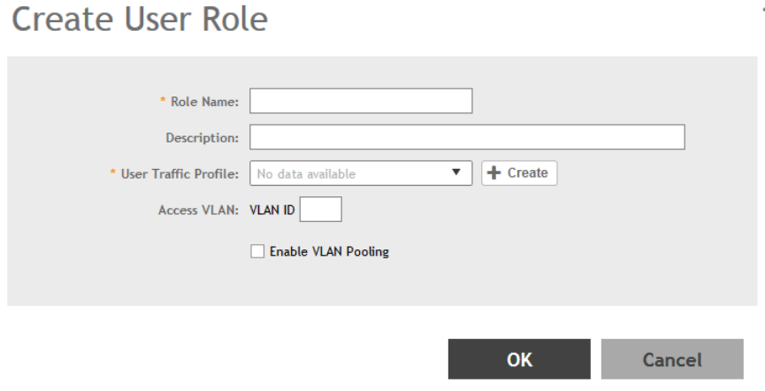
3. Click Create.
The Create User Role page appears.
FIGURE 40 Create User Role
4. Configure the options in the Create User Role form.
• Role Name: Type a name for this user role.
• Description: Type a description for this user role.
• User Traffic Profiles: Select the user traffic profile form the drop-down menu. You can also create the user traffic profile. For
more information, see Creating a User Traffic Profile on page 177.
• Access VLAN: Provide the VLAN ID.
You can also select the Enable VLAN Pooling check-box and select the VLAN ID from the drop-down list. You can also create
a VLAN Pooling profile. For more information, see Creating a VLAN Pooling Profile on page 182.
5. Click OK.
You have completed creating a user role.
NOTE
You can also edit, clone and delete user roles by selecting the options Configure, Clone and Delete respectively, from the User
Roles tab.
Creating a User Role with Active Directory Authentication
Configuring user roles using AD authentication provides broad range of directory-based identity-related services.
To create a User Role with AD authentication:
1. Create a new UTP for a particular role, refer Creating a User Traffic Profile.
2. Create a role, refer Creating a User Role.
Managing Clients
Working with Users and Roles
SCG200 vSZ-H and SZ300 Administrator Guide
132 Part Number: 800-71563-001
3. NOTE
Non-proxy Auth servers are not supported.
Create a new Proxy AD server and apply the UTP. Refer Creating Proxy AAA Servers.
4. NOTE
In step 4 of the authentication test, for the Service Protocol option, choose Active Directory and proceed.
Perform an authentication test to ensure that the user gets assigned the correct Role. Refer Testing AAA Servers.
5. Create a web authentication portal WLAN configuration and assign the Non-proxy AD server to it. Refer Creating a WLAN
Configuration.
a) Choose WLAN Usage > Authentication Type > Web Authentication.
b) Configure the following for Authentication & Accounting Server:
Web Authentication Portal: choose the option from the drop-down.
Authentication Server: select the Use the Controller Proxy check box and choose the authentication service from the drop-
down.
Creating a User Role with 802.1x Authentication
To create a User Role with 802.1x authentication:
1. Create a new UTP for a particular role, refer Creating a User Traffic Profile.
2. Create a role, refer Creating a User Role.
3. NOTE
Non-proxy Auth servers are not supported.
NOTE
In step 4 of this procedure, for the Service Protocol option, choose RADIUS and proceed.
Create a new Proxy RADIUS server and apply the UTP. Refer Creating Proxy AAA Servers.
4. Perform an authentication test to ensure that the user gets assigned the correct Role. Refer Testing AAA Servers.
5. Create a web authentication portal WLAN configuration and assign the Non-proxy RADIUS server to it. Refer Creating a WLAN
Configuration.
a) Choose WLAN Usage > Authentication Type > Web Authentication.
b) Go to Authentication Options > Methods, choose 802.1x EAP and proceed.
Limitations Applying Role Policies to Users
You must be aware of some limitations in applying roles to a user.
• Role-based policies are only supported in proxy-mode AAA WLANs, where proxy AAA method is used for authentication. If the
authentication method is non-proxy AAA, where the AP authenticates the user, the user equipment (UE) cannot be
determined and therefore, user-role policies are not supported on non-proxy mode AAA WLANs.
• Typically, the RADIUS/AAA servers return a user attribute to the controller, and the controller assigns it to an UE. However, you
must establish a mapping between the user attribute and the user role, so that the user role policy can be applied to the UE.
The attribute-role mapping is configured within the AAA policy.
Managing Clients
Working with Users and Roles
SCG200 vSZ-H and SZ300 Administrator Guide
Part Number: 800-71563-001 133
• User Traffic Profiles are configured with various policies such as rate limiting so when a profile is applied to a WLAN, the policies in
the profile are applied to all the UEs in the WLAN. The policies can also be applied to a user role in a WLAN, but not all the
polices defined in the profile are applied to the role.
If a role-based VLAN policy is defined in the profile, it cannot be applied to the WLAN if its authenticated based on a L7
method (WebAuth or Hotspot/WISPr). This is because when a VLAN is applied on a per-role basis for a L7 authentication
method, the user receives an IP address via DHCP before the UE is authenticated - this happens at layer 3 or 4, and you
cannot authenticate the UE and assign a role to it till layer 7 is reached. This results in a mismatch between the VLAN IDs set
within the roles, and could possibly lead to service disruptions.
• Precedence profiles are configured at the WLAN level, but impact the manner in which roles are assigned. The manner in which
the profile is defined, indicates the order in which policies defined within the profile are assigned. The order of priorities can be
customized. For example, if you have WLAN5 configured with VLAN ID 5, An OS policy configured with an iOS VALN ID 10,
and a role policy assigned to a student with VALN ID 40, then there are multiple orders one can set when a
student user with
iOS connects to WLAN 5
.
• You can assign a UE to a role through RADIUS, or you can use RADIUS attributes to apply policies. However, using RADIUS
attributes take precedence over assigning UEs to a role (though it is easy to configure, as the only element required to
authenticate the UE is the role information).
In the RADIUS attributes method, each policy, such a rate limiting or user traffic profile has a unique RADIUS attribute.
Therefore, specifying the RADIUS attribute for a policy will override all other forms of the controller policy. For example, if a UE
is already assigned to VLAN 7 through RADIUS, setting a RADIUS attribute for VLAN IDs to 9 will override all VLAN=7
configurations in say WLANs, OS policies, role policies etc.
Creating a Local User
A local user in the controller refers to a registered user who may be given access to the controller hotspot. A user account contains a user's
personal information, logon information, and the subscription package that he or she has been assigned. The controller's local user
database can include 802.1X, WISPr, and Zero-IT users.
When you create a user account, you will be required to assign a subscription package to the user. Before creating a user account, Ruckus
Wireless® recommends creating at least one subscription package. See Creating a VLAN Pooling Profile on page 182 for more information.
1. Go to Clients > Users & Roles.
2. Select the Local Users tab, and then select the zone for which you want to create the local user.
Managing Clients
Working with Users and Roles
SCG200 vSZ-H and SZ300 Administrator Guide
134 Part Number: 800-71563-001
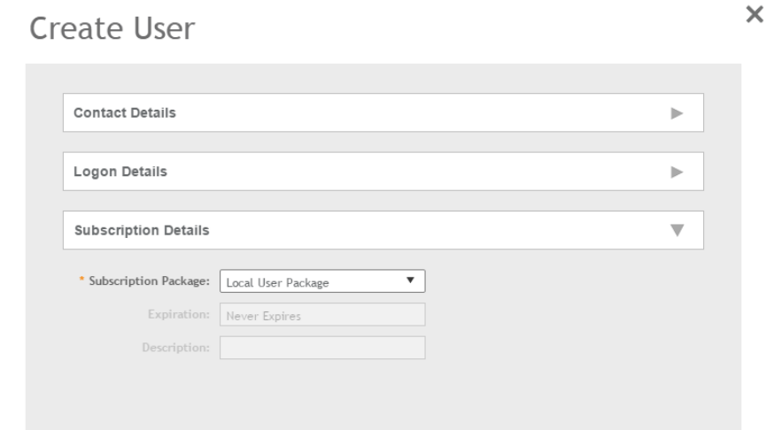
3. Click Create.
The Create User page appears.
FIGURE 41 Create User
4. Configure the options in the Create User form.
1. In the Contact Details section, fill the following:
• First Name
• Last Name
• Email
• Phone
• Address
• City
• State
• Zip Code
• Country
• Remark
2. In the Login Details section, fill out the following boxes to create the logon credentials of this user:
• User Name: Type a name for this user. The user name is not case-sensitive and will always be displayed in lowercase
characters.
• Password: Type a password for this user. The password must be at least eight characters in length.
•Confirm Password: Retype the password above.
3. In the Subscription Details section, select a subscription package that you want to assign to this user. See Creating a
Subscription Package on page 136, for more information.
5. Click OK.
Managing Clients
Working with Users and Roles
SCG200 vSZ-H and SZ300 Administrator Guide
Part Number: 800-71563-001 135

You have completed creating a local user.
Select Enable to enable this user profile or select Disable.
You can view the list of local users by applying filters. Click the icon to do so.
The following information is displayed when you click on the user:
• Summary: Displays a summary of information about the user.
• Admin Activities: Displays information about the administrator activities.
•
Event: Displays information about events associated with the user. Click the icon to apply filters.
Click the icon to export all the data into a CSV file.
NOTE
You can also edit, clone and delete user by selecting the options Configure, Clone and Delete respectively, from the Local Users
tab.
Creating a Subscription Package
A subscription package defines the characteristics of a subscription that has been created for a registered user. These characteristics
include the expiration date of the subscription.
If the user is connected at the time when his or her subscription expires, the user will get disconnected from the AP and any attempts to re-
authenticate will fail.
1. Go to Clients > Users & Roles.
2. Select the Subscription Package tab, and then select the zone for which you want to create the package.
Managing Clients
Working with Users and Roles
SCG200 vSZ-H and SZ300 Administrator Guide
136 Part Number: 800-71563-001
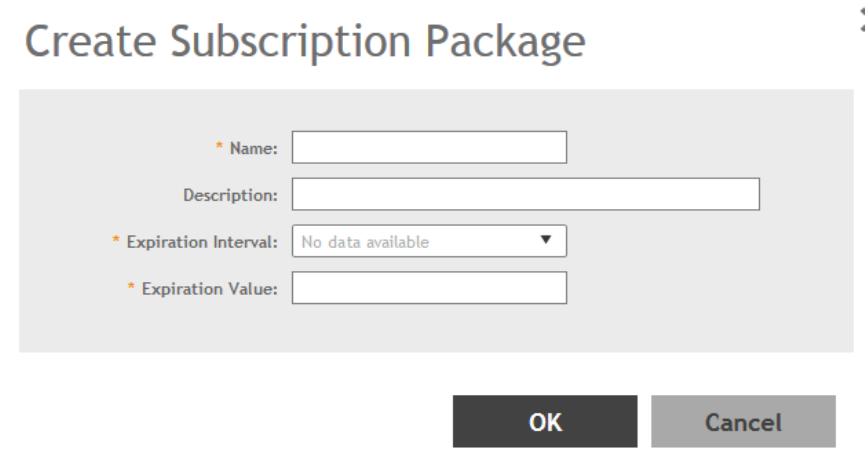
3. Click Create.
The Create Subscription Package page appears.
FIGURE 42 Create Subscription Package
4. Configure the options in the Create Subscription Package form.
• Name: Type a name for the subscription package that you are creating.
• Description: Type a description for this package.
• Expiration Interval: Set the time unit to use for the package expiration. Options include: Hour, Day, Week, Month, Year and
Never.
• Expiration Value: Set the actual value to use in combination with the Expiration Time.
5. Click OK.
You have completed creating a subscription package.
NOTE
You can also edit and delete a package by selecting the options Configure and Delete respectively, from the Subscription
Package tab.
Working with Guest Passes
Similar to user accounts, guest passes in the controller allow users to gain access to the controller hotspots. However, unlike user
accounts, guest pass users are not required to provide personal information to access the controller hotspots and can therefore remain
anonymous.
Guest passes are generated for specific WLANs only – guest pass users will only be able to gain access to the WLANs for which the guest
pass was generated.
Managing Clients
Working with Guest Passes
SCG200 vSZ-H and SZ300 Administrator Guide
Part Number: 800-71563-001 137
Generating Guest Passes
Generating guest passes involves four steps:
Step 1: Create a Guest Access Service on page 138
Step 2: Create a Guest Access WLAN on page 138
Step 3: Generate a Guest Pass on page 139
Step 4: Send Guest Passes to Guest Users on page 141
Step 1: Create a Guest Access Service
1. Follow the instructions in Creating a Guest Access Portal on page 161 to create at least one guest access service in Guest Access
Portal.
2. When you finish creating a guest access service, continue to the next task.
Step 2: Create a Guest Access WLAN
Guest passes are generated for specific WLANs only. Guest pass users will only be able to gain access to the WLANs for which the guest
pass is generated.
Follow these steps to create a WLAN that will be used for guest access only.
1. Click Wireless LANs.
The Wireless LANs page appears.
2. Click Create.
The Create WLAN Configuration page appears.
3. In General Options, configure the following:
•Name
•SSID
•Description
•Zone
•WLAN Group
4. In WLAN Usage, configure the following:
a) In Access Network, select the Tunnel WLAN traffic through Ruckus GRE check box if you want to tunnel the traffic from this
WLAN back to the controller.
b) In Authentication Type, click Guest Access.
5. Configure the rest of the WLAN settings.
For details on each setting, see the Working with WLANs section.
Managing Clients
Working with Guest Passes
SCG200 vSZ-H and SZ300 Administrator Guide
138 Part Number: 800-71563-001
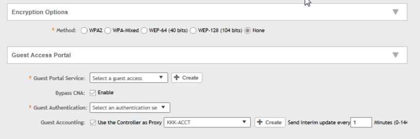
6. When you finish creating a guest access WLAN, continue to the next step.
FIGURE 43 Creating a WLAN for guest access only
Step 3: Generate a Guest Pass
Follow these steps to generate a guest pass.
1. Click Clients > Guests.
The Guest Pass page appears.
2. Click Generate Guest Pass.
The Generate Guest Pass form appears.
3. Configure the following options:
•Guest Name: Type a name that you want to assign to the guest user.
•Guest WLAN: Select the guest WLAN that you created in Step 2: Create a Guest Access WLAN on page 138.
•Number of Passes: Type the number of guest passes that you want to generate.
•Pass Valid For: Set the validity period for the guest pass by filling in the two boxes. For example, if you want the guest pass to
be valid for seven days, type 7 in the first box, and then select Days in the second box.
Managing Clients
Working with Guest Passes
SCG200 vSZ-H and SZ300 Administrator Guide
Part Number: 800-71563-001 139

4. Configure the advanced options:
a) Pass Generation: Select the Auto Generate check box if you want the controller to generate the guest pass key automatically.
If you want to generate the guest pass manually, clear the Auto Generate check box.
If you are generating more than one guest pass, the Auto Generate check box is selected automatically and is not
configurable.
b) Pass Effective Since: Set the guest pass validity period by selecting one of the following options:
•Effective from the creation time: This type of guest pass is valid from the time it is first created to the specified expiration
time, even if it is not being used by any end user.
•Effective from first use: This type of guest pass is valid from the time the user uses it to authenticate with the controller
until the specified expiration time. An additional parameter (Guest Pass will expire in X days) can be configured to specify
when an unused guest pass will expire regardless of use. The default is 7 days.
•Expire guest pass if not used within [ ] days: If you want this guest pass to expire if it is unused after you generated it,
type the number of days in the box (maximum value is 365 days).
c) Max Devices Allowed: Set the number of users that can share this guest pass.
•Limited to [ ]: If you want a limited number of users to share this guest pass, click this option, and then type the number
in the box.
•Unlimited: If you want an unlimited number of users to share this guest pass, click this option.
•Session Duration: If you clicked Unlimited, this option appears. If you want require users to log on again after their
sessions expire, select the Require guest re-login after [ ] check box, and then select a time increment. If this feature is
disabled, connected users will not be required to re-log in until the guest pass expires.
d) In Remarks (optional), type your notes about this guest pass, if any.
5. Click Generate.
The page refreshes, and then the guest pass you generated appears in a table, along with other guest passes that exist on the
controller.
Click Enable to enable the guest pass for a user, and Disable to revoke the guest pass for a particular user.
You have completed generating a guest pass. You are now ready to send the guest pass to guest users. See Step 4: Send Guest Passes
to Guest Users on page 141 for information.
You can view the list of guest passes by applying filters. Click the icon to do so.
The following information is displayed when you click on the guest pass created:
• Summary: Displays a summary of information about the user and credentials.
• Admin Activities: Displays information about the administrator activities.
• Event: Displays information about events associated with the user.
Click the icon to apply filters. Click the icon to export all the data into a CSV file.
Managing Clients
Working with Guest Passes
SCG200 vSZ-H and SZ300 Administrator Guide
140 Part Number: 800-71563-001
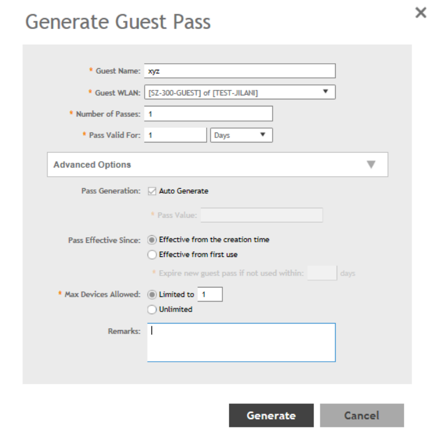
FIGURE 44 Generating a guest pass
Step 4: Send Guest Passes to Guest Users
Deliver the guest passes to guest users as per the delivery options that you choose.
The page that appears after you generate a guest pass contains options for delivering the guest pass to guest users (see the following
image).
Managing Clients
Working with Guest Passes
SCG200 vSZ-H and SZ300 Administrator Guide
Part Number: 800-71563-001 141
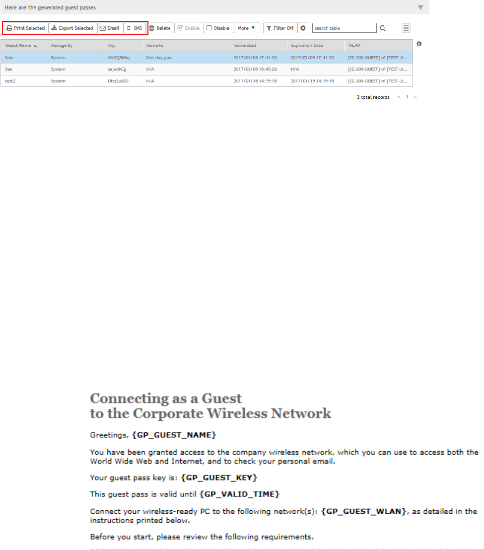
FIGURE 45 Options for delivering guest passes to guest users
Creating a Guest Pass Template
A guest pass template is a HTML file which contains variables for the information that guest users need to connect to the controller
hotspots (for example, guest name, key, and WLAN name), and actual instructions for connecting to the guest WLAN.
A default printout template exists in the controller. If you want to create your own printout template, follow these steps.
1. Go to Clients > Guests.
2. Click Guest Pass Template.
The Guest Pass Template page appears.
3. In the Guest Instruction HTML Template section, click default.html, which is the default guest pass printout template.
The content of the default guest pass printout template appears in the
Name: default.html
.
4. Click Download below the template preview area to download a copy of the template to your computer.
5. Using an HTML editor, create a new HTML file.
6. Add content to the file.
Typically, a printout template contains instructions for connecting to the controller hotspot. See the following image for the content
of the default printout template.
FIGURE 46 Content of the default printout template
Managing Clients
Working with Guest Passes
SCG200 vSZ-H and SZ300 Administrator Guide
142 Part Number: 800-71563-001
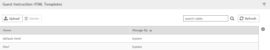
7. Insert the following variables into the content of your template:
•
{GP_GUEST_NAME}
: This is the guest pass user name.
•
{GP_GUEST_KEY}
: This is the guest pass key.
•
{GP_VALID_TIME}
: This is the expiration date and time of the guest pass.
•
{GP_GUEST_WLAN}
: This is the WLAN with which the guest user can associate using the guest name and guest key.
8. Save the file.
9. In the Guest Instruction HTML Template page, click the Upload button for the template that you are creating.
The Upload a Template File form appears on the right side of the page.
10. Configure the Upload a Template File options:
•Template Name: Type a name for the template that you are uploading.
•Template File: Click Browse, and select the template file you created.
11. Click Upload.
An information message box appears and informs you that the template file has been uploaded successfully.
12. Click OK.
The template file you uploaded now appears in the list of templates.
FIGURE 47 The Upload a Template File form
Creating a Guest Instruction SMS Template
A guest SMS template is a tect file which contains variables for the information that guest users need to connect to the controller hotspots
(for example, guest name, key, and WLAN name), and actual instructions for connecting to the guest WLAN.
A default printout template exists in the controller. If you want to create your own printout template, follow these steps.
1. Go to Clients > Guests.
2. Click Guest Pass Template.
The Guest Pass Template page appears.
3. In the Guest Instruction SMS Template section, click default.txt, which is the default guest pass printout template.
The content of the default guest pass printout template appears in the
Name: default.txt
.
4. Click Download below the template preview area to download a copy of the template to your computer.
5. Using an HTML editor, create a new text file.
Managing Clients
Working with Guest Passes
SCG200 vSZ-H and SZ300 Administrator Guide
Part Number: 800-71563-001 143
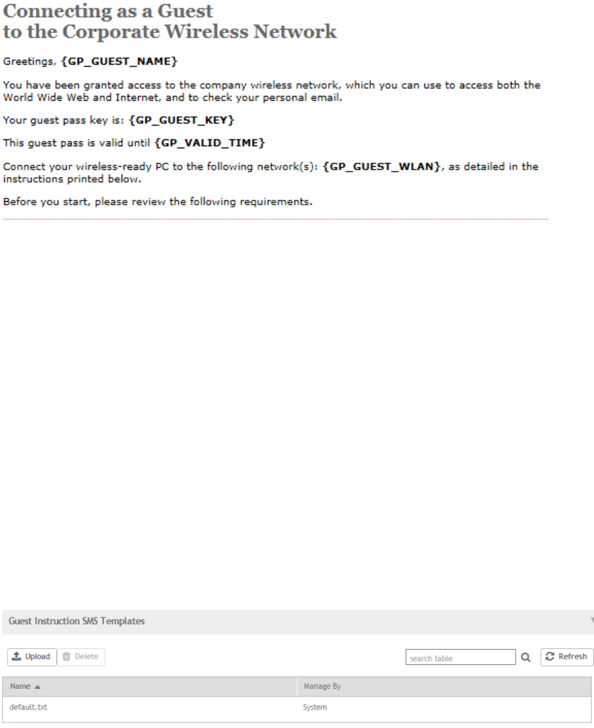
6. Add content to the file.
Typically, a printout template contains instructions for connecting to the controller hotspot. See the following image for the content
of the default printout template.
FIGURE 48 Content of the default printout template
7. Insert the following variables into the content of your template:
•
{GP_GUEST_NAME}
: This is the guest pass user name.
•
{GP_GUEST_KEY}
: This is the guest pass key.
•
{GP_VALID_TIME}
: This is the expiration date and time of the guest pass.
•
{GP_GUEST_WLAN}
: This is the WLAN with which the guest user can associate using the guest name and guest key.
8. Save the file.
9. In the Guest Instruction SMS Template page, click the Upload button for the template that you are creating.
The Upload a Template File form appears on the right side of the page.
10. Configure the Upload a Template File options:
•Template Name: Type a name for the template that you are uploading.
•Template File: Click Browse, and select the template file you created.
11. Click Upload.
An information message box appears and informs you that the template file has been uploaded successfully.
12. Click OK.
The template file you uploaded now appears in the list of templates.
FIGURE 49 The Upload a Template File form
Managing Clients
Working with Guest Passes
SCG200 vSZ-H and SZ300 Administrator Guide
144 Part Number: 800-71563-001
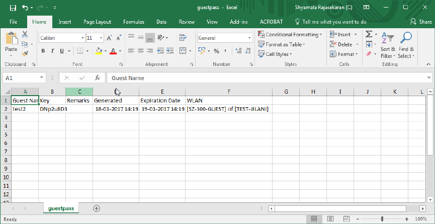
Exporting the Guest Pass to CSV
Follow these steps to export the last generated guest passes to a comma-separated value (CSV) file.
1. From the generate guest pass list, select the guest passes that you want to export to CSV.
2. Click Export Selected.
Your web browser downloads the CSV file to its default download location.
3. Go to your web browser's default download location and look for a file named guestpass.csv.
4. Using Microsoft Excel or a similar application, open the CSV file. The CSV file displays the details of the guest passes, including:
• Guest Name
• Key
• Remarks
• Generated
• Expiration Date
• WLAN
You have completed exporting the last generated guest passes to CSV.
FIGURE 50 A sample CSV of generated guest passes when opened in Excel
Generating Guest Passes from an Imported CSV
You can also manually define the guest passes that you want to generate in a comma-separated value (CSV) file (a sample of which is
available for download from the Guest Pass page).
Follow these steps to generate guest passes from an imported CSV file.
1. Click Clients > Guests .
The Guest Pass page appears.
Managing Clients
Working with Guest Passes
SCG200 vSZ-H and SZ300 Administrator Guide
Part Number: 800-71563-001 145
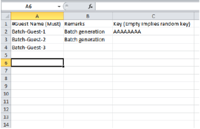
2. Click Import Guest Pass,
The Import Guest Pass form appears.
3. Look for the following text under Browse:
To download a sample guest pass, click here.
4. Click the here link to download the sample CSV file.
5. Using Microsoft Excel or a similar application, open the CSV file.
6. In the CSV file, fill out the following columns:
• #Guest Name (Must): Assign a user name to the guest pass user.
• Remarks (Optional): Add some notes or comments about this guest pass.
• Key: Enter a guest pass key or leave it blank so the controller can generate the key automatically.
FIGURE 51 The sample CSV file when opened in Excel
7. Save the CSV file.
8. Go back to the Import Guest Pass page, and then configure the following settings on the Common Guest Pass Settings:
•Guest WLAN: Select the guest WLAN that you created in Step 2: Create a Guest Access WLAN on page 138.
•Pass Valid For: Set the validity period for the guest pass by filling in the two boxes. For example, if you want the guest pass to
be valid for seven days, type 7 in the first box, and then select Days in the second box.
Managing Clients
Working with Guest Passes
SCG200 vSZ-H and SZ300 Administrator Guide
146 Part Number: 800-71563-001
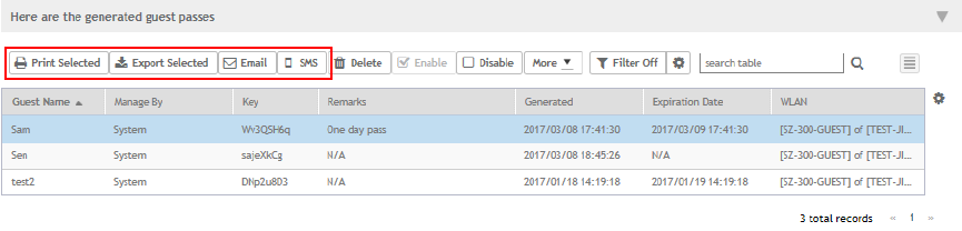
9. Configure the advanced options:
a) Pass Effective Since: Set the guest pass validity period by selecting one of the following options:
•Effective from the creation time: This type of guest pass is valid from the time it is first created to the specified expiration
time, even if it is not being used by any end user.
•Effective from first use: This type of guest pass is valid from the time the user uses it to authenticate with the controller
until the specified expiration time. An additional parameter (Guest Pass will expire in X days) can be configured to specify
when an unused guest pass will expire regardless of use. The default is 7 days.
•Expire guest pass if not used within [ ] days: If you want this guest pass to expire if it is unused after you generated it,
type the number of days in the box (maximum value is 365 days).
b) Max Devices Allowed: Set the number of users that can share this guest pass.
•Limited to [ ]: If you want a limited number of users to share this guest pass, click this option, and then type the number
in the box.
•Unlimited: If you want an unlimited number of users to share this guest pass, click this option.
•Session Duration: If you clicked Unlimited, this option appears. If you want require users to log on again after their
sessions expire, select the Require guest re-login after [ ] check box, and then select a time increment. If this feature is
disabled, connected users will not be required to re-log in until the guest pass expires.
10. In Guest List CSV File (at the top of the page), click Browse, and then select the CSV file you edited earlier.
The page refreshes, and the number of guest passes that the controller has identified in the CSV file appears below the Browse
button.
11. Click Import.
The page refreshes, and then the guest pass you generated appears in a table, along with other guest passes that exist on the
controller.
You have completed generating a guest pass. You are now ready to send the guest pass to guest users. See Step 4: Send Guest Passes
to Guest Users on page 141 for information.
FIGURE 52 The Guest Pass page for importing a CSV file
Sending the Guest Pass via Email
To send guest passes via email, you must have added an external email server to the controller.
Follow these steps to send the guest pass via email.
1. From the generated guest passes list, select the guest passes that you want to send via email.
2. Click Email.
The Recipient Email form appears on the right side of the page (see Figure 53).
Managing Clients
Working with Guest Passes
SCG200 vSZ-H and SZ300 Administrator Guide
Part Number: 800-71563-001 147
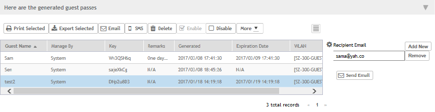
3. Click Add New.
4. In the box that appears below, type the email address to which you want to send the guest passes.
5. To add another recipient, click Add Newagain, and then type another email address.
6. When you have finished adding all the email recipients, click Send Email.
A dialog box appears and informs you that the emails have been sent to the message queue successfully
7. Click OKto close the dialog box.
You have completed sending guest passes via email.
FIGURE 53 Use the Recipient Email form to specify who will receive the guest passes via email
Printing the Guest Pass
After you generate the guest pass, you can print the guest pass information, which contains the guest user information and instructions on
how to connect to the hotspot, and give it to the guest user.
NOTE
If your browser is blocking pop-ups, make you temporarily disable the pop-up blocker so you can view and print the guest pass.
Follow these steps to print a guest pass.
1. From the generated guest passes list, select the guest passes that you want to print.
2. In Guest Instruction HTML Template, select a printout template to use.
The default printout template (default.html) is selected by default. If you created custom printout templates (see Creating a
Guest Pass Template on page 142), they will appear in the drop-down menu.
3. Click Print Selected.
A new browser page appears, which displays the guest pass and available printing options.
4. Configure your printer settings, and then print the guest passes.
You have completed printing the guest passes.
Managing Clients
Working with Guest Passes
SCG200 vSZ-H and SZ300 Administrator Guide
148 Part Number: 800-71563-001
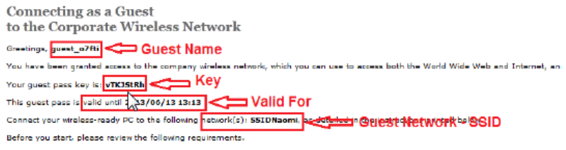
FIGURE 54 What a guest pass printout looks like
Sending the Guest Pass via SMS
To send guest passes via sms, you must have added an external SMS gateway to the controller.
Follow these steps to send the guest pass via email.
1. From the generated guest passes list, select the guest pass that you want to send via SMS.
2. Click SMS.
SMS options appear on the right side of the page (see Figure 55).
3. In Guest Instruction SMS Template, select the SMS template that you want to use.
4. Click Add New.
5. In the box that appears below, type the phone number to which you want to send the guest passes via SMS.
6. To add another SMS recipient, click Add New again, and then type another phone number.
7. When you have finished adding all the SMS recipients, click Send SMS.
A dialog box appears and informs you that the SMS messages have been sent to the message queue successfully
8. Click OK to close the dialog box.
You have completed sending guest passes via SMS.
Managing Clients
Working with Guest Passes
SCG200 vSZ-H and SZ300 Administrator Guide
Part Number: 800-71563-001 149
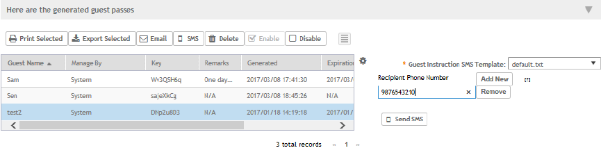
FIGURE 55 Options for sending guest passes via SMS
Working with Dynamic PSKs
Dynamic PSKs (DPSKs) are unique pre-shared keys assigned to a user or device. DPSKs are used to provide secure wireless access,
which helps avoid manual wireless configuration and managing encryption keys.
DPSK is a form of PSK (static key) in a WPA2 WLAN and its purpose is to provide each user device with a unique dynamic PSK to
associate to a WLAN without any modifications to the WLAN configuration. For example, a school administrator provides a time-limited
DPSK for student's device so that the student can access the school's WLAN for the period their DPSK is valid. After the validity period
ends, the DPSK expires and the student's device can no longer access the school's WLAN. Without the use of DPSKs, the school
administrator would have to change the default static key to prevent the student from using the WLAN resources, which in turn would
impact all other users of that WLAN.
Individual DPSKs can be deleted in the event of a student leaving the school, or their device being lost or stolen without impacting other
users of the WLAN.
A “bound” DPSK is one which is assigned to the MAC address of a user device at the time of creation. No other user device can utilize this
DSPK. Bound DPSKs are stored in on APs.
An “unbound” DPSK is not assigned to a device's MAC address during creation, but upon its first use (that is, when the device first
connects to a WLAN and the DPSK is entered as the WLAN security key). Once a DPSK becomes assigned to a user device, it becomes
bound and no other user device can use it.
NOTE
If you generate a single unbound DPSK, then only one device can be connected to the DPSK WLAN by the key, since other
devices can still use “admin” PSK to connect to the DPSK WLAN. However, when devices from different APs try to use the same
unbound DPSK simultaneously, for a short period, they could both connect to the WLAN successfully, but the later device will be
disconnected by the controller. If the AP happens to disconnect from the controller, the device could stay connected until the AP
connects back to the controller.
When DPSKs are created, there are some prevented behaviors that are considered database conflicts such as the following:
• You cannot create two unbound DPSKs with the same passphrase.
• You cannot create two bound DPSKs for the same MAC address and passphrase. Create two DPSKs for the same MAC address,
the former will be replaced. However, you can create multiple bound DPSKs with different MAC addresses and the same
passphrase.
• You can also create bound DPSKs and a single unbound DPSK with the same passphrase.
UEs within a PSK WLAN use the same shared key to encrypt data traffic, but if the key is compromised by even one WLAN user, the entire
user traffic can be accessed/hacked. Therefore, a secure tunnel is created for each user connected to the WLAN, by configuring the PSK
WLAN as an
Internal
or
External
DPSK.
Managing Clients
Working with Dynamic PSKs
SCG200 vSZ-H and SZ300 Administrator Guide
150 Part Number: 800-71563-001
In Internal DPSKs, the controller manages and records the DPSK for each individual user and a limited number of DPSKs are supported.
In External DPSKs, the DPSK is maintained by the Radius Server (AAA) and Radius protocols are used to authenticate the UE. The UE is
authenticated by the open authentication WLAN - WPA/WPA2 encryption where in, the controller uses the RADIUS interface with the
RADIUS server (AAA includes the DPSK in the Radius response or Access Accept message and sends it to the AP) so that the DPSK is
maintained in one place. There is no limitation on the number of DPSK supported in this mode.
NOTE
Only proxy AAA authentication is supported for External DPSK.
NOTE
External DPSKs are supported only on bounded DPSKs.
Viewing Dynamic PSKs
View dynamic PSKs that have been generated on the controller.
The following information about dynamic PSKs is available:
• User Name
• MAC Address
• WLAN (SSID)
• VLAN ID
• Created Date
• Expiration Date
• Expired
• Actions
Follow these steps to view the DPSKs:
1. Click Clients > Dynamic PSK > other options.
The Dynamic PSK page appears listing the DPSKs that have been generated.
You can sort the list of DPSKs or export the DPSKs listed to a CSV file.
2. An optional step is to select the Delete Expired DPSKs option available on the Dynamic PSKs page allows you to customize when
the system must remove the DPSKs that are no longer valid.
Following are the settings available:
•Never: No action must be taken for the expired DPSKs.
•After 1 day: Auto deletes DPSKs that have expired after one day.
•After 6 months: Auto deletes DPSKs that have expired after 6 months.
You have completed viewing the list of dynamic PSKs.
Generating Dynamic PSKs
You can generate new dynamic PSKs to secure the WiFi network.
Follow these steps to generate the dynamic PSKs (DPSKs):
1. Click Clients > Dynamic PSK > other options.
The Dynamic PSK page appears listing the PSKs that were generated.
Managing Clients
Working with Dynamic PSKs
SCG200 vSZ-H and SZ300 Administrator Guide
Part Number: 800-71563-001 151

2. Click Generate DPSKs.
The Generate DPSKs dialog box appears.
3. Provide the following information
•WLAN: From the drop-down list, select a DPSK-enabled WLAN.
•Number of DPSKs: Type the number of PSKs you want to create. You can generate up to a maximum of 320 DPSKs at a
time.
NOTE
For SZ300/SCG200/vSZ-H, a maximum of 10,000 DPSKs can be included within an AP zone and a maximum of
20,000 DPSKs can be included within a cluster (Carrier: per Domain. Enterprise: System), and up to 50,000 DPSKs
an be included within a cluster (Carrier: System). Up to 320 unbound + group DPSKs, and 64 group DPSKs ( those
that are not bound to a MAC address) can be included within an AP zone.
•User Name: Leave it blank if you want the controller to auto-generate the user name, or enter the user name manually.
•Passphrase: Leave it blank if you want the controller to auto-generate the passphrase, or enter the passphrase manually.
•User Role: If you have created user roles, select the user role that you want to assign to the device that connects to the
SmartZone network using this DPSK. The device will be assigned the same attributes and permissions (VLAN, UTP, time
restrictions, etc.) that have been defined for the assigned user role.
•VLAN ID: Type a VLAN ID within the range 1-4094.
•Group DPSK: If you want multiple devices to be able to use this DPSK, click Yes. If you want only a single device to use this
DPSK (bound DPSK), click No.
4. Click Generate.
You have completed creating dynamic PSKs.
To delete a DPSK, click the DPSK from the list, and then click the Delete icon.
Importing Dynamic PSKs
You can import CSV files to create DPSKs to secure the WiFi network.
Follow these steps to import dynamic PSKs (DPSKs):
1. Click Clients > Dynamic PSK.
The Dynamic PSK page appears and lists the DPSKs that have been generated.
Managing Clients
Working with Dynamic PSKs
SCG200 vSZ-H and SZ300 Administrator Guide
152 Part Number: 800-71563-001
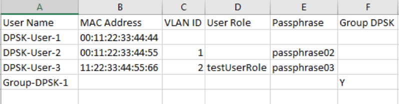
2. Click the Download Sample (CSV) link to download the CSV template for generating DPSKs.
A sample CSV file is displayed as show in the figure.
FIGURE 56 Sample CSV file
3. Modify the CSV file as appropriate and save it. The following are the fields that need to be completed in the CSV file:
•User Name (mandatory field): Enter the user name.
•MAC Address (optional): Enter the MAC address of the device for which to generate a DPSK (bound DPSK). If you leave the
MAC address field empty, the controller will generate an unbound DPSK.
•VLAN ID (optional): Enter a value to override the WLAN VLAN ID, or leave it empty if you do not want to override the WLAN
VLAN ID.
•User Role (optional): If you have created user roles, type the name of the user role that you want to assign to the device that
connects to the SmartZone network using this DPSK. The device will be assigned the same attributes and permissions
(VLAN, UTP, time restrictions, etc.) that have been defined for the assigned user role.
•Passphrase (optional): Leave it blank if you want the controller to auto-generate the passphrase, or enter the passphrase
manually.
•Group DPSK (optional): Enter Y to indicate the entry is a Group DPSK if you want multiple devices to use this DPSK.
4. Click Import CSV.
The Import CSV dialog box appears.
NOTE
Importing a CSV file that contains a MAC address to which an existing DPSK (on the same target WLAN) is already
assigned will replace the existing DPSK on the controller database.
5. In DPSK Enabled WLAN, select a WLAN from the drop-down list. Only WLANs that support DPSK must be selected.
6. In Choose File, click Browse to choose the CSV file.
Click Clear if you want to replace the CSV file.
You can also specify Group DPSK in the CSV file.
7. Click Upload.
The generated DPSKs appear in the table on the Dynamic PSK page.
NOTE
You can import up to 1,000 DPSKs (not over 320 unbound + group DPSKs) at a time.
Managing Clients
Working with Dynamic PSKs
SCG200 vSZ-H and SZ300 Administrator Guide
Part Number: 800-71563-001 153
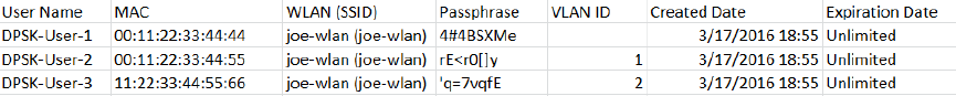
8. Click Download CSV to download a CSV that contains the generated DPSKs.
The CSV file appears in the following format.
FIGURE 57 New CSV format
You have completed generating DPSKs.
NOTE
Click Export All to export all the dynamic PSKs to a CSV file. You can also export specific dynamic PSKs by selected them and
clicking Export Selected.
Creating an External DPSK Over RADIUS WLAN
External DPSKs use the radius interface with the RADIUS Server (AAA) to maintain the DPSKs centrally. There is no limitation in the number
of DPSKs that are supported.
To create an external DPSK over RADIUS WLAN:
1. Create an Authentication Service. Refer, Creating Non-Proxy Authentication AAA servers.
2. Create an Accounting Service. Refer, Creating Proxy Accounting AAA Servers.
3. Create Zone Configuration. Refer, Creating an AP Zone.
Managing Clients
Working with Dynamic PSKs
SCG200 vSZ-H and SZ300 Administrator Guide
154 Part Number: 800-71563-001
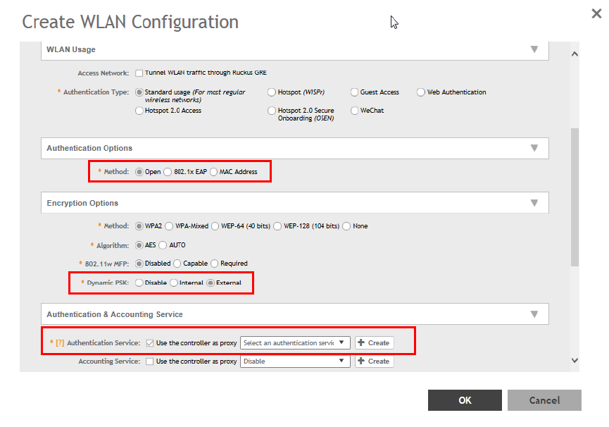
4. Create a WLAN Configuration for DPSK. Refer, Creating a WLAN Configuration.
FIGURE 58 External DPSK Configuration
Managing Clients
Working with Dynamic PSKs
SCG200 vSZ-H and SZ300 Administrator Guide
Part Number: 800-71563-001 155
SCG200 vSZ-H and SZ300 Administrator Guide
156 Part Number: 800-71563-001

Application Recognition and Control
• Monitoring Applications......................................................................................................................................... 157
Application Recognition and Control enables you to identify, monitor and control the applications that are running on wireless clients
associated with managed APs.
Monitoring Applications
If you have enabled Application Recognition and Control for at least one WLAN, you can monitor the applications that run on wireless
clients associated with that WLAN.
NOTE
To configure application recognition and control policies, go to Services and Profiles > Application Control. For more information,
see Configuring Application Controls on page 189.
To monitor the top applications by traffic consumption on the wireless network:
1. Go to Applications on the main menu.
2. Select whether to view the Top Applications by Application or Port, select a time period to display, and optionally filter the data by
AP MAC address and WLAN name using the drop-down menus.
SCG200 vSZ-H and SZ300 Administrator Guide
Part Number: 800-71563-001 157
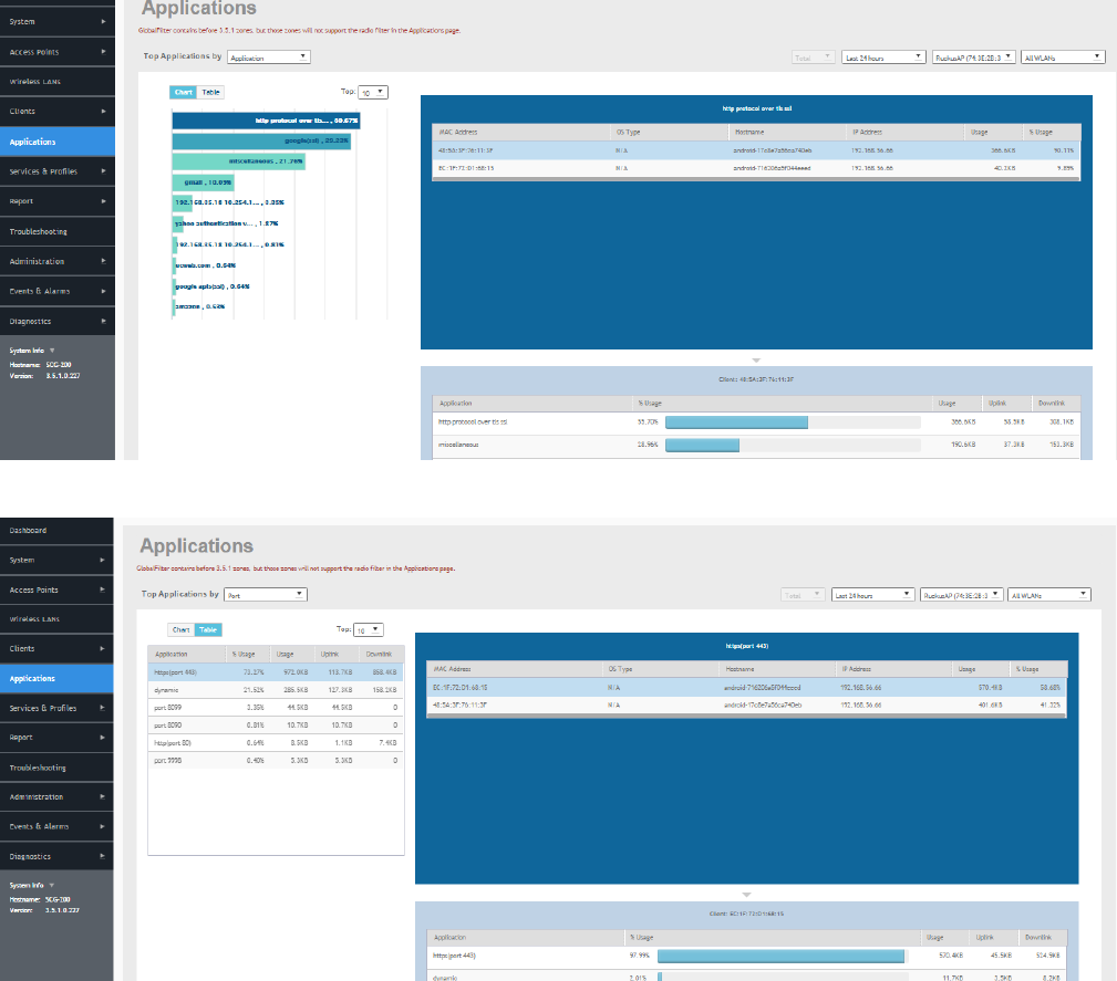
3. Select whether to display the Top 10 or Top 25 applications in Chart or Table format.
NOTE
If Application Recognition and Control is unable to find an application name, it displays the source and destination IP:
port address of the application
FIGURE 59 Top Applications - Chart View
FIGURE 60 Top Applications by Port - Table View
Application Recognition and Control
Monitoring Applications
SCG200 vSZ-H and SZ300 Administrator Guide
158 Part Number: 800-71563-001
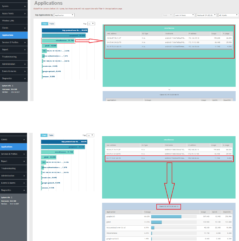
4. Click on an application from the list on the left (either Chart or Table view) to view a list of the top clients using the selected
application in the list on the right. The client list displays the client's MAC address, OS, hostname, IP address (IPv4 and IPv6), and
application usage volume and percent of application traffic generated by the client. From the Total option, you can also filter the
data based on the radio frequencies (2.4 GHz and 5 GHz).
FIGURE 61 Click an application to view top client details
5. Click on a client in the list on the right, and scroll down to the client specific details table on the bottom right to view the top 10
applications used by the client.
FIGURE 62 Click a client to view application details
Application Recognition and Control
Monitoring Applications
SCG200 vSZ-H and SZ300 Administrator Guide
Part Number: 800-71563-001 159
NOTE
You can configure application control policies (denial, rate limiting, and QoS) using the Services and Profiles > Application Control
page. For more information, see Configuring Application Controls on page 189.
Application Recognition and Control
Monitoring Applications
SCG200 vSZ-H and SZ300 Administrator Guide
160 Part Number: 800-71563-001

Services and Profiles
• Working with Hotspots and Portals........................................................................................................................161
•Configuring Access Control................................................................................................................................... 177
•Configuring Application Controls............................................................................................................................189
• URL Filtering..........................................................................................................................................................197
• Authentication....................................................................................................................................................... 203
• Accounting............................................................................................................................................................215
• Classifying Rogue Policy........................................................................................................................................218
• Bonjour................................................................................................................................................................. 219
• Working with Tunnels and Ports.............................................................................................................................225
• Managing Core Network Tunnels...........................................................................................................................239
• Location Services.................................................................................................................................................. 244
• DHCP/NAT............................................................................................................................................................245
The Services and Profiles menu provides options for monitoring and configuring services such as guest access, access controls,
authentication servers, application recognition and control, Bonjour services, tunneling, location services and DHCP server configuration.
Working with Hotspots and Portals
Creating a Guest Access Portal
Using the controller's Guest Access features, you can provide visitors to your organization limited access to a guest WLAN with
configurable guest policies. The following sections describe how to configure guest WLANs and access policies that control guest use of
your network.
Each guest WLAN must be associated with a Guest Access service portal, which defines the behavior of the guest WLAN interface. Follow
these steps to create a guest access service.
1. Go to Services & Profiles > Hotspots & Portals.
2. Select the Guest Access tab, and then select the zone for which you want to create the portal.
SCG200 vSZ-H and SZ300 Administrator Guide
Part Number: 800-71563-001 161
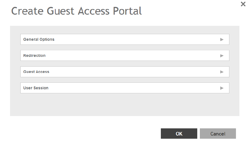
3. Click Create.
The Create Guest Access Portal page appears.
FIGURE 63 Creating a Guest Access Portal
Services and Profiles
Working with Hotspots and Portals
SCG200 vSZ-H and SZ300 Administrator Guide
162 Part Number: 800-71563-001
4. Configure the following:
1. General Options
• Portal Name: Type a name for the guest access service portal that you are creating.
• Portal Description: Type a short description of the guest access service portal.
• Language: Select the display language to use for the buttons on the guest access logon page.
2. Redirection: select where to redirect the user after successfully completing authentication.
• Redirect to the URL that the user intends to visit: Allows the guest user to continue to their destination without
redirection.
• Redirect to the following URL: Redirect the user to a specified web page (entered into the text box) prior to forwarding
them to their destination. When guest users land on this page, they are shown the expiration time for their guest pass.
3. Guest Access
• Guest Pass SMS Gateway: You can deliver the guest pass to the user using Short Message Service (SMS). But first you
need to configure an SMS server. If you previously configured an SMS server, you can select it here or you can select
Disable.
• Terms and Conditions: To require users to read and accept your terms and conditions prior to use, Show Terms and
Conditions check box. The box below, Terms and Conditions which contains the default Terms of Use text, becomes
editable. Edit the text or leave it unchanged to use the default text.
• Web Portal Logo: By default, the guest hotspot logon page displays the Ruckus Wireless logo. To use your own logo,
click the Browse button, select your logo Web Portal Logo (recommended size is 138 x 40 pixels, maximum file size is
20KB), and then click Open.
• Web Portal Title: Type your own guest hotspot welcome text or accept the default welcome text (Welcome to the Guest
Access login page).
4. User Session
• Session Timeout: Specify a time limit after which users will be disconnected and required to log on again.
• Grace Period: Set the time period during which clients will not need to re-authenticate after getting disconnected from
the hotspot. Enter a number (in minutes) between 1 and 14399.
5. Click OK.
You have completed creating a guest access service.
NOTE
You can also edit, clone and delete a guest access portal by selecting the options Configure, Clone and Delete respectively, from
the Guest Access tab.
Working with Hotspot (WISPr) Services
A hotspot is a venue or area that provides Internet access to devices with wireless networking capability such as notebooks and smart
phones.
Hotspots are commonly available in public venues such as hotels, airports, coffee shops and shopping malls. Configure a traditional (WISPr
1.0) hotspot service to provide public access to users via its WLANs. In addition to the controller and its managed APs, you will need the
following to deploy a hotspot:
Captive Portal: A special web page, typically a login page, to which users that have associated with your hotspot will be redirected for
authentication purposes. Users will need to enter a valid user name and password before they are allowed access to the Internet through
the hotspot.
Services and Profiles
Working with Hotspots and Portals
SCG200 vSZ-H and SZ300 Administrator Guide
Part Number: 800-71563-001 163
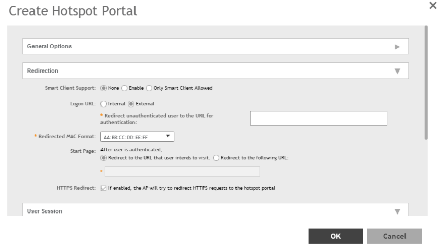
RADIUS Server: A Remote Authentication Dial-In User Service (RADIUS) server through which users can authenticate.
For installation and configuration instructions for the captive portal and RADIUS server software, refer to the documentation that was
provided with them. After completing the steps below, you will need to edit the WLAN(s) for which you want to enable Hotspot service. The
controller supports up to 32 WISPr hotspot service entries, each of which can be assigned to multiple WLANs.
Creating a Hotspot (WISPr) Portal
Define the basic settings that you need to configure to create a hotspot service.
Before creating a hotspot, you need to create a user defined interface.
1. Go to Services & Profiles > Hotspots & Portals.
2. Select the Hotspot (WISPr) tab, and then select the zone for which you want to create the portal.
3. Click Create.
The Create Hotspot (WISPr) Portal page appears.
FIGURE 64 Creating a Hotspot (WISPr) Portal
Services and Profiles
Working with Hotspots and Portals
SCG200 vSZ-H and SZ300 Administrator Guide
164 Part Number: 800-71563-001
4. Configure the following:
1. General Options
• Portal Name: Type a name for the hotspot service portal that you are creating.
• Portal Description: Type a short description of the hotspot service portal.
2. Redirection: select where to redirect the user after successfully completing authentication.
• Smart Client Support: select one of the following
– None: Select this option to disable Smart Client support on the hotspot service.
– Enable: Selection this option to enable Smart Client support.
– Only Smart Client Allowed: Select this option to allow only Smart Clients to connect to the hotspot service.
• Logon URL: select one of the following
– Internal: Type the internal URL of the subscriber portal (the page where hotspot users can log in to access the
service).
– External: Type the external URL of the subscriber portal.
• Redirect MAC Format: Type the MAC address to which redirection must be done.
• Start Page: select one of the following
– Redirect to the URL that the user intends to visit: You could redirect users to the page that they want to visit.
– Redirect to the following URL: You could set a different page where users will be redirected (for example, your
company website).
• HTTPS Redirect: Enable this option if you want the AP to redirect HTTPS requests to the Hotspot portal.
3. User Session
• Session Timeout: Set a time limit (in minutes) after which users will be disconnected from the hotspot service and will be
required to log on again.
• Grace Period: Set the time period (in minutes) during which disconnected users are allowed access to the hotspot
service without having to log on again.
4. Location Information
• Location ID: Type the ISO and ITU country and area code that the AP includes in accounting and authentication
requests. The required code includes:
– isocc (ISO-country-code): The ISO country code that the AP includes in RADIUS authentication and accounting
requests.
– cc (country-code): The ITU country code that the AP includes in RADIUS authentication and accounting requests.
– ac (area-code): The ITU area code that the AP includes in RADIUS authentication and accounting requests.
– network: The following is an example of what the Location ID entry should look like:
isocc=us,cc=1,ac=408,network=RuckusWireless
• Location Name: Type the name of the location of the hotspot service.
5. Walled garden: A walled garden is a limited environment to which an unauthenticated user is given access for the purpose of
setting up an account.
Click Add to add a user to walled garden, to provide access.
Click Import CSV to import the CSV file with user information.
5. Click OK.
You have completed creating a Hotspot (WISPr) service portal.
Services and Profiles
Working with Hotspots and Portals
SCG200 vSZ-H and SZ300 Administrator Guide
Part Number: 800-71563-001 165
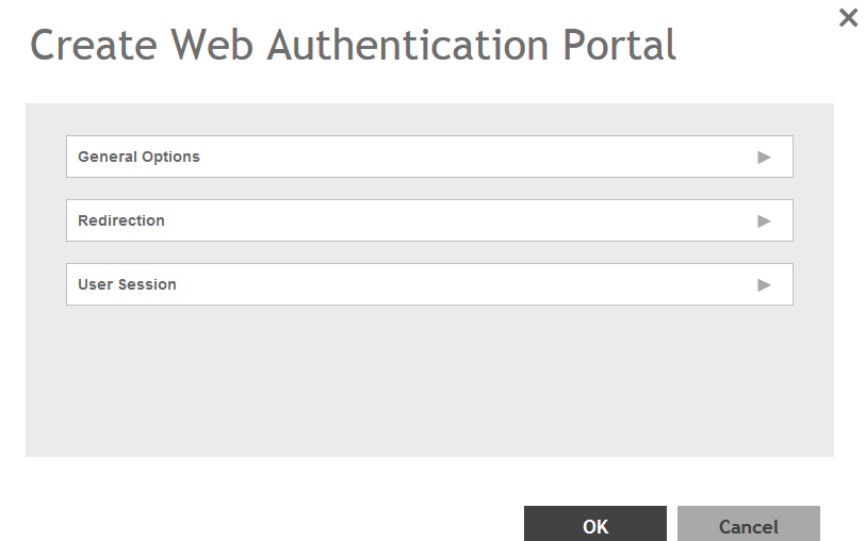
NOTE
You can also edit, clone and delete a Hotspot (WISPr) service portal by selecting the options Configure, Clone and Delete
respectively, from the Hotspot (WISPr) tab.
Creating a Web Authentication Portal
Web authentication (also known as a “captive portal”) redirects users to a logon web page the first time they connect to this WLAN, and
requires them to log on before granting access to use the WLAN.
1. Go to Services & Profiles > Hotspots & Portals.
2. Select the Web Auth tab, and then select the zone for which you want to create the portal.
3. Click Create.
The Create Web Authentication Portal page appears.
FIGURE 65 Creating a Web Authentication Portal
Services and Profiles
Working with Hotspots and Portals
SCG200 vSZ-H and SZ300 Administrator Guide
166 Part Number: 800-71563-001
4. Configure the following:
1. General Options
• Portal Name: Type a name for the hotspot service portal that you are creating.
• Portal Description: Type a short description of the hotspot service portal.
• Language: Select the display language that you want to use on the web authentication portal.
2. Redirection: select where to redirect the user after successfully completing authentication.
• Start Page: select one of the following
– Redirect to the URL that the user intends to visit: Allows the guest user to continue to their destination without
redirection.
– Redirect to the following URL: Redirect the user to a specified web page (entered into the text box) prior to
forwarding them to their destination. When guest users land on this page, they are shown the expiration time for
their guest pass.
3. User Session
• Session Timeout: Set a time limit (in minutes) after which users will be disconnected from the hotspot service and will be
required to log on again.
• Grace Period: Set the time period (in minutes) during which disconnected users are allowed access to the hotspot
service without having to log on again.
5. Click OK.
You have completed creating a Web Auth service portal.
NOTE
You can also edit, clone and delete a Web Auth service portal by selecting the options Configure, Clone and Delete respectively,
from the Web Auth tab.
Creating a WeChat Portal
WeChat is a mobile app from Tenecent that enables its users to call and send text messages to one another. If you have WeChat users on
the network and you want your WLANs to support WeChat services, you can create a WeChat portal that WeChat users can use.
A WeChat portal defines the third party authentication server, also known as the equipment service provider (ESP) server, to which the
controller will forward all WeChat authentication requests from wireless devices that are associated with controller-managed APs. In turn,
the third party authentication server will forward these authentication requests to the WeChat server.
1. Go to Services & Profiles > Hotspots & Portals.
2. Select the WeChat tab, and then select the zone for which you want to create the portal.
Services and Profiles
Working with Hotspots and Portals
SCG200 vSZ-H and SZ300 Administrator Guide
Part Number: 800-71563-001 167
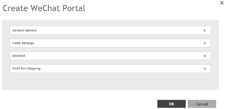
3. Click Create.
The Create WeChat Portal page appears.
FIGURE 66 Creating a WeChat Portal
Services and Profiles
Working with Hotspots and Portals
SCG200 vSZ-H and SZ300 Administrator Guide
168 Part Number: 800-71563-001
4. Configure the following:
1. General Options
• Name: Type a name for the portal that you are creating.
• Description: Type a short description of the portal.
2. Portal Settings: configure the following
• Authentication URL: Type the authentication interface URL on the third party authentication server. When a managed AP
receives a WeChat logon request from a client device, it will send the request to this authentication URL and get the
authorization result.
• DNAT Destination: Type the DNAT destination server address to which the controller will forward HTTP requests from
unauthenticated client devices. The DNAT destination server and the authentication server (above) may or may not be the
same server.
• Grace Period: Type the number of minutes during which disconnected users who were recently connected will be
allowed to reconnect to the portal without needing to re-authenticate. The default grace period is 60 minutes (range is
between 1 and 14399 minutes).
• Blacklist: Type network destinations that the controller will automatically block associated wireless clients from accessing.
Use a comma to separate multiple entries.
3. Whitelist: Type network destinations that the controller will automatically allow associated wireless clients to access. You can
add a single entry or multiple entries.
To add a single entry, type the entry in Wall Garden Entry, and then click Add. The entry you added appears in the table
below. To add multiple entries, in a comma-separated value (CSV) file, type all the network destinations that you want to add
to the whitelist, and then save the CSV file. In the Whitelist section, click Import CSV, and then select the CSV file you
created. Click Open. The entries in the CSV file are added to the whitelist.
4. DNAT Port Mapping: specify at least one pair of source-to-destination port mapping. To add a port mapping, type the source
and destination ports in the boxes provided, and then click Add. The AP will use this information to drop or forward HTTP
requests from associated clients to specified ports on the DNAT server. For example, if an HTTP request from a wireless client
does not originate from the specified source (from) port, the AP will discard the HTTP request. By default, a port mapping of
80-80 (source-destination) exists.
5. Click OK.
You have completed creating a WeChat portal.
NOTE
You can also edit, clone and delete a WeChat service portal by selecting the options Configure, Clone and Delete respectively,
from the WeChat tab.
Working with Hotspot 2.0 Services
You must be aware of Hotspot 2.0 - a Wi-Fi Alliance specification that allows for automated roaming between service provider access
points when both the client and access gateway support the newer protocol.
Hotspot 2.0 (also known as Passpoint™, the trademark name of the Wi-Fi Alliance certification) aims to improve the experience of mobile
users when selecting and joining a Wi-Fi hotspot by providing information to the station prior to association.
This information can then be used by the client to automatically select an appropriate network based on the services provided and the
conditions under which the user can access them. In this way, rather than being presented with a list of largely meaningless SSIDs to
choose from, the Hotspot 2.0 client can automatically select and authenticate to an SSID based on the client's configuration and services
offered, or allow the user to manually select an SSID for which the user has login credentials.
Services and Profiles
Working with Hotspots and Portals
SCG200 vSZ-H and SZ300 Administrator Guide
Part Number: 800-71563-001 169
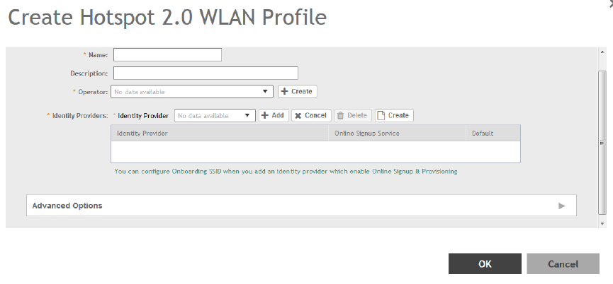
The controller's Hotspot 2.0 implementation complies with the IEEE 802.11u standard and the Wi-Fi Alliance Hotspot 2.0 Technical
Specification.
See the
Hotspot 2.0 Reference Guide for SmartZone
for information on configuring Hotspot 2.0 services, including:
• Working with Hotspot 2.0 operator profiles
• Working with Hotspot 2.0 identity providers
• Creating a Hotspot 2.0 online signup portal
Creating a Hotspot 2.0 WLAN Profile
You can assign and Hotspot 2.0 service to a Hotspot 2.0 WLAN, for which you must create a Hotspot 2.0 WLAN profile.
Follow these steps to create a Hotspot 2.0 WLAN profile.
1. Go to Services & Profiles > Hotspots & Portals.
2. Select the Hotspot 2.0 tab, and then select the zone for which you want to create the profile.
3. Click Create.
The Create Hotspot 2.0 WLAN Profile page appears.
FIGURE 67 Creating a Hotspot 2.0 WLAN Profile
Services and Profiles
Working with Hotspots and Portals
SCG200 vSZ-H and SZ300 Administrator Guide
170 Part Number: 800-71563-001
4. Configure the following:
1. Name: Enter a name for this WLAN profile. This name identifies the WLAN profile when assigning an HS2.0 service to a HS2.0
WLAN.
2. Description: Enter a description for the WLAN profile.
3. Operator: Select the operator profile. This name identifies the service operator when assigning an HS2.0 service to a HS2.0
WLAN.
You can also click Create to create a Hotspot 2.0 WiFi operator. See Creating a Hotspot 2.0 WiFi Operator Profile on page
171 for more information.
4. Identity Provider: Choose one or more identity providers. Choose the identity provider. You can configure an OSU SSID when
you add an Identity Provider which enables OSU and provisioning. Since there may be more than one identity provider per
Hotspot 2.0 profiles having its own authentication profile, the No Match and Unspecified mapping could be duplicated. To
avoid duplication, the default identity provider is taken as the correct configuration for No Match and Unspecified mapping.
OSUSSID can be OSEN or OPEN [Guest].
You can also click Create to create a Hotspot 2.0 WiFi operator. See Creating a Hotspot 2.0 Identity Provider on page 172 for
more information.
5. Advanced Options:
• Internet Options: Specify if this HS2.0 network provides connectivity to the Internet.
• Access Network Type: Access network type (private, free public, chargeable public, etc.), as defined in IEEE802.11u.
• IPv4 Address: Select IPv4 address type availability information, as defined in IEEE802.11u
• IPv6 Address: Select IPv6 address type availability information, as defined in IEEE802.11u
• Connection Capabilities: Provides information on the connection status within the hotspot of the most commonly used
communications protocols and ports.
Provide the Protocol Name, Protocol Number, Port Number and Status to Add a new connection.
• Custom Connection Capabilities: Allows addition of custom connection capability rules. Up to 21 custom rules can be
created.
Provide the Protocol Name, Protocol Number, Port Number and Status to Add a new connection.
5. Click OK.
You have completed creating a Hotspot 2.0 WLAN profile.
NOTE
You can also edit, clone and delete a Hotspot 2.0 WLAN profile by selecting the options Configure, Clone and Delete respectively,
from the WLAN Profile section in the Hotspot 2.0 tab.
Creating a Hotspot 2.0 WiFi Operator Profile
An operator profile defines all the properties pertaining to an operator while a service profile defines the properties related to a service
provider. If a WLAN is configured to provide Hotspot 2.0 service, it must be linked exactly like a Hotspot 2.0 operator profile.
1. Go to Services & Profiles > Hotspots & Portals.
2. Select the Hotspot 2.0 tab, and then select the device for which you want to create the profile.
Services and Profiles
Working with Hotspots and Portals
SCG200 vSZ-H and SZ300 Administrator Guide
Part Number: 800-71563-001 171
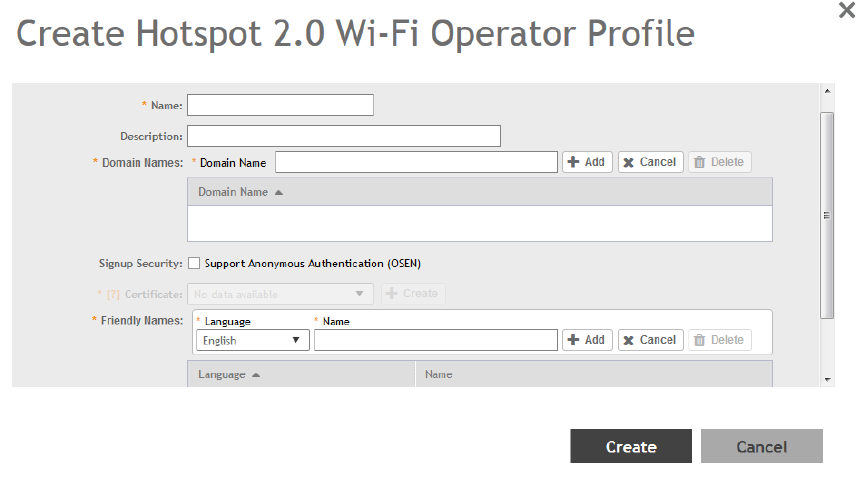
3. Click Create.
The Creating Hotspot 2.0 WiFi Operator Profile page appears.
FIGURE 68 Creating a hotspot 2.0 WiFi operator profile
4. Configure the following:
1. Name: Enter a name for this Wi-Fi operator profile.
2. Description: Enter a description for the venue profile.
3. Domain Names: HS2.0 operator's domain name is a mandatory field, which specifies the operator’s domain name. Hotspot
2.0 AP broadcasts the domain name to indicate the home Wi-Fi providers.
4. Signup Security: This is an optional field and is disabled by default. Enabling would mean that operator supports secure
onboarding (OSEN).
5. Certificate: Select the certificate for the operator - AAA. This can be the same certificate as the one used with OSU service.
6. Friendly Names: HS2.0 operator's friendly name is a mandatory field. Operator's friendly name is displayed on mobile client's
screen. It is also used for operator verification during secure onboarding (OSEN). Select the display language from the drop
down list.
5. Click OK.
Creating a Hotspot 2.0 Identity Provider
The Hotspot 2.0 Identity provider provides authentication, accounting and online sign-up service. There can be one or more identity
providers per Hotspot 2.0 access WLAN.
To configure the HS 2.0 identity provider, you must configure the following:
Network Identifier
Follow these steps to create a Hotspot 2.0 Identity Provider - Network Identifier.
Services and Profiles
Working with Hotspots and Portals
SCG200 vSZ-H and SZ300 Administrator Guide
172 Part Number: 800-71563-001
1. Configure the following:
1. Name: Enter a name or this network identifier profile.
2. Description: Enter a description for the network identifier profile.
3. PLMNs: Each record contains MCC and MNC.
MCC: Set the correct country code for the geographical location. This is required when the controller sends MAP
authentication information. Type the mobile country code digits. Decimal digit strings with maximum length of 3 and minimum
length of 2.
MNC: Set the mobile network code based on the geographical location. This is required when controller sends MAP
authentication information. Type the mobile network code digits. Decimal digit strings with maximum length of 3 and minimum
length of 2.
4. Realms: List of NAI realms corresponding to service providers or other entities whose networks or services are accessible via
this AP. Up to 16 NAI realm entries can be created. Each NAI realm entry can contain up to four EAP methods. You can add a
realm by providing the realm Name, Encoding technique (choose between RFC-4282 and UTF-8) and EAP Methods.
5. Home Ols: Organization Identifier (OI) is a unique value assigned to the organization. User can configure a maximum of 12 OI
values and can adjust the order since the AP takes only 3 OIs in the beacon.
2. Click Next.
You have completed creating a Hotspot 2.0 Identity Provider - Network Identifier.
Online Signup and Provisioning
Follow these steps to create a Hotspot 2.0 Identity Provider - Online Signup and Provisioning.
1. Configure the following:
1. Provisioning Options
• Provisioning Service: The provisioning service is responsible for any subscription provisioning process in which messages
are communicated between the UE and the SZ resulting in a PPS-MO provisioned into the UE. The provisioning supports
both SOAP-XML and OMA-DM as communication protocols for the process based on the initial request coming from the
UE. The provisioning service supports sign-up; remediation and policy update flows where the UE is provisioned with a
full PPS -MO or only with internal node/s of the PPS-MO. Administrator can only set External Internal Provisioning
Services. , where the administrator is required to fill the external OSU server URL.
• Provisioning Protocol: Select communication protocols OMA-DM or SOAP-XML.
2. Online Signup Options
• OSU NAI Realm: This configuration is only for External Provision Service. In case of Internal Provisioning Service, the NAI
realm should be configured per authentication service, which is available during on-boarding.
• Common Language Icon: This is the default icon presented in the device for this identity provider in case the device does
not find any match for other icons per language in the table.
• OSU Service Description: This table configures the friendly name, description and icon per language. This information is
presented on the device when it receives ANQP message which includes OSU providers. Friendly names, which are
required to be part of the OSU certificate is automatically populated in this table. In case description is also included in
the OSU certificate it is automatically populated into the table. Administrators are required to set the matched icon per
language as included in the OSU certificate.
• Whitelisted Domain: Add the domain names of the External Portal domain.
2. Click Next.
You have completed creating a Hotspot 2.0 Identity Provider - Online Signup and Provisioning.
Services and Profiles
Working with Hotspots and Portals
SCG200 vSZ-H and SZ300 Administrator Guide
Part Number: 800-71563-001 173
Authentication
Follow these steps to create a Hotspot 2.0 Identity Provider - Authentication.
1. Configure the following:
1. Realm: configure the realm mapping to the authentication service.
2. Auth Service: map the realm to an external RADIUS server which should be pre-configured.
3. Dynamic VLAN ID: type the VLAN ID.
2. Click Next.
You have completed creating a Hotspot 2.0 Identity Provider - Authentication.
Accounting
Follow these steps to create a Hotspot 2.0 Identity Provider - Accounting.
1. Configure the following:
1. Realm: if the authentication's realm is set as remote credential type, administrator should set this realm here to the
customer's external accounting server.
2. Accounting Service: select the accounting service.
2. Click Next.
You have completed creating a Hotspot 2.0 Identity Provider - Accounting.
Review
Review the configuration on the page before committing the changes to the server. Click Create to create the Hotspot 2.0 Identity
Provider.
Creating a Hotspot 2.0 Venue Profile
The Hotspot 2.0 technology allows users to seamlessly roam between the provider's home Wi-Fi network and the visited Wi-Fi network in a
different location. A Wi-Fi provider can partner with several roaming partners to provide Wi-Fi access to partner's subscribers. Public
venues such as institutions, restaurants, and stadiums are considered roaming partners.
1. Go to Services & Profiles > Hotspots & Portals.
2. Select the Hotspot 2.0 tab, and then select the zone for which you want to create the profile.
Services and Profiles
Working with Hotspots and Portals
SCG200 vSZ-H and SZ300 Administrator Guide
174 Part Number: 800-71563-001
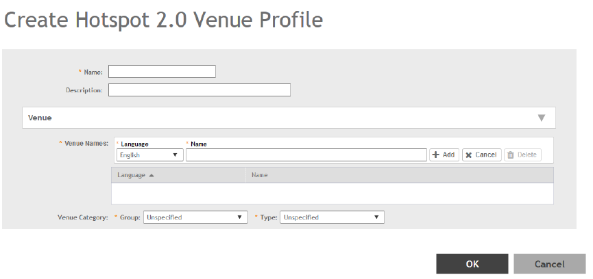
3. Click Create.
The Create Hotspot 2.0 Venue Profile page appears.
FIGURE 69 Creating a Hotspot 2.0 Venue Profile
4. Configure the following:
1. Name: Enter a name for this venue profile. This name identifies the venue profile when assigning an HS2.0 service to a HS2.0
venue.
2. Description: Enter a description for the venue profile.
3. Venue:
• Venue Names: Create a new venue name. Select the language and enter the venue name in that language.
• Venue Category: Select venue group and venue type as defined in IEEE802.11u, Table 7.25m/n.
• WAN Metrics: Provides information about the WAN link connecting an IEEE 802.11 access network and the Internet;
includes uplink/downlink speed estimates
Select the operator profile. This name identifies the service operator when assigning an HS2.0 service to a HS2.0 WLAN.
5. Click OK.
You have completed creating a Hotspot 2.0 WLAN profile.
NOTE
You can also edit, clone and delete a Hotspot 2.0 venue profile by selecting the options Configure, Clone and Delete respectively,
from the Venue Profile section in the Hotspot 2.0 tab.
Creating a UA Blacklist Profile
The controller automatically blocks certain user agents (or software used by a user) from accessing hotspots provided by controller-
managed APs. When the controller blocks any of these user agents, an error message appears on the user device. You can add to or
remove user agents from this blacklist.
Following are some of the blocked user agents:
• ZoneAlarm
Services and Profiles
Working with Hotspots and Portals
SCG200 vSZ-H and SZ300 Administrator Guide
Part Number: 800-71563-001 175
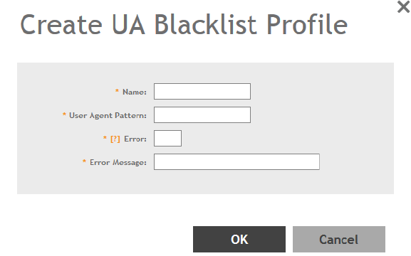
• VCSoapClient
• XTier NetIdentity
• DivX Player
• Symantec LiveUpdate
• Windows Live Messenger
• StubInstaller
• windows-update-agent
• Windows Live Essentials
• Microsoft Dr. Watson for Windows (MSDW)
• Avast Antivirus Syncer
• Microsoft Background Intelligent Transfer Service (BITS)
• Google Update
• TrendMicro client
• Skype WISPr
1. Go to Services & Profiles > Hotspots & Portals.
2. Select the UA Blacklist tab, and then select the zone for which you want to create the portal.
3. Click Create.
The Creating a UA Blacklist Profile page appears.
FIGURE 70 Creating a UA Blacklist Profile
4. Configure the following:
1. Name: Type a name of the user agent.
2. User Agent Pattern: Type the agent pattern.
3. Error: Specify the error message number.
4. Error Message: Specify the error message.
5. Click Create.
You have completed creating a UA Blacklist Profile
Services and Profiles
Working with Hotspots and Portals
SCG200 vSZ-H and SZ300 Administrator Guide
176 Part Number: 800-71563-001
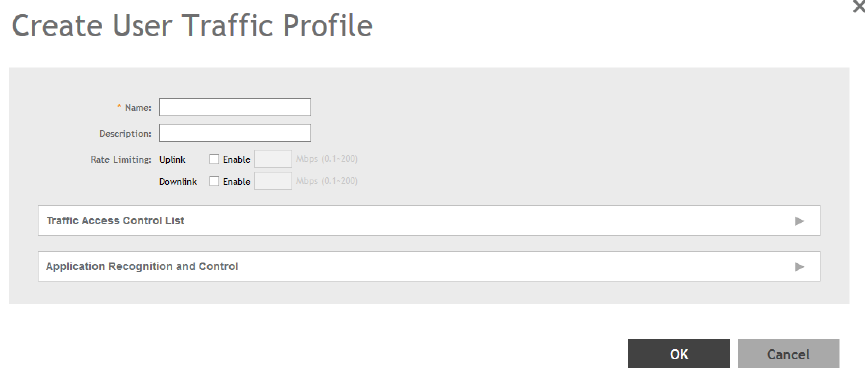
NOTE
You can also edit, clone and delete a UA blacklist profile by selecting the options Configure, Clone and Delete respectively, from
the UA Blacklist tab.
Configuring Access Control
SmartZone's Access Control features provide a wide range of options to control access and utilization of the wireless network.
Creating a User Traffic Profile
A User Traffic Profile (UTP) can be created to block or limit user traffic based on a number of factors, including Source IP address, Port,
Destination IP address, Protocol, etc. Additionally, a UTP can be created to shape traffic according to a configurable Application Control
Policy.
Once the UTP is created, it can be applied to any WLAN from the Wireless LANs page.
1. Go to Services & Profiles > Access Control.
2. Select the User Traffic tab, and then select the zone for which you want to create the profile.
3. Click Create. The Create User Traffic Profile page appears.
FIGURE 71 Create User Traffic Profile
4. Configure the following:
1. Name: Type a name for the user profile.
2. Description: Type a short description for this profile.
3. Rate Limiting: Specify and apply rate limit values for the user profile to control the data rate. Select the Enable check-box to
set the
Uplink
and
Downlink
rate limit values.
5. To create traffic control rules, click Create in the Traffic Access Control List section, and then configure Traffic Control Rules as
required. For Default Access, select whether to Allow or Block access if no rule is matched. See Creating a User Traffic Access
Control Rule on page 178 for more information.
6. In Application Recognition and Control, select an Application Policy from the list, or click Create to create a new policy.
For more information, see Configuring Application Controls on page 189.
Services and Profiles
Configuring Access Control
SCG200 vSZ-H and SZ300 Administrator Guide
Part Number: 800-71563-001 177
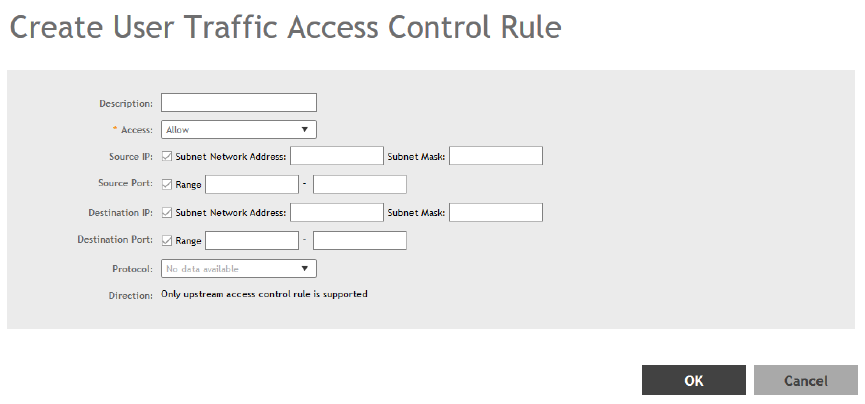
7. Click OK to save the User Traffic Profile.
You have completed creating a UTP. You can now assign this traffic profile to a WLAN from the Wireless LANs page.
NOTE
You can also edit, clone and delete a profile by selecting the options Configure, Clone and Delete respectively, from the User
Traffic tab.
Creating a User Traffic Access Control Rule
User Traffic Profiles consist of multiple traffic control rules, which can be enforced in any order you prefer (click up or down arrows to
rearrange rules).
To create a user traffic control rule:
1. Click Create. The Create User Traffic Access Control Rule page appears.
FIGURE 72 Creating a User Traffic Access Control Rule
Services and Profiles
Configuring Access Control
SCG200 vSZ-H and SZ300 Administrator Guide
178 Part Number: 800-71563-001
2. Configure the following:
•Description: Type a short description for the user traffic rule.
•Access: Select Allow or Block depending on whether you want to set this rule as the default rule.
•Source IP: Specify the source IP address to which this rule will apply. To apply this rule to an IP address range, type the
network address and the subnet mask. To apply this rule to a single IP, clear the Subnet check box, and then enter the IP
address.
•Source Port: Specify the source port to which this rule will apply. To apply this rule to a port range, type the starting and
ending port numbers in the two boxes. To apply this rule to a single port number, clear the Range check box, and then enter
the port number.
•Destination IP: Specify the destination IP address to which this rule will apply. To apply this rule to an IP address range, type
the network address and the subnet mask. To apply this rule to a single IP, clear the Subnet check box, and then enter the IP
address.
•Destination Port: Specify the source port to which this rule will apply. To apply this rule to a port range, type the starting and
ending port numbers in the two boxes. To apply this rule to a single port number, clear the Range check box, and then enter
the port number.
•Protocol: Select the network protocol to which this rule will apply. Supported protocols include TCP, UDP, UDPLITE, ICMP
(ICMPv4), ICMPV6, IGMP, ESP, AH, SCTP.
3. Click OK to save your changes.
Creating OS Policy Service
You can control how devices installed with certain OS configurations can be connected to the network, and also control what they can be
allowed to do within the network. Using the OS policy service, the system can identify the type of client attempting to connect, and perform
control actions such as allow/block, rate limiting, and VLAN tagging based on the OS rule.
1. Go to Services & Profiles > Access Control.
2. Select the OS Policy tab, and then select the zone for which you want to create the policy.
Services and Profiles
Configuring Access Control
SCG200 vSZ-H and SZ300 Administrator Guide
Part Number: 800-71563-001 179
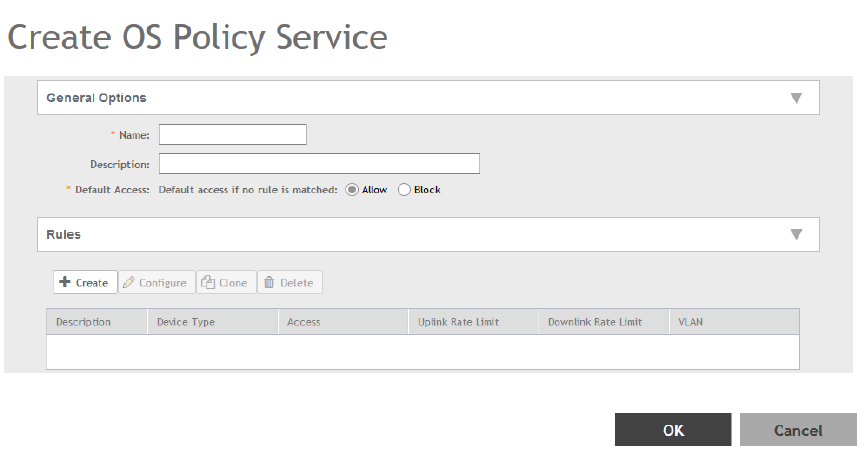
3. Click Create.
The Create OS Policy Service page appears.
FIGURE 73 Creating an OS Policy Service
4. Configure the following:
1. Name: Type a name for the OS policy.
2. Description: Type a short description for this OS policy.
3. Default Access: select either Allow or Block. This is the default action that the system will take if no rules are matched.
4. Rules: Define the OS Policy rules. For more information see, Creating OS Policy Rules on page 181
5. Click OK.
You have created the OS policy service.
NOTE
You can also edit, clone and delete a service by selecting the options Configure, Clone and Delete respectively, from the OS Policy
tab.
Services and Profiles
Configuring Access Control
SCG200 vSZ-H and SZ300 Administrator Guide
180 Part Number: 800-71563-001
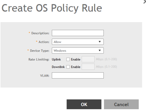
Creating OS Policy Rules
You can create rules for every OS policy service that you create.
1. Click Create. The Create OS Policy Rule page appears.
FIGURE 74 Create OS Policy Rule
2. Configure the following:
• Description: Type a short description for the rule.
• Access: Select Allow or Block. This is the action that the system will take if the client matches any of the attributes in the rule.
• Device Type: Select from any of the supported OS types.
• Rate Limiting: Specify and apply rate limit values for the device.
Select the Enable check-box to set the
Uplink
and
Downlink
rate limit values.
• VLAN: Segment this client type into a specified VLAN (1~4094; if no value is entered, this policy does not impact device VLAN
assignment).
• Click OK.
You have created the OS policy rule.
VLAN Pooling
When Wi-Fi is deployed in a high density environment such as a stadium or a university campus, the number of IP addresses required for
client devices can easily run into the thousands. Placing thousands of clients into a single large subnet or VLAN can result in degraded
performance due to factors like broadcast and multicast traffic. VLAN pooling is adopted to address this problem.
VLAN pooling allows administrators to a deploy pool of multiple VLANs to which clients are assigned, thereby automatically segmenting
large groups of clients into multiple smaller subgroups, even when connected to the same SSID. As the client device joins the WLAN, the
VLAN is assigned to one of the VLANs in the pool based on a hash of the client’s MAC address. To use the VLAN pooling feature, you first
need to create a VLAN pooling profile, and then you can assign the profile to a specific WLAN or override the VLAN settings of a WLAN
group.
Services and Profiles
Configuring Access Control
SCG200 vSZ-H and SZ300 Administrator Guide
Part Number: 800-71563-001 181
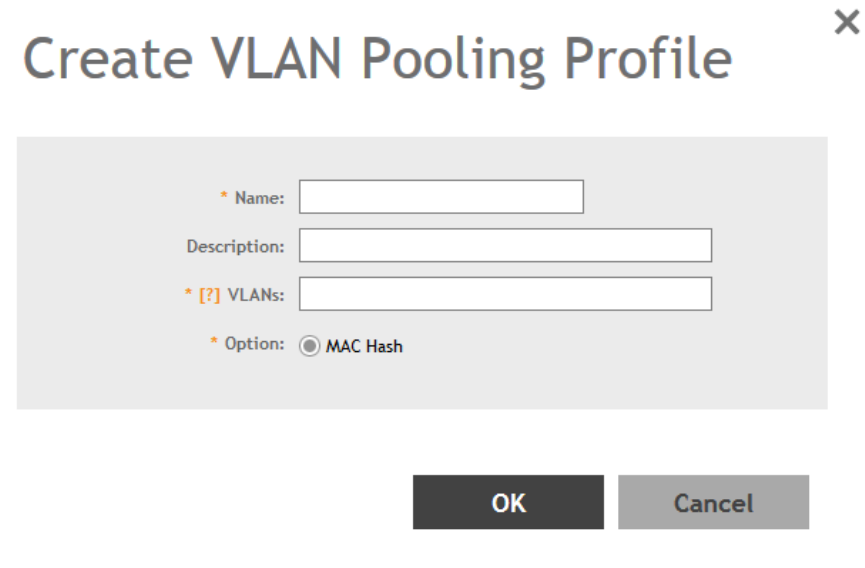
NOTE
AP model: 11ac wave 2 supports a maximum of 64 VLANs. Other AP models support up to 32 VLANs.
Creating a VLAN Pooling Profile
Each VLAN pool can contain up to 16 VLANs, and a maximum of 64 VLAN pools can be created. Each WLAN can be configured with a
single VLAN pool.
1. Go to Services & Profiles > Access Control.
2. Select the VLAN Pooling tab, and then select the zone for which you want to create the profile.
3. Click Create.
The Create VLAN Pooling page appears.
FIGURE 75 Creating a VLAN Pooling Profile
4. Configure the following:
1. Name: Type a name for the VLAN profile.
2. Description: Type a short description for this profile.
3. VLANS: Type the VLAN IDs to be assigned to this pool. VLAN IDs can be separated by hyphens, commas, or a combination
(for example, 7-10, 13, 17, 20-28).
4. Click OK.
You have created the VLAN Pooling profile.
Services and Profiles
Configuring Access Control
SCG200 vSZ-H and SZ300 Administrator Guide
182 Part Number: 800-71563-001
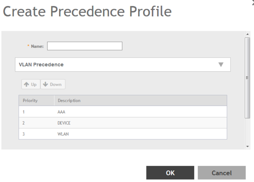
NOTE
You can also edit, clone and delete a profile by selecting the options Configure, Clone and Delete respectively, from the VLAN
Pooling tab.
Create Precedence Profile
Clients are assigned to VLANs by various methods, and there is an order of precedence by which VLANs are assigned. The assignment is
commonly done from lowest to highest precedence. You can also set precedence for Rate limiting attribute of the profile.
NOTE
Each WLAN has a default precedence.
1. Go to Services & Profiles > Access Control.
2. Select the Precedence tab, and then select the zone for which you want to create the policy.
3. Click Create.
The Create Precedence Profile page appears.
FIGURE 76 Creating a Create Precedence Profile
Services and Profiles
Configuring Access Control
SCG200 vSZ-H and SZ300 Administrator Guide
Part Number: 800-71563-001 183
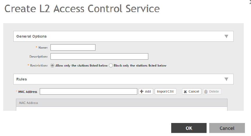
4. Configure the following:
1. Name: Type the name of the profile.
2. VLAN Precedence: Use the Up and Down options to set the VLAN priority.
3. Rate Limiting Precedence: Use the Up and Down options to set the Rate Limit priority.
NOTE
When SSID Rate Limiting (restricts total usage on WLAN) is enabled, per-user rate limiting is disabled.
4. Click OK.
You have created the Precedence profile.
NOTE
You can also edit, clone and delete a profile by selecting the options Configure, Clone and Delete respectively, from the
Precedence tab.
Creating an L2 Access Control Service
Another method to control access to the network is by defining Layer 2/MAC address access control lists (ACLs), which can then be
applied to one or more WLANs or WLAN groups. L2 ACLs are either allow-only or deny-only; that is, an ACL can be set up to allow only
specified clients or to deny only specified clients. MAC addresses that are in the deny list are blocked at the AP.
1. Go to Services & Profiles > Access Control.
2. Select the L2 Access Control tab, and then select the zone for which you want to create the access control service.
3. Click Create.
The Create L2 Access Control Service page appears.
FIGURE 77 Creating an L2 Access Control Service
Services and Profiles
Configuring Access Control
SCG200 vSZ-H and SZ300 Administrator Guide
184 Part Number: 800-71563-001
4. Configure the following:
1. General Options:
• Name: Type a name for this policy.
• Description: Type a short description for this policy.
• Restriction: Select the default action that the controller will take if no rules are matched. Available options include: Allow
only the stations listed below or Block only the stations listed below.
2. Rules:
• MAC Address: Type the MAC address to which this L2 access policy applies.
3. Click OK.
You have created an L2 access policy.
NOTE
You can also edit, clone and delete a policy by selecting the options Configure, Clone and Delete respectively, from the L2 Access
Control tab.
Creating Blocked Clients
You can deny access to the network for certain clients by using the block client access control feature.
1. Go to Services & Profiles > Access Control.
2. Select the Blocked Client tab, and then select the zone for which you want to block the client access.
Services and Profiles
Configuring Access Control
SCG200 vSZ-H and SZ300 Administrator Guide
Part Number: 800-71563-001 185
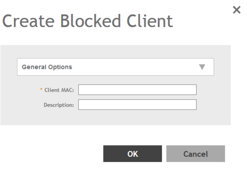
3. Click Create.
The Create Blocked Client page appears.
FIGURE 78 Create Blocked Client
4. Configure the following:
1. Client MAC: Type MAC address of the client that you want to block.
2. Description: Type a short description for client.
3. Click OK.
You have created the blocked client list.
NOTE
You can also edit, clone and delete a list by selecting the options Configure, Clone and Delete respectively, from the Blocked
Client tab.
Creating a Client Isolation Whitelist
This feature allows the administrator to manually specify an approved list of wired destinations that may be reachable by wireless clients.
NOTE
The whitelist only applies to destinations that are on the wired network, and it will not work on wireless destinations.
1. Go to Services & Profiles > Access Control.
2. Select the Client Isolation Whitelist tab, and then select the zone for which you want to specify the list of approved clients.
Services and Profiles
Configuring Access Control
SCG200 vSZ-H and SZ300 Administrator Guide
186 Part Number: 800-71563-001
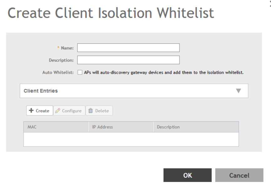
3. Click Create.
The Create Client Isolation Whitelist page appears.
FIGURE 79 Creating a Client Isolation Whitelist
4. Configure the following:
1. Name: Type a name for the client.
2. Description: Type a short description about the client.
3. Auto Whitelist: Select this check-box if you want the AP to automatically scan for devices and include them to the whitelist.
4. Client Entries: To add the clients to the list, click Create and provide client information such as MAC address (mandatory), IP
address and Description.
5. Click OK.
You have created the list of whitelisted clients that can access the network.
NOTE
You can also edit, clone and delete the list by selecting the options Configure, Clone and Delete respectively, from the Client
Isolation Whitelist tab.
Creating Time Schedules
You can control client access to the network by providing a time schedule within which the device can access the network.
1. Go to Services & Profiles > Access Control.
2. Select the Time Schedule tab, and then select the zone for which you want to create the schedule.
Services and Profiles
Configuring Access Control
SCG200 vSZ-H and SZ300 Administrator Guide
Part Number: 800-71563-001 187
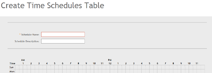
3. Click Create.
The Create Time Schedule Table page appears.
FIGURE 80 Creating a Time Schedule Table
4. Configure the following:
1. Schedule Name: Type a name for the schedule you want to create.
2. Schedule Description: Type a short description for this schedule.
3. Draw the schedule table.
4. Click OK.
You have created the schedule.
NOTE
You can also edit, clone and delete the schedule by selecting the options Configure, Clone and Delete respectively, from the Time
Schedule tab.
Creating a DNS Server Profile
By creating a DNS server profile, you can specify the primary and secondary address of the DNS server that will be used to transmit data
packets to the DNS server.
1. Go to Services & Profiles > Access Control.
2. Select the DNS Servers tab, and then select the zone for which you want to create the profile.
Services and Profiles
Configuring Access Control
SCG200 vSZ-H and SZ300 Administrator Guide
188 Part Number: 800-71563-001
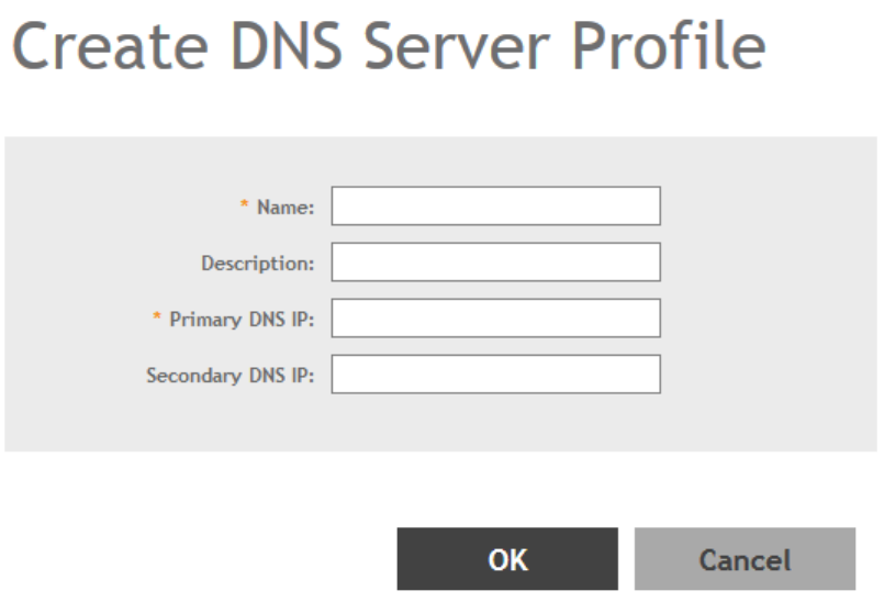
3. Click Create.
The Create DNS Server Profile page appears.
FIGURE 81 Creating a DNS Server Profile
4. Configure the following:
1. Name: Type a name for the DNS server profile.
2. Description: Type a short description for profile.
3. Primary DNS IP: Type the primary DNS IP address.
4. Secondary DNS IP: Type the secondary DNS IP address.
5. Click OK.
You have created the DNS Server Profile.
NOTE
You can also edit, clone and delete the profile by selecting the options Configure, Clone and Delete respectively, from the DNS
Servers tab.
Configuring Application Controls
Using the Application Control screen, you can identify, control, and monitor applications that are running on wireless clients associated with
managed APs, and you can also apply filtering policies to prevent users from accessing certain applications.
Additionally, you can create your own user-defined applications, import an updated application signature package, and configure rate
limiting and QoS traffic shaping policies based on system-defined or user-defined applications.
Services and Profiles
Configuring Application Controls
SCG200 vSZ-H and SZ300 Administrator Guide
Part Number: 800-71563-001 189
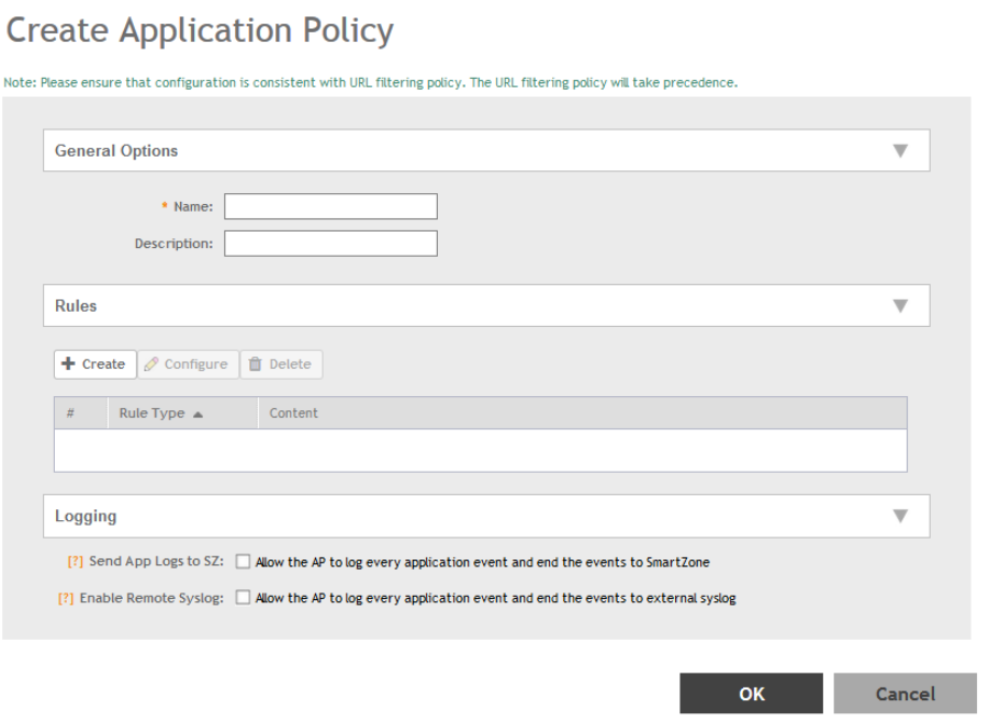
Creating an Application Control Policy
You can create an application policy to limit traffic by application, to classify traffic into priority queues using QoS traffic shaping rules, or to
completely block access to an application.
To create an application policy:
1. Go to Services & Profiles > Application Control.
2. Select the Application Policy tab.
3. Click Create.
The Create Application Policy page appears.
FIGURE 82 Creating an Application Policy
4. Enter a Name and optionally a Description for the policy.
Services and Profiles
Configuring Application Controls
SCG200 vSZ-H and SZ300 Administrator Guide
190 Part Number: 800-71563-001
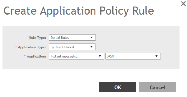
5. In Rules, click Create to create a new rule. Each application policy can contain up to 32 rules.
The Create Application Policy Rule page appears.
FIGURE 83 Creating an Application Policy Rule
6. Configure the following:
•Rule Type: Enter the type of rule from options: Denial Rules, QoS and Rate Limiting.
•Application Type: Select whether the application is user defined or system defined.
•Application: Select the application for which you want to create a policy rule.
7. Click OK to save the rule.
If are rule is already created, you can edit its configuration settings by selecting it, and clicking Configure as shown in the Create
Application Policy screen.
8. In Logging, select the appropriate check-box for the AP to log events:
• Allow the AP to log every application event and end the events to SmartZone
• Allow the AP to log every application event and end the events to external syslog
9. Click OK to save the application policy.
You have created an application policy.
Next, you can continue to apply the application control policy to user traffic, as described in Implementing an Application Control Policy on
page 191.
Implementing an Application Control Policy
Deploying an application control policy involves configuring a User Traffic Profile (UTP) with the policy, and then applying that profile to a
WLAN.
To implement an Application Control Policy:
1. Go to Services and Profiles > Access Control > User Traffic.
2. Click Create. The Create User Traffic Profile form appears.
3. Enter a Name, and optionally a Description for the UTP.
4. In the Application Recognition and Control section, select an Application Policy from the drop-down list. Alternatively, click Create
to create a new policy.
5. Click OK to save the User Traffic Profile.
Services and Profiles
Configuring Application Controls
SCG200 vSZ-H and SZ300 Administrator Guide
Part Number: 800-71563-001 191
6. Go to Wireless LANs.
7. Locate the WLAN for which you want to apply the application policy, and select it from the list.
8. Click Configure. The Edit WLAN [WLAN Name] form appears.
9. Expand the Advanced Options section, and select a User Traffic Profile you created from the drop-down list. Alternatively, click
Create to create a new UTP.
Services and Profiles
Configuring Application Controls
SCG200 vSZ-H and SZ300 Administrator Guide
192 Part Number: 800-71563-001
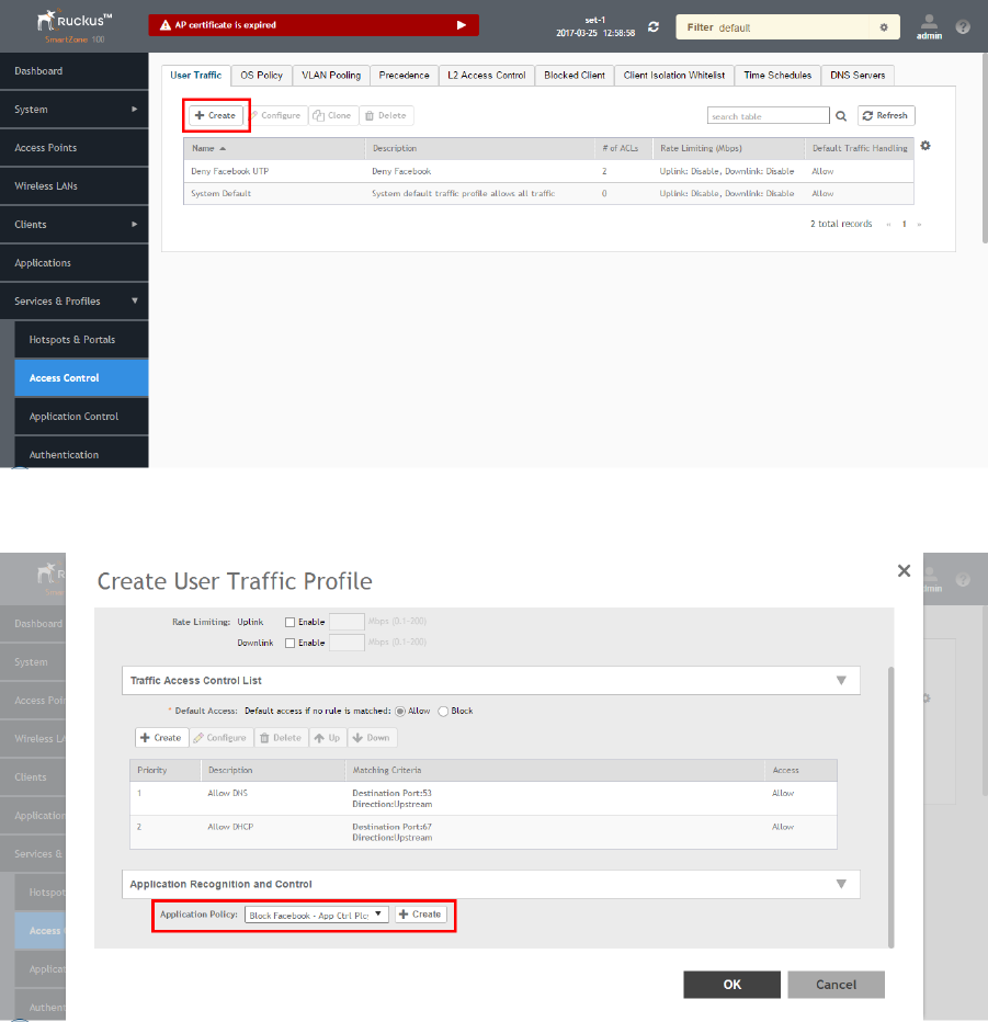
10. Click OK to save your WLAN changes.
FIGURE 84 Create a User Traffic Profile (UTP)
FIGURE 85 Select an Application Policy to apply to this UTP
Services and Profiles
Configuring Application Controls
SCG200 vSZ-H and SZ300 Administrator Guide
Part Number: 800-71563-001 193
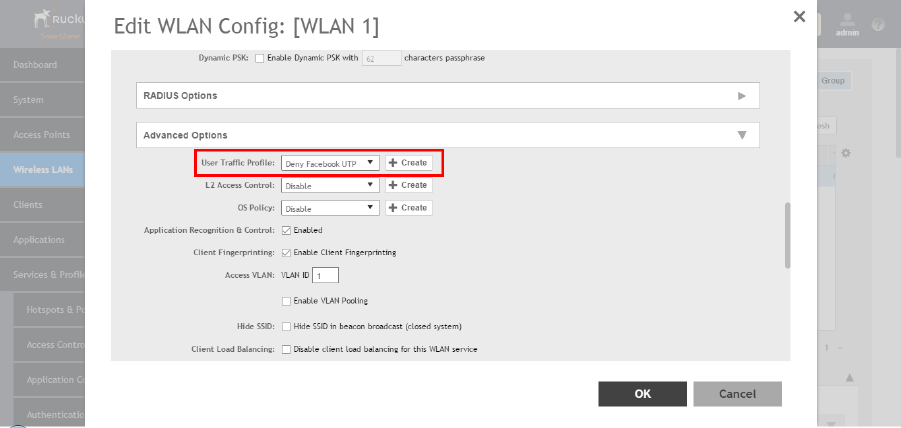
FIGURE 86 Apply the UTP to a WLAN
Creating a User Defined Application
When an application is unrecognized and generically (or incorrectly) categorized, the controller will be unable to monitor its traffic, unless you
configure an explicit application identification policy based on IP address/mask, port and protocol.
To configure a user-defined application:
1. Go to Services & Profiles > Application Control.
2. Select the User Defined tab.
Services and Profiles
Configuring Application Controls
SCG200 vSZ-H and SZ300 Administrator Guide
194 Part Number: 800-71563-001
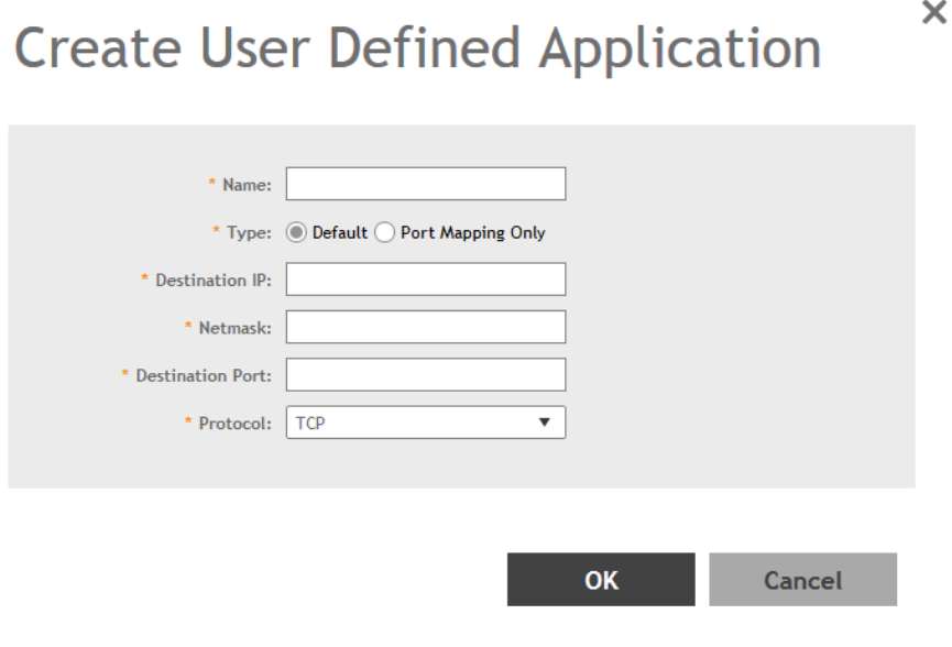
3. Click Create.
The Create User Defined Application page appears.
FIGURE 87 Creating a User Defined Application
4. Configure the following:
1. Name: Type a name for the application. This is the name that will identify this application on the dashboard.
2. Type: Select Default or Port Mapping Only (destination port).
3. Destination IP: Type the destination IP address of the application.
4. Netmask: Type the netmask of the destination IP address.
5. Destination Port: Type the destination port for the application.
6. Protocol: Select the protocol used by the application. Options include TCP and UDP.
7. Click OK.
You have created the user defined application.
NOTE
You can also edit, clone and delete the application policy by selecting the options Configure, Clone and Delete respectively, from
the User Defined tab.
Services and Profiles
Configuring Application Controls
SCG200 vSZ-H and SZ300 Administrator Guide
Part Number: 800-71563-001 195
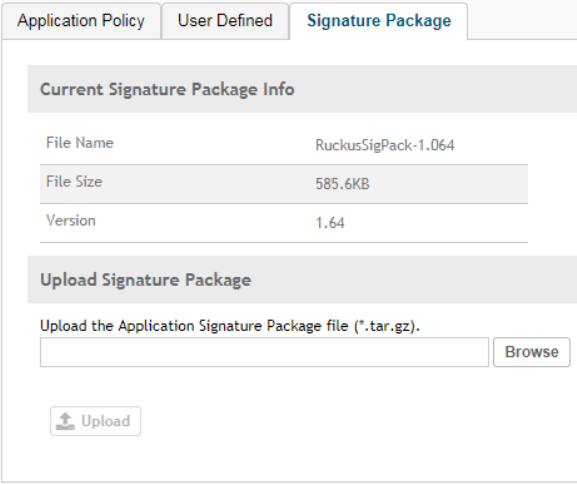
Importing an Application Signature Package
Ruckus Wireless will periodically release and make new application signature packages available for download.
Step 1: Uploading the Signature Package
Once you have downloaded a new signature package, you can import it into SmartZone using the following procedure:
1. Go to Services & Profiles > Application Control.
2. Select the Signature Package tab.
FIGURE 88 Viewing and Uploading Signature Package File Information
3. The Current Signature Package Info section displays the information about the signature
package file name, size and version.
4. In Upload Signature Package, click Browse to select the file.
5. Click Upload to upload the file.
Once the import is complete, the list of system-defined
applications is updated immediately.
Step 2: Validating the Signature Package
The application updates the latest signature package in all the connected APs. To validate the latest version follow the procedure:
1. In the Access Point, enter the Privileged EXEC mode using CLI.
Services and Profiles
Configuring Application Controls
SCG200 vSZ-H and SZ300 Administrator Guide
196 Part Number: 800-71563-001
2. Enter the following CLI command, which displays the latest version of the signature package.
rkscli:get tdts-sigpack
Current TDTS Signature Package is Ruckus-SigPack-Ver-x.xx.trf
OK
URL Filtering
Administrators can use the URL filtering feature to block access to inappropriate websites. The Web pages available on the internet are
classified into different categories, and those identified to be blocked can be configured based on available categories. Administrators can
also create policies based on these categories, to allow or deny user access.
After categorizing websites accessed by the clients connected to the AP, a third-party cloud hosted URL categorization service called
Webroot Brightcloud URL categorization
is used to categorize the live web traffic generated from the client devices. By default, traffic which
is not categorized is allowed. The packets from the client device are dropped only after the URL is successfully categorized, and DENY is
configured for the client in the policy.
The AP periodically generates statistics such as the Top 10 Denied URLs/categories, Top 10 URLs/categories by traffic and sends them to
controller which collects this information and maintains it based on the filters applied per Zone and WLAN.
URLs are typically classified by third-party applications to enhance internet security and usage. To categorize the web page or URL, the
network packets must be analyzed. In HTTP packets, the complete URL value is extracted and in HTTPS packets, the domain name of the
URL is extracted for URL web page categorization. The AP remembers the signature of the packet it forwards and when the packet is
identified as HTTP or HTTPS, it receives the domain name/URL from the packet and sends it to the
Webroot Brightcloud Web Classification
engine to verify the Web category. If the retrieved category is blocked as per the configured policy, packets with the same signature are
blocked.
The AP maintains a cache of up to 80000 URL entries and attempts to find the URL category from the local cache. It contacts the Webroot
server only when the URL is not available in the local cache.
Limitations
Following are some limitations of this feature:
• If multiple domains resolve to a single IP address, URL categorization can be inaccurate.
• Currently, if a website is blocked by URL filtering, you will not know why it is not open as a DENY page, as redirection is not
available.
• This feature requires internet connectivity as it needs to connect to the webroot server to get the URL categories.
Viewing a Summary of URL Filters
The Summary page provides administrators with a view to analyze URL traffic based on the user activity over the network.
You can view the top ten URLs by:
•Traffic - displays all URLs accessed (including blocked URLs) the most
• Categories Traffic - displays all categories accessed (including blocked categories) the most
• Clients Traffic - displays all clients accessed (including blocked clients) the most
• Blocked URLs - displays the URLs that have been denied access the most
Services and Profiles
URL Filtering
SCG200 vSZ-H and SZ300 Administrator Guide
Part Number: 800-71563-001 197
• Blocked Categorize - displays the URL categories that have been denied the most
• Blocked Clients - displays the clients that have been denied access the most
Creating a URL Filtering Policy
Administrators can create URL filtering policies and reuse them across WLAN controllers. You can define the policy based on the web page
categorization, whitelist, blacklist and web search.
Policies can also be created based on the role assigned to the user. Users can be allowed or denied access to a particular URL based on
the role assigned, and the SSID login details for that role.
Follow these steps to create a URL filtering policy:
1. Go to Services & Profiles > URL Filtering.
Services and Profiles
URL Filtering
SCG200 vSZ-H and SZ300 Administrator Guide
198 Part Number: 800-71563-001
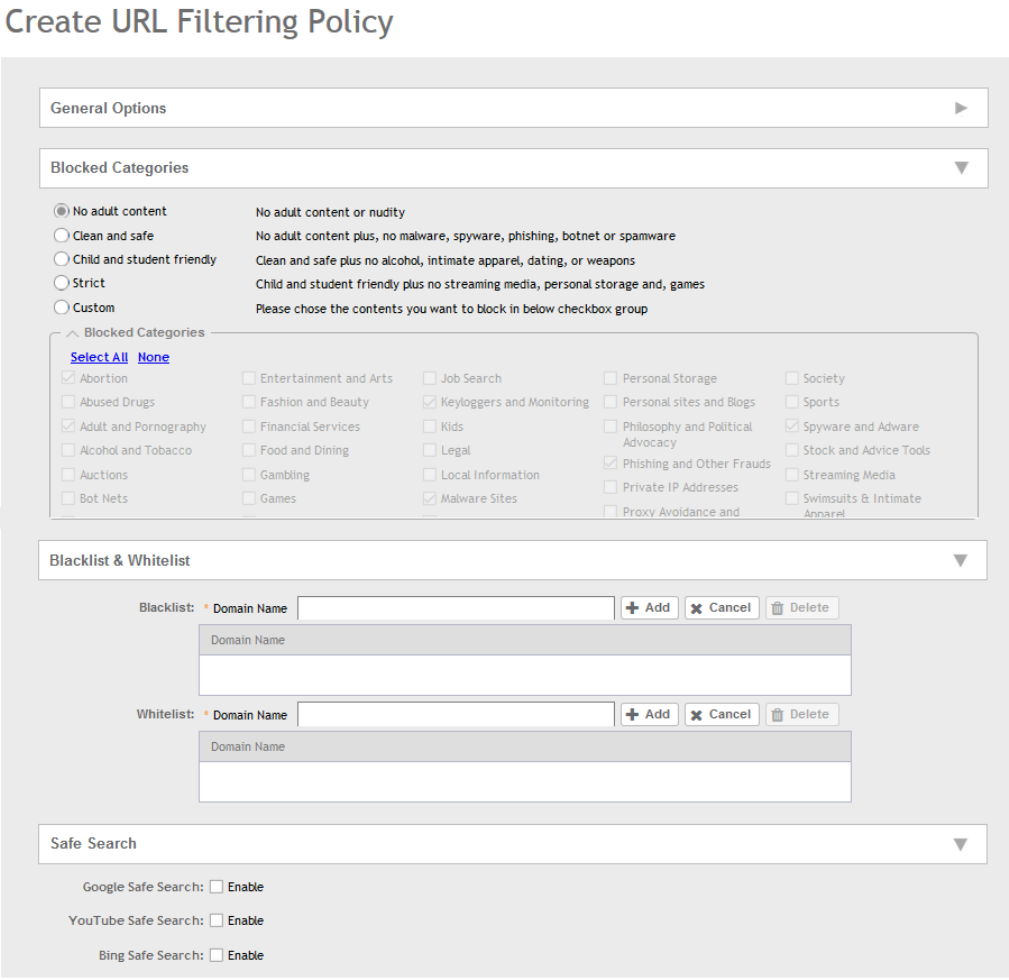
2. Select the Profiles tab, and then click Create.
The Create URL Filtering Policy page appears.
FIGURE 89 Creating a URL Filtering Policy
Configure the following:
• General Options
Name: type the name of the policy you want to create.
Services and Profiles
URL Filtering
SCG200 vSZ-H and SZ300 Administrator Guide
Part Number: 800-71563-001 199
Description: type a brief description for the policy to identify
• Blocked Categories: select one of the categories to block. Choosing the Custom option allows the administrator to customize
the list of categories to block for the user. You can also use Select All to choose all of the categories listed, or None to set no
filters for the user to access - user can access any URL in this case as no web page is blocked.
• Blacklist and Whitelist: If web content categorization is unable to classify URLs that the user, organization or institution needs,
then Whitelist or Blacklist profiles can be created by the administrator. The URLs listed by the administrator under Blacklist are
blocked and those listed under Whitelist are allowed access. The domain names under the Blacklist and Whitelist take
precedence over the default allow or deny action of the URL filter.
The AP matches the URL pattern against all the configured Whitelist and Blacklists through the
egrep
(Extended Global
Regular Expressions Print) program which performs a line-by-line scan of the file and returns lines that contain a pattern
matching the given expression. Currently, the exact URL name or a wildcard at the beginning of the URL is used to match the
pattern.
Administrators can also add specific IP addresses or wildcard domain names under Whitelist and Blacklist.
In Domain Name, type the domain name of the web page that you want to deny user access to in the Blacklist tab, and
provide user access to in the Whitelist tab. You can define up to 16 domains.
Click Add. The domain name/web page is listed in the corresponding tab.
Click Cancel to remove the domain name you have entered in the field.
If you want to delete the domain name from the
Blacklist
or
Whitelist
tab, select the URL and click Delete.
• Safe Search: Administrators can configure the policy to include a safe search option when users access Google, YouTube or
Bing to search on the internet. Select the Enable check box to set the safe search feature to ON. Enabling this option will
mandate all users using this policy on the network to use safe search on Google, YouTube and Bing. This option provides a
secure connection via HTTPS while still allowing access to the internet. Enabling safe search on the browser displays the
virtual IP address of the browser.
3. Click OK.
The URL Filtering Policy form is submitted with the specified configuration settings.
You have created the URL filtering policy. The newly created policy is displayed on Profiles page.
If you click on the policy, it displays the following information:
• Name
• Managed By
• Description
• Filtering Level
• # of Blocked Categorize
• # of Blacklist
• #of Whiltelist
• Last Modified By
• Last Modified On
Click Configure to edit the policy. Click Clone to create a duplicate of the policy, or to make modifications to the existing settings of the
clone.
Click Delete to delete the policy from the URL Filtering Profile.
Services and Profiles
URL Filtering
SCG200 vSZ-H and SZ300 Administrator Guide
200 Part Number: 800-71563-001
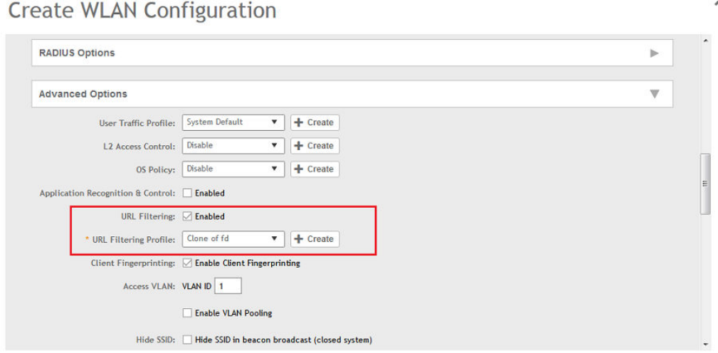
Enabling URL Filtering on the Controller
You can enable the URL filtering feature on the WLAN controller to block or allow access to specific web sites or web pages.
By configuring the controller, the administrator can create a wireless network SSID and allow or deny access to a category of websites for
all users that join this SSID.
Follow these steps to enable URL filtering on the controller:
1. In the Wireless LANs page, from the System tree hierarchy, select the domain, zone or WLAN system for which you want to
enable URL.
2. Click Create.
The Wireless LANs page appears.
3. In Advance Options, select the Enabled check-box against the URL Filtering option.
The URL Filtering Profile field appears. Select a profile from a list of existing URL filtering profiles displayed in the drop-down menu.
You can also click Create to create a new URL filtering profile.
For more information, see Creating a URL Filtering Policy on page 198.
FIGURE 90 Enabling URL Filtering
NOTE
Application rules are applied based on the following priority, and user defined rules take precedence over URL filtering.
1. User defined ARC profile
2. URL Filtering
3. ARC
You have enabled URL filtering on the controller.
Services and Profiles
URL Filtering
SCG200 vSZ-H and SZ300 Administrator Guide
Part Number: 800-71563-001 201
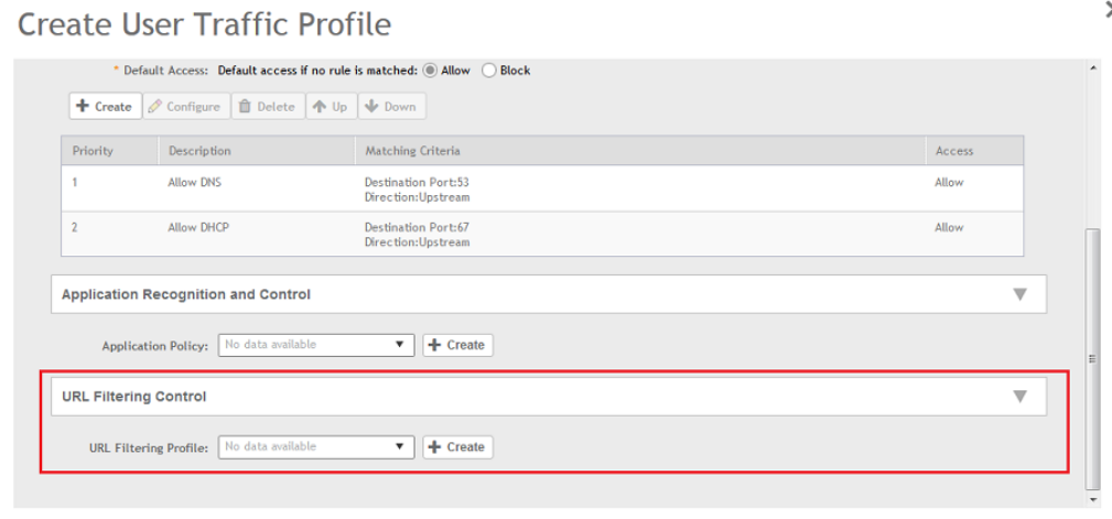
Enabling URL Filtering in the User Traffic Profile
A User Traffic Profile (UTP) can be created to block or limit user traffic based on a number of factors, including URL filtering in addition to
Source IP address, Port, Destination IP address, Protocol, etc. A UTP can be created to shape traffic according to a configurable
Application Control Policy.
After the UTP is created, it can be applied to any WLAN from the Wireless LANs page.
1. Go to Services & Profiles > Access Control.
2. Select the User Traffic tab, and then select the zone for which you want to create the profile.
3. Click Create.
The Create User Traffic Profile page appears.
4. In URL Filtering Control, select the URL Filtering Profile from the drop-down menu.
You can also create a URL filtering profile by clicking Create. For more information, refer to Creating a URL Filtering Policy on page
198.
NOTE
You must select a UTP in which URL filtering is enabled, and also ensure URL filtering in enabled within the same WLAN
configuration.
FIGURE 91 UTP Page
You have successfully enable URL filtering in the UTP.
Services and Profiles
URL Filtering
SCG200 vSZ-H and SZ300 Administrator Guide
202 Part Number: 800-71563-001
Managing URL Filtering Licenses
URL Filtering license for the selected partners-to use the content database is issued for a duration of one year for an AP. Dashboard
warnings are issued thirty days before the end of the license term.
You can add licenses over time. For example, you can purchase 100 one-year licenses on January 1st and add another 200 one-year
licenses in May. The controller receives a new expiry date for the combined license count of 300 APs.
To view license details such as start date, end date, and capacity, go to Administration > Licenses > Installed Licenses tab. For more
information on importing installed licenses, synchronizing the controller with the license server, and downloading license files, refer
Managing
Licenses
.
When the license capacity is exhausted, event code 1281 is triggered. When the license period expires, alarm code 8003 is generated
which indicates that the URL filtering server is unreachable. For more information, refer
Managing Events and Alarms
.
NOTE
A permissive license similar to the BSD 2-Clause License, but with a 3rd clause that prohibits others from using the name of the
project or its contributors to promote derived products without written consent.
Copyright (c) 2005, Google Inc. All rights reserved.
Redistribution and use in source and binary forms, with or without modification, are permitted provided that the following
conditions are met:
• Redistributions of source code must retain the above copyright notice, this list of conditions and the following disclaimer.
• Redistributions in binary form must reproduce the above copyright notice, this list of conditions and the following
disclaimer in the documentation and/or other materials provided with the distribution.
• Neither the name of Google Inc. nor the names of its contributors may be used to endorse or promote products derived
from this software without specific prior written permission.
ATTENTION
THIS SOFTWARE IS PROVIDED BY THE COPYRIGHT HOLDERS AND CONTRIBUTORS "AS IS" AND ANY EXPRESS OR
IMPLIED WARRANTIES, INCLUDING, BUT NOT LIMITED TO, THE IMPLIED WARRANTIES OF MERCHANTABILITY AND
FITNESS FOR A PARTICULAR PURPOSE ARE DISCLAIMED. IN NO EVENT SHALL THE COPYRIGHT OWNER OR
CONTRIBUTORS BE LIABLE FOR ANY DIRECT, INDIRECT, INCIDENTAL, SPECIAL, EXEMPLARY, OR CONSEQUENTIAL
DAMAGES (INCLUDING, BUT NOT LIMITED TO, PROCUREMENT OF SUBSTITUTE GOODS OR SERVICES; LOSS OF USE,
DATA, OR PROFITS; OR BUSINESS INTERRUPTION) HOWEVER CAUSED AND ON ANY THEORY OF LIABILITY, WHETHER IN
CONTRACT, STRICT LIABILITY, OR TORT (INCLUDING NEGLIGENCE OR OTHERWISE) ARISING IN ANY WAY OUT OF THE
USE OF THIS SOFTWARE, EVEN IF ADVISED OF THE POSSIBILITY OF SUCH DAMAGE.
Authentication
You can add AAA servers to the controller in order to use them to authenticate users attempting to associate with controller-managed APs.
Creating Non-Proxy Authentication AAA servers
A non-proxy AAA server is used when the APs connect to the external AAA server directly.
1. Go to Services & Profiles > Authentication.
2. Select the Non-Proxy (AP Authenticator) tab, and then select the zone for which you want to create the AAA server.
Services and Profiles
Authentication
SCG200 vSZ-H and SZ300 Administrator Guide
Part Number: 800-71563-001 203
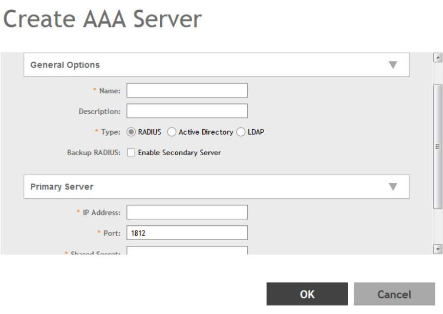
3. Click Create.
The Create AAA Server page appears.
FIGURE 92 Creating an AAA Server
Services and Profiles
Authentication
SCG200 vSZ-H and SZ300 Administrator Guide
204 Part Number: 800-71563-001
4. Configure the following:
1. General Options
• Name: Type a name for the AAA server that you are creating.
• Description: Type a short description of the AAA server.
• Type: Select the type of AAA server that you are creating. Options include RADIUS, Active Directory and LDAP.
• Backup RADIUS (appears if you clicked RADIUS above): Select the Enable Secondary Server check box if a secondary
RADIUS server exists on the network.
• Global Catalog (appears if you clicked Active Directory above): Select the Enable Global Catalog support if you the Active
Directory server to provide a global list of all objects.
2. Authentication Types
• If you selected RADIUS, configure the following options in the Primary Server section:
– IP Address: Type the IP address of the AAA server. Both IPv4 and IPv6 addressing formats are supported.
– Port: Type the port number of the AAA server. The default RADIUS server port number is 1812.
– Shared Secret: Type the AAA shared secret.
–Confirm Secret: Retype the shared secret to confirm.
If you have enabled Backup RADIUS to the Secondary Sever, you must provide similar information as in the primary
server.
See RADIUS Service Options on page 210 for more information.
• If you selected Active Directory, configure the following options in the Primary Server section:
– IP Address: Type the IPv4 address of the AD server.
– Port: Type the port number of the AD server. The default port number (389) should not be changed unless you have
configured the AD server to use a different port.
– Windows Domain Name: Type the Windows domain name assigned to the AD server (for example,
domain.ruckuswireless.com).
• If you selected LDAP, configure the following options:
– IP Address: Type the IPv4 address of the LDAP server.
– Port: Type the port number of the LDAP server. Default is 389.
– Base Domain Name: Type the base DN in LDAP format for all user accounts (for example, dc=ldap,dc=com).
– Admin Domain Name: Type the admin DN in LDAP format (for example, cn=Admin;dc=<Your Domain>,dc=com).
– Admin Password: Type the administrator password for the LDAP server.
–Confirm Password: Retype the administrator password to confirm.
– Key Attribute: Type a key attribute to denote users (for example, default: uid)
– Search Filter: Type a search filter (for example, objectClass=Person).
5. Click OK.
You have completed creating a Non-proxy AAA server.
NOTE
You can also edit, clone and delete an AAA server by selecting the options Configure, Clone and Delete respectively, from the
Non-Proxy (AP Authenticator) tab.
Services and Profiles
Authentication
SCG200 vSZ-H and SZ300 Administrator Guide
Part Number: 800-71563-001 205
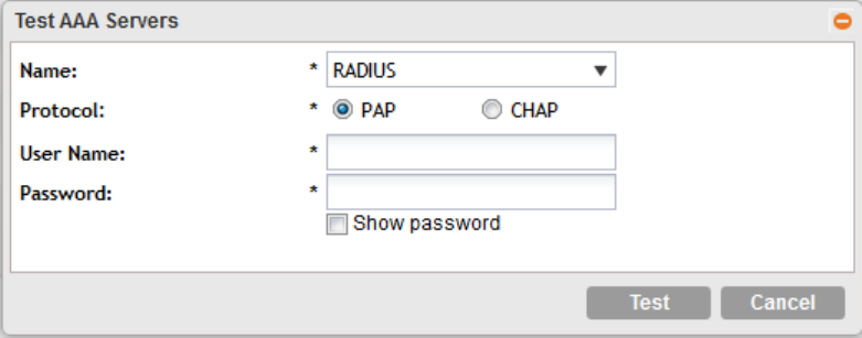
Testing AAA Server (Auth)
To ensure that the controller administrators will be able to authenticate successfully with the RADIUS server type that you selected, Ruckus
Wireless strongly recommends testing the AAA server after you set it up.
The test queries the RADIUS server for a known authorized user and return groups associated with the user that can be used for
configuring roles within the controller.
1. Go to Services & Profiles > Authentication.
2. Select the Non-Proxy (AP Authenticator) tab, and then select the zone for which you want to test the AAA server.
3. Click Test AAA.
The Test AAA Server page appears.
FIGURE 93 Testing an AAA Server
4. Configure the following:
1. Name: Select one of the AAA servers that you previous created.
2. Protocol: Select the Password Authentication Protocol (PAP), or the Challenge Handshake Authentication Protocol (CHAP) to
authenticate the AAA server.
3. User Name: Type an existing user name on the AAA server that you selected.
4. Password: Type the password for the user name you specified.
5. Click Test.
If the test was unsuccessful, there are two possible results (other than success) that will be displayed to inform you if you have
entered information incorrectly: Admin invalid or User name or password invalid. These results can be used to troubleshoot the
reasons for failure to authenticate administrators with an AAA server through the controller.
You have completed testing the non-proxy AAA servers that you created.
Creating Proxy AAA Servers
A proxy AAA server is used when APs send authentication/accounting messages to the controller and the controller forwards these
messages to an external AAA server.
1. Go to Services & Profiles > Authentication.
2. Select the Proxy (SZ Authenticator) tab, and then select the zone for which you want to create the AAA server.
Services and Profiles
Authentication
SCG200 vSZ-H and SZ300 Administrator Guide
206 Part Number: 800-71563-001
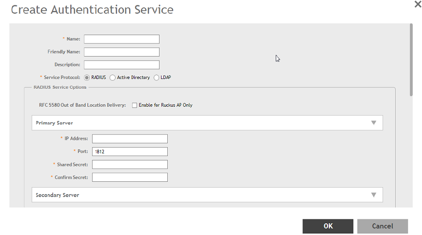
3. Click Create.
The Create Authentication Service page appears.
FIGURE 94 Creating an Authentication Service
Services and Profiles
Authentication
SCG200 vSZ-H and SZ300 Administrator Guide
Part Number: 800-71563-001 207
4. Configure the following:
1. Name: Type a name for the authentication service that you are adding.
2. Friendly Name: Type an alternative name that is easy to remember.
3. Description: Type a description for the authentication service.
4. Service Protocol: If you select
• RADIUS, see RADIUS Service Options on page 210 for more information.
• Active Directory, configure the following:
1. Global Catalog: Select the Enable Global Catalog support if you the Active Directory server to provide a global list of
all objects.
2. Primary Server:
– Encryption: Select the Enable TLS Encryption check box if you want to use the
Transport Layer Security
(TLS)
protocol to secure communication with the server.
NOTE
You must also configure the Trusted CA certificates to support TLS encryption.
3. IP Address: Type the IPv4 address of the AD server.
4. Port: Type the port number of the AD server. The default port number (389) should not be changed unless you have
configured the AD server to use a different port.
5. Windows Domain Name: Type the Windows domain name assigned to the AD server (for example,
domain.ruckuswireless.com).
• LDAP, configure the following:
1. Select the Enable TLS Encryption check box if you want to use the
Transport Layer Security
(TLS) protocol to secure
communication with the server.
NOTE
You must also configure the Trusted CA certificates to support TLS encryption.
2. IP Address: Type the IPv4 address of the LDAP server.
3. Port: Type the port number of the LDAP server.
4. Base DN: Type the base DN in LDAP format for all user accounts (for example, dc=ldap,dc=com).
5. Admin DN: Type the admin DN in LDAP format (for example, cn=Admin;dc=<Your Domain>,dc=com).
6. Admin Password: Type the administrator password for the LDAP server.
7. Confirm Password: Retype the administrator password to confirm.
8. Key Attribute: Type a key attribute to denote users (for example, default: uid)
9. Search Filter: Type a search filter (for example, objectClass=Person).
• OAuth, configure the following:
1. Provider: Authorize Google, Facebook or LinkedIn by selecting one of them.
2. Application ID: Specify the application ID.
3. Application Secret: Type the application secret.
4. Collect E-mail Address: Select this check-box if you want the controller to collect the user's email address and
maintain it for further use.
• HLR, configure the following:
Services and Profiles
Authentication
SCG200 vSZ-H and SZ300 Administrator Guide
208 Part Number: 800-71563-001
1. General Settings
– SGSN ISDN Address: Type any number from 1 to 9.
– Routing Context: Type 1 to identify the application service process (ASP).
– Local Point Code: Type the local point code number for the controller. Default is 1.
– Default Point Code format: Select Integer format.
– EAP-SIM Map Version: Select map version 3 from the drop-down menu.
– Authorization Map Version: Select map version 3 from the drop-down menu.
2. SCCP Addresses Default Settings
– Source GT Indicator: Select a GT indicator from the drop-down. You can select translation type only or in
addition to numbering plan, encoding scheme and nature of address indicator.
– Source Has Point Code: Select Yes or No.
– Source Translation Type: Type the appropriate integer value.
– Source Numbering Plan: Select ISDN/Recommended plan (E.163/E.164).
– Source Nature Address of Indicator: Select from Subscriber Number, Reserved for National Use, National
Significant Number and International Number (recommended).
– Address Indicator: Select between Route on GT and SSN.
– Destination GT Indicator: Select a GT indicator from the drop-down. You can select translation type only or in
addition to numbering plan, encoding scheme and nature of address indicator.
– Destination Translation Type: Type the appropriate integer value.
– Destination Numbering Plan: Select ISDN/Recommended plan (E.163/E.164) or E.214.
– Destination Nature Address of Indicator: Select from Subscriber Number, Reserved for National Use, National
Significant Number and International Number.
– GT Point Code: Set to 2.
3. SCTP Association to Core Network
– Destination IP: Type the IP address of the destination port.
– Destination Port: Type the number of the destination port.
– Source Port: Type the number of the source port.
– Max Inbound Streams: Set to 32.
– Max Outbound Streams: Set to 32
– Adjacent Point Code: Set to 2.
4. SCCP GTT Table
– GT Digits: Type any number (1 to 15 digit number).
– Address Indicator: Select between options to route on GT or SSN.
– Point Code: Set to 1.
– Translation Type: Type the appropriate integer value.
– GT Indicator: Select a GT indicator from the drop-down. You can select translation type only or in addition to
numbering plan, encoding scheme and nature of address indicator.
– Has Point Code: Select between Yes and No.
– Has SSN: Select between Yes and No.
– Number Planning: Select ISDN/Recommended plan (E.163/E.164) or E.214.
– Nature of Address Indicator: Select from Subscriber Number, Reserved for National Use, National Significant
Number and International Number.
NOTE
Ensure that the settings provided in the GTT table are match the ones provided in the SCCP
Addresses Default Settings section.
Services and Profiles
Authentication
SCG200 vSZ-H and SZ300 Administrator Guide
Part Number: 800-71563-001 209

5. Cache Options: select Enable AV Caching (makes use of the existing cache memory values).
5. Advanced Options - Domain name: Type the whitelisted domain name that you want to add.
6. User Traffic Profile Mapping:
a. Type a Group Attribute Value.
b. Select a User Role from the drop-down list.
c. Click Add.
The mapped user profile is listed.
5. Click OK.
You have completed creating a Proxy AAA server.
NOTE
You can also edit, clone and delete an AAA server by selecting the options Configure, Clone and Delete respectively, from the
Proxy (SZ Authenticator) tab.
RADIUS Service Options
These are the Radius service options available for the primary and secondary servers.
RFC 5580 Out of Band Location Delivery: If you want out-of-band location delivery (RFC 5580) to apply only to Ruckus Wireless APs, select
the Enable for Ruckus AP Only check box.
Configure the primary RADIUS server settings as shown in the following table.
Configure the primary RADIUS server settings.
TABLE 22 Primary Server Options
Option Description
IP Address Type the IP address of the RADIUS server. IPv4 and IPv6 addressing
formats are supported.
Port Type the port number of the RADIUS server. The default RADIUS server port
number is 1812 and the default RADIUS Accounting server port number is
1813.
Shared Secret Type the RADIUS shared secret.
Confirm Secret Retype the shared secret to confirm.
If you have a secondary RADIUS server on the network that you want to use as a backup, select the Enable Secondary Server check box,
and then configure the settings in the following table.
TABLE 23 Secondary Server Options
Option Description
Backup RADIUS Select Enable Secondary Server.
When a secondary RADIUS server is enabled and the primary RADIUS
server becomes unavailable, the secondary Automatic Fallback Disable
server takes over the handling of RADIUS requests. When the primary
server becomes available again, it takes back control over RADIUS requests
from the secondary server. If you want to prevent the primary server from
retaking control over RADIUS requests from the secondary server, select the
Automatic Fallback Disable check box.
IP Address Type the IP address of the secondary AAA server.
Services and Profiles
Authentication
SCG200 vSZ-H and SZ300 Administrator Guide
210 Part Number: 800-71563-001

TABLE 23 Secondary Server Options (continued)
Option Description
Port Type the port number of the secondary AAA server port number. The default
RADIUS server port number is 1812 and the default RADIUS Accounting
server port number is 1813.
Shared Secret Type the AAA shared secret.
Confirm Secret Retype the shared secret to confirm.
The following options define the health monitoring settings of the primary and secondary RADIUS servers, when the controller is configured
as RADIUS proxy for RADIUS Authentication and Accounting messages.
TABLE 24 Health Check Policy
Option Description
Response Window Set the time (in seconds) after which, if the AAA server does not respond to
a request, the controller will initiate the zombie period (see below).
Response Window
If the primary AAA server does not respond to RADIUS messages sent after
Response Window expires, the controller will forward the retransmitted
RADIUS messages to the secondary AAA server.
NOTE
The zombie period is not started immediately after the
Response Window expires, but after the configured Response
Window plus ¼ of the configured Zombie Period. The default
Response Window is 20 seconds
Zombie Period Set the time (in seconds) after which, if the AAA server does not respond to
ANY packets during the zombie period, it will be considered to inactive or
unreachable.
An AAA server that is marked zombie (inactive or unreachable) will be used
to proxy with a low priority. If there are other live AAA servers, the controller
will attempt to use these servers first instead of the zombie AAA server.
The controller will only proxy requests to a zombie server only when there
are no other live servers. Any request that is sent as a proxy to an AAA
server will continue to be sent to that AAA server until the home server is
marked inactive or unreachable. At that point, the request will fail over to
another server, if a live AAA server is available. The default Zombie Period is
40 seconds.
Revive Interval Set the time (in seconds) after which, if no RADIUS messages are sent as
proxy to the AAA server after it has been marked as inactive or unreachable,
the controller will mark the AAA server as active again (and assume that it
has become reachable again). The default Revive Interval is 120 seconds.
No Response Fail Click Yes to respond with a reject message to the NAS if no response is
received from the RADIUS server. Click No to skip sending a response.
NOTE
To ensure that the RADIUS fail-over mechanism functions correctly, either accept the default values for the Response Window,
Zombie Period, and Revive Interval, or make sure that the value for Response Window is always higher than the value for RADIUS
NAS request timeout multiplied by the value for RADIUS NAS max number of retries. For third party APs, you must ensure that the
configured Response Window on the controller is higher than the RADIUS NAS request timeout multiplied by the RADIUS value.
The maximum number of retries is configured at the 3rd party controller/AP.
Services and Profiles
Authentication
SCG200 vSZ-H and SZ300 Administrator Guide
Part Number: 800-71563-001 211
Configure the following options.
TABLE 25 Rate Limiting
Options Description
Maximum Outstanding Requests (MOR) Set the maximum outstanding requests per server. Type 0 to disable it, or
set a value between 10 and 4096.
Threshold (% of MOR) Set a percentage value of the MOR at which (when reached) the controller
will generate an event. Threshold (% of MOR)
For example, if the MOR is set to 1000 and the threshold is set to 50%, the
controller will generate an event when the number of outstanding requests
reaches 500.
Sanity Timer Set a timer (in seconds) that will be started whenever a condition that
generates an event is reached. This helps prevent conditions that trigger
events which occur frequently.
Testing AAA Servers
To ensure that the controller administrators will be able to authenticate successfully with the RADIUS server type that you selected, Ruckus
Wireless strongly recommends testing the AAA server after you set it up.
1. Go to Services & Profiles > Authentication.
2. Select the Proxy (SZ Authenticator) tab, and then select the zone for which you want to test the AAA server.
Services and Profiles
Authentication
SCG200 vSZ-H and SZ300 Administrator Guide
212 Part Number: 800-71563-001
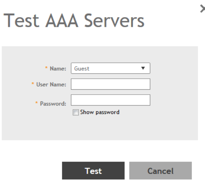
3. Click Test AAA.
The Test AAA Server page appears.
FIGURE 95 Testing an AAA Server
4. Configure the following:
1. Name: Select one of the AAA servers that you previously created.
2. User Name: Type an existing user name on the AAA server that you selected.
3. Password: Type the password for the user name you specified.
5. Click Test.
If the controller was able to connect to the authentication server and retrieve the configured groups/attributes, the information
appears at the bottom of the page. If the test was unsuccessful, there are two possible results (other than success) that will be
displayed to inform you if you have entered information incorrectly: Admin invalid or User name or password invalid. These results
can be used to troubleshoot the reasons for failure to authenticate administrators with an AAA server through the controller.
Creating Realm Based Authentication Profile
An authentication profile defines the authentication policy when the controller is used as a Radius proxy service for WLANs.
1. Go to Services & Profiles > Authentication.
2. Select the Realm Based Proxy tab, and then select the zone for which you want to create the profile.
Services and Profiles
Authentication
SCG200 vSZ-H and SZ300 Administrator Guide
Part Number: 800-71563-001 213
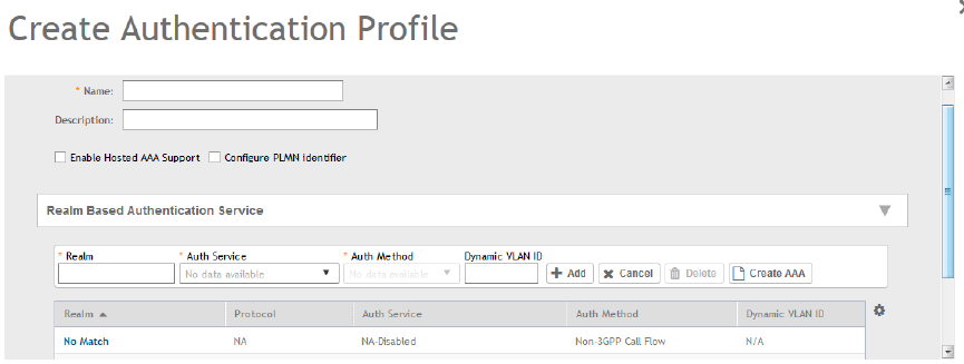
3. Click Create.
The Create Authentication Profile page appears.
FIGURE 96 Creating a Realm Based Proxy Authentication Profile
4. Configure the following:
1. Name: Type a name for the authentication service profile that you are creating.
2. Description: Type a short description of the authentication service profile.
3. To enable hosted AAA support, select the Enable Hosted AAA Support check box, and then configure these options:
a. Interim Accounting Interval (secs): Set the interim time interval for RADIUS clients to send accounting updates. Default is
0, which indicates that the accounting interval is disabled.
b. Sessions Timeout (secs): Set a time limit after which users will be disconnected and required to log on again.
c. Session Idle Timeout (secs): Set a value in seconds (60 to 600) after which idle clients will be disconnected.
4. Select the Configure PLMN Identifier check-box, and set the following options:
a. Mobile Country Code: Set the correct country code for the geographical location. This is required when the controller
sends MAP authentication information to the HLR.
b. Mobile Network Code: Set the mobile network code based on the geographical location. This is required when the
controller sends MAP authentication information to HLR.
5. Realm-Based Authentication Service
• Realm: Type wthere the realm is No Match or Unspecified.
• Auth Service: Select a default authentication service for the realm.
• Auth Method: Select an authorization method as 3GPP or Non-3GPP call flow.
• Dynamic VLAN ID: Type the vlan ID.
6. Redirection: select where to redirect the user after successfully completing authentication.
• Redirect to the URL that the user intends to visit: Allows the guest user to continue to their destination without
redirection.
• Redirect to the following URL: Redirect the user to a specified web page (entered into the text box) prior to forwarding
them to their destination. When guest users land on this page, they are shown the expiration time for their guest pass.
5. Click OK.
Services and Profiles
Authentication
SCG200 vSZ-H and SZ300 Administrator Guide
214 Part Number: 800-71563-001

Accounting
Creating Non-Proxy Accounting AAA Servers
A non proxy AAA server is used when the APs connect to the external AAA server directly.
1. Go to Services & Profiles > Accounting.
2. Select the Non-Proxy tab, and then select the zone for which you want to create the AAA server.
3. Click Create.
The Create AAA Server page appears.
FIGURE 97 Creating an AAA Server
Services and Profiles
Accounting
SCG200 vSZ-H and SZ300 Administrator Guide
Part Number: 800-71563-001 215
4. Configure the following:
1. General Options
• Name: Type a name for the AAA server that you are creating.
• Description: Type a short description of the AAA server.
• Type: Select RADIUS Accounting.
• Backup RADIUS (appears if you clicked RADIUS above): Select the Enable Secondary Server check box if a secondary
RADIUS server exists on the network.
2. If you selected RADIUS, configure the following options in the Primary and Secondary server sections:
• IP Address: Type the IP address of the AAA server.
• Port: Type the port number of the AAA server. The default RADIUS server port number is 1813.
• Shared Secret: Type the AAA shared secret.
•Confirm Secret: Retype the shared secret to confirm.
5. Click OK.
You have completed creating a Non-proxy Accounting AAA server.
For information on how to test this server, see Testing AAA Servers on page 212
NOTE
You can also edit, clone and delete an AAA server by selecting the options Configure, Clone and Delete respectively, from the
Non-Proxy tab.
Creating Proxy Accounting AAA Servers
A proxy AAA server is used when APs send authentication/accounting messages to the controller and the controller forwards these
messages to an external AAA server.
1. Go to Services & Profiles > Accounting.
2. Select the Proxy tab, and then select the zone for which you want to create the AAA server.
Services and Profiles
Accounting
SCG200 vSZ-H and SZ300 Administrator Guide
216 Part Number: 800-71563-001
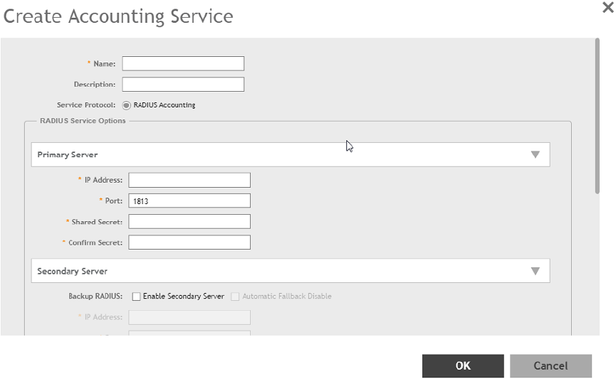
3. Click Create.
The Create Accounting Service page appears.
FIGURE 98 Creating an Accounting Service
4. Configure the following:
1. Name: Type a name for the authentication service that you are adding.
2. Description: Type a description for the authentication service.
3. Service Protocol: By default, the RADIUS Accounting selected. For more information, see RADIUS Service Options on page
210.
5. Click OK.
You have completed creating a Proxy Accounting AAA server.
For information on how to test this server, see Testing AAA Servers on page 212
NOTE
You can also edit, clone and delete an AAA server by selecting the options Configure, Clone and Delete respectively, from the
Proxy tab.
Creating Realm Based Proxy
An accounting profile defines the accounting policy when the controller is used as a RADIUS proxy for WLAN services.
1. Go to Services & Profiles > Accounting.
2. Select the Realm Based Proxy tab, and then select the zone for which you want to create the AAA server.
Services and Profiles
Accounting
SCG200 vSZ-H and SZ300 Administrator Guide
Part Number: 800-71563-001 217
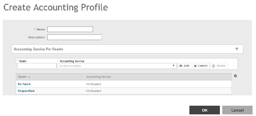
3. Click Create.
The Create Accounting Profile page appears.
FIGURE 99 Creating an Accounting Profile
4. Configure the following:
1. Name: Type a name for the authentication service that you are adding.
2. Description: Type a description for the authentication service.
3. Accounting Service per Realm: Specify the accounting service for each of the realms specified in this table. If you set the
accounting service for a particular realm to NA-Disabled, then the accounting request is rejected. To create a new service
click, Create and then configure Realm and Accounting Service.
5. Click OK.
You have completed creating a Realm-based proxy Accounting AAA server.
NOTE
You can also edit, clone and delete an AAA server by selecting the options Configure, Clone and Delete respectively, from the
Realm Based Proxy tab.
Classifying Rogue Policy
You can create rogue classification policy with rules at the zone-level. This helps in automatic classification behavior when a specific-rogue
detection criteria are met.
To create a rogue classification policy:
1. Go to Services & Profiles > WIPS.
2. In the Policy tab, select the zone for which you want to create the policy.
3. Click Create.
The Create Rogue Classification Policy page appears.
Services and Profiles
Classifying Rogue Policy
SCG200 vSZ-H and SZ300 Administrator Guide
218 Part Number: 800-71563-001
4. Configure the following:
a) Name : Type a name for the policy.
b) Description : Type a description for the policy.
c) Rogue Classification Rules : Create the policy rule by configuring the following :
• Click Create. The Create Rogue Classification Rules page appears.
•Configure the following options:
–Name: Enter a name for the rule.
–Rule Type: Select one of following the rule type for the Classification:
› Low RSSI
› MAC OUI
› MAC Spoofing
› Same Network
› SSID
› SSID Spoofing
–Signal Threshold: Enter the RSSI threshold in dBm. This option is available only for Low RSSI rule type.
–MAC OUI: Enter the first three octets of the MAC. For example, 11:22:33. This option is available only for MAC OUI
rule type.
–SSID: Enter the SSID. This option is available only for SSID rule type.
–Classification: Select one of the following action for the selected Rule Type:
› Ignore
› Know
› Malicious
› Rogue
• Click OK. You have created a Rogue classification rule.
.
5. Click OK.
You have created Rogue classification policy.
NOTE
You can also edit or delete a Rogue classification policy. To do so, select the rogue classification from the list and click Configure
or Delete as required.
NOTE
To prioritize the classification rule, select the rule from the list and click UP or Down to position the rule.
Bonjour
Bonjour is Apple's implementation of a zero-configuration networking protocol for Apple devices over IP.
Bonjour allows OS X and iOS devices to locate other devices such as printers, file servers and other clients on the same broadcast domain
and use the services offered without any network configuration required.
Multicast applications such as Bonjour require special consideration when being deployed over wireless networks. Bonjour only works
within a single broadcast domain, which is usually a small area. This is by design to prevent flooding a large network with multicast traffic.
However, in some situations, a user may want to offer Bonjour services from one VLAN to another.
Services and Profiles
Bonjour
SCG200 vSZ-H and SZ300 Administrator Guide
Part Number: 800-71563-001 219
SmartZone provides two features for controlling how and where Bonjour services are available to clients:
•Bonjour Gateway on page 220: Bridge Bonjour services from one VLAN to another.
•Bonjour Fencing on page 222: Limit the range in physical space at which Bonjour services are available to clients.
Bonjour Gateway
Bonjour Gateway policies enable APs to provide Bonjour services across VLANs.
The controller's Bonjour gateway feature provides an mDNS proxy service configurable from the web interface to allow administrators to
specify which types of Bonjour services can be accessed from/to which VLANs.
In order for the Bonjour Gateway to function, the following network configuration requirements must be met:
• The target networks must be segmented into VLANs.
• VLANs must be mapped to different SSIDs.
• The controller must be connected to a VLAN trunk port.
Additionally, if the VLANs to be bridged by the gateway are on separate subnets, the network has to be configured to route traffic between
them.
The following requirements and limitations should be taken into consideration before enabling the Bonjour Gateway feature:
• Bonjour policy deployment to an AP takes effect after the AP joins the controller.
• Some APs of one local area link must be in one subnet. The switch interfaces connected to these APs must be configured in
VLAN-trunk mode. Only by doing so can the designated AP receive all the multicast Bonjour protocol packets from other VLANs.
• Dynamic VLANs are not supported.
• Some AP models are incompatible with this feature due to memory requirements.
Creating Bonjour Gateway Policies
A Bonjour Gateway policy must be created for an AP zone before the policy can be deployed to an AP or group of APs.
To create a Bonjour Gateway policy:
1. Go to Services & Profiles > Bonjour.
2. Select the Gateway tab, and then select the zone for which you want to create the policy.
Services and Profiles
Bonjour
SCG200 vSZ-H and SZ300 Administrator Guide
220 Part Number: 800-71563-001
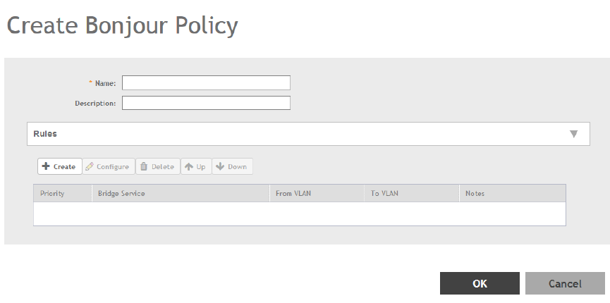
3. Click Create.
The Create Bonjour Policy page appears.
FIGURE 100 Creating a Bonjour Gateway Policy
4. Configure the following:
1. Name: Type a name for the policy.
2. Description: Type a description for the policy.
3. Rules: Create the policy rule by configuring the following
a. Click Create. The Create Bonjour Policy Rule page appears.
b. Configure the following options:
•Bridge Service: Select the Bonjour service from the list.
•From VLAN: Select the VLAN from which the Bonjour service will be advertised.
•To VLAN: Select the VLAN to which the service should be made available.
•Notes: Add optional notes for this rule.
c. Click OK.
You have created a Bonjour policy rule.
4. Click OK.
You have created a Bonjour policy with a rule.
NOTE
You can also edit, clone and delete the policy by selecting the options Configure, Clone and Delete respectively, from the Gateway
tab.
You may now continue to apply this Bonjour gateway policy to an AP or AP group, as described in Applying a Bonjour Gateway Policy to an
AP or AP Group on page 222.
Services and Profiles
Bonjour
SCG200 vSZ-H and SZ300 Administrator Guide
Part Number: 800-71563-001 221
Applying a Bonjour Gateway Policy to an AP or AP Group
Once a Bonjour Gateway policy is created, you can select which AP (or AP group) will serve as the gateway for Bonjour services.
To apply a Bonjour Gateway policy to an AP or AP group:
1. Go to Access Points > Access Points.
2. Select the AP or AP group that you want to configure from the zone in which the AP/group exists.
3. Click Configure.
4. Expand the Advanced Options, and in Bonjour Gateway, enable the check box next to Enable as Bonjour Gateway with policy,
and select the policy you created from the drop-down list.
5. Click OK to save your changes.
Bonjour Fencing
Bonjour Fencing provides a mechanism to limit the scope of Bonjour (mDNS) service discovery in the physical/spatial domain.
While Bonjour Fencing is related to Bonjour Gateway, they are two separate features designed for different purposes. Bonjour Gateway
bridges mDNS services across VLANs, and is useful because Bonjour is designed as a same-VLAN protocol. Bonjour Fencing limits the
range of Bonjour service discovery within physical space, which is useful because logical network boundaries (e.g. VLANs) do not always
correlate well to physical boundaries within a building/floor.
The following considerations should be taken into account before deploying Bonjour fencing policies:
• Bonjour fencing is not supported on Mesh APs.
• Switch interfaces to which APs are connected must be configured in VLAN trunk mode so that Bonjour traffic gets forwarded
across VLANs based on Bonjour Gateway Policies.
• Bonjour fencing is implemented at the AP, not at the controller.
• Fencing policies can be applied on a zone level only, and cannot be configured per AP group.
• In order for a wired fencing policy to work properly, wireless fencing for the same mDNS service should also be enabled. If wired
fencing is enabled but wireless is disabled, APs that are not the "closest AP" will be unable to determine whether the source of the
mDNS advertisement was wired or wireless.
• Bonjour fencing will work for local breakout scenarios, but will not work for tunnel based configuration. (This feature is supported
only for SZ300 controllers)
Creating Bonjour Fencing Policies
Bonjour Fencing policies can be created and applied to a zone at the same time using the Fencing tab on the Services and Profiles >
Bonjour screen.
To create a Bonjour Fencing policy:
1. Go to Services & Profiles > Bonjour.
2. Select the Fencing tab, and then select the zone for which you want to create the policy.
Services and Profiles
Bonjour
SCG200 vSZ-H and SZ300 Administrator Guide
222 Part Number: 800-71563-001
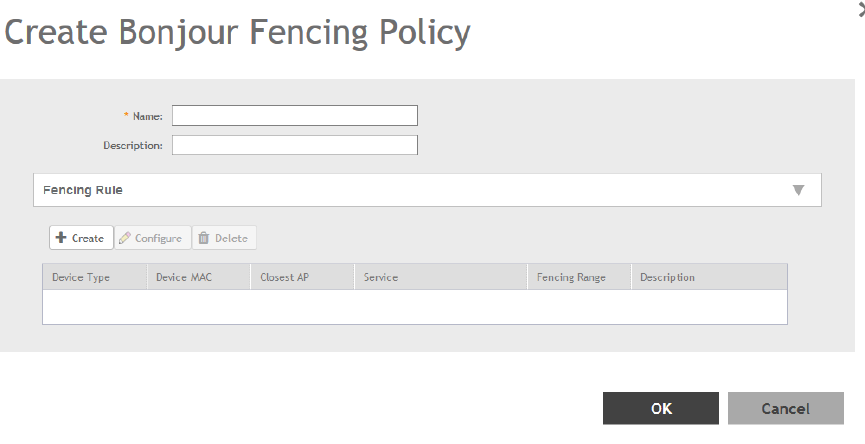
3. Click Create.
The Create Bonjour Fencing Policy page appears.
FIGURE 101 Creating a Bonjour Fencing Policy
Services and Profiles
Bonjour
SCG200 vSZ-H and SZ300 Administrator Guide
Part Number: 800-71563-001 223
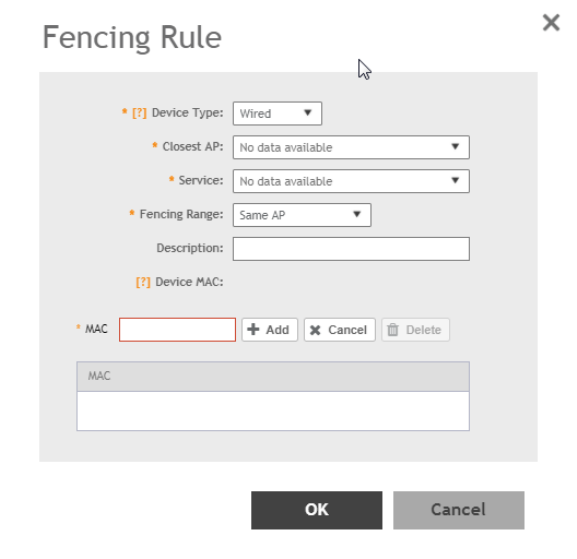
4. Configure the following:
1. Name: Type a name for the policy.
2. Description: Type a description for the policy.
3. Fencing Rule: Create the policy rule by configuring the following:
FIGURE 102 Fencing Rule
a. Click Create. The Fencing Rule page appears.
b. Configure the following options:
•Device Type: Select the Wireless or Wired network connection method for the device advertising bonjour services.
•Closest AP: Select the closest AP to create a physical anchor point for fencing, and the closest AP is auto-detected
for wireless devices, based on the AP association.
•Service: Select one of the bonjour services from the drop-down list.
•Fencing Range: Select the fencing range to be the Same AP or 1-Hop AP Neighbors.
•Description: Specify any notes you may need to refer.
•Device MAC: Specify the MAC address of the device advertising bonjour services. This option is available only for
Wired Device Type. It supports up to four wired MAC addresses.
c. Click OK to save the rule.
You have created a Bonjour fencing rule. Each policy can contain up to 32 rules.
4. Click OK to save the policy.
You have created a Bonjour fencing policy.
Services and Profiles
Bonjour
SCG200 vSZ-H and SZ300 Administrator Guide
224 Part Number: 800-71563-001
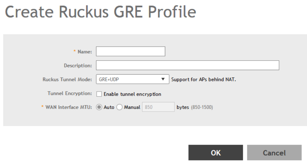
NOTE
You can also edit, clone and delete the policy by selecting the options Configure, Clone and Delete respectively, from the Fencing
tab.
Working with Tunnels and Ports
Creating a Ruckus GRE Profile
You can configure the Ruckus GRE tunnel profile of the controller to manage AP traffic.
1. Go to Services & Profiles > Tunnels and Ports.
2. Select the Ruckus GRE tab, and then select the zone for which you want to create the profile.
3. Click Create.
The Create Ruckus GRE Profile page appears.
FIGURE 103 Creating a Ruckus GRE Profile
Services and Profiles
Working with Tunnels and Ports
SCG200 vSZ-H and SZ300 Administrator Guide
Part Number: 800-71563-001 225
4. Configure the following:
1. Name: Type a name for the profile.
2. Description: Type a description for the profile.
3. Ruckus Tunnel Model: Select a protocol to use for tunneling WLAN traffic back to the controller.
• GRE + UDP: Select this option to allow APs behind a NAT server to tunnel WLAN traffic back to the controller.
• GRE: Select this option to tunnel regular WLAN traffic only.
4. Tunnel Encryption: Select the Enable tunnel encryption check box if you want managed APs to decrypt 802.11 packets, and
then use an AES encrypted tunnel to send them to the controller. By default, when WLAN traffic is tunneled to the controller,
only the management traffic is encrypted; data traffic is unencrypted.
5. WAN Interface MTU: Set the maximum transmission unit (MTU) for the tunnel to either Auto (default) or Manual (a specific size
850 to 1500 bytes). MTU is the size of the largest protocol data unit that can be passed on the controller network.
6. Click OK.
You have created the Ruckus GRE profile.
NOTE
You can also edit, clone and delete the profile by selecting the options Configure, Clone and Delete respectively, from the Ruckus
GRE tab.
Creating a Soft GRE Profile
You can configure the Soft GRE tunnel profile of the controller to manage AP traffic.
1. Go to Services & Profiles > Tunnels and Ports.
2. Select the Soft GRE tab, and then select the zone for which you want to create the profile.
Services and Profiles
Working with Tunnels and Ports
SCG200 vSZ-H and SZ300 Administrator Guide
226 Part Number: 800-71563-001
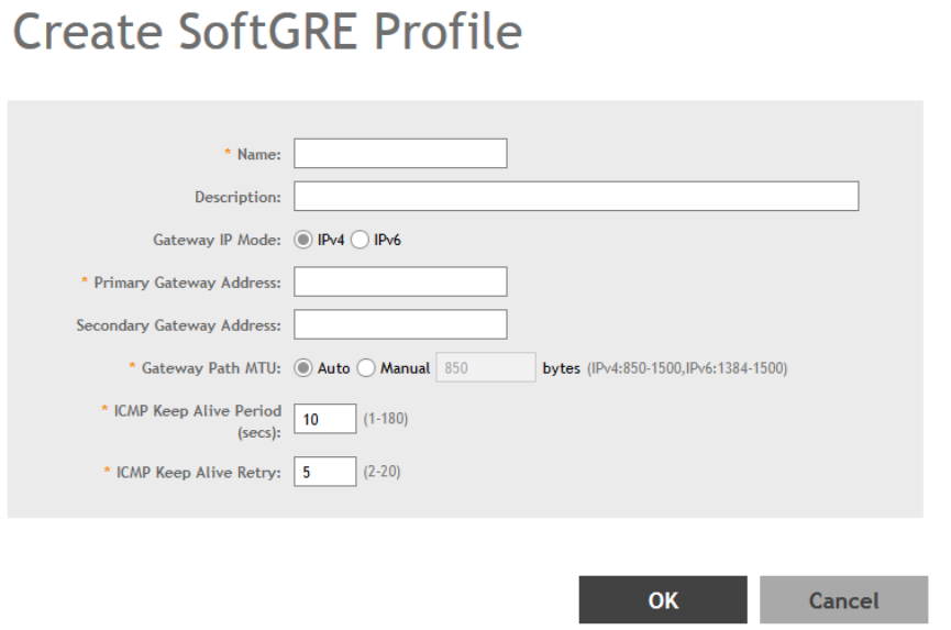
3. Click Create.
The Create Soft GRE Profile page appears.
FIGURE 104 Creating a Soft GRE Profile
4. Configure the following:
1. Name: Type a name for the profile.
2. Description: Type a description for the profile.
3. Gateway IP Mode: Select IPv4 or IPv6 addressing.
4. Primary Gateway Address: Type the IP address or fully-qualified domain name (FQDN) of the primary gateway server.
5. Secondary Gateway Address: If you have a secondary gateway server on the network, type its IP address or FQDN in the box
provided. If the controller is unable to reach the primary gateway server, it will automatically attempt to reach the secondary
gateway address that you specify here.
6. Gateway Path MTU: Set the maximum transmission unit (MTU) for the gateway path. Options include Auto (default) and
Manual (range is 850 to 1500 bytes).
7. ICMP Keep Alive Period: Type the time interval (in seconds) at which APs send a keepalive message to the active third party
WLAN gateway. The range is 1 to 180 seconds and the default value is 10 seconds.
8. ICMP Keep Alive Retry: Type the number of keepalive attempts that APs wait for a response from the active third party WLAN
gateway before failing over to the standby WLAN gateway. The range is 2 to 10 retries and the default value is 5 retries.
9. Force Disassociate Client: Enable this option by selecting the check-box if you want to disassociate the client when AP fails
over to another tunnel.
10. Click OK.
You have created the Soft GRE profile.
Services and Profiles
Working with Tunnels and Ports
SCG200 vSZ-H and SZ300 Administrator Guide
Part Number: 800-71563-001 227
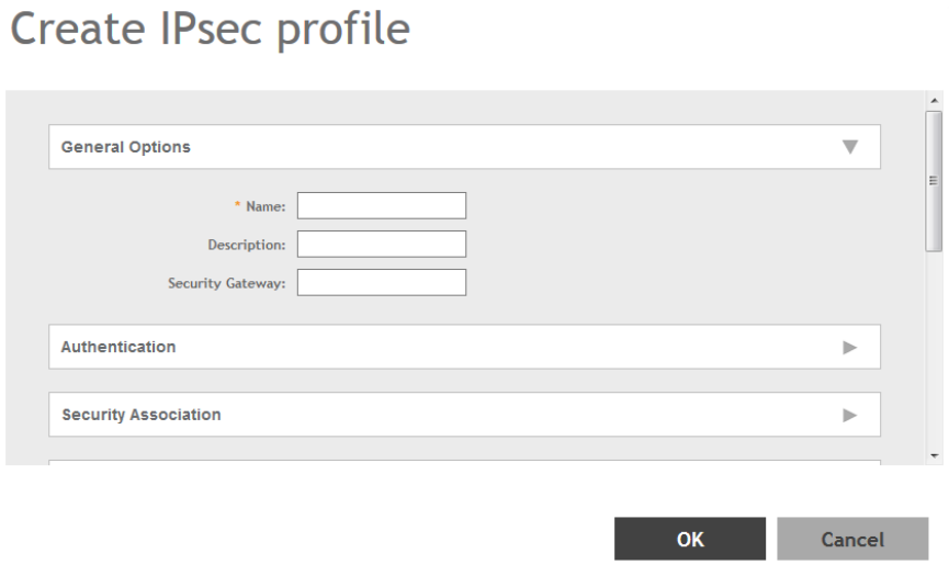
NOTE
You can also edit, clone and delete the profile by selecting the options Configure, Clone and Delete respectively, from the Soft
GRE tab.
Creating an IPsec Profile
1. Go to Services & Profiles > Tunnels and Ports.
2. Select the IPsec tab, and then select the zone for which you want to create the profile.
3. Click Create.
The Create IPsec Profile page appears.
FIGURE 105 Creating an IPsec Profile
Services and Profiles
Working with Tunnels and Ports
SCG200 vSZ-H and SZ300 Administrator Guide
228 Part Number: 800-71563-001
4. Configure the following:
1. Name: Type a name for the profile.
2. Description: Type a description for the profile.
3. Security Gateway: Type the IP address or FQDN of the IPSec server. If you use the IP address, the IP address format that you
must enter will depend on the IP mode that is configured on the controller.
4. IP Mode: Select IPv4 or IPv6 addressing modes.
NOTE
This option is only applicable to SZ300.
5. Authentication: Select Preshared Key to use PSK for authentication or Certificate to use an X.509 certificate on the certificate
authority (CA) or registration authority (RA) server. The controller uses the CMPv2 protocol to obtain the signed certificate from
the CA/RA server.
If you selected Preshared Key, type the PSK in this box. The PSK must be eight to 128 ASCII characters in length.
6. Security Association
a. IKE Proposal Type: Select Default to use the default Internet Key Exchange (IKE) security association (SA) proposal type
or select Specific to manually configure the IKE SA proposal. If you clicked Specific, you will need to configure the
following settings:
• Encryption Algorithm: Options include 3DES, AES128, AES192, and AES256.
• Integrity Algorithm: Options include MD5, SHA1, AES-XCBC, SHA256, SHA384, and SHA512.
• Pseudo-Random Function: Options include Use integrity ALG, PRF-MD5, PRF-SHA1, PRF-AES-XCBC, PRF-AES-
CMAC, PRF-SHA256, and PRF-SHA384.
• DH Group: Options for Diffie-Hellman groups for IKE include modp768, modp1024, modp1536, modp2048,
modp3072, modp4096, modp6144, and modp8192.
b. ESP Proposal Type: Click Default to use the default Encapsulating Security Payload (ESP) SA proposal type or click
Specific to manually configure the ESP proposal. If you clicked Specific, you will need to configure the following settings:
• Encryption Algorithm: Options include 3DES, AES128, AES192, AES256, and NONE.
• Integrity Algorithm: Options include MD5, SHA1, AES-XCBC, SHA256, SHA384, and SHA512.
• DH Group: Options for Diffie-Hellman groups for ESP include None, modp768, modp1024, modp1536, modp2048,
modp3072, modp4096, modp6144, and modp8192.
7. Rekey Options
a. Internet Key Exchange: To set time interval at which the IKE key renews, select a time unit (day, hour, or minute) from the
drop-down list, and then type a number in the box. To disable IKE rekey, select the Disable check box. SmartZone 100/
Virtual SmartZone Essentials for Release 3.4 Administrator Guide 82 Configuring the Wireless Network Configuring
Access Points.
b. Encapsulating Security Payload: To set time interval at which the ESP key renews, select a time unit (day, hour, or minute)
from the drop-down list, and then type a number in the box. To disable ESP rekey, select the Disable check box.
8. Certificate Management Protocol
a. DHCP Option 43 Sub Code for CA/RA Address: Set the DHCP Option 43 subcode that will be used to discover the
address of the CA/RA server on the network. The default subcode is 8.
b. CA/RA Address: Type the IP address or FQDN of the CA/RA server. If you use the IP address, the IP address format that
you must enter will depend on the IP mode that is configured on the controller.
c. Server Path: Type the path to the X.509 certificate on the CA/RA server.
Services and Profiles
Working with Tunnels and Ports
SCG200 vSZ-H and SZ300 Administrator Guide
Part Number: 800-71563-001 229
d. DHCP Option 43 Sub Code for Subject Name of CA/RA: Set the DHCP Option 43 subcode that will be used to discover
the subject name of the CA/RA server on the network. The default subcode is 5.
e. Subject Name of CA/RA: Type an ASCII string that represents the subject name of the CA/RA server.
9. Advanced Options
a. DHCP Option 43 Sub Code for Security Gateway: Set the DHCP Option 43 subcode that will be used to discover the
address of the security gateway on the network. The default subcode is 7.
b. Retry Limit: Set the number of times that the controller will attempt to discover the address of the security gateway. The
default retry count is 5. Accepted values are 0 (disable) to 16.
c. Replay Window: Set the ESP replay window (in packets). The default size is 32 packets. Accepted values are 0 (disable)
to 32 packets.
d. IP Compression: To enable IP Payload Compression Protocol (IPComp) compression before encryption, click Enable. The
default value is Disable.
e. Force NAT-T: To enforce UDP encapsulation of ESP packets, click Enable. The default value is Disable.
f. Dead Peer Detection: By default, the IKE protocol runs a health check with remote peer to ensure that it is alive. To
disable this health check, click Disable.
g. NAT-T Keep Alive Interval: To set the keep alive interval (in seconds) for NAT traversal, type a value in the box. The default
keep alive interval is 20 seconds. Accepted values are 1 to 65536. To disable the keep alive interval, click Disable.
h. FailOver Options: To configure the failover settings when APs are unable to connect, configure the following:
i. Retry Period: Set the number of days (minimum 3 days) during which APs will keep attempting to connect. To keep try
indefinitely, select the Forever check box.
j. Retry Interval: Set the interval (in minutes) between each retry attempt. The default retry interval is 1 minute. Accepted
values are from 1 to 30 minutes.
k. Retry Mode: If you want APs to fall back to the specified primary security gateway, click Revertive. If you want APs to
maintain connectivity with the security gateway to which they are currently connected, click Non-revertive.
10. Click OK.
You have created the IPsec GRE profile.
NOTE
You can also edit, clone and delete the profile by selecting the options Configure, Clone and Delete respectively, from the IPsec
GRE tab.
Creating an Ethernet Port Profile
An Ethernet port profile contains settings that define how an AP will handle VLAN packets when its port is designated as either trunk,
access, or general port. By default, three Ethernet port profiles exist: General Port, Access Port and Trunk Port. In 3.6 SCG200-C is
supported. SCG200-C is the SCG200 model without the internal DP functions. If Ruckus GRE tunnel is enabled, upgrade to SCG200-C is
blocked and the following message appears:There exists an EthernetPortProfile [PROFILE_NAME] with RuckusGRE
tunnel is applied
1. Go to Services & Profiles > Tunnels and Ports.
2. Select the Ethernet Port tab, and then select the zone for which you want to create the profile.
Services and Profiles
Working with Tunnels and Ports
SCG200 vSZ-H and SZ300 Administrator Guide
230 Part Number: 800-71563-001
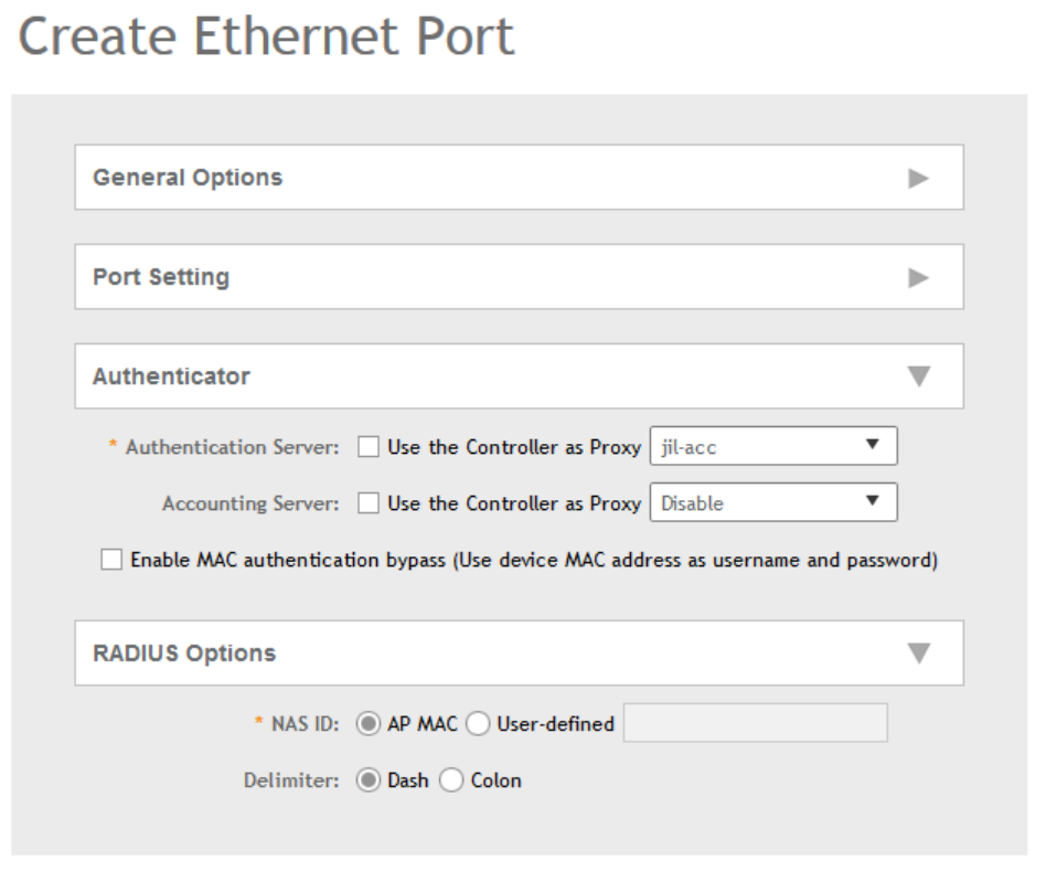
3. Click Create.
The Create Ethernet Port page appears.
FIGURE 106 Creating a Ethernet Port Profile
Services and Profiles
Working with Tunnels and Ports
SCG200 vSZ-H and SZ300 Administrator Guide
Part Number: 800-71563-001 231
4. Configure the following:
1. General Options
a. Name: Type a name for the Ethernet port profile that you are creating.
b. Description: Type a short description about the profile.
c. Type: The Ethernet port type defines how the AP will manage VLAN frames. You can set Ethernet ports on an AP to one
of the following types: Trunk Port, Access Port or General Port.
By selecting the appropriate port type, authentication method, and 802.1X Role, administrator can configure the ethernet
ports to be used for the wired client. Up to 16 devices can be configured to connect to one ethernet port. After
configuring the ports, the wired clients and their stats are displayed in the Clients > Wired Clients page. You can also
delete a wired client from this page.
2. Ethernet Port Usage
a. Access Network: Select this check box to enable tunneling on the Ethernet port.
b. VLAN Untag ID: Type the ID of the native VLAN (typically, 1), which is the VLAN into which untagged ingress packets are
placed upon arrival. If your network uses a different VLAN as the native VLAN, configure the AP Trunk port’s VLAN Untag
ID with the native VLAN used throughout your network.
c. VLAN Members: Type the VLAN IDs that you want to use to tag WLAN traffic that will use this profile. You can type a
single VLAN ID or a VLAN ID range (or a combination of both). The valid VLAN ID range is 1 to 4094.
d. Enable Dynamic VLAN: Select this check box if you want the controller to assign VLAN IDs on a per-user basis. Before
enabling dynamic VLAN, you need to define on the RADIUS server the VLAN IDs that you want to assign to users.
NOTE
This option is only available when Type is set to Access Port and 802.1X authentication is set to MAC-based
Authenticator.
3. Guest VLAN: If you want to assign a device that fails authentication to still be able to access the Internet but to internal
network resources, select this check box.
NOTE
This check box only appear when the Enable Dynamic VLAN check box is selected.
4. Authentication Options
a. 802.1X: Select this check box to enable 802.1X authentication.
b. Enable client visibility regardless of 802.1X authentication: select this check box to bypass 802.1X authentication for
client visibility.
NOTE
You can view statistical information about wired clients even without enabling 802.1X authentication.
c. 802.1X Role: Select the authenticator role from the drop-down menu. Options include Supplicant, MAC-based
Authenticator and Port-based Authenticator. When you select Supplicant, you can customize the username and
password to authenticate as a supplicant role or use the credentials of the AP MAC address. When you select Port-
based Authenticator, only a single MAC host must be authenticated for all hosts to be granted access to the network. If
you select MAC-based Authenticator, each MAC address host is individually authenticated. Each newly-learned MAC
address triggers an EAPOL request-identify frame.
5. Authentication and Accounting Services
Services and Profiles
Working with Tunnels and Ports
SCG200 vSZ-H and SZ300 Administrator Guide
232 Part Number: 800-71563-001
a. Authentication Server: Select the check-box and a controller from the drop-down menu to use the controller as a proxy
authentication server.
b. Accounting Server: Select the check-box and a controller from the drop-down menu to use the controller as a proxy
accounting server.
c. Enable MAC authentication bypass: Select this check-box if you want to use the device MAC address as access
credentials (username and password).
6. RADIUS Options
a. NAS ID: Set the NAS ID for the AP to communicate with the RADIUS server. Options include using the AP MAC address
or any User-defined address.
b. Delimiter: If AP MAC is selected to configure the NAS ID, then you can choose between Dash or Colon as delimiters to
separate.
7. Click OK.
You have created the Ethernet Port profile.
NOTE
You can also edit, clone and delete the profile by selecting the options Configure, Clone and Delete respectively, from the Ethernet
Port tab.
Creating a Tunnel DiffServ Profile
If you need to configure the type of traffic (ToS) bit settings for the access side traffic from Ruckus Wireless APs, follow these steps to create
a Differentiated Services (DiffServ) profile. This profile can only be applied to Ruckus GRE and SoftGRE traffic.
1. Go to Services & Profiles > Tunnels and Ports.
2. Select the DiffServ tab, and then select the zone for which you want to create the profile.
Services and Profiles
Working with Tunnels and Ports
SCG200 vSZ-H and SZ300 Administrator Guide
Part Number: 800-71563-001 233
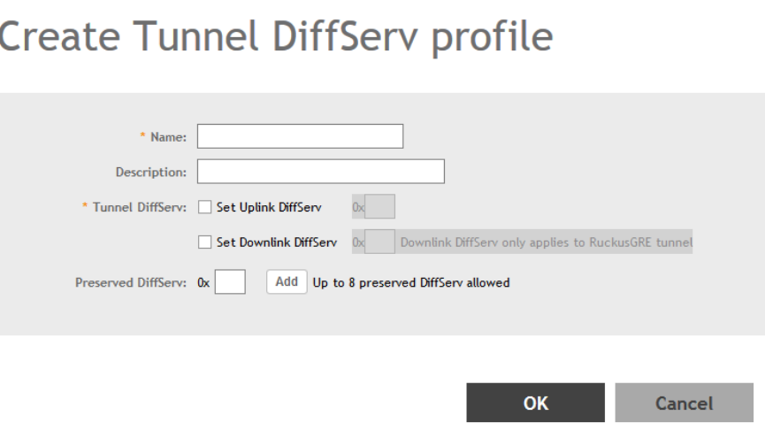
3. Click Create.
The Create Tunnel DiffServ Profile page appears.
FIGURE 107 Creating a Tunnel DiffServ Profile
4. Configure the following:
1. Name: Type a name for the DiffServ profile that you are creating.
2. Description: Type a brief description for the DiffServ profile.
3. Tunnel DiffServ: configure the following options.
a. Set Uplink DiffServ: Select the check box if you want to set the Differentiated Services field for uplink user traffic from
Ruckus Wireless APs towards either the controller or a third SmartCell Gateway 200/Virtual SmartZone High-Scale for
Release 3.4.1 Administrator Guide 92 Managing Ruckus Wireless AP Zones Creating a DiffServ Profile party gateway via
SoftGRE. Configure the desired value to be set by the Ruckus Wireless AP.
b. Set Downlink DiffServ: Select the check box if you want to set the Differentiated Services field for downlink user traffic
from the controller towards the AP, and then configure the desired value to be set by the Ruckus Wireless AP.
4. Preserved DiffServ: Configure up to eight (8) entries in the preserved DiffServ list. The Preserved DiffServ list allows the
preservation of values that have been already marked in incoming packets either in uplink or downlink traffic.
5. Click OK.
You have created the DiffServ profile.
NOTE
You can also edit, clone and delete the profile by selecting the options Configure, Clone and Delete respectively, from the DiffServ
tab.
Services and Profiles
Working with Tunnels and Ports
SCG200 vSZ-H and SZ300 Administrator Guide
234 Part Number: 800-71563-001
Communications Assistance for Law Enforcement Act (CALEA)
The Communications Assistance for Law Enforcement Act is a law passed by the United States to enhance the ability of law enforcement
agencies to conduct electronic surveillance by requiring that telecommunications carriers and manufacturers of telecommunications
equipment to modify and design their equipment, facilities, and services to ensure that they have built-in surveillance capabilities.
NOTE
This feature only applies to the SmartZone 300 (SZ300) controller.
1. Go to Services & Profiles > Tunnels and Ports.
2. Select the CALEA tab.
3. Server IP: Type the CALEA server IP address.
4. Click Create.
The Create UE MAC page appears.
5. MAC Address: Type the MAC address of the client/user equipment for which CALEA mirroring is required. The MAC address is
sent by the SZ controller to the vSZ-D.
Enabling Flexi VPN
You can enable Flexi-VPN and limit the network resources that a UE can access. Flexi-VPN allows an administrator to customize the
network topology, and is thereby able to control the network resources accessible to the end-user. This feature is only supported on vSZ-E
and vSZ-H, and is enabled by purchasing the Flexi-VPN license.
1. Go to Services & Profiles > Tunnels and Ports.
Services and Profiles
Working with Tunnels and Ports
SCG200 vSZ-H and SZ300 Administrator Guide
Part Number: 800-71563-001 235
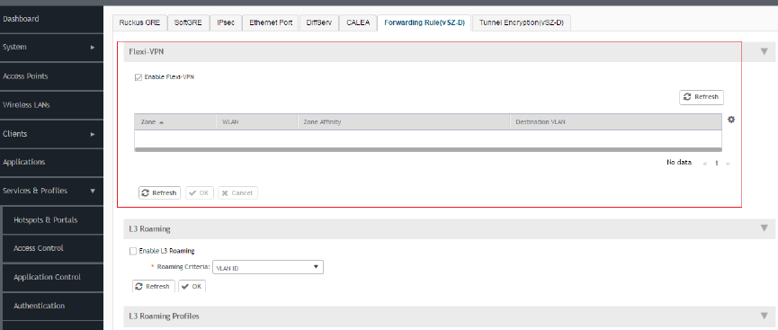
2. Select the Forwarding Rule (vSZ-D) tab.
The page with Flexi-VPN and L3 Roaming settings appears.
FIGURE 108 Enabling Flexi-VPN
NOTE
The Flexi-VPN option is only available if the Access VLAN ID is 1, and when VLAN Pooling, Dynamic VLAN and Core
Network VLAN options are disabled.
NOTE
You can only apply 1024 WLAN IDs to a Flexi-VPN profile.
Flexi-VPN supports IPv4 addressing formats and Ruckus GRE tunnel protocol. It does not support IPv6 addressing
formats.
3. Select a virtual data plane for which you want to enable the Flexi-VPN feature, and then select the Enable Flexi-VPN check-box.
4. Click OK.
You have successfully enabled the Flexi-VPN feature on the selected vDP.
Enabling L3 Roaming Criteria for vDPs
Using the layer 3 roaming feature, clients can roam across APs in the network (from one data plane to another data plane). This is typically
required when the number of clients in the network increases and clients have to roam from a network that they were connected to, to
another WLAN network with similar access settings. This feature enables seamless roaming and ensures session continuity between the
client and the network.
NOTE
L3 roaming is only supported on vSZ-H and vSZ-E.
You can configure the roaming criteria for a vDP so that it uses one of these two options - UE subnet or VLAN ID to access another vDP to
connect to, within a network. Before this, you must ensure that the L3 roaming feature is enabled in the vDP.
1. Go to Services & Profiles > Tunnels and Ports.
Services and Profiles
Working with Tunnels and Ports
SCG200 vSZ-H and SZ300 Administrator Guide
236 Part Number: 800-71563-001
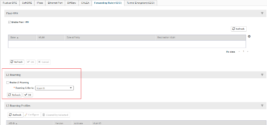
2. Select the Forwarding Rule (vSZ-D) tab.
The page with Flexi-VPN and L3 Roaming settings appears.
FIGURE 109 Enabling L3 Roaming
3. Select the Enable L3 Roaming check-box.
4. From the Roaming Criteria drop-down, select one of these options to define the data format to establish connection between
vDPs: UE Subnet or VLAN ID.
5. Click OK.
You have successfully enabled L3 roaming, and also set the roaming criteria based on which vDPs would connect within the network.
NOTE
A fresh controller software installation or upgrade from a version that does not support L3 roaming resets the L3 roaming
configuration and it remains disabled. You must enable L3 roaming on a vDP again.
Editing L3 Roaming for a vDP
For L3 roaming to work without session break, the vDPs between which the roaming happens must both be enabled with the L3 Roaming
feature.
NOTE
If the IP address of the UE changes, then the session breaks.
1. Go to Services & Profiles > Tunnels and Ports.
2. Select the Forwarding Rule (vSZ-D) tab.
The page with Flexi-VPN and L3 Roaming settings appears.
Services and Profiles
Working with Tunnels and Ports
SCG200 vSZ-H and SZ300 Administrator Guide
Part Number: 800-71563-001 237
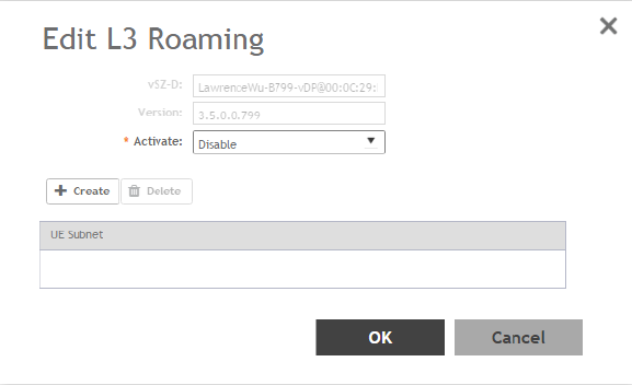
3. In L3 Roaming Profiles, select a virtual data plane for which you want to enable the L3 roaming feature, and then click Configure.
The Edit L3 Roaming page appears.
FIGURE 110 Configuring the L3 Roaming setting for a vDP
4. In Activate, select Enable or Disable as appropriate.
5. Based on the
Roaming Criteria
that you set, you will be able to add a UE subnet or a VLAN ID to the selected vDP. Click Create to
add a UE Subnet or VLAN ID to the vDP. The UE Subnet or Add VLAN ID page appears, respectively, depending on the roaming
criteria you chose.
6. Type the UE Subnet IP address or the VLAN ID as appropriate.
7. Click OK.
8. Click OK again.
In L3 Roaming Profiles, the following information about the vDP is displayed:
• vSZ-D: Displays the name of the virtual data plane.
• Version: Displays the version of the vDP.
• Activate: Displays whether L3 roaming is enabled or disabled.
• UE Subnet or VLAN ID: Depending on the global settings you choose for the roaming criteria, the UE subnet IP address or the
VLAN ID is displayed.
You have enabled L3 roaming in the selected vDP.
Enabling Tunnel Encryption
You can use the tunnel encryption feature to encrypt data for a private network, through a public network. This feature is available in vSZ-H
and vSZ-E.
1. Go to Services & Profiles > Tunnels and Ports.
Services and Profiles
Working with Tunnels and Ports
SCG200 vSZ-H and SZ300 Administrator Guide
238 Part Number: 800-71563-001
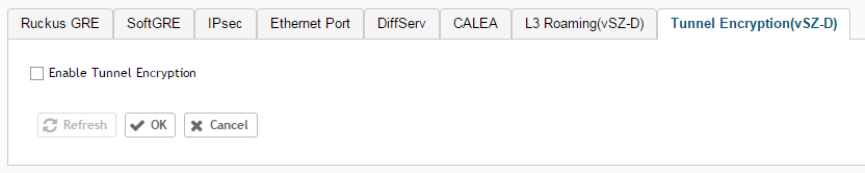
2. Select the Tunnel Encryption (vSZ-D) tab, and then select the zone for which you want to create the profile.
The Tunnel Encryption (vSZ-D) page appears.
FIGURE 111 Tunnel Encryption (vSZ-D)
3. Select the Enable Tunnel Encryption check-box.
4. Click OK.
You have successfully enabled tunnel encryption.
Managing Core Network Tunnels
Tunneling protocols allows a user to access or provide a network service that the network does not support or provide directly.
Creating Bridge Forwarding Profiles
An Bridge forwarding profile defines the DHCP configuration for the core network.
1. Go to Services & Profiles > Core Network Tunnel.
2. Select the Bridge tab, and then select the zone for which you want to create the profile.
Services and Profiles
Managing Core Network Tunnels
SCG200 vSZ-H and SZ300 Administrator Guide
Part Number: 800-71563-001 239
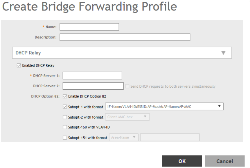
3. Click Create.
The Create Bridge Forwarding Profile page appears.
FIGURE 112 Creating a Bridge Forwarding Profile
Services and Profiles
Managing Core Network Tunnels
SCG200 vSZ-H and SZ300 Administrator Guide
240 Part Number: 800-71563-001
4. Configure the following:
1. Name: Type a name for the profile that you are creating.
2. Description: Type a brief description for the profile.
3. DHCP Relay: Select the Enable DHCP Relaycheck-box and configure the DHCP server IP address and DHCP option 82
settings.
a. DHCP Server 1: Type the IPv4 address of the DHCP server that will allocate IP addresses to DHCP clients.
b. DHCP Server 2: If a secondary DHCP server exists on the network, type the IPv4 address of the secondary server.
c. DHCP Option 82: Select this check box if you want the DHCP relay agent (in this case, the controller) to insert specific
identification information into requests that are forwarded to the DHCP server. If you enabled DHCP Option 82, you can
configure the following Option 82 sub-options by selecting the corresponding check boxes:
• Subopt-1 with format: You can customize sub-option 1 (Circuit ID) to send only the AP’s MAC address in
hexadecimal format or the MAC address and ESSID. The default format is: IFName:VLAN-ID:ESSID:AP-Model:AP-
Name:AP-MAC.
• Subopt 2 with format: You can customize sub-option 2 (Remote ID), which sends the client’s MAC address by
default, to send the AP’s MAC address, or the client MAC plus ESSID or AP MAC plus ESSID.
• Subopt-150 with VLAN ID: This sub-option encapsulates the VLAN ID.
• Subopt-151 with format: This sub-option can encapsulate either the ESSID or a configurable Area Name.
•
4. Click OK.
You have created the Bridge forwarding profile.
NOTE
You can also edit and delete the profile by selecting the options Configure and Delete respectively, from the Bridge tab.
Creating L2oGRE Forwarding Profiles
An L2oGRE forwarding profile defines the gateway and tunnel configuration for the core network of L2oGRE tunnels.
1. Go to Services & Profiles > Core Network Tunnel.
2. Select the L2oGRE tab, and then select the zone for which you want to create the profile.
Services and Profiles
Managing Core Network Tunnels
SCG200 vSZ-H and SZ300 Administrator Guide
Part Number: 800-71563-001 241
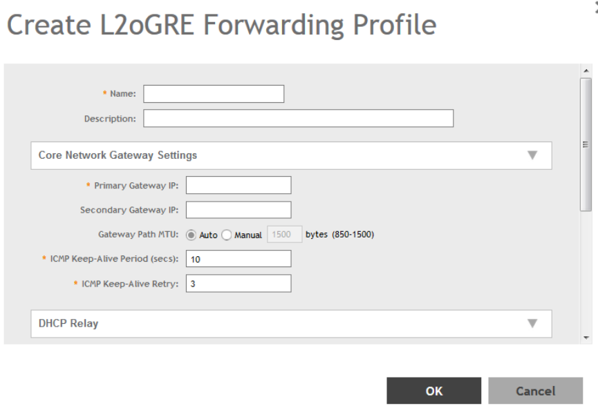
3. Click Create.
The Create L2oGRE Forwarding Profile page appears.
FIGURE 113 Creating a L2oGRE Forwarding Profile
Services and Profiles
Managing Core Network Tunnels
SCG200 vSZ-H and SZ300 Administrator Guide
242 Part Number: 800-71563-001
4. Configure the following:
1. Name: Type a name for the profile that you are creating.
2. Description: Type a brief description for the profile.
3. Core Network Gateway Settings
a. Primary Gateway IP: Type the IP address of the primary gateway for the L2oGRE tunnel.
b. Secondary Gateway IP: Type the IP address of the secondary gateway for the L2oGRE tunnel. If the primary gateway is
unreachable, this gateway will be used for the L2oGRE tunnel.
c. Gateway Path MTU: Set it the MTU manually or use Auto (default). MTU is the size of the largest protocol data unit (in
bytes) that can be passed on the controller network.
d. ICMP Keep-Alive Period (secs): Set the time in seconds between sending retry messages to the keepalive IP address.
Enter an integer between 2 and 255. The default is 10 seconds.
e. ICMP Keep-Alive Retry: Set the retry period to send messages to the keepalive IP address. The default value is 3 retries.
4. DHCP Relay: Select the Enable DHCP Relaycheck-box and configure the DHCP server IP address and DHCP option 82
settings.
a. DHCP Server 1: Type the IPv4 address of the DHCP server that will allocate IP addresses to DHCP clients.
b. DHCP Server 2: If a secondary DHCP server exists on the network, type the IPv4 address of the secondary server.
c. DHCP Option 82: Select this check box if you want the DHCP relay agent (in this case, the controller) to insert specific
identification information into requests that are forwarded to the DHCP server. If you enabled DHCP Option 82, you can
configure the following Option 82 sub-options by selecting the corresponding check boxes:
• Subopt-1 with format: You can customize sub-option 1 (Circuit ID) to send only the AP’s MAC address in
hexadecimal format or the MAC address and ESSID. The default format is: IFName:VLAN-ID:ESSID:AP-Model:AP-
Name:AP-MAC.
• Subopt 2 with format: You can customize sub-option 2 (Remote ID), which sends the client’s MAC address by
default, to send the AP’s MAC address, or the client MAC plus ESSID or AP MAC plus ESSID.
• Subopt-150 with VLAN ID: This sub-option encapsulates the VLAN ID.
• Subopt-151 with format: This sub-option can encapsulate either the ESSID or a configurable Area Name.
•
5. Click OK.
You have created the L2oGRE forwarding profile.
NOTE
You can also edit and delete the profile by selecting the options Configure and Delete respectively, from the L2oGRE tab.
Services and Profiles
Managing Core Network Tunnels
SCG200 vSZ-H and SZ300 Administrator Guide
Part Number: 800-71563-001 243
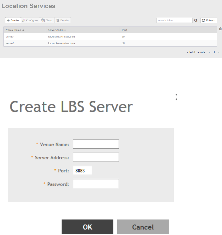
Location Services
If your organization purchased the Ruckus Wireless Smart Positioning Technology (SPoT) location service, the controller must be configured
with the venue information that is displayed in the SPoT Administration Portal.
After completing purchase of the SPoT location service, you will be given account login information that you can use to log into the SPoT
Administration Portal. The Admin Portal provides tools for configuring and managing all of your venues (the physical locations in which SPoT
service is deployed). After a venue is successfully set up, you will need to enter the same venue information in the controller.
1. Go to Services & Profiles > Location Services.
The Location Services page appears.
FIGURE 114 Location Services
2. Click Create.
The Create LBS Server page appears.
FIGURE 115 Creating an LBS Server
Services and Profiles
Location Services
SCG200 vSZ-H and SZ300 Administrator Guide
244 Part Number: 800-71563-001
3. Configure the following:
1. Venue Name: Type a venue name for server.
2. Server Address: Type the IP address of the server.
3. Port: Type the port number to communicate with the server. Default is 8883.
4. Password: Type the password to access the server.
5. Click OK.
You have created the location-based service on the controller.
NOTE
You can also edit, clone and delete the service by selecting the options Configure, Clone and Delete respectively, from the
Location Services tab.
DHCP/NAT
DHCP/NAT functionality on SZ-managed APs and DPs (data planes) allows customers to reduce costs and complexity by removing the
need for DHCP server/NAT router to provide IP addresses to clients. For data traffic aggregation and services delivery you can choose
appropriate user profile for DHCP and NAT services on vDP.
AP-based DHCP/NAT
In highly distributed environments, particularly those with only a few APs per site, the ability for an AP or a set of APs to provide DHCP/NAT
support to local client devices simplifies deployment by providing all-in-one functionality on the AP, which eliminates the need for a separate
router and DHCP server for each site. It also eases site management by providing central control and monitoring of the distributed APs and
their clients.
Three general DHCP scenarios are supported:
• SMB Single AP: DHCP is running on a single AP only. This AP also functions as the Gateway AP.
• SMB Multiple APs (<12): DHCP service is running on all APs, among which two of the APs will be Gateway APs. These two
Gateway APs will provide the IP addresses as well as Internet connectivity to the clients via NAT.
• Enterprise (>12): For Enterprise sites, an additional on site vDP will be deployed at the remote site which will assume the
responsibilities of performing DHCP/NAT functions. Therefore, DHCP/NAT service will not be running on any APs (they will serve
clients only), while the DHCP/NAT services are provided by the onsite vDP.
Profile-based DHCP
The DHCP Server is designed in-line in the data plane and provides extreme scale in terms of IP address assignment to clients. This feature
is especially useful in high density and dynamic deployments like stadiums, train stations where large number of clients continuously move
in & out of WiFi coverage. The DHCP server in the network needs to scale to meet these challenging requirements. The DHCP server on the
vSZ-D provides high scale IP assignment and management with minimal impact on forwarding latency. By default, the maximum allowed IP
assignment for the DHCP server is 50K IP addresses in a vSZ cluster managing multiple vDP. Additional IP assignment requires additional
licensing.
NOTE
DHCP Server/NAT function if enabled is supported only for wireless client IPv4 address assignment.
Services and Profiles
DHCP/NAT
SCG200 vSZ-H and SZ300 Administrator Guide
Part Number: 800-71563-001 245
Profile-based NAT
With NAT service enabled, all the WiFi client traffic is NATed by the vSZ-D before being forwarded to the core network. Each vSZ-D
supports up to 900K NAT ports (traffic sessions) and 128 public IP addresses for NAT. This feature essentially reduces the network
overhead significantly since this reduces the MAC-table considerations on the UP-stream switches significantly. Again, very useful in high
density deployments.
Caveats and Limitations
The SmartZone DHCP on AP functionality has some limitations. These limitations should be considered before enabling this feature:
• Running DHCP/NAT services on an AP can consume significant memory resources. Therefore, Ruckus recommends deploying
this feature only on APs with 256MB or more RAM.
• Max 4 IP address pools. Each pool must have non-overlapping IP addresses, and must be assigned a VLAN ID (2~4094).
• Max 1,000 IP addresses per pool.
• The following features are incompatible with the DHCP feature and cannot be enabled for a zone in which DHCP is enabled (or, if
enabled for a zone, DHCP cannot be enabled or will be allowed but with a warning message):
– IPv6
– WeChat WLANs
– Mesh (irrelevant for single-AP scenarios, configurable but with limitations for multi-AP scenarios)
– DVLAN
– VLAN Pooling
– Bonjour Fencing
– Client Isolation: If any WLAN within a zone uses a "Manual-Only" client isolation whitelist, DHCP cannot be enabled. Only Auto
and Hybrid options are supported for zones with DHCP enabled.
Configuring AP-based DHCP Service Settings
Using DHCP service settings, you can configure an AP to assign private IP addresses to Wi-Fi clients without the need for a separate DHCP
server (router).
To configure DHCP services:
1. Go to Services & Profiles > DHCP & NAT.
2. Select the DHCP Setting (AP) tab, and then select the zone for which you want to configure the settings.
Services and Profiles
DHCP/NAT
SCG200 vSZ-H and SZ300 Administrator Guide
246 Part Number: 800-71563-001
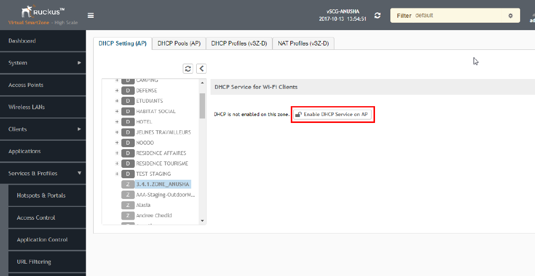
3. Select a Zone from the zone list on the left side of the screen, and click Enable DHCP Service on AP.
FIGURE 116 Enabling DHCP Service
Services and Profiles
DHCP/NAT
SCG200 vSZ-H and SZ300 Administrator Guide
Part Number: 800-71563-001 247
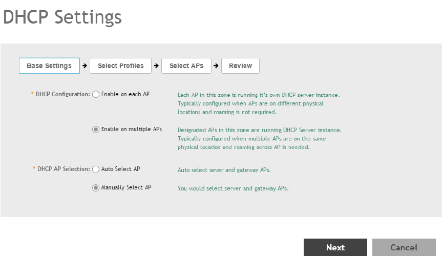
4. Click Edit DHCP Service on AP. The DHCP Settings wizard appears.
FIGURE 117 DHCP Settings wizard
5. On the first page of the wizard (Base Settings), configure the DHCP Configuration as follows:
•Enable on Each AP: Each AP in this zone runs its own DHCP server instance. This option is typically used when APs are at
different sites and roaming is not required.
•Enable on Multiple APs: Designate which APs will provide DHCP/NAT service. This option is typically used when multiple APs
are at the same site and roaming is required. This option also allows you to choose whether to automatically or manually
specify which APs will provide DHCP service.
Services and Profiles
DHCP/NAT
SCG200 vSZ-H and SZ300 Administrator Guide
248 Part Number: 800-71563-001
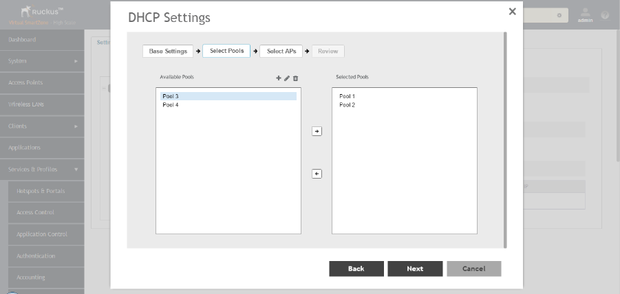
6. On the next wizard screen, (Select Pools), select up to four DHCP pools from which to assign client IP addresses.
FIGURE 118 Selecting Pools
NOTE
If you have not already created DHCP pools, you can do so from within the wizard. Click the Plus (+) icon and configure
the IP address pools as described in Creating an AP DHCP Pool on page 251.
7. Click Next. The Select APs screen appears.
NOTE
If you selected Auto Select AP on the first wizard screen, this configuration screen will be skipped.
Services and Profiles
DHCP/NAT
SCG200 vSZ-H and SZ300 Administrator Guide
Part Number: 800-71563-001 249
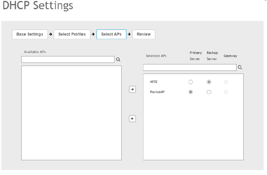
8. On the Select APs wizard screen, select the AP(s) that you want to set as the primary and secondary DHCP servers (if you
previously selected Enable on Multiple APs).
FIGURE 119 Selecting APs
9. Click Next.
Services and Profiles
DHCP/NAT
SCG200 vSZ-H and SZ300 Administrator Guide
250 Part Number: 800-71563-001
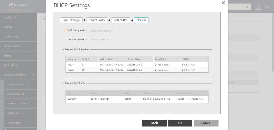
10. On the Review screen, review your settings to make sure everything is correct. Once you are satisfied with your settings, click OK
to confirm.
FIGURE 120 Review DHCP settings
You have configured the DHCP server settings and applied them to an AP (or multiple APs). These APs will now provide DHCP/NAT
functionality and assign IP addresses to wireless clients from the DHCP address pools you specified.
Creating an AP DHCP Pool
Creating a DHCP pool is necessary for assigning IP addresses to clients. Multiple address pools can be created and assigned to APs that
are running DHCP services. Then, when a client connects to the wireless network, it will be assigned an address from the DHCP pool(s) you
specified.
To configure a DHCP pool for IP address allocation:
1. Go to Services & Profiles > DHCP & NAT.
2. Select the DHCP Pools (AP) tab, and then select the zone for which you want to create the pool.
Services and Profiles
DHCP/NAT
SCG200 vSZ-H and SZ300 Administrator Guide
Part Number: 800-71563-001 251
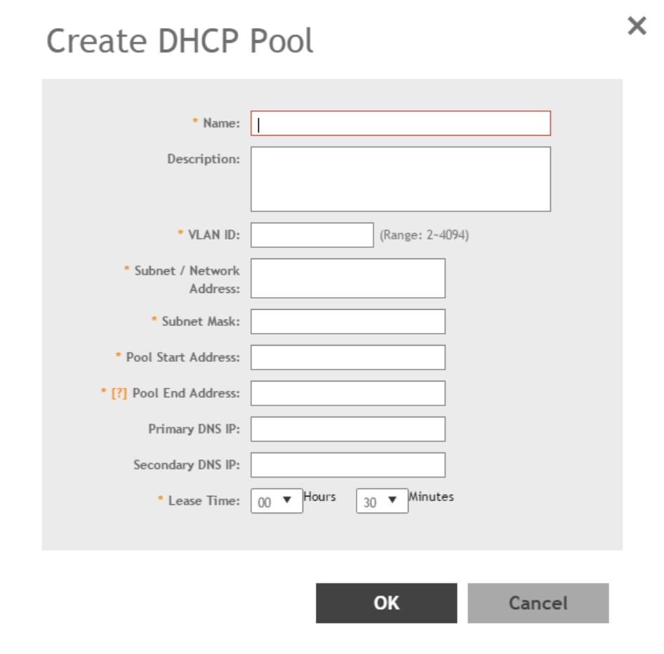
3. Click Create.
The Create DHCP Pool page appears.
FIGURE 121 Creating a DHCP Pool
Services and Profiles
DHCP/NAT
SCG200 vSZ-H and SZ300 Administrator Guide
252 Part Number: 800-71563-001
4. Configure the following:
•Name: Type a name for the pool you want to create.
•Description: Type a description of the pool you want to create.
•VLAN ID: Type the vlan id for the pool.
•Subnet Network Address: Type the IP subnet network address (e.g., 192.168.0.0).
•Subnet Mask: Type the subnet mask address (e.g., 255.255.255.0).
•Pool Start Address: Type the first IP address to be allocated to clients from the pool (e.g., 192.168.0.1).
•Pool End Address: Type the last IP address to be allocated to clients from the pool (e.g., 192.168.0.253).
•Primary DNS IP: Type the primary DNS server IP address.
•Secondary DNS IP: Type the secondary DNS server IP address.
•Lease Time: Enter the IP address lease time, after which clients will have to renew or request new IP addresses.
5. Click OK.
You have created a DHCP address pool. You can now apply this address pool to a DHCP service, as described in Configuring AP-based
DHCP Service Settings on page 246.
NOTE
You can also edit, clone and delete the address pool by selecting the options Configure, Clone and Delete respectively, from the
Pool tab.
Creating Profile-based DHCP
DHCP profile can be applied to vDP and the vDP server can assign IP to the UE based on the profile rule. Different pools with the same
subnet can be created without overlapping IP range.
NOTE
DHCP supports only access-side network.
•Configuring Global Settings on page 253
•Configuring DHCP Pool Settings on page 254
Configuring Global Settings
To configure Profile-based DHCP Global settings:
1. Go to Services & Profiles > DHCP & NAT > DHCP Profiles (DP).
2. Click Create, the Create DHCP Profile page appears.
Services and Profiles
DHCP/NAT
SCG200 vSZ-H and SZ300 Administrator Guide
Part Number: 800-71563-001 253
3. Configure the following:
•Profile Name: Type a name for the DHCP profile you want to create. AP supports 32 bytes.
•Description: Type a description of the settings you want to create.
•Domain Name: Type the domain name address.
•Primary DNS Server: Type the primary domain name server address.
•Secondary DNS Server: Type the secondary domain name server address.
•Lease Time: Type the duration in Hours, Minutes and Seconds. Range: 1 through 86400 seconds.
•DHCP Option43 Space: Click Create, the Create DHCP Option43 Space form appears. Configure the following:
–Space Name: Type a name for Option43 space.
–Description: Type a description for Option43 space.
– Under Option43 Sub Option, click Create and configure the following:
›Sub Option Name: Type a sub option name.
›Type: Select the required option from the drop-down.
›Code: Enter a code. Range: 1 through 254.
›Click OK, you have created Option43 Sub Option.
– Click OK, you have created Option43 Space.
•Hosts: Click Create, the Create Host Configuration form appears. Configure the following:
–General Options
›Host: Type a name for the host settings that you want to create.
›Description: Type a description for the host settings that you want to create.
–Policy Options
›Mac Address: Type the MAC address of the DHCP host.
–Assigning Options
›Broadcast Address: Type the broadcast IP address.
›Fixed Address: Type the fixed IP address of the host.
›Gateway: Type the gateway IP address.
›DNS Server: Type the IP address of the DNS server.
›Domain Name: Type the domain name.
›Host Name: Type the host name.
›Lease Time: Type the duration in Hours, Minutes and Seconds. Range: 1 through 86400 seconds.
– Click OK, you have created DHCP Host configuration.
4. Click OK.
You have created DHCP Profile settings.
Configuring DHCP Pool Settings
To configure DHCP pool settings:
1. Go to Services & Profiles > DHCP & NAT > DHCP Profiles (DP).
2. Select the DHCP prolife from the list for which you want to configure the pool settings.
3. Select the Pools tab page.
Services and Profiles
DHCP/NAT
SCG200 vSZ-H and SZ300 Administrator Guide
254 Part Number: 800-71563-001
4. Click Create and configure the following:
•General Options
–Pool Name: Type a name for the pool configuration.
–Description: Type a description for the pool configuration.
•Policy Options
–VLAN Range: Type the VLAN range. Range: 1, 2 through 4095. For example: 1, 2 or 2-3.
–QinQ VLAN: Select the check box and update the following:
›QinQ SVLAN Range: Type a SVLAN range. Range: 2 through 4095.
›QinQ CVLAN Range: Type a CVLAN range. Range: 2 through 4095.
•Assigning Options
–Subnet: Type the IP address.
–Subnet Mask: Type the network address.
–Broadcast Address: Type the broadcast IP address.
–Pool Range: Type the address range for the pool.
–Exclude Pool: Type the address range that must be excluded.
–Primary Gateway: Type the primary gateway IP address.
–Secondary Gateway: Type the secondary gateway IP address.
–Primary DNS Server: Type the IP address of the primary DNS server.
–Secondary DNS Server: Type the IP address of the secondary DNS server.
–Domain Name: Type the domain name.
–Host Name: Type the host name.
–Lease Time: Type the duration in Hours, Minutes and Seconds. Range: 1 through 86400 seconds.
•Option43 Value
– Click Create, the Create Option43 value form appears. Configure the following:
› Choose the Space Name or click Create to configure Option 43 Space Name.
› Enter a Description.
– Click OK, you have configured Option43 value.
5. Click OK.
You have created DHCP pool configuration.
Creating Profile-based NAT
A NAT Profile could be applied to a vDP. The NAT server settings work independently. You must configure the following settings to create a
NAT profile:
NOTE
NAT does not support multiple public subnet/VLAN.
•Configuring NAT Global Settings on page 256
•Configuring NAT Pool Setting on page 256
Services and Profiles
DHCP/NAT
SCG200 vSZ-H and SZ300 Administrator Guide
Part Number: 800-71563-001 255
Configuring NAT Global Settings
To create a NAT global setting:
1. Go to Services & Profiles > DHCP & NAT > NAT Profiles (DP).
2. Click Create, the Create NAT Profile page appears.
3. Configure the following:
•Profile Name: Type a name for the NAT profile that you want to create. AP supports 32 bytes.
•Description: Type a description for the profile that you want to create.
•Subnet: Type the IP address.
•Prefix: Type a prefix value. Maximum range: 31.
•Public VLAN: Type the VLAN range. Range: 2 through 4095.
•Gateway: Type the gateway IP address.
4. Click OK.
You have created a NAT Profile.
Configuring NAT Pool Setting
To configure NAT pool settings
1. Go to Services & Profiles > DHCP & NAT > NAT Profiles (DP).
2. Select the NAT profile from the list and click the Pools tab.
3. Click Create, the Create Pool Configuration page appears.
4. Configure the following:
•General Options
–Pool Name: Type a name for the NAT pool settings that you want to create.
–Description: Type a description for the pool settings that you want to create.
•Policy Options
–Private VLAN Range: Type the VLAN range and click Add. Range: 1 through 4095. For example: 1 or 1-2.
–Private QinQ VLAN Range: Type SVLAN range, CVLAN range and click Add. Range: 2 through 4095. For example: 2 or
2-3.
•Translation Options
–Port Range: Type the port range. Range: 10000 through 65534. For example: 10000-20000.
–Public Address Range: Type the public address range.
Note: This public address must not be duplicated with the other public address in the same subnet, which includes
applied NAT Profile and vSZ-D's Access and Core Interface Address.
5. Click OK.
You have created a NAT pool setting.
Services and Profiles
DHCP/NAT
SCG200 vSZ-H and SZ300 Administrator Guide
256 Part Number: 800-71563-001

Working with Reports
• Types of Reports................................................................................................................................................... 257
• Managing Report Generation.................................................................................................................................257
• Rogue Access Points............................................................................................................................................ 260
• Historical Client Stats............................................................................................................................................ 261
• Ruckus AP Tunnel Stats........................................................................................................................................ 262
• Core Network Tunnel Stats....................................................................................................................................265
Types of Reports
The controller provides the following types of reports:
Client Number Report
The Client Number report shows a historical view of the maximum and minimum number of clients connect to the system.
Client number can be shown in different time intervals for a specified duration. The report can be generated based on a specific AP, SSID,
or radio.
Continuously Disconnected APs Report
The Continuously Disconnected APs report shows a list of access points disconnected within the specified time range.
System Resource Utilization Report
The System Resource Utilization report shows a historical view of the CPU and memory usage of the system. The CPU and memory usage
can be shown in different time intervals for a specific duration. The report can be generated based on specific plane.
TX/RX Bytes Report
The TX/RX Bytes report shows a historical view of the transmitted (TX) and received (RX) bytes of the system. The transmitted and received
bytes can be shown in different time intervals for a specified duration. The report can be generated based on a specific AP, SSID or radio.
Managing Report Generation
You can create and manage reports.
NOTE
Global filter settings does not apply to the Reports feature.
As reports are segmented by individual administrators, each administrator’s reports are unique and applies only to them.
SCG200 vSZ-H and SZ300 Administrator Guide
Part Number: 800-71563-001 257
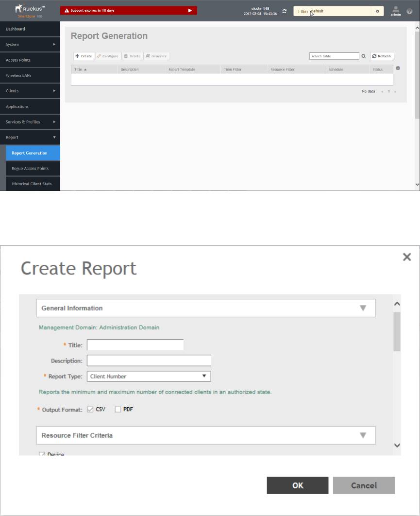
Creating Reports
To create a new report:
1. From the left pane, select Report > Report Generation. Figure 122 appears.
FIGURE 122 Report Generation Screen
2. Click Create, Figure 123 appears.
FIGURE 123 Create Reports Screen
Working with Reports
Managing Report Generation
SCG200 vSZ-H and SZ300 Administrator Guide
258 Part Number: 800-71563-001

3. Enter the required parameters as explained in Table 26.
4. Click OK.
TABLE 26 Report Parameters
Field Description Your Action
General Information
Title Indicates the report name. Enter a title for the report.
Description Describes the report type. Enter a short description.
Report Type Specifies the report type Select the required report.
Output Format Specifies the report output format. Select the required report output format.
Resource Filter Criteria
Device Indicates the level of resource filtering for which
you want to generate the report. For example:
Managenemt Domains, AP Zone or Access Point.
Enter the Device name or select the Device from
the list and choose the option.
SSID Indicates the SSID for which you want to
generate the report.
Select the check box and choose the SSID for
which you want the report. You can select All
SSIDs to generate reports for all the SSIDs
available. This option is convenient as you do not
have to update the resource filter criteria
periodically.
Radio Indicates the frequency for which you want to
generate the report.
Select the check box and choose the required
frequency:
•2.4G
•5G
Time Filter
Time Interval Defines the time interval at which to generate the
report.
Select the required time interval.
Time Filter Defines the time duration for which to generate
the report.
Select the required time filter.
Schedules
Enable/Disable Specifies the scheduled time when a report must
be generated. By default, the current system time
zone is also displayed.
By default the option is disabled. Select Enable
and select the Interval, Hour and Minute. You can
add multiple schedules.
Email Notification
Enable/Disable Triggers an email notification when the report is
generated.
By default the option is disabled. Select Enable
and click the Add New and enter the email
address. You can add multiple email addresses.
Export Report Results
Export Report Results, Enable/Disable Uploads the report results to an FTP server. By default the option is disabled. Select Enable
and select the FTP Server.
NOTE
You can also edit or delete a report by selecting the options Configure or Delete respectively.
Generating Reports
To generate a report:
1. From the left pane, select Report > Report Generation. Figure 122 on page 258 appears.
2. Select the required report from the list and click Generate. The Report Generated form appears.
Working with Reports
Managing Report Generation
SCG200 vSZ-H and SZ300 Administrator Guide
Part Number: 800-71563-001 259

3. Click OK, the report will be generated and listed in the Report Results area.
4. Select the required format from the Result Links column and click Open.
Rogue Access Points
Viewing Rogue Access Points
Rogue (or unauthorized) APs pose problems for a wireless network in terms of airtime contention, as well as security.
Usually, a rogue AP appears in the following way: an employee obtains another manufacturer's AP and connects it to the LAN, to gain
wireless access to other LAN resources. This would potentially allow even more unauthorized users to access your corporate LAN - posing
a security risk. Rogue APs also interfere with nearby Ruckus Wireless APs, thus degrading overall wireless network coverage and
performance.
The controller's rogue AP detection options include identifying the presence of a rogue AP, categorizing it as either a known neighbor AP or
as a malicious rogue.
If you enabled rogue AP detection when you configured the common AP settings (see Configuring APs), click Report > Rogue Access
Points. The Rogue Access Points page displays all rogue APs that the controller has detected on the network, including the following
information:
•Rogue MAC: MAC address of the rogue AP.
•Type: Rogue, a normal rogue AP, not yet categorized as malicious or non-malicious.
•Channel: Radio channel used by the rogue AP.
•Radio: WLAN standards with which the rogue AP complies.
•SSID: WLAN name that the rogue AP is broadcasting.
•Detecting AP Name: Name of the AP.
•Zone: Zone to which the AP belongs.
•RSSI: Radio signal strength.
•Encryption: Indicates whether the wireless signal is encrypted or not.
•Last Detected: Date and time when the rogue AP was last detected by the controller.
Filtering Rogue Access Points
From the list of Rogue Access Points you can filter the requried rogue APs based on Rogue MAC or Type.
To filter rogue APs:
1. From the Rogue Access Points page, click Settings button. The Apply Filters form appears.
2. Enter the Rogue MAC ID or select the rogue AP Type from the drop-down.
3. Click OK. Filtered rogue APs appear in the list.
Marking Rogue Access Points
You can mark a Rogue (or unauthorized) AP as known.
Working with Reports
Rogue Access Points
SCG200 vSZ-H and SZ300 Administrator Guide
260 Part Number: 800-71563-001

To mark a Rogue AP as known:
1. From the left pane, click Report and Rogue Access Points. The Rogue Access Points page appears.
2. Select the Rogue AP from the list and click Mark as Known. The classification Type of the Rogue AP changes to Known. You can
also select the Rogue AP from the list and click Unmark, to change the classification.
Locating a Rogue Access Point
You can identify the estimated location area of a rogue AP on a map. Managed APs that detect the rogue APs are also visible in the map.
To locate the Rogue AP:
1. From the left pane, click Report and Rogue Access Points. The Rogue Access Points page appears.
2. Select the Rogue AP from the list and click Locate Rogue. The Rogue AP Location pop-up window appears locating the rogue AP.
a) You can select:
•Map-to view the location in street view
•Satellite-to view the location as satellite imagery
•+-to zoom in the location
•--to zoom out the location.
b) You can find the following information:
• Rogue APs: MAC, Type, and SSID
• Detecting APs: MAC, Name, and RSSI
3. Click OK.
Historical Client Stats
Viewing AP Client Statistics
AP Client Statistics is a cumulative value per session and one entry is created per session. Data is reported every 60 seconds and is not bin
data. The user interface displays the table and its corresponding graph chart. The two representations are synchronized and controlled by
the search criteria. For performance reasons, the total counters per DP or per GGSN IP for each bin is precalculated.
To view AP Client Statistics:
1. From the left pane, select Report > Historical Client Stats. The Ruckus AP Client page appears.
2. Update the parameters as explained in Table 27.
3. Click:
•Load Data— To view the report in the workspace.
•Export CSV—To open or save the report in CSV file format.
TABLE 27 AP Client Statistics Report Parameters
Field Description Your Action
Time Period Indicate the time period for which you want to
view the report.
Move the slider to set the duration.
Working with Reports
Historical Client Stats
SCG200 vSZ-H and SZ300 Administrator Guide
Part Number: 800-71563-001 261

TABLE 27 AP Client Statistics Report Parameters (continued)
Field Description Your Action
Zone Name Specifies the zone for which you want to view
the report.
Enter the zone name or choose the zone from
the list.
Client MAC Specifies the MAC. Enter the client MAC.
Client IP Indicates the client IP. Enter the client IP address.
MVNO Name Indicates the mobile virtual network operator
name.
Choose the MVNO.
Table 28 contains historical client statistics report based on the UE session statistics.
TABLE 28 AP Client Statistics Report Attributes
Attribute Type Description
Start Long Indicates the session creation time.
End Long Indicates the session end time.
Client MAC String Indicates the Mac address of the client.
Client IP Address String Indicates the IP address of the client.
Core Type String Indicates the core network tunnel type.
MVNO Name String Indicates the mobile virtual network operator
name.
AP MAC String Indicates the Client AP MAC.
SSID String Indicates the SSID
Bytes from Client Long Indicates the number of bytes received from the
client.
Bytes to Client Long Indicates the number of bytes sent to the client.
Packets from Client Long Indicates the number of packets received from
the client.
Packets to Client Long Indicates the number of packets sent to the
client.
Dropped Packets from Client Long Indicates the number of packets dropped from
the client.
Dropped Packets to Client Long Indicates the number of packets dropped to the
client.
Ruckus AP Tunnel Stats
Viewing Statistics for Ruckus GRE Tunnels
The web interface displays the table and its corresponding graph chart. The two representations are synchronized and controlled by the
search criteria. For performance reasons, the total counters per DP or per AP for each bin may be pre-calculated.
To view the Ruckus GRE Tunnel Statistics:
1. From the left pane, select Report > Ruckus AP Tunnel Stats. The Ruckus GRE tab appears by default.
2. Update the parameters as explained in Table 29.
3. Click:
•Load Data— To view the report in the workspace.
Working with Reports
Ruckus AP Tunnel Stats
SCG200 vSZ-H and SZ300 Administrator Guide
262 Part Number: 800-71563-001

•Export CSV—To open or save the report in CSV file format.
TABLE 29 Ruckus GRE Report Parameters
Field Description Your Action
Time Period Indicate the time period for which you want to
view the report.
Move the slider to set the duration.
Data Plane Indicates the Data Plane. Select the Data Plane.
AP MAC or IP Address Indicates the MAC of the Access Point or IP
Address.
Enter the AP MAC or IP address.
Zone Name Specifies the zone for which you want to view
the report.
Enter the zone name or select the zone from
the list.
Table 30 contains the report based on the statistics for Ruckus GRE. Each entry contains the 15 minutes cumulative data.
TABLE 30 Ruckus GRE report attributes
Attribute Type Description
Time Long Bin ID, which is stamped at a 15 minute interval. For
example, 10:00, 10:15.
TXBytes Long Indicates the number of bytes sent.
RXBytes Long Indicates the number of bytes received.
TXPkts Long Indicates the number of packets sent.
RXPkts Long Indicates the number of packets received.
Dropped Packets Long Indicates the number of packets dropped.
Viewing Statistics for SoftGRE Tunnels
The web interface displays the table and its corresponding graph chart. The two representations are synchronized and controlled by the
search criteria. For performance reasons, the total counters per DP or per AP for each bin may be pre-calculated.
To view the SoftGRE Tunnel Statistics:
1. From the left pane, select Report > Ruckus AP Tunnel Stats. The Ruckus GRE tab appears by default.
2. Select SoftGRE. Update the parameters as explained in Table 31.
3. Click:
•Load Data— To view the report in the workspace.
•Export CSV—To open or save the report in CSV file format.
TABLE 31 SoftGRE Report Parameters
Field Description Your Action
Time Period Indicate the time period for which you want to
view the report.
Move the slider to set the duration.
Zone Name Specifies the zone for which you want to view
the report.
Select the required zone.
Gateway Address Specifies the gateway address Enter the gateway address.
AP MAC or IP Address Indicates the MAC of the Access Point or IP
Address.
Enter the AP MAC or IP address.
Table 32 contains the report based on the statistics for SoftGRE. Each entry contains the 15 minutes cumulative data.
Working with Reports
Ruckus AP Tunnel Stats
SCG200 vSZ-H and SZ300 Administrator Guide
Part Number: 800-71563-001 263

TABLE 32 SoftGRE Report Attributes
Attribute Type Description
Time Long Bin ID, which is stamped at a 15 minute interval. For example,
10:00, 10:15.
TXBytes Long Indicates the number of bytes sent.
RXBytes Long Indicates the number of bytes received.
TXPkts Long Indicates the number of packets sent.
RXPkts Long Indicates the number of packets received.
RX Dropped Packets Long Indicates the number of packets dropped.
TX Dropped Packets Long Indicates the number of packets dropped.
TX Error Packets Long Indicates the number of packets with a header error.
RX Error Packets Long Indicates the number of packets with a header error.
Viewing Statistics for SoftGRE IPsec Tunnels
The web interface displays the table and its corresponding graph chart. The two representations are synchronized and controlled by the
search criteria. For performance reasons, total counters per DP or per AP for each bin may be pre-calculated.
To view the SoftGRE IPsec Tunnel Statistics:
1. From the left pane, select Report > Ruckus AP Tunnel Stats. The Ruckus GRE tab appears by default.
2. Select SoftGRE + IPsec. Update the parameters as explained in Table 33.
3. Click:
•Load Data— To view the report in the workspace.
•Export CSV—To open or save the report in CSV file format.
TABLE 33 SoftGRE + IPsec Report Parameters
Field Description Your Action
Time Period Indicate the time period for which you want to
view the report.
Move the slider to set the duration.
Zone Name Specifies the zone for which you want to view
the report.
Select the required zone.
Gateway Address Specifies the gateway address Enter the gateway address.
AP MAC or IP Address Indicates the MAC of the Access Point or IP
Address.
Enter the AP MAC or IP address.
Table 34 contains the report based on the statistics for access point IPsec. Each entry contains the 15 minutes cumulative data.
TABLE 34 SoftGRE + IPsecReport Attributes
Attribute Type Description
Time Long Bin ID, which is stamped at a 15 minute interval. For example,
10:00, 10:15.
TXBytes Long Indicates the number of bytes sent.
RXBytes Long Indicates the number of bytes received.
TXPkts Long Indicates the number of packets sent.
RXPkts Long Indicates the number of packets received.
TX Dropped Packets Long Indicates the number of packets dropped.
Working with Reports
Ruckus AP Tunnel Stats
SCG200 vSZ-H and SZ300 Administrator Guide
264 Part Number: 800-71563-001
TABLE 34 SoftGRE + IPsecReport Attributes (continued)
Attribute Type Description
RX Dropped Packets Long Indicates the number of packets dropped.
Core Network Tunnel Stats
Viewing Statistics for SoftGRE Core Network Tunnel
To view Stats for SoftGRE Core Network Tunnel:
1. From the left pane, select Report > Core Network Tunnel Stats. The SoftGRE page appears.
2. Update the parameters as explained in Table 35.
3. Click:
•Load Data— To view the report in the workspace.
•Export CSV—To open or save the report in CSV file format.
TABLE 35 SoftGRE Core Network Tunnel Parameters
Field Description Your Action
Time Period Indicate the time period for which you want to
view the report.
Move the slider to set the duration.
Data Plane Indicates the Data Plane. Select the Data Plane.
Gateway IP Address Indicates the gateway IP Address. Enter the gateway IP address.
MVNO Name Indicates teh mobile virtual network operator
name.
Choose the MVNO name.
Table 36 contains the report based on the statistics for SoftGRE core network tunnel.
TABLE 36 SoftGRE Core Network Tunnel Attributes
Attribute Type Description
Time Long Bin ID, which is stamped at a 15 minute interval.
For example, 10:00, 10:15.
TX Bytes Long Indicates the number of bytes sent.
RX Bytes Long Indicates the number of bytes received.
TX Packets Long Indicates the number of packets sent.
RX Packets Long Indicates the number of packets received.
Dropped Packets Long Indicates the number of packets dropped.
Working with Reports
Core Network Tunnel Stats
SCG200 vSZ-H and SZ300 Administrator Guide
Part Number: 800-71563-001 265
SCG200 vSZ-H and SZ300 Administrator Guide
266 Part Number: 800-71563-001
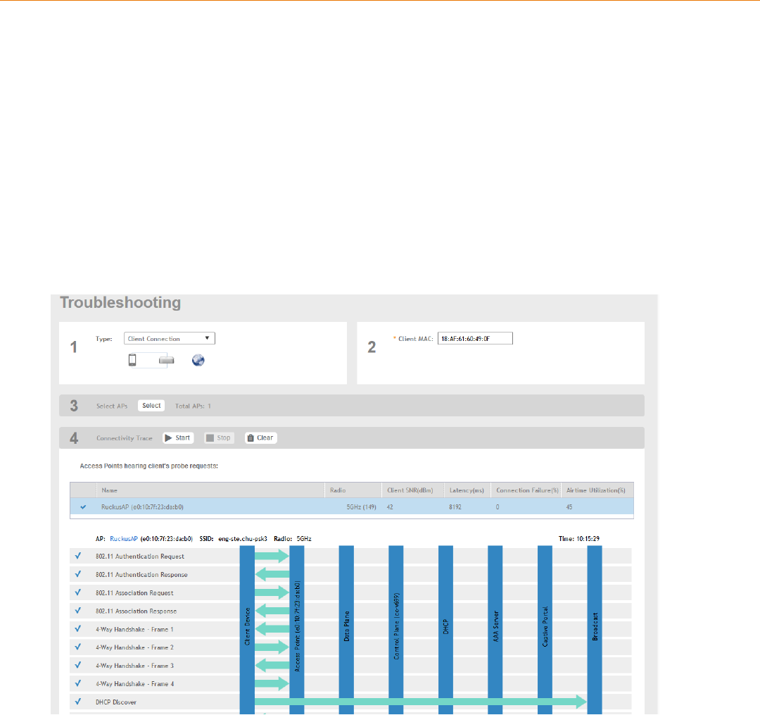
Troubleshooting
• Troubleshooting Client Connections.......................................................................................................................267
• Troubleshooting through Spectrum Analysis.......................................................................................................... 268
Troubleshooting Client Connections
This feature allows network administrators to connect to client devices and analyze network connection issues in real-time.
The network administrator types the MAC address of the client device and starts various services to identify the connectivity issue. The APs
assigned to the client device relay data frames from the device to the controller which the administrator analysis to determine which stage of
the connection is causing problems.
1. Go to Troubleshooting.
The Troubleshooting page appears.
FIGURE 124 Troubleshooting - Client Connections
2. In Type, select Client Connection from the drop-down menu.
3. In Client MAC, type the MAC address of the client device which is facing connectivity issues.
4. In Select APs, click Select.
The Select APs page appears. Select an AP to communicate between the client and controller and then click OK.
SCG200 vSZ-H and SZ300 Administrator Guide
Part Number: 800-71563-001 267
5. In Connectivity Trace, click Start.
The controller configures the APs to receive data frame from the target client so that the APs can relay relevant frames that match
the client filter to the controller.
The APs that receive probe requests from the target client are listed in a table along with the APs operating channel and the RSSI
at which the client’s frames were received. This stage of the connection identifies whether there are acceptable APs for the client
to connect to.
Following are the details displayed in the table:
• AP Name and MAC Address.
• Radio: Identifies the 2.4 or 5 GHz radio of the AP and the channel number the radio is operating on.
• Client SNR: This is the signal-to-noise ratio received in dB.
• Latency: Time delay in connecting the AP to the client.
• Connection Failures: Displays the percentage of AP-client connection attempts that failed.
• Airtime Utilization: Percentage of the air time that was used by the client to transfer data.
AT this stage, the tool displays the statuses Client is in a discovery state and not currently
connected(when the tool starts/when the client is already connected to an AP) and Client is attempting a new
connection(when the target client sends an 802.11 authentication request frame to an AP to initiate a connection.).
By using the list of APs that communicated with the client, you will be able to identify if the client chose the best AP based on
signal quality and other health metrics.
When the client sends an 802.11 authentication request frame, a flow diagram depicting different stages of the AP-client
connection is initiated. This sends a trigger frame to the AP and it is highlighted from the list for reporting APs.
The
Flow ladder
in the diagram shows the step-by-step exchange of information between devices during the connection process.
As the steps are completed, colored arrows are displayed based on whether the step depicts a warnings (yellow) or event (for
example, red for failure). Typical warning scenarios include time delays or when a client negotiates and EAP type that's not
supported. Failure conditions are also highlighted as red arrows typically when the connection itself fails.
6. Click Stop to terminate connection between the AP and client.
NOTE
The following authentication types are supported:
• Open
• PSK (WPA2-Personal)
• 802.1X (PEAP, TTLS, TLS, SIM)
• WISPr
Troubleshooting through Spectrum Analysis
Interference between wireless devices is seen to increase dramatically due to the increase in the number of device used, and the availability
of only three non-interfering channels in 802.11. This reduces the performance of the wireless network, therefore, it is important to monitor
the spectrum usage in a particular area and efficiently allocate the spectrum as needed to wireless devices.
In addition, spectrum analysis provides the flexibility to troubleshoot issues remotely, identify sources of interferences within the network and
allow administrators access to the RF health of the network environment.
Troubleshooting
Troubleshooting through Spectrum Analysis
SCG200 vSZ-H and SZ300 Administrator Guide
268 Part Number: 800-71563-001
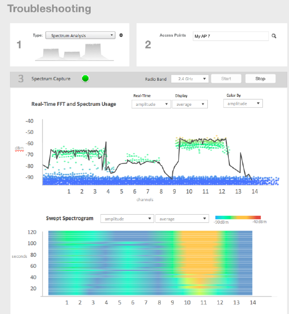
APs which are put in spectrum-mode transmit data to the controller, which in turn displays the data in specturm-mode for analysis.
1. Go to Troubleshooting.
The Troubleshooting page appears.
FIGURE 125 Troubleshooting - Spectrum Analysis
2. In Type, select Spectrum Analysis from the drop-down menu.
3. In AP MAC Address, select the AP that needs to be in the spectrum analysis-mode.
Troubleshooting
Troubleshooting through Spectrum Analysis
SCG200 vSZ-H and SZ300 Administrator Guide
Part Number: 800-71563-001 269
4. In Spectrum Capture, select the radio frequency values (2.4GHz or 5GHz) for the analysis from the Radio option.
The 2.4GHz band spans from 2400 - 2480 GHz and 5GHz band spans from 5.15 - 5.875 GHz.
You can select and view the spectrum analysis trends in these graphs:
• Spectrum Usage: This chart uses a color-based view to show collections of data points over time. As more data samples are
measured at a specific frequency and amplitude coordinate, the color shown at that coordinate will change. If you choose to
view colors by amplitude, the warm colors depict higher amplitude and cool colors lower amplitudes. If you view the colors by
density, the warm colors depict a high number of samples at a given coordinate and cool colors show low number of samples
at a given coordinate.
• Real-Time FFT : This chart is a second-by-second (2sec) update of measured data across the band. If you view by Amplitude
(signal strength), then the chart displays both average and maximum amplitudes of energy measured across the band for that
sample period. If you view by Utilization (duty cycle), then the chart displays the percentage (%) of time at which the frequency
is utilized at an amplitude above N. The amplitude threshold is configurable but the default is -85dBm.
• Swept Spectrogram: This chart displays a waterfall of color over time, where each horizontal line in the waterfall represents
one sample period (e.g. 2 seconds), and the full waterfall display spans 2 minutes of time (60 sample bins of 2sec each).
There are two display options for the spectrogram chart:
– Amplitude: Shows both average and maximum amplitude of energy measured across the band for that sample period.
– Utilization: Shows the percentage of time at which the frequency is utilized at an amplitude above N. The amplitude
threshold is configurable but the default is -85dBm.
5. After you select the parameters that you want to use to view the graphs, click Start.
6. Click Stop to terminate viewing spectrum analysis trends.
Troubleshooting
Troubleshooting through Spectrum Analysis
SCG200 vSZ-H and SZ300 Administrator Guide
270 Part Number: 800-71563-001

Administering the Controller
• Managing Administrator and Roles........................................................................................................................ 271
• Backing Up and Restoring Clusters....................................................................................................................... 275
• Upgrading the Controller....................................................................................................................................... 286
• Managing Licenses................................................................................................................................................290
• ZoneDirector to SmartZone Migration....................................................................................................................292
• Monitoring Administrator Activities.........................................................................................................................293
• Managing Mobile Virtual Network Operator (MVNO) Accounts...............................................................................294
Managing Administrator and Roles
The controller must be able to manage various administrators and roles that are created within the network in order to assign tasks and
functions, and to authenticate users.
Creating User Groups
Creating user groups and configuring their access permissions, resources and administrator accounts allows administrators to manage a
large number of users.
1. Go to Administration > Admins and Roles.
2. Select the Groups tab.
3. Click Create after selecting the system domain.
The Create User Group page appears.
4. Configure the following:
1. Permission
a. Name: Type the name of the user group you want to create.
b. Description: Type a short description for the user group you plan to create.
c. Permission: Select one of the access permission for the user group, from the drop-down menu. You can also grant
admin permission to generate guest passes.
d. Click Next.
2. Resource: From Select Resources, add the resources you want to assign to this user group.
3. Click Next.
4. Domain: Select the domain from the list of domains to which this user group will be associated.
5. Click Next.
6. Administrator: Select the users available in the list and add them under Selected User. You can also create Administrator
accounts for the group from this page.
7. Click Next.
8. Review: Verify the user group's configuration that you have selected.
9. Click OK to confirm.
You have created the user groups.
SCG200 vSZ-H and SZ300 Administrator Guide
Part Number: 800-71563-001 271

NOTE
You can also edit and delete the group configuration by selecting the options Configure, and Delete respectively, from the Groups
tab.
Creating Administrator Accounts
The controller supports the creation of additional administrator accounts. This allows you to share or delegate management and monitoring
functions with other members of your organization.
1. Go to Administration > Admins and Roles.
2. Select the Administrators tab.
3. Click Create.
The Create Administrator Account page appears.
FIGURE 126 Creating an Administrator Account
Administering the Controller
Managing Administrator and Roles
SCG200 vSZ-H and SZ300 Administrator Guide
272 Part Number: 800-71563-001
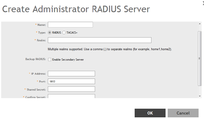
4. Configure the following:
1. Account Name: Type the name that this administrator will use to log on to the controller.
2. Real Name: Type the actual name (for example, John Smith) of the administrator.
3. Password: Type the password that this administrator will use (in conjunction with the Account Name) to log on to the
controller.
4. Confirm Password: Type the same password as above.
5. Phone: Type the phone number of this administrator.
6. Email: Type the email address of this administrator.
7. Job Title: Type the job title or position of this administrator in your organization.
8. Click OK.
You have created the administrator account.
NOTE
You can also edit and delete the admin account by selecting the options Configure, and Delete respectively, from the
Administrator tab.
Creating a RADIUS Server for Administrator Authentication
You can add RADIUS servers that you want to use for authorizing and authenticating administrators.
1. Go to Administration > Admins and Roles.
2. Select the AAA tab.
3. Click Create.
The Create Administrator RADIUS Server page appears.
FIGURE 127 Creating an Administrator RADIUS Server
Administering the Controller
Managing Administrator and Roles
SCG200 vSZ-H and SZ300 Administrator Guide
Part Number: 800-71563-001 273
4. Configure the following:
1. Name: Type a name for the RADIUS server.
2. Type: Select the type of RADIUS server that you are using. Options include:
• RADIUS: Click this option to use a Remote Authentication Dial-In User Service (RADIUS) server on the network for
authenticating controller administrators.
• TACACS+: Click this option to use a Terminal Access Controller Access-Control System Plus (TACACS+) server on the
network for authentication controller administrators.
3. Realm: Type the realm (or realms) to which the RADIUS server belongs. If the RADIUS server belongs to multiple realms, use a
comma (,) to separate the realm names.
4. Backup RADIUS: Select the Enable Secondary Server to back up the RADIUS server configuration.
a. Primary Server: Type the IP address, port, shared secret for the primary server that needs to be backed up.
b. Secondary Server: Type the IP address, port, shared secret for the secondary server to which the back must be done.
c. Failover Policy at NAS:'
• Request Timeout: Type the timeout period (in seconds) after which an expected RADIUS response message is
considered to have failed.
• Max Number of Retries: Type the number of failed connection attempts after which the controller will fail over to the
backup RADIUS server.
• Reconnect Primary: Type the number of minutes after which the controller will attempt to reconnect to the primary
RADIUS server after failover to the backup server.
5. IP Address: Type the IP address of the RADIUS server.
6. Port: Type the UDP port that the RADIUS server is using. The default port is 1812.
7. Shared Secret: Type the shared secret.
8. Confirm Secret: Retype the same secret in.
9. Click OK.
You have completed adding a RADIUS server for authenticating administrators.
NOTE
You can also edit, clone and delete the server by selecting the options Configure, Clone and Delete respectively, from the
Administrator tab.
Enabling the Access Control List
You can control access to management interfaces from CLI or SSH.
1. Go to Administration > Admins and Roles.
2. Select the Access Control List tab.
3. Select Enable.
Administering the Controller
Managing Administrator and Roles
SCG200 vSZ-H and SZ300 Administrator Guide
274 Part Number: 800-71563-001
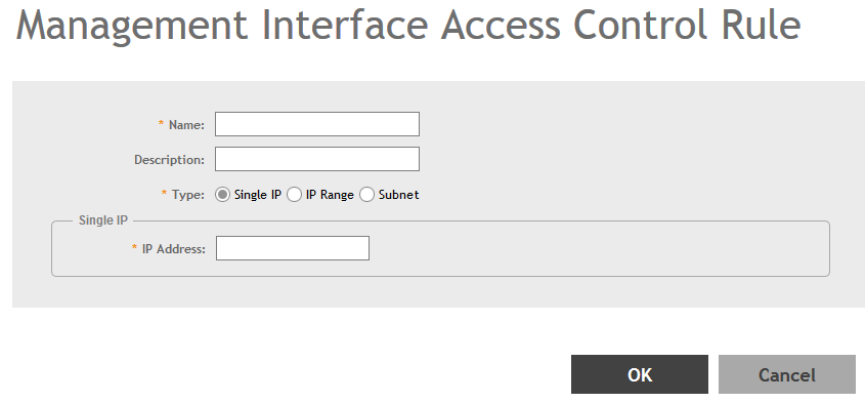
4. Click Create.
The Management Interface Access Control Rule page appears.
FIGURE 128 Management Interface Access Control Rule
5. Configure the following:
1. Name: Type the name that rule you want to create to access the management interface.
2. Description: Type a short description for the rule.
3. Type: Select one of the following
• Single IP: Type the IP address of the interface that can be accessed per this rule.
• IP Range: Type the range of IP address that will be allowed access.
4. Subnet: Type the network address and subnet mask address of the interface that will be allowed access.
5. Click OK.
You have created the access control list rule.
NOTE
You can also edit and delete the list by selecting the options Configure and Delete respectively, from the Access Control List tab.
Backing Up and Restoring Clusters
Back up the controller cluster periodically to ensure that you can restore the control plane, data plane, and AP firmware versions as well as
the system configuration in the cluster if is a system failure occurs.
Creating a Cluster Backup
Backing up the cluster (includes OS, configuration, database and firmware) periodically enables you to restore it in the event of an
emergency. Ruckus Wireless also recommends that you back up the cluster before you upgrade the controller software.
1. Go to Administration > Backup and Restore.
2. Select the Cluster tab.
Administering the Controller
Backing Up and Restoring Clusters
SCG200 vSZ-H and SZ300 Administrator Guide
Part Number: 800-71563-001 275
3. In Cluster Backup and Restore, click Backup Entire Cluster to backup both nodes in a cluster.
The following confirmation message appears: Are you sure you want to back up the cluster?
4. 4. Click Yes.
The following message appears: The cluster is in maintenance mode. Please wait a few minutes.
When the cluster backup process is complete, a new entry appears in the Cluster Backups History section with a Created On
value that is approximate to the time when you started the cluster backup process.
Restoring a Cluster Backup
You must be able to restore a cluster to ts previous version in the case of a failure.
1. Go to Administration > Backup and Restore.
2. Select the Cluster tab.
3. In Cluster Backup History, select the cluster and click Restore.
The following confirmation message appears:
Are you sure you want to restore the cluster?
4. Click Yes.
The cluster restore process may take several minutes to complete. When the restore process is complete, the controller logs you
off the web interface automatically.
ATTENTION
Do not refresh the controller web interface while the restore process is in progress. Wait for the restore process to
complete successfully.
5. Log on to the controller web interface.
If the web interface displays the message Cluster is out of service. Please try again in a few minutes
appears after you log on to the controller web interface, wait for about three minutes. The dashboard will appear shortly. The
message appears because the controller is still initializing its processes.
6. Go to Administration > Upgrade, and then check the Current System Information section and verify that all nodes in the cluster
have been restored to the previous version and are all in service.
7. Go to Diagnostics > Application Logs, and then under Application Logs & Status check the Health Status column and verify that
all of the controller processes are online.
You have completed restoring the cluster backup.
Backing Up and Restoring the Controller's Network Configuration from
an FTP Server
In addition to backing up and restoring the controller's network configuration from its own database, the controller supports backup and
restore of its network configuration from an FTP server using the CLI.
This section describes the requirements for backing up and restoring the controller's network configuration from an FTP server, the
information that is included in the backup file, and how to perform the backup and restore process.
To back up and restore the controller's network configuration from an FTP server, the controller must have already been set up and in
service. In case of a multi-node cluster, all the nodes in the cluster must be in service.
Administering the Controller
Backing Up and Restoring Clusters
SCG200 vSZ-H and SZ300 Administrator Guide
276 Part Number: 800-71563-001
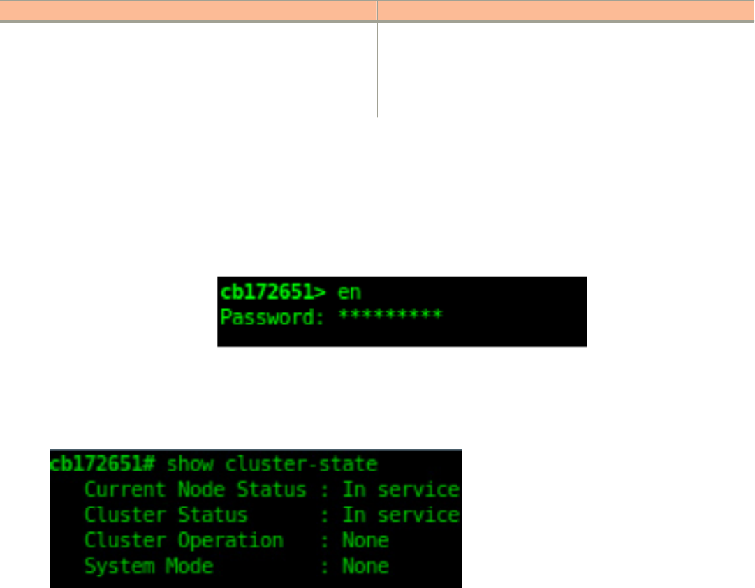
The following table lists the network configuration that is backed up from the control and data planes when you perform a backup
procedure to an FTP server.
TABLE 37 Information that is backed up to the FTP server
Control Plane Data Plane
• Control interface
• Cluster interface
• Management interface
• Static routes
•User-defined interfaces
• Primary interface
• Static routes
• Internal subnet prefix
Backing Up to an FTP Server
Follow these steps to back up the controller network configuration to an FTP server.
1. Log on to the controller from the controller's command line interface (CLI). For more information, see the corresponding
Command
Line Interface Reference Guide
for your controller platform.
2. At the prompt, enter en to enable privileged mode.
FIGURE 129 Enable privileged mode
3. Enter - to display the statuses of the node and the cluster.
Before continuing to the next step, verify that both the node and the cluster are in service.
FIGURE 130 Verify that both the node and the cluster are in service
Administering the Controller
Backing Up and Restoring Clusters
SCG200 vSZ-H and SZ300 Administrator Guide
Part Number: 800-71563-001 277
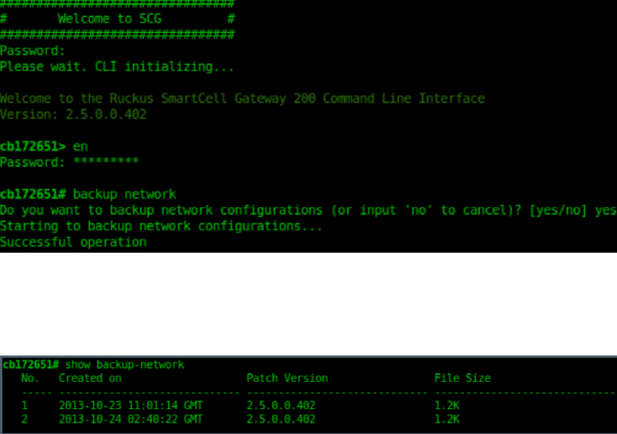
4. Enter backup network to back up the controller network configuration, including the control plane and data plane information.
The controller creates a backup of its network configuration on its database.
FIGURE 131 Run backup network
5. Enter show backup-network to view a list of backup files that have been created.
Verify that the Created On column displays an entry that has a time stamp that is approximate to the time you started the backup.
FIGURE 132 Enter the show backup-network command
6. Enter copy backup-network
{ftp-url}
, where
{ftp-url}
(remove the braces) is the URL or IP address of the FTP server to which you
want to back up the cluster configuration.
The CLI prompts you to choose the number that corresponds to the backup file that you want to export to the FTP server.
Administering the Controller
Backing Up and Restoring Clusters
SCG200 vSZ-H and SZ300 Administrator Guide
278 Part Number: 800-71563-001
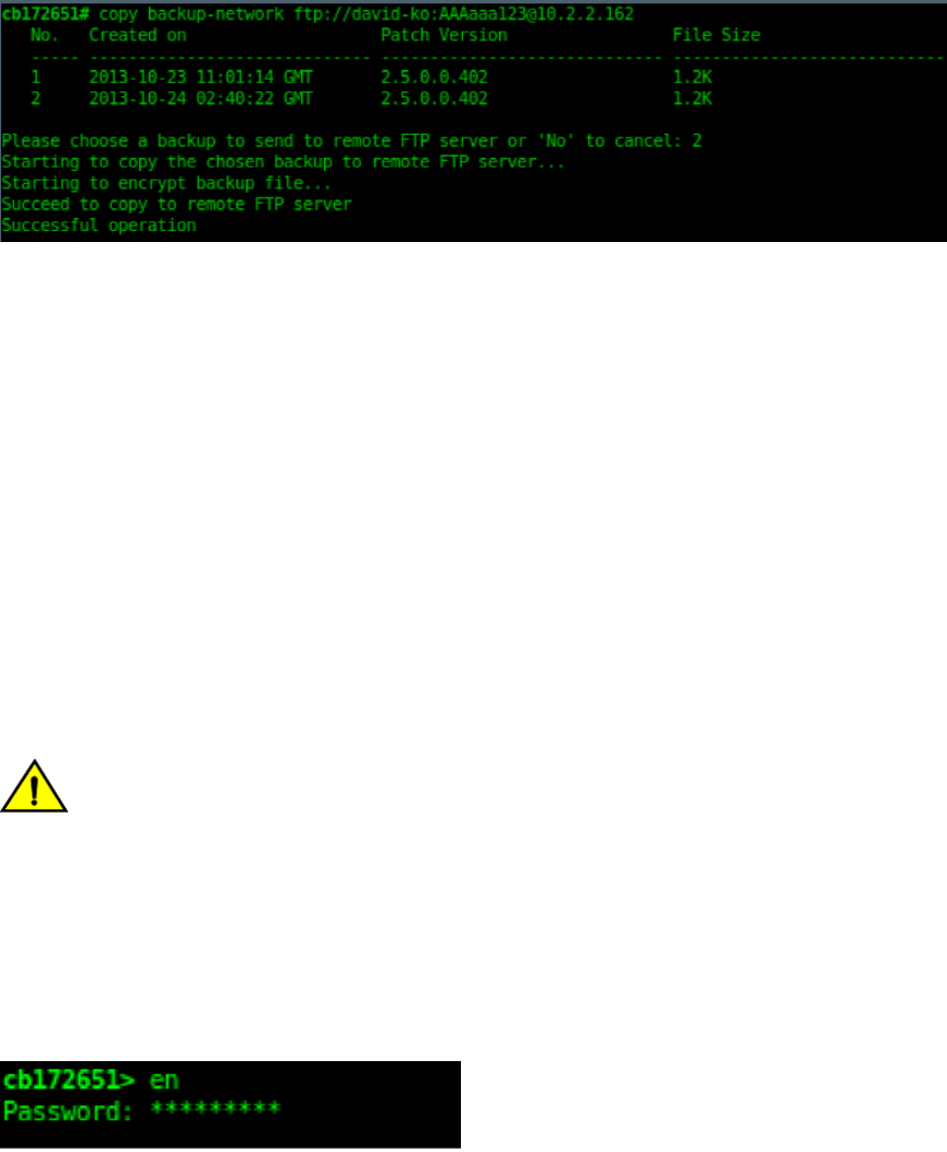
7. Enter the number of the backup file that you want to export to the FTP server.
The controller encrypts the backup file, and then exports it to the FTP server. When the export process is complete, the following
message appears on the CLI:
Succeed to copy to remote FTP server Successful operation
FIGURE 133 Succeed to copy to remote FTP server indicates that you have exported the backup file to the FTP server successfully
8. Using an FTP client, log on to the FTP server, and then verify that the backup file exists.
The file format of the backup file is network_<YYYYMMDDHHmmss>_<controller-version>.bak.
For example, if you created the backup file on October 24th 2013 at 02:40:22 and the controller version is 2.5.0.0.402, you should
see a file named network_20131024024022_2.5.0.0.402.bak on the FTP server.
You have completed backing up the controller to an FTP server.
Restoring from an FTP Server
Before you continue, take note of the following limitations with restoring a backup file of the controller network configuration from an FTP
server:
• Only release 2.1 and later support restoring from an FTP server.
• In this current release, restoring the entire cluster from an FTP server is unsupported. The restore process must be performed on
one node at a time.
• Restoring from an FTP server can only be performed using the CLI.
CAUTION
Restoring a backup file to the controller requires restarting all of the controller services.
Follow these steps to restore a backup file of the controller's network configuration that you previously uploaded to an FTP back to the
controller.
1. Log on to the controller from the CLI. For more information, see the corresponding
Command Line Interface Reference Guide
for
your controller platform.
2. At the prompt, enter en to enable privileged mode.
FIGURE 134 Enable privileged mode
Administering the Controller
Backing Up and Restoring Clusters
SCG200 vSZ-H and SZ300 Administrator Guide
Part Number: 800-71563-001 279
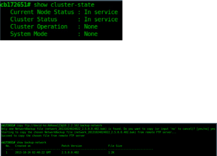
3. Enter show cluster-state to display the statuses of the node and the cluster.
Before continuing to the next step, verify that both the node and the cluster are in service.
FIGURE 135 Verify that both the node and the cluster are in service
4. Enter the following command to log on to the FTP server and check for available backup files that can be copied to the controller:
copy <ftp-url> backup-network
5. If multiple backup files exist on the FTP server, the CLI prompts you to select the number that corresponds to the file that you want
to copy back to the controller.
If a single backup file exists, the CLI prompts you to confirm that you want to copy the existing backup file to the controller.
When the controller finishes copying the selected backup file from the FTP server back to the controller, the following message
appears: Succeed to copy the chosen file from the remote FTP server
6. Enter show backup-network to verify that the backup file was copied back to the controller successfully.
FIGURE 136 Verify that the backup file was copied to the controller successfully
7. Run restore network to start restoring the contents of the backup file to the current controller.
The CLI displays a list of backup files, and then prompts you to select the backup file that you want to restore to the controller.
Administering the Controller
Backing Up and Restoring Clusters
SCG200 vSZ-H and SZ300 Administrator Guide
280 Part Number: 800-71563-001
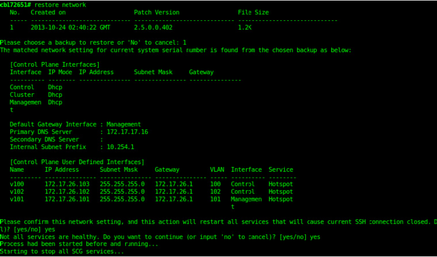
8. Enter the number that corresponds to the backup file that you want to restore.
FIGURE 137 Enter the number that corresponds to the backup file that you want to restore
The CLI displays the network configuration that the selected backup file contains.
If the serial number of the current controller matches the serial number contained in one of the backup files, the CLI automatically
selects the backup file to restore and displays the network configuration that it contains.
9. Type yes to confirm that you want to restore the selected backup file. The controller starts the restore process and performs the
following steps:
a) Stop all services.
b) Back up the current network configuration.
This will enable the controller to roll back to the current configuration, in case there is an issue with the restore process.
c) Clean up the current network configuration.
The controller deletes its previous network configuration, including static routes, name server, user defined interfaces, etc.
10. Restore the network configuration contained in the selected backup file.
Administering the Controller
Backing Up and Restoring Clusters
SCG200 vSZ-H and SZ300 Administrator Guide
Part Number: 800-71563-001 281
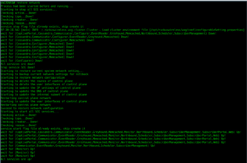
11. Restart all services.
When the restore process is complete, the following message appears on the CLI: All services are up!
FIGURE 138 The controller performs several steps to restore the backup file
Administering the Controller
Backing Up and Restoring Clusters
SCG200 vSZ-H and SZ300 Administrator Guide
282 Part Number: 800-71563-001
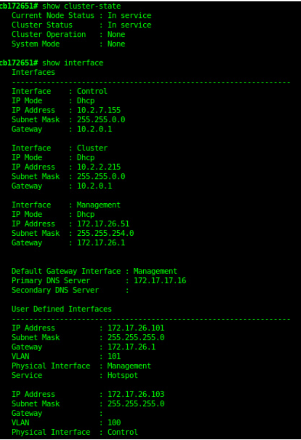
12. Do the following to verify that the restore process was completed successfully:
a) Run show cluster-state to verify that the node and the cluster are back in service.
b) Run show interface to verify that all of the network configuration settings have been restored.
FIGURE 139 Verify that the node and cluster are back in service and that the network configuration has been restored successfully
You have completed importing and applying the network configuration backup from the FTP server to the controller.
Administering the Controller
Backing Up and Restoring Clusters
SCG200 vSZ-H and SZ300 Administrator Guide
Part Number: 800-71563-001 283

Backing up Cluster Configuration
Ruckus Wireless® strongly recommends that you back up the controller database periodically. This will help ensure that you can restore the
system configuration settings easily if the database becomes corrupted for any reason.
The following are backed up in the system configuration backup file:
TABLE 38 Contents of a cluster configuration backup file
Configuration Data Administration Data Report Data Identity Data
AP zones Cluster backup Saved reports Created profiles
Third-party AP zones System configuration backups Historical client statistics Generated guest passes
Services and profiles Upgrade settings and history Network tunnel statistics
Packages Uploaded system diagnostic scripts
System settings Installed licenses
Management domains
Administrator accounts
MVNO accounts
A system configuration backup does not include control plane settings, data plane settings, and user-defined interface settings.
1. Go to Administration > Backup and Restore.
2. Select the Configuration tab.
3. In System Configuration Backup History, click Backup.
The following confirmation message appears: Are you sure you want to back up the controller’s
configuration?
4. Click Yes.
A progress bar appears as the controller creates a backup of the its database. When the backup process is complete, the
progress bar disappears, and the backup file appears under the System Configuration Backup History section.
Scheduling a Configuration Backup
1. Go to Administration > Backup and Restore.
2. Select the Configuration tab.
3. In Schedule Backup, you can configure the controller to backup its configuration automatically based on a schedule you specify.
1. In Schedule Backup, click Enable.
2. In Interval, set the schedule when the controller will automatically create a backup of its configuration. Options include: Daily,
Weekly and Monthly.
3. Hour: Select the hour of the day when the controller must generate the backup.
4. Minute: Select the minute of the hour.
5. Click OK.
You have completed configuring the controller to create a backup automatically.
Administering the Controller
Backing Up and Restoring Clusters
SCG200 vSZ-H and SZ300 Administrator Guide
284 Part Number: 800-71563-001
Exporting the Configuration Backup to an FTP Server Automatically
In addition to backing up the configuration file manually, you can configure the controller to export the configuration file to an FTP server
automatically whenever you click Backup.
Follow these steps to back up the configuration file to an FTP server automatically.
1. Go to Administration > Backup and Restore.
2. Select the Configuration tab.
3. In Auto Export Backup, you can configure the controller to export the configuration file to an FTP server automatically whenever
you back up the configuration file.
1. In Auto Export Backup, click Enable.
2. FTP Server: Select the FTP server to which you want to export the backup file.
3. Click Test. The controller attempts to establish connection to the FTP server using the user name and password that you
supplied. If the connection attempt is successful, a success message is displayed. If the connection attempt is unsuccessful,
verify that the FTP server details (including the user name and password) are correct, and then click Test again.
4. Click OK.
4. After you verify the controller is able to connect to the FTP server successfully, click OK to save the FTP server settings.
You have completed configuring the controller to export the configuration backup file to an FTP server.
Downloading a Copy of the Configuration Backup
After you create a configuration backup, you have the option to download the backup file from the System Configuration Backups History
section.
1. Go to Administration > Backup and Restore.
2. Select the Configuration tab.
3. Locate the entry for the backup file that you want to download. If multiple backup files appear on the list, use the date when you
created the backup to find the backup entry that you want.
4. Click Download.
Your web browser downloads the backup file to its default download folder. NOTE: When your web browser completes
downloading the backup file, you may see a notification at the bottom of the page.
5. Check the default download folder for your web browser and look for a file that resembles the following naming convention:
{Cluster Name}_BackupConf_{MMdd}_db_{MM}_{dd}_{HH}_{mm}.bak
For example, if the controller cluster is named Cluster A and you created the configuration backup on September 7 at 11:08 AM,
the backup file name will be: ClusterA_BackupConf_0907_db_09_07_11_08.bak
You have completed downloading a copy of the configuration backup.
Restoring a System Configuration Backup
In the event of a failure or emergency where you may need to go back to the previous version of a cluster, you will have to restore your
system configuration backup and restart the cluster.
1. Go to Administration > Backup and Restore.
2. Select the Configuration tab.
Administering the Controller
Backing Up and Restoring Clusters
SCG200 vSZ-H and SZ300 Administrator Guide
Part Number: 800-71563-001 285

3. Once you locate the backup file, click Restore that is in the same row as the backup file. A confirmation message appears.
NOTE
Take note of the backup version that you are using. At the end of this procedure, you will use the backup version to
verify that the restore process was completed successfully.
4. Click Yes. The following message appears: System is restoring. Please wait... When the restore process is
complete, the controller logs you off the web interface automatically.
5. Log on to the controller web interface.
Check the web interface pages and verify that the setting and data contained in the backup file have been restored successfully to
the controller.
You have completed restoring a system configuration backup file.
Upgrading the Controller
Ruckus Wireless may periodically release controller software updates that contain new features, enhancements, and fixes for known issues.
These software updates may be made available on the Ruckus Wireless support website or released through authorized channels.
CAUTION
Although the software upgrade process has been designed to preserve all controller settings, Ruckus Wireless strongly
recommends that you back up the controller cluster before performing an upgrade. Having a cluster backup will ensure that you
can easily restore the controller system if the upgrade process fails for any reason.
CAUTION
Ruckus Wireless strongly recommends that you ensure that all interface cables are intact during the upgrade procedure.
CAUTION
Ruckus Wireless strongly recommends that you ensure that the power supply is not disrupted during the upgrade procedure.
If you are managing a SCG200 controller, you can also perform system configuration backup, restore, and upgrade from the controller
command line interface.
Performing the Upgrade
Ruckus Wireless® strongly recommends backing up the controller cluster before performing the upgrade. If the upgrade process fails for
any reason, you can use the latest backup file to restore the controller cluster.
Before starting this procedure, you should have already obtained a valid controller software upgrade file from Ruckus Wireless® Support or
an authorized reseller.
Always back up the controller before attempting a software upgrade. If you are managing a multi-node cluster, back up the entire cluster,
and then verify that the backup process completes successfully.
If you have an FTP server, back up the entire cluster and upload the backup files from all the nodes in a cluster to a remote FTP server.
1. Copy the software upgrade file that you received from Ruckus Wireless® to the computer where you are accessing the controller
web interface or to any location on the network that is accessible from the web interface.
2. Go to Administration > Upgrade.
Administering the Controller
Upgrading the Controller
SCG200 vSZ-H and SZ300 Administrator Guide
286 Part Number: 800-71563-001
3. Select the Upgrade tab.
In Current System Information, the controller version information displayed.
NOTE
The Upgrade History tab displays information about previous cluster upgrades.
4. In Upload, select the Run Pre-Upgrade Validations check box to verify if the data migration was successful. This option allows you
to verify data migration errors before performing the upgrade.
5. Click Browse to select the patch file.
6. Click Upload to upload the controller configuration to the one in the patch file.
The controller uploads the file to its database, and then performs file verification. After the file is verified, the Patch for Pending
Upgrade section is populated with information about the upgrade file. If data migration was unsuccessful, the following error is
displayed: Exception occurred during the validation of data migration. Please apply the system
configuration backup and contact system administrator.
7. You can now:
• Click Upgrade to start the upgrade process without backing up the current controller cluster or its system configuration, or
• Click Backup & Upgrade to back up the controller cluster and system configuration before performing the upgrade.
When the upgrade (or backup-and-upgrade) process is complete, the controller logs you off the web interface automatically. When the
controller log on page appears again, you have completed upgrading the controller.
In the Current System Information section, check the value for controller version. If the firmware version is newer than the firmware version
that controller was using before you started the upgrade process, then the upgrade process was completed successfully.
NOTE
APs periodically send scheduled configuration requests to the controller, including the firmware version. Therefore, when an AP
joins a zone for the first time, the firmware version is verified by the controller. If the firmware version is different from that which is
configured for the zone, the controller responds with a request to upgrade it, after which the AP initiates a request to upgrade the
firmware using HTTP.
Uploading an AP Patch File
New AP models and firmware updates are supported without the need to upgrade the controller image by using the AP patch files supplied
by Ruckus Wireless.
1. Go to Administration > Upgrade.
2. Select the AP Patch tab.
3. In Patch File Upload, click Browse to select the patch file (with extension .patch).
4. Click Open.
5. Click Upload. The upload status bar is displayed, and after the patch file is uploaded, the section is populated with the patch
filename, size, firmware version, and supporting AP models.
6. Click Apply Patch. The apply patch status bar is displayed.
After the patch file is updated, you will be prompted to log out.
When you login again, the AP Patch History section displays information about the patch file such as start time, AP firmware and
model.
You have successfully updated the AP models and AP firmware with the patch file, without having to upgrade the controller software.
Administering the Controller
Upgrading the Controller
SCG200 vSZ-H and SZ300 Administrator Guide
Part Number: 800-71563-001 287
Verifying the Upgrade
You can verify that the controller upgrade was completed successfully.
1. Go to Administration > Upgrade.
2. In the Current System Information section, check the value for
Controller Version
. If the firmware version is newer than the firmware
version that controller was using before you started the upgrade process, then the upgrade process was completed successfully.
NOTE
APs periodically send scheduled configuration requests to the controller, including the firmware version. Therefore, when
an AP joins a zone for the first time, the firmware version is verified by the controller. If the firmware version is different
from that which is configured for the zone, the controller responds with a request to upgrade it, after which the AP
initiates a request to upgrade the firmware using HTTP.
Rolling Back to a Previous Software Version
There are scenarios in which you may want to roll back the controller software to a previous version.
Here are two:
• You encounter issues during the software upgrade process and the controller cannot be upgraded successfully. In this scenario,
you can only perform the software rollback from the CLI using the restore local command. If you have a two-node controller
cluster, run the restore local command on each of the nodes to restore them to the previous software before attempting to
upgrade them again.
• You prefer a previous software version to the newer version to which you have upgraded successfully. For example, you feel that
the controller does not operate normally after you upgraded to the newer version and you want to restore the previous software
version, which was more stable. In this scenario, you can perform the software rollback either from the web interface or the CLI. If
you have a two-node controller cluster, you must have cluster backup on both of the nodes.
To ensure that you will be able to roll back to a previous version, Ruckus Wireless® strongly recommends the following before attempting to
upgrade the controller software:
• Always back up the controller before attempting a software upgrade. If you are managing a multi-node cluster, back up the entire
cluster, and then verify that the backup process completes successfully. See Creating a Cluster Backup on page 275 for the local
backup instructions. If you have a local backup and you want to roll back the controller to a previous software version, follow the
same procedure described in Creating a Cluster Backup on page 275.
• If you have an FTP server, back up the entire cluster and upload the backup files from all the nodes in a cluster to a remote FTP
server. See Backing Up to an FTP Server on page 277 for remote backup instructions and Restoring from an FTP Server on page
279 for remote restore instructions.
Upgrading the Data Plane
You can view and upgrade the virtual data plane version using patch files. This feature is only applicable for vSZ-H and vSZ-E.
1. Go to Administration > Upgrade.
Administering the Controller
Upgrading the Controller
SCG200 vSZ-H and SZ300 Administrator Guide
288 Part Number: 800-71563-001
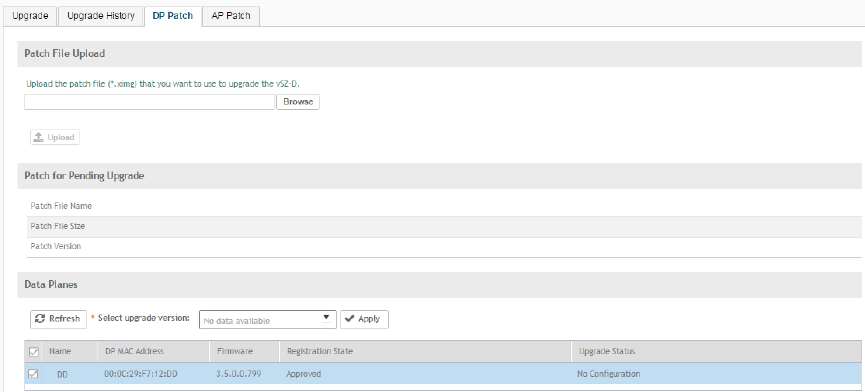
2. Select the DP Patch tab.
The DP Patch page appears.
FIGURE 140 DP Patch - Virtual Data Plane Upgrade
3. In Patch File Upload, click Browse to select the patch file (.ximg file).
4. Click Upload. The patch files is uploaded.
The controller uploads the file to its database, and then performs file verification. After the file is verified, the Patch for Pending
Upgrade section is populated with information about the upgrade file.
The following details are displayed:
• Patch File Name: Displays the name of the patch file.
• Patch File Size: Displays the size of the patch file.
• Patch Version: Displays the version of the patch file.
5. In Data Planes, identify the virtual data plane you want to upgrade, and then choose a patch file version from Select upgrade
version.
6. Click Apply to apply the patch file version to the virtual data plane.
The following information about the virtual data plane is displayed after the patch file upgrade is completed.
• Name: Displays the name of the virtual data plane.
• DP MAC Address: Displays the MAC IP address of the data plane.
• Firmware: Displays the version of the data plane that has been upgraded.
• Registration State: This field displays whether all licenses pertaining to the data plane are approved.
• Upgrade Status: Displays the completion status of the patch file upgrade for the virtual data plane.
You have successfully upgraded the virtual data plane.
Administering the Controller
Upgrading the Controller
SCG200 vSZ-H and SZ300 Administrator Guide
Part Number: 800-71563-001 289
Managing Licenses
Depending on the number of Ruckus Wireless APs that you need to manage with the controller, you may need to upgrade the controller
license as your network expands.
The maximum number of access points that the controller can manage is controlled by the license file that came with the controller. If the
number of access points on the network exceeds the limit in the license file, you will need to obtain an additional license file and upload it to
the controller.
NOTE
For information on obtaining additional license files, contact Ruckus Wireless Support or an authorized Ruckus Wireless reseller.
The maximum number of access points that a license supports depends on its stock-keeping unit (SKU).
Viewing Installed Licenses
You can synchronizing the license data, import a license file into the controller if it is unable to connect to the Ruckus Wireless SmartLicense
system and release licenses bound to an offline controller by downloading a copy of the licenses.
1. Go to Administration > Licenses.
2. Select the Installed Licenses tab.
You can view the following information about the licenses you have uploaded to the controller:
• Name: The name of the node to which the license was uploaded
• Node: Displays the name of the node
• Start Date: The date when the license file was activated.
• End Date: For time-bound licenses, this column shows the date when the license file expires.
• Capacity: The number of units or license seats that the license file provides.
• Description: The type of license.
Importing Installed Licenses
If the controller is disconnected from the Internet or is otherwise unable to communicate with the Ruckus Wireless SmartLicense system
(due to firewall policies, etc.), you can manually import a license entitlement file into the controller.
NOTE
The option to import a license file manually into the controller is only available if the controller is using the cloud license
server.
1. Obtain the license file. You can do this by logging on to your Ruckus Wireless Support account, going to the license management
page, and then downloading the license file (the license file is in .bin format).
2. Log on to the controller web interface, and then go to Administration > Licenses.
3. Select the Installed Licenses tab.
4. Select the node for which you are uploading the license file and click Upload.
The Upload License page appears where you must provide the following information:
• Select Controller: Select the node for which you are uploading the license file.
• Select License File: Click Browse, locate the license file (.bin file) that you downloaded from your Ruckus Wireless Support
account, and then select it.
Administering the Controller
Managing Licenses
SCG200 vSZ-H and SZ300 Administrator Guide
290 Part Number: 800-71563-001
The page refreshes, and the information displayed changes to reflect the updated information imported from the SmartLicense platform.
Synchronizing Controller with the License Server
By default, the controller automatically synchronizes its license data with the selected license server every 24 hours. If you made changes to
the controller licenses (for example, you purchased additional licenses) and you want the controller to download the updated license data
immediately, you can trigger a manual synchronization.
1. Log on to the controller web interface, and then go to Administration > Licenses.
2. Select the Installed Licenses tab.
3. Click Sync Now.
When the sync process is complete, the message Sync license with the license server successful appears. If
the previously saved license data are different the latest license data on the server, the information in the Installed Licenses section
refreshes to reflect the latest data.
You have completed manually synchronizing the controller with the license server.
Downloading License Files
If you need to release licenses bound to an offline controller and allow those licenses to be used elsewhere (on a different controller), you
can download a copy of the controller licenses. The option to download a copy of the controller licenses is only available if the controller is
using the Ruckus Wireless cloud license server.
1. Log on to the controller web interface, and then go to Administration > Licenses.
2. Select the Installed Licenses tab.
3. Click Download.
The Download License page appears. In Select Controller, select the controller node for which you want to download the license
files.
NOTE
You can upload and download license files only if the controller is using the Ruckus Wireless cloud license server.
4. Click Download. Your web browser downloads the license files from the controller.
5. When the download is complete, go to the default download folder that you have configured for your web browser, and then verify
that the binary copy of the license files (with .bin extension) exists.
You have completed downloading copies of the controller licenses.
Configuring the License Server
Ruckus Wireless provides two options for managing the licenses that you have purchased for the controller - Cloud License Server and
Local License Server (LLS).
Cloud License Server also known as the SmartLicense server, this a cloud-based server that stores all of the licenses and support
entitlements that you have purchased for the controller. For information on how to set up and activate your SmartLicense account, see the
SmartLicense User Guide.
1. Go to Administration > Licenses.
2. Select the License Server tab.
The Server details and Synchronization history are displayed.
Administering the Controller
Managing Licenses
SCG200 vSZ-H and SZ300 Administrator Guide
Part Number: 800-71563-001 291
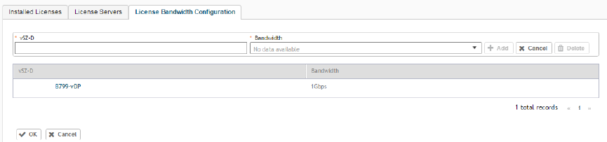
3. Click Configure.
The License Server Configuration page appears.
• Cloud License Server: Select this option to use the Ruckus Wireless SmartLicense server.
• Local License Server: Select this option to use an LLS that you have set up on the network, and then configure
– Domain or IP: Type the FQDN or IP address of the LLS.
– Port: Type the port number. Port range is from 0 to 65535 (default is 3333).
4. Click OK.
5. Click Sync Now and the controller saves the selected license server configuration, deletes all of its saved license data, and then
automatically synchronizing the license information with the selected license server.
You have completed configuring the license server that the controller will use.
Configuring License Bandwidth
You can assign a license bandwidth for a virtual data plane provided it is already approved. Each virtual data plane can be configured with
only one bandwidth license. This feature is only applicable to vSZ-H and vSZ-E.
1. Go to Administration > Licenses.
2. Select the License Bandwidth Configuration tab.
The License Bandwidth Configuration page appears.
FIGURE 141 License Bandwidth Configuration
3. In vSZ-D, type the name of the virtual data plane.
4. From the Bandwidth drop-down menu, select the license bandwidth you want to assign to the virtual data plane.
5. Click Add. The vSZ-D with the assigned license bandwidth is displayed.
6. Click OK.
You have successfully assigned a license bandwidth to the virtual data plane.
ZoneDirector to SmartZone Migration
SmartZone controllers are better equipped to handle large WiFi deployments such as within campuses and when customers are vastly
distributed; therefore, Ruckus Wireless recommends that you migrate existing ZoneDirector deployments to SamrtZone controller
deployments. You can migrate ZoneDirector AP configuration information to SmartZone controllers from the controller itself, using a
migration tool.
The AP models should be supported by the controller.
Administering the Controller
ZoneDirector to SmartZone Migration
SCG200 vSZ-H and SZ300 Administrator Guide
292 Part Number: 800-71563-001

NOTE
Only ZD versions 9.13, 9.13.1, 9.13.2 and 9.13.3 are supported.
1. Go to Administration > ZD Migration.
The ZoneDirector Migration page appears.
2. Configure the following:
1. ZoneDirector IP Address: Type the IP address of the ZD that you want to migrate.
2. Admin Credentials: Enter the username and password details to access/login to ZD.
3. Click Connect. Lists of APs connected to the ZD deployment are displayed.
4. Click Select AP to choose the AP information that you want to migrate from ZD.
5. Click Migrate to migrate the AP. The controller imports the ZD configuration and applies it to the selected AP.
The ZoneDirector Migration Status section displays the status of the migration. When completed successfully, a success message
is displayed. If migration fails, a failure message is displayed and you can attempt the migration process again.
Monitoring Administrator Activities
The controller keeps a record of all actions and configuration changes that administrators perform on the server. This feature enables you
and other administrators in the organization to determine what changes were made to the controller and by whom.
1. Go to Administration > Admin Activities.
2. Select the Admin Activities tab. the Admin Activities page displays the administrator actions.
The following information is displayed:
• Date and Time: Date and time when the alarm was triggered
• Administrator: Name of the administrator who performed the action
• Managed By: Displays the system that manages the admin activities.
• Source IP: Displays the IP address of the device form which the administrator manages the controller.
• Browser IP: IP address of the browser that the administrator used to log on to the controller.
• Action: Action performed by the administrator.
• Resource: Target of the action performed by the administrator. For example, if the action is Create and the object is Hotspot
Service, this means that the administrator created a new hotspot service.
• Description: Displays additional details about the action. For example, if the administrator created a new hotspot service, this
column may show the following: Hotspot [company_hotspot] .
Click to export the administrator activity list to a CSV file. You can view the default download folder of your web browser to
see the CSV file named clients.csv. Use a spreadsheet application (for example, Microsoft® Excel®) to view the contents of the
CSV file.
Administering the Controller
Monitoring Administrator Activities
SCG200 vSZ-H and SZ300 Administrator Guide
Part Number: 800-71563-001 293
Managing Mobile Virtual Network Operator (MVNO)
Accounts
A Mobile Virtual Network Operator (MVNO) uses a host carrier network to service its mobile users. An MVNO account is created for each
operator and the MVNO page lists the accounts that are created.
1. Go to Administration > MVNO.
The MVNO page appears displaying information about MVNO accounts created.
2. Click Create to create an MVNO account.
The The Mobile Virtual Network Operator page appears.
3. Configure the following:
1. The Mobile Virtual Network Operator Summary
a. 'Domain Name: Type a domain name to which this account will be assigned
b. Description: Type a brief description about this domain name.
2. AP Zones of Mobile Virtual Network Operator: Displays the AP zones that are allocated to this MVNO account
a. Click Add AP Zone. The Add AP Zone page appears.
b. AP Zone: Select the AP zone you want to add to the MVNO account from the drop-down menu.
c. Click OK.
NOTE
You can only select a single AP zone at a time. If you want to grant the MVNO account management privileges
to multiple AP zones, select them one at time.
3. WLAN Services: Configure the WLAN services to which the MVNO account that you are creating will have management
privileges.
a. Click Add WLAN. The Add WLAN page appears.
b. SSID: Select the WLAN to which the MVNO account will have management privileges.
NOTE
You can only select one WLAN service at a time. If you want to grant the MVNO account management
privileges to multiple WLAN service zones, select them one at time.
c. Click OK.
4. Super Administrator: Configure and define the logon details and management capabilities that will be assigned to the
account.
a. Account Name: Type the name that this MVNO will use to log on to the controller.
b. Real Name: Type the actual name (for example, John Smith) of the MVNO.
c. Password: Type the password that this MVNO will use (in conjunction with the Account Name) to log on to the controller.
d. Confirm Password: Type the same password as above. f) In Phone, type the phone number of this MVNO.
e. Phone: Type the phone number of the administrator.
f. Email: Type the email address of this MVNO.
g. Job Title: Type the job title or position of this MVNO in his organization.
5. RADIUS Server for Administrator Authorization and Authentication: See Creating a RADIUS Server for Administrator
Authentication on page 273 for more information.
Administering the Controller
Managing Mobile Virtual Network Operator (MVNO) Accounts
SCG200 vSZ-H and SZ300 Administrator Guide
294 Part Number: 800-71563-001
4. Click OK.
You have created an MVNO account.
NOTE
You can also edit and delete the account by selecting the options Configure, and Delete respectively, from the MVNO page.
Administering the Controller
Managing Mobile Virtual Network Operator (MVNO) Accounts
SCG200 vSZ-H and SZ300 Administrator Guide
Part Number: 800-71563-001 295
SCG200 vSZ-H and SZ300 Administrator Guide
296 Part Number: 800-71563-001

Managing Events and Alarms
• Viewing Events...................................................................................................................................................... 297
• Sending SNMP Traps and Email Notifications for Events....................................................................................... 297
•Configuring Event Threshold..................................................................................................................................298
•Configuring Alarms................................................................................................................................................ 299
Viewing Events
An event is an occurrence or the detection of certain conditions in and around the network. An AP being rebooted, an AP changing its IP
address, and a user updating an AP's configuration are all examples of events.
Go to Events and Alarms > Events.
The Events page appears displaying the following information:
You can also click the icon to apply filters, to display events based on time and severity.
• Date and Time: Displays the date and time when the event occurred
• Code: Displays the event code (see the Alarm and Event Reference Guide for your controller platform more information).
• Type: Displays the type of event that occurred (for example, AP configuration updated).
• Severity: Displays the severity level assigned to the events such as Critical, Debug, Informational, Warning, Major etc.
• Activity: Displays additional details about the event, including (if available) the specific access point, control plane, or data
plane that triggered the event.
NOTE
Click to export the event details to a CSV file. Check the default download folder of your web browser and look for
a file named
events.csv
and view it using a spreadsheet application (for example, Microsoft Excel®).
Sending SNMP Traps and Email Notifications for
Events
By default, the controller saves a record of all events that occur to its database. You can configure the controller to also send SNMP traps
and email notifications for specific events whenever they occur.
Verify that global SNMP traps are enabled to ensure that the controller can send SNMP traps for alarms.
You can also manually trigger SNMP traps without generating events using CLI. You can use the #trigger-trap <event code> command to
trigger traps for respective events with their default attributes.
You can acquire the status of a specific client MAC address by using the query RUCKUS-CTRL-MIB. For more information, see the
SmartZone SNMP MIB Reference Guide
.
1. Go to Events and Alarms > Events.
SCG200 vSZ-H and SZ300 Administrator Guide
Part Number: 800-71563-001 297
2. Click the Event Management tab.
The Event Management page appears displaying the following information:
• Email Notification: Select the Enable check box, and then type an email address or email addresses in the Mail To box. If you
want to send notifications to multiple recipients, use a comma to separate the email addresses. Then, click OK.
• Events: View the table and select the events for which you want to send traps or email notifications (or both). Select the
Enable or Disable options from the drop-down menu, and configure the following:
– Enable SNMP Notification: Click this link to enable SNMP trap notifications for all selected events.
– Enable Email: Click this link to enable email notifications for all selected events.
– Enable DB Persistence: Click this link to enable saving of all selected events to the controller database. If an event is
already currently enabled, it will stay enabled after you click this link.
Configuring Event Threshold
An event threshold defines a set of conditions related to the controller hardware that need to be met before the controller triggers an event.
You can accept the default threshold values or you can update the threshold values to make them more suitable to your deployment or
controller environment.
1. Go to Events and Alarms > Events.
2. Click the Event Threshold tab.
This page displays the list of events with configurable thresholds including the event code, severity level, default value and
accepted range, and unit of measurement for each event.
3. Identify the event threshold that you want to configure.
4. Click the event name under the Name column.
The threshold value for the event becomes editable. Next to the threshold value, the acceptable range is displayed.
5. Edit the threshold value.
6. Click OK.
Managing Events and Alarms
Configuring Event Threshold
SCG200 vSZ-H and SZ300 Administrator Guide
298 Part Number: 800-71563-001

Configuring Alarms
Alarms are a type of event that typically warrants your attention. Alarms are generated by managed access points and the controller system
(control plane and data plane).
Go to Events and Alarms > Alarms.
The Alarms page appears displaying the following information:
• Date and Time: Displays the date and time when the alarm was triggered.
• Code: Displays the alarm code (see the Alarm and Reference Guide for your controller platform for more information).
• Alarm Type: Displays the type of alarm event that occurred (for example, AP reset to factory settings).
• Severity: Displays the severity level assigned to the events such as Critical, Major, Minor and Warning.
• Status: Indicates whether the alarm has already been cleared or still outstanding.
• Activity: Displays additional details about the alarm, including (if available) the specific access point, control plane, or data
plane that triggered the alarm.
• Acknowledged On: Displays the date and time when the administrator acknowledge the alarm.
• Cleared By: Displays information about who cleared the alarm.
• Cleared On: Displays the date and time when the alarm was cleared.
• Comments: Displays administrator notes recorded during alarm management.
NOTE
Click to export the alarms details to a CSV file. Check the default download folder of your web browser and look
for a file named
alarms.csv
and view it using a spreadsheet application (for example, Microsoft Excel®).
Clearing Alarms
Clearing an alarm removes the alarm from the list but keeps it on the controller's database.
To clear an alarm:
1. Select the alarm form the list and click Clear Alarm. The Clear Alarm page appears.
2. Type your comments and select Apply.
Acknowledging Alarms
Acknowledging an alarm lets other administrators know that you have examined the alarm. After you acknowledge an alarm, it will remain
on the list of alarms and will show the date and time that you acknowledged it.
To acknowledge an alarm:
1. Select the alarm from the list and click Acknowledge Alarm.
This message appears:
Are you sure you want to acknowledge the selected alarms?
.
2. Select Yes.
Managing Events and Alarms
Configuring Alarms
SCG200 vSZ-H and SZ300 Administrator Guide
Part Number: 800-71563-001 299

Applying Filters
You can view a list of alarms by date, time, severity and status.
1.
Click the icon.
The Apply Filters page appears. Configure the following:
1. Severity: Select the severity level by which you want to filter the list of alarms.
2. Status: Select the status by which you want to filter the list of alarms.
3. Date and Time: Select the alarms by their start and end dates.
2. Click OK.
All the alarms that meet the filter criteria are displayed on the Alarms page and the display changes to Filter On.
You can export the alarms into a CSV file by clicking the icon.
Managing Events and Alarms
Configuring Alarms
SCG200 vSZ-H and SZ300 Administrator Guide
300 Part Number: 800-71563-001

Diagnostics
• Applying Scripts.................................................................................................................................................... 301
• Applying AP CLI Scripts........................................................................................................................................ 301
• Viewing and Downloading Logs.............................................................................................................................302
• Viewing RADIUS Proxy Settings............................................................................................................................ 304
• Viewing RADIUS Server Settings........................................................................................................................... 304
• Viewing DHCP Relay Settings................................................................................................................................304
Applying Scripts
New AP models and firmware updates are supported without the need to upgrade the controller image by using AP patch files and
diagnostic scripts.
1. Go to Administration > Diagnostics > Scripts.
2. Select the Patch/Diagnostic Scripts tab.
3. Select the Upload to current node check-box.
4. Click Browse to select a script that you want to upload to the controller.
5. Click Upload.
The script is listed in the System Uploaded Scripts section.
If you have uploaded a patch script, it is displayed in the System Uploaded Patch Scripts section with the following information:
• Name of the patch file
• Patch file description
• Supported AP firmware version
• AP model number
Click Delete to delete scripts.
6. Click Apply Patch to apply the patch file to the AP model or firmware as appropriate.
You have successfully applied scripts to the controller AP.
Applying AP CLI Scripts
New AP models and firmware updates are supported without the need to upgrade the controller image by using AP CLI scripts.
1. Go to Administration > Diagnostics > Scripts.
2. Select the AP CLI Scripts tab.
3. From Select AP Zone, choose the AP zone for which you want to apply the script.
4. Click Browse to select an AP CLI script that you want to upload.
5. Click Upload.
The script is listed in the Script Execution Summary section.
Click Delete to delete scripts.
6. Click Execute to apply the AP CLI script file to the AP zone.
SCG200 vSZ-H and SZ300 Administrator Guide
Part Number: 800-71563-001 301
You have successfully applied AP CLI scripts to the controller AP.
Viewing and Downloading Logs
The controller generates logs for all the applications that are running on the server.
1. Go to Administration > Diagnostics > Application Logs.
The Application Logs page appears.
2. From Select the Control Plan, select the control plane for which you want to download logs.
3. Select the Upload to current node check-box.
4. You can now opt to select:
Option Description
Download Logs To download all logs for the selected application.
Download All
Logs
To download all available logs from the controller.
Go to your web browsers default download location and verify that the TGZ file was downloaded successfully.
You must use your preferred compression/decompression program to extract the log files from the TGZ file.
When the log files are extracted (for example, adminweb.log, cassandra.log, communicator.log,
etc.), use a text editor to open and view the log contents.
Download
Snapshot Logs
To download snapshot logs that contain system and configuration information, such as the AP list,
configurations settings, event list, communicator logs, SSH tunnel lists, etc.
If you triggered the controller to generate a snapshot from the CLI, you have the option to download snapshot
logs from the web interface.
Go to your browser's default download folder, and then verify that the snapshot log file or files have been
downloaded successfully. Extract the contents of the tar file.
You have successfully completed downloading log files/snapshot logs from the controller.
Available System Logs for SCG200, vSZ-H and SZ300
The controller generates logs for all the applications that are running on the server.
The following table lists the controller applications that are running.
TABLE 39 Controller applications and log types
Application Description
AIP Handles the accounting messages for TTG sessions
CaptivePortal Performs portal redirect for clients and manages the walled garden and blacklist
Cassandra The controller's database server that stores most of the run-time information and statistical data
CIP The Charging Interface module, which handles the Ga interface towards CGF server
CNR An application that obtains TTG configuration updates and applies the settings to related modules
Communicator Communicates with access points and retrieves statuses, statistics, and configuration updates
Configurer Performs configuration synchronization and cluster operations (for example, join, remove, upgrade, backup, and
restore)
DHCPServer The DHCP server in the SCG-C TTG module receives DHCP messages from DHCP relay in d-blade
Diagnostics
Viewing and Downloading Logs
SCG200 vSZ-H and SZ300 Administrator Guide
302 Part Number: 800-71563-001

TABLE 39 Controller applications and log types (continued)
Application Description
DiaAuthProcess Uses the STa/Gx interface for authentication through the Diameter Protocol.
Diagnostics An interface that can be use to upload Ruckus Wireless scripts (.ksp files) for troubleshooting or applying software
patches. This interface displays the diagnostic scripts and system patch scripts that are uploaded to a node.
EAuth Manages the sessions on the SCG-C TTG module
EventReader Receives event messages from access points and saves the information into the database
Greyhound The interface between the SCG-C TTG module and the AP interface, used to send and receive proprietary
messages for AP association and disassociation
HIP Module with SIGTRAN stack and interface to operator HLR(s)
LogMgr Organizes the Application Logs into a common format, segregates them, and copies them into the respective
Application log file
MdProxy MdProxy on AP and SCG connect to AP-MD and SCG-MD respectively. MdProxy on SCG receives messages and
retrieves the message header. It also forwards the response to SCG-MD. This message is sent to the MdProxy on
AP through AP-MD. MdProxy on the AP removes the MSL header and responds to the connection on which the
request was received.
Memcached The controller’s memory cache that stores client authentication information for fast authentication or roaming
MemProxy Replicates MemCached entries to other cluster nodes
Monitor Monitors the health of cluster processes and communicates cluster state changes to the cluster node
Mosquitto A lightweight method used to carry out messaging between LBS and APs
Mqttclient A lightweight client used to communicated with the MQTT server using methods that block intrusion until an
operation completes.
MsgDist The Message distributor (MD) maintains a list of communication points for both local applications and remote MDs
to perform local and remote routing
NC The Node Controller, which monitors all SCG-C TTG processes
NginX Is a web server that is used as a reserve proxy server or a HTTP cache
Northbound As an interface between SP and AAA, it performs UE authentication and handles approval or denial of UEs to AP.
OnlineSignup A standard and secured method to access devices in a WPA2 hotspot network
PMIPv6d Handles UE Session Context details for PMIP calls
RadiusProxy Sets the RADIUS dispatch rules and synchronizes configuration to each cluster node
Scheduler Performs task scheduling and aggregates statistical data
SNMP Provides a framework for the monitoring devices on a network. The SNMP manager is the system is used to control
and monitor the activities of network hosts using SNMP. As an agent that responds to queries from the SNMP
Manager, SNMP Traps with relevant details are sent to the SNMP Manager when configured.
SubscriberManagement Maintains local user credentials for WISPr authentication.
SubscriberPortal Internal portal page for WISPr (hotspot)
System Collects and sends log information from all processes
Web Runs the controller management web server
Diagnostics
Viewing and Downloading Logs
SCG200 vSZ-H and SZ300 Administrator Guide
Part Number: 800-71563-001 303
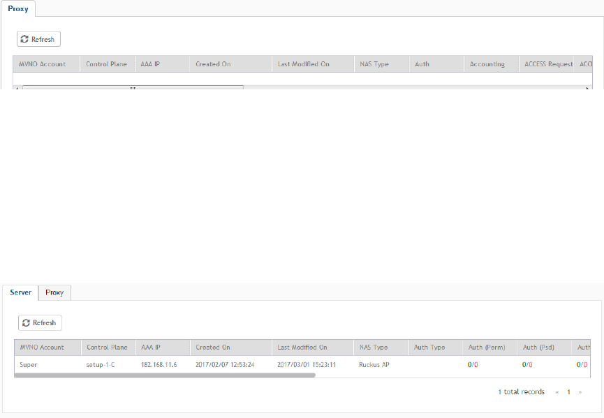
Viewing RADIUS Proxy Settings
You must be aware of the RADIUS proxy settings on the controller to monitor the health of the controller.
Go to Administration > Diagnostics > RADIUS.
The Proxy page appears displaying the RADIUS settings.
FIGURE 142 Diagnostics - RADIUS Proxy
Viewing RADIUS Server Settings
You must be aware of the RADIUS server settings on the controller to monitor the health of the controller.
Go to Administration > Diagnostics > RADIUS.
The Server page appears displaying the RADIUS settings.
FIGURE 143 Diagnostics - RADIUS Server
Viewing DHCP Relay Settings
You must be aware of the DHCP relay settings on the controller to monitor the health of the controller.
1. Go to Administration > Diagnostics > DHCP .
Diagnostics
Viewing RADIUS Proxy Settings
SCG200 vSZ-H and SZ300 Administrator Guide
304 Part Number: 800-71563-001
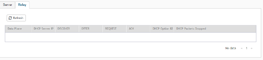
2. Select the Relay tab.
The DHCP Relay page appears displaying the settings.
FIGURE 144 Diagnostics - DHCP Relay
Diagnostics
Viewing DHCP Relay Settings
SCG200 vSZ-H and SZ300 Administrator Guide
Part Number: 800-71563-001 305
SCG200 vSZ-H and SZ300 Administrator Guide
306 Part Number: 800-71563-001

Statistics Files the Controller Exports to
an FTP Server
If you added an FTP server to the controller, the controller will export statistics files to that FTP server, either on demand or based on a
schedule. This is however only applicable for SCG200, SZ300 and vSZ-H.
NOTE
The feature to export CSV files is only supported in SCG200, SZ300, and vSZ-H platforms.
To enable this feature, go to the controller web UI and select the Enable uploading statistical data to the FTP server check-box from
System > General Settings > FTP.
After the feature is enabled, each controller node sends a zip file to the FTP server via FTP or SFTP, on an hourly basis. The zip file is named
as: <directory_name> + '_' + <scg_node_identifier> + ".zip" .
Here, directory_name is named as yyyymmddhh (indicating the beginning of the hour that the data was received). For example, the
directory name for the data that comes between 10 and 11 AM of May 26, 2016, is "2016052610" .
The zip file contains all the reported data collected within the hour.
The data is divided into tables, and each data table is associated with files. The files are named as follows: <Table Name> + '_' +
<Thread_ID> + '_' + <Sequence_No>.csv.
Here, Table Name is as described in Table 40. Thread_ID is an integer, and Sequence_No is from 1 to N to limit each file to be capped
around 1G bytes.
Each AP sends its statistic counters to the controller, every 180 seconds. The controller stores the data, and exports them as CSV files to
the external FTP server, every hour. The controller stores the data for up to 6 hours; if the FTP server is down, the controller resends data for
up to 6 hours.
TABLE 40 Exported CSV file table
Table Name Table Description
APStatus Root for all Status: Cluster, Domain, Zone info
APStatusSystem AP Level Info
APStatusRadio AP Radio Info
APStatusWlan AP Wlan Info
APStatusTunnel AP Tunnel Info
APStatusIPSec AP IPSec Info
APStatusIPSecStats AP IPSec stats
LanPortStatus AP Lan Port Status
CertificateReload AP Certificate Reload Info
CableModemInfo Cable Modem inside AP
APStatusLBS Location-Based Service
APStatusBrownout AP Voltage Brownout Event
APReportStats Root for all ReportCluster, Domain, Zone Info
APReportBin Little Bin info
APReportBinRadio Radio Stats
SCG200 vSZ-H and SZ300 Administrator Guide
Part Number: 800-71563-001 307

TABLE 40 Exported CSV file table (continued)
Table Name Table Description
APReportBinWlan Wlan Stats
APReportBinClient Client Stats
APReportBinTunnel Tunnel Stats
APReportBinIPSec IPSec Stats
APClientStats Root for all Client
APClientInfo Client Stats
APClientRadio Radio Static Info
APClientWlan Wlan Static Info
APMeshStats Root for all Mesh
APMeshDownlink Mesh Downlink AP
APMeshUplink Mesh Uplink AP
APMeshNeighbor AP Mesh Neighbor
ArcMessage Root for all AVC
FlowMessage AVC Flow
RogueAPStats Root for all Rogue
ReportType Rogue Devices
Statistics Files the Controller Exports to an FTP Server
SCG200 vSZ-H and SZ300 Administrator Guide
308 Part Number: 800-71563-001
Ports to Open for AP-SCG/SZ/vSZ/vSZ-D
Communication
The table below lists the ports that must be opened in the network firewall to ensure that the SCG/vSZ-D/SZ/vSZ (controller), managed
APs, and RADIUS servers can communicate with each other successfully.
TABLE 41 Ports to open for AP-SCG/SZ/vSZ/vSZ-D communication
Port Number Layer 4 Protocol From (Sender) To (Listener) Configurable from
Web Interface?
Purpose
21 TCP AP vSZ control plane Yes FTP upload of reports, statistics, and
configuration backups
22 TCP • AP
• vSZ-D
vSZ control plane No SSH tunnel
49 TCP TACACS+ server vSZ control plane Yes TACACS+ based authentication of
controller administrators
Port 91 (AP
firmware version
2.0 to 3.1.x) and
11443 (AP firmware
version 3.2 and
later)
TCP AP vSZ control plane No AP firmware upgrade
NOTE
Starting in release 3.2, the
controller uses an HTTPS
connection and an encrypted
path for the firmware
download. The port used for
AP firmware downloads has
also been changed from port
91 to 11443 to distinguish
between the two methods. To
ensure that all APs can be
upgraded successfully to the
new firmware, open both
ports 11443 and 91 in the
network firewall.
9997 TCP Client Device SZ control Plane No Internal Subscriber Portal in HTTP
protocol
443 TCP • AP
• vSZ-D
vSZ control plane No Access to the SCG/vSZ/SZ control plane
over secure HTTPS
6868 TCP vSZ-D vSZ No Internal communication port
8443
NOTE
The
Public
API port
has
changed
from
7443 to
8443.
TCP Any vSZ management
plane
No Access to the SCG/vSZ/SZ web interface
via HTTPS
23232 TCP AP SCG (data plane) No GRE tunnel
SCG200 vSZ-H and SZ300 Administrator Guide
Part Number: 800-71563-001 309

TABLE 41 Ports to open for AP-SCG/SZ/vSZ/vSZ-D communication (continued)
Port Number Layer 4 Protocol From (Sender) To (Listener) Configurable from
Web Interface?
Purpose
23233 UDP and TCP AP Data plane Yes GRE tunnel (required only when tunnel
mode is GRE over UDP)
NOTE
On the vSZ-D, this port is
used for both data and
control in both UDP and TCP.
12222/12223 UDP AP vSZ control plane No LWAPP discovery
NOTE
If your AP is within the same
subnet as the controller,
disable nat-ip-translation to
establish a connection
between the AP and the
controller so that AP firmware
upgrade progresses.
If your AP is on the side of the
NAT server and if the NAT
server does not support
PASV-Mode FTP, enable nat-
ip-translation. If the NAT
server supports PASV-Mode
FTP, then disable nat-ip-
translation for AP firmware
upgrade to progress
1812/1813 UDP AP Radius servers (s) Yes AAA authentication and accounting
8022 No (SSH) Any Management
interface
Yes When the management ACL is enabled,
you must use port 8022 (instead of the
default port 22) to log on to the CLI or to
use SSH.
8090 TCP Any vSZ control plane No Allows unauthorized UEs to browse to an
HTTP website
8099 TCP Any vSZ control plane No Allows unauthorized UEs to browse to an
HTTPS website
8100 TCP Any vSZ control plane No Allows unauthorized UEs to browse using
a proxy UE
8111 TCP Any vSZ control plane No Allows authorized UEs to browse using a
proxy UE
9080 HTTP Any vSZ control plane No Northbound Portal Interface for hotspots
9443 HTTPS Any vSZ control plane No Northbound Portal Interface for hotspots
9998 TCP Any vSZ control plane No Hotspot WISPr subscriber portal login/
logout over HTTPSl
3333 TCP Controller License server No Local license server
3799 UDP External AAA
Server (free Radius)
SZ-RAC No Supports Disconnect Message and CoA
(Change Of Authorization) which allows
dynamic changes to a user session such
as disconnecting users and changing
authorizations applicable to a user
session.
443 HTTPS Controller License server No Cloud license server
Ports to Open for AP-SCG/SZ/vSZ/vSZ-D Communication
SCG200 vSZ-H and SZ300 Administrator Guide
310 Part Number: 800-71563-001
TABLE 41 Ports to open for AP-SCG/SZ/vSZ/vSZ-D communication (continued)
Port Number Layer 4 Protocol From (Sender) To (Listener) Configurable from
Web Interface?
Purpose
9996 TCP Client Controller interface No HotSpot 2.0 portal for onboarding and
remediation
9999 TCP Client Controller interface No HotSpot 2.0 trust CA verification
8200 TCP Client Controller interface No HotSpot 2.0 Oauth in HTTP
8222 TCP Client Controller interface No HotSpot 2.0 Oauth in HTTPS
NOTE
The destination interfaces are meant for three interface deployments. In a single interface deployment, all the destination ports
must be forwarded to the combined management/control interface IP address.
NOTE
Communication between APs is not possible across NAT servers.
Ports to Open for AP-SCG/SZ/vSZ/vSZ-D Communication
SCG200 vSZ-H and SZ300 Administrator Guide
Part Number: 800-71563-001 311
SCG200 vSZ-H and SZ300 Administrator Guide
312 Part Number: 800-71563-001

SoftGRE Support
• Overview of SoftGRE Support............................................................................................................................... 313
•Configuring And Monitoring AP Zones...................................................................................................................315
• SoftGRE SNMP MIBs............................................................................................................................................316
• SoftGRE Events and Alarms.................................................................................................................................. 317
This appendix describes the SoftGRE support that the controller provides and the supported deployment topology.
Overview of SoftGRE Support
There are numerous equipment vendors serving the service provider market today. Among these vendors, the more prominent ones include
Alcatel-Lucent (ALU), Ericsson, NSN, Huawei and Cisco. Most of these vendors support different tunneling and mobility management
protocols at their packet gateways.
Since most (if not all) of these equipment vendors do not develop access points themselves, they are publishing SoftGRE specifications to
enable access point vendors (such as Ruckus Wireless) to support SoftGRE on their devices.
Supported Deployment Scenario
The controller supports SoftGRE in the deployment scenario wherein the controller functions purely as an AP controller. In this deployment
topology, the controller only manages the Ruckus Wireless APs and does not perform other functions. All control paths (RADIUS
Authentication/Accounting) and data paths (SoftGRE tunnel) terminate on the third party WLAN gateway.
If 802.1x authentication is used, the RADIUS server will be outside of the SoftGRE tunnel. If open, WISPr-based authentication is used, the
portal or redirect function will be on the edge router or northbound of the edge router. The controller does not play any role in the control
and data path functions.
SCG200 vSZ-H and SZ300 Administrator Guide
Part Number: 800-71563-001 313
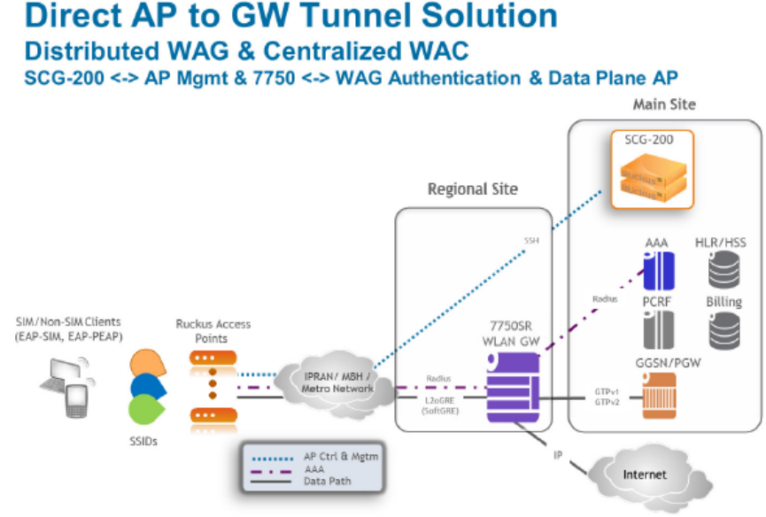
FIGURE 145 The controller as a pure AP controller
SoftGRE Packet Format
The following figure displays a screen shot of SoftGRE packet capture data.
SoftGRE Support
Overview of SoftGRE Support
SCG200 vSZ-H and SZ300 Administrator Guide
314 Part Number: 800-71563-001
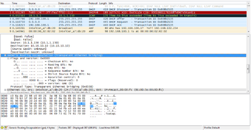
FIGURE 146 Example of SoftGRE packet format
Configuring And Monitoring AP Zones
If no tunneled WLANs exist in the zone, you can change the tunnel type from SoftGRE to GRE or GRE + UDP.
MVNO accounts are currently unsupported by SoftGRE tunnels. If you create an MVNO account and assign an AP zone that is using a
SoftGRE tunnel, an error message appears.
1. Follow the steps as described in Monitoring Domains, Zones, and AP Groups on page 91 to change the tunnel type from
SoftGRE.
2. Scroll down to the AP GRE Tunnel Option section.
3. In AP Tunnel Type, select the tunnel type to which you want to change from SoftGRE.
If you attempt to change the tunnel type when a tunneled WLAN exists within the zone, the following error message appears:
Unable to update the configuration of the AP zone. Reason: It is disallowed to change the tunnel type, because it has tunneled
WLAN.
SoftGRE Support
Configuring And Monitoring AP Zones
SCG200 vSZ-H and SZ300 Administrator Guide
Part Number: 800-71563-001 315
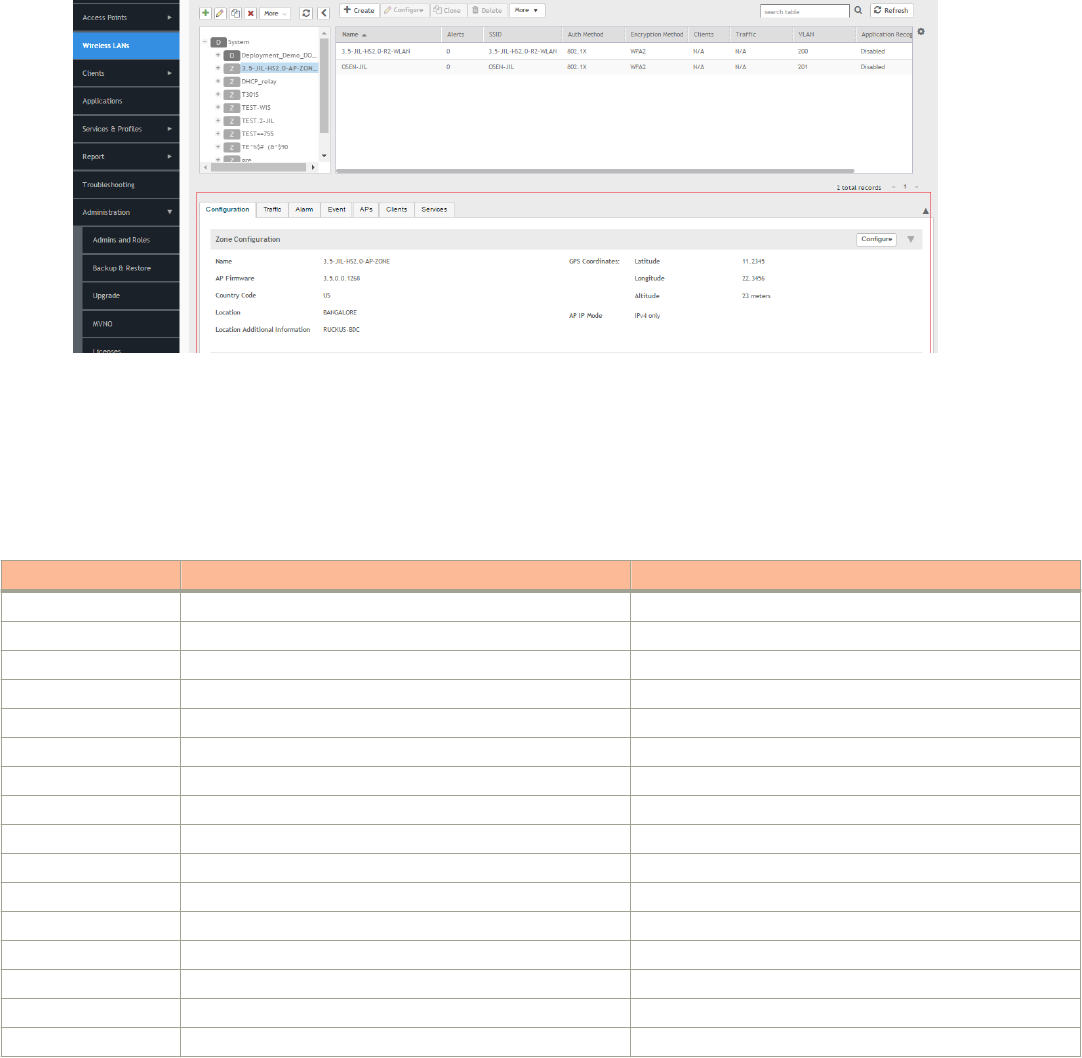
4. Click OK.
The zone configuration information is displayed.
FIGURE 147 Monitoring Zone Configuration
SoftGRE SNMP MIBs
The following table lists the SoftGRE OIDs.
TABLE 42 OIDs related to SoftGRE
Parent Node Node Name OID
ruckusWLANAPInfo ruckusSCGWLANAPMacAddr 1.3.6.1.4.1.25053.1.3.2.1.1.2.3.1.1
ruckusSCGWLANAPSoftGREServer 1.3.6.1.4.1.25053.1.3.2.1.1.2.3.1.2
ruckusSCGWLANAPSoftGREGWAddr 1.3.6.1.4.1.25053.1.3.2.1.1.2.3.1.3
ruckusSCGWLANAPSoftGREActive 1.3.6.1.4.1.25053.1.3.2.1.1.2.3.1.4
ruckusSCGWLANAPSoftGRETxPkts 1.3.6.1.4.1.25053.1.3.2.1.1.2.3.1.5
ruckusSCGWLANAPSoftGRETxBytes 1.3.6.1.4.1.25053.1.3.2.1.1.2.3.1.6
ruckusSCGWLANAPSoftGRERxPkts 1.3.6.1.4.1.25053.1.3.2.1.1.2.3.1.7
ruckusSCGWLANAPSoftGRERxBytes 1.3.6.1.4.1.25053.1.3.2.1.1.2.3.1.8
ruckusSCGWLANAPSoftGRETxPktsErr 1.3.6.1.4.1.25053.1.3.2.1.1.2.3.1.9
ruckusSCGWLANAPSoftGRERxPktsErr 1.3.6.1.4.1.25053.1.3.2.1.1.2.3.1.10
ruckusSCGWLANAPSoftGRETxPktsDropped 1.3.6.1.4.1.25053.1.3.2.1.1.2.3.1.11
ruckusSCGWLANAPSoftGRERxPktsDropped 1.3.6.1.4.1.25053.1.3.2.1.1.2.3.1.12
ruckusSCGWLANAPSoftGRETxPktsFrag 1.3.6.1.4.1.25053.1.3.2.1.1.2.3.1.13
ruckusSCGWLANAPSoftGREICMPTotal 1.3.6.1.4.1.25053.1.3.2.1.1.2.3.1.14
ruckusSCGWLANAPSoftGREICMPNoReply 1.3.6.1.4.1.25053.1.3.2.1.1.2.3.1.15
ruckusSCGWLANAPSoftGREDisconnect 1.3.6.1.4.1.25053.1.3.2.1.1.2.3.1.16
SoftGRE Support
SoftGRE SNMP MIBs
SCG200 vSZ-H and SZ300 Administrator Guide
316 Part Number: 800-71563-001
SoftGRE Events and Alarms
If there is no downstream traffic in the tunnel, APs that belong to the zone configured for SoftGRE send out-of-band ICMP keep-alive
messages (interval is configurable) to the active third party WLAN gateway. If an AP does not receive a response from the active WLAN
gateway, it triggers an alarm and it automatically creates a SoftGRE tunnel to the standby WLAN gateway.
If the AP does not receive a response from the standby WLAN gateway either, the AP disconnects all tunneled WLAN services. It continues
to send keep-alive messages to both the active WLAN gateway (primary GRE remote peer) and standby WLAN gateway (secondary GRE
remote peer). If it receives a response from either WLAN gateway, the AP restores all tunneled WLAN services automatically.
There are four types of events that APs send to the controller:
• Failover from primary GRE remote peer to secondary GRE remote peer
• Failover from secondary GRE remote peer to primary GRE remote peer.
• Tunnel disconnected because both primary and secondary GRE remote peers are unreachable
• Tunnel restored because either primary or secondary GRE remote peer is reachable
For the list of alarms and events related to SoftGRE that APs generate, refer to SoftGRE Events on page 317 and SoftGRE Alarms on page
318.
SoftGRE Events
SoftGRE related events that APs send to the controller.
Following are the events related to SoftGRE that AP generates.
apSoftGRETunnelFai
loverPtoS
AP [{apname@apMac}] fails over from primaryGRE [{address}] to secondaryGRE [{address}].
Code: 611
Severity:
Attributes:
• "apMac"="xx:xx:xx:xx:xx:xx"
• "primaryGRE"="xxx.xxx.xxx.xxx"
• "secondaryGRE"="xxx.xxx.xxx.xxx"
apSoftGRETunnelFai
loverStoP
AP [{apname@apMac}] fails over from secondaryGRE [{address }] to primaryGRE [{address}].
Code: 612
Severity: Warning
Attributes:
• "apMac"="xx:xx:xx:xx:xx:xx"
• "secondaryGRE"="xxx.xxx.xxx.xxx"
• "primaryGRE"="xxx,xxx.xxx.xxx"
apSoftGREGateway
Reachable
AP [{apname@apMac}] is able to reach [{softgreGW}] [{softgreGWAddress}] successfully.
Code: 613
Severity: Informational
Attributes:
• "apMac"="xx:xx:xx:xx:xx:xx"
• "softgreGW"="primaryGRE"
• "softgreGWAddress" = "xxx.xxx.xxx.xxx"
apSoftGREGateway
NotReachable
AP [{apname@apMac}] is able to reach [{softgreGW}] [{softgreGWAddress}] successfully.
Code: 614
SoftGRE Support
SoftGRE Events and Alarms
SCG200 vSZ-H and SZ300 Administrator Guide
Part Number: 800-71563-001 317
Severity: Critical
Attributes:
• apMac"="xx:xx:xx:xx:xx:xx"
• "softGREGatewayList"="xxx.xxx.xxx.xxx, yyy,yyy.yyy.yyy"
SoftGRE Alarms
SoftGRE related alarms that APs send to the controller.
Following are the SoftGRE related alarms:
apSoftGRETunnelFai
loverPtoS
AP[{apname@apMac}] fails over from primaryGRE[{address}] to secondaryGRE[{address}]
Code: 611
Default to Trap: true
Severity: major
Attributes:
• "apMac"="xx:xx:xx:xx:xx:xx"
• "primaryGRE"="xxx.xxx.xxx.xxx
• "secondaryGRE"="xxx.xxx.xxx.xxx
apSoftGRETunnelFai
loverStoP
AP[{apname@apMac}] fails over from secondaryGRE[{address }] to primaryGRE[{address}]
Code: 612
Default to Trap: true
Severity: major
Attributes:
• "apMac"="xx:xx:xx:xx:xx:xx
• "secondaryGRE"="xxx.xxx.xxx.xxx"
• "primaryGRE"="xxx,xxx.xxx.xxx"
apSoftGREGateway
Reachable
AP [{apname@apMac}] is able to reach [{softgreGW}] [{softgreGWAddress}] successfully
Code: 613
Default to Trap: true
Severity: informational
Attributes:
• "apMac"="xx:xx:xx:xx:xx:xx"
• "softgreGW"="primaryGRE"
• "softgreGWAddress"="xxx.xxx.xxx.xxx"
apSoftGREGateway
NotReachable
AP [{apname@apMac }] is unable to reach the following gateways: [{gateway list}]
Code: 614
Default to Trap: true
Severity: major
Attributes:
• “apMac"="xx:xx:xx:xx:xx:xx"
• "softGREGatewayList"="xxx.xxx.xxx.xxx, yyy,yyy.yyy.yyy"
SoftGRE Support
SoftGRE Events and Alarms
SCG200 vSZ-H and SZ300 Administrator Guide
318 Part Number: 800-71563-001

Replacing Hardware Components
• Installing or Replacing Hard Disk Drives.................................................................................................................319
This appendix describes how to replace hardware components (including hard disk drives, power supply units, and system fans) on the
controller.
This section only describes replacing the hardware components for SCG200.
Installing or Replacing Hard Disk Drives
You can install up to six hot-swappable SAS or SATA hard disk drives on the controller. The drives go into carriers that connect to the SAS/
SATA backplane board once the carriers with drives attached are inserted back into the drive bays. The controller ships with six drive
carriers.
CAUTION
If you install fewer than six hard disk drives, the unused drive bays must contain the empty carriers that ship with the server to
maintain proper cooling.
Ordering a Replacement Hard Disk
To order a replacement hard disk for the controller, contact your Ruckus Wireless sales representative and place an order for FRU part
number 902-0188-0000 (Hard Drive, 600GB, 10K RPM, 64MB Cache 2.5 SAS 6Gb/s, Internal).
CAUTION
Use only FRU part number 902-0188-0000 as replacement hard disk for the controller. Using other unsupported hard disks will
render the controller hardware warranty void.
Removing the Front Bezel
You must remove the front bezel to add or replace a hard drive in one of the drive bays. It is not necessary to remove the front chassis
cover or to power down the system. The hard drives are hot-swappable.
Follow these steps to remove the front bezel of the controller.
You need to remove the front bezel for tasks such as:
• Installing or removing hard disk drives or an SD flash card
• Observing the individual hard disk drive activity/fault indicators
• Replacing the control panel LED/switch board
The server does not have to be powered down just to remove the front bezel.
1. Loosen the captive bezel retention screw on the right side of the bezel (see A in Figure 148).
2. Rotate the bezel to the left to free it from the pins on the front panel (see B in Figure 148), and then remove it.
SCG200 vSZ-H and SZ300 Administrator Guide
Part Number: 800-71563-001 319
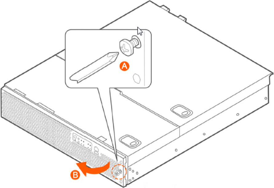
FIGURE 148 Removing the front bezel
Removing an HDD Carrier from the Chassis
Follow these steps to remove a hard disk drive carrier from the chassis.
1. Remove the front bezel (see Removing the Front Bezel on page 319).
2. Select the drive bay where you want to install or replace the drive.
Drive bay 0 must be used first, then drive bay 1 and so on. The drive bay numbers are printed on the front panel below the drive
bays.
3. Remove the drive carrier by pressing the green button to open the lever.
(See A in Figure 149).
Replacing Hardware Components
Installing or Replacing Hard Disk Drives
SCG200 vSZ-H and SZ300 Administrator Guide
320 Part Number: 800-71563-001
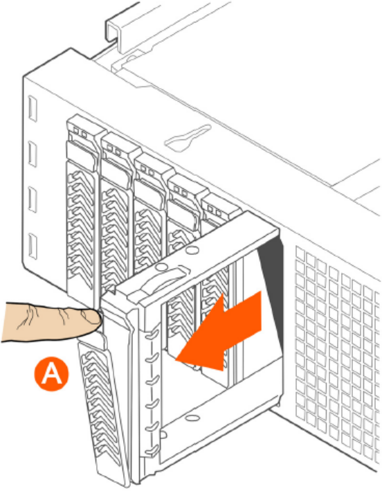
4. Pull the drive carrier out of the chassis.
FIGURE 149 Removing the drive carrier
Installing a Hard Drive in a Carrier
Follow these steps to install a hard drive in a drive carrier.
1. If a drive is already installed (that is, if you are replacing the drive), remove it by unfastening the four screws that attach the drive to
the drive carrier (see A in Figure 150). Set the screws aside for use with the new drive.
Replacing Hardware Components
Installing or Replacing Hard Disk Drives
SCG200 vSZ-H and SZ300 Administrator Guide
Part Number: 800-71563-001 321
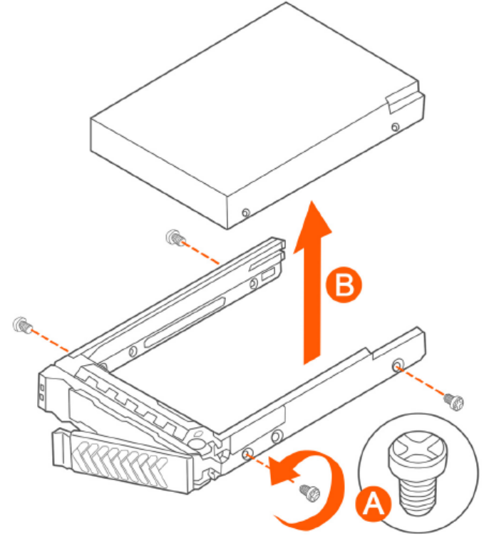
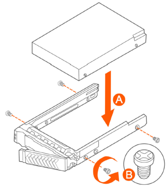
3. Install the new drive in the drive carrier (see A in Figure 151), and then secure the drive with the four screws that come with the
carrier (see B).
FIGURE 151 Installing the hard drive
Replacing Hardware Components
Installing or Replacing Hard Disk Drives
SCG200 vSZ-H and SZ300 Administrator Guide
Part Number: 800-71563-001 323
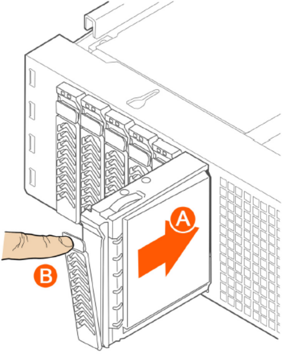
4. With the drive carrier locking lever fully open, push the hard drive carrier into the drive bay in the chassis until it stops (see A in
Figure 152).
FIGURE 152 Inserting the carrier back into the chassis
5. Press the locking lever until it snaps shut and secures the drive in the bay.
You have completed installing or replacing the hard drive onto the controller.
NOTE
The new hard drive will synchronize automatically with the existing RAID array. During the synchronization process, the HDD LED
on the controller will blink amber and green alternately. When the process is complete, the HDD LED will turn off.
Reinstalling the Front Bezel
Follow these steps to reinstall the front bezel on the controller.
1. Insert the tabs on the left side of the bezel into the slots on the front panel of the chassis.
2. Move the bezel toward the right of the front panel and align it on the front panel pins.
3. Snap the bezel into place and tighten the retention screw to secure it.
Replacing Hardware Components
Installing or Replacing Hard Disk Drives
SCG200 vSZ-H and SZ300 Administrator Guide
324 Part Number: 800-71563-001
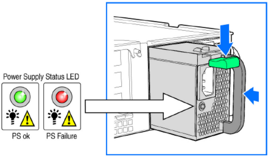
Replacing PSUs
The controller includes two redundant, hot-swappable power supply units (2 AC PSUs or 2 DC PSUs). No chassis components need to be
removed to add or replace a PSU.
Follow these steps to remove and replace a PSU.
1. Identify the faulty PSU by looking at the PSU status LED (red indicates PSU failure, green indicates normal operation).
2. Press and hold the green safety lock downward while grasping the PSU handle.
3. Pull outward on the handle, sliding the PSU all the way out of the rear of the machine.
4. Insert the new PSU into the slot and, while holding the green safety lock, slide the PSU into the slot until it locks in place.
The PSU status LED turns green, indicating that the PSU is operating normally.
NOTE
If you are installing a DC power supply, there are two threaded studs for chassis enclosure grounding. A 90" standard barrel, two-
hole, compression terminal lug with 5/8-inch pitch suitable for a #14-10 AWG conductor must be used for proper safety
grounding. A crimping tool may be needed to secure the terminal lug to the grounding cable.
FIGURE 153 Replacing a PSU
Replacing System Fans
The controller includes six redundant, hot-swappable system fans (four 80mm fans and two 60mm fans). There are also two fans located
inside the power supply units. Redundancy for the two PSU fans is only achieved when both PSUs are installed.
If any of the system fans requires replacement, the replacement procedure is identical.
Electrostatic discharge (ESD) can damage internal components such as printed circuit boards and other parts. Ruckus Wireless
recommends that you only perform this procedure with adequate ESD protection. At a minimum, wear an anti-static wrist strap attached to
the ESD ground strap attachment on the front panel of the chassis.
Replacing Hardware Components
Installing or Replacing Hard Disk Drives
SCG200 vSZ-H and SZ300 Administrator Guide
Part Number: 800-71563-001 325
Follow these steps to replace a system fan.
1. Open the front chassis cover of the controller. It may be necessary to extend the controller into a maintenance position.
2. Identify the faulty fan. Each fan has a "service required" LED that turns amber when the fan is malfunctioning.
3. Remove the faulty fan by grasping both sides of the fan assembly, using the plastic finger guard on the left side and pulling the fan
out of the metal fan enclosure.
4. Slide the replacement fan into the same metal fan enclosure. Use the edges of the metal enclosure to align the fan properly and
ensure the power connector is seated properly in the header on the side of the enclosure.
5. Apply firm pressure to fully seat the fan.
6. Verify that the (service required) LED on the top of the fan is not lit.
Replacing Hardware Components
Installing or Replacing Hard Disk Drives
SCG200 vSZ-H and SZ300 Administrator Guide
326 Part Number: 800-71563-001
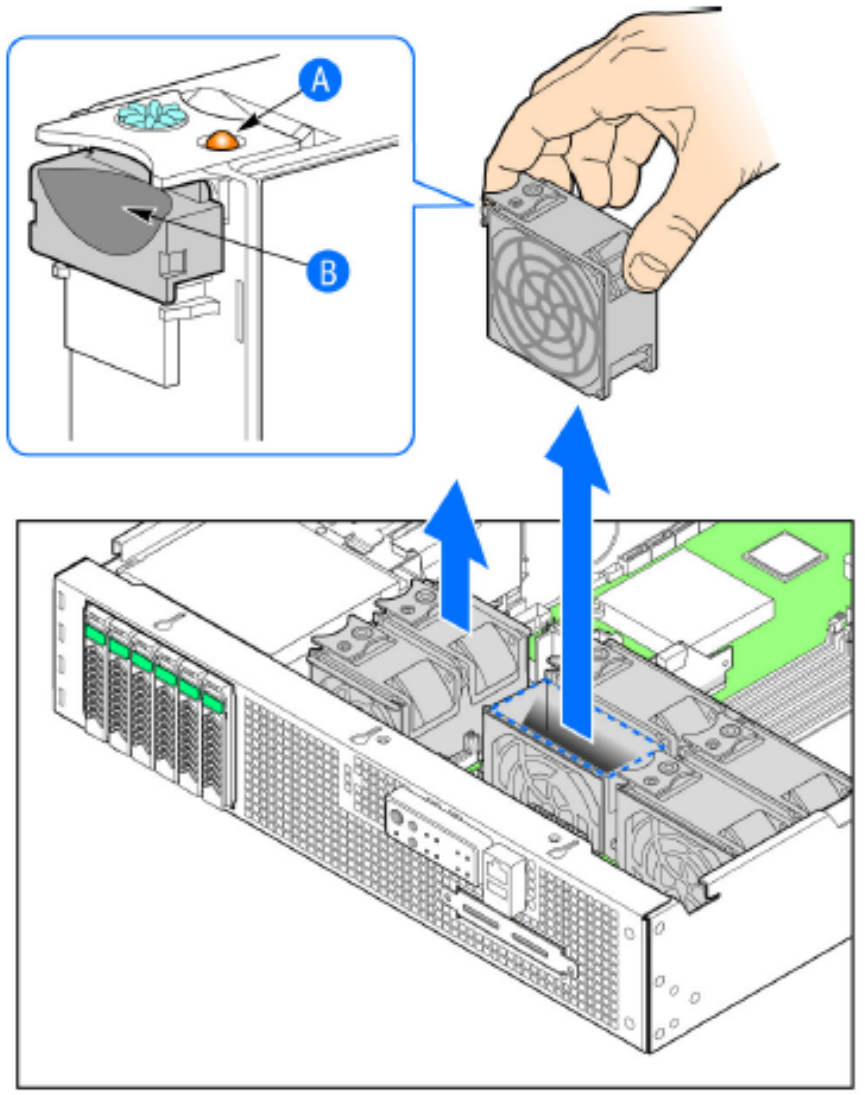
7. Close the front chassis cover and return the controller to its normal position in the rack, if necessary.
FIGURE 154 Replacing a system fan
Replacing Hardware Components
Installing or Replacing Hard Disk Drives
SCG200 vSZ-H and SZ300 Administrator Guide
Part Number: 800-71563-001 327
SCG200 vSZ-H and SZ300 Administrator Guide
328 Part Number: 800-71563-001

Replacing a Controller Node
• Introduction........................................................................................................................................................... 329
• Backing Up and Resorting the Cluster...................................................................................................................329
• Backing Up and Restoring Configuration............................................................................................................... 335
Introduction
NOTE
The information in this section only applies to the SCG-200.
This section describes how to back up cluster and configuration data and replace a controller node.
The following are required to perform the procedures described in this guide.
1. A remote FTP server with at least 50GB of free disk space. You must create an FTP account (user name and password) before
starting these procedures.
2. If you are restoring to a multi node cluster environment, all backup files must be taken around the same time. If the backup files are
out-of-sync, the restore process may be unsuccessful.
Backing Up and Resorting the Cluster
Cluster backup creates a backup of the entire cluster.
Take note of the following before performing a cluster backup.
• The cluster backup file is typically very large (larger than 1GB).
• Cluster backup cannot be completed successfully if any one of the nodes has less than 50GB of disk space after the backup
process.
Step 1: Backing Up the Cluster from the Web Interface
For information on how to back up the cluster from the controller web interface, see Creating a Cluster Backup on page 275.
Step 2: Back Up the Cluster from the Controller CLI
Cluster backup creates a backup of the entire cluster.
Follow the steps to back up the cluster from the controller CLI.
1. Log on to the controller CLI as a system administrator.
2. Run the enable command to enable privileged mode on the CLI.
ruckus> enable
Password: ********
ruckus#
SCG200 vSZ-H and SZ300 Administrator Guide
Part Number: 800-71563-001 329
3. Run the show diskinfo command to determine the current disk size of the node.
To complete the cluster backup successfully, the /mnt directory must have at least 50GB (53,687,091,200 in 1K-blocks) of free
disk space.
ruckus# show diskinfo
Filesystem 1K-blocks Used Available Use% Mounted on
rootfs 4128448 315520 3603216 9% /
/dev/root 4128448 315520 3603216 9% /
/dev/sda1 2064208 97208 1862144 5% /boot
/dev/mapper/vg00-lv00
41276736 5646756 33533240 15% /mnt
tmpfs 1048576 696 1047880 1% /tmp
tmpfs 3066864 0 3066864 0% /dev/shm
4. Run the backup command to start the backing up the current cluster.
ruckus# backup
Do you want to backup system in this context (yes/no)? yes
Backup process starts.
Backup process has been scheduled to run. You can check backup version using 'show backup'.
5. Run the show backup command to verify that the cluster backup file has been created successfully.
Step 3: Transfer the Cluster Backup File to an FTP Server
1. Log on to the controller CLI as a system administrator.
2. Enable privileged mode on the CLI.
ruckus> enable
Password: ********
ruckus#
Replacing a Controller Node
Backing Up and Resorting the Cluster
SCG200 vSZ-H and SZ300 Administrator Guide
330 Part Number: 800-71563-001
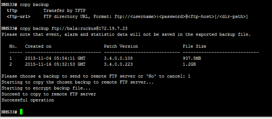
3. Run the copy backup command to copy the cluster backup file to an FTP server as shown in the figure.
FIGURE 155 Command to copy the cluster backup file
NOTE
The names of the backup files are automatically assigned by the controller based on the timestamp when the backup file
was generated and the controller release version. To make it easy for you to identify the backup files, Ruckus Wireless
strongly recommends moving each node's backup file to its own directory on the FTP server (for example, //ftp/
node1) after the backup process is completed.
Replacing a Controller Node
Backing Up and Resorting the Cluster
SCG200 vSZ-H and SZ300 Administrator Guide
Part Number: 800-71563-001 331
Step 4: Restoring the Cluster Backup to the Controller
The procedure for restoring the cluster backup to the controller depends on the controller environment – whether it is a single node
environment or a multi-node environment.
Restoring to a Single Node Environment
The procedure for restoring the cluster backup to the controller depends on the controller environment – whether it is a single node
environment or a multi-node environment.
Follow these steps to restore a cluster backup to a single node environment.
1. Prepare the new controller to which you will restore the cluster backup.
a) Either obtain a new controller or factory reset an existing controller.
b) Log on to the controller as a system administrator.
c) Run the setup command to configure the controller's network settings.
ruckus> setup
################################################
Start SCG setup process:
################################################
:
:
Setup configuration of ethers...
Network would be restarted. You could connect to SCG back by using Management port (10.2.2.35)!!
Enter "restart network" to continue... restart network
2. Transfer the backup file from the FTP server to the controller.
a) Log on to the controller CLI as a system administrator.
b) Run the enable command to enable privileged mode on the CLI.
ruckus> enable
Password: ********
ruckus#
c) Run the copy <ftp-url> backup command to transfer the backup file from the FTP server to the controller.
ruckus# copy <ftp-url> backup
NOTE
If there is only one backup file on the FTP server, the system will automatically transfer this file to the controller. If
there are multiple files, it will show the list of all available files and you will be prompted to select the file that you
want to transfer.
3. Run the restore local command to restore the backup file to the controller.
ruckus# restore local
This action will REBOOT the system. Do you want to only restore this SCG node (yes/no)? yes
idx version date
------------------------------------------
1 1.1.1.0.93 2013-02-01 03:09:27 GMT
2 1.1.1.0.93 2013-02-03 07:21:24 GMT
Please choose a backup version to restore (ex: 1, 2, ...): 2
You have completed restoring the backup file to a single node.
Replacing a Controller Node
Backing Up and Resorting the Cluster
SCG200 vSZ-H and SZ300 Administrator Guide
332 Part Number: 800-71563-001
Restoring to a Multi-Node Environment
If you are restoring to a multi-node cluster, you can either replace only one node in the (still-healthy) cluster or replace multiple nodes in the
cluster.
Replacing a Single Node in a Cluster
Follow these steps to replace a single node in a cluster backup.
1. If the node that you want to replace is still functioning, follow these steps to remove the node.
a) Choose a controller that will remain in the cluster.
b) Log on to that controller's web interface as an administrator.
c) Go to System > Cluster.
d) Locate the node that you want to replace in the cluster planes.
e) Click Delete to remove the node from the cluster.
2. If the node that you want to replace is out of service, you will need to shut it down before you can replace it. Follow these steps.
a) On the node that you want to replace, log on to the CLI as a system administrator.
b) Run the enable command to enable privileged mode on the CLI.
ruckus> enable
Password: ********
ruckus#
c) (Optional) Back up the current controller system.
See Step 2: Back Up the Cluster from the Controller CLI on page 329.
d) On the node that you want to replace, run the shutdown command.
ruckus# shutdown
e) Log on to the controller web interface as a system administrator.
f) Go to System > Cluster.
g) Locate the node that you want to replace in teh cluster planes.
h) Click Delete to remove the node from the cluster.
i) Set up the node as a new controller, and then join the existing cluster. For step by step instructions, see the
SmartCell
Gateway 200 Getting Started Guide
.
Replacing Multiple Nodes in a Cluster
If the cluster itself is not healthy anymore or if multiple nodes need to be replaced, you must restore backup files taken around the same
time to all of the nodes in the cluster.
Follow these steps to restore backups to multiple nodes in a cluster.
Replacing a Controller Node
Backing Up and Resorting the Cluster
SCG200 vSZ-H and SZ300 Administrator Guide
Part Number: 800-71563-001 333

CAUTION
Backup files must be taken around the same time. If the backup file of one node is out of sync from the others, the restore
process will be unsuccessful.
When restoring to multiple nodes, it is critical that you perform the restore process on all nodes at the same time.
Use the restore local command to restore the cluster from the backup file as you cannot restore the cluster by using a backup file
from another cluster.
1. Log on to the CLI as a system administrator.
2. Run the enable command to enable privileged mode on the CLI.
ruckus> enable
Password: ********
ruckus#
3. Run the remote restore command to transfer the backup file from the FTP server to the controller.
ruckus# remote restore <ftp-username> <ftp-password> <ftp-server-address> <ftp-server-port>
<directory>
idx version date
------------------------------------------
1 1.1.0.0.207 2012-10-16 06:46:07 GMT
2 1.1.0.0.209 2012-10-17 05:20:51 GMT
Please choose a backup version to get from remote FTP: 2
Remote restore process starts
Remote restore process completed
The ftp-server-port is optional.
NOTE
If there is only one backup file on the FTP server, the system will automatically transfer this file to the controller. If there
are multiple files, it will show the list of all available files and you will be prompted to select the file that you want to
transfer. If the backup files are in the root directory, use "/" in
{directory}
. If the backup files are in a subdirectory, use "/
{subdir}/{subdir}" to indicate the subdirectory in which the system should check.
4. After all backup files for all nodes have been transferred from the FTP server to the controller, run the restore local command to
restore the backup file to the controller.
ruckus# restore local
This action will REBOOT the system. Do you want to only restore this SCG node (yes/no)? yes
idx version date
------------------------------------------
1 1.1.1.0.93 2013-02-01 03:09:27 GMT
2 1.1.1.0.93 2013-02-03 07:21:24 GMT
Please choose a backup version to restore (ex: 1, 2, ...): 2
5. Verify that the following message appears on each node:
Remote restore process completed
This indicates that the node is ready for the restore process.
6. Once all nodes are ready for the restore process, run the restore command for all nodes at the same time.
Replacing a Controller Node
Backing Up and Resorting the Cluster
SCG200 vSZ-H and SZ300 Administrator Guide
334 Part Number: 800-71563-001
Backing Up and Restoring Configuration
Configuration backup creates a backup of all existing configuration information on the controller. In additional to backing up a different set of
information, configuration backup is different from cluster backup in a few ways:
• The configuration backup file is smaller, compared to the cluster backup file.
• The controller can be configured to back up its configuration to an external FTP server automatically.
•Configuration backup does not back up any statistical files or general system configuration.
Backed Up Configuration Information
The following list show which configuration information will be backing up.
• AP zones
• AP zone global configuration
• Zone templates
• WLAN templates
• AP registration rules
• Access point information
• General system settings
• Web certificate
• SNMP agent
• Alarm to SNMP agent
• Cluster planes
• Management interface ACL
• Domain information
• User credentials and information
• Mobile Virtual Network Operators (MVNO) information
Backing Up Configuration
There are two methods you can use to back up the controller configuration:
Backing Up Configuration from the Web Interface
1. For information on how to back up the controller configuration to an external FTP server automatically, see Backing up Cluster
Configuration on page 284.
2. In Auto Export Backup, click Enable.
3. In FTP Server, select the FTP server to which you want to export the backup file.
4. Click Test. The controller attempts to establish connection to the FTP server using the user name and password that you supplied.
If the connection attempt is successful, the following message appears: FTP server connection established
successfully.
If the connection attempt is unsuccessful, verify that the FTP server details (including the user name and password) are correct,
and then click Test again.
Replacing a Controller Node
Backing Up and Restoring Configuration
SCG200 vSZ-H and SZ300 Administrator Guide
Part Number: 800-71563-001 335
5. After you verify the controller is able to connect to the FTP server successfully, click OK to save the FTP server settings.
Backing Up Configuration from the CLI
There are two methods you can use to back up the controller configuration either using the web interface or CLI (Command Line Interface).
Follow these steps to back up the controller configuration from the CLI.
1. Log on to the controller CLI as a system administrator.
2. Run the enable command to enable privileged mode on the CLI.
ruckus> enable
Password: ********
ruckus#
3. Run the backup cong command to start backing up and transferring the node configuration to an FTP server.
ruckus# backup config <ftp-username> <ftp-password> <ftp-server-address> <ftp-server-port>
Do you want to backup configuration (yes/no)? yes
Backup Configuration process starts
Backup Configuration process has been scheduled to run. You can check backup version using 'show
backup-config'
4. Run the show backup-cong command to verify that the backup file has been created.
You have completed backing up the controller node to an external FTP server.
Restoring Configuration
Restoring Configuration to a Single Node Environment
Restoring the configured backup in a single node environment.
Follow the steps below to restore configuration to a single node environment.
1. Prepare the new controller to which you will restore the cluster backup.
a) Either obtain a new controller or factory reset an existing controller.
b) Log on to the controller as a system administrator.
c) Run the setup command to configure the controller's network settings.
ruckus> setup
################################################
Start SCG setup process:
################################################
:
:
Setup configuration of ethers...
Network would be restarted. You could connect to SCG back by using Management port (10.2.2.35)!!
Enter "restart network" to continue... restart network
d) Complete the controller setup process from the CLI.
2. After you complete the controller setup, log on to the controller web interface as a system administrator.
3. Go to Administration > Backup and Restore.
4. Click the Configuration tab.
5. Click Upload.
6. Browse to the location (either on the local computer or on the network) of the configuration backup file that you want to restore.
Replacing a Controller Node
Backing Up and Restoring Configuration
SCG200 vSZ-H and SZ300 Administrator Guide
336 Part Number: 800-71563-001
7. Select the configuration backup file, and then click Upload.
When the upload process is complete, the backup file appears in the Configuration section.
8. Restore the configuration backup file to the node, either using the web interface or the CLI.
9. To use the web interface:
a) On the web interface, go to Administration > Backup and Restore.
b) In the Configuration tab, locate the configuration backup file that you want to restore, and then click Restore.
c) Follow the prompts (if any) to complete the restore process.
10. To use the CLI:
a) Log on to the CLI as a system administrator.
b) Run the restore cong command.
ruckus# restore config
This action will REBOOT the system. Do you want to only restore this SCG node (yes/no)? yes
idx version date
------------------------------------------
1 1.1.1.0.93 2013-02-01 03:09:27 GMT
2 1.1.1.0.93 2013-02-03 07:21:24 GMT
Please choose a backup version to restore (ex: 1, 2, ...): 2
c) Follow the prompts (if any) to complete the restore process.
You have completed restoring the configuration to a single node controller.
Restoring Configuration to Multi Node Environment
If you are restoring to a multi node cluster, you can either replace only one node in the (still-healthy) cluster or replace multiple nodes in the
cluster.
Restoring Configuration to a Single Node in a Cluster
Follow these steps to replace the configuration of a single node in a cluster.
1. If the node that you want to replace is still functioning, follow these steps to remove the node.
a) Choose a controller that will remain in the cluster.
b) Log on to that controller's web interface as an administrator.
c) Go to System > Cluster.
d) Locate the node that you want to replace.
e) Click Delete to remove the node from the cluster.
Replacing a Controller Node
Backing Up and Restoring Configuration
SCG200 vSZ-H and SZ300 Administrator Guide
Part Number: 800-71563-001 337
2. If the node that you want to replace is out of service, you will need to shut down the node before you can replace it. Follow these
steps.
a) On the node that you want to replace, log on to the CLI as a system administrator.
b) Run the enable command to enable privileged mode on the CLI.
ruckus> enable
Password: ********
ruckus#
c) (Optional) Back up the current controller system.
See Step 2: Back Up the Cluster from the Controller CLI on page 329.
d) On the node that you want to replace, run the shutdown command.
ruckus# shutdown
e) Log on to the controller web interface as a system administrator.
f) Go to System > Cluster.
g) Locate the node that you want to replace,
h) Click Delete to remove the node from the cluster.
i) Set up the node as a new controller, and then join the existing cluster. For step by step instructions, see the
SmartCell 200
Getting Started Guide
.
You have completed restoring configuration to a single node in the cluster.
Restoring Configuration to Multiple Nodes in a Cluster
If the cluster itself is not healthy anymore or if multiple nodes need to replaced, you must you must factory reset all remaining nodes to
ensure that configuration restore to the cluster will be successful.
Follow the steps to restore the configuration to multiple nodes in a cluster.
1. Prepare the new controller nodes and factory reset all of the existing nodes in the cluster.
2. Complete the setup procedure for one of the controller nodes.
For instructions, see the
SmartCell Gateway 200 Getting Started Guide
for this release.
3. After you complete the setup of one node, log on to the web interface of that node as a system administrator.
4. Go to Administration > Backup and Restore.
5. In the Configuration tab, click Upload.
6. Locate the configuration backup file that you want to restore.
7. Click Upload.
After the configuration file is uploaded successfully, it appears in the Configuration section.
8. Restore the configuration backup to the node either using the web interface or the CLI.
9. To use the web interface:
a) Go to Administration > Backup and Restore page.
b) In the Configuration tab, locate the configuration backup file that you want to restore.
c) Click Restore.
d) Follow the prompts (if any) to complete the restore process.
Replacing a Controller Node
Backing Up and Restoring Configuration
SCG200 vSZ-H and SZ300 Administrator Guide
338 Part Number: 800-71563-001
10. To use the CLI:
a) Log on to the CLI of the node as a system administrator.
b) Run the restore cong command.
ruckus# restore config
This action will REBOOT the system. Do you want to only restore this SCG node (yes/no)? yes
idx version date
------------------------------------------
1 1.1.1.0.93 2013-02-01 03:09:27 GMT
2 1.1.1.0.93 2013-02-03 07:21:24 GMT
Please choose a backup version to restore (ex: 1, 2, ...): 2
c) When the configuration restore process on this node is complete, set up the next node and configure it to join the existing
cluster.
You have completed restoring configuration backup to multiple nodes in a cluster.
Replacing a Controller Node
Backing Up and Restoring Configuration
SCG200 vSZ-H and SZ300 Administrator Guide
Part Number: 800-71563-001 339
SCG200 vSZ-H and SZ300 Administrator Guide
340 Part Number: 800-71563-001

SCG SSID Syntax
• SSIDs Supported in Release 1.1.x.........................................................................................................................341
• SSIDs Supported in Release 2.1.x.........................................................................................................................341
• SSIDs Supported in Release 2.5.x.........................................................................................................................342
• SSIDs Supported in Release 3.0 and Above..........................................................................................................342
• ZoneDirector SSID Syntax..................................................................................................................................... 343
• ZoneFlex AP SSID Syntax..................................................................................................................................... 344
The following sections describe the supported SSID syntax in the following SCG release versions:
SSIDs Supported in Release 1.1.x
Release 1.1.x supports a specific set of SSID syntaxes, which may be different from the syntaxes supported in other releases.
The following table describes the SSID syntaxes that are supported in release 1.1.x.
TABLE 43 Supported SSID syntaxes in 1.1.x
Web Interface Length Between 1 and 32 characters, including characters from
printable characters (ASCII characters space (32) to ~
(126)
Supported
Characters
• A-Z
• a-z
• 0-9
• _space_!"#$%&'()*+,-./
• :;<=?@
• [\]^_`
• {|}
CLI Length Unsupported
Supported
Characters
Unsupported
SSIDs Supported in Release 2.1.x
Release 2.1.x supports a specific set of SSID syntaxes, which may be different from the syntaxes supported in other releases.
The following table describes the SSID syntaxes that are supported in release 2.1.x.
TABLE 44 Supported SSID syntaxes in 2.1.x
Web Interface Length Between 1 and 32 characters, including characters from
printable characters (ASCII characters space (32) to
~(126)
Supported
Characters
• A-Z
• a-z
• 0-9
• _space_!"#$%&'()*+,-./
• :;<=?@
SCG200 vSZ-H and SZ300 Administrator Guide
Part Number: 800-71563-001 341

TABLE 44 Supported SSID syntaxes in 2.1.x (continued)
• [\]^_`
• {|}
CLI Length Between 2 and 32 characters
Supported
Characters
All characters, but the space character cannot be the
first or last character in the SSID
SSIDs Supported in Release 2.5.x
Release 2.5.x supports a specific set of SSID syntaxes, which may be different from the syntaxes supported in other releases.
The following table describes the SSID syntaxes that are supported in release 2.5.x.
TABLE 45 Supported SSID syntax in 2.5.x
Web Interface Length Between 1 and 32 characters, including characters from
printable characters (ASCII characters space (32) to ~
(126)
Supported
Characters
• A-Z
• a-z
• 0-9
• _space_!"#$%&'()*+,-./
• :;<=?@
• [\]^_`
• {|}
CLI Length Between 2 and 32 characters
Supported
Characters
All characters
SSIDs Supported in Release 3.0 and Above
Release 3.0 and above supports a specific set of SSID syntaxes, which may be different from the syntaxes supported in other releases.
The following table describes the SSID syntaxes that are supported in release 3.0 and above.
TABLE 46 Supported SSID syntax in 3.0 and above
Web Interface
and CLI
Length Between 2 to 32 characters are supported
Characters Unsupported: ` and $(
Space is allowed, but it must include at least one non-
space character (" abc" is valid, however only space
such as " " is invalid).
NOTE
One Chinese word is regarded as three
special characters.
SCG SSID Syntax
SSIDs Supported in Release 2.5.x
SCG200 vSZ-H and SZ300 Administrator Guide
342 Part Number: 800-71563-001

ZoneDirector SSID Syntax
The following sections describe the supported SSID syntax in the following SCG release version:
SSIDs Supported in Releases 9.8 and 9.7
ZoneFlex releases 9.8 and 9.7 support a specific set of SSID syntaxes, which may be different from the syntaxes supported in other
releases.
TABLE 47 Supported SSID syntaxes in ZoneFlex 9.8 and 9.7
Web Interface Length Between one and 32 characters
Supported
Characters
All printable ASCII characters from space (32) to ~(126)
Exceptions The space character (32) cannot be the first or last
character in the SSID. Otherwise, the following error
message appears:
can only contain between 1 and 32
characters, including characters from !
(char 33) to ~ (char 126).
CLI Length Between one and 32 characters
Supported
Characters
All printable ASCII characters from space (32) to ~(126)
Exceptions The space character (32) can be placed anywhere in the
SSID (including the beginning or end) provided that it
enclosed by a double quotation mark.
Supported SSIDs in ZoneFlex Release 9.6
ZoneFlex release 9.6 supports a specific set of SSID syntaxes, which may be different from the syntaxes supported in other releases.
TABLE 48 Supported SSID syntaxes in ZoneFlex 9.6
Web Interface Length Between two and 32 characters
Supported
Characters
All printable ASCII characters from space (32) to ~(126)
Exceptions The space character (32) cannot be the first or last
character in the SSID. Otherwise, the following error
message appears:
can only contain between 1 and 32
characters, including characters from !
(char 33) to ~ (char 126).
CLI Length Between two and 32 characters
Supported
Characters
All printable ASCII characters from space (32) to ~ (126)
Exceptions The space character (32) can be placed anywhere in the
SSID (including the beginning or end) provided that it
enclosed in a double quotation mark (for example,
“Ruckus Wireless SSID”).
SCG SSID Syntax
ZoneDirector SSID Syntax
SCG200 vSZ-H and SZ300 Administrator Guide
Part Number: 800-71563-001 343

ZoneFlex AP SSID Syntax
The following sections describe the supported SSID syntax in the following ZoneFlex AP release versions:
Supported SSIDs in Releases 9.8, 9.7, and 9.6
ZoneFlex release 9.8, 9.7, and 9.6 support a specific set of SSID syntaxes, which may be different from the syntaxes supported in other
releases.
TABLE 49 Supported SSID syntaxes in ZoneFlex AP 9.8, 9.7, and 9.6
Web Interface Length Between one and 32 characters
Supported
Characters
All printable ASCII characters from space (32) to ~(126)
CLI Length Between one and 32 characters
Supported
Characters
All printable ASCII characters from space (32) to ~ (126)
Exceptions The space character (32) can be placed anywhere in the
SSID (including the beginning or end) provided that it
enclosed in a double quotation mark (for example,
"Ruckus Wireless SSID").
If the space character is not enclosed in a double
quotation mark, the space character and any characters
after that will be ignored. For example, if you run the
command "set ssid wlan0 ruckus-ap 123", the
controller CLI will run the command as "set ssid wlan0
ruckus-ap 123".
SCG SSID Syntax
ZoneFlex AP SSID Syntax
SCG200 vSZ-H and SZ300 Administrator Guide
344 Part Number: 800-71563-001

Copyright © 2006-2017. Ruckus Wireless, Inc.
350 West Java Dr. Sunnyvale, CA 94089. USA
www.ruckuswireless.com
