Ruckus Brocade “Effortless Network” Architecture For K 12 School Districts [BP] District Vd
2017-12-12
User Manual: Ruckus [BP] Ruckus “Effortless Network” Architecture for K-12 School Districts
Open the PDF directly: View PDF ![]() .
.
Page Count: 70
- Contents
- Preface
- Introduction
- K-12 Reference Architecture
- School Network Architecture
- District Office Network Architecture
- Solution Components—Hardware and Software
- Layer 2 Network Design
- Layer 3 Network Design
- Network Security Design
- Network Services
- Quality of Service
- Network Management
- Brocade Network Advisor
- Network Element Discovery and Management
- Traffic Monitoring and sFlow
- PoE Management
- Brocade Network Advisor Server Requirements
- SNMP Settings on Brocade Network Advisor
- Sample Flow (sFlow)
- Traffic Management Using Brocade Network Advisor
- PoE Management Using Brocade Network Advisor
- Event Notification
- Configuration Backup
- Glossary

53-1004097-03
13 June 2016
Brocade “Effortless
Network” Architecture for
K-12 School Districts
Brocade Validated Design
© 2016, Brocade Communications Systems, Inc. All Rights Reserved.
Brocade, Brocade Assurance, the B-wing symbol, ClearLink, DCX, Fabric OS, HyperEdge, ICX, MLX, MyBrocade, OpenScript, VCS, VDX,
Vplane, and Vyatta are registered trademarks, and Fabric Vision is a trademark of Brocade Communications Systems, Inc., in the United
States and/or in other countries. Other brands, products, or service names mentioned may be trademarks of others.
Notice: This document is for informational purposes only and does not set forth any warranty, expressed or implied, concerning any
equipment, equipment feature, or service offered or to be offered by Brocade. Brocade reserves the right to make changes to this document
at any time, without notice, and assumes no responsibility for its use. This informational document describes features that may not be
currently available. Contact a Brocade sales office for information on feature and product availability. Export of technical data contained in
this document may require an export license from the United States government.
The authors and Brocade Communications Systems, Inc. assume no liability or responsibility to any person or entity with respect to the
accuracy of this document or any loss, cost, liability, or damages arising from the information contained herein or the computer programs that
accompany it.
The product described by this document may contain open source software covered by the GNU General Public License or other open
source license agreements. To find out which open source software is included in Brocade products, view the licensing terms applicable to
the open source software, and obtain a copy of the programming source code, please visit http://www.brocade.com/support/oscd.

Contents
Preface.....................................................................................................................................5
About Brocade.................................................................................................. 5
Brocade Validated Designs............................................................................... 5
Document History..............................................................................................5
Purpose of This Document................................................................................6
Target Audience................................................................................................ 6
Introduction..............................................................................................................................7
K-12 Reference Architecture..................................................................................................... 9
School Network Architecture ...................................................................................................11
Access Layer...................................................................................................11
Distribution Layer............................................................................................ 12
District Office Network Architecture.........................................................................................13
Solution Components—Hardware and Software....................................................................... 15
Product Details................................................................................................15
Layer 2 Network Design........................................................................................................... 17
Network Device Discovery.............................................................................. 17
Stacking.......................................................................................................... 18
Link Aggregation Groups................................................................................ 20
VLANs............................................................................................................. 21
Spanning Tree Protocol...................................................................................22
Uni-Directional Link Detection.........................................................................23
BPDU Guard................................................................................................... 24
Edge Ports...................................................................................................... 25
Root Guard......................................................................................................25
Power over Ethernet....................................................................................... 26
Layer 3 Network Design...........................................................................................................29
Unicast Routing Design...................................................................................29
OSPF Routing Design.........................................................................29
BGP Internet-Connectivity Design...................................................... 31
Multicast Routing Design................................................................................ 36
PIM-SM............................................................................................... 36
IGMP/MLD Snooping.......................................................................... 37
Multicast Configuration Details............................................................37
Network Security Design..........................................................................................................41
Brocade “Effortless Network” Architecture for K-12 School Districts Brocade Validated Design 3
53-1004097-03
Device Access Security.................................................................................41
RADIUS.............................................................................................41
Secure Shell..................................................................................................42
Network Access Security.............................................................................. 43
IPv4 Access Control Lists............................................................................. 47
DoS Attack Mitigation....................................................................................48
Smurf Attack......................................................................................48
TCP SYN Attack................................................................................49
Network Services.................................................................................................................. 51
Network Time Protocol..................................................................................51
DHCPv4 and DHCPv6.................................................................................. 51
Simple Network Management Protocol.........................................................53
Recommendations for K-12 SNMP Deployment...............................53
Quality of Service..................................................................................................................55
Network Management...........................................................................................................59
Brocade Network Advisor..............................................................................59
Network Element Discovery and Management.............................................59
Traffic Monitoring and sFlow......................................................................... 60
PoE Management......................................................................................... 60
Brocade Network Advisor Server Requirements...........................................60
SNMP Settings on Brocade Network Advisor............................................... 60
Sample Flow (sFlow).....................................................................................62
Traffic Management Using Brocade Network Advisor.................................. 63
PoE Management Using Brocade Network Advisor..................................... 63
Event Notification.......................................................................................... 64
Configuration Backup....................................................................................66
Glossary............................................................................................................................... 69
4Brocade “Effortless Network” Architecture for K-12 School Districts Brocade Validated Design
53-1004097-03

Preface
● About Brocade.................................................................................................................. 5
● Brocade Validated Designs............................................................................................... 5
● Document History..............................................................................................................5
● Purpose of This Document................................................................................................6
● Target Audience................................................................................................................ 6
About Brocade
Brocade® (NASDAQ: BRCD) networking solutions help the world's leading organizations transition
smoothly to a world where applications and information reside anywhere. This vision is designed to
deliver key business benefits such as unmatched simplicity, non-stop networking, application
optimization, and investment protection.
Innovative Ethernet and storage networking solutions for data center, campus, and service provider
networks help reduce complexity and cost while enabling virtualization and cloud computing to increase
business agility.
To help ensure a complete solution, Brocade partners with world-class IT companies and provides
comprehensive education, support, and professional services offerings (www.brocade.com).
Brocade Validated Designs
Brocade Validated Designs are reference architectures that are created and validated by Brocade
engineers to address various customer deployment scenarios and use cases. These validated designs
provide a well-defined and standardized architecture for each deployment scenario, and they
incorporate a broad set of technologies and feature sets across Brocade's product range that address
customer-unique requirements. These designs are comprehensively validated end-to-end so that the
design solutions and configurations can be deployed more quickly, more reliably, and more predictably.
Brocade validated designs are continuously validated using a test automation framework to ensure that
once a design has been validated, it remains validated on new software releases and products.
Document History
Date Version Description
10/26/2015 1.0 Initial version.
11/23/2015 2.0 Formatting changes.
6/13/2016 3.0 New software release recommendations.
Brocade “Effortless Network” Architecture for K-12 School Districts Brocade Validated Design 5
53-1004097-03
Purpose of This Document
This Brocade validated design provides building blocks and reusable validated design templates that
are tailored for the unique requirements of K-12 school districts.
Target Audience
This document is written for Brocade system engineers and K-12 network administrators who design,
implement, and support K-12 networks.
Purpose of This Document
6 Brocade “Effortless Network” Architecture for K-12 School Districts Brocade Validated Design
53-1004097-03

Introduction
The primary objective of this document is to provide a solid foundation to facilitate successful K-12
designs and deployments that effectively meet current and future requirements. This document provides
technical guidance for network solutions that are suggested for K-12 deployments. It discusses the
various topologies and Brocade validated configurations for seamless network performance and
scalability with Brocade switches and routers.
K-12 network design and infrastructure are driven by continuously evolving technology. Network
administrators and those responsible for building the infrastructures required to support today's
demanding communications needs are under increasing pressure to maintain and scale their networks.
Many trends are impacting this requirement. Seamless connectivity is no longer a matter of ensuring
reliable connectivity for the local area network. The network must extend communications outside and
must reach coverage areas that are often many miles away, which remains an important educational
tool that cannot be ignored. Network connectivity-for streaming video, distance learning, and the wealth
of Internet-based tools-brings the world into the classroom. With new technologies in place, videos are
no longer rolled from room to room on a cart, and computers are not the only classroom tools. Devices
are connected either locally or widely through the Internet.
The need for network connectivity means having a robust and flexible infrastructure to satisfy the
evolving requirements of the school. The network must support a wide variety of network applications
within the classroom and throughout the school district. These applications include:
• Internet, intranet, and e-mail
• Communications
• Distance learning
• Phones
• Video
• Administrative tasks
• Security
• Building automation
• Smart board and collaboration
This document discusses the Brocade Validated Design to fulfill the network considerations for K-12
schools, with an emphasis on the classroom and these diverse applications. The document
encompasses the fact that the technologies and applications embedded in Brocade switches are
designed to support the evolving requirements today and also to future-proof the network.
Brocade “Effortless Network” Architecture for K-12 School Districts Brocade Validated Design 7
53-1004097-03
Introduction
8 Brocade “Effortless Network” Architecture for K-12 School Districts Brocade Validated Design
53-1004097-03
K-12 Reference Architecture
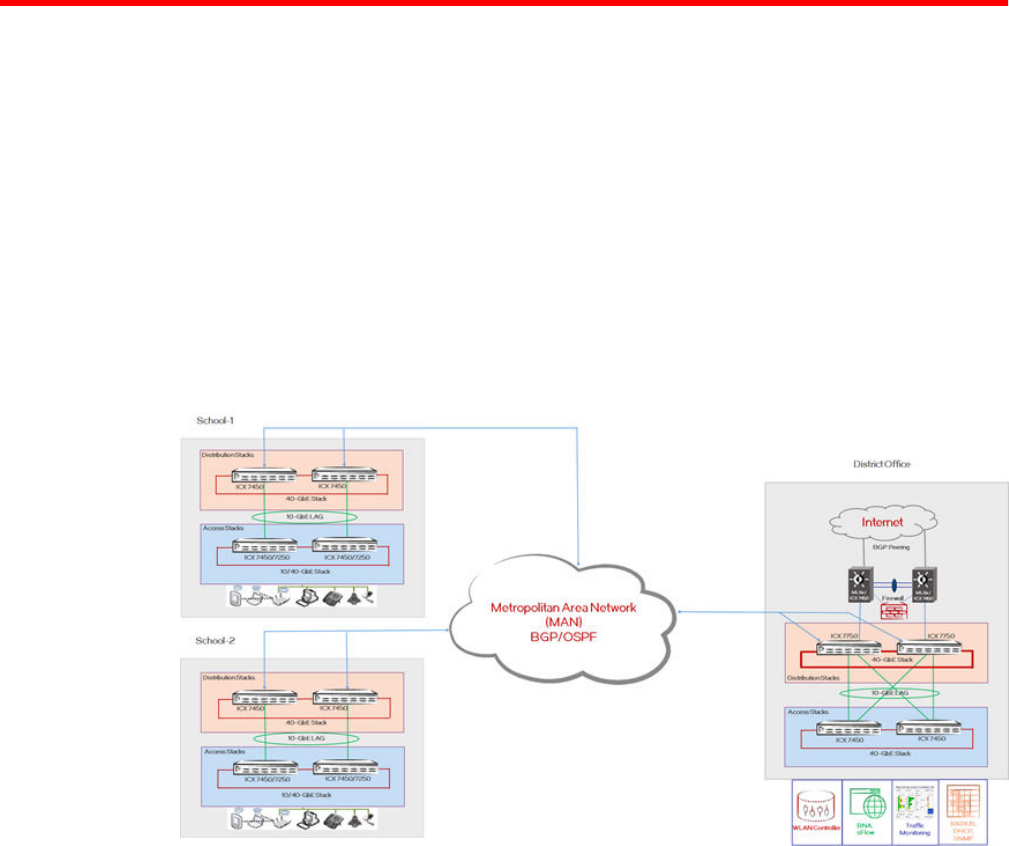
Brocade's recommended design for K-12 school districts uses an optimized two-tier architecture that
addresses the unique requirements for school districts. A minimal number of network devices can be
used to deliver cost-effective, scalable networks that easily interconnect through a Metropolitan Area
Network (MAN). This design also provides network connectivity to the Internet and the data center in
the district office. This solution is scalable, supporting various school types such as elementary, middle,
and high schools in a school district.
The reference design is built with templates, which can be replicated across all campuses, making it
easier to build and manage the network. Two such templates, which are connected via a MAN, are
defined:
• School template
• District office template
The following figure shows Brocade's K-12 school reference architecture.
FIGURE 1 K-12 Reference Architecture for School Districts
Brocade “Effortless Network” Architecture for K-12 School Districts Brocade Validated Design 9
53-1004097-03
K-12 Reference Architecture
10 Brocade “Effortless Network” Architecture for K-12 School Districts Brocade Validated Design
53-1004097-03
School Network Architecture
● Access Layer...................................................................................................................11
● Distribution Layer............................................................................................................ 12
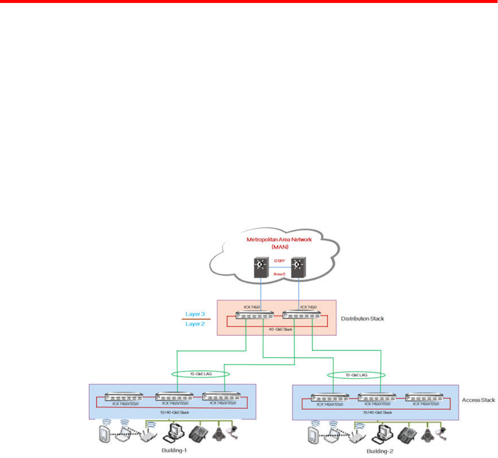
The school network architecture is modular, so it can be scaled up and scaled out to meet the
requirements of different school facilities such as high, middle, and elementary schools.
The School template is based on a two-tier architecture:
• Access layer
• Distribution layer
The Brocade ICX 7250/7450 switches form the access layer or lower tier of the campus, and the
Brocade ICX 7450 switches form the distribution layer or upper tier. Any tier can be managed as a
single entity using Brocade's HyperEdge stacking. Brocade recommends that you run LLDP or CDP on
all interfaces of all devices, which helps to identify the peer devices on each link.
The following figure shows the School template design.
FIGURE 2 K-12 School Network Architecture
Access Layer
The access layer of the School template is the connectivity layer for the end-user devices in the school
campus to access network services. These end users can use devices such as PCs, laptops, PDAs,
smart phones, intermediate devices like wireless access points, and network printers. Each school
campus consists of one or more buildings, each of which may have multiple floors, each having one or
more classrooms. The devices positioned in this part of network can be configured in a stack or as
Brocade “Effortless Network” Architecture for K-12 School Districts Brocade Validated Design 11
53-1004097-03
standalone devices based upon the number of connected users. For example: Classrooms like
computer and science labs may require more ports, requiring devices to be stacked. Whereas facilities
like the gymnasium may need few port connections and can be serviced by a standalone device.
Multiple such stacks can be provisioned to scale up the solution as needed. Based upon the
requirements, Brocade ICX 7250/7450 devices having PoE and PoE+ capable ports can be used to
power the access devices, such as IP phones and wireless LAN access points.
• The access layer is primarily a Layer 2 network with associated VLANs for each user group or
department. If a user wants to initiate inter-department communication, the same is serviced by the
distribution layer using inter-VLAN routing. Intra-VLAN traffic is handled directly by the access
devices.
• Brocade recommends that, for resiliency and bandwidth aggregation, the links toward distribution
layer devices be grouped in a cross-unit LAG configuration. This configuration helps scale the
available bandwidth as needed.
• LAGs can be used to bundle multiple individual links into higher bandwidth links while connecting
the access layer to the distribution layer (10 Gbps and higher); this helps to avoid network
bottlenecks.
• Multiple cross-unit LAGs between the access and distribution layers are used for redundancy, and
Rapid Spanning Tree Protocol (RSTP) is employed for a Layer 2 loop-free topology.
Distribution Layer
The distribution layer in the school provides the Layer 3 routing and the connectivity to the district
office for the campus through a Metropolitan Area Network (MAN). The distribution layer terminates
the Layer 2 traffic within the school and provides Layer 3 network connectivity, including Internet
access via the district office. In the Brocade K‐12 solution, a stack of Brocade ICX 7450 switches with
40-GbE stacking at the distribution layer provides resiliency, high density, significant bandwidth, and
advanced routing functionality. Brocade recommends always using a minimum of two stacked units as
a distribution switch. Connectivity to the district office and other campuses via 1/10-GbE uplinks
accommodates higher loads with higher performance.
• Robust Layer 3 protocols such as OSPF and PIM-SM help route unicast and multicast traffic across
the network. The switches in the distribution layer (Brocade ICX 7450) require an Advanced Routing
license to enable routing in this part of the network design.
• Application servers are intended to be located in the server farms that are hosted at the district
office segment; most of the traffic from schools will be northbound over the MAN links. This design
scales well by adding multiple links to the routing process to achieve load-balancing across the
links.
Distribution Layer
12 Brocade “Effortless Network” Architecture for K-12 School Districts Brocade Validated Design
53-1004097-03
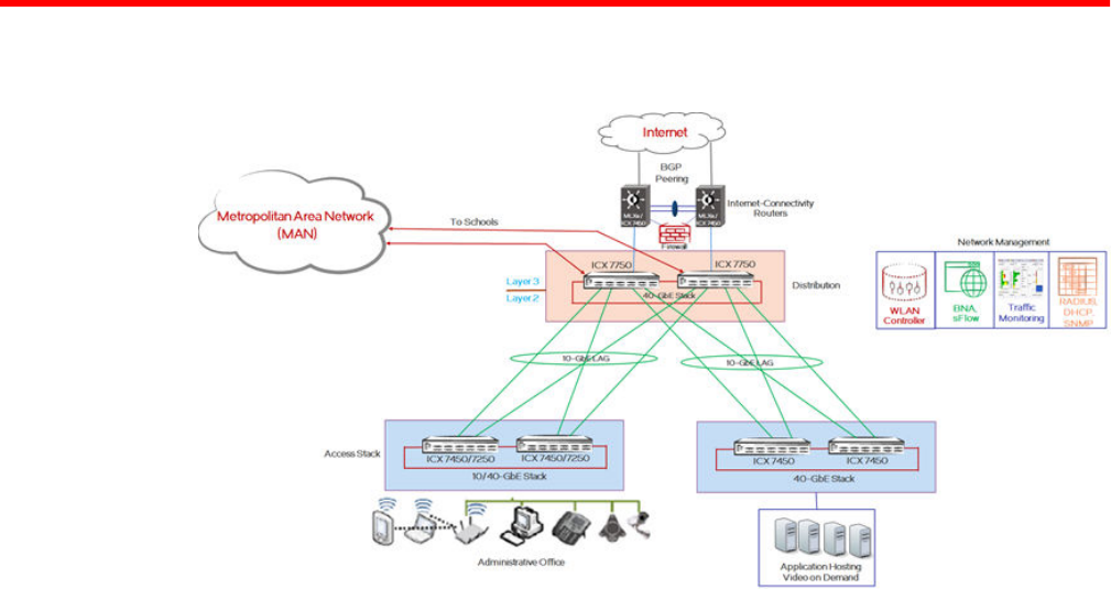
District Office Network Architecture
FIGURE 3 K-12 District Office Network Architecture
From the perspective of the school district's network architecture, the district office is the central hub for
the schools where the Metro Ethernet connections to all the school sites aggregate, and it provides
upstream connectivity to the Internet. Generally, the district office supports the school district's
administrative functions and the IT services, and it is also where most of the IT personnel are situated.
The district office provides Internet access for all schools in the district, it connects to a service-provider-
supported WAN using 1-GbE or 10-GbE links, and it connects to the data center network so that the
schools can access central applications as required. The district office network includes a firewall, a
wireless LAN controller, RADIUS, DHCP servers, and Brocade Network Advisor for the network
management and user-access control.
The district office connects to the data center network, which hosts the different application servers, for
example, file servers, video servers, call managers, mail servers. These servers provide services like
real-time streaming of audio/video lessons over multicast channels, webcasts, podcasts, video on
demand. This design enables the schools to access central applications as required.
The district office network is based on a three-tier architecture:
• Access layer
• Distribution layer
• Internet WAN connectivity
The access layer provides wired and wireless (PoE/PoE+) device access for staff; a dedicated access
layer stack connects to the server farms, which host applications and other services such as video on
demand. For maximum redundancy, the access stack is a high-bandwidth 40-GbE stack in a ring
topology. The access stack is connected to the distribution stack through a 10-GbE LAG link.
The distribution layer in the district office is a very critical part of the K-12 network architecture. Brocade
ICX 7750 switches in a stack configuration are used for high availability. The distribution network layer
provides Internet and server-farm connectivity for school campuses and the district office. School
campuses and the district office are connected through a Metropolitan Area Network (MAN). The MAN
is the service-provider end of the network, which may be owned by the school district itself, and it
Brocade “Effortless Network” Architecture for K-12 School Districts Brocade Validated Design 13
53-1004097-03
provides network services over the WAN links with the intention of reaching the district office from
individual schools. The network design assumptions include Layer 3 hand-off for MAN connectivity.
For Internet connectivity, the distribution layer connects to two separate MLXe Internet-connectivity
routers. For routing design simplicity, OSPF as an IGP is used between distribution switches and
MLXe routers. MLXe routers are connected to the ISP via BGP, and they learn the default route from
the ISP to direct school Internet traffic via the Internet routers. The learned BGP default route is
advertised to the rest of the network by the OSPF default-information originate mechanism. The
distribution switches have dual paths toward the MLXe routers for Internet traffic.
Alternatively, Brocade ICX 7450 Routers can be used as Internet-connectivity routers; the relevant
validated configuration template is provided in the "BGP Internet-Connectivity Design" section.
For multicast traffic, the distribution layer stack is configured as a static rendezvous point (RP), and
PIM-SM is used as the multicast routing protocol on distribution switches. The switches in the
distribution layer (ICX 7750) require an Advanced Routing license to enable routing in this part of
network design.
District Office Network Architecture
14 Brocade “Effortless Network” Architecture for K-12 School Districts Brocade Validated Design
53-1004097-03

Solution Components—Hardware and Software
The K-12 network consists of the following components and products.
Component/Product Function Software
Brocade ICX 7750 Distribution switch for the district
office
SWR08030h
Brocade ICX 7450 Distribution switch for schools
Access switch for the district office
(application hosting)
SPR08030h
Brocade ICX 7250 Access switch for schools
Access switch for the district office
SPS08030h
SPS08030h
Brocade MLXe-4 Internet-connectivity router 05.9.00b
Brocade Network Advisor Integrated network management 12.4.2
Product Details
Brocade ICX 7750—The Brocade ICX 7750 provides unprecedented stacking density and performance
with up to 12 switches per stack and up to 2,880 Gbps of aggregated stacking bandwidth. The switch
enables a single point of management across the campus through a distributed chassis architecture
that supports long-distance stacking. It offers industry-leading 10/40-GbE port density and flexibility in a
1U form factor with up to 32×40GbE or 96×10GbE ports per unit, saving valuable rack space and power
in wiring closets. It provides chassis-class high availability with six full-duplex 40-Gbps stacking ports
per switch, hitless stacking failover, and hot-swappable power supplies and fan assemblies. It provides
OpenFlow support in true hybrid port mode, enabling software-defined networking (SDN) for
programmatic control of network data flows.
Brocade ICX 7450—The Brocade ICX 7450 provides a unique modular design with three expansion
slots for a choice of 1-GbE, 10-GbE, or 40-GbE uplinks, providing ultimate flexibility and "pay as you
grow" scalability. The switch delivers market-leading stacking scalability with up to 12 switches per
stack, 160 Gbps of stacking bandwidth, and long-distance stacking using open-standard QSFP+ or SFP
+ ports to enable single-point management across the campus. It provides OpenFlow support in true
hybrid port mode, enabling software-defined networking (SDN) for programmatic control of network data
flows. It offers Power over HDBaseT (PoH) to power video surveillance and video conferencing
equipment, VDI terminals, and HD displays directly from the switch.
Brocade ICX 7250—The Brocade ICX 7250 provides market-leading stackability with up to 12 switches
per stack (port scale-out up to 12x24 or 12x48) and up to 80 Gbps of stacking bandwidth. The switch
offers full Power over Ethernet (PoE+) to power wireless access points and video-surveillance and
video-conferencing equipment. It is manageable via the standard CLI and Brocade Network Advisor
enterprise management tool. The switch is future-proof with OpenFlow support for network
programmability. Brocade ICX switches support distributed chassis deployment models that use
standards-based optics and cabling interface connections to help ensure the maximum distance
between campus switches—up to 80 km—and with minimum cabling costs.
Brocade MLXe—The Brocade MLXe Series is highly optimized for IP Ethernet deployments, providing
symmetric scaling with chassis options that include 4-, 8-, 16-, and 32-slot systems. The Brocade MLXe
router is designed to meet the requirements of scalability, performance, programmability, and
Brocade “Effortless Network” Architecture for K-12 School Districts Brocade Validated Design 15
53-1004097-03
operational simplicity. Built with a state-of-the-art, sixth-generation, network-processor-based
architecture and terabit-scale switch fabrics, the Brocade MLXe Series provides a rich set of high-
performance functionality for Layer 2/3, IPv4, IPv6, Multiprotocol Label Switching (MPLS), wire-speed
encryption, and software-defined networking (SDN). As a result, these routers address the diverse
needs of environments that include the service-provider data centers, the enterprise, public sector
organizations, Internet exchange points (IXPs), and research and education networks.
Brocade Network Advisor—Brocade Network Advisor greatly simplifies daily operations while
improving the performance and reliability of the overall Storage Area Network (SAN) and IP
networking environment. Brocade Network Advisor unifies, under a single platform, the full life-cycle
network management for SAN, LAN, and converged networks. Brocade Network Advisor provides a
consistent user experience across the entire Brocade portfolio of switches, routers, and adapters. This
network management tool offers flexible and proactive SAN/IP network performance analysis in
addition to network configuration change deployment and monitoring for compliance. Brocade Network
Advisor supports Fibre Channel SANs, Layer 2/3 IP networks, wireless networks, and Multiprotocol
Label Switching (MPLS) networks for service providers.
Solution Components—Hardware and Software
16 Brocade “Effortless Network” Architecture for K-12 School Districts Brocade Validated Design
53-1004097-03

Layer 2 Network Design
● Network Device Discovery.............................................................................................. 17
● Stacking.......................................................................................................................... 18
● Link Aggregation Groups................................................................................................ 20
● VLANs............................................................................................................................. 21
● Spanning Tree Protocol...................................................................................................22
● Uni-Directional Link Detection.........................................................................................23
● BPDU Guard................................................................................................................... 24
● Edge Ports...................................................................................................................... 25
● Root Guard......................................................................................................................25
● Power over Ethernet....................................................................................................... 26
Layer 2 network design forms the basis of effective Layer 2 communication between devices. This
section deals with the feature sets and protocols that need to be enabled on the Brocade ICX family
products. Key network behaviors expected from this design are an easily manageable network, fast
convergence, high availability, and security. Brocade ICX family products and features are identified and
validated to accomplish these requirements. The following section details the various feature sets and
protocols that are implemented in schools and the district office.
Network Device Discovery
Brocade devices support various network device discovery protocols, such as FDP (Foundry
proprietary), CDP (Cisco proprietary), and LLDP (open standard). Brocade recommends using LLDP on
all devices and all interfaces, since it is industry standard and nonproprietary. LLDP enables a station
attached to an IEEE 802 LAN/MAN to advertise its capabilities to, and discover, other stations in the
same 802 LAN segments. LLDP aids the network admin in multiple ways: network management,
network inventory data, and network troubleshooting.
Cisco Discovery Protocol (CDP) is Cisco proprietary, whereas Link Layer Discovery Protocol (LLDP) is
vendor independent. CDP must be enabled on all interfaces that are connected to Cisco devices, such
as Cisco IP phones.
! Configure FDP globally.
SCH-ACCESS-101(config)# fdp run
! Configure CDP globally.
SCH-ACCESS-101(config)# cdp run
! Configure CDP selectively under an interface.
SCH-ACCESS-101(config)# interface ethernet 1/2/1
SCH-ACCESS-101(config-if-1/2/1)# cdp enable
! Configure LLDP globally.
SCH-ACCESS-101(config)# lldp run
! Configure LLDP selectively under the interface.
SCH-ACCESS-101(config)# lldp enable ports ethernet 1/2/4 ethernet 1/2/5
Brocade “Effortless Network” Architecture for K-12 School Districts Brocade Validated Design 17
53-1004097-03
SCH-ACCESS-101# show lldp neighbors
Lcl Port Chassis ID Port ID Port Description System Name
1/1/13 cc4e.24f1.1230 cc4e.24f1.123c GigabitEthernet1/1/13 SCH-DIST-201
1/1/14 cc4e.24f1.1230 cc4e.24f1.123d GigabitEthernet1/1/14 SCH-DIST-201
1/1/15 cc4e.24f1.1230 cc4e.24f1.123e GigabitEthernet1/1/15 SCH-DIST-201
1/1/16 cc4e.24f1.1230 cc4e.248a.ff04 GigabitEthernet2/1/13 SCH-DIST-201
1/1/17 cc4e.24f1.1230 cc4e.248b.1444 GigabitEthernet3/1/13 SCH-DIST-201
1/2/2 cc4e.24f1.1230 cc4e.248a.ff11 10GigabitEthernet2/2/1 SCH-DIST-201
2/1/11 cc4e.24f1.1230 cc4e.248a.ff02 GigabitEthernet2/1/11 SCH-DIST-201
2/1/24 cc4e.24f1.1230 cc4e.248a.ff0d GigabitEthernet2/1/22 SCH-DIST-201
2/2/2 cc4e.24f1.1230 cc4e.248b.1451 10GigabitEthernet3/2/1 SCH-DIST-201
Stacking
Stacking provides the ability to operate multiple devices logically as a single device. This helps in
better network management and low administrative overhead, since we can use the active controller to
manage the entire stack with a single configured management IP address. This provides redundancy
and the ability to grow as needed (more units can be added as required). Devices in a stack can
assume different roles such as: the active controller to handle stack management and configuration of
all units and interface-level features; the standby controller to take over if the current active controller
fails; a stack member, which is a functional unit in the stack other than the active controller or standby
controller. In a 2-unit stack, one device is elected as the active controller, and the other device is the
standby controller. In a 3- to 12-unit stack, there is the active and standby controller, and the remaining
units are stack members.
The fundamental building block of a K-12 network is based on Brocade's stacking technology. Access
and distribution layer switches in schools and the district office use the stacking method. Brocade
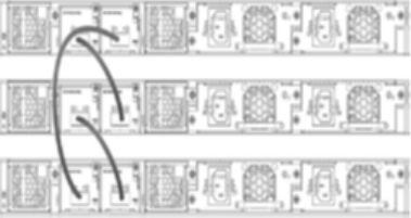
stacking supports both linear and ring stack topologies. Brocade highly recommends using the stack in
a ring topology for the best redundancy and the most resiliency. Unicast switching follows the shortest
path in a ring topology. When the ring is broken, the stack recalculates the forwarding path and
resumes the flow of traffic within a few seconds. In a ring topology, all stack members must have two
stacking ports; however, in a linear topology, both end units use only one stacking port, leaving the
other port available as a data port.
Consider the following factors when designing the stack bandwidth:
• Failure scenarios
• Number of uplinks and their capacity
• Per-unit edge capacity
• Oversubscription ratio
• Traffic direction assumptions (north-south or east-west)
Ring Stack
Stacking
18 Brocade “Effortless Network” Architecture for K-12 School Districts Brocade Validated Design
53-1004097-03

Stacking Support on Brocade Devices
Brocade Product Maximum Number
of Stack Units
Maximum Number
of Ports
Stacking Ports Stacking
Bandwidth
ICX 7250 12 576 x 1 GbE 4 Full Duplex SFP+
10 Gbps
80 Gbps
ICX 7450 12 576 x 1 GbE
or
48 x 10 GbE
2 Full Duplex
QSFP+ 40 Gbps (or)
10 Gbps using 4 X 10 GF
module
160 Gbps
ICX 7750 12 384 x 40 GbE
or
1152 x 10 GbE
6 full duplex
QSFP+ 40 Gbps
2,880 Gbps
Stack Configuration
1. Connect the devices using the stacking ports and stack cabling. Power on the unit.
2. Connect your console to the intended active controller. The unit through which you run secure setup
becomes the active controller by default.
3. Issue the stack enable command on the intended active controller.
SCH-ACCESS-101(config)# stack enable
Enable stacking. This unit actively participates in stacking
SCH-ACCESS-101(config)# exit
4. Enter the stack secure-setup command.
SCH-ACCESS-101# stack secure-setup
SCH-ACCESS-101# Discovering the stack topology...
Current Discovered Topology - RING
Available UPSTREAM units
Hop(s) Id Type Mac Address
1 2 ICX7450-24P cc4e.248a.7890
Available DOWNSTREAM units
Hop(s) Id Type Mac Address
1 2 ICX7450-24P cc4e.248a.7890
No new units found...
Selected Topology:
Active Id Type Mac Address
1 ICX7450-24P cc4e.248a.7200
Selected UPSTREAM units
Hop(s) Id Type Mac Address
1 2 ICX7450-24P cc4e.248a.7890
Selected DOWNSTREAM units
Hop(s) Id Type Mac Address
1 2 ICX7450-24P cc4e.248a.7890
Do you accept the topology (RING) (y/n)?: y
Layer 2 Network Design
Brocade “Effortless Network” Architecture for K-12 School Districts Brocade Validated Design 19
53-1004097-03
5. Enter y to accept the topology. You should see output similar to the following.
Selected Topology:
Active Id Type MAC Address
1 ICX7450-24P cc4e.248a.7200
Selected UPSTREAM units
Hop(s) Id Type MAC Address
1 2 ICX7450-24P cc4e.248a.7890
Selected DOWNSTREAM units
Hop(s) Id Type MAC Address
1 2 ICX7450-24P cc4e.248a.7890
Do you accept the unit ids (y/n)?: y
6. To accept the unit ID assignments, enter y.
7. If you accept the unit IDs, the stack is formed.
SCH-ACCESS-101# show stack
T=2d19h17m13.8: alone: standalone, D: dynamic cfg, S: static
ID Type Role Mac Address Pri State Comment
1 S ICX7450-24P active cc4e.248a.7200 0 local Ready
2 S ICX7450-24P standby cc4e.248a.7890 0 remote Ready
active standby
+---+ +---+
-2/3| 1 |2/1--2/1| 2 |2/3-
| +---+ +---+ |
| |
|------------------------|
Standby u2 - Learn other units for 28 sec, protocols may not be ready in 42 s.
Current stack management MAC is cc4e.248a.7200
Link Aggregation Groups
Link aggregation allows a network administrator to combine multiple Ethernet links into a larger logical
trunk known as a Link Aggregation Group (LAG). This results in traffic load sharing via redundant,
alternate paths for traffic if any of the segments fail. The switch treats the trunk as a single logical link.
All physical links must have the same speed and duplex setting and must connect to the same
adjacent switch including stackable switches. All interface parameters in a LAG must match, including
the port tag type (tagged/untagged), the configured port speed and duplex setting, and the QoS
priority.
Brocade switches support the use of static and dynamic LAGs on the same device, but can use only
one type of LAG for any given port. Brocade recommends using dynamic LAGs because they simplify
the configurations and help avoid possible administrative mistakes in link assignments.
Brocade recommends that the design have port members distributed across multiple stack units. If a
stack unit fails or is removed, the remaining ports from the LAG continue to forward traffic.
All configuration under the primary port applies to the LAG.
! Configure the LAG and assign member ports.
SCH-ACCESS-102(config)# lag dynSP102toAGG201_2 dynamic id 1012
SCH-ACCESS-102(config-lag-dynSP102toAGG201_2)# ports ethernet 1/1/13 ethernet 2/1/13
ethernet 3/1/13
SCH-ACCESS-102(config-lag-dynSP102toAGG201_2)# primary-port 1/1/13
SCH-ACCESS-102(config-lag-dynSP102toAGG201_2)# deploy
SCH-ACCESS-102(config)# lag staticSP102toAGG201 static id 1
SCH-ACCESS-102(config-lag-staticSP102toAGG201)# ports ethernet 1/2/1 ethernet 2/2/1
ethernet 3/2/1
SCH-ACCESS-102(config-lag-staticSP102toAGG201)# primary-port 1/2/1
SCH-ACCESS-102(config-lag-staticSP102toAGG201)# deploy
! Show command to verify the LAG.
SCH-ACCESS-102# show lag brief
Total number of LAGs: 2
Total number of deployed LAGs: 2
Link Aggregation Groups
20 Brocade “Effortless Network” Architecture for K-12 School Districts Brocade Validated Design
53-1004097-03
Total number of trunks created:2 (254 available)
LACP System Priority / ID: 1 / cc4e.24f1.1bb0
LACP Long timeout: 90, default: 90
LACP Short timeout: 3, default: 3
LAG Type Deploy Trunk Primary Port List
dynamicSP102todynamic Y 1022 1/1/13 e 1/1/13 e 2/1/13 e 3/1/13
staticSP102toAstatic Y 1 1/2/1 e 1/2/1 e 2/2/1 e 3/2/1
-------------------------------------------------------------------------------
SCH-ACCESS-102# show lag
Total number of LAGs: 2
Total number of deployed LAGs: 2
Total number of trunks created:2 (254 available)
LACP System Priority / ID: 1 / cc4e.24f1.1bb0
LACP Long timeout: 90, default: 90
LACP Short timeout: 3, default: 3
=== LAG "dynamicSP102toAGG201_2" ID 1022 (dynamic Deployed) ===
LAG Configuration:
Ports: e 1/1/13 e 2/1/13 e 3/1/13
Port Count: 3
Primary Port: 1/1/13
Trunk Type: hash-based
LACP Key: 21022
Deployment: HW Trunk ID 1
Port Link State Dupl Speed Trunk Tag Pvid Pri MAC Name
1/1/13 Up Forward Full 1G 1022 Yes N/A 0 cc4e.
2488.98dc
2/1/13 Up Forward Full 1G 1022 Yes N/A 0 cc4e.
2488.98dc
3/1/13 Up Forward Full 1G 1022 Yes N/A 0 cc4e.
2488.98dc
Port [Sys P] [Port P] [ Key ] [Act][Tio][Agg][Syn][Col][Dis][Def][Exp][Ope]
1/1/13 1 1 21022 Yes L Agg Syn Col Dis No No Ope
2/1/13 1 1 21022 Yes L Agg Syn Col Dis No No Ope
3/1/13 1 1 21022 Yes L Agg Syn Col Dis No No Ope
Partner Info and PDU Statistics
Port Partner Partner LACP LACP
System MAC Key Rx Count Tx Count
1/1/13 cc4e.24f1.1230 21022 4876 4927
2/1/13 cc4e.24f1.1230 21022 4860 4858
3/1/13 cc4e.24f1.1230 21022 4871 4910
=== LAG "staticSP102toAGG201" ID 1 (static Deployed) ===
LAG Configuration:
Ports: e 1/2/1 e 2/2/1 e 3/2/1
Port Count: 3
Primary Port: 1/2/1
Trunk Type: hash-based
Deployment: HW Trunk ID 2
Port Link State Dupl Speed Trunk Tag Pvid Pri MAC Name
1/2/1 Disable None None None 1 Yes N/A 0 cc4e.
2488.9901
2/2/1 Up Forward Full 10G 1 Yes N/A 0 cc4e.2488.9901
VLANs
A VLAN is a group of devices on one or more LANs that are configured to communicate as if they were
attached to the same wire, when in fact they are located on a number of different LAN segments.
Because VLANs are based on logical instead of physical connections, they are extremely flexible.
VLANs can span multiple switches through the Layer 2 network, and they can have more than one
VLAN on each switch. Trunking helps multiple VLANs on multiple switches communicate via a single
link.
VLAN classification helps to:
VLANs
Brocade “Effortless Network” Architecture for K-12 School Districts Brocade Validated Design 21
53-1004097-03
• Provide security
• Isolate broadcast domains
• Classify users in a meaningful way
• Use the network on a per-VLAN basis
The Brocade ICX product family supports various types of VLANs, and the K-12 architecture
recommends deploying a Layer 2 port-based VLAN: a set of physical ports that share a common,
exclusive Layer 2 broadcast domain. By default, all ports on a Brocade device are members of the
default VLAN. When you configure a port-based VLAN, the device automatically reassigns the port to
the configured VLAN from the default VLAN. 802.1Q tagging is an IEEE standard that allows a
networking device to add information to a Layer 2 packet in order to identify the VLAN membership of
the packet.
To classify various kinds of user traffic, Brocade recommends having four VLAN categories in a K-12
environment:
• Student
• Teacher
• Administration
• Guest
Management VLANs—By default, the management IP address that is configured on a Layer 2 switch
applies globally to all ports on the device. This can be restricted by using a specific port-based VLAN
configured as the designated management VLAN for the device. To establish a Telnet management
session with the device, a user must access the device through one of the ports in the designated
VLAN. Up to five default gateways can be configured for the designated VLAN, each with its
associated metric. This helps secure the accessibility of the device through specific predefined ports,
providing added security.
! Management VLAN configuration.
SCH-ACCESS-101(config)# vlan 10 by port
SCH-ACCESS-101(config-vlan-10)# untag ethernet 1/1/1 to 1/1/4
SCH-ACCESS-101(config-vlan-10)# management-vlan
SCH-ACCESS-101(config-vlan-10)# default-gateway 10.10.10.1 1
SCH-ACCESS-101(config-vlan-10)# default-gateway 10.20.20.1 2
! User VLAN configuration.
SCH-ACCESS-101(config)# vlan 1011
SCH-ACCESS-101(config-vlan-1011)# tagged ethernet 1/1/13 to 1/1/17 ethernet 1/2/2
ethernet 1/2/4 ethernet 2/2/2 ethernet 2/2/4
SCH-ACCESS-101(config-vlan-1011)# untagged ethernet 1/1/12
SCH-ACCESS-101# show vlan 1011
Total PORT-VLAN entries: 14
Maximum PORT-VLAN entries: 64
Legend: [Stk=Stack-Id, S=Slot]
PORT-VLAN 1011, Name data_vlan, Priority level0, Spanning tree On
Untagged Ports: (U1/M1) 12
Tagged Ports: (U1/M1) 13 14 15 16 17
Tagged Ports: (U1/M2) 2 4
Tagged Ports: (U2/M2) 2 4
Uplink Ports: None
DualMode Ports: None
Mac-Vlan Ports: None
Monitoring: Disabled
Spanning Tree Protocol
Spanning Tree Protocol (STP) eliminates Layer 2 loops in a network by selectively blocking some
ports and allowing other ports to forward traffic, based on global (bridge) and local (port) parameters
Spanning Tree Protocol
22 Brocade “Effortless Network” Architecture for K-12 School Districts Brocade Validated Design
53-1004097-03
that you can configure. STP-related features, such as Rapid Spanning Tree Protocol (RSTP), extend
the operation of standard STP, enabling users to fine-tune standard STP and avoid some of its
limitations. Because of the inherent benefits of using RSTP (IEEE 802.1W) over STP in terms of faster
convergence and improved network stability, all switches (Layer 2 domain) in the K-12 network must run
RSTP. Bridge priority should be defined while configuring RSTP under each VLAN because this enables
the administrator to determinately elect the root bridge in the network. The distribution switch in the
schools and the district office must be configured with a lower bridge priority and acts as the root bridge.
! Configure the Rapid Spanning Tree Protocol and assign bridge priority.
SCH-ACCESS-101(config)# vlan 1013 name wireless_vlan by port
SCH-ACCESS-101(config-vlan-1013)# tagged ethernet 1/2/2 ethernet 2/2/2 ethernet 2/2/4
SCH-ACCESS-101(config-vlan-1013)# spanning-tree 802-1w
SCH-ACCESS-101(config-vlan-1013)# spanning-tree 802-1w priority <0-65535>
! Configure the priority on the access switch as 65535; configure the priority on the
distribution switch as 0 in order to elect the distribution switch as the root bridge.
! Show command to verify the Spanning Tree Protocol information and link status.
SCH-ACCESS-101# show 802-1w vlan 1013
--- VLAN 1013 [ STP Instance owned by VLAN 1013 ] ---------------------------
Bridge IEEE 802.1W Parameters:
Bridge Bridge Bridge Bridge Force tx
Identifier MaxAge Hello FwdDly Version Hold
hex sec sec sec cnt
ffffcc4e248a7200 20 2 15 Default 3
RootBridge RootPath DesignatedBri- Root Max Fwd Hel
Identifier Cost dge Identifier Port Age Dly lo
hex hex sec sec sec
0000cc4e24f11230 2000 0000cc4e24f11230 1/2/2 20 15 2
Port IEEE 802.1W Parameters:
<--- Config Params --><-------------- Current state ----------------->
Port Pri PortPath P2P Edge Role State Designa- Designated
Num Cost Mac Port ted cost bridge
1/1/13 128 20000 F F ALTERNATE DISCARDING 0 0000cc4e24f11230
1/1/14 128 20000 F F ALTERNATE DISCARDING 0 0000cc4e24f11230
1/1/15 128 20000 F F ALTERNATE DISCARDING 0 0000cc4e24f11230
1/1/16 128 20000 F F ALTERNATE DISCARDING 0 0000cc4e24f11230
1/1/17 128 20000 F F ALTERNATE DISCARDING 0 0000cc4e24f11230
1/2/2 128 2000 F F ROOT FORWARDING 0 0000cc4e24f11230
2/2/2 128 2000 F F ROOT FORWARDING 0 0000cc4e24f11230
2/2/4 128 2000 F T DESIGNATED FORWARDING 2000 ffffcc4e248a7200
Uni-Directional Link Detection
Uni-Directional Link Detection (UDLD) monitors a link between two Brocade devices that are not directly
connected, and it brings the ports on both ends of the link down if the link goes down at any point
between the two devices. UDLD can also help to detect wiring mistakes when receive and transmit
fibers are not connected to the same port on the remote side. Ports that are enabled for UDLD
exchange proprietary health-check packets once every second (keepalive interval). If a port does not
receive a health-check packet for three times the keepalive (keepalive retries), the port is brought down.
Without UDLD, a link failure on a link that is not directly attached or any wiring mistakes are undetected
by the other device. This can result in traffic being forwarded on the failed link and can cause traffic
black-holing. In a K-12 network, UDLD should be enabled on all member ports in a LAG. When the link
fails, UDLD quickly detects the failure and brings down the port in the LAG.
! Configuration for UDLD on the access switch.
SCH-ACCESS-101(config)# link-keepalive ethernet 1/1/18 vlan 22
SCH-ACCESS-101(config)# link-keepalive interval 4
Uni-Directional Link Detection
Brocade “Effortless Network” Architecture for K-12 School Districts Brocade Validated Design 23
53-1004097-03
SCH-ACCESS-101(config)# link-keepalive retries 10
! Configuration for UDLD on the distribution switch.
SCH-DIST-201(config)# link-keepalive ethernet 1/1/19 ethernet 1/2/1 ethernet 2/1/19
ethernet 2/2/2 ethernet 3/1/19 ethernet 3/2/2 vlan 1021
SCH-DIST-201(config)# link-keepalive interval 4
SCH-DIST-201(config)# link-keepalive retries 10
SCH-ACCESS-102# show link-keepalive
Total link-keepalive enabled ports: 6
Keepalive Retries: 10 Keepalive Interval: 4 * 100 MilliSec.
Port Physical Link Logical Link State Link-vlan
2/2/1 up up FORWARDING 1021
3/2/1 up up FORWARDING 1021
1/2/1 up up FORWARDING 1021
2/1/13 up up FORWARDING 1021
3/1/13 up up FORWARDING 1021
1/1/13 up up FORWARDING 1021
BPDU Guard
BPDU guard is an enhancement to STP and removes a node that reflects Bridge Protocol Data Units
(BPDUs) back in the network. BPDU guard enforces the STP domain borders and keeps the active
topology predictable by not allowing any network devices behind a BPDU-guard-enabled port to
participate in STP. A connected device, such as an end station, need not initiate or participate in an
STP topology change. STP BPDU guard shuts down the port and puts it into an "errdisable" state if an
STP BPDU is received on the port and is used on interfaces that connect to end users.
This feature is critical for a K-12 network to secure the STP boundary because any misconfiguration or
accidently connected device participating in the STP topology can cause Layer 2 network instability.
BPDU guard is not supported on tagged ports. It can be configured on a tagged port, but the
configuration has no effect.
Default Behavior
STP BPDU guard is disabled by default. Enable it on individual interfaces.
Failure Condition
If an STP BPDU is received on a BPDU-guard-enabled port, a log message is generated for a BPDU
guard violation, and a CLI message is displayed to warn the network administrator of a severe invalid
configuration.
Recovery
To re-enable a port that is in the errdisable state, you must first disable the port and then re-enable it.
! Configure BPDU guard on the access ports connecting to the end-user workstations
or computers.
SCH-ACCESS-101(config)# interface ethernet 2/2/4
SCH-ACCESS-101(config-if-2/2/4)# stp-bpdu-guard
SCH-ACCESS-101# show 802-1w vlan 1013
--- VLAN 1013 [ STP Instance owned by VLAN 1013 ] ---------------------------
Bridge IEEE 802.1W Parameters:
BPDU Guard
24 Brocade “Effortless Network” Architecture for K-12 School Districts Brocade Validated Design
53-1004097-03
Bridge Bridge Bridge Bridge Force tx
Identifier MaxAge Hello FwdDly Version Hold
hex sec sec sec cnt
ffffcc4e248a7200 20 2 15 Default 3
RootBridge RootPath DesignatedBri- Root Max Fwd Hel
Identifier Cost dge Identifier Port Age Dly lo
hex hex sec sec sec
0000cc4e24f11230 2000 0000cc4e24f11230 1/2/2 20 15 2
Port IEEE 802.1W Parameters:
<--- Config Params --><-------------- Current state ----------------->
Port Pri PortPath P2P Edge Role State Designa- Designated
Num Cost Mac Port ted cost bridge
1/1/13 128 20000 F F ALTERNATE DISCARDING 0 0000cc4e24f11230
1/1/14 128 20000 F F ALTERNATE DISCARDING 0 0000cc4e24f11230
1/1/15 128 20000 F F ALTERNATE DISCARDING 0 0000cc4e24f11230
1/1/16 128 20000 F F ALTERNATE DISCARDING 0 0000cc4e24f11230
1/1/17 128 20000 F F ALTERNATE DISCARDING 0 0000cc4e24f11230
1/2/2 128 2000 F F ROOT FORWARDING 0 0000cc4e24f11230
2/2/2 128 2000 F F ROOT FORWARDING 0 0000cc4e24f11230
2/2/4 128 2000 F T DESIGNATED FORWARDING 2000 ffffcc4e248a7200
Edge Ports
In an 802.1W topology, edge ports are ports of a bridge that connect to workstations or computers.
Edge ports do not register any incoming BPDU activities. Edge ports assume designated port roles.
Port flapping does not cause any topology change events on edge ports because 802.1W does not
consider edge ports in spanning-tree calculations. However, if any incoming RSTP BPDU is received
from a previously configured edge port, 802.1W automatically makes the port a non-edge port. This is
extremely important to ensure a loop-free Layer 2 operation because a non-edge port is part of the
active RSTP topology. The 802.1W protocol can auto-detect an edge port and a non-edge port. A
network administrator can configure a port to be an edge port using the CLI.
In a K-12 network, all the end-user-facing access ports can be configured as edge ports. If a port is
configured as an edge port, it goes into a forwarding state instantly (within 100 msec). When the link to
a port comes up and 802.1W detects that the port is an edge port, that port instantly goes into a
forwarding state.
• Brocade strongly recommends enabling BPDU guard on edge ports in order to control RSTP
boundaries and also to secure the network from rogue switch attachments at the edge.
• Edge ports are explicitly configured to take advantage of the edge port feature, instead of allowing
the protocol to auto-detect them.
! Configure the edge port feature on the access ports connecting to the end-user
workstations or computers.
SCH-ACCESS-101(config)# interface ethernet 2/2/4
SCH-ACCESS-101(config-if-2/2/4)# spanning-tree 802-1w admin-edge-port
Root Guard
In a K-12 network, for easy management and to troubleshoot any network issues, it is important to have
the spanning-tree topology determinately configured so that the logical topology definition is clearly
understood. In a typical spanning-tree domain, any switch can be elected as the root bridge in a
network as long as it has the lowest bridge ID. The network administrator cannot enforce the position of
the root bridge. Root guard can be used to predetermine a root bridge location and prevent rogue or
unwanted switches from becoming the root bridge. When root guard is enabled on a port, it keeps the
port in a designated role. If the port receives a superior STP Bridge Protocol Data Unit (BPDU), it puts
Edge Ports
Brocade “Effortless Network” Architecture for K-12 School Districts Brocade Validated Design 25
53-1004097-03
the port into a ROOT-INCONSISTANT state and triggers a log message and an SNMP trap. The
ROOT-INCONSISTANT state is equivalent to the BLOCKING state in 802.1D and to the DISCARDING
state in 802.1W. Once the port stops receiving superior BPDUs, root guard automatically sets the port
back to learning and eventually to a forwarding state through the spanning-tree algorithm.
Root guard must be configured on all ports where the root bridge should not appear. This establishes
a protective network perimeter around the core bridged network, cutting it off from the user network.
In a K-12 network, defining the root guard enables the network administrator to provide additional
security around the root bridge election. The distribution switch in the schools and district office must
be configured with a lower bridge priority and will act as the root bridge. Root guard must be
configured on all ports that connect to the access switches. For access switches that connect over a
LAG, the root guard configuration should go under the primary port of the LAG.
Error Condition
If a port receives a superior STP BPDU, it puts the port into a ROOT-INCONSISTANT state and
triggers a log message and an SNMP trap.
Recovery
Once the port stops receiving superior BPDUs, root guard automatically sets the port back to learning
and eventually to a forwarding state through the spanning-tree algorithm.
! Configure root guard on the ports connecting to the access switches.
SCH-DIST-201(config)# interface ethernet 2/2/3
SCH-DIST-201(config-if-2/2/3)# spanning-tree root-protect
SCH-DIST-201# show span root-protect
Root Protection Enabled on:
Ports: (U1/M1) 13 14 15 19
Ports: (U1/M2) 1 2
Ports: (U2/M1) 13 19 20
Ports: (U2/M2) 1 2 3
Ports: (U3/M1) 13 19 20
Ports: (U3/M2) 1 2 3
Power over Ethernet
Brocade Power over Ethernet (PoE) devices are compliant with the standards described in the IEEE
802.3af and 802.3at specifications for delivering inline power. PoE technology eliminates the need for
an electrical outlet and dedicated UPS near IP-powered devices. With power-sourcing equipment such
as a Brocade ICX PoE device, power is consolidated and centralized in wiring closets, improving the
reliability and resilience of the network.
Brocade devices supports Endspan with Alternative A, wherein power is supplied through the Ethernet
ports on a power-sourcing device (specifically, power is carried over the live wire pairs that deliver
data) or Alternative B, the two spare pairs.
• An auto-discovery mechanism detects whether the device requires power and how much power is
needed (802.3af or 802.3at).
• 802.3af (PoE) provides 15.4 watts (44 to 50 volts); 802.3at 2008 (PoE+) provides 30 watts (52 to 55
volts); Power over HDBaseT (PoH) provides 95 watts (48 volts).
Power over Ethernet
26 Brocade “Effortless Network” Architecture for K-12 School Districts Brocade Validated Design
53-1004097-03
• The 802.3af and 802.3at standards support PoE and PoE+ on 10/100/1000-Mbps Ethernet ports that
operate over standard Category 5 unshielded twisted pair (UTP) cable.
• Voice over IP (VoIP) phones, wireless LAN access points, and IP surveillance cameras are the
commonly deployed devices in a K-12 school environment; the access switches can provide the PoE
for these devices.
! Configure PoE on the ports connecting to VoIP phones, wireless access point, etc.
DO-ACCESS-401(config)# interface ethernet 1/1/1
DO-ACCESS-401(config-if-e1000-1/1/1)# inline power
DO-ACCESS-401(config-if-e1000-1/1/1)# interface ethernet 1/1/2
DO-ACCESS-401(config-if-e1000-1/1/2)# inline power
DO-ACCESS-401# show inline power
Power Capacity: Total is 748000 mWatts. Current Free is 735400 mWatts.
Power Allocations: Requests Honored 9 times
Port Admin Oper ---Power(mWatts)--- PD Type PD Class Pri Fault/
State State Consumed Allocated Error
--------------------------------------------------------------------------
1/1/1 On On 3500 6300 802.3af Class 2 3 n/a
1/1/2 On On 3600 6300 802.3af Class 2 3 n/a
--------------------------------------------------------------------------
Total 7100 12600
Layer 2 Network Design
Brocade “Effortless Network” Architecture for K-12 School Districts Brocade Validated Design 27
53-1004097-03
Power over Ethernet
28 Brocade “Effortless Network” Architecture for K-12 School Districts Brocade Validated Design
53-1004097-03

Layer 3 Network Design
● Unicast Routing Design...................................................................................................29
● Multicast Routing Design................................................................................................ 36
Unicast Routing Design
Layer 3 routing is a critical component of the K-12 network. Layer 3 routing provides network
connectivity between schools and the district office through the Metropolitan Area Network and Internet
connectivity. The primary design considerations for the Layer 3 routing design in a K-12 network follow:
• Resilient, standards-based, and secure routing
• High availability
• Fast convergence for voice and video applications
• Traffic load balancing
• IPv6-ready transport
• Simplified design and easy management and troubleshooting
On Brocade ICX product family switches, by default, none of the unicast routing protocols are enabled.
For each protocol, global- and interface-level configurations are required to bring it to an operational
status. Brocade ICX product family switches supports the following routing protocols for unicast v4 and
v6 forwarding: OSPF, OSPFv3, BGPv4+, and RIP to support Layer 3 forwarding in addition to static
routing.
OSPF/OSPFv3 is a robust Interior Gateway Protocol (IGP) for a campus type of network. OSPF is a
link-state routing protocol that supports both IPv4 and IPv6 transport. For a K-12 network, Brocade
recommends OSPF/OSPFv3 for the routing between schools and the district office. For the external
connectivity from the district office to the ISP, Brocade recommends Border Gateway Protocol
(BGPv4+). Both OSPF and BGP protocols are widely deployed in various types of networks, such as
those for enterprises, service providers, and educational institutions, and they are considered to be
matured and Next-Gen ready.
OSPF Routing Design
OSPF is configured as a single OSPF area across the school campus and district office. In a school
district environment, the expected route table size is a few hundred routes; this design supports efficient
forwarding with a single area. OSPF supports IPv4 and IPv6 routing; however, a separate OSPF
process must be configured for IPv4 and IPv6. IPv4 is enabled using an OSPFv2 process, and IPv6 is
enabled using an OSPFv3 process.
OSPF is enabled on the distribution switches in the schools and district office. For redundancy and load
balancing across the links, Brocade recommends dual links from the distribution switch to the MAN.
Brocade recommends the following other key feature sets for the K-12 network:
• High-availability features such as Non-Stop Forwarding for OSPFv2 (IPv4) and Graceful Restart for
OSPFv3 (IPv6)
• Security features such as MD5 for OSPFv2 and IPsec for OSPFv3
Most external connectivity links used in a K-12 network are point-to-point Ethernet links that connect the
school or district Office to the MAN. By default, in an OSPF network, an Ethernet link acts as a multi-
Brocade “Effortless Network” Architecture for K-12 School Districts Brocade Validated Design 29
53-1004097-03
access network that elects a designated router (DR) and a backup designated router (BDR) to form
the OSPF adjacency. In an OSPF point-to-point network, where a direct Layer 3 connection exists
between a single pair of OSPF routers, there is no need for designated and backup designated
routers. The OSPF point-to-point network establishes adjacency and converges faster. The OSPF
network type must be configured as point-to-point for all external connectivity links facing the MAN.
The K-12 network administrator must ensure that the MAN-side routers are also configured as OSPF
network type point-to-point. For optimum performance, Brocade recommends using the default cost
value and timer settings for OSPFv2 and OSPFv3.
By default, IP load sharing is enabled on all Brocade ICX switches on the forwarding. OSPF load
sharing is enabled by default when IP load sharing is enabled. The default is four equal-cost paths, but
the user can specify from two to eight paths.
SNMP traps for OSPF must be enabled for routing management.
OSPFv2 (IPv4) Configuration Details
Enable an OSPFv2 (IPv4) process on the distribution switches in the schools and district office.
! Configure the OSPF process and assign the area as Area 0. Enable non-stop routing.
SCH-DIST-201(config)# router ospf
SCH-DIST-201(config-ospf-router)# area 0
SCH-DIST-201(config-ospf-router)# nonstop-routing
SCH-DIST-201(config-ospf-router)# log adjacency
A VE interface is a logical interface that comprises physical ports and port-channel interfaces. A VE
interface is the Layer 3 counterpart of a VLAN interface. In order to create a VE interface, the router-
interface command is issued under the VLAN configuration; this configuration defines the VE interface
number as well, and the configured VLAN and VE interface are coupled together. The port
membership for VE is derived from the corresponding VLAN. Deletion of the VLAN deletes the VE
interface, although the converse is not true; that is, deletion of the VE interface only removes the
configuration from the VE interface.
By virtue of being a Layer 3 only interface, the VE interface contains only configurations that pertain to
Layer 3 (such as IP addresses, IP protocols). All Layer 2 configurations are available under the VLAN
interfaces.
! To create a VE interface under the VLAN, configure the following:
SCH-DIST-201(config)# interface vlan 1011
SCH-DIST-201(config-vlan-1011)# router-interface ve 1011
SCH-DIST-201(config-vlan-1011)# exit
SCH-DIST-201(config)# interface ve 1011
SCH-DIST-201(config-vif-1011)# ip address 10.1.1.1/24
Enable OSPFv2 on interfaces with MD5 authentication on the distribution switches in the schools and
district office.
! Under the interface participating in the OSPF process (connecting to the MAN),
configure the following.
SCH-DIST-201(config)# interface ve 3922
SCH-DIST-201(config-vif-3922)# ip ospf network point-to-point
SCH-DIST-201(config-vif-3922)# ip ospf md5-authentication key-id 1 key brocade
! Under all interfaces facing the access side, configure the OSPF interface as
passive.
SCH-DIST-201(config)# interface ve 1011
SCH-DIST-201(config-vif-1011)# ip ospf passive
Enable OSPF SNMP traps.
! Enable SNMP traps for OSPF on all OSPF-enabled routers.
DO-DIST-301(config)# snmp-server enable traps ospf
! To make ICX switches send traps to the receiver from the same source IP address
irrespective of the outgoing interface.
Layer 3 Network Design
30 Brocade “Effortless Network” Architecture for K-12 School Districts Brocade Validated Design
53-1004097-03
DO-DIST-301(config)# snmp-server trap-source loopback 1
OSPFv3 (IPv6) Configuration Details
Enable an OSPFv3 (IPv6) process on the distribution switches in the schools and district office.
! Configure an OSPFv3 process and assign the area as Area 0. Enable non-stop routing.
SCH-DIST-201(config)# ipv6 router ospf
SCH-DIST-201(config-ospf6-router)# area 0
SCH-DIST-201(config-ospf6-router)# nonstop-routing
Enable OSPFv3 on interfaces with IPsec authentication on the distribution switches in the schools and
district office.
! Under the interface participating in the OSPFv3 process (connecting to MAN),
configure the following:
DO-DIST-301(config)# interface loopback 1
DO-DIST-301(config-lbif-1)# ipv6 ospf area 0
DO-DIST-301(config-lbif-1)# end
DO-DIST-301(config)# interface ve 3931
DO-DIST-301(config-vif-3931)# ipv6 ospf area 0
DO-DIST-301(config-vif-3931)# ipv6 ospf authentication ipsec spi 501 esp sha1
1234567890abcdef1234567890abcdef12345678
DO-DIST-301(config-vif-3931)# ipv6 ospf network point-to-point
! Under all interfaces facing the access side, configure the following:
DO-DIST-301(config)# interface ve 4011
DO-DIST-301(config-vif-4011)# ipv6 ospf passive
BGP Internet-Connectivity Design
The BGP design provides Internet connectivity for school campuses and the district office with node- or
link-failure protection. The Internet infrastructure is considered a critical part of the school campus
network environment, so this validated design has been influenced by those availability factors. This
design provides redundant and reliable connectivity with minimum protocol deployment for easy
network administration.
BGP4 is the standard Exterior Gateway Protocol (EGP) used on the Internet to route traffic between
autonomous systems and to maintain loop-free routing. BGP4 is used in the K-12 network to connect
Internet-connectivity routers to the Internet Service Provider (ISP). BGP is designed to support multiple
address family networks. With a single BGP protocol, network reachability can be established for
multiple address families, such as networks based on IPv4, IPv6, multicast, VPNv4, and VPNv6.
In a K-12 network, both IPv4 and IPv6 address families are configured under BGP. External BGP
(eBGP) is deployed between the ISP router and the MLXe Internet-connectivity routers with IPv4 and
IPv6 address families enabled. Assumptions include that the default route is received from the ISP on
both eBGP neighbors. MLXe Internet-connectivity routers install the IPv4 and IPv6 default routes in the
route table.
BGP Internet-Connectivity Design
Brocade “Effortless Network” Architecture for K-12 School Districts Brocade Validated Design 31
53-1004097-03
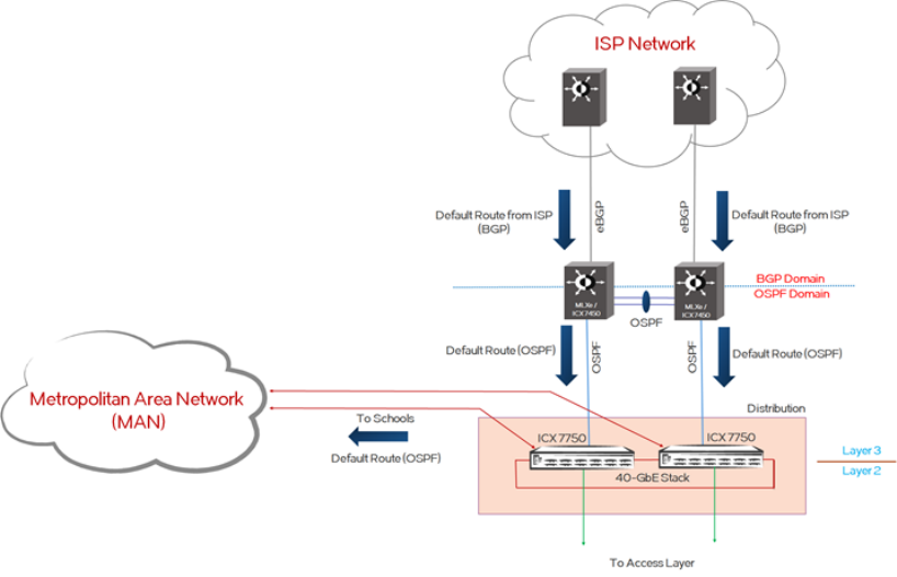
FIGURE 4 BGP Internet-Connectivity Design
OSPF and OSPFv3 are configured between the MLXe Internet-connectivity routers and the district
office distribution switch (ICX 7750) in OSPF Area 0. MD5 for OSPF and IPsec for OSPFv3 are
configured for security purposes. Non-stop routing (NSR) for OSPF and OSPFv3 are deployed on the
MLXe router and the distribution switch. OSPF is configured between the MLXe Internet-connectivity
routers.
The default-information-originate command is configured on both MLXe Internet-connectivity
routers so that OSPF/OSPFv3 advertises the default route only after the MLXe routers receive a
default route from the ISP. The district distribution switch receives the default route from both MLXe
routers; the default route has dual exit paths for Internet traffic with load balancing. The IPv4/IPv6
default route that is received by the distribution switch is advertised to the rest of the school network
via OSPF/OSPFv3.
The school campus/district office Internet traffic uses the default route, and the rest of the school traffic
depends on local-route-table-specific entries. This design reduces the routing load or churn from
external sources while not excluding efficient external network reachability for end users.
Consider the following regarding BGP timers in the K-12 BGP design:
•Timers—Brocade recommends using the default timers for BGP deployment on MLXe routers. The
default keepalive timer is 60 seconds. The default hold timer is 180 seconds. After the hold timer
expires, the BGP session to the neighbor is closed.
•BGP Graceful Restart—The Graceful Restart feature provides BGP high availability for traffic
forwarding during a system restart, switch-over, or hitless OS upgrade. BGP4 restart must be
enabled on all connected neighbors. When a restart begins, neighbors mark all routes from the
restarting neighbor as stale, but they continue to use the routes for the length of time specified by
the restart timer. After the device is restarted, it begins to receive routing updates from the
neighbors. After receiving an end-of-route indication, BGP calculates routes to be installed and
replaces any stale routes in the route table. If the neighbor does not come back up within the time
configured by the purge timer, the stale routes are removed.
Brocade recommends using the default Graceful Restart timers, as follows:
Layer 3 Network Design
32 Brocade “Effortless Network” Architecture for K-12 School Districts Brocade Validated Design
53-1004097-03
• Restart Timer: 120 seconds
• Stale Route Timer: 360 seconds
• Purge Timer: 600 seconds
The Internet-connectivity routers can be Brocade MLXe routers or the Brocade ICX 7450 with routing
software. The following sections provides the configuration template for the Brocade MLXe and the
Brocade ICX 7450.
If the Brocade MLXe is used as the Internet-connectivity router, the following configuration template can
be used for OSPF and BGP.
OSPF Configuration for Brocade MLXe Internet-Connectivity Routers
Enable an OSPFv2 process on the MLXe routers in the district office.
! Configure an OSPF process for IPv4.
MLXe-WAN-1(config)# router ospf
MLXe-WAN-1(config-ospf-router)# area 0
MLXe-WAN-1(config-ospf-router)# nonstop-routing
MLXe-WAN-1(config-ospf-router)# log adjacency
! To base the conditional default-route advertisement on the default route received
from the ISP router, issue the following command.
MLXe-WAN-1(config-ospf-router)# default-information-originate
Enable OSPFv2 on interfaces with MD5 authentication on the MLXe routers in the district office.
! Configure OSPF between the MLXe routers and the distribution switch.
MLXe-WAN-1(config)# interface ethernet 1/3
MLXe-WAN-1(config-if-e10000-1/3)# ip ospf area 0
MLXe-WAN-1(config-if-e10000-1/3)# ip ospf md5-authentication key-id 1 key
2 $MlVzZCFAbg==
MLXe-WAN-1(config-if-e10000-1/3)# ip ospf network point-to-point
Enable an OSPFv3 (IPv6) process on the MLXe routers in the district office.
! Configure an OSPF process for IPv6.
MLXe-WAN-1(config)# ipv6 router ospf
MLXe-WAN-1(config-ospf6-router)# area 0
MLXe-WAN-1(config-ospf6-router)# nonstop-routing
! To base the conditional IPv6 default-route advertisement on the default route
received from the ISP router, issue the following command.
MLXe-WAN-1(config-ospf6-router)# default-information-originate
Enable OSPFv3 on interfaces with IPsec authentication on the MLXe routers in the district office.
MLXe-WAN-1(config-if-e10000-1/17)# ipv6 ospf area 0
MLXe-WAN-1(config-if-e10000-1/17)# ipv6 ospf authentication ipsec spi 500 esp sha1
encrypt b64 $ITJkQG5HWnw4M09tWVd7UVF7V1ltTzM4fFpHbkBkMiFafDgzT21ZVw==
MLXe-WAN-1(config-if-e10000-1/17)# ipv6 ospf network point-to-point
Enable BGP4+ on the MLXe routers in the district office.
! BGP configuration on MLXe routers.
MLXe-WAN-1(config)# router bgp
MLXe-WAN-1(config-bgp)# local-as 200
MLXe-WAN-1(config-bgp)# graceful-restart
MLXe-WAN-1(config-bgp)# neighbor 172.28.85.2 remote-as 5050
MLXe-WAN-1(config-bgp)# neighbor 172.28.85.2 update-source ethernet 1/18
MLXe-WAN-1(config-bgp)# neighbor fdd7:b215:19cb:4552:172:28:85:2 remote-as 5050
MLXe-WAN-1(config-bgp)# address-family ipv6 unicast
MLXe-WAN-1(config-bgp-ipv6u)# graceful-restart
! Verify the BGP neighbor between the ISP and the MLXe routers.
MLXe-WAN-1# show ip bgp summary
BGP4 Summary
Router ID: 192.168.6.11 Local AS Number: 200
Layer 3 Network Design
Brocade “Effortless Network” Architecture for K-12 School Districts Brocade Validated Design 33
53-1004097-03
Confederation Identifier: not configured
Confederation Peers:
Maximum Number of IP ECMP Paths Supported for Load Sharing: 1
Number of Neighbors Configured: 1, UP: 1
Number of Routes Installed: 21, Uses 1806 bytes
Number of Routes Advertising to All Neighbors: 0 (0 entries)
Number of Attribute Entries Installed: 1, Uses 90 bytes
'+': Data in InQueue '>': Data in OutQueue '-': Clearing
'*': Update Policy 'c': Group change 'p': Group change Pending
'r': Restarting 's': Stale '^': Up before Restart '<': EOR waiting
Neighbor Address AS# State Time Rt:Accepted Filtered Sent
ToSend
172.28.85.2 5050 ESTAB 21h53m31s 21 0 0
0
! Verify the default route learned from the ISP on the MLXe routers.
MLXe-WAN-1# show ip route 0.0.0.0/0
Type Codes - B:BGP D:Connected I:ISIS O:OSPF R:RIP S:Static; Cost - Dist/Metric
BGP Codes - i:iBGP e:eBGP
ISIS Codes - L1:Level-1 L2:Level-2
OSPF Codes - i:Inter Area 1:External Type 1 2:External Type 2 s:Sham Link
STATIC Codes - d:DHCPv6
Destination Gateway Port Cost Type Uptime
src-vrf
1 0.0.0.0/0 172.28.85.2 eth 1/18 20/0 Be 21h46m –
! Verify OSPF neighbor adjacency between the distribution switch and the MLXe
routers.
DO-DIST-301# show ip ospf neighbor
Number of Neighbors is 4, in FULL state 4
Port Address Pri State Neigh Address Neigh ID Ev Opt
Cnt
1/1/37 172.28.76.3 1 FULL/OTHER 172.28.76.2 192.168.5.11 4 2 0
2/1/37 172.28.75.3 1 FULL/OTHER 172.28.75.2 192.168.6.11 4 2 0
DO-DIST-301# show ipv6 ospf neighbor
Total number of neighbors in all states: 4
Number of neighbors in state Init : 1
Number of neighbors in state Full : 3
RouterID Pri State DR BDR Interface [State]
192.168.5.11 1 Full 0.0.0.0 0.0.0.0 e 1/1/37 [P2P]
192.168.6.11 1 Full 0.0.0.0 0.0.0.0 e 2/1/37 [P2P]
! Verify the two default routes learned from the MLXe routers on the distribution
switch in the district office.
DO-DIST-301# show ip route 0.0.0.0/0
Type Codes - B:BGP D:Connected O:OSPF R:RIP S:Static; Cost - Dist/Metric
BGP Codes - i:iBGP e:eBGP
OSPF Codes - i:Inter Area 1:External Type 1 2:External Type 2
Destination Gateway Port Cost Type Uptime
1 0.0.0.0/0 172.28.75.2 e 2/1/37 110/10 O2 53m46s
0.0.0.0/0 172.28.76.2 e 1/1/37 110/10 O2 53m46s
! Verify the two default routes learned from the district office and installed on
the distribution switch in the school.
SCH-DIST-201# show ip route 0.0.0.0/0
Type Codes - B:BGP D:Connected O:OSPF R:RIP S:Static; Cost - Dist/Metric
BGP Codes - i:iBGP e:eBGP
OSPF Codes - i:Inter Area 1:External Type 1 2:External Type 2
Destination Gateway Port Cost Type Uptime
1 0.0.0.0/0 172.25.2.2 ve 3922 110/10 O2 14h31m
0.0.0.0/0 172.25.5.2 ve 3921 110/10 O2 14h31m
If the Brocade ICX 7450 is used as the Internet-connectivity router, the following configuration
template can be used for OSPF and BGP.
Layer 3 Network Design
34 Brocade “Effortless Network” Architecture for K-12 School Districts Brocade Validated Design
53-1004097-03
OSPF Configuration for Brocade ICX 7450 Internet-Connectivity Routers
Enable an OSPFv2 process on the Brocade ICX 7450 routers in the district office.
! Configure an OSPF process for IPv4.
DO_WAN_601(config)# router ospf
DO_WAN_601(config-ospf-router)# area 0
DO_WAN_601(config-ospf-router)# nonstop-routing
DO_WAN_601(config-ospf-router)# log adjacency
! To base the conditional default-route advertisement on the default route received
from the ISP router, issue the following command.
DO_WAN_601(config-ospf-router)# default-information-originate
Enable OSPFv2 on interfaces with MD5 authentication on the ICX 7450 routers in the district office.
! Configure OSPF between the ICX 7750 routers and the distribution switch.
DO_WAN_601(config)# interface ethernet 1/2/1
DO_WAN_601(config-if-e10000-1/2/1)# ip ospf area 0
DO_WAN_601(config-if-e10000-1/2/1)# ip ospf md5-authentication key-id 1 key brocade
DO_WAN_601(config-if-e10000-1/2/1)# ip ospf network point-to-point
Enable an OSPFv3 (IPv6) process on the ICX 7450 routers in the district office.
! Configure an OSPF process for IPv6.
DO_WAN_601(config)# ipv6 router ospf
DO_WAN_601(config-ospf6-router)# area 0
DO_WAN_601(config-ospf6-router)# nonstop-routing
! To base the conditional IPv6 default-route advertisement on the default route
received from the ISP router, issue the following command.
DO_WAN_601(config-ospf6-router)# default-information-originate
Enable OSPFv3 on interfaces with IPsec authentication on the ICX 7450 routers in the district office.
DO_WAN_601(config-if-e10000-1/17)# ipv6 ospf area 0
DO_WAN_601(config-if-e10000-1/17)# ipv6 ospf authentication ipsec spi 501 esp sha1
1234567890abcdef1234567890abcdef12345678
DO_WAN_601(config-if-e10000-1/17)# ipv6 ospf network point-to-point
! BGP configuration on ICX 7450 routers.
DO_WAN_601(config)# router bgp
DO_WAN_601(config-bgp)# local-as 200
DO_WAN_601(config-bgp)# graceful-restart
DO_WAN_601(config-bgp)# neighbor 172.28.85.2 remote-as 5050
DO_WAN_601(config-bgp)# neighbor fdd7:b215:19cb:4552:172:28:85:2 remote-as 5050
DO_WAN_601(config-bgp)# address-family ipv6 unicast
DO_WAN_601(config-bgp-ipv6u)# graceful-restart
! Verify the BGP neighbor between the ISP and the ICX 7450 routers.
DO_WAN_601# show ip bgp summary
BGP4 Summary
Router ID: 10.60.1.1 Local AS Number: 200
Confederation Identifier: not configured
Confederation Peers:
Maximum Number of IP ECMP Paths Supported for Load Sharing: 1
Number of Neighbors Configured: 1, UP: 1
Number of Routes Installed: 201, Uses 17286 bytes
Number of Routes Advertising to All Neighbors: 0 (0 entries)
Number of Attribute Entries Installed: 1, Uses 90 bytes
Neighbor Address AS# State Time Rt:Accepted Filtered Sent
ToSend
172.28.85.2 5050 ESTAB 3h36m 3s 201 0 0 0
! Verify the default route learned from the ISP on ICX 7750 routers.
DO_WAN_601# show ip route 0.0.0.0/0
Type Codes - B:BGP D:Connected O:OSPF R:RIP S:Static; Cost - Dist/Metric
BGP Codes - i:iBGP e:eBGP
OSPF Codes - i:Inter Area 1:External Type 1 2:External Type 2
Layer 3 Network Design
Brocade “Effortless Network” Architecture for K-12 School Districts Brocade Validated Design 35
53-1004097-03
Destination Gateway Port Cost Type Uptime
1 0.0.0.0/0 172.28.85.2 e 1/2/2 20/0 Be 3h3m
! Verify OSPF neighbor adjacency between the distribution switch and the ICX 7750
routers.
DO-DIST-301# show ip ospf neighbor
Number of Neighbors is 4, in FULL state 4
Port Address Pri State Neigh Address Neigh ID Ev Opt
Cnt
1/1/1 172.28.76.3 1 FULL/OTHER 172.28.76.2 10.60.2.2 5 2 0
2/1/1 172.28.75.3 1 FULL/OTHER 172.28.75.2 10.60.1.1 5 2 0
DO-DIST-301# show ipv6 ospf neighbor
Total number of neighbors in all states: 4
Number of neighbors in state Full : 4
RouterID Pri State DR BDR Interface [State]
10.60.2.2 1 Full 0.0.0.0 0.0.0.0 e 1/1/1 [P2P]
10.60.1.1 1 Full 0.0.0.0 0.0.0.0 e 2/1/1 [P2P]
! Verify the two default routes learned from the ICX 7750 distribution switch in the
district office.
DO-DIST-301# show ip route 0.0.0.0/0
Type Codes - B:BGP D:Connected O:OSPF R:RIP S:Static; Cost - Dist/Metric
BGP Codes - i:iBGP e:eBGP
OSPF Codes - i:Inter Area 1:External Type 1 2:External Type 2
Destination Gateway Port Cost Type Uptime
1 0.0.0.0/0 172.28.75.2 e 2/1/1 110/10 O2 3h1m
0.0.0.0/0 172.28.76.2 e 1/1/1 110/10 O2 3h1m
! Verify the two default routes learned from the district office and installed on
the
distribution switch in the school.
SCH-DIST-201# show ip route 0.0.0.0/0
Type Codes - B:BGP D:Connected O:OSPF R:RIP S:Static; Cost - Dist/Metric
BGP Codes - i:iBGP e:eBGP
OSPF Codes - i:Inter Area 1:External Type 1 2:External Type 2
Destination Gateway Port Cost Type Uptime
1 0.0.0.0/0 172.25.2.2 ve 3922 110/10 O2 3h6m
0.0.0.0/0 172.25.5.2 ve 3921 110/10 O2 3h6m
Multicast Routing Design
On Brocade ICX family products, the multicast implementation helps efficiently forward IP packets that
are destined for two or more receivers, which in turn helps to save network bandwidth and data
replication at the source. To support multicast forwarding, various protocols must be considered to
deploy. The prime multicast applications in a school environment include audio/video conferencing,
video streaming, IPTV, etc. The Protocol Independent Multicast (PIM), Internet Group Management
Protocol (IGMP), and Multicast Listener Discovery (MLD) protocols are required to forward multicast
packets.
The multicast design recommendation for the K-12 network includes IPv4 and IPv6 multicast
forwarding. PIM Sparse Mode (PIM-SM) is used in the K-12 network for multicast forwarding.
IGMP/MLD snooping is enabled on all access layer switches. The Brocade ICX switch product family
supports the efficient and stable multicast routing protocol PIM-SM (IPv4 and IPv6).
PIM-SM
The Protocol Independent Multicast (PIM) protocol is a broadcast and pruning multicast protocol that
delivers IP multicast datagrams. This protocol employs a reverse path lookup check and pruning to
Multicast Routing Design
36 Brocade “Effortless Network” Architecture for K-12 School Districts Brocade Validated Design
53-1004097-03
allow source-specific multicast delivery trees to reach all group members. PIM builds a different
multicast tree for each source and destination host group.
The rendezvous point (RP) is the meeting point for PIM Sparse sources and receivers. A PIM Sparse
domain can have multiple RPs, but each PIM Sparse multicast group address can have only one active
RP. PIM Sparse switches learn the addresses of RPs. A Brocade ICX family switch uses the RP to
forward only the first packet from a group source to the group’s receivers. After the first packet, the
switch calculates the shortest path between the receiver and source (the Shortest Path Tree, or SPT)
and uses the SPT for subsequent packets from the source to the receiver. Brocade ICX product
switches calculate a separate SPT for each source-receiver pair.
In a K-12 network, the distribution switch in the district office is configured as the RP for the entire
school network. The RP is statically configured on all PIM-enabled routers. When the source is
activated in a PIM RP domain, the PIM First Hop (FH) registers the source to the PIM RP. In a school
environment, the static RP configuration is simple and easy to manage as compared to dynamic
methods in a multicast network.
Brocade ICX product family switches also support IPv6 Protocol Independent Multicast (PIM) Sparse.
IPv6 PIM Sparse provides multicasting that is especially suitable for widely distributed multicast
environments. In an IPv6 PIM Sparse network, an IPv6 PIM Sparse router that is connected to a host
that wants to receive information for a multicast group must explicitly send a join request on behalf of
the receiver (host).
IGMP/MLD Snooping
When Brocade ICX product family switches process a multicast packet, by default, they broadcast the
packet to all ports except the incoming port of a VLAN. This behavior causes some clients to receive
unwanted traffic. IGMP snooping provides multicast containment by forwarding traffic to only the ports
that have IGMP receivers for a specific multicast group (destination address). A switch maintains the
IGMP group membership information by processing the IGMP reports and leave messages, so traffic
can be forwarded to ports receiving IGMP reports. MLD snooping provides multicast containment by
forwarding traffic to only those clients that have MLD receivers for a specific multicast group (destination
address) in an IPv6 network. The switch maintains the MLD group membership information by
processing MLD reports and generating messages so traffic can be forwarded to ports receiving MLD
reports. This is analogous to IGMP snooping. IGMP and MLD snooping must be enabled on all access
switches in the school and district office.
Multicast Configuration Details
Enable IGMP snooping and MLD snooping under VLANs on the access switches in the school and
district office.
! Configure IGMP snooping on per-VLAN basis.
SCH-ACCESS-101(config)# vlan 1011
SCH-ACCESS-101(config-vlan-1011)# multicast passive
! Configuration for enabling MLD snooping on per-VLAN basis.
SCH-ACCESS-101(config)# vlan 1011
SCH-ACCESS-101(config-vlan-1011)# multicast6 passive
! A passive configuration means that the device is a non-querier, which means that it
listens for IGMP/MLD queries and forwards them to the entire VLAN, which eventually
reaches the PIM-enabled router.
Enable the IPv4 and IPv6 PIM Sparse protocols on the distribution switch in the school and district
office.
! Configure PIM on the school’s distribution switch. All PIM-enabled routers use the
district office’s distribution switch as the RP. The RP is statically configured on
all PIM routers.
IGMP/MLD Snooping
Brocade “Effortless Network” Architecture for K-12 School Districts Brocade Validated Design 37
53-1004097-03
SCH-DIST-201(config)# router pim
SCH-DIST-201(config-pim-router)# rp-address 10.1.1.5
SCH-DIST-201(config)# ipv6 router pim
SCH-DIST-201(config-ipv6-pim-router)# rp-address fdd7:b215:19cb:4552:10:1:1:5
! Configure PIM on the Layer 3 interfaces on all PIM-enabled routers.
SCH-DIST-201(config)# interface ve 1011
SCH-DIST-201(config-vif-1011)# ip pim-sparse
SCH-DIST-201(config-vif-1011)# ipv6 pim-sparse
SCH-DIST-201(config)# interface ethernet 1/2/2
SCH-DIST-201(config-vif-3921)# ip pim-sparse
SCH-DIST-201(config-vif-3921)# ipv6 pim-sparse
! Configure a loopback address to be used as the multicast RP on the district
office’s distribution switch.
DO-DIST-301(config)# interface loopback 1
DO-DIST-301(config-lbif-1)# ip address 10.1.1.5 255.255.255.255
DO-DIST-301(config-lbif-1)# ip pim-sparse
DO-DIST-301(config-lbif-1)# ip ospf area 0
DO-DIST-301(config-lbif-1)# ipv6 address fdd7:b215:19cb:4552:10:1:1:5/128
DO-DIST-301(config-lbif-1)# ipv6 ospf area 0
DO-DIST-301(config-lbif-1)# ipv6 pim-sparse
! Configure static RPs on the district office’s distribution switch for IPv4 and
IPv6 muticast.
DO-DIST-301(config)# router pim
DO-DIST-301(config-pim-router)# rp-address 10.1.1.5
DO-DIST-301(config-pim-router)# ipv6 router pim
DO-DIST-301(config-ipv6-pim-router)# rp-address fdd7:b215:19cb:4552:10:1:1:5
! Show command to verify the RP configuration.
DO-DIST-301# show ip pim rp-set
Static RP
---------
Static RP count: 1
10.1.1.5
Number of group prefixes Learnt from BSR: 0
No BSR RP-Set present.
DO-DIST-301# show ipv6 pim rp-set
Static RP
---------
Static RP count: 1
fdd7:b215:19cb:4552:10:1:1:5
Number of group prefixes Learnt from BSR: 0
No BSR RP-Set present.
! Show command to verify PIM neighbors.
DO-DIST-301# show ip pim neighbor
--------+---------+---------------+--------+---+---------+---------+-----
+----------------+-----------+----+
Port |PhyPort |Neighbor |Holdtime|T |PropDelay|Override |Age |
UpTime |VRF |Prio
| | |sec |Bit|msec |msec |sec
| | |
--------+---------+---------------+--------+---+---------+---------+-----
+----------------+-----------+----+
v3931 e2/1/24 172.25.3.1 105 1 500 3000 25 6d
00:20:28 default 1
v3932 e1/1/25 172.25.9.2 105 1 500 3000 23
00:20:23 default 1
Total Number of Neighbors : 2
! Show command to verify multicast routes.
DO-DIST-301# show ip pim mcache
Layer 3 Network Design
38 Brocade “Effortless Network” Architecture for K-12 School Districts Brocade Validated Design
53-1004097-03
IP Multicast Mcache Table
Entry Flags : SM - Sparse Mode, SSM - Source Specific Multicast, DM - Dense Mode
RPT - RPT Bit, SPT - SPT Bit, LSRC - Local Source, LRCV - Local
Receiver
HW - HW Forwarding Enabled, FAST - Resource Allocated, TAG - Need
For Replication Entry
REGPROB - Register In Progress, REGSUPP - Register Suppression Timer
MSDPADV - Advertise MSDP, NEEDRTE - Route Required for Src/RP, PRUN
- DM Prune Upstream
Interface Flags: IM - Immediate, IH - Inherited, WA - Won Assert, MCTPEERF - Traffic
Forw By Cluster Peer CCEP
MJ - Membership Join, MI - Membership Include, ME - Membership
Exclude
BR - Blocked RPT, BA - Blocked Assert, BF - Blocked Filter, BI -
Blocked IIF
Total entries in mcache: 10
1 (*, 225.1.1.1) RP 10.1.1.5, in NIL (NIL), Uptime 00:00:11 (SM)
No upstream neighbor because RP 10.1.1.5 is itself
Flags (0x00220480) SM RPT
slow ports: ethe 2/1/24
AgeSltMsk: 0, IPMC: NotReq, RegPkt: 0, profile: none
Forwarding_oif: 1, Immediate_oif: 1, Blocked_oif: 0
L3 (SW) 1:
e2/1/24(VL3931), 00:00:11/199, Flags: IM
2 (172.25.33.220, 225.1.1.1) in e2/1/48 (e2/1/48), Uptime 00:05:36, Rate 0 (SM)
Source is directly connected. RP 10.1.1.5
Flags (0x2042c4c1) SM SPT LSRC HW FAST
fast ports: ethe 2/1/24
AgeSltMsk: 1, IPMC: 44 , RegPkt: 0, AvgRate: 0, profile: none
Forwarding_oif: 1, Immediate_oif: 1, Blocked_oif: 0
L3 (HW) 1:
e2/1/24(VL3931), 00:00:11/199, Flags: IM IH
Src-Vlan: 1
. . . . . . . . . . . . . . . . .
. . . . . . . . . . . . . . . . .
. . . . . . . . . . . . . . . . .
10 (172.25.33.224, 225.1.1.5) in e2/1/48 (e2/1/48), Uptime 00:05:13, Rate 0 (SM)
Source is directly connected. RP 10.1.1.5
Flags (0x2042c4c1) SM SPT LSRC HW FAST
fast ports: ethe 2/1/24
AgeSltMsk: 1, IPMC: 44 , RegPkt: 0, AvgRate: 0, profile: none
Forwarding_oif: 1, Immediate_oif: 1, Blocked_oif: 0
L3 (HW) 1:
e2/1/24(VL3931), 00:00:11/199, Flags: IM IH
Src-Vlan: 1
Number of matching entries: 10
Layer 3 Network Design
Brocade “Effortless Network” Architecture for K-12 School Districts Brocade Validated Design 39
53-1004097-03
Multicast Configuration Details
40 Brocade “Effortless Network” Architecture for K-12 School Districts Brocade Validated Design
53-1004097-03

Network Security Design
● Device Access Security...................................................................................................41
● Secure Shell....................................................................................................................42
● Network Access Security................................................................................................ 43
● IPv4 Access Control Lists............................................................................................... 47
● DoS Attack Mitigation......................................................................................................48
Device Access Security
Device access must be secured with user access privileges and access control. A RADIUS-based
authentication method must be used to control device access in the K-12 network. The Brocade ICX
and MLXe support device access through Telnet, SSH, and web management.
RADIUS
Remote Authentication Dial-In User Service (RADIUS) is a networking protocol that provides centralized
Authentication, Authorization, and Accounting (AAA) management for users who connect and use a
network service. RADIUS is a client/server protocol that runs in the application layer and uses UDP for
transport. Network access servers, Brocade devices that control access to a network, usually contain a
RADIUS client component that communicates with the RADIUS server.
When RADIUS authentication is implemented, the Brocade device prompts the user for a username
and password, and the supplied credentials are matched against the username and password in the
RADIUS database. If the username is found in the database, the RADIUS server validates the
password, directing the device to grant access to the user with a specified privilege level.
RADIUS can be optionally configured to provide authorization wherein the Brocade device consults a
list of commands supplied by the RADIUS server to determine whether a user can issue a command he
or she has entered. RADIUS can also be configured to provide accounting, which causes the Brocade
device to log information on a RADIUS accounting server when specified events occur on the device.
For the K-12 reference solution, the RADIUS server installed in the district office server farm is
employed to provide device access security including Telnet access, SSH access, web management
access, access to the privileged EXEC level and configuration levels of the CLI, and network access
security including dot1x authentication and MAC authentication services.
! Configure RADIUS server details.
SCH-ACCESS-102(config)# radius-server host 10.20.33.167 auth-port 1812 acct-port 1813
default key brocade123
! Enable Telnet access.
SCH-ACCESS-102(config)# enable telnet authentication
! Configure an authentication-method list that specifies RADIUS as the primary
authentication method for securing access to the device. If authentication fails due
to an error with the RADIUS server,authentication is performed using local user
accounts. Local user accounts must be created on individual switches before using the
local authentication method as fallback authentication. Local user accounts can be
created using the “username xxxx password xxxx” command. Up to 32 local usernames can
be created on Brocade ICX products. Use the “enable user password-masking” command to
securely enter the password information to the device.
Brocade “Effortless Network” Architecture for K-12 School Districts Brocade Validated Design 41
53-1004097-03
SCH-ACCESS-102(config)# aaa authentication login default radius local
! Configure an authentication-method list that specifies RADIUS as the primary
authentication method for securing access to privileged EXEC level and configuration
levels in the CLI. If authentication fails due to an error with the RADIUS server,
authentication is performed using local user accounts.
SCH-ACCESS-102(config)# aaa authentication enable default radius local
! Configure an authentication-method list for web management.
SCH-ACCESS-102(config)# aaa authentication web-server default radius local
SCH-ACCESS-102(config)# web-management https
Secure Shell
Secure Shell (SSH) is a mechanism for allowing secure remote access to management functions.
SSH provides a function similar to Telnet. Users can log in to and configure the device using a publicly
or commercially available SSH client program, just as they can with Telnet. Unlike Telnet, which uses a
clear-text connection, SSH provides a secure, encrypted connection to the device.
The Brocade SSH2 implementation is compatible with all versions of the SSH2 protocol (2.1, 2.2, and
so on) and multiple commonly used SSH clients (SSH Secure Shell 3.2.3, VanDyke SecureCRT 5.2.2,
F-Secure SSH Client 5.3 and 6.0, PuTTY 0.62). At the beginning of an SSH session, the Brocade
device negotiates the version of SSH2 to be used. The highest version of SSH2 supported by both the
Brocade device and the client is the version that is used for the session. Once the SSH2 version is
negotiated, the encryption algorithm with the highest security ranking is selected for the session.
For SSH to work, the public-private key pair must be generated on the server, and the public key is
shared with the SSH client during the start of session (with the option to save the public key for the
future sessions); the client uses the public key to encrypt all communication with the server.
User authentication and authorization are handled using AAA as in the case of Telnet and other
protocols, and no separate configuration is required for the same.
! Configure SSH2 on all devices.
! The first time while provisioning the device, generate a host DSA or RSA and a
private key pair.
DO-DIST-301(config)# crypto key generate rsa modulus 2048
DO-DIST-301(config)#
Creating RSA key pair, please wait...
Download request from active unit 2 mac = cc4e.24d0.7580
Downloading - $$ssh8rsahost.key
stack done ssh rsa host key sync
Done.
RSA Key pair is successfully created
! Now any SSH client can be used to securely log in (over the encrypted session) to
the device after the user provides the required credentials.
! Configure an authentication-method list that specifies RADIUS as the primary
authentication method for securing access to the device. If authentication fails due
to an error with the RADIUS server, authentication is performed using local user
accounts.
DO-DIST-301(config)# aaa authentication login default radius local
DO-DIST-301(config)# show ip ssh
Connection Version Encryption Username HMAC Server Hostkey IP
Address
Inbound:
1 SSH-2 aes256-ctr brocade hmac-sha1 ssh-rsa
10.37.224.233
Outbound:
Secure Shell
42 Brocade “Effortless Network” Architecture for K-12 School Districts Brocade Validated Design
53-1004097-03
SSH-v2.0 enabled; hostkey: RSA(2048)
Network Access Security
Brocade ICX products support various authentication methods to control user access to the network.
Brocade's Flexible Authentication (FlexAuth) feature allows the network administrator to set the
sequence of the authentication methods to be attempted on a switch port. This feature supports two
methods: 802.1X and MAC authentication. By default, 802.1X is attempted first, and if the user is not
802.1X capable, MAC authentication is attempted. If both of these authentication methods fail, the client
is blocked. This allows each client connected to the same switch port to have a different network policy
using the MAC-based VLANs. The default behavior can be changed by the administrator using the CLI.
The K-12 network administrator can use these security features to manage the users and wired end
devices, such as servers, IP phones, wireless access points, IP video equipment. Access for users and
end devices is authenticated using 802.1X or MAC authentication. Based on the defined authentication
parameters, proper authorization for available network services is provided.
After successful authentication, the RADIUS server returns the details of the VLAN where the client
should be assigned based on the user profile configured on the RADIUS server. The client (MAC
address of the client) is moved to the configured VLAN as a MAC VLAN member. The network
administrator must create the VLANs that are assigned to clients by RADIUS. For example, RADIUS
returns VLAN 200 for Client A and VLAN 201 for Client B; these two VLANs must be set up on the
switch. Any additional configurations that are required, like virtual interfaces 200 and 201, are also
created in these VLANs respectively, so that client A and B can use the virtual interface IP address as
their gateway IP address.
If RADIUS assigns a dynamic ACL to at least one client on the interface, the maximum number of MAC
sessions that can be authenticated is limited to 32 on all Brocade devices, which severely limits the
maximum number of MAC sessions (default 1024); hence, for a K-12 network, it is desirable to assign
the network policies on the next-hop Layer 3 device on a per-VLAN basis.
By default, the number of MAC sessions that can be authenticated on a single interface is two; this
number can be changed using the authentication max-sessions command under the port
configuration.
By default, the authentication VLAN mode is "single untagged." In a K-12 network, since multiple
untagged VLANs must be assigned to different users, the mode needs to be changed to "multiple
untagged."
The network administrator can configure specific VLANs to be assigned to the user based on the
authentication results, such as successful authentication, failed authentication, and RADIUS timeout
scenarios. The default action is to block access to the user if the authentication fails. However, the
administrator can assign the user to special VLANs, such as the Guest VLAN, Critical VLAN, or
Restricted VLAN, based on the organization's security policy and can grant limited access to the
authentication failures and other scenarios.
VLAN Requirements for Flexible Authentication
To deploy Flexible Authentication, VLANs, such as the Critical VLAN, Restricted VLAN, Guest VLAN,
and Auth-Default VLAN, are used for various success, failure, and timeout scenarios. After
authentication is enabled on the port, the port becomes a part of the auth-default VLAN. After
successful authentication, the VLAN is assigned to the client (MAC address of the client), not to the
entire port.
Critical VLAN—There may be scenarios where the RADIUS server times out or is not available,
resulting in authentication failure. This can happen the first time that the client is authenticating or when
Network Access Security
Brocade “Effortless Network” Architecture for K-12 School Districts Brocade Validated Design 43
53-1004097-03
it reauthenticates. In this situation, the network administrator can decide to grant some or the same
access as original instead of blocking the access. This VLAN should be configured with the desired
access levels.
Restricted VLAN—When authentication fails, the client can be moved into a restricted VLAN instead
of blocking the access completely. The network administrator may decide to grant some access in this
scenario, instead of blocking the access. This VLAN should be configured with the desired access
levels.
Guest VLAN—Specifically used with 802.1X security authentication, the client is moved to a Guest
VLAN when it does not respond to the 802.1X requests for authentication. It is possible that the client
does not have the 802.1X authenticator loaded and hence needs some way to access the network
from where it can download the client software. The network administrator can configure the Guest
VLAN with access methods as required.
Auth-Default VLAN—When a port is enabled for Dot1x or MAC authentication, by default the port is
assigned to this VLAN as a MAC-based VLAN member. Sometimes the RADIUS server may
authenticate the client but may not return the required VLAN information on where the client should be
placed. In this scenario, the client is placed into the Auth-Default VLAN.
802.1X
802.1X is an IEEE standard for port-based network access control (PNAC) to provide an
authentication mechanism for devices that need to attach to a LAN or WLAN. 802.1X authentication
involves three parties: a supplicant, an authenticator, and an authentication server. The supplicant is a
client device (such as a laptop) that wishes to attach to the LAN/WLAN. The authenticator is a network
device, such as an Ethernet switch or wireless access point. And the authentication server is typically
a host running software supporting the RADIUS and EAP protocols.
The supplicant provides credentials, such as the username/password or digital certificate, to the
authenticator, and the authenticator forwards the credentials to the authentication server for
verification. Based upon the scenario, the following actions are taken:
1. If the authentication server determines that the credentials are valid, one of two actions is taken:
• If the RADIUS server returns the VLAN ID, the supplicant is placed in that VLAN.
• If the RADIUS server does not return the VLAN ID, the Auth-Default VLAN is used.
2. If the supplicant is not 802.1X capable, the authenticator either puts it in the Guest VLAN or tries
MAC authentication if enabled on the port.
3. If the supplicant fails to get authenticated and the authentication fail action is defined as Restricted
VLAN, it is placed in the Restricted VLAN.
4. If the supplicant fails to get authenticated and an authentication fail action is not defined, its MAC
address is blocked in the hardware (default action).
5. If the authentication server (RADIUS) itself times out, and the authentication timeout action is
defined as Critical VLAN, the supplicant is placed in the Critical VLAN.
MAC Authentication
MAC authentication is a mechanism by which incoming traffic originating from a specific MAC address
is forwarded by the Brocade switch only if the source MAC address is successfully authenticated by a
RADIUS server. The MAC address itself is used as the username and password for RADIUS
authentication. If the RADIUS server cannot validate the user's MAC address, it is considered an
authentication failure, and a specified authentication-failure action can be taken. MAC authentication
supports the use of the Critical VLAN and the Restricted VLAN.
Based upon the scenario, the following actions are taken:
1. If MAC authentication is successful for the client authentication, one of two actions is taken:
Network Security Design
44 Brocade “Effortless Network” Architecture for K-12 School Districts Brocade Validated Design
53-1004097-03
• If the RADIUS server returns the VLAN ID, the supplicant is placed in that VLAN.
• If the RADIUS server does not return the VLAN ID, the Auth-Default VLAN is used.
2. If the RADIUS server cannot authenticate the client's MAC address, it is considered an authentication
failure, and if the authentication-failure action is configured as Restricted VLAN, the client is placed in
the Restricted VLAN.
3. If the RADIUS server cannot authenticate the user's MAC address, it is considered an authentication
failure, and if the authentication-failure action is not configured as Restricted VLAN, the client's MAC
address is blocked in the hardware (default action).
4. If the authentication server (RADIUS) itself times out, and the authentication-timeout action is defined
as Critical VLAN, the client is placed in the Critical VLAN.
To deploy MAC authentication, the network administrator must maintain a MAC database in the
RADIUS server. To ease deployment in an existing network, Brocade ICX products support three
different MAC address formats for RADIUS Attribute 1 (username) and RADIUS Attribute 2 (password).
The K-12 network administrator can use the Flexible Authentication feature for user access
management for the wired and wireless clients by using either 802.1X or MAC authentication. Based
upon the defined authentication parameters, proper authorization for available network services is
provided. Using Flexible Authentication, the network administrator can set the sequence of the
authentication methods to be attempted, resulting in better user management.
! Configure the authentication method as 802.1X and define RADIUS server details on
the access switches.
SCH-ACCESS-102(config)# aaa authentication dot1x default radius
SCH-ACCESS-102(config)# radius-server host 10.20.33.167 auth-port 1812 acct-port 1813
default key brocade123
! Configure 802.1X accounting.
SCH-ACCESS-102(config)# aaa accounting dot1x default start-stop radius
! Configure the Auth-Default VLAN.
SCH-ACCESS-102(config)# vlan 240 name Auth_def_VLAN
SCH-ACCESS-102(config-vlan-240)# tagged ethernet 1/1/13 ethernet 1/2/1 ethernet
2/1/13 ethernet 2/2/1 ethernet 3/1/13 ethernet 3/2/1
SCH-ACCESS-102(config-vlan-240)# spanning-tree 802-1w
SCH-ACCESS-102(config-vlan-240)# spanning-tree 802-1w priority 65535
! Configure the Guest VLAN.
SCH-ACCESS-102(config)# vlan 241 name Guest_VLAN
SCH-ACCESS-102(config-vlan-241)# tagged ethernet 1/1/13 ethernet 1/2/1 ethernet
2/1/13 ethernet 2/2/1 ethernet 3/1/13 ethernet 3/2/1
SCH-ACCESS-102(config-vlan-241)# spanning-tree 802-1w
SCH-ACCESS-102(config-vlan-241)# spanning-tree 802-1w priority 65535
! Configure the Restricted VLAN.
SCH-ACCESS-102(config)# vlan 242 name Restricted_VLAN
SCH-ACCESS-102(config-vlan-242)# tagged ethernet 1/1/13 ethernet 1/2/1 ethernet
2/1/13 ethernet 2/2/1 ethernet 3/1/13 ethernet 3/2/1
SCH-ACCESS-102(config-vlan-242)# spanning-tree 802-1w
SCH-ACCESS-102(config-vlan-242)# spanning-tree 802-1w priority 65535
! Configure the Critical VLAN.
SCH-ACCESS-102(config)# vlan 243 name Critical_VLAN
SCH-ACCESS-102(config-vlan-243)# tagged ethernet 1/1/13 ethernet 1/2/1 ethernet
2/1/13 ethernet 2/2/1 ethernet 3/1/13 ethernet 3/2/1
SCH-ACCESS-102(config-vlan-243)# spanning-tree 802-1w
SCH-ACCESS-102(config-vlan-243)# spanning-tree 802-1w priority 65535
! Under the user access interfaces, configure the maximum number of sessions allowed.
SCH-ACCESS-102(config)# interface ethernet 2/2/4
SCH-ACCESS-102(config-if-e10000-2/2/4)# authentication max-sessions 10
SCH-ACCESS-102(config-if-e10000-2/2/4)# interface ethernet 3/2/4
SCH-ACCESS-102(config-if-e10000-3/2/4)# authentication max-sessions 10
Network Security Design
Brocade “Effortless Network” Architecture for K-12 School Districts Brocade Validated Design 45
53-1004097-03
! Under the user access interfaces, configure the RADIUS timeout action.
SCH-ACCESS-102(config)# interface ethernet 2/2/4
SCH-ACCESS-102(config-if-e10000-2/2/4)# authentication timeout-action critical-vlan
243
SCH-ACCESS-102(config-if-e10000-2/2/4)# interface ethernet 3/2/4
SCH-ACCESS-102(config-if-e10000-3/2/4)# authentication timeout-action critical-vlan
243
! Under the user access interfaces, enable dot1x.
SCH-ACCESS-102(config-if-e10000-3/2/4)# dot1x port-control auto
! Under the user access interfaces, enable the allocation of dynamic VLANs for MAC
authentication.
SCH-ACCESS-102(config-if-e10000-3/2/4)# mac-authentication enable-dynamic-vlan
! Configure authentication parameters.
SCH-ACCESS-102(config)# authentication
SCH-ACCESS-102(config-authen)# critical-vlan 243
SCH-ACCESS-102(config-authen)# auth-default-vlan 240
SCH-ACCESS-102(config-authen)# restricted-vlan 242
SCH-ACCESS-102(config-authen)# auth-fail-action restricted-vlan
SCH-ACCESS-102(config-authen)# auth-vlan-mode multiple-untagged
! Enable 802.1X authentication.
SCH-ACCESS-102(config-authen)# dot1x enable
SCH-ACCESS-102(config-authen)# dot1x enable ethernet 3/2/4
SCH-ACCESS-102(config-authen)# dot1x guest-vlan 241
! Enable MAC authentication.
SCH-ACCESS-102(config-authen)# mac-authentication enable
SCH-ACCESS-102(config-authen)# mac-authentication enable ethernet 3/2/4
SCH-ACCESS-102(config-authen)# mac-authentication password-format xxxx.xxxx.xxxx
! Required ACLs can be configured and applied under the corresponding VE interfaces
of the VLANs on the distribution switch to grant/deny access to various network
services to users who are part of those VLANs.
! Show commands to verify the FlexAuth.
SCH-ACCESS-102(config)# show running-config interface ethernet 3/2/4
interface ethernet 3/2/4
authentication max-sessions 10
authentication timeout-action critical-vlan
dot1x port-control auto
mac-authentication enable-dynamic-vlan
!
! dot1x-authentication-specific show command.
SCH-ACCESS-102(config)# show dot1x sessions all
----------------------------------------------------------------------------------
Port MAC IP User Vlan Auth ACL Age PAE
Addr Addr Name State State
----------------------------------------------------------------------------------
3/2/4 0010.9401.0101 N/A student1 240 permit none Ena AUTHENTICATED
3/2/4 0010.9401.0103 N/A teacher1 251 permit none Ena AUTHENTICATED
3/2/4 0010.9401.0102 N/A student2 250 permit none Ena AUTHENTICATED
3/2/4 0010.9401.0105 N/A admin1 252 permit none Ena AUTHENTICATED
3/2/4 0010.9401.0104 N/A teacher2 251 permit none Ena AUTHENTICATED
3/2/4 0010.9401.0107 N/A visitor1 253 permit none Ena AUTHENTICATED
3/2/4 0010.9401.0106 N/A admin2 252 permit none Ena AUTHENTICATED
3/2/4 0010.9401.0108 N/A visitor2 253 permit none Ena AUTHENTICATED
! MAC-authentication-specific show command.
SCH-ACCESS-102(config)# show mac-authentication session all
-------------------------------------------------------------------------
Port MAC IP Vlan Auth ACL Age
Addr Addr State
Network Security Design
46 Brocade “Effortless Network” Architecture for K-12 School Districts Brocade Validated Design
53-1004097-03
-------------------------------------------------------------------------
3/2/4 0010.9401.0101 N/A 240 Yes none Ena
3/2/4 0010.9401.0103 N/A 255 Yes none Ena
3/2/4 0010.9401.0102 N/A 242 No none Ena
3/2/4 0010.9401.0105 N/A 256 Yes none Ena
3/2/4 0010.9401.0104 N/A 255 Yes none Ena
3/2/4 0010.9401.0107 N/A 257 Yes none Ena
3/2/4 0010.9401.0106 N/A 256 Yes none Ena
3/2/4 0010.9401.0108 N/A 257 Yes none Ena
SCH-ACCESS-102# show dot1x configuration
PAE Capability : Authenticator Only
Status : Enabled
Auth Order : dot1x mac-auth
Default VLAN : 240
Auth VLAN Mode : Multiple Untagged Mode
Restricted VLAN : 242
Critical VLAN : 243
Guest VLAN : 241
Action on Auth failure : Move to Restricted VLAN (242)
MAC Session Aging : Enabled
Filter Strict Security : Enabled
Re-authentication : Disabled
Session max sw-age : 120 seconds
Session max hw-age : 70 seconds
Quiet-period : 60 seconds
TX-period : 30 seconds
Reauth-period : 3600 seconds
Supplicant-timeout : 30 seconds
Max Reauth requests : 2
Protocol Version : 1
SCH-ACCESS-102# show mac-authentication configuration
Status : Enabled
Auth Order : dot1x mac-auth
Default VLAN : 240
Auth VLAN Mode : Multiple Untagged Mode
Restricted VLAN : 242
Critical VLAN : 243
Action on Auth failure : Move to Restricted VLAN (242)
MAC Session Aging : Enabled
Filter Strict Security : Enabled
Dot1x Override : Disabled
Passwird Override : Disabled
Password Format : xxxx.xxxx.xxxx
Session max sw-age : 120 seconds
Session max hw-age : 70 seconds
IPv4 Access Control Lists
Brocade devices support rule-based Access Control Lists (ACLs), sometimes called hardware-based
ACLs, wherein the decisions to permit or deny packets are processed in hardware, and all permitted
packets are switched or routed in hardware. All denied packets are also dropped in hardware. Brocade
ICX devices support both inbound and outbound ACLs. Two type of IP ACLs are available: standard
ACLs, which permit or deny packets based on source IP address; and extended ACLs, which permit or
deny packets based on source and destination IP address and also IP protocol information. Valid
extended ACL IDs are a number from 100 to 199 or a character string.
The default action when no ACLs are configured on a device is to permit all traffic. However, once you
configure an ACL and apply it to a port, the default action for that port is to deny all traffic that is not
explicitly permitted on the port.
In a K-12 network, it is important to apply proper security policies in order to ascertain that rogue traffic
is contained and that legitimate users can access the intended network services. An access control list
enables the network administrator to tailor the security policies as required, restricting or allowing user
access based on parameters in the traffic headers.
IPv4 Access Control Lists
Brocade “Effortless Network” Architecture for K-12 School Districts Brocade Validated Design 47
53-1004097-03
The following configurations provide sample access control list.
! Standard numbered ACL.
SCH-ACCESS-103(config)# access-list 1 deny host 10.157.22.26 log
SCH-ACCESS-103(config)# access-list 1 deny 10.157.29.12 log
SCH-ACCESS-103(config)# access-list 1 deny host IPHost1 log
SCH-ACCESS-103(config)# access-list 1 permit any
SCH-ACCESS-103(config)# interface ethernet 1/1/1
SCH-ACCESS-103(config-if-1/1/1)# ip access-group 1 in
! Standard named ACL.
SCH-ACCESS-103(config)# ip access-list standard Net1
SCH-ACCESS-103(config-std-nACL)# deny host 10.157.22.26 log
SCH-ACCESS-103(config-std-nACL)# deny 10.157.29.12 log
SCH-ACCESS-103(config-std-nACL)# deny host IPHost1 log
SCH-ACCESS-103(config-std-nACL)# permit any
SCH-ACCESS-103(config-std-nACL)# exit
SCH-ACCESS-103(config)# interface ethernet 1/1/1
SCH-ACCESS-103(config-if-e1000-1/1/1)# ip access-group Net1 in
! Extended numbered ACL.
SCH-ACCESS-103(config)# access-list 101 deny tcp host 10.157.22.26 any eq telnet log
SCH-ACCESS-103(config)# access-list 101 permit ip any any
SCH-ACCESS-103(config)# interface ethernet 1/1/1
SCH-ACCESS-103(config-if-e1000-1/1/1)# ip access-group 101 in
! Extended named ACL.
SCH-ACCESS-103(config)# ip access-list extended "block Telnet"
SCH-ACCESS-103(config-ext-nACL)# deny tcp host 10.157.22.26 any eq telnet log
SCH-ACCESS-103(config-ext-nACL)# permit ip any any
SCH-ACCESS-103(config-ext-nACL)# exit
SCH-ACCESS-103(config)# interface ethernet 1/1/1
SCH-ACCESS-103(config-if-1/1/1)# ip access-group "block Telnet" in
DoS Attack Mitigation
In a Denial of Service (DoS) attack, a router is flooded with useless packets, hindering normal
operation. Brocade ICX products include measures for defending against two types of DoS Attacks:
Smurf attacks and TCP SYN attacks.
Smurf Attack
A Smurf attack is a kind of DoS attack in which an attacker causes a victim to be flooded with Internet
Control Message Protocol (ICMP) echo (ping) replies sent from another network. A Smurf attack relies
on the intermediary to broadcast ICMP echo request packets to hosts on a target subnet. When the
ICMP echo request packet arrives at the target subnet, it is converted into a Layer 2 broadcast and
sent to the connected hosts. This conversion occurs only when directed broadcast forwarding is
enabled on the device.
! Configuration to avoid being an intermediary in a Smurf attack.
DO-DIST-301(config)# no ip directed-broadcast
! Configuration to avoid being a victim in a Smurf attack.
DO-DIST-301(config)# ip icmp attack-rate burst-normal 2500 burst-max 3450 lockup 50
! In this configuration example, if the number of ICMP packets received per second
exceeds 2500, the excess packets are dropped. If the number of ICMP packets received
per second exceeds 3450, the device drops all ICMP packets for the next 50 seconds.
DoS Attack Mitigation
48 Brocade “Effortless Network” Architecture for K-12 School Districts Brocade Validated Design
53-1004097-03
TCP SYN Attack
During the TCP handshake, while waiting for the connecting host to send an ACK packet, the
destination host keeps track of the as yet incomplete TCP connection in a connection queue. When the
ACK packet is received, information about the connection is removed from the connection queue.
Usually there is not much time between the destination host sending a SYN ACK packet and the source
host sending an ACK packet, so the connection queue clears quickly.
In a TCP SYN attack, an attacker floods a host with TCP SYN packets that have random source IP
addresses. For each of these TCP SYN packets, the destination host responds with a SYN ACK packet
and adds information to the connection queue. However, because the source host does not exist, no
ACK packet is sent back to the destination host, and an entry remains in the connection queue until it
ages out (after approximately a minute). If the attacker sends enough TCP SYN packets, the connection
queue can fill up, and service can be denied to legitimate TCP connections.
To protect against TCP SYN attacks, a Brocade device can be configured to drop TCP SYN packets
when excessive numbers are encountered. Threshold values for TCP SYN packets that are targeted at
the router itself or that pass through an interface are set, and the TCP SYN packets are dropped when
the thresholds are exceeded.
! Configuration to avoid being a victim in a TCP SYN attack.
DO-DIST-301(config)# interface ve 3931
DO-DIST-301(config-vif-3931)# ip tcp burst-normal 1000 burst-max 1500 lockup 30
! In this configuration example, if the number of TCP connections received per second
exceeds 1000, the excess packets are dropped. If the number of ICMP packets received
per second exceeds 1500, the device drops all TCP connections for the next 30 seconds.
! Show command to verify the DOS attack statistics.
DO-DIST-301# show statistics dos-attack
------------------------------ Local Attack Statistics -------------------------
ICMP TCP-SYN
-------------------------------------- --------------------------------------
Dropped pkts Blocked pkts Lockup Count Dropped pkts Blocked pkts Lockup Count
------------ ------------ ------------ ------------ ------------ ------------
0 0 0 0 0 0
---------------------------- Transit Attack Statistics ------------------------------
ICMP TCP-SYN
------------------------------------------- --------------------------------------
Port/VE Dropped pkts Blocked pkts Lockup Count Dropped pkts Blocked pkts Lockup Count
------- ------------ ------------ ------------ ------------ ------------ ------------
TCP SYN Attack
Brocade “Effortless Network” Architecture for K-12 School Districts Brocade Validated Design 49
53-1004097-03
TCP SYN Attack
50 Brocade “Effortless Network” Architecture for K-12 School Districts Brocade Validated Design
53-1004097-03

Network Services
● Network Time Protocol.................................................................................................... 51
● DHCPv4 and DHCPv6.................................................................................................... 51
● Simple Network Management Protocol...........................................................................53
Network Time Protocol
For any network, it is imperative to synchronize the clocks on all devices because the same helps to
take a snapshot of a network at any particular time. This is especially useful to determine the time of a
particular event. For example, to logically deduce the sequence of events on different network elements
while accessing the syslog data, it is essential that the timestamps in all logs be in sync. This time-
keeping service is provided by the industry-standard Network Time Protocol (NTP), which is configured
on all network devices to synchronize the system time with the NTP server.
NTP synchronizes the system time with the NTP server, but it is also important that the time zone for
the devices be maintained across the network, which is achieved by defining the local clock and time
zone on the individual devices.
! Configure NTP on all devices.
DO-DIST-301(config)# ntp
DO-DIST-301(config-ntp)# server 2620:100:0:e200::81 burst
DO-DIST-301(config-ntp)# server 10.31.2.80
DO-DIST-301(config-ntp)# end
! Configuring the local clock and timezone on the device.
DO-DIST-301(config)# clock summer-time
DO-DIST-301(config)# clock timezone us Pacific
! Show command to verify NTP operation.
DO-DIST-301# show ntp status
Clock is synchronized, stratum 5, reference clock is 10.31.2.80
precision is 2**-16
reference time is 3654504379.1437583243 (04:06:19.1437583243 Pacific Thu Oct 22 2015)
clock offset is 0.5558 msec, root delay is 66.7788 msec
root dispersion is 180.4455 msec, peer dispersion is 176.5544 msec
system poll interval is 64, last clock update was 113 sec ago
NTP server mode is enabled, NTP client mode is enabled
NTP master mode is disabled, NTP master stratum is 8
NTP is not in panic mode
DHCPv4 and DHCPv6
Dynamic Host Configuration Protocol (DHCP) is a standardized network protocol used on Internet
Protocol (IP) networks for dynamically distributing network configuration parameters, such as IP
addresses for interfaces and services. With DHCP, computers request IP addresses and networking
parameters automatically from a DHCP server, reducing the need for a network administrator or a user
to configure these settings manually.
Brocade “Effortless Network” Architecture for K-12 School Districts Brocade Validated Design 51
53-1004097-03
DHCP operations fall into four phases: server discovery, IP lease offer, IP request, and IP lease
acknowledgment. These stages are often abbreviated as DORA for discovery, offer, request, and
acknowledgment.
In a K-12 network, any host machine that intends to use network services is assigned an IP address
and related information dynamically using DHCP, with the centralized DHCP server hosted in the
district office server farm. In this case, since DHCP clients are not directly served by DHCP servers,
DHCP relay services are configured on first-hop Layer 3 switches, that is on distribution switches with
the helper address configured. The IP address configured under the interface belongs to the same IP
subnet pool, from which the dynamically assigned IP address is drawn. Further, the DHCP server IP
address is configured as the helper address. The DHCP client broadcasts on the local link; the relay
agent (distribution switch) receives the broadcast and transmits it to one or more DHCP servers using
unicast.
Like DHCPv4, DHCPv6 is designed to enable the distribution of IPv6 network configuration
parameters.
As an extended use case, optionally, DHCP can also be used to assign management IP addresses to
network devices. This functionality is called DHCP auto-config; it allows Layer 2 and Layer 3 devices
to automatically obtain leased IP addresses through a DHCP server, to negotiate address lease
renewal, and to obtain flash image and configuration files. For this purpose, a management VLAN
must be created on a device. This disables the management port, in effect disabling the out-of-band
management functionality, and helps with in-band management of the device.
! DHCPv4 Configuration:
! The DHCP client that initiates the DHCP transaction connects to the Layer 2 switch
on a port assigned to a specific VLAN; this VLAN is used to reach the next-hop Layer
3 switch, where the IP address of the DHCP server is configured as the IP helper
address under the corresponding Layer 3 interface.
SCH-ACCESS-101(conf)# vlan 4082 by port
SCH-ACCESS-101(config-vlan-4082)# untagged ethernet 2/2/4
SCH-ACCESS-101(config-vlan-4082)# tagged ethernet 2/1/24
SCH-DIST-201(conf)# vlan 4082 by port
SCH-DIST-201(config-vlan-4082)# tagged ethernet 2/1/22 to 2/1/24 ethernet 2/2/1
ethernet 3/2/1
SCH-DIST-201(config-vlan-4082)# router-interface ve 4082
SCH-DIST-201(config-vlan-4082)# interface ve 4082
SCH-DIST-201(config-vif-4082)# ip address 172.25.82.1 255.255.255.0
SCH-DIST-201(config-vif-4082)# ip helper-address 1 172.25.10.162
! DHCPv6 Configuration:
! The DHCPv6 client that initiates the DHCPv6 transaction connects to the Layer 2
switch on a port assigned to a specific VLAN; this VLAN is used to reach the next-
hop Layer 3 switch, where the IPv6 address of the DHCPv6 server is configured as
ipv6 dhcp-relay destination under the corresponding Layer 3 interface.
SCH-DIST-201(conf)# vlan 1031 by port
SCH-DIST-201(config-vlan-1031)# tagged ethernet 1/2/2 ethernet 2/1/20 ethernet 2/2/3
ethernet 3/1/20 ethernet 3/2/3
SCH-DIST-201(config-vlan-1031)# router-interface ve 1031
SCH-DIST-201(config-vlan-1031)# interface ve 1031
SCH-DIST-201(config-vif-1031)# ipv6 address fdd7:b215:19cb:4552:172:25:131:1/112
SCH-DIST-201(config-vif-1031)# ipv6 dhcp-relay destination fdd7:b215:19cb:
4552:172:25:10:162
! DHCP auto-config Configuration:
! Configure the DHCP gateway to reach the DHCP server, and enable the DHCP client on
the local device. When the management VLAN is configured, the out-of-band management
port goes down.
SCH-ACCESS-101(conf)# dhcp-gateway-list 1 172.25.60.1
SCH-ACCESS-101(conf)# ip dhcp-client enable
SCH-ACCESS-101(conf)# vlan 4081 by port
SCH-ACCESS-101(config-vlan-4081)# tagged ethernet 2/1/24
SCH-ACCESS-101(config-vlan-4081)# management-vlan
SCH-DIST-201(conf)# vlan 4081 by port
Network Services
52 Brocade “Effortless Network” Architecture for K-12 School Districts Brocade Validated Design
53-1004097-03
SCH-DIST-201(config-vlan-4081)# tagged ethernet 2/1/22 to 2/1/24 ethernet 2/2/1
ethernet 3/2/1
SCH-DIST-201(config-vlan-4081)# router-interface ve 4081
SCH-DIST-201(config-vlan-4081)# interface ve 4081
SCH-DIST-201(config-vif-4081)# ip address 172.25.60.1 255.255.255.0
SCH-DIST-201(config-vif-4081)# ip helper-address 1 172.25.10.162
! Note: It is important that the DHCPv4 and DHCPv6 servers be running and be
reachable. Also, the IP addresses assigned to Layer 3 interfaces should be included
in the exclusion list in DHCP servers.
Simple Network Management Protocol
Simple Network Management Protocol (SNMP) is a set of protocols for managing networks. SNMP
sends messages, called protocol data units (PDUs), to different parts of a network. SNMP-compliant
devices, called agents, store data about themselves in Management Information Bases (MIBs) and
return this data to the SNMP requesters.
SNMP access to the switch can be restricted to a:
• Specific IP address
• Specific VLAN
A user can use the following methods:
• A community-string match in SNMP versions 1 and 2
• A user-based model in SNMP version 3
Recommendations for K-12 SNMP Deployment
SNMPv2c is deployed in the K-12 network. The required configuration follows.
Configuring SNMP on ICX Switches for Brocade Network Advisor Accessibility
! SNMPv2c Configuration:
! Restrict which SNMP host can access the switch; multiple SNMP hosts can be
configured.
DO-DIST-301(config)# snmp-client 172.25.10.161
! Configure the SNMP community.
DO-DIST-301(config)# snmp-server community private rw
! Configure the SNMP trap receiver.
DO-DIST-301(config)# snmp-server host 172.25.10.161 version v2c
! By default, SNMP traps are enabled. If a trap is disabled, the admin can re-enable
it (e.g., an OSPF trap).
DO-DIST-301(config)# snmp-server enable traps ospf
! Show command to verify the enabled SNMP traps.
DO-DIST-301# show snmp server
Status: Enabled
Contact:
Location:
Community (ro): public
Community (rw): brocade, private
Max Ifindex per module: 64
Traps
Cold start: Enable
Link up: Enable
Link down: Enable
Simple Network Management Protocol
Brocade “Effortless Network” Architecture for K-12 School Districts Brocade Validated Design 53
53-1004097-03
Authentication: Enable
Power supply failure: Enable
Fan failure: Enable
Fan speed change: Enable
Module inserted: Enable
Module removed: Enable
Redundant module state change: Enable
Temperature warning: Enable
STP new root: Enable
STP topology change: Enable
MAC notification: Enable
MAC-AUTH notification: Enable
OSPF: Enable
BGP: Enable
ISIS: Enable
VRRP: Enable
VSRP: Enable
MRP: Enable
UDLD: Enable
VRF: Enable
link-oam: Enable
cfm: Enable
Total Trap-Receiver Entries: 2
Trap-Receiver IP-Address Version Port-Number Comm-or-Security
1 10.20.33.161 v2c 162 $U1U9ciFvbg==
2 172.25.10.161 v2c 162 $U2kyXj1k
Network Services
54 Brocade “Effortless Network” Architecture for K-12 School Districts Brocade Validated Design
53-1004097-03

Quality of Service
Quality of Service (QoS) features are used to prioritize the use of bandwidth on a switch. When QoS
features are enabled, traffic is classified as it arrives at the switch, and it is processed on the basis of
configured priorities. Traffic can be dropped, prioritized for guaranteed delivery, or subjected to limited
delivery options as configured by a number of different mechanisms.
In the K-12 reference design, because users may use different kinds of services for data/voice and
video reception, it is important that the different traffic be treated differently so as to provide the
appropriate amount of bandwidth to each service, while not starving the other network services. For
example, high jitter while using real-time applications like VoIP, VoD, or webcast results in a less than
acceptable user experience. Well-defined QoS policies can help to achieve this requirement.
Classification—The process of selecting packets on which to perform QoS, reading the QoS
information, and assigning a priority to the packets. The classification process assigns a priority to
packets as they enter the switch. This priority can be determined on the basis of information contained
within the packet, or the priority can be assigned to the packet as it arrives at the switch. Once a packet
or traffic flow is classified, it is mapped to a forwarding priority queue.
Packets on Brocade devices are classified in up to eight traffic classes with values from 0 to 7. Once a
packet is classified, it is mapped to a forwarding queue. Packets with higher-priority classifications are
given precedence for forwarding.
Marking (optional)—The process of changing the packet QoS information (the 802.1p and DSCP
information in a packet) for the next hop. For example, for traffic coming from a device that does not
support Differentiated Services (DiffServ), you can change the packet IP precedence value into a DSCP
value before forwarding the packet.
Scheduling—The process of mapping a packet to an internal forwarding queue based on its QoS
information and servicing the queues according to a mechanism.
DSCP-based QoS is not automatically honored for switched traffic. The default is 802.1p-to-CoS
mapping. To honor DSCP-based QoS, enter the trust DSCP command at the interface level of the CLI.
By default, the bandwidth scheduling mechanism is mixed weighted priority with strict priority (WRR with
strict priority), which combines both the SP and WRR mechanisms. The combined method enables the
Brocade device to give strict priority to delay-sensitive traffic and weighted round-robin priority to all
other traffic types.
The Brocade device assigns strict priority to traffic in qosp7 and qosp6, and it assigns weighted round-
robin priority to traffic in qosp0 through qosp5. Thus, the Brocade device schedules traffic in queue 7
and queue 6 first, based on the strict priority queueing method. When there is no traffic in queue 7 and
queue 6, the device schedules the other queues in weighted round-robin fashion from the highest-
priority queue to the lowest-priority queue.
QoS Implementation Guidelines for the K-12 Network
1. Re-mark the traffic coming with COS value 6/7 to COS value 5 as COS 6/7 maps internally for control
protocols.
2. Configure Trust DSCP on the ingress ports of the access switches where the end-user devices are
connected.
3. Re-mark the DSCP in voice packets to 46 based on the UDP port number.
Brocade “Effortless Network” Architecture for K-12 School Districts Brocade Validated Design 55
53-1004097-03
4. Re-mark the voice-control packets that normally arrive marked with DSCP 24/26 to 46.
5. Perform internal priority marking using ACL clauses.
! Configure QoS on the access switches.
! Configure Trust DSCP on the ingress ports.
SCH-ACCESS-102(config-if-e10000-1/2/4)# trust dscp
! Configure an extended access list for traffic marking.
SCH-ACCESS-102(config)# ip access-list extended MARK-DVLAN-TRAFFIC
Clause to match the UDP port for Lync services.
SCH-ACCESS-102(config-ext-nacl)# permit udp any any range 30000 30100 dscp-matching
46 dscp-marking 46 802.1p-and-internal-marking 5
Clause to match the TCP port of Skinny client (IP phone, SCCP) service.
SCH-ACCESS-102(config-ext-nacl)# permit tcp any any eq 2000 dscp-marking 46 802.1p-
and-internal-marking 5
Clauses to match the TCP/UDP port of H.323 services.
SCH-ACCESS-102(config-ext-nacl)# permit tcp any any range 1719 1720 dscp-marking 46
802.1p-and-internal-marking 5
SCH-ACCESS-102(config-ext-nacl)# permit udp any any range 1719 1720 dscp-marking 46
802.1p-and-internal-marking 5
! Clauses to match the TCP/UDP port of MS-ICCP (Audio Call Control Protocol,
NetMeeting) services.
SCH-ACCESS-102(config-ext-nacl)# permit tcp any any eq 1731 dscp-marking 46 802.1p-
and-internal-marking 5
SCH-ACCESS-102(config-ext-nacl)# permit udp any any eq 1731 dscp-marking 46 802.1p-
and-internal-marking 5
! Clauses to match the TCP/UDP port for SIP services.
SCH-ACCESS-102(config-ext-nacl)# permit tcp any any eq 5060 dscp-marking 46 802.1p-
and-internal-marking 5
SCH-ACCESS-102(config-ext-nacl)# permit udp any any eq 5060 dscp-marking 46 802.1p-
and-internal-marking 5
! Clauses to re-mark the voice-control/video-control packets that normally arrive
marked with DSCP 24 to 46.
SCH-ACCESS-102(config-ext-nacl)# permit udp any any dscp-matching 24 dscp-marking 46
802.1p-and-internal-marking 5
SCH-ACCESS-102(config-ext-nacl)# permit tcp any any dscp-matching 24 dscp-marking 46
802.1p-and-internal-marking 5
! Clause to match the UDP port for Cisco unified services.
SCH-ACCESS-102(config-ext-nacl)# permit udp any any eq 5445 dscp-marking 34 802.1p-
and-internal-marking 4
! Clauses to match the TCP/UDP port for remote file transfer services.
SCH-ACCESS-102(config-ext-nacl)# permit tcp any any dscp-matching 34 dscp-marking 34
802.1p-and-internal-marking 4
SCH-ACCESS-102(config-ext-nacl)# permit udp any any dscp-matching 34 dscp-marking 34
802.1p-and-internal-marking 4
! Clauses to match the TCP/UDP port for Polycom voice and video services.
SCH-ACCESS-102(config-ext-nacl)# permit tcp any any range 3230 3247 dscp-marking 34
802.1p-and-internal-marking 4
SCH-ACCESS-102(config-ext-nacl)# permit udp any any range 3230 3247 dscp-marking 34
802.1p-and-internal-marking 4
! Clauses to re-mark the traffic arriving with different COS values with appropriate
DSCP values.
SCH-ACCESS-102(config-ext-nacl)# permit ip any any 802.1p-priority-matching 0 dscp-
marking 0 802.1p-and-internal-marking 0
SCH-ACCESS-102(config-ext-nacl)# permit ip any any 802.1p-priority-matching 1 dscp-
Quality of Service
56 Brocade “Effortless Network” Architecture for K-12 School Districts Brocade Validated Design
53-1004097-03
marking 8 802.1p-and-internal-marking 1
SCH-ACCESS-102(config-ext-nacl)# permit ip any any 802.1p-priority-matching 2 dscp-
marking 16 802.1p-and-internal-marking 2
SCH-ACCESS-102(config-ext-nacl)# permit ip any any 802.1p-priority-matching 3 dscp-
marking 24 802.1p-and-internal-marking 3
SCH-ACCESS-102(config-ext-nacl)# permit ip any any 802.1p-priority-matching 4 dscp-
marking 34 802.1p-and-internal-marking 4
SCH-ACCESS-102(config-ext-nacl)# permit ip any any 802.1p-priority-matching 5 dscp-
marking 46 802.1p-and-internal-marking 5
! Clauses to re-mark the traffic arriving with COS value 6/7 to COS value 5 since COS
6/7 maps internally for control protocols.
SCH-ACCESS-102(config-ext-nacl)# permit ip any any 802.1p-priority-matching 6 dscp-
marking 46 802.1p-and-internal-marking 5
SCH-ACCESS-102(config-ext-nacl)# permit ip any any 802.1p-priority-matching 7 dscp-
marking 46 802.1p-and-internal-marking 5
! Permit clause for any other IP traffic.
SCH-ACCESS-102(config-ext-nacl)# permit ip any any
! Apply QoS marking on the ingress interface.
SCH-ACCESS-102(config-if-e10000-1/2/4)# per-vlan 1021
SCH-ACCESS-102(config-if-e10000-1/2/4-vlan-1021)# ip access-group MARK-DVLAN-TRAFFIC
in
SCH-ACCESS-102(config-if-e10000-1/2/4-vlan-1021)# exit
SCH-ACCESS-102(config-if-e10000-1/2/4)# per-vlan 1022
SCH-ACCESS-102(config-if-e10000-1/2/4-vlan-1022)# ip access-group MARK-DVLAN-TRAFFIC
in
! Configure QoS on the distribution switch.
SCH-DIST-201(config)# interface ethernet 1/1/19
SCH-DIST-201(config-if-e1000-1/1/19)# trust dscp
! Clauses to re-mark the traffic arriving with different COS values with appropriate
DSCP values.
SCH-DIST-201(config)# ip access-list extended MARK-DVLAN-TRAFFIC
SCH-DIST-201(config-ext-nacl)# permit ip any any 802.1p-priority-matching 0 dscp-
marking 0 802.1p-and-internal-marking 0
SCH-DIST-201(config-ext-nacl)# permit ip any any 802.1p-priority-matching 1 dscp-
marking 8 802.1p-and-internal-marking 1
SCH-DIST-201(config-ext-nacl)# permit ip any any 802.1p-priority-matching 2 dscp-
marking 16 802.1p-and-internal-marking 2
SCH-DIST-201(config-ext-nacl)# permit ip any any 802.1p-priority-matching 3 dscp-
marking 24 802.1p-and-internal-marking 3
SCH-DIST-201(config-ext-nacl)# permit ip any any 802.1p-priority-matching 4 dscp-
marking 34 802.1p-and-internal-marking 4
SCH-DIST-201(config-ext-nacl)# permit ip any any 802.1p-priority-matching 5 dscp-
marking 46 802.1p-and-internal-marking 5
! Clauses to re-mark the traffic arriving with COS value 6/7 to COS value 5 since COS
6/7 maps internally for control protocols.
SCH-DIST-201(config-ext-nacl)# permit ip any any 802.1p-priority-matching 6 dscp-
marking 46 802.1p-and-internal-marking 5
SCH-DIST-201(config-ext-nacl)# permit ip any any 802.1p-priority-matching 7 dscp-
marking 46 802.1p-and-internal-marking 5
! Permit clause for any other IP traffic.
SCH-DIST-201(config-ext-nacl)# permit ip any any
SCH-DIST-201(config)# interface ve 1021
SCH-DIST-201(config-vif-1021)# ip access-group MARK-DVLAN-TRAFFIC in
! Note: The port numbers mentioned here are not an exhaustive list of all the ports.
There can be multiple other applications that may require a better QoS, and,
accordingly, more ACL clauses with appropriate marking may need to be added in
production environments.
SCH-ACCESS-102# show ip access-lists MARK-DVLAN-TRAFFIC
Extended IP access list MARK-DVLAN-TRAFFIC: 24 entries
permit udp any any range 30000 30100 dscp-matching 46 dscp-marking 46 802.1p-and-
internal-marking 5
permit tcp any any eq 2000 dscp-marking 46 802.1p-and-internal-marking 5
Quality of Service
Brocade “Effortless Network” Architecture for K-12 School Districts Brocade Validated Design 57
53-1004097-03
permit tcp any any range 1719 1720 dscp-marking 46 802.1p-and-internal-marking 5
permit udp any any range 1719 1720 dscp-marking 46 802.1p-and-internal-marking 5
permit tcp any any eq 1731 dscp-marking 46 802.1p-and-internal-marking 5
permit udp any any eq 1731 dscp-marking 46 802.1p-and-internal-marking 5
permit tcp any any eq 5060 dscp-marking 46 802.1p-and-internal-marking 5
permit udp any any eq 5060 dscp-marking 46 802.1p-and-internal-marking 5
permit udp any any dscp-matching 24 dscp-marking 46 802.1p-and-internal-marking 5
permit tcp any any dscp-matching 24 dscp-marking 46 802.1p-and-internal-marking 5
permit udp any any eq 5445 dscp-marking 34 802.1p-and-internal-marking 4
permit udp any any dscp-matching 34 dscp-marking 34 802.1p-and-internal-marking 4
permit tcp any any dscp-matching 34 dscp-marking 34 802.1p-and-internal-marking 4
permit tcp any any range 3230 3247 dscp-marking 34 802.1p-and-internal-marking 4
permit udp any any range 3230 3247 dscp-marking 34 802.1p-and-internal-marking 4
permit ip any any 802.1p-priority-matching 0 dscp-marking 0 802.1p-and-internal-
marking 0
permit ip any any 802.1p-priority-matching 1 dscp-marking 8 802.1p-and-internal-
marking 1
permit ip any any 802.1p-priority-matching 2 dscp-marking 16 802.1p-and-internal-
marking 2
permit ip any any 802.1p-priority-matching 3 dscp-marking 24 802.1p-and-internal-
marking 3
permit ip any any 802.1p-priority-matching 4 dscp-marking 34 802.1p-and-internal-
marking 4
permit ip any any 802.1p-priority-matching 5 dscp-marking 46 802.1p-and-internal-
marking 5
permit ip any any 802.1p-priority-matching 6 dscp-marking 46 802.1p-and-internal-
marking 5
permit ip any any 802.1p-priority-matching 7 dscp-marking 46 802.1p-and-internal-
marking 5
SCH-ACCESS-102# show qos-profiles all
bandwidth scheduling mechanism: mixed weighted priority with strict priority
Unicast Traffic
Profile qosp7 : Priority7(Highest) Set as strict priority
Profile qosp6 : Priority6 Set as strict priority
Profile qosp5 : Priority5 bandwidth requested 25% calculated 25%
Profile qosp4 : Priority4 bandwidth requested 15% calculated 15%
Profile qosp3 : Priority3 bandwidth requested 15% calculated 15%
Profile qosp2 : Priority2 bandwidth requested 15% calculated 15%
Profile qosp1 : Priority1 bandwidth requested 15% calculated 15%
Profile qosp0 : Priority0(Lowest) bandwidth requested 15% calculated 15%
Multicast Traffic
Profile qosp7+qosp6 : Priority7(Highest),6 Set as strict
priority
Profile qosp5 : Priority5 bandwidth
requested 25%
calculated 25%
Profile qosp4+qosp3+qosp2 : Priority4,3,2 bandwidth
requested 45%
calculated 45%
Profile qosp1+qosp0 : Priority1,0(Lowest) bandwidth
requested 30%
calculated 30%
Quality of Service
58 Brocade “Effortless Network” Architecture for K-12 School Districts Brocade Validated Design
53-1004097-03

Network Management
● Brocade Network Advisor................................................................................................59
● Network Element Discovery and Management............................................................... 59
● Traffic Monitoring and sFlow........................................................................................... 60
● PoE Management........................................................................................................... 60
● Brocade Network Advisor Server Requirements.............................................................60
● SNMP Settings on Brocade Network Advisor................................................................. 60
● Sample Flow (sFlow).......................................................................................................62
● Traffic Management Using Brocade Network Advisor.....................................................63
● PoE Management Using Brocade Network Advisor........................................................63
● Event Notification............................................................................................................ 64
● Configuration Backup......................................................................................................66
Brocade Network Advisor
Brocade Network Advisor simplifies daily network operations with customizable dashboards that allow
network administrators to identify network problems quickly and maintain network availability. Brocade
Network Advisor automates repetitive tasks, so that network teams can focus on proactively and
efficiently managing their network resources and the network operations lifecycle, including monitoring,
diagnostics, change management, and troubleshooting.
Brocade Network Advisor helps K-12 network administrators deliver highly available wired and wireless
networks by providing:
• Customizable health and performance dashboards
• Configuration discovery and management
• Traffic monitoring and management
• Policy monitoring
• Real-time alerts
• Reports for audit and compliance
• A power center for PoE usage
Network Element Discovery and Management
When a device is contacted by Brocade Network Advisor, discovery tries the credentials in the order
that they are listed on the SNMP tab on the Global Setting tab of the Discover Setup - IP dialog box
until it finds one that matches the credentials on the device. Discovery tries the SNMPv3 credentials
first. If none of the SNMPv3 credentials work, discovery tries the SNMPv1 and SNMPv2c credentials.
Discovery must detect the read-only credentials to proceed to the read-write credentials. If discovery
does not detect any read-write credential, the device may still be discovered; however, all write
operations through SNMP (such as configure device) do not execute properly. SNMPv2c is enabled on
all devices in the K-12 network so that all devices can be managed from a single tool-Brocade Network
Advisor.
Brocade “Effortless Network” Architecture for K-12 School Districts Brocade Validated Design 59
53-1004097-03
Traffic Monitoring and sFlow
sFlow helps analyze traffic trends on various configured links, and alerts can be set to inform the
network administrator when threshold levels are reached. This analysis aids in taking preventive
measures to overcome unexpected congestion and also aids with network capacity planning. sFlow
settings on switches can be configured from Brocade Network Advisor or from the switch CLI. In the
K-12 network design, Brocade Network Advisor acts like an sFlow collector to receive samples from
switches to analyze traffic trends. Brocade Network Advisor provides traffic information such as Layer
2, Layer 3, and Layer 4 information and also the topper list of who is consuming the most network
bandwidth. The sampling rate and frequency play a key role, so care should be taken while configuring
these parameters; otherwise the switch CPU is impacted.
PoE Management
In the K-12 network design, PoE management can be accomplished with Brocade Network Advisor to
assess the total capacity per switch, the allocated power, and the remaining usable power for new
devices to be connected. It is also possible to set threshold levels to warn the network administrator
for appropriate action.
Brocade Network Advisor Server Requirements
For 64-bit Windows and Linux systems, the following is required:
• Intel Core 2 Duo Dual CPU
• 2.4 GHz or equivalent
• 8 to 16 GB of RAM
• 80-GB disk
SNMP Settings on Brocade Network Advisor
From the Discovery Setup - IP dialog box, select the Global Settings and SNMP tabs to define the
SNMP community string as "private."
Traffic Monitoring and sFlow
60 Brocade “Effortless Network” Architecture for K-12 School Districts Brocade Validated Design
53-1004097-03

FIGURE 5 Sample Display of Front Panel from Element Manager
Network Management
Brocade “Effortless Network” Architecture for K-12 School Districts Brocade Validated Design 61
53-1004097-03
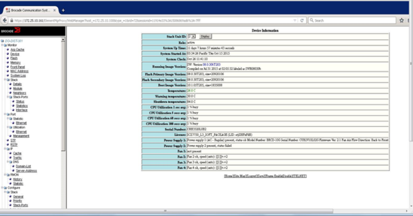
FIGURE 6 Sample Display of Element Manager Switch Details
Sample Flow (sFlow)
sFlow is a standards-based protocol that allows network traffic to be sampled at a user-defined rate for
monitoring traffic flow patterns and identifying packet transfer rates on user-specified interfaces.
Brocade Network Advisor can be used as the sFlow data collector for the traffic analysis and
management.
sFlow is enabled on a Layer 2 or Layer 3 switch; the system performs the following:
• Samples traffic flows by copying packet-header information.
• Identifies ingress and egress interfaces for the sampled flows.
• Forwards byte and packet-count data, or counter samples, to sFlow collectors ( Brocade Network
Advisor).
• Combines sFlow samples into UDP packets and forwards them to the sFlow collectors for analysis.
! sFlow configuration template for the Brocade ICX switches.
! Enable sFlow.
DO-DIST-301(config)# sflow enable
! Configure the sFlow collector—Brocade Network Advisor is used as the sFlow
collector.
DO-DIST-301(config)# sflow destination 10.30.5.140
! Configure sFlow on interfaces.
DO-DIST-301(config)# interface ethernet 1/1/37
DO-DIST-301(config-if-e10000-1/1/37)# sflow forwarding
! The sampling rate is the average ratio of the number of incoming packets on the
sFlow-enabled port to the number of flow samples taken from those packets. The lower
the sample, the higher the CPU utilization.
DO-DIST-301(config-if-e10000-1/1/37)# sflow sample 2048
DO-DIST-301(config)# sflow polling-interval 20
Sample Flow (sFlow)
62 Brocade “Effortless Network” Architecture for K-12 School Districts Brocade Validated Design
53-1004097-03
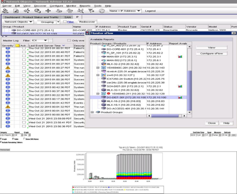
DO-DIST-301(config)# sflow source loopback 1
DO-DIST-301(config)# sflow source ipv6 loopback 1
Traffic Management Using Brocade Network Advisor
From the Brocade Network Advisor main menu, select Monitor > Traffic Analysis > Monitor sFlow to
configure or view the traffic statistics.
PoE Management Using Brocade Network Advisor
From the Brocade Network Advisor main menu, select Monitor > Power Center to view the PoE status
of discovered devices.
Traffic Management Using Brocade Network Advisor
Brocade “Effortless Network” Architecture for K-12 School Districts Brocade Validated Design 63
53-1004097-03
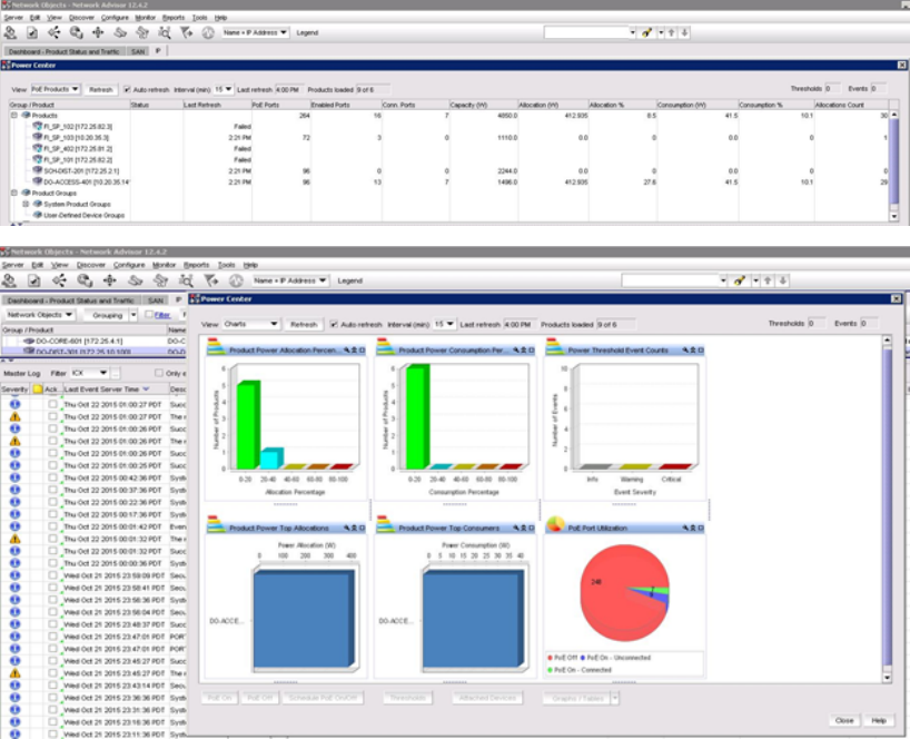
Event Notification
From the Brocade Network Advisor main menu, select Monitor > Event Processing > Event Actions
to configure the required to notify the administrator.
Event Notification
64 Brocade “Effortless Network” Architecture for K-12 School Districts Brocade Validated Design
53-1004097-03
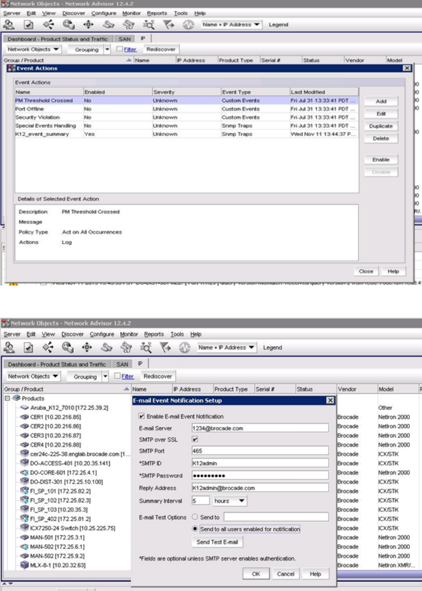
From the Brocade Network Advisor main menu, select Monitor > Event Notification > Email to send
an email to the network administrator.
Network Management
Brocade “Effortless Network” Architecture for K-12 School Districts Brocade Validated Design 65
53-1004097-03
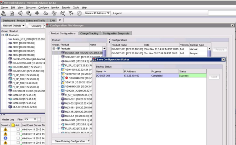
Configuration Backup
From the Brocade Network Advisor main menu, select Configure > Configure File Manager >
Product Configurations > Products; and then select the desired product and click Save Running
Configuration.
From the Brocade Network Advisor main menu, select the desired device and then select Configure >
Configuration File > Schedule Backup. In the Schedule Backup dialog box, select ConfigBackup
and click Edit to schedule the backup.
Configuration Backup
66 Brocade “Effortless Network” Architecture for K-12 School Districts Brocade Validated Design
53-1004097-03
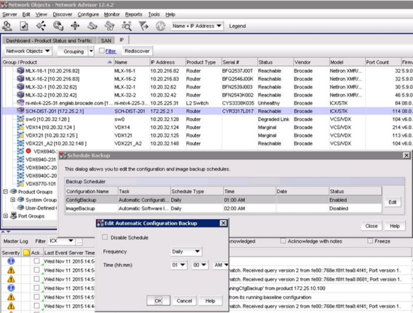
Network Management
Brocade “Effortless Network” Architecture for K-12 School Districts Brocade Validated Design 67
53-1004097-03
Configuration Backup
68 Brocade “Effortless Network” Architecture for K-12 School Districts Brocade Validated Design
53-1004097-03

Glossary
•AAA—Authentication, Authorization, and Accounting
•ACL—Access Control List
•BGP—Border Gateway Protocol
•BDPU—Bridge Protocol Data Unit
•DHCP—Dynamic Host Configuration Protocol
•DoS—Denial of Service
•IGMP—Internet Group Management Protocol
•IP—Internet Protocol
•IPTV—Internet Protocol Television
•LAG—Link Aggregation Group
•MAC—Media Access Control (in Ethernet, refers to te 48-bit hardware address)
•MAN—Metropolitan Area Network
•MLD—Multicast Listener Discovery
•NTP—Network Time Protocol
•OSPF—Open Shortest Path First
•PIM—Protocol Independent Multicast
•PoE—Power over Ethernet
•QoS—Quality of Service
•RADIUS—Remote Authentication Dial-in User Service
•RSTP—Rapid Spanning Tree Protocol
•SNMP—Simple Network Management Protocol
•SSH—Secure Shell
•TCP—Transport Control Protocol
•UDLD—Uni-Directional Link Detection
•VLAN—Virtual Local Area Network
Brocade “Effortless Network” Architecture for K-12 School Districts Brocade Validated Design 69
53-1004097-03
Glossary
70 Brocade “Effortless Network” Architecture for K-12 School Districts Brocade Validated Design
53-1004097-03
