Ruckus Brocade Voice Over IP Solutions For Campus Network Design Guide [BP] (Vo IP) Voip Sdg
2017-12-12
User Manual: Ruckus [BP] Voice over IP (VoIP) Solutions for Campus Network Design Guide
Open the PDF directly: View PDF ![]() .
.
Page Count: 24
- Contents
- Campus Enterprise Networks Voice over IP (VoIP) Solutions
- Executive Summary
- Introduction
- Campus Network Reference Model
- Key Considerations for Designing Packet Voice Infrastructure
- Brocade VoIP Solutions
- Advanced Capabilities for VoIP
- Tracking VoIP Data to Multiple Servers
- LLDP-MED
- E911
- How Emergency Call Services Works
- Brocade Interoperability and Alliances for Unified Communication
- Summary
- References

53-1003573-01
30 September 2014
Campus Enterprise
Networks: Voice over IP
(VoIP)
Solution Design Guide
© 2014, Brocade Communications Systems, Inc. All Rights Reserved.
Brocade, the B-wing symbol, Brocade Assurance, ADX, AnyIO, DCX, Fabric OS, FastIron, HyperEdge, ICX, MLX, MyBrocade, NetIron,
OpenScript, VCS, VDX, and Vyatta are registered trademarks, and The Effortless Network and the On-Demand Data Center are trademarks
of Brocade Communications Systems, Inc., in the United States and in other countries. Other brands and product names mentioned may be
trademarks of others.
Notice: This document is for informational purposes only and does not set forth any warranty, expressed or implied, concerning any
equipment, equipment feature, or service offered or to be offered by Brocade. Brocade reserves the right to make changes to this document
at any time, without notice, and assumes no responsibility for its use. This informational document describes features that may not be
currently available. Contact a Brocade sales office for information on feature and product availability. Export of technical data contained in
this document may require an export license from the United States government.
The authors and Brocade Communications Systems, Inc. assume no liability or responsibility to any person or entity with respect to the
accuracy of this document or any loss, cost, liability, or damages arising from the information contained herein or the computer programs that
accompany it.
The product described by this document may contain open source software covered by the GNU General Public License or other open
source license agreements. To find out which open source software is included in Brocade products, view the licensing terms applicable to
the open source software, and obtain a copy of the programming source code, please visit http://www.brocade.com/support/oscd.

Contents
Campus Enterprise Networks Voice over IP (VoIP) Solutions....................................................... 4
Executive Summary.......................................................................................... 4
Introduction....................................................................................................... 4
Campus Network Reference Model ................................................................. 5
Campus Access ................................................................................... 6
Campus Distribution .............................................................................6
Campus Core ....................................................................................... 6
Key Considerations for Designing Packet Voice Infrastructure.........................6
Services Offered................................................................................... 6
Quality of Service.................................................................................. 7
Signaling Protocols............................................................................... 8
Peer-to-Peer Call Signaling Protocols...................................................8
Client-Server Protocols......................................................................... 8
High Availability.....................................................................................9
Regulatory Issues................................................................................. 9
Security................................................................................................. 9
Future-Proof Infrastructure....................................................................9
Brocade VoIP Solutions.................................................................................... 9
Brocade VoIP Architecture....................................................................9
Advanced Capabilities for VoIP.......................................................................11
High Availability...................................................................................11
Quality of Service................................................................................ 12
Security............................................................................................... 12
Tracking VoIP Data to Multiple Servers.......................................................... 13
LLDP-MED...................................................................................................... 14
E911................................................................................................................15
Brocade Supporting E911 Functionality..............................................15
How Emergency Call Services Works.............................................................17
Brocade Interoperability and Alliances for Unified Communication................ 19
IP Phones and Audio Conferencing - Interoperability......................... 19
Brocade and ShoreTel Alliance for Unified Communications............. 20
Brocade and Avaya Alliance for Unified Communications.................. 21
Brocade Networks and Microsoft Lync................................................22
Summary.........................................................................................................24
References......................................................................................................24
Campus Enterprise Networks: Voice over IP (VoIP) Solution Design Guide 3
53-1003573-01

Campus Enterprise Networks Voice over IP (VoIP) Solutions
● Executive Summary........................................................................................................ 4
● Introduction..................................................................................................................... 4
● Campus Network Reference Model ............................................................................... 5
● Key Considerations for Designing Packet Voice Infrastructure.......................................6
● Brocade VoIP Solutions.................................................................................................. 9
● Advanced Capabilities for VoIP.....................................................................................11
● Tracking VoIP Data to Multiple Servers........................................................................ 13
● LLDP-MED....................................................................................................................14
● E911..............................................................................................................................15
● How Emergency Call Services Works...........................................................................17
● Brocade Interoperability and Alliances for Unified Communication.............................. 19
● Summary.......................................................................................................................24
● References....................................................................................................................24
Executive Summary
The trend of offering voice services over a packet-based network has provided many opportunities for
telecommunications providers, both existing and new, a market that is expected to grow as providers
offer additional multimedia services over the same network. This makes it imperative that the
underlying network is scalable and designed with diligence. Voice services demand a highly reliable
network that can maintain voice quality. This is achieved through networking products that offer high
reliability, low latency, and traffic prioritization based on packet priorities. Routers and switches should
also be able to support traffic engineering capabilities that can guarantee consistent and predictable
behavior through the network. Brocade® routers and switches enable a wide variety of Campus
network solutions that make it easier to deliver these advanced multimedia services.
Introduction
The ability to packetize and carry voice over an Internet Protocol (IP) network is called Voice over IP
(VoIP). The technology provides IP telephony service that can be combined with data and various
multimedia services over a converged IP network. This Paper concentrates on the architecture and
requirements for campus enterprise customers.
Voice has traditionally been carried on circuit switched networks with resources dedicated for each
call. These networks are highly reliable and have set the standards for voice quality. Data networks
have co-existed with circuit switched networks, and in the last decade their growth has outpaced the
growth in voice networks. At the same time there have been vast improvements in the data networking
standards and in the switching and router technology. Today data networks and technology advances
in Compression and VOCODER are capable of delivering toll-quality voice over a network that is much
more scalable. The growing requirements of Campus networks have led to Unified communications,
comprising of voice, data and messaging in one application. These features are required to be
supported with high quality of service, priority and enabled security.
Campus Enterprise Networks Voice over IP (VoIP) Solutions
4 Campus Enterprise Networks: Voice over IP (VoIP) Solution Design Guide
53-1003573-01
VoIP is a key technology for modern enterprises. Enterprises get a high ROI by aggregating Data and
VoIP into infrastructure. For the deployment of VoIP, a network infrastructure should support key PoE
and QoS features. QoS is essential to protect VoIP traffic from the effects of high volume data traffic.
This ensures high-quality VoIP service with low jitter and latency.
Today’s VoIP solutions also require enhanced security and storage features to comply with CALEA
(Communications assistance for law Enforcement Act)requirements, to enforce phone policies, and to
collect VoIP streams for billing and accounting. Brocade’s Fast Iron PoE switches such as
ICX/FSX/FCX provide enhanced VoIP, QoS and security features required for a successful VoIP
deployment.
The technological innovations in IP telephony and wide availability of cost-effective IP infrastructure
networks have given rise to new business models. Many new technologies have emerged and some
solution providers are expanding into enhanced voice services. Customers demand services similar to
PSTN at a lower cost point and additional value-added services including video, unified messaging, and
conferencing.
An example of emerging value-added services is Hosted VoIP, which provides voice service with full
PBX-like functionality with no onsite hardware requirements. The In-Stat market research firm projects
strong growth for Hosted VoIP over the next few years, driven mainly by cost savings as well as
additional benefits for companies with a distributed workforce. The research firm has also projected
strong revenue and subscriber growth for residential and SMB VoIP service offerings.
Campus Network Reference Model
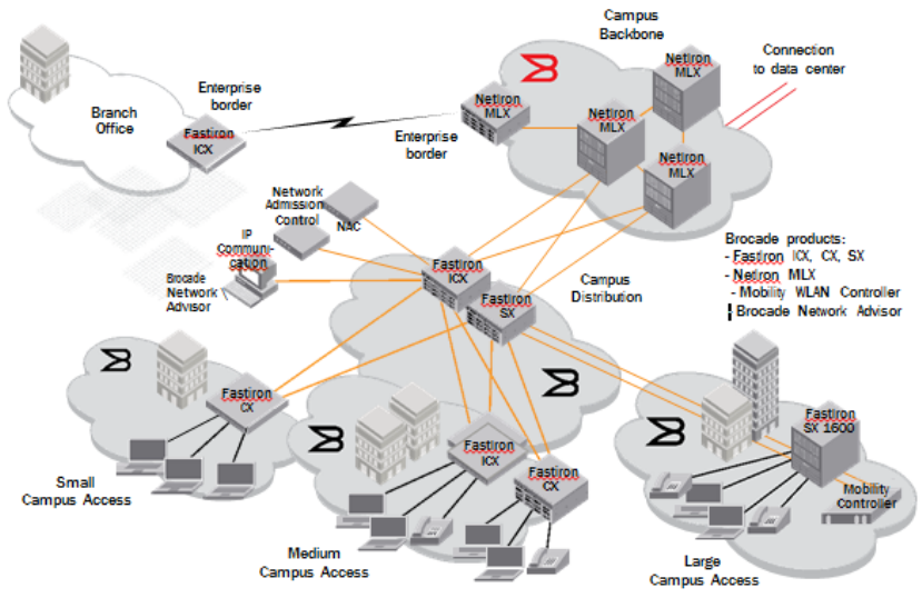
Figure 1 is a reference diagram for the enterprise campus network and shows where Brocade IP
products are generally positioned. This is simply one of several reference designs for Brocade products
in an enterprise campus network scenario.
FIGURE 1 Campus network reference model
Campus Network Reference Model
Campus Enterprise Networks: Voice over IP (VoIP) Solution Design Guide 5
53-1003573-01
Campus Access
The access layer is where laptop or desktop computers, workstations, VoIP phones, and WLAN AP’s
are connected to “access” the network services. Collaboration services, such as voice and video
conferencing equipment and video surveillance cameras, are also connected at this layer. This layer is
often referred to physically as the “wiring closet”. Access-level security, Quality of Service (QoS), and
PoE are implemented at this layer. The Brocade Fast Iron families of PoE/PoE+-capable switches are
most commonly deployed in this layer of the campus network.
Campus Distribution
The distribution layers (Also known as the aggregation layer), aggregates multiple access layer
switches and connects them to the campus core. This layer deals with complex security, Access
Control List (ACL), scalability, QoS, STP, and MCT and so on. Usually each access switch is dual
connected to this layer for high availability. Brocade Fast Iron SX and ICX Series switches are most
commonly deployed at this layer of the campus network.
Campus Core
Also known as the “backbone”, the core layer consists of high-speed, high-performance, high-
availability switches that interconnect user segments and provide connectivity to both data center
services and the outside world. Brocade Net Iron MLX Series and Fast Iron ICX 7750 routers are most
commonly deployed at this layer of the campus network.
Key Considerations for Designing Packet Voice Infrastructure
Services Offered
VoIP has enabled many new services, the most basic being Internet telephony service to users over
an IP network. This may involve PC-to-PC connection or PC-to-phone connectivity using PSTN
gateways. It could be either a best-effort service over the Internet or offered as a service by a service
provider with required guarantees. The service has already evolved to video telephony and many
service providers are offering video telephone service for users that own a video phone. Further,
business could benefit from value-added services such as videoconferencing and application sharing.
The services can be categorized as follows:
• Residential VoIP. Voice over broadband services sold to residential and home office customers
• Hosted VoIP for businesses. Voice service with full PBX-like functionality for SMB (CENTREX
service from ATT)
• Long-distance bypass. IP Trunking service offered by carriers to enable long haul voice providers to
bypass long distance toll networks.
• IP Trunking services. Connected islands of PSTN networks using private IP networks
• VoIP peering. Allows direct peering of VoIP networks to completely bypass PSTN networks
wherever possible, providing relief from PSTN regulations and tariffs
Campus Access
6 Campus Enterprise Networks: Voice over IP (VoIP) Solution Design Guide
53-1003573-01
Quality of Service
Voice quality has been one of the major considerations in deploying these networks. Noise, voice
delays, jitter, and echo interfere with regular voice conversations and must be addressed to deliver a
toll-quality voice service. To achieve the requisite Quality of Service (QoS) requirements for toll-quality
voice, various techniques have been deployed in the network. Echo is a serious issue in voice networks
and is caused by impedance mismatches in a classical circuit switched network, or simple acoustic
coupling between a phone’s microphone and speaker. Echo can occur in either classical or VoIP
networks. Echo becomes more pronounced as the round-trip delay exceeds 50ms. In a VoIP network,
every device and link introduces delay, causing mouth-to-ear delay, which is the sum of:
• Encoding delay
• Packet serialization delay
• Propagation delay
• Network equipment delay
• Play-out buffer delay
Voice services are sensitive to packet loss as well, and steps must to be taken to avoid end-to-end
packet loss. In IP networks, packet loss is usually a result of congestion or the burst nature of data
traffic. Hence voice packets must receive preferential treatment. A few of the approaches used are
described below.
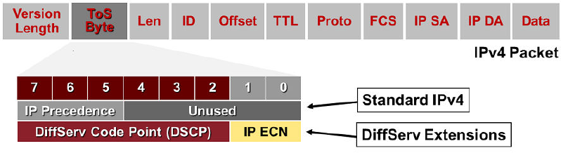
• Differentiated Services (DiffServ). Differentiated Services (RFC 2475) can be used to provide class-
based traffic management capabilities in the network without the need for per-flow state and
signaling at every hop. The method is based on classification and marking of packets at the edge into
a limited number of classes. The Per-Hop Behavior (PHB) of each packet will be determined by the
class of the packet. The RFC has reused the IP precedence bits as 8 bit DS field. Six bits of DS field
are specified as Differentiated Services Code Point (DSCP), which determines the PHB of a packet.
Although there are 64 different DSCPs, most networks map these to the following standardized
PHBs:
‐Expedited Forward: Loss sensitive traffic requiring minimum delay and delay variation (jitter)
‐Assured Forward: This has multiple classes and applies to loss-sensitive traffic. Traffic
forwarding is assured as long as the traffic is within the service specifications. In other
words, each class is guaranteed a certain amount of bandwidth.
‐Best Effort
• Layer 2 CoS (IEEE 802.1p). The approach is to use 802.1p priority bits to prioritize traffic. The
packets are remarked as they traverse to a Layer 3 network.
Quality of Service
Campus Enterprise Networks: Voice over IP (VoIP) Solution Design Guide 7
53-1003573-01
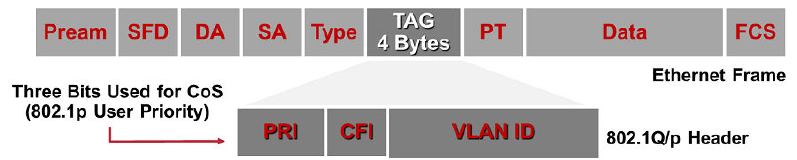
FIGURE 2 IPV4 Packet with DSCP description
Networks are not designed nor are they optimized for peak traffic demands; hence, packet loss will still
occur but can be optimized for voice traffic. A good number of VoIP gateways and IP phones also
implement sophisticated concealment methods that can mask the effect of minor packet loss. One
simple concealment method is rerunning the last correct packet, which makes the packet loss less
perceptible, although it might add additional delay in the network.
Jitter is the variation of end-to-end delay from one packet to the next packet. It is a major problem for
voice networks. In order to remove the effects of jitter, many IP phones use buffers to collect the
packets and smooth out the variation before play out—hence called play-out buffers. This process
introduces some additional delay and potential for packet loss if it is not tuned correctly. Network
designers must carefully tune the appropriate buffer size.
Signaling Protocols
In a PSTN network (Public Switched Telephone Network), voice calls require setup and tear down of
the circuit connection, in similar fashion, a VoIP network requires signaling protocols for creating,
modifying, and terminating sessions between end-points in a VoIP network. The signaling protocols
can be divided into two broad categories: peer-to-peer call signaling protocols and client-server
protocols.
Peer-to-Peer Call Signaling Protocols
Peer-to-peer call signaling protocols include Session Initiation Protocol (SIP) and ITU H.323, which
were initially designed to allow two intelligent end-points to communicate with each other. They allow
users to find the remote device and provide call setup, call teardown, capabilities exchange, and call
control functions to establish multimedia communication (voice, video, and so on). SIP is defined in
RFC 3261 as “An application-layer control (signaling) protocol for creating, modifying, and terminating
sessions with one or more participants. These sessions include Internet telephone calls, multimedia
distribution, and multimedia conferences.” ITU H.323 is an umbrella standard that came from the
telephony world and defines protocols for call establishment and teardown in a packet-based network.
Although H.323 and SIP protocols have some differences, they offer very similar capabilities and are
both widely deployed.
Client-Server Protocols
The second category comprises client-server protocols such as H.248 (MEdia GAteway COntrol/
MEGACO) and Media Gateway Control Protocol (MGCP). This model assumes very little intelligence
at the end terminal and provides the intelligence in core. It uses low-cost phones, Media Gateway
Controllers (MGCs) for call control and signaling, and Media Gateways (MGs) to interface to PSTN.
MGCP and MEGACO provide a method of communication between MGC (also referred to as a call
agent or soft switch), and the MG. Hence, MGCP and MEGACO protocols can be complementary to
SIP or H.323.
Signaling Protocols
8 Campus Enterprise Networks: Voice over IP (VoIP) Solution Design Guide
53-1003573-01
High Availability
Telephone users are accustomed to extremely high availability on current circuit-switched telephone
networks. The networks are also used for many mission-critical applications for businesses that demand
networks to always be available. Such consistent service is expected of VoIP networks as well. High
availability is achieved through reliable systems and network-level high availability features.
Regulatory Issues
Regulatory compliance might necessitate lawful intercept and emergency services on publicly available
VoIP networks. The US FCC has mandated that VoIP networks comply with the Communications
Assistance for Law Enforcement Act (CALEA). Currently not all countries have such regulations, but it is
recommended that networks be designed with this in mind.
Security
Threats to the VoIP network include service disruption, capturing voice conversations, theft of service,
and attacks to other devices through VoIP servers. Each of these potential risks to the network should
be addressed while designing the network.
Future-Proof Infrastructure
It is important to build a scalable infrastructure that can adapt to changing standards and grow to
accommodate future VoIP capacity needs as well as additional higher bandwidth services.
Brocade VoIP Solutions
Brocade provides a wide variety of Enterprise network infrastructure options for delivering services that
require high availability, low latency and jitter, and strict Service Level Agreements (SLAs). The
products offer network-level resiliency, hardware-based QoS with strict priority queueing for delay
sensitive applications, ease of management, and flexible network processor-based architecture. For Up
to Date information on the Brocade Campus products please visit www.brocade.com/campusnetwork
Brocade VoIP Architecture
Brocade FastIron PoE switches provides the customers a state-of-the-art VoIP infrastructure. The
following section briefly describes a typical VoIP architecture within an enterprise. It also describes the
VoIP call setup and tear-down paths, and VoIP data paths for calls made within the enterprise and
outside of the enterprise.
High Availability
Campus Enterprise Networks: Voice over IP (VoIP) Solution Design Guide 9
53-1003573-01
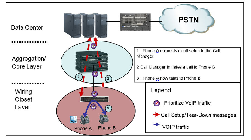
FIGURE 3 Voip Call Setup- Tear-down within enterprise
Figure 3 shows enterprise network architecture with VoIP infrastructure elements. A typical enterprise
network would contain PoE-capable devices in the wiring closet layer, and deliver power to PoE
devices such as IP Phones. The Aggregation/core layer includes high performance switches and
routers such as the ICX/FSX family of switches. The Datacenter layer contains management elements
such as Call Managers, Billing and Accounting servers, etc.
When an IP phone (Phone A) calls up a second IP Phone (Phone B) within the enterprise network, a
call setup message is sent to the Call Manager. The Call Manager will identify Phone B’s IP address
and send down call setup messages to the IP Phones. Once the call is set up, VoIP traffic is switched
within the network without being forwarded to the Call Manger.
Enterprise customers should use QoS to ensure low jitter and latency for VoIP traffic. Brocade
Switches provide advanced QoS features that allow customers to prioritize VoIP traffic over data
traffic. As shown in Figure 1 on page 5, QoS features should be applied throughout the network, not
just at the edge, to ensure that both call setup and VoIP traffic is prioritized throughout the entire
network.
Campus Enterprise Networks Voice over IP (VoIP) Solutions
10 Campus Enterprise Networks: Voice over IP (VoIP) Solution Design Guide
53-1003573-01
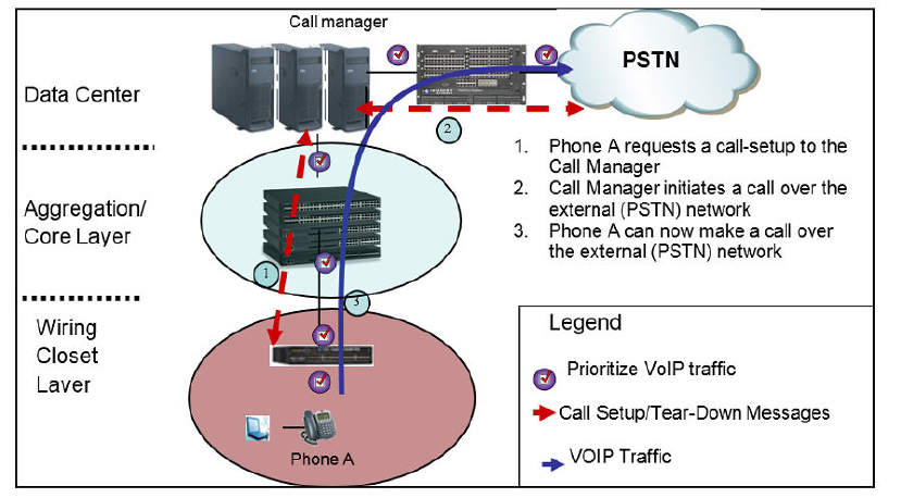
FIGURE 4 VoIP Call Setup – Tear-down when calling external
Figure 4 shows a call setup, tear-down and VoIP traffic path when a call is made from within the
enterprise network to an outside phone via the PSTN network. The call setup messages are sent to the
Call Manager from the VoIP Phones within the enterprise. The Call Manager identifies the destination
phone number as external and sends the call setup message to the PSTN network via the enterprise
gateway switch/router. Once the call is setup, VoIP traffic is forwarded to the PSTN network.
Network managers, who have created their own QoS architecture within the enterprise, need to match
the VoIP traffic coming into their network from the PSTN and re-mark the QoS values (802.1p/
DSCP/TOS etc.) in accordance to their network architecture. Brocade’s advanced QoS features allow
network managers to ensure that VoIP traffic entering their network from external service providers is
mapped as per their enterprise requirements.
Advanced Capabilities for VoIP
Brocade’s broad range of high-performance routing and switching products offer advanced capabilities
for VoIP networks. The products provide multiple form factors to suit the needs of most network
infrastructures. They also offer full-featured Layer 2, Layer 3 and advanced MPLS capabilities that give
service providers the flexibility to choose a network design that offers converged voice, data, and other
multimedia services.
High Availability
High availability is achieved through a combination of hardware and software architecture. The Brocade
FastIron ICX, FCX and SX product families integrate a set of advanced features and high availability
tools. All the system modules/fixed stack switches are hot pluggable and removal of any system
module/Stack Switch does not impact the performance of the rest of the platform. The modular and
stacking architecture of the Multi-Service Iron Ware® operating system has several high-availability
features that distinguish it from legacy operating systems that run on other routers:
Advanced Capabilities for VoIP
Campus Enterprise Networks: Voice over IP (VoIP) Solution Design Guide 11
53-1003573-01
• Support for hitless software upgrade
• Hitless Layer 2 and Layer 3 failovers
• Sub-second switchover to the standby management module/Stack Switch if a communication failure
occurs between active and standby management modules/Stack switch
Quality of Service
QoS plays an important part at this level. QoS provides the ability to prioritize designated traffic over
other traffic in a switch. When QoS features are enabled on Brocade switches, traffic is classified as it
arrives at the switch and handled on the basis of configured priorities. Traffic can be dropped,
prioritized for guaranteed delivery, placed into a best-effort queue, or be subject to limited delivery
options.
• The classification process assigns a priority to packets as they enter the switch.
• These priorities can be determined on the basis of information contained in the packet or assigned
to the packet as it arrives at the switch. Once a packet or traffic flow is classified, it is mapped to a
forwarding priority queue.
• Packets on Brocade devices are classified in up to eight traffic classes, with values from 0 through
7. Packets with higher priority classifications are given precedence for forwarding. Typically, voice
traffic requires a classification between CoS value 4 and 6, while video requires a classification in
the range of CoS value 3 through 5, to ensure that enough resources are reserved.
The Brocade device establishes the trust level based on the configuration of certain features if the
traffic is switched or routed. The trust level can be one of the following
• Ingress port default priority.
The port priority command never affects the DSCP value of the packet. It is used only to assign
internal prioritization for egress queuing and to assign the 802.1p value when a packet comes in as
untagged interface.
• Static MAC address. Allows the user to control the priorities assigned to traffic based on the
destination MAC address. This is not recommended, due to the overhead in management.
• Access Control Lists. ACLs can prioritize traffic and mark it before sending it to the next hop.
• Layer 2 Class of Service (CoS) value. This is the 802.1p priority value in the Ethernet frame. It can
be a value from 0 through 7. The 802.1p priority is also called the Class of Service.
• Layer 3 Differentiated Service Code Point (DSCP). The value in the six most significant bits of the
IP packet header 8-bit DSCP field, please refer to the Figure 2 above. It can be a value from 0
through 63. The DSCP value is sometimes called the DiffServ value. The device automatically
maps a packet's DSCP value to a hardware-forwarding queue.
Security
Security must be enabled on the access layer switches to avoid network attacks such Man-in-the-
middle, DDos. Security features such as DHCP snoop, DAI, Mac authentication, Port Security, 802.1x,
SSH and SCP, Telnet can be used.
DHCP Snooping
The DHCP Snooping feature allows us to enable security by building up a table of DHCP-provided IP
addresses corresponding to MAC addresses and connected physical ports. DHCP Snooping can
enabled on a voice vlan at the global level
ICX6450-48P Router(config)#ip dhcp snooping vlan 2000
ICX6450-48P Router(config)#show run | i dhcp
ip dhcp snooping vlan 2000
Quality of Service
12 Campus Enterprise Networks: Voice over IP (VoIP) Solution Design Guide
53-1003573-01
dhcp snooping trust
dhcp snooping trust
Then DHCP trust needs to be configured on the uplink ports of the switches to which the phones are
connected. It enables the Brocade device to filter untrusted DHCP packets in a subnet. DHCP snooping
can ward off Man-in-the-middle attacks, such as a malicious user posing as a DHCP server sending
false DHCP server reply packets with the intention of misdirecting other users. DHCP snooping can also
stop unauthorized DHCP servers and prevent errors due to user misconfiguration of DHCP servers
Port security
Port security can be enabled on the phone interfaces and secure MACs can be configured to specify a
limited number of secure MACs. The interface will forward only packets with source MAC addresses
that match these learned secure addresses. The secure MAC addresses can be specified manually, or
the Brocade device can learn them automatically.
After the device reaches the limit for the number of secure MAC addresses it can learn on the interface,
if the interface then receives a packet with a source MAC address that does not match the learned
addresses, it is considered a security violation and then the device takes one of two actions: it either
drops packets from the violating address (or allows packets from the secure addresses), or disables the
port for a specified amount of time.
You can specify which of these actions takes place. The secure MAC addresses are not flushed when
an interface is disabled and re-enabled on older FastIron X Series devices. The secure MAC addresses
are flushed when an interface is disabled and re-enabled on FCX and ICX devices. The secure
addresses can be kept secure permanently (the default), or can be configured to age out, at which time
they are no longer secure. You can configure the device to automatically save the secure MAC address
list to the startup-config file at specified intervals, allowing addresses to be kept secure across system
restarts.
Port security can be configured at interface level
MAC port security is not supported on static trunk group members or ports that are configured for link
aggregation.
802.1x MAC authentication
802.1x MAC authentication also can be enabled on the phone ports. Dot1x needs to be enabled and
then configured at interface level. You can specify what action needs to be taken if a port fails
authentication. Any Radius or TACACS server can be used to enable authentication.
Tracking VoIP Data to Multiple Servers
Customers may need to replicate the VoIP stream to multiple servers for CALEA and accounting
purposes. This is done using a combination of ACL based mirroring and MAC Learning Disable.
As shown in Figure 5 , ACL-based Mirroring is used to capture the VoIP stream and mirror it to port 13.
Port 13 is physically looped back into port 20, which is part of a different VLAN (VLAN 20). Because
MAC learning is disabled on port 20, the VoIP traffic that is received on port 20 is flooded out on all
ports belonging to VLAN 20. The customer can attach multiple servers to different ports on VLAN 20
and get the replicated VoIP stream on each of the ports
Tracking VoIP Data to Multiple Servers
Campus Enterprise Networks: Voice over IP (VoIP) Solution Design Guide 13
53-1003573-01
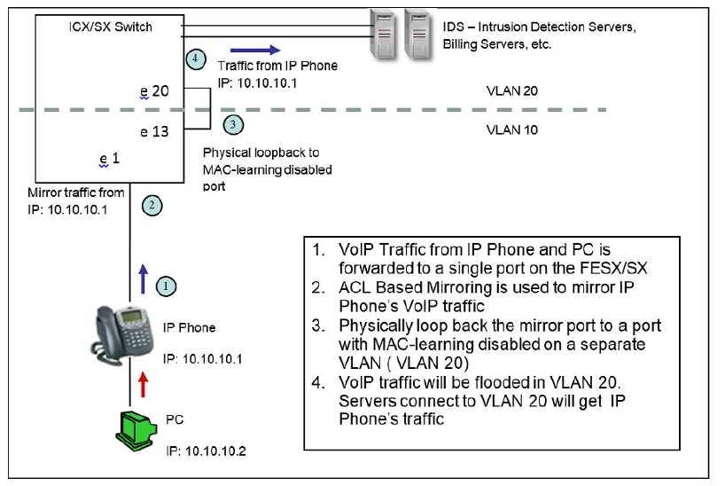
FIGURE 5 Tracking VoIP data to multiple servers
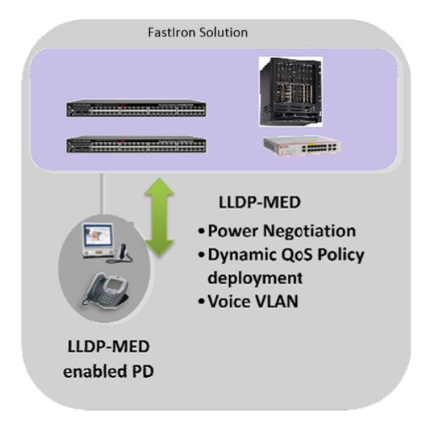
LLDP-MED
ANSI TIA 1057 Link Layer Discovery Protocol-Media Endpoint Discovery (LLDP_MED) is an
enhancement of the IEEE Standard 802.1AB Link Layer Discovery Protocol (LLDP). LLDP-MED is a
Layer 2 protocol that allows for power negotiation between a PoE switch and a power device, dynamic
QoS policy deployment, and automatic voice vlan configuration. Brocade FastIron VOIP solution
devices support LLDP MED solution to define the network policy for voice and video signaling for
guest and conferencing. It defines the tagged/Untagged voice/Video data and prioritized with the
DSCP and COS value on a per vlan and per port settings. Brocade FastIron Devices support the
LLDP-MED network policy configuration with respect to various network policies.
LLDP-MED supports the Fast start transmit count with the interval setting to repeat the count
notification for the fast transmitted packets. The location-ID support is used in LLDP-MED config to
support the E911 functionality (please see the E911 section below). The user sets the network policies
based on the classification of network types along with prioritizing the traffic with the COS and DSCP
values. The Specific policy can be applied to the ports carrying the traffic with the vlan associated to
prioritize the traffic based on the type of network policy. Please see the details on the configuration
below.
ICX6450-24 Router(config)#lldp med
fast-start-repeat-count Specify the LLDP-MED fast start transmit count
location-id Define an LLDP-MED location ID
network-policy Define an LLDP-MED network policy
LLDP-Med has different applications as shown above. The fast-start transmit count will transmit the
LLDP-MED packet at the specified interval on a repeat. The Location-id is used in case of E-911 and
LLDP-MED
14 Campus Enterprise Networks: Voice over IP (VoIP) Solution Design Guide
53-1003573-01
emergency services for the location detection. The network policy defines the various policies
applications for Video and Voice(details below).
ICX6450-24 Router(config)#lldp med location-id
civic-address Civic address Location Configuration Information
coordinate-based Coordinate-based Location Configuration Information
ecs-elin Emergency Call Service ELIN
As shown above the location-id is used for the emergency services e.g. E-911, defining the Civic
address, Coordinate based or the PSTN based ELIN address.
ICX6450-24 Router(config)#lldp med network-policy
application Specify the network policy application type
ICX6450-24 Router(config)#lldp med network-policy application
guest-voice Guest voice application
guest-voice-signaling Guest voice signaling application
softphone-voice Softphone voice application
streaming-video Streaming video application
video-conferencing Video conferencing application
video-signaling Video signaling application
voice Voice application
voice-signaling Voice signaling application
As shown above the brocade devices support various applications based on the network services
based on the voice and Video traffic. The traffic can be classified as streaming, guest or signaling based
on the user profile. Traffic can be tagged with the priority and DSCP attached to the interface. A
configuration example is shown below.
ICX6450-24 Router(config)#lldp med network-policy application voice tagged vlan 100
priority 5 dscp 46 ports ethernet 1/1/1
E911
An initial major concern with the implementation of Voice over IP (VOIP) was the ability for switches to
intelligently determine the location of a user calling for emergency services via 911. With legacy
landlines, a 911 call is routed to a local public safety answering point (PSAP) and services are
dispatched based on the information provided by caller’s phone number and location. With VOIP,
However, a method to determine user location was needed.
Brocade Supporting E911 Functionality
In current-generation and next-generation E911 scenarios, an important function is the call routing
function (which is performed over the traditional TDM network via the Automatic Number Identification
Database [ANI DB] spill and coupled with a dedicated NI2 interface to the end office). Another element
involves provision of the call over the IP backbone onto the next-generation E911 Emergency Services
IP backbone.
However, these functions are not the key functions for successful E911 implementation. 911 planners
consistently hold that the key starting point is providing the initial dynamic update of the information that
identifies the location of the end instrument. It is essential that the correct information is populated into
the ASLAN switch port and communicated dynamically to the end instrument, which updates the LSC
database. In some cases, multiple Public Safety Answering Points (PSAPs) are involved in providing
the response to the emergency call. When the E911 call is dialed, the call is monitored by the LSC’s
internal call routing system. The LSC routes the emergency call itself over the appropriate trunks to the
appropriate PSAP, which includes the ANI (the number for the PSAP to return the call to the original
caller in case of disconnect). As the call is in progress, the local responders are given the internal
location (LLDP-MED location data) mapped against the external Automatic Location Identifier (ALI),
which enables the local responders to meet the public responders who receive the entry, street, or
external location information provided from the ALI database (via the ANI spill).
E911
Campus Enterprise Networks: Voice over IP (VoIP) Solution Design Guide 15
53-1003573-01
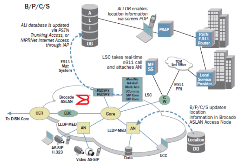
FIGURE 6 LLDP-MED location field data fill from the Brocade ASLAN enables location ERL transfer
coupled with the E911 management server. LLDP-MED from the access switch enables power
management to EIs that are IEEE 802.1af and LLDP-MED-compliant
The dual response of both internal and external responders ensures that the correct external entry or
arrival point for the public responder is met by the internal security or local in-building response
personnel. The crucial need is to provide a dynamic location update for the EI, regardless of where the
users access the network. In scenarios where there are thousands, or even tens of thousands of end
users in a B/P/C/S UC enterprise deployment, personnel mobility (office, equipment, or personnel
moves) can quickly number into the hundreds or even thousands in a short period of time. A dynamic
location update mechanism is essential, and the Brocade provision of the LLDP-MED feature is the
key to providing dynamic location updates and, therefore, the safety of the UC community.
It would create an administrative burden to manage the manual input of location data from the EI, yet
concerns exists with trusting the end user to input the correct location data upon login. Thus, there is a
clear need for a dynamic protocol, such as LLDP, to handle population of the location data for the
placement of the end device into the building location such that it is referenced by the wired location of
the Ethernet port. If this is not feasible, site planners implementing UC are required to instruct the end
users to populate or select their location upon login, or the E911 management server needs to be
enabled to pull the location information by dynamically scanning the network ports and associating the
device MAC address against a subnet translated to a zone (location) within the building.
One of the key questions routinely asked is about the user who has accessed the network by using
their UC client from a remote location. How does this person obtain E911 services? The answer
depends on how the LSC is set up. If the LSC has provided for known locations and instituted the
appropriate trunks and routing for the E911 call handling, the user can select a location upon login.
The location might be remote, pre-provisioned by UC planners, or dynamically obtained by the
Ethernet switch powering the EI, and it may be obtained dynamically during the login process by the
user. However, when the location cannot be dynamically updated and is not selectable by the user, a
default option must be made available. For example, the option of selecting “other” as a location is
provided. This is a general option that might indicate a home office, hotel, or conference location. In
remote sites—for instance, off main campus offices where the location is known by the LSC, the E911
Campus Enterprise Networks Voice over IP (VoIP) Solutions
16 Campus Enterprise Networks: Voice over IP (VoIP) Solution Design Guide
53-1003573-01
service has been set up with the PSAP local to that location, and the LLDP-MED fields may have been
populated into the access switch—the call still takes place. In cases where the location information is
not provided into the ASLAN access switch, a series of “null” characters in the LLDP location field may
trigger the UC client to ignore the field and cycle to the next location option, prompting the user to enter
a manual location identifier.
How Emergency Call Services Works
When an LLDP-MED capable device is plugged in to a switch port, negotiations occur to push
configurations and the Emergency Line identification Number (ELIN) from the switch to the end device.
The ELIN information can be managed by a third party vendor application that will store the ELIN and
Automatic Location Identification (ALI) in their Databases.
FIGURE 7 LLDP-MED negotiation Process between end devices and brocade FastIron Device
How Emergency Call Services Works
Campus Enterprise Networks: Voice over IP (VoIP) Solution Design Guide 17
53-1003573-01
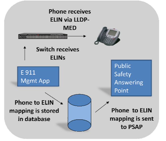
FIGURE 8 The Switch Passes ELIN information to the end device and to the PSAP via the E911
Management application
When a user dials 911 on a VOIP device, the switch passes the call to the call manager with the
emergency call management capabilities. The call management application will receive the ELIN and
gather the relevant ALI to determine which PSAP to send the call. Please see the figure below.
Campus Enterprise Networks Voice over IP (VoIP) Solutions
18 Campus Enterprise Networks: Voice over IP (VoIP) Solution Design Guide
53-1003573-01
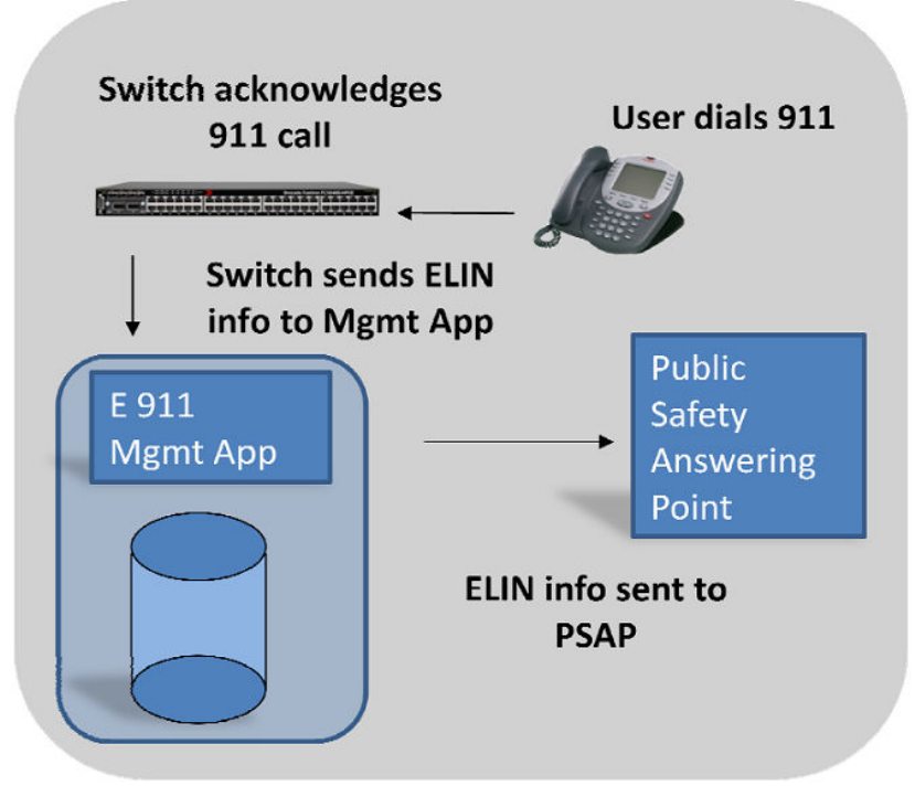
FIGURE 9 When a user dials 911, the switch forwards the call to the call manager with emergency
services - the call manager gathers more granular location information stored in its database and
forwards the call to the correct PSAP
Brocade Interoperability and Alliances for Unified Communication
IP Phones and Audio Conferencing - Interoperability
Since Brocade switches are fully IEEE PoE and PoE+ standards compliant, any PD that is compliant
with these standards can be seamlessly plugged and powered with Brocade PoE switches. This opens
up the whole range of end devices for organizations and eliminates the single vendor lock. Figure Below
shows a few of the industry-leading IP phones that can be deployed with the Brocade FastIron family of
switches.
Brocade Interoperability and Alliances for Unified Communication
Campus Enterprise Networks: Voice over IP (VoIP) Solution Design Guide 19
53-1003573-01
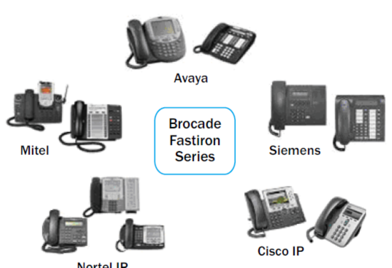
FIGURE 10 Brocade Interoperability- IP Phones and Audio Conferencing
Brocade PoE switches are tested with the most popular IP phones in the industry—including Avaya,
Mitel, Shoretel, Microsoft, Nortel, and Cisco. Some of the solutions and IP devices from these vendors
are tested, certified, and recommended by Brocade as a preferred solution partner. For more
information, visit VoIP Solutions on www.brocade.com.
The convergence of voice and data services on a single IP network can create significant business
benefits, including reduced network costs, simplified management, improved productivity, and the
seamless exchange of information and communications across a distributed enterprise. But in order to
fully realize the benefits of IP communications, a solution should not create more complexity and cost
than it relieves.
Alternative server-centric IP communications solutions require increased investment in servers for
each location, driving up hardware and operating costs, reducing reliability, and making it difficult to
implement enterprise-wide changes to the system. This results in management difficulties, making it
more costly, resource-consuming and challenging to ensure consistency across the enterprise
network.
Brocade and ShoreTel Alliance for Unified Communications
Brocade® and ShoreTel® have joined together to deliver a validated, highly reliable and interoperable
solution that scales seamlessly to meet the needs of distributed enterprises without adding cost or
complexity to the network.
Based upon Brocade networking infrastructure and ShoreTel’s Pure IP Communications solutions,
Brocade and ShoreTel provide an easy-to-deploy, interoperable, highly reliable and scalable VoIP
networking solution. Customer validation of this fully integrated solution ensures the interoperability of
joint platforms, as well as industry leading ease-of-installation and operation, reliability and low Total
Cost of Ownership (TCO).
Brocade and ShoreTel Alliance for Unified Communications
20 Campus Enterprise Networks: Voice over IP (VoIP) Solution Design Guide
53-1003573-01
Support for both new and legacy telephony equipment, Quality of Service, Power over Ethernet (PoE),
and standard based networking security ensures smooth system migration and maximum network asset
protection over time.
Built from the ground up and designed to be the easiest to use, easiest to manage, full-featured IP PBX
solution on the market today, the ShoreTel system is a completely integrated IP phone system that
scales seamlessly from 1 to 10,000 users including PBX, voice mail, and automated attendant functions
Based on a fully distributed software architecture, software can be accessed across each site of a
company so all users have access to the same features regardless of location. With no single point of
failure, ShoreTel’s robust distributed architecture provides rapid failover and re-routing of calls around
problem areas. The distributed architecture, which enables call control software to be distributed to
each voice switch in a geographically dispersed deployment, creates a more reliable IP communications
platform than server-centric solutions while making it easier for administrators to make changes to any
location from one single point.
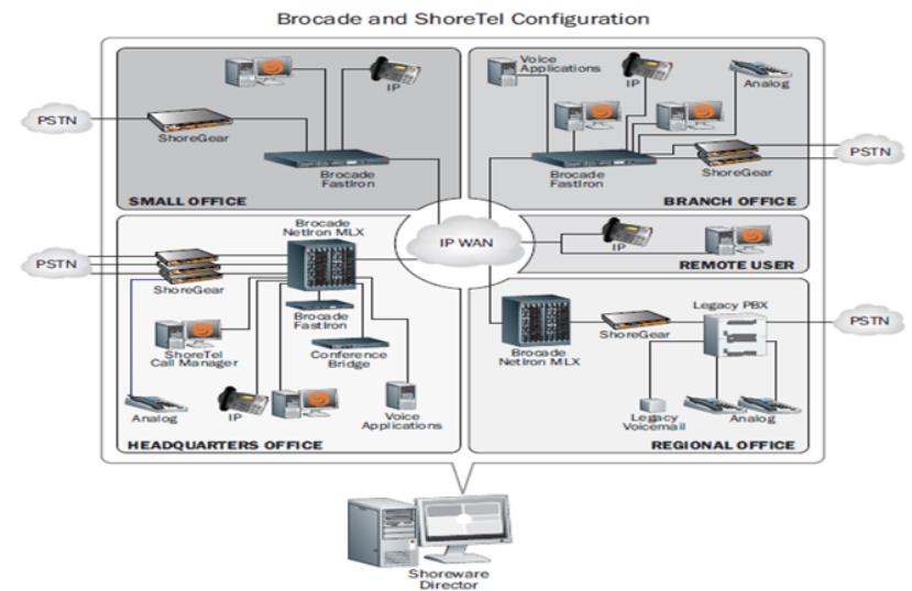
FIGURE 11 Brocade and ShoreTel Alliance network Configuration
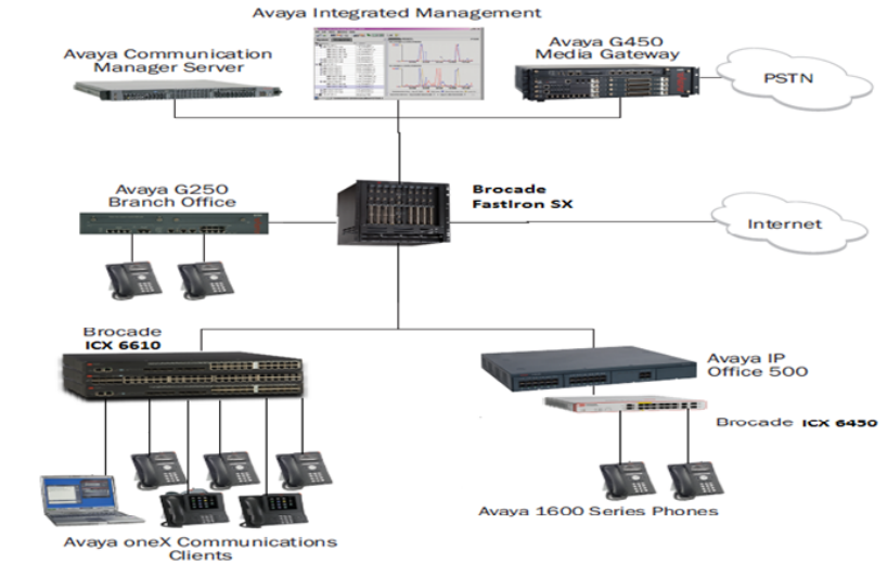
Brocade and Avaya Alliance for Unified Communications
Designed to ensure a higher return on investment and deliver the highest quality real-time
communications to customers, the Brocade® and Avaya relationship results in a fully integrated
networking platform for deploying highly scalable Unified Communications solutions.
The Brocade and Avaya solution delivers a superior quality convergence solution that uses the latest
advanced IP infrastructure technology. This solution delivers full Class 3 PoE density to support large
enterprise IP Telephony installations and provides high availability, advanced QoS, and ease of
deployment.
Brocade provides the industry’s most scalable and reliable family of chassis and stackable networking
infrastructure products to enable Unified Communications. With a multi-service switching architecture
that provides the highest performance and lowest-latency solution on the market, Brocade delivers
Brocade and Avaya Alliance for Unified Communications
Campus Enterprise Networks: Voice over IP (VoIP) Solution Design Guide 21
53-1003573-01
guaranteed call quality for real-time multimedia traffic without compromising performance. Wire-speed
traffic prioritization eliminates packet loss and ensures that Unified Communications sessions get
through loud and clear, even when there are high volumes of data traffic.
As a world leader in Unified Communications, Avaya helps customers grow revenue, lower risk,
reduce costs, and achieve superior business results. Avaya drives the integration of communications
and business applications across any network and device through innovative solutions that enable
enterprise customers to enhance and evolve their networks and communications applications in the
areas of:
• Unified Communications
• Contact Centers
• IP Telephony
FIGURE 12 Brocade and Avaya Alliance network configuration
By combining the Brocade high performance switching infrastructure with Avaya’s innovative
applications, enterprise customers can simplify and unify communications on a single easy-to-manage
network. That’s why Brocade and Avaya Unified Communication solutions are used across the globe,
providing converged network solutions with the performance, flexibility, and reliability required by some
of the world’s most demanding customers.
Brocade Networks and Microsoft Lync
Organizations communicate with many different kinds of devices including cell phones, office phones,
voice mail, web conferencing, fax, email, instant messaging, and video conferencing.
A unified communications solution can help solve the complex challenges of managing multiple
communication applications and devices by enabling streamlined communications within the
applications that users rely on the most. This reduces IT management complexity and resource
requirements, and improves user productivity by reducing communication latency.
Brocade Networks and Microsoft Lync
22 Campus Enterprise Networks: Voice over IP (VoIP) Solution Design Guide
53-1003573-01
Together, Brocade and Microsoft offer a highly scalable unified communications solution, enabling
organizations to consolidate business communications systems onto a single, high-performance
network that delivers high levels of reliability, availability, and security.
BENEFITS
Using the power of software to streamline communications, Microsoft Lync Server 2010 ushers in a
new, connected user experience that transforms each communication into a more collaborative,
engaged, and accessible interaction. Lync Server 2010 is a highly secure and reliable system that
works with existing tools and systems for easier management, lower cost of ownership, smoother
deployment and migration, and greater flexibility.
Brocade provides a complete set of switching and routing solutions that help organizations implement
Lync Server without replacing existing network infrastructures. With a rich set of features that help
ensure the highest-quality Lync Server environments, including unified wired and wireless network
access, advanced Quality of Service (QoS), and a single, easy-to-use management solution across the
local area network (LAN) and storage area network (SAN), Brocade delivers the always-on reliability
and network security a unified communications solution demands.
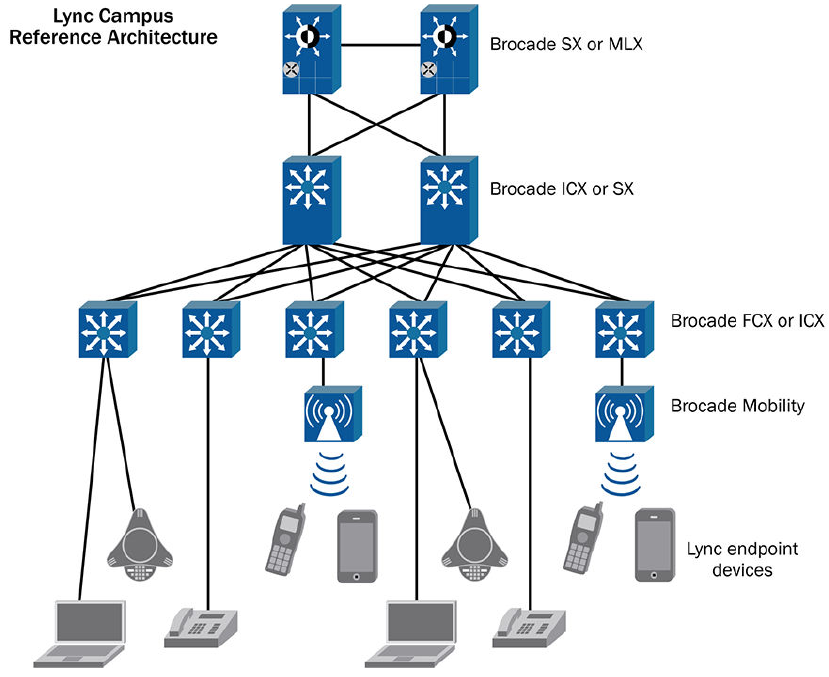
FIGURE 13 Lync Reference architecture for campus environment
Brocade campus access solutions enable automated port configuration with support for a variety of
industry-standard methods for placing an IP phone on the proper voice virtual local area network
(VLAN). With both automated QoS and voice VLAN discovery, an IP phone is automatically given the
proper QoS features and placed in the proper voice VLAN with no manual intervention. This decreases
the cost of deploying a unified communications infrastructure and service and helps eliminate costly
Campus Enterprise Networks Voice over IP (VoIP) Solutions
Campus Enterprise Networks: Voice over IP (VoIP) Solution Design Guide 23
53-1003573-01
configuration errors. In addition, modular, easily upgradable line cards, management cards,
acceleration cards, and switch fabrics provide investment protection.
Brocade’s hardware load balancer solutions for Lync Server 2010 provide load balancing capacity-on-
demand. Enabled by software license, the hardware load balancer process throughput can gracefully
scale alongside the Lync servers.
Other features that enhance Lync Server 2010 include the following:
• Fully redundant internal power management solutions span both high-density stackable and chassis
product lines, and include internal, hot-swappable, redundant, load sharing power supplies, and
power upgradeability with no system impact.
• Full support for 802.3af PoE and 802.3at PoE+ standards, with integrated and redundant PoE
power capabilities.
• Embedded flow monitoring to provide scalable and comprehensive network access control,
intrusion detection, and network traffic monitoring capabilities.
A Lync Server 2010 and Brocade solution can cost-effectively scale from the smallest to the largest
enterprises, allowing you to seamlessly expand the solution as enterprise demands increase.
Summary
Voice over IP services offer many lucrative advantages to the customers. However, as with any
technology, it brings its own sets of network design and optimization issues. By understanding the
important parameters, and acquiring the proper tools, you can reap the benefits of voice over packet
services. With the proper solution to deploy the network and provide the best partner alliances and
interoperability with the industry leaders, the road becomes extremely smooth for the customers and
the service providers.
Brocade routers and switches have the required solution to deliver advanced VOIP and multimedia
services. The matrix of capabilities involving a wide range of functionalities including robust Layer 2
and 3 protocols, IPv6 routing The above along with Quality of service, High Availability, security and
advanced Layer 2 and 3 functionality makes the product best fit for cost effective VOIP deployments.
References
• FastIron ICX, FCX, SX datasheets
www.brocade.com
• Brocade unified communication documents
http://www.brocade.com/solutions-technology/enterprise/unified-communications/index.page
• Brocade voice alliances
www.brocade.com
• Cisco CER documentation
http://www.cisco.com/c/en/us/td/docs/voice_ip_comm/cer/8_0/English/administration/guide/
CERAG_80/e911plan.html#wp1043266
• “MultiService Forum Release 3 Architecture Framework
http://www.msforum.org/techinfo/approved/MSF-ARCH-003.00-FINAL.pdf
Summary
24 Campus Enterprise Networks: Voice over IP (VoIP) Solution Design Guide
53-1003573-01
