Ruckus FastIron Ethernet Switch Stacking Configuration Guide, 08.0.20a Fast Iron 08.0.20 Guide 08020a Switchstackingguide
FastIron 08.0.20 Stacking Guide fastiron-08020a-switchstackingguide
2017-12-14
User Manual: Ruckus FastIron 08.0.20 Stacking Guide
Open the PDF directly: View PDF ![]() .
.
Page Count: 172 [warning: Documents this large are best viewed by clicking the View PDF Link!]
- Contents
- Preface
- About This Guide
- Traditional Stacking
- Supported traditional stacking features
- Traditional stacking benefits
- Connectivity options for stacking with FCX and ICX devices
- Brocade stackable models
- Brocade traditional stacking terminology
- Planning to build a traditional stack
- Traditional stack construction methods
- Verifying a traditional stack configuration
- Displaying information on stack connections
- FCX stack configuration overview
- ICX 6430 or ICX 6450 stack configuration overview
- ICX 6430 and ICX 6450 stack topologies
- Connecting ICX 6430 or ICX 6450 devices in a traditional stack
- Configuring an ICX 6430 or ICX 6450 traditional stack
- ICX 6610 traditional stack configuration overview
- ICX 7450 stack configuration overview
- ICX 7750 stack configuration overview
- ICX 7750 stacking topologies
- Installing the ICX 7750-26Q in a remote stack
- ICX 7750 stacking configuration notes
- ICX 7750 secure-setup example
- Creating an ICX 7750 stack trunk in a production environment
- Converting an ICX 7750 trunk to a port connection
- Removing stacking ports from an ICX 7750
- Displaying basic information for an ICX 7750 stack
- Displaying details for an ICX 7750 stack
- Traditional Stack Management
- Managing a traditional stack through one IP address
- Enabling or disabling stacking mode
- Controlling the stack through the CLI
- Traditional stack management MAC address
- Traditional stack device roles and elections
- Traditional stack unit priority
- Traditional stack software images
- Copying the flash image to a stack unit from the active controller
- Adding, removing, or replacing units in a traditional stack
- Renumbering stack units
- Reloading a stack unit
- Controlling stack size to allow for a data port
- Managing traditional stack partitioning
- Merging traditional stacks
- Unconfiguring a traditional stack
- Syslog, SNMP, and traps for stack units
- PHY calibration errors in stack ports of the ICX 6610
- Displaying traditional stack information
- Displaying stacking topology
- Displaying running configuration information
- How the show running-config command displays configured stacking ports
- Displaying software version information
- Displaying traditional stack flash information
- Displaying traditional stack memory information
- Displaying traditional stack chassis information
- Displaying stack module information
- Displaying stack resource information
- Displaying general or detailed information about stack members
- Displaying IPC statistics for a specific stack unit
- Displaying reliable IPC statistics for stack units
- Displaying information about stack neighbors
- Displaying stack port information
- Displaying stacking port statistics
- Displaying stacking port interface information
- MIB support for the traditional stack
- Traditional Stack Troubleshooting
- Problems commonly diagnosed with stack formation
- Background problem diagnosis
- Troubleshooting an unsuccessful stack build
- Troubleshooting secure-setup
- Troubleshooting unit replacement issues
- Troubleshooting a stacking upgrade
- Stack mismatches
- Troubleshooting image copy issues
- Configuration, startup configuration files, and stacking flash
- Port down and aging
- Hitless Stacking
- Hitless stacking overview
- Supported hitless stacking events
- Non-supported hitless stacking events
- Supported hitless stacking protocols and services
- Hitless stacking configuration notes and feature limitations
- What happens during a hitless stacking switchover or failover
- Standby controller role in hitless stacking
- Support during stack formation, stack merge, and stack split
- Hitless stacking behavior
- Hitless stacking failover
- Hitless stacking switchover
- Displaying information about hitless stacking
- Displaying information about stack failover
- Displaying information about link synchronization status
- Syslog messages for hitless stacking failover and switchover
- Mixed Stacking
- Supported mixed stacking features
- Mixed stacking overview
- Configuring basic mixed stacking
- Displaying information about mixed stacking configuration
- Specifying a TFTP server for Autocopy
- Recovering a pre-stacking configuration on peripheral devices

53-1003406-03
10 September 2015
FastIron Ethernet Switch
Stacking Configuration Guide
Supporting FastIron Software Release 08.0.20a
© 2014, Brocade Communications Systems, Inc. All Rights Reserved.
Brocade, the B-wing symbol, Brocade Assurance, ADX, AnyIO, DCX, Fabric OS, FastIron, HyperEdge, ICX, MLX, MyBrocade, NetIron,
OpenScript, VCS, VDX, and Vyatta are registered trademarks, and The Effortless Network and the On-Demand Data Center are trademarks
of Brocade Communications Systems, Inc., in the United States and in other countries. Other brands and product names mentioned may be
trademarks of others.
Notice: This document is for informational purposes only and does not set forth any warranty, expressed or implied, concerning any
equipment, equipment feature, or service offered or to be offered by Brocade. Brocade reserves the right to make changes to this document
at any time, without notice, and assumes no responsibility for its use. This informational document describes features that may not be
currently available. Contact a Brocade sales office for information on feature and product availability. Export of technical data contained in
this document may require an export license from the United States government.
The authors and Brocade Communications Systems, Inc. assume no liability or responsibility to any person or entity with respect to the
accuracy of this document or any loss, cost, liability, or damages arising from the information contained herein or the computer programs that
accompany it.
The product described by this document may contain open source software covered by the GNU General Public License or other open
source license agreements. To find out which open source software is included in Brocade products, view the licensing terms applicable to
the open source software, and obtain a copy of the programming source code, please visit http://www.brocade.com/support/oscd.

Contents
Preface.....................................................................................................................................7
Document conventions......................................................................................7
Text formatting conventions.................................................................. 7
Command syntax conventions.............................................................. 7
Notes, cautions, and warnings.............................................................. 8
Brocade resources............................................................................................ 9
Contacting Brocade Technical Support.............................................................9
Document feedback........................................................................................ 10
About This Guide.....................................................................................................................11
Supported hardware........................................................................................11
What’s new in this document.......................................................................... 11
How command information is presented in this guide.....................................12
Traditional Stacking................................................................................................................13
Supported traditional stacking features...........................................................13
Traditional stacking benefits............................................................................14
Connectivity options for stacking with FCX and ICX devices..........................14
Brocade stackable models.............................................................................. 15
Brocade traditional stacking terminology........................................................ 16
Planning to build a traditional stack.................................................................17
Traditional stacks versus mixed stacks...............................................17
Brocade traditional stacking topologies...............................................18
Extended distance stacking................................................................ 18
Software requirements for traditional stacks....................................... 19
Traditional stacking configuration guidelines...................................... 19
Traditional stack construction methods...........................................................20
Scenario 1 - Three-member traditional stack in a ring topology
using secure-setup........................................................................ 20
Scenario 2 - Configuring a three-member traditional stack in a
ring topology using the automatic setup process.......................... 25
Scenario 3 - Three-member traditional stack in a ring topology
using the manual configuration process........................................ 27
Verifying a traditional stack configuration........................................................28
Displaying information on stack connections.................................................. 29
FCX stack configuration overview...................................................................30
FCX stack topologies.......................................................................... 31
Configuring an FCX traditional stack...................................................34
ICX 6430 or ICX 6450 stack configuration overview.......................................40
ICX 6430 and ICX 6450 stack topologies........................................... 41
Connecting ICX 6430 or ICX 6450 devices in a traditional stack........43
Configuring an ICX 6430 or ICX 6450 traditional stack.......................44
ICX 6610 traditional stack configuration overview.......................................... 47
ICX 6610 stacking for different topologies.......................................... 48
Configuration notes for ICX 6610 stack topologies............................. 50
ICX 6610 trunked stacking port configuration..................................... 51
Stack port resiliency in the ICX 6610.................................................. 51
ICX 7450 stack configuration overview........................................................... 52
FastIron Ethernet Switch Stacking Configuration Guide 3
53-1003406-03
ICX 7450 stacking topologies............................................................53
ICX 7450 stacking configuration notes............................................. 55
ICX 7450 secure-setup example.......................................................55
Displaying basic information for an ICX 7450 stack..........................58
Displaying details for an ICX 7450 stack...........................................59
ICX 7750 stack configuration overview.........................................................60
ICX 7750 stacking topologies............................................................62
Installing the ICX 7750-26Q in a remote stack................................. 65
ICX 7750 stacking configuration notes............................................. 66
ICX 7750 secure-setup example.......................................................67
Creating an ICX 7750 stack trunk in a production environment........71
Converting an ICX 7750 trunk to a port connection.......................... 72
Removing stacking ports from an ICX 7750......................................73
Displaying basic information for an ICX 7750 stack..........................73
Displaying details for an ICX 7750 stack...........................................74
Traditional Stack Management..............................................................................................75
Managing a traditional stack through one IP address...................................75
Enabling or disabling stacking mode............................................................ 75
Traditional stack unit identification ................................................... 76
Controlling the stack through the CLI............................................................76
Logging in through the console port..................................................77
CLI command syntax for stack units................................................. 78
Traditional stack CLI commands.......................................................78
Traditional stack management MAC address............................................... 81
Manually allocating the traditional stack MAC address.....................81
Removing MAC address entries....................................................... 82
Traditional stack device roles and elections................................................. 83
Active controller.................................................................................83
Standby controller............................................................................. 83
Bootup role........................................................................................83
Active controller and standby controller elections.............................84
Active controller and standby controller resets................................. 84
Standby controller selection based on priority configuration.............85
Standby controller election criteria....................................................85
Traditional stack unit priority......................................................................... 85
Traditional stack software images.................................................................87
Confirming traditional stack software versions..................................87
Encountering a problem after upgrading and reloading the
software.......................................................................................87
Copying the flash image to a stack unit from the active controller................88
Adding, removing, or replacing units in a traditional stack............................88
Installing a new unit in a traditional stack using secure-setup.......... 89
Installing a new unit using static configuration..................................89
Removing a unit from a traditional stack...........................................89
Replacing traditional stack units........................................................90
Moving a unit to another stack.......................................................... 91
Removing an active controller from a powered stack....................... 91
Renumbering stack units...............................................................................91
Configuration notes for renumbering stack units ...................... 92
Reloading a stack unit...................................................................................92
Controlling stack size to allow for a data port............................................... 93
Managing traditional stack partitioning..........................................................94
Merging traditional stacks............................................................................. 94
Unconfiguring a traditional stack...................................................................95
Syslog, SNMP, and traps for stack units.......................................................96
Configuring SNMP for a traditional stack.......................................... 96
4FastIron Ethernet Switch Stacking Configuration Guide
53-1003406-03
SNMP engine IDs for stackable devices............................................. 96
PHY calibration errors in stack ports of the ICX 6610.....................................97
Syslog messages for PHY calibration................................................. 97
Displaying traditional stack information...........................................................97
Displaying stacking topology...............................................................98
Displaying running configuration information...................................... 99
How the show running-config command displays configured
stacking ports.............................................................................. 100
Displaying software version information............................................100
Displaying traditional stack flash information.................................... 102
Displaying traditional stack memory information...............................103
Displaying traditional stack chassis information ...............................103
Displaying stack module information.................................................104
Displaying stack resource information.............................................. 105
Displaying general or detailed information about stack members.....106
Displaying IPC statistics for a specific stack unit.............................. 108
Displaying reliable IPC statistics for stack units................................ 109
Displaying information about stack neighbors...................................112
Displaying stack port information...................................................... 113
Displaying stacking port statistics..................................................... 114
Displaying stacking port interface information...................................115
MIB support for the traditional stack..............................................................116
Traditional Stack Troubleshooting......................................................................................... 117
Problems commonly diagnosed with stack formation................................... 117
Background problem diagnosis.....................................................................118
Manually triggering stack diagnosis.................................................. 118
Suppressing background stack diagnostic warnings........................ 118
Troubleshooting an unsuccessful stack build................................................118
Troubleshooting secure-setup.......................................................................120
Troubleshooting unit replacement issues......................................................121
Troubleshooting a stacking upgrade............................................................. 121
Stack mismatches......................................................................................... 122
Advanced feature privileges..............................................................123
Auto Image Copy for stack units....................................................... 123
Configuration mismatch for stack units............................................. 124
Memory allocation failure.................................................................. 125
Troubleshooting image copy issues..............................................................126
Configuration, startup configuration files, and stacking flash........................ 126
Port down and aging..................................................................................... 127
Hitless Stacking....................................................................................................................129
Hitless stacking overview.............................................................................. 129
Supported hitless stacking events ................................................................130
Non-supported hitless stacking events......................................................... 130
Supported hitless stacking protocols and services....................................... 130
Hitless stacking configuration notes and feature limitations..........................133
What happens during a hitless stacking switchover or failover.....................133
Real-time synchronization among all units in a stack....................... 133
Standby controller role in hitless stacking..................................................... 134
Standby controller election................................................................135
Runtime configuration mismatch.......................................................135
Support during stack formation, stack merge, and stack split.......................135
Hitless stacking behavior.............................................................................. 138
Enabling hitless stacking...................................................................139
Displaying hitless stacking status......................................................140
FastIron Ethernet Switch Stacking Configuration Guide 5
53-1003406-03
Displaying pending device roles..................................................... 140
Hitless stacking failover...............................................................................140
Enabling hitless stacking failover.................................................... 141
Hitless stacking failover example....................................................142
Hitless stacking switchover......................................................................... 142
Executing a hitless stacking switchover..........................................143
Hitless stacking switchover examples.............................................143
Displaying information about hitless stacking............................................. 148
Displaying information about stack failover.................................................149
Displaying information about link synchronization status............................149
Syslog messages for hitless stacking failover and switchover....................149
Mixed Stacking...................................................................................................................151
Supported mixed stacking features.............................................................151
Mixed stacking overview............................................................................. 151
Mixed stacking devices................................................................... 152
Mixed stacking topologies...............................................................152
Additional topology support for mixed stacking...............................152
Mixed stacking terms...................................................................... 153
Mixed stacking software image requirements.................................154
Mixed stacking configuration prerequisites..................................... 154
Configuring basic mixed stacking................................................................155
Configuring a mixed stack using secure-setup............................... 155
Configuring a mixed stack using automatic configuration...............159
Configuring a mixed stack using manual configuration...................161
Displaying information about mixed stacking configuration........................ 163
Displaying mixed stack information for an automatic
configuration..............................................................................163
Displaying mixed stack information for a manual configuration...... 165
Displaying mixed stack information for a star topology...................166
Specifying a TFTP server for Autocopy...................................................... 167
How Autocopy works.......................................................................168
Recovering a pre-stacking configuration on peripheral devices................. 168
Verifying pre-stacking configuration recovery................................. 172
6FastIron Ethernet Switch Stacking Configuration Guide
53-1003406-03

Preface
● Document conventions......................................................................................................7
● Brocade resources............................................................................................................ 9
● Contacting Brocade Technical Support.............................................................................9
● Document feedback........................................................................................................ 10
Document conventions
The document conventions describe text formatting conventions, command syntax conventions, and
important notice formats used in Brocade technical documentation.
Text formatting conventions
Text formatting conventions such as boldface, italic, or Courier font may be used in the flow of the text
to highlight specific words or phrases.
Format Description
bold text Identifies command names
Identifies keywords and operands
Identifies the names of user-manipulated GUI elements
Identifies text to enter at the GUI
italic text Identifies emphasis
Identifies variables and modifiers
Identifies paths and Internet addresses
Identifies document titles
Courier font Identifies CLI output
Identifies command syntax examples
Command syntax conventions
Bold and italic text identify command syntax components. Delimiters and operators define groupings of
parameters and their logical relationships.
Convention Description
bold text Identifies command names, keywords, and command options.
italic text Identifies a variable.
FastIron Ethernet Switch Stacking Configuration Guide 7
53-1003406-03
Convention Description
value In Fibre Channel products, a fixed value provided as input to a command
option is printed in plain text, for example, --show WWN.
[ ] Syntax components displayed within square brackets are optional.
Default responses to system prompts are enclosed in square brackets.
{ x | y | z } A choice of required parameters is enclosed in curly brackets separated by
vertical bars. You must select one of the options.
In Fibre Channel products, square brackets may be used instead for this
purpose.
x | yA vertical bar separates mutually exclusive elements.
< > Nonprinting characters, for example, passwords, are enclosed in angle
brackets.
... Repeat the previous element, for example, member[member...].
\Indicates a “soft” line break in command examples. If a backslash separates
two lines of a command input, enter the entire command at the prompt without
the backslash.
Notes, cautions, and warnings
Notes, cautions, and warning statements may be used in this document. They are listed in the order of
increasing severity of potential hazards.
NOTE
A Note provides a tip, guidance, or advice, emphasizes important information, or provides a reference
to related information.
ATTENTION
An Attention statement indicates a stronger note, for example, to alert you when traffic might be
interrupted or the device might reboot.
CAUTION
A Caution statement alerts you to situations that can be potentially hazardous to you or cause
damage to hardware, firmware, software, or data.
DANGER
A Danger statement indicates conditions or situations that can be potentially lethal or
extremely hazardous to you. Safety labels are also attached directly to products to warn of
these conditions or situations.
Notes, cautions, and warnings
8 FastIron Ethernet Switch Stacking Configuration Guide
53-1003406-03

Brocade resources
Visit the Brocade website to locate related documentation for your product and additional Brocade
resources.
You can download additional publications supporting your product at www.brocade.com. Select the
Brocade Products tab to locate your product, then click the Brocade product name or image to open the
individual product page. The user manuals are available in the resources module at the bottom of the
page under the Documentation category.
To get up-to-the-minute information on Brocade products and resources, go to MyBrocade. You can
register at no cost to obtain a user ID and password.
Release notes are available on MyBrocade under Product Downloads.
White papers, online demonstrations, and data sheets are available through the Brocade website.
Contacting Brocade Technical Support
As a Brocade customer, you can contact Brocade Technical Support 24x7 online, by telephone, or by e-
mail. Brocade OEM customers contact their OEM/Solutions provider.
Brocade customers
For product support information and the latest information on contacting the Technical Assistance
Center, go to http://www.brocade.com/services-support/index.html.
If you have purchased Brocade product support directly from Brocade, use one of the following methods
to contact the Brocade Technical Assistance Center 24x7.
Online Telephone E-mail
Preferred method of contact for non-
urgent issues:
•My Cases through MyBrocade
•Software downloads and licensing
tools
•Knowledge Base
Required for Sev 1-Critical and Sev
2-High issues:
• Continental US: 1-800-752-8061
• Europe, Middle East, Africa, and
Asia Pacific: +800-AT FIBREE
(+800 28 34 27 33)
• For areas unable to access toll
free number: +1-408-333-6061
•Toll-free numbers are available in
many countries.
support@brocade.com
Please include:
• Problem summary
• Serial number
• Installation details
• Environment description
Brocade OEM customers
If you have purchased Brocade product support from a Brocade OEM/Solution Provider, contact your
OEM/Solution Provider for all of your product support needs.
• OEM/Solution Providers are trained and certified by Brocade to support Brocade® products.
• Brocade provides backline support for issues that cannot be resolved by the OEM/Solution Provider.
Brocade resources
FastIron Ethernet Switch Stacking Configuration Guide 9
53-1003406-03
• Brocade Supplemental Support augments your existing OEM support contract, providing direct
access to Brocade expertise. For more information, contact Brocade or your OEM.
• For questions regarding service levels and response times, contact your OEM/Solution Provider.
Document feedback
To send feedback and report errors in the documentation you can use the feedback form posted with
the document or you can e-mail the documentation team.
Quality is our first concern at Brocade and we have made every effort to ensure the accuracy and
completeness of this document. However, if you find an error or an omission, or you think that a topic
needs further development, we want to hear from you. You can provide feedback in two ways:
• Through the online feedback form in the HTML documents posted on www.brocade.com.
• By sending your feedback to documentation@brocade.com.
Provide the publication title, part number, and as much detail as possible, including the topic heading
and page number if applicable, as well as your suggestions for improvement.
Document feedback
10 FastIron Ethernet Switch Stacking Configuration Guide
53-1003406-03

About This Guide
● Supported hardware........................................................................................................11
● What’s new in this document.......................................................................................... 11
● How command information is presented in this guide.....................................................12
Supported hardware
The following devices from the Brocade FastIron product family support stacking:
• Brocade FCX Series (FCX) Switch
• Brocade ICX 6430 Series (ICX 6430)
• Brocade ICX 6450 Series (ICX 6450)
• Brocade ICX™ 6610 (ICX 6610) Switch
• Brocade ICX 7450 Series (ICX 7450)
• Brocade ICX 7750 Series (ICX 7750)
NOTE
The Brocade ICX 6430-C switch supports the same feature set as the Brocade ICX 6430 switch unless
otherwise noted.
NOTE
The Brocade ICX 6450-C12-PD switch supports the same feature set as the Brocade ICX 6450 switch,
unless otherwise noted.
For information about the specific models and modules supported in a product family, refer to the
hardware installation guide for that product family.
What’s new in this document
The following tables provide descriptions of new information added to this guide for FastIron software
releases 08.0.20 and 08.0.20a.
Summary of enhancements in FastIron release 08.0.20aTABLE 1
Feature Description Location
ICX 7750 distance stacking
capability
Certain ICX 7750 models can be
configured for remote stacking for
distances up to 10 kilometers.
Refer to Installing the ICX 7750 in a
remote stack. Additional updates
occur throughout the guide.
FastIron Ethernet Switch Stacking Configuration Guide 11
53-1003406-03

Summary of enhancements in FastIron release 08.0.20TABLE 2
Feature Description Location
ICX 7450 stacking capabilities. The ICX 7450 is a new hardware
platform with enhanced stacking
capacity.
Refer to ICX 7450 stack
configuration overview. Additional
updates occur throughout the guide.
ICX 7750 stacking capabilities The ICX 7750 platform can now be
installed in a stack configuration.
Refer to ICX 7750 stack
configuration overview. Additional
updates occur throughout the guide.
hitless failover enabled by default The hitless failover feature is enabled
by default beginning with this release.
Related changes have been
incorporated throughout the manual.
How command information is presented in this guide
For all new content supported in FastIron Release 08.0.20 and later, command information is
documented in a standalone command reference guide.
In an effort to provide consistent command line interface (CLI) documentation for all products, Brocade
is in the process of completing a standalone command reference for the FastIron platforms. This
process involves separating command syntax and parameter descriptions from configuration tasks.
Until this process is completed, command information is presented in two ways:
• For all new content supported in FastIron Release 08.0.20 and later, the CLI is documented in
separate command pages included in the FastIron Command Reference. Command pages are
compiled in alphabetical order and follow a standard format to present syntax, parameters, usage
guidelines, examples, and command history.
NOTE
Many commands from previous FastIron releases are also included in the command reference.
• Legacy content in configuration guides continues to include command syntax and parameter
descriptions in the chapters where the features are documented.
If you do not find command syntax information embedded in a configuration task, refer to the FastIron
Command Reference.
How command information is presented in this guide
12 FastIron Ethernet Switch Stacking Configuration Guide
53-1003406-03

Traditional Stacking
● Supported traditional stacking features...........................................................................13
● Traditional stacking benefits............................................................................................14
● Connectivity options for stacking with FCX and ICX devices..........................................14
● Brocade stackable models.............................................................................................. 15
● Brocade traditional stacking terminology........................................................................ 16
● Planning to build a traditional stack.................................................................................17
● Traditional stack construction methods...........................................................................20
● Verifying a traditional stack configuration........................................................................28
● Displaying information on stack connections.................................................................. 29
● FCX stack configuration overview...................................................................................30
● ICX 6430 or ICX 6450 stack configuration overview.......................................................40
● ICX 6610 traditional stack configuration overview.......................................................... 47
● ICX 7450 stack configuration overview........................................................................... 52
● ICX 7750 stack configuration overview........................................................................... 60
Supported traditional stacking features
The following table lists traditional stacking features supported on FastIron devices.
The following table lists the individual Brocade FastIron switches and the traditional stacking features
they support. These features are supported only on FastIron stackable devices, and are supported in
the Layer 2 and full Layer 3 software images, except where explicitly noted.
Feature ICX 6430 ICX 6450 FCX ICX 6610 ICX 6650 FSX 800
FSX 1600
ICX 7450 ICX 7750
Building traditional stacking: Secure-
setup, Automatic configuration,
Manual configuration
08.0.01 08.0.01 08.0.01 08.0.01 No No 08.0.20 08.0.20
Traditional stacking management 08.0.01 08.0.01 08.0.01 08.0.01 No No 08.0.20 08.0.20
Traditional stacking management
MAC address
08.0.01 08.0.01 08.0.01 08.0.01 No No 08.0.20 08.0.20
Traditional stacking partitioning 08.0.01 08.0.01 08.0.01 08.0.01 No No 08.0.20 08.0.20
Persistent MAC address 08.0.01 08.0.01 08.0.01 08.0.01 No No 08.0.20 08.0.20
Traditional stacking software
upgrade
08.0.01 08.0.01 08.0.01 08.0.01 No No 08.0.20 08.0.20
Traditional stacking and stack
mismatch troubleshooting
08.0.01 08.0.01 08.0.01 08.0.01 No No 08.0.20 08.0.20
Hitless stacking: Hitless failover,
Hitless switchover
08.0.01 08.0.01 08.0.01 08.0.01 No No 08.0.20 08.0.20
FastIron Ethernet Switch Stacking Configuration Guide 13
53-1003406-03

Feature ICX 6430 ICX 6450 FCX ICX 6610 ICX 6650 FSX 800
FSX 1600
ICX 7450 ICX 7750
Trunking of stacked ports 08.0.01 08.0.01 No 08.0.01 No No No 08.0.20
Auto Image Copy for stack units 08.0.01 08.0.01 08.0.01 08.0.01 No No 08.0.20 08.0.20
Stack port resiliency No No No 08.0.10a No No No No
NOTE
Traditional stacking is not supported on the ICX 6430-C devices.
Traditional stacking benefits
A stack is a group of devices that are connected so that they operate as a single chassis. Brocade
traditional stacking technology features include:
• Management by a single IP address
• Support for up to twelve units per stack on ICX 7450 and ICX 7750 devices
• Support for up to eight units per stack on FCX, ICX 6450, and ICX 6610 devices
• Support for four units per stack on ICX 6430 devices
• Flexible stacking ports
• Linear and ring stack topology support
• Secure-setup utility to make stack setup easy and secure
• Active controller, standby controller, and member units in a stack
• Active controller management of entire stack
• Active controller download of software images to all stack units
• Standby controller for stack redundancy
• Active controller maintenance of information database for all stack units
• Packet switching in hardware between ports on stack units
• All protocols operate with traditional stacking in the same way as on a chassis system.
Connectivity options for stacking with FCX and ICX devices
You can use stack connections to link distributed switches instead of standard inter-switch links with
Layer 2 Spanning Tree Protocol (STP) or Layer 3 routing. Using stack connections has the following
significant advantages:
• Layer 2 simplicity. Stack links do not need to be considered as part of the overall network topology,
which means that they can be used to provide resiliency, and Layer 3 routing is not needed to
manage traffic flows.
• No shut links. Because the stack links are internal to the switches, they are not seen as part of a
Layer 2 network. This means that all links can remain open and can be used to carry traffic
simultaneously, maximizing throughput.
Traditional stacking benefits
14 FastIron Ethernet Switch Stacking Configuration Guide
53-1003406-03

• Fast failover. The rapid detection and recovery techniques used on stack links mean that failure of a
link or a switch results in hitless failover, with no impact on user services.
• Simplified management. Even when all the switches within a stack are physically distributed, you can
manage them as a single entity, enabling one-touch configuration changes via a single IP address.
Brocade stackable models
All FCX devices can be active members of a Brocade IronStack. FCX-E and FCX-I models require an
optional 10 Gbps SFP+ module to support stacking. For information about how to install FCX devices,
refer to the Brocade FCX Series Hardware Installation Guide.
All ICX 6430, ICX 6450, ICX 6610, ICX 7450, and ICX 7750 devices can be active members of a
Brocade IronStack. Most ICX devices also support trunked stacking ports. For information about how to
install each type of device, refer to the appropriate hardware installation guide.
NOTE
The ICX 7450 does not support stacked trunks.
Refer to the following sections for information on the ICX 6430 and ICX 6450:
•ICX 6430 and ICX 6450 stack topologies on page 41.
•Connecting ICX 6450 or ICX 6430 devices in a traditional stack on page 43.
Refer to the following sections for information on the ICX 6610:
•ICX 6610 stacking for different topologies on page 48.
•Mixed stacking topologies on page 152 and Additional topology support for mixed stacking on page
152.
NOTE
The ICX 6610 can be ordered from the factory as an -ADV model with support for Layer 3 BGP.
Refer to the following sections for information on the ICX 7450:
•ICX 7450 stacking topologies on page 53.
•Configuring an ICX 7450 traditional stack on page 52.
Refer to the following sections for information on the ICX 7750:
•ICX 7750 stacking topologies on page 62.
•Configuring an ICX 7750 traditional stack on page 60.
Brocade stackable models
FastIron Ethernet Switch Stacking Configuration Guide 15
53-1003406-03
Brocade traditional stacking terminology
Certain terms and roles specific to stacking are used throughout this guide. This section describes the
roles stack units may assume as well as terms key to understanding stacking.
Stack unit roles
• Active controller - Handles stack management and configures all system- and interface-level
features.
‐Future active controller - The unit that will take over as active controller after the next reload, if its
priority has been changed to the highest priority. When a priority for a stack unit is changed to be
higher than the existing active controller, the takeover does not occur immediately to prevent
disruptions in stack operation.
• Standby controller - The stack member with the highest priority after the active controller. The
standby controller takes over if the current active controller fails.
• Stack member - A unit functioning in the stack in a capacity other than active controller or standby
controller.
• Stack unit - Any device functioning within the stack, including the active controller and standby
controller.
‐Upstream stack unit - An upstream unit is connected to the first stacking port on the active
controller. (The left port as you face the stacking ports.)
‐Downstream stack unit - A downstream unit is connected to the second stacking port on the
active controller. (The right port as you face the stacking ports.)
Stacking terms
• Bootup role - The role a unit takes during the boot sequence. This role can be standalone, active
controller, standby controller, or stack member. The active controller or a standalone unit can
access the full range of the CLI. Until a stack is formed, the local consoles on the standby controller
and stack members provide access to a limited form of the CLI, such as the show, stack, and a few
debug commands. When the stack is formed, all local consoles are directed to the active controller,
which can access the entire CLI. The last line of output from the show version command indicates
the role of a unit (except for standalone units) as shown in the following example:
My stack unit ID = 1, bootup role = active
• Clean unit - A unit that contains no startup flash configuration or runtime configuration. To erase old
configuration information, enter the erase startup-config command and reset the unit. For FCX
devices, the runtime configuration on a clean unit may also contain default-port information.
• Control path - A path across stacking links dedicated to carrying control traffic such as commands
to program hardware or software image data for upgrades. A stack unit must join the control path to
operate fully in the stack.
• Default ports - FCX devices use the default-ports command to define stacking port candidates.
• Dynamic configuration - A unit configuration that is dynamically learned by a new stack unit from the
active controller. A dynamic configuration disappears when the unit leaves the stack.
• Interprocessor Communications (IPC) - The process by which proprietary packets are exchanged
between stack unit CPUs.
• IronStack - A set of Brocade stackable units (maximum of eight) and their connected stacking links
so that all units can be accessed through their common connections. A single unit can manage the
entire stack, and configurable entities, such as VLANs and trunk groups, can have members on
multiple stack units.
Brocade traditional stacking terminology
16 FastIron Ethernet Switch Stacking Configuration Guide
53-1003406-03
• Non-Functioning stack unit - A stack unit that is recognized as a stack member, and is
communicating with the active controller over the Control Path, but is in a non-functioning state. A
non-functioning stack unit will drop or discard traffic from non-stacked ports. This may be caused by
an image or configuration mismatch.
• Reserved / provisional unit - A unit configuration number that has no physical unit associated with it.
• Secure-setup - A software utility that establishes a secure stack.
• Sequential connection - Stack unit IDs, beginning with the active controller, are sequential. For
example, 1, 3, 4, 6, 7 is sequential if active controller is 1. 1, 7, 6, 4, 3 are non-sequential in a linear
topology, but become sequential in a ring topology when counted from the other direction as: 1, 3, 4,
6, 7. Gaps in numbering are allowed.
• Stack path - A data path formed across the stacking links to determine the set of stack members that
are present in the stack topology, and their locations in the stack.
• Stack slot - A slot in a stack is synonymous with a line model in a chassis.
• Stack topology - A contiguously-connected set of stack units in an IronStack that are currently
communicating with each other. All units that are present in the stack topology appear in output from
the show stack command.
• Stacking link - A cable that connects a stacking port on one unit to a stacking port on another unit.
• Stacking port - A physical interface on a stack unit that connects a stacking link. Stacking ports are
point-to-point links that exchange proprietary packets. Stacking ports must be 10 Gbps Ethernet
ports (except for the ICX 6430 that uses 1 Gbps ports), and cannot be configured for any other
purpose while operating as stacking ports. The number of available stacking ports depends on the
platform. Some ports can be configured as either stacking ports or regular data ports. Refer to the
hardware installation guide for the specific device for more information.
• Standalone unit - A unit that is not enabled for stacking, or an active controller without any standby
controller or stack members.
• Static configuration - A configuration that remains in the database of the active controller even if the
unit it refers to is removed from the stack. Static configurations are derived from the startup
configuration file during the boot sequence, are manually entered, or are converted from dynamic
configurations after a write memory command is issued.
• Trunked stacking port (trunk) - A trunk consists of multiple stacking ports and is treated as one logical
link. It provides more bandwidth and better resilience than individually connected ports.
• Unit replacement - The process of swapping out a unit with a clean unit. No configuration change is
required.
Planning to build a traditional stack
Before you begin to build a traditional stack, you should be familiar with supported stack topologies and
software requirements.
Traditional stacks versus mixed stacks
Traditional stacks must contain devices of the same type or product line. For example, a traditional
stack cannot contain both FCX and ICX 6450 devices. However, a traditional stack can contain any
combination of FCX devices because they are from the same product line.
Stacks that contain more than one type of device are called mixed stacks. For example, a mixed stack
may contain ICX 6610 and ICX 6450 devices. For information about configuring a mixed stack, refer to
Mixed Stacking.
Planning to build a traditional stack
FastIron Ethernet Switch Stacking Configuration Guide 17
53-1003406-03

Brocade traditional stacking topologies
Brocade traditional stacking technology supports linear and ring topologies.
Although Brocade stackable units may be connected in a simple linear topology, Brocade
recommends a ring topology because it offers the best redundancy and the most resilient operation.
Unicast switching follows the shortest path in a ring topology. When the ring is broken, the stack
recalculates the forwarding path and then resumes the flow of traffic within a few seconds.
In a ring topology, all stack members must have two stacking ports; however, in a linear topology, both
end units use only one stacking port, leaving the other port available as a data port.
Extended distance stacking
Because Brocade devices use Ethernet for the inter-switch stack connections, the deployment options
are greatly increased. If standard copper stacking cables are used, the inter-switch connections can
be up to 5 meters, which is usually sufficient for locally distributed stacks, such as in Top-of-Rack
(ToR) applications. For broader distribution, fiber-optic cables should be used, allowing a stack to be
deployed across multiple physical locations, such as the wiring closets of an office building.
The following table shows copper and fiber-optic options approved for stacking and stacking distance
combinations. For more information on Brocade cable options, refer to The Brocade Optics Family
Datasheet on the Brocade website.
Copper and fiber-optic options and stacking distancesTABLE 3
Device Stacking port Copper options Fiber-optic options Fiber-optic
maximum
stacking distance
ICX 7750 6 X 40 Gbps
Front or rear
Stacking and uplink
1-, 3-, or 5-meter QSFP-
QSFP active copper
40G-QSFP-SR4 100 meters
40G-QSFP-LR4 10 kilometers for
ICX 7750-26Q
device only
ICX 7450 1 X 40 Gbps
Stacking and uplink
on slots 3 and 4
1-, 3-, or 5-meter active
copper
40G-QSFP-SR4 100 meters
ICX 6610 4 X 40 Gbps
Dedicated
1- or 5-meter QSFP-QSFP
passive copper
5 meters
ICX 6450 4 X 10 Gbps
Stacking and uplink
1-, 3-, or 5-meter SFPP
Twinax cable
10G-SFPP-USR 100 meters
10G-SFPP-SR 300 meters
10G-SFPP-LRM 220 meters
ICX 6430 4 X 1 Gbps
Stacking and uplink
1-, 3-, or 5-meter SFP
Twinax cable
E1 MG-TX 100 meters
E1 MG-SX 300 meters
FCX 624S
FCX 648S
2 X 16 Gbps
Dedicated
0.5-, 1-, or 3-meter CX4
cable
N/A N/A
1The 40G-QSFP-LR4 fiber optic can be used only on specified ICX 7750 ports. Refer to "Supported transceivers and cables" in the
FastIron ICX 7750 Hardware Installation Guide.
2Extended distance stacking on the ICX 7750-26Q is restricted to certain ports. Refer to "Installing the ICX 7750-26Q in a remote
stack" in this guide.
Brocade traditional stacking topologies
18 FastIron Ethernet Switch Stacking Configuration Guide
53-1003406-03

Copper and fiber-optic options and stacking distances (Continued)TABLE 3
Device Stacking port Copper options Fiber-optic options Fiber-optic
maximum
stacking distance
FCX 624S-F Optional 2-port 10
Gbps XFP module
N/A 10G-XFP-SR 300 meters
10G-XFP-1310 220 meters
Optional 2-port
10Gbps SFPP
module
1-, 3-, or 5-meter SFPP
Twinax cable
10-G-SFPP-USR 100 meters
10-G-SFPP-SR 300 meters
10-G-SFPP-LRM 220 meters
FCX 624-I
FCX 624-E
FCX 648-I
FCX 648-E
Optional 4-port 10
Gbps SFPP
module
1-, 3-, or 5-meter SFPP
Twinax cable
10G-SFPP-USR 100 meters
10G-SFPP-SR 300 meters
10G-SFPP-LRM 220 meters
Optional 4-port 1
Gbps SFP module
Not supported for stacking Not supported for stacking Not supported for
stacking
Software requirements for traditional stacks
All units in a traditional stack must be running the same software version.
Traditional stacking configuration guidelines
Before you configure your traditional stack, consider the following guidelines:
• Plan the number of units and how the stacking ports on the units will be connected. For more
information, refer to the hardware installation guide for your device.
• The stack should be physically cabled in a linear or ring topology. Connect only those units that will
be active in the stack.
• Make sure all units intended for the stack are running the same software version. Use the show
version command on any of the console ports in the stack.
NOTE
If you are running a router image and there is a potential loop in your topology, you must configure the
Spanning Tree Protocol in the would-be active controller. Otherwise, the excessive looping packets may
affect stack formation. The Spanning Tree Protocol is enabled by default in switch images.
• When you have a stack of eight or more units, you may need to increase the trap hold time from the
default (60 seconds) to five minutes (300 seconds). This will prevent the loss of initial boot traps. To
increase the trap hold time, use the following command.
device(config)# snmp-server enable traps holddown-time 300
Syntax: [no] snmp-server enable traps holddown-time seconds
Software requirements for traditional stacks
FastIron Ethernet Switch Stacking Configuration Guide 19
53-1003406-03

Traditional stack construction methods
NOTE
The principles outlined in stack construction scenarios apply to all ICX devices. Some figures (for
example, to illustrate a certain stack topology) are not necessarily representative of other devices
described in the scenario. For illustrations specific to a particular device, refer to the configuration
section for that device. The configuration section for a particular stacking device also contains device-
specific stacking considerations and configuration examples.
There are three ways to build a traditional stack.
1. The secure-setup utility. Secure-setup gives you control over the design of your stack topology and
provides security through password verification. For the secure-setup procedure, refer to Scenario 1
- Three-member traditional stack in a ring topology using secure-setup on page 20.
2. Automatic stack configuration. With this method, you enter all configuration information, including
the module type and the priorities of all members into the unit you decide will be the active controller
and set its priority to be the highest. When you enable stacking on the active controller, the stack
then forms automatically. This method requires that you start with clean units (except for the active
controller) that do not contain startup or runtime configurations. Refer to Configuring a three-
member traditional stack in a ring topology using secure-setup on page 21.
3. Manual stack configuration. With this method, you configure every unit individually and enable
stacking on each unit. Once the units are connected together, they automatically operate as a
traditional stack. With this method, the unit with the highest priority becomes the active controller,
and ID assignment is determined by the sequence in which you physically connect the units. Refer
to Scenario 3 - Three-member traditional stack in a ring topology using the manual configuration
process on page 27.
Scenario 1 - Three-member traditional stack in a ring topology using
secure-setup
Secure-setup lets you easily configure your entire stack through the active controller, which
propagates the configuration to all stack members. Secure-setup is the most secure way to build a
traditional stack. It gives you the most control over how your stack is built. For example, secure-setup
offers three security features that prevent unauthorized devices from accessing or joining a traditional
stack:
• Authentication of secure-setup packets provides verification that these packets are from a genuine
Brocade stack unit. MD5-based port verification confirms stacking ports.
• A superuser password is required to allow password-protected devices to become members of a
traditional stack.
• The stack disable command prevents a unit from listening for or sending stacking packets. When a
unit is stack-disabled, no other device in the network can force the unit to join a traditional stack.
Secure-setup can also be used to add units to an existing traditional stack and to change the stack IDs
of stack members.
When secure-setup is issued on a unit that is not already the active controller, the unit becomes the
active controller. If this unit does not already have an assigned priority and if no other unit in the stack
has a priority higher than 128, secure-setup assigns the unit a priority of 128 by default. However, if
another unit in the stack has a priority of 128 or higher, secure-setup gives the active controller a
priority equal to the highest priority unit in the stack (which is by default the standby controller). When
the active controller and the standby controller have identical priorities, during a reset, the old active
controller cannot reassume its role from the standby controller (which became the active controller at
the reset).
Traditional stack construction methods
20 FastIron Ethernet Switch Stacking Configuration Guide
53-1003406-03
If the previous active controller again becomes active and you want it to resume the role of active
controller, you should set the priority for the standby controller to a priority lower than 128. If you do not
want the previous active controller to remain the active controller, you can set the same priority for both
active and standby controllers (equal to or higher than128).
NOTE
Secure-setup works for units within a single stack. It does not work across stacks.
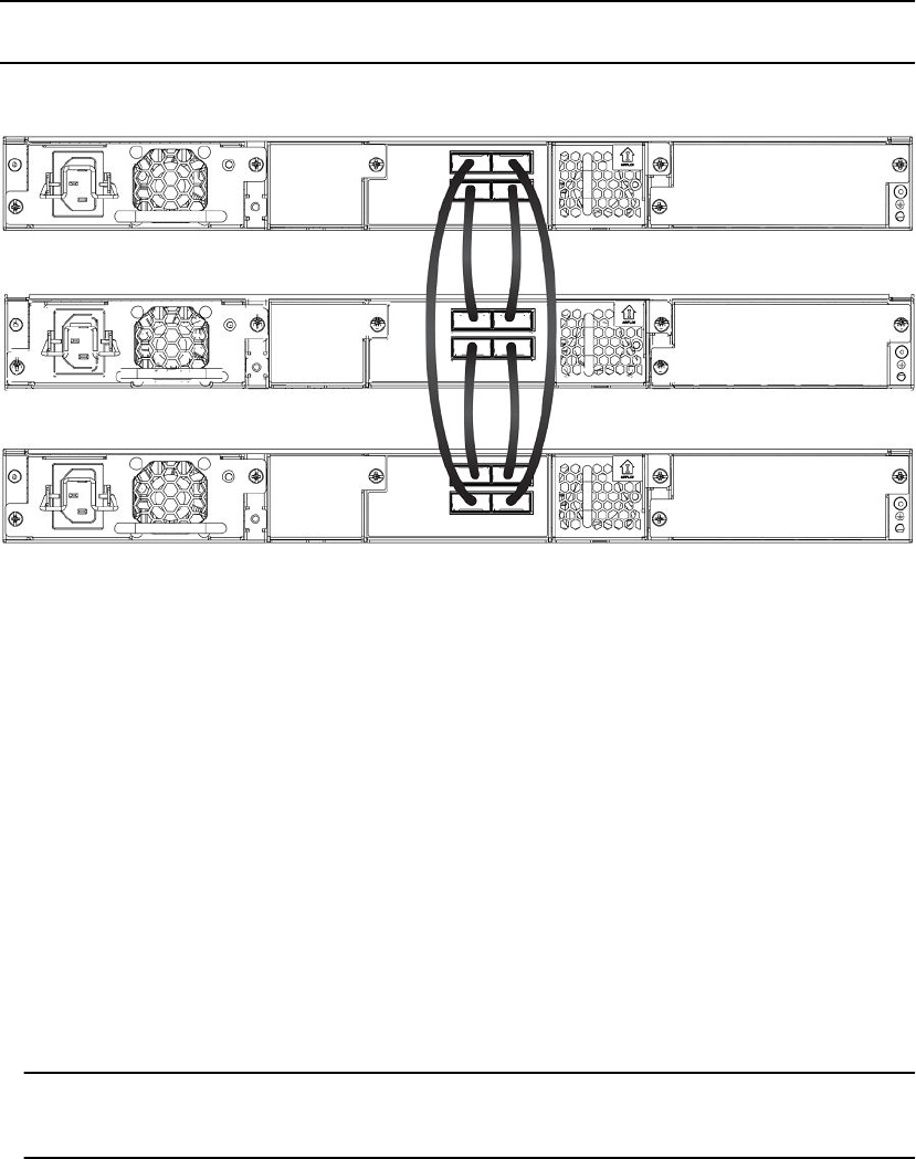
FIGURE 1 Traditional stack with ring topology
Configuring a three-member traditional stack in a ring topology using secure-setup
1. Connect the devices using the stacking ports and stack cabling. For more information, refer to the
appropriate hardware installation guides.
2. Power on the units.
3. Connect your console to the intended active controller. The unit through which you run secure-setup
becomes the active controller by default.
4. Issue the stack enable command on the intended active controller.
device# configure terminal
device(config)# stack enable
device(config)# exit
5. Enter the stack secure-setup command. As shown in the following example, this command triggers
a Brocade proprietary discovery protocol that begins the discovery process in both upstream and
downstream directions. The discovery process produces a list of upstream and downstream devices
that are available to join the stack. Secure-setup can detect up to 11 units in each direction (22 units
total); however, you must select a total number of units that is less than the maximum stack size for
the device because the controller is also part of the stack.
NOTE
During the secure-setup process, after one minute of inactivity, authentication for stack members
expires, forcing you to restart the process.
Configuring a three-member traditional stack in a ring topology using secure-setup
FastIron Ethernet Switch Stacking Configuration Guide 21
53-1003406-03

NOTE
To exit the secure-setup, enter ^C at any time.
device# stack secure-setup
device# Discovering the stack topology...
Current Discovered Topology - RING
Available UPSTREAM units
Hop(s) Type MAC Address
1 FCX624 0000.0039.2d40
2 FCX624 0000.00d5.2100
Available DOWNSTREAM units
Hop(s) Type MAC Address
1 FCX624 0000.00d5.2100
2 FCX624 0000.0039.2d40
Do you accept the topology (RING) (y/n)?: y
6. Enter y to accept the topology. You should see output similar to the following.
Selected Topology:
Active Id Type MAC Address
1 FCX648 0000.00ab.cd00
Selected UPSTREAM units
Hop(s) Id Type MAC Address
1 3 FCX624 0000.0039.2d40
2 2 FCX624 0000.00d5.2100
Selected DOWNSTREAM units
Hop(s) Id Type MAC Address
1 2 FCX624 0000.00d5.2100
2 3 FCX624 0000.0039.2d40
Do you accept the unit ids (y/n)?: y
7. To accept the unit ID assignments, enter y. If you do not want to accept the ID assignments, enter
n.
NOTE
You can use secure-setup to renumber the units in your stack. Refer to Renumbering stack units on
page 91.
If you accept the unit IDs, the stack is formed.
8. To see the stack topology, enter the show stack command.
device# show stack
alone: standalone, D: dynamic config, S: static config
ID Type Role MAC Address Pri State Comment
1 S FCX648 active 0000.00ab.cd00 128 local Ready
2 D FCX624 standby 0000.00d5.2100 60 remote Ready
3 D FCX624 member 0000.0039.2d40 0 remote Ready
active standby
+---+ +---+ +---+
-2/1| 1 |3/1--2/1| 2 |3/1--2/2| 3 |2/1-
+---+ +---+ +---+
Current stack management MAC is 0000.00ab.cd00
For ICX devices, an equal sign (=) is used to show connections, between trunk ports, for example:
ICX6610-24P POE Router# show stack
active standby
+---+ +---+ +---+
=2/1| 1 |2/6==2/6| 5 |2/1==2/1| 4 |2/6=
| +---+ +---+ +---+ |
|-------------------------------------|
NOTE
In this output, D indicates a dynamic configuration. After you perform a write memory, the D
changes to an S, for static configuration.
Traditional Stacking
22 FastIron Ethernet Switch Stacking Configuration Guide
53-1003406-03
9. The active controller automatically checks all prospective stack members to see if they are password-
protected. If a unit is password- protected, you must enter the password before you can add the unit.
If you do not know the password, take one of the following actions:
• Discontinue secure-setup by entering ^C.
• Obtain the device password from the administrator.
• Skip this unit and continue the secure-setup for your stack. The password-protected device and all
devices connected behind it will not be included in the setup process.
In the following example, the second unit is password-protected, so you are asked for the password.
device# stack secure-setup
device# Discovering the stack topology...
Verifying password for the password protected units...
Found UPSTREAM units
Hop(s) Type MAC Address
1 2 FCX648 0000.005e.c480
2 3 FCX648 0000.0005.0000
Enter password for FCX648 located at 2 hop(s): ****
Enter the number of the desired UPSTREAM units (1-2)[1]: 2
Selected Topology:
Active Id Type MAC Address
1 FCX624 0000.0001.4000
Selected UPSTREAM units
Hop(s) Id Type MAC Address
1 2 FCX648 0000.005e.c480
2 3 FCX648 0000.0005.0000
Do you accept the unit id's (y/n)?: y
When the active controller has finished the authentication process, the output shows the suggested
assigned stack IDs for each member.
10.Accept these recommendations, or manually configure stack IDs as described in Renumbering stack
units on page 91.
11.Enter the show stack command to verify that all units are in the ready state.
device# show stack
alone: standalone, D: dynamic config, S: static config
ID Type Role MAC Address Pri State Comment
1 S FCX624 active 0000.0001.4000 128
local Ready
2 S FCX648 standby 0000.005e.c480 0
remote Ready
3 S FCX648 member 0000.0005.0000 0
remote Ready
active standby
+---+ +---+ +---+
-2/1| 1 |3/1--2/1| 2 |3/1--2/2| 3 |2/1-
| +---+ +---+ +---+ |
| |
|-------------------------------------|
Current stack management MAC is 0000.0001.4000
device#
For ICX devices, the output displays the port up state of all ports of the trunk, for example:
ICX6610-24P POE Router# show stack stack-port
active standby
+---+ +---+ +---+
=2/1| 1 |2/6==2/6| 5 |2/1==2/1| 4 |2/6=
| +---+ +---+ +---+ |
| |
|-------------------------------------|
U# Stack-port1 Stack-port2
1 up (1/2/1-1/2/5) up (1/2/6-1/2/10)
up ports: 1/2/1, 1/2/2, 1/2/3, 1/2/4, 1/2/5
up ports: 1/2/6, 1/2/7, 1/2/8, 1/2/9, 1/2/10
4 up (4/2/1-4/2/5) up (4/2/6-4/2/10)
up ports: 4/2/1, 4/2/2, 4/2/3, 4/2/4, 4/2/5
up ports: 4/2/6, 4/2/7, 4/2/8, 4/2/9, 4/2/10
5 up (5/2/1-5/2/5) up (5/2/6-5/2/10)
Traditional Stacking
FastIron Ethernet Switch Stacking Configuration Guide 23
53-1003406-03

up ports: 5/2/1, 5/2/2, 5/2/3, 5/2/4, 5/2/5
up ports: 5/2/6, 5/2/7, 5/2/8, 5/2/9, 5/2/10
NOTE
A 4x10 Gbps port consists of four sub-ports. The show stack stack-port command displays all
sub-ports. In the previous code example, ports 1/2/2-1/2/5 are sub-ports of port 1/2/2, and
1/2/7-1/2/10 are sub-ports of 1/2/7.
12.Once all of the stack units are active, enter the write memory command on the active controller.
This command initiates configuration synchronization, which copies the configuration file of the
active controller to the rest of the stack units.
NOTE
The secure-setup process may modify your configuration with information about new units, stacking
ports, and so on. For this reason, it is very important to save this information by issuing the write
memory command. If you do not do this, you may lose your configuration information the next time
the stack reboots.
The secure-setup process for your stack is now complete.
Invalid stacking trunk errors and network loops
Invalid stacking trunk errors are displayed when stack ports have been assigned incorrectly or do not
match physical connections, or when trunk connections are incorrect.
NOTE
You can verify the connections for each unit based on the MAC address.
When connecting a standalone unit to a stack using data ports, be sure to issue the stack disable
command first on the standalone unit before using the secure-setup utility to add the unit. Otherwise,
the secure-setup utility will issue an invalid stacking trunk error and will not be able to discover the
unit.
When incorrect connections are detected, the secure-setup utility displays a message similar to the
following.
ICX7750-48F Router# stack secure-setup
ICX7750-48F Router#Discovering the stack topology...
Invalid Stacking Trunk connection at Unit with mac cc4e.2439.1280, port 1/3/5
Please check connection and then re-try...
ICX7750-48F Router#
If a stack is incorrectly constructed and contains loop connections, secure-setup cannot be performed.
A message similar to the following is displayed when this occurs.
ICX7750-48F Router# stack secure
CPU utilization too high: 81 percent. Check loops in the network and try again...
Invalid stacking trunk errors and network loops
24 FastIron Ethernet Switch Stacking Configuration Guide
53-1003406-03

Scenario 2 - Configuring a three-member traditional stack in a ring
topology using the automatic setup process
If you are adding clean units without a startup or run-time configuration to a stack, you may elect to use
the automatic setup process.
Complete the following steps to configure a three-member traditional stack in a ring topology using the
automatic setup process.
NOTE
FCX devices determine stacking port candidates through the default-ports setting. An FCX stackable
device with the default port configuration is still considered a clean unit. To ensure that the device
remains a clean unit, do not enter the write memory command on the device.
1. Power on the devices.
2. This process requires clean devices (except for the active controller) that do not contain any
configuration information. To change a device to a clean device, enter the erase startup-config
command and reset the device. When all of the devices are clean, continue with the next step.
NOTE
The physical connections must be sequential and must match the stack configuration.
3. Log in to the device that you want to be the active controller.
4. Configure the rest of the units by assigning ID numbers and module information for each unit. The
stack ID can be any number from 1 through 8 (1 through 12 for ICX 7450 and ICX 7750 devices).
device# configure terminal
device(config)# stack unit 2
device(config-unit-2)# module 1 fcx-24-port-copper-base-module
device(config-unit-2)# module 2 fcx-xfp-1-port-10g-module
device(config-unit-2)# module 3 fcx-xfp-1-port-10g-module
device(config-unit-2)# stack unit 3
device(config-unit-3)# module 1 fcx-24-port-copper-base-module
device(config-unit-3)# module 2 fcx-xfp-1-port-10g-module
device(config-unit-3)# module 3 fcx-xfp-1-port-10g-module
NOTE
Each stack unit must have a unique ID number.
5. Assign a priority to the active controller using the priority command.
device(config)# stack unit 1
device(config-stack-1)# priority 255
Syntax: priority num
The num variable is a value from 0 through 255, where 255 is the highest priority.
6. Assign a priority to the unit that will act as standby controller.
device# configure terminal
device(config)# stack unit 2
device(config-unit-2)# priority 240
7. Enter the write memory command to save your settings.
8. Enter the stack enable command.
9. Physically connect the devices in a stack topology. This triggers an election during which the stack is
automatically configured. For more information about cabling the devices, refer to the appropriate
hardware installation guide.
Scenario 2 - Configuring a three-member traditional stack in a ring topology using the automatic setup process
FastIron Ethernet Switch Stacking Configuration Guide 25
53-1003406-03

NOTE
When you are configuring individual stack units, you can skip ID numbers. However, the sequence
in which the units are connected must match the order in which you configure them. For example,
you could configure unit 1 as FCX624, unit 3 as FCX648, unit 4 as FCX624, unit 6 as FCX624 and
unit 7 as FCX648. The physical connection order must be: active (FCX624), FCX648 (3), FCX624
(4), FCX624 (6) and FCX648 (7). The active controller is stack unit 1.
10.Verify your stack configuration by entering the show running config command.
device# show running-config
Current configuration:
!
ver 05.0.02
!
stack unit 1
module 1 fcx-24-port-copper-base-module
module 2 module 2 fcx-cx4-2-port-16g-module
module 3 fcx-xfp-1-port-10g-module
priority 255
stack-port 2/2/1 2/2/2
stack unit 2
module 1 fcx-24-port-copper-base-module
module 2 fcx-cx4-2-port-16g-module
module 3 fcx-xfp-1-port-10g-module
priority 240
stack-port 2/2/1 2/2/2
stack unit 3
module 1 fcx-24-port-copper-base-module
module 2 fcx-cx4-2-port-16g-module
module 3 fcx-xfp-1-port-10g-module
stack-port 2/2/1 2/2/2
stack enable
!
11.To see information about your stack, enter the show stack command.
device# show stack
alone: standalone, D: dynamic config, S: static config
ID Type Role MAC Address Pri State Comment
1 S FCX624 active 0000.0000.0100 255 local Ready
2 S FCX624 standby 0000.00eb.afc0 240 remote Ready
3 S FCX624 member 0000.005d.a1c0 0 remote Ready
active standby
+---+ +---+ +---+
-2/1| 1 |3/1--2/1| 2 |3/1--2/2| 3 |2/1-
| +---+ +---+ +---+ |
|-------------------------------------|
Current stack management MAC is 0000.0000.0100
device#
Results for ICX devices are similar, with an equal sign (=) to show connections between trunk ports,
rather than the hyphen symbol (-) showing connection.
Configuration tips for building a stack using the automatic setup process
Remember the following tips when using the automatic setup process for building a stack:
• If a new unit configuration matches other unit configurations, the active controller gives this unit the
lowest sequential ID. For example, in a stack configuration that contains eight FCX624
configurations, but only units 1, 4, and 8 are currently active, if you place a new FCX624 unit
between units 4 and 8, the new unit will be assigned unit ID 5. This unit assignment occurs because
unit 5 is the lowest sequential ID that comes directly after active unit 4, even though it might match
unused inactive unit IDs 2, 3, 5, 6, and 7.
• In a ring topology, the same new unit might assume either ID if either direction produces sequential
IDs. For example, in a four-member stack where IDs 2 and 4 are reserved, a new unit could
assume the ID 2 or the ID 4, to create the ID sequence 1, 2, 3 or the sequence 1, 3, 4.
Configuration tips for building a stack using the automatic setup process
26 FastIron Ethernet Switch Stacking Configuration Guide
53-1003406-03

Scenario 3 - Three-member traditional stack in a ring topology using
the manual configuration process
If you are connecting units that have been individually configured for stacking and want unit IDs to be
assigned based on physical sequence, you may want to configure the stack manually.
Complete the following steps to configure a three-member traditional stack in a ring topology using the
manual configuration process.
1. Power on the devices. Do not connect the stacking cables at this point.
2. In this example, device 1 is the active controller, and device 2 is the standby controller. Assign a
priority of 255 to unit 1 and a priority of 240 to unit 3 using the priority command. You do not have to
assign a priority to the third device. Enter the stack enable command on each device.
Unit 1
device# configure terminal
device(config)# stack unit 1
device(config-unit-1)# priority 255
device(config-unit-1)# stack enable
Enable stacking. This unit actively participates in stacking
device(config-unit-1)# write memory
Write startup-config done.
Flash Memory Write (8192 bytes per dot) .Flash to Flash Done.
device(config-unit-1)# end
Unit 2
device# configure terminal
device(config)# stack suggested-id 2
device(config)# stack enable
Enable stacking. This unit actively participates in stacking
Write startup-config done.
Flash Memory Write (8192 bytes per dot) .Flash to Flash Done.
device(config-unit-1)# end
Unit 3
device# configure terminal
device(config)# stack suggested-id 3
device(config)# stack unit 1
device(config-unit-1)# priority 240
device(config-unit-1)# stack enable
Enable stacking. This unit actively participates in stacking
device(config-unit-1)# end
3. Connect the devices in a stack topology. The active controller retains its ID. The rest of the units are
assigned unique ID numbers depending on the sequence in which you connected them.
For more information about cabling the devices, refer to the appropriate hardware installation guide.
NOTE
This method does not guarantee sequential stack IDs if you do not configure the optional stack
suggested-id command on each standalone unit. If you want to change stack IDs to make them
sequential, you can use secure-setup. Refer to Renumbering stack units on page 91.
NOTE
You can configure the stack suggested-id command in a standalone unit before using the stack
enable command to cause the unit to join the stack. A unit is assigned the suggested ID if no other
unit in the stack has that ID.
Scenario 3 - Three-member traditional stack in a ring topology using the manual configuration process
FastIron Ethernet Switch Stacking Configuration Guide 27
53-1003406-03
Verifying a traditional stack configuration
Log in to the active controller and verify the stack information by entering the show running-config
and show stack or show stack detail commands. If your stack is configured properly, you should see
the following:
• One active controller, one standby controller, and stack members
• All stack members with a status of Ready
The following output shows a sample configuration of an FCX traditional stack.
device# show stack
alone: standalone, D: dynamic config, S: static config
ID Type Role MAC Address Pri State Comment
2 S FCX648POE standby 0000.0002.0000 0 remote Ready
3 S FCX624POE member 0000.0003.0000 0 remote Ready
4 S FCX648 member 0000.0004.0000 0 remote Ready
5 S FCX648POE member 0000.0000.0000 0 remote Ready
8 S FCX648POE active 0000.0001.0000 128 local Ready
active standby
+---+ +---+ +---+ +---+
-2/1| 8 |2/2--2/1| 4 |2/2--2/1| 3 |2/2--2/1| 2 |2/2-
| +---+ +---+ +---+ +---+ |
|--------------------------------------------------|
Current stack management MAC is 0000.0001.0000
Results for ICX devices are similar, with an equal sign (=) to show connections between trunk ports,
rather than the hyphen symbol (-) showing connections.
The next example shows output from the show version command for the same FCX stack.
device# show version
Copyright (c) 1996-2009 Brocade Communications Systems, Inc.
UNIT 8: compiled on Jun 17 2009 at 06:23:29 labeled as FCX06000a359
(3578117 bytes) from Primary FCX06000a359.bin
SW: Version 06.0.00a359T7f1
UNIT 2: compiled on Jun 17 2009 at 06:23:29 labeled as FCX06000a359
(3578117 bytes) from Primary FCX06000a359.bin
SW: Version 06.0.00a359T7f1
UNIT 3: compiled on Jun 17 2009 at 06:23:29 labeled as FCX06000a359
(3578117 bytes) from Primary FCX06000a359.bin
SW: Version 06.0.00a359T7f1
UNIT 4: compiled on Jun 17 2009 at 06:23:29 labeled as FCX06000a359
(3578117 bytes) from Primary FCX06000a359.bin
SW: Version 06.0.00a359T7f1
Boot-Monitor Image size = 365257, Version:06.0.00T7f5 (grz06000)
HW: Stackable FCX648P-POE
==========================================================================
UNIT 2: SL 1: FCX-48G POE 48-port Management Module
P-ENGINE 0: type DB90, rev 01
P-ENGINE 1: type DB90, rev 01
==========================================================================
UNIT 2: SL 2: FCX-2XGC 2-port 16G Module (2-CX4)
==========================================================================
UNIT 3: SL 1: FCX-24G POE 24-port Management Module
P-ENGINE 0: type DB90, rev 01
==========================================================================
UNIT 3: SL 2: FCX-2XGC 2-port 16G Module (2-CX4)
==========================================================================
UNIT 3: SL 3: FCX-2XG 2-port 10G Module (2-XFP)
==========================================================================
UNIT 4: SL 1: FCX-48G 48-port Management Module
P-ENGINE 0: type DB90, rev 01
P-ENGINE 1: type DB90, rev 01
==========================================================================
UNIT 4: SL 2: FCX-2XGC 2-port 16G Module (2-CX4)
==========================================================================
UNIT 4: SL 3: FCX-2XG 2-port 10G Module (2-XFP)
==========================================================================
UNIT 8: SL 1: FCX-48G POE 48-port Management Module
P-ENGINE 0: type DB90, rev 01
Verifying a traditional stack configuration
28 FastIron Ethernet Switch Stacking Configuration Guide
53-1003406-03

P-ENGINE 1: type DB90, rev 01
==========================================================================
UNIT 8: SL 2: FCX-2XGC 2-port 16G Module (2-CX4)
==========================================================================
800 MHz Power PC processor (version 33/0022) 144 MHz bus
65536 KB flash memory
256 MB DRAM
Monitor Option is on
STACKID 8 system uptime is 21 hours 2 minutes 23 seconds
STACKID 2 system uptime is 21 hours 2 minutes 22 seconds
STACKID 3 system uptime is 21 hours 2 minutes 23 seconds
STACKID 4 system uptime is 21 hours 2 minutes 22 seconds
The system : started=warm start reloaded=by "reload"
My stack unit ID = 8, bootup role = active
*** NOT FOR PRODUCTION ***
NOTE
For field descriptions of the show running-config command, refer to “Displaying running configuration
information.”
NOTE
For field descriptions of the show stack and show stack detail commands, refer to “Displaying stack
information.”
The output from the show stack command contains a visual diagram of the stack. The dashed line
between ports 1/2/1 and 3/2/1 indicates that this stack is configured in a ring topology. If the link
between ports 1/2/1 and 3/2/1 is lost, the stack topology changes to linear, and the diagram changes to
resemble the following diagram.
active standby
+---+ +---+ +---+
-2/1| 1 |3/1--2/1| 2 |3/1--2/2| 3 |2/1-
+---+ +---+ +---+
In the diagrams, the interfaces at either end of a stack member are stacking ports. If no interface is
displayed, it indicates that there is no stacking port configured. For example, the following diagram
shows that stack units 1 and 3 each have only one stacking port configured.
active standby
+---+ +---+ +---+
| 1 |3/1--2/1| 2 |3/1--2/2| 3 |
+---+ +---+ +---+
For more detailed information, you can enter the show stack detail command.
Displaying information on stack connections
You can check the data connections between stack units with the show stack connection command.
When the show stack connection command output includes the message *** error: one-way,
this may indicate a stack port to non-stack-port connection. When this occurs, the side of the connection
that is incorrectly configured as a stack port must be converted to a data port.
Displaying information on stack connections
FastIron Ethernet Switch Stacking Configuration Guide 29
53-1003406-03

In the following example, the show stack connection command output indicates that CPU-to-CPU
connections are working properly between all 12 members of the stack.
ICX7750-48F Router# show stack connection
Probing the topology. Please wait ...
ICX7750-48F Router#
active
+---+ +---+ +---+ +---+ +---+ +---+
-2/1| 1 |2/4--3/1| C |3/4==2/1| B |2/4==2/1| A |2/4--2/1| 9 |2/4--2/1| 8 |2/4-
| +---+ +---+ +---+ +---+ +---+ +---+ |
| |
| standby |
| +---+ +---+ +---+ +---+ +---+ +---+ |
-2/4| 2 |2/1--2/4| 3 |2/1--2/4| 4 |2/1==2/4| 5 |2/1--2/4| 6 |2/1==2/4| 7 |2/1-
+---+ +---+ +---+ +---+ +---+ +---+
trunk probe results: 12 links
Link 1: u1 -- u2, num=1
1: 1/2/1 (P0) <---> 2/2/4 (P1)
Link 2: u1 -- u12, num=1
1: 1/2/4 (P1) <---> 12/3/1 (P0)
Link 3: u2 -- u3, num=1
1: 2/2/1 (P0) <---> 3/2/4 (P1)
Link 4: u3 -- u4, num=1
1: 3/2/1 (P0) <---> 4/2/4 (P1)
Link 5: u4 -- u5, num=2
1: 4/2/1 (T0) <---> 5/2/4 (T1)
2: 4/2/2 (T0) <---> 5/2/5 (T1)
Link 6: u5 -- u6, num=1
1: 5/2/1 (P0) <---> 6/2/4 (P1)
Link 7: u6 -- u7, num=3
1: 6/2/1 (T0) <---> 7/2/4 (T1)
2: 6/2/2 (T0) <---> 7/2/5 (T1)
3: 6/2/3 (T0) <---> 7/2/6 (T1)
Link 8: u7 -- u8, num=1
1: 7/2/1 (P0) <---> 8/2/4 (P1)
Link 9: u8 -- u9, num=1
1: 8/2/1 (P0) <---> 9/2/4 (P1)
Link 10: u9 -- u10, num=1
1: 9/2/1 (P0) <---> 10/2/4 (P1)
Link 11: u10 -- u11, num=2
1: 10/2/1 (T0) <---> 11/2/4 (T1)
2: 10/2/2 (T0) <---> 11/2/5 (T1)
Link 12: u11 -- u12, num=2
1: 11/2/1 (T0) <---> 12/3/4 (T1)
2: 11/2/2 (T0) <---> 12/3/5 (T1)
CPU to CPU packets are fine between 12 units.
FCX stack configuration overview
The following table provides an overview of FCX stacking capabilities.
FCX traditional stacking capabilityTABLE 4
Stacking capability FCX Additional information
Topologies supported Ring and linear Refer to FCX stack topologies on
page 31.
Maximum stack size 8 Traditional stacking only
Maximum stacking distance 300 meters Refer to Extended distance stacking
on page 18 for more information.
FCX stack configuration overview
30 FastIron Ethernet Switch Stacking Configuration Guide
53-1003406-03

FCX traditional stacking capability (Continued)TABLE 4
Stacking capability FCX Additional information
Stacking ports 4 ports:
Two 16 Gbps ports in rear (Slot 2)
Two 10 Gbps ports in front (Slot 3)
NOTE
No stacking ports on FCX-I or FCX-
E models without upgrade.
Refer to Configuring FCX stacking
ports on page 34.
Default ports Ports 1/2/1 and 1/2/2 Use the default-ports command to
change to 1/3/1 and 1/3/2. Refer to
Changing default stacking port
configurations on page 37.
Reconfigurable ports Default stacking ports can be
reconfigured as data ports.
10 Gbps and 16 Gbps port speeds
can be reconfigured.
Refer to Configuring a default
stacking port to function as a data
port on page 40.
For information on changing
stacking port speeds, refer to
Configuring FCX stacking ports on
page 34.
Stack trunks Not supported
Hitless switchover and hitless
failover
Supported Refer to Hitless stacking on page
129.
License requirements None
NOTE
FCX-I or FCX-E models cannot be
used for stacking without an optional
10 Gbps SFP+ module.
Configuration options Manual and automatic, including
Secure-setup
Refer to Traditional stack
construction methods on page 20.
Access methods TFTP, SCP Software images, boot images, and
signatures can be downloaded to a
stack using TFTP and SCP
applications. Refer to the FastIron
Ethernet Switch Software Upgrade
Guide for more information.
Traditional stacking CLI All traditional stacking CLI is
supported.
Refer to Traditional stack CLI
commands on page 78.
FCX stack topologies
A Brocade traditional stack can contain all one model, or any combination of the FCX models. You can
mix 24-port and 48-port FCX devices in a single stack, to a maximum of eight units per stack.
The procedure for cabling a stack of FCX devices differs depending on whether your stack contains
FCX-E and FCX-I devices. The following two figures show FCX-S or FCXS-F devices cabled in linear
and ring stack topologies. These devices are cabled from the rear panel.
FCX stack topologies
FastIron Ethernet Switch Stacking Configuration Guide 31
53-1003406-03
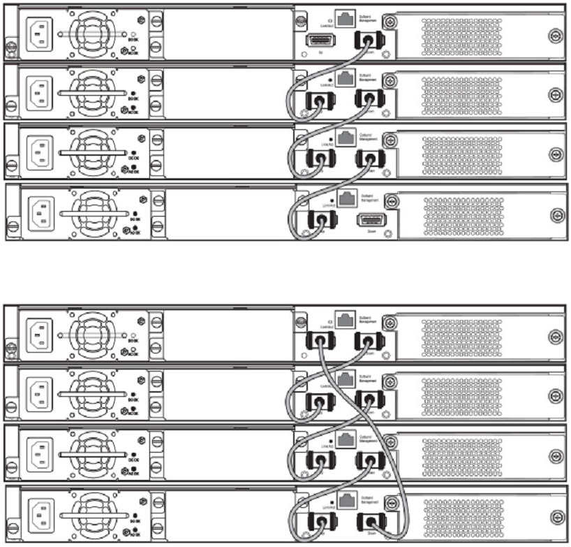
FIGURE 2 FCX linear stack topology
FIGURE 3 FCX ring stack topology
The next two figures show FCX-E devices configured in stacks with a linear topology and a ring
topology. These devices are cabled from the front panel.
Traditional Stacking
32 FastIron Ethernet Switch Stacking Configuration Guide
53-1003406-03
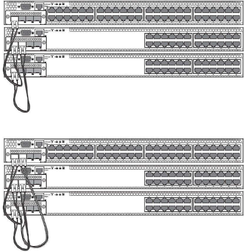
FIGURE 4 FCX-E linear topology stack using SFP+ module ports
FIGURE 5 FCX-E ring topology stack using SFP+ module ports
The following figure shows a mixed linear topology stack of FCX-S, FCXS-F, and FCX-E or FCX-I
devices. Because the FCX-E and FCX-I devices are cabled from the front panel, but FCX-S and FCXS-
F devices are cabled from the rear panel by default, you must reconfigure the default stacking ports on
FCX-S or FCXS-F devices to the ports on the front panel. For more information about reconfiguring
default stacking ports, refer to Configuring default ports on FCX or ICX devices on page 36.
Traditional Stacking
FastIron Ethernet Switch Stacking Configuration Guide 33
53-1003406-03
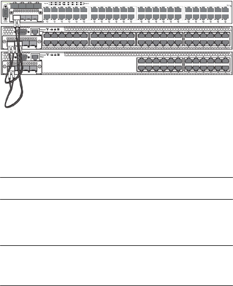
FIGURE 6 Mixed linear stack of FCX-E devices and FCX-S devices
Configuring an FCX traditional stack
FCX devices cannot be intermixed with non-FCX devices, and FCX devices have additional potential
stacking ports.
Every FCX-S and FCXS-F device contains two default 16 Gbps stacking ports on the rear panel and
two 10 Gbps ports on the front panel that can also be used as stacking ports.
NOTE
FCX-I and FCX-E devices can only be used for stacking if they have an optional 10 Gbps SFP+
module installed in the front panel. These devices do not have stacking ports on the rear panels.
An FCX traditional stack may contain up to eight 24-port and 48-port devices, using any combination
of the rear panel stacking ports and the front panel optional stacking ports. For FCX-S and FCXS-F
devices, to use ports other than the factory-default 16 Gbps ports, you must define the ports for each
device in the runtime configuration. You can also configure the 16 Gbps ports to operate as 10 Gbps
ports.
NOTE
The automatic setup process does not work for FCX devices that do not contain the default port
information in their clean unit configurations. An FCX "clean unit" may contain a default port
configuration and still be considered a clean unit. To preserve this state, do not execute the write
memory command on the unit before you build the stack. (The write memory command adds a
startup-config, and the device is no longer a clean unit.)
Configuring FCX stacking ports
FCX-S and FCXS-F devices have two 10 Gbps ports on the front panel and two 16 Gbps ports on the
rear panel. All of these ports may be used as stacking ports; however, the non-default ports must be
configured as stacking ports when you set up your FCX-S or FCXS-F traditional stack.
FCX-I and FCX-E devices do not have 16 Gbps ports on the rear panel. These devices may be used
in a traditional stack by installing the 10 Gbps 4-port SFP+ module in the module slot on the front
Configuring an FCX traditional stack
34 FastIron Ethernet Switch Stacking Configuration Guide
53-1003406-03

panel. Once you have installed one of these modules, ports 1 and 2 act as the default stacking ports.
However, you can also use these ports to pass regular traffic, once you have disabled the stacking
default.
NOTE
If you are adding FCX-E or FCX-I devices to a stack containing FCX-S or FCXS-F devices, you must
reconfigure the stacking ports on the FCX-S or FCXS-F devices to be the 10 Gbps ports on the front
panel. You can then connect all of the devices in a stack using front panel ports.
Changing FCX-S and FCXS-F CX4 ports from 16 Gbps to 10 Gbps
You can configure the 16 Gbps CX4 ports to operate as 10 Gbps ports using the speed-duplex
command as shown in the following example.
device(config-if-e10000-cx4-1/2/1)# speed-duplex 10g-full
device(config-if-e10000-cx4-1/2/1)# end
device# show interface br | in Up
1/1/4 Up Forward Full 1G None No 1 0 0000.0088.0003
1/2/1 Up Forward Full 10G None No 1 0 0000.0088.0019
1/3/1 Up Forward Full 10G None No N/A 0 0000.0088.001b
3/3/1 Up Forward Full 10G None No N/A 0 0000.0014.9df3
mgmt1 Up None Full 1G None No 1
0 0000.0088.0018
device# show interface e 1/2/1
16GigabitEthernet1/2/1 is up, line protocol is up
Hardware is 16GigabitEthernet, address is 0000.0088.0019 (bia 0000.0088.0019)
Interface type is 16Gig CX4
Configured speed 10Gbit, actual 10Gbit, configured duplex fdx, actual fdx
Member of L2 VLAN ID 1, port is untagged, port state is FORWARDING
BPDU guard is Disabled, ROOT protect is Disabled
Link Error Dampening is Disabled
STP configured to ON, priority is level0, mac-learning is enabled
Flow Control is enabled
mirror disabled, monitor disabled
Not member of any active trunks
Not member of any configured trunks
No port name
IP MTU 1500 bytes, encapsulation ethernet
300 second input rate: 0 bits/sec, 0 packets/sec, 0.00% utilization
300 second output rate: 0 bits/sec, 0 packets/sec, 0.00% utilization
0 packets input, 0 bytes, 0 no buffer
Received 0 broadcasts, 0 multicasts, 0 unicasts
0 input errors, 0 CRC, 0 frame, 0 ignored
0 runts, 0 giants
0 packets output, 0 bytes, 0 underruns
Transmitted 0 broadcasts, 0 multicasts, 0 unicasts
0 output errors, 0 collisions
Relay Agent Information option: Disabled
Syntax: speed-duplex { 10-full | 10-half | 100-full | 100-half | 1000-full-master | 1000-full-slave |
10g-full | auto }
•10-full - 10 Mbps, full duplex
•10-half - 10 Mbps, half duplex
•100-full - 100 Mbps, full duplex
•100-half - 100 Mbps, half duplex
•1000-full-master - 1 Gbps, full duplex, master
•1000-full-slave - 1 Gbps, full duplex, slave
•10g-full - 10 Gbps, full duplex
•auto - Auto-negotiation
Changing FCX-S and FCXS-F CX4 ports from 16 Gbps to 10 Gbps
FastIron Ethernet Switch Stacking Configuration Guide 35
53-1003406-03

NOTE
Both ends of a link must be configured for 10 Gbps for the link to operate as 10 Gbps. If you want the
link to operate as a 16 Gbps link, both ends of the link must be configured for 16 Gbps.
Changing FCX-S and FCXS-F CX4 ports from 10 Gbps to 16 Gbps
To change the CX4 ports from 10 Gbps back to 16 Gbps, enter the no speed-duplex 10g command
at the interface level of the CLI as shown in the following example.
device(config-if-e10000-cx4-1/2/1)# no speed-duplex 10g
device(config-if-e10000-cx4-1/2/1)# show interface br | in Up
1/1/4 Up Forward Full 1G None No 1 0 0000.0088.0003
1/2/1 Up Forward Full 16G None No 1 0 0000.0088.0019
1/3/1 Up Forward Full 10G None No N/A 0 0000.0088.001b
3/3/1 Up Forward Full 10G None No N/A 0 0000.0014.9df3
mgmt1 Up None Full 1G None No 1 0 0000.0088.0018
device(config-if-e10000-cx4-1/2/1)# show interface e 1/2/1
16GigabitEthernet1/2/1 is up, line protocol is up
Hardware is 16GigabitEthernet, address is 0000.0088.0019 (bia 0000.0088.0019)
Interface type is 16Gig CX4
Configured speed 16Gbit, actual 16Gbit, configured duplex fdx, actual fdx
Member of L2 VLAN ID 1, port is untagged, port state is FORWARDING
BPDU guard is Disabled, ROOT protect is Disabled
Link Error Dampening is Disabled
STP configured to ON, priority is level0, mac-learning is enabled
Flow Control is enabled
mirror disabled, monitor disabled
Not member of any active trunks
Not member of any configured trunks
No port name
IP MTU 1500 bytes, encapsulation ethernet
300 second input rate: 0 bits/sec, 0 packets/sec, 0.00% utilization
300 second output rate: 0 bits/sec, 0 packets/sec, 0.00% utilization
0 packets input, 0 bytes, 0 no buffer
Received 0 broadcasts, 0 multicasts, 0 unicasts
0 input errors, 0 CRC, 0 frame, 0 ignored
0 runts, 0 giants
0 packets output, 0 bytes, 0 underruns
Transmitted 0 broadcasts, 0 multicasts, 0 unicasts
0 output errors, 0 collisions
Relay Agent Information option: Disabled
device(config-if-e10000-cx4-1/2/1)#
Configuring default ports on FCX or ICX devices
FCX and ICX stackable devices typically ship with two default stacking ports configured. Use the
stack-port command if you want to select only one of these factory default ports as the stacking port.
If you do not configure stack-port, both default ports will operate as stacking ports.
Use the default-ports command to designate ports other than the factory default ports as stacking
ports. You must designate any additional potential stacking ports using the default-ports command on
each unit that will be included in the stack before building a stack. Once you have designated these
ports using the default-ports command on all units, you can use any construction method to build a
stack. The active controller then learns the port configuration for each unit.
NOTE
You cannot change the setting for a default port if the port is in use.
Changing FCX-S and FCXS-F CX4 ports from 10 Gbps to 16 Gbps
36 FastIron Ethernet Switch Stacking Configuration Guide
53-1003406-03

NOTE
On FCX devices, a shorter 4-byte Ethernet preamble for the Ethernet frame is used when a port is
configured as a default stacking port. For non-default ports, the standard 8-byte Ethernet preamble is
used. To use a default stacking port as a regular data port, the standard 8-byte Ethernet preamble must
be explicitly enabled on the port using the long-preamble command. For details, refer to Configuring a
default stacking port to function as a data port on page 40.
Changing default stacking port configurations
NOTE
FCX-I and FCX-E devices cannot be used in a traditional stack without the addition of an optional 10
Gbps SFP+ module.
For FCX-E and FCX-I devices, ports 1 and 2 of the optional 10 Gbps SFP+ module (slot 2) act as the
default stacking ports. You can change the default stacking ports to 3 and 4 on this module, or you can
disable stacking on all of the module ports.
NOTE
Do not connect stacking ports to non-stacking ports. Stacking ports have a proprietary packet format
that renders them incompatible with regular ports even when they are forwarding regular packets.
The following example changes the default ports on a 10 Gbps module from 1 and 2 to 3 and 4.
device 10g-1(config)# stack unit 1
10g-1(config-unit-1)#
10g-1(config-unit-1)# default-ports 1/2/3 1/2/4
Slot and port designations for FastIron FCX stackable devices TABLE 5
Device Slot 1 Slot 2 Slot 3 Slot 4
FCX624S-F 24 10/100/1000 ports on front panel Two 16 Gbps ports on
rear panel
Two 10 Gbps
ports on front
panel
N/A
FCX648S-F 48 10/100/1000 ports on front panel Two 16 Gbps ports on
rear panel
Two 10 Gbps
ports on front
panel
N/A
FCX-E devices with four-
port 1 Gbps SFP module
Four-port 1 Gbps SFP module plus
the first four copper ports act as a
combo port. Slot 1 also contains the
remaining 20 10/100/1000 ports.
N/A N/A N/A
FCX-I devices with four-
port 1 Gbps SFP module
Four-port 1 Gbps SFP module plus
the first four copper ports act as a
combo port. Slot 1 also contains the
remaining 20 10/100/1000 ports.
N/A N/A N/A
Changing default stacking port configurations
FastIron Ethernet Switch Stacking Configuration Guide 37
53-1003406-03

Slot and port designations for FastIron FCX stackable devices (Continued)TABLE 5
Device Slot 1 Slot 2 Slot 3 Slot 4
FCX-E devices with four-
port 10 Gbps SFP+
module
48 10/100/1000 ports on front panel Four-port 10 Gbps
SFP+ module
(supports stacking)
N/A N/A
FCX-I devices with four-
port 10 Gbps SFP+
module
48 10/100/1000 ports on front panel Four-port 10 Gbps
SFP+ module
(supports stacking)
N/A N/A
NOTE
In linear topologies, make sure that end units have only one stacking port configured (secure-setup
automatically configures only one stacking port for an end unit).
Configuring a single stack port
To configure a single stack port, enter a command similar to the following.
device(config)# stack unit 3
device(config-unit-3)# stack-port 3/2/1
Syntax: [no] stack-port stack-unit/slotnum/portnum
If you enter an incorrect stack port number, an error similar to the following is displayed.
device(config-unit-3)# stack-port 3/4/1
Error! port 3/4/1 is invalid
device(config-unit-3)# stack-port 3/2/1
To return both default stacking ports to stacking status, enter the no stack-port command on the ports
that have been reconfigured to act as stacking ports.
NOTE
By default, if both ports are stacking ports, they are displayed by the system only when stacking is
enabled. If only one port is configured as a stacking port, the system always displays this port.
Using secure-setup to build a traditional FCX stack
After designating the desired stacking ports on each FCX unit and connecting the units to operate as a
stack, you can use the secure-setup utility to build a traditional stack.
1. On stack unit 1, enter stack enable.
2. Enter stack secure-setup to discover the stack topology.
NOTE
To cancel the secure-setup process and exit the session at any time, enter CTRL+C. The message
"secure-setup cancelled" will be displayed.
device# stack enable
device# stack secure-setup
device# Discovering the stack topology...
Available UPSTREAM units
Hop(s) Id Type MAC Address
Using secure-setup to build a traditional FCX stack
38 FastIron Ethernet Switch Stacking Configuration Guide
53-1003406-03

1 new FCX648POE 0000.00d6.0511
2 new FCX624 0000.0099.0000
Enter the number of the desired UPSTREAM units (0-2)[0]: 2
Selected Topology:
Active Id Type MAC Address
1 FCX624POE 0000.00e5.0100
Selected UPSTREAM units
Hop(s) Id Type MAC Address
1 2 FCX648POE 0000.00d6.0511
2 3 FCX624 0000.0099.0000
3. Review the topology and the unit IDs that are displayed. When prompted, enter y to accept the
assigned unit IDs.
NOTE
You can also enter n to decline the assigned unit IDs. The system then prompts you to enter different
IDs, warns that changing the unit IDs manually may modify stack configuration, and recommends
that you save the configuration and reload it after the stack is ready.
Do you accept the unit ids (y/n)?: y
device# Election, was alone --> active, assigned-ID=1, total 3 units, my
priority=128
Election, was active, no role change, assigned-ID=1, total 3 units, my priority=128
reset unit 2: diff bootup id=1
reset unit 3: diff bootup id=1
Election, was alone --> active, assigned-ID=1, total 3 units, my priority=128
Detect stack member 2 POE capable
Detect stack unit 2 has different startup config flash, will synchronize it
Detect stack unit 3 has different startup config flash, will synchronize it
Done hot swap: Set stack unit 3 to Ready
Done hot swap: Set stack unit 2 to Ready
Synchronize startup config to stack unit 2
Flash Memory Write (8192 bytes per dot).Synchronize startup config to stack unit 3
Flash Memory Write (8192 bytes per dot).POE: Stack unit 2 Power supply 1 with 4
10000 mwatts capacity is up
Stack unit 2 Power supply 2 is down
Stack unit 3 Power supply 1 is up
Stack unit 3 Power supply 2 is down
Config changed due to add/del units. Do write mem if you want to keep it
Election, was active, no role change, assigned-ID=1, total 3 units, my priority=128
device#
Config changed due to add/del units. Do write mem if you want to keep it
device# PoE Info: PoE module 1 of Unit 2 on ports 2/1/1 to 2/1/48 detected.
Initializing....
PoE Info: PoE module 1 of Unit 2 initialization is done.
4. Review remaining setup information as it is displayed. Then enter show stack to display an overview
of the stack topology.
device# show stack
alone: standalone, D: dynamic config, S: static config
ID Type Role MAC Address Pri State Comment
1 S FCX624POE active
0000.00e5.0100 128 local Ready
2 D FCX648POE standby
0000.00d6.0511 0 remote Ready
3 D FCX624 member
0000.0099.0000 0 remote Ready
standby active
+---+ +---+ +---+
| 3 |3/1--3/1| 2 |2/1--2/1| 1 |
+---+ +---+ +---+
Current stack management MAC is 0000.00e5.0100
5. Once you have reviewed the topology, enter the write memory command as directed earlier in the
secure-setup utility output.
device# write memory
Write startup-config done.
Flash Memory Write (8192 bytes per dot) .Flash to Flash Done.
device# show stack
alone: standalone, D: dynamic config, S: static config
ID Type Role MAC Address Pri State Comment
1 S FCX624POE active
0000.00e5.0100 128 local Ready
2 S FCX648POE standby
0000.00d6.0511 0 remote Ready
Traditional Stacking
FastIron Ethernet Switch Stacking Configuration Guide 39
53-1003406-03

3 S FCX624 member
0000.0099.0000 0 remote Ready
standby active
+---+ +---+ +---+
| 3 |3/1--3/1| 2 |2/1--2/1| 1 |
+---+ +---+ +---+
Current stack management MAC is 0000.00e5.0100
Configuring a default stacking port to function as a data port
You can configure one of the two default stacking ports as a stacking port and the other port as a
regular data port. By default, the 4-byte Ethernet preamble for the Ethernet frame is used when a port
is configured as a default stacking port. The shorter preamble compensates for extra overhead
required by the stacking protocol. To use a default stacking port as a regular data port, the Ethernet
preamble must be set to 8 bytes.
To configure a default port to use the longer preamble, enter the long-preamble command at the
interface level of the CLI.
device(config)# interface ethernet 1/2/1
device(config-if-e10000-1/2/1)# long-preamble
Syntax: [no] long-preamble
Use the no form of the command to revert to the 4-byte Ethernet preamble on a default stacking port.
ICX 6430 or ICX 6450 stack configuration overview
The following table provides an overview of ICX 6430 and ICX 6450 stacking capabilities.
ICX 6430 and ICX 6450 traditional stacking capabilityTABLE 6
Stacking capability ICX 6430 and ICX 6450 Additional information
Topologies supported Ring and linear
NOTE
ICX 6450 devices can also be
installed in a mixed stack.
Refer to ICX 6430 and ICX 6450
stack topologies on page 41. For
information on installing the ICX
6450 in a mixed stack, refer to
Mixed Stacking on page 151.
Maximum stack size 4 ICX 6430 units
8 ICX 6450 units
Traditional stacking only. Any
combination of ICX 7450 devices
may be stacked.
Maximum stacking distance 100 meters Refer to Extended distance stacking
on page 18 for more information on
available media.
Stacking ports 4 ports on front panel (Ports 1, 2, 3,
and 4)
Ports 2 and 4 require additional
configuration.
Refer to ICX 6430 and ICX 6450
stack topologies on page 41 and
Connecting ICX 6450 or ICX 6430
devices in a traditional stack on
page 43.
Default ports Ports 1 and 3 Default ports cannot be changed.
Use the stack-port command to
select a single default port.
Configuring a default stacking port to function as a data port
40 FastIron Ethernet Switch Stacking Configuration Guide
53-1003406-03

ICX 6430 and ICX 6450 traditional stacking capability (Continued)TABLE 6
Stacking capability ICX 6430 and ICX 6450 Additional information
Reconfigurable ports Stacking ports can be used as data
uplink ports if stacking is not
enabled.
Stacking ports can be used as data
ports, but not vice versa. Refer to
Connecting ICX 6450 or ICX 6430
devices in a traditional stack on
page 43.
Trunking Supported; must be configured. Refer to Configuring an ICX 6430 or
ICX 6450 traditional stack on page
44.
Hitless switchover and hitless
failover
Supported Refer to Hitless stacking on page
129.
License requirements None required for default stacking
ports
For the ICX 6450, an
ICX6450-2X10G-LIC-POD license is
required to enable ports 2 and 4 in
10-Gbps port speed. Refer to the
FastIron Ethernet Switch Software
Licensing Guide for more
information.
Configuration options Manual and automatic, including
Secure-setup
Refer to Traditional stack
construction methods on page 20.
Access methods TFTP, SCP Software images, boot images, and
signatures can be downloaded to a
stack using TFTP and SCP
applications. Refer to the FastIron
Ethernet Switch Software Upgrade
Guide for more information.
Traditional stacking CLI All traditional stacking CLI is
supported.
Refer to Traditional stack CLI
commands on page 78.
ICX 6430 and ICX 6450 stack topologies
In a linear stack topology, there is a single stack cable connection between each switch that carries two-
way communications across the stack. In a ring stack topology, an extra cable connects the top and
bottom switches to form a "ring" or "closed-loop." The closed-loop cable provides a redundant path for
the stack link, so if one link fails, stack communications can be maintained. The closed-loop cable
provides more stacking bandwidth and shortens the paths between some units.
The following figures show stacking cabling configurations. All the stacking configuration examples that
follow are applicable to both ICX 6430 and ICX 6450 switches; however, the two types of switches
cannot be combined in the same stack.
The following figure shows both linear and ring stacking configurations with only one port connection
per trunk. The one-port-per-trunk topology is the most common stacking configuration.
ICX 6430 and ICX 6450 stack topologies
FastIron Ethernet Switch Stacking Configuration Guide 41
53-1003406-03
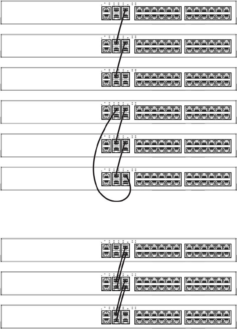
FIGURE 7 ICX 6430 or ICX 6450 stacking with one port per trunk
The following figure shows how stack cables are connected between switches in a linear stack to form
dual links.
FIGURE 8 ICX 6430 or ICX 6450 linear stacking configuration
The following figure shows how stack cables are connected between switches in a ring configuration.
Traditional Stacking
42 FastIron Ethernet Switch Stacking Configuration Guide
53-1003406-03
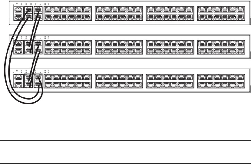
FIGURE 9 ICX 6430 or ICX 6450 ring stacking configuration
Connecting ICX 6430 or ICX 6450 devices in a traditional stack
NOTE
Although ICX 6430 and ICX 6450 devices share many stacking characteristics, ICX 6430 models and
ICX 6450 models cannot be mixed in the same stack.
ICX 6430 and ICX 6450 devices support linear and ring stack topologies and can also operate as
standalone devices. Up to four ICX 6430 units can be combined in a stack. Up to eight ICX 6450 units
can be combined in a stack.
ICX 6430 and ICX 6450 devices have four ports on the front panel that can be used for a stack
configuration. If stacking is not enabled on the ports, then all four stacking ports can be used for data or
uplink ports.
ICX 6430 and ICX 6450 devices ship with two default stacking ports configured. When stacking is
enabled, ports 1 and 3 are dedicated to stacking and cannot be used for data ports. Use the stack-port
command to select only one of these default ports as the stacking port. If you do not select a default
port as the stacking port, both default ports operate as stacking ports. For more information about using
the stack-port command on ICX 6430 or ICX 6450 devices, refer to Error messages encountered
during configuration of an ICX 6430 or ICX 6450 traditional stack on page 47.
By default, ICX 6430 and ICX 6450 devices are not configured for trunked stacking. You can
dynamically configure or remove a stacking trunk port configuration using the stack-trunk command or
the multi-stack-trunk command. For more information about these commands, refer to Configuring an
ICX 6430 or ICX 6450 traditional stack on page 44.
ICX 6430 and ICX 6450 devices support hitless stacking switchover and failover. The secure-setup
utility is supported for ICX 6430 and ICX 6450 devices.
Connecting ICX 6450 devices in a stack
ICX 6450 devices have 24 or 48 10/100/1000 Mbps data ports and 4 ports with 1-Gbps or 10-Gbps SFP
+ fiber uplink and stacking ports. The top row consists of ports 1 and 3, and the bottom row consists of
ports 2 and 4. By default, ports 1 and 3 are 10-Gbps stacking ports and do not have license-based
restrictions. However, without a license, ports 2 and 4 boot up in an error-disabled state. To enable
ports 2 and 4 in 10-Gbps port speed, you must purchase the ICX6450-2X10G-LIC-POD license.
Connecting ICX 6430 or ICX 6450 devices in a traditional stack
FastIron Ethernet Switch Stacking Configuration Guide 43
53-1003406-03

ICX 6450 devices are available with 4 1/10-Gbps optical (dual mode) ports. If you want to use more
than two 1-Gbps ports on the ICX 6450 with the optical ports, you must enable the 10-Gbps ports as
1-Gbps ports for uplinks.
For more information about enabling ports 2 and 4 to 10-Gbps port speed, refer to "Licensing for Ports
on Demand" in the FastIron Ethernet Switch Administration Guide.
Configuring a 10-Gbps port for a 1-Gbps uplink
If you want to use more than two 1-Gbps ports on an ICX 6450 device with 4 1/10-Gbps optical (dual
mode) ports, you must enable the 10-Gbps ports as 1-Gbps ports for uplinks.
To reconfigure a 10-Gbps port as a 1-Gbps data port, enter the speed-duplex 1000-full-master
command in router configuration mode. In the following example, port 1/2/1 is reconfigured as a 1-
Gbps data port.
ICX6450-24 Router# show module
U1:M1 ICX6450-24 24-port Management Module OK 24 748e.f883.0120
U1:M2 ICX6450-SFP-Plus 4port 40G Module OK 4 748e.f883.0139
ICX6450-24 Router# configure terminal
ICX6450-24 Router(config)# speed-duplex 1000-full-master
ICX6450-24 Router(config)# interface ethernet 1/2/1
ICX6450-24 Router(config-if-e10000-1/2/1)# speed-duplex 1000-full-master
ICX6450-24 Router# show running interface ethernet 1/2/1
interface ethernet 1/2/1
speed-duplex 1000-full-master
Connecting ICX 6430 devices in a stack
ICX 6430 devices have 24 or 48 10/100/1000 Mbps data ports and four 1-Gbps SFP fiber uplink and
stacking ports. The default stacking ports are 1 and 3. The four 1-Gbps ports are not eligible for an
upgrade to 10-Gbps port speed. Trunk stacking configuration is supported for ICX 6430 devices. Link
Aggregation Group (LAG) configuration is supported for stacking or uplink ports when a pair of 1-Gbps
ports are aggregated.
Configuring an ICX 6430 or ICX 6450 traditional stack
ICX 6430 or ICX 6450 devices can be stacked using the methods and topologies described in
Connecting ICX 6430 or ICX 6450 devices in a traditional stack on page 43. ICX 6430 or ICX 6450
devices can be trunked to form a single trunk-to-port connection on two directly connected stack units.
The ICX 6430 or ICX 6450 can also be configured with a dual-port trunk.
Trunking configuration considerations for ICX 6430 and ICX 6450 devices
The ICX 6430 and ICX 6450 stacking ports are grouped into two trunks. Follow these guidelines for
connecting and configuring the stacking ports.
NOTE
After enabling the ICX 6430 and ICX 6450 trunked stacking ports, it is recommended that you enter
the write memory command to save your configuration.
• You can connect one or both ports in a trunk. Connecting both ports in a trunk increases stacking
bandwidth and provides resiliency.
• You must enable stacking and connect cables properly for the stack to work. The active copper
cable lengths for 1-Gbps ports are 1 m (3.2 ft) and 5 m (16.4 ft). The copper cable lengths for 10-
Gbps ports are 1 m (3.2 ft), 3 m (9.8 ft), and 5 m (16.4 ft).
Configuring a 10-Gbps port for a 1-Gbps uplink
44 FastIron Ethernet Switch Stacking Configuration Guide
53-1003406-03

• The default stacking ports are always ports 1 and 3. You can trunk (or un-trunk) ports 1 to 2 or ports
3 to 4. One or both of the two sets of stacking ports can be trunked (or un-trunked).
• For ICX 6450 devices, all stack ports must be configured to 10-Gbps port speed to enable trunking.
• For ICX 6430 devices, all stack ports must be at 1-Gbps port speed to enable trunking.
• When creating a trunk, the ports in the same column are always trunked. For example, you can
connect ports 1/2/3 to 1/2/4 to form one trunk on one device, and ports 2/2/1 to 2/2/2 to form a
second trunk on another device.
• If you connect both ports in a trunk, both ports must connect to both ports of one trunk on another
device.
Configuring ICX 6430 or ICX 6450 trunked stacking ports
NOTE
Use the stack-trunk command in a new environment on first deployment. Use the multi-stack-trunk
command in a production environment.
The stack-trunk command forms a single trunk-to-port connection on two connected stack units. A
trunk-to-port connection is formed when one side of the ports forms a trunk, but the other side of the
ports does not. You can use the stack-trunk command to configure a stack trunk if one or both of the
units are provisional units. You must enable stacking and connect cables properly for the stack to work.
To enable the stack-trunk command, the primary port in the trunk must be configured under the stack-
port command configuration.
For ICX 6450 devices, the data ports on both units must be configured to 10-Gbps port speed to enable
trunking. To upgrade to 10-Gbps port speed on ports 2 and 4, you need the ICX6450-2X10G-LIC-POD
license. If the data port is not enabled for 10-Gbps port speed, the port status is down. For more
information about configuring ports to 10-Gbps port speed, refer to "Licensing for Ports on Demand" in
the FastIron Ethernet Switch Administration Guide.
Configure a stack trunk by entering the following command under the stack unit configuration level.
Brocade (config)# stack unit 1
Brocade (config-unit-1)# stack-trunk 1/2/3 to 1/2/4
The following warning is displayed in the CLI if the stack-trunk command results in a trunk-to-port
connection.
Error- this command will result in a port-to-trunk connection between stack 1 and 2.
Please use "multi-stack-trunk" command instead.
Syntax: [no] stack-trunk
Use the no form of the command to disable the stack trunk configuration.
Use the multi-stack-trunk command to configure a stack trunk on two directly connected stack units to
ensure that a trunk-to-trunk connection is formed on both units at the same time.
To save the configuration, enter the write memory command.
Configuring ICX 6430 or ICX 6450 multi-trunked stacking ports
To upgrade from a single to a double port trunk configuration, use the multi-stack-trunk command.
The multi-stack-trunk command is used to ensure that a stack trunk is formed on two directly
connected stack units at the same time. The multi-stack-trunk command can only be enabled on the
active controller unit. By configuring a multi-stack trunk on two sets of connected stack ports, a trunk-to-
port connection is avoided. A trunk-to-port connection is formed when one side of the ports forms a
Configuring ICX 6430 or ICX 6450 trunked stacking ports
FastIron Ethernet Switch Stacking Configuration Guide 45
53-1003406-03
trunk, and the other side of the ports does not. A trunk-to-port connection can result in dropped
packets and can potentially break a stacking link.
To upgrade to a double port trunk configuration, enter the multi-stack-trunk command at the stack
unit configuration level. Your entries should look similar to the following example.
device(config)# stack unit 1
device(config-unit-1)# multi-stack-trunk 1/2/3 to 1/2/4 and 2/2/1 to 2/2/2
device(config-unit-1)# stack unit 2
device(config-unit-2)# multi-stack-trunk 2/2/3 to 2/2/4 and 3/2/1 to 3/2/2
Syntax: [no] multi-stack-trunk
Use the no form of the command to disable the configuration of the two connected stack trunk ports.
A stack trunk cannot be removed if the primary port is down. The primary ports of the stack trunk must
be connected and in an up status to use the no multi-stack-trunk command. If the primary stack
trunk ports are not connected and are not in an up status, the command is rejected, and the following
error message is displayed.
Error- Primary trunk port 1/2/3 is not UP; removing the trunk might break the stack
Displaying multi-trunked stacking configuration
The multi-stack-trunk command is effectively a combination of two stack-trunk commands to ensure
that a trunk-to-trunk connection is created on both ends of a stack link. When the multi-stack trunk
command is used to upgrade to a double port trunk, the configuration is saved as stack trunk ports,
and the running configuration displays the stack trunk details on both ends under the heading stack
unit <unit> configuration. Use the show running-config command to display the related
configuration under "stack-trunk" and "stack-port" as shown in the following example.
In the following code sample, a multi-stack trunk is created.
device(config-unit-1)# multi-stack-trunk 1/2/3 to 1/2/4 and 2/2/1 to 2/2/2
For the multi-stack trunk created in the previous example, the running or startup configuration displays
the following configuration for the show running-config command.
device# show running-config
stack unit 1
module 1 icx6450-48p-poe-port-management-module
module 2 icx6450-sfp-plus-4port-40g-module
stack-trunk 1/2/3 to 1/2/4
stack-port 1/2/1 1/2/3
stack unit 2
module 1 icx6450-24-port-management-module
module 2 icx6450-sfp-plus-4port-40g-module
stack-trunk 2/2/1 to 2/2/2
stack-port 2/2/1 2/2/3
Displaying multi-trunked stacking configuration
46 FastIron Ethernet Switch Stacking Configuration Guide
53-1003406-03

Error messages encountered during configuration of an ICX 6430 or ICX 6450 traditional stack
The following error messages may occur when you configure an ICX 6430 or ICX 6450 traditional stack:
• If you form a multi-trunk connection on two sets of stack ports that are not directly connected on
neighboring units, the multi-stack-trunk command is rejected, and an error message similar to the
follow example is displayed.
Error! 1/2/3 has no connection. Please use "stack-trunk".
• When a unit joins or leaves a stack, or a stack trunk is configured using the stack-trunk command, a
stack election is triggered. The multi-stack-trunk command triggers a stack election among the
stack units and reprograms (or removes) the stack trunk port in the hardware. A timer is set on all
units to coordinate a stack election. Traffic is generally interrupted for less than 5 seconds for the
system to detect the port down event and reprogram hardware. You must wait for the stack election
to be completed before entering another command. If you do not wait for the stack election to finish,
the following warning message is displayed.
Stack port or trunk change is in progress, please try later.
• You cannot enter the stack switch-over command until the stack election is completed or until the
multi-stack-trunk command configuration is complete. If you enter the stack switch-over command
too early, the following warning message is displayed.
Please try later, reason: during stack port or trunk deployment.
• If ports 2 and 4 of the ICX 6450 device are not configured to 10 Gbps port speed, then the multi-
stack-trunk command and the stack-trunk command are rejected with the following error message.
Error! port 1/2/2 is not configured as 10G
You must first enable the port to 10 Gbps port speed using the speed-duplex 10g-full command.
For more information about configuring ports to 10 Gbps port speed, refer to “Licensing for Ports on
Demand” in the FastIron Ethernet Switch Administration Guide.
• You cannot use the stack-port command to remove a stacking port if the port is part of a stack trunk.
You must first remove the stack trunk and then remove the stack port. Use the stack-trunk
command or the multi-stack-trunk command to remove the stack trunk. If you attempt to remove the
stack port before removing the stack trunk, an error message similar to the following example is
displayed.
Please remove stack-trunk 1/2/3 - 1/2/4 using "stack-trunk" or "multi-stack-trunk"
command before removing stack port 1/2/3.
ICX 6610 traditional stack configuration overview
The following table provides an overview of ICX 6610 stacking capabilities.
ICX 6610 traditional stacking capabilityTABLE 7
Stacking capability ICX 6610 Additional information
Topologies supported Ring and linear
NOTE
Can also be installed in a mixed
stack.
Refer to ICX 6610 stacking for
different topologies on page 48.
For information on the ICX 6610 in
mixed stacks, refer to Mixed
Stacking on page 151.
Maximum stack size 8 Traditional and mixed stacking
Error messages encountered during configuration of an ICX 6430 or ICX 6450 traditional stack
FastIron Ethernet Switch Stacking Configuration Guide 47
53-1003406-03
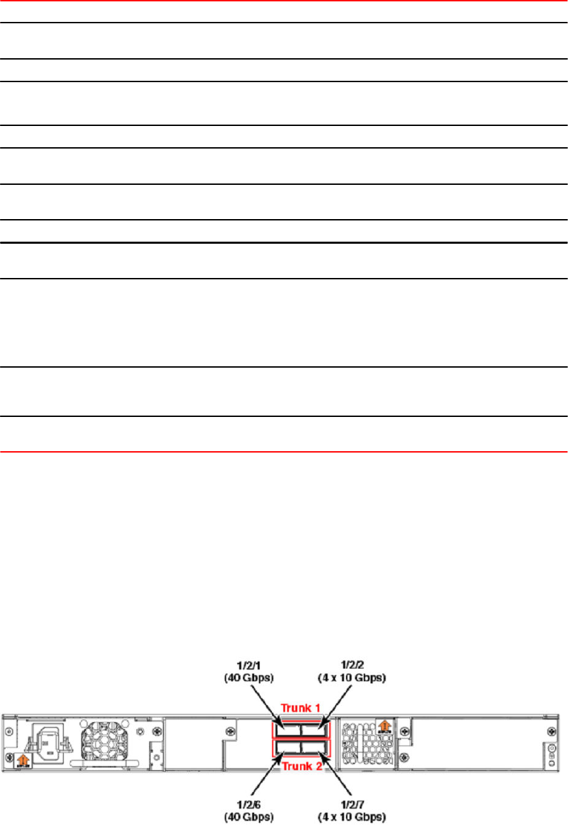
ICX 6610 traditional stacking capability (Continued)TABLE 7
Stacking capability ICX 6610 Additional information
Maximum stacking distance 5 meters Refer to Extended distance stacking
on page 18 for more information.
Stacking ports 4 dedicated ports
Default ports Dedicated ports: 1/2/1, 1/2/2, 1/2/6,
and 1/2/7
Refer to ICX 6610 stacking for
different topologies on page 48.
Reconfigurable ports Not supported
Stack trunks Supported. Stack ports are trunked
by default.
Refer to ICX 6610 trunked stacking
port configuration on page 51.
Hitless switchover and hitless
failover
Supported Refer to Hitless stacking on page
129.
License requirements None
Configuration options Manual and automatic, including
Secure-setup
Refer to Traditional stack
construction methods on page 20.
Access methods TFTP, SCP Software images, boot images, and
signatures can be downloaded to a
stack using TFTP and SCP
applications. Refer to the FastIron
Ethernet Switch Software Upgrade
Guide for more information.
PHY calibration Supported Refer to PHY calibration errors in
stack ports of the ICX 6610 on page
97 for additional information.
Traditional stacking CLI All traditional stacking CLI is
supported.
Refer to Traditional stack CLI
commands on page 78.
ICX 6610 stacking for different topologies
Earlier generations of Brocade switches did not have ports exclusively dedicated to stacking. The ICX
6610 includes four ports on the back panel that are used exclusively for stacking. These ports cannot
be used as data ports, even when stacking is not enabled.
There are the two 40-Gbps ports and two 4 x 10-Gbps ports arranged in two rows. By default, these
ports form stacked trunks. The following figure shows one stacked trunk on the top row between 1/2/1
and 1/2/2 and the second stacked trunk on the bottom row between 1/2/6 and 1/2/7.
FIGURE 10 ICX 6610 device back panel
ICX 6610 stacking for different topologies
48 FastIron Ethernet Switch Stacking Configuration Guide
53-1003406-03
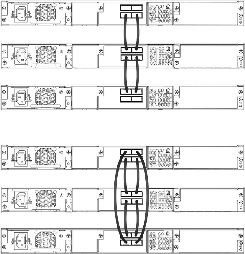
To properly connect stacked trunk ports between devices, you must connect corresponding trucks from
one device to another. For example, the following figures show correctly connected ports. The two
stacked trunks can form either linear or ring topologies.
The following figure shows a fully connected linear stacked trunk topology.
FIGURE 11 ICX 6610 linear stack topology
The following figure shows a fully connected stacked trunk ring topology.
FIGURE 12 ICX 6610 ring stack topology
In contrast, the following figure shows a linear and ring topology with partial trunk cabling. These
configurations are functional but do not form a trunk-stacked set of devices.
Traditional Stacking
FastIron Ethernet Switch Stacking Configuration Guide 49
53-1003406-03
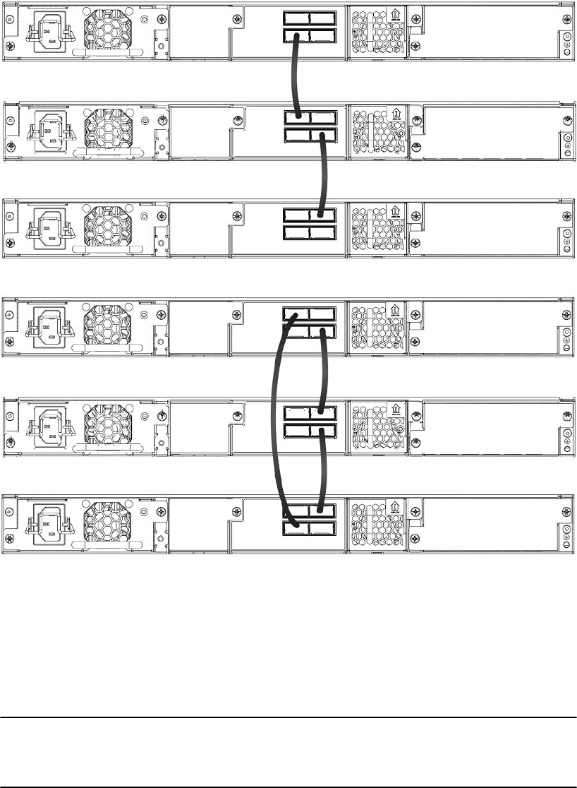
FIGURE 13 ICX 6610 linear and ring stack topologies with partial cabling
Configuration notes for ICX 6610 stack topologies
• The ICX 6610 does not allow users to change the stack-port command configuration. Secure-setup
sets the endpoints of a linear FCX stack to data ports, but it does not do so for the ICX 6610.
• An ICX 6610 supports up to 120 user-configured or LACP trunks. IDs 121-124 are reserved for peri-
trunks in mixed stacking. For more information, refer to Mixed Stacking on page 151.
NOTE
The ICX 6610 40-Gbps and 4 x 10-Gbps ports cannot be used as data ports, even when stacking is
not enabled. In standalone mode, these ports drop all packets except stacking probe packets. As a
result, secure-setup and unit replacement can still discover a standalone unit.
Configuration notes for ICX 6610 stack topologies
50 FastIron Ethernet Switch Stacking Configuration Guide
53-1003406-03

ICX 6610 trunked stacking port configuration
A trunk doubles the stacking port bandwidth and provides better resilience than a single port-to-port link.
As long as at least one port on the trunk is connected properly, communication between the neighboring
units will work. Traffic is load balanced to the trunk ports. With large numbers of sessions, traffic load
should be well balanced between 40-Gbps and 4 x10-Gbps ports. Traffic should also be well distributed
among the four sub-ports of a 4 x10-Gbps port. If a 4 x10-Gbps sub-port fails due to hardware failure,
traffic is re-distributed to other ports, and the stack system should still work. Periodic background
diagnosis provides warning messages when any 4 x10-Gbps sub-port is down.
When only one stacking port on a trunk goes down, no stack election or topology changes should occur.
The resulting traffic interruption time should be in the sub-second range as the system detects that the
port is down and re-programs hardware.
Stacking ports are trunked by default in the ICX 6610. The system automatically generates the trunk
configuration; however, you do have to enable stacking and connect cables properly for the stack to
work.
The show trunk command shows user-configured or LACP trunks but does not show stacking trunks.
At least one port of a trunk must be connected. If multiple ports of a trunk are connected, they must be
connected to the same trunk on the other unit. Two ports on the same trunk cannot connect to two
different units, nor can two ports on the same trunk connect to different trunks on the same unit.
Incorrect connections are likely to cause stacking formation failure or other problems.
Some invalid connections still form a stack but with forwarding problems. Stack probe packets use the
first connected port of a stacking trunk. Consequently, as long as the first connected port on a trunk is
connected properly, a stack can form. However, packet forwarding may not work for some streams that
are hashed into the incorrectly connected trunk port. In this case, periodic background diagnosis may
detect wrong connections and provide related error messages in about 20 minutes.
Stack port resiliency in the ICX 6610
In an ICX 6610, sometimes a stacking port cannot send or receive packets, even though the port is
logically operational. To detect this problem, probe packets are sent between the ICX 6610 units in a
stack every two seconds. If a port is logically operational but does not receive a probe packet for 90
seconds, it is considered a malfunctioning port. To resolve this, you can configure the active controller
to perform corrective steps such as error-disabling malfunctioning ports and reloading one or more
stack units. You can use the show errdisable summary command to view a list of all error-disabled
ports along with the reason these ports were error-disabled.
NOTE
A malfunctioning stack port that is error-disabled cannot be enabled until the unit is reloaded.
NOTE
Traffic may be interrupted for a few seconds or more while the port malfunction is detected and fixed.
Configuring stack port resiliency in the ICX 6610
To configure stack port resiliency on an ICX 6610 in a stack, enter the stack stack-port-resiliency
command on the active controller in global configuration mode.
The command enables the active controller to perform corrective steps. The steps that the active
controller takes are specified by the level variable entered after the command, with 0 being the
ICX 6610 trunked stacking port configuration
FastIron Ethernet Switch Stacking Configuration Guide 51
53-1003406-03

lowest setting and 3 being the highest possible setting. No action is taken when the level is set to 0.
The active controller may error-disable malfunctioning ports and reload one or more stack units
based on the level specified.
The following example shows a stack being configured for stack port resiliency with the level variable
set to 2.
Brocade(config)# stack stack-port-resiliency 2
Syntax: [no] stack stack-port-resiliency level
Syslog messages for stack port resiliency
For stack port resiliency, syslog messages are generated when the active controller performs
corrective steps such as error-disabling malfunctioning ports, reloading one or more stack units, or
reloading an entire stack. These syslog messages do not have a fixed format. The messages may not
be entirely accurate because of communication problems between stack units.
When a malfunctioning port is error-disabled, the stack unit generates a syslog message similar to the
following example.
SYSLOG: <10>0d00h10m22s : ICX6610-24P Router Stack: port 2/2/8 U2 errdisable
2/2/8: reason: 2/2/8 --> 1/2/8
When a stack unit reloads, the stack unit generates a syslog message similar to the following
example.
SYSLOG: <9>3d21h52m57s : ICX6610-24P Router Stack: unit 3 Reload u3 in 10 sec due
to 3/2/6 port problems. reason: lose one nbr
SYSLOG: <9>0d00h08m59s : ICX6610-48 Router Stack: unit 2 U3 detects stack port
problem. will reload u2: one directional CPU to CPU: u2 --> u3, one directional CPU
to CPU: u2 --> u4,
When the entire stack reloads, the active controller generates a syslog message similar to the
following example.
SYSLOG: <9>0d00h12m07s : ICX6610-48 Router Stack: "stack stack-port-resiliency 3"
is configured. Active u3 reloads the stack in 5s. reason: no CPU to CPU: u1 -x- u4,
no CPU to CPU: u2 -x- u4, no CPU to CPU: u3 -x- u4,
SYSLOG: <9>0d00h12m28s : ICX6610-24P Router Stack: "stack stack-port-resiliency 3"
is configured. Active u1 reloads the stack in 5s. reason: 1: 1/2/1 (T0) --->
2/2/6 (T1) *** error: one-way 2: 1/2/2 (T0) ---> 2/2/7 (T1) *** error:
one-way 3: 1/2/3 (T0) ---> 2/2/8 (T1) *** error: one-way 4: 1/2/4 (T0) ---
> 2/2/9 (T1) *** error: one-way 5: 1/2/5 (T0) ---> 2/2/10(T1) ***
error: one-way one directional CPU to CPU: u2 --> u4,
ICX 7450 stack configuration overview
The following table provides an overview of ICX 7450 stacking capabilities.
ICX 7450 traditional stacking capability
TABLE 8
Stacking capability ICX 7450 Additional information
Topologies supported Ring and linear Refer to ICX 7450 stacking
topologies on page 53.
Syslog messages for stack port resiliency
52 FastIron Ethernet Switch Stacking Configuration Guide
53-1003406-03

ICX 7450 traditional stacking capability (Continued)TABLE 8
Stacking capability ICX 7450 Additional information
Maximum stack size 12 Traditional stacking only. Any
combination of ICX 7450 devices
may be stacked.
Maximum stacking distance 100 meters Refer to Extended distance stacking
on page 18 for more information.
Stacking ports Two 40 Gbps ports in rear Modules 3 and 4, one port each.
Refer to ICX 7450 stacking
topologies on page 53 for module
locations.
Default ports Ports 1/3/1 and 1/4/1 Default ports cannot be changed.
Refer to ICX 7450 stacking
topologies on page 53 for port
locations.
Reconfigurable ports Use the stack-port command to
reconfigure ports.
Stacking ports can be reconfigured
as data ports, but not vice versa.
Refer to Traditional stack CLI
commands on page 78.
Stack trunks Not supported Refer to the FastIron Feature and
RFC Support Matrix for a list of
platforms that support stacked
trunks.
Hitless switchover and hitless
failover
Supported Refer to Hitless stacking on page
129.
License requirements No license required for stack-port
configuration
Premium feature requires trust-
based license. Refer to the FastIron
Ethernet Switch Software Licensing
Guide for information.
Configuration options Manual and automatic, including
Secure-setup
Refer to Traditional stack
construction methods on page 20.
Access methods TFTP, SCP Software images, boot images, and
signatures can be downloaded to a
stack using TFTP and SCP. Refer to
the FastIron Ethernet Switch
Software Upgrade Guide for more
information.
Traditional stacking CLI These commands are not available
on the ICX 7450:
connect
default-ports
multi-stack-port
multi-stack-trunk
stack-trunk
Refer to Traditional stack CLI
commands on page 78.
ICX 7450 stacking topologies
Up to 12 ICX 7450 units of any kind can be connected in a linear or ring topology. Default stacking ports
are located on the rear panel as shown in the following figures. The default port numbers are 1/3/1 and
ICX 7450 stacking topologies
FastIron Ethernet Switch Stacking Configuration Guide 53
53-1003406-03
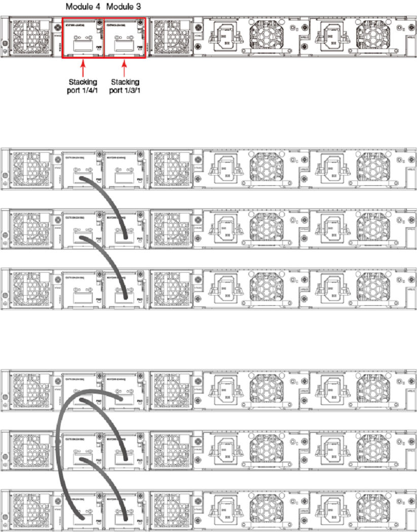
1/4/1 (unit/slot/port); that is, they are the single port located in modules 3 and 4 of the ICX 7450 as
shown.
The following figure shows the default stacking ports for the ICX 7450.
FIGURE 14 ICX 7450 stacking ports
The following figure shows ICX 7450 units connected in a linear stack.
FIGURE 15 ICX 7450 linear stack
The following figure shows ICX 7450 units connected in a ring stack.
FIGURE 16 ICX 7450 ring stack
Traditional Stacking
54 FastIron Ethernet Switch Stacking Configuration Guide
53-1003406-03
ICX 7450 stacking configuration notes
• The 1x40G module supports stacking only when installed in rear panel slot 3 or 4 (module 3 or 4).
• Stack ports can be configured using the stack-ports command.
• Stack trunks are not supported on ICX 7450 devices.
• When the secure-setup utility is used to configure an ICX 7450 stack, endpoints or ports of ending
units that are not used for stacking are left as data ports, except on active units, where both port
1/3/1 and port 1/4/1 become stack ports as a result of the stack enable command being executed.
ICX 7450 secure-setup example
Use the stack secure-setup command to automatically form a correctly connected stack. For more
information on stack construction, refer to Traditional stack construction methods on page 20
ICX 7450 stacking configuration notes
FastIron Ethernet Switch Stacking Configuration Guide 55
53-1003406-03
In the following example, the stack secure-setup command is used to form a 12-unit ICX 7450 stack
in a ring topology.
ICX7450-48P Router# configure terminal
ICX7450-48P Router(config)# stack enable
Enable stacking. This unit actively participates in stacking
stacking is enable. optical monitoring for stacking ports 1/3/1, 1/4/1 is not
available.
ICX7450-48P Router(config)# exit
ICX7450-48P Router# stack secure-setup
ICX7450-48P Router# Discovering the stack topology...
Current Discovered Topology - RING
Available UPSTREAM units
Hop(s) Id Type Mac Address
1 new ICX7450-48G cc4e.2489.a220
2 new ICX7450-48G cc4e.246d.1838
3 new ICX7450-48P cc4e.246d.2938
4 new ICX7450-24P cc4e.246d.0520
5 new ICX7450-24P cc4e.2489.8a38
6 new ICX7450-48P cc4e.2489.b388
7 new ICX7450-48GF cc4e.246d.1478
8 new ICX7450-48P cc4e.2489.8640
9 new ICX7450-48G cc4e.246d.1df8
10 new ICX7450-48G cc4e.246d.1b78
11 new ICX7450-48G cc4e.246d.1c78
Available DOWNSTREAM units
Hop(s) Id Type Mac Address
1 new ICX7450-48G cc4e.246d.1c78
2 new ICX7450-48G cc4e.246d.1b78
3 new ICX7450-48G cc4e.246d.1df8
4 new ICX7450-48P cc4e.2489.8640
5 new ICX7450-48GF cc4e.246d.1478
6 new ICX7450-48P cc4e.2489.b388
7 new ICX7450-24P cc4e.2489.8a38
8 new ICX7450-24P cc4e.246d.0520
9 new ICX7450-48P cc4e.246d.2938
10 new ICX7450-48G cc4e.246d.1838
11 new ICX7450-48G cc4e.2489.a220
Do you accept the topology (RING) (y/n)?: y
Selected Topology:
Active Id Type Mac Address
1 ICX7450-48P cc4e.2489.b188
Selected UPSTREAM units
Hop(s) Id Type Mac Address
1 2 ICX7450-48G cc4e.2489.a220
2 3 ICX7450-48G cc4e.246d.1838
3 4 ICX7450-48P cc4e.246d.2938
4 5 ICX7450-24P cc4e.246d.0520
5 6 ICX7450-24P cc4e.2489.8a38
6 7 ICX7450-48P cc4e.2489.b388
7 8 ICX7450-48GF cc4e.246d.1478
8 9 ICX7450-48P cc4e.2489.8640
9 10 ICX7450-48G cc4e.246d.1df8
10 11 ICX7450-48G cc4e.246d.1b78
11 12 ICX7450-48G cc4e.246d.1c78
Selected DOWNSTREAM units
Hop(s) Id Type Mac Address
1 12 ICX7450-48G cc4e.246d.1c78
2 11 ICX7450-48G cc4e.246d.1b78
3 10 ICX7450-48G cc4e.246d.1df8
4 9 ICX7450-48P cc4e.2489.8640
5 8 ICX7450-48GF cc4e.246d.1478
6 7 ICX7450-48P cc4e.2489.b388
7 6 ICX7450-24P cc4e.2489.8a38
8 5 ICX7450-24P cc4e.246d.0520
9 4 ICX7450-48P cc4e.246d.2938
10 3 ICX7450-48G cc4e.246d.1838
11 2 ICX7450-48G cc4e.2489.a220
Traditional Stacking
56 FastIron Ethernet Switch Stacking Configuration Guide
53-1003406-03
Do you accept the unit id's (y/n)?: y
ICX7450-48P Router#T=13m8.4: Election, was alone --> active, ID=1, pri=128,
12U(1-12), A=u1, nbr#=11 11, reason: u7: SecureS, ,
Config changed due to add/del units. Do write mem if you want to keep it
T=13m13.9: reset unit 2: u2 bo-id=1
T=13m13.9: reset unit 3: u3 bo-id=1
T=13m13.9: reset unit 4: u4 bo-id=1 SS or UR
T=13m13.9: reset unit 5: u5 bo-id=1 SS or UR
T=13m13.9: reset unit 6: u6 bo-id=1 SS or UR
T=13m13.9: reset unit 7: u7 bo-id=1 SS or UR
T=13m13.9: reset unit 8: u8 bo-id=1 SS or UR
T=13m13.9: reset unit 9: u9 bo-id=1 SS or UR
T=13m13.9: reset unit 10: u10 bo-id=1 SS or UR
T=13m13.9: reset unit 11: u11 bo-id=1 SS or UR
T=13m13.9: reset unit 12: u12 bo-id=1 SS or UR
T=13m23.8: Election, was active, no change, ID=1, pri=128, 12U(1-12), A=u1,
nbr#=11 11, reason: u7: port-up, ,
T=13m26.8: reset unit 2: u2 bo-id=1
T=13m26.8: reset unit 3: u3 bo-id=1
T=13m26.8: reset unit 4: u4 bo-id=1
T=13m26.8: reset unit 5: u5 bo-id=1
T=13m26.8: reset unit 6: u6 bo-id=1
T=13m26.8: reset unit 7: u7 bo-id=1
T=13m26.8: reset unit 8: u8 bo-id=1
T=13m26.8: reset unit 9: u9 bo-id=1
T=13m26.8: reset unit 10: u10 bo-id=1
T=13m26.8: reset unit 11: u11 bo-id=1
T=13m26.8: reset unit 12: u12 bo-id=1
T=13m28.5: Unit 1 loses all neighbors.
T=13m28.9: Active U1 deletes U2 and its config because it is learned.
T=13m29.5: Active U1 deletes U3 and its config because it is learned.
T=13m29.9: Active U1 deletes U4 and its config because it is learned.
T=13m30.1: Active U1 deletes U5 and its config because it is learned.
T=13m30.1: Active U1 deletes U6 and its config because it is learned.
T=13m30.1: Active U1 deletes U7 and its config because it is learned.
T=13m30.2: Active U1 deletes U8 and its config because it is learned.
T=13m30.7: Active U1 deletes U9 and its config because it is learned.
T=13m31.2: Active U1 deletes U10 and its config because it is learned.
T=13m31.6: Active U1 deletes U11 and its config because it is learned.
T=13m32.1: Active U1 deletes U12 and its config because it is learned.
Config changed due to add/del units. Do write mem if you want to keep it
ICX7450-48P Router#T=15m36.4: Election, was active, no change, ID=1, pri=128,
10U(1,4-12), A=u1, nbr#=0 9, reason: u4: port-up, ,
T=15m38.1: Synchronize webauth files to u7
Detect stack member 7 POE capable
T=15m38.2: Synchronize webauth files to u8
T=15m38.3: Synchronize webauth files to u9
T=15m38.3: Synchronize webauth files to u10
Detect stack member 9 POE capable
T=15m38.3: Synchronize webauth files to u11
T=15m38.3: Synchronize webauth files to u12
T=15m39.2: Synchronize webauth files to u4
T=15m39.2: Synchronize webauth files to u5
Detect stack member 4 POE capable
Detect stack member 5 POE capable
T=15m39.2: Synchronize webauth files to u6
Detect stack member 6 POE capable
T:15m39.5: Done hot swap: active controller u1 sets u7 to Ready.
T:15m39.7: Done hot swap: active controller u1 sets u8 to Ready.
T:15m39.9: Done hot swap: active controller u1 sets u9 to Ready.
T:15m40.4: Done hot swap: active controller u1 sets u10 to Ready.
T:15m40.9: Done hot swap: active controller u1 sets u11 to Ready.
T:15m41.4: Done hot swap: active controller u1 sets u12 to Ready.
Config changed due to add/del units. Do write mem if you want to keep it
Stack unit 10 Power supply 1 is up
Stack unit 10 Power supply 2 is down
Stack unit 8 Power supply 1 is up
Stack unit 8 Power supply 2 is down
T:15m43.2: Done hot swap: active controller u1 sets u4 to Ready.
T:15m43.6: Done hot swap: active controller u1 sets u5 to Ready.
T:15m44.1: Done hot swap: active controller u1 sets u6 to Ready.
Stack unit 7 Power supply 1 is down
Traditional Stacking
FastIron Ethernet Switch Stacking Configuration Guide 57
53-1003406-03
PoE: Stack unit 7 Power supply 2 with 748000 mwatts capacity is up
PoE: Stack unit 9 Power supply 1 with 748000 mwatts capacity is up
Stack unit 9 Power supply 2 is down
Stack unit 11 Power supply 1 is up
Stack unit 11 Power supply 2 is down
PoE: Stack unit 5 Power supply 1 with 258000 mwatts capacity is up
PoE: Stack unit 5 Power supply 2 with 258000 mwatts capacity is up
Stack unit 12 Power supply 1 is up
Stack unit 12 Power supply 2 is down
PoE: Stack unit 4 Power supply 1 with 748000 mwatts capacity is up
Stack unit 4 Power supply 2 is down
PoE: Stack unit 6 Power supply 1 with 748000 mwatts capacity is up
Stack unit 6 Power supply 2 is down
T=16m44.4: Assigned unit 4 to be standby
T=16m46.4: start running config sync to standby u4
T=16m47.0: Running config sync to standby u4 is complete
T=17m30.5: Election, was active, no change, ID=1, pri=128, 12U(1-12), A=u1,
nbr#=11 11, reason: u2: port-up, ,
T=17m34.6: Synchronize webauth files to u2
T=17m35.1: Synchronize webauth files to u3
Config changed due to add/del units. Do write mem if you want to keep it
T:17m37.2: Done hot swap: active controller u1 sets u2 to Ready.
T:17m39.1: Done hot swap: active controller u1 sets u3 to Ready.
T=17m39.2: Election, was active, no change, ID=1, pri=128, 12U(1-12), A=u1,
nbr#=11 11, reason: u3: port-up, ,
Stack unit 2 Power supply 1 is up
Stack unit 2 Power supply 2 is down
Stack unit 3 Power supply 1 is up
Stack unit 3 Power supply 2 is down
Config changed due to add/del units. Do write mem if you want to keep it
In the next example, show stack command output displays details for the 12-unit stack just formed.
ICX7450-48P Router# show stack
T=18m12.1: alone: standalone, D: dynamic cfg, S: static, A=10, B=11, C=12
ID Type Role Mac Address Pri State Comment
1 S ICX7450-48P active cc4e.2489.b188 128 local Ready
2 D ICX7450-48G member cc4e.2489.a220 0 remote Ready
3 D ICX7450-48G member cc4e.246d.1838 0 remote Ready
4 D ICX7450-48P standby cc4e.246d.2938 0 remote Ready
5 D ICX7450-24P member cc4e.246d.0520 0 remote Ready
6 D ICX7450-24P member cc4e.2489.8a38 0 remote Ready
7 D ICX7450-48P member cc4e.2489.b388 0 remote Ready
8 D ICX7450-48GF member cc4e.246d.1478 0 remote Ready
9 D ICX7450-48P member cc4e.2489.8640 0 remote Ready
10 D ICX7450-48G member cc4e.246d.1df8 0 remote Ready
11 D ICX7450-48G member cc4e.246d.1b78 0 remote Ready
12 D ICX7450-48G member cc4e.246d.1c78 0 remote Ready
active
+---+ +---+ +---+ +---+ +---+ +---+
-3/1| 1 |4/1--3/1| C |4/1--3/1| B |4/1--3/1| A |4/1--3/1| 9 |4/1--3/1| 8 |4/1-
| +---+ +---+ +---+ +---+ +---+ +---+ |
| |
| standby |
| +---+ +---+ +---+ +---+ +---+ +---+ |
-4/1| 2 |3/1--4/1| 3 |3/1--4/1| 4 |3/1--4/1| 5 |3/1--4/1| 6 |3/1--4/1| 7 |3/1-
+---+ +---+ +---+ +---+ +---+ +---+
Will assign standby in 28 sec due to all ready
Standby u4 - wait for standby assignment due to election
Current stack management MAC is cc4e.2489.b188
Displaying basic information for an ICX 7450 stack
Enter the show stack command at the device level to display general information about the stack,
including unit IDs, device type, role, MAC address, priority, status, and connections.
Displaying basic information for an ICX 7450 stack
58 FastIron Ethernet Switch Stacking Configuration Guide
53-1003406-03
The following show stack command output is for a 12-unit ICX 7450 linear topology.
ICX7450-24 Router# show stack
T=17h38m45.2: alone: standalone, D: dynamic cfg, S: static, A=10, B=11, C=12
ID Type Role Mac Address Pri State Comment
1 S ICX7450-24G active cc4e.246c.ff80 128 local Ready
2 S ICX7450-24G standby cc4e.246d.02c8 0 remote Ready
3 S ICX7450-24G member cc4e.246c.ffd0 0 remote Ready
4 S ICX7450-24P member cc4e.246d.0520 0 remote Ready
5 S ICX7450-48G member cc4e.246d.1c78 0 remote Ready
6 S ICX7450-48G member cc4e.246d.1b78 0 remote Ready
7 S ICX7450-48G member cc4e.246d.1df8 0 remote Ready
8 S ICX7450-48P member cc4e.2489.8640 0 remote Ready
9 S ICX7450-48GF member cc4e.246d.1478 0 remote Ready
10 D ICX7450-24P member cc4e.246d.0638 0 remote Ready
11 D ICX7450-24P member cc4e.246d.0778 0 remote Ready
12 D ICX7450-48P member cc4e.246d.2938 0 remote Ready
active standby
+---+ +---+ +---+ +---+ +---+ +---+
3/1| 1 |4/1--3/1| 2 |4/1--3/1| 3 |4/1--3/1| 4 |4/1--3/1| 5 |4/1--3/1| 6 |4/1-
+---+ +---+ +---+ +---+ +---+ +---+ |
|
|
+---+ +---+ +---+ +---+ +---+ +---+ |
| C |3/1--4/1| B |3/1--4/1| A |3/1--4/1| 9 |3/1--4/1| 8 |3/1--4/1| 7 |3/1-
+---+ +---+ +---+ +---+ +---+ +---+
Will assign standby in 53 sec due to all ready
Standby u2 - wait for standby assignment due to election
Current stack management MAC is cc4e.246c.ff80
Displaying details for an ICX 7450 stack
Use the show stack detail command to display information on all units in the stack, including their role,
MAC address, priority, status, and stack connections.
Displaying details for an ICX 7450 stack
FastIron Ethernet Switch Stacking Configuration Guide 59
53-1003406-03
The following show stack detail command output provides information on a full ICX 7450 stack
containing 12 units, with six different models among them.
ICX7450-24 Router# show stack detail
T=17h38m45.2: alone: standalone, D: dynamic cfg, S: static, A=10, B=11, C=12
ID Type Role Mac Address Pri State Comment
1 S ICX7450-24G active cc4e.246c.ff80 128 local Ready
2 S ICX7450-24G standby cc4e.246d.02c8 0 remote Ready
3 S ICX7450-24G member cc4e.246c.ffd0 0 remote Ready
4 S ICX7450-24P member cc4e.246d.0520 0 remote Ready
5 S ICX7450-48G member cc4e.246d.1c78 0 remote Ready
6 S ICX7450-48G member cc4e.246d.1b78 0 remote Ready
7 S ICX7450-48G member cc4e.246d.1df8 0 remote Ready
8 S ICX7450-48P member cc4e.2489.8640 0 remote Ready
9 S ICX7450-48GF member cc4e.246d.1478 0 remote Ready
10 D ICX7450-24P member cc4e.246d.0638 0 remote Ready
11 D ICX7450-24P member cc4e.246d.0778 0 remote Ready
12 D ICX7450-48P member cc4e.246d.2938 0 remote Ready
active standby
+---+ +---+ +---+ +---+ +---+ +---+
3/1| 1 |4/1--3/1| 2 |4/1--3/1| 3 |4/1--3/1| 4 |4/1--3/1| 5 |4/1--3/1| 6 |4/1-
+---+ +---+ +---+ +---+ +---+ +---+ |
|
|
+---+ +---+ +---+ +---+ +---+ +---+ |
| C |3/1--4/1| B |3/1--4/1| A |3/1--4/1| 9 |3/1--4/1| 8 |3/1--4/1| 7 |3/1-
+---+ +---+ +---+ +---+ +---+ +---+
Will assign standby in 53 sec due to all ready
Standby u2 - wait for standby assignment due to election
Current stack management MAC is cc4e.246c.ff80
Image-Auto-Copy is Enabled.
Stack Port Status Neighbors
Unit# Stack-port1 Stack-port2 Stack-port1 Stack-port2
1 dn (1/3/1) up (1/4/1) none U2 (2/3/1)
2 up (2/3/1) up (2/4/1) U1 (1/4/1) U3 (3/3/1)
3 up (3/3/1) up (3/4/1) U2 (2/4/1) U4 (4/3/1)
4 up (4/3/1) up (4/4/1) U3 (3/4/1) U5 (5/3/1)
5 up (5/3/1) up (5/4/1) U4 (4/4/1) U6 (6/3/1)
6 up (6/3/1) up (6/4/1) U5 (5/4/1) U7 (7/3/1)
7 up (7/3/1) up (7/4/1) U6 (6/4/1) U8 (8/3/1)
8 up (8/3/1) up (8/4/1) U7 (7/4/1) U9 (9/3/1)
9 up (9/3/1) up (9/4/1) U8 (8/4/1) U10 (10/3/1)
10 up (10/3/1) up (10/4/1) U9 (9/4/1) U11 (11/3/1)
11 up (11/3/1) up (11/4/1) U10 (10/4/1) U12 (12/3/1)
12 up (12/3/1) none U11 (11/4/1) none
Unit# System uptime
1 17 hours 38 minutes 45 seconds
2 17 hours 38 minutes 43 seconds
3 17 hours 38 minutes 45 seconds
4 17 hours 38 minutes 44 seconds
5 17 hours 38 minutes 44 seconds
6 17 hours 38 minutes 44 seconds
7 17 hours 38 minutes 44 seconds
8 17 hours 38 minutes 45 seconds
9 17 hours 38 minutes 43 seconds
10 17 hours 32 minutes 24 seconds
11 1 minutes 9 seconds
12 1 minutes 9 seconds
ICX 7750 stack configuration overview
The following table provides an overview of ICX 7750 stacking capabilities.
ICX 7750 stack configuration overview
60 FastIron Ethernet Switch Stacking Configuration Guide
53-1003406-03

ICX 7750 Traditional stacking capabilityTABLE 9
Stacking capability ICX 7750 Additional information
Topologies supported Ring and linear Refer to ICX 7750 stacking
topologies on page 62.
Maximum stack size 12 Traditional stacking only.
Maximum stacking distance 100 meters (most models)
10 kilometers (ICX 7750-2Q 1/2/1 or
1/2/4, Front)
Refer to Extended distance stacking
on page 18 and Installing the ICX
7750-26Q in a remote stack on page
65 for more information.
ICX 7750 model combinations Allowed ICX 7750-48C, ICX 7750 -48F, and
ICX 7750-26Q models can be
combined in the same stack.
Stacking ports Six 40 Gbps ports, Module 2: 1/2/1
to 1/2/6 (Front)
or
Six 40 Gbps ports, Module 3: 1/3/1
to 1/3/6 (Rear)
Module 2 (right front) and Module 3
(rear). Use all front or all rear 40
Gbps ports for ICX 7750 stacking.
No mixed combination is allowed.
Default ports Ports 1/2/1 and 1/2/4 Default ports can be changed to rear
ports 1/3/1 or 1/3/4. No other ports
are allowed.
Reconfigurable ports Use the default-ports and stack-
port commands to reconfigure ports.
Default ports can be changed only
between front and rear 40 Gbps
modules.
Trunking Up to two stack trunks Each stack trunk can support up to
three ports.
Possible 3-port trunks:
1/2/1 to 1/2/3
1/2/4 to 1/2/6
1/3/1 to 1/3/3
1/3/4 to 1/3/6
Possible 2-port trunks:
1/2/1 to 1/2/2
1/2/4 to 1/2/5
1/3/1 to 1/3/2
1/3/4 to 1/3/5
Hitless switchover and hitless
failover
Supported Refer to Hitless stacking on page
129.
License requirements No license required for stack-port
configuration. No license required for
Premium features.
For more information on ICX 7750
license options, refer to the FastIron
Ethernet Switch Software Licensing
Guide.
Configuration options Manual and automatic, including
Secure-setup
Refer to Traditional stack
construction methods on page 20.
Traditional Stacking
FastIron Ethernet Switch Stacking Configuration Guide 61
53-1003406-03
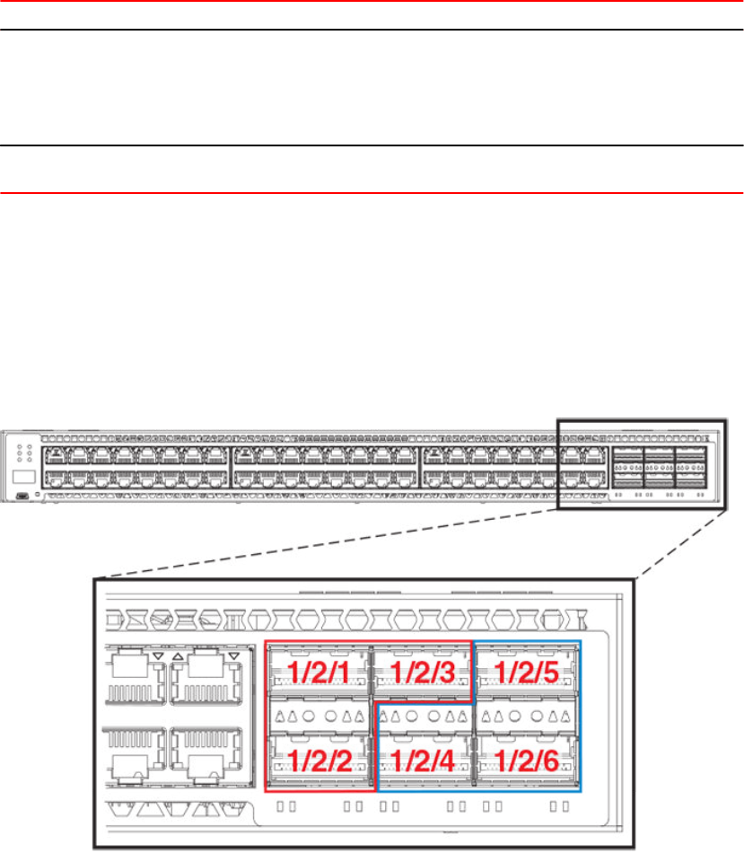
ICX 7750 Traditional stacking capability (Continued)TABLE 9
Stacking capability ICX 7750 Additional information
Access methods TFTP, SCP Software images, boot images, and
signatures can be downloaded to a
stack using TFTP and SCP
applications. Refer to the FastIron
Ethernet Switch Software Upgrade
Guide for more information.
Traditional stacking CLI All traditional stacking CLI is
supported.
Refer to Traditional stack CLI
commands on page 78.
ICX 7750 stacking topologies
The following figures show available ICX 7750 stacking ports on the front and rear panel. Available
front panel stacking ports are 1/2/1 through 1/2/6. Default stacking ports are 1/2/1 and 1/2/4.
FIGURE 17 ICX 7750 default stacking ports on front panel
ICX 7750 stacking topologies
62 FastIron Ethernet Switch Stacking Configuration Guide
53-1003406-03
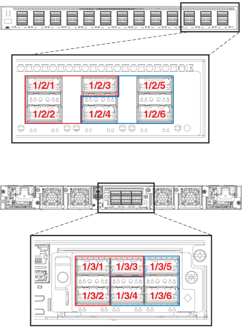
FIGURE 18 ICX 7750-26Q default front panel stacking ports
Available stacking ports on the ICX 7750 rear panel are ports 1/3/1 through 1/3/6. Default ports can be
changed from front panel ports 1/2/1 and 1/2/4 to rear panel ports 1/3/1 and 1/3/4.
FIGURE 19 ICX 7750 default stacking ports on rear panel
The following figure shows an ICX 7750 linear stack.
Traditional Stacking
FastIron Ethernet Switch Stacking Configuration Guide 63
53-1003406-03
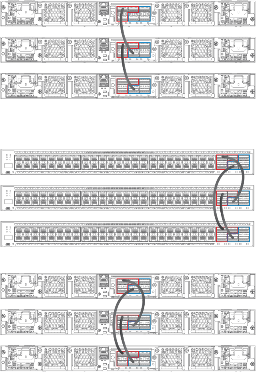
FIGURE 20 ICX 7750 linear stack from rear panel
The following figures show ICX 7750 ring stacks from the front and rear panels. Default stacking ports
are located on the front panel, but they can be changed to the rear panel using the default-ports
command.
FIGURE 21 ICX 7750 ring stack from front panel
FIGURE 22 ICX 7750 ring stack from rear panel
Traditional Stacking
64 FastIron Ethernet Switch Stacking Configuration Guide
53-1003406-03
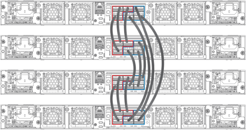
FIGURE 23 ICX 7750 fully populated ring stack from rear panel with three-port stack trunks
Installing the ICX 7750-26Q in a remote stack
Most ICX 7750 models can support distances of up to 100 meters. The ICX 7750-26Q can support
stacking distances of up to 10 kilometers.
To achieve maximum stacking distance, the ICX 7750-26Q must use a specified Brocade fiber optic.
The stacking cable must be attached to port 1/2/1 or 1/2/4 (refer to the following figure), and the port
must be configured as a default stacking port. Port and trunk configuration are otherwise the same as
for any ICX 7750 stack.
Installing the ICX 7750-26Q in a remote stack
FastIron Ethernet Switch Stacking Configuration Guide 65
53-1003406-03
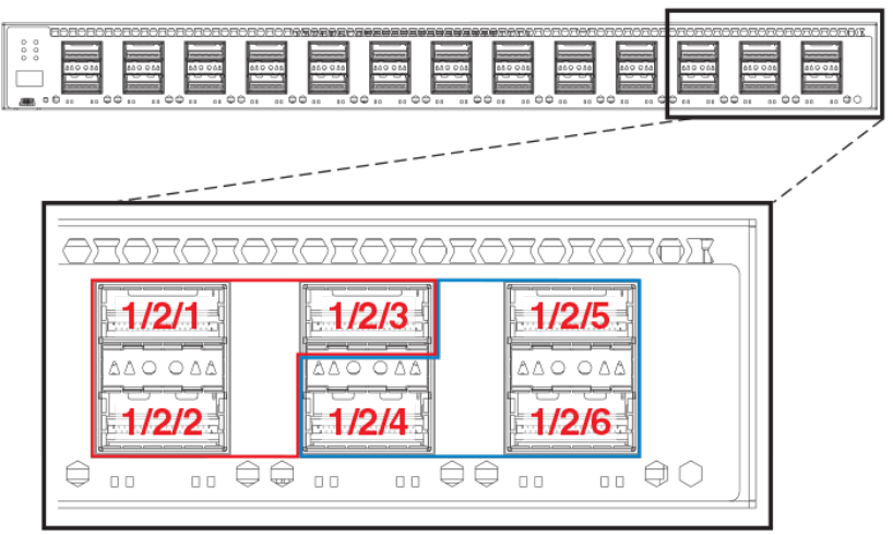
FIGURE 24 ICX 7750-26Q front panel stacking ports
Refer to Extended distance stacking on page 18 for information on Brocade cable options and
distances supported by the different ICX 7750 models.
ICX 7750 stacking configuration notes
• Use all front or all rear 40 Gbps ports (module 2 on the front or module 3 on the rear) to form an ICX
7750 stack. Front and rear connectors on the same unit cannot be used together for stacking.
• When adding a new unit on a linear stack, make sure that the last unit of the existing stack has both
stack ports configured.
• Unused stacking ports can be used as data ports. For example, you can elect to use only one
default port as a stacking port and use the other default port as a data port. Furthermore, when an
ICX 7750 stacking module is not configured for stacking, its stacking ports can be used as data
ports.
• Only ports recognized as default ports can be used as stacking ports. Before a unit can use non-
default stacking ports, the default-ports command must be configured on the local console for the
unit so the unit can be discovered by the secure-setup utility used to form a stack.
• Default ports cannot be changed on a live stack. The following example shows the error message
displayed if you attempt to do so.
ICX7750-48F Router# configure terminal
ICX7750-48F Router(config)# stack unit 8
ICX7750-48F Router(config-unit-8)# default-ports 8/3/1 8/3/4
New default-ports 8/3/1 8/3/4 result in removing both old stack ports. Abort
• When module 3 on the rear of ICX 7750 devices is used for stacking, before performing secure-
setup, change the default ports on the respective units as shown in the following example.
Otherwise, the secure-setup utility will not be able to discover the stacking ports in module 3, and
invalid stack trunk messages will be displayed.
ICX7750-48F Router# configure terminal
ICX7750-48F Router(config)# stack unit 1
ICX7750-48F Router(config-unit-1)# default-ports 1/3/1 1/3/4
ICX 7750 stacking configuration notes
66 FastIron Ethernet Switch Stacking Configuration Guide
53-1003406-03

NOTE
For more information on invalid stacking trunk error and network loops, refer to Invalid stacking trunk
errors on page 24.
• To configure a stack trunk manually on a stack unit, use the stack-trunk command. However, in a
live production environment, use the multi-stack-trunk command as described in Creating an ICX
7750 stack trunk in a production environment on page 71.
• Only ports that are in sequential order can be configured as a stacking trunk.
• A default port, either port 1/2/1 or 1/2/4 in module 2 or port 1/3/1 or 1/3/4 in module 3, is always the
first sequential port in a trunk.
• Combining module 2 and module 3 connections in the same stack is not allowed. The following error
message is displayed when modules have been incorrectly combined.
*** Warning! Some units in the stack have module 2 to module 3 connection.
The stack may not work. Please refer to documentation for more details.
• A trunk may contain two or three ports. For example, a two-port trunk on slot 3 (module 3) may
contain ports 1/3/1 and 1/3/2, and a three-port trunk may contain ports 1/3/1, 1/3/2, and 1/3/3. A
second trunk on slot 3 may contain ports 1/3/4 and 1/3/5, or it may contain all three ports, 1/3/4,
1/3/5, and 1/3/6.
ICX 7750 secure-setup example
Use the stack secure-setup command to configure a stack automatically. For more information about
stack construction and secure-setup, refer to Traditional stack construction methods on page 20.
In FastIron release 08.0.20 and later releases, stack trunks are formed automatically in homogeneous
stacks. During ICX 7750 secure-setup, the system prompts you to Enter the desired number of links,
after it displays the available options, from 1 to 3, when all three stack trunk ports are available.
In the following excerpt from stack secure-setup output, only two stack trunk ports are available, so
options are shown as 1-2. To form a two-port trunk, you would enter "2" at the prompt. To use a single
stacking port without forming a stack trunk, you would enter "1" at the prompt.
Confirm Stacking Links...
UPSTREAM Unit: Id 12 at 11 hop(s) ICX7750-48XGC cc4e.2439.1280
Enter the desired links(1-2)[1]: 2
In the next excerpt, 3 ports are available to form a trunk. You may elect to enter "2" for a two-port trunk
or "3" for a full three-port trunk as shown.
Confirm Stacking Links...
UPSTREAM Unit: Id 7 at 6 hop(s) ICX7750-20QXG cc4e.2439.3880
Enter the desired links(1-3)[1]: 3
It is also possible to modify trunk configuration when you add stack trunks. In the following excerpt, an
existing trunk configuration is modified during secure-setup. Available options are shown as 2-3 [2]
where a two-port trunk is currently configured. In the example, "3" is entered to modify the configuration
and create a three-port trunk.
Confirm Stacking Links...
UPSTREAM Unit: Id 5 at 4 hop(s) ICX7750-20QXG cc4e.2439.2a80
Enter the desired links(2-3)[2]: 3
Selected Topology:
ICX 7750 secure-setup example
FastIron Ethernet Switch Stacking Configuration Guide 67
53-1003406-03
Active Id Type Mac Address
1 ICX7750-48XGF cc4e.246d.9e00
Selected UPSTREAM units
The following output shows secure-setup for a 12-unit ICX 7750 ring that includes some two-port and
some three-port stack trunk designations.
Traditional Stacking
68 FastIron Ethernet Switch Stacking Configuration Guide
53-1003406-03
ICX7750-48F Router# stack secure-setup
ICX7750-48F Router# Discovering the stack topology...
Current Discovered Topology - RING
Available UPSTREAM units
Hop(s) Id Type Mac Address
1 new ICX7750-48XGF cc4e.246d.8d80
2 new ICX7750-48XGF cc4e.246d.9b00
3 new ICX7750-48XGF cc4e.246d.9c80
4 new ICX7750-20QXG cc4e.2439.2a80
5 new ICX7750-20QXG cc4e.2439.3700
6 new ICX7750-20QXG cc4e.2439.3880
7 new ICX7750-20QXG cc4e.2439.2d00
8 new ICX7750-48XGC cc4e.2439.1a00
9 new ICX7750-48XGC cc4e.2439.1680
10 new ICX7750-48XGC cc4e.2439.1d80
11 new ICX7750-48XGC cc4e.2439.1280
Available DOWNSTREAM units
Hop(s) Id Type Mac Address
1 new ICX7750-48XGC cc4e.2439.1280
2 new ICX7750-48XGC cc4e.2439.1d80
3 new ICX7750-48XGC cc4e.2439.1680
4 new ICX7750-48XGC cc4e.2439.1a00
5 new ICX7750-20QXG cc4e.2439.2d00
6 new ICX7750-20QXG cc4e.2439.3880
7 new ICX7750-20QXG cc4e.2439.3700
8 new ICX7750-20QXG cc4e.2439.2a80
9 new ICX7750-48XGF cc4e.246d.9c80
10 new ICX7750-48XGF cc4e.246d.9b00
11 new ICX7750-48XGF cc4e.246d.8d80
Do you accept the topology (RING) (y/n)?: y
Confirm Stacking Links...
UPSTREAM Unit: Id new at 4 hop(s) ICX7750-20QXG cc4e.2439.2a80
Enter the desired links(1-3)[1]: 3
UPSTREAM Unit: Id new at 6 hop(s) ICX7750-20QXG cc4e.2439.3880
Enter the desired links(1-3)[1]: 3
UPSTREAM Unit: Id new at 10 hop(s) ICX7750-48XGC cc4e.2439.1d80
Enter the desired links(1-2)[1]: 2
UPSTREAM Unit: Id new at 11 hop(s) ICX7750-48XGC cc4e.2439.1280
Enter the desired links(1-2)[1]: 2
Selected Topology:
Active Id Type Mac Address
1 ICX7750-48XGF cc4e.246d.9e00
Selected UPSTREAM units
Hop(s) Id Type Mac Address
1 2 ICX7750-48XGF cc4e.246d.8d80
2 3 ICX7750-48XGF cc4e.246d.9b00
3 4 ICX7750-48XGF cc4e.246d.9c80
4 5 ICX7750-20QXG cc4e.2439.2a80
5 6 ICX7750-20QXG cc4e.2439.3700
6 7 ICX7750-20QXG cc4e.2439.3880
7 8 ICX7750-20QXG cc4e.2439.2d00
8 9 ICX7750-48XGC cc4e.2439.1a00
9 10 ICX7750-48XGC cc4e.2439.1680
10 11 ICX7750-48XGC cc4e.2439.1d80
11 12 ICX7750-48XGC cc4e.2439.1280
Selected DOWNSTREAM units
Hop(s) Id Type Mac Address
1 12 ICX7750-48XGC cc4e.2439.1280
Traditional Stacking
FastIron Ethernet Switch Stacking Configuration Guide 69
53-1003406-03
2 11 ICX7750-48XGC cc4e.2439.1d80
3 10 ICX7750-48XGC cc4e.2439.1680
4 9 ICX7750-48XGC cc4e.2439.1a00
5 8 ICX7750-20QXG cc4e.2439.2d00
6 7 ICX7750-20QXG cc4e.2439.3880
7 6 ICX7750-20QXG cc4e.2439.3700
8 5 ICX7750-20QXG cc4e.2439.2a80
9 4 ICX7750-48XGF cc4e.246d.9c80
10 3 ICX7750-48XGF cc4e.246d.9b00
11 2 ICX7750-48XGF cc4e.246d.8d80
Do you accept the unit id's (y/n)?: y
ICX7750-48F Router#T=18m45.7: Election, was alone --> active, ID=1, pri=128,
12U(1-12), A=u1, nbr#=11 11, reason: u6: SecureS, ,
T=18m49.7: Election, was active, no change, ID=1, pri=128, 12U(1-12), A=u1,
nbr#=11 11, reason: u1: stk-po-chg, ,
T=18m52.3: reset unit 2: u2 bo-id=1
T=18m52.3: reset unit 3: u3 bo-id=1
T=18m52.3: reset unit 5: u5 bo-id=1
T=18m52.3: reset unit 6: u6 bo-id=1
T=18m52.3: reset unit 7: u7 bo-id=1
T=18m52.3: reset unit 8: u8 bo-id=1
T=18m52.3: reset unit 9: u9 bo-id=1
T=18m52.3: reset unit 10: u10 bo-id=1
T=18m52.3: reset unit 11: u11 bo-id=1
T=18m52.3: reset unit 12: u12 bo-id=1
Reset extra units due to path: 4
Config changed due to add/del units. Do write mem if you want to keep it
T=18m55.3: Unit 1 loses all neighbors.
T=18m55.4: Active U1 deletes U2 and its config because it is learned.
T=18m55.6: Active U1 deletes U3 and its config because it is learned.
T=18m55.8: Active U1 deletes U4 and its config because it is learned.
T=18m55.9: Active U1 deletes U5 and its config because it is learned.
T=18m56.0: Active U1 deletes U6 and its config because it is learned.
T=18m56.1: Active U1 deletes U7 and its config because it is learned.
T=18m56.2: Active U1 deletes U8 and its config because it is learned.
T=18m56.3: Active U1 deletes U9 and its config because it is learned.
T=18m56.4: Active U1 deletes U10 and its config because it is learned.
T=18m56.6: Active U1 deletes U11 and its config because it is learned.
T=18m56.7: Active U1 deletes U12 and its config because it is learned.
ICX7750-48F Router# T=19m55.7: Election, was active, no change, ID=1, pri=128,
3U(1-3), A=u1, nbr#=2 0, reason: u3: port-dw, ,
T=19m55.8: Synchronize webauth files to u2
T=19m55.8: Synchronize webauth files to u3
T:19m57.1: Done hot swap: active controller u1 sets u2 to Ready.
T:19m57.1: Done hot swap: active controller u1 sets u3 to Ready.
Config changed due to add/del units. Do write mem if you want to keep it
Stack unit 2 Power supply 1 is up
Stack unit 2 Power supply 2 is down
Stack unit 3 Power supply 1 is up
Stack unit 3 Power supply 2 is down
T=20m2.4: Election, was active, no change, ID=1, pri=128, 3U(1-3), A=u1, nbr#=2 0,
reason: u1: port-up, ,
T=20m3.6: 1/2/4 goes down. delete direction 1, trigger election
T=20m7.3: Election, was active, no change, ID=1, pri=128, 12U(1-12), A=u1,
nbr#=11 11, reason: u12: port-up, ,
T=20m7.6: Synchronize webauth files to u10
T=20m7.6: Synchronize webauth files to u11
Detect stack unit 12 has different startup config flash, will synchronize it
T=20m7.6: Synchronize webauth files to u12
Detect stack unit 4 has different startup config flash, will synchronize it
T=20m7.6: Synchronize webauth files to u4
T=20m7.6: Synchronize webauth files to u5
T=20m7.6: Synchronize webauth files to u6
T=20m7.6: Synchronize webauth files to u7
T=20m7.7: Synchronize webauth files to u8
T=20m8.3: Synchronize webauth files to u9
T:20m8.8: Done hot swap: active controller u1 sets u10 to Ready.
T:20m9.0: Done hot swap: active controller u1 sets u11 to Ready.
T:20m9.3: Done hot swap: active controller u1 sets u12 to Ready.
T:20m9.9: Done hot swap: active controller u1 sets u4 to Ready.
T:20m10.2: Done hot swap: active controller u1 sets u5 to Ready.
T:20m10.5: Done hot swap: active controller u1 sets u6 to Ready.
T:20m10.9: Done hot swap: active controller u1 sets u7 to Ready.
T:20m11.4: Done hot swap: active controller u1 sets u8 to Ready.
Stack unit 12 Power supply 1 is up
Traditional Stacking
70 FastIron Ethernet Switch Stacking Configuration Guide
53-1003406-03

Stack unit 12 Power supply 2 is down
Stack unit 10 Power supply 1 is up
Stack unit 10 Power supply 2 is down
Config changed due to add/del units. Do write mem if you want to keep it
T:20m13.1: Done hot swap: active controller u1 sets u9 to Ready.
T=20m16.9: Election, was active, no change, ID=1, pri=128, 12U(1-12), A=u1,
nbr#=11 11, reason: u1: stk-po-chg, ,
Config changed due to add/del units. Do write mem if you want to keep it
ICX7750-48F Router#T=21m16.9: Assigned unit 2 to be standby
cT=21m18.9: start running config sync to standby u2
T=21m19.3: Running config sync to standby u2 is complete
The folloiwng show stack command output shows the resulting 12-unit ICX 7750 ring topology.
ICX7750-48F Router# show stack
T=23m12.5: alone: standalone, D: dynamic cfg, S: static, A=10, B=11, C=12
ID Type Role Mac Address Pri State Comment
1 S ICX7750-48XGF active cc4e.246d.9e00 128 local Ready
2 D ICX7750-48XGF standby cc4e.246d.8d80 0 remote Ready
3 D ICX7750-48XGF member cc4e.246d.9b00 0 remote Ready
4 D ICX7750-48XGF member cc4e.246d.9c80 0 remote Ready
5 D ICX7750-20QXG member cc4e.2439.2a80 0 remote Ready
6 D ICX7750-20QXG member cc4e.2439.3700 0 remote Ready
7 D ICX7750-20QXG member cc4e.2439.3880 0 remote Ready
8 D ICX7750-20QXG member cc4e.2439.2d00 0 remote Ready
9 D ICX7750-48XGC member cc4e.2439.1a00 0 remote Ready
10 D ICX7750-48XGC member cc4e.2439.1680 0 remote Ready
11 D ICX7750-48XGC member cc4e.2439.1d80 0 remote Ready
12 D ICX7750-48XGC member cc4e.2439.1280 0 remote Ready
active
+---+ +---+ +---+ +---+ +---+ +---+
-2/1| 1 |2/4--2/1| C |2/4==2/1| B |2/4==2/1| A |2/4--2/1| 9 |2/4--2/1| 8 |2/4-
| +---+ +---+ +---+ +---+ +---+ +---+ |
| |
| standby |
| +---+ +---+ +---+ +---+ +---+ +---+ |
-2/4| 2 |2/1--2/4| 3 |2/1--2/4| 4 |2/1==2/4| 5 |2/1--2/4| 6 |2/1==2/4| 7 |2/1-
+---+ +---+ +---+ +---+ +---+ +---+
Standby u2 - protocols ready, can failover
Current stack management MAC is cc4e.246d.9e00
Creating an ICX 7750 stack trunk in a production environment
The stack-trunk command cannot be used to form a trunk manually in a live enviornment. Instead, use
the multi-stack-trunk command. The multi-stack-trunk command configures both ends of a trunk,
based on the range of ports you specify for each side.
NOTE
Configure the same size trunk on either side.
Creating an ICX 7750 stack trunk in a production environment
FastIron Ethernet Switch Stacking Configuration Guide 71
53-1003406-03

In the following example, a port connection is converted to a two-port trunk connection between stack
unit 4 and stack unit 5.
ICX7750-48F Router# configure terminal
ICX7750-48F Router(config)# stack unit 4
ICX7750-48F Router(config-unit-4)# multi-stack-trunk 4/2/1 to 4/2/2 and 5/2/4 to
5/2/5
stack unit 4
module 1 icx7750-48-xgf-port-management-module
module 2 icx7750-qsfp-6port-qsfp-240g-module
module 3 icx7750-6q-6port-qsfp-240g-module
stack-trunk 4/2/1 to 4/2/2
stack-port 4/2/1 4/2/4
stack unit 5
module 1 icx7750-20-qxg-port-management-module
module 2 icx7750-qsfp-6port-qsfp-240g-module
stack-trunk 5/2/4 to 5/2/5
stack-port 5/2/1 5/2/4
Syntax: multi-stack-trunk stack-unit/slotnum/portnum to stack-unit/slotnum/portnum and stack-unit/
slotnum/portnum to stack-unit/slotnum/portnum
Converting an ICX 7750 trunk to a port connection
To remove a trunk and create a port connection on a live stack, use the multi-stack-port command.
NOTE
Only primary ports (stack module ports 1 and 4) can be designated in the multi-stack-port command.
The following code excerpt displays configuration information for stack units 6 and 7.
stack unit 6
module 1 icx7750-20-qxg-port-management-module
module 2 icx7750-qsfp-6port-qsfp-240g-module
stack-trunk 6/2/1 to 6/2/3
stack-port 6/2/1 6/2/4
stack unit 7
module 1 icx7750-20-qxg-port-management-module
module 2 icx7750-qsfp-6port-qsfp-240g-module
stack-trunk 7/2/4 to 7/2/6
stack-port 7/2/1 7/2/4
In the following example, the stack trunk between units 6 and 7 is removed.
ICX7750-48F Router# configure terminal
ICX7750-48F Router(config)# stack unit 6
ICX7750-48F Router(config-unit-6)# multi-stack-port 6/2/1 and 7/2/4
Syntax: [no] multi-stack-port stack-unit/slotnum/portnum and stack-unit/slotnum/portnum
The no form of the command removes port configuration on the designated ports.
Converting an ICX 7750 trunk to a port connection
72 FastIron Ethernet Switch Stacking Configuration Guide
53-1003406-03
Removing stacking ports from an ICX 7750
Use the no stack-port command to remove stack ports from a unit, for example, to change a ring
topology to a linear topology.
In the following example, one stacking port, port 3/2/4, is removed from stack unit 3.
ICX7750-48F Router# stack unit 3
ICX7750-48F Router(config-unit-3)# no stack-port 3/2/1
Remove stacking port 3/2/1. The remaining stacking port is 3/2/4
The no stack-port command cannot be used when a trunk is configured. You must first remove the
trunk before removing the stacking port.
In the following example, an attempt to remove a stack port that is part of a configured trunk results in
an error message.
ICX7750-48F Router(config)# stack unit 10
ICX7750-48F Router(config-unit-10)# no stack-port 10/2/1
Please remove stack-trunk 10/2/1 to 10/2/2 before removing stacking port 10/2/1
using "stack-trunk" or "multi-stack-trunk" command.
Displaying basic information for an ICX 7750 stack
Enter the show stack command at the device level to display general information about the stack,
including unit IDs, device type, role, MAC address, priority, status, and connections.
The following show stack command output is for a 12-unit ICX 7750 ring. Units 10, 11, and 12 are
represented as A, B, and C in the topology diagram.
show stack
alone: standalone, D: dynamic cfg, S: static, A=10, B=11, C=12
ID Type Role Mac Address Pri State Comment
1 S ICX7750-48XGF active cc4e.246d.9e00 128 local Ready
2 S ICX7750-48XGF standby cc4e.246d.8d80 0 remote Ready
3 S ICX7750-48XGF member cc4e.246d.9b00 0 remote Ready
4 S ICX7750-48XGF member cc4e.246d.9c80 0 remote Ready
5 S ICX7750-20QXG member cc4e.2439.2a80 0 remote Ready
6 S ICX7750-20QXG member cc4e.2439.3700 0 remote Ready
7 S ICX7750-20QXG member cc4e.2439.3880 0 remote Ready
8 S ICX7750-20QXG member cc4e.2439.2d00 0 remote Ready
9 S ICX7750-48XGC member cc4e.2439.1a00 0 remote Ready
10 S ICX7750-48XGC member cc4e.2439.1680 0 remote Ready
11 S ICX7750-48XGC member cc4e.2439.1d80 0 remote Ready
12 S ICX7750-48XGC member cc4e.2439.1280 0 remote Ready
active
+---+ +---+ +---+ +---+ +---+ +---+
-2/1| 1 |2/4--2/1| C |2/4--2/1| B |2/4==2/1| A |2/4--2/1| 9 |2/4--2/1| 8 |2/4=
| +---+ +---+ +---+ +---+ +---+ +---+ |
| |
| standby |
| +---+ +---+ +---+ +---+ +---+ +---+ |
-2/4| 2 |2/1==2/4| 3 |2/1--2/4| 4 |2/1==2/4| 5 |2/1--2/4| 6 |2/1==2/4| 7 |2/1=
+---+ +---+ +---+ +---+ +---+ +---+
Standby u2 - protocols ready, can failover
Current stack management MAC is cc4e.246d.9e00
Removing stacking ports from an ICX 7750
FastIron Ethernet Switch Stacking Configuration Guide 73
53-1003406-03
Displaying details for an ICX 7750 stack
Enter the show stack detail command to display information for the stack, including device type, role,
MAC address, priority, status, and connections.
The following show stack detail output provides information on a 12-unit stack containing three
different ICX 7750 models connected in a ring.
ICX7750-48F Router# show stack detail
alone: standalone, D: dynamic cfg, S: static, A=10, B=11, C=12
ID Type Role Mac Address Pri State Comment
1 S ICX7750-48XGF active cc4e.246d.9e00 128 local Ready
2 S ICX7750-48XGF standby cc4e.246d.8d80 0 remote Ready
3 S ICX7750-48XGF member cc4e.246d.9b00 0 remote Ready
4 S ICX7750-48XGF member cc4e.246d.9c80 0 remote Ready
5 S ICX7750-20QXG member cc4e.2439.2a80 0 remote Ready
6 S ICX7750-20QXG member cc4e.2439.3700 0 remote Ready
7 S ICX7750-20QXG member cc4e.2439.3880 0 remote Ready
8 S ICX7750-20QXG member cc4e.2439.2d00 0 remote Ready
9 S ICX7750-48XGC member cc4e.2439.1a00 0 remote Ready
10 S ICX7750-48XGC member cc4e.2439.1680 0 remote Ready
11 S ICX7750-48XGC member cc4e.2439.1d80 0 remote Ready
12 S ICX7750-48XGC member cc4e.2439.1280 0 remote Ready
active
+---+ +---+ +---+ +---+ +---+ +---+
-2/1| 1 |2/4--2/1| C |2/4--2/1| B |2/4==2/1| A |2/4--2/1| 9 |2/4--2/1| 8 |2/4=
| +---+ +---+ +---+ +---+ +---+ +---+ |
| |
| standby |
| +---+ +---+ +---+ +---+ +---+ +---+ |
-2/4| 2 |2/1==2/4| 3 |2/1--2/4| 4 |2/1==2/4| 5 |2/1--2/4| 6 |2/1==2/4| 7 |2/1=
+---+ +---+ +---+ +---+ +---+ +---+
Standby u2 - protocols ready, can failover
Current stack management MAC is cc4e.246d.9e00
Image-Auto-Copy is Enabled.
Stack Port Status Neighbors
Unit# Stack-port1 Stack-port2 Stack-port1 Stack-port2
1 up (1/2/1) up (1/2/4) U2 (2/2/4) U12 (12/2/1)
2 up (2/2/1-2/2/2) up (2/2/4) U3 (3/2/4-3/2/5) U1 (1/2/1)
3 up (3/2/1) up (3/2/4-3/2/5) U4 (4/2/4) U2 (2/2/1-2/2/2)
4 up (4/2/1-4/2/2) up (4/2/4) U5 (5/2/4-5/2/5) U3 (3/2/1)
5 up (5/2/1) up (5/2/4-5/2/5) U6 (6/2/4) U4 (4/2/1-4/2/2)
6 up (6/2/1-6/2/3) up (6/2/4) U7 (7/2/4-7/2/6) U5 (5/2/1)
7 up (7/2/1-7/2/2) up (7/2/4-7/2/6) U8 (8/2/4-8/2/5) U6 (6/2/1-6/2/3)
8 up (8/2/1) up (8/2/4-8/2/5) U9 (9/2/4) U7 (7/2/1-7/2/2)
9 up (9/2/1) up (9/2/4) U10 (10/2/4) U8 (8/2/1)
10 up (10/2/1-10/2/2 up (10/2/4) U11 (11/2/4-11/2/ U9 (9/2/1)
11 up (11/2/1) up (11/2/4-11/2/5 U12 (12/2/4) U10 (10/2/1-10/2/
12 up (12/2/1) up (12/2/4) U1 (1/2/4) U11 (11/2/1)
Unit# System uptime
1 17 hours 20 minutes 8 seconds
2 17 hours 20 minutes 13 seconds
3 17 hours 20 minutes 13 seconds
4 17 hours 20 minutes 12 seconds
5 17 hours 20 minutes 13 seconds
6 17 hours 20 minutes 13 seconds
7 17 hours 20 minutes 13 seconds
8 17 hours 20 minutes 11 seconds
9 17 hours 20 minutes 13 seconds
10 17 hours 20 minutes 15 seconds
11 17 hours 20 minutes 13 seconds
12 17 hours 20 minutes 11 seconds
Displaying details for an ICX 7750 stack
74 FastIron Ethernet Switch Stacking Configuration Guide
53-1003406-03

Traditional Stack Management
● Managing a traditional stack through one IP address..................................................... 75
● Enabling or disabling stacking mode...............................................................................75
● Controlling the stack through the CLI..............................................................................76
● Traditional stack management MAC address................................................................. 81
● Traditional stack device roles and elections....................................................................83
● Traditional stack unit priority........................................................................................... 85
● Traditional stack software images...................................................................................87
● Copying the flash image to a stack unit from the active controller.................................. 88
● Adding, removing, or replacing units in a traditional stack.............................................. 88
● Renumbering stack units.................................................................................................91
● Reloading a stack unit.....................................................................................................92
● Controlling stack size to allow for a data port..................................................................93
● Managing traditional stack partitioning............................................................................94
● Merging traditional stacks............................................................................................... 94
● Unconfiguring a traditional stack..................................................................................... 95
● Syslog, SNMP, and traps for stack units.........................................................................96
● PHY calibration errors in stack ports of the ICX 6610.....................................................97
● Displaying traditional stack information...........................................................................97
● MIB support for the traditional stack..............................................................................116
Managing a traditional stack through one IP address
Your Brocade traditional stack can be managed through a single IP address. You can manage the stack
using this IP address even if you remove the active controller or any member from the stack. You can
also connect to the active controller through Telnet or SSH using this address. All management
functions, such as SNMP, use this IP address to acquire MIB information and other management data.
Enabling or disabling stacking mode
When a unit is stack-enabled or joins a stack either actively or passively, it reserves priority queue 7 for
stacking traffic control, assigns buffers for the stacking ports, and configures the first two 10 Gbps ports
as stacking ports.
NOTE
Designated stacking ports cannot contain any configuration information, such as VLAN membership. If
configuration information exists, stack enable will fail. You must remove all configuration information
from the port and re-issue the stack enable command.
FastIron Ethernet Switch Stacking Configuration Guide 75
53-1003406-03
To enable stacking mode on a new unit before you add it to the stack, enter the following command.
device(config)# stack enable
Enable stacking. This unit actively participates in stacking
Syntax: [no] stack enable
To see the configuration of the stack at any time, enter the show running-config command. Refer to
"Displaying running configuration information" for details.
Disabling stacking mode
To remove stacking capability, enter the no stack enable command. This prevents the unit from
actively sending out probe messages; however, the unit could still be called to join a stack by an active
controller. To prevent this, enter the stack disable command in device configuration mode.
The stack disable command prevents a unit from sending or listening for any stacking probe
messages. In this mode, the unit cannot be forced to join a stack.
device# configure terminal
device(config)# stack disable
Syntax: [no] stack disable
To restore the capability of the device to send and receive stacking probe messages, enter the no
stack disable command in device configuration mode.
Traditional stack unit identification
Stack units are identified by numbers 1 though 8 (1 through 12 on ICX 7450 and ICX 7750 devices).
You can display stack unit IDs by entering the show stack command.
A new device (one that has not been connected in a traditional stack or that has not been manually
assigned a stack unit number) ships with a default number of 1. Once you enable stacking and the unit
becomes part of a traditional stack, its default stack unit number changes to the lowest available
number in the stack. You can configure the stack suggested-id command in a standalone unit before
it joins a stack to assign this unit the suggested ID.
Stack units must each have a unique identification number. Every stack member, including any
standalone units, retains its stack unit number unless that number is already being used in the stack,
or until you manually renumber the unit using secure-setup. For more information about how to
renumber stack IDs using secure-setup, refer to Renumbering stack units on page 91.
Controlling the stack through the CLI
A Brocade traditional stack can be configured and managed using the command line interface (CLI).
You can access the traditional stack and the command CLI in two ways:
• Through a direct serial connection to the console port
• Through a local or remote Telnet session using the stack IP address
You can initiate a local Telnet or SNMP connection by attaching a cable to a port and specifying the
assigned management station IP address.
The stacking commands in the CLI are organized into the following levels:
Traditional stack unit identification
76 FastIron Ethernet Switch Stacking Configuration Guide
53-1003406-03

•Global - Commands issued in global mode are applied to the entire stack.
•Configuration mode - In this mode, you can make configuration changes to the entire stack. To
save changes across reloads, you must save them to the active controller startup-config file. The
configuration mode contains sub-levels for individual units and ports, VLANs, routing protocols, and
other configuration areas.
•Stack unit configuration mode - Commands issued in this mode apply to the specified stack unit.
Configuration information resides in the active controller.
NOTE
By default, any user who can open a serial or Telnet connection to the traditional stack can access all of
these CLI levels. To secure access, you can configure Enable passwords or local user accounts, or you
can configure the active controller to use a RADIUS or TACACS/TACACS+ server for authentication.
Refer to the FastIron Ethernet Switch Security Configuration Guide.
Logging in through the console port
When a device becomes a stack member in the traditional stack, it establishes a remote connection to a
virtual console port on the active controller. Input and output are relayed between the physical console
port on the stack member and the virtual console port on the active controller. Because each stack
member connects to an independent virtual console port on the active controller, the console ports on
multiple stack units may be used simultaneously.
When a stack unit establishes communication with the active controller, it also establishes a remote
console session to the active controller. In a normally functioning traditional stack, a console cable may
be connected to any of the stack units and provide access to the same commands on the active
controller.
To establish a remote console session, enter the rconsole command.
device# rconsole 1
Syntax: rconsole stack-unit
You can terminate a session in any of these ways:
• By entering the logout command at any level.
• By entering the exit command from the User EXEC level
NOTE
For rconsole connections from stack units to the active controller, the escape sequence and other
methods of terminating the session are not available.
NOTE
Error messages that are generated during a reload of the active controller do not appear on rconsole
connections from the stack units to the active controller. To see these error messages, you must
connect a console cable to the active controller itself.
The following example shows how to establish remote console sessions to stack members and obtain
status information. Notice that the show stack command on the stack members displays different
information from what is shown when the show stack command is entered on the active controller.
A remote console session is established with stack unit 2 in the following example.
device# rconsole 2
Logging in through the console port
FastIron Ethernet Switch Stacking Configuration Guide 77
53-1003406-03

Connecting to unit 2... (Press Ctrl-O X to exit)
rconsole-2@device# show stack
ID Type Role Mac Address Prio State Comment
2 S FCX624P standby 0000.00e2.ba40 0 local Ready
rconsole-2@device# exit
rconsole-2@device> exit
Disconnected. Returning to local session...
To see the status of all your stack units, enter the show stack command on the active controller.
device# show stack
alone: standalone, D: dynamic config, S: static config A=10, B=11, C=12
ID Type Role MAC Address Pri State Comment
1 S FCX648P active 0000.00de.8100 128 local Ready
2 S FCX624P standby 0000.00e2.ba40 0 remote Ready
3 S FCX624P member 0000.007a.22c0 0 remote Ready
active standby
+---+ +---+ +---+
-2/1| 1 |3/1--2/1| 2 |3/1--2/2| 3 |2/1-
| +---+ +---+ +---+ |
| |
|-------------------------------------|
Current stack management MAC is 0000.00de.8100
device#
NOTE
On the ICX 7450 and ICX 7750, unit ID 10 is represented in the show stack command output as A,
unit ID 11 as B, and unit ID 12 as C.
NOTE
For field descriptions for the show stack command, refer to Displaying general or detailed information
about stack members on page 106.
CLI command syntax for stack units
CLI syntax that refers to stack units must contain all of the following parameters:
•stack-unit - If the device is operating as a standalone, the stack-unit is 1. Stack unit IDs can be any
number from 1 through 8.
•slotnum - This refers to a specific group of ports on each device.
•portnum - This must be a valid port number.
Traditional stack CLI commands
For more information about a specific traditional stacking command, refer to its command reference
page in the FastIron Command Reference. For general information on CLI commands and syntax
conventions, refer to the FastIron Ethernet Switch Administration Guide.
Traditional stack configuration commandsTABLE 10
Configuration command Location of command description
long-preamble Configuring a default stacking port to function as a data
port on page 40
priority Traditional stack unit priority on page 85
CLI command syntax for stack units
78 FastIron Ethernet Switch Stacking Configuration Guide
53-1003406-03

Traditional stack configuration commands (Continued)TABLE 10
Configuration command Location of command description
stack enable Enabling or disabling stacking mode on page 75
stack disable Enabling or disabling stacking mode on page 75
stack mac [mac-address] Traditional stack management MAC address on page
81
stack persistent-mac-timer Command deprecated in FastIron release 08.0.20
stack suppress-warning Suppressing background stack diagnostic warnings on
page 118
stack-port Changing default stacking port configurations on page
37
default-ports Configuring default ports on FCX or ICX devices on
page 36 or ICX 7750 stacking configuration notes on
page 66
hitless-failover enable Enabling hitless stacking failover on page 141
Traditional stack executive commands TABLE 11
Executive command Location of command description
clear mac-address ethernet vlan Removing MAC address entries on page 82
clear stack ipc Troubleshooting an unsuccessful stack build on page 118
copy flash flash Copying the flash image to a stack unit from the active controller on page 88
image-auto-copy disable Disabling Auto Image Copy on page 124
kill console "Configuring TACACS/TACACS+ for devices in a traditional stack" in the
FastIron Ethernet Switch Security Configuration Guide
rconsole Logging in through the console port on page 77
reload Reloading a stack unit on page 92
stack secure-setup Scenario 1 - Three-member traditional stack in a ring topology using secure-
setup on page 20
stack unconfigure Unconfiguring a traditional stack on page 95
stack switch-over Executing a hitless stacking switchover on page 143
Traditional Stack Management
FastIron Ethernet Switch Stacking Configuration Guide 79
53-1003406-03

Traditional stack show commandsTABLE 12
Show command Location of command description
show chassis Displaying traditional stack chassis information on page
103
show flash Displaying traditional stack flash information on page
102
show interfaces stack-ports Displaying stacking port interface information on page
115
show memory Displaying traditional stack memory information on
page 103
show module Displaying stack module information on page 104
show running-config Displaying running configuration information on page
99
show stack Displaying general or detailed information about stack
members on page 106
Displaying information about hitless stacking on page
148
show stack connection Displaying stacking topology on page 98
show stack detail Displaying general or detailed information about stack
members on page 106
show stack failover Displaying information about stack failover on page
149
show stack flash Displaying traditional stack flash information on page
102
show stack ipc Troubleshooting an unsuccessful stack build on page
118
show stack link-sync status Displaying information about link synchronization status
on page 149
show stack neighbors Displaying information about stack neighbors on page
112
show stack rel-ipc stats Displaying reliable IPC statistics for stack units on page
109
show stack rel-ipc stats unit # Displaying IPC statistics for a specific stack unit on
page 108
show stack resource Displaying stack resource information on page 105
show stack stack-ports Displaying stack port information on page 113
show statistics stack-ports Displaying stacking port statistics on page 114
Traditional Stack Management
80 FastIron Ethernet Switch Stacking Configuration Guide
53-1003406-03

Traditional stack show commands (Continued)TABLE 12
Show command Location of command description
show version Displaying software version information on page 100
Traditional stack management MAC address
The traditional stack is identified in the network by a single MAC address, usually the MAC address of
the active controller (the default). If a new active controller is elected, the MAC address of the new
active controller (by default) becomes the MAC address for the entire stack. However, you can manually
configure your stack to use a specified MAC address.
In a traditional stack, the management MAC address is generated by the software and is always the
MAC address of the first port of the active controller. This ensures that the management MAC address
remains consistent across stack reboots and helps prevent frequent topology changes that result from
protocol enable, disable, and configuration changes.
When you are configuring Layer 2 protocols, such as STP, RSTP, and MSTP, on stack units, the
management MAC address of the active controller acts as the Bridge ID.
Manually allocating the traditional stack MAC address
NOTE
Beginning with FastIron release 08.0.20, when a stack is enabled or when hitless-failover occurs, a
default stack MAC address is assigned if none is configured.
You can manually configure your traditional stack to use a specific MAC address.
NOTE
The stack mac command may be useful for administration purposes; however, it should be used with
caution to prevent duplication of MAC addresses.
To configure a stack MAC address manually, enter the following command in device configuration
mode.
device# configure terminal
device(config)# stack mac 0000.0000.0011
Syntax: [no] stack mac mac-address
The mac-address variable is a hexadecimal MAC address in the format xxxx.xxxx.xxxx.
Enter the no form of this command to revert to the use of the active controllers' MAC address.
The following example shows the stack MAC address being configured manually as confirmed in the
show running-config command output.
device# configure terminal
device(config)# stack mac 0000.0000.0011
device(config)# show running-config
Current configuration:
!
ver 05.0.01 100T7e1
!
Traditional stack management MAC address
FastIron Ethernet Switch Stacking Configuration Guide 81
53-1003406-03

stack 1
module 1 fcx-48-port-copper-base-module
module 2 fcx-cx4-1-port-10g-module
priority 80
stack 2
module 1 fcx-24-port-copper-base-module
module 2 fcx-cx4-1-port-10g-module
module 3 fcx-cx4-1-port-10g-module
stack enable
stack mac 0000.0000.0011
To display the stack MAC address, enter the show chassis command.
device# show chassis
The stack unit 1 chassis info:
Power supply 1 (NA - AC - Regular) present, status ok
Power supply 2 not present
Fan 1 ok
Fan 2 ok
Exhaust Side Temperature Readings:
Current temperature : 35.5 deg-C
Warning level.......: 80.0 deg-C
Shutdown level......: 90.0 deg-C
Intake Side Temperature Readings:
Current temperature : 33.5 deg-C
Boot Prom MAC: 0000.00de.9440
Management MAC: 0000.0000.0011
The stack unit 2 chassis info:
Power supply 1 (NA - AC - Regular) present, status ok
Power supply 2 not present
Fan 1 ok
Fan 2 ok
--More--, next page: Space, next line: Return key, quit: Control-c
NOTE
For field descriptions of the show chassis command, refer to Displaying traditional stack chassis
information on page 103.
Removing MAC address entries
You can remove the following types of learned MAC address entries, for example, for debugging
purposes, from the Brocade system MAC address table:
• All MAC address entries
• All MAC address entries for a specified Ethernet port
• All MAC address entries for a specified VLAN
• A specified MAC address entry in all VLANs
For example, to remove entries for the MAC address 0000.0080.00d in all VLANs, enter the following
command at the device prompt.
device# clear mac-address 0000.0080.00d0
Syntax: clear mac-address [ mac-address | ethernet port | vlan number ]
• If you enter the clear mac-address command without any parameters, the software removes all
MAC entries.
• Use the mac-address variable to remove a specified MAC address from all VLANs. Specify the
MAC address in the following format: XXXX.XXXX.XXXX.
• Use the ethernet port parameter to remove all MAC addresses for a specified Ethernet port.
Specify the port variable in the format stack-unit/slot number/port number
• Use the vlan number parameter to remove all MAC addresses for a specified VLAN.
Removing MAC address entries
82 FastIron Ethernet Switch Stacking Configuration Guide
53-1003406-03
Traditional stack device roles and elections
There are three distinct roles played by units that are part of a traditional stack:
• Active controller
• Standby controller
• Stack member
Active controller
The active controller contains the saved and running configuration files for each stack member. The
configuration files include the system-level settings for the stack and the interface-level settings for each
stack member, as well as MIB counters and port status. The standby controller also has a synchronized
copy of the active controller startup-config file in case the active controller fails.
When a stack is formed, the console function for each stack member is automatically redirected to the
active controller console. The active controller console port handles all stack management functions, as
well as ping activity, Telnet sessions, and TFTP image downloads for every stack member. If you
connect to the console port on a stack member that is not the active controller, you are automatically
directed through the console of the active controller.
The active controller synchronizes its startup configuration with the standby controller and the rest of the
stack members. You can recover the previous flash configuration of the standby controller and the stack
members by issuing the stack unconfigure command. For an example of this command and the output
generated, refer to Unconfiguring a traditional stack on page 95.
The active controller may reset the rest of the stack members, if necessary. However, if the active
controller itself must be reset because of a role or ID change, you must issue the reset command.
If the active controller fails, the standby controller waits 30 seconds and then takes over as active
controller, resetting itself and all other stack members. If the old active controller becomes operational, it
may or may not resume its role as active controller, depending on the configured priorities.
Standby controller
In addition to the active controller, another stack member is elected as the standby controller. If the
active controller fails, the standby controller takes over after a default interval of 30 seconds. If hitless
stacking failover is enabled, the standby controller can take over immediately without reloading any unit.
The standby controller synchronizes its configuration with the active controller at each reset.
Bootup role
When a stack unit boots, it boots in a particular role, active controller, standby controller, or stack
member, or as a standalone device. When the bootup role is standby controller or stack member, the
CLI available to the unit is limited to show and stack commands. A unit in the role of standby controller
or stack member does not act without instructions from the active controller.
The last line of the show version output identifies the unit role unless the unit is in standalone mode.
My stack unit ID = 1, bootup role = active
My stack unit ID = 3, bootup role = standby
Traditional stack device roles and elections
FastIron Ethernet Switch Stacking Configuration Guide 83
53-1003406-03

NOTE
To convert a standby controller or stack member to a standalone device, use the stack unconfigure
me command (refer to Unconfiguring a traditional stack on page 95).
Active controller and standby controller elections
Whenever there is a topology change in the stack (a reset, unit failure, or the addition or removal of
members), elections are held to determine the status of the active controller and standby controller.
The results of the election take effect after the next stack reset.
The following conditions, in the order shown, determine which units serve as active controller and
standby controller after an election. The reason for this hierarchy of factors is to achieve a predictable
winner, regardless of the boot up sequence for a unit.
• Boot as active controller - Indicates that a unit was previously active controller before the current
boot sequence and will again assume the role of active controller when two standalone units are
combined into a stack. When a third standalone unit joins the stack, the current active controller
becomes subject to the other factors in this list. You can upgrade your current active controller to
"boot as active controller" status by executing the write memory command. The system interprets
the write memory action as a directive to maintain the current active controller role regardless of
resets or a new unit joining the stack.
• Priority - The unit with the highest priority value.
• Greater number of members - The unit that has control over the greater number of stack members.
• Longer up time - An up time that is more than 30 seconds longer than the next one in size is
considered. Where up times are compared, there is no effect if the difference is less than 30
seconds.
• Lowest boot stack ID - The unit that has the lowest boot stack ID. Unit ID 1 is the lowest. The unit ID
may be 1 through 8 (or 1 through 12 for ICX 7450 or ICX 7750 devices).
• MAC address - The member with the lowest MAC address.
Active controller and standby controller resets
If hitless stacking failover is enabled, when an active controller is reset or removed from the stack, the
standby controller takes over immediately.
NOTE
Hitless stacking failover is enabled by default in FastIron release 08.0.20 and later releases.
If hitless stacking failover is not enabled, the stack behaves differently when a failover occurs. When
hitless stacking failover is not enabled and the active controller is reset or removed from the stack, the
entire stack reloads, and active controller and standby controller elections are initiated. If the unit that
previously functioned as the active controller is no longer part of the stack, the standby controller unit
becomes the active controller. After a reset, if no stack member qualifies as active controller, the
existing standby controller waits 120 seconds and then assumes the role of active controller.
If both the active and the standby controllers are removed, the rest of the stack continues to function
because the other stack members are operating on whatever is programmed in the hardware.
However, the stack members are not able to learn any new addresses. In this case, the following
message is displayed every few minutes.
Stack member is non-operational because of no Active or standby controller
You can recover to standalone mode by "stack unconfigure me"
Active controller and standby controller elections
84 FastIron Ethernet Switch Stacking Configuration Guide
53-1003406-03

Use the stack unconfigure me command to restore the units as standalone devices with a pre-
stacking configuration.
Standby controller selection based on priority configuration
You can choose a standby controller by configuring a stack unit with the second highest priority or with
the same priority as the active controller. If the two stack units have the same priority configured, the
standby controller takes over when the active controller fails. If the original active controller becomes
active again, it does not win back its active role, which helps to minimize traffic interruption on the stack.
However, if the original active controller has the higher priority, it regains its role and resets all of the
stack units.
Standby controller election criteria
Standby controller election is based on the following criteria:
• The highest priority
• Bootup as active controller
• Bootup as standby controller
• The lowest boot stack ID
• The lowest MAC address
Because standby election candidates must have startup configurations that have been synchronized
with the active controller, if the active controller does not have a startup-config.txt file, no standby
controller is elected. Once the write memory command is executed on the active controller, the startup-
config.txt file is written and synchronized to all stack members, and a standby controller can be elected.
Traditional stack unit priority
A unit with a higher priority is more likely to be elected active controller. The priority value can be from 0
through 255, with a priority of 255 being the highest. The default priority value assigned to the active
controller and standby controller is 128.
You can assign the highest priority value to the stack unit you want to function as the active controller.
When you enter a new priority value for a stack unit, that value takes effect immediately but does not
affect the current active controller until the next reset. However, with hitless stacking failover enabled,
the stack unit with the highest priority will become the active controller in about five minutes (two
minutes in the case of ICX 6430 devices).
NOTE
Hitless stacking failover is enabled by default in FastIron release 08.0.20 and later releases.
You can give your active controller and standby controllers the same priority or different priorities (active
controller highest, standby controller second-highest). If the active controller and standby controller
have the same priority, when the active controller fails and the standby controller takes over, the original
active controller is not able to resume its original role once it becomes operational again if the new
active controller has more members.
In the same situation, when the priority of the active controller is higher than the priority of the standby
controller, the old active controller will regain its role and will reset the other units.
Standby controller selection based on priority configuration
FastIron Ethernet Switch Stacking Configuration Guide 85
53-1003406-03
As an example, suppose both the active controller and standby controller have the same priority. If
there are more than two units in a stack and the active controller leaves and comes back, it cannot win
back the active role because the new active controller now has more members, and the old active
controller has none.
If there are only two units in a stack, both the old active controller and the new active controller have
no members, so the unit with the longer up time wins the active role. When hitless stacking failover is
enabled (which is the default in FastIron release 08.0.20 and later releases), if the old active controller
stops responding or reloads, the standby controller takes over immediately. When the old active
controller reloads and comes back as an active controller, there are two active controllers, which
causes the stacks to merge. The old active controller loses the active controller election regardless of
its priority because it has a shorter up time. Consequently, the old active controller is reloaded by the
new active controller and boots up as a member. Then it is assigned the standby controller role. If the
former active controller has a higher priority, the system triggers an internal switchover to make it the
new active controller. If the former active controller has an equal priority, it remains the standby
controller.
When the active controller and standby controller have the same priority, the system allows a stack
switchover as long as hitless stacking failover is enabled. Hitless stacking failover allows the active
controller and standy controller to switch roles without traffic interruption.
If you want to assign the same priority to the active controller and the standby controller, you must do
so after the stack is formed. This prevents the intended standby controller from becoming the active
controller during stack construction.
Changing the priority of a stack member triggers an election that takes effect immediately unless the
active controller role changes and hitless stacking failover is disabled, in which case the member
priority changes do not take effect until after the next stack reload. With hitless stacking failover, the
stack unit with the highest priority becomes the active controller without reload.
To display stack member priority values, enter the show stack command.
device# configure terminal
device(config)# stack unit 3
device(config-unit-3)# show stack
alone: standalone, D: dynamic config, S: static config
ID Type Role Mac Address Pri State Comment
1 S FCX624 active 0000.00eb.a900
128 local Ready
2 S FCX624 standby 0000.004f.4243
0 remote Ready, member after reload
3 S FCX624 member 0000.005d.a100
200 remote Ready, active after reload
Changing the priority of a stack unit
To change the priority value for a stack unit, enter the priority command at the stack unit configuration
level.
device# configure terminal
device(config)# stack unit 1
device(config-unit-1)# priority 128
Syntax: priority num
The num variable is a value from 0 through 255. The highest priority is 255.
Traditional Stack Management
86 FastIron Ethernet Switch Stacking Configuration Guide
53-1003406-03

Traditional stack software images
Consider the notes in this section when upgrading from a pre-stacking release to a stacking release or
when reverting from a stacking release to a pre-stacking release.
Refer to the release notes and to the FastIron Ethernet Switch Software Upgrade Guide for instructions
about upgrading the software.
Confirming traditional stack software versions
All units in a traditional stack must be running the same software image. To confirm this, check the
software version on all devices that you want to add to a traditional stack. Upgrade any units that are
running older versions of the software before you build the stack.
To check the software version for each stack member, perform the following steps.
1. Use Telnet or SSH or connect to any of the console ports in the stack.
2. Enter the show version command. Output similar to the following is displayed.
device# show version
Copyright (c) 1996-2010 Brocade Communications Systems, Inc.
UNIT 1: compiled on Jan 26 2010 at 22:16:08 labeled as FCX07001
(2441570 bytes) from Primary fcx07001.bin
SW: Version 07.0.0151T7e1
UNIT 2: compiled on Jan 26 2010 at 22:16:08 labeled as FCX07001
(2441570 bytes) from Primary fcx07001.bin
SW: Version 07.0.0151T7e1
UNIT 3: compiled on Jan 26 2010 at 22:16:08 labeled as FCX07001
(2441570 bytes) from Primary fcx07001.bin
SW: Version 07.0.0151T7e1
UNIT 4: compiled on Jan 26 2010 at 22:16:08 labeled as FCX07001
(2441570 bytes) from Primary fcx07001.bin
SW: Version 07.0.0151T7e1
NOTE
If any unit in the traditional stack is running an incorrect version of the software, it will appear as non-
operational. You must install the correct software version on that unit for it to operate properly in the
stack.
Encountering a problem after upgrading and reloading the software
If you encounter a problem after upgrading and reloading the software, make sure the device has the
correct boot code version and the following (if applicable) are installed correctly:
• EEPROM
• Memory DIMM
If the stacking EEPROM is missing or is not installed correctly, or if you have installed the wrong
EEPROM, you will see output similar to the following.
FCX MEM size: 0x10000000
FCX Flash config....
FCX Boot Code Version 05.0.01
Enter ‘b’ to stop at boot....
BOOT INFO: load monitor from primary, size=103408
BOOT INFO: load image from primary..........
BOOT INFO: bootparam at 000543e8, mp_flash_size=002ee6c5
BOOT INFO: code decompression completed
BOOT INFO: branch to 00400100
Starting Main Task.......
Traditional stack software images
FastIron Ethernet Switch Stacking Configuration Guide 87
53-1003406-03

*****************************************************************************
ERR: This software needs License PROM to be installed in the system
*****************************************************************************
System Reset!
If your memory DIMM is not installed correctly, you will see output similar to the following.
FCX Mem size: 0x8000000
Flash Config...
FCX Boot Code Version 05.0.01
Enter ‘b’ to stop at boot.....
BOOT INFO: load monitor from primary, size = 103380
BOOT INFO: debug enabled!!
BOOT INFO: load image from primary...
BOOT INFO: bootparam at 00054338 mp_flash_size = 002f1aeb
BOOT INFO: code decompression completed
BOOT INFO: branch to 00400100
Starting Main Task...
*****************************************************************************
ERR: This software requires 256M memory to be installed in the system.
*****************************************************************************
System Reset!
When you have confirmed that your hardware upgrade is installed correctly, restart the system and
check the software version using the show version command.
Copying the flash image to a stack unit from the active controller
You can replace a bad image on a stack unit or an image that does not match the active controller's
image by copying the correct flash image from the active controller.
To copy the flash image to a stack unit from the active controller primary or secondary flash, enter the
following command at the device prompt.
device# copy flash flash unit-id-pri 2
Syntax: copy flash flash [ primary | secondary | unit-id-pri unit-num |unit-id-sec unit-num ]
•primary - Copy secondary to primary
•secondary - Copy primary to secondary
•unit-id-pri - Copy active primary image to unit ID
•unit-id-sec - Copy active secondary image to unit ID
The unit-id-pri and unit-id-sec keywords are used to copy images to a stack member from the active
controller primary and secondary flash, respectively. For unit-num, enter a valid stack unit number
from 1 through 8 (1 through 12 for ICX 7450 or ICX 7750 devices).
NOTE
You do not have to manually copy the flash image to a mismatched stack unit. For more information,
refer to Auto Image Copy for stack units on page 123.
Adding, removing, or replacing units in a traditional stack
You can add, remove, or replace traditional stack units using secure-setup or manually using static
configuration. The recommended method is to connect units to the stack before you supply power to
the units; however, you can also connect powered units.
Copying the flash image to a stack unit from the active controller
88 FastIron Ethernet Switch Stacking Configuration Guide
53-1003406-03
Installing a new unit in a traditional stack using secure-setup
This method can be applied to clean units or units that have existing configurations.
1. Connect the new unit to the stack by connecting the 10 Gbps stacking ports.
2. Run secure-setup on the active controller, and assign an ID to the new unit. The active controller
resets the new unit.
3. Once the new unit boots and joins the stack, enter the write memory command on the active
controller.
Installing a new unit using static configuration
If the new unit is a clean unit and the connection is sequential, you can add the unit to a stack using the
static setup process.
1. Enter the module configuration of the new unit into the active controller configuration.
2. Connect the new unit to the stack using the 10-Gbps stacking ports. The sequence in which you
connect the unit must match the sequence in the active controller configuration. The active controller
automatically resets the unit.
3. Once the new unit boots and joins the stack, enter the write memory command on the active
controller. You should see a message similar to the following example.
Done hot swap: Set stack unit 3 to Fully-Operational:16
Configuration notes
Configuration of a new unit can be learned in the following ways.
• If the active controller has no configuration information for the new unit, it learns the new unit's
configuration. This is a dynamic configuration that disappears if the new unit leaves the stack. To
retain the configuration on the active controller (to make it a static configuration), you must execute
the write memory command on the active controller.
• If the active controller has configuration information for a new unit that matches the base module
(module 1) of the new unit, the new unit may be placed in the operational or configuration mismatch
(non-operational) state depending on the matching of other modules. For example, if the active
controller has configuration information for another module (such as module 3), but the new unit has
no module 3, the new unit will be operational. However, if the new unit has a module 3, but it does
not match the configured module type, the new unit will be non-operational due to configuration
mismatch.
• A user can return a configuration-mismatched unit to operation by configuring the no stack unit
command for the non-operational unit from the active controller. This removes the entire stack
configuration so the active controller can learn the configuration-mismatched unit as a new unit. The
active controller triggers an election and learns the unit. Refer to Recovering from a stack unit
configuration mismatch on page 125.
Removing a unit from a traditional stack
To remove a unit from the stack, disconnect the cables from the stacking ports. This can be done
whether the units are powered on or powered off. When you remove a unit that is powered on, it is still
in stacking-enabled mode. To remove the stacking files, enter the stack unconfigure me or stack
unconfigure clean command.
The stack unconfigure me command returns a unit to the state it had before joining a stack and
recovers its startup configuration. The stack unconfigure clean command removes the unit's startup
configuration. When you issue either command, the unit operates as a standalone unit once it reboots.
Installing a new unit in a traditional stack using secure-setup
FastIron Ethernet Switch Stacking Configuration Guide 89
53-1003406-03

When a unit is removed from a stack, the active controller deletes the unit configuration if it has been
dynamically learned. Refer to Brocade traditional stacking terminology on page 16 for definitions of
static and dynamic configurations.
Replacing traditional stack units
Use one of the following methods to replace older stack units. The first section describes how to
replace an individual unit. The following sections explain how to replace multiple units and how to use
secure-setup.
Replacing one traditional stack unit with a clean traditional stack unit
If the stack unit ID numbering is sequential, you can swap a failed unit with an identical clean unit
using this procedure.
1. Remove the old unit from the stack.
2. Make sure that the hardware (module) configuration of the replacement unit is identical to the
hardware configuration of the failed unit.
3. Connect the new unit to the stack using the same stacking ports as the old unit.
4. If the replacement unit configuration matches the configuration retained on the active controller, the
active controller resets the new unit. The new unit automatically becomes active in the stack, and
the stack keeps its original topology.
Replacing multiple traditional stack units with multiple clean traditional stack units
If you are replacing multiple old units with clean units, the active controller replaces the unit with the
lowest ID first. For example, if you remove units 5 and 6, the active controller assigns ID 5 to the first
new device you install. If you wanted this particular unit to replace unit 6 instead of unit 5, you must
use secure-setup.
Using secure-setup to replace traditional stack units
You must use secure-setup to replace traditional stack units in the following cases:
• The replacement is not a clean unit.
• The connection is not sequential.
• You do not want the active controller to trigger an automatic replacement.
Use the following steps.
1. Remove the old stack unit from the stack.
2. Connect the new unit to the existing stack using the same stacking ports as the old unit.
3. Run secure‐setup to select the ID of the old unit for the new unit. The active controller resets the
unit, and it joins the stack.
NOTE
Adding, removing, or replacing a stack unit that is not at the end of a linear topology may cause the
other units in the stack to reset if these units lose their path to the active controller during the
change. Adding or removing a unit in a ring topology should not cause the other units to reset
because each unit can still find a path to the active controller.
Replacing traditional stack units
90 FastIron Ethernet Switch Stacking Configuration Guide
53-1003406-03

Moving a unit to another stack
Moving a member from one stack to another stack can cause non-sequential ID assignment. The active
controller will honor the original ID of the newly added unit if the ID is not already in use. The active
controller assigns a new ID if the original ID is already in use. To prevent non-sequential stack ID
assignments, configure the unit as a clean unit before adding it to the stack.
Removing an active controller from a powered stack
To remove an active controller from a powered stack, disconnect the active controller. The standby
controller waits for 30 seconds and then assumes the role of active controller. If hitless failover is
enabled on the stack, the standby controller takes over immediately. A single active controller device
functions as a standalone unit even if it is still stacking-enabled. You do not have to issue a stack
unconfigure me command for an active controller.
Renumbering stack units
You can use the stack secure-setup command to renumber stack units in a previously constructed
stack. The most effective way to number your stack members is sequentially. You can skip numbers,
but stack ID numbers should still be sequential. Sequential numbering makes it easier to replace stack
units or to troubleshoot issues.
NOTE
In a ring topology, 1, 2, 4, 5, and 1, 5, 4, 2 are both sequential.
In the following example, three units make up a stack, but two of the units are numbered 5 and 6 (the
active controller is numbered 1). Because this stack only contains three units, you can renumber the
other units so that they are unit 2 and unit 3.
device# stack secure-setup
device# Discovering the stack topology...
Available UPSTREAM units
Hop(s) Type MAC Address
1 FCX624 0000.00d5.2100
2 FCX624 0000.005d.9940
Enter the number of the desired UPSTREAM units (1-2)[1]: 2
Selected topology:
Active id Type MAC Address
1 FCX624 0000.0039.2d40
Selected UPSTREAM units
Hop(s) id Type MAC Address
1 5 FCX624 0000.00d5.2100
2 6 FCX624 0000.005d.9940
Do you accept the unit ids? (y/n)?: n
Enter an unused id for the UPSTREAM FCX623 unit a 1 hop(s) (1-8)[5]: 2
Enter an unused id for the UPSTREAM FCX624 unit at 2 hop(s) (1-8) [6]: 3
device# Election, was active, no role change, assigned-ID=1
reset unit 2: diff bootup id=5
reset unit 3: diff bootup id=6
Election, was active, no role change, assigned-ID=1
device# show stack
ID Type Role MAC Address Pri State Comment
1 S FCX624 active 0000.0039.2d40 128
local Ready
2 S FCX624 standby 0000.00d5.2100 0 remote
Ready
3 S FCX624 member 0000.005d.9940 0 remote
Ready
Moving a unit to another stack
FastIron Ethernet Switch Stacking Configuration Guide 91
53-1003406-03

Configuration notes for renumbering stack units
• Renumbering may cause loss of a unit configuration if the stack unit base module does not match
the configuration on the active controller. However, secure-setup renumbering never changes the
interface configuration. For example, if you switch the IDs of identical units 2 and 3, the active
controller does not change 2/1/5 to 3/1/5 and vice versa.
• If you assign an ID with an associated configuration to a stack unit with a different configuration,
secure-setup changes the static configuration into a dynamic configuration so it can be overwritten
by the learned configuration.
• Swapping IDs for two or more identical units (for example, if units 2, 3, and 4 are identical, changing
2 to 3, 3 to 4, and 4 to 2) does not affect unit configuration except that the units are reset and
assume the new IDs.
• If you swap IDs for two units that are not identical (for example, unit 2 is an FCX648, and unit 3 is
an FCX624), you may cause a configuration mismatch. If this happens, the active controller
removes the configurations and resets both units. When both units boot with new IDs, the active
controller learns their module types and creates new unit configurations for both. However, all
interface configuration information related to units 2 and 3 is removed.
• When you renumber identical units using secure-setup, the configurations are not mapped to the
new units (because the configurations match exactly). However, if you switch IDs on units that are
not identical, a configuration mismatch occurs. Refer to Recovering from a stack unit configuration
mismatch on page 125.
• When you assign an unused ID to a stack unit, the unit is reset with the new ID. All unit and
interface configuration information related to the old stack ID is deleted. The active controller learns
the configuration for the new unit.
• Secure-setup does not swap configuration information for units that have had their IDs changed.
For example, it does not change the 2/1/3 interface configuration or VLAN membership information
into 3/1/3 information if the unit ID changes from 2 to 3.
• If the configuration for a unit being replaced does not match the new unit type, the active controller
removes the unit configuration and associated interface configuration.
• All configurations learned following mismatches or the addition of new units are dynamic
configurations. To convert them into static configurations, execute a write memory command on
the active controller. This command preserves the configuration if a unit is removed from the stack.
Reloading a stack unit
Use the reload command to reload one or more stack units, for example, when necessary to repair a
malfunctioning unit. Stack units can be reloaded only if they are not the active controller. When hitless
stacking failover is enabled, the active controller is automatically reloaded.
When the reload command is entered on the active controller without the unit-id parameter as shown
in the following example, the entire stack reloads.
NOTE
device# reload
Syntax: reload [ after duration | at time | cancel | unit-id unit-list ]
Configuration notes for renumbering stack units
92 FastIron Ethernet Switch Stacking Configuration Guide
53-1003406-03
•after - Schedules reloading after a specified length of time (duration in seconds, entered as a value
from 1 to 4096)
•at - Schedules reloading at an exact later time (time, entered in the format: hh:mm:ss, where hh
represents hours from 01 to 24, mm represents minutes, from 00 to 59, and ss represents seconds,
from 0 to 59)
•cancel - Cancels scheduled reload
•unit-id - Designates stack member or members to reload. The unit-list variable can be a single ID, a
list of IDs, a range of IDs, or a combination, such as 2,4-6,8. Values must be separated by a comma,
with no space.
If you need to reload the active controller, use the stack switch-over command. When switchover
occurs, the original active controller can be reloaded using the reload unit-id command.
Controlling stack size to allow for a data port
Because stackable devices allow you to use one of the two ports intended for stacking as a regular data
port, you may wish to control the size of your stack. The following example shows a stack where the
existing ring topology is changed so that only one unit in the upstream direction is connected through a
stacking port, which limits the size of the stack to two units.
device# stack secure-setup
device# Discovering the stack topology...
Current Discovered Topology - RING
Available UPSTREAM units
Hop(s) Type MAC Address
1 FCX624 0000.00d5.2100
2 FCX624 0000.005d.9940
Available DOWNSTREAM units
Hop(s) Type MAC Address
1 FCX624 0000.005d.9940
2 FCX624 0000.00d5.2100
Do you accept the topology (RING) (y/n)?: n
Available UPSTREAM units
Hop(s) Type MAC Address
1 FCX624 0000.00d5.2100
2 FCX624 0000.005d.9940
Available DOWNSTREAM units
Hop(s) Type MAC Address
1 FCX624 0000.005d.9940
2 FCX624 0000.00d5.2100
Enter the number of the desired UPSTREAM units (0-2)[0]: 1
Enter the number of the desired DOWNSTREAM units (0-1)[0]:
Selected Topology:
Active Id Type MAC Address
1 FCX624 0000.0039.2d40
Selected UPSTREAM units
Hop(s) Id Type MAC Address
1 2 FCX624 0000.00d5.2100
Do you accept the unit ids (y/n)?: y
device# Election, was alone --> active, assigned-ID=1
reset unit 2: diff bootup id=1
device# show stack
alone: standalone, D: dynamic config, S: static config
ID Type Role MAC Address Pri State Comment
1 S FCX624 active 0000.0039.2d40 128
local Ready
2 S FCX624 standby 0000.00d5.2100 0 remote
Ready
Controlling stack size to allow for a data port
FastIron Ethernet Switch Stacking Configuration Guide 93
53-1003406-03

Managing traditional stack partitioning
Ring topology stacks do not partition when a stack member fails. Operation is interrupted briefly while
the stack recalculates a new path. Ring topologies are more stable than linear topologies because
they provide redundant pathways in case of accidental failure.
When a unit in a traditional stack with a linear topology fails, the traditional stack divides (partitions)
into two or more separate stacks that all have the same configuration. This may cause an IP address
conflict in the network. To keep the stacks separate, change the IP address of each new stack.
When a stack breaks into partitions, the partition with the active controller remains operational. If a
partition contains the standby controller, this partition becomes operational because the standby
controller assumes the active role and reloads the partition units. However, if hitless failover is
enabled, the partition units are not reloaded. A partition without an active controller or standby
controller does not function. To reconfigure these units to act in standalone mode, you must first enter
a stack unconfigure me command on each unit.
To reverse the partitioning, reconnect all of the units into the original stack topology using the stacking
ports. This is the same as merging stacks. If the original active controller again has the highest priority,
it regains its role. If two partition active controllers have the same priority, the active controller with the
most stack members is elected. This process helps minimize traffic interruption.
Merging traditional stacks
Traditional stacks may be merged, but the total number of stack units must not exceed the maximum
stack supported by the device. For example, you could combine two stacks of ICX 6610 devices with
four units each into a single stack of eight units.
NOTE
You cannot use secure-setup to merge stacks because secure-setup does not work across stack
boundaries.
You can merge stacks by connecting them together using the stacking ports. Before doing this, make
sure that no stacking ports (for example, ports on an end unit in a linear stack topology) have been
reconfigured as data ports.
When stacks are merged, an election is held among the active controllers. The winning controller
retains its configuration and the IDs of all of its original stack members. The remaining stack units lose
their configuration and are reset. If the IDs of the losing stack units conflict with the IDs of the winning
units, they may change, and the IDs will no longer be sequential.
NOTE
You can use secure-setup to renumber the members in the newly merged stack. Refer to
"Renumbering stack units" for more information.
The following examples show how stack merging works:
• If a stack partitions into multiple stacks because of a connection failure, you can fix the connection
and the stack partitions will merge back into the original stack with no change to stack IDs because
all stack IDs are distinct.
• In a linear stack topology, the end units of the stack have only one stacking port configured. Before
you can merge two linear stacks, you must reconfigure the end units so that both ports are stacking
ports.
Managing traditional stack partitioning
94 FastIron Ethernet Switch Stacking Configuration Guide
53-1003406-03

Unconfiguring a traditional stack
The stack unconfigure command is a runtime command that returns stack units to their pre-stacking
state. When a stack unit is unconfigured, its stacking flash is removed, and its startup-config.txt flash file
is recovered. These actions apply to all units to which this command is applied, regardless of the role of
the unit in the stack.
When the stack unconfigure command is applied to the active controller, it removes stack enable
from the runtime configuration but not from the startup configuration. If you want to remove the stack
enable command from the active controller permanently, you must enter the write memory command
after the stack unconfigure command.
When the stack unconfigure command is applied to the standby controller or a stack member (besides
the active controller), it removes stack enable from the recovered startup-config.txt file and resets the
unit.
NOTE
When a stack member becomes a standalone unit after the stack unconfigure command, it could
become a clean unit if it had no startup configuration flash. When a clean unit matches the active
controller’s static configuration, the active controller integrates the clean unit into the stack. Thus, the
standalone unit is reloaded to be a member of the stack. Users can avoid this problem by disconnecting
the member unit from the stack and issuing the stack unconfigure me command on the unit to change
it to a standalone unit.
To remove the configuration from a specific traditional stack unit or from the entire stack, enter a
command similar to the following.
device# stack unconfigure me
Syntax: stack unconfigure [ stack-unit | all | me | clean | mixed-stack ]
•stack-unit - Unconfigures the stack member with this ID
•all - Unconfigures every unit including this unit
•me - Unconfigures this unit only
•clean - Removes all startup configuration files including v4 and v5 and makes this a clean unit
•mixed-stack - Removes all peripheral ports and peripheral trunks from the ICX 6610 devices in a
mixed stack
NOTE
The stack unconfigure me command can be entered from any unit; however, stack unconfigure all
and stack unconfigure stack-unit commands can be issued only on the active controller.
The following example shows a session where stack unit 2 is unconfigured.
device# show stack
alone: standalone, D: dynamic config, S: static config
ID Type Role MAC Address Pri State Comment
1 S FCX624 active 0000.00eb.a900 128
local Ready
2 S FCX648 standby 0000.004f.4243 0 remote
Ready
3 S FCX624 member 0000.0001.0100 0 remote
Ready
device# stack unconfigure 2
Will recover pre-stacking startup config of this unit, and reset it. Are you sure?
(enter 'y' or 'n'): y
Stack 2 deletes stack bootup flash and recover startup-config.txt from .old
device# show stack
Unconfiguring a traditional stack
FastIron Ethernet Switch Stacking Configuration Guide 95
53-1003406-03

alone: standalone, D: dynamic config, S: static config
ID Type Role MAC Address Pri State Comment
1 S FCX624 active 0000.00eb.a900 128
local Ready
2 S FCX648 member 0000.0000.0000 0 reserved
3 S FCX624 standby 0000.0001.0100 0
remote Ready
When the stack unconfigure 2 command is issued, stack unit 2 recovers the startup-config.txt from
the startup-config.old configuration file that was saved when this unit downloaded its configuration
from the active controller. As the output shows, stack member 2 has been removed from the stack,
and ID 2 is now reserved for a replacement unit. Stack member 3 is now the standby controller.
Syslog, SNMP, and traps for stack units
Syslog messages from stack units are forwarded to, and can be viewed from, the active controller.
All stack units support SNMP gets, sets, and traps, which are managed by the active controller. An
SNMP trap is sent from a stack unit to the stack active controller and forwarded from the active
controller to an SNMP-configured server. An external network management station can execute
SNMP gets and sets for MIBs and collect information about any port on the stack.
SNMP traps can be configured for the insertion or removal of a stack unit or uplink module, and for
optic identification.
For more information about syslog messages, refer to the FastIron Ethernet Switch Administration
Guide.
Configuring SNMP for a traditional stack
SNMP server and feature configuration is the same for a traditional stack as for standalone units. In a
traditional stack, SNMP gets and sets are processed by the active controller for the standby controller
and all stack members. SNMP traps generated by the standby controller and stack members are
propagated to the configured SNMP server through the active controller. For more information about
how to configure an SNMP server for FastIron devices, refer to the FastIron Ethernet Switch
Administration Guide.
SNMP engine IDs for stackable devices
NOTE
In FastIron release 08.0.20 and later releases, when a stack is enabled or when hitless failover occurs,
a default stack MAC address is assigned if none is configured.
For Brocade stacking devices, if an engine ID is not manually created or a stack MAC address is not
specified and saved, the stack loses its engine ID when the active controller fails and the standby
controller takes over because the standby controller creates a new engine ID at bootup. To prevent
this from happening, create a new engine ID or a new stack MAC address to save the engine ID to the
startup configuration. This should be done before the SNMPv3 user is created.
If a new active controller is elected (for example, the standby controller becomes the active controller),
you will see the following results:
Syslog, SNMP, and traps for stack units
96 FastIron Ethernet Switch Stacking Configuration Guide
53-1003406-03
• If you have configured the engine ID and saved it to the startup configuration file, the new stack
configuration uses the saved engine ID.
• If you have not configured an engine ID, but a stack MAC address is configured, the new stack
configuration retains the original engine ID because it is based on the stack MAC address.
• If you have not configured an engine ID and no stack MAC address is configured, the new stack
configuration uses the default engine ID. The default engine ID is based on the stack's own
management MAC address for the new active controller. Because the engine ID has changed, any
SNMPv3 clients must be reconfigured with the new engine ID.
PHY calibration errors in stack ports of the ICX 6610
On every boot initialization, an ICX 6610 performs PHY calibration on the 40-Gbps and 4 x10-Gbps
stack ports. Sometimes, this calibration is incorrect, causing CRC errors to be generated and links on a
port to drop. FastIron IronWare detects the calibration errors and, by default, recovers the port by
recalibrating it. You can use the no snmp-server enable traps nlp-phy-40g command to disable the
recovery of incorrectly calibrated stack ports. To re-enable the default behavior of recalibrating stack
ports for recovery, use the snmp-server enable traps nlp-phy-40g command.
Syslog messages for PHY calibration
On boot initialization, an ICX 6610 device in a stack performs PHY calibration on its 40-Gbps and 4 x10-
Gbps stack ports and generates a syslog message. The following syslog message example shows the
calibration of all 16 ports (4 PHY with 4 lanes for each) on an ICX 6610 stack unit.
SYSLOG: <14>0d00h02m52s : ICX6610-48 Router System: Port init success Stack unit 3
Port 3/2/1 Lane 0 T 0 R 0 Type 0: 1630x00000x0000 1640x00000x0000 1710x00000x0000
1580x00000x0000 1630x00000x0000 1630x00000x0000 1640x00000x0000 1630x00000x0000
1670x00000x0000 1680x00000x0000 1690x00000x0000 1680x00000x0000 1650x00000x0000
1680x00000x0000 1660x00000x0000 1640x00000x0000
If any stack port in an ICX 6610 device has the PHY Tx or Rx CMU (voltage) reaching a threshold value
of 31 and the port is recalibrated, the stack unit generates a syslog message similar to the following
example.
SYSLOG: <14>0d00h08m49s : ICX6610-48 Router System: Port init success Stack unit 2
Port 2/2/1 Lane 0 T 22 R 23 Type 0: 10xc0f00x0216 10xc2430x87ea 10xcc080x08dc
10xcc090x08a3 10xcc040x004b 10xcc000x00fb 10xcc010x4880 10xcc0d0x002c 10xefed0x0027
10xef020x8000 10xef030xfa66 10xef040x8000 10xef050xfd03 10xeffc0x0001 10xeff90x0000
10xeff90x0000 10xeff60x0000 10xeff60x0000 10xeffd0x0000 10xefd20xc6ec 10xefd30x8121
10xefeb0x08a3 10xd0800x0ab9 10xd08f0x00fe 10xc0f20x0000 10xcc0a0x0668 10xcc0b0x0b6e
10xcc0c0x08e1 10xd0080x0001 10xd0920x0001 10xc20c0x1880 10xefe10x0000 10xefe20x0000
10xefe30x0000 10xefe40x0000 10xef2c0x00a9 10xefcc0x00a9 10xeffe0x0004 10xeffe0x0004
10xeffe0x0004 10xeff70x0000 10xeff80x0000 10xeff60x0000 10xca140x82f8 10xca440x82f8
30x00200x100d 30x00210x80ff 10xd0920x0001 10xca240x0001 10xca250x00e1 10xca260x0001
10xca270x0100 10xca280x0000 10xca290x1010 10xca2a0x1314 10xca2b0x1010 10xca2c0x8000
10xca2d0x0000 10xd0920x0000
Displaying traditional stack information
This section describes the show commands for a traditional stack and includes output examples and
field descriptions.
PHY calibration errors in stack ports of the ICX 6610
FastIron Ethernet Switch Stacking Configuration Guide 97
53-1003406-03

Displaying stacking topology
The show stack connection command displays the topology and a detailed connection report. It also
displays connection errors or hardware failures as shown in the following sample output from an ICX
6610.
device# show stack connection
Probing the topology. Please wait ...
device#
active
+---+ +---+ +---+ +---+ +---+ +---+
=2/1| 4 |2/6==2/6| 3 |2/1==2/1| 2 |2/6==2/6| 1 |2/1==2/1| 7 |2/6==2/6| 6 |2/1=
| +---+ +---+ +---+ +---+ +---+ +---+ |
| |
| standby |
| +---+ |
------------------------------------------------------------------2/1| 5 |2/6=
+---+
trunk probe results: 7 links
Link 1: u7 -- u1, num=5
1: 1/2/1 (T0) <---> 7/2/1 (T0)
2: 1/2/2 (T0) <---> 7/2/2 (T0)
3: 1/2/3 (T0) <---> 7/2/3 (T0)
4: 1/2/4 (T0) <---> 7/2/4 (T0)
5: 1/2/5 (T0) <---> 7/2/5 (T0)
Link 2: u2 -- u1, num=5
1: 1/2/6 (T1) <---> 2/2/6 (T1)
2: 1/2/7 (T1) <---> 2/2/7 (T1)
3: 1/2/8 (T1) <---> 2/2/8 (T1)
4: 1/2/9 (T1) <---> 2/2/9 (T1)
5: 1/2/10(T1) <---> 2/2/10(T1)
Link 3: u3 -- u2, num=5
1: 2/2/1 (T0) <---> 3/2/1 (T0)
2: 2/2/2 (T0) <---> 3/2/2 (T0)
3: 2/2/3 (T0) <---> 3/2/3 (T0)
4: 2/2/4 (T0) <---> 3/2/4 (T0)
5: 2/2/5 (T0) <---> 3/2/5 (T0)
Link 4: u4 -- u3, num=5
1: 3/2/6 (T1) <---> 4/2/6 (T1)
2: 3/2/7 (T1) <---> 4/2/7 (T1)
3: 3/2/8 (T1) <---> 4/2/8 (T1)
4: 3/2/9 (T1) <---> 4/2/9 (T1)
5: 3/2/10(T1) <---> 4/2/10(T1)
Link 5: u5 -- u4, num=5
1: 4/2/1 (T0) <---> 5/2/1 (T0)
2: 4/2/2 (T0) <---> 5/2/2 (T0)
3: 4/2/3 (T0) <---> 5/2/3 (T0)
4: 4/2/4 (T0) <---> 5/2/4 (T0)
5: 4/2/5 (T0) <---> 5/2/5 (T0)
Link 6: u6 -- u5, num=5
1: 5/2/6 (T1) <---> 6/2/1 (T0)
2: 5/2/7 (T1) <---> 6/2/2 (T0)
3: 5/2/8 (T1) <---> 6/2/3 (T0)
4: 5/2/9 (T1) <---> 6/2/4 (T0)
5: 5/2/10(T1) <---> 6/2/5 (T0)
Link 7: u7 -- u6, num=5
1: 6/2/6 (T1) <---> 7/2/6 (T1)
2: 6/2/7 (T1) <---> 7/2/7 (T1)
3: 6/2/8 (T1) <---> 7/2/8 (T1)
4: 6/2/9 (T1) <---> 7/2/9 (T1)
5: 6/2/10(T1) <---> 7/2/10(T1)
CPU to CPU packets are fine between 7 units.
Field definitions for the show stack connection command TABLE 13
Field Description
T0 Identifies Trunk 0
T1 Identifies Trunk 1
Displaying stacking topology
98 FastIron Ethernet Switch Stacking Configuration Guide
53-1003406-03

Syntax: show stack connection
Displaying running configuration information
The show running-config command displays information about the current stack configuration.
device(config)# show running-config
Current configuration:
!
ver 05.0.00T7e1
!
stack unit 1
module 1 fcx-24-port-management-module
module 2 fcx-cx4-2-port-10g-module
module 3 fcx-xfp-1-port-10g-module
stack-port 1/2/1 1/3/1
stack unit 2
module 1 fcx-48-port-management-module
module 2 fcx-xfp-2-port-10g-module
stack unit 3
module 1 fcx-48-port-copper-base-module
module 2 fcx-xfp-1-port-10g-module
module 3 fcx-cx4-1-port-10g-module
stack unit 4
module 1 fcx-48-port-copper-base-module
module 2 fcx-cx4-1-port-10g-module
module 3 fcx-xfp-1-port-10g-module
priority 128
stack enable
!
For ICX devices with stacking enabled, the following information is displayed.
stack unit 1
module 1 icx6610-24p-poe-port-management-module
module 2 icx6610-qsfp-10-port-160g-module
module 3 icx6610-8-port-10g-dual-mode-module
priority 128
stack-trunk 1/2/1 to 1/2/2
stack-trunk 1/2/6 to 1/2/7
stack-port 1/2/1 1/2/6
stack unit 4
module 1 icx6610-48p-poe-port-management-module
module 2 icx6610-qsfp-10-port-160g-module
module 3 icx6610-8-port-10g-dual-mode-module
priority 100
stack-trunk 4/2/1 to 4/2/2
stack-trunk 4/2/6 to 4/2/7
stack-port 4/2/1 4/2/6
stack unit 5
module 1 icx6610-48-port-management-module
module 2 icx6610-qsfp-10-port-160g-module
module 3 icx6610-8-port-10g-dual-mode-module
priority 128
stack-trunk 5/2/1 to 5/2/2
stack-trunk 5/2/6 to 5/2/7
stack-port 5/2/1 5/2/6
stack enable
Syntax: show running-config
Field descriptions for the show running-config command TABLE 14
Field Description
stack unit # The stack identification number for this unit
module # Identifies the configuration for modules on this unit
Displaying running configuration information
FastIron Ethernet Switch Stacking Configuration Guide 99
53-1003406-03

Field descriptions for the show running-config command (Continued)TABLE 14
Field Description
priority Indicates the priority assigned to this stack unit
stack-trunk Indicates the trunk configuration
How the show running-config command displays configured stacking
ports
The stacking ports may be displayed in three different ways in the output from the show running-
config command.
1. When stacking is enabled, the output shows both stacking ports.
stack unit 1
module 1 fcx-24-port-management-module
module 2 fcx-cx4-2-port-10g-module
module 3 fcx-xfp-1-port-10g-module
stack-port 1/2/1 1/3/1
2. When stacking is not enabled, neither stacking port is displayed.
stack unit 1
module 1 fcx-24-port-management-module
module 2 fcx-cx4-2-port-10g-module
module 3 fcx-xfp-1-port-10g-module
3. If one stacking port is configured, that port is displayed, whether or not stacking is enabled.
stack unit 1
module 1 fcx-24-port-management-module
module 2 fcx-cx4-2-port-10g-module
module 3 fcx-xfp-1-port-10g-module
stack-port 1/3/1
Displaying software version information
The show version command shows the software version that the stack is running. The last line of the
output shows the bootup ID and role for the unit. Output resembles the following example.
device(config)# show version
Copyright (c) 1996-2013 Brocade Communications Systems, Inc. All rights reserved.
UNIT 1: compiled on Apr 26 2013 at 20:08:17 labeled as FCXR08000a
(8837030 bytes) from Primary FCXR08000a.bin
SW: Version 08.0.00aT7f3
UNIT 2: compiled on Apr 26 2013 at 20:08:17 labeled as FCXR08000a
(8837030 bytes) from Primary FCXR08000a.bin
SW: Version 08.0.00aT7f3
UNIT 3: compiled on Apr 26 2013 at 20:08:17 labeled as FCXR08000a
(8837030 bytes) from Primary FCXR08000a.bin
SW: Version 08.0.00aT7f3
UNIT 4: compiled on Apr 26 2013 at 20:08:17 labeled as FCXR08000a
(8837030 bytes) from Primary FCXR08000a.bin
SW: Version 08.0.00aT7f3
UNIT 5: compiled on Apr 26 2013 at 20:08:17 labeled as FCXR08000a
(8837030 bytes) from Primary FCXR08000a.bin
SW: Version 08.0.00aT7f3
UNIT 6: compiled on Apr 26 2013 at 20:08:17 labeled as FCXR08000a
(8837030 bytes) from Primary FCXR08000a.bin
SW: Version 08.0.00T7f3
UNIT 7: compiled on Apr 26 2013 at 20:08:17 labeled as FCXR08000a
(8837030 bytes) from Primary FCXR08000a.bin
SW: Version 08.0.00T7f3
UNIT 8: compiled on Apr 26 2013 at 20:08:17 labeled as FCXR08000a
How the show running-config command displays configured stacking ports
100 FastIron Ethernet Switch Stacking Configuration Guide
53-1003406-03
(8837030 bytes) from Primary FCXR08000a.bin
SW: Version 08.0.00aT7f3
Boot-Monitor Image size = 370733, Version:07.3.03T7f5 (grz07303)
HW: Stackable ICX6610-24
==========================================================================
UNIT 1: SL 1: ICX6610-24 24-port Management Module
Serial #: BMA2523H00P
License: ICX6610_PREM_ROUTER_SOFT_PACKAGE (LID: docHKHIjFFr)
P-ENGINE 0: type E02B, rev 01
==========================================================================
UNIT 1: SL 2: ICX6610-QSFP 10-port 160G Module
==========================================================================
UNIT 1: SL 3: ICX6610-8-port Dual Mode(SFP/SFP+) Module
==========================================================================
UNIT 2: SL 1: ICX6610-24 24-port Management Module
Serial #: BMA2524H02T
License: ICX6610_PREM_ROUTER_SOFT_PACKAGE (LID: docHKHJjFHv)
P-ENGINE 0: type E02B, rev 01
==========================================================================
UNIT 2: SL 2: ICX6610-QSFP 10-port 160G Module
==========================================================================
UNIT 2: SL 3: ICX6610-8-port Dual Mode(SFP/SFP+) Module
==========================================================================
UNIT 3: SL 1: ICX6610-24 24-port Management Module
Serial #: BMA2524H02W
License: ICX6610_PREM_ROUTER_SOFT_PACKAGE (LID: docHKHJjFHy)
P-ENGINE 0: type E02B, rev 01
==========================================================================
UNIT 3: SL 2: ICX6610-QSFP 10-port 160G Module
==========================================================================
UNIT 3: SL 3: ICX6610-8-port Dual Mode(SFP/SFP+) Module
==========================================================================
UNIT 4: SL 1: ICX6610-48 48-port Management Module
Serial #: BXN2522H00R
License: ICX6610_PREM_ROUTER_SOFT_PACKAGE (LID: dzpHKHHjFFt)
P-ENGINE 0: type E023, rev 01
P-ENGINE 1: type E023, rev 01
==========================================================================
UNIT 4: SL 2: ICX6610-QSFP 10-port 160G Module
==========================================================================
UNIT 4: SL 3: ICX6610-8-port Dual Mode(SFP/SFP+) Module
==========================================================================
UNIT 5: SL 1: ICX6610-48 48-port Management Module
Serial #: BXN2522H00S
License: ICX6610_PREM_ROUTER_SOFT_PACKAGE (LID: dzpHKHHjFFu)
P-ENGINE 0: type E023, rev 01
P-ENGINE 1: type E023, rev 01
==========================================================================
UNIT 5: SL 2: ICX6610-QSFP 10-port 160G Module
==========================================================================
UNIT 5: SL 3: ICX6610-8-port Dual Mode(SFP/SFP+) Module
==========================================================================
UNIT 6: SL 1: ICX6610-24 24-port Management Module
Serial #: BMA2524H02S
License: ICX6610_PREM_ROUTER_SOFT_PACKAGE (LID: docHKHJjFHu)
P-ENGINE 0: type E02B, rev 01
==========================================================================
UNIT 6: SL 2: ICX6610-QSFP 10-port 160G Module
==========================================================================
UNIT 6: SL 3: ICX6610-8-port Dual Mode(SFP/SFP+) Module
==========================================================================
UNIT 7: SL 1: ICX6610-24 24-port Management Module
Serial #: BXP2523H00L
License: ICX6610_PREM_ROUTER_SOFT_PACKAGE (LID: dzrHKHIjFFn)
P-ENGINE 0: type E02B, rev 01
==========================================================================
UNIT 7: SL 2: ICX6610-QSFP 10-port 160G Module
==========================================================================
UNIT 7: SL 3: ICX6610-8-port Dual Mode(SFP/SFP+) Module
==========================================================================
UNIT 8: SL 1: ICX6610-24F 24-port Management Module
Serial #: BLH0422G00K
License: ICX6610_PREM_ROUTER_SOFT_PACKAGE (LID: dnjFJHHiFFm)
P-ENGINE 0: type E02B, rev 01
==========================================================================
UNIT 8: SL 2: ICX6610-QSFP 10-port 160G Module
==========================================================================
UNIT 8: SL 3: ICX6610-8-port Dual Mode(SFP/SFP+) Module
Traditional Stack Management
FastIron Ethernet Switch Stacking Configuration Guide 101
53-1003406-03

==========================================================================
800 MHz Power PC processor 8544E (version 0021/0023) 400 MHz bus
65536 KB flash memory
512 MB DRAM
STACKID 1 system uptime is 32 minutes 54 seconds
STACKID 2 system uptime is 32 minutes 54 seconds
STACKID 3 system uptime is 32 minutes 54 seconds
STACKID 4 system uptime is 32 minutes 54 seconds
STACKID 5 system uptime is 32 minutes 54 seconds
STACKID 6 system uptime is 32 minutes 54 seconds
STACKID 7 system uptime is 32 minutes 54 seconds
STACKID 8 system uptime is 32 minutes 53 seconds
The system : started=warm start reloaded=by "reload"
My stack unit ID = 1, bootup role =
Syntax: show version
Displaying traditional stack flash information
Use the show flash command to display flash memory information for all members of a stack or for a
specified stack member.
Syntax: show flash stack-unit
The following example shows output from the active controller for the entire stack (the stack has three
members).
device# show flash
Stack unit 1:
Compressed Pri Code size = 3034232, Version 05.0.00T7e1 (fcx05000.bin)
Compressed Sec Code size = 2873568, Version 04.2.00T7e1 (fcx04200.bin)
Compressed BootROM Code size = 405217, Version 04.0.00T7e5
Code Flash Free Space = 2146304
Stack unit 2:
Compressed Pri Code size = 3034232, Version 05.0.00T7e1 (fcx05000.bin)
Compressed Sec Code size = 2873523, Version 04.2.00aT7e1 (fcx04200a.bin)
Compressed BootROM Code size = 403073, Version 03.0.00T7e5
Code Flash Free Space = 24117248
Stack unit 3:
Compressed Pri Code size = 3034232, Version 05.0.00T7e1 (fcx05000.bin)
Compressed Sec Code size = 2873568, Version 04.2.00T7e1 (fcx04200.bin)
Compressed BootROM Code size = 405217, Version 04.0.00T7e5
Code Flash Free Space = 2252800
The following example shows output for stack member 3 only.
device# show flash 3
Stack unit 3:
Compressed Pri Code size = 3034232, Version 05.0.00T7e1 (fcx05000.bin)
Compressed Sec Code size = 2873568, Version 04.2.00T7e1 (fcx04200.bin)
Compressed BootROM Code size = 405217, Version 04.0.00T7e5
Code Flash Free Space = 2252800
Field definitions for the show flash command TABLE 15
Field Description
Compressed Pri Code size The compressed size, version, and image name for the Primary Code
Compressed Sec Code size The compressed size, version, and image name for the Secondary Code
Compressed BootROM Code size The compressed size and version for the BootROM Code
Code Flash Free Space The amount of available free space in Flash memory
Displaying traditional stack flash information
102 FastIron Ethernet Switch Stacking Configuration Guide
53-1003406-03

Displaying traditional stack memory information
The show memory command displays information about stack units. The following example shows
output for a stack with eight units.
device# show memory
Stack unit 1:
Total DRAM: 268435456 bytes
Dynamic memory: 238026752 bytes total, 182820476 bytes free, 23% used
Stack unit 2:
Total DRAM: 268435456 bytes
Dynamic memory: 238026752 bytes total, 172751776 bytes free, 27% used
Stack unit 3:
Total DRAM: 268435456 bytes
Dynamic memory: 238026752 bytes total, 172751776 bytes free, 27% used
Stack unit 4:
Total DRAM: 268435456 bytes
Dynamic memory: 238026752 bytes total, 172751776 bytes free, 27% used
Stack unit 5:
Total DRAM: 268435456 bytes
Dynamic memory: 238026752 bytes total, 107140664 bytes free, 54% used
Stack unit 6:
Total DRAM: 268435456 bytes
Dynamic memory: 238026752 bytes total, 172751740 bytes free, 27% used
Stack unit 7:
Total DRAM: 268435456 bytes
Dynamic memory: 238026752 bytes total, 182820504 bytes free, 23% used
Stack unit 8:
Total DRAM: 268435456 bytes
Dynamic memory: 238026752 bytes total, 182811440 bytes free, 23% used
Syntax: show memory
Field definitions for the show memory command TABLE 16
Field Description
Total DRAM The size (in bytes) of DRAM
Dynamic memory The total number of bytes in dynamic memory, including the number of bytes that are available
(free or unused) and the percentage of memory used.
Displaying traditional stack chassis information
The show chassis command displays chassis information for each stack unit. Output resembles the
following (in this example, a three-member stack).
device# show chassis
The stack unit 1 chassis info:
Power supply 1 (NA - AC - Regular) present, status ok
Power supply 2 not present
Fan 1 ok
Fan 2 ok
Exhaust Side Temperature Readings:
Current temperature : 33.0 deg-C
Warning level.......: 85.0 deg-C
Shutdown level......: 90.0 deg-C
Intake Side Temperature Readings:
Current temperature : 31.0 deg-C
Boot Prom MAC: 0000.00e4.6e00
Management MAC: 0000.00e4.6e00
The stack unit 2 chassis info:
Power supply 1 (NA - AC - Regular) present, status ok
Power supply 2 not present
Fan 1 ok
Fan 2 ok
Displaying traditional stack memory information
FastIron Ethernet Switch Stacking Configuration Guide 103
53-1003406-03

Exhaust Side Temperature Readings:
Current temperature : 32.5 deg-C
Warning level.......: 85.0 deg-C
Shutdown level......: 90.0 deg-C
Intake Side Temperature Readings:
Current temperature : 31.0 deg-C
Boot Prom MAC: 0000.00e3.11c0
The stack unit 3 chassis info:
Power supply 1 (NA - AC - Regular) present, status ok
Power supply 2 not present
Fan 1 ok
Fan 2 ok
Exhaust Side Temperature Readings:
Current temperature : 31.5 deg-C
Warning level.......: 85.0 deg-C
Shutdown level......: 90.0 deg-C
Intake Side Temperature Readings:
Current temperature : 32.0 deg-C
Boot Prom MAC: 0000.00db.e500
Syntax: show chassis
Field definitions for the show chassis command TABLE 17
Field Description
Power supply 1 The status of the primary power supply
Power supply 2 The status of the secondary power supply, if present
Fan 1 and Fan 2 The status of the cooling fans
Exhaust Side Temperature Readings From the air exhaust side of the chassis, the current temperature reading,
the warning level temperature setting, and the shutdown level temperature
setting
Intake Side Temperature Readings The current temperature reading from the air intake side of the chassis
Boot Prom MAC The MAC address of the boot prom
Management MAC For the active controller only, the management MAC address
Displaying stack module information
The show module command displays information about stack unit modules. Output resembles the
following.
device(config)# show module
Module Status Ports Starting MAC
S1:M1 FCX-24G 24-port Management Module + PoE OK 24 0000.0001.4000
S1:M2 FCX-2XGC 2-port 10G Module (2-CX4) OK 2 0000.0001.4018
S1:M3 FCX-1XG 1-port 10G Module (1-XFP) OK 1 0000.0001.401a
S3:M1 FCX-48G 48-port Management Module OK 48 0000.005e.c480
S3:M2 FCX-1XG 1-port 10G Module (1-XFP) OK 1 0000.005e.c4b0
S3:M3 FCX-1XGC 1-port 10G Module (1-CX4) OK 1 0000.005e.c4b1
S4:M1 FCX-48G 48-port Management Module OK 48 0000.005e.ac00
S4:M2 FCX-1XGC 1-port 10G Module (1-CX4) OK 1 0000.005e.ac30
S4:M3 FCX-1XG 1-port 10G Module (1-XFP) OK 1 0000.005e.ac31
S5:M1 FCX-24G 24-port Management Module OK 24 0000.005d.a180
S5:M2 FCX-1XG 1-port 10G Module (1-XFP) OK 1 0000.005d.a198
S5:M3 FCX-1XG 1-port 10G Module (1-XFP) OK 1 0000.005d.a199
S5:M4 FCX-1XG 1-port 10G Module (1-XFP) OK 1 0000.005d.a19a
S6:M1 FCX-24G 24-port Management Module OK 24 0000.0000.3000
Displaying stack module information
104 FastIron Ethernet Switch Stacking Configuration Guide
53-1003406-03

S6:M2 FCX-1XGC 1-port 10G Module (1-CX4) OK 1 0000.0000.3018
S6:M3 FCX-1XGC 1-port 10G Module (1-CX4) OK 1 0000.0000.3019
S7:M1 FCX-48G 48-port Management Module OK 48 0000.0044.0000
S7:M2 FCX-1XGC 1-port 10G Module (1-CX4) OK 1 0000.0044.0030
S7:M3 FCX-1XGC 1-port 10G Module (1-CX4) OK 1 0000.0044.0031
S8:M1 FCX-48G 48-port Management Module OK 48 0000.00eb.d540
S8:M2 FCX-1XG 1-port 10G Module (1-XFP) OK 1 0000.00eb.d570
S8:M3 FCX-1XG 1-port 10G Module (1-XFP) OK 1 0000.00eb.d571
Syntax: show module
Field definitions for the show module command TABLE 18
Field Description
Module Identifies the module by stack unit ID, module number, and module type
Status The status of this module
Ports The number of ports in this module
Starting MAC The starting MAC address for this module
Displaying stack resource information
Use the show stack resource command to display stack resource information as shown in this sample
output from an ICX 6610.
device# show stack resource
alloc in-use avail get-fail limit get-mem size init
register attribute 4800 2710 2090 0 556800 4810 334 2400
general 12B data 32 10 22 0 7424 12 12 32
RB-tree node 4096 2714 1382 0 237568 3026 18 1024
variable length link 3905 4 3901 0 905960 4 8 3905
AU msg dev0 4092 0 4092 0 16368 0 16 4092
AU msg dev1 4092 0 4092 0 16368 0 16 4092
Syntax: show stack resource
Field definitions for the show stack resource command TABLE 19
Field Description
alloc Memory allocated
in-use Memory in use
avail Available memory
get-fail The number of get requests that have failed
limit The maximum memory allocation
get-mem The number of get-memory requests
size The size
Displaying stack resource information
FastIron Ethernet Switch Stacking Configuration Guide 105
53-1003406-03

Field definitions for the show stack resource command (Continued)TABLE 19
Field Description
init The number of requests initiated
Displaying general or detailed information about stack members
You can display information about any member in a traditional stack by entering show commands
from the active controller console port. If you enter show commands from a unit that is not the active
controller, the information may not be displayed correctly.
The show stack command displays general information about a traditional stack, for all members, for
a specified member, or for all members with additional detail.
The following output covers the entire stack as shown in this sample output from an ICX 6610.
device# show stack
alone: standalone, D: dynamic config, S: static config
ID Type Role MAC Address Pri State Comment
1 S ICX6610-24P member 0000.0034.5238 0 remote Ready
2 S ICX6610-48P member 0000.0034.4800 0 remote Ready
3 S ICX6610-24F member 0000.0085.0124 0 remote Ready
4 S ICX6610-48P active 0000.0034.4930 200 local Ready
5 S ICX6610-48P standby 0000.0034.4d14 200 remote Ready
6 S ICX6610-24P member 0000.0034.50b4 0 remote Ready
7 S ICX6610-24P member 0000.0034.504c 0 remote Ready
8 S ICX6610-24F member 0000.0000.0000 200 reserve
active
+--+ +--+ +--+ +--+ +--+ +--+
=2/1| 4|2/6==2/6| 3|2/1==2/1| 2|2/6==2/6| 1|2/1==2/1| 7|2/6==2/6| 6|2/1=
| +--+ +--+ +--+ +--+ +--+ +--+ |
| |
| standby |
| +--+ |
-------------------------------------------------------------2/1| 5|2/6=
+--+
Standby u5 - protocols ready, can failover or manually switch over
Current stack management MAC is 0000.0034.1234
If you add a stack member ID, output is displayed for that member only.
device# show stack 1
ID Type Role MAC Address Prio State Comment
1 S FCX648 active 0000.00eb.a900 130 local Ready
device# show stack 2
ID Type Role MAC Address Prio State Comment
2 S FCX648 standby 0000.004f.4243 0 remote Ready, member after reload
device#show stack 3
ID Type Role MAC Address Prio State Comment
3 S FCX624 member 0000.004f.4243 0 remote Ready
If you add the detail keyword to the show stack command, output resembles the following on an ICX
6610.
device(config)# show stack detail
alone: standalone, D: dynamic config, S: static config
ID Type Role MAC Address Pri State Comment
1 S ICX6610-24P member 0000.0034.5238 0 remote Ready
2 S ICX6610-48P member 0000.0034.4800 0 remote Ready
3 S ICX6610-24F member 0000.0085.0124 0 remote Ready
4 S ICX6610-48P active 0000.0034.4930 200 local Ready
5 S ICX6610-48P standby 0000.0034.4d14 200 remote Ready
6 S ICX6610-24P member 0000.0034.50b4 0 remote Ready
7 S ICX6610-24P member 0000.0034.504c 0 remote Ready
8 S ICX6610-24F member 0000.0000.0000 200 reserve
active
+-+ +-+ +-+ +-+ +-+ +-+
Displaying general or detailed information about stack members
106 FastIron Ethernet Switch Stacking Configuration Guide
53-1003406-03

=2/1|4|2/6==2/6|3|2/1==2/1|2|2/6==2/6|1|2/1==2/1|7|2/6==2/6|6|2/1=
| +-+ +-+ +-+ +-+ +-+ +-+ |
| |
| standby|
| +-+ |
--------------------------------------------------------2/1|5|2/6=
+-+
Standby u5 - protocols ready, can failover or manually switch over
Current stack management MAC is 0000.0034.1234
Stack Port Status Neighbors
Unit# Stack-port1 Stack-port2 Stack-port1 Stack-port2
1 up (1/2/1-1/2/5) up (1/2/6-1/2/10) unit7 (7/2/1-7/2/5) unit2 (2/2/6-2/2/10)
2 up (2/2/1-2/2/5) up (2/2/6-2/2/10) unit3 (3/2/1-3/2/5) unit1 (1/2/6-1/2/10)
3 up (3/2/1-3/2/5) up (3/2/6-3/2/10) unit2 (2/2/1-2/2/5) unit4 (4/2/6-4/2/10)
4 up (4/2/1-4/2/5) up (4/2/6-4/2/10) unit5 (5/2/1-5/2/5) unit3 (3/2/6-3/2/10)
5 up (5/2/1-5/2/5) up (5/2/6-5/2/10) unit4 (4/2/1-4/2/5) unit6 (6/2/1-6/2/5)
6 up (6/2/1-6/2/5) up (6/2/6-6/2/10) unit5 (5/2/6-5/2/10) unit7 (7/2/6-7/2/10)
7 up (7/2/1-7/2/5) up (7/2/6-7/2/10) unit1 (1/2/1-1/2/5) unit6 (6/2/6-6/2/10)
Unit# System uptime
1 5 days 6 hours 58 minutes 20 seconds
2 5 days 6 hours 58 minutes 20 seconds
3 5 days 6 hours 58 minutes 20 seconds
4 5 days 6 hours 58 minutes 21 seconds
5 1 days 11 hours 45 minutes 37 seconds
6 5 days 6 hours 58 minutes 21 seconds
7 5 days 6 hours 58 minutes 21 seconds
The system started at 23:43:14 GMT+00 Thu Oct 20 2011
Syntax: show stack [ stack-unit | detail ]
Field descriptions for the show stack command TABLE 20
Field Description
alone: Standalone This device is operating as a standalone device.
S: static configuration The configuration for this unit is static (has been saved with a write memory command).
D: dynamic configuration The configuration for this unit is dynamic and may be overwritten by a new stack unit. To
change to a static configuration, enter the write memory command.
ID The stack identification number for this unit
Type The model of this unit
Role The role of this unit within the stack
MAC address The MAC address of this unit
Pri (Priority) The priority assigned to this unit
State The operational state of this unit
Comments Additional information about this unit (optional)
NOTE
The active controller removes the dynamic configuration of a unit when the unit leaves the stack.
However, if there is a static trunk configuration associated with the unit, the active controller cannot
remove the dynamic configuration. In this case, you must remove the static trunk and use the no stack
unit stack-unit command to manually remove the configuration.
Traditional Stack Management
FastIron Ethernet Switch Stacking Configuration Guide 107
53-1003406-03

Field descriptions for the show stack detail command TABLE 21
Field Description
Stack Port Status Indicates stacking port status for each stack unit
Neighbors Identifies stack neighbors (by unit ID) for each stack unit
Unit # The stack identification number for this unit
Stack-port 1 Indicates the port state (up or down) and identifies the port by number (stack-ID/slot/port)
Stack-port 2 Indicates the port state (up or down) and identifies the port by number (stack-ID/slot/port)
Displaying IPC statistics for a specific stack unit
To display IPC statistics for a specific stack unit, enter the show stack rel-ipc stats command
followed by the keyword unit and the stack ID for the unit as shown in the following example.
device# show stack rel-ipc stats unit 3
Unit 3 statistics:
Msgs sent: 1217 Msgs received: 509, Pkt sends failed: 0
Message types sent:
[9]=1182, [10]=2, [11]=2, [13]=2,
[19]=29,
Message types received:
[9]=506, [10]=1, [13]=2,
Session statistics, unit 3, channel 0:
Session state: established (last established 32 minutes 19 seconds ago)
Connections established: 1
Remote resets: 0, Reset packets sent: 0
Connection statistics (for current connection, if established):
Msgs sent: 971, Msgs received: 506
Atomic batches sent: 0, Atomic batches received: 0
Pkts sent: 1205, Pkts received: 1088
Msg bytes sent: 44281, Msg bytes received: 19308
Pkt bytes sent: 238004, Pkt bytes received: 34652
Flushes requested: 59, Suspends: 0, Resumes: 0
Packets sent with data (DAT), ACKs, and window updates (WND):
Other: 2, ACK: 504, WND: 7, ACK+WND: 0
DAT: 691, DAT+ACK: 1, DAT+WND: 0, DAT+ACK+WND: 0
Data retransmits done: 129, Zero-window probes sent: 0
Dup ACK pkts rcvd: 18, Pkts rcvd w/dup data: 0
Pkts rcvd w/data past window: 0
Session statistics, unit 3, channel 2:
Session state: established (last established 32 minutes 17 seconds ago)
Connections established: 1
Remote resets: 0, Reset packets sent: 0
Connection statistics (for current connection, if established):
Msgs sent: 0, Msgs received: 0
Atomic batches sent: 0, Atomic batches received: 0
Pkts sent: 1, Pkts received: 7
Msg bytes sent: 0, Msg bytes received: 0
Pkt bytes sent: 12, Pkt bytes received: 84
Flushes requested: 0, Suspends: 0, Resumes: 0
Packets sent with data (DAT), ACKs, and window updates (WND):
Other: 1, ACK: 0, WND: 0, ACK+WND: 0
DAT: 0, DAT+ACK: 0, DAT+WND: 0, DAT+ACK+WND: 0
Data retransmits done: 0, Zero-window probes sent: 0
Dup ACK pkts rcvd: 7, Pkts rcvd w/dup data: 0
Pkts rcvd w/data past window: 0
Session statistics, unit 3, channel 3:
Session state: established (last established 32 minutes 19 seconds ago)
Connections established: 1
Remote resets: 0, Reset packets sent: 0
Connection statistics (for current connection, if established):
Msgs sent: 242, Msgs received: 0
Displaying IPC statistics for a specific stack unit
108 FastIron Ethernet Switch Stacking Configuration Guide
53-1003406-03
Atomic batches sent: 0, Atomic batches received: 0
Pkts sent: 243, Pkts received: 246
Msg bytes sent: 8712, Msg bytes received: 0
Pkt bytes sent: 12596, Pkt bytes received: 2952
Flushes requested: 0, Suspends: 0, Resumes: 0
Packets sent with data (DAT), ACKs, and window updates (WND):
Other: 1, ACK: 0, WND: 0, ACK+WND: 0
DAT: 242, DAT+ACK: 0, DAT+WND: 0, DAT+ACK+WND: 0
Data retransmits done: 0, Zero-window probes sent: 0
Dup ACK pkts rcvd: 4, Pkts rcvd w/dup data: 0
Pkts rcvd w/data past window: 0
Session statistics, unit 3, channel 6:
Session state: established (last established 32 minutes 17 seconds ago)
Connections established: 1
Remote resets: 0, Reset packets sent: 0
Connection statistics (for current connection, if established):
Msgs sent: 2, Msgs received: 2
Atomic batches sent: 0, Atomic batches received: 0
Pkts sent: 8, Pkts received: 13
Msg bytes sent: 123, Msg bytes received: 20
Pkt bytes sent: 232, Pkt bytes received: 296
Flushes requested: 2, Suspends: 0, Resumes: 0
Packets sent with data (DAT), ACKs, and window updates (WND):
Other: 5, ACK: 1, WND: 0, ACK+WND: 0
DAT: 2, DAT+ACK: 0, DAT+WND: 0, DAT+ACK+WND: 0
Data retransmits done: 0, Zero-window probes sent: 0
Dup ACK pkts rcvd: 6, Pkts rcvd w/dup data: 0
Pkts rcvd w/data past window: 0
device#
Syntax: show stack rel-ipc stats { unit num }
Displaying reliable IPC statistics for stack units
Use the show stack rel-ipc stats command to display session statistics for stack units. The following
output is displayed for an ICX 6610.
device# show stack rel-ipc stats
Reliable IPC statistics:
Global statistics:
Pkts rcvd w/no session: 0
Msgs rcvd w/no handler: 0
Unit statistics:
Unit 2 statistics:
Msgs sent: 41384 Msgs received: 14052, Pkt sends failed: 0
Message types sent:
[9]=21674, [10]=19703, [11]=2, [13]=5,
Message types received:
[9]=14016, [10]=2, [11]=28, [13]=6,
Session statistics: base-channel, unit 2, channel 0:
Session state: established (last established 15 hours 33 minutes 31 seconds ago)
Connections established: 1
Remote resets: 0, Reset packets sent: 0
Connection statistics (for current connection, if established):
Msgs sent: 14636, Msgs received: 14039
Atomic batches sent: 0, Atomic batches received: 0
Pkts sent: 30892, Pkts received: 30842
Msg bytes sent: 1828190, Msg bytes received: 1232988
Pkt bytes sent: 2659848, Pkt bytes received: 1763028
Flushes requested: 30, Suspends: 0, Resumes: 0
Packets sent with data (DAT), ACKs, and window updates (WND):
Other: 888, ACK: 14010, WND: 437, ACK+WND: 0
DAT: 15556, DAT+ACK: 1, DAT+WND: 0, DAT+ACK+WND: 0
Data retransmits done: 1069, Zero-window probes sent: 0
Dup ACK pkts rcvd: 1224, Pkts rcvd w/dup data: 0
Pkts rcvd w/data past window: 0
Session statistics: image-transfer, unit 2, channel 1:
Session state: established (last established 15 hours 11 minutes 2 seconds ago)
Connections established: 1
Remote resets: 0, Reset packets sent: 0
Connection statistics (for current connection, if established):
Msgs sent: 9850, Msgs received: 1
Atomic batches sent: 0, Atomic batches received: 0
Pkts sent: 9899, Pkts received: 10606
Displaying reliable IPC statistics for stack units
FastIron Ethernet Switch Stacking Configuration Guide 109
53-1003406-03
Msg bytes sent: 10124076, Msg bytes received: 8
Pkt bytes sent: 10341308, Pkt bytes received: 127284
Flushes requested: 1, Suspends: 0, Resumes: 0
Packets sent with data (DAT), ACKs, and window updates (WND):
Other: 1, ACK: 1, WND: 0, ACK+WND: 0
DAT: 9897, DAT+ACK: 0, DAT+WND: 0, DAT+ACK+WND: 0
Data retransmits done: 49, Zero-window probes sent: 0
Dup ACK pkts rcvd: 757, Pkts rcvd w/dup data: 0
Pkts rcvd w/data past window: 0
Session statistics: ACL, unit 2, channel 3:
Session state: established (last established 15 hours 33 minutes 31 seconds ago)
Connections established: 1
Remote resets: 0, Reset packets sent: 0
Connection statistics (for current connection, if established):
Msgs sent: 7011, Msgs received: 4
Atomic batches sent: 0, Atomic batches received: 0
Pkts sent: 7588, Pkts received: 7617
Msg bytes sent: 629316, Msg bytes received: 5840
Pkt bytes sent: 802504, Pkt bytes received: 107508
Flushes requested: 0, Suspends: 0, Resumes: 0
Packets sent with data (DAT), ACKs, and window updates (WND):
Other: 1, ACK: 1, WND: 0, ACK+WND: 2
DAT: 7584, DAT+ACK: 0, DAT+WND: 0, DAT+ACK+WND: 0
Data retransmits done: 573, Zero-window probes sent: 0
Dup ACK pkts rcvd: 596, Pkts rcvd w/dup data: 0
Pkts rcvd w/data past window: 0
Session statistics: sync-reliable, unit 2, channel 4:
Session state: established (last established 15 hours 32 minutes 27 seconds ago)
Connections established: 1
Remote resets: 0, Reset packets sent: 0
Connection statistics (for current connection, if established):
Msgs sent: 27, Msgs received: 1
Atomic batches sent: 0, Atomic batches received: 0
Pkts sent: 53, Pkts received: 40
Msg bytes sent: 39420, Msg bytes received: 1460
Pkt bytes sent: 73836, Pkt bytes received: 1944
Flushes requested: 0, Suspends: 0, Resumes: 0
Packets sent with data (DAT), ACKs, and window updates (WND):
Other: 2, ACK: 1, WND: 0, ACK+WND: 0
DAT: 50, DAT+ACK: 0, DAT+WND: 0, DAT+ACK+WND: 0
Data retransmits done: 22, Zero-window probes sent: 0
Dup ACK pkts rcvd: 6, Pkts rcvd w/dup data: 0
Pkts rcvd w/data past window: 0
Session statistics: rconsole-server-to-2, unit 2, channel 6:
Session state: established (last established 15 hours 33 minutes 30 seconds ago)
Connections established: 1
Remote resets: 0, Reset packets sent: 0
Connection statistics (for current connection, if established):
Msgs sent: 5, Msgs received: 6
Atomic batches sent: 0, Atomic batches received: 0
Pkts sent: 14, Pkts received: 40
Msg bytes sent: 183, Msg bytes received: 56
Pkt bytes sent: 384, Pkt bytes received: 1052
Flushes requested: 5, Suspends: 0, Resumes: 0
Packets sent with data (DAT), ACKs, and window updates (WND):
Other: 4, ACK: 5, WND: 0, ACK+WND: 0
DAT: 5, DAT+ACK: 0, DAT+WND: 0, DAT+ACK+WND: 0
Data retransmits done: 0, Zero-window probes sent: 0
Dup ACK pkts rcvd: 0, Pkts rcvd w/dup data: 0
Pkts rcvd w/data past window: 0
Unit 3 statistics:
Msgs sent: 41356 Msgs received: 14007, Pkt sends failed: 0
Message types sent:
[9]=21623, [10]=19703, [11]=29, [13]=1,
Message types received:
[9]=14003, [10]=2, [13]=2,
Session statistics: base-channel, unit 3, channel 0:
Session state: established (last established 15 hours 33 minutes 49 seconds ago)
Connections established: 1
Remote resets: 0, Reset packets sent: 0
Connection statistics (for current connection, if established):
Msgs sent: 14647, Msgs received: 14003
Atomic batches sent: 0, Atomic batches received: 0
Pkts sent: 31055, Pkts received: 31403
Msg bytes sent: 1801742, Msg bytes received: 1232204
Pkt bytes sent: 2402644, Pkt bytes received: 1877788
Flushes requested: 32, Suspends: 0, Resumes: 0
Traditional Stack Management
110 FastIron Ethernet Switch Stacking Configuration Guide
53-1003406-03
Packets sent with data (DAT), ACKs, and window updates (WND):
Other: 1269, ACK: 13911, WND: 437, ACK+WND: 0
DAT: 15346, DAT+ACK: 92, DAT+WND: 0, DAT+ACK+WND: 0
Data retransmits done: 966, Zero-window probes sent: 0
Dup ACK pkts rcvd: 661, Pkts rcvd w/dup data: 0
Pkts rcvd w/data past window: 0
Session statistics: image-transfer, unit 3, channel 1:
Session state: established (last established 15 hours 11 minutes 2 seconds ago)
Connections established: 1
Remote resets: 0, Reset packets sent: 0
Connection statistics (for current connection, if established):
Msgs sent: 9850, Msgs received: 1
Atomic batches sent: 0, Atomic batches received: 0
Pkts sent: 9930, Pkts received: 10599
Msg bytes sent: 10124076, Msg bytes received: 8
Pkt bytes sent: 10457352, Pkt bytes received: 127200
Flushes requested: 1, Suspends: 0, Resumes: 0
Packets sent with data (DAT), ACKs, and window updates (WND):
Other: 1, ACK: 1, WND: 0, ACK+WND: 0
DAT: 9928, DAT+ACK: 0, DAT+WND: 0, DAT+ACK+WND: 0
Data retransmits done: 140, Zero-window probes sent: 0
Dup ACK pkts rcvd: 798, Pkts rcvd w/dup data: 0
Pkts rcvd w/data past window: 0
Session statistics: ACL, unit 3, channel 3:
Session state: established (last established 15 hours 33 minutes 49 seconds ago)
Connections established: 1
Remote resets: 0, Reset packets sent: 0
Connection statistics (for current connection, if established):
Msgs sent: 7004, Msgs received: 0
Atomic batches sent: 0, Atomic batches received: 0
Pkts sent: 7447, Pkts received: 7300
Msg bytes sent: 616352, Msg bytes received: 0
Pkt bytes sent: 774304, Pkt bytes received: 87600
Flushes requested: 0, Suspends: 0, Resumes: 0
Packets sent with data (DAT), ACKs, and window updates (WND):
Other: 2, ACK: 0, WND: 0, ACK+WND: 0
DAT: 7445, DAT+ACK: 0, DAT+WND: 0, DAT+ACK+WND: 0
Data retransmits done: 441, Zero-window probes sent: 0
Dup ACK pkts rcvd: 295, Pkts rcvd w/dup data: 0
Pkts rcvd w/data past window: 0
Session statistics: rconsole-server-to-3, unit 3, channel 7:
Session state: established (last established 15 hours 33 minutes 48 seconds ago)
Connections established: 1
Remote resets: 0, Reset packets sent: 0
Connection statistics (for current connection, if established):
Msgs sent: 1, Msgs received: 2
Atomic batches sent: 0, Atomic batches received: 0
Pkts sent: 3, Pkts received: 2
Msg bytes sent: 35, Msg bytes received: 20
Pkt bytes sent: 76, Pkt bytes received: 52
Flushes requested: 1, Suspends: 0, Resumes: 0
Packets sent with data (DAT), ACKs, and window updates (WND):
Other: 1, ACK: 1, WND: 0, ACK+WND: 0
DAT: 1, DAT+ACK: 0, DAT+WND: 0, DAT+ACK+WND: 0
Data retransmits done: 0, Zero-window probes sent: 0
Dup ACK pkts rcvd: 0, Pkts rcvd w/dup data: 0
Pkts rcvd w/data past window: 0
Unit 4 statistics:
Msgs sent: 41337 Msgs received: 14035, Pkt sends failed: 0
Message types sent:
[9]=21632, [10]=19702, [11]=2, [13]=1,
Message types received:
[9]=14031, [10]=2, [13]=2,
Session statistics: base-channel, unit 4, channel 0:
Session state: established (last established 15 hours 33 minutes 49 seconds ago)
Connections established: 1
Remote resets: 0, Reset packets sent: 0
Connection statistics (for current connection, if established):
Msgs sent: 14630, Msgs received: 14031
Atomic batches sent: 0, Atomic batches received: 0
Pkts sent: 30186, Pkts received: 31052
Msg bytes sent: 1801548, Msg bytes received: 1234680
Pkt bytes sent: 2325044, Pkt bytes received: 1857824
Flushes requested: 30, Suspends: 0, Resumes: 0
Packets sent with data (DAT), ACKs, and window updates (WND):
Other: 1199, ACK: 13879, WND: 434, ACK+WND: 4
DAT: 14522, DAT+ACK: 148, DAT+WND: 0, DAT+ACK+WND: 0
Data retransmits done: 197, Zero-window probes sent: 0
Traditional Stack Management
FastIron Ethernet Switch Stacking Configuration Guide 111
53-1003406-03
Dup ACK pkts rcvd: 560, Pkts rcvd w/dup data: 0
Pkts rcvd w/data past window: 0
Session statistics: image-transfer, unit 4, channel 1:
Session state: established (last established 15 hours 11 minutes 2 seconds ago)
Connections established: 1
Remote resets: 0, Reset packets sent: 0
Connection statistics (for current connection, if established):
Msgs sent: 9850, Msgs received: 1
Atomic batches sent: 0, Atomic batches received: 0
Pkts sent: 9852, Pkts received: 10675
Msg bytes sent: 10124076, Msg bytes received: 8
Pkt bytes sent: 10284896, Pkt bytes received: 128112
Flushes requested: 1, Suspends: 0, Resumes: 0
Packets sent with data (DAT), ACKs, and window updates (WND):
Other: 1, ACK: 1, WND: 0, ACK+WND: 0
DAT: 9850, DAT+ACK: 0, DAT+WND: 0, DAT+ACK+WND: 0
Data retransmits done: 2, Zero-window probes sent: 0
Dup ACK pkts rcvd: 826, Pkts rcvd w/dup data: 0
Pkts rcvd w/data past window: 0
Session statistics: ACL, unit 4, channel 3:
Session state: established (last established 15 hours 33 minutes 49 seconds ago)
Connections established: 1
Remote resets: 0, Reset packets sent: 0
Connection statistics (for current connection, if established):
Msgs sent: 7004, Msgs received: 0
Atomic batches sent: 0, Atomic batches received: 0
Pkts sent: 7051, Pkts received: 7240
Msg bytes sent: 616352, Msg bytes received: 0
Pkt bytes sent: 733028, Pkt bytes received: 86880
Flushes requested: 0, Suspends: 0, Resumes: 0
Packets sent with data (DAT), ACKs, and window updates (WND):
Other: 3, ACK: 0, WND: 0, ACK+WND: 0
DAT: 7048, DAT+ACK: 0, DAT+WND: 0, DAT+ACK+WND: 0
Data retransmits done: 44, Zero-window probes sent: 0
Dup ACK pkts rcvd: 234, Pkts rcvd w/dup data: 0
Pkts rcvd w/data past window: 0
Session statistics: rconsole-server-to-4, unit 4, channel 8:
Session state: established (last established 15 hours 33 minutes 48 seconds ago)
Connections established: 1
Remote resets: 0, Reset packets sent: 0
Connection statistics (for current connection, if established):
Msgs sent: 1, Msgs received: 2
Atomic batches sent: 0, Atomic batches received: 0
Pkts sent: 5, Pkts received: 8
Msg bytes sent: 35, Msg bytes received: 20
Pkt bytes sent: 140, Pkt bytes received: 264
Flushes requested: 1, Suspends: 0, Resumes: 0
Packets sent with data (DAT), ACKs, and window updates (WND):
Other: 2, ACK: 1, WND: 0, ACK+WND: 0
DAT: 2, DAT+ACK: 0, DAT+WND: 0, DAT+ACK+WND: 0
Data retransmits done: 1, Zero-window probes sent: 0
Dup ACK pkts rcvd: 1, Pkts rcvd w/dup data: 0
Pkts rcvd w/data past window: 0
Syntax: show stack rel-ipc stats
Displaying information about stack neighbors
The show stack neighbors command displays information about stack member neighbors. The
following output is for an ICX 6610.
device# show stack neighbors
U# Stack-port1 Stack-port2
1 unit7 (7/2/1-7/2/5) unit2 (2/2/6-2/2/10)
2 unit3 (3/2/1-3/2/5) unit1 (1/2/6-1/2/10)
3 unit2 (2/2/1-2/2/5) unit4 (4/2/6-4/2/10)
4 unit5 (5/2/1-5/2/5) unit3 (3/2/6-3/2/10)
5 unit4 (4/2/1-4/2/5) unit6 (6/2/1-6/2/5)
6 unit5 (5/2/6-5/2/10) unit7 (7/2/6-7/2/10)
7 unit1 (1/2/1-1/2/5) unit6 (6/2/6-6/2/10)
Topology: Ring, 7 unit(s), order: 4 3 2 1 7 6 5
active
+-+ +-+ +-+ +-+ +-+ +-+
=2/1|4|2/6==2/6|3|2/1==2/1|2|2/6==2/6|1|2/1==2/1|7|2/6==2/6|6|2/1=
Displaying information about stack neighbors
112 FastIron Ethernet Switch Stacking Configuration Guide
53-1003406-03

| +-+ +-+ +-+ +-+ +-+ +-+ |
| |
| standby|
| +-+ |
--------------------------------------------------------2/1|5|2/6=
+-+
Syntax: show stack neighbors
Field descriptions for the show stack neighbors commandTABLE 22
Field Description
U# The stack identification number for this unit
Stack-port1 Identifies the neighbor stack unit for stack-port1 for this unit ID
Stack-port2 Identifies the neighbor stack unit for stack-port2 for this unit ID
Displaying stack port information
The show stack stack-ports command displays information about stack port status.
device(config)# show stack stack-ports
ID Stack-port1 Stack-port2
1 up (1/2/1) up (1/2/2)
2 up (2/2/1) up (2/2/2)
3 up (3/2/1) up (3/3/1)
4 up (4/2/1) up (4/3/1)
5 up (5/2/1) up (5/3/1)
For ICX devices, an equal signs (=) in command output show connections between trunk ports. The
output is enhanced to display the port up state of all trunked ports. The following example is for an ICX
6610.
device# show stack stack-ports
active
+-+ +-+ +-+ +-+ +-+ +-+
=2/1|4|2/6==2/6|3|2/1==2/1|2|2/6==2/6|1|2/1==2/1|7|2/6==2/6|6|2/1=
| +-+ +-+ +-+ +-+ +-+ +-+ |
| |
| standby|
| +-+ |
--------------------------------------------------------2/1|5|2/6=
+-+
U# Stack-port1 Stack-port2
1 up (1/2/1-1/2/5) up (1/2/6-1/2/10)
up ports: 1/2/1, 1/2/2, 1/2/3, 1/2/4, 1/2/5
up ports: 1/2/6, 1/2/7, 1/2/8, 1/2/9, 1/2/10
2 up (2/2/1-2/2/5) up (2/2/6-2/2/10)
up ports: 2/2/1, 2/2/2, 2/2/3, 2/2/4, 2/2/5
up ports: 2/2/6, 2/2/7, 2/2/8, 2/2/9, 2/2/10
3 up (3/2/1-3/2/5) up (3/2/6-3/2/10)
up ports: 3/2/1, 3/2/2, 3/2/3, 3/2/4, 3/2/5
up ports: 3/2/6, 3/2/7, 3/2/8, 3/2/9, 3/2/10
4 up (4/2/1-4/2/5) up (4/2/6-4/2/10)
up ports: 4/2/1, 4/2/2, 4/2/3, 4/2/4, 4/2/5
up ports: 4/2/6, 4/2/7, 4/2/8, 4/2/9, 4/2/10
5 up (5/2/1-5/2/5) up (5/2/6-5/2/10)
up ports: 5/2/1, 5/2/2, 5/2/3, 5/2/4, 5/2/5
up ports: 5/2/6, 5/2/7, 5/2/8, 5/2/9, 5/2/10
6 up (6/2/1-6/2/5) up (6/2/6-6/2/10)
up ports: 6/2/1, 6/2/2, 6/2/3, 6/2/4, 6/2/5
up ports: 6/2/6, 6/2/7, 6/2/8, 6/2/9, 6/2/10
7 up (7/2/1-7/2/5) up (7/2/6-7/2/10)
up ports: 7/2/1, 7/2/2, 7/2/3, 7/2/4, 7/2/5
up ports: 7/2/6, 7/2/7, 7/2/8, 7/2/9, 7/2/10
Displaying stack port information
FastIron Ethernet Switch Stacking Configuration Guide 113
53-1003406-03

Syntax: show stack stack-ports
Field descriptions for the show stack stack-ports commandTABLE 23
Field Description
ID The stack identification number for this unit
Stack-port1 Indicates port state (up or down) and identifies the port by number (stack-ID/slot/port)
Stack-port 2 Indicates port state (up or down) and identifies the port by number (stack-ID/slot/port)
Displaying stacking port statistics
The show statistics stack-ports command displays information about all stacking ports in a
traditional stack topology.
device# show statistics stack-ports
Port In Packets Out Packets In Errors Out Errors
1/2/1 22223 4528 0 0
1/2/2 35506 3844 0 0
2/2/1 3161 34173 0 0
2/2/2 24721 3676 0 0
3/2/1 3048 23881 0 0
3/2/2 13540 2857 0 0
4/2/1 2862 13537 0 0
4/2/2 3626 3184 0 0
5/2/1 3183 3621 0 0
5/2/2 3265 13508 0 0
6/2/1 14020 3655 0 0
6/3/1 3652 17705 0 0
7/2/1 17705 3658 0 0
7/3/1 4047 21802 0 0
TOTAL 154559 153629 0 0
Syntax: show statistics stack-ports
Field definitions for the show statistics stack-ports command TABLE 24
Field Description
Port The stack identification number for this unit
In Packets The number of incoming packets on this port
Out Packets The number of outgoing packets on this port
In Errors The number of incoming errors on this port
Out Errors The number of outgoing errors on this port
Displaying stacking port statistics
114 FastIron Ethernet Switch Stacking Configuration Guide
53-1003406-03

Displaying stacking port interface information
The show interfaces stack-ports command displays information about the stacking ports for all
members in a stack.
ICX6610-48 Router# show interfaces stack-ports
Port Link State Dupl Speed Trunk Tag Pvid Pri MAC Name
1/2/1 Up Forward Full 40G None No N/A 0 0000.0034.1db5
1/2/2 Up Forward Full 10G None No N/A 0 0000.0034.1db6
1/2/6 Up Forward Full 40G None No N/A 0 0000.0034.1db7
1/2/7 Down None None None None No N/A 0 0000.0034.1db8
2/2/1 Down None None None None No N/A 0 0000.0000.0000
2/2/2 Down None None None None No N/A 0 0000.0000.0000
2/2/6 Down None None None None No N/A 0 0000.0000.0000
2/2/7 Down None None None None No N/A 0 0000.0000.0000
3/2/1 Down None None None None No N/A 0 0000.0034.266d
3/2/2 Up Forward Full 10G None No N/A 0 0000.0034.266e
3/2/6 Up Forward Full 40G None No N/A 0 0000.0034.266f
3/2/7 Up Forward Full 10G None No N/A 0 0000.0034.2670
5/2/1 Down None None None None No N/A 0 0000.0034.11ad
5/2/2 Up Forward Full 10G None No N/A 0 0000.0034.11ae
5/2/6 Up Forward Full 40G None No N/A 0 0000.0034.11af
5/2/7 Down None None None None No N/A 0 0000.0034.11b0
Syntax: show interfaces stack-ports
Field descriptions for the show interfaces stack-ports command TABLE 25
Field Description
Port Specifies the stack identification number for this unit
Link Identifies the configuration for modules on this unit
State Indicates that a priority has been assigned to this stack unit
Dupl Indicates whether the port is configured as half- or full-duplex
Speed Indicates the port speed
Trunk Indicates whether the port is part of a trunk
Tag Indicates whether the port is tagged or untagged
Pvid Port VLAN ID, if applicable
Pri Specifies port priority
MAC Provides the MAC address of the port
Name Displays the optional name assigned to the port if present
NOTE
If a unit is provisional (that is, if it is reserved and does not have a physical unit associated with the unit
ID), its interface MAC address shows as 0000.0000.0000.
Displaying stacking port interface information
FastIron Ethernet Switch Stacking Configuration Guide 115
53-1003406-03
MIB support for the traditional stack
All statistics about packets received and sent, RMON, jumbo frames (greater than 1518 bytes), runts,
giants, and other instances are gathered through the stack interfaces and are accessible through
SNMP. MIB support for traditional stacks is the same as for a standard 10 Gbps interface. Information
includes types of modules, including optics modules.
MIB support for the traditional stack
116 FastIron Ethernet Switch Stacking Configuration Guide
53-1003406-03

Traditional Stack Troubleshooting
● Problems commonly diagnosed with stack formation................................................... 117
● Background problem diagnosis.....................................................................................118
● Troubleshooting an unsuccessful stack build................................................................118
● Troubleshooting secure-setup.......................................................................................120
● Troubleshooting unit replacement issues......................................................................121
● Troubleshooting a stacking upgrade............................................................................. 121
● Stack mismatches......................................................................................................... 122
● Troubleshooting image copy issues..............................................................................126
● Configuration, startup configuration files, and stacking flash........................................ 126
● Port down and aging..................................................................................................... 127
Problems commonly diagnosed with stack formation
The most common reason for an unsuccessful stack build is a hardware configuration mismatch, a
software configuration mismatch, or a combination of both.
After a stack forms, the system performs background problem diagnosis, which helps to reveal common
problems with stack formation. For information on background diagnostics and manual control, refer to
"Background problem diagnosis."
The following common problems may be encountered when building stacks:
• Ports on the same trunk connect to different units.
• Ports on the same trunk connect to different trunks on the same unit.
• Sub-ports of the 4 x 10-Gbps module are down.
• One end of a 10 Gbps port is up, but the other end is down.
• Communication problems exist between units in the stack.
A common connection error is that the two cables of a trunk go to different units or to different trunks on
the same unit. A stack may still form in these cases, but the incorrect connection may cause an internal
forwarding loop, or the unit may have forwarding problems.
The most common connection error in forming an ICX 6610 stack is connecting a 40 Gbps port to a 4
x10-Gbps port, possibly because the two port types use the same type of cable. When this happens,
the system may show one end is up, and one end is down. The stack cannot be formed, and the
periodic background diagnosis does not run.
When a stack diagnosis indicates that 4 x 10-Gbps sub-ports are down, one end of a 10-Gbps port is
down, or communication problems exist between stack units, the cause may be hardware failure or a
software problem.
FastIron Ethernet Switch Stacking Configuration Guide 117
53-1003406-03

For example, the active controller console displays the following messages for an ICX 6610 stack if a
4 x10-Gbps sub-port is down.
*** Warning! miss 4*10G link 5/2/8(down)to 1/2/8(down). Stack can still work.
*** Warning! U1, dir=1, 4*10G ports: 1/2/8 are down.
*** Warning! U5, dir=1, 4*10G ports: 5/2/8 are down.
Please use "show stack conn" to view detailed connections
You can suppress the error messages by configuring "stack suppress-warning"
In this situation, the ICX 6610 stack should still work because of trunking. However, if all sub-ports of a
4 x10-Gbps are down, no diagnostic warning is displayed because the periodic probe cannot
distinguish between a hardware failure and a disconnected cable.
Background problem diagnosis
After a stack forms, the system periodically probes the topology to check connections between units in
the stack. This diagnosis, which is run in the background, can detect user connection errors and
hardware failures. Related error messages are provided approximately every 20 minutes. No
messages are displayed if no problem is detected.
Manually triggering stack diagnosis
You can manually trigger the diagnosis using the show stack connection command. This command
can provide additional detail on connections that are identified as problems in the diagnostic report.
The command can also be used when periodic diagnostic warnings have been suppressed.
NOTE
Periodic background stack diagnosis is performed every minute. When you manually trigger stack
diagnosis, the system may print the following message:
There is a trunk probe going on. Please try later.
Suppressing background stack diagnostic warnings
You can control the automatic background stacking diagnosis that runs periodically when stacking is
enabled.
To stop periodic output of background diagnostic reports, enter the stack suppress-warning
command at the configuration level on the active controller.
To start receiving diagnostic warnings again, enter the no form of the command.
Troubleshooting an unsuccessful stack build
If you are unable to build a stack (for example, the show stack command does not display any stack
units), perform the following steps.
Background problem diagnosis
118 FastIron Ethernet Switch Stacking Configuration Guide
53-1003406-03

1. Enter the show run command on each unit to make sure the configuration contains “stack enable.” If
it does not, enter the stack enable command on the unit. Before a stack is formed, you can still
access the console port on each device. Once a stack is successfully formed, you are redirected to
the active controller.
NOTE
If you are building a stack using secure-setup, you do not have to enter the stack enable command
on each unit.
2. Check that all of your stacking port connections are secure and working properly. Enter show
interfaces stack on each device to confirm that the stacking port links are up and the ports are in the
forward state.
device# show interfaces stack
Port Link State Dupl Speed Trunk Tag P MAC Name
1/2/1 Up Forward Full 10G None No 1 0000.00eb.a902
1/2/2 Up Forward Full 10G None No 1 0000.00eb.a904
3. Confirm that all of the devices are running the same software image.
4. Use the show log command to display any IPC version mismatch messages. These messages
appear in one minute when receiving mismatched probe packets, and then once every 10 minutes.
5. Use the show stack ipc command to see if any traffic has been sent or received. Enter clear stack
ipc to clear the traffic statistics and then enter show stack ipc again so you can easily see
differences in traffic flow. The following output is from an ICX 6610.
device# show stack ipc
V15, G1, Recv: SkP0:3749372, P1:3756064, MAIL:184291175, sum:191796611, t=457152.2
Message types have callbacks:
1 :Reliable IPC message 2 :Reliable IPC atomic 4 :fragmentation, jumbo
5 :probe by mailbox 6 :rel-mailbox 7 :test ipc
8 :disable keep-alive 9 :register cache 10:ipc dnld stk
11:chassis operation 12:ipc stk boot 13:Rconsole IPC message
14:auth msg 15:ipc erase flash 16:unconfigure
17:ipc stk boot 18:ss set 19:sFlow IPC message
21:SYNC download reques 23:SYNC download 1 spec 28:SYNC client hello
30:SYNC dy chg error 32:active-uprintf 33:test auth msg
34:probe KA 39:unrel-mailbox 40:trunk-probe
Send message types:
[1]=2342639, [4]=44528, [5]=961830, [6]=37146,
[9]=73104634, [11]=137082, [14]=487007, [20]=2304,
[22]=1395, [25]=23, [26]=1901701, [29]=415888,
[34]=1827543, [39]=30451, [40]=289420,
Recv message types:
[1]=2016251, [4]=1352759, [5]=470884, 475144,
[6]=114459, 114572, [9]=367644144, [11]=1785229,
[14]=973285, 974177, [21]=1395, [30]=25,
[34]=912972, 914086, [39]=973492, 973440, [40]=700313,
Statistics:
send pkt num : 34068433, recv pkt num : 191796609,
send msg num : 79756048, recv msg num : 379902767,
send frag pkt num : 22264, recv frag pkt num : 493860,
pkt buf alloc : 34068433,
Reliable-mail send success receive duplic
target ID 1 1 0 0
target MAC 15230 15230 0 0
unrel target ID 7615 0
There is 1 current jumbo IPC session
Possible errors:
*** recv from non-exist unit 2 times: unit 5
If the "Send message types" field is empty, stack enable has not been configured. If the number of
"Recv IPC packets" increases, but there are no "Recv message types," then the packets are being
dropped for various reasons, including the wrong IPC version, or a checksum error. The "Possible
errors" field lists reasons for packet loss.
NOTE
A small "***state not ready" count is normal, but if it continues to increase, a problem is indicated.
Traditional Stack Troubleshooting
FastIron Ethernet Switch Stacking Configuration Guide 119
53-1003406-03

6. If the results of a show stack command show other stack members, but lists them as non-
operational, this could be due to an image mismatch, or a configuration mismatch. In the event of
an image mismatch, you can download the correct images to the entire stack from the active
controller.
NOTE
If your intended stacking ports are connected in a ring topology, they will not all appear to be in the
forwarding state because of Spanning Tree Protocol, but secure-setup can still build the stack.
7. Check to be sure you do not have any stacking to non-stacking connections. The following
message indicates that you may have a connection between a stacking port and a non-stacking
port.
Warning! Proc ???? packet in 2m from 0012.f2222.8300, Wrong dev/port: dev=4,
port=18, DSA=4971100 497--E
You might have stacking to non-stacking port connections
This message appears every 10 minutes after the first display. If you see this message only once
and your connections are correct, your stack should be operating properly. Only repeat displays of
this message indicate a problem.
8. If you run out of flash memory while performing a write memory, your stack devices may contain
very large startup-config.v4 or startup-config.old files, which are preserved for recovery purposes.
Enter the show dir command at the privileged EXEC level to see all flash files. If you identify these
old files and they are not needed, you can delete them by entering the flash delete command at the
privileged EXEC level as shown in the following example.
ICX7450-48F Router# show dir
Type Size Name
----------------------
F 27615428 primary
F 27851652 secondary
F 21 sil_logs
F 2361 startup-config.backup
F 2361 startup-config.old
F 2442 startup-config.txt
F 256 secondary.sig
F 256 bootrom.sig
F 77002 debug.boot
55551779 bytes 9 File(s) in FI root
1766779193 bytes free in FI root
1766779193 bytes free in /
ICX7450-48F Router# flash delete
ASCII string flash file name to delete
ICX7450-48F Router# flash delete startup-config.old
Troubleshooting secure-setup
Secure-setup can be used to form linear and ring stack topologies. For information about the
procedure, refer to Scenario 1 - Three-member traditional stack in a ring topology using secure-setup
on page 20. During this procedure, if secure-setup does not detect all the units that should be
detected, perform the following checks:
• Make sure that all the cables are properly connected.
• Make sure that all the relevant ports are in the UP state.
• Make sure that all the units are running the same image.
• Issue the stack enable command only on the unit that will serve as the active controller.
Troubleshooting secure-setup
120 FastIron Ethernet Switch Stacking Configuration Guide
53-1003406-03
• Make sure that stack disable is not configured on any prospective members (for example, by
entering the show running-config command on the unit).
• Make sure that the connection is sequential (refer to the definition of sequential connection in
Brocade traditional stacking terminology on page 16).
If secure-setup times out (this may happen due to inactivity), you will not be able to make any changes
in your configuration or stack topology until you restart the session by entering the stack secure-setup
command.
The stack unit discovery process is triggered when secure-setup is initiated. However, if the stack unit is
placed in a topology where another unit in the stack is already running the discovery process, the
current discovery process is terminated. If this is the case, a message similar to the following one is
displayed.
"Topology discovery is already in progress originated from mac-address. Please try
later."
This means a discovery process is already active and was initiated from the unit with the MAC address
mentioned in the message. You will need to re-issue secure-setup.
If there is already an active discovery process, secure-setup may not discover all the intended units. If
this is the case, you will need to restart the secure-setup process.
Troubleshooting unit replacement issues
If you are unsuccessful in building a stack using the automatic setup process (refer to Scenario 2 -
Configuring a three-member traditional stack in a ring topology using the automatic setup process on
page 25), or cannot add or replace a unit in a stack, consider the following issues:
• Make sure that the number of units in your stack does not exceed the maximum allowed (4 units for
ICX 6430 devices, 12 units for ICX 7450 and ICX 7750 stacks, and 8 units for all other devices in a
traditional stack).
• Make sure that the replacement unit is a clean unit (does not contain a startup-config.txt file).
• Make sure that the replacement unit running configuration does not contain the stack enable
command.
• Make sure the replacement unit running configuration does not contain the stack disable command.
• Make sure that the configurations for the stack ports on the active controller match the physical
connections to the unit.
Troubleshooting a stacking upgrade
After you upgrade your device to support stacking, restart the device with the upgraded software. If you
encounter a problem at this step, make sure the memory DIMM and stacking EEPROM are installed
correctly. If they are not installed correctly, you may see output similar to the following.
FCX MEM size: 0x10000000
FCX Flash config....
FCX Boot Code Version 05.0.00
Enter ‘b’ to stop at boot....
BOOT INFO: load monitor from primary, size=103408
BOOT INFO: load image from primary..........
BOOT INFO: bootparam at 000543e8, mp_flash_size=002ee6c5
BOOT INFO: code decompression completed
BOOT INFO: branch to 00400100
Starting Main Task.......
Troubleshooting unit replacement issues
FastIron Ethernet Switch Stacking Configuration Guide 121
53-1003406-03

*****************************************************************************
ERR: This software needs License PROM to be installed in the system
*****************************************************************************
System Reset!
If your memory DIMM is not installed correctly, you will see output similar to the following.
FCX Mem size: 0x8000000
Flash Config...
FCX Boot Code Version 05.0.00
Enter ‘b’ to stop at boot.....
BOOT INFO: load monitor from primary, size = 103380
BOOT INFO: debug enabled!!
BOOT INFO: load image from primary...
BOOT INFO: bootparam at 00054338 mp_flash_size = 002f1aeb
BOOT INFO: code decompression completed
BOOT INFO: branch to 00400100
Starting Main Task ...
*****************************************************************************
ERR: This software requires 256M memory to be installed in the system.
*****************************************************************************
System Reset!
Check your upgraded hardware for the following problems:
• EEPROM is installed incorrectly in the socket. Make sure Pin 1 on the EEPROM matches the Pin 1
hole in the socket.
• Make sure your memory DIMM is securely installed in the memory DIMM socket. Refer to the
hardware installation guide or the instructions that came with your upgrade kit for more information.
Stack mismatches
When a stack mismatch occurs, the active controller can put any stack member into a non-operational
state, which disables all of the ports except the stacking ports. Stack mismatches can occur for a
variety of reasons.
NOTE
After a stack mismatch, the active controller can still download an image to the non-operational unit.
The active controller generates a log message whenever it puts a stack unit into a non-operational
state. The following examples describe the types of mismatches and the related log message:
• Advanced feature mismatch - The active controller is enabled for advanced features (such as BGP),
and the stack unit is not enabled.
Stack: Unit 2 0000.0020.0100 doesn’t have the matching advanced feature privileges
• Image mismatch - A stack unit is running a different software image than the active controller is
running.
Stack: Unit 2 0000.0020.0100 image mismatch
• Configuration mismatch - The module configuration for a stack unit does not match the reserved
configuration on the active controller.
Stack: Unit 2 0000.0020.0100 config mismatch
• Memory allocation mismatch - The active controller does not have enough memory to
accommodate the stack unit.
Stack: Malloc failure for unit 2.0000.0020.0100
Stack mismatches
122 FastIron Ethernet Switch Stacking Configuration Guide
53-1003406-03
Advanced feature privileges
Advanced feature privileges must be enabled to run features such as BGP. For advanced features to
operate across the stack, both the active controller and standby controller must be enabled for
advanced features. A unit that is not enabled for these features is put into a non-operational state.
If the active controller is not enabled for advanced features, these features will not operate on the stack.
Traditional stack technology requires that all stack units run the same version of the software image. In
cases where the software version differs, there are two levels of mismatch, major and minor.
Major mismatch for stack units
A major mismatch indicates an Interprocessor Communications (IPC)-related data structure change, an
election algorithm change, or a version of the software that does not support stacking. This can happen
when the software undergoes a major change (such as a change from 05.0.00 to 05.1.00). When a
major mismatch occurs, the system logs and displays a message similar to the following.
Warning! Recv 424 IPC in 1m from 0000.001b.a900 e1/1/25: wrong version 5 !=6. Please
make sure all units run the same image.
In a major mismatch, the stack cannot be built and will not operate. You must download the correct
version of the software to the mismatched units individually.
Minor mismatch for stack units
With a minor mismatch, an operating stack can still exist, but traffic is dropped from all ports except the
stacking ports for units with the mismatched software. You can download the correct image to the
mismatched devices from the active controller. A minor software mismatch means that there is no IPC
or election algorithm change, but there is a release version disparity. Minor software mismatches can
occur with patch release upgrades. The system logs and displays a message similar to the following.
Warning! put stack unit 2 to non-operational reason=image mismatch
The show stack command displays output similar to the following.
device# show stack
alone: standalone, D: dynamic config, S: static config
ID Type Role MAC Address Pri State Comment
1 S FCX624 active 0000.00eb.a900 128 local Ready
2 S FCX648 standby 0000.004f.4243 0 remote NON-OP: image mismatch
3 S FCX624 member 0000.0001.0100 0 remote Ready
If the configuration of a stack unit does not match the configuration of the active controller, the stack unit
does not function. In this example, unit 2 is non-operational due to an image mismatch. To correct this
situation, use the copy flash flash command. Refer to Copying the flash image to a stack unit from the
active controller on page 88.
Auto Image Copy for stack units
The Auto Image Copy feature ensures that all units in a stack are running the same flash image after a
stack merge. This feature also enables automatic reload of the stack units. It prevents the image
mismatch that occurs when one or more member units join the stack with a different running image and
signature than the active controller and standby controller.
Auto Image Copy is enabled by default on devices, and the user does not have to manually copy the
active controller’s running image to the mismatched members.
Advanced feature privileges
FastIron Ethernet Switch Stacking Configuration Guide 123
53-1003406-03

Auto Image Copy limitations
The following limitations apply to the Auto Image Copy feature:
• Auto Image Copy is applicable only to those stack units that are in a non-operational image
mismatch state.
• Auto Image Copy does not work if there is a major image mismatch, when the image version of the
IPC is different from the stack unit version.
• Auto Image Copy does not work if the user has copied a different image into the flash, creating a
mismatch in versions between the flash and the running image on the active controller for the stack.
Disabling Auto Image Copy
Auto Image Copy is enabled by default. However, if you wish to disable this feature, enter the following
command in global configuration mode.
device(config)# image-auto-copy disable
Syntax: [no] image-auto-copy disable
Use the no image-auto-copy disable command to enable Auto Image Copy. This restarts Auto
Image Copy immediately and ensures that all stack units have the same image.
NOTE
You can use the show running-config or the show stack detail command to see if Auto Image Copy
is disabled.
Verifying Auto Image Copy
Use the show stack detail command to check for any units in the mismatch state after the stack is
formed.
Configuration mismatch for stack units
Generally, when a stack unit is added to or removed from the stack, its static configuration is not
overwritten by the active controller. However, the active controller deletes the dynamic configuration
for a unit if it leaves the stack.
A configuration mismatch occurs when the base module configuration for a replacement stack unit
does not match the runtime configuration on the active controller. If the configuration on the active
controller is static, it cannot be overwritten by the new configuration, and a configuration mismatch
occurs.
Configuration mismatches can occur during manual setup when a unit is moved from one stack to
another stack or when the ID of a unit is changed by secure-setup.
When you renumber identical units using secure-setup, the configurations are not mapped to the new
units (because they match exactly). However, if you switch the IDs of units that are not identical, a
configuration mismatch occurs.
When a configuration mismatch occurs, port-related functions on all ports are disabled on the
mismatched unit (except for the stacking ports). All other functions are unaffected. For example, the
active controller can still copy the unit's image or reset the unit.
Auto Image Copy limitations
124 FastIron Ethernet Switch Stacking Configuration Guide
53-1003406-03

Recovering from a stack unit configuration mismatch
When a configuration mismatch occurs, the active controller logs and displays a configuration mismatch
message and puts the mismatched unit into a non-operational state. In the following example, the
original stack unit 3 has failed, and a replacement unit has been installed that does not match the
configuration of the original unit. You should see the following message.
Warning! put stack unit 3 to non-operational reason= config mismatch
Complete the following steps to recover from a configuration mismatch.
1. Enter the show stack command to see the status of the stack, and the show running-config
command to see the configurations of the stack units.
device# show stack
alone: standalone, D: dynamic config, S: static config
ID Type Role MAC Address Pri State Comment
1 FCX624 active 0000.00eb.a900 128 local Ready
2 FCX648 member 0000.004f.4243 0 remote Ready
3 FCX624 standby 0000.0001.0100 0 remote NON-OP:config mismatch
device# show running-config
stack unit 1
module 1 fcx-24-port-copper-base-module
module 3 fcx-cx4-1-port-10g-module
module 4 fcx-xfp-1-port-10g-module
priority 128
stack unit 2
module 1 fcx-24-port-management-module
module 3 fcx-xfp-1-port-10g-module
stack unit 3
module 1 fcx-48-port-copper-base-module
module 2 fcx-cx4-1-port-10g-module
module 3 fcx-cx4-1-port-10g-module
stack enable
2. To resolve the mismatch, you must remove the configuration for stack unit 3. Use the no stack unit
command in configuration mode.
device# configure terminal
device(config)# no stack unit 3
This removes configuration related to unit 3.
If you are unable to remove the configuration because of a multi-slot trunk configuration or other
configuration identified by system output, you must first manually remove the problem configuration.
When you have successfully deleted the mismatched stack unit, a re-election is triggered, and the
active controller learns the correct module configuration from the standby controller or from other
stack members. No reload is required.
Memory allocation failure
A memory allocation (malloc) failure occurs when the active controller does not have enough memory to
run a stack unit. This failure may occur if you configure a large number of VLANs (for example, 4000) or
STP instances (for example, 255) in the router image. A memory allocation failure message means that
the active controller is low on memory after allocating these resources and does not have enough
remaining memory to control a stack member. You can correct this by reducing the number of VLANs or
STP instances.
NOTE
After you make configuration changes, such as the number of VLANs or STP instances, you must reset
the stack.
Recovering from a stack unit configuration mismatch
FastIron Ethernet Switch Stacking Configuration Guide 125
53-1003406-03
Troubleshooting image copy issues
The copy tftp flash command copies the image to all stack units including the active controller. The
copy flash flash command copies the image from the primary or secondary flash on the active
controller to the primary or secondary flash image of a stack member. If you are unable to copy an
image to one or more stack units, check the following:
• Make sure the unit is actually part of the stack. Use the show stack command.
• If a unit joins a stack after the image copy command was issued, you will need to copy the image
to this unit separately.
Configuration, startup configuration files, and stacking flash
Stacking system behavior is defined by the runtime configuration, which can be displayed using the
show run command. The write memory command stores the runtime configuration in a flash file
called startup-config.txt. During bootup, the system reads and applies the startup-config.txt file to the
runtime configuration. The startup-config.txt file can be shown using the show config command.
The stacking system installs a stacking.boot file on each unit that tells the unit what its role is during
the boot process. The stacking.boot file is generated whenever there is an election that defines the
roles for all units.
When an active controller is booted or a write memory command is issued, the active controller
synchronizes its startup-config.txt file to every stack unit. The original startup-config.txt files in the
standby controller and other stack members are renamed to startup-config.old. If you issue the stack
unconfigure me command on the standby controller or stack member directly, these units recover
their original startup-config.txt files and reboot as standalone devices. If you enter the stack
unconfigure all command from the active controller, all devices recover their old startup-config.txt
files and become standalone devices. When this happens, the startup-config.old file is renamed to
startup-config.txt, and the stacking.boot file is removed.
Whenever a stack unit configuration parameter, such as the priority setting, is changed, an election is
held to determine the active controller, and the result is written into the stacking.boot file. A prompt
message appears on the console that recommends you use the write memory command. For an
active controller role change to take effect, you must reset the entire stack.
If you do not use the write memory command but reset the stack, the stack units continue to operate
in their roles as defined by the stacking.boot file. After the reset, each unit readjusts based on the
current runtime configuration. However, you may observe different results depending on what has not
been saved. If you have renumbered the stack unit IDs, you may see a configuration mismatch
because your changes no longer match the active controller configuration.
If you change priorities to elect an active controller, the new active controller assumes its role after a
reboot, whether or not you have used the write memory command. If you do not save your priority
change before the next reboot, the reboot triggers an election that may result in a different winner
based on the priority in the unsaved configuration. The new winner assumes the active controller role
after the next reboot.
If you change the stacking port configuration and do not save your changes, you may encounter
connectivity errors. To recover from a configuration error, define the correct stacking port by running
secure-setup.
Troubleshooting image copy issues
126 FastIron Ethernet Switch Stacking Configuration Guide
53-1003406-03

NOTE
You should always execute the write memory command after making stacking-related configuration
changes such as changing priority or changing stacking ports. If you do not want to keep the changes,
change the configuration back to the previous version, and then execute the write memory command.
Do not discard configuration changes by using a reset without executing the write memory command.
Port down and aging
Aging is only used as a safeguard. If a unit is powered down or the stacking link is removed, the system
immediately detects that the port is down and knows that its neighbor is gone. That unit is immediately
removed from the active controller.
If a stacking port does not receive keep-alive messages from its neighbor within 60 seconds, it ages out
the neighbor. When a unit is no longer stack-enabled or when one stacking port becomes a non-
stacking port, it sends a notification that the port is no longer a stacking port. When the neighboring port
receives the notification from its neighbor, it immediately removes the neighbor.
The following message is logged and displayed when a port is aged out.
Warning! my mac=0000.004f.4243, age out up-stream
Port down and aging
FastIron Ethernet Switch Stacking Configuration Guide 127
53-1003406-03
Port down and aging
128 FastIron Ethernet Switch Stacking Configuration Guide
53-1003406-03

Hitless Stacking
● Hitless stacking overview.............................................................................................. 129
● Supported hitless stacking events ................................................................................130
● Non-supported hitless stacking events......................................................................... 130
● Supported hitless stacking protocols and services....................................................... 130
● Hitless stacking configuration notes and feature limitations..........................................133
● What happens during a hitless stacking switchover or failover.....................................133
● Standby controller role in hitless stacking..................................................................... 134
● Support during stack formation, stack merge, and stack split.......................................135
● Hitless stacking behavior.............................................................................................. 138
● Hitless stacking failover.................................................................................................140
● Hitless stacking switchover........................................................................................... 142
● Displaying information about hitless stacking............................................................... 148
● Displaying information about stack failover...................................................................149
● Displaying information about link synchronization status..............................................149
● Syslog messages for hitless stacking failover and switchover......................................149
Hitless stacking overview
Hitless stacking is supported on FCX and ICX units in a traditional stack. It is a High Availability feature
set that ensures sub-second or no loss of data traffic during the following events:
• Active controller failure or role change
• Software failure
• Addition or removal of units in a stack
• Removal or disconnection of the stacking cable between the active controller and the standby
controller
During such events, the standby controller takes over the active role, and the system continues to
forward traffic seamlessly, as if no failure or topology change has occurred. In software releases that do
not support hitless stacking, events such as these could cause most of the units in a stack to reset,
affecting data traffic.
FCX and ICX stackable units support the following hitless stacking features:
Hitless stacking switchover - A manually-controlled (CLI-driven) or automatic switchover of the active
controller and standby controller without reloading the stack and without any packet loss to the services
and protocols that are supported by hitless stacking. A switchover is activated by the CLI command
stack switch-over command. A switchover may also be activated by the priority command, depending
on the configured priority value.
Hitless stacking failover - An automatic, forced switchover of the active controller and standby controller
because of a failure or abnormal termination of the active controller. During a failover, the active
controller abruptly leaves the stack, and the standby controller immediately assumes the active role. As
with a switchover, a failover occurs without the stack being reloaded. Unlike a switchover, a failover
generally occurs without warning and is likely to result in sub-second packet loss (although packets
traversing the stacking link may be lost).
Hitless stacking failover is enabled by default beginning with Fastiron release 08.0.20.
FastIron Ethernet Switch Stacking Configuration Guide 129
53-1003406-03

Supported hitless stacking events
The following events are supported by hitless stacking:
• Failover
• Switchover
• Priority change
• Role change
Non-supported hitless stacking events
The following events are not supported by hitless stacking. These events require a software reload,
affecting data traffic.
• Unit ID change - When a stack is formed or when a unit is renumbered using secure-setup.
• Stack merge - When the old active controller comes back up, it reboots. If it has fewer members
than the present active controller, it loses the election, regardless of its priority. If it has a higher
priority, it becomes the standby controller after the reboot and is synchronized with the active
controller. Next, a switchover occurs, and it again becomes the active controller.
• Stack upgrade - Software cannot be upgraded on stack units without impact on traffic.
Supported hitless stacking protocols and services
The following table highlights the impact of a hitless switchover or failover on the major functions of the
system.
NOTE
Services and protocols that are not listed in the following table encounter disruptions, but resume
normal operation once the new active controller is back up and running.
Supported hitless stacking events
130 FastIron Ethernet Switch Stacking Configuration Guide
53-1003406-03

Supported hitless stacking protocols and servicesTABLE 26
Traffic type Supported protocols and
services
Impact
Layer 2 switched traffic,
including
unicast and multicast
+
System-level
+
Layer 4
• 802.1p and 802.1Q
• 802.3ad - LACP
• 802.3af - PoE
• 802.3at - PoE+
• DSCP honoring and
Diffserv
• Dual-mode VLAN
• IGMP v1, v2, and v3
snooping
• IPv4 ACLs
• Layer 2 switching
(VLAN and 802.1Q-in-
Q)
• MAC-based VLANs
• MLD v1 and v2
snooping
• MRP
• Multiple Spanning Tree
(MSTP)
• Physical port/link state
• PIM SM snooping
• Port mirroring and
monitoring
• Port trunking
• Rapid Spanning Tree
(RSTP)
• Spanning Tree (STP)
• ToS-based QoS
• Policy Based Routing
• Traffic policies
• UDLD
• VSRP
Layer 2 switched traffic is not affected during a hitless
stacking event. All existing switched traffic flows
continue without interruption.
New switched flows are not learned by the switch during
the switchover process and are flooded to the VLAN
members in hardware. After the new active controller
becomes operational, new switched flows are learned
and forwarded accordingly. The Layer 2 control protocol
states are not interrupted during the switchover process.
Layer 3 IPv4 routed traffic
(unicast)
• IPv4 unicast forwarding
• Static routes
• OSPF v2
• OSPF v2 with ECMP
• VRRP
• VRRP-E
• BGP4+
Layer 3 routed traffic for supported protocols is not
affected during a hitless stacking event.
All existing Layer 3 IPv4 multicast flows and receivers
may be interrupted. Traffic converges to normalcy after
the new active module becomes operational.
Other Layer 3 protocols that are not supported will be
interrupted during the switchover or failover.
If BGP4+ graceful restart or OSPF graceful restart is
enabled, traffic converges to normalcy after the new
active module becomes operational. For details about
OSPF graceful restart and BGP4+ graceful restart, refer
to the FastIron Ethernet Switch Layer 3 Routing
Configuration Guide.
Hitless Stacking
FastIron Ethernet Switch Stacking Configuration Guide 131
53-1003406-03

Supported hitless stacking protocols and services (Continued)TABLE 26
Traffic type Supported protocols and
services
Impact
Management traffic N/A All existing management sessions (SNMP, Telnet,
HTTP, HTTPS, FTP, TFTP, SSH, and so on) are
interrupted during the switchover process. Sessions are
terminated and can be re-established after the new
active controller takes over.
Security • 802.1X, including use
with VLANs
• EAP with RADIUS
• IPv4 ACLs
• DHCP snooping
• Dynamic ARP
inspection
• IP source guard
• Multi-device port
authentication (MDPA),
including use with
dynamic VLANs
• MAC port security
Supported security protocols and services are not
affected during a switchover or failover, with the
following exceptions:
• 802.1X is affected if re-authentication does not occur
in a specific time window.
• MDPA is affected if re-authentication does not occur
in a variable-length time window.
• In some cases, a few IP source guard packets may
be permitted or dropped.
• If 802.1X and MDPA are enabled together on the
same port, both will be affected during a switchover
or failover. Hitless stacking support for these features
applies to ports with 802.1X only or multi-device port
authentication only.
• For MAC port security, secure MAC addresses are
synchronized between the active and standby
controllers, so they are hitless. However, denied
MAC addresses are lost during a switchover or
failover but may be relearned if traffic is present.
Configured ACLs will operate in a hitless manner. That
is, the system will continue to permit and deny traffic
during the switchover or failover process. However,
dynamic ACLs are not supported for hitless switchover
and failover.
After a switchover or failover, the new active controller
will re-authenticate 802.1X or MDPA sessions that were
being forwarded in hardware. The hardware continues to
forward them (even with dynamic VLANs) while re-
authentication occurs. After trying to re-authenticate for
a certain amount of time (depending on the number of
sessions to re-authorize), sessions that did not re-
authenticate are removed.
Other services to
management
• AAA
• DHCP
• sFlow
• SNMP v1, v2, and v3
• SNMP traps
• SNTP
• Traceroute
Supported protocols and services are not affected
during a switchover or failover.
DNS lookups will continue after a switchover or failover.
This information is not synchronized.
Ping traffic will be minimally affected.
NOTE
If the FCX stack is rebooted, sFlow is disabled on the
standby controller and stack members until the
configuration is synchronized between the active
controller and the standby controller.
Hitless Stacking
132 FastIron Ethernet Switch Stacking Configuration Guide
53-1003406-03
Hitless stacking configuration notes and feature limitations
• Layer 3 multicast traffic is supported by hitless stacking.
• After a switchover or failover, the syslog may contain invalid (non-existent) port numbers in
messages such as “Interface portnum state up.” This is because some messages from the old active
controller remain in the syslog after a switchover or failover.
• Failover for devices connected to the management port is not supported. For example, if during a
failover, an end station is connected to the stack through the management port of the active
controller, the connection is shut down. After the failover, the management port on the new active
controller will work.
• The following describes hitless stacking limitations with software-based licensing for BGP:
‐To enable BGP on a stack unit, you should have an appropriate BGP license installed on all the
stack units.
‐If the active controller has a BGP license but any other unit in the stack does not have one, you
cannot enable BGP on the stack unit.
‐If the active controller is not running BGP, a stack unit is operational regardless of whether the
active controller or stack units have a BGP license.
‐If the active controller is running BGP and a unit without a BGP license joins the stack, the unit is
put into a non-operational state. However, If the user installs a valid BGP license to a non-
operational unit, the unit immediately becomes operational. If the user disables BGP instead, the
active controller returns the non-operational units to operation.
What happens during a hitless stacking switchover or failover
This section describes the internal events that enable a controlled or forced switchover to take place in
a hitless manner as well as the events that occur during the switchover.
Real-time synchronization among all units in a stack
Hitless stacking requires the active controller, standby controller, and stack members to be fully
synchronized at all times. This is accomplished by baseline and dynamic synchronization of all units in a
stack.
When a stack is first booted and becomes operational, baseline synchronization occurs across all of the
units in the stack. The active controller copies the current state of its CPU to all units of the stack,
including the standby controller. The information received from the active controller is programmed
locally in the hardware on all units. The information includes:
• Startup and runtime configuration (CLI) - These files are copied to the standby controller only.
• Layer 2 protocols - Layer 2 protocols such as STP, RSTP, MRP, and VSRP run concurrently on both
the active controller and standby controller.
• Hardware Abstraction Layer (HAL) - This includes the prefix-based routing table, next hop
information for outgoing interfaces, and tunnel information.
• Layer 3 IP forwarding information - This includes the routing table, IP cache table, and ARP table as
well as static and connected routes. Layer 3 routing protocols are not copied to any of the units in the
stack but remain in standby state on the standby controller until a switchover occurs. Peer adjacency
is restored after a switchover. If BGP4 or OSPF graceful restart is enabled during a switchover, the
Hitless stacking configuration notes and feature limitations
FastIron Ethernet Switch Stacking Configuration Guide 133
53-1003406-03

standby controller (new active controller) initiates a graceful restart, and a new set of routes is
relearned. The new set of routes will be the same as the old routes, unless the network has
changed.
• OSPFv2 and OSPFv3 non-stop routing support - For more information, refer to the FastIron
Ethernet Switch Layer 3 Routing Configuration Guide.
When control protocols are synchronized and protocol synchronization timers have expired, the
standby controller is placed in hot-standby mode, ready to take over as the active controller. If a
switchover occurs, the standby controller takes over without interrupting data traffic.
After baseline synchronization, any new events that occur on the active controller are dynamically
synchronized on the standby controller. Such events include:
• CLI, HTTP, and SNMP configurations
• Link events
• Interrupts
• Layer 2 and Layer 3 forwarding table updates
• Dynamic user authentication updates such as 802.1X or multi-device port authentication
After a switchover, the new active controller receives updates from the stack members and sends
verification information to the stack members to ensure that they are synchronized.
NOTE
The events described previously occur internally and do not create or affect the external network
topology.
NOTE
If there is no active controller after a reload, the bootup standby assumes the active role in
approximately 60 seconds without a reload. A bootup standby is the device that was the standby
controller before the reload. It may not be the current standby controller.
Standby controller role in hitless stacking
In software releases that do not support hitless stacking, the standby controller functions as a dummy
device, meaning it provides limited access to CLI commands such as show, stack, and a few debug
commands. The active controller can access the full range of the CLI. The standby controller
synchronizes its configuration with the active controller at each reset.
With the introduction of hitless stacking, the standby controller shadows the active controller. The role
or behavior of the standby controller with hitless stacking is as follows:
• The local console on the standby controller still accepts only show, stack, and a few debug
commands.
• The runtime configuration on the standby controller is synchronized with the active controller
whenever there is a configuration change.
• Protocols are configured in the runtime configuration, but no protocol packets are sent out on the
standby controller.
• The state of every unit is known, including the state of the active controller. The show commands
display current information such as STP or port states.
Standby controller role in hitless stacking
134 FastIron Ethernet Switch Stacking Configuration Guide
53-1003406-03
• When a failover occurs, the standby controller uses its current runtime configuration. The
configuration could be different from the active controller if the last configuration transmission was
lost.
• After a failover, the new active controller (the old standby controller) programs all other units in
hardware, based on its runtime configuration.
Standby controller election
Candidates for standby controller must meet the following criteria:
• The unit is operational, and the image and module configuration match those of the active controller.
• The runtime configuration matches that of the active controller.
If more than one unit in the stack meets these criteria, the standby controller is chosen according to the
following criteria, in the order shown:
• Priority - The unit with the highest priority value.
• Current standby - The unit that is currently the standby controller.
• Bootup master - The unit that was the active controller before the stack was reloaded.
• Bootup standby - The unit that was the standby controller before the stack was reloaded.
Once the standby controller is identified, the following internal events take place.
1. The standby controller is assigned by the active controller 30 to 60 seconds after election (60
seconds if the active controller boots up in less than 120 seconds).
2. The standby controller receives and processes the runtime configuration sent by the active controller.
3. The standby controller learns the protocols within 70 seconds.
When the standby controller is fully synchronized, the system is ready for a switchover or failover.
Runtime configuration mismatch
In some cases, such as a runtime configuration mismatch between the active controller and candidate
standby controller, the standby controller cannot be assigned by the active controller unless the
candidate standby controller is reloaded.
As shown in the following example, the show stack command output indicates whether there is a
runtime configuration mismatch.
device# show stack
alone: standalone, D: dynamic config, S: static config
ID Type Role MAC Address Pri State Comment
1 S FCX624S active 0000.0001.0000 30 local Ready
2 d FCX648SPOE member 0000.0002.0000 20 remote Ready, standby if reload
active
+---+ +---+
-2/1| 2 |2/2--2/1| 1 |2/2-
+---+ +---+
Note: There is no standby. Reason: u2: diff runtime config
Current stack management MAC is 0000.0001.0000
Note: no "stack mac" config. My MAC will change after failover.
Support during stack formation, stack merge, and stack split
The following figure illustrates hitless stacking support during stack formation. Operational stages 1 and
2 are also shown.
Standby controller election
FastIron Ethernet Switch Stacking Configuration Guide 135
53-1003406-03
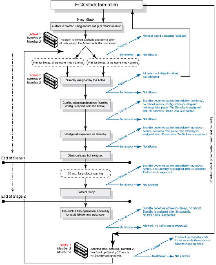
FIGURE 25 Hitless stacking support during stack formation
The following figure illustrates hitless stacking support during a stack merge.
Hitless Stacking
136 FastIron Ethernet Switch Stacking Configuration Guide
53-1003406-03
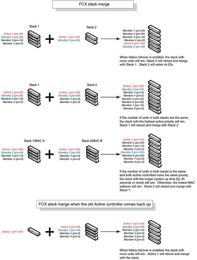
FIGURE 26 Hitless stacking support during a stack merge
The following figure illustrates hitless stacking support in a stack split.
Hitless Stacking
FastIron Ethernet Switch Stacking Configuration Guide 137
53-1003406-03
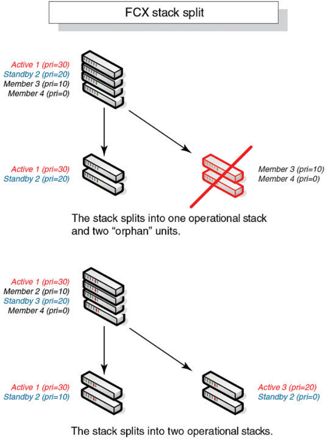
FIGURE 27 Hitless stacking support in a stack split
Hitless stacking behavior
Hitless stacking is enabled by default for FastIron release 08.0.20 and later releases. In previous
releases, the hitless-failover command must be set to enable in the configuration.
If you install a FastIron 08.0.20 or later image on a new system with no previous configuration, the
hitless-failover command is enabled by default.
If you upgrade to FastIron release 08.0.20 or later from a previous version that has hitless-failover
enabled, hitless-failover is retained as the default.
If you upgrade to FastIron release 08.0.20 or later on a system with an earlier release that does not
have hitless-failover enabled in its configuration, the previous configuration is retained.
Hitless stacking behavior
138 FastIron Ethernet Switch Stacking Configuration Guide
53-1003406-03

Hitless stacking can be disabled using the no hitless-failover enable command. When stacking is
disabled, the following limitations are in effect:
• If a failover occurs, every unit in the stack reloads.
• Manual switchover is not allowed. If the stack switch-over command is entered, the following
message appears on the console:
Switch-over is not allowed. Reason: hitless-failover not configured.
• Internal switchover resulting from a priority change is blocked until the entire stack is reloaded or
hitless stacking is enabled. A priority change triggers an election, but the newly elected winner does
not immediately assume its role.
• If there is no active controller after a reload, the bootup standby assumes the active role after
reloading every unit in the stack, including itself.
• During a stack merge, the active controller with the highest priority wins the election and reloads
every unit of the losing stack.
NOTE
Synchronization between the active controller, standby controller, and stack members occurs whether
or not hitless stacking is enabled.
If hitless stacking has been disabled, enable hitless stacking failover as described in "Enabling hitless
stacking failover." As soon as hitless stacking is enabled, the following behavior takes effect
immediately:
• If a failover occurs, the stack does not reload.
• Manual switchover (CLI command stack switch-over) is allowed.
• If a priority change occurred while hitless stacking was disabled and the configured priority value
requires a switchover, the system starts a 60-second timer before performing a switchover. After the
switchover, the highest priority standby controller becomes the active controller.
• If there is no active controller after a reload, the bootup standby controller assumes the active
controller role in approximately 120 seconds without a reload.
• During a stack merge, the active controller with the larger number of units wins the election and
reloads every unit of the losing stack. If two stacks have the same number of units, then the priority,
system up time, ID, and finally the MAC address are compared. If two stacks have the same number
of units and the same priority, then the stack with the longest system up time (by 30 seconds or
more) wins the election. Otherwise, the smallest ID is compared next, followed by MAC address. If
the losing active controller has the highest priority, it becomes the standby controller after reloading
and relearning the protocols. It becomes the active controller after an internal switchover.
NOTE
If the active controllers of two merging stacks have different hitless stacking settings (for example,
hitless stacking is enabled in one stack and disabled in the other), the winning controller retains its
hitless stacking setting and runtime configuration for the merged stack.
You can use the show stack command to check whether hitless stacking is enabled.
Enabling hitless stacking
Hitless stacking is enabled by default, beginning with FastIron release 08.0.20; however, certain
restrictions apply as described in Hitless stacking behavior on page 138.
If hitless stacking has been disabled, you can enable it as described in Enabling hitless stacking failover
on page 141.
Enabling hitless stacking
FastIron Ethernet Switch Stacking Configuration Guide 139
53-1003406-03
Displaying hitless stacking status
You can use the show stack command to check whether hitless stacking is enabled. The following
example shows that hitless stacking is disabled.
device# show stack
alone: standalone, D: dynamic config, S: static config
ID Type Role MAC Address Pri State Comment
2 S FCX648S member 0000.0000.0000 0 reserve
3 S FCX624 member 0000.0076.2640 0 remote Ready
5 S FCX624 standby 0000.0000.0400 100 remote Ready
8 S FCX648 active 0000.0077.7980 128 local Ready
active standby
+---+ +---+ +---+
-2/1| 8 |2/2--2/2| 3 |2/1--2/1| 5 |2/2-
| +---+ +---+ +---+ |
| |
|-------------------------------------|
Standby u5 - No hitless failover. Reason: hitless-failover not configured
Displaying pending device roles
When hitless stacking is disabled, a priority change triggers an election, but the newly-elected winner
does not assume its role until the entire stack is reloaded or hitless stacking is enabled.
You can use the show stack command to view pending device roles. The “Role” column displays the
current role for each unit. The “Comment” column displays the role that will take effect after a reload or
when hitless stacking is enabled.
device# show stack
alone: standalone, D: dynamic config, S: static config
ID Type Role MAC Address Pri State Comment
2 S FCX648S member 0000.0000.0000 0 reserve
3 S FCX624 standby 0000.0076.2640 200 remote Ready, active if reloaded
5 S FCX624 member 0000.0000.0400 128 remote Ready, standby if reloaded
8 S FCX648 active 0000.0077.7980 128 local Ready, member if reloaded
active standby
+---+ +---+ +---+
-2/1| 8 |2/2--2/2| 3 |2/1--2/1| 5 |2/2-
| +---+ +---+ +---+ |
| |
|-------------------------------------|
Standby u3 - No hitless failover. Reason: hitless-failover not configured
Hitless stacking failover
Hitless stacking failover provides automatic failover from the active controller to the standby controller
without resetting any of the units in the stack and with sub-second or no packet loss to hitless
stacking-supported services and protocols.
For a description of the events that occur during a hitless failover, refer to What happens during a
hitless stacking switchover or failover on page 133.
For a description of this feature’s impact on major system functions, refer to Supported hitless stacking
protocols and services on page 130.
For an example of hitless failover operation, refer to Hitless stacking failover example on page 142.
For feature limitations and configuration notes, refer to Hitless stacking configuration notes and feature
limitations on page 133.
Displaying hitless stacking status
140 FastIron Ethernet Switch Stacking Configuration Guide
53-1003406-03

Enabling hitless stacking failover
NOTE
Hitless stacking failover is enabled by default in FastIron release 08.0.20 and later releases.
To enable hitless stacking failover, enter the following command at the global CONFIG level of the CLI:
device# configure terminal
device(config)# hitless-failover enable
The command takes effect immediately. Hitless switchover is allowed, and in the event of a failover, the
standby controller takes over the active role without reloading the stack.
Syntax: [no] hitless-failover enable
Use the no form of the command to disable hitless stacking failover once it has been enabled.
Enabling hitless stacking failover
FastIron Ethernet Switch Stacking Configuration Guide 141
53-1003406-03
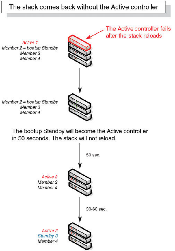
Hitless stacking failover example
FIGURE 28 Hitless stacking failover when the active controller fails
Hitless stacking switchover
Hitless stacking switchover is a manually-controlled (CLI-driven) or automatic switchover of the active
controller and standby controller without reloading the stack and without any packet loss to the
services and protocols that are supported by hitless stacking. A switchover is activated by the stack
switch-over CLI command. A switchover may also be activated by the priority command, depending
on the configured priority value.
Hitless stacking failover example
142 FastIron Ethernet Switch Stacking Configuration Guide
53-1003406-03
By default, hitless switchover is allowed on systems with FastIron release 08.0.20 or later installed, as
long as hitless failover is configured, and the priority of the two controllers is the same. Hitless
switchover behavior is described in Hitless stacking behavior on page 138.
Hitless switchover can be used by a system administrator to perform maintenance on a controller that
has been functioning as the active controller.
For a description of the events that occur during a hitless stacking switchover, refer to What happens
during a hitless stacking switchover or failover on page 133.
For a description of how hitless stacking switchover affects major system functions, refer to Supported
hitless stacking protocols and services on page 130.
For examples of hitless stacking switchover operation, refer to Hitless stacking switchover examples on
page 143.
Executing a hitless stacking switchover
The following must be in effect before a hitless switchover (to the standby controller) is allowed:
• Hitless stacking is enabled.
• The stack has a standby controller.
• The standby controller has learned the protocols.
• The standby controller has the same priority as the active controller.
• More than 120 seconds have passed since the previous switchover or failover.
You can use the show stack command to check these criteria.
To perform a switchover, enter the following command.
device# stack switch-over
Standby unit 8 will become active controller, and unit 1 will become standby
Are you sure? (enter 'y' or 'n'): y
Unit 1 is no longer the active controller
Syntax: stack switch-over
Hitless stacking switchover examples
The following examples illustrate hitless stacking failover and switchover operation during a CLI-driven
switchover or priority change.
The following figure illustrates a hitless stacking switchover triggered by the stack switch-over
command.
Executing a hitless stacking switchover
FastIron Ethernet Switch Stacking Configuration Guide 143
53-1003406-03
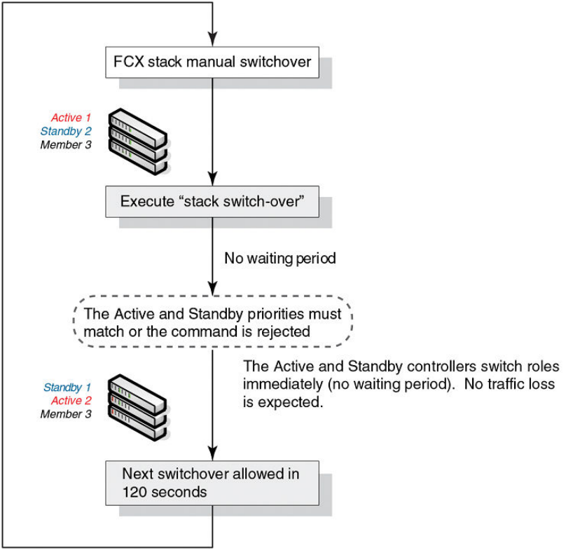
FIGURE 29 Manual switchover
The following figure illustrates a hitless stacking switchover when the active controller goes down and
then comes back up. The stack in this example has user-configured priorities.
Hitless Stacking
144 FastIron Ethernet Switch Stacking Configuration Guide
53-1003406-03
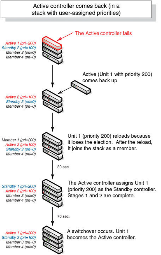
FIGURE 30 Hitless stacking switchover when the active controller comes back up
The following figure illustrates a hitless stacking switchover after the network administrator increases
the priority value of the standby controller.
Hitless Stacking
FastIron Ethernet Switch Stacking Configuration Guide 145
53-1003406-03
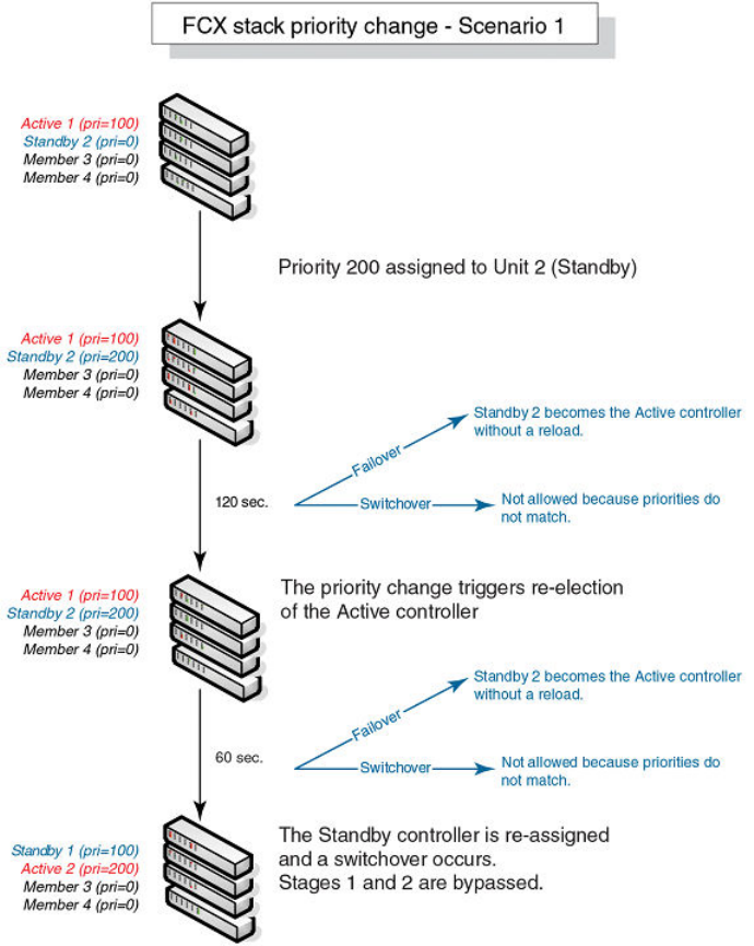
FIGURE 31 Scenario 1 - Hitless stacking switchover after a priority change
The following figure illustrates a hitless stacking switchover after the network administrator increases
the priority value of one of the stack members.
Hitless Stacking
146 FastIron Ethernet Switch Stacking Configuration Guide
53-1003406-03
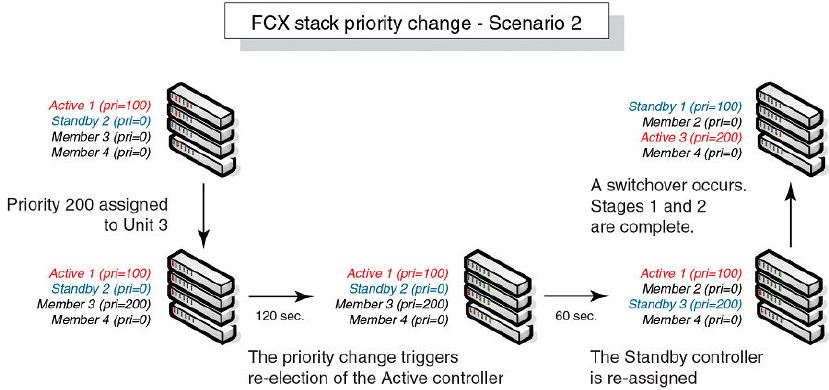
FIGURE 32 Scenario 2 - Hitless stacking switchover after a priority change
The following figure illustrates a hitless stacking switchover after the network administrator increases
the priority value for two of the stack members.
Hitless Stacking
FastIron Ethernet Switch Stacking Configuration Guide 147
53-1003406-03
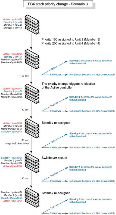
FIGURE 33 Scenario 3 - Hitless stacking switchover after a priority change
Displaying information about hitless stacking
Use the show stack command to view information pertinent to a hitless stacking switchover or
failover. The command output illustrates the active controller and standby controller, as well as the
readiness of the standby controller to take over the role of active controller, if needed.
device# show stack
alone: standalone, D: dynamic config, S: static config
ID Type Role MAC Address Pri State Comment
1 S FCX624S active 0000.0000.2900 128 local Ready
2 S FCX624S standby 0000.0000.0100 128 remote Ready
3 S FCX624SPOE member 0000.0088.8888 50 remote Ready
4 S FCX624S member 0000.0000.0000 128 reserve
Displaying information about hitless stacking
148 FastIron Ethernet Switch Stacking Configuration Guide
53-1003406-03

active standby
+---+ +---+ +---+
-1/3| 1 |1/5--1/5| 2 |1/3--1/5| 3 |1/3-
| +---+ +---+ +---+ |
| |
|-------------------------------------|
Standby unit 2: protocols ready, can failover or manually switch over
Current stack management MAC is 0000.0000.1100
NOTE
The text “can failover or manually switch over” was added for hitless stacking failover and switchover.
Displaying information about stack failover
Use the show stack failover command to view information about rapid failover.The show stack
failover command provides information on the current standby controller and its status as shown in the
following example.
device# show stack failover
Current standby is unit 2. state=ready
Standby u2 - protocols ready, can failover
Displaying information about link synchronization status
Use the show stack link-sync status command to view the status of the link synchronization. The
following command output is from an ICX 6610.
device# show stack link-sync status
STACKING_LINK_GLOBAL_CTRL messages sent: 0, received: 0
STACKING_LINK_INDIVIDUAL_CTRL messages sent: 359, received: 0
STACKING_LINK_STATUS messages sent: 22300, received: 128883
STACKING_POE_SCTRL messages sent: 0, received: 0
STACKING_POE_STATUS messages sent: 0, received: 0
global_ctrl_dest: ffffffff
individual_ctrl_dest: ee
status_dest: 30
Syslog messages for hitless stacking failover and switchover
Syslog messages are generated for the following events:
• Switchover
• Failover
• Standby controller assignment
The following table lists the supported syslog messages for hitless stacking failover and switchover.
Displaying information about stack failover
FastIron Ethernet Switch Stacking Configuration Guide 149
53-1003406-03

Supported syslog messages for hitless stacking faiilover and switchoverTABLE 27
Message level Message Explanation
Informational Stack: Stack unit unit_number has
been assigned as STANDBY unit of
the stack system
Indicates that the unit has been
assigned as the standby controller.
Informational Stack: Stack is operational due to
SWITCH-OVER
Indicates that a switchover has
occurred.
Informational Stack: Stack is operational due to
FAIL-OVER
Indicates that a failover has
occurred.
To view the system log or the traps logged on an SNMP trap receiver, enter the show log command
at any level of the CLI. The following sample output shows what the log may look like after a
switchover or assignment of the standby controller.
Brocade# show log
Syslog logging: enabled (0 messages dropped, 1 flushes, 0 overruns)
Buffer logging: level ACDMEINW, 8 messages logged
level code: A=alert C=critical D=debugging M=emergency E=error
I=informational N=notification W=warningDynamic Log Buffer (50
lines):
0d00h05m34s:I:System: Interface ethernet mgmt1, state up
0d00h05m33s:I:Stack: Stack unit 8 has been assigned as STANDBY unit of the stack
system
0d00h05m33s:I:Stack: Stack is operational due to SWITCH-OVER
0d00h05m32s:I:Stack: Stack unit 1 has been elected as ACTIVE unit of the stack system
0d00h05m29s:W:System:Stack unit 2 Fan speed changed automatically to 2
0d00h05m25s:W:System:Stack unit 5 Fan speed changed automatically to 2
0d00h05m00s:I:System: Interface ethernet mgmt1, state down
0d00h05m00s:I:Security: Telnet server enabled by from session
The following sample output shows what the log may look like after a failover of the active controller.
NOTE
After failover in FCX devices, the output of the show log command displays the status of the previous
management port interface.
Brocade# show log
Syslog logging: enabled (0 messages dropped, 0 flushes, 0 overruns)
Buffer logging: level ACDMEINW, 12 messages logged
level code: A=alert C=critical D=debugging M=emergency E=error
I=informational N=notification W=warning
Dynamic Log Buffer (50 lines):
0d00h04m41s:I:Stack: Stack unit 3 has been assigned as STANDBY unit of the stack
system
0d00h04m12s:I:System: Interface ethernet mgmt1, state up
0d00h04m10s:I:System: Interface ethernet mgmt1, state down
0d00h04m10s:I:System: Interface ethernet mgmt1, state up
0d00h04m09s:I:STP: VLAN 1 Bridge is RootBridge: 800000e052010000 (MgmtPriChg)
0d00h04m09s:I:System: Management MAC address changed to 0000.0001.0000
0d00h04m09s:I:Stack: Stack is operational due to FAIL-OVER
0d00h04m08s:I:Stack: Stack unit 1 has been elected as ACTIVE unit of the stack system
0d00h04m08s:I:STP: VLAN 1 Port 8/1/1 STP State -> DISABLED (PortDown)
0d00h04m08s:I:STP: VLAN 1 Port 8/1/1 STP State -> FORWARDING (PortDown)
0d00h04m08s:I:System: Interface ethernet 1/2/2, state down
0d00h04m06s:I:System: Interface ethernet 8/2/2, state down
Hitless Stacking
150 FastIron Ethernet Switch Stacking Configuration Guide
53-1003406-03

Mixed Stacking
● Supported mixed stacking features...............................................................................151
● Mixed stacking overview............................................................................................... 151
● Configuring basic mixed stacking..................................................................................155
● Displaying information about mixed stacking configuration.......................................... 163
● Specifying a TFTP server for Autocopy........................................................................ 167
● Recovering a pre-stacking configuration on peripheral devices....................................168
Supported mixed stacking features
The following table lists the individual Brocade FastIron switches and the mixed stacking features they
support. These features are supported in Layer 2, base Layer 3, and full Layer 3 software images.
Feature ICX 6430 ICX 6450 FCX ICX 6610 ICX 6650 FSX 800
FSX 1600
ICX 7450 ICX 7750
Mixed stacking No 08.0.01 No 08.0.01 No No No No
Show chassis enhancements No No No No No 08.0.01 No No
Enhanced topology support No 08.0.01 No 08.0.01 No No No No
NOTE
This chapter builds on the information presented in Traditional Stacking and describes areas where
mixed stacking differs from traditional stacking. The chapter does not repeat information where mixed
stacking and traditional stacking function in the same way.
NOTE
HyperEdge stacking is an enhancement to mixed stacking.
Mixed stacking overview
A stack is a group of Brocade stackable units and their connected stacking links that are connected so
that the stack is managed as a single entity.
Distributed Services extend advanced features such as Layer 3 services, VRF, and IPv6 multicast
across devices in a stack. Mixed stacking is a topology that allows the distribution of services to occur
between stack members. In mixed stacking, Distributed Services enable the mixing of premium and
entry-level devices in a single domain so that the advanced features and services of premium devices
are propagated to all switches in the domain.
FastIron Ethernet Switch Stacking Configuration Guide 151
53-1003406-03
Mixed stacking devices
A mixed stack contains ICX 6610 devices and ICX 6450 devices. ICX 6610 devices form the backbone
of the mixed stack. ICX 6450 devices are peripheral units that connect to the backbone and to other
peripheral units.
A mixed stack can contain one or two ICX 6610 devices and one to six ICX 6450 devices. ICX 6610
devices have full Layer 2 and Layer 3 unicast and multicast capabilities. ICX 6450 devices support full
Layer 2 switching and basic Layer 3 routing capabilities.
In a mixed stack, all Layer 3 functions are performed by the ICX 6610 devices. Layer 3 traffic received
on ICX 6450 devices is redirected to the ICX 6610 devices.
Mixed stacking topologies
Linear and ring topologies are supported. For information about how to connect devices in a mixed
stack, including cabling, stacking ports, stacking trunks, trunking requirements, and supported
topologies, refer to the hardware installation guides:
•Brocade ICX 6610 Stackable Switch Hardware Installation Guide
•Brocade ICX 6430 and ICX 6450 Stackable Switches Hardware Installation Guide
Additional topology support for mixed stacking
Additional stacking topologies are available for mixed stacking, including a star topology, for ICX 6610
and ICX 6450 devices.
The following restrictions apply to the topologies:
• Up to two ICX 6610 devices
• Up to six ICX 6450 devices
• Up to six logical peripheral links per ICX 6610 (either ports or trunks)
• Each ICX 6450 device can have only one connection with each ICX 6610 device.
• Each ICX 6450 must be connected directly to an ICX 6610 device.
Each ICX 6610 device can have up to eight 10 Gbps ports that can be used as peripheral ports to
connect to ICX 6450 devices (four of them are available with PoD licensing). Two neighboring ports
can be trunked together to form a peripheral trunk, allowing each ICX 6610 device to have up to four
peripheral trunks. Although there can be four to eight logical peripheral links (depending on the
number of peripheral trunks), only six peripheral ICX 6450 devices can be connected in a valid
HyperEdge topology.
Star topology for ICX 6610 and ICX 6450
A star topology provides a mesh-like connection between the backbone active controller device and
the peripheral devices. The following star topology consists of two ICX 6610 devices in a ring topology
with six ICX 6450 devices connected as peripherals. Each ICX 6610 device is directly connected to
each ICX 6450 device. Each ICX 6450 device is connected to two ICX 6610 devices.
Mixed stacking devices
152 FastIron Ethernet Switch Stacking Configuration Guide
53-1003406-03
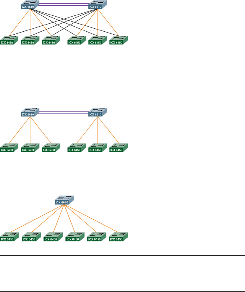
FIGURE 34 Star topology for ICX 6610 and ICX 6450 devices
Other stacking topologies
The following mixed stacking topology consists of two ICX 6610 devices in a ring topology with six
peripheral devices. Each ICX 6610 device has three peripheral links. Each ICX 6450 device is
connected directly to one ICX 6610 device.
FIGURE 35 Ring topology
The following mixed stacking topology consists of one active controller device with six peripheral
devices. The ICX 6610 device has six peripheral links. Each peripheral is connected directly to the ICX
6610 device.
FIGURE 36 Single ICX 6610 mixed stack
NOTE
If a topology is not a valid mixed stacking topology, the following warning message is displayed on the
console or as part of the output from the show stack and show stack stack-ports commands: ***
Warning! The current HyperEdge topology is not a validated topology. Please
refer to documentation for more details.
Mixed stacking terms
The following table shows definitions of mixed stacking terms.
Mixed stacking terms
FastIron Ethernet Switch Stacking Configuration Guide 153
53-1003406-03

Mixed stacking termsTABLE 28
Term Definition
Active controller ICX 6610 device.
Backbone or core Topology formed by ICX 6610 devices.
Backbone or core unit ICX 6610 device.
Peripheral port or trunk (peri-port or
peri-trunk)
On ICX 6610 devices only, used to link to a stacking port or trunk of an ICX
6450 device.
Peripheral unit ICX 6450 device.
Stacking port or trunk Used to link:
• ICX 6610 devices to each other
• ICX 6450 devices to each other
• ICX 6450 device to a peripheral port or peripheral trunk of an ICX 6610
device.
Standby controller ICX 6610 device.
Substack Topology formed by ICX 6450 devices. If ICX 6450 devices are separated
by an ICX 6610 device, the ICX 6450 devices belong to different substacks.
Mixed stacking software image requirements
• All devices in a mixed stack must run router software images.
• All devices in a mixed stack must run the same version of the software image.
The stack cannot form if the software images are different major versions, such as FastIron release
07.4.00 and FastIron release 08.00.0a. Stacking communication is blocked in this case.
A stack member is not operational if it runs a different minor version than other stack members, such
as FastIron release 08.00.0a and FastIron release 08.00.1. In this case, however, stacking
communication is possible so that the image mismatch can be fixed.
Mixed stacking configuration prerequisites
Before configuring and forming a mixed stack, be sure to complete the following pre-requisites:
• Load a software image on each device.
• Load a software license on each ICX 6610 device.
• Purchase and load the ICX6610-10G-LIC-POD license for each ICX 6610 SFP+ port that connects
to an ICX 6450 device.
• If you use ICX 6450 ports 2 and 4 as stacking ports, purchase and load the ICX6450-2X10G-LIC-
POD license.
• Physically connect the devices using stacking cables.
Mixed stacking software image requirements
154 FastIron Ethernet Switch Stacking Configuration Guide
53-1003406-03

Configuring basic mixed stacking
There are three ways to configure a mixed stack: the secure-setup utility, automatic configuration, and
manual configuration.
Mixed Stack Construction MethodsTABLE 29
Method Description
Secure-setup utility An interactive utility requiring some selection on the part of the user but minimal use of
CLI for configuration.
Automatically forms trunks.
Requires configuring the SFP+ ports on ICX 6610 devices to 10 Gbps using the speed
command.
Automatic configuration All stack members are configured from the active controller for the stack.
Automatically forms trunks.
Does not require configuring the speed command.
Manual configuration Configuration must be done on each individual stack member.
Does not require configuring the speed command.
Configuring a mixed stack using secure-setup
The secure-setup utility requires minimal use of CLI compared to other available mixed stack
configuration methods.
The secure-setup utility is an interactive utility that allows you to select the active and standby
controllers, topology, and the peripheral devices of the mixed stack. It automatically configures trunks
between ICX 6610 stack units (provided the port numbers are consecutive and the first port in the trunk
is an odd number). It allows you to do all this from the active controller and does not require you to log
into each device to configure it.
NOTE
You must run the secure-setup utility on the ICX 6610 that you intend to be the active controller.
Perform the following steps to configure a mixed stack using the secure-setup utility.
1. Enable stacking on the ICX 6610 device that you want to be the active controller.
Brocade(config)# stack enable
2. Configure the SFP+ ports on the ICX 6610 devices to 10 Gbps using the speed command.
Brocade(config)# interface ethernet 1/3/1 to 1/3/2
Brocade(config-mif-1/3/1-1/3/2)# speed 10g-full
Brocade(config-mif-1/3/1-1/3/2)# interface ethernet 1/3/7 to 1/3/8
Brocade(config-mif-1/3/7-1/3/8)# speed 10g-full
Brocade(config-mif-1/3/7-1/3/8)# exit
Brocade(config)# exit
If you have the required POD licenses, the secure-setup utility can use the 10 Gbps SFP+ ports on
the front panel of ICX 6610 devices to connect ICX 6610 devices to ICX 6450 devices in a mixed
stack.
Configuring basic mixed stacking
FastIron Ethernet Switch Stacking Configuration Guide 155
53-1003406-03
3. Launch the secure-setup utility on the ICX 6610 device that you want to be the active controller.
Brocade(config)# stack secure-setup
Based on how you have physically connected the devices, the stack topology is discovered.
4. When prompted, specify the topology by accepting the discovered topology.
Do you accept the topology (RING) (y/n)?: y
The devices in the substacks are discovered.
5. When prompted, enter the number of devices (units) you want to include in the substacks.
Enter the number of the desired units in the above sub stack(0-3)[0]: 3
Stack unit IDs are assigned.
6. When prompted, specify the stack unit IDs by accepting the assigned IDs.
Do you accept the unit id's (y/n)?: y
All units (except for the active controller) reboot, and the mixed stack is formed.
Mixed Stacking
156 FastIron Ethernet Switch Stacking Configuration Guide
53-1003406-03
The following example shows the configuration of a mixed stack using the secure-setup utility. The
mixed stack contains two ICX 6610 devices in the backbone, and there are two substacks containing
three ICX 6450 devices each.
Brocade(config)# stack enable
Brocade(config)# interface ethernet 1/3/1 to 1/3/2
Brocade(config-mif-1/3/1-1/3/2)# speed 10g-full
Brocade(config-mif-1/3/1-1/3/2)# interface ethernet 1/3/7 to 1/3/8
Brocade(config-mif-1/3/7-1/3/8)# speed 10g-full
Brocade(config-mif-1/3/7-1/3/8)# exit
Brocade(config)# exit
Brocade#stack secure-setup
Brocade#Discovering the stack topology...
Current Discovered Topology - RING
Available UPSTREAM units
Hop(s) Id Type Mac Address
1 new ICX6610-48P 748e.f834.4800
Available DOWNSTREAM units
Hop(s) Id Type Mac Address
1 new ICX6610-48P 748e.f834.4800
Do you accept the topology (RING) (y/n)?: y
Active Unit: Id 1, ICX6610-24F 748e.f891.c5b8 - Peripheral Link 1/3/1
Available units
Hop(s) Id Type Mac Address
1 new ICX6450-24 748e.f86d.7aa7
2 new ICX6450-24P 748e.f8b0.7aa0
3 new ICX6450-24P 748e.f8b0.7cc0
Enter the number of the desired units in the above sub stack(0-3)[0]: 3
Active Unit: Id 1, ICX6610-24F 748e.f891.c5b8 - Peripheral Link 1/3/7
Available units
Hop(s) Id Type Mac Address
1 new ICX6450-48 748e.f8d4.02c0
2 new ICX6450-48 748e.f8d4.2300
3 new ICX6450-24P 748e.f8b0.6c00
Enter the number of the desired units in the above sub stack(0-3)[0]: 3
Max Stacking Unit limit reached...
Selected Topology:
Active Id Type Mac Address
1 ICX6610-24F 748e.f891.c5b8
Active Unit: Id 1, ICX6610-24F 748e.f891.c5b8 - Peripheral Link 1/3/1
Hop(s) Id Type Mac Address
1 3 ICX6450-24 748e.f86d.7aa7
2 4 ICX6450-24P 748e.f8b0.7aa0
3 5 ICX6450-24P 748e.f8b0.7cc0
Active Unit: Id 1, ICX6610-24F 748e.f891.c5b8 - Peripheral Link 1/3/7
Hop(s) Id Type Mac Address
1 6 ICX6450-48 748e.f8d4.02c0
2 7 ICX6450-48 748e.f8d4.2300
3 8 ICX6450-24P 748e.f8b0.6c00
Selected UPSTREAM units
Hop(s) Id Type Mac Address
1 2 ICX6610-48P 748e.f834.4800
Selected DOWNSTREAM units
Hop(s) Id Type Mac Address
1 2 ICX6610-48P 748e.f834.4800
Do you accept the unit id's (y/n)?: y
Mixed Stacking
FastIron Ethernet Switch Stacking Configuration Guide 157
53-1003406-03
Use the show stack command or the show stack connection command to verify the mixed stack
configuration.
Brocade# show stack
alone: standalone, D: dynamic config, S: static config
ID Type Role Mac Address Pri State Comment
1 S ICX6610-24F active 748e.f891.c5b8 128 local Ready
2 D ICX6610-48P standby 748e.f834.4800 0 remote Ready
3 D ICX6450-24 member 748e.f86d.7aa7 0 remote Ready
4 D ICX6450-24P member 748e.f8b0.7aa0 0 remote Ready
5 D ICX6450-24P member 748e.f8b0.7cc0 0 remote Ready
6 D ICX6450-48 member 748e.f8d4.02c0 0 remote Ready
7 D ICX6450-48 member 748e.f8d4.2300 0 remote Ready
8 D ICX6450-24P member 748e.f8b0.6c00 0 remote Ready
active standby
+---+ +---+
=2/6| 1 |2/1==2/6| 2 |2/1=
| +---+ +---+ |
| |
|------------------------|
active
--- +---+ +---+ +---+
( 1 )3/7==2/1| 6 |2/3==2/1| 7 |2/3==2/1| 8 |
--- +---+ +---+ +---+
active
--- +---+ +---+ +---+
( 1 )3/1==2/3| 3 |2/1==2/3| 4 |2/1==2/3| 5 |
--- +---+ +---+ +---+
Standby u2 - No hitless failover. Reason: hitless-failover not configured
Current stack management MAC is 748e.f891.c5b8
Note: no "stack mac" config. My MAC will change after failover.
Brocade# show stack connection
Probing the topology. Please wait ...
ICX6610-24F Router#
active standby
+---+ +---+
=2/6| 1 |2/1==2/6| 2 |2/1=
| +---+ +---+ |
| |
|------------------------|
standby active
--- +---+ +---+ +---+ ---
( 2 )3/1==2/1| 5 |2/3==2/1| 4 |2/3==2/1| 3 |2/3==3/1( 1 )
--- +---+ +---+ +---+ ---
active standby
--- +---+ +---+ +---+ ---
( 1 )3/7==2/1| 6 |2/3==2/1| 7 |2/3==2/1| 8 |2/3==3/7( 2 )
--- +---+ +---+ +---+ ---
trunk probe results: 10 links
Link 1: u1 -- u2, num=5
1: 1/2/1 (T0) <---> 2/2/6 (T1)
2: 1/2/2 (T0) <---> 2/2/7 (T1)
3: 1/2/3 (T0) <---> 2/2/8 (T1)
4: 1/2/4 (T0) <---> 2/2/9 (T1)
5: 1/2/5 (T0) <---> 2/2/10(T1)
Link 2: u1 -- u2, num=5
1: 1/2/6 (T1) <---> 2/2/1 (T0)
2: 1/2/7 (T1) <---> 2/2/2 (T0)
3: 1/2/8 (T1) <---> 2/2/3 (T0)
4: 1/2/9 (T1) <---> 2/2/4 (T0)
5: 1/2/10(T1) <---> 2/2/5 (T0)
Link 3: u1 -- u3, num=2
1: 1/3/1 (T2) <---> 3/2/3 (T1)
2: 1/3/2 (T2) <---> 3/2/4 (T1)
Link 4: u1 -- u6, num=2
1: 1/3/7 (T3) <---> 6/2/1 (T0)
2: 1/3/8 (T3) <---> 6/2/2 (T0)
Link 5: u2 -- u5, num=2
1: 2/3/1 (T2) <---> 5/2/1 (T0)
2: 2/3/2 (T2) <---> 5/2/2 (T0)
Link 6: u2 -- u8, num=2
1: 2/3/7 (T3) <---> 8/2/3 (T1)
Mixed Stacking
158 FastIron Ethernet Switch Stacking Configuration Guide
53-1003406-03

2: 2/3/8 (T3) <---> 8/2/4 (T1)
Link 7: u3 -- u4, num=2
1: 3/2/1 (T0) <---> 4/2/3 (T1)
2: 3/2/2 (T0) <---> 4/2/4 (T1)
Link 8: u4 -- u5, num=2
1: 4/2/1 (T0) <---> 5/2/3 (T1)
2: 4/2/2 (T0) <---> 5/2/4 (T1)
Link 9: u6 -- u7, num=2
1: 6/2/3 (T1) <---> 7/2/1 (T0)
2: 6/2/4 (T1) <---> 7/2/2 (T0)
Link 10: u7 -- u8, num=2
1: 7/2/3 (T1) <---> 8/2/1 (T0)
2: 7/2/4 (T1) <---> 8/2/2 (T0)
CPU to CPU packets are fine between 8 units.
Configuring a mixed stack using automatic configuration
In automatic configuration, you must configure all stack members from the stack member that you
intend to be the active controller. It should have the highest priority of all stack units. Using automatic
configuration requires some command entry on the stack's active controller but, unlike secure-setup,
does not require configuring the speed command.
NOTE
You must configure all the devices in a mixed stack on the ICX 6610 device that you intend to be the
active controller.
Perform the following steps to configure the active controller in a mixed stack using the automatic
configuration method.
1. From the device that you want to be the active controller, configure the stack unit ID.
Brocade(config)# stack unit 1
2. If there are two backbone devices, specify the priority.
Brocade(config-unit-1)# priority 128
The priority should be the same on each controller. The priority setting is used to manage a
switchover between the active controller and the standby controller.
3. Specify the trunks or ports on this backbone device that connect to a peripheral unit in a substack.
Brocade(config-unit-1)# peri-trunk 1/3/1 to 1/3/2
Brocade(config-unit-1)# peri-trunk 1/3/7 to 1/3/8
4. If there are two backbone devices, perform the steps in Automatically configuring a standby controller
device in a mixed stack on page 160.
5. To configure peripheral devices, perform the steps Automatically configuring peripheral devices in a
mixed stack on page 161.
Configuring a mixed stack using automatic configuration
FastIron Ethernet Switch Stacking Configuration Guide 159
53-1003406-03
The following example shows the configuration of a mixed stack using the automatic configuration
method in which all stack members are configured from the active controller. The mixed stack contains
two ICX 6610 devices in the backbone and two substacks of three ICX 6450 peripheral devices each.
Brocade(config)# stack unit 1
Brocade(config-unit-1)# priority 128
Brocade(config-unit-1)# peri-trunk 1/3/1 to 1/3/2
Brocade(config-unit-1)# peri-trunk 1/3/7 to 1/3/8
Brocade(config-unit-1)# stack unit 2
Brocade(config-unit-2)# module 1 icx6610-48p-poe-port-management-module
Brocade(config-unit-2)# priority 128
Brocade(config-unit-2)# peri-trunk 2/3/1 to 2/3/2
Brocade(config-unit-2)# peri-trunk 2/3/7 to
2/3/8
Brocade(config-unit-2)# stack unit 3
Brocade(config-unit-3)# module 1 icx6450-24-port-management-module
Brocade(config-unit-3)# stack-trunk 3/2/1 to 3/2/2
Brocade(config-unit-3)# stack-trunk 3/2/3 to 3/2/4
Brocade(config-unit-3)# connect 1/3/1
Brocade(config-unit-3)# connect 4/2/3
Brocade(config-unit-3)# stack unit 4
Brocade(config-unit-4)# module 1 icx6450-24p-poe-port-management-module
Brocade(config-unit-4)# stack-trunk 4/2/1 to 4/2/2
Brocade(config-unit-4)# stack-trunk 4/2/3 to 4/2/4
Brocade(config-unit-4)# connect 3/2/1
Brocade(config-unit-4)# connect 7/2/3
Brocade(config-unit-4)# stack unit 5
Brocade(config-unit-5)# module 1 icx6450-48-port-management-module
Brocade(config-unit-5)# stack-trunk 5/2/1 to 5/2/2
Brocade(config-unit-5)# stack-trunk 5/2/3 to 5/2/4
Brocade(config-unit-5)# connect
1/3/7
Brocade(config-unit-5)# connect 6/2/1
Brocade(config-unit-5)# stack unit 6
Brocade(config-unit-6)# module 1 icx6450-48-port-management-module
Brocade(config-unit-6)# stack-trunk 6/2/1 to 6/2/2
Brocade(config-unit-6)# stack-trunk 6/2/3 to 6/2/4
Brocade(config-unit-6)# connect 5/2/3
Brocade(config-unit-6)# connect 8/2/1
Brocade(config-unit-6)# stack unit 7
Brocade(config-unit-7)# module 1 icx6450-24p-poe-port-management-module
Brocade(config-unit-7)# stack-trunk 7/2/1 to 7/2/2
Brocade(config-unit-7)# stack-trunk 7/2/3 to 7/2/4
Brocade(config-unit-7)# connect 2/3/1
Brocade(config-unit-7)# connect 4/2/1
Brocade(config-unit-7)# stack unit 8
Brocade(config-unit-8)# module 1 icx6450-24p-poe-port-management-module
Brocade(config-unit-8)# stack-trunk 8/2/1 to 8/2/2
Brocade(config-unit-8)# stack-trunk 8/2/3 to
8/2/4
Brocade(config-unit-8)# connect 2/3/7
Brocade(config-unit-8)# connect 6/2/3
Brocade(config-unit-8)# stack enable
Enable stacking. This unit actively participates in stacking.
Automatically configuring a standby controller device in a mixed stack
If there are two backbone devices, perform the following steps to configure the standby controller in a
mixed stack using the automatic configuration method.
1. From the ICX 6610 device that you want to be the active controller, configure the stack unit ID.
Brocade(config)# stack unit 2
2. Specify a port module.
Brocade(config-unit-2)# module 1 icx6610-24-port-management-module
Specifying the port module identifies the device to the active controller. Use the show running-
config command to get port module information. You only need to specify one port module,
because the active controller generates information for other modules.
Automatically configuring a standby controller device in a mixed stack
160 FastIron Ethernet Switch Stacking Configuration Guide
53-1003406-03
3. Specify the priority.
Brocade(config-unit-1)# priority 128
The priority should be equal to or less than the active controller priority. The priority setting is used to
manage a switchover between the active controller and the standby controller.
4. Specify the trunks or ports on this backbone device that connect to a peripheral unit in a substack.
Brocade(config-unit-1)# peri-trunk 2/3/1 to 2/3/2
Brocade(config-unit-1)# peri-trunk 2/3/7 to 2/3/8
Automatically configuring peripheral devices in a mixed stack
Perform the following steps to configure the peripheral devices in a mixed stack using the automatic
configuration method.
1. From the ICX 6610 device that is the active controller, configure the stack unit ID.
Brocade(config)# stack unit 3
2. Specify a port module.
Brocade(config-unit-3)# module 1 icx6450-24-port-management-module
Specifying the port modules identifies the device to the active controller. Use the show running-
config command to get port module information. You only need to specify one port module because
the active controller generates information for other modules.
3. (Optional) Create stacking trunks on this peripheral device.
Brocade(config-unit-3)# stack-trunk 3/2/1 to 3/2/2
Brocade(config-unit-3)# stack-trunk 3/2/3 to 3/2/4
4. (Optional) Specify the devices to which this peripheral device connects.
Brocade(config-unit-3)# connect 1/3/1
Brocade(config-unit-3)# connect 4/2/3
The connect command cannot override the physical connections, but it is used on peripheral
devices to match a unit ID to a peripheral device for unit replacement or stack construction.
5. Repeat Step 1 through Step 4 for each additional peripheral device. Specify a different stack unit ID
for each device in Step 1.
6. Enable stacking.
Brocade(config-unit-8)# stack enable
Configuring a mixed stack using manual configuration
Configuring a mixed stack manually offers more individual control over configuration parameters than
you have when you use automatic configuration.
You must configure each device that you want to include in the stack from the device itself. You cannot
configure all devices from the active controller as you can in the automatic configuration method.
Perform the following steps on the backbone device designated as the active controller.
1. Specify the stack unit ID.
Brocade# stack unit 1
2. Specify the trunks or ports on this backbone device that connect to a peripheral device in a substack.
Brocade(config-unit-1)# peri-port 1/3/1
Brocade(config-unit-1)# peri-port 1/3/2
Brocade(config-unit-1)# peri-port 1/3/7
Brocade(config-unit-1)# peri-port 1/3/8
Brocade(config-unit-1)# exit
Automatically configuring peripheral devices in a mixed stack
FastIron Ethernet Switch Stacking Configuration Guide 161
53-1003406-03
3. Enable stacking.
Brocade(config)# stack enable
4. If there are two backbone devices, perform the steps in Manually configuring a standby controller
device in a mixed stack on page 162.
5. To configure peripheral devices, perform the steps in the Manually configuring peripheral devices in
a mixed stack on page 163.
The following example shows the configuration of a mixed stack using the manual configuration
method in which all stack members are configured from each individual device. The mixed stack
contains two ICX 6610 devices in the backbone and two substacks of three ICX 6450 peripheral
devices each.
Unit 1
Brocade(config)# stack unit 1
Brocade(config-unit-1)# peri-port 1/3/1
Brocade(config-unit-1)# peri-port 1/3/2
Brocade(config-unit-1)# peri-port 1/3/7
Brocade(config-unit-1)# peri-port 1/3/8
Brocade(config-unit-1)# exit
Brocade(config)# stack enable
Unit 2
Brocade(config)#stack suggested-id 2
Brocade(config)#stack unit 1
Brocade(config-unit-1)# peri-port 1/3/1
Brocade(config-unit-1)# peri-port 1/3/2
Brocade(config-unit-1)# peri-port 1/3/7
Brocade(config-unit-1)# peri-port 1/3/8
Brocade(config-unit-1)# exit
Brocade(config)# stack enable
Unit 3
Brocade(config)# stack suggested-id 3
Brocade(config)# stack enable
Unit 4
Brocade(config)# stack suggested-id 4
Brocade(config)# stack enable
Unit 5
Brocade(config)# stack suggested-id 5
Brocade(config)# stack enable
Unit 6
Brocade(config)# stack suggested-id 6
Brocade(config)# stack enable
Unit 7
Brocade(config)# stack suggested-id 7
Brocade(config)# stack enable
Unit 8
Brocade(config)# stack suggested-id 8
Brocade(config)# stack enable
Manually configuring a standby controller device in a mixed stack
If there are two backbone devices, perform the following steps to configure the standby controller in a
mixed stack using the manual configuration method.
1. Specify the stack unit ID.
Brocade# stack unit 1
Because you are configuring each device from the device itself and the stack is not yet formed, the
stack unit ID is 1 for each device.
2. Specify the trunks or ports on this backbone device that connect to a member device in a substack.
Brocade(config-unit-1)# peri-port 2/3/1
Brocade(config-unit-1)# peri-port 2/3/2
Brocade(config-unit-1)# peri-port 2/3/7
Brocade(config-unit-1)# peri-port 2/3/8
Brocade(config-unit-1)# exit
Manually configuring a standby controller device in a mixed stack
162 FastIron Ethernet Switch Stacking Configuration Guide
53-1003406-03
3. Specify the stack unit ID that you want this device to have in the stack.
Brocade(config)# stack suggested-id 2
The system attempts to assign a device bootup ID as its stack unit ID. However, due to timing issues
or the possible unavailability of the bootup ID, a member device might not get the stack unit ID that
you want. The optional stack suggested-id command allows you to specify the stack unit ID for
devices other than the active controller.
4. Enable stacking.
Brocade(config)# stack enable
Manually configuring peripheral devices in a mixed stack
Perform the following steps to configure the peripheral devices in a mixed stack using the manual
configuration method.
1. Specify the stack unit ID that you want this device to have in the stack.
Brocade(config)# stack suggested-id 3
The system attempts to assign a device bootup ID as its stack unit ID. However, due to timing issues
or the possible unavailability of the bootup ID, a member device might not get the stack unit ID that
you want. The optional stack suggested-id command allows you to specify the stack unit ID for
devices other than the active controller.
2. Enable stacking.
Brocade(config)# stack enable
3. Repeat Step 1 and Step 2 for each additional member device. Specify a different suggested stack
unit ID for each device in Step 1.
Displaying information about mixed stacking configuration
Several show commands are available to verify mixed stack configurations, including a star topology.
You can use any of the following commands to verify the configuration of a mixed stack.
•show running-config
•show stack
•show stack detail.
Displaying mixed stack information for an automatic configuration
Use the show running-config command to view the mixed stack configuration.
Manually configuring peripheral devices in a mixed stack
FastIron Ethernet Switch Stacking Configuration Guide 163
53-1003406-03
The following example of show running-config command output shows information for an
automatically configured stack with eight stack units, including information on peripheral trunks and
link connections.
device# show running-config
stack unit 1
priority 128
peri-trunk 1/3/1 to 1/3/2
peri-trunk 1/3/7 to 1/3/8
stack unit 2
module 1 icx6610-48p-poe-port-management-module
priority 128
peri-trunk 2/3/1 to 2/3/2
peri-trunk 2/3/7 to 2/3/8
stack unit 3
module 1 icx6450-24-port-management-module
stack-trunk 3/2/1 to 3/2/2
stack-trunk 3/2/3 to 3/2/4
connect 1/3/1
connect 4/2/3
stack unit 4
module 1 icx6450-24p-poe-port-management-module
stack-trunk 4/2/1 to 4/2/2
stack-trunk 4/2/3 to 4/2/4
connect 3/2/1
connect 7/2/3
stack unit 5
module 1 icx6450-48-port-management-module
stack-trunk 5/2/1 to 5/2/2
stack-trunk 5/2/3 to 5/2/4
connect 1/3/7
connect 6/2/1
stack unit 6
module 1 icx6450-48-port-management-module
stack-trunk 6/2/1 to 6/2/2
stack-trunk 6/2/3 to 6/2/4
connect 5/2/3
connect 8/2/1
stack unit 7
module 1 icx6450-24p-poe-port-management-module
stack-trunk 7/2/1 to 7/2/2
stack-trunk 7/2/3 to 7/2/4
connect 2/3/1
connect 4/2/1
stack unit 8
module 1 icx6450-24p-poe-port-management-module
stack-trunk 8/2/1 to 8/2/2
stack-trunk 8/2/3 to 8/2/4
connect 2/3/7
connect 6/2/3
stack enable
Enable stacking. This unit actively participates in stacking
Using the show stack command to verify automatic stack configuration
In the following example, show stack command output displays information for an eight member
mixed stack, including connections, MAC address, priority setting, role, and state for each stack
member. The output also indicates that hitless stacking failover is not enabled on the stack.
Brocade# show stack
alone: standalone, D: dynamic config, S: static config
ID Type Role Mac Address Pri State Comment
1 S ICX6610-24 active 748e.f8ce.bc40 128 local Ready
2 S ICX6610-48P standby 748e.f834.4800 128 remote Ready
3 S ICX6450-24 member 748e.f86d.7aa7 0 remote Ready
4 S ICX6450-24P member 748e.f8b0.7aa0 0 remote Ready
5 S ICX6450-48 member 748e.f8d4.02c0 0 remote Ready
6 S ICX6450-48 member 748e.f8d4.2300 0 remote Ready
7 S ICX6450-24P member 748e.f8b0.7cc0 0 remote Ready
8 S ICX6450-24P member 748e.f8b0.6c00 0 remote Ready
active standby
+---+ +---+
Mixed Stacking
164 FastIron Ethernet Switch Stacking Configuration Guide
53-1003406-03
2/1| 1 |2/6==2/1| 2 |2/6
+---+ +---+
active standby
--- +---+ +---+ +---+ ---
( 1 )3/7==2/1| 5 |2/3==2/1| 6 |2/3==2/1| 8 |2/3==3/7( 2 )
--- +---+ +---+ +---+ ---
standby active
--- +---+ +---+ +---+ ---
( 2 )3/1==2/1| 7 |2/3==2/1| 4 |2/3==2/1| 3 |2/3==3/1( 1 )
--- +---+ +---+ +---+ ---
Standby u2 - No hitless failover. Reason: hitless-failover not configured
Current stack management MAC is 748e.f8ce.bc40
Displaying mixed stack information for a manual configuration
Use the show running-config command to view general information on mixed stack configuration. The
following example shows the configuration for a mixed stack for which all stack members have been
configured from each individual device. The mixed stack contains two ICX 6610 devices in the
backbone and two substacks of three ICX 6450 peripheral devices each.
device# show running-config
stack unit 1
peri-port 1/3/1
peri-port 1/3/2
peri-port 1/3/7
peri-port 1/3/8
exit
stack enable
Unit 2
stack suggested-id 2
stack unit 2
peri-port 2/3/1
peri-port 2/3/2
peri-port 2/3/7
peri-port 2/3/8
exit
stack enable
Unit 3
stack suggested-id 3
stack enable
Unit 4
stack suggested-id 4
stack enable
Unit 5
stack suggested-id 5
stack enable
Unit 6
stack suggested-id 6
stack enable
Unit 7
stack suggested-id 7
stack enable
Unit 8
stack suggested-id 8
stack enable
Use the show stack command to verify additional information for the mixed stack configuration. The
following show stack command output displays additional information for the same eight-member
stack, including the device type for each stack member, its role, MAC address, priority setting, and
state. Information on hitless stacking failover and stack MAC address settings is also displayed.
device# show stack
alone: standalone, D: dynamic config, S: static config
ID Type Role Mac Address Pri State Comment
1 S ICX6610-48P active 748e.f834.4800 0 local Ready
2 D ICX6610-24F standby 748e.f891.c5b8 0 remote Ready
3 D ICX6450-24 member 748e.f86d.7aa7 0 remote Ready
4 D ICX6450-24P member 748e.f8b0.7aa0 0 remote Ready
5 D ICX6450-24P member 748e.f8b0.7cc0 0 remote Ready
6 D ICX6450-48 member 748e.f8d4.02c0 0 remote Ready
7 D ICX6450-48 member 748e.f8d4.2300 0 remote Ready
Displaying mixed stack information for a manual configuration
FastIron Ethernet Switch Stacking Configuration Guide 165
53-1003406-03
8 D ICX6450-24P member 748e.f8b0.6c00 0 remote Ready
active standby
+---+ +---+
=2/6| 1 |2/1==2/6| 2 |2/1=
| +---+ +---+ |
| |
|------------------------|
standby active
--- +---+ +---+ +---+ ---
( 2 )3/7--2/1| 6 |2/3--2/1| 7 |2/3--2/1| 8 |2/3--3/7( 1 )
--- +---+ +---+ +---+ ---
active standby
--- +---+ +---+ +---+ ---
( 1 )3/1--2/1| 5 |2/3--2/1| 4 |2/3--2/1| 3 |2/3--3/1( 2 )
--- +---+ +---+ +---+ ---
peri-ports w/o link: 1/3/2, 1/3/8, 2/3/2, 2/3/8
Standby u2 - No hitless failover. Reason: hitless-failover not configured
Current stack management MAC is 748e.f834.4800
Note: no "stack mac" config. My MAC will change after failover.
Displaying mixed stack information for a star topology
Use the show running-config command for general connection information about a mixed stack
configured with a star topology. The following show running-config command output displays
information for a six-member mixed stack. Stack unit modules, priority, stack-trunks, stack-ports, and
peri-ports are identified. The display indicates that stacking is enabled. The stack MAC address is
identified. However, the example does not identify the role of each stack member or other
configuration details.
device# show running-config
Current configuration:
!
ver 08.0.01q024T7f3
!
stack unit 1
module 1 icx6610-24p-poe-port-management-module
module 2 icx6610-qsfp-10-port-160g-module
module 3 icx6610-8-port-10g-dual-mode-module
priority 128
stack-trunk 1/2/1 to 1/2/2
stack-trunk 1/2/6 to 1/2/7
stack-port 1/2/1 1/2/6
peri-port 1/3/1
peri-port 1/3/2
peri-port 1/3/3
peri-port 1/3/4
stack unit 2
module 1 icx6610-24-port-management-module
module 2 icx6610-qsfp-10-port-160g-module
module 3 icx6610-8-port-10g-dual-mode-module
priority 128
stack-trunk 2/2/1 to 2/2/2
stack-trunk 2/2/6 to 2/2/7
stack-port 2/2/1 2/2/6
peri-port 2/3/1
peri-port 2/3/2
peri-port 2/3/3
peri-port 2/3/4
stack unit 3
module 1 icx6450-24-port-management-module
module 2 icx6450-sfp-plus-4port-40g-module
stack-port 3/2/1 3/2/3
connect 1/3/4
connect 2/3/4
stack unit 4
module 1 icx6450-24p-poe-port-management-module
module 2 icx6450-sfp-plus-4port-40g-module
stack-port 4/2/1 4/2/3
connect 1/3/3
Displaying mixed stack information for a star topology
166 FastIron Ethernet Switch Stacking Configuration Guide
53-1003406-03
connect 2/3/3
stack unit 5
module 1 icx6450-48p-poe-port-management-module
module 2 icx6450-sfp-plus-4port-40g-module
stack-port 5/2/1 5/2/3
connect 1/3/2
connect 2/3/2
stack unit 6
module 1 icx6450-48-port-management-module
module 2 icx6450-sfp-plus-4port-40g-module
stack-port 6/2/1 6/2/3
connect 1/3/1
connect 2/3/1
stack enable
stack rconsole-off
stack mac 748e.f834.1f08
!
Use the show stack detail command to verify additional configuration details for a mixed stack
configured in a star topology. The following output for the show stack detail command provides
information on each stack member in the same six-member stack, including device type, role, MAC
address, priority, and state. The six-member stack in the example is configured for hitless stacking
failover.
device# show stack detail
alone: standalone, D: dynamic config, S: static config
ID Type Role Mac Address Pri State Comment
1 S ICX6610-24P active 748e.f834.1f08 128 local Ready
2 S ICX6610-24 standby 748e.f893.a686 128 remote Ready
3 S ICX6450-24 member 00a9.0003.0001 0 remote Ready
4 S ICX6450-24P member 748e.f8b0.62e0 0 remote Ready
5 S ICX6450-48P member 748e.f883.1200 0 remote Ready
6 S ICX6450-48 member 788e.2e00.0000 0 remote Ready
active standby
+---+ +---+
2/1| 1 |2/6==2/1| 2 |2/6
+---+ +---+
active standby
--- +---+ ---
( 1 )3/1--2/1| 6 |2/3--3/1( 2 )
--- +---+ ---
active standby
--- +---+ ---
( 1 )3/3--2/1| 4 |2/3--3/3( 2 )
--- +---+ ---
active standby
--- +---+ ---
( 1 )3/4--2/1| 3 |2/3--3/4( 2 )
--- +---+ ---
active standby
--- +---+ ---
( 1 )3/2--2/1| 5 |2/3--3/2( 2 )
--- +---+
---
Standby u2 - protocols ready, can failover or manually switch over
Current stack management MAC is 748e.f834.1f08
Specifying a TFTP server for Autocopy
All devices in a mixed stack must run the same version of the software image. If they run different major
or minor versions, an image mismatch occurs.
If they run different minor versions, the active controller uses the Autocopy mechanism to copy an
image from another device to the device that has the image mismatch. Autocopy does not work if
mismatched devices run different major versions because stacking communication is blocked.
Specifying a TFTP server for Autocopy
FastIron Ethernet Switch Stacking Configuration Guide 167
53-1003406-03

Autocopy is enabled by default.
To avoid image mismatch issues in a mixed stack, set up a TFTP server for Autocopy before
configuring a stack. Configure the tftp-server at the device configuration level as shown in the following
example. Indicate the IP address of the server where the image is stored and the directory path to the
correct software image on the server.
device# configure terminal
device(config)# tftp-server 10.1.2.1 image-location /server/builds/
Syntax: tftp-server ip-address image-location path
How Autocopy works
When an ICX 6610 minor image version mismatch occurs, the active controller copies its own image
to the mismatched ICX 6610 device. When an ICX 6450 minor image version mismatch occurs, the
active controller copies an image from another peripheral device that runs the correct image.
In some cases, Autocopy must retrieve the image from a TFTP server (if there is only one ICX 6450
device or if all of the ICX 6450 devices are in mismatch with the backbone). If you have not configured
a TFTP server for Autocopy, the system prompts you to configure a TFTP server where an image for
an ICX 6450 device can be downloaded.
If the TFTP server has the correct image and Autocopy has not been disabled, the image is
downloaded to the mismatched device. When the image copy is complete, a reboot for the
mismatched devices is issued. All mismatched devices are rebooted at the same time.
NOTE
You cannot upload an ICX 6450 image from a mixed stack to a TFTP server or SCP client.
Recovering a pre-stacking configuration on peripheral devices
Before joining a mixed stack as member devices in a substack, ICX 6450 devices in a mixed stack can
be part of independent traditional stacks or can be standalone devices. A recovery mechanism allows
you to recover the configuration that the ICX 6450 devices had before they were members of the
mixed stack. If a member device was a clean unit before joining the mixed stack, it becomes a clean
unit after the recovery mechanism is performed.
The recovery mechanism removes all the peripheral ports and peripheral trunks from the ICX 6610
devices. It also detaches member ICX 6450 devices from the mixed stack and reloads them after
recovering their previous configurations.
Perform the following steps to execute recovery.
NOTE
You must execute the recovery commands from the active controller.
How Autocopy works
168 FastIron Ethernet Switch Stacking Configuration Guide
53-1003406-03
1. Launch the recovery mechanism on the active controller.
device# stack unconfigure mixed-stack
2. When prompted, confirm the removal of all peripheral ports and peripheral trunks and the recovery of
previous configurations for the member devices.
All the peri-ports/trunks will be removed and all the ICX6450 units will recover
pre-mixed-stacking configuration. Are you sure? (enter 'y' or 'n'):y
All peripheral ports and peripheral trunks are removed from the ICX 6610 devices. The ICX 6450
devices recover the configurations they had before becoming members of the mixed stack, and they
are reloaded.
Mixed Stacking
FastIron Ethernet Switch Stacking Configuration Guide 169
53-1003406-03
In this example, ICX 6450 devices are removed from a mixed stack. The mixed stack contains two ICX
6610 devices in the backbone, and there are two substacks containing three ICX 6450 devices each.
The following show stack output displays the configuration of the mixed stack before the stack
unconfigure mixed-stack command is executed. The show stack command is executed on the
active controller.
device# show stack
alone: standalone, D: dynamic config, S: static config
ID Type Role Mac Address Pri State Comment
1 S ICX6610-24F active 748e.f891.c5b8 128 local Ready
2 S ICX6610-48P standby 748e.f834.4d14 0 remote Ready
3 S ICX6450-24 member 748e.f86d.7aa7 0 remote Ready
4 S ICX6450-24P member 748e.f8b0.7aa0 0 remote Ready
5 S ICX6450-24P member 748e.f8b0.7cc0 0 remote Ready
6 S ICX6450-48 member 748e.f8d4.02c0 0 remote Ready
7 S ICX6450-48 member 748e.f8d4.2300 0 remote Ready
8 S ICX6450-24P member 748e.f8b0.6c00 0 remote Ready
active standby
+---+ +---+
=2/6| 1 |2/1==2/6| 2 |2/1=
| +---+ +---+ |
| |
|------------------------|
active standby
--- +---+ +---+ +---+ ---
( 1 )3/7--2/1| 6 |2/3==2/1| 7 |2/3==2/1| 8 |2/3==3/7( 2 )
--- +---+ +---+ +---+ ---
standby active
--- +---+ +---+ +---+ ---
( 2 )3/1==2/1| 5 |2/3==2/1| 4 |2/3==2/1| 3 |2/3--3/1( 1 )
--- +---+ +---+ +---+ ---
Will assign standby in 23 sec due to all ready
Standby u2 - No hitless failover. Reason: hitless-failover not configured
Current stack management MAC is 748e.f891.c5b8
Note: no "stack mac" config. My MAC will change after failover.
The following show running-config output shows the configuration of each mixed stack member. The
show running-config command is executed on the active controller.
device# show running-config
Current configuration:
!
ver 08.0.00B3T7f3
!
stack unit 1
module 1 icx6610-24f-sf-port-management-module
module 2 icx6610-qsfp-10-port-160g-module
module 3 icx6610-8-port-10g-dual-mode-module
priority 128
stack-trunk 1/2/1 to 1/2/2
stack-trunk 1/2/6 to 1/2/7
stack-port 1/2/1 1/2/6
peri-port 1/3/1
peri-port 1/3/7
stack unit 2
module 1 icx6610-48p-poe-port-management-module
module 2 icx6610-qsfp-10-port-160g-module
module 3 icx6610-8-port-10g-dual-mode-module
stack-trunk 2/2/1 to 2/2/2
stack-trunk 2/2/6 to 2/2/7
stack-port 2/2/1 2/2/6
peri-trunk 2/3/1 to 2/3/2
peri-trunk 2/3/7 to 2/3/8
stack unit 3
module 1 icx6450-24-port-management-module
module 2 icx6450-sfp-plus-4port-40g-module
stack-trunk 3/2/1 to 3/2/2
stack-port 3/2/1 3/2/3
connect 1/3/1
connect 4/2/3
stack unit 4
Mixed Stacking
170 FastIron Ethernet Switch Stacking Configuration Guide
53-1003406-03
module 1 icx6450-24p-poe-port-management-module
module 2 icx6450-sfp-plus-4port-40g-module
stack-trunk 4/2/1 to 4/2/2
stack-trunk 4/2/3 to 4/2/4
stack-port 4/2/1 4/2/3
connect 3/2/1
connect 5/2/3
stack unit 5
module 1 icx6450-24p-poe-port-management-module
module 2 icx6450-sfp-plus-4port-40g-module
stack-trunk 5/2/1 to 5/2/2
stack-trunk 5/2/3 to 5/2/4
stack-port 5/2/1 5/2/3
connect 2/3/1
connect 4/2/1
stack unit 6
module 1 icx6450-48-port-management-module
module 2 icx6450-sfp-plus-4port-40g-module
stack-trunk 6/2/3 to 6/2/4
stack-port 6/2/1 6/2/3
connect 1/3/7
connect 7/2/1
stack unit 7
module 1 icx6450-48-port-management-module
module 2 icx6450-sfp-plus-4port-40g-module
stack-trunk 7/2/1 to 7/2/2
stack-trunk 7/2/3 to 7/2/4
stack-port 7/2/1 7/2/3
connect 6/2/3
connect 8/2/1
stack unit 8
module 1 icx6450-24p-poe-port-management-module
module 2 icx6450-sfp-plus-4port-40g-module
no legacy-inline-power
stack-trunk 8/2/1 to 8/2/2
stack-trunk 8/2/3 to 8/2/4
stack-port 8/2/1 8/2/3
connect 2/3/7
connect 7/2/3
stack enable
stack rconsole-off
!
!
!
tftp-server 10.120.34.184 image-location /
ip route 0.0.0.0/0 10.20.69.129
!
logging console
The following sequence shows the stack unconfigure mixed-stack command being executed on the
active controller. After confirmation, all peripheral ports and peripheral trunks are removed from the ICX
6610 devices. The ICX 6450 devices recover the configurations they had before becoming members of
the mixed stack, and they are reloaded.
device# stack unconfigure mixed-stack
All the peri-ports/trunks will be removed and all the ICX6450 units will recover
pre-mixed-stacking configuration. Are you sure? (enter 'y' or 'n'): y
Removed peri-ports from configuration: 1/3/1 1/3/7
Removed peri-trunks from configuration: 2/3/1-to-2/3/2 2/3/7-to-2/3/8
The show stack command is executed on the active controller. The output shows that the ICX 6450
devices are no longer part of the mixed stack. The MAC addresses are all zeroes, the State column
shows “reserve,” and the device status in the Comment column does not show “Ready.”
The Role column still shows “member” because the active controller holds the configuration of the
former stack member in reserve so that it can create a stack later if a stack is merged or formed. To
remove a stack member from the configuration, use the no stack id command.
device# show stack
alone: standalone, D: dynamic config, S: static config
ID Type Role Mac Address Pri State Comment
1 S ICX6610-24F active 748e.f891.c5b8 128 local Ready
2 S ICX6610-48P standby 748e.f834.4d14 0 remote Ready
3 S ICX6450-24 member 0000.0000.0000 0 reserve
Mixed Stacking
FastIron Ethernet Switch Stacking Configuration Guide 171
53-1003406-03
4 S ICX6450-24P member 0000.0000.0000 0 reserve
5 S ICX6450-24P member 0000.0000.0000 0 reserve
6 S ICX6450-48 member 0000.0000.0000 0 reserve
7 S ICX6450-48 member 0000.0000.0000 0 reserve
8 S ICX6450-24P member 0000.0000.0000 0 reserve
active standby
+---+ +---+
=2/6| 1 |2/1==2/6| 2 |2/1=
| +---+ +---+ |
| |
|------------------------|
Will assign standby in 10 sec due to all ready
Standby u2 - No hitless failover. Reason: hitless-failover not configured
Current stack management MAC is 748e.f891.c5b8
Note: no "stack mac" config. My MAC will change after failover.
Verifying pre-stacking configuration recovery
Use the show stack command to verify that peripheral devices are no longer part of the mixed stack.
The show stack command is executed on one of the ICX 6450 devices that is no longer part of the
mixed stack.
In the following example, the Role column shows “alone,” indicating that the device was a standalone
device before joining the mixed stack.
device# show stack
***** Warning! stack is not enabled. *****
alone: standalone, D: dynamic config, S: static config
ID Type Role Mac Address Pri State Comment
1 S ICX6450-24P alone 748e.f8b0.6c00 0 local None:0
+---+
2/1| 1 |2/3
+---+
Current stack management MAC is 748e.f8b0.6c00
Note: no "stack mac" config. My MAC will change after failover.
In the following example, the Role column shows "active," "standby," or "member," indicating that
these devices were part of a traditional stack before joining the mixed stack.
device# show stack
alone: standalone, D: dynamic config, S: static config
ID Type Role Mac Address Pri State Comment
1 S ICX6450-24P active 748e.f8b0.6c00 128 local Ready
2 S ICX6450-48 standby 748e.f8d4.2300 0 remote Ready
3 S ICX6450-48 member 748e.f8d4.02c0 0 remote Ready
standby active
+---+ +---+ +---+
2/1| 3 |2/3--2/1| 2 |2/3--2/1| 1 |2/3
+---+ +---+ +---+
Standby u2 - No hitless failover. Reason: hitless-failover not configured
Current stack management MAC is 748e.f8b0.6c00
Note: no "stack mac" config. My MAC will change after failover.
Verifying pre-stacking configuration recovery
172 FastIron Ethernet Switch Stacking Configuration Guide
53-1003406-03
