Ruckus FastIron Ethernet Switch Security Configuration Guide, 08.0.20c Fast Iron 08.0.20 Guide 08020c Securityguide
FastIron 08.0.20 Security Guide fastiron-08020c-securityguide
2017-12-14
User Manual: Ruckus FastIron 08.0.20 Security Guide
Open the PDF directly: View PDF ![]() .
.
Page Count: 442 [warning: Documents this large are best viewed by clicking the View PDF Link!]
- Contents
- Preface
- About This Document
- Security Access
- Supported security access features
- Securing access methods
- Remote access to management function restrictions
- ACL usage to restrict remote access
- Defining the console idle time
- Remote access restrictions
- Restricting access to the device based on IP orMAC address
- Defining the Telnet idle time
- Changing the login timeout period for Telnet sessions
- Specifying the maximum number of login attemptsfor Telnet access
- Restricting remote access to the device to specific VLAN IDs
- Designated VLAN for Telnet management sessions to a Layer 2 Switch
- Device management security
- Disabling specific access methods
- Passwords used to secure access
- Local user accounts
- TACACS and TACACS+ security
- How TACACS+ differs from TACACS
- TACACS/TACACS+ authentication, authorization,and accounting
- TACACS authentication
- TACACS/TACACS+ configuration considerations
- Enabling TACACS
- Identifying the TACACS/TACACS+ servers
- Specifying different servers for individual AAA functions
- Setting optional TACACS and TACACS+ parameters
- Configuring authentication-method lists forTACACS and TACACS+
- Configuring TACACS+ authorization
- TACACS+ accounting configuration
- Configuring an interface as the source for allTACACS and TACACS+ packets
- Displaying TACACS/TACACS+ statistics andconfiguration information
- RADIUS security
- RADIUS authentication, authorization, and accounting
- RADIUS configuration considerations
- Configuring RADIUS
- Brocade-specific attributes on the RADIUS server
- Enabling SNMP to configure RADIUS
- Identifying the RADIUS server to the Brocade device
- Specifying different servers for individual AAA functions
- RADIUS server per port
- RADIUS server to individual ports mapping
- RADIUS parameters
- Setting authentication-method lists for RADIUS
- RADIUS authorization
- RADIUS accounting
- Configuring an interface as the source for all RADIUS packets
- Displaying RADIUS configuration information
- RADIUS dynamic authorizations
- RADIUS Disconnect Message and CoA events
- Enabling RADIUS CoA and Disconnect Message handling
- Supported IETF attributes in RFC 5176
- SSL security
- TLS support
- Authentication-method lists
- TCP Flags - edge port security
- SSH2 and SCP
- Supported SSH2 and Secure Copy features
- SSH version 2 overview
- SSH2 authentication types
- Optional SSH parameters
- Filtering SSH access using ACLs
- Terminating an active SSH connection
- Displaying SSH information
- Secure copy with SSH2
- Enabling and disabling SCP
- Secure copy configuration notes
- Example file transfers using SCP
- Copying a file to the running config
- Copying a file to the startup config
- Copying the running config file to an SCP-enabled client
- Copying the startup config file to an SCP-enabled client
- Copying a software image file to flash memory
- Copying a Software Image file from flash memory
- Importing a digital certificate using SCP
- Importing an RSA private key
- Importing a DSA or RSA public key
- Copying license files
- SSH2 client
- SCP client support
- SCP Client Support features
- SCP client
- SCP client support limitations
- Supported SCP client configurations
- Downloading an image from an SCP server
- Uploading an image to an SCP server
- Uploading configuration files to an SCP server
- Downloading configuration files from an SCP server
- Copying an image between devices
- Rule-Based IP ACLs
- Supported Rule-Based IP ACL Features
- ACL overview
- How hardware-based ACLs work
- ACL configuration considerations
- Configuring standard numbered ACLs
- Standard named ACL configuration
- Extended numbered ACL configuration
- Extended named ACL configuration
- Applying egress ACLs to Control (CPU) traffic
- Preserving user input for ACL TCP/UDP port numbers
- ACL comment text management
- Applying an ACL to a virtual interface in a protocol-or subnet-based VLAN
- ACL logging
- Enabling strict control of ACL filtering of fragmented packets
- Enabling ACL support for switched traffic in the router image
- Enabling ACL filtering based on VLAN membership or VE port membership
- ACLs to filter ARP packets
- Filtering on IP precedence and ToS values
- QoS options for IP ACLs
- ACL-based rate limiting
- ACL statistics
- ACL accounting
- ACLs to control multicast features
- Enabling and viewing hardware usage statistics for an ACL
- Displaying ACL information
- Troubleshooting ACLs
- Policy-based routing (PBR)
- Configuration considerations for policy-based routing
- Configuring a PBR policy
- Configuring the ACLs
- Configuring the route map
- Enabling PBR
- Configuration examples for policy based routing
- Basic example of policy based routing
- Setting the next hop
- Setting the output interface to the null interface
- Trunk formation with PBR policy
- IPv6 ACLs
- Supported IPv6 ACL features
- IPv6 ACL overview
- IPv6 ACL configuration notes
- Configuring an IPv6 ACL
- Creating an IPv6 ACL
- Enabling IPv6 on an interface to which an ACL will be applied
- Applying an IPv6 ACL to an interface
- Adding a comment to an IPv6 ACL entry
- Deleting a comment from an IPv6 ACL entry
- Support for ACL logging
- Configuring IPv6 ACL accounting
- Displaying IPv6 ACLs
- MACsec Key-based Security
- MAC Port Security
- Supported MAC port security features
- MAC port security overview
- MAC port security configuration
- Clearing port security statistics
- Displaying port security information
- MAC-based VLANs
- Supported MAC-based VLAN features
- MAC-based VLAN overview
- Dynamic MAC-based VLAN
- MAC-based VLAN configuration
- Using MAC-based VLANs and 802.1X securityon the same port
- Configuring generic and Brocade vendor-specificattributes on the RADIUS server
- Aging for MAC-based VLAN
- Disabling aging for MAC-based VLAN sessions
- Configuring the maximum MAC addresses per port
- Configuring a MAC-based VLAN for a static host
- Configuring MAC-based VLAN for a dynamic host
- Configuring dynamic MAC-based VLAN
- Configuring MAC-based VLANs using SNMP
- Displaying Information about MAC-based VLANs
- Displaying the MAC-VLAN table
- Displaying the MAC-VLAN table for a specific MAC address
- Displaying allowed MAC addresses
- Displaying denied MAC addresses
- Displaying detailed MAC-VLAN data
- Displaying MAC-VLAN information for a specific interface
- Displaying MAC addresses in a MAC-based VLAN
- Displaying MAC-based VLAN logging
- Clearing MAC-VLAN information
- Sample MAC-based VLAN application
- Defining MAC Address Filters
- 802.1X Port Security for ICX 6650 and FSX Devices
- Supported 802.1X port security features
- IETF RFC support
- How 802.1X port security works
- 802.1X port security configuration
- Configuring an authentication method list for 802.1x
- Setting RADIUS parameters
- Dynamic VLAN assignment for 802.1X port configuration
- Dynamically applying IP ACLs and MAC address filters to 802.1X ports
- Configuration considerations for applying IP ACLs and MAC address filters to 802.1x ports
- Disabling and enabling strict security mode for dynamic filter assignment
- Disabled strict security mode
- Disabling strict security mode globally
- Dynamically applying existing ACLs or MAC address filters
- Notes for dynamically applying ACLs or MAC address filters
- Configuring per-user IP ACLs or MAC address filters
- Enabling 802.1X port security
- Setting the port control
- Configuring periodic re-authentication
- Re-authenticating a port manually
- Setting the quiet period
- Specifying the wait interval and number of EAP-request/identity frame retransmissions from the Brocade device
- Wait interval and number of EAP-request/identity frame retransmissions from the RADIUS server
- Specifying a timeout for retransmission of messages to the authentication server
- Initializing 802.1X on a port
- Allowing access to multiple hosts
- MAC address filters for EAP frames
- Configuring VLAN access for non-EAP-capable clients
- 802.1X accounting configuration
- Displaying 802.1X information
- Sample 802.1X configurations
- Multi-device port authentication and 802.1Xsecurity on the same port
- Multi-Device Port Authentication for ICX 6650 and FSX Devices
- Supported Multi-device port authentication (MDPA) features
- How multi-device port authentication works
- RADIUS authentication
- Authentication-failure actions
- Unauthenticated port behavior
- Supported RADIUS attributes
- Support for dynamic VLAN assignment
- Support for dynamic ACLs
- Support for authenticating multiple MAC addresses on an interface
- Support for dynamic ARP inspection with dynamic ACLs
- Support for DHCP snooping with dynamic ACLs
- Support for source guard protection
- Multi-device port authentication and 802.1X security on the same port
- Multi-device port authentication configuration
- Enabling multi-device port authentication
- Specifying the format of the MAC addresses sent to theRADIUS server
- Specifying the authentication-failure action
- Generating traps for multi-device port authentication
- Defining MAC address filters
- Configuring dynamic VLAN assignment
- Configuring a port to remain in the restricted VLAN after a successful authentication attempt
- Configuration notes for configuring a port to remain in the restricted VLAN
- Configuring the RADIUS server to support dynamic VLAN assignment
- Enabling dynamic VLAN support for tagged packets on non-member VLAN ports
- Specifying to which VLAN a port is moved after its RADIUS-specified VLAN assignment expires
- Automatic removal of dynamic VLAN assignments for MAC authenticated ports
- Saving dynamic VLAN assignments to the running-config file
- Dynamically applying IP ACLs to authenticated MAC addresses
- Enabling denial of service attack protection
- Enabling source guard protection
- Clearing authenticated MAC addresses
- Disabling aging for authenticated MAC addresses
- Changing the hardware aging period for blockedMAC addresses
- Specifying the aging time for blocked MAC addresses
- Specifying the RADIUS timeout action
- Multi-device port authentication password override
- Limiting the number of authenticated MAC addresses
- Displaying multi-device port authentication information
- Displaying authenticated MAC address information
- Displaying multi-device port authenticationconfiguration information
- Displaying multi-device port authentication informationfor a specific MAC address or port
- Displaying the authenticated MAC addresses
- Displaying the non-authenticated MAC addresses
- Displaying multi-device port authentication information for a port
- Displaying multi-device port authentication settingsand authenticated MAC addresses
- Displaying the MAC authentication table for FCX and ICX devices
- Example port authentication configurations
- Flexible Authentication
- Flexible Authentication Feature Support
- Flexible authentication
- How flexible authentication works
- Authentication failure and timeout options
- Authentication flow
- Flexible authentication assumptions
- 802.1x Port Security
- IETF RFC support
- How 802.1X port security works
- 802.1X port security configuration
- Configuring an authentication method list
- Setting RADIUS parameters
- Enabling 802.1X port security
- Specifying the RADIUS timeout action
- Specifying the authentication timeout action
- Dynamic VLAN assignment for 802.1X port configuration
- Dynamically applying IP ACLs and MAC address filters to 802.1X ports
- Configuration considerations for applying IP ACLs and MAC address filters to 802.1x ports
- Disabling and enabling strict security mode for dynamic filter assignment
- Disabled strict security mode
- Disabling strict filter security
- Dynamically applying existing ACLs or MAC address filters
- Configuring per-user IP ACLs or MAC address filters using vendor specific attributes
- Setting the port control
- Configuring periodic re-authentication
- Initializing 802.1X on a port
- Specifying the authentication failure action
- MAC address filters for EAP frames
- Configuring an authentication method list
- 802.1X accounting configuration
- Displaying 802.1X information
- Sample 802.1X configurations
- Multi-Device Port Authentication
- How multi-device port authentication works
- Multi-device port authentication configuration
- Enabling multi-device port authentication
- Specifying the format of the MAC addresses sent to the RADIUS server
- Generating traps for multi-device port authentication
- Defining MAC address filters
- Configuring dynamic VLAN assignment
- Dynamically applying IP ACLs to authenticated MAC addresses
- Enabling denial of service protection
- Enabling source guard protection
- Clearing authenticated MAC addresses
- Displaying multi-device port authentication information
- Example port authentication configurations
- Web Authentication
- Supported Web Authentication features
- Web authentication overview
- Web authentication configuration considerations
- Web authentication configuration tasks
- Enabling and disabling web authentication
- Web authentication mode configuration
- Using local user databases
- Configuring a local user database
- Creating a local user database
- Adding a user record to a local user database
- Deleting a user record from a local user database
- Deleting All user records from a local user database
- Creating a text file of user records
- Importing a text file of user records from a TFTP server
- Using a RADIUS server as the web authentication method
- Setting the local user database authentication method
- Setting the web authentication failover sequence
- Assigning a local user database to a web authentication VLAN
- Passcodes for user authentication
- Configuring passcode authentication
- Creating static passcodes
- Enabling passcode authentication
- Configuring the length of dynamically-generated passcodes
- Configuring the passcode refresh method
- Configuring a grace period for an expired passcode
- Flushing all expired passcodes that are in the grace period
- Disabling and re-enabling passcode logging
- Re-sending the passcode log message
- Manually refreshing the passcode
- Automatic authentication
- Using local user databases
- Web authentication options configuration
- Enabling RADIUS accounting for web authentication
- Changing the login mode (HTTPS or HTTP)
- Specifying trusted ports
- Specifying hosts that are permanently authenticated
- Configuring the re-authentication period
- Defining the web authentication cycle
- Limiting the number of web authentication attempts
- Clearing authenticated hosts from the webauthentication table
- Setting and clearing the block duration for webauthentication attempts
- Manually blocking and unblocking a specific host
- Limiting the number of authenticated hosts
- Filtering DNS queries
- Forcing reauthentication when ports are down
- Forcing re-authentication after an inactive period
- Defining the web authorization redirect address
- Deleting a web authentication VLAN
- Web authentication pages
- Displaying web authentication information
- DoS Attack Protection
- DHCP
- Supported DHCP packet inspection and tracking features
- Dynamic ARP inspection
- DHCP snooping
- How DHCP snooping works
- System reboot and the binding database
- Configuration notes and feature limitations for DHCP snooping
- Configuring DHCP snooping
- Clearing the DHCP binding database
- Displaying DHCP snooping status and ports
- Displaying the DHCP snooping binding database
- Displaying DHCP binding entry and status
- DHCP snooping configuration example
- Multi-VRF support
- DHCP relay agent information
- IP source guard
- DHCPv6
- Supported DHCPv6 packet inspection and tracking features
- Securing IPv6 address configuration
- DHCPv6 snooping
- How DHCPv6 snooping works
- Configuration notes and feature limitations for DHCPv6 snooping
- Configuring DHCPv6 snooping
- Clearing the DHCPv6 binding database
- Displaying DHCPv6 snooping status and ports
- Displaying the DHCPv6 snooping binding database
- DHCPv6 snooping configuration example
- Multi-VRF support for DHCPv6 snooping
- IPv6 Neighbor Discovery Inspection
- IPv6 RA Guard

53-1003405-04
22 January 2016
FastIron Ethernet Switch
Security Configuration Guide
Supporting FastIron Software Release 08.0.20c
© 2016, Brocade Communications Systems, Inc. All Rights Reserved.
Brocade, Brocade Assurance, the B-wing symbol, ClearLink, DCX, Fabric OS, HyperEdge, ICX, MLX, MyBrocade, OpenScript, VCS, VDX,
Vplane, and Vyatta are registered trademarks, and Fabric Vision is a trademark of Brocade Communications Systems, Inc., in the United
States and/or in other countries. Other brands, products, or service names mentioned may be trademarks of others.
Notice: This document is for informational purposes only and does not set forth any warranty, expressed or implied, concerning any
equipment, equipment feature, or service offered or to be offered by Brocade. Brocade reserves the right to make changes to this document
at any time, without notice, and assumes no responsibility for its use. This informational document describes features that may not be
currently available. Contact a Brocade sales office for information on feature and product availability. Export of technical data contained in
this document may require an export license from the United States government.
The authors and Brocade Communications Systems, Inc. assume no liability or responsibility to any person or entity with respect to the
accuracy of this document or any loss, cost, liability, or damages arising from the information contained herein or the computer programs that
accompany it.
The product described by this document may contain open source software covered by the GNU General Public License or other open
source license agreements. To find out which open source software is included in Brocade products, view the licensing terms applicable to
the open source software, and obtain a copy of the programming source code, please visit http://www.brocade.com/support/oscd.

Contents
Preface...................................................................................................................................15
Document conventions....................................................................................15
Text formatting conventions................................................................ 15
Command syntax conventions............................................................ 15
Notes, cautions, and warnings............................................................ 16
Brocade resources.......................................................................................... 17
Contacting Brocade Technical Support...........................................................17
Document feedback........................................................................................ 18
About This Document.............................................................................................................. 19
What’s new in this document ......................................................................... 19
Supported hardware........................................................................................19
How command information is presented in this guide.....................................20
Security Access ......................................................................................................................21
Supported security access features................................................................ 21
Securing access methods............................................................................... 22
Remote access to management function restrictions..................................... 25
ACL usage to restrict remote access ................................................. 25
Defining the console idle time............................................................. 27
Remote access restrictions................................................................. 28
Restricting access to the device based on IP orMAC address........... 29
Defining the Telnet idle time................................................................30
Changing the login timeout period for Telnet sessions....................... 30
Specifying the maximum number of login attemptsfor Telnet
access........................................................................................... 30
Restricting remote access to the device to specific VLAN IDs............30
Designated VLAN for Telnet management sessions to a Layer 2
Switch............................................................................................ 32
Device management security..............................................................33
Disabling specific access methods..................................................... 34
Passwords used to secure access..................................................................36
Setting a Telnet password ..................................................................36
Setting passwords for management privilege levels........................... 37
Recovering from a lost password........................................................39
Displaying the SNMP community string.............................................. 39
Specifying a minimum password length..............................................39
Local user accounts........................................................................................ 40
Enhancements to username and password........................................40
Local user account configuration........................................................ 44
Changing a local user password......................................................... 45
Changing the SSL server certificate key size......................................46
TACACS and TACACS+ security....................................................................46
How TACACS+ differs from TACACS.................................................47
TACACS/TACACS+ authentication, authorization,and accounting.....47
TACACS authentication...................................................................... 49
TACACS/TACACS+ configuration considerations.............................. 51
Enabling TACACS...............................................................................52
FastIron Ethernet Switch Security Configuration Guide 3
53-1003405-04
Identifying the TACACS/TACACS+ servers......................................52
Specifying different servers for individual AAA functions..................53
Setting optional TACACS and TACACS+ parameters......................53
Configuring authentication-method lists forTACACS and
TACACS+....................................................................................55
Configuring TACACS+ authorization................................................ 57
TACACS+ accounting configuration................................................. 60
Configuring an interface as the source for allTACACS and
TACACS+ packets...................................................................... 61
Displaying TACACS/TACACS+ statistics andconfiguration
information...................................................................................61
RADIUS security........................................................................................... 63
RADIUS authentication, authorization, and accounting.................... 63
RADIUS configuration considerations...............................................66
Configuring RADIUS......................................................................... 66
Brocade-specific attributes on the RADIUS server........................... 66
Enabling SNMP to configure RADIUS.............................................. 68
Identifying the RADIUS server to the Brocade device...................... 68
Specifying different servers for individual AAA functions..................69
RADIUS server per port.................................................................... 69
RADIUS server to individual ports mapping......................................70
RADIUS parameters......................................................................... 71
Setting authentication-method lists for RADIUS............................... 72
RADIUS authorization.......................................................................74
RADIUS accounting.......................................................................... 76
Configuring an interface as the source for all RADIUS packets....... 77
Displaying RADIUS configuration information...................................77
RADIUS dynamic authorizations.......................................................78
RADIUS Disconnect Message and CoA events................................79
Enabling RADIUS CoA and Disconnect Message handling............. 79
Supported IETF attributes in RFC 5176............................................79
SSL security..................................................................................................80
Enabling the SSL server on the Brocade device.............................. 81
Specifying a port for SSL communication......................................... 81
Changing the SSL server certificate key size....................................81
Support for SSL digital certificates larger than 2048 bits.................. 82
Importing digital certificates and RSA private key files..................... 82
Generating an SSL certificate........................................................... 82
Deleting the SSL certificate...............................................................82
TLS support...................................................................................................83
Authentication-method lists...........................................................................83
Configuration considerations for authentication-method lists........... 84
Examples of authentication-method lists...........................................84
TCP Flags - edge port security..................................................................... 86
Using TCP Flags in combination with other ACL features................ 87
SSH2 and SCP......................................................................................................................89
Supported SSH2 and Secure Copy features................................................ 89
SSH version 2 overview................................................................................89
Tested SSH2 clients..........................................................................90
SSH2 supported features..................................................................90
SSH2 unsupported features..............................................................91
SSH2 authentication types............................................................................91
Configuring SSH2............................................................................. 91
Enabling and disabling SSH by generating and deleting host
keys............................................................................................. 92
Configuring DSA or RSA challenge-response authentication...........94
4FastIron Ethernet Switch Security Configuration Guide
53-1003405-04
Optional SSH parameters............................................................................... 96
Setting the number of SSH authentication retries............................... 96
Deactivating user authentication......................................................... 96
Enabling empty password logins.........................................................97
Setting the SSH port number.............................................................. 97
Setting the SSH login timeout value....................................................97
Designating an interface as the source for all SSH packets............... 98
Configuring the maximum idle time for SSH sessions........................ 98
Filtering SSH access using ACLs................................................................... 98
Terminating an active SSH connection........................................................... 98
Displaying SSH information............................................................................ 98
Displaying SSH connection information.............................................. 99
Displaying SSH configuration information...........................................99
Displaying additional SSH connection information............................101
Secure copy with SSH2................................................................................ 101
Enabling and disabling SCP..............................................................101
Secure copy configuration notes.......................................................102
Example file transfers using SCP......................................................102
SSH2 client................................................................................................... 105
Enabling SSH2 client........................................................................ 105
Configuring SSH2 client public key authentication............................105
Using SSH2 client............................................................................. 107
Displaying SSH2 client information................................................... 107
SCP client support................................................................................................................ 109
SCP Client Support features......................................................................... 109
SCP client..................................................................................................... 109
SCP client support limitations....................................................................... 110
Supported SCP client configurations............................................................ 110
Downloading an image from an SCP server................................................. 111
Uploading an image to an SCP server..........................................................111
Uploading configuration files to an SCP server.............................................111
Downloading configuration files from an SCP server....................................112
Copying an image between devices............................................................. 112
Rule-Based IP ACLs ..............................................................................................................113
Supported Rule-Based IP ACL Features...................................................... 113
ACL overview................................................................................................ 115
Types of IP ACLs.............................................................................. 116
ACL IDs and entries.......................................................................... 116
Numbered and named ACLs.............................................................117
Default ACL action............................................................................ 117
How hardware-based ACLs work..................................................................118
How fragmented packets are processed...........................................118
Hardware aging of Layer 4 CAM entries........................................... 118
ACL configuration considerations................................................................. 118
Configuring standard numbered ACLs..........................................................119
Standard numbered ACL syntax....................................................... 120
Configuration example for standard numbered ACLs....................... 121
Standard named ACL configuration.............................................................. 121
Standard named ACL syntax............................................................ 121
Configuration example for standard named ACLs............................ 123
Extended numbered ACL configuration........................................................ 124
Extended numbered ACL syntax...................................................... 124
Extended named ACL configuration............................................................. 130
Applying egress ACLs to Control (CPU) traffic............................................. 134
FastIron Ethernet Switch Security Configuration Guide 5
53-1003405-04
Preserving user input for ACL TCP/UDP port numbers..............................134
ACL comment text management.................................................................135
Adding a comment to an entry in a numbered ACL........................ 135
Adding a comment to an entry in a named ACL............................. 136
Deleting a comment from an ACL entry..........................................136
Viewing comments in an ACL......................................................... 136
Applying an ACL to a virtual interface in a protocol-or subnet-based
VLAN..................................................................................................... 137
ACL logging.................................................................................................138
Configuration notes for ACL logging............................................... 138
Configuration tasks for ACL logging............................................... 139
Example ACL logging configuration................................................139
Displaying ACL Log Entries............................................................ 140
Enabling strict control of ACL filtering of fragmented packets.................... 140
Enabling ACL support for switched traffic in the router image.................... 141
Enabling ACL filtering based on VLAN membership or VE port
membership...........................................................................................142
Configuration notes for ACL filtering............................................... 142
Applying an IPv4 ACL to specific VLAN members on a port
(Layer 2 devices only)............................................................... 143
Applying an IPv4 ACL to a subset of ports on a virtual interface
(Layer 3 devices only)............................................................... 144
ACLs to filter ARP packets..........................................................................144
Configuration considerations for filtering ARP packets...................145
Configuring ACLs for ARP filtering..................................................145
Displaying ACL filters for ARP........................................................ 146
Clearing the filter count................................................................... 146
Filtering on IP precedence and ToS values................................................ 146
TCP flags - edge port security.........................................................147
QoS options for IP ACLs.............................................................................147
Configuration notes for QoS options on FCX and ICX devices...... 148
Using an ACL to map the DSCP value (DSCP CoS mapping)....... 148
Using an IP ACL to mark DSCP values (DSCP marking)...............149
DSCP matching...............................................................................152
ACL-based rate limiting...............................................................................152
ACL statistics.............................................................................................. 152
ACL accounting...........................................................................................153
Configuring IPv4 ACL accounting................................................... 153
ACLs to control multicast features.............................................................. 154
Enabling and viewing hardware usage statistics for an ACL...................... 154
Displaying ACL information.........................................................................155
Troubleshooting ACLs.................................................................................156
Policy-based routing (PBR).........................................................................156
Configuration considerations for policy-based routing.................... 156
Configuring a PBR policy................................................................ 157
Configuring the ACLs......................................................................157
Configuring the route map...............................................................159
Enabling PBR..................................................................................160
Configuration examples for policy based routing............................ 160
Basic example of policy based routing............................................160
Setting the next hop........................................................................ 161
Setting the output interface to the null interface..............................162
Trunk formation with PBR policy.....................................................162
IPv6 ACLs .......................................................................................................................... 163
Supported IPv6 ACL features..................................................................... 163
IPv6 ACL overview......................................................................................163
6FastIron Ethernet Switch Security Configuration Guide
53-1003405-04
IPv6 ACL traffic filtering criteria.........................................................164
IPv6 protocol names and numbers................................................... 164
IPv6 ACL configuration notes........................................................................165
Configuring an IPv6 ACL...............................................................................166
Example IPv6 configurations.............................................................166
Default and implicit IPv6 ACL action................................................. 167
Creating an IPv6 ACL................................................................................... 168
Syntax for creating an IPv6 ACL....................................................... 169
Enabling IPv6 on an interface to which an ACL will be applied.................... 174
Syntax for enabling IPv6 on an interface.......................................... 174
Applying an IPv6 ACL to an interface........................................................... 174
Syntax for applying an IPv6 ACL...................................................... 175
Applying an IPv6 ACL to a trunk group............................................. 175
Applying an IPv6 ACL to a virtual interface in a protocol-based or
subnet-based VLAN.................................................................... 175
Adding a comment to an IPv6 ACL entry...................................................... 175
Deleting a comment from an IPv6 ACL entry................................................176
Support for ACL logging................................................................................176
Configuring IPv6 ACL accounting................................................................. 177
Displaying IPv6 ACLs ...................................................................................178
MACsec Key-based Security..................................................................................................179
FastIron MACsec overview........................................................................... 179
Supported MACsec hardware configurations....................................179
MACsec RFCs and Standards.......................................................... 179
MACsec considerations.................................................................... 180
How MACsec works...................................................................................... 180
MACsec authenticated security.........................................................180
MACsec message exchange between two switches........................ 180
Secure channels............................................................................... 181
MACsec frame format....................................................................... 181
Processing incoming frames............................................................. 182
Processing outgoing frames..............................................................183
Configuring MACsec..................................................................................... 184
Enabling MACsec and configuring a group...................................................185
Configuring MACsec key-server priority............................................185
Configuring MACsec integrity and encryption................................... 185
Configuring MACsec frame validation...............................................187
Configuring replay protection............................................................ 187
Enabling and configuring group interfaces for MACsec................................ 188
Configuring the pre-shared key.........................................................188
Sample MACsec configuration......................................................................189
Displaying MACsec information.................................................................... 190
Displaying MACsec configuration details.......................................... 190
Displaying information on current MACsec sessions........................ 191
Displaying MKA protocol statistics for an interface........................... 192
Displaying MACsec secure channel activity for an interface.............192
MAC Port Security.................................................................................................................193
Supported MAC port security features.......................................................... 193
MAC port security overview.......................................................................... 194
Local and global resources used for MAC port security....................194
Configuration notes and feature limitations for MAC port security.... 194
Secure MAC movement.................................................................... 195
MAC port security configuration.................................................................... 195
Enabling the MAC port security feature............................................ 195
FastIron Ethernet Switch Security Configuration Guide 7
53-1003405-04
Setting the maximum number of secure MAC addresses for an
interface.....................................................................................196
Setting the port security age timer.................................................. 196
Specifying secure MAC addresses................................................. 197
Autosaving secure MAC addresses to the startup configuration.... 198
Specifying the action taken when a security violation occurs......... 198
Clearing port security statistics................................................................... 199
Clearing restricted MAC addresses................................................ 199
Clearing violation statistics..............................................................200
Displaying port security information ........................................................... 200
Displaying port security settings......................................................200
Displaying the secure MAC addresses........................................... 201
Displaying port security statistics.................................................... 201
Displaying restricted MAC addresses on a port..............................202
MAC-based VLANs..............................................................................................................203
Supported MAC-based VLAN features....................................................... 203
MAC-based VLAN overview........................................................................203
Static and dynamic hosts................................................................ 204
MAC-based VLAN feature structure................................................204
Dynamic MAC-based VLAN........................................................................205
Configuration notes and feature limitations for dynamic MAC-
based VLAN.............................................................................. 205
Dynamic MAC-based VLAN CLI commands...................................206
Dynamic MAC-based VLAN configuration example....................... 207
MAC-based VLAN configuration................................................................. 207
Using MAC-based VLANs and 802.1X securityon the same port ..208
Configuring generic and Brocade vendor-specificattributes on
the RADIUS server....................................................................208
Aging for MAC-based VLAN........................................................... 209
Disabling aging for MAC-based VLAN sessions.............................210
Configuring the maximum MAC addresses per port....................... 211
Configuring a MAC-based VLAN for a static host...........................211
Configuring MAC-based VLAN for a dynamic host.........................212
Configuring dynamic MAC-based VLAN.........................................212
Configuring MAC-based VLANs using SNMP............................................ 213
Displaying Information about MAC-based VLANs...................................... 213
Displaying the MAC-VLAN table..................................................... 213
Displaying the MAC-VLAN table for a specific MAC address......... 214
Displaying allowed MAC addresses................................................215
Displaying denied MAC addresses................................................. 215
Displaying detailed MAC-VLAN data.............................................. 216
Displaying MAC-VLAN information for a specific interface............. 217
Displaying MAC addresses in a MAC-based VLAN .......................218
Displaying MAC-based VLAN logging.............................................218
Clearing MAC-VLAN information................................................................ 219
Sample MAC-based VLAN application....................................................... 219
Defining MAC Address Filters.............................................................................................. 223
Supported MAC address filter features.......................................................223
MAC address filters configuration notes and limitations............................. 223
MAC address filters command syntax.........................................................224
Enabling logging of management traffic permitted by MAC address
filters......................................................................................................225
MAC address filter logging command syntax..................................226
Configuring MAC filter accounting...............................................................226
8FastIron Ethernet Switch Security Configuration Guide
53-1003405-04
MAC address filter override for 802.1X-enabled ports.................................. 227
MAC address filter override configuration notes............................... 227
Configuring MAC address filter override........................................... 227
802.1X Port Security for ICX 6650 and FSX Devices...............................................................229
Supported 802.1X port security features.......................................................229
IETF RFC support ........................................................................................ 230
How 802.1X port security works....................................................................230
Device roles in an 802.1X configuration............................................230
Communication between the devices............................................... 232
Controlled and uncontrolled ports..................................................... 232
Message exchange during authentication.........................................233
Authenticating multiple hosts connected to the same port................236
802.1X port security and sFlow.........................................................240
802.1X accounting............................................................................ 240
802.1X port security configuration.................................................................240
Configuring an authentication method list for 802.1x........................ 241
Setting RADIUS parameters............................................................. 241
Dynamic VLAN assignment for 802.1X port configuration................ 243
Dynamically applying IP ACLs and MAC address filters to 802.1X
ports.............................................................................................247
Enabling 802.1X port security .......................................................... 251
Setting the port control...................................................................... 252
Configuring periodic re-authentication.............................................. 253
Re-authenticating a port manually.................................................... 253
Setting the quiet period..................................................................... 253
Specifying the wait interval and number of EAP-request/identity
frame retransmissions from the Brocade device......................... 254
Wait interval and number of EAP-request/identity frame
retransmissions from the RADIUS server....................................254
Specifying a timeout for retransmission of messages to the
authentication server................................................................... 255
Initializing 802.1X on a port...............................................................256
Allowing access to multiple hosts......................................................256
MAC address filters for EAP frames................................................. 259
Configuring VLAN access for non-EAP-capable clients....................259
802.1X accounting configuration...................................................................260
802.1X Accounting attributes for RADIUS........................................ 260
Enabling 802.1X accounting............................................................. 261
Displaying 802.1X information...................................................................... 261
Displaying 802.1X configuration information.....................................261
Displaying 802.1X statistics.............................................................. 266
Clearing 802.1X statistics..................................................................267
Displaying dynamically-assigned VLAN information......................... 267
Displaying information about dynamically appliedMAC address
filters and IP ACLs.......................................................................268
Displaying 802.1X multiple-host authentication information..............269
Sample 802.1X configurations...................................................................... 271
Point-to-point configuration............................................................... 271
Hub configuration.............................................................................. 273
802.1X Authentication with dynamic VLAN assignment................... 274
Multi-device port authentication and 802.1Xsecurity on the same port ........276
Multi-Device Port Authentication for ICX 6650 and FSX Devices.............................................277
Supported Multi-device port authentication (MDPA) features....................... 277
How multi-device port authentication works..................................................279
FastIron Ethernet Switch Security Configuration Guide 9
53-1003405-04
RADIUS authentication................................................................... 279
Authentication-failure actions..........................................................279
Unauthenticated port behavior........................................................280
Supported RADIUS attributes......................................................... 280
Support for dynamic VLAN assignment.......................................... 280
Support for dynamic ACLs.............................................................. 280
Support for authenticating multiple MAC addresses on an
interface.....................................................................................281
Support for dynamic ARP inspection with dynamic ACLs...............281
Support for DHCP snooping with dynamic ACLs............................281
Support for source guard protection............................................... 281
Multi-device port authentication and 802.1X security on the same port..... 281
Configuring Brocade-specific attributes on the RADIUS server......282
Multi-device port authentication configuration.............................................283
Enabling multi-device port authentication....................................... 284
Specifying the format of the MAC addresses sent to
theRADIUS server.....................................................................284
Specifying the authentication-failure action.................................... 285
Generating traps for multi-device port authentication..................... 285
Defining MAC address filters...........................................................286
Configuring dynamic VLAN assignment..........................................286
Dynamically applying IP ACLs to authenticated MAC addresses...290
Enabling denial of service attack protection....................................292
Enabling source guard protection................................................... 292
Clearing authenticated MAC addresses......................................... 294
Disabling aging for authenticated MAC addresses......................... 294
Changing the hardware aging period for blockedMAC addresses..295
Specifying the aging time for blocked MAC addresses...................296
Specifying the RADIUS timeout action............................................296
Multi-device port authentication password override........................297
Limiting the number of authenticated MAC addresses................... 298
Displaying multi-device port authentication information..............................298
Displaying authenticated MAC address information....................... 298
Displaying multi-device port authenticationconfiguration
information.................................................................................299
Displaying multi-device port authentication informationfor a
specific MAC address or port.................................................... 300
Displaying the authenticated MAC addresses................................ 300
Displaying the non-authenticated MAC addresses......................... 301
Displaying multi-device port authentication information for a port.. 301
Displaying multi-device port authentication settingsand
authenticated MAC addresses.................................................. 302
Displaying the MAC authentication table for FCX and ICX
devices...................................................................................... 305
Example port authentication configurations................................................ 306
Multi-device port authentication with dynamic VLAN assignment ..306
Examples of multi-device port authentication and 802.1X
authentication configuration on the same port.......................... 310
Flexible Authentication....................................................................................................... 315
Flexible Authentication Feature Support.....................................................315
Flexible authentication................................................................................ 317
How flexible authentication works...............................................................318
Authentication failure and timeout options.................................................. 319
MAC-based VLANs and ACLs........................................................ 319
Enabling flexible authentication order............................................. 319
Specifying the auth-default VLAN................................................... 320
10 FastIron Ethernet Switch Security Configuration Guide
53-1003405-04
Specifying the restricted VLAN......................................................... 321
Specifying the critical VLAN.............................................................. 321
Authentication flow........................................................................................ 322
Flexible authentication assumptions............................................................. 323
802.1x Port Security......................................................................................324
IETF RFC support ............................................................................ 324
How 802.1X port security works........................................................324
802.1X port security configuration.....................................................333
802.1X accounting configuration.......................................................343
Displaying 802.1X information.......................................................... 344
Sample 802.1X configurations.......................................................... 348
Multi-Device Port Authentication................................................................... 351
How multi-device port authentication works......................................351
Multi-device port authentication configuration...................................354
Displaying multi-device port authentication information.................... 360
Example port authentication configurations...................................... 361
Web Authentication.............................................................................................................. 365
Supported Web Authentication features....................................................... 365
Web authentication overview........................................................................ 365
Web authentication configuration considerations..........................................366
Web authentication configuration tasks........................................................ 368
Enabling and disabling web authentication................................................... 369
Web authentication mode configuration........................................................369
Using local user databases............................................................... 370
Passcodes for user authentication.................................................... 373
Automatic authentication...................................................................378
Web authentication options configuration..................................................... 378
Enabling RADIUS accounting for web authentication....................... 378
Changing the login mode (HTTPS or HTTP).................................... 379
Specifying trusted ports.....................................................................379
Specifying hosts that are permanently authenticated ...................... 379
Configuring the re-authentication period........................................... 380
Defining the web authentication cycle...............................................380
Limiting the number of web authentication attempts.........................380
Clearing authenticated hosts from the webauthentication table........381
Setting and clearing the block duration for webauthentication
attempts.......................................................................................381
Manually blocking and unblocking a specific host.............................381
Limiting the number of authenticated hosts...................................... 382
Filtering DNS queries........................................................................ 382
Forcing reauthentication when ports are down................................. 382
Forcing re-authentication after an inactive period............................. 383
Defining the web authorization redirect address............................... 383
Deleting a web authentication VLAN.................................................384
Web authentication pages.................................................................384
Displaying web authentication information....................................................391
Displaying the web authentication configuration............................... 391
Displaying a list of authenticated hosts............................................. 393
Displaying a list of hosts attempting to authenticate......................... 394
Displaying a list of blocked hosts...................................................... 394
Displaying a list of local user databases........................................... 395
Displaying a list of users in a local user database............................ 395
Displaying passcodes....................................................................... 395
DoS Attack Protection...........................................................................................................397
FastIron Ethernet Switch Security Configuration Guide 11
53-1003405-04
Supported DoS protection features.............................................................397
Smurf attacks.............................................................................................. 397
Avoiding being an intermediary in a Smurf attack...........................398
Avoiding being a victim in a Smurf attack....................................... 398
TCP SYN attacks........................................................................................ 400
TCP security enhancement ............................................................401
Displaying statistics about packets dropped because of DoS
attacks....................................................................................... 402
DHCP................................................................................................................................. 405
Supported DHCP packet inspection and tracking features.........................405
Dynamic ARP inspection ............................................................................405
ARP poisoning................................................................................ 405
About Dynamic ARP Inspection......................................................406
Configuration notes and feature limitations for DAI........................ 407
Dynamic ARP inspection configuration...........................................408
Displaying ARP inspection status and ports................................... 409
Displaying the ARP table ............................................................... 409
Multi-VRF support........................................................................... 410
DHCP snooping.......................................................................................... 410
How DHCP snooping works............................................................411
System reboot and the binding database....................................... 412
Configuration notes and feature limitations for DHCP snooping.....412
Configuring DHCP snooping...........................................................413
Clearing the DHCP binding database............................................. 414
Displaying DHCP snooping status and ports.................................. 414
Displaying the DHCP snooping binding database.......................... 414
Displaying DHCP binding entry and status..................................... 414
DHCP snooping configuration example ......................................... 415
Multi-VRF support........................................................................... 415
DHCP relay agent information ................................................................... 416
Configuration notes for DHCP option 82.........................................417
DHCP Option 82 sub-options..........................................................418
DHCP option 82 configuration.........................................................419
Viewing information about DHCP option 82 processing................. 421
Configuring the source IP address of a DHCP-client packet on
the DHCP relay agent................................................................423
IP source guard...........................................................................................423
Configuration notes and feature limitations for IP source guard..... 423
Enabling IP source guard on a port................................................ 424
Defining static IP source bindings...................................................425
Enabling IP source guard per-port-per-VLAN................................. 425
Enabling IP source guard on a VE..................................................425
Enabling IP Source Guard to support a Multi-VRF instance...........426
Displaying learned IP addresses.....................................................426
DHCPv6..............................................................................................................................427
Supported DHCPv6 packet inspection and tracking features..................... 427
Securing IPv6 address configuration.......................................................... 427
DHCPv6 snooping.......................................................................................427
How DHCPv6 snooping works........................................................428
Configuration notes and feature limitations for DHCPv6 snooping.429
Configuring DHCPv6 snooping....................................................... 429
Clearing the DHCPv6 binding database......................................... 430
Displaying DHCPv6 snooping status and ports ............................. 430
Displaying the DHCPv6 snooping binding database ..................... 431
12 FastIron Ethernet Switch Security Configuration Guide
53-1003405-04
DHCPv6 snooping configuration example ....................................... 431
Multi-VRF support for DHCPv6 snooping......................................... 431
IPv6 Neighbor Discovery Inspection.......................................................................................433
IPv6 Neighbor Discovery Inspection Feature Support.................................. 433
IPv6 neighbor discovery inspection...............................................................433
Neighbor discovery inspection configuration.................................................436
Syslog message for ND inspection............................................................... 436
IPv6 RA Guard.......................................................................................................................437
Supported platforms for the IPv6 RA guard feature...................................... 437
Securing IPv6 address configuration............................................................ 437
IPv6 RA guard overview................................................................................437
RA guard policy.................................................................................438
Whitelist.............................................................................................438
Prefix list............................................................................................438
Maximum preference........................................................................ 438
Trusted, untrusted, and host ports.................................................... 438
Configuration notes and feature limitations for IPv6 RA guard..................... 439
Configuring IPv6 RA guard........................................................................... 439
Example of configuring IPv6 RA guard......................................................... 440
Example: Configuring IPv6 RA guard on a device............................ 440
Example: Configuring IPv6 RA guard in a network........................... 440
Example: Verifying the RA guard configuration................................ 442
FastIron Ethernet Switch Security Configuration Guide 13
53-1003405-04
14 FastIron Ethernet Switch Security Configuration Guide
53-1003405-04

Preface
● Document conventions....................................................................................................15
● Brocade resources.......................................................................................................... 17
● Contacting Brocade Technical Support...........................................................................17
● Document feedback........................................................................................................ 18
Document conventions
The document conventions describe text formatting conventions, command syntax conventions, and
important notice formats used in Brocade technical documentation.
Text formatting conventions
Text formatting conventions such as boldface, italic, or Courier font may be used in the flow of the text
to highlight specific words or phrases.
Format Description
bold text Identifies command names
Identifies keywords and operands
Identifies the names of user-manipulated GUI elements
Identifies text to enter at the GUI
italic text Identifies emphasis
Identifies variables and modifiers
Identifies paths and Internet addresses
Identifies document titles
Courier font Identifies CLI output
Identifies command syntax examples
Command syntax conventions
Bold and italic text identify command syntax components. Delimiters and operators define groupings of
parameters and their logical relationships.
Convention Description
bold text Identifies command names, keywords, and command options.
italic text Identifies a variable.
FastIron Ethernet Switch Security Configuration Guide 15
53-1003405-04
Convention Description
value In Fibre Channel products, a fixed value provided as input to a command
option is printed in plain text, for example, --show WWN.
[ ] Syntax components displayed within square brackets are optional.
Default responses to system prompts are enclosed in square brackets.
{ x | y | z } A choice of required parameters is enclosed in curly brackets separated by
vertical bars. You must select one of the options.
In Fibre Channel products, square brackets may be used instead for this
purpose.
x | yA vertical bar separates mutually exclusive elements.
< > Nonprinting characters, for example, passwords, are enclosed in angle
brackets.
... Repeat the previous element, for example, member[member...].
\Indicates a “soft” line break in command examples. If a backslash separates
two lines of a command input, enter the entire command at the prompt without
the backslash.
Notes, cautions, and warnings
Notes, cautions, and warning statements may be used in this document. They are listed in the order of
increasing severity of potential hazards.
NOTE
A Note provides a tip, guidance, or advice, emphasizes important information, or provides a reference
to related information.
ATTENTION
An Attention statement indicates a stronger note, for example, to alert you when traffic might be
interrupted or the device might reboot.
CAUTION
A Caution statement alerts you to situations that can be potentially hazardous to you or cause
damage to hardware, firmware, software, or data.
DANGER
A Danger statement indicates conditions or situations that can be potentially lethal or
extremely hazardous to you. Safety labels are also attached directly to products to warn of
these conditions or situations.
Notes, cautions, and warnings
16 FastIron Ethernet Switch Security Configuration Guide
53-1003405-04

Brocade resources
Visit the Brocade website to locate related documentation for your product and additional Brocade
resources.
You can download additional publications supporting your product at www.brocade.com. Select the
Brocade Products tab to locate your product, then click the Brocade product name or image to open the
individual product page. The user manuals are available in the resources module at the bottom of the
page under the Documentation category.
To get up-to-the-minute information on Brocade products and resources, go to MyBrocade. You can
register at no cost to obtain a user ID and password.
Release notes are available on MyBrocade under Product Downloads.
White papers, online demonstrations, and data sheets are available through the Brocade website.
Contacting Brocade Technical Support
As a Brocade customer, you can contact Brocade Technical Support 24x7 online, by telephone, or by e-
mail. Brocade OEM customers contact their OEM/Solutions provider.
Brocade customers
For product support information and the latest information on contacting the Technical Assistance
Center, go to http://www.brocade.com/services-support/index.html.
If you have purchased Brocade product support directly from Brocade, use one of the following methods
to contact the Brocade Technical Assistance Center 24x7.
Online Telephone E-mail
Preferred method of contact for non-
urgent issues:
•My Cases through MyBrocade
•Software downloads and licensing
tools
•Knowledge Base
Required for Sev 1-Critical and Sev
2-High issues:
• Continental US: 1-800-752-8061
• Europe, Middle East, Africa, and
Asia Pacific: +800-AT FIBREE
(+800 28 34 27 33)
• For areas unable to access toll
free number: +1-408-333-6061
•Toll-free numbers are available in
many countries.
support@brocade.com
Please include:
• Problem summary
• Serial number
• Installation details
• Environment description
Brocade OEM customers
If you have purchased Brocade product support from a Brocade OEM/Solution Provider, contact your
OEM/Solution Provider for all of your product support needs.
• OEM/Solution Providers are trained and certified by Brocade to support Brocade® products.
• Brocade provides backline support for issues that cannot be resolved by the OEM/Solution Provider.
Brocade resources
FastIron Ethernet Switch Security Configuration Guide 17
53-1003405-04
• Brocade Supplemental Support augments your existing OEM support contract, providing direct
access to Brocade expertise. For more information, contact Brocade or your OEM.
• For questions regarding service levels and response times, contact your OEM/Solution Provider.
Document feedback
To send feedback and report errors in the documentation you can use the feedback form posted with
the document or you can e-mail the documentation team.
Quality is our first concern at Brocade and we have made every effort to ensure the accuracy and
completeness of this document. However, if you find an error or an omission, or you think that a topic
needs further development, we want to hear from you. You can provide feedback in two ways:
• Through the online feedback form in the HTML documents posted on www.brocade.com.
• By sending your feedback to documentation@brocade.com.
Provide the publication title, part number, and as much detail as possible, including the topic heading
and page number if applicable, as well as your suggestions for improvement.
Document feedback
18 FastIron Ethernet Switch Security Configuration Guide
53-1003405-04

About This Document
● What’s new in this document ......................................................................................... 19
● Supported hardware........................................................................................................19
● How command information is presented in this guide.....................................................20
What’s new in this document
The following table includes descriptions of new information added to this guide for the FastIron
08.0.20c release.
Summary of enhancements in FastIron release 08.0.20cTABLE 1
Feature Description Described in
MAC-authentication password format
enhancement.
Introduces a new option to include
the MAC-authentication password in
uppercase.
Flexible Authentication on page 315
Supported hardware
This guide supports the following product families from Brocade:
• FCX Series
• FastIron X Series (FSX 800 and FSX 1600)
• ICX 6610 Series
• ICX 6430 Series (ICX 6430, ICX 6430-C12)
• ICX 6450 Series (ICX 6450, ICX 6450-C12-PD)
• ICX 6650 Series
• ICX 7750 Series
• ICX 7450 Series
NOTE
The Brocade ICX 6430-C switch supports the same feature set as the Brocade ICX 6430 switch unless
otherwise noted.
NOTE
The Brocade ICX 6450-C12-PD switch supports the same feature set as the Brocade ICX 6450 switch
unless otherwise noted.
For information about the specific models and modules supported in a product family, refer to the
hardware installation guide for that product family.
FastIron Ethernet Switch Security Configuration Guide 19
53-1003405-04

How command information is presented in this guide
For all new content supported in FastIron Release 08.0.20 and later, command information is
documented in a standalone command reference guide.
In an effort to provide consistent command line interface (CLI) documentation for all products, Brocade
is in the process of completing a standalone command reference for the FastIron platforms. This
process involves separating command syntax and parameter descriptions from configuration tasks.
Until this process is completed, command information is presented in two ways:
• For all new content supported in FastIron Release 08.0.20 and later, the CLI is documented in
separate command pages included in the FastIron Command Reference. Command pages are
compiled in alphabetical order and follow a standard format to present syntax, parameters, usage
guidelines, examples, and command history.
NOTE
Many commands from previous FastIron releases are also included in the command reference.
• Legacy content in configuration guides continues to include command syntax and parameter
descriptions in the chapters where the features are documented.
If you do not find command syntax information embedded in a configuration task, refer to the FastIron
Command Reference.
How command information is presented in this guide
20 FastIron Ethernet Switch Security Configuration Guide
53-1003405-04

Security Access
● Supported security access features................................................................................ 21
● Securing access methods............................................................................................... 22
● Remote access to management function restrictions..................................................... 25
● Passwords used to secure access..................................................................................36
● Local user accounts........................................................................................................ 40
● TACACS and TACACS+ security....................................................................................46
● RADIUS security............................................................................................................. 63
● SSL security.................................................................................................................... 80
● TLS support.....................................................................................................................83
● Authentication-method lists............................................................................................. 83
● TCP Flags - edge port security....................................................................................... 86
Supported security access features
Lists security access features supported on FastIron devices.
The following table lists the individual Brocade FastIron switches and the security access features they
support. These features are supported in the Layer 2 and Layer 3 software images, except where
explicitly noted.
Feature ICX 6430 ICX 6450 FCX ICX 6610 ICX 6650 FSX 800
FSX 1600
ICX 7450 ICX 7750
Authentication, Authorization and
Accounting (AAA): RADIUS,
TACACS, TACACS+
08.0.01 08.0.01 08.0.01 08.0.01 08.0.01 08.0.01 08.0.20 08.0.10
AAA support for console commands 08.0.01 08.0.01 08.0.01 08.0.01 08.0.01 08.0.01 08.0.20 08.0.10
Restricting remote access to
management functions
08.0.01 08.0.01 08.0.01 08.0.01 08.0.01 08.0.01 08.0.20 08.0.10
Disabling TFTP access 08.0.01 08.0.01 08.0.01 08.0.01 08.0.01 08.0.01 08.0.20 08.0.10
Using ACLs to restrict remote
access
08.0.01 08.0.01 08.0.01 08.0.01 08.0.01 08.0.01 08.0.20 08.0.10
Local user accounts 08.0.01 08.0.01 08.0.01 08.0.01 08.0.01 08.0.01 08.0.20 08.0.10
Local user passwords 08.0.01 08.0.01 08.0.01 08.0.01 08.0.01 08.0.01 08.0.20 08.0.10
SSL security 08.0.01 08.0.01 08.0.01 08.0.01 08.0.01 08.0.01 08.0.20 08.0.10
AAA authentication-method lists 08.0.01 08.0.01 08.0.01 08.0.01 08.0.01 08.0.01 08.0.20 08.0.10
Packet filtering on TCP flags 08.0.01 08.0.01 08.0.01 08.0.01 08.0.01 No 08.0.20 08.0.10
This chapter explains how to secure access to management functions on a Brocade device.
FastIron Ethernet Switch Security Configuration Guide 21
53-1003405-04
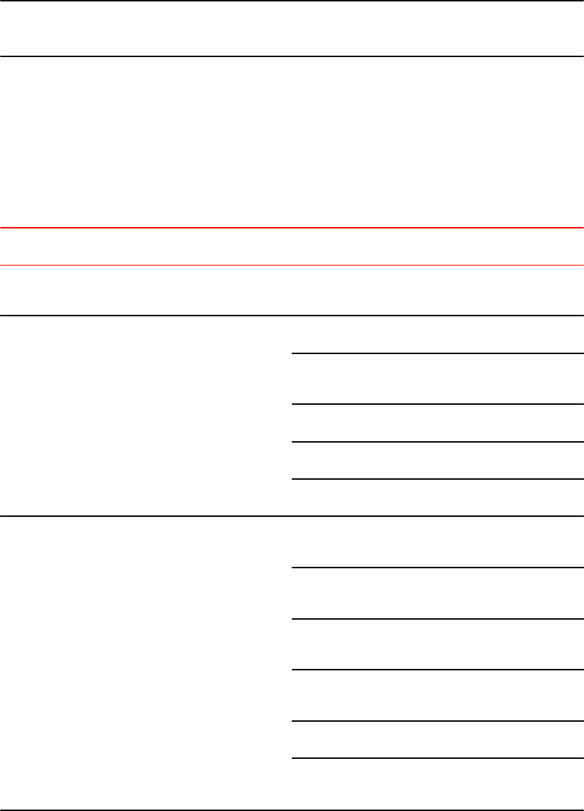
NOTE
For all Brocade devices, RADIUS Challenge is supported for 802.1x authentication but not for login
authentication. Also, multiple challenges are supported for TACACS+ login authentication.
Securing access methods
The following table lists the management access methods available on a Brocade device, how they
are secured by default, and the ways in which they can be secured.
Ways to secure management access to Brocade devices TABLE 2
Access method How the access method
is secured by default
Ways to secure the
access method
See page
Serial access to the CLI Not secured Establish passwords for
management privilege
levels
Setting passwords for
management privilege
levels on page 37
Access to the Privileged
EXEC and CONFIG levels
of the CLI
Not secured Establish a password for
Telnet access to the CLI
Setting a Telnet password
on page 36
Establish passwords for
management privilege
levels
Setting passwords for
management privilege
levels on page 37
Set up local user accounts Local user accounts on
page 40
Configure TACACS/
TACACS+ security
TACACS and TACACS+
security on page 46
Configure RADIUS
security
RADIUS security on page
63
Telnet access Not secured Regulate Telnet access
using ACLs
Using an ACL to restrict
Telnet access on page
25
Allow Telnet access only
from specific IP addresses
Restricting Telnet access
to a specific IP address on
page 28
Restrict Telnet access
based on a client MAC
address
Restricting access to the
device based on IP orMAC
address on page 29
Allow Telnet access only
from specific MAC
addresses
Restricting Telnet access
to a specific VLAN on
page 31
Define the Telnet idle time Defining the Telnet idle
time on page 30
Change the Telnet login
timeout period
Changing the login timeout
period for Telnet sessions
on page 30
Securing access methods
22 FastIron Ethernet Switch Security Configuration Guide
53-1003405-04

Ways to secure management access to Brocade devices (Continued)TABLE 2
Access method How the access method
is secured by default
Ways to secure the
access method
See page
Specify the maximum
number of login attempts
for Telnet access
Specifying the maximum
number of login
attemptsfor Telnet access
on page 30
Disable Telnet access Disabling Telnet access on
page 34
Establish a password for
Telnet access
Setting a Telnet password
on page 36
Establish passwords for
privilege levels of the CLI
Setting passwords for
management privilege
levels on page 37
Set up local user accounts Local user accounts on
page 40
Configure TACACS/
TACACS+ security
TACACS and TACACS+
security on page 46
Configure RADIUS
security
RADIUS security on page
63
Secure Shell (SSH)
access
Not configured Configure SSH Refer to the Configuring
SSH2 section
Regulate SSH access
using ACLs
Using an ACL to restrict
SSH access on page 26
Allow SSH access only
from specific IP addresses
Restricting SSH access to
a specific IP address on
page 28
Allow SSH access only
from specific MAC
addresses
Restricting access to the
device based on IP orMAC
address on page 29
Establish passwords for
privilege levels of the CLI
Setting passwords for
management privilege
levels on page 37
Set up local user accounts Local user accounts on
page 40
Configure TACACS/
TACACS+ security
TACACS and TACACS+
security on page 46
Configure RADIUS
security
RADIUS security on page
63
Web management access SNMP read or read-write
community strings
Regulate Web
management access using
ACLs
Using an ACL to restrict
Web management access
on page 26
Allow Web management
access only from specific
IP addresses
Restricting Web
management access to a
specific IP address on
page 28
Allow Web management
access only to clients
connected to a specific
VLAN
Restricting Web
management access to a
specific VLAN on page
31
Security Access
FastIron Ethernet Switch Security Configuration Guide 23
53-1003405-04

Ways to secure management access to Brocade devices (Continued)TABLE 2
Access method How the access method
is secured by default
Ways to secure the
access method
See page
Disable Web management
access
Disabling Web
management access on
page 35
Configure SSL security SSL security on page 80
Set up local user accounts Local user accounts on
page 40
Establish SNMP read or
read-write community
strings for SNMP versions
1 and 2
Refer to the FastIron
Ethernet Switch
Administration Guide
Establishing user groups
for SNMP version 3
Refer to the FastIron
Ethernet Switch
Administration Guide
Configure TACACS/
TACACS+ security
TACACS and TACACS+
security on page 46
Configure RADIUS
security
RADIUS security on page
63
SNMP access SNMP read or read-write
community strings and the
password to the Super
User privilege level
NOTE
SNMP read or read-write
community strings are
always required for SNMP
access to the device.
Regulate SNMP access
using ACLs
Using ACLs to restrict
SNMP access on page
26
Allow SNMP access only
from specific IP addresses
Restricting SNMP access
to a specific IP address on
page 29
Disable SNMP access Disabling SNMP access
on page 35
Allow SNMP access only
to clients connected a
specific VLAN
Restricting SNMP access
to a specific VLAN on
page 31
Establish passwords to
management levels of the
CLI
Setting passwords for
management privilege
levels on page 37
Set up local user accounts Local user accounts on
page 40
Establish SNMP read or
read-write community
strings
TACACS and TACACS+
security on page 46
TFTP access Not secured Allow TFTP access only to
clients connected to a
specific VLAN
Restricting TFTP access to
a specific VLAN on page
31
Disable TFTP access Disabling TFTP access on
page 35
Access for Stacked
Devices
Access to multiple
consoles must be secured
after AAA is enabled
Extra steps must be taken
to secure multiple
consoles in an IronStack.
Configuring TACACS/
TACACS+ for devices in a
Brocade traditional stack
on page 47
Security Access
24 FastIron Ethernet Switch Security Configuration Guide
53-1003405-04
Remote access to management function restrictions
You can restrict access to management functions from remote sources, including Telnet, the Web
Management Interface, and SNMP. The following methods for restricting remote access are supported:
• Using ACLs to restrict Telnet, Web Management Interface, or SNMP access
• Allowing remote access only from specific IP addresses
• Allowing Telnet and SSH access only from specific MAC addresses
• Allowing remote access only to clients connected to a specific VLAN
• Specifically disabling Telnet, Web Management Interface, or SNMP access to the device
The following sections describe how to restrict remote access to a Brocade device using these
methods.
ACL usage to restrict remote access
You can use standard ACLs to control the following access methods to management functions on a
Brocade device:
• Telnet
• SSH
• Web management
• SNMP
Consider the following to configure access control for these management access methods.
1. Configure an ACL with the IP addresses you want to allow to access the device.
2. Configure a Telnet access group, SSH access group, and SNMP community strings. Each of these
configuration items accepts an ACL as a parameter. The ACL contains entries that identify the IP
addresses that can use the access method.
The following sections present examples of how to secure management access using ACLs. Refer to
the Rule-Based IP ACLs chapter for more information on configuring ACLs.
Using an ACL to restrict Telnet access
To configure an ACL that restricts Telnet access to the device, enter commands such as the following.
device(config)#access-list 10 deny host 10.157.22.32 log
device(config)#access-list 10 deny 10.157.23.0 0.0.0.255 log
device(config)#access-list 10 deny 10.157.24.0 0.0.0.255 log
device(config)#access-list 10 deny 10.157.25.0/24 log
device(config)#access-list 10 permit any
device(config)#telnet access-group 10
device(config)#write memory
Syntax: telnet access-group num
The num parameter specifies the number of a standard ACL and must be from 1 - 99.
The commands above configure ACL 10, then apply the ACL as the access list for Telnet access. The
device allows Telnet access to all IP addresses except those listed in ACL 10.
To configure a more restrictive ACL, create permit entries and omit the permit any entry at the end of
the ACL.
device(config)#access-list 10 permit host 10.157.22.32
device(config)#access-list 10 permit 10.157.23.0 0.0.0.255
Remote access to management function restrictions
FastIron Ethernet Switch Security Configuration Guide 25
53-1003405-04

device(config)#access-list 10 permit 10.157.24.0 0.0.0.255
device(config)#access-list 10 permit 10.157.25.0/24
device(config)#telnet access-group 10
device(config)#write memory
The ACL in this example permits Telnet access only to the IP addresses in the permit entries and
denies Telnet access from all other IP addresses.
Using an ACL to restrict SSH access
To configure an ACL that restricts SSH access to the device, enter commands such as the following.
device(config)#access-list 12 deny host 10.157.22.98 log
device(config)#access-list 12 deny 10.157.23.0 0.0.0.255 log
device(config)#access-list 12 deny 10.157.24.0/24 log
device(config)#access-list 12 permit any
device(config)#ssh access-group 12
device(config)#write memory
Syntax: ssh access-group num
The num parameter specifies the number of a standard ACL and must be from 1 - 99.
These commands configure ACL 12, then apply the ACL as the access list for SSH access. The
device denies SSH access from the IP addresses listed in ACL 12 and permits SSH access from all
other IP addresses. Without the last ACL entry for permitting all packets, this ACL would deny SSH
access from all IP addresses.
NOTE
In this example, the command ssh access-group 10 could have been used to apply the ACL
configured in the example for Telnet access. You can use the same ACL multiple times.
Using an ACL to restrict Web management access
To configure an ACL that restricts Web management access to the device, enter commands such as
the following.
Brocade(config)#access-list 12 deny host 209.157.22.98 log
Brocade(config)#access-list 12 deny 209.157.23.0 0.0.0.255 log
Brocade(config)#access-list 12 deny 209.157.24.0/24 log
Brocade(config)#access-list 12 permit any
Brocade(config)#web access-group 12
Brocade(config)#write memory
Syntax: web access-group num
The num parameter specifies the number of a standard ACL and must be from 1 – 99. These
commands configure ACL 12, then apply the ACL as the access list for Web management access.
The device denies Web management access from the IP addresses listed in ACL 12 and permits Web
management access from all other IP addresses. Without the last ACL entry for permitting all packets,
this ACL would deny Web management access from all IP addresses.
Using ACLs to restrict SNMP access
To restrict SNMP access to the device using ACLs, enter commands such as the following.
Using an ACL to restrict SSH access
26 FastIron Ethernet Switch Security Configuration Guide
53-1003405-04

NOTE
The syntax for using ACLs for SNMP access is different from the syntax for controlling Telnet, SSH, and
Web management access using ACLs.
device(config)#access-list 25 deny host 10.157.22.98 log
device(config)#access-list 25 deny 10.157.23.0 0.0.0.255 log
device(config)#access-list 25 deny 10.157.24.0 0.0.0.255 log
device(config)#access-list 25 permit any
device(config)#access-list 30 deny 10.157.25.0 0.0.0.255 log
device(config)#access-list 30 deny 10.157.26.0/24 log
device(config)#access-list 30 permit any
device(config)#snmp-server community public ro 25
device(config)#snmp-server community private rw 30
device(config)#write memory
Syntax: snmp-server community string [ ro | rw ] num
The string parameter specifies the SNMP community string the user must enter to gain SNMP access.
The ro parameter indicates that the community string is for read-only ("get") access. The rw parameter
indicates the community string is for read-write ("set") access.
The num parameter specifies the number of a standard ACL and must be from 1 - 99.
These commands configure ACLs 25 and 30, then apply the ACLs to community strings.
ACL 25 is used to control read-only access using the "public" community string. ACL 30 is used to
control read-write access using the "private" community string.
NOTE
When snmp-server community is configured, all incoming SNMP packets are validated first by their
community strings and then by their bound ACLs.
Defining the console idle time
By default, a Brocade device does not time out serial console sessions. A serial session remains open
indefinitely until you close it. You can however define how many minutes a serial management session
can remain idle before it is timed out.
NOTE
You must enable AAA support for console commands, AAA authentication, and Exec authorization in
order to set the console idle time.
To configure the idle time for a serial console session, use the following command.
device(config)#console timeout 120
Syntax: [no] console timeout [ 0-240 ]
Possible values: 0 - 240 minutes
Default value: 0 minutes (no timeout)
Defining the console idle time
FastIron Ethernet Switch Security Configuration Guide 27
53-1003405-04

NOTE
In RADIUS, the standard attribute Idle-Timeout is used to define the console session timeout value.
The attribute Idle-Timeout value is specified in seconds. Within the switch, it is truncated to the nearest
minute, because the switch configuration is defined in minutes.
Remote access restrictions
By default, a Brocade device does not control remote management access based on the IP address of
the managing device. You can restrict remote management access to a single IP address for the
following access methods:
• Telnet access
• SSH access
• Web management access
• SNMP access
In addition, you can restrict all access methods to the same IP address using a single command.
The following examples show the CLI commands for restricting remote access. You can specify only
one IP address with each command. However, you can enter each command ten times to specify up
to ten IP addresses.
NOTE
You cannot restrict remote management access using the Web Management Interface.
Restricting Telnet access to a specific IP address
To allow Telnet access to the Brocade device only to the host with IP address 10.157.22.39, enter the
following command.
device(config)#telnet client 10.157.22.39
Syntax: [no] telnet client { ip-addr | ipv6-addr }
Restricting SSH access to a specific IP address
To allow SSH access to the Brocade device only to the host with IP address 10.157.22.39, enter the
following command.
device(config)#ip ssh client 10.157.22.39
Syntax: [no] ip ssh client { ip-addr | ipv6-addr }
Restricting Web management access to a specific IP address
To allow Web management access to the Brocade device only to the host with IP address
209.157.22.26, enter the following command.
Brocade(config)#web-client 209.157.22.26
Syntax: [no] web-client { ip-addr | ipv6-addr }
Remote access restrictions
28 FastIron Ethernet Switch Security Configuration Guide
53-1003405-04
Restricting SNMP access to a specific IP address
To allow SNMP access only to the host with IP address 10.157.22.14, enter the following command.
device(config)#snmp-client 10.157.22.14
Syntax: [no] snmp-client { ip-addr | ipv6-addr }
Restricting all remote management access to a specific IP address
To allow Telnet and SNMP management access to the Brocade device only to the host with IP address
10.157.22.69, enter three separate commands (one for each access type) or enter the following
command.
device(config)#all-client 10.157.22.69
Syntax: [no] all-client { ip-addr | ipv6-addr }
Restricting access to the device based on IP orMAC address
You can restrict remote management access to the Brocade device, using Telnet, SSH, HTTP, and
HTTPS, based on the connecting client IP or MAC address.
Restricting Telnet connection
You can restrict Telnet connection to a device based on the client IP address or MAC address.
To allow Telnet access to the Brocade device only to the host with IP address 10.157.22.39 and MAC
address 0000.000f.e9a0, enter the following command.
device(config)#telnet client 10.157.22.39 0000.000f.e9a0
Syntax: [no] telnet client { ip-addr | ipv6-addrmac-addr }
The following command allows Telnet access to the Brocade device to a host with any IP address and
MAC address 0000.000f.e9a0.
device(config)#telnet client any 0000.000f.e9a0
Syntax: [no] telnet client any mac-addr
Restricting SSH connection
You can restrict SSH connection to a device based on the client IP address or MAC address.
To allow SSH access to the Brocade device only to the host with IP address 10.157.22.39 and MAC
address 0000.000f.e9a0, enter the following command.
device(config)#ip ssh client 10.157.22.39 0000.000f.e9a0
Syntax: [no] ip ssh client { ip-addr | ipv6-addrmac-addr }
To allow SSH access to the Brocade device to a host with any IP address and MAC address
0000.000f.e9a0, enter the following command.
device(config)#ip ssh client any 0000.000f.e9a0
Restricting SNMP access to a specific IP address
FastIron Ethernet Switch Security Configuration Guide 29
53-1003405-04

Syntax: [no] ip ssh client any mac-addr
Defining the Telnet idle time
You can define how many minutes a Telnet session can remain idle before it is timed out. An idle
Telnet session is a session that is still sending TCP ACKs in response to keepalive messages from the
device, but is not being used to send data.
To configure the idle time for a Telnet session, use the following command.
device(config)#telnet timeout 120
Syntax: [no] telnet timeout minutes
For minutes enter a value from 0 - 240. The default value is 0 minutes (no timeout).
Changing the login timeout period for Telnet sessions
By default, the login timeout period for a Telnet session is 1 minute. To change the login timeout
period, use the following command.
device(config)#telnet login-timeout 5
Syntax: [no] telnet login-timeout minutes
For minutes , enter a value from 1 to 10. The default timeout period is 1 minute.
Specifying the maximum number of login attemptsfor Telnet access
If you are connecting to the Brocade device using Telnet, the device prompts you for a username and
password. By default, you have up to 4 chances to enter a correct username and password. If you do
not enter a correct username or password after 4 attempts, the Brocade device disconnects the Telnet
session.
You can specify the number of attempts a Telnet user has to enter a correct username and password
before the device disconnects the Telnet session. For example, to allow a Telnet user up to 5 chances
to enter a correct username and password, enter the following command.
device(config)#telnet login-retries 5
Syntax: [no] telnet login-retries number
You can specify from 0 - 5 attempts. The default is 4 attempts.
NOTE
You need to configure telnet with the enable telnet authentication local command to enable only a
certain number of telnet login attempts.
Restricting remote access to the device to specific VLAN IDs
You can restrict management access to a Brocade device to ports within a specific port-based VLAN.
VLAN-based access control applies to the following access methods:
Defining the Telnet idle time
30 FastIron Ethernet Switch Security Configuration Guide
53-1003405-04
• Telnet access
• Web management access
• SNMP access
• TFTP access
By default, access is allowed for all the methods listed above on all ports. Once you configure security
for a given access method based on VLAN ID, access to the device using that method is restricted to
only the ports within the specified VLAN.
VLAN-based access control works in conjunction with other access control methods. For example,
suppose you configure an ACL to permit Telnet access only to specific client IP addresses, and you
also configure VLAN-based access control for Telnet access. In this case, the only Telnet clients that
can access the device are clients that have one of the IP addresses permitted by the ACL and are
connected to a port that is in a permitted VLAN. Clients who have a permitted IP address but are
connected to a port in a VLAN that is not permitted still cannot access the device through Telnet.
Restricting Telnet access to a specific VLAN
To allow Telnet access only to clients in a specific VLAN, enter a command such as the following.
device(config)#telnet server enable vlan 10
The command in this example configures the device to allow Telnet management access only to clients
connected to ports within port-based VLAN 10. Clients connected to ports that are not in VLAN 10 are
denied management access.
Syntax: [no] telnet server enable vlan vlan-id
Restricting Web management access to a specific VLAN
To allow Web management access only to clients in a specific VLAN, enter a command such as the
following.
Brocade(config)#web-management enable vlan 10
The command in this example configures the device to allow Web management access only to clients
connected to ports within port-based VLAN 10. Clients connected to ports that are not in VLAN 10 are
denied management access.
Syntax: [no] web-management enable vlan vlan-id
Restricting SNMP access to a specific VLAN
To allow SNMP access only to clients in a specific VLAN, enter a command such as the following.
device(config)#snmp-server enable vlan 40
The command in this example configures the device to allow SNMP access only to clients connected to
ports within port-based VLAN 40. Clients connected to ports that are not in VLAN 40 are denied access.
Syntax: [no] snmp-server enable vlan vlan-id
Restricting TFTP access to a specific VLAN
To allow TFTP access only to clients in a specific VLAN, enter a command such as the following.
device(config)#tftp client enable vlan 40
Restricting Telnet access to a specific VLAN
FastIron Ethernet Switch Security Configuration Guide 31
53-1003405-04

The command in this example configures the device to allow TFTP access only to clients connected to
ports within port-based VLAN 40. Clients connected to ports that are not in VLAN 40 are denied
access.
Syntax: [no] tftp client enable vlan vlan-id
Designated VLAN for Telnet management sessions to a Layer 2 Switch
All Brocade FastIron devices support the creation of management VLANs. By default, the
management IP address you configure on a Layer 2 Switch applies globally to all the ports on the
device. This is true even if you divide the device ports into multiple port-based VLANs.
If you want to restrict the IP management address to a specific port-based VLAN, you can make that
VLAN the designated management VLAN for the device. When you configure a VLAN to be the
designated management VLAN, the management IP address you configure on the device is
associated only with the ports in the designated VLAN. To establish a Telnet management session
with the device, a user must access the device through one of the ports in the designated VLAN.
You also can configure up to five default gateways for the designated VLAN, and associate a metric
with each one. The software uses the gateway with the lowest metric. The other gateways reside in
the configuration but are not used. To use one of the other gateways, modify the configuration so that
the gateway you want to use has the lowest metric.
If more than one gateway has the lowest metric, the gateway that appears first in the running-config is
used.
NOTE
On ICX 7750, ICX 7450 and ICX 7250 devices, pings to the data port in a VLAN are not supported if
the management VLAN is not configured on the VLAN.
NOTE
If you have already configured a default gateway globally and you do not configure a gateway in the
VLAN, the software uses the globally configured gateway and gives the gateway a metric value of 1.
To configure a designated management VLAN, enter commands such as the following.
device(config)# vlan 10 by port
device(config-vlan-10)# untag ethernet 1/1 to 1/4
device(config-vlan-10)# management-vlan
device(config-vlan-10)# default-gateway 10.10.10.1 1
device(config-vlan-10)# default-gateway 10.20.20.1 2
These commands configure port-based VLAN 10 to consist of ports 1/1 - 1/4 and to be the designated
management VLAN. The last two commands configure default gateways for the VLAN. Since the
10.10.10.1 gateway has a lower metric, the software uses this gateway. The other gateway remains in
the configuration but is not used. You can use the other one by changing the metrics so that the
10.20.20.1 gateway has the lower metric.
Syntax: [no] default-gateway ip-addr metric
The ip-addr parameters specify the IP address of the gateway router.
The metric parameter specifies the metric (cost) of the gateway. You can specify a value from 1 - 5.
There is no default. The software uses the gateway with the lowest metric.
Designated VLAN for Telnet management sessions to a Layer 2 Switch
32 FastIron Ethernet Switch Security Configuration Guide
53-1003405-04
Device management security
By default, all management access is disabled. Each of the following management access methods
must be specifically enabled as required in your installation:
• SSHv2
• SNMP
• Web management through HTTP
• Web management through HTTPS
The commands for granting access to each of these management interfaces is described in the
following.
Allowing SSHv2 access to the Brocade device
To allow SSHv2 access to the Brocade device, you must generate a Crypto Key as shown in the
following command.
device(config)#crypto key generate
Syntax: crypto key [ generate | zeroize ]
The generate parameter generates a dsa key pair.
The zeroize parameter deletes the currently operative dsa key pair.
In addition, you must use AAA authentication to create a password to allow SSHv2 access. For
example the following command configures AAA authentication to use TACACS+ for authentication as
the default or local if TACACS+ is not available.
device(config)#aaa authentication login default tacacs+ local
Allowing SNMP access to the Brocade device
To allow SNMP access to the Brocade device, enter the following command.
device(config)#snmp-server
Syntax: [no] snmp server
Allowing Web management through HTTP for the Brocade device
To allow web management through HTTP for the Brocade device, you enable web management as
shown in the following command.
Brocade(config)#web-management http
Syntax: [no] web-management [ http | https ]
When using the web-management command, specify the http or https parameters.
The http parameter specifies that web management is enabled for HTTP access.
The https parameter specifies that web management is enabled for HTTPS access.
Device management security
FastIron Ethernet Switch Security Configuration Guide 33
53-1003405-04

Allowing Web management through HTTPS
To allow web management through HTTPS, you must enable web management as shown in Allowing
Web management through HTTP for the Brocade device on page 33. Additionally, you must generate
a crypto SSL certificate or import digital certificates issued by a third-party Certificate Authority (CA).
To generate a crypto SSL certificate use the following command.
Brocade(config)#crypto-ssl certificate generate
Syntax: crypto-ssl certificate [ generate | zeroize ]
Using the web-management command without the http or https option makes web management
available for both.
The generate parameter generates an ssl certificate.
The zeroize parameter deletes the currently operative ssl certificate.
To import a digital certificate issued by a third-party Certificate Authority (CA) and save it in the flash
memory, use the following command.
Brocade(config)#ip ssl certificate-data-file tftp 10.10.10.1 cacert.pem
Syntax: ip ssl certificate-data-file tftp ip-addr file-name
The ip-addr variable is the IP address of the TFTP server from which the digital certificate file is being
downloaded.
The file-name variable is the file name of the digital certificate that you are importing to the router.
Disabling specific access methods
You can specifically disable the following access methods:
• Telnet access
• Web management access
• SNMP access
• TFTP
NOTE
If you disable Telnet access, you will not be able to access the CLI except through a serial connection
to the management module. If you disable SNMP access, you will not be able to use an SNMP-based
management applications.
Disabling Telnet access
You can use a Telnet client to access the CLI on the device over the network. If you do not plan to use
the CLI over the network and want to disable Telnet access to prevent others from establishing CLI
sessions with the device, enter the following command.
device(config)#no telnet server
To re-enable Telnet operation, enter the following command.
device(config)#telnet server
Syntax: [no] telnet server
Allowing Web management through HTTPS
34 FastIron Ethernet Switch Security Configuration Guide
53-1003405-04

Disabling Web management access
If you want to prevent access to the device through the Web Management Interface, you can disable
the Web Management Interface.
NOTE
As soon as you make this change, the device stops responding to Web management sessions. If you
make this change using your Web browser, your browser can contact the device, but the device will not
reply once the change takes place.
To disable the Web Management Interface, enter the following command.
Brocade(config)#no web-management
Syntax: [no] web-management [ http | https ]
Use the no web-management command with no option specified to disable both web management
through http access and web management through https access.
Use the command no web-management http to disable only web management through http access.
Use the command no web-management https to disable only web management through https access.
Disabling Web management access by HP ProCurve Manager
By default, TCP ports 80 and 280 are enabled on the Brocade device. TCP port 80 (HTTP) allows
access to the device Web Management Interface. TCP port 280 allows access to the device by HP
ProCurve Manager.
The no web-management command disables both TCP ports. However, if you want to disable only
port 280 and leave port 80 enabled, use the hp-top-tools option with the command. Here is an
example.
Brocade(config)#no web-management hp-top-tools
Syntax: [no] web-management [ allow-no-password | enable [ vlan vlan-id ] | front-panel | hp-top-
tools | list-menu ]
The hp-top-tools parameter disables TCP port 280.
Disabling SNMP access
To disable SNMP management of the device.
device(config)#no snmp-server
To later re-enable SNMP management of the device.
device(config)#snmp-server
Syntax: [no] snmp-server
Disabling TFTP access
You can globally disable TFTP to block TFTP client access. By default, TFTP client access is enabled.
To disable TFTP client access, enter the following command at the Global CONFIG level of the CLI.
device(config)#tftp disable
Disabling Web management access
FastIron Ethernet Switch Security Configuration Guide 35
53-1003405-04

When TFTP is disabled, users are prohibited from using the copy tftp command to copy files to the
system flash. If users enter this command while TFTP is disabled, the system will reject the command
and display an error message.
To re-enable TFTP client access once it is disabled, enter the following command.
device(config)#no tftp disable
Syntax: [no] tftp disable
Passwords used to secure access
Passwords can be used to secure the following access methods:
• Telnet access can be secured by setting a Telnet password. Refer to Setting a Telnet password on
page 36.
• Access to the Privileged EXEC and CONFIG levels of the CLI can be secured by setting passwords
for management privilege levels. Refer to Setting passwords for management privilege levels on
page 37.
This section also provides procedures for enhancing management privilege levels, recovering from a
lost password, and disabling password encryption.
NOTE
You also can configure up to 16 user accounts consisting of a user name and password, and assign
each user account a management privilege level. Refer to Local user accounts on page 40.
Setting a Telnet password
By default, the device does not require a user name or password when you log in to the CLI using
Telnet. You can assign a password for Telnet access using one of the following methods.
Set the password "letmein" for Telnet access to the CLI using the following command at the global
CONFIG level.
device(config)#enable telnet password letmein
Syntax: [no] enable telnet password string
Suppressing Telnet connection rejection messages
By default, if a Brocade device denies Telnet management access to the device, the software sends a
message to the denied Telnet client. You can optionally suppress the rejection message. When you
enable the option, a denied Telnet client does not receive a message from the Brocade device.
Instead, the denied client simply does not gain access.
To suppress the connection rejection message, use the following CLI method.
To suppress the connection rejection message sent by the device to a denied Telnet client, enter the
following command at the global CONFIG level of the CLI.
device(config)#telnet server suppress-reject-message
Syntax: [no] telnet server suppress-reject-message
Passwords used to secure access
36 FastIron Ethernet Switch Security Configuration Guide
53-1003405-04

Setting passwords for management privilege levels
You can set one password for each of the following management privilege levels:
• Super User level - Allows complete read-and-write access to the system. This is generally for system
administrators and is the only management privilege level that allows you to configure passwords.
• Port Configuration level - Allows read-and-write access for specific ports but not for global (system-
wide) parameters.
• Read Only level - Allows access to the Privileged EXEC mode and User EXEC mode of the CLI but
only with read access.
You can assign a password to each management privilege level. You also can configure up to 16 user
accounts consisting of a user name and password, and assign each user account to one of the three
privilege levels. Refer to Local user accounts on page 40.
NOTE
You must use the CLI to assign a password for management privilege levels. You cannot assign a
password using the Web Management Interface.
If you configure user accounts in addition to privilege level passwords, the device will validate a user
access attempt using one or both methods (local user account or privilege level password), depending
on the order you specify in the authentication-method lists. Refer to Authentication-method lists on page
83.
Follow the steps given below to set passwords for management privilege levels.
1. At the opening CLI prompt, enter the following command to change to the Privileged level of the
EXEC mode.
device> enable
device#
2. Access the CONFIG level of the CLI by entering the following command.
device#configure terminal
device(config)#
3. Enter the following command to set the Super User level password.
device(config)#enable super-user-password text
NOTE
You must set the Super User level password before you can set other types of passwords. The
Super User level password can be an alphanumeric string, but cannot begin with a number.
4. Enter the following commands to set the Port Configuration level and Read Only level passwords.
device(config)#enable port-config-password text
device(config)#enable read-only-password text
Syntax: enable super-user-password text
Syntax: enable port-config-password text
Syntax: enable read-only-password text
NOTE
If you forget your Super User level password, refer to Recovering from a lost password on page 39.
Setting passwords for management privilege levels
FastIron Ethernet Switch Security Configuration Guide 37
53-1003405-04

Augmenting management privilege levels
Each management privilege level provides access to specific areas of the CLI by default:
• Super User level provides access to all commands and displays.
• Port Configuration level gives access to:
‐The User EXEC and Privileged EXEC levels
‐The port-specific parts of the CONFIG level
‐All interface configuration levels
• Read Only level gives access to:
‐The User EXEC and Privileged EXEC levels
You can grant additional access to a privilege level on an individual command basis. To grant the
additional access, you specify the privilege level you are enhancing, the CLI level that contains the
command, and the individual command.
NOTE
This feature applies only to management privilege levels on the CLI.
Enhance the Port Configuration privilege level so users also can enter IP commands at the global
CONFIG level.
device(config)#privilege configure level 4 ip
In this command, configure specifies that the enhanced access is for a command at the global
CONFIG level of the CLI. The level 4 parameter indicates that the enhanced access is for
management privilege level 4 (Port Configuration). All users with Port Configuration privileges will
have the enhanced access. The ip parameter indicates that the enhanced access is for the IP
commands. Users who log in with valid Port Configuration level user names and passwords can enter
commands that begin with "ip" at the global CONFIG level.
Syntax: [no] privilege cli-level level privilege-level command-string
The cli-level parameter specifies the CLI level and can be one of the following values:
•exec - EXEC level; for example, device> or device#
•configure - CONFIG level; for example, device(config)#
•interface - Interface level; for example, device(config-if-6)#
•loopback-interface - loopback interface level
•virtual-interface - Virtual-interface level; for example, device(config-vif-6)#
•dot1x - 802.1X configuration level
•ipv6-access-list - IPv6 access list configuration level
•rip-router - RIP router level; for example, device(config-rip-router)#
•ospf-router - OSPF router level; for example, device(config-ospf-router)#
•dvmrp-router - DVMRP router level; for example, device(config-dvmrp-router)#
•pim-router - PIM router level; for example, device(config-pim-router)#
•bgp-router - BGP4 router level; for example, device(config-bgp-router)#
•vrrp-router - VRRP configuration level
•gvrp - GVRP configuration level
•trunk - trunk configuration level
•port-vlan - Port-based VLAN level; for example, device(config-vlan)#
•protocol-vlan - Protocol-based VLAN level
The privilege-level indicates the number of the management privilege level you are augmenting. You
can specify one of the following:
Augmenting management privilege levels
38 FastIron Ethernet Switch Security Configuration Guide
53-1003405-04

•0 - Super User level (full read-write access)
•4 - Port Configuration level
•5 - Read Only level
The command -string parameter specifies the command you are allowing users with the specified
privilege level to enter. To display a list of the commands at a CLI level, enter "?" at that level's
command prompt.
Recovering from a lost password
Recovery from a lost password requires direct access to the serial port and a system reset.
NOTE
You can perform this procedure only from the CLI.
Follow the steps given below to recover from a lost password.
1. Start a CLI session over the serial interface to the device.
2. Reboot the device.
3. At the initial boot prompt at system startup, enter b to enter the boot monitor mode.
4. Enter no password at the prompt. (You cannot abbreviate this command.) This command will cause
the device to bypass the system password check.
5. Enter boot system flash primary at the prompt. On ICX 6430 and ICX 6450 devices, enter
boot_primary.
6. After the console prompt reappears, assign a new password.
Displaying the SNMP community string
If you want to display the SNMP community string, enter the following commands.
device(config)#enable password-display
device#show snmp server
The enable password-display command enables display of the community string in the output of the
show snmp server command. Display of the string is still encrypted in the startup-config file and
running-config. When the enable password-display command is configured, the user password and
snmp community string are encrypted in the show run command output. Enter the command at the
global CONFIG level of the CLI.
Specifying a minimum password length
By default, the Brocade device imposes no minimum length on the Line (Telnet), Enable, or Local
passwords. You can configure the device to require that Line, Enable, and Local passwords be at least
a specified length.
For example, to specify that the Line, Enable, and Local passwords be at least 8 characters, enter the
following command.
device(config)#enable password-min-length 8
Syntax: enable password-min-length number-of-characters
The number-of-characters can be from 1 - 48.
Recovering from a lost password
FastIron Ethernet Switch Security Configuration Guide 39
53-1003405-04

Local user accounts
You can define up to 32 local user accounts on a Brocade device. User accounts regulate who can
access the management functions in the CLI using the following methods:
• Telnet access
• Web management access
• SNMP access
• SSH access
Local user accounts provide greater flexibility for controlling management access to Brocade devices
than do management privilege level passwords and SNMP community strings of SNMP versions 1 and
2. You can continue to use the privilege level passwords and the SNMP community strings as
additional means of access authentication. Alternatively, you can choose not to use local user
accounts and instead continue to use only the privilege level passwords and SNMP community
strings. Local user accounts are backward-compatible with configuration files that contain privilege
level passwords. Refer to Setting passwords for management privilege levels on page 37.
If you configure local user accounts, you also need to configure an authentication-method list for
Telnet access, Web management access, and SNMP access. Refer to Authentication-method lists on
page 83.
For each local user account, you specify a user name. You also can specify the following parameters:
• A password
NOTE
If you use AAA authentication for SNMP access and set the password same as the username,
providing the password during authentication is optional. You can provide just the correct username
for successful authentication.
• A management privilege level, which can be one of the following:
‐Super User level (default) - Allows complete read-and-write access to the system. This is
generally for system administrators and is the only privilege level that allows you to configure
passwords.
‐Port Configuration level - Allows read-and-write access for specific ports but not for global
parameters.
‐Read Only level - Allows access to the Privileged EXEC mode and User EXEC mode with read
access only.
• You can set additional username and password rules. Refer to Enhancements to username and
password on page 40.
Enhancements to username and password
This section describes the enhancements to the username and password features introduced in earlier
releases.
The following rules are enabled by default:
• Users are required to accept the message of the day.
• Users are locked out (disabled) if they fail to login after three attempts. This feature is automatically
enabled. Use the disable-on-login-failure command to change the number of login attempts (up to
10) before users are locked out.
The following rules are disabled by default:
Local user accounts
40 FastIron Ethernet Switch Security Configuration Guide
53-1003405-04

• Enhanced user password combination requirements
• User password masking
• Quarterly updates of user passwords
• You can configure the system to store up to 15 previously configured passwords for each user.
• You can use the disable-on-login-failure command to change the number of login attempts (up to
10) before users are locked out.
• A password can now be set to expire.
Enabling enhanced user password combination requirements
When strict password enforcement is enabled on the Brocade device, you must enter a minimum of
eight characters containing the following combinations when you create an enable and a user
password:
• At least two upper case characters
• At least two lower case characters
• At least two numeric characters
• At least two special characters
NOTE
Password minimum and combination requirements are strictly enforced.
Use the enable strict-password-enforcement command to enable the password security feature.
device(config)#enable strict-password-enforcement
Syntax: [no] enable strict-password-enforcement
This feature is disabled by default.
The following security upgrades apply to the enable strict-password-enforcement command:
• Passwords must not share four or more concurrent characters with any other password configured
on the router. If the user tries to create a password with four or more concurrent characters, the
following error message will be returned.
Error - The substring str within the password has been used earlier, please choose a
different password.
For example, the previous password was Ma!i4aYa&, the user cannot use any of the following as his or
her new password:
•‐Ma!imai$D because "Mail" were used consecutively in the previous password
‐&3B9aYa& because "aYa&" were used consecutively in the previous password
‐i4aYEv#8 because "i4aY" were used consecutively in the previous password
• If the user tries to configure a password that was previously used, the Local User Account
configuration will not be allowed and the following message will be displayed.
This password was used earlier for same or different user, please choose a different
password.
Enabling user password masking
By default, when you use the CLI to create a user password, the password displays on the console as
you type it. For enhanced security, you can configure the Brocade device to mask the password
Enabling enhanced user password combination requirements
FastIron Ethernet Switch Security Configuration Guide 41
53-1003405-04

characters entered at the CLI. When password masking is enabled, the CLI displays asterisks (*) on
the console instead of the actual password characters entered.
The following shows the default CLI behavior when configuring a username and password.
device(config)#username kelly password summertime
The following shows the CLI behavior when configuring a username and password when password-
masking is enabled.
device(config)#username kelly password
Enter Password: ********
NOTE
When password masking is enabled, press the [Enter] key before entering the password.
Syntax: username name password [Enter]
For [Enter], press the Enter key. Enter the password when prompted.
If strict-password-enforcement is enabled, enter a password which contains the required character
combination. Refer to Enabling enhanced user password combination requirements on page 41.
To enable password masking, enter the following command.
device(config)#enable user password-masking
Syntax: [no] enable user password-masking
Enabling user password aging
For enhanced security, password aging enforces quarterly updates of all user passwords. After 180
days, the CLI will automatically prompt users to change their passwords when they attempt to sign on.
When password aging is enabled, the software records the system time that each user password was
configured or last changed. The time displays in the output of the show running configuration
command, indicated by set-time time .
device#show run
Current configuration:
....
username waldo password .....
username raveen set-time 2086038248
....
The password aging feature uses the NTP server clock to record the set-time. If the network does not
have an NTP server, then set-time will appear as set-time 0 in the output of the show running
configuration command.
A username set-time configuration is removed when:
• The username and password is deleted from the configuration
• The username password expires
When a username set-time configuration is removed, it no longer appears in the show running
configuration output.
Note that if a username does not have an assigned password, the username will not have a set-time
configuration.
Enabling user password aging
42 FastIron Ethernet Switch Security Configuration Guide
53-1003405-04
Password aging is disabled by default. To enable it, enter the following command at the global CONFIG
level of the CLI.
device(config)#enable user password-aging
Syntax: [no] enable user password-aging
Configuring password history
By default, the Brocade device stores the last five user passwords for each user. When changing a user
password, the user cannot use any of the five previously configured passwords.
For security purposes, you can configure the Brocade device to store up to 15 passwords for each user,
so that users do not use the same password multiple times. If a user attempts to use a password that is
stored, the system will prompt the user to choose a different password.
To configure enhanced password history, enter a command such as the following at the global CONFIG
level of the CLI.
device(config)#enable user password-history 15
Syntax: [no] enable user password-history 1-15
Enhanced login lockout
The CLI provides up to three login attempts. If a user fails to login after three attempts, that user is
locked out (disabled). If desired, you can increase or decrease the number of login attempts before the
user is disabled. To do so, enter a command such as the following at the global CONFIG level of the
CLI.
device(config)#enable user disable-on-login-failure 7
Syntax: enable user disable-on-login-failure 1-10
To re-enable a user that has been locked out, do one of the following:
• Reboot the Brocade device to re-enable all disabled users.
• Enable the user by entering the following command.
device(config)#username sandy enable
device(config)#user sandy enable
device#show user
Username Password Encrypt Priv Status Expire Time
==============================================================================
sandy $1$Gz...uX/$wQ44fVGtsqbKWkQknzAZ6. enabled 0 enabled 90 days
Syntax: username name enable
Setting passwords to expire
You can set a user password to expire. Once a password expires, the administrator must assign a new
password to the user. To configure a user password to expire, enter the following.
device(config)#username sandy expires 20
Syntax: username name expires days
Enter 1 - 365 for number of days. The default is 90 days.
Configuring password history
FastIron Ethernet Switch Security Configuration Guide 43
53-1003405-04

device(config)#username sandy expires 20
device#show user
Username Password Encrypt Priv Status Expire Time
================================================================================
sandy $1$Gz...uX/$wQ44fVGtsqbKWkQknzAZ6. enabled 0 enabled 20 days
Requirement to accept the message of the day
If a message of the day (MOTD) is configured, a user will be required to press the Enter key before he
or she can login. MOTD is configured using the banner motd command.
There are no new CLI commands for this feature.
NOTE
This requirement is disabled by default, unless configured. Users are not required to press Enter after
the MOTD banner is displayed. Refer to "Requiring users to press the Enter key after the message of
the day banner" section in the FastIron Ethernet Switch Administration Guide .
Local user account configuration
You can create accounts for local users with or without passwords. Accounts with passwords can have
encrypted or unencrypted passwords.
You can assign privilege levels to local user accounts, but on a new device, you must create a local
user account that has a Super User privilege before you can create accounts with other privilege
levels.
NOTE
You must grant Super User level privilege to at least one account before you add accounts with other
privilege levels. You need the Super User account to make further administrative changes.
Local user accounts with no passwords
To create a user account without a password, enter the following command at the global CONFIG
level of the CLI.
device(config)#username wonka nopassword
Syntax: [no] username user-string privilege privilege-level nopassword
Local user accounts with unencrypted passwords
If you want to use unencrypted passwords for local user accounts, enter a command such as the
following at the global CONFIG level of the CLI.
device(config)#username wonka password willy
If password masking is enabled, press the [Enter] key before entering the password.
device(config)#username wonka password
Enter Password: *******
Requirement to accept the message of the day
44 FastIron Ethernet Switch Security Configuration Guide
53-1003405-04

The above commands add a local user account with the user name "wonka" and the password. This
account has the Super User privilege level; this user has full access to all configuration and display
features.
device(config)#username waldo privilege 5 password whereis
This command adds a user account for user name "waldo", password "whereis", with the Read Only
privilege level. Waldo can look for information but cannot make configuration changes.
Syntax: [no] usernameuser-string privilege privilege-level [ password | nopassword ] password-
string
You can enter up to 48 characters for user-string .
The privilege privilege-level parameter specifies the privilege level for the account. You can specify one
of the following:
•0 - Super User level (full read-write access)
•4 - Port Configuration level
•5 - Read Only level
The default privilege level is 0 . If you want to assign Super User level access to the account, you can
enter the command without privilege 0 , as shown in the command example above.
The password | nopassword parameter indicates whether the user must enter a password. If you
specify password , enter the string for the user's password. You can enter up to 48 characters for
password-string . If strict password enforcement is enabled on the device, you must enter a minimum
of eight characters containing the following combinations:
• At least two upper case characters
• At least two lower case characters
• At least two numeric characters
• At least two special characters
NOTE
You must be logged on with Super User access (privilege level 0) to add user accounts or configure
other access parameters.
To display user account information, enter the following command.
device#show users
Syntax: show users
To know the different methods to secure access to the device using the configured username and
password, see Authentication-method lists on page 83.
Changing a local user password
To change a local user password for an existing local user account, enter a command such as the
following at the global CONFIG level of the CLI.
NOTE
You must be logged on with Super User access (privilege level 0) to change user passwords.
device(config)#username wonka password willy
Changing a local user password
FastIron Ethernet Switch Security Configuration Guide 45
53-1003405-04

If password masking is enabled, enter the username, press the [Enter] key, then enter the password.
device(config)#username wonka password
Enter Password:
The above commands change wonka's user name and password.
Syntax: [no] username user-string password password-string
Enter up to 48 characters for user-string.
The password-string parameter is the user password. The password can be up to 48 characters and
must differ from the current password and two previously configured passwords.
When a password is changed, a message such as the following is sent to the Syslog.
SYSLOG: <14>Jan 1 00:00:00 10.44.9.11 Security: Password has been changed for user
tester from console session.
The message includes the name of the user whose password was changed and during which session
type, such as Console, Telnet, SSH, Web, SNMP, or others, the password was changed.
Changing the SSL server certificate key size
The default key size for Brocade-issued and imported digital certificates is 1024 bits. If desired, you
can change the default key size to a value of 512, 2048, or 4096 bits.
To do so, enter a command such as the following at the Global CONFIG level of the CLI.
Brocade(config)#ip ssl cert-key-size 512
Syntax: ip ssl cert-key-size 512/ 1024/ 2048/ 4096
NOTE
The SSL server certificate key size applies only to digital certificates issued by Brocade and does not
apply to imported certificates.
TACACS and TACACS+ security
You can use the security protocol Terminal Access Controller Access Control System (TACACS) or
TACACS+ to authenticate the following kinds of access to the Brocade device:
• Telnet access
• SSH access
• Console access
• Web management access
• Access to the Privileged EXEC level and CONFIG levels of the CLI
The TACACS and TACACS+ protocols define how authentication, authorization, and accounting
information is sent between a Brocade device and an authentication database on a TACACS/TACACS
+ server. TACACS/TACACS+ services are maintained in a database, typically on a UNIX workstation
or PC with a TACACS/TACACS+ server running.
Changing the SSL server certificate key size
46 FastIron Ethernet Switch Security Configuration Guide
53-1003405-04

How TACACS+ differs from TACACS
TACACS is a simple UDP-based access control protocol originally developed by BBN for MILNET.
TACACS+ is an enhancement to TACACS and uses TCP to ensure reliable delivery.
TACACS+ is an enhancement to the TACACS security protocol. TACACS+ improves on TACACS by
separating the functions of authentication, authorization, and accounting (AAA) and by encrypting all
traffic between the Brocade device and the TACACS+ server. TACACS+ allows for arbitrary length and
content authentication exchanges, which allow any authentication mechanism to be utilized with the
Brocade device. TACACS+ is extensible to provide for site customization and future development
features. The protocol allows the Brocade device to request very precise access control and allows the
TACACS+ server to respond to each component of that request.
NOTE
TACACS+ provides for authentication, authorization, and accounting, but an implementation or
configuration is not required to employ all three.
TACACS/TACACS+ authentication, authorization,and accounting
When you configure a Brocade device to use a TACACS/TACACS+ server for authentication , the
device prompts users who are trying to access the CLI for a user name and password, then verifies the
password with the TACACS/TACACS+ server.
If you are using TACACS+, Brocade recommends that you also configure authorization , in which the
Brocade device consults a TACACS+ server to determine which management privilege level (and which
associated set of commands) an authenticated user is allowed to use. You can also optionally configure
accounting , which causes the Brocade device to log information on the TACACS+ server when
specified events occur on the device.
NOTE
By default, a user logging into the device from Telnet or SSH would first enter the User EXEC level. The
user can enter the enable command to get to the Privileged EXEC level. A user that is successfully
authenticated can be automatically placed at the Privileged EXEC level after login. Refer to Entering
privileged EXEC mode after a Telnet or SSH login on page 56.
Configuring TACACS/TACACS+ for devices in a Brocade traditional stack
Becausedevices operating in a Brocade traditional stack topology present multiple console ports, you
must take additional steps to secure these ports when configuring TACACS/TACACS+.
The following is a sample AAA console configuration using TACACS+.
aaa authentication login default tacacs+ enable
aaa authentication login privilege-mode
aaa authorization commands 0 default tacacs+
aaa authorization exec default tacacs+
aaa accounting commands 0 default start-stop tacacs+
aaa accounting exec default start-stop tacacs+
aaa accounting system default start-stop tacacs+
enable aaa console
hostname Fred
ip address 10.10.6.56/255
tacacs-server host 255.253.255
tacacs-server key 2 $d3NpZ0BVXFpJ
kill console
How TACACS+ differs from TACACS
FastIron Ethernet Switch Security Configuration Guide 47
53-1003405-04
Syntax: kill console [ all | unit ]
•all - logs out all console port on stack units that are not the Active Controller
•unit - logs out the console port on a specified unit
Once AAA console is enabled, you should log out any open console ports on your traditional stack
using the kill console command:
device(config)#kill console all
In case a user forgets to log out or a console is left unattended, you can also configure the console
timeout (in minutes) on all stack units (including the Active Controller).
device(config)#stack unit 3
device(config-unit-3)#console timeout 5
device(config-unit-3)#exit
device(config)#stack unit 4
device(config-unit-4)#console timeout 5
Use the show who and the show telnet commands to confirm the status of console sessions.
stack9#show who
Console connections (by unit number):
1 established
you are connecting to this session
4 seconds in idle
2 established
1 hours 3 minutes 12 seconds in idle
3 established
1 hours 3 minutes 9 seconds in idle
4 established
1 hours 3 minutes 3 seconds in idle
Telnet connections (inbound):
1 closed
2 closed
3 closed
4 closed
5 closed
Telnet connection (outbound):
6 closed
SSH connections:
1 closed
2 closed
3 closed
4 closed
5 closed
stack9#
stack9#show telnet
Console connections (by unit number):
1 established
you are connecting to this session
1 minutes 5 seconds in idle
2 established
1 hours 4 minutes 18 seconds in idle
3 established
1 hours 4 minutes 15 seconds in idle
4 established
1 hours 4 minutes 9 seconds in idle
Telnet connections (inbound):
1 closed
2 closed
3 closed
4 closed
5 closed
Telnet connection (outbound):
6 closed
SSH connections:
1 closed
2 closed
3 closed
4 closed
5 closed
stack9#
Security Access
48 FastIron Ethernet Switch Security Configuration Guide
53-1003405-04

TACACS authentication
NOTE
Also, multiple challenges are supported for TACACS+ login authentication.
When TACACS authentication takes place, the following events occur.
1. A user attempts to gain access to the Brocade device by doing one of the following:
•‐Logging into the device using Telnet, SSH, or the Web Management Interface
‐Entering the Privileged EXEC level or CONFIG level of the CLI
2. The user is prompted for a username and password.
3. The user enters a username and password.
4. The Brocade device sends a request containing the username and password to the TACACS server.
5. The username and password are validated in the TACACS server database.
6. If the password is valid, the user is authenticated.
TACACS+ authentication
When TACACS+ authentication takes place, the following events occur.
1. A user attempts to gain access to the Brocade device by doing one of the following:
•‐Logging into the device using Telnet, SSH, or the Web Management Interface
‐Entering the Privileged EXEC level or CONFIG level of the CLI
2. The user is prompted for a username.
3. The user enters a username.
4. The Brocade device obtains a password prompt from a TACACS+ server.
5. The user is prompted for a password.
6. The user enters a password.
7. The Brocade device sends the password to the TACACS+ server.
8. The password is validated in the TACACS+ server database.
9. If the password is valid, the user is authenticated.
TACACS+ authorization
Brocade devices support two kinds of TACACS+ authorization:
• Exec authorization determines a user privilege level when they are authenticated
• Command authorization consults a TACACS+ server to get authorization for commands entered by
the user
When TACACS+ exec authorization takes place, the following events occur.
1. A user logs into the Brocade device using Telnet, SSH, or the Web Management Interface
2. The user is authenticated.
3. The Brocade device consults the TACACS+ server to determine the privilege level of the user.
4. The TACACS+ server sends back a response containing an A-V (Attribute-Value) pair with the
privilege level of the user.
5. The user is granted the specified privilege level.
When TACACS+ command authorization takes place, the following events occur.
TACACS authentication
FastIron Ethernet Switch Security Configuration Guide 49
53-1003405-04

1. A Telnet, SSH, or Web Management Interface user previously authenticated by a TACACS+server
enters a command on the Brocade device.
2. A Telnet, SSH, or Web Management Interface user previously authenticated by a TACACS+server
enters a command on the Brocade device.
3. The Brocade device looks at its configuration to see if the command is at a privilege level that
requires TACACS+ command authorization.
4. If the command belongs to a privilege level that requires authorization, the Brocade device consults
the TACACS+ server to see if the user is authorized to use the command.
5. If the user is authorized to use the command, the command is executed.
TACACS+ accounting
TACACS+ accounting works as follows.
1. One of the following events occur on the Brocade device:
•‐A user logs into the management interface using Telnet or SSH
‐A user enters a command for which accounting has been configured
‐A system event occurs, such as a reboot or reloading of the configuration file
2. The Brocade device checks the configuration to see if the event is one for which TACACS+
accounting is required.
3. If the event requires TACACS+ accounting, the Brocade device sends a TACACS+ Accounting
Start packet to the TACACS+ accounting server, containing information about the event.
4. The TACACS+ accounting server acknowledges the Accounting Start packet.
5. The TACACS+ accounting server records information about the event.
6. When the event is concluded, the Brocade device sends an Accounting Stop packet to the TACACS
+ accounting server.
7. The TACACS+ accounting server acknowledges the Accounting Stop packet.
AAA operations for TACACS/TACACS+
The following table lists the sequence of authentication, authorization, and accounting operations that
take place when a user gains access to a Brocade device that has TACACS/TACACS+ security
configured.
User action Applicable AAA operations
User attempts to gain access to the Privileged EXEC
and CONFIG levels of the CLI
Enable authentication: aaa authentication enable
default method-list
Exec authorization (TACACS+): aaa authorization exec
default tacacs+
System accounting start (TACACS+): aaa accounting
system default start-stop method-list
User logs in using Telnet/SSH Login authentication: aaa authentication login default
method-list
Exec authorization (TACACS+): aaa authorization exec
default tacacs+
Exec accounting start (TACACS+): aaa accounting
exec default method-list
System accounting start (TACACS+): aaa accounting
system default start-stop method-list
TACACS+ accounting
50 FastIron Ethernet Switch Security Configuration Guide
53-1003405-04

User action Applicable AAA operations
User logs into the Web Management Interface Web authentication: aaa authentication web-server
default <method-list>
Exec authorization (TACACS+): aaa authorization exec
default tacacs+
User logs out of Telnet/SSH session Command accounting (TACACS+): aaa accounting
commands privilege-level default start-stop method-list
EXEC accounting stop (TACACS+): aaa accounting
exec default start-stop method-list
User enters system commands (for example, reload ,
boot system)
Command authorization (TACACS+): aaa authorization
commands privilege-level default method-list
Command accounting (TACACS+): aaa accounting
commands privilege-level default start-stop method-list
System accounting stop (TACACS+): aaa accounting
system default start-stop method-list
User enters the command: [no] aaa accounting system
defaultstart-stop method-list
Command authorization (TACACS+): aaa authorization
commands privilege-level default method-list
Command accounting (TACACS+): aaa accounting
commands privilege-level default start-stop method-list
System accounting start (TACACS+): aaa accounting
system default start-stop method-list
AAA security for commands pasted into the running-config
If AAA security is enabled on the device, commands pasted into the running-config are subject to the
same AAA operations as if they were entered manually.
When you paste commands into the running-config, and AAA command authorization or accounting, or
both, are configured on the device, AAA operations are performed on the pasted commands. The AAA
operations are performed before the commands are actually added to the running-config. The server
performing the AAA operations should be reachable when you paste the commands into the running-
config file. If the device determines that a pasted command is invalid, AAA operations are halted on the
remaining commands. The remaining commands may not be executed if command authorization is
configured.
TACACS/TACACS+ configuration considerations
• You must deploy at least one TACACS/TACACS+ server in your network.
• Brocade devices support authentication using up to eight TACACS/TACACS+ servers. The device
tries to use the servers in the order you add them to the device configuration.
• You can select only one primary authentication method for each type of access to a device (CLI
through Telnet, CLI Privileged EXEC and CONFIG levels). For example, you can select TACACS+
as the primary authentication method for Telnet CLI access, but you cannot also select RADIUS
authentication as a primary method for the same type of access. However, you can configure backup
authentication methods for each access type.
• You can configure the Brocade device to authenticate using a TACACS or TACACS+ server, not
both.
AAA security for commands pasted into the running-config
FastIron Ethernet Switch Security Configuration Guide 51
53-1003405-04
Configuring TACACS
Follow the procedure given below for TACACS configurations.
1. Identify TACACS servers. Refer to Identifying the TACACS/TACACS+ servers on page 52.
2. Set optional parameters. Refer to Setting optional TACACS and TACACS+ parameters on page
53.
3. Configure authentication-method lists. Refer to Configuring authentication-method lists forTACACS
and TACACS+ on page 55.
Configuring TACACS+
Follow the procedure given below for TACACS+ configurations.
1. Identify TACACS+ servers. Refer to Identifying the TACACS/TACACS+ servers on page 52.
2. Set optional parameters. Refer to Setting optional TACACS and TACACS+ parameters on page
53.
3. Configure authentication-method lists. Refer to Configuring authentication-method lists forTACACS
and TACACS+ on page 55.
4. Optionally configure TACACS+ authorization. Refer to Configuring TACACS+ authorization on page
57.
5. Optionally configure TACACS+ accounting. Refer to TACACS+ accounting configuration on page
60.
Enabling TACACS
TACACS is disabled by default. To configure TACACS/TACACS+ authentication parameters, you
must enable TACACS by entering the following command.
device(config)#enable snmp config-tacacs
Syntax: [no] enable snmp [ config-radius | config-tacacs ]
The config-radius parameter specifies the RADIUS configuration mode. RADIUS is disabled by
default.
The config-tacacs parameter specifies the TACACS configuration mode. TACACS is disabled by
default.
Identifying the TACACS/TACACS+ servers
To use TACACS/TACACS+ servers to authenticate access to a Brocade device, you must identify the
servers to the Brocade device.
For example, to identify three TACACS/TACACS+ servers, enter commands such as the following.
device(config)#tacacs-server host 10.94.6.161
device(config)#tacacs-server host 10.94.6.191
device(config)#tacacs-server host 10.94.6.122
Syntax: tacacs-server host { ip-addr |ipv6-addr | server-name } [ auth-port number ] [ acct-
portnumber]
The ip-addr | ipv6-addr | hostname parameter specifies the IP address or host name of the server. You
can enter up to eight tacacs-server host commands to specify up to eight different servers.
Configuring TACACS
52 FastIron Ethernet Switch Security Configuration Guide
53-1003405-04

NOTE
To specify the server's host name instead of its IP address, you must first identify a DNS server using
the ip dns server-address ip-addr command at the global CONFIG level.
If you add multiple TACACS/TACACS+ authentication servers to the Brocade device, the device tries to
reach them in the order you add them. For example, if you add three servers in the following order, the
software tries the servers in the same order.
1. 10.94.6.161
2. 10.94.6.191
3. 10.94.6.122
You can remove a TACACS/TACACS+ server by entering no followed by the tacacs-server
command. For example, to remove 10.94.6.161, enter the following command.
device(config)#no tacacs-server host 10.94.6.161
NOTE
If you erase a tacacs-server command (by entering "no" followed by the command), make sure you
also erase the aaa commands that specify TACACS/TACACS+ as an authentication method. (Refer
to Configuring authentication-method lists forTACACS and TACACS+ on page 55.) Otherwise,
when you exit from the CONFIG mode or from a Telnet session, the system continues to believe it is
TACACS/TACACS+ enabled and you will not be able to access the system.
The auth-port parameter specifies the UDP (for TACACS) or TCP (for TACACS+) port number of
the authentication port on the server. The default port number is 49.
Specifying different servers for individual AAA functions
In a TACACS+ configuration, you can designate a server to handle a specific AAA task. For example,
you can designate one TACACS+ server to handle authorization and another TACACS+ server to
handle accounting. You can set the TACACS+ key for each server.
To specify different TACACS+ servers for authentication, authorization, and accounting, enter the
command such as following.
device(config)#tacacs-server host 10.2.3.4 auth-port 49 authentication-only key abc
device(config)#tacacs-server host 10.2.3.5 auth-port 49 authorization-only key def
device(config)#tacacs-server host 10.2.3.6 auth-port 49 accounting-only key ghi
Syntax: tacacs-server host { ip-addr | ipv6-addr | server-name } [ auth-port num ] [ authentication-
only | authorization-only | accounting-only | default ] [ key [ 0 | 1 ] string ]
The default parameter causes the server to be used for all AAA functions.
After authentication takes place, the server that performed the authentication is used for authorization
and accounting. If the authenticating server cannot perform the requested function, then the next server
in the configured list of servers is tried; this process repeats until a server that can perform the
requested function is found, or every server in the configured list has been tried.
Setting optional TACACS and TACACS+ parameters
You can set the following optional parameters in a TACACS and TACACS+ configuration:
Specifying different servers for individual AAA functions
FastIron Ethernet Switch Security Configuration Guide 53
53-1003405-04

• TACACS+ key - This parameter specifies the value that the Brocade device sends to the TACACS+
server when trying to authenticate user access.
• Retransmit interval - This parameter specifies how many times the Brocade device will resend an
authentication request when the TACACS/TACACS+ server does not respond. The retransmit value
can be from 1 - 5 times. The default is 3 times.
• Dead time - This parameter specifies how long the Brocade device waits for the primary
authentication server to reply before deciding the server is dead and trying to authenticate using the
next server. The dead-time value can be from 1 - 5 seconds. The default is 3 seconds.
• Timeout - This parameter specifies how many seconds the Brocade device waits for a response
from a TACACS/TACACS+ server before either retrying the authentication request, or determining
that the TACACS/TACACS+ servers are unavailable and moving on to the next authentication
method in the authentication-method list. The timeout can be from 1 - 15 seconds. The default is 3
seconds.
Setting the TACACS+ key
The key parameter in the tacacs-server command is used to encrypt TACACS+ packets before they
are sent over the network. The value for the key parameter on the Brocade device should match the
one configured on the TACACS+ server. The key can be from 1 - 32 characters in length and cannot
include any space characters.
NOTE
The tacacs-server key command applies only to TACACS+ servers, not to TACACS servers. If you
are configuring TACACS, do not configure a key on the TACACS server and do not enter a key on the
Brocade device.
To specify a TACACS+ server key, enter a command such as following.
device(config)#tacacs-server key rkwong
Syntax: tacacs-server key [ 0 ] string
When you display the configuration of the Brocade device, the TACACS+ keys are encrypted. For
example.
device(config)#
tacacs-server key abc
device(config)#write terminal
...
tacacs-server host 10.2.3.5 auth-port 49
tacacs key 2$!2d
NOTE
Encryption of the TACACS+ keys is done by default. The 0 parameter disables encryption. The 1
parameter is not required; it is provided for backwards compatibility.
Setting the retransmission limit
The retransmit parameter specifies how many times the Brocade device will resend an authentication
request when the TACACS/TACACS+ server does not respond. The retransmit limit can be from 1 - 5
times. The default is 3 times.
To set the TACACS and TACACS+ retransmit limit, enter a command such as the following.
device(config)#tacacs-server retransmit 5
Setting the TACACS+ key
54 FastIron Ethernet Switch Security Configuration Guide
53-1003405-04

Syntax: tacacs-server retransmit number
Setting the timeout parameter
The timeout parameter specifies how many seconds the Brocade device waits for a response from the
TACACS/TACACS+ server before either retrying the authentication request, or determining that the
TACACS/TACACS+ server is unavailable and moving on to the next authentication method in the
authentication-method list. The timeout can be from 1 - 15 seconds. The default is 3 seconds.
device(config)#tacacs-server timeout 5
Syntax: tacacs-server timeout number
Configuring authentication-method lists forTACACS and TACACS+
You can use TACACS/TACACS+ to authenticate Telnet/SSH access and access to Privileged EXEC
level and CONFIG levels of the CLI. When configuring TACACS/TACACS+ authentication, you create
authentication-method lists specifically for these access methods, specifying TACACS/TACACS+ as the
primary authentication method.
Within the authentication-method list, TACACS/TACACS+ is specified as the primary authentication
method and up to six backup authentication methods are specified as alternates. If TACACS/TACACS+
authentication fails due to an error, the device tries the backup authentication methods in the order they
appear in the list.
When you configure authentication-method lists for TACACS/TACACS+ authentication, you must create
a separate authentication-method list for Telnet/SSH CLI access, and for access to the Privileged EXEC
level and CONFIG levels of the CLI.
To create an authentication method list that specifies TACACS/TACACS+ as the primary authentication
method for securing Telnet/SSH access to the CLI.
device(config)#enable telnet authentication
device(config)#aaa authentication login default tacacs local
The commands above cause TACACS/TACACS+ to be the primary authentication method for securing
Telnet/SSH access to the CLI. If TACACS/TACACS+ authentication fails due to an error with the server,
authentication is performed using local user accounts instead.
To create an authentication-method list that specifies TACACS/TACACS+ as the primary authentication
method for securing access to Privileged EXEC level and CONFIG levels of the CLI.
device(config)#aaa authentication enable default tacacs local none
The command above causes TACACS/TACACS+ to be the primary authentication method for securing
access to Privileged EXEC level and CONFIG levels of the CLI. If TACACS/TACACS+ authentication
fails due to an error with the server, local authentication is used instead. If local authentication fails, no
authentication is used; the device automatically permits access.
Syntax: [no] aaa authentication { enable | login default } method 1 [ method 2-7 ]
The web-server | enable | login parameter specifies the type of access this authentication-method list
controls. You can configure one authentication-method list for each type of access.
NOTE
If you configure authentication for Web management access, authentication is performed each time a
page is requested from the server. When frames are enabled on the Web Management Interface, the
browser sends an HTTP request for each frame. The Brocade device authenticates each HTTP request
Setting the timeout parameter
FastIron Ethernet Switch Security Configuration Guide 55
53-1003405-04

from the browser. To limit authentications to one per page, disable frames on the Web Management
Interface.
The method1 parameter specifies the primary authentication method. The remaining optional method
parameters specify additional methods to try if an error occurs with the primary method. A method can
be one of the values listed in the Method Parameter column in the following table.
Authentication method values TABLE 3
Method parameter Description
line Authenticate using the password you configured for Telnet access. The Telnet password is
configured using the enable telnet password... command. Refer to Setting a Telnet
password on page 36.
enable Authenticate using the password you configured for the Super User privilege level. This
password is configured using the enable super-user-password... command. Refer to
Setting passwords for management privilege levels on page 37.
local Authenticate using a local user name and password you configured on the device. Local
user names and passwords are configured using the username... command. Refer to Local
user account configuration on page 44.
tacacs Authenticate using the database on a TACACS server. You also must identify the server to
the device using the tacacs-server command.
tacacs+ Authenticate using the database on a TACACS+ server. You also must identify the server to
the device using the tacacs-server command.
radius Authenticate using the database on a RADIUS server. You also must identify the server to
the device using the radius-server command.
none Do not use any authentication method. The device automatically permits access.
NOTE
For examples of how to define authentication-method lists for types of authentication other than
TACACS/TACACS+, refer to Authentication-method lists on page 83.
Entering privileged EXEC mode after a Telnet or SSH login
By default, a user enters User EXEC mode after a successful login through Telnet or SSH. Optionally,
you can configure the device so that a user enters Privileged EXEC mode after a Telnet or SSH login.
To do this, use the following command.
device(config)#aaa authentication login privilege-mode
Syntax: aaa authentication login privilege-mode
The user privilege level is based on the privilege level granted during login.
Entering privileged EXEC mode after a Telnet or SSH login
56 FastIron Ethernet Switch Security Configuration Guide
53-1003405-04
Configuring enable authentication to prompt for password only
If Enable authentication is configured on the device, when a user attempts to gain Super User access to
the Privileged EXEC and CONFIG levels of the CLI, by default he or she is prompted for a username
and password. You can configure the Brocade device to prompt only for a password. The device uses
the username entered at login, if one is available. If no username was entered at login, the device
prompts for both username and password.
To configure the Brocade device to prompt only for a password when a user attempts to gain Super
User access to the Privileged EXEC and CONFIG levels of the CLI.
device(config)#aaa authentication enable implicit-user
Syntax: [no] aaa authentication enable implicit-user
Telnet and SSH prompts when the TACACS+ Server is unavailable
When TACACS+ is the first method in the authentication method list, the device displays the login
prompt received from the TACACS+ server. If a user attempts to login through Telnet or SSH, but none
of the configured TACACS+ servers are available, the following takes place:
• If the next method in the authentication method list is "enable", the login prompt is skipped, and the
user is prompted for the Enable password (that is, the password configured with the enable super-
user-password command).
• If the next method in the authentication method list is "line", the login prompt is skipped, and the user
is prompted for the Line password (that is, the password configured with the enable telnet
password command).
Configuring TACACS+ authorization
Brocade devices support TACACS+ authorization for controlling access to management functions in the
CLI. Two kinds of TACACS+ authorization are supported:
• Exec authorization determines a user privilege level when they are authenticated
• Command authorization consults a TACACS+ server to get authorization for commands entered by
the user
Configuring exec authorization
When TACACS+ exec authorization is performed, the Brocade device consults a TACACS+ server to
determine the privilege level of the authenticated user. To configure TACACS+ exec authorization on
the Brocade device, enter the following command.
device(config)#aaa authorization exec default tacacs+
Syntax: aaa authorization exec default tacacs+[none]
If you specify none , or omit the aaa authorization exec command from the device configuration, no
exec authorization is performed.
A user privilege level is obtained from the TACACS+ server in the "foundry-privlvl" A-V pair. If the aaa
authorization exec default tacacs+ command exists in the configuration, the device assigns the user
the privilege level specified by this A-V pair. If the command does not exist in the configuration, then the
value in the "foundry-privlvl" A-V pair is ignored, and the user is granted Super User access.
Configuring enable authentication to prompt for password only
FastIron Ethernet Switch Security Configuration Guide 57
53-1003405-04

NOTE
If the aaa authorization exec default tacacs+ command exists in the configuration, following
successful authentication the device assigns the user the privilege level specified by the "foundry-
privlvl" A-V pair received from the TACACS+ server. If the aaa authorization exec default tacacs+
command does not exist in the configuration, then the value in the "foundry-privlvl" A-V pair is ignored,
and the user is granted Super User access.Also note that in order for the aaa authorization exec
default tacacs+ command to work, either theaaa authentication enable default tacacs+ command,
or the aaa authentication login privilege-mode command must also exist in the configuration.
Configuring an Attribute-Value pair on the TACACS+ server
During TACACS+ exec authorization, the Brocade device expects the TACACS+ server to send a
response containing an A-V (Attribute-Value) pair that specifies the privilege level of the user. When
the Brocade device receives the response, it extracts an A-V pair configured for the Exec service and
uses it to determine the user privilege level.
To set a user privilege level, you can configure the "foundry-privlvl" A-V pair for the Exec service on
the TACACS+ server.
user=bob {
default service = permit
member admin
#Global password
global = cleartext "cat"
service = exec {
foundry-privlvl = 0
}
}
In this example, the A-V pair foundry-privlvl = 0 grants the user full read-write access. The
value in the foundry-privlvl A-V pair is an integer that indicates the privilege level of the user. Possible
values are 0 for super-user level, 4 for port-config level, or 5 for read-only level. If a value other than 0,
4, or 5 is specified in the foundry-privlvl A-V pair, the default privilege level of 5 (read-only) is used.
The foundry-privlvl A-V pair can also be embedded in the group configuration for the user. See your
TACACS+ documentation for the configuration syntax relevant to your server.
If the foundry-privlvl A-V pair is not present, the Brocade device extracts the last A-V pair configured
for the Exec service that has a numeric value. The Brocade device uses this A-V pair to determine the
user privilege level.
user=bob {
default service = permit
member admin
#Global password
global = cleartext "cat"
service = exec {
privlvl = 15
}
}
The attribute name in the A-V pair is not significant; the Brocade device uses the last one that has a
numeric value. However, the Brocade device interprets the value for a non-"foundry-privlvl" A-V pair
differently than it does for a "foundry-privlvl" A-V pair. The following table lists how the Brocade device
associates a value from a non-"foundry-privlvl" A-V pair with a Brocade privilege level.
Security Access
58 FastIron Ethernet Switch Security Configuration Guide
53-1003405-04

Brocade equivalents for non-"foundry-privlvl" A-V pair values TABLE 4
Value for non-"foundry-privlvl" A-V pair Brocade privilege level
15 0 (super-user)
From 14 - 1 4 (port-config)
Any other number or 0 5 (read-only)
In the example above, the A-V pair configured for the Exec service is privlvl = 15 . The Brocade
device uses the value in this A-V pair to set the user privilege level to 0 (super-user), granting the user
full read-write access.
In a configuration that has both a "foundry-privlvl" A-V pair and a non-"foundry-privlvl" A-V pair for the
Exec service, the non-"foundry-privlvl" A-V pair is ignored.
user=bob {
default service = permit
member admin
#Global password
global = cleartext "cat"
service = exec {
foundry-privlvl = 4
privlvl = 15
}
}
In this example, the user would be granted a privilege level of 4 (port-config level). The privlvl = 15
A-V pair is ignored by the Brocade device.
If the TACACS+ server has no A-V pair configured for the Exec service, the default privilege level of 5
(read-only) is used.
Configuring command authorization
When TACACS+ command authorization is enabled, the Brocade device consults a TACACS+ server
to get authorization for commands entered by the user.
You enable TACACS+ command authorization by specifying a privilege level whose commands require
authorization. For example, to configure the Brocade device to perform authorization for the commands
available at the Super User privilege level (that is, all commands on the device), enter the following
command.
device(config)#aaa authorization commands 0 default tacacs+
Syntax: aaa authorization commands privilege-level default [ tacacs+ | radius | none ]
The privilege-level parameter can be one of the following:
•0 - Authorization is performed for commands available at the Super User level (all commands)
•4 - Authorization is performed for commands available at the Port Configuration level (port-config and
read-only commands)
•5 - Authorization is performed for commands available at the Read Only level (read-only commands)
Configuring command authorization
FastIron Ethernet Switch Security Configuration Guide 59
53-1003405-04

NOTE
TACACS+ command authorization can be performed only for commands entered from Telnet or SSH
sessions, or from the console. No authorization is performed for commands entered at the Web
Management Interface.
TACACS+ command authorization is not performed for the following commands:
• At all levels: exit , logout , end , and quit .
• At the Privileged EXEC level: enable or enable text , where text is the password configured for the
Super User privilege level.
If configured, command accounting is performed for these commands.
AAA support for console commands
AAA support for commands entered at the console includes the following:
• Login prompt that uses AAA authentication, using authentication-method Lists
• Exec Authorization
• Exec Accounting
• Command authorization
• Command accounting
• System Accounting
To enable AAA support for commands entered at the console, enter the following command.
device(config)#enable aaa console
Syntax: [no] enable aaa console
TACACS+ accounting configuration
Brocade devices support TACACS+ accounting for recording information about user activity and
system events. When you configure TACACS+ accounting on a Brocade device, information is sent to
a TACACS+ accounting server when specified events occur, such as when a user logs into the device
or the system is rebooted.
Configuring TACACS+ accounting for Telnet/SSH (Shell) access
To send an Accounting Start packet to the TACACS+ accounting server when an authenticated user
establishes a Telnet or SSH session on the Brocade device, and an Accounting Stop packet when the
user logs out.
device(config)#aaa accounting exec default start-stop tacacs+
Syntax: aaa accounting exec default start-stop [ tacacs+ | radius | none ]
Configuring TACACS+ accounting for CLI commands
You can configure TACACS+ accounting for CLI commands by specifying a privilege level whose
commands require accounting. For example, to configure the Brocade device to perform TACACS+
TACACS+ accounting configuration
60 FastIron Ethernet Switch Security Configuration Guide
53-1003405-04

accounting for the commands available at the Super User privilege level (that is; all commands on the
device), enter the following command.
device(config)#aaa accounting commands 0 default start-stop tacacs+
An Accounting Start packet is sent to the TACACS+ accounting server when a user enters a command,
and an Accounting Stop packet is sent when the service provided by the command is completed.
NOTE
If authorization is enabled, and the command requires authorization, then authorization is performed
before accounting takes place. If authorization fails for the command, no accounting takes place.
Syntax: aaa accounting commands privilege-level default start-stop [ radius | tacacs+ | none ]
The privilege-level parameter can be one of the following:
•0 - Records commands available at the Super User level (all commands)
•4 - Records commands available at the Port Configuration level (port-config and read-only
commands)
•5 - Records commands available at the Read Only level (read-only commands)
Configuring TACACS+ accounting for system events
You can configure TACACS+ accounting to record when system events occur on the Brocade device.
System events include rebooting and when changes to the active configuration are made.
The following command causes an Accounting Start packet to be sent to the TACACS+ accounting
server when a system event occurs, and a Accounting Stop packet to be sent when the system event is
completed.
device(config)#aaa accounting system default start-stop tacacs+
Syntax: aaa accounting system default start-stop [ radius | tacacs+ | none ]
Configuring an interface as the source for allTACACS and TACACS+
packets
You can designate the lowest-numbered IP address configured an Ethernet port, loopback interface, or
virtual interface as the source IP address for all TACACS/TACACS+ packets from the Layer 3 Switch.
For configuration details, see "Specifying a single source interface for specified packet types" section in
the FastIron Ethernet Switch Layer 3 Routing Configuration Guide .
Displaying TACACS/TACACS+ statistics andconfiguration information
The show aaa command displays information about all TACACS+ and RADIUS servers identified on
the device.
device#show aaa
Tacacs+ key: foundry
Tacacs+ retries: 1
Tacacs+ timeout: 15 seconds
Tacacs+ dead-time: 3 minutes
Tacacs+ Server: 10.95.6.90 Port:49:
opens=6 closes=3 timeouts=3 errors=0
packets in=4 packets out=4
no connection
Configuring TACACS+ accounting for system events
FastIron Ethernet Switch Security Configuration Guide 61
53-1003405-04
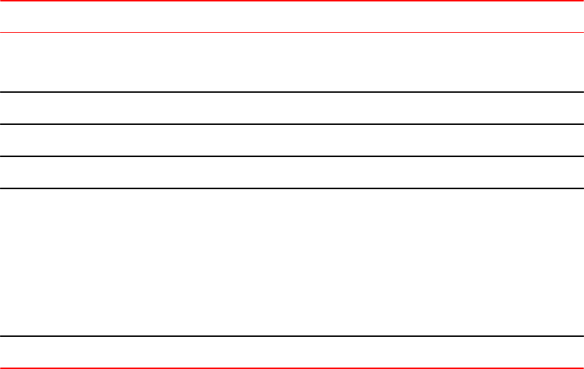
Radius key: networks
Radius retries: 3
Radius timeout: 3 seconds
Radius dead-time: 3 minutes
Radius Server: 10.95.6.90 Auth Port=1645 Acct Port=1646:
opens=2 closes=1 timeouts=1 errors=0
packets in=1 packets out=4
no connection
The following table describes the TACACS/TACACS+ information displayed by the show aaa
command.
Output of the show aaa command for TACACS/TACACS+TABLE 5
Field Description
Tacacs+ key The setting configured with the tacacs-server key command. At the Super User privilege
level, the actual text of the key is displayed. At the other privilege levels, a string of periods
(....) is displayed instead of the text.
Tacacs+ retries The setting configured with the tacacs-server retransmit command.
Tacacs+ timeout The setting configured with the tacacs-server timeout command.
Tacacs+ dead-time The setting configured with the tacacs-server dead-time command.
Tacacs+ Server For each TACACS/TACACS+ server, the IP address, port, and the following statistics are
displayed:
• opens - Number of times the port was opened for communication with the server
• closes - Number of times the port was closed normally
• timeouts - Number of times port was closed due to a timeout
• errors - Number of times an error occurred while opening the port
• packets in - Number of packets received from the server
• packets out - Number of packets sent to the server
connection The current connection status. This can be "no connection" or "connection active".
The show web connection command displays the privilege level of Web Management Interface
users.
Example
Brocade#show web-connection
We management Sessions:
User Privilege IP address MAC address Timeout(secs) Connection
roy READ-WRITE 10.1.1.3 0030.488.b84d9 279 HTTPS
Syntax: show web connection
Use the following command to clear web connections:
Brocade#clear web-connection
Syntax: clear web connection
After issuing the clear web connection command, the show web connection command displays the
following output:
Brocade#show web-connection
No WEB-MANAGEMENT sessions are currently established!
Security Access
62 FastIron Ethernet Switch Security Configuration Guide
53-1003405-04
RADIUS security
You can use a Remote Authentication Dial In User Service (RADIUS) server to secure the following
types of access to the Brocade Layer 2 Switch or Layer 3 Switch:
• Telnet access
• SSH access
• Web management access
• Access to the Privileged EXEC level and CONFIG levels of the CLI
RADIUS authentication, authorization, and accounting
When RADIUS authentication is implemented, the Brocade device consults a RADIUS server to verify
user names and passwords. You can optionally configure RADIUS authorization , in which the Brocade
device consults a list of commands supplied by the RADIUS server to determine whether a user can
issue a command he or she has entered, as well as accounting , which causes the Brocade device to
log information on a RADIUS accounting server when specified events occur on the device.
RADIUS authentication
When RADIUS authentication takes place, the following events occur.
1. A user attempts to gain access to the Brocade device by doing one of the following:
• Logging into the device using Telnet, SSH, or the Web Management Interface
• Entering the Privileged EXEC level or CONFIG level of the CLI
2. The user is prompted for a username and password.
3. The user enters a username and password.
4. The Brocade device sends a RADIUS Access-Request packet containing the username and
password to the RADIUS server.
5. The RADIUS server validates the Brocade device using a shared secret (the RADIUS key).
6. The RADIUS server looks up the username in its database.
7. If the username is found in the database, the RADIUS server validates the password.
8. If the password is valid, the RADIUS server sends an Access-Accept packet to the Brocade device,
authenticating the user. Within the Access-Accept packet are three Brocade vendor-specific
attributes that indicate:
• The privilege level of the user
• A list of commands
• Whether the user is allowed or denied usage of the commands in the list
The last two attributes are used with RADIUS authorization, if configured.
9. The user is authenticated, and the information supplied in the Access-Accept packet for the user is
stored on the Brocade device. The user is granted the specified privilege level. If you configure
RADIUS authorization, the user is allowed or denied usage of the commands in the list.
RADIUS authorization
When RADIUS authorization takes place, the following events occur.
RADIUS security
FastIron Ethernet Switch Security Configuration Guide 63
53-1003405-04

1. A user previously authenticated by a RADIUS server enters a command on the Brocade device.
2. The Brocade device looks at its configuration to see if the command is at a privilege level that
requires RADIUS command authorization.
3. If the command belongs to a privilege level that requires authorization, the Brocade device looks at
the list of commands delivered to it in the RADIUS Access-Accept packet when the user was
authenticated. (Along with the command list, an attribute was sent that specifies whether the user is
permitted or denied usage of the commands in the list.)
NOTE
After RADIUS authentication takes place, the command list resides on the Brocade device. The
RADIUS server is not consulted again once the user has been authenticated. This means that any
changes made to the user command list on the RADIUS server are not reflected until the next time
the user is authenticated by the RADIUS server, and the new command list is sent to the Brocade
device.
4. If the command list indicates that the user is authorized to use the command, the command is
executed.
RADIUS accounting
RADIUS accounting works as follows.
1. One of the following events occur on the Brocade device:
• A user logs into the management interface using Telnet or SSH
• A user enters a command for which accounting has been configured
• A system event occurs, such as a reboot or reloading of the configuration file
2. The Brocade device checks its configuration to see if the event is one for which RADIUS accounting
is required.
3. If the event requires RADIUS accounting, the Brocade device sends a RADIUS Accounting Start
packet to the RADIUS accounting server, containing information about the event.
4. The RADIUS accounting server acknowledges the Accounting Start packet.
5. The RADIUS accounting server records information about the event.
6. When the event is concluded, the Brocade device sends an Accounting Stop packet to the RADIUS
accounting server.
7. The RADIUS accounting server acknowledges the Accounting Stop packet.
AAA operations for RADIUS
The following table lists the sequence of authentication, authorization, and accounting operations that
take place when a user gains access to a Brocade device that has RADIUS security configured.
User action Applicable AAA operations
User attempts to gain access to the Privileged EXEC
and CONFIG levels of the CLI
Enable authentication: aaa authentication enable
default method-list
System accounting start: aaa accounting system default
start-stop method-list
User logs in using Telnet/SSH Login authentication: aaa authentication login default
method-list
EXEC accounting Start: aaa accounting exec default
start-stop method-list
RADIUS accounting
64 FastIron Ethernet Switch Security Configuration Guide
53-1003405-04

User action Applicable AAA operations
System accounting Start: aaa accounting system
default start-stop method-list
User logs into the Web Management Interface Web authentication: aaa authentication web-server
default <method-list>
User logs out of Telnet/SSH session Command authorization for logout command: aaa
authorization commands privilege-level default method-
list
Command accounting: aaa accounting commands
privilege-level default start-stop method-list
EXEC accounting stop: aaa accounting exec default
start-stop method-list
User enters system commands (for example, reload ,
boot system)
Command authorization: aaa authorization commands
privilege -level default method-list
Command accounting: aaa accounting commands
privilege-level default start-stop method-list
System accounting stop: aaa accounting system default
start-stop method-list
User enters the command: [no] aaa accounting system
defaultstart-stop method-list
Command authorization: aaa authorization commands
privilege-level default method-list
Command accounting: aaa accounting commands
privilege-level default start-stop method-list
System accounting start: aaa accounting system default
start-stop method-list
User enters other commands Command authorization: aaa authorization commands
privilege-level default method-list
Command accounting: aaa accounting commands
privilege-level default start-stop method-list
AAA security for commands pasted Into the running-config
If AAA security is enabled on the device, commands pasted into the running-config are subject to the
same AAA operations as if they were entered manually.
When you paste commands into the running-config, and AAA command authorization or accounting, or
both, are configured on the device, AAA operations are performed on the pasted commands. The AAA
operations are performed before the commands are actually added to the running-config. The server
performing the AAA operations should be reachable when you paste the commands into the running-
config file. If the device determines that a pasted command is invalid, AAA operations are halted on the
remaining commands. The remaining commands may not be issued if command authorization is
configured.
NOTE
Since RADIUS command authorization relies on a list of commands received from the RADIUS server
when authentication is performed, it is important that you use RADIUS authentication when you also
use RADIUS command authorization.
AAA security for commands pasted Into the running-config
FastIron Ethernet Switch Security Configuration Guide 65
53-1003405-04

RADIUS configuration considerations
• You must deploy at least one RADIUS server in your network.
• Brocade devices support authentication using up to eight RADIUS servers, including those used for
802.1X authentication and for management. The device tries to use the servers in the order you add
them to the device configuration. If one RADIUS server times out (does not respond), the Brocade
device tries the next one in the list. Servers are tried in the same sequence each time there is a
request.
• You can optionally configure a RADIUS server as a port server , indicating that the server will be
used only to authenticate users on ports to which it is mapped, as opposed to globally
authenticating users on all ports of the device. In earlier releases, all configured RADIUS servers
are "global" servers and apply to users on all ports of the device. Refer to RADIUS server per port
on page 69.
• You can map up to eight RADIUS servers to each port on the Brocade device. The port will
authenticate users using only the RADIUS servers to which it is mapped. If there are no RADIUS
servers mapped to a port, it will use the "global" servers for authentication. In earlier releases, all
RADIUS servers are "global" servers and cannot be bound to individual ports. Refer to RADIUS
server to individual ports mapping on page 70.
• You can select only one primary authentication method for each type of access to a device (CLI
through Telnet, CLI Privileged EXEC and CONFIG levels). For example, you can select RADIUS as
the primary authentication method for Telnet CLI access, but you cannot also select TACACS+
authentication as the primary method for the same type of access. However, you can configure
backup authentication methods for each access type.
Configuring RADIUS
Follow the procedure given below to configure a Brocade device for RADIUS.
1. Configure Brocade vendor-specific attributes on the RADIUS server. Refer to Brocade-specific
attributes on the RADIUS server on page 66.
2. Identify the RADIUS server to the Brocade device. Refer to Identifying the RADIUS server to the
Brocade device on page 68.
3. Optionally specify different servers for individual AAA functions. Refer to Specifying different servers
for individual AAA functions on page 69.
4. Optionally configure the RADIUS server as a "port only" server. Refer to RADIUS server per port on
page 69.
5. Optionally bind the RADIUS servers to ports on the Brocade device. Refer to RADIUS server to
individual ports mapping on page 70.
6. Set RADIUS parameters. Refer to RADIUS parameters on page 71.
7. Configure authentication-method lists. Refer to Setting authentication-method lists for RADIUS on
page 72.
8. Optionally configure RADIUS authorization. Refer to RADIUS authorization on page 74.
9. Optionally configure RADIUS accounting. Refer to RADIUS accounting on page 76.
Brocade-specific attributes on the RADIUS server
NOTE
For all Brocade devices, RADIUS Challenge is supported for 802.1x authentication but not for login
authentication.
RADIUS configuration considerations
66 FastIron Ethernet Switch Security Configuration Guide
53-1003405-04

During the RADIUS authentication process, if a user supplies a valid username and password, the
RADIUS server sends an Access-Accept packet to the Brocade device, authenticating the user. Within
the Access-Accept packet are three Brocade vendor-specific attributes that indicate:
• The privilege level of the user
• A list of commands
• Whether the user is allowed or denied usage of the commands in the list
You must add these three Brocade vendor-specific attributes to your RADIUS server configuration, and
configure the attributes in the individual or group profiles of the users that will access the Brocade
device.
Brocade Vendor-ID is 1991, with Vendor-Type 1. The following table describes the Brocade vendor-
specific attributes.
Brocade vendor-specific attributes for RADIUS TABLE 6
Attribute name Attribute ID Data type Description
foundry-privilege-
level
1 integer Specifies the privilege level for the user. This attribute can be set
to one of the following:
•0 - Super User level - Allows complete read-and-write access
to the system. This is generally for system administrators and
is the only management privilege level that allows you to
configure passwords.
•4 - Port Configuration level - Allows read-and-write access
for specific ports but not for global (system-wide) parameters.
•5 - Read Only level - Allows access to the Privileged EXEC
mode and User EXEC mode of the CLI but only with read
access.
foundry-command-
string
2 string Specifies a list of CLI commands that are permitted or denied to
the user when RADIUS authorization is configured.
The commands are delimited by semi-colons (;). You can specify
an asterisk (*) as a wildcard at the end of a command string.
For example, the following command list specifies all show and
debug ip commands, as well as the write terminal command:
show *; debug ip *; write term*
foundry-command-
exception-flag
3 integer Specifies whether the commands indicated by the foundry-
command-string attribute are permitted or denied to the user. This
attribute can be set to one of the following:
•0 - Permit execution of the commands indicated by foundry-
command-string, deny all other commands.
•1 - Deny execution of the commands indicated by foundry-
command-string, permit all other commands.
foundry-access-list 5 string Specifies the access control list to be used for RADIUS
authorization. Enter the access control list in the following format.
type=string, value="ipacl.[e|s].[in|out] = [ acl-name | acl-number ]
separator macfilter.in = [ acl-name | acl-number ]
Where:
• separator can be a space, newline, semicolon, comma, or null
characater
• ipacl.e is an extended ACL; ipacl.s is a standard ACL.
Security Access
FastIron Ethernet Switch Security Configuration Guide 67
53-1003405-04

Brocade vendor-specific attributes for RADIUS (Continued)TABLE 6
Attribute name Attribute ID Data type Description
foundry-MAC-
authent-needs-802x
6 integer Specifies whether or not 802.1x authentication is required and
enabled.
0 - Disabled
1 - Enabled
foundry-802.1x-valid-
lookup
7 integer Specifies if 802.1x lookup is enabled:
0 - Disabled
1 - Enabled
foundry-MAC-based-
VLAN-QOS
8 integer Specifies the priority for MAC-based VLAN QOS:
0 - qos_priority_0
1 - qos_priority_1
2 - qos_priority_2
3 - qos_priority_3
4 - qos_priority_4
5 - qos_priority_5
6 - qos_priority_6
7 - qos_priority_7
Enabling SNMP to configure RADIUS
To enable SNMP access to RADIUS MIB objects on the device, enter a command such as the
following.
device(config)#enable snmp config-radius
Syntax: [no] enable snmp [ config-radius |config-tacacs ]
The config-radius parameter specifies the RADIUS configuration mode. RADIUS is disabled by
default.
The config-tacacs parameter specifies the TACACS configuration mode. TACACS is disabled by
default.
Identifying the RADIUS server to the Brocade device
To use a RADIUS server to authenticate access to a Brocade device, you must identify the server to
the Brocade device.
device(config)#radius-server host 10.157.22.99
Syntax: radius-server host { ip-addr |ipv6-addr | hostname } [ auth-port number ]
The host ip-addr | ipv6-addr | server-name parameter is either an IP address or an ASCII text string.
The auth-port parameter is the Authentication port number. The default is 1645.
Enabling SNMP to configure RADIUS
68 FastIron Ethernet Switch Security Configuration Guide
53-1003405-04
The acct-port parameter is the Accounting port number. The default is 1646.
Specifying different servers for individual AAA functions
In a RADIUS configuration, you can designate a server to handle a specific AAA task. For example, you
can designate one RADIUS server to handle authorization and another RADIUS server to handle
accounting. You can specify individual servers for authentication and accounting, but not for
authorization. You can set the RADIUS key for each server.
To specify different RADIUS servers for authentication, authorization, and accounting, enter commands
such as the following.
device(config)# radius-server host 10.2.3.4 authentication-only key abc
device(config)# radius-server host 10.2.3.5 authorization-only key def
device(config)# radius-server host 10.2.3.6 accounting-only key ghi
Syntax: radius-server host { ip-addr | ipv6-addr | server-name } [ auth-port number ] [ acct-port
number ] [ authentication-only | authorization-only | accounting-only | default ] [ key { [ 0 | 2 ]
string } ]
The default parameter causes the server to be used for all AAA functions.
After authentication takes place, the server that performed the authentication is used for authorization
and accounting. If the authenticating server cannot perform the requested function, then the next server
in the configured list of servers is tried; this process repeats until a server that can perform the
requested function is found, or every server in the configured list has been tried.
RADIUS server per port
You can optionally configure a RADIUS server per port, indicating that it will be used only to
authenticate users on ports to which it is mapped. A RADIUS server that is not explicitly configured as a
RADIUS server per port is a global server , and can be used to authenticate users on ports to which no
RADIUS servers are mapped.
RADIUS server per port configuration notes
• This feature works with 802.1X and multi-device port authentication only.
• You can define up to eight RADIUS servers per Brocade device.
RADIUS configuration example and command syntax
The following shows an example configuration.
device(config)#radius-server host 10.10.10.103 auth-port 1812 acct-port 1813 default
key mykeyword dot1x port-only
device(config)#radius-server host 10.10.10.104 auth-port 1812 acct-port 1813 default
key mykeyword dot1x port-only
device(config)#radius-server host 10.10.10.105 auth-port 1812 acct-port 1813 default
key mykeyword dot1x
device(config)#radius-server host 10.10.10.106 auth-port 1812 acct-port 1813 default
key mykeyword dot1x
The above configuration has the following affect:
Specifying different servers for individual AAA functions
FastIron Ethernet Switch Security Configuration Guide 69
53-1003405-04
• RADIUS servers 10.10.10.103 and 10.10.10.104 will be used only to authenticate users on ports to
which the servers are mapped. To map a RADIUS server to a port, refer to RADIUS server to
individual ports mapping on page 70.
• RADIUS servers 10.10.10.105 and 10.10.10.106 will be used to authenticate users on ports to
which no RADIUS servers are mapped. For example, port e 9, to which no RADIUS servers are
mapped, will send a RADIUS request to the first configured RADIUS server, 10.10.10.105. If the
request fails, it will go to the second configured RADIUS server, 10.10.10.106. It will not send
requests to 10.10.10.103 or 10.10.10.104, since these servers are configured as port servers.
Syntax: radius-server host { ip-addr | server-name } [ auth-port number ] [ acct-portnumber]
[default key string dot1x] [port-only]
The host ip-addr is the IPv4 address.
The auth-port number parameter is the Authentication port number; it is an optional parameter. The
default is 1645.
The acct-port number parameter is the Accounting port number; it is an optional parameter. The
default is 1646.
The default key string dot1x parameter indicates that this RADIUS server supports the 802.1X
standard. A RADIUS server that supports the 802.1X standard can also be used to authenticate
non-802.1X authentication requests.
The port-only parameter is optional and specifies that the server will be used only to authenticate
users on ports to which it is mapped.
RADIUS server to individual ports mapping
You can map up to eight RADIUS servers to each port on the Brocade device. The port will
authenticate users using only the RADIUS servers to which the port is mapped. If there are no
RADIUS servers mapped to a port, it will use the "global" servers for authentication.
As in previous releases, a port goes through the list of servers in the order in which it was mapped or
configured, until a server that can perform the requested function is found, or until every server in the
list has been tried.
RADIUS server-to-ports configuration notes
• This feature works with 802.1X and multi-device port authentication only.
• You can map a RADIUS server to a physical port only. You cannot map a RADIUS server to a VE.
RADIUS server-to-ports configuration example and command syntax
To map a RADIUS server to a port, enter commands such as the following.
device(config)#int e 3
device(config-if-e1000-3)#dot1x port-control auto
device(config-if-e1000-3)#use-radius-server 10.10.10.103
device(config-if-e1000-3)#use-radius-server 10.10.10.110
With the above configuration, port e 3 would send a RADIUS request to 10.10.10.103 first, since it is
the first server mapped to the port. If it fails, it will go to 10.10.10.110.
Syntax: use-radius-server ip-addr
The host ip-addr is an IPv4 address.
RADIUS server to individual ports mapping
70 FastIron Ethernet Switch Security Configuration Guide
53-1003405-04

RADIUS parameters
You can set the following parameters in a RADIUS configuration:
• RADIUS key - This parameter specifies the value that the Brocade device sends to the RADIUS
server when trying to authenticate user access.
• Retransmit interval - This parameter specifies how many times the Brocade device will resend an
authentication request when the RADIUS server does not respond. The retransmit value can be from
1 - 5 times. The default is 3 times.
• Timeout - This parameter specifies how many seconds the Brocade device waits for a response from
a RADIUS server before either retrying the authentication request, or determining that the RADIUS
servers are unavailable and moving on to the next authentication method in the authentication-
method list. The timeout can be from 1 - 15 seconds. The default is 3 seconds.
Setting the RADIUS key
The key parameter in the radius-server command is used to encrypt RADIUS packets before they are
sent over the network. The value for the key parameter on the Brocade device should match the one
configured on the RADIUS server. The key can be from 1 - 32 characters in length and cannot include
any space characters.
To specify a RADIUS server key, enter a command such as the following.
device(config)#radius-server key mirabeau
Syntax: radius-server key [ 0 ] string
When you display the configuration of the Brocade device, the RADIUS key is encrypted.
Brocade(config)#radius-server key abc
Brocade(config)#write terminal
...
Brocade(config)#sh run | in radius
radius-server key abc
NOTE
Encryption of the RADIUS keys is done by default and the default value is 2
( SIMPLE_ENCRYPTION_BASE64). The 0 parameter disables encryption. The 1 parameter is not
required; it is provided for backwards compatibility.
Setting the retransmission limit
The retransmit parameter specifies the maximum number of retransmission attempts. When an
authentication request times out, the Brocade software will retransmit the request up to the maximum
number of retransmissions configured. The default retransmit value is 3 retries. The range of retransmit
values is from 1 - 5.
To set the RADIUS retransmit limit, enter a command such as the following.
device(config)#radius-server retransmit 5
Syntax: tacacs-server retransmit number
RADIUS parameters
FastIron Ethernet Switch Security Configuration Guide 71
53-1003405-04
Setting the timeout parameter
The timeout parameter specifies how many seconds the Brocade device waits for a response from
the RADIUS server before either retrying the authentication request, or determining that the RADIUS
server is unavailable and moving on to the next authentication method in the authentication-method
list. The timeout can be from 1 - 15 seconds. The default is 3 seconds.
device(config)#radius-server timeout 5
Syntax: radius-server timeout number
Setting RADIUS over IPv6
Brocade devices support the ability to send RADIUS packets over an IPv6 network.
To enable the Brocade device to send RADIUS packets over IPv6, enter a command such as the
following at the Global CONFIG level of the CLI.
device(config)#radius-server host ipv6 2001:DB8::300
Syntax: radius-server host ipv6 ipv6-host-address
The ipv6-host address is the IPv6 address of the RADIUS server. When you enter the IPv6 host
address, you do not need to specify the prefix length. A prefix length of 128 is implied.
Setting authentication-method lists for RADIUS
You can use RADIUS to authenticate Telnet/SSH access and access to Privileged EXEC level and
CONFIG levels of the CLI. When configuring RADIUS authentication, you create authentication-
method lists specifically for these access methods, specifying RADIUS as the primary authentication
method.
Within the authentication-method list, RADIUS is specified as the primary authentication method and
up to six backup authentication methods are specified as alternates. If RADIUS authentication fails
due to an error, the device tries the backup authentication methods in the order they appear in the list.
When you configure authentication-method lists for RADIUS, you must create a separate
authentication-method list for Telnet or SSH CLI access and for CLI access to the Privileged EXEC
level and CONFIG levels of the CLI.
To create an authentication-method list that specifies RADIUS as the primary authentication method
for securing Telnet access to the CLI.
device(config)#enable telnet authentication
device(config)#aaa authentication login default radius local
The commands above cause RADIUS to be the primary authentication method for securing Telnet
access to the CLI. If RADIUS authentication fails due to an error with the server, local authentication is
used instead.
To create an authentication-method list that specifies RADIUS as the primary authentication method
for securing access to Privileged EXEC level and CONFIG levels of the CLI.
device(config)#aaa authentication enable default radius local none
The command above causes RADIUS to be the primary authentication method for securing access to
Privileged EXEC level and CONFIG levels of the CLI. If RADIUS authentication fails due to an error
with the server, local authentication is used instead. If local authentication fails, no authentication is
used; the device automatically permits access.
Setting the timeout parameter
72 FastIron Ethernet Switch Security Configuration Guide
53-1003405-04
Syntax: [no] aaa authentication { enable | login default } method 1 [ method 2-7 ]
The aaa authentication | enable | login parameter specifies the type of access this authentication-
method list controls. You can configure one authentication-method list for each type of access.
NOTE
If you configure authentication for Web management access, authentication is performed each time a
page is requested from the server. When frames are enabled on the Web Management Interface, the
browser sends an HTTP request for each frame. The Brocade device authenticates each HTTP request
from the browser. To limit authentications to one per page, disable frames on the Web Management
Interface.
The method1 parameter specifies the primary authentication method. The remaining optional method
parameters specify additional methods to try if an error occurs with the primary method. A method can
be one of the values listed in the Method Parameter column in the following table.
Authentication method values TABLE 7
Method parameter Description
line Authenticate using the password you configured for Telnet access. The Telnet password is
configured using the enable telnet password... command. Refer to Setting a Telnet
password on page 36.
enable Authenticate using the password you configured for the Super User privilege level. This
password is configured using the enable super-user-password... command. Refer to Setting
passwords for management privilege levels on page 37.
local Authenticate using a local user name and password you configured on the device. Local user
names and passwords are configured using the username... command. Refer to Local user
account configuration on page 44.
tacacs Authenticate using the database on a TACACS server. You also must identify the server to
the device using the tacacs-server command.
tacacs+ Authenticate using the database on a TACACS+ server. You also must identify the server to
the device using the tacacs-server command.
radius Authenticate using the database on a RADIUS server. You also must identify the server to the
device using the radius-server command.
none Do not use any authentication method. The device automatically permits access.
NOTE
For examples of how to define authentication-method lists for types of authentication other than
RADIUS, refer to Authentication-method lists on page 83.
Security Access
FastIron Ethernet Switch Security Configuration Guide 73
53-1003405-04

Entering privileged EXEC mode after a Telnet or SSH login
By default, a user enters User EXEC mode after a successful login through Telnet or SSH. Optionally,
you can configure the device so that a user enters Privileged EXEC mode after a Telnet or SSH login.
To do this, use the following command.
device(config)#aaa authentication login privilege-mode
Syntax: aaa authentication login privilege-mode
The user privilege level is based on the privilege level granted during login.
Configuring enable authentication to prompt for password only
If Enable authentication is configured on the device, when a user attempts to gain Super User access
to the Privileged EXEC and CONFIG levels of the CLI, by default he or she is prompted for a
username and password. You can configure the Brocade device to prompt only for a password. The
device uses the username entered at login, if one is available. If no username was entered at login,
the device prompts for both username and password.
To configure the Brocade device to prompt only for a password when a user attempts to gain Super
User access to the Privileged EXEC and CONFIG levels of the CLI.
device(config)#aaa authentication enable implicit-user
Syntax: [no] aaa authentication enable implicit-user
RADIUS authorization
Brocade devices support RADIUS authorization for controlling access to management functions in the
CLI. Two kinds of RADIUS authorization are supported:
• Exec authorization determines a user privilege level when they are authenticated
• Command authorization consults a RADIUS server to get authorization for commands entered by
the user
Configuring exec authorization
When RADIUS exec authorization is performed, the Brocade device consults a RADIUS server to
determine the privilege level of the authenticated user. To configure RADIUS exec authorization on the
Brocade device, enter the following command.
device(config)#aaa authorization exec default radius
Syntax: aaa authorization exec default [ radius | none ]
If you specify none , or omit the aaa authorization exec command from the device configuration, no
exec authorization is performed.
NOTE
If the aaa authorization exec default radius command exists in the configuration, following
successful authentication the device assigns the user the privilege level specified by the foundry-
privilege-level attribute received from the RADIUS server. If the aaa authorization exec default
radius command does not exist in the configuration, then the value in the foundry-privilege-level
attribute is ignored, and the user is granted Super User access.Also note that in order for the aaa
Entering privileged EXEC mode after a Telnet or SSH login
74 FastIron Ethernet Switch Security Configuration Guide
53-1003405-04

authorization exec default radius command to work, either theaaa authentication enable default
radius command, or the aaa authentication login privilege-mode command must also exist in the
configuration.
Configuring command authorization
When RADIUS command authorization is enabled, the Brocade device consults the list of commands
supplied by the RADIUS server during authentication to determine whether a user can issue a
command he or she has entered.
You enable RADIUS command authorization by specifying a privilege level whose commands require
authorization. For example, to configure the Brocade device to perform authorization for the commands
available at the Super User privilege level (that is; all commands on the device), enter the following
command.
device(config)#aaa authorization commands 0 default radius
Syntax: aaa authorization commands privilege-level default [ tacacs+ | radius | none ]
The privilege-level parameter can be one of the following:
•0 - Authorization is performed (that is, the Brocade device looks at the command list) for commands
available at the Super User level (all commands)
•4 - Authorization is performed for commands available at the Port Configuration level (port-config and
read-only commands)
•5 - Authorization is performed for commands available at the Read Only level (read-only commands)
NOTE
RADIUS command authorization can be performed only for commands entered from Telnet or SSH
sessions, or from the console. No authorization is performed for commands entered at the Web
Management Interface.
NOTE
Since RADIUS command authorization relies on the command list supplied by the RADIUS server
during authentication, you cannot perform RADIUS authorization without RADIUS authentication.
Command authorization and accounting for console commands
The Brocade device supports command authorization and command accounting for CLI commands
entered at the console. To configure the device to perform command authorization and command
accounting for console commands, enter the following.
device(config)#enable aaa console
Syntax: [no] enable aaa console
Configuring command authorization
FastIron Ethernet Switch Security Configuration Guide 75
53-1003405-04

CAUTION
If you have previously configured the device to perform command authorization using a
RADIUS server, entering the enable aaa console command may prevent the execution of any
subsequent commands entered on the console. This happens because RADIUS command
authorization requires a list of allowable commands from the RADIUS server. This list is
obtained during RADIUS authentication. For console sessions, RADIUS authentication is
performed only if you have configured Enable authentication and specified RADIUS as the
authentication method (for example, with the aaa authentication enable default radius
command). If RADIUS authentication is never performed, the list of allowable commands is
never obtained from the RADIUS server. Consequently, there would be no allowable commands
on the console.
RADIUS accounting
Brocade devices support RADIUS accounting for recording information about user activity and system
events. When you configure RADIUS accounting on a Brocade device, information is sent to a
RADIUS accounting server when specified events occur, such as when a user logs into the device or
the system is rebooted.
Configuring RADIUS accounting for Telnet/SSH (Shell) access
To send an Accounting Start packet to the RADIUS accounting server when an authenticated user
establishes a Telnet or SSH session on the Brocade device, and an Accounting Stop packet when the
user logs out.
device(config)#aaa accounting exec default start-stop radius
Syntax: aaa accounting exec default start-stop [ radius | tacacs+ | none ]
Configuring RADIUS accounting for CLI commands
You can configure RADIUS accounting for CLI commands by specifying a privilege level whose
commands require accounting. For example, to configure the Brocade device to perform RADIUS
accounting for the commands available at the Super User privilege level (that is; all commands on the
device), enter the following command.
device(config)#aaa accounting commands 0 default start-stop radius
An Accounting Start packet is sent to the RADIUS accounting server when a user enters a command,
and an Accounting Stop packet is sent when the service provided by the command is completed.
NOTE
If authorization is enabled, and the command requires authorization, then authorization is performed
before accounting takes place. If authorization fails for the command, no accounting takes place.
Syntax: aaa accounting commands privilege-level default start-stop [ radius | tacacs | none ]
The privilege-level parameter can be one of the following:
RADIUS accounting
76 FastIron Ethernet Switch Security Configuration Guide
53-1003405-04

•0 - Records commands available at the Super User level (all commands)
•4 - Records commands available at the Port Configuration level (port-config and read-only
commands)
•5 - Records commands available at the Read Only level (read-only commands)
Configuring RADIUS accounting for system events
You can configure RADIUS accounting to record when system events occur on the Brocade device.
System events include rebooting and when changes to the active configuration are made.
The following command causes an Accounting Start packet to be sent to the RADIUS accounting server
when a system event occurs, and a Accounting Stop packet to be sent when the system event is
completed.
device(config)#aaa accounting system default start-stop radius
Syntax: aaa accounting system default start-stop [ radius | tacacs+ | none ]
Configuring an interface as the source for all RADIUS packets
You can designate the lowest-numbered IP address configured an Ethernet port, loopback interface, or
virtual interface as the source IP address for all RADIUS packets from the Layer 3 Switch. For
configuration details, see "Specifying a single source interface for specified packet types" section in the
FastIron Ethernet Switch Layer 3 Routing Configuration Guide .
Displaying RADIUS configuration information
The show aaa command displays information about all TACACS/TACACS+ and RADIUS servers
identified on the device.
device#show aaa
Tacacs+ key: foundry
Tacacs+ retries: 1
Tacacs+ timeout: 15 seconds
Tacacs+ Server: 10.95.6.90 Port:49:
opens=6 closes=3 timeouts=3 errors=0
packets in=4 packets out=4
no connection
Radius key: networks
Radius retries: 3
Radius timeout: 3 seconds
Radius Server: 10.95.6.90 Auth Port=1645 Acct Port=1646:
opens=2 closes=1 timeouts=1 errors=0
packets in=1 packets out=4
no connection
The following table describes the RADIUS information displayed by the show aaa command.
Output of the show aaa command for RADIUS TABLE 8
Field Description
Radius key The setting configured with the radius-server key command. At the Super User privilege level,
the actual text of the key is displayed. At the other privilege levels, a string of periods (....) is
displayed instead of the text.
Radius retries The setting configured with the radius-server retransmit command.
Configuring RADIUS accounting for system events
FastIron Ethernet Switch Security Configuration Guide 77
53-1003405-04

Output of the show aaa command for RADIUS (Continued)TABLE 8
Field Description
Radius timeout The setting configured with the radius-server timeout command.
Radius Server For each RADIUS server, the IP address, and the following statistics are displayed:
Auth Port RADIUS authentication port number (default 1645)
Acct Port RADIUS accounting port number (default 1646)
• opens - Number of times the port was opened for communication with the server
• closes - Number of times the port was closed normally
• timeouts - Number of times port was closed due to a timeout
• errors - Number of times an error occurred while opening the port
• packets in - Number of packets received from the server
• packets out - Number of packets sent to the server
connection The current connection status. This can be "no connection" or "connection active".
The show web connection command displays the privilege level of Web Management Interface
users.
Example
Brocade#show web-connection
We management Sessions:
User Privilege IP address MAC address Timeout(secs) Connection
roy READ-WRITE 10.1.1.3 0030.488.b84d9 279 HTTPS
Syntax: show web connection
Use the following command to clear web connections:
FastIron#clear web-connection
Syntax: clear web connection
After issuing the clear web connection command, the show web connection command displays the
following output:
Brocade#show web-connection
No WEB-MANAGEMENT sessions are currently established!
RADIUS dynamic authorizations
Adds two new packets to the current RADIUS standard.
When a user or device is authenticated on the RADIUS server, the session can only be ended if the
user or device logs out. There is no way to change the previously downloaded policies or
configuration.
RFC 5176 addresses this issue by adding two more packet types to the current RADIUS standard:
Disconnect Message and Change of Authorization. The Dynamic Authorization Client (DAC) server
makes the requests to either delete the previously established sessions or replace the previous
configuration or policies. Currently, these new extensions can be used to dynamically terminate or
authorize sessions that are authenticated through multi-device-port-authentication or dot1x
authentication.
RADIUS dynamic authorizations
78 FastIron Ethernet Switch Security Configuration Guide
53-1003405-04

RADIUS Disconnect Message and CoA events
Describes the events that take place during Disconnect Message and Change of Authorization.
The following events occur when a disconnect message is sent out by the Dynamic Authorization Client
(DAC):
• A disconnect request packet is sent by the Dynamic Authorization Client (DAC) to terminate the
session on the NAS (Network Access Server) and discard the associated session contexts.
• The request identifies the NAS and the session to be removed. This packet is sent to UDP port 3799
on the NAS.
• The NAS responds with a disconnect-ACK, if the session is identified, removed, and no longer valid.
• The NAS sends a disconnect-NAK if it is unable to disconnect the session.
The following events occur when a change of authorization request packet is sent by the Dynamic
Authorization Client (DAC):
• A change of authorization request packet is sent by the Dynamic Authorization Client (DAC) to
change the session authorizations on the NAS. This is used to change the filters, such as Layer 3
ACLs.
• The request identifies the NAS and the sessions to be authorized. The request carries the filter ID
attribute (type 11). The attribute will specify the IP ACL that is to be applied. This packet is sent to
UDP port 3799 on the NAS.
• The NAS responds with a CoA-ACK (CoA acknowledgment) if the session is identified and
authorized with new filters. It sends a CoA non-acknowledgment, if it is unable to apply the filters on
the session.
NOTE
Currently Brocade devices support applying ACLs to those sessions that have IP ACLs applied in the
previous Authorization. You cannot use CoA to configure IP ACLs on a session that is not authenticated
with an ACL.
Enabling RADIUS CoA and Disconnect Message handling
Describes enabling RADIUS CoA and Disconnect Message handling.
To enable RADIUS Disconnect Message and CoA handling, complete the following steps:
1. Enter global configuration mode.
2. Enter the aaa authorization coa enable command.
device(config)# aaa authorization coa enable
Supported IETF attributes in RFC 5176
Describes the supported IETF attributes and error clause values.
Some of the supported IETF attributes are listed in the following table.
Supported IETF attributes
TABLE 9
Attribute Name Attribute Number Description
NAS-IP-Address 4 IPv4 address of NAS
RADIUS Disconnect Message and CoA events
FastIron Ethernet Switch Security Configuration Guide 79
53-1003405-04

Supported IETF attributes (Continued)TABLE 9
Attribute Name Attribute Number Description
NAS-Identifier 32 The port, where the session is terminated
NAS-IPv6-Address 95 IPv6 address of NAS
Calling-Station-Id 31 Link address from which sessions are connected
Filter-ID 11 Indicates the name of a data filter list to be applied for the sessions
that the identification attributes map to.
Error clause values
When the NAS cannot honor the disconnect message and CoA requests, the NAS sends
corresponding NAK responses. These responses must include the error clause attribute to provide
more details on the possible cause of the problem. The format of this error clause attribute is the same
as any other attribute and the value field consists of a 4-byte integer.
The error cause attribute values are organized in the following series:
• 0-199 Reserved
• 200-299 Successful completion
• 300-399 Reserved
• 400-499 Fatal errors committed by Dynamic Authorization Client (DAC)
• 500-599 Fatal errors committed by Dynamic Authorization Server (DAS)
Error clause valuesTABLE 10
Value Description
401 Unsupported attribute
402 Missing attribute
403 NAS identification mismatch
404 Invalid Request
405 Unsupported services
407 Invalid attribute value
501 Administratively prohibited (used when a CoA request or disconnect message is ignored because
of configuration)
503 Session context not found
506 Resources unavailable
SSL security
The Brocade device supports Transport Level Security. By default, all TLS versions will be supported
on devices that act as an HTTP server.
When enabled, the SSL protocol uses digital certificates and public-private key pairs to establish a
secure connection to the Brocade device. Digital certificates serve to prove the identity of a connecting
SSL security
80 FastIron Ethernet Switch Security Configuration Guide
53-1003405-04

client, and public-private key pairs provide a means to encrypt data sent between the device and the
client.
Configuring SSL consists of the following tasks:
1. Optionally enabling the SSL server on the Brocade device
NOTE
The SSL server is automatically enabled when an SSL certificate is generated.
2. Importing an RSA certificate and private key file from a client (optional)
3. Generating a certificate
Enabling the SSL server on the Brocade device
To enable the SSL server on the Brocade device, enter the following command.
Brocade(config)#web-management https
Syntax: [no] web-management [ http | https ]
You can enable either the HTTP or HTTPs servers with this command. You can disable both the HTTP
and HTTPs servers by entering the following command.
Brocade(config)#no web-management
Syntax: no web-management
Specifying a port for SSL communication
By default, SSL protocol exchanges occur on TCP port 443. You can optionally change the port number
used for SSL communication.
For example, the following command causes the device to use TCP port 334 for SSL communication.
Brocade(config)#ip ssl port 334
Syntax: [no] ip ssl port port-number
The default port for SSL communication is 443.
Changing the SSL server certificate key size
The default key size for Brocade-issued and imported digital certificates is 1024 bits. If desired, you can
change the default key size to a value of 512, 2048, or 4096 bits. To do so, enter a command such as
the following at the Global CONFIG level of the CLI.
Brocade(config)#ip ssl cert-key-size 512
Syntax: ip ssl cert-key-size <512/ 1024/ 2048/ 4096>
NOTE
The SSL server certificate key size applies only to digital certificates issued by Brocade and does not
apply to imported certificates.
Enabling the SSL server on the Brocade device
FastIron Ethernet Switch Security Configuration Guide 81
53-1003405-04

Support for SSL digital certificates larger than 2048 bits
Brocade devices have the ability to store and retrieve SSL digital certificates that are up to 4000 bits in
size.
Support for SSL certificates larger than 2048 bits is automatically enabled. You do not need to perform
any configuration procedures to enable it.
Importing digital certificates and RSA private key files
To allow a client to communicate with other Brocade device using an SSL connection, you configure a
set of digital certificates and RSA public-private key pairs on the device. A digital certificate is used for
identifying the connecting client to the server. It contains information about the issuing Certificate
Authority, as well as a public key. You can either import digital certificates and private keys from a
server, or you can allow the Brocade device to create them.
If you want to allow the Brocade device to create the digital certificates, refer to the next section,
Generating an SSL certificate on page 82. If you choose to import an RSA certificate and private key
file from a client, you can use TFTP to transfer the files.
For example, to import a digital certificate using TFTP, enter a command such as the following:
Brocade(config)#ip ssl certificate-data-file tftp 192.168.9.210 certfile
Syntax: [no] ip ssl certificate-data-file tftpip-address certificate-filename
To import an RSA private key from a client using TFTP, enter a command such as the following:
Brocade(config)#ip ssl private-key-file tftp 192.168.9.210 keyfile
Syntax: [no] ip ssl private-key-file tftp ip-address key-filename
The ip-address is the IP address of a TFTP server that contains the digital certificate or private key.
NOTE
The RSA key can be up to 4096 bits.
Generating an SSL certificate
After you have imported the digital certificate, it should automatically generate.
If the certificate does not automatically generate, enter the following command to generate it.
Brocade(config)#crypto-ssl certificate generate
Syntax: [no] crypto-ssl certificate generate
Deleting the SSL certificate
To delete the SSL certificate, enter the following command.
Brocade(config)#crypto-ssl certificate zeroize
Syntax: [no] crypto-ssl certificate zeroize
Support for SSL digital certificates larger than 2048 bits
82 FastIron Ethernet Switch Security Configuration Guide
53-1003405-04

TLS support
By default, all TLS versions such as TLS 1.0, TLS 1.1, and TLS 1.2 are supported on devices that act
as an HTTP server.
For devices which acts as the SSL client or the syslog, OpenFlow, or secure AAA client, the TLS
version is decided based on the server support.
You can configure the minimum TLS version on FastIron devices using the ip ssl min-version
command. The TLS version configured as the minimum version and all the later versions are supported
to establish the connection. For example, if TLS 1.1 version is configured as the minimum version, both
TLS 1.1 and TLS 1.2 versions are supported. For devices which act as a SSL server or HTTPS server,
the default connection is with TLS1.2.
You can use the show ip ssl command to identify the TLS version that is configured on the device.
Authentication-method lists
To implement one or more authentication methods for securing access to the device, you configure
authentication-method lists that set the order in which the authentication methods are consulted.
In an authentication-method list, you specify the access method (Telnet, SNMP, and so on) and the
order in which the device tries one or more of the following authentication methods:
• Local Telnet login password
• Local password for the Super User privilege level
• Local user accounts configured on the device
• Database on a TACACS or TACACS+ server
• Database on a RADIUS server
• No authentication
NOTE
The TACACS/TACACS+, RADIUS, and Telnet login password authentication methods are not
supported for SNMP access.
NOTE
To authenticate Telnet access to the CLI, you also must enable the authentication by entering the
enable telnet authentication command at the global CONFIG level of the CLI. You cannot enable
Telnet authentication using the Web Management Interface.
NOTE
You do not need an authentication-method list to secure access based on ACLs or a list of IP
addresses. Refer to ACL usage to restrict remote access on page 25 or Remote access restrictions on
page 28.
In an authentication-method list for a particular access method, you can specify up to seven
authentication methods. If the first authentication method is successful, the software grants access and
stops the authentication process. If the access is rejected by the first authentication method, the
software denies access and stops checking.
TLS support
FastIron Ethernet Switch Security Configuration Guide 83
53-1003405-04

However, if an error occurs with an authentication method, the software tries the next method on the
list, and so on. For example, if the first authentication method is the RADIUS server, but the link to the
server is down, the software will try the next authentication method in the list.
NOTE
If an authentication method is working properly and the password (and user name, if applicable) is not
known to that method, this is not an error. The authentication attempt stops, and the user is denied
access.
The software will continue this process until either the authentication method is passed or the software
reaches the end of the method list. If the Super User level password is not rejected after all the access
methods in the list have been tried, access is granted.
Configuration considerations for authentication-method lists
• For CLI access, you must configure authentication-method lists if you want the device to
authenticate access using local user accounts or a RADIUS server. Otherwise, the device will
authenticate using only the locally based password for the Super User privilege level.
• When no authentication-method list is configured specifically for Web management access, the
device performs authentication using the SNMP community strings:
‐For read-only access, you can use the user name “get” and the password “public”. The default
read-only community string is “public”.
‐There is no default read-write community string. Thus, by default, you cannot open a read-write
management session using the Web Management Interface. You first must configure a read-
write community string using the CLI. Then you can log on using “set” as the user name and the
read-write community string you configure as the password. Refer to TACACS and TACACS+
security on page 46.
• If you configure an authentication-method list for Web management access and specify “local” as
the primary authentication method, users who attempt to access the device using the Web
Management Interface must supply a user name and password configured in one of the local user
accounts on the device. The user cannot access the device by entering “set” or “get” and the
corresponding SNMP community string.
Examples of authentication-method lists
The following examples show how to configure authentication-method lists. In these examples, the
primary authentication method for each is "local". The device will authenticate access attempts using
the locally configured usernames and passwords.
The command syntax for each of the following examples is provided in the Command Syntax section.
Example 1
To configure an authentication-method list for the Web Management Interface, enter a command such
as the following.
device(config)#aaa authentication web-server default local
This command configures the device to use the local user accounts to authenticate access to the
device through the Web Management Interface. If the device does not have a user account that
matches the user name and password entered by the user, the user is not granted access.
Example 2
Configuration considerations for authentication-method lists
84 FastIron Ethernet Switch Security Configuration Guide
53-1003405-04

To configure an authentication-method list for SNMP, enter a command such as the following.
device(config)#aaa authentication snmp-server default local
This command allows certain incoming SNMP SET operations to be authenticated using the locally
configured usernames and passwords. When this command is enabled, community string validation is
not performed for incoming SNMP V1 and V2c packets. This command takes effect as long as the first
varbind for SNMP packets is set to one of the following:
• snAgGblPassword=" username password " (for AAA method local)
• snAgGblPassword=" password " (for AAA method line, enable)
NOTE
Certain SNMP objects need additional validation. These objects include but are not limited to:
snAgReload , snAgWriteNVRAM , snAgConfigFromNVRAM , snAgImgLoad , snAgCfgLoad and
snAgGblTelnetPassword . For more information, see snAgGblPassword in the IronWare MIB
Reference Guide>.
If AAA is set up to check both the username and password, the string contains the username, followed
by a space then the password. If AAA is set up to authenticate with the current Enable or Line
password, the string contains the password only.
Note that the above configuration can be overridden by the command no snmp-server pw-check ,
which disables password checking for SNMP SET requests.
Example 3
To configure an authentication-method list for the Privileged EXEC and CONFIG levels of the CLI, enter
the following command.
device(config)#aaa authentication enable default local
This command configures the device to use the local user accounts to authenticate attempts to access
the Privileged EXEC and CONFIG levels of the CLI.
Example 4
To configure the device to consult a RADIUS server first to authenticate attempts to access the
Privileged EXEC and CONFIG levels of the CLI, then consult the local user accounts if the RADIUS
server is unavailable, enter the following command.
device(config)#aaa authentication enable default radius local
Command Syntax
The following is the command syntax for the preceding examples.
Syntax: [no] aaa authentication { snmp-server | web-server | enable | login default } method 1 [
method 2-7 ]
The snmp-server | web-server | enable | login parameter specifies the type of access this
authentication-method list controls. You can configure one authentication-method list for each type of
access.
NOTE
TACACS/TACACS+ and RADIUS are supported only with the enable and login parameters.
The method1 parameter specifies the primary authentication method. The remaining optional method
parameters specify additional methods to try if an error occurs with the primary method. A method can
be one of the values listed in the Method Parameter column in the following table.
Security Access
FastIron Ethernet Switch Security Configuration Guide 85
53-1003405-04
Authentication method values TABLE 11
Method parameter Description
line Authenticate using the password you configured for Telnet access. The Telnet password is
configured using the enable telnet password... command. Refer to Setting a Telnet
password on page 36.
enable Authenticate using the password you configured for the Super User privilege level. This
password is configured using the enable super-user-password... command. Refer to
Setting passwords for management privilege levels on page 37.
local Authenticate using a local user name and password you configured on the device. Local
user names and passwords are configured using the username... command. Refer to Local
user account configuration on page 44.
tacacs Authenticate using the database on a TACACS server. You also must identify the server to
the device using the tacacs-server command.
tacacs+ Authenticate using the database on a TACACS+ server. You also must identify the server to
the device using the tacacs-server command.
radius Authenticate using the database on a RADIUS server. You also must identify the server to
the device using the radius-server command. Refer to RADIUS security on page 63.
none Do not use any authentication method. The device automatically permits access.
TCP Flags - edge port security
NOTE
This feature is not supported on FastIron X Series devices.
The edge port security feature works in combination with IP ACL rules, and supports all 6 TCP flags
present in the offset 13 of the TCP header:
• +|- urg = Urgent
• +|- ack = Acknowledge
• +|- psh = Push
• +|- rst = Reset
• +|- syn = Synchronize
• +|- fin = Finish
TCP flags can be combined with other ACL functions (such as dscp-marking and traffic policies),
giving you greater flexibility when designing ACLs.
The TCP flags feature offers two options, match-all and match-any:
•Match-any - Indicates that incoming TCP traffic must be matched against any of the TCP flags
configured as part of the match-any ACL rule. In CAM hardware, the number of ACL rules will
match the number of configured flags.
•Match-all - Indicates that incoming TCP traffic must be matched against all of the TCP flags
configured as part of the match-all ACL rule. In CAM hardware, there will be only one ACL rule for
all configured flags.
TCP Flags - edge port security
86 FastIron Ethernet Switch Security Configuration Guide
53-1003405-04

NOTE
The match-all option is not supported on ICX 7750 and ICX 7450 devices.
device(config-ext-nACL)#permit tcp 10.1.1.1 0.0.0.255 eq 100 10.2.2.2 0.0.0.255 eq
300 match-all +urg +ack +syn -rst
This command configures a single rule in CAM hardware. This rule will contain all of the configured TCP
flags (urg, ack, syn, and rst).
Using TCP Flags in combination with other ACL features
The TCP Flags feature has the added capability of being combined with other ACL features.
device(config-ext-nACL)#permit tcp any any match-all +urg +ack +syn -rst traffic-
policy test
This command configures the ACL to match incoming traffic with the TCP Flags urg, ack, and syn and
also to apply the traffic policy (rate, limit, etc.) to the matched traffic.
device(config-ext-nACL)#permit tcp any any match-all +urg +ack +syn -rst tos normal
This command configures the ACL to match incoming traffic with the flags urg, ack, and syn, and also
sets the tos bit to normal when the traffic exits the device.
NOTE
TCP Flags combines the functionality of older features such as TCP Syn Attack and TCP Establish.
Avoid configuring these older features on a port where you have configured TCP Flags. TCP Flags can
perform all of the functions of TCP Syn Attack and TCP Establish, and more. However, if TCP Syn
Attack is configured on a port along with TCP Flags, TCP Syn Attack will take precedence.
NOTE
If an ACL clause with match-any exists, and the system runs out of CAM, if the total number of TCP
rules to TCP Flags will not fit within 1021 entries (the maximum rules allowed per device), then none of
the TCP Flag rules will be programmed into the CAM hardware.
NOTE
If a range option and match-any TCP-flags are combined in the same ACL, the total number of rules will
be calculated as: Total number of rules in CAM hardware = (number of rules for range)* (number of
rules for match-any TCP-flags).
Using TCP Flags in combination with other ACL features
FastIron Ethernet Switch Security Configuration Guide 87
53-1003405-04
Using TCP Flags in combination with other ACL features
88 FastIron Ethernet Switch Security Configuration Guide
53-1003405-04
SSH2 and SCP
● Supported SSH2 and Secure Copy features.................................................................. 89
● SSH version 2 overview.................................................................................................. 89
● SSH2 authentication types..............................................................................................91
● Optional SSH parameters............................................................................................... 96
● Filtering SSH access using ACLs................................................................................... 98
● Terminating an active SSH connection........................................................................... 98
● Displaying SSH information............................................................................................ 98
● Secure copy with SSH2................................................................................................ 101
● SSH2 client................................................................................................................... 105
Supported SSH2 and Secure Copy features
Lists SSH2 and Secure Copy features supported in FastIron devices.
The following table lists individual Brocade switches and the SSH2 and Secure Copy features they
support.
Feature ICX 6430 ICX 6450 FCX ICX 6610 ICX 6650 FSX 800
FSX 1600
ICX 7450 ICX 7750
Secure Shell (SSH) version 2 08.0.01 08.0.01 08.0.01 08.0.01 08.0.01 08.0.01 08.0.20 08.0.10
AES encryption for SSHv2 08.0.01 08.0.01 08.0.01 08.0.01 08.0.01 08.0.01 08.0.20 08.0.10
Optional parameters for SSHv2 08.0.01 08.0.01 08.0.01 08.0.01 08.0.01 08.0.01 08.0.20 08.0.10
Using secure copy (SCP) with
SSHv2
08.0.01 08.0.01 08.0.01 08.0.01 08.0.01 08.0.01 08.0.20 08.0.10
Filtering SSHv2 access using ACLs 08.0.01 08.0.01 08.0.01 08.0.01 08.0.01 08.0.01 08.0.20 08.0.10
Terminating an active SSHv2
connection
08.0.01 08.0.01 08.0.01 08.0.01 08.0.01 08.0.01 08.0.20 08.0.10
SSH client 08.0.01 08.0.01 08.0.01 08.0.01 08.0.01 08.0.01 08.0.20 08.0.10
Boot image download over SCP 08.0.01 08.0.01 08.0.01 08.0.01 08.0.01 08.0.01 08.0.20 08.0.10
SSH version 2 overview
Secure Shell (SSH) is a mechanism for allowing secure remote access to management functions on a
Brocade device. SSH provides a function similar to Telnet. Users can log into and configure the device
using a publicly or commercially available SSH client program, just as they can with Telnet. However,
unlike Telnet, which provides no security, SSH provides a secure, encrypted connection to the device.
FastIron Ethernet Switch Security Configuration Guide 89
53-1003405-04

The Brocade SSH2 implementation is compatible with all versions of the SSH2 protocol (2.1, 2.2, and
so on). At the beginning of an SSH session, the Brocade device negotiates the version of SSH2 to be
used. The highest version of SSH2 supported by both the Brocade device and the client is the version
that is used for the session. Once the SSH2 version is negotiated, the encryption algorithm with the
highest security ranking is selected to be used for the session.
Brocade devices also support Secure Copy (SCP) for securely transferring files between a Brocade
device and SCP-enabled remote hosts.
NOTE
The SSH feature includes software that is copyright Allegro Software Development Corporation.
SSH2 is supported in the Layer 2 and Layer 3 codes.
SSH2 is a substantial revision of Secure Shell, comprising the following hybrid protocols and
definitions:
• SSH Transport Layer Protocol
• SSH Authentication Protocol
• SSH Connection Protocol
• SECSH Public Key File Format
• SSH Fingerprint Format
• SSH Protocol Assigned Numbers
• SSH Transport Layer Encryption Modes
• SCP/SSH URI Format
Tested SSH2 clients
The following SSH clients have been tested with SSH2:
• SSH Secure Shell 3.2.3
• Van Dyke SecureCRT 5.2.2
• F-Secure SSH Client 5.3 and 6.0
• PuTTY 0.62
NOTE
SSH session may drop when using PuTTY on Windows system and left idle for more than 45 minutes.
• OpenSSH 4.3p2
• Brocade FastIron SSH Client
NOTE
Supported SSH client public key sizes are 1024 or 2048 bits for DSA keys and RSA keys.
SSH2 supported features
SSH2 (Secure Shell version 2 protocol) provides an SSH server and an SSH client. The SSH server
allows secure remote access management functions on a Brocade device. SSH provides a function
that is similar to Telnet, but unlike Telnet, SSH provides a secure, encrypted connection.
Brocade SSH2 support includes the following:
Tested SSH2 clients
90 FastIron Ethernet Switch Security Configuration Guide
53-1003405-04
• Key exchange methods are diffie-hellman-group1-sha1 and diffie-hellman-group14-sha1.
• The supported public key algorithms are ssh-dss and ssh-rsa .
• Encryption is provided with 3des-cbc , aes128-cbc , aes192-cbc, aes256-cbc, aes128-ctr, aes192-
ctr, aes256-ctr. AES encryption has been adopted by the U.S. Government as an encryption
standard.
• Data integrity is ensured with hmac-sha1.
• Supported authentication methods are Password , interactive, and Key authentication.
• Five inbound SSH connection at one time are supported.
• Five outbound SSH is supported.
SSH2 unsupported features
The following are not supported with SSH2:
• Compression
• TCP/IP port forwarding, X11 forwarding, and secure file transfer
• SSH version 1
SSH2 authentication types
The Brocade implementation of SSH2 supports the following types of user authentication:
• DSA challenge-response authentication , where a collection of public keys are stored on the device.
Only clients with a private key that corresponds to one of the stored public keys can gain access to
the device using SSH.
• RSA challenge-response authentication , where a collection of public keys are stored on the device.
Only clients with a private key that corresponds to one of the stored public keys can gain access to
the device using SSH.
• Password authentication , where users attempting to gain access to the device using an SSH client
are authenticated with passwords stored on the device or on a TACACS or TACACS+ server or a
RADIUS server.
• Interactive-authentication
• Keyboard-interactive authentication
Configuring SSH2
You can configure the device to use any combination of these authentication types. The SSH server
and client negotiate which type to use.
To configure SSH2, follow these steps:
1. Generate a host Digital Signature Algorithm (DSA) or Ron Rivest, Adi Shamir and Leonard Adleman
Algorithm (RSA), and private key pair for the device.
See the section Enabling and disabling SSH by generating and deleting host keys on page 92.
2. Configure DSA or RSA challenge-response authentication.
See the section Configuring DSA or RSA challenge-response authentication on page 94.
3. Set optional parameters.
See the section Optional SSH parameters on page 96.
SSH2 unsupported features
FastIron Ethernet Switch Security Configuration Guide 91
53-1003405-04
Enabling and disabling SSH by generating and deleting host keys
To enable SSH, you generate a DSA or RSA host key on the device. The SSH server on the Brocade
device uses this host DSA or RSA key, along with a dynamically generated server DSA or RSA key
pair, to negotiate a session key and encryption method with the client trying to connect to it.
While the SSH listener exists at all times, sessions can not be started from clients until a host key is
generated. After a host key is generated, clients can start sessions.
To disable SSH, you delete all of the host keys from the device.
When a host key is generated, it is saved to the flash memory of all management modules. When a
host key is is deleted, it is deleted from the flash memory of all management modules.
The time to initially generate SSH keys varies depending on the configuration, and can be from a
under a minute to several minutes.
SSHv2 RSA host key format is different between FastIron 07.x.xx, 08.0.00 and 08.0.00a software
versions .
• When you upgrade from FastIron 07.x.xx, 08.0.00 to 08.0.00a software version , if RSA key is
present in FastIron 07.x.xx or 08.0.00 software version, same size will be regenerated in FastIron
08.0.00a software version. Old SSHv2 host key is retained unless they are cleared by the crypto
key zeroize command.
• When you downgrade the FastIron software from version 08.0.00a to 08.0.00 or 07.x.xx, consider
the following scenarios:
‐SSHv2 RSA host key created in FastIron 07.x.xx or 08.0.00 software version and retained in
FastIron 08.0.00a-- In this case, booting up with FastIron 07.x.xx or 08.0.00 software versions
reads the old format SSHv2 RSA host keys and enables the SSHv2 RSA server on the switch.
‐SSHv2 RSA host key created in FastIron 08.0.00a--In this case, booting up with FastIron 07.x.xx
or 08.0.00 software versions does not read the new format SSHv2 RSA host keys and SSHv2
server is not enabled on the switch.
SSH host keys created with DSA method is interoperable between FastIron 07.x.xx, 08.0.00 and
08.0.00a software versions.
Generating and deleting a DSA key pair
To generate a DSA key pair, enter the following command.
device(config)#crypto key generate dsa
To delete the DSA host key pair, enter the following command.
device(config)#crypto key zeroize dsa
Syntax: crypto key { generate | zeroize } dsa
The generate keyword places a host key pair in the flash memory and enables SSH on the device, if it
is not already enabled.
The zeroize keyword deletes the host key pair from the flash memory. This disables SSH if no other
server host keys exist on the device.
The dsa keyword specifies a DSA host key pair. This keyword is optional. If you do not enter it, the
command crypto key generate generates a DSA key pair by default, and the command crypto key
zeroize works as described in Deleting DSA and RSA key pairs on page 93.
Enabling and disabling SSH by generating and deleting host keys
92 FastIron Ethernet Switch Security Configuration Guide
53-1003405-04

Generating and deleting an RSA key pair
To generate an RSA key pair, enter a command such as the following:
device(config)#crypto key generate rsa modulus 2048
To delete the RSA host key pair, enter the following command.
device(config)#crypto key zeroize rsa
Syntax: crypto key { generate | zeroize } rsa [ modulus modulus-size ]
The generate keyword places an RSA host key pair in the flash memory and enables SSH on the
device, if it is not already enabled.
The optional [modulus modulus-size ] parameter specifies the modulus size of the RSA key pair, in
bits. The valid values for modulus-size are 1024 or 2048. The default value is 1024.
The zeroize keyword deletes the RSA host key pair from the flash memory. This disables SSH if no
other authentication keys exist on the device.
The rsa keyword specifies an RSA host key pair.
NOTE
OnICX 6430 and ICX 6450 devices, the crypto key generate command can take up to 16 minutes to
complete.
Deleting DSA and RSA key pairs
To delete DSA and RSA key pairs from the flash memory, enter the following command:
device(config)#crypto key zeroize
Syntax: crypto key zeroize
The zeroize keyword deletes the host key pair from the flash memory. This disables SSH.
Providing the public key to clients
The host DSA or RSA key pair is stored in the system-config file of the Brocade device. Only the public
key is readable. Some SSH client programs add the public key to the known hosts file automatically. In
other cases, you must manually create a known hosts file and place the public key of the Brocade
device in it.
If you are using SSH to connect to a Brocade device from a UNIX system, you may need to add the
public key on the Brocade device to a “known hosts” file on the client UNIX system; for example,
$HOME/.ssh/known_hosts. The following is an example of an entry in a known hosts file.
AAAAB3NzaC1kc3MAAACBAPY8ZOHY2yFSJA6XYC9HRwNHxaehvx5wOJ0rzZdzoSOXxbET
W6ToHv8D1UJ/
z+zHo9Fiko5XybZnDIaBDHtblQ+Yp7StxyltHnXF1YLfKD1G4T6JYrdH YI14Om
1eg9e4NnCRleaqoZPF3UGfZia6bXrGTQf3gJq2e7Yisk/gF+1VAAAAFQDb8D5cv
wHWTZDPfX0D2s9Rd7NBvQAAAIEAlN92+Bb7D4KLYk3IwRbXblwXdkPggA4pfdtW9v
GfJ0/RHd+NjB4eo1D+0dix6tXwYGN7PKS5R/FXPNwxHPapcj9uL1Jn2AWQ2dsknf+i/FAA
vioUPkmdMc0zuWoSOEsSNhVDtX3WdvVcGcBq9cetzrtOKWOocJmJ80qadxTRHtUAAACB
AN7CY+KKv1gHpRzFwdQm7HK9bb1LAo2KwaoXnadFgeptNBQeSXG1vO+JsvphVMBJc9HS
n24VYtYtsMu74qXviYjziVucWKjjKEb11juqnF0GDlB3VVmxHLmxnAz643WK42Z7dLM5
sY29ouezv4Xz2PuMch5VGPP+CDqzCM4loWgV
Generating and deleting an RSA key pair
FastIron Ethernet Switch Security Configuration Guide 93
53-1003405-04

Configuring DSA or RSA challenge-response authentication
With DSA or RSA challenge-response authentication, a collection of clients’ public keys are stored on
the Brocade device. Clients are authenticated using these stored public keys. Only clients that have a
private key that corresponds to one of the stored public keys can gain access to the device using SSH.
When DSA or RSA challenge-response authentication is enabled, the following events occur when a
client attempts to gain access to the device using SSH:
1. The client sends its public key to the Brocade device.
2. The Brocade device compares the client public key to those stored in memory.
3. If there is a match, the Brocade device uses the public key to encrypt a random sequence of bytes.
4. The Brocade device sends these encrypted bytes to the client.
5. The client uses its private key to decrypt the bytes.
6. The client sends the decrypted bytes back to the Brocade device.
7. The Brocade device compares the decrypted bytes to the original bytes it sent to the client. If the
two sets of bytes match, it means that the client private key corresponds to an authorized public
key, and the client is authenticated.
Setting up DSA or RSA challenge-response authentication consists of the following steps.
Importing authorized public keys into the Brocade device
SSH clients that support DSA or RSA authentication normally provide a utility to generate a DSA or
RSA key pair. The private key is usually stored in a password-protected file on the local host; the
public key is stored in another file and is not protected. You must import the client public key for each
client into the Brocade device.
Collect one public key of each key type (DSA and/or RSA) from each client to be granted access to
the Brocade device and place all of these keys into one file. This public key file may contain up to 16
keys. The following is an example of a public key file containing one public key:
---- BEGIN SSH2 PUBLIC KEY ----
Comment: DSA Public Key
AAAAB3NzaC1kc3MAAACBAPY8ZOHY2yFSJA6XYC9HRwNHxaehvx5wOJ0rzZdzoSOXxbET W6ToHv8D1UJ/
z+zHo9Fiko5XybZnDIaBDHtblQ+Yp7StxyltHnXF1YLfKD1G4T6JYrdH YI14Om
1eg9e4NnCRleaqoZPF3UGfZia6bXrGTQf3gJq2e7Yisk/gF+1VAAAAFQDb8D5cv
wHWTZDPfX0D2s9Rd7NBvQAAAIEAlN92+Bb7D4KLYk3IwRbXblwXdkPggA4pfdtW9v
GfJ0/RHd+NjB4eo1D+0dix6tXwYGN7PKS5R/FXPNwxHPapcj9uL1Jn2AWQ2dsknf+i/FAA
vioUPkmdMc0zuWoSOEsSNhVDtX3WdvVcGcBq9cetzrtOKWOocJmJ80qadxTRHtUAAACB
AN7CY+KKv1gHpRzFwdQm7HK9bb1LAo2KwaoXnadFgeptNBQeSXG1vO+JsvphVMBJc9HS
n24VYtYtsMu74qXviYjziVucWKjjKEb11juqnF0GDlB3VVmxHLmxnAz643WK42Z7dLM5
sY29ouezv4Xz2PuMch5VGPP+CDqzCM4loWgV
---- END SSH2 PUBLIC KEY ----
NOTE
Each key in the public key file must begin and end with the first and last lines in this example. If your
client does not include these lines in the public key, you must manually add them.
Import the authorized public keys into the Brocade device active configuration by loading this public
key file from a TFTP server.
To load a public key file called pkeys.txt from a TFTP server, enter a command such as the following:
device(config)#ip ssh pub-key-file tftp 10.168.1.234 pkeys.txt
Syntax: ip ssh pub-key-file { tftp tftp-server-ip-addr filename | remove }
Configuring DSA or RSA challenge-response authentication
94 FastIron Ethernet Switch Security Configuration Guide
53-1003405-04
The tftp-server-ip-addr variable is the IP address of the tftp server that contains the public key file that
you want to import into the Brocade device.
The filename variable is the name of the public key file that you want to import into the Brocade device.
The remove parameter deletes the public keys from the device.
To display the currently loaded public keys, enter the following command.
device#show ip client-pub-key
---- BEGIN SSH2 PUBLIC KEY ----
Comment: DSA Public Key
AAAAB3NzaC1kc3MAAACBAPY8ZOHY2yFSJA6XYC9HRwNHxaehvx5wOJ0rzZdzoSOXxbET W6ToHv8D1UJ/
z+zHo9Fiko5XybZnDIaBDHtblQ+Yp7StxyltHnXF1YLfKD1G4T6JYrdH YI14Om
1eg9e4NnCRleaqoZPF3UGfZia6bXrGTQf3gJq2e7Yisk/gF+1VAAAAFQDb8D5cv
wHWTZDPfX0D2s9Rd7NBvQAAAIEAlN92+Bb7D4KLYk3IwRbXblwXdkPggA4pfdtW9v
GfJ0/RHd+NjB4eo1D+0dix6tXwYGN7PKS5R/FXPNwxHPapcj9uL1Jn2AWQ2dsknf+i/FAA
vioUPkmdMc0zuWoSOEsSNhVDtX3WdvVcGcBq9cetzrtOKWOocJmJ80qadxTRHtUAAACB
AN7CY+KKv1gHpRzFwdQm7HK9bb1LAo2KwaoXnadFgeptNBQeSXG1vO+JsvphVMBJc9HS
n24VYtYtsMu74qXviYjziVucWKjjKEb11juqnF0GDlB3VVmxHLmxnAz643WK42Z7dLM5
sY29ouezv4Xz2PuMch5VGPP+CDqzCM4loWgV
---- END SSH2 PUBLIC KEY ----
Syntax: show ip client-pub-key [ begin expression | exclude expression | include expression ]
To clear the public keys from the buffers, enter the following command.
device#clear public-key
Syntax: clear public-key
Enabling DSA or RSA challenge-response authentication
DSA and RSA challenge-response authentication is enabled by default. You can disable or re-enable it
manually.
To enable DSA and RSA challenge-response authentication.
device(config)#ip ssh password-authentication yes
To disable DSA and RSA challenge-response authentication.
device(config)#ip ssh password-authentication no
Syntax: ip ssh password-authentication{ yes | no }
To enable keyboard-interactive authentication:
device(config)#ip ssh interactive-authentication yes
To disable keyboard interactive authentication:
device(config)#ip ssh interactive-authentication no
Syntax: ip ssh interactive--authentication{ yes | no }
To enable public key authentication:
device(config)#ip ssh key-authentication yes
To disable public key authentication:
device(config)#ip ssh key-authentication no
Syntax: ip ssh interactive--authentication { yes | no }
Enabling DSA or RSA challenge-response authentication
FastIron Ethernet Switch Security Configuration Guide 95
53-1003405-04

Optional SSH parameters
You can adjust the following SSH settings on the Brocade device:
• The number of SSH authentication retries
• The user authentication method the Brocade device uses for SSH connections
• Whether the Brocade device allows users to log in without supplying a password
• The port number for SSH connections
• The SSH login timeout value
• A specific interface to be used as the source for all SSH traffic from the device
• The maximum idle time for SSH sessions
Setting the number of SSH authentication retries
By default, the Brocade device attempts to negotiate a connection with the connecting host three
times. The number of authentication retries can be changed to between 1 - 5.
NOTE
The ip ssh authentication-retries command is not applicable on Brocade devices which acts as an
SSH client. When the Brocade device acts as an SSH client and when you try to establish an SSH
connection with wrong credentials, the session is not be established. The connection is terminated.
The device does not check the SSH authentication retry configuration set using the ip ssh
authentication-retries command. The command is applicable only to SSH clients like PUTTY, Secure
CRT, and so on.
For example, the following command changes the number of authentication retries to 5.
device(config)#ip ssh authentication-retries 5
Syntax: ip ssh interactive--authentication-retries number
Deactivating user authentication
After the SSH server on the Brocade device negotiates a session key and encryption method with the
connecting client, user authentication takes place. The Brocade implementation of SSH supports DSA
or RSA challenge-response authentication and password authentication.
With DSA or RSA challenge-response authentication, a collection of clients’ public keys are stored on
the Brocade device. Clients are authenticated using these stored public keys. Only clients that have a
private key that corresponds to one of the stored public keys can gain access to the device using SSH.
With password authentication, users are prompted for a password when they attempt to log into the
device (provided empty password logins are not allowed). If there is no user account that matches the
user name and password supplied by the user, the user is not granted access.
You can deactivate one or both user authentication methods for SSH. Note that deactivating both
authentication methods essentially disables the SSH server entirely.
To disable DSA or RSA challenge-response authentication, enter the following command.
device(config)#ip ssh key-authentication no
Syntax: ip ssh key--authentication { yes | no }
Optional SSH parameters
96 FastIron Ethernet Switch Security Configuration Guide
53-1003405-04
The default is yes .
To deactivate password authentication, enter the following command.
device(config)#ip ssh password-authentication no
Syntax: ip ssh password--authentication { no | yes }
The default is yes .
Enabling empty password logins
By default, empty password logins are not allowed. This means that users with an SSH client are
always prompted for a password when they log into the device. To gain access to the device, each user
must have a user name and password. Without a user name and password, a user is not granted
access.
If you enable empty password logins, users are not prompted for a password when they log in. Any user
with an SSH client can log in without being prompted for a password.
To enable empty password logins, enter the following command.
device(config)#ip ssh permit-empty-passwd yes
Syntax: ip ssh permit-empty-passwd { no | yes }
Setting the SSH port number
By default, SSH traffic occurs on TCP port 22. You can change this port number. For example, the
following command changes the SSH port number to 2200.
device(config)#ip ssh port 2200
Note that if you change the default SSH port number, you must configure SSH clients to connect to the
new port. Also, you should be careful not to assign SSH to a port that is used by another service. If you
change the SSH port number, Brocade recommends that you change it to a port number greater than
1024.
Syntax: ip ssh port number
Setting the SSH login timeout value
When the SSH server attempts to negotiate a session key and encryption method with a connecting
client, it waits a maximum of 120 seconds for a response from the client. If there is no response from
the client after 120 seconds, the SSH server disconnects. You can change this timeout value to
between 1 - 120 seconds. For example, to change the timeout value to 60 seconds, enter the following
command.
device(config)#ip ssh timeout 60
Syntax: ip ssh timeout seconds
Enabling empty password logins
FastIron Ethernet Switch Security Configuration Guide 97
53-1003405-04
Designating an interface as the source for all SSH packets
You can designate a loopback interface, virtual interface, or Ethernet port as the source for all SSH
packets from the device. For details, see "Specifying a single source interface for specified packet
types" section in the FastIron Ethernet Switch Layer 3 Routing Configuration Guide .
Configuring the maximum idle time for SSH sessions
By default, SSH sessions do not time out. Optionally, you can set the amount of time an SSH session
can be inactive before the Brocade device closes it. For example, to set the maximum idle time for
SSH sessions to 30 minutes, enter the following command.
device(config)#ip ssh idle-time 30
Syntax: ip ssh idle-time minutes
If an established SSH session has no activity for the specified number of minutes, the Brocade device
closes it. An idle time of 0 minutes (the default value) means that SSH sessions never time out. The
maximum idle time for SSH sessions is 240 minutes.
Filtering SSH access using ACLs
You can permit or deny SSH access to the Brocade device using ACLs. To use ACLs, first create the
ACLs you want to use. You can specify a numbered standard IPv4 ACL, a named standard IPv4 ACL
Enter commands such as the following.
device(config)#access-list 10 permit host 10.168.144.241
device(config)#access-list 10 deny host 10.168.144.242 log
device(config)#access-list 10 permit host 10.168.144.243
device(config)#access-list 10 deny any
device(config)#ssh access-group 10
Syntax: ssh access-group { standard-named-acl | standard-numbered-acl }
Terminating an active SSH connection
To terminate one of the active SSH connections, enter the following command
device#kill ssh 1
Syntax: kill ssh connection-id
Displaying SSH information
Up to five SSH connections can be active on the Brocade device.
Designating an interface as the source for all SSH packets
98 FastIron Ethernet Switch Security Configuration Guide
53-1003405-04

Displaying SSH connection information
To display information about SSH connections, enter the show ip ssh command.
device#show ip ssh
Connection Version Encryption Username HMAC Server Hostkey IP Address
Inbound:
1 SSH-2 3des-cbc Raymond hmac-sha1 ssh-dss 10.120.54.2
Outbound:
6 SSH-2 aes256-cbc Steve hmac-sha1 ssh-dss 10.37.77.15
SSH-v2.0 enabled; hostkey: DSA(1024), RSA(2048)
device#show ip ssh
Connection Version Encryption Username HMAC Server Hostkey IP Address
Inbound:
1 SSH-2 aes128-ctr Raymond hmac-sha1 ssh-dss 10.120.54.2
Outbound:
SSH-v2.0 enabled; hostkey: DSA(1024), RSA(2048)
Syntax: show ip ssh [ begin expression | exclude expression | include expression ]
This display shows the following information about the active SSH connections.
SSH connection information TABLE 12
Field Description
Inbound Connections listed under this heading are inbound.
Outbound Connections listed under this heading are outbound.
Connection The SSH connection ID.
Version The SSH version number.
Encryption The encryption method used for the connection.
Username The user name for the connection.
HMAC The HMAC version
Server Hostkey The type of server hostkey. This can be DSA or RSA.
IP Address The IP address of the SSH client
SSH-v2.0 enabled Indicates that SSHv2 is enabled.
hostkey Indicates that at least one host key is on the device. It is followed by a list of the the host key
types and modulus sizes.
Displaying SSH configuration information
To display SSH configuration information, use the show ip ssh config command:
Brocade# show ip ssh config
SSH server : Disabled
Displaying SSH connection information
FastIron Ethernet Switch Security Configuration Guide 99
53-1003405-04

SSH port : tcp\22
Host Key : DSA 1024
Encryption : aes256-cbc, aes192-cbc, aes128-cbc, aes256-ctr, aes192-
ctr, aes128-ctr, 3des-cbc
Permit empty password : Yes
Authentication methods : Password, Public-key, Interactive
Authentication retries : 3
Login timeout (seconds) : 120
Idle timeout (minutes) : 0
Strict management VRF : Disabled
SCP : Enabled
SSH IPv4 clients : All
SSH IPv6 clients : All
SSH IPv4 access-group :
SSH IPv6 access-group :
SSH Client Keys :
Brocade#
Syntax: show ip ssh config
This display shows the following information.
Field Description
SSH server SSH server is enabled or disabled
SSH port SSH port number
Encryption The encryption used for the SSH connection. The following values are displayed when
Standard mode is enabled:
• aes256-ctr, aes192-ctr, aes128-ctr, aes256-cbc, aes192-cbc, aes128-cbc, 3des-cbc
indicate the different AES methods used for encryption.
• 3-DES indicates 3-DES algorithm is used for encryption.
Permit empty password Empty password login is allowed or not allowed.
Authentication methods The authentication methods used for SSH. The authentication can have one or more of
the following values:
• Password - indicates that you are prompted for a password when attempting to log
into the device.
• Public-key - indicates that DSA or RSA challenge-response authentication is
enabled.
• Interactive - indicates the interactive authentication si enabled.
Authentication retries The number of authentication retries. This number can be from 1 to 5.
Login timeout (seconds) SSH login timeout value in seconds. This can be from 0 to 120.
Idle timeout (minutes) SSH idle timeout value in minutes. This can be from 0 to 240.
Strict management VRF Strict management VRF is enabled or disabled.
SCP SCP is enabled or disabled.
SSH IPv4 clients The list of IPv4 addresses to which SSH access is allowed. The default is "All".
SSH IPv6 clients The list of IPv4 addresses to which SSh access is allowed. Default "All".
SSH2 and SCP
100 FastIron Ethernet Switch Security Configuration Guide
53-1003405-04

Field Description
SSH IPv4 access-list The IPv4 ACL used to permit or deny access using SSH.
SSH IPv6 access-list The IPv6 ACL used to permit or deny access to device using SSH.
Displaying additional SSH connection information
The show who command also displays information about SSH connections:
device#show who
Console connections:
Established
you are connecting to this session
2 minutes 56 seconds in idle
SSH server status: Enabled
SSH connections (inbound):
1. established, client ip address 10.2.2.1, server hostkey DSA
1 minutes 15 seconds in idle
2. established, client ip address 10.2.2.2, server hostkey RSA
2 minutes 25 seconds in idle
SSH connection (outbound):
3. established, server ip address 10.37.77.15, server hostkey RSA
7 seconds in idle
Syntax: show who { begin expression | exclude expression | include expression }
Secure copy with SSH2
Secure Copy (SCP) uses security built into SSH to transfer image and configuration files to and from
the device. SCP automatically uses the authentication methods, encryption algorithm, and data
compression level configured for SSH. For example, if password authentication is enabled for SSH, the
user is prompted for a user name and password before SCP allows a file to be transferred. No
additional configuration is required for SCP on top of SSH.
You can use SCP to copy files on the Brocade device, including the startup configuration and running
configuration files, to or from an SCP-enabled remote host.
Enabling and disabling SCP
SCP is enabled by default and can be disabled. To disable SCP, enter the following command.
device(config)#ip ssh scp disable
Syntax: ip ssh [ scp ] { disable | enable }
NOTE
If you disable SSH, SCP is also disabled.
Displaying additional SSH connection information
FastIron Ethernet Switch Security Configuration Guide 101
53-1003405-04
Secure copy configuration notes
• When using SCP, enter the scp commands on the SCP-enabled client, rather than the console on
the Brocade device.
• Certain SCP client options, including -p and -r, are ignored by the SCP server on the Brocade
device. If an option is ignored, the client is notified.
• An SCP AES copy of the running or start configuration file from the Brocade device to Linux WS 4
or 5 may fail if the configuration size is less than 700 bytes. To work around this issue, use PuTTY
to copy the file.
• SCP does not support running config overwite except acl configuration.
Example file transfers using SCP
The following are examples of using SCP to transfer files to and from a Brocade device.
Copying a file to the running config
To copy a configuration file (c:\cfg\brocade.cfg) to the running configuration file on a Brocade device at
10.168.1.50 and log in as user terry, enter the following command on the SCP-enabled client.
C:\> scp c:\cfg\brocade.cfg terry@10.168.1.50:runConfig
If password authentication is enabled for SSH, the user is prompted for user terry password before the
file transfer takes place.
Copying a file to the startup config
To copy the configuration file to the startup configuration file, enter the following command.
C:\> scp c:\cfg\brocade.cfg terry@10.168.1.50:startConfig
Copying the running config file to an SCP-enabled client
To copy the running configuration file on the Brocade device to a file called c:\cfg\fdryrun.cfg on the
SCP-enabled client, enter the following command.
C:\> scp terry@10.168.1.50:runConfig c:\cfg\brcdrun.cfg
Copying the startup config file to an SCP-enabled client
To copy the startup configuration file on the Brocade device to a file called c:\cfg\brcdestart.cfg on the
SCP-enabled client, enter the following command.
C:\> scp terry@10.168.1.50:startConfig c:\cfg\brcdstart.cfg
To overwrite the running configuration file
C:\> scp c:\cfg\brocade.cfg terry@10.168.1.50:runConfig-overwrite
Secure copy configuration notes
102 FastIron Ethernet Switch Security Configuration Guide
53-1003405-04

Copying a software image file to flash memory
The scp command syntax differs between device series. Use the command syntax in the appropriate
section.
Brocade FCX Series, ICX 6610, and FastIron X Series Devices
To copy a software image file from an SCP-enabled client to the primary flash on these devices, enter
one of the following commands.
C:\> scp FCXR08000.bin terry@10.168.1.50:flash:primary
or
C:\>scp FCXR08000.bin terry@10.168.1.50:flash:pri:FCXR08000.bin
To copy a software image file from an SCP-enabled client to the secondary flash on these devices,
enter one of the following commands.
C:\> scp FCXR08000.bin terry@10.168.1.50:flash:secondary
or
c:\> scp FCXR08000.bin terry@10.168.1.50:flash:sec:FCXR08000.bin
NOTE
After the copy operation is completed at the host, you do not get the command prompt back because
the switch is synchronizing the image to flash. To ensure that you have successfully copied the file,
issue the show flash command. If the copy operation is not complete, the show flash command output
will show the partition (primary or secondary) as EMPTY.
NOTE
The Brocade device supports only one SCP copy session at a time.
Copying a Software Image file from flash memory
The scp command syntax differs between device series. Use the command syntax in the appropriate
section.
To copy a software image file from the primary flash on these devices to an SCP-enabled client, enter a
command such as the following.
C:\> scp terry@10.168.1.50:flash:primary
FCXR08000.bin
To copy a software image file from the secondary flash on these devices to an SCP-enabled client,
enter a command such as the following.
C:\> scp terry@10.168.1.50:flash:secondary
FCXR08000.bin
Copying a software image file to flash memory
FastIron Ethernet Switch Security Configuration Guide 103
53-1003405-04
Importing a digital certificate using SCP
To import a digital certificate using SCP, enter a command such as the following one:
C:\> scp certfile user@10.168.89.210:sslCert
Syntax: scp certificate-filenameuser@ip-address :sslCert
The ip-address variable is the IP address of the server from which the digital certificate file is
downloaded.
The certificate-filename variable is the file name of the digital certificate that you are importing to the
device.
The scp command can be used when TFTP access is unavailable or not permitted and the command
has an equivalent functionality to the ip ssl certificate-data-file tftp .
Importing an RSA private key
To import an RSA private key from a client using SCP, enter a command such as the following one:
C:\> scp keyfile user@10.168.9.210:sslPrivKey
Syntax: scp key-filenameuser@ip-address sslPrivKey
The ip-address variable is the IP address of the server that contains the private key file.
The key-filename variable is the file name of the private key that you want to import into the device.
The scp command can be used when TFTP access is unavailable or not permitted and the command
has an equivalent functionality to the ip ssl private-key-file tftp command.
Importing a DSA or RSA public key
To import a DSA or RSA public key from a client using SCP, enter a command such as the following
one:
C:\> scp pkeys.txt user@10.168.1.234:sshPubKey
Syntax: scp key-filenameuser@ip-address :sshPubKey
The ip-address variable is the IP address of the server that contains the public key file.
The key-filename variable is the name of the DSA or RSA public key file that you want to import into
the device.
The scp command can be used when TFTP access is unavailable or not permitted and the command
has an equivalent function to the ip ssh pub-key-file tftp command. For more information on the ip
ssh pub-key-file tftp command, refer to Importing authorized public keys into the Brocade device on
page 94.
Copying license files
To copy the license files from a client using SCP, enter commands such as the following:
Importing a digital certificate using SCP
104 FastIron Ethernet Switch Security Configuration Guide
53-1003405-04
For FSX:
C:\> scp license.xml user@10.168.1.234:license
For stacking products:
C:\> scp license.xml user@10.168.1.234:license:3 (unit3)
Syntax: scp license-filenameuser@ip-address :license
SSH2 client
SSH2 client allows you to connect from a Brocade device to an SSH2 server, including another Brocade
device that is configured as an SSH2 server. You can start an outbound SSH2 client session while you
are connected to the device by any connection method (SSH2, Telnet, console). Brocade devices
support one outbound SSH2 client session at a time.
The supported SSH2 client features are as follows:
• Encryption algorithms, in the order of preference:
‐aes256-ctr
‐aes192-ctr
‐aes128-ctr
‐aes256-cbc
‐aes192-cbc
‐aes128-cbc
‐3des-cbc
• SSH2 client session authentication algorithms:
‐Password authentication
‐Public Key authentication
• Message Authentication Code (MAC) algorithm: hmac-sha1
• Key exchange algorithm: diffie-hellman-group1-sha1
• No compression algorithms are supported.
• The client session can be established through either in-band or out-of-band management ports.
• The client session can be established through IPv4 or IPv6 protocol access.
• The client session can be established to a server listening on a non-default SSH port.
Enabling SSH2 client
To use SSH2 client, you must first enable SSH2 server on the device. See SSH2 authentication types
on page 91.
When SSH2 server is enabled, you can use SSH client to connect to an SSH server using password
authentication.
Configuring SSH2 client public key authentication
To use SSH client for public key authentication, you must generate SSH client authentication keys and
export the public key to the SSH servers to which you want to connect.
The following sections describe how to configure SSH client public key authentication:
SSH2 client
FastIron Ethernet Switch Security Configuration Guide 105
53-1003405-04
•Generating and deleting a client DSA key pair on page 106
•Generating and deleting a client RSA key pair on page 106
•Exporting client public keys on page 106
Generating and deleting a client DSA key pair
To generate a client DSA key pair, enter the following command.
device(config)#crypto key client generate dsa
To delete the DSA host key pair, enter the following command.
device(config)#crypto key client zeroize dsa
Syntax: crypto key client { generate | zeroize } dsa
The generate keyword places a host key pair in the flash memory.
The zeroize keyword deletes the host key pair from the flash memory.
The dsa keyword specifies a DSA host key pair.
Generating and deleting a client RSA key pair
To generate a client RSA key pair, enter a command such as the following:
device(config)#crypto key client generate rsa modulus 2048
To delete the RSA host key pair, enter the following command.
device(config)#crypto key client zeroize rsa
Syntax: crypto key client { generate | zeroize } rsa [ modulus modulus-size ]
The generate keyword places an RSA host key pair in the flash memory.
The zeroize keyword deletes the RSA host key pair from the flash memory.
The optional [modulus modulus-size ] parameter specifies the modulus size of the RSA key pair, in
bits. The valid values for modulus-size are 1024 or 2048. It is used only with the generate parameter.
The default value is 1024.
The rsa keyword specifies an RSA host key pair.
Exporting client public keys
Client public keys are stored in the following files in flash memory:
• A DSA key is stored in the file $$sshdsapub.key .
• An RSA key is stored in the file $$sshrsapub.key .
To copy key files to a TFTP server, you can use the copy flash tftp command.
You must copy the public key to the SSH server. If the SSH server is a brocade device, see the
section Importing authorized public keys into the Brocade device on page 94.
Generating and deleting a client DSA key pair
106 FastIron Ethernet Switch Security Configuration Guide
53-1003405-04
Using SSH2 client
To start an SSH2 client connection to an SSH2 server using password authentication, enter a command
such as the following:
device# ssh 10.10.10.2
To start an SSH2 client connection to an SSH2 server using public key authentication, enter a
command such as the following:
device# ssh 10.10.10.2 public-key dsa
Syntax: ssh ipv4Addr | ipv6Addr | host-name [ public-key [ dsa | rsa ] ] [ port portnum ]
The ipv4Addr , ipv6Addr , and host-name variables identify an SSH2 server. You identify the server to
connect to by entering its IPv4 or IPv6 address or its hostname.
The optional [public-key [dsa | rsa]] parameter specifies the type of public key authentication to use for
the connection, either DSA or RSA. If you do not enter this parameter, the default authentication type is
password.
The optional port portnum parameter specifies that the SSH2 connection will use a non-default SSH2
port, where portnum is the port number. The default port number is 22.
Displaying SSH2 client information
For information about displaying SSH2 client information, see the following sections:
•Displaying SSH connection information on page 99
•Displaying additional SSH connection information on page 101
Using SSH2 client
FastIron Ethernet Switch Security Configuration Guide 107
53-1003405-04
Displaying SSH2 client information
108 FastIron Ethernet Switch Security Configuration Guide
53-1003405-04

SCP client support
● SCP Client Support features......................................................................................... 109
● SCP client..................................................................................................................... 109
● SCP client support limitations....................................................................................... 110
● Supported SCP client configurations............................................................................ 110
● Downloading an image from an SCP server................................................................. 111
● Uploading an image to an SCP server..........................................................................111
● Uploading configuration files to an SCP server.............................................................111
● Downloading configuration files from an SCP server....................................................112
● Copying an image between devices............................................................................. 112
SCP Client Support features
Lists the supported SCP client features in FastIron devices.
The following table lists the individual FastIron devices and the SCP client features they support.
Feature ICX 6430 ICX 6450 FCX ICX 6610 ICX 6650 FSX 800
FSX 1600
IC 7450 ICX 7750
SCP client support 08.0.20 08.0.20 08.0.20 08.0.20 08.0.20 08.0.20 08.0.20 08.0.20
SCP client
Secure copy (SCP) supports file transfer between local and a remote hosts. It combines the file-transfer
element of BSD remote copy (RCP) with the authentication and encryption are provided by the secure
shell (SSH) Protocol.
The SCP client feature on Brocade FastIron devices helps to transfer files to and from the SCP server
and maintains the confidentiality of the data being transferred by blocking packet sniffers from extracting
valuable information from the data packets. You can use SCP client to do the following:
• Download a boot file, FastIron application image file, signature file, license file, startup configuration
file, or running configuration from an SCP server.
• Upload a FastIron application image file, startup configuration file, or running configuration to an SCP
server
• Upgrade the PoE firmware by downloading a file from an SCP server.
SCP client uploads the file to the SCP server (that is, the SSH server) by providing files to be uploaded.
You can specify file attributes like permissions and time-stamps as part of file data when you use SCP
client to upload files. It supports the same copy features as the TFTP client feature on FastIron devices,
but the SSH2 protocol secures data transfer.
FastIron Ethernet Switch Security Configuration Guide 109
53-1003405-04
SCP client support limitations
SCP client sessions are limited by file size and by whether other SCP client sessions are running and
by whether SC server sessions are in progress.
The following limitations apply to SCP client sessions:
• An SCP copy of the running or start configuration file from a FastIron device to Linux WS 4 or 5 may
fail if the configuration size is less than 700 bytes.
• Only one SCP client session is supported at a time.
• An SCP client session cannot be initiated if an SCP server session is in progress.
• SSH client outbound session cannot be initiated if an SCP client session is in progress from the
same terminal.
• Uploading and downloading public or private key files is not supported.
• Downloading signature files is not supported.
• When transferring files between devices under test (DUTs), the following limitations apply:
‐When using a binary image copy to transfer files between DUTs, you should configure the
flash:primary keyword rather than the primary keyword because the SCP server does not
support remote-filename aliases. See the description of the copy scp flash or the copy flash
scpcommand for more information.
‐Be sure to download the compatible configurations when you transfer startup configuration ot
running configuration files copy between DUTs because the overwrite option is restricted.
‐Copying power over Ethernet (POE) firmware between two DUTs is not supported.
‐During Image copy between two mixed stacking units, KX image copy is not supported and cant
upload the KX image from mixed stacking to Linux or Windows servers.
‐Bootrom image copy between two DUTs is not supported.
‐License copy between two DUTs is not supported.
‐Manifest file copy between two DUTs is not supported.
Supported SCP client configurations
SCP client automatically uses the authentication methods, encryption algorithm, and data
compression level configured for SSH.
For example, if password authentication is enabled for SSH, you are prompted for a username and
password before SCP allows a file to be transferred.
The following conditions also apply:
• SCP is enabled by default and can be enabled/disabled using the ip ssh scp disable | enable
command.
• If SSH is disabled, SCP is disabled automatically.
• The SCP client session uses one SSH outbound client session.
• Becasue the SCP client internally uses the SSH2 client for creating outbound SSH session from the
FastIron device, all configurations related to the SSH2 client are required for SCP client support, as
described here:
‐The SSH2 server on the device must be enabled by creating an SSH server DSA or RSA key
pair; otherwise the SSH2 client cannot be used.
‐You can use the crypto key client { generate | zeroize } dsa command to generate or delete an
SSH-client-DSA-key pair. The SSH-client-DSA public key is stored in the file $$sshdsapub.key.
SCP client support limitations
110 FastIron Ethernet Switch Security Configuration Guide
53-1003405-04
‐You can use the crypto key client generate rsa [modulus { <1024> | <2048> } ] command to
generate an SSH-client-RSA-key pair. The SSH-client-RSA public key is stored in the file $
$sshrsapub.key.
‐You can use the crypto key client zeroize rsa command to delete an SSH-client-RSA key pair.
Downloading an image from an SCP server
Securely download image files from a secure copy (SCP) server.
Copy an image from the SCP server to a device.
Device#copy scp flash 10.20.1.1 FCXR08011.bin primary
Device#copy scp flash 10.20.1.1 FCXR08011.bin secondary
Uploading an image to an SCP server
Securely upload image files to a secure copy (SCP) server.
Copy an image from a device to the SCP server
Device#copy flash scp 10.20.1.1 FCXR08011-scp.bin primary
Device#copy flash scp 10.20.1.1 FCXR08011-scp.bin secondary
Uploading configuration files to an SCP server
Securely upload startup and running configuration files to a secure copy (SCP) server.
1. Copy a startup configuration file to the SCP server.
Device#copy startup-config scp 10.20.1.1 fcx-74-startup
The startup configuration file is uploaded to the SCP server and you are notified when the transfer is
complete.
user name:name
Password:
Connecting to remote host......
Sending data (8192 bytes per dot)
.
SCP transfer from device completed
SYSLOG: <14>2014 Apr 1 14:34:16 FCX-74-CC SCP transfer from device completed
Connection Closed
Device#
2. Copy a running configuration file to the SCP server.
Device#copy running-config scp 10.20.1.1 fcx-74-run
Downloading an image from an SCP server
FastIron Ethernet Switch Security Configuration Guide 111
53-1003405-04
Downloading configuration files from an SCP server
Securely download startup and running configuration files from a secure copy (SCP) server.
1. Copy a startup configuration file from the SCP server.
Device#copy scp startup-config 10.20.1.1 fcx-74-startup
2. Copy a running configuration file from the SCP server.
Device#copy scp running-config 10.20.1.1 fcx-74-run
Copying an image between devices
Securely copy image files between FastIron devices
Copy an image between devices.
Device#copy flash scp 10.20.66.15 flash:sec:fcxr08011q012-blue.bin primary
Device#copy scp flash 10.20.66.15 flash:secondary primary
Downloading configuration files from an SCP server
112 FastIron Ethernet Switch Security Configuration Guide
53-1003405-04

Rule-Based IP ACLs
● Supported Rule-Based IP ACL Features...................................................................... 113
● ACL overview................................................................................................................ 115
● How hardware-based ACLs work..................................................................................118
● ACL configuration considerations................................................................................. 118
● Configuring standard numbered ACLs..........................................................................119
● Standard named ACL configuration.............................................................................. 121
● Extended numbered ACL configuration........................................................................ 124
● Extended named ACL configuration............................................................................. 130
● Applying egress ACLs to Control (CPU) traffic............................................................. 134
● Preserving user input for ACL TCP/UDP port numbers................................................ 134
● ACL comment text management...................................................................................135
● Applying an ACL to a virtual interface in a protocol-or subnet-based VLAN.................137
● ACL logging...................................................................................................................138
● Enabling strict control of ACL filtering of fragmented packets.......................................140
● Enabling ACL support for switched traffic in the router image...................................... 141
● Enabling ACL filtering based on VLAN membership or VE port membership...............142
● ACLs to filter ARP packets............................................................................................144
● Filtering on IP precedence and ToS values.................................................................. 146
● QoS options for IP ACLs............................................................................................... 147
● ACL-based rate limiting.................................................................................................152
● ACL statistics................................................................................................................ 152
● ACL accounting.............................................................................................................153
● ACLs to control multicast features................................................................................ 154
● Enabling and viewing hardware usage statistics for an ACL........................................ 154
● Displaying ACL information...........................................................................................155
● Troubleshooting ACLs...................................................................................................156
● Policy-based routing (PBR)...........................................................................................156
Supported Rule-Based IP ACL Features
Lists the rule-based IP ACL features supported on FastIron devices.
The following tables list the individual BrocadeFastIron switches and Access Control List (ACL) features
they support. The feature support tables listed further provide the features supported on inbound traffic
and on outbound traffic. These features are supported in the Layer 2 and Layer 3 software images,
except where explicitly noted.
Feature ICX 6430 ICX 6450 FCX ICX 6610 ICX 6650 FSX 800
FSX 1600
ICX 7450 ICX 7750
Supported ACL features on
inbound traffic
FastIron Ethernet Switch Security Configuration Guide 113
53-1003405-04

Feature ICX 6430 ICX 6450 FCX ICX 6610 ICX 6650 FSX 800
FSX 1600
ICX 7450 ICX 7750
Hardware-based ACLs 08.0.01 08.0.01 08.0.01 08.0.01 08.0.01 08.0.01 08.0.20 08.0.10
ACL accounting No 08.0.10a 08.0.10a 08.0.10a 08.0.10a 08.0.10a 08.0.20 08.0.10a
Standard named and numbered
ACLs
08.0.01 08.0.01 08.0.01 08.0.01 08.0.01 08.0.01 08.0.20 08.0.10
Extended named and numbered
ACLs
08.0.01 08.0.01 08.0.01 08.0.01 08.0.01 08.0.01 08.0.20 08.0.10
User input preservation for ACL
TCP/UDP port numbers
08.0.01 08.0.01 08.0.01 08.0.01 08.0.01 08.0.01 08.0.20 08.0.10
ACL comment text 08.0.01 08.0.01 08.0.01 08.0.01 08.0.01 08.0.01 08.0.20 08.0.10
ACL logging of denied packets 08.0.01 08.0.01 08.0.01 08.0.01 08.0.01 08.0.01 08.0.20 08.0.10
ACL logging with traffic rate limiting
(to prevent CPU overload)
08.0.01 08.0.01 08.0.01 08.0.01 08.0.01 08.0.01 08.0.20 08.0.10
Strict control of ACL filtering of
fragmented packets
08.0.01 08.0.01 08.0.01 08.0.01 08.0.01 08.0.01 08.0.20 08.0.10
ACL support for switched traffic in
the router image
No 08.0.01 08.0.01 08.0.01 08.0.01 08.0.01 08.0.20 08.0.10
ACL filtering based on VLAN
membership or VE port membership
08.0.01 08.0.01 08.0.01 08.0.01 08.0.01 08.0.01 08.0.20 08.0.10
ACLs to filter ARP packets 08.0.01 08.0.01 08.0.01 08.0.01 08.0.01 08.0.01 08.0.20 08.0.10
Filtering on IP precedence and ToS
value
08.0.01 08.0.01 08.0.01 08.0.01 08.0.01 08.0.01 08.0.20 08.0.10
Combined DSCP and internal
marking in one ACL rule
No No No No No 08.0.01 No No
QoS options for IP ACLs 08.0.01 08.0.01 08.0.01 08.0.01 08.0.01 08.0.01 08.0.20 08.0.10
DSCP CoS mapping No No No No No 08.0.01 No No
Priority mapping using ACLs 08.0.01 08.0.01 08.0.01 08.0.01 08.0.01 08.0.01 08.0.20 08.0.10
Hardware usage statistics 08.0.01 08.0.01 08.0.01 08.0.01 08.0.01 08.0.01 08.0.20 08.0.10
Policy-based routing (PBR) for IPv4 No No 08.0.01 08.0.01 08.0.01 08.0.01 08.0.20 08.0.10
Supported ACL features on
outbound traffic
Hardware-based ACLs 08.0.01 08.0.01 08.0.01 08.0.01 08.0.01 08.0.01 08.0.20 08.0.10
ACL accounting No 08.0.10a 08.0.10a 08.0.10a 08.0.10a 08.0.10a 08.0.20 08.0.10a
Standard named and numbered
ACLs
08.0.01 08.0.01 08.0.01 08.0.01 08.0.01 08.0.01 08.0.20 08.0.10
Extended named and numbered
ACLs
08.0.01 08.0.01 08.0.01 08.0.01 08.0.01 08.0.01 08.0.20 08.0.10
User input preservation for ACL
TCP/UDP port numbers
08.0.01 08.0.01 08.0.01 08.0.01 08.0.01 08.0.01 08.0.20 08.0.10
Rule-Based IP ACLs
114 FastIron Ethernet Switch Security Configuration Guide
53-1003405-04

Feature ICX 6430 ICX 6450 FCX ICX 6610 ICX 6650 FSX 800
FSX 1600
ICX 7450 ICX 7750
ACL comment text 08.0.01 08.0.01 08.0.01 08.0.01 08.0.01 08.0.01 08.0.20 08.0.10
ACL logging of denied packets No No No No No No No No
ACL logging with traffic rate limiting
(to prevent CPU overload)
No No No No No No No No
Strict control of ACL filtering of
fragmented packets
08.0.01 08.0.01 08.0.01 08.0.01 08.0.01 08.0.01 08.0.20 08.0.10
ACL support for switched traffic in
the router image.
No 08.0.01 08.0.01 08.0.01 08.0.01 08.0.01 08.0.20 08.0.10
ACL filtering based on VLAN
membership or VE port membership
No No No No 08.0.01 No No 08.0.10
ACLs to filter ARP packets No No No No No No No No
Filtering on IP precedence and ToS
value
08.0.01 08.0.01 08.0.01 08.0.01 08.0.01 08.0.01 08.0.20 08.0.10
Combined DSCP and internal
marking in one ACL rule
No No No No No No No No
QoS options for IP ACLs2 08.0.01 08.0.01 08.0.01 08.0.01 08.0.01 08.0.01 08.0.20 08.0.10
DSCP CoS mapping No No No No 08.0.01 No No 08.0.10
Priority mapping using ACLs No1No1No1No108.0.01 No1No108.0.10
Hardware usage statistics 08.0.01 08.0.01 08.0.01 08.0.01 08.0.01 08.0.01 08.0.20 08.0.10
NOTE
ACL features for outbound traffic are not supported on Gen2 modules of FSX series. Please check with
your Brocade Support representative for details.
This chapter describes how Access Control Lists (ACLs) are implemented and configured in the
Brocade devices.
NOTE
For information about IPv6 ACLs, refer to the IPv6 ACLs chapter.
ACL overview
Brocade devices support rule-based ACLs (sometimes called hardware-based ACLs), where the
decisions to permit or deny packets are processed in hardware and all permitted packets are switched
or routed in hardware. All denied packets are also dropped in hardware. FCX and ICX devices support
both inbound and outbound ACLs. The ACL features supported on inbound and outbound traffic are as
listed in the Supported ACL features on inbound traffic and Supported ACL features on outbound traffic
tables respectively and discussed in more detail in the rest of this chapter.
1Internal priority marking is not supported for outgoing traffic.
ACL overview
FastIron Ethernet Switch Security Configuration Guide 115
53-1003405-04

NOTE
FastIron devices do not support flow-based ACLs.
Rule-based ACLs program the ACL entries you assign to an interface into Content Addressable
Memory (CAM) space allocated for the ports. The ACLs are programmed into hardware at startup (or
as new ACLs are entered and bound to ports). Devices that use rule-based ACLs program the ACLs
into the CAM entries and use these entries to permit or deny packets in the hardware, without sending
the packets to the CPU for processing.
Rule-based ACLs are supported on the following interface types:
• Gbps Ethernet ports
• 10 Gbps Ethernet ports
• Trunk groups
• Virtual routing interfaces
Types of IP ACLs
You can configure the following types of IP ACLs:
• Standard - Permits or denies packets based on source IP address. Valid standard ACL IDs are 1 -
99 or a character string.
• Extended - Permits or denies packets based on source and destination IP address and also based
on IP protocol information. Valid extended ACL IDs are a number from 100 - 199 or a character
string.
ACL IDs and entries
ACLs consist of ACL IDs and ACL entries:
• ACL ID - An ACL ID is a number from 1 - 99 (for a standard ACL) or 100 - 199 (for an extended
ACL) or a character string. The ACL ID identifies a collection of individual ACL entries. When you
apply ACL entries to an interface, you do so by applying the ACL ID that contains the ACL entries to
the interface, instead of applying the individual entries to the interface. This makes applying large
groups of access filters (ACL entries) to interfaces simple. Refer to Numbered and named ACLs on
page 117.
NOTE
This is different from IP access policies. If you use IP access policies, you apply the individual policies
to interfaces.
• ACL entry - Also called an ACL rule , this is a filter command associated with an ACL ID. The
maximum number of ACL rules you can configure is a system-wide parameter and depends on the
device you are configuring. You can configure up to the maximum number of entries in any
Types of IP ACLs
116 FastIron Ethernet Switch Security Configuration Guide
53-1003405-04

combination in different ACLs. The total number of entries in all ACLs cannot exceed the system
maximum listed in the following table.
Maximum number of ACL entriesTABLE 13
System Maximum ACL rules per port
region
Maximum ACL entries per
system
FSX 800 and FSX 1600 Layer 2 Switch
FSX 800 and FSX 1600 Layer 3 Switch
1015 8192
FCX Layer 2 or Layer 3 Switch 4093 8192
ICX 6610 3067 8192
ICX 6430 507 8192
ICX 6450 3067 8192
ICX 6650 2045 8192
ICX 7750 2047 8192
You configure ACLs on a global basis, then apply them to the incoming or outgoing traffic on specific
ports. The software applies the entries within an ACL in the order they appear in the ACL configuration.
As soon as a match is found, the software takes the action specified in the ACL entry (permit or deny
the packet) and stops further comparison for that packet.
Numbered and named ACLs
When you configure an ACL, you can refer to the ACL by a numeric ID or by an alphanumeric name.
The commands to configure numbered ACLs are different from the commands for named ACLs.
• Numbered ACL - If you refer to the ACL by a numeric ID, you can use 1 - 99 for a standard ACL or
100 - 199 for an extended ACL.
• Named ACL - If you refer to the ACL by a name, you specify whether the ACL is a standard ACL or
an extended ACL, then specify the name.
You can configure up to 99 standard numbered IP ACLs and 100 extended numbered IP ACLs. You
also can configure up to 99 standard named ACLs and 100 extended named ACLs by number.
Default ACL action
The default action when no ACLs are configured on a device is to permit all traffic. However, once you
configure an ACL and apply it to a port, the default action for that port is to deny all traffic that is not
explicitly permitted on the port:
• If you want to tightly control access, configure ACLs consisting of permit entries for the access you
want to permit. The ACLs implicitly deny all other access.
• If you want to secure access in environments with many users, you might want to configure ACLs
that consist of explicit deny entries, then add an entry to permit all access to the end of each ACL.
The software permits packets that are not denied by the deny entries.
Numbered and named ACLs
FastIron Ethernet Switch Security Configuration Guide 117
53-1003405-04

How hardware-based ACLs work
When you bind an ACL to inbound or outbound traffic on an interface, the device programs the Layer 4
CAM with the ACL. Permit and deny rules are programmed. Most ACL rules require one Layer 4 CAM
entry. However, ACL rules that match on more than one TCP or UDP application port may require
several CAM entries. The Layer 4 CAM entries for ACLs do not age out. They remain in the CAM until
you remove the ACL:
• If a packet received on the interface matches an ACL rule in the Layer 4 CAM, the device permits or
denies the packet according to the ACL.
• If a packet does not match an ACL rule, the packet is dropped, since the default action on an
interface that has ACLs is to deny the packet.
How fragmented packets are processed
The default processing of fragments by hardware-based ACLs is as follows:
• The first fragment of a packet is permitted or denied using the ACLs. The first fragment is handled
the same way as non-fragmented packets, since the first fragment contains the Layer 4 source and
destination application port numbers. The device uses the Layer 4 CAM entry if one is programmed,
or applies the interface's ACL entries to the packet and permits or denies the packet according to
the first matching ACL.
• For other fragments of the same packet, they are subject to a rule only if there is no Layer 4
information in the rule or in any preceding rules.
The fragments are forwarded even if the first fragment, which contains the Layer 4 information, was
denied. Generally, denying the first fragment of a packet is sufficient, since a transaction cannot be
completed without the entire packet.
For tighter control, you can configure the port to drop all packet fragments. Refer to Enabling strict
control of ACL filtering of fragmented packets on page 140.
Hardware aging of Layer 4 CAM entries
Rule-based ACLs use Layer 4 CAM entries. The device permanently programs rule-based ACLs into
the CAM. The entries never age out.
ACL configuration considerations
• See ACL overview on page 115 for details on which devices support inbound and outbound ACLs.
• Hardware-based ACLs are supported on the following devices:
‐Gbps Ethernet ports
‐10 Gbps Ethernet ports
‐Trunk groups
‐Virtual routing interfaces
NOTE
Brocade FCX devices do not support ACLs on Group VEs, even though the CLI contains commands
for this action.
How hardware-based ACLs work
118 FastIron Ethernet Switch Security Configuration Guide
53-1003405-04
• Inbound ACLs apply to all traffic, including management traffic. By default outbound ACLs are not
applied to traffic generated by the CPU. This must be enabled using the enable egress-acl-on-
control-traffic command. See Applying egress ACLs to Control (CPU) traffic on page 134 for details.
• The number of ACLs supported per device is listed in the Maximum number of ACL entries table.
• Hardware-based ACLs support only one ACL per port. The ACL of course can contain multiple
entries (rules). For example, hardware-based ACLs do not support ACLs 101 and 102 on port 1, but
hardware-based ACLs do support ACL 101 containing multiple entries.
• For devices that support both, inbound ACLs and outbound ACLs can co-exist. When an inbound
ACL and an outbound ACL are configured on the same port, the outbound ACL is applied only on
outgoing traffic.
• ACLs are affected by port regions. For example, on the FSX and multiple ACL groups share 1015
ACL rules per port region. Each ACL group must contain one entry for the implicit deny all IP traffic
clause. Also, each ACL group uses a multiple of 8 ACL entries. For example, if all ACL groups
contain 5 ACL entries, you could add 127ACL groups (1016/8) in that port region. If all your ACL
groups contain 8 ACL entries, you could add 63 ACL groups, since you must account for the implicit
deny entry.
• By default, the first fragment of a fragmented packet received by the Brocade device is permitted or
denied using the ACLs, but subsequent fragments of the same packet are forwarded in hardware.
Generally, denying the first fragment of a packet is sufficient, since a transaction cannot be
completed without the entire packet.
• ACLs are supported on member ports of a VLAN on which DHCP snooping and Dynamic ARP
Inspection (DAI) are enabled. Also, IP source guard and ACLs are supported together on the same
port, as long as both features are configured at the port-level or per-port-per-VLAN level. Brocade
ports do not support IP source guard and ACLs on the same port if one is configured at the port-level
and the other is configured at the per-port-per-VLAN level.
• Ingress MAC filters can be applied to the same port as an outbound ACL.
• A DOS attack configuration on a port will only apply on the ingress traffic.
• Outbound ACLs cannot be configured through a RADIUS server as dynamic or user-based ACLs.
However, outbound ACLs can still be configured with MAC-AUTH/DOT1X enabled, as they the two
are configured in different directions.
• The following ACL features and options are not supported on the FastIron devices:
‐Applying an ACL on a device that has Super Aggregated VLANs (SAVs) enabled.
‐ACL logging of permitted packets- ACL logging is supported for packets that are sent to the CPU
for processing (denied packets) for inbound traffic. ACL logging is not supported for packets that
are processed in hardware (permitted packets).
‐Flow-based ACLs
‐Layer 2 ACLs
• You can apply an ACL to a port that has TCP SYN protection or ICMP smurf protection, or both,
enabled.
Configuring standard numbered ACLs
This section describes how to configure standard numbered ACLs with numeric IDs and provides
configuration examples.
Standard ACLs permit or deny packets based on source IP address. You can configure up to 99
standard numbered ACLs. There is no limit to the number of ACL entries an ACL can contain except for
the system-wide limitation. For the number of ACL entries supported on a device, refer to ACL IDs and
entries on page 116.
Configuring standard numbered ACLs
FastIron Ethernet Switch Security Configuration Guide 119
53-1003405-04

Standard numbered ACL syntax
Syntax: [no] access-list ACL-num { deny | permit } { source-ip | hostnamewildcard } [ log ]
or
Syntax: [no] access-list ACL-num { deny | permit } { source-ip/mask-bits | hostname } [ log ]
Syntax: [no] access-list ACL-num { deny | permit } { source-ip | hostname } [ log ]
Syntax: [no] access-list ACL-num { deny | permit } any [ log ]
Syntax: [no] ip access-group ACL-num [ in | out ]
The ACL-num parameter is the access list number from 1 - 99.
The deny | permit parameter indicates whether packets that match a policy in the access list are
denied (dropped) or permitted (forwarded).
The source-ip parameter specifies the source IP address. Alternatively, you can specify the host
name.
NOTE
To specify the host name instead of the IP address, the host name must be configured using the DNS
resolver on the Brocade device. To configure the DNS resolver name, use the ip dns server-
address ... command at the global CONFIG level of the CLI.
The wildcard parameter specifies the mask value to compare against the host address specified by the
source-ip parameter. The wildcard is in dotted-decimal notation (IP address format). It is a four-part
value, where each part is 8 bits (one byte) separated by dots, and each bit is a one or a zero. Each
part is a number ranging from 0 to 255, for example 0.0.0.255. Zeros in the mask mean the packet
source address must match the source-ip . Ones mean any value matches. For example, the source-
ip and wildcard values 10.157.22.26 0.0.0.255 mean that all hosts in the Class C subnet 10.157.22.x
match the policy.
If you prefer to specify the wildcard (mask value) in CIDR format, you can enter a forward slash after
the IP address, then enter the number of significant bits in the mask. For example, you can enter the
CIDR equivalent of "10.157.22.26 0.0.0.255" as "10.157.22.26/24". The CLI automatically converts the
CIDR number into the appropriate ACL mask (where zeros instead of ones are the significant bits) and
changes the non-significant portion of the IP address into ones. For example, if you specify
10.157.22.26/24 or 10.157.22.26 0.0.0.255, then save the changes to the startup-config file, the value
appears as 10.157.22.0/24 (if you have enabled display of subnet lengths) or 10.157.22.0 0.0.0.255 in
the startup-config file.
If you enable the software to display IP subnet masks in CIDR format, the mask is saved in the file in "/
mask-bits " format. To enable the software to display the CIDR masks, enter the ip show-subnet-
length command at the global CONFIG level of the CLI. You can use the CIDR format to configure the
ACL entry regardless of whether the software is configured to display the masks in CIDR format.
NOTE
If you use the CIDR format, the ACL entries appear in this format in the running-config and startup-
config files, but are shown with subnet mask in the display produced by the show ip access-list
command.
The host source-ip | hostname parameter lets you specify a host IP address or name. When you use
this parameter, you do not need to specify the mask. A mask of all zeros (0.0.0.0) is implied.
The any parameter configures the policy to match on all host addresses.
Standard numbered ACL syntax
120 FastIron Ethernet Switch Security Configuration Guide
53-1003405-04

The log argument configures the device to generate Syslog entries and SNMP traps for inbound
packets that are denied by the access policy.
The in | out parameter applies the ACL to incoming or outgoing traffic on the interface to which you
apply the ACL. You can apply the ACL to an Ethernet port, or virtual interface.
NOTE
If the ACL is for a virtual routing interface, you also can specify a subset of ports within the VLAN
containing that interface when assigning an ACL to the interface.
Configuration example for standard numbered ACLs
To configure a standard ACL and apply it to incoming traffic on port 1/1, enter the following commands.
device(config)#access-list 1 deny host 10.157.22.26 log
device(config)#access-list 1 deny 10.157.29.12 log
device(config)#access-list 1 deny host IPHost1 log
device(config)#access-list 1 permit any
device(config)#int eth 1/1
device(config-if-1/1)#ip access-group 1 in
device(config)#write memory
The commands in this example configure an ACL to deny packets from three source IP addresses from
being received on port 1/1. The last ACL entry in this ACL permits all packets that are not explicitly
denied by the first three ACL entries.
Standard named ACL configuration
This section describes how to configure standard named ACLs with alphanumeric IDs. This section also
provides configuration examples.
Standard ACLs permit or deny packets based on source IP address. You can configure up to 99
standard named ACLs. There is no limit to the number of ACL entries an ACL can contain except for the
system-wide limitation. For the number of ACL entries supported on a device, refer to ACL IDs and
entries on page 116.
The commands for configuring named ACL entries are different from the commands for configuring
numbered ACL entries. The command to configure a numbered ACL is access-list . The command for
configuring a named ACL is ip access-list . In addition, when you configure a numbered ACL entry,
you specify all the command parameters on the same command. When you configure a named ACL,
you specify the ACL type (standard or extended) and the ACL name with one command, which places
you in the configuration level for that ACL. Once you enter the configuration level for the ACL, the
command syntax is the same as the syntax for numbered ACLs.
Standard named ACL syntax
Syntax: [no] ip access-list standard {ACL-name | ACL-num } { deny | permit } { source-ip | hostname
wildcard } [ log ]
or
Syntax: [no] ip access-list standard {ACL-name | ACL-num } { deny | permit } { source-ip/mask-bits |
hostname } [ log ]
Configuration example for standard numbered ACLs
FastIron Ethernet Switch Security Configuration Guide 121
53-1003405-04

Syntax: [no] ip access-list standard {ACL-name |ACL-num } { deny | permit } { source-ip |
hostname } [ log ]
Syntax: [no] ip access-list standard {ACL-name |ACL-num } { { deny | permit } any [ log ]
Syntax: [no] ip access-group ACL-name [ in | out ]
The ACL-name parameter is the access list name. You can specify a string of up to 256 alphanumeric
characters. You can use blanks in the ACL name if you enclose the name in quotation marks (for
example, "ACL for Net1").
The ACL-num parameter allows you to specify an ACL number if you prefer. If you specify a number,
you can specify from 1 - 99 for standard ACLs.
NOTE
For convenience, the software allows you to configure numbered ACLs using the syntax for named
ACLs. The software also still supports the older syntax for numbered ACLs. Although the software
allows both methods for configuring numbered ACLs, numbered ACLs are always formatted in the
startup-config and running-config files in using the older syntax, as follows. access-list 1 deny
host 10.157.22.26 logaccess-list 1 deny 10.157.22.0 0.0.0.255 logaccess-
list 1 permit any access-list 101 deny tcp any any eq http log
The deny | permit parameter indicates whether packets that match a policy in the access list are
denied (dropped) or permitted (forwarded).
The source-ip parameter specifies the source IP address. Alternatively, you can specify the host
name.
NOTE
To specify the host name instead of the IP address, the host name must be configured using the DNS
resolver on the Brocade device. To configure the DNS resolver name, use the ip dns server-
address ... command at the global CONFIG level of the CLI.
The wildcard parameter specifies the mask value to compare against the host address specified by the
source-ip parameter. The wildcard is in dotted-decimal notation (IP address format). It is a four-part
value, where each part is 8 bits (one byte) separated by dots, and each bit is a one or a zero. Each
part is a number ranging from 0 to 255, for example 0.0.0.255. Zeros in the mask mean the packet
source address must match the source-ip . Ones mean any value matches. For example, the source-
ip and wildcard values 10.157.22.26 0.0.0.255 mean that all hosts in the Class C subnet 10.157.22.x
match the policy.
If you prefer to specify the wildcard (mask value) in CIDR format, you can enter a forward slash after
the IP address, then enter the number of significant bits in the mask. For example, you can enter the
CIDR equivalent of "10.157.22.26 0.0.0.255" as "10.157.22.26/24". The CLI automatically converts the
CIDR number into the appropriate ACL mask (where zeros instead of ones are the significant bits) and
changes the non-significant portion of the IP address into ones. For example, if you specify
10.157.22.26/24 or 10.157.22.26 0.0.0.255, then save the changes to the startup-config file, the value
appears as 10.157.22.0/24 (if you have enabled display of subnet lengths) or 10.157.22.0 0.0.0.255 in
the startup-config file.
If you enable the software to display IP subnet masks in CIDR format, the mask is saved in the file in "/
mask-bits " format. To enable the software to display the CIDR masks, enter the ip show-subnet-
length command at the global CONFIG level of the CLI. You can use the CIDR format to configure the
ACL entry regardless of whether the software is configured to display the masks in CIDR format.
Rule-Based IP ACLs
122 FastIron Ethernet Switch Security Configuration Guide
53-1003405-04

NOTE
If you use the CIDR format, the ACL entries appear in this format in the running-config and startup-
config files, but are shown with subnet mask in the display produced by the show ip access-list
command.
The host source-ip | hostname parameter lets you specify a host IP address or name. When you use
this parameter, you do not need to specify the mask. A mask of all zeros (0.0.0.0) is implied.
The any parameter configures the policy to match on all host addresses.
The log argument configures the device to generate Syslog entries and SNMP traps for inbound
packets that are denied by the access policy.
NOTE
You can enable logging on inbound ACLs and filters that support logging even when the ACLs and
filters are already in use. To do so, re-enter the ACL or filter command and add the log parameter to the
end of the ACL or filter. The software replaces the ACL or filter command with the new one. The new
ACL or filter, with logging enabled, takes effect immediately.
The in | out parameter applies the ACL to incoming or outgoing traffic on the interface to which you
apply the ACL. You can apply the ACL to an Ethernet port or virtual interface.
NOTE
If the ACL is bound to a virtual routing interface, you also can specify a subset of ports within the VLAN
containing that interface when assigning an ACL to the interface. See Enabling ACL filtering based on
VLAN membership or VE port membership on page 142 for further details.
Configuration example for standard named ACLs
To configure a standard named ACL, enter commands such as the following.
device(config)#ip access-list standard Net1
device(config-std-nACL)#deny host 10.157.22.26 log
device(config-std-nACL)#deny 10.157.29.12 log
device(config-std-nACL)#deny host IPHost1 log
device(config-std-nACL)#permit any
device(config-std-nACL)#exit
device(config)#int eth 1/1
device(config-if-e1000-1/1)#ip access-group Net1 in
The commands in this example configure a standard ACL named "Net1". The entries in this ACL deny
packets from three source IP addresses from being forwarded on port 1. Since the implicit action for an
ACL is "deny", the last ACL entry in this ACL permits all packets that are not explicitly denied by the first
three ACL entries. For an example of how to configure the same entries in a numbered ACL, refer to
Configuring standard numbered ACLs on page 119.
Notice that the command prompt changes after you enter the ACL type and name. The "std" in the
command prompt indicates that you are configuring entries for a standard ACL. For an extended ACL,
this part of the command prompt is "ext". The "nACL" indicates that you are configuring a named ACL.
Configuration example for standard named ACLs
FastIron Ethernet Switch Security Configuration Guide 123
53-1003405-04
Extended numbered ACL configuration
This section describes how to configure extended numbered ACLs.
Extended ACLs let you permit or deny packets based on the following information:
• IP protocol
• Source IP address or host name
• Destination IP address or host name
• Source TCP or UDP port (if the IP protocol is TCP or UDP)
• Destination TCP or UDP port (if the IP protocol is TCP or UDP)
The IP protocol can be one of the following well-known names or any IP protocol number from 0 - 255:
• Internet Control Message Protocol (ICMP)
• Internet Group Management Protocol (IGMP)
• Internet Gateway Routing Protocol (IGRP)
• Internet Protocol (IP)
• Open Shortest Path First (OSPF)
• Transmission Control Protocol (TCP)
• User Datagram Protocol (UDP)
For TCP and UDP, you also can specify a comparison operator and port name or number. For
example, you can configure a policy to block web access to a specific website by denying all TCP port
80 (HTTP) packets from a specified source IP address to the website IP address.
Extended numbered ACL syntax
Syntax: [no] access-list ACL-num { deny | permit } ip-protocol { source-ip | hostname wildcard } [
operator [ source-tcp | udp-port ] ] | destination-ip | hostname [ icmp-num | icmp-type ] wildcard [ tcp |
udp ] comparison operator destination [ tcp | udp port ] [ 802.1p-priority-matching 0-7 ] [ dscp-cos-
mapping ] [ dscp-marking 0-63 [ 802.1p-priority-marking 0-7... | dscp-cos-mapping ]] [ dscp-
matching 0-63 ] [ log ] [ precedence name | 0-7 ] [ tos 0-63 | name ] [ traffic-policy name ]
Syntax: [no] access-list ACL-num { deny | permit } host ip-protocol any any
Syntax: [no] ip access-group ACL-num [ in | out ]
The ACL-num parameter is the extended access list number. Specify a number from 100 - 199.
The deny | permit parameter indicates whether packets that match the policy are dropped or
forwarded.
The ip-protoco parameter indicates the type of IP packet you are filtering. You can specify a well-
known name for any protocol whose number is less than 255. For other protocols, you must enter the
number. Enter "?" instead of a protocol to list the well-known names recognized by the CLI.
The source-ip | hostname parameter specifies the source IP host for the policy. If you want the policy
to match on all source addresses, enter any .
The wildcard parameter specifies the portion of the source IP host address to match against. The
wildcard is in dotted-decimal notation (IP address format). It is a four-part value, where each part is 8
bits (one byte) separated by dots, and each bit is a one or a zero. Each part is a number ranging from
0 to 255, for example 0.0.0.255. Zeros in the mask mean the packet’s source address must match the
source-ip . Ones mean any value matches. For example, the source-ip and wildcard values
10.157.22.26 0.0.0.255 mean that all hosts in the Class C subnet 10.157.22.x match the policy.
Extended numbered ACL configuration
124 FastIron Ethernet Switch Security Configuration Guide
53-1003405-04

If you prefer to specify the wildcard (mask value) in Classless Interdomain Routing (CIDR) format, you
can enter a forward slash after the IP address, then enter the number of significant bits in the mask. For
example, you can enter the CIDR equivalent of "10.157.22.26 0.0.0.255" as "10.157.22.26/24". The CLI
automatically converts the CIDR number into the appropriate ACL mask (where zeros instead of ones
are the significant bits) and changes the non-significant portion of the IP address into zeros. For
example, if you specify 10.157.22.26/24 or 10.157.22.26 0.0.0.255, then save the changes to the
startup-config file, the value appears as 10.157.22.0/24 (if you have enabled display of subnet lengths)
or 10.157.22.0 0.0.0.255 in the startup-config file.
If you enable the software to display IP subnet masks in CIDR format, the mask is saved in the file in "/
mask-bits " format. To enable the software to display the CIDR masks, enter the ip show-subnet-
length command at the global CONFIG level of the CLI. You can use the CIDR format to configure the
ACL entry regardless of whether the software is configured to display the masks in CIDR format.
NOTE
If you use the CIDR format, the ACL entries appear in this format in the running-config and startup-
config files, but are shown with subnet mask in the display produced by the show ip access-list
command.
The destination-ip | hostname parameter specifies the destination IP host for the policy. If you want the
policy to match on all destination addresses, enter any .
The icmp-type | icmp-num parameter specifies the ICMP protocol type:
• This parameter applies only if you specified icmp as the ip-protocol value.
• If you use this parameter, the ACL entry is sent to the CPU for processing.
• If you do not specify a message type, the ACL applies to all types of ICMP messages.
The icmp-num parameter can be a value from 0 - 255.
The icmp-type parameter can have one of the following values, depending on the software version the
device is running:
• any-icmp-type
• echo
• echo-reply
• information-request
• log
• mask-reply
• mask-request
• parameter-problem
• redirect
• source-quench
• time-exceeded
• timestamp-reply
• timestamp-request
• traffic policy
• unreachable
• num
NOTE
The QoS options listed below are only available if a specific ICMP type is specified for the icmp-type
parameter and cannot be used with the any-icmp-type option above. See QoS options for IP ACLs on
page 147 for more information on using ACLs to perform QoS.
Rule-Based IP ACLs
FastIron Ethernet Switch Security Configuration Guide 125
53-1003405-04

The tcp/udp comparison operator parameter specifies a comparison operator for the TCP or UDP port
number. This parameter applies only when you specify tcp or udp as the IP protocol. For example, if
you are configuring an entry for HTTP, specify tcp eq http . You can enter one of the following
operators:
•eq - The policy applies to the TCP or UDP port name or number you enter after eq .
•established - This operator applies only to TCP packets. If you use this operator, the policy applies
to TCP packets that have the ACK (Acknowledgment) or RST (Reset) bits set on (set to "1") in the
Control Bits field of the TCP packet header. Thus, the policy applies only to established TCP
sessions, not to new sessions. Refer to Section 3.1, "Header Format", in RFC 793 for information
about this field.
NOTE
This operator applies only to destination TCP ports, not source TCP ports.
•gt - The policy applies to TCP or UDP port numbers greater than the port number or the numeric
equivalent of the port name you enter after gt .
•lt - The policy applies to TCP or UDP port numbers that are less than the port number or the
numeric equivalent of the port name you enter after lt .
•neq - The policy applies to all TCP or UDP port numbers except the port number or port name you
enter after neq .
•range - The policy applies to all TCP or UDP port numbers that are between the first TCP or UDP
port name or number and the second one you enter following the range parameter. The range
includes the port names or numbers you enter. For example, to apply the policy to all ports between
and including 23 (Telnet) and 53 (DNS), enter the following: range 23 53 . The first port number in
the range must be lower than the last number in the range.
The tcp/udp-port parameter specifies the TCP or UDP port number or well-known name. You can
specify a well-known name for any application port whose number is less than 1024. For other
application ports, you must enter the number. Enter "?" instead of a port to list the well-known names
recognized by the CLI.
The in | out parameter specifies that the ACL applies to incoming traffic on the interface to which you
apply the ACL. You can apply the ACL to an Ethernet port or a virtual interface.
NOTE
If the ACL is for a virtual routing interface, you also can specify a subset of ports within the VLAN
containing that interface when assigning an ACL to the interface. Refer to Configuring standard
numbered ACLs on page 119.
The precedence name | num parameter of the ip access-list command specifies the IP precedence.
The precedence option for of an IP packet is set in a three-bit field following the four-bit header-length
field of the packet’s header. You can specify one of the following:
•critical or 5 - The ACL matches packets that have the critical precedence. If you specify the option
number instead of the name, specify number 5.
•flash or 3 - The ACL matches packets that have the flash precedence. If you specify the option
number instead of the name, specify number 3.
•flash-override or 4 - The ACL matches packets that have the flash override precedence. If you
specify the option number instead of the name, specify number 4.
•immediate or 2 - The ACL matches packets that have the immediate precedence. If you specify the
option number instead of the name, specify number 2.
•internet or 6 - The ACL matches packets that have the internetwork control precedence. If you
specify the option number instead of the name, specify number 6.
Rule-Based IP ACLs
126 FastIron Ethernet Switch Security Configuration Guide
53-1003405-04

•network or 7 - The ACL matches packets that have the network control precedence. If you specify
the option number instead of the name, specify number 7.
•priority or 1 - The ACL matches packets that have the priority precedence. If you specify the option
number instead of the name, specify number 1.
•routine or 0 - The ACL matches packets that have the routine precedence. If you specify the option
number instead of the name, specify number 0.
The tos name | num parameter of the ip access-list command specifies the IP ToS. You can specify
one of the following:
•max-reliability or 2 - The ACL matches packets that have the maximum reliability ToS. The decimal
value for this option is 2.
•max-throughput or 4 - The ACL matches packets that have the maximum throughput ToS. The
decimal value for this option is 4.
•min-delay or 8 - The ACL matches packets that have the minimum delay ToS. The decimal value for
this option is 8.
•min-monetary-cost or 1 - The ACL matches packets that have the minimum monetary cost ToS.
The decimal value for this option is 1.
NOTE
This value is not supported on 10 Gigabit Ethernet modules.
•‐normal or 0 - The ACL matches packets that have the normal ToS. The decimal value for this
option is 0.
‐num - A number from 0 - 15 that is the sum of the numeric values of the options you want. The
ToS field is a four-bit field following the Precedence field in the IP header. You can specify one or
more of the following. To select more than one option, enter the decimal value that is equivalent to
the sum of the numeric values of all the ToS options you want to select. For example, to select the
max-reliability and min-delay options, enter number 10. To select all options, select 15.
NOTE
The following QoS options are only available if a specific ICMP type is specified and cannot be used
with the any-icmp-type option set for the icmp-type parameter. See QoS options for IP ACLs on page
147 for more information on using ACLs to perform QoS.
The 802.1p-priority-matching option inspects the 802.1p bit in the ACL that can be used with adaptive
rate limiting. Enter a value from 0 - 7. For details, refer to "Inspecting the 802.1p bit in the ACL for
adaptive rate limiting" section in the FastIron Ethernet Switch Traffic Management Guide.
The dscp-cos-mapping option maps the DSCP value in incoming packets to a hardware table that
provides mapping of each of the 0 - 63 DSCP values, and distributes them among eight traffic classes
(internal priorities) and eight 802.1p priorities.
NOTE
The dscp-cos-mapping option overrides port-based priority settings.
NOTE
The dscp-cos-mapping option is supported on FSX devices only.
The dscp-marking option enables you to configure an ACL that marks matching packets with a
specified DSCP value. Enter a value from 0 - 63. Refer to Using an IP ACL to mark DSCP values
(DSCP marking) on page 149.
Rule-Based IP ACLs
FastIron Ethernet Switch Security Configuration Guide 127
53-1003405-04
The dscp-matching option matches on the packet’s DSCP value. Enter a value from 0 - 63. This
option does not change the packet’s forwarding priority through the device or mark the packet. Refer
to DSCP matching on page 152.
The log parameter enables SNMP traps and Syslog messages for inbound packets denied by the
ACL:
• You can enable logging on inbound ACLs and filters that support logging even when the ACLs and
filters are already in use. To do so, re-enter the ACL or filter command and add the log parameter
to the end of the ACL or filter. The software replaces the ACL or filter command with the new one.
The new ACL or filter, with logging enabled, takes effect immediately.
The traffic-policy option enables the device to rate limit inbound traffic and to count the packets and
bytes per packet to which ACL permit or deny clauses are applied. For configuration procedures and
examples, refer to the chapter "Traffic Policies" in the FastIron Ethernet Switch Traffic Management
Guide .
Configuration example for extended named ACLs
To configure an extended named ACL, enter the ip access-list extended ACL_name command.
device(config)#ip access-list extended "block Telnet"
device(config-ext-nACL)#deny tcp host 10.157.22.26 any eq telnet log
device(config-ext-nACL)#permit ip any any
device(config-ext-nACL)#exit
device(config)#int eth 1/1
device(config-if-1/1)#ip access-group "block Telnet" in
The options at the ACL configuration level and the syntax for the ip access-group command are the
same for numbered and named ACLs and are described in Extended numbered ACL configuration on
page 124 and Extended numbered ACL configuration on page 124.
Configuration examples for extended numbered ACLs
To configure an extended access control list that blocks all Telnet traffic received on port 1/1 from IP
host 10.157.22.26, enter the following commands.
device(config)#access-list 101 deny tcp host 10.157.22.26 any eq telnet log
device(config)#access-list 101 permit ip any any
device(config)#int eth 1/1
device(config-if-e1000-1/1)#ip access-group 101 in
device(config)#write memory
Here is another example of commands for configuring an extended ACL and applying it to an
interface. These examples show many of the syntax choices. Notice that some of the entries are
configured to generate log entries while other entries are not thus configured.
device(config)#access-list 102 perm icmp 10.157.22.0/24 10.157.21.0/24
device(config)#access-list 102 deny igmp host rkwong 10.157.21.0/24 log
device(config)#access-list 102 deny igrp 10.157.21.0/24 host rkwong log
device(config)#access-list 102 deny ip host 10.157.21.100 host 10.157.22.1 log
device(config)#access-list 102 deny ospf any any log
device(config)#access-list 102 permit ip any any
The first entry permits ICMP traffic from hosts in the 10.157.22.x network to hosts in the 10.157.21.x
network.
Rule-Based IP ACLs
128 FastIron Ethernet Switch Security Configuration Guide
53-1003405-04
The second entry denies IGMP traffic from the host device named "rkwong" to the 10.157.21.x network.
The third entry denies IGMP traffic from the 10.157.21.x network to the host device named "rkwong".
The fourth entry denies all IP traffic from host 10.157.21.100 to host 10.157.22.1 and generates Syslog
entries for packets that are denied by this entry.
The fifth entry denies all OSPF traffic and generates Syslog entries for denied traffic.
The sixth entry permits all packets that are not explicitly denied by the other entries. Without this entry,
the ACL would deny all incoming or outgoing IP traffic on the ports to which you assign the ACL.
The following commands apply ACL 102 to the incoming traffic on port 1/2 and to the incoming traffic on
port 4/3.
device(config)#int eth 1/2
device(config-if-1/2)#ip access-group 102 in
device(config-if-1/2)#exit
device(config)#int eth 4/3
device(config-if-4/3)#ip access-group 102 in
device(config)#write memory
Here is another example of an extended ACL.
device(config)#access-list 103 deny tcp 10.157.21.0/24 10.157.22.0/24
device(config)#access-list 103 deny tcp 10.157.21.0/24 eq ftp 10.157.22.0/24
device(config)#access-list 103 deny tcp 10.157.21.0/24 10.157.22.0/24 lt
telnet neq 5
device(config)#access-list 103 deny udp any range 5 6 10.157.22.0/24 range 7 8
device(config)#access-list 103 permit ip any any
The first entry in this ACL denies TCP traffic from the 10.157.21.x network to the 10.157.22.x network.
The second entry denies all FTP traffic from the 10.157.21.x network to the 10.157.22.x network.
The third entry denies TCP traffic from the 10.157.21.x network to the 10.157.22.x network, if the TCP
port number of the traffic is less than the well-known TCP port number for Telnet (23), and if the TCP
port is not equal to 5. Thus, TCP packets whose TCP port numbers are 5 or are greater than 23 are
allowed.
The fourth entry denies UDP packets from any source to the 10.157.22.x network, if the UDP port
number from the source network is 5 or 6 and the destination UDP port is 7 or 8.
The fifth entry permits all packets that are not explicitly denied by the other entries. Without this entry,
the ACL would deny all incoming or outgoing IP traffic on the ports to which you assign the ACL.
The following commands apply ACL 103 to the incoming traffic on ports 2/1 and 2/2.
device(config)#int eth 2/1
device(config-if-2/1)#ip access-group 103 in
device(config-if-2/1)#exit
device(config)#int eth 0/2/2
device(config-if-2/2)#ip access-group 103 in
device(config)#write memory
Rule-Based IP ACLs
FastIron Ethernet Switch Security Configuration Guide 129
53-1003405-04
Extended named ACL configuration
The commands for configuring named ACL entries are different from the commands for configuring
numbered ACL entries. The command to configure a numbered ACL is access-list. The command for
configuring a named ACL is ip access-list. In addition, when you configure a numbered ACL entry,
you specify all the command parameters on the same command. When you configure a named ACL,
you specify the ACL type (standard or extended) and the ACL number with one command, which
places you in the configuration level for that ACL. Once you enter the configuration level for the ACL,
the command syntax is the same as the syntax for numbered ACLs.
Extended ACLs let you permit or deny packets based on the following information:
• IP protocol
• Source IP address or host name
• Destination IP address or host name
• Source TCP or UDP port (if the IP protocol is TCP or UDP)
• Destination TCP or UDP port (if the IP protocol is TCP or UDP)
The IP protocol can be one of the following well-known names or any IP protocol number from 0 - 255:
• Internet Control Message Protocol (ICMP)
• Internet Group Management Protocol (IGMP)
• Internet Gateway Routing Protocol (IGRP)
• Internet Protocol (IP)
• Open Shortest Path First (OSPF)
• Transmission Control Protocol (TCP)
• User Datagram Protocol (UDP)
For TCP and UDP, you also can specify a comparison operator and port name or number. For
example, you can configure a policy to block web access to a specific website by denying all TCP port
80 (HTTP) packets from a specified source IP address to the website’s IP address.
Extended named ACL syntax
Syntax: [no] access-list extended ACL-name { deny | permit } ip-protocol { source-ip | hostname
wildcard } [ operator [ source-tcp | udp-port ] ] | destination-ip | hostname [ icmp-num | icmp-type ]
wildcard [ tcp | udp ] comparison operator destination [ tcp | udp port ] [802.1p-priority-matching
0-7 ] [ dscp-cos-mapping ] [ dscp-marking 0-63 [ 802.1p-priority-marking 0-7... | dscp-cos-
mapping ]] [ dscp-matching 0-63 ] [ log ] [ precedence name | 0-7 ] [ tos 0-63 | name ] [ traffic-
policy name ]
Syntax: [no] ip access-group num [ in | out ]
The ACL-name parameter is the access list name. You can specify a string of up to 256 alphanumeric
characters. You can use blanks in the ACL name if you enclose the name in quotation marks (for
example, "ACL for Net1").
The deny | permit parameter indicates whether packets that match the policy are dropped or
forwarded.
The ip-protoco parameter indicates the type of IP packet you are filtering. You can specify a well-
known name for any protocol whose number is less than 255. For other protocols, you must enter the
number. Enter "?" instead of a protocol to list the well-known names recognized by the CLI.
The source-ip | hostname parameter specifies the source IP host for the policy. If you want the policy
to match on all source addresses, enter any .
Extended named ACL configuration
130 FastIron Ethernet Switch Security Configuration Guide
53-1003405-04

The wildcard parameter specifies the portion of the source IP host address to match against. The
wildcard is in dotted-decimal notation (IP address format). It is a four-part value, where each part is 8
bits (one byte) separated by dots, and each bit is a one or a zero. Each part is a number ranging from 0
to 255, for example 0.0.0.255. Zeros in the mask mean the packet’s source address must match the
source-ip . Ones mean any value matches. For example, the source-ip and wildcard values
10.157.22.26 0.0.0.255 mean that all hosts in the Class C subnet 10.157.22.x match the policy.
If you prefer to specify the wildcard (mask value) in Classless Interdomain Routing (CIDR) format, you
can enter a forward slash after the IP address, then enter the number of significant bits in the mask. For
example, you can enter the CIDR equivalent of "10.157.22.26 0.0.0.255" as "10.157.22.26/24". The CLI
automatically converts the CIDR number into the appropriate ACL mask (where zeros instead of ones
are the significant bits) and changes the non-significant portion of the IP address into zeros. For
example, if you specify 10.157.22.26/24 or 10.157.22.26 0.0.0.255, then save the changes to the
startup-config file, the value appears as 10.157.22.0/24 (if you have enabled display of subnet lengths)
or 10.157.22.0 0.0.0.255 in the startup-config file.
If you enable the software to display IP subnet masks in CIDR format, the mask is saved in the file in "/
mask-bits " format. To enable the software to display the CIDR masks, enter the ip show-subnet-
length command at the global CONFIG level of the CLI. You can use the CIDR format to configure the
ACL entry regardless of whether the software is configured to display the masks in CIDR format.
NOTE
If you use the CIDR format, the ACL entries appear in this format in the running-config and startup-
config files, but are shown with subnet mask in the display produced by the show ip access-list
command.
The destination-ip | hostname parameter specifies the destination IP host for the policy. If you want the
policy to match on all destination addresses, enter any .
The icmp-type | icmp-num parameter specifies the ICMP protocol type:
• This parameter applies only if you specified icmp as the ip-protocol value.
• If you use this parameter, the ACL entry is sent to the CPU for processing.
• If you do not specify a message type, the ACL applies to all types of ICMP messages.
The icmp-num parameter can be a value from 0 - 255.
The icmp-type parameter can have one of the following values, depending on the software version the
device is running:
• any-icmp-type
• echo
• echo-reply
• information-request
• log
• mask-reply
• mask-request
• parameter-problem
• redirect
• source-quench
• time-exceeded
• timestamp-reply
• timestamp-request
• traffic policy
• unreachable
• num
Rule-Based IP ACLs
FastIron Ethernet Switch Security Configuration Guide 131
53-1003405-04

NOTE
The QoS options listed below are only available if a specific ICMP type is specified for the icmp-type
parameter and cannot be used with the any-icmp-type option above. See QoS options for IP ACLs on
page 147 for more information on using ACLs to perform QoS.
The tcp/udp comparison operator parameter specifies a comparison operator for the TCP or UDP port
number. This parameter applies only when you specify tcp or udp as the IP protocol. For example, if
you are configuring an entry for HTTP, specify tcp eq http . You can enter one of the following
operators:
•eq - The policy applies to the TCP or UDP port name or number you enter after eq .
•established - This operator applies only to TCP packets. If you use this operator, the policy applies
to TCP packets that have the ACK (Acknowledgment) or RST (Reset) bits set on (set to "1") in the
Control Bits field of the TCP packet header. Thus, the policy applies only to established TCP
sessions, not to new sessions. Refer to Section 3.1, "Header Format", in RFC 793 for information
about this field.
NOTE
This operator applies only to destination TCP ports, not source TCP ports.
•gt - The policy applies to TCP or UDP port numbers greater than the port number or the numeric
equivalent of the port name you enter after gt .
•lt - The policy applies to TCP or UDP port numbers that are less than the port number or the
numeric equivalent of the port name you enter after lt .
•neq - The policy applies to all TCP or UDP port numbers except the port number or port name you
enter after neq .
•range - The policy applies to all TCP or UDP port numbers that are between the first TCP or UDP
port name or number and the second one you enter following the range parameter. The range
includes the port names or numbers you enter. For example, to apply the policy to all ports between
and including 23 (Telnet) and 53 (DNS), enter the following: range 23 53 . The first port number in
the range must be lower than the last number in the range.
The tcp/udp-port parameter specifies the TCP or UDP port number or well-known name. You can
specify a well-known name for any application port whose number is less than 1024. For other
application ports, you must enter the number. Enter "?" instead of a port to list the well-known names
recognized by the CLI.
The in | out parameter specifies that the ACL applies to incoming traffic on the interface to which you
apply the ACL. You can apply the ACL to an Ethernet port or a virtual interface.
NOTE
If the ACL is for a virtual routing interface, you also can specify a subset of ports within the VLAN
containing that interface when assigning an ACL to the interface. Refer to Configuring standard
numbered ACLs on page 119.
The precedence name | num parameter of the ip access-list command specifies the IP precedence.
The precedence option for of an IP packet is set in a three-bit field following the four-bit header-length
field of the packet’s header. You can specify one of the following:
•critical or 5 - The ACL matches packets that have the critical precedence. If you specify the option
number instead of the name, specify number 5.
•flash or 3 - The ACL matches packets that have the flash precedence. If you specify the option
number instead of the name, specify number 3.
Rule-Based IP ACLs
132 FastIron Ethernet Switch Security Configuration Guide
53-1003405-04

•flash-override or 4 - The ACL matches packets that have the flash override precedence. If you
specify the option number instead of the name, specify number 4.
•immediate or 2 - The ACL matches packets that have the immediate precedence. If you specify the
option number instead of the name, specify number 2.
•internet or 6 - The ACL matches packets that have the internetwork control precedence. If you
specify the option number instead of the name, specify number 6.
•network or 7 - The ACL matches packets that have the network control precedence. If you specify
the option number instead of the name, specify number 7.
•priority or 1 - The ACL matches packets that have the priority precedence. If you specify the option
number instead of the name, specify number 1.
•routine or 0 - The ACL matches packets that have the routine precedence. If you specify the option
number instead of the name, specify number 0.
The tos name | num parameter of the ip access-list command specifies the IP ToS. You can specify
one of the following:
•max-reliability or 2 - The ACL matches packets that have the maximum reliability ToS. The decimal
value for this option is 2.
•max-throughput or 4 - The ACL matches packets that have the maximum throughput ToS. The
decimal value for this option is 4.
•min-delay or 8 - The ACL matches packets that have the minimum delay ToS. The decimal value for
this option is 8.
•min-monetary-cost or 1 - The ACL matches packets that have the minimum monetary cost ToS.
The decimal value for this option is 1.
NOTE
This value is not supported on 10 Gigabit Ethernet modules.
•‐normal or 0 - The ACL matches packets that have the normal ToS. The decimal value for this
option is 0.
‐num - A number from 0 - 15 that is the sum of the numeric values of the options you want. The
ToS field is a four-bit field following the Precedence field in the IP header. You can specify one or
more of the following. To select more than one option, enter the decimal value that is equivalent to
the sum of the numeric values of all the ToS options you want to select. For example, to select the
max-reliability and min-delay options, enter number 10. To select all options, select 15.
NOTE
The following QoS options are only available if a specific ICMP type is specified and cannot be used
with the any-icmp-type option set for the icmp-type parameter. See QoS options for IP ACLs on page
147 for more information on using ACLs to perform QoS.
The 802.1p-priority-matching option inspects the 802.1p bit in the ACL that can be used with adaptive
rate limiting. Enter a value from 0 - 7. For details, refer to "Inspecting the 802.1p bit in the ACL for
adaptive rate limiting" section in the FastIron Ethernet Switch Traffic Management Guide.
The dscp-cos-mapping option maps the DSCP value in incoming packets to a hardware table that
provides mapping of each of the 0 - 63 DSCP values, and distributes them among eight traffic classes
(internal priorities) and eight 802.1p priorities.
NOTE
The dscp-cos-mapping option overrides port-based priority settings.
Rule-Based IP ACLs
FastIron Ethernet Switch Security Configuration Guide 133
53-1003405-04

NOTE
The dscp-cos-mapping option is supported on FSX devices only.
The dscp-marking option enables you to configure an ACL that marks matching packets with a
specified DSCP value. Enter a value from 0 - 63. Refer to Using an IP ACL to mark DSCP values
(DSCP marking) on page 149.
The dscp-matching option matches on the packet’s DSCP value. Enter a value from 0 - 63. This
option does not change the packet’s forwarding priority through the device or mark the packet. Refer
to DSCP matching on page 152.
The log parameter enables SNMP traps and Syslog messages for inbound packets denied by the
ACL:
• You can enable logging on inbound ACLs and filters that support logging even when the ACLs and
filters are already in use. To do so, re-enter the ACL or filter command and add the log parameter
to the end of the ACL or filter. The software replaces the ACL or filter command with the new one.
The new ACL or filter, with logging enabled, takes effect immediately.
The traffic-policy option enables the device to rate limit inbound traffic and to count the packets and
bytes per packet to which ACL permit or deny clauses are applied. For configuration procedures and
examples, refer to the chapter "Traffic Policies" in the FastIron Ethernet Switch Traffic Management
Guide .
Configuration example for extended named ACLs
To configure an extended named ACL, enter the ip access-list extended ACL_name command.
device(config)#ip access-list extended "block Telnet"
device(config-ext-nACL)#deny tcp host 10.157.22.26 any eq telnet log
device(config-ext-nACL)#permit ip any any
device(config-ext-nACL)#exit
device(config)#int eth 1/1
device(config-if-1/1)#ip access-group "block Telnet" in
The options at the ACL configuration level and the syntax for the ip access-group command are the
same for numbered and named ACLs and are described in Extended numbered ACL configuration on
page 124 and Extended numbered ACL configuration on page 124.
Applying egress ACLs to Control (CPU) traffic
By default, outbound ACLs are not applied to traffic generated by the CPU. This must be enabled
using the enable egress-acl-on-control-traffic command.
Syntax: enable egress-acl-on-control-traffic
Preserving user input for ACL TCP/UDP port numbers
ACL implementations automatically display the TCP/UDP port name instead of the port number,
regardless of user preference, unless the device is configured to preserve user input. When the option
to preserve user input is enabled, the system will display either the port name or the number.
Applying egress ACLs to Control (CPU) traffic
134 FastIron Ethernet Switch Security Configuration Guide
53-1003405-04
To enable this feature, enter the ip preserve-ACL-user-input-format command.
device(config)#ip preserve-ACL-user-input-format
Syntax: ip preserve-ACL-user-input-format
The following example shows how this feature works for a TCP port (this feature works the same way
for UDP ports). In this example, the user identifies the TCP port by number (80) when configuring ACL
group 140. However, show ip access-list 140 reverts to the port name for the TCP port (http in this
example). After the user issues the new ip preserve-ACL-user-input-format command, show ip
access-list 140 displays either the TCP port number or name, depending on how it was configured by
the user.
device(config)#access-list 140 permit tcp any any eq 80
device(config)#access-list 140 permit tcp any any eq ftp
device#show ip access-lists 140
Extended IP access list 140
permit tcp any any eq http
permit tcp any any eq ftp
device(config)#access-list 140 permit tcp any any eq 80
device(config)#access-list 140 permit tcp any any eq ftp
device#show ip access-lists 140
Extended IP access list 140
permit tcp any any eq http
permit tcp any any eq ftp
device(config)#ip preserve-ACL-user-input-format
device#show ip access-lists 140
Extended IP access list 140
permit tcp any any eq 80
permit tcp any any eq ftp
ACL comment text management
ACL comment text describes entries in an ACL. The comment text appears in the output of show
commands that display ACL information.
This section describes how to add, delete, and view ACL comments.
Adding a comment to an entry in a numbered ACL
To add comments to entries in a numbered ACL, enter commands such as the following.
device(config)#access-list 100 remark The following line permits TCP packets
device(config)#access-list 100 permit tcp 192.168.4.40/24 2.2.2.2/24
device(config)#access-list 100 remark The following permits UDP packets
device(config)#access-list 100 permit udp 192.168.2.52/24 2.2.2.2/24
device(config)#access-list 100 deny ip any any
You can add comments to entries in a numbered ACL using the syntax for named ACLs. For example,
using the same example configuration above, you could instead enter the following commands.
device(config)#ip access-list extended 100
device(config-ext-nACL)#remark The following line permits TCP packets
device(config-ext-nACL)#permit tcp 192.168.4.40/24 2.2.2.2/24
device(config-ext-nACL)#remark The following permits UDP packets
device(config-ext-nACL)#permit udp 192.168.2.52/24 2.2.2.2/24
device(config-ext-nACL)#deny ip any any
Syntax: [no] access-list ACL-num remark comment-text
or
ACL comment text management
FastIron Ethernet Switch Security Configuration Guide 135
53-1003405-04
Syntax: [no] ip access-list [ standard | extended ] ACL-num
Syntax:remark comment-text
For ACL-num , enter the number of the ACL.
The comment-text can be up to 128 characters in length. The comment must be entered separately
from the actual ACL entry; that is, you cannot enter the ACL entry and the ACL comment with the
same access-list or ip access-list command. Also, in order for the remark to be displayed correctly in
the output of show commands, the comment must be entered immediately before the ACL entry it
describes. Note that an ACL comment is tied to the ACL entry immediately following the comment.
Therefore, if the ACL entry is removed, the ACL comment is also removed.
The standard | extended parameter indicates the ACL type.
Adding a comment to an entry in a named ACL
To add comments to entries in a named ACL, enter commands such as the following.
device(config)#ip access-list extended TCP/UDP
device(config-ext-nACL)#remark The following line permits TCP packets
device(config-ext-nACL)#permit tcp 192.168.4.40/24 2.2.2.2/24
device(config-ext-nACL)#remark The following permits UDP packets
device(config-ext-nACL)#permit udp 192.168.2.52/24 2.2.2.2/24
device(config-ext-nACL)#deny ip any any
Syntax: [no] access-list [ standard | extended ] ACL-name remark comment-text
The standard | extended parameter indicates the ACL type.
For ACL-name, enter the name of the ACL.
The comment-text can be up to 128 characters in length. The comment must be entered separately
from the actual ACL entry; that is, you cannot enter the ACL entry and the ACL comment with the
same ip access-list command. Also, in order for the remark to be displayed correctly in the output of
show commands, the comment must be entered immediately before the ACL entry it describes. Note
that an ACL comment is tied to the ACL entry immediately following the comment. Therefore, if the
ACL entry is removed, the ACL comment is also removed.
Deleting a comment from an ACL entry
To delete a comment from an ACL entry, enter commands such as the following.
device(config)#ip access-list standard 99
device(config)#no remark The following line permits TCP packets
Syntax: [no] remark comment-text
Viewing comments in an ACL
You can use the following commands to display comments for ACL entries:
•show running-config
•show access-list
•show ip access-list
Adding a comment to an entry in a named ACL
136 FastIron Ethernet Switch Security Configuration Guide
53-1003405-04
The following shows the comment text for a numbered ACL, ACL 100, in a show running-config
display.
device#show running-config
...
access-list 100 remark The following line permits TCP packets
access-list 100 permit tcp 192.168.4.40/24 2.2.2.2/24
access-list 100 remark The following line permits UDP packets
access-list 100 permit udp 192.168.2.52/24 2.2.2.2/24
access-list 100 deny ip any any
Syntax: show running-config
The following example shows the comment text for an ACL in a show access-list display. The output is
identical in a show ip access-list display.
device#show access-list 100
IP access list rate-limit 100 aaaa.bbbb.cccc
Extended IP access list TCP/UDP (Total flows: N/A, Total packets: N/A)
ACL Remark: The following line permits TCP packets
permit tcp 0.0.0.40 255.255.255.0 0.0.0.2 255.255.255.0 (Flows: N/A, Packets: N/A)
ACL Remark: The following line permits UDP packets
permit udp 0.0.0.52 255.255.255.0 0.0.0.2 255.255.255.0 (Flows: N/A, Packets: N/A)
deny ip any any (Flows: N/A, Packets: N/A)
Syntax: show access-list { ACL-num | ACL-name | all }
or
Syntax: show ip access-list { ACL-num | ACL-name | all }
Applying an ACL to a virtual interface in a protocol-or subnet-based
VLAN
By default, when you apply an ACL to a virtual interface in a protocol-based or subnet-based VLAN, the
ACL takes effect on all protocol or subnet VLANs to which the untagged port belongs. To prevent the
Brocade device from denying packets on other virtual interfaces that do not have an ACL applied,
configure an ACL that permits packets in the IP subnet of the virtual interface in all protocol-based or
subnet-based VLANs to which the untagged port belongs. The following is an example configuration.
device#configure terminal
device(config)#vlan 1 name DEFAULT-VLAN by port
device(config-vlan-1)#ip-subnet 192.168.10.0 255.255.255.0
device(config-vlan-ip-subnet)#static ethe 1
device(config-vlan-ip-subnet)#router-interface ve 10
device(config-vlan-ip-subnet)#ip-subnet 10.15.1.0 255.255.255.0
device(config-vlan-ip-subnet)#static ethe 1
device(config-vlan-ip-subnet)#router-interface ve 20
device(config-vlan-ip-subnet)#logging console
device(config-vlan-ip-subnet)#exit
device(config-vlan-1)#no vlan-dynamic-discovery
Vlan dynamic discovery is disabled
device(config-vlan-1)#int e 2
device(config-if-e1000-2)#disable
device(config-if-e1000-2)#interface ve 10
device(config-vif-10)#ip address 192.168.10.254 255.255.255.0
device(config-vif-10)#int ve 20
device(config-vif-20)#ip access-group test1 in
device(config-vif-20)#ip address 10.15.1.10 255.255.255.0
device(config-vif-20)#exit
device(config)#ip access-list extended test1
device(config-ext-nACL)#permit ip 10.15.1.0 0.0.0.255 any log
device(config-ext-nACL)#permit ip 192.168.10.0 0.0.0.255 any log
device(config-ext-nACL)#end
device#
Applying an ACL to a virtual interface in a protocol-or subnet-based VLAN
FastIron Ethernet Switch Security Configuration Guide 137
53-1003405-04

ACL logging
Brocade devices support ACL logging of inbound packets that are sent to the CPU for processing
(denied packets).
NOTE
ACL logging is not supported for outbound packets or any packets that are processed in hardware
(permitted packets).
You may want the software to log entries in the Syslog for packets that are denied by ACL filters. ACL
logging is disabled by default; it must be explicitly enabled on a port.
When you enable logging for ACL entries, statistics for packets that match the deny conditions of the
ACL entries are logged. For example, if you configure a standard ACL entry to deny all packets from
source address 10.157.22.26, statistics for packets that are explicitly denied by the ACL entry are
logged in the Syslog buffer and in SNMP traps sent by the Brocade device.
The first time an ACL entry denies a packet, the software immediately generates a Syslog entry and
an SNMP trap. The software also starts a five-minute timer. The timer keeps track of all packets
explicitly denied by the ACL entries. After five minutes, the software generates a single Syslog entry
for each ACL entry that denied a packet. The Syslog entry (message) indicates the number of packets
denied by the ACL entry during the previous five minutes. Note however, that packet count may be
inaccurate if the packet rate is high and exceeds the CPU processing rate.
If no ACL entries explicitly deny packets during an entire five-minute timer interval, the timer stops.
The timer restarts when an ACL entry explicitly denies a packet.
NOTE
The timer for logging packets denied by MAC address filters is a different timer than the ACL logging
timer.
Configuration notes for ACL logging
Note the following points before configuring ACL logging:
• ACL logging is supported for denied packets, which are sent to the CPU for logging. ACL logging is
not supported for permitted packets.
• ACL logging is not supported for dynamic ACLs with multi-device port authentication or 802.1X
enabled.
• Packets that are denied by ACL filters are logged in the Syslog based on a sample time-period.
• You can enable ACL logging on physical and virtual interfaces.
• When ACL logging is disabled, packets that match the ACL rule are forwarded or dropped in
hardware.
• ACL logging is supported on FCX and ICX devices for ACLs that are applied to network
management access features such as Telnet, SSH, and SNMP.
• When an ACL that includes an entry with a logging option is applied to a port that has logging
enabled, and then the same ACL is applied to another port on the same system, traffic on the latter
port is also logged, whether logging is explicitly enabled for that latter port or not.On the other hand,
when an ACL is applied to a port that has logging disabled, and then the same ACL is applied to
another port on the same system, traffic on the latter port is also not logged, whether logging is
explicitly enabled for that latter port or not.
ACL logging
138 FastIron Ethernet Switch Security Configuration Guide
53-1003405-04

NOTE
The above limitation applies only to IPv4 ACLs, it does not apply to the use of ACLs to log IPv6 traffic.
• When ACL logging is enabled on Brocade FCX Series and ICX devices, packets sent to the CPU are
automatically rate limited to prevent CPU overload.
• When ACL logging is enabled on FastIron X Series devices, Brocade recommends that you
configure a traffic conditioner, then link the ACL to the traffic conditioner to prevent CPU overload.
For example:
device(config)#traffic-policy TPD1 rate-limit fixed 100 exceed-action drop
device(config)#access-list 101 deny ip host 10.10.12.2 any traffic-policy TPD1 log
• ACL logging is intended for debugging purposes. Brocade recommends that you disable ACL logging
after the debug session is over.
Configuration tasks for ACL logging
To enable ACL logging, complete the following steps:
1. Create ACL entries with the log option
2. Enable ACL logging on individual ports
NOTE
The command syntax for enabling ACL logging is different on IPv4 devices than on IPv6 devices.
See the configuration examples in the next section.
3. Bind the ACLs to the ports on which ACL logging is enabled
Example ACL logging configuration
The following shows an example ACL logging configuration on an IPv4 device.
device(config)#access-list 1 deny host 10.157.22.26 log
device(config)#access-list 1 deny 10.157.29.12 log
device(config)#access-list 1 deny host IPHost1 log
device(config)#access-list 1 permit any
device(config)#interface e 1/4
device(config-if-e1000-1/4)#ACL-logging
device(config-if-e1000-1/4)#ip access-group 1 in
The above commands create ACL entries that include the log option, enable ACL logging on interface e
1/4, then bind the ACL to interface e 1/4. Statistics for packets that match the deny statements will be
logged.
Syntax: ACL-logging
The ACL-logging command applies to IPv4 devices only. For IPv6 devices, use the logging-enable
command as shown in the following example.
The following shows an example configuration on an IPv6 device.
device(config)#ipv6 acc ACL_log_v6
device(config-ipv6-access-list ACL_log_v6)#logging-enable
device(config-ipv6-access-list ACL_log_v6)# deny ipv6 host 2001:DB8::1 any log
device(config-ipv6-access-list ACL_log_v6)#inter e 9/12
device(config-if-e1000-9/12)#ipv6 traffic-filter ACL_log_v6 in
Configuration tasks for ACL logging
FastIron Ethernet Switch Security Configuration Guide 139
53-1003405-04

The above commands create ACL entries that include the log option, then bind the ACL to interface e
9/12. Statistics for packets that match the deny statement will be logged.
Syntax: logging-enable
NOTE
The logging-enabled command applies to IPv6 devices only. For IPv4 devices, use the ACL-logging
command as shown in the previous example.
Displaying ACL Log Entries
The first time an entry in an ACL permits or denies a packet and logging is enabled for that entry, the
software generates a Syslog message and an SNMP trap. Messages for packets permitted or denied
by ACLs are at the warning level of the Syslog.
When the first Syslog entry for a packet permitted or denied by an ACL is generated, the software
starts an ACL timer. After this, the software sends Syslog messages every five minutes. If an ACL
entry does not permit or deny any packets during the timer interval, the software does not generate a
Syslog entry for that ACL entry.
NOTE
For an ACL entry to be eligible to generate a Syslog entry for denied packets, logging must be enabled
for the entry. The Syslog contains entries only for the ACL entries that deny packets and have logging
enabled.
To display Syslog entries, enter the show log command from any CLI prompt:
device#show log
Syslog logging: enabled (0 messages dropped, 2 flushes, 0 overruns)
Buffer logging: level ACDMEINW, 9 messages logged
level code: A=alert C=critical D=debugging M=emergency E=error
I=informational N=notification W=warning
Dynamic Log Buffer (50 lines):
0d00h12m18s:W:ACL: ACL: List 122 denied tcp 10.20.15.6(0)(Ethernet 4
0000.0004.01) -> 10.20.18.6(0), 1 event(s)
0d00h12m18s:W:ACL: ACL: List 122 denied tcp 10.20.15.2(0)(Ethernet 4
0000.0004.01) -> 10.20.18.2(0), 1 event(s)
0d00h12m18s:W:ACL: ACL: List 122 denied tcp 10.20.15.4(0)(Ethernet 4
0000.0004.01) -> 10.20.18.4(0), 1 event(s)
0d00h12m18s:W:ACL: ACL: List 122 denied tcp 10.20.15.3(0)(Ethernet 4
0000.0004.01) -> 10.20.18.3(0), 1 event(s)
0d00h12m18s:W:ACL: ACL: List 122 denied tcp 10.20.15.5(0)(Ethernet 4
0000.0004.01) -> 10.20.18.5(0), 1 event(s)
0d00h12m18s:I:ACL: 122 applied to port 4 by from console session
0d00h10m12s:I:ACL: 122 removed from port 4 by from console session
0d00h09m56s:I:ACL: 122 removed from port 4 by from console session
0d00h09m38s:I:ACL: 122 removed from port 4 by from console session
Syntax: show log
Enabling strict control of ACL filtering of fragmented packets
The default processing of fragments by hardware-based ACLs is as follows:
• The first fragment of a packet is permitted or denied using the ACLs. The first fragment is handled
the same way as non-fragmented packets, since the first fragment contains the Layer 4 source and
destination application port numbers. The device uses the Layer 4 CAM entry if one is programmed,
Displaying ACL Log Entries
140 FastIron Ethernet Switch Security Configuration Guide
53-1003405-04

or applies the interface's ACL entries to the packet and permits or denies the packet according to the
first matching ACL.
• For other fragments of the same packet, they are subject to a rule only if there is no Layer 4
information in the rule or in any preceding rules.
The fragments are forwarded even if the first fragment, which contains the Layer 4 information, was
denied. Generally, denying the first fragment of a packet is sufficient, since a transaction cannot be
completed without the entire packet.
For tighter control, you can configure the port to drop all packet fragments. To do so, enter commands
such as the following.
device(config)#interface ethernet 1/1
Brocade(config-if-1/1)#ip access-group frag deny
This option begins dropping all fragments received by the port as soon as you enter the command. This
option is especially useful if the port is receiving an unusually high rate of fragments, which can indicate
a hacker attack.
Syntax: [no] ip access-group frag deny
Enabling ACL support for switched traffic in the router image
NOTE
The bridged-routed CLI parameter applies to FSX devices only. For Brocade FCX Series and ICX
devices, ACL support for switched traffic in the router image is enabled by default. There is no
command to enable or disable it. For outbound traffic, ACL support is enabled on switched traffic by
default. The bridged-routed command is not applicable.
To enable ACL support for switched traffic on FSX 0-port management modules (SX-FI-ZMR-XL
module and SX-FI-ZMR-XL-PREM6 module), enter the following command.
device(config)# ip access-list extended 111
device(config-ext-nacl)#bridged-routed
Syntax: bridged-routed
Applying the ACL rule above to an interface on the FSX 0-port management module enables filtering of
switched traffic within a VLAN or virtual routing interface.To display the configuration for ACL support for
switched traffic, use the show ip access-list <ACL-num> command. The following output from the show
ip access-list 111 command displays the configuration of the bridged-routed parameter.
device(config-ext-nacl)#show ip access-list 111
Extended IP access list 111: 5 entries
bridged-routed
permit ip host 1.1.1.111 host 2.2.2.111
permit ospf any any
permit pim any any
deny ip 20.20.20.96 0.0.0.15 any
permit ip any any dscp-marking 40 802.1p-priority-marking 4 internal-priority-marking
4
You can use the bridged-routed feature in conjunction with enable ACL-per-port-per-vlan , to assign
an ACL to certain ports of a VLAN under the virtual interface configuration level. In this case, all of the
Layer 3 traffic (bridged and routed) are filtered by the ACL. The following shows an example
configuration.
device(config)#vlan 101 by port
device(config-vlan-101)#tagged ethernet 1 to 4
Enabling ACL support for switched traffic in the router image
FastIron Ethernet Switch Security Configuration Guide 141
53-1003405-04

device(config-vlan-101)#router-interface ve 101
device(config-vlan-101)#exit
device(config)#enable ACL-per-port-per-vlan
device(config)#ip access-list extended 101
device(config-ext-nacl)#bridged-routed
device(config)#write memory
device(config)#exit
device#reload
...
device(config-vif-101)#ip access group 1 in ethernet 1 ethernet 3 ethernet 4
NOTE
The enable ACL-per-port-per-vlan command must be followed by the write-memory and reload
commands to place the change into effect.
Enabling ACL filtering based on VLAN membership or VE port
membership
NOTE
This section applies to IPv4 ACLs only. IPv6 ACLs do not support ACL filtering based on VLAN
membership or VE port membership. This feature is not applicable to outbound traffic.
You can apply an inbound IPv4 ACL to specific VLAN members on a port (Layer 2 devices only) or to
specific ports on a virtual interface (VE) (Layer 3 Devices only). By default, this feature support is
disabled. To enable it, enter the following commands at the Global CONFIG level of the CLI.
device(config)#enable ACL-per-port-per-vlan
device(config)#write memory
device(config)#exit
device#reload
NOTE
For complete configuration examples, see Applying an IPv4 ACL to specific VLAN members on a port
(Layer 2 devices only) on page 143 and Applying an IPv4 ACL to a subset of ports on a virtual
interface (Layer 3 devices only) on page 144.
NOTE
For FastIron X Series devices, you must save the configuration and reload the software to place the
change into effect.
Syntax: [no] enable ACL-per-port-per-vlan VLAN-ID
Enter the no form of the command to disable this feature.
Configuration notes for ACL filtering
• Before enabling this feature on FastIron SX series devices that have second-generation modules,
make sure that the VLAN numbers are contiguous. For example, the VLAN numbers can be 201,
Enabling ACL filtering based on VLAN membership or VE port membership
142 FastIron Ethernet Switch Security Configuration Guide
53-1003405-04

202, 203, and 204, but not 300, 401, 600, and 900. See the release notes for a list of supported
modules.
• Brocade devices do not support a globally-configured PBR policy together with per-port-per-VLAN
ACLs.
• IPv4 ACLs that filter based on VLAN membership or VE port membership (ACL-per-port-per-VLAN),
are supported together with IPv6 ACLs on the same device, as long as they are not bound to the
same port or virtual interface.
Applying an IPv4 ACL to specific VLAN members on a port (Layer 2
devices only)
NOTE
This section applies to IPv4 ACLs only. IPv6 ACLs do not support ACL filtering based on VLAN
membership.
When you bind an IPv4 ACL to a port, the port filters all inbound traffic on the port. However, on a
tagged port, there may be a need to treat packets for one VLAN differently from packets for another
VLAN. In this case, you can configure a tagged port on a Layer 2 device to filter packets based on the
packets’ VLAN membership.
To apply an IPv4 ACL to a specific VLAN on a port, enter commands such as the following.
device(config)#enable ACL-per-port-per-vlan
...
device(config)#vlan 12 name vlan12
device(config-vlan-12)#untag ethernet 5 to 8
device(config-vlan-12)#tag ethernet 23 to 24
device(config-vlan-12)#exit
device(config)#access-list 10 deny host 10.157.22.26 log
device(config)#access-list 10 deny 10.157.29.12 log
device(config)#access-list 10 deny host IPHost1 log
device(config)#access-list 10 permit
device(config)#int e 1/23
device(config-if-e1000-1/23))#per-vlan 12
device(config-if-e1000-1/23-vlan-12))#ip access-group 10 in
NOTE
The enable ACL-per-port-per-vlan command must be followed by the write-memory and reload
commands to place the change into effect.
The commands in this example configure port-based VLAN 12, and add ports e 5 - 8 as untagged ports
and ports e 23 - 24 as tagged ports to the VLAN. The commands following the VLAN configuration
commands configure ACL 10. Finally, the last three commands apply ACL 10 on VLAN 12 for which
port e 23 is a member.
Syntax: [no] enable ACL-per-port-per-vlan VLAN-ID
Syntax: [no] ip access-group ACL-ID
The VLAN ID parameter specifies the VLAN name or number to which you will bind the ACL.
The ACL ID parameter is the access list name or number.
Applying an IPv4 ACL to specific VLAN members on a port (Layer 2 devices only)
FastIron Ethernet Switch Security Configuration Guide 143
53-1003405-04

Applying an IPv4 ACL to a subset of ports on a virtual interface (Layer 3
devices only)
NOTE
This section applies to IPv4 ACLs only. IPv6 ACLs do not support ACL filtering based on VE port
membership.
You can apply an IPv4 ACL to a virtual routing interface. The virtual interface is used for routing
between VLANs and contains all the ports within the VLAN. The IPv4 ACL applies to all the ports on
the virtual routing interface. You also can specify a subset of ports within the VLAN containing a
specified virtual interface when assigning an ACL to that virtual interface.
Use this feature when you do not want the IPv4 ACLs to apply to all the ports in the virtual interface
VLAN or when you want to streamline IPv4 ACL performance for the VLAN.
To apply an ACL to a subset of ports within a virtual interface, enter commands such as the following.
device(config)#enable ACL-per-port-per-vlan
...
device(config)#vlan 10 name IP-subnet-vlan
device(config-vlan-10)#untag ethernet 1/1 to 2/12
device(config-vlan-10)#router-interface ve 1
device(config-vlan-10)#exit
device(config)#access-list 1 deny host 10.157.22.26 log
device(config)#access-list 1 deny 10.157.29.12 log
device(config)#access-list 1 deny host IPHost1 log
device(config)#access-list 1 permit any
device(config)#interface ve 1/1
device(config-vif-1/1)#ip access-group 1 in ethernet 1/1 ethernet 1/3 ethernet 2/1
to 2/4
NOTE
The enable ACL-per-port-per-vlan command must be followed by the write-memory and reload
commands to place the change into effect.
The commands in this example configure port-based VLAN 10, add ports 1/1 - 2/12 to the VLAN, and
add virtual routing interface 1 to the VLAN. The commands following the VLAN configuration
commands configure ACL 1. Finally, the last two commands apply ACL 1 to a subset of the ports
associated with virtual interface 1.
Syntax: [no] ip access-group ACL-ID in interface port [ to port ]
The ACL ID parameter is the access list name or number.
ACLs to filter ARP packets
NOTE
This feature is not applicable to outbound traffic.
You can use ACLs to filter ARP packets. Without this feature, ACLs cannot be used to permit or deny
incoming ARP packets. Although an ARP packet contains an IP address just as an IP packet does, an
ARP packet is not an IP packet; therefore, it is not subject to normal filtering provided by ACLs.
When a Brocade device receives an ARP request, the source MAC and IP addresses are stored in the
device ARP table. A new record in the ARP table overwrites existing records that contain the same IP
Applying an IPv4 ACL to a subset of ports on a virtual interface (Layer 3 devices only)
144 FastIron Ethernet Switch Security Configuration Guide
53-1003405-04
address. This behavior can cause a condition called "ARP hijacking", when two hosts with the same IP
address try to send an ARP request to the Brocade device.
Normally ARP hijacking is not a problem because IP assignments are done dynamically; however, in
some cases, ARP hijacking can occur, such as when a configuration allows a router interface to share
the IP address of another router interface. Since multiple VLANs and the router interfaces that are
associated with each of the VLANs share the same IP segment, it is possible for two hosts in two
different VLANs to fight for the same IP address in that segment. ARP filtering using ACLs protects an
IP host record in the ARP table from being overwritten by a hijacking host. Using ACLs to filter ARP
requests checks the source IP address in the received ARP packet. Only packets with the permitted IP
address will be allowed to be to be written in the ARP table; others are dropped.
Configuration considerations for filtering ARP packets
• This feature is available on devices running Layer 3 code. This filtering occurs on the management
processor.
• The feature is available on physical interfaces and virtual routing interfaces. It is supported on the
following physical interface types Ethernet and trunks.
• ACLs used to filter ARP packets on a virtual routing interface can be inherited from a previous
interface if the virtual routing interface is defined as a follower virtual routing interface.
• Only extended ACLs which are with protocol IP only can be used. If any other ACL is used, an error
is displayed.
Configuring ACLs for ARP filtering
To implement the ACL ARP filtering feature, enter commands such as the following.
device(config)# access-list 101 permit ip host 192.168.2.2 any
device(config)# access-list 102 permit ip host 192.168.2.3 any
device(config)# access-list 103 permit ip host 192.168.2.4 any
device(config)# vlan 2
device(config-vlan-2)# tag ethe 1/1 to 1/2
device(config-vlan-2)# router-interface ve 2
device(config-vlan-2)# vlan 3
device(config-vlan-3)# tag ethe 1/1 to 1/2
device(config-vlan-3)#router-int ve 3
device(config-vlan-3)# vlan 4
device(config-vlan-4)# tag ethe 1/1 to 1/2
device(config-vlan-4)# router-int ve 4
device(config-vlan-4)# interface ve 2
device(config-ve-2)# ip access-group 101 in
device(config-ve-2)# ip address 192.168.2.1/24
device(config-ve-2)# ip use-ACL-on-arp 103
device(config-ve-2)# exit
device(config)# interface ve 3
device(config-ve-3)# ip access-group 102 in
device(config-ve-3)# ip follow ve 2
device(config-ve-3)# ip use-ACL-on-arp
device(config-ve-3)# exit
device(config-vlan-4)# interface ve 4
device(config-ve-4)# ip follow ve 2
device(config-ve-4)# ip use-ACL-on-arp
device(config-ve-4)# exit
Syntax: [no] ip use-ACL-on-arp [ access-list-number ]
When the use-ACL-on-arp command is configured, the ARP module checks the source IP address of
the ARP request packets received on the interface. It then applies the specified ACL policies to the
packet. Only the packet with the IP address that the ACL permits will be allowed to be to be written in
the ARP table; those that are not permitted will be dropped.
Configuration considerations for filtering ARP packets
FastIron Ethernet Switch Security Configuration Guide 145
53-1003405-04
The access-list-number parameter identifies the ID of the standard ACL that will be used to filter the
packet. Only the source and destination IP addresses will be used to filter the ARP packet. You can do
one of the following for access-list-number :
• Enter an ACL ID to explicitly specify the ACL to be used for filtering. In the example above, the line
device#ip use-ACL-on-arp 103 specifies ACL 103 to be used as the filter.
• Allow the ACL ID to be inherited from the IP ACLs that have been defined for the device. In the
example above, the line device#ip use-ACL-on-arp allows the ACL to be inherited from IP ACL
101 because of the ip follow relationship between virtual routing interface 2 and virtual routing
interface 4. Virtual routing interface 2 is configured with IP ACL 101; thus virtual routing interface 4
inherits IP ACL 101.
ARP requests will not be filtered by ACLs if one of the following conditions occur:
• If the ACL is to be inherited from an IP ACL, but there is no IP ACL defined.
• An ACL ID is specified for the use-ACL-on-arp command, but no IP address or "any any" filtering
criteria have been defined under the ACL ID.
Displaying ACL filters for ARP
To determine which ACLs have been configured to filter ARP requests, enter a command such as the
following.
device(config)#show ACL-on-arp
Port ACL ID Filter Count
2 103 10
3 102 23
4 101 12
Syntax: show ACL-on-arp [ interface port ] | loopback [ num ] | ve [ num ]]
If the port variable is not specified, all ports on the device that use ACLs for ARP filtering will be
included in the display.
The Filter Count column shows how many ARP packets have been dropped on the interface since the
last time the count was cleared.
Clearing the filter count
To clear the filter count for all interfaces on the device, enter a command such as the following.
device(config)#clear ACL-on-arp
The above command resets the filter count on all interfaces in a device back to zero.
Syntax: clear ACL-on-arp
Filtering on IP precedence and ToS values
To configure an extended IP ACL that matches based on IP precedence, enter commands such as the
following.
device(config)#access-list 103 deny tcp 10.157.21.0/24 10.157.22.0/24
precedence internet
device(config)#access-list 103 deny tcp 10.157.21.0/24 eq ftp 10.157.22.0/24
Displaying ACL filters for ARP
146 FastIron Ethernet Switch Security Configuration Guide
53-1003405-04
precedence 6
device(config)#access-list 103 permit ip any any
The first entry in this ACL denies TCP traffic from the 10.157.21.x network to the 10.157.22.x network, if
the traffic has the IP precedence option "internet" (equivalent to "6").
The second entry denies all FTP traffic from the 10.157.21.x network to the 10.157.22.x network, if the
traffic has the IP precedence value "6" (equivalent to "internet").
The third entry permits all packets that are not explicitly denied by the other entries. Without this entry,
the ACL would deny all incoming or outgoing IP traffic on the ports to which you assign the ACL.
To configure an IP ACL that matches based on ToS, enter commands such as the following.
device(config)#access-list 104 deny tcp 10.157.21.0/24 10.157.22.0/24 tos
normal
device(config)#access-list 104 deny tcp 10.157.21.0/24 eq ftp 10.157.22.0/24
tos 13
device(config)#access-list 104 permit ip any any
The first entry in this IP ACL denies TCP traffic from the 10.157.21.x network to the 10.157.22.x
network, if the traffic has the IP ToS option "normal" (equivalent to "0").
The second entry denies all FTP traffic from the 10.157.21.x network to the 10.157.22.x network, if the
traffic has the IP ToS value "13" (equivalent to "max-throughput", "min-delay", and "min-monetary-
cost").
The third entry permits all packets that are not explicitly denied by the other entries. Without this entry,
the ACL would deny all incoming or outgoing IP traffic on the ports to which you assign the ACL.
TCP flags - edge port security
The edge port security feature works in combination with IP ACL rules and can be combined with other
ACL functions (such as dscp-marking and traffic policies), giving you greater flexibility when designing
ACLs.
For details about the edge port security feature, refer to the Using TCP Flags in combination with other
ACL features section.
QoS options for IP ACLs
Quality of Service (QoS) options enable you to perform QoS for packets that match the ACLs. Using an
ACL to perform QoS is an alternative to directly setting the internal forwarding priority based on
incoming port, VLAN membership, and so on. (This method is described in "QoS priorities-to-traffic
assignment" section in the FastIron Ethernet Switch Traffic Management Guide .)
The following QoS ACL options are supported:
•dscp-cos-mapping - This option is similar to the dscp-matching command (described below). This
option maps the DSCP value in incoming packets to a hardware table that provides mapping of each
of the 0 - 63 DSCP values, and distributes them among eight traffic classes (internal priorities) and
eight 802.1p priorities.
By default, the Brocade device does the 802.1p to CoS mapping. If you want to change the priority
mapping to DSCP to CoS mapping, you must enter the following ACL statement.
permit ip any any dscp-cos-mapping
TCP flags - edge port security
FastIron Ethernet Switch Security Configuration Guide 147
53-1003405-04

•dscp-marking - Marks the DSCP value in the outgoing packet with the value you specify.
•internal-priority-marking and 802.1p-priority-marking - Supported with the DSCP marking
option, these commands assign traffic that matches the ACL to a hardware forwarding queue
(internal-priority-marking ), and re-mark the packets that match the ACL with the 802.1p priority
(802.1p-priority-marking ).
•dscp-matching - Matches on the packet DSCP value. This option does not change the packet
forwarding priority through the device or mark the packet.
• 802.1p-priority-matching - Inspects the 802.1p bit in the ACL that can be used with adaptive rate
limiting. For details, refer to "Inspecting the 802.1p bit in the ACL for adaptive rate limiting" section
in the FastIron Ethernet Switch Traffic Management Guide.
NOTE
These QoS options are only available if a specific ICMP type is specified for the icmp-type parameter
while configuring extended ACLS, and cannot be used with the any-icmp-type option. See Extended
numbered ACL syntax on page 124 and Extended named ACL configuration on page 130for the
syntax for configuring extended ACLs.
Configuration notes for QoS options on FCX and ICX devices
• These devices do not support marking and prioritization simultaneously with the same rule (and do
not support DSCP CoS mapping at all). To achieve this, you need to create two separate rules. In
other words, you can mark a rule with DSCP or 802.1p information, or you can prioritize a rule
based on DSCP or 802.1p information. You can enable only one of the following ACL options per
rule:
‐802.1p-priority-marking
‐dscp-marking
‐internal-priority-marking
For example, any one of the following commands is supported.
device(config)#access-list 101 permit ip any any dscp-marking 43
or
device(config)#access-list 101 permit ip any any 802.1p-priority-marking
or
device(config)#access-list 101 permit ip any any internal-priority-marking 6
The following command is supported on FCX, ICX 6610, ICX 6450 devices (24 and 48-port models),
mixed stack devices (ICX 6610 devices stacked with ICX 6450 devices), ICX 6650, and ICX 7750. It is
not supported on FastIron SX chassis based platforms.
device(config)#access-list 101 permit ip any any dscp-marking 43
802.1p-priority-marking 4 internal-priority-marking 6
Using an ACL to map the DSCP value (DSCP CoS mapping)
NOTE
The dscp-cos-mapping option is supported on FSX devices only. It is not supported on Stackable
devices. This feature is not applicable to outbound traffic.
Configuration notes for QoS options on FCX and ICX devices
148 FastIron Ethernet Switch Security Configuration Guide
53-1003405-04

The dscp-cos-mapping option maps the DSCP value in incoming packets to a hardware table that
provides mapping of each of the 0 - 63 DSCP values, and distributes them among eight traffic classes
(internal priorities) and eight 802.1p priorities.
NOTE
The dscp-cos-mapping option overrides port-based priority settings.
By default, the Brocade device does the 802.1p to CoS mapping. If you want to change the priority
mapping to DSCP to CoS mapping, you must enter the following ACL statement.
permit ip any any dscp-cos-mapping
The complete CLI syntax for this feature is shown in Extended numbered ACL configuration on page
124 and Extended named ACL configuration on page 130. The following shows the syntax specific to
the DSCP Cos mapping feature.
[ dscp-marking dscp-value dscp-cos-mapping ]
or
[ dscp-cos-mapping ]
NOTE
The dscp-cos-mapping option should not be used when assigning an 802.1p priority. To assign an
802.1p priority to a specific DSCP (using dscp-match ), re-assign the DSCP value as well. For
exampledevice(config)#access-list 100 permit ip any any dscp-match dscp-marking
802.1p internal
Using an IP ACL to mark DSCP values (DSCP marking)
The dscp-marking option for extended ACLs allows you to configure an ACL that marks matching
packets with a specified DSCP value. You also can use DSCP marking to assign traffic to a specific
hardware forwarding queue (refer to Using an ACL to change the forwarding queue on page 151).
For example, the following commands configure an ACL that marks all IP packets with DSCP value 5.
The ACL is then applied to incoming packets on interface 7. Consequently, all inbound packets on
interface 7 are marked with the specified DSCP value.
device(config)#access-list 120 permit ip any any dscp-marking 5 dscp-cos-mapping
device(config)#interface 1/7
device(config-if-e1000-1/7)#ip access-group 120 in
Syntax: dscp-marking dscp-value
The dscp-marking dscp-value parameter marks all traffic to a new DSCP value which can be from 0
through 63.
NOTE
The dscp-cos-mapping option is supported on FSX devices only.
Combined ACL for 802.1p marking
Brocade devices support a simple method for assigning an 802.1p priority value to packets without
affecting the actual packet or the DSCP. In early IronWare software releases, users were required to
Using an IP ACL to mark DSCP values (DSCP marking)
FastIron Ethernet Switch Security Configuration Guide 149
53-1003405-04

provide DSCP-marking and DSCP-matching information in order to assign 802.1p priority values,
which required the deployment of a 64-line ACL to match all possible DSCP values. Users were also
required to configure an internal priority marking value. Now, users can easily specify 802.1p priority
marking values directly, and change internal priority marking from required to optional .
NOTE
This feature is not applicable to outbound traffic.
On the following devices, if the user does not set a specific internal marking priority, the default value
is the same as the 802.1-priority marking value:
• FCX and ICX devices
• FSX modules, with the exception of SX-48GCPP modules, released prior to hardware release
07.3.00, including:
‐SX-FI624C
‐SX-FI624HF
‐SX-FI62XG
‐SX-FI42XG
‐SX-FI424C
‐SX-FI424F
‐SX-FI8GMR6
‐SX-FI2XGMR4
On the following devices, if the user does not set a specific internal marking priority, then the internal
priority does not change:
• SX-48GCPP modules
• All FSX modules released in hardware release 07.3.00 and later releases, including:
‐SX-FI24GPP
‐SX-FI24HF
‐SX-FI2XG
‐SX-FI8XG
Priority values range from 0 to 7.
Two new ACL parameters support this feature, one required for priority marking and one optional for
internal priority marking. These parameters apply to IP, and TCP, and UDP.
For IP
device(config)#acc 104 per ip any any 802.1p-priority-marking 1
or the following command, which also assigns an optional internal-priority-marking value.
device(config)#acc 104 per ip any any 802.1p-priority-marking 1 internal-priority-
marking 5
Syntax: access-list num (100-199) permit ip any any 802.1p-priority-marking priority value 0-7 [
internal-priority-marking value 0-7 ]
For TCP
device(config)#acc 105 per tcp any any 802.1p-priority-marking 1
or the following command, which also assigns an optional internal-priority-marking value.
device(config)#acc 105 per tcp any any 802.1p-priority-marking 1 internal-priority-
marking 5
Rule-Based IP ACLs
150 FastIron Ethernet Switch Security Configuration Guide
53-1003405-04

Syntax: access-list num (100-199) permit tcp any any 802.1p-priority-marking priority value (0-7) [
internal-priority-marking value (0-7) ]
For UDP
device(config)#acc 105 per udp any any 802.1p-priority-marking 1
or the following command, which also assigns an optional internal-priority-marking value.
device(config)#acc 105 per udp any any 802.1p-priority-marking 1 internal-priority-
marking 5
Syntax: access-list num (100-199) permit udp any any 802.1p-priority-marking priority value (0-7) [
internal-priority-marking value (0-7) ]
In each of these examples, in the first command the internal-priority value is not specified, which means
it maintains a default value of 1 (equal to that of the 802.1p value). In the second command, the
internal-priority value has been configured by the user to 5.
Using an ACL to change the forwarding queue
The 802.1p-priority-marking priority value (0 - 7) parameter re-marks the packets of the 802.1Q traffic
that match the ACL with this new 802.1p priority, or marks the packets of the non-802.1Q traffic that
match the ACL with this 802.1p priority, later at the outgoing 802.1Q interface.
The 802.1p priority mapping is shown in the Default mapping of forwarding queues to 802.1p priorities
table.
The internal-priority-marking value (0 - 7) parameter assigns traffic that matches the ACL to a specific
hardware forwarding queue (qosp0 - qosp7).
NOTE
The internal-priority-marking parameter overrides port-based priority settings.On the FCX platform,
using either 802.1p-priority-marking or 802.1p-priority-marking with internal-priority-marking
performs both marking and internal prioritization.
In addition to changing the internal forwarding priority, if the outgoing interface is an 802.1Q interface,
this parameter maps the specified priority to its equivalent 802.1p (CoS) priority and marks the packet
with the new 802.1p priority. The following table lists the default mappings of hardware forwarding
queues to 802.1p priorities on the FSX.
Default mapping of forwarding queues to 802.1p prioritiesTABLE 14
Forwarding queue qosp0 qosp1 qosp2 qosp3 qosp4 qosp5 qosp6 qosp7
802.1p 0 1 2 3 4 5 6 7
The complete CLI syntax for 802.1p priority marking and internal priority marking is shown in Extended
numbered ACL configuration on page 124 and Extended named ACL configuration on page 130. The
following shows the syntax specific to these features.
Syntax:...dscp-marking 0-63 802.1p-priority-marking 0-7 internal-priority-marking 0-7
Using an ACL to change the forwarding queue
FastIron Ethernet Switch Security Configuration Guide 151
53-1003405-04

DSCP matching
The dscp-matching option matches on the packet DSCP value. This option does not change the
packet forwarding priority through the device or mark the packet.
To configure an ACL that matches on a packet with DSCP value 29, enter a command such as the
following.
device(config)#access-list 112 permit ip 1 0.1.1.0 0.0.0.255 10.2.2.x 0.0.0.255 dscp-
matching 29
The complete CLI syntax for this feature is shown in Extended numbered ACL configuration on page
124 and Extended named ACL configuration on page 130. The following shows the syntax specific to
this feature.
Syntax: ...dscp-matching 0-63
NOTE
For complete syntax information, refer to Extended numbered ACL syntax on page 124.
ACL-based rate limiting
ACL-based rate limiting provides the facility to limit the rate for IP traffic that matches the permit
conditions in extended IP ACLs. This feature is available in the Layer 2 and Layer 3 code.
NOTE
Brocade devices support ACL-based rate limiting for inbound traffic. This feature is not supported for
outbound traffic.
For more details, including configuration procedures, refer to chapter "Traffic Policies" in the FastIron
Ethernet Switch Traffic Management Guide .
ACL statistics
ACL statistics is a mechanism for counting the number of packets and the number of bytes per packet
to which ACL filters are applied.
To see the configuration procedures for ACL statistics, refer to chapter "Traffic Policies" in the FastIron
Ethernet Switch Traffic Management Guide .
NOTE
The terms ACL statistics and ACL counting are used interchangeably in this guide and mean the same
thing.
DSCP matching
152 FastIron Ethernet Switch Security Configuration Guide
53-1003405-04

ACL accounting
ACL accounting helps to collect usage information for access lists configured on the device. Counters,
stored in hardware, keep track of the number of times an ACL filter is used. ACL accounting provides
statistics for permit rules, deny rules, and implicit rules that help in identifying usage of particular traffic.
ACL accounting is supported on IPv4 ACLs, IPv6 ACLs, and Layer 2 MAC filters and provides
accounting information for inbound ACLs. Accounting on IPv4 ACLs, IPv6 ACLs, and MAC filters are
explained in the corresponding sections of this guide.
Feature limitations for ACL accounting
• Traffic Policer and ACL accounting cannot coexist.
• ACL accounting is not supported on outbound ACLs.
• ACL accounting is not supported on dynamic ACLs.
• ACL accounting is not supported on ICX 6430 devices and the following FastIron SX device series:
SX-FI624HF, SX-FI624C, SX-FI62XG, SX-FIZMRXL6 or their combination.
• On FastIron SXR800 and SXR1600 devices, traffic terminating at the devices will not be accounted.
Configuring IPv4 ACL accounting
Steps to enable, display, and clear IPv4 ACL accounting
On enabling IPv4 ACL accounting for FastIron devices, it will be enabled on all the filters of the ACL
including the implicit rule. You can enable ACL accounting for named and numbered ACLs.
1. To enable ACL accounting for a configured ACL, choose one of the following options.
• For a numbered ACL, use the access list enable accounting command in the global
configuration mode.
• For a named ACL, use the enable accounting command in the ACL configuration mode.
device(config)#access-list 10 enable-accounting
device(config-std-nacl)#enable-accounting
NOTE
When the ACL on which accounting is enabled is shared between multiple interfaces, enable ACL-
PER-PORT-PER-VLAN flag to get statistics at the port level.
2. To display ACL accounting information, use the show access list accounting command. The
accounting statistics is collected every five seconds and is synchronized to remote unit(s) every one
minute.
device#show access-list accounting ve 16 in
IPV4 ACL Accounting Information
devNum[0] => ACL: 10
0: permit any
Hit Count: (1Min) 0 (5Sec) 0
(PktCnt) 0 (ByteCnt) 0
--------------------------------------------------
65535: Implicit Rule deny any any
Hit Count: (1Min) 0 (5Sec) 0
(PktCnt) 0 (ByteCnt) 0
--------------------------------------------------
IPV6 ACL Accounting Information
devNum[0] => ACL: v6
0: permit ipv6 any any
Hit Count: (1Min) 0 (5Sec) 0
(PktCnt) 0 (ByteCnt) 0
-------------------------------------------------
ACL accounting
FastIron Ethernet Switch Security Configuration Guide 153
53-1003405-04
65533: Implicit ND_NA Rule: permit any any
Hit Count: (1Min) 0 (5Sec) 0
(PktCnt) 0 (ByteCnt) 0
-------------------------------------------------
65534: Implicit ND_NS Rule: permit any any
Hit Count: (1Min) 0 (5Sec) 0
(PktCnt) 0 (ByteCnt) 0
-------------------------------------------------
65535: Implicit Rule: deny any any
Hit Count: (1Min) 0 (5Sec) 0
(PktCnt) 0 (ByteCnt) 0
-------------------------------------------------
3. To clear ACL accounting statistics for ACLs configured, choose one of the following options.
• For ACLs configured on a specific interface, use the clear access list accounting command in
the global configuration mode.
• For all ACLs configured in the device, use the clear access list accounting all command in the
global configuration mode.
device(config)#clear access-list accounting ethernet 1/5 in
device(config)#clear access list accounting all
The following example shows how to enable ACL accounting for a numbered ACL.
device(config)# access-list 10 permit host 10.10.10.1
device(config)# access-list 10 enable-accounting
device(config)# interface ethernet 1/1
device(config-if-1/1)# ip access-group 10 in
The following example shows how to enable ACL accounting for an IPv4 named ACL.
device(config)# ip access-list standard std
device(config-std-nacl)# permit 10.10.10.0/24
device(config-std-nacl)# deny 20.20.20.0/24
device(config-std-nacl)# enable-accounting
device(config-std-nacl)# interface ve 121
device(config-vif-121)# ip access-group std in
ACLs to control multicast features
You can use ACLs to control the following multicast features:
• Limit the number of multicast groups that are covered by a static rendezvous point (RP)
• Control which multicast groups for which candidate RPs sends advertisement messages to
bootstrap routers
• Identify which multicast group packets will be forwarded or blocked on an interface
For configuration procedures, refer to chapter "IP Multicast Protocols" in the FastIron Ethernet Switch
IP Multicast Configuration Guide .
Enabling and viewing hardware usage statistics for an ACL
The number of configured ACL rules can affect the rate at which hardware resources are used. You
can use the show access-list hw-usage on command to enable hardware usage statistics, followed
by the show access-list access-list-id command to determine the hardware usage for an ACL. To
gain more hardware resources, you can modify the ACL rules so that it uses less hardware resource.
ACLs to control multicast features
154 FastIron Ethernet Switch Security Configuration Guide
53-1003405-04

To enable and view hardware usage statistics, enter commands such as the following:
device#show access-list hw-usage on
device#show access-list 100
Extended IP access list 100 (hw usage : 2)
deny ip any any (hw usage : 1
The first command enables hardware usage statistics, and the second command displays the hardware
usage for IP access list 100.
NOTE
Hardware usage statistics for ACLs differ for FSX 800 and FSX 1600 devices with one or more SX-
FI48GPP interface modules, compared to devices that do not have this interface module.
The following displays an example of the show output for an FSX 800 device in which an SX-FI48GPP
interface module is installed.
device#show access-list all
Standard IP access list 1 (hw usage (if applied on 24GC modules) : 2) (hw usage (if
applied on 48GC modules) : 2)
permit any (hw usage (if applied on 24GC modules) : 1) (hw usage (if applied on 48GC
modules) : 1)
Extended IP access list 100 (hw usage (if applied on 24GC modules) : 7) (hw usage (if
applied on 48GC modules) : 7)
deny tcp any range newacct src any (hw usage (if applied on 24GC modules) : 6) (hw
usage (if applied on 48GC modules) : 6)
FastIron SX 800 Router#sh mod
Module Status Ports Starting MAC
F1: SX-FISF Switch Fabric active
F2: SX-FISF Switch Fabric active
S1:
S2:
S3: Configured as SX-FI648 48-port 100/1000 Copper
S4: SX-FI648PP 48-port 100/1000 Copper OK 48 0000.0027.7918
S5: SX-FI624C 24-port Gig Copper OK 24 0000.0027.7960
S6:
S7: SX-FI624C 24-port Gig Copper OK 24 0000.0027.7990
S8:
S9: SX-FIZMR6 0-port Management Standby 0
{ Status : OK }
S10: SX-FIZMR6 0-port Management Active 0
Syntax: show access-list hw-usage [ on | off ]
Syntax: show access-list [ access-list-id | all ]
By default, hardware usage statistics are disabled. To disable hardware usage statistics after it has
been enabled, use the show access-list hw-usage off command.
The access-list-id variable is a valid ACL name or number.
Displaying ACL information
To display the number of Layer 4 CAM entries used by each ACL, enter the following command.
device#show access-list all
Extended IP access list 100 (Total flows: N/A, Total packets: N/A, Total rule cam
use: 3)
permit udp host 192.168.2.169 any (Flows: N/A, Packets: N/A, Rule cam use: 1)
Displaying ACL information
FastIron Ethernet Switch Security Configuration Guide 155
53-1003405-04
permit icmp any any (Flows: N/A, Packets: N/A, Rule cam use: 1)
deny ip any any (Flows: N/A, Packets: N/A, Rule cam use: 1)
Syntax: show access-list [ ACL-num | ACL-name | all ]
The Rule cam use field lists the number of CAM entries used by the ACL or entry. The number of CAM
entries listed for the ACL itself is the total of the CAM entries used by the ACL entries.
For flow-based ACLs, the Total flows and Flows fields list the number of Layer 4 session table flows in
use for the ACL.
The Total packets and Packets fields apply only to flow-based ACLs.
Troubleshooting ACLs
Use the following methods to troubleshoot access control lists (ACLs):
• To display the number of Layer 4 CAM entries being used by each ACL, enter the show access-
list ACL-num | ACL-name | all command. Refer to Displaying ACL information on page 155.
• To determine whether the issue is specific to fragmentation, remove the Layer 4 information (TCP
or UDP application ports) from the ACL, then reapply the ACL.
If you are using another feature that requires ACLs, either use the same ACL entries for filtering and
for the other feature, or change to flow-based ACLs.
Policy-based routing (PBR)
Policy-Based Routing (PBR) allows you to use ACLs and route maps to selectively modify and route
IP packets in hardware. The ACLs classify the traffic. Route maps that match on the ACLs set routing
attributes for the traffic.
A PBR policy specifies the next hop for traffic that matches the policy. Using standard ACLs with PBR,
you can route IP packets based on their source IP address. With extended ACLs, you can route IP
packets based on all of the clauses in the extended ACL.
You can configure the Brocade device to perform the following types of PBR based on a packet Layer
3 and Layer 4 information:
• Select the next-hop gateway.
• Send the packet to the null interface (null0).
When a PBR policy has multiple next hops to a destination, PBR selects the first live next hop
specified in the policy that is up. If none of the policy's direct routes or next hops are available, the
packet is routed in the normal way.
Configuration considerations for policy-based routing
• PBR is supported in the full Layer 3 code only.
• PBR is not supported together with Ingress ACLs on the same port.
• Global PBR is not supported when IP Follow is configured on an interface.
• Global PBR is not supported with per-port-per-VLAN ACLs.
• A PBR policy on an interface takes precedence over a global PBR policy.
• You cannot apply PBR on a port if that port already has ingress ACLs, ACL-based rate limiting,
DSCP-based QoS, MAC address filtering.
Troubleshooting ACLs
156 FastIron Ethernet Switch Security Configuration Guide
53-1003405-04

• The number of route maps that you can define is limited by the available system memory, which is
determined by the system configuration and how much memory other features use. When a route
map is used in a PBR policy, the PBR policy uses up to six instances of a route map, up to five ACLs
in a matching policy of each route map instance, and up to six next hops in a set policy of each route
map instance. Note that the CLI will allow you configure more than six next hops in a route map;
however, the extra next hops will not be placed in the PBR database. The route map could be used
by other features like BGP or OSPF, which may use more than six next hops.
• ACLs with the log option configured should not be used for PBR purposes.
• PBR ignores explicit or implicit deny ip any any ACL entries, to ensure that for route maps that use
multiple ACLs, the traffic is compared to all the ACLs. PBR also ignores any deny clauses in an ACL.
Traffic that matches a deny clause is routed normally using Layer 3 paths.
• PBR always selects the first next hop from the next hop list that is up. If a PBR policy's next hop goes
down, the policy uses another next hop if available. If no next hops are available, the device routes
the traffic in the normal way.
• PBR is not supported for fragmented packets. If the PBR ACL filters on Layer 4 information like
TCP/UDP ports, fragmented packed are routed normally.
• You can change route maps or ACL definitions dynamically and do not need to rebind the PBR policy
to an interface.
• PBR is supported only on the default VRF.
NOTE
On all platforms other than FSX, PBR will not be applied on tunnel interfaces.
Configuring a PBR policy
To configure PBR, you define the policies using IP ACLs and route maps, then enable PBR globally or
on individual interfaces. The device programs the ACLs into the packet processor on the interfaces and
routes traffic that matches the ACLs according to the instructions in the route maps.
To configure a PBR policy:
• Configure ACLs that contain the source IP addresses for the IP traffic you want to route using PBR.
• Configure a route map that matches on the ACLs and sets the route information.
• Apply the route map on untagged interface or on virtual interface.
Configuring the ACLs
PBR uses route maps to change the routing attributes in IP traffic. This section shows an example of
how to configure a standard ACL to identify the source subnet for IP traffic.
To configure a standard ACL to identify a source subnet, enter a command such as the following.
device(config)#access-list 99 permit 10.157.23.0 0.0.0.255
The command in this example configures a standard ACL that permits traffic from subnet
10.157.23.0/24. After you configure a route map that matches based on this ACL, the software uses the
route map to set route attributes for the traffic, thus enforcing PBR.
NOTE
Do not use an access group to apply the ACL to an interface. Instead, use a route map to apply the
ACL globally or to individual interfaces for PBR, as shown in the following sections.
Syntax: [no] access-group num { deny | permit } { source-ip | hostname wildcard }
Configuring a PBR policy
FastIron Ethernet Switch Security Configuration Guide 157
53-1003405-04

or
Syntax: [no] access-list num { deny | permit } { source-ip/mask-bits | hostname }
Syntax: [no] access-list num { deny | permit } host { source-ip | hostname }
Syntax: [no] access-list num { deny | permit } any
The num parameter is the access list number and can be from 1 - 99.
The deny | permit parameter indicates whether packets that match a policy in the access list are
denied (dropped) or permitted (forwarded).
NOTE
If you are configuring the ACL for use in a route map, always specify permit . Otherwise, the Brocade
device will ignore deny clauses and packets that match deny clauses are routed normally.
The source-ip parameter specifies the source IP address. Alternatively, you can specify the host
name.
NOTE
To specify the host name instead of the IP address, the host name must be configured using the DNS
resolver on the Brocade device. To configure the DNS resolver name, use the ip dns server-
address ... command at the global CONFIG level of the CLI.
The wildcard parameter specifies the mask value to compare against the host address specified by the
source-ip parameter. The wildcard is in dotted-decimal notation (IP address format). It is a four-part
value, where each part is 8 bits (one byte) separated by dots, and each bit is a one or a zero. Each
part is a number ranging from 0 to 255, for example 0.0.0.255. Zeros in the mask mean the packet
source address must match the source-ip . Ones mean any value matches. For example, the source-
ip and wildcard values 10.157.22.26 0.0.0.255 mean that all hosts in the Class C subnet 10.157.22.x
match the policy.
If you prefer to specify the wildcard (mask value) in CIDR format, you can enter a forward slash after
the IP address, then enter the number of significant bits in the mask. For example, you can enter the
CIDR equivalent of "10.157.22.26 0.0.0.255" as "10.157.22.26/24". The CLI automatically converts the
CIDR number into the appropriate ACL mask (where zeros instead of ones are the significant bits) and
changes the non-significant portion of the IP address into zeros. For example, if you specify
10.157.22.26/24 or 10.157.22.26 0.0.0.255, then save the changes to the startup-config file, the value
appears as 10.157.22.0/24 (if you have enabled display of subnet lengths) or 10.157.22.0 0.0.0.255 in
the startup-config file.
If you enable the software to display IP subnet masks in CIDR format, the mask is saved in the file in "/
mask-bits " format. To enable the software to display the CIDR masks, enter the ip show-subnet-
length command at the global CONFIG level of the CLI. You can use the CIDR format to configure the
ACL entry regardless of whether the software is configured to display the masks in CIDR format.
NOTE
If you use the CIDR format, the ACL entries appear in this format in the running-config and startup-
config files, but are shown with subnet mask in the display produced by the show ip access-list
command.
The host source-ip | hostname parameter lets you specify a host IP address or name. When you use
this parameter, you do not need to specify the mask. A mask of all zeros (0.0.0.0) is implied.
The any parameter configures the policy to match on all host addresses.
Rule-Based IP ACLs
158 FastIron Ethernet Switch Security Configuration Guide
53-1003405-04

NOTE
Do not use the log option in ACLs that will be used for PBR.
Configuring the route map
After you configure the ACLs, you can configure a PBR route map that matches based on the ACLs and
sets routing information in the IP traffic.
NOTE
The match and set statements described in this section are the only route-map statements supported
for PBR. Other route-map statements described in the documentation apply only to the protocols with
which they are described.
To configure a PBR route map, enter commands such as the following.
device(config)#route-map test-route permit 99
device(config-routemap test-route)#match ip address 99
device(config-routemap test-route)#set ip next-hop 192.168.2.1
device(config-routemap test-route)#exit
The commands in this example configure an entry in a route map named "test-route". The match
statement matches on IP information in ACL 99. The set statement changes the next-hop IP address
for packets that match to 192.168.2.1.
Syntax: [no] route-map map-name { permit | deny } num
The map-name is a string of characters that names the map. Map names can be up to 32 characters in
length. You can define an unlimited number of route maps on the Brocade device, as long as system
memory is available.
The permit | deny parameter specifies the action the Brocade device will take if a route matches a
match statement:
• If you specify deny route map instance, it is ignored and not programmed in Layer 4 CAM.
• If you specify permit, the Brocade device applies the match and set statements associated with this
route map instance.
The num parameter specifies the instance of the route map you are defining. Routes are compared to
the instances in ascending numerical order. For example, a route is compared to instance 1, then
instance 2, and so on.
When a route map is used in a PBR policy, the PBR policy uses up to six instances of a route map, up
to five ACLs in a matching policy of each route map instance, and up to six next hops in a set policy of
each route map instance.
You can apply multiple ACLs to a route map by entering commands such as the following:
device(config)#route-map test-route
device(config-routemap test-route)match ip address 50 51 52 53 54
Syntax: [no] match ip address ACL-num-or-name
The ACL-num parameter specifies a standard or extended ACL number or name.
Syntax: [no] set ip next hop ip-addr
This command sets the next-hop IP address for traffic that matches a match statement in the route
map.
Syntax: [no] set interface null0
Configuring the route map
FastIron Ethernet Switch Security Configuration Guide 159
53-1003405-04
This command sends the traffic to the null0 interface, which is the same as dropping the traffic.
Enabling PBR
After you configure the ACLs and route map entries, you can enable PBR globally, on individual
interfaces, or both as described in this section. To enable PBR, you apply a route map you have
configured for PBR globally or locally.
Enabling PBR globally
To enable PBR globally, enter a command such as the following at the global CONFIG level.
device(config)#ip policy route-map test-route
This command applies a route map named "test-route" to all interfaces on the device for PBR.
Syntax: ip policy route-map map-name
Enabling PBR locally
To enable PBR locally, enter commands such as the following.
device(config)#interface ve 1
device(config-vif-1)#ip policy route-map test-route
The commands in this example change the CLI to the Interface level for virtual interface 1, then apply
the "test-route" route map to the interface. You can apply a PBR route map to Ethernet ports or virtual
interfaces.
Syntax: ip policy route-map map-name
Enter the name of the route map you want to use for the route-map map-name parameter.
Configuration examples for policy based routing
This section presents configuration examples for configuring and applying a PBR policy.
Basic example of policy based routing
The following commands configure and apply a PBR policy that routes HTTP traffic received on virtual
routing interface 1 from the 10.10.10.x/24 network to 5.5.5.x/24 through next-hop IP address
1.1.1.1/24 or, if 1.1.1.x is unavailable, through 2.2.2.1/24.
deviceBrocade(config)#access-list 101 permit tcp 10.10.10.0 0.0.0.255 eq http
5.5.5.0 0.0.0.255
device(config)#route-map net10web permit 101
device(config-routemap net10web)#match ip address 101
device(config-routemap net10web)#set ip next-hop 1.1.1.1
device(config-routemap net10web)#set ip next-hop 2.2.2.2
device(config-routemap net10web)#exit
device(config)#vlan 10
device(config-vlan-10)#tagged ethernet 1/1 to 1/4
device(config-vlan-10)#router-interface ve 1
device(config)#interface ve 1
device(config-vif-1)#ip policy route-map net10web
Syntax: [no] route-map map-name { permit |deny } num
Enabling PBR
160 FastIron Ethernet Switch Security Configuration Guide
53-1003405-04
Syntax: [no] set ip next hopip-addr
This command sets the next-hop IP address for traffic that matches a match statement in the route
map.
Setting the next hop
The following commands configure the Brocade device to apply PBR to traffic from IP subnets
209.157.23.x, 10.157.24.x, and 209.157.25.x. In this example, route maps specify the next-hop gateway
for packets from each of these subnets:
• Packets from 209.157.23.x are sent to 192.168.2.1.
• Packets from 209.157.24.x are sent to 192.168.2.2.
• Packets from 209.157.25.x are sent to 192.168.2.3.
The following commands configure three standard ACLs. Each ACL contains one of the ACLs listed
above. Make sure you specify permit instead of deny in the ACLs, so that the Brocade device permits
the traffic that matches the ACLs to be further evaluated by the route map. If you specify deny , the
traffic that matches the deny statements are routed normally. Notice that these ACLs specify any for the
destination address.
device(config)#access-list 50 permit 209.157.23.0 0.0.0.255
device(config)#access-list 51 permit 209.157.24.0 0.0.0.255
device(config)#access-list 52 permit 209.157.25.0 0.0.0.255
The following commands configure three entries in a route map called "test-route". The first entry
(permit 50) matches on the IP address information in ACL 50 above. For IP traffic from subnet
209.157.23.0/24, this route map entry sets the next-hop IP address to 192.168.2.1.
device(config)#route-map test-route permit 50
device(config-routemap test-route)#match ip address 50
device(config-routemap test-route)#set ip next-hop 192.168.2.1
device(config-routemap test-route)#exit
The following commands configure the second entry in the route map. This entry (permit 51) matches
on the IP address information in ACL 51 above. For IP traffic from subnet 209.157.24.0/24, this route
map entry sets the next-hop IP address to 192.168.2.2.
device(config)#route-map test-route permit 51
device(config-routemap test-route)#match ip address 51
device(config-routemap test-route)#set ip next-hop 192.168.2.2
device(config-routemap test-route)#exit
The following commands configure the third entry in the test-route route map. This entry (permit 52)
matches on the IP address information in ACL 52 above. For IP traffic from subnet 209.157.25.0/24, this
route map entry sets the next-hop IP address to 192.168.2.3.
device(config)#route-map test-route permit 52
device(config-routemap test-route)#match ip address 51
device(config-routemap test-route)#set ip next-hop 192.168.2.3
device(config-routemap test-route)#exit
The following command enables PBR by globally applying the test-route route map to all interfaces.
device(config)#ip policy route-map
test-route
Alternatively, you can enable PBR on specific interfaces, as shown in the following example. The
commands in this example configure IP addresses in the three source subnets identified in ACLs 50,
51, and 52, then apply route map test-route to the interface.
device(config)#interface ve 1
device(config-vif-1)#ip address 209.157.23.1/24
Setting the next hop
FastIron Ethernet Switch Security Configuration Guide 161
53-1003405-04
device(config-vif-1)#ip address 209.157.24.1/24
device(config-vif-1)#ip address 209.157.25.1/24
device(config-vif-1)#ip policy route-map test-route
Setting the output interface to the null interface
The following commands configure a PBR policy to send all traffic from 192.168.1.204/32 to the null
interface, thus dropping the traffic instead of forwarding it.
device(config)#access-list 56 permit 192.168.1.204 0.0.0.0
The following commands configure an entry in a route map called "file-13". The first entry (permit 56)
matches on the IP address information in ACL 56 above. For IP traffic from the host 192.168.1.204/32,
this route map entry sends the traffic to the null interface instead of forwarding it, thus sparing the rest
of the network the unwanted traffic.
device(config)#route-map file-13 permit 56
device(config-routemap file-13)#match ip address 56
device(config-routemap file-13)#set interface null0
device(config-routemap file-13)#exit
The following command enables PBR by globally applying the route map to all interfaces.
Brocade(config)#ip policy route-map file-13
Alternatively, you can enable PBR on specific interfaces, as shown in the following example. The
commands in this example configure IP addresses in the source subnet identified in ACL 56, then
apply route map file-13 to the interface.
device(config)#interface ethernet 3/11
device(config-if-e10000-3/11)#ip address 192.168.1.204/32
device(config-if-e10000-3/11)#ip policy route-map file-13
Trunk formation with PBR policy
PBR can be applied on trunk primary port ,only if the port is untagged. When a trunk is formed, the
PBR policy on the primary port applies to all the secondary ports. If a different PBR policy exists on a
secondary port at the time of a trunk formation, that policy is overridden by the PBR policy on the
primary port. If the primary port does not have a PBR policy, then the secondary ports will not have a
PBR policy.
When a trunk is removed, the PBR policy that was applied to the trunk interface is unbound (removed)
from former secondary ports. If global PBR is configured, the secondary ports adhere to the global
PBR; otherwise, no PBR policy is bound to former secondary ports.
Setting the output interface to the null interface
162 FastIron Ethernet Switch Security Configuration Guide
53-1003405-04
IPv6 ACLs
● Supported IPv6 ACL features....................................................................................... 163
● IPv6 ACL overview........................................................................................................163
● IPv6 ACL configuration notes........................................................................................165
● Configuring an IPv6 ACL...............................................................................................166
● Creating an IPv6 ACL................................................................................................... 168
● Enabling IPv6 on an interface to which an ACL will be applied.................................... 174
● Applying an IPv6 ACL to an interface........................................................................... 174
● Adding a comment to an IPv6 ACL entry...................................................................... 175
● Deleting a comment from an IPv6 ACL entry................................................................176
● Support for ACL logging................................................................................................176
● Configuring IPv6 ACL accounting................................................................................. 177
● Displaying IPv6 ACLs ...................................................................................................178
Supported IPv6 ACL features
Lists the IPv6 ACL features supported on FastIron devices.
The following table lists the individual Brocade FastIron switches and the IPv6 Access Control Lists
(ACL) features they support. These features are supported in Brocade FastIron switches that can be
configured as an IPv6 host in an IPv6 network, and in devices that support IPv6 routing. These features
are supported in the Layer 2 and Layer 3 software images, except where explicitly noted.
Feature ICX 6430 ICX 6450 FCX ICX 6610 ICX 6650 FSX 800
FSX 1600
ICX 7450 ICX 7750
IPv6 ACLs 08.0.01 08.0.01 08.0.01 08.0.01 08.0.01 08.0.01 08.0.20 08.0.10
Accounting ACLs No 08.0.10a 08.0.10a 08.0.10a 08.0.10a 08.0.10a 08.0.20 08.0.10a
Applying an IPv6 ACL to an interface 08.0.01 08.0.01 08.0.01 08.0.01 08.0.01 08.0.01 08.0.20 08.0.10
IPv6 ACL comment text 08.0.01 08.0.01 08.0.01 08.0.01 08.0.01 08.0.01 08.0.20 08.0.10
IPv6 ACL logging of denied packets 08.0.01 08.0.01 08.0.01 08.0.01 08.0.01 08.0.01 08.0.20 08.0.10
This chapter describes how Access Control Lists (ACLs) are implemented and configured on a Brocade
FastIron IPv6 switch.
IPv6 ACL overview
Brocade devices support IPv6 Access Control Lists (ACLs) for inbound and outbound traffic filtering, as
detailed in the Supported IPv6 ACL features table. You can configure up to 100 IPv6 ACLs and, by
default, up to a system-wide maximum of 4000 ACL rules. For example, you can configure one ACL
FastIron Ethernet Switch Security Configuration Guide 163
53-1003405-04

with 4000 entries, two ACLs with 2000 and 2093 entries respectively (combining IPv4 and IPv6 ACLs),
etc.
An IPv6 ACL is composed of one or more conditional statements that pose an action (permit or deny)
if a packet matches a specified source or destination prefix. For FSX devices, there can be up to 1024
statements per port region, including IPv6, IPv4, MAC address filters, and default statements. For FCX
devices, there can be up to 4096 statements per port region, including IPv6, IPv4, MAC address filters,
and default statements. For ICX devices, there can be up to 1536 statements per port region, including
IPv6, IPv4, MAC address filters, and default statements. ICX 6650 and ICX 7750 devices have 2048
TCAM rules per-port region. When the maximum number of ACL rules allowed per port region is
reached, an error message will display on the console.
In ACLs with multiple statements, you can specify a priority for each statement.The specified priority
determines the order in which the statement appears in the ACL. The last statement in each IPv6 ACL
is an implicit deny statement for all packets that do not match the previous statements in the ACL.
You can configure an IPv6 ACL on a global basis, then apply it to the incoming or outgoing IPv6
packets on specified interfaces. You can apply only one incoming and only one outgoing IPv6 ACL to
an interface. When an interface sends or receives an IPv6 packet, it applies the statements within the
ACL in their order of appearance to the packet. As soon as a match occurs, the Brocade device takes
the specified action (permit or deny the packet) and stops further comparison for that packet.
IPv6 ACLs are supported on:
• Gbps Ethernet ports
• 10 Gbps Ethernet ports
• Trunk groups
• Virtual routing interfaces
NOTE
IPv6 ACLs are supported on inbound and outbound traffic and are implemented in hardware, making it
possible for the Brocade device to filter traffic at line-rate speed on 10 Gbps interfaces.
IPv6 ACL traffic filtering criteria
The Brocade implementation of IPv6 ACLs enable traffic filtering based on the following information:
• IPv6 protocol
• Source IPv6 address
• Destination IPv6 address
• IPv6 message type
• Source TCP or UDP port (if the IPv6 protocol is TCP or UDP)
• Destination TCP or UDP port (if the IPv6 protocol is TCP or UDP)
NOTE
When setting the ACL rule to filter specific ICMP packets, the IPv6 ACL mirroring option is not
supported. Hence, the permit icmp any any echo-request mirror command cannot be used.
IPv6 protocol names and numbers
The IPv6 protocol can be one of the following well-known names or any IPv6 protocol number from 0 -
255:
IPv6 ACL traffic filtering criteria
164 FastIron Ethernet Switch Security Configuration Guide
53-1003405-04

• Authentication Header (AHP)
• Encapsulating Security Payload (ESP)
• Internet Control Message Protocol (ICMP)
• Internet Protocol Version 6 (IPv6)
• Stream Control Transmission Protocol (SCTP)
• Transmission Control Protocol (TCP)
• User Datagram Protocol (UDP)
NOTE
TCP and UDP filters will be matched only if they are listed as the first option in the extension header.
For TCP and UDP, you also can specify a comparison operator and port name or number. For example,
you can configure a policy to block web access to a specific website by denying all TCP port 80 (HTTP)
packets from a specified source IPv6 address to the website IPv6 address.
IPv6 ACLs also provide support for filtering packets based on DSCP.
IPv6 ACL configuration notes
• IPv4 source guard and IPv6 ACLs are supported together on the same device, as long as they are
not configured on the same port or virtual Interface.
• IPv6 ACLs do not support ACL filtering based on VLAN membership or VE port membership.
• IPv6 ACLs cannot be used with GRE
• IPv6 ACLs cannot be employed to implement a user-based ACL scheme
• If an IPv6 ACL has the implicit deny condition, make sure it also permits the IPv6 link-local address,
in addition to the global unicast address. Otherwise, routing protocols such as OSPF will not work. To
view the link-local address, use the show ipv6 interface command.
• IPv6 must be enabled on interface or an IPv6 address should be configured on the interface before
an ACL can be applied to it. If IPv6 is not enabled or if there is no IPv6 address configured on the
interface, the system will display the following error message.
• On interfaces that have IPv6 ACLs applied on outbound packets, the following features are not
supported:
‐ACL mirroring
‐ACL accounting
‐ACL logging
‐Traffic policies
‐Internal priority marking
‐dscp-cos-mapping
To enable IPv6 on an interface, enter ipv6 enable at the Interface level of the CLI, or assign an IPv6
address to the interface as described in section "IPv6 configuration on each router interface" in the
FastIron Ethernet Switch Administration Guide and further discussed in Enabling IPv6 on an interface to
which an ACL will be applied on page 174.
device(config-if-e1000-7)#ipv6 traffic-filter netw in Error: IPv6 is not enabled for
interface 7
• You cannot disable IPv6 on an interface to which an ACL is bound. Attempting to do so will cause the
system to return the following error message.
device(config-if-e1000-7)#no ipv6 enable
Error: Port 7 has IPv6 ACL configured. Cannot disable IPv6
IPv6 ACL configuration notes
FastIron Ethernet Switch Security Configuration Guide 165
53-1003405-04
To disable IPv6, first remove the ACL from the interface.
• For notes on applying IPv6 ACLs to trunk ports, see Applying an IPv6 ACL to a trunk group on page
175.
• For notes on applying IPv6 ACLs to virtual ports, see Applying an IPv6 ACL to a virtual interface in
a protocol-based or subnet-based VLAN on page 175.
• The dscp-cos-mapping option is supported on FSX devices only.
Configuring an IPv6 ACL
Follow the steps given below to configure an IPv6 ACL.
1. Create the ACL.
2. Enable IPv6 on the interface to which the ACL will be applied.
3. Apply the ACL to the interface.
Example IPv6 configurations
To configure an access list that blocks all Telnet traffic received on port 1/1 from IPv6 host
2001:DB8:e0bb::2, enter the following commands.
device(config)# ipv6 access-list fdry
device(config-ipv6-access-list-fdry)# deny tcp host 2001:DB8:e0bb::2 any eq
telnet
device(config-ipv6-access-list-fdry)# permit ipv6 any any
device(config-ipv6-access-list-fdry)# exit
device(config)# int eth 1/1
device(config-if-1/1)# ipv6 enable
device(config-if-1/1)# ipv6 traffic-filter fdry in
device(config)# write memory
The following is another example of commands for configuring an ACL and applying it to an interface.
device(config)# ipv6 access-list netw
device(config-ipv6-access-list-netw)# permit icmp 2001:DB8:e0bb::/64
2001:DB8::/64
device(config-ipv6-access-list-netw)# deny ipv6 host 2001:DB8:e0ac::2 host
2001:DB8:e0aa:0::24
device(config-ipv6-access-list-netw)# deny udp any any
device(config-ipv6-access-list-netw)# permit ipv6 any any
The first condition permits ICMP traffic from hosts in the 2001:DB8:e0bb::x network to hosts in the
2001:DB8::x network.
The second condition denies all IPv6 traffic from host 2001:DB8:e0ac::2 to host 2001:DB8:e0aa:0::24.
The third condition denies all UDP traffic.
The fourth condition permits all packets that are not explicitly denied by the other entries. Without this
entry, the ACL would deny all incoming IPv6 traffic on the ports to which you assigned the ACL.
The following commands apply the ACL "netw" to the incoming traffic on port 1/2 and to the incoming
traffic on port 4/3.
device(config)# int eth 1/2
device(config-if-1/2)# ipv6 enable
device(config-if-1/2)# ipv6 traffic-filter netw in
device(config-if-1/2)# exit
device(config)# int eth 4/3
device(config-if-4/3)# ipv6 enable
Configuring an IPv6 ACL
166 FastIron Ethernet Switch Security Configuration Guide
53-1003405-04
device(config-if-4/3)# ipv6 traffic-filter netw in
device(config)# write memory
Here is another example.
device(config)# ipv6 access-list nextone
device(config-ipv6-access-list rtr)# deny tcp 2001:DB8:21::/24
2001:DB8:22::/24
device(config-ipv6-access-list rtr)# deny udp any range 5 6 2001:DB8:22::/24
device(config-ipv6-access-list rtr)# permit ipv6 any any
device(config-ipv6-access-list rtr)# write memory
The first condition in this ACL denies TCP traffic from the 2001:DB8:21::x network to the
2001:DB8:22::x network.
The next condition denies UDP packets from any source with source UDP port in ranges 5 to 6 and
whose destination is to the 2001:DB8:22::/24 network.
The third condition permits all packets containing source and destination addresses that are not
explicitly denied by the first two. Without this entry, the ACL would deny all incoming IPv6 traffic on the
ports to which you assign the ACL.
A show running-config command displays the following.
device(config)# show running-config
ipv6 access-list rtr
deny tcp 2001:DB8:21::/24 2001:DB8:22::/24
deny udp any range rje 6 2001:DB8:22::/24
permit ipv6 any anyy
A show ipv6 access-list command displays the following.
device(config)# sh ipv6 access-list rtr
ipv6 access-list rtr: 3 entries
10: deny tcp 2001:DB8:21::/24 2001:DB8:22::/24
20: deny udp any range rje 6 2001:DB8:22::/24
30: permit ipv6 any any
The following commands apply the ACL "rtr" to the incoming traffic on ports 2/1 and 2/2.
device(config)# int eth 2/1
device(config-if-2/1)# ipv6 enable
device(config-if-2/1)# ipv6 traffic-filter rtr in
device(config-if-2/1)# exit
device(config)# int eth 2/2
device(config-if-2/2)# ipv6 enable
device(config-if-2/2)# ipv6 traffic-filter rtr in
device(config)# write memory
Default and implicit IPv6 ACL action
The default action when no IPv6 ACLs are configured on an interface is to permit all IPv6 traffic.
However, once you configure an IPv6 ACL and apply it to an interface, the default action for that
interface is to deny all IPv6 traffic that is not explicitly permitted on the interface.
• If you want to tightly control access, configure ACLs consisting of permit entries for the access you
want to permit. The ACLs implicitly deny all other access.
• If you want to secure access in environments with many users, you might want to configure ACLs
that consist of explicit deny entries, then add an entry to permit all access to the end of each ACL.
The permit entry permits packets that are not denied by the deny entries.
Every IPv6 ACL has the following implicit conditions as its last match conditions.
Default and implicit IPv6 ACL action
FastIron Ethernet Switch Security Configuration Guide 167
53-1003405-04

•permit icmp any any nd-na - Allows ICMP neighbor discovery acknowledgements.
•permit icmp any any nd-ns - Allows ICMP neighbor discovery solicitations.
•deny ipv6 any any - Denies IPv6 traffic. You must enter a permit ipv6 any any as the last
statement in the access-list if you want to permit IPv6 traffic that were not denied by the previous
statements.
NOTE
If an IPv6 ACL has the implicit deny condition, make sure it also permits the IPv6 link-local address, in
addition to the global unicast address. Otherwise, routing protocols such as OSPF will not work. To
view the link-local address, use the show ipv6 interface command.
The conditions are applied in the order shown above, with deny ipv6 any any as the last condition
applied.
For example, if you want to deny ICMP neighbor discovery acknowledgement, then permit any
remaining IPv6 traffic, enter commands such as the following.
device(config)# ipv6 access-list netw
device(config-ipv6-access-list-netw)# permit icmp 2001:DB8:e0bb::/64
2001:DB8::/64
device(config-ipv6-access-list-netw)# deny icmp any any nd-na
device(config-ipv6-access-list-netw)# permit ipv6 any any
The first permit statement permits ICMP traffic from hosts in the 2001:DB8:e0bb::x network to hosts in
the 2001:DB8::x network.
The deny statement denies ICMP neighbor discovery acknowledgement.
The last entry permits all packets that are not explicitly denied by the other entries. Without this entry,
the ACL will deny all incoming IPv6 traffic on the ports to which you assigned the ACL.
Furthermore, if you add the statement deny icmp any any in the access list, then all neighbor
discovery messages will be denied. You must explicitly enter the permit icmp any any nd-na and
permit icmp any any nd-ns statements just before the deny icmp statement if you want the ACLs to
permit neighbor discovery as in the example below.
device(config)#ipv6 access-list netw
device(config-ipv6-access-list-netw)#permit icmp 2001:DB8:e0bb::/64
2001:DB8::/64
device(config-ipv6-access-list-netw)#permit icmp any any nd-na
device(config-ipv6-access-list-netw)#permit icmp any any nd-ns
device(config-ipv6-access-list-netw)#deny icmp any any
device(config-ipv6-access-list-netw)#permit ipv6 any any
Creating an IPv6 ACL
Before an IPv6 ACL can be applied to an interface, it must first be created, and then IPv6 must be
enabled on that interface.
To create an IPv6 ACL, enter commands such as the following:
device(config)# ipv6 access-list fdry
device(config-ipv6-access-list-fdry)# deny tcp host 2001:DB8:e0bb::2 any eq
telnet
device(config-ipv6-access-list-fdry)# permit ipv6 any any
device(config-ipv6-access-list-fdry)# exit
This creates an access list that blocks all Telnet traffic from IPv6 host 2001:DB8:e0bb::2.
Creating an IPv6 ACL
168 FastIron Ethernet Switch Security Configuration Guide
53-1003405-04

Syntax for creating an IPv6 ACL
NOTE
The following features are not supported:
•ipv6-operator flow-label
•ipv6-operator fragments when any protocol is specified. The option " fragments" can be specified
only when "permit/deny ipv6" is specified. If you specify "tcp" or any other protocol instead of "ipv6"
the keyword, "fragments" cannot be used.
•ipv6-operator routing when any protocol is specified. (Same limitation as for ipv6-
operatorfragments )
When creating ACLs, use the appropriate syntax below for the protocol you are filtering.
For IPv6 and supported protocols other than ICMP, TCP, or UDP
Syntax: [no] ipv6 access-list ACL-name
{ permit | deny } protocol
{ ipv6-source-prefix/prefix-length | any | host source-ipv6_address ipv6-destination-prefix/prefix-length |
any | host ipv6-destination-address }
[ ipv6-operator [ value ]]
[802.1p-priority-matching number ]
[[ dscp-marking number 802.1p-priority-marking number internal-priority-marking number ] | [dscp-
marking dscp-value dscp-cos-mapping ] | [dscp-cos-mapping ]]
For ICMP
Syntax: [no] ipv6 access-list ACL-name
{ permit | deny } icmp {ipv6-source-prefix/prefix-length | any | host source-ipv6_address ipv6-
destination-prefix/prefix-length | any | host ipv6-destination-address }
[ ipv6-operator [ value ]]
[[ icmp-type ] [icmp-code ]] | [ icmp-message ]
[ dscp-marking number ]
[dscp-marking dscp-value dscp-cos-mapping ]
[dscp-cos-mapping ]]
For TCP
Syntax: [no] ipv6 access-list ACL-name
{ permit | deny } tcp
{ipv6-source-prefix/prefix-length | any | host source-ipv6_address [ tcp-udp-operator }
[ source-port-number ]]ipv6-destination-prefix/prefix-length | any | host ipv6-destination-address }
[ tcp-udp-operator [ destination-port-number ]]
[ ipv6-operator [ value ]]
Syntax for creating an IPv6 ACL
FastIron Ethernet Switch Security Configuration Guide 169
53-1003405-04

[ 802.1p-priority-matching number ]
[ dscp-marking number 802.1p-priority-markingnumber internal-priority-marking number ]
[dscp-marking dscp-value dscp-cos-mapping ]
[dscp-cos-mapping ]
For UDP
Syntax: [no] ipv6 access-list ACL-name
{ permit | deny } udp
{ipv6-source-prefix/prefix-length | any | host source-ipv6_address [ tcp-udp-operator
[ source-port-number ]] ipv6-destination-prefix/prefix-length | any | host ipv6-destination-address }
[ tcp-udp-operator [ destination-port-number ]]
[ ipv6-operator [ value ]]
[ 802.1p-priority-matching number ]
[ dscp-marking number 802.1p-priority-markingnumber internal-priority-marking number ]
[dscp-marking dscp-value dscp-cos-mapping ]
[dscp-cos-mapping ]
Syntax descriptions TABLE 15
IPv6 ACL
arguments
Description
ipv6 access-list
ACL name
Enables the IPv6 configuration level and defines the name of the IPv6 ACL. The ACL name
can contain up to 199 characters and numbers, but cannot begin with a number and cannot
contain any spaces or quotation marks.
permit The ACL will permit (forward) packets that match a policy in the access list.
deny The ACL will deny (drop) packets that match a policy in the access list.
icmp Indicates the you are filtering ICMP packets.
protocol The type of IPv6 packet you are filtering. You can specify a well-known name for some
protocols whose number is less than 255. For other protocols, you must enter the number.
Enter "?" instead of a protocol to list the well-known names recognized by the CLI. IPv6
protocols include
AHP - Authentication Header
ESP - Encapsulating Security Payload
IPv6 - Internet Protocol version 6
SCTP - Stream Control Transmission Protocol
For UDP
170 FastIron Ethernet Switch Security Configuration Guide
53-1003405-04

Syntax descriptions (Continued)TABLE 15
IPv6 ACL
arguments
Description
ipv6-source-
prefix/prefix-
length
The ipv6-source-prefix/prefix-length parameter specify a source prefix and prefix length that a
packet must match for the specified action (deny or permit) to occur. You must specify the
ipv6-source-prefix parameter in hexadecimal using 16-bit values between colons as
documented in RFC 2373. You must specify the prefix-length parameter as a decimal value. A
slash mark (/) must follow the ipv6-prefix parameter and precede the prefix-length parameter.
ipv6-destination-
prefix/prefix-
length
The ipv6-destination-prefix/prefix-length parameter specify a destination prefix and prefix
length that a packet must match for the specified action (deny or permit) to occur. You must
specify the ipv6-destination-prefix parameter in hexadecimal using 16-bit values between
colons as documented in RFC 2373. You must specify the prefix-length parameter as a
decimal value. A slash mark (/) must follow the ipv6-prefix parameter and precede the prefix-
length parameter
any When specified instead of the ipv6-source-prefix /prefix-length or ipv6-destination-prefix /prefix-
length parameters, matches any IPv6 prefix and is equivalent to the IPv6 prefix::/0.
host Allows you specify a host IPv6 address. When you use this parameter, you do not need to
specify the prefix length. A prefix length of all128 is implied.
icmp-type ICMP packets can be filtered by ICMP message type. The type is a number from 0 to 255.
icmp code ICMP packets, which are filtered by ICMP message type can also be filtered by the ICMP
message code. The code is a number from 0 to 255,
icmp-message ICMP packets are filtered by ICMP messages. Refer to ICMP message configurations on page
173 for a list of ICMP message types.
tcp Indicates the you are filtering TCP packets.
udp Indicates the you are filtering UDP packets.
ipv6-source-
prefix /prefix-
length
The ipv6-source-prefix /prefix-length parameter specify a source prefix and prefix length that a
packet must match for the specified action (deny or permit) to occur. You must specify the
ipv6-source-prefix parameter in hexadecimal using 16-bit values between colons as
documented in RFC 2373. You must specify the prefix-length parameter as a decimal value. A
slash mark (/) must follow the ipv6-prefix parameter and precede the prefix-length parameter.
ipv6-destination-
prefix /prefix-
length
The ipv6-destination-prefix /prefix-length parameter specify a destination prefix and prefix
length that a packet must match for the specified action (deny or permit) to occur. You must
specify the ipv6-destination-prefix parameter in hexadecimal using 16-bit values between
colons as documented in RFC 2373. You must specify the prefix-length parameter as a
decimal value. A slash mark (/) must follow the ipv6-prefix parameter and precede the prefix-
length parameter
any When specified instead of the ipv6-source-prefix /prefix-length or ipv6-destination-prefix /prefix-
length parameters, matches any IPv6 prefix and is equivalent to the IPv6 prefix::/0.
host Allows you specify a host IPv6 address. When you use this parameter, you do not need to
specify the prefix length. A prefix length of all128 is implied.
IPv6 ACLs
FastIron Ethernet Switch Security Configuration Guide 171
53-1003405-04

Syntax descriptions (Continued)TABLE 15
IPv6 ACL
arguments
Description
tcp-udp-operator The tcp-udp-operator parameter can be one of the following:
•eq - The policy applies to the TCP or UDP port name or number you enter after eq .
•gt - The policy applies to TCP or UDP port numbers greater than the port number or the
numeric equivalent of the port name you enter after gt . Enter " ?" to list the port names.
•lt - The policy applies to TCP or UDP port numbers that are less than the port number or
the numeric equivalent of the port name you enter after lt .
•neq - The policy applies to all TCP or UDP port numbers except the port number or port
name you enter after neq .
•range - The policy applies to all TCP port numbers that are between the first TCP or UDP
port name or number and the second one you enter following the range parameter. The
range includes the port names or numbers you enter. For example, to apply the policy to all
ports between and including 23 (Telnet) and 53 (DNS), enter the following range23 53 .
The first port number in the range must be lower than the last number in the range.
The source-port number and destination-port-number for the tcp-udp-operator is the number of
the port.
ipv6-operator Allows you to filter the packets further by using one of the following options:
•dscp - The policy applies to packets that match the traffic class value in the traffic class
field of the IPv6 packet header. This operator allows you to filter traffic based on TOS or IP
precedence. You can specify a value from 0 - 63.
•fragments - The policy applies to fragmented packets that contain a non-zero fragment
offset.
NOTE
This option is not applicable to filtering based on source or destination port, TCP flags, and
ICMP flags.
•routing - The policy applies only to IPv6 source-routed packets.
NOTE
This option is not applicable to filtering based on source or destination port, TCP flags, and
ICMP flags.
802.1p-priority-
matching
number
Enables the device to match only those packets that have the same 802.1p priorities as
specified in the ACL. Enter 0 - 7.
Use this option in conjunction with traffic policies to rate limit traffic for a specified 802.1p
priority value. For details, refer to "Inspecting the 802.1p bit in the ACL for adaptive rate
limiting" section in the FastIron Ethernet Switch Traffic Management Guide .
dscp-marking
number
Use the dscp-markingnumber parameter to specify a new QoS value to the packet. If a
packet matches the filters in the ACL statement, this parameter assigns the DSCP value that
you specify to the packet. Enter 0 - 63.
IPv6 ACLs
172 FastIron Ethernet Switch Security Configuration Guide
53-1003405-04

Syntax descriptions (Continued)TABLE 15
IPv6 ACL
arguments
Description
802.1p-priority-
marking number
Use the 802.1p-priority-markingnumber parameter to specify a new QoS value to the packet
(0-7). If a packet matches the filters in the ACL statement, the following actions happen:
• On FSX devices, this parameter assigns the 802.1p priority that you specify to the packet.
• On all platforms other than FSX, this parameter assigns the priority that you specify to the
802.1p priority and the internal priority.
internal-
priority-
marking number
Use the internal-priority-markingnumber parameter to specify a new QoS value to the packet
(0-7). If a packet matches the filters in the ACL statement, the following actions happen:
• On FSX devices, this parameter assigns the internal priority that you specify to the packet.
• On all platforms other than FSX, this parameter assigns the priority that you specify to the
internal priority and the 802.1p priority.
NOTE
On all platforms other than FSX, configuring 802.1p-priority-marking alone or configuring
both 802.1p-priority-marking and internal-priority-marking has the same functionality.
That is, it assigns the priority that you specify to the 802.1p priority and the internal priority.
dscp-marking
number
Use the dscp-markingnumberdscp-cos-mapping parameters parameters to specify a DSCP
value and map that value to an internal QoS table to obtain the packet new QoS value. The
following occurs when you use these parameters.
• You enter 0 - 63 for the dscp-markingnumber parameter.
• The dscp-cos-mapping parameter takes the DSCP value you specified and compares it to
an internal QoS table, which is indexed by DSCP values. The corresponding 802.1p
priority, internal forwarding priority, and DSCP value is assigned to the packet.
dscp-cos-
mapping
Use dscp-cos-mapping if you want to use the DSCP value in the packet header to alter its
QoS value. When you enter dscp-cos-mapping , the DSCP value in the packet header is
compared to a column in the internal QoS table. The 802.1p priority, internal forwarding
priority, and DSCP value that are mapped to the matching column is assigned to the packet.
ICMP message configurations
If you want to specify an ICMP message, you can enter one of the following ICMP message types:
• beyond-scope
• destination-unreachable
• echo-reply
• echo-request
• header
• hop-limit
• mld-query
• mld-reduction
• mld-report
• nd-na
2dscp-cos-mapping is supported on FSX devices only.
ICMP message configurations
FastIron Ethernet Switch Security Configuration Guide 173
53-1003405-04

• nd-ns
• next-header
• no-admin
• no-route
• packet-too-big
• parameter-option
• parameter-problem
• port-unreachable
• reassembly-timeout
• renum-command
• renum-result
• renum-seq-number
• router-advertisement
• router-renumbering
• router-solicitation
• time-exceeded
• unreachable
NOTE
If you do not specify a message type, the ACL applies to all types ICMP messages types.
Enabling IPv6 on an interface to which an ACL will be applied
Before an IPv6 ACL can be applied to an interface, it must first be created, and then IPv6 must be
enabled on that interface.
To enable IPv6 on an interface, enter ipv6 enable at the Interface level of the CLI, or assign an IPv6
address to the interface, as described in section "IPv6 configuration on each router interface" in the
FastIron Ethernet Switch Administration Guide .
For example:
device(config)#interface ethernet 1/1
device(config-if-1/1)#ipv6 enable
These commands enable IPv6 on Ethernet interface 1/1 ready for an IPv6 ACL to be applied.
Syntax for enabling IPv6 on an interface
Syntax: ipv6 enable
When issued at the Interface Configuration level, this command enables IPv6 for a specific interface.
Applying an IPv6 ACL to an interface
As mentioned in IPv6 ACL overview on page 163, IPv6 ACLs are supported on the following devices:
Enabling IPv6 on an interface to which an ACL will be applied
174 FastIron Ethernet Switch Security Configuration Guide
53-1003405-04

• Gbps Ethernet ports
• 10 Gbps Ethernet ports
• Trunk groups
• Virtual routing interfaces
To apply an IPv6 ACL to an interface, enter commands such as the following.
device(config)#interface ethernet 3/1
device(config-if-e100-3/1)#ipv6 traffic-filter access1 in
This example applies the IPv6 ACL "access1" to incoming IPv6 packets on Ethernet interface 3/1. As a
result, Ethernet interface 3/1 denies all incoming packets from the site-local prefix 2001:DB8:0:2::/64
and the global prefix 2001:DB8:1::/48 and permits all other incoming packets.
Syntax for applying an IPv6 ACL
NOTE
The ipv6 traffic-filteripv6-ACL-name in command is supported on FCX, ICX 6610,ICX 6430,ICX 6450,
ICX 6650, and ICX 7750 devices only. The command is not supported on FSX and FLS devices.
Syntax: ipv6 traffic-filter ipv6-ACL-name { in | out }
For the ipv6-ACL-name parameter, specify the name of an IPv6 ACL created using the ipv6 access-
list command.
The in keyword applies the specified IPv6 ACL to incoming IPv6 packets on the interface.
The out keyword applies the specified IPv6 ACL to outgoing IPv6 packets on the interface.
Applying an IPv6 ACL to a trunk group
When applying an IPv6 ACL to a trunk group, apply it to the primary port of the trunk, as described
under Applying an IPv6 ACL to an interface on page 174. IPv6 ACLs cannot be applied to secondary
ports. When an IPv6 ACL is applied to a primary port in a trunk, it filters the traffic on the secondary
ports of the trunk as well as the traffic on the primary port.
Applying an IPv6 ACL to a virtual interface in a protocol-based or
subnet-based VLAN
As with IPv4 ACLs, by default, when you apply an IPv6 ACL to a virtual interface in a protocol-based or
subnet-based VLAN, the ACL takes effect on all protocol or subnet VLANs to which the untagged port
belongs. To prevent the Brocade device from denying packets on other virtual interfaces that do not
have an ACL applied, configure an ACL that permits packets in the IP subnet of the virtual interface in
all protocol-based or subnet-based VLANs to which the untagged port belongs.
Adding a comment to an IPv6 ACL entry
You can optionally add a comment to describe entries in an IPv6 ACL. The comment appears in the
output of show commands that display ACL information.
Syntax for applying an IPv6 ACL
FastIron Ethernet Switch Security Configuration Guide 175
53-1003405-04
You can add a comment by entering the remark command immediately preceding an ACL entry, For
example, to enter comments preceding an ACL entry, enter commands such as the following.
device(config)#ipv6 access-list rtr
device(config-ipv6-access-list rtr)# remark This entry permits ipv6 packets from
2001:DB8::2 to any destination
device(config-ipv6-access-list rtr)# permit ipv6 host 2001:DB8::2 any
device(config-ipv6-access-list rtr)# remark This entry denies udp packets from
any source to any destination
device(config-ipv6-access-list rtr)# deny udp any any
device(config-ipv6-access-list rtr)# remark This entry denies IPv6 packets from
any source to any destination
device(config-ipv6-access-list rtr)# deny ipv6 any any
device(config-ipv6-access-list rtr)# write memory
Syntax: remark comment-text
The comment-text can be up to 256 characters in length.
The following shows the comment text for the ACL named "rtr" in a show running-config display.
device#show running-config
ipv6 access-list rtr
remark This entry permits ipv6 packets from 2001:DB8::2 to any destination
permit ipv6 host 2001:DB8::2 any
remark This entry denies udp packets from any source to any destination
deny udp any any
remark This entry denies IPv6 packets from any source to any destination
deny ipv6 any any
Syntax: show running-config
Deleting a comment from an IPv6 ACL entry
To delete a comment from an IPv6 ACL entry, enter commands such as the following.
device(config)#ipv6 access-list rtr
device(config-ipv6-access-list rtr)#no remark This entry permits ipv6 packets
from 2001:DB8::2 to any destination
Syntax: [no] remark comment-text
For comment-text, enter the text exactly as you did when you created the comment.
Support for ACL logging
Brocade devices support ACL logging of inbound packets that are sent to the CPU for processing
(denied packets). ACL logging is not supported for any packets that are processed in hardware
(permitted packets). ACL logging of both denied as well as permitted outbound packets is not
supported.
You may want the software to log entries in the Syslog for inbound packets that are denied by ACL
filters. ACL logging is disabled by default; it must be explicitly enabled on a port. Refer to the ACL
logging section.
Deleting a comment from an IPv6 ACL entry
176 FastIron Ethernet Switch Security Configuration Guide
53-1003405-04

Configuring IPv6 ACL accounting
Steps to enable, display, and clear IPv6 ACL accounting
On enabling IPv6 ACL accounting for FastIron devices, it will be enabled on all the filters of the ACL
including the implicit rule.
1. To enable IPv6 ACL accounting, use the enable-accounting command.
device(config-ipv6-access-list v6)#enable-accounting
NOTE
When the ACL on which accounting is enabled is shared between multiple interfaces, enable ACL-
PER-PORT-PER-VLAN flag to get statistics at the port level.
2. To display ACL accounting information, use the show access list accounting command. The
accounting statistics is collected every five seconds and is synchronized to remote unit(s) every one
minute.
device#show access-list accounting ve 16 in
IPV4 ACL Accounting Information
devNum[0] => ACL: 10
0: permit any
Hit Count: (1Min) 0 (5Sec) 0
(PktCnt) 0 (ByteCnt) 0
--------------------------------------------------
65535: Implicit Rule deny any any
Hit Count: (1Min) 0 (5Sec) 0
(PktCnt) 0 (ByteCnt) 0
--------------------------------------------------
IPV6 ACL Accounting Information
devNum[0] => ACL: v6
0: permit ipv6 any any
Hit Count: (1Min) 0 (5Sec) 0
(PktCnt) 0 (ByteCnt) 0
-------------------------------------------------
65533: Implicit ND_NA Rule: permit any any
Hit Count: (1Min) 0 (5Sec) 0
(PktCnt) 0 (ByteCnt) 0
-------------------------------------------------
65534: Implicit ND_NS Rule: permit any any
Hit Count: (1Min) 0 (5Sec) 0
(PktCnt) 0 (ByteCnt) 0
-------------------------------------------------
65535: Implicit Rule: deny any any
Hit Count: (1Min) 0 (5Sec) 0
(PktCnt) 0 (ByteCnt) 0
-------------------------------------------------
3. To clear ACL accounting statistics for ACLs configured, choose one of the following options.
• For ACLs configured on a specific interface, use the clear access list accounting command in
the global configuration mode.
• For all ACLs configured in the device, use the clear access list accounting all command in the
global configuration mode.
device(config)#clear access-list accounting ethernet 1/5 in
device(config)#clear access list accounting all
Configuring IPv6 ACL accounting
FastIron Ethernet Switch Security Configuration Guide 177
53-1003405-04
The following example shows how to enable IPv6 ACL accounting.
device(config)# ipv6 access-list v6
device(config-ipv6-access-list v6)# enable-accounting
device(config)# interface ethernet 1/1
device(config-if-1/1)# ipv6 enable
device(config-if-1/1)# ipv6 access-list v6 in
device(config)# write memory
Displaying IPv6 ACLs
To display the IPv6 ACLs configured on a device, enter the show ipv6 access-list command. Here is
an example.
device#show ipv6 access-list
ipv6 access-list v6-ACL1: 1 entries
deny ipv6 any any
ipv6 access-list v6-ACL2: 1 entries
permit ipv6 any any
ipv6 access-list v6-ACL3: 2 entries
deny ipv6 2001:DB8:10::/64 any
permit ipv6 any any
ipv6 access-list v6-ACL4: 2 entries
deny ipv6 2001:DB8::/64 any
permit ipv6 any any
ipv6 access-list rate-ACL: 1 entries
permit ipv6 any any traffic-policy rate800M
ipv6 access-list v6-ACL5: 8 entries
permit tcp 2001:DB8::/64 any
permit ipv6 2001:DB8::/64 any
permit ipv6 2001:DB8:101::/64 any
permit ipv6 2001:DB8:10::/64 2001:DB8:102::/64
permit ipv6 host 2001:DB8:aa:10::102 host 2001:DB8:101::102
permit ipv6 host 2001:DB8:10::101 host 2001:DB8:101::101 dscp-matching 0
dscp-marking 63 dscp-cos-mapping
permit ipv6 any any dscp-matching 63 dscp-cos-mapping
permit ipv6 any any fragments
Syntax: show ipv6 access-list
To display a specific IPv6 ACL configured on a device, enter the show ipv6 access-list command
followed by the ACL name. The following example shows the ACL named "rtr".
device#show ipv6 access-list rtr
ipv6 access-list rtr: 3 entries
remark This entry permits ipv6 packets from 2001:DB8::2 to any destination
permit ipv6 host 2001:DB8::2 any
remark This entry denies udp packets from any source to any destination
deny udp any any
remark This entry denies IPv6 packets from any source to any destination
deny ipv6 any any
Syntax: show ipv6 access-list [ access-list-name ]
For the access-list-name parameter, specify the name of an IPv6 ACL created using the ipv6
access-list command.
Displaying IPv6 ACLs
178 FastIron Ethernet Switch Security Configuration Guide
53-1003405-04

MACsec Key-based Security
● FastIron MACsec overview........................................................................................... 179
● How MACsec works...................................................................................................... 180
● Configuring MACsec..................................................................................................... 184
● Enabling MACsec and configuring a group...................................................................185
● Enabling and configuring group interfaces for MACsec................................................ 188
● Sample MACsec configuration......................................................................................189
● Displaying MACsec information.................................................................................... 190
FastIron MACsec overview
Media Access Control Security (MACsec) is a Layer 2 security technology that provides point-to-point
security on Ethernet links between nodes.
MACsec, defined in the IEEE 802.1AE-2006 standard, is based on symmetric cryptographic keys.
Macsec Key Agreement (MKA) protocol, defined as part of the IEEE 802.1x-2010 standard, operates
above Layer 2 to generate and distribute the cryptographic keys used by the MACsec functionality
installed in the hardware. This configuration allows security features to be applied at gigabit speeds.
As a hop-to-hop Layer 2 security feature, MACsec can be combined with Layer 3 security technologies
such as IPsec for end-to-end data security.
Supported MACsec hardware configurations
MACsec key-enabled security can be deployed on a point-to-point LAN between two connected
Brocade ICX 6610 devices over interfaces that share a preconfigured static key, the Connectivity
Association Key (CAK).
Any 10 Gbps port on a licensed Brocade ICX 6610 switch can be configured for MACsec key-based
security. Licenses are available per device as described in the FastIron Ethernet Switch Licensing
Guide.
MACsec RFCs and Standards
FastIron MACsec is one of several IEEE 802.1X capabilities supported by Brocade Ethernet switches.
FastIron MACsec complies with the following industry standards:
• IEEE Std 802.1X-2010: Port-Based Network Access Control
• IEEE Std 802.1AE-2006: Media Access Control (MAC) Security
• RFC 3394: Advanced Encryption Standard (AES) Key Wrap Algorithm
• RFC 5649: Advanced Encryption Standard (AES) Key Wrap with Padding Algorithm
Refer to the chapter MAC Port Security for information on other IEEE 802.1X features.
FastIron Ethernet Switch Security Configuration Guide 179
53-1003405-04
MACsec considerations
Review the following considerations before deploying MACsec.
• As a prerequisite, MACsec must be licensed on each device where it is used.
• MACsec introduces an additional transit delay, due to the increase in the MAC Service Data Unit
(MSDU) size.
How MACsec works
MACsec capabilities prevent Layer 2 security threats, such as passive wiretapping, denial of service,
intrusion, man-in-the-middle, and playback attacks.
MACsec protects communications using several configurable techniques. Data origin is authenticated
and data is transported over secured channels. Frames are validated as MACsec Ethernet frames.
The integrity of frame content is verified on receipt. Frame sequence is monitored using an
independent replay protection counter. Invalid frames are discarded or monitored.
Data traffic carried within the MACsec frame is encrypted and decrypted using an industry-standard
cipher suite.
MACsec authenticated security
MACsec Key Agreement (MKA) protocol installed on a Brocade device relies on an IEEE 802.1X
Extensible Authentication Protocol (EAP) framework to establish communication.
MACsec peers on the same LAN belong to a unique connectivity association. Members of the same
connectivity association identify themselves with a shared Connectivity Association Key (CAK). The
CAK is a static key that is preconfigured on each MACsec-enabled interface. MACsec authentication
is based on mutual possession and acknowledgment of the preconfigured CAK.
Each peer device establishes a single unidirectional secure channel for transmitting MACsec frames,
that is, Ethernet frames with MACsec headers that usually carry encrypted data, to its peers within the
connectivity association. A typical connectivity association consists of two secure channels, one for
inbound traffic, and one for outbound traffic. All peers within the connectivity association use the same
cipher suite, currently Galois/Counter Method Advanced Encryption Standard 128 (GCM-AES-128),
for MACsec authenticated security functions.
MACsec Key Agreement (MKA) protocol uses the Connectivity Association Key to derive transient
session keys called Secure Association Keys (SAKs). SAKs are required to sustain communication
over the secure channel and to perform encryption and other MACsec security functions. SAKs, along
with other essential control information, are distributed in MKA protocol control packets, also referred
to as MKPDUs.
MACsec message exchange between two switches
When two MACsec peers confirm possession of a shared CAK, MKA protocol initiates key-server
election.
The key-server is responsible for determining whether MACsec encryption is used and what cipher
suite is used to encrypt data. The key-server is also responsible for generating Secure Association
Keys (SAKs) and distributing them to the connected device. Once a SAK is successfully installed, the
two devices can exchange secure data.
MACsec considerations
180 FastIron Ethernet Switch Security Configuration Guide
53-1003405-04
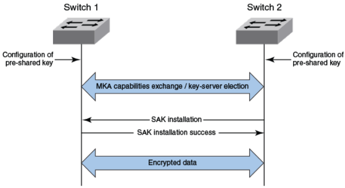
The following figure shows the message flow between two switches during MACsec communication.
FIGURE 1 MKA message exchange between two switches
Secure channels
Communication on each secure channel takes place as a series of transient sessions called secure
associations. These sessions can only be established with a unique Secure Association Key (SAK)
assigned to the session.
Secure associations expire and must be re-established after transmission of a certain number of
frames, or after a peer disconnects and reconnects.
The secure association is designated by a Secure Association Identifier (SAI), formed from the Secure
Channel Identifier (SCI) combined with an Association Number (AN). When a MACsec frame is
received by a peer interface, the Brocade device identifies the session key from the SAI carried in the
MACsec frame and uses the key to decrypt and authenticate the received frame.
SCIs and SAIs are carried in each MACsec frame as described in the section MACsec frame format.
MACsec frame format
When MACsec is enabled, Brocade hardware transforms each Ethernet frame by adding a security tag
(secTAG) to the frame.
The following figure shows how the Ethernet frame is converted into a MACsec frame.
Secure channels
FastIron Ethernet Switch Security Configuration Guide 181
53-1003405-04
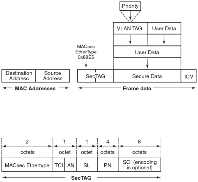
FIGURE 2 MACsec frame format
The security tag passes MACsec-related information to MACsec peers.
The following figure defines the fields in a security tag.
FIGURE 3 MACsec security tag format
Processing incoming frames
Brocade hardware processes each MACsec frame received or transmitted based on the information in
the MACsec security tag.
The Brocade switch first confirms the Ethertype on incoming frames as MACsec and then processes
incoming MACsec frames as illustrated in the following figure.
Processing incoming frames
182 FastIron Ethernet Switch Security Configuration Guide
53-1003405-04
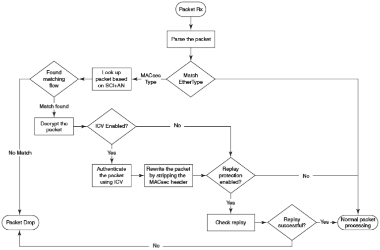
FIGURE 4 MACsec incoming frames
Processing outgoing frames
The Brocade switch parses each outgoing frame and, if MACsec is enabled, processes the outgoing
MACsec frame to apply configured MACsec options.
The following figure shows how the device applies configured MACsec options before transmitting the
frames.
Processing outgoing frames
FastIron Ethernet Switch Security Configuration Guide 183
53-1003405-04
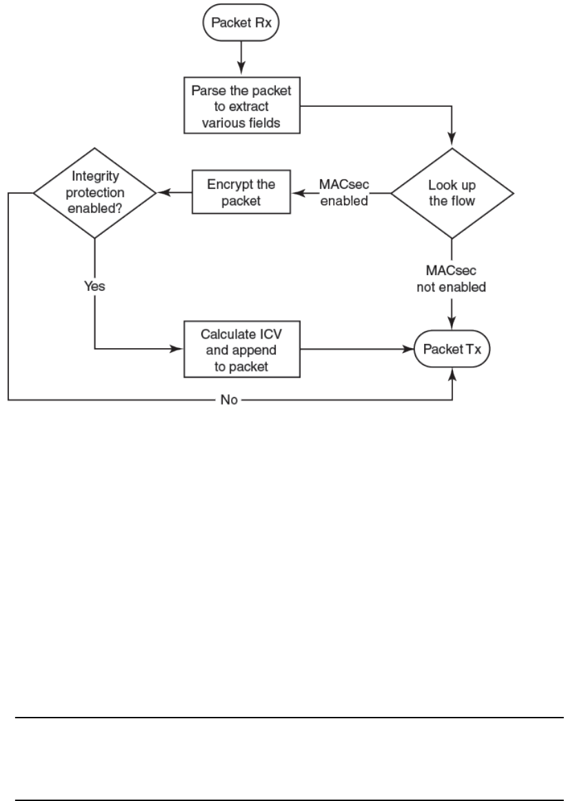
FIGURE 5 MACsec outgoing frames
Configuring MACsec
Although the MACsec configuration options outlined in this section are always visible, they cannot be
applied unless an active license is present on the switch and MACsec is enabled. MACsec licenses
are required on a per-device basis. Each device in the stack requires a separate MACsec license.
These steps are required to configure MACsec security on a link or a group of connected ports:
1. Enter the dot1x-mka level from the global configuration level, and enable MACsec for the device.
2. Configure the MACsec Key Agreement (MKA) protocol group.
3. Configure required parameters for the group, including frame validation, confidentiality, replay
protection, and actions to be taken when MACsec requirements are not met.
4. Enable MKA on each participating interface.
5. Apply a set of MKA group parameters on each MACsec interface.
NOTE
If an MKA group is not applied to an enabled MACsec interface, or if parameters within the applied
group have not been configured, default values are applied to the interface. Configured parameters
are visible in show command output; default parameters are not always visible. See the command
reference page for each command for default values.
6. Configure Connectivity Association Key (CAK) and Connectivity Association Key Name (CKN) on
each interface.
Configuring MACsec
184 FastIron Ethernet Switch Security Configuration Guide
53-1003405-04

Enabling MACsec and configuring a group
Enable MACsec globally on the licensed device and configure the MACsec Key Agreement Group
(MKA) before configuring MACsec security features for the group.
1. At the global configuration level, enter the dot1x-mka-enable command to enable MACsec on the
device.
ICX6610-48P Router(config)# dot1x-mka
dot1x-mka-enable Enable MACsec
ICX6610-48P Router(config)#dot1x-mka-enable
ICX6610-48P Router(config-dot1x-mka)#
MACsec is enabled, and the device is placed at the dot1x-mka configuration level.
2. Enter the mka-cfg-group command followed by a group name to create a group.
ICX6610-48P Router(config-dot1x-mka)#mka-cfg-group test1
ICX6610-48P Router(config-dot1x-mka-group-test1)#
The group is created, and the device is placed at the group configuration level.
At the group configuration level, set key-server priority and define MACsec security features to be
applied to interfaces once they are assigned to the group.
Configuring MACsec key-server priority
MACsec uses a key-server to generate and distribute encryption parameters and secure key
information to members of a MACsec connectivity association.
The key-server is elected by comparing key-server priority values during MKA message exchange
between peer devices. The elected key-server is the peer with the lowest configured key-server priority,
or the lowest Secure Channel Identifier (SCI) in case of a tie. Key-server priority may be set to a value
from 0 through 255. When no priority is configured, the device defaults to a priority of 16, which is not
displayed in MACsec configuration details.
NOTE
Refer to Configuring MACsec on page 184 for an overview of enabling and configuring MACsec
features.
At the dot1x-mka group configuration level, enter the key-server-priority command, and specify a
value from 0 through 255 to define key-server priority.
device(config-dot1x-mka-group-test1)# key-server-priority 5
device(config-dot1x-mka-group-test1)#
Configuring MACsec integrity and encryption
To ensure point-to-point integrity, MACsec computes an Integrity Check Value (ICV) on the entire
Ethernet frame using the designated cipher suite. The designated cipher suite is also used for
encryption.
MACsec adds the ICV to the frame before transmission. The receiving device recalculates the ICV and
checks it against the computed value that has been added to the frame. Because the ICV is computed
on the entire Ethernet frame, any modifications to the frame can be easily recognized.
Enabling MACsec and configuring a group
FastIron Ethernet Switch Security Configuration Guide 185
53-1003405-04

Integrity protection using the ICV is enabled by default in MACsec and can be used independently or
in conjunction with encryption.
MACsec encrypts traffic between devices at the MAC layer and decrypts frames within participating
networked devices. MACsec uses the Galois/Counter Mode Advanced Encryption Standard 128
(GCM-AES-128) cipher suite to encrypt data and to compute the ICV for each transmitted and
received MACsec frame.
MACsec also encrypts the VLAN tag and the original Ethertype field in the Layer 2 header of the
secured data. When initial bytes in a secure data packet must be transparent, a confidentiality offset of
30 or 50 bytes can be applied.
NOTE
Refer to Configuring MACsec on page 184 for an overview of enabling and configuring MACsec
features.
1. At the dot1x-mka group configuration level, enter the macsec cipher-suite command with one of
the available options:
a) gcm-aes-128: Enables encryption and integrity checking using the GCM-AES-128 cipher suite.
b) gcm-aes-128 integrity-only: Enables integrity checking.
device(config-dot1x-mka-group-test1)#macsec cipher-suite gcm-aes-128
device(config-dot1x-mka-group-test1)#
In the previous example, MACsec encryption has been configured as a group test1 setting. By
default, ICV integrity check is also enabled.
device(config-dot1x-mka-group-test1)# macsec cipher-suite gcm-aes-128 integrity-
only
device(config-dot1x-mka-group-test1)#
In the second example, data for MKA group test1 is not encrypted, but integrity checking is
performed using GCM-AES-128 capabilities.
NOTE
The no form of the macsec cipher-suite command disables both encryption and integrity checking.
2. Enter the macsec confidentiality-offset command with the desired encryption offset:
a) 0: Entire data packet is encrypted.
b) 30: Encryption begins at byte 31 of the data packet.
c) 50: Encryption begins at byte 51 of the data packet.
device(config-dot1x-mka-group-test1)#macsec confidentiality-offset 30
device(config-dot1x-mka-group-test1)#
In the previous example, the encryption offset is defined as 30 bytes. The first 30 bytes of each data
packet carried within the MACsec frame are transmitted without encryption.
MACsec Key-based Security
186 FastIron Ethernet Switch Security Configuration Guide
53-1003405-04

Configuring MACsec frame validation
You can specify whether incoming frames are checked for MACsec (secTAG) headers and how invalid
frames are handled.
NOTE
Refer to Configuring MACsec on page 184 for an overview of enabling and configuring MACsec
features.
At the MKA group configuration level, enter the macsec frame-validation command and select an
option:
a) disable: Received frames are not checked for a MACsec header.
b) check: If frame validation fails, counters are incremented, but packets are accepted.
c) strict: If frame validation fails, packets are dropped, and counters are incremented.
ICX6610-48P Router(config-dot1x-mka-group-test1)# macsec frame-validation strict
ICX6610-48P Router(config-dot1x-mka-group-test1)#
In the example, group test1 is configured to validate frames and discard invalid ones.
Configuring replay protection
MACsec replay protection detects repeated or delayed packets and acts as a safeguard against man-in-
the-middle attacks.
When replay protection is configured, MACsec uses a separate replay packet number (PN) counter and
gives each Ethernet frame a packet number. As frames are received, packet numbers are monitored.
Two modes of replay protection are supported: strict and out-of-order. In strict mode (the default),
packets must be received in the correct incrementing sequence. In out-of-order mode, packets are
allowed to arrive out of sequence within a defined window.
NOTE
Refer to Configuring MACsec on page 184 for an overview of enabling and configuring MACsec
features.
At the dot1x-mka group configuration level, enter the macsec replay-protection command with one
of the available modes:
a) strict: Frames must be received in exact incremental sequence.
b) out-of-order window size: Frames are accepted out of order within the designated window size.
ICX6610-48P Router(config-dot1x-mka-group-test1)# macsec replay-protection strict
ICX6610-48P Router(config-dot1x-mka-group-test1)#
In the example, replay protection is enabled for group test1. Frames must be received in exact order.
Configuring MACsec frame validation
FastIron Ethernet Switch Security Configuration Guide 187
53-1003405-04

Once you have configured desired MKA group settings, these settings can be applied to specific
interfaces.
Enabling and configuring group interfaces for MACsec
After MACsec is enabled for the device, each MACsec interface must be individually enabled and then
a configured group of parameters must be applied.
1. To enable MACsec, at the dot1x-mka configuration level, enter the enable-mka ethernet command
and specify the interface as device/slot/port.
In the following example, Ethernet port 2 on slot 3 of the first device in the stack is enabled for
MACsec security.
device(config-dot1x-mka)# enable-mka ethernet 1/3/2
device(config-dot1x-mka-1/3/2)#
NOTE
The following output is displayed if there is no MACsec license present on the device.
device(config-dot1x-mka)# enable-mka ethernet 1/3/2
Error: No MACsec License available for the port 1/3/2. Cannot enable MACsec !!!
Error: MKA cannot be enabled on port 1/3/2
2. At the dot1x-mka interface configuration level, enter the mka-cfg-group command to specify the
MKA group configuration to apply to the interface.
In the following example, MACsec options configured for group test1 are applied to the enabled
interface.
device(config-dot1x-mka-1/3/2)# mka-cfg-group test1
Configuring the pre-shared key
MACsec security is based on a pre-shared key, the Connectivity Association Key (CAK), which you
define and name. Only MACsec-enabled interfaces that are configured with the same key can
communicate over secure MACsec channels.
NOTE
Refer to Configuring MACsec on page 184 for an overview of enabling and configuring MACsec
features.
At the dot1x-mka-interface configuration level, enter the pre-shared-key command to define and
name the pre-shared key.
Enabling and configuring group interfaces for MACsec
188 FastIron Ethernet Switch Security Configuration Guide
53-1003405-04
a) Key id: Define the key ID value using 32 hexadecimal characters.
b) key-name hex-string: Give the key a name using 32 hexadecimal characters.
device(config-dot1x-mka-1/3/2)# pre-shared-key 135bd758b0ee5c11c55ff6ab19fdb199 key-
name 96437a93ccf10d9dfe347846cce52c7d
device(config-dot1x-mka-1/3/2)#
In the example, the pre-shared key with the hex value shown and the key name beginning with
"96437a93" is applied to interface 1/3/2.
Enable and configure each MACsec interface. Configure the same pre-shared key (CAK) on the
interfaces between which a secure channel can be established.
Sample MACsec configuration
Here is a complete example of how to enable MACsec, configure general parameters, enable and
configure interfaces, and assign a key that is shared with peers.
device(config)# dot1x-mka
dot1x-mka-enable Enable MACsec
device(config)# dot1x-mka-enable
device(config-dot1x-mka)#
device(config-dot1x-mka)# mka-cfg-group
ASCII string Name for this group
device(config-dot1x-mka)# mka-cfg-group test1
device(config-dot1x-mka-group-test1)#
device(config-dot1x-mka-group-test1)# key-server-priority
DECIMAL Priority of the Key Server. Valid values should be between 0 and 255
device(config-dot1x-mka-group-test1)# key-server-priority 5
device(config-dot1x-mka-group-test1)#
device(config-dot1x-mka-group-test1)# macsec cipher-suite
gcm-aes-128 GCM-AES-128 Cipher suite
device(config-dot1x-mka-group-test1)# macsec cipher-suite gcm-aes-128
device(config-dot1x-mka-group-test1)#
device(config-dot1x-mka-group-test1)# macsec confidentiality-offset
30 Confidentiality offset of 30
50 Confidentiality offset of 50
device(config-dot1x-mka-group-test1)# macsec confidentiality-offset 30
device(config-dot1x-mka-group-test1)#
device(config-dot1x-mka-group-test1)# macsec frame-validation
check Validate frames with secTAG and accept frames without secTAG
disable Disable frame validation
strict Validate frames with secTAG and discard frames without secTAG
device(config-dot1x-mka-group-test1)# macsec frame-validation strict
device(config-dot1x-mka-group-test1)#
device(config-dot1x-mka-group-test1)# macsec replay-protection
out-of-order Validate MACsec frames arrive in the given window size
strict Validate MACsec frames arrive in a sequence
device(config-dot1x-mka-group-test1)# macsec replay-protection strict
device(config-dot1x-mka-group-test1)#
device(config-dot1x-mka)#enable-mka ethernet 1/3/2
device(config-dot1x-mka-1/3/2)#
device(config-dot1x-mka-1/3/2)# mka-cfg-group
ASCII string Name for the group to be applied
device(config-dot1x-mka-1/3/2)# mka-cfg-group test1
device(config-dot1x-mka-1/3/2)#
Sample MACsec configuration
FastIron Ethernet Switch Security Configuration Guide 189
53-1003405-04
device(config-dot1x-mka-1/3/2)# pre-shared-key 135bd758b0ee5c11c55ff6ab19fdb199 key-
name 96437a93ccf10d9dfe347846cce52c7d
device(config-dot1x-mka-1/3/2)#
Displaying MACsec information
Use MACsec show commands to display information on MACsec for a device, group, or individual
interface.
MACsec show commands can be used to display configuration information. In addition, show
commands are available to report on MACsec sessions that are currently active on a device or to
monitor MACsec statistics on a particular interface.
Displaying MACsec configuration details
You can display configuration information for all MACsec groups on a device, or display details for a
particular group.
1. At the EXEC or Privileged EXEC level, use the show dot1x-mka config command to display
MACsec configuration details for the device.
device(config-dot1x-mka-1/3/3)# show dot1x-mka config
dot1x-mka-enable
mka-cfg-group test1
key-server-priority 5
macsec cipher-suite gcm-aes-128 integrity-only
macsec confidentiality-offset 30
macsec frame-validation strict
mka-cfg-group group1
key-server-priority 20
macsec cipher-suite gcm-aes-128
macsec confidentiality-offset 30
enable-mka ethernet 1/3/2
mka-cfg-group test1
pre-shared-key 135bd758b0ee5c11c55ff6ab19fdb199 key-name
96437a93ccf10d9dfe347846cce52c7d
enable-mka ethernet 1/3/3
mka-cfg-group group1
pre-shared-key 135bd758b0ee5c11c55ff6ab19fdb199 key-name
96437a93ccf10d9dfe347846cce52c7d
enable-mka ethernet 1/3/4
mka-cfg-group group1
pre-shared-key 135bd758b0ee5c11c55ff6ab19fdb199 key-name
96437a93ccf10d9dfe347846cce52c7d
device(config-dot1x-mka-1/3/2)#
In the previous example, MACsec parameters are displayed for the device and all groups
configured on it. Specific MACsec interfaces are displayed as well as the pre-shared key for each
interface.
2. At the EXEC or Privileged EXEC level, enter the show dot1x-mka config-group command to
display information for configured groups. Add a group name to the command to narrow the
information displayed to one group.
device(config-dot1x-mka-1/3/3)# show dot1x-mka config-group test1
mka-cfg-group test1
key-server-priority 5
macsec cipher-suite gcm-aes-128 integrity-only
macsec confidentiality-offset 30
macsec frame-validation strict
Displaying MACsec information
190 FastIron Ethernet Switch Security Configuration Guide
53-1003405-04

NOTE
Group information does not include the pre-shared key or enabled connections. Use the show
dot1x-mka config command to obtain that information.
Displaying information on current MACsec sessions
You can display MACsec session activity for an interface, including the pre-shared key name, the most
recent SAI information, and a list of peers.
1. For a quick overview of current MACsec sessions, enter the show dot1x-mka session brief
command.
ICX6610-48P Router(config-dot1x-mka-1/3/3)# show dot1x-mka session brief
Port Link-Status MKA-Status Key-Server Negotiated
Capability
1/3/2 Down Pending --- ---
1/3/3 Up Secured No Integrity, Confidentiality with Off. 30
1/3/4 Up Secured No Integrity, Confidentiality with Off. 30
ICX6610-48P Router(config-dot1x-mka-1/3/3)#
2. To display full details on current MACsec sessions, at the EXEC or Privileged ExEC level, enter the
show dot1x-mka session ethernet command followed by the interface identifier (device/slot/port).
ICX6610-48P Router(config-dot1x-mka-1/3/3)# show dot1x-mka session ethernet 1/3/3
Interface : 1/3/3
MACsec Status : Secured
DOT1X-MKA Enabled : Yes
DOT1X-MKA Active : Yes
Key Server : No
Configuration Status:
Enabled : Yes
Capability : Integrity, Confidentiality
Desired : Yes
Protection : Yes
Frame Validation : Disable
Replay Protection : Strict
Replay Protection Size : 0
Cipher Suite : GCM-AES-128
Key Server Priority : 20
Local SCI : 748ef8344a510082
Member Identifier : 802ed0536fcafc43407ba222
Message Number : 8612
Secure Channel Information:
Latest SAK Status : Rx & Tx
Latest SAK AN : 0
Latest KI : d08483062aa9457e7c2470e300000001
Negotiated Capability : Integrity, Confidentiality with offset 30
Peer Information:
State Member Identifier Message Number SCI
Priority
----- ----------------- -------------- ----------------
--------
Live d08483062aa9457e7c2470e3 8527
748ef83443910082 20
ICX6610-48P Router(config-dot1x-mka-1/3/3)#
Displaying information on current MACsec sessions
FastIron Ethernet Switch Security Configuration Guide 191
53-1003405-04
Displaying MKA protocol statistics for an interface
You can display a report on MKA protocol activity for a particular interface.
1. At the EXEC or Privileged EXEC level, enter the clear dot1x-mka statistics ethernet command for
the designated interface.
Results of the previous show dot1x-mka statistics ethernet command are removed.
2. Enter the show dot1x-mka statistics ethernet command to display MKA protocol statistics for the
designated interface.
ICX6610-48P Router(config-dot1x-mka-1/3/3)# clear dot1x-mka statistics ethernet
1/3/3
ICX6610-48P Router(config-dot1x-mka-1/3/3)# show dot1x-mka statistics ethernet
1/3/3
Interface : 1/3/3
MKA in Pkts : 8585
MKA in SAK Pkts : 1
MKA in Bad Pkts : 0
MKA in Bad ICV Pkts : 0
MKA in Mismatch Pkts : 0
MKA out Pkts : 8687
MKA out SAK Pkts : 0
Number of SAK : 1
ICX6610-48P Router(config-dot1x-mka-1/3/3)#
Displaying MACsec secure channel activity for an interface
You can display currently enforced MACsec capabilities for a specific interface, along with secure
channel statistics.
1. At the EXEC or Privileged EXEC level, enter the clear macsec ethernet command for the
designated interface.
Results of the previous show macsec statistics ethernet command are removed.
2. Enter the show macsec statistics ethernet command to display information on MACsec
configuration and secure channel activity for a particular interface.
device(config-dot1x-mka-1/3/1)# clear macsec ethernet 1/3/1
device(config-dot1x-mka-1/3/1)# show macsec statistics ethernet 1/3/1
Interface : 1/3/1
Replay Protection : Enabled
Replay Window : 0
Frame Validation : Check
Secure Channel Statistics:
TxPktProtectedOnly 165074761 TxOctetProtectedOnly 20491766144
TxPktEncrypted 0 TxOctetEncrypted 0
TxPktMiss 0 TxOctetMiss 0
TxPktDrop 0 TxPktBad 0
RxPktDecryptedAuth 3455 RxOctetTotal 257506
RxOctetAuthOnly 230740 RxOctetDecrypted 0
RxPktFailReplayCheck 0 RxPktFailICVCheck 0
RxPktNoMACsecTag 414 RxPktFrameValFail 0
RxPktMiss 414 RxOctetMiss 26766
RxPktDrop 0
device(config-dot1x-mka-1/3/1)#
Displaying MKA protocol statistics for an interface
192 FastIron Ethernet Switch Security Configuration Guide
53-1003405-04
MAC Port Security
● Supported MAC port security features.......................................................................... 193
● MAC port security overview.......................................................................................... 194
● MAC port security configuration.................................................................................... 195
● Clearing port security statistics..................................................................................... 199
● Displaying port security information ............................................................................. 200
Supported MAC port security features
Lists the MAC port security features supported on FastIron devices
The following table lists the individual BrocadeFastIron switches and the Media Access Control (MAC)
port security features they support. These features are supported in the Layer 2 and Layer 3 software
images, except where explicitly noted.
Feature ICX 6430 ICX 6450 FCX ICX 6610 ICX 6650 FSX 800
FSX 1600
ICX 7450 ICX 7750
MAC port security 08.0.01 08.0.01 08.0.01 08.0.01 08.0.01 08.0.01 08.0.20 08.0.10
Setting the maximum number of
secure MAC addresses on an
interface
08.0.01 08.0.01 08.0.01 08.0.01 08.0.01 08.0.01 08.0.20 08.0.10
Setting the port security age timer 08.0.01 08.0.01 08.0.01 08.0.01 08.0.01 08.0.01 08.0.20 08.0.10
Specifying secure MAC
addresses
08.0.01 08.0.01 08.0.01 08.0.01 08.0.01 08.0.01 08.0.20 08.0.10
Autosaving secure MAC
addresses to the startup-config
file
08.0.01 08.0.01308.0.01 08.0.01 08.0.01 08.0.01 08.0.20 08.0.10
Specifying the action taken when
a security violation occurs
08.0.01 08.0.01 08.0.01 08.0.01 08.0.01 08.0.01 08.0.20 08.0.10
Clearing port security statistics 08.0.01 08.0.01 08.0.01 08.0.01 08.0.01 08.0.01 08.0.20 08.0.10
This chapter describes how to configure Brocade devices to learn "secure" MAC addresses on an
interface so that the interface will forward only packets that match the secure addresses.
3Hardware forwarding.
FastIron Ethernet Switch Security Configuration Guide 193
53-1003405-04
MAC port security overview
You can configure the Brocade device to learn "secure" MAC addresses on an interface. The interface
will forward only packets with source MAC addresses that match these learned secure addresses. The
secure MAC addresses can be specified manually, or the Brocade device can learn them
automatically. After the device reaches the limit for the number of secure MAC addresses it can learn
on the interface, if the interface then receives a packet with a source MAC address that does not
match the learned addresses, it is considered a security violation.
When a security violation occurs, a Syslog entry and an SNMP trap are generated. In addition, the
device takes one of two actions: it either drops packets from the violating address (and allows packets
from the secure addresses), or disables the port for a specified amount of time. You specify which of
these actions takes place.
The secure MAC addresses are not flushed when an interface is disabled and re-enabled on FastIron
X Series devices. The secure MAC addresses are flushed when an interface is disabled and re-
enabled on FCX and ICX devices.
The secure addresses can be kept secure permanently (the default), or can be configured to age out,
at which time they are no longer secure. You can configure the device to automatically save the
secure MAC address list to the startup-config file at specified intervals, allowing addresses to be kept
secure across system restarts.
Local and global resources used for MAC port security
The MAC port security feature uses a concept of local and global "resources" to determine how many
MAC addresses can be secured on each interface. In this context, a "resource" is the ability to store
one secure MAC address entry. Each interface is allocated 64 local resources. Additional global
resources are shared among all interfaces on the device.
When the MAC port security feature is enabled on an interface, the interface can store one secure
MAC address. You can increase the number of MAC addresses that can be secured using local
resources to a maximum of 64.
Besides the maximum of 64 local resources available to an interface, there are additional global
resources. Depending on flash memory size, a device can have 1024, 2048, or 4096 global resources
available. When an interface has secured enough MAC addresses to reach its limit for local resources,
it can secure additional MAC addresses by using global resources. Global resources are shared
among all the interfaces on a first-come, first-served basis.
The maximum number of MAC addresses any single interface can secure is 64 (the maximum number
of local resources available to the interface), plus the number of global resources not allocated to other
interfaces.
Configuration notes and feature limitations for MAC port security
The following limitations apply to this feature:
• MAC port security applies only to Ethernet interfaces.
• Unknown unicast traffic is flooded out of port with maximum secure MAC learnt on removing the
ACL.
• MAC port security is not supported on static trunk group members or ports that are configured for
link aggregation.
• MAC port security is not supported on 802.1X port security-enabled ports.
• Brocade devices do not support the reserved-vlan-id num command, which changes the default
VLAN ID for the MAC port security feature.
MAC port security overview
194 FastIron Ethernet Switch Security Configuration Guide
53-1003405-04
• The SNMP trap generated for restricted MAC addresses indicates the VLAN ID associated with the
MAC address, as well as the port number and MAC address.
• MAC port security is not supported on ports that have multi-device port authentication enabled.
• The first packet from each new secure MAC address is dropped if secure MAC addresses are
learned dynamically.
• Violated MAC movement is not supported.
Secure MAC movement
If you move a connected device that has MAC address configured as secure on one port to another
port, the FastIron device connects through the new port without waiting for the MAC address to age out
on the previous port. This MAC movement feature is supported when the connected device moves from
a secure port to another secure or non-secure port.
MAC movement feature is not supported in the following cases:
• MAC address is permanently secured to a port with age 0 command.
• MAC address causes a MAC security violation on the previous port.
MAC port security configuration
To configure the MAC port security feature, perform the following tasks:
• Enable the MAC port security feature
• Set the maximum number of secure MAC addresses for an interface
• Set the port security age timer
• Specify secure MAC addresses
• Configure the device to automatically save secure MAC addresses to the startup-config file
• Specify the action taken when a security violation occurs
Enabling the MAC port security feature
By default, the MAC port security feature is disabled on all interfaces. You can enable or disable the
feature on all interfaces at once, or on individual interfaces.
To enable the feature on all interfaces at once, enter the following commands.
device(config)#port security
device(config-port-security)#enable
To disable the feature on all interfaces at once, enter the following commands.
device(config)#port security
device(config-port-security)#no enable
To enable the feature on a specific interface, enter the following commands.
device(config)#interface ethernet 7/11
device(config-if-e1000-7/11)#port security
device(config-port-security-e1000-7/11)#enable
Syntax: port security
Syntax: no enable
Secure MAC movement
FastIron Ethernet Switch Security Configuration Guide 195
53-1003405-04

Setting the maximum number of secure MAC addresses for an
interface
When MAC port security is enabled, an interface can store one secure MAC address. You can
increase the number of MAC addresses that can be stored to a maximum of 64, plus the total number
of global resources available.
For example, to configure interface 7/11 to have a maximum of 10 secure MAC addresses, enter the
following commands.
device(config)#interface ethernet 7/11
device(config-if-e1000-7/11)#port security
device(config-port-security-e1000-7/11)#maximum 10
Syntax: maximum number-of-addresses
The number-of-addresses parameter can be set to a number from 0 through 64 plus (the total
number of global resources available). The total number of global resources is 2048 or 4096,
depending on flash memory size. Setting the parameter to 0 prevents any addresses from being
learned. The default is 1.
Setting the port security age timer
By default, learned MAC addresses stay secure indefinitely. You can optionally configure the device to
age out secure MAC addresses after a specified amount of time.
To set the port security age timer to 10 minutes on all interfaces, enter the following commands.
device
(config)# port security
device
(config-port-security)# age 10
To age out all secure MAC-addresses immediately after two minutes, enter the following commands.
device
(config)#
port security
device
(config-port-security)# age 2 absolute
To set the port security age timer to 10 minutes on a specific interface, enter the following commands.
device(config)# interface ethernet 7/1/1
device(config-if-e1000-7/1/1)# port security
device(config-port-security-e1000-7/1/1)# age 10
Syntax: [no] age minutes [ minutes | absolute ]
The minutes variable specifies a range from 0 through 1440 minutes. The default is 0 (never age out
secure MAC addresses).
The optional absolute keyword sets all secure MAC addresses to age out immediately once the
specified time expires. If the absolute keyword is not specified, secure MAC addresses are aged out
only when the configured hardware MAC age time expires.
NOTE
When using the absolute option to age out MAC addresses on timer expiry, make sure that the age
timer value is sufficient. Avoid using a very short timer expiry with the absolute option, as the value
may be in conflict with other timer settings and may cause performance problems in the network. For
Setting the maximum number of secure MAC addresses for an interface
196 FastIron Ethernet Switch Security Configuration Guide
53-1003405-04

example, a one-minute timer expiry will cause MAC addresses to be flushed every minute. As a result,
operational (enable/disable) loops and packet flooding may occur following a security violation, which by
default causes a port to be disabled for one minute.
NOTE
Even though you can set age time to specific ports independent of the device-level setting, the actual
age timer will take the greater of the two values. Thus, if you set the age timer to 3 minutes for the port,
and 10 minutes for the device, the port MAC aging happens in 10 minutes (the device-level setting),
which is greater than the port setting that you have configured.
On the ICX 7750 device, the port security age can only be set to the global hardware age. The absolute
age and no age secure MACs are configured as static in hardware. To set or unset PMS MAC age time
to global-mac-timer (hardware age timer), enter the following commands:
device(config-port-security-e1000-7/1/1)#age global-mac
device(config-port-security-e1000-7/1/1)#no age global-mac
Specifying secure MAC addresses
You can configure secure MAC addresses on tagged and untagged interfaces.
On an untagged interface
To specify a secure MAC address on an untagged interface, enter commands such as the following.
device(config)#interface ethernet 7/11
device(config-if-e1000-7/11)#port security
device(config-port-security-e1000-7/11)#secure-mac-address 0000.0018.747C
Syntax: [no] secure-mac-address mac-address
On a tagged interface
When specifying a secure MAC address on a tagged interface, you must also specify the VLAN ID. To
do so, enter commands such as the following.
device(config)#interface ethernet 7/11
device(config-if-e1000-7/11)#port security
device(config-port-security-e1000-7/11)#secure-mac-address 0000.0018.747C 2
Syntax: [no] secure-mac-address mac-address [ vlan-ID ]
NOTE
If MAC port security is enabled on a port and you change the VLAN membership of the port, make sure
that you also change the VLAN ID specified in the secure-mac-address configuration statement for the
port.
When a secure MAC address is applied to a tagged port, the VLAN ID is generated for both tagged and
untagged ports. When you display the configuration, you will see an entry for the secure MAC
addresses. For example, you might see an entry similar to the following line.
secure-mac-address 0000.0011.2222 10 10
Specifying secure MAC addresses
FastIron Ethernet Switch Security Configuration Guide 197
53-1003405-04

This line means that MAC address 0000.0011.2222 10 on VLAN 10 is a secure MAC address.
Autosaving secure MAC addresses to the startup configuration
Learned MAC addresses can automatically be saved to the startup configuration at specified intervals.
The autosave feature saves learned MAC addresses by copying the running configuration to the
startup configuration.
For example, to automatically save learned secure MAC addresses every 20 minutes, enter the
following commands.
device(config)#port security
device(config-port-security)#autosave 20
Syntax: [no] autosave minutes ]
The minutes variable can be from 15 through 1440 minutes. By default, secure MAC addresses are
not autosaved to the startup-config file.
If you change the autosave interval, the next save happens according to the old interval, then the new
interval takes effect. To change the interval immediately, disable autosave by entering the no
autosave command, then configure the new autosave interval using the autosave command.
Specifying the action taken when a security violation occurs
A security violation can occur when a user tries to connect to a port where a MAC address is already
locked, or the maximum number of secure MAC addresses has been exceeded. When a security
violation occurs, an SNMP trap and Syslog message are generated.
You can configure the device to take one of two actions when a security violation occurs; either drop
packets from the violating address (and allow packets from secure addresses), or disable the port for a
specified time.
Dropping packets from a violating address
To configure the device to drop packets from a violating address and allow packets from secure
addresses, enter the following commands.
device(config)#interface ethernet 7/11
device(config-if-e1000-7/11)#port security
device(config-port-security-e1000-7/11)#violation restrict
Syntax: violation [ restrict ]
NOTE
When the restrict option is used, the maximum number of MAC addresses that can be restricted is
128. If the number of violating MAC addresses exceeds this number, the port is shut down. An SNMP
trap and the following Syslog message are generated: "Port Security violation restrict limit 128
exceeded on interface ethernet port_id ". This is followed by a port shutdown Syslog message and
trap.
Autosaving secure MAC addresses to the startup configuration
198 FastIron Ethernet Switch Security Configuration Guide
53-1003405-04
Specifying the period of time to drop packets from a violating address
To specify the number of minutes that the device drops packets from a violating address, use
commands similar to the following.
device(config)#interface ethernet 7/11
device(config-if-e1000-7/11)#port security
device(config-port-security-e1000-7/11)#violation restrict 5
Syntax: violation [ restrict ] [age ]
The age variable can be from 0 through 1440 minutes. The default is 5 minutes. Specifying 0 drops
packets from the violating address permanently.
Aging for restricted MAC addresses is done in software. There can be a worst case inaccuracy of one
minute from the specified time.
The restricted MAC addresses are denied in hardware.
Disabling the port for a specified amount of time
You can configure the device to disable the port for a specified amount of time when a security violation
occurs.
To shut down the port for 5 minutes when a security violation occurs, enter the following commands.
device(config)#interface ethernet 7/11
device(config-if-e1000-7/11)#port security
device(config-port-security-e1000-7/11)#violation shutdown 5
Syntax: violation [ shutdown ] [minutes ]
The minutes can be from 0 through 1440 minutes. Specifying 0 shuts down the port permanently when
a security violation occurs.
Clearing port security statistics
You can clear restricted MAC addresses and violation statistics from ports on all ports or on individual
ports.
Clearing restricted MAC addresses
To clear all restricted MAC addresses globally, enter the clear port security restricted-macs all
command.
device#clear port security restricted-macs all
To clear restricted MAC addresses on a specific port, enter a command such as the following.
Brocade#clear port security restricted-macs ethernet 5
Syntax: clear port security restricted-macs [ all | ethernet port ]
Disabling the port for a specified amount of time
FastIron Ethernet Switch Security Configuration Guide 199
53-1003405-04

Clearing violation statistics
To clear violation statistics globally, enter the clear port security statistics all command.
device#clear port security statistics all
To clear violation statistics on a specific port, enter a command such as the following.
device#clear port security statistics ethernet 1/5
Syntax: clear port security statistics [ all | ethernet port ]
Displaying port security information
You can display the following information about the MAC port security feature:
• The port security settings for an individual port or for all the ports on a specified module
• The secure MAC addresses configured on the device
• Port security statistics for an interface or for a module
Displaying port security settings
You can display the port security settings for an individual port or for all the ports on a specified
module. For example, to display the port security settings for port 7/11, enter the following command.
Brocade#show port security ethernet 7/11
Port Security Violation Shutdown-Time Age-Time Max-MAC
----- -------- --------- ------------- --------- -------
7/11 disabled shutdown 10 10 1
Syntax: show port security ethernet port
Output from the show port security ethernet command TABLE 16
Field Description
Port The slot and port number of the interface.
Security Whether the port security feature has been enabled on the interface.
Violation The action to be undertaken when a security violation occurs, either "shutdown" or "restrict".
Shutdown-Time The number of seconds a port is shut down following a security violation, if the port is set to
"shutdown" when a violation occurs.
Age-Time The amount of time, in minutes, MAC addresses learned on the port will remain secure.
Max-MAC The maximum number of secure MAC addresses that can be learned on the interface.
Clearing violation statistics
200 FastIron Ethernet Switch Security Configuration Guide
53-1003405-04

Displaying the secure MAC addresses
To list the secure MAC addresses configured on the device, enter the following command.
device#show port security mac
Port Num-Addr Secure-Src-Addr Resource Age-Left Shutdown/Time-Left
----- -------- --------------- -------- --------- ------------------
7/11 1 0000.018.747c Local
10 no
Syntax: show port security mac
The following table describes the output from the show port security mac command.
Output from the show port security mac command TABLE 17
Field Description
Port The slot and port number of the interface.
Num-Addr The number of MAC addresses secured on this interface.
Secure-Src-Addr The secure MAC address.
Resource Whether the address was secured using a local or global resource.Refer to Local and global
resources used for MAC port security on page 194 for more information.
Age-Left The number of minutes the MAC address will remain secure.
Shutdown/Time-Left Whether the interface has been shut down due to a security violation and the number of
seconds before it is enabled again.
NOTE
For FCX and ICX switches, after every switchover or failover, the MAC "Age-Left" timer is reset to start
since it is not synchronized between the master and the standby stack unit. This behavior is different on
the FSX devices where the "Age-Left" timer is not reset.
Displaying port security statistics
You can display port security statistics for an interface or for a module.
For example, to display port security statistics for interface 7/11, enter the following command.
device#show port security statistics e 7/11
Port Total-Addrs Maximum-Addrs Violation Shutdown/Time-Left
----- ----------- ------------- --------- ------------------
7/11 1 1 0 no
Syntax: show port security statistics port
Displaying the secure MAC addresses
FastIron Ethernet Switch Security Configuration Guide 201
53-1003405-04

Output from the show port security statisticsport command TABLE 18
Field Description
Port The slot and port number of the interface.
Total-Addrs The total number of secure MAC addresses on the interface.
Maximum-Addrs The maximum number of secure MAC addresses on the interface.
Violation The number of security violations on the port.
Shutdown/Time-Left Whether the port has been shut down due to a security violation and the number of
seconds before it is enabled again.
For example, to display port security statistics for interface module 7, enter the show port security
statistics command.
device#show port security statistics 7
Module 7:
Total ports: 0
Total MAC address(es): 0
Total violations: 0
Total shutdown ports 0
Syntax: show port security statistics module
The following table describes the output from the show port security statisticsmodule command.
Output from the show port security statisticsmodule command TABLE 19
Field Description
Total ports The number of ports on the module.
Total MAC address(es) The total number of secure MAC addresses on the module.
Total violations The number of security violations encountered on the module.
Total shutdown ports The number of times that ports on the module shut down as a result of security
violations.
Displaying restricted MAC addresses on a port
To display a list of restricted MAC addresses on a port, enter a command such as the following.
device#show port security ethernet 1/5 restricted-macs
Syntax: show port security ethernet port restricted-macs
Displaying restricted MAC addresses on a port
202 FastIron Ethernet Switch Security Configuration Guide
53-1003405-04
MAC-based VLANs
● Supported MAC-based VLAN features......................................................................... 203
● MAC-based VLAN overview..........................................................................................203
● Dynamic MAC-based VLAN..........................................................................................205
● MAC-based VLAN configuration................................................................................... 207
● Configuring MAC-based VLANs using SNMP...............................................................213
● Displaying Information about MAC-based VLANs........................................................ 213
● Clearing MAC-VLAN information.................................................................................. 219
● Sample MAC-based VLAN application......................................................................... 219
Supported MAC-based VLAN features
Lists MAC-based VLAN features supported on FastIron devices.
The following table lists the individual BrocadeFastIron switches and the MAC-based VLAN features
they support. These features are supported in the Layer 2 and Layer 3 software images, except where
explicitly noted.
FastIron 08.0.20 release onwards, MAC-based VLAN features are replaced on most FastIron platforms
by Flexible Authentication (flexauth) features.
Feature ICX 6430 ICX 6450 FCX ICX 6610 ICX 6650 FSX 800
FSX 1600
IC 7450 ICX 7750
MAC-based VLANs
• Source MAC address
authentication
• Policy-based classification and
forwarding
No No No No 08.0.01 No No No
MAC-based VLANs and 802.1X
security on the same port
No No No No 08.0.01 No No No
MAC-based VLAN aging No No No No 08.0.01 No No No
Dynamic MAC-based VLANs No No No No 08.0.01 No No No
MAC-based VLAN overview
NOTE
Beginning in FastIron release 08.0.20, MAC-based VLAN features (introduced in FastIron release
08.0.01) are replaced on most FastIron platforms by flexible authentication.
FastIron Ethernet Switch Security Configuration Guide 203
53-1003405-04
The MAC-based VLAN feature controls network access by authenticating a host source MAC address,
and mapping the incoming packet source MAC to a VLAN. Mapping is based on the MAC address of
the end station connected to the physical port. Users who relocate can remain on the same VLAN as
long as they connect to any switch in the same domain, on a port which is permitted in the VLAN. The
MAC-based VLAN feature may be enabled for two types of hosts: static and dynamic.
MAC-based VLAN activity is determined by authentication through a RADIUS server. Incoming traffic
that originates from a specific MAC address is forwarded only if the source MAC address-to-VLAN
mapping is successfully authenticated. While multi-device port authentication is in progress, all traffic
from the new MAC address will be blocked or dropped until the authentication succeeds. Traffic is
dropped if the authentication fails.
Static and dynamic hosts
Static hosts are devices on the network that do not speak until spoken to. Static hosts may not initiate
a request for authentication on their own. Such static hosts can be managed through a link up or link
down notification.
Dynamic hosts are "chatty" devices that generate packets whenever they are in the link up state.
Dynamic hosts must be authenticated before they can switch or forward traffic.
MAC-based VLAN feature structure
The MAC-based VLAN feature operates in two stages:
• Source MAC Address Authentication
• Policy-Based Classification and Forwarding
Source MAC address authentication
Source MAC address authentication is performed by a central RADIUS server when it receives a PAP
request with a username and password that match the MAC address being authenticated. When the
MAC address is successfully authenticated, the server must return the VLAN identifier, which is
carried in the Tunnel-Type, Tunnel-Medium-Type, and Tunnel-Private-Group-ID attributes of the
RADIUS packets. If the Tunnel-Type is tagged, the MAC address will be blocked or restricted. If the
identified VLAN does not exist, then the authentication is considered a failure, and action is taken
based on the configured failure options. (The default failure action is to drop the traffic.) The RADIUS
server may also optionally return the QoS attribute for the authenticated MAC address. Refer to the
Brocade vendor-specific attributes for RADIUS table for more information about attributes.
Policy-based classification and forwarding
Once the authentication stage is complete, incoming traffic is classified based on the response from
the RADIUS server. There are three possible actions:
• Incoming traffic from a specific source MAC is dropped because authentication failed
• Incoming traffic from a specific source MAC is classified as untagged into a specific VLAN
• Incoming traffic from a specific source MAC is classified as untagged into a restricted VLAN
Traffic classification is performed by programming incoming traffic and RADIUS-returned attributes in
the hardware. Incoming traffic attributes include the source MAC address and the port on which the
feature is enabled. The RADIUS-returned attributes are the VLAN into which the traffic is to be
classified, and the QoS priority.
Static and dynamic hosts
204 FastIron Ethernet Switch Security Configuration Guide
53-1003405-04

NOTE
This feature drops any incoming tagged traffic on the port, and classifies and forwards untagged traffic
into the appropriate VLANs.
This feature supports up to a maximum of 32 MAC addresses per physical port, with a default of 2.
NOTE
Even though the feature supports up tp a maximum of 32 MAC address per physical port, the
configuration of the maximum number of MAC addresses per port is limited by the available hardware
resources.
Once a client MAC address is successfully authenticated and registered, the MAC-to-VLAN association
remains until the port connection is dropped, or the MAC entry expires.
MAC-based VLAN and port up or down events
When the state of a port is changed to down, all authorized and unauthorized MAC addresses are
removed from the MAC-to-VLAN mapping table, any pending authentication requests are cancelled.
Dynamic MAC-based VLAN
When enabled, the dynamic MAC-based VLAN feature allows the dynamic addition of mac-vlan-permit
ports to the VLAN table only after successful RADIUS authentication. Ports that fail RADIUS
authentication are not added to the VLAN table.
When this feature is not enabled, the physical port is statically added to the hardware table, regardless
of the outcome of the authentication process. This feature prevents the addition of unauthenticated
ports to the VLAN table. For information about how to configure Dynamic MAC-based VLAN, refer to
Configuring dynamic MAC-based VLAN on page 212.
Configuration notes and feature limitations for dynamic MAC-based
VLAN
The following guidelines apply to MAC-based VLAN configurations:
• MAC-based VLAN is not currently supported for trunk ports and LACP.
• MAC-based VLAN is not supported for VLAN groups, topology groups and dual-mode configuration.
• MAC-based VLAN is not supported together with ACLs or MAC address filters.
• FastIron devices do not support UDLD link-keepalives on ports with MAC-based VLAN enabled.
• FastIron devices do not support STP BPDU packets on ports with MAC-based VLAN enabled.
• MAC-to-VLAN mapping must be associated with VLANs that exist on the switch. Create the VLANs
before you configure the MAC-based VLAN feature.
• Ports participating in MAC-based VLANs must first be configured as mac-vlan-permit ports under the
VLAN configuration.
• In the RADIUS server configuration file, a MAC address cannot be configured to associate with more
than one VLAN.
MAC-based VLAN and port up or down events
FastIron Ethernet Switch Security Configuration Guide 205
53-1003405-04

• This feature does not currently support dynamic assignment of a port to a VLAN. Users must pre-
configure VLANs and port membership before enabling the feature.
• Multi-device port authentication filters will not work with MAC-based VLANs on the same port.
Dynamic MAC-based VLAN CLI commands
The following table describes the CLI commands used to configure MAC-based VLANs.
CLI commands for MAC-based VLANs TABLE 20
CLI command Description CLI level
mac-auth mac-vlan enable Enables per-port MAC-based VLAN Interface
mac-auth mac-vlan disable Disables per-port MAC-based VLAN interface
mac-auth mac-vlan-dyn-activation Enables Dynamic MAC-based VLAN global
no mac-auth mac-vlan-dyn-activation Disables Dynamic MAC-based VLAN global
no mac-auth mac-vlan Removes the MAC-VLAN configuration from the port interface
mac-auth mac-vlan max-mac-entries
num of entries
The maximum number of allowed and denied MAC
addresses (static and dynamic) that can be learned on a
port. The default is 2.
interface
mac-auth mac-vlan mac-addr vlan vlan id
priority 0-7
Adds a static MAC-VLAN mapping to the MAC-based
VLAN table (for static hosts)
interface
clear table-mac-vlan Clears the contents of the authenticated MAC address
table
global
clear table-mac-vlan ethernet port Clears all MAC-based VLAN mapping on a port global
show table-mac-vlan Displays information about allowed and denied MAC
addresses on ports with MAC-based VLAN enabled.
global
show table-mac-vlan allowed-mac Displays MAC addresses that have been successfully
authenticated
global
show table-mac-vlan denied-mac Displays MAC addresses for which authentication failed global
show table-mac-vlan detailed Displays detailed MAC-VLAN settings and classified MAC
addresses for a port with the feature enabled
global
show table-mac-vlan mac-address Displays status and details for a specific MAC address global
show table-mac-vlan ethernet port Displays all MAC addresses allowed or denied on a
specific port
global
Dynamic MAC-based VLAN CLI commands
206 FastIron Ethernet Switch Security Configuration Guide
53-1003405-04
Dynamic MAC-based VLAN configuration example
The following example shows a MAC-based VLAN configuration.
device#show run
Current configuration:
ver 04.0.00b122T7e1
fan-threshold mp speed-3 35 100
module 1 fls-24-port-copper-base-module
module 4 fls-xfp-1-port-10g-module
vlan 1 by port
untagged ethe 0/1/10
mac-vlan-permit ethe 0/1/1 to 0/1/3
no spanning-tree
vlan 2 by port
untagged ethe 0/1/24
mac-vlan-permit ethe 0/1/1 to 0/1/3
no spanning-tree
vlan 222 name RESTRICTED_MBV by port
untagged ethe 0/1/4
mac-vlan-permit ethe 0/1/1 to 0/1/3
vlan 666 name RESTRICTED_MAC_AUTH by port
untagged ethe 0/1/20
mac-vlan-permit ethe 0/1/1 to 0/1/3
spanning-tree 802-1w
vlan 4000 name DEFAULT-VLAN by port
vlan 4004 by port
mac-vlan-permit ethe 0/1/1 ethe 0/1/3
default-vlan-id 4000
ip address 10.44.3.3 255.255.255.0
ip default-gateway 10.44.3.1
radius-server host 10.44.3.111
radius-server key 1 $-ndUno
mac-authentication enable
mac-authentication mac-vlan-dyn-activation
mac-authentication max-age 60
mac-authentication hw-deny-age 30
mac-authentication auth-passwd-format xxxx.xxxx.xxxx
mac-authentication auth-fail-vlan-id 666
interface ethernet 0/1/1
mac-authentication mac-vlan max-mac-entries 5
mac-authentication mac-vlan 0000.0088.b9fe vlan 1 priority 1
mac-authentication mac-vlan enable
interface ethernet 0/1/2
mac-authentication mac-vlan max-mac-entries 10
mac-authentication mac-vlan enable
mac-authentication auth-fail-action restrict-vlan 222
interface ethernet 0/1/3
mac-authentication mac-vlan enable
mac-authentication auth-fail-action restrict-vlan
!
end
MAC-based VLAN configuration
Configure MAC-based VLAN mapping on the switch statically for static hosts, or dynamically for non-
static hosts, by directing the RADIUS server to authenticate the incoming packet.
To configure the a MAC-based VLAN, first perform the following tasks:
• In the VLANs, configure mac-vlan-permit for each port that will be participating in the MAC-based
VLAN
• If a port has been MAC-based VLAN-enabled, but has not been added as mac-vlan-permit in any of
the VLANs, any MAC addresses learned on this port will be blocked in the reserved VLAN. To
prevent this, you must create all of the VLANs and add all ports as mac-vlan-permit before enabling
MAC-based VLAN on any ports.
• Disable any multi-device port authentication on ports you will be using for MAC-to-VLAN mapping
Dynamic MAC-based VLAN configuration example
FastIron Ethernet Switch Security Configuration Guide 207
53-1003405-04

NOTE
Do not configure MAC-based VLAN on ports that are tagged to any VLAN. Do not use ports on which
MAC-based VLAN is configured as tagged ports.
NOTE
For FCX and ICX devices, MAC-based VLAN with 802.1X will not work on the same port if 802.1X has
the RADIUS VLAN attribute defined as an untagged VLAN (for example U:1, U:2).
NOTE
MAC-based VLAN is not supported on trunk or LACP ports. Do not configure trunks on MAC-based
VLAN-enabled ports.
Using MAC-based VLANs and 802.1X securityon the same port
On Brocade devices, MAC-based VLANs and 802.1X security can be configured on the same port.
When both of these features are enabled on the same port, MAC-based VLAN is performed prior to
802.1X authentication. If MAC-based VLAN is successful, 802.1X authentication may be performed,
based on the configuration of a vendor-specific attribute (VSA) in the profile for the MAC address on
the RADIUS server.
When both features are configured on a port, a device connected to the port is authenticated as
follows.
1. MAC-based VLAN is performed on the device to authenticate the device MAC address.
2. If MAC-based VLAN is successful, the device then checks to see if the RADIUS server included the
Foundry-802_1x-enable VSA (described in the Brocade vendor-specific attributes for RADIUS
table) in the Access-Accept message that authenticated the device.
3. If the Foundry-802_1x-enable VSA is not present in the Access-Accept message, or is present and
set to 1, then 802.1X authentication is performed for the device.
4. If the Foundry-802_1x-enable VSA is present in the Access-Accept message, and is set to 0, then
802.1X authentication is skipped.
Configuring generic and Brocade vendor-specificattributes on the
RADIUS server
If the RADIUS authentication process is successful, the RADIUS server sends an Access-Accept
message to the Brocade device, authenticating the device. The Access-Accept message includes
Vendor-Specific Attributes (VSAs) that specify additional information about the device.
Add Brocade vendor-specific attributes to your RADIUS server configuration, and configure the
attributes in the individual or group profiles of the devices that will be authenticated. Brocade. vendor-
ID is 1991, vendor-type 1.
Using MAC-based VLANs and 802.1X securityon the same port
208 FastIron Ethernet Switch Security Configuration Guide
53-1003405-04

Generic RADIUS attributes TABLE 21
Attribute name Attribute ID Data type Optional or
mandatory
Description
Tunnel-Type 64 13 decimalVLAN Mandatory RFC 2868.
Tunnel-Medium-Type 65 6decimal802 Mandatory RFC 2868.
Tunnel-Private-Group-
ID
81 decimal Mandatory RFC 2868. vlan-id or U:vlan -id - a
MAC-based VLAN ID configured
on the Brocade device.
Brocade vendor-specific attributes for RADIUS TABLE 22
Attribute name Attribute ID Data type Optional
ormandatory
Description
Foundry-MAC-based
VLAN-QoS
8 decimal Optional The QoS attribute specifies the priority of the
incoming traffic based on any value between 0
(lowest priority) and 7 (highest priority). Default
is 0.
Foundry-802_1x-
enable
6 integer Optional Specifies whether 802.1X authentication is
performed when MAC-based VLAN is
successful for a device. This attribute can be
set to one of the following:
0 - Do not perform 802.1X authentication on a
device that passes MAC-based VLAN. Set the
attribute to zero (0) for devices that do not
support 802.1X authentication.
1 - Perform 802.1X authentication when a
device passes MAC-based VLAN. Set the
attribute to one (1) for devices that support
802.1X authentication.
Foundry-802_1x-
valid
7 integer Optional Specifies whether the RADIUS record is valid
only for MAC-based VLAN, or for both MAC-
based VLAN and 802.1X authentication.
This attribute can be set to one of the following:
0 - The RADIUS record is valid only for MAC-
based VLAN. Set this attribute to zero (0) to
prevent a user from using their MAC address as
username and password for 802.1X
authentication
1 - The RADIUS record is valid for both MAC-
based VLAN and 802.1X authentication.
Aging for MAC-based VLAN
The aging process for MAC-based VLAN works as described below.
NOTE
MAC aging is applicable to dynamic MAC-based VLANs only.
Aging for MAC-based VLAN
FastIron Ethernet Switch Security Configuration Guide 209
53-1003405-04

For permitted hosts
For permitted hosts, as long as the Brocade device is receiving traffic aging does not occur. The age
column in the output of the show table-mac-vlan command displays Ena or S num . If the Brocade
device stops receiving traffic, the entry first ages out from the MAC table (in the hardware) and then
the aging cycle for MAC-based VLAN begins. Aging in the MAC-based VLAN continues for 2 minutes
(the default is 120 seconds) after which the MAC-based VLAN session is flushed out.
For blocked hosts
For blocked hosts, as long as the Brocade device is receiving traffic, aging does not occur. In the
output of the show table-mac-vlan command, the age column displays H0 to H70, S0, and H0 to
H70, etc. Aging of the MAC-based VLAN MAC occurs in two phases: hardware aging and software
aging. The hardware aging period can be configured using the mac-authentication hw-deny-age
command in config mode. The default is 70 seconds. The software aging time for MAC-based VLAN
MACs can be configured using the mac-authentication max-age command. When the Brocade
device is no longer receiving traffic from a MAC-based VLAN MAC address, the hardware aging
period begins and lasts for a fixed length of time (default or user-configured). When the hardware
aging period ends, the software aging period begins. The software aging period lasts for a
configurable amount of time (the default is 120 seconds). After the software aging period ends, the
MAC-based VLAN session is flushed, and the MAC address can be authenticated or denied if the
Brocade device again receives traffic from that MAC address.
For MAC-based dynamic activation
If all of the sessions age out on a port, the port is dynamically removed from the VLAN table. When
any new session is established, the port is dynamically added back to the VLAN table.
NOTE
If the Brocade device receives a packet from an authenticated MAC address, and the MAC-based
VLAN software aging is still in progress (hardware aging has already occurred), a RADIUS message is
NOT sent to the RADIUS server. Instead the MAC address is reentered in the hardware along with the
parameters previously returned from the RADIUS server. A RADIUS message is sent only when the
MAC-based VLAN session ages out from the software.
To change the length of the software aging period
To change the length of the software aging period for blocked MAC addresses, enter a command such
as the following.
device(config-authen)# max-sw-age <age>
Syntax: [no] max-sw-age age seconds
You can specify from 1 - 65535 seconds. The default is 120 seconds.
Disabling aging for MAC-based VLAN sessions
MAC addresses that have been authenticated or denied by a RADIUS server are aged out if no traffic
is received from the MAC address for a certain period of time.
You can optionally disable aging for MAC-based VLAN session subject to authentication, either for all
MAC addresses or for those learned on a specified interface.
Disabling aging for MAC-based VLAN sessions
210 FastIron Ethernet Switch Security Configuration Guide
53-1003405-04

Globally disabling aging
On most devices, you can disable aging on all interfaces where MAC-based VLAN has been enabled,
by entering the following command.
device(config)#mac-authentication disable-aging
Syntax: mac-authentication disable-aging
Enter the command at the global or interface configuration level.
The denied-mac-only parameter prevents denied sessions from being aged out, but ages out
permitted sessions.
The permitted-mac-only parameter prevents permitted (authenticated and restricted) sessions from
being aged out and ages denied sessions.
Disabling the aging on interfaces
To disable aging on a specific interface where MAC-based VLAN has been enabled, enter the
command at the interface level.
device(config)#interface e 3/1
device(config-if-e1000-3/1)#mac-authentication disable-aging
Syntax: [no] mac-authentication disable-aging
Configuring the maximum MAC addresses per port
To configure the maximum number of MAC addresses allowed per port, use the following commands:
device(config)#interface e 0/1/1
device(config-if-e1000-0/1/1)#mac-authentication mac-vlan max-mac-entries 24
NOTE
32 MAC addresses maximum are allowed per port. This total includes both static and dynamic hosts.
The default number of allowed MACs is 2. Even though the feature supports up tp a maximum of 32
MAC address per physical port, the configuration of the maximum number of MAC addresses per port is
limited by the available hardware resources.
NOTE
To change the maximum MAC addresses per port, you must first disable MAC-based VLAN on that
port.
Configuring a MAC-based VLAN for a static host
Follow the steps given below to configure a MAC-based VLAN for a static host.
1. Enable multi-device port authentication globally using the following command.
device(config)#mac-authentication enable
2. Add each port on which you want MAC-based VLAN enabled as mac-vlan-permit for a specific
VLAN.
device(config)#vlan 10 by port
Globally disabling aging
FastIron Ethernet Switch Security Configuration Guide 211
53-1003405-04
device(config-vlan-10)#mac-vlan-permit ethernet 0/1/1 to 0/1/6
added mac-vlan-permit ports ethe 0/1/1 to 0/1/6 to port-vlan 10.
3. Add the static MAC-based VLAN configuration on the port.
device(config)#interface e 0/1/1
device(config-if-e1000-0/1/1)#mac-authentication mac-vlan 0000.0010.0011 vlan 10
priority 5
4. To enable MAC-based VLAN on the port.
device(config)#interface e 0/1/1
device(config-if-e1000-0/1/1)#mac-authentication mac-vlan enable
5. To disable MAC-based VLAN on the port.
device(config)#interface e 0/1/1
device(interface-0/1/1)#mac-auth mac-vlan disable
6. To remove and disable the MAC-based VLAN configuration.
device(config)#interface e 0/1/1
device(config-if-e1000-0/1/1)#no mac-auth mac-vlan
Configuring MAC-based VLAN for a dynamic host
Follow the steps given below to configure MAC-based VLAN for a dynamic host.
1. Enable multi-device port authentication globally using the following command.
device(config)#mac-authentication enable
2. Add each port on which you want MAC-based VLAN enabled as mac-vlan-permit for a specific
VLAN.
device(config)#vlan 10 by port
device(config-vlan-10)#mac-vlan-permit ethernet 0/1/1 to 0/1/6
3. Enable MAC-based VLAN on the port.
device(config)#interface e 0/1/1
device(config-if-e1000-0/1/1)#mac-authentication mac-vlan enable
4. Disable MAC-based VLAN on the port.
device(config)#interface e 0/1/1
device(config-if-e1000-0/1/1)#mac-auth mac-vlan disable
5. Remove and disable the MAC-based VLAN configuration.
device(config)#interface e 0/1/1
device(config-if-e1000-0/1/1)#no mac-auth mac-vlan
Configuring dynamic MAC-based VLAN
To globally enable MAC-based VLAN globally (for all MAC-based VLAN ports), enter the following
commands.
device(config)#mac-authentication enable
device(config)#mac-authentication mac-vlan-dyn-activation
To configure Dynamic MAC-based VLAN to add a specific port to a specific VLAN, enter commands
similar to the following.
device(config)#vlan 10
device(config-vlan-10)#mac-vlan-permit e 0/1/35
Syntax: mac-vlan-permit ethernet stack-unit/slotnum/portnum
Configuring MAC-based VLAN for a dynamic host
212 FastIron Ethernet Switch Security Configuration Guide
53-1003405-04
To disable Dynamic MAC-based VLAN, enter the following command.
device(config)#no mac-authentication mac-vlan-dyn-activation
NOTE
If static Mac-Based VLAN is configured on a port, the port will be added only to the VLAN table for
which the static MAC-based VLAN configuration exists.
NOTE
If the Dynamic MAC-based VLAN is enabled after any MAC-based VLAN sessions are established, all
sessions are flushed and the mac-vlan-permit ports are removed from the VLAN. The ports are then
added back to the VLAN dynamically after they successfully pass the RADIUS authentication process.
Configuring MAC-based VLANs using SNMP
Several MIB objects have been developed to allow the configuration of MAC-based VLANs using
SNMP. For more information, refer to the Unified IP MIB Reference Guide.
Displaying Information about MAC-based VLANs
This section describes the show commands that display information related to MAC-based VLANs.
Displaying the MAC-VLAN table
Enter the following command to display the MAC-VLAN table.
device(config)#show table-mac-vlan
----------------------------------------------------------------
Port Vlan Accepted Rejected Attempted Static Static Max
Macs Macs Macs Macs Conf Macs
----------------------------------------------------------------
1/1/1 N/A 1 1 0 0 1 10
Syntax: show table-mac-vlan
The following table describes the information in this output.
Field Description
Port The port number where MAC-based VLAN is enabled.
Vlan Not applicable for this feature, will always display n/a.
Accepted Macs The number of MAC addresses that have been successfully authenticated (dynamic hosts)
combined with the number of active static MAC addresses (static hosts).
Configuring MAC-based VLANs using SNMP
FastIron Ethernet Switch Security Configuration Guide 213
53-1003405-04

Field Description
Rejected Macs The number of MAC addresses for which authentication has failed for dynamic hosts.
Attempted Macs The number of attempts made to authenticate MAC addresses.
Static Macs The number of currently connected active static hosts.
Static Conf The number of static hosts that are configured on the physical port.
Max Macs The maximum number of allowed MAC addresses.
Displaying the MAC-VLAN table for a specific MAC address
Enter the show table-mac-vlan command to display the MAC-VLAN table information for a specific
MAC address.
device(config)#show table-mac-vlan 0000.0010.1001
-------------------------------------------------------------------------------
MAC Address Port Vlan Authenticated Time Age dot1x
-------------------------------------------------------------------------------
0000.0010.1001 1/1/1 2 Yes 00d00h05m45s Ena Dis
Syntax: show table-mac-vlan mac-address
The following table describes the information in this output.
Field Description
MAC Address The MAC address for which this information is displayed.
Port The port where MAC-based VLAN is enabled.
Vlan The VLAN to which the MAC address has been assigned.
Authenticated Yes indicates authentication is successful.
No indicates authentication has failed.
Inp indicates authentication in progress
Rst indicates a restricted VLAN
Time The time at which the MAC address was authenticated. If the clock is set on the Brocade device,
then the actual date and time are displayed. If the clock has not been set, then the time is
displayed relative to when the device was last restarted.
Age The age of the MAC address entry in the authenticated MAC address list.
Dot1x Indicates if 802.1X authentication is enabled or disabled for the MAC address.
Displaying the MAC-VLAN table for a specific MAC address
214 FastIron Ethernet Switch Security Configuration Guide
53-1003405-04
Displaying allowed MAC addresses
Enter the show table-mac-vlan allowed-mac command to display information about successfully
authenticated MAC addresses.
device#show table-mac-vlan allowed-mac
-------------------------------------------------------------------------------
MAC Address Port Vlan Authenticated Time Age dot1x
-------------------------------------------------------------------------------
0000.0074.3181 2/1/17 76 Yes 00d01h17m22s Ena Dis
Syntax: show table-mac-vlan allowed-mac
The following table describes the information in this output.
Field Description
MAC Address The allowed MAC addresses for which the information is displayed.
Port The port where MAC-based VLAN is enabled.
Vlan The VLAN to which the MAC address has been assigned.
Authenticated Yes indicates authentication has been successful.
Inp indicates authentication is in progress.
Time The time at which each MAC address was authenticated. If the clock is set on the Brocade device,
then the actual date and time are displayed. If the clock has not been set, then the time is displayed
relative to when the device was last restarted.
Age The age of the MAC address entry in the authenticated MAC address list.
Dot1x Indicates whether 802.1X authentication is enabled or disabled for each MAC address.
Displaying denied MAC addresses
Enter the show table-mac-vlan denied-mac command to display information about denied
(authentication failed) MAC addresses.
device(config)#show table-mac-vlan denied-mac
-------------------------------------------------------------------------------
MAC Address Port Vlan Authenticated Time Age dot1x
-------------------------------------------------------------------------------
0000.0030.1002 1/1/1 4092 No 00d00h11m57s H40 Dis
Syntax: show table-mac-vlan denied-mac
The following table describes the information in this output.
Field Description
MAC Address The denied MAC address for which the information is displayed.
Port The port where MAC-based VLAN is enabled.
Displaying allowed MAC addresses
FastIron Ethernet Switch Security Configuration Guide 215
53-1003405-04

Field Description
Vlan This field displays VLAN 4092 for blocked hosts, or the restricted VLAN ID if it is configured on the
port.
Authenticated No indicates that authentication has failed.
Inp indicates that authentication is in progress.
Time The time at which authenticated failed.
Age The age of the MAC address entry in the authenticated MAC address list.
Dot1x Indicates whether 802.1X authentication is disabled (Dis) or enabled (Ena) for this MAC address.
Displaying detailed MAC-VLAN data
Enter the show table-mac-vlan detailed command to display a detailed version of MAC-VLAN
information.
device#show table-mac-vlan detailed e 0/1/2
Port : 0/1/2
Dynamic-Vlan Assignment : Disabled
RADIUS failure action : Block Traffic
Failure restrict use dot1x : No
Override-restrict-vlan : Yes
Vlan : (MAC-PERMIT-VLAN )
Port Vlan State : DEFAULT
802.1X override Dynamic PVID : NO
Original PVID : 1
DOS attack protection : Disabled
Accepted Mac Addresses : 32
Rejected Mac Addresses : 0
Authentication in progress : 0
Authentication attempts : 54
RADIUS timeouts : 16817
Num of MAC entries in TCAM : 32
Num of MAC entries in MAC : 32
Aging of MAC-sessions : Enabled
Port move-back vlan : Port-configured-vlan
Max-Age of sw mac session : 60 seconds
hw age for denied mac : 30 seconds
MAC Filter applied : No
------------------------------------------------------------------------------
MAC Address RADIUS Authenticated Time Age CAM MAC Dot1x Type Pri
Index Index
------------------------------------------------------------------------------
0000.0000.0012 0.0.0.0 No 00d00h00m00s S12 N/A N/A Dis Dyn 0
0000.0000.0017 0.0.0.0 No 00d00h00m00s S20 N/A N/A Dis Dyn 0
0000.0000.0018 0.0.0.0 No 00d00h00m00s S20 N/A N/A Dis Dyn 0
0000.0000.000a 10.44.3.111 Yes 00d19h38m30s Ena 000b 22d4 Dis Dyn 5
0000.0000.0019 0.0.0.0 No 00d00h00m00s S20 N/A N/A Dis Dyn 0
0000.0000.001a 0.0.0.0 No 00d00h00m00s S20 N/A N/A Dis Dyn 0
0000.0000.001b 0.0.0.0 No 00d00h00m00s S20 N/A N/A Dis Dyn 0
0000.0000.001c 0.0.0.0 No 00d00h00m00s S20 N/A N/A Dis Dyn 0
0000.0000.001d 0.0.0.0 No 00d00h00m00s S20 N/A N/A Dis Dyn 0
------------------------------------------------------------------------------
MAC Address RADIUS Authenticated Time Age CAM MAC Dot1x Type Pri
Index Index
------------------------------------------------------------------------------
0000.00ed.1111 0.0.0.0 No 07d17h00m43s S0 0000 4000 Dis Sta 1
0000.00ed.1112 0.0.0.0 No 07d17h01m51s S0 0001 4000 Dis Sta 2
0000.00ed.1113 0.0.0.0 No 07d17h03m00s S0 0002 4000 Dis Sta 3
Displaying detailed MAC-VLAN data
216 FastIron Ethernet Switch Security Configuration Guide
53-1003405-04

Displaying MAC-VLAN information for a specific interface
Enter the show table-mac-vlan e command to display MAC-VLAN information for a specific interface.
device#show table-mac-vlan e 0/1/1
-------------------------------------------------------------------------------
MAC Address Port Vlan Authenticated Time Age CAM MAC Dot1x Type Pri
Index Index
-------------------------------------------------------------------------------
0000.0000.0001 0/1/1 1 Yes 00d19h38m29s Ena 0008 0970 Dis Dyn 0
0000.0000.0002 0/1/1 1 Yes 00d19h38m29s Ena 0009 0a40 Dis Dyn 1
0000.0000.0003 0/1/1 1 Yes 00d19h38m30s Ena 000a 2b44 Dis Dyn 2
0000.0000.0004 0/1/1 1 Yes 00d19h38m49s S96 0013 4000 Dis Dyn 3
0000.0000.0005 0/1/1 1 Yes 00d19h38m53s Ena 0014 2d24 Dis Dyn 4
0000.0000.0006 0/1/1 1 Yes 00d19h38m53s Ena 0015 2e14 Dis Dyn 5
0000.0000.0007 0/1/1 1 Yes 00d19h38m41s S80 000f 4000 Dis Dyn 6
0000.0000.0008 0/1/1 1 Yes 00d19h39m07s Ena 001f 00e0 Dis Dyn 7
0000.0000.000a 0/1/1 1 Yes 00d19h38m30s Ena 000b 22d4 Dis Dyn 0
0000.0000.0009 0/1/1 1 Yes 00d19h38m19s Ena 0001 21e4 Dis Dyn 0
0000.0000.000a 0/1/1 1 Yes 00d19h38m30s Ena 000b 22d4 Dis Dyn 0
0000.0000.000b 0/1/1 1 Yes 00d19h38m19s Ena 0002 03d0 Dis Dyn 0
0000.0000.000c 0/1/1 1 Yes 00d19h38m57s Ena 001a 24b4 Dis Dyn 0
0000.0000.000d 0/1/1 1 Yes 00d19h38m19s Ena 0003 05b0 Dis Dyn 0
0000.0000.000e 0/1/1 1 Yes 00d19h38m31s S120 000c 4000 Dis Dyn 0
0000.0000.000f 0/1/1 1 Yes 00d19h38m20s Ena 0004 2784 Dis Dyn 0
0000.0000.0010 0/1/1 1 Yes 00d19h39m04s S32 001d 4000 Dis Dyn 0
0000.0000.0011 0/1/1 1 Yes 00d19h38m43s Ena 0010 3864 Dis Dyn 0
0000.0000.0012 0/1/1 1 Yes 00d19h38m39s Ena 000d 3b54 Dis Dyn 0
The following table describes the information in this output.
Field Description
MAC Address The MAC addresses related to the specified interface.
Port The interface for which this information is displayed.
Vlan The VLAN to which the interface has been assigned.
Authenticated Yes indicates authentication is successful.
No indicates authentication has failed.
Inp indicates authentication in progress
Rst indicates a restricted VLAN
Time The time at which the MAC address was authenticated. If the clock is set on the Brocade device,
then the actual date and time are displayed. If the clock has not been set, then the time is displayed
relative to when the device was last restarted.
Age The age of the MAC address entry in the authenticated MAC address list.
CAM Index This field displays the index of the CAM entry. The index value will be between 0 and 31. A value of
"ff" indicates that the index is not used.
MAC Index The index of the entry in the hardware MAC table.
Dot1x Indicates whether 802.1X authentication is enabled or disabled for this MAC address.
Type Dyn Indicates a dynamic host. Sta indicates a static host.
Displaying MAC-VLAN information for a specific interface
FastIron Ethernet Switch Security Configuration Guide 217
53-1003405-04

Field Description
Pri This field indicates the value set for Foundry-MAC-based VLAN-QoS attribute in the RADIUS
configuration for dynamic hosts, if configured. If the Foundry-MAC-based VLAN-QoS attribute is not
configured, the value will be zero. For static hosts, the user-configured priority value for the MAC
address is displayed.
Displaying MAC addresses in a MAC-based VLAN
Enter the show mac-address command to display a list of MAC addresses in a MAC-based VLAN.
device#show mac-address
Total active entries from all ports = 1541
MAC-Address Port Type Index VLAN
0000.0000.0001 0/1/32 Dynamic(MBV) 1048 1
0000.0000.0002 0/1/32 Dynamic(MBV) 1832 1
0000.0000.0003 0/1/32 Dynamic(MBV) 9772 1
0000.0000.0004 0/1/32 Static(MBV) 328 1
0000.0000.0005 0/1/32 Dynamic(MBV) 8268 1
0000.0000.0006 0/1/32 Dynamic(MBV) 9084 1
0000.0000.0007 0/1/32 Dynamic(MBV) 632 1
0000.0000.0008 0/1/32 Dynamic(MBV) 3464 1
0000.0000.0009 0/1/32 Dynamic(MBV) 11404 1
0000.0000.000a 0/1/32 Dynamic(MBV) 12220 1
0000.0000.000b 0/1/32 Dynamic(MBV) 3768 1
NOTE
In this output, (MBV) indicates MAC-based VLAN is enabled.
The following table describes the output from this command.
Field Description
Total active entries The total number of active entries for all ports.
MAC Address The MAC addresses assigned to this VLAN.
Port The interface for which this information is displayed.
Type Dynamic (MBV) Indicates a dynamic host. Static (MBV) indicates a static host.
Index The index of the entry in the hardware MAC table.
VLAN The VLAN to which these addresses are assigned.
Displaying MAC-based VLAN logging
Enter the show logging command to display MAC-based VLAN logging activity.
device#show logging
Syslog logging: enabled (0 messages dropped, 0 flushes, 15 overruns)
Buffer logging: level ACDMEINW, 50 messages logged
level code: A=alert C=critical D=debugging M=emergency E=error
Static Log Buffer
0d00h00m12s:A:System: Power supply 1 is up
Dynamic Log Buffer (50 lines):
Displaying MAC addresses in a MAC-based VLAN
218 FastIron Ethernet Switch Security Configuration Guide
53-1003405-04
0d18h46m28s:I:running-config was changed from console
0d02h12m25s:A:MAC Based Vlan Mapping failed for [0000.0011.0108 ] on port 0/2/1
(Invalid User)
0d02h08m52s:A:MAC Based Vlan Mapping failed for [0000.0011.011b ] on port 0/2/1
(Invalid User)
0d02h05m01s:A:MAC Based Vlan Mapping failed for [0000.0011.00df ] on port 0/2/1
(Invalid User)
0d02h01m15s:A:MAC Based Vlan Mapping failed for [0000.0011.0108 ] on port 0/2/1
(Invalid User)
0d02h01m15s:A:MAC Based Vlan Mapping failed for [0000.0011.0107 ] on port 0/2/1
(Invalid User)
0d01h58m43s:N:MAC Based Vlan Enabled on port 0/2/1
0d01h58m32s:N:MAC Based Vlan Disabled on port 0/2/1
0d01h39m00s:I:running-config was changed from console
0d01h38m28s:I:System: Interface ethernet 0/1/47, state up
0d01h38m27s:I:System: Interface ethernet 0/1/46, state up
0d01h38m27s:I:System: Interface ethernet 0/1/34, state up
0d01h38m27s:I:System: Interface ethernet 0/1/25, state up
Clearing MAC-VLAN information
Enter the clear table-mac-vlan interface command to clear MAC-VLAN information. Add the interface
id to clear information for a specific interface.
device#clear table-mac-vlan
interface
Sample MAC-based VLAN application
The following figure illustrates a sample configuration that uses MAC-based VLAN on port e 0/1/1 on
the Brocade device. In this configuration, three host PCs are connected to port e 0/1/1 through a hub.
Host A MAC address is statically configured on port e 0/1/1. The profile for Host B MAC address on the
RADIUS server specifies that the PC should be assigned to VLAN 2. Host C profile does not exist in the
RADIUS server, and will be put into a restricted VLAN.
Clearing MAC-VLAN information
FastIron Ethernet Switch Security Configuration Guide 219
53-1003405-04
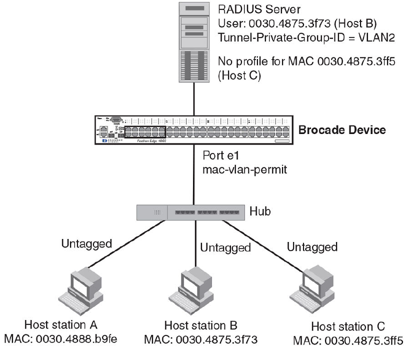
FIGURE 6 Sample MAC-based VLAN configuration
Host A MAC address is statically mapped to VLAN 1 with priority 1 and is not subjected to RADIUS
authentication. When Host B MAC address is authenticated, the Access-Accept message from the
RADIUS server specifies that Host B MAC address be placed into VLAN 2. Since Host C MAC
address is not present in the RADIUS server, Host C will be rejected by the server and its MAC
address will be placed into a restricted VLAN.
Below is the configuration for this example.
module 1 fcx-48-port-management-module
module 2 fcx-xfp-1-cx4-1-port-10g-module
vlan 1 by port
untagged ethe 0/1/10
mac-vlan-permit ethe 0/1/1 to 0/1/2
no spanning-tree
vlan 2 by port
untagged ethe 0/1/30
mac-vlan-permit ethe 0/1/1 to 0/1/2
no spanning-tree
vlan 666 name mac_restricted by port
untagged ethe 0/1/20
mac-vlan-permit ethe 0/1/1 to 0/1/2
no spanning-tree
vlan 4000 name DEFAULT-VLAN by port
no spanning-tree
vlan 4004 by port
mac-vlan-permit ethe 0/1/1
default-vlan-id 4000
ip address 10.44.3.8 255.255.255.0
ip default-gateway 10.44.3.1
MAC-based VLANs
220 FastIron Ethernet Switch Security Configuration Guide
53-1003405-04
radius-server host 10.44.3.111
radius-server key 1 $-ndUno
mac-authentication enable
mac-authentication max-age 60
mac-authentication hw-deny-age 30
mac-authentication auth-passwd-format xxxx.xxxx.xxxx
interface ethernet 0/1/1
mac-authentication mac-vlan max-mac-entries 5
mac-authentication mac-vlan 0000.0088.b9fe vlan 1 priority 1
mac-authentication mac-vlan enable
!
interface ethernet 0/1/2
mac-authentication mac-vlan max-mac-entries 5
mac-authentication mac-vlan enable
!
!
end
The show table-mac-vlan command returns the following results for all ports in this configuration.
device#show table-mac-vlan
---------------------------------------------------------------
Port Vlan Accepted Rejected Attempted Static Static Max
Macs Macs Macs Macs Conf Macs
----------------------------------------------------------------
0/1/1 N/A 2 1 0 1 1 5
0/1/2 N/A 0 0 0 0 0 5
The show table-mac-vlan e 0/1/1 command returns the following results for port 0/1/1 in this
configuration.
device#show table-mac-vlan e 0/1/1
-------------------------------------------------------------------------------
MAC Address Port Vlan Authenticated Time Age CAM MAC Dot1x Type Pri
Index Index
-------------------------------------------------------------------------------
0000.0075.3f73 0/1/1 2 Yes 00d00h00m46s S32 0001 3728 Dis Dyn 4
0000.0088.b9fe 0/1/1 1 Yes 00d00h00m08s Dis 0000 0970 Dis Sta 1
0000.0075.3ff5 0/1/1 666 Rst 01d18h47m58s S8 0002 1ee4 Dis Dyn 0
MAC-based VLANs
FastIron Ethernet Switch Security Configuration Guide 221
53-1003405-04
Sample MAC-based VLAN application
222 FastIron Ethernet Switch Security Configuration Guide
53-1003405-04
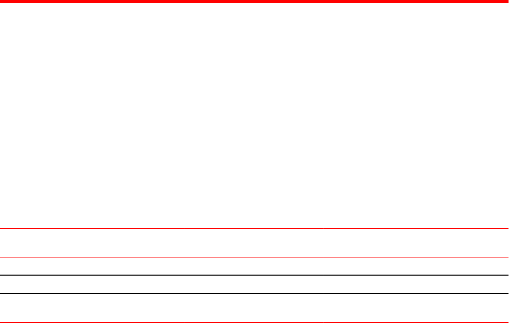
Defining MAC Address Filters
● Supported MAC address filter features......................................................................... 223
● MAC address filters configuration notes and limitations............................................... 223
● MAC address filters command syntax...........................................................................224
● Enabling logging of management traffic permitted by MAC address filters...................225
● Configuring MAC filter accounting.................................................................................226
● MAC address filter override for 802.1X-enabled ports.................................................. 227
Supported MAC address filter features
Lists MAC address filter features supported on FastIron devices.
The following table lists individual Brocade switches and the MAC address filter features they support.
Feature ICX 6430 ICX 6450 FCX ICX 6610 ICX 6650 FSX 800
FSX 1600
ICX 7450 ICX 7750
MAC accounting No 08.0.10a 08.0.10a 08.0.10a 08.0.10a 08.0.10a 08.0.20 08.0.10a
MAC address filtering 08.0.01 08.0.01 08.0.01 08.0.01 08.0.01 08.0.01 08.0.20 08.0.10
MAC address filter override of
802.1X
08.0.01 08.0.01 08.0.01 08.0.01 08.0.01 08.0.01 08.0.20 08.0.10
MAC address filters configuration notes and limitations
• MAC address filtering on FastIron devices is performed in hardware.
• MAC address filtering on FastIron devices differ from other Brocade devices in that you can only filter
on source and destination MAC addresses. Other Brocade devices allow you to also filter on the
encapsulation type and frame type.
• MAC address filtering applies to all traffic, including management traffic. To exclude management
traffic from being filtered, configure a MAC address filter that explicitly permits all traffic headed to the
management MAC (destination) address. The MAC address for management traffic is always the
MAC address of port 1.
• MAC address filters that have a global deny statement can cause the device to block all BPDUs. In
this case, include exception statements for control protocols in the MAC address filter configuration.
• MAC address filtering cannot be applied on management interface for all platforms.
The following configuration notes apply to Brocade Layer 3 devices:
• MAC address filters apply to both switched and routed traffic. If a routing protocol (for example,
OSPF) is configured on an interface, the configuration must include a MAC address filter rule that
allows the routing protocol MAC and the neighbor system MAC address.
• You cannot use MAC address filters to filter Layer 4 information.
• MAC address filters are supported on tagged ports in the Layer 3 software images.
FastIron Ethernet Switch Security Configuration Guide 223
53-1003405-04

MAC address filters command syntax
To configure and apply a MAC address filter, enter commands such as the following.
device(config)# mac filter 1 deny 0000.0075.3676 ffff.0000.0000
device(config)# mac filter 2 deny any ffff.ffff.ffff ffff.ffff.ffff
device(config)# mac filter 3 deny any 0180.c200.0000 ffff.ffff.fff0
device(config)# mac filter 4 deny any 0000.0034.5678 ffff.ffff.ffff
device(config)# mac filter 5 deny any 0000.0045.6789 ffff.ffff.ffff
device(config)# mac filter 1024 permit any any
device(config)# int e 1
device(config-if-e1000-1)# mac filter-group 1 to 5 1024
These commands configure filter 1 to deny traffic with a source MAC address that begins with "3565"
to any destination, and configure filters 2 through 5 to deny traffic with the specified destination MAC
addresses. Filter 1024 permits all traffic that is not denied by any other filter.
NOTE
Once you apply a MAC address filter to a port, the device drops all Ethernet traffic on the port that
does not match a MAC permit filter on the port.
Syntax: [no] mac filter filter-num { permit | deny } [ src-mac mask | any ] [ dest-mac mask | any ]
You can configure up to 507 MAC filters for filter-num. The default value is 512.
The permit or deny argument determines the action the software takes when a match occurs.
The src-mac mask | any parameter specifies the source MAC address. You can enter a specific
address value and a comparison mask or the keyword any to filter on all MAC addresses. Specify the
mask using f (ones) and zeros. For example, to match on the first two bytes of the address
aabb.ccdd.eeff, use the mask ffff.0000.0000. In this case, the filter matches on all MAC addresses that
contain "aabb" as the first two bytes. The filter accepts any value for the remaining bytes of the MAC
address. If you specify any , do not specify a mask. In this case, the filter matches on all MAC
addresses.
The dest-mac mask | any parameter specifies the destination MAC address. The syntax rules are the
same as those for the src-mac mask | any parameter.
Syntax: no mac filter log-enable
Globally enables logging for filtered packets.
Syntax: no mac filter-group log-enable
Enables logging for filtered packets on a specific port.
Syntax: [no] mac filter-group filter-number [ to filter-number | filter-number ... ]
Applies MAC address filters to a port.
When applying the filter-group to the interface, specify each line to be applied separately or use the to
keyword to apply a consecutive range of filter lines, for example, 1 3 to 8 10.
NOTE
The filters must be applied as a group. For example, if you want to apply four filters to an interface,
they must all appear on the same command line.
MAC address filters command syntax
224 FastIron Ethernet Switch Security Configuration Guide
53-1003405-04

NOTE
You cannot add or remove individual filters in the group. To add or remove a filter on an interface, apply
the filter group again containing all the filters you want to apply to the port.
NOTE
If you apply a filter group to a port that already has a filter group applied, the older filter group is
replaced by the new filter group.
When a MAC address filter is applied to or removed from an interface, a Syslog message such as the
following is generated.
SYSLOG: <14>Jan 1 00:00:00 10.44.9.11 MAC Filter applied to port 0/1/2 by tester from
telnet session (filter id=5 ).
SYSLOG: <14>Jan 1 00:00:00 10.44.9.11 MAC Filter removed from port 0/1/2 by tester
from telnet session (filter id=5 ).
The Syslog messages indicate that a MAC address filter was applied to the specified port by the
specified user during the specified session type. Session type can be Console, Telnet, SSH, Web,
SNMP, or others. The filter IDs that were added or removed are listed.
Enabling logging of management traffic permitted by MAC address
filters
You can configure the Brocade device to generate Syslog entries and SNMP traps for management
traffic that is permitted by MAC address filters. Management traffic applies to packets that are destined
for the CPU, such as control packets. You can enable logging of permitted management traffic on a
global basis or an individual port basis.
The first time an entry in a MAC address filter permits a management packet and logging is enabled for
that entry, the software generates a Syslog message and an SNMP trap. Messages for management
packets permitted by MAC address filters are at the warning level of the Syslog.
When the first Syslog entry for a management packet permitted by a MAC address filter is generated,
the software starts a five-minute timer. After this, the software sends Syslog messages every five
minutes. The messages list the number of management packets permitted by each MAC address filter
during the previous five-minute interval. If a MAC address filter does not permit any packets during the
five-minute interval, the software does not generate a Syslog entry for that MAC address filter.
NOTE
For a MAC address filter to be eligible to generate a Syslog entry for permitted management packets,
logging must be enabled for the filter. The Syslog contains entries only for the MAC address filters that
permit packets and have logging enabled.
When the software places the first entry in the log, the software also starts the five-minute timer for
subsequent log entries. Thus, five minutes after the first log entry, the software generates another log
entry and SNMP trap for permitted management packets.
Enabling logging of management traffic permitted by MAC address filters
FastIron Ethernet Switch Security Configuration Guide 225
53-1003405-04
MAC address filter logging command syntax
To configure MAC address filter logging globally, enter the following CLI commands at the global
CONFIG level.
device(config)#mac filter log-enable
device(config)#write memory
Syntax: [no] mac filter log-enable
To configure MAC address filter logging for MAC address filters applied to ports 1 and 3, enter the
following CLI commands.
device(config)#int ethernet 1
device(config-if-e1000-1)#mac filter-group log-enable
device(config-if-e1000-1)#int ethernet 3
device(config-if-e1000-3)#mac filter-group log-enable
device(config-if-e1000-3)#write memory
Syntax: [no] mac filter-group log-enable
Configuring MAC filter accounting
Steps to configure and display Layer 2 MAC filter accounting
For FastIron devices, ACL accounting is supported on Layer 2 MAC filters.
1. To enable ACL accounting on a Layer 2 MAC filter, use the mac filter in the global configuration
mode.
2. To display MAC accounting information, use the show access list accounting command. The
accounting statistics is collected every five seconds and is synchronized to remote unit(s) every one
minute.
device#show access-list accounting ethernet 3/1/2 in
MAC Filters Accounting Information
0: DA ANY SA 0000.0000.0001 - MASK FFFF.FFFF.FFFF
action to take : DENY
Hit Count: (1Min) 0 (5Sec) 0
(PktCnt) 0 (ByteCnt) 0
-------------------------------------------------------
65535: Implicit Rule deny any any
Hit Count: (1Min) 5028 (5Sec) 2129
(PktCnt) 5028 (ByteCnt) 643584
--------------------------------------------------------
3. To clear ACL accounting statistics for ACLs configured, choose one of the following options.
• For ACLs configured on a specific interface, use the clear access list accounting command in
the global configuration mode.
• For all ACLs configured in the device, use the clear access list accounting all command in the
global configuration mode.
device(config)#clear access-list accounting ethernet 1/5 in
device(config)#clear access list accounting all
The following example shows MAC filter "10" on which ACL accounting is enabled.
device(config)#mac filter 10 enable-accounting
MAC address filter logging command syntax
226 FastIron Ethernet Switch Security Configuration Guide
53-1003405-04
MAC address filter override for 802.1X-enabled ports
The MAC address filtering feature on an 802.1X-enabled port allows 802.1X and non-802.1X devices to
share the same physical port. For example, this feature enables you to connect a PC and a non-802.1X
device, such as a Voice Over IP (VOIP) phone, to the same 802.1X-enabled port on the Brocade
device. The IP phone will bypass 802.1X authentication and the PC will require 802.1X authentication.
To enable this feature, first create a MAC address filter, then bind it to an interface on which 802.1X is
enabled. The MAC address filter includes a mask that can match on any number of bytes in the MAC
address. The mask can eliminate the need to enter MAC addresses for all non-802.1X devices
connected to the Brocade device, and the ports to which these devices are connected.
MAC address filter override configuration notes
• This feature is supported on untagged, tagged, and dual-mode ports.
• You can configure this feature on ports that have ACLs and MAC address filters defined.
Configuring MAC address filter override
The dot1x auth-filter command binds the MAC address filters to a port.
To configure MAC address filter override on an 802.1X-enabled port, follow these steps.
1. Enter the dot1x configuration mode.
2. Enter the specific interface configuration and enter the dot1x auth-filter command followed by the
parameters id and vlan.
The example shows configuring MAC address filter override.
device(config)# interface ethernet 1/1/1
device(config-if-e1000-1/1/1)# dot1x auth-filter <id> vlan <vlan>
MAC address filter override for 802.1X-enabled ports
FastIron Ethernet Switch Security Configuration Guide 227
53-1003405-04
Configuring MAC address filter override
228 FastIron Ethernet Switch Security Configuration Guide
53-1003405-04

802.1X Port Security for ICX 6650 and FSX Devices
● Supported 802.1X port security features.......................................................................229
● IETF RFC support ........................................................................................................ 230
● How 802.1X port security works....................................................................................230
● 802.1X port security configuration.................................................................................240
● 802.1X accounting configuration...................................................................................260
● Displaying 802.1X information...................................................................................... 261
● Sample 802.1X configurations...................................................................................... 271
● Multi-device port authentication and 802.1Xsecurity on the same port ........................276
Supported 802.1X port security features
Lists the 802.1X port security features supported on FastIron devices
The following table lists individual Brocade switches and the 802.1X port security features they support.
These features are supported in the Layer 2 and Layer 3 software images, except where explicitly
noted.
NOTE
The 802.1x Port Security feature configurations described in this chapter are applicable to the ICX 6650
and FCX devices only. Refer to 802.1x Port Security section in the "Flexible Authentication" chapter for
information on 802.1x Port Security configuration on Flexible Authentication supported devices.
Feature ICX 6430 ICX 6450 FCX ICX 6610 ICX 6650 FSX 800
FSX 1600
ICX 7450 ICX 7750
802.1X port security 08.0.01 08.0.01 08.0.01 08.0.01 08.0.01 08.0.01 08.0.20 08.0.10
EAP pass-through support 08.0.01 08.0.01 08.0.01 08.0.01 08.0.01 08.0.01 08.0.20 08.0.10
802.1X accounting 08.0.01 08.0.01 08.0.01 08.0.01 08.0.01 08.0.01 08.0.20 08.0.10
802.1X dynamic assignment for
ACL, MAC address filter, and VLAN
08.0.01 08.0.01 08.0.01 08.0.01 08.0.01 08.0.01 08.0.20 08.0.10
Automatic removal of Dynamic
VLAN for 802.1X ports
08.0.01 08.0.01 08.0.01 08.0.01 08.0.01 08.0.01 08.0.20 08.0.10
RADIUS timeout action 08.0.01 08.0.01 08.0.01 08.0.01 08.0.01 08.0.01 08.0.20 08.0.10
802.1X and multi-device port
authentication on the same port
08.0.01 08.0.01 08.0.01 08.0.01 08.0.01 08.0.01 08.0.20 08.0.10
802.1X and sFlow: 802.1X user
name export support for encrypted
and non-encrypted EAP types
08.0.01 08.0.01 08.0.01 08.0.01 08.0.01 08.0.01 08.0.20 08.0.10
MACsec key-based security4No No No 08.0.20 No No No No
FastIron Ethernet Switch Security Configuration Guide 229
53-1003405-04

IETF RFC support
Brocade FastIron devices support the IEEE 802.1X standard for authenticating devices attached to
LAN ports. Using 802.1X port security, you can configure a FastIron device to grant access to a port
based on information supplied by a client to an authentication server.
When a user logs on to a network that uses 802.1X port security, the Brocade device grants (or does
not grant) access to network services after the user is authenticated by an authentication server. The
user-based authentication in 802.1X port security provides an alternative to granting network access
based on a user IP address, MAC address, or subnetwork.
The Brocade implementation of 802.1X port security supports the following RFCs:
• RFC 2284 PPP Extensible Authentication Protocol (EAP)
• RFC 2865 Remote Authentication Dial In User Service (RADIUS)
• RFC 2869 RADIUS Extensions
How 802.1X port security works
This section explains the basic concepts behind 802.1X port security, including device roles, how the
devices communicate, and the procedure used for authenticating clients.
NOTE
802.1X Port Security cannot be configured on MAC Port Security-enabled ports.
Device roles in an 802.1X configuration
The 802.1X standard defines the roles of Client/Supplicant, Authenticator, and Authentication Server
in a network.
The Client (known as a Supplicant in the 802.1X standard) provides username/password information
to the Authenticator. The Authenticator sends this information to the Authentication Server. Based on
the Client's information, the Authentication Server determines whether the Client can use services
provided by the Authenticator. The Authentication Server passes this information to the Authenticator,
which then provides services to the Client, based on the authentication result.
The following figure illustrates these roles.
4MACsec encryption and related security features are covered in a separate chapter, MACsec Key-based Security.
IETF RFC support
230 FastIron Ethernet Switch Security Configuration Guide
53-1003405-04
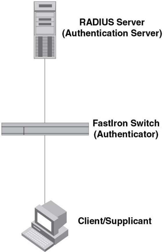
FIGURE 7 Authenticator, client/supplicant, and authentication server in an 802.1X configuration
Authenticator - The device that controls access to the network. In an 802.1X configuration, the
Brocade device serves as the Authenticator. The Authenticator passes messages between the Client
and the Authentication Server. Based on the identity information supplied by the Client, and the
authentication information supplied by the Authentication Server, the Authenticator either grants or does
not grant network access to the Client.
Client/Supplicant - The device that seeks to gain access to the network. Clients must be running
software that supports the 802.1X standard (for example, the Windows XP operating system). Clients
can either be directly connected to a port on the Authenticator, or can be connected by way of a hub.
Authentication server - The device that validates the Client and specifies whether or not the Client
may access services on the device. Brocade supports Authentication Servers running RADIUS.
802.1X Port Security for ICX 6650 and FSX Devices
FastIron Ethernet Switch Security Configuration Guide 231
53-1003405-04
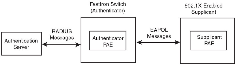
Communication between the devices
For communication between the devices, 802.1X port security uses the Extensible Authentication
Protocol (EAP), defined in RFC 2284. The 802.1X standard specifies a method for encapsulating EAP
messages so that they can be carried over a LAN. This encapsulated form of EAP is known as EAP
over LAN (EAPOL). The standard also specifies a means of transferring the EAPOL information
between the Client/Supplicant, Authenticator, and Authentication Server.
EAPOL messages are passed between the Port Access Entity (PAE) on the Supplicant and the
Authenticator. The following figure shows the relationship between the Authenticator PAE and the
Supplicant PAE.
FIGURE 8 Authenticator PAE and supplicant PAE
Authenticator PAE - The Authenticator PAE communicates with the Supplicant PAE, receiving
identifying information from the Supplicant. Acting as a RADIUS client, the Authenticator PAE passes
the Supplicant information to the Authentication Server, which decides whether the Supplicant can
gain access to the port. If the Supplicant passes authentication, the Authenticator PAE grants it access
to the port.
Supplicant PAE - The Supplicant PAE supplies information about the Client to the Authenticator PAE
and responds to requests from the Authenticator PAE. The Supplicant PAE can also initiate the
authentication procedure with the Authenticator PAE, as well as send log off messages.
Controlled and uncontrolled ports
A physical port on the device used with 802.1X port security has two virtual access points: a controlled
port and an uncontrolled port. The controlled port provides full access to the network. The uncontrolled
port provides access only for EAPOL traffic between the Client and the Authentication Server. When a
Client is successfully authenticated, the controlled port is opened to the Client. The following figure
illustrates this concept.
Communication between the devices
232 FastIron Ethernet Switch Security Configuration Guide
53-1003405-04

FIGURE 9 Controlled and uncontrolled ports before and after client authentication
Before a Client is authenticated, only the uncontrolled port on the Authenticator is open. The
uncontrolled port allows only EAPOL frames to be exchanged between the Client and the
Authentication Server. The controlled port is in the unauthorized state and allows no traffic to pass
through.
During authentication, EAPOL messages are exchanged between the Supplicant PAE and the
Authenticator PAE, and RADIUS messages are exchanged between the Authenticator PAE and the
Authentication Server.Refer to Message exchange during authentication on page 233 for an example
of this process. If the Client is successfully authenticated, the controlled port becomes authorized, and
traffic from the Client can flow through the port normally.
By default, all controlled ports on the Brocade device are placed in the authorized state, allowing all
traffic. When authentication is activated on an 802.1X-enabled interface, the interface controlled port is
placed initially in the unauthorized state. When a Client connected to the port is successfully
authenticated, the controlled port is then placed in the authorized state until the Client logs off. Refer to
Enabling 802.1X port security on page 251 for more information.
Message exchange during authentication
The following figure illustrates a sample exchange of messages between an 802.1X-enabled Client, a
FastIron switch acting as Authenticator, and a RADIUS server acting as an Authentication Server.
Message exchange during authentication
FastIron Ethernet Switch Security Configuration Guide 233
53-1003405-04

FIGURE 10 Message exchange between client/supplicant, authenticator, and authentication server
In this example, the Authenticator (the FastIron switch) initiates communication with an 802.1X-
enabled Client. When the Client responds, it is prompted for a username (255 characters maximum)
and password. The Authenticator passes this information to the Authentication Server, which
determines whether the Client can access services provided by the Authenticator. When the Client is
successfully authenticated by the RADIUS server, the port is authorized. When the Client logs off, the
port becomes unauthorized again.
The Brocade 802.1X implementation supports dynamic VLAN assignment. If one of the attributes in
the Access-Accept message sent by the RADIUS server specifies a VLAN identifier, and this VLAN is
available on the Brocade device, the client port is moved from its default VLAN to the specified VLAN.
When the client disconnects from the network, the port is placed back in its default VLAN.Refer to
Dynamic VLAN assignment for 802.1X port configuration on page 243 for more information.
If a Client does not support 802.1X, authentication cannot take place. The Brocade device sends EAP-
Request/Identity frames to the Client, but the Client does not respond to them.
When a Client that supports 802.1X attempts to gain access through a non-802.1X-enabled port, it
sends an EAP start frame to the Brocade device. When the device does not respond, the Client
considers the port to be authorized, and starts sending normal traffic.
Brocade devices support Identity and MD5-challenge requests in EAP Request/Response messages
as well as the following 802.1X authentication challenge types:
NOTE
Refer to also EAP pass-through support on page 236.
• EAP-TLS (RFC 2716) - EAP Transport Level Security (TLS) provides strong security by requiring
both client and authentication server to be identified and validated through the use of public key
infrastructure (PKI) digital certificates. EAP-TLS establishes a tunnel between the client and the
802.1X Port Security for ICX 6650 and FSX Devices
234 FastIron Ethernet Switch Security Configuration Guide
53-1003405-04

authentication server to protect messages from unauthorized users’ eavesdropping activities. Since
EAP-TLS requires PKI digital certificates on both the clients and the authentication servers, the roll
out, maintenance, and scalability of this authentication method is much more complex than other
methods. EAP-TLS is best for installations with existing PKI certificate infrastructures.
• EAP-TTLS (Internet-Draft) - The EAP Tunnelled Transport Level Security (TTLS) is an extension of
EAP-TLS Like TLS, EAP-TTLS provides strong authentication; however it requires only the
authentication server to be validated by the client through a certificate exchange between the server
and the client. Clients are authenticated by the authentication server using user names and
passwords.
A TLS tunnel can be used to protect EAP messages and existing user credential services such as
Active Directory, RADIUS, and LDAP. Backward compatibility for other authentication protocols such as
PAP, CHAP, MS-CHAP, and MS-CHAP-V2 are also provided by EAP-TTLS. EAP-TTLS is not
considered foolproof and can be fooled into sending identity credentials if TLS tunnels are not used.
EAP-TTLS is suited for installations that require strong authentication without the use of mutual PKI
digital certificates.
• PEAP (Internet-Draft) - Protected EAP Protocol (PEAP) is an Internet-Draft that is similar to EAP-
TTLS. PEAP client authenticates directly with the backend authentication server. The authenticator
acts as a pass-through device, which does not need to understand the specific EAP authentication
protocols.
Unlike EAP-TTLS, PEAP does not natively support user name and password to authenticate clients
against an existing user database such as LDAP. PEAP secures the transmission between the client
and authentication server with a TLS encrypted tunnel. PEAP also allows other EAP authentication
protocols to be used. It relies on the mature TLS keying method for its key creation and exchange.
PEAP is best suited for installations that require strong authentication without the use of mutual
certificates.
Configuration for these challenge types is the same as for the EAP-MD5 challenge type.
NOTE
If the 802.1X Client will be sending a packet that is larger than 1500 bytes, you must enable jumbo at
the Global config level of the CLI. If the supplicant or the RADIUS server does not support jumbo
frames and jumbo is enabled on the switch, you can set the CPU IP MTU size. Refer to Setting the IP
MTU size on page 235, next.
Setting the IP MTU size
When jumbo frames are enabled on a FastIron device and the certificate in use is larger than the
standard packet size of 1500 bytes, 802.1X authentication will not work if the supplicant or the RADIUS
server does not support jumbo frames. In this case, you can change the IP MTU setting so that the
certificate will be fragmented before it is forwarded to the supplicant or server for processing. This
feature is supported in the Layer 2 switch code only. It is not supported in the Layer 3 router code.
To enable this feature, enter commands such as the following:
device(config)# interface ethernet 3/1
Brocade(config-if-e1000-3/1)# ip mtu 1500
Syntax: [no] ip mtu num
The num parameter specifies the MTU. Ethernet II packets can hold IP packets from 576 - 1500 bytes
long. If jumbo mode is enabled, Ethernet II packets can hold IP packets from 576 - 10,218 bytes long.
Ethernet SNAP packets can hold IP packets from 576 - 1492 bytes long. If jumbo mode is enabled,
SNAP packets can hold IP packets from 576 to 10,200 bytes long. The default MTU is 1500 for Ethernet
II packets and 1492 for SNAP packets.
Setting the IP MTU size
FastIron Ethernet Switch Security Configuration Guide 235
53-1003405-04

NOTE
IP MTU cannot be configured globally.
EAP pass-through support
EAP pass-through is supported on FastIron devices that have 802.1X enabled. EAP pass-through
support is fully compliant with RFC 3748, in which, by default, compliant pass-through authenticator
implementations forward EAP challenge request packets of any type, including those listed in the
previous section.
If the 802.1X supplicant or authentication server will be sending packets that are greater than 1500
MTU, you should configure the device to accommodate a larger buffer size, in order to reduce
problems during initial setup. Refer to the FastIron Ethernet Switch Layer 3 Routing Configuration
Guide.
Support for RADIUS user-name attribute in access-accept messages
Brocade 802.1X-enabled ports support the RADIUS user-name (type 1) attribute in the Access-Accept
message returned during 802.1X authentication.
This feature is useful when the client/supplicant does not provide its user-name in the EAP-response/
identity frame, and the username is key to providing useful information. For example, when the user-
name attribute is sent in the Access-Accept message, it is then available for display in sFlow sample
messages sent to a collector, and in the output of some show dot1x CLI commands, such as show
dot1x mac-sessions.
This same information is sent as the "user-name" attribute of RADIUS accounting messages, and is
sent to the RADIUS accounting servers.
To enable this feature, add the following attribute on the RADIUS server.
Attribute name Type Value
user-name 1 name (string)
Authenticating multiple hosts connected to the same port
Brocade devices support 802.1X authentication for ports with more than one host connected to them.
The following figure illustrates a sample configuration where multiple hosts are connected to a single
802.1X port.
EAP pass-through support
236 FastIron Ethernet Switch Security Configuration Guide
53-1003405-04
FIGURE 11 Multiple hosts connected to a single 802.1X-enabled port
If there are multiple hosts connected to a single 802.1X-enabled port, the Brocade device authenticates
each of them individually. Each host authentication status is independent of the others, so that if one
authenticated host disconnects from the network, it has no effect on the authentication status of any of
the other authenticated hosts.
By default, traffic from hosts that cannot be authenticated by the RADIUS server is dropped in
hardware. You can optionally configure the Brocade device to assign the port to a "restricted" VLAN if
authentication of the Client is unsuccessful.
How 802.1X host authentication works
When multiple hosts are connected to a single 802.1X-enabled port on a Brocade device, 802.1X
authentication is performed in the following way.
How 802.1X host authentication works
FastIron Ethernet Switch Security Configuration Guide 237
53-1003405-04
1. One of the 802.1X-enabled Clients attempts to log into a network in which a Brocade device serves
as an Authenticator.
2. The Brocade device creates an internal session (called a dot1x-mac-session) for the Client. A
dot1x-mac-session serves to associate a Client MAC address and username with its authentication
status.
3. The Brocade device performs 802.1X authentication for the Client. Messages are exchanged
between the Brocade device and the Client, and between the device and the Authentication Server
(RADIUS server). The result of this process is that the Client is either successfully authenticated or
not authenticated, based on the username and password supplied by the client.
4. If the Client is successfully authenticated, the Client dot1x-mac-session is set to "access-is-
allowed". This means that traffic from the Client can be forwarded normally.
5. If authentication for the Client is unsuccessful the first time, multiple attempts to authenticate the
client will be made as determined by the attempts variable in the auth-fail-max-attempts
command.
• Refer to the Specifying the number of authentication attempts the device makes before dropping
packets section for information on how to do this.
6. If authentication for the Client is unsuccessful more than the number of times specified by the
attempts variable in the auth-fail-max-attempts command, an authentication-failure action is taken.
The authentication-failure action can be either to drop traffic from the Client, or to place the port in a
"restricted" VLAN:
• If the authentication-failure action is to drop traffic from the Client, then the Client dot1x-mac-
session is set to "access-denied", causing traffic from the Client to be dropped in hardware.
• If the authentication-failure action is to place the port in a "restricted" VLAN, If the Client dot1x-
mac-session is set to "access-restricted" then the port is moved to the specified restricted VLAN,
and traffic from the Client is forwarded normally.
7. When the Client disconnects from the network, the Brocade device deletes the Client dot1x-mac-
session. This does not affect the dot1x-mac-session or authentication status (if any) of the other
hosts connected on the port.
Configuration notes for 802.1x multiple-host authentication
• The Client dot1x-mac-session establishes a relationship between the username and MAC address
used for authentication. If a user attempts to gain access from different Clients (with different MAC
addresses), he or she would need to be authenticated from each Client.
• If a Client has been denied access to the network (that is, the Client dot1x-mac-session is set to
"access-denied"), then you can cause the Client to be re-authenticated by manually disconnecting
the Client from the network, or by using the clear dot1x mac-session command. Refer to the
Clearing a dot1x-mac-session for a MAC address section for information on this command.
• When a Client has been denied access to the network, its dot1x-mac-session is aged out if no traffic
is received from the Client MAC address over a fixed hardware aging period (70 seconds), plus a
configurable software aging period. You can optionally change the software aging period for dot1x-
mac-sessions or disable aging altogether. After the denied Client dot1x-mac-session is aged out,
traffic from that Client is no longer blocked, and the Client can be re-authenticated.
In addition, you can configure disable aging for the dot1x-mac-session of Clients that have been
granted either full access to the network, or have been placed in a restricted VLAN. After a Client
dot1x-mac-session ages out, the Client must be re-authenticated.Refer to the Disabling aging for
dot1x-mac-sessions section for more information.
• Dynamic IP ACL and MAC address filter assignment is supported in an 802.1X multiple-host
configuration. Refer to Dynamically applying IP ACLs and MAC address filters to 802.1X ports on
page 247.
• 802.1X multiple-host authentication has the following additions:
802.1X Port Security for ICX 6650 and FSX Devices
238 FastIron Ethernet Switch Security Configuration Guide
53-1003405-04
‐Configurable hardware aging period for denied client dot1x-mac-sessions. Refer to Configurable
hardware aging period for denied client dot1x-mac-sessions on page 239.
‐Dynamic ACL and MAC address filter assignment in 802.1X multiple-host configurations. Refer to
Dynamically applying IP ACLs and MAC address filters to 802.1X ports on page 247.
‐Dynamic multiple VLAN assignment for 802.1X ports. Refer Dynamic multiple VLAN assignment
for 802.1X ports on page 245.
‐Configure a restriction to forward authenticated and unauthenticated tagged and untagged clients
to a restricted VLAN.
‐Configure an override to send failed dot1x and non-dot1x clients to a restricted VLAN.
‐Configure VLAN assignments for clients attempting to gain access through dual-mode ports.
‐Enhancements to some show commands.
‐Differences in command syntax for saving dynamic VLAN assignments to the startup-config file.
How 802.1x host authentication works for multiple clients
Authenticating devices on a port involves assigning VLAN IDs, dynamically or otherwise.
Authentication of multiple 802.1x-enabled clients on a single 802.1X-enabled port on a Brocade device
is performed in the following way.
• The first 802.1x-enabled client logs on to the network in which a Brocade device serves as an
authenticator. If a VLAN ID or name is included in a Radius Access-Accept message, Port is moved
to that VLAN and Port's operation VLAN is changed to that of Radius-assigned VLAN.
• Subsequent 802.1x-enabled clients log on the network and are authorized with a VLAN ID that
matches the VLAN ID or name provided by the Radius Access-Accept message for the first host. If
an 802.1x-enabled client gets a different VLAN ID or name in the Radius Access-Accept message, it
is an authentication failure. If a restricted VLAN is configured as an action for failed authentication, all
the hosts, including the successfully authenticated clients, are placed in the restricted VLAN. If the
failure action is to block the client's MAC, only the failed client is blocked.
• Even if subsequent 802.1x-enabled clients do not receive VLAN information from Radius, clients
authorized later still use the operational VLAN of the port. See the Dynamic multiple VLAN
assignment for 802.1X ports section for more information on restrictions for dynamic VLAN
assignment.
• However, ACLs received in Radius Access-Accept messages are applied to each 802.1x-enabled
clients separately. In a multi-host scenario some clients might have a dynamic ACL and some not. If
there are dynamic ACL for any clients, access control is applied only to clients with dynamic ACLs
See the Dynamically applying IP ACLs and MAC address filters to 802.1X ports section for more
information on restrictions on dynamic IP ACLs or MAC address filters.
Configurable hardware aging period for denied client dot1x-mac-sessions
When one of the 802.1X-enabled Clients in a multiple-host configuration attempts to log into a network
in which a Brocade device serves as an Authenticator, the device creates a dot1x-mac-session for the
Client.
When a Client has been denied access to the network, its dot1x-mac-session is aged out if no traffic is
received from the Client MAC address over a period of time. After a denied Client dot1x-mac-session
ages out, the Client can be re-authenticated. Aging of a denied Client's dot1x-mac-session occurs in
two phases, known as hardware aging and software aging.
The hardware aging period for a denied Client's dot1x-mac-session is not fixed at 70 seconds. The
hardware aging period for a denied Client's dot1x-mac-session is equal to the length of time specified
with the dot1x timeout quiet-period command. By default, the hardware aging time is 60 seconds.
Once the hardware aging period ends, the software aging period begins. When the software aging
period ends, the denied Client's dot1x-mac-session ages out, and the Client can be authenticated
again.
How 802.1x host authentication works for multiple clients
FastIron Ethernet Switch Security Configuration Guide 239
53-1003405-04
802.1X port security and sFlow
sFlow is a standards-based protocol that allows network traffic to be sampled at a user-defined rate for
the purpose of monitoring traffic flow patterns and identifying packet transfer rates on user-specified
interfaces.
When you enable sFlow forwarding on an 802.1X-enabled interface, the samples taken from the
interface include the user name string at the inbound or outbound port, or both, if that information is
available.
For more information on sFlow, refer to chapter "Network Monitoring" in the FastIron Ethernet Switch
Administration Guide .
802.1X accounting
When 802.1X port security is enabled on the Brocade device, you can enable 802.1X accounting. This
feature enables the Brocade device to log information on the RADIUS server about authenticated
802.1X clients. The information logged on the RADIUS server includes the 802.1X client session ID,
MAC address, and authenticating physical port number.
802.1X accounting works as follows.
1. A RADIUS server successfully authenticates an 802.1X client.
2. If 802.1X accounting is enabled, the Brocade device sends an 802.1X Accounting Start packet to
the RADIUS server, indicating the start of a new session.
3. The RADIUS server acknowledges the Accounting Start packet.
4. The RADIUS server records information about the client.
5. When the session is concluded, the Brocade device sends an Accounting Stop packet to the
RADIUS server, indicating the end of the session.
6. The RADIUS server acknowledges the Accounting Stop packet.
To enable 802.1X accounting, refer to 802.1X accounting configuration on page 260.
802.1X port security configuration
Configuring 802.1X port security on a Brocade device consists of the following tasks.
1. Configure the device interaction with the Authentication Server:
•‐Configuring an authentication method list for 802.1x on page 241
‐Setting RADIUS parameters on page 241
‐Dynamic VLAN assignment for 802.1X port configuration on page 243 (optional)
‐Dynamically applying IP ACLs and MAC address filters to 802.1X ports on page 247
2. Configure the device role as the Authenticator:
•‐Enabling 802.1X port security on page 251
‐Initializing 802.1X on a port on page 256 (optional)
3. Configure the device interaction with Clients:
•‐Configuring periodic re-authentication on page 253 (optional)
‐Re-authenticating a port manually on page 253 (optional)
‐Setting the quiet period on page 253 (optional)
‐Setting the wait interval for EAP frame retransmissions on page 254 (optional)
802.1X port security and sFlow
240 FastIron Ethernet Switch Security Configuration Guide
53-1003405-04

‐Setting the maximum number of EAP frame retransmissions on page 254 (optional)
‐Specifying a timeout for retransmission of messages to the authentication server on page 255
(optional)
‐Allowing access to multiple hosts on page 256 (optional)
‐MAC address filters for EAP frames on page 259 (optional)
Configuring an authentication method list for 802.1x
To use 802.1X port security, you must specify an authentication method to be used to authenticate
Clients. Brocade supports RADIUS authentication with 802.1X port security. To use RADIUS
authentication with 802.1X port security, you create an authentication method list for 802.1X and specify
RADIUS as an authentication method, then configure communication between the Brocade device and
RADIUS server.
Brocade(config)#aaa authentication dot1x default radius
Syntax: [no] aaa authentication dot1x default method-list
For the method-list , enter at least one of the following authentication methods
radius - Use the list of all RADIUS servers that support 802.1X for authentication.
none - Use no authentication. The Client is automatically authenticated by other means, without the
device using information supplied by the Client.
NOTE
If you specify both radius and none , make sure radius comes before none in the method list.
Setting RADIUS parameters
To use a RADIUS server to authenticate access to a Brocade device, you must identify the server to the
Brocade device.
device(config)#radius-server host 10.157.22.99 auth-port 1812 acct-port 1813
default key mirabeau dot1x
Syntax: radius-server { hostip-addr | ipv6-addr | server-name } [ auth-port num | acct-port num |
default ] [ key {0 | 2 } string ] [ dot1x ]
The host ip-addr , ipv6-addr or server-name parameters are either an IP address or an ASCII text string.
The dot1x parameter indicates that this RADIUS server supports the 802.1X standard. A RADIUS
server that supports the 802.1X standard can also be used to authenticate non-802.1X authentication
requests.
NOTE
To implement 802.1X port security, at least one of the RADIUS servers identified to the Brocade device
must support the 802.1X standard.
Configuring an authentication method list for 802.1x
FastIron Ethernet Switch Security Configuration Guide 241
53-1003405-04
Supported RADIUS attributes
Many IEEE 802.1X Authenticators will function as RADIUS clients. Some of the RADIUS attributes
may be received as part of IEEE 802.1X authentication. Brocade devices support the following
RADIUS attributes for IEEE 802.1X authentication:
• Username (1) - RFC 2865
• NAS-IP-Address (4) - RFC 2865
• NAS-Port (5) - RFC 2865
• Service-Type (6) - RFC 2865
• FilterId (11) - RFC 2865
• Framed-MTU (12) - RFC 2865
• State (24) - RFC 2865
• Vendor-Specific (26) - RFC 2865
• Session-Timeout (27) - RFC 2865
• Termination-Action (29) - RFC 2865
• Calling-Station-ID (31) - RFC 2865
• NAS-Identifier (32) - RFC 2865
• NAS-Port-Type (61) - RFC 2865
• Tunnel-Type (64) - RFC 2868
• Tunnel-Medium-Type (65) - RFC 2868
• EAP Message (79) - RFC 2579
• Message-Authenticator (80) RFC 3579
• Tunnel-Private-Group-Id (81) - RFC 2868
• NAS-Port-id (87) - RFC 2869
Specifying the RADIUS timeout action
A RADIUS timeout occurs when the Brocade device does not receive a response from a RADIUS
server within a specified time limit and after a certain number of retries. The time limit and number of
retries can be manually configured using the CLI commands radius-server timeout and radius-
server retransmit , respectively. If the parameters are not manually configured, the Brocade device
applies the default value of three seconds time limit with a maximum of three retries.
You can better control port behavior when a RADIUS timeout occurs. That is, you can configure a port
on the Brocade device to automatically pass or fail users being authenticated. A pass essentially
bypasses the authentication process and permits user access to the network. A fail bypasses the
authentication process and blocks user access to the network, unless restrict-vlan is configured, in
which case, the user is placed into a VLAN with restricted or limited access. By default, the Brocade
device will reset the authentication process and retry to authenticate the user.
Specify the RADIUS timeout action at the Interface level of the CLI.
Permit user access to the network after a RADIUS timeout
To set the RADIUS timeout behavior to bypass 802.1X authentication and permit user access to the
network, enter commands such as the following
device(config)#interface ethernet 3/1
device(config-if-e100-3/1)#dot1x auth-timeout-action success
Syntax: [no] dot1x auth-timeout-action success
Once the success timeout action is enabled, use the no form of the command to reset the RADIUS
timeout behavior to retry .
Supported RADIUS attributes
242 FastIron Ethernet Switch Security Configuration Guide
53-1003405-04

Re-authenticate a user
To configure RADIUS timeout behavior to bypass multi-device port authentication and permit user
access to the network, enter commands similar to the following
device(config)#interface ethernet 3/1
device(config-if-e100-3/1)#dot1x re-auth-timeout-success 60
Syntax: no dot1x re-auth-timeout- success seconds
The seconds parameter specifies the number of seconds the device will wait to re-authenticate a user
after a timeout. The minimum value is 10 seconds. The maximum value is 2 16 -1 (maximum unsigned
16-bit value).
Deny user access to the network after a RADIUS timeout
To set the RADIUS timeout behavior to bypass 802.1X authentication and block user access to the
network, enter commands such as the following
device(config)#interface ethernet 3/1
device(config-if-e100-3/1)#dot1x auth-timeout-action failure
Syntax: [no] dot1x auth-timeout-action failure
Once the failure timeout action is enabled, use the no form of the command to reset the RADIUS
timeout behavior to retry .
NOTE
If restrict-vlan is configured along with auth-timeout-action failure, the user will be placed into a VLAN
with restricted or limited access.Refer to Allow user access to a restricted VLAN after a RADIUS timeout
on page 243.
Allow user access to a restricted VLAN after a RADIUS timeout
To set the RADIUS timeout behavior to bypass 802.1X authentication and place the user in a VLAN
with restricted or limited access, enter commands such as the following
device(config)#interface ethernet 3/1
device(config-if-e100-3/1)#dot1x auth-timeout-action failure
Syntax: [no] dot1x auth-timeout-action failure
NOTE
The commands auth-fail-action restrict-vlan and auth-fail-vlanid are supported in the global dot1x
mode and are not supported at the port-level. The failure action of dot1x auth-timeout-action failure
will follow the auth-fail-action defined at the global dot1x level.
Dynamic VLAN assignment for 802.1X port configuration
When a client successfully completes the EAP authentication process, the Authentication Server (the
RADIUS server) sends the Authenticator (the Brocade device) a RADIUS Access-Accept message that
grants the client access to the network. The RADIUS Access-Accept message contains attributes set
for the user in the user's access profile on the RADIUS server.
Allow user access to a restricted VLAN after a RADIUS timeout
FastIron Ethernet Switch Security Configuration Guide 243
53-1003405-04
If one of the attributes in the Access-Accept message specifies a VLAN identifier, and if this VLAN is
available on the Brocade device, the client port is moved from its default VLAN to this specified VLAN.
NOTE
This feature is supported on port-based VLANs only. This feature cannot be used to place an 802.1X-
enabled port into a Layer 3 protocol VLAN.
Automatic removal of dynamic VLAN assignments for 802.1X ports
For increased security, this feature removes any association between a port and a dynamically-
assigned VLAN when all 802.1x sessions for that VLAN have expired on the port.
NOTE
When a show run command is issued during a session, the dynamically-assigned VLAN is not
displayed.
Enable 802.1X VLAN ID support by adding the following attributes to a user profile on the RADIUS
server.
Attribute name Type Value
Tunnel-Type 064 13 (decimal) - VLAN
Tunnel-Medium-Type 065 6 (decimal) - 802
Tunnel-Private-Group-ID 081 vlan-name (string) - either the name or the number of a VLAN configured on the
Brocade device.
The device reads the attributes as follows:
• If the Tunnel-Type or the Tunnel-Medium-Type attributes in the Access-Accept message do not
have the values specified above, the Brocade device ignores the three Attribute-Value pairs. The
client becomes authorized, but the client port is not dynamically placed in a VLAN.
• If the Tunnel-Type or the Tunnel-Medium-Type attributes in the Access-Accept message do have
the values specified above, but there is no value specified for the Tunnel-Private-Group-ID attribute,
the client will not become authorized.
• When the Brocade device receives the value specified for the Tunnel-Private-Group-ID attribute, it
checks whether the vlan-name string matches the name of a VLAN configured on the device. If
there is a VLAN on the device whose name matches the vlan-name string, then the client port is
placed in the VLAN whose ID corresponds to the VLAN name.
• If the vlan-name string does not match the name of a VLAN, the Brocade device checks whether
the string, when converted to a number, matches the ID of a VLAN configured on the device. If it
does, then the client port is placed in the VLAN with that ID.
• If the vlan-name string does not match either the name or the ID of a VLAN configured on the
device, then the client will not become authorized.
The show VLAN command displays the VLAN to which an 802.1X-enabled port has been dynamically
assigned, as well as the port from which it was moved (that is, the port default VLAN).Refer to
Displaying dynamically-assigned VLAN information on page 267 for sample output indicating the port
dynamically assigned VLAN.
Automatic removal of dynamic VLAN assignments for 802.1X ports
244 FastIron Ethernet Switch Security Configuration Guide
53-1003405-04
Dynamic multiple VLAN assignment for 802.1X ports
When you add attributes to a user profile on the RADIUS server, the vlan-name value for the Tunnel-
Private-Group-ID attribute can specify the name or number of one or more VLANs configured on the
Brocade device.
For example, to specify one VLAN, configure the following for the vlan-name value in the Tunnel-
Private-Group-ID attribute on the RADIUS server.
"10" or "marketing"
In this example, the port on which the Client is authenticated is assigned to VLAN 10 or the VLAN
named "marketing". The VLAN to which the port is assigned must have previously been configured on
the Brocade device.
Specifying an untagged VLAN
To specify an untagged VLAN, use the following.
"U:10" or "U:marketing"'
When the RADIUS server specifies an untagged VLAN ID, the port default VLAN ID (or PVID) is
changed from the system DEFAULT-VLAN (VLAN 1) to the specified VLAN ID. The port transmits only
untagged traffic on its PVID. In this example, the port PVID is changed from VLAN 1 (the DEFAULT-
VLAN) to VLAN 10 or the VLAN named "marketing".
The PVID for a port can be changed only once through RADIUS authentication. For example, if
RADIUS authentication for a Client causes a port PVID to be changed from 1 to 10, and then RADIUS
authentication for another Client on the same port specifies that the port PVID be moved to 20, then the
second PVID assignment from the RADIUS server is ignored.
If the link goes down, or the dot1x-mac-session for the Client that caused the initial PVID assignment
ages out, then the port reverts back to its original (non-RADIUS-specified) PVID, and subsequent
RADIUS authentication can change the PVID assignment for the port.
If a port PVID is assigned through the multi-device port authentication feature, and 802.1X
authentication subsequently specifies a different PVID, then the PVID specified through 802.1X
authentication overrides the PVID specified through multi-device port authentication.
Specifying a tagged VLAN
To specify a tagged VLAN, use the following.
"T:12;T:20" or "T:12;T:marketing"
In this example, the port is added to VLANs 12 and 20 or VLANs 12 and the VLAN named "marketing".
When a tagged packet is authenticated, and a list of VLANs is specified on the RADIUS server for the
MAC address, then the packet tag must match one of the VLANs in the list in order for the Client to be
successfully authenticated. If authentication is successful, then the port is added to all of the VLANs
specified in the list.
Unlike with a RADIUS-specified untagged VLAN, if the dot1x-mac-session for the Client ages out, the
port membership in RADIUS-specified tagged VLANs is not changed. In addition, if multi-device port
authentication specifies a different list of tagged VLANs, then the port is added to the specified list of
VLANs. Membership in the VLANs specified through 802.1X authentication is not changed.
Specifying an untagged VLAN and multiple tagged VLANs
To specify an untagged VLAN and multiple tagged VLANs, use the following.
"U:10;T:12;T:marketing"
Dynamic multiple VLAN assignment for 802.1X ports
FastIron Ethernet Switch Security Configuration Guide 245
53-1003405-04

When the RADIUS server returns a value specifying both untagged and tagged VLAN IDs, the port
becomes a dual-mode port, accepting and transmitting both tagged traffic and untagged traffic at the
same time. A dual-mode port transmits only untagged traffic on its default VLAN (PVID) and only
tagged traffic on all other VLANs.
In this example, the port VLAN configuration is changed so that it transmits untagged traffic on VLAN
10, and transmits tagged traffic on VLAN 12 and the VLAN named "marketing".
For a configuration example, refer to 802.1X Authentication with dynamic VLAN assignment on page
274.
Saving dynamic VLAN assignments to the running-config file
You can configure the Brocade device to save the RADIUS-specified VLAN assignments to the
device's running-config file. Enter commands such as the following.
device(config)#dot1x-enable
device(config-dot1x)#save-dynamicvlan-to-config
Syntax: save-dynamicvlan-to-config
By default, the dynamic VLAN assignments are not saved to the running-config file. Entering the show
running-config command does not display dynamic VLAN assignments, although they can be
displayed with the show vlan and show authenticated-mac-address detail commands.
NOTE
When this feature is enabled, issuing the command write mem will save any dynamic VLAN
assignments to the startup configuration file.
Considerations for dynamic VLAN assignment in an 802.1X multiple-host configuration
The following considerations apply when a Client in a 802.1X multiple-host configuration is
successfully authenticated, and the RADIUS Access-Accept message specifies a VLAN for the port:
• If the port is not already a member of a RADIUS-specified VLAN, and the RADIUS Access-Accept
message specifies the name or ID of a valid VLAN on the Brocade device, then the port is placed in
that VLAN.
• If the port is already a member of a RADIUS-specified VLAN, and the RADIUS Access-Accept
message specifies the name or ID of a different VLAN, then it is considered an authentication
failure. The port VLAN membership is not changed.
• If the port is already a member of a RADIUS-specified VLAN, and the RADIUS Access-Accept
message specifies the name or ID of that same VLAN, then traffic from the Client is forwarded
normally.
• If the RADIUS Access-Accept message specifies the name or ID of a VLAN that does not exist on
the Brocade device, then it is considered an authentication failure.
• If the port is a tagged or dual-mode port, and the RADIUS Access-Accept message specifies the
name or ID of a valid VLAN on the Brocade device, then the port is placed in that VLAN. If the port
is already a member of the RADIUS-specified VLAN, no further action is taken.
• If the RADIUS Access-Accept message does not contain any VLAN information, the Client dot1x-
mac-session is set to "access-is-allowed". If the port is already in a RADIUS-specified VLAN, it
remains in that VLAN.
Saving dynamic VLAN assignments to the running-config file
246 FastIron Ethernet Switch Security Configuration Guide
53-1003405-04
Dynamically applying IP ACLs and MAC address filters to 802.1X ports
The Brocade 802.1X implementation supports dynamically applying an IP ACL or MAC address filter to
a port, based on information received from an Authentication Server.
When a client/supplicant successfully completes the EAP authentication process, the Authentication
Server (the RADIUS server) sends the Authenticator (the Brocade device) a RADIUS Access-Accept
message that grants the client access to the network. The RADIUS Access-Accept message contains
attributes set for the user in the user's access profile on the RADIUS server.
If the Access-Accept message contains Filter-ID (type 11) or Vendor-Specific (type 26), or both
attributes, the Brocade device can use information in these attributes to apply an IP ACL or MAC
address filter to the authenticated port. This IP ACL or MAC address filter applies to the port for as long
as the client is connected to the network. When the client disconnects from the network, the IP ACL or
MAC address filter is no longer applied to the port. If an IP ACL or MAC address filter had been applied
to the port prior to 802.1X authentication, it is then re-applied to the port.
The Brocade device uses information in the Filter ID and Vendor-Specific attributes as follows:
• Supports dynamic ACLs together with ACL-per-port-per-vlan (ACL filtering based on VLAN
membership or VE port membership).
• 802.1x and dynamic ACLs are supported on tagged, dual-mode, and untagged ports, with or without
virtual Interfaces.
• The Filter-ID attribute can specify the number of an existing IP ACL or MAC address filter configured
on the Brocade device. In this case, the IP ACL or MAC address filter with the specified number is
applied to the port.
• The vendor-specific attribute can specify actual syntax for a Brocade IP ACL or MAC address filter,
which is then applied to the authenticated port. Configuring a Vendor-Specific attribute in this way
allows you to create IP ACLs and MAC address filters that apply to individual users; that is, per-user
IP ACLs or MAC address filters.
• When Multi Device Port Authentication (MDPA) is enabled and RADIUS provides Dynamic ACL, the
Dynamic IP ACL received from the RADIUS will overwrite the MDPA Dynamic IP ACL. In case of a
802.1x authentication failure, MDPA dynamic IP ACL will remain on the port. Also, if the 802.1x
authentication does not return the Dynamic IP ACL, the MDPA dynamic IP ACL will remain on the
port.
• Dynamic IP ACLs can be applied on a port which can have a membership on untagged and tagged
VLANs.
Configuration considerations for applying IP ACLs and MAC address filters to 802.1x ports
The following restrictions apply to dynamic IP ACLs or MAC address filters:
• Inbound dynamic IP ACLs are supported. Outbound dynamic ACLs are not supported.
• Inbound Vendor-Specific attributes are supported. Outbound Vendor-Specific attributes are not
supported.
• A maximum of one IP ACL can be configured in the inbound direction on an interface.
• 802.1X with dynamic MAC filter will work for one client at a time on a port. If a second client tries to
authenticate with 802.1X and dynamic MAC filter, the second client will be rejected.
• MAC address filters cannot be configured in the outbound direction on an interface.
• Concurrent operation of MAC address filters and IP ACLs is not supported.
• A dynamic IP ACL will take precedence over an IP ACL that is bound to an untagged port (port ACL).
When a client authenticates with a dynamic IP ACL, the port ACL will not be applied. Also, future
clients on the same port will authenticate with a dynamic IP ACL or no IP ACL. If no clients on the
port use dynamic ACL, then the port ACL will be applied to all traffic.
• On Layer 3 router code, dynamic IP ACLs are allowed on physical ports when ACL-per-port-per-vlan
is enabled.
Dynamically applying IP ACLs and MAC address filters to 802.1X ports
FastIron Ethernet Switch Security Configuration Guide 247
53-1003405-04

• On Layer 3 router code, dynamic IP ACLs are allowed on tagged and dual-mode ports when ACL
per-port-per-vlan is enabled. If ACL-per-port-per-vlan is not enabled, dynamic IP ACLs are not
allowed on tagged or dual-mode ports.
• Dynamic IP ACLs can be added to tagged/untagged ports in a VLAN with or without a VE, as long
as the tagged/untagged ports do not have configured ACLs assigned to them.
Dynamic IP ACLs will not apply in the following scenarios:
• A port is a tagged/untagged member of VLAN 20. VLAN 20 includes VE 20, and an ACL is bound to
VE 20.
• A port is a tagged/untagged member of VLAN 20. VLAN 20 includes VE 20, and a per-port-per-vlan
ACL is bound to VE 20 and to a subset of ports in VE 20
In the above scenarios, dynamic IP ACL assignment would not apply in either instance, because a
configured ACL is bound to VE 20 on the port. Consequently, the MAC session would fail.
Disabling and enabling strict security mode for dynamic filter assignment
By default, 802.1X dynamic filter assignment operates in strict security mode. When strict security
mode is enabled, 802.1X authentication for a port fails if the Filter-ID attribute contains invalid
information, or if insufficient system resources are available to implement the per-user IP ACLs or
MAC address filters specified in the Vendor-Specific attribute.
When strict security mode is enabled:
• If the Filter-ID attribute in the Access-Accept message contains a value that does not refer to an
existing filter (that is, a MAC address filter or IP ACL configured on the device), then the port will not
be authenticated, regardless of any other information in the message (for example, if the Tunnel-
Private-Group-ID attribute specifies a VLAN on which to assign the port).
• If the Vendor-Specific attribute specifies the syntax for a filter, but there are insufficient system
resources to implement the filter, then the port will not be authenticated.
• If the device does not have the system resources available to dynamically apply a filter to a port,
then the port will not be authenticated.
NOTE
If the Access-Accept message contains values for both the Filter-ID and Vendor-Specific attributes,
then the value in the Vendor-Specific attribute (the per-user filter) takes precedence.
Also, if authentication for a port fails because the Filter-ID attribute referred to a non-existent filter, or
there were insufficient system resources to implement the filter, then a Syslog message is generated.
Disabled strict security mode
When strict security mode is disabled:
• If the Filter-ID attribute in the Access-Accept message contains a value that does not refer to an
existing filter (that is, a MAC address filter or IP ACL configured on the device), then the port is still
authenticated, but no filter is dynamically applied to it.
• If the Vendor-Specific attribute specifies the syntax for a filter, but there are insufficient system
resources to implement the filter, then the port is still authenticated, but the filter specified in the
Vendor-Specific attribute is not applied to the port.
By default, strict security mode is enabled for all 802.1X-enabled interfaces, but you can manually
disable or enable it, either globally or for specific interfaces.
Disabling and enabling strict security mode for dynamic filter assignment
248 FastIron Ethernet Switch Security Configuration Guide
53-1003405-04

Disabling strict security mode globally
To disable strict security mode globally, enter the following commands.
device(config)#dot1x-enable
device(config-dot1x)#no global-filter-strict-security
After you globally disable strict security mode, you can re-enable it by entering the following command.
device(config-dot1x)#global-filter-strict-security
Syntax: [no] global-filter-strict-security
To disable strict security mode for a specific interface, enter commands such as the following.
device(config)#interface e 1
device(config-if-e1000-1)#dot1x disable-filter-strict-security
To re-enable strict security mode for an interface, enter the following command.
device(config-if-e1000-1)#no dot1x disable-filter-strict-security
Syntax: [no] dot1x disable-filter-strict-security
The output of the show dot1x and show dot1x config commands has been enhanced to indicate
whether strict security mode is enabled or disabled globally and on an interface. Refer to Displaying the
status of strict security mode on page 269.
Dynamically applying existing ACLs or MAC address filters
When a port is authenticated using 802.1X security, an IP ACL or MAC address filter that exists in the
running-config on the Brocade device can be dynamically applied to the port. To do this, you configure
the Filter-ID (type 11) attribute on the RADIUS server. The Filter-ID attribute specifies the name or
number of the Brocade IP ACL or MAC address filter.
The following is the syntax for configuring the Filter-ID attribute to refer to a Brocade IP ACL or MAC
address filter.
Value Description
ip.number .in Applies the specified numbered ACL to the 802.1X authenticated port in the inbound direction.
ip.name .in Applies the specified named ACL to the 802.1X authenticated port in the inbound direction.
mac.number .in Applies the specified numbered MAC address filter to the 802.1X authenticated port in the
inbound direction.
The following table lists examples of values you can assign to the Filter-ID attribute on the RADIUS
server to refer to IP ACLs and MAC address filters configured on a Brocade device.
Possible values for the filter ID
attribute on the RADIUS server
ACL or MAC address filter configured on the Brocade device
ip.2.in access-list 2 permit host 10.48.0.3access-list 2 permit 10.0.0.0
0.255.255.255
ip.102.in access-list 102 permit ip 10.0.0.0 0.255.255.255 any
Disabling strict security mode globally
FastIron Ethernet Switch Security Configuration Guide 249
53-1003405-04

Possible values for the filter ID
attribute on the RADIUS server
ACL or MAC address filter configured on the Brocade device
ip.fdry_filter.in ip access-list standard fdry_filter permit host 10.48.0.3
mac.2.in mac filter 2 permit 3333.3333.3333 ffff.ffff.ffff any
mac.3.in mac filter 3 permit 2222.2222.2222 ffff.ffff.ffff any
Notes for dynamically applying ACLs or MAC address filters
• The name in the Filter ID attribute is case-sensitive.
• You can specify only numbered MAC address filters in the Filter ID attribute. Named MAC address
filters are not supported.
• Dynamic ACL filters are supported only for the inbound direction. Dynamic outbound ACL filters are
not supported.
• MAC address filters are supported only for the inbound direction. Outbound MAC address filters are
not supported.
• Dynamically assigned IP ACLs and MAC address filters are subject to the same configuration
restrictions as non-dynamically assigned IP ACLs and MAC address filters.
• If Dynamically assigned IP ACLs already exist, then MAC address filters cannot be applied
dynamically using 802.1X.
• Dynamic IP ACL assignment with 802.1x is not supported in conjunction with any of the following
features:
‐IP source guard
‐Rate limiting
‐Protection against ICMP or TCP Denial-of-Service (DoS) attacks
‐Policy-based routing
‐802.1x dynamic filter
Configuring per-user IP ACLs or MAC address filters
Per-user IP ACLs and MAC address filters make use of the Vendor-Specific (type 26) attribute to
dynamically apply filters to ports. Defined in the Vendor-Specific attribute are Brocade ACL or MAC
address filter statements. When the RADIUS server returns the Access-Accept message granting a
client access to the network, the Brocade device reads the statements in the Vendor-Specific attribute
and applies these IP ACLs or MAC address filters to the client port. When the client disconnects from
the network, the dynamically applied filters are no longer applied to the port. If any filters had been
applied to the port previous to the client connecting, then those filters are reapplied to the port.
NOTE
Dynamic IP ACL filters and MAC address filters are not supported on the same port at the same time.
The following table shows the syntax for configuring the Brocade Vendor-Specific attributes with ACL
or MAC address filter statements.
Value Description
ipacl.e.in=extended-ACL-entries Applies the specified extended ACL entries to the 802.1X authenticated port in
the inbound direction.
Notes for dynamically applying ACLs or MAC address filters
250 FastIron Ethernet Switch Security Configuration Guide
53-1003405-04

Value Description
macfilter.in=mac-filter-entries Applies the specified MAC address filter entries to the 802.1X authenticated
port in the inbound direction.
The following table shows examples of IP ACLs and MAC address filters configured in the Brocade
Vendor-Specific attribute on a RADIUS server. These IP ACLs and MAC address filters follow the same
syntax as other Brocade ACLs and MAC address filters. Refer to the related chapters in this book for
information on syntax.
ACL or MAC address filter Vendor-specific attribute on RADIUS server
MAC address filter with one entry macfilter.in= deny any any
MAC address filter with two entries macfilter.in= permit 0000.0000.3333 ffff.ffff.0000 any, macfilter.in= permit
0000.0000.4444 ffff.ffff.0000 any
The RADIUS server allows one instance of the Vendor-Specific attribute to be sent in an Access-Accept
message.
NOTE
Configuration considerations for per-user IP ACLs are similar to those applicable to applying dynamic IP
ACLs.
Enabling 802.1X port security
By default, 802.1X port security is disabled on Brocade devices. To enable the feature on the device
and enter the dot1x configuration level, enter the following command.
device(config)#dot1x-enable
device(config-dot1x)#
Syntax: [no] dot1x-enable
At the dot1x configuration level, you can enable 802.1X port security on all interfaces at once, on
individual interfaces, or on a range of interfaces.
For example, to enable 802.1X port security on all interfaces on the device, enter the following
command.
device(config-dot1x)#enable all
Syntax: [no] enable all
To enable 802.1X port security on interface 3/11, enter the following command.
device(config-dot1x)#enable ethernet 3/11
Syntax: [no] enable ethernet port
To enable 802.1X port security on interfaces 3/11 through 3/16, enter the following command.
device(config-dot1x)#enable ethernet 3/11 to 3/16
Syntax: [no] enable ethernet port to port
Enabling 802.1X port security
FastIron Ethernet Switch Security Configuration Guide 251
53-1003405-04

NOTE
You must set the port control to activate authentication on an 802.1X-enabled interface. Refer to
Setting the port control on page 252 for more details.
Setting the port control
To activate authentication on an 802.1X-enabled interface, you specify the kind of port control to be
used on the interface. An interface used with 802.1X port security has two virtual access points: a
controlled port and an uncontrolled port:
• The controlled port can be either the authorized or unauthorized state. In the authorized state, it
allows normal traffic to pass between the Client and the Authenticator. In the unauthorized state, no
traffic is allowed to pass.
• The uncontrolled port allows only EAPOL traffic between the Client and the Authentication Server.
Refer to the Controlled and uncontrolled ports before and after client authentication figure for an
illustration of this concept.
By default, all controlled ports on the device are in the authorized state, allowing all traffic. When you
activate authentication on an 802.1X-enabled interface, its controlled port is placed in the unauthorized
state. When a Client connected to the interface is successfully authenticated, the controlled port is
then placed in the authorized state. The controlled port remains in the authorized state until the Client
logs off.
To activate authentication on an 802.1X-enabled interface, you configure the interface to place its
controlled port in the authorized state when a Client is authenticated by an Authentication Server. To
do this, enter commands such as the following.
device(config)#interface e 3/1
device(config-if-3/1)#dot1x port-control auto
Syntax: no dot1x port-control [ force-authorized | force-unauthorized | auto ]
When an interface control type is set to auto, the controlled port is initially set to unauthorized, but is
changed to authorized when the connecting Client is successfully authenticated by an Authentication
Server.
The port control type can be one of the following
force-authorized - The controlled port is placed unconditionally in the authorized state, allowing all
traffic. This is the default state for ports on the Brocade device.
force-unauthorized - The controlled port is placed unconditionally in the unauthorized state.
auto - The controlled port is unauthorized until authentication takes place between the Client and
Authentication Server. Once the Client passes authentication, the port becomes authorized. This
activates authentication on an 802.1X-enabled interface.
NOTE
You cannot enable 802.1X port security on ports that have any of the following features enabled:
• Link aggregation
• Metro Ring Protocol (MRP)
• Mirror port
• Trunk port
Setting the port control
252 FastIron Ethernet Switch Security Configuration Guide
53-1003405-04
Configuring periodic re-authentication
You can configure the device to periodically re-authenticate Clients connected to 802.1X-enabled
interfaces. When you enable periodic re-authentication, the device re-authenticates Clients every 3,600
seconds by default. You can optionally specify a different re-authentication interval of between 1 -
4294967295 seconds.
To configure periodic re-authentication using the default interval of 3,600 seconds, enter the following
command.
device(config-dot1x)#re-authentication
Syntax: [no] re-authentication
To configure periodic re-authentication with an interval of 2,000 seconds, enter the following
commands.
device(config-dot1x)#re-authentication
device(config-dot1x)#timeout re-authperiod 2000
Syntax: [no] timeout re-authperiod seconds
The re-authentication interval is a global setting, applicable to all 802.1X-enabled interfaces. To re-
authenticate Clients connected to a specific port manually, use the dot1x re-authenticate command.
Refer to Re-authenticating a port manually on page 253, below.
Re-authenticating a port manually
When periodic re-authentication is enabled, by default the Brocade device re-authenticates Clients
connected to an 802.1X-enabled interface every 3,600 seconds (or the time specified by the dot1x
timeout re-authperiod command). You can also manually re-authenticate Clients connected to a
specific port.
For example, to re-authenticate Clients connected to interface 3/1, enter the following command.
device#dot1x re-authenticate e 3/1
Syntax: dot1x re-authenticate ethernet port
Setting the quiet period
If the Brocade device is unable to authenticate the Client, the Brocade device waits a specified amount
of time before trying again. The amount of time the Brocade device waits is specified with the quiet-
period parameter. The quiet-period parameter can be from 1 - 4294967295 seconds. The default is 60
seconds.
For example, to set the quiet period to 30 seconds, enter the following command.
device(config-dot1x)#timeout quiet-period 30
Syntax: [no] timeout quiet-period seconds
Configuring periodic re-authentication
FastIron Ethernet Switch Security Configuration Guide 253
53-1003405-04
Specifying the wait interval and number of EAP-request/identity frame
retransmissions from the Brocade device
When the Brocade device sends an EAP-request/identity frame to a Client, it expects to receive an
EAP-response/identity frame from the Client. By default, if the Brocade device does not receive an
EAP-response/identity frame from a Client, the device waits 30 seconds, then retransmits the EAP-
request/identity frame. Also by default, the Brocade device retransmits the EAP-request/identity frame
a maximum of two times. You can optionally configure the amount of time the device will wait before
retransmitting an EAP-request/identity frame, and the number of times the EAP-request/identity frame
will be transmitted. This section provides the command syntax for these features.
Setting the wait interval for EAP frame retransmissions
By default, if the Brocade device does not receive an EAP-response/identity frame from a Client, the
device waits 30 seconds, then retransmits the EAP-request/identity frame. You can optionally change
the amount of time the Brocade device waits before retransmitting the EAP-request/identity frame to
the Client.
For example, to cause the Brocade device to wait 60 seconds before retransmitting an EAP-request/
identity frame to a Client, enter the following command.
device(config-dot1x)#timeout tx-period 60
If the Client does not send back an EAP-response/identity frame within 60 seconds, the device will
transmit another EAP-request/identity frame.
Syntax: [no] timeout tx-period seconds
where seconds is a value from 1 - 4294967295. The default is 30 seconds.
Setting the maximum number of EAP frame retransmissions
The Brocade device retransmits the EAP-request/identity frame a maximum of two times. If no EAP-
response/identity frame is received from the Client after two EAP-request/identity frame
retransmissions (or the amount of time specified with the auth-max command), the device restarts the
authentication process with the Client.
You can optionally change the number of times the Brocade device should retransmit the EAP-
request/identity frame. You can specify between 1 - 10 frame retransmissions. For example, to
configure the device to retransmit an EAP-request/identity frame to a Client a maximum of three times,
enter the following command:
device(config-dot1x)#dot1x max-reauth-req 3
Syntax: dot1x max-reauth-req value
value is a number from 1 - 10. The default is 2.
Wait interval and number of EAP-request/identity frame
retransmissions from the RADIUS server
Acting as an intermediary between the RADIUS Authentication Server and the Client, the Brocade
device receives RADIUS messages from the RADIUS server, encapsulates them as EAPOL frames,
and sends them to the Client. By default, when the Brocade device relays an EAP-Request frame from
the RADIUS server to the Client, it expects to receive a response from the Client within 30 seconds. If
Specifying the wait interval and number of EAP-request/identity frame retransmissions from the Brocade device
254 FastIron Ethernet Switch Security Configuration Guide
53-1003405-04
the Client does not respond within the allotted time, the device retransmits the EAP-Request frame to
the Client. Also by default, the Brocade device retransmits the EAP-request frame twice. If no EAP-
response frame is received from the Client after two EAP-request frame retransmissions, the device
restarts the authentication process with the Client.
You can optionally configure the amount of time the device will wait before retransmitting an EAP-
request/identity frame, and the number of times the EAP-request/identity frame will be transmitted. This
section provides the command syntax for these features.
Setting the wait interval for EAP frame retransmissions
By default, when the Brocade device relays an EAP-Request frame from the RADIUS server to the
Client, it expects to receive a response from the Client within 30 seconds. You can optionally specify the
wait interval using the supptimeout command.
For example, to configure the device to retransmit an EAP-Request frame if the Client does not respond
within 45 seconds, enter the following command.
device(config-dot1x)#supptimeout 45
Syntax: supptimeout seconds
seconds is a number from 1 - 4294967295 seconds. The default is 30 seconds.
Setting the maximum number of EAP frame retransmissions
You can optionally specify the number of times the Brocade device will retransmit the EAP-request
frame. You can specify between 1 - 10 frame retransmissions. For example, to configure the device to
retransmit an EAP-request frame to a Client a maximum of three times, enter the following command.
device(config-dot1x)#max-req 3
Syntax: maxreq value
value is a number from 1 - 10. The default is 2.
Specifying a timeout for retransmission of messages to the
authentication server
When performing authentication, the Brocade device receives EAPOL frames from the Client and
passes the messages on to the RADIUS server. The device expects a response from the RADIUS
server within 30 seconds. If the RADIUS server does not send a response within 30 seconds, the
Brocade device retransmits the message to the RADIUS server. The time constraint for retransmission
of messages to the Authentication Server can be between 0 - 4294967295 seconds.
For example, to configure the device to retransmit a message if the Authentication Server does not
respond within 45 seconds, enter the following command.
device(config-dot1x)#servertimeout 45
Syntax: servertimeout seconds
Setting the wait interval for EAP frame retransmissions
FastIron Ethernet Switch Security Configuration Guide 255
53-1003405-04

Initializing 802.1X on a port
To initialize 802.1X port security on a port, enter a command such as the following.
device#dot1x initialize e 3/1
Syntax: dot1x initialize ethernet port
Allowing access to multiple hosts
Brocade devices support 802.1X authentication for ports with more than one host connected to them.
If there are multiple hosts connected to a single 802.1X-enabled port, the Brocade device
authenticates each of them individually.
Configuring 802.1X multiple-host authentication
When multiple hosts are connected to the same 802.1X-enabled port, the functionality described in
How 802.1X host authentication works on page 237 is enabled by default. You can optionally do the
following:
• Specify the authentication-failure action
• Specify the number of authentication attempts the device makes before dropping packets
• Disabling aging for dot1x-mac-sessions
• Configure aging time for blocked clients
• Moving native VLAN mac-sessions to restrict VLAN
• Clear the dot1x-mac-session for a MAC address
Specifying the authentication-failure action
In an 802.1X multiple-host configuration, if RADIUS authentication for a client is unsuccessful, either
traffic from that client is dropped in hardware (the default), or the client port is placed in a "restricted"
VLAN. You can specify which of these authentication-failure actions to use. When you enable 802.1X,
the default authentication-failure action is to drop client traffic.
If you configure the authentication-failure action to place the client port in a restricted VLAN, you can
specify the ID of the restricted VLAN. If you do not specify a VLAN ID, the default VLAN is used.
You can configure the authentication-failure action using one of the following methods:
• Configure the same authentication-failure action for all ports on the device (globally).
• Configure an authentication-failure action on individual ports.
If a previous authentication failed, and as a result the port was placed in the restricted VLAN, but a
subsequent authentication attempt was successful, the RADIUS Access-Accept message may specify
a VLAN for the port. The device moves the port out of the restricted VLAN and into the RADIUS-
specified VLAN.
If a previous authentication was successful and the RADIUS Access-Accept message specifies a
VLAN for the port and then the device moves into the RADIUS-specified VLAN. But a subsequent
authentication failed, the port will not be placed in the restricted VLAN. But the non-authenticated
client will be blocked.
NOTE
You cannot configure the authentication-failure action globally and per-port at the same time.
Initializing 802.1X on a port
256 FastIron Ethernet Switch Security Configuration Guide
53-1003405-04
To configure the authentication-failure action for all ports on the device to place the client port in a
restricted VLAN, enter the following commands.
device(config)# dot1x-enable
device(config-dot1x)#auth-fail-action restricted-vlan
Syntax: [no] auth-fail-action restricted-vlan
To specify VLAN 300 as the restricted VLAN for all ports on the device, enter the auth-fail-vlanid num
command.
device(config-dot1x)# auth-fail-vlanid 300
Syntax: [no] auth-fail-vlanid vlan-id
To specify on an individual port that the authentication-failure action is to place the client port in
restricted VLAN 300, enter the following command at the interface configuration level.
device(config-if-e1000-1/1/1)# dot1x auth-fail-action restrict-vlan 300
Syntax: [no] dot1x auth-fail-action restrict-vlan vlan-id
Specifying the number of authentication attempts the device makes before dropping
packets
When the authentication-failure action is to drop traffic from the Client, and the initial authentication
attempt made by the device to authenticate the Client is unsuccessful, the Brocade device immediately
retries to authenticate the Client. After three unsuccessful authentication attempts, the Client dot1x-
mac-session is set to "access-denied", causing traffic from the Client to be dropped in hardware.
Optionally, you can configure the number of authentication attempts the device makes before dropping
traffic from the Client. To do so, enter a command such as the following.
device(config-dot1x)# auth-fail-max-attempts 2
Syntax: [no] auth-fail-max-attempts attempts
By default, the device makes three attempts to authenticate a Client before dropping packets from the
Client. You can specify from 1 through 10 authentication attempts.
Disabling aging for dot1x-mac-sessions
The dot1x-mac-sessions for Clients authenticated or denied by a RADIUS server are aged out if no
traffic is received from the Client MAC address for a certain period of time. After a Client dot1x-mac-
session is aged out, the Client must be re-authenticated:
• Permitted dot1x-mac-sessions, which are the dot1x-mac-sessions for authenticated Clients, as well
as for non-authenticated Clients whose ports have been placed in the restricted VLAN, are aged out
if no traffic is received from the Client MAC address over the normal MAC aging interval on the
Brocade device.
• Denied dot1x-mac-sessions, which are the dot1x-mac-sessions for non-authenticated Clients that are
blocked by the Brocade device are aged out over a configurable software aging period. (Refer to the
next section for more information on configuring the software aging period).
You can optionally disable aging of the permitted or denied dot1x-mac-sessions, or both, on the
Brocade device.
To disable aging of the permitted dot1x-mac-sessions, enter the following command.
device(config-dot1x)#mac-session-aging no-aging permitted-mac-only
802.1X Port Security for ICX 6650 and FSX Devices
FastIron Ethernet Switch Security Configuration Guide 257
53-1003405-04

Syntax: [no] mac-session-aging no-aging permitted-mac-only
To disable aging of the denied dot1x-mac-sessions, enter the following command.
device(config-dot1x)#mac-session-aging no-aging denied-mac-only
Syntax: [no] mac-session-aging no-aging denied-mac-only
NOTE
This command enables aging of permitted sessions.
As a shortcut, use the command [no] mac-session-aging to enable or disable aging for permitted
and denied sessions.
Specifying the aging time for blocked clients
When the Brocade device is configured to drop traffic from non-authenticated Clients, traffic from the
blocked Clients is dropped in hardware, without being sent to the CPU. A Layer 2 CAM entry is
created that drops traffic from the blocked Client MAC address in hardware. If no traffic is received
from the blocked Client MAC address for a certain amount of time, this Layer 2 CAM entry is aged out.
If traffic is subsequently received from the Client MAC address, then an attempt can be made to
authenticate the Client again.
Aging of the Layer 2 CAM entry for a blocked Client MAC address occurs in two phases, known as
hardware aging and software aging. The hardware aging period is fixed at 70 seconds and is non-
configurable. The software aging time is configurable through the CLI.
Once the Brocade device stops receiving traffic from a blocked Client MAC address, the hardware
aging begins and lasts for a fixed period of time. After the hardware aging period ends, the software
aging period begins. The software aging period lasts for a configurable amount of time (by default 120
seconds). After the software aging period ends, the blocked Client MAC address ages out, and can be
authenticated again if the Brocade device receives traffic from the Client MAC address.
Change the length of the software aging period for a blocked Client MAC address by entering the
mac-age-timenum command.
device(config-dot1x)#mac-age-time 180
Syntax: [no] mac-age-time seconds
You can specify from 1 - 65535 seconds. The default is 120 seconds.
Moving native VLAN mac-sessions to restrict VLAN
You can move the native VLAN mac-sessions to restrict VLAN on authentication failure. You can
configure the option of overriding the dual-mode port native untagged VLAN with restricted VLAN in
case 802.1x authentication fails and there is no RADIUS assigned VLAN. Use this command when
you configure multi-device port authentication and 802.1X authentication configuration with dynamic
VLAN assignment from RADIUS Server on the same port.
device(config-dot1x)# auth-fail-force-restrict
Syntax: [no] auth-fail-force-restrict
802.1X Port Security for ICX 6650 and FSX Devices
258 FastIron Ethernet Switch Security Configuration Guide
53-1003405-04
Clearing a dot1x-mac-session for a MAC address
You can clear the dot1x-mac-session for a specified MAC address, so that the Client with that MAC
address can be re-authenticated by the RADIUS server.
device#clear dot1x mac-session 0000.0034.abd4
Syntax: clear dot1x mac-session mac-address
MAC address filters for EAP frames
You can create MAC address filters to permit or deny EAP frames. To do this, you specify the Brocade
device 802.1X group MAC address as the destination address in a MAC address filter, then apply the
filter to an interface.
Creating MAC address filters for EAPS on most devices
For example, the following command creates a MAC address filter that denies frames with the
destination MAC address of 0000.0000.0003, which is the 802.1X group MAC address on the Brocade
device.
device(config)#mac filter 1 deny any 0000.0000.0003 ffff.ffff.ffff
The following commands apply this filter to interface e 3/1.
device(config)#interface e 3/11
device(config-if-3/1)#mac filter-group 1
Refer to the Defining MAC address filters section for more information.
Configuring VLAN access for non-EAP-capable clients
You can configure the Brocade device to grant "guest" or restricted VLAN access to clients that do not
support Extensible EAP. The restricted VLAN limits access to the network or applications, instead of
blocking access to these services altogether.
When the Brocade device receives the first packet (non-EAP packet) from a client, the device waits for
10 seconds or the amount of time specified with the timeout restrict-fwd-period command. If the
Brocade device does not receive subsequent packets after the timeout period, the device places the
client on the restricted VLAN.
This feature is disabled by default. To enable this feature and change the timeout period, enter
commands such as the following.
device(config)#dot1x-enable
device(config-dot1x)#restrict-forward-non-dot1x
device(config-dot1x)#timeout restrict-fwd-period 15
Once the success timeout action is enabled, use the no form of the command to reset the RADIUS
timeout behavior to retry .
Syntax: timeout restrict-fwd-period num
The num parameter is a value from 0 to 4294967295. The default value is 10.
See the section “Specifying the authentication-failure action” for information on configuring the
authentication-failure action or specifying a VLAN as a restricted VLAN.
MAC address filters for EAP frames
FastIron Ethernet Switch Security Configuration Guide 259
53-1003405-04
802.1X accounting configuration
802.1X accounting enables the recording of information about 802.1X clients who were successfully
authenticated and allowed access to the network. When 802.1X accounting is enabled on the Brocade
device, it sends the following information to a RADIUS server whenever an authenticated 802.1X client
(user) logs into or out of the Brocade device:
• The user name
• The session ID
• The user MAC address
• The authenticating physical port number
An Accounting Start packet is sent to the RADIUS server when a user is successfully authenticated.
The Start packet indicates the start of a new session and contains the user MAC address and physical
port number. The 802.1X session state will change to Authenticated and Permit after receiving a
response from the accounting server for the accounting Start packet. If the Accounting service is not
available, the 802.1X session status will change to Authenticated and Permit after a RADIUS timeout.
The device will retry authentication requests three times (the default), or the number of times
configured on the device.
An Accounting Stop packet is sent to the RADIUS server when one of the following events occur:
• The user logs off
• The port goes down
• The port is disabled
• The user fails to re-authenticate after a RADIUS timeout
• The 802.1X port control-auto configuration changes
• The MAC session clears (through use of the clear dot1x mac-session CLI command)
The Accounting Stop packet indicates the end of the session and the time the user logged out.
802.1X Accounting attributes for RADIUS
Brocade devices support the following RADIUS attributes for 802.1X accounting.
802.1X accounting attributes for RADIUS TABLE 23
Attribute name Attribute ID Data Type Description
Acct-Session-ID 44 Integer The account session ID, which is a number from 1 to 4294967295.
Acct-Status-Type 40 integer Indicates whether the accounting request marks the beginning
(start) or end (stop) of the user service.
1 - Start
2 - Stop
Calling-Station-Id 31 string The supplicant MAC address in ASCII format (upper case only),
with octet values separated by a dash (-). For example
00-00-00-23-19-C0
NAS-Identifier 32 string The hostname of the device. Here NAS stands for "network access
server".
802.1X accounting configuration
260 FastIron Ethernet Switch Security Configuration Guide
53-1003405-04
802.1X accounting attributes for RADIUS (Continued)TABLE 23
Attribute name Attribute ID Data Type Description
NAS-Port 5 integer The physical port number. Here NAS stands for "network access
server".
NAS-Port-Type 61 integer The physical port type. Here NAS stands for "network access
server".
user-name 1 string The user name.
Enabling 802.1X accounting
To enable 802.1X accounting, enter the following command.
device(config)#aaa accounting dot1x default start-stop radius none
Syntax: aaa accounting dot1x default start-stop { radius | none }
radius - Use the list of all RADIUS servers that support 802.1X for authentication.
none - Use no authentication. The client is automatically authenticated without the device using
information supplied by the client.
NOTE
If you specify both radius and none , make sure radius comes before none .
Displaying 802.1X information
You can display the following 802.1X-related information:
• The 802.1X configuration on the device and on individual ports
• Statistics about the EAPOL frames passing through the device
• 802.1X-enabled ports dynamically assigned to a VLAN
• User-defined and dynamically applied MAC address filters and IP ACLs currently active on the device
• The 802.1X multiple-host configuration
Displaying 802.1X configuration information
To display information about the 802.1X configuration on the Brocade device, enter the show dot1x
command.
device#show dot1x
PAE Capability : Authenticator Only
system-auth-control : Enable
re-authentication : Disable
global-filter-strict-security : Enable
quiet-period : 60 Seconds
tx-period : 30 Seconds
supptimeout : 30 Seconds
servertimeout : 30 Seconds
maxreq : 2
Enabling 802.1X accounting
FastIron Ethernet Switch Security Configuration Guide 261
53-1003405-04

reAuthMax : 2
re-authperiod : 3600 Seconds
Protocol Version : 1
Syntax: show dot1x
The following table describes the information displayed by the show dot1x command.
Output from the show dot1x commandTABLE 24
Field Description
PAE Capability The Port Access Entity (PAE) role for the Brocade device. This is always
"Authenticator Only".
system-auth-control Whether system authentication control is enabled on the device. The dot1x-enable
command enables system authentication control on the device.
re-authentication Whether periodic re-authentication is enabled on the device. Refer to Configuring
periodic re-authentication on page 253.
When periodic re-authentication is enabled, the device automatically
re-authenticates Clients every 3,600 seconds by default.
global-filter-strict-
security
Whether strict security mode is enabled or disabled globally. Refer to Disabling and
enabling strict security mode for dynamic filter assignment on page 248.
quiet-period When the Brocade device is unable to authenticate a Client, the amount of time the
Brocade device waits before trying again (default 60 seconds). Refer to Setting the quiet
period on page 253.
tx-period When a Client does not send back an EAP-response/identity frame, the amount of time
the Brocade device waits before retransmitting the EAP-request/identity frame to a Client
(default 30 seconds). Refer to Setting the wait interval for EAP frame retransmissions on
page 254.
supptimeout When a Client does not respond to an EAP-request frame, the amount of time before the
Brocade device retransmits the frame. Refer to "Setting the wait interval for EAP frame
retransmissions on page 254.
servertimeout When the Authentication Server does not respond to a message sent from the Client, the
amount of time before the Brocade device retransmits the message. Refer to Specifying
a timeout for retransmission of messages to the authentication server on page 255.
maxreq The number of times the Brocade device retransmits an EAP-request/identity frame if it
does not receive EAP-response/identity frame from a Client (default 2 times). Refer to an
Setting the maximum number of EAP frame retransmissions on page 255.
reAuthMax The maximum number of re-authentication attempts. Refer to " an Setting the maximum
number of EAP frame retransmissions on page 255.
re-authperiod How often the device automatically re-authenticates Clients when periodic re-
authentication is enabled (default 3,600 seconds).
Refer to Configuring periodic re-authentication on page 253.
802.1X Port Security for ICX 6650 and FSX Devices
262 FastIron Ethernet Switch Security Configuration Guide
53-1003405-04
Output from the show dot1x command (Continued)TABLE 24
Field Description
Protocol Version The version of the 802.1X protocol in use on the device.
To display detailed information about the 802.1X configuration on the Brocade device, enter the show
dot1x configuration command.
Brocade#show dot1x configuration
PAE Capability : Authenticator Only
system-auth-control : Enable
Number of Ports enabled : 3
Re-Authentication : Disabled
Authentication-fail-action : Per Port
Mac Session Aging : Enabled
Mac Session max-age : 120 seconds
Protocol Version : 1
quiet-period : 60 Seconds
tx-period : 30 Seconds
supptimeout : 30 Seconds
servertimeout : 30 Seconds
maxreq : 2
reAuthmax : 2
re-authperiod : 3600 Seconds
global strict security : Enable
Output from the show dot1x configuration command. TABLE 25
Field Description
PAE Capability The Port Access Entity (PAE) role for the Brocade device. This is always
"Authenticator Only".
system-auth-control Whether system authentication control is enabled on the device. The dot1x-enable
command enables system authentication control on the device.
Number of Ports enabled The number of ports on which dot1x feature is enabled.
re-authentication Whether periodic re-authentication is enabled on the device. Refer to Configuring
periodic re-authentication on page 253. When periodic re-authentication is enabled, the
device automatically re-authenticates Clients every 3,600 seconds by default.
Authentication-fail-action The configured authentication-failure action. This can be Restricted VLAN or Block
Traffic.
Mac Session Aging Whether aging for dot1x-mac-sessions has been enabled or disabled for permitted or
denied dot1x-mac-sessions.
Mac Session max-age The configured software aging time for dot1x-mac-sessions.
Protocol Version The version of the 802.1X protocol in use on the device.
quiet-period When the Brocade device is unable to authenticate a Client, the amount of time the
Brocade device waits before trying again (default 60 seconds). Refer to Setting the quiet
period on page 253.
802.1X Port Security for ICX 6650 and FSX Devices
FastIron Ethernet Switch Security Configuration Guide 263
53-1003405-04

Output from the show dot1x configuration command. (Continued)TABLE 25
Field Description
tx-period When a Client does not send back an EAP-response/identity frame, the amount of time
the Brocade device waits before retransmitting the EAP-request/identity frame to a
Client (default 30 seconds). Refer to Setting the wait interval for EAP frame
retransmissions on page 254.
supptimeout When a Client does not respond to an EAP-request frame, the amount of time before
the Brocade device retransmits the frame. Refer to "Setting the wait interval for EAP
frame retransmissions on page 254.
servertimeout When the Authentication Server does not respond to a message sent from the Client,
the amount of time before the Brocade device retransmits the message. Refer to
Specifying a timeout for retransmission of messages to the authentication server on
page 255.
maxreq The number of times the Brocade device retransmits an EAP-request/identity frame if it
does not receive EAP-response/identity frame from a Client (default 2 times). Refer to
an Setting the maximum number of EAP frame retransmissions on page 255.
reAuthmax The maximum number of re-authentication attempts. Refer to Setting the maximum
number of EAP frame retransmissions on page 255.
re-authperiod How often the device automatically re-authenticates Clients when periodic re-
authentication is enabled (default 3,600 seconds).
Refer to Configuring periodic re-authentication on page 253.
global strict security Whether strict security mode is enabled or disabled globally. Refer to Disabling and
enabling strict security mode for dynamic filter assignment on page 248.
To display information about the 802.1X configuration on an individual port, enter the show dot1x
configuration ethernet command.
Brocade#show dot1x configuration ethernet 4/1/12
Port-Control : control-auto
filter strict security : Enable
Action on RADIUS timeout : Restart authentication
Authentication-fail-action : Restricted VLAN(299)
PVID State : Normal (1)
Original PVID : 1
Authorized PVID ref count : 2
Restricted PVID ref count : 0
Radius assign PVID ref count : 0
num mac sessions : 2
num mac authorized : 2
num Dynamic Tagged Vlan : 0
Number of Auth filter : 0
Syntax: show dot1x config ethernet port
The following additional information is displayed in the show dot1x config command for an interface.
802.1X Port Security for ICX 6650 and FSX Devices
264 FastIron Ethernet Switch Security Configuration Guide
53-1003405-04

Output from the show dot1x config command for an interfaceTABLE 26
Field Description
Port-Control The configured port control type for the interface. This can be one of the following:
force-authorized - The controlled port is placed unconditionally in the authorized
state, allowing all traffic. This is the default state for ports on the Brocade device.
force-unauthorized - The controlled port is placed unconditionally in the
unauthorized state. No authentication takes place for any connected 802.1X Clients.
auto - The authentication status for each 802.1X Client depends on the
authentication status returned from the RADIUS server.
filter strict security Whether strict security mode is enabled or disabled on the interface.
Action on RADIUS timeout The action taken for the client/MAC session on this port upon a Radius timeout.
Refer to the Permit user access to the network after a RADIUS timeout and Deny
user access to the network after a RADIUS timeout sections.
Authentication-fail-action The configured authentication-failure action. This can be Restricted VLAN or Block
Traffic.
PVID State The port default VLAN ID (PVID) and the state of the port PVID. The PVID state can
be one of the following
Normal - The port PVID is not set by a RADIUS server, nor is it the restricted VLAN.
RADIUS - The port PVID was dynamically assigned by a RADIUS server.
RESTRICTED - The port PVID is the restricted VLAN.
Original PVID The originally configured (not dynamically assigned) PVID for the port.
Authorized PVID ref count The number of authenticated MAC sessions on this port’s current PVID (port default
VLAN ID).
Restricted PVID ref count The number of MAC sessions on the port that failed authentication and are now in
the restricted VLAN (which should be the port’s current PVID).
Radius assign PVID ref
count
The number of times the port has changed PVIDs due to Radius VLAN assignment.
num mac sessions The number of dot1x-mac-sessions on the port.
num mac authorized The number of authorized dot1x-mac-sessions on the port.
num Dynamic Tagged Vlan The number of dynamically tagged VLANs on the port.
Number of Auth filter The number of dynamic MAC filters applied to the port.
802.1X Port Security for ICX 6650 and FSX Devices
FastIron Ethernet Switch Security Configuration Guide 265
53-1003405-04

Displaying 802.1X statistics
To display 802.1X statistics for an individual port, enter the show dot1x statistics command.
device#show dot1x statistics e 3/3
Port 3/3 Statistics:
RX EAPOL Start: 0
RX EAPOL Logoff: 0
RX EAPOL Invalid: 0
RX EAPOL Total: 0
RX EAP Resp/Id: 0
RX EAP Resp other than Resp/Id: 0
RX EAP Length Error: 0
Last EAPOL Version: 0
Last EAPOL Source: 0000.0050.0B83
TX EAPOL Total: 217
TX EAP Req/Id: 163
TX EAP Req other than Req/Id: 0
Syntax: show dot1x statisticsethernet port
The following table describes the information displayed by the show dot1x statistics command for an
interface.
Output from the show dot1x statistics commandTABLE 27
Field Statistics
RX EAPOL Start The number of EAPOL-Start frames received on the port.
RX EAPOL Logoff The number of EAPOL-Logoff frames received on the port.
RX EAPOL Invalid The number of invalid EAPOL frames received on the port.
RX EAPOL Total The total number of EAPOL frames received on the port.
RX EAP Resp/Id The number of EAP-Response/Identity frames received on the port
RX EAP Resp other than Resp/Id The total number of EAPOL-Response frames received on the port that were
not EAP-Response/Identity frames.
RX EAP Length Error The number of EAPOL frames received on the port that have an invalid packet
body length.
Last EAPOL Version The version number of the last EAPOL frame received on the port.
Last EAPOL Source The source MAC address in the last EAPOL frame received on the port.
TX EAPOL Total The total number of EAPOL frames transmitted on the port.
TX EAP Req/Id The number of EAP-Request/Identity frames transmitted on the port.
TX EAP Req other than Req/Id The number of EAP-Request frames transmitted on the port that were not
EAP-Request/Identity frames.
Displaying 802.1X statistics
266 FastIron Ethernet Switch Security Configuration Guide
53-1003405-04
Clearing 802.1X statistics
You can clear the 802.1X statistics counters on all interfaces at once, on individual interfaces, or on a
range of interfaces.
For example, to clear the 802.1X statistics counters on all interfaces on the device, enter the clear
dot1x statistics all command.
device#clear dot1x statistics all
Syntax: clear dot1x statistics all
To clear the 802.1X statistics counters on interface e 3/11, enter the following command.
device#clear dot1x statistics e 3/11
Syntax: clear dot1x statistics ethernet port
Displaying dynamically-assigned VLAN information
The show interface command displays the VLAN to which an 802.1X-enabled port has been
dynamically assigned, as well as the port from which it was moved (that is, the port default VLAN).
The following example of the show interface command indicates the port dynamically assigned VLAN.
Information about the dynamically assigned VLAN is shown in bold type.
device#show interface e 12/2
FastEthernet12/2 is up, line protocol is up
Hardware is FastEthernet, address is 0000.00a0.4681 (bia 0000.00a0.4681)
Configured speed auto, actual 100Mbit, configured duplex fdx, actual fdx
Member of L2 VLAN ID 2 (dot1x-RADIUS assigned), original L2 VLAN ID is 1,
port is untagged, port state is FORWARDING
STP configured to ON, priority is level0, flow control enabled
mirror disabled, monitor disabled
Not member of any active trunks
Not member of any configured trunks
No port name
MTU 1518 bytes
300 second input rate: 0 bits/sec, 0 packets/sec, 0.00% utilization
300 second output rate: 256 bits/sec, 0 packets/sec, 0.00% utilization
3 packets input, 192 bytes, 0 no buffer
Received 0 broadcasts, 0 multicasts, 3 unicasts
0 input errors, 0 CRC, 0 frame, 0 ignored
0 runts, 0 giants, DMA received 3 packets
919 packets output, 58816 bytes, 0 underruns
Transmitted 1 broadcasts, 916 multicasts, 2 unicasts
0 output errors, 0 collisions, DMA transmitted 919 packets
In this example, the 802.1X-enabled port has been moved from VLAN 1 to VLAN 2. When the client
disconnects, the port will be moved back to VLAN 1.
The show run command also indicates the VLAN to which the port has been dynamically assigned.
The output can differ depending on whether GARP VLAN Registration Protocol (GVRP) is enabled on
the device:
•Without GVRP - When you enter the show run command, the output indicates that the port is a
member of the VLAN to which it was dynamically assigned through 802.1X. If you then enter the
write memory command, the VLAN to which the port is currently assigned becomes the port default
VLAN in the device configuration.
•With GVRP - When you enter the show run command, if the VLAN name supplied by the RADIUS
server corresponds to a VLAN learned through GVRP, then the output indicates that the port is a
member of the VLAN to which it was originally assigned (not the VLAN to which it was dynamically
assigned).
Clearing 802.1X statistics
FastIron Ethernet Switch Security Configuration Guide 267
53-1003405-04
If the VLAN name supplied by the RADIUS server corresponds to a statically configured VLAN, the
output indicates that the port is a member of the VLAN to which it was dynamically assigned through
802.1X. If you then enter the write memory command, the VLAN to which the port is currently
assigned becomes the port default VLAN in the device configuration.
Displaying information about dynamically appliedMAC address filters
and IP ACLs
You can display information about currently active user-defined and dynamically applied MAC address
filters and IP ACLs.
Displaying user-defined MAC address filters and IP ACLs
To display the user-defined MAC address filters active on the device, enter the following command.
device#show dot1x mac-address filter
Port 1/3 (User defined MAC Address Filter) :
mac filter 1 permit any any
Syntax: show dot1x mac-address-filter
To display the user-defined IP ACLs active on the device, enter the show dot1x ip-ACL command.
device#show dot1x ip-ACL
Port 1/3 (User defined IP ACLs):
Extended IP access list Port_1/3_E_IN
permit udp any any
Extended IP access list Port_1/3_E_OUT
permit udp any any
Syntax: show dot1x ip-ACL
Displaying dynamically applied MAC address filters and IP ACLs
To display the dynamically applied MAC address filters active on an interface, enter a command such
as the following.
device#show dot1x mac-address-filter e
1/3
Port 1/3 MAC Address Filter information:
802.1X Dynamic MAC Address Filter :
mac filter-group 2
Port default MAC Address Filter:
No mac address filter is set
Syntax: show dot1x mac-address-filter [ all | ethernet port ]
The all keyword displays all dynamically applied MAC address filters active on the device.
To display the dynamically applied IP ACLs active on an interface, enter a command such as the
following.
device#show dot1x ip-ACL e
1/3
Port 1/3 IP ACL information:
802.1X dynamic IP ACL (user defined) in:
ip access-list extended Port_1/3_E_IN in
Port default IP ACL in:
No inbound ip access-list is set
802.1X dynamic IP ACL (user defined) out:
ip access-list extended Port_1/3_E_OUT out
Displaying information about dynamically appliedMAC address filters and IP ACLs
268 FastIron Ethernet Switch Security Configuration Guide
53-1003405-04
Port default IP ACL out:
No outbound ip access-list is set
Syntax: show dot1x ip-ACL [ all | ethernet port ]
The all keyword displays all dynamically applied IP ACLs active on the device.
Displaying the status of strict security mode
The output of the show dot1x and show dot1x config commands indicate whether strict security mode
is enabled or disabled globally and on an interface.
Displaying the status of strict security mode globally on the device
To display the status of strict security mode globally on the device, enter the show dot1x command.
Brocade#show dot1x
PAE Capability : Authenticator Only
system-auth-control : Enable
re-authentication : Disable
global-filter-strict-security : Enable
quiet-period : 60 Seconds
tx-period : 30 Seconds
supptimeout : 30 Seconds
servertimeout : 30 Seconds
maxreq : 2
reAuthMax : 2
re-authperiod : 3600 Seconds
Protocol Version : 1
Syntax: show dot1x
Displaying the status of strict security mode on an interface
To display the status of strict security mode on an interface, enter a command such as the following
Brocade#show dot1x configuration ethernet 4/1/12
Port-Control : control-auto
filter strict security : Enable
Action on RADIUS timeout : Restart authentication
Authentication-fail-action : Restricted VLAN(299)
PVID State : Normal (1)
Original PVID : 1
Authorized PVID ref count : 2
Restricted PVID ref count : 0
Radius assign PVID ref count : 0
num mac sessions : 2
num mac authorized : 2
num Dynamic Tagged Vlan : 0
Number of Auth filter : 0
Syntax: show dot1x config ethernet port
Displaying 802.1X multiple-host authentication information
You can display the following information about 802.1X multiple-host authentication:
• The dot1x-mac-sessions on each port
• The number of users connected on each port in a 802.1X multiple-host configuration
Displaying the status of strict security mode
FastIron Ethernet Switch Security Configuration Guide 269
53-1003405-04

Displaying information about the dot1x MAC sessions on each port
The show dot1x mac-session command displays information about the dot1x-mac-sessions on each
port on the device. The output also shows the authenticator PAE state.
device#show dot1x mac-session
Port MAC/IP(username) Vlan Auth ACL Age PAE
State State
-----------------------------------------------------------------------------
4/1/12 0044.0002.0002 :user1 10 permit none Ena AUTHENTICATED
4/1/12 0044.0002.0003 :user2 10 permit none Ena AUTHENTICATED
Syntax: show dot1x mac-session
The following table lists the new fields in the display.
Output from the show dot1x mac-session commandTABLE 28
Field Description
Port The port on which the dot1x-mac-session exists.
MAC/IP
(username)
The MAC address of the Client and the username used for RADIUS authentication.
Vlan The VLAN to which the port is currently assigned.
Auth-State The authentication state of the dot1x-mac-session. This can be one of the following
permit - The Client has been successfully authenticated, and traffic from the Client is being
forwarded normally.
blocked - Authentication failed for the Client, and traffic from the Client is being dropped in
hardware.
restricted - Authentication failed for the Client, but traffic from the Client is allowed in the
restricted VLAN only.
init - The Client is in is in the process of 802.1X authentication, or has not started the
authentication process.
Age The software age of the dot1x-mac-session.
PAE State The current status of the Authenticator PAE state machine. This canbe INITIALIZE,
DISCONNECTED, CONNECTING,AUTHENTICATING, AUTHENTICATED, ABORTING,
HELD,FORCE_AUTH, or FORCE_UNAUTH.
NOTE
When the Authenticator PAE state machine is in theAUTHENTICATING state, if the
reAuthenticate, eapStart, eapLogoff,or authTimeout parameters are set to TRUE, it may
place theAuthenticator PAE state machine indefinitely in the ABORTING state.If this should
happen, use the dot1x initialize command to initialize802.1X port security on the port, or
unplug the Client or hubconnected to the port, then reconnect it.
Displaying information about the dot1x MAC sessions on each port
270 FastIron Ethernet Switch Security Configuration Guide
53-1003405-04

Displaying information about the ports in an 802.1X multiple-host configuration
To display information about the ports in an 802.1X multiple-host configuration, enter the sh do mac-s
br command.
Brocade#show dot1x mac-session brief
Port Number of Number of Dynamic Dynamic Dynamic
users Authorized users VLAN ACL MAC-Filt
--------------------------------------------------------------------
4/1/12 2 2 no no no
Syntax: show dot1x mac-session brief
The following table describes the information displayed by the show dot1x mac-session brief
command.
Output from the show dot1x mac-session brief commandTABLE 29
Field Description
Port Information about the users connected to each port.
Number of users The number of users connected to the port.
Number of Authorized users The number of users connected to the port that have been successfully
authenticated.
Dynamic VLAN Whether the port is a member of a RADIUS-specified VLAN.
Dynamic Filters Whether RADIUS-specified IP ACLs or MAC address filters have been applied to the
port.
Sample 802.1X configurations
This section illustrates a sample point-to-point configuration and a sample hub configuration that use
802.1X port security.
Point-to-point configuration
The following figure illustrates a sample 802.1X configuration with Clients connected to three ports on
the Brocade device. In a point-to-point configuration, only one 802.1X Client can be connected to each
port.
Displaying information about the ports in an 802.1X multiple-host configuration
FastIron Ethernet Switch Security Configuration Guide 271
53-1003405-04
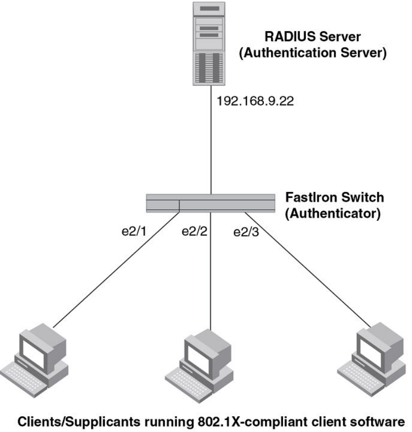
FIGURE 12 Sample point-to-point 802.1X configuration
Sample 802.1x configuration
The following commands configure the Brocade device in the Sample point-to-point 802.1X
configuration figure.
device(config)#aaa authentication dot1x default radius
device(config)#radius-server host 192.168.9.22 auth-port 1812 acct-port 1813
default key mirabeau dot1x
device(config)#dot1x-enable e 1 to 3
device(config-dot1x)#re-authentication
device(config-dot1x)#timeout re-authperiod 2000
device(config-dot1x)#timeout quiet-period 30
device(config-dot1x)#timeout tx-period 60
device(config-dot1x)#maxreq 6
device(config-dot1x)#exit
device(config)#interface e 1
device(config-if-e1000-1)#dot1x port-control auto
Sample 802.1x configuration
272 FastIron Ethernet Switch Security Configuration Guide
53-1003405-04

device(config-if-e1000-1)#exit
device(config)#interface e 2
device(config-if-e1000-2)#dot1x port-control auto
device(config-if-e1000-2)#exit
device(config)#interface e 3
device(config-if-e1000-3)#dot1x port-control auto
device(config-if-e1000-3)#exit
Hub configuration
The following figure illustrates a configuration where three 802.1X-enabled Clients are connected to a
hub, which is connected to a port on the Brocade device. The configuration is similar to that in the
Sample point-to-point 802.1X configuration figure, except that 802.1X port security is enabled on only
one port, and the multiple-hosts command is used to allow multiple Clients on the port.
FIGURE 13 Sample 802.1X configuration using a hub
Hub configuration
FastIron Ethernet Switch Security Configuration Guide 273
53-1003405-04
Sample 802.1x configuration using a hub
The following commands configure the Brocade device in the Sample 802.1X configuration using a
hub figure.
device(config)#aaa authentication dot1x default radius
device(config)#radius-server host 192.168.9.22 auth-port 1812 acct-port 1813
default key mirabeau dot1x
device(config)#dot1x-enable e 1
device(config-dot1x)#re-authentication
device(config-dot1x)#timeout re-authperiod 2000
device(config-dot1x)#timeout quiet-period 30
device(config-dot1x)#timeout tx-period 60
device(config-dot1x)#maxreq 6
device(config-dot1x)#exit
device(config)#interface e 1
device(config-if-e1000-1)#dot1x port-control auto
device(config-if-e1000-1)#exit
802.1X Authentication with dynamic VLAN assignment
The following figure illustrates 802.1X authentication with dynamic VLAN assignment. In this
configuration, two user PCs are connected to a hub, which is connected to port e2. Port e2 is
configured as a dual-mode port. Both PCs transmit untagged traffic. The profile for User 1 on the
RADIUS server specifies that User 1 PC should be dynamically assigned to VLAN 3. The RADIUS
profile for User 2 on the RADIUS server specifies that User 2 PC should be dynamically assigned to
VLAN 20.
Sample 802.1x configuration using a hub
274 FastIron Ethernet Switch Security Configuration Guide
53-1003405-04
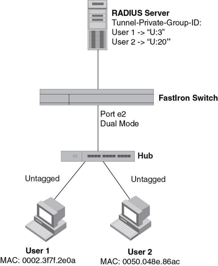
FIGURE 14 Sample configuration using 802.1X authentication with dynamic VLAN assignment
In this example, the PVID for port e2 would be changed based on the first host to be successfully
authenticated. If User 1 is authenticated first, then the PVID for port e2 is changed to VLAN 3. If User 2
is authenticated first, then the PVID for port e2 is changed to VLAN 20. Since a PVID cannot be
changed by RADIUS authentication after it has been dynamically assigned, if User 2 is authenticated
after the port PVID was changed to VLAN 3, then User 2 would not be able to gain access to the
network.
If there were only one device connected to the port, and authentication failed for that device, it could be
placed into the restricted VLAN, where it could gain access to the network.
The portion of the running-config related to 802.1X authentication is as follows.
dot1x-enable
re-authentication
servertimeout 10
timeout re-authperiod 10
auth-fail-action restricted-vlan
802.1X Port Security for ICX 6650 and FSX Devices
FastIron Ethernet Switch Security Configuration Guide 275
53-1003405-04
auth-fail-vlanid 1023
mac-session-aging no-aging permitted-mac-only
enable ethe 2 to 4
!
!
!
interface ethernet 2
dot1x port-control auto
dual-mode
If User 1 is successfully authenticated before User 2, the PVID for port e2 would be changed from the
default VLAN to VLAN 3.
Had User 2 been the first to be successfully authenticated, the PVID would be changed to 20, and
User 1 would not be able to gain access to the network. If User 1 authentication failed first, the PVID
for port e2 would be changed from the default VLAN to restricted VLAN 1023 in this example and
would be able to gain access to the limited network. Then, if User 2 is successfully authenticated, the
PVID would be changed to 20 and User2 would be able to gain access to the network and User1 is
moved out of the restricted VLAN and will be blocked.
Multi-device port authentication and 802.1Xsecurity on the same
port
You can configure the Brocade device to use multi-device port authentication and 802.1X security on
the same port:
• The multi-device port authentication feature allows you to configure a Brocade device to forward or
block traffic from a MAC address based on information received from a RADIUS server. Incoming
traffic originating from a given MAC address is switched or forwarded by the device only if the
source MAC address is successfully authenticated by a RADIUS server. The MAC address itself is
used as the username and password for RADIUS authentication. A connecting user does not need
to provide a specific username and password to gain access to the network.
• The IEEE 802.1X standard is a means for authenticating devices attached to LAN ports. Using
802.1X port security, you can configure a Brocade device to grant access to a port based on
information supplied by a client to an authentication server.
When both of these features are enabled on the same port, multi-device port authentication is
performed prior to 802.1X authentication. If multi-device port authentication is successful, 802.1X
authentication may be performed, based on the configuration of a vendor-specific attribute (VSA) in
the profile for the MAC address on the RADIUS server.
For more information, including configuration examples, see Multi-device port authentication and
802.1Xsecurity on the same port .
Multi-device port authentication and 802.1Xsecurity on the same port
276 FastIron Ethernet Switch Security Configuration Guide
53-1003405-04

Multi-Device Port Authentication for ICX 6650 and FSX Devices
● Supported Multi-device port authentication (MDPA) features....................................... 277
● How multi-device port authentication works..................................................................279
● Multi-device port authentication and 802.1X security on the same port........................281
● Multi-device port authentication configuration...............................................................283
● Displaying multi-device port authentication information................................................ 298
● Example port authentication configurations.................................................................. 306
Supported Multi-device port authentication (MDPA) features
Lists the supported Multi-device port authentication features.
The following table lists individual Brocade switches and the multi-device port authentication features
they support. These features are supported in the Layer 2 and Layer 3 software images, except where
explicitly noted.
NOTE
The Multi-device port authentication feature configurations described in this chapter are applicable to
the ICX 6650 and FCX devices only. Refer to the Multi-Device Port Authentication section in the
"Flexible Authentication" chapter for information on Multi-Device Port Authentication configuration on
Flexible Authentication supported devices.
Feature ICX 6430 ICX 6450 FCX ICX 6610 ICX 6650 FSX 800
FSX 1600
ICX 7450 ICX 7750
Support for Multi-Device Port
Authentication together with
Dynamic VLAN assignment
08.0.01 08.0.01 08.0.01 08.0.01 08.0.01 08.0.01 08.0.20 08.0.10
Support for Multi-Device Port
Authentication together with
Dynamic ACLs
08.0.01 08.0.01 08.0.01 08.0.01 08.0.01 08.0.01 08.0.20 08.0.10
Support for Multi-Device Port
Authentication together with 802.1X
08.0.01 08.0.01 08.0.01 08.0.01 08.0.01 08.0.01 08.0.20 08.0.10
Support for Multi-Device Port
Authentication together with
Dynamic ARP inspection with
dynamic ACLs
No No No No 08.0.01 08.0.01 No No
Support for Multi-Device Port
Authentication together with DHCP
snooping with dynamic ACLs
No No No No 08.0.01 08.0.01 No No
FastIron Ethernet Switch Security Configuration Guide 277
53-1003405-04

Feature ICX 6430 ICX 6450 FCX ICX 6610 ICX 6650 FSX 800
FSX 1600
ICX 7450 ICX 7750
Support for Multi-Device Port
Authentication together with Denial
of Service (DoS) attack protection
08.0.01 08.0.01 08.0.01 08.0.01 08.0.01 08.0.01 08.0.20 08.0.10
Support for Multi-Device Port
Authentication together with Source
guard protection
08.0.20 08.0.01 08.0.01 08.0.01 08.0.01 08.0.01 08.0.20 08.0.10
Support for Multi-Device Port
Authentication together with ACL-
per-port-per-VLAN
08.0.01 08.0.01 08.0.01 08.0.01 08.0.01 08.0.01 08.0.20 08.0.10
Automatic removal of Dynamic
VLAN for MAC authenticated ports
08.0.01 08.0.01 08.0.01 08.0.01 08.0.01 08.0.01 08.0.20 08.0.10
Authenticating multiple MAC
addresses on an interface
08.0.01 08.0.01 08.0.01 08.0.01 08.0.01 08.0.01 08.0.20 08.0.10
Authenticating clients that send
tagged packets on non-member
ports
No No No No No 08.0.01 No No
Specifying the format of the MAC
addresses sent to the RADIUS
server
08.0.01 08.0.01 08.0.01 08.0.01 08.0.01 08.0.01 08.0.20 08.0.10
Specifying the authentication-failure
action
08.0.01 08.0.01 08.0.01 08.0.01 08.0.01 08.0.01 08.0.20 08.0.10
Password override 08.0.01 08.0.01 08.0.01 08.0.01 08.0.01 08.0.01 08.0.20 08.0.10
Specifying the RADIUS timeout
action
08.0.01 08.0.01 08.0.01 08.0.01 08.0.01 08.0.01 08.0.20 08.0.10
SNMP Traps 08.0.01 08.0.01 08.0.01 08.0.01 08.0.01 08.0.01 08.0.20 08.0.10
MAC Address Filters 08.0.01 08.0.01 08.0.01 08.0.01 08.0.01 08.0.01 08.0.20 08.0.10
MAC address filtering (filtering on
source and destination MAC
addresses)
08.0.01 08.0.01 08.0.01 08.0.01 08.0.01 08.0.01 08.0.20 08.0.10
Aging time for blocked MAC
Addresses
08.0.01 08.0.01 08.0.01 08.0.01 08.0.01 08.0.01 08.0.20 08.0.10
RADIUS Change of Authorization 08.0.20 08.0.20 08.0.20 08.0.20 08.0.20 08.0.20 08.0.20 08.0.20
NOTE
FCX devices do not support:- multi-device authentication on dynamic (LACP) and static trunk ports-
multi-device authentication and port security configured on the same port- multi-device authentication
and lock-address configured on the same port
Multi-device port authentication is a way to configure a Brocade device to forward or block traffic from
a MAC address based on information received from a RADIUS server.
Multi-Device Port Authentication for ICX 6650 and FSX Devices
278 FastIron Ethernet Switch Security Configuration Guide
53-1003405-04
How multi-device port authentication works
Multi-device port authentication is a way to configure a Brocade device to forward or block traffic from a
MAC address based on information received from a RADIUS server.
The multi-device port authentication feature is a mechanism by which incoming traffic originating from a
specific MAC address is switched or forwarded by the device only if the source MAC address is
successfully authenticated by a RADIUS server. The MAC address itself is used as the username and
password for RADIUS authentication; the user does not need to provide a specific username and
password to gain access to the network. If RADIUS authentication for the MAC address is successful,
traffic from the MAC address is forwarded in hardware.
If the RADIUS server cannot validate the user's MAC address, then it is considered an authentication
failure, and a specified authentication-failure action can be taken. The default authentication-failure
action is to drop traffic from the non-authenticated MAC address in hardware. You can also configure
the device to move the port on which the non-authenticated MAC address was learned into a restricted
or "guest" VLAN, which may have limited access to the network.
RADIUS authentication
The multi-device port authentication feature communicates with the RADIUS server to authenticate a
newly found MAC address. The Brocade device supports multiple RADIUS servers; if communication
with one of the RADIUS servers times out, the others are tried in sequential order. If a response from a
RADIUS server is not received within a specified time (by default, 3 seconds) the RADIUS session
times out, and the device retries the request up to three times. If no response is received, the next
RADIUS server is chosen, and the request is sent for authentication.
The RADIUS server is configured with the user names and passwords of authenticated users. For multi-
device port authentication, the username and password is the MAC address itself; that is, the device
uses the MAC address for both the username and the password in the request sent to the RADIUS
server. For example, given a MAC address of 0000000feaa1, the users file on the RADIUS server
would be configured with a username and password both set to 0000000feaa1. When traffic from this
MAC address is encountered on a MAC-authentication-enabled interface, the device sends the RADIUS
server an Access-Request message with 0000000feaa1 as both the username and password. The
format of the MAC address sent to the RADIUS server is configurable through the CLI.
The request for authentication from the RADIUS server is successful only if the username and
password provided in the request matches an entry in the users database on the RADIUS server. When
this happens, the RADIUS server returns an Access-Accept message back to the Brocade device.
When the RADIUS server returns an Access-Accept message for a MAC address, that MAC address is
considered authenticated, and traffic from the MAC address is forwarded normally by the Brocade
device.
Authentication-failure actions
If the MAC address does not match the username and password of an entry in the users database on
the RADIUS server, then the RADIUS server returns an Access-Reject message. When this happens, it
is considered an authentication failure for the MAC address. When an authentication failure occurs, the
Brocade device can either drop traffic from the MAC address in hardware (the default), or move the port
on which the traffic was received to a restricted VLAN.
How multi-device port authentication works
FastIron Ethernet Switch Security Configuration Guide 279
53-1003405-04

Unauthenticated port behavior
Incoming traffic on unauthenticated ports is blocked by Brocade devices, while allowing for outgoing
broadcasts and multicasts to account for waking connected devices that are in a sleep state. This is
the default behavior and there is no configuration option.
Supported RADIUS attributes
Brocade devices support the following RADIUS attributes for multi-device port authentication:
• Username (1) - RFC 2865
• NAS-IP-Address (4) - RFC 2865
• NAS-Port (5) - RFC 2865
• Service-Type (6) - RFC 2865
• FilterId (11) - RFC 2865
• Framed-MTU (12) - RFC 2865
• State (24) - RFC 2865
• Vendor-Specific (26) - RFC 2865
• Session-Timeout (27) - RFC 2865
• Termination-Action (29) - RFC 2865
• Calling-Station-ID (31) - RFC 2865
• NAS-Identifier (32) - RFC 2865
• NAS-Port-Type (61) - RFC 2865
• Tunnel-Type (64) - RFC 2868
• Tunnel-Medium-Type (65) - RFC 2868
• EAP Message (79) - RFC 2579
• Message-Authenticator (80) RFC 3579
• Tunnel-Private-Group-Id (81) - RFC 2868
• NAS-Port-id (87) - RFC 2869
NOTE
NAS-Identifier attribute supports a maximum number of 253 characters.
Support for dynamic VLAN assignment
The Brocade multi-device port authentication feature supports dynamic VLAN assignment, where a
port can be placed in one or more VLANs based on the MAC address learned on that interface. For
details about this feature, refer to Configuring the RADIUS server to support dynamic VLAN
assignment on page 287.
Support for dynamic ACLs
The multi-device port authentication feature supports the assignment of a MAC address to a specific
ACL, based on the MAC address learned on the interface. For details about this feature, refer to
Dynamically applying IP ACLs to authenticated MAC addresses on page 290.
Unauthenticated port behavior
280 FastIron Ethernet Switch Security Configuration Guide
53-1003405-04

Support for authenticating multiple MAC addresses on an interface
The multi-device port authentication feature allows multiple MAC addresses to be authenticated or
denied authentication on each interface. The maximum number of MAC addresses that can be
authenticated on each interface is limited only by the amount of system resources available on the
Brocade device.
Support for dynamic ARP inspection with dynamic ACLs
NOTE
This feature is not supported on ICX 6610 and FCX devices.
Multi-device port authentication and Dynamic ARP Inspection (DAI) are supported in conjunction with
dynamic ACLs. Support is available in the Layer 3 software images only.
DAI is supported together with multi-device port authentication as long as ACL-per-port-per-vlan is
enabled. Otherwise, you do not need to perform any extra configuration steps to enable support with
dynamic ACLs. When these features are enabled on the same port/VLAN, support is automatically
enabled.
Support for DHCP snooping with dynamic ACLs
NOTE
This feature is not supported on FCX devices.
Multi-device port authentication and DHCP snooping are supported in conjunction with dynamic ACLs.
Support is available in the Layer 3 software images only.
DHCP Snooping is supported together with multi-device port authentication as long as ACL-per-port-
per-vlan is enabled. Otherwise, you do not need to perform any extra configuration steps to enable
support with dynamic ACLs. When these features are enabled on the same port/VLAN, support is
automatically enabled.
Support for source guard protection
The Brocade proprietary Source Guard Protection feature, a form of IP Source Guard, can be used in
conjunction with multi-device port authentication. For details, refer to Enabling source guard protection
on page 292.
Multi-device port authentication and 802.1X security on the same
port
On some Brocade devices, multi-device port authentication and 802.1X security can be configured on
the same port, as long as the port is not a trunk port or an LACP port. When both of these features are
enabled on the same port, multi-device port authentication is performed prior to 802.1X authentication.
If multi-device port authentication is successful, 802.1X authentication may be performed, based on the
Support for authenticating multiple MAC addresses on an interface
FastIron Ethernet Switch Security Configuration Guide 281
53-1003405-04

configuration of a vendor-specific attribute (VSA) in the profile for the MAC address on the RADIUS
server.
NOTE
When multi-device port authentication and 802.1X security are configured together on the same port,
Brocade recommends that dynamic VLANs and dynamic ACLs are done at the multi-device port
authentication level, and not at the 802.1X level.
When both features are configured on a port, a device connected to the port is authenticated as
follows.
1. Multi-device port authentication is performed on the device to authenticate the device MAC address.
2. If multi-device port authentication is successful for the device, then the device checks whether the
RADIUS server included the Foundry-802_1x-enable VSA (described in the Brocade vendor-
specific attributes for RADIUS table) in the Access-Accept message that authenticated the device.
3. If the Foundry-802_1x-enable VSA is not present in the Access-Accept message, or is present and
set to 1, then 802.1X authentication is performed for the device.
4. If the Foundry-802_1x-enable VSA is present in the Access-Accept message, and is set to 0, then
802.1X authentication is skipped. The device is authenticated, and any dynamic VLANs specified in
the Access-Accept message returned during multi-device port authentication are applied to the port.
5. If 802.1X authentication is performed on the device, and is successful, then dynamic VLANs or
ACLs specified in the Access-Accept message returned during 802.1X authentication are applied to
the port.
If multi-device port authentication fails for a device, then by default traffic from the device is either
blocked in hardware, or the device is placed in a restricted VLAN. You can optionally configure the
Brocade device to perform 802.1X authentication on a device when it fails multi-device port
authentication. Refer to Example 2 -- Creating a profile on the RADIUS server for each MAC
address on page 312 for a sample configuration where this is used.
Configuring Brocade-specific attributes on the RADIUS server
If the RADIUS authentication process is successful, the RADIUS server sends an Access-Accept
message to the Brocade device, authenticating the device. The Access-Accept message can include
Vendor-Specific Attributes (VSAs) that specify additional information about the device. If you are
configuring multi-device port authentication and 802.1X authentication on the same port, then you can
configure the Brocade VSAs listed in following table on the RADIUS server.
You add these Brocade vendor-specific attributes to your RADIUS server configuration, and configure
the attributes in the individual or group profiles of the devices that will be authenticated. The Brocade
Vendor-ID is 1991, with Vendor-Type 1.
Configuring Brocade-specific attributes on the RADIUS server
282 FastIron Ethernet Switch Security Configuration Guide
53-1003405-04

Brocade vendor-specific attributes for RADIUS TABLE 30
Attribute name Attribute ID Data type Description
Foundry-802_1x-
enable
6 integer Specifies whether 802.1X authentication is performed when
multi-device port authentication is successful for a device. This
attribute can be set to one of the following:
0 - Do not perform 802.1X authentication on a device that passes
multi-device port authentication. Set the attribute to zero for
devices that do not support 802.1X authentication.
1 - Perform 802.1X authentication when a device passes multi-
device port authentication. Set the attribute to one for devices
that support 802.1X authentication.
Foundry-802_1x-valid 7 integer Specifies whether the RADIUS record is valid only for multi-
device port authentication, or for both multi-device port
authentication and 802.1X authentication.
This attribute can be set to one of the following:
0 - The RADIUS record is valid only for multi-device port
authentication. Set this attribute to zero to prevent a user from
using their MAC address as username and password for 802.1X
authentication
1 - The RADIUS record is valid for both multi-device port
authentication and 802.1X authentication.
If neither of these VSAs exist in a device profile on the RADIUS server, then by default the device is
subject to multi-device port authentication (if configured), then 802.1X authentication (if configured). The
RADIUS record can be used for both multi-device port authentication and 802.1X authentication.
Configuration examples are shown in Examples of multi-device port authentication and 802.1X
authentication configuration on the same port on page 310.
Multi-device port authentication configuration
Configuring multi-device port authentication on the Brocade device consists of the following tasks:
• Enabling multi-device port authentication globally and on individual interfaces
• Specifying the format of the MAC addresses sent to the RADIUS server (optional)
• Specifying the authentication-failure action (optional)
• Enabling and disabling SNMP traps for multi-device port authentication
• Defining MAC address filters (optional)
• Configuring dynamic VLAN assignment (optional)
• Dynamically Applying IP ACLs to authenticated MAC addresses
• Enabling denial of service attack protection (optional)
• Clearing authenticated MAC addresses (optional)
• Disabling aging for authenticated MAC addresses (optional)
• Configuring the hardware aging period for blocked MAC addresses
• Specifying the aging time for blocked MAC addresses (optional)
Multi-device port authentication configuration
FastIron Ethernet Switch Security Configuration Guide 283
53-1003405-04
Enabling multi-device port authentication
To enable multi-device port authentication, you first enable the feature globally on the device. On
some Brocade devices, you can then enable the feature on individual interfaces.
Globally enabling multi-device port authentication
To globally enable multi-device port authentication on the device, enter the following command.
device(config)#mac-authentication enable
Syntax: [no] mac-authentication enable
Enabling multi-device port authentication on an interface
To enable multi-device port authentication on an individual interface, enter a command such as the
following.
device(config)#mac-authentication enable ethernet 3/1
Syntax: [no] mac-authentication enable [ port | all ]
The all option enables the feature on all interfaces at once.
You can enable the feature on an interface at the interface CONFIG level.
of enabling multi-device port authentication on an interface
device(config)#interface e 3/1
device(config-if-e1000-3/1)#mac-authentication enable
Syntax: [no] mac-authentication enable
You can also configure multi-device port authentication commands on a range of interfaces.
of enabling multi-device port authentication on a range of interfaces
device(config)#int e 3/1 to 3/12
device(config-mif-3/1-3/12)#mac-authentication enable
Specifying the format of the MAC addresses sent to theRADIUS server
When multi-device port authentication is configured, the Brocade device authenticates MAC
addresses by sending username and password information to a RADIUS server. The username and
password is the MAC address itself; that is, the device uses the MAC address for both the username
and the password in the request sent to the RADIUS server.
By default, the MAC address is sent to the RADIUS server in the format xxxxxxxxxxxx . You can
optionally configure the device to send the MAC address to the RADIUS server in the format xx-xx-xx-
xx-xx-xx , or the format xxxx.xxxx.xxxx . To do this, enter a command such as the following.
device(config)#mac-authentication auth-passwd-format xxxx.xxxx.xxxx
Syntax: [no] mac-authentication auth-passwd-format { xxxx.xxxx.xxxx | xx-xx-xx-xx-xx-xx |
xxxxxxxxxxxx }
Enabling multi-device port authentication
284 FastIron Ethernet Switch Security Configuration Guide
53-1003405-04
Specifying the authentication-failure action
When RADIUS authentication for a MAC address fails, you can configure the device to perform one of
two actions:
• Drop traffic from the MAC address in hardware (the default)
• Move the port on which the traffic was received to a restricted VLAN
To configure the device to move the port to a restricted VLAN when multi-device port authentication
fails, enter commands such as the following.
device(config)#interface e 3/1
device(config-if-e1000-3/1)#mac-authentication auth-fail-action restrict-vlan
100
Syntax: [no] mac-authentication auth-fail-action restrict-vlan [ vlan-id ]
If the ID for the restricted VLAN is not specified at the interface level, the global restricted VLAN ID
applies for the interface.
To specify the VLAN ID of the restricted VLAN globally, enter the following command.
device
(config)#mac-authentication auth-fail-vlan-id 200
Syntax: [no] mac-authentication auth-fail-vlan-id vlan-id
The command above applies globally to all MAC-authentication-enabled interfaces.
Note that the restricted VLAN must already exist on the device. You cannot configure the restricted
VLAN to be a non-existent VLAN. If the port is a tagged or dual-mode port, you cannot use a restricted
VLAN as the authentication-failure action.
To configure the device to drop traffic from non-authenticated MAC addresses in hardware, enter
commands such as the following.
device(config)#interface e 3/1
device(config-if-e1000-3/1)#mac-authentication auth-fail-action block-traffic
Syntax: [no] mac-authentication auth-fail-action block-traffic
Dropping traffic from non-authenticated MAC addresses is the default behavior when multi-device port
authentication is enabled.
Generating traps for multi-device port authentication
You can enable and disable SNMP traps for multi-device port authentication. SNMP traps are enabled
by default.
To enable SNMP traps for multi-device port authentication after they have been disabled, enter the
following command.
device(config)#snmp-server enable traps mac-authentication
Syntax: [no] snmp-server enable traps mac-authentication
Use the no form of the command to disable SNMP traps for multi-device port authentication.
Specifying the authentication-failure action
FastIron Ethernet Switch Security Configuration Guide 285
53-1003405-04
Defining MAC address filters
You can specify MAC addresses that do not have to go through multi-device port authentication.
These MAC addresses are considered pre-authenticated, and are not subject to RADIUS
authentication. To do this, you can define MAC address filters that specify the MAC addresses to
exclude from multi-device port authentication.
You should use a MAC address filter when the RADIUS server itself is connected to an interface
where multi-device port authentication is enabled. If a MAC address filter is not defined for the MAC
address of the RADIUS server and applied on the interface, the RADIUS authentication process would
fail since the device would drop all packets from the RADIUS server itself.
For example, the following command defines a MAC address filter for address 0000.0058.aca4.
device(config)#mac-authentication mac-filter 1 0000.0058.aca4
Syntax: [no] mac-authentication mac-filter filter
The following commands apply the MAC address filter on an interface so that address 0000.0058.aca4
is excluded from multi-device port authentication.
device(config)#interface e 3/1
device(config-if-e1000-3/1)#mac-authentication apply-mac-auth-filter 1
Syntax: [no] mac-authentication apply-mac-auth-filter filter-id
Configuring dynamic VLAN assignment
An interface can be dynamically assigned to one or more VLANs based on the MAC address learned
on that interface. When a MAC address is successfully authenticated, the RADIUS server sends the
Brocade device a RADIUS Access-Accept message that allows the Brocade device to forward traffic
from that MAC address. The RADIUS Access-Accept message can also contain attributes set for the
MAC address in its access profile on the RADIUS server.
If one of the attributes in the Access-Accept message specifies one or more VLAN identifiers, and the
VLAN is available on the Brocade device, the port is moved from its default VLAN to the specified
VLAN.
To enable dynamic VLAN assignment for authenticated MAC addresses, you must add attributes to
the profile for the MAC address on the RADIUS server, then enable dynamic VLAN assignment on
multi-device port authentication-enabled interfaces. Refer to Configuring the RADIUS server to support
dynamic VLAN assignment on page 287 for a list of the attributes that must be set on the RADIUS
server.
To enable dynamic VLAN assignment on a multi-device port authentication-enabled interface, enter
commands such as the following.
device(config)#interface e 3/1
device(config-if-e1000-3/1)#mac-authentication enable-dynamic-vlan
Syntax: [no] mac-authentication enable-dynamic-vlan
Configuring a port to remain in the restricted VLAN after a successful authentication attempt
If a previous authentication attempt for a MAC address failed, and as a result the port was placed in
the restricted VLAN, but a subsequent authentication attempt was successful, the RADIUS Access-
Accept message may specify a VLAN for the port. By default, the Brocade device moves the port out
Defining MAC address filters
286 FastIron Ethernet Switch Security Configuration Guide
53-1003405-04

of the restricted VLAN and into the RADIUS-specified VLAN. You can optionally configure the device to
leave the port in the restricted VLAN. To do this, enter the following command.
device(config-if-e1000-3/1)# mac-authentication no-override-restrict-vlan
When the above command is applied, if the RADIUS-specified VLAN configuration is tagged (e.g., T:
1024) and the VLAN is valid, then the port is placed in the RADIUS-specified VLAN as a tagged port
and left in the restricted VLAN. If the RADIUS-specified VLAN configuration is untagged (e.g., U:1024),
the configuration from the RADIUS server is ignored, and the port is left in the restricted VLAN.
Syntax: [no] mac-authentication no-override-restrict-vlan
Configuration notes for configuring a port to remain in the restricted VLAN
• If you configure dynamic VLAN assignment on a multi-device port authentication enabled interface,
and the Access-Accept message returned by the RADIUS server contains a Tunnel-Type and
Tunnel-Medium-Type, but does not contain a Tunnel-Private-Group-ID attribute, then it is considered
an authentication failure, and the configured authentication failure action is performed for the MAC
address.
• If the vlan-name string does not match either the name or the ID of a VLAN configured on the device,
then it is considered an authentication failure, and the configured authentication failure action is
performed for the MAC address.
• For tagged or dual-mode ports, if the VLAN ID provided by the RADIUS server does not match the
VLAN ID in the tagged packet that contains the authenticated MAC address as its source address,
then it is considered an authentication failure, and the configured authentication failure action is
performed for the MAC address.
• If an untagged port had previously been assigned to a VLAN through dynamic VLAN assignment,
and then another MAC address is authenticated on the same port, but the RADIUS Access-Accept
message for the second MAC address specifies a different VLAN, then it is considered an
authentication failure for the second MAC address, and the configured authentication failure action is
performed. Note that this applies only if the first MAC address has not yet aged out. If the first MAC
address has aged out, then dynamic VLAN assignment would work as expected for the second MAC
address.
• For dual mode ports, if the RADIUS server returns T:vlan-name , the traffic will still be forwarded in
the statically assigned PVID. If the RADIUS server returns U:vlan-name , the traffic will not be
forwarded in the statically assigned PVID.
Configuring the RADIUS server to support dynamic VLAN assignment
To specify VLAN identifiers on the RADIUS server, add the following attributes to the profile for the
MAC address on the RADIUS server, then enable dynamic VLAN assignment on multi-device port
authentication-enabled interfaces.
Attribute name Type Value
Tunnel-Type 064 13 (decimal) - VLAN
Tunnel-Medium-Type 065 6 (decimal) - 802
Tunnel-Private-Group-ID 081 vlan-name (string)
The vlan-name value can specify either the name or the number of one or more
VLANs configured on the Brocade device.
Configuration notes for configuring a port to remain in the restricted VLAN
FastIron Ethernet Switch Security Configuration Guide 287
53-1003405-04

For information about the attributes, refer to the Dynamic multiple VLAN assignment for 802.1X ports
section.
Also, refer to the example configuration of Multi-device port authentication with dynamic VLAN
assignment on page 306.
Enabling dynamic VLAN support for tagged packets on non-member VLAN ports
NOTE
This feature is not supported on ICX 6610 and FCX devices.
By default, the Brocade device drops tagged packets that are received on non-member VLAN ports.
This process is called ingress filtering. Since the MAC address of the packets are not learned,
authentication does not take place.
The Brocade device can authenticate clients that send tagged packets on non-member VLAN ports.
This enables the Brocade device to add the VLAN dynamically. To enable support, enter the following
command at the Interface level of the CLI.
device(config)#interface e 3/1
device(config-if-e1000-3/1)#mac-authentication disable-ingress-filtering
If the client MAC address is successfully authenticated and the correct VLAN attribute is sent by the
RADIUS server, the MAC address will be successfully authenticated on the VLAN.
Syntax: mac-authentication disable-ingress-filtering
Configuration notes and limitations:
• This feature works in conjunction with multi-device port authentication with dynamic VLAN
assignment only. If this feature is not enabled, authentication works as in Example 2 -- multi-device
port authentication with dynamic VLAN assignment on page 308.
• The port on which ingress filtering is disabled must be tagged to a VLAN.
• If a host sends both tagged and untagged traffic, and ingress filtering is disabled on the port, the
port must be configured as a dual-mode port.
• Enabling dynamic VLAN support for tagged packets on non-member VLAN ports is not supported
on FWS and FCX devices.
• The mac-authentication disable-ingress-filtering command is not available on the ICX 6610 and
ICX 6450 platforms.
Specifying to which VLAN a port is moved after its RADIUS-specified VLAN assignment expires
When a port is dynamically assigned to a VLAN through the authentication of a MAC address, and the
MAC session for that address is deleted on the Brocade device, then by default the port is removed
from its RADIUS-assigned VLAN and placed back in the VLAN where it was originally assigned.
A port can be removed from its RADIUS-assigned VLAN when any of the following occur:
• The link goes down for the port
• The MAC session is manually deleted with the mac-authentication clear-mac-session command
• The MAC address that caused the port to be dynamically assigned to a VLAN ages out
For example, say port 1/1 is currently in VLAN 100, to which it was assigned when MAC address
0000.00a1.e90f was authenticated by a RADIUS server. The port was originally configured to be in
VLAN 111. If the MAC session for address 0000.00a1.e90f is deleted, then port 1/1 is moved from
VLAN 100 back into VLAN 111.
Enabling dynamic VLAN support for tagged packets on non-member VLAN ports
288 FastIron Ethernet Switch Security Configuration Guide
53-1003405-04

You can optionally specify an alternate VLAN to which to move the port when the MAC session for the
address is deleted. For example, to place the port in the restricted VLAN, enter commands such as the
following.
device(config)#interface e 3/1
device(config-if-e1000-3/1)#mac-auth move-back-to-old-vlan port-restrict-vlan
Syntax: [no] mac-authentication move-back-to-old-vlan [ port-restrict-vlan | port-configured-vlan
| system-default-vlan ]
The port-configured-vlan keyword removes the port from its RADIUS-assigned VLAN and places it
back in the VLAN where it was originally assigned. This is the default.
The port-restrict-vlan keyword removes the port from its RADIUS-assigned VLAN and places it in the
restricted VLAN.
The system-default-vlan keyword removes the port from its RADIUS-assigned VLAN and places it in
the DEFAULT-VLAN.
NOTE
When a MAC session is deleted, if the port is moved back to a VLAN that is different than the running-
config file, the system will update the running-config file to reflect the changes. This will occur even if
mac-authentication save-dynamicvlan-to-config" is not configured.
Automatic removal of dynamic VLAN assignments for MAC authenticated ports
NOTE
This feature is not supported on ICX 6610 and FCX devices.
By default, the Brocade device removes any association between a port and a dynamically-assigned
VLAN when all authenticated MAC sessions for that tagged or untagged VLAN have expired on the
port. Thus, RADIUS-specified VLAN assignments are not saved to the device running-config file. When
the show run command is issued during a session, dynamically-assigned VLANs are not displayed,
although they can be displayed with the show vlan , show auth-mac-addresses detail , and show
auth-mac-addresses authorized-mac commands.
You can optionally configure the Brocade device to save the RADIUS-specified VLAN assignments to
the device's running-config file. Refer to Saving dynamic VLAN assignments to the running-config file on
page 289, next.
Saving dynamic VLAN assignments to the running-config file
By default, dynamic VLAN assignments are not saved to the running-config file of the Brocade device.
However, you can configure the device to do so by entering the following command.
device(config)#mac-authentication save-dynamicvlan-to-config
When the above command is applied, dynamic VLAN assignments are saved to the running-config file
and are displayed when the show run command is issued. Dynamic VLAN assignments can also be
displayed with the show vlan , show auth-mac-addresses detail , and show auth-mac-addresses
authorized-mac commands.
Syntax: [no] mac-authentication save-dynamicvlan-to-config
Automatic removal of dynamic VLAN assignments for MAC authenticated ports
FastIron Ethernet Switch Security Configuration Guide 289
53-1003405-04

Dynamically applying IP ACLs to authenticated MAC addresses
The Brocade multi-device port authentication implementation supports the assignment of a MAC
address to a specific ACL, based on the MAC address learned on the interface.
When a MAC address is successfully authenticated, the RADIUS server sends the Brocade device a
RADIUS Access-Accept message that allows the Brocade device to forward traffic from that MAC
address. The RADIUS Access-Accept message can also contain, among other attributes, the Filter-ID
(type 11) attribute for the MAC address. When the Access-Accept message containing the Filter-ID
(type 11) attribute is received by the Brocade device, it will use the information in these attributes to
apply an IP ACL on a per-MAC (per user) basis.
The dynamic IP ACL is active as long as the client is connected to the network. When the client
disconnects from the network, the IP ACL is no longer applied to the port. If an IP ACL had been
applied to the port prior to multi-device port authentication; it will be re-applied to the port.
NOTE
A dynamic IP ACL will take precedence over an IP ACL that is bound to an untagged port (port ACL).
When a client authenticates with a dynamic IP ACL, the port ACL will not be applied. Also, future
clients on the same port will authenticate with a dynamic IP ACL or no IP ACL. If no clients on the port
use dynamic ACL, then the port ACL will be applied to all traffic. However since the port already has a
static ACL, dynamic VLAN assignment is not allowed.
The Brocade device uses information in the Filter ID to apply an IP ACL on a per-user basis. The
Filter-ID attribute can specify the number of an existing IP ACL configured on the Brocade device. If
the Filter-ID is an ACL number, the specified IP ACL is applied on a per-user basis.
Multi-device port authentication with dynamic IP ACLs and ACL-per-port-per-VLAN
The following features are supported:
• FastIron X Series devices support multi-device port authentication and dynamic ACLs together with
ACL-per-port-per-vlan (ACL filtering based on VLAN membership or VE port membership).
• Multi-device port authentication and dynamic ACLs are supported on tagged, dual-mode, and
untagged ports, with or without virtual Interfaces.
• Multi-Device Port Authentication and 802.1x both support dynamic ACL together. The
authentication server can provide dynamic IP ACL using the Filter-Id attribute for both MAC-
Authentication and 802.1x when both the authentication methods are active on the port. If the
RADIUS provides IP ACL using Filter-id attribute for both MAC-authentication and 802.1x. at first,
dynamic ACL will be applied to that client once MAC-authentication is complete. When 802.1x
authentication is completed, the previously applied MAC-authentication dynamic IP ACL will be
removed and 802.1x Dynamic IP ACL will be applied to the client. If 802.1x fails or 802.1x does not
return any IP ACL, then MAC-Authentication dynamic IP ACL will remain on the port
Support is automatically enabled when all of the required conditions are met.
The following describes the conditions and feature limitations:
• On Layer 3 router code, dynamic IP ACLs are allowed on physical ports when ACL-per-port-per-
vlan is enabled.
• On Layer 3 router code, dynamic IP ACLs are allowed on tagged and dual-mode ports when ACL-
per-port-per-vlan is enabled. If ACL-per-port-per-vlan is not enabled, dynamic IP ACLs are not
allowed on tagged or dual-mode ports.
• Dynamic IP ACLs can be added to tagged/untagged ports in a VLAN with or without a VE, as long
as the tagged/untagged ports do not have configured ACLs assigned to them. The following shows
some example scenarios where dynamic IP ACLs would not apply:
Dynamically applying IP ACLs to authenticated MAC addresses
290 FastIron Ethernet Switch Security Configuration Guide
53-1003405-04

‐A port is a tagged/untagged member of VLAN 20, VLAN 20 includes VE 20, and an ACL is bound
to VE 20.
‐A port is a tagged/untagged member of VLAN 20, VLAN 20 includes VE 20, and a per-port-per-
vlan ACL is bound to VE 20 and to a subset of ports in VE 20
In the above scenarios, dynamic IP ACL assignment would not apply in either instance, because a
configured ACL is bound to VE 20 on the port. Consequently, the MAC session would fail.
Configuration considerations and guidelines for multi-device port authentication
• On FastIron X Series devices, dynamic ARP inspection (DAI) and DHCP Snooping are supported
together with dynamic ACLs.
• Dynamic IP ACLs with multi-device port authentication are supported. Dynamic MAC address filters
with multi-device port authentication are not supported.
• In the Layer 2 switch code, dynamic IP ACLs are not supported when ACL-per-port-per-vlan is
enabled on a global-basis.
• The RADIUS Filter ID (type 11) attribute is supported. The Vendor-Specific (type 26) attribute is not
supported.
• The dynamic ACL must be an extended ACL. Standard ACLs are not supported.
• Multi-device port authentication and 802.1x can be used together on the same port.
• Dynamically assigned IP ACLs are subject to the same configuration restrictions as non-dynamically
assigned IP ACLs.
• Dynamic ACL filters are supported only for the inbound direction. Dynamic outbound ACL filters are
not supported.
• Dynamic ACL assignment with multi-device port authentication is not supported in conjunction with
any of the following features:
‐IP source guard
‐Rate limiting
‐Protection against ICMP or TCP Denial-of-Service (DoS) attacks
‐Policy-based routing
‐802.1X dynamic MAC filter
Configuring the RADIUS server to support dynamic IP ACLs
When a port is authenticated using multi-device port authentication, an IP ACL filter that exists in the
running-config file on the Brocade device can be dynamically applied to the port. To do this, you
configure the Filter-ID (type 11) attribute on the RADIUS server. The Filter-ID attribute specifies the
name or number of the Brocade IP ACL.
The following is the syntax for configuring the Filter-ID attribute on the RADIUS server to refer to a
Brocade IP ACL.
Value Description
ip.number .in5Applies the specified numbered ACL to the authenticated port in the inbound direction.
ip.name .in 1 ,6Applies the specified named ACL to the authenticated port in the inbound direction.
The following table lists examples of values you can assign to the Filter-ID attribute on the RADIUS
server to refer to IP ACLs configured on a Brocade device.
5The ACL must be an extended ACL. Standard ACLs are not supported.
6The name in the Filter ID attribute is case-sensitive
Configuration considerations and guidelines for multi-device port authentication
FastIron Ethernet Switch Security Configuration Guide 291
53-1003405-04

Possible values for the filter ID attribute on the RADIUS
server
ACLs configured on the Brocade device
ip.102.in access-list 102 permit ip 36.0.0.0 0.255.255.255 any
ip.fdry_filter.in ip access-list extended foundry_filter
permit ip 36.0.0.0 0.255.255.255 any
Enabling denial of service attack protection
The Brocade device does not start forwarding traffic from an authenticated MAC address in hardware
until the RADIUS server authenticates the MAC address; traffic from the non-authenticated MAC
addresses is sent to the CPU. A denial of service (DoS) attack could be launched against the device
where a high volume of new source MAC addresses is sent to the device, causing the CPU to be
overwhelmed with performing RADIUS authentication for these MAC addresses. In addition, the high
CPU usage in such an attack could prevent the RADIUS response from reaching the CPU in time,
causing the device to make additional authentication attempts.
To limit the susceptibility of the Brocade device to such attacks, you can configure the device to use
multiple RADIUS servers, which can share the load when there are a large number of MAC addresses
that need to be authenticated. The Brocade device can run a maximum of 10 RADIUS clients per
server and will attempt to authenticate with a new RADIUS server if current one times out.
In addition, you can configure the Brocade device to limit the rate of authentication attempts sent to
the RADIUS server. When the multi-device port authentication feature is enabled, it keeps track of the
number of RADIUS authentication attempts made per second. When you also enable the DoS
protection feature, if the number of RADIUS authentication attempts for MAC addresses learned on an
interface per second exceeds a configurable rate (by default 512 authentication attempts per second),
the device considers this a possible DoS attack and disables the port. You must then manually re-
enable the port.
The DoS protection feature is disabled by default. To enable it on an interface, enter commands such
as the following.
device(config)#interface e 3/1
device(config-if-e1000-3/1)#mac-authentication dos-protection enable
To specify a maximum rate for RADIUS authentication attempts, enter commands such as the
following.
device(config)#interface e 3/1
device(config-if-e1000-3/1)#mac-authentication dos-protection mac-limit 256
Syntax: [no] mac-authentication dos-protection mac-limit number
You can specify a rate from 1 - 65535 authentication attempts per second. The default is a rate of 512
authentication attempts per second.
Enabling source guard protection
Source Guard Protection is a form of IP Source Guard used in conjunction with multi-device port
authentication. When Source Guard Protection is enabled, IP traffic is blocked until the system learns
the IP address. Once the IP address is validated, traffic with that source address is permitted.
Enabling denial of service attack protection
292 FastIron Ethernet Switch Security Configuration Guide
53-1003405-04

NOTE
Source Guard Protection is supported together with multi-device port authentication as long as ACL-
per-port-per-vlan is enabled.
When a new MAC session begins on a port that has Source Guard Protection enabled, the session will
either apply a dynamically created Source Guard ACL entry, or it will use the dynamic IP ACL assigned
by the RADIUS server. If a dynamic IP ACL is not assigned, the session will use the Source Guard ACL
entry. The Source Guard ACL entry is permit ip secure-ip any , where secure-ip is obtained from the
ARP Inspection table or from the DHCP Secure table. The DHCP Secure table is comprised of DHCP
Snooping and Static ARP Inspection entries.
The Source Guard ACL permit entry is added to the hardware table after all of the following events
occur:
• The MAC address is authenticated
• The IP address is learned
• The MAC-to-IP mapping is checked against the Static ARP Inspection table or the DHCP Secure
table.
The Source Guard ACL entry is not written to the running configuration file. However, you can view the
configuration using the show auth-mac-addresses authorized-mac ip-addr . Refer to Viewing the
assigned ACL for ports on which source guard protection is enabled on page 293 in the following
section.
NOTE
The secure MAC-to-IP mapping is assigned at the time of authentication and remains in effect as long
as the MAC session is active. If the DHCP Secure table is updated after the session is authenticated
and while the session is still active, it does not affect the existing MAC session.
The Source Guard ACL permit entry is removed when the MAC session expires or is cleared.
To enable Source Guard Protection on a port on which multi-device port authentication is enabled, enter
the following command at the Interface level of the CLI.
device(config)int e 1/4
device(config-if-e1000-1/4)mac-authentication source-guard-protection enable
Syntax: [no] mac-authentication source-guard-protection enable
Enter the no form of the command to disable SG protection.
NOTE
Source guard protection is supported only on the router image and not on the switch image.
Viewing the assigned ACL for ports on which source guard protection is enabled
Use the following command to view whether a Source Guard ACL or dynamic ACL is applied to ports on
which Source Guard Protection is enabled.
device(config)#show auth-mac-addresses authorized-mac ip-addr
-------------------------------------------------------------------------------
MAC Address SourceIp Port Vlan Auth Age ACL dot1x
-------------------------------------------------------------------------------
0000.0010.2000 10.1.17.5 6/12 171 Yes Dis SG
Ena
Viewing the assigned ACL for ports on which source guard protection is enabled
FastIron Ethernet Switch Security Configuration Guide 293
53-1003405-04

0000.0010.2001 10.1.17.6 6/13 171 Yes Dis 103
Ena
In the above output, for port 6/12, Source Guard Protection is enabled and the Source Guard ACL is
applied to the MAC session, as indicated by SG in the ACL column. For port 6/13, Source Guard
Protection is also enabled, but in this instance, a dynamic ACL (103) is applied to the MAC session.
Clearing authenticated MAC addresses
The Brocade device maintains an internal table of the authenticated MAC addresses (viewable with
the show authenticated-mac-address command). You can clear the contents of the authenticated
MAC address table either entirely, or just for the entries learned on a specified interface. In addition,
you can clear the MAC session for an address learned on a specific interface.
To clear the entire contents of the authenticated MAC address table, enter the clear auth-mac-table
command.
device#clear auth-mac-table
Syntax: clear auth-mac-table
To clear the authenticated MAC address table of entries learned on a specified interface, enter a
command such as the following.
device#clear auth-mac-table e 3/1
Syntax: clear auth-mac-table ethernet port
To clear the MAC session for an address learned on a specific interface, enter commands such as the
following.
device(config)#interface e 3/1
device(config-if-e1000-3/1)#mac-authentication clear-mac-session 0000.0034.abd4
Syntax: clear auth-mac-table clear-mac-session mac-address
This command removes the Layer 2 CAM entry created for the specified MAC address. If the Brocade
device receives traffic from the MAC address again, the MAC address is authenticated again.
NOTE
In a configuration with multi-device port authentication and 802.1X authentication on the same port,
the mac-authentication clear-mac-session command will clear the MAC session, as well as its
respective 802.1X session, if it exists.
Disabling aging for authenticated MAC addresses
MAC addresses that have been authenticated or denied by a RADIUS server are aged out if no traffic
is received from the MAC address for a certain period of time:
• Authenticated MAC addresses or non-authenticated MAC addresses that have been placed in the
restricted VLAN are aged out if no traffic is received from the MAC address over the device normal
MAC aging interval.
• Non-authenticated MAC addresses that are blocked by the device are aged out if no traffic is
received from the address over a fixed hardware aging period (70 seconds), plus a configurable
software aging period. (Refer to the next section for more information on configuring the software
aging period).
Clearing authenticated MAC addresses
294 FastIron Ethernet Switch Security Configuration Guide
53-1003405-04
You can optionally disable aging for MAC addresses subject to authentication, either for all MAC
addresses or for those learned on a specified interface.
Globally disabling aging of MAC addresses
On most devices, you can disable aging for all MAC addresses on all interfaces where multi-device port
authentication has been enabled by entering the mac-authentication disable-aging command.
device(config)#mac-authentication disable-aging
Syntax: mac-authentication disable-aging
Enter the command at the global or interface configuration level.
The denied-only parameter prevents denied sessions from being aged out, but ages out permitted
sessions.
The permitted-only parameter prevents permitted (authenticated and restricted) sessions from being
aged out and ages denied sessions.
Disabling the aging of MAC addresses on interfaces
To disable aging for all MAC addresses subject to authentication on a specific interface where multi-
device port authentication has been enabled, enter the command at the interface level.
device(config)#interface e 3/1
device(config-if-e1000-3/1)#mac-authentication disable-aging
Syntax: [no] mac-authentication disable-aging
Changing the hardware aging period for blockedMAC addresses
When the Brocade device is configured to drop traffic from non-authenticated MAC addresses, traffic
from the blocked MAC addresses is dropped in hardware, without being sent to the CPU. A Layer 2
hardware entry is created that drops traffic from the MAC address in hardware. If no traffic is received
from the MAC address for a certain amount of time, this Layer 2 hardware entry is aged out. If traffic is
subsequently received from the MAC address, then an attempt can be made to authenticate the MAC
address again.
Aging of the Layer 2 hardware entry for a blocked MAC address occurs in two phases, known as
hardware aging and software aging.
On FastIron devices, the hardware aging period for blocked MAC addresses is fixed at 70 seconds and
is non-configurable. (The hardware aging time for non-blocked MAC addresses is the length of time
specified with the mac-age command.) The software aging period for blocked MAC addresses is
configurable through the CLI, with the mac-authentication max-age command. Once the hardware
aging period ends, the software aging period begins. When the software aging period ends, the blocked
MAC address ages out, and can be authenticated again if the Brocade device receives traffic from the
MAC address.
On FastIron X Series devices, the hardware aging period for blocked MAC addresses is not fixed at 70
seconds. The hardware aging period for blocked MAC addresses is equal to the length of time specified
with the mac-age command. As on FastIron devices, once the hardware aging period ends, the
software aging period begins. When the software aging period ends, the blocked MAC address ages
out, and can be authenticated again if the device receives traffic from the MAC address.
Globally disabling aging of MAC addresses
FastIron Ethernet Switch Security Configuration Guide 295
53-1003405-04
To change the hardware aging period for blocked MAC addresses, enter a command such as the
following.
device(config)#mac-authentication hw-deny-age 10
Syntax: [no] mac-authentication hw-deny-age num
The num parameter is a value from 1 to 65535 seconds. The default is 70 seconds.
Specifying the aging time for blocked MAC addresses
When the Brocade device is configured to drop traffic from non-authenticated MAC addresses, traffic
from the blocked MAC addresses is dropped in hardware, without being sent to the CPU. A Layer 2
CAM entry is created that drops traffic from the blocked MAC address in hardware. If no traffic is
received from the blocked MAC address for a certain amount of time, this Layer 2 CAM entry is aged
out. If traffic is subsequently received from the MAC address, then an attempt can be made to
authenticate the MAC address again.
Aging of the Layer 2 CAM entry for a blocked MAC address occurs in two phases, known as hardware
aging and software aging. The hardware aging period is fixed at 70 seconds and is non-configurable.
The software aging time is configurable through the CLI.
Once the Brocade device stops receiving traffic from a blocked MAC address, the hardware aging
begins and lasts for a fixed period of time. After the hardware aging period ends, the software aging
period begins. The software aging period lasts for a configurable amount of time (by default 120
seconds). After the software aging period ends, the blocked MAC address ages out, and can be
authenticated again if the Brocade device receives traffic from the MAC address.
To change the length of the software aging period for blocked MAC addresses, enter a command such
as the following.
device(config)#mac-authentication max-age 180
Syntax: [no] mac-authentication max-age seconds
You can specify from 1 - 65535 seconds. The default is 120 seconds.
Specifying the RADIUS timeout action
A RADIUS timeout occurs when the Brocade device does not receive a response from a RADIUS
server within a specified time limit and after a certain number of retries. The time limit and number of
retries can be manually configured using the CLI commands radius-server timeout and radius-
server retransmit , respectively. If the parameters are not manually configured, the Brocade device
applies the default value of three seconds with a maximum of three retries.
You can better control port behavior when a RADIUS timeout occurs by configuring a port on the
Brocade device to automatically pass or fail user authentication. A pass essentially bypasses the
authentication process and permits user access to the network. A fail bypasses the authentication
process and blocks user access to the network, unless restrict-vlan is configured, in which case, the
user is placed into a VLAN with restricted or limited access. By default, the Brocade device will reset
the authentication process and retry to authenticate the user.
Specify the RADIUS timeout action at the Interface level of the CLI.
Specifying the aging time for blocked MAC addresses
296 FastIron Ethernet Switch Security Configuration Guide
53-1003405-04

Permit User access to the network after a RADIUS timeout
To set the RADIUS timeout behavior to bypass multi-device port authentication and permit user access
to the network, enter commands such as the following.
device(config)#interface ethernet 1/3
device(config-if-e100-1/3)#mac-authentication auth-timeout-action success
Syntax: [no] mac-authentication auth-timeout-action success
Once the success timeout action is enabled, use the no form of the command to reset the RADIUS
timeout behavior to retry .
Deny User access to the network after a RADIUS timeout
To set the RADIUS timeout behavior to bypass multi-device port authentication and block user access
to the network, enter commands such as the following.
device(config)#interface ethernet 1/3
device(config-if-e100-1/3)#mac-authentication auth-timeout-action failure
Syntax: [no] mac-authentication auth-timeout-action failure
Once the failure timeout action is enabled, use the no form of the command to reset the RADIUS
timeout behavior to retry .
NOTE
If restrict-vlan is configured along with auth-timeout-action failure , the user will be placed into a
VLAN with restricted or limited access. Refer to Allow user access to a restricted VLAN after a RADIUS
timeout on page 297.
Allow user access to a restricted VLAN after a RADIUS timeout
To set the RADIUS timeout behavior to bypass multi-device port authentication and place the user in a
VLAN with restricted or limited access, enter commands such as the following.
device(config)#interface ethernet 1/3
device(config-if-e100-1/3)#mac-authentication auth-fail-action restrict-vlan 100
device(config-if-e100-1/3)#mac-authentication auth-timeout-action failure
Syntax: [no] mac-authentication auth-fail-action restrict-vlan [ vlan-id ]
Syntax: [no] mac-authentication auth-timeout-action failure
Multi-device port authentication password override
The multi-device port authentication feature communicates with the RADIUS server to authenticate a
newly found MAC address. The RADIUS server is configured with the user names and passwords of
authenticated users. For multi-device port authentication, the username and password is the MAC
address itself; that is, the device uses the MAC address for both the username and the password in the
request sent to the RADIUS server. For example, given a MAC address of 0000000feaa1, the users file
on the RADIUS server would be configured with a username and password both set to 0000000feaa1.
When traffic from this MAC address is encountered on a MAC-authentication-enabled interface, the
device sends the RADIUS server an Access-Request message with 0000000feaa1 as both the
username and password.
Permit User access to the network after a RADIUS timeout
FastIron Ethernet Switch Security Configuration Guide 297
53-1003405-04
The MAC address is the default password for multi-device port authentication, and you can optionally
configure the device to use a different password. Note that the MAC address is still the username and
cannot be changed.
To change the password for multi-device port authentication, enter a command such as the following
at the GLOBAL Config Level of the CLI.
device(config)#mac-authentication password-override
Syntax: [no] mac-authentication password-override password
where password can have up to 32 alphanumeric characters, but cannot include blank spaces.
Limiting the number of authenticated MAC addresses
You cannot enable MAC port security on the same port that has multi-device port authentication
enabled. To simulate the function of MAC port security, you can enter a command such as the
following.
device(config-if-e1000-2)#mac-authentication max-accepted-session 5
Syntax: [no] mac-authentication max-accepted-session session-number
This command limits the number of successfully authenticated MAC addresses. Enter a value from 1 -
250 for session-number
Displaying multi-device port authentication information
You can display the following information about the multi-device port authentication configuration:
• Information about authenticated MAC addresses
• Information about the multi-device port authentication configuration
• Authentication Information for a specific MAC address or port
• Multi-device port authentication settings and authenticated MAC addresses for each port where the
multi-device port authentication feature is enabled
• The MAC addresses that have been successfully authenticated
• The MAC addresses for which authentication was not successful
Displaying authenticated MAC address information
To display information about authenticated MAC addresses on the ports where the multi-device port
authentication feature is enabled, enter the show auth-mac address command.
device#show auth-mac-address
----------------------------------------------------------------------
Port Vlan Accepted MACs Rejected MACs Attempted-MACs
----------------------------------------------------------------------
1/18 100 1 100 0
1/20 40 0 0 0
1/22 100 0 0 0
4/5 30 0 0 0
Syntax: show auth-mac-address
The following table describes the information displayed by the show auth-mac-address command.
Limiting the number of authenticated MAC addresses
298 FastIron Ethernet Switch Security Configuration Guide
53-1003405-04
Output from the show authenticated-mac-address command TABLE 31
Field Description
Port The port number where the multi-device port authentication feature is enabled.
Vlan The VLAN to which the port has been assigned.
Accepted MACs The number of MAC addresses that have been successfully authenticated
Rejected MACs The number of MAC addresses for which authentication has failed.
Attempted-MACs The rate at which authentication attempts are made for MAC addresses.
Displaying multi-device port authenticationconfiguration information
To display information about the multi-device port authentication configuration, enter the show auth-
mac-address configuration command.
device#show auth-mac-address configuration
Feature enabled : Yes
Number of Ports enabled : 4
--------------------------------------------------------------------------
Port Fail-Action Fail-vlan Dyn-vlan MAC-filter
--------------------------------------------------------------------------
1/18 Block Traffic 1 No No
1/20 Block Traffic 1 No No
1/22 Block Traffic 1 No Yes
4/5 Block Traffic 1 No No
Syntax: show auth-mac-address configuration
The following table describes the output from the show auth-mac-address configuration command.
Output from theshow authenticated-mac-address configuration command TABLE 32
Field Description
Feature enabled Whether multi-device port authentication is enabled on the Brocade device.
Number of Ports enabled The number of ports on which the multi-device port authentication feature is enabled.
Port Information for each multi-device port authentication-enabled port.
Fail-Action What happens to traffic from a MAC address for which RADIUS authentication has failed
either block the traffic or assign the MAC address to a restricted VLAN.
Fail-vlan The restricted VLAN to which non-authenticated MAC addresses are assigned, if the
Fail-Action is to assign the MAC address to a restricted VLAN.
Dyn-vlan Whether RADIUS dynamic VLAN assignment is enabled for the port.
MAC-filter Whether a MAC address filter has been applied to specify pre-authenticated MAC
addresses.
Displaying multi-device port authenticationconfiguration information
FastIron Ethernet Switch Security Configuration Guide 299
53-1003405-04

Displaying multi-device port authentication informationfor a specific
MAC address or port
To display authentication information for a specific MAC address or port, enter a command such as
the following.
device#show auth-mac-address 0000.000f.eaa1
-------------------------------------------------------------------------------
MAC / IP Address Port Vlan Authenticated Time Age CAM
Index
-------------------------------------------------------------------------------
0000.000f.aaa1 : 10.25.25.25 1/18 100
Yes 00d01h10m06s 0 N/A
Syntax: show auth-mac-address [mac-address | ip-addr | port ]
The ip-addr variable lists the MAC address associated with the specified IP address.
The slotnum variable is required on chassis devices.
The following table describes the information displayed by the show authenticated-mac-address
command for a specified MAC address or port.
Output from the show authenticated-mac-address address command TABLE 33
Field Description
MAC/IP Address The MAC address for which information is displayed. If the packet for which multi-device port
authentication was performed also contained an IP address, then the IP address is displayed
as well.
Port The port on which the MAC address was learned.
Vlan The VLAN to which the MAC address was assigned.
Authenticated Whether the MAC address was authenticated.
Time The time at which the MAC address was authenticated. If the clock is set on the Brocade
device, then the actual date and time are displayed. If the clock has not been set, then the time
is displayed relative to when the device was last restarted.
Age The age of the MAC address entry in the authenticated MAC address list.
CAM Index If the MAC address is blocked, this is the index entry for the Layer 2 CAM entry created for this
MAC address. If the MAC address is not blocked, either through successful authentication or
through being placed in the restricted VLAN, then "N/A" is displayed. If the hardware aging
period has expired, then "ffff" is displayed for the MAC address during the software aging
period.
Displaying the authenticated MAC addresses
To display the MAC addresses that have been successfully authenticated, enter the show auth-mac-
addresses authorized-mac command.
Displaying multi-device port authentication informationfor a specific MAC address or port
300 FastIron Ethernet Switch Security Configuration Guide
53-1003405-04
The following example output is from a FastIron X Series device. The display output on your device may
differ, depending on the software version running on the device.
device#show auth-mac-addresses authorized-mac
-------------------------------------------------------------------------------
MAC Address Port Vlan Authenticated Time Age dot1x
-------------------------------------------------------------------------------
0000.0074.3181 15/23 101 Yes 00d01h03m17s Ena Ena
0000.0000.0001 18/1 87 Yes 00d01h03m17s Ena Ena
0000.0000.012d 18/1 87 Yes 00d01h03m17s Ena Ena
0000.0000.0065 18/1 87 Yes 00d01h03m17s Ena Ena
0000.0000.0191 18/1 87 Yes 00d01h03m17s Ena Ena
0000.0000.01f5 18/1 87 Yes 00d01h03m17s Ena Ena
Syntax: show auth-mac-addresses authorized-mac
Displaying the non-authenticated MAC addresses
To display the MAC addresses for which authentication was not successful, enter the show auth-mac-
addresses unauthorized-mac command
device#show auth-mac-addresses unauthorized-mac
-------------------------------------------------------------------------------
MAC Address Port Vlan Authenticated Time Age dot1x
-------------------------------------------------------------------------------
0000.0000.0321 18/1 87 No 00d01h03m17s H44 Ena
0000.0000.0259 18/1 87 No 00d01h03m17s H44 Ena
0000.0000.0385 18/1 87 No 00d01h03m17s H44 Ena
0000.0000.02bd 18/1 87 No 00d01h03m17s H44 Ena
0000.0000.00c9 18/1 87 No 00d01h03m17s H44 Ena
Syntax: show auth-mac-addresses unauthorized-mac
The Output of show auth-mac-address table explains the information in the output.
Displaying multi-device port authentication information for a port
To display a summary of Multi-Device Port Authentication for ports on a device, enter the following
command
device#show auth-mac-addresses ethernet 18/1
--------------------------------------------------------------
MAC Address Port Vlan Authenticated Time Age Dot1x
--------------------------------------------------------------
0000.0000.0001 18/1 87 Yes 00d01h03m17s Ena Ena
0000.0000.012d 18/1 87 Yes 00d01h03m17s Ena Ena
0000.0000.0321 18/1 87 No 00d01h03m17s H52 Ena
0000.0000.0259 18/1 87 No 00d01h03m17s H52 Ena
0000.0000.0065 18/1 87 Yes 00d01h03m17s Ena Ena
0000.0000.0385 18/1 87 No 00d01h03m17s H52 Ena
0000.0000.0191 18/1 87 Yes 00d01h03m17s Ena Ena
0000.0000.02bd 18/1 87 No 00d01h03m17s H52 Ena
0000.0000.00c9 18/1 87 No 00d01h03m17s H52 Ena
000f.ed00.01f5 18/1 87 Yes 00d01h03m17s Ena Ena
Syntax: show auth-mac-address ethernet port
The following table explains the information in the output.
Displaying the non-authenticated MAC addresses
FastIron Ethernet Switch Security Configuration Guide 301
53-1003405-04

Output of show auth-mac-address TABLE 34
Field Description
MAC Address The MAC addresses learned on the port. If the packet for which multi-device port authentication
was performed also contained an IP address, the IP address is also displayed.
Port ID of the port on which the MAC address was learned.
VLAN VLAN of which the port is a member.
Authenticated Whether the MAC address has been authenticated by the RADIUS server.
Time The time the MAC address was authenticated. If the clock is set on the Brocade device, then the
actual date and time are displayed. If the clock has not been set, the time is displayed relative to
when the device was last restarted.
Age The age of the MAC address entry in the authenticated MAC address list.
Dot1x Indicates if 802.1X authentication is enabled or disabled for the MAC address
Displaying multi-device port authentication settingsand authenticated
MAC addresses
To display the multi-device port authentication settings and authenticated MAC addresses for a port
where the feature is enabled, enter the following command.
Syntax: show auth-mac-address [ detail ] [ ethernet port ]
Omitting the ethernetport parameter displays information for all interfaces where the multi-device port
authentication feature is enabled.
device#show auth-mac-addresses detailed ethernet 15/23
Port : 15/23
Dynamic-Vlan Assignment : Enabled
RADIUS failure action : Block Traffic
Failure restrict use dot1x : No
Override-restrict-vlan : Yes
Port Default VLAN : 101 ( RADIUS assigned: No) (101)
Port Vlan State : DEFAULT
802.1x override Dynamic PVID : YES
override return to PVID : 101
Original PVID : 101
DOS attack protection : Disabled
Accepted Mac Addresses : 1
Rejected Mac Addresses : 0
Authentication in progress : 0
Authentication attempts : 0
RADIUS timeouts : 0
RADIUS timeouts action : Success
MAC Address on PVID : 1
MAC Address authorized on PVID : 1
Aging of MAC-sessions : Enabled
Port move-back vlan : Port-configured-vlan
Max-Age of sw mac session : 120 seconds
hw age for denied mac : 70 seconds
MAC Filter applied : No
Dynamic ACL applied : No
num Dynamic Tagged Vlan : 2
Dynamic Tagged Vlan list : 1025 (1/1) 4060 (1/0)
------------------------------------------------------------------------------
Displaying multi-device port authentication settingsand authenticated MAC addresses
302 FastIron Ethernet Switch Security Configuration Guide
53-1003405-04

MAC Address RADIUS Server Authenticated Time Age Dot1x
------------------------------------------------------------------------------
0000.0074.3181 10.12.12.5 Yes 00d01h03m17s Ena Ena
The following table describes the information displayed by the show auth-mac-addresses detailed
command.
Output from the show auth-mac-addresses detailed commandTABLE 35
Field Description
Port The port to which this information applies.
Dynamic-Vlan Assignment Whether RADIUS dynamic VLAN assignment has been enabled for the port.
RADIUS failure action What happens to traffic from a MAC address for which RADIUS authentication has
failed either block the traffic or assign the MAC address to a restricted VLAN.
Failure restrict use dot1x Indicates if 802.1x traffic that failed multi-device port authentication, but succeeded
802.1x authentication to gain access to the network.
Override-restrict-vlan Whether a port can be dynamically assigned to a VLAN specified by a RADIUS
server, if the port had been previously placed in the restricted VLAN because a
previous attempt at authenticating a MAC address on that port failed.
Port Default Vlan The VLAN to which the port is assigned, and whether the port had been dynamically
assigned to the VLAN by a RADIUS server.
Port VLAN state Indicates the state of the port VLAN. The State can be one of the following
"Default", "RADIUS Assigned" or "Restricted".
802.1X override Dynamic
PVID
Indicates if 802.1X can dynamically assign a Port VLAN ID (PVID).
override return to PVID If a port PVID is assigned through the multi-device port authentication feature, and
802.1X authentication subsequently specifies a different PVID, then the PVID
specified through 802.1X authentication overrides the PVID specified through multi-
device port authentication. This line indicates the PVID the port will use if 802.1X
dynamically assigns PVID.
Original PVID The originally configured (not dynamically assigned) PVID for the port.
DOS attack protection Whether denial of service attack protection has been enabled for multi-device port
authentication, limiting the rate of authentication attempts sent to the RADIUS
server.
Accepted Mac Addresses The number of MAC addresses that have been successfully authenticated.
Rejected Mac Addresses The number of MAC addresses for which authentication has failed.
Authentication in progress The number of MAC addresses for which authentication is pending.
This is the number of MAC addresses for which an Access-Request message has
been sent to the RADIUS server, and for which the RADIUS server has not yet sent
an Access-Accept message.
Multi-Device Port Authentication for ICX 6650 and FSX Devices
FastIron Ethernet Switch Security Configuration Guide 303
53-1003405-04

Output from the show auth-mac-addresses detailed command (Continued)TABLE 35
Field Description
Authentication attempts The total number of authentication attempts made for MAC addresses on an
interface, including pending authentication attempts.
RADIUS timeouts The number of times the session between the Brocade device and the RADIUS
server timed out.
RADIUS timeout action Action to be taken by the RADIUS server if it times out.
MAC address on the PVID Number of MAC addresses on the PVID.
MAC address authorized on
PVID
Number of authorized MAC addresses on the PVID.
Aging of MAC-sessions Whether software aging of MAC addresses is enabled.
Port move-back VLAN Indicates the destination VLAN when a RADIUS assigned VLAN is removed. By
default, it would return the configured VLAN.
Max-Age of sw MAC-
sessions
The configured software aging period for MAC addresses.
hw age for denied MAC The hardware aging period for blocked MAC addresses. The MAC addresses are
dropped in hardware ones the aging period expires.
MAC Filter applied Indicates whether a MAC address filter has been applied to this port to specify pre-
authenticated MAC addresses.
Dynamic ACL applied Indicates whether a dynamic ACL was applied to this port.
num Dynamic Tagged Vlan The number of dynamically tagged VLANs on this port.
Dynamic Tagged Vlan list The list of dynamically tagged VLANs on this port. In this example, 1025 (1/1)
indicates that there was one MAC session and one learned MAC address for VLAN
1025. Likewise, 4060 (1/0) indicates that there was one MAC session and no
learned MAC addresses for VLAN 4060.
MAC Address The MAC addresses learned on the port. If the packet for which multi-device port
authentication was performed also contained an IP address, then the IP address is
displayed as well.
RADIUS Server The IP address of the RADIUS server used for authenticating the MAC addresses.
Authenticated Whether the MAC address has been authenticated by the RADIUS server.
Time The time at which the MAC address was authenticated. If the clock is set on the
Brocade device, then the actual date and time are displayed. If the clock has not
been set, then the time is displayed relative to when the device was last restarted.
Age The age of the MAC address entry in the authenticated MAC address list.
Multi-Device Port Authentication for ICX 6650 and FSX Devices
304 FastIron Ethernet Switch Security Configuration Guide
53-1003405-04

Output from the show auth-mac-addresses detailed command (Continued)TABLE 35
Field Description
Dot1x Indicated if 802.1X authentication is enabled or disabled for the MAC address
Displaying the MAC authentication table for FCX and ICX devices
For FCX and ICX devices, there are three commands you can use to display MAC authentication
information for MAC based VLAN:
•show table mac address
•show table allowed-mac
•show table denied-mac
This section describes the output for these commands.
To display MAC authentication information for MAC based VLANs, enter the show table mac address
command as shown.
device#show table 0000.0010.1002
Syntax: show table mac-address
The mac-address variable is the specified MAC address.
device#show table 0000.0010.1002
-------------------------------------------------------------------------------
MAC Address Port Vlan Authenticated Time
Age dot1x
-------------------------------------------------------------------------------
0000.0010.1002 2/1/48 2 Yes 00d00h30m57s
Ena Dis
device#
To display the table of allowed (authenticated) mac addresses enter the show table allowed-mac
command as shown.
Syntax: show table allowed-mac
device#show table allowed-mac
-------------------------------------------------------------------------------
MAC Address Port Vlan Authenticated Time Age dot1x
-------------------------------------------------------------------------------
0000.0010.100a 1/1/1 2 Yes 00d00h30m57s Ena Dis
0000.0010.100b 1/1/1 2 Yes 00d00h31m00s Ena Dis
0000.0010.1002 2/1/48 2 Yes 00d00h30m57s Ena Dis
0000.0010.1003 2/1/48 2 Yes 00d00h30m57s Ena Dis
0000.0010.1004 2/1/48 2 Yes 00d00h30m57s Ena Dis
device#
To display the table of allowed mac addresses enter the show table denied-mac command as shown.
Syntax: show table mac address
The mac address variable is the specified MAC address.
device#show table denied-mac
-------------------------------------------------------------------------------
MAC Address Port Vlan Authenticated Time Age dot1x
-------------------------------------------------------------------------------
0000.0010.1021 2/1/48 4092 No 00d00h32m48s H8 Dis
0000.0010.1022 2/1/48 4092 No 00d00h32m48s H8 Dis
device
Displaying the MAC authentication table for FCX and ICX devices
FastIron Ethernet Switch Security Configuration Guide 305
53-1003405-04
To display MAC authentication for a specific port, enter the show table ethernet stack-unit/slot/port
command as shown.
device#show table eth 2/1/48
-------------------------------------------------------------------------------------
----------
MAC Address Port Vlan Authenticated Time Age CAM MAC Dot1x Type Pri Index
Index
-------------------------------------------------------------------------------------
----------
0000.0010.1002 2/1/48 2 Yes 00d00h30m 57s Ena 0000
70d4 Dis Dyn 0
0000.0010.1003 2/1/48 2 Yes 00d00h30m 57s Ena 0002
3df0 Dis Dyn 0
0000.0010.1004 2/1/48 2 Yes 00d00h30m 57s Ena 0001
1e74 Dis Dyn 0
0000.0010.1021 2/1/48 4092 No 00d00h36m 22s H60 0003
7a2c Dis Dyn 0
0000.0010.1022 2/1/48 4092 No 00d00h36m 22s H60 0004
4d7c Dis Dyn 0
device#
Example port authentication configurations
This section includes configuration examples of multi-device port authentication with dynamic VLAN
assignment, and multi-device port authentication and 802.1X authentication.
Multi-device port authentication with dynamic VLAN assignment
The following figure illustrates multi-device port authentication with dynamic VLAN assignment on a
Brocade device. In this configuration, a PC and an IP phone are connected to a hub, which is
connected to port e1 on a Brocade device. The profile for the PC MAC address on the RADIUS server
specifies that the PC should be dynamically assigned to VLAN 102, and the RADIUS profile for the IP
phone specifies that it should be dynamically assigned to VLAN 3.
Example port authentication configurations
306 FastIron Ethernet Switch Security Configuration Guide
53-1003405-04
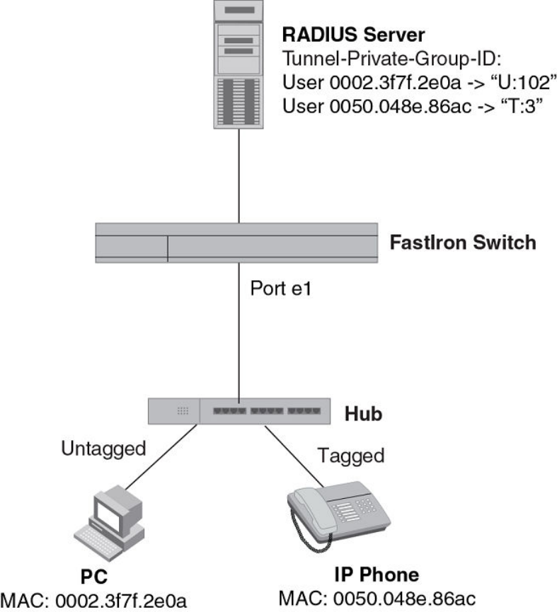
FIGURE 15 Using multi-device port authentication with dynamic VLAN assignment
In this example, multi-device port authentication is performed for both devices. If the PC is successfully
authenticated, port e1 PVID is changed from VLAN 1 (the DEFAULT-VLAN) to VLAN 102. If
authentication for the PC fails, then the PC can be placed in a specified "restricted" VLAN, or traffic from
the PC can be blocked in hardware. In this example, if authentication for the PC fails, the PC would be
placed in VLAN 1023, the restricted VLAN.
If authentication for the IP phone is successful, then port e1 is added to VLAN 3. If authentication for the
IP phone fails, then traffic from the IP phone would be blocked in hardware. (Devices sending tagged
traffic cannot be placed in the restricted VLAN.)
The portion of the running-config related to multi-device port authentication is as follows.
mac-authentication enable
mac-authentication auth-fail-vlan-id 1023
interface ethernet 1
dual-mode
mac-authentication enable
Multi-Device Port Authentication for ICX 6650 and FSX Devices
FastIron Ethernet Switch Security Configuration Guide 307
53-1003405-04
mac-authentication auth-fail-action restrict-vlan
mac-authentication enable-dynamic-vlan
mac-authentication disable-ingress-filtering
The mac-authentication disable-ingress-filtering command enables tagged packets on the port,
even if the port is not a member of the VLAN. If this feature is not enabled, authentication works as in
Example 2 -- multi-device port authentication with dynamic VLAN assignment on page 308
Example 2 -- multi-device port authentication with dynamic VLAN assignment
The following figure illustrates multi-device port authentication with dynamic VLAN assignment on a
Brocade device. In this configuration, a PC and an IP phone are connected to a hub, which is
connected to port e1 on a Brocade device. Port e1 is configured as a dual-mode port. The profile for
the PC MAC address on the RADIUS server specifies that the PC should be dynamically assigned to
VLAN 102, and the RADIUS profile for the IP phone specifies that it should be dynamically assigned to
VLAN 3.
Example 2 -- multi-device port authentication with dynamic VLAN assignment
308 FastIron Ethernet Switch Security Configuration Guide
53-1003405-04
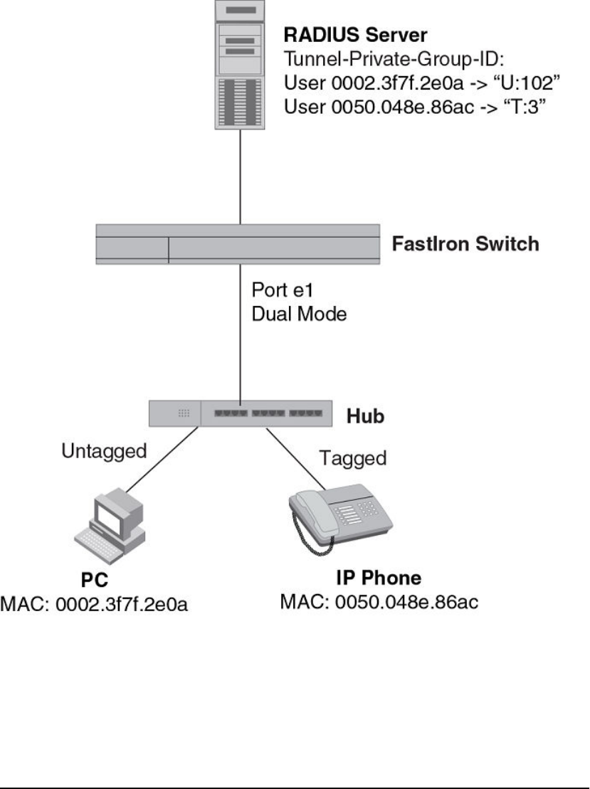
FIGURE 16 Using multi-device port authentication with dynamic VLAN assignment
In this example, multi-device port authentication is performed for both devices. If the PC is successfully
authenticated, dual-mode port e1 PVID is changed from the VLAN 1 (the DEFAULT-VLAN) to VLAN
102. If authentication for the PC fails, then the PC can be placed in a specified "restricted" VLAN, or
traffic from the PC can be blocked in hardware. In this example, if authentication for the PC fails, the PC
would be placed in VLAN 1023, the restricted VLAN.
If authentication for the IP phone is successful, then dual-mode port e1 is added to VLAN 3. If
authentication for the IP phone fails, then traffic from the IP phone would be blocked in hardware.
(Devices sending tagged traffic cannot be placed in the restricted VLAN.)
NOTE
This example assumes that the IP phone initially transmits untagged packets (for example, CDP or
DHCP packets), which trigger the authentication process on the Brocade device and client lookup on
the RADIUS server. If the phone sends only tagged packets and the port (e1) is not a member of that
Multi-Device Port Authentication for ICX 6650 and FSX Devices
FastIron Ethernet Switch Security Configuration Guide 309
53-1003405-04

VLAN, authentication would not occur. In this case, port e1 must be added to that VLAN prior to
authentication.
The part of the running-config related to multi-device port authentication would be as follows.
mac-authentication enable
mac-authentication auth-fail-vlan-id 1023
interface ethernet 1
mac-authentication enable
mac-authentication auth-fail-action restrict-vlan
mac-authentication enable-dynamic-vlan
dual-mode
Examples of multi-device port authentication and 802.1X
authentication configuration on the same port
The following examples show configurations that use multi-device port authentication and 802.1X
authentication on the same port.
Example 1 -- Multi-device port authentication and 802.1x authentication on the same port
The following figure illustrates an example configuration that uses multi-device port authentication and
802.1X authentication n the same port. In this configuration, a PC and an IP phone are connected to
port e 1/3 on a Brocade device. Port e 1/3 is configured as a dual-mode port.
The profile for the PC MAC address on the RADIUS server specifies that the PC should be
dynamically assigned to VLAN "Login-VLAN", and the RADIUS profile for the IP phone specifies that it
should be dynamically assigned to the VLAN named "IP-Phone-VLAN". When User 1 is successfully
authenticated using 802.1X authentication, the PC is then placed in the VLAN named "User-VLAN".
NOTE
This example assumes that the IP phone initially transmits untagged packets (for example, CDP or
DHCP packets), which trigger the authentication process on the Brocade device and client lookup on
the RADIUS server. If the phone sends only tagged packets and the port (e 1/3) is not a member of
that VLAN, authentication would not occur. In this case, port e 1/3 must be added to that VLAN prior to
authentication.
Examples of multi-device port authentication and 802.1X authentication configuration on the same port
310 FastIron Ethernet Switch Security Configuration Guide
53-1003405-04
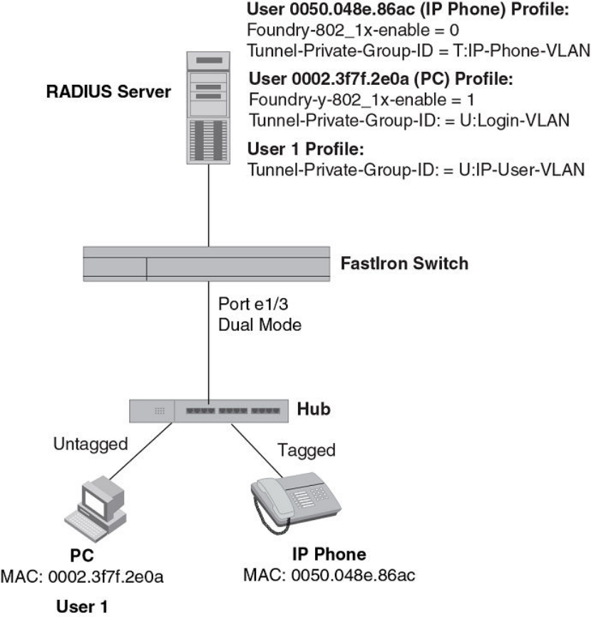
FIGURE 17 Using multi-device port authentication and 802.1X authentication on the same port
When the devices attempt to connect to the network, they are first subject to multi-device port
authentication.
When the MAC address of the IP phone is authenticated, the Access-Accept message from the
RADIUS server specifies that the IP phone port be placed into the VLAN named "IP-Phone-VLAN".
which is VLAN 7. The Foundry-802_1x-enable attribute is set to 0, meaning that 802.1X authentication
is skipped for this MAC address. Port e 1/3 is placed in VLAN 7 as a tagged port. No further
authentication is performed.
When the PC MAC address is authenticated, the Access-Accept message from the RADIUS server
specifies that the PVID for the PC port be changed to the VLAN named "Login-VLAN", which is VLAN
1024. The Foundry-802_1x-enable attribute is set to 1, meaning that 802.1X authentication is required
for this MAC address. The PVID of the port e 1/3 is temporarily changed to VLAN 1024, pending 802.1X
authentication.
Multi-Device Port Authentication for ICX 6650 and FSX Devices
FastIron Ethernet Switch Security Configuration Guide 311
53-1003405-04
When User 1 attempts to connect to the network from the PC, he is subject to 802.1X authentication. If
User 1 is successfully authenticated, the Access-Accept message from the RADIUS server specifies
that the PVID for User 1 port be changed to the VLAN named "User-VLAN", which is VLAN 3. If
802.1X authentication for User 1 is unsuccessful, the PVID for port e 1/3 is changed to that of the
restricted VLAN, which is 1023, or untagged traffic from port e 1/3 can be blocked in hardware.
The part of the running-config related to port e 1/3 would be as follows.
interface ethernet 1/3
dot1x port-control auto
mac-authentication enable
dual-mode
When the PC is authenticated using multi-device port authentication, the port PVID is changed to
"Login-VLAN", which is VLAN 1024 in this example.
When User 1 is authenticated using 802.1X authentication, the port PVID is changed to "User-VLAN",
which is VLAN 3 in this example.
Example 2 -- Creating a profile on the RADIUS server for each MAC address
The configuration in the 802.1X Authentication is performed when a device fails multi-device port
authentication figure requires that you create a profile on the RADIUS server for each MAC address to
which a device or user can connect to the network. In a large network, this can be difficult to
implement and maintain.
As an alternative, you can create MAC address profiles only for those devices that do not support
802.1X authentication, such as IP phones and printers, and configure the device to perform 802.1X
authentication for the other devices that do not have MAC address profiles, such as user PCs. To do
this, you configure the device to perform 802.1X authentication when a device fails multi-device port
authentication.
The following figure shows a configuration where multi-device port authentication is performed for an
IP phone, and 802.1X authentication is performed for a user PC. There is a profile on the RADIUS
server for the IP phone MAC address, but not for the PC MAC address.
Example 2 -- Creating a profile on the RADIUS server for each MAC address
312 FastIron Ethernet Switch Security Configuration Guide
53-1003405-04
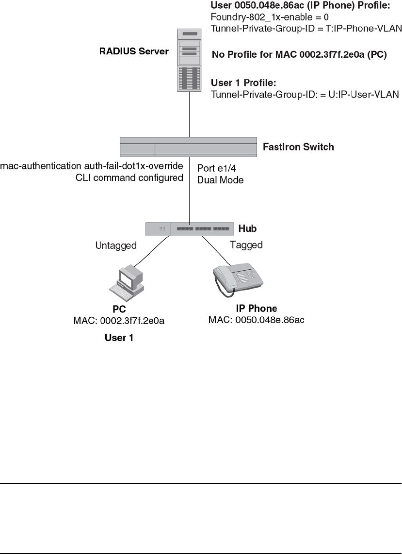
FIGURE 18 802.1X Authentication is performed when a device fails multi-device port authentication
Multi-device port authentication is initially performed for both devices. The IP phone MAC address has a
profile on the RADIUS server. This profile indicates that 802.1X authentication should be skipped for
this device, and that the device port be placed into the VLAN named "IP-Phone-VLAN".
Since there is no profile for the PC MAC address on the RADIUS server, multi-device port
authentication for this MAC address fails. Ordinarily, this would mean that the PVID for the port would
be changed to that of the restricted VLAN, or traffic from this MAC would be blocked in hardware.
However, the device is configured to perform 802.1X authentication when a device fails multi-device
port authentication, so when User 1 attempts to connect to the network from the PC, he is subject to
802.1X authentication. If User 1 is successfully authenticated, the PVID for port e 1/4 is changed to the
VLAN named "User-VLAN".
NOTE
This example assumes that the IP phone initially transmits untagged packets (for example, CDP or
DHCP packets), which trigger the authentication process on the Brocade device and client lookup on
the RADIUS server. If the phone sends only tagged packets and the port (e 1/4) is not a member of that
VLAN, authentication would not occur"User-VLAN"n this case, port e 1/4 must be added to that VLAN
prior to authentication.
Multi-Device Port Authentication for ICX 6650 and FSX Devices
FastIron Ethernet Switch Security Configuration Guide 313
53-1003405-04
To configure the device to perform 802.1X authentication when a device fails multi-device port
authentication, enter the following command.
device(config)#mac-authentication auth-fail-dot1x-override
Syntax: [no] mac-authentication auth-fail-dot1x-override
Multi-Device Port Authentication for ICX 6650 and FSX Devices
314 FastIron Ethernet Switch Security Configuration Guide
53-1003405-04

Flexible Authentication
● Flexible Authentication Feature Support....................................................................... 315
● Flexible authentication.................................................................................................. 317
● How flexible authentication works................................................................................. 318
● Authentication failure and timeout options.................................................................... 319
● Authentication flow........................................................................................................ 322
● Flexible authentication assumptions............................................................................. 323
● 802.1x Port Security......................................................................................................324
● Multi-Device Port Authentication................................................................................... 351
Flexible Authentication Feature Support
Lists the flexible authentication features supported in FastIron devices.
The following table lists individual Brocade switches and the flexible authentication features they
support.
NOTE
Flexible authentication combines Multi-device port authentication and 802.1x authentication as a single
authentication procedure. This method is currently supported only on the devices listed below. Refer to
the 802.1X Port Security for ICX 6650 and FSX Devices chapter for 802.1x Port Security configuration
on ICX 6650 and FSX devices. Refer to the Multi-Device Port Authentication for ICX 6650 and FSX
Devices chapter for Multi-Device Port Authentication configuration on ICX 6650 and FSX devices.
Feature ICX 6430 ICX 6450 FCX ICX 6610 ICX 6650 FSX 800
FSX 1600
ICX 7450 ICX 7750
Flexible Authentication 08.0.20 08.0.20 08.0.20 08.0.20 No No 08.0.20 08.0.20
802.1x Port Security Support
Lists the 802.1x Port Security features supported in FastIron devices.
The following table lists individual Brocade switches and the 802.1x Port Security features they support.
These features are supported in the Layer 2 and Layer 3 software images, except where explicitly
noted.
Feature ICX 6430 ICX 6450 FCX ICX 6610 ICX 6650 FSX 800
FSX 1600
ICX 7450 ICX 7750
802.1X port security 08.0.01 08.0.01 08.0.01 08.0.01 08.0.01 08.0.01 08.0.20 08.0.10
EAP pass-through support 08.0.01 08.0.01 08.0.01 08.0.01 08.0.01 08.0.01 08.0.20 08.0.10
FastIron Ethernet Switch Security Configuration Guide 315
53-1003405-04

Feature ICX 6430 ICX 6450 FCX ICX 6610 ICX 6650 FSX 800
FSX 1600
ICX 7450 ICX 7750
802.1X accounting 08.0.01 08.0.01 08.0.01 08.0.01 08.0.01 08.0.01 08.0.20 08.0.10
802.1X dynamic assignment for
ACL, MAC address filter, and VLAN
08.0.01 08.0.01 08.0.01 08.0.01 08.0.01 08.0.01 08.0.20 08.0.10
Automatic removal of Dynamic
VLAN for 802.1X ports
08.0.01 08.0.01 08.0.01 08.0.01 08.0.01 08.0.01 08.0.20 08.0.10
RADIUS timeout action 08.0.01 08.0.01 08.0.01 08.0.01 08.0.01 08.0.01 08.0.20 08.0.10
802.1X and multi-device port
authentication on the same port
08.0.01 08.0.01 08.0.01 08.0.01 08.0.01 08.0.01 08.0.20 08.0.10
802.1X and sFlow: 802.1X user
name export support for encrypted
and non-encrypted EAP types
08.0.01 08.0.01 08.0.01 08.0.01 08.0.01 08.0.01 08.0.20 08.0.10
MACsec key-based security7No No No 08.0.20 No No No No
Multi-Device Port Authentication Support
Lists the Multi-Device Port Authentication features supported in FastIron devices.
The following table lists individual Brocade switches and the Multi-Device Port Authentication features
they support. These features are supported in the Layer 2 and Layer 3 software images, except where
explicitly noted.
Feature ICX 6430 ICX 6450 FCX ICX 6610 ICX 6650 FSX 800
FSX 1600
ICX 7450 ICX 7750
Support for Multi-Device Port
Authentication together with
Dynamic VLAN assignment
08.0.01 08.0.01 08.0.01 08.0.01 08.0.01 08.0.01 08.0.20 08.0.10
Support for Multi-Device Port
Authentication together with
Dynamic ACLs
08.0.01 08.0.01 08.0.01 08.0.01 08.0.01 08.0.01 08.0.20 08.0.10
Support for Multi-Device Port
Authentication together with 802.1X
08.0.01 08.0.01 08.0.01 08.0.01 08.0.01 08.0.01 08.0.20 08.0.10
Support for Multi-Device Port
Authentication together with
Dynamic ARP inspection with
dynamic ACLs
No No No No 08.0.01 08.0.01 No No
Support for Multi-Device Port
Authentication together with DHCP
snooping with dynamic ACLs
No No No No 08.0.01 08.0.01 No No
Support for Multi-Device Port
Authentication together with Denial
of Service (DoS) attack protection
08.0.01 08.0.01 08.0.01 08.0.01 08.0.01 08.0.01 08.0.20 08.0.10
7MACsec encryption and related security features are covered in a separate chapter, MACsec Key-based Security.
Flexible Authentication
316 FastIron Ethernet Switch Security Configuration Guide
53-1003405-04

Feature ICX 6430 ICX 6450 FCX ICX 6610 ICX 6650 FSX 800
FSX 1600
ICX 7450 ICX 7750
Support for Multi-Device Port
Authentication together with Source
guard protection
08.0.20 08.0.01 08.0.01 08.0.01 08.0.01 08.0.01 08.0.20 08.0.10
Support for Multi-Device Port
Authentication together with ACL-
per-port-per-VLAN
08.0.01 08.0.01 08.0.01 08.0.01 08.0.01 08.0.01 08.0.20 08.0.10
Automatic removal of Dynamic
VLAN for MAC authenticated ports
08.0.01 08.0.01 08.0.01 08.0.01 08.0.01 08.0.01 08.0.20 08.0.10
Authenticating multiple MAC
addresses on an interface
08.0.01 08.0.01 08.0.01 08.0.01 08.0.01 08.0.01 08.0.20 08.0.10
Authenticating clients that send
tagged packets on non-member
ports
No No No No No 08.0.01 No No
Specifying the format of the MAC
addresses sent to the RADIUS
server
08.0.01 08.0.01 08.0.01 08.0.01 08.0.01 08.0.01 08.0.20 08.0.10
Specifying the authentication-failure
action
08.0.01 08.0.01 08.0.01 08.0.01 08.0.01 08.0.01 08.0.20 08.0.10
Password override 08.0.01 08.0.01 08.0.01 08.0.01 08.0.01 08.0.01 08.0.20 08.0.10
Specifying the RADIUS timeout
action
08.0.01 08.0.01 08.0.01 08.0.01 08.0.01 08.0.01 08.0.20 08.0.10
SNMP Traps 08.0.01 08.0.01 08.0.01 08.0.01 08.0.01 08.0.01 08.0.20 08.0.10
MAC Address Filters 08.0.01 08.0.01 08.0.01 08.0.01 08.0.01 08.0.01 08.0.20 08.0.10
MAC address filtering (filtering on
source and destination MAC
addresses)
08.0.01 08.0.01 08.0.01 08.0.01 08.0.01 08.0.01 08.0.20 08.0.10
Aging time for blocked MAC
Addresses
08.0.01 08.0.01 08.0.01 08.0.01 08.0.01 08.0.01 08.0.20 08.0.10
RADIUS Change of Authorization 08.0.20 08.0.20 08.0.20 08.0.20 08.0.20 08.0.20 08.0.20 08.0.20
Flexible authentication
Flexible authentication allows you to set the sequence of authentication methods.
Multi-device port authentication (MAC authentication) or 802.1x port security authentication (dot1x
authentication) can be configured at the port level to authenticate devices. MAC-authentication and
802.1x authentication can be configured in any order. When both methods are configured and the first
method succeeds, the authentication is considered complete with policies downloaded from the AAA
server. if the first method does not succeed, the second method is attempted to authenticate the
devices. The only exception to this rule is MAC authentication followed by dot1x authentication, even
after MAC-authentication succeeds; dot1x authentication is performed to be backward compatible with
the previous Brocade implementation.
Flexible authentication
FastIron Ethernet Switch Security Configuration Guide 317
53-1003405-04

When the last method or the only method fails, the MAC address of the device is blocked or is moved
to a restricted VLAN, which can be configured on the switch. If MAC authentication or 802.1x
authentication succeeds, the device can be moved into a target VLAN. When a client is placed in the
RADIUS assigned VLAN, the authentication is treated as complete.
NOTE
Refer to the FastIron Command Reference for Flexible Authentication supported commands.
How flexible authentication works
With flexible authentication, success and failure actions are applied for MAC authentication and dot1x
authentication.
Authentication success action
• MAC authentication - When MAC authentication succeeds, the MAC address is moved to a VLAN
returned by the AAA server and further authentication is carried out for the user, depending on the
attributes returned from the AAA server.
• dot1x authentication - When dot1x authentication succeeds, the MAC address is moved to the
VLAN returned by the AAA server and the authentication is complete.
Authentication failure action
A single authentication failure action that applies to MAC authentication and dot1x authentication can
be configured. An administrator can take the following actions when there is a failure:
• Block the client’s MAC address (default action) - This blocks the client from accessing any network
resource for a configured amount of time, after which it can try authenticating again.
• Move the MAC address to a restricted VLAN - This moves the client to a preconfigured, restricted
VLAN. Any access policies applied in that VLAN apply to this client. If a re-authentication timeout is
configured at the interface level, re-authentication is attempted at that time. Re-authentication in a
restricted VLAN is set by reauth-timeout at the interface level. The timeout is enabled by default
and set to 60 seconds.
Authentication timeout action
An authentication timeout action can be specified for MAC-authentication dot1x authentication
timeouts. The following options are available:
• Failure (default) - This blocks the client from accessing any network resource for a configured
amount of time, after which it can try to authenticate again.
• Success - This moves the client to an auth-default-VLAN. Re-authentication is set by reauth-
timeout at the interface level. The timeout is enabled by default and is set to 60 seconds.
• Move the client to a critical VLAN - The client is moved to a preconfigured critical VLAN. Any access
policies applied to that VLAN will apply to this client. Re-authentication in critical VLAN is set by
reauth-timeout at the interface level. The timeout is enabled by default and is set to 60 seconds.
How flexible authentication works
318 FastIron Ethernet Switch Security Configuration Guide
53-1003405-04
Authentication failure and timeout options
A client may fail to get authenticated in various scenarios. The scenarios and options available to place
the client in various VLANs due to authentication failure are described below.
• Guest VLAN -The client is moved to a Guest VLAN when it does not respond to the dot1x requests
for authentication. It is possible that the client does not have the dot1x authenticator loaded and
hence needs some way to access the network, from where it can download the authenticator. The
administrator can configure the Guest VLAN with such access and other access methods, as
required.
• Critical VLAN - There may be scenarios in which the RADIUS server is not available and
authentication fails. This can happen the first time the client is authenticating or when it re-
authenticates. The administrator can decide to grant some or the same access as original in this
situation instead of blocking the access. This VLAN should be configured with the desired access
levels.
• Restricted VLAN - When the authentication fails, the client can be moved into a restricted VLAN
instead of failing completely. The administrator may decide to grant some access in this scenario,
instead of blocking the access. This VLAN should be configured with the desired access levels.
MAC-based VLANs
MAC-based VLANs allow the creation of VLANs based on MAC addresses instead of the traditional
method of port membership. This helps the multi-level authentication become more flexible while
associating clients to VLANs.
With the port-based VLANs, if the port is moved to a dynamic VLAN and a second client attempts to
move the port again to a different VLAN, a failure is triggered, as the port can belong to only one VLAN
as an untagged member. System default VLANs or VLANs belonging to a VLAN-group are not allowed
to be MAC-based VLANs.
MAC-based VLANs and ACLs
MAC-based VLANs and ACLs allow a client to belong to a distinct VLAN and a distinct ACL.
After successful AAA authentication, the AAA server returns a VLAN which the client should belong to.
The AAA server can return only an untagged VLAN. Support for a tagged VLAN along with an untagged
VLAN is allowed only for voice VLANs, if the port is configured. The client (MAC through the incoming
port) is moved to this VLAN as a MAC-VLAN member. The client is removed from the corresponding
VLAN in situations when the client logs out, the port goes down or when the MAC ages out.
After successful AAA authentication, the AAA server may return an ACL which should be applied to this
client on the port. If MAC filters are applied on some of the clients, the subsequent clients can only have
the same type of ACLs. No combination of dynamic MAC filters are allowed on the same port. The ACL
is removed from the corresponding port when the client logs out, the port goes down or when the MAC
address ages out.
All dot1x and MAC-Authentication sessions are synchronized to the standby when changes occur to the
sessions. The session information at any given time is same on active and standby units of the stack.
Enabling flexible authentication order
Choose MAC and dot1x authentication order using this command.
To enable the authentication order, follow these steps:
Authentication failure and timeout options
FastIron Ethernet Switch Security Configuration Guide 319
53-1003405-04

1. Enter global configuration.
2. Enter the authentication command.
3. Enter the auth-order mac dot1x or auth-order dot1x mac command to choose the authentication
order.
The following example shows how to enable mac-auth followed by dot1x.
device(config)# authentication
device(config-authen)# auth-order mac dot1x
Multi-device port authentication and 802.1X security on the same port
On some Brocade devices, multi-device port authentication and 802.1X security can be configured on
the same port, as long as the port is not a trunk port or an LACP port. When both of these features are
enabled on the same port, multi-device port authentication is performed prior to 802.1X authentication.
If multi-device port authentication is successful, 802.1X authentication may be performed, based on
the configuration of a vendor-specific attribute (VSA) in the profile for the MAC address on the
RADIUS server.
NOTE
When multi-device port authentication and 802.1X security are configured together on the same port,
Brocade recommends that dynamic VLANs and dynamic ACLs are done at the multi-device port
authentication level, and not at the 802.1X level.
When both features are configured on a port, a device connected to the port is authenticated as
follows.
1. Multi-device port authentication is performed on the device to authenticate the device MAC address.
2. If multi-device port authentication is successful for the device, then the device checks whether the
RADIUS server included the Foundry-802_1x-enable VSA (described in the Brocade vendor-
specific attributes for RADIUS table) in the Access-Accept message that authenticated the device.
3. If the Foundry-802_1x-enable VSA is not present in the Access-Accept message, or is present and
set to 1, then 802.1X authentication is performed for the device.
4. If the Foundry-802_1x-enable VSA is present in the Access-Accept message, and is set to 0, then
802.1X authentication is skipped. The device is authenticated, and any dynamic VLANs specified in
the Access-Accept message returned during multi-device port authentication are applied to the port.
5. If 802.1X authentication is performed on the device, and is successful, then dynamic VLANs or
ACLs specified in the Access-Accept message returned during 802.1X authentication are applied to
the port.
If multi-device port authentication fails for a device, then by default traffic from the device is either
blocked in hardware, or the device is placed in a restricted VLAN. You can optionally configure the
Brocade device to perform 802.1X authentication on a device when it fails multi-device port
authentication. Refer to Example 2 -- Creating a profile on the RADIUS server for each MAC
address on page 312 for a sample configuration where this is used.
Specifying the auth-default VLAN
You must specify the default VLAN. This is applicable to both dot 1x and MAC authentication.
This VLAN must be configured to enable authentication. When any port is enabled for dot1x or MAC
authentication, the port is moved into this VLAN by default as a MAC-based VLAN member.
Sometimes the RADIUS server may authenticate the client but not return the required VLAN
Multi-device port authentication and 802.1X security on the same port
320 FastIron Ethernet Switch Security Configuration Guide
53-1003405-04
information on where the client should be placed. The auth-default VLAN is used in this scenario. This
VLAN should be configured with the required access levels.
Without specifying this VLAN ID, the user doesn’t belong to any VLAN and authentication may fail. This
VLAN should be specified at the global and interface levels. To specify the default VLAN at the global
configuration, follow these steps.
1. Enter global configuration mode.
2. Enter the authentication command.
3. Enter the auth-default-vlan<vlan id> command.
The following example shows the default VLAN specified at the global level.
device(config-authen)# auth-default-vlan 2
Configuring the auth-default-vlan at the interface level is preferred over the global auth-default-vlan. The
client can be placed in this VLAN if the RADIUS server doesn't return any VLAN information. The
following example shows the default VLAN specified at the interface level.
device(config-if-e1000-1/1/1)# auth-default-vlan 3
Specifying the restricted VLAN
This is an optional step applicable to both MAC authentication and dot1x authentication.
To specify the restricted VLAN at the global configuration, follow these steps.
1. Enter global configuration mode.
2. Enter the authentication command.
3. Enter the restricted-vlan command.
The following example shows the restricted VLAN specified.
device(config-authen)# restricted-vlan 4
Specifying the critical VLAN
This step is applicable to both MAC authentication and dot1x authentication and is used when the
RADIUS server times out while re-authenticating the users.
To specify the restricted VLAN at the global configuration, follow these steps.
1. Enter global configuration mode.
2. Enter the authentication command.
3. Enter the critical-vlan command.
The following example shows the critical VLAN specified.
device(config-authen)# critical-vlan 7
Specifying the restricted VLAN
FastIron Ethernet Switch Security Configuration Guide 321
53-1003405-04
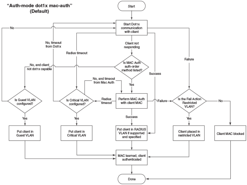
Authentication flow
Multiple authentication methods are supported as part of flexible authentication.
Single method
If only dot1x or MAC authentication is configured at the port level, then either method is attempted and
when it fails, the appropriate failure action is applied. If it succeeds, the action from the authentication
success is applied and the authentication is complete.
Multiple methods
If Dot1x followed by MAC-Authentication is configured: Dot1x authentication is attempted first. If
the device does not respond to dot1x messages, then MAC-authentication is attempted. If MAC-
authentication fails, the failure action is applied; alternately any policies returned by the AAA server
are applied.
If MAC Authentication followed by Dot1x is configured: MAC authentication is attempted first. If
MAC authentication succeeds and depending on the returned attributes from the AAA server, dot1x
authentication may be attempted. When MAC authentication fails and dot1x override is configured,
then dot1x is attempted. If dot1x fails, the failure action is applied; alternately any policies returned by
AAA server are applied.
Authentication flow
322 FastIron Ethernet Switch Security Configuration Guide
53-1003405-04
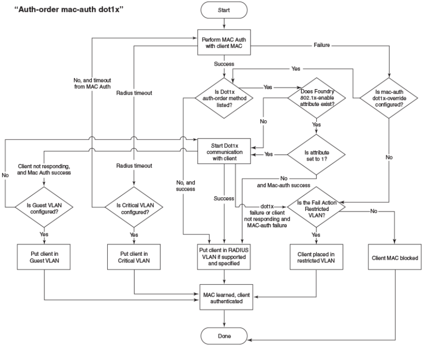
Flexible authentication assumptions
The following assumptions and restrictions are implicitly assumed to implement flexible authentication.
•Port VLAN State - To enable authentication on a port, the port must belong to the system default-
vlan. After authentication is enabled on a port, the port becomes part of the auth-default-vlan as a
MAC-based VLAN.
•Voice VLAN - Prior to configuring authentication the port can only be part of the system default
VLAN, with the exception being support for voice VLAN. When a voice VLAN is configured on the
port, the port is expected to be a tagged member in the voice VLAN. Authentication is still allowed on
the port when the voice VLAN is enabled. This is mandatory to have the IP phones work with dot1x
authentication and MAC authentication.
•Dynamic VLAN - In general, a RADIUS server returns the VLAN information, so the user (MAC
address) can be assigned to that VLAN. When the RADIUS doesn't return the VLAN information, the
auth default VLAN configured in the authentication configuration is used to associate the MAC
address. As flexible authentication uses MAC-based VLANs, it's recommended to configure the
VLAN information in the RADIUS server. A port can be configured with single or multiple
authentication methods. If only one authentication is performed, then the VLAN returned from that
authentication is used. If multiple authentications (dot1x and MAC-authentication) are performed, the
VLAN from the last authentication is used. If the last authentication doesn't return any VLAN, the
VLAN from the previous method is used. This ensures that the user is always placed in a VLAN.
Flexible authentication assumptions
FastIron Ethernet Switch Security Configuration Guide 323
53-1003405-04

802.1x Port Security
IETF RFC support
Brocade FastIron devices support the IEEE 802.1X standard for authenticating devices attached to
LAN ports. Using 802.1X port security, you can configure a FastIron device to grant access to a port
based on information supplied by a client to an authentication server.
When a user logs on to a network that uses 802.1X port security, the Brocade device grants (or does
not grant) access to network services after the user is authenticated by an authentication server. The
user-based authentication in 802.1X port security provides an alternative to granting network access
based on a user IP address, MAC address, or subnetwork.
The Brocade implementation of 802.1X port security supports the following RFCs:
• RFC 2284 PPP Extensible Authentication Protocol (EAP)
• RFC 2865 Remote Authentication Dial In User Service (RADIUS)
• RFC 2869 RADIUS Extensions
How 802.1X port security works
This section explains the basic concepts behind 802.1X port security, including device roles, how the
devices communicate, and the procedure used for authenticating clients.
NOTE
802.1X Port Security cannot be configured on MAC Port Security-enabled ports.
Device roles in an 802.1X configuration
The 802.1X standard defines the roles of Client/Supplicant, Authenticator, and Authentication Server
in a network.
The Client (known as a Supplicant in the 802.1X standard) provides username/password information
to the Authenticator. The Authenticator sends this information to the Authentication Server. Based on
the Client's information, the Authentication Server determines whether the Client can use services
provided by the Authenticator. The Authentication Server passes this information to the Authenticator,
which then provides services to the Client, based on the authentication result.
The following figure illustrates these roles.
802.1x Port Security
324 FastIron Ethernet Switch Security Configuration Guide
53-1003405-04

FIGURE 19 Authenticator, client/supplicant, and authentication server in an 802.1X configuration
Authenticator - The device that controls access to the network. In an 802.1X configuration, the
Brocade device serves as the Authenticator. The Authenticator passes messages between the Client
and the Authentication Server. Based on the identity information supplied by the Client, and the
authentication information supplied by the Authentication Server, the Authenticator either grants or does
not grant network access to the Client.
Client/Supplicant - The device that seeks to gain access to the network. Clients must be running
software that supports the 802.1X standard (for example, the Windows XP operating system). Clients
can either be directly connected to a port on the Authenticator, or can be connected by way of a hub.
Authentication server - The device that validates the Client and specifies whether or not the Client
may access services on the device. Brocade supports Authentication Servers running RADIUS.
Flexible Authentication
FastIron Ethernet Switch Security Configuration Guide 325
53-1003405-04

Communication between the devices
For communication between the devices, 802.1X port security uses the Extensible Authentication
Protocol (EAP), defined in RFC 2284. The 802.1X standard specifies a method for encapsulating EAP
messages so that they can be carried over a LAN. This encapsulated form of EAP is known as EAP
over LAN (EAPOL). The standard also specifies a means of transferring the EAPOL information
between the Client/Supplicant, Authenticator, and Authentication Server.
EAPOL messages are passed between the Port Access Entity (PAE) on the Supplicant and the
Authenticator. The following figure shows the relationship between the Authenticator PAE and the
Supplicant PAE.
FIGURE 20 Authenticator PAE and supplicant PAE
Authenticator PAE - The Authenticator PAE communicates with the Supplicant PAE, receiving
identifying information from the Supplicant. Acting as a RADIUS client, the Authenticator PAE passes
the Supplicant information to the Authentication Server, which decides whether the Supplicant can
gain access to the port. If the Supplicant passes authentication, the Authenticator PAE grants it access
to the port.
Supplicant PAE - The Supplicant PAE supplies information about the Client to the Authenticator PAE
and responds to requests from the Authenticator PAE. The Supplicant PAE can also initiate the
authentication procedure with the Authenticator PAE, as well as send log off messages.
Controlled and uncontrolled ports
A physical port on the device used with 802.1X port security has two virtual access points: a controlled
port and an uncontrolled port. The controlled port provides full access to the network. The uncontrolled
port provides access only for EAPOL traffic between the Client and the Authentication Server. When a
Client is successfully authenticated, the controlled port is opened to the Client. The following figure
illustrates this concept.
Communication between the devices
326 FastIron Ethernet Switch Security Configuration Guide
53-1003405-04
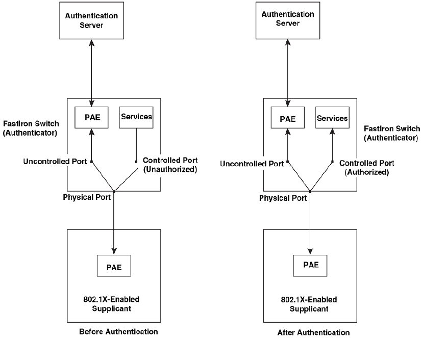
FIGURE 21 Controlled and uncontrolled ports before and after client authentication
Before a Client is authenticated, only the uncontrolled port on the Authenticator is open. The
uncontrolled port allows only EAPOL frames to be exchanged between the Client and the
Authentication Server. The controlled port is in the unauthorized state and allows no traffic to pass
through.
During authentication, EAPOL messages are exchanged between the Supplicant PAE and the
Authenticator PAE, and RADIUS messages are exchanged between the Authenticator PAE and the
Authentication Server.Refer to Message exchange during authentication on page 233 for an example of
this process. If the Client is successfully authenticated, the controlled port becomes authorized, and
traffic from the Client can flow through the port normally.
By default, all controlled ports on the Brocade device are placed in the authorized state, allowing all
traffic. When authentication is activated on an 802.1X-enabled interface, the interface controlled port is
placed initially in the unauthorized state. When a Client connected to the port is successfully
authenticated, the controlled port is then placed in the authorized state until the Client logs off. Refer to
Enabling 802.1X port security on page 251 for more information.
Message exchange during authentication
The following figure illustrates a sample exchange of messages between an 802.1X-enabled Client, a
FastIron switch acting as Authenticator, and a RADIUS server acting as an Authentication Server.
Message exchange during authentication
FastIron Ethernet Switch Security Configuration Guide 327
53-1003405-04
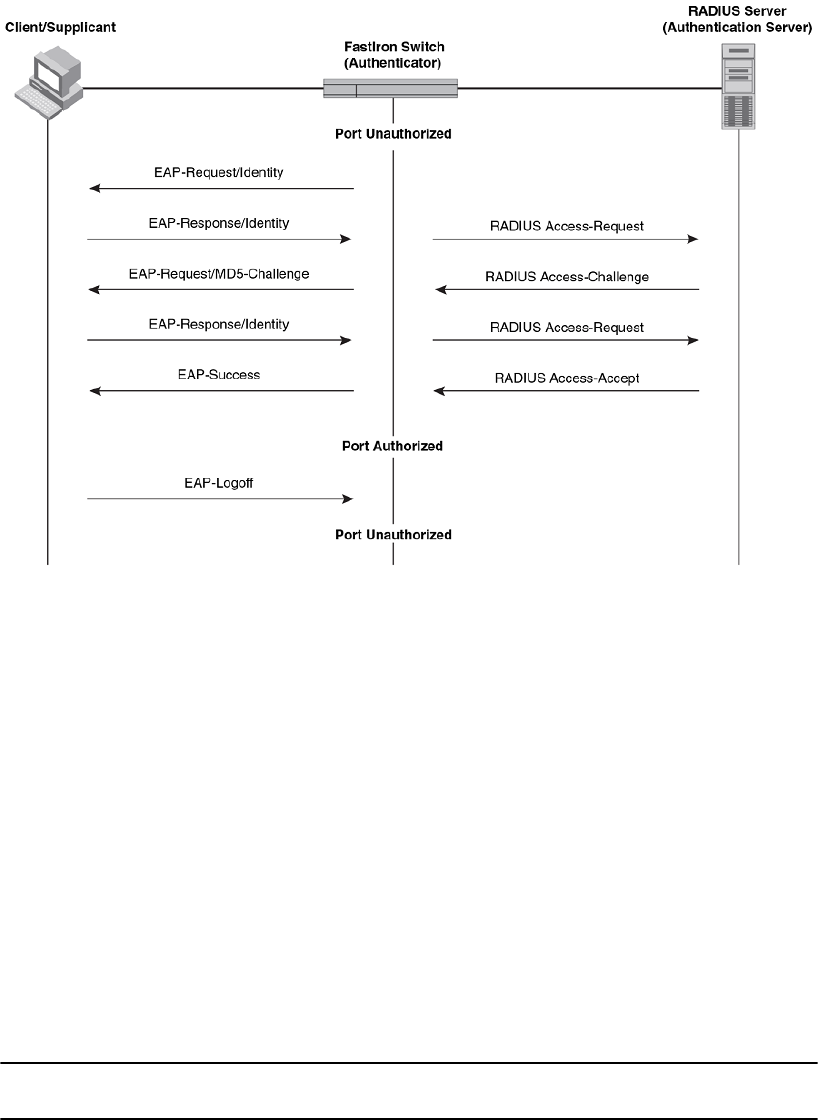
FIGURE 22 Message exchange between client/supplicant, authenticator, and authentication server
In this example, the Authenticator (the FastIron switch) initiates communication with an 802.1X-
enabled Client. When the Client responds, it is prompted for a username (255 characters maximum)
and password. The Authenticator passes this information to the Authentication Server, which
determines whether the Client can access services provided by the Authenticator. When the Client is
successfully authenticated by the RADIUS server, the port is authorized. When the Client logs off, the
port becomes unauthorized again.
The Brocade 802.1X implementation supports dynamic VLAN assignment. If one of the attributes in
the Access-Accept message sent by the RADIUS server specifies a VLAN identifier, and this VLAN is
available on the Brocade device, the client port becomes a MAC VLAN member of the specified
VLAN. When the client disconnects from the network, the port is removed from the authorized VLAN.
Refer to Dynamic VLAN assignment for 802.1X port configuration on page 243 for more information.
If a Client does not support 802.1X, authentication cannot take place. The Brocade device sends EAP-
Request/Identity frames to the Client, but the Client does not respond to them.
When a Client that supports 802.1X attempts to gain access through a non-802.1X-enabled port, it
sends an EAP start frame to the Brocade device. When the device does not respond, the Client
considers the port to be authorized, and starts sending normal traffic.
Brocade devices support Identity and MD5-challenge requests in EAP Request/Response messages
as well as the following 802.1X authentication challenge types:
NOTE
Refer to also EAP pass-through support on page 236.
• EAP-TLS (RFC 2716) - EAP Transport Level Security (TLS) provides strong security by requiring
both client and authentication server to be identified and validated through the use of public key
infrastructure (PKI) digital certificates. EAP-TLS establishes a tunnel between the client and the
Flexible Authentication
328 FastIron Ethernet Switch Security Configuration Guide
53-1003405-04

authentication server to protect messages from unauthorized users’ eavesdropping activities. Since
EAP-TLS requires PKI digital certificates on both the clients and the authentication servers, the roll
out, maintenance, and scalability of this authentication method is much more complex than other
methods. EAP-TLS is best for installations with existing PKI certificate infrastructures.
• EAP-TTLS (Internet-Draft) - The EAP Tunnelled Transport Level Security (TTLS) is an extension of
EAP-TLS Like TLS, EAP-TTLS provides strong authentication; however it requires only the
authentication server to be validated by the client through a certificate exchange between the server
and the client. Clients are authenticated by the authentication server using user names and
passwords.
A TLS tunnel can be used to protect EAP messages and existing user credential services such as
Active Directory, RADIUS, and LDAP. Backward compatibility for other authentication protocols such as
PAP, CHAP, MS-CHAP, and MS-CHAP-V2 are also provided by EAP-TTLS. EAP-TTLS is not
considered foolproof and can be fooled into sending identity credentials if TLS tunnels are not used.
EAP-TTLS is suited for installations that require strong authentication without the use of mutual PKI
digital certificates.
• PEAP (Internet-Draft) - Protected EAP Protocol (PEAP) is an Internet-Draft that is similar to EAP-
TTLS. PEAP client authenticates directly with the backend authentication server. The authenticator
acts as a pass-through device, which does not need to understand the specific EAP authentication
protocols.
Unlike EAP-TTLS, PEAP does not natively support user name and password to authenticate clients
against an existing user database such as LDAP. PEAP secures the transmission between the client
and authentication server with a TLS encrypted tunnel. PEAP also allows other EAP authentication
protocols to be used. It relies on the mature TLS keying method for its key creation and exchange.
PEAP is best suited for installations that require strong authentication without the use of mutual
certificates.
Configuration for these challenge types is the same as for the EAP-MD5 challenge type.
NOTE
If the 802.1X Client will be sending a packet that is larger than 1500 bytes, you must enable jumbo at
the Global config level of the CLI. If the supplicant or the RADIUS server does not support jumbo
frames and jumbo is enabled on the switch, you can set the CPU IP MTU size.
EAP pass-through support
EAP pass-through is supported on FastIron devices that have 802.1X enabled. EAP pass-through
support is fully compliant with RFC 3748, in which, by default, compliant pass-through authenticator
implementations forward EAP challenge request packets of any type, including those listed in the
previous section.
Support for RADIUS user-name attribute in access-accept messages
Brocade 802.1X-enabled ports support the RADIUS user-name (type 1) attribute in the Access-Accept
message returned during 802.1X authentication.
This feature is useful when the client/supplicant does not provide its user-name in the EAP-response/
identity frame, and the username is key to providing useful information. For example, when the user-
name attribute is sent in the Access-Accept message, it is then available for display in sFlow sample
messages sent to a collector, and in the output of some show dot1x CLI commands, such as show
dot1x sessions.
This same information is sent as the "user-name" attribute of RADIUS accounting messages, and is
sent to the RADIUS accounting servers.
To enable this feature, add the following attribute on the RADIUS server.
EAP pass-through support
FastIron Ethernet Switch Security Configuration Guide 329
53-1003405-04
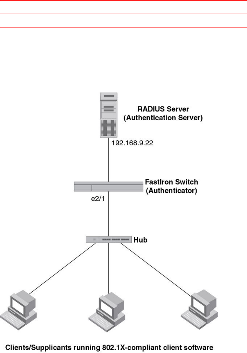
Attribute name Type Value
user-name 1 name (string)
Authenticating multiple hosts connected to the same port
Brocade devices support 802.1X authentication for ports with more than one host connected to them.
The following figure illustrates a sample configuration where multiple hosts are connected to a single
802.1X port.
FIGURE 23 Multiple hosts connected to a single 802.1X-enabled port
If there are multiple hosts connected to a single 802.1X-enabled port, the Brocade device
authenticates each of them individually. Each host authentication status is independent of the others,
Authenticating multiple hosts connected to the same port
330 FastIron Ethernet Switch Security Configuration Guide
53-1003405-04
so that if one authenticated host disconnects from the network, it has no effect on the authentication
status of any of the other authenticated hosts.
By default, traffic from hosts that cannot be authenticated by the RADIUS server is dropped in
hardware. You can optionally configure the Brocade device to assign the port to a "restricted" VLAN if
authentication of the Client is unsuccessful.
How 802.1X host authentication works
When multiple hosts are connected to a single 802.1X-enabled port on a Brocade device, 802.1X
authentication is performed in the following way.
1. One of the 802.1X-enabled Clients attempts to log into a network in which a Brocade device serves
as an Authenticator.
2. The Brocade device creates an internal session (called a dot1x-mac-session) for the Client. A dot1x-
mac-session serves to associate a Client MAC address and username with its authentication status.
3. The Brocade device performs 802.1X authentication for the Client. Messages are exchanged
between the Brocade device and the Client, and between the device and the Authentication Server
(RADIUS server). The result of this process is that the Client is either successfully authenticated or
not authenticated, based on the username and password supplied by the client.
4. If the Client is successfully authenticated, the Client dot1x-mac-session is set to "access-is-allowed".
This means that traffic from the Client can be forwarded normally.
5. If authentication for the Client is unsuccessful, an authentication-failure action is taken. The
authentication-failure action can be either to drop traffic from the Client, or to place the port in a
"restricted" VLAN:
• If the authentication-failure action is to drop traffic from the Client, then the Client dot1x-mac-
session is set to "access-denied", causing traffic from the Client to be dropped in hardware.
• If the authentication-failure action is to place the port in a "restricted" VLAN, If the Client dot1x-
mac-session is set to "access-restricted" then the port is moved to the specified restricted VLAN,
and traffic from the Client is forwarded normally.
6. When the Client disconnects from the network, the Brocade device deletes the Client dot1x-mac-
session. This does not affect the dot1x-mac-session or authentication status (if any) of the other
hosts connected on the port.
Configuration notes for 802.1x multiple-host authentication
• The Client dot1x-mac-session establishes a relationship between the username and MAC address
used for authentication. If a user attempts to gain access from different Clients (with different MAC
addresses), he or she would need to be authenticated from each Client.
• If a Client has been denied access to the network (that is, the Client dot1x-mac-session is set to
"access-denied"), then you can cause the Client to be re-authenticated by manually disconnecting
the Client from the network, or by using the clear dot1x-session command. Refer to the Clearing a
dot1x-session for a MAC address section for information on this command.
• When a Client has been denied access to the network, its dot1x-mac-session is aged out if no traffic
is received from the Client MAC address over a fixed hardware aging period (70 seconds), plus a
configurable software aging period. You can optionally change the software aging period for dot1x-
mac-sessions or disable aging altogether. After the denied Client dot1x-mac-session is aged out,
traffic from that Client is no longer blocked, and the Client can be re-authenticated.
• When a Client has been denied access to the network, if the fail-action is specified as blocked, the
device will try to re-authenticate after the specified quiet period. If the action is specified as restricted
VLAN, the device will try to re-authenticate according to the re-authentication timeout value specified.
In addition, you can configure disable aging for the dot1x-mac-session of Clients that have been
granted either full access to the network, or have been placed in a restricted VLAN. After a Client dot1x-
mac-session ages out, the Client must be re-authenticated. Refer to the Disabling aging for dot1x-mac-
sessions section for more information.
How 802.1X host authentication works
FastIron Ethernet Switch Security Configuration Guide 331
53-1003405-04
• Dynamic IP ACL and MAC address filter assignment is supported in an 802.1X multiple-host
configuration. Refer to Dynamically applying IP ACLs and MAC address filters to 802.1X ports on
page 247.
• 802.1X multiple-host authentication has the following additions:
‐Configurable hardware aging period for denied client dot1x-mac-sessions. Refer to Configurable
hardware aging period for denied client dot1x-mac-sessions on page 239.
‐Dynamic ACL and MAC address filter assignment in 802.1X multiple-host configurations. Refer
to Dynamically applying IP ACLs and MAC address filters to 802.1X ports on page 247.
‐Dynamic multiple VLAN assignment for 802.1X ports. Refer Dynamic multiple VLAN assignment
for 802.1X ports on page 245.
How 802.1x host authentication works for multiple clients
Authenticating devices on a port involves assigning VLAN IDs, dynamically or otherwise.
Authentication of multiple 802.1x-enabled clients on a single 802.1X-enabled port on a Brocade device
is performed in the following way.
• If any 802.1x-enabled client logs on to the network in which a Brocade device serves as an
authenticator. If a VLAN ID or name is included in a Radius Access-Accept message, Port is moved
to that VLAN as a MAC VLAN member.
• If any 802.1x-enabled clients do not receive VLAN information from Radius, clients authorized later
use the auth-default-vlan. See the Dynamic multiple VLAN assignment for 802.1X ports section for
more information on restrictions for dynamic VLAN assignment.
• ACLs received in Radius Access-Accept messages are applied to each 802.1x-enabled clients
separately. In a multi-host scenario some clients might have a dynamic ACL and some not. If there
are dynamic ACL for any clients, access control is applied only to clients with dynamic ACLs See
the Dynamically applying IP ACLs and MAC address filters to 802.1X ports on page 247 section for
more information on restrictions on dynamic IP ACLs or MAC address filters.
Configurable hardware aging period for denied client dot1x-mac-sessions
When one of the 802.1X-enabled Clients attempts to log into a network in which a Brocade device
serves as an Authenticator, the device creates a dot1x-mac-session for the Client.
When a Client has been denied access to the network, its dot1x-mac-session is aged out if no traffic is
received from the Client MAC address over a period of time. After a denied Client dot1x-mac-session
ages out, the Client can be re-authenticated. Aging of a denied Client's dot1x-mac-session occurs in
two phases, known as hardware aging and software aging.
The hardware aging period for a denied Client's dot1x-mac-session is not fixed at 70 seconds. The
hardware aging period for a denied Client's dot1x-mac-session is equal to the length of time specified
with the dot1x timeout quiet-period command. By default, the hardware aging time is 60 seconds.
Once the hardware aging period ends, the software aging period begins. When the software aging
period ends, the denied Client's dot1x-mac-session ages out, and the Client can be authenticated
again.
802.1X port security and sFlow
sFlow is a standards-based protocol that allows network traffic to be sampled at a user-defined rate for
the purpose of monitoring traffic flow patterns and identifying packet transfer rates on user-specified
interfaces.
When you enable sFlow forwarding on an 802.1X-enabled interface, the samples taken from the
interface include the user name string at the inbound or outbound port, or both, if that information is
available.
How 802.1x host authentication works for multiple clients
332 FastIron Ethernet Switch Security Configuration Guide
53-1003405-04
For more information on sFlow, refer to chapter "Network Monitoring" in the FastIron Ethernet Switch
Administration Guide .
802.1X accounting
When 802.1X port security is enabled on the Brocade device, you can enable 802.1X accounting. This
feature enables the Brocade device to log information on the RADIUS server about authenticated
802.1X clients. The information logged on the RADIUS server includes the 802.1X client session ID,
MAC address, and authenticating physical port number.
802.1X accounting works as follows.
1. A RADIUS server successfully authenticates an 802.1X client.
2. If 802.1X accounting is enabled, the Brocade device sends an 802.1X Accounting Start packet to the
RADIUS server, indicating the start of a new session.
3. The RADIUS server acknowledges the Accounting Start packet.
4. The RADIUS server records information about the client.
5. When the session is concluded, the Brocade device sends an Accounting Stop packet to the
RADIUS server, indicating the end of the session.
6. The RADIUS server acknowledges the Accounting Stop packet.
To enable 802.1X accounting, refer to 802.1X accounting configuration on page 260.
802.1X port security configuration
Configuring 802.1X port security on a Brocade device consists of the following tasks.
1. Configure the device interaction with the Authentication Server:
•‐Configuring an authentication method list for 802.1x on page 241
‐Setting RADIUS parameters on page 241
‐Dynamic VLAN assignment for 802.1X port configuration on page 243 (optional)
‐Dynamically applying IP ACLs and MAC address filters to 802.1X ports on page 247
2. Configure the device role as the Authenticator:
•‐Enabling 802.1X port security on page 251
‐Initializing 802.1X on a port on page 256 (optional)
3. Configure the device interaction with Clients:
•‐MAC address filters for EAP frames on page 259 (optional)
Configuring an authentication method list
To use 802.1X port security, you must specify an authentication method to be used to authenticate
Clients. Brocade supports RADIUS authentication with 802.1X port security. To use RADIUS
authentication with 802.1X port security, you create an authentication method list for 802.1X and specify
RADIUS as an authentication method, then configure communication between the Brocade device and
RADIUS server.
Brocade(config)#aaa authentication dot1x default radius
Syntax: [no] aaa authentication dot1x default method-list
For the method-list , enter at least one of the following authentication methods
radius - Use the list of all RADIUS servers that support 802.1X for authentication.
802.1X accounting
FastIron Ethernet Switch Security Configuration Guide 333
53-1003405-04

none - Use no authentication. The Client is automatically authenticated by other means, without the
device using information supplied by the Client.
NOTE
If you specify both radius and none , make sure radius comes before none in the method list.
Setting RADIUS parameters
To use a RADIUS server to authenticate access to a Brocade device, you must identify the server to
the Brocade device.
device(config)#radius-server host 10.157.22.99 auth-port 1812 acct-port 1813
default key mirabeau dot1x
Syntax: radius-server { hostip-addr | ipv6-addr | server-name } [ auth-port num | acct-port num |
default ] [ key {0 | 2 } string ] [ dot1x ]
The host ip-addr , ipv6-addr or server-name parameters are either an IP address or an ASCII text
string.
The dot1x parameter indicates that this RADIUS server supports the 802.1X standard. A RADIUS
server that supports the 802.1X standard can also be used to authenticate non-802.1X authentication
requests.
NOTE
To implement 802.1X port security, at least one of the RADIUS servers identified to the Brocade
device must support the 802.1X standard.
Supported RADIUS attributes
Many IEEE 802.1X Authenticators will function as RADIUS clients. Some of the RADIUS attributes
may be received as part of IEEE 802.1X authentication. Brocade devices support the following
RADIUS attributes for IEEE 802.1X authentication:
• Username (1) - RFC 2865
• NAS-IP-Address (4) - RFC 2865
• NAS-Port (5) - RFC 2865
• Service-Type (6) - RFC 2865
• FilterId (11) - RFC 2865
• Framed-MTU (12) - RFC 2865
• State (24) - RFC 2865
• Vendor-Specific (26) - RFC 2865
• Session-Timeout (27) - RFC 2865
• Termination-Action (29) - RFC 2865
• Calling-Station-ID (31) - RFC 2865
• NAS-Identifier (32) - RFC 2865
• NAS-Port-Type (61) - RFC 2865
• Tunnel-Type (64) - RFC 2868
• Tunnel-Medium-Type (65) - RFC 2868
• EAP Message (79) - RFC 2579
• Message-Authenticator (80) RFC 3579
Setting RADIUS parameters
334 FastIron Ethernet Switch Security Configuration Guide
53-1003405-04

• Tunnel-Private-Group-Id (81) - RFC 2868
• NAS-Port-id (87) - RFC 2869
Enabling 802.1X port security
By default, 802.1X port security is disabled on Brocade devices. To enable the feature on the device
and enter the dot1x configuration level, enter the following command.
device(config)# authentication
device(config-authen)# dot1x enable
device(config-authen)#
Syntax: [no] dot1x enable
At the dot1x configuration level, you can enable 802.1X port security on all interfaces at once, on
individual interfaces, or on a range of interfaces.
For example, to enable 802.1X port security on all interfaces on the device, enter the following
command.
device(config)# authentication
device(config-authen)# dot1x enable all
device(config-authen)#
Syntax: [no] dot1x enable all
To enable 802.1X port security on interface 3/11, enter the following command.
device(config)# authentication
device(config-authen)#dot1x enable ethernet 3/11
device(config-authen)
Syntax: [no] enable ethernet port
To enable 802.1X port security on interfaces 3/11 through 3/16, enter the following command.
device(config)# authentication
device(config-authen)#dot1x enable ethernet 3/11 to 3/16
device(config-authen)
Syntax: [no] dot1x enable ethernet port to port
NOTE
You must set the port control to activate authentication on an 802.1X-enabled interface. Refer to Setting
the port control on page 341 for more details.
Specifying the RADIUS timeout action
A RADIUS timeout occurs when the Brocade device does not receive a response from a RADIUS
server within a specified time limit and after a certain number of retries. The time limit and number of
retries can be manually configured using the CLI commands radius-server timeout and radius-server
retransmit , respectively. If the parameters are not manually configured, the Brocade device applies the
default value of three seconds with a maximum of three retries.
You can better control port behavior when a RADIUS timeout occurs by configuring a port on the
Brocade device to automatically pass or fail user authentication. A pass essentially bypasses the
authentication process and permits user access to the network. A fail bypasses the authentication
process and blocks user access to the network, unless restrict-vlan is configured, in which case, the
user is placed into a VLAN with restricted or limited access. By default, the Brocade device will reset the
authentication process and retry to authenticate the user.
Enabling 802.1X port security
FastIron Ethernet Switch Security Configuration Guide 335
53-1003405-04

Specify the RADIUS timeout action at the Interface level of the CLI.
Specifying the authentication timeout action
Specify the RADIUS timeout action at the interface level of the CLI for dot1x and MAC authentication.
Follow these steps to specify the timeout action for the RADIUS server.
1. Enter the interface configuration mode.
2. Enter the auth timeout-action command along with the required parameter. You can use either the
success, failure or critical-vlan parameter.
The example shows the auth timeout-action for the RADIUS server specified as success.
device(config-if-e1000-1/1/1)# auth timeout-action <success | failure | critical-
vlan>
Dynamic VLAN assignment for 802.1X port configuration
When a client successfully completes the EAP authentication process, the Authentication Server (the
RADIUS server) sends the Authenticator (the Brocade device) a RADIUS Access-Accept message
that grants the client access to the network. The RADIUS Access-Accept message contains attributes
set for the user in the user's access profile on the RADIUS server.
If one of the attributes in the Access-Accept message specifies a VLAN identifier, and if this VLAN is
available on the Brocade device, the client is assigned to the specified VLAN.
NOTE
When a show run command is issued during a session, the dynamically-assigned VLAN is not
displayed.
Enable 802.1X VLAN ID support by adding the following attributes to a user profile on the RADIUS
server.
Attribute name Type Value
Tunnel-Type 064 13 (decimal) - VLAN
Tunnel-Medium-Type 065 6 (decimal) - 802
Tunnel-Private-Group-ID 081 vlan-name (string) - either the name or the number of a VLAN configured on the
Brocade device.
The device reads the attributes as follows:
• If the Tunnel-Type or the Tunnel-Medium-Type attributes in the Access-Accept message do not
have the values specified above, the Brocade device ignores the three Attribute-Value pairs. The
client becomes authorized, but the client port is not dynamically placed in a VLAN.
• If the Tunnel-Type or the Tunnel-Medium-Type attributes in the Access-Accept message do have
the values specified above, but there is no value specified for the Tunnel-Private-Group-ID attribute,
the client will not become authorized.
• When the Brocade device receives the value specified for the Tunnel-Private-Group-ID attribute, it
checks whether the vlan-name string matches the name of a VLAN configured on the device. If
there is a VLAN on the device whose name matches the vlan-name string, then the client port is
placed in the VLAN whose ID corresponds to the VLAN name.
Specifying the authentication timeout action
336 FastIron Ethernet Switch Security Configuration Guide
53-1003405-04
• If the vlan-name string does not match the name of a VLAN, the Brocade device checks whether the
string, when converted to a number, matches the ID of a VLAN configured on the device. If it does,
then the client port is placed in the VLAN with that ID.
• If the vlan-name string does not match either the name or the ID of a VLAN configured on the device,
then the client will not become authorized.
The show VLAN command displays the VLAN to which an 802.1X-enabled port has been dynamically
assigned, as well as the port from which it was moved (that is, the port default VLAN).Refer to
Displaying dynamically-assigned VLAN information on page 267 for sample output indicating the port
dynamically assigned VLAN.
Dynamic multiple VLAN assignment for 802.1X ports
When you add attributes to a user profile on the RADIUS server, the value for the Tunnel-Private-
Group-ID attribute can specify the name or number of only one untagged VLAN and one voice VLAN
configured on the Brocade device.
Specifying an untagged VLAN
You can specify only one untagged VLAN. Use the following example to specify the untagged VLAN.
"U:10" or "U:marketing"'
When the RADIUS server specifies an untagged VLAN ID, the port is moved as a MAC VLAN member
to the specified VLAN. The port transmits only untagged traffic in this VLAN.
Specifying an untagged and tagged VLAN
To specify an untagged VLAN and a tagged VLANs, use the following example.
"U:10;T:20"
"U:10,T:marketing"
Considerations for dynamic VLAN assignment in an 802.1X multiple-host configuration
The following considerations apply when a Client in a 802.1X multiple-host configuration is successfully
authenticated, and the RADIUS Access-Accept message specifies a VLAN for the port:
• If the port is not already a member of a RADIUS-specified VLAN, and the RADIUS Access-Accept
message specifies the name or ID of a valid VLAN on the Brocade device, then the port is placed in
that VLAN.
• If the RADIUS Access-Accept message specifies the name or ID of a VLAN that does not exist on
the Brocade device, then it is considered an authentication failure.
• If the RADIUS Access-Accept message does not contain any VLAN information, the Client dot1x-
mac-session is set to "access-is-allowed" and the Client is placed in the auth-default-VLAN.
Dynamically applying IP ACLs and MAC address filters to 802.1X ports
The Brocade 802.1X implementation supports dynamically applying an IP ACL or MAC address filter to
a port, based on information received from an Authentication Server.
When a client/supplicant successfully completes the EAP authentication process, the Authentication
Server (the RADIUS server) sends the Authenticator (the Brocade device) a RADIUS Access-Accept
message that grants the client access to the network. The RADIUS Access-Accept message contains
attributes set for the user in the user's access profile on the RADIUS server.
If the Access-Accept message contains Filter-ID (type 11) or Vendor-Specific (type 26), or both
attributes, the Brocade device can use information in these attributes to apply an IP ACL or MAC
address filter to the authenticated port. This IP ACL or MAC address filter applies to the port for as long
Dynamic multiple VLAN assignment for 802.1X ports
FastIron Ethernet Switch Security Configuration Guide 337
53-1003405-04
as the client is connected to the network. When the client disconnects from the network, the IP ACL or
MAC address filter is no longer applied to the port.
The Brocade device uses information in the Filter ID and Vendor-Specific attributes as follows:
• The Filter-ID attribute can specify the number of an existing IP ACL or MAC address filter
configured on the Brocade device. In this case, the IP ACL or MAC address filter with the specified
number is applied to the port.
• The vendor-specific attribute can specify actual syntax for a Brocade IP ACL or MAC address filter,
which is then applied to the authenticated port. Configuring a Vendor-Specific attribute in this way
allows you to create IP ACLs and MAC address filters that apply to individual users; that is, per-user
IP ACLs or MAC address filters.
• Dynamic ACLs are not supported in layer 2 code when acl-per-port-per-VLAN is enabled.
Configuration considerations for applying IP ACLs and MAC address filters to 802.1x
ports
The following restrictions apply to dynamic IP ACLs or MAC address filters:
• The name in the Filter ID attribute is case-sensitive.
• You can specify only numbered MAC address filters in the Filter ID attribute. Named MAC address
filters are not supported.
• Dynamically assigned IP ACLs and MAC address filters are subject to the same configuration
restrictions as non-dynamically assigned IP ACLs and MAC address filters.
• If Dynamically assigned IP ACLs already exist, then MAC address filters cannot be applied
dynamically using 802.1X.
• Inbound dynamic IP ACLs are supported. Outbound dynamic ACLs are not supported.
• Inbound Vendor-Specific attributes are supported. Outbound Vendor-Specific attributes are not
supported.
• A maximum of one IP ACL per client can be configured in the inbound direction on an interface.
• 802.1X with dynamic MAC filter will work for one client at a time on a port. If a second client tries to
authenticate with 802.1X and dynamic MAC filter, the second client will be rejected.
• MAC address filters cannot be configured in the outbound direction on an interface.
• Concurrent operation of MAC address filters and IP ACLs is not supported.
• Static ACLs are not supported on the dot1x or MAC authentication enabled port. However the ACLs
can be applied on the VE of the VLAN the port belongs to.
• Concurrent operation of dynamic IP ACL and Static IP ACL is not supported.
• Dynamic IP ACL assignment with 802.1x is not supported in conjunction with any of the following
features:
‐IP source guard
‐Rate limiting
‐Protection against ICMP or TCP Denial-of-Service (DoS) attacks
‐Policy-based routing
Disabling and enabling strict security mode for dynamic filter assignment
By default, 802.1X dynamic filter assignment operates in strict security mode. When strict security
mode is enabled, 802.1X authentication for a port fails if the Filter-ID attribute contains invalid
information, or if insufficient system resources are available to implement the per-user IP ACLs or
MAC address filters specified in the Vendor-Specific attribute.
When strict security mode is enabled:
• If the Filter-ID attribute in the Access-Accept message contains a value that does not refer to an
existing filter (that is, a MAC address filter or IP ACL configured on the device), then the client will
Configuration considerations for applying IP ACLs and MAC address filters to 802.1x ports
338 FastIron Ethernet Switch Security Configuration Guide
53-1003405-04

not be authenticated, regardless of any other information in the message (for example, if the Tunnel-
Private-Group-ID attribute specifies a VLAN on which to assign the port).
• If the Vendor-Specific attribute specifies the syntax for a filter, but there are insufficient system
resources to implement the filter, then the client will not be authenticated.
• If the device does not have the system resources available to dynamically apply a filter to a port, then
the client will not be authenticated.
NOTE
If the Access-Accept message contains values for both the Filter-ID and Vendor-Specific attributes, then
the value in the Vendor-Specific attribute (the per-user filter) takes precedence.
Also, if authentication for a client fails because the Filter-ID attribute referred to a non-existent filter, or
there were insufficient system resources to implement the filter, then a Syslog message is generated.
Disabled strict security mode
When strict security mode is disabled:
• If the Filter-ID attribute in the Access-Accept message contains a value that does not refer to an
existing filter (that is, a MAC address filter or IP ACL configured on the device), then the client is still
authenticated, but no filter is dynamically applied to it.
• If the Vendor-Specific attribute specifies the syntax for a filter, but there are insufficient system
resources to implement the filter, then the client is still authenticated, but the filter specified in the
Vendor-Specific attribute is not applied to the port.
By default, strict security mode is enabled for all 802.1X-enabled interfaces, but you can manually
disable or enable it, either globally or for specific interfaces.
Disabling strict filter security
Enables or disables strict filter security for both MAC and dot1x authentication.
When enabled and if the filters contain invalid information, the authentication fails.
1. Enter global configuration.
2. Enter the authentication command.
3. Enter the filter-strict-security command.
The example shows enabling strict filter security at the global and interface levels.
device(config-authen)# filter-strict-security enable
device(config-if-e1000-1/1/1)# auth filter-strict-security enable
Dynamically applying existing ACLs or MAC address filters
When a port is authenticated using 802.1X security, an IP ACL or MAC address filter that exists in the
running-config on the Brocade device can be dynamically applied to the port. To do this, you configure
the Filter-ID (type 11) attribute on the RADIUS server. The Filter-ID attribute specifies the name or
number of the Brocade IP ACL or MAC address filter.
The following is the syntax for configuring the Filter-ID attribute to refer to a Brocade IP ACL or MAC
address filter.
Disabled strict security mode
FastIron Ethernet Switch Security Configuration Guide 339
53-1003405-04
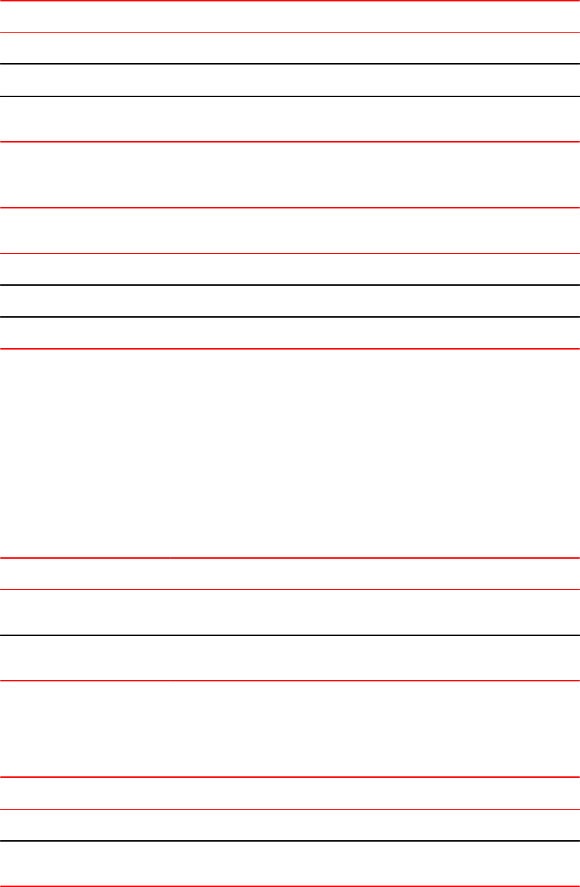
Value Description
ip.number .in Applies the specified numbered ACL to the 802.1X authenticated port in the inbound direction.
ip.name .in Applies the specified named ACL to the 802.1X authenticated port in the inbound direction.
mac.number .in Applies the specified numbered MAC address filter to the 802.1X authenticated port in the
inbound direction.
The following table lists examples of values you can assign to the Filter-ID attribute on the RADIUS
server to refer to IP ACLs and MAC address filters configured on a Brocade device.
Possible values for the filter ID attribute on
the RADIUS server
ACL or MAC address filter configured on the Brocade device
ip.102.in access-list 102 permit ip 10.0.0.0 0.255.255.255 any
ip.fdry_filter.in ip access-list standard fdry_filter permit host 10.48.0.3
mac.2.in mac filter 2 permit 3333.3333.3333 ffff.ffff.ffff any
Configuring per-user IP ACLs or MAC address filters using vendor specific attributes
Per-user IP ACLs and MAC address filters make use of the Vendor-Specific (type 26) attribute to
dynamically apply filters to ports. Defined in the Vendor-Specific attribute are Brocade ACL or MAC
address filter statements. When the RADIUS server returns the Access-Accept message granting a
client access to the network, the Brocade device reads the statements in the Vendor-Specific attribute
and applies these IP ACLs or MAC address filters to the client port. When the client disconnects from
the network, the dynamically applied filters are no longer applied to the port.
The following table shows the syntax for configuring the Brocade Vendor-Specific attributes with ACL
or MAC address filter statements.
Value Description
ipacl.e.in=extended-ACL-entries Applies the specified extended ACL entries to the 802.1X authenticated port in
the inbound direction.
macfilter.in=mac-filter-entries Applies the specified MAC address filter entries to the 802.1X authenticated
port in the inbound direction.
The following table shows examples of IP ACLs and MAC address filters configured in the Brocade
Vendor-Specific attribute on a RADIUS server. These IP ACLs and MAC address filters follow the
same syntax as other Brocade ACLs and MAC address filters. Refer to the related chapters in this
book for information on syntax.
ACL or MAC address filter Vendor-specific attribute on RADIUS server
MAC address filter with one entry macfilter.in= deny any any
MAC address filter with two entries macfilter.in= permit 0000.0000.3333 ffff.ffff.0000 any, macfilter.in= permit
0000.0000.4444 ffff.ffff.0000 any
Configuring per-user IP ACLs or MAC address filters using vendor specific attributes
340 FastIron Ethernet Switch Security Configuration Guide
53-1003405-04

The RADIUS server allows one instance of the Vendor-Specific attribute to be sent in an Access-Accept
message.
NOTE
Configuration considerations for per-user IP ACLs are similar to those applicable to applying dynamic IP
ACLs.
Setting the port control
To activate authentication on an 802.1X-enabled interface, you specify the kind of port control to be
used on the interface. An interface used with 802.1X port security has two virtual access points: a
controlled port and an uncontrolled port:
• The controlled port can be either the authorized or unauthorized state. In the authorized state, it
allows normal traffic to pass between the Client and the Authenticator. In the unauthorized state, no
traffic is allowed to pass.
• The uncontrolled port allows only EAPOL traffic between the Client and the Authentication Server.
Refer to the Controlled and uncontrolled ports before and after client authentication figure for an
illustration of this concept.
By default, all controlled ports on the device are in the authorized state, allowing all traffic. When you
activate authentication on an 802.1X-enabled interface, its controlled port is placed in the unauthorized
state. When a Client connected to the interface is successfully authenticated, the controlled port is then
placed in the authorized state. The controlled port remains in the authorized state until the Client logs
off.
To activate authentication on an 802.1X-enabled interface, you configure the interface to place its
controlled port in the authorized state when a Client is authenticated by an Authentication Server. To do
this, enter commands such as the following.
device(config)#interface e 3/1
device(config-if-3/1)#dot1x port-control auto
Syntax: no dot1x port-control [ force-authorized | force-unauthorized | auto ]
When an interface control type is set to auto, the controlled port is initially set to unauthorized, but is
changed to authorized when the connecting Client is successfully authenticated by an Authentication
Server.
The port control type can be one of the following
force-authorized - The controlled port is placed unconditionally in the authorized state, allowing all
traffic. This is the default state for ports on the Brocade device.
force-unauthorized - The controlled port is placed unconditionally in the unauthorized state.
auto - The controlled port is unauthorized until authentication takes place between the Client and
Authentication Server. Once the Client passes authentication, the port becomes authorized. This
activates authentication on an 802.1X-enabled interface.
NOTE
You cannot enable 802.1X port security on ports that have any of the following features enabled:
• Link aggregation
• Metro Ring Protocol (MRP)
• Mirror port
Setting the port control
FastIron Ethernet Switch Security Configuration Guide 341
53-1003405-04
• LAG port
• UDLD
Configuring periodic re-authentication
You can configure the device to periodically re-authenticate Clients connected to MAC authentication
and 802.1X-enabled interfaces. When you enable periodic re-authentication, the device re-
authenticates Clients every 3,600 seconds by default. You can optionally specify a different re-
authentication interval of between 1 - 4294967295 seconds.
To configure periodic re-authentication using the default interval of 3,600 seconds, enter the following
command.
device(config-authen)#re-authentication
Syntax: [no] re-authentication
To configure periodic re-authentication with an interval of 2,000 seconds, enter the following
commands.
device(config-authen)#re-authentication
device(config-authen)#reauth-period 2000
Syntax: [no] reauth-period seconds
The re-authentication interval is a global setting, applicable to all MAC authentication and 802.1X-
enabled interfaces.
Initializing 802.1X on a port
To initialize 802.1X port security on a port, enter a command such as the following.
device#dot1x initialize e 3/1
Syntax: dot1x initialize ethernet port
Specifying the authentication failure action
In an 802.1x multiple-host configuration, if RADIUS authentication for a client is unsuccessful, either
traffic from that client is dropped in hardware (the default) or the client port is placed in a restricted
VLAN.
You can specify which of these authentication-failure actions to use for both dot1x and MAC
authentication. When you enable 802.1X, the default authentication-failure action is to drop client
traffic.
1. Enter global configuration.
2. Enter the authentication command.
3. Enter the auth-order command and specify the required authentication order.
4. Enter the auth-fail-action restrict-vlan command.
The following example shows the failure action as restrict-vlan specified.
device (config)# authentication
device(config-authen)# auth-fail-action restrict-vlan
Configuring periodic re-authentication
342 FastIron Ethernet Switch Security Configuration Guide
53-1003405-04
MAC address filters for EAP frames
You can create MAC address filters to permit or deny EAP frames. To do this, you specify the Brocade
device 802.1X group MAC address as the destination address in a MAC address filter, then apply the
filter to an interface.
Creating MAC address filters for EAPS on most devices
For example, the following command creates a MAC address filter that denies frames with the
destination MAC address of 0000.0000.0003, which is the 802.1X group MAC address on the Brocade
device.
device(config)#mac filter 1 deny any 0000.0000.0003 ffff.ffff.ffff
The following commands apply this filter to interface e 3/1.
device(config)#interface e 3/11
device(config-if-3/1)#mac filter-group 1
Refer to the Defining MAC address filters section for more information.
802.1X accounting configuration
802.1X accounting enables the recording of information about 802.1X clients who were successfully
authenticated and allowed access to the network. When 802.1X accounting is enabled on the Brocade
device, it sends the following information to a RADIUS server whenever an authenticated 802.1X client
(user) logs into or out of the Brocade device:
• The user name
• The session ID
• The user MAC address
• The authenticating physical port number
An Accounting Start packet is sent to the RADIUS server when a user is successfully authenticated.
The Start packet indicates the start of a new session and contains the user MAC address and physical
port number. The 802.1X session state will change to Authenticated and Permit after receiving a
response from the accounting server for the accounting Start packet. If the Accounting service is not
available, the 802.1X session status will change to Authenticated and Permit after a RADIUS timeout.
The device will retry authentication requests three times (the default), or the number of times configured
on the device.
An Accounting Stop packet is sent to the RADIUS server when one of the following events occur:
• The user logs off
• The port goes down
• The port is disabled
• The user fails to re-authenticate after a RADIUS timeout
• The 802.1X port control-auto configuration changes
• The MAC session clears (through use of the clear dot1x mac-session CLI command)
The Accounting Stop packet indicates the end of the session and the time the user logged out.
802.1X Accounting attributes for RADIUS
Brocade devices support the following RADIUS attributes for 802.1X accounting.
MAC address filters for EAP frames
FastIron Ethernet Switch Security Configuration Guide 343
53-1003405-04

802.1X accounting attributes for RADIUS TABLE 36
Attribute name Attribute ID Data Type Description
Acct-Session-ID 44 Integer The account session ID, which is a number from 1 to 4294967295.
Acct-Status-Type 40 integer Indicates whether the accounting request marks the beginning
(start) or end (stop) of the user service.
1 - Start
2 - Stop
Calling-Station-Id 31 string The supplicant MAC address in ASCII format (upper case only),
with octet values separated by a dash (-). For example
00-00-00-23-19-C0
NAS-Identifier 32 string The hostname of the device. Here NAS stands for "network access
server".
NAS-Port 5 integer The physical port number. Here NAS stands for "network access
server".
NAS-Port-Type 61 integer The physical port type. Here NAS stands for "network access
server".
user-name 1 string The user name.
Enabling 802.1X accounting
To enable 802.1X accounting, enter the following command.
device(config)#aaa accounting dot1x default start-stop radius none
Syntax: aaa accounting dot1x default start-stop { radius | none }
radius - Use the list of all RADIUS servers that support 802.1X for authentication.
none - Use no authentication. The client is automatically authenticated without the device using
information supplied by the client.
NOTE
If you specify both radius and none , make sure radius comes before none .
Displaying 802.1X information
You can display the following 802.1X-related information:
• The 802.1X configuration on the device and on individual ports
• Statistics about the EAPOL frames passing through the device
• 802.1X-enabled ports dynamically assigned to a VLAN
• User-defined and dynamically applied MAC address filters and IP ACLs currently active on the
device
• The 802.1X multiple-host configuration
Enabling 802.1X accounting
344 FastIron Ethernet Switch Security Configuration Guide
53-1003405-04

Displaying 802.1X statistics
To display 802.1X statistics for an individual port, enter the show dot1x statistics command.
device#show dot1x statistics e 3/3
Port 3/3 Statistics:
RX EAPOL Start: 0
RX EAPOL Logoff: 0
RX EAPOL Invalid: 0
RX EAPOL Total: 0
RX EAP Resp/Id: 0
RX EAP Resp other than Resp/Id: 0
RX EAP Length Error: 0
Last EAPOL Version: 0
Last EAPOL Source: 0000.0050.0B83
TX EAPOL Total: 217
TX EAP Req/Id: 163
TX EAP Req other than Req/Id: 0
Syntax: show dot1x statisticsethernet port
The following table describes the information displayed by the show dot1x statistics command for an
interface.
Output from the show dot1x statistics commandTABLE 37
Field Statistics
RX EAPOL Start The number of EAPOL-Start frames received on the port.
RX EAPOL Logoff The number of EAPOL-Logoff frames received on the port.
RX EAPOL Invalid The number of invalid EAPOL frames received on the port.
RX EAPOL Total The total number of EAPOL frames received on the port.
RX EAP Resp/Id The number of EAP-Response/Identity frames received on the port
RX EAP Resp other than Resp/Id The total number of EAPOL-Response frames received on the port that were
not EAP-Response/Identity frames.
RX EAP Length Error The number of EAPOL frames received on the port that have an invalid packet
body length.
Last EAPOL Version The version number of the last EAPOL frame received on the port.
Last EAPOL Source The source MAC address in the last EAPOL frame received on the port.
TX EAPOL Total The total number of EAPOL frames transmitted on the port.
TX EAP Req/Id The number of EAP-Request/Identity frames transmitted on the port.
TX EAP Req other than Req/Id The number of EAP-Request frames transmitted on the port that were not EAP-
Request/Identity frames.
Displaying 802.1X statistics
FastIron Ethernet Switch Security Configuration Guide 345
53-1003405-04
Clearing 802.1X statistics
You can clear the 802.1X statistics counters on all interfaces at once, on individual interfaces, or on a
range of interfaces.
For example, to clear the 802.1X statistics counters on all interfaces on the device, enter the clear
dot1x statistics all command.
device#clear dot1x statistics all
Syntax: clear dot1x statistics all
To clear the 802.1X statistics counters on interface e 3/11, enter the following command.
device#clear dot1x statistics e 3/11
Syntax: clear dot1x statistics ethernet port
Displaying dynamically-assigned VLAN information
The show interface command displays the information related to the port as shown in the output
below.
The following example of the show interface command indicates the port dynamically assigned
VLAN.
device#show interface e 12/2
GigabitEthernet2/1/11 is up, line protocol is up
Port up for 1 minutes 59 seconds
Hardware is GigabitEthernet, address is 748e.f8dc.90d6 (bia 748e.f834.60b6)
Configured speed auto, actual 1Gbit, configured duplex fdx, actual fdx
Configured mdi mode AUTO, actual MDIX
Member of 3 L2 VLANs, port is tagged, port state is FORWARDING
BPDU guard is Disabled, ROOT protect is Disabled, Designated protect is Disabled
Link Error Dampening is Disabled
STP configured to ON, priority is level0, mac-learning is enabled
Openflow is Disabled, Openflow Hybrid mode is Disabled, Openflow Hybrid mode is
Disabled, Flow Control is config enabled, oper enabled, negotiation disabled
Mirror disabled, Monitor disabled
Mac-notification is disabled
Not member of any active trunks
Not member of any configured trunks
No port name
Inter-Packet Gap (IPG) is 96 bit times
MTU 1500 bytes, encapsulation ethernet
300 second input rate: 56778176 bits/sec, 55447 packets/sec, 6.55% utilization
300 second output rate: 184 bits/sec, 0 packets/sec, 0.00% utilization
6639950 packets input, 849912640 bytes, 0 no buffer
Received 0 broadcasts, 15 multicasts, 6639935 unicasts
0 input errors, 0 CRC, 0 frame, 0 ignored
0 runts, 0 giants
14 packets output, 2794 bytes, 0 underruns
Transmitted 0 broadcasts, 7 multicasts, 7 unicasts
0 output errors, 0 collisions
Relay Agent Information option: Disabled
Egress queues:
Queue counters Queued packets Dropped Packets
0 0 0
1 0 0
2 0 0
3 0 0
4 0 0
5 0 0
6 14 0
7 0 0
Clearing 802.1X statistics
346 FastIron Ethernet Switch Security Configuration Guide
53-1003405-04
The show run command also indicates the VLAN to which the port has been dynamically assigned.
The output can differ depending on whether GARP VLAN Registration Protocol (GVRP) is enabled on
the device:
If the VLAN name supplied by the RADIUS server corresponds to a statically configured VLAN, the
output indicates that the port is a member of the VLAN to which it was dynamically assigned through
802.1X.
Displaying information about dynamically appliedMAC address filters and IP ACLs
You can display information about currently active user-defined and dynamically applied MAC address
filters and IP ACLs.
Displaying user-defined MAC address filters and IP ACLs
To display the user-defined MAC address filters active on the device, enter the following command.
device#show dot1x mac-filter
Port 1/3 (User defined MAC Address Filter) :
mac filter 1 permit any any
Syntax: show dot1x mac-filter
To display the user-defined IP ACLs active on the device, enter the show dot1x ip-ACL command.
device#show dot1x ip-ACL
Port 1/3 (User defined IP ACLs):
Extended IP access list Port_1/3_E_IN
permit udp any any
Syntax: show dot1x ip-ACL
Displaying dynamically applied MAC address filters and IP ACLs
To display the dynamically applied MAC address filters active on an interface, enter a command such
as the following.
device#show dot1x ip-acl ethe 2/1/11
802.1X MAC Address Filter Information :
Port 2/1/11:
Dynamic MAC filter-list: 1
Syntax: show dot1x mac-filter [ all | ethernet port ]
The all keyword displays all dynamically applied MAC address filters active on the device.
To display the dynamically applied IP ACLs active on an interface, enter a command such as the
following.
device# show dot1x ip-acl ethe 2/1/11
802.1X IP ACL Information :
Port 2/1/11 : 0022.0002.0002
In-bound IP ACL : 100
Syntax: show dot1x ip acl [ all | ethernet port ]
Displaying information about dynamically appliedMAC address filters and IP ACLs
FastIron Ethernet Switch Security Configuration Guide 347
53-1003405-04
Displaying the status of strict security mode
The output of the show dot1x and show dot1x config commands indicate whether strict security
mode is enabled or disabled globally and on an interface.
Displaying the status of strict security mode globally on the device
To display the status of strict security mode globally on the device, enter the show dot1x command.
Brocade#show dot1x config
PAE Capability : Authenticator Only
Status : Enabled
Auth Order : mac-auth dot1x
Default VLAN : 2
Restricted VLAN : 4
Critical VLAN : 3
Guest VLAN : 5
Action on Auth failure : Move to Restricted VLAN (4)
MAC Session Aging : Enabled
Filter Strict Security : Enabled
Re-authentication : Disabled
Session max sw-age : 120 seconds
Session max hw-age : 70 seconds
Quiet-period : 60 seconds
TX-period : 30 seconds
Reauth-period : 60 seconds
Supplicant-timeout : 30 seconds
Max Reauth requests : 2
Protocol Version : 1
Mixed-STK#
Syntax: show dot1x
Displaying the status of strict security mode on an interface
To display the status of strict security mode on an interface, enter a command such as the following
Brocade#show dot1x configuration ethernet 2/1/11
device# show dot1x config ethe 2/1/11
Port 2/1/11 Configuration:
Port-Control : control-auto
Auth Order : mac-auth dot1x
Action on Auth failure : Move to Restricted VLAN (4)
Action on Auth timeout : Treat as a failed authentication
Action on Voice timeout : Treat as a failed authentication
Filter Strict Security : Enabled
DoS Protection : Disabled (limit = 512)
Source-guard Protection : Disabled
Reauth-timeout : 60 seconds
Aging : Enabled
Max-sessions : 4
Syntax: show dot1x config ethernet port
Sample 802.1X configurations
This section illustrates a sample point-to-point configuration and a sample hub configuration that use
802.1X port security.
802.1x configuration
The following figure illustrates a sample 802.1X configuration with Clients connected to three ports on
the Brocade device.
Displaying the status of strict security mode
348 FastIron Ethernet Switch Security Configuration Guide
53-1003405-04

FIGURE 24 Sample 802.1X configuration
Sample 802.1x configuration
The following commands configure the Brocade device in the Sample 802.1X configuration figure.
device(config)#aaa authentication dot1x default radius
device(config)#radius-server host 192.168.9.22 auth-port 1812 acct-port 1813
default key mirabeau dot1x
device(config)#authentication
device(config-authen)#auth-default-vlan 10
device(config-authen)#dot1x enable
device(config-authen)#dot1x enable e 2/1/1 to 2/1/3
device(config)#interface e 2/1/1
device(config-if-e1000-2/1/1)#dot1x port-control auto
device(config)#interface e 2/1/2
device(config-if-e1000-2/1/2)#dot1x port-control auto
device(config)#interface e 2/1/3
device(config-if-e1000-2/1/3)#dot1x port-control auto
Hub configuration
The following figure illustrates a configuration where three 802.1X-enabled Clients are connected to a
hub, which is connected to a port on the Brocade device. The configuration is similar to that in the
Sample point-to-point 802.1X configuration figure, except that 802.1X port security is enabled on only
one port, and the multiple-hosts command is used to allow multiple Clients on the port.
Sample 802.1x configuration
FastIron Ethernet Switch Security Configuration Guide 349
53-1003405-04
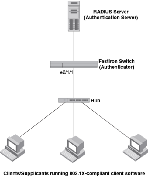
FIGURE 25 Sample 802.1X configuration using a hub
Sample 802.1x configuration using a hub
The following commands configure the Brocade device in the Sample 802.1X configuration using a
hub figure.
device(config)#aaa authentication dot1x default radius
device(config)#radius-server host 192.168.9.22 auth-port 1812 acct-port 1813
default key mirabeau dot1x
device(config)#authentication
device(config-authen)#auth-default-vlan 10
device(config-authen)#dot1x enable
device(config-authen)#dot1x enable e 2/1/1
device(config)#interface e 2/1/1
device(config-if-e1000-2/1/1)#dot1x port-control auto
802.1X Authentication with dynamic VLAN assignment
The following figure illustrates 802.1X authentication with dynamic VLAN assignment. In this
configuration, three user PCs are connected to a hub, which is connected to port e2/1/1. Both PCs
transmit untagged traffic. The profile for User 1 on the RADIUS server specifies that User 1 PC should
be dynamically assigned to VLAN 3. The RADIUS profile for User 2 on the RADIUS server specifies
that User 2 PC should be dynamically assigned to VLAN 20. The RADIUS profile for User 3 on the
RADIUS server specifies that User 3 PC should be dynamically assigned to VLAN 10.
Sample 802.1x configuration using a hub
350 FastIron Ethernet Switch Security Configuration Guide
53-1003405-04
FIGURE 26 Sample configuration using 802.1X authentication with dynamic VLAN assignment
If authentication fails for any device, it could be placed into the restricted VLAN, where it could gain
access to the network.
The portion of the running-config related to 802.1X authentication is as follows.
device(config)#aaa authentication dot1x default radius
device(config)#radius-server host 192.168.9.22 auth-port 1812 acct-port 1813
default key mirabeau dot1x
device(config)#authentication
device(config-authen)#auth-default-vlan 10
device(config-authen)#restricted-vlan 20
device(config-authen)#auth-fail-action restricted-vlan
device(config-authen)#dot1x enable
device(config-authen)#dot1x enable e 2/1/1
device(config)#interface e 2/1/1
device(config-if-e1000-2/1/1)#dot1x port-control auto
Multi-Device Port Authentication
How multi-device port authentication works
Multi-device port authentication is a way to configure a Brocade device to forward or block traffic from a
MAC address based on information received from a RADIUS server.
The multi-device port authentication feature is a mechanism by which incoming traffic originating from a
specific MAC address is switched or forwarded by the device only if the source MAC address is
successfully authenticated by a RADIUS server. The MAC address itself is used as the username and
password for RADIUS authentication; the user does not need to provide a specific username and
password to gain access to the network. If RADIUS authentication for the MAC address is successful,
traffic from the MAC address is forwarded in hardware.
Multi-Device Port Authentication
FastIron Ethernet Switch Security Configuration Guide 351
53-1003405-04
If the RADIUS server cannot validate the user's MAC address, then it is considered an authentication
failure, and a specified authentication-failure action can be taken. The default authentication-failure
action is to drop traffic from the non-authenticated MAC address in hardware. You can also configure
the device to move the port on which the non-authenticated MAC address was learned into a restricted
VLAN, which may have limited access to the network.
RADIUS authentication
The multi-device port authentication feature communicates with the RADIUS server to authenticate a
newly found MAC address. The Brocade device supports multiple RADIUS servers; if communication
with one of the RADIUS servers times out, the others are tried in sequential order. If a response from a
RADIUS server is not received within a specified time (by default, 3 seconds) the RADIUS session
times out, and the device retries the request up to three times. If no response is received, the next
RADIUS server is chosen, and the request is sent for authentication.
The RADIUS server is configured with the user names and passwords of authenticated users. For
multi-device port authentication, the username and password is the MAC address itself; that is, the
device uses the MAC address for both the username and the password in the request sent to the
RADIUS server. For example, given a MAC address of 0000000feaa1, the users file on the RADIUS
server would be configured with a username and password both set to 0000000feaa1. When traffic
from this MAC address is encountered on a MAC-authentication-enabled interface, the device sends
the RADIUS server an Access-Request message with 0000000feaa1 as both the username and
password. The format of the MAC address sent to the RADIUS server is configurable through the CLI.
The request for authentication from the RADIUS server is successful only if the username and
password provided in the request matches an entry in the users database on the RADIUS server.
When this happens, the RADIUS server returns an Access-Accept message back to the Brocade
device. When the RADIUS server returns an Access-Accept message for a MAC address, that MAC
address is considered authenticated, and traffic from the MAC address is forwarded normally by the
Brocade device.
Authentication-failure actions
If the MAC address does not match the username and password of an entry in the users database on
the RADIUS server, then the RADIUS server returns an Access-Reject message. When this happens,
it is considered an authentication failure for the MAC address. When an authentication failure occurs,
the Brocade device can either drop traffic from the MAC address in hardware (the default), or move
the port on which the traffic was received to a restricted VLAN, if specified.
Unauthenticated port behavior
Incoming traffic on unauthenticated ports is blocked by Brocade devices, while allowing for outgoing
broadcasts and multicasts to account for waking connected devices that are in a sleep state. This is
the default behavior and there is no configuration option.
Support for dynamic VLAN assignment
The Brocade multi-device port authentication feature supports dynamic VLAN assignment, where a
port can be placed in one or more VLANs based on the MAC address learned on that interface. For
details about this feature, refer to Configuring the RADIUS server to support dynamic VLAN
assignment on page 287.
RADIUS authentication
352 FastIron Ethernet Switch Security Configuration Guide
53-1003405-04

Support for dynamic ACLs
The multi-device port authentication feature supports the assignment of a MAC address to a specific
ACL, based on the MAC address learned on the interface. For details about this feature, refer to
Dynamically applying IP ACLs to authenticated MAC addresses on page 290.
Support for authenticating multiple MAC addresses on an interface
The multi-device port authentication feature allows multiple MAC addresses to be authenticated or
denied authentication on each interface. The maximum number of MAC addresses that can be
authenticated on each interface is limited to 32.
Support for source guard protection
The Brocade proprietary Source Guard Protection feature, a form of IP Source Guard, can be used in
conjunction with multi-device port authentication.
Configuring Brocade-specific attributes on the RADIUS server
If the RADIUS authentication process is successful, the RADIUS server sends an Access-Accept
message to the Brocade device, authenticating the device. The Access-Accept message can include
Vendor-Specific Attributes (VSAs) that specify additional information about the device. If you are
configuring multi-device port authentication and 802.1X authentication on the same port, then you can
configure the Brocade VSAs listed in following table on the RADIUS server.
You add these Brocade vendor-specific attributes to your RADIUS server configuration, and configure
the attributes in the individual or group profiles of the devices that will be authenticated. The Brocade
Vendor-ID is 1991, with Vendor-Type 1.
Brocade vendor-specific attributes for RADIUS TABLE 38
Attribute name Attribute ID Data type Description
Foundry-802_1x-
enable
6 integer Specifies whether 802.1X authentication is performed when
multi-device port authentication is successful for a device. This
attribute can be set to one of the following:
0 - Do not perform 802.1X authentication on a device that passes
multi-device port authentication. Set the attribute to zero for
devices that do not support 802.1X authentication.
1 - Perform 802.1X authentication when a device passes multi-
device port authentication. Set the attribute to one for devices
that support 802.1X authentication.
Foundry-802_1x-valid 7 integer Specifies whether the RADIUS record is valid only for multi-
device port authentication, or for both multi-device port
authentication and 802.1X authentication.
This attribute can be set to one of the following:
0 - The RADIUS record is valid only for multi-device port
authentication. Set this attribute to zero to prevent a user from
using their MAC address as username and password for 802.1X
authentication
1 - The RADIUS record is valid for both multi-device port
authentication and 802.1X authentication.
Support for dynamic ACLs
FastIron Ethernet Switch Security Configuration Guide 353
53-1003405-04
If neither of these VSAs exist in a device profile on the RADIUS server, then by default the device is
subject to multi-device port authentication (if configured), then 802.1X authentication (if configured).
The RADIUS record can be used for both multi-device port authentication and 802.1X authentication.
Configuration examples are shown in Examples of multi-device port authentication and 802.1X
authentication configuration on the same port on page 310.
Multi-device port authentication configuration
Configuring multi-device port authentication on the Brocade device consists of the following tasks:
• Enabling multi-device port authentication globally and on individual interfaces
• Specifying the format of the MAC addresses sent to the RADIUS server (optional)
• Specifying the authentication-failure action (optional)
• Enabling and disabling SNMP traps for multi-device port authentication
• Defining MAC address filters (optional)
• Configuring dynamic VLAN assignment (optional)
• Dynamically Applying IP ACLs to authenticated MAC addresses
• Enabling denial of service attack protection (optional)
• Clearing authenticated MAC addresses (optional)
• Disabling aging for authenticated MAC addresses (optional)
• Configuring the hardware aging period for blocked MAC addresses
• Specifying the aging time for blocked MAC addresses (optional)
Enabling multi-device port authentication
You can enable multi-device port authentication on all or specific interfaces.
To enable multi-device port authentication follow these steps:
1. Enter the global configuration mode.
2. Enter the authentication to enter the authentication mode.
3. Enter the mac-auth enablecommand along with the required parameters all or ethernet.
The example shows enabling multi-device port authentication.
device(config)# authentication
device(config-authen)# mac-auth enable
device(config-authen)# mac-auth enable all
device(config-authen)# mac-auth enable interface ethernet 1/1/1
Specifying the format of the MAC addresses sent to the RADIUS server
The MAC address of the device is used as the username and password for authentication.
When multi-device port authentication is configured, the Brocade device authenticates MAC
addresses by sending username and password information to a RADIUS server. The device uses the
MAC address for both the username and the password in the request sent to the RADIUS server. For
ease of configuration and depending on the RADIUS server you use, you can opt to send the
password in uppercase. The lowercase option is used by default.
Multi-device port authentication configuration
354 FastIron Ethernet Switch Security Configuration Guide
53-1003405-04
1. Enter authentication mode.
2. Enter the mac-auth password-format command with the format specified. Include the upper-case
option if you want to send the password in the uppercase format. If you do not enter the upper-case
option, the lowercase is used.
The following example shows specifying the password format.
device# authentication
device(config-authen)# mac-auth password-format xx-xx-xx-xx-xx-xx upper-case
Generating traps for multi-device port authentication
You can enable and disable SNMP traps for multi-device port authentication. SNMP traps are enabled
by default.
To enable SNMP traps for multi-device port authentication after they have been disabled, enter the
following command.
device(config)#snmp-server enable traps mac-authentication
Syntax: [no] snmp-server enable traps mac-authentication
Use the no form of the command to disable SNMP traps for multi-device port authentication.
Defining MAC address filters
Use this task to specify MAC addresses that do not have to go through multi-device port authentication.
These MAC addresses are considered pre-authenticated, and are not subject to RADIUS
authentication. To do this, you can define MAC address filters that specify the MAC addresses to
exclude from multi-device port authentication. You should use a MAC address filter when the RADIUS
server itself is connected to an interface where multi-device port authentication is enabled. If a MAC
address filter is not defined for the MAC address of the RADIUS server and applied on the interface, the
RADIUS authentication process would fail since the device would drop all packets from the RADIUS
server itself.
1. Enter global configuration.
2. In the interface configuration mode enter either the mac-auth auth-filter command with the required
parameters filter-id and vlan-id.
The example shows the MAC-authentication auth-filter ID and VLAN specified.
(config-if-e1000-1/1/1)# mac-auth auth-filter 1 vlan 2
Configuring dynamic VLAN assignment
An interface can be dynamically assigned to a VLAN based on the MAC address learned on that
interface. When a MAC address is successfully authenticated, the RADIUS server sends the Brocade
device a RADIUS Access-Accept message that allows the Brocade device to forward traffic from that
MAC address. The RADIUS Access-Accept message can also contain attributes set for the MAC
address in its access profile on the RADIUS server.
If one of the attributes in the Access-Accept message specifies a VLAN identifier, and the VLAN is
available on the Brocade device, the port becomes a MAC-VLAN member of the specified VLAN.
Generating traps for multi-device port authentication
FastIron Ethernet Switch Security Configuration Guide 355
53-1003405-04
Configuration notes for configuring a port to remain in the restricted VLAN
• If you configure dynamic VLAN assignment on a multi-device port authentication enabled interface,
and the Access-Accept message returned by the RADIUS server contains a Tunnel-Type and
Tunnel-Medium-Type, but does not contain a Tunnel-Private-Group-ID attribute, then it is
considered an authentication failure, and the configured authentication failure action is performed
for the MAC address.
• If the vlan-name string does not match either the name or the ID of a VLAN configured on the
device, then it is considered an authentication failure, and the configured authentication failure
action is performed for the MAC address.
Configuring the RADIUS server to support dynamic VLAN assignment
To specify VLAN identifiers on the RADIUS server, add the following attributes to the profile for the
MAC address on the RADIUS server, then enable dynamic VLAN assignment on multi-device port
authentication-enabled interfaces.
Attribute name Type Value
Tunnel-Type 064 13 (decimal) - VLAN
Tunnel-Medium-Type 065 6 (decimal) - 802
Tunnel-Private-Group-ID 081 U:vlan-id
U:vlan-name
For voice VLAN use:
U:vlan-id;T:vlan-id
For information about the attributes, refer to the Dynamic multiple VLAN assignment for 802.1X
portssection.
Also, refer to the example configuration of Multi-device port authentication with dynamic VLAN
assignment on page 306.
Automatic removal of dynamic VLAN assignments for MAC authenticated ports
By default, the Brocade device removes any association between a port and a dynamically-assigned
VLAN when authenticated MAC sessions for that tagged or untagged VLAN have expired on the port.
Thus, RADIUS-specified VLAN assignments are not saved to the device running-config file. When the
show run command is issued during a session, dynamically-assigned VLANs are not displayed,
although they can be displayed with the show vlan , and show mac-auth sessions command.
Dynamically applying IP ACLs to authenticated MAC addresses
The Brocade multi-device port authentication implementation supports the assignment of a MAC
address to a specific ACL, based on the MAC address learned on the interface.
When a MAC address is successfully authenticated, the RADIUS server sends the Brocade device a
RADIUS Access-Accept message that allows the Brocade device to forward traffic from that MAC
address. The RADIUS Access-Accept message can also contain, among other attributes, the Filter-ID
(type 11) attribute for the MAC address. When the Access-Accept message containing the Filter-ID
(type 11) attribute is received by the Brocade device, it will use the information in these attributes to
apply an IP ACL on a per-MAC (per user) basis.
Configuration notes for configuring a port to remain in the restricted VLAN
356 FastIron Ethernet Switch Security Configuration Guide
53-1003405-04
The dynamic IP ACL is active as long as the client is connected to the network. When the client
disconnects from the network, the IP ACL is no longer applied to the port.
The Brocade device uses information in the Filter ID to apply an IP ACL on a per-user basis. The Filter-
ID attribute can specify the number of an existing IP ACL configured on the Brocade device. If the Filter-
ID is an ACL number, the specified IP ACL is applied on a per-user basis.
Multi-device port authentication with dynamic IP ACLs
The following features are supported:
• FastIron devices support multi-device port authentication and dynamic ACLs together with or without
ACL-per-port-per-vlan.
• Multi-device port authentication and dynamic ACLs are supported on ports with or without virtual
Interfaces.
Support is automatically enabled when all of the required conditions are met.
The following describes the conditions and feature limitations:
• The following shows some example scenarios where dynamic IP ACLs would not apply:
‐A port is a member of VLAN 20, VLAN 20 includes VE 20, and an ACL is bound to VE 20.
‐A port is a member of VLAN 20, VLAN 20 includes VE 20, and a per-port-per-vlan ACL is bound to
VE 20 and to a subset of ports in VE 20
In the above scenarios, dynamic IP ACL assignment would not apply in either instance, because a
configured ACL is bound to VE 20 on the port. Consequently, the MAC session would fail.
Configuration considerations and guidelines for multi-device port authentication
• Dynamic MAC address filters with multi-device port authentication are not supported.
• In the Layer 2 switch code, dynamic IP ACLs are not supported when ACL-per-port-per-vlan is
enabled on a global-basis.
• The RADIUS Filter ID (type 11) attribute is supported. The Vendor-Specific (type 26) attribute is not
supported.
• The dynamic ACL must be an extended ACL. Standard ACLs are not supported.
• Multi-device port authentication and 802.1x can be used together on the same port.
• Dynamically assigned IP ACLs are subject to the same configuration restrictions as non-dynamically
assigned IP ACLs.
• Dynamic ACL filters are supported only for the inbound direction. Dynamic outbound ACL filters are
not supported.
• Dynamic ACL assignment with multi-device port authentication is not supported in conjunction with
any of the following features:
‐IP source guard
‐Rate limiting
‐Protection against ICMP or TCP Denial-of-Service (DoS) attacks
‐Policy-based routing
Enabling denial of service protection
The Brocade device does not start forwarding traffic from an authenticated MAC address in hardware
until the RADIUS server authenticates the MAC address; traffic from the non-authenticated MAC
addresses is sent to the CPU.
A denial of service (DoS) attack could be launched against the device where a high volume of new
source MAC addresses is sent to the device, causing the CPU to be overwhelmed with performing
Multi-device port authentication with dynamic IP ACLs
FastIron Ethernet Switch Security Configuration Guide 357
53-1003405-04
RADIUS authentication for these MAC addresses. In addition, the high CPU usage in such an attack
could prevent the RADIUS response from reaching the CPU in time, causing the device to make
additional authentication attempts.
Follow these steps to enable denial of service protection.
1. Enter the interface configuration mode.
2. Enter the auth dos-protection command along with the MAC limit count.
The example shows enabling denial of service protection.
device(config-if-e1000-1/1/1)# auth dos-protection mac-limit 256
Enabling source guard protection
When Source Guard Protection is enabled, IP traffic is blocked until the system learns the IP address.
Source Guard Protection is a form of IP Source Guard used in conjunction with multi-device port
authentication. Once the IP address is validated, traffic with that source address is permitted.
To enable source guard protection perform the following steps.
1. Enter the interface configuration mode.
2. Enter the auth source-guard-protection command.
The example shows enabling source guard protection.
(config-if-e1000-1/1/1)# auth source-guard-protection enable
Clearing authenticated MAC addresses
Clear the authenticated MAC addresses table using the clear mac-session command. This command
is applicable to both dot1x and MAC authentication modes.
The Brocade device maintains an internal table of the authenticated MAC addresses (viewable with
the show authenticated-mac-address command). You can clear the contents of the authenticated MAC
address table either entirely, or just for the entries learned on a specified interface. In addition, you can
clear the MAC session for an address learned on a specific interface.
Enter the clear mac-session command along with the mac-address and ethernet parameters.
The example shows clearing MAC-authentication MAC addresses.
device (config)# clear mac-authentication mac-session 0000.0034.abd4
Disabling aging for authenticated MAC addresses
MAC addresses that have been authenticated or denied by a RADIUS server are aged out if no traffic
is received from the MAC address for a certain period of time:
• Authenticated MAC addresses or non-authenticated MAC addresses that have been placed in the
restricted VLAN are aged out if no traffic is received from the MAC address over the device normal
MAC aging interval.
• Non-authenticated MAC addresses that are blocked by the device are aged out if no traffic is
received from the address over a fixed hardware aging period (70 seconds), plus a configurable
software aging period. (Refer to the next section for more information on configuring the software
aging period).
You can optionally disable aging for MAC addresses subject to authentication, either for all MAC
addresses or for those learned on a specified interface.
Enabling source guard protection
358 FastIron Ethernet Switch Security Configuration Guide
53-1003405-04
Disabling aging of MAC addresses
On most devices, you can disable aging for all MAC addresses at the global and interface levels where
multi-device port authentication or dot1x authentication has been enabled.
To disable aging of MAC addresses perform the following steps.
1. Enter global configuration.
2. Enter the authentication command.
3. Enter the disable-aging command followed by the required parameters permitted-mac or denied-
mac.
4. To disable aging at the interface level, specify the interface and enter the auth disable-aging
command, followed by the required parameter.
The following example shows disabling aging of MAC addresses.
(config-authen)# disable-aging <permitted-mac | denied-mac>
(config- if-e1000-1/1/1)# auth disable-aging <permitted-mac | denied-mac>
Changing the hardware aging period for blocked MAC addresses
Specifies the hardware aging for blocked MAC addresses for dot1x and MAC authentication.
When the Brocade device is configured to drop traffic from non-authenticated MAC addresses, traffic
from the blocked MAC addresses is dropped in hardware, without being sent to the CPU. A Layer 2
hardware entry is created that drops traffic from the MAC address in hardware. If no traffic is received
from the MAC address for a certain amount of time, this Layer 2 hardware entry is aged out. If traffic is
subsequently received from the MAC address, then an attempt can be made to authenticate the MAC
address again.
Follow these steps to change the hardware aging period for blocked MAC addresses.
1. At the global level enter the authentication command to enter the authentication mode.
2. Enter the max-hw-age command along with the age variable. The value can be 1 to 65535 seconds.
The default is 70 seconds.
The example shows specifying a value of 160.
device(config-authen)#max-hw-age 160
Specifying the aging time for blocked MAC addresses
You can specify the aging time for blocked MAC addresses for dot1x and MAC authentication.
Once the Brocade device stops receiving traffic from a blocked MAC address, the hardware aging
begins and lasts for a fixed period of time. After the hardware aging period ends, the software aging
period begins. The software aging period lasts for a configurable amount of time (by default 120
seconds). After the software aging period ends, the blocked MAC address ages out, and can be
authenticated again if the Brocade device receives traffic from the MAC address. To change the length
of the software aging period for blocked MAC addresses, perform the following steps.
1. Enter the authentication configuration mode.
2. Enter the max-sw-age command along with the age variable. The value can be 1 to 65535 seconds.
The default is 120 seconds.
The example shows specifying a value of 160.
device(config-authen)#max-sw-age 160
Disabling aging of MAC addresses
FastIron Ethernet Switch Security Configuration Guide 359
53-1003405-04
Overriding the multi-device port authentication password
You can specify a password instead of the MAC address for authentication.
The multi-device port authentication feature communicates with the RADIUS server to authenticate a
newly found MAC address. The RADIUS server is configured with the user names and passwords of
authenticated users. For multi-device port authentication, the username and password is the MAC
address itself; that is, the device uses the MAC address for both the username and the password in
the request sent to the RADIUS server. For example, given a MAC address of 0000000feaa1, the
users file on the RADIUS server would be configured with a username and password both set to
0000000feaa1. When traffic from this MAC address is encountered on a MAC-authentication-enabled
interface, the device sends the RADIUS server an Access-Request message with 0000000feaa1 as
both the username and password.
To change the password for multi-device port authentication follow these steps.
1. Enter the authentication command to enter the global authentication mode.
2. Enter the mac-auth password-override command.
The example shows configuring the device to use a different password.
device(config-authen)# mac-auth password-override <password>
Limiting the number of authenticated MAC addresses
Use the auth max-sessions command to simulate the function of MAC port security for both MAC
authentication and dot1x authentication.
You cannot enable MAC port security on the same port that has multi-device port authentication
enabled. To specify the maximum number of authenticated MAC sessions, follow these steps.
1. Enter the interface configuration mode and specify the interface on which you want enable the
functionality.
2. Enter the auth max-sessions command.
The example shows the functionality enabled.
device(config-if-e1000-1/1/1)# auth max-sessions <count>
Displaying multi-device port authentication information
You can display the following information about the multi-device port authentication configuration:
• Information about authenticated MAC addresses
• Information about the multi-device port authentication configuration
• Authentication Information for a specific MAC address or port
• Multi-device port authentication settings and authenticated MAC addresses for each port where the
multi-device port authentication feature is enabled
• The MAC addresses that have been successfully authenticated
• The MAC addresses for which authentication was not successful
Displaying the MAC authentication sessions
Use this command to view details of the MAC authentication sessions like the ports, MAC addresses,
IP addresses, VLANs etc.
To display the MAC authentication sessions, follow these steps.
Enter the show mac-auth sessions command along with the parameter all or ethernet.
Overriding the multi-device port authentication password
360 FastIron Ethernet Switch Security Configuration Guide
53-1003405-04
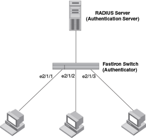
The example displays the show mac-auth sessions all command entered.
device(config)# show mac-auth sessions all
Example port authentication configurations
This section includes configuration examples of multi-device port authentication with dynamic VLAN
assignment, and multi-device port authentication and 802.1X authentication.
Multi-device port authentication with dynamic VLAN assignment
FIGURE 27 Using multi-device port authentication with dynamic VLAN assignment
Sample MAC-authentication configuration
The following commands configure the Brocade device in the Sample MAC-authentication figure.
device(config)#aaa authentication dot1x default radius
device(config)#radius-server host 192.168.9.22 auth-port 1812 acct-port 1813
default key mirabeau dot1x
device(config)#authentication
device(config-authen)#auth-default-vlan 10
device(config-authen)#mac-authentication enable
device(config-authen)#mac-authentication enable e 2/1/1 to 2/1/3
Example 2 -- multi-device port authentication with dynamic VLAN assignment
The following figure illustrates multi-device port authentication with dynamic VLAN assignment on a
Brocade device. In this configuration, a PC and an IP phone are connected to a hub, which is
connected to port e2/1/1 on a Brocade device. The profile for the PC MAC address on the RADIUS
server specifies that the PC should be dynamically assigned to VLAN 102, and the RADIUS profile for
the IP phone specifies that it should be dynamically assigned to VLAN 3.
Example port authentication configurations
FastIron Ethernet Switch Security Configuration Guide 361
53-1003405-04
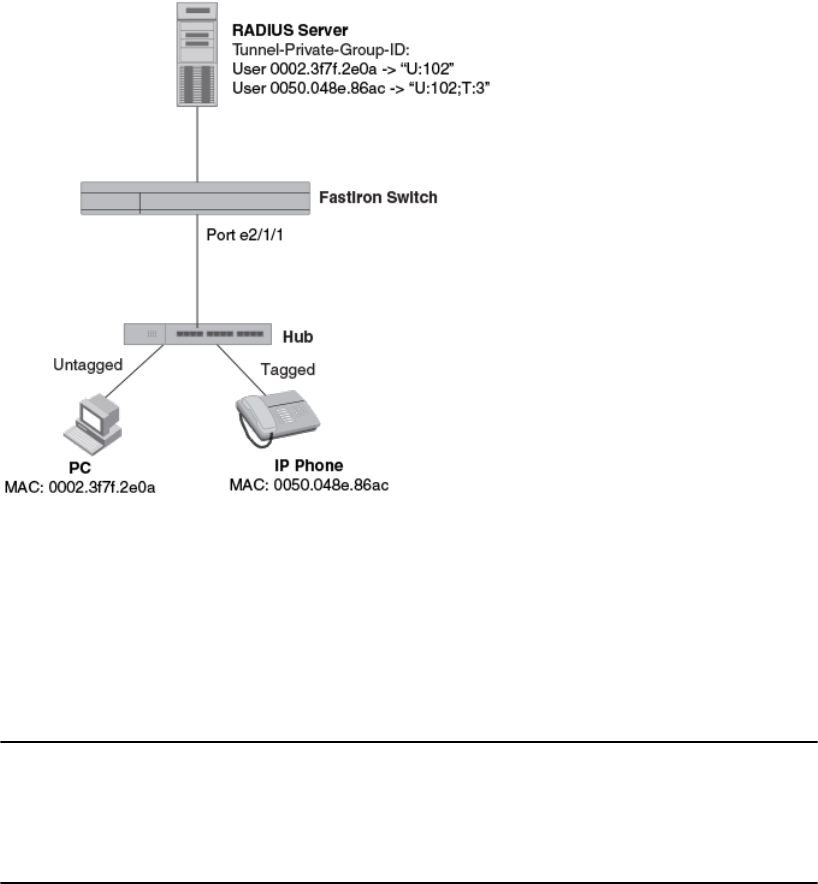
FIGURE 28 Using multi-device port authentication with dynamic VLAN assignment
In this example, multi-device port authentication is performed for both devices. If the PC is
successfully authenticated, the port is added as a MAC-VLAN member in 102. If authentication for the
PC fails, then the PC can be placed in a specified "restricted" VLAN, or traffic from the PC can be
blocked in hardware. In this example, if authentication for the PC fails, the PC would be placed in
VLAN 1023, the restricted VLAN.
If authentication for the IP phone is successful, then the port e2/1/1 is added to VLAN 3. If
authentication for the IP phone fails, then traffic from the IP phone would be blocked in hardware.
(Devices sending tagged traffic cannot be placed in the restricted VLAN.)
NOTE
This example assumes that the IP phone initially transmits untagged packets (for example, CDP or
DHCP packets), which trigger the authentication process on the Brocade device and client lookup on
the RADIUS server. If the phone sends only tagged packets and the port (e2/1/1) is not a member of
that VLAN, authentication would not occur. In this case, port e2/1/1 must be added to that VLAN prior
to authentication.
The part of the running-config related to multi-device port authentication would be as follows.
device(config)#aaa authentication dot1x default radius
device(config)#radius-server host 192.168.9.22 auth-port 1812 acct-port 1813
default key mirabeau dot1x
device(config)#authentication
device(config-authen)#auth-default-vlan 10
device(config-authen)#restricted-vlan 1023
device(config-authen)#auth-fail-action restricted-vlan
device(config-authen)#mac-authentication enable
device(config-authen)#mac-authentication enable e 2/1/1
device(config)#interface e 2/1/1
device(config-if-e1000-2/1/1)#inline power
device(config-if-e1000-2/1/1)#voice-vlan 3
Flexible Authentication
362 FastIron Ethernet Switch Security Configuration Guide
53-1003405-04
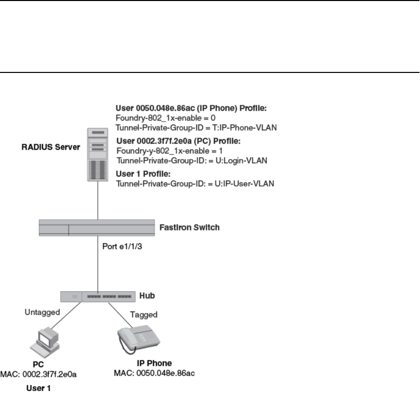
Examples of multi-device port authentication and 802.1X authentication configuration on the
same port
The following examples show configurations that use multi-device port authentication and 802.1X
authentication on the same port.
Multi-device port authentication and 802.1x authentication on the same port
The following figure illustrates an example configuration that uses multi-device port authentication and
802.1X authentication n the same port. In this configuration, a PC and an IP phone are connected to
port e 1/1/3 on a Brocade device. Port e 1/1/3 is configured as a dual-mode port.
The profile for the PC MAC address on the RADIUS server specifies that the PC should be dynamically
assigned to VLAN "Login-VLAN", and the RADIUS profile for the IP phone specifies that it should be
dynamically assigned to the VLAN named "IP-Phone-VLAN". When User 1 is successfully authenticated
using 802.1X authentication, the PC is then placed in the VLAN named "User-VLAN".
NOTE
This example assumes that the IP phone initially transmits untagged packets (for example, CDP or
DHCP packets), which trigger the authentication process on the Brocade device and client lookup on
the RADIUS server. If the phone sends only tagged packets and the port (e 1/1/3) is not a member of
that VLAN, authentication would not occur. In this case, port e 1/1/3 must be added to that VLAN prior
to authentication.
FIGURE 29 Using multi-device port authentication and 802.1X authentication on the same port
When the devices attempt to connect to the network, they are first subject to multi-device port
authentication.
Examples of multi-device port authentication and 802.1X authentication configuration on the same port
FastIron Ethernet Switch Security Configuration Guide 363
53-1003405-04
When the MAC address of the IP phone is authenticated, the Access-Accept message from the
RADIUS server specifies that the IP phone port be placed into the VLAN named "IP-Phone-VLAN".
which is VLAN 7. The Foundry-802_1x-enable attribute is set to 0, meaning that 802.1X authentication
is skipped for this MAC address. Port e 1/1/3 is placed in VLAN 7 as a tagged port. No further
authentication is performed.
When the PC MAC address is authenticated, the Access-Accept message from the RADIUS server
specifies that the VLAN for the PC port be changed to the VLAN named "Login-VLAN", which is VLAN
1024. The Foundry-802_1x-enable attribute is set to 1, meaning that 802.1X authentication is required
for this MAC address. The VLAN of the port e 1/1/3 is temporarily changed to VLAN 1024, pending
802.1X authentication.
When User 1 attempts to connect to the network from the PC, he is subject to 802.1X authentication. If
User 1 is successfully authenticated, the Access-Accept message from the RADIUS server specifies
that the VLAN for User 1 port be changed to the VLAN named "User-VLAN", which is VLAN 3. If
802.1X authentication for User 1 is unsuccessful, the VLAN for port e 1/1/3 is changed to that of the
restricted VLAN, which is 1023, or untagged traffic from port e 1/1/3 can be blocked in hardware.
The part of the running-config related to port e 1/1/3 would be as follows.
device(config)#aaa authentication dot1x default radius
device(config)#radius-server host 192.168.9.22 auth-port 1812 acct-port 1813
default key mirabeau dot1x
device(config)#authentication
device(config-authen)#auth-default-vlan 10
device(config-authen)#auth-order mac-auth dot1x
device(config-authen)#restricted-vlan 1023
device(config-authen)#auth-fail-action restricted-vlan
device(config-authen)#mac-authentication enable
device(config-authen)#mac-authentication enable e 1/1/3
device(config-authen)#dot1x enable
device(config-authen)#dot1x enable e 1/1/3
device(config)#interface e 1/1/3
device(config-if-e1000-1/1/3)#inline power
device(config-if-e1000-1/1/3)#voice-vlan 7
device(config-if-e1000-1/1/3)#dot1x port-control auto
Flexible Authentication
364 FastIron Ethernet Switch Security Configuration Guide
53-1003405-04
Web Authentication
● Supported Web Authentication features....................................................................... 365
● Web authentication overview........................................................................................ 365
● Web authentication configuration considerations..........................................................366
● Web authentication configuration tasks........................................................................ 368
● Enabling and disabling web authentication................................................................... 369
● Web authentication mode configuration........................................................................369
● Web authentication options configuration..................................................................... 378
● Displaying web authentication information....................................................................391
Supported Web Authentication features
Lists Web Authentication features supported on FastIron devices.
The following table lists individual Brocade switches and the Web Authentication features they support.
These features are supported in the Layer 2 and Layer 3 software images, except where explicitly
noted.
Feature ICX 6430 ICX 6450 FCX ICX 6610 ICX 6650 FSX 800
FSX 1600
ICX 7450 ICX 7750
Enabling and disabling Web
Authentication
08.0.01 08.0.01 08.0.01 08.0.01 No 08.0.01 08.0.20 No
Configuring the Web Authentication
mode
08.0.01 08.0.01 08.0.01 08.0.01 No 08.0.01 08.0.20 No
Web Authentication options 08.0.01 08.0.01 08.0.01 08.0.01 No 08.0.01 08.0.20 No
Web authentication overview
Authentication is important in enterprise networks because the network is considered a secure area: it
contains sensitive data and a finite amount of resources. Unauthorized users must be prevented from
accessing the network to protect the sensitive data and prevent the unnecessary consumption of
resources.
The ideal authentication method blocks unauthorized users at the earliest possible opportunity. For
internal enterprise networks, this can be controlled at the edge switch port. Two popular forms of port-
based security authentication used at the edge switch are multi-device port authentication and 802.1x.
Multi-device port authentication authenticates the MAC addresses of hosts or users that are attempting
to access the network. This type of authentication requires no intervention from the host or user who is
attempting to be authenticated. It is easy to use, but it can only authorize hosts; it cannot be used to
authorize users. 802.1x authentication can authorize users or hosts. It is more flexible than the multi-
device port authentication method; however, it requires more support, configuration, maintenance and
user intervention than multi-device port authentication.
FastIron Ethernet Switch Security Configuration Guide 365
53-1003405-04

The Brocade Web authentication method provides an ideal port-based authentication alternative to
multi-device port authentication without the complexities and cost of 802.1x authentication. Hosts gain
access to the network by opening a Web browser and entering a valid URL address using HTTP or
HTTPS services. Instead of being routed to the URL, the host browser is directed to an authentication
Web page on the FastIron switch. The Web page prompts the host to enter a user ID and password or
a passcode. The credentials a host enters are used by a trusted source to authenticate the host MAC
address. (Multiple MAC addresses can be authenticated with the same user name and password.)
If the authentication is unsuccessful, the appropriate page is displayed on the host browser. The host
is asked to try again or call for assistance, depending on what message is configured on the Web
page. If the host MAC address is authenticated by the trusted source, a Web page is displayed with a
hyperlink to the URL the host originally entered. If the user clicks on the link, a new window is opened
and the the user is directed to the requested URL.
While a MAC address is in the authenticated state, the host can forward data through the FastIron
switch. The MAC address remains authenticated until one of the following events occurs:
• The host MAC address is removed from a list of MAC addresses that are automatically
authenticated. (Refer to Specifying hosts that are permanently authenticated on page 379).
• The re-authentication timer expires and the host is required to re-authenticate (Refer to Configuring
the re-authentication period on page 380).
• The host has remained inactive for a period of time and the inactive period timer has expired. (Refer
to Forcing re-authentication after an inactive period on page 383.)
• All the ports on the VLAN on which Web Authentication has been configured are in a down state. All
MAC addresses that are currently authenticated are de-authenticated (Refer to Forcing
reauthentication when ports are down on page 382.)
• The authenticated client is cleared from the Web Authentication table. (Refer to Clearing
authenticated hosts from the webauthentication table on page 381).
The FastIron switch can be configured to automatically authenticate a host MAC address. The host will
not be required to login or re-authenticate (depending on the re-authentication period) once the MAC
address passes authentication.
A host that is logged in and authenticated remains logged in indefinitely, unless a re-authentication
period is configured. When the re-authentication period ends, the host is logged out. A host can log
out at any time by pressing the Logout button in the Web Authentication Success page.
NOTE
The host can log out as long as the Logout window (Success page) is visible. If the window is
accidentally closed, the host cannot log out unless the re-authentication period ends or the host is
manually cleared from the Web Authentication table.
Web authentication configuration considerations
Web Authentication is modeled after other RADIUS-based authentication methods currently available
on Brocade edge switches. However, Web Authentication requires a Layer 3 protocol (TCP/IP)
between the host and the authenticator. Therefore, to implement Web Authentication, you must
consider the following configuration and topology configuration requirements:
• Web authentication works only when both the HTTP and HTTPS servers are enabled on the device.
• Web Authentication works only on the default HTTP or HTTPS port.
• The host must have an IP address prior to Web Authentication. This IP address can be configured
statically on the host; however, DHCP addressing is also supported.
Web authentication configuration considerations
366 FastIron Ethernet Switch Security Configuration Guide
53-1003405-04
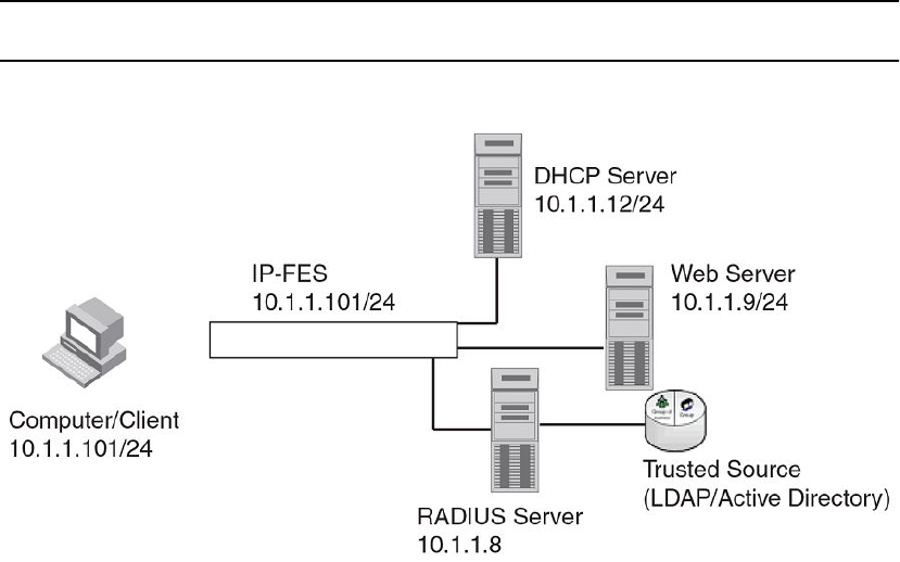
• If you are using DHCP addressing, a DHCP server must be in the same broadcast domain as the
host. This DHCP server does not have to be physically connected to the switch. Also, DHCP assist
from a router may be used.
• Web Authentication, 802.1X port security, and multi-device port authentication are not supported
concurrently on the same port.
• Web Authentication is not supported on an MCT VLAN.
The following applies to Web Authentication in the Layer 2 switch image:
• If the management VLAN and Web Authentication VLAN are in different IP networks, make sure
there is at least one routing element in the network topology that can route between these IP
networks.
The following are required for Web Authentication in the base Layer 3 and full Layer 3 images:
• Each Web Authentication VLAN must have a virtual interface (VE).
• The VE must have at least one assigned IPv4 address.
Web Authentication is enabled on a VLAN. That VLAN becomes a Web Authentication VLAN that does
the following:
• Forwards traffic from authenticated hosts, just like a regular VLAN.
• Blocks traffic from unauthenticated hosts except from ARP, DHCP, DNS, HTTP, and HTTPs that are
required to perform Web Authentication.
The Basic topology for web authentication figure shows the basic components of a network topology
where Web Authentication is used. You will need:
• A Brocade FastIron switch running a software release that supports Web Authentication
• DHCP server, if dynamic IP addressing is to be used
• Computer/host with a web browser
Your configuration may also require a RADIUS server with some Trusted Source such as LDAP or
Active Directory.
NOTE
The Web server, RADIUS server, and DHCP server can all be the same server.
FIGURE 30 Basic topology for web authentication
Web Authentication
FastIron Ethernet Switch Security Configuration Guide 367
53-1003405-04

Web authentication configuration tasks
Follow the steps given below to configure Web Authentication on a device.
1. Set up any global configuration required for the FastIron switch, RADIUS server, Web server and
other servers.
•‐On a Layer 2 FastIron switch, make sure the FastIron switch has an IP address.
device#configure terminal
device(config)#ip address 10.1.1.10/24
•‐On a Layer 3 FastIron switch, assign an IP address to a virtual interface (VE) for each VLAN
on which Web Authentication will be enabled.
device#configure terminal
device(config)#vlan 10
device(config-vlan-10)#router-interface ve1
device(config-vlan-10)#untagged e 1/1/1 to 1/1/10
device(config-vlan-10)#interface ve1
device(config-vif-1)#ip address 10.1.2.1/24
2. By default, Web Authentication will use a RADIUS server to authenticate host usernames and
passwords, unless it is configured to use a local user database. If Web Authentication will use a
RADIUS server, you must configure the RADIUS server and other servers. For example, if your
RADIUS server has an IP address of 10.168.1.253, then use the CLI to configure the following
global CLI commands on the FastIron switch.
device(config)#radius-server host 10.1.1.8
device(config)#radius-server key $GSig@U\
NOTE
Remember the RADIUS key you entered. You will need this key when you configure your RADIUS
server.
3. Web authentication can be configured to use secure (HTTPS) or non-secure (HTTP) login and
logout pages. By default, HTTPS is used.
To enable the non-secure Web server on the FastIron switch, enter the following command.
device(config)# web-management HTTP
device(config# vlan 10
device(config-vlan-10# webauth
device(config-vlan-10-webauth# no secure-login
To enable the secure Web server on the FastIron switch, enter the following command.
device(config)# web-management HTTPS
device(config# vlan 10
device(config-vlan-10# webauth
device(config-vlan-10-webauth)# secure-login
4. If the secure Web server is used, in order to access a secure Web page, the Web server needs to
provide a key. This key is exchanged using a certificate. A certificate is a digital document that is
issued by a trusted source that can validate the authenticity of the certificate and the Web server
that is presenting it. Therefore the switch must have a certificate for web authentication to work.
There are two choices for providing the switch with a certificate:
•‐Upload one using the following global CLI command.
device(config)# ip ssl private-key-file tftp ip-addr key-filename
•‐Generate one using the following global CLI command.
device(config)#crypto-ssl certificate generate
Web authentication configuration tasks
368 FastIron Ethernet Switch Security Configuration Guide
53-1003405-04
5. Create a Web Authentication VLAN and enable Web Authentication on that VLAN.
device(config)#vlan 10
device(config-vlan-10)#webauth
device(config-vlan-10-webauth)#enable
Once enabled, the CLI changes to the "webauth" configuration level. In the example above, VLAN 10
will require hosts to be authenticated using Web Authentication before they can forward traffic.
6. Configure the Web Authentication mode:
•‐Username and password - Blocks users from accessing the switch until they enter a valid
username and password on a web login page.
‐Passcode - Blocks users from accessing the switch until they enter a valid passcode on a web
login page.
‐None - Blocks users from accessing the switch until they press the ’Login’ button. A username
and password or passcode is not required.
Refer to Web authentication mode configuration on page 369.
7. Configure other Web Authentication options (refer to Web authentication options configuration on
page 378).
Enabling and disabling web authentication
Web Authentication is disabled by default. To enable it, enter the following commands.
device(config)# vlan 10
device(config-vlan-10# webauth
device(config(config-vlan-10-webauth)# enable
The first command changes the CLI level to the VLAN configuration level. The second command
changes the configuration level to the Web Authentication VLAN level. The last command enables Web
Authentication. In the example above, VLAN 10 will require hosts to be authenticated using Web
Authentication before they can forward traffic.
Syntax: webauth
FastIron devices support a maximum of two Web Authentication VLANs.
Syntax: [no] enable
Enter the no enable command to disable Web Authentication.
Web authentication mode configuration
You can configure the FastIron switch to use one of three Web Authentication modes:
• Username and password - Block users from accessing the switch until they enter a valid username
and password on a web login page. Refer to Using local user databases on page 370.
• Passcode - Blocks users from accessing the switch until they enter a valid passcode on a web login
page. Refer to Passcodes for user authentication on page 373.
• None - Blocks users from accessing the switch until they press the ’Login’ button. A username and
password or passcode is not required. Refer to Automatic authentication on page 378.
This following sections describe how to configure these Web Authentication modes.
Enabling and disabling web authentication
FastIron Ethernet Switch Security Configuration Guide 369
53-1003405-04
Using local user databases
Web Authentication supports the use of local user databases consisting of usernames and passwords,
to authenticate devices. Users are blocked from accessing the switch until they enter a valid username
and password on a web login page.
Once a user successfully authenticates through username and password, the user is subjected to the
same policies as for RADIUS-authenticated devices (for example, the re-authentication period,
maximum number of users allowed, etc.). Similarly, once a user fails username and password
authentication, the user is subjected to the same policies as for devices that fail RADIUS
authentication.
You can create up to ten local user databases on the FastIron switch either by entering a series of CLI
commands, or by uploading a list of usernames and passwords from a TFTP file to the FastIron
switch. The user databases are stored locally, on the FastIron switch.
Configuring a local user database
Follow the steps given below to configure a local user database.
1. Create the local user database.
2. Add records to the local user database either by entering a series of CLI commands, or by importing
a list of user records from an ASCII text file on the TFTP server to the FastIron switch.
3. Set the local user database authentication mode.
4. If desired, set the authentication method (RADIUS/local) failover sequence.
5. Assign a local user databse to a Web Authentication VLAN.
Creating a local user database
The FastIron switch supports a maximum of ten local user databases, each containing up to 50 user
records. Each user record consists of a username and password.
To create a local user database, enter a command such as the following.
device(config)# local-userdb userdb1
device(config-localuserdb-userdb1)#
This command creates a local user database named userdb1. To add user records to this database,
refer to Adding a user record to a local user database on page 370.
Syntax: local-userdb db-name
You can create up to ten local user databases for Web Authentication.
For db-name, enter up to 31 alphanumeric characters.
Adding a user record to a local user database
To add a user record, enter commands such as the following.
device(config)# local-userdb userdb1
device(config-localuserdb-userdb1)# username marcia password bunch4
The first command changes the configuration level to the local user database level for userdb1 . If the
database does not already exist, it is created. The second command adds the user record marcia to
the userdb1 database.
Using local user databases
370 FastIron Ethernet Switch Security Configuration Guide
53-1003405-04
Syntax: username username password password
For username , enter up to 31 ASCII characters.
For username , enter up to 29 ASCII characters.
You can add up to 50 usernames and passwords to a local user database.
To view a list of users in a local user database, use the CLI command vlan-mod-port-userdb . Refer to
Displaying a list of local user databases on page 395.
Deleting a user record from a local user database
To delete a user record from the local user database, enter commands such as the following.
device(config)# local-userdb userdb1
device(config-localuserdb-userdb1)# no username marcia
The first command changes the configuration level to the local user database level for userdb1 . The
second command deletes the user record marcia from the userdb1 database.
Syntax: [no] username username
Deleting All user records from a local user database
To delete all user records from a local user database, enter the delete-all command.
device(config-localuserdb-userdb1)# delete-all
Syntax: delete-all
Creating a text file of user records
If desired, you can use the TFTP protocol to import a list of usernames and passwords from a text file
on a TFTP server to the FastIron switch. The text file to be imported must be in the following ASCII
format.
[delete-all]
[no] username
username1
password
password1
cr
[no] username
username2
password
password2
cr
...
The [delete-all] keyword indicates that the user records in the text file will replace the user records in the
specified local user database on the FastIron switch. If the [delete-all] keyword is not present, the new
user records will be added to the specified local user database on the FastIron switch. The [delete-all]
keyword is optional. If present, it must appear on the first line, before the first user record in the text file.
The optional [no] keyword indicates that the user entry will be deleted from the specified local user
database on the FastIron switch.
User records that already exist in the local user database will be updated with the information in the text
file when it is uploaded to the switch.
For username1 , username2 , etc., enter up to 31 ASCII characters.
Deleting a user record from a local user database
FastIron Ethernet Switch Security Configuration Guide 371
53-1003405-04

For password1 , password2 , etc., enter up to 29 ASCII characters.
Be sure to Insert a cursor return (cr ) after each user record.
You can enter up to 50 user records per text file.
Importing a text file of user records from a TFTP server
NOTE
Before importing the file, make sure it adheres to the ASCII text format described in the previous
section, Creating a text file of user records on page 371.
To import a text file of user records from a TFTP server to the FastIron switch, enter a command such
as the following.
device(config-localuserdb-userdb1)# import-users tftp 192.168.1.1 filename userdb1
Syntax: import-users tftp ip-address filename filename
The ip-address parameter specifies the IPv4 address of the TFTP server on which the desired text file
resides.
The filename parameter specifies the name of the image on the TFTP server.
Using a RADIUS server as the web authentication method
By default, Web Authentication will use a RADIUS server to authenticate hosts’ usernames and
passwords, unless the device is configured to use the local user database (see the previous section).
To configure the FastIron switch to use a RADIUS server, refer to the RADIUS security section. You
must also perform the following steps.
1. Configure the RADIUS server information on the FastIron switch. Enter a command such as the
following.
device(config)#radius-server host 10.1.1.8 auth-port 1812 acct-port 1813 default
key $GSig@U\
NOTE
Web Authentication will use the first reachable RADIUS server listed in the configuration. The use-
radius-server on individual ports is not supported for Web Authentication.
2. Enable the username and password authentication mode.
device(config-vlan-10-webauth)# auth-mode username-password
3. Enable the RADIUS authentication method. Refer to Setting the local user database authentication
method on page 372 or Setting the web authentication failover sequence on page 373
Setting the local user database authentication method
By default, the FastIron switch uses a RADIUS server to authenticate users in a VLAN. The previous
section describes how to configure a RADIUS server to authenticate users in a VLAN. To configure
the switch to instead use a local user database to authenticate users in a VLAN, enter the following
command.
device(config-vlan-10-webauth)#auth-mode username-password auth-methods local
Syntax: auth-mode username-password auth-methods local
Importing a text file of user records from a TFTP server
372 FastIron Ethernet Switch Security Configuration Guide
53-1003405-04
To revert back to using the RADIUS server, enter the following command.
device(config-vlan-10-webauth)# auth-mode username-password auth-methods radius
Syntax: auth-mode username-password auth-methods radius
Setting the web authentication failover sequence
You can optionally specify a failover sequence for RADIUS and local user database authentication
methods. For example, you can configure Web Authentication to first use a local user database to
authenticate users in a VLAN. If the local user database is not available, it will use a RADIUS server.
Enter the following command.
device(config-vlan-10-webauth)# auth-mode username-password auth-methods local radius
Syntax: auth-mode username-password auth-methods method1 method2
For method1method2, enter radiuslocal or local radius .
Assigning a local user database to a web authentication VLAN
After creating or importing a local user database on the FastIron switch and setting the local user
database authentication method to local , you can configure a Web Authentication VLAN to use the
database to authenticate users in a VLAN. To do so, enter a command such as the following.
device(config-vlan-10-webauth)# auth-mode username-password local-user-database
userdb1
These commands configure Web Authentication to use the usernames and passwords in the userdb1
database to authenticate users in VLAN 10.
Syntax: [no] auth-mode username-password local-user-database db-name
For db-name , enter a valid local user database.
Use the no form of the command to remove the database from the Web Authentication VLAN.
Passcodes for user authentication
Web Authentication supports the use of passcodes to authenticate users. Users are blocked from
accessing the switch until they enter a valid passcode on a web login page. Unlike username and
password authentication, passcode authentication uses a simple number to authenticate users. The
simplicity of a passcode reduces user errors and lowers the overhead of supporting and managing
simple tasks, such as Internet access for guests and visitors in the office.
When passcodes are enabled, the system will automatically generate them every 1440 minutes (24
hours), and when the system boots up. You can optionally create up to four static passcodes which will
be used in conjunction with the dynamic passcodes generated by the system.
Configuring passcode authentication
Follow the steps given below to configure the device to use the passcode authentication mode.
1. Optionally create up to four static passcodes
2. Enable passcode authentication
3. Configure other options
Setting the web authentication failover sequence
FastIron Ethernet Switch Security Configuration Guide 373
53-1003405-04
Creating static passcodes
Static passcodes can be used for troubleshooting purposes, or for networks that want to use passcode
authentication, but do not have the ability to support automatically-generated passcodes (for example,
the network does not fully support the use of SNMP traps or Syslog messages with passcodes).
Manually-created passcodes are used in conjunction with dynamic passcodes . You can configure up
to four static passcodes that never expire. Unlike dynamically-created passcodes, static passcodes
are saved to flash memory. By default, there are no static passcodes configured on the switch.
To create static passcodes, enter commands such as the following.
device(config-vlan-10-webauth)# auth-mode passcode static 3267345
device(config-vlan-10-webauth)# auth-mode passcode static 56127
Syntax: auth-mode passcode static passcode
For passcode , enter a number from 4 to 16 digits in length. You can create up to four static
passcodes, each with a different length. Static passcodes do not have to be the same length as
passcodes that are automatically generated.
After creating static passcodes, you can enable passcode authentication as described in the next
section.
To view the passcodes configured on the switch, use the show webauth vlan vlan-id passcode
command. Refer to Displaying passcodes on page 395.
Enabling passcode authentication
To enable passcode authentication, enter the following command.
device(config-vlan-10-webauth)# auth-mode passcode
This command enables Web Authentication to use dynamically-created passcodes to authenticate
users in the VLAN. If the configuration includes static passcodes, they are used in conjunction with
dynamically-created passcodes.
Syntax: [no] auth-mode passcode
Enter no auth-mode passcode to disable passcode authentication.
Configuring the length of dynamically-generated passcodes
By default, dynamically-generated passcodes are 4 digits in length, for example, 0123. If desired, you
can increase the passcode length to up to 16 digits. To do so, enter a command such as the following
at the Web Authentication level of the CLI.
device(config-vlan-10-webauth)# auth-mode passcode length 10
The next dynamically-created passcode will be 10 digits in length, for example, 0123456789.
Syntax: auth-mode passcode length value
For value , enter a number from 4 to 16.
Configuring the passcode refresh method
Passcode authentication supports two passcode refresh methods:
Creating static passcodes
374 FastIron Ethernet Switch Security Configuration Guide
53-1003405-04

• Duration of time - By default, dynamically-created passcodes are refreshed every 1440 minutes (24
hours). When refreshed, a new passcode is generated and the old passcode expires. You can
increase or decrease the duration of time after which passcodes are refreshed, or you can configure
the device to refresh passcodes at a certain time of day instead of after a duration of time.
• Time of day - When initially enabled, the time of day method will cause passcodes to be refreshed at
0:00 (12:00 midnight). If desired, you can change this time of day, and you can add up to 24 refresh
periods in a 24-hour period.
When a passcode is refreshed, the old passcode will no longer work, unless a grace period is
configured (refer to Configuring a grace period for an expired passcode on page 376).
If a user changes the passcode refresh value, the configuration is immediately applied to the current
passcode. For example, if the passcode duration is 100 minutes and the passcode was last generated
60 minutes prior, a new passcode will be generated in 40 minutes. However, if the passcode duration is
changed from 100 to 75 minutes, and the passcode was last generated 60 minutes prior, a new
passcode will be generated in 15 minutes. Similarly, if the passcode duration is changed from 100 to 50
minutes, and the passcode was last generated 60 minutes prior, the passcode will immediately expire
and a new passcode will be generated. The same principles apply to the time of day passcode refresh
method.
If you configure both duration of time and time of day passcode refresh values, they are saved to the
configuration file. You can switch back and forth between the passcode refresh methods, but only one
method can be enabled at a time.
NOTE
Passcodes are not stateful, meaning a software reset or reload will cause the system to erase the
passcode. When the FastIron switch comes back up, a new passcode will be generated.
Changing the passcode refresh duration
To change the duration of time after which passcodes are refreshed, enter commands such as the
following.
device(config-vlan-10-webauth)# auth-mode passcode refresh-type duration 4320
The passcode will be refreshed after 4320 minutes (72 hours).
Syntax: auth-mode passcode refresh-type duration value
For value, enter a number from 5 to 9999 minutes. The default is 1440 minutes (24 hours).
Refreshing passcodes at a certain time of the day
You can configure the FastIron switch to refresh passcodes at a certain time of day , up to 24 times
each day, instead of after a duration of time. When this feature is enabled, by default passcodes will be
refreshed at 00:00 (12 midnight).
To configure the switch to refresh passcodes at a certain time of day, enter commands such as the
following.
device(config-vlan-10-webauth)# auth-mode passcode refresh-type time 6:00
device(config-vlan-10-webauth)# auth-mode passcode refresh-type time 14:30
The passcode will be refreshed at 6:00am, 2:30pm, and 0:00 (12 midnight).
Syntax: [no] auth-mode passcode refresh-type hh:mm
Web Authentication
FastIron Ethernet Switch Security Configuration Guide 375
53-1003405-04

hh:mm is the hour and minutes. If you do not enter a value for hh:mm , by default, passcodes will be
refreshed at 00:00 (12:00 midnight). You can configure up to 24 refresh times. Each must be at least
five minutes apart.
Enter the no form of the command to remove the passcode refresh time of day.
Resetting the passcode refresh time of day configuration
If the FastIron switch is configured to refresh passcodes several times during the day (time of day
configuration), you can use the following comand to delete all of the configured times and revert back
to the default time of 00:00 (12 midnight).
device(config-vlan-10-webauth)# auth-mode passcode refresh-type time delete-all
Syntax: auth-mode passcode refresh-type time delete-all
Configuring a grace period for an expired passcode
You can optionally configure a grace period for an expired passcode. The grace period is the period of
time that a passcode will remain valid, even after a new passcode is generated. For example, if a five
minute grace period is set and the passcode 1234 is refreshed to 5678, both passcodes will be valid
for five minutes, after which the 1234 passcode will expire and the 5678 passcode will remain in effect.
To configure the grace period for an expired passcode, enter a command such as the following.
device(config-vlan-10-webauth)# auth-mode passcode grace-period 5
Syntax: auth-mode passcode grace-period value
value is a number between 0 and 5 minutes. 0 means there is no grace period.
NOTE
If the grace period is re-configured while a passcode is already in the grace period, the passcode is
not affected by the configuration change. The new grace period will apply only to passcodes that
expire after the new grace period is set.
Flushing all expired passcodes that are in the grace period
You can delete old passcodes that have expired but are still valid because they are in the grace
period. This feature is useful in situations where the old passcodes have been compromised but are
still valid because of the grace period. This feature does not affect current valid passcodes or
passcodes that newly expire.
To flush out all expired passcodes that are currently in the grace period, enter the following command.
device(config-vlan-10-webauth)# auth-mode passcode flush-expired
Syntax: auth-mode passcode flush-expired
Disabling and re-enabling passcode logging
The software generates a Syslog message and SNMP trap message every time a new passcode is
generated and passcode authentication is attempted,. This is the default behavior. If desired, you can
disable passcode-related Syslog messages or SNMP trap messages, or both.
Configuring a grace period for an expired passcode
376 FastIron Ethernet Switch Security Configuration Guide
53-1003405-04

The following shows an example Syslog message and SNMP trap message related to passcode
authentication.
New passcode: 01234567. Expires in 1440 minutes. Old passcode is valid for another 5
minutes.
To disable Syslog messages for passcodes, enter the no auth-mode passcode log syslog command.
device(config-vlan-10-webauth)# no auth-mode passcode log syslog
Enter the following command to disable SNMP trap messages for passcodes.
device(config-vlan-10-webauth)# no auth-mode passcode log snmp-trap
Enter the following command to re-enable Syslog messages for passcodes after they have been
disabled.
device(config-vlan-10-webauth)# auth-mode passcode log syslog
Enter the following command to re-enable SNMP trap messages for passcodes after they have been
disabled.
device(config-vlan-10-webauth)# auth-mode passcode log snmp-trap
Syntax: [no] auth-mode passcode log [ syslog | snmp-trap ]
Re-sending the passcode log message
If passcode logging is enabled, you can enter a CLI command to retransmit the current passcode to a
Syslog message or SNMP trap. To do so, enter the auth-mode passcode resend-log command.
device(config-vlan-10-webauth)# auth-mode passcode resend-log
Syntax: auth-mode passcode resend-log
NOTE
The switch retransmits the current passcode only. Passcodes that are in the grace period are not sent.
Manually refreshing the passcode
You can manually refresh the passcode instead of waiting for the system to automatically generate one.
When manually refreshed, the old passcode will no longer work, even if a grace period is configured.
Also, if the passcode refresh method duration of time is used, the duration counter is reset when the
passcode is manually refreshed. The passcode refresh method time of day is not affected when the
passcode is manually refreshed.
To immediately refresh the passcode, enter the auth-mode passcode generate command.
device(config-vlan-10-webauth)# auth-mode passcode generate
Syntax: auth-mode passcode generate
Re-sending the passcode log message
FastIron Ethernet Switch Security Configuration Guide 377
53-1003405-04

Automatic authentication
By default, if Web Authentication is enabled, hosts need to login and enter authentication credentials
in order to gain access to the network. If a re-authentication period is configured, the host will be
asked to re-enter authentication credentials once the re-authentication period ends.
You can configure Web Authentication to authenticate a host when the user presses the ’Login’ button.
When a host enters a valid URL address, Web Authentication checks the list of blocked MAC
addresses. If the hosts’ MAC address is not on the list and the number of allowable hosts has not
been reached, after pressing the ’Login’ button, the host is automatically authenticated for the duration
of the configured re-authentication period, if one is configured. Once the re-authentication period ends,
the host is logged out and needs to enter the URL address again.
NOTE
Automatic authentication is not the same as permanent authentication. (Refer to Specifying hosts that
are permanently authenticated on page 379). You must still specify devices that are to be
permanently authenticated even if automatic authentication is enabled.
To enable automatic authentication, enter the following command.
device(config)# vlan 10
device(config-vlan-10)#webauth
device(config-vlan-10-webauth)# auth-mode none
Syntax: [no] auth-mode none
If automatic authentication is enabled and a host address is not in the blocked MAC address list, Web
Authentication authenticates the host and displays the Login page without user credentials, then
provides a hyperlink to the requested URL site..
To determine if automatic authentication is enabled on your device, issue the show webauth vlan
vlan-id command at the VLAN configuration level.
Syslog messages are generated under the following conditions:
• The feature is enabled
• The feature is disabled
• A MAC address is successfully authenticated
• Automatic authentication cannot occur because the maximum number of hosts allowed has been
reached
Web authentication options configuration
The sections below explain other configuration options for Web Authentication.
Enabling RADIUS accounting for web authentication
When Web Authentication is enabled, you can enable RADIUS accounting to record login (start) and
logout (stop) events per host. The information is sent to a RADIUS server. Note that packet/byte count
is not supported.
To enable RADIUS accounting, enter the accounting command.
device(config-vlan-10-webauth)# accounting
Automatic authentication
378 FastIron Ethernet Switch Security Configuration Guide
53-1003405-04
Syntax: [no] accounting
Enter the no accounting command to disable RADIUS accounting for Web Authentication.
Changing the login mode (HTTPS or HTTP)
Web Authentication can be configured to use secure (HTTPS) or non-secure (HTTP) login and logout
pages. By default, HTTPS is used. Web authentication pages on page 384 shows an example Login
page.
To change the login mode to non-secure (HTTP), enter the no secure-login command.
device(config-vlan-10-webauth)# no secure-login
To revert to secure mode, enter the secure-login command.
device#secure-login
Syntax: [no] secure-login
Specifying trusted ports
You can configure certain ports of a Web Authentication VLAN as trusted ports. All hosts connected to
the trusted ports need not authenticate and are automatically allowed access to the network.
To create a list of trusted ports, enter commands such as the following.
device(config-vlan-10-webauth)# trust-port ethernet 3
device(config-vlan-10-webauth)# trust port ethernet 6 to 10
The above commands configure ports 3 and 6 - 10 as trusted ports.
Syntax: trust-port ethernet port [ to port ]
Specifying hosts that are permanently authenticated
Certain hosts, such as DHCP server, gateway, printers, may need to be permanently authenticated.
Typically, these hosts are managed by the network administrator and are considered to be authorized
hosts. Also, some of these hosts (such as printers) may not have a Web browser and will not be able to
perform the Web Authentication.
To permanently authenticate these types of hosts, enter a command such as the following at the
"webauth" configuration level.
device(config-vlan-10-webauth)# add mac 0000.00eb.2d14 duration 0
device(config-vlan-10-webauth)# add mac 0000.000e.de3b duration 0
Syntax: [no] add mac [ mac-address duration seconds | ethernet port duration seconds ]
Syntax: [no] add mac mac-address
seconds specifies how long the MAC address remains authenticated. Enter 0 - 128000 seconds. The
default is the current value of reauth-time . A value of "0" means that Web Authentication for the MAC
address will not expire.
Instead of just entering a duration for how long the MAC address remains authenticated, you can
specify the MAC address to be added by the specified port that is a member of the VLAN. To do this,
enter values for the ethernetportdurationseconds option. Enter the port number and the number of
seconds the MAC address remains authenticated.
Changing the login mode (HTTPS or HTTP)
FastIron Ethernet Switch Security Configuration Guide 379
53-1003405-04

Entering a no add mac mac-addressdurationseconds|ethernetportdurationseconds command sets
duration and ethernet to their default values. If you want to remove a host, enter the no add mac mac-
address command.
NOTE
If a MAC address is statically configured, this MAC address will not be allowed to be dynamically
configured on any port.
Configuring the re-authentication period
After a successful authentication, a user remains authenticated for a duration of time. At the end of this
duration, the host is automatically logged off. The user must be re-authenticated again. To set the
number of seconds a host remains authenticated before being logged off, enter a command such as
the following.
device(config-vlan-10-webauth)# reauth-time 10
Syntax: [no] reauth-time seconds
You can specify 0 - 128000 seconds. The default is 28800 seconds, and 0 means the user is always
authenticated and will never have to re-authenticate, except if an inactive period less than the re-
authentication period is configured on the Web Authentication VLAN. If this is the case, the user
becomes de-authenticated if there is no activity and the timer for the inactive period expires.
Defining the web authentication cycle
You can set a limit as to how many seconds users have to be Web Authenticated by defining a cycle
time. This time begins at a user first Login attempt on the Login page. If the user has not been
authenticated successfully when this time expires, the user must enter a valid URL again to display the
Web Authentication Welcome page.
To define a cycle time, enter a command such as the following.
device(config-vlan-10-webauth)# cycle time 20
Syntax: [no] cycle time seconds
Enter 0 - 3600 seconds, where 0 means there is no time limit. The default is 600 seconds
Limiting the number of web authentication attempts
You can set a limit on the number of times a user enters an invalid user name and password during
the specified cycle time. If the user exceeds the limit, the user is blocked for a duration of time, which
is defined by the block duration command. Also, the Web browser will be redirected to the Exceeded
Allowable Attempts webpage.
To limit the number of Web Authentication attempts, enter a command such as the following.
device(config-vlan-10-webauth)# attempt-max-num 4
Syntax: [no] attempt-max-num number
Enter a number from 0 to 64, where 0 means there is no limit to the number of Web Authentication
attempts. The default is 5.
Configuring the re-authentication period
380 FastIron Ethernet Switch Security Configuration Guide
53-1003405-04
Clearing authenticated hosts from the webauthentication table
Use the following commands to clear dynamically-authenticated hosts from the Web Authentication
table.
To clear all authenticated hosts in a Web authentication VLAN, enter a command such as the following.
device#clear webauth vlan 25 authenticated-mac
This command clears all the authenticated hosts in VLAN 25.
To clear a particular host in a Web authentication VLAN, enter a command such as the following.
device#clear webauth vlan 25 authenticated-mac 0000.0022.3333
This command clears host 0000.0022.3333 from VLAN 25.
Syntax: clear webauth vlan vlan-id authenticated-mac [ mac-address ]
Setting and clearing the block duration for webauthentication attempts
After users exceed the limit for Web Authentication attempts, specify how many seconds users must
wait before the next cycle of Web Authenticated begins. Enter a command such as the following.
device(config-vlan-10-webauth)# block duration 4
Syntax: [no] block duration seconds
Users cannot attempt Web Authentication during this time.
Enter 0-128000 seconds. The default is 90 seconds, and entering 0 means that the MAC address is
infinitely blocked.
To unblock the MAC address, wait until the block duration timer expires or enter a command such as
the following.
Brocade(config-vlan-10-webauth)# clear webauth vlan 10 block-mac 000.000.1234
Syntax: clear webauth vlan vlan-id block-mac [ mac-address ]
If you do not enter a mac-address , then all the entries for the specified VLAN will be cleared.
Manually blocking and unblocking a specific host
A host can be temporarily or permanently blocked from attempting Web Authentication by entering a
command such as the following.
Brocade(config-vlan-10-webauth)# block mac 0000.00d1.0a3d duration 4
Syntax: [no] block mac mac-address duration seconds
Syntax: [no] block mac mac-address
Enter 0 - 128000 for seconds . The default is the current value of block duration command. Entering a
value of "0" means the MAC address is blocked permanently.
Entering no block mac mac-address duration seconds resets duration to its default value.
You can unblock a host by entering the no block mac mac-address command.
Clearing authenticated hosts from the webauthentication table
FastIron Ethernet Switch Security Configuration Guide 381
53-1003405-04
Limiting the number of authenticated hosts
You can limit the number of hosts that are authenticated at any one time by entering a command such
as the following.
device(config-vlan-10-webauth)# host-max-num 300
Syntax: [no] host-max-num number
You can enter 0 - 8192, where 0 means there is no limit to the number of hosts that can be
authenticated. The default is 0. The maximum is 8192 or the maximum number of MAC addresses the
device supports.
When the maximum number of hosts has been reached, the FastIron switch redirects any new host
that has been authenticated successfully to the Maximum Host webpage.
Filtering DNS queries
Many of the Web Authentication solutions allow DNS queries to be forwarded from unauthenticated
hosts. To eliminate the threat of forwarding DNS queries from unauthenticated hosts to unknown or
untrusted servers (also known as domain-casting), you can restrict DNS queries from unauthenticated
hosts to be forwarded explicitly to defined servers by defining DNS filters. Any DNS query from an
unauthenticated host to a server that is not defined in a DNS filter are dropped. Only DNS queries
from unauthenticated hosts are affected by DNS filters; authenticated hosts are not. If the DNS filters
are not defined, then any DNS queries can be made to any server.
You can have up to four DNS filters. Create a filter by entering the following command.
device(config-vlan-10-webauth)# dns-filter 1 10.166.2.44/24
Syntax: [no] dns-filter number [ ip-address subnet-mask | wildcard]
For number , enter a number from 1 to 4 to identify the DNS filter.
Enter the IP address and subnet mask of unauthenticated hosts that will be forwarded to the unknown/
untrusted servers. Use the ip-addresssubnet-mask or ip-address/subnet-mask format.
You can use a wildcard for the filter. The wildcard is in dotted-decimal notation (IP address format). It
is a four-part value, where each part is 8 bits (one byte) separated by dots, and each bit is a one or a
zero. Each part is a number ranging from 0 to 255, for example 0.0.0.255. Zeros in the mask mean the
packet source address must match the IP address. Ones mean any value matches. For example, the
ip-address and subnet-mask values 10.157.22.26 0.0.0.255 mean that all hosts in the Class C sub-net
10.157.22.x match the policy.
Forcing reauthentication when ports are down
By default, the device checks the link state of all ports that are members of the Web Authentication
VLAN and if the state of all the ports is down, then the device forces all authenticated hosts to
reauthenticate. That is, the port-down-authenticated-mac-cleanup command that enforces
reauthentication of all authenticated hosts when all the ports are down is enabled by default. However,
hosts that were authenticated using the add mac command will remain authenticated; they are not
affected by the port-down-authenticated-mac-cleanup command.
device(config-vlan-10-webauth)# port-down-authenticated-mac-cleanup
Syntax: [no] port-down-authenticated-mac-cleanup
Limiting the number of authenticated hosts
382 FastIron Ethernet Switch Security Configuration Guide
53-1003405-04
Forcing re-authentication after an inactive period
You can force Web Authenticated hosts to be re-authenticated if they have been inactive for a period of
time. The inactive duration is calculated by adding the mac-age-time that has been configured for the
device and the configured authenticated-mac-age-time . (The mac-age-time command defines how
long a port address remains active in the address table.) If the authenticated host is inactive for the sum
of these two values, the host is forced to be re-authenticated.
To force authenticated hosts to re-authenticate after a period of inactivity, enter commands such as the
following.
device
(config)# mac-age-time 600
device
(config)# vlan 23
device
(config-vlan-23)webauth
device
(config-vlan-23-webauth)# reauth-time 303
device
(config-vlan-23-webauth)# authenticated-mac-age-time 300
Syntax: [no] authenticated-mac-age-time seconds
You can enter a value from 0 to the value entered for reauth-time . The default is 3600.
Refer to "Changing the MAC age time and disabling MAC address learning" section in the FastIron
Ethernet Switch Platform and Layer 2 Switching Configuration Guid e for details on the mac-age-time
command. The default mac-age-time is 300 seconds and can be configured to be between 60 and 600
on the FastIron switch. If it is configured to be 0, then the MAC address does not age out due to
inactivity.
Defining the web authorization redirect address
When a user enters a valid URL address (one that exists), the user is redirected to the switch Web
Authentication page and the welcome page is displayed. By default, the Web Authentication address
returned to the browser is the IP address of the FastIron switch but to prevent the display of error
messages saying that the certificate does not match the name of the site, you can change this address
so that it matches the name on the security certificates.
To change the address on a Layer 2 switch, enter a command such as the following at the global
configuration level.
device(config)# webauth-redirect-address my.domain.net
To change the address on a Layer 3 switch, enter a command such as the following at the Web
Authentication VLAN level.
device(config-vlan-10-webauth)# webauth-redirect-address my.domain.net
Entering "my.domain.net" redirects the browser to https://my.domain.net/ when the user enters a valid
URL on the Web browser.
Syntax: [no] webauth-redirect-address string
For string , enter up to 64 alphanumeric characters. You can enter any value for string , but entering the
name on the security certificate prevents the display of error messages saying that the security
certificate does not match the name of the site.
Forcing re-authentication after an inactive period
FastIron Ethernet Switch Security Configuration Guide 383
53-1003405-04
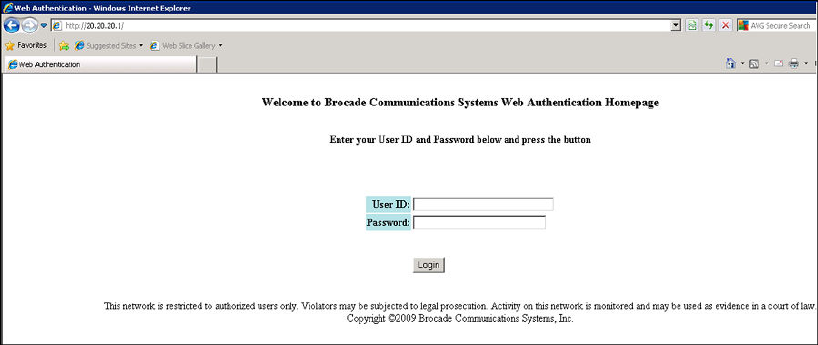
Deleting a web authentication VLAN
To delete a Web Authentication VLAN, enter the following commands:
device(config)# vlan 10
device(config-vlan-10)# no webauth
Syntax: [no] webauth
Web authentication pages
There are several pages that can be displayed for Web Authentication.
When a user enters a valid URL address (one that exists), the user is redirected to the switch Web
Authentication page (refer to Defining the web authorization redirect address on page 383).
If Automatic Authentication is enabled, a Welcome page appears. The browser will then be directed to
the requested URL.
If username and password (Local User Database) authentication is enabled, the following Login page
appears.
FIGURE 31 Example of a login page when automatic authentication is disabled and local user
database is enabled
The user enters a user name and password, which are then sent for authentication.
If passcode authentication is enabled, the following Login page appears.
Deleting a web authentication VLAN
384 FastIron Ethernet Switch Security Configuration Guide
53-1003405-04
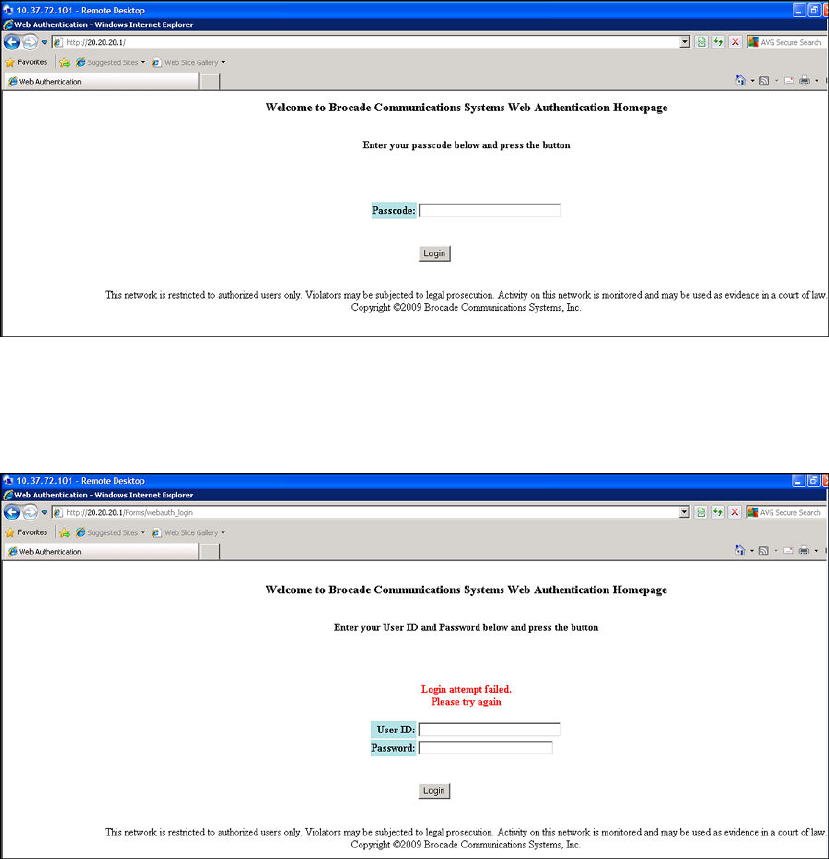
FIGURE 32 Example of a login page when automatic authentication is disabled and passcode
Authentication is Enabled
The user enters a passcode, which is then sent for authentication.
If the Web Authentication fails, the page to try again is displayed as shown below.
FIGURE 33 Example of a try again page
If the limit for the number of authenticated users on the network is exceeded, the Maximum Host Limit
page is displayed as shown below.
Web Authentication
FastIron Ethernet Switch Security Configuration Guide 385
53-1003405-04

FIGURE 34 Example of a maximum Host limit page
If the number of Web Authentication attempts by a user has been exceeded, the Maximum Attempts
Limit page is displayed as shown below. The user is blocked from attempting any Web Authentication
unless either the user MAC address is removed from the blocked list (using the clear webauth block-
mac mac-address command) or when the block duration timer expires.
FIGURE 35 Example of a maximum attempts limit page
If the user Web Authentication attempt is successful, the Success page is displayed as shown below.
Web Authentication
386 FastIron Ethernet Switch Security Configuration Guide
53-1003405-04
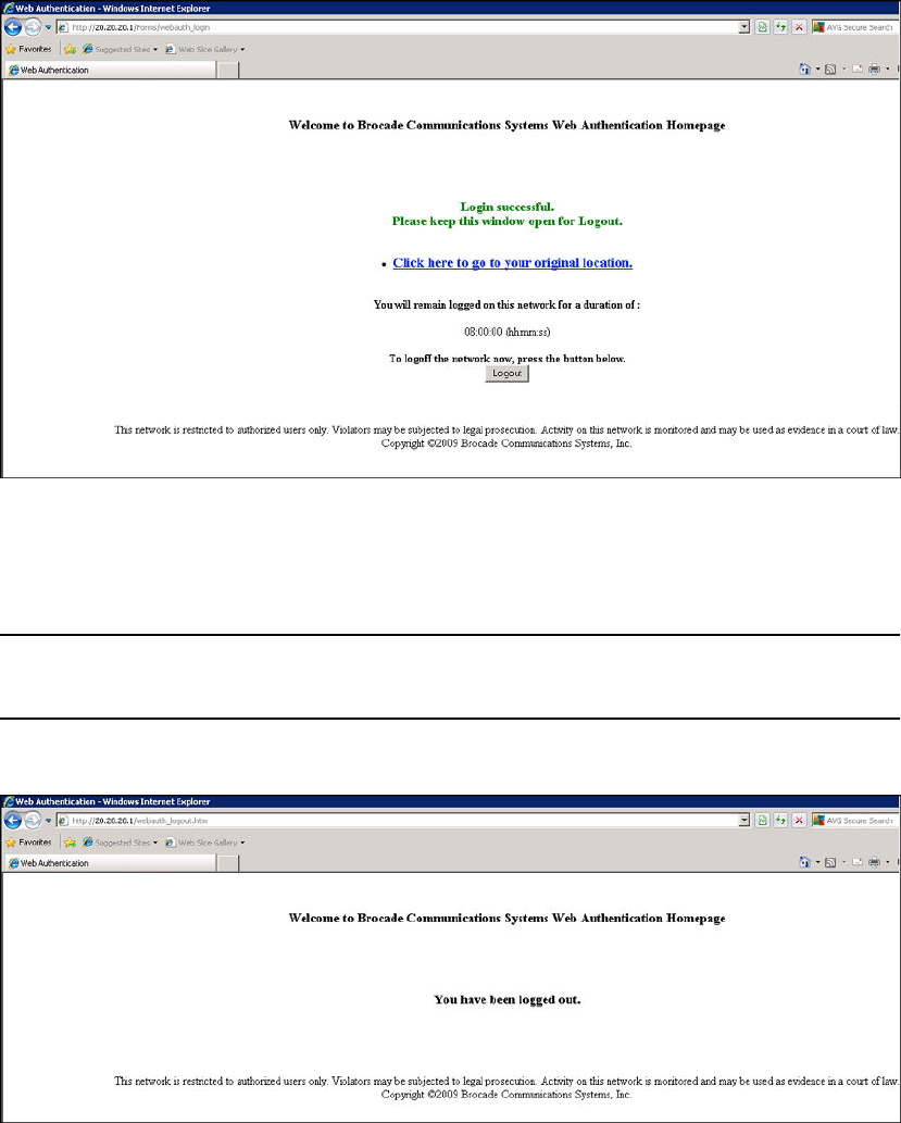
FIGURE 36 Example of a web authentication success page
Once a host is authenticated, that host can manually de-authenticate by clicking the Logout button in
the Login Success page. The host remains logged in until the re-authentication period expires. At that
time, the host is automatically logged out. However, if a re-authentication period is not configured, then
the host remains logged in indefinitely.
NOTE
If you accidentally close the Success page, you will not be able to log out. if a re-authentication period is
configured, you will be logged out once the re-authentication period ends.
The host can log out of the Web session by simply clicking the Logout button. Once logged out, the
following window appears.
You can customize the top and bottom text for the Welcome page and all windows shown in the
previous figures.
Web Authentication
FastIron Ethernet Switch Security Configuration Guide 387
53-1003405-04

Displaying text for web authentication pages
Use the show webauth vlan vlan-ID webpage command to determine what text has been configured
for Web Authentication pages.
device#show webauth vlan 25 webpage
=================================
Web Page Customizations (VLAN 25):
Top (Header): Default Text
"<h3>Welcome to Brocade Communications, Inc. Web Authentication Homepage</
h3>"
Bottom (Footer): Custom Text
"Copyright 2009 SNL"
Title: Default Text
"Web Authentication"
Login Button: Custom Text
"Sign On"
Web Page Logo: blogo.gif
align: left (Default)
Web Page Terms and Conditions: policy1.txt
Syntax: show webauth vlan vlan-ID webpage
Customizing web authentication pages
You can customize the following objects in the Web Authentication pages:
• Title bar
• Banner image (the logo)
• Header
• Text box
• Login button
• Footer
You can use the CLI commands show webauth and show webauth vlan vlan-ID webpage to
determine what text has been configured for Web Authentication pages.
NOTE
The banner image does not apply to the Web Authentication Maximum Attempts Limit page. The text
box and Login button apply to the Login page only.
The following figure shows the placement of these objects in the Login page.
Displaying text for web authentication pages
388 FastIron Ethernet Switch Security Configuration Guide
53-1003405-04
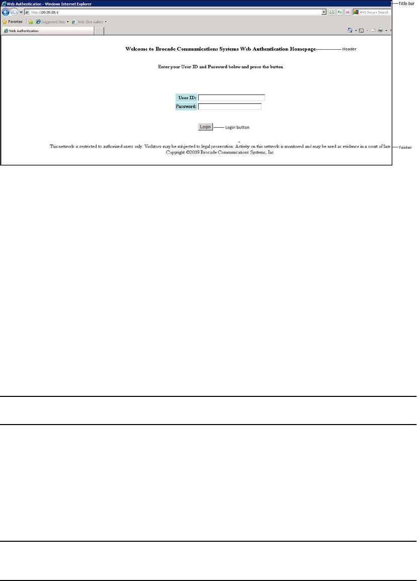
FIGURE 37 Objects in the web authentication pages that can be customized
Customizing the title bar
You can customize the title bar that appears on all Web Authentication pages. To do so, enter a
command such as the following.
device(config-vlan-10-webauth)#webpage custom-text title "Brocade Secure Access Page"
Syntax: [no] webpage custom-text title title
For title , enter up to 128 alphanumeric characters. The default title bar is "Web Authentication".
To reset the title bar back to the default value, enter the command no webpage custom-text title .
Customizing the banner image (Logo)
You can customize the logo that appears on all Web Authentication pages. The Objects in the web
authentication pages that can be customized figure shows placement of the banner image in the Login
page.
NOTE
The banner image does not display in the Maximum Attempts Limit page.
To customize the banner image, use the TFTP protocol to upload an image file from a TFTP server to
the FastIron switch. The image file can be in the format jpg, bmp, or gif, and its size must be 64K or
less. When you upload a new image file, it willl overwrite the existing image file.
To replace the existing logo with a new one, enter a command such as the following.
device(config-vlan-10-webauth)#webpage logo copy tftp 10.10.5.1 brocadelogo.gif
Syntax: [no] webpage logo copy tftp ip-address filename
NOTE
This command downloads the image file and stores it in the device flash memory. Therefore, it is not
necessary to follow this command with a write memory .
The ip-address parameter specifies the address of the TFTP server on which the image file resides.
Web Authentication
FastIron Ethernet Switch Security Configuration Guide 389
53-1003405-04

The filename parameter specifies the name of the image file on the TFTP server.
Use the no webpage logo command to delete the logo from all Web Authentication pages and remove
it from flash memory.
Aligning the banner image (Logo)
You can optionally configure the placement of the logo that appears on all Web Authentication pages.
By default, the logo is left-aligned at the top of the page. To center the logo at the top of the page,
enter the following command.
device(config-vlan-10-webauth)#webpage logo align center
To right-justify the log at the top of the page, enter the following command.
device(config-vlan-10-webauth)#webpage logo align right
Syntax: [no] webpage logo align { center | left | right }
Use the no webpage logo align command to reset the logo back to its default position (left).
Customizing the header
You can customize the header that appears on all Web Authentication pages.
To customize the header, enter a command such as the following.
device(config-vlan-10-webauth)#webpage custom-text top "Welcome to Network One"
Syntax: [no] webpage custom-text top text
For text , enter up to 255 alphanumeric characters.
To reset the header back to the default text, enter the command no webpage custom-text top. The
default text is "Welcome to Brocade Communications, Inc. Web Authentication Homepage" .
Customizing the text box
You can customize the text box that appears on the Web Authentication Login page. The Objects in
the web authentication pages that can be customized figure shows placement of the text box in the
Login page. By default, the text box is empty and is not visible. To create a text box or to replace the
existing one, upload an ASCII text file from a TFTP server to the FastIron switch. The text file size
must not exceed 2K.
To create or replace a text box, enter a command such as the following.
device(config-vlan-10-webauth)#webpage terms copy tftp 10.10.5.1 policy.txt
Syntax: [no] webpage terms copy tftp ip-address filename
NOTE
This command downloads the text file and stores it in the device flash memory. Therefore, it is not
necessary to follow this command with a write memory .
The ip-address parameter is the address of the TFTP server on which the image resides.
The filename parameter is the name of the text file on the TFTP server.
To revert back to the default text box (none), enter the command no webpage terms .
Web Authentication
390 FastIron Ethernet Switch Security Configuration Guide
53-1003405-04
Customizing the login button
You can customize the Login button that appears on the bottom of the Web Authentication Login page.
To do so, enter a command such as the following.
device(config-vlan-10-webauth)#webpage custom-text login-button "Press to Log In"
Syntax: [no] webpage custom-text login-button text
For text , enter up to 32 alphanumeric characters.
To reset the Login button back to the default value ("Login"), enter the command no webpage custom-
text login-button .
Customizing the footer
You can customize the footer that appears on all Web Authentication pages.
To customize the footer enter a command such as the following.
device(config-vlan-10-webauth)#webpage custom-text bottom "Network One Copyright
2010"
Syntax: [no] webpage custom-text bottom text
For text , enter up to 255 alphanumeric characters.
To reset the footer back to the default text, enter the command no webpage custom-text bottom. The
default text is "This network is restricted to authorized users only. Violators may be subjected to legal
prosecution. Activity on this network is monitored and may be used as evidence in a court of law.
Copyright 2009 Brocade Communications, Inc."
Displaying web authentication information
The following sections present the show commands you can use to display information about the Web
Authentication feature.
Displaying the web authentication configuration
Enter the show webauth command to display the configuration for the Web Authentication feature.
device#show webauth
=============================================================================
WEB AUTHENTICATION (VLAN 25): Enable
attempt-max-num: 5 (Default)
host-max-num: 0 (Default)
block duration: 90 (Default)
cycle-time: 600 (Default)
port-down-authenticated-mac-cleanup: Enable (Default)
reauth-time: 28800 (Default)
authenticated-mac-age-time: 3600 (Default)
dns-filter: Disable (Default)
authentication mode: username and password (Default)
authentication methods: radius
Local user database name: <none>
Radius accounting: Enable (Default)
Trusted port list: None
Secure Login (HTTPS): Enable (Default)
Web Page Customizations:
Top (Header): Default Text
Displaying web authentication information
FastIron Ethernet Switch Security Configuration Guide 391
53-1003405-04

Bottom (Footer): Custom Text
"SNL Copyright 2009"
Title: Default Text
Login Button: Custom Text
"Sign On"
Web Page Logo: blogo.gif
align: left (Default)
Web Page Terms and Conditions: policy1.txt
Host statistics:
Number of hosts dynamically authenticated: 0
Number of hosts statically authenticated: 2
Number of hosts dynamically blocked: 0
Number of hosts statically blocked: 0
Number of hosts authenticating: 1
The show webauth command displays the following information.
Field Description
WEB AUTHENTICATION
(VLAN 10)
Identifies the VLAN on which Web Authentication is enabled.
attempt-max-num The maximum number of Web Authentication attempts during a cycle.
host-max-num The maximum number of users that can be authenticated at one time.
block duration How many seconds a user who failed Web Authentication must wait before
attempting to be authenticated.
cycle-time The number of seconds in one Web Authentication cycle.
port-down-authenticated-mac-
cleanup
Indicates if this option is enabled or disabled. If enabled, all authenticated users
are de-authenticated if all the ports in the VLAN go down.
reauth-time The number of seconds an authenticated user remains authenticated. Once
this timer expires, the user must re-authenticate.
authenticated-mac-age-time If a user is inactive, this time shows how many seconds a user has before the
user associated MAC address is aged out. The user will be forced to re-
authenticate.
dns-filter Shows the definition of any DNS filter that have been set. (Refer to Filtering
DNS queries on page 382
authentication mode The authentication mode:
• username and password (default)
• passcode
• none
Also displays configuration details for the authentication mode.
RADIUS accounting Whether RADIUS accounting is enabled or disabled.
Trusted port list The statically-configured trusted ports of the Web Authentication VLAN.
Secure login (HTTPS) Whether HTTPS is enabled or disabled.
Web Authentication
392 FastIron Ethernet Switch Security Configuration Guide
53-1003405-04

Field Description
Web Page Customizations The current configuration for the text that appears on the Web Authentication
pages. Either "Custom Text" or "Default Text" displays for each page type:
• "Custom Text" means the message for the page has been customized. The
custom text is also displayed.
• "Default Text" means the default message that ships with the FastIron
switch is used.
The actual text on the Web Authentication pages can be displayed using the
show webauth vlan <vlan-id> webpage command. Refer to Displaying text for
web authentication pages on page 388.
Host statistics The authentication status and the number of hosts in each state.
Syntax: show webauth [ vlan vlan-id ]
The show webauth command by itself displays information for all VLANs on which Web Authentication
is enabled. Use the vlan vlan-id parameter to display information for a specific VLAN.
Displaying a list of authenticated hosts
Enter the show webauth allowed-list command to display a list of hosts that are currently
authenticated.
device#show webauth allowed-list
=============================================================================
VLAN 1: Web Authentication
-----------------------------------------------------------------------------
Web Authenticated List Configuration Authenticated Duration Remaining
MAC Address User Name Static/Dynamic HH:MM:SS
-----------------------------------------------------------------------------
0000.006c.2807 N/A D 00:03:05
0000.0069.79ea fdry1 D 04:58:01
0000.0082.8bca N/A S Infinite
0000.000e.de3b N/A S Infinite
0000.0042.a50e fdry2 D 00:25:25
The displays shows the following information.
Field Description
VLAN #: Web Authentication The ID of the VLAN on which Web Authentication is enabled.
Web Authenticated List MAC Address The MAC addresses that have been authenticated.
User Name The authenticated username.
Configuration Static/Dynamic If the MAC address was dynamically (passed Web Authentication) or
statically (added to the authenticated list using the add mac command)
authenticated.
Authenticated Duration The remainder of time the MAC address will remain authenticated
Syntax: show webauth allowed-list
Displaying a list of authenticated hosts
FastIron Ethernet Switch Security Configuration Guide 393
53-1003405-04

Displaying a list of hosts attempting to authenticate
Enter the show webauth authenticating-list command to display a list of hosts that are trying to
authenticate.
device#show webauth authenticating-list
===============================================================================
VLAN 25: Web Authentication
-------------------------------------------------------------------------------
Web Authenticating List # of Failed Cycle Time Remaining
MAC Address User Name Attempts HH:MM:SS
-------------------------------------------------------------------------------
0000.00f9.1fc6 N/A
0 00:09:46
The report shows the following information.
This field... Displays...
VLAN #: Web Authentication The ID of the VLAN on which Web Authentication is enabled.
MAC Address The MAC addresses that are trying to be authenticated.
User Name The User Name associated with the MAC address.
# of Failed Attempts Number of authentication attempts that have failed.
Cycle Time Remaining The remaining time the user has to be authenticated before the current
authentication cycle expires. Once it expires, the user must enter a valid URL again
to display the Web Authentication Welcome page.
Syntax: show webauth authenticating-list
Displaying a list of blocked hosts
Enter the show webauth blocked-list command to display a list of hosts that are currently blocked
from any Web Authentication Attempt.
device#show webauth blocked-list
=============================================================================
VLAN 1: Web Authentication
-----------------------------------------------------------------------------
Web Block List Configuration Block Duration Remaining
MAC Address User Name Static/Dynamic HH:MM:SS
-----------------------------------------------------------------------------
0000.0013.ff09 bauser S 00:31:27
0000.006c.2807 causer D 00:01:24
0000.0090.1ab3 dauser S infinite
The report shows the following information.
Field Description
VLAN #: Web Authentication The ID of the VLAN on which Web Authentication is enabled.
Web Block List MAC Address The MAC addresses that have been blocked from Web Authentication.
Displaying a list of hosts attempting to authenticate
394 FastIron Ethernet Switch Security Configuration Guide
53-1003405-04

Field Description
User Name The User Name associated with the MAC address.
Configuration Static/Dynamic If the MAC address was dynamically or statically blocked. The block mac
command statically blocks MAC addresses.
Block Duration Remaining The remaining time the MAC address has before the user with that MAC address
can attempt Web Authentication.
Syntax: show webauth blocked-list
Displaying a list of local user databases
The show local-userdb command displays a list of all local user databases configured on the FastIron
switch and the number of users in each database.
device#show local-userdb
=============================================================================
Local User Database Name : My_Database
Number of users in the database : 4
=============================================================================
Local User Database Name : test
Number of users in the database : 3
=============================================================================
Local User Database Name : test123
Number of users in the database : 3
Syntax: show local-userdb
Displaying a list of users in a local user database
The show local-userdb test command displays a list of all users in a particular local user database.
device#show local-userdb test
=============================================================================
Local User Database : test
Username Password
-------- --------
user1 $e$&Z9'%*&+
user2 $e$,)A=)65N,%-3*%1?@U
user3 $e$5%&-5%YO&&A1%6%<@U
As shown in the above example, passwords are encrypted in the command output.
Syntax: show local-userdb db-name
Displaying passcodes
If the passcode Web authentication mode is enabled, you can use the following command to display
current passcodes.
device#show webauth vlan 25 passcode
Current Passcode : 1389
This passcode is valid for 35089 seconds
Syntax: show webauth vlan vlan-id passcode
Displaying a list of local user databases
FastIron Ethernet Switch Security Configuration Guide 395
53-1003405-04
Displaying passcodes
396 FastIron Ethernet Switch Security Configuration Guide
53-1003405-04
DoS Attack Protection
● Supported DoS protection features...............................................................................397
● Smurf attacks................................................................................................................ 397
● TCP SYN attacks.......................................................................................................... 400
Supported DoS protection features
Lists DoS protection features supported on FastIron devices.
The following table lists individual Brocade switches and the DoS protection features they support.
These features are supported in the Layer 2, base Layer 3, edge Layer 3, and full Layer 3 software
images, except where noted.
Feature ICX 6430 ICX 6450 FCX ICX 6610 ICX 6650 FSX 800
FSX 1600
ICX 7450 ICX 7750
Smurf attack (ICMP attack)
protection
08.0.01 08.0.01 08.0.01 08.0.01 08.0.01 08.0.01 08.0.20 08.0.10
TCP SYN attack protection 08.0.01 08.0.01 08.0.01 08.0.01 08.0.01 08.0.01 08.0.20 08.0.10
This chapter explains how to protect your Brocade devices from Denial of Service (DoS) attacks.
In a Denial of Service (DoS) attack, a router is flooded with useless packets, hindering normal
operation. Brocade devices include measures for defending against two types of DoS attacks Smurf
attacks and TCP SYN attacks.
Smurf attacks
A Smurf attack is a kind of DoS attack in which an attacker causes a victim to be flooded with Internet
Control Message Protocol (ICMP) echo (Ping) replies sent from another network. The following figure
illustrates how a Smurf attack works.
FastIron Ethernet Switch Security Configuration Guide 397
53-1003405-04
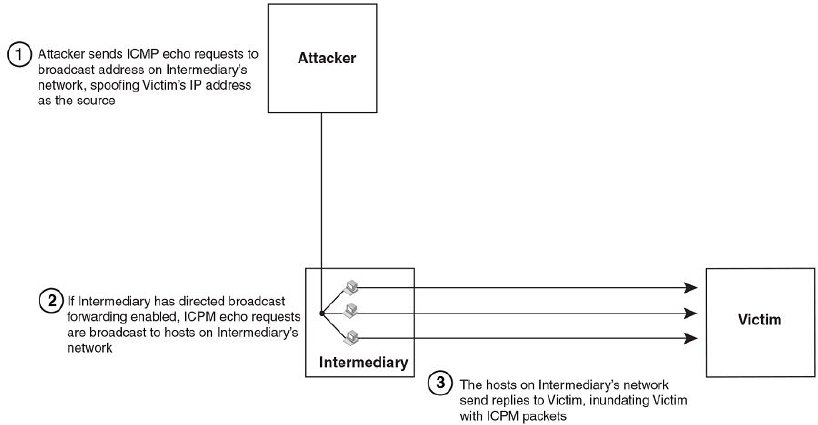
FIGURE 38 How a Smurf attack floods a victim with ICMP replies
The attacker sends an ICMP echo request packet to the broadcast address of an intermediary
network. The ICMP echo request packet contains the spoofed address of a victim network as its
source. When the ICMP echo request reaches the intermediary network, it is converted to a Layer 2
broadcast and sent to the hosts on the intermediary network. The hosts on the intermediary network
then send ICMP replies to the victim network.
For each ICMP echo request packet sent by the attacker, a number of ICMP replies equal to the
number of hosts on the intermediary network are sent to the victim. If the attacker generates a large
volume of ICMP echo request packets, and the intermediary network contains a large number of
hosts, the victim can be overwhelmed with ICMP replies.
Avoiding being an intermediary in a Smurf attack
A Smurf attack relies on the intermediary to broadcast ICMP echo request packets to hosts on a target
subnet. When the ICMP echo request packet arrives at the target subnet, it is converted to a Layer 2
broadcast and sent to the connected hosts. This conversion takes place only when directed broadcast
forwarding is enabled on the device.
To avoid being an intermediary in a Smurf attack, make sure forwarding of directed broadcasts is
disabled on the Brocade device. Directed broadcast forwarding is disabled by default. To disable
directed broadcast forwarding, do one of the following.
device(config)#no ip directed-broadcast
Syntax: [no] ip directed-broadcast
Avoiding being a victim in a Smurf attack
You can configure the Brocade device to drop ICMP packets when excessive numbers are
encountered, as is the case when the device is the victim of a Smurf attack. You can set threshold
values for ICMP packets that are targeted at the router itself or passing through an interface, and drop
them when the thresholds are exceeded.
Avoiding being an intermediary in a Smurf attack
398 FastIron Ethernet Switch Security Configuration Guide
53-1003405-04

For example, to set threshold values for ICMP packets targeted at the router, enter the following
command in global CONFIG mode.
device(config)#ip icmp burst-normal 5000 burst-max 10000 lockup 300
For a ICX 7750 device, enter the following command in global CONFIG mode.
device(config)#ip icmp attack-rate burst-normal 2500 burst-max 3450 lockup 50
To set threshold values for ICMP packets received on interface 3/11, enter the following commands.
device(config)#interface ethernet 3/11
device(config-if-e1000-3/11)#ip icmp burst-normal 5000 burst-max 10000 lockup 300
To set threshold values for ICMP packets received on interface 3/11 for a ICX 7750 device, enter the
following commands.
device(config)#interface ethernet 3/11
device(config-if-e1000-3/11)#ip icmp attack-rate burst-normal 5000 burst-max 10000
lockup 300
For Layer 3 router code, if the interface is part of a VLAN that has a router VE, you must configure
ICMP attack protection at the VE level. Otherwise, you can configure this feature at the interface level
as shown in the previous example. When ICMP attack protection is configured at the VE level, it will
apply to routed traffic only. It will not affect switched traffic.
NOTE
You must configure VLAN information for the port before configuring ICMP attack protection. You
cannot change the VLAN configuration for a port on which ICMP attack protection is enabled.
To set threshold values for ICMP packets received on VE 31, enter commands such as the following.
device(config)#interface ve 31
device(config-vif-31)#ip icmp burst-normal 5000 burst-max 10000 lockup 300
To set threshold values for ICMP packets received on VE 31 for a ICX 7750 device, enter commands
such as the following.
device(config)#interface ve 31
device(config-vif-31)#ip icmp attack-rate burst-normal 5000 burst-max 10000 lockup 300
Syntax: [no] ip icmp attack-rate burst-normal value burst-max value lockup seconds
The attack-rate parameter is specific to ICX 7750 and has no associated value.
The burst-normal value parameter can be from 1 through 100,000 packets per second.
The burst-max value paramter can be from 1 through 100,000 packets per second.
The lockup seconds parameter can be from 1 through 10,000 seconds.
This command is supported on Ethernet and Layer 3 interfaces.
NOTE
For ICX 7750, the units of "burst-normal" and "burst-max" values are Kbps.
The number of incoming ICMP packets per second is measured and compared to the threshold values
as follows:
DoS Attack Protection
FastIron Ethernet Switch Security Configuration Guide 399
53-1003405-04

• If the number of ICMP packets exceeds the burst-normal value, the excess ICMP packets are
dropped.
• If the number of ICMP packets exceeds the burst-max value, all ICMP packets are dropped for the
number of seconds specified by the lockup value. When the lockup period expires, the packet
counter is reset and measurement is restarted.
In the example, if the number of ICMP packets received per second exceeds 5,000, the excess
packets are dropped. If the number of ICMP packets received per second exceeds 10,000, the device
drops all ICMP packets for the next 300 seconds (5 minutes).
TCP SYN attacks
TCP SYN attacks exploit the process of how TCP connections are established to disrupt normal traffic
flow. When a TCP connection starts, the connecting host first sends a TCP SYN packet to the
destination host. The destination host responds with a SYN ACK packet, and the connecting host
sends back an ACK packet. This process, known as a "TCP three-way handshake," establishes the
TCP connection.
While waiting for the connecting host to send an ACK packet, the destination host keeps track of the
as-yet incomplete TCP connection in a connection queue. When the ACK packet is received,
information about the connection is removed from the connection queue. Usually there is not much
time between the destination host sending a SYN ACK packet and the source host sending an ACK
packet, so the connection queue clears quickly.
In a TCP SYN attack, an attacker floods a host with TCP SYN packets that have random source IP
addresses. For each of these TCP SYN packets, the destination host responds with a SYN ACK
packet and adds information to the connection queue. However, because the source host does not
exist, no ACK packet is sent back to the destination host, and an entry remains in the connection
queue until it ages out (after approximately a minute). If the attacker sends enough TCP SYN packets,
the connection queue can fill up, and service can be denied to legitimate TCP connections.
To protect against TCP SYN attacks, you can configure the Brocade device to drop TCP SYN packets
when excessive numbers are encountered. You can set threshold values for TCP SYN packets that
are targeted at the router itself or passing through an interface, and drop them when the thresholds
are exceeded.
For example, to set threshold values for TCP SYN packets targeted at the router, enter the following
command in global CONFIG mode.
device(config)#ip tcp burst-normal 10 burst-max 100 lockup 300
To set threshold values for TCP SYN packets received on interface 3/11, enter the following
commands.
device(config)#interface ethernet 3/11
device(config-if-e1000-3/11)#ip tcp burst-normal 10 burst-max 100 lockup 300
For Layer 3 router code, if the interface is part of a VLAN that has a router VE, you must configure
TCP/SYN attack protection at the VE level. Otherwise, you can configure this feature at the interface
level as shown in the previous example. WhenTCP/SYN attack protection is configured at the VE
level, it will apply to routed traffic only. It will not affect switched traffic.
NOTE
You must configure VLAN information for the port before configuring TCP/SYN attack protection. You
cannot change the VLAN configuration for a port on which TCP/SYN attack protection is enabled.
TCP SYN attacks
400 FastIron Ethernet Switch Security Configuration Guide
53-1003405-04

NOTE
For ICX 7750 devices, the "attack rate" parameter is only applicable for smurf attacks and not for
TCP/SYN attacks.
To set threshold values for TCP/SYN packets received on VE 31, enter commands such as the
following.
device(config)#interface ve 31
device(config-vif-31)#ip tcp burst-normal 5000 burst-max 10000 lockup 300
Syntax: ip tcp burst-normal value burst-max value lockup seconds
NOTE
This command is available at the global CONFIG level on both Chassis devices and Compact devices.
On Chassis devices, this command is available at the Interface level as well. This command is
supported on Ethernet and Layer 3 interfaces.
The burst-normalvalue parameter can be from 1 - 100,000 packets per second.
The burst-maxvalue parameter can be from 1 - 100,000 packets per second.
The lockupseconds parameter can be from 1 - 10,000 seconds.
The number of incoming TCP SYN packets per second is measured and compared to the threshold
values as follows:
• If the number of TCP SYN packets exceeds the burst-normal value, the excess TCP SYN packets
are dropped.
• If the number of TCP SYN packets exceeds the burst-max value, all TCP SYN packets are dropped
for the number of seconds specified by the lockup value. When the lockup period expires, the packet
counter is reset and measurement is restarted.
In the example, if the number of TCP SYN packets received per second exceeds 10, the excess
packets are dropped. If the number of TCP SYN packets received per second exceeds 100, the device
drops all TCP SYN packets for the next 300 seconds (5 minutes).
TCP security enhancement
TCP security enhancement improves upon the handling of TCP inbound segments. This enhancement
eliminates or minimizes the possibility of a TCP reset attack, in which a perpetrator attempts to
prematurely terminate an active TCP session, and a data injection attack, wherein an attacker injects or
manipulates data in a TCP connection.
In both cases, the attack is blind, meaning the perpetrator does not have visibility into the content of the
data stream between two devices, but blindly injects traffic. Also, the attacker does not see the direct
effect, the continuing communications between the devices and the impact of the injected packet, but
may see the indirect impact of a terminated or corrupted session.
The TCP security enhancement prevents and protects against the following three types of attacks:
• Blind TCP reset attack using the reset (RST) bit
• Blind TCP reset attack using the synchronization (SYN) bit
• Blind TCP packet injection attack
The TCP security enhancement is automatically enabled.
TCP security enhancement
FastIron Ethernet Switch Security Configuration Guide 401
53-1003405-04
Protecting against a blind TCP reset attack using the RST bit
In a blind TCP reset attack using the RST bit, a perpetrator attempts to guess the RST bits to
prematurely terminate an active TCP session.
To prevent a user from using the RST bit to reset a TCP connection, the RST bit is subject to the
following rules when receiving TCP segments:
• If the RST bit is set and the sequence number is outside the expected window, the Brocade device
silently drops the segment.
• If the RST bit is exactly the next expected sequence number, the Brocade device resets the
connection.
• If the RST bit is set and the sequence number does not exactly match the next expected sequence
value, but is within the acceptable window, the Brocade device sends an acknowledgement.
Protecting against a blind TCP reset attack using the SYN bit
In a blind TCP reset attack using the SYN bit, a perpetrator attempts to guess the SYN bits to
prematurely terminate an active TCP session.
To prevent a user from using the SYN bit to tear down a TCP connection, in current software releases,
the SYN bit is subject to the following rules when receiving TCP segments:
• If the SYN bit is set and the sequence number is outside the expected window, the Brocade device
sends an acknowledgement (ACK) back to the peer.
• If the SYN bit is set and the sequence number is an exact match to the next expected sequence,
the Brocade device sends an ACK segment to the peer. Before sending the ACK segment, the
software subtracts one from the value being acknowledged.
• If the SYN bit is set and the sequence number is acceptable, the Brocade device sends an
acknowledgement (ACK) segment to the peer.
Protecting against a blind injection attack
In a blind TCP injection attack, a perpetrator tries to inject or manipulate data in a TCP connection.
To reduce the chances of a blind injection attack, an additional check on all incoming TCP segments is
performed.
Displaying statistics about packets dropped because of DoS attacks
To display information about ICMP and TCP SYN packets dropped because burst thresholds were
exceeded, enter the show statistics dos-attack command.
device#show statistics dos-attack
---------------------------- Local Attack Statistics --------------------------
ICMP Drop Count ICMP Block Count SYN Drop Count SYN Block Count
--------------- ---------------- -------------- ---------------
0 0 0 0
--------------------------- Transit Attack Statistics -------------------------
Port ICMP Drop Count ICMP Block Count SYN Drop Count SYN Block Count
----- --------------- ---------------- -------------- ---------------
3/11 0 0 0 0
Syntax: show statistics dos-attack
To clear statistics about ICMP and TCP SYN packets dropped because burst thresholds were
exceeded, enter the clear statistics dos-attack command.
device#clear statistics dos-attack
Protecting against a blind TCP reset attack using the RST bit
402 FastIron Ethernet Switch Security Configuration Guide
53-1003405-04
Syntax: clear statistics dos-attack
DoS Attack Protection
FastIron Ethernet Switch Security Configuration Guide 403
53-1003405-04
Displaying statistics about packets dropped because of DoS attacks
404 FastIron Ethernet Switch Security Configuration Guide
53-1003405-04
DHCP
● Supported DHCP packet inspection and tracking features........................................... 405
● Dynamic ARP inspection ..............................................................................................405
● DHCP snooping............................................................................................................ 410
● DHCP relay agent information ..................................................................................... 416
● IP source guard.............................................................................................................423
Supported DHCP packet inspection and tracking features
Lists DHCP packet inspection and tracking features supported on FastIron devices.
The following table lists individual Brocade switches and the Dynamic Host Configuration Protocol
(DHCP) packet inspection and tracking features they support. These features are supported in the
Layer 2 and Layer 3 software images, except where explicitly noted.
Feature ICX 6430 ICX 6450 FCX ICX 6610 ICX 6650 FSX 800
FSX 1600
IC 7450 ICX 7750
Dynamic ARP inspection 08.0.01 08.0.01 08.0.01 08.0.01 08.0.01 08.0.01 08.0.20 08.0.10
DHCP snooping 08.0.01 08.0.01 08.0.01 08.0.01 08.0.01 08.0.01 08.0.20 08.0.10
DHCP relay agent information
(DHCP Option 82) RFC 3046
No 08.0.01 08.0.01 08.0.01 08.0.01 08.0.01 08.0.20 08.0.10
Port statistics 08.0.01 08.0.01 08.0.01 08.0.01 08.0.01 08.0.01 08.0.20 08.0.10
IP source guard 08.0.01 08.0.01 08.0.01 08.0.01 08.0.01 08.0.01 08.0.20 08.0.10
Dynamic ARP inspection
For enhanced network security, you can configure the Brocade device to inspect and keep track of
Dynamic Host Configuration Protocol (DHCP) assignments.
Dynamic ARP Inspection (DAI) enables the Brocade device to intercept and examine all ARP request
and response packets in a subnet and discard those packets with invalid IP to MAC address bindings.
DAI can prevent common man-in-the-middle (MiM) attacks such as ARP cache poisoning, and disallow
mis-configuration of client IP addresses.
ARP poisoning
ARP provides IP communication within a Layer 2 broadcast domain by mapping an IP address to a
MAC address. Before a host can talk to another host, it must map the IP address to a MAC address
first. If the host does not have the mapping in its ARP table, it creates an ARP request to resolve the
FastIron Ethernet Switch Security Configuration Guide 405
53-1003405-04
mapping. All computers on the subnet will receive and process the ARP requests, and the host whose
IP address matches the IP address in the request will send an ARP reply.
An ARP poisoning attack can target hosts, switches, and routers connected to the Layer 2 network by
poisoning the ARP caches of systems connected to the subnet and by intercepting traffic intended for
other hosts on the subnet. For instance, a malicious host can reply to an ARP request with its own
MAC address, thereby causing other hosts on the same subnet to store this information in their ARP
tables or replace the existing ARP entry. Furthermore, a host can send gratuitous replies without
having received any ARP requests. A malicious host can also send out ARP packets claiming to have
an IP address that actually belongs to another host (e.g. the default router). After the attack, all traffic
from the device under attack flows through the attacker computer and then to the router, switch, or
host.
About Dynamic ARP Inspection
Dynamic ARP Inspection (DAI) allows only valid ARP requests and responses to be forwarded.
A Brocade device on which DAI is configured does the following:
• Intercepts ARP packets received by the system CPU
• Inspects all ARP requests and responses received on untrusted ports
• Verifies that each of the intercepted packets has a valid IP-to-MAC address binding before updating
the local ARP table, or before forwarding the packet to the appropriate destination
• Drops invalid ARP packets
When you enable DAI on a VLAN, by default, all member ports are untrusted. You must manually
configure trusted ports. In a typical network configuration, ports connected to host ports are untrusted.
You configure ports connected to other switches or routers as trusted.
DAI inspects ARP packets received on untrusted ports, as shown in the Dynamic ARP inspection at
work figure. DAI carries out the inspection based on IP-to-MAC address bindings stored in a trusted
binding database. For the Brocade device, the binding database is the ARP table, which supports DAI,
DHCP snooping, and IP Source Guard. To inspect an ARP request packet, DAI checks the source IP
and source MAC address against the ARP table. For an ARP reply packet, DAI checks the source IP,
source MAC, destination IP, and destination MAC addresses. DAI forwards the valid packets and
discards those with invalid IP-to-MAC address bindings.
When ARP packets reach a trusted port, DAI lets them through, as shown in the following figure.
About Dynamic ARP Inspection
406 FastIron Ethernet Switch Security Configuration Guide
53-1003405-04
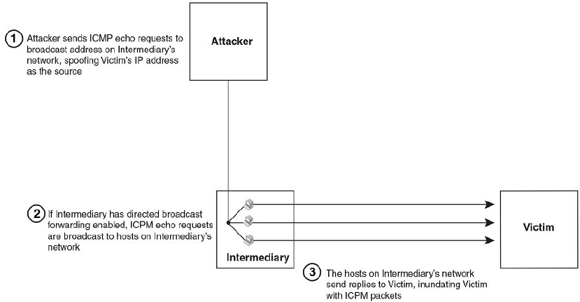
FIGURE 39 Dynamic ARP inspection at work
ARP entries
DAI uses the IP/MAC mappings in the ARP table to validate ARP packets received on untrusted ports.
ARP entries in the ARP table derive from the following:
• Dynamic ARP - normal ARP learned from trusted ports.
• Static ARP - statically configured IP/MAC/port mapping.
• Inspection ARP - statically configured IP/MAC mapping, where the port is initially unspecified. The
actual physical port mapping will be resolved and updated from validated ARP packets.Refer to
Configuring an inspection ARP entry on page 408.
• DHCP-Snooping ARP - information collected from snooping DHCP packets when DHCP snooping is
enabled on VLANs.
The status of an ARP entry is either pending or valid:
• Valid - the mapping is valid, and the port is resolved. This is always the case for static ARP entries.
• Pending - for normal dynamic and inspection ARP entries before they are resolved, and the port
mapped. Their status changes to valid when they are resolved, and the port mapped.
Refer to also System reboot and the binding database on page 412.
Configuration notes and feature limitations for DAI
The following limits and restrictions apply when configuring DAI:
• To run Dynamic ARP Inspection, you must first enable support for ACL filtering based on VLAN
membership or VE port membership. To do so, enter the following commands at the Global CONFIG
Level of the CLI.
device(config)#enable ACL-per-port-per-vlan
device(config)#write memory
device(config)#exit
device#reload
ARP entries
FastIron Ethernet Switch Security Configuration Guide 407
53-1003405-04

NOTE
You must save the configuration and reload the software to place the change into effect.
• Brocade does not support DAI on trunk or LAG ports.
• The maximum number of DHCP and static DAI entries depends on the maximum number of ARP
table entries allowed on the device. A FastIron Layer 2 switch can have up to 4096 ARP entries and
a FastIron Layer 3 switch can have up to 64,000 ARP entries. In a FastIron Layer 3 switch, you can
use the system-max ip-arp command to change the maximum number of ARP entries for the
device.
However, only up to 1024 DHCP entries can be saved to flash.
• ACLs are supported on member ports of a VLAN on which DHCP snooping and Dynamic ARP
Inspection (DAI) are enabled.
• On FastIron X Series devices, DAI is supported together with multi-device port authentication and
dynamic ACLs.
• DAI is supported on a VLAN without a VE, or on a VE with or without an assigned IP address.
Dynamic ARP inspection configuration
Configuring DAI consists of the following steps.
1. Configure inspection ARP entries for hosts on untrusted ports.Refer to Configuring an inspection
ARP entry on page 408.
2. Enable DAI on a VLAN to inspect ARP packets.Refer to Enabling DAI on a VLAN on page 409.
3. Configure the trust settings of the VLAN members. ARP packets received on trusted ports bypass
the DAI validation process. ARP packets received on untrusted ports go through the DAI validation
process.Refer to Enabling trust on a port on page 409.
4. Enable DHCP snooping to populate the DHCP snooping IP-to-MAC binding database.
The following shows the default settings of DAI.
Feature Default
Dynamic ARP Inspection Disabled
Trust setting for ports Untrusted
Configuring an inspection ARP entry
Static ARP and static inspection ARP entries need to be configured for hosts on untrusted ports.
Otherwise, when DAI checks ARP packets from these hosts against entries in the ARP table, it will not
find any entries for them, and the Brocade device will not allow and learn ARP from an untrusted host.
To configure an inspection ARP entry, enter a command such as the following.
device(config)#arp 10.20.20.12 0000.0002.0003 inspection
This command defines an inspection ARP entry in the static ARP table, mapping a device IP address
10.20.20.12 with its MAC address 0000.0002.0003. ARP entry will be moved to the ARP table once
the DAI receives a valid ARP packet.
Dynamic ARP Inspection has to be enabled to use static ARP inspection entries.
Dynamic ARP inspection configuration
408 FastIron Ethernet Switch Security Configuration Guide
53-1003405-04
The ARP entry will be in Pend (pending) status until traffic with the matching IP-to-MAC is received on a
port.
Syntax: [no] arp ip-addr mac-addr inspection
The ip-addr mac-addr parameter specifies a device IP address and MAC address pairing.
Enabling DAI on a VLAN
DAI is disabled by default. To enable DAI on an existing VLAN, enter the following command.
device(config)#ip arp inspection vlan 2
The command enables DAI on VLAN 2. ARP packets from untrusted ports in VLAN 2 will undergo DAI
inspection.
Syntax: [no] ip arp inspection vlan vlan-number
The vlan-number variable specifies the ID of a configured VLAN.
Enabling trust on a port
The default trust setting for a port is untrusted. For ports that are connected to host ports, leave their
trust settings as untrusted.
To enable trust on a port, enter commands such as the following.
device(config)#interface ethernet 1/4
device(config-if-e10000-1/4)#arp inspection trust
The commands change the CLI to the interface configuration level of port 1/4 and set the trust setting of
port 1/4 to trusted.
Syntax: [no] arp inspection trust
Displaying ARP inspection status and ports
To display the ARP inspection status for a VLAN and the trusted or untrusted port, enter the following
command.
device#show ip arp inspection vlan 2
IP ARP inspection VLAN 2: Disabled
Trusted Ports : ethe 1/4
Untrusted Ports : ethe 2/1 to 2/3 ethe 4/1 to 4/24 ethe 6/1 to 6/4 ethe 8/1 to
8/4
Syntax: show ip arp inspection vlan vlan_id
The vlan_id variable specifies the ID of a configured VLAN.
Displaying the ARP table
To display the ARP table, enter the show arp command.
device#show arp
Total number of ARP entries: 2, maximum capacity: 6000
No IP Address MAC Address Type Age Port Status
1 10.43.1.1 0000.00a0.4000
Dynamic 0 mgmt1 Valid
Enabling DAI on a VLAN
FastIron Ethernet Switch Security Configuration Guide 409
53-1003405-04
2 10.43.1.78 0000.0060.6ab1
Dynamic 2 mgmt1 Valid
The command displays all ARP entries in the system. For field definitions, refer to Table 25 in the
FastIron Ethernet Switch Layer 3 Routing Configuration Guide .
Syntax: show arp
Multi-VRF support
DAI supports Multi-VRF (Virtual Routing and Forwarding) instances. You can deploy multiple VRFs on
a Brocade Ethernet switch. Each VLAN having a Virtual Interface (VE) is assigned to a VRF.
You can enable DAI on individual VLANs and assign any interface as the arp inspect trust interface. If
an interface is a tagged port in this VLAN, you can turn on the trust port per VRF, so that traffic
intended for other VRF VLANs will not be trusted.
To configure DAI to support a VRF instance, do the following:
• DAI requires that the acl-per-port-per-vlan setting be enabled. To enable the setting:
Brocade(config)# enable acl-per-port-per-vlan
Reload required. Please write memory and then reload or power cycle.
• Configure DAI on a VLAN using the ip arp inspection vlan vlan-id command . For example:
Brocade(config)# ip arp inspection vlan 2
Syntax: ip arp inspection vlan vlan-id
• To add an static ARP Inspection entry for a specific VRF, use arp ip-address mac-address
inspection command in the VRF CLI - context. For example:
Brocade(config-vrf-one-ipv4)#arp 5.5.5.5 00a2.bbaa.0033 inspection
Syntax: arp ip-address mac-address inspection
Enabling trust on a port for a specific VRF
The default trust setting for a port is untrusted. For ports that are connected to host ports, leave their
trust settings as untrusted.
To enable trust on a port for a specific VRF, enter commands such as the following.
Brocade(config)#interface ethernet 1/4
Brocade(config-if-e10000-1/4)#arp inspection trust vrf vrf2
The commands change the CLI to the interface configuration level of port 1/4 and set the trustsetting
of port 1/4 on VRF 2 to trusted.
Syntax: [no] arp inspection trust vrf vrf-name
DHCP snooping
Dynamic Host Configuration Protocol (DHCP) snooping enables the Brocade device to filter untrusted
DHCP packets in a subnet. DHCP snooping can ward off MiM attacks, such as a malicious user
posing as a DHCP server sending false DHCP server reply packets with the intention of misdirecting
Multi-VRF support
410 FastIron Ethernet Switch Security Configuration Guide
53-1003405-04
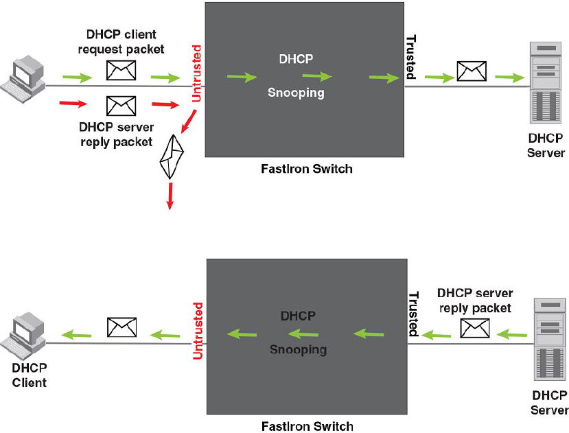
other users. DHCP snooping can also stop unauthorized DHCP servers and prevent errors due to user
mis-configuration of DHCP servers.
Often DHCP snooping is used together with Dynamic ARP Inspection and IP Source Guard.
How DHCP snooping works
When enabled on a VLAN, DHCP snooping stands between untrusted ports (those connected to host
ports) and trusted ports (those connected to DHCP servers). A VLAN with DHCP snooping enabled
forwards DHCP request packets from clients and discards DHCP server reply packets on untrusted
ports, and it forwards DHCP server reply packets on trusted ports to DHCP clients, as shown in the
following figures
FIGURE 40 DHCP snooping at work - on an untrusted port
FIGURE 41 DHCP snooping at work - on a trusted port
DHCP binding database
On trusted ports, DHCP server reply packets are forwarded to DHCP clients. The DHCP server reply
packets collect client IP to MAC address binding information, which is saved in the DHCP binding
database. This information includes MAC address, IP address, lease time, VLAN number, and port
number.
In the Brocade device, the DHCP binding database is integrated with the enhanced ARP table, which is
used by Dynamic ARP Inspection. For more information, refer to ARP entries on page 407.
How DHCP snooping works
FastIron Ethernet Switch Security Configuration Guide 411
53-1003405-04

The lease time will be refreshed when the client renews its IP address with the DHCP server;
otherwise the Brocade device removes the entry when the lease time expires.
About client IP-to-MAC address mappings
Client IP addresses need not be on directly-connected networks, as long as the client MAC address is
learned on the client port and the client port is in the same VLAN as the DHCP server port. In this
case, the system will learn the client IP-to-MAC port mapping. Therefore, a VLAN with DHCP
snooping enabled does not require a VE interface.
In earlier releases, in the Layer 3 software image, DHCP snooping does not learn the secure IP-to-
MAC address mapping for a client, if the client port is not a virtual ethernet (VE) interface with an IP
subnet address. In other words, the client IP address had to match one of the subnets of the client port
in order for DHCP to learn the address mapping.
System reboot and the binding database
To allow DAI and DHCP snooping to work smoothly across a system reboot, the binding database is
saved to a file in the system flash memory after an update to the binding database, with a 30 second
delay. The flash file is written and read only if DHCP snooping is enabled.
Configuration notes and feature limitations for DHCP snooping
The following limits and restrictions apply to DHCP snooping:
• To run DHCP snooping, you must first enable support for ACL filtering based on VLAN membership
or VE port membership. To do so, enter the following commands at the Global CONFIG Level of the
CLI.
device(config)#enable ACL-per-port-per-vlan
device(config)#write memory
device(config)#exit
device#reload
NOTE
You must save the configuration and reload the software to place the change into effect.
• DHCP snooping is not supported on LAG ports.
• DHCP snooping is not supported together with DHCP Auto-configuration.
• You cannot apply MAC address filters on a VLAN member on which DHCP snooping is already
enabled and vice versa.
• A switch can have up to 256 ARP entries, therefore, DHCP entries are limited to 256. A router,
however, can have 64,000 ARP entries, so a router can have up to 64,000 DHCP entries, of which
only 1024 entries can be saved to flash on reboot.
• ACLs are supported on member ports of a VLAN on which DHCP snooping and Dynamic ARP
Inspection (DAI) are enabled.
• See also About client IP-to-MAC address mappings on page 412.
• On FastIron X Series devices, DHCP snooping is supported together with multi-device port
authentication and dynamic ACLs.
• DHCP snooping supports DHCP relay agent information (DHCP Option 82). For details, refer to
DHCP relay agent information on page 416.
• For default vlan-id changes, DHCP Snooping and Dynamic ARP Inspection should be re-applied on
the new default VLAN.
About client IP-to-MAC address mappings
412 FastIron Ethernet Switch Security Configuration Guide
53-1003405-04

Configuring DHCP snooping
Configuring DHCP snooping consists of the following steps.
1. Enable DHCP snooping on a VLAN.Refer to Enabling DHCP snooping on a VLAN on page 413.
2. For ports that are connected to a DHCP server, change their trust setting to trusted.Refer to Enabling
DHCP snooping on a VLAN on page 413.
The following shows the default settings of DHCP snooping.
Feature Default
DHCP snooping Disabled
Trust setting for ports Untrusted
Enabling DHCP snooping on a VLAN
When DHCP snooping is enabled on a VLAN, DHCP packets are inspected.
DHCP snooping is disabled by default. This feature must be enabled on the client and the DHCP server
VLANs. To enable DHCP snooping, enter the following global command for these VLANs.
device(config)#ip dhcp snooping vlan 2
The command enables DHCP snooping on VLAN 2.
Syntax: [no] ip dhcp snooping vlan vlan-id
The vlan-id variable specifies the ID of a configured client or DHCP server VLAN.
Enabling trust on a port connected to a DHCP server
The default trust setting for a port is untrusted. To enable trust on a port connected to a DHCP server,
enter commands such as the following.
device(config)#interface ethernet 1/1
device(config-if-e10000-1/1)#dhcp snooping trust
Port 1/1 is connected to a DHCP server. The commands change the CLI to the interface configuration
level of port 1/1 and set the trust setting of port 1/1 to trusted.
Syntax: [no] ip dhcp snooping trust
Disabling the learning of DHCP clients on a port
You can disable DHCP client learning on an individual port. To do so, enter commands such as the
following.
device(config)#interface ethernet 1/1
device(config-if-e10000-1/1)#dhcp snooping client-learning disable
Syntax: [no] dhcp snooping client-learning disable
Use the no form of the command to re-enable DHCP client learning on a port once it has been disabled.
Configuring DHCP snooping
FastIron Ethernet Switch Security Configuration Guide 413
53-1003405-04
Clearing the DHCP binding database
You can clear the DHCP binding database using the CLI command clear DHCP . You can remove all
entries in the database, or remove entries for a specific IP address only.
To remove all entries from the DHCP binding database, enter the clear dhcp command.
device#clear dhcp
To clear entries for a specific IP address, enter a command such as the following.
device#clear dhcp 10.10.102.4
Syntax: clear dhcp ip-address
Displaying DHCP snooping status and ports
To display the DHCP snooping status for a VLAN and the trusted/untrusted port, use the show ip
dhcp snooping vlan command.
device#show ip dhcp snooping vlan 2
IP DHCP snooping VLAN 2: Enabled
Syntax: show ip dhcp snooping vlan vlan_id
Displaying the DHCP snooping binding database
To display the DHCP snooping binding database, use the show ip dhcp snooping info command.
device#show ip dhcp snooping info
Dhcp snooping Info
Total learnt entries 1
SAVED DHCP ENTRIES IN FLASH
IP Address Mac Address Port vlan lease
0 10.10.10.20 0000.0002.0003 6/13
1112 361
Syntax: show ip dhcp snooping info
Displaying DHCP binding entry and status
To display the DHCP binding entry and its current status, use the show arp command.
device#show arp
Total number of ARP entries: 2, maximum capacity: 6000
No. IP Address MAC Address Type Age Port Status
1 10.43.1.1 0000.0001.c320
Dynamic 0 mgmt1 Valid
2 10.43.1.199 0000.0002.b263
Dynamic 7 mgmt1 Valid
Syntax: show arp
For field definitions, refer to Table 25 in the FastIron Ethernet Switch Layer 3 Routing Configuration
Guide .
Clearing the DHCP binding database
414 FastIron Ethernet Switch Security Configuration Guide
53-1003405-04

DHCP snooping configuration example
The following example configures VLAN 2 and VLAN 20, and changes the CLI to the global
configuration level to enable DHCP snooping on the two VLANs. The commands are as follows.
device(config)#vlan 2
device(config-vlan-2)#untagged ethe 1/3 to 1/4
device(config-vlan-2)#router-interface ve 2
device(config-vlan-2)#exit
device(config)#ip dhcp snooping vlan 2
device(config)#vlan 20
device(config-vlan-20)#untagged ethe 1/1 to 1/2
device(config-vlan-20)#router-interface ve 20
device(config-vlan-20)#exit
device(config)#ip dhcp snooping vlan 20
On VLAN 2, client ports 1/3 and 1/4 are untrusted by default all client ports are untrusted. Hence, only
DHCP client request packets received on ports 1/3 and 1/4 are forwarded.
On VLAN 20, ports 1/1 and 1/2 are connected to a DHCP server. DHCP server ports are set to trusted.
device(config)#interface ethernet 1/1
device(config-if-e10000-1/1)#dhcp snooping trust
device(config-if-e10000-1/1)#exit
device(config)#interface ethernet 1/2
device(config-if-e10000-1/2)#dhcp snooping trust
device(config-if-e10000-1/2)#exit
Hence, DHCP server reply packets received on ports 1/1 and 1/2 are forwarded, and client IP/MAC
binding information is collected.
The example also sets the DHCP server address for the local relay agent.
device(config)#interface ve 2
device(config-vif-2)#ip address 10.20.20.1/24
device(config-vif-2)#ip helper-address 1 10.30.30.4
device(config-vif-2)#interface ve 20
device(config-vif-20)#ip address 10.30.30.1/24
Multi-VRF support
NOTE
For VRF related configurations and changes, see FastIron Ethernet Switch Layer 3 Routing
Configuration Guide .
DHCP supports Multi-VRF (Virtual Routing and Forwarding) instances. You can deploy multiple VRFs
on a Brocade Ethernet switch. Each VLAN having a Virtual Interface (VE) is assigned to a VRF.
You can enable DHCP snooping on individual VLANs and assign any interface as the DHCP trust
interface. If an interface is a tagged port in this VLAN, you can turn on the trust port per VRF, so that
traffic intended for other VRF VLANs will not be trusted.
To configure DHCP IPv4 snooping to support a Multi-VRF instance, do the following:
• DHCP IPv4 snooping requires that the acl-per-port-per-vlan setting be enabled. To enable the
setting:
Brocade(config)# enable acl-per-port-per-vlan
Reload required. Please write memory and then reload or power cycle.
DHCP snooping configuration example
FastIron Ethernet Switch Security Configuration Guide 415
53-1003405-04
Syntax: enable acl-per-port-per-vlan
• Configure DHCP IPv4 snooping on a specific VLAN using ip dhcp snooping vlan vlan-id . For
example:
Brocade(config)# ip dhcp snooping vlan 2
Syntax: ip dhcp snooping vlan vlan-id
• The trust port setting for DHCP snooping can be specified per VRF. Set the port as a trust port
using dhcp snooping trust vrf vrf-id . The default trust setting for a port is untrusted. For ports that
are connected to host ports, leave their trust settings as untrusted. For example:
Brocade(config)#interface ethernet 1/4
Brocade(config-if-e10000-1/4)# dhcp snooping trust vrf vrf2
Syntax: ip dhcp snooping trust vrf vrf-id
The commands change the CLI to the interface configuration level of port 1/4 and set the trust setting
of port 1/4 on VRF 2 to trusted.
• If the client and server are in the same VLAN, and the client and server ports are L3 interfaces with
IP addresses, you need to configure the IP helper address on the client port. For example:
Brocade(config)# interface ve 2
Brocade(config-vif-2)#ip helper-address 1 10.1.1.2
Syntax: ip helper-address number dhcp server-address
In the example above, 10.1.1.2 is the DHCP server’s IP address.
• If the client and server are in different VLANs, configure the server port as the trust port.
• To clear any entry specific to a VRF instance, use the clear dhcp ip-address vrfvrf-id command as
displayed in the example below.
device(config)#clear dhcp 3.3.3.5 vrf one
Syntax: clear dhcp ip-address vrf vrf-id
• To display the DHCP binding entry, and its current status, use the show arp vrfvrf-id command as
displayed in the example below.
device(config-vif-10)#show arp vrf one
Total number of ARP entries: 10
Entries in VRF one:
No. IP Address MAC Address Type Age Port Status
1 3.3.3.5 bc00.0c35.ee55 Dy-DHCP 0 1/1/11 Valid
2 3.3.3.6 4800.0c88.4166 Dy-DHCP 0 1/1/11 Valid
3 3.3.3.7 fc00.0c99.939b Dy-DHCP 0 1/1/11 Valid
Syntax: show arp vrf vrf-id
DHCP relay agent information
DHCP relay agent information, also known as DHCP option 82, enables a DHCP relay agent to insert
information about a clients’ identity into a DHCP client request being sent to a DHCP server.
When DHCP snooping is enabled on the FastIron switch, DHCP option 82 is automatically enabled.
DHCP packets are processed as follows:
DHCP relay agent information
416 FastIron Ethernet Switch Security Configuration Guide
53-1003405-04
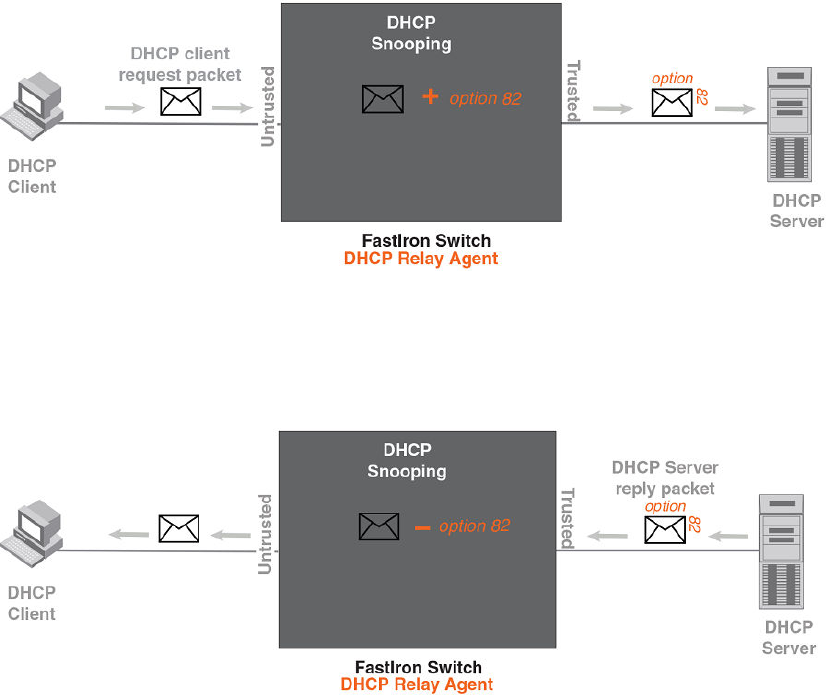
• Before relaying a DHCP discovery packet or DHCP request packet from a client to a DHCP server,
the FastIron switch will add agent information to the packet.
• Before relaying a DHCP reply packet from a DHCP server to a client, the FastIron switch will remove
relay agent information from the packet.
As illustrated in the following figure, the DHCP relay agent (the FastIron switch), inserts DHCP option
82 attributes when relaying a DHCP request packet to a DHCP server.
FIGURE 42 DHCP Option 82 attributes added to the DHCP packet
t
As illustrated in the following figure, the FastIron switch deletes DHCP option 82 attributes before
forwarding a server reply packet back to a DHCP client.
FIGURE 43 DHCP Option 82 attributes removed from the DHCP packet
The DHCP option 82 insertion/deletion feature is available only when DHCP snooping is enabled for the
client/server ports.
Configuration notes for DHCP option 82
• DHCP snooping and DHCP option 82 are supported on a per-VLAN basis.
• DHCP option 82 follows the same configuration rules and limitations as for DHCP snooping. For
more information, refer to Configuration notes and feature limitations for DHCP snooping on page
412.
Configuration notes for DHCP option 82
FastIron Ethernet Switch Security Configuration Guide 417
53-1003405-04
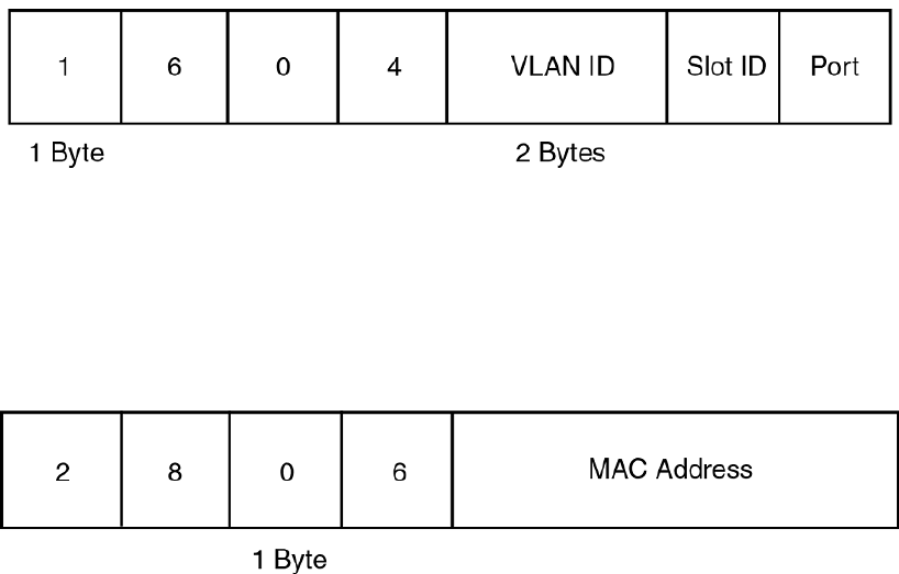
DHCP Option 82 sub-options
The Brocade implementation of DHCP Option 82 supports the following sub-options:
• Sub-Option 1 - Circuit ID
• Sub-Option 2 - Remote ID
• Sub-Option 6 - Subscriber ID
These sub-options are described in the following sections.
Sub-option 1 - circuit id
The Circuit ID (CID) identifies the circuit or port from which a DHCP client request was sent. The
FastIron switch uses this information to relay DHCP responses back to the proper circuit, for example,
the port number on which the DHCP client request packet was received.
Brocade FastIron devices support the General CID packet format. This simple format encodes the CID
type, actual information length, VLAN ID, slot number, and port number. This format is compatible with
the format used by other vendors’ devices. The following figure illustrates the general CID packet
format.
FIGURE 44 General CID packet format
Sub-option 2 - Remote ID
The Remote ID (RID) identifies the remote host end of the circuit (the relay agent). Brocade devices
use the MAC address to identify itself as the relay agent. The following figure illustrates the RID packet
format.
FIGURE 45 RID packet format
Sub-option 6 - subscriber id
The Subscriber ID (SID) is a unique identification number that enables an Internet Service Provider to:
• Identify a subscriber
• Assign specific attributes to that subscriber (for example, host IP address, subnet mask, and
domain name server (DNS))
• Trigger accounting
DHCP Option 82 sub-options
418 FastIron Ethernet Switch Security Configuration Guide
53-1003405-04

The following figure illustrates the SID packet format.
FIGURE 46 SID packet format
The second byte (N in the figure) is the length of the ASCII string that follows. The FastIron switch
supports up to 50 ASCII characters.
DHCP option 82 configuration
When DHCP snooping is enabled on a VLAN, DHCP option 82 also is enabled by default. You do not
need to perform any extra configuration steps to enable this feature. To enable DHCP snooping, refer
toEnabling DHCP snooping on a VLAN on page 413.
When processing DHCP packets, the FastIron switch applies the following default behavior when DHCP
option 82 is enabled:
• Subjects all ports in the VLAN to DHCP option 82 processing
• Uses the general CID packet format
• Uses the standard RID packet format
• Replaces relay agent information received in DHCP packets with its own information
• Does not enable SID processing
When DHCP option 82 is enabled, you can optionally:
• Disable DHCP Option 82 processing on individual ports in the VLAN
• Configure the device to drop or keep the relay agent information in a DHCP packet instead of
replacing it with its own information
• Enable SID processing
Disabling and re-enabling DHCP option 82 processing on an individual interface
By default, when DHCP option 82 is enabled on a VLAN, DHCP packets received on all member ports
of the VLAN are subject to DHCP option 82 processing. You can optionally disable and later re-enable
DHCP option 82 processing on one or more member ports of the VLAN. To do so, use the commands
in this section.
To disable a particular port in a VLAN from adding relay agent information to DHCP packets, enter
commands such as the following.
device(config)#ip dhcp snooping vlan 1
device(config)#interface ethernet 1/4
device(config-if-e1000-1/4)#no dhcp snooping relay information
The first CLI command enables DHCP snooping and DHCP option 82 on VLAN 1. The second
command changes the CLI configuration level to the Interface configuration level for port e 1/4. The last
command disables DHCP option 82 on interface e 1/4, which is a member of VLAN 1.
DHCP option 82 configuration
FastIron Ethernet Switch Security Configuration Guide 419
53-1003405-04
To re-enable DHCP option 82 on an interface after it has been disabled, enter the following command
at the Interface level of the CLI.
device(config-if-e1000-1/4)#dhcp snooping relay information
Syntax: [no] dhcp snoopingrelay information
Use the show ip dhcp snooping vlan command to view the ports on which DHCP option 82 processing
is disabled. For more information, refer to Viewing the ports on which DHCP option 82 is disabled on
page 421.
Changing the forwarding policy
When the Brocade device receives a DHCP message that contains relay agent information, by default,
the device replaces the information with its own relay agent information. If desired, you can configure
the device to keep the information instead of replacing it, or to drop (discard) messages that contain
relay agent information. To do so, use the CLI commands in this section.
For example, to configure the device to keep the relay agent information contained in a DHCP
message, enter the ip dhcp relay information policy keep command.
device(config)#ip dhcp relay information policy keep
To configure the device to drop DHCP messages that contain relay agent information, enter theip
dhcp relay information policy drop command.
device(config)#ip dhcp relay information policy drop
Syntax: ip dhcp relay information policy policy-type
policy-type can be one of the following:
•drop - Configures the device to discard messages containing relay agent information
•keep - Configures the device to keep the existing relay agent information
•replace - Configures the device to overwrite the relay agent information with the information in the
Brocade configuration. This is the default behavior.
Use the show ip dhcp relay information command to view the forwarding policy configured on the
switch.Refer to Viewing the circuit Id, remote id, and forwarding policy on page 421.
Enabling and disabling subscriber ID processing
You can configure a unique subscriber ID (SID) per port. Unlike the CID and RID sub-options, the SID
sub-option is not automatically enabled when DHCP option 82 is enabled. To enable SID processing,
enter commands such as the following.
device(config)#ip dhcp snooping vlan 1
device(config)#interface ethernet 1/4
device(config-if-e1000-1/4)#dhcp snooping relay information subscriber-id Brcd01
The first CLI command enables DHCP snooping and DHCP option 82 on VLAN 1. The second
command changes the CLI configuration level to the Interface configuration level for port e 1/4. The
last command enables interface e 1/4 to insert the SID information in DHCP packets. In this case, the
SID is Brcd01. All other ports in VLAN 1 on which SID is not enabled will send the standard relay
agent information (CID and RID information) only.
Syntax: [no] dhcp snooping relay information option subscriber-id ASCII string
Enter up to 50 alphanumeric characters for ASCII string .
Use the no form of the command to disable SID processing once it is enabled.
Changing the forwarding policy
420 FastIron Ethernet Switch Security Configuration Guide
53-1003405-04

Use the show interfaces ethernet command to view the subscriber ID configured on a port.Refer to
Viewing the status of DHCP option 82 and the subscriber id on page 422.
Viewing information about DHCP option 82 processing
Use the commands in this section to view information about DHCP option 82 processing.
Viewing the circuit Id, remote id, and forwarding policy
Use the show ip dhcp relay information command to obtain information about the circuit ID, remote
ID, and forwarding policy for DHCP option 82. The following shows an example output.
device#show ip dhcp relay information
Relay Information: Format: Circuit-ID : vlan-mod-port
Remote-ID : mac
Policy : keep
Syntax: show ip dhcp relay information
Output for the ip dhcp relay information command TABLE 39
Field Description
Circuit-ID The agent circuit ID format:
•vlan-mod-port - The default circuit ID format.
Remote-ID The remote ID format. This field displays mac , which is the default remote ID format.
Policy How the Brocade switch processes relay agent information it receives in DHCP messages:
•drop - drops the relay agent information
•keep - keeps the relay agent information
•replace - replaces the relay agent information with its own
Viewing the ports on which DHCP option 82 is disabled
Use the following command to refer which port in a DHCP snooping VLAN has DHCP Option 82
disabled.
device#show ip dhcp snooping vlan 1
IP DHCP snooping VLAN 1: Enabled
Trusted Ports : ethe 3
Untrusted Ports : ethe 1 to 2 ethe 4 to 24
Relay Info. disabled Ports: ethe 10
Syntax: show ip dhcp snooping vlan vlan-id
Viewing information about DHCP option 82 processing
FastIron Ethernet Switch Security Configuration Guide 421
53-1003405-04
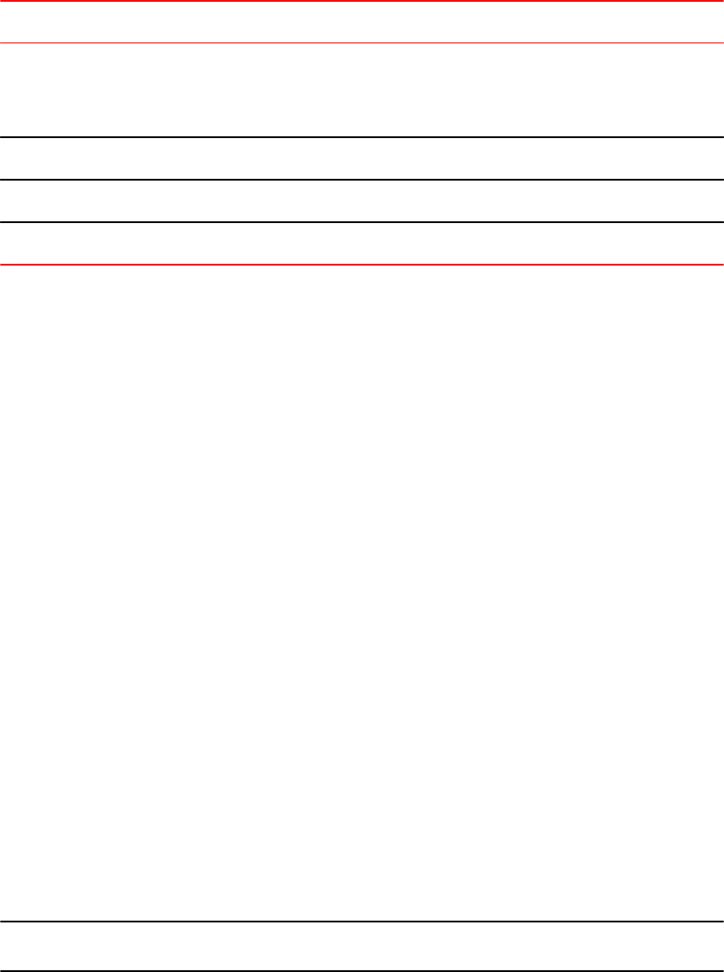
Output for the show ip dhcp snooping vlan commandTABLE 40
Field Description
IP DHCP snooping VLAN vlan-id The DHCP snooping and DHCP option 82 status for a VLAN:
• Enabled
• Disabled
Trusted Ports A list of trusted ports in the VLAN.
Untrusted Ports A list of untrusted ports in the VLAN.
Relay Info. disabled Ports Ports on which DHCP option 82 was disabled.
Viewing the status of DHCP option 82 and the subscriber id
Use the show interfaces ethernet command to obtain information about the status of DHCP option
82 and the configured subscriber ID, if applicable. In the example below, the text in bold type displays
the information specific to DHCP option 82.
device#show interfaces ethernet 3
GigabitEthernet3 is up, line protocol is up
Port up for 40 minutes 10 seconds
Hardware is GigabitEthernet, address is 0000.0000.0002 (bia 0000.0000.0002)
Configured speed auto, actual 1Gbit, configured duplex fdx, actual fdx
Configured mdi mode AUTO, actual MDI
Member of L2 VLAN ID 1, port is untagged, port state is FORWARDING
BPDU guard is Disabled, ROOT protect is Disabled
Link Error Dampening is Disabled
STP configured to ON, priority is level0
Flow Control is config enabled, oper enabled, negotiation disabled
mirror disabled, monitor disabled
Not member of any active trunks
Not member of any configured trunks
No port name
IPG MII 96 bits-time, IPG GMII 96 bits-time
IP MTU 1500 bytes
300 second input rate: 0 bits/sec, 0 packets/sec, 0.00% utilization
300 second output rate: 264 bits/sec, 0 packets/sec, 0.00% utilization
0 packets input, 0 bytes, 0 no buffer
Received 0 broadcasts, 0 multicasts, 0 unicasts
0 input errors, 0 CRC, 0 frame, 0 ignored
0 runts, 0 giants
0 packets output, 0 bytes, 0 underruns
Transmitted 0 broadcasts, 0 multicasts, 0 unicasts
0 output errors, 0 collisions
Relay Agent Information option: Enabled, Subscriber-ID: Brocade001
The above output shows that DHCP option 82 is Enabled on the device and the configured subscriber
ID is Brocade001.
Syntax: show interfaces ethernet port
NOTE
The port up/down time is required only for physical ports and not for loopback/ ve/ tunnel ports.
Viewing the status of DHCP option 82 and the subscriber id
422 FastIron Ethernet Switch Security Configuration Guide
53-1003405-04

Configuring the source IP address of a DHCP-client packet on the DHCP
relay agent
Enables the DHCP server to know the source subnet or network of a DHCP-client packet.
By default, a DHCP relay agent forwards a DHCP-client packet with the source IP address set to the IP
address of the outgoing interface to the DHCP server. You can configure ACLs on a DHCP server to
provide or block DHCP services to particular subnets or networks. Running the ip bootp-use-intf-ip
command configures a DHCP relay agent to set the source IP address of a DHCP-client packet with the
IP address of the incoming interface for the packet. This reveals the source subnet or network of a
DHCP-client packet to the DHCP server and enables the DHCP server to process or discard the DHCP
traffic according to the configured ACLs.
Run the ip bootp-use-intf-ip command in the global configuration mode of the DHCP relay agent.
Brocade (config)# ip bootp-use-intf-ip
The following example shows a DHCP relay agent set to configure the source IP address of a DHCP-
client packet with the IP address of the interface on which the DHCP-client packet is received.
Brocade (config)# ip bootp-use-intf-ip
IP source guard
You can use IP Source Guard together with Dynamic ARP Inspection on untrusted ports. Refer to
DHCP snooping on page 410 and Dynamic ARP inspection on page 405.
The Brocade implementation of the IP Source Guard feature supports configuration on a port, on
specific VLAN memberships on a port (Layer 2 devices only), and on specific ports on a virtual interface
(VE) (Layer 3 devices only).
When IP Source Guard is first enabled, only DHCP packets are allowed and all other IP traffic is
blocked. When the system learns a valid IP address, IP Source Guard then allows IP traffic. Only the
traffic with valid source IP addresses are permitted. The system learns of a valid IP address from DHCP
Snooping. When it learns a valid IP address, the system permits the learned source IP address.
When a new IP source entry binding on the port is created or deleted, the ACL will be recalculated and
reapplied in hardware to reflect the change in IP source binding. By default, if IP Source Guard is
enabled without any IP source binding on the port, an ACL that denies all IP traffic is loaded on the port.
Configuration notes and feature limitations for IP source guard
• To run IP Source Guard, you must first enable support for ACL filtering based on VLAN membership
or VE port membership. To do so, enter the following commands at the Global CONFIG Level of the
CLI.
device(config #enable ACL-per-port-per-vlan
device(config)#write memory
device(config)#exit
device#reload
NOTE
You must save the configuration and reload the software to place the change into effect.
Configuring the source IP address of a DHCP-client packet on the DHCP relay agent
FastIron Ethernet Switch Security Configuration Guide 423
53-1003405-04
• Brocade FCX devices do not support IP Source Guard and dynamic ACLs on the same port.
• Brocade devices support IP Source Guard together with IPv4 ACLs (similar to ACLs for Dot1x), as
long as both features are configured at the port-level or per-port-per-VLAN level. Brocade devices
do not support IP Source Guard and IPv4 ACLs on the same port if one is configured at the port-
level and the other is configured at the per-port-per-VLAN level.
• IP source guard and IPv6 ACLs are supported together on the same device, as long as they are not
configured on the same port or virtual Interface.
• The following limitations apply when configuring IP Source Guard on Layer 3 devices:
‐You cannot enable IP Source Guard on a tagged port on a Layer 3 device. To enable IP Source
Guard on a tagged port, enable it on a per-VE basis.
‐You cannot enable IP Source Guard on an untagged port with VE on a Layer 3 device. To enable
IP Source Guard in this configuration, enable it on a per-VE basis.
‐There are no restrictions for Layer 2, either on the port or per-VLAN.
• You cannot enable IP Source Guard on a port that has any of the following features enabled:
‐MAC address filter
‐Rate limiting
‐Trunk port
‐802.1x with ACLs
‐Multi-device port authentication
• A port on which IP Source Guard is enabled limits the support of IP addresses, VLANs, and ACL
rules per port. An IP Source Guard port supports a maximum of:
‐64 IP addresses. When IP Source Guard is enabled on a port, DHCP entries are limited to 64 IP
addresses per port.
‐64 VLANs
‐64 rules per ACL
• The number of configured ACL rules affect the rate at which hardware resources are used when IP
Source Guard is enabled. Use the show access-list hw-usage on command to enable hardware
usage for an ACL, followed by a show access-listaccess-list-id command to determine the
hardware usage for an ACL.
device#show access-list hw-usage on
device#show access-list 100
Extended IP access list 100 (hw usage : 2)
deny ip any any (hw usage : 1)
To provide more hardware resource for IP Source Guard addresses, modify the ACL rules so that it
uses less hardware resource.
• If you enable IP Source Guard in a network topology that has DHCP clients, you must also enable
DHCP snooping. Otherwise, all IP traffic including DHCP packets will be blocked.
• When you enable IP Source Guard in a network topology that does not have DHCP clients, you
must create an IP source binding for each client that will be allowed access to the network.
Otherwise, data packets will be blocked. Refer to Defining static IP source bindings on page 425.
• Source Guard Protection enables concurrent support with multi-device port authentication.
• IP Source Guard is supported on a VE with or without an assigned IP address.
• IP Source Guard supports Multi-VRF (Virtual Routing and Forwarding) instances. For information,
refer to the "Configuring Multi-VRF" chapter in the FastIron Ethernet Switch Layer 3 Routing
Configuration Guide .
Enabling IP source guard on a port
You can enable IP Source Guard on DHCP snooping untrusted ports. Refer to DHCP snooping on
page 410 for how to configure DHCP and DHCP untrusted ports.
Enabling IP source guard on a port
424 FastIron Ethernet Switch Security Configuration Guide
53-1003405-04
By default, IP Source Guard is disabled. To enable IP Source Guard on a DHCP untrusted port, enter
the following commands.
device(config)#interface ethernet 1/4
device(config-if-e10000-1/4)#source-guard enable
The commands change the CLI to the interface configuration level for port 1/4 and enable IP Source
Guard on the port.
Syntax: [no] source-guard enable
Defining static IP source bindings
You can manually enter valid IP addresses in the binding database. To do so, enter a command such
as the following.
device(config)#ip source binding 10.10.10.1 e 2/4 vlan 4
Syntax: no ip source binding ip-address ethernet slotnum / portnum [ vlan vlannum ]
For ip-address , enter a valid IP address.
The slotnum parameter is required on chassis devices.
The portnum parameter is a valid port number.
The [vlanvlannum ] parameter is optional. If you enter a VLAN number, the binding applies to that
VLAN only. If you do not enter a VLAN number, the static binding applies to all VLANs associated with
the port. Note that since static IP source bindings consume system resources, you should avoid
unnecessary bindings.
Enabling IP source guard per-port-per-VLAN
To enable IP Source Guard per-port-per VLAN, enter commands such as the following.
device(config)#vlan 12 name vlan12
device(config-vlan-12)#untag ethernet 5 to 8
device(config-vlan-12)#tag ethernet 23 to 24
device(config-vlan-12)#exit
device(config)#int e 23
device(config-if-e1000-23)#per-vlan vlan12
device(config-if-e1000-23-vlan-12))#source-guard enable
The commands in this example configure port-based VLAN 12, and add ports e 5 - 8 as untagged ports
and ports e 23 - 24 as tagged ports to the VLAN. The last two commands enable IP Source Guard on
port e 23, a member of VLAN 12.
Syntax: [no] source-guard enable
Enabling IP source guard on a VE
To enable IP Source Guard on a virtual interface, enter commands such as the following.
device(config)#vlan 2
device(config-vlan-2)#tag e1
Added tagged port(s) ethe 1 to port-vlan 2
device(config-vlan-2)#router-int ve 2
device(config-vlan-2)#int ve 2
device(config-vif-2)#source-guard enable e 1
Syntax: [no] source-guard enable
Defining static IP source bindings
FastIron Ethernet Switch Security Configuration Guide 425
53-1003405-04
Enabling IP Source Guard to support a Multi-VRF instance
You can use IP Source Guard (IPSG) together with Dynamic ARP Inspection on untrusted ports. The
Brocade implementation of the IP Source Guard feature supports configuration on a port, on specific
VLAN memberships on a port (Layer 2 devices only), and on specific ports on a virtual interface (VE)
(Layer 3 devices only).To configure IP Source Guard to support a VRF instance, do the following:
• IPSG requires that the acl-per-port-per-vlan setting be enabled. To enable the setting:
Brocade(config)# enable acl-per-port-per-vlan
Reload required. Please write memory and then reload or power cycle.
Syntax: enable acl-per-port-per-vlan
• Configure IPSG:
‐On a port using source-guard enable . For example:
Brocade(config)# interfacce ethernet 1/1
Brocade(config-if-e1000-1/1)# source-guard enable
Syntax: source-guard enable
•‐For Layer 2 devices, per port per VLAN using source-guard enable . For example:
Brocade(config-if-e1000-1/1)# per-vlan 2
Brocade(config-if-e1000-1/1-vlan-2)# source-guard enable
•‐For Layer 3 devices, per ve using source-guard enable . IPSG cannot be configured on tagged
ports or untagged ports which have a VE. For example:
Brocade(config)# interface ve 30
Brocade(config-vif-30)# source-guard enable ethernet 1/1
•‐Manually enter valid IP addresses in the binding database. For example:
Brocade(config)# ip source binding 1.1.1.2 ethernet 1/1 vlan 2
If the VLAN is not provided, it is applied on the port.
Displaying learned IP addresses
To display the learned IP addresses for IP Source Guard ports, use the CLI commands show ip
source-guard ethernet .
device(config)#show ip source-guard ethernet 1/1/37
Total number of IP Source Guard entries: 5
No Interface Type Flter-mode IP-address Vlan
-- --------- ---- ---------- ---------- ----
1 1/1/37 ip active 10.1.1.3 500
2 1/1/37 ip active 10.1.1.4 500
3 1/1/37 ip active 10.1.1.5 500
4 1/1/37 ip active 10.1.1.6 500
5 1/1/37 ip active 10.1.1.7 500
Syntax: show ip source-guard ethernet stack-unit/slotnum/portnum
for FWS, FCX, and ICX stackable switches.
Syntax: show ip source-guard ethernet slotnum/portnum
for FSX, 800, and FSX 1600 chassis devices.
Enabling IP Source Guard to support a Multi-VRF instance
426 FastIron Ethernet Switch Security Configuration Guide
53-1003405-04

DHCPv6
● Supported DHCPv6 packet inspection and tracking features....................................... 427
● Securing IPv6 address configuration............................................................................ 427
● DHCPv6 snooping.........................................................................................................427
Supported DHCPv6 packet inspection and tracking features
Lists Dynamic Host Configuration Protocol (DHCP) IPv6 packet inspection and tracking features
supported on FastIron devices.
The following table lists individual Brocade switches and the Dynamic Host Configuration Protocol
(DHCP) IPv6 packet inspection and tracking features they support. These features are supported in the
Layer 2 and Layer 3 software images, except where explicitly noted.
Feature ICX 6430 ICX 6450 FCX ICX 6610 ICX 6650 FSX 800
FSX 1600
ICX 7450 ICX 7750
DHCPv6 snooping 08.0.01 08.0.01 08.0.01 08.0.01 08.0.01 08.0.01 08.0.20 08.0.10
Securing IPv6 address configuration
In a IPv6 domain, a node can obtain an IPv6 address using the following two mechanisms:
• IPv6 address auto-configuration using router advertisements
• DHCPv6 protocol
In a typical man-in-middle (MiM) attack, the attacker can snoop or spoof the traffic act as a rogue
DHCPv6 server. To prevent such attacks, DHCPv6 snooping helps to secure the IPv6 address
configuration in the network.
DHCPv6 snooping
DHCPv6 snooping enables the Brocade device to filter untrusted DHCPv6 packets in a subnet on an
IPv6 network. DHCPv6 snooping can ward off MiM attacks, such as a malicious user posing as a
DHCPv6 server sending false DHCPv6 server reply packets with the intention of misdirecting other
users. DHCPv6 snooping can also stop unauthorized DHCPv6 servers and prevent errors due to user
mis-configuration of DHCPv6 servers.
FastIron Ethernet Switch Security Configuration Guide 427
53-1003405-04
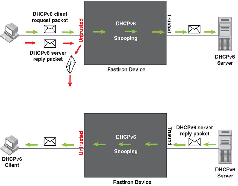
How DHCPv6 snooping works
When enabled on a VLAN, DHCPv6 snooping stands between untrusted ports (those connected to
host ports) and trusted ports (those connected to DHCPv6 servers). A VLAN with DHCPv6 snooping
enabled forwards DHCPv6 request packets from clients and discards DHCPv6 server reply packets on
untrusted ports, and it forwards DHCPv6 server reply packets on trusted ports to DHCPv6 clients, as
shown in the following figures
FIGURE 47 DHCPv6 snooping at work - on an untrusted port
FIGURE 48 DHCPv6 snooping at work - on a trusted port
DHCPv6 binding database
On trusted ports, DHCPv6 server reply packets are forwarded to DHCPv6 clients. The lease time will
be refreshed when the client renews its IPv6 address with the DHCPv6 server; otherwise the Brocade
device removes the entry when the lease time expires.
How DHCPv6 snooping works
428 FastIron Ethernet Switch Security Configuration Guide
53-1003405-04

Configuration notes and feature limitations for DHCPv6 snooping
The following limits and restrictions apply to DHCPv6 snooping:
• To run DHCPv6 snooping, you must first enable support for ACL filtering based on VLAN
membership or VE port membership. To do so, enter the following commands at the Global CONFIG
Level of the CLI.
device(config)#enable acl-per-port-per-vlan
device(config)#write memory
device(config)#exit
device#reload
NOTE
You must save the configuration and reload the software to place the change into effect.
• DHCPv6 snooping must be enabled on both client and server VLANs.
• For default vlan-id changes, DHCPv6 Snooping should be re-applied on the new default VLAN.
Configuring DHCPv6 snooping
Configuring DHCPv6 snooping consists of the following steps.
1. Enable DHCPv6 snooping on a VLAN. Refer to the Enabling DHCPv6 snooping on a VLAN section.
2. For ports that are connected to a DHCPv6 server, change their trust setting to trusted. Refer to
Enabling trust on a port connected to a DHCPv6 server on page 430.
The following shows the default settings of DHCPv6 snooping.
Feature Default
DHCPv6 snooping Disabled
Trust setting for ports Untrusted
Enabling DHCPv6 snooping on a VLAN
When DHCPv6 snooping is enabled on a VLAN, DHCPv6 packets are inspected.
DHCPv6 snooping is disabled by default. This feature must be enabled on the client and the DHCPv6
server VLANs. To enable DHCPv6 snooping, enter the following global command for these VLANs.
device(config)#ipv6 dhcp6 snooping vlan 2
The command enables DHCPv6 snooping on VLAN 2.
Syntax: no ipv6 dhcp6 snooping vlanvlan-id
The vlan-id variable specifies the ID of a configured client or DHCPv6 server VLAN.
Configuration notes and feature limitations for DHCPv6 snooping
FastIron Ethernet Switch Security Configuration Guide 429
53-1003405-04
Enabling trust on a port connected to a DHCPv6 server
The default trust setting for a port is untrusted. To enable trust on a port connected to a DHCPv6
server, enter commands such as the following.
device(config)#interface ethernet 1/1
device(config-if-e10000-1/1)#dhcp6 snooping trust
Port 1/1 is connected to a DHCPv6 server. The commands change the CLI to the interface
configuration level of port 1/1 and set the trust setting of port 1/1 to trusted.
Syntax: no dhcp6 snooping trust
Disabling the learning of DHCPv6 clients on a port
You can disable DHCPv6 client learning on an individual port. To do so, enter commands such as the
following.
device(config)#interface ethernet 1/1
device(config-if-e10000-1/1)#dhcp6 snooping client-learning disable
Syntax: no dhcp6 snooping client-learning disable
Use the no form of the command to re-enable DHCPv6 client learning on a port once it has been
disabled.
Clearing the DHCPv6 binding database
You can clear the DHCPv6 binding database using the CLI command clear ipv6 dhcp6 snooping .
You can remove all entries in the database, or remove entries for a specific IP address only.
To remove all entries from the DHCPv6 binding database, enter the clear ipv6 dhcp6 snooping
command.
device#clear ipv6 dhcp6 snooping
Syntax: clear ipv6 dhcp6 snooping
To clear the DHCPv6 bindings in the database that belong to a specific IPv6 address, enter the clear
ipv6 dhcp6 snooping ipv6-address command.
device#clear ipv6 dhcp6 snooping 2001::2
Syntax: clear ipv6 dhcp6 snooping ipv6-address
Displaying DHCPv6 snooping status and ports
To view DHCPv6 snooping status and ports, enter the show ipv6 dhcp6 snooping vlan vlan-id
command. The following is an example of the output.
Brocade# show ipv6 dhcp6 snooping
IP dhcpv6 snooping enabled on 1 VLANS(s):
VLAN:10
Brocade# show ipv6 dhcp6 snooping vlan 10
IP dhcpv6 snooping VLAN 10: Enabled
Trusted Ports: ethe 1/1/1
Untrusted Ports: ethe 1/1/2 ethe 1/1/3
Syntax: show ipv6 dhcp6 snooping
Enabling trust on a port connected to a DHCPv6 server
430 FastIron Ethernet Switch Security Configuration Guide
53-1003405-04

Syntax: show ipv6 dhcp6 snooping vlan vlan-id
Displaying the DHCPv6 snooping binding database
To see DHCPv6 snooping binding database, enter the show ipv6 dhcp6 snooping info command.
The following is an example of the output.
Brocade# show ipv6 dhcp6 snooping info
IP dhcpv6 snooping enabled on 1 VLANS(s):
IPv6 Address LinkLayer-Addr Age VRF
2002::24 0000.0343.0958 259198 0
2002::4a 7c00.030c.ccc9 259198 0
Syntax: show ipv6 dhcp6 snooping info
DHCPv6 snooping configuration example
The following example configures VLAN 10, and changes the CLI to the global configuration level to
enable DHCPv6 snooping on the configured VLANs. The commands are as follows.
device(config)#vlan 10
device(config-vlan-10)#untagged ethe 1/1/1 to 1/1/3
device(config-vlan-10)#exit
device(config)#ipv6 dhcp6 snooping vlan 10
Syntax: ipv6 dhcp6 snooping vlan vlan-id
On VLAN 10, client ports 1/1/2 and 1/1/3 are untrusted. By default, all client ports are untrusted. Only
DHCPv6 client’s SOLICIT and REQUEST packets received on ports 1/1/2 and 1/1/3 are forwarded.
Port 1/1/1 is connected to a DHCPv6 server. DHCPv6 server port is set to be a trusted port as
displayed in the following example.
device(config)#interface ethernet 1/1/1
device(config-if-e10000-1/1/1)#dhcp6 snooping trust
device(config-if-e10000-1/1/1)#exit
The DHCPv6 server ADVERTISE and REPLY packets received on port 1/1/1 are forwarded.
Multi-VRF support for DHCPv6 snooping
NOTE
For how to configure VRF, refer to the FastIron Ethernet Switch Layer 3 Routing Configuration Guide .
DHCPv6 snooping supports Multi-VRF (Virtual Routing and Forwarding) instances. You can deploy
multiple VRFs on a Brocade Ethernet switch. Each VLAN having a Virtual Interface (VE) is assigned to
a VRF.
You can enable DHCPv6 snooping on individual VLANs and assign any interface as the DHCPv6 trust
interface. If an interface is a tagged port in this VLAN, you can turn on the trust port per VRF, so that
traffic intended for other VRF VLANs will not be trusted.
To configure DHCPv6 snooping to support a Multi-VRF instance, do the following:
• DHCPv6 snooping requires that the acl-per-port-per-vlan setting be enabled. To enable the setting:
Brocade(config)# enable acl-per-port-per-vlan
Reload required. Please write memory and then reload or power cycle.
Displaying the DHCPv6 snooping binding database
FastIron Ethernet Switch Security Configuration Guide 431
53-1003405-04
Syntax: enable acl-per-port-per-vlan
• Configure DHCPv6 snooping on a specific VLAN using ipv6 dhcp6 snooping vlan vlan-id. For
example:
Brocade(config)# ipv6 dhcp6 snooping vlan 10
Syntax: ipv6 dhcp6 snooping vlan vlan-id
• The trust port setting for DHCPv6 snooping can be specified per VRF. Set the port as a trust port
using dhcp6 snooping trust vrf vrf-id. For example:
Brocade(config-if-e1000-1/1/1)# dhcp6 snooping trust vrf red
Syntax: dhcp6 snooping trust vrf vrf-id
• If the client and server are not in the same VLAN, then the DHCPv6 relay agent has to be
configured on the VE interface. For example:
Brocade (config-vif-23)#ipv6 dhcp-relay destination 2001:100::2
Syntax: ipv6 dhcp-relay destination destination address for DHCPv6 Relay Agent
• To clear a DHCPv6 binding database of a specific Multi-VRF, enter the following:
Brocade(config)# clear ipv6 dhcp6 snooping vrf vrf2
Syntax: clear ipv6 dhcp6 snooping vrf vrf-id
• To clear a specific DHCPv6 binding belonging to a specific IPv6 address and VRF, enter the clear
ipv6 dhcp6 snooping ipv6-address vrf vrf-name command.
device#clear ipv6 dhcp6 snooping 2001::2 vrf vrf2
Syntax: clear ipv6 dhcp6 snooping ipv6-address vrf vrf-id
• To clear default VRF DHCPv6 snooping entries, enter the clear ipv6 dhcp6 snooping vrf default
command.
device#clear ipv6 dhcp6 snooping vrf default
Syntax: clear ipv6 dhcp6 snooping vrf default
DHCPv6
432 FastIron Ethernet Switch Security Configuration Guide
53-1003405-04

IPv6 Neighbor Discovery Inspection
● IPv6 Neighbor Discovery Inspection Feature Support.................................................. 433
● IPv6 neighbor discovery inspection...............................................................................433
● Neighbor discovery inspection configuration.................................................................436
● Syslog message for ND inspection............................................................................... 436
IPv6 Neighbor Discovery Inspection Feature Support
Lists the IPv6 neighbor discovery (ND) inspection feature supported in FastIron devices.
The following table lists individual Brocade switches and IPv6 ND inspection feature they support.
NOTE
The IPv6 ND inspection feature is supported on both switch and router images.
Feature ICX 6430 ICX 6450 FCX ICX 6610 ICX 6650 FSX 800
FSX 1600
ICX 7450 ICX 7750
IPv6 Neighbor Discovery Inspection 08.0.20 08.0.20 08.0.20 08.0.20 No No 08.0.20 08.0.20
IPv6 neighbor discovery inspection
IPv6 ND inspection is an internal network security system that detects and prevents IPv6 address
spoofing at the switch level.
IP communication within a Layer 2 infrastructure is established by mapping an IP address to a MAC
address. An invalid host can intercept packet flow between legitimate hosts by sending a neighbor
solicitation or neighbor advertisement with a forged IP-to-MAC address binding. The victim host
includes an illegitimate entry in the neighbor cache, which is looked up to validate the IP-to-MAC
address binding. After a successful attack, all the traffic will be redirected through the invalid host and is
vulnerable to man-in-the-middle attacks. The ND inspection validates all the IPv6 packets carrying
neighbor discovery messages by checking the IP-to-MAC address binding of the packets. If there is a
discrepancy in the IP-to-MAC address binding, the neighbor discovery message is considered to be
from an invalid host and the packets are discarded.
The following figure illustrates the method by which Host 3 performs ND cache poisoning by sending a
neighbor solicitation message to Host 1 with the source IP of Host 2, and similarly to Host 2 with the
source IP of Host 1, with its own MAC address. By doing this, Host 3 can intercept the packet flow from
Host 1 to Host 2.
FastIron Ethernet Switch Security Configuration Guide 433
53-1003405-04
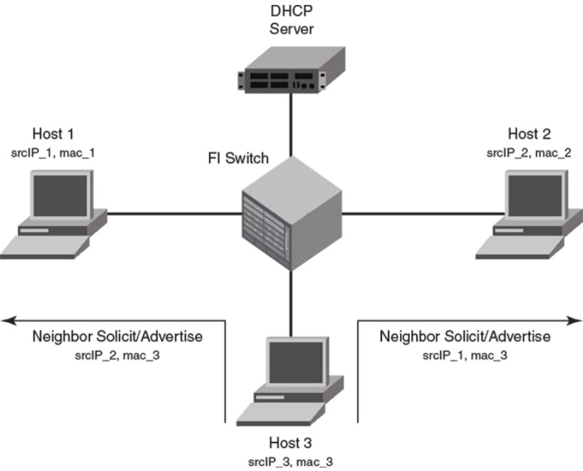
FIGURE 49 Neighbor discovery cache poisoning
ND inspection, when enabled on a VLAN, checks all the neighbor discovery messages flowing through
the switches between the hosts that are part of the VLAN and validates the IP-to-MAC address binding
of the packets. All the packets are verified against the trusted binding tables where the preconfigured
static ND inspection entries or dynamically learned DHCPv6 snoop entries are stored. DHCPv6
snooping must be enabled for dynamic inspection of ND messages. For more information on
dynamically learned DHCPv6 snoop entries, see DHCPv6 on page 427.
To inspect a neighbor discovery message, all the neighbor solicitation and neighbor advertisement
messages are directed to a CPU, and the source IP address and source MAC address of each packet
are validated against the entries in the trusted tables. Only the valid packets are forwarded and those
with invalid IP-to-MAC address bindings are discarded. ND inspection follows CPU-based packet
forwarding and thus the neighbor discovery messages in the ND inspection-enabled VLAN may get
discarded depending on the CPU load. The neighbor discovery messages are also rate limited to
CPU.
The router interface configuration on the ND inspection-enabled VLAN is also subjected to ND
inspection. That is, if the interface is a Layer 3 interface, the neighbor solicitation and neighbor
advertisement messages addressed to the router are also validated. If there is a discrepancy in the IP-
to-MAC address binding, the packets are discarded and the IPv6 neighbor tables will not be updated.
Unlike the neighbor solicitation and neighbor advertisement messages, the router solicitation
messages are not directed to the CPU, because the hosts are supposed to reject the router solicitation
messages by default.
The following figure illustrates unhindered flow of packets from Host 1 to Host 2, while the messages
that are sent by Host 3 with invalid IP-to-MAC address bindings are discarded.
IPv6 Neighbor Discovery Inspection
434 FastIron Ethernet Switch Security Configuration Guide
53-1003405-04
FIGURE 50 Neighbor discovery inspection
Though you can configure interfaces in “trust” or “untrust” mode, ND inspection is performed only on
untrusted ports that are part of the ND inspection-enabled VLAN. When you enable ND inspection on a
VLAN, by default, all the interfaces and member ports are considered as untrusted. When configured,
ND inspection protects the directly connected hosts from ND cache poisoning; the hosts connected
across the switches are not insulated from any attack.
When configured, ND inspection performs the following functions:
• Intercepts and inspects the IPv6 packets that carry neighbor discovery messages on untrusted ports.
• Validates the source IP addresses and the source MAC addresses of the intercepted packets against
the IP-to-MAC address bindings stored in a trusted binding database.
• Forwards the packets which have valid IP-to-MAC address bindings to the destination host and
discards the invalid packets. The ICMPv6 packets with auto-generated link-local address (from the
MAC address) are also forwarded, provided there is a match between MAC address and the auto-
generated link-local address. Hence, there is no need of separate configuration of auto-generated
link-local address in the ND inspection database.
IPv6 Neighbor Discovery Inspection
FastIron Ethernet Switch Security Configuration Guide 435
53-1003405-04

NOTE
ND inspection is supported on LAGs and trunk ports and supports Multi-VRF instances. Multiple VRFs
can be deployed on a Brocade Ethernet switch. Each VLAN having a Virtual Interface (VE) is assigned
to a VRF.
Neighbor discovery inspection configuration
The ND inspection configuration includes enabling ND inspection on a VLAN, adding static inspection
entries, and enabling trust mode for switch or server ports.
The acl-per-port-per-vlan must be enabled (using enable acl-per-port-per-vlan) command before
configuring ND inspection.
1. Enter the ipv6 neighbor inspection vlan vlan-number command to enable ND inspection on a
VLAN.
2. Enter the ipv6 neighbor inspection ipv6-address mac-address command to add a static ND
inspection entry. You can add multiple static ND inspection entries.
3. Enter the interface ethernet command to enter the interface configuration mode.
4. Enter the ipv6-neighbor inspection trust command to enable trust mode for the switch or server
port. You can enable trust mode for multiple ports.
The following output shows an example of ND inspection configuration.
device(config)# ipv6 neighbor inspection vlan 10
device(config)# ipv6 neighbor inspection 2001::1 0000.1234.5678
device(config)# interface ethernet 1/1/1
device(config-if-e1000-1/1/1)# ipv6-neighbor inspection trust
Syslog message for ND inspection
The following table lists the syslog message related to ND inspection.
Syslog message related to ND inspectionTABLE 41
Event Syslog output
Rejected ND ND Inspect: no static inspect or DHCP6 entry found, packet dropped rx-sip 2001::100
rx-smac 0000.0000.0055 vlan_id 2 vrf_id 0
Neighbor discovery inspection configuration
436 FastIron Ethernet Switch Security Configuration Guide
53-1003405-04
IPv6 RA Guard
● Supported platforms for the IPv6 RA guard feature...................................................... 437
● Securing IPv6 address configuration............................................................................ 437
● IPv6 RA guard overview................................................................................................437
● Configuration notes and feature limitations for IPv6 RA guard..................................... 439
● Configuring IPv6 RA guard........................................................................................... 439
● Example of configuring IPv6 RA guard......................................................................... 440
Supported platforms for the IPv6 RA guard feature
Lists the supported platforms for the IPv6 RA guard feature.
The following table lists the supported platforms for the IPv6 RA guard feature.
Feature ICX 6430 ICX 6450 FCX ICX 6610 ICX 6650 FSX 800
FSX 1600
ICX 7450 ICX 7750
IPv6 RA Guard 08.0.01 08.0.01 08.0.01 08.0.01 08.0.01 08.0.01 08.0.20 08.0.10
NOTE
This feature is supported with both Layer 2 and Layer 3 images. The ICX 6430 supports only the Layer
2 image.
Securing IPv6 address configuration
In a IPv6 domain, a node can obtain an IPv6 address using the following two mechanisms:
• IPv6 address auto-configuration using router advertisements
• DHCPv6 protocol
In a typical man-in-middle (MiM) attack, the attacker can spoof as a router with spurious router
advertisements.To prevent such attacks, IPv6 RA guard helps to secure the IPv6 address configuration
in the network.
IPv6 RA guard overview
In an IPv6 network, devices are configured to send IPv6 Router Advertisements (RAs). Router
advertisement and solicitation messages enable a node on a link to discover the routers on the same
FastIron Ethernet Switch Security Configuration Guide 437
53-1003405-04
link. This helps the nodes to autoconfigure themselves on the network. Unintended misconfigurations
or malicious attacks on the network lead to false RAs being present, which in turn causes operational
problems for hosts on the network.
IPv6 RA guard improves security of the local IPv6 networks. The IPv6 RA guard is useful in network
segments that are designed around a single Layer 2 switching device or a set of Layer 2 switching
devices. You can configure IPv6 RA guard if you have local IPv6 networks and you are using auto-
configuration for local addresses. IPv6 RA guard filters untrusted sources; host ports are dropped, and
trusted ports are passed. The IPv6 RA guard filters RAs based on certain criteria.
You can configure RA guard policy and associate criteria such as whitelist, prefix list, and preference
maximum value against which the RAs are inspected and the decision is taken whether to forward or
drop the RA packets. You can configure a port as host, trusted, or untrusted. For the RA guard policy
to take effect, you must configure the RA guard policy, and associate the criteria, and set the port type
as host, trusted, or untrusted.
RA guard policy
An RA guard policy is a set of criteria against which the RAs are inspected by ports. Based on the RA
guard policy configurations, RAs are forwarded or dropped. The whitelist, prefix-list, and maximum
preference value configurations are set for a particular RA guard policy so that the RAs are inspected
against all the criteria before being forwarded or dropped.
Before configuring an RA guard policy, you must enable ACL filtering based on VLAN membership
using the enable acl-per-port-per-vlan command.
Whitelist
The whitelist contains the link-local addresses of the trusted sources; RAs from these sources can be
forwarded. The RAs from the sources permitted by the whitelist are forwarded and the remaining RAs
are dropped.
Prefix list
Prefix list is supported only on Layer 3 devices. The prefix list is configured at the global level using
the ipv6 prefix-list command. IPv6 prefix lists can be used in the RA policy to inspect and restrict the
advertised prefixes in the RA packets. RA packets from the trusted sources in the whitelist can be
further inspected using the prefix list. If the RA packet has a prefix that does not match with the
configured prefix list, the RA packet is dropped.
Maximum preference
RA packets may contain a router preference value. If the RA packets have a preference value higher
the policy's maximum-preference value, the packets are dropped. If, for example, this value is set to
medium and the advertised default router preference is set to high in the received packet, then the
packet is dropped. If the option is set to medium or low in the received packet, then the packet is not
dropped.
Trusted, untrusted, and host ports
IPv6 RA guard classifies interfaces on devices as trusted, untrusted, or host ports. For the
configuration to take effect (trusted, untrusted, or host ports), the RA guard policy must be applied to
RA guard policy
438 FastIron Ethernet Switch Security Configuration Guide
53-1003405-04
the VLAN the ports are a part of. By default, all interfaces are configured as host ports. On a host port,
all the RAs are dropped with a policy configured on the VLAN. Trusted ports are those that receive RAs
within the network. Trusted ports allow received RAs to pass through without checking.
Depending on the configured policy settings, an RA packet is either forwarded through the interface or
dropped. If you do not configure an RA guard policy on an untrusted or host port, all RAs are forwarded.
Configuration notes and feature limitations for IPv6 RA guard
• MAC filters and MAC-based VLANs are not supported with IPv6 RA guard.
• If an IPv6 ACL matching an ICMPv6 type RA packet is configured on an interface that is part of an
RA guard-enabled VLAN, RA guard policy configuration takes precedence.
• IPv6 RA guard does not offer protection in environments where IPv6 traffic is tunneled.
• IPV6 RA guard can be configured on a switch port interface in the ingress direction and is supported
only in the ingress direction; it is not supported in the egress direction.
Configuring IPv6 RA guard
• (Optional) Configure the IPv6 prefix list using the ipv6 prefix-list command (for a Layer 3 device) to
associate a prefix list to an RA guard policy. For more information, see the FastIron Ethernet Switch
Layer 3 Routing Configuration Guide .
• Configure the enable acl-per-port-per-vlan command before you define an RA guard policy. For
more information, see the FastIron Ethernet Switch Security Configuration Guide .
Configuring IPv6 RA guard includes the following steps:
1. Define an RA guard whitelist using the ipv6 raguard whitelist command. Add IPv6 addresses of all
the sources from which the RA packets can be forwarded. You can create a maximum of 64
whitelists and each whitelist can have a maximum of 128 IPv6 address entries.
2. Define an RA guard policy using the ipv6 raguard policy command. You can configure a maximum
of 256 RA guard policies.
3. Configure ports as trusted, untrusted, or host ports using the raguard command in the interface
configuration mode.
4. Associate a whitelist with an RA guard policy using the whitelist command in the RA guard policy
configuration mode. You can associate only one whitelist with an RA guard policy. If you do not
associate a whitelist with an RA guard policy, all RA packets are dropped.
5. (Optional) (Only for Layer 3 devices) Associate an already defined prefix list with the RA guard policy
using the prefix-list command in the RA guard policy configuration mode. You must provide the
name of an IPv6 prefix list already configured using the ipv6 prefix-list command. Associate a
prefix-list with an RA guard policy using the prefix-list command.
6. (Optional) Set the preference for RA packets using the preference-maximum command in the RA
guard policy configuration mode.
7. Apply the RA guard policy to a VLAN using the ipv6 raguard vlan command in the global
configuration mode. You can associate only one RA guard policy with a VLAN.
8. (Optional) Enable logging using the logging command in the RA guard policy configuration mode. If
logging is enabled, you can verify the logs like RAs dropped, permitted, count for dropped packets,
and reasons for the drop. Logging increases the CPU load and, for higher traffic rates, RA packets
drop due to congestion if they are received at the line rate.
9. (Optional) Verify the RA guard configuration using the show ipv6 raguard command.
Configuration notes and feature limitations for IPv6 RA guard
FastIron Ethernet Switch Security Configuration Guide 439
53-1003405-04
10.(Optional) Clear the RA packet counter using the clear ipv6 raguard command.
11.(Optional) Verify the RA packet counts using the show ipv6 raguard counts command. Logging
has to be enabled to verify the counts.
Example of configuring IPv6 RA guard
The following sections describe how to configure IPv6 RA guard on a device or in a network.
Example: Configuring IPv6 RA guard on a device
The following example shows how to configure RA guard on a device.
Brocade(config)# ipv6 raguard whitelist 1 permit fe80:db8::db8:1
Brocade(config)# ipv6 raguard whitelist 1 permit fe80:db8::db8:3
Brocade(config)# ipv6 raguard whitelist 1 permit fe80:db8::db8:10
Brocade(config)# ipv6 raguard policy policy1
Brocade(ipv6-RAG-policy policy1)# whitelist 1
Brocade(ipv6-RAG-policy policy1)# prefix-list raguard-prefix1
Brocade(ipv6-RAG-policy policy1)# preference-maximum medium
Brocade(ipv6-RAG-policy policy1)# logging
Brocade(ipv6-RAG-policy policy1)# exit
Brocade(config)# interface ethernet 1/1/1
Brocade(config-int-e1000-1/1/1)# raguard untrusted
Brocade(config-int-e1000-1/1/1)# exit
Brocade(config)# ipv6 raguard vlan 1 policy policy1
Brocade(config)# show ipv6 raguard all
Brocade(config)# show ipv6 raguard counts all
Example: Configuring IPv6 RA guard in a network
The following example shows how to configure IPv6 RA guard on devices in a network. In this network
topology, port A (ethernet 1/1/1) is configured as trusted, port B (ethernet 1/1/2) is configured as
untrusted, and port C (ethernet 1/1/3) is configured as host. A whitelist is configured on port B.
Example of configuring IPv6 RA guard
440 FastIron Ethernet Switch Security Configuration Guide
53-1003405-04
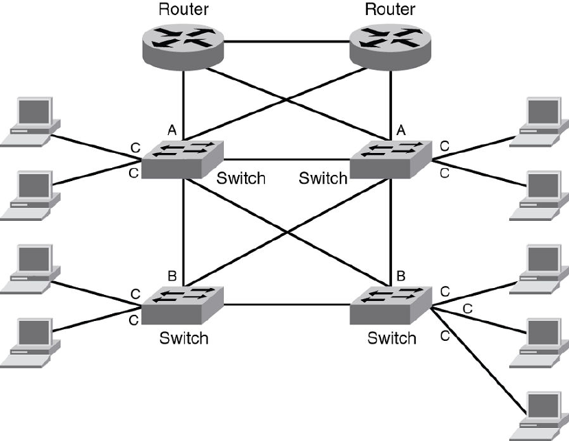
FIGURE 51 IPv6 RA guard configuration in a network
Configuring port A:
Configure port A as a trusted port.
Brocade(config)# interface ethernet 1/1/1
Brocade(config-int-e1000-1/1/1)# raguard trust
Configuring port C:
On port C, create an RA Guard policy with no other options and associate the policy with a VLAN of
which C is a member of. This helps block all RAs from C ports.
Brocade(config)# ipv6 raguard policy policyC
Brocade(ipv6-RAG-policy policyC)# exit
Brocade(config)# ipv6 raguard vlan 1 policyC
Configuring port B:
On port B create an RA Guard policy with supported whitelist. This helps to permit RAs from only those
sources. Associate a whitelist or prefix list with the RA guard policy.
Brocade(config)# ipv6 raguard whitelist 1 permit fe80:db8::db8:10
Brocade(config)# ipv6 raguard whitelist 1 permit fe80:db8::db8:5
Brocade(config)# ipv6 raguard whitelist 1 permit fe80:db8::db8:12
IPv6 RA Guard
FastIron Ethernet Switch Security Configuration Guide 441
53-1003405-04
Brocade(config)# prefix-list raguard-prefix-list1 permit 2001:db8::/16
Brocade(config)# ipv6 raguard policy policyB
Brocade(ipv6-RAG-policy policyB)# whitelist 1
Brocade(ipv6-RAG-policy policyB)# prefix-list raguard-prefix-list1
Brocade(ipv6-RAG-policy policyB)# exit
Brocade(config)# interface ethernet 1/1/2
Brocade(config-int-e1000-1/1/2)# raguard untrust
Brocade(config-int-e1000-1/1/2)# exit
Brocade(config)# ipv6 raguard vlan 2 policyB
Example: Verifying the RA guard configuration
To view the RA guard packet counts, use the show ipv6 raguard counts command.
Brocade# show ipv6 raguard counts policyB
DROPPED-host port:0
DROPPED-whitelist:3
DROPPED-prefixlist:1
DROPPED-max pref:1
DROPPED-trusted port:2
DROPPED-untrusted port:1
To verify the RA guard configuration, use the show ipv6 raguard command.
Brocade# show ipv6 raguard all
policy:policyC
whitelist:0
max_pref:medium
policy:policyB
whitelist:1
Example: Verifying the RA guard configuration
442 FastIron Ethernet Switch Security Configuration Guide
53-1003405-04
