Ruckus Brocade FastIron SX, FCX, And ICX Web Management Interface User Guide, 08.0.30 Fast Iron Guide 08030 Webguide
FastIron 08.0.30 Web Management Guide fastiron-08030-webguide
2017-12-14
User Manual: Ruckus FastIron 08.0.30 Web Management Guide
Open the PDF directly: View PDF ![]() .
.
Page Count: 275 [warning: Documents this large are best viewed by clicking the View PDF Link!]
- Brocade FastIron SX, FCX, and ICX Web Management Interface User Guide, 08.0.30
- Preface
- About This Document
- Getting Started with the GUI
- Monitoring Basic Device Information
- Displaying the ARP cache
- Displaying the device information
- Displaying flash information
- Displaying memory information
- Displaying the front panel
- Status LED display
- Displaying the front panel for the Brocade FCX devices
- Displaying the front panel for the Brocade ICX 6610 device
- Displaying the front panel for the Brocade ICX 6430 device
- Displaying the front panel for the Brocade ICX 6450 device
- Displaying the front panel for the Brocade ICX 6650 device
- Displaying the front panel for the Brocade FastIron SX devices
- Displaying the front panel for the Brocade ICX 7750 device
- Displaying the front panel for the Brocade ICX 7450 device
- Displaying the front panel for the Brocade ICX 7250 device
- Displaying MAC addresses
- Displaying the system log
- Monitoring Stacks
- Monitoring Ports
- Monitoring STP
- Monitoring RSTP
- Monitoring IP
- Monitoring RMON
- Configuring Stack Components
- Configuring System Components
- Configuring the system boot sequence for the Brocade FCX and Brocade ICX devices
- Configuring the system boot sequence for the Brocade FastIron SX devices
- Configuring the system clock
- Configuring the system DNS
- Configuring the general system settings
- Configuring the system identification
- Configuring the system IP address
- Configuring a standard ACL
- Configuring an extended ACL
- Configuring an IP access group
- Configuring the system MAC filter
- Configuring the maximum system parameter value
- Configuring a system module
- Configuring a RADIUS server
- Configuring a TACACS/TACACS+ server
- Configuring management authentication
- Configuring management authorization
- Configuring management accounting
- Configuring an SNMP community string
- Configuring the general management parameters
- Configuring a management system log
- Configuring a trap
- Configuring a trap receiver
- Configuring a management user account
- Configuring the web management preferences
- Configuring Module Components
- Configuring Port Parameters
- Configuring Monitor and Mirror Port
- Configuring QoS
- Configuring VLAN
- Configuring STP
- Configuring RSTP
- Configuring LAGs
- Configuring a Static Station
- Configuring IP
- Configuring the router IP address
- Configuring a standard ACL
- Configuring an extended ACL
- Configuring an IP access group
- Configuring an IP Autonomous System-path access list
- Configuring an IP community list
- Configuring an IP prefix list
- Configuring a DNS entry
- Configuring the general IP settings
- Configuring IP interfaces
- Configuring a static ARP
- Configuring a static RARP
- Configuring a static route
- Configuring a UDP helper
- Configuring RIP
- Basic Device Commands
- Clearing information for a Layer 2 switch
- Clearing information for a Layer 3 switch
- Disabling or enabling the menu view
- Logging out
- Reloading units in a stack
- Saving the configuration to flash
- Switching over to the active role
- Performing hitless-reload from primary images
- Performing hitless-reload from secondary images
- Accessing the Telnet command prompt
- Performing a trace
- Using TFTP

Supporting FastIron Software Release 08.0.30
USER GUIDE
Brocade FastIron SX, FCX, and ICX Web
Management Interface User Guide, 08.0.30
Part Number: 53-1003615-02
Publication Date: 11 August 2017
© 2017, Brocade Communications Systems, Inc. All Rights Reserved.
Brocade, the B-wing symbol, and MyBrocade are registered trademarks of Brocade Communications Systems, Inc., in the United States and in other
countries. Other brands, product names, or service names mentioned of Brocade Communications Systems, Inc. are listed at www.brocade.com/en/legal/
brocade-Legal-intellectual-property/brocade-legal-trademarks.html. Other marks may belong to third parties.
Notice: This document is for informational purposes only and does not set forth any warranty, expressed or implied, concerning any equipment,
equipment feature, or service oered or to be oered by Brocade. Brocade reserves the right to make changes to this document at any time, without
notice, and assumes no responsibility for its use. This informational document describes features that may not be currently available. Contact a Brocade
sales oce for information on feature and product availability. Export of technical data contained in this document may require an export license from the
United States government.
The authors and Brocade Communications Systems, Inc. assume no liability or responsibility to any person or entity with respect to the accuracy of this
document or any loss, cost, liability, or damages arising from the information contained herein or the computer programs that accompany it.
The product described by this document may contain open source software covered by the GNU General Public License or other open source license
agreements. To nd out which open source software is included in Brocade products, view the licensing terms applicable to the open source software, and
obtain a copy of the programming source code, please visit http://www.brocade.com/support/oscd.
Brocade FastIron SX, FCX, and ICX Web Management Interface User Guide, 08.0.30
2 Part Number: 53-1003615-02

Contents
Preface...................................................................................................................................................................................................................................7
Document conventions............................................................................................................................................................................................................................7
Text formatting conventions.........................................................................................................................................................................................................7
Command syntax conventions....................................................................................................................................................................................................7
Notes, cautions, and warnings.....................................................................................................................................................................................................8
Brocade resources.....................................................................................................................................................................................................................................8
Contacting Brocade Technical Support............................................................................................................................................................................................ 9
Brocade customers..........................................................................................................................................................................................................................9
Brocade OEM customers............................................................................................................................................................................................................. 9
Document feedback..................................................................................................................................................................................................................................9
About This Document..................................................................................................................................................................................................... 11
Supported hardware...............................................................................................................................................................................................................................11
What’s new in this document ............................................................................................................................................................................................................ 11
Getting Started with the GUI..........................................................................................................................................................................................13
Access requirements............................................................................................................................................................................................................................. 13
Prerequisite conguration....................................................................................................................................................................................................................13
Logging in to the Web Management Interface........................................................................................................................................................................... 14
Logging out of the Web Management Interface........................................................................................................................................................................ 17
Using the Web Management Interface.......................................................................................................................................................................................... 17
Web Management Interface areas..........................................................................................................................................................................................19
Monitoring Basic Device Information...........................................................................................................................................................................21
Displaying the ARP cache...................................................................................................................................................................................................................21
Displaying the device information....................................................................................................................................................................................................23
Displaying ash information............................................................................................................................................................................................................... 26
Displaying memory information....................................................................................................................................................................................................... 27
Displaying the front panel....................................................................................................................................................................................................................28
Status LED display........................................................................................................................................................................................................................28
Displaying the front panel for the Brocade FCX devices.............................................................................................................................................. 29
Displaying the front panel for the Brocade ICX 6610 device.....................................................................................................................................32
Displaying the front panel for the Brocade ICX 6430 device.....................................................................................................................................32
Displaying the front panel for the Brocade ICX 6450 device.....................................................................................................................................33
Displaying the front panel for the Brocade ICX 6650 device.....................................................................................................................................34
Displaying the front panel for the Brocade FastIron SX devices................................................................................................................................34
Displaying the front panel for the Brocade ICX 7750 device.....................................................................................................................................36
Displaying the front panel for the Brocade ICX 7450 device.....................................................................................................................................36
Displaying the front panel for the Brocade ICX 7250 device.....................................................................................................................................37
Displaying MAC addresses.................................................................................................................................................................................................................38
Displaying the system log................................................................................................................................................................................................................... 39
Monitoring Stacks............................................................................................................................................................................................................ 41
Displaying the stack details.................................................................................................................................................................................................................41
Displaying a stack module.................................................................................................................................................................................................................. 43
Displaying stack neighbors.................................................................................................................................................................................................................44
Displaying stack ports information.................................................................................................................................................................................................. 45
Displaying stack port statistics.......................................................................................................................................................................................................... 47
Brocade FastIron SX, FCX, and ICX Web Management Interface User Guide, 08.0.30
Part Number: 53-1003615-02 3
Monitoring peri-ports............................................................................................................................................................................................................................ 48
Monitoring peri-trunks.......................................................................................................................................................................................................................... 48
Displaying stack port interfaces........................................................................................................................................................................................................ 49
Displaying stack resources..................................................................................................................................................................................................................51
Monitoring Ports...............................................................................................................................................................................................................55
Displaying Ethernet port statistics....................................................................................................................................................................................................55
Displaying Ethernet port attributes.................................................................................................................................................................................................. 57
Displaying Ethernet port utilization..................................................................................................................................................................................................59
Displaying the management port information............................................................................................................................................................................61
Displaying the management port real-time information...............................................................................................................................................63
Displaying port inline power for the Brocade FCX and Brocade ICX devices...............................................................................................................64
Displaying inline power statistics.............................................................................................................................................................................................65
Displaying inline power details ................................................................................................................................................................................................68
Displaying port inline power for the Brocade FastIron SX devices.................................................................................................................................... 70
Monitoring STP.................................................................................................................................................................................................................73
Displaying STP information................................................................................................................................................................................................................73
Monitoring RSTP..............................................................................................................................................................................................................79
Displaying RSTP information.............................................................................................................................................................................................................79
Monitoring IP.....................................................................................................................................................................................................................83
Displaying IP cache................................................................................................................................................................................................................................83
Displaying IP trac information for devices running Layer 2 code...................................................................................................................................85
Displaying IP trac information for devices running Layer 3 code...................................................................................................................................89
Monitoring RMON............................................................................................................................................................................................................95
Displaying RMON history....................................................................................................................................................................................................................95
Displaying RMON Ethernet statistics............................................................................................................................................................................................. 98
Changing polling interval...................................................................................................................................................................................................................103
Displaying RMON Ethernet error statistics...............................................................................................................................................................................103
Conguring Stack Components................................................................................................................................................................................. 107
Conguring the general settings for a traditional stack........................................................................................................................................................ 107
Modifying stack priority.....................................................................................................................................................................................................................108
Modifying stack ports.........................................................................................................................................................................................................................110
Conguring a stack module.............................................................................................................................................................................................................112
Conguring peri-ports....................................................................................................................................................................................................................... 115
Conguring peri-trunks..................................................................................................................................................................................................................... 115
Conguring stack connect................................................................................................................................................................................................................116
Conguring System Components..............................................................................................................................................................................117
Conguring the system boot sequence for the Brocade FCX and Brocade ICX devices.....................................................................................117
Conguring the system boot sequence for the Brocade FastIron SX devices...........................................................................................................119
Conguring the system clock..........................................................................................................................................................................................................120
Conguring the system DNS..........................................................................................................................................................................................................122
Conguring the general system settings....................................................................................................................................................................................123
Conguring the system identication.......................................................................................................................................................................................... 125
Conguring the system IP address.............................................................................................................................................................................................. 127
Conguring a standard ACL............................................................................................................................................................................................................128
Conguring an extended ACL........................................................................................................................................................................................................ 129
Conguring an IP access group.....................................................................................................................................................................................................133
Conguring the system MAC lter............................................................................................................................................................................................... 135
Brocade FastIron SX, FCX, and ICX Web Management Interface User Guide, 08.0.30
4 Part Number: 53-1003615-02
Conguring a lter group.........................................................................................................................................................................................................137
Conguring the maximum system parameter value.............................................................................................................................................................138
Conguring a system module.........................................................................................................................................................................................................139
Conguring a RADIUS server.........................................................................................................................................................................................................142
Conguring a TACACS/TACACS+ server.................................................................................................................................................................................144
Conguring management authentication...................................................................................................................................................................................145
Conguring management authorization.....................................................................................................................................................................................147
Conguring management accounting ........................................................................................................................................................................................148
Conguring an SNMP community string.................................................................................................................................................................................. 150
Conguring the general management parameters................................................................................................................................................................151
Conguring a management system log..................................................................................................................................................................................... 152
Adding a log server....................................................................................................................................................................................................................154
Conguring a trap................................................................................................................................................................................................................................ 154
Conguring a trap receiver............................................................................................................................................................................................................... 155
Conguring a management user account................................................................................................................................................................................. 157
Conguring the web management preferences......................................................................................................................................................................158
Conguring Module Components..............................................................................................................................................................................161
Conguring a module.........................................................................................................................................................................................................................161
Modifying inline power budget ......................................................................................................................................................................................................162
Conguring Port Parameters...................................................................................................................................................................................... 165
Conguring an Ethernet port...........................................................................................................................................................................................................165
Conguring port inline power..........................................................................................................................................................................................................167
Conguring a management port................................................................................................................................................................................................... 168
Conguring the port uplink relative utilization.......................................................................................................................................................................... 169
Conguring Monitor and Mirror Port.........................................................................................................................................................................173
Conguring a mirror port.................................................................................................................................................................................................................. 173
Conguring a monitor port...............................................................................................................................................................................................................175
Conguring QoS............................................................................................................................................................................................................ 177
Conguring the QoS prole.............................................................................................................................................................................................................177
Conguring the QoS prole bind...................................................................................................................................................................................................178
Conguring VLAN......................................................................................................................................................................................................... 181
Conguring a port VLAN for the Brocade FCX and Brocade ICX devices.................................................................................................................181
Modifying a port VLAN.....................................................................................................................................................................................................................185
Conguring a port VLAN for the Brocade FastIron SX devices.......................................................................................................................................188
Conguring STP............................................................................................................................................................................................................ 193
Conguring STP parameters.......................................................................................................................................................................................................... 193
Changing STP bridge parameters.......................................................................................................................................................................................193
Changing STP port parameters........................................................................................................................................................................................... 197
Conguring RSTP..........................................................................................................................................................................................................203
Conguring RSTP parameters.......................................................................................................................................................................................................203
Changing RSTP bridge parameters....................................................................................................................................................................................203
Changing RSTP port parameters........................................................................................................................................................................................ 207
Conguring LAGs.......................................................................................................................................................................................................... 213
Conguring a static dynamic or keep-alive LAG....................................................................................................................................................................213
Displaying a congured LAG.......................................................................................................................................................................................................... 216
Conguring a Static Station.........................................................................................................................................................................................217
Brocade FastIron SX, FCX, and ICX Web Management Interface User Guide, 08.0.30
Part Number: 53-1003615-02 5
Adding a static station........................................................................................................................................................................................................................217
Modifying a static station..................................................................................................................................................................................................................218
Conguring IP.................................................................................................................................................................................................................221
Conguring the router IP address................................................................................................................................................................................................. 221
Conguring a standard ACL............................................................................................................................................................................................................223
Conguring an extended ACL........................................................................................................................................................................................................ 224
Conguring an IP access group.....................................................................................................................................................................................................228
Conguring an IP Autonomous System-path access list...................................................................................................................................................230
Conguring an IP community list..................................................................................................................................................................................................231
Conguring an IP prex list..............................................................................................................................................................................................................232
Conguring a DNS entry...................................................................................................................................................................................................................234
Conguring the general IP settings.............................................................................................................................................................................................. 235
Conguring IP interfaces...................................................................................................................................................................................................................237
Conguring a static ARP...................................................................................................................................................................................................................239
Conguring a static RARP................................................................................................................................................................................................................240
Conguring a static route..................................................................................................................................................................................................................241
Conguring a UDP helper................................................................................................................................................................................................................243
Enabling forwarding for a UDP application......................................................................................................................................................................244
Specifying the UDP application............................................................................................................................................................................................245
Conguring RIP..............................................................................................................................................................................................................247
Conguring the general RIP settings...........................................................................................................................................................................................247
Conguring a RIP interface..............................................................................................................................................................................................................248
Conguring a RIP neighbor lter................................................................................................................................................................................................... 252
Conguring a RIP route lter...........................................................................................................................................................................................................253
Conguring a lter group.........................................................................................................................................................................................................254
Conguring a RIP redistribution lter...........................................................................................................................................................................................255
Basic Device Commands............................................................................................................................................................................................. 259
Clearing information for a Layer 2 switch..................................................................................................................................................................................259
Clearing information for a Layer 3 switch..................................................................................................................................................................................260
Disabling or enabling the menu view...........................................................................................................................................................................................261
Logging out............................................................................................................................................................................................................................................ 262
Reloading units in a stack.................................................................................................................................................................................................................263
Saving the conguration to ash................................................................................................................................................................................................... 264
Switching over to the active role.................................................................................................................................................................................................... 265
Performing hitless-reload from primary images.....................................................................................................................................................................265
Performing hitless-reload from secondary images...............................................................................................................................................................266
Accessing the Telnet command prompt.................................................................................................................................................................................... 267
Performing a trace...............................................................................................................................................................................................................................269
Using TFTP.....................................................................................................................................................................................................................271
Conguring TFTP................................................................................................................................................................................................................................271
Conguring a TFTP image.............................................................................................................................................................................................................. 273
Brocade FastIron SX, FCX, and ICX Web Management Interface User Guide, 08.0.30
6 Part Number: 53-1003615-02

Preface
• Document conventions...................................................................................................................................................................................... 7
• Brocade resources............................................................................................................................................................................................... 8
• Contacting Brocade Technical Support.......................................................................................................................................................9
• Document feedback............................................................................................................................................................................................9
Document conventions
The document conventions describe text formatting conventions, command syntax conventions, and important notice formats used in
Brocade technical documentation.
Text formatting conventions
Text formatting conventions such as boldface, italic, or Courier font may be used in the ow of the text to highlight specic words or
phrases.
Format Description
bold text Identies command names
Identies keywords and operands
Identies the names of user-manipulated GUI elements
Identies text to enter at the GUI
italic text Identies emphasis
Identies variables
Identies document titles
Courier font Identies CLI output
Identies command syntax examples
Command syntax conventions
Bold and italic text identify command syntax components. Delimiters and operators dene groupings of parameters and their logical
relationships.
Convention Description
bold text Identies command names, keywords, and command options.
italic text Identies a variable.
value In Fibre Channel products, a xed value provided as input to a command option is printed in plain text, for
example, --show WWN.
[ ] Syntax components displayed within square brackets are optional.
Default responses to system prompts are enclosed in square brackets.
{ x | y | z } A choice of required parameters is enclosed in curly brackets separated by vertical bars. You must select
one of the options.
In Fibre Channel products, square brackets may be used instead for this purpose.
Brocade FastIron SX, FCX, and ICX Web Management Interface User Guide, 08.0.30
Part Number: 53-1003615-02 7

Convention Description
x | yA vertical bar separates mutually exclusive elements.
< > Nonprinting characters, for example, passwords, are enclosed in angle brackets.
... Repeat the previous element, for example, member[member...].
\ Indicates a “soft” line break in command examples. If a backslash separates two lines of a command
input, enter the entire command at the prompt without the backslash.
Notes, cautions, and warnings
Notes, cautions, and warning statements may be used in this document. They are listed in the order of increasing severity of potential
hazards.
NOTE
A Note provides a tip, guidance, or advice, emphasizes important information, or provides a reference to related information.
ATTENTION
An Attention statement indicates a stronger note, for example, to alert you when trac might be interrupted or the device might
reboot.
CAUTION
A Caution statement alerts you to situations that can be potentially hazardous to you or cause damage to hardware,
rmware, software, or data.
DANGER
A Danger statement indicates conditions or situations that can be potentially lethal or extremely hazardous to you. Safety
labels are also attached directly to products to warn of these conditions or situations.
Brocade resources
Visit the Brocade website to locate related documentation for your product and additional Brocade resources.
You can download additional publications supporting your product at www.brocade.com. Select the Brocade Products tab to locate your
product, then click the Brocade product name or image to open the individual product page. The user manuals are available in the
resources module at the bottom of the page under the Documentation category.
To get up-to-the-minute information on Brocade products and resources, go to MyBrocade. You can register at no cost to obtain a user
ID and password.
Release notes are available on MyBrocade under Product Downloads.
White papers, online demonstrations, and data sheets are available through the Brocade website.
Brocade resources
Brocade FastIron SX, FCX, and ICX Web Management Interface User Guide, 08.0.30
8 Part Number: 53-1003615-02

Contacting Brocade Technical Support
As a Brocade customer, you can contact Brocade Technical Support 24x7 online, by telephone, or by e-mail. Brocade OEM customers
contact their OEM/Solutions provider.
Brocade customers
For product support information and the latest information on contacting the Technical Assistance Center, go to http://www.brocade.com/
services-support/index.html.
If you have purchased Brocade product support directly from Brocade, use one of the following methods to contact the Brocade
Technical Assistance Center 24x7.
Online Telephone E-mail
Preferred method of contact for non-urgent
issues:
•My Cases through MyBrocade
•Software downloads and licensing
tools
•Knowledge Base
Required for Sev 1-Critical and Sev 2-High
issues:
• Continental US: 1-800-752-8061
• Europe, Middle East, Africa, and Asia
Pacic: +800-AT FIBREE (+800 28
34 27 33)
• For areas unable to access toll free
number: +1-408-333-6061
•Toll-free numbers are available in
many countries.
support@brocade.com
Please include:
• Problem summary
• Serial number
• Installation details
• Environment description
Brocade OEM customers
If you have purchased Brocade product support from a Brocade OEM/Solution Provider, contact your OEM/Solution Provider for all of
your product support needs.
• OEM/Solution Providers are trained and certied by Brocade to support Brocade® products.
• Brocade provides backline support for issues that cannot be resolved by the OEM/Solution Provider.
• Brocade Supplemental Support augments your existing OEM support contract, providing direct access to Brocade expertise.
For more information, contact Brocade or your OEM.
• For questions regarding service levels and response times, contact your OEM/Solution Provider.
Document feedback
To send feedback and report errors in the documentation you can use the feedback form posted with the document or you can e-mail
the documentation team.
Quality is our rst concern at Brocade and we have made every eort to ensure the accuracy and completeness of this document.
However, if you nd an error or an omission, or you think that a topic needs further development, we want to hear from you. You can
provide feedback in two ways:
• Through the online feedback form in the HTML documents posted on www.brocade.com.
• By sending your feedback to documentation@brocade.com.
Provide the publication title, part number, and as much detail as possible, including the topic heading and page number if applicable, as
well as your suggestions for improvement.
Document feedback
Brocade FastIron SX, FCX, and ICX Web Management Interface User Guide, 08.0.30
Part Number: 53-1003615-02 9
Brocade FastIron SX, FCX, and ICX Web Management Interface User Guide, 08.0.30
10 Part Number: 53-1003615-02

About This Document
• Supported hardware......................................................................................................................................................................................... 11
• What’s new in this document .......................................................................................................................................................................11
Supported hardware
This guide supports the web management interface for the following hardware platforms:
• FCX Series
• FastIron X Series (FSX 800 and FSX 1600)
• ICX 6610 Series
• ICX 6430 Series (ICX 6430, ICX 6430-C12)
• ICX 6450 Series (ICX 6450, ICX 6450-C12-PD)
• ICX 6650 Series
• ICX 7750 Series
• ICX 7450 Series
• ICX 7250 Series
NOTE
The Brocade ICX 6430-C switch supports the same feature set as the Brocade ICX 6430 switch unless otherwise noted.
NOTE
The Brocade ICX 6450-C12-PD switch supports the same feature set as the Brocade ICX 6450 switch unless otherwise
noted.
For information about the specic models and modules supported in a product family, refer to the hardware installation guide for that
product family.
What’s new in this document
The Web Management Interface support is added for Brocade ICX 7250.
Brocade FastIron SX, FCX, and ICX Web Management Interface User Guide, 08.0.30
Part Number: 53-1003615-02 11
Brocade FastIron SX, FCX, and ICX Web Management Interface User Guide, 08.0.30
12 Part Number: 53-1003615-02

Getting Started with the GUI
• Access requirements........................................................................................................................................................................................13
• Prerequisite conguration...............................................................................................................................................................................13
• Logging in to the Web Management Interface......................................................................................................................................14
• Logging out of the Web Management Interface...................................................................................................................................17
• Using the Web Management Interface.....................................................................................................................................................17
Access requirements
The Web Management Interface is a browser-based interface that allows administrators to manage and monitor a single Brocade device
or a group of Brocade devices connected together. For many of the features on a Brocade device, the Web Management Interface can
be used as an alternate to the CLI for creating new congurations, modifying existing ones, and monitoring the trac on a device.
The Web Management Interface can be accessed from a management station using a web browser through an HTTP connection. The
management options can be accessed from a menu tree or a list. The menu tree view is available when you use the Web Management
Interface with the following web browsers:
• Netscape 4.0 or higher
• Internet Explorer 4.0 or higher
• Safari 3.1
• Google Chrome
• Mozilla Firefox
• Opera
For all the other older browsers, the Web Management Interface displays only the list view.
NOTE
Web management pages may not get properly displayed with Google Chrome when Network Mapper (Nmap 6.4) is active.
Prerequisite conguration
The following steps must be completed to enable access to the Web Management Interface.
1. Connect a PC via a serial connection to the Brocade switch using the console port. Use a terminal program such as PuTTY to
access the Command Line Interface (CLI).
If the switch is already connected to a network, the switch will automatically receive its IP conguration via DHCP. To check the
IP conguration of the switch, use the show ip command.
If the switch is not connected to a network or you wish to assign an IP address manually, then use the commands described in
step 2, otherwise go to step 3.
Brocade FastIron SX, FCX, and ICX Web Management Interface User Guide, 08.0.30
Part Number: 53-1003615-02 13

2. Assign an IP address to the Brocade switch using the Command Line Interface (CLI).
device> enable
device# configure terminal
device(config)# ip address 10.37.71.212/24
device(config)# ip default-gateway 10.37.71.129
For more information on assigning IP addresses for a device, refer to the FastIron Ethernet Switch Layer 3 Routing
Conguration Guide.
3. Generate a Secure Sockets Layer (SSL) certicate and then congure a username and password to log in.
device(config)# crypto-ssl certificate generate
device(config)# username brocade password brocade
device(config)# aaa authentication login default local
device(config)# aaa authentication web-server default local
It may take several minutes to generate the certicate key.
4. Save the conguration.
device(config)# write memory
Logging in to the Web Management Interface
To log in to the Web Management Interface, perform the following steps.
1. Open a web browser and enter the IP address of the management port in the Location or Address eld.
The web browser contacts the Brocade device and displays the login page, as shown in the gure below.
FIGURE 1 Web Management Interface login page
NOTE
If you are unable to connect with the device through a web browser due to a proxy problem, it may be necessary to set
your web browser for direct Internet access instead of using a proxy. For information on how to change a proxy setting,
refer to the online help provided with your web browser.
Logging in to the Web Management Interface
Brocade FastIron SX, FCX, and ICX Web Management Interface User Guide, 08.0.30
14 Part Number: 53-1003615-02
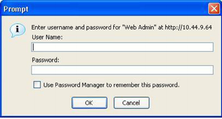
2. Click Login. The dialog box as shown in the gure below is displayed.
FIGURE 2 User name and password dialog box
Logging in to the Web Management Interface
Brocade FastIron SX, FCX, and ICX Web Management Interface User Guide, 08.0.30
Part Number: 53-1003615-02 15
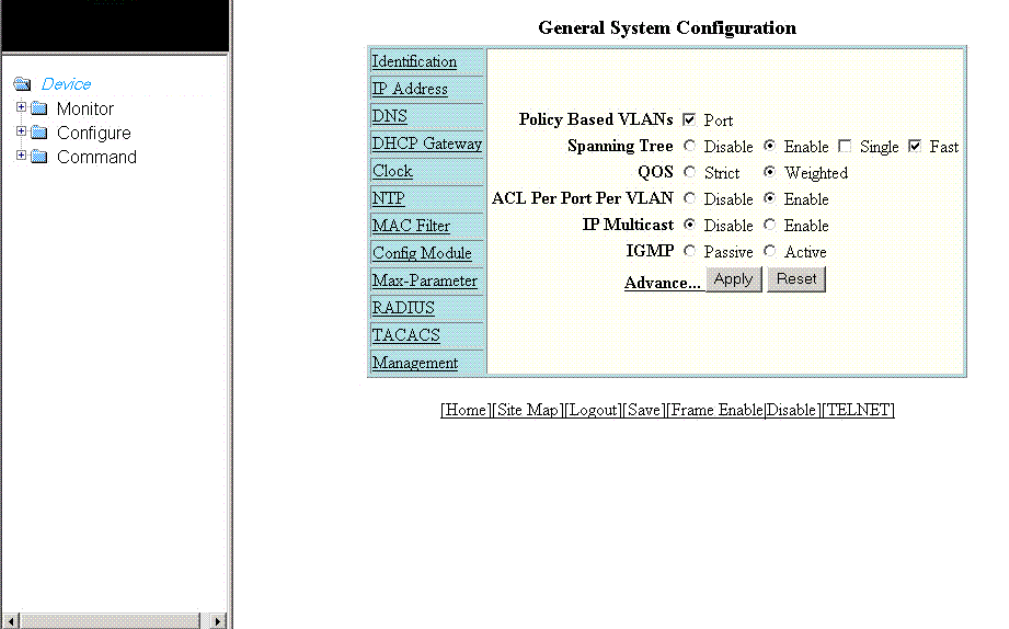
3. Enter the user name and password that you created using the CLI as described in Prerequisite conguration on page 13.
The gure below displays the home page of the Web Management Interface for a Layer 2 switch.
FIGURE 3 Home page for Layer 2 switch features
The gure below displays the home page of the Web Management Interface for a Layer 3 switch.
Logging in to the Web Management Interface
Brocade FastIron SX, FCX, and ICX Web Management Interface User Guide, 08.0.30
16 Part Number: 53-1003615-02
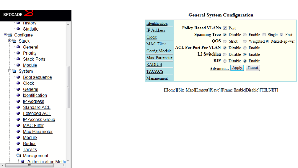
FIGURE 4 Home page for Layer 3 switch features
NOTE
If you are using Internet Explorer 6.0 to view the Web Management Interface, make sure the version you are running
includes the latest service packs. Otherwise, the navigation tree (the left-most pane in the two gures above) will not
display properly. For information on how to load the latest service packs, refer to the online help provided with your
web browser.
Logging out of the Web Management Interface
You can log out of the Web Management Interface in two ways:
• Click Logout on the window.
• Click Command in the left pane and select Logout.
Using the Web Management Interface
The following procedure explains in detail about using the Web Management Interface.
1. Click the plus sign (+) next to Congure in the tree view to expand the list of conguration options.
2. Click the plus sign (+) next to System in the tree view to expand the list of system conguration links.
3. Click the plus sign (+) next to Management in the tree view to expand the list of system management links.
4. Click Authentication Methods to display the Authentication Method panel.
Using the Web Management Interface
Brocade FastIron SX, FCX, and ICX Web Management Interface User Guide, 08.0.30
Part Number: 53-1003615-02 17
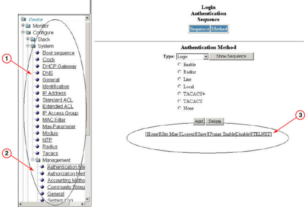
5. Enable or disable elements on the Web Management Interface by clicking the appropriate options on the panel. The gure
below identies the elements you can change.
FIGURE 5 Web Management Interface elements
1. Menu Type (Tree view)
2. Menu Frame
3. Shortcut links
NOTE
The tree view is available when you use the Web Management Interface with Netscape 4.0 or higher or Internet
Explorer 4.0 or higher. If you use the Web Management Interface with an older browser, the Web Management
Interface displays the list view only, and the Web Management Preferences panel does not include an option to display
the tree view.
6. When you have nished, click Add on the panel to add the authentication types. Click Delete to remove authentication types.
Using the Web Management Interface
Brocade FastIron SX, FCX, and ICX Web Management Interface User Guide, 08.0.30
18 Part Number: 53-1003615-02
7. To save the conguration, click the plus sign (+) next to the Command folder, and then click Save to Flash.
NOTE
The only changes that become permanent are the settings to the Menu Type and the Panel Frame. Any other
elements you enable or disable will go back to their default settings the next time you start the Web Management
Interface.
Web Management Interface areas
The following sections describe the Web Management Interface areas and how to use them.
Menu tree or list
The left panel shows the menu tree or list of options. The interface can be set up to display a menu tree or a list of options. You can
enable or disable the menu tree view in two ways:
• Click Frame Enable|Disable on the bottom of the window.
• Click Command and select Disable Frame
• .
Conguration panel
The conguration panel consists of the tables with the eld elements that display information or the input elds for which the values have
to be entered. The input elds can be of four types:
• Fields into which data must be entered using the keyboard.
• Lists from which one of several options can be chosen.
• Options allow you to select only one of the settings or features of a set of options.
• Check boxes allow you to turn on or o a parameter and you can also make multiple selections.
After entering the values, you must click the appropriate button to congure the values.
Shortcuts to functions and other panels
All the pages in the Web Management Interface provide shortcut links to the functions that are specic to that page and to other panels.
All of the Web Management Interface panels have the following links:
• [Home] --Returns you to the home page of the Web Management Interface.
• [Site Map] -- Lists all options available from the Web Management Interface with links to the panels for those options. Use the
Site Map link to move through the interface if the menu is not displayed.
• [Logout] -- Logs you out of the Web Management Interface.
• [Save] -- Saves the changes you entered on the panels.
• [TELNET] -- Opens a Telnet session to the device.
• [Frame Enable|Disable] --Enables or disables the bookmark options available in the left panel. If frames are disabled, you will
not be able to choose any of the options on the web preference panel that use frames.
Using the Web Management Interface
Brocade FastIron SX, FCX, and ICX Web Management Interface User Guide, 08.0.30
Part Number: 53-1003615-02 19
Brocade FastIron SX, FCX, and ICX Web Management Interface User Guide, 08.0.30
20 Part Number: 53-1003615-02

Monitoring Basic Device Information
• Displaying the ARP cache..............................................................................................................................................................................21
• Displaying the device information...............................................................................................................................................................23
• Displaying ash information..........................................................................................................................................................................26
• Displaying memory information..................................................................................................................................................................27
• Displaying the front panel...............................................................................................................................................................................28
• Displaying MAC addresses........................................................................................................................................................................... 38
• Displaying the system log..............................................................................................................................................................................39
Displaying the ARP cache
The Address Resolution Protocol (ARP) cache table contains entries that map IP addresses to Media Access Control (MAC) addresses.
There are two types of ARP entries: static (user-congured) and dynamic (learned).
To display the ARP cache information, click Monitor on the left pane and select ARP Cache.
The ARP Cache window is displayed as shown in the gure below.
Brocade FastIron SX, FCX, and ICX Web Management Interface User Guide, 08.0.30
Part Number: 53-1003615-02 21
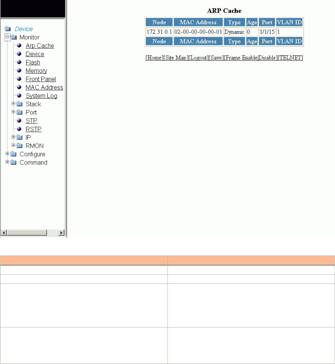
FIGURE 6 Monitoring the ARP cache
TABLE 1 Description of the elds in the ARP Cache window
Field Description
Node Displays the IP address of the device.
MAC Address Displays the MAC address of the device.
Type Displays the type of ARP entry, which can be one of the following:
•Dynamic --The Layer 3 switch learned the entry from an
incoming packet.
•Static --The Layer 3 switch loaded the entry from the static
ARP table when the device for the entry was connected to the
Layer 3 switch.
Age Displays the number of minutes the entry has remained unused. If this
value reaches the ARP aging period, the entry is removed from the cache.
NOTE
Static entries do not age out.
Displaying the ARP cache
Brocade FastIron SX, FCX, and ICX Web Management Interface User Guide, 08.0.30
22 Part Number: 53-1003615-02

TABLE 1 Description of the elds in the ARP Cache window (continued)
Field Description
Port Displays the port attached to the device for which the entry was made. For
dynamic entries, this is the port on which the entry was learned.
The port number varies based on the product:
• For Brocade FCX and Brocade ICX devices - stack-unit/
slotnum/portnum
• For Brocade FastIron SX devices - slotnum/portnum
VLAN ID Displays the VLAN Identier of the port, which learned the entry.
NOTE
This eld is not available in the ARP Cache window for the
Brocade FastIron SX devices.
Displaying the device information
To display the device information, perform the following steps.
1. Click Monitor on the left pane and select Device.
Displaying the device information
Brocade FastIron SX, FCX, and ICX Web Management Interface User Guide, 08.0.30
Part Number: 53-1003615-02 23
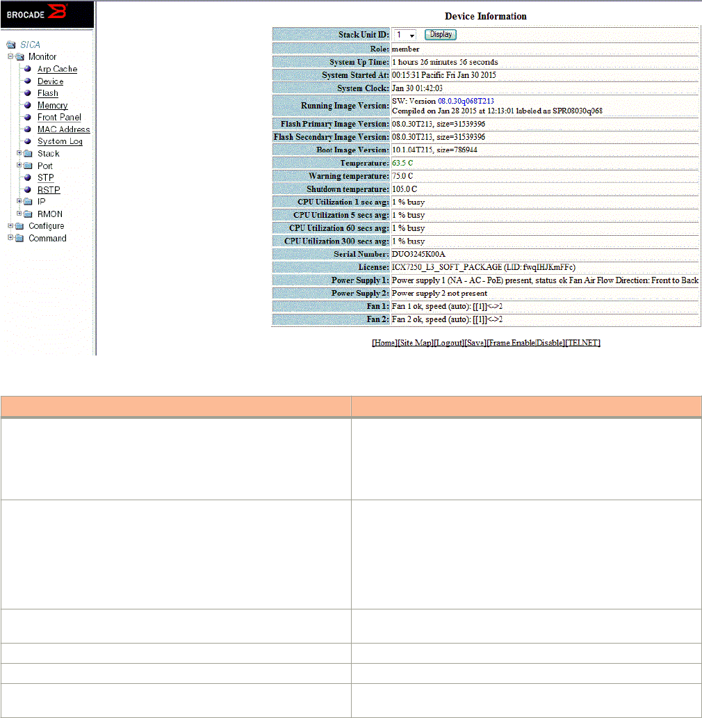
2. For the Brocade FCX and Brocade ICX devices, select a stack Identier from the Stack Unit ID list and click Display to view the
information for any device in an IronStack.
NOTE
The Stack Unit ID list is not available in the Device Information window for the Brocade FastIron SX devices.
The Device Information window for the Brocade FCX and Brocade ICX devices is displayed as shown in the gure below.
FIGURE 7 Monitoring the device information
TABLE 2 Description of the elds in the Device Information window
Field Description
Stack Unit ID Displays the number of the unit within a stack.
NOTE
This eld is not available in the Device Information
window for the Brocade FastIron SX devices.
Role Displays the role of the device, which can be Active, Standby,
Member, or alone. If the role is alone, the device is operating as a
standalone device.
NOTE
This eld is not available in the Device Information
window for the Brocade FastIron SX devices.
System Up Time Displays the quantity of time the system has been running since the
last restart.
System Started At Displays the time when the system started.
System Clock Displays the time congured in the system.
Running Image Version Displays the software version currently running and some details on
the version.
Displaying the device information
Brocade FastIron SX, FCX, and ICX Web Management Interface User Guide, 08.0.30
24 Part Number: 53-1003615-02

TABLE 2 Description of the elds in the Device Information window (continued)
Field Description
Flash Primary Image Version Displays the release number and size of the software loaded on the
primary ash.
Flash Secondary Image Version Displays the release number and size of the software loaded on the
secondary ash.
Boot Image Version Displays the release number and size of the boot image.
Temperature For the Brocade FCX and Brocade ICX devices, this eld displays the
actual temperature. The color of the degrees provides a visual
indicator for the device:
• Green—The temperature is within the normal operating range.
• Orange—The temperature has reached the warning level.
• Red—The temperature has reached the shutdown level.
For the Brocade FastIron SX devices, click Temperature in the right
pane to display the Chassis Temperature Information window, which
shows the temperature of each slot (from 1 through 10) and the
switch fabric modules SF 1 and SF 2. Figure 8 shows the Chassis
Temperature Information window.
Warning temperature Displays the warning level temperature.
NOTE
This eld is not available in the Device Information
window for the Brocade FastIron SX devices.
Shutdown temperature Displays the shutdown level temperature.
NOTE
This eld is not available in the Device Information
window for the Brocade FastIron SX devices.
CPU Utilization Displays the percentage of CPU being used by the device at 1-
second, 5-second, 1-minute, and 5-minute intervals.
Serial Number Displays the serial number of the device.
License Displays the software license and License ID (LID) of the device.
NOTE
This eld is not available in the Device Information
window for the Brocade FastIron SX devices.
Power Supply 1 Displays the status of the primary power supply.
Power Supply 2 Displays the status of the secondary power supply, if present.
Fan 1 Displays the status of the primary cooling fan.
Fan 2 Displays the status of the secondary cooling fan, if present.
NOTE
There is an entry for each fan in the device.
The gure below shows the Chassis Temperature Information window for the Brocade FastIron SX devices.
Displaying the device information
Brocade FastIron SX, FCX, and ICX Web Management Interface User Guide, 08.0.30
Part Number: 53-1003615-02 25

FIGURE 8 Monitoring the chassis temperature
Displaying ash information
NOTE
This feature is applicable only for the Brocade FCX and Brocade ICX devices.
To display the ash information, click Monitor on the left pane and select Flash.
The Flash Information window is displayed as shown in the gure below.
Displaying ash information
Brocade FastIron SX, FCX, and ICX Web Management Interface User Guide, 08.0.30
26 Part Number: 53-1003615-02
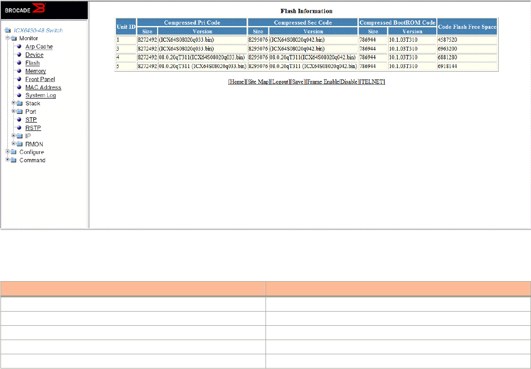
FIGURE 9 Monitoring the ash information
The table below describes the elds in the Flash Information window.
TABLE 3 Description of the elds in the Flash Information window
Field Description
Unit ID Displays the number of the unit within a stack.
Compressed Pri Code Displays the compressed size and version for the primary code.
Compressed Sec Code Displays the compressed size and version for the secondary code.
Compressed BootROM Code Displays the compressed size and version for the BootROM code.
Code Flash Free Space Displays the amount of free space available on the ash memory.
Displaying memory information
NOTE
This feature is applicable only for the Brocade FCX and Brocade ICX devices.
To display the memory information of the device, click Monitor on the left pane and select Memory.
The Memory Information window is displayed as shown in the gure below.
Displaying memory information
Brocade FastIron SX, FCX, and ICX Web Management Interface User Guide, 08.0.30
Part Number: 53-1003615-02 27
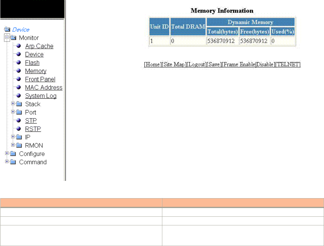
FIGURE 10 Monitoring the memory information
TABLE 4 Description of the elds in the Memory Information window
Field Description
Unit ID Displays the number of the unit within a stack.
Total DRAM Displays the size (in bytes) of dynamic random access memory (DRAM).
Dynamic Memory Displays the total number of bytes in dynamic memory, including the
number of bytes that are available (free or unused), and the percentage of
memory used.
Displaying the front panel
The front panel of the device allows you to view the modules in each device and the ports within each module.
The front panel shows the status of devices using colors. Green ports are connected, and gray ports are not connected. Ports of the
same color on two units are connected with cables. A gray uplink port is not connected to a device. Ports with amber LEDs linked up
have downgraded speeds from their default speeds.
Status LED display
The status LEDs that appear on the front panel provide information about system activity. The gure below shows the LEDs that appear
on the front panel of ICX 7750 device.
Displaying the front panel
Brocade FastIron SX, FCX, and ICX Web Management Interface User Guide, 08.0.30
28 Part Number: 53-1003615-02
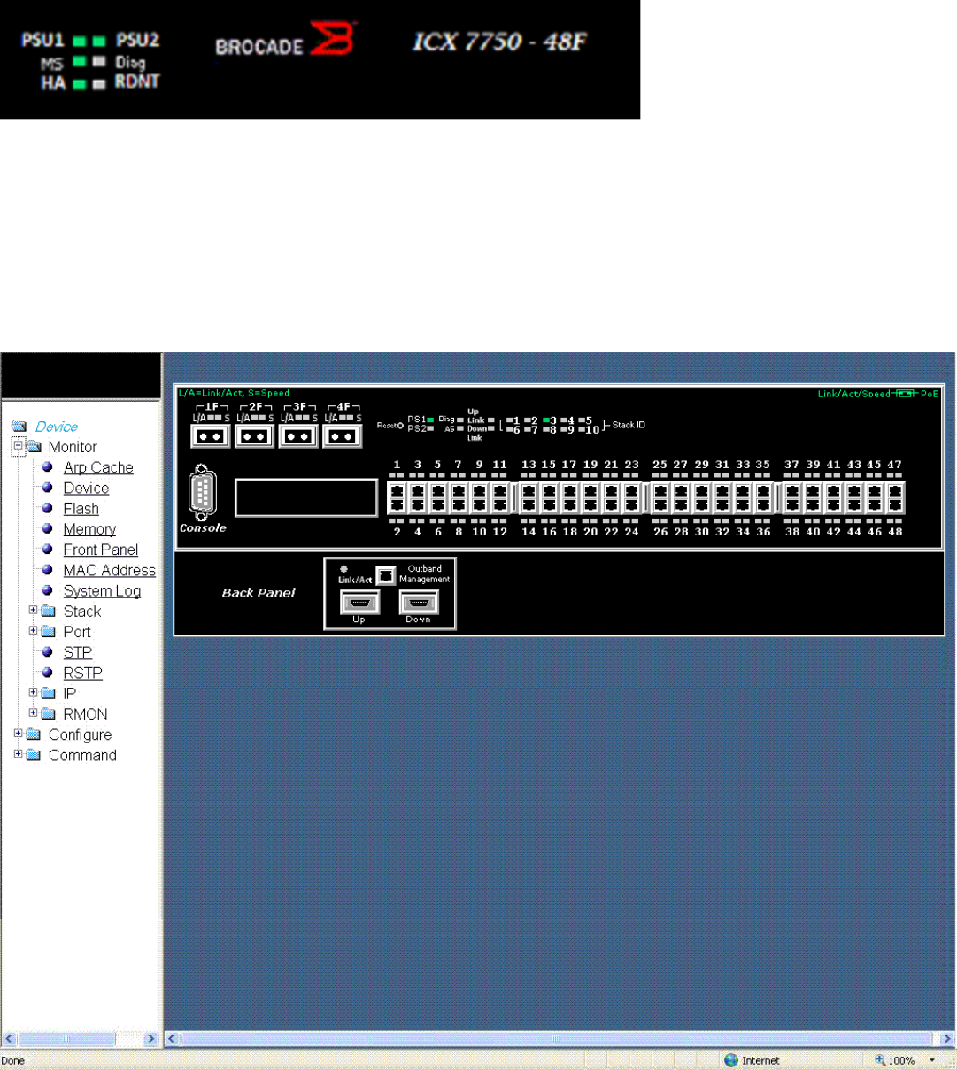
FIGURE 11 Front panel LEDs
For more information about the LED labels and status indicators in Brocade devices, refer respective Hardware Installation Guides.
Displaying the front panel for the Brocade FCX devices
To display the front panel, click Monitor on the left pane and select Front Panel.
The gure below shows the front panel for the Brocade FCX 648 device.
FIGURE 12 Brocade FCX 648 front panel
Displaying the front panel
Brocade FastIron SX, FCX, and ICX Web Management Interface User Guide, 08.0.30
Part Number: 53-1003615-02 29
Click any port to display the real-time port information for that port. The gure below shows the Port Realtime Information window.
Clicking elsewhere on the panel opens the Device Information window. For more information, refer to Displaying the device information
on page 23.
Displaying the front panel
Brocade FastIron SX, FCX, and ICX Web Management Interface User Guide, 08.0.30
30 Part Number: 53-1003615-02
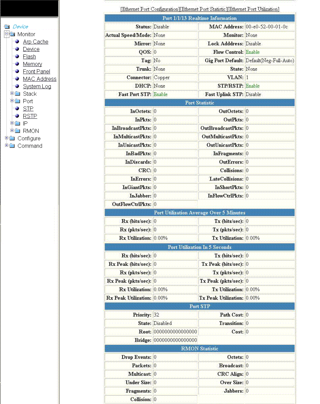
FIGURE 13 Monitoring the real-time port information
Displaying the front panel
Brocade FastIron SX, FCX, and ICX Web Management Interface User Guide, 08.0.30
Part Number: 53-1003615-02 31
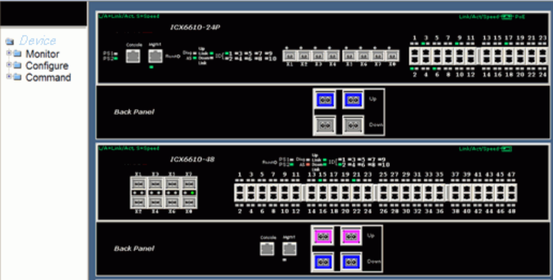
The Port Realtime Information window provides links to congure and monitor port parameters:
• To congure an Ethernet port, click Ethernet Port Conguration. For more information, refer to Conguring an Ethernet port on
page 165.
• To view the total number of packets, number of collisions, and number of errors that have occurred on a port, click Ethernet
Port Statistic. For more information, refer to Displaying Ethernet port statistics on page 55.
• To view the trac that is received and transmitted on a port, click Ethernet Port Utilization . For more information, refer to
Displaying Ethernet port utilization on page 59.
Displaying the front panel for the Brocade ICX 6610 device
To display the front panel, click Monitor on the left panel and select Front Panel.
The gure below shows the front panel of the Brocade ICX 6610 device.
FIGURE 14 Brocade ICX 6610 front panel
Displaying the front panel for the Brocade ICX 6430 device
To display the front panel, click Monitor on the left panel and select Front Panel.
The gure below shows the front panel of the Brocade ICX 6430-24 device.
Displaying the front panel
Brocade FastIron SX, FCX, and ICX Web Management Interface User Guide, 08.0.30
32 Part Number: 53-1003615-02
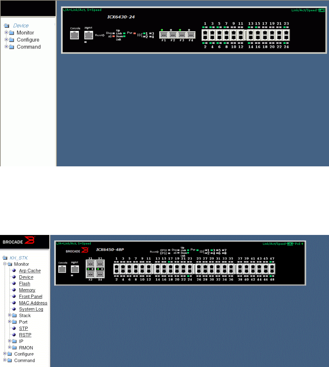
FIGURE 15 Brocade ICX 6430 front panel
Displaying the front panel for the Brocade ICX 6450 device
To display the front panel, click Monitor on the left panel and select Front Panel.
The gure below shows the front panel of the Brocade ICX 6450-48P device.
FIGURE 16 Brocade ICX 6450 front panel
Displaying the front panel
Brocade FastIron SX, FCX, and ICX Web Management Interface User Guide, 08.0.30
Part Number: 53-1003615-02 33
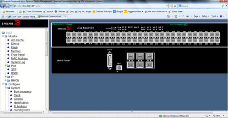
Displaying the front panel for the Brocade ICX 6650 device
To display the front panel, click Monitor on the left panel and select Front Panel.
The gure below shows the front panel of the Brocade ICX 6650 device.
FIGURE 17 Brocade ICX 6650 device front panel
Displaying the front panel for the Brocade FastIron SX devices
To display the front panel, click Monitor on the left panel and select Front Panel.
The gure below shows the front panel for the Brocade FastIron SX device.
Displaying the front panel
Brocade FastIron SX, FCX, and ICX Web Management Interface User Guide, 08.0.30
34 Part Number: 53-1003615-02
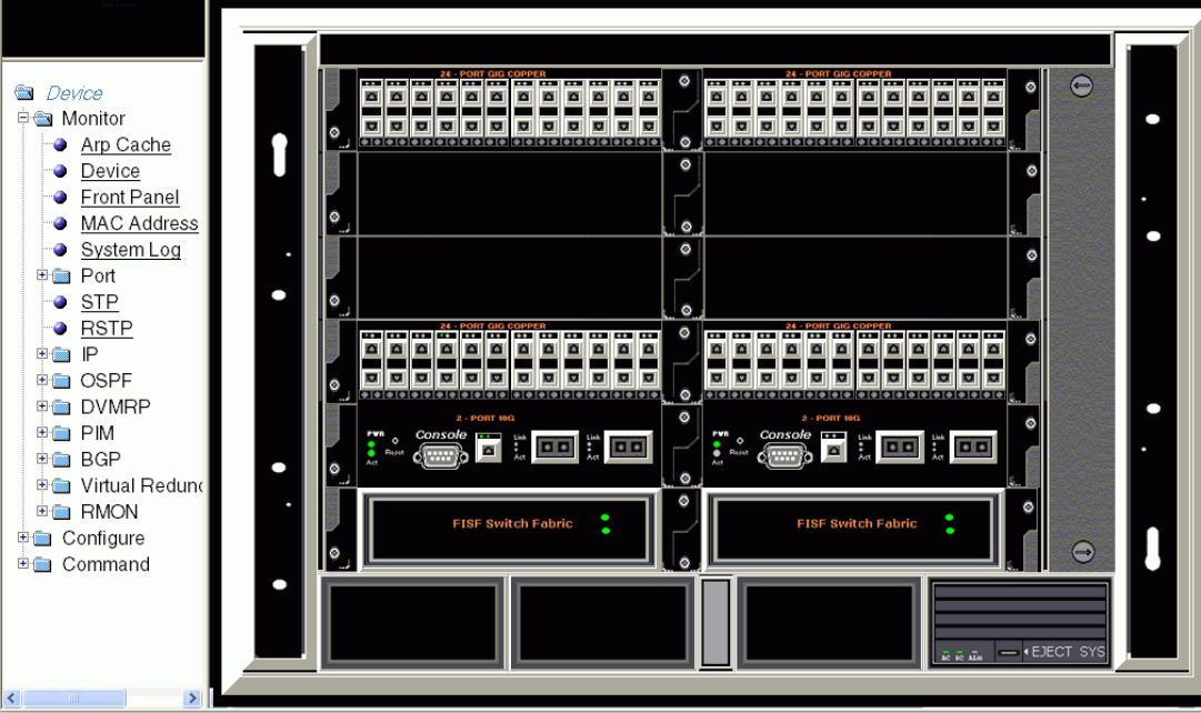
FIGURE 18 Brocade FastIron SX device front panel
You can perform the following tasks in the panel:
• Click the Console port to display the Device Information window. For more information, refer to Displaying the device
information on page 23.
• Click management port to display the current management port real-time information. The gure below shows the mgmt1 Port
Realtime Information window. For more information, refer to Displaying the management port information on page 61.
• Click any port to display the real-time port information for that port. Figure 13 on page 31 shows the Port Realtime
Information window.
• Click elsewhere on the panel to display the Device Information window.
Displaying the front panel
Brocade FastIron SX, FCX, and ICX Web Management Interface User Guide, 08.0.30
Part Number: 53-1003615-02 35
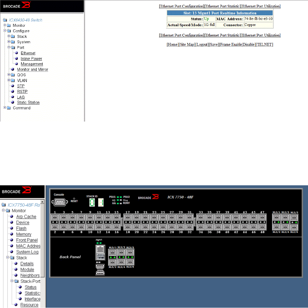
FIGURE 19 Monitoring the real-time port information of the management port
Displaying the front panel for the Brocade ICX 7750 device
To display the front panel, click Monitor on the left panel and select Front Panel.
The gure below shows the front panel of the Brocade ICX 7750 device.
FIGURE 20 Brocade ICX 7750 device front panel
Displaying the front panel for the Brocade ICX 7450 device
To display the front panel, click Monitor on the left panel and select Front Panel.
Displaying the front panel
Brocade FastIron SX, FCX, and ICX Web Management Interface User Guide, 08.0.30
36 Part Number: 53-1003615-02
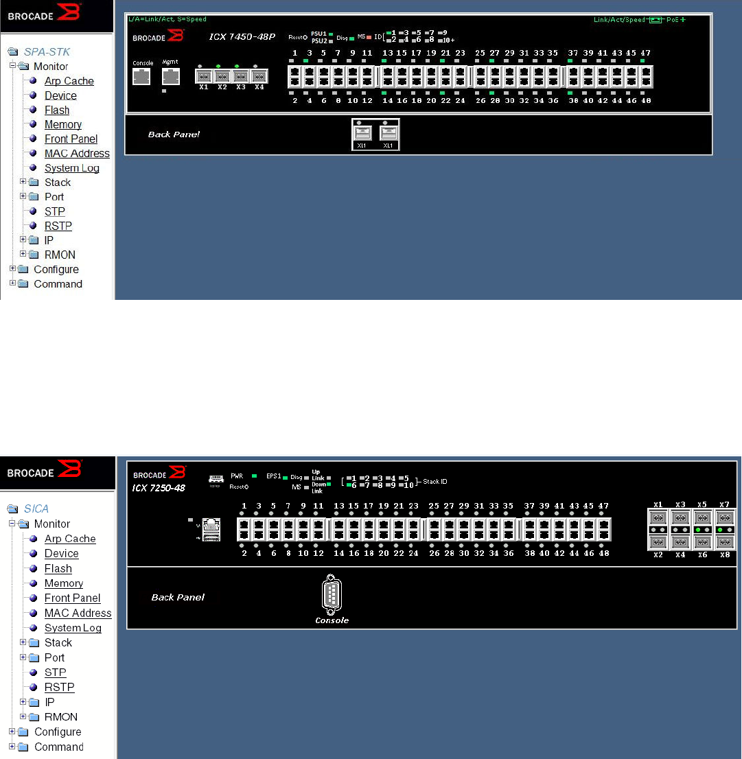
The gure below shows the front panel of the Brocade ICX 7450 device.
FIGURE 21 Brocade ICX 7450 device front panel
Displaying the front panel for the Brocade ICX 7250 device
To display the front panel, click Monitor on the left panel and select Front Panel.
The gure below shows the front panel of the Brocade ICX 7250-48 device.
FIGURE 22 Brocade ICX 7250 device front panel
Displaying the front panel
Brocade FastIron SX, FCX, and ICX Web Management Interface User Guide, 08.0.30
Part Number: 53-1003615-02 37
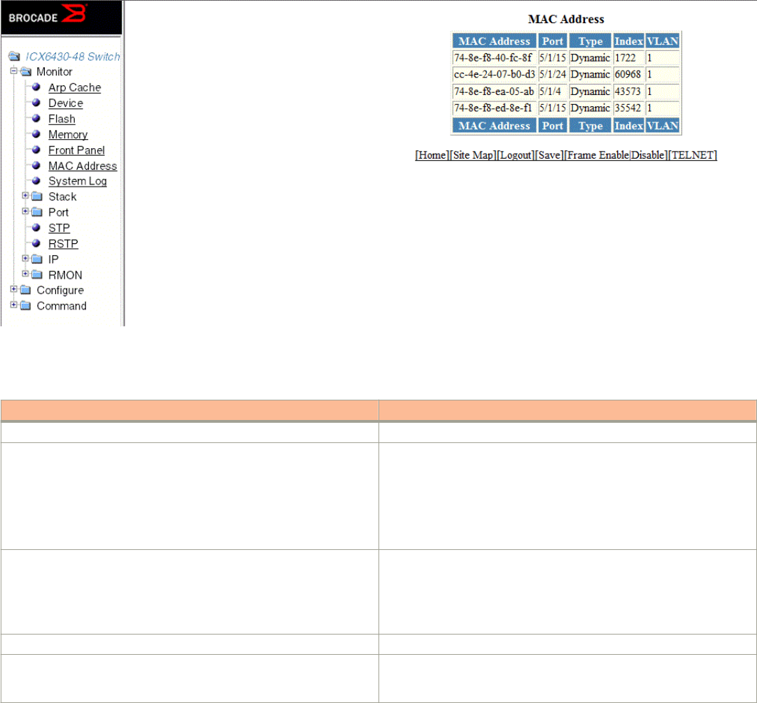
Displaying MAC addresses
To display the list of MAC addresses that have been learned by the device, click Monitor on the left pane and select MAC Address.
The MAC Address window is displayed as shown in the gure below.
FIGURE 23 Monitoring the MAC address
The table below describes the elds in the MAC Address window.
TABLE 5 Description of the elds in the MAC Address window
Field Description
MAC Address Displays the MAC address of the device.
Port Displays the port attached to the device for which the entry was made. For
dynamic entries, this is the port on which the entry was learned.
The port number varies based on the product:
• For Brocade FCX and Brocade ICX devices - stack-unit/
slotnum/portnum
• For Brocade FastIron SX devices - slotnum/portnum
Type Displays the type of the entry, which can be one of the following:
•Dynamic—The MAC address changes if the Active Controller
changes.
•Static—The MAC address will not change if the Active Controller
changes.
Index Displays the index of the entry in the MAC address table.
VLAN Displays the port-based VLAN that contains this (instance of) spanning
tree. VLAN 1 is the default VLAN. If you have not congured port-based
VLANs on this device, all STP information is for VLAN 1.
Displaying MAC addresses
Brocade FastIron SX, FCX, and ICX Web Management Interface User Guide, 08.0.30
38 Part Number: 53-1003615-02
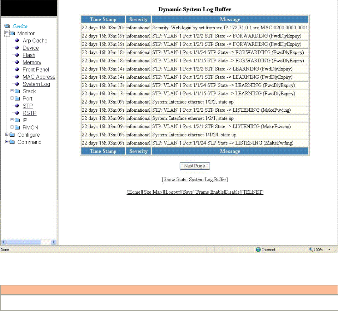
Displaying the system log
The software provides two types of system log buers:
• Static—Logs power supply failures, fan failures, and temperature warning or shutdown messages.
• Dynamic—Logs all other message types.
To display the current information of the system log buer, click Monitor on the left pane and select System Log.
The Dynamic System Log Buer window is displayed as shown in the gure below.
The table below describes the elds in the Dynamic System Log Buer window.
TABLE 6 Description of the elds in the Dynamic System Log Buer window
Field Description
Time Stamp Displays the system uptime in DD:HH:MM:SS or the actual time if the
date and time was set.
Displaying the system log
Brocade FastIron SX, FCX, and ICX Web Management Interface User Guide, 08.0.30
Part Number: 53-1003615-02 39
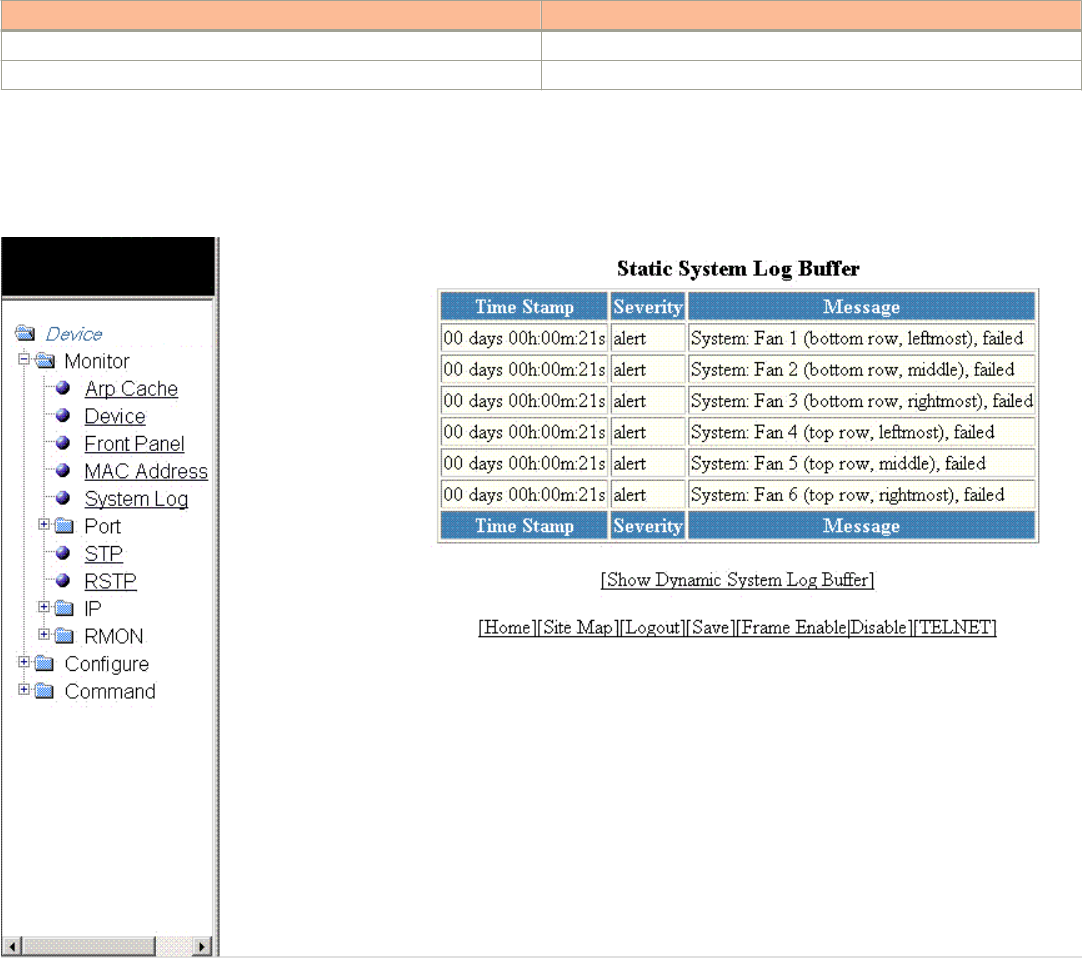
TABLE 6 Description of the elds in the Dynamic System Log Buer window (continued)
Field Description
Severity Displays the severity of the event.
Message Displays the description of the event.
To view the next set of the Dynamic System Log Buer entries, click Next Page. To display the static system log buer information, click
Show Static System Log Buer.
The Static System Log Buer window is displayed as shown in the gure below.
For information on the Static System Log Buer elds, refer to the table above.
Displaying the system log
Brocade FastIron SX, FCX, and ICX Web Management Interface User Guide, 08.0.30
40 Part Number: 53-1003615-02

Monitoring Stacks
• Displaying the stack details........................................................................................................................................................................... 41
• Displaying a stack module.............................................................................................................................................................................43
• Displaying stack neighbors............................................................................................................................................................................44
• Displaying stack ports information.............................................................................................................................................................45
• Displaying stack port statistics.....................................................................................................................................................................47
• Monitoring peri-ports.......................................................................................................................................................................................48
• Monitoring peri-trunks.....................................................................................................................................................................................48
• Displaying stack port interfaces...................................................................................................................................................................49
• Displaying stack resources............................................................................................................................................................................ 51
Displaying the stack details
To display current stack details, stack port status, and stack neighbors information, perform the following steps.
1. Click Monitor on the left pane and select Stack.
Brocade FastIron SX, FCX, and ICX Web Management Interface User Guide, 08.0.30
Part Number: 53-1003615-02 41
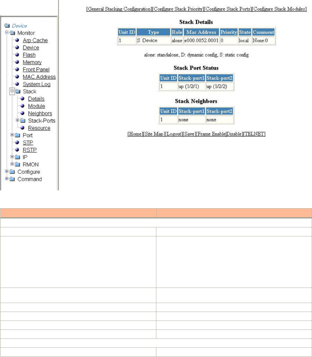
2. Click Details.
The Stack Details window is displayed in the gure below.
TABLE 7 Description of the elds in the Stack Details window
Field Description
Stack Details parameters
Unit ID Displays the number of the unit within a stack.
Type Displays the type of conguration and the device model. The types of
conguration are as follows:
•alone --Indicates that the device is operating as a standalone
device.
•S --Indicates that the conguration for this unit is static.
•D --Indicates that the conguration for this unit is dynamic and
may be overwritten by a new stack unit.
Role Displays the role of this unit within the stack: Active, Standby,
Member, or alone.
Mac Address Displays the MAC address of the device.
Priority Displays the priority assigned to this unit.
State Displays the operational state of this unit: local or remote.
Comment Displays additional information about this unit.
Stack Port Status parameters
Unit ID Displays the number of the unit within a stack.
Displaying the stack details
Brocade FastIron SX, FCX, and ICX Web Management Interface User Guide, 08.0.30
42 Part Number: 53-1003615-02

TABLE 7 Description of the elds in the Stack Details window (continued)
Field Description
Stack-port1 Displays the port state and the port number for stack-port1. The port
states are as follows:
•up --Each end is connected.
•down --Port is congured as a stacking port, but not connected.
•none --Port is not congured as a stacking port.
Stack-port2 Displays the port state and the port number for stack-port2. The port
states are as follows:
•up --Each end is connected.
•down --Port is congured as a stacking port, but not connected.
•none --Port is not congured as a stacking port.
Stack Neighbors parameters
Unit ID Displays the number of the unit within a stack.
Stack-port1 Displays the neighbor stack unit for stack-port1 for this unit ID.
Stack-port2 Displays the neighbor stack unit for stack-port2 for this unit ID.
The Stack Details window provides links to congure the stack components:
• To change the stack settings, click General Stacking Conguration. For more information, refer to Conguring the general
settings for a traditional stack on page 107.
• To congure the priority of units within a stack, click Congure Stack Priority. For more information, refer to the “Modifying
stack priority” section.
• To congure a stack port, click Congure Stack Ports. For more information, refer to the “Modifying stack ports” section.
• To congure a stack module, click Congure Stack Modules. For more information, refer to the “Conguring a stack
module” section.
Displaying a stack module
To display current information about the stack unit modules, perform the following steps.
1. Click Monitor on the left pane and select Stack.
Displaying a stack module
Brocade FastIron SX, FCX, and ICX Web Management Interface User Guide, 08.0.30
Part Number: 53-1003615-02 43
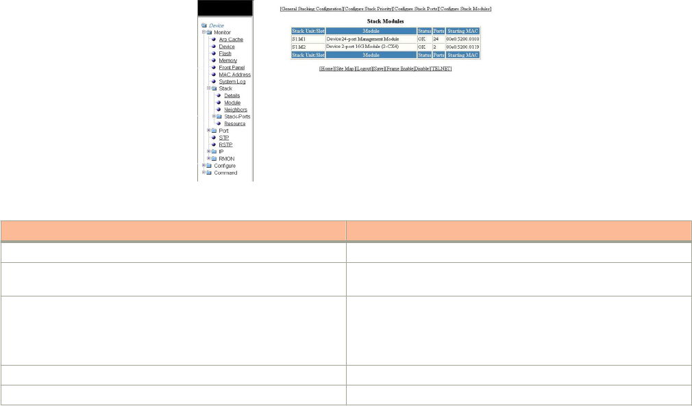
2. Click Module.
The Stack Modules window is displayed as shown in the gure below.
TABLE 8 Description of the elds in the Stack Modules window
Field Description
Stack Unit: Slot Displays the number of the unit within the stack and the slot number.
Module Displays the device information, such as module number and
module type.
Status Displays the status, which can be one of the following:
•OK -- The module came up and is operating normally.
•CFG --The module is congured, but does not physically exist
within the units of the stack.
Ports Displays the number of ports on the module.
Starting MAC Displays the starting MAC address for this module.
The Stack Modules window provides links to congure the stack components:
• To change the stack settings, click General Stacking Conguration. For more information, refer to Conguring the general
settings for a traditional stack on page 107.
• To congure the priority of units within a stack, click Congure Stack Priority. For more information, refer to the “Modifying
a stack priority” section.
• To congure a stack port, click Congure Stack Ports. For more information, refer to the “Modifying stack ports” section.
• To congure a stack module, click Congure Stack Modules. For more information, refer to the “Conguring Stack
Components” section.
Displaying stack neighbors
To display information of the stack member neighbors, perform the following steps.
1. Click Monitor on the left pane and select Stack.
Displaying stack neighbors
Brocade FastIron SX, FCX, and ICX Web Management Interface User Guide, 08.0.30
44 Part Number: 53-1003615-02
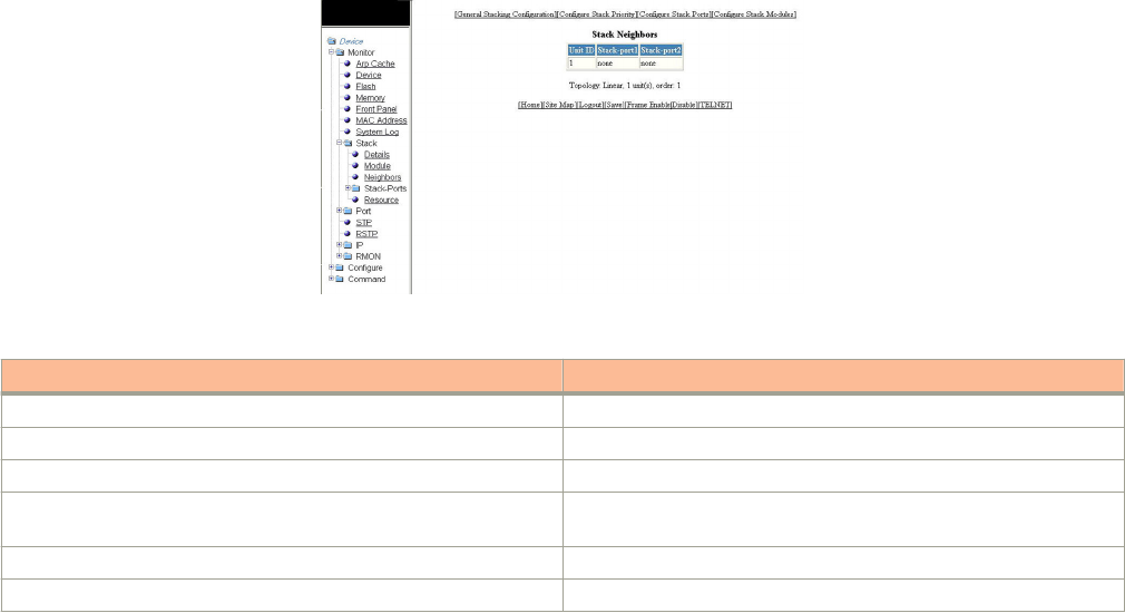
2. Click Neighbors.
The Stack Neighbors window is displayed as shown in the gure below.
TABLE 9 Description of the elds in the Stack Neighbors window
Field Description
Unit ID Displays the number of the unit within the stack.
Stack-port1 Displays the neighbor stack unit for stack-port1 for this unit ID.
Stack-port2 Displays the neighbor stack unit for stack-port2 for this unit ID.
Topology Displays either Linear or Ring stack topology of the connected
devices.
unit(s) Displays the number of units within the stack.
order Displays the order of the unit IDs within the stack.
The Stack Neighbors window provides links to congure the stack components:
• To change the stack settings, click General Stacking Conguration . For more information, refer to Conguring the general
settings for a traditional stack on page 107.
• To congure the priority of units within a stack, click Congure Stack Priority . For more information, refer to the “Modifying
a stack priority” section.
• To congure a stack port, click Congure Stack Ports . For more information, refer to the “Modifying stack ports” section.
• To congure a stack module, click Congure Stack Modules . For more information, refer to “Conguring a stack module”
section.
Displaying stack ports information
To display the information of the stack ports, perform the following steps.
1. Click Monitor on the left pane and select Stack .
Displaying stack ports information
Brocade FastIron SX, FCX, and ICX Web Management Interface User Guide, 08.0.30
Part Number: 53-1003615-02 45

2. Click Stack-Ports and then select Status .
The Stack Port Status window is displayed as shown in the gure below.
FIGURE 24 Monitoring stack port status
TABLE 10 Description of the elds in the Stack Port Status window
Field Description
Unit ID Displays the number of the unit within the stack.
Stack-port1 Displays the port state and the port number for stack-port1 for this
unit ID.
The port states are as follows:
•up --Each end is connected.
•down --Port is congured as a stacking port, but not connected.
•none --Port is not congured as a stacking port.
The port number varies based on the product:
• For Brocade FCX and Brocade ICX devices - stack-unit/
slotnum/portnum
• For Brocade FastIron SX devices - slotnum/portnum
Stack-port2 Displays the port state and the port number for stack-port2 for this
unit ID.
The port states are:
•up --Each end is connected.
•down --Port is congured as a stacking port, but not connected.
•none --Port is not congured as a stacking port.
The port number varies based on the product:
• For Brocade FCX and Brocade ICX devices - stack-unit/
slotnum/portnum
• For Brocade FastIron SX devices - slotnum/portnum
The Stack Port Status window provides links to congure the stack components:
• To change the stack settings, click General Stacking Conguration . For more information, refer to Conguring the general
settings for a traditional stack on page 107.
Displaying stack ports information
Brocade FastIron SX, FCX, and ICX Web Management Interface User Guide, 08.0.30
46 Part Number: 53-1003615-02
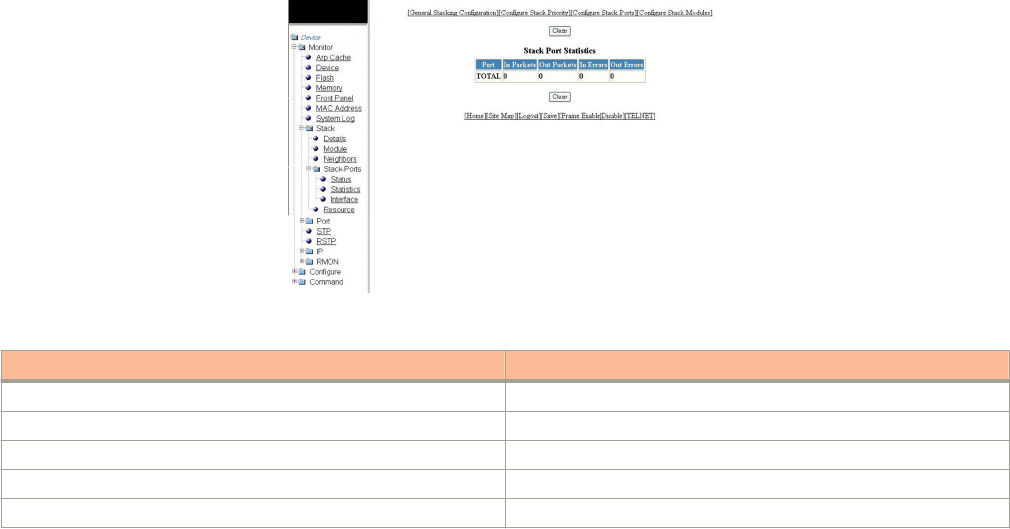
• To congure the priority of units within a stack, click Congure Stack Priority . For more information, refer to Modifying
stack priority on page 108.
• To congure a stack port, click Congure Stack Ports . For more information, refer to Modifying stack ports on page 110.
• To congure a stack module, click Congure Stack Modules . For more information, refer to Conguring a stack module
on page 112.
Displaying stack port statistics
To display stack port information for all ports in an IronStack topology, perform the following steps.
1. Click Monitor on the left pane and select Stack .
2. Click Stack-Ports and then select Statistics .
The Stack Port Statistics window is displayed as shown in the gure below.
FIGURE 25 Monitoring stack port statistics
TABLE 11 Description of the elds in the Stack Port Statistics window
Field Description
Port Displays the stack identication number for this port.
In Packets Displays the number of incoming packets on this port.
Out Packets Displays the number of outgoing packets on this port.
In Errors Displays the number of errors on the incoming packets on this port.
Out Errors Displays the number of errors on the outgoing packets on this port.
To clear the information and begin a new monitoring cycle, click Clear . The Stack Port Statistics window provides links to
congure the stack components:
• To change the stack settings, click General Stacking Conguration . For more information, refer to Conguring the general
settings for a traditional stack on page 107.
• To congure the priority of units within a stack, click Congure Stack Priority . For more information, refer to Modifying
stack priority on page 108.
• To congure a stack port, click Congure Stack Ports . For more information, refer to Modifying stack ports on page 110.
• To congure a stack module, click Congure Stack Modules . For more information, refer to Conguring a stack module
on page 112.
Displaying stack port statistics
Brocade FastIron SX, FCX, and ICX Web Management Interface User Guide, 08.0.30
Part Number: 53-1003615-02 47
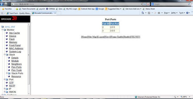
Monitoring peri-ports
To display peri-port information, perform the following steps.
1. Click Monitor on the left pane and select Stack.
2. Click Peri-Ports.
The Peri-Ports window is displayed.
FIGURE 26 Peri-ports
Monitoring peri-trunks
To display peri-trunk information, perform the following steps.
1. Click Monitor on the left pane and select Stack.
Monitoring peri-ports
Brocade FastIron SX, FCX, and ICX Web Management Interface User Guide, 08.0.30
48 Part Number: 53-1003615-02
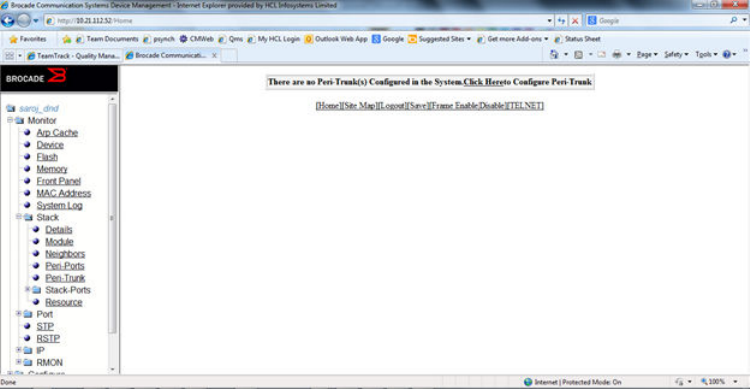
2. Click Peri-Trunks.
The Peri-trunks window is displayed.
FIGURE 27 Peri-trunks
Displaying stack port interfaces
To display information about stack port interfaces, perform the following steps.
1. Click Monitor on the left pane and select Stack .
Displaying stack port interfaces
Brocade FastIron SX, FCX, and ICX Web Management Interface User Guide, 08.0.30
Part Number: 53-1003615-02 49

2. Click Stack-Ports and then select Interface .
The Stack Port Interface window is displayed as shown in the gure below.
FIGURE 28 Monitoring stack port interfaces
TABLE 12 Description of the elds in the Stack Port Interface window
Field Description
Port Displays the stack identication number for this port.
Link Displays whether the link is up or down.
State Displays the state of the stack unit.
Duplex Displays whether the port is congured as half or full duplex.
Speed Displays the port speed as 10 Mbps, 100 Mbps, or 1000 Mbps.
Trunk Displays the trunk group number, if the port is a member of a trunk
group.
Tag Displays whether the port is tagged or untagged.
Priority Displays the port priority.
MAC Displays the MAC address of the port.
Name Displays the name assigned to the port.
The Stack Port Interface window provides links to congure the stack components:
• To change the stack settings, click General Stacking Conguration . For more information, refer to Conguring the general
settings for a traditional stack on page 107.
Displaying stack port interfaces
Brocade FastIron SX, FCX, and ICX Web Management Interface User Guide, 08.0.30
50 Part Number: 53-1003615-02
• To congure the priority of units within a stack, click Congure Stack Priority . For more information, refer to Modifying
stack priority on page 108.
• To congure a stack port, click Congure Stack Ports . For more information, refer to Modifying stack ports on page 110 .
• To congure a stack module, click Congure Stack Modules . For more information, refer to Conguring a stack module
on page 112.
Displaying stack resources
To display information about stack resources, perform the following steps.
1. Click Monitor on the left pane and select Stack.
Displaying stack resources
Brocade FastIron SX, FCX, and ICX Web Management Interface User Guide, 08.0.30
Part Number: 53-1003615-02 51
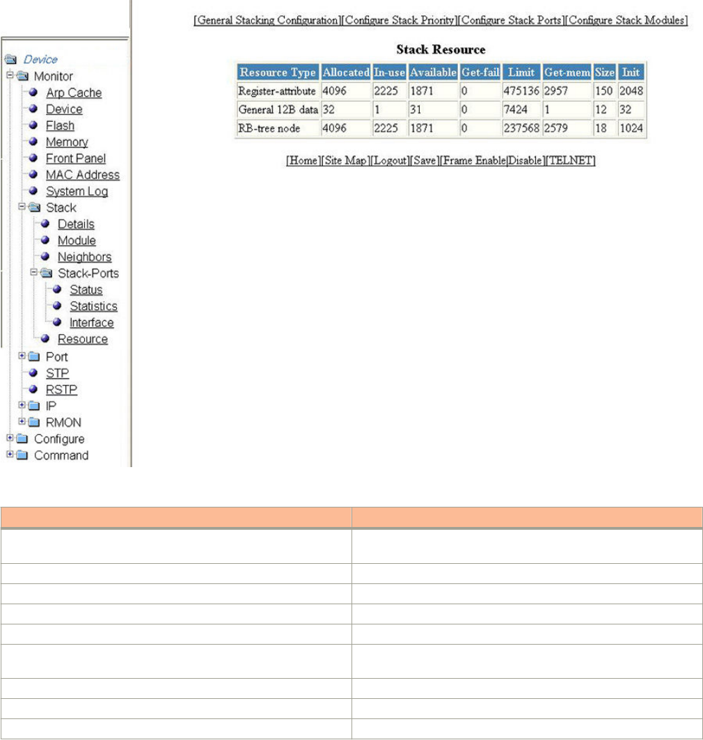
2. Click Resource.
The Stack Resource window is displayed as shown in the gure below.
FIGURE 29 Monitoring stack resources
TABLE 13 Description of the elds in the Stack Resource window
Field Description
Resource Type Displays the resource type as Register-attributes, General 12B data,
or RB-tree node.
Allocated Displays the amount of memory allocated for the stack.
In-use Displays the amount of memory used by the stack.
Available Displays the amount of free memory available.
Get-fail Displays the number of get requests that have failed.
Limit Displays the maximum amount of memory the system could allocate
for a stack.
Get-mem Displays the number of get-memory requests.
Size Displays the size (bytes) for each stack resource.
Init Displays the number of requests initiated.
The Stack Resource window provides links to congure the stack components:
Displaying stack resources
Brocade FastIron SX, FCX, and ICX Web Management Interface User Guide, 08.0.30
52 Part Number: 53-1003615-02
• To change the stack settings, click General Stacking Conguration. For more information, refer to Conguring the general
settings for a traditional stack on page 107.
• To congure the priority of units within a stack, click Congure Stack Priority. For more information, refer to the “Modifying
stack priority” section.
• To congure a stack port, click Congure Stack Ports. For more information, refer to the “Modifying stack ports” section.
• To congure a stack module, click Congure Stack Modules . For more information, refer to the “Conguring a stack
module” section.
Displaying stack resources
Brocade FastIron SX, FCX, and ICX Web Management Interface User Guide, 08.0.30
Part Number: 53-1003615-02 53
Brocade FastIron SX, FCX, and ICX Web Management Interface User Guide, 08.0.30
54 Part Number: 53-1003615-02

Monitoring Ports
• Displaying Ethernet port statistics.............................................................................................................................................................. 55
• Displaying Ethernet port attributes.............................................................................................................................................................57
• Displaying Ethernet port utilization.............................................................................................................................................................59
• Displaying the management port information.......................................................................................................................................61
• Displaying port inline power for the Brocade FCX and Brocade ICX devices......................................................................... 64
• Displaying port inline power for the Brocade FastIron SX devices...............................................................................................70
Displaying Ethernet port statistics
The ETHERNET Port Statistic window lists the total number of packets, number of collisions, and number of errors that have occurred
on a port. To display the Ethernet port statistics, perform the following steps.
1. Click Monitor on the left pane and select Port.
2. Click Statistic and then select Ethernet.
The ETHERNET Port Statistic window for the Brocade FCX and Brocade ICX devices is displayed as shown in the gure
below.
Brocade FastIron SX, FCX, and ICX Web Management Interface User Guide, 08.0.30
Part Number: 53-1003615-02 55
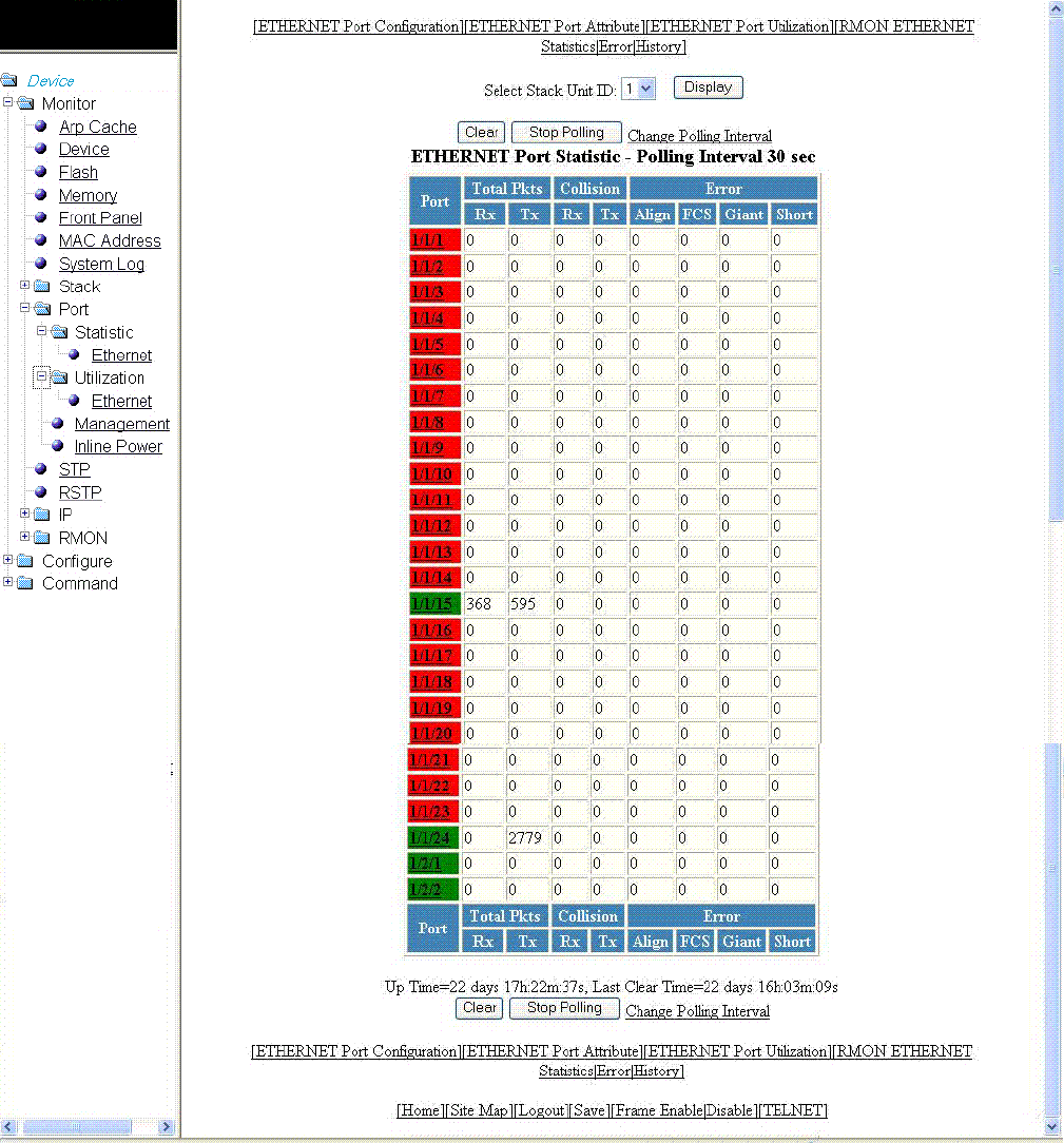
3. For the Brocade FCX and Brocade ICX devices, select a unit ID in the Select Stack Unit ID list and click Display to view
information about a specic stack unit.
NOTE
The Select Stack Unit ID list is not available on the ETHERNET Port Statistic window for the Brocade FastIron SX
devices.
Displaying Ethernet port statistics
Brocade FastIron SX, FCX, and ICX Web Management Interface User Guide, 08.0.30
56 Part Number: 53-1003615-02

TABLE 14 Description of the elds in the ETHERNET Port Statistic window
Field Description
Port Displays the port number for which the statistics were collected.
Total Packets Displays the total number of packets received (Rx) and transmitted
(Tx) on the port.
Collision Shows the number of received (Rx) and transmitted (Tx) collisions on
the port.
Error Displays the number of errors on the port for the following types:
•Alignment --Packets with frame alignment errors.
•FCS --Packets with frame check sequence errors.
•Giant --Packets that were longer than the congured MTU.
•Short -- Packets that were shorter than the minimum valid
length.
To remove the current data and restart the monitoring process, click Clear. To stop the polling process, click Stop Polling. You
can also change the current polling interval by clicking Change Polling Interval.
The ETHERNET Port Statistic window provides links to congure the port parameters:
• To congure an Ethernet port, click ETHERNET Port Conguration. For more information on how to congure an Ethernet
port, refer to the “Conguring an Ethernet port” section.
• To monitor the Ethernet port attributes, click ETHERNET Port Attribute. For more information, refer to the “Displaying
Ethernet port attributes” section.
• To monitor the Ethernet port utilization, click ETHERNET Port Utilization. For more information, refer to the “Displaying
Ethernet port utilization” section.
• To monitor Remote Monitoring (RMON) Ethernet statistics, click RMON ETHERNET Statistics Error. For more
information, refer to the “Displaying RMON Ethernet statistics” section.
• To monitor RMON history, click RMON ETHERNET Statistics History. For more information, refer to the “Displaying
RMON history” section.
Displaying Ethernet port attributes
The Port Attributes window lists the number, state, media, connector, and MAC address of the port. To display the Ethernet port attribute
information, perform the following steps.
1. Click Monitor on the left pane and select Port .
2. Click Statistic and then select Ethernet .
3. Click ETHERNET Port Attribute on the ETHERNET Port Statistic window.
Displaying Ethernet port attributes
Brocade FastIron SX, FCX, and ICX Web Management Interface User Guide, 08.0.30
Part Number: 53-1003615-02 57
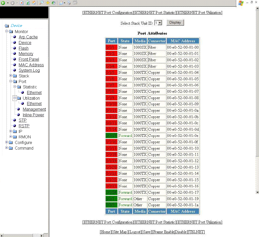
4. For the Brocade FCX and Brocade ICX devices, select a unit ID in the Select Stack Unit ID list and click Display to view
information about a specic stack unit.
NOTE
The Select Stack Unit ID list is not available on the Port Attributes window for the Brocade FastIron SX devices.
The Port Attributes window for the Brocade FCX and Brocade ICX devices is displayed as shown in the gure below.
FIGURE 30 Monitoring Ethernet port attributes
Displaying Ethernet port attributes
Brocade FastIron SX, FCX, and ICX Web Management Interface User Guide, 08.0.30
58 Part Number: 53-1003615-02

TABLE 15 Description of the elds in the Port Attributes window
Field Description
Port Displays the port number.
State Displays the status of the port.
Media Displays the type of the Ethernet cable used.
Connector Displays the physical type of connector.
MAC Address Displays the Media Access Control (MAC) address of the port.
The Port Attributes window provides links to congure the port parameters:
• To congure an Ethernet port, click ETHERNET Port Conguration . For more information on how to congure an
Ethernet port, refer to Conguring an Ethernet port on page 165.
• To monitor the Ethernet port statistics, click ETHERNET Port Statistic . For more information, refer to Displaying Ethernet
port statistics on page 55.
• To monitor the Ethernet port utilization, click ETHERNET Port Utilization . For more information, refer to Displaying
Ethernet port utilization on page 59.
Displaying Ethernet port utilization
The ETHERNET Port Utilization window lists the trac that is received and transmitted on a port. To display the Ethernet port utilization
information, perform the following steps.
1. Click Monitor on the left pane and select Port.
2. Click Utilization and then select Ethernet.
The ETHERNET Port Utilization window for the Brocade FCX and Brocade ICX devices is displayed as shown in the gure
below.
Displaying Ethernet port utilization
Brocade FastIron SX, FCX, and ICX Web Management Interface User Guide, 08.0.30
Part Number: 53-1003615-02 59
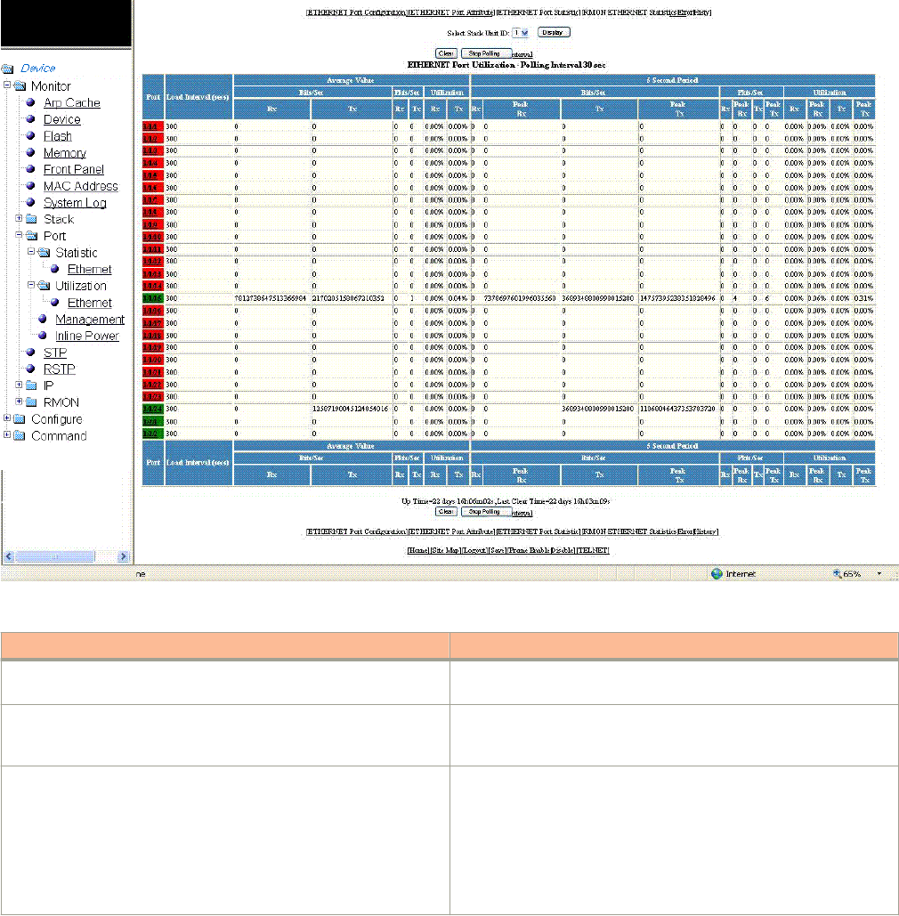
3. For the Brocade FCX and Brocade ICX devices, select a unit ID in the Select Stack Unit ID list and click Display to view
information about a specic stack unit.
NOTE
The Select Stack Unit ID list is not available on the ETHERNET Port Utilization window for the Brocade FastIron SX
devices.
FIGURE 31 Ethernet port utilization
TABLE 16 Description of the elds in the ETHERNET Port Utilization window
Field Description
Port Displays the port number. Each entry has a link to detailed
information about the port.
Load Interval (secs) Displays the number of seconds for which average port utilization
should be calculated. This object can have a value from 30 through
300, in 30-second increments. The default value is 300 seconds.
Average Value Displays the following information:
•Bits/Sec --The average number of bits per second received and
transmitted on the port.
•Pkts/Sec --The average number of packets per second
received and transmitted on the port.
•Utilization -- The average percent utilization received and
transmitted on the port.
Displaying Ethernet port utilization
Brocade FastIron SX, FCX, and ICX Web Management Interface User Guide, 08.0.30
60 Part Number: 53-1003615-02

TABLE 16 Description of the elds in the ETHERNET Port Utilization window (continued)
Field Description
5 Second Period This set of columns show the number of bits per second (Bits/Sec),
number of packets per second (Pkts/Sec), and utilization
percentages (Utilization) received and transmitted on a port at each
5-second interval. Peak activities for each category are also provided.
To remove the current data and restart the monitoring process, click Clear . To stop the statistics polling process, click Stop
Polling. You can also change the current polling interval by clicking Change Polling Interval .
The ETHERNET Port Utilization window provides links to congure the port parameters:
• To congure an Ethernet port, click ETHERNET Port Conguration. For more information on how to congure an Ethernet
port, refer to Conguring an Ethernet port on page 165.
• To monitor the Ethernet port attributes, click ETHERNET Port Attribute. For more information, refer to the “Displaying
Ethernet port attributes” section.
• To monitor the Ethernet port statistics, click ETHERNET Port Statistic. For more information, refer to the “Displaying
Ethernet port statistics” section.
• To monitor Remote Monitoring (RMON) statistics, click RMON ETHERNET Statistics Error. For more information, refer to
the “Displaying RMON Ethernet statistics” section.
• To monitor RMON history, click RMON ETHERNET Statistics History . For more information, refer to the “Displaying
RMON history” section.
Displaying the management port information
To display the current management port conguration information, perform the following steps.
1. Click Monitor on the left pane and select Port.
Displaying the management port information
Brocade FastIron SX, FCX, and ICX Web Management Interface User Guide, 08.0.30
Part Number: 53-1003615-02 61
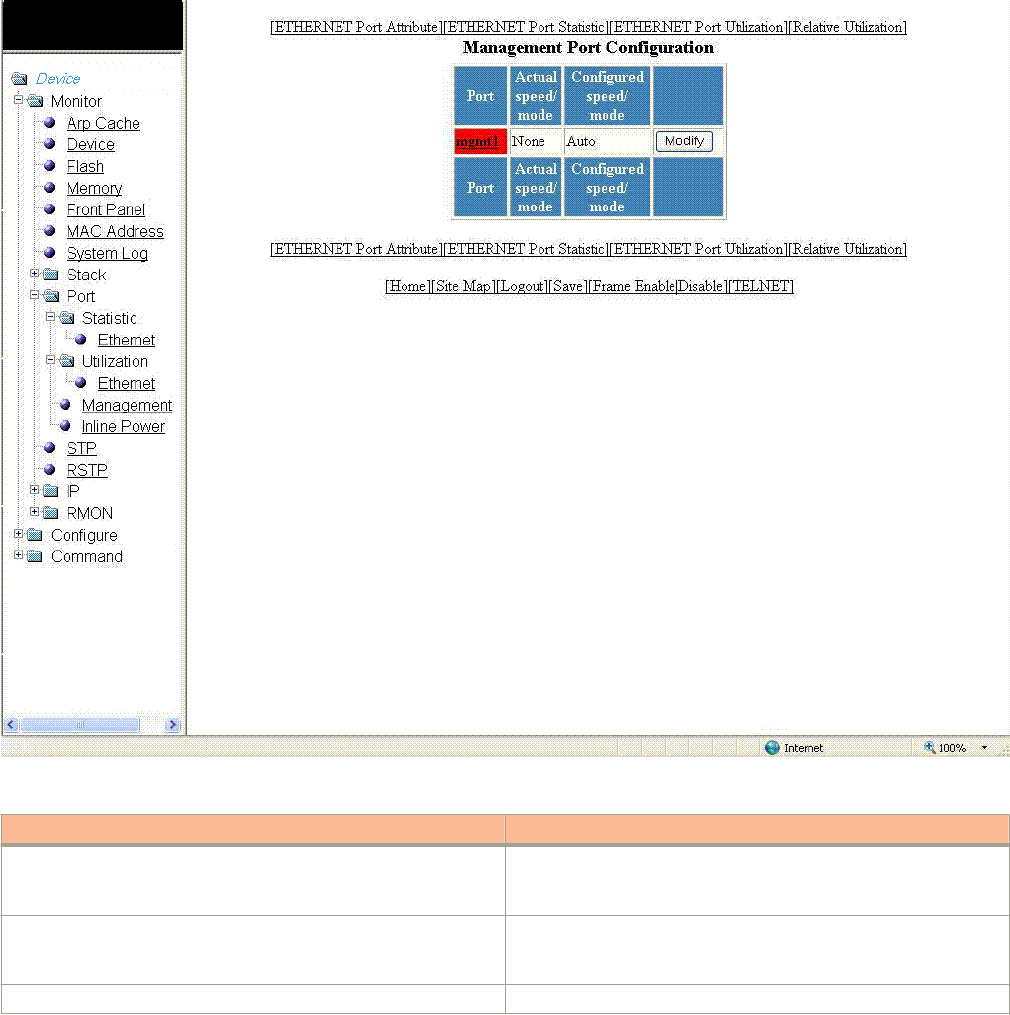
2. Click Management.
The Management Port Conguration window is displayed as shown in the gure below.
FIGURE 32 Management port conguration
TABLE 17 Description of the elds in the Management Port Conguration window
Field Description
Port Displays the name of the management port. Each entry has a link to
detailed real-time information about the port. Refer to the “Displaying
the management port real-time information” section.
Actual speed/mode Shows whether the actual speed matches the congured speed. If
the congured speed is set to Auto, then the speed is set by the
software.
Congured speed/mode The speed duplex set for the port.
To congure a management port or change the conguration of a current management port, click Modify. For more
information, refer to the “Conguring a management port” section.
The Management Port Conguration window provides links to congure the port parameters:
Displaying the management port information
Brocade FastIron SX, FCX, and ICX Web Management Interface User Guide, 08.0.30
62 Part Number: 53-1003615-02
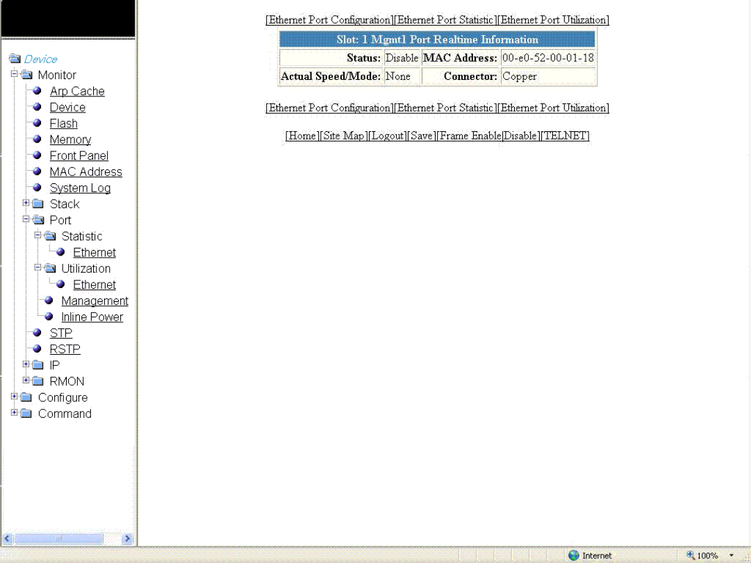
• To monitor the Ethernet port attributes, click ETHERNET Port Attribute. For more information, refer to the “Displaying
Ethernet port attributes” section.
• To monitor the Ethernet port statistics, click ETHERNET Port Statistic. For more information, refer to the “Displaying
Ethernet port statistics” section.
• To monitor the Ethernet port utilization, click ETHERNET Port Utilization. For more information, refer to the “Displaying
Ethernet port utilization” section.
• To congure the port uplink utilization list, click Relative Utilization. For more information, refer to the “Conguring the port
uplink relative utilization” section.
Displaying the management port real-time information
To display the real-time information of a port, click on the management port (for example, mgmt1).
The Port Realtime Information window is displayed as shown in the gure below.
FIGURE 33 Monitoring management port real-time information
Displaying the management port information
Brocade FastIron SX, FCX, and ICX Web Management Interface User Guide, 08.0.30
Part Number: 53-1003615-02 63

TABLE 18 Description of the elds in the Port Realtime Information window
Field Description
Status Displays the status of the port.
MAC Address Displays the MAC address of the port.
Actual Speed/Mode Shows whether the actual speed matches the congured speed. If the
congured speed is set to Auto, then the speed is set by the software.
Connector Displays the physical type of connector.
The Port Realtime Information window provides links to congure the port parameters:
• To congure an Ethernet port, click ETHERNET Port Conguration. For more information on how to congure an Ethernet
port, refer to the “Conguring an Ethernet port” section.
• To monitor the Ethernet port statistics, click ETHERNET Port Statistic. For more information, refer to the “Displaying Ethernet
port statistics” section.
• To monitor the Ethernet port utilization, click ETHERNET Port Utilization. For more information, refer to the “Displaying
Ethernet port utilization” section .
Displaying port inline power for the Brocade FCX and
Brocade ICX devices
The port inline power statistics allow you to monitor Power over Ethernet (PoE), the ability to transfer electrical power and data to remote
devices over standard twisted-pair cable in an Ethernet network. To display the inline power statistics for a PoE stack device, perform the
following steps.
1. Click Monitor on the left pane and select Port.
2. Click Inline Power.
The port inline power window is displayed.
Displaying port inline power for the Brocade FCX and Brocade ICX devices
Brocade FastIron SX, FCX, and ICX Web Management Interface User Guide, 08.0.30
64 Part Number: 53-1003615-02
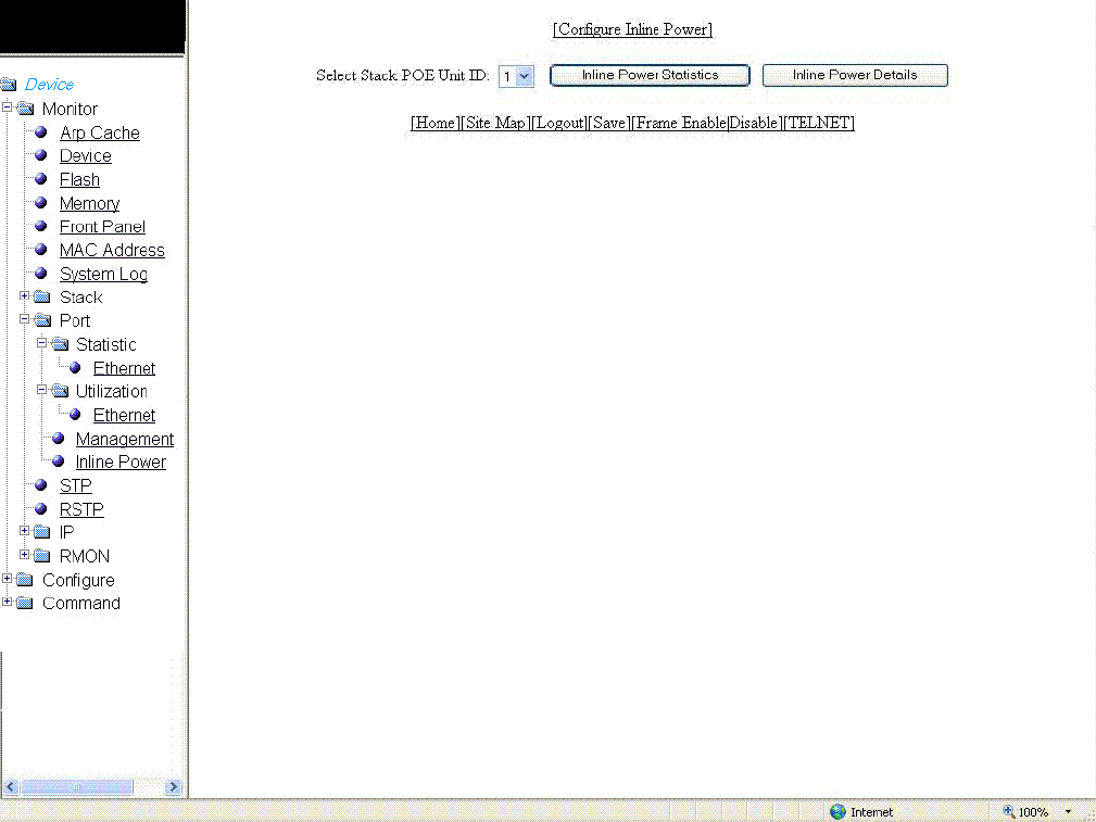
3. Select a unit ID in the Select Stack POE Unit ID list and click either Inline Power Statistics or Inline Power Details.
FIGURE 34 Monitoring inline power
NOTE
Only PoE-capable units are displayed in the Select Stack POE Unit ID list. If there are no PoE units, you will receive
No units with POE modules as an error message.
Displaying inline power statistics
To display the inline power statistics, select the unit ID in the Select Stack POE Unit ID list and click Inline Power Statistics .
The Inline Power Statistics window is displayed as shown in the gure below.
Displaying port inline power for the Brocade FCX and Brocade ICX devices
Brocade FastIron SX, FCX, and ICX Web Management Interface User Guide, 08.0.30
Part Number: 53-1003615-02 65
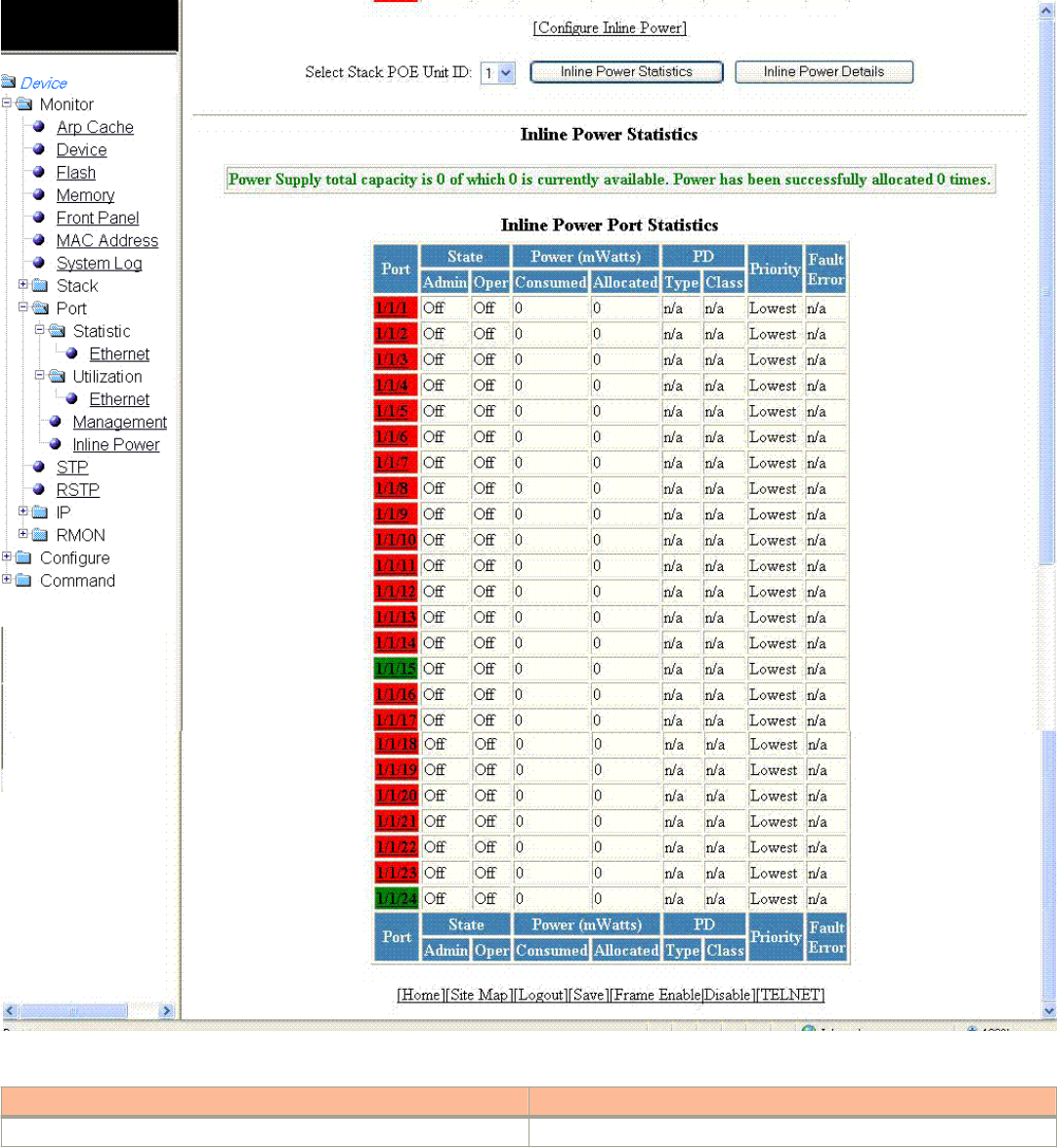
FIGURE 35 Monitoring inline power statistics
TABLE 19 Description of the elds in the Inline Power Statistics window
Field Description
Port Displays the stack port identication of the port as stack#/slot#/port#.
Displaying port inline power for the Brocade FCX and Brocade ICX devices
Brocade FastIron SX, FCX, and ICX Web Management Interface User Guide, 08.0.30
66 Part Number: 53-1003615-02

TABLE 19 Description of the elds in the Inline Power Statistics window (continued)
Field Description
State: Admin Species whether PoE has been enabled on the port, using one of the
following values:
•ON --The inline power command was issued on the port.
•OFF --The inline power command has not been issued on the
port.
State: Oper Displays the status of inline power on the port, using one of the following
values:
•ON --The PoE power supply is delivering inline power to the
powered device.
•OFF --The PoE power supply is not delivering inline power to
the powered device.
•DENIED --The port is in standby mode waiting for power
because currently there is not enough available power for the
port.
Power (mWatts) Consumed Displays the amount of current (milliwatts) the powered device is
consuming.
Power (mWatts) Allocated Displays the amount of current (milliwatts) allocated to the port. This value
is either the default or congured maximum power level, or the power
class that was automatically detected.
PD Type Displays the type of powered device connected to the port. This value can
be one of the following:
•802.3at --The PD connected to this port is 802.3at-compliant.
•802.3af --The PD connected to this port is 802.3af-compliant.
•LEGACY --The powered device connected to this port is a
legacy product (not 802.3af-compliant).
•n/a-- One of the following is true:
– The device connected to this port is a non-powered device.
– No device is connected to this port.
– The port is in standby or denied mode (waiting for power).
PD Class Displays the maximum amount of power received by a powered device.
This value can be one of the following:
•Class1 --Receives 4 watts maximum.
•Class2 --Receives 7 watts maximum.
•Class3 --Receives 15.4 watts maximum.
•Class 4 --Receives 30 watts maximum.
•n/a --The device attached to the port cannot advertise its class.
Priority Displays the inline power priority of the port, which determines the order in
which the port receives power while in standby mode (waiting for power).
Ports with a higher priority receive power before ports with a low priority.
The value of priority can be one of the following:
•1 --Critical priority
•2 --High priority
•3 --Low priority
Fault Error Displays the fault or error that occurred on the port, if applicable.
Otherwise, n/a is displayed. The value can be one of the following:
•critical temperature --The PoE chip temperature limit rose
above the safe operating level, thereby powering down the port.
•detection failed --The port failed capacitor detection (legacy PD
detection) because of a discharged capacitor. This can occur
when connecting a non-PD on the port.
Displaying port inline power for the Brocade FCX and Brocade ICX devices
Brocade FastIron SX, FCX, and ICX Web Management Interface User Guide, 08.0.30
Part Number: 53-1003615-02 67

TABLE 19 Description of the elds in the Inline Power Statistics window (continued)
Field Description
•detection failed --The port failed capacitor detection (legacy PD
detection) because of an out-of-range capacitor value. This can
occur when connecting a non-PD on the port.
•internal h/w fault --A hardware problem has hindered port
operation.
•lack of power --The port has shut down due to lack of power.
•main supply voltage high --The voltage was higher than the
maximum voltage limit, thereby tripping the port.
•main supply voltage low --The voltage was lower than the
minimum voltage limit, thereby tripping the port.
•overload state --The PD consumed more power than the
maximum limit congured on the port, based on the default
conguration, user conguration, or CDP conguration.
•over temperature --The port temperature rose above the
temperature limit, thereby powering down the port.
•PD DC fault --A succession of underload and overload states,
or a PDDC/DC fault, caused the port to shutdown.
•short circuit --A short circuit was detected on the port delivering
power.
•underload state --The PD consumes less power than the
minimum limit specied in the 802.3af standard.
•voltage applied from ext src --The port failed capacitor
detection (legacy PD detection) because the voltage applied to
the port was from an external source.
Displaying inline power details
To display the inline power details, select the unit ID in the Select Stack POE Unit ID list and click Inline Power Details .
The Inline Power Details window is displayed as shown in the gure below.
Displaying port inline power for the Brocade FCX and Brocade ICX devices
Brocade FastIron SX, FCX, and ICX Web Management Interface User Guide, 08.0.30
68 Part Number: 53-1003615-02
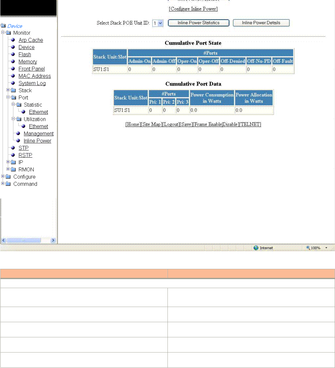
FIGURE 36 Monitoring inline power details
TABLE 20 Description of the elds in the Inline Power Details window
Field Description
Cumulative Port State parameters
Stack Unit: Slot Displays the stack ID and slot ID (1 or 2).
The PoE-capable slots are available on PoE stack units.
# Ports Admin-On Displays the number of ports on the interface module on which the inline
power was congured.
# Ports Admin-O Displays the number of ports on the interface module on which the inline
power was not congured.
# Port Oper-On Displays the number of ports on the interface module that are receiving
inline power from the PoE power supply.
# Port Oper-O Displays the number of ports on the interface module that are not
receiving inline power from the PoE power supply.
Displaying port inline power for the Brocade FCX and Brocade ICX devices
Brocade FastIron SX, FCX, and ICX Web Management Interface User Guide, 08.0.30
Part Number: 53-1003615-02 69

TABLE 20 Description of the elds in the Inline Power Details window (continued)
Field Description
# Ports O-Denied Displays the number of ports on the interface module that were denied
power because of insucient power.
# Ports O No-PD Displays the number of ports on the interface module to which no
powered devices (PDs) are connected.
# Ports O-Fault Displays the number of ports on the interface module that are not
receiving power because of a subscription overload.
Cumulative Port Data parameters
Stack Unit: Slot Displays the stack ID and slot ID (1 or 2).
The PoE-capable slots are available on PoE stack units.
# Ports Displays the total number of available ports in each level of priority.
Power Consumption in Watts Displays the total number of watts consumed by both PoE power-
consuming devices and the PoE module (daughter card) attached to the
interface module.
Power Allocation in Watts Displays the number of watts allocated to the interface module PoE ports.
This value is the sum of port default or congured maximum power levels,
or power classes automatically detected by the PoE device.
Displaying port inline power for the Brocade FastIron
SX devices
To display the inline power statistics for a Brocade FastIron SX device, perform the following steps.
1. Click Monitor on the left pane and select Port.
Displaying port inline power for the Brocade FastIron SX devices
Brocade FastIron SX, FCX, and ICX Web Management Interface User Guide, 08.0.30
70 Part Number: 53-1003615-02
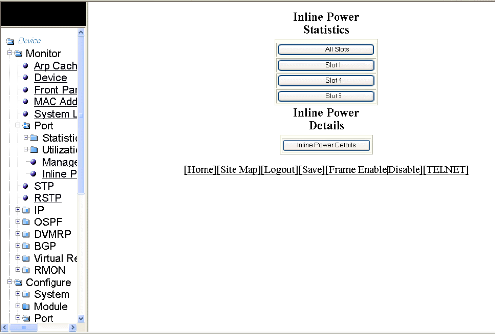
2. Click Inline Power.
The port inline power window is displayed.
FIGURE 37 Monitoring inline power
3. Click All Slots to display the inline power statistics of all the slots.
4. Click Slot 1, Slot 4, or Slot 5 to display the inline power statistics for the individual slot.
5. Click Inline Power Details to display detailed operational information about the PoE power supplies.
Displaying port inline power for the Brocade FastIron SX devices
Brocade FastIron SX, FCX, and ICX Web Management Interface User Guide, 08.0.30
Part Number: 53-1003615-02 71
Brocade FastIron SX, FCX, and ICX Web Management Interface User Guide, 08.0.30
72 Part Number: 53-1003615-02

Monitoring STP
• Displaying STP information.......................................................................................................................................................................... 73
Displaying STP information
Brocade Layer 2 switches and Layer 3 switches support standard Spanning Tree Protocol (STP) as described in the IEEE 802.1D
specication. By default, STP is enabled on Layer 2 switches and disabled on Layer 3 switches. To display the STP information, perform
the following steps.
1. Click Monitor on the left pane and select STP .
By default, STP is disabled on Layer 3 switches and therefore the message STP is disabled. Go to system to
enable STP is displayed.
Brocade FastIron SX, FCX, and ICX Web Management Interface User Guide, 08.0.30
Part Number: 53-1003615-02 73
2. For the Brocade FCX and Brocade ICX devices, select a unit ID in the Select Stack Unit ID list and click Display to view
information about a specic stack unit.
NOTE
The Select Stack Unit ID list is not available in the STP window for the Brocade FastIron SX devices.
The STP window for the Brocade FCX and Brocade ICX devices is displayed as shown in the gure below.
Displaying STP information
Brocade FastIron SX, FCX, and ICX Web Management Interface User Guide, 08.0.30
74 Part Number: 53-1003615-02
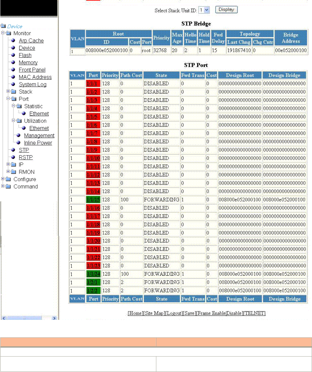
FIGURE 38 Monitoring the STP bridge and port
TABLE 21 Description of the elds in the STP window
Field Description
STP Bridge parameters (global parameters)
VLAN Displays the port-based virtual local area network (VLAN) that
contains this spanning tree (instance of STP). VLAN 1 is the default
Displaying STP information
Brocade FastIron SX, FCX, and ICX Web Management Interface User Guide, 08.0.30
Part Number: 53-1003615-02 75

TABLE 21 Description of the elds in the STP window (continued)
Field Description
VLAN. If you have not congured port-based VLANs on this device,
all STP information is for VLAN 1.
Root ID Displays the ID assigned by STP to the root bridge for this spanning
tree.
Root Cost Displays the cumulative cost from this bridge to the root bridge. If
this device is the root bridge, then the root cost is 0.
Root Port Displays the port on this device that connects to the root bridge. If
this device is the root bridge, then the value is root instead of a port
number.
Priority Displays the STP priority of this device or VLAN. The value is shown
in hexadecimal format.
Max Age Displays the number of seconds this device or VLAN waits for a
Hello message from the root bridge before deciding that the root has
become unavailable and performing a reconvergence.
Hello Time Displays the interval between each conguration Bridge Packet Data
Unit (BPDU) sent by the root bridge.
Hold Time Displays the minimum number of seconds that must elapse between
transmissions of consecutive conguration BPDUs on a port.
Fwd Delay Displays the number of seconds this device or VLAN waits following
a topology change and consequent reconvergence.
Topology Last Chng Displays the number of seconds since the last time a topology
change occurred.
Topology Chg Cntr Displays the number of times the topology has changed since the
device was reloaded.
Bridge Address Displays the STP address of this device or VLAN.
STP Port parameters
VLAN Displays the VLAN that the port is in. This eld displays only when
port VLAN is enabled.
Port Displays the port number. The port number varies based on the
product:
• For Brocade FCX and Brocade ICX devices - stack-unit/
slotnum/portnum
• For Brocade FastIron SX devices - slotnum/portnum
Priority Displays the STP priority of the port in hexadecimal format.
Path Cost Displays the STP path cost of the port.
State Displays the STP state of the port. The state can be one of the
following:
•BLOCKING --STP has blocked Layer 2 trac on this port to
prevent a loop. The device or VLAN can reach the root bridge
using another port, whose state is FORWARDING. When a port
is in the BLOCKING state, the port does not transmit or receive
user frames, but the port does continue to receive STP BPDUs.
•DISABLED --The port is not participating in STP. This can
occur when the port is disconnected or STP is disabled on the
port.
•FORWARDING --STP is allowing the port to send and receive
frames.
•LISTENING --STP is responding to a topology change and this
port is listening for a BPDU from neighboring bridges in order
Displaying STP information
Brocade FastIron SX, FCX, and ICX Web Management Interface User Guide, 08.0.30
76 Part Number: 53-1003615-02

TABLE 21 Description of the elds in the STP window (continued)
Field Description
to determine the new topology. No frames are transmitted or
received during this state.
•LEARNING --The port has passed through the LISTENING
state and will change to the BLOCKING or FORWARDING
state depending on the results of STP’s reconvergence. The
port does not transmit or receive frames during this state.
However, the device can learn the MAC addresses of frames
that the port receives during this state and make corresponding
entries in the MAC table.
Fwd Trans Displays the number of times STP has changed the state of this port
between BLOCKING and FORWARDING.
Cost Displays the cost to the root bridge as advertised by the designated
bridge that is connected to this port. If the designated bridge is the
root bridge itself, then the cost is 0.
Design Root Displays the root bridge as recognized on this port. The value is the
same as the root bridge ID listed in the Root ID eld.
Design Bridge Displays the designated bridge to which this port is connected. The
designated bridge is the device that connects the network segment
on the port to the root bridge.
Displaying STP information
Brocade FastIron SX, FCX, and ICX Web Management Interface User Guide, 08.0.30
Part Number: 53-1003615-02 77
Brocade FastIron SX, FCX, and ICX Web Management Interface User Guide, 08.0.30
78 Part Number: 53-1003615-02
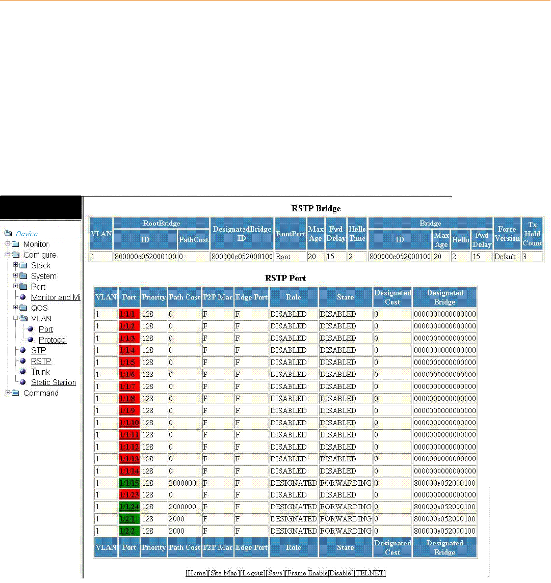
Monitoring RSTP
• Displaying RSTP information....................................................................................................................................................................... 79
Displaying RSTP information
To view current Rapid Spanning Tree Protocol (RSTP) information for a device, you must congure RSTP. For more information on how
to congure RSTP, refer to Monitoring RSTP on page 79. By default, RSTP is enabled on Layer 2 switches and disabled on Layer 3
switches.
To display RSTP bridge and port information, click Monitor on the left pane and select RSTP .
The RSTP window is displayed as shown in the gure below.
FIGURE 39 Monitoring the RSTP bridge and port
Brocade FastIron SX, FCX, and ICX Web Management Interface User Guide, 08.0.30
Part Number: 53-1003615-02 79

TABLE 22 Description of the elds in the RSTP window
Field Description
RSTP Bridge parameters
VLAN Displays the port-based VLAN that owns the STP instance. VLAN 1 is the
default VLAN. If you have not congured port-based VLANs on this
device, all RSTP information is for VLAN 1.
RootBridge ID Displays the ID of the root bridge that is associated with this bridge.
RootBridge PathCost Displays the cumulative cost from this bridge to the root bridge. If this
device is the root bridge, then the root cost is 0.
DesignateBridge ID Displays the bridge from where the root information was received. It can
be from the root bridge itself or from another bridge.
RootPort Displays the port on this device that connects to the root bridge. If this
device is the root bridge, then the value is root instead of a port number.
Max.Age Displays the number of seconds this device or VLAN waits for a Hello
message from the root bridge before deciding the root has become
unavailable and performing a reconvergence.
Fwd Delay Displays the number of seconds a non-edge designated port waits until it
can apply any of the following transitions, if the received RST BPDU does
not have an agreed ag:
• Discarding state to learning state
• Learning state to forwarding state
When a non-edge port receives the RST BPDU, it goes into forwarding
state within 4 seconds or after two hello timers expire on the port.
Forward delay is also the number of seconds that a root port waits for an
RST BPDU with a proposal ag before it applies the state transitions listed
above.
If the port is operating in 802.1D-compatible mode, then forward delay
functionality is the same as in 802.1D (STP).
Hello Time Displays the duration (secs) between two Hello packets.
Bridge ID Displays the ID of the bridge.
Bridge Max Age Displays the congured maximum age for this bridge. The default is 20.
Bridge Hello Displays the congured hello time for this bridge.The default is 2.
Bridge Fwd Delay Displays the congured forward delay time for this bridge. The default is
15.
Force Version Displays the congured force version value, which can be one of the
following:
•0 --The bridge has been forced to operate in an STP
compatibility mode.
•2 --The bridge has been forced to operate in an RSTP mode.
This is the default.
Tx Hold Count Displays the number of BPDUs that can be transmitted per Hello interval.
The
default is 3.
RSTP Port parameters
VLAN Displays the port-based VLAN that owns the STP instance. VLAN 1 is the
default
VLAN. If you have not congured port-based VLANs on this device, all
RSTP information is for VLAN 1.
Displaying RSTP information
Brocade FastIron SX, FCX, and ICX Web Management Interface User Guide, 08.0.30
80 Part Number: 53-1003615-02

TABLE 22 Description of the elds in the RSTP window (continued)
Field Description
Port Displays the port number. The port number varies based on the product:
• For Brocade FCX and Brocade ICX devices - stack-unit/
slotnum/portnum
• For Brocade FastIron SX devices - slotnum/portnum
Priority Displays the congured priority of the port. The default is 128 or 0x80.
Path Cost Displays the congured path cost on a link connected to this port.
P2P Mac Displays whether the point-to-point-MAC parameter is congured to be a
point-to-point link:
•T -- The link is congured as a point-to-point link.
•F --The link is not congured as a point-to-point link. This is the
default.
Edge Port Displays whether the port is congured as an operational edge port:
•T --The port is congured as an edge port.
•F --The port is not congured as an edge port. This is the
default.
Role Displays the current role of the port, which can be one of the following:
•ROOT --Provides the lowest cost path to the root bridge from a
specic bridge.
•DESIGNATED --Provides the lowest cost path to the root
bridge from a LAN to which it is connected.
•ALTERNATE --Provides an alternate path to the root bridge
when the root port goes down.
•BACKUP --Provides a backup to the LAN when the Designated
port goes down.
•DISABLED --Has no role in the topology.
For more information, refer to "Bridges and bridge port roles" of the
appropriate FastIron Ethernet Switch Platform and Layer 2 Switching
Conguration Guide.
State Displays the RSTP state of the port, which can be one of the following:
•DISCARDING -- RSTP has blocked data trac on this port to
prevent a loop. The device or VLAN can reach the root bridge
using another port, whose state is FORWARDING. When a port
is in this state, the port does not transmit or receive user frames,
but the port does continue to receive STP BPDUs. This state
corresponds to the listening and blocking states of 802.1D.
•DISABLED -- The port is not participating in RSTP. This can
occur when the port is disconnected or STP is disabled on the
port.
•FORWARDING --RSTP is allowing the port to send and receive
frames.
•LEARNING --RSTP is allowing MAC entries to be added to the
ltering database but does not permit forwarding of data frames.
The device can learn the MAC addresses of frames that the port
receives during this state and make corresponding entries in the
MAC table.
Designated Cost Displays the best root path cost that this port received, including the best
root path cost that it can transmit.
Designated Bridge Displays the ID of the bridge that sent the best RST BPDU that was
received on
this port.
Displaying RSTP information
Brocade FastIron SX, FCX, and ICX Web Management Interface User Guide, 08.0.30
Part Number: 53-1003615-02 81
Brocade FastIron SX, FCX, and ICX Web Management Interface User Guide, 08.0.30
82 Part Number: 53-1003615-02

Monitoring IP
• Displaying IP cache...........................................................................................................................................................................................83
• Displaying IP trac information for devices running Layer 2 code..............................................................................................85
• Displaying IP trac information for devices running Layer 3 code..............................................................................................89
Displaying IP cache
NOTE
The IP cache is specic to the Brocade FCX-ADV, Brocade ICX, and Brocade FastIron SX devices running Layer 3 code.
To display the IP forwarding cache information, perform the following steps.
1. Click Monitor on the left pane and select IP .
Brocade FastIron SX, FCX, and ICX Web Management Interface User Guide, 08.0.30
Part Number: 53-1003615-02 83
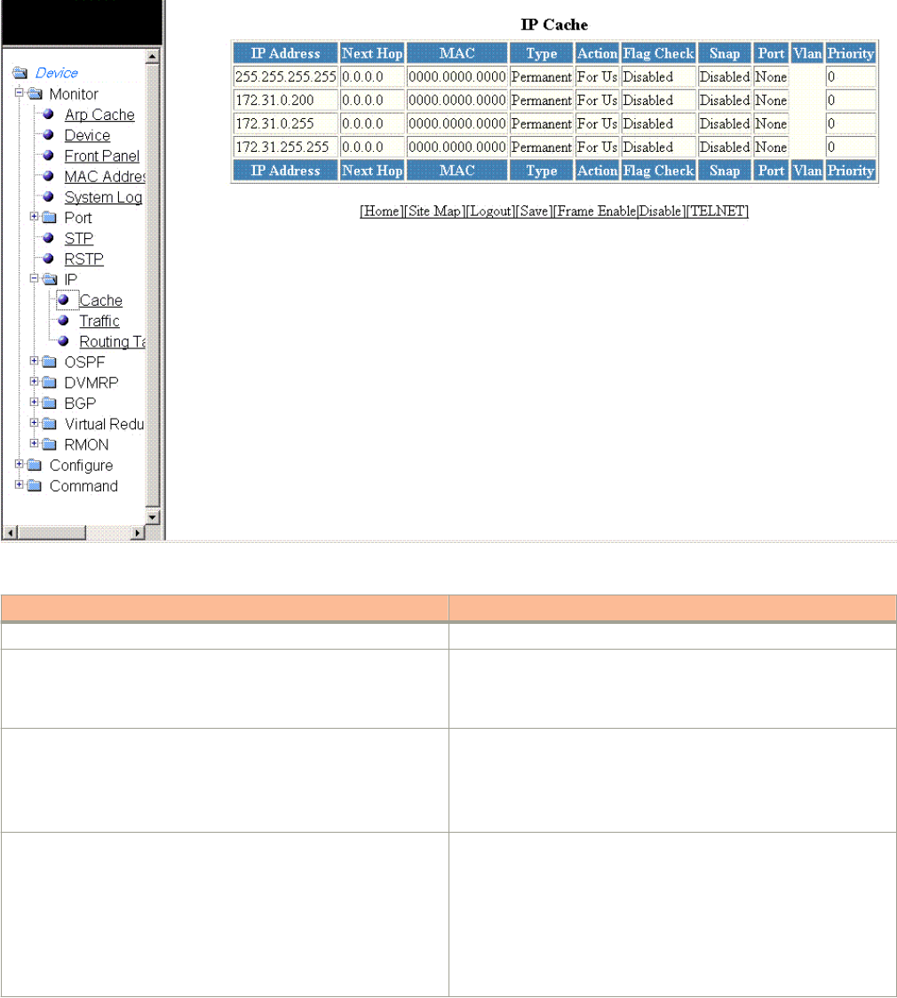
2. Click Cache .
The IP Cache window is displayed as shown in the gure below.
FIGURE 40 Monitoring the IP cache
TABLE 23 Description of the elds in the IP Cache window
Field Description
IP Address Displays the IP address of the destination.
Next Hop Displays the IP address of the next hop router to the destination. This
eld contains either an IP address or the value DIRECT. DIRECT
means the destination is either directly attached or the destination is
an address on this Brocade device.
MAC Displays the MAC address of the destination.
NOTE
If the entry is type Us (indicating that the destination is
this Brocade device), the address consists of zeroes.
Type Displays the type of host entry, which can be one of the following:
•Dynamic
•Permanent
•Forward
•Us
•Complex Filter
•Wait ARP
Displaying IP cache
Brocade FastIron SX, FCX, and ICX Web Management Interface User Guide, 08.0.30
84 Part Number: 53-1003615-02

TABLE 23 Description of the elds in the IP Cache window (continued)
Field Description
•ICMP Deny
•Drop
•Fragment
•Snap Encap
Action Displays the action the router takes for the packet.
Flag Check Displays whether the ag check has been enabled or disabled.
Snap Displays whether the snap encapsulation has been enabled or
disabled.
Port Displays the port through which this device reaches the destination.
For destinations that are located on this device, the port number is
shown as "n/a".
Vlan Displays the VLAN the port is in.
Priority Displays the Quality of Service (QoS) priority of the port or the VLAN.
Displaying IP trac information for devices running
Layer 2 code
To display the IP trac statistics for the Brocade FCX, Brocade ICX, and Brocade FastIron SX devices running Layer 2 code, perform the
following steps.
1. Click Monitor on the left pane and select IP.
Displaying IP trac information for devices running Layer 2 code
Brocade FastIron SX, FCX, and ICX Web Management Interface User Guide, 08.0.30
Part Number: 53-1003615-02 85
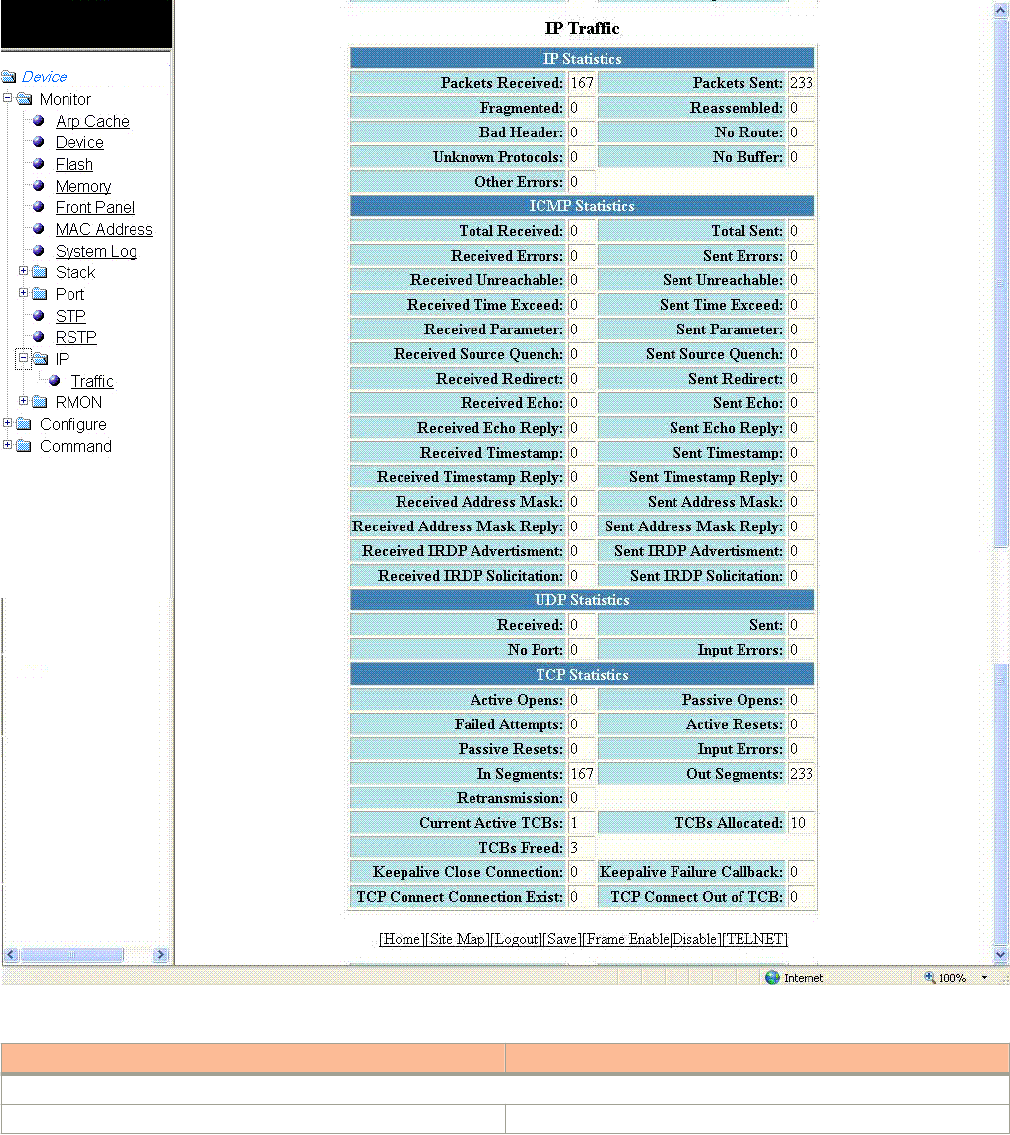
2. Click Trac.
The IP Trac window is displayed as shown in the gure below.
FIGURE 41 Monitoring the IP trac for devices running Layer 2 code
TABLE 24 Description of the elds in the IP Trac window
Field Description
IP Statistics parameters
Packets Received Displays the number of IP packets received by the device.
Displaying IP trac information for devices running Layer 2 code
Brocade FastIron SX, FCX, and ICX Web Management Interface User Guide, 08.0.30
86 Part Number: 53-1003615-02

TABLE 24 Description of the elds in the IP Trac window (continued)
Field Description
Packets Sent Displays the number of IP packets originated and sent by the device.
Fragmented Displays the number of IP packets fragmented by this device before
sending or forwarding them.
Reassembled Displays the number of fragmented IP packets received and re-
assembled by the device.
Bad Header Displays the number of IP packets dropped because they had a bad
header.
No Route Displays the number of packets dropped by the device because they
had no route information.
Unknown Protocols Displays the number of packets dropped by the device because the
value in the protocol eld of the packet header is unrecognized by
this device.
No Buer Displays the number of packets dropped because the device ran out
of buer space.
Other Errors Displays the number of packets dropped due to errors other than the
ones already indicated in the IP Statistics parameters.
ICMP Statistics parameters
Total Received Displays the number of Internet Control Message Protocol (ICMP)
packets received by the device.
Total Sent Displays the number of ICMP packets sent by the device.
Received Errors Displays the number of errors received by the device. This
information is used by Brocade customer support.
Sent Errors Displays the number of errors sent by the device. This information is
used by Brocade customer support.
Received Unreachable Displays the number of Destination Unreachable messages received
by the device.
Sent Unreachable Displays the number of Destination Unreachable messages sent by
the device.
Received Time Exceed Displays the number of Time Exceeded messages received by the
device.
Sent Time Exceed Displays the number of Time Exceeded messages sent by the
device.
Received Parameter Displays the number of Parameter Problem messages received by
the device.
Sent Parameter Displays the number of Parameter Problem messages sent by the
device.
Received Source Quench Displays the number of Source Quench messages received by the
device.
Sent Source Quench Displays the number of Source Quench messages sent by the
device.
Received Redirect Displays the number of Redirect messages received by the device.
Sent Redirect Displays the number of Redirect messages sent by the device.
Received Echo Displays the number of Echo messages received by the device.
Sent Echo Displays the number of Echo messages sent by the device.
Received Echo Reply Displays the number of Echo Reply messages received by the
device.
Sent Echo Reply Displays the number of Echo Reply messages sent by the device.
Displaying IP trac information for devices running Layer 2 code
Brocade FastIron SX, FCX, and ICX Web Management Interface User Guide, 08.0.30
Part Number: 53-1003615-02 87

TABLE 24 Description of the elds in the IP Trac window (continued)
Field Description
Received Timestamp Displays the number of Timestamp messages received by the
device.
Sent Timestamp Displays the number of Timestamp messages sent by the device.
Received Timestamp Reply Displays the number of Timestamp Reply messages received by the
device.
Sent Timestamp Reply Displays the number of Timestamp Reply messages sent by the
device.
Received Address Mask Displays the number of Address Mask Request messages received
by the device.
Sent Address Mask Displays the number of Address Mask Request messages sent by
the device.
Received Address Mask Reply Displays the number of Address Mask Reply messages received by
the device.
Sent Address Mask Reply Displays the number of Address Mask Reply messages sent by the
device.
Received IRDP Advertisement Displays the number of ICMP Router Discovery Protocol (IRDP)
Advertisement messages received by the device.
Sent IRDP Advertisement Displays the number of IRDP Advertisement messages sent by the
device.
Received IRDP Solicitation Displays the number of IRDP Solicitation messages received by the
device.
Sent IRDP Solicitation Displays the number of IRDP Solicitation messages sent by the
device.
UDP Statistics parameters
Received Displays the number of User Datagram Protocol (UDP) packets
received by the device.
Sent Displays the number of UDP packets sent by the device.
No Port Displays the number of UDP packets dropped because the packet
did not contain a valid UDP port number.
Input Errors Displays the number of errors on the incoming packets. This
information is used by Brocade customer support.
TCP Statistics parameters
Active Opens Displays the number of Transmission Control Protocol (TCP)
connections opened by this device by sending a TCP SYN to another
device.
Passive Opens Displays the number of TCP connections opened by this device in
response to connection requests (TCP SYNs) received from other
devices.
Failed Attempts Displays the number of failed attempts. This information is used by
Brocade customer support.
Active Resets Displays the number of TCP connections this device reset by
sending a TCP RESET message to the device at the other end of the
connection.
Passive Resets Displays the number of TCP connections this device reset because
the device at the other end of the connection sent a TCP RESET
message.
Input Errors Displays the number of incoming errors. This information is used by
Brocade customer support.
In Segments Displays the number of TCP segments received by the device.
Displaying IP trac information for devices running Layer 2 code
Brocade FastIron SX, FCX, and ICX Web Management Interface User Guide, 08.0.30
88 Part Number: 53-1003615-02

TABLE 24 Description of the elds in the IP Trac window (continued)
Field Description
Out Segments Displays the number of TCP segments sent by the device.
Retransmission Displays the number of segments that this device retransmitted
because the retransmission timer for the segment had expired before
the device at the other end of the connection had acknowledged
receipt of the segment.
Current Active TCBs Displays the number of TCP Control Blocks (TCBs) that are currently
active.
TCBs Allocated Displays the number of TCBs that have been allocated.
TCBs Freed Displays the number of TCBs that have been freed.
Displaying IP trac information for devices running
Layer 3 code
To display the IP trac statistics for the Brocade FCX, Brocade ICX, and Brocade FastIron SX devices running Layer 3 code, perform the
following steps.
1. Click Monitor on the left pane and select IP .
Displaying IP trac information for devices running Layer 3 code
Brocade FastIron SX, FCX, and ICX Web Management Interface User Guide, 08.0.30
Part Number: 53-1003615-02 89
2. Click Trac
The IP Trac window is displayed as shown in the gure below.
Displaying IP trac information for devices running Layer 3 code
Brocade FastIron SX, FCX, and ICX Web Management Interface User Guide, 08.0.30
90 Part Number: 53-1003615-02
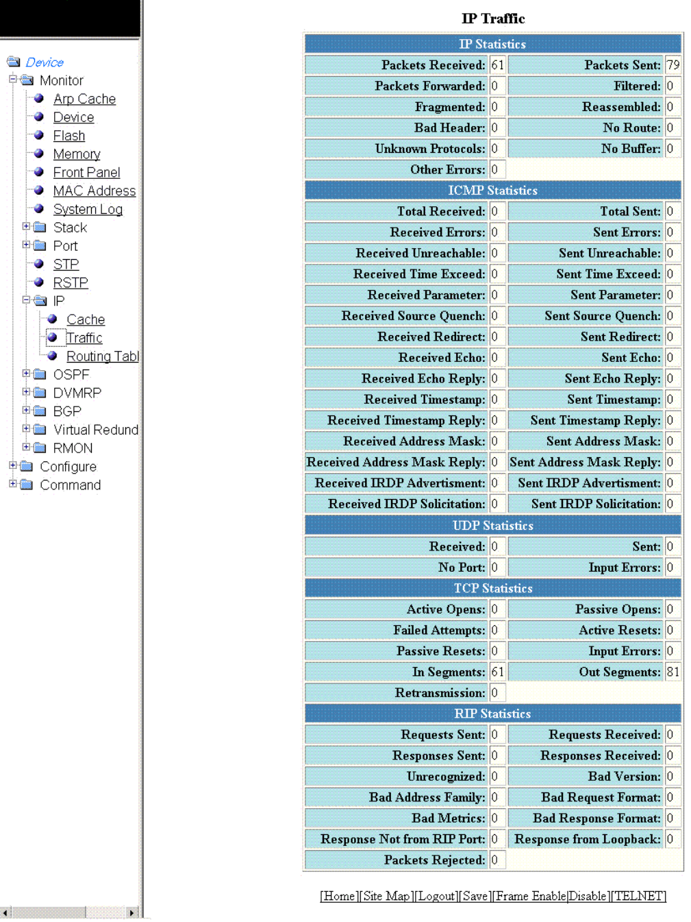
FIGURE 42 Monitoring the IP trac information for devices running Layer 3 code
Displaying IP trac information for devices running Layer 3 code
Brocade FastIron SX, FCX, and ICX Web Management Interface User Guide, 08.0.30
Part Number: 53-1003615-02 91

TABLE 25 Description of the elds in the IP Trac window
Field Description
IP Statistics parameters
Packets Received Displays the number of IP packets received by the device.
Packets Sent Displays the number of IP packets originated and sent by the device.
Packets Forwarded Displays the total number of IP packets received by the device and
forwarded to other devices.
Filtered Displays the total number of IP packets ltered by the device.
Fragmented Displays the number of IP packets fragmented by this device before
sending or forwarding them.
Reassembled Displays the number of fragmented IP packets received and re-
assembled by the device.
Bad Header Displays the number of IP packets dropped because they had a bad
header.
No Route Displays the number of packets dropped by the device because they
had no route information.
Unknown Protocols Displays the number of packets dropped by the device because the
value in the protocol eld of the packet header is unrecognized by
this device.
No Buer Displays the number of packets dropped because the device ran out
of buer space.
Other Errors Displays the number of packets dropped due to errors other than the
ones already indicated in the IP Statistics parameters.
ICMP Statistics Refer to Displaying IP trac information for devices running Layer 2
code on page 85.
UDP Statistics Refer to Displaying IP trac information for devices running Layer 2
code on page 85.
TCP Statistics parameters
Active Opens Displays the number of TCP connections opened by this device by
sending a TCP SYN to another device.
Passive Opens Displays the number of TCP connections opened by this device in
response to connection requests (TCP SYNs) received from other
devices.
Failed Attempts Displays the number of failed attempts. This information is used by
Brocade customer support.
Active Resets Displays the number of TCP connections this device reset by
sending a TCP RESET message to the device at the other end of the
connection.
Passive Resets Displays the number of TCP connections this device reset because
the device at the other end of the connection sent a TCP RESET
message.
Input Errors Displays the number of incoming errors. This information is used by
Brocade customer support.
In Segments Displays the number of TCP segments received by the device.
Out Segments Displays the number of TCP segments sent by the device.
Retransmission Displays the number of segments that this device retransmitted
because the retransmission timer for the segment had expired before
the device at the other end of the connection had acknowledged
receipt of the segment.
RIP Statistics parameters
Displaying IP trac information for devices running Layer 3 code
Brocade FastIron SX, FCX, and ICX Web Management Interface User Guide, 08.0.30
92 Part Number: 53-1003615-02

TABLE 25 Description of the elds in the IP Trac window (continued)
Field Description
Requests Sent Displays the number of requests this device has sent to another
Routing Information Protocol (RIP) Layer 3 switch for all or part of its
RIP routing table.
Requests Received Displays the number of requests this device has received from
another RIP Layer 3 switch for all or part of this device’s RIP routing
table.
Responses Sent Displays the number of responses this device has sent to another
RIP Layer 3 switch’s request for all or part of this device’s RIP routing
table.
Responses Received Displays the number of responses this device has received to
requests for all or part of another RIP Layer 3 switch’s routing table.
Unrecognized Displays the number of RIP packets that were not recognized by the
device.
Bad Version Displays the number of RIP packets dropped by the device because
the RIP version was either invalid or is not supported by this device.
Bad Address Family Displays the number of RIP packets dropped because the value in
the Address Family Identier eld of the packet’s header was invalid.
Bad Request Format Displays the number of RIP request packets this Layer 3 switch
dropped because the format was bad.
Bad Metrics Displays the number of responses to RIP request packets this Layer
3 switch dropped because of the bad metric value. This information
is used by Brocade customer support.
Bad Response Format Displays the number of responses to RIP request packets this Layer
3 switch dropped because the format was bad.
Response Not from RIP Port Displays the number of RIP responses received from non-RIP ports.
This information is used by Brocade customer support.
Response from Loopback Displays the number of RIP responses received from loopback
interfaces.
Packets Rejected Displays the number of RIP packets rejected by the device.
Displaying IP trac information for devices running Layer 3 code
Brocade FastIron SX, FCX, and ICX Web Management Interface User Guide, 08.0.30
Part Number: 53-1003615-02 93
Brocade FastIron SX, FCX, and ICX Web Management Interface User Guide, 08.0.30
94 Part Number: 53-1003615-02

Monitoring RMON
• Displaying RMON history..............................................................................................................................................................................95
• Displaying RMON Ethernet statistics........................................................................................................................................................98
• Changing polling interval............................................................................................................................................................................. 103
• Displaying RMON Ethernet error statistics..........................................................................................................................................103
Displaying RMON history
By default, all active ports generate two history control data entries per active port. An active port is dened as one with a link up. If the
link goes down, the two history entries are automatically cleared.
The following history entries are generated for each device:
• A sampling of statistics every 30 seconds
• A sampling of statistics every 30 minutes
To display Remote Monitoring (RMON) history, perform the following steps.
1. Click Monitor on the left pane and select RMON .
Brocade FastIron SX, FCX, and ICX Web Management Interface User Guide, 08.0.30
Part Number: 53-1003615-02 95
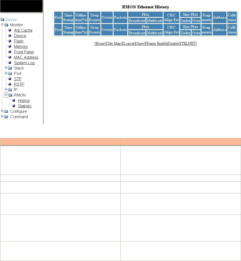
2. Click History .
The RMON Ethernet History window is displayed as shown in the gure below.
FIGURE 43 Monitoring the RMON Ethernet history
TABLE 26 Description of the elds in the RMON Ethernet History window
Field Description
Port Displays the port for which the history data is being presented. The
port number varies based on the product:
• For Brocade FCX and Brocade ICX devices - stack-unit/
slotnum/portnum
• For Brocade FastIron SX devices - slotnum/portnum
Time Stamp Displays the day and time when the data was collected.
Utilization(%) Displays the percentage of the port that was being utilized when the
data was taken.
Drop Events Displays the total number of events in which packets were dropped
by the RMON probe due to lack of resources. This number is not
necessarily the number of packets dropped, but is the number of
times an overrun condition has been detected.
Octets Displays the total number of octets of data received on the network.
This number includes octets in bad packets.
This number does not include framing bits but does include Frame
Check Sequence (FCS) octets.
Packets Displays the total number of packets received.
This number includes bad packets, broadcast packets, and multicast
packets.
Displaying RMON history
Brocade FastIron SX, FCX, and ICX Web Management Interface User Guide, 08.0.30
96 Part Number: 53-1003615-02

TABLE 26 Description of the elds in the RMON Ethernet History window (continued)
Field Description
Packets: Broadcast Displays the total number of good packets received that were
directed to the broadcast address.
This number does not include multicast packets.
Packets: Multicast Displays the total number of good packets received that were
directed to a multicast address.
This number does not include packets directed to the broadcast
address.
CRC Alignment Errors Displays the total number of packets received that were from 64
through 1518 octets long, but had either a bad FCS with an integral
number of octets (FCS Error) or a bad FCS with a non-integral
number of octets (Alignment Error).
The packet length does not include framing bits but does include
FCS octets.
Size Packets: Under Displays the total number of packets received that were less than 64
octets long and were otherwise well formed.
This number does not include framing bits but does include FCS
octets.
Size Packets: Over Displays the total number of packets received that were longer than
1518 octets and were otherwise well formed.
This number does not include framing bits but does include FCS
octets.
Fragments Displays the total number of packets received that were less than 64
octets long and had either a bad FCS with an integral number of
octets (FCS Error) or a bad FCS with a non-integral number of octets
(Alignment Error).
It is normal for this counter to be incremented, because it counts both
runts (which are normal occurrences due to collisions) and noise hits.
This number does not include framing bits but does include FCS
octets.
Jabbers Displays the total number of packets received that were longer than
1518 octets and had either a bad FCS with an integral number of
octets (FCS Error) or a bad FCS with a non-integral number of octets
(Alignment Error).
NOTE
This denition of jabber is dierent from the denition in
IEEE-802.3 section 8.2.1.5 (10BASE5) and section
10.3.1.4 (10BASE2). These documents dene jabber as
the condition where any packet exceeds 20 ms. The
allowed range to detect jabber is between 20 ms and
150 ms.
This number does not include framing bits but does include FCS
octets.
Collisions Displays the best estimate of the total number of collisions on this
Ethernet segment.
Displaying RMON history
Brocade FastIron SX, FCX, and ICX Web Management Interface User Guide, 08.0.30
Part Number: 53-1003615-02 97
Displaying RMON Ethernet statistics
RMON statistics provide count information on multicast and broadcast packets. This information includes total packets sent, undersized
and oversized packets, CRC alignment errors, jabbers, collisions, fragments, and dropped events for each port on the system. RMON
statistics collection is activated automatically during system startup, and requires no conguration.
To display RMON statistics, perform the following steps.
1. Click Monitor on the left pane and select RMON.
2. Click Statistic.
Displaying RMON Ethernet statistics
Brocade FastIron SX, FCX, and ICX Web Management Interface User Guide, 08.0.30
98 Part Number: 53-1003615-02
3. For the Brocade FCX and Brocade ICX devices, select a unit ID in the Select Stack Unit ID list and click Display to view
information about a specic stack unit.
NOTE
The Select Stack Unit ID list is not available in the RMON Ethernet Statistics window for the Brocade FastIron SX
devices.
The RMON Ethernet Statistics window for the Brocade FCX and Brocade ICX devices is displayed as shown in the gure
below.
Displaying RMON Ethernet statistics
Brocade FastIron SX, FCX, and ICX Web Management Interface User Guide, 08.0.30
Part Number: 53-1003615-02 99
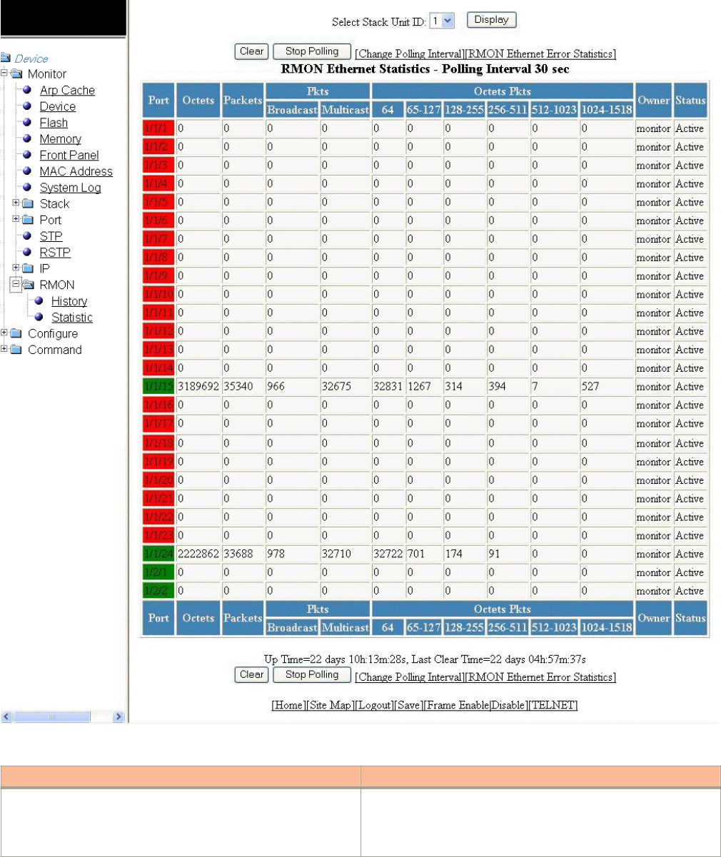
FIGURE 44 Monitoring RMON Ethernet statistics
TABLE 27 Description of the elds in the RMON Ethernet Statistics window
Field Description
Port Displays the port number. The port number varies based on the
product:
• For Brocade FCX and Brocade ICX devices - stack-unit/
slotnum/portnum
Displaying RMON Ethernet statistics
Brocade FastIron SX, FCX, and ICX Web Management Interface User Guide, 08.0.30
100 Part Number: 53-1003615-02

TABLE 27 Description of the elds in the RMON Ethernet Statistics window (continued)
Field Description
• For Brocade FastIron SX devices - slotnum/portnum
Octets Displays the total number of octets of data received on the network.
This number includes octets in bad packets.
This number does not include framing bits but does include Frame
Check Sequence (FCS) octets.
Packets Displays the total number of packets received.
This number includes bad packets, broadcast packets, and multicast
packets.
Packets: Broadcast Displays the total number of good packets received that were
directed to the broadcast address.
This number does not include multicast packets.
Packets: Multicast Displays the total number of good packets received that were
directed to a multicast address.
This number does not include packets directed to the broadcast
address.
Octet Packets: 64 Displays the total number of packets received that were 64 octets
long.
This number includes bad packets.
This number does not include framing bits but does include FCS
octets.
Octet Packets: 65 - 127 Displays the total number of packets received that were from 65
through 127 octets long.
This number includes bad packets.
This number does not include framing bits but does include FCS
octets.
Octet Packets: 128 - 255 Displays the total number of packets received that were from 128
through 255 octets long.
This number includes bad packets.
This number does not include framing bits but does include FCS
octets.
Octet Packets: 256 - 511 Displays the total number of packets received that were from 256
through 511 octets long.
This number includes bad packets.
This number does not include framing bits but does include FCS
octets.
Octet Packets: 512 - 1023 Displays the total number of packets received that were from 512
through 1023 octets long.
This number includes bad packets.
This number does not include framing bits but does include FCS
octets.
Octet Packets: 1024 - 1518 Displays the total number of packets received that were from 1024
through 1518 octets long.
This number includes bad packets.
This number does not include framing bits but does include FCS
octets.
Displaying RMON Ethernet statistics
Brocade FastIron SX, FCX, and ICX Web Management Interface User Guide, 08.0.30
Part Number: 53-1003615-02 101

TABLE 27 Description of the elds in the RMON Ethernet Statistics window (continued)
Field Description
Owner Displays the owner of the packets.
Status Displays the status of the port.
Up Time Displays the length of time the device has been available.
Last Clear Time Displays the length of time data has been accumulating in the current
table.
To remove the current data in the table and restart monitoring, click Clear. To stop reporting the statistics, click Stop Polling.
The RMON Ethernet Statistics window contains the following links:
• To change the polling interval, click Change Polling interval. For more information, refer to the “Changing polling interval”
section.
• To display the RMON Ethernet error statistics, click RMON Ethernet Error Statistics. For more information, refer to the
“Displaying RMON Ethernet error statistics” section.
Displaying RMON Ethernet statistics
Brocade FastIron SX, FCX, and ICX Web Management Interface User Guide, 08.0.30
102 Part Number: 53-1003615-02

Changing polling interval
To change the number of seconds between reporting the RMON Ethernet statistics, perform the following steps.
1. Click Change Polling interval on the RMON Ethernet Statistics window.
The Web Management Preferences window is displayed as shown in the gure below.
FIGURE 45 Modifying web management preferences
2. Specify the RMON polling interval in the RMON eld.
3. Click Apply .
The message The change has been made is displayed at the top of the window. To undo the changes, click Reset . For
more information on web management preferences, refer to Conguring the web management preferences on page 158.
Displaying RMON Ethernet error statistics
To display RMON error information, perform the following steps.
1. Click RMON Ethernet Error Statistics on the RMON Ethernet Statistics window.
Displaying RMON Ethernet error statistics
Brocade FastIron SX, FCX, and ICX Web Management Interface User Guide, 08.0.30
Part Number: 53-1003615-02 103
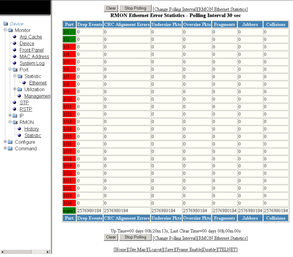
2. For the Brocade FCX and Brocade ICX devices, select a unit ID in the Select Stack Unit ID list and click Display to view
information about a specic stack unit.
NOTE
The Select Stack Unit ID list is not available in the RMON Ethernet Error Statistics window for the Brocade FastIron
SX devices.
The RMON Ethernet Error Statistics window for the Brocade FCX and Brocade ICX devices is displayed as shown in the gure
below.
FIGURE 46 Monitoring the RMON Ethernet error statistics
Displaying RMON Ethernet error statistics
Brocade FastIron SX, FCX, and ICX Web Management Interface User Guide, 08.0.30
104 Part Number: 53-1003615-02

TABLE 28 Description of the elds in the RMON Ethernet Error Statistics window
Field Description
Port Displays the port number. The port number varies based on the
product:
• For Brocade FCX and Brocade ICX devices - stack-unit/
slotnum/portnum
• For Brocade FastIron SX devices - slotnum/portnum
Drop Events Displays the total number of events in which packets were dropped
by the RMON probe due to lack of resources. This number is not
necessarily the number of packets dropped, but is the number of
times an overrun condition has been detected.
CRC Alignment Errors Displays the total number of packets received that were from 64
through 1518 octets long, but had either a bad FCS with an integral
number of octets (FCS Error) or a bad FCS with a non-integral
number of octets (Alignment Error).
The packet length does not include framing bits but does include
FCS octets.
Undersize Pkts Displays the total number of packets received that were less than 64
octets long and were otherwise well formed.
This number does not include framing bits but does include FCS
octets.
Oversize Pkts Displays the total number of packets received that were longer than
1518 octets and were otherwise well formed.
This number does not include framing bits but does include FCS
octets.
Fragments Displays the total number of packets received that were less than 64
octets long and had either a bad FCS with an integral number of
octets (FCS Error) or a bad FCS with a non-integral number of octets
(Alignment Error).
It is normal for this counter to increment, because it counts both runts
(which are normal occurrences due to collisions) and noise hits.
This number does not include framing bits but does include FCS
octets.
Jabbers Displays the total number of packets received that were longer than
1518 octets and had either a bad FCS with an integral number of
octets (FCS Error) or a bad FCS with a non-integral number of octets
(Alignment Error).
NOTE
This denition of jabber is dierent from the denition in
IEEE-802.3 section 8.2.1.5 (10BASE5) and section
10.3.1.4 (10BASE2). These documents dene jabber as
the condition where any packet exceeds 20 ms. The
allowed range to detect jabber is between 20 ms and
150 ms.
This number does not include framing bits but does include FCS
octets.
Collisions Displays the best estimate of the total number of collisions on this
Ethernet segment.
Up Time Displays the length of time the device has been available.
Last Clear Time Displays the length of time data has been accumulating in the current
table.
Displaying RMON Ethernet error statistics
Brocade FastIron SX, FCX, and ICX Web Management Interface User Guide, 08.0.30
Part Number: 53-1003615-02 105
To remove the current data in the table and restart monitoring, click Clear . To stop reporting the statistics, click Stop Polling .
The RMON Ethernet Error Statistics window contains the following links:
• To change the polling interval, click Change Polling interval . For more information, refer to Changing polling interval on
page 103.
• To display the RMON statistics, click RMON Ethernet Statistics . For more information, refer to Displaying RMON
Ethernet statistics on page 98.
Displaying RMON Ethernet error statistics
Brocade FastIron SX, FCX, and ICX Web Management Interface User Guide, 08.0.30
106 Part Number: 53-1003615-02
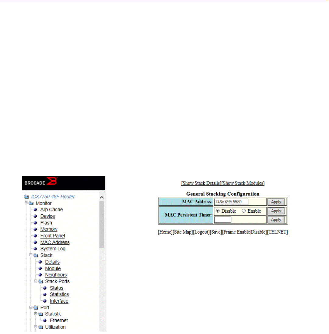
Conguring Stack Components
•Conguring the general settings for a traditional stack...................................................................................................................107
• Modifying stack priority................................................................................................................................................................................108
• Modifying stack ports................................................................................................................................................................................... 110
•Conguring a stack module....................................................................................................................................................................... 112
•Conguring peri-ports..................................................................................................................................................................................115
•Conguring peri-trunks................................................................................................................................................................................115
•Conguring stack connect.......................................................................................................................................................................... 116
NOTE
This chapter is specic to the Brocade FCX and Brocade ICX devices.
Conguring the general settings for a traditional stack
To change the stack settings to improve performance and reliability of the device, perform the following steps.
1. Click Congure on the left pane and select Stack.
2. Click General.
The General Stacking Conguration window is displayed as shown in the gure below.
FIGURE 47 General stacking conguration
3. Enter the Media Access Control (MAC) address of the device in the MAC Address eld and then click Apply.
Brocade FastIron SX, FCX, and ICX Web Management Interface User Guide, 08.0.30
Part Number: 53-1003615-02 107
4. Click Disable or Enable for MAC Persistent Timer and then click Apply.
If you click Enable, type the time delay before the stack MAC address changes in the MAC Persistent Timer eld and then click
Apply.
The General Stacking Conguration window provides links to monitor stack parameters:
• To display the current stack information, click Show Stack Details . For more information, refer to the “Displaying the stack
details” section.
• To display the current information about the stack modules, click Show Stack Modules . For more information, refer to the
“Displaying a stack module” section.
Modifying stack priority
The stack unit with the highest priority is the Active Controller (128 by default). The stack unit with the second highest priority is the
Standby Controller, which takes over if the current Active Controller fails.
It is possible to assign the same priority for Active and Standby Controllers, or dierent priorities (Active highest and Standby second-
highest). When the Active and Standby Controllers have the same priority, if the Active Controller fails, the Standby Controller takes over.
If the original Active Controller becomes operational again, it will not be able to resume its original role.
When the priorities of the Active and Standby Controllers are dierent, if the Active Controller fails, the Standby Controller takes over. If
the original Active Controller becomes operational again, the old Active Controller regains its role and resets the other units.
You can assign the same priority to the Active and Standby Controllers after the stack is formed. This prevents the intended Standby
Controller from becoming the Active Controller during stack construction.
Changing the priority of a stack member triggers an election that takes eect immediately unless the Active Controller’s role changes.
This change will not take eect until the next stack reload.
To congure the priority of the units within a stack, perform the following steps.
1. Click Congure on the left pane and select Stack .
Modifying stack priority
Brocade FastIron SX, FCX, and ICX Web Management Interface User Guide, 08.0.30
108 Part Number: 53-1003615-02
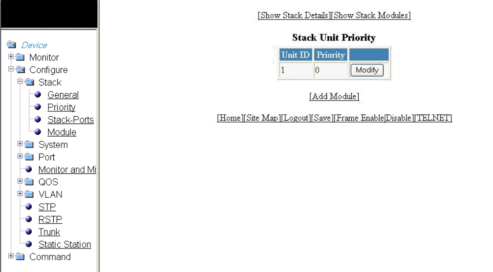
2. Click Priority .
The Stack Unit Priority window is displayed as shown in the gure below.
FIGURE 48 Stack unit priority
Modifying stack priority
Brocade FastIron SX, FCX, and ICX Web Management Interface User Guide, 08.0.30
Part Number: 53-1003615-02 109
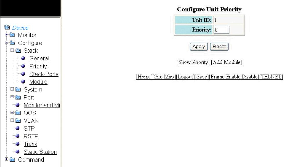
3. Click Modify .
The Congure Unit Priority window is displayed as shown in the gure below.
FIGURE 49 Conguring unit priority
4. Type the priority (from 0 through 255) you want to assign to the stack unit in the Priority eld.
5. Click Apply .
The priority is assigned to the stack unit and the Stack Unit Priority window is displayed. To reset the data entered in the
conguration pane, click Reset .
To display the priority of the stack units, click Show Priority . To add a new stack module, click Add Module . For more
information on how to congure a stack module, refer to Conguring a stack module on page 112.
Modifying stack ports
NOTE
You cannot change the stack ports for the Brocade ICX devices.
To modify the stack ports, perform the following steps.
1. Click Congure on the left pane and select Stack.
Modifying stack ports
Brocade FastIron SX, FCX, and ICX Web Management Interface User Guide, 08.0.30
110 Part Number: 53-1003615-02
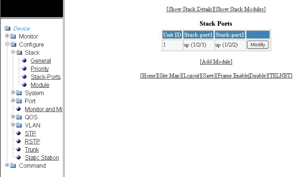
2. Click Stack-Ports.
The Stack Ports window is displayed.
FIGURE 50 Modifying stack ports
Modifying stack ports
Brocade FastIron SX, FCX, and ICX Web Management Interface User Guide, 08.0.30
Part Number: 53-1003615-02 111
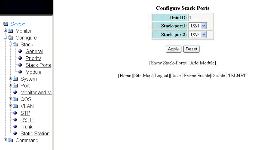
3. Click Modify .
The Congure Stack Ports window is displayed as shown in the gure below.
FIGURE 51 Modifying stack ports
4. Select a port in the Stack-port1 list.
5. Select a port in the Stack-port2 list.
6. Click Apply.
The stack ports are modied and the Stack Ports window is displayed.
To reset the data entered in the conguration pane, click Reset . To display the congured stack port, click Show Stack-Ports.
To congure a stack module, click Add Module . For more information on how to congure a stack module, refer to the
“Conguring a stack module” section.
Conguring a stack module
To congure a stack module, perform the following steps.
1. Click Congure on the left pane and select Stack .
Conguring a stack module
Brocade FastIron SX, FCX, and ICX Web Management Interface User Guide, 08.0.30
112 Part Number: 53-1003615-02
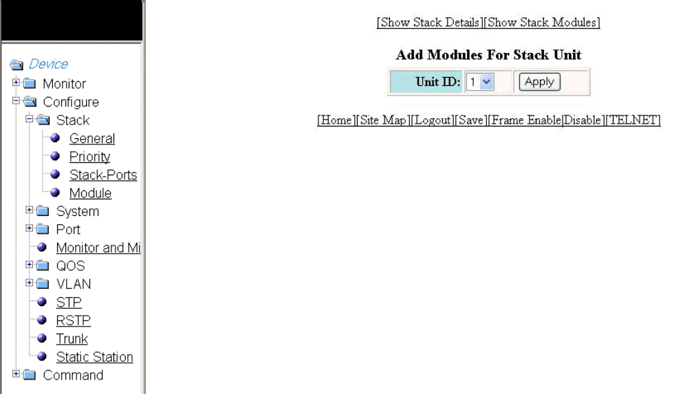
2. Click Module .
The Add Modules For Stack Unit window is displayed as shown in the gure below.
FIGURE 52 Adding modules for a stack unit
3. Select a stack unit identier in the Unit ID list.
Conguring a stack module
Brocade FastIron SX, FCX, and ICX Web Management Interface User Guide, 08.0.30
Part Number: 53-1003615-02 113
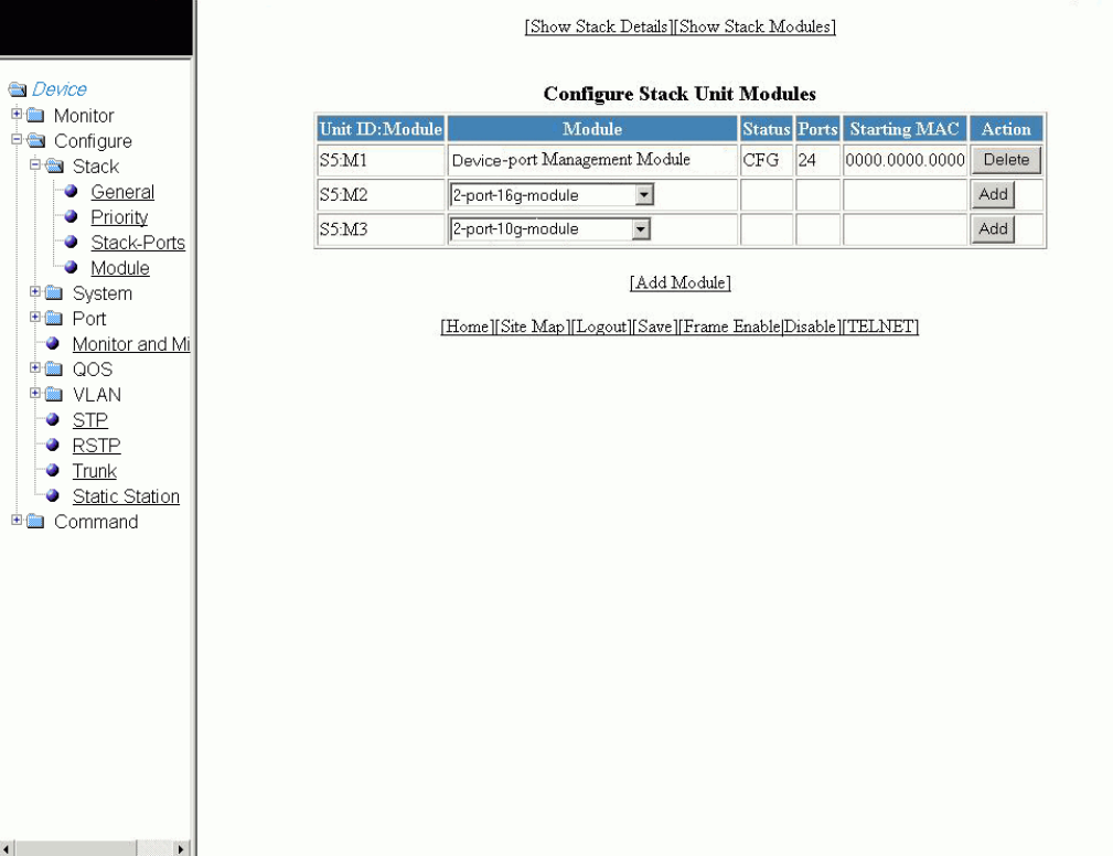
4. Click Apply .
The Congure Stack Unit Modules window is displayed as shown in the gure below.
FIGURE 53 Adding and deleting a stack unit module
5. Select a stack module in the list on the Module column and then click Add .
To display current stack details, stack port status, and stack neighbors information, click Show Stack Details . For more
information, refer to Displaying the stack details on page 41. Click Delete to delete a stack unit module. You cannot delete the
active modules.
To display the stack unit modules, click Show Stack Modules . For more information, refer to Displaying a stack module on
page 43.
Conguring a stack module
Brocade FastIron SX, FCX, and ICX Web Management Interface User Guide, 08.0.30
114 Part Number: 53-1003615-02
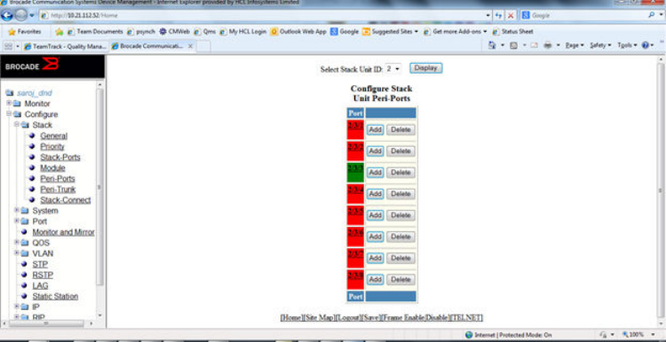
Conguring peri-ports
To congure peri-ports, perform the following steps.
1. Click Congure on the left pane and select Stack .
2. Click Peri-Ports.
The Congure Stack-Unit Peri-Ports window is displayed.
Conguring peri-trunks
To congure peri-trunks, perform the following steps.
1. Click Congure on the left pane and select Stack.
Conguring peri-trunks
Brocade FastIron SX, FCX, and ICX Web Management Interface User Guide, 08.0.30
Part Number: 53-1003615-02 115
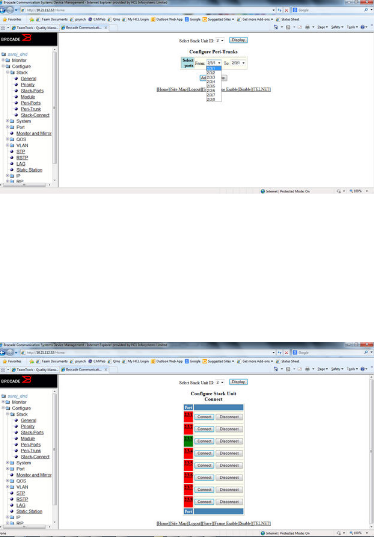
2. Click Peri-Trunks.
The Congure Peri-Trunks window is displayed.
Conguring stack connect
To congure stack connect perform the following steps.
1. Click Congure on the left pane and select Stack.
2. Click Stack-Connect.
The Congure Stack-Unit Connect window is displayed.
Conguring stack connect
Brocade FastIron SX, FCX, and ICX Web Management Interface User Guide, 08.0.30
116 Part Number: 53-1003615-02

Conguring System Components
•Conguring the system boot sequence for the Brocade FCX and Brocade ICX devices................................................117
•Conguring the system boot sequence for the Brocade FastIron SX devices..................................................................... 119
•Conguring the system clock....................................................................................................................................................................120
•Conguring the system DNS.....................................................................................................................................................................122
•Conguring the general system settings.............................................................................................................................................. 123
•Conguring the system identication.....................................................................................................................................................125
•Conguring the system IP address.........................................................................................................................................................127
•Conguring a standard ACL.......................................................................................................................................................................128
•Conguring an extended ACL...................................................................................................................................................................129
•Conguring an IP access group............................................................................................................................................................... 133
•Conguring the system MAC lter..........................................................................................................................................................135
•Conguring the maximum system parameter value........................................................................................................................138
•Conguring a system module...................................................................................................................................................................139
•Conguring a RADIUS server................................................................................................................................................................... 142
•Conguring a TACACS/TACACS+ server............................................................................................................................................144
•Conguring management authentication............................................................................................................................................. 145
•Conguring management authorization............................................................................................................................................... 147
•Conguring management accounting ..................................................................................................................................................148
•Conguring an SNMP community string.............................................................................................................................................150
•Conguring the general management parameters...........................................................................................................................151
•Conguring a management system log................................................................................................................................................152
•Conguring a trap...........................................................................................................................................................................................154
•Conguring a trap receiver..........................................................................................................................................................................155
•Conguring a management user account............................................................................................................................................157
•Conguring the web management preferences.................................................................................................................................158
Conguring the system boot sequence for the
Brocade FCX and Brocade ICX devices
To congure the system boot sequence for the Brocade FCX and Brocade ICX devices, perform the following steps.
1. Click Congure on the left pane and select System.
Brocade FastIron SX, FCX, and ICX Web Management Interface User Guide, 08.0.30
Part Number: 53-1003615-02 117
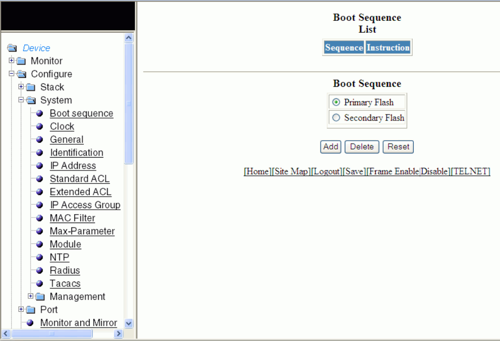
2. Click Boot sequence.
The Boot Sequence window is displayed as shown in the gure below.
FIGURE 54 Conguring system boot sequence for the Brocade FCX and Brocade ICX devices
3. There are two types of boot sequence operations:
• Select Primary Flash to store the image les and conguration les in the local storage device. By default, Primary Flash is
enabled.
• Select Secondary Flash to store the redundant images for additional reload reliability or to preserve one software image
while testing another one.
4. Click Add.
The message The change has been made is displayed and the boot sequence is listed in the Boot Sequence List pane.
To reset the data entered in the conguration pane, click Reset . You can also delete the boot sequence operation by clicking
Delete.
Conguring the system boot sequence for the Brocade FCX and Brocade ICX devices
Brocade FastIron SX, FCX, and ICX Web Management Interface User Guide, 08.0.30
118 Part Number: 53-1003615-02
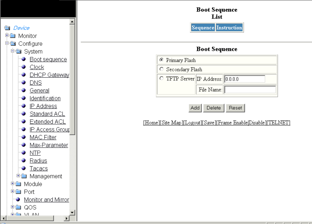
Conguring the system boot sequence for the
Brocade FastIron SX devices
To congure the system boot sequence for the Brocade FastIron SX devices, perform the following steps.
1. Click Congure on the left pane and select System.
2. Click Boot sequence.
The Boot Sequence window is displayed as shown in the gure below.
FIGURE 55 Conguring system boot sequence for the Brocade FastIron SX devices
Conguring the system boot sequence for the Brocade FastIron SX devices
Brocade FastIron SX, FCX, and ICX Web Management Interface User Guide, 08.0.30
Part Number: 53-1003615-02 119
3. There are three types of boot sequence operations:
• Select Primary Flash to store the image les and conguration les in the local storage device. By default, Primary Flash is
enabled.
• Select Secondary Flash to store the redundant images for additional reload reliability or to preserve one software image
while testing another one.
• Click TFTP Server to store conguration les to a Trivial File Transfer Protocol (TFTP) server. Provide the following
information:
–IP Address --Type the IP address of the TFTP server.
–File Name --Type the le name.
4. Click Add.
The message The change has been made is displayed and the boot sequence is listed in the Boot Sequence List pane.
To reset the data entered in the conguration pane, click Reset. You can also delete the boot sequence operation by clicking
Delete.
Conguring the system clock
To congure the system clock, perform the following steps.
1. Click Congure on the left pane and select System .
Conguring the system clock
Brocade FastIron SX, FCX, and ICX Web Management Interface User Guide, 08.0.30
120 Part Number: 53-1003615-02
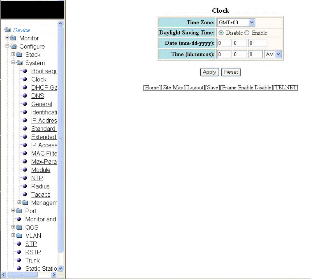
2. Click Clock .
The Clock window is displayed as shown in the gure below.
FIGURE 56 Conguring the system clock
3. Select the GMT time zone that you want to congure for the device in the Time Zone list.
4. Click Disable or Enable for Daylight Saving Time . Daylight Saving Time applies to the US time zone only.
5. Type the date in mm-dd-yyyy format in the Date (mm-dd-yyyy) eld.
6. Type the time in hh:mm:ss format in the Time (hh:mm:ss) eld and select AM or PM in the list.
7. Click Apply .
The message The change has been made is displayed. To reset the data entered in the conguration pane, click Reset .
Conguring the system clock
Brocade FastIron SX, FCX, and ICX Web Management Interface User Guide, 08.0.30
Part Number: 53-1003615-02 121
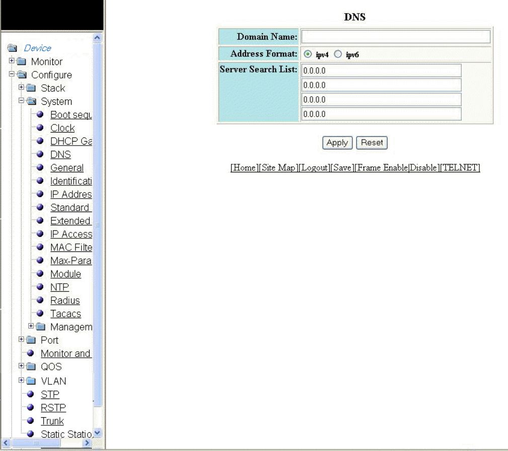
Conguring the system DNS
To congure the system Domain Name System (DNS), perform the following steps.
1. Click Congure on the left pane and select System .
2. Click DNS .
The DNS window is displayed as shown in the gure below.
FIGURE 57 Conguring the system DNS
3. Type the name of the domain that can be used to resolve host names in the Domain Name eld.
4. Select ipv4 or ipv6 for the Address Format .
Conguring the system DNS
Brocade FastIron SX, FCX, and ICX Web Management Interface User Guide, 08.0.30
122 Part Number: 53-1003615-02
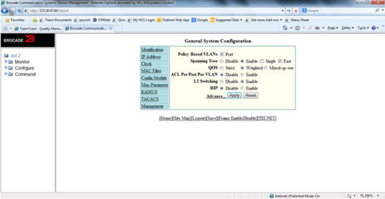
5. Type the server IP addresses in the Server Search List elds.
You can congure a Brocade device to recognize up to four DNS servers. The rst entry serves as the primary default address.
If a query to the primary address fails to be resolved after three attempts, the next DNS address is queried (also up to three
times). This process continues for each dened DNS address until the query is resolved. The order in which the default DNS
addresses are polled is the same as the order in which you enter them.
6. Click Apply .
The message The change has been made is displayed. To reset the data entered in the conguration pane, click Reset .
Conguring the general system settings
To congure the general system settings, perform the following steps.
1. Click Congure on the left pane and select System.
2. Click General.
The General System Conguration window is displayed.
FIGURE 58 Conguring the general system
3. Select the Port check box for Policy based VLANs to enable conguration of port-based VLANs.
4. Click Disable or Enable for Spanning Tree . If you click Enable, select the Single or Fast check box.
5. Click Strict or Weighted for QOS.
6. Click Disable or Enable for ACL Per Port Per VLAN.
Conguring the general system settings
Brocade FastIron SX, FCX, and ICX Web Management Interface User Guide, 08.0.30
Part Number: 53-1003615-02 123
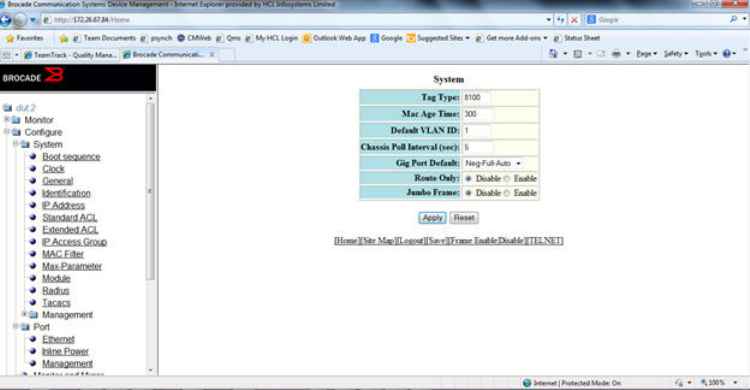
7. Click Advance to congure additional system parameters.
The System window is displayed.
FIGURE 59 Advance system information
8. Type the VLAN tag type in hexadecimal format from 0 through in the Tag Type eld. The default is 0081.
9. Type the number of seconds a port address remains active in the address table in the Mac Age Time eld.
10. Type the default VLAN ID number in the Default VLAN ID eld.
11. Type the interval, in seconds, in which the chassis is polled in the Chassis Poll Interval (sec) eld.
12. Select a negotiation mode in the Gig Port Default list.
13. Click Disable or Enable for Route Only. If you click Enable , Layer 2 switching is disabled globally.
14. Click Disable or Enable for Jumbo Frame.
Jumbo frames are Ethernet frames with more than 1,500 bytes MTU.
Conguring the general system settings
Brocade FastIron SX, FCX, and ICX Web Management Interface User Guide, 08.0.30
124 Part Number: 53-1003615-02
15. Click Apply.
The message The change has been made is displayed. To reset the data entered in the conguration pane, click Reset.
The General System Conguration window provides the following links to congure the system parameters:
•Identication
•IP Address
•DNS
•DHCP Gateway
•Clock
•MAC Filter
•Module
•Max-Parameter
•RADIUS
•TACACS
•Management
Conguring the system identication
To congure the system identication information, perform the following steps.
1. Click Congure on the left pane and select System .
Conguring the system identication
Brocade FastIron SX, FCX, and ICX Web Management Interface User Guide, 08.0.30
Part Number: 53-1003615-02 125
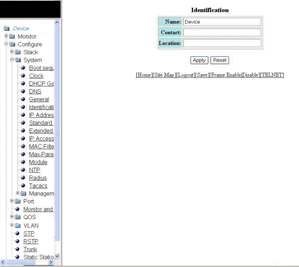
2. Click Identication .
The Identication window is displayed as shown in the gure below.
FIGURE 60 Conguring the system identication
3. Type the name of the device in the Name eld.
4. Type the contact information of the device in the Contact eld.
5. Type the location of the device in the Location eld.
6. Click Apply .
The message The change has been made is displayed. To reset the data entered in the conguration pane, click Reset .
Conguring the system identication
Brocade FastIron SX, FCX, and ICX Web Management Interface User Guide, 08.0.30
126 Part Number: 53-1003615-02
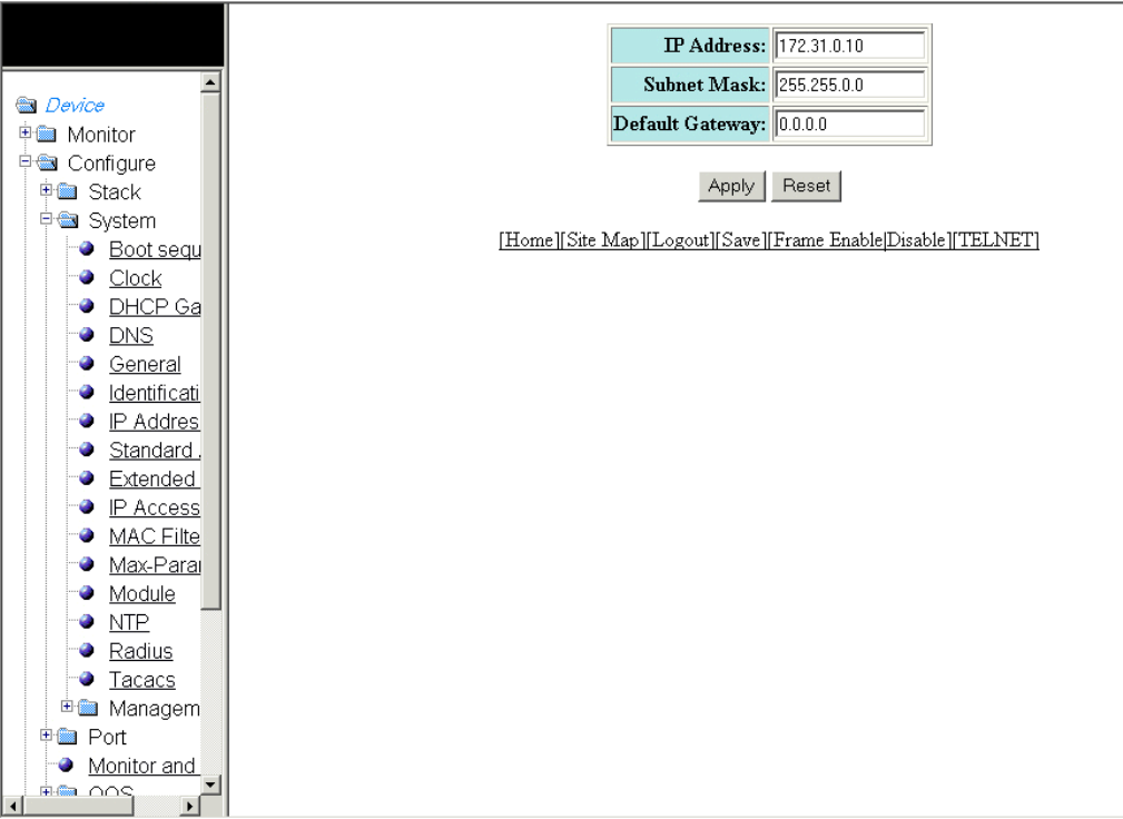
Conguring the system IP address
To congure the IP address of the system, perform the following steps.
1. Click Congure on the left pane and select System .
2. Click IP Address .
The IP address window is displayed as shown in the gure below.
FIGURE 61 Conguring the system IP address
3. Type the IP address of the device in the IP Address eld.
4. Type the network mask for the IP address in the Subnet Mask eld.
5. Type the IP address of a locally attached Layer 3 switch (or a Layer 3 switch attached to the Layer 2 switch by bridges or other
Layer 2 switches) in the Default Gateway eld.
6. Click Apply .
The message The change has been made is displayed. To reset the data entered in the conguration pane, click Reset .
Conguring the system IP address
Brocade FastIron SX, FCX, and ICX Web Management Interface User Guide, 08.0.30
Part Number: 53-1003615-02 127
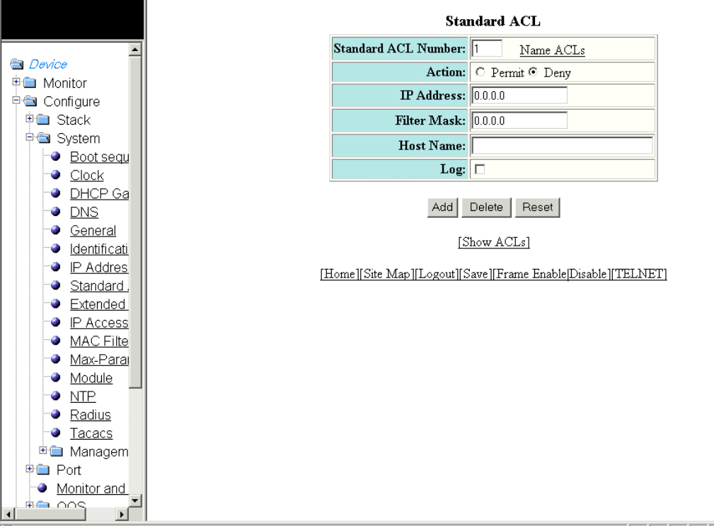
Conguring a standard ACL
To congure a standard Access Control List (ACL), perform the following steps.
1. Click Congure on the left pane and select System .
2. Click Standard ACL .
The Standard ACL window is displayed as shown in the gure below.
FIGURE 62 Conguring a standard ACL
3. Type the standard ACL number from 1 through 99 in the Standard ACL Number eld. If you want to type an ACL name, click
Name ACLs . The eld label changes to Standard ACL Name .
4. Click Permit or Deny for Action so that the ACL forwards or drops the packets that match the policy in the ACL.
5. Type the IP address of the route's destination in the IP Address eld.
6. Type the masking bits in the Filter Mask eld. This allows you to specify a range of IP addresses to include or exclude based on
mask matching.
7. Type the host name in the Host Name eld. The host name enables you to perform Telnet, ping, and trace route commands.
Conguring a standard ACL
Brocade FastIron SX, FCX, and ICX Web Management Interface User Guide, 08.0.30
128 Part Number: 53-1003615-02
8. Select the Log check box to log the entries.
9. Click Add .
The message The change has been made is displayed. To display the congured standard ACL, click Show ACLs . To
delete the congured ACL, click Delete . To reset the data entered in the conguration pane, click Reset .
Conguring an extended ACL
To congure an extended Access Control List (ACL), perform the following steps.
1. Click Congure on the left pane and select System.
Conguring an extended ACL
Brocade FastIron SX, FCX, and ICX Web Management Interface User Guide, 08.0.30
Part Number: 53-1003615-02 129
2. Click Extended ACL.
The Extended ACL window is displayed as shown in the gure below.
Conguring an extended ACL
Brocade FastIron SX, FCX, and ICX Web Management Interface User Guide, 08.0.30
130 Part Number: 53-1003615-02
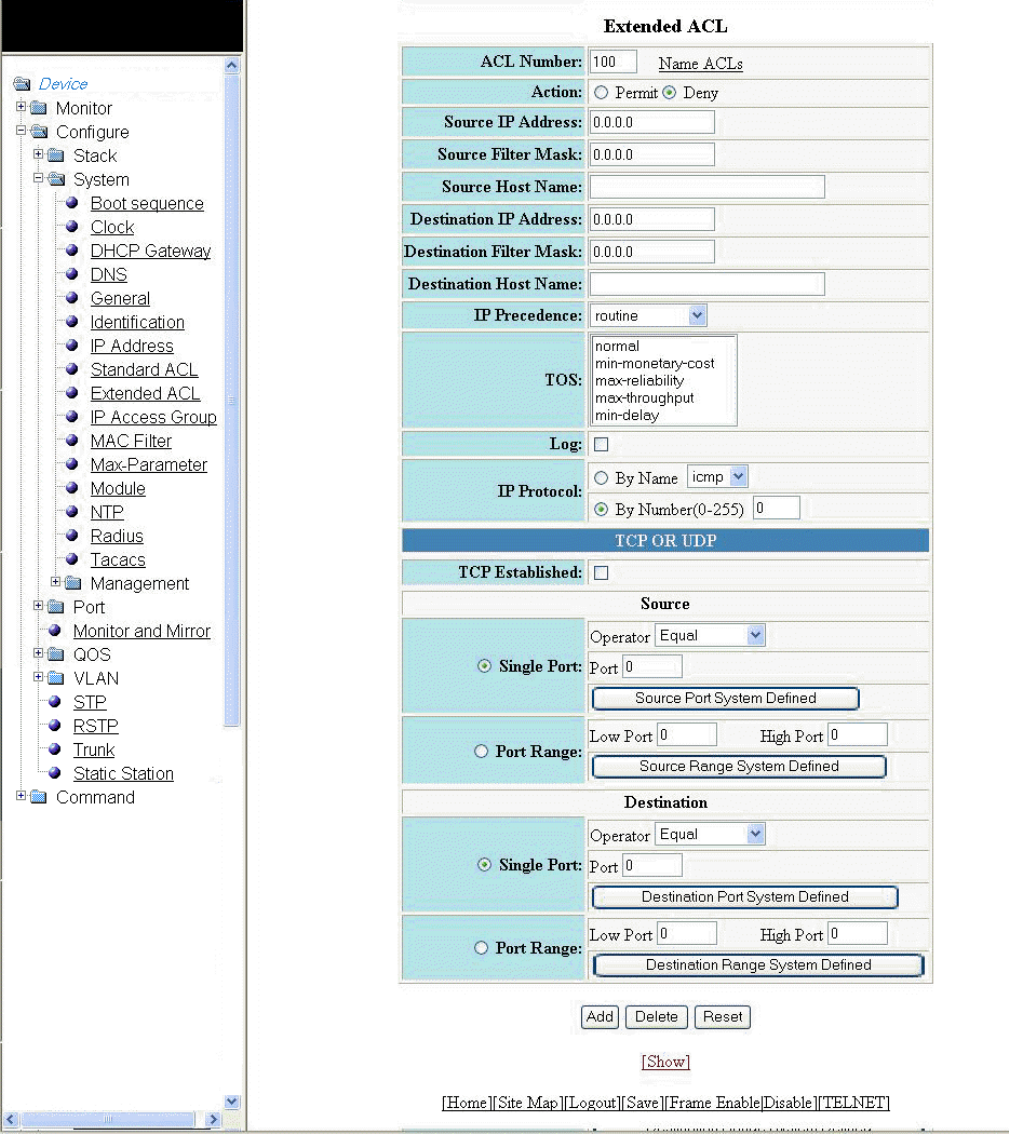
FIGURE 63 Conguring an extended ACL
Conguring an extended ACL
Brocade FastIron SX, FCX, and ICX Web Management Interface User Guide, 08.0.30
Part Number: 53-1003615-02 131
3. Type the extended ACL number (from 100 through 199) in the ACL Number eld. If you want to specify an extended ACL
name, click Name ACLs. The eld label changes to ACL Name.
4. Click Permit or Deny for Action so that the packets that match the policy are forwarded or dropped.
5. Type the source IP address in the Source IP Address eld.
6. Type the source mask in the Source Filter Mask eld.
7. Type the source host name in the Source Host Name eld.
8. Type the destination IP address in the Destination IP Address eld.
9. Type the destination mask in the Destination Filter Mask eld.
10. Type the destination host name in the Destination Host Name eld.
11. Select one of the following options in the IP Precedence list:
•routine --The ACL matches packets that have the routine precedence.
•priority --The ACL matches packets that have the priority precedence.
•immediate --The ACL matches packets that have the immediate precedence.
•ash --The ACL matches packets that have the ash precedence.
•ash-override --The ACL matches packets that have the ash override precedence.
•critical --The ACL matches packets that have the critical precedence.
•internet --The ACL matches packets that have the internetwork control precedence.
•network --The ACL matches packets that have the network control precedence.
12. Select one of the following options in the TOS list:
•normal --The ACL matches packets that have the normal Type of Service (ToS).
•min-monetary-cost --The ACL matches packets that have the minimum monetary cost ToS.
•max-reliability --The ACL matches packets that have the maximum reliability ToS.
•max-throughput --The ACL matches packets that have the maximum throughput ToS.
•min-delay --The ACL matches packets that have the minimum delay ToS.
13. Select the Log check box to enable generation of SNMP traps and syslog messages for packets denied by the ACL.
14. Click By Name for IP Protocol to select the IP protocol by name or click By Number to specify the number (from 0 through
255).
15. Select the TCP Established check box so that the policy applies to TCP packets that have the ACK (Acknowledgment) or RST
(Reset) bits set on (set to "1") in the Control Bits eld of the TCP packet header. The policy applies only to the established TCP
sessions, not to the new sessions.
NOTE
This eld applies only to the destination TCP ports, not the source TCP ports.
Conguring an extended ACL
Brocade FastIron SX, FCX, and ICX Web Management Interface User Guide, 08.0.30
132 Part Number: 53-1003615-02
16. Enter the following information for Source:
a) To congure a single port, click Single Port.
Select one of the following options for Operator:
•Equal --The policy applies to the TCP or UDP port number or name you enter.
•NotEqual --The policy applies to all the TCP or UDP port numbers except the port number or port name you enter.
•LessThan --The policy applies to the TCP or UDP port numbers that are less than the port number or the numeric
equivalent of the port name you enter.
•GreaterThan --The policy applies to the TCP or UDP port numbers greater than the port number or the numeric
equivalent of the port name you enter.
Click Source Port System Dened.
b) To congure a range of ports, click Port Range.
Type the lower port number in the Low Port eld and the highest port number in the High Port eld.
Click Source Range System Dened.
17. To congure the destination port settings under Destination, follow the procedure explained in step 16 .
18. Click Add.
The message The change has been made is displayed. To display the congured extended numbered ACL, click Show.
To delete the congured extended numbered ACL, click Delete . To reset the data entered in the conguration pane, click Reset.
Conguring an IP access group
To congure an IP access group, perform the following steps.
1. Click Congure on the left pane and select System.
Conguring an IP access group
Brocade FastIron SX, FCX, and ICX Web Management Interface User Guide, 08.0.30
Part Number: 53-1003615-02 133
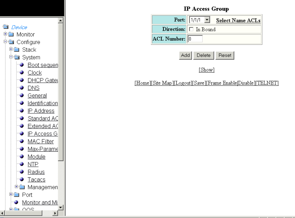
2. Click IP Access Group.
The IP Access Group window is displayed as shown in the gure below.
FIGURE 64 Conguring IP access groups
3. Select a port in the Port list. The port number varies based on the product:
• For Brocade FCX and Brocade ICX devices - stack-unit/slotnum/portnum
• For Brocade FastIron SX devices - slotnum/portnum
4. Select the In Bound check box for Direction to enable incoming trac on the interface to which you apply the ACL.
5. Type the ACL number in the ACL Number list. If you want to type an ACL name, click Select Name ACLs. The eld label
changes to ACL Name . Now, you can type the ACL name up to 256 alphanumeric characters.
6. Click Add.
The message The change has been made is displayed. To display the congured IP access group, click Show.
To delete the congured IP access group, click Delete. To reset the data entered in the conguration pane, click Reset.
Conguring an IP access group
Brocade FastIron SX, FCX, and ICX Web Management Interface User Guide, 08.0.30
134 Part Number: 53-1003615-02
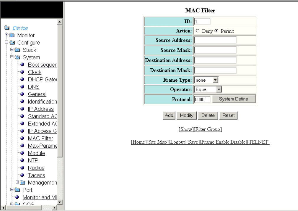
Conguring the system MAC lter
To congure the system MAC lter, perform the following steps.
1. Click Congure on the left pane and select System.
2. Click MAC Filter.
The MAC Filter window is displayed as shown in the gure below.
FIGURE 65 Conguring a MAC lter
3. Type the lter number in the ID eld.
4. Click Deny or Permit for Action.
5. Type the source MAC address in xx.xx.xx.xx.xx.xx format in the Source Address eld.
6. Type the source mask in the Source Mask eld.
7. Type the destination MAC address in xx.xx.xx.xx.xx.xx format in the Destination Address eld.
8. Type the destination mask in the Destination Mask eld.
Conguring the system MAC lter
Brocade FastIron SX, FCX, and ICX Web Management Interface User Guide, 08.0.30
Part Number: 53-1003615-02 135
9. Select the type of frame in the Frame Type list.
NOTE
The Frame Type list is not available in the MAC Filter window for the Brocade FastIron SX devices.
10. Select the comparison operator in the Operator list.
NOTE
The Operator list is not available in the MAC Filter window for the Brocade FastIron SX devices.
11. Type the protocol identier in the Protocol eld. To select the system-dened protocol, click System Dene.
NOTE
The Protocol eld is not available in the MAC Filter window for the Brocade FastIron SX devices.
12. Click Add.
The message The change has been made is displayed. To display the congured MAC lter, click Show.
To change the congured MAC lter, click Modify. You can also delete the MAC lter by clicking Delete . To reset the data
entered in the conguration pane, click Reset.
To congure a lter group, click Filter Group. For more information on how to congure a lter group, refer to the “Conguring a
lter group” section.
Conguring the system MAC lter
Brocade FastIron SX, FCX, and ICX Web Management Interface User Guide, 08.0.30
136 Part Number: 53-1003615-02
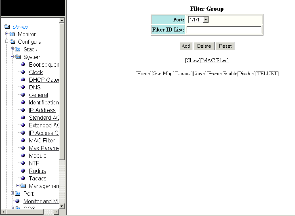
Conguring a lter group
To congure a system lter group, perform the following steps.
1. Click Filter Group on the right pane of the MAC Filter window.
The Filter Group window is displayed as shown in the gure below.
FIGURE 66 Conguring a lter group
2. Select a port number in the Port list. The port number varies based on the product:
• For Brocade FCX and Brocade ICX devices - stack-unit/slotnum/portnum
• For Brocade FastIron SX devices - slotnum/portnum
3. Type the lter identier in the Filter ID List eld.
4. Click Add.
The message The change has been made is displayed. To display the congured lter group, click Show.
To delete the congured lter group, click Delete. To reset the data entered in the conguration pane, click Reset.
Conguring the system MAC lter
Brocade FastIron SX, FCX, and ICX Web Management Interface User Guide, 08.0.30
Part Number: 53-1003615-02 137
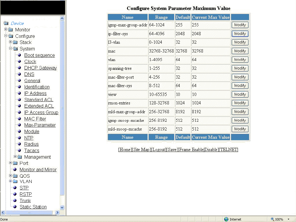
Conguring the maximum system parameter value
To congure the maximum system parameter value, perform the following steps.
1. Click Congure on the left pane and select System .
2. Click Max-Parameter .
The Congure System Parameter Maximum Value window is displayed as shown in the gure below.
FIGURE 67 Conguring the maximum system parameter
Conguring the maximum system parameter value
Brocade FastIron SX, FCX, and ICX Web Management Interface User Guide, 08.0.30
138 Part Number: 53-1003615-02
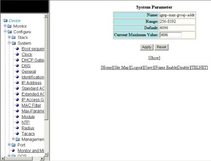
3. To change the values for each system parameter, click Modify .
The System Parameter window is displayed as shown in the gure below.
FIGURE 68 Modifying the maximum parameter value
4. Type the maximum value in the Current Maximum Value eld.
5. Click Apply .
The message The change has been made is displayed. To display the congured maximum system value, click Show . To
reset the data entered in the conguration pane, click Reset .
Conguring a system module
NOTE
The system module described here is specic to the Brocade FCX and Brocade ICX devices and is not available for the
Brocade FastIron SX devices.
To congure a system module, perform the following steps.
1. Click Congure on the left pane and select System.
Conguring a system module
Brocade FastIron SX, FCX, and ICX Web Management Interface User Guide, 08.0.30
Part Number: 53-1003615-02 139
2. Click Module.
The Module window is displayed as shown in the gure below.
Conguring a system module
Brocade FastIron SX, FCX, and ICX Web Management Interface User Guide, 08.0.30
140 Part Number: 53-1003615-02
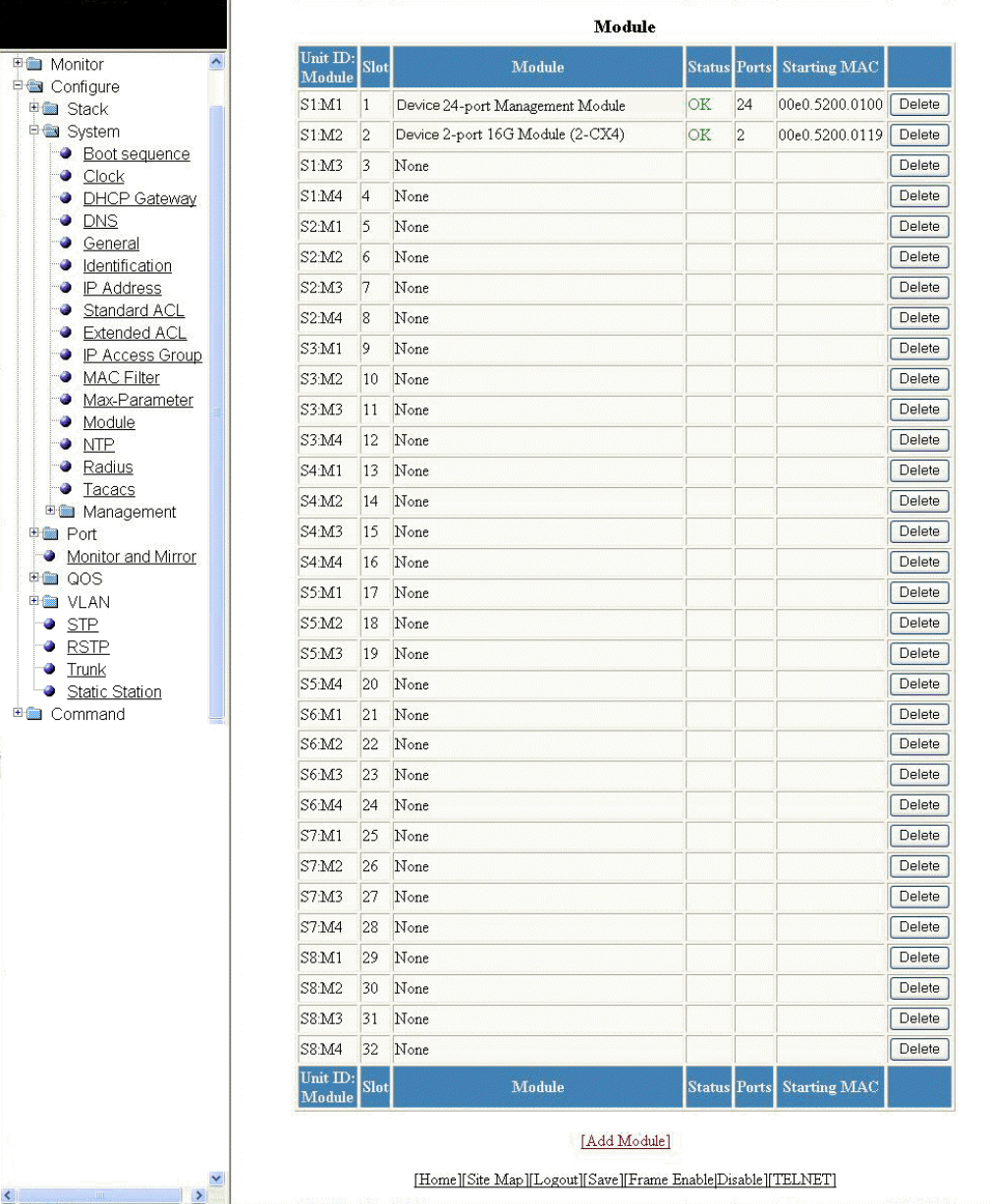
FIGURE 69 Conguring system modules
Conguring a system module
Brocade FastIron SX, FCX, and ICX Web Management Interface User Guide, 08.0.30
Part Number: 53-1003615-02 141
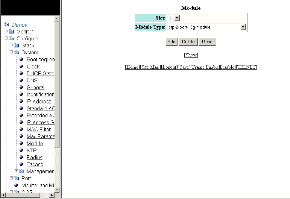
3. Click Add Module.
The Module window is displayed as shown in the gure below.
FIGURE 70 Adding system modules
4. Select a slot number in the Slot list.
5. Select a chassis module type in the Module Type list.
6. Click Add.
The message The change has been made is displayed. To display the congured module, click Show.
To delete the congured module, click Delete. To reset the data entered in the conguration pane, click Reset.
Conguring a RADIUS server
To congure a Remote Authentication Dial In User Service (RADIUS) server, perform the following steps.
1. Click Congure on the left pane and select System .
Conguring a RADIUS server
Brocade FastIron SX, FCX, and ICX Web Management Interface User Guide, 08.0.30
142 Part Number: 53-1003615-02

2. Click Radius .
The RADIUS window is displayed as shown in the gure below.
FIGURE 71 Conguring a RADIUS server
3. Type the retransmission interval, which species how many times the Brocade device resends an authentication request when
the RADIUS server does not respond, in the Retransmit eld. The range is from 1 through 5 times. The default is 3 times.
4. Type the timeout interval, which species how many seconds the Brocade device waits for a response from a RADIUS server
before either retrying the authentication request or determining that the RADIUS servers are unavailable and moving on to the
next authentication method in the authentication method list, in the Timeout eld. The range is from 1 through 15 seconds. The
default is 3 seconds.
5. Type the dead interval, which species how long the Brocade device waits for the primary authentication server to reply before
deciding the server is dead and trying to authenticate using the next server, in the Dead Time eld. The range is from 1 through
5 seconds. The default is 3 seconds.
6. Type the RADIUS key in the Key eld. This is used to encrypt RADIUS packets before they are sent over the network. The value
for the key parameter on the Brocade device should match the one congured on the RADIUS server. The key can be from 1
through 32 characters in length and cannot include any space characters.
Conguring a RADIUS server
Brocade FastIron SX, FCX, and ICX Web Management Interface User Guide, 08.0.30
Part Number: 53-1003615-02 143
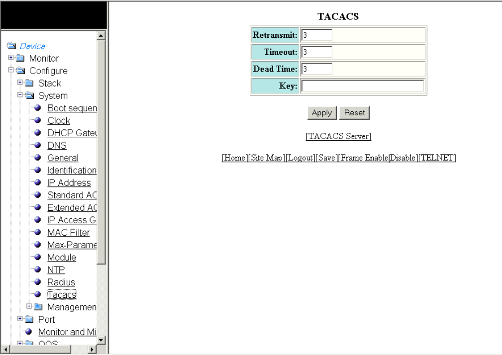
7. Click Apply .
The message The change has been made is displayed. To display the congured RADIUS server, click RADIUS Server .
To reset the data entered in the conguration pane, click Reset .
Conguring a TACACS/TACACS+ server
To congure a TACACS/TACACS+ server, perform the following steps.
1. Click Congure on the left pane and select System .
2. Click Tacacs .
The TACACS window is displayed as shown in the gure below.
FIGURE 72 Conguring a TACACS/TACACS+ server
3. Type the retransmission interval, which species how many times the Brocade device resends an authentication request when
the TACACS/TACACS+ server does not respond, in the Retransmit eld. The range is from 1 through 5 times. The default is 3
times.
Conguring a TACACS/TACACS+ server
Brocade FastIron SX, FCX, and ICX Web Management Interface User Guide, 08.0.30
144 Part Number: 53-1003615-02
4. Type the timeout interval, which species how many seconds the Brocade device waits for a response from a TACACS/
TACACS+ server before either retrying the authentication request or determining that the TACACS/TACACS+ servers are
unavailable and moving on to the next authentication method in the authentication method list, in the Timeout eld. The range is
from 1 through 15 seconds. The default is 3 seconds.
5. Type the dead interval, which species how long the Brocade device waits for the primary authentication server to reply before
deciding the server is dead and trying to authenticate using the next server, in the Dead Time eld. The range is from 1 through
5 seconds. The default is 3 seconds.
6. Type the TACACS/TACACS+ key in the Key eld. This is used to encrypt TACACS/TACACS+ packets before they are sent over
the network. The value for the key parameter on the Brocade device should match the one congured on the TACACS/
TACACS+ server. The key can be from 1 through 32 characters in length and cannot include any space characters.
7. Click Apply .
The message The change has been made is displayed. To display the congured TACACS/TACACS+ server, click
TACACS Server . To reset the data entered in the conguration pane, click Reset .
Conguring management authentication
To congure management authentication, perform the following steps.
1. Click Congure on the left pane and select System.
Conguring management authentication
Brocade FastIron SX, FCX, and ICX Web Management Interface User Guide, 08.0.30
Part Number: 53-1003615-02 145
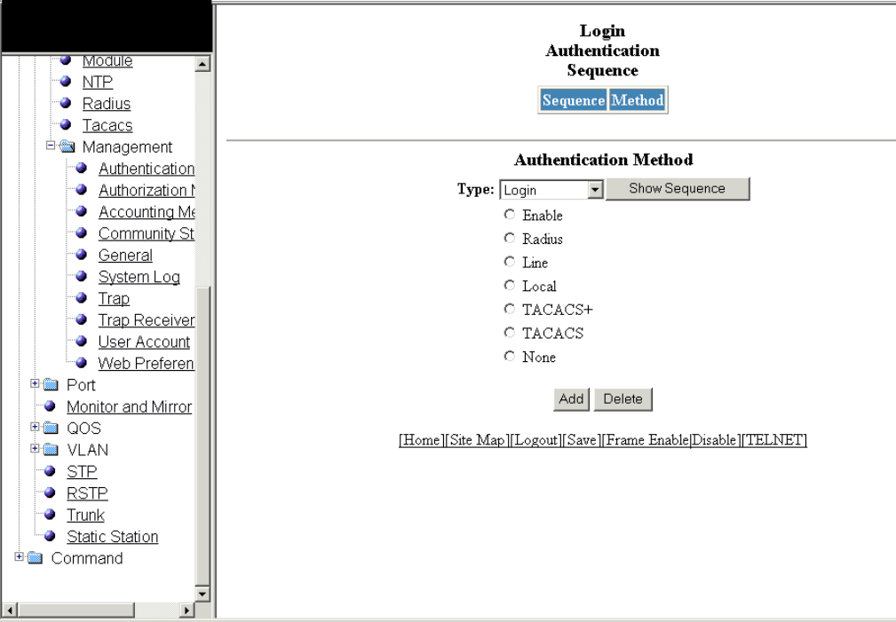
2. Click Management and select Authentication Methods.
The Authentication Method window is displayed as shown in the gure below.
FIGURE 73 Conguring management authentication
3. Select one of the following types of authentication in the Type list:
•Login
•Enable
•Web Server
•SNMP Server
4. Click one of the following servers:
•Enable
•Radius
•Line
•Local
•TACACS+
•TACACS
•None
Conguring management authentication
Brocade FastIron SX, FCX, and ICX Web Management Interface User Guide, 08.0.30
146 Part Number: 53-1003615-02
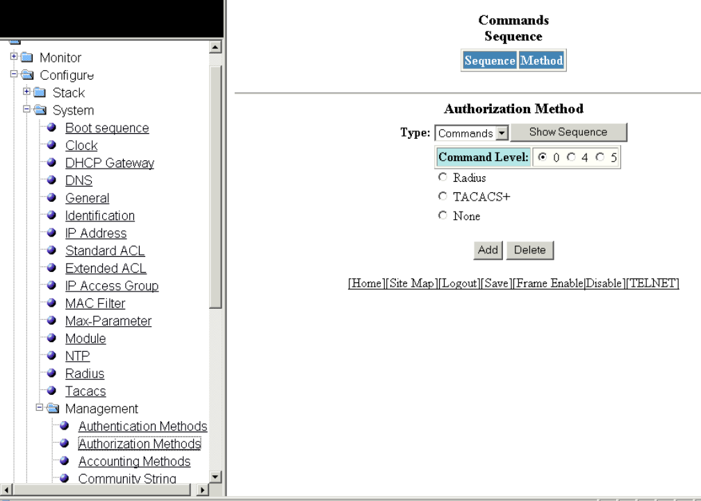
5. Click Add.
The message The change has been made is displayed and the congured authentication method is listed in the Login
Authentication Sequence pane. Click Show Sequence to display the list of authentication methods added. To remove the
congured management authentication, click Delete.
Conguring management authorization
To congure management authorization, perform the following steps.
1. Click Congure on the left pane and select System.
2. Click Management and select Authorization Methods.
The Authorization Method window is displayed as shown in the gure below.
FIGURE 74 Conguring management authorization
Conguring management authorization
Brocade FastIron SX, FCX, and ICX Web Management Interface User Guide, 08.0.30
Part Number: 53-1003615-02 147
3. Select either of the following modes of authorization in the Type list:
•Commands
•Exec
4. Click 0 or 4 or 5 for Command Level.
5. Click one of the following servers:
•Radius
•TACACS+
•None
6. Click Add.
The message The change has been made is displayed and the congured authorization method is listed in the Commands
Sequence pane. Click Show Sequence to display the list of authentication methods added. To delete the congured
management authorization, click Delete.
Conguring management accounting
To congure management accounting, perform the following steps.
1. Click Congure on the left pane and select System.
Conguring management accounting
Brocade FastIron SX, FCX, and ICX Web Management Interface User Guide, 08.0.30
148 Part Number: 53-1003615-02
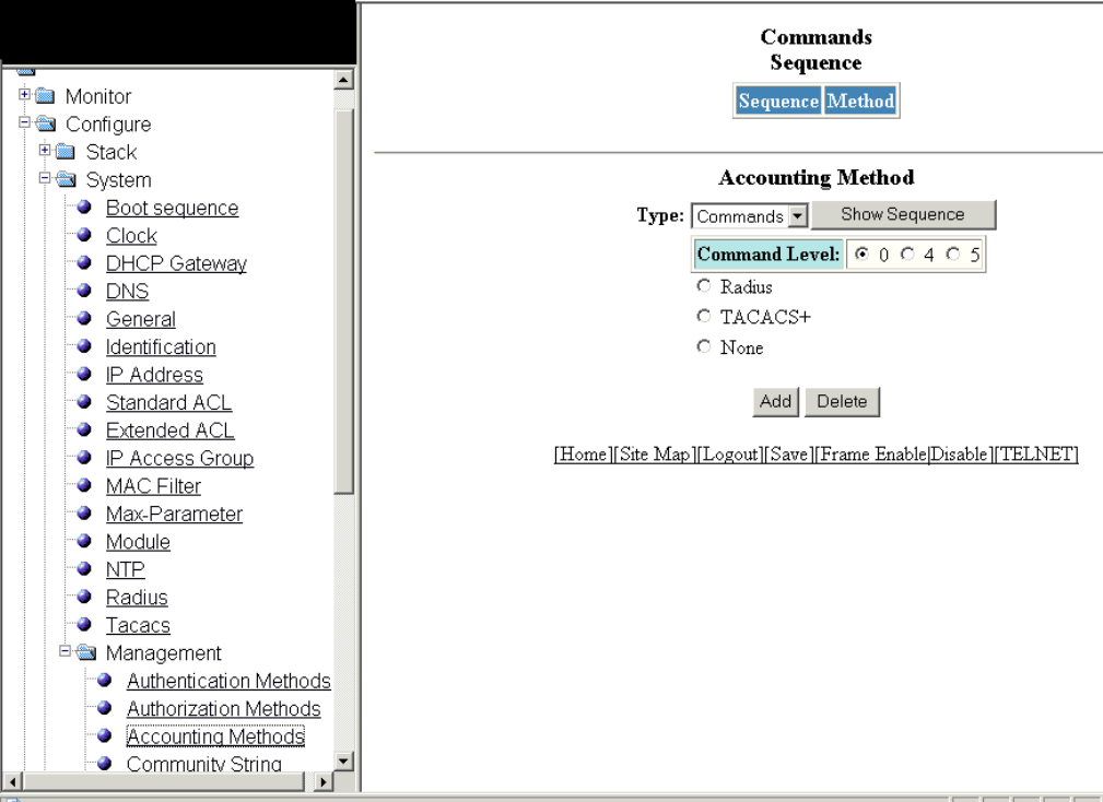
2. Click Management and select Accounting Methods.
The Accounting Method window is displayed as shown in the gure below.
FIGURE 75 Conguring management accounting methods
3. Select one of the following modes of authorization:
•Commands
•Exec
•System
4. Click 0 or 4 or 5 for Command Level .
5. Click one of the following servers:
•Radius
•TACACS+
•None
Conguring management accounting
Brocade FastIron SX, FCX, and ICX Web Management Interface User Guide, 08.0.30
Part Number: 53-1003615-02 149
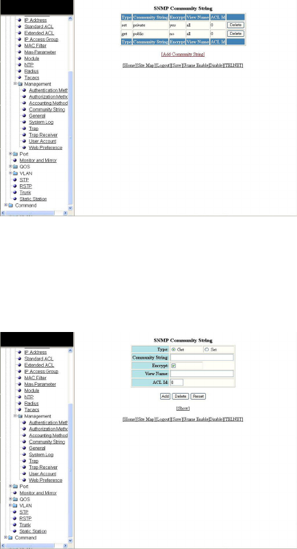
6. Click Add.
The message The change has been made is displayed and the congured accounting method is listed in the Commands
Sequence pane. To delete the congured accounting method, click Delete.
Conguring an SNMP community string
To congure an SNMP community string, perform the following steps.
1. Click Congure on the left pane and select System .
2. Click Management and select Community String.
The SNMP Community String window is displayed as shown in the gure below.
FIGURE 76 Conguring an SNMP community string
3. Click Add Community String .
The SNMP Community String window is displayed as shown in the gure below.
FIGURE 77 Adding community strings
4. Click Get or Set for Type .
Conguring an SNMP community string
Brocade FastIron SX, FCX, and ICX Web Management Interface User Guide, 08.0.30
150 Part Number: 53-1003615-02
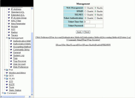
5. Type the user name to open a web management session in the Community String eld.
6. Select the Encrypt check box to enable encryption for a particular string.
7. Type the name of the community string in the View Name eld.
8. Type the ACL number in the ACL Id eld.
9. Click Add .
The message The change has been made is displayed. To display the congured community string, click Show .
To delete the community string, click Delete . To reset the data entered in the conguration pane, click Reset .
Conguring the general management parameters
To congure the general management parameters, perform the following steps.
1. Click Congure on the left pane and select System .
2. Click Management and select General .
The Management window is displayed as shown in the gure below.
FIGURE 78 Conguring general management parameters
3. Click Disable or Enable for Web Management .
4. Click Disable or Enable for SNMP .
5. Click Disable or Enable for TELNET .
6. Click Disable or Enable for Telnet Authentication .
7. Type the timeout interval in seconds to wait for a response in the Telnet Time Out eld.
8. Type an alphanumeric password in the Telnet Password eld.
Conguring the general management parameters
Brocade FastIron SX, FCX, and ICX Web Management Interface User Guide, 08.0.30
Part Number: 53-1003615-02 151
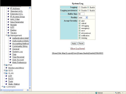
9. Click Apply .
The message The change has been made is displayed. To reset the data entered in the conguration pane, click Reset .
The Management window provides links to congure other management parameters:
• To congure the web management preferences, click Web Preference . For more information, refer to Conguring the web
management preferences on page 158.
• To congure a management user account, click User Account . For more information, refer to Conguring a management
user account on page 157.
• To congure management authentication, click Authentication Methods . For more information, refer to Conguring
management authentication on page 145.
• To congure management authorization, click Authorization Methods . For more information, refer to Conguring
management authorization on page 147.
• To congure management accounting, click Accounting Methods . For more information, refer to Conguring
management accounting on page 148.
• To congure a system module, click System . For more information, refer to Conguring a system module on page 139.
• To congure an SNMP community string, click Community String . For more information, refer to Conguring a system
module on page 139.
• To congure a trap, click Trap . For more information, refer to Conguring a trap on page 154.
• To congure a trap receiver, click Trap Receiver . For more information, refer to Conguring a trap receiver on page 155.
Conguring a management system log
To congure a management system log, perform the following steps.
1. Click Congure on the left pane and select System.
2. Click Management and select System Log.
The System Log window is displayed as shown in the gure below.
FIGURE 79 Conguring a system log
3. Click Disable or Enable for Logging. By default, the syslog buer is enabled.
Conguring a management system log
Brocade FastIron SX, FCX, and ICX Web Management Interface User Guide, 08.0.30
152 Part Number: 53-1003615-02

4. Click Disable or Enable for Logging persistence. By default, logging persistence is disabled.
5. Type the number of messages in the Buer Size eld.
6. Select a facility in the Facility list.
7. Select one of the following severity levels for Accept Severity:
•alert
•critical
•debugging
•emergency
•error
•informational
•notication
•warning
8. Click Apply .
The message The change has been made is displayed. To display log server entries, click Show Log Server. To reset the
data entered in the conguration pane, click Reset.
If there are no log servers, the message There are no Log Server entries is displayed as shown in the gure below.
FIGURE 80 Viewing log server entries
To add extra log servers to your system log conguration, perform the following steps.
Conguring a management system log
Brocade FastIron SX, FCX, and ICX Web Management Interface User Guide, 08.0.30
Part Number: 53-1003615-02 153
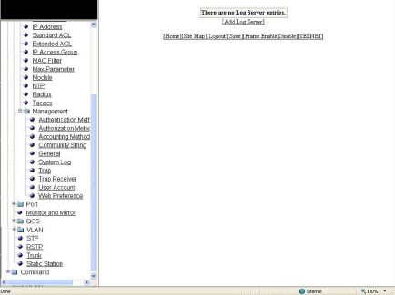
Adding a log server
To add a log sever, perform the following steps.
1. Click Add Log Server.
The System Log Server window is displayed as shown in the gure below.
FIGURE 81 Adding a Log Server
2. Click ipv4 or ipv6 and then type the IPv4 or IPv6 address in the Server IP Address eld.
3. Type the application port that can be used for the syslog facility in the Server Udp Port eld. The default value is 514.
4. Click Add .
The message The change has been made is displayed. To display the log server entries, click Show Log Server . To
display the system log window, click Show System Log .
To delete the changes made, click Delete. To reset the data entered in the conguration pane Reset.
Conguring a trap
To congure a trap, perform the following steps.
1. Click Congure on the left pane and select System .
Conguring a trap
Brocade FastIron SX, FCX, and ICX Web Management Interface User Guide, 08.0.30
154 Part Number: 53-1003615-02
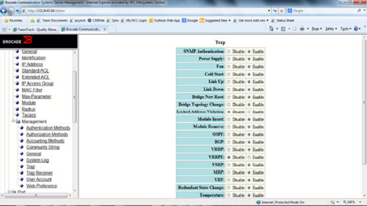
2. Click Management and select Trap .
The Trap window is displayed as shown in the gure below.
FIGURE 82 Conguring a trap
3. Click Disable or Enable for SNMP Authentication .
4. Click Disable or Enable for Power Supply .
5. Click Disable or Enable for Fan .
6. Click Disable or Enable for Cold Start .
7. Click Disable or Enable for Link Up .
8. Click Disable or Enable for Link Down .
9. Click Disable or Enable for STP New Root .
10. Click Disable or Enable for STP Topology Change .
11. Click Disable or Enable for Locked Address Violation .
12. Click Disable or Enable for Module Inserted .
13. Click Disable or Enable for Module Removed .
14. Click Disable or Enable for OSPF .
15. Click Disable or Enable for Temperature warning .
16. Click Apply .
The message The change has been made is displayed. To reset the data entered in the conguration pane, click Reset .
Conguring a trap receiver
To congure a trap receiver, perform the following steps.
1. Click Congure on the left pane and select System.
Conguring a trap receiver
Brocade FastIron SX, FCX, and ICX Web Management Interface User Guide, 08.0.30
Part Number: 53-1003615-02 155
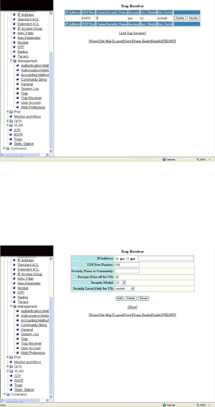
2. Click Management and select Trap Receiver.
The Trap Receiver window is displayed as shown in the gure below.
FIGURE 83 Conguring a trap receiver
3. Click Add Trap Receiver to congure a new trap receiver.
The Trap Receiver window is displayed as shown here.
FIGURE 84 Adding a new trap receiver
4. Click ipv4 or ipv6 and then type the IP address of the destination of the route in the IP Address eld.
5. Type the UDP port number of the host that will receive the trap in the UDP Port Number eld.
6. Type an arbitrary value made of two ve-digit integers joined by a colon in the Security Name or Community eld. Each string
in the community name can be a number from 0 through 65535.
7. Select the Encrypt (Turn o for V3) check box to enable or disable encryption for a particular string. It is turned o for V3.
8. Select one of the following options in the Security Model list:
•V1
•V2C
•V3
Conguring a trap receiver
Brocade FastIron SX, FCX, and ICX Web Management Interface User Guide, 08.0.30
156 Part Number: 53-1003615-02
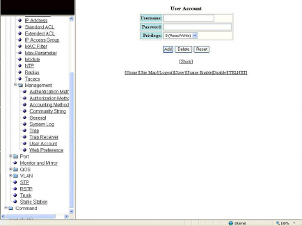
9. For V3 only, select one of the following options in the Security Level (Only for V3) list:
•noAuth --Allow all packets.
•authNoPriv --Allow only authenticated packets.
•authPriv --A password is required.
10. Click Add.
The message The change has been made is displayed. To view the trap receiver entries, click Show.
To delete the trap receiver, click Delete. To reset the data entered in the conguration pane, click Reset.
Conguring a management user account
To congure a management user account, perform the following steps.
1. Click Congure on the left pane and select System.
2. Click Management and select User Account.
The User Account window is displayed as shown in the gure below.
FIGURE 85 Conguring a management user account
3. Type the user identier in the Username eld.
4. Type the login password in the Password eld.
5. Select one of the following options in the Privilege list:
•0 (Read-Write)
•4 (Port-Cong)
•5 (Read-Only)
6. Click Add.
The message The change has been made is displayed. To view the congured user account, click Show.
To delete the congured user account, click Delete. To reset the data entered in the conguration pane, click Reset.
Conguring a management user account
Brocade FastIron SX, FCX, and ICX Web Management Interface User Guide, 08.0.30
Part Number: 53-1003615-02 157
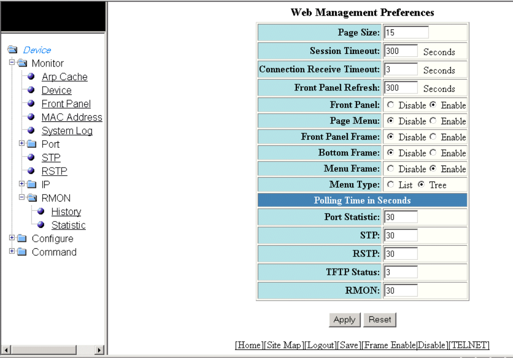
Conguring the web management preferences
To congure the web management preferences, perform the following steps.
1. Click Congure on the left pane and select System.
2. Click Management and select Web Preference.
The Web Management Preferences window for the Brocade FastIron SX devices is displayed as shown in the gure below.
FIGURE 86 Conguring the web management preferences
3. Type the page size in the Page Size eld.
4. Type the console session timeout value in seconds in the Session Timeout eld.
5. Type the wait time interval after getting disconnected from the application in the Connection Receive Timeout eld.
6. Type the number of seconds after which the front panel gets refreshed in the Front Panel Refresh eld.
7. Click Disable or Enable for Front Panel. By default, it is enabled and the ports are labelled on the front panel of the devices.
8. Click Disable or Enable for Page Menu.
9. Click Disable or Enable for Front Panel Frame.
10. Click Disable or Enable for Bottom Frame.
Conguring the web management preferences
Brocade FastIron SX, FCX, and ICX Web Management Interface User Guide, 08.0.30
158 Part Number: 53-1003615-02
11. Click Disable or Enable for Menu Frame.
12. Click List or Tree for Menu Type.
13. Type the port statistics polling time in the Port Statistic eld.
14. Type the STP statistics polling time in the STP eld.
15. Type the RSTP statistics polling time in the RSTP eld.
NOTE
The RSTP eld is not available in the Web Management Preference window for the Brocade FCX and Brocade ICX
devices.
16. Type the TFTP polling time in seconds in the TFTP Status eld.
17. Type the polling time for Remote Monitoring in the RMON eld.
18. Click Apply.
The message The change has been made is displayed. To reset the data entered in the conguration pane, click Reset.
Conguring the web management preferences
Brocade FastIron SX, FCX, and ICX Web Management Interface User Guide, 08.0.30
Part Number: 53-1003615-02 159
Brocade FastIron SX, FCX, and ICX Web Management Interface User Guide, 08.0.30
160 Part Number: 53-1003615-02
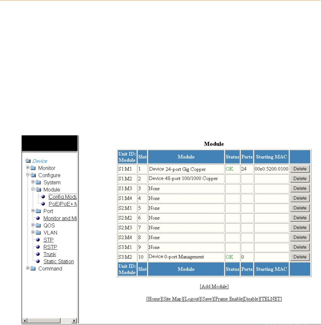
Conguring Module Components
•Conguring a module................................................................................................................................................................................... 161
• Modifying inline power budget ................................................................................................................................................................ 162
NOTE
This chapter is specic to the Brocade FastIron SX devices.
Conguring a module
To congure a chassis module, perform the following steps.
1. Click Congure on the left pane and select Module .
2. Click Cong Module .
The Module window is displayed as shown in the gure below.
FIGURE 87 Conguring a module
Brocade FastIron SX, FCX, and ICX Web Management Interface User Guide, 08.0.30
Part Number: 53-1003615-02 161
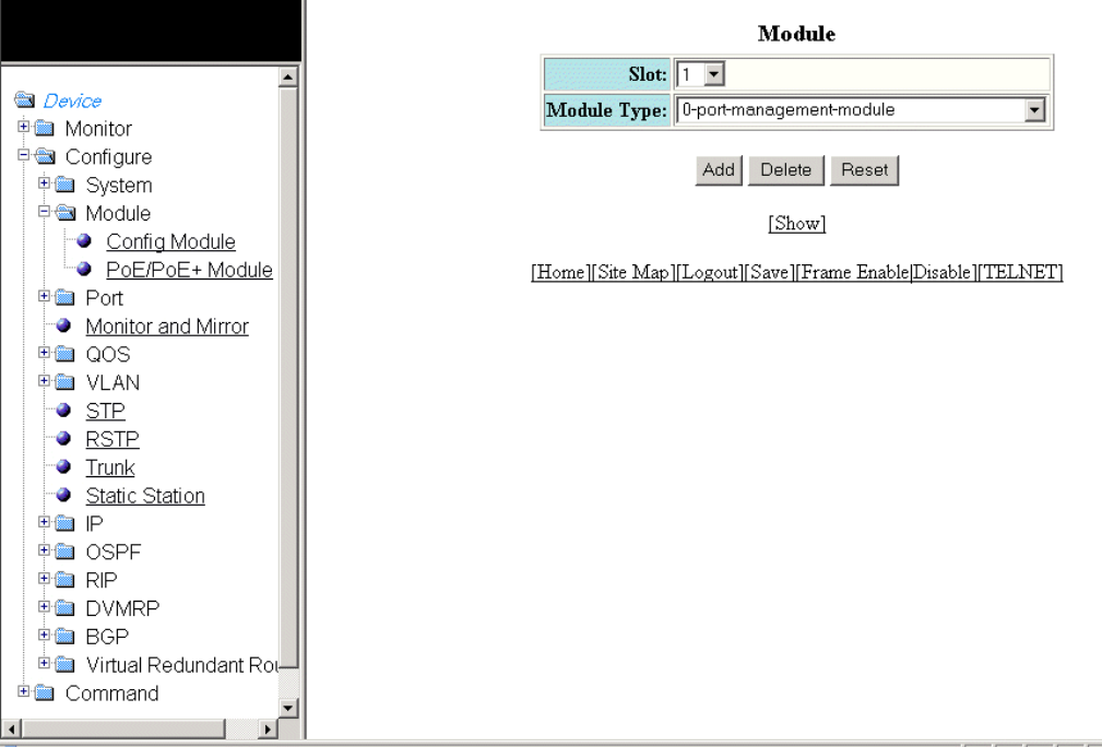
3. Click Add Module .
The Module window is displayed as shown in the gure below.
FIGURE 88 Conguring a module
4. Select a slot number in the Slot list.
5. Select a chassis module type in the Module Type list.
6. Click Add .
The message The change has been made is displayed. To display the congured module, click Show .
To delete the congured module, click Delete . To reset the data entered in the conguration pane, click Reset .
Modifying inline power budget
To congure Power over Ethernet (PoE), perform the following steps.
1. Click Congure on the left pane and select Module .
Modifying inline power budget
Brocade FastIron SX, FCX, and ICX Web Management Interface User Guide, 08.0.30
162 Part Number: 53-1003615-02
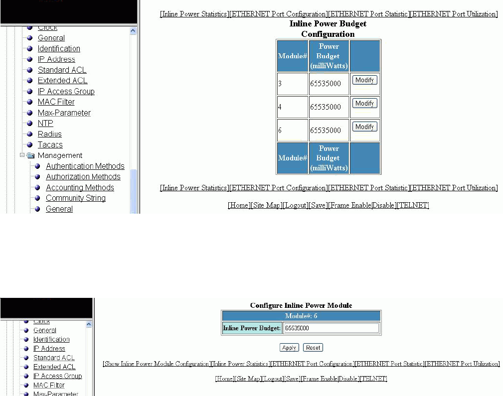
2. Click PoE/PoE+ Module .
The Inline Power Budget Conguration window is displayed as shown in the gure below.
FIGURE 89 Conguring PoE
3. Click Modify .
The Congure Inline Power Module window is displayed as shown in the gure below.
FIGURE 90 Modifying the inline power module
4. Type the number of milliwatts (from 0 through 65535000) to allocate to the module in the Inline Power Budget eld. The
default value is 65535000 milliwatts.
Modifying inline power budget
Brocade FastIron SX, FCX, and ICX Web Management Interface User Guide, 08.0.30
Part Number: 53-1003615-02 163
5. Click Apply .
The message The change has been made is displayed. To reset the data entered in the conguration pane, click Reset . To
display the congured inline power budget, click Show Inline Power Module Conguration .
The Inline Power Budget Conguration window provides links to monitor the power budget of the PoE or PoE+ modules and
to congure and monitor port parameters:
• To display the power budget of the PoE or PoE+ module, click Inline Power Statistics . For more information, refer to
Displaying inline power details on page 68.
• To congure an Ethernet port, click ETHERNET Port Conguration . For more information, refer to Conguring an
Ethernet port on page 165.
• To view the total number of packets, collisions, and errors that have occurred on a port, click ETHERNET Port Statistic .
For more information, refer to Displaying Ethernet port statistics on page 55.
• To view the trac that is received and transmitted on a port, click ETHERNET Port Utilization . For more information, refer
to Displaying Ethernet port utilization on page 59.
Modifying inline power budget
Brocade FastIron SX, FCX, and ICX Web Management Interface User Guide, 08.0.30
164 Part Number: 53-1003615-02
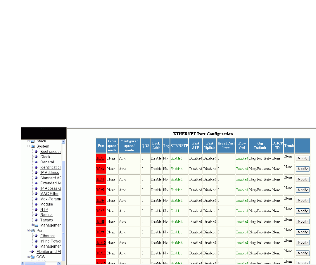
Conguring Port Parameters
•Conguring an Ethernet port..................................................................................................................................................................... 165
•Conguring port inline power.................................................................................................................................................................... 167
•Conguring a management port..............................................................................................................................................................168
•Conguring the port uplink relative utilization.....................................................................................................................................169
Conguring an Ethernet port
To congure an Ethernet port, perform the following steps.
1. Click Congure on the left pane and select Port.
2. Click Ethernet.
The ETHERNET Port Conguration window is displayed as shown in the gure below.
FIGURE 91 Conguring an Ethernet port
3. For the Brocade FCX and Brocade ICX devices, select a unit ID in the Select Stack Unit ID list and click Display to display the
information about a specic stack unit.
NOTE
The Select Stack Unit ID list is not available in the ETHERNET Port Conguration window for the Brocade FastIron
SX devices.
Brocade FastIron SX, FCX, and ICX Web Management Interface User Guide, 08.0.30
Part Number: 53-1003615-02 165
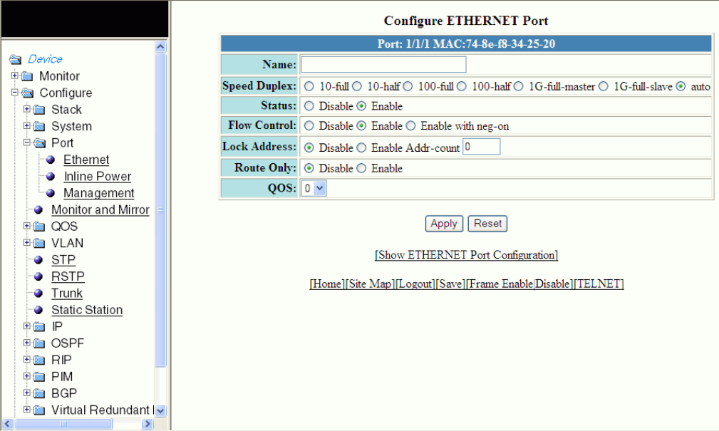
4. Click Modify to modify the respective Ethernet port.
The Congure ETHERNET Port window is displayed as shown in the gure below.
FIGURE 92 Modifying the port settings
5. Type the name of the Ethernet port in the Name eld.
6. Select the type of the port speed for Speed Duplex, which can be one of the following:
•10-full --10 Mbps, full duplex
•10-half --10 Mbps, half duplex
•100-full --100 Mbps, full duplex
•100-half --100 Mbps, half duplex
•1G-full-master --1 Gbps, full duplex master
•1G-full-slave --1 Gbps, full duplex slave
•auto --Auto-negotiation
7. Click Disable or Enable for Status to disable or enable an Ethernet port.
8. Click Disable or Enable or Enable with neg-on for Flow Control . By default, ow control is enabled.
9. Click Disable or Enable for Lock Address . If you click Enable , type the number of devices that can have access to a specic
port in the Addr-count eld.
10. Click Disable or Enable for Route Only. If you click Enable , Layer 2 switching is disabled globally.
11. Select the QoS priority for the port in the QOS list.
Conguring an Ethernet port
Brocade FastIron SX, FCX, and ICX Web Management Interface User Guide, 08.0.30
166 Part Number: 53-1003615-02
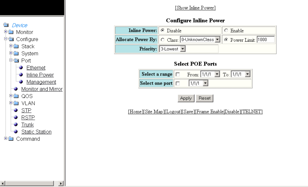
12. Click Apply.
The message The change has been made is displayed. To reset the data entered in the conguration pane, click Reset.
To display the ETHERNET Port Conguration window, click Show ETHERNET Port Conguration .
To display the inline power statistics for a PoE stack device, click Show Inline Power. For more information, refer to the
“Displaying port inline power for the Brocade FCX and Brocade ICX devices” section.
Conguring port inline power
To congure port inline power, perform the following steps.
1. Click Congure on the left pane and select Port .
2. Click Inline Power .
The Congure Inline Power window is displayed as shown in the gure below.
FIGURE 93 Conguring port inline power
3. Click Disable or Enable for Inline Power .
4. Click Class for Allocate Power By and then select a power class in the Class list, or click Power Limit and then type the
maximum power level for a power-consuming device in the Power Limit eld.
5. Select an inline power priority for a Power over Ethernet (PoE) port in the Priority list.
Conguring port inline power
Brocade FastIron SX, FCX, and ICX Web Management Interface User Guide, 08.0.30
Part Number: 53-1003615-02 167
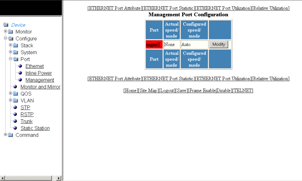
6. To select the PoE ports, select the Select a range check box and select the range of ports in the From and To lists, or select the
Select one port check box and select the port in the list.
7. Click Apply .
The message The change has been made is displayed. To reset the data entered in the conguration pane, click Reset .
To display the inline power statistics and details, click Show Inline Power . For more information, refer to Displaying port inline
power for the Brocade FCX and Brocade ICX devices on page 64.
Conguring a management port
To congure a management port, perform the following steps.
1. Click Congure on the left pane and select Port .
2. Click Management .
The Management Port Conguration window is displayed as shown in the gure below.
FIGURE 94 Management port conguration
Conguring a management port
Brocade FastIron SX, FCX, and ICX Web Management Interface User Guide, 08.0.30
168 Part Number: 53-1003615-02
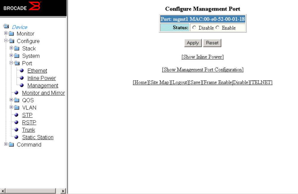
3. Click Modify .
The Congure Management Port window is displayed as shown in the gure below.
FIGURE 95 Conguring a management port
4. Click Disable or Enable for Status .
5. Click Apply .
The message The change has been made is displayed. To reset the data entered in the conguration pane, click Reset .
To display the congured management port information, click Show Management Port Conguration .
To display the inline power statistics and details, click Show Inline Power . For more information, refer to Displaying port inline
power for the Brocade FCX and Brocade ICX devices on page 64.
Conguring the port uplink relative utilization
To congure the port uplink utilization list, perform the following steps.
1. Click Congure on the left pane and select Port.
Conguring the port uplink relative utilization
Brocade FastIron SX, FCX, and ICX Web Management Interface User Guide, 08.0.30
Part Number: 53-1003615-02 169

2. Click Relative Utilization on the ETHERNET Port Conguration, Congure Inline Power, or Management Port Conguration
window.
The Port Uplink Relative Utilization window is displayed as shown in the gure below.
FIGURE 96 Conguring the port uplink relative utilization
3. Type the uplink utilization list number (from 1 through 4) in the ID eld.
4. Click Select Uplink Port Members to select the uplink ports.
Conguring the port uplink relative utilization
Brocade FastIron SX, FCX, and ICX Web Management Interface User Guide, 08.0.30
170 Part Number: 53-1003615-02
5. Click Select Downlink Port Members to select the downlink ports.
NOTE
The port number varies based on the product:
• For Brocade FCX and Brocade ICX devices - stack-unit/slotnum/portnum
• For Brocade FastIron SX devices - slotnum/portnum
6. Click Add.
The message The change has been made is displayed. To display the congured port uplink utilization list, click Show.
To modify the congured port uplink utilization list, click Modify. You can also delete the congured port uplink utilization list by
clicking Delete. To reset the data entered in the conguration pane, click Reset.
Conguring the port uplink relative utilization
Brocade FastIron SX, FCX, and ICX Web Management Interface User Guide, 08.0.30
Part Number: 53-1003615-02 171
Brocade FastIron SX, FCX, and ICX Web Management Interface User Guide, 08.0.30
172 Part Number: 53-1003615-02
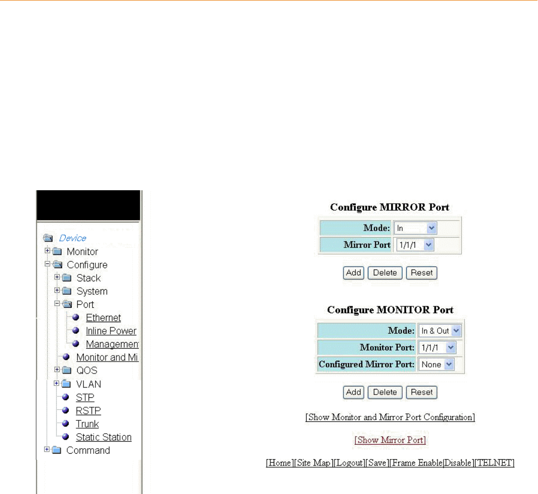
Conguring Monitor and Mirror Port
•Conguring a mirror port.............................................................................................................................................................................173
•Conguring a monitor port......................................................................................................................................................................... 175
Conguring a mirror port
To congure port monitoring, rst congure the mirror port. The mirror port is the port to which the monitored trac is copied. To
congure a mirror port, perform the following steps.
1. Click Congure on the left pane and select Monitor and Mirror.
The Congure MIRROR Port window is displayed as shown in the gure below.
FIGURE 97 Conguring a mirror port
2. Select the mode in which the port operates in the Mode list, which can be one of the following:
•In
•Out
•In & Out
Brocade FastIron SX, FCX, and ICX Web Management Interface User Guide, 08.0.30
Part Number: 53-1003615-02 173
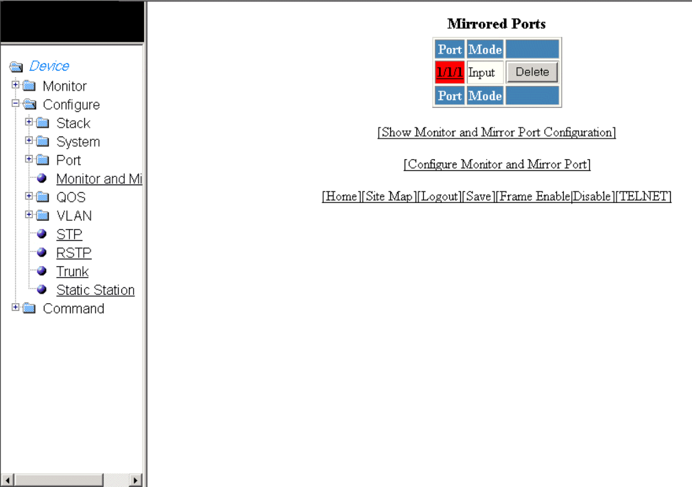
3. Select a port to which the monitored trac must be copied in the Mirror Port list. The port number varies based on the product:
• For Brocade FCX and Brocade ICX devices - stack-unit/slotnum/portnum
• For Brocade FastIron SX devices - slotnum/portnum
4. Click Add .
The message The change has been made is displayed. To display the congured mirror port, click Show Mirror Port. The
gure below shows the Mirrored Ports window with the congured mirror port information.
To delete the congured mirror port, click Delete. To reset the data entered in the conguration pane, click Reset .
FIGURE 98 Monitoring mirror ports
Conguring a mirror port
Brocade FastIron SX, FCX, and ICX Web Management Interface User Guide, 08.0.30
174 Part Number: 53-1003615-02
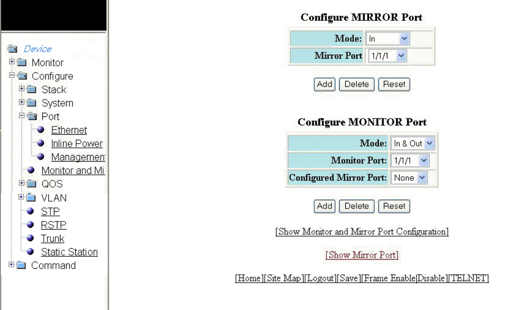
Conguring a monitor port
To congure port monitoring on an individual port on a Brocade device, perform the following steps.
1. Click Congure on the left pane and select Monitor and Mirror.
The Congure MONITOR Port window is displayed as shown in the gure below.
FIGURE 99 Conguring the monitor port
2. Select one of the following modes in which the port operates in the Mode list:
•In
•Out
•In & Out
3. Select a port for which you want to monitor the trac in the Monitor Port list. The port number varies based on the product:
• – For Brocade FCX and Brocade ICX devices - stack-unit/slotnum/portnum
– For Brocade FastIron SX devices - slotnum/portnum
4. Select a mirror port that you have congured in the Congured Mirror Port list.
5. Click Add.
The message The change has been made is displayed. To display the congured monitor port, click Show Monitor and
Mirror Port Conguration. To display the mirror port, click Show Mirror Port.
To delete the congured monitor port, click Delete. To reset the data entered in the conguration pane, click Reset.
Conguring a monitor port
Brocade FastIron SX, FCX, and ICX Web Management Interface User Guide, 08.0.30
Part Number: 53-1003615-02 175
Brocade FastIron SX, FCX, and ICX Web Management Interface User Guide, 08.0.30
176 Part Number: 53-1003615-02
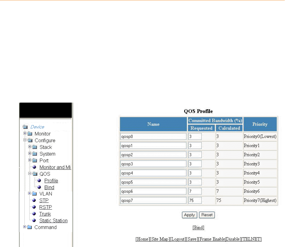
Conguring QoS
•Conguring the QoS prole....................................................................................................................................................................... 177
•Conguring the QoS prole bind............................................................................................................................................................. 178
Conguring the QoS prole
To congure the Quality of Service (QoS) prole, perform the following steps.
1. Click Congure on the left pane and select QOS .
2. Click Prole .
The QOS Prole window is displayed as shown in the gure below.
FIGURE 100 Conguring a QoS prole
3. The default queue names are qosp0 , qosp1 , qosp2 , qosp3 , qosp4 , qosp5 , qosp6 , and qosp7 . You can change one or
more of the names, if desired. Type the QoS name in the Name eld.
Brocade FastIron SX, FCX, and ICX Web Management Interface User Guide, 08.0.30
Part Number: 53-1003615-02 177
4. The Committed Bandwidth (%) is the percentage of the device outbound bandwidth that is allocated to the queue. Brocade
QoS queues require a minimum bandwidth of 3 percent for each priority. Type the percentage of bandwidth you want for the
queue in the Requested eld.
NOTE
The total of the percentages you enter must be equal to 100. The Brocade device does not adjust the bandwidth
percentages you enter.
5. Click Apply .
The message The change has been made is displayed and the committed bandwidth is changed to the congured value in
the Calculated eld. The Priority eld shows the default priority of the individual QoS from lowest to highest (0 through 7).
To clear the entered data in the elds, click Reset . To congure the QoS prole bind, click Bind . For more information on how
to congure a QoS prole bind, refer to Conguring the QoS prole bind on page 178.
Conguring the QoS prole bind
To bind an 802.1p priority to a hardware forwarding queue, perform the following steps.
1. Click Congure on the left pane and select QOS .
Conguring the QoS prole bind
Brocade FastIron SX, FCX, and ICX Web Management Interface User Guide, 08.0.30
178 Part Number: 53-1003615-02
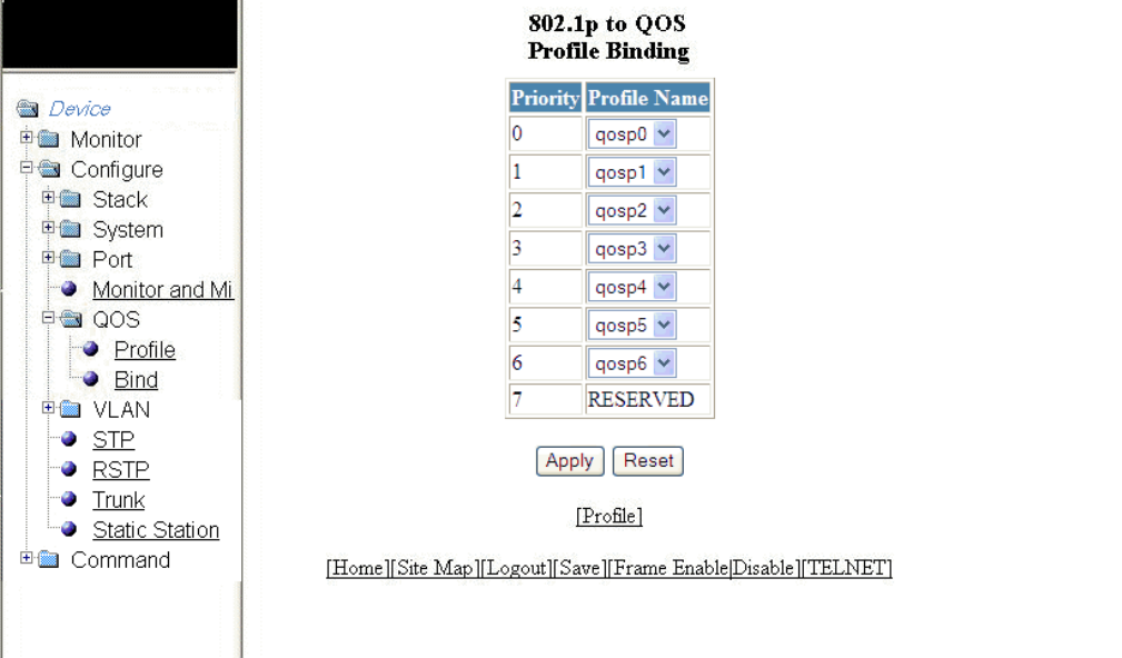
2. Click Bind .
The 802.1p to QOS Prole Binding window is displayed as shown in the gure below.
FIGURE 101 802.1p to QoS prole binding
3. Select a hardware forwarding queue to which you are reassigning the priority in the Prole Name lists.
4. Click Apply .
The message The change has been made is displayed. To reset the data entered in the conguration pane, click Reset .
To congure the Quality of Service (QoS) prole, click Prole . For more information, refer to Conguring the QoS prole on
page 177.
Conguring the QoS prole bind
Brocade FastIron SX, FCX, and ICX Web Management Interface User Guide, 08.0.30
Part Number: 53-1003615-02 179
Brocade FastIron SX, FCX, and ICX Web Management Interface User Guide, 08.0.30
180 Part Number: 53-1003615-02
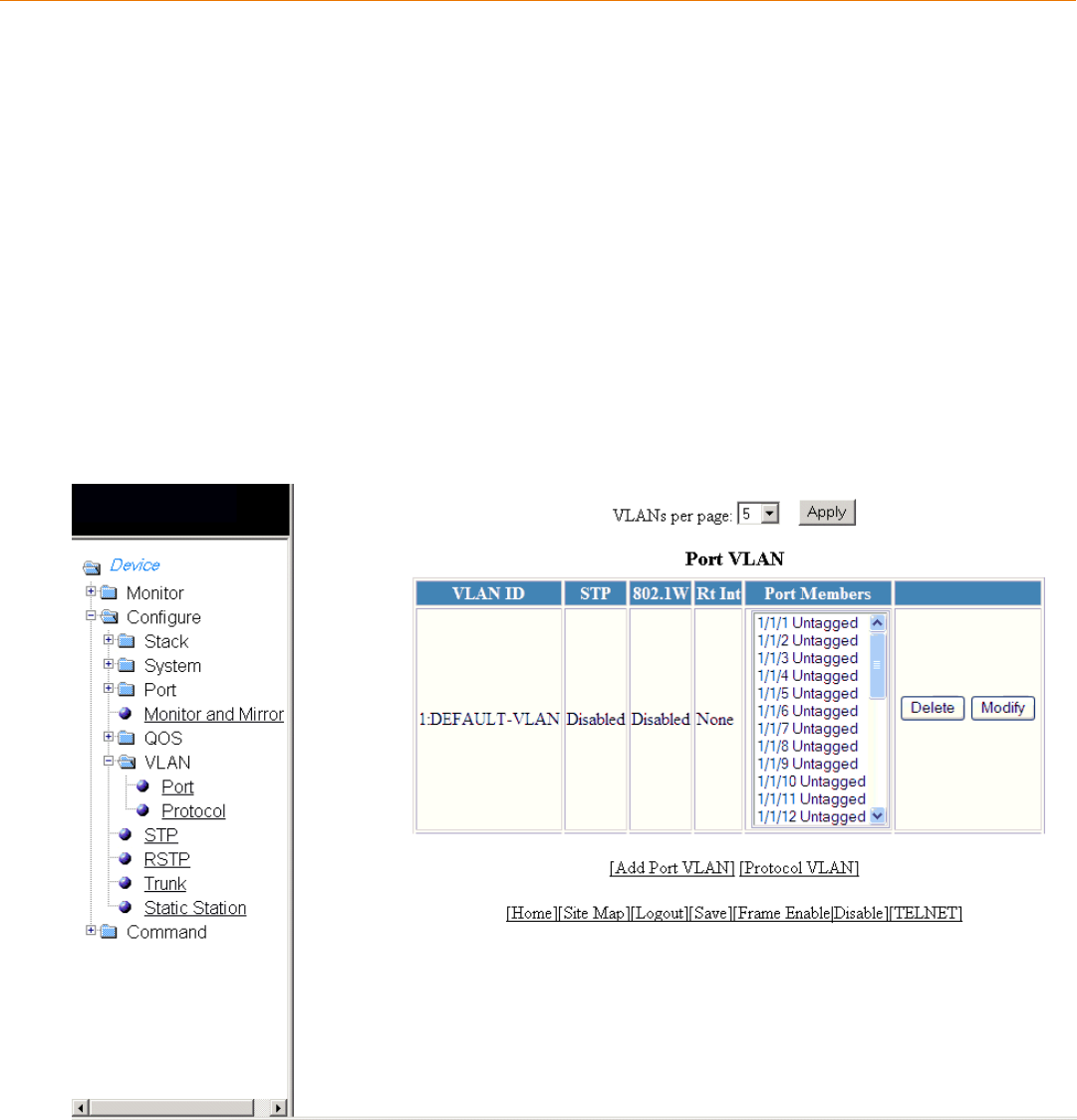
Conguring VLAN
•Conguring a port VLAN for the Brocade FCX and Brocade ICX devices............................................................................181
• Modifying a port VLAN................................................................................................................................................................................185
•Conguring a port VLAN for the Brocade FastIron SX devices................................................................................................. 188
Conguring a port VLAN for the Brocade FCX and
Brocade ICX devices
To congure a port-based Virtual LAN (VLAN) for the Brocade FCX and Brocade ICX devices, perform the following steps.
1. Click Congure on the left pane and select VLAN .
2. Click Port .
The Port VLAN window is displayed as shown in the gure below. You can limit the number of VLANs displayed per page
using the VLANs per page list.
FIGURE 102 Conguring port VLANs
Brocade FastIron SX, FCX, and ICX Web Management Interface User Guide, 08.0.30
Part Number: 53-1003615-02 181
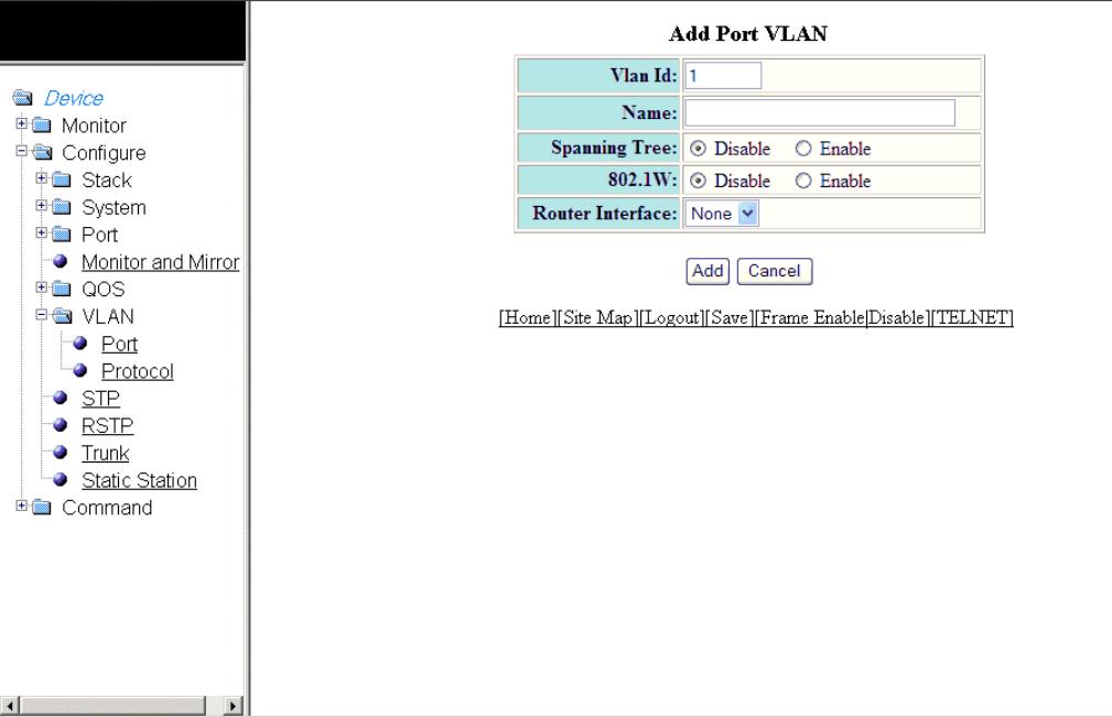
3. Click Add Port VLAN .
The Add Port VLAN window is displayed as shown in the gure below.
NOTE
Port-based VLAN cannot be congured, if the VLAN does not have any ports assigned to it.
FIGURE 103 Adding port VLANs
4. Type the VLAN identier of the port in the Vlan Id eld.
5. Type the port VLAN name in the Name eld.
6. Click Disable or Enable for Spanning Tree .
7. Click Disable or Enable for 802.1W .
8. Select a virtual routing interface in the Router Interface list.
Conguring a port VLAN for the Brocade FCX and Brocade ICX devices
Brocade FastIron SX, FCX, and ICX Web Management Interface User Guide, 08.0.30
182 Part Number: 53-1003615-02
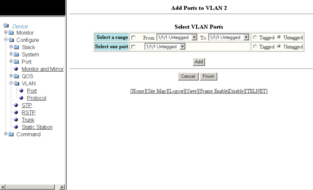
9. Click Add .
The Add Ports to VLAN window is displayed as shown in the gure below.
FIGURE 104 Adding ports to VLANs
10. To select the VLAN ports, select the Select a range check box, select the range of VLAN ports in the From and To lists, and
click Tagged or Untagged , or select the Select one port check box, select a port-based VLAN in the list, and click Tagged or
Untagged .
Conguring a port VLAN for the Brocade FCX and Brocade ICX devices
Brocade FastIron SX, FCX, and ICX Web Management Interface User Guide, 08.0.30
Part Number: 53-1003615-02 183
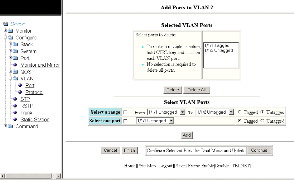
11. Click Add .
The Selected VLAN Ports window is displayed as shown in the gure below.
FIGURE 105 Selected VLAN ports
12. The selected VLAN ports are displayed in the Selected VLAN Ports list. Click Delete or Delete All to delete the VLAN ports.
NOTE
The VLAN conguration is retained even if the last port member is deleted.
13. You can add more VLAN ports from the Select VLAN Ports pane. To do so, complete step 10 and step 11 .
Conguring a port VLAN for the Brocade FCX and Brocade ICX devices
Brocade FastIron SX, FCX, and ICX Web Management Interface User Guide, 08.0.30
184 Part Number: 53-1003615-02
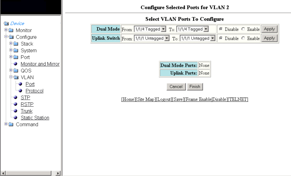
14. Click Finish to return to the Port VLAN window with the congured port-based VLAN displayed, or click Continue to congure
selected ports for dual mode and uplink. The Congure Selected Ports for VLAN window is displayed as shown in the gure
below.
FIGURE 106 Conguring dual mode and uplink for ports
15. To congure dual mode and uplink for the ports, perform the following steps.
a) Select the ports for which you want to congure the dual mode in the From and To lists for Dual Mode . Click Disable or
Enable and then click Apply . The congured ports are displayed in the Dual Mode Ports list.
b) Select the ports for which you want to congure uplink in the From and To lists for Uplink Switch . Click Disable or Enable
and then click Apply . The congured ports are displayed in the Uplink Ports list.
c) Click Finish .
The congured port VLAN is displayed in the Port VLAN window. To cancel the VLAN port conguration and return to the
Port VLAN window, click Cancel .
Modifying a port VLAN
To modify a port VLAN, perform the following steps.
1. Click Congure on the left pane and select VLAN .
Modifying a port VLAN
Brocade FastIron SX, FCX, and ICX Web Management Interface User Guide, 08.0.30
Part Number: 53-1003615-02 185
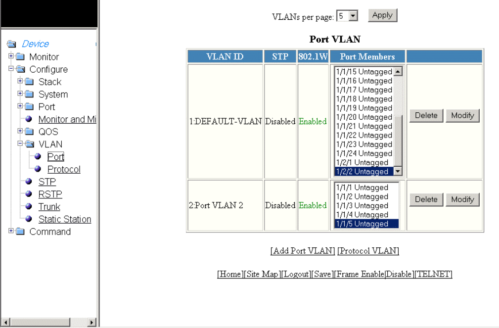
2. Click Port .
The Port VLAN window is displayed as shown in the gure below.
FIGURE 107 Conguring port VLANs
Modifying a port VLAN
Brocade FastIron SX, FCX, and ICX Web Management Interface User Guide, 08.0.30
186 Part Number: 53-1003615-02
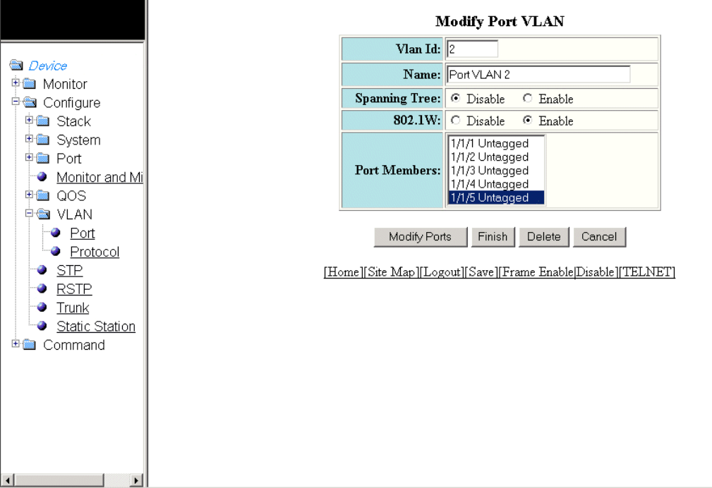
3. Click Modify .
The Modify Port VLAN window is displayed as shown in the gure below .
FIGURE 108 Modifying port VLANs
4. Type the VLAN identier of the port in the Vlan Id eld.
5. Type the port VLAN name in the Name eld.
6. Click Disable or Enable for Spanning Tree .
7. Click Disable or Enable for 802.1W .
8. Select the VLAN ports in the Port Members list.
9. Click Modify Ports to add or delete VLAN ports.
10. Click Finish .
To delete the congured port VLAN, click Delete . To undo your changes and go back to the Port VLAN window, click Cancel .
Modifying a port VLAN
Brocade FastIron SX, FCX, and ICX Web Management Interface User Guide, 08.0.30
Part Number: 53-1003615-02 187
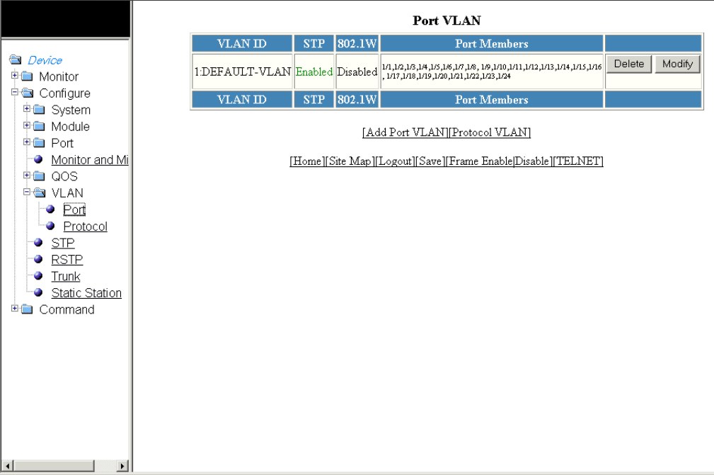
Conguring a port VLAN for the Brocade FastIron SX
devices
To congure a port-based Virtual LAN (VLAN) for the Brocade FastIron SX devices, perform the following steps.
1. Click Congure on the left pane and select VLAN.
2. Click Port.
The Port VLAN window is displayed as shown in the gure below.
FIGURE 109 Conguring port VLANs
Conguring a port VLAN for the Brocade FastIron SX devices
Brocade FastIron SX, FCX, and ICX Web Management Interface User Guide, 08.0.30
188 Part Number: 53-1003615-02
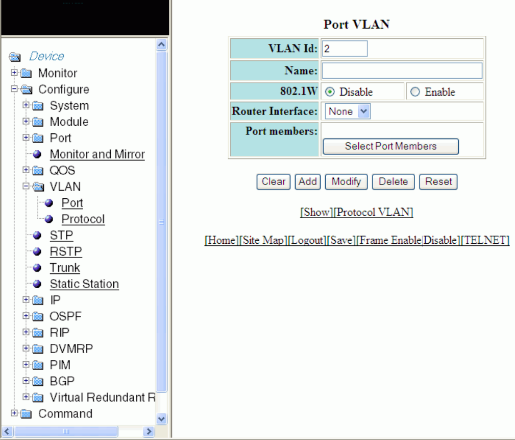
3. Click Add Port VLAN.
ThePort VLAN window is displayed as shown in the gure below.
NOTE
Port-based VLAN cannot be congured, if the VLAN does not have any ports assigned to it.
FIGURE 110 Adding port VLANs
4. Type the VLAN identier of the port in the VLAN Id eld.
5. Type the port VLAN name in the Name eld.
6. Click Disable or Enable for 802.1W .
7. Select a virtual routing interface in the Router Interface list.
Conguring a port VLAN for the Brocade FastIron SX devices
Brocade FastIron SX, FCX, and ICX Web Management Interface User Guide, 08.0.30
Part Number: 53-1003615-02 189
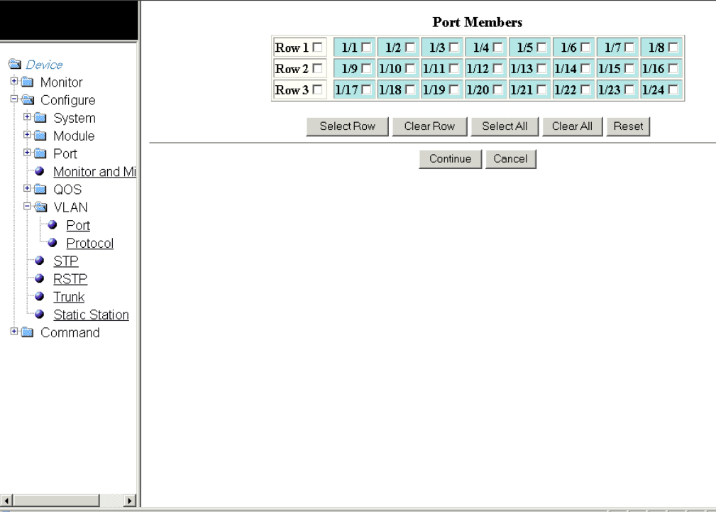
8. Click Select Port Members to add ports to the VLAN.
The Port Members window is displayed as shown in the gure below.
FIGURE 111 Adding port members
The options within the right panel include:
•Select Row—Allows you to select the entire row.
•Clear Row—Allows you to clear any selected row.
•Select All—Allows you to select all the port members.
•Clear All—Allows you to clear all the port members selected.
•Reset—Allows you to undo your changes.
NOTE
The VLAN conguration is retained even if the last port member is deleted.
9. Select the port members and click Continue. The Port VLAN window is displayed and the selected port members are displayed
in the Port Members eld. To cancel the selection of the ports and go back to the Port VLAN window, click Cancel.
The Port VLAN window is displayed and you can view the selected port members in the Port Members eld.
Conguring a port VLAN for the Brocade FastIron SX devices
Brocade FastIron SX, FCX, and ICX Web Management Interface User Guide, 08.0.30
190 Part Number: 53-1003615-02
10. Click Add on thePort VLAN window.
The message The change has been made is displayed. To delete the congured port VLAN, click Delete . To undo your
changes and go back to the Port VLAN window, click Cancel.
Conguring a port VLAN for the Brocade FastIron SX devices
Brocade FastIron SX, FCX, and ICX Web Management Interface User Guide, 08.0.30
Part Number: 53-1003615-02 191
Brocade FastIron SX, FCX, and ICX Web Management Interface User Guide, 08.0.30
192 Part Number: 53-1003615-02

Conguring STP
•Conguring STP parameters.....................................................................................................................................................................193
Conguring STP parameters
Brocade Layer 2 switches and Layer 3 switches support standard Spanning Tree Protocol (STP) as described in the IEEE 802.1D
specication.
Each port-based VLAN on a Brocade device runs a separate spanning tree. A Brocade device has one port-based VLAN (VLAN 1) that
contains all the device ports. However, if you congure additional port-based VLANs on a Brocade device, then each of those VLANs on
which STP is enabled and the VLAN 1 run separate spanning trees.
If you congure a port-based VLAN on the device, the VLAN has the same STP state as the default STP state on the device. Thus, by
default on Layer 2 switches, new VLANs have STP enabled and on Layer 3 switches, new VLANs have STP disabled. You can enable or
disable STP in each VLAN separately and also on individual ports.
Using the Web Management Interface, you can change the default STP bridge and port parameters.
Changing STP bridge parameters
The table below lists the default STP bridge parameters.
TABLE 29 Default STP bridge parameters
Parameter Default value
Forward Delay 15 seconds
Maximum Age 20 seconds
Hello Time 2 seconds
Priority 32768
NOTE
To change STP bridge timers, you must stay within the following ranges:2 * (Forward Delay-1) >= Maximum Age >= 2 * (Hello
Time +1)
Brocade FastIron SX, FCX, and ICX Web Management Interface User Guide, 08.0.30
Part Number: 53-1003615-02 193
To change the default STP bridge values, perform the following steps.
1. Click Congure on the left pane and select STP .
The STP Bridge window is displayed as shown in the gure below.
Conguring STP parameters
Brocade FastIron SX, FCX, and ICX Web Management Interface User Guide, 08.0.30
194 Part Number: 53-1003615-02
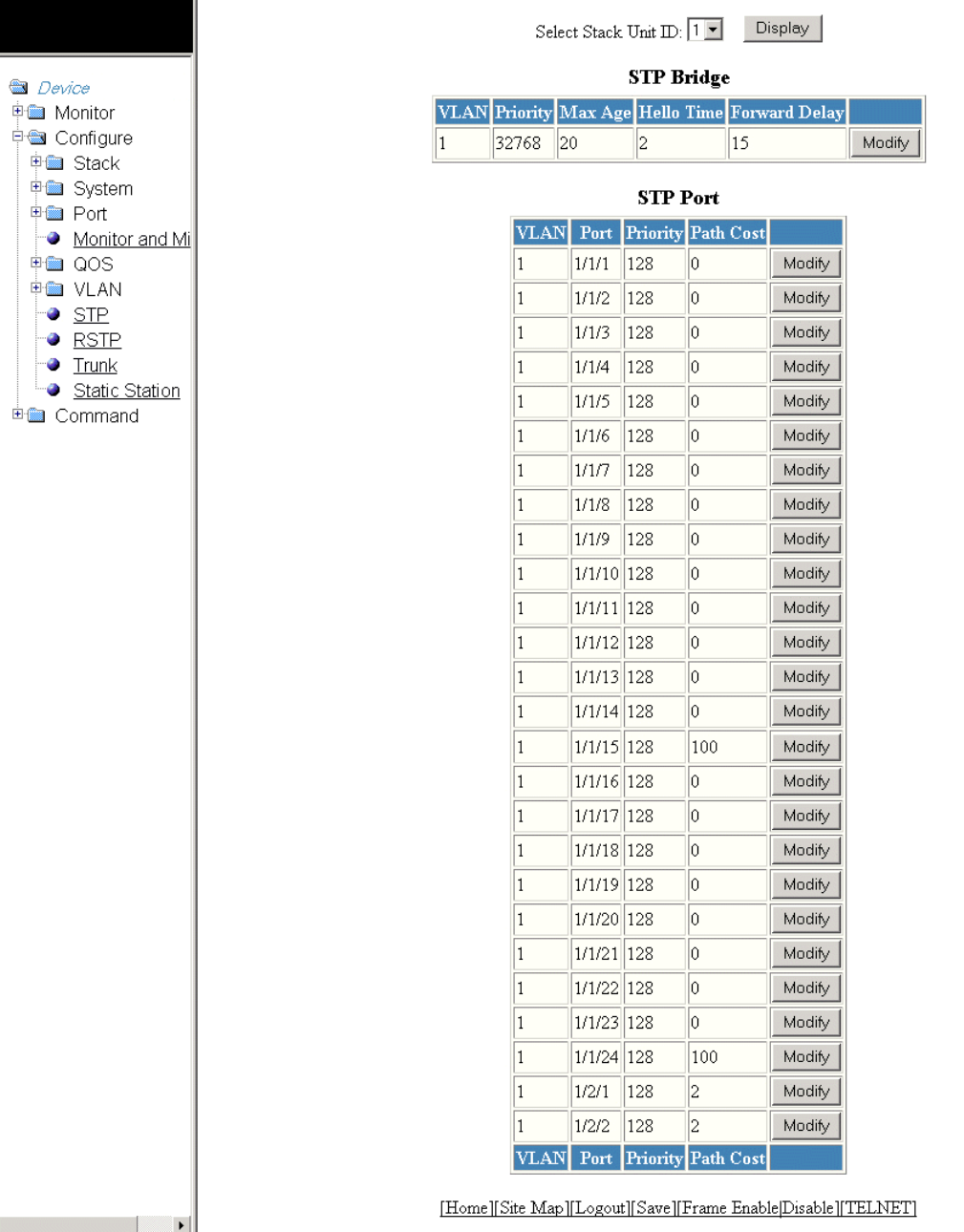
FIGURE 112 Conguring the STP bridge
Conguring STP parameters
Brocade FastIron SX, FCX, and ICX Web Management Interface User Guide, 08.0.30
Part Number: 53-1003615-02 195

2. For the Brocade FCX and Brocade ICX devices, select a unit ID in the Select Stack Unit ID list and click Display to display the
information about a specic stack unit.
NOTE
The Select Stack Unit ID list is not available in the STP Bridge window for the Brocade FastIron SX devices.
3. To change the default values of the STP bridge, click Modify .
The STP window is displayed as shown in the gure below.
FIGURE 113 Conguring STP bridge parameters
4. Type the VLAN identier of the port in the VLAN ID eld.
NOTE
The VLAN ID eld is not available in the STP window for the Brocade FastIron SX devices.
5. Type the forward delay time, which is the period of time spent by a port in the listening and learning state before moving on to
the learning or forwarding state, in the Forward Delay (Seconds) eld. The range is from 4 through 30 seconds.
6. Type the maximum amount of time the device waits before a topology change in the Maximum Age (Seconds) eld. The range
is from 6 through 40 seconds.
Conguring STP parameters
Brocade FastIron SX, FCX, and ICX Web Management Interface User Guide, 08.0.30
196 Part Number: 53-1003615-02

7. Type the hello time, which is the interval of time between each conguration BPDU sent by the root bridge, in the Hello Time
(Seconds) eld. The range is from 1 through 10 seconds.
8. Type the priority used to identify the root bridge in a spanning tree in the Priority eld. The range is from 0 through 65535.
9. Click Apply .
The message The change has been made is displayed and the congured values are displayed in the STP Bridge window.
To display the STP Bridge window, click Show . To display STP information, click Statistic . For more information on the eld
descriptions, refer to Displaying STP information on page 73.
Changing STP port parameters
The table below lists the default STP port parameters.
TABLE 30 Default STP port parameters
Parameter Default value
Priority 128
Path Cost The default path cost depends on the port type.
• 10 Mbps - 100
• 100 Mbps - 19
• 1 Gbps - 4
• 10 Gbps - 2
To change the default STP port values, perform the following steps.
1. Click Congure on the left pane and select STP.
The STP Port window is displayed as shown in the gure below.
Conguring STP parameters
Brocade FastIron SX, FCX, and ICX Web Management Interface User Guide, 08.0.30
Part Number: 53-1003615-02 197
2. For the Brocade FCX and Brocade ICX devices, select a unit ID in the Select Stack Unit ID list and click Display to display the
information about a specic stack unit.
NOTE
The Select Stack Unit ID list is not available in the STP Bridge window for the Brocade FastIron SX devices.
Conguring STP parameters
Brocade FastIron SX, FCX, and ICX Web Management Interface User Guide, 08.0.30
198 Part Number: 53-1003615-02

FIGURE 114 Conguring the STP port
Conguring STP parameters
Brocade FastIron SX, FCX, and ICX Web Management Interface User Guide, 08.0.30
Part Number: 53-1003615-02 199
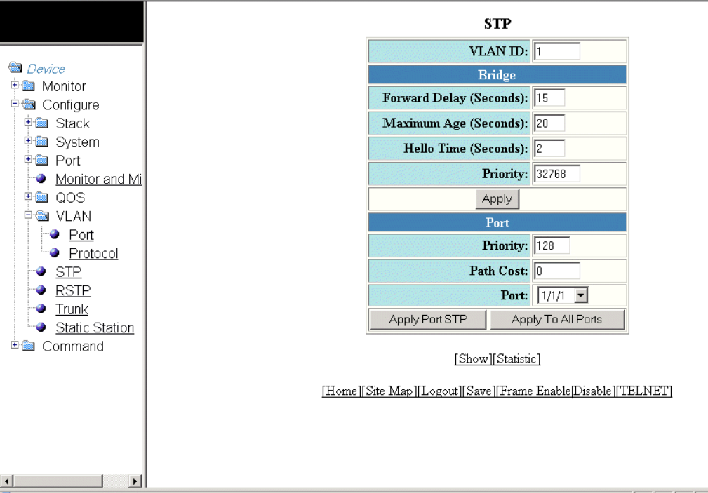
3. Click Modify to change the default values of individual STP ports.
The STP window is displayed.
FIGURE 115 Conguring STP port parameters
4. Type the VLAN identier of the port in the VLAN ID eld.
5. Type the preference that STP should give to this port relative to other ports for forwarding trac out of the spanning tree in the
Priority eld. The range is from 0 through 240.
6. Type the cost of using the port to reach the root bridge in the Path Cost eld. The range is from 0 through 65535.
7. Select a port number in the Port list. The port number varies based on the product:
• For Brocade FCX and Brocade ICX devices - stack-unit/slotnum/portnum
• For Brocade FastIron SX devices - slotnum/portnum
Conguring STP parameters
Brocade FastIron SX, FCX, and ICX Web Management Interface User Guide, 08.0.30
200 Part Number: 53-1003615-02
8. Click Apply Port STP to congure the entered values only to the specied port. Click Apply To All Ports to congure the
entered values to all the ports.
The message The change has been made is displayed and the congured values are displayed in the STP Port window. To
display the STP Port window, click Show.
To display STP information, click Statistic. For more information on the eld descriptions, refer to the “Displaying STP
information” section.
Conguring STP parameters
Brocade FastIron SX, FCX, and ICX Web Management Interface User Guide, 08.0.30
Part Number: 53-1003615-02 201
Brocade FastIron SX, FCX, and ICX Web Management Interface User Guide, 08.0.30
202 Part Number: 53-1003615-02

Conguring RSTP
•Conguring RSTP parameters..................................................................................................................................................................203
Conguring RSTP parameters
You can change the RSTP default bridge and port parameters using the Web Management Interface.
Changing RSTP bridge parameters
The table below lists the default RSTP bridge parameters.
TABLE 31 Default RSTP bridge parameters
Parameter Default value
Forward Delay 15 seconds
Maximum Age 20 seconds
Hello Time 2 seconds
Priority 32768
Force Version RSTP Default Mode
Brocade FastIron SX, FCX, and ICX Web Management Interface User Guide, 08.0.30
Part Number: 53-1003615-02 203
To change the default RSTP bridge values, perform the following steps.
1. Click Congure on the left pane and select RSTP.
The RSTP Bridge window is displayed as shown in the gure below.
Conguring RSTP parameters
Brocade FastIron SX, FCX, and ICX Web Management Interface User Guide, 08.0.30
204 Part Number: 53-1003615-02

FIGURE 116 Conguring RSTP parameters
Conguring RSTP parameters
Brocade FastIron SX, FCX, and ICX Web Management Interface User Guide, 08.0.30
Part Number: 53-1003615-02 205

2. Click Modify.
The RSTP window is displayed as shown in the gure below.
FIGURE 117 Changing RSTP bridge values
3. Type the forward delay, which species how long a port waits before it forwards an RST BPDU after a topology change, in the
Forward Delay (Seconds) eld. The range is from 4 through 30 seconds.
4. Type the maximum age, which species the amount of time the device waits to receive a Hello packet before it starts a topology
change, in the Maximum Age (Seconds) eld. The range is from 6 through 40 seconds.
5. Type the hello time, which species the interval between two Hello packets, in the Hello Time (Seconds) eld. The range is from
1 through 10 seconds.
6. Type the priority of the bridge in the Priority eld. The range is from 0 through 65535.
7. Click STP Compatibility Mode or RSTP Default Mode for Force Version . By default, RSTP Default Mode is enabled.
8. Click Apply.
The message The change has been made is displayed and the congured values are shown in the RSTP Bridge window.
Conguring RSTP parameters
Brocade FastIron SX, FCX, and ICX Web Management Interface User Guide, 08.0.30
206 Part Number: 53-1003615-02

Changing RSTP port parameters
The table below lists the default RSTP port parameters.
TABLE 32 Default RSTP port parameters
Parameter Default value
Admin Edge Port Disable
Admin Pt2pt Mac Disable
Force Migration Check Disable
Priority 128
Path Cost The default path cost varies based on the products:
• For Brocade FCX and Brocade ICX devices - 0
• For Brocade FastIron SX devices - 2000
Conguring RSTP parameters
Brocade FastIron SX, FCX, and ICX Web Management Interface User Guide, 08.0.30
Part Number: 53-1003615-02 207
To change the default RSTP port values, perform the following steps.
1. Click Congure on the left pane and select RSTP
The RSTP Port window is displayed as shown in the gure below.
Conguring RSTP parameters
Brocade FastIron SX, FCX, and ICX Web Management Interface User Guide, 08.0.30
208 Part Number: 53-1003615-02
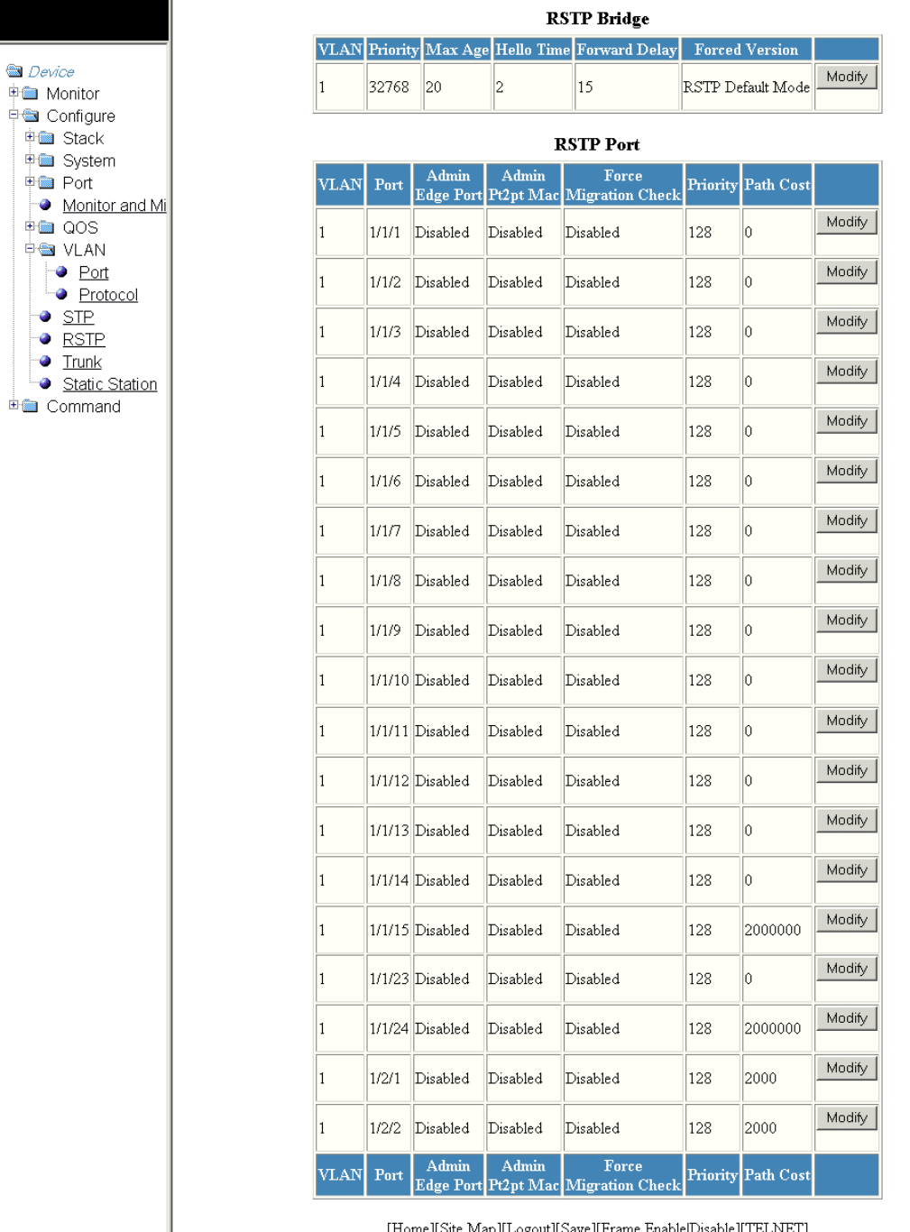
FIGURE 118 Conguring RSTP ports
Conguring RSTP parameters
Brocade FastIron SX, FCX, and ICX Web Management Interface User Guide, 08.0.30
Part Number: 53-1003615-02 209
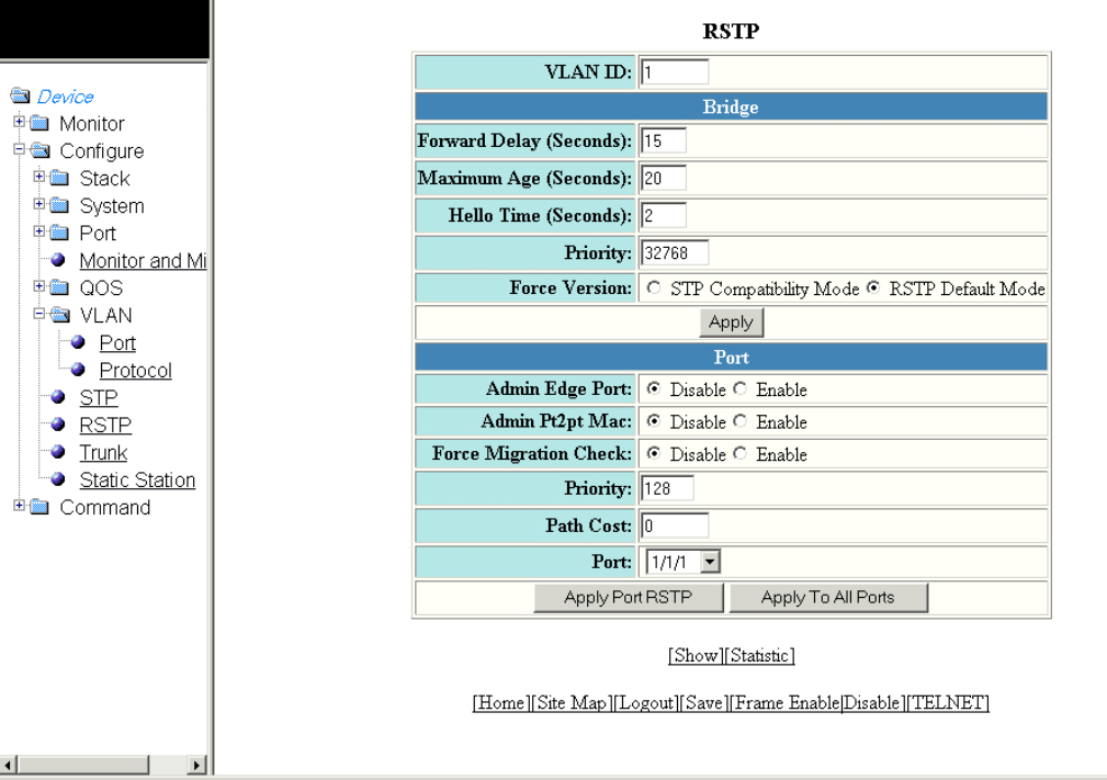
2. Click Modify to change the default values for an individual RSTP ports.
The RSTP window is displayed as shown in the gure below.
FIGURE 119 Changing RSTP port values
3. Click Disable or Enable for Admin Edge Port. If you click Enable , the port becomes an edge port in the domain.
4. Click Disable or Enable for Admin Pt2pt Mac. If you click Enable, a port will be connected to another port through a point-to-
point link.
5. Click Disable or Enable for Force Migration Check. If you click Enable, the specied port will be forced to send one RST
BPDU. If only STP BPDUs are received in response to the sent RST BPDU, then the port returns to sending STP BPDUs.
6. Type the priority, which is the preference that RSTP gives to this port relative to other ports for forwarding trac out of the
topology, in the Priority eld. The range is from 0 through 240.
7. Type the cost of the port path to the root bridge in the Path Cost eld. The range is from 1 through 20,000,000.
8. Select a port in the Port list. The port number varies based on the product:
• For Brocade FCX and Brocade FCX devices - stack-unit/slotnum/portnum
• For Brocade FastIron SX devices - slotnum/portnum
Conguring RSTP parameters
Brocade FastIron SX, FCX, and ICX Web Management Interface User Guide, 08.0.30
210 Part Number: 53-1003615-02
9. Click Apply Port RSTP to congure the values only to the specied port, or click Apply To All Ports to congure the values to
all the ports.
The message The change is made is displayed and the congured RSTP port values are reected in the RSTP Port
window.
Conguring RSTP parameters
Brocade FastIron SX, FCX, and ICX Web Management Interface User Guide, 08.0.30
Part Number: 53-1003615-02 211
Brocade FastIron SX, FCX, and ICX Web Management Interface User Guide, 08.0.30
212 Part Number: 53-1003615-02
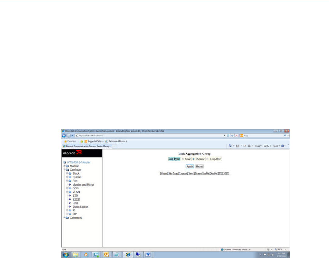
Conguring LAGs
•Conguring a static dynamic or keep-alive LAG...............................................................................................................................213
• Displaying a congured LAG.....................................................................................................................................................................216
Conguring a static dynamic or keep-alive LAG
You can congure a static, dynamic, or keep-alive link aggregation group (LAG).
NOTE
sFlow and rate-limiting commands are not supported in the Web Management interface.
To congure a LAG, perform the following steps.
1. Click Congure on the left pane and select LAG.
The Link Aggregation Group window is displayed.
You can select among the LAG types: static, dynamic, or keep-alive.
Brocade FastIron SX, FCX, and ICX Web Management Interface User Guide, 08.0.30
Part Number: 53-1003615-02 213
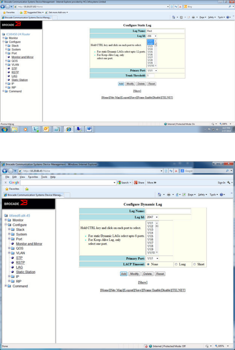
2. Click Apply.
• If you select a static LAG, this window is displayed:
• If you select a dynamic LAG, this window is displayed:
• If you select a keep-alive LAG, this window is displayed:
Conguring a static dynamic or keep-alive LAG
Brocade FastIron SX, FCX, and ICX Web Management Interface User Guide, 08.0.30
214 Part Number: 53-1003615-02
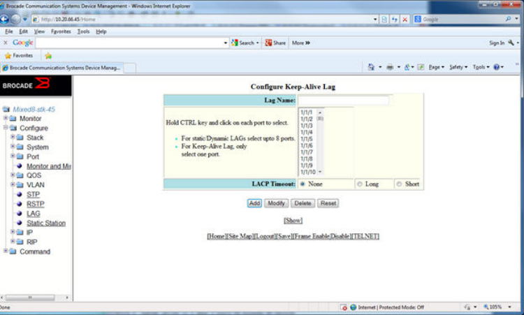
3. Enter the LAG name in the Lag Name eld.
You can enter up to 64 alphanumeric characters.
4. Enter the LAG ID in the Lag Id eld.
Hold down the CTRL key and, for static and dynamic LAGs only, select ports from the list. The number of ports you can select
for static and dynamic LAGs depends on the platform. You can select only one port for keep-alive LAGs.
NOTE
If you do not select a LAG ID, an ID is automatically generated.
5. NOTE
This step applies only to static and dynamic LAGs.
Select the primary port.
The Primary Port list displays a list of the ports you selected for the LAG; you can select a primary port from it.
6. NOTE
This step applies only to static LAGs.
Congure the trunk threshold.
7. NOTE
This step applies only to dynamic and keep-alive LAGs.
Congure the LACP timeout.
8. Click Add.
The LAG is added.
Conguring a static dynamic or keep-alive LAG
Brocade FastIron SX, FCX, and ICX Web Management Interface User Guide, 08.0.30
Part Number: 53-1003615-02 215
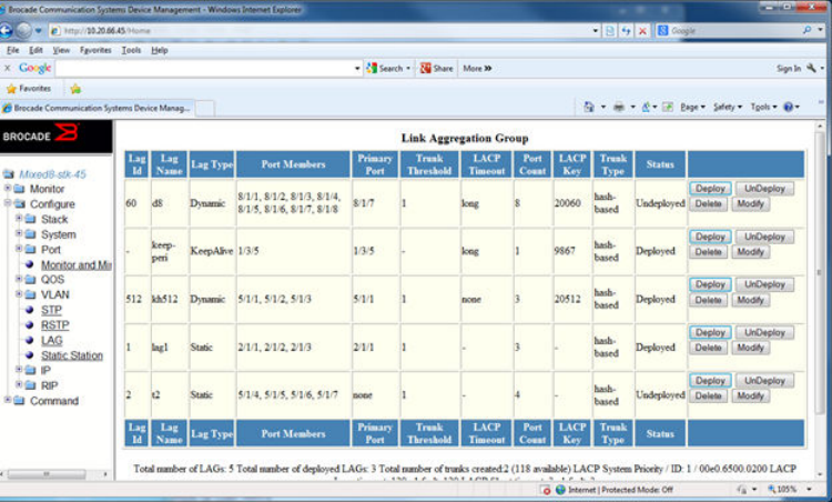
Displaying a congured LAG
You can display information for a congured link aggregation group (LAG). You can also deploy, undeploy, modify, or delete congured
LAGs.
To display LAG information, perform the following step.
Click Show in the Congure LAG window.
This window has information elds for all LAG types; the elds are populated according to the LAG type, as follows:
• For static LAGs, the LACP Timeout and LACP Key elds display “–” because these parameters do not apply to static
LAGs.
• For dynamic LAGs, the Trunk Threshold eld displays “–” because this parameter does not apply to dynamic LAGs.
You can perform the following actions in this window:
• You can select the Modify button to display the Link Aggregation Group conguration window.
• You can select the Add LAG link to congure a new LAG.
Displaying a congured LAG
Brocade FastIron SX, FCX, and ICX Web Management Interface User Guide, 08.0.30
216 Part Number: 53-1003615-02
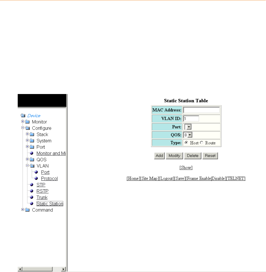
Conguring a Static Station
• Adding a static station...................................................................................................................................................................................217
• Modifying a static station.............................................................................................................................................................................218
Adding a static station
To congure a static MAC entry and assign the trac priority (QoS) and VLAN membership (VLAN ID) to the entry, perform the following
steps.
1. Click Congure on the left pane and select Static Station.
The Static Station Table window is displayed as shown in the gure below.
FIGURE 120 Conguring the static station
2. Type the MAC address of the device in xx-xx-xx-xx-xx-xx format in the MAC Address eld.
3. Type the port-based VLAN identier in the VLAN ID eld. VLAN 1 is the default VLAN.
Brocade FastIron SX, FCX, and ICX Web Management Interface User Guide, 08.0.30
Part Number: 53-1003615-02 217
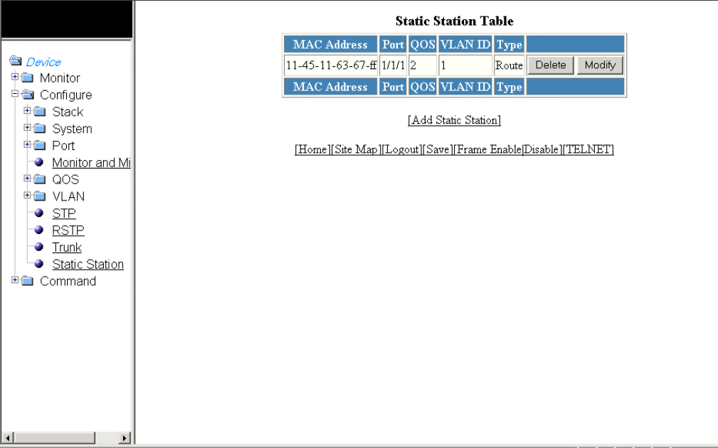
4. Select a port number in the Port list. The port number varies based on the product:
• For Brocade FCX and Brocade ICX devices - stack-unit/slotnum/portnum
• For Brocade FastIron SX devices - slotnum/portnum
5. Select a QoS priority in the QOS list. A static MAC entry can be assigned a priority from 0 through 7.
6. Click Host or Route for Type. By default, Host is selected.
7. Click Add.
The message The change has been made is displayed. To display the congured static station, click Show.
To reset the data entered in the conguration pane, click Reset. You can also delete the congured static station entry by clicking
Delete.
Modifying a static station
After you congure a static station, you can modify the port number, QoS priority, VLAN ID, and device type of the entry by performing
the following steps.
1. Click Congure on the left pane and select Static Station.
The Static Station Table window is displayed as shown in the gure below.
FIGURE 121 Modifying the static station
Modifying a static station
Brocade FastIron SX, FCX, and ICX Web Management Interface User Guide, 08.0.30
218 Part Number: 53-1003615-02
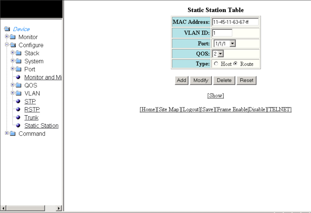
2. Click Modify .
The Static Station Table window is displayed as shown in the gure below.
FIGURE 122 Modifying the static station
3. Type the port-based VLAN identier in the VLAN ID eld. VLAN 1 is the default VLAN.
NOTE
The VLAN ID eld is not available in the Static Station Table window for the Brocade FastIron SX devices.
4. Select a port number in the Port list. The port number varies based on the product:
• For Brocade FCX and Brocade ICX devices - stack-unit/slotnum/portnum
• For Brocade FastIron SX devices - slotnum/portnum
5. Select a QoS priority in the QOS list. A static MAC entry can be assigned a priority from 0 through 7.
6. Click Host or Route for Type.
7. Click Modify.
The message The change has been made is displayed and the congured values are reected in the Static Station
window. To display the modied static station, click Show.
To reset the data entered in the conguration pane, click Reset . You can also delete the static station entry by clicking Delete.
Modifying a static station
Brocade FastIron SX, FCX, and ICX Web Management Interface User Guide, 08.0.30
Part Number: 53-1003615-02 219
Brocade FastIron SX, FCX, and ICX Web Management Interface User Guide, 08.0.30
220 Part Number: 53-1003615-02

Conguring IP
•Conguring the router IP address............................................................................................................................................................221
•Conguring a standard ACL.......................................................................................................................................................................223
•Conguring an extended ACL...................................................................................................................................................................224
•Conguring an IP access group............................................................................................................................................................... 228
•Conguring an IP Autonomous System-path access list..............................................................................................................230
•Conguring an IP community list.............................................................................................................................................................231
•Conguring an IP prex list.........................................................................................................................................................................232
•Conguring a DNS entry............................................................................................................................................................................. 234
•Conguring the general IP settings.........................................................................................................................................................235
•Conguring IP interfaces............................................................................................................................................................................. 237
•Conguring a static ARP............................................................................................................................................................................. 239
•Conguring a static RARP.......................................................................................................................................................................... 240
•Conguring a static route.............................................................................................................................................................................241
•Conguring a UDP helper...........................................................................................................................................................................243
The IP feature is specic to the Brocade FCX, Brocade ICX, and Brocade FastIron SX devices running Layer 3 code.
NOTE
The terms "Layer 3 switch" and "router" are used interchangeably in this chapter.
Conguring the router IP address
To congure an IP address to an interface, perform the following steps.
1. Click Congure on the left pane and select IP.
Brocade FastIron SX, FCX, and ICX Web Management Interface User Guide, 08.0.30
Part Number: 53-1003615-02 221
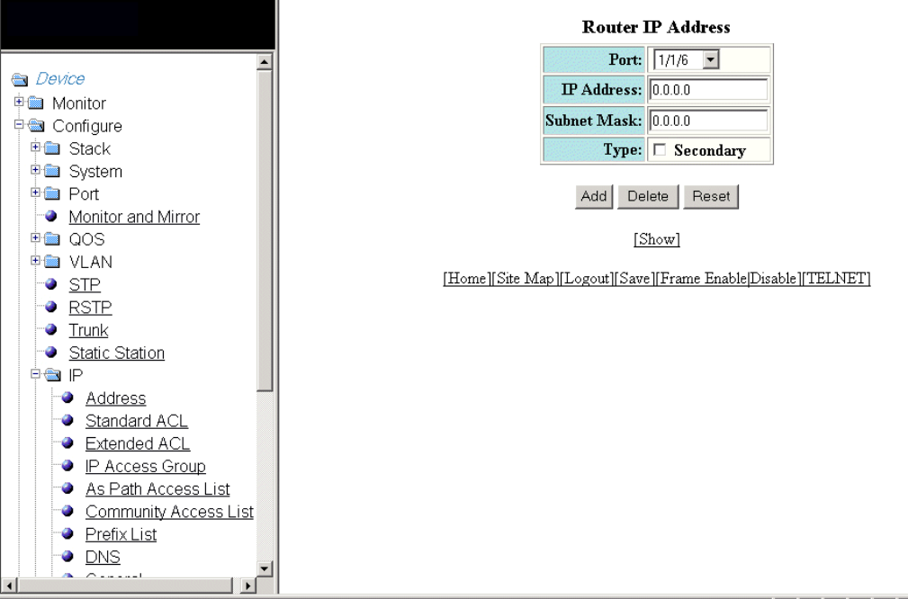
2. Click Address.
The Router IP Address window is displayed as shown in the gure below.
FIGURE 123 Conguring router IP addresses
3. Select a port in the Port list. The port number varies based on the product:
• For Brocade FCX and Brocade ICX devices - stack-unit/slotnum/portnum
• For Brocade FastIron SX devices - slotnum/portnum
4. Type the IP address of the device in the IP Address eld.
5. Type the IP subnet mask in the Subnet Mask eld.
6. Select the Secondary check box for Type if you have already congured an IP address within the same subnet on the interface.
7. Click Add.
The message The change has been made is displayed and the specied IP address is assigned to the interface. To display
the congured router IP address, click Show.
To delete the congured IP address, click Delete. To reset the data entered in the conguration pane, click Reset.
Conguring the router IP address
Brocade FastIron SX, FCX, and ICX Web Management Interface User Guide, 08.0.30
222 Part Number: 53-1003615-02
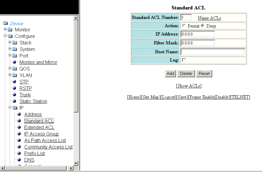
Conguring a standard ACL
To congure a standard ACL, perform the following steps.
1. Click Congure on the left pane and select IP .
2. Click Standard ACL .
The Standard ACL window is displayed as shown in the gure below.
FIGURE 124 Conguring standard ACLs
3. Type the ACL number from 1 through 99 in the Standard ACL Number eld. If you want to type an ACL name, click Name
ACLs . The eld label changes to Standard ACL Name . Now you can type an ACL name up to 256 alphanumeric characters in
length.
4. Click Permit or Deny for Action so that the packets that match a policy in the ACL can be permitted (forwarded) or denied
(dropped).
5. Type the host IP address in the IP Address eld.
6. Type the IP subnet mask in the Filter Mask eld.
7. Type the host name in the Host Name eld.
8. Select the Log check box so that the device generates syslog entries and SNMP traps for the packets that are denied by the
access policy.
Conguring a standard ACL
Brocade FastIron SX, FCX, and ICX Web Management Interface User Guide, 08.0.30
Part Number: 53-1003615-02 223
9. Click Add .
The message The change has been made is displayed and the ACL is added. To display the congured ACL, click Show
ACLs .
To delete the congured ACL, click Delete . To reset the data entered in the conguration pane, click Reset .
Conguring an extended ACL
To congure an extended numbered ACL, perform the following steps.
1. Click Congure on the left pane and select IP .
Conguring an extended ACL
Brocade FastIron SX, FCX, and ICX Web Management Interface User Guide, 08.0.30
224 Part Number: 53-1003615-02
2. Click Extended ACL .
The Extended ACL window is displayed as shown in the gure below.
Conguring an extended ACL
Brocade FastIron SX, FCX, and ICX Web Management Interface User Guide, 08.0.30
Part Number: 53-1003615-02 225
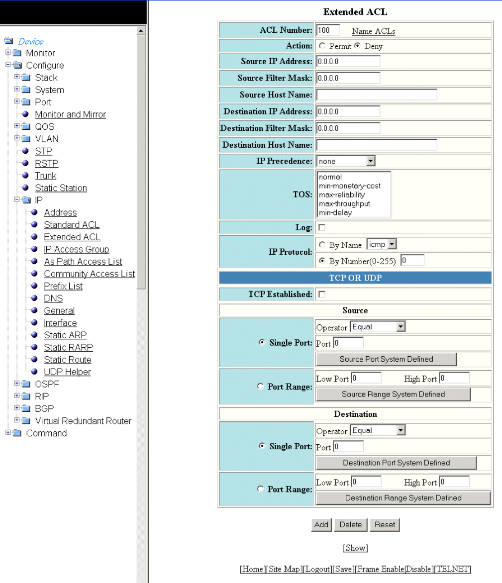
FIGURE 125 Conguring an extended ACL
Conguring an extended ACL
Brocade FastIron SX, FCX, and ICX Web Management Interface User Guide, 08.0.30
226 Part Number: 53-1003615-02
3. Type the extended ACL number from 100 through 199 in the ACL Number eld. If you want to specify the extended ACL
name, click Name ACLs . The eld label is changed to ACL Name .
4. Click Permit or Deny for Action so that the packets that match the policy can be forwarded or dropped.
5. Type the source IP address in the Source IP Address eld.
6. Type the source mask in the Source Filter Mask eld.
7. Type the source host name in the Source Host Name eld.
8. Type the destination IP address in the Destination IP Address eld.
9. Type the destination mask in the Destination Filter Mask eld.
10. Type the destination host name in the Destination Host Name eld.
11. Select one of the following options in the IP Precedence list:
• – routine --The ACL matches packets that have the routine precedence.
–priority --The ACL matches packets that have the priority precedence.
–immediate --The ACL matches packets that have the immediate precedence.
–ash --The ACL matches packets that have the ash precedence.
–ash-override --The ACL matches packets that have the ash override precedence.
–critical --The ACL matches packets that have the critical precedence.
–internet --The ACL matches packets that have the internetwork control precedence.
–network --The ACL matches packets that have the network control precedence.
12. Select one of the following options in the TOS list:
• – normal --The ACL matches packets that have the normal ToS.
–min-monetary-cost --The ACL matches packets that have the minimum monetary cost ToS.
–max-reliability --The ACL matches packets that have the maximum reliability ToS.
–max-throughput --The ACL matches packets that have the maximum throughput ToS.
–min-delay --The ACL matches packets that have the minimum delay ToS.
13. Select the Log check box to enable generation of SNMP traps and syslog messages for packets denied by the ACL.
14. Click By Name for IP Protocol to select the IP protocol by name or click By Number to specify the number (from 0 through
255).
15. Select the TCP Established check box so that the policy applies to the TCP packets that have the ACK (Acknowledgment) or
RST (Reset) bits set on (set to "1") in the Control Bits eld of the TCP packet header. The policy applies only to the established
TCP sessions, not to the new sessions.
NOTE
This eld applies only to the destination TCP ports, not the source TCP ports.
Conguring an extended ACL
Brocade FastIron SX, FCX, and ICX Web Management Interface User Guide, 08.0.30
Part Number: 53-1003615-02 227
16. Enter the following information for Source :
a) To congure a single port, click Single Port .
Select one of the following for Operator :
• – Equal --The policy applies to the TCP or UDP port name or number you enter.
–NotEqual --The policy applies to all the TCP or UDP port numbers except the port number or port name you
enter.
–LessThan --The policy applies to the TCP or UDP port numbers that are less than the port number or the
numeric equivalent to the port name you enter.
–GreaterThan --The policy applies to the TCP or UDP port numbers greater than the port number or the numeric
equivalent to the port name you enter.
Click Source Port System Dened
b) To congure a range of ports, click Port Range .
Type the lower port number in the Low Port eld and the highest port number in the High Port eld.
Click Source Range System Dened .
17. To congure the destination port settings under Destination , follow the procedure explained in step 16 .
18. Click Add .
The message The change has been made is displayed. To display the congured extended numbered ACL, click Show .
To delete the congured extended numbered ACL, click Delete . To reset the data entered in the conguration pane, click
Reset .
Conguring an IP access group
To congure an IP access group, perform the following steps.
1. Click Congure on the left pane and select IP .
Conguring an IP access group
Brocade FastIron SX, FCX, and ICX Web Management Interface User Guide, 08.0.30
228 Part Number: 53-1003615-02
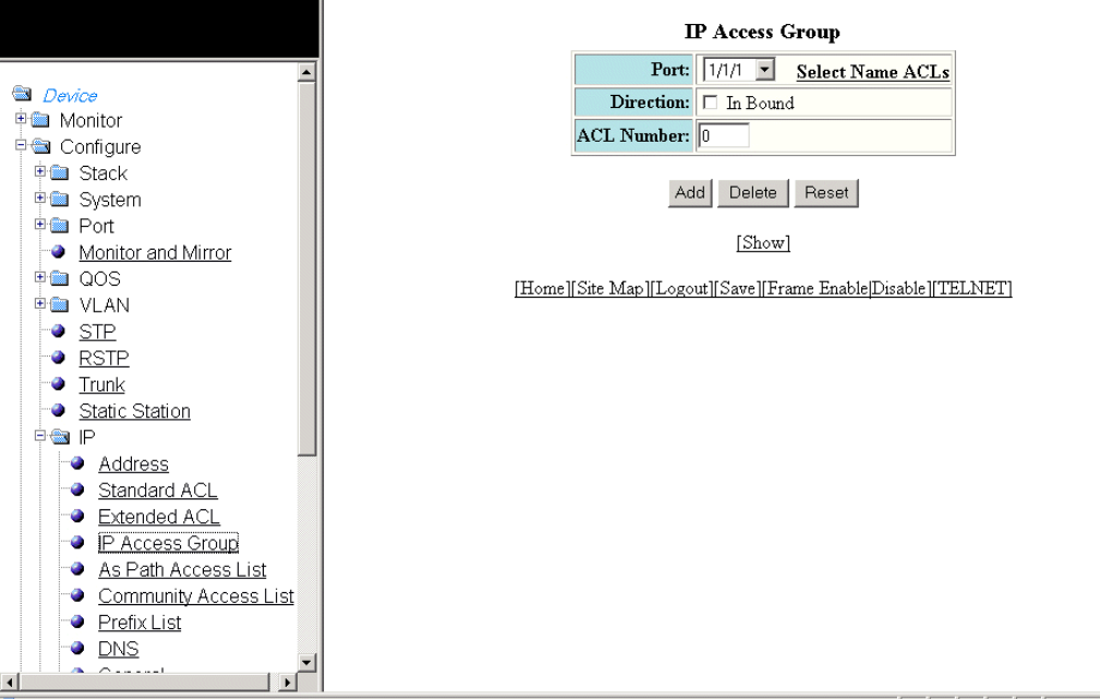
2. Click IP Access Group .
The IP Access Group window is displayed as shown in the gure below.
FIGURE 126 Conguring IP access groups
3. Select a port in the Port list. The port number varies based on the product:
• – For Brocade FCX and Brocade ICX devices - stack-unit/slotnum/portnum
– For Brocade FastIron SX devices - slotnum/portnum
4. Select the In Bound check box for Direction to enable incoming trac on the interface to which you apply the ACL.
5. Type the ACL number in the ACL Number eld. If you want to type an ACL name, click Select Name ACLs . The eld label
changes to ACL Name . Now you can type the ACL name up to 256 alphanumeric characters in length.
6. Click Add .
The message The change has been made is displayed. To display the congured IP access group, click Show .
To delete the congured IP access group, click Delete . To reset the data entered in the conguration pane, click Reset .
Conguring an IP access group
Brocade FastIron SX, FCX, and ICX Web Management Interface User Guide, 08.0.30
Part Number: 53-1003615-02 229
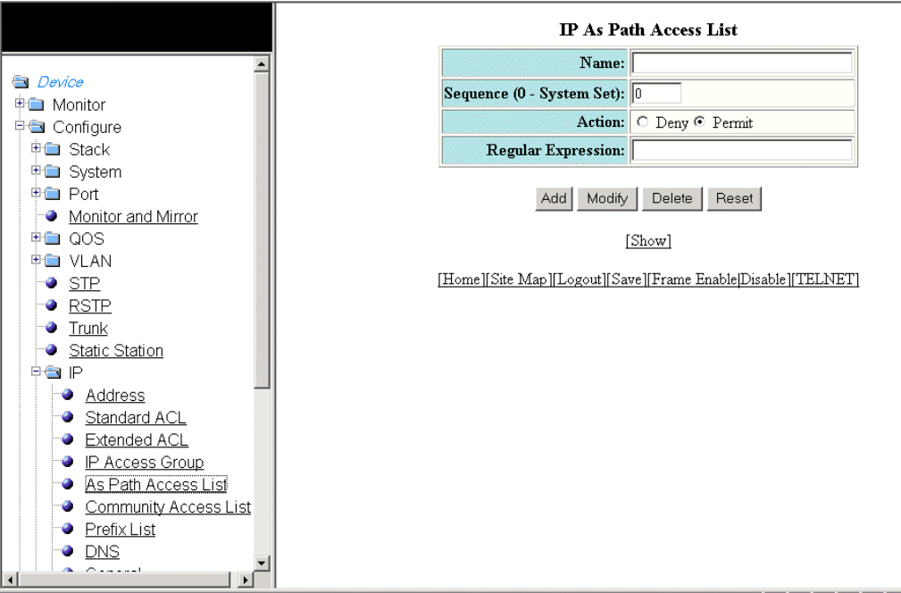
Conguring an IP Autonomous System-path access
list
To congure an Autonomous System-path access list, perform the following steps.
1. Click Congure on the left pane and select IP .
2. Click Autonomou System Path Access List .
The IP Autonomous System Path Access List window is displayed as shown in the gure below.
FIGURE 127 Conguring the IP Autonomous System-path access list
3. Type the ACL name in the Name eld.
4. Type the Autonomous System-path list sequence number in the Sequence (0 - System Set) eld. You can congure up to 199
entries in an Autonomous System-path list.
If you do not specify a sequence number, the software numbers the entries in increments of ve, beginning with number 5. The
software interprets the entries in an Autonomous System-path list in numerical order, beginning with the lowest sequence
number.
5. Click Deny or Permit for Action .
Conguring an IP Autonomous System-path access list
Brocade FastIron SX, FCX, and ICX Web Management Interface User Guide, 08.0.30
230 Part Number: 53-1003615-02
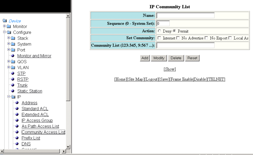
6. Type the Autonomous System-path information you want to permit or deny to routes that match any of the match statements
within the ACL in the Regular Expression eld.
7. Click Add .
The message The change has been made is displayed. To display the congured Autonomous System-path list, click
Show .
To modify the Autonomous System-path list, click Modify . You can also delete the Autonomous System-path list by clicking
Delete . To reset the data entered in the conguration pane, click Reset .
Conguring an IP community list
To congure an IP community list, perform the following steps.
1. Click Congure on the left pane and select IP .
2. Click Community Access List .
The IP Community List window is displayed as shown in the gure below.
FIGURE 128 Conguring the IP community list
3. Type the ACL name in the Name eld.
Conguring an IP community list
Brocade FastIron SX, FCX, and ICX Web Management Interface User Guide, 08.0.30
Part Number: 53-1003615-02 231
4. Type the community list sequence number in the Sequence (0 - System Set) eld. You can congure up to 199 entries in a
community list.
If you do not specify a sequence number, the software numbers the entries in increments of ve, beginning with number 5. The
software interprets the entries in a community list in numerical order, beginning with the lowest sequence number.
5. Click Deny or Permit for Action .
6. Select one of the following options for Set Community :
• – Internet --The Internet community.
–No Advertise --Routes with this community cannot be advertised to any other BGP Layer 3 switches.
–No Export --The community of sub-Autonomous Systems within a confederation. Routes with this community can be
exported to other sub-Autonomous Systems within the same confederation but cannot be exported outside the
confederation to other Autonomous Systems or otherwise sent to EBGP neighbors.
–Local Autonomous System --The local sub-Autonomous System within the confederation. Routes with this
community can be advertised only within the local sub-Autonomous System.
7. Type the community number in num :num format in the Community List eld.
8. Click Add .
The message The change has been made is displayed. To display the congured community list, click Show .
To modify the community list, click Modify . You can also delete the community list by clicking Delete . To reset the data
entered in the conguration pane, click Reset .
Conguring an IP prex list
To congure an IP prex list, perform the following steps.
1. Click Congure on the left pane and select IP .
Conguring an IP prex list
Brocade FastIron SX, FCX, and ICX Web Management Interface User Guide, 08.0.30
232 Part Number: 53-1003615-02
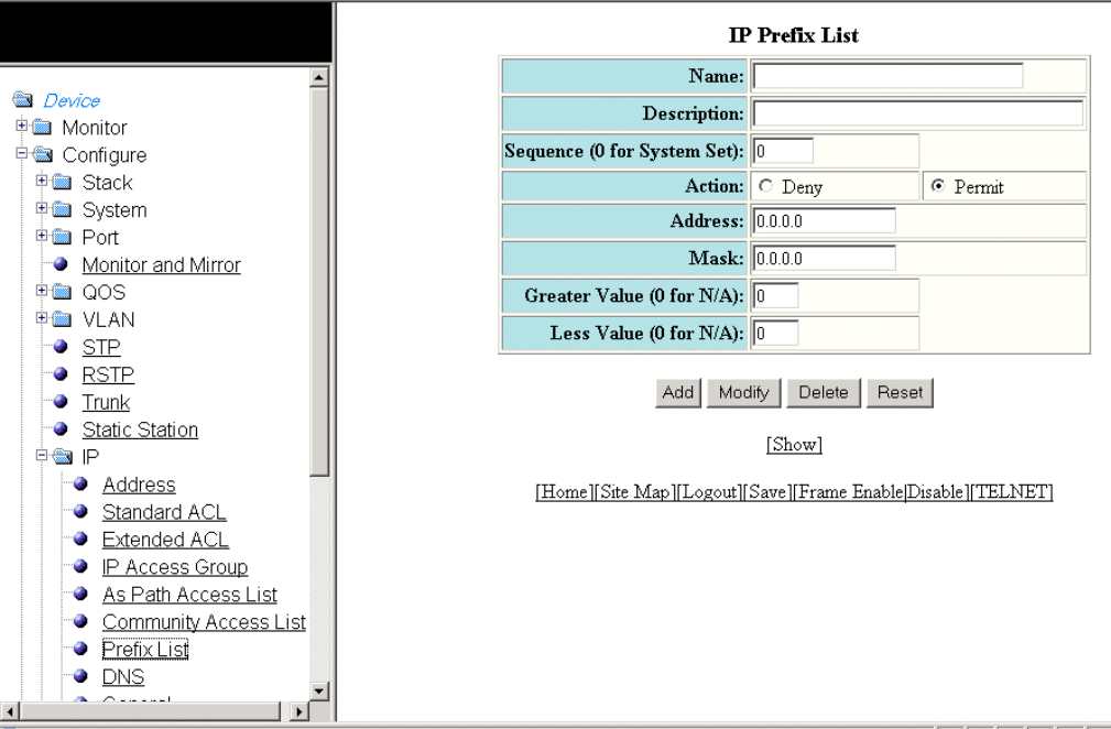
2. Click Prex List .
The IP Prex List window is displayed as shown in the gure below.
FIGURE 129 Conguring IP prex lists
3. Type the prex list name in the Name eld.
4. Type a text string describing the prex list in the Description eld.
5. Type the IP prex list sequence number in the Sequence (0 for System Set) eld. You can congure up to 100 prex list
entries.
If you do not specify a sequence number, the software numbers the entries in increments of ve, beginning with prex list entry
5. The software interprets the prex list entries in numerical order, beginning with the lowest sequence number.
6. Click Deny or Permit for Action .
7. Type the network IP address in the Address eld.
8. Type the network mask address in the Mask eld.
9. Type the maximum value of the mask length in the Greater Value (0 for N/A) eld.
Conguring an IP prex list
Brocade FastIron SX, FCX, and ICX Web Management Interface User Guide, 08.0.30
Part Number: 53-1003615-02 233
10. Type the least value of the mask length in the Less Value (0 for N/A) eld.
NOTE
The Greater Value (0 for N/A) or Less Value (0 for N/A) values you specify must meet the following condition:Length
< Greater Value <= Less Value <= 32
11. Click Add .
The message The change has been made is displayed. To display the congured IP prex list, click Show .
To modify the IP prex list, click Modify . You can also delete the IP prex list by clicking Delete . To reset the data entered in the
conguration pane, click Reset .
Conguring a DNS entry
You can congure the Brocade device to recognize up to four Domain Name System (DNS) servers. The rst entry serves as the primary
default address. If a query to the primary address fails to be resolved after three attempts, the next DNS address is queried (also up to
three times). This process continues for each dened DNS address until the query is resolved. The order in which the default DNS
addresses are polled is the same as the order in which you enter them.
To congure DNS, perform the following steps.
1. Click Congure on the left pane and select IP .
Conguring a DNS entry
Brocade FastIron SX, FCX, and ICX Web Management Interface User Guide, 08.0.30
234 Part Number: 53-1003615-02
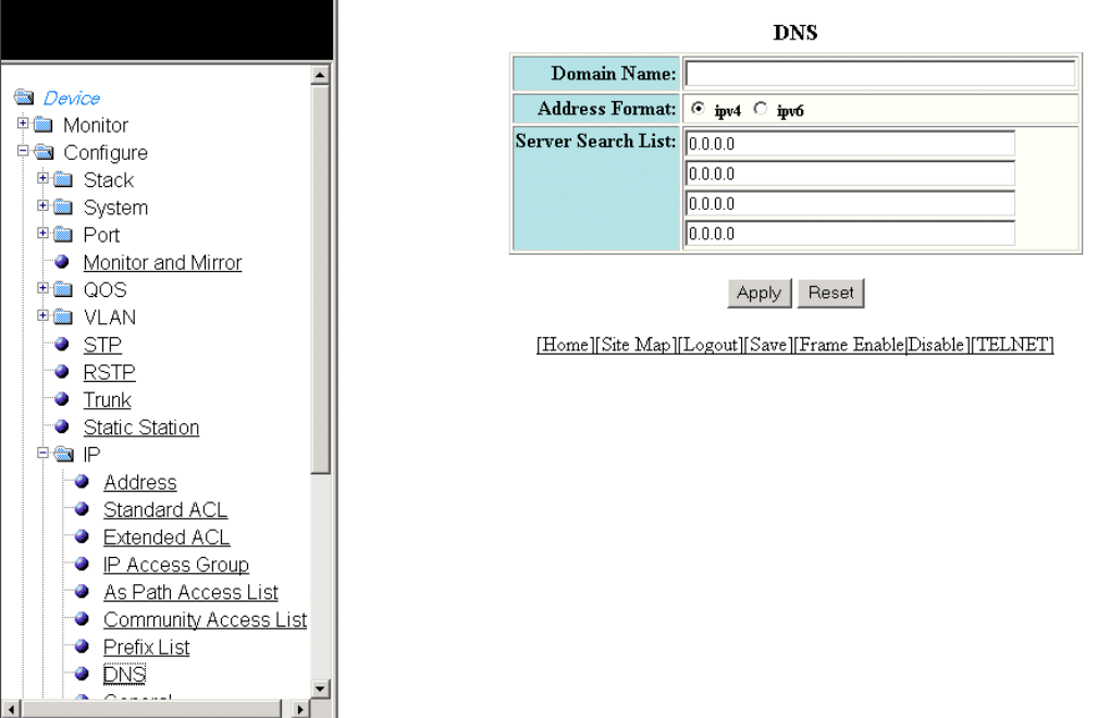
2. Click DNS .
The DNS window is displayed as shown in the gure below.
FIGURE 130 Conguring a DNS entry
3. Type the domain name in the Domain Name eld.
4. Click ipv4 or ipv6 for Address Format .
5. Type the IPv4 or IPv6 address of the DNS in the Server Search List elds.
6. Click Apply .
The message The change has been made is displayed. To reset the data entered in the conguration pane, click Reset .
Conguring the general IP settings
To congure the general IP settings, perform the following steps.
1. Click Congure on the left pane and select IP .
Conguring the general IP settings
Brocade FastIron SX, FCX, and ICX Web Management Interface User Guide, 08.0.30
Part Number: 53-1003615-02 235
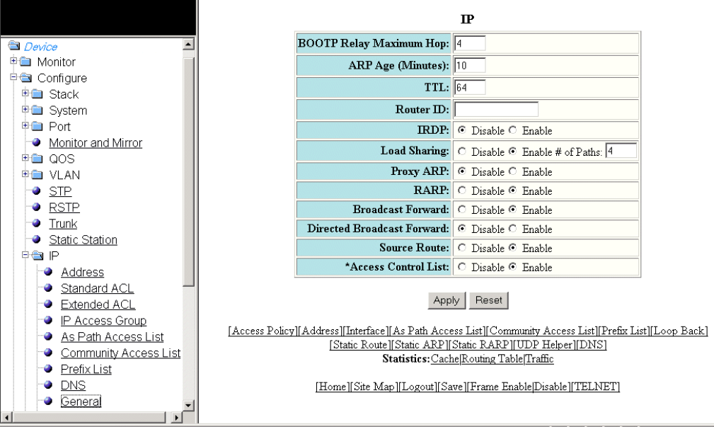
2. Click General .
The IP window is displayed as shown in the gure below.
FIGURE 131 Conguring the general IP settings
3. Type the maximum number of hops away a BootP server can be located from a Layer 3 switch and still be used by the router
clients for network booting in the BOOTP Relay Maximum Hop eld. The range is from 1 through 15. The default value is 4
hops.
4. Type the amount of time the device should keep a MAC address learned through ARP in the device ARP cache in the ARP Age
(Minutes) eld. The range is from 0 through 240 minutes. The default is 10 minutes.
5. Type the maximum number of Layer 3 switches (hops) through which a packet can pass before being discarded in the TTL
eld. The range is from 1 through 255 hops. The default is 64 hops.
6. Type the Layer 3 switch identier in the Router ID eld.
7. Click Disable or Enable for IRDP . By default, this protocol is disabled.
ICMP Router Discovery Protocol (IRDP) is an IP protocol a Layer 3 switch can use to advertise the IP addresses of its interfaces
to the directly attached hosts.
8. Click Disable or Enable for Load Sharing . If you click Enable , type the number of load sharing paths in the # of Paths eld.
9. Click Disable or Enable for Proxy ARP .
Proxy ARP is an IP mechanism a Layer 3 switch can use to answer an ARP request on behalf of a host, by replying with the
Layer 3 switch’s own MAC address instead of the host.
Conguring the general IP settings
Brocade FastIron SX, FCX, and ICX Web Management Interface User Guide, 08.0.30
236 Part Number: 53-1003615-02
10. Click Disable or Enable for RARP .
Reverse ARP (RARP) is an IP mechanism a host can use to request an IP address from a directly attached Layer 3 switch when
the host boots.
11. Click Disable or Enable for Broadcast Forward .
12. Click Disable or Enable for Directed Broadcast Forward .
A directed broadcast is a packet containing all ones (or in some cases, all zeros) in the host portion of the destination IP address.
When a Layer 3 switch forwards such a broadcast, it sends a copy of the packet to each of its enabled IP interfaces.
13. Click Disable or Enable for Source Route .
14. Click Disable or Enable for Access Control List .
15. Click Apply .
The message The change has been made is displayed. To reset the data entered in the conguration pane, click Reset .
Conguring IP interfaces
To congure an IP interface, perform the following steps.
1. Click Congure on the left pane and select IP .
Conguring IP interfaces
Brocade FastIron SX, FCX, and ICX Web Management Interface User Guide, 08.0.30
Part Number: 53-1003615-02 237
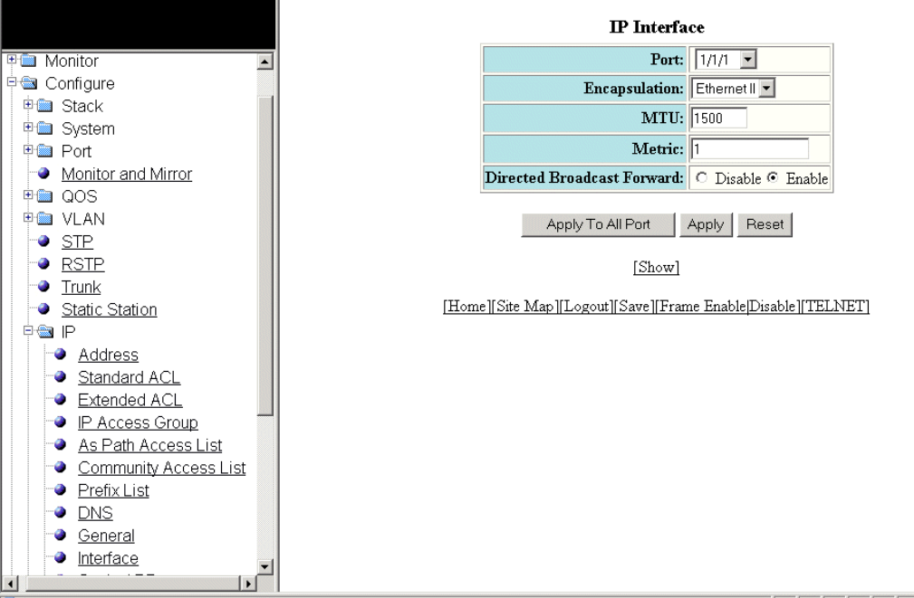
2. Click Interface .
The IP Interface window is displayed as shown in the gure below.
FIGURE 132 Conguring an IP interface
3. Select a port in the Port list. The port number varies based on the product:
• – For Brocade FCX and Brocade ICX devices - stack-unit/slotnum/portnum
– For Brocade FastIron SX devices - slotnum/portnum
4. Select the format of the Layer 2 packets in the Encapsulation list.
5. Type the maximum size of the IP packet when encapsulated in a Layer 2 packet, in the MTU eld.
6. Type the cost in the Metric eld.
7. Click Disable or Enable for Directed Broadcast Forward .
8. Click Apply to congure the IP interface to the specied port or click Apply To All Ports to congure the IP interface on all the
ports.
The message The change has been made is displayed. To display the congured IP interface, click Show . To reset the data
entered in the conguration pane, click Reset .
Conguring IP interfaces
Brocade FastIron SX, FCX, and ICX Web Management Interface User Guide, 08.0.30
238 Part Number: 53-1003615-02
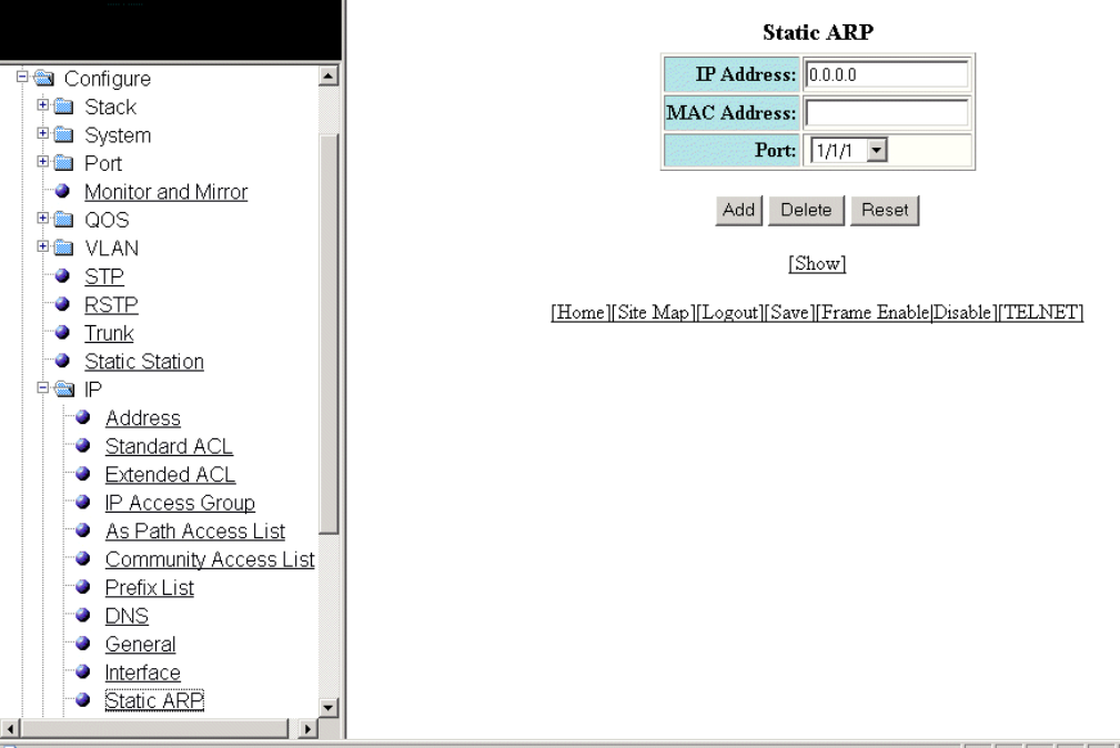
Conguring a static ARP
To congure a static Address Resolution Protocol (ARP) entry, perform the following steps.
1. Click Congure on the left pane and select IP .
2. Click Static ARP .
The Static ARP window is displayed as shown in the gure below.
FIGURE 133 Conguring static ARP
3. Type the IP address of the directly connected device in the IP Address eld.
4. Type the MAC address of the device in xx-xx-xx-xx-xx-xx format in the MAC Address eld.
5. Select a port number in the Port list. The port number varies based on the product:
• – For Brocade FCX and Brocade ICX devices - stack-unit/slotnum/portnum
– For Brocade FastIron SX devices - slotnum/portnum
Conguring a static ARP
Brocade FastIron SX, FCX, and ICX Web Management Interface User Guide, 08.0.30
Part Number: 53-1003615-02 239
6. Click Add .
The message The change has been made is displayed. To display the congured static ARP entry, click Show .
To reset the data entered in the conguration pane, click Reset .
NOTE
The delete operation is not supported in 08.0.20 and later releases.
Conguring a static RARP
The Reverse Address Resolution Protocol (RARP) provides a simple mechanism for directly attached IP hosts to boot over the network.
RARP allows an IP host that does not have a means of storing its IP address across power cycles or software reloads to query a directly
attached Layer 3 switch for an IP address.
To congure a static IP RARP entry for static routes on a Brocade Layer 3 switch, perform the following steps.
1. Click Congure on the left pane and select IP .
Conguring a static RARP
Brocade FastIron SX, FCX, and ICX Web Management Interface User Guide, 08.0.30
240 Part Number: 53-1003615-02
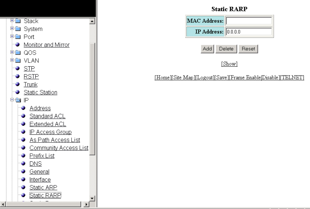
2. Click Static RARP .
The Static RARP window is displayed as shown in the gure below.
FIGURE 134 Conguring static RARP
3. Type the MAC address of the boot client in xx-xx-xx-xx-xx-xx format in the MAC Address eld.
4. Type the IP address you want the Layer 3 switch to give to the client in the IP Address eld.
5. Click Add .
The message The change has been made is displayed. To display the congured static IP RARP entry, click Show .
To delete the congured static IP RARP entry, click Delete . To reset the data entered in the conguration pane, click Reset .
Conguring a static route
To congure an IP static route, perform the following steps.
1. Click Congure on the left pane and select IP .
Conguring a static route
Brocade FastIron SX, FCX, and ICX Web Management Interface User Guide, 08.0.30
Part Number: 53-1003615-02 241
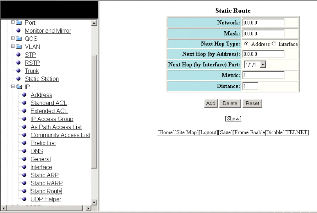
2. Click Static Route .
The Static Route window is displayed as shown in the gure below.
FIGURE 135 Conguring static routes
3. Type the route destination IP address in the Network eld.
4. Type the network mask in the Mask eld.
5. Click Address for Next Hop Type and type the IP address of the next hop router (gateway) for the route in the Next Hop (by
Address) eld.
Or
Click Interface for Next Hop Type and select an Ethernet port in the Next Hop (by Interface) Port list.
6. Type the metric value from 1 through 16 in the Metric eld. The default is 1.
7. Type the administrative distance of the route in the Distance eld. The default is 1.
8. Click Add .
The message The change has been made is displayed. To display the congured static route, click Show .
To delete the congured static route, click Delete . To reset the data entered in the conguration pane, click Reset .
Conguring a static route
Brocade FastIron SX, FCX, and ICX Web Management Interface User Guide, 08.0.30
242 Part Number: 53-1003615-02
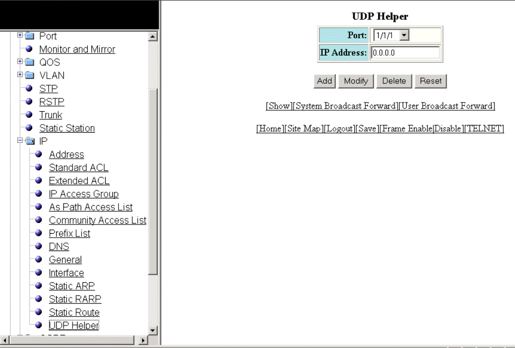
Conguring a UDP helper
To congure a helper address on the interface connected to the clients, perform the following steps.
1. Click Congure on the left pane and select IP .
2. Click UDP Helper .
The UDP Helper window is displayed as shown in the gure below.
FIGURE 136 Conguring UDP helper
3. Select an Ethernet port in the Port list. The port number varies based on the product:
• – For Brocade FCX and Brocade ICX devices - stack-unit/slotnum/portnum
– For Brocade FastIron SX devices - slotnum/portnum
4. Type the server IP address or the subnet directed broadcast address of the IP subnet the server belongs to in the IP Address
eld.
5. Click Add .
The message The change has been made is displayed. To display the congured UDP helper, click Show .
To modify the congured UDP helper, click Modify . You can also delete the UDP helper by clicking Delete . To reset the data
entered in the conguration pane, click Reset .
Conguring a UDP helper
Brocade FastIron SX, FCX, and ICX Web Management Interface User Guide, 08.0.30
Part Number: 53-1003615-02 243
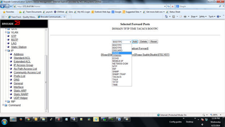
Enabling forwarding for a UDP application
To specify a UDP application by using an application name, perform the following steps.
1. Click System Broadcast Forward on the UDP Helper window.
The system broadcast forward window is displayed as shown in this gure.
FIGURE 137 Enabling forwarding for a UDP application
2. Select one of the following forward ports in the list:
• – BOOTPC
–BOOTPS
–DISCARD
–DNSIX
–DOMAIN
–ECHO
–MOBILE-IP
–NETBIOS-DGM
–RIP
–SNMP
–SNMP-TRAP
–TACACS
–TALK
–TFTP
–TIME
3. Click Add .
The added port is displayed in the Selected Forward Ports pane, which displays the application ports that are enabled by
default. To delete the forwarding port, click Delete . To reset the data entered in the conguration pane, click Reset .
To specify the UDP application by using an application UDP port number, perform the following steps.
Conguring a UDP helper
Brocade FastIron SX, FCX, and ICX Web Management Interface User Guide, 08.0.30
244 Part Number: 53-1003615-02
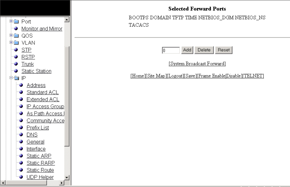
Specifying the UDP application
To specify the UDP application by using an application UDP port number, perform the following steps.
1. Click User Broadcast Forward on the UDP Helper window.
The user broadcast forward window is displayed as shown in the gure below.
FIGURE 138 Enabling user broadcast forward
2. Type the UDP port number in the eld.
3. Click Add.
The added port is displayed in the Selected Forward Ports pane, which displays the application ports that are enabled by
default. To delete the forwarding port, click Delete . To reset the data entered in the conguration pane, click Reset .
Conguring a UDP helper
Brocade FastIron SX, FCX, and ICX Web Management Interface User Guide, 08.0.30
Part Number: 53-1003615-02 245
Brocade FastIron SX, FCX, and ICX Web Management Interface User Guide, 08.0.30
246 Part Number: 53-1003615-02
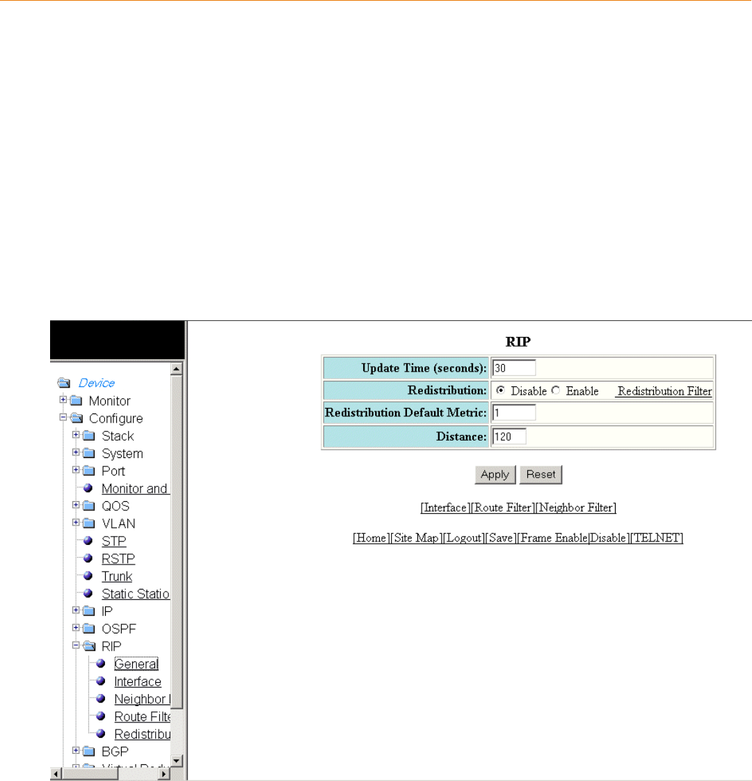
Conguring RIP
•Conguring the general RIP settings......................................................................................................................................................247
•Conguring a RIP interface.........................................................................................................................................................................248
•Conguring a RIP neighbor lter..............................................................................................................................................................252
•Conguring a RIP route lter......................................................................................................................................................................253
•Conguring a RIP redistribution lter..................................................................................................................................................... 255
Conguring the general RIP settings
To congure the general RIP settings, perform the following steps.
1. Click Congure on the left pane and select RIP .
2. Click General .
The RIP window is displayed as shown in the gure below.
FIGURE 139 Conguring the general RIP settings
Brocade FastIron SX, FCX, and ICX Web Management Interface User Guide, 08.0.30
Part Number: 53-1003615-02 247
3. Type the update interval from 1 through 1000 seconds in the Update Time (seconds) eld. The default value is 30 seconds.
The update interval species how often the Layer 3 switch sends route advertisements to its RIP neighbors.
4. Click Disable or Enable for Redistribution . To congure a redistribution lter, click Redistribution Filter . For more information
on how to congure a RIP redistribution lter, refer to Conguring a RIP redistribution lter on page 255.
5. Type the RIP cost from 1 through 15 in the Redistribution Default Metric eld. The default is 1.
6. Type the administrative distance of the RIP Layer 3 switches in the Distance eld. The default value is 120.
7. Click Apply .
The message The change has been made is displayed. To reset the data entered in the conguration pane, click Reset .
The RIP window provides links to congure other RIP parameters:
• To congure a RIP interface, click Interface . For more information, refer to Conguring a RIP interface on page 248.
• To congure a RIP route lter, click Route Filter . For more information, refer to Conguring a RIP route lter on page 253.
• To congure a RIP neighbor lter, click Neighbor Filter . For more information, refer to Conguring a RIP neighbor lter on
page 252.
Conguring a RIP interface
To congure a RIP interface, perform the following steps.
1. Click Congure on the left pane and select RIP .
Conguring a RIP interface
Brocade FastIron SX, FCX, and ICX Web Management Interface User Guide, 08.0.30
248 Part Number: 53-1003615-02
2. Click Interface .
The RIP Interface window is displayed as shown in the gure below.
Conguring a RIP interface
Brocade FastIron SX, FCX, and ICX Web Management Interface User Guide, 08.0.30
Part Number: 53-1003615-02 249
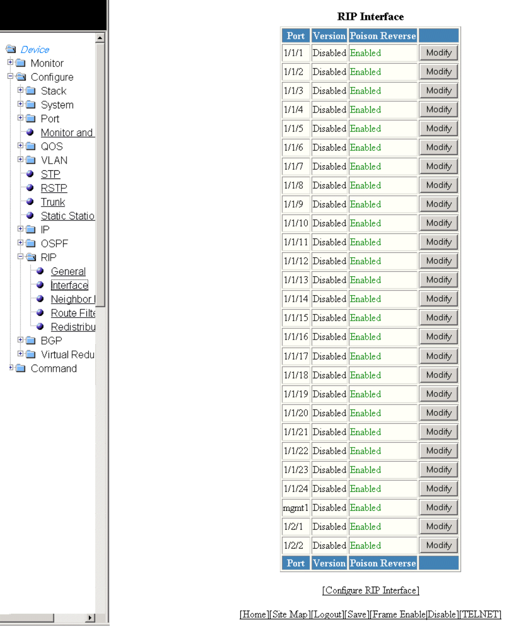
FIGURE 140 RIP interface
Conguring a RIP interface
Brocade FastIron SX, FCX, and ICX Web Management Interface User Guide, 08.0.30
250 Part Number: 53-1003615-02
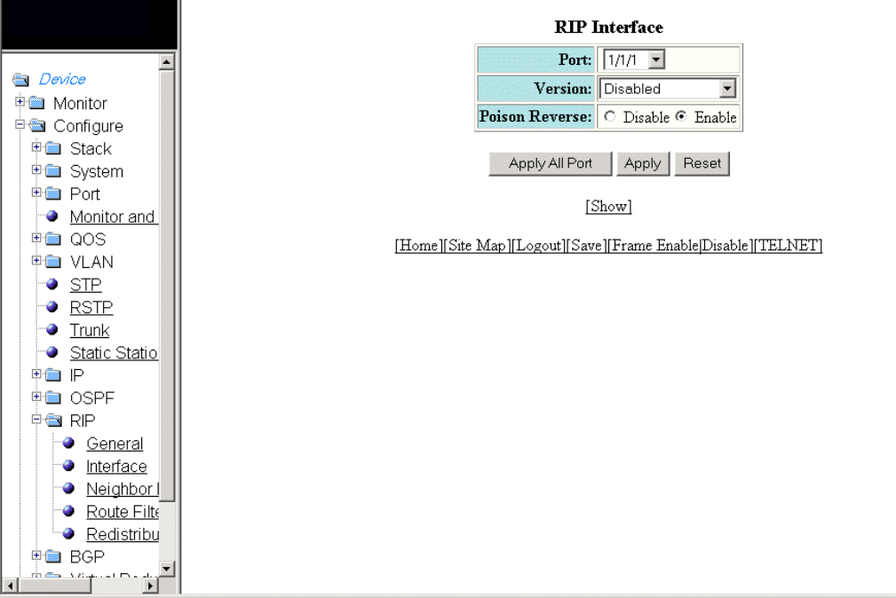
3. Click Congure RIP Interface or Modify to change the RIP interface parameters for the respective port.
The RIP Interface window is displayed as shown in the gure below.
FIGURE 141 Conguring a RIP interface
4. Select a port in the Port list. The port number varies based on the product:
• – For Brocade FCX and Brocade ICX devices - stack-unit/slotnum/portnum
– For Brocade FastIron SX devices - slotnum/portnum
5. Select one of the following options for Version :
• – Disabled
–V1 Only
–V2 Only
–V1-Compatible-V2
6. Click Disable or Enable for Poison Reverse .
Poison reverse is the method a Layer 3 switch uses to prevent routing loops caused by advertising a route on the same
interface as the one on which the Layer 3 switch learned the route.
Conguring a RIP interface
Brocade FastIron SX, FCX, and ICX Web Management Interface User Guide, 08.0.30
Part Number: 53-1003615-02 251
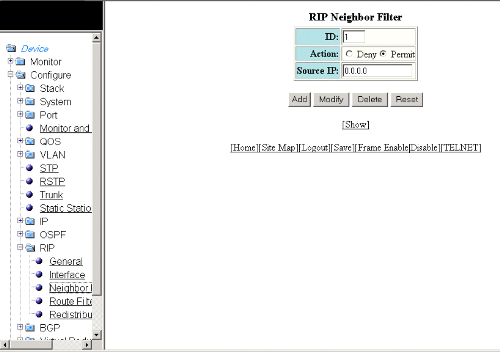
7. Click Apply to congure the RIP interface to the specied port or click Apply All Port to congure the RIP interface on all the
ports.
The message The change has been made is displayed. To display the congured RIP interface, click Show . To reset the
data entered in the conguration pane, click Reset .
Conguring a RIP neighbor lter
By default, a Brocade Layer 3 switch learns RIP routes from all its RIP neighbors. Neighbor lters allow you to specify the neighbor
Layer 3 switches from which the Brocade device can receive RIP routes. Neighbor lters apply globally to all ports.
To congure a RIP neighbor lter, perform the following steps.
1. Click Congure on the left pane and select RIP .
2. Click Neighbor Filter .
The RIP Neighbor Filter window is displayed as shown in the gure below.
FIGURE 142 Conguring a RIP neighbor lter
3. Type a lter number in the ID eld.
Conguring a RIP neighbor lter
Brocade FastIron SX, FCX, and ICX Web Management Interface User Guide, 08.0.30
252 Part Number: 53-1003615-02
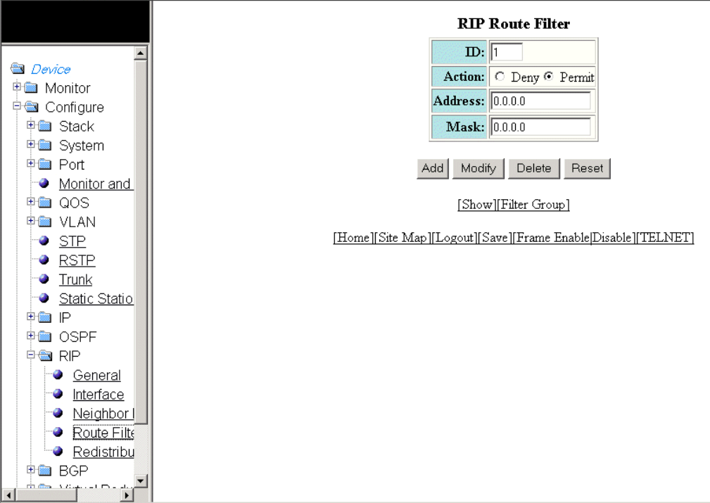
4. Click Deny or Permit for Action .
5. Type a source IP address in the Source IP eld.
6. Click Add .
The message The change has been made is displayed. To display the congured RIP neighbor lter, click Show .
To modify the congured RIP neighbor lter, click Modify . To reset the data entered in the conguration pane, click Reset . You
can also delete the congured RIP neighbor lter by clicking Delete .
Conguring a RIP route lter
To congure a RIP route lter to permit or deny learning or advertising of specic routes, perform the following steps.
1. Click Congure on the left pane and select RIP .
2. Click Route Filter .
The RIP Route Filter window is displayed as shown in the gure below.
FIGURE 143 Conguring a RIP route lter
Conguring a RIP route lter
Brocade FastIron SX, FCX, and ICX Web Management Interface User Guide, 08.0.30
Part Number: 53-1003615-02 253
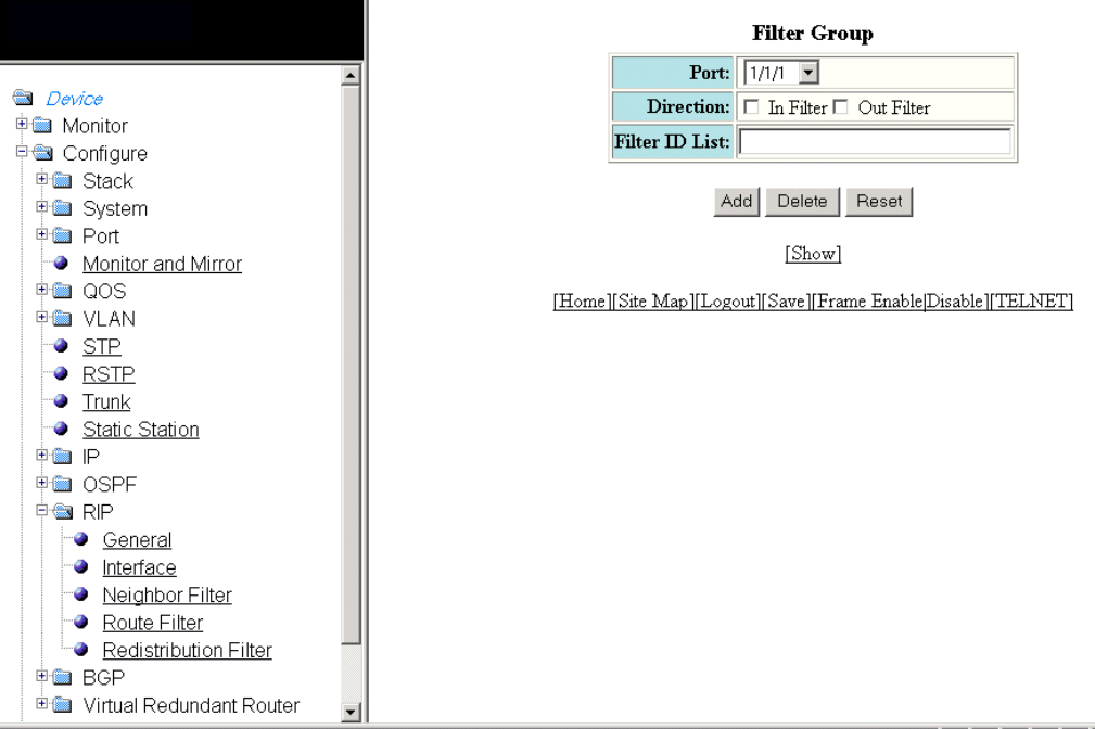
3. Type a lter number in the ID eld.
4. Click Deny or Permit for Action .
5. Type a source IP address in the Address eld.
6. Type a source mask in the Mask eld.
7. Click Add .
The message The change has been made is displayed. To display the congured RIP route lter, click Show .
To modify the congured RIP route lter, click Modify . To reset the data entered in the conguration pane, click Reset . You can
also delete the congured RIP route lter by clicking Delete .
Conguring a lter group
After you dene RIP route lters, you must assign them to individual interfaces. The lters do not take eect until you apply them to the
interfaces. To apply a RIP route lter to an interface, perform the following steps.
1. Click Filter Group on the RIP Route Filter window.
The Filter Group window is displayed as shown in the gure below.
FIGURE 144 Conguring a lter group
Conguring a RIP route lter
Brocade FastIron SX, FCX, and ICX Web Management Interface User Guide, 08.0.30
254 Part Number: 53-1003615-02
2. Select an Ethernet port in the Port list. The port number varies based on the product:
• – For Brocade FCX and Brocade ICX devices - stack-unit/slotnum/portnum
– For Brocade FastIron SX devices - slotnum/portnum
3. Select one of the following for Directions :
• – In lters --Applies to routes the Layer 3 switch learns from its neighbor on the interface.
–Out lters --Applies to routes the Layer 3 switch advertises to its neighbor on the interface.
4. Type the RIP route lters that you want to apply for an interface in the Filter ID List eld.
5. Click Add .
The message The change has been made is displayed. To display the congured RIP route lter group, click Show .
To delete the congured RIP route lter group, click Delete . To reset the data entered in the conguration pane, click Reset .
Conguring a RIP redistribution lter
To congure a RIP redistribution lter, perform the following steps.
1. Click Congure on the left pane and select RIP .
Conguring a RIP redistribution lter
Brocade FastIron SX, FCX, and ICX Web Management Interface User Guide, 08.0.30
Part Number: 53-1003615-02 255
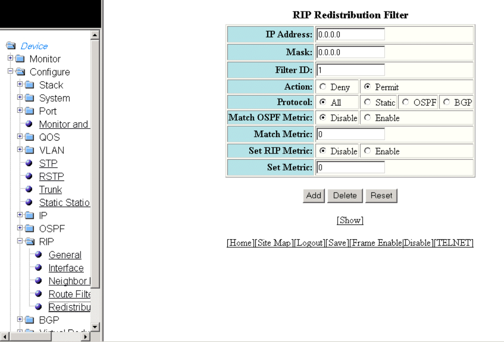
2. Click Redistribution Filter .
The RIP Redistribution Filter window is displayed as shown in the gure below.
FIGURE 145 Conguring the RIP redistribution lter
3. Type a network IP address in the IP Address eld.
4. Type an IP subnet mask in the Mask eld.
5. Type a redistribution lter identier in the Filter ID eld.
6. Click Deny or Permit for Action .
7. Select one of the following options for Protocol :
• – All --Applies redistribution to all route types.
–Static --Applies redistribution to IP static routes only.
–OSPF --Applies redistribution to OSPF routes only.
–BGP --Applies redistribution to BGP routes only.
8. Click Disable or Enable for Set OSPF Metric .
9. Type the match metric value from 1 through 15 in the Match Metric eld. The match metric parameter applies the
redistribution lter only to those routes with the specied metric value.
10. Click Disable or Enable for Set RIP Metric .
Conguring a RIP redistribution lter
Brocade FastIron SX, FCX, and ICX Web Management Interface User Guide, 08.0.30
256 Part Number: 53-1003615-02
11. Type the RIP metric value in the Set Metric eld.
12. Click Add .
The message The change has been made is displayed. To display the congured RIP redistribution lter, click Show .
To delete the congured RIP redistribution lter, click Delete . To reset the data entered in the conguration pane, click Reset .
Conguring a RIP redistribution lter
Brocade FastIron SX, FCX, and ICX Web Management Interface User Guide, 08.0.30
Part Number: 53-1003615-02 257
Brocade FastIron SX, FCX, and ICX Web Management Interface User Guide, 08.0.30
258 Part Number: 53-1003615-02
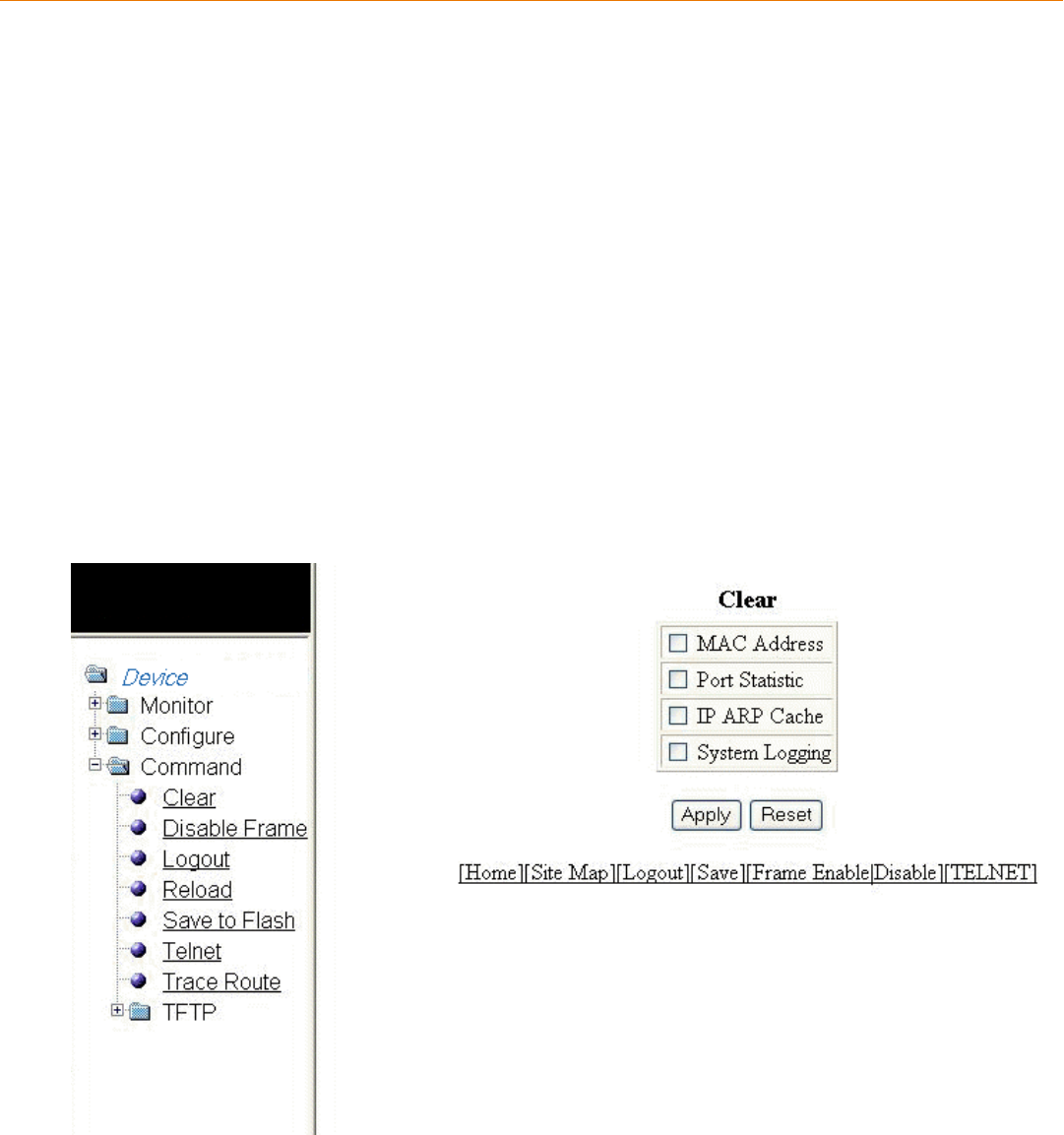
Basic Device Commands
• Clearing information for a Layer 2 switch.............................................................................................................................................259
• Clearing information for a Layer 3 switch.............................................................................................................................................260
• Disabling or enabling the menu view..................................................................................................................................................... 261
• Logging out.......................................................................................................................................................................................................262
• Reloading units in a stack............................................................................................................................................................................263
• Saving the conguration to ash..............................................................................................................................................................264
• Switching over to the active role...............................................................................................................................................................265
• Performing hitless-reload from primary images............................................................................................................................... 265
• Performing hitless-reload from secondary images..........................................................................................................................266
• Accessing the Telnet command prompt...............................................................................................................................................267
• Performing a trace..........................................................................................................................................................................................269
Clearing information for a Layer 2 switch
To clear specic data related to a Layer 2 switch, perform the following steps.
1. Click Command on the left pane and select Clear.
The Clear window is displayed as shown in the gure below.
FIGURE 146 Clear window
Brocade FastIron SX, FCX, and ICX Web Management Interface User Guide, 08.0.30
Part Number: 53-1003615-02 259
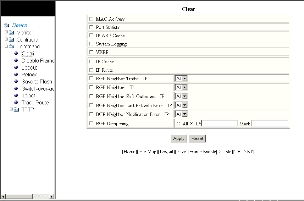
2. Select the following check boxes to clear information:
• – MAC Address
–Port Statistic
–IP ARP Cache
–System Logging
3. Click Apply .
All the current entries will be deleted.
Clearing information for a Layer 3 switch
To clear specic data related to a Layer 3 switch, perform the following steps.
1. Click Command on the left pane and select Clear.
The Clear window is displayed as shown in the gure below .
FIGURE 147 Clear window
Clearing information for a Layer 3 switch
Brocade FastIron SX, FCX, and ICX Web Management Interface User Guide, 08.0.30
260 Part Number: 53-1003615-02
2. Select the following check boxes to clear information:
•MAC Address
•Port Statistic
•IP ARP Cache
•System Logging
•VRRP
•IP Cache
•IP Route
•BGP Neighbor Trac - IP --Select All in the list to clear the BGP message counter for all neighbors.
•BGP Neighbor - IP --Select All in the list to close all neighbor sessions and clear all the routes exchanged by the Layer 3
switch and the neighbors.
•BGP Neighbor Soft-Outbound - IP --Select All in the list to update all outbound routes by applying the new or changed
lters.
•BGP Neighbor Last Pkt with Error - IP --Select All in the list to clear the last packet from the neighbors that contained an
error.
•BGP Neighbor Notication Error - IP --Select All in the list to clear the buer for all neighbors containing the last
NOTIFICATION message sent or received.
•BGP Dampening --Perform one of the following tasks:
– Click All to clear all the route dampening statistics.
– Click IP and type the network IP address in the IP eld and the network mask in the Mask eld.
3. Click Apply.
All the current entries will be deleted.
Disabling or enabling the menu view
To enable or disable the menu view, click Command on the left pane and select Disable Frame. The menu tree from the left panel is
hidden as shown in the gure below. Click Frame Enable to view the menu tree.
Disabling or enabling the menu view
Brocade FastIron SX, FCX, and ICX Web Management Interface User Guide, 08.0.30
Part Number: 53-1003615-02 261
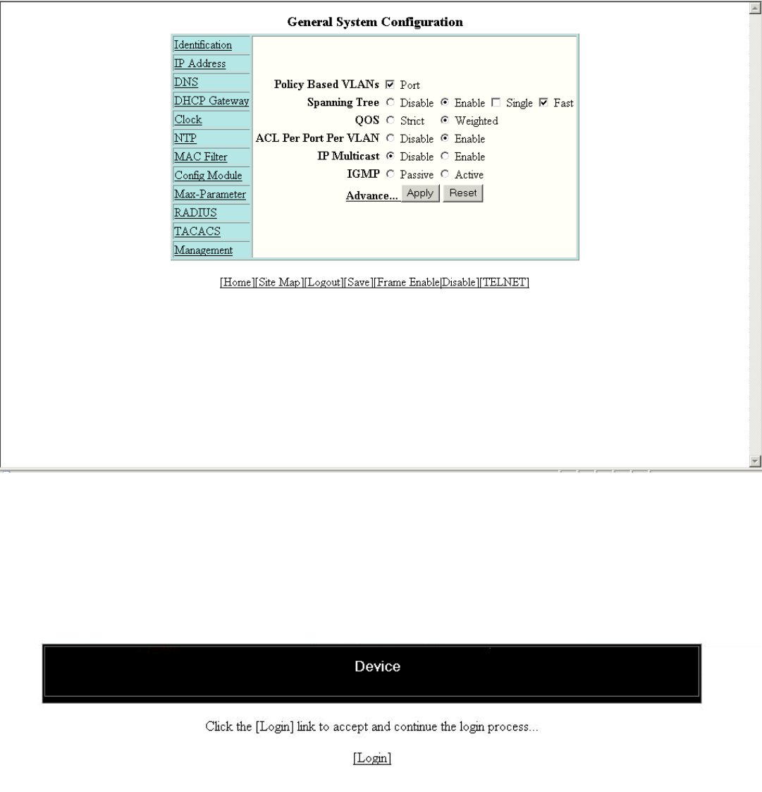
FIGURE 148 Disabling the menu tree
Logging out
To exit the Web Management Interface, click Command on the left pane and select Logout . The login window is displayed as shown in
the gure below. To re-log in, click Login on the window.
FIGURE 149 Logging out
Logging out
Brocade FastIron SX, FCX, and ICX Web Management Interface User Guide, 08.0.30
262 Part Number: 53-1003615-02
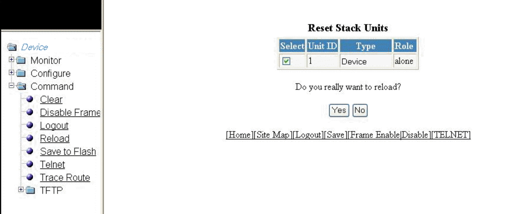
Reloading units in a stack
NOTE
This section is applicable to the Brocade FCX-ADV and Brocade ICX devices.
To reload any or all of the units within a device, perform the following steps.
1. Click Command on the left pane and select Reload .
The Reset Stack Units window is displayed as shown in the gure below.
FIGURE 150 Reloading the units
2. Click Yes to start the process.
NOTE
For the Brocade FCX and Brocade ICX devices, if the Active Controller is reset or removed from the stack, the entire
stack reloads and Active Controller and Standby Controller elections are started. If the unit functioning as the previous
Active Controller is no longer part of the stack, the Standby Controller unit becomes the new Active Controller. After a
reset, if no stack member qualies as the Active Controller, the existing Standby Controller waits 30 seconds and then
assumes the role of the Active Controller.If both the Active Controller and the Standby Controllers are removed, the
rest of the stack continues to function. The stack members will not be able to learn any new addresses.
Reloading units in a stack
Brocade FastIron SX, FCX, and ICX Web Management Interface User Guide, 08.0.30
Part Number: 53-1003615-02 263
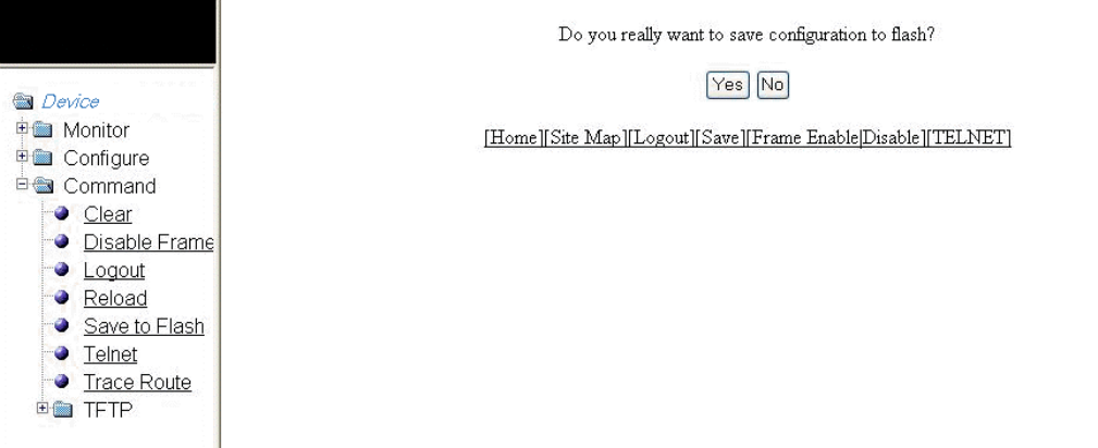
Saving the conguration to ash
To save the conguration changes to ash, perform the following tasks.
1. Click Command on the left pane and select Save To Flash .
The save conguration window is displayed as shown in the gure below.
FIGURE 151 Saving the conguration to ash
2. Click Yes to conrm saving the conguration.
NOTE
To apply the changes to memory allocation, reload the software after you save the changes to the startup-
conguration le.
Saving the conguration to ash
Brocade FastIron SX, FCX, and ICX Web Management Interface User Guide, 08.0.30
264 Part Number: 53-1003615-02

Switching over to the active role
To switch a standby module to become an Active Controller, perform the following steps.
1. Click Command on the left pane and select Switch-over-active-controller .
NOTE
For the Brocade FastIron SX devices, select Switch-over-active-role .
The switch over window is displayed as shown in the gure below.
FIGURE 152 Switching over to an Active Controller
2. Click Yes to switch the standby module to become an Active Controller or click No to cancel the operation.
Performing hitless-reload from primary images
NOTE
Hitless-reload is supported on the Brocade FastIron SX devices and applies to both Layer 2 and Layer 3 protocols. Hitless-
reload is not supported on the Brocade FCX and Brocade ICX devices.
To perform a hitless-reload of the system from a primary image, perform the following steps.
1. Click Command on the left pane and select Hitless-reload .
Performing hitless-reload from primary images
Brocade FastIron SX, FCX, and ICX Web Management Interface User Guide, 08.0.30
Part Number: 53-1003615-02 265
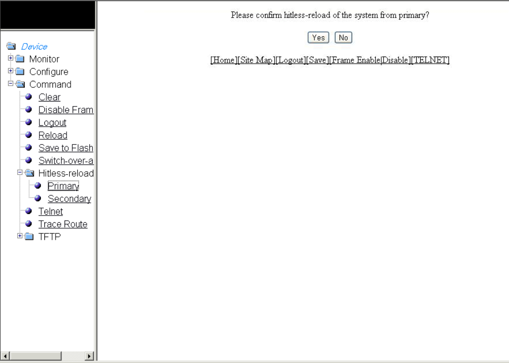
2. Click Primary .
The primary hitless-reload window is displayed as shown in the gure below.
FIGURE 153 Hitless-reload from the primary image
3. Click Yes to reload the system from the primary image or click No to cancel the operation.
Performing hitless-reload from secondary images
NOTE
Hitless-reload is supported on the Brocade FastIron SX devices and applies to both Layer 2 and Layer 3 protocols. Hitless-
reload is not supported on the Brocade FCX and Brocade ICX devices.
To perform a hitless-reload of the system from a secondary image, perform the following steps.
1. Click Command on the left pane and select Hitless-reload .
Performing hitless-reload from secondary images
Brocade FastIron SX, FCX, and ICX Web Management Interface User Guide, 08.0.30
266 Part Number: 53-1003615-02

2. Click Secondary .
The secondary hitless-reload window is displayed as shown in the gure below.
FIGURE 154 Hitless-reload from a secondary image
3. Click Yes to reload the system from the secondary image or click No to cancel the operation.
Accessing the Telnet command prompt
To open a Telnet CLI window, click Command on the left pane and select Telnet .
The Telnet window is displayed as shown in the gure below.
Accessing the Telnet command prompt
Brocade FastIron SX, FCX, and ICX Web Management Interface User Guide, 08.0.30
Part Number: 53-1003615-02 267
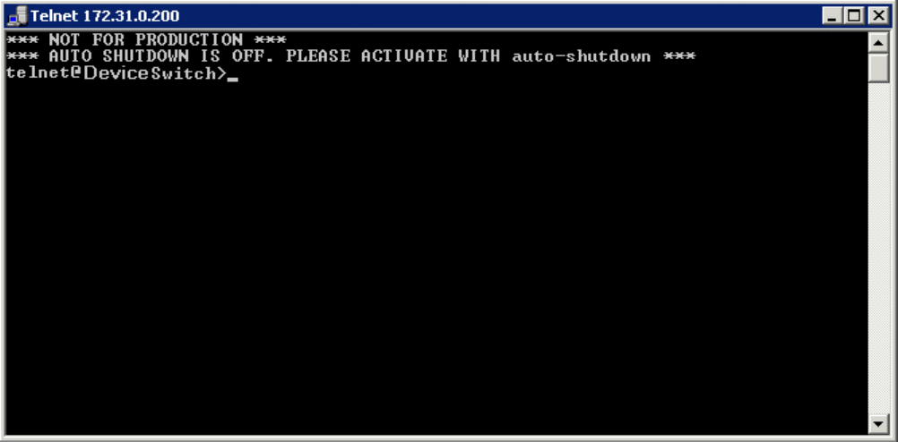
FIGURE 155 Accessing Telnet
Accessing the Telnet command prompt
Brocade FastIron SX, FCX, and ICX Web Management Interface User Guide, 08.0.30
268 Part Number: 53-1003615-02
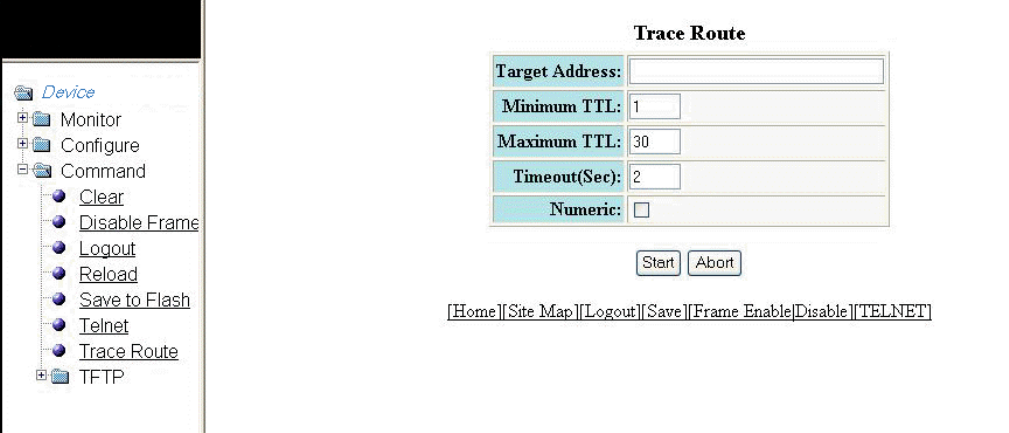
Performing a trace
Trace Route allows you to trace a path from the Brocade device to an IPv4 host. Trace route requests show all responses to a minimum
Time To Live (TTL) of 1 second and a maximum TTL of 30 seconds. In addition, if there are multiple equal-cost routes to the
destination, the Brocade device displays up to three responses. To run a trace, perform the following steps.
1. Click Command on the left pane and select Trace Route .
The Trace Route window is displayed as shown in the gure below.
FIGURE 156 Performing a trace
2. Type the IP address of the host at the other end of the route in the Target Address eld.
3. Type the minimum value of TTL in the Minimum TTL eld. The default is 1.
4. Type the maximum value of TTL in the Maximum TTL eld. The default is 30.
5. Type the number of seconds the router waits for a reply from the pinged device in the Timeout (Sec) eld.
6. Select the Numeric check box so that, for parameters that require a numeric value, the trace route does not check that the value
you enter is within the allowed range. Instead, if you do exceed the range for a numeric value, the software rounds the value to
the nearest valid value.
7. Click Start to begin the trace process or click Abort to exit without performing the trace.
Performing a trace
Brocade FastIron SX, FCX, and ICX Web Management Interface User Guide, 08.0.30
Part Number: 53-1003615-02 269
Brocade FastIron SX, FCX, and ICX Web Management Interface User Guide, 08.0.30
270 Part Number: 53-1003615-02

Using TFTP
•Conguring TFTP.......................................................................................................................................................................................... 271
•Conguring a TFTP image.........................................................................................................................................................................273
Conguring TFTP
When the device reboots, or the auto-conguration feature has been disabled and then re-enabled, the device uses information from the
Dynamic Host Conguration Protocol (DHCP) server to contact the Trivial File Transfer Protocol (TFTP) server to update the running
conguration le. If the DHCP server provides a TFTP server name or IP address, the device uses this information to request les from
the TFTP server. If the DHCP server does not provide a TFTP server name or IP address, the device requests the conguration les
from the DHCP server.
The device requests the conguration les from the TFTP server in the following order:
• Boot le name provided by the DHCP server (if congured)
• Host name MAC address conguration le
• Brocade conguration le
If the device is successful in contacting the TFTP server and the server has the conguration les, the les are merged. If there is a
conict, the server le takes precedence. If the device is unable to contact the TFTP server or if the les are not found on the server, the
TFTP part of the conguration download process ends.
To access the TFTP conguration, perform the following steps.
1. Click Command on the left pane and select TFTP .
Brocade FastIron SX, FCX, and ICX Web Management Interface User Guide, 08.0.30
Part Number: 53-1003615-02 271
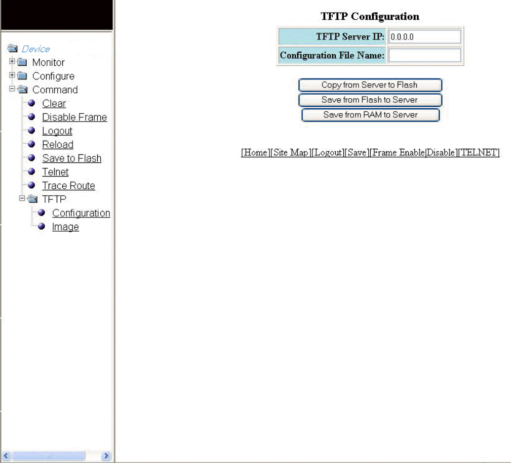
2. Click Conguration .
The TFTP Conguration window is displayed as shown in the gure below.
FIGURE 157 Conguring TFTP
3. Type the IP address of the most recently contacted TFTP server (if the switch has contacted a TFTP server since the last time
the software was reloaded or the switch was rebooted) in the TFTP Server IP eld.
4. Type the name under which the startup-cong le of the Layer 2 switch or Layer 3 switch was uploaded or downloaded during
the most recent TFTP access in the Conguration File Name eld.
Conguring TFTP
Brocade FastIron SX, FCX, and ICX Web Management Interface User Guide, 08.0.30
272 Part Number: 53-1003615-02
5. You can perform one of the following tasks with the conguration le:
• – Click Copy from Server to Flash to copy the le from a TFTP server to the device ash memory.
– Click Save from Flash to Server to save the le from the device ash memory to a TFTP server.
– Click Save from RAM to Server to save the le from the device RAM memory to a TFTP server.
Conguring a TFTP image
To access a TFTP image, perform the following steps.
1. Click Command on the left pane and select TFTP .
Conguring a TFTP image
Brocade FastIron SX, FCX, and ICX Web Management Interface User Guide, 08.0.30
Part Number: 53-1003615-02 273
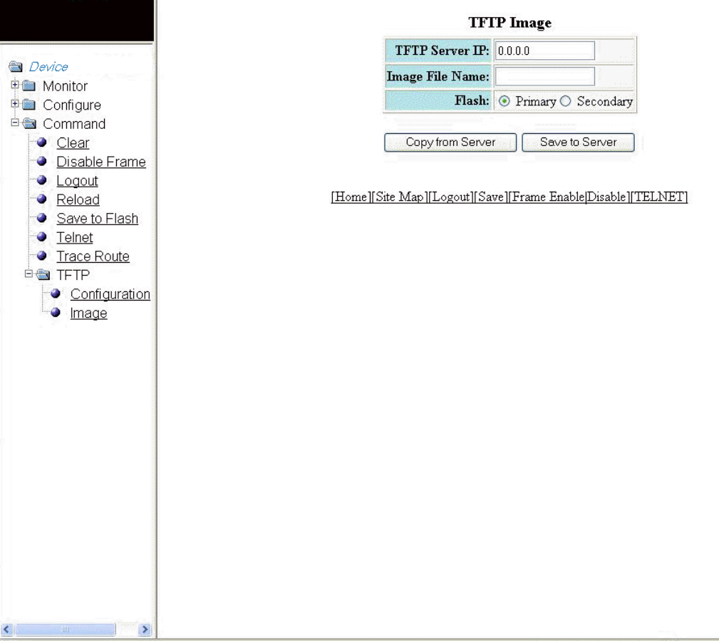
2. Click Image .
The TFTP Image window is displayed as shown in the gure below.
FIGURE 158 Conguring a TFTP image
3. Type the IP address of the most recently contacted TFTP server (if the switch has contacted a TFTP server since the last time
the software was reloaded or the switch was rebooted) in the TFTP Server IP eld.
4. Type the name of the Layer 2 switch or Layer 3 switch ash image (system software le) that was uploaded or downloaded
during the most recent TFTP access in the Image File Name eld.
Conguring a TFTP image
Brocade FastIron SX, FCX, and ICX Web Management Interface User Guide, 08.0.30
274 Part Number: 53-1003615-02
5. Click one of the following for Flash :
• – Primary --The default local storage device for image les and conguration les.
–Secondary --The second ash storage device you can use to store redundant images for additional booting reliability
or to preserve one software image while testing another one.
6. You can perform one of the following tasks with the TFTP image:
• – Click Copy from Server to copy a boot image from a TFTP server to the primary or secondary storage location in the
device ash memory.
– Click Save to Server to save the boot image from the primary or secondary storage location of the device ash
memory to a TFTP server.
Conguring a TFTP image
Brocade FastIron SX, FCX, and ICX Web Management Interface User Guide, 08.0.30
Part Number: 53-1003615-02 275
