Ruckus Brocade FastIron IP Multicast Configuration Guide, 08.0.50 Fast Iron Guide 08050 Ipmulticastguide
FastIron 08.0.50 IP Multicast Configuration Guide fastiron-08050-ipmulticastguide
2017-12-14
User Manual: Ruckus FastIron 08.0.50 IP Multicast Configuration Guide
Open the PDF directly: View PDF ![]() .
.
Page Count: 196 [warning: Documents this large are best viewed by clicking the View PDF Link!]
- Brocade FastIron IP Multicast Configuration Guide, 08.0.50
- Preface
- About This Document
- IPv4 Multicast VLAN Traffic Reduction
- PIM convergence on MAC movement
- IGMP snooping overview
- IGMP snooping configuration
- IGMP snooping mcache entries and group addresses
- IGMP snooping software resource limits
- Changing the maximum number of supported IGMP snooping mcache entries
- Setting the maximum number of IGMP group addresses
- Enabling IGMP snooping globally on the device
- Configuring the IGMP mode
- Configuring the IGMP version
- Configuring static groups to specific ports
- Disabling IGMP snooping on a VLAN
- Modifying the age interval for group membership entries
- Modifying the query interval (active IGMP snooping mode only)
- Modifying the maximum response time
- Configuring report control
- Modifying the wait time before stopping traffic when receiving a leave message
- Modifying the multicast cache age time
- Enabling or disabling error and warning messages
- Configuring static router ports
- Configuring the Layer 2 Mode IPv4 Querier Address
- Turning off static group proxy
- Enabling IGMP V3 membership tracking and fast leave for the VLAN
- Enabling fast leave for IGMP V2
- Enabling fast convergence
- Displaying the IGMP snooping configuration
- Displaying IGMP snooping errors
- Displaying IGMP group information
- Displaying IGMP snooping mcache information
- Displaying software resource usage for VLANs
- Displaying the status of IGMP snooping traffic
- Displaying querier information
- Clearing the IGMP mcache
- Clearing the mcache on a specific VLAN
- Clearing traffic on a specific VLAN
- Clearing IGMP counters on VLANs
- Disabling the flooding of unregistered IPv4 multicast frames in an IGMP-snooping-enabled VLAN
- PIM SM traffic snooping overview
- PIM SM snooping configuration
- PIM SM snooping show commands
- IPv6 Multicast VLAN Traffic Reduction
- MLD snooping overview
- Support for MLD snooping and Layer 3 IPv6 multicast routing together on the same device
- Forwarding mechanism in hardware
- Hardware resources for MLD and PIMv6 SM snooping
- MLD snooping configuration notes and feature limitations
- MLD snooping-enabled queriers and non-queriers
- MLD and VLAN configuration
- MLDv1 with MLDv2
- MLD snooping configuration
- Configuring the hardware and software resource limits
- Configuring the global MLD mode
- Modifying the age interval
- Modifying the query interval (active MLD snooping mode only)
- Configuring the global MLD version
- Configuring report control
- Modifying the wait time before stopping traffic when receiving a leave message
- Modifying the multicast cache aging time
- Disabling error and warning messages
- Configuring the MLD mode for a VLAN
- Disabling MLD snooping for the VLAN
- Configuring the MLD version for the VLAN
- Configuring the MLD version for individual ports
- Configuring static groups
- Configuring the Layer 2 Mode IPv6 Querier Address
- Configuring static router ports
- Disabling static group proxy
- Enabling MLDv2 membership tracking and fast leave for the VLAN
- Configuring fast leave for MLDv1
- Enabling fast convergence
- Displaying MLD snooping information
- Clearing MLD counters on all VLANs
- Clearing the mcache on all VLANs
- Clearing the mcache on a specific VLAN
- Clearing traffic counters on a specific VLAN
- Disabling the flooding of unregistered IPv6 multicast frames in an MLD-snooping-enabled VLAN
- PIM6 SM traffic snooping overview
- PIM6 SM snooping configuration
- Displaying PIM6 SM snooping information
- Displaying PIM6 SM snooping for a VLAN
- MLD snooping overview
- IPv4 Multicast Protocols
- Overview of IP multicasting
- Support for Multicast Multi-VRF
- Changing global IP multicast parameters
- Adding an interface to a multicast group
- Multicast non-stop routing
- Passive multicast route insertion
- IP multicast boundaries
- PIM Dense
- Initiating PIM multicasts on a network
- Pruning a multicast tree
- Grafts to a multicast tree
- PIM DM versions
- Configuring PIM DM
- Failover time in a multi-path topology
- Configuring a DR priority
- Displaying basic PIM Dense configuration information
- Displaying all multicast cache entries in a pruned state
- Displaying all multicast cache entries
- PIM convergence on MAC movement
- PIM Sparse
- IP multicast PIM neighbor filter
- PIM Passive
- Multicast Outgoing Interface (OIF) list optimization
- Displaying system values
- Displaying PIM resources
- Displaying PIM Sparse configuration information and statistics
- Displaying basic PIM Sparse configuration information
- Displaying a list of multicast groups
- Displaying BSR information
- Displaying candidate RP information
- Displaying RP-to-group mappings
- Displaying RP Information for a PIM Sparse group
- Displaying the RP set list
- Displaying multicast neighbor information
- Displaying the PIM multicast cache
- Displaying the PIM multicast cache for DIT
- Clearing the PIM forwarding cache
- Displaying PIM traffic statistics
- Clearing the PIM message counters
- Displaying PIM RPF
- Configuring Multicast Source Discovery Protocol (MSDP)
- Peer Reverse Path Forwarding (RPF) flooding
- Source Active caching
- Configuring MSDP
- Disabling an MSDP peer
- Designating the interface IP address as the RP IP address
- Filtering MSDP source-group pairs
- Filtering incoming and outgoing Source-Active messages
- Filtering advertised Source-Active messages
- Displaying MSDP information
- Displaying MSDP RPF-Peer
- Displaying MSDP Peer
- Displaying MSDP VRF RPF-Peer
- Clearing MSDP information
- Configuring MSDP mesh groups
- MSDP Anycast RP
- PIM Anycast RP
- Static multicast routes
- IGMP Proxy
- IGMP V3
- Default IGMP version
- Compatibility with IGMP V1 and V2
- Globally enabling the IGMP version
- Enabling the IGMP version per interface setting
- Enabling the IGMP version on a physical port within a virtual routing interface
- Enabling membership tracking and fast leave
- Creating a static IGMP group
- Setting the query interval
- Setting the group membership time
- Setting the maximum response time
- Displaying IGMPv3 information
- Clearing the IGMP group membership table
- Displaying static IGMP groups
- Clearing IGMP traffic statistics
- Source-specific multicast
- Configuring PIM SSM group range
- Configuring multiple SSM group ranges
- IGMPv2 SSM mapping
- IPv6 Multicast Protocols
- IPv6 PIM Sparse
- PIM Sparse router types
- RP paths and SPT paths
- RFC 3513 and RFC 4007 compliance for IPv6 multicast scope-based forwarding
- Configuring PIM Sparse
- IPv6 PIM-Sparse mode
- Configuring IPv6 PIM-SM on a virtual routing interface
- Enabling IPv6 PIM-SM for a specified VRF
- Configuring BSRs
- Setting the BSR message interval
- Configuring candidate RP
- Statically specifying the RP
- Updating IPv6 PIM Sparse forwarding entries with a new RP configuration
- Embedded Rendezvous Point
- Changing the Shortest Path Tree threshold
- Setting the RP advertisement interval
- Changing the PIM Join and Prune message interval
- Modifying neighbor timeout
- Setting the prune wait interval
- Setting the register suppress interval
- Setting the register probe time
- Setting the inactivity timer
- Changing the hello timer
- Enabling Source-specific Multicast
- Configuring a DR priority
- Passive Multicast Route Insertion
- Displaying system values
- Displaying PIM Sparse configuration information and statistics
- Displaying basic PIM Sparse configuration information
- Displaying IPv6 PIM interface information
- Displaying a list of multicast groups
- Displaying BSR information
- Displaying candidate RP information
- Displaying RP-to-group mappings
- Displaying RP information for an IPv6 PIM Sparse group
- Displaying the RP set list
- Displaying multicast neighbor information
- Displaying the IPv6 PIM multicast cache
- Displaying IPv6 PIM RPF
- Displaying IPv6 PIM counters
- Displaying the IPv6 PIM resources
- Displaying PIM traffic statistics
- Clearing the IPv6 PIM forwarding cache
- Clearing the IPv6 PIM message counters
- Updating PIM Sparse forwarding entries witha new RP configuration
- Clearing the IPv6 PIM traffic
- Defining the maximum number of IPv6 PIM cache entries
- Configuring a static multicast route within a VRF
- Configuring the route precedence by specifying the route types
- Configuring IPv6 PIM neighbor filtering
- IPv6 PIM convergence on MAC movement
- PIM Anycast RP
- Multicast Listener Discovery and source-specific multicast protocols
- Enabling MLDv2
- Configuring MLD parameters for default and non-default VRFs
- Configuring MLD parameters at the interface level
- Displaying MLD group information
- Displaying MLD definitions for an interface
- Displaying MLD settings
- Displaying static MLD groups
- Displaying MLD traffic
- Clearing IPv6 MLD traffic
- Clearing the IPv6 MLD group membership table cache
- IPv6 Multicast Boundaries
- IPv6 PIM Sparse
- IP Multicast Switch Port Extender Stacking

Supporting FastIron Software Release 08.0.50
FOR BROCADE CONTROLLED RELEASE ONLY
CONFIGURATION GUIDE
Brocade FastIron IP Multicast Conguration
Guide, 08.0.50
53-1004455-01
18 November 2016
© 2016, Brocade Communications Systems, Inc. All Rights Reserved.
Brocade, the B-wing symbol, and MyBrocade are registered trademarks of Brocade Communications Systems, Inc., in the United States and in other
countries. Other brands, product names, or service names mentioned of Brocade Communications Systems, Inc. are listed at www.brocade.com/en/legal/
brocade-Legal-intellectual-property/brocade-legal-trademarks.html. Other marks may belong to third parties.
Notice: This document is for informational purposes only and does not set forth any warranty, expressed or implied, concerning any equipment,
equipment feature, or service oered or to be oered by Brocade. Brocade reserves the right to make changes to this document at any time, without
notice, and assumes no responsibility for its use. This informational document describes features that may not be currently available. Contact a Brocade
sales oce for information on feature and product availability. Export of technical data contained in this document may require an export license from the
United States government.
The authors and Brocade Communications Systems, Inc. assume no liability or responsibility to any person or entity with respect to the accuracy of this
document or any loss, cost, liability, or damages arising from the information contained herein or the computer programs that accompany it.
The product described by this document may contain open source software covered by the GNU General Public License or other open source license
agreements. To nd out which open source software is included in Brocade products, view the licensing terms applicable to the open source software, and
obtain a copy of the programming source code, please visit http://www.brocade.com/support/oscd.
Brocade FastIron IP Multicast Conguration Guide, 08.0.50
2 53-1004455-01

Contents
Preface...................................................................................................................................................................................................................................9
Document conventions............................................................................................................................................................................................................................9
Brocade resources.....................................................................................................................................................................................................................................9
Document feedback..................................................................................................................................................................................................................................9
Contacting Brocade Technical Support......................................................................................................................................................................................... 10
Brocade customers.......................................................................................................................................................................................................................10
Brocade OEM customers.......................................................................................................................................................................................................... 10
About This Document..................................................................................................................................................................................................... 11
Supported hardware...............................................................................................................................................................................................................................11
What’s new in this document............................................................................................................................................................................................................. 11
How command information is presented in this guide............................................................................................................................................................11
IPv4 Multicast VLAN Trac Reduction.......................................................................................................................................................................13
PIM convergence on MAC movement.......................................................................................................................................................................................... 13
IGMP snooping overview.................................................................................................................................................................................................................... 13
Queriers and non-queriers........................................................................................................................................................................................................ 14
VLAN-specic conguration.................................................................................................................................................................................................... 15
Tracking and fast leave................................................................................................................................................................................................................ 15
Support for IGMP snooping and Layer 3 multicast routing together on the same device............................................................................ 15
Hardware resources for IGMP and PIM-SM snooping................................................................................................................................................. 15
Conguration notes and feature limitations for IGMP snooping and Layer 3 multicast routing.................................................................. 15
IGMP snooping conguration............................................................................................................................................................................................................16
IGMP snooping mcache entries and group addresses................................................................................................................................................. 17
IGMP snooping software resource limits.............................................................................................................................................................................17
Changing the maximum number of supported IGMP snooping mcache entries..............................................................................................17
Setting the maximum number of IGMP group addresses...........................................................................................................................................17
Enabling IGMP snooping globally on the device............................................................................................................................................................. 18
Conguring the IGMP mode.....................................................................................................................................................................................................18
Conguring the IGMP version..................................................................................................................................................................................................19
Conguring static groups to specic ports......................................................................................................................................................................... 20
Disabling IGMP snooping on a VLAN..................................................................................................................................................................................20
Modifying the age interval for group membership entries........................................................................................................................................... 20
Modifying the query interval (active IGMP snooping mode only)............................................................................................................................. 20
Modifying the maximum response time..............................................................................................................................................................................20
Conguring report control..........................................................................................................................................................................................................21
Modifying the wait time before stopping trac when receiving a leave message............................................................................................. 21
Modifying the multicast cache age time.............................................................................................................................................................................. 21
Enabling or disabling error and warning messages.........................................................................................................................................................22
Conguring static router ports..................................................................................................................................................................................................22
Conguring the Layer 2 Mode IPv4 Querier Address...................................................................................................................................................22
Turning o static group proxy...................................................................................................................................................................................................23
Enabling IGMP V3 membership tracking and fast leave for the VLAN.................................................................................................................23
Enabling fast leave for IGMP V2.............................................................................................................................................................................................23
Enabling fast convergence ........................................................................................................................................................................................................24
Displaying the IGMP snooping conguration....................................................................................................................................................................24
Displaying IGMP snooping errors.......................................................................................................................................................................................... 25
Brocade FastIron IP Multicast Conguration Guide, 08.0.50
53-1004455-01 3
Displaying IGMP group information......................................................................................................................................................................................25
Displaying IGMP snooping mcache information............................................................................................................................................................. 27
Displaying software resource usage for VLANs...............................................................................................................................................................27
Displaying the status of IGMP snooping trac.................................................................................................................................................................28
Displaying querier information................................................................................................................................................................................................. 29
Clearing the IGMP mcache....................................................................................................................................................................................................... 31
Clearing the mcache on a specic VLAN........................................................................................................................................................................... 32
Clearing trac on a specic VLAN........................................................................................................................................................................................ 32
Clearing IGMP counters on VLANs.......................................................................................................................................................................................32
Disabling the ooding of unregistered IPv4 multicast frames in an IGMP-snooping-enabled VLAN.............................................................. 32
PIM SM trac snooping overview...................................................................................................................................................................................................33
Application examples of PIM SM trac snooping.......................................................................................................................................................... 33
Conguration notes and limitations for PIM SM snooping..........................................................................................................................................34
PIM SM snooping conguration.......................................................................................................................................................................................................35
Enabling or disabling PIM SM snooping............................................................................................................................................................................. 35
Enabling PIM SM snooping on a VLAN..............................................................................................................................................................................36
Disabling PIM SM snooping on a VLAN.............................................................................................................................................................................36
PIM SM snooping show commands..............................................................................................................................................................................................36
Displaying PIM SM snooping information..........................................................................................................................................................................36
Displaying PIM SM snooping information on a Layer 2 switch.................................................................................................................................36
Displaying PIM SM snooping information for a specic group or source group pair.......................................................................................37
IPv6 Multicast VLAN Trac Reduction.......................................................................................................................................................................39
MLD snooping overview......................................................................................................................................................................................................................39
Support for MLD snooping and Layer 3 IPv6 multicast routing together on the same device...................................................................40
Forwarding mechanism in hardware......................................................................................................................................................................................40
Hardware resources for MLD and PIMv6 SM snooping.............................................................................................................................................. 40
MLD snooping conguration notes and feature limitations.........................................................................................................................................41
MLD snooping-enabled queriers and non-queriers.......................................................................................................................................................42
MLD and VLAN conguration................................................................................................................................................................................................. 42
MLDv1 with MLDv2....................................................................................................................................................................................................................42
MLD snooping conguration............................................................................................................................................................................................................. 42
Conguring the hardware and software resource limits.................................................................................................................................................43
Conguring the global MLD mode........................................................................................................................................................................................ 44
Modifying the age interval..........................................................................................................................................................................................................44
Modifying the query interval (active MLD snooping mode only)...............................................................................................................................45
Conguring the global MLD version......................................................................................................................................................................................45
Conguring report control..........................................................................................................................................................................................................45
Modifying the wait time before stopping trac when receiving a leave message............................................................................................. 45
Modifying the multicast cache aging time...........................................................................................................................................................................46
Disabling error and warning messages................................................................................................................................................................................ 46
Conguring the MLD mode for a VLAN............................................................................................................................................................................. 46
Disabling MLD snooping for the VLAN...............................................................................................................................................................................47
Conguring the MLD version for the VLAN...................................................................................................................................................................... 47
Conguring the MLD version for individual ports............................................................................................................................................................47
Conguring static groups........................................................................................................................................................................................................... 47
Conguring the Layer 2 Mode IPv6 Querier Address...................................................................................................................................................48
Conguring static router ports..................................................................................................................................................................................................48
Disabling static group proxy......................................................................................................................................................................................................48
Enabling MLDv2 membership tracking and fast leave for the VLAN.....................................................................................................................49
Conguring fast leave for MLDv1.......................................................................................................................................................................................... 49
Brocade FastIron IP Multicast Conguration Guide, 08.0.50
4 53-1004455-01
Enabling fast convergence ........................................................................................................................................................................................................49
Displaying MLD snooping information..........................................................................................................................................................................................50
Displaying MLD snooping error information..................................................................................................................................................................... 50
Displaying MLD group information........................................................................................................................................................................................50
Displaying MLD snooping mcache information...............................................................................................................................................................52
Displaying status of MLD snooping trac..........................................................................................................................................................................53
Displaying MLD snooping information by VLAN............................................................................................................................................................54
Clearing MLD counters on all VLANs............................................................................................................................................................................................55
Clearing the mcache on all VLANs................................................................................................................................................................................................. 55
Clearing the mcache on a specic VLAN.....................................................................................................................................................................................55
Clearing trac counters on a specic VLAN...............................................................................................................................................................................55
Disabling the ooding of unregistered IPv6 multicast frames in an MLD-snooping-enabled VLAN................................................................56
PIM6 SM trac snooping overview................................................................................................................................................................................................56
Application examples of PIM6 SM trac snooping....................................................................................................................................................... 56
Conguration notes and limitations for PIM6 SM snooping.......................................................................................................................................58
PIM6 SM snooping conguration....................................................................................................................................................................................................58
Enabling or disabling PIM6 SM snooping..........................................................................................................................................................................58
Enabling PIM6 SM snooping on a VLAN...........................................................................................................................................................................59
Disabling PIM6 SM snooping on a VLAN..........................................................................................................................................................................59
Displaying PIM6 SM snooping information................................................................................................................................................................................ 59
Displaying PIM6 SM snooping for a VLAN................................................................................................................................................................................ 60
IPv4 Multicast Protocols.................................................................................................................................................................................................61
Overview of IP multicasting................................................................................................................................................................................................................61
Multicast terms............................................................................................................................................................................................................................... 61
Support for Multicast Multi-VRF...................................................................................................................................................................................................... 62
system-max command changes............................................................................................................................................................................................ 62
Show and clear command support........................................................................................................................................................................................62
Changing global IP multicast parameters.....................................................................................................................................................................................63
Concurrent support for multicast routing and snooping............................................................................................................................................... 63
Dening the maximum number of PIM cache entries...................................................................................................................................................63
Dening the maximum number of IGMP group addresses........................................................................................................................................64
Changing IGMP V1 and V2 parameters............................................................................................................................................................................. 64
Adding an interface to a multicast group...................................................................................................................................................................................... 65
Multicast non-stop routing..................................................................................................................................................................................................................66
Conguration considerations....................................................................................................................................................................................................67
Conguring multicast non-stop routing............................................................................................................................................................................... 67
Displaying the multicast NSR status..................................................................................................................................................................................... 67
Passive multicast route insertion .....................................................................................................................................................................................................68
Conguring PMRI..........................................................................................................................................................................................................................69
Displaying hardware-drop..........................................................................................................................................................................................................69
IP multicast boundaries........................................................................................................................................................................................................................69
Conguration considerations....................................................................................................................................................................................................69
Conguring multicast boundaries...........................................................................................................................................................................................70
Displaying multicast boundaries..............................................................................................................................................................................................70
PIM Dense ................................................................................................................................................................................................................................................71
Initiating PIM multicasts on a network.................................................................................................................................................................................. 71
Pruning a multicast tree.............................................................................................................................................................................................................. 72
Grafts to a multicast tree.............................................................................................................................................................................................................74
PIM DM versions...........................................................................................................................................................................................................................75
Conguring PIM DM ...................................................................................................................................................................................................................75
Brocade FastIron IP Multicast Conguration Guide, 08.0.50
53-1004455-01 5
Failover time in a multi-path topology..................................................................................................................................................................................78
Conguring a DR priority............................................................................................................................................................................................................78
Displaying basic PIM Dense conguration information................................................................................................................................................ 78
Displaying all multicast cache entries in a pruned state................................................................................................................................................ 79
Displaying all multicast cache entries....................................................................................................................................................................................80
PIM convergence on MAC movement.......................................................................................................................................................................................... 83
PIM Sparse ...............................................................................................................................................................................................................................................83
PIM Sparse device types............................................................................................................................................................................................................84
RP paths and SPT paths............................................................................................................................................................................................................ 85
Conguring PIM Sparse..............................................................................................................................................................................................................85
ACL based RP assignment....................................................................................................................................................................................................... 89
IP multicast PIM neighbor lter.........................................................................................................................................................................................................90
Limitations........................................................................................................................................................................................................................................ 90
Conguring IPv4 PIM neighbor ltering.............................................................................................................................................................................. 91
PIM Passive...............................................................................................................................................................................................................................................91
Multicast Outgoing Interface (OIF) list optimization................................................................................................................................................................. 92
Displaying system values.................................................................................................................................................................................................................... 92
Displaying PIM resources....................................................................................................................................................................................................................92
Displaying PIM Sparse conguration information and statistics.........................................................................................................................................94
Displaying basic PIM Sparse conguration information............................................................................................................................................... 94
Displaying a list of multicast groups...................................................................................................................................................................................... 96
Displaying BSR information......................................................................................................................................................................................................97
Displaying candidate RP information....................................................................................................................................................................................98
Displaying RP-to-group mappings........................................................................................................................................................................................99
Displaying RP Information for a PIM Sparse group.....................................................................................................................................................100
Displaying the RP set list.........................................................................................................................................................................................................100
Displaying multicast neighbor information...................................................................................................................................................................... 101
Displaying the PIM multicast cache....................................................................................................................................................................................102
Displaying the PIM multicast cache for DIT....................................................................................................................................................................104
Clearing the PIM forwarding cache.............................................................................................................................................................................................. 105
Displaying PIM trac statistics.......................................................................................................................................................................................................105
Clearing the PIM message counters............................................................................................................................................................................................107
Displaying PIM RPF........................................................................................................................................................................................................................... 107
Conguring Multicast Source Discovery Protocol (MSDP)................................................................................................................................................ 108
Peer Reverse Path Forwarding (RPF) ooding.............................................................................................................................................................. 109
Source Active caching.............................................................................................................................................................................................................. 109
Conguring MSDP.....................................................................................................................................................................................................................109
Disabling an MSDP peer.........................................................................................................................................................................................................111
Designating the interface IP address as the RP IP address......................................................................................................................................111
Filtering MSDP source-group pairs....................................................................................................................................................................................111
Filtering incoming and outgoing Source-Active messages......................................................................................................................................112
Filtering advertised Source-Active messages................................................................................................................................................................113
Displaying MSDP information...............................................................................................................................................................................................114
Displaying MSDP RPF-Peer.................................................................................................................................................................................................118
Displaying MSDP Peer............................................................................................................................................................................................................ 119
Displaying MSDP VRF RPF-Peer...................................................................................................................................................................................... 119
Clearing MSDP information...................................................................................................................................................................................................119
Conguring MSDP mesh groups ................................................................................................................................................................................................ 120
Conguring MSDP mesh group.......................................................................................................................................................................................... 121
MSDP Anycast RP..............................................................................................................................................................................................................................122
Brocade FastIron IP Multicast Conguration Guide, 08.0.50
6 53-1004455-01
Conguring MSDP Anycast RP........................................................................................................................................................................................... 122
Example..........................................................................................................................................................................................................................................123
PIM Anycast RP................................................................................................................................................................................................................................... 126
Conguring PIM Anycast RP.................................................................................................................................................................................................126
Static multicast routes........................................................................................................................................................................................................................128
IGMP Proxy............................................................................................................................................................................................................................................ 128
IGMP proxy conguration notes...........................................................................................................................................................................................129
IGMP proxy limitations............................................................................................................................................................................................................. 129
Conguring IGMP Proxy..........................................................................................................................................................................................................129
Filtering groups in proxy report messages...................................................................................................................................................................... 130
Displaying IGMP Proxy information................................................................................................................................................................................... 130
IGMP V3..................................................................................................................................................................................................................................................131
Default IGMP version................................................................................................................................................................................................................133
Compatibility with IGMP V1 and V2..................................................................................................................................................................................133
Globally enabling the IGMP version .................................................................................................................................................................................. 133
Enabling the IGMP version per interface setting ..........................................................................................................................................................133
Enabling the IGMP version on a physical port within a virtual routing interface ............................................................................................. 134
Enabling membership tracking and fast leave................................................................................................................................................................134
Creating a static IGMP group................................................................................................................................................................................................ 135
Setting the query interval.........................................................................................................................................................................................................135
Setting the group membership time...................................................................................................................................................................................135
Setting the maximum response time................................................................................................................................................................................. 136
Displaying IGMPv3 information...........................................................................................................................................................................................136
Clearing the IGMP group membership table .................................................................................................................................................................137
Displaying static IGMP groups..............................................................................................................................................................................................138
Clearing IGMP trac statistics .............................................................................................................................................................................................140
Source-specic multicast........................................................................................................................................................................................................141
Conguring PIM SSM group range.................................................................................................................................................................................... 142
Conguring multiple SSM group ranges.......................................................................................................................................................................... 142
IGMPv2 SSM mapping........................................................................................................................................................................................................... 143
IPv6 Multicast Protocols..............................................................................................................................................................................................147
IPv6 PIM Sparse .................................................................................................................................................................................................................................147
PIM Sparse router types..........................................................................................................................................................................................................148
RP paths and SPT paths......................................................................................................................................................................................................... 148
RFC 3513 and RFC 4007 compliance for IPv6 multicast scope-based forwarding..................................................................................148
Conguring PIM Sparse.......................................................................................................................................................................................................... 149
IPv6 PIM-Sparse mode...........................................................................................................................................................................................................149
Conguring IPv6 PIM-SM on a virtual routing interface........................................................................................................................................... 149
Enabling IPv6 PIM-SM for a specied VRF...................................................................................................................................................................150
Conguring BSRs ..................................................................................................................................................................................................................... 150
Enabling Source-specic Multicast.....................................................................................................................................................................................156
Conguring a DR priority.........................................................................................................................................................................................................157
Passive Multicast Route Insertion........................................................................................................................................................................................157
Displaying system values........................................................................................................................................................................................................158
Displaying PIM Sparse conguration information and statistics.............................................................................................................................158
Clearing the IPv6 PIM forwarding cache..........................................................................................................................................................................172
Clearing the IPv6 PIM message counters....................................................................................................................................................................... 172
Updating PIM Sparse forwarding entries witha new RP conguration.................................................................................................................172
Clearing the IPv6 PIM trac .................................................................................................................................................................................................172
Dening the maximum number of IPv6 PIM cache entries.....................................................................................................................................172
Brocade FastIron IP Multicast Conguration Guide, 08.0.50
53-1004455-01 7
Conguring a static multicast route within a VRF......................................................................................................................................................... 173
Conguring the route precedence by specifying the route types...........................................................................................................................173
Conguring IPv6 PIM neighbor ltering...........................................................................................................................................................................175
IPv6 PIM convergence on MAC movement............................................................................................................................................................................ 175
PIM Anycast RP................................................................................................................................................................................................................................... 176
Conguring PIM Anycast RP.................................................................................................................................................................................................176
Multicast Listener Discovery and source-specic multicast protocols..........................................................................................................................178
Enabling MLDv2.........................................................................................................................................................................................................................178
Conguring MLD parameters for default and non-default VRFs.......................................................................................................................... 179
Conguring MLD parameters at the interface level......................................................................................................................................................181
Displaying MLD group information.................................................................................................................................................................................... 183
Displaying MLD denitions for an interface.................................................................................................................................................................... 183
Displaying MLD settings......................................................................................................................................................................................................... 184
Displaying static MLD groups...............................................................................................................................................................................................185
Displaying MLD trac..............................................................................................................................................................................................................185
Clearing IPv6 MLD trac....................................................................................................................................................................................................... 186
Clearing the IPv6 MLD group membership table cache...........................................................................................................................................186
IPv6 Multicast Boundaries...............................................................................................................................................................................................................187
Conguration considerations.................................................................................................................................................................................................187
Conguring multicast boundaries........................................................................................................................................................................................187
Displaying multicast boundaries.......................................................................................................................................................................................... 188
IP Multicast Switch Port Extender Stacking............................................................................................................................................................ 189
Switch Port Extender and IP Multicast........................................................................................................................................................................................189
Multicast E-CID and IEE 802.1BR.................................................................................................................................................................................... 189
Multicast E-CID Manager........................................................................................................................................................................................................189
Considerations for multicast forwarding on PE units...................................................................................................................................................189
Layer 2 multicast in an SPX conguration.......................................................................................................................................................................190
Layer 3 multicast in an SPX conguration.......................................................................................................................................................................192
Displaying multicast SPX information................................................................................................................................................................................194
IP multicast hardware entry optimization................................................................................................................................................................................... 195
How disabling IP multicast hardware entry optimization works..............................................................................................................................195
Disabling multicast hardware entry optimization...........................................................................................................................................................195
Brocade FastIron IP Multicast Conguration Guide, 08.0.50
8 53-1004455-01

Preface
• Document conventions...................................................................................................................................................................................... 9
• Brocade resources............................................................................................................................................................................................... 9
• Document feedback............................................................................................................................................................................................9
• Contacting Brocade Technical Support....................................................................................................................................................10
Document conventions
The document conventions describe text formatting conventions, command syntax conventions, and important notice formats used in
Brocade technical documentation.
Brocade resources
Visit the Brocade website to locate related documentation for your product and additional Brocade resources.
You can download additional publications supporting your product at www.brocade.com. Select the Brocade Products tab to locate your
product, then click the Brocade product name or image to open the individual product page. The user manuals are available in the
resources module at the bottom of the page under the Documentation category.
To get up-to-the-minute information on Brocade products and resources, go to MyBrocade. You can register at no cost to obtain a user
ID and password.
Release notes are available on MyBrocade under Product Downloads.
White papers, online demonstrations, and data sheets are available through the Brocade website.
Document feedback
To send feedback and report errors in the documentation you can use the feedback form posted with the document or you can e-mail
the documentation team.
Quality is our rst concern at Brocade and we have made every eort to ensure the accuracy and completeness of this document.
However, if you nd an error or an omission, or you think that a topic needs further development, we want to hear from you. You can
provide feedback in two ways:
• Through the online feedback form in the HTML documents posted on www.brocade.com.
• By sending your feedback to documentation@brocade.com.
Provide the publication title, part number, and as much detail as possible, including the topic heading and page number if applicable, as
well as your suggestions for improvement.
FOR BROCADE CONTROLLED RELEASE ONLY
Brocade FastIron IP Multicast Conguration Guide, 08.0.50
53-1004455-01 9

Contacting Brocade Technical Support
As a Brocade customer, you can contact Brocade Technical Support 24x7 online, by telephone, or by e-mail. Brocade OEM customers
contact their OEM/Solutions provider.
Brocade customers
For product support information and the latest information on contacting the Technical Assistance Center, go to http://www.brocade.com/
services-support/index.html.
If you have purchased Brocade product support directly from Brocade, use one of the following methods to contact the Brocade
Technical Assistance Center 24x7.
Online Telephone E-mail
Preferred method of contact for non-urgent
issues:
•My Cases through MyBrocade
•Software downloads and licensing
tools
•Knowledge Base
Required for Sev 1-Critical and Sev 2-High
issues:
• Continental US: 1-800-752-8061
• Europe, Middle East, Africa, and Asia
Pacic: +800-AT FIBREE (+800 28
34 27 33)
• For areas unable to access toll free
number: +1-408-333-6061
•Toll-free numbers are available in
many countries.
support@brocade.com
Please include:
• Problem summary
• Serial number
• Installation details
• Environment description
Brocade OEM customers
If you have purchased Brocade product support from a Brocade OEM/Solution Provider, contact your OEM/Solution Provider for all of
your product support needs.
• OEM/Solution Providers are trained and certied by Brocade to support Brocade® products.
• Brocade provides backline support for issues that cannot be resolved by the OEM/Solution Provider.
• Brocade Supplemental Support augments your existing OEM support contract, providing direct access to Brocade expertise.
For more information, contact Brocade or your OEM.
• For questions regarding service levels and response times, contact your OEM/Solution Provider.
FOR BROCADE CONTROLLED RELEASE ONLY
Contacting Brocade Technical Support
Brocade FastIron IP Multicast Conguration Guide, 08.0.50
10 53-1004455-01

About This Document
• Supported hardware......................................................................................................................................................................................... 11
• What’s new in this document........................................................................................................................................................................11
• How command information is presented in this guide...................................................................................................................... 11
Supported hardware
This guide supports the following product families from Brocade:
• ICX 7750 Series
• ICX 7450 Series
• ICX 7250 Series
What’s new in this document
The table summarizes updates to this guide for Version 08.0.50 of the FastIron software release.
TABLE 1 Summary of enhancements in FastIron Release 08.0.50
Feature Description Location
Layer 2 mode querier multicast This feature allows you to congure a Layer 2
mode querier IP address in IPv4 and IPv6
environments.
IPv4 Multicast VLAN Trac Reduction
IPv6 Multicast VLAN Trac Reduction
How command information is presented in this guide
For all new content supported in FastIron Release 8.0.20 and later, command information is documented in a standalone command
reference guide.
To provide consistent CLI documentation for all products, there is now a standalone command reference for the FastIron platforms.
In the Brocade FastIron Command Reference, the command pages are in alphabetical order and follow a standard format to present
syntax, parameters, mode, usage guidelines, examples, and command history.
NOTE
Many commands from previous FastIron releases are also included in the command reference.
FOR BROCADE CONTROLLED RELEASE ONLY
Brocade FastIron IP Multicast Conguration Guide, 08.0.50
53-1004455-01 11
Brocade FastIron IP Multicast Conguration Guide, 08.0.50
12 53-1004455-01

IPv4 Multicast VLAN Trac Reduction
• PIM convergence on MAC movement.....................................................................................................................................................13
• IGMP snooping overview...............................................................................................................................................................................13
• IGMP snooping conguration...................................................................................................................................................................... 16
• Disabling the ooding of unregistered IPv4 multicast frames in an IGMP-snooping-enabled VLAN.........................32
• PIM SM trac snooping overview..............................................................................................................................................................33
• PIM SM snooping conguration................................................................................................................................................................. 35
• PIM SM snooping show commands.........................................................................................................................................................36
PIM convergence on MAC movement
PIM convergence occurs when the PIM module is notied of a topology change.
The notication is triggered upon a change in port status, Reverse Path Forwarding (RPF) failure in the hardware, or by the unicast routing
module if there is a change in the Layer 3 topology. If the topology change occurs without setting o any of the two events or if the Layer
3 topology change is not notied by the unicast routing module, PIM convergence does not take place.
If there is a change in the source trac at the Layer 2 interface level, the RPF check fails because only loose RPF check is supported
(loose RPF check detects the change in the source trac only at the Layer 3 interface level). A notication for a change in the source
trac at the Layer 2 interface level can be triggered by establishing a signaling process for MAC address movement. The MAC address
movement notication triggers RPF check on MAC movement for directly connected sources. The MAC address movement notication
can be triggered by conguring the ip multicast-routing rpf-check mac-movement command. The MAC address movement
notication triggers a notication to the PIM module which results in convergence. PIM convergence is supported in both PIM Sparse
and PIM Dense modes.
PIM convergence on MAC movement is supported on the Brocade ICX 7250, ICX 7450, and ICX 7750 switches.
NOTE
PIM convergence on MAC movement is applicable only in a topology where the multicast source port and PIM routers are in
the same Layer 2 domain.
IGMP snooping overview
When a device processes a multicast packet, by default, it broadcasts the packets to all ports except the incoming port of a VLAN.
Packets are ooded by hardware without going to the CPU. This behavior causes some clients to receive unwanted trac.
IGMP snooping provides multicast containment by forwarding trac to only the ports that have IGMP receivers for a specic multicast
group (destination address). A device maintains the IGMP group membership information by processing the IGMP reports and leave
messages, so trac can be forwarded to ports receiving IGMP reports.
An IPv4 multicast address is a destination address in the range of 224.0.0.0 to 239.255.255.255. Addresses of 224.0.0.X are
reserved. Because packets destined for these addresses may require VLAN ooding, devices do not snoop in the reserved range. Data
packets destined to addresses in the reserved range are ooded to the entire VLAN by hardware, and mirrored to the CPU. Multicast data
packets destined for the non-reserved range of addresses are snooped. A client must send IGMP reports in order to receive trac.
An IGMP device's responsibility is to broadcast general queries periodically, and to send group queries when receiving a leave message,
to conrm that none of the clients on the port still want specic trac before removing the trac from the port. IGMP V2 lets clients
specify what group (destination address) will receive the trac but not to specify the source of the trac. IGMP V3 is for source-specic
FOR BROCADE CONTROLLED RELEASE ONLY
Brocade FastIron IP Multicast Conguration Guide, 08.0.50
53-1004455-01 13
multicast trac, adding the capability for clients to INCLUDE or EXCLUDE specic trac sources. An IGMP V3 device port state could
be INCLUDE or EXCLUDE, and there are dierent types of group records for client reports.
The interfaces respond to general or group queries by sending a membership report that contains one or more of the following records
associated with a specic group:
• Current-state record that indicates from which sources the interface wants to receive and not receive trac. This record contains
the source address of interfaces and whether or not trac will be included (IS_IN) or not excluded (IS_EX) from this source.
• Filter-mode-change record. If the interface state changes from IS_IN to IS_EX, a TO_EX record is included in the membership
report. Likewise, if the interface state changes from IS_EX to IS_IN, a TO_IN record appears in the membership report.
• An IGMP V2 leave report is equivalent to a TO_IN (empty) record in IGMP V3. This record means that no trac from this group
will be received regardless of the source.
• An IGMP V2 group report is equivalent to an IS_EX (empty) record in IGMP V3. This record means that all trac from this
group will be received regardless of source.
• Source-list-change record. If the interface wants to add or remove trac sources from its membership report, the report can
contain an ALLOW record, which includes a list of new sources from which the interface wishes to receive trac. It can also
contain a BLOCK record, which lists the current trac sources from which the interface wants to stop receiving trac.
IGMP protocols provide a method for clients and a device to exchange messages, and let the device build a database indicating which
port wants what trac. The protocols do not specify forwarding methods. They require IGMP snooping or multicast protocols such as
PIM to handle packet forwarding. PIM can route multicast packets within and outside a VLAN, while IGMP snooping can switch packets
only within a VLAN.
If a VLAN is not IGMP snooping-enabled, it oods multicast data and control packets to the entire VLAN in hardware. When snooping is
enabled, IGMP packets are trapped to the CPU. Data packets are mirrored to the CPU in addition to being VLAN ooded. The CPU then
installs hardware resources, so that subsequent data packets can be switched to desired ports in hardware without going to the CPU. If
there is no client report or port to queriers for a data stream, the hardware resource drops it.
Queriers and non-queriers
An IGMP snooping-enabled Brocade device can be congured as a querier (active) or non-querier (passive). An IGMP querier sends
queries; a non-querier listens for IGMP queries and forwards them to the entire VLAN. VLANs can be independently congured to be
queriers or non-queriers. If a VLAN has a connection to a PIM-enabled port on another router, the VLAN must be congured as a non-
querier. When multiple IGMP snooping devices are connected together, and there is no connection to a PIM-enabled port, one of the
devices must be congured as a querier. If multiple devices are congured as queriers, after these devices exchange queries, then all
except the winner stop sending queries. The device with the lowest address becomes the querier. Although the system will work when
multiple devices are congured as queriers, Brocade recommends that only one device (preferably the one with the trac source) is
congured as a querier.
The non-queriers always forward multicast data trac and IGMP messages to router ports which receive IGMP queries or PIM hellos.
Brocade recommends that you congure the device with the data trac source (server) as a querier. If a server is attached to a non-
querier, the non-querier always forwards trac to the querier regardless of whether there are any clients on the querier.
NOTE
In a topology of one or more connecting devices, at least one device must be running PIM congured as active. Otherwise,
none of the devices can send out queries, and trac cannot be forwarded to clients.
FOR BROCADE CONTROLLED RELEASE ONLY
IGMP snooping overview
Brocade FastIron IP Multicast Conguration Guide, 08.0.50
14 53-1004455-01
VLAN-specic conguration
IGMP snooping can be enabled on some VLANs or on all VLANs. Each VLAN can be independently congured to be a querier or non-
querier and can be congured for IGMP V2 or IGMP V3. In general, the ip multicast commands apply globally to all VLANs except
those congured with VLAN-specic multicast commands. The VLAN-specic multicast commands supersede the global ip multicast
commands.
IGMP snooping can be congured for IGMP V2 or IGMP V3 on individual ports of a VLAN. An interface or router sends the queries and
reports that include its IGMP version specied on it. The version conguration only applies to sending queries. The snooping device
recognizes and processes IGMP V2 and IGMP V3 packets regardless of the version conguration.
To avoid version deadlock, an interface retains its version conguration even when it receives a report with a lower version.
Tracking and fast leave
Brocade devices support fast leave for IGMP V2, and tracking and fast leave for IGMP V3. Fast leave stops the trac immediately when
the port receives a leave message. Tracking traces all IGMP V3 clients. Refer to Enabling IGMP V3 membership tracking and fast leave
for the VLAN on page 23 and Enabling fast leave for IGMP V2 on page 23.
Support for IGMP snooping and Layer 3 multicast routing together on the
same device
The Brocade device supports global Layer 2 IP multicast trac reduction (IGMP snoopoing) and Layer 3 multicast routing (PIM-Sparse
or PIM-Dense) together on the same device in the full Layer 3 software image, as long as the Layer 2 feature conguration is at the
VLAN level.
Hardware resources for IGMP and PIM-SM snooping
Brocade devices allocate/program fdb/mac entries to achieve multicast snooping in hardware. If a data packet does not match any of
these resources, it might be sent to the CPU, which increases the CPU burden. This can happen if the device runs out of hardware
resources, or is unable to install resources for a specic matching address due to a hashing collision.
The hardware hashes addresses into available fdb/mac entries, with some addresses hashed into the same entry. If the collision number
in an entry is more than the hardware chain length, the resource cannot be installed.
Conguration notes and feature limitations for IGMP snooping and Layer
3 multicast routing
The following notes apply to all devices:
• Layer 2 IGMP multicast is automatically enabled with Layer 3 multicast routing. If Layer 3 multicast routing is enabled on your
system, do not attempt to enable Layer 2 IGMP snooping.
• The default IGMP version is V2.
• A user can congure the maximum numbers of group address entries.
• An IGMP device can be congured to rate-limit the forwarding IGMP V2 membership reports to queriers.
• The device supports static groups. The device acts as a proxy to send IGMP reports for the static groups when receiving
queries.
• A user can congure static router ports to force all multicast trac to these specic ports.
FOR BROCADE CONTROLLED RELEASE ONLY
IGMP snooping overview
Brocade FastIron IP Multicast Conguration Guide, 08.0.50
53-1004455-01 15
• If a VLAN has a connection to a PIM-enabled port on another router, the VLAN must be congured as a non-querier (passive).
When multiple snooping devices connect together and there is no connection to PIM ports, one device must be congured as a
querier (active). If multiple devices are congured as active (queriers), only one will keep sending queries after exchanging
queries.
• The querier must congure an IP address to send out queries.
• IGMP snooping requires hardware resource. Hardware resource is installed only when there is data trac. If resource is
inadequate, the data stream without a resource is mirrored to the CPU in addition to being VLAN ooded, which can cause high
CPU usage. Brocade recommends that you avoid global enabling of snooping unless necessary.
• IGMP snooping requires clients to send membership reports in order to receive data trac. If a client application does not send
reports, you must congure static groups on the snooping VLAN to force trac to client ports. Note that servers (trac sources)
are not required to send IGMP memberships.
• Support for VSRP together with IGMP snooping on the same interface.
• When VSRP or VSRP-aware is congured on a VLAN, only IGMP version 2 is recommended; IGMP version 3 is not
recommended.
• Each VLAN can independently enable or disable IGMP, or congure IGMP v2 or IGMP v3.
• IGMP/PIM-SM snooping over Multi-Chassis Trunking is supported on ICX 7750 devices.
IGMP snooping conguration
Conguring IGMP snooping on a Brocade device consists of the following global, VLAN-specic, and port-specic tasks:
Perform the following global IGMP snooping tasks:
•Conguring the IGMP V3 snooping software resource limits
• Enabling IGMP snooping globally on the device
•Conguring the global IGMP mode
•Conguring the global IGMP version
• Modifying the age interval for group membership entries
• Modifying the query interval (active IGMP snooping mode only)
• Modifying the maximum response time
•Conguring report control (rate limiting)
• Modifying the wait time before stopping trac when receiving a leave message
• Modifying the multicast cache age time
• Enabling or disabling error and warning messages
Perform the following VLAN-specic IGMP snooping tasks:
•Conguring the IGMP mode for a VLAN (active or passive)
• Disabling IGMP snooping on a VLAN
•Conguring the IGMP version for a VLAN
•Conguring static router ports
• Turning o static group proxy
• Enabling IGMP V3 membership tracking and fast leave for the VLAN
• Enabling fast leave for IGMP
FOR BROCADE CONTROLLED RELEASE ONLY
IGMP snooping conguration
Brocade FastIron IP Multicast Conguration Guide, 08.0.50
16 53-1004455-01
• Enabling fast convergence
Perform the following port-specic IGMP snooping task:
•Conguring the IGMP version for individual ports in a VLAN
IGMP snooping mcache entries and group addresses
An IGMP snooping group address entry is created when an IGMP join message is received for a group. An IGMP snooping mcache
entry is created when data trac is received for that group. Each mcache entry represents one data stream, and multiple mcache entries
(up to 32) can share the same hardware (MAC) address entry. The egress port list for the mcache entry is obtained from the IGMP group
address entry. If there is no existing IGMP group address entry when an mcache entry is created, data trac for that multicast group is
dropped in hardware. If there is an existing IGMP group address entry when an mcache is created, data trac for that multicast group is
switched in hardware.
IGMP snooping software resource limits
These are the IGMP snooping mcache resource limits for Brocade devices.
• ICX 7750 switches support 8192 IGMP snooping mcache entries.
• ICX 7750 routers support 6K IGMP snooping mcache entries.
• ICX 7250 devices support 8192 IGMP snooping mcache entries.
• ICX 7450 devices support 8192 IGMP snooping mcache entries.
Changing the maximum number of supported IGMP snooping mcache
entries
You can congure the system-max igmp-snoop-mcache command to change the maximum number of IGMP snooping cache entries
supported on a device.
Device(config)#system-max igmp-snoop-mcache 2000
Syntax: [no] system-max igmp-snoop-mcache num
The num variable is a value from 256 through 8192. The default is 512.
Setting the maximum number of IGMP group addresses
The congured number of IGMP group addresses is the upper limit of an expandable database. Client memberships exceeding the
group limit are not processed. Congure the system-max igmp-snoop-group-addr command to dene the maximum number of IGMP
group addresses.
Device(config)# system-max igmp-snoop-group-addr 1600
Syntax: [no] system-max igmp-snoop-group-addr num
The num variable is a value from 256 to 8192. The default for IGMP snooping group addresses is 4096.
FOR BROCADE CONTROLLED RELEASE ONLY
IGMP snooping conguration
Brocade FastIron IP Multicast Conguration Guide, 08.0.50
53-1004455-01 17
Enabling IGMP snooping globally on the device
When you globally enable IGMP snooping, you can specify IGMP V2 or IGMP V3. The ip multicast version command enables IGMP
V3.
device(config)#ip multicast version 3
Syntax: [no] ip multicast version [2 | 3]
If you do not specify a version number, IGMP V2 is assumed.
Conguration notes for Layer 3 devices
• If Layer 3 multicast routing is enabled on your system, do not attempt to enable Layer 2 IGMP snooping. Layer 2 IGMP
snooping is automatically enabled with Layer 3 multicast routing.
• If the "route-only" feature is enabled on the Layer 3 Switch, then IP multicast trac reduction will not be supported.
• IGMP snooping is not supported on the default VLAN of Layer 3 Switches.
Disabling the ooding of unregistered IPv6 multicast frames in an MLD-snooping-enabled VLAN
NOTE
Disabling the ooding of unregistered IPv6 multicast frames in an MLD-snooping-enabled VLAN is supported only on the
Brocade ICX 7750 (standalone and stacking) platform.
Support for this feature on the Brocade ICX 7750 was introduced in FastIron 8.0.10d. In releases prior to FastIron 8.0.30,
support for this feature on the Brocade ICX 7750 was for devices in standalone mode only.
To disable the ooding of unregistered IPv6 multicast frames in an MLD-snooping-enabled VLAN, use the ipv6 multicast disable-
ooding command in global conguration mode.
The following example disables ooding of unregistered IPv6 multicast frames.
Device(config)# ipv6 multicast disable-flooding
Conguring the IGMP mode
You can congure active or passive IGMP modes on the Brocade device. The default mode is passive. If you specify an IGMP mode for
a VLAN, it overrides the global setting.
•Active - When active IGMP mode is enabled, a Brocade device actively sends out IGMP queries to identify multicast groups on
the network, and makes entries in the IGMP table based on the group membership reports it receives.
NOTE
Routers in the network generally handle this operation. Use the active IGMP mode only when the device is in a stand-alone
Layer 2 Switched network with no external IP multicast router attachments. In this case, enable the active IGMP mode on only
one of the devices and leave the other devices congured for passive IGMP mode.
•Passive - When passive IGMP mode is enabled, it forwards reports to the router ports which receive queries. IGMP snooping in
the passive mode does not send queries. However, it forwards queries to the entire VLAN.
Conguring the global IGMP mode
To globally set the IGMP mode to active, enter the following command.
device(config)#ip multicast active
FOR BROCADE CONTROLLED RELEASE ONLY
IGMP snooping conguration
Brocade FastIron IP Multicast Conguration Guide, 08.0.50
18 53-1004455-01
Syntax: [no] ip multicast [ active | passive ]
If you do not enter either active or passive, the passive mode is assumed.
Conguring the IGMP mode for a VLAN
If you specify an IGMP mode for a VLAN, it overrides the global setting.
To set the IGMP mode for VLAN 20 to active, enter the following commands.
device(config)#vlan 20
device(config-vlan-20)#multicast active
Syntax: [no] multicast [ active | passive]
Conguring the IGMP version
Use the procedures in this section to specify the IGMP version.
Conguring the global IGMP version
To globally specify IGMP V2 or IGMP V3, refer to Enabling IGMP snooping globally on the device on page 18.
Conguring the IGMP version for a VLAN
You can specify the IGMP version for a VLAN. For example, the following commands congure VLAN 20 to use IGMP V3.
device(config)#vlan 20
device(config-vlan-20)#multicast version 3
Syntax: [no] multicast version [2 | 3 ]
If no IGMP version is specied, then the globally-congured IGMP version is used. If an IGMP version is specied for individual ports,
those ports use that version, instead of the VLAN version.
Conguring the IGMP version for individual ports in a VLAN
You can specify the IGMP version for individual ports in a VLAN. For example, the following commands congure ports 1/2/4, 1/2/5,
and 1/2/6 to use IGMP V3. The other ports either use the IGMP version specied with the multicast version command, or the globally-
congured IGMP version.
device(config)#vlan 20
device(config-vlan-20)#multicast port-version 3 ethernet 1/2/4 to 1/2/6
Syntax: [no] multicast port-version [2 | 3 ] ethernetunit/slot/port [ethernet unit/slot/port| tounit/slot/port]
To specify a list of ports, enter each port as ethernetunit/slot/port followed by a space. For example, ethernet 1/1/24 ethernet 1/3/24
ethernet 1/4/17.
To specify a range of ports, enter the rst port in the range as ethernetport followed by the last port in the range. For example, ethernet
1/1/1 to 1/1/8.
You can combine lists and ranges in the same command. For example: enable ethernet 1/1/1 to 1/1/8 ethernet 1/1/24 ethernet
1/4/24 ethernet 1/4/17.
FOR BROCADE CONTROLLED RELEASE ONLY
IGMP snooping conguration
Brocade FastIron IP Multicast Conguration Guide, 08.0.50
53-1004455-01 19
Conguring static groups to specic ports
A snooping-enabled VLAN cannot forward multicast trac to ports that do not receive IGMP membership reports. If clients cannot send
reports, you can congure a static group which applies to specic ports. The static group allows packets to be forwarded to the static
group ports even though they have no client membership reports.
device(config)#vlan 20
device(config-vlan-20)#multicast static-group 224.1.1.1 count 2 ethernet 1/1/3 ethernet 1/1/5 to 1/1/7
Disabling IGMP snooping on a VLAN
When IGMP snooping is enabled globally, you can still disable it for a specic VLAN. For example, the following commands cause IGMP
snooping to be disabled for VLAN 20. This setting overrides the global setting.
device(config)#vlan 20
device(config-vlan-20)#multicast disable-multicast-snoop
Syntax: [no] multicast disable-multicast-snoop
Modifying the age interval for group membership entries
When the device receives a group membership report, it makes an entry for that group in the IGMP group table. The age interval
species how long the entry can remain in the table before the device receives another group membership report. When multiple devices
connect together, all devices must be congured for the same age interval, which must be at least twice the length of the query interval,
so that missing one report won't stop trac. Non-querier age intervals must be the same as the age interval of the querier.
To modify the age interval, enter the following command.
device(config)#ip multicast age-interval 280
Syntax: [no] ip multicast age-interval interval
The interval parameter species the aging time. You can specify a value from 20 through 26000 seconds. The default is 260 seconds.
Modifying the query interval (active IGMP snooping mode only)
If IP multicast trac reduction is set to active mode, you can modify the query interval to specify how often the device sends general
queries. When multiple queriers connect together, they must all be congured with the same query interval.
To modify the query interval, enter the following command.
device(config)#ip multicast query-interval 120
Syntax: [no] ip multicast query-interval interval
The interval parameter species the time between queries. You can specify a value from 10 through 3600 seconds. The default is 125
seconds.
Modifying the maximum response time
The maximum response time is the number of seconds that a client can wait before responding to a query sent by the switch.
To change the IPv4 multicast maximum response time, enter the following command.
device(config)#ip multicast max-response-time 5
FOR BROCADE CONTROLLED RELEASE ONLY
IGMP snooping conguration
Brocade FastIron IP Multicast Conguration Guide, 08.0.50
20 53-1004455-01
To change the IPv6 multicast maximum response time, enter the following command.
device(config)# ipv6 multicast max-response-time 5
Syntax: [no] ip multicast max-response-time interval
Syntax: [no] ipv6 multicast max-response-time interval
For interval , enter a value from 1 through 25 seconds. The default is 10 seconds.
Conguring report control
A device in passive mode forwards reports and leave messages from clients to the upstream router ports that are receiving queries.
You can congure report control to rate-limit report forwarding within the same group to no more than once every 10 seconds. This rate-
limiting does not apply to the rst report answering a group-specic query.
NOTE
This feature applies to IGMP V2 only. The leave messages are not rate limited.
IGMP V2 membership reports of the same group from dierent clients are considered to be the same and are rate-limited.
Use the ip multicast report-control command to alleviate report storms from many clients answering the upstream router query.
device(config)#ip multicast report-control
Syntax: [no] ip multicast-report-control
The original command, ip igmp-report-control , has been renamed to ip multicast report-control . The original command is still
accepted; however, it is renamed when you congure a show conguration command.
Modifying the wait time before stopping trac when receiving a leave
message
You can dene the wait time before stopping trac to a port when a leave message is received. The device sends group-specic queries
once per second to ask if any client in the same port still needs this group. Due to internal timer granularity, the actual wait time is
between n and (n+1) seconds (n is the congured value).
device(config)#ip multicast leave-wait-time 1
Syntax: [no] ip multicast leave-wait-time num
num is the number of seconds from 1 through 5. The default is 2 seconds.
Modifying the multicast cache age time
You can set the time for an mcache to age out when it does not receive trac. The trac is hardware switched. One minute before aging
out an mcache, the device mirrors a packet of this mcache to CPU to reset the age. If no data trac arrives within one minute, this
mcache is deleted. A lower value quickly removes resources consumed by idle streams, but it mirrors packets to CPU often. A higher
value is recommended only data streams are continually arriving.
device(config)#ip multicast mcache-age 180
Syntax: [no] ip multicast mcache-age num
num is the number of seconds from 60 through 3600. The default is 60 seconds.
FOR BROCADE CONTROLLED RELEASE ONLY
IGMP snooping conguration
Brocade FastIron IP Multicast Conguration Guide, 08.0.50
53-1004455-01 21
Enabling or disabling error and warning messages
The device prints error or warning messages when it runs out of software resources or when it receives packets with the wrong checksum
or groups. These messages are rate-limited. You can turn o these messages by entering the following command.
device(config)#ip multicast verbose-off
Syntax: [no] ip multicast verbose-o
Conguring static router ports
The Brocade device forwards all multicast control and data packets to router ports which receive queries. Although router ports are
learned, you can force multicast trac to specied ports even though these ports never receive queries. To congure static router ports,
enter the following commands.
device(config)#vlan 70
device(config-vlan-70)#multicast router-port ethernet 1/1/4 to 1/1/5 ethernet 1/1/8
Syntax: [no] multicast router-port ethernet unit/slot/port [ ethernet unit/slot/port | to unit/slot/port ]
To specify a list of ports, enter each port as ethernet unit/slot/port followed by a space. For example, ethernet 1/1/24 ethernet 1/2//17
ethernet 1/4/24.
To specify a range of ports, enter the rst port in the range as ethernet unit/slot/port followed by the last port in the range. For example,
ethernet 1/1/1 to 1/1/8.
You can combine lists and ranges in the same command. For example, enable ethernet 1/1/1 to 1/1/8 ethernet 1//1/24 ethernet
1/2/17 ethernet 1/4/24 .
Conguring the Layer 2 Mode IPv4 Querier Address
You can congure an IPv4 querier address for every VLAN. This functionality is available only for multicast snooping.
In releases before FastIron 08.0.50, you cannot specically congure a querier address per VLAN. Instead, in an IPv4 environment, the
device internally attempts to select an address, either a VE address and a loopback address for a router image, or a management port
address for a switch image.
Starting with FastIron release 08.0.50, you can congure a Layer 2 mode querier IP address. You can now plan an elected querier
location suitable for your network, and use the most suitable querier location. This address can be congured regardless of whether the
current multicast snooping mode is set to active or passive. Once the mode changes to active, the congured IP address is used as a
querier address. You can congure a dierent querier IP address for every VLAN.
1. Enter global conguration mode.
device# configure terminal
2. Enter VLAN conguration mode.
device(config)# vlan 100
3. Enter the multicast querier-address command followed by the IPv4 address.
The following example congures an IPv4 address as the multicast querier address for the VLAN.
device# configure terminal
device(config)# vlan 100
device(config-vlan-100)# multicast querier-address 2.2.2.2
FOR BROCADE CONTROLLED RELEASE ONLY
IGMP snooping conguration
Brocade FastIron IP Multicast Conguration Guide, 08.0.50
22 53-1004455-01
Turning o static group proxy
If a device has been congured for static groups, it acts as a proxy and sends membership reports for the static groups when it receives
general or group-specic queries. When a static group conguration is removed, it is deleted from the active group table immediately.
However, leave messages are not sent to the querier, and the querier must age out the group. Proxy activity can be turned o. The default
is on. To turn proxy activity o for VLAN 20, enter the following commands.
device(config)#vlan 20
device(config-vlan-20)#multicast proxy-off
Syntax: [no] multicast proxy-o
Enabling IGMP V3 membership tracking and fast leave for the VLAN
IGMP V3 gives clients membership tracking and fast leave capability. In IGMP V2, only one client on an interface needs to respond to a
router's queries. This can leave some clients invisible to the router, making it impossible to track the membership of all clients in a group.
When a client leaves the group, the device sends group-specic queries to the interface to see if other clients on that interface need the
data stream of the client who is leaving. If no client responds, the device waits a few seconds before it stops the trac. You can congure
the wait time using the ip multicast leave-wait-time command.
IGMP V3 requires every client to respond to queries, allowing the device to track all clients. When tracking is enabled, and an IGMP V3
client sends a leave message and there is no other client, the device immediately stops forwarding trac to the interface. This feature
requires the entire VLAN be congured for IGMP V3 with no IGMP V2 clients. If a client does not send a report during the specied
group membership time (the default is 260 seconds), that client is removed from the tracking list.
Every group on a physical port keeps its own tracking record. However, it can only track group membership; it cannot track by (source,
group). For example, Client A and Client B belong to group1 but each receives trac streams from dierent sources. Client A receives a
stream from (source_1, group1) and Client B receives a stream from (source_2, group1). The device still waits for the congured leave-
wait-time before it stops the trac because these two clients are in the same group. If the clients are in dierent groups, then the waiting
period is not applied and trac is stopped immediately.
To enable the tracking and fast leave feature for VLAN 20, enter the following commands.
device(config)#vlan 20
device(config-vlan-20)#multicast tracking
Syntax: [no] multicast tracking
The membership tracking and fast leave features are supported for IGMP V3 only. If any port or any client is not congured for IGMP
V3, then the multicast tracking command is ignored.
Enabling fast leave for IGMP V2
When a device receives an IGMP V2 leave message, it sends out multiple group-specic queries. If no other client replies within the
waiting period, the device stops forwarding trac. When fast-leave-v2 is congured, and when the device receives a leave message, it
immediately stops forwarding to that port. The device does not send group specic-queries. When fast-leave-v2 is congured on a
VLAN, you must not have multiple clients on any port that is part of the VLAN. In a scenario where two devices connect, the querier
device should not be congured for fast-leave-v2 because the port might have multiple clients through the non-querier. The number of
queries, and the waiting period (in seconds) can be congured using the ip multicast leave-wait-time command. The default is 2
seconds.
To congure fast leave for IGMP V2, enter the following commands.
device(config)#vlan 20
device(config-vlan-20)#multicast fast-leave-v2
FOR BROCADE CONTROLLED RELEASE ONLY
IGMP snooping conguration
Brocade FastIron IP Multicast Conguration Guide, 08.0.50
53-1004455-01 23
Syntax: [no] multicast fast-leave-v2
Enabling fast convergence
In addition to sending periodic general queries, an active device sends general queries when it detects a new port. However, because the
device does not recognize the other device's port up event, multicast trac might still require up to the query-interval time to resume
after a topology change. Fast convergence allows the device to listen to topology change events in Layer 2 protocols such as spanning
tree, and then send general queries to shorten the convergence time.
If the Layer 2 protocol cannot detect a topology change, fast convergence may not work in some cases. For example, if the direct
connection between two devices switches from one interface to another, the rapid spanning tree protocol (802.1w) considers this
optimization, rather than a topology change. In this example, other devices will not receive topology change notications, and will be
unable to send queries to speed up the convergence. Fast convergence works well with the regular spanning tree protocol in this case.
To enable fast-convergency, enter the following commands.
device(config)#vlan 70
device(config-vlan-70)#multicast fast-convergence
Syntax: multicast fast-convergence
Displaying the IGMP snooping conguration
To display the global IGMP snooping conguration, enter the show ip multicast command at any level of the CLI.
device# show ip multicast
Summary of all vlans. Please use "sh ip mu vlan <vlan-id>" for details
Version=2, Intervals: Query=30, Group Age=80, Max Resp=10, Other Qr=65,
Leave Wait=2, Robustness=2
Replication resource sharing: Enabled.
VL20: dft V2, glb cfg active, 0 grp, 0 (*G) cache, no rtr port,
My Query address: 20.1.1.1 (configured)
VL30: cfg V3, glb cfg active, track, 0 grp, 0 (SG) cache, no rtr port,
My Query address: 30.1.1.1 (configured)
VL40: dft V2, glb cfg active, 0 grp, 0 (*G) cache, no rtr port,
My Query address: None
VL100: dft V2, vlan cfg passive, 0 grp, 0 (*G) cache, rtr ports,
router ports: e2/1/15(80) 10.1.1.1,
My Query address: None
VL200: dft V2, vlan cfg passive, 0 grp, 0 (*G) cache, rtr ports,
router ports: e2/1/15(80) 20.2.2.2,
My Query address: None
ICX7250-24 Router#
To display the IGMP snooping information for a specic VLAN, enter the following command.
device# show ip multicast vlan 4050
Version=2, Intervals: Query=125, Group Age=260, Max Resp=10, Other Qr=255,
Leave Wait=2, Robustness=2
VL4050: dft V2, glb cfg passive, , pimsm (glb cfg), 0 grp, 100 (*G) cache, rtr ports,
router ports: e1/1/1(85) 192.168.1.3, e1/1/41(85) 192.168.1.4, e1/1/4(85) 192.168.1.2,
My Query address: None
e1/1/1 has 0 grp, non-QR (passive), default V2 trunk
e1/1/4 has 0 grp, non-QR (QR=192.168.1.2, age=80, mrt=100), default V2 trunk
e1/1/41 has 0 grp, non-QR (passive), default V2 trunk
Syntax: show ip multicast vlan vlan-id
If you do not specify a vlan-id , information for all VLANs is displayed.
FOR BROCADE CONTROLLED RELEASE ONLY
IGMP snooping conguration
Brocade FastIron IP Multicast Conguration Guide, 08.0.50
24 53-1004455-01

The following table describes the information displayed by the show ip multicast vlan command.
Field Description
Version The global IGMP version. In this example, the device is congured for
IGMP version 2.
Query How often a querier sends a general query on the interface. In this
example, the general queries are sent every 125 seconds.
Group Age The number of seconds membership groups can be members of this
group before aging out.
Max Resp The maximum number of seconds a client waits before replying to a
query.
Other Qr How long it took a switch with a lower IP address to become a new querier.
This value is 2 x Query + Max Resp.
cfg The IGMP version for the specied VLAN. In this example, VL10: cfg V3
indicates that VLAN 10 is congured for IGMP V3.
vlan cfg The IGMP conguration mode, which is either passive or active.
pimsm Indicates that PIM SM is enabled on the VLAN.
rtr port The router ports, which are the ports receiving queries.
Displaying IGMP snooping errors
To display information about possible IGMP errors, enter the show ip multicast error command.
device#show ip multicast error
snoop SW processed pkt: 173, up-time 160 sec
Syntax: show ip multicast error
The following table describes the output from the show ip multicast error command.
Field Description
SW processed pkt The number of multicast packets processed by IGMP snooping.
up-time The time since the IGMP snooping is enabled.
Displaying IGMP group information
To display default, maximum, current, and congured values for system maximum parameters, use the show default values command.
The following output example does not show complete output; it shows only IGMP group values.
device(config)#show default values
System Parameters Default Maximum Current Configured
igmp-snoop-group-add 4096 8192 5000 5000
To display information about IGMP groups, enter the show ip multicast group command.
device#show ip multicast group
p-:physical, ST:static, QR:querier, EX:exclude, IN:include, Y:yes, N:no
VL70 : 3 groups, 4 group-port, tracking_enabled
group p-port ST QR life mode source
1 224.1.1.2 1/1/33 no yes 120 EX 0
2 224.1.1.1 1/1/33 no yes 120 EX 0
3 226.1.1.1 1/1/35 yes yes 100 EX 0
4 226.1.1.1 1/1/33 yes yes 100 EX 0
FOR BROCADE CONTROLLED RELEASE ONLY
IGMP snooping conguration
Brocade FastIron IP Multicast Conguration Guide, 08.0.50
53-1004455-01 25

In this example, an IGMP V2 group is in EXCLUDE mode with a source of 0. The group only excludes trac from the 0 (zero) source list,
which actually means that all trac sources are included.
To display detailed IGMP group information for a specic group, enter the show ip multicast group detail command.
device#show ip multicast group 226.1.1.1 detail
Display group 226.1.1.1 in all interfaces in details.
p-:physical, ST:static, QR:querier, EX:exclude, IN:include, Y:yes, N:no
VL70 : 1 groups, 2 group-port, tracking_enabled
group p-port ST QR life mode source
1 226.1.1.1 1/1/35 yes yes 120 EX 0
group: 226.1.1.1, EX, permit 0 (source, life):
life=120, deny 0:
group p-port ST QR life mode source
2 226.1.1.1 1/1/33 yes yes 120 EX 0
group: 226.1.1.1, EX, permit 0 (source, life):
life=120, deny 0:
If the tracking and fast leave features are enabled, you can display the list of clients that belong to a particular group by entering the
following command.
device#show ip multicast group 224.1.1.1 tracking
Display group 224.1.1.1 in all interfaces with tracking enabled.
p-:physical, ST:static, QR:querier, EX:exclude, IN:include, Y:yes, N:no
VL70 : 1 groups, 1 group-port, tracking_enabled
group p-port ST QR life mode source
*** Note: has 1 static groups to the entire vlan, not displayed here
1 224.1.1.1 1/1/33 no yes 100 EX 0
receive reports from 1 clients: (age)
(10.2.100.2 60)
Syntax: show ip multicast group [group-address [detail] [tracking]]
If you want a report for a specic multicast group, enter that group's address for group-address .
Enter detail to display the source list of a specic VLAN.
Enter tracking for information on interfaces that have tracking enabled.
The following table describes the information displayed by the show ip multicast group command.
Field Description
group The address of the group (destination address in this case, 224.1.1.1)
p-port The physical port on which the group membership was received.
ST Yes indicates that the IGMP group was congured as a static group; No
means the address was learned from reports.
QR Yes means the port is a querier port; No means it is not. A port becomes a
non-querier port when it receives a query from a source with a lower
source IP address than the device.
life The number of seconds the group can remain in EXCLUDE mode. An
EXCLUDE mode changes to INCLUDE mode if it does not receive an
"IS_EX" or "TO_EX" message during a certain period of time. The default
is 260 seconds. There is no life displayed in INCLUDE mode.
mode Indicates current mode of the interface: INCLUDE or EXCLUDE. If the
interface is in INCLUDE mode, it admits trac only from the source list. If
an interface is in EXCLUDE mode, it denies trac from the source list and
accepts the rest.
source Identies the source list that will be included or excluded on the interface.
For example, if an IGMP V2 group is in EXCLUDE mode with a source of
0, the group excludes trac from the 0 (zero) source list, which actually
means that all trac sources are included.
FOR BROCADE CONTROLLED RELEASE ONLY
IGMP snooping conguration
Brocade FastIron IP Multicast Conguration Guide, 08.0.50
26 53-1004455-01

Displaying IGMP snooping mcache information
To display default, maximum, current, and congured values for system maximum parameters, use the show default values command.
The following output example does not show complete output; it shows only IGMP mcache values.
device(config)#show default values
System Parameters Default Maximum Current Configured
igmp-snoop-mcache 512 8192 300 300
The IGMP snooping mcache contains multicast forwarding information for VLANs. To display information in the multicast forwarding
mcache, enter the show ip multicast mcache command.
device#show ip multicast mcache
Example: (S G) cnt=: cnt is number of SW processed packets
OIF: e1/1/22 TR(1/1/32,1/1/33), TR is trunk, e1/1/32 primary, e1/1/33 output
vlan 10, 1 caches. use 1 VIDX
1 (10.10.10.2 239.0.0.3) cnt=0
OIF: tag e2
age=2s up-time=2s change=2s vidx=8191 (ref-cnt=1)
Syntax: show ip multicast mcache
The following table describes the output of the show ip multicast mcache command.
Field Description
(source group) Source and group addresses of this data stream. (* group) means match
group only; (source group) means match both.
cnt The number of packets processed in software. Packets are switched in
hardware, which increases this number slowly.
OIF The output interfaces. If entire vlan is displayed, this indicates that
static groups apply to the entire VLAN.
age The mcache age. The mcache will be reset to 0 if trac continues to
arrive, otherwise the mcache will be aged out when it reaches the time
dened by the ip multicast mcache-age command.
uptime The up time of this mcache in seconds.
vidx Vidx species output port list index. Range is from 4096 through 8191
ref-cnt The vidx is shared among mcaches having the same output interfaces.
Ref-cnt indicates the number of mcaches using this vidx.
Displaying software resource usage for VLANs
To display information about the software resources used, enter the show ip multicast resource command.
device#show ip multicast resource
alloc in-use avail get-fail limit get-mem size init
igmp group 256 1 255 0 32000 1 16 256
igmp phy port 1024 1 1023 0 200000 1 22 1024
.... entries deleted ...
snoop mcache entry 128 2 126 0 8192 3 56 128
total pool memory 109056 bytes
has total 2 forwarding hash
VIDX sharing hash : size=2 anchor=997 2nd-hash=no fast-trav=no
Available vidx: 4060. IGMP/MLD use 2
Syntax: show ip multicast resource
The following table describes the output displayed by the show ip multicast resource command.
FOR BROCADE CONTROLLED RELEASE ONLY
IGMP snooping conguration
Brocade FastIron IP Multicast Conguration Guide, 08.0.50
53-1004455-01 27

Field Description
alloc The allocated number of units.
in-use The number of units which are currently being used.
avail The number of available units.
get-fail This displays the number of resource failures.
NOTE
It is important to pay attention to this
eld.
limit The upper limit of this expandable eld. The limit of multicast group is
congured by the system-max igmp-snoop-group-addr command. The
limit of snoop mcache entry is congured by the system-max igmp-
snoop-mcache command.
get-mem The number of memory allocation. This number must continue to
increase.
size The size of a unit (in bytes).
init The initial allocated amount of memory. More memory may be allocated if
resources run out.
Available vidx The output interface (OIF) port mask used by mcache. The entire device
has a maximum of 4096 vidx. Dierent mcaches with the same OIF share
the same vidx. If vidx is not available, the stream cannot be hardware-
switched.
Displaying the status of IGMP snooping trac
To display status information for IGMP snooping trac, enter the show ip multicast trac command.
device#show ip multicast traffic
IGMP snooping: Total Recv: 22, Xmit: 26
Q: query, Qry: general Q, G-Qry: group Q, GSQry: group-source Q, Mbr: member
Recv QryV2 QryV3 G-Qry GSQry MbrV2 MbrV3 Leave
VL1 0 0 0 0 4 0 0
VL70 18 0 0 0 0 0 0
Recv IsIN IsEX ToIN ToEX ALLOW BLOCK Pkt-Err
VL1 0 4 0 0 0 0 0
VL70 0 0 0 0 0 0 0
Send QryV2 QryV3 G-Qry GSQry MbrV2 MbrV3
VL1 0 0 8 0 0 0
VL70 0 0 0 0 0 18
VL70 pimsm-snooping, Hello: 12, Join/Prune: 9
Syntax: show ip multicast trac
The following table describes the information displayed by the show ip multicast trac command.
Field Description
Q Query
Qry General Query
QryV2 Number of general IGMP V2 queries received or sent.
QryV3 Number of general IGMP V3 queries received or sent.
G-Qry Number of group-specic queries received or sent.
GSQry Number of group source-specic queries received or sent.
Mbr The membership report.
MbrV2 The IGMP V2 membership report.
FOR BROCADE CONTROLLED RELEASE ONLY
IGMP snooping conguration
Brocade FastIron IP Multicast Conguration Guide, 08.0.50
28 53-1004455-01

Field Description
MbrV3 The IGMP V3 membership report.
IsIN Number of source addresses that were included in the trac.
IsEX Number of source addresses that were excluded in the trac.
ToIN Number of times the interface mode changed from EXCLUDE to
INCLUDE.
ToEX Number of times the interface mode changed from INCLUDE to
EXCLUDE.
ALLO Number of times that additional source addresses were allowed on the
interface.
BLK Number of times that sources were removed from an interface.
Pkt-Err Number of packets having errors, such as checksum.
Pimsm-snooping hello, join, prune Number of PIM sparse hello, join, and prune packets
Displaying querier information
You can use the show ip multicast vlan command to display the querier information for a VLAN. This command displays the VLAN
interface status and if there is any other querier present with the lowest IP address. The following list provides the combinations of querier
possibilities:
• Active Interface with no other querier present
• Passive Interface with no other querier present
• Active Interface with other querier present
• Passive Interface with other querier present
Displaying the active interface with no other querier present
The following example shows the output in which the VLAN interface is active and no other querier is present with the lowest IP address.
device#show ip multicast vlan 10
Version=2, Intervals: Query=125, Group Age=260, Max Resp=10, Other Qr=260
VL10: dft
V2, vlan cfg active, 0 grp, 0 (*G) cache, no rtr port,
Vlan Querier address configured: 20.1.1.1
1/1/16 has 0 groups,
This interface is Querier
default V2
1/1/24 has 0 groups,
This interface is Querier
default V2
2/1/16 has 0 groups,
This interface is Querier
default V2
2/1/24 has 0 groups,
This interface is Querier
default V2
3/1/1 has 0 groups,
This interface is Querier
default V2
3/1/4 has 0 groups,
This interface is Querier
default V2
Syntax: show ip multicast vlan vlan-id
If you do not specify a vlan-id , information for all VLANs is displayed.
FOR BROCADE CONTROLLED RELEASE ONLY
IGMP snooping conguration
Brocade FastIron IP Multicast Conguration Guide, 08.0.50
53-1004455-01 29
Displaying the passive interface with no other querier present
The following example shows the output in which the VLAN interface is passive and no other querier is present with the lowest IP
address.
device#show ip multicast vlan 10
Version=2, Intervals: Query=125, Group Age=260, Max Resp=10, Other Qr=260
VL10: dft V2, vlan cfg passive, 0 grp, 0 (*G) cache, no rtr port,
1/1/16 has 0 groups,
This interface is non-Querier (passive)
default V2
1/1/24 has 0 groups,
This interface is non-Querier (passive)
default V2
2/1/16 has 0 groups,
This interface is non-Querier (passive)
default V2
2/1/24 has 0 groups,
This interface is non-Querier (passive)
default V2
3/1/1 has 0 groups,
This interface is non-Querier (passive)
default V2
3/1/4 has 0 groups,
This interface is non-Querier (passive)
default V2
Displaying the active Interface with other querier present
The following example shows the output in which the VLAN interface is active and another querier is present with the lowest IP address.
device#show ip multicast vlan 10
Version=2, Intervals: Query=125, Group Age=260, Max Resp=10, Other Qr=260
VL10: dft V2, vlan cfg active, 7 grp, 6 (*G) cache, rtr ports,
router ports: 2/1/24(260) 10.5.5.5, 3/1/4(260) 10.8.8.8,
1/1/16 has 4 groups,
This interface is Querier
default V2
group: 226.6.6.6, life = 240
group: 228.8.8.8, life = 240
group: 230.0.0.0, life = 240
group: 224.4.4.4, life = 240
1/1/24 has 1 groups,
This interface is Querier
default V2
group: 228.8.8.8, life = 240
2/1/16 has 4 groups,
This interface is Querier
default V2
group: 226.6.6.6, life = 240
group: 228.8.8.8, life = 240
group: 230.0.0.0, life = 240
group: 224.4.4.4, life = 240
2/1/24 has 2 groups,
This interface is non-Querier
Querier is 10.5.5.5
Age is 0
Max response time is 100
default V2
**** Warning! has V3 (age=0) nbrs
group: 234.4.4.4, life = 260
group: 226.6.6.6, life = 260
3/1/1 has 4 groups,
This interface is Querier
default V2
group: 238.8.8.8, life = 260
group: 228.8.8.8, life = 260
group: 230.0.0.0, life = 260
group: 224.4.4.4, life = 260
FOR BROCADE CONTROLLED RELEASE ONLY
IGMP snooping conguration
Brocade FastIron IP Multicast Conguration Guide, 08.0.50
30 53-1004455-01
3/1/4 has 1 groups,
This interface is non-Querier
Querier is 10.8.8.8
Age is 0
Max response time is 100
default V2
**** Warning! has V3 (age=0) nbrs
group: 236.6.6.6, life = 260
Displaying the passive interface with other querier present
The following example shows the output in which the VLAN interface is passive and another querier is present with the lowest IP address.
device#show ip multicast vlan 10
Version=2, Intervals: Query=125, Group Age=260, Max Resp=10, Other Qr=260
VL10: dft V2, vlan cfg passive, 7 grp, 6 (*G) cache, rtr ports,
router ports: 2/1/24(260) 10.5.5.5, 3/1/4(260) 10.8.8.8,
1/1/16 has 4 groups,
This interface is non-Querier (passive)
default V2
group: 226.6.6.6, life = 260
group: 228.8.8.8, life = 260
group: 230.0.0.0, life = 260
group: 224.4.4.4, life = 260
1/1/24 has 1 groups,
This interface is non-Querier (passive)
default V2
group: 228.8.8.8, life = 260
2/1/16 has 4 groups,
This interface is non-Querier (passive)
default V2
group: 226.6.6.6, life = 260
group: 228.8.8.8, life = 260
group: 230.0.0.0, life = 260
group: 224.4.4.4, life = 260
2/1/24 has 2 groups,
This interface is non-Querier (passive)
Querier is 10.5.5.5
Age is 0
Max response time is 100
default V2
**** Warning! has V3 (age=0) nbrs
group: 234.4.4.4, life = 260
group: 226.6.6.6, life = 260
3/1/1 has 4 groups,
This interface is non-Querier (passive)
default V2
group: 238.8.8.8, life = 260
group: 228.8.8.8, life = 260
group: 230.0.0.0, life = 260
group: 224.4.4.4, life = 260
3/1/4 has 1 groups,
This interface is non-Querier (passive)
Querier is 10.8.8.8
Age is 0
Max response time is 100
default V2
**** Warning! has V3 (age=0) nbrs
group: 236.6.6.6, life = 260
Clearing the IGMP mcache
To clear the mcache on all VLANs, enter the clear ip multicast mcache command.
device#clear ip multicast mcache
Syntax: clear ip multicast mcache
FOR BROCADE CONTROLLED RELEASE ONLY
IGMP snooping conguration
Brocade FastIron IP Multicast Conguration Guide, 08.0.50
53-1004455-01 31
Clearing the mcache on a specic VLAN
To clear the mcache on a specic VLAN, enter the following command.
device#clear ip multicast vlan 10 mcache
Syntax: clear ip multicast vlan vlan-id mcache
The vlan-id parameter species the specic VLAN in which the mcache needs to be cleared.
Clearing trac on a specic VLAN
To clear the trac counters on a specic VLAN, enter the following command.
device#clear ip multicast vlan 10 traffic
Syntax: clear ip multicast vlanvlan-id trac
The vlan-id parameter species the specic VLAN in which trac counters needs to be cleared.
Clearing IGMP counters on VLANs
To clear IGMP snooping on error and trac counters for all VLANs, enter the clear ip multicast counters command.
device#clear ip multicast counters
Syntax: clear ip multicast counters
Disabling the ooding of unregistered IPv4 multicast
frames in an IGMP-snooping-enabled VLAN
NOTE
Disabling the ooding of unregistered IPv4 multicast frames in an IGMP-snooping-enabled VLAN is supported only on the
following platforms:
• The Brocade ICX 7750 (standalone and stacking)
• The Brocade ICX 7450 (standalone and stacking)
• The Brocade ICX 7250 (standalone and stacking)
Support for this feature on the Brocade ICX 7750 was introduced in FastIron 8.0.10d. In releases prior to FastIron 8.0.30, support for
this feature on the Brocade ICX 7750 was for devices in standalone mode only.
To disable the ooding of unregistered IPv4 multicast frames in an IGMP-snooping-enabled VLAN, use the ip multicast disable-
ooding command in global conguration mode.
The following example disables ooding of unregistered IPv4 multicast frames.
Device(config)# ip multicast disable-flooding
FOR BROCADE CONTROLLED RELEASE ONLY
Disabling the ooding of unregistered IPv4 multicast frames in an IGMP-snooping-enabled VLAN
Brocade FastIron IP Multicast Conguration Guide, 08.0.50
32 53-1004455-01
PIM SM trac snooping overview
When multiple PIM sparse routers connect through a snooping-enabled device, the Brocade device always forwards multicast trac to
these routers. For example, PIM sparse routers R1, R2, and R3 connect through a device. Assume R2 needs trac, and R1 sends it to
the device, which forwards it to both R2 and R3, even though R3 does not need it. A PIM SM snooping-enabled device listens to join
and prune messages exchanged by PIM sparse routers, and stops trac to the router that sends prune messages. This allows the device
to forward the data stream to R2 only.
PIM SM trac snooping requires IGMP snooping to be enabled on the device. IGMP snooping congures the device to listen for IGMP
messages. PIM SM trac snooping provides a ner level of multicast trac control by conguring the device to listen specically for PIM
SM join and prune messages sent from one PIM SM router to another through the device.
Application examples of PIM SM trac snooping
Figure 1 shows an example application of the PIM SM trac snooping feature. In this example, a device is connected through an IP
router to a PIM SM group source that is sending trac for two PIM SM groups. The device also is connected to a receiver for each of the
groups.
When PIM SM trac snooping is enabled, the device starts listening for PIM SM join and prune messages and IGMP group
membership reports. Until the device receives a PIM SM join message or an IGMP group membership report, the device forwards IP
multicast trac out all ports. Once the device receives a join message or group membership report for a group, the device forwards
subsequent trac for that group only on the ports from which the join messages or IGMP reports were received.
In this example, the router connected to the receiver for group 239.255.162.1 sends a join message toward the group source. Because
PIM SM trac snooping is enabled on the device, the device examines the join message to learn the group ID, then makes a forwarding
entry for the group ID and the port connected to the receiver router. The next time the device receives trac for 239.255.162.1 from the
group source, the device forwards the trac only on port 1/4/1, because that is the only port connected to a receiver for the group.
Notice that the receiver for group 239.255.162.69 is directly connected to the device. As a result, the device does not see a join
message on behalf of the client. However, because IGMP snooping also is enabled, the device uses the IGMP group membership report
from the client to select the port for forwarding trac to group 239.255.162.69 receivers.
The IGMP snooping feature and the PIM SM trac snooping feature together build a list of groups and forwarding ports for the VLAN.
The list includes PIM SM groups learned through join messages as well as MAC addresses learned through IGMP group membership
reports. In this case, even though the device never sees a join message for the receiver for group 239.255.162.69, the device
nonetheless learns about the receiver and forwards group trac to the receiver.
The device stops forwarding IP multicast trac on a port for a group if the port receives a prune message for the group.
Notice that the ports connected to the source and the receivers are all in the same port-based VLAN on the device. This is required for
the PIM SM snooping feature. The devices on the edge of the Global Ethernet cloud are congured for IGMP snooping and PIM SM
trac snooping. Although this application uses multiple devices, the feature has the same requirements and works the same way as it
does on a single device.
The following gure shows another example application for PIM SM trac snooping. This example shows devices on the edge of a
Global Ethernet cloud (a Layer 2 Packet over SONET cloud). Assume that each device is attached to numerous other devices such as
other Layer 2 Switches and Layer 3 Switches (routers).
NOTE
This example assumes that the devices are actually Brocade devices running Layer 2 Switch software.
FOR BROCADE CONTROLLED RELEASE ONLY
PIM SM trac snooping overview
Brocade FastIron IP Multicast Conguration Guide, 08.0.50
53-1004455-01 33

FIGURE 1 PIM SM trac reduction in Global Ethernet environment
The devices on the edge of the Global Ethernet cloud are congured for IGMP snooping and PIM SM trac snooping. Although this
application uses multiple devices, the feature has the same requirements and works the same way as it does on a single device.
Conguration notes and limitations for PIM SM snooping
• PIM SM snooping applies only to PIM SM version 2 (PIM SM V2).
• PIM SM trac snooping is supported in the Layer 2, base Layer 3, and full Layer 3 code.
• IGMP snooping must be enabled on the device that will be running PIM SM snooping. The PIM SM trac snooping feature
requires IGMP snooping.
NOTE
Use the passive mode of IGMP snooping instead of the active mode. The passive mode assumes that a router is sending
group membership queries as well as join and prune messages on behalf of receivers. The active mode congures the device to
send group membership queries.
• All the device ports connected to the source and receivers or routers must be in the same port-based VLAN.
FOR BROCADE CONTROLLED RELEASE ONLY
PIM SM trac snooping overview
Brocade FastIron IP Multicast Conguration Guide, 08.0.50
34 53-1004455-01
• The PIM SM snooping feature assumes that the group source and the device are in dierent subnets and communicate through
a router. The source must be in a dierent IP subnet than the receivers. A PIM SM router sends PIM join and prune messages
on behalf of a multicast group receiver only when the router and the source are in dierent subnet. When the receiver and
source are in the same subnet, they do not need the router in order to nd one another. They nd one another directly within the
subnet.
The device forwards all IP multicast trac by default. Once you enable IGMP snooping and PIM SM trac snooping, the device initially
blocks all PIM SM trac instead of forwarding it. The device forwards PIM SM trac to a receiver only when the device receives a join
message from the receiver. Consequently, if the source and the downstream router are in the same subnet, and PIM SM trac snooping
is enabled, the device blocks the PIM SM trac and never starts forwarding the trac. This is because the device never receives a join
message from the downstream router for the group. The downstream router and group nd each other without a join message because
they are in the same subnet.
NOTE
If the "route-only" feature is enabled on a Layer 3 switch, PIM SM snooping trac is not
supported.
PIM SM snooping conguration
Conguring PIM SM snooping on a Brocade device consists of the following global and VLAN-specic tasks.
Perform the following global PIM SM snooping task:
• Enabling or disabling PIM SM snooping
Perform the following VLAN-specic PIM SM snooping tasks:
• Enabling PIM SM snooping on a VLAN
• Disabling PIM SM snooping on a VLAN
Enabling or disabling PIM SM snooping
Use PIM SM snooping only in topologies where multiple PIM sparse routers connect through a device. PIM SM snooping does not work
on a PIM dense mode router which does not send join messages and trac to PIM dense ports is stopped. A PIM SM snooping-
enabled device displays a warning if it receives PIM dense join or prune messages.
To enable PIM sparse snooping globally, enter the ip pimsm-snooping command.
device(config)#ip pimsm-snooping
This command enables PIM SM trac snooping. The PIM SM trac snooping feature assumes that the network has routers that are
running PIM SM.
NOTE
The device must be in passive mode before it can be congured for PIM SM
snooping.
To disable the feature, enter the no ip pimsm-snooping command.
device(config)#no ip pimsm-snooping
If you also want to disable IP multicast trac reduction, enter the no ip multicast command.
device(config)#no ip multicast
FOR BROCADE CONTROLLED RELEASE ONLY
PIM SM snooping conguration
Brocade FastIron IP Multicast Conguration Guide, 08.0.50
53-1004455-01 35
Syntax: [no] ip pimsm-snooping
Enabling PIM SM snooping on a VLAN
You can enable PIM SM snooping for a specic VLAN. For example, the following commands enable PIM SM snooping on VLAN 20.
device(config)#vlan 20
device(config-vlan-20)#multicast pimsm-snooping
Syntax: [no] multicast pimsm-snooping
Disabling PIM SM snooping on a VLAN
When PIM SM snooping is enabled globally, you can still disable it for a specic VLAN. For example, the following commands disable
PIM SM snooping for VLAN 20. This setting overrides the global setting.
device(config)#vlan 20
device(config-vlan-20)#multicast disable-pimsm-snoop
Syntax: [no] multicast disable-pimsm-snoop
PIM SM snooping show commands
This section shows how to display information about PIM SM snooping, including:
•Displaying PIM SM snooping information on page 36
•Displaying PIM SM snooping information on a Layer 2 switch on page 36
•Displaying PIM SM snooping information for a specic group or source group pair on page 37
Displaying PIM SM snooping information
To display PIM SM snooping information, enter the show ip multicast pimsm-snooping command.
Device#show ip multicast pimsm-snooping
Example: Port: 7/3 (ref_count=1)
ref_count: no of entries in pimsm snoop cache added this oif)
vlan 503, has 1 caches.
1 (* 225.1.1.1) has 3 pim join ports out of 4 OIF
4/23 (ref_count=2), 4/13 (ref_count=1), 4/5 (ref_count=3),
Syntax: show ip multicast pimsm-snooping [ vlan-id ]
Use the vlan-id parameter to display PIM SM snooping information for a specic VLAN.
Refer to the FastIron Command Reference for more information on PIM SM commands.
Displaying PIM SM snooping information on a Layer 2 switch
You can display PIM SM snooping information for all groups by entering the following command at any level of the CLI on a Layer 2
Switch.
Device#show ip multicast pimsm-snooping vlan 100
VLAN 100, has 2 caches
1(*230.1.1.1) has 1 pim join ports out of 1OIF
FOR BROCADE CONTROLLED RELEASE ONLY
PIM SM snooping show commands
Brocade FastIron IP Multicast Conguration Guide, 08.0.50
36 53-1004455-01

1(age=60)
1 has 1 src: 10.20.20.66(60)
2(* 230.2.2.2) has 1 pim join ports out of 1 OIF
1(age=60)
1 has 1 src: 10.20.20.66(60)
Syntax: show ip multicast pimsm-snooping vlan vlan-id
Enter the ID of the VLAN for the vlanvlan-id parameter.
If you want to display PIM SM snooping information for one source or one group, enter a command as in the following example. The
command also displays the (source, port) list of the group.
Device#show ip multicst pimsm-snooping 230.1.1.1
Show pimsm snooping group 230.1.1.1 in all vlans
VLAN 10, has 2 caches
1(*230.1.1.1) has 1 pim join ports out of 1 OIF
1(age=120)
1 has 1 src:10.20.20.66(120)
Syntax: show ip multicast pimsm-snooping [group-address | source-address]
If the address you entered is within the range of source addresses, then the router treats it as the source address. Likewise, if the address
falls in the range of group addresses, then the router assumes that you are requesting a report for that group.
The following table describes the information displayed by the show ip multicast pimsm-snooping command.
Field Description
VLAN ID The port-based VLAN to which the following information applies and the
number of members in the VLAN.
PIM SM Neighbor list The PIM SM routers that are attached to the Layer 2 Switch ports.
The value following "expires" indicates how many seconds the Layer 2
Switch will wait for a hello message from the neighbor before determining
that the neighbor is no longer present and removing the neighbor from the
list.
Multicast Group The IP address of the multicast group.
NOTE
The d and CAM index values are used by Brocade Technical
Support for troubleshooting.
Forwarding Port The ports attached to the group receivers. A port is listed here when it
receives a join message for the group, an IGMP membership report for
the group, or both.
PIMv2 Group Port The ports on which the Layer 2 Switch has received PIM SM join
messages for the group.
Source, Port list The IP address of each PIM SM source and the Layer 2 Switch ports
connected to the receivers of the source.
Refer to the FastIron Command Reference for information on PIM SM snooping commands.
Displaying PIM SM snooping information for a specic group or source
group pair
To display PIM SM snooping information for a specic group, enter the following command at any level of the CLI.
device#show ip multicast pimsm-snooping 230.1.1.1
Show pimsm snooping group 230.1.1.1 in all vlans
FOR BROCADE CONTROLLED RELEASE ONLY
PIM SM snooping show commands
Brocade FastIron IP Multicast Conguration Guide, 08.0.50
53-1004455-01 37

vlan 10,has 2 caches.
1 (*230.1.1.1) has 1 pim join ports out of 1 OIF
1(age=120)
1 has 1 src:10.20.20.66(120)
To display PIM SM snooping information for a specic (source, group) pair, enter the following command at any level of the CLI.
device#show ip multicast pimsm-snooping 230.2.2.2 20.20.20.66
Show pimsm snooping source 10.20.20.66, group 230.2.2.2 in all vlans
vlan 10:(*230.2.2.2) has 1 pim join ports out of 2 OIF
1(age=0)
1 has 1 src:10.20.20.66(0)
Syntax: show ip multicast pimsm-snooping group-address [source-ip-address]
The Brocade device determines which address is the group address and which one is the source address based on the ranges that the
address fall into. If the address is within the range of source addresses, then the router treats it as the source address. Likewise, if the
address falls in the range of group addresses, then the router assumes it is a group address.
The following table describes the information displayed by the show ip multicast pimsm-snooping command.
Field Description
vlan The VLAN membership ID of the source.
port The port on which the source is sending trac. In this example, the port
number is 1.
age The age of the port, in seconds.
src The source address and age. The age (number of seconds) is indicated in
brackets immediately following the source.
FOR BROCADE CONTROLLED RELEASE ONLY
PIM SM snooping show commands
Brocade FastIron IP Multicast Conguration Guide, 08.0.50
38 53-1004455-01

IPv6 Multicast VLAN Trac Reduction
• MLD snooping overview................................................................................................................................................................................ 39
• MLD snooping conguration........................................................................................................................................................................42
• Displaying MLD snooping information.................................................................................................................................................... 50
• Clearing MLD counters on all VLANs...................................................................................................................................................... 55
• Clearing the mcache on all VLANs............................................................................................................................................................55
• Clearing the mcache on a specic VLAN............................................................................................................................................... 55
• Clearing trac counters on a specic VLAN......................................................................................................................................... 55
• Disabling the ooding of unregistered IPv6 multicast frames in an MLD-snooping-enabled VLAN.......................... 56
• PIM6 SM trac snooping overview.......................................................................................................................................................... 56
• PIM6 SM snooping conguration.............................................................................................................................................................. 58
• Displaying PIM6 SM snooping information...........................................................................................................................................59
• Displaying PIM6 SM snooping for a VLAN...........................................................................................................................................60
MLD snooping overview
The default method a device uses to process an IPv6 multicast packet is to broadcast it to all ports except the incoming port of a VLAN.
Packets are ooded by hardware without going to the CPU, which may result in some clients receiving unwanted trac.
If a VLAN is not Multicast Listening Discovery (MLD) snooping-enabled, it oods IPv6 multicast data and control packets to the entire
VLAN in hardware. When snooping is enabled, MLD packets are trapped to the CPU. Data packets are mirrored to the CPU and ooded
to the entire VLAN. The CPU then installs hardware resources so subsequent data packets can be hardware-switched to desired ports
without going through the CPU. If there is no client report, the hardware resource drops the data stream.
MLD protocols provide a way for clients and a device to exchange messages, and allow the device to build a database indicating which
port wants what trac. Since the MLD protocols do not specify forwarding methods, MLD snooping or multicast protocols such as IPv6
PIM-Sparse Mode (PIM6 SM) are required to handle packet forwarding. PIM6 SM can route multicast packets within and outside a
VLAN, while MLD snooping can switch packets only within a VLAN.
MLD snooping provides multicast containment by forwarding trac only to those clients that have MLD receivers for a specic multicast
group (destination address). The device maintains the MLD group membership information by processing MLD reports and generating
messages so trac can be forwarded to ports receiving MLD reports. This is analogous to IGMP Snooping on Brocade Layer 3
switches.
An IPv6 multicast address is a destination address in the range of FF00::/8. A limited number of multicast addresses are reserved.
Because packets destined for the reserved addresses may require VLAN ooding, Data packets destined to these addresses are ooded
to the entire VLAN by hardware and mirrored to the CPU. Multicast data packets destined to addresses outside the FF0X::00X range
and FFXX:XXXX:XXXX:XXXX:XXXX:XXXX:1:2 are snooped. A client must send MLD reports in order to receive trac.
An MLD device periodically sends general queries and sends group queries upon receiving a leave message, to ensure no other clients
at the same port still want this specic trac before removing it. MLDv1 allows clients to specify which group (destination IPv6 address)
will receive trac. (MLDv1 cannot choose the source of the trac.) MLDv2 deals with source-specic multicasts, adding the capability
for clients to INCLUDE or EXCLUDE specic trac sources. An MLDv2 device's port state can either be in INCLUDE or EXCLUDE
mode.
FOR BROCADE CONTROLLED RELEASE ONLY
Brocade FastIron IP Multicast Conguration Guide, 08.0.50
53-1004455-01 39
There are dierent types of group records for client reports. Clients respond to general queries by sending a membership report
containing one or more of the following records associated with a specic group:
•Current-state record - Indicates the sources from which the client wants to receive or not receive trac. This record contains
the addresses of the multicast sources and indicates whether or not trac will be included (IS_IN) or excluded (IS_EX) from that
source address.
•Filter-mode-change record - If the client changes its current state from IS_IN to IS_EX, a TO_EX record is included in the
membership report. Likewise, if a client current state changes from IS_EX to IS_IN, a TO_IN record appears in the membership
report.
•MLDv1 leave report - Equivalent to a TO_IN (empty) record in MLDv2. This record means that no trac from this group will be
received, regardless of the source.
•An MLDv1 group report - Equivalent to an IS_EX (empty) record in MLDv2. This record means that all trac from this group
will be received, regardless of the source.
•Source-list-change record - If the client wants to add or remove trac sources from its membership report, the report can
include an ALLOW record, which contains a list of new sources from which the client wishes to receive trac. The report can
also contain a BLOCK record, which lists current trac sources from which the client wants to stop receiving trac.
Support for MLD snooping and Layer 3 IPv6 multicast routing together
on the same device
The Brocade device supports global Layer 2 IPv6 multicast trac reduction (MLD snooping) and Layer 3 IPv6 multicast routing (PIM-
Sparse) together on the same device in the full Layer 3 software image, as long as the Layer 2 feature conguration is at the VLAN level.
Forwarding mechanism in hardware
MAC-based forwarding implementation on the Brocade ICX 7750, ICX 7450, and ICX 7250
Multicast Listening Discovery (MLD) snooping on Brocade devices is based on MAC address entries. When an IPv6 multicast data
packet is received, the packet destination MAC is matched with the MAC address entries in the IPv6 multicast table. If a match is found,
packets are sent to the ports associated with the MAC address. If a match is not found, packets are ooded to the VLAN and copied to
the CPU.
For IPv6 multicast, the destination MAC address is in the format 33-33-xx-yy-zz-kk, where xx-yy-zz-kk are the 32 lowest bits of the
IPv6 multicast group address. For example, the IPv6 group address 0xFF3E:40:2001:660:3007:123:0034:5678 maps to the IPv6
MAC address 33-33-00-34-56-78.
For two multicast trac streams, Source_1 and Group1 (S1,G1) and Source_2 and Group2 (S2,G2), with the same or dierent source
addresses, if the lowest 32 bits of the 128-bit IPv6 group address are the same, they would map to the same destination MAC.
Hardware resources for MLD and PIMv6 SM snooping
Brocade devices allocate/program fdb/mac entries and application VLAN (vidx) to achieve multicast snooping in hardware. If a data
packet does not match any of these resources, it might be sent to the CPU, which increases the CPU burden. This can happen if the
device runs out of hardware resource, or is unable to install resources for a specic matching address due to hashing collision. The
hardware hashes addresses into available entries, with some addresses hashed into the same entry. If the collision number in an entry is
more than the hardware chain length, the resource cannot be installed.
FOR BROCADE CONTROLLED RELEASE ONLY
MLD snooping overview
Brocade FastIron IP Multicast Conguration Guide, 08.0.50
40 53-1004455-01
MLD snooping conguration notes and feature limitations
• Servers (trac sources) are not required to send Multicast Listening Discovery (MLD) memberships.
• The default MLD version is V1, where the source address is not sensitive. In this version, (S1,G1) and (S2,G1) would be
considered the same group as (*,G1).
• If MLDv2 is congured on any port of a VLAN, you can check the source information, but because MLD snooping is MAC
based, (S,G) switching is not feasible.
• Hardware resources are installed only when there is data trac.
• You can congure the maximum number of groups and the multicast cache (mcache) number.
• The device supports static groups applying to specic ports. The device acts as a proxy to send MLD reports for the static
groups when receiving queries.
• A user can congure static router ports, forcing all multicast trac to be sent to these ports.
• Brocade devices support fast leave for MLDv1, which stops trac immediately to any port that has received a leave message.
• Brocade devices support tracking and fast leave for MLDv2, which tracks all MLDv2 clients. If the only client on a port leaves,
trac is stopped immediately.
• An MLD device can be congured as a querier (active) or non-querier (passive). Queriers send queries. Non-queriers listen for
queries and forward them to the entire VLAN.
• Every VLAN can be independently congured as a querier or a non-querier.
• A VLAN that has a connection to an IPv6 PIM-enabled port on another router should be congured as a non-querier. When
multiple snooping devices connect together and there is no connection to IPv6 PIM ports, only one device should be
congured as the querier. If multiple devices are congured as active, only one will continue to send queries after the devices
have exchanged queries. Refer to the MLD snooping-enabled queriers and non-queriers section.
• An MLD device can be congured to rate-limit the forwarding of MLDv1 membership reports to queriers.
• Because an IPv6 link-local address as the source address when sending queries, a global address is not required.
• The MLD implementation allows snooping on some VLANs or on all VLANs. MLD can be enabled or disabled independently
for each VLAN. In addition, individual ports of a VLAN can be congured as MLDv1 and MLDv2. In general, global
conguration commands such as ipv6 multicast.... apply to all VLANs except those with a local multicast... conguration, which
supersedes the global conguration. Conguring the version on a port or a VLAN only aects the device sent query version.
The device always processes all versions of client reports regardless of the version congured.
• MLD snooping requires hardware resources. If the device has insucient resources, the data stream without a resource is
mirrored to the CPU in addition to being VLAN ooded, which can cause high CPU usage. To avoid this situation, Brocade
recommends that you avoid enabling snooping globally unless necessary.
• To receive data trac, MLD snooping requires clients to send membership reports. If a client does not send reports, you must
congure a static group to force trac to client ports.
• Multicast Router Discovery (MRD) messages are useful for determining which nodes attached to a switch have multicast routing
enabled. This capability is useful in a Layer 2 bridge domain with snooping switches. By utilizing MRD messages, Layer 2
switches can determine where to send multicast source data and group membership messages. Multicast source data and
group membership reports must be received by all multicast routers on a segment. Using the group membership protocol
Query messages to discover multicast routers is insucient due to query suppression.
Because Brocade does not support MRD, this can lead to stream loss when non-Querier router ports age out on the Querier after the
initial Query election. To avoid such stream loss, congure a static router port on the querier on each interface that connects to a non-
querier snooping device.
On the Brocade ICX 7750, ICX 7450, and ICX 7250, if MLDv2 is congured on any port of a VLAN, you can check the source
information, but because MLD snooping is MAC-based, (S,G) switching is not feasible.
FOR BROCADE CONTROLLED RELEASE ONLY
MLD snooping overview
Brocade FastIron IP Multicast Conguration Guide, 08.0.50
53-1004455-01 41
MLD/PIMv6 SM snooping over Multi-Chasis Trunking is only supported on the Brocade ICX 7750.
Use MLD v2 only in a source-specic application. Because each VLAN can be congured for the version independently, some VLANs
might match (* G) while others match (S G)
MLD snooping-enabled queriers and non-queriers
An MLD snooping-enabled device can be congured as a querier (active) or non-querier (passive). An MLD querier sends queries; a
non-querier listens for MLD queries and forwards them to the entire VLAN. When multiple MLD snooping devices are connected
together, and there is no connection to an IPv6 PIM-enabled port, one of the devices should be congured as a querier. If multiple
devices are congured as queriers, after multiple devices exchange queries, then all devices except the winner (the device with the lowest
address) stop sending queries. Although the system works when multiple devices are congured as queriers, Brocade recommends that
only one device, preferably the one with the trac source, is congured as the querier.
VLANs can also be independently congured as queriers or non-queriers. If a VLAN has a connection to an IPv6 PIM-enabled port on
another router, the VLAN should be congured as a non-querier.
Because non-queriers always forward multicast data trac and MLD messages to router ports which receive MLD queries or IPv6 PIM
hellos, Brocade recommends that you congure the devices with the data trac source (server) as queriers. If a server is attached to a
non-querier, the non-querier always forwards trac to the querier regardless of whether or not there are clients on the querier.
NOTE
In a topology with one or more connected devices, at least one device must be running PIM, or congured as active. Otherwise,
no devices can send queries, and trac cannot be forwarded to clients.
To congure the MLD mode (querier or non-querier) on an MLD snooping-enabled device, refer to Conguring the global MLD mode
on page 44. To congure the MLD mode on a VLAN, refer to Conguring the MLD mode for a VLAN on page 46.
MLD and VLAN conguration
You can congure MLD snooping on some VLANs or all VLANs. Each VLAN can be independently enabled or disabled for MLD
snooping, or can be congured with MLDv1 or MLDv2. In general, the IPv6 MLD snooping commands apply globally to all VLANs
except those congured with VLAN-specic MLD snooping commands. VLAN-specic MLD snooping commands supersede global
IPv6 MLD snooping commands.
MLDv1 with MLDv2
MLD snooping can be congured as MLDv1 or MLDv2 on individual ports on a VLAN. An interface or router sends queries and reports
that include the MLD version with which it has been congured. The version conguration applies only to the sending of queries. The
snooping device recognizes and processes MLDv1 and MLDv2 packets regardless of the version congured.
NOTE
To avoid version deadlock, when an interface receives a report with a lower version than that for which it has been congured,
the interface does not automatically downgrade the running MLD version.
MLD snooping conguration
Conguring Multicast Listening Discovery (MLD) snooping on an IPv6 device consists of the following global and VLAN-specic tasks.
FOR BROCADE CONTROLLED RELEASE ONLY
MLD snooping conguration
Brocade FastIron IP Multicast Conguration Guide, 08.0.50
42 53-1004455-01
MLD snooping global tasks
•Conguring hardware and software resource limits
• Disabling transmission and receipt of MLD packets on a port
•Conguring the MLD mode: active or passive (must be enabled for MLD snooping)
• Modifying the age interval
• Modifying the interval for query messages (active MLD mode only)
• Specifying the global MLD version
• Enabling and disabling report control (rate limiting)
• Modifying the leave wait time
• Modifying the mcache age interval
• Disabling error and warning messages
MLD snooping VLAN-specic tasks:
•Conguring the MLD mode for the VLAN: active or passive
• Enabling or disabling MLD snooping for the VLAN
•Conguring the MLD version for the VLAN
•Conguring the MLD version for individual ports
•Conguring static groups
•Conguring static router ports
• Disabling proxy activity for a static group
• Enabling client tracking and the fast leave feature for MLDv2
•Conguring fast leave for MLDv1
•Conguring fast-convergence
Conguring the hardware and software resource limits
The system supports up to 8K of hardware-switched multicast streams. The following are the resource limits:
• The default is 512.
• ICX 7750 routers support 3072 MLD snooping mcache entries; ICX 7750 switches support 8192 MLD snooping mcache
entries.
• In Release 8.0.10a and later releases, ICX 7750 routers support 6144 MLD snooping mcache entries; ICX 7750 switches
support 8192 MLD snooping mcache entries.
• ICX 7250 and ICX 7450 devices support up to 8192 MLD snooping mcache entries.
To dene the maximum number of MLD snooping mcache entries, enter the system-max mld-snoop-mcache num command.
Device(config)#system-max mld-snoop-mcache 8000
Syntax:[no] system-max mld-snoop-mcache num
The num variable is a value from 256 to 8192. The default is 512.
The congured number is the upper limit of an expandable database. Client memberships exceeding the group limits are not processed.
• ICX 7750 switches support 8192 MLD group addresses.
• ICX 7750 routers support 6K MLD group addresses.
FOR BROCADE CONTROLLED RELEASE ONLY
MLD snooping conguration
Brocade FastIron IP Multicast Conguration Guide, 08.0.50
53-1004455-01 43
• ICX 7250 devices support 8192 MLD group addresses.
• ICX 7450 devices support 8192 MLD group addresses.
To dene the maximum number of multicast group addresses supported, enter the system-max mld-snoop-group-addr num
command.
The default for MLD snooping group addresses is 4096.
Device(config)#system-max mld-snoop-group-addr 4000
Syntax:[no] system-max mld-snoop-group-addr num
For all devices, the num variable is a value from 256 to 8192. The default is 4096.
Conguring the global MLD mode
You can congure a Brocade device for either active or passive (default) MLD mode. If you specify an MLD mode for a VLAN, the MLD
mode overrides the global setting.
• Active - In active MLD mode, a device actively sends out MLD queries to identify IPv6 multicast groups on the network, and
makes entries in the MLD table based on the group membership reports it receives from the network.
• Passive - In passive MLD mode, the device forwards reports to the router ports which receive queries. MLD snooping in
passive mode does not send queries, but does forward queries to the entire VLAN.
To globally set the MLD mode to active, enter the ipv6 multicast active command.
device(config)#ipv6 multicast active
Syntax: [no] ipv6 multicast [ active | passive ]
Omitting both the active and passive keywords is the same as entering ipv6 multicast passive .
NOTE
The ipv6 mld-snooping command is replaced by the ipv6 multicast command; the mld-snooping command is replaced by
the multicast6 command.
Modifying the age interval
When the device receives a group membership report, it makes an entry in the MLD group table for the group in the report. The age
interval species how long the entry can remain in the table without the device receiving another group membership report. When
multiple devices connect together, all devices should be congured with the same age interval. The age interval should be at least twice
that of the query interval, so that missing one report will not stop trac. For a non-querier, the query interval should equal that of the
querier.
To modify the age interval, enter a command such as the following.
device(config)#ipv6 multicast age-interval 280
Syntax:[no] ipv6 multicast age-interval interval
The interval parameter species the aging time. You can specify a value from 20 to 7200 seconds. The default is 260 seconds.
FOR BROCADE CONTROLLED RELEASE ONLY
MLD snooping conguration
Brocade FastIron IP Multicast Conguration Guide, 08.0.50
44 53-1004455-01
Modifying the query interval (active MLD snooping mode only)
If the MLD mode is set to active, you can modify the query interval, which species how often the Brocade device sends group
membership queries. By default, queries are sent every 60 seconds. When multiple queriers connect together, all queriers should be
congured with the same interval.
To modify the query interval, enter the ipv6 multicast query-interval interval command.
Device(config)#ipv6 multicast query-interval 120
Syntax: [no] ipv6 multicast query-interval interval
The interval parameter species the interval between queries. You can specify a value from 10 to 3600 seconds. The default is 125
seconds.
Conguring the global MLD version
The default version is MLDv1. You can specify the global MLD version on the device as either MLDv1 or MLDv2. For example, the
following command congures the device to use MLDv2.
device(config)#ipv6 multicast version 2
Syntax: [no] ipv6 multicast version {1 | 2}
You can also specify the MLD version for individual VLANs, or individual ports within VLANs. If no MLD version is specied for a VLAN,
then the globally congured MLD version is used. If an MLD version is specied for individual ports in a VLAN, those ports use that
version instead of the version specied for the VLAN or the globally specied version. The default is MLDv1.
Conguring report control
When a device is in passive mode, it forwards reports and leave messages from clients to the upstream router ports that are receiving
queries.
You can congure report control to rate-limit report forwarding for the same group to no more than once per 10 seconds. This rate
limiting does not apply to the rst report answering a group-specic query.
NOTE
This feature applies to MLDv1 only. The leave messages are not rate limited.
MLDv1 membership reports for the same group from dierent clients are considered to be the same, and are rate-limited. This alleviates
the report storm caused by multiple clients answering the upstream router query.
To enable report-control, enter the ipv6 multicast report-control command.
device(config)#ipv6 multicast report-control
Syntax: [no] ipv6 multicast report-control
Modifying the wait time before stopping trac when receiving a leave
message
You can dene the wait time before stopping trac to a port when the device receives a leave message for that port. The device sends
group-specic queries once per second to determine if any client on the same port still needs the group.
Device(config)#ipv6 multicast leave-wait-time 1
FOR BROCADE CONTROLLED RELEASE ONLY
MLD snooping conguration
Brocade FastIron IP Multicast Conguration Guide, 08.0.50
53-1004455-01 45
Syntax: [no] ipv6 multicast leave-wait-time num
The num variable is a value from 1 to 5. The default is 2. Because of the internal timer accuracy, the actual wait time is between n and (n
+1) seconds, where n is the congured value.
Modifying the multicast cache aging time
You can set the time for a multicast cache (mcache) to age out when it does not receive trac. Two seconds before an mcache is aged
out, the device mirrors a packet of the mcache to the CPU to reset the age. If no data trac arrives within two seconds, the mcache is
deleted.
Note that with Brocade ICX 7750, ICX 7450, and ICX 7250 devices, where MAC-based MLD snooping is supported, more than one
mcache can be mapped to the same destination MAC. Hence, when an mcache entry is deleted, the MAC entry may not be deleted. If
you congure a lower value, the resource consumed by idle streams is quickly removed, but packets are mirrored to the CPU more
frequently. Congure a higher value only when data streams are arriving consistently.
You can use the show ipv6 multicast mcache command to view the currently congured mcache age. Refer to the “Enabling or
disabling PIM6 SM snooping” section.
To modify the multicast cache age out time, enter the ipv6 multicast mcache-age command.
Device(config)#ipv6 multicast mcache-age 180
Syntax: [no] ipv6 multicast mcache-age num
The num variable is a value from 60 to 3600 seconds, and the default is 60 seconds.
Disabling error and warning messages
Error or warning messages are printed when the device runs out of software resources or when it receives packets with the wrong
checksum or groups. These messages are rate limited. You can turn o these messages by entering the ipv6 multicast verbose-o
command.
device(config)#ipv6 multicast verbose-off
Syntax: [no] ipv6 multicast verbose-o
Conguring the MLD mode for a VLAN
You can congure a VLAN for either the active or passive (default) MLD mode. The VLAN setting overrides the global setting:
• Active - In active MLD mode, the device actively sends out MLD queries to identify IPv6 multicast groups on the network, and
makes entries in the MLD table based on the group membership reports it receives from the network.
• Passive - In passive MLD mode, the device forwards reports to router ports that receive queries. MLD snooping in the passive
mode does not send queries. However, it does forward queries to the entire VLAN.
To set the MLD mode for VLAN 20 to active, enter the following commands.
device(config)#vlan 20
device(config-vlan-20)#multicst6 active
Syntax: [no] multicast6 [active | passive]
The default mode is passive.
FOR BROCADE CONTROLLED RELEASE ONLY
MLD snooping conguration
Brocade FastIron IP Multicast Conguration Guide, 08.0.50
46 53-1004455-01
Disabling MLD snooping for the VLAN
When MLD snooping is enabled globally, you can disable it for a specic VLAN. For example, the following commands disable MLD
snooping for VLAN 20. This setting overrides the global setting for VLAN 20.
device(config)#vlan 20
device(config-vlan-20)#multicast6 disable-mld-snoop
Syntax: [no] multicast6 disable-mld-snoop
Conguring the MLD version for the VLAN
You can specify the MLD version for a VLAN. For example, the following commands congure VLAN 20 to use MLDv2.
device(config)#vlan 20
device(config-vlan-20)#multicast6 version 2
Syntax: [no] multicast6 version [1 | 2]
When no MLD version is specied, the globally-congured MLD version is used. If an MLD version is specied for individual ports,
these ports use that version, instead of the version specied for the VLAN.
Conguring the MLD version for individual ports
You can specify the MLD version for individual ports in a VLAN. For example, the following commands congure ports 1/1/4, 1/1/5,
1/1/6 and 1/2/1 to use MLDv2. The other ports use the MLD version specied with the multicast6 version command, or the globally
congured MLD version.
Device(config)#vlan 20
Device(config-vlan-20)#multicast6 port-version 2 ethernet 1/2/1 ethernet 1/1/4 to 1/1/6
Syntax: [no] multicast6 port-version [1 | 2 ] ethernet unit/slot/port
Conguring static groups
A snooping-enabled VLAN cannot forward multicast trac to ports that do not receive MLD membership reports. To allow clients to
send reports, you can congure a static group that applies to individual ports on the VLAN. You cannot congure a static group that
applies to the entire VLAN.
The maximum number of supported static groups in a VLAN is 512, and the maximum number of supported static groups for individual
ports in a VLAN is 256. The static group forwards packets to the static group ports even if they have no client membership reports.
Congure a static group for specic ports on VLAN 20 using commands similar to the following.
device(config)#vlan 20
device(config-vlan-20)#multicast6 static-group ff05::100 count 2 ethe 1/1/3 ethe 1/1/5 to 1/1/7
Syntax: [no] multicast6 static-group ipv6-address [ count num ] [ unit/slot/port ]
The ipv6-address parameter is the IPv6 address of the multicast group.
The count is optional, which allows a contiguous range of groups. Omitting the count num is equivalent to the count being 1.
FOR BROCADE CONTROLLED RELEASE ONLY
MLD snooping conguration
Brocade FastIron IP Multicast Conguration Guide, 08.0.50
53-1004455-01 47
Conguring the Layer 2 Mode IPv6 Querier Address
You can congure an IPv6 querier address for every VLAN. This functionality is available only for multicast snooping.
In releases prior to FastIron 08.0.50, you could not specically congure a querier address per VLAN. Instead, in an IPv6 environment, a
system MAC-dependent link local address was used as a querier address.
Starting with FastIron release 08.0.50, you can congure a Layer 2 mode querier IP address. You can now plan an elected querier
location suitable for your network and use the most suitable querier location. This address can be congured regardless of whether the
current multicast snooping mode is set to active or passive. Once the mode changes to active, the congured IP address is used as a
querier address. You can congure a dierent querier IP address for every VLAN.
1. Enter global conguration mode.
device# configure terminal
2. Enter VLAN conguration mode.
device(config)# vlan 100
3. Enter the multicast6 querier-address command followed by the IPv6 address.
The following example congures an IPv6 address as the multicast querier address for the VLAN.
device# configure terminal
device(config)# vlan 100
device(config-vlan-100)# multicast6 querier-address FE80::44
Conguring static router ports
All multicast control and data packets are forwarded to router ports that receive queries. Although router ports are learned, you can
congure static router ports to force multicast trac to specic ports, even though these ports never receive queries. To congure static
router ports, enter commands such as the following:
Device(config)#vlan 70
Device(config-vlan-70)#multicast6 router-port ethernet 1/1/4 to 1/1/5 ethernet 1/1/8
Syntax: [no] multicast6 router-port ethernet unit/slot/port
Disabling static group proxy
A device with statically congured groups acts as a proxy and sends membership reports for its static groups when it receives general or
group-specic queries. When a static group conguration is removed, the group is immediately deleted from the active group table.
However, the device does not send leave messages to the querier. The querier should age out the group. The proxy activity can be
disabled (the default is enabled).
device(config)#vlan 20
device(config-vlan-20)#multicast6 proxy-off
Syntax: [no] multicast6 proxy-o
By default, MLD snooping proxy is enabled.
FOR BROCADE CONTROLLED RELEASE ONLY
MLD snooping conguration
Brocade FastIron IP Multicast Conguration Guide, 08.0.50
48 53-1004455-01
Enabling MLDv2 membership tracking and fast leave for the VLAN
MLDv2 provides membership tracking and fast leave services to clients. In MLDv1, only one client per interface must respond to a
router queries; leaving some clients invisible to the router, which makes it impossible for the device to track the membership of all clients
in a group. In addition, when a client leaves the group, the device sends group-specic queries to the interface to see if other clients on
that interface need the data stream of the client who is leaving. If no client responds, the device waits a few seconds before stopping the
trac. You can congure the wait time with the ipv6 multicast6 leave-wait-time command. See Enabling or disabling PIM6 SM
snooping for more information.
MLDv2 requires that every client respond to queries, allowing the device to track every client. When the tracking feature is enabled, the
device immediately stops forwarding trac to the interface if an MLDv2 client sends a leave message, and there is no other client. This
feature requires the entire VLAN to be congured for MLDv2 and have no MLDv1 clients. If a client does not send a report during the
specied group membership time (the default is 140 seconds), that client is removed from the tracking list.
Every group on a physical port keeps its own tracking record. However, it can track group membership only; it cannot track by (source,
group). For example, Client A and Client B belong to group1 but each is receiving trac from dierent sources. Client A receives a trac
stream from (source_1, group1) and Client B receives a trac stream from (source_2, group1). The device waits for the congured
leave-wait-time before it stops the trac because the two clients are in the same group. If the clients are in dierent groups, the waiting
period is ignored and trac is stopped immediately.
To enable tracking and fast leave for VLAN 20, enter the following commands.
device(config)#vlan 20
device(config-vlan-20)#multicast6 tracking
Syntax: [no] multicast6 tracking
The membership tracking and fast leave features are supported for MLDv2 only. If a port or client is not congured for MLDv2, the
multicast6 tracking command is ignored.
Conguring fast leave for MLDv1
When a device receives an MLDv1 leave message, it sends out multiple group-specic queries. If no other client replies within the
waiting period, the device stops forwarding trac to this port. Conguring fast-leave-v1 allows the device to stop forwarding trac to a
port immediately upon receiving a leave message. The device does not send group-specic queries. When fast-leave-v1 is congured
on a VLAN, make sure you do not have multiple clients on any port that is part of the VLAN. In a scenario where two devices connect,
the querier device should not be congured for fast-leave-v1, because the port might have multiple clients through the non-querier. The
number of queries and the waiting period (in seconds) can be congured using the ipv6 multicast leave-wait-time command. See
Enabling or disabling PIM6 SM snooping for more information.
To congure fast leave for MLDv1, use commands such as the following.
device(config)#vlan 20
device(config-vlan-20)#multicast6 fast-leave-v1
Syntax: [no] multicast6 fast-leave-v1
Enabling fast convergence
In addition to periodically sending general queries, an active (querier) device sends out general queries when it detects a new port.
However, since it does not recognize the other device port-up event, the multicast trac might still use the query-interval time to resume
after a topology change. Conguring fast-convergence allows the device to listen to topology change events in Layer 2 protocols, such
as spanning tree, and send general queries to shorten the convergence time.
FOR BROCADE CONTROLLED RELEASE ONLY
MLD snooping conguration
Brocade FastIron IP Multicast Conguration Guide, 08.0.50
53-1004455-01 49

If the Layer 2 protocol is unable to detect a topology change, the fast-convergence feature may not work. For example, if the direct
connection between two devices switches from one interface to another, the rapid spanning tree protocol (802.1w) considers this an
optimization action, rather than a topology change. In this case, other devices will not receive topology change notications and will be
unable to send queries to speed up the convergence. The original spanning tree protocol does not recognize optimization actions, and
fast-convergence works in all cases.
To enable fast-convergence, enter commands such as the following.
device(config)#vlan 70
device(config-vlan-70)#multicast6 fast-convergence
Syntax: [no] multicast6 fast-convergence
Displaying MLD snooping information
You can display the following MLD snooping information:
• MLD snooping error information
• Group and forwarding information for VLANs
• Information about MLD snooping mcache
• MLD memory pool usage
• Status of MLD trac
• MLD information by VLAN
Displaying MLD snooping error information
To display information about possible MLD errors, enter the following command.
device#show ipv6 multicast error
snoop SW processed pkt: 173, up-time 160 sec
Syntax: show ipv6 multicast error
The following table describes the output from the show ipv6 multicast error command.
Field Description
SW processed pkt The number of IPv6 multicast packets processed by MLD snooping.
up-time The MLD snooping up time.
Displaying MLD group information
To display default, maximum, current, and congured values for system maximum parameters, use the show default values command.
The following output example does not show complete output; it shows only MLD group values.
Device(config)#show default values
System Parameters Default Maximum Current Configured
MLD-snoop-group-addr 4096 8192 5000 5000
To display MLD group information, enter the show ipv6 multicast group command.
Device#show ipv6 multicast group
p-:physical, ST:static, QR:querier, EX:exclude, IN:include, Y:yes, N:no
VL1 : 263 grp, 263 grp-port, tracking_enabled
FOR BROCADE CONTROLLED RELEASE ONLY
Displaying MLD snooping information
Brocade FastIron IP Multicast Conguration Guide, 08.0.50
50 53-1004455-01

group p-port ST QR life mode source
1 ff0e::ef00:a0e3 1/1/7 N Y 120 EX 0
2 ff01::1:f123:f567 1/1/9 N Y IN 1
NOTE
In this example, an MLDv1 group is in EXCLUDE mode with a source of 0. The group excludes trac from the 0 (zero) source
list, which actually means that all trac sources are included.
To display detailed MLD group information, enter the following command.
Device#show ipv6 multicast group ff0e::ef00:a096 detail
Display group ff0e::ef00:a096 in all interfaces in details.
p-:physical, ST:static, QR:querier, EX:exclude, IN:include, Y:yes, N:no
VL1 : 1 grp, 1 grp-port, tracking_enabled
group p-port ST QR life mode source
1 ff0e::ef00:a096 1/1/7 N Y 100 EX 0
group: ff0e::ef00:a096, EX, permit 0 (source, life):
life=100, deny 0:
If tracking and fast leave are enabled, you can display the list of clients for a particular group by entering the following command.
Device#show ipv6 multicast group ff0e::ef00:a096 tracking
Display group ff0e::ef00:a096 in all interfaces with tracking enabled.
p-:physical, ST:static, QR:querier, EX:exclude, IN:include, Y:yes, N:no
VL1 : 1 grp, 1 grp-port, tracking_enabled
group p-port ST QR life mode source
1 ff0e::ef00:a096 1/1/7 N Y 80 EX 0
receive reports from 1 clients: (age)
(2001:DB8::1011:1213:1415 60)
Syntax: show ipv6 multicast group [ group-address [ detail ] [ tracking ] ]
To receive a report for a specic multicast group, enter that group address for group-address.
Enter the detail keyword to display the source list of a specic VLAN.
Enter the tracking keyword for information on interfaces that are tracking-enabled.
The following table describes the information displayed by the show ipv6 multicast group command.
Field Description
group The address of the IPv6 group (destination IPv6 address).
p-port The physical port on which the group membership was received.
ST Yes indicates that the MLD group was congured as a static group; No
means it was learned from reports.
QR Yes means the port is a querier port; No means it is not. A port becomes a
non-querier port when it receives a query from a source with a lower
source IP address than the port.
life The number of seconds the group can remain in EXCLUDE mode. An
EXCLUDE mode changes to INCLUDE if it does not receive an IS_EX or
TO_EX message during a specied period of time. The default is 140
seconds. There is no life displayed in INCLUDE mode.
mode The current mode of the interface: INCLUDE or EXCLUDE. If the interface
is in INCLUDE mode, it admits trac only from the source list. If the
interface is in EXCLUDE mode, it denies trac from the source list and
accepts the rest.
source Identies the source list that will be included or excluded on the interface.
An MLDv1 group is in EXCLUDE mode with a source of 0. The group
excludes trac from 0 (zero) source list, which actually means that all
trac sources are included.
FOR BROCADE CONTROLLED RELEASE ONLY
Displaying MLD snooping information
Brocade FastIron IP Multicast Conguration Guide, 08.0.50
53-1004455-01 51

Field Description
group If you requested a detailed report, the following information is displayed:
• The multicast group address
• The mode of the group
• Sources from which trac will be admitted (INCLUDE) or
denied (EXCLUDE) on the interface.
• The life of each source list.
If you requested a tracking/fast leave report, the clients from which
reports were received are identied.
Displaying MLD snooping mcache information
To display default, maximum, current, and congured values for system maximum parameters, use the show default values command.
The following output example does not show complete output; it shows only MLD mcache values.
device(config)#show default values
System Parameters Default Maximum Current Configured
mld-snoop-mcache 512 8192 512 512
The MLD snooping mcache contains multicast forwarding information for VLANs. To display information in the multicast forwarding
mcache, enter the show ipv6 multicast mcache command.
device#show ipv6 multicast mcache
Example: (S G) cnt=: (S G) are the lowest 32 bits, cnt: SW proc. count
OIF: 1/1/22 TR(1/1/32,1/1/33), TR is trunk, 1/1/32 primary, 1/1/33 output
vlan 1, has 2 cache
1 (abcd:ef50 0:100), cnt=121
OIF: 1/1/11 1/1/9
age=0s up-time=120s vidx=4130 (ref-cnt=1)
2 (abcd:ef50 0:101), cnt=0
OIF: entire vlan
age=0s up-time=0s vidx=8191 (ref-cnt=1)
vlan 70, has 0 cache
Syntax: show ipv6 multicast mcache
The following table describes the output from the show ipv6 multicast mcache command. Displaying software resource usage for
VLANs
Field Description
(abcd:ef50 0:100): The lowest 32 bits of source and group. It is displayed in XXXX:XXXX hex
format. Here XXXX is a 16-bit hex number.
cnt The number of packets processed in software.
OIF Output interfaces.
age The mcache age in seconds. The mcache is reset to 0 if trac continues
to arrive, otherwise it is aged out when it reaches the time dened by ipv6
multicast mcache-age.
uptime The up time of this mcache in seconds.
vidx The vidx is shared among mcaches using the same output interfaces. The
vidx species the output port list, which shows the index. Valid range is
from 4096 to 8191.
ref-cnt The number of mcaches using this vidx.
FOR BROCADE CONTROLLED RELEASE ONLY
Displaying MLD snooping information
Brocade FastIron IP Multicast Conguration Guide, 08.0.50
52 53-1004455-01

To display information about the software resources used, enter the following command.
device#show ipv6 multicast resource
alloc in-use avail get-fail limit get-mem size init
mld group 512 9 503 0 32000 272 28 256
mld phy port 1024 16 1008 0 200000 279 21 1024
snoop group hash 512 9 503 0 59392 272 20 256
.... Entries deleted
total pool memory 194432 bytes
has total 1 forwarding hash
Available vidx: 4061
Syntax: show ipv6 multicast resource
The following table describes the output from the show ipv6 multicast resource command.
Field Displays
alloc The allocated number of units.
in-use The number of units which are currently used.
avail The number of available units.
get-fail The number of resource failures
NOTE
It is important to pay close attention to this
eld.
limit The upper limit of this expandable eld. The MLD group limit is congured
using the system-max mld-snoop-group-addr command. The snoop
mcache entry limit is congured using the system-max mld-snoop-
mcache command.
get-mem The current memory allocation. This number should continue to increase.
size The size of a unit (in bytes).
init The initial allocated amount of memory.
NOTE
This number can be increased. (More memory can be allocated
if necessary.)
Available vidx The output interface (OIF) port mask used by mcache. The entire device
has a maximum of 4096 vidx. Dierent mcaches with the same OIF share
the same vidx. If vidx is not available, the stream cannot be hardware-
switched.
Displaying status of MLD snooping trac
To display status information for MLD snooping trac, enter the show ipv6 multicast trac command.
device#show ipv6 multicast traffic
MLD snooping: Total Recv: 32208, Xmit: 166
Q: query, Qry: general Q, G-Qry: group Q, GSQry: group-source Q, Mbr: member
Recv QryV1 QryV2 G-Qry GSQry MbrV1 MbrV2 Leave
VL1 0 0 0 0 31744 208 256
VL70 0 0 0 0 0 0 0
Recv IsIN IsEX ToIN ToEX ALLOW BLOCK Pkt-Err
VL1 1473 31784 0 1 1 7 0
VL70 0 0 0 0 0 0 0
Send QryV1 QryV2 G-Qry GSQry MbrV1 MbrV2
VL1 0 0 166 0 0 0
VL70 0 0 0 0 0 0
FOR BROCADE CONTROLLED RELEASE ONLY
Displaying MLD snooping information
Brocade FastIron IP Multicast Conguration Guide, 08.0.50
53-1004455-01 53

Syntax: show ipv6 multicast trac
The following table describes the information displayed by the show ipv6 multicast trac command.
Field Description
Q Query
Qry General Query
QryV1 Number of general MLDv1 queries received or sent.
QryV2 Number of general MLDv2 snooping queries received or sent.
G-Qry Number of group specic queries received or sent.
GSQry Number of group source specic queries received or sent.
MBR The membership report.
MbrV1 The MLDv1 membership report.
MbrV2 The MLDv2 membership report.
IsIN Number of source addresses that were included in the trac.
IsEX Number of source addresses that were excluded in the trac.
ToIN Number of times the interface mode changed from EXCLUDE to
INCLUDE.
ToEX Number of times the interface mode changed from INCLUDE to
EXCLUDE.
ALLO Number of times additional source addresses were allowed on the
interface.
BLK Number of times sources were removed from an interface.
Pkt-Err Number of packets having errors such as checksum errors.
Displaying MLD snooping information by VLAN
You can display MLD snooping information for all VLANs or for a specic VLAN. For example, to display MLD snooping information for
VLAN 70, enter the show ipv6 multicast vlan command.
device#show ipv6 multicast vlan 70
version=1, query-t=60, group-aging-t=140, max-resp-t=3, other-qr-present-t=123
VL70: cfg V2, vlan cfg passive, 2 grp, 0 (SG) cache, rtr ports,
router ports: 1/1/36(120) 2001:DB8::2e0:52ff:fe00:9900,
1/1/26 has 2 grp, non-QR (passive), cfg V1
1/1/26 has 2 grp, non-QR (passive), cfg V1
group: ff10:1234::5679, life = 100
group: ff10:1234::5678, life = 100
1/1/35 has 0 grp, non-QR (QR=2001:DB8::2e0:52ff:fe00:9900, age=20), dft V2 trunk
Syntax: show ipv6 multicast vlan [vlan-id]
If you do not specify the vlan-id variable, information for all VLANs is displayed.
The following table describes information displayed by the show ipv6 multicast vlan command.
Field Description
version The MLD version number.
query-t How often a querier sends a general query on the interface.
group-aging-t Number of seconds membership groups can be members of this group
before aging out.
FOR BROCADE CONTROLLED RELEASE ONLY
Displaying MLD snooping information
Brocade FastIron IP Multicast Conguration Guide, 08.0.50
54 53-1004455-01

Field Description
rtr-port The router ports which are the ports receiving queries. The display
router ports: 1/1/36(120) 2001:DB8::2e0:52ff:fe00:9900
means port 1/1/36 has a querier with 2001:DB8::2e0:52:fe00:9900
as the link-local address, and the remaining life is 120 seconds.
max-resp-t The maximum number of seconds a client can wait before it replies to the
query.
non-QR Indicates that the port is a non-querier.
QR Indicates that the port is a querier.
Clearing MLD counters on all VLANs
The clear commands for MLD snooping should only be used in troubleshooting situations or when recovering from error conditions.
To clear MLD snooping error and trac counters on all VLANs, enter the clear ipv6 multicast counters command.
device#clear ipv6 multicast counters
Syntax: clear ipv6 multicast counters
Clearing the mcache on all VLANs
To clear the mcache on all VLANs, enter the clear ipv6 multicast mcache command.
device#clear ipv6 multicast mcache
Syntax: clear ipv6 multicast mcache
Clearing the mcache on a specic VLAN
To clear the mcache on a specic VLAN, enter the clear ipv6 multicast vlan mcache command.
device#clear ipv6 multicast vlan 10 mcache
Syntax: clear ipv6 multicast vlan vlan-id mcache
The vlan-id parameter species the specic VLAN from which to clear the cache.
Clearing trac counters on a specic VLAN
To clear the trac counters on a specic VLAN, enter the clear ipv6 multicast vlan trac command.
device#clear ipv6 multicast vlan 10 traffic
Syntax: clear ipv6 multicast vlan vlan-id trac
The vlan-id parameter species the specic VLAN from which to clear the trac counters.
FOR BROCADE CONTROLLED RELEASE ONLY
Clearing trac counters on a specic VLAN
Brocade FastIron IP Multicast Conguration Guide, 08.0.50
53-1004455-01 55
Disabling the ooding of unregistered IPv6 multicast
frames in an MLD-snooping-enabled VLAN
NOTE
Disabling the ooding of unregistered IPv6 multicast frames in an MLD-snooping-enabled VLAN is supported only on the
Brocade ICX 7750 (standalone and stacking) platform.
Support for this feature on the Brocade ICX 7750 was introduced in FastIron 8.0.10d. In releases prior to FastIron 8.0.30,
support for this feature on the Brocade ICX 7750 was for devices in standalone mode only.
To disable the ooding of unregistered IPv6 multicast frames in an MLD-snooping-enabled VLAN, use the ipv6 multicast disable-
ooding command in global conguration mode.
The following example disables ooding of unregistered IPv6 multicast frames.
Device(config)# ipv6 multicast disable-flooding
PIM6 SM trac snooping overview
When multiple PIM sparse routers connect through a snooping-enabled device, the Brocade device always forwards multicast trac to
these routers. For example, PIM sparse routers R1, R2, and R3 connect through a device. Assume R2 needs trac, and R1 sends it to
the device, which forwards it to both R2 and R3, even though R3 does not need it. A PIM6 SM snooping-enabled device listens to join
and prune messages exchanged by PIM sparse routers, and stops trac to the router that sends prune messages. This allows the device
to forward the data stream to R2 only.
PIM6 SM trac snooping requires MLD snooping to be enabled on the device. MLD snooping congures the device to listen for MLD
messages. PIM6 SM trac snooping provides a ner level of multicast trac control by conguring the device to listen specically for
PIM6 SM join and prune messages sent from one PIM6 SM router to another through the device.
Application examples of PIM6 SM trac snooping
Figure 2 shows an example application of the PIM6 SM trac snooping feature. In this example, a device is connected through an IP
router to a PIM6 SM group source that is sending trac for two PIM6 SM groups. The device also is connected to a receiver for each of
the groups.
When PIM6 SM trac snooping is enabled, the device starts listening for PIM6 SM join and prune messages and MLD group
membership reports. Until the device receives a PIM6 SM join message or an MLD group membership report, the device forwards IP
multicast trac out all ports. Once the device receives a join message or group membership report for a group, the device forwards
subsequent trac for that group only on the ports from which the join messages or MLD reports were received.
In this example, the router connected to the receiver for group 1e::1:2 sends a join message toward the group source. Because PIM6
SM trac snooping is enabled on the device, the device examines the join message to learn the group ID, then makes a forwarding entry
for the group ID and the port connected to the receiver router. The next time the device receives trac for 1e::1:2 from the group
source, the device forwards the trac only on port 1/5/1, because that is the only port connected to a receiver for the group.
Notice that the receiver for group 1e::3:4 is directly connected to the device. As a result, the device does not see a join message on
behalf of the client. However, because MLD snooping also is enabled, the device uses the MLD group membership report from the client
to select the port for forwarding trac to group 1e::3:4 receivers.
The MLD snooping feature and the PIM6 SM trac snooping feature together build a list of groups and forwarding ports for the VLAN.
The list includes PIM6 SM groups learned through join messages as well as MAC addresses learned through MLD group membership
FOR BROCADE CONTROLLED RELEASE ONLY
Disabling the ooding of unregistered IPv6 multicast frames in an MLD-snooping-enabled VLAN
Brocade FastIron IP Multicast Conguration Guide, 08.0.50
56 53-1004455-01
reports. In this case, even though the device never sees a join message for the receiver for group 1e::3:4, the device nonetheless learns
about the receiver and forwards group trac to the receiver.
The device stops forwarding IP multicast trac on a port for a group if the port receives a prune message for the group.
Notice that the ports connected to the source and the receivers are all in the same port-based VLAN on the device. This is required for
the PIM6 SM snooping feature. The devices on the edge of the Global Ethernet cloud are congured for MLD snooping and PIM6 SM
trac snooping. Although this application uses multiple devices, the feature has the same requirements and works the same way as it
does on a single device.
The following gure shows another example application for PIM6 SM trac snooping. This example shows devices on the edge of a
Global Ethernet cloud (a Layer 2 Packet over SONET cloud). Assume that each device is attached to numerous other devices such as
other Layer 2 Switches and Layer 3 Switches (routers).
NOTE
This example assumes that the devices are actually Brocade devices running Layer 2 Switch software.
FIGURE 2 PIM6 SM trac reduction in Global Ethernet environment
The devices on the edge of the Global Ethernet cloud are congured for MLD snooping and PIM6 SM trac snooping. Although this
application uses multiple devices, the feature has the same requirements and works the same way as it does on a single device.
FOR BROCADE CONTROLLED RELEASE ONLY
PIM6 SM trac snooping overview
Brocade FastIron IP Multicast Conguration Guide, 08.0.50
53-1004455-01 57
Conguration notes and limitations for PIM6 SM snooping
• PIM6 SM snooping applies only to PIM6 SM version 2 (PIM6 SM V2).
• PIM6 SM trac snooping is supported in the Layer 2, base Layer 3, and full Layer 3 code.
• MLD snooping must be enabled on the device that will be running PIM6 SM snooping. The PIM6 SM trac snooping feature
requires MLD snooping.
NOTE
Use the passive mode of MLD snooping instead of the active mode. The passive mode assumes that a router is sending group
membership queries as well as join and prune messages on behalf of receivers. The active mode congures the device to send
group membership queries.
• All the device ports connected to the source and receivers or routers must be in the same port-based VLAN.
• The PIM6 SM snooping feature assumes that the group source and the device are in dierent subnets and communicate
through a router. The source must be in a dierent IP subnet than the receivers. A PIM6 SM router sends PIM join and prune
messages on behalf of a multicast group receiver only when the router and the source are in dierent subnet. When the receiver
and source are in the same subnet, they do not need the router in order to nd one another. They nd one another directly
within the subnet.
The device forwards all IP multicast trac by default. Once you enable MLD snooping and PIM6 SM trac snooping, the device initially
blocks all PIM6 SM trac instead of forwarding it. The device forwards PIM6 SM trac to a receiver only when the device receives a join
message from the receiver. Consequently, if the source and the downstream router are in the same subnet, and PIM6 SM trac
snooping is enabled, the device blocks the PIM6 SM trac and never starts forwarding the trac. This is because the device never
receives a join message from the downstream router for the group. The downstream router and group nd each other without a join
message because they are in the same subnet.
NOTE
If the "route-only" feature is enabled on a Layer 3 Switch, PIM6 SM trac snooping will not be
supported.
PIM6 SM snooping conguration
Conguring PIM6 SM snooping on a Brocade device consists of the following global and VLAN-specic tasks.
Perform the following global PIM6 SM snooping task:
• Enabling or disabling PIM6 SM snooping
Perform the following VLAN-specic PIM6 SM snooping tasks:
• Enabling PIM6 SM snooping on a VLAN
• Disabling PIM6 SM snooping on a VLAN
Enabling or disabling PIM6 SM snooping
Use PIM6 SM snooping only in topologies where multiple PIM sparse routers connect through a device. PIM6 SM snooping does not
work on a PIM dense mode router which does not send join messages and trac to PIM dense ports is stopped. A PIM6 SM snooping-
enabled device displays a warning if it receives PIM dense join or prune messages.
FOR BROCADE CONTROLLED RELEASE ONLY
PIM6 SM snooping conguration
Brocade FastIron IP Multicast Conguration Guide, 08.0.50
58 53-1004455-01
Perform the following steps to enable PIM6 SM snooping globally.
1. Enable MLD snooping passive globally.
device(config)#ipv6 multicast passive
2. Enable PIM6 SM snooping globally.
device(config)#ipv6 pimsm-snooping
This command enables PIM6 SM trac snooping. The PIM6 SM trac snooping feature assumes that the network has routers
that are running PIM6 SM.
To disable PIM6 SM snooping, enter the no ipv6 pimsm-snooping command.
device(config)#no ipv6 pimsm-snooping
If you also want to disable IP multicast trac reduction, enter the no ipv6 multicast command.
device(config)#no ipv6 multicast
Syntax: [no] ipv6 pimsm-snooping
Enabling PIM6 SM snooping on a VLAN
Perform the following steps to enable PIM6 SM snooping on a VLAN.
1. Congure a VLAN and add the ports that are connected to the device and host in the same port-based VLAN.
device(config)#vlan 20
device(config-vlan-20)#untagged etherenet 1/1/5 ethernet 1/1/7 ethernet 1/1/11
2. Enable MLD snooping passive on the VLAN.
device(config-vlan-20)#multicast6 passive
3. Enable PIM6 SM snooping on the VLAN.
device(config-vlan-20)#multicast6 pimsm-snooping
Syntax: [no] multicast6 pimsm-snooping
Disabling PIM6 SM snooping on a VLAN
When PIM6 SM snooping is enabled globally, you can still disable it for a specic VLAN. For example, the following commands disable
PIM6 SM snooping for VLAN 20. This setting overrides the global setting.
device(config)#vlan 20
device(config-vlan-20)#multicast6 disable-pimsm-snoop
Syntax: [no] multicast6 disable-pimsm-snoop
Displaying PIM6 SM snooping information
To display PIM6 SM snooping information, enter the show ipv6 multicast pimsm-snooping command.
Device#show ipv6 multicast pimsm-snooping
Example: Port: 1/7/3 (ref_count=1)
FOR BROCADE CONTROLLED RELEASE ONLY
Displaying PIM6 SM snooping information
Brocade FastIron IP Multicast Conguration Guide, 08.0.50
53-1004455-01 59

ref_count: no of entries in pimsm snoop cache added this oif)
vlan 503, has 1 caches.
1 (* 2:3) has 1 pim join ports out of 1 OIF
1/1/4 (ref_count=2),
Refer to the FastIron Command Reference for more information on PIM SM commands.
Displaying PIM6 SM snooping for a VLAN
You can display PIM6 SM snooping information for all groups by entering the following command at any level of the CLI on a Layer 2
switch.
Device#show ipv6 multicast pimsm-snooping vlan 25
vlan 25, has 2 caches.
1 (0:11 1:3) has 2 pim join ports out of 2 OIF
1/1/2 (age=30), 2/1/3 (age=30),
1/1/2 has 1 src: 15::11(30),
2/1/3 has 1 src: 15::11(30),
2 (0:16 1:3) has 2 pim join ports out of 2 OIF
2/1/3 (age=90), 1/1/2 (age=10),
1/1/2 has 1 src: 15::16(10),
Syntax: show ipv6 multicast pimsm-snooping vlan vlan-id
Enter the ID of the VLAN for the vlan-id parameter.
The following table describes the information displayed by the show ipv6 multicast pimsm-snooping command.
Field Description
VLAN ID The port-based VLAN to which the following information applies and the
number of members in the VLAN.
PIM6 SM Neighbor list The PIM6 SM routers that are attached to the Layer 2 Switch ports.
The value following "expires" indicates how many seconds the Layer 2
Switch will wait for a hello message from the neighbor before determining
that the neighbor is no longer present and removing the neighbor from the
list.
Multicast Group The IP address of the multicast group.
NOTE
The d and camindex values are used by Brocade Technical
Support for troubleshooting.
Forwarding Port The ports attached to the group receivers. A port is listed here when it
receives a join message for the group, an MLD membership report for the
group, or both.
PIMv2 Group Port The ports on which the Layer 2 Switch has received PIM6 SM join
messages for the group.
Source, Port list The IP address of each PIM6 SM source and the Layer 2 Switch ports
connected to the receivers of the source.
Refer to the FastIron Command Reference for more information on PIM SM commands.
FOR BROCADE CONTROLLED RELEASE ONLY
Displaying PIM6 SM snooping for a VLAN
Brocade FastIron IP Multicast Conguration Guide, 08.0.50
60 53-1004455-01

IPv4 Multicast Protocols
• Overview of IP multicasting...........................................................................................................................................................................61
• Support for Multicast Multi-VRF.................................................................................................................................................................62
• Changing global IP multicast parameters............................................................................................................................................... 63
• Adding an interface to a multicast group.................................................................................................................................................65
• Multicast non-stop routing.............................................................................................................................................................................66
• Passive multicast route insertion ............................................................................................................................................................... 68
• IP multicast boundaries...................................................................................................................................................................................69
• PIM Dense ...........................................................................................................................................................................................................71
• PIM convergence on MAC movement.....................................................................................................................................................83
• PIM Sparse ..........................................................................................................................................................................................................83
• IP multicast PIM neighbor lter................................................................................................................................................................... 90
• PIM Passive......................................................................................................................................................................................................... 91
• Multicast Outgoing Interface (OIF) list optimization............................................................................................................................92
• Displaying system values...............................................................................................................................................................................92
• Displaying PIM resources.............................................................................................................................................................................. 92
• Displaying PIM Sparse conguration information and statistics....................................................................................................94
• Clearing the PIM forwarding cache.........................................................................................................................................................105
• Displaying PIM trac statistics................................................................................................................................................................. 105
• Clearing the PIM message counters...................................................................................................................................................... 107
• Displaying PIM RPF......................................................................................................................................................................................107
•Conguring Multicast Source Discovery Protocol (MSDP)...........................................................................................................108
•Conguring MSDP mesh groups ...........................................................................................................................................................120
• MSDP Anycast RP.........................................................................................................................................................................................122
• PIM Anycast RP..............................................................................................................................................................................................126
• Static multicast routes...................................................................................................................................................................................128
• IGMP Proxy.......................................................................................................................................................................................................128
• IGMP V3............................................................................................................................................................................................................ 131
Overview of IP multicasting
Multicast protocols allow a group or channel to be accessed over dierent networks by multiple stations (clients) for the receipt and
transmission of multicast data.
Distribution of stock quotes, video transmissions such as news services and remote classrooms, and video conferencing are all examples
of applications that use multicast routing.
Brocade devices support the Protocol-Independent Multicast (PIM) protocol, along with the Internet Group Membership Protocol (IGMP).
PIM is a broadcast and pruning multicast protocol that delivers IP multicast datagrams. This protocol employs reverse path lookup check
and pruning to allow source-specic multicast delivery trees to reach all group members. PIM builds a dierent multicast tree for each
source and destination host group.
Multicast terms
The following terms are commonly used in discussing multicast-capable devices. These terms are used throughout this chapter:
Node: A device.
FOR BROCADE CONTROLLED RELEASE ONLY
Brocade FastIron IP Multicast Conguration Guide, 08.0.50
53-1004455-01 61
Root Node: The node that initiates the tree building process. It is also the device that sends the multicast packets down the multicast
delivery tree.
Upstream: The direction from which a device receives multicast data packets. An upstream device is a node that sends multicast
packets.
Downstream: The direction to which a device forwards multicast data packets. A downstream device is a node that receives multicast
packets from upstream transmissions.
Group Presence: A multicast group has been learned from one of the directly connected interfaces. Members of the multicast group are
present on the device.
Intermediate nodes: Devices that are in the path between source devices and leaf devices.
Leaf nodes: Devices that do not have any downstream devices.
Multicast Tree: A unique tree is built for each source group (S,G) pair. A multicast tree is comprised of a root node and one or more
nodes that are leaf or intermediate nodes.
Support for Multicast Multi-VRF
Multicast Multi-VRF support for the Brocade device includes the following:
• PIM (PIM-SM and PIM-DM) The procedure for conguring PIM within a VRF instance is described in the “Enabling PIM on the
device and an interface” and the “Conguring global PIM Sparse parameters” sections.
system-max command changes
Several changes have been made to thesystem-max commands in support of Multicast Multi-VRF.
The system-max pim-mcache command has been deprecated and replaced by the system max pim-hw-mcache command.
The following new runtime commands have been introduced:
max-mcache This command is described in the “Dening the maximum number of PIM cache entries” section.
ip igmp max-group-address This command, which is described in the “Dening the maximum number of IGMP group ” section,
addresses replaces the system-max igmp-max-group-address command.
Show and clear command support
The following show and clear commands support Multicast Multi-VRF:
• clear ip igmp [ vrf vrf-name ] cache
• clear ip igmp [ vrf vrf-name ] trac
• show ip igmp [vrf vrf-name] group [group-address [detail] [tracking]]
• show ip igmp [vrf vrf-name] interface [ve number | ethernet unit/slot/port | tunnel num]
• show ip igmp [vrf vrf-name] settings
• show ip igmp [vrf vrf-name] trac
FOR BROCADE CONTROLLED RELEASE ONLY
Support for Multicast Multi-VRF
Brocade FastIron IP Multicast Conguration Guide, 08.0.50
62 53-1004455-01
Changing global IP multicast parameters
The following sections apply to PIM-DM, PIM-SM, and IGMP.
Concurrent support for multicast routing and snooping
Multicast routing and multicast snooping instances work concurrently on the same device. For example, you can congure PIM routing
on certain VEs interfaces and snooping on other VEs or VLANs. The limitation is that either multicast snooping or routing can be
enabled on a VE interface or VLAN, but not on both. This is because all of the multicast data and control packets (IGMP, PIM) received
on the snooping VLAN are handled by multicast snooping and do not reach the multicast routing component. Similarly, any multicast
data or control packets received on a VE interface enabled with PIM routing are handled by the PIM routing component and are not seen
by the IGMP or PIM snooping component.
The following considerations apply when conguring concurrent operation of Multicast Routing and Snooping.
1. Either multicast snooping or routing can be enabled on a VE or VLAN but not both.
2. Snooping can be enabled globally by conguring the ip multicast active | passive command.
3. The global snooping conguration is inherited by all current VLANs that are not enabled for multicast routing.
4. The global snooping conguration is also inherited by all new VLANs. Enabling multicast routing on a newly created VLAN or
VE automatically disables snooping on the VLAN or VE.
5. When a VLAN-level snooping is congured, it is displayed.
Dening the maximum number of PIM cache entries
You can use the following run-time command to dene the maximum number of repeated PIM trac being sent from the same source
address and being received by the same destination address. To dene this maximum for the default VRF, enter the following
commands.
device(config)# router pim
device(config-pim-router)# max-mcache 999
Syntax: [no] max-cache num
The num variable species the maximum number of multicast cache entries for PIM in the default VRF. If not dened by this command,
the maximum value is determined by the system-max pim-hw-mcache command or by available system resources.
To dene the maximum number of PIM Cache entries for a specied VRF, use the following command.
device(config)# router pim vrf vpn1
device(config-pim-router-vrf-vpn1)# max-mcache 999
Syntax: [no] router pim [ vrf vrf-name ]
The vrf parameter specied with the router pim command allows you to congure the max-mcache command for a virtual routing and
forwarding (VRF) instance specied by the vrf-name variable.
The num variable species the maximum number of multicast cache entries for PIM in the specied VRF. If not dened by this
command, the maximum value is determined by the system-max command option pim-hw-mcache or by available system resources.
FOR BROCADE CONTROLLED RELEASE ONLY
Changing global IP multicast parameters
Brocade FastIron IP Multicast Conguration Guide, 08.0.50
53-1004455-01 63
Dening the maximum number of IGMP group addresses
You can use the ip igmp max-group-address run-time command to set the maximum number of IGMP addresses for the default virtual
routing and forwarding (VRF) instance or for a specied VRF. To dene this maximum for the default VRF, enter the following command.
device(config)# ip igmp max-group-address 1000
Syntax: [no] ip igmp max-group-address num
The num variable species the maximum number of IGMP group addresses for all VRFs, including the default VRF. If not dened by this
command, the maximum value is determined by available system resources.
To dene this maximum for a specied VRF, enter the following commands.
device(config)# vrf vpn1
device(config-vrf-vpn1)# address-family ipv4
device(config-vrf-vpn1-ipv4)# ip igmp max-group-address 1000
Syntax: [no] vrf vrf-name
Syntax: [no] address-family ipv4
Syntax: [no] ip igmp max-group-address num
The vrf parameter species the VRF instance specied by the vrf-name variable.
The num parameter species the number of IGMP group addresses that you want to make available for the specied VRF. If not dened
by this command, the maximum value is determined by available system resources.
Changing IGMP V1 and V2 parameters
IGMP allows Brocade devices to limit the multicast of IGMP packets to only those ports on the device that are identied as IP Multicast
members.
The device actively sends out host queries to identify IP Multicast groups on the network, inserts the group information in an IGMP
packet, and forwards the packet to IP Multicast neighbors.
The following IGMP V1 and V2 parameters apply to PIM:
• IGMP query interval - Species how often the Brocade device queries an interface for group membership. Possible values are 2
- 3600. The default is 125.
• IGMP group membership time - Species how many seconds an IP Multicast group can remain on a Brocade device interface
in the absence of a group report. Possible values are 5 - 26000. The default is 260.
• IGMP maximum response time - Species how many seconds the Brocade device will wait for an IGMP response from an
interface before concluding that the group member on that interface is down and removing the interface from the group.
Possible values are 1 - 25. The default is 10.
Modifying IGMP (V1 and V2) query interval period
The IGMP query interval period denes how often a device will query an interface for group membership. Possible values are 2 to 3600
seconds and the default value is 125 seconds.
To modify the default value for the IGMP (V1 and V2) query interval, enter the following:
Device(config)# ip igmp query-interval 120
Syntax: [no] ip igmp query-interval num
The num variable species the number of seconds and can be a value from 2 to 3600.
FOR BROCADE CONTROLLED RELEASE ONLY
Changing global IP multicast parameters
Brocade FastIron IP Multicast Conguration Guide, 08.0.50
64 53-1004455-01
The default value is 125.
Modifying IGMP (V1 and V2) membership time
Group membership time denes how long a group will remain active on an interface in the absence of a group report. Possible values are
from 5 to 26000 seconds and the default value is 260 seconds.
To dene an IGMP (V1 and V2) membership time of 240 seconds, enter the following.
device(config)# ip igmp group-membership-time 240
Syntax: [no] ip igmp group-membership-time num
The num variable species the number of seconds and can be a value from 5 to 26000.
The default value is 260.
Modifying IGMP (V1 and V2) maximum response time
Maximum response time denes how long the Brocade device will wait for an IGMP (V1 and V2) response from an interface before
concluding that the group member on that interface is down and removing the interface from the group. Possible values are 1 to 25. The
default is 10.
To change the IGMP (V1 and V2) maximum response time, enter a command such as the following at the global CONFIG level of the
CLI.
Device(config)# ip igmp max-response-time 8
Syntax:[no] ip igmp max-response-time num
The num variable species the number of seconds and can be a value from 1 to 25. The default is 10.
Security enhancement for IGMP
A security enhancement was made to IGMPv2 to comply with the following recommendation of RFC 2236: “Ignore the Report if you
cannot identify the source address of the packet as belonging to a subnet assigned to the interface on which the packet was received.”
NOTE
When used in applications such as IP-TV (or any multicast application in general), the administrator should ensure that the set-
top box (or multicast client) is congured on the same subnet as the v.e. congured on the device. This is typically the case but
is emphasized here to ensure correct operation. Without this conguration, IGMP messages received by the device are ignored,
which causes an interruption in any multicast trac directed towards the set-top box (multicast client).
Adding an interface to a multicast group
You can manually add an interface to a multicast group. This is useful in the following cases:
• Hosts attached to the interface are unable to add themselves as members of the group using IGMP.
• There are no members for the group attached to the interface.
When you manually add an interface to a multicast group, the device forwards multicast packets for the group but does not itself accept
packets for the group.
You can manually add a multicast group to individual ports only. If the port is a member of a virtual routing and forwarding (VRF)
interface, you must add the ports to the group individually.
FOR BROCADE CONTROLLED RELEASE ONLY
Adding an interface to a multicast group
Brocade FastIron IP Multicast Conguration Guide, 08.0.50
53-1004455-01 65
To manually add a port to a multicast group, enter a command such as the following at the conguration level for the port.
Device(config-if-e10000-1/1/1)# ip igmp static-group 224.2.2.2
This command adds port 1/1 to multicast group 224.2.2.2.
To add a port that is a member of a VRF interface to a multicast group, enter a command such as the following at the conguration level
for the virtual routing interface.
Device(config-vif-1)# ip igmp static-group 224.2.2.2 ethernet 1/4/2
This command adds port 1/4/2 in VRF interface 1 to multicast group 224.2.2.2.
Syntax: [no] ip igmp static-group ip-addr [ ethernet unit/slot//port ]
The ip-addr variable species the group number.
The ethernet unit/slot//port parameter species the port number. Use this parameter if the port is a member of a VRF interface, and you
are entering this command at the conguration level for the VRF interface.
Manually added groups are included in the group information displayed by the following commands:
•show ip igmp group
•show ip pim group
To display static multicast groups in the default VRF, enter the following command.
device#show ip igmp static
Group Address Interface Port List
----------------------------------
224.2.2.2 v1 ethe 1/4/2
Syntax: show ip igmp [ vrf vrf_name ] static
The vrf parameter allows you to display static IGMP groups for the VRF instance specied by the vrf_name variable.
Multicast non-stop routing
Multicast non-stop routing (NSR) provides hitless-failover support on all platforms for IPv4 multicast features (default and non-default
VRFs): PIM-DM, PIM-SM, and PIM-SSM.
If multicast NSR is enabled, the software state is kept in sync between the active and standby modules. The standby module is NSR
ready when the software state of the standby and active modules are in sync. When the standby module is NSR ready, a hitless-failover
does not result in a disruption to the multicast forwarding state or trac
If Multicast NSR is not enabled, or if the standby module is not NSR ready, the software state of the standby and active modules are not
in sync. In this case, after a switchover or failover occurs, the new active module enters protocol learning phase for a duration of 55
seconds. During this phase, it learns the protocol state information from its PIM neighbors and local clients. During this period, new
multicast ows will not be forwarded, but the existing mutlicast ows (which existed prior to switchover or failover) are forwarded in
hardware without any disruption. At the end of the period, all the existing ows are deleted from hardware and they are reprogrammed as
per the newly learned state information. Multicast trac will incur a slight disturbance until the new active module reprograms the
hardware with new forwarding state information.
The following message is displayed on the console of the active and standby modules to indicate that the standby module is NSR ready:
Mcastv4 is NSR ready
FOR BROCADE CONTROLLED RELEASE ONLY
Multicast non-stop routing
Brocade FastIron IP Multicast Conguration Guide, 08.0.50
66 53-1004455-01

Conguration considerations
• Multicast NSR is not supported for IPv6 multicast.
• When multicast NSR is turned on, unicast routing must be protected by NSR or graceful restart on all multicast VRFs.
Conguring multicast non-stop routing
To globally enable multicast non-stop routing for all VRFs, enter the ip multicast-nonstop-routing command on the CLI as shown in this
example:
Device(config)#ip multicast-nonstop-routing
Syntax: ip multicast-nonstop-routing
During a hitless upgrade and switchover, this syslog message is generated on the CLI. The message displayed depends on which
version of PIM is congured.
PIM v4 is congured
MCASTv4 protocol receives switchover event
Mcastv4 protocol switchover done
PIM v6 is congured
MCASTv6 protocol receives switchover event
Mcastv6 protocol switchover done
The syslog message shows the state transition of multicast NSR as the standby module takes over as the active module. The multicast
data trac will continue to ow during state transition.
Displaying the multicast NSR status
To display the multicast nonstop routing (NSR) status, enter the following command:
Device# show ip pim nsr
Global Mcast NSR Status
NSR: ON
Switchover In Progress Mode: FALSE
The following table displays the output from the show ip pim nsr command.
Field Description
NSR The NSR eld indicates whether the ip multicast-nonstop-routing
command is enabled (ON) or disabled (OFF).
Switchover in Progress Mode The Switchover in Progress Mode eld indicates whether the multicast
trac is in the middle of a switchover (displaying a TRUE status), or not
(displaying a FALSE status).
Displaying counter and statistic information for multicast NSR
To display multicast NSR counter and statistic information, enter the following command.
device#show ip pim counter nsr
Mcache sync (entity id: 203)
pack: 0
FOR BROCADE CONTROLLED RELEASE ONLY
Multicast non-stop routing
Brocade FastIron IP Multicast Conguration Guide, 08.0.50
53-1004455-01 67

unpack: 0
ack: 0
RPset sync (entity id: 201)
pack: 0
unpack: 0
ack: 0
BSR status (entity id: 202)
pack: 1
unpack: 0
ack: 1
Syntax: show ip pim [vrf vrf_name ] counter nsr
The vrf parameter allows you to display IP PIM counters for the VRF instance specied by the vrf-name variable.
The following table displays the output from the show ip pim counter nsr command.
This eld... Displays...
Mcache sync The mcache NSR sync queue that carries the NSR sync message for
mcache updates.
pack The number of NSR sync messages that are packed from the active
module to the standby module.
unpack The number of NSR sync messages that are received and unpacked by
the standby module.
ack The number of NSR sync acknowledgements received by the active
module.
RPset sync The RPset sync queue that carries the NSR sync message for RPset
update.
BSR status The BSR status sync queue that carries the NSR sync message for BSR
information update.
Passive multicast route insertion
To prevent unwanted multicast trac from being sent to the CPU, PIM routing and passive multicast route insertion (PMRI) can be used
together to ensure that multicast streams are forwarded out only ports with interested receivers and unwanted trac is dropped in
hardware on Layer 3 switches.
PMRI enables a Layer 3 switch running PIM Sparse to create an entry for a multicast route (for example, (S,G)), with no directly attached
clients or when connected to another PIM device (transit network).
When a multicast stream has no output interfaces (OIF), the Layer 3 switch can drop packets in hardware if the multicast trac meets
either of the following conditions:
In PIM-SM:
• – The route has no OIF and
– If directly connected source passed source reverse-path forwarding (RPF) check and completed data registration with
reverse path (RP) or
– If non directly connected source passed source RPF check.
In PIM-DM:
• – The route has no OIF and
– passed source RPF check and
– Device has no downstream PIM neighbor.
If the OIF is inserted after the hardware-drop entries are installed, the hardware entries will be updated to include the OIFs.
FOR BROCADE CONTROLLED RELEASE ONLY
Passive multicast route insertion
Brocade FastIron IP Multicast Conguration Guide, 08.0.50
68 53-1004455-01
NOTE
Disabling hardware-drop does not immediately take away existing hardware-drop entries, they will go through the normal route
aging processing when the trac stops.
Conguring PMRI
PMRI is enabled by default. To disable PMRI, enter commands such as the following.
device(config)# router pim
device(config-pim-router)# hardware-drop-disable
Syntax: [no] hardware-drop-disable
Displaying hardware-drop
Use the show ip pim sparse command to display if the hardware-drop feature has been enabled or disabled.
device(config)#show ip pim sparse
Global PIM Sparse Mode Settings
Maximum Mcache : 12992 Current Count : 0
Hello interval : 30 Neighbor timeout : 105
Join/Prune interval : 60 Inactivity interval : 180
Hardware Drop Enabled : Yes Prune Wait Interval : 3
Bootstrap Msg interval : 60 Candidate-RP Msg interval : 60
Register Suppress Time : 60 Register Probe Time : 10
Register Stop Delay : 10 Register Suppress interval : 60
SSM Enabled : Yes SPT Threshold : 1
SSM Group Range : 232.0.0.0/8
Route Precedence : mc-non-default mc-default uc-non-default uc-default
IP multicast boundaries
The IP multicast boundary feature is designed to selectively allow or disallow multicast ows to congured interfaces.
The ip multicast-boundary command allows you to congure a boundary on a PIM enabled interface by dening which multicast groups
may not forward packets over a specied interface. This includes incoming and outgoing packets. By default, all interfaces that are
enabled for multicast are eligible to participate in a multicast ow provided they meet the multicast routing protocol’s criteria for
participating in a ow.
Conguration considerations
• Only one ACL can be bound to any interface.
• Normal ACL restrictions apply as to how many software ACLs can be created, but there is no hardware restrictions on ACLs
with this feature.
• Creation of a static IGMP client is allowed for a group on a port that may be prevented from participation in the group on
account of an ACL bound to the port’s interface. In such a situation, the ACL would prevail and the port will not be added to the
relevant entries.
• Either standard or extended ACLs can be used with the multicast boundary feature. When a standard ACL is used, the address
specied is treated as a group address and NOT a source address.
• When a boundary is applied to an ingress interface, all packets destined to a multicast group that is ltered out will be dropped
by software. Currently, there is no support to drop such packets in hardware.
FOR BROCADE CONTROLLED RELEASE ONLY
IP multicast boundaries
Brocade FastIron IP Multicast Conguration Guide, 08.0.50
53-1004455-01 69
• The ip multicast-boundary command may not stop clients from receiving multicast trac if the lter is applied on the egress
interface up-stream from RP.
Conguring multicast boundaries
To dene boundaries for PIM enabled interfaces, enter a commands such as the following.
device(config)# interface ve 40
device(config-vif-40)#ip multicast-boundary MyBrocadeAccessList
Syntax: [no] ip multicast-boundary acl-spec
Use the acl-spec parameter to dene the number or name identifying an access list that controls the range of group addresses aected
by the boundary.
Use the no ip multicast boundary command to remove the boundary on a PIM enabled interface.
The ACL, MyBrocadeAccessList can be congured using standard ACL syntax. Some examples of how ACLs can be used to lter
multicast trac are as follows:
Standard ACL to permit multicast trac
To permit multicast trac for group 225.1.0.2 and deny all other trac, enter the following command.
device(config)# access-list 10 permit host 225.1.0.2
device(config)# access-list 10 deny any
Extended ACL to deny multicast trac
To deny multicast data trac from group 225.1.0.1 and permit all other trac, enter the following command.
device(config)# access-list 101 deny ip any host 225.1.0.1
device(config)# access-list 101 permit ip any any
Extended ACL to permit multicast trac
To permit multicast data trac from source 97.1.1.50 for group 225.1.0.1 and deny all other trac, enter the following commands:
Device(config)# access-list 102 permit ip host 97.1.1.50 host 225.1.0.1
Device(config)# access-list 102 deny ip any any
Displaying multicast boundaries
To display multicast boundary information, enter the show ip pim interface command.
device# show ip pim interface ethernet 1/1/7
Flags : SM - Sparse Mode v2, DM - Dense Mode v2, P - Passive Mode
---------+---------------+----+---+-----------------------+---+---------+-------+------+---------+
Interface|Local |Mode|St | Designated Router |TTL|Multicast| VRF | DR | Override
|Address | | |Address Port|Thr|Boundary | | Prio | Interval
---------+---------------+----+---+-----------------------+---+---------+-------+------+---------+
e1/1/7 30.0.0.1 SM Ena Itself 1 None default 1 3000ms
Total Number of Interfaces : 1
Syntax: show ip pim [ vrf vrf-name ] interface [ethernet unit/slot/port | loopback num | ve num | tunnel num ]
The vrf keyword allows you to display multicast boundary information for the VRF instance identied by the vrf-name variable.
The ethernet parameter species the physical port by its unit, slot, and port number.
FOR BROCADE CONTROLLED RELEASE ONLY
IP multicast boundaries
Brocade FastIron IP Multicast Conguration Guide, 08.0.50
70 53-1004455-01

The loopback parameter species the loopback port.
The veparameter species a virtual interface.
The tunnel parameter species a GRE tunnel interface that is being congured. The GRE tunnel interface is enabled under the device
PIM conguration.
The following table describes the output from the show ip pim interface ethernet command.
Field Description
Interface Name of the interface.
Local Address IP address of the interface.
Mode PIM mode, dense or sparse..
St PIM status for this interface, enabled or disabled.
Designated Router Address, Port Address, port number of the designated router.
TTL Thr Time to live threshold. Multicast packets with TTL less than this threshold
value are not be forwarded on this interface.
Multicast Boundary Multicast boundary ACL, if one exists.
VRF Name of the VRF.
DR Prio Designated router priority assigned to this interface.
Override Interval Eective override interval in milliseconds.
PIM Dense
NOTE
This section describes the "dense" mode of PIM, described in RFC 3973. Refer to PIM Sparse on page 83 for information
about PIM Sparse.
PIM was introduced to simplify some of the complexity of the routing protocol at the cost of additional overhead tied with a greater
replication of forwarded multicast packets. PIM builds source-routed multicast delivery trees and employs reverse path check when
forwarding multicast packets.
There are two modes in which PIM operates: Dense and Sparse. The Dense Mode is suitable for densely populated multicast groups,
primarily in the LAN environment. The Sparse Mode is suitable for sparsely populated multicast groups with the focus on WAN.
PIM uses the IP routing table instead of maintaining its own, thereby being routing protocol independent.
Initiating PIM multicasts on a network
Once PIM is enabled on each device, a network user can begin a video conference multicast from the server on R1 as shown in Figure 3
on page 73. When a multicast packet is received on a PIM-capable device interface, the interface checks its IP routing table to
determine whether the interface that received the message provides the shortest path back to the source. If the interface does provide
the shortest path back to the source, the multicast packet is then forwarded to all neighboring PIM devices. Otherwise, the multicast
packet is discarded and a prune message is sent back upstream.
In Figure 3 on page 73, the root node (R1) is forwarding multicast packets for group 229.225.0.1, which it receives from the server, to
its downstream nodes, R2, R3, and R4. Device R4 is an intermediate device with R5 and R6 as its downstream devices. Because R5
and R6 have no downstream interfaces, they are leaf nodes. The receivers in this example are those workstations that are resident on
devices R2, R3, and R6.
FOR BROCADE CONTROLLED RELEASE ONLY
PIM Dense
Brocade FastIron IP Multicast Conguration Guide, 08.0.50
53-1004455-01 71
Pruning a multicast tree
As multicast packets reach these leaf devices, the devices check their IGMP databases for the group. If the group is not in the IGMP
database of the device, the device discards the packet and sends a prune message to the upstream device. The device that discarded the
packet also maintains the prune state for the source, group (S,G) pair. The branch is then pruned (removed) from the multicast tree. No
further multicast packets for that specic (S,G) pair will be received from that upstream device until the prune state expires. You can
congure the PIM Prune Timer (the length of time that a prune state is considered valid).
For example, in the “Transmission of multicast packets from the source to host group members” gure, the sender with address
207.95.5.1 is sending multicast packets to the group 229.225.0.1. If a PIM device receives any groups other than that group, the
device discards the group and sends a prune message to the upstream PIM device.
In the “Pruning leaf nodes from a multicast tree” gure, device R5 is a leaf node with no group members in its IGMP database. Therefore,
the device must be pruned from the multicast tree. R5 sends a prune message upstream to its neighbor device R4 to remove itself from
the multicast delivery tree and install a prune state, as seen in the “Pruning leaf nodes from a multicast tree” gure. Device 5 will not
receive any further multicast trac until the prune age interval expires.
When a node on the multicast delivery tree has all of its downstream branches (downstream interfaces) in the prune state, a prune
message is sent upstream. In the case of R4, if both R5 and R6 are in a prune state at the same time, R4 becomes a leaf node with no
downstream interfaces and sends a prune message to R1. With R4 in a prune state, the resulting multicast delivery tree would consist
only of leaf nodes R2 and R3.
FOR BROCADE CONTROLLED RELEASE ONLY
PIM Dense
Brocade FastIron IP Multicast Conguration Guide, 08.0.50
72 53-1004455-01
FIGURE 3 Transmission of multicast packets from the source to host group members
FOR BROCADE CONTROLLED RELEASE ONLY
PIM Dense
Brocade FastIron IP Multicast Conguration Guide, 08.0.50
53-1004455-01 73
FIGURE 4 Pruning leaf nodes from a multicast tree
Grafts to a multicast tree
A PIM device restores pruned branches to a multicast tree by sending graft messages towards the upstream device. Graft messages
start at the leaf node and travel up the tree, rst sending the message to its neighbor upstream device.
In the preceding example, if a new 229.255.0.1 group member joins on device R6, which was previously pruned, a graft is sent
upstream to R4. Since the forwarding state for this entry is in a prune state, R4 sends a graft to R1. Once R4 has joined the tree, R4
along with R6 once again receive multicast packets.
Prune and graft messages are continuously used to maintain the multicast delivery tree. You do not need to congure anything.
FOR BROCADE CONTROLLED RELEASE ONLY
PIM Dense
Brocade FastIron IP Multicast Conguration Guide, 08.0.50
74 53-1004455-01
PIM DM versions
The Brocade device supports only PIM V2. PIM DM V2 sends messages to the multicast address 224.0.0.13 (ALL-PIM-ROUTERS)
with protocol number 103.
Conguring PIM DM
NOTE
This section describes how to congure the "dense" mode of PIM, described in RFC 1075. Refer to Conguring PIM Sparse on
page 85 for information about conguring PIM Sparse.
Enabling PIM on the device and on an interface
By default, PIM is disabled. To enable PIM:
• Enable the feature globally.
•Congure the IP interfaces that will use PIM.
• Enable PIM locally on the ports that have the IP interfaces you congured for PIM.
Suppose you want to initiate the use of desktop video for fellow users on a sprawling campus network. All destination workstations have
the appropriate hardware and software but the devices that connect the various buildings need to be congured to support PIM
multicasts from the designated video conference server as shown in the “Pruning leaf nodes from a multicast tree” gure.
PIM is enabled on each of the devices shown in the “Pruning leaf nodes from a multicast tree” gure, on which multicasts are expected.
You can enable PIM on each device independently or remotely from one of the devices with a Telnet connection. Follow the same steps
for each device. All changes are dynamic.
Globally enabling and disabling PIM
To globally enable PIM, enter the following command.
Device(config)# router pim
Syntax:[no] router pim
The [no] router pim command behaves in the following manner:
• Entering a router pim command to enable PIM does not require a software reload.
• Entering a no router pim command removes all conguration for PIM multicast on a device (router pim level) only.
Enabling PIM for a specied VRF
To enable PIM for the VRF named "blue", use the following commands.
Device(config)# router pim vrf blue
Syntax: [no] router pim [ vrf vrf-name ]
The vrf parameter allows you to congure PIM (PIM-DM and PIM-SM) on the virtual routing and forwarding instance (VRF) specied by
the vrf-name variable. All PIM parameters available for the default device instance are congurable for a VRF-based PIM instance.
The [no] router pim vrf command behaves in the following manner:
• Entering the router pim vrf command to enable PIM does not require a software reload.
• Entering a no router pim vrf command removes all conguration for PIM multicast on the specied VRF.
FOR BROCADE CONTROLLED RELEASE ONLY
PIM Dense
Brocade FastIron IP Multicast Conguration Guide, 08.0.50
53-1004455-01 75
Modifying PIM global parameters
PIM global parameters come with preset values. The defaults work well in most networks, but you can modify the following parameters if
necessary:
• Neighbor timeout
• Hello timer
• Prune timer
• Prune wait timer
• Graft retransmit timer
• Inactivity timer
Modifying neighbor timeout
Neighbor timeout is the interval after which a PIM device will consider a neighbor to be absent. Absence of PIM hello messages from a
neighboring device indicates that a neighbor is not present.
The interval can be set between 3 and 65535 seconds, and it should not be less than 3.5 times the hello timer value. The default value
is 105 seconds.
To apply a PIM neighbor timeout value of 360 seconds to all ports on the device operating with PIM, enter the following.
Device(config)# router pim
Device(config-pim-router)# nbr-timeout 360
Syntax: [no] nbr-timeout seconds
The default is 105 seconds. The range is 35 to 65535 seconds.
Modifying hello timer
This parameter denes the interval at which periodic hellos are sent out PIM interfaces. Devices use hello messages to inform
neighboring devices of their presence. The interval can be set between 10 and 3600 seconds, and the default rate is 30 seconds.
To apply a PIM hello timer of 120 seconds to all ports on the device operating with PIM, enter the following.
Device(config)# router pim
Device(config-pim-router)# hello-timer 120
Syntax: [no] hello-timer 10-3600
The default is 30 seconds.
Modifying prune timer
This parameter denes how long a PIM device will maintain a prune state for a forwarding entry.
The rst received multicast interface is forwarded to all other PIM interfaces on the device. If there is no presence of groups on that
interface, the leaf node sends a prune message upstream and stores a prune state. This prune state travels up the tree and installs a
prune state.
A prune state is maintained until the prune timer expires or a graft message is received for the forwarding entry. The default value is 180
seconds.
To set the PIM prune timer to 90, enter the following.
Device(config)# router pim
Device(config-pim-router)# prune-timer 90
FOR BROCADE CONTROLLED RELEASE ONLY
PIM Dense
Brocade FastIron IP Multicast Conguration Guide, 08.0.50
76 53-1004455-01
Syntax: [no] prune-timer seconds
The default is 180 seconds. The range is 60 to 3600 seconds.
Modifying the prune wait timer
The prune-wait command allows you to congure the amount of time a PIM device will wait before stopping trac to neighbor devices
that do not want the trac. The value can be from zero to 30 seconds. The default is three seconds. A smaller prune wait value reduces
ooding of unwanted trac.
A prune wait value of zero causes the PIM device to stop trac immediately upon receiving a prune message. If there are two or more
neighbors on the physical port, then the prune-wait command should not be used because one neighbor may send a prune message
while the other sends a join message at the same time, or within less than three seconds.
To set the prune wait time to zero, enter the following commands.
Device(config)#router pim
Device(config-pim-router)#prune-wait 0
Syntax: [no] prune-wait seconds
The seconds can be 0 - 30. A value of 0 causes the PIM device to stop trac immediately upon receiving a prune message. The default
is 3 seconds.
To view the currently congured prune wait time, enter the show ip pim dense command as described in the Displaying basic PIM Dense
conguration information” section.
Modifying graft retransmit timer
The graft retransmit timer denes the interval between the transmission of graft messages.
A graft message is sent by a device to cancel a prune state. When a device receives a graft message, the device responds with a Graft
Ack (acknowledge) message. If this Graft Ack message is lost, the device that sent the graft message will resend it.
To change the graft retransmit timer from the default of 180 to 90 seconds, enter the following.
Device(config)# router pim
Device(config-pim-router)# graft-retransmit-timer 90
Syntax: [no] graft-retransmit-timer seconds
The default is 180 seconds. The range is from 60 to 3600 seconds.
Modifying inactivity timer
The device deletes a forwarding entry if the entry is not used to send multicast packets. The PIM inactivity timer denes how long a
forwarding entry can remain unused before the device deletes it.
To apply a PIM inactivity timer of 90 seconds to all PIM interfaces, enter the following.
Device(config)# router pim
Device(config-pim-router)# inactivity-timer 90
Syntax: [no] inactivity-timer seconds
The default is 180 seconds. The range is from 60 to 3600 seconds.
FOR BROCADE CONTROLLED RELEASE ONLY
PIM Dense
Brocade FastIron IP Multicast Conguration Guide, 08.0.50
53-1004455-01 77
Selection of shortest path back to source
By default, when a multicast packet is received on a PIM-capable interface in a multi-path topology, the interface checks its IP routing
table to determine the shortest path back to the source. If the alternate paths have the same cost, the rst alternate path in the table is
picked as the path back to the source. For example, in the following example, the rst four routes have the same cost back to the source.
However, 137.80.127.3 is chosen as the path to the source since it is the rst one on the list. The device rejects trac from any port
other than Port V11 on which 137.80.127.3 resides
Total number of IP routes: 19
Type Codes - B:BGP D:Connected I:ISIS S:Static R:RIP O:OSPF Cost - Dist/Metric
Destination Gateway Port Cost Type
..
172.17.41.4 137.80.127.3 v11 2 O
172.17.41.4 137.80.126.3 v10 2 O
172.17.41.4 137.80.129.1 v13 2 O
172.17.41.4 137.80.128.3 v12 2 O
172.17.41.8 0.0.0.0 1/2 1 D
Failover time in a multi-path topology
When a port in a multi-path topology fails, multicast devices, depending on the routing protocol being used, take a few seconds to
establish a new path, if the failed port is the input port of the downstream device.
Conguring a DR priority
The DR priority option lets you give preference to a particular device in the DR election process by assigning it a numerically higher DR
priority. This value can be set for IPv4 interfaces. To set a DR priority higher than the default value of 1, use the ip pim dr-priority
command as shown:
device(config-if-e10000-1/3/24)# ip pim dr-priority 50
Syntax: [no] ip pim dr-priority priority-value
The priority-value variable is the value that you want to set for the DR priority. Optional values are: 0 - 65535. The default value is 1.
The no option removes the command and sets the DR priority back to the default value of 1.
The following information may be useful for troubleshooting.
1. If more than one device has the same DR priority on a subnet (as in the case of default DR priority on all), the device with the
numerically highest IP address on that subnet is elected as the DR.
2. The DR priority information is used in the DR election ONLY IF ALL the PIM devices connected to the subnet support the DR
priority option. If there is at least one PIM device on the subnet that does not support this option, then the DR election falls back
to the backwards compatibility mode in which the device with the numerically highest IP address on the subnet is declared the
DR regardless of the DR priority values.
Displaying basic PIM Dense conguration information
To display PIM Dense conguration information, enter the following command at any CLI level.
Device(config)# show ip pim dense
Global PIM Dense Mode Settings
Maximum Mcache : 12992 Current Count : 2
Hello interval : 30 Neighbor timeout : 105
Join/Prune interval : 60 Inactivity interval : 180
Hardware Drop Enabled : Yes Prune Wait Interval : 3
FOR BROCADE CONTROLLED RELEASE ONLY
PIM Dense
Brocade FastIron IP Multicast Conguration Guide, 08.0.50
78 53-1004455-01

Graft Retransmit interval : 180 Prune Age : 180
Route Precedence : mc-non-default mc-default uc-non-default uc-default
Syntax: show ip pim [ vrf vrf-name ] dense
The vrf keyword allows you to display PIM dense conguration information for the VRF instance identied by the vrf-name variable.
This display shows the following information.
Field Description
Maximum Mcache The maximum number multicast cache entries allowed on the device.
Current Count The number of multicast cache entries currently used.
Hello interval How frequently the device sends hello messages out the PIM dense
interfaces.
Neighbor timeout The interval after which a PIM device will consider a neighbor to be absent.
Join/Prune interval How long a PIM device will maintain a prune state for a forwarding entry.
Inactivity interval How long a forwarding entry can remain unused before the device deletes
it.
Hardware Drop Enabled Displays Yes if the Passive Multicast Route Insertion feature is enabled
and No if it is not.
Prune Wait Interval The amount of time a PIM device waits before stopping trac to neighbor
devices that do not want the trac. The value can be from zero to three
seconds. The default is three seconds.
Graft Retransmit interval The interval between the transmission of graft messages.
Prune Age The number of packets the device sends using the path through the RP
before switching to using the SPT path.
Route Precedence The route precedence congured to control the selection of routes based
on the four route types:
• Non-default route from the mRTM
• Default route from the mRTM
• Non-default route from the uRTM
• Default route from the uRTM
Displaying all multicast cache entries in a pruned state
Use the following command to display all multicast cache entries that are currently in a pruned state and have not yet aged out.
Device(config)# show ip pim prune
1 (104.1.1.2 231.0.1.1):
e2/2,2/2(150)
2 (108.1.1.100 231.0.1.1):
e2/2,2/2(150)
3 (104.1.1.2 231.0.1.2):
e2/2,2/2(150)
4 (108.1.1.100 231.0.1.2):
e2/2,2/2(150)
5 (108.1.1.100 231.0.1.3):
e2/2,2/2(150)
6 (104.1.1.2 231.0.1.4):
e2/2,2/2(150)
7 (108.1.1.100 231.0.1.4):
e2/2,2/2(150)
8 (104.1.1.2 231.0.1.5):
e2/2,2/2(150)
9 (108.1.1.100 231.0.1.5):
e2/2,2/2(150)
Total Prune entries: 9
FOR BROCADE CONTROLLED RELEASE ONLY
PIM Dense
Brocade FastIron IP Multicast Conguration Guide, 08.0.50
53-1004455-01 79

Syntax: show ip pim [vrf vrf-name ] prune
Displaying all multicast cache entries
You can use the following command to display all multicast cache entries.
Brocade(config)# show ip pim mcache
IP Multicast Mcache Table
Entry Flags : SM - Sparse Mode, SSM - Source Specific Multicast, DM - Dense Mode
RPT - RPT Bit, SPT - SPT Bit, LSRC - Local Source, LRCV - Local Receiver
HW - HW Forwarding Enabled, FAST - Resource Allocated, TAG - Need For
Replication Entry
REGPROB - Register In Progress, REGSUPP - Register Suppression Timer
MSDPADV - Advertise MSDP, NEEDRTE - Route Required for Src/RP, PRUN - DM
Prune Upstream
Interface Flags: IM - Immediate, IH - Inherited, WA - Won Assert
MJ - Membership Join, MI - Membership Include, ME - Membership Exclude
BR - Blocked RPT, BA - Blocked Assert, BF - Blocked Filter, BI - Blocked IIF
Total entries in mcache: 20
1 (140.140.140.3, 225.0.0.1) in v340 (tag e1/1/8), Uptime 00:00:02
Source is directly connected
Flags (0x200004e1) DM HW FAST TAG
fast ports: ethe 1/4/6 ethe 1/8/26
AgeSltMsk: 1, L2 FID: 8188, DIT: 3
Forwarding_oif: 2
L3 (HW) 2:
TR(e1/4/6,e1/4/6)(VL330), 00:00:02/0, Flags: IM
e1/8/26(VL310), 00:00:02/0, Flags: IM
Src-Vlan: 340
Syntax: show ip pim mcache [source-address | group-address | counts | dense | dit-idx | g_entries | receiver | sg_entries | sparse |
ssm ]
The source-address parameter selects the multicast cache source address.
The group-address parameter selects the multicast cache group address.
The counts keyword indicates the count of entries.
The dense keyword displays only the PIM Dense Mode entries.
The dit-idx variable allows you to display all entries that match a specied dit.
The g_entries keyword displays only the (*, G) entries.
The receiver keyword allows you to display all entries that egress a specied interface.
The sg_entries keyword displays only the (S, G) entries.
The sparse keyword displays only the PIM Sparse Mode entries.
The ssm keyword displays only the SSM entries.
TABLE 2 Output elds from the show ip pim mcache command
Field Description
Total entries in mcache Shows the total number of PIM mcache entries
MJ Membership Join
MI Membership Include
ME Membership Exclude - Legend for the mcache entry printed once per
page, it gives the explanation of each of the ags used in the entry.
BR Blocked RPT
FOR BROCADE CONTROLLED RELEASE ONLY
PIM Dense
Brocade FastIron IP Multicast Conguration Guide, 08.0.50
80 53-1004455-01

TABLE 2 Output elds from the show ip pim mcache command (continued)
Field Description
BA Blocked Assert
BF Blocked Filter
BI Blocked IIF
Uptime Shows the software entry uptime.
upstream neighbor Shows the upstream neighbor for the Source/RP based on the type of
entry. For (*,G) it shows the upstream neighbor towards the RP. For (S,G)
entries it shows the upstream neighbor towards the source.
Flags Flags Represent Entry ags in hex format in the braces. And indicates the
meaning of the ags set in abbreviated string whose explanations are as
follows. Only shows the ags which are set.
SM - Shows If the entry is created by PIM Sparse Mode
DM - Shows If DM mode entry is enabled
SSM - Shows If the SSM mode entry is enabled
RPT - Shows If the entry is on the Rendezvous Point (RP)
SPT - Shows If the entry is on the source tree
LSRC - Shows If the source is in a directly-connected interface
LRcv - Shows If the receiver is directly connected to the router
REG - if the data registration is in progress
L2REG - if the source is directly connected to the router
REGSUPP - if the register suppression timer is running
RegProbe
HW - Shows If the candidate for hardware forwarding is enabled
FAST - Shows If the resources are allocated for hardware forwarding
TAG - Shows If there is a need for allocating entries from the replication
table
MSDPADV - Shows If RP is responsible for the source and must be
advertised to its peers.
NEEDRTE - Shows If there is no route to the source and RP is available
PRUNE - Shows If PIM DM Prune to upstream is required
RP Show the IP address of the RP.
fast ports Shows forwarding port mask.
AgeSltMsk Shows the slot number on which active module expects ingress trac.
This value is 1 if the entry is programmed in hardware and is 0 if the entry
is not programmed in hardware.
L2 FID Hardware Resource allocated for the trac switched to receivers in the
ingress VLAN.
DIT Hardware Resource allocated for router receivers.
RegPkt Shows the number of packets forwarded due to the Register
decapsulation. This eld is displayed only on the active module. This eld
displays only those entries for which the device is the RP. However, for a
PIM DM entry the RegPkt eld is not displayed for the (S,G) entries on the
active module.
Number of matching entries Shows the total number of mcache entries matching a particular multicast
lter specied.
FOR BROCADE CONTROLLED RELEASE ONLY
PIM Dense
Brocade FastIron IP Multicast Conguration Guide, 08.0.50
53-1004455-01 81

TABLE 2 Output elds from the show ip pim mcache command (continued)
Field Description
Outgoing interfaces Section This section consists of three parts. L3 OIFs, L2OIFs and Blocked OIFs.
And each section has Format of L3/L2/Blocked followed by (HW/SW)
followed by count of the number of OIF in each section.
Additionally, each section displays the OIFs one per line. And shows the
OIF in the format eth/Tr(Vlan) followed by uptime/expiry time, followed by
the Flags associated with each OIF.
L3 Shows whether the trac is routed out of the interface.
L2 Shows whether the trac is switched out of the interface.
HW Shows whether the entry is hardware forwarded.
SW Shows whether the entry is software forwarded.
Eth/Tr(VL1) Shows the outgoing interface on the specied VLAN.
Flags (explanation of ags in the OIF section) Shows the ags set in each of the Outgoing interface in abbreviated string
format whose explanations are as follows. Legend of this shown at the top
of each entry
IM - Immediate
IH - Inherited
MJ - Membership Join
MI - Membership Include
ME - Membership Exclude
BR - Blocked due to SG RPT
BA - Blocked due to Assert
BF - Blocked due to Filter
BI - Blocked IIF (Incoming interface) matches OIF
Src-VLAN VLAN associated with the ingress interface.
MCTPEERF - Trac Forw By Cluster Peer CCEP Applies only to Layer 3 multicast routing over MCT. This means multicast
trac for this stream is forwarded by cluster peer [remote] CCEP port
because of ow load balancing
You can use the following command to lter the output to display only entries that egress ethernet port 1/1/1.
device#show ip pim mcache receiver ethernet 1/1/1
You can use the following command to lter the output to display only the Source Specic Multicast (SSM) routes in the mcache.
device#show ip pim mcache ssm
You can use the following command to lter the output to display only the Sparse Mode routes in the mcache.
device#show ip pim mcache sparse
You can use the following command to lter the output to display only the Dense Mode routes in the mcache.
device#show ip pim mcache dense
You can use the following command to lter the output to display only the entries matching a specic source.
device#show ip pim mcache 1.1.1.1
FOR BROCADE CONTROLLED RELEASE ONLY
PIM Dense
Brocade FastIron IP Multicast Conguration Guide, 08.0.50
82 53-1004455-01
You can use the following command to lter the output to display only the entries matching a specic group.
device#show ip pim mcache 239.1.1.1
Displaying information across VRFs
Use the following command to display information across all active VRFs.
Brocade#show ip pim all-vrf
bsr Bootstrap router
flow-count Show flowcache counters
hw-resource PIM hw resources
interface PIM interface
neighbor PIM neighbor states
resource PIM resources
rp-set List of rendezvous point (RP) candidates
traffic Active multicast traffic
PIM convergence on MAC movement
PIM convergence occurs when the PIM module is notied of a topology change.
The notication is triggered upon a change in port status, Reverse Path Forwarding (RPF) failure in the hardware, or by the unicast routing
module if there is a change in the Layer 3 topology. If the topology change occurs without setting o any of the two events or if the Layer
3 topology change is not notied by the unicast routing module, PIM convergence does not take place.
If there is a change in the source trac at the Layer 2 interface level, the RPF check fails because only loose RPF check is supported
(loose RPF check detects the change in the source trac only at the Layer 3 interface level). A notication for a change in the source
trac at the Layer 2 interface level can be triggered by establishing a signaling process for MAC address movement. The MAC address
movement notication triggers RPF check on MAC movement for directly connected sources. The MAC address movement notication
can be triggered by conguring the ip multicast-routing rpf-check mac-movement command. The MAC address movement
notication triggers a notication to the PIM module which results in convergence. PIM convergence is supported in both PIM Sparse
and PIM Dense modes.
PIM convergence on MAC movement is supported on the Brocade ICX 7250, ICX 7450, and ICX 7750 switches.
NOTE
PIM convergence on MAC movement is applicable only in a topology where the multicast source port and PIM routers are in
the same Layer 2 domain.
PIM Sparse
Brocade devices support Protocol Independent Multicast (PIM) Sparse version 2. PIM Sparse provides multicasting that is especially
suitable for widely distributed multicast environments. The Brocade implementation is based on RFC 2362.
In a PIM Sparse network, a PIM Sparse device that is connected to a host that wants to receive information for a multicast group must
explicitly send a join request on behalf of the receiver (host).
PIM Sparse devices are organized into domains. A PIM Sparse domain is a contiguous set of devices that all implement PIM and are
congured to operate within a common boundary. Figure 5 shows a simple example of a PIM Sparse domain. This example shows three
devices congured as PIM Sparse devices. The conguration is described in detail following the gure.
FOR BROCADE CONTROLLED RELEASE ONLY
PIM Sparse
Brocade FastIron IP Multicast Conguration Guide, 08.0.50
53-1004455-01 83
FIGURE 5 Example PIM Sparse domain
PIM Sparse device types
Devices that are congured with PIM Sparse interfaces also can be congured to ll one or more of the following roles:
• PMBR - A PIM device that has some interfaces within the PIM domain and other interface outside the PIM domain. PBMRs
connect the PIM domain to the Internet.
• BSR - The Bootstrap Router (BSR) distributes RP information to the other PIM Sparse devices within the domain. Each PIM
Sparse domain has one active BSR. For redundancy, you can congure ports on multiple devices as candidate BSRs. The PIM
Sparse protocol uses an election process to select one of the candidate BSRs as the BSR for the domain. The BSR with the
highest BSR priority (a user-congurable parameter) is elected. If the priorities result in a tie, then the candidate BSR interface
with the highest IP address is elected. In the example in Figure 5 on page 84, PIM Sparse device B is the BSR. Port 1/2/2 is
congured as a candidate BSR.
• RP - The RP is the meeting point for PIM Sparse sources and receivers. A PIM Sparse domain can have multiple RPs, but each
PIM Sparse multicast group address can have only one active RP. PIM Sparse devices learn the addresses of RPs and the
groups for which they are responsible from messages that the BSR sends to each of the PIM Sparse devices. In the example in
Figure 5 on page 84, PIM Sparse device B is the RP. Port 1/2/2 is congured as a candidate Rendezvous Point (RP). To
enhance overall network performance, the Brocade device uses the RP to forward only the rst packet from a group source to
the group’s receivers. After the rst packet, the Brocade device calculates the shortest path between the receiver and source (the
Shortest Path Tree, or SPT) and uses the SPT for subsequent packets from the source to the receiver. The Brocade device
calculates a separate SPT for each source-receiver pair.
NOTE
It is recommended that you congure the same ports as candidate BSRs and
RPs.
FOR BROCADE CONTROLLED RELEASE ONLY
PIM Sparse
Brocade FastIron IP Multicast Conguration Guide, 08.0.50
84 53-1004455-01
RP paths and SPT paths
Figure 5 on page 84 shows two paths for packets from the source for group 239.255.162.1 and a receiver for the group. The source is
attached to PIM Sparse device A and the recipient is attached to PIM Sparse device C. PIM Sparse device B in is the RP for this
multicast group. As a result, the default path for packets from the source to the receiver is through the RP. However, the path through the
RP sometimes is not the shortest path. In this case, the shortest path between the source and the receiver is over the direct link between
device A and device C, which bypasses the RP (device B).
To optimize PIM trac, the protocol contains a mechanism for calculating the Shortest Path Tree (SPT) between a given source and
receiver. PIM Sparse devices can use the SPT as an alternative to using the RP for forwarding trac from a source to a receiver. By
default, the Brocade device forwards the rst packet they receive from a given source to a given receiver using the RP path, but forward
subsequent packets from that source to that receiver through the SPT. In Figure 5 on page 84, device A forwards the rst packet from
group 239.255.162.1’s source to the destination by sending the packet to device B, which is the RP. Device B then sends the packet to
device C. For the second and all future packets that device A receives from the source for the receiver, device A forwards them directly to
device C using the SPT path.
Conguring PIM Sparse
To congure a Brocade device for PIM Sparse, perform the following tasks:
•Congure the following global parameter:
– Enable the PIM Sparse mode of multicast routing.
•Congure the following interface parameters:
–Congure an IP address on the interface
– Enable PIM Sparse.
– Identify the interface as a PIM Sparse border, if applicable.
•Congure the following PIM Sparse global parameters:
– Identify the Brocade device as a candidate PIM Sparse Bootstrap Router (BSR), if applicable.
– Identify the Brocade device as a candidate PIM Sparse Rendezvous Point (RP), if applicable.
– Specify the IP address of the RP (if you want to statically select the RP).
NOTE
It is recommended that you congure the same Brocade device as both the BSR and the
RP.
Current limitations
The implementation of PIM Sparse in the current software release has the following limitations:
• PIM Sparse and regular PIM (dense mode) cannot be used on the same interface.
• You cannot congure or display PIM Sparse information using the Web Management Interface. (You can display some general
PIM information, but not specic PIM Sparse information.)
Conguring global PIM Sparse parameters
To congure basic global PIM Sparse parameters, enter commands such as the following on each Brocade device within the PIM Sparse
domain.
Device(config)# router pim
Syntax: [no] router pim
FOR BROCADE CONTROLLED RELEASE ONLY
PIM Sparse
Brocade FastIron IP Multicast Conguration Guide, 08.0.50
53-1004455-01 85
NOTE
You do not need to globally enable IP multicast routing when conguring PIM
Sparse.
The command in this example enables IP multicast routing, and enables the PIM Sparse mode of IP multicast routing. The command
does not congure the Brocade device as a candidate PIM Sparse Bootstrap Router (BSR) and candidate Rendezvous Point (RP). You
can congure a device as a PIM Sparse device without conguring the Brocade device as a candidate BSR and RP. However, if you do
congure the device as one of these, it is recommended that you congure the device as both of these. Refer to the “Conguring BSRs”
section.
Entering a no router pim command does the following:
• Disables PIM.
• Removes all conguration for PIM multicast on a Brocade device (router pim level) only.
Enabling PIM Sparse for a specied VRF
To enable PIM for the VRF named "blue", use the following commands.
Device(config)# router pim vrf blue
Syntax: [no] router pim [vrf vrf-name ]
The vrf parameter allows you to congure PIM (PIM-DM and PIM-SM) on the virtual routing instance (VRF) specied by the vrf-name
variable. All PIM parameters available for the default router instance are congurable for a VRF-based PIM instance.
The no router pim vrf command behaves in the following manner:
• Entering the router pim vrf command to enable PIM does not require a software reload.
• Entering a no router pim vrf command removes all conguration for PIM multicast on the specied VRF.
Conguring PIM interface parameters
After you enable IP multicast routing and PIM Sparse at the global level, you must enable it on the individual interfaces connected to the
PIM Sparse network.
To enable PIM Sparse mode on an interface, enter commands such as the following.
device(config)# interface ethernet 1/2/2
device(config-if-e10000-1/2/2)# ip address 207.95.7.1 255.255.255.0
device(config-if-e10000-1/2/2)# ip pim-sparse
Syntax: [no] ip pim-sparse
The commands in this example add an IP interface to port 1/2/2, then enable PIM Sparse on the interface.
If the interface is on the border of the PIM Sparse domain, you also must enter the following command.
device(config-if-e10000-1/2/2)# ip pim border
Syntax: [no] ip pim border
Conguring BSRs
In addition to the global and interface parameters described in the previous sections, you need to identify an interface on at least one
device as a candidate PIM Sparse Bootstrap router (BSR) and candidate PIM Sparse rendezvous point (RP).
FOR BROCADE CONTROLLED RELEASE ONLY
PIM Sparse
Brocade FastIron IP Multicast Conguration Guide, 08.0.50
86 53-1004455-01
NOTE
It is possible to congure the device as only a candidate BSR or RP, but it is recommended that you congure the same
interface on the same device as both a BSR and an RP.
This section describes how to congure BSRs. Refer to the “Conguring RPs” section for instructions on how to congure RPs.
To congure the device as a candidate BSR, enter commands such as the following.
Device(config)# router pim
Device(config-pim-router)# bsr-candidate ethernet 1/2/2 30 255
These commands congure the PIM Sparse interface on port 1/2/2 as a BSR candidate, with a hash mask length of 30 and a priority of
255.
Syntax: [no] bsr-candidate { ethernet unit/slot/port | loopback num | ve num | tunnel } num hash-mask-length [ priority ]
The ethernet unit/slot/port, loopback num, ve num, and tunnel num parameters specify the interface. The device will advertise the IP
address of the specied interface as a candidate BSR.
• Enter ethernet unit/slot/port for a physical interface (port).
• Enter ve num for a virtual interface.
• Enter loopback num for a loopback interface.
• Enter tunnel num for a GRE tunnel interface.
The numhash-mask-length variable species the number of bits in a group address that are signicant when calculating the group-to-
RP mapping. You can specify a value from 1 to 32.
NOTE
it is recommended that you specify 30 for IP version 4 (IPv4) networks.
The priority variable species the BSR priority. You can specify a value from 0 to 255. When the election process for BSR takes place,
the candidate BSR with the highest priority becomes the BSR. The default is 0.
Conguring RPs
Enter a command such as the following to congure the device as a candidate RP.
Device(config-pim-router)# rp-candidate ethernet 1/2/2
Syntax: [no] rp-candidate ethernet { ethernet unit/slot/port | loopback num | ve num | tunnel num }
The ethernet unit/slot/port, loopback num, ve num, and tunnel num parameters specify the interface. The device will advertise the IP
address of the specied interface as a candidate RP.
• Enter ethernet unit/slot/port for a physical interface (port).
• Enter ve num for a virtual interface.
• Enter loopback num for a loopback interface.
• Enter tunnel num for a GRE tunnel interface.
By default, this command congures the device as a candidate RP for all group numbers beginning with 224. As a result, the device is a
candidate RP for all valid PIM Sparse group numbers. You can change this by adding or deleting specic address ranges. Consider the
following when conguring the RP.
• When the candidate RP is congured, before explicitly specifying the groups that it serves, the c-rp does, by default, serve all
the groups in the PIMSM multicast range, but this includes all groups beginning with 224.x.x.x all the way up to 239.x.x.x. This
is reected in the "rp-candidate add 224.0.0.0 4" line displayed as part of the runtime conguration. This entry will be referred
to as the DEFAULT PREFIX.
FOR BROCADE CONTROLLED RELEASE ONLY
PIM Sparse
Brocade FastIron IP Multicast Conguration Guide, 08.0.50
53-1004455-01 87
• When any group prex is explicitly added (and the 224.0.0.0/4 prex itself can also be explicitly added through CLI), the default
prex is implicitly removed. Now, the only groups served by the candidate RP, are the groups that have been explicitly added.
• All explicitly added groups can be removed using the "delete" option or "no ... add" option. However, once all the explicitly added
groups are deleted from the Candidate RP group prex list, the default prex becomes active once more. This default group
prex CANNOT BE REMOVED.
• It is not possible to punch holes in the group prex range. For instance executing
rp-candidate add 228.0.0.0/16
and then,
rp-candidate delete 228.0.1.0/24
is not permissible. It cannot be used to ensure that the rp-candidate will serve all group prexes in the 228.0.0.0/16 range except those
in the 228.0.1.0/24 range.
The following example narrows the group number range for which the device is a candidate RP by explicitly adding a range.
Device(config-pim-router)# rp-candidate add 224.126.0.0 16
Syntax: [no] rp-candidate add group-addr mask-bits
The group-addr mask-bits variable species the group address and the number of signicant bits in the subnet mask. In this example,
the device is a candidate RP for all groups that begin with 224.126. When you add a range, you override the default. The device then
becomes a candidate RP only for the group address ranges you add.
You also can delete the congured rp-candidate group ranges by entering the following command.
Device(config-pim-router)# rp-candidate delete 224.126.22.0 24
Syntax: [no] rp-candidate delete group-addr mask-bits
The usage of the group-addr mask-bits parameter is the same as for the rp-candidate add command.
Updating PIM-Sparse forwarding entries with new RP conguration
If you make changes to your static RP conguration, the entries in the PIM-Sparse multicast forwarding table continue to use the old RP
conguration until they are aged out.
The clear pim rp-map command allows you to update the entries in the static multicast forwarding table immediately after making RP
conguration changes. This command is meant to be used with rp-address command.
To update the entries in a PIM sparse static multicast forwarding table with new RP conguration, enter the following command at the
privileged EXEC level of the CLI.
Device(config)# clear ip pim rp-map
Syntax: clear ip pim [ vrf vrf-name ] rp-map
Use the vrf keyword to clear the PIM sparse static multicast forwarding table for a VRF instance specied by the vrf-name variable.
Statically specifying the RP
It is recommended that you use the PIM Sparse protocol’s RP election process so that a backup RP can automatically take over if the
active RP router becomes unavailable. However, if you do not want the RP to be selected by the RP election process but instead you
want to explicitly identify the RP by P address, use the rp-address command.
If you explicitly specify the RP, the device uses the specied RP for all group-to-RP mappings and overrides the set of candidate RPs
supplied by the BSR.
FOR BROCADE CONTROLLED RELEASE ONLY
PIM Sparse
Brocade FastIron IP Multicast Conguration Guide, 08.0.50
88 53-1004455-01
NOTE
Specify the same IP address as the RP on all PIM Sparse devices within the PIM Sparse domain. Make sure the device is on the
backbone or is otherwise well connected to the rest of the network.
To specify the IP address of the RP, enter commands such as the following.
Device(config)# router pim
Device(config-pim-router)# rp-address 207.95.7.1
Syntax: [no] rp-address ip-addr
The ip-addr variable species the IP address of the RP.
The command in this example identies the device interface at IP address 207.95.7.1 as the RP for the PIM Sparse domain. The device
uses the specied RP and ignore group-to-RP mappings received from the BSR.
ACL based RP assignment
The rp-address command allows multiple static rendezvous point (RP) congurations. For each static RP, an ACL can be given as an
option to dene the multicast address ranges that the static RP permit or deny to serve.
A static RP by default serves the range of 224.0.0.0/4 if the RP is congured without an ACL name. If an ACL name is given but the
ACL is not dened, the static RP is set to inactive mode and it will not cover any multicast group ranges.
The optional static RP ACL can be congured as a standard ACL or as an extended ACL. For an extended ACL, the destination lter will
be used to derive the multicast group range and all other lters are ignored. The content of the ACL needs to be dened in the order of
prex length; the longest prex must be placed at the top of the ACL denition.
If there are overlapping group ranges among the static RPs, the static RP with the longest prex match is selected. If more than one static
RP covers the exact same group range, the highest IP static RP will be used.
Conguration considerations:
• The Static RP has higher precedence over RP learnt from the BSR.
• There is a limit of 64 static RPs in the systems.
Conguring an ACL based RP assignment
To congure an ACL based RP assignment, enter commands such as the following.
device(config)# router pim
device(config-pim-router)# rp-address 130.1.1.1 acl1
Syntax: [no] rp-address ip_address [acl_name_or_id ]
Use the ip address parameter to specify the IP address of the device you want to designate as an RP device.
Use the acl name or id (optional) parameter to specify the name or ID of the ACL that species which multicast groups use this RP.
Displaying the static RP
Use the show ip pim rp-set command to display static RP and the associated group ranges.
device(config)# show ip pim rp-set
Static RP and associated group ranges
-------------------------------------
Static RP count: 4
130.1.1.1
FOR BROCADE CONTROLLED RELEASE ONLY
PIM Sparse
Brocade FastIron IP Multicast Conguration Guide, 08.0.50
53-1004455-01 89
120.1.1.1
120.2.1.1
124.1.1.1
Number of group prefixes Learnt from BSR: 0
No RP-Set present.
Use the show ip pim rp-map command to display all current multicast group addresses to RP address mapping.
device(config)# show ip pim rp-map
Number of group-to-RP mappings: 5
-------------------------------------------
S.No Group address RP address
-------------------------------------------
1 225.1.1.1 25.0.0.25
2 225.1.1.2 25.0.0.25
3 225.1.1.3 25.0.0.25
4 225.1.1.4 25.0.0.25
5 225.1.1.5 25.0.0.25
IP multicast PIM neighbor lter
The IP multicast PIM neighbor lter feature allows you to control which devices can be PIM neighbors.
When two PIM-enabled neighbor devices exchange Hello packets at regular intervals they become PIM neighbors by default. The IP
multicast PIM neighbor lter feature gives you more control over which devices can be PIM neighbors by conguring the ip pim
neighbor-lter command or ipv6 pim neighbor-lter command. You can congure the ACL to lter PIM Hello packets from sources
you want to deny or allow, thereby controlling those devices' eligibility to become PIM neighbors.
FIGURE 6 Multicast PIM lter topology
Device 1 Device 2
access-list 10 deny host 10.0.0.2
access-list 10 permit any
interface ethernet 1/1/1
enable
ip address 10.0.0.1/24
ip pim-sparse
ip pim neighbor-lter 10
interface ethernet 1/1/2
enable
ip address 10.0.0.2/24
ip pim-sparse
Limitations
ACLs deny all access by default and you must congure the access-list permit command to permit access to one or more devices. You
can congure the access-list permit all command on an interface to permit trac on the interface to pass through without ltering.
An interface can have only one ACL congured on it.
FOR BROCADE CONTROLLED RELEASE ONLY
IP multicast PIM neighbor lter
Brocade FastIron IP Multicast Conguration Guide, 08.0.50
90 53-1004455-01
There are no checks to validate whether an ACL applies to an interface. If the interface has no ACL, a warning that no ltering can occur is
displayed.
The IP multicast PIM neighbor lter feature supports a maximum of 128 PIM neighbor lters for both IPv4 and IPv6.
Precedence-value matching in extended-ACL congurations is not supported. Refer to the FastIron Security Conguration Guide for
information on ACLs.
Conguring IPv4 PIM neighbor ltering
Congure an ACL and apply it to an interface to control neighbor access.
1. Congure an ACL named 10 to deny access to the device 10.10. 102.
Device(config)#access-list 10 deny host 10.10.10.2
You can identify the ACL by name as an ASCII string, by a number in the range 1 to 99 (for a standard ACL), or by a number in
the range 100 to 199 (for an extended ACL).
2. Congure ACL 10 to permit access to all other devices.
Device(config)#access-list 10 permit any
3. Congure an Ethernet interface.
Device(config)#interface ethernet 1/3/2
Congures an interface and enters interface conguration mode.
4. Congure a lter that applies ACL 10 to the interface.
Device(config-if-e1000-1/3/2)#ip pim neighbor-filter 10
Prevents the host that is specied in ACL 10, 10.10.10.2, from becoming a PIM neighbor on the interface.
PIM Passive
PIM Passive is used to reduce and minimize unnecessary PIM Hello and other PIM control messages.
PIM Passive allows you to specify that the interface is "passive" in regards to PIM. No PIM control packets are sent or processed (if
received), but hosts can still send and receive multicast trac and IGMP control trac on the interface. Also, PIM Passive prevents any
malicious router from taking over as the designated router (DR), which can prevent all hosts on the LAN from joining multicast trac
outside the LAN.
The following guidelines apply to PIM Passive:
• PIM Passive is a Layer 3 interface [Ethernet/VE] level feature.
• Because the loopback interfaces are never used to form PIM neighbors, PIM Passive is not supported on loopback interfaces.
• Both PIM SM and PIM DM modes support PIM Passive.
• Applying PIM Passive on an interface requires PIM to be enabled on the interface.
• The sent and received statistics of a PIM Hello message are not changed for an interface while it is congured as PIM passive.
To enable PIM Passive on an interface, enter the following commands:
device# configure terminal
device(config)# router pim
device(config-pim-router)# exit
device(config)# interface ethernet 2
FOR BROCADE CONTROLLED RELEASE ONLY
PIM Passive
Brocade FastIron IP Multicast Conguration Guide, 08.0.50
53-1004455-01 91
device(config-if-e1000-2)# ip pim
device(config-if-e1000-2)# ip pim passive
device(config-if-e1000-2)# exit
device(config)# interface ve 2
device(config-vif-2)# ip pim-sparse
device(config-vif-2)# ip pim passive
device(config-vif-2)# exit
Syntax: [no] ip pim passive
Multicast Outgoing Interface (OIF) list optimization
Each multicast route entry maintains a list of outgoing interfaces (OIF List) to which an incoming multicast data packet matching the
route is replicated. In hardware-forwarded route entries, these OIF lists are stored inside the hardware in replication tables which are
limited in size. In many deployment scenarios, more than one multicast route can have identical OIF lists and can optimize usage of the
replication table entries by sharing them across multiple multicast routes.
Multicast OIF list optimization keeps track of all the OIF lists in the system. It manages the hardware replication resources optimally, in
real time, by dynamically assigning or re-assigning resources to multicast route entries to suit their current OIF list requirements, while
maximizing resource sharing.
NOTE
IPv4 multicast routes do not share hardware replication table entries with IPv6 multicast routes even if they share the same OIF
lists.
Displaying system values
To display default, maximum, current, and congured values for system maximum parameters, use the show default values command.
The following output example does not show complete output; it shows only PIM hardware mcache values.
device(config)#show default values
System Parameters Default Maximum Current Configured
pim-hw-mcache 1024 6144 1500 1500
Displaying PIM resources
To display the hardware resource information, such as hardware allocation, availability, and limit for software data structure, enter the show
ip pim resource command.
device# show ip pim resource
Global PIM Parameters :-
GLOBAL Ipv4 MULTICAST CLASS Size:16811 bytes
GLOBAL Ipv4 PIM CLASS Size:1065 bytes
MULTICAST IPV4 CLASS Num alloc:5, System max:129, Size:1228 bytes
PIM IPV4 CLASS Num alloc:5, System max:129, Size:50440
Vrf Instance : default-vrf
--------------------------------------
alloc in-use avail get-fail limit get-mem size init
NBR list 256 3 253 0 512 4 90 256
RP set list 256 4 252 0 1536 5032 43 256
Static RP 64 0 64 0 64 0 36 64
LIF Entry 512 0 512 0 512 0 41 512
Anycast RP 64 0 64 0 64 0 190 64
timer 256 0 256 0 59392 4 64 256
prune 128 0 128 0 29696 0 34 128
pimsm J/P elem 1024 0 1024 0 48960 1258 29 1024
FOR BROCADE CONTROLLED RELEASE ONLY
Multicast Outgoing Interface (OIF) list optimization
Brocade FastIron IP Multicast Conguration Guide, 08.0.50
92 53-1004455-01

Timer Data 256 1 255 0 59392 2 28 256
mcache SLIB Sync 280 0 280 0 64960 20 28 280
mcache 56 2 54 0 12992 2 796 56
graft if no mcache 197 0 197 0 45704 0 64 197
HW replic vlan 2000 3 1997 0 464000 4 66 2000
HW replic port 1024 3 1021 0 237568 4 78 1024
pim/dvm intf. group 256 0 256 0 59392 0 24 256
pim/dvm global group 256 2 254 0 59392 2 46 256
repl entry(Global) 1024 0 1024 0 237568 4 43 1024
IGMP Resources(All Vrfs):
groups 256 2 254 0 4096 2 210 256
group-memberships 256 2 254 0 4096 2 142 256
sources 56 1 55 0 12992 606 59 56
client sources 56 0 56 0 12992 0 81 56
ssm-map 256 0 256 0 256 0 18 256
ssm-map-sources 256 0 256 0 59392 0 1024 256
Hardware-related Resources:
Total (S,G) entries 1
Total SW FWD entries 0
Total sw w/Tag MVID entries 0
Total sw w/Tag invalid MVID entries 0
Total HW FWD entries 1
Total hw w/Tag MVID entries 0
Total hw w/Tag invalid MVID entries 0
Syntax: show ip pim [all-vrf | [ vrf vrf-name ] ] resource
The vrf parameter allows you to display hardware resource information for the VRF instance identied by the vrf-name variable.
The following table displays the output from the show ip pim resource command.
TABLE 4 Output from the show ip pim resource command
Field Description
Num alloc Number of VRF instances allocated.
System max Maximum number of VRFs allowed in the system.
Size Size of one instance of the resource in bytes.
alloc Number of nodes of that data that are currently allocated in memory.
in-use Number of allocated nodes in use.
avail Number of allocated nodes are not in use.
get-fail Number of allocation failures for this node.
limit Maximum number of nodes that can be allocated for a data structure. This
may or may not be congurable, depending on the data structure
get-mem Number of successful allocations for this node.
size Size of the node in bytes.
init Number of nodes that are allocated during initialization time.
To display usage and fail-count information for SG entries on each VRF, use the show ip pim all-vrf hw-resource command.
device# show ip pim all-vrf hw-resource
VRF Usage Fail
default-vrf 3072 8
blue 3072 0
-------------------------------
Total usage 6144
System-max limit for SG entries: 6144
Syntax: show ip pim [all-vrf | [ vrf vrf-name ] ] hw-resource
The vrf parameter allows you to display hardware resource information for the VRF instance identied by the vrf-name variable.
FOR BROCADE CONTROLLED RELEASE ONLY
Displaying PIM resources
Brocade FastIron IP Multicast Conguration Guide, 08.0.50
53-1004455-01 93

The following table displays the output from the show ip pim all-vrf hw-resource command.
TABLE 5 Output from the show ip pim all-vrf hw-resource command
Field Description
VRF Name of the VRF.
Usage Number of allocated SG entries in this VRF.
Fail Number of failures while allocating SG entries in this VRF (due to the
system-max limit.
Total usage Total number of SG entries in the system (all VRFs).
System-max limit for SG entries Congured system limit for pim-hw-mcache.
Displaying PIM Sparse conguration information and
statistics
You can display the following PIM Sparse information:
• Basic PIM Sparse conguration information
• Group information
• BSR information
• Candidate RP information
• RP-to-group mappings
• RP information for a PIM Sparse group
• RP set list
• PIM neighbor information
• The PIM ow cache
• The PIM multicast cache
• PIM trac statistics
• PIM counter statistics
Displaying basic PIM Sparse conguration information
To display PIM Sparse conguration information, enter the following command at any CLI level.
Device(config)# show ip pim sparse
Global PIM Sparse Mode Settings
Maximum Mcache : 12992 Current Count : 2
Hello interval : 30 Neighbor timeout : 105
Join/Prune interval : 60 Inactivity interval : 180
Hardware Drop Enabled : Yes Prune Wait Interval : 3
Bootstrap Msg interval : 60 Candidate-RP Msg interval : 60
Register Suppress Time : 60 Register Probe Time : 10
Register Stop Delay : 10 Register Suppress interval : 60
SSM Enabled : Yes SPT Threshold : 1
SSM Group Range : 232.0.0.0/8
Route Precedence : mc-non-default mc-default uc-non-default uc-default
Syntax: show ip pim [vrf vrf-name ] sparse
FOR BROCADE CONTROLLED RELEASE ONLY
Displaying PIM Sparse conguration information and statistics
Brocade FastIron IP Multicast Conguration Guide, 08.0.50
94 53-1004455-01

The vrf keyword allows you to display PIM sparse conguration information for the VRF instance identied by the vrf-name variable.
This example shows the PIM Sparse conguration information on PIM Sparse device A in Figure 5 on page 84.
The following table shows the information displayed by the show ip pim sparse command.
TABLE 6 Output of the show ip pim sparse command
This eld... Displays...
Global PIM Sparse mode settings
Maximum mcache Maximum number of multicast cache entries.
Current Count Number of multicast cache entries used.
Hello interval How frequently the device sends IPIM Sparse hello messages to its PIM
Sparse neighbors. This eld shows the number of seconds between hello
messages. PIM Sparse routers use hello messages to discover one
another.
Neighbor timeout Number of seconds the device waits for a hello message from a neighbor
before determining that the neighbor is no longer present and is not
removing cached PIM Sparse forwarding entries for the neighbor. Default
is 105 seconds.
Join or Prune interval How frequently the device sends IPv6 PIM Sparse Join or Prune
messages for the multicast groups it is forwarding. This eld shows the
number of seconds between Join or Prune messages.
The device sends Join or Prune messages on behalf of multicast receivers
that want to join or leave an PIM Sparse group. When forwarding packets
from PIM Sparse sources, the device sends the packets only on the
interfaces on which it has received join requests in Join or Prune
messages for the source group.
Inactivity interval Number of seconds a forwarding entry can remain unused before the
router deletes it. Default is 180 sec.
Hardware Drop Enabled Indicates whether hardware drop is enabled or disabled.
To prevent unwanted multicast trac from being sent to the CPU, PIM
Routing and Passive Multicast Route Insertion (PMRI) can be used
together to ensure that multicast streams are only forwarded out ports with
interested receivers and unwanted trac is dropped in the hardware on
Layer 3 Switches.
Prune Wait Interval Number of seconds a PIM device waits before stopping trac to neighbor
devices that do not want the trac. Range is from zero to three seconds.
Default is three seconds.
Bootstrap Msg interval How frequently the BSR congured on the device sends the RP set to the
RPs within the PIM Sparse domain. The RP set is a list of candidate RPs
and their group prexes. The group prex of a candidate RP indicates the
range of PIM Sparse group numbers for which it can be an RP.
NOTE
This eld contains a value only if an interface on the device is
elected to be the BSR. Otherwise, the eld is blank.
Candidate-RP Msg interval Number of seconds the candidate RP congured on the Layer 3 switch
sends candidate RP advertisement messages to the BSR. Default is 60
seconds.
Register Suppress Time This is the mean interval between receiving a Register-Stop and allowing
registers to be sent again. A lower value means more frequent register
bursts at RP, while a higher value means longer join latency for new
receivers. Default: 60 seconds.
FOR BROCADE CONTROLLED RELEASE ONLY
Displaying PIM Sparse conguration information and statistics
Brocade FastIron IP Multicast Conguration Guide, 08.0.50
53-1004455-01 95

TABLE 6 Output of the show ip pim sparse command (continued)
This eld... Displays...
Register Probe Time Number of seconds the PIM router waits for a register-stop from an RP
before it generates another NULL register to the PIM RP. Default is 10
seconds.
Register Stop Delay Register stop message. Default is 10 seconds.
Register Suppress interval Number of seconds that it takes the designated router to send a Register-
encapsulated date to the RP after receiving a Register-Stop message.
Default is 60 seconds.
SSM Enabled If yes, source-specic multicast is congured globally on this router.
SPT threshold Number of packets the device sends using the path through the RP before
switching to the SPT path. Default is 1 packet.
SSM Group Range Source-specic multicast group range.
Route Precedence The route precedence congured to control the selection of routes based
on the four route types:
• Non-default route from the mRTM
• Default route from the mRTM
• Non-default route from the uRTM
• Default route from the uRTM
Displaying a list of multicast groups
To display PIM group information, enter the following command at any CLI level.
Device(config)# show ip pim group
Total number of groups for VRF default-vrf: 7
1 Group 226.0.34.0
Group member at e1/2/9: v59
Group member at e1/1/16: v57
2 Group 226.0.77.0
Group member at e1/2/9: v59
Group member at e1/1/16: v57
3 Group 226.0.120.0
Group member at e1/2/9: v59
Group member at e1/1/16: v57
4 Group 226.0.163.0
Group member at e1/2/9: v59
Group member at e1/1/16: v57
5 Group 226.0.206.0
Group member at e1/2/9: v59
Group member at e1/16: v57
6 Group 226.0.249.0
Group member at e1/2/9: v59
Group member at e1/1/16: v57
7 Group 226.0.30.0
Group member at e1/2/9: v59
Group member at e1/1/16: v57
device(config)#
Syntax: show ip pim [vrf vrf-name ] group
The vrf keyword allows you to display PIM group information for the VRF instance identied by the vrf-name variable.
The following table describes the output from this command:
TABLE 7 Output from the show ip pim group command
This eld... Displays...
Total number of Groups Lists the total number of IP multicast groups the device is forwarding.
FOR BROCADE CONTROLLED RELEASE ONLY
Displaying PIM Sparse conguration information and statistics
Brocade FastIron IP Multicast Conguration Guide, 08.0.50
96 53-1004455-01

TABLE 7 Output from the show ip pim group command (continued)
This eld... Displays...
NOTE
This list can include groups that are not PIM Sparse groups. If
interfaces on the device are congured for regular PIM (dense
mode), these groups are listed too.
Index The index number of the table entry in the display.
Group The multicast group address
Ports The device ports connected to the receivers of the groups.
Displaying BSR information
To display BSR information, enter the following command at any CLI level.
device(config)# show ip pim bsr
PIMv2 Bootstrap information for Vrf Instance : default-vrf
------------------------------------------------------------------------------
This system is the Elected BSR
BSR address: 1.51.51.1. Hash Mask Length 32. Priority 255.
Next bootstrap message in 00:01:00
Configuration:
Candidate loopback 2 (Address 1.51.51.1). Hash Mask Length 32. Priority 255.
Next Candidate-RP-advertisment in 00:01:00
RP: 1.51.51.1
group prefixes:
224.0.0.0 / 4
Candidate-RP-advertisement period: 60
This example shows information displayed on a device that has been elected as the BSR. The next example shows information displayed
on a device that is not the BSR. Notice that some elds shown in the example above do not appear in the example below
device(config)#show ip pim bsr
PIMv2 Bootstrap information for Vrf Instance : default-vrf
----------------------------------------------------------------------------
BSR address: 1.51.51.1. Hash Mask Length 32. Priority 255.
Next Candidate-RP-advertisment in 00:00:30
RP: 1.51.51.3
group prefixes:
224.0.0.0 / 4
Candidate-RP-advertisement period: 60
device(config)#
Syntax: show ip pim [vrf vrf-name ] bsr
The vrf keyword allows you to display BSR information for the VRF instance identied by the vrf-namevrf-name variable.
The following table describes the output from this command.
TABLE 8 Output from the show ip pim bsr command
This eld... Displays...
BSR address The IP address of the interface congured as the PIM Sparse Bootstrap
Router (BSR).
BSR priority The priority assigned to the interface for use during the BSR election
process. During BSR election, the priorities of the candidate BSRs are
compared and the interface with the highest BSR priority becomes the
BSR.
Hash mask length The number of signicant bits in the IP multicast group comparison mask.
This mask determines the IP multicast group numbers for which the
FOR BROCADE CONTROLLED RELEASE ONLY
Displaying PIM Sparse conguration information and statistics
Brocade FastIron IP Multicast Conguration Guide, 08.0.50
53-1004455-01 97

TABLE 8 Output from the show ip pim bsr command (continued)
This eld... Displays...
device can be a BSR. The default is 32 bits, which allows the device to be
a BSR for any valid IP multicast group number.
NOTE
This eld appears only if this device is a candidate
BSR.
Next bootstrap message in Indicates how much time will pass before the BSR sends the next
bootstrap message. The time is displayed in "hh:mm:ss" format.
NOTE
This eld appears only if this device is the
BSR.
Next Candidate-RP-advertisement message in Indicates how much time will pass before the BSR sends the next
candidate PR advertisement message. The time is displayed in
"hh:mm:ss" format.
NOTE
This eld appears only if this device is a candidate
BSR.
RP Indicates the IP address of the Rendezvous Point (RP).
NOTE
This eld appears only if this device is a candidate
BSR.
group prexes Indicates the multicast groups for which the RP listed by the previous eld
is a candidate RP.
NOTE
This eld appears only if this device is a candidate
BSR.
Candidate-RP-advertisement period Indicates how frequently the BSR sends candidate RP advertisement
messages.
NOTE
This eld appears only if this device is a candidate
BSR.
Displaying candidate RP information
To display candidate RP information, enter the following command at any CLI level.
device# show ip pim rp-candidate
Next Candidate-RP-advertisement in 00:00:10
RP: 207.95.7.1
group prefixes:
224.0.0.0 / 4
Candidate-RP-advertisement period: 60
This example show information displayed on a device that is a candidate RP. The next example shows the message displayed on a
device that is not a candidate RP.
device# show ip pim rp-candidate
This system is not a Candidate-RP.
FOR BROCADE CONTROLLED RELEASE ONLY
Displaying PIM Sparse conguration information and statistics
Brocade FastIron IP Multicast Conguration Guide, 08.0.50
98 53-1004455-01

Syntax: show ip pim [vrf vrf-name ] rp-candidate
This command displays candidate RP information for the VRF instance identied by the vrf-name variable.
The following table describes the output from this command.
TABLE 9 Output from the show ip pim rp-candidate command
This eld... Displays...
Candidate-RP-advertisement in Indicates how time will pass before the BSR sends the next RP message.
The time is displayed in "hh:mm:ss" format.
NOTE
This eld appears only if this device is a candidate
RP.
RP Indicates the IP address of the Rendezvous Point (RP).
NOTE
This eld appears only if this device is a candidate
RP.
group prexes Indicates the multicast groups for which the RP listed by the previous eld
is a candidate RP.
NOTE
This eld appears only if this device is a candidate
RP.
Candidate-RP-advertisement period Indicates how frequently the BSR sends candidate RP advertisement
messages.
NOTE
This eld appears only if this device is a candidate
RP.
Displaying RP-to-group mappings
To display RP-to-group-mappings, enter the following command at any CLI level.
device# show ip pim rp-map
Number of group-to-RP mappings: 6
Group address RP address
-------------------------------
1 239.255.163.1 99.99.99.5
2 239.255.163.2 99.99.99.5
3 239.255.163.3 99.99.99.5
4 239.255.162.1 99.99.99.5
5 239.255.162.2 43.43.43.1
6 239.255.162.3 99.99.99.5
Syntax: show ip pim [vrf vrf-name ] rp-map
The vrf option allows you to display candidate RP-to-group mappings for the VRF instance identied by the vrf-name variable.
The following table describes the output from this command.
TABLE 10 Output of the show ip pim rp-map command
This eld... Displays...
Group address Indicates the PIM Sparse multicast group address using the listed RP.
FOR BROCADE CONTROLLED RELEASE ONLY
Displaying PIM Sparse conguration information and statistics
Brocade FastIron IP Multicast Conguration Guide, 08.0.50
53-1004455-01 99

TABLE 10 Output of the show ip pim rp-map command (continued)
This eld... Displays...
RP address Indicates the IP address of the Rendezvous Point (RP) for the listed PIM
Sparse group.
Displaying RP Information for a PIM Sparse group
To display RP information for a PIM Sparse group, enter the following command at any CLI level.
device# show ip pim rp-hash 239.255.162.1
RP: 207.95.7.1, v2
Info source: 207.95.7.1, via bootstrap
Syntax: show ip pim [vrf vrf-name ] rp-hash group-addr
The vrf option allows you to display RP information for the VRF instance identied by the vrf-name variable.
The group-addr parameter is the address of a PIM Sparse IP multicast group.
The following table describes the output from this command.
TABLE 11 Output from the show ip pim command
This eld... Displays...
RP Indicates the IP address of the Rendezvous Point (RP) for the specied
PIM Sparse group.
Info source Indicates the source of the RP information. It can be a static-RP
conguration or learned via the bootstrap router. If RP information is
learned from the boot strap, the BSR IP address is also displayed.
Displaying the RP set list
To display the RP set list for the device elected as BSR, enter the following command at any CLI level.
device(config)# show ip pim rp-set
Static RP
---------
Static RP count: 2
1.51.51.4
1.51.51.5
Number of group prefixes Learnt from BSR: 1
Group prefix = 224.0.0.0/4 # RPs: 2
RP 1: 1.51.51.1 priority=0 age=60 holdtime=150
RP 2: 1.51.51.3 priority=0 age=30 holdtime=150
To display the RP set list for devices that are not elected as BSR, enter the following command at any CLI level.
Brocade(config)# show ip pim rp-set
Static RP
---------
Static RP count: 2
1.51.51.4
1.51.51.5
Number of group prefixes Learnt from BSR: 1
Group prefix = 224.0.0.0/4 # RPs expected: 2
# RPs received: 2
RP 1: 1.51.51.1 priority=0 age=60 holdtime=150
RP 2: 1.51.51.3 priority=0 age=30 holdtime=150
Syntax: show ip pim [ vrf vrf-name ] rp-set
The vrf option allows you to display the RP set list for the VRF instance identied by the vrf-name variable.
FOR BROCADE CONTROLLED RELEASE ONLY
Displaying PIM Sparse conguration information and statistics
Brocade FastIron IP Multicast Conguration Guide, 08.0.50
100 53-1004455-01

The following table describes the output from this command.
TABLE 12 Output from the show ip pim vrf rp-set command
This eld... Displays...
Number of group prexes The number of PIM Sparse group prexes for which the RP is responsible.
Group prex Indicates the multicast groups for which the RP listed by the previous eld
is a candidate RP.
RPs expected or received Indicates how many RPs were expected and received in the latest
bootstrap message.
RP num Indicates the RP number. If there are multiple RPs in the PIM Sparse
domain, a line of information for each RP is listed, in ascending numerical
order.
priority The RP priority of the candidate RP. During the election process, the
candidate RP with the highest priority is elected as the RP.
age The age (in seconds) of this RP-set.
holdtime Indicates the time in seconds for which this rp-set information is valid.
If this rp-set information is not received from BSR within the holdtime
period, the rp-set information is aged out and deleted.
Displaying multicast neighbor information
To display information about PIM neighbors, enter the following command at any CLI level.
device(config)# show ip pim nbr
--------+--------+---------------+--------+---+---------+---------+-----+----------------+-----------+----+
Port |PhyPort |Neighbor |Holdtime|T |PropDelay|Override |Age |UpTime |VRF |Prio
| | |sec |Bit|msec |msec |sec | | |
--------+--------+---------------+--------+---+---------+---------+-----+----------------+-----------+----+
v2 e1/1/1 2.1.1.2 105 1 500 3000 0 00:44:10 default-vrf 1
v4 e1/2/2 4.1.1.2 105 1 500 3000 10 00:42:50 default-vrf 1
v5 e1/1/4 5.1.1.2 105 1 500 3000 0 00:44:00 default-vrf 1
v22 e1/1/1 22.1.1.1 105 1 500 3000 0 00:44:10 default-vrf 1
Total Number of Neighbors : 4
device(config)#
Syntax: show ip pim [vrf vrf-name ] neighbor
The vrf option allows you to display information about the PIM neighbors for the VRF instance identied by the vrf-name variable.
The following table describes the output from this command.
TABLE 13 Output from the show ip pim vrf neighbor command
This eld... Displays...
Port The interface through which the device is connected to the neighbor.
Phyport When there is a virtual interface, this is the physical port to which the
neighbor is connected.
Neighbor The IP interface of the PIM neighbor.
Holdtime sec Indicates how many seconds the neighbor wants this device to hold the
entry for this neighbor in memory. The neighbor sends the Hold Time in
Hello packets:
• If the device receives a new Hello packet before the Hold Time
received in the previous packet expires, the device updates its
table entry for the neighbor.
• If the device does not receive a new Hello packet from the
neighbor before the Hold time expires, the device assumes the
FOR BROCADE CONTROLLED RELEASE ONLY
Displaying PIM Sparse conguration information and statistics
Brocade FastIron IP Multicast Conguration Guide, 08.0.50
53-1004455-01 101

TABLE 13 Output from the show ip pim vrf neighbor command (continued)
This eld... Displays...
neighbor is no longer available and removes the entry for the
neighbor.
Age sec The number of seconds since the device received the last hello message
from the neighbor.
UpTime sec The number of seconds the PIM neighbor has been up. This timer starts
when the device receives the rst Hello messages from the neighbor.
VRF The VRF in which the interface is congured. This can be a VRF that the
port was assigned to or the default VRF of the device.
Priority The DR priority that is used in the DR election process. This can be a
congured value or the default value of 1.
Displaying the PIM multicast cache
To display the PIM multicast cache, enter the following command at any CLI level.
Brocade(config)# show ip pim mcache 10.140.140.14 230.1.1.9
IP Multicast Mcache Table
Entry Flags : SM - Sparse Mode, SSM - Source Specific Multicast, DM - Dense Mode
RPT - RPT Bit, SPT - SPT Bit, LSRC - Local Source, LRCV - Local Receiver
HW - HW Forwarding Enabled, FAST - Resource Allocated, TAG - Need For Replication Entry
REGPROB - Register In Progress, REGSUPP - Register Suppression Timer
MSDPADV - Advertise MSDP, NEEDRTE - Route Required for Src/RP, PRUN - DM Prune Upstream
Interface Flags: IM - Immediate, IH - Inherited, WA - Won Assert
MJ - Membership Join, MI - Membership Include, ME - Membership Exclude
BR - Blocked RPT, BA - Blocked Assert, BF - Blocked Filter, BI - Blocked IIF
Total entries in mcache: 20
1 (10.140.140.14, 230.1.1.9) in v1001 (tag e1/4/29), Uptime 00:03:12
upstream neighbor 10.11.11.13
Flags (0x600680e1) SM SPT LRCV HW FAST TAG
fast ports: ethe 1/4/29 ethe 1/5/2
AgeSltMsk: 1, L2 FID: 8188, DIT: 8 , AvgRate: 0, profile: none
Forwarding_oif: 3, Immediate_oif: 0, Blocked_oif: 0
L3 (HW) 2:
e1/4/29(VL13), 00:03:12/0, Flags: MJ
e1/5/2(VL1004), 00:03:12/0, Flags: MJ
L2 (HW) 1:
e1/5/2, 00:00:07/0, Flags: MJ
L2 MASK: ethe 1/5/2
Src-Vlan: 1001
Syntax: show ip pim [vrf vrf-name ] mcache [source-address | group-address | counts | dense | dit-idx dit-idx | g_entries | receiver |
sg_entries | sparse | ssm]
The vrf option allows you to display the PIM multicast cache for the VRF instance identied by the vrf-name variable.
The source-address parameter selects the multicast cache source address.
The group-address parameter selects the multicast cache group address.
The counts keyword indicates the count of entries.
The dense keyword displays only the PIM Dense Mode entries.
The dit-idx variable allows you to display all entries that match a specied dit.
The g_entries keyword displays only the (*, G) entries.
The receiver keyword allows you to display all entries that egress a specied interface.
The sg_entries keyword displays only the (S, G) entries.
FOR BROCADE CONTROLLED RELEASE ONLY
Displaying PIM Sparse conguration information and statistics
Brocade FastIron IP Multicast Conguration Guide, 08.0.50
102 53-1004455-01

The sparse keyword displays only the PIM Sparse Mode entries.
The ssm keyword displays only the SSM entries.
The following table describes the output from this command.
TABLE 14 Output elds from the show ip pim mcache command
Field Description
Total entries in mcache Shows the total number of PIM mcache entries
MJ Membership Join
MI Membership Include
ME Membership Exclude - Legend for the mcache entry printed once per
page, it gives the explanation of each of the ags used in the entry.
BR Blocked RPT
BA Blocked Assert
BF Blocked Filter
BI Blocked IIF
Uptime Shows the entry uptime
upstream neighbor Shows the upstream neighbor for the Source/RP based on the type of
entry. For (*,G) it shows the upstream neighbor towards the RP. For (S,G)
entries it shows the upstream neighbor towards the source.
Flags Flags Represent Entry ags in hex format in the braces. And indicates the
meaning of the ags set in abbreviated string whose explanations are as
below. Only shows the ags which are set.
SM - Shows If the entry is created by PIM Sparse Mode
DM - Shows If DM mode entry is enabled
SSM - Shows If the SSM mode entry is enabled
RPT - Shows If the entry is on the Rendezvous Point (RP)
SPT - Shows If the entry is on the source tree
LSRC - Shows If the source is in a directly-connected interface
LRcv - Shows If the receiver is directly connected to the router
REG - if the data registration is in progress
L2REG - if the source is directly connected to the router
REGSUPP - if the register suppression timer is running
RegProbe
HW - Shows If the candidate for hardware forwarding is enabled
FAST - Shows If the resources are allocated for hardware forwarding
TAG - Shows If there is a need for allocating entries from the replication
table
MSDPADV - Shows If RP is responsible for the source and must be
advertised to its peers.
NEEDRTE - Shows If there is no route to the source and RP is available
PRUNE - Shows If PIM DM Prune to upstream is required
RP Show the IP address of the RP.
fast ports Shows forwarding port mask.
AgeSltMsk Shows the slot number on which active module expects ingress trac.
FOR BROCADE CONTROLLED RELEASE ONLY
Displaying PIM Sparse conguration information and statistics
Brocade FastIron IP Multicast Conguration Guide, 08.0.50
53-1004455-01 103

TABLE 14 Output elds from the show ip pim mcache command (continued)
Field Description
L2 FID Shows the hardware resource allocated for the trac switched to receivers
in the ingress VLAN.
DIT Shows the hardware resource allocated for routed receivers.
RegPkt Shows Count of Packets forwarded due to the Register decapsulation.
AvgRate Shows the average Rate of packets ingressing for this entry over 30
seconds.
Prole Shows the Prole ID associated with the Stream.
Number of matching entries Shows the total number of mcache entries matching a particular multicast
lter specied.
Outgoing interfaces Section This section consists of three parts. L3 OIFs, L2OIFs and Blocked OIFs.
And each section has Format of L3/L2/Blocked followed by (HW/SW)
followed by count of the number of OIF in each section.
Additionally, each section displays the OIFs one per line. And shows the
OIF in the format eth/Tr(Vlan) followed by uptime/expiry time, followed by
the Flags associated with each OIF.
L3 Shows whether the trac is routed out of the interface.
L2 Shows whether the trac is switched out of the interface.
HW Shows whether the entry is hardware forwarded.
SW Shows whether the entry is software forwarded
Eth/Tr(VL1) Shows the outgoing interface on the specied VLAN.
Flags (explanation of ags in the OIF section) Shows the ags set in each of the Outgoing interface in abbreviated string
format whose explanations are as below. Legend of this shown at the top
of each entry
IM - Immediate
IH - Inherited
MJ - Membership Join
MI - Membership Include
ME - Membership Exclude
BR - Blocked due to SG RPT
BA - Blocked due to Assert
BF - Blocked due to Filter
BI - Blocked IIF (Incoming interface) matches OIF
Src-Vlan Shows the VLAN associated with the ingress interface.
MCTPEERF - Trac Forw By Cluster Peer CCEP Applies only to Layer 3 multicast routing over MCT. This means multicast
trac for this stream is forwarded by cluster peer [remote] CCEP port
because of ow load balancing
Displaying the PIM multicast cache for DIT
To display the PIM multicast cache for a specied dit, enter the following command at any CLI level.
Brocade#show ip pim mcache dit-idx 2
IP Multicast Mcache Table
Entry Flags : SM - Sparse Mode, SSM - Source Specific Multicast, DM - Dense Mode
RPT - RPT Bit, SPT - SPT Bit, LSRC - Local Source, LRCV - Local Receiver
HW - HW Forwarding Enabled, FAST - Resource Allocated, TAG - Need For Replication Entry
REGPROB - Register In Progress, REGSUPP - Register Suppression Timer
FOR BROCADE CONTROLLED RELEASE ONLY
Displaying PIM Sparse conguration information and statistics
Brocade FastIron IP Multicast Conguration Guide, 08.0.50
104 53-1004455-01
MSDPADV - Advertise MSDP, NEEDRTE - Route Required for Src/RP, PRUN - DM Prune Upstream
Interface Flags: IM - Immediate, IH - Inherited, WA - Won Assert
MJ - Membership Join, MI - Membership Include, ME - Membership Exclude
BR - Blocked RPT, BA - Blocked Assert, BF - Blocked Filter, BI - Blocked IIF
Total entries in mcache: 30
1 (20.20.20.100, 225.1.1.1) in v220 (tag e1/1/13), Uptime 07:12:07
upstream neighbor 220.220.220.1
Flags (0x200680e1) SM SPT LRCV HW FAST TAG
fast ports: ethe 1/1/11
AgeSltMsk: 1, L2 FID: 105c, DIT: 2 , AvgRate: 0, profile: none
Forwarding_oif: 1, Immediate_oif: 0, Blocked_oif: 0
L3 (HW) 1:
e1/1/11(VL40), 07:12:07/0, Flags: MJ
Src-Vlan: 220
2 (20.20.20.100, 225.1.1.2) in v220 (tag e1/1/13), Uptime 00:01:00
upstream neighbor 220.220.220.1
Flags (0x200680e1) SM SPT LRCV HW FAST TAG
fast ports: ethe 1/1/11
AgeSltMsk: 1, L2 FID: 105c, DIT: 2 , AvgRate: 0, profile: none
Forwarding_oif: 1, Immediate_oif: 0, Blocked_oif: 0
L3 (HW) 1:
e1/1/11(VL40), 00:01:00/0, Flags: MJ
Src-Vlan: 220
3 (20.20.20.100, 225.1.1.3) in v220 (tag e1/1/13), Uptime 00:01:00
upstream neighbor 220.220.220.1
Flags (0x200680e1) SM SPT LRCV HW FAST TAG
fast ports: ethe 1/1/11
AgeSltMsk: 1, L2 FID: 105c, DIT: 2 , AvgRate: 0, profile: none
Forwarding_oif: 1, Immediate_oif: 0, Blocked_oif: 0
L3 (HW) 1:
e1/1/11(VL40), 00:01:00/0, Flags: MJ
Src-Vlan: 220
Syntax: show ip pim [vrf vrf-name ] mcache dit-idx dit
The dit variable allows you to display an entry that matches a specied dit.
Clearing the PIM forwarding cache
You can clear the PIM forwarding cache using the following command.
device# clear ip pim cache
Syntax: clear ip pim [vrf vrf-name ] cache
Use the vrf option to clear the PIM forwarding cache for a VRF instance specied by the vrf-name variable.
Displaying PIM trac statistics
To display PIM trac statistics, enter the following command at any CLI level.
device(config)# show ip pim traffic
Port HELLO JOIN-PRUNE ASSERT REGISTER REGISTER BOOTSTRAP CAND. RP Err
GRAFT(DM) STOP(SM) MSGS (SM) ADV. (SM)
-------+---------+-----------+---------+---------+---------+---------+---------+---
Rx Rx Rx Rx Rx Rx Rx Rx
------+---------+-----------+---------+---------+---------+---------+---------+---
v30 0 0 0 0 0 0 0 0
v50 2526 1260 0 0 0 1263 0 0
v150 2531 0 0 0 0 1263 0 0
v200 2531 0 0 0 0 1 0 0
Port HELLO JOIN-PRUNE ASSERT REGISTER REGISTER BOOTSTRAP CAND. RP Err
GRAFT(DM) STOP(SM) MSGS (SM) ADV. (SM)
-------+---------+-----------+---------+---------+---------+---------+---------+---
FOR BROCADE CONTROLLED RELEASE ONLY
Displaying PIM trac statistics
Brocade FastIron IP Multicast Conguration Guide, 08.0.50
53-1004455-01 105
Tx Tx Tx Tx Tx Tx Tx
------+---------+-----------+---------+---------+---------+---------+---------+---
v30 2528 0 0 0 0 0 0
v50 2540 1263 0 0 0 2 0
v150 2529 0 0 0 0 1262 0
v200 2529 0 0 0 0 1262 0
Brocade#show ip pim traffic rx
Port HELLO JOIN-PRUNE ASSERT REGISTER REGISTER BOOTSTRAP CAND. RP Err
GRAFT(DM) STOP(SM) MSGS (SM) ADV. (SM)
-------+---------+-----------+---------+---------+---------+---------+---------+---
Rx Rx Rx Rx Rx Rx Rx Rx
------+---------+-----------+---------+---------+---------+---------+---------+---
v30 0 0 0 0 0 0 0 0
v50 2526 1260 0 0 0 1263 0 0
v150 2531 0 0 0 0 1263 0 0
v200 2531 0 0 0 0 1 0 0
Brocade#show ip pim traffic tx
Port HELLO JOIN-PRUNE ASSERT REGISTER REGISTER BOOTSTRAP CAND. RP Err
GRAFT(DM) STOP(SM) MSGS (SM) ADV. (SM)
-------+---------+-----------+---------+---------+---------+---------+---------+---
Tx Tx Tx Tx Tx Tx Tx
------+---------+-----------+---------+---------+---------+---------+---------+---
v30 2528 0 0 0 0 0 0
v50 2540 1263 0 0 0 2 0
v150 2529 0 0 0 0 1262 0
v200 2530 0 0 0 0 1262 0
Brocade#show ip pim traffic join-prune
Port Packet Join Prune Avg Aggr Last Aggr
-----+---------+---------+---------+---------+----------
Rx Rx Rx Rx Rx
-----+---------+---------+---------+---------+----------
v30 0 0 0 0 0
v50 1260 1260 0 1 1
v150 0 0 0 0 0
v200 0 0 0 0 0
Port Packet Join Prune Avg Aggr Last Aggr
-----+---------+---------+---------+---------+----------
Tx Tx Tx Tx Tx
-----+---------+---------+---------+---------+----------
v30 0 0 0 0 0
v50 1263 1262 1 1 1
v150 0 0 0 0 0
v200 0 0 0 0 0
Brocade#show ip pim traffic join-prune rx
Port Packet Join Prune Avg Aggr Last Aggr
-----+---------+---------+---------+---------+----------
Rx Rx Rx Rx Rx
-----+---------+---------+---------+---------+----------
v30 0 0 0 0 0
v50 1260 1260 0 1 1
v150 0 0 0 0 0
v200 0 0 0 0 0
Brocade#show ip pim traffic join-prune tx
Port Packet Join Prune Avg Aggr Last Aggr
-----+---------+---------+---------+---------+----------
Tx Tx Tx Tx Tx
-----+---------+---------+---------+---------+----------
v30 0 0 0 0 0
v50 1264 1263 1 1 1
v150 0 0 0 0 0
v200 0 0 0 0 0
Syntax: show ip pim [vrf vrf-name ] trac [join-prune | rx | tx ]
•vrf --PIM trac statistics for the VRF instance identied by vrf-name
•join-prune --Join/prune statistics.
•rx --Received PIM trac statistics.
•tx --Transmitted PIM trac statistics.
FOR BROCADE CONTROLLED RELEASE ONLY
Displaying PIM trac statistics
Brocade FastIron IP Multicast Conguration Guide, 08.0.50
106 53-1004455-01

NOTE
If you have congured interfaces for standard PIM (dense mode) on the device, statistics for these interfaces are listed rst by
the display.
The following table describes the output for this show command.
TABLE 15 Output from the show ip pim vrf trac command
This eld... Displays...
Port The port or virtual interface on which the PIM interface is congured.
Hello The number of PIM Hello messages sent or received on the interface.
J or P The number of Join or Prune messages sent or received on the interface.
NOTE
Unlike PIM dense, PIM Sparse uses the same messages for
Joins and Prunes.
Register The number of Register messages sent or received on the interface.
RegStop The number of Register Stop messages sent or received on the interface.
Assert The number of Assert messages sent or received on the interface.
Total Recv or Xmit The total number of IGMP messages sent and received by the device.
Total Discard or chksum The total number of IGMP messages discarded, including a separate
counter for those that failed the checksum comparison.
Clearing the PIM message counters
You can clear the PIM message counters using the following command.
device# clear ip pim traffic
Syntax: clear ip pim [vrf vrf-name ] trac
Use the vrf option to clear the PIM message counters for a VRF instance specied by the vrf-name variable.
Displaying PIM RPF
The show ip pim rfp command displays what PIM sees as the reverse path to the source as shown in the following. While there may be
multiple routes back to the source, the one displayed by this command is the one that PIM thinks is best.
device# show ip pim vrf eng rpf 130.50.11.10
Source 130.50.11.10 directly connected on e4/1
Syntax: show ip pim [vrf vrf-name ] rpf ip-address
The ip-address variable species the source address for RPF check.
The vrf option to display what PIM sees as the reverse path to the source for a VRF instance specied by the vrf-name variable.
FOR BROCADE CONTROLLED RELEASE ONLY
Displaying PIM RPF
Brocade FastIron IP Multicast Conguration Guide, 08.0.50
53-1004455-01 107
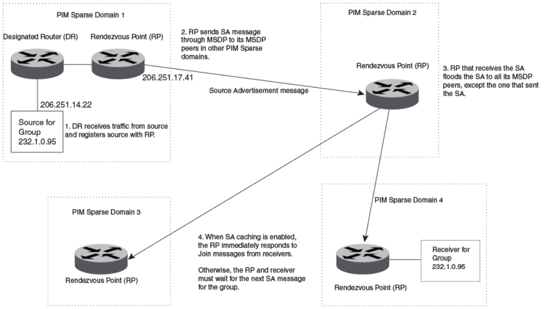
Conguring Multicast Source Discovery Protocol
(MSDP)
The Multicast Source Discovery Protocol (MSDP) is used by Protocol Independent Multicast (PIM) Sparse devices to exchange source
information across PIM Sparse domains. Devices running MSDP can discover PIM Sparse sources in other PIM Sparse domains.
The following gure shows an example of some PIM Sparse domains. For simplicity, this example shows one Designated Router (DR),
one group source, and one receiver for the group. Only one PIM Sparse device within each domain needs to run MSDP.
FIGURE 7 PIM Sparse domains joined by MSDP devices
In this example, the source for PIM Sparse multicast group 232.0.1.95 is in PIM Sparse domain 1. The source sends a packet for the
group to its directly attached DR. The DR sends a PIM register message for this ow to the RPDR. The RP is congured for MSDP,
which enables the RP to exchange source information with other PIM Sparse domains by communicating with RPs in other domains that
are running MSDP.
The RP sends the source information to each peer through a Source Active message. The message contains the IP address of the
source, the group address to which the source is sending, and the IP address of the RP.
In this example, the Source Active message contains the following information:
• Source address: 206.251.14.22
• Group address: 232.1.0.95
• RP address: 206.251.17.41
FOR BROCADE CONTROLLED RELEASE ONLY
Conguring Multicast Source Discovery Protocol (MSDP)
Brocade FastIron IP Multicast Conguration Guide, 08.0.50
108 53-1004455-01
Figure 7 shows only one peer for the MSDP device (which is also the RP here) in domain 1, so the Source Active message goes to only
that peer. When an MSDP device has multiple peers, it sends a Source Active message to each of those peers. Each peer sends the
Source Advertisement to other MSDP peers. The RP that receives the Source Active message also sends a Join message to the source
if the RP that received the message has receivers for the group and source.
Peer Reverse Path Forwarding (RPF) ooding
When the MSDP device (also the RP) in domain 2 receives the Source Active message from the peer in domain 1, the MSDP device in
domain 2 forwards the message to all other peers. This propagation process is sometimes called "peer Reverse Path Forwarding (RPF)
ooding". In Figure 7 on page 108, the MSDP device oods the Source Active message it receives from the peer in domain 1 to peers
in domains 3 and 4.
The MSDP device in domain 2 does not forward the Source Active back to the peer in domain 1, because that is the peer from which the
device received the message. An MSDP device never sends a Source Active message back to the peer that sent it. The peer that sent the
message is sometimes called the "RPF peer". The MSDP device uses the unicast routing table for its Exterior Gateway Protocol (EGP) to
identify the RPF peer by looking for the route entry that is the next hop toward the source. Often, the EGP protocol is Border Gateway
Protocol (BGP) version 4.
NOTE
MSDP depends on BGP for inter-domain operations.
The MSDP routers in domains 3 and 4 also forward the Source Active message to all peers except the ones that sent them the message.
Figure 7 on page 108 does not show additional peers.
Source Active caching
When an MSDP device that is also an RP receives a Source Active message, it checks the PIM sparse multicast group table for receivers
for that group. If there are receivers for that group being advertised in the Source Active message, the RP sends a Join message towards
the source.
In Figure 7 on page 108, if the MSDP device and RP in domain 4 has a table entry for the receiver, the RP sends a Join message on
behalf of the receiver back through the RPF tree to the source, in this case the source in domain 1.
Source Active caching is enabled in MSDP on Brocade devices. The RP caches the Source Active messages it receives even if the RP
does not have a receiver for the group. Once a receiver arrives, the RP can then send a Join to the cached source immediately.
The size of the cache used to store MSDP Source Active messages is 4K. MSDP SA cache size can be congured using the system-
max msdp-sa-cache command. The default value is 4K; the range is 1K to 8K.
Conguring MSDP
To congure MSDP, perform the following tasks:
• Enable MSDP.
•Congure the MSDP peers.
NOTE
The PIM Sparse Rendezvous Point (RP) is also an MSDP peer.
NOTE
Devices that run MSDP usually also run BGP. The source address used by the MSDP device is normally congured to be the
same source address used by BGP.
FOR BROCADE CONTROLLED RELEASE ONLY
Conguring Multicast Source Discovery Protocol (MSDP)
Brocade FastIron IP Multicast Conguration Guide, 08.0.50
53-1004455-01 109
Enabling MSDP
To enable MSDP, enter the following command.
device(config)# router msdp
Syntax: [no] router msdp
Enabling MSDP for a specied VRF
The vrf parameter allows you to congure MSDP on the virtual routing instance (VRF) specied by the vrf-name variable. All MSDP
parameters available for the default router instance are congurable for a VRF-based MSDP instance.
To enable MSDP for the VRF named "blue", enter the following commands.
device(config)# router msdp vrf blue
device(config-msdp-router-vrf-blue)
Syntax: [no] router msdp [vrf vrf-name ]
The vrf parameter allows you to congure MSDP on the virtual routing instance (VRF) specied by the vrf-name variable.
Entering a no router msdp vrf command removes the MSDP conguration from the specied VRF only.
Conguring MSDP peers
To congure an MSDP peer, enter a command such as the following at the MSDP conguration level.
device(config-msdp-router)# msdp-peer 205.216.162.1
To congure an MSDP peer on a VRF, enter the following commands at the MSDP VRF conguration level.
device(config)# router msdp vrf blue
device(config-msdp-router-vrf-blue)# msdp-peer 205.216.162.1
Syntax: [no] msdp-peer ip-addr [connect-source loopback num ]
The ip-addr parameter species the IP address of the neighbor.
The connect-source loopbacknum parameter species the loopback interface you want to use as the source for sessions with the
neighbor and must be reachable within the VRF.
NOTE
It is strongly recommended that you use the connect-source loopback num parameter when issuing the msdp-peer command.
If you do not use this parameter, the device uses the IP address of the outgoing interface. You should also make sure the IP
address of the connect-source loopback is the source IP address used by the PIM-RP, and the BGP device.
The commands in the following example add an MSDP neighbor and specify a loopback interface as the source interface for sessions
with the neighbor. By default, the device uses the subnet address congured on the physical interface where you congure the neighbor
as the source address for sessions with the neighbor.
device(config)# interface loopback 1
device(config-lbif-1)# ip address 9.9.9.9/32
device(config)# router msdp
device(config-msdp-router)# msdp-peer 2.2.2.99 connect-source loopback 1
FOR BROCADE CONTROLLED RELEASE ONLY
Conguring Multicast Source Discovery Protocol (MSDP)
Brocade FastIron IP Multicast Conguration Guide, 08.0.50
110 53-1004455-01
Disabling an MSDP peer
To disable an MSDP peer, enter the following command at the congure MSDP router level.
device(config-msdp-router)# msdp-peer 205.216.162.1 shutdown
To disable the MSDP VRF peer named "blue", enter the following commands.
device(config)# router msdp vrf blue
device(config-msdp-router-vrf-blue)# no msdp-peer 205.216.162.1
Syntax: [no] msdp-peer ip-addr shutdown
The ip-addr parameter species the IP address of the MSDP peer that you want to disable.
Designating the interface IP address as the RP IP address
When an RP receives a Source Active message, it checks its PIM Sparse multicast group table for receivers for the group. If a receiver
exists the RP sends a Join to the source.
By default, the IP address included in the RP address eld of the SA message is the IP address of the originating RP. An SA message
can use the IP address of any interface on the originating RP. (The interface is usually a loopback interface.)
To designate an interface IP address to be the IP address of the RP, enter commands such as the following.
device(config)#
interface loopback 2
device(config-lbif-2)# ip address 2.2.1.99/32
device(config)# router msdp
device(config-msdp-router)# originator-id loopback 2
device(config-msdp-router)# exit
To specify VRF information, enter the following commands at the MSDP VRF conguration level.
device(config)#
interface loopback 2
device(config-lbif-2)# ip address 2.2.1.99/32
device(config)# router msdp vrf blue
device(config-msdp-router-vrf blue)# originator-id loopback 2
device(config-msdp-router-vrf blue)# exit
Syntax: [no] originator-id type number
The originator-id command instructs MSDP to use the specied interface IP address as the IP address of the RP in an SA message.
This address must be the address of the interface used to connect the RP to the source. The default address used is the RP IP address.
The type parameter indicates the type of interface used by the RP. Ethernet, loopback and virtual routing interfaces (ve) can be used.
The number parameter species the interface number (for example: loopback number, port number or virtual routing interface number.)
Filtering MSDP source-group pairs
You can lter individual source-group pairs in MSDP Source-Active messages:
•sa-lter in - Filters source-group pairs received in Source-Active messages from an MSDP neighbor.
•sa-lter originate - Filters self-originated source-group pairs in outbound Source-Active messages sent to an MSDP neighbor
•sa-lter out - Filters self-originated and forwarded source-group pairs in outbound Source-Active messages sent to an MSDP
neighbor
FOR BROCADE CONTROLLED RELEASE ONLY
Conguring Multicast Source Discovery Protocol (MSDP)
Brocade FastIron IP Multicast Conguration Guide, 08.0.50
53-1004455-01 111
Filtering incoming and outgoing Source-Active messages
The following example congures lters for incoming Source-Active messages from three MSDP neighbors:
• For peer 2.2.2.99, all source-group pairs in Source-Active messages from the neighbor are ltered (dropped).
• For peer 2.2.2.97, all source-group pairs except those with source address matching 10.x.x.x and group address of
235.10.10.1 are permitted.
• For peer 2.2.2.96, all source-group pairs except those associated with RP 2.2.42.3 are permitted.
To congure lters for incoming Source-Active messages, enter commands at the MSDP VRF conguration level.
To congure lters for outbound Source-Active messages, enter the optional out keyword.
Example
The following commands congure extended ACLs. The ACLs will be used in route maps, which will be used by the Source-Active lters.
device(config)# access-list 123 permit ip 10.0.0.0 0.255.255.255 host 235.10.10.1
device(config)# access-list 124 permit ip host 2.2.42.3 any
device(config)# access-list 125 permit ip any any
The following commands congure the route maps.
device(config)# route-map msdp_map deny 1
device(config-routemap msdp_map)# match ip address 123
device(config-routemap msdp_map)# exit
device(config)# route-map msdp_map permit 2
device(config-routemap msdp_map)# match ip address 125
device(config-routemap msdp_map)# exit
device(config)# route-map msdp2_map permit 1
device(config-routemap msdp2_map)# match ip address 125
device(config-routemap msdp2_map)# exit
device(config)# route-map msdp2_rp_map deny 1
device(config-routemap msdp2_rp_map)# match ip route-source 124
device(config-routemap msdp2_rp_map)# exit
device(config)# route-map msdp2_rp_map permit 2
device(config-routemap msdp2_rp_map)# match ip route-source 125
device(config-routemap msdp2_rp_map)# exit
The following commands congure the Source-Active lters.
To specify VRF information, enter the following commands at the MSDP VRF conguration level.
device(config)# router msdp vrf blue
device(config-msdp-router-vrf blue)# sa-filter in 2.2.2.99
device(config-msdp-router-vrf blue)# sa-filter in 2.2.2.97 route-map msdp_map
device(config-msdp-router-vrf blue)# sa-filter in 2.2.2.96 route-map msdp2_map rp-route-map msdp2_rp_map
The sa-lter commands congure the following lters:
•sa-lter in 2.2.2.99 - This command drops all source-group pairs received from neighbor 2.2.2.99.
NOTE
The default action is to deny all source-group pairs from the specied neighbor. If you want to permit some pairs, use route
maps.
•sa-lter in 2.2.2.97 route-map msdp_map - This command drops source-group pairs received from neighbor 2.2.2.97 if the
pairs have source addresses matching 10.x.x.x and group address 235.10.10.1.
•sa-lter in 2.2.2.96 route-map msdp2_map rp-route-map msdp2_rp_map - This command accepts all source-group pairs
except those associated with RP 2.2.42.3.
Syntax: [no] sa-lter in | originate | out ip-addr [route-map map-tag ] [rp-route-map rp-map-tag]
FOR BROCADE CONTROLLED RELEASE ONLY
Conguring Multicast Source Discovery Protocol (MSDP)
Brocade FastIron IP Multicast Conguration Guide, 08.0.50
112 53-1004455-01
Selecting the in option applies the lter to incoming Source-Active messages.
Selecting the originate option applies the lter to self-originated outbound Source-Active messages.
Selecting the out option applies the lter to self-originated and forwarded outbound Source-Active messages.
The ip-addr parameter species the IP address of the MSDP neighbor. The lters apply to Source-Active messages received from or
sent to this neighbor.
The route-mapmap-tag parameter species a route map. The device applies the lter to source-group pairs that match the route map.
Use the match ip addressacl-id command in the route map to specify an extended ACL that contains the source addresses.
The rp-route-maprp-map-tag parameter species a route map to use for ltering based on Rendezvous Point (RP) address. Use this
parameter if you want to lter Source-Active messages based on their originating RP. Use the match ip route-sourceacl-id command in
the route map to specify an extended ACL that contains the RP address.
NOTE
The default lter action is deny. If you want to permit some source-group pairs, use a route
map.
Filtering advertised Source-Active messages
The following example congures the device to advertise all source-group pairs except the ones that have source address 10.x.x.x.
The following commands congure extended ACLs to be used in the route map denition.
device(config)# access-list 123 permit ip 10.0.0.0 0.255.255.255 any
device(config)# access-list 125 permit ip any any
The following commands use the above ACLs to congure a route map which denies source-group with source address 10.x.x.x and any
group address, while permitting everything else.
device(config)# route-map msdp_map deny 1
device(config-routemap msdp_map)# match ip address 123
device(config-routemap msdp_map)# exit
device(config)# route-map msdp_map permit 2
device(config-routemap msdp_map)# match ip address 125
device(config-routemap msdp_map)# exit
The following commands congure the Source-Active lter.
device(config)# router msdp
device(config-msdp-router)# sa-filter originate route-map msdp_map
To specify VRF information, enter the following commands at the MSDP VRF conguration level.
device(config)# router msdp vrf blue
device(config-msdp-router-vrf blue)# sa-filter originate route-map msdp_map
Syntax: [no] sa-lter originate [route-map map-tag ]
The route-mapmap-tag parameter species a route map. The router applies the lter to source-group pairs that match the route map.
Use the match ip addressacl-id command in the route map to specify an extended ACL that contains the source and group addresses.
NOTE
The default lter action is deny. If you want to permit some source-group pairs, use a route map. A permit action in the route
map allows the device to advertise the matching source-group pairs. A deny action in the route map drops the source-group
pairs from advertisements.
FOR BROCADE CONTROLLED RELEASE ONLY
Conguring Multicast Source Discovery Protocol (MSDP)
Brocade FastIron IP Multicast Conguration Guide, 08.0.50
53-1004455-01 113

Displaying MSDP information
You can display the following MSDP information:
•Summary information - the IP addresses of the peers, the state of the device MSDP session with each peer, and statistics for
keepalive, source active, and notication messages sent to and received from each of the peers
•VRF Information - Summary information for a specic VRF
•Peer information - the IP address of the peer, along with detailed MSDP and TCP statistics
•Source Active cache entries - the source active messages cached by the router.
Displaying summary information
To display summary MSDP information, enter the CLI command.
Brocade(config)#show ip msdp vrf blue summary
MSDP Peer Status Summary
KA: Keepalive SA:Source-Active NOT: Notification
Peer Address Peer As State KA SA NOT Age
In Out In Out In Out
40.40.40.1 1001 ESTABLISH 59 59 0 0 0 0 6
40.40.40.3 1001 ESTABLISH 59 59 0 0 0 0 47
47.1.1.2 N/A ESTABLISH 59 59 0 0 0 0 47
Brocade(config)#
Syntax: show ip msdp summary
The following table describes the output from this command.
TABLE 16 MSDP summary information
This eld... Displays...
Peer address The IP address of the peer interface with the device
State The state of the MSDP device connection with the peer. The state can be
one of the following:
• CONNECTING - The session is in the active open state.
• ESTABLISHED - The MSDP session is fully up.
• INACTIVE - The session is idle.
• LISTENING - The session is in the passive open state.
KA In The number of MSDP keepalive messages the MSDP device has received
from the peer
KA Out The number of MSDP keepalive messages the MSDP device has sent to
the peer
SA In The number of source active messages the MSDP device has received
from the peer
SA Out The number of source active messages the MSDP device has sent to the
peer
NOT In The number of notication messages the MSDP router has received from
the peer
NOT Out The number of notication messages the MSDP router has sent to the
peer
FOR BROCADE CONTROLLED RELEASE ONLY
Conguring Multicast Source Discovery Protocol (MSDP)
Brocade FastIron IP Multicast Conguration Guide, 08.0.50
114 53-1004455-01

Displaying peer information
To display MSDP peer information, enter the following command.
Brocade#show ip msdp peer
IP Address State Mesh-group-name
1 77.1.1.2 ESTABLISH
Keep Alive Time Hold Time Age
60 75 53
Message Sent Message Received
Keep Alive 1240 1239
Notifications 0 0
Source-Active 0 0
Lack of Resource 0
Last Connection Reset Reason:Reason Unknown
Notification Message Error Code Received:Unspecified
Notification Message Error SubCode Received:Not Applicable
Notification Message Error Code Transmitted:Unspecified
Notification Message Error SubCode Transmitted:Not Applicable
Local IP Address: 55.1.1.2
TCP Connection state: ESTABLISHED
Local host: 55.1.1.2, Local Port: 8730
Remote host: 77.1.1.2, Remote Port: 639
ISentSeq: 1207132337 SendNext: 1207132386 TotUnAck: 0
SendWnd: 16381 TotSent: 49 ReTrans: 0
IRcvSeq: 4000739 RcvNext: 4000788 RcvWnd: 16384
TotalRcv: 49 RcvQue: 0 SendQue: 0
Input SA Filter:Not Applicable
Input (S,G) route-map:None
Input RP route-map:None
Output SA Filter:Not Applicable
Output (S,G) route-map:None
Output RP route-map:None
Syntax: show ip msdp [vrf vrf-name ] peer
The following table describes the output from this command.
TABLE 17 MSDP peer information
This eld... Displays...
Total number of MSDP peers The number of MSDP peers congured on the device
IP Address The IP address of the peer’s interface with the device
State The state of the MSDP device connection with the peer. The state can be
one of the following:
• CONNECTING - The session is in the active open state.
• ESTABLISHED - The MSDP session is fully up.
• INACTIVE - The session is idle.
• LISTENING - The session is in the passive open state.
Keep Alive Time The keepalive time, which species how often this MSDP device sends
keep alive messages to the neighbor. The keep alive time is 60 seconds
and is not congurable.
Hold Time The hold time, which species how many seconds the MSDP device will
wait for a KEEPALIVE or UPDATE message from an MSDP neighbor
before deciding that the neighbor is dead. The hold time is 90 seconds
and is not congurable.
Keep Alive Message Sent The number of keepalive messages the MSDP device has sent to the
peer.
Keep Alive Message Received The number of keepalive messages the MSDP device has received from
the peer.
Notications Sent The number of notication messages the MSDP device has sent to the
peer.
FOR BROCADE CONTROLLED RELEASE ONLY
Conguring Multicast Source Discovery Protocol (MSDP)
Brocade FastIron IP Multicast Conguration Guide, 08.0.50
53-1004455-01 115

TABLE 17 MSDP peer information (continued)
This eld... Displays...
Notications Received The number of notication messages the MSDP device has received from
the peer.
Source-Active Sent The number of source active messages the MSDP device has sent to the
peer.
Source-Active Received The number of source active messages the MSDP device has received
from the peer.
Last Connection Reset Reason The reason the previous session with this neighbor ended.
Notication Message Error Code Received The MSDP device has received a notication message from the neighbor
that contains an error code corresponding to one of the following errors.
Some errors have subcodes that clarify the reason for the error. Where
applicable, the subcode messages are listed underneath the error code
messages:
• 1 - Message Header Error
• 2 - SA-Request Error
• 3 - SA-Message or SA-Response Error
• 4 - Hold Timer Expired
• 5 - Finite State Machine Error
• 6 - Notication
• 7 - Cease
For information about these errors, refer to section 17 in the Internet draft
describing MSDP, "draft-ietf-msdp-spec".
Notication Message Error SubCode Received See above.
Notication Message Error Code Transmitted The error message corresponding to the error code in the NOTIFICATION
message this MSDP router sent to the neighbor. See the description for
the Notication Message Error Code Received eld for a list of possible
codes.
Notication Message Error SubCode Transmitted See above.
TCP Statistics
TCP connection state The state of the connection with the neighbor. Can be one of the following:
• LISTEN - Waiting for a connection request.
• SYN-SENT - Waiting for a matching connection request after
having sent a connection request.
• SYN-RECEIVED - Waiting for a conrming connection request
acknowledgment after having both received and sent a
connection request.
• ESTABLISHED - Data can be sent and received over the
connection. This is the normal operational state of the
connection.
• FIN-WAIT-1 - Waiting for a connection termination request
from the remote TCP, or an acknowledgment of the connection
termination request previously sent.
• FIN-WAIT-2 - Waiting for a connection termination request
from the remote TCP.
• CLOSE-WAIT - Waiting for a connection termination request
from the local user.
• CLOSING - Waiting for a connection termination request
acknowledgment from the remote TCP.
• LAST-ACK - Waiting for an acknowledgment of the connection
termination request previously sent to the remote TCP (includes
an acknowledgment of the connection termination request).
FOR BROCADE CONTROLLED RELEASE ONLY
Conguring Multicast Source Discovery Protocol (MSDP)
Brocade FastIron IP Multicast Conguration Guide, 08.0.50
116 53-1004455-01

TABLE 17 MSDP peer information (continued)
This eld... Displays...
• TIME-WAIT - Waiting for enough time to pass to be sure the
remote TCP received the acknowledgment of the connection
termination request.
• CLOSED - There is no connection state.
Local host The IP address of the MSDP device interface with the peer.
Local port The TCP port the MSDP router is using for the BGP4 TCP session with
the neighbor.
Remote host The IP address of the neighbor.
Remote port The TCP port number of the peer end of the connection.
ISentSeq The initial send sequence number for the session.
SendNext The next sequence number to be sent.
TotUnAck The number of sequence numbers sent by the MSDP device that have not
been acknowledged by the neighbor.
SendWnd The size of the send window.
TotSent The number of sequence numbers sent to the neighbor.
ReTrans The number of sequence numbers the MSDP device retransmitted
because they were not acknowledged.
IRcvSeq The initial receive sequence number for the session.
RcvNext The next sequence number expected from the neighbor.
RcvWnd The size of the receive window.
TotalRcv The number of sequence numbers received from the neighbor.
RcvQue The number of sequence numbers in the receive queue.
SendQue The number of sequence numbers in the send queue.
Displaying Source Active cache information
To display the Source Actives in the MSDP cache, use the following command.
device # show ip msdp vrf blue sa-cacheTotal of 10 SA cache entriesIndex RP address (Source, Group)
Orig Peer Age1 2.2.2.2 (192.6.1.10, 227.1.1.1) 192.1.1.2 0 2 2.2.2.2 (192.6.1.10, 227.1.1.2)
192.1.1.2 0 3 2.2.2.2 (192.6.1.10, 227.1.1.3) 192.1.1.2 0 4 2.2.2.2 (192.6.1.10, 227.1.1.4)
192.1.1.2 0 5 2.2.2.2 (192.6.1.10, 227.1.1.5) 192.1.1.2 0 6 2.2.2.2 (192.6.1.10, 227.1.1.6)
192.1.1.2 0 7 2.2.2.2 (192.6.1.10, 227.1.1.7) 192.1.1.2 0 8 2.2.2.2 (192.6.1.10, 227.1.1.8)
192.1.1.2 0 9 2.2.2.2 (192.6.1.10, 227.1.1.9) 192.1.1.2 0 10 2.2.2.2 (192.6.1.10, 227.1.1.10)
192.1.1.2 0
Syntax: show ip msdp [ vrf vrf-name ] sa-cache [source-address | group-address | peer-as as-number | counts | orig-rp rp-address |
peer peer-address ] [ rejected | self-originated ] ]
The source-address parameter selects the source address of the SA entry.
The group-address parameter selects the group address of the SA entry.
The peer-as keyword species the BGP AS Number of the forwarding peer.
The counts keyword displays only the count of entries.
The orig-rp keyword species the originating RP address.
The peer keyword species the peer address.
FOR BROCADE CONTROLLED RELEASE ONLY
Conguring Multicast Source Discovery Protocol (MSDP)
Brocade FastIron IP Multicast Conguration Guide, 08.0.50
53-1004455-01 117

The rejected keyword displays the rejected SAs.
The self-originated keyword displays the self-originated SAs.
The following table describes the output from this command.
TABLE 18 MSDP source active cache
This eld... Displays...
Total The number of entries the cache currently contains.
Index The cache entry number.
RP The RP through which receivers can access the group trac from the
source
SourceAddr The IP address of the multicast source.
GroupAddr The IP multicast group to which the source is sending information.
Orig Peer The peer from which this source-active entry was received.
Age The number of seconds the entry has been in the cache
You can use the following command to lter the output to display only the entries matching a specic source.
device#show ip msdp sa-cache 1.1.1.1
You can use the following command to lter the output to display only the entries matching a specic group.
device#show ip msdp sa-cache 239.1.1.1
You can use the following command to lter the output to display only the SA cache entries that are
received from peers in the BGP AS Number 100.
device#show ip msdp sa-cache 100
You can use the following command to lter the output to display only the SA cache entries that are
originated by the RP 1.1.1.1.
device#show ip msdp sa-cache orig-rp 1.1.1.1
You can use the following command to lter the output to display only the SA cache entries that are
received from the peer 1.1.1.1.
device#show ip msdp sa-cache peer 1.1.1.1
You can use the following command to display the rejected SAs. You can further narrow down by quoting the reason for rejection.
device#show ip msdp sa-cache rejected
You can use the following command to display the self-originated SAs.
device#show ip msdp sa-cache self-originated
Displaying MSDP RPF-Peer
To display MSDP peer information for the RP 1.1.1.1, enter the following command.
device# show ip msdp rpf-peer 1.1.1.1
MSDP Peer Status Summary
KA: Keepalive SA:Source-Active NOT: Notification
Peer Address Peer As State KA SA NOT Age
FOR BROCADE CONTROLLED RELEASE ONLY
Conguring Multicast Source Discovery Protocol (MSDP)
Brocade FastIron IP Multicast Conguration Guide, 08.0.50
118 53-1004455-01
In Out In Out In Out
40.40.40.3 1001 ESTABLISH 62 62 0 0 0 0 7
Brocade#
Syntax: show ip msdp [vrf vrf-name ] rpf-peer ip-addr
Displaying MSDP Peer
To display MSDP peer information, enter the following command.
Brocade# show ip msdp peer 40.40.40.3
MSDP Peer Status Summary
KA: Keepalive SA:Source-Active NOT: Notification
Peer Address Peer As State KA SA NOT Age
In Out In Out In Out
40.40.40.3 1001 ESTABLISH 62 62 0 0 0 0 7
Brocade#
Syntax: show ip msdp peer peer-addr
Displaying MSDP VRF RPF-Peer
To display MSDP peer information for a specic VRF, enter the following command.
Brocade#sh ip msdp vrf Blue rpf-peer 40.40.40.2
MSDP Peer Status Summary
KA: Keepalive SA:Source-Active NOT: Notification
Peer Address Peer As State KA SA NOT Age
In Out In Out In Out
40.40.40.2 1001 ESTABLISH 5569 5568 0 0 0 0 57
Syntax: show ip msdp vrf VRF-name rpf-peer ip-addr
Clearing MSDP information
You can clear the following MSDP information:
• Peer information
• Source active cache
• MSDP statistics
Clearing peer information
To clear MSDP peer information, enter the following command at the Privileged EXEC level of the CLI.
device# clear ip msdp peer 205.216.162.1
Syntax: clear ip msdp peer [ip-addr ]
The command in this example clears the MSDP peer connection with MSDP router 205.216.162.1. The CLI displays a message to
indicate when the connection has been successfully closed. To clear all the peers, omit the ip-addr variable from the command.
Clearing peer information on a VRF
To clear the MSDP VRF peers, enter the following command at the MSDP VRF conguration level.
device#clear ip msdp vrf blue peer 207.207.162.5
FOR BROCADE CONTROLLED RELEASE ONLY
Conguring Multicast Source Discovery Protocol (MSDP)
Brocade FastIron IP Multicast Conguration Guide, 08.0.50
53-1004455-01 119
Syntax: clear ip msdp [vrf vrf-name ] peer [ ip-addr ]
Clearing the source active cache
To clear the source active cache, enter the following command at the Privileged EXEC level of the CLI.
device# clear ip msdp sa-cache
Syntax: clear ip msdp sa-cache [ ip-addr ]
The command in this example clears all the cache entries. Use the ip-addr variable to clear only the entries matching either a source or a
group.
Clearing the source active cache for a VRF
To clear the MSDP VRF source active cache by entering the following command at the MSDP VRF conguration level.
device#clear ip msdp sa-cache
vrf blue
Syntax: clear ip msdp [vrf vrf-name ] sa-cache [ ip-addr ]
Clearing MSDP statistics
To clear MSDP statistics, enter the following command at the Privileged EXEC level of the CLI.
device# clear ip msdp statistics
Syntax: clear ip msdp statistics [ ip-addr ]
The command in this example clears statistics for all the peers. To clear statistics for only a specic peer, enter the IP address of the peer.
Clearing MSDP VRF statistics
To clear the MSDP VRF statistics by entering the following command.
device# clear ip msdp vrf blue statistics
Syntax: clear ip msdp [vrf vrf-name ] statistics [ip-addr ]
The command in this example clears statistics for all the peers. To clear statistics for only a specic peer, enter the IP address of the peer.
The command in this example clears all statistics for all the peers in the VRF "blue".
Conguring MSDP mesh groups
A PIM Sparse domain can have several RPs that are connected to each other to form an MSDP mesh group. To qualify as a mesh
group, the RPs have to be fully meshed; that is, each RP must be connected to all peer RPs in a domain. (Refer to Figure 8.)
A mesh group reduces the forwarding of SA messages within a domain. Instead of having every RP in a domain forward SA messages
to all the RPs within that domain, only one RP forwards the SA message. Since an MSDP mesh group is fully meshed, peers do not
forward SA messages received in a domain from one member to any member of the group. The RP that originated the SA or the rst RP
in a domain that receives the SA message is the only one that forwards the message to the members of a mesh group. An RP can
forward an SA message to any MSDP router as long as that peer is farther away from the originating RP than the current MSDP router.
FOR BROCADE CONTROLLED RELEASE ONLY
Conguring MSDP mesh groups
Brocade FastIron IP Multicast Conguration Guide, 08.0.50
120 53-1004455-01
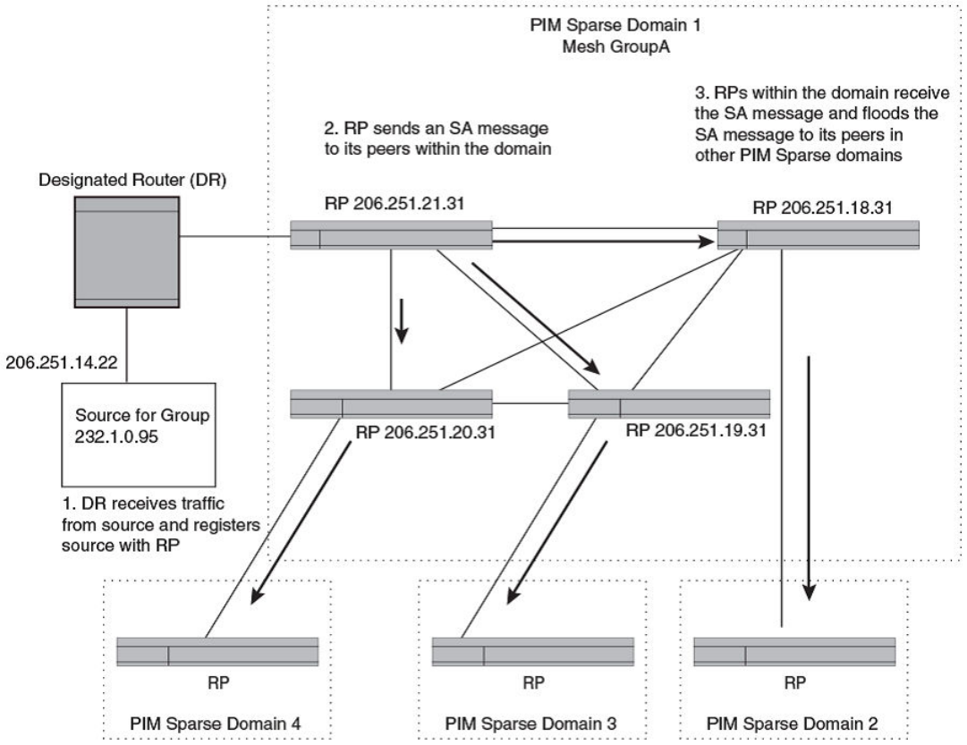
The following gure shows an example of an MSDP mesh group. In a PIM-SM mesh group the RPs are congured to be peers of each
other. They can also be peers of RPs in other domains.
FIGURE 8 Example of MSDP mesh group
PIM Sparse Domain 1 in Figure 8 contains a mesh group with four RPs. When the rst RP, for example, RP 206.251.21.31 originates
or receives an SA message from a peer in another domain, it sends the SA message to its peers within the mesh group. However, the
peers do not send the message back to the originator RP or to each other. The RPs then send the SA message farther away to their
peers in other domains.The process continues until all RPs within the network receive the SA message.
Conguring MSDP mesh group
To congure an MSDP mesh group, enter commands such as the following on each device that will be included in the mesh group.
device(config)# router msdp
device(config-msdp-router)# msdp-peer 206.251.18.31 connect-source loopback 2
FOR BROCADE CONTROLLED RELEASE ONLY
Conguring MSDP mesh groups
Brocade FastIron IP Multicast Conguration Guide, 08.0.50
53-1004455-01 121
device(config-msdp-router)# msdp-peer 206.251.19.31 connect-source loopback 2
device(config-msdp-router)# msdp-peer 206.251.20.31 connect-source loopback 2
device(config-msdp-router)# mesh-group GroupA 206.251.18.31
device(config-msdp-router)# mesh-group GroupA 206.251.19.31
device(config-msdp-router)# mesh-group GroupA 206.251.20.31
device(config-msdp-router)# exit
Syntax: [no] mesh-group group-name peer-address
The sample conguration above reects the conguration in Figure 8 on page 121. On RP 206.251.21.31 you specify its peers within
the same domain (206.251.18.31, 206.251.19.31, and 206.251.20.31).
You rst congure the MSDP peers using the msdp-peer command to assign their IP addresses and the loopback interfaces.
Next, place the MSDP peers within a domain into a mesh group. Use the mesh-group command. There are no default mesh groups.
The group-name parameter identies the mesh group. Enter up to 31 characters for group-name. You can have up to 4 mesh groups
within a multicast network. Each mesh group can include up to 15 peers.
The peer-address parameter species the IP address of the MSDP peer that is being placed in the mesh group. Each mesh group can
include up to 32 peers.
NOTE
On each of the device that will be part of the mesh group, there must be a mesh group denition for all the peers in the mesh-
group.
A maximum of 32 MSDP peers can be congured per mesh group.
You can use the show ip msdp [ vrf vrf-name ] mesh-group group-name command to view the details of a specic mesh-group or the
mesh-group details for the VRF instance specied by the vrf-name variable. .
MSDP Anycast RP
MSDP Anycast RP is a method of providing intra-domain redundancy and load-balancing between multiple Rendezvous Points (RP) in a
Protocol Independent Multicast Sparse mode (PIM-SM) network. It is accomplished by conguring all RPs within a domain with the
same anycast RP address which is typically a loopback IP address. Multicast Source Discovery Protocol (MSDP) is used between all of
the RPs in a mesh conguration to keep all RPs in sync regarding the active sources.
PIM-SM routers are congured to register (statically or dynamically) with the RP using the same anycast RP address. Since multiple RPs
have the same anycast address, an Interior Gateway Protocol (IGP) such as OSPF routes the PIM-SM router to the RP with the best
route. If the PIM-SM routers are distributed evenly throughout the domain, the loads on RPs within the domain will be distributed. If the
RP with the best route goes out of service, the PIM-SM router’s IGP changes the route to the closest operating RP that has the same
anycast address.
This conguration works because MSDP is congured between all of the RPs in the domain. Consequently, all of the RPs share
information about active sources.
This feature uses functionality that is already available on the Brocade device but re-purposes it to provide the benets desired as
described in RFC 3446.
Conguring MSDP Anycast RP
To congure MSDP Anycast RP, you must perform the following tasks:
•Congure a loopback interface with the anycast RP address on each of the RPs within the domain and enable PIM-SM on
these interfaces.
FOR BROCADE CONTROLLED RELEASE ONLY
MSDP Anycast RP
Brocade FastIron IP Multicast Conguration Guide, 08.0.50
122 53-1004455-01
• Ensure that the anycast RP address is leaked into the IGP domain. This is typically done by enabling the IGP on the loopback
interface (in passive mode) or redistributing the connected loopback IP address into the IGP.
NOTE
The anycast RP address *must* not be the IGP router-id.
• Enable PIM-SM on all interfaces on which multicast routing is desired.
• Enable an IGP on each of the loopback interfaces and physical interfaces congured for PIM-SM.
•Congure loopback interfaces with unique IP addresses on each of the RPs for MSDP peering. This loopback interface is also
used as the MSDP originator-id.
• The non-RP PIM-SM routers may be congured to use the anycast RP address statically or dynamically (by the PIMv2
bootstrap mechanism).
Example
The example shown in Figure 9 is a simple MSDP Anycast-enabled network with two RPs and two PIM-SM routers. Loopback 1 in RP
1 and RP 2 have the same IP address. Loopback 2 in RP1 and Loopback 2 in RP2 have dierent IP addresses and are congured as
MSDP peering IP addresses in a mesh conguration.
In the PIM conguration for PIM-SM routers PIMR1 and PIMR2 the RP address is congured to be the anycast RP address that was
congured on the Loopback 1 interfaces on RP1 and RP2. OSPF is congured as the IGP for the network and all of the devices are in
OSPF area 0.
Since PIMR1 has a lower cost path to RP1 and PIMR2 has a lower cost path to RP2 they will register with the respective RPs when both
are up and running. This shares the load between the two RPs. If one of the RPs fails, the higher-cost path to the IP address of Loopback
1 on the RPs is used to route to the still-active RP.
The conguration examples demonstrate the commands required to enable this application.
FOR BROCADE CONTROLLED RELEASE ONLY
MSDP Anycast RP
Brocade FastIron IP Multicast Conguration Guide, 08.0.50
53-1004455-01 123
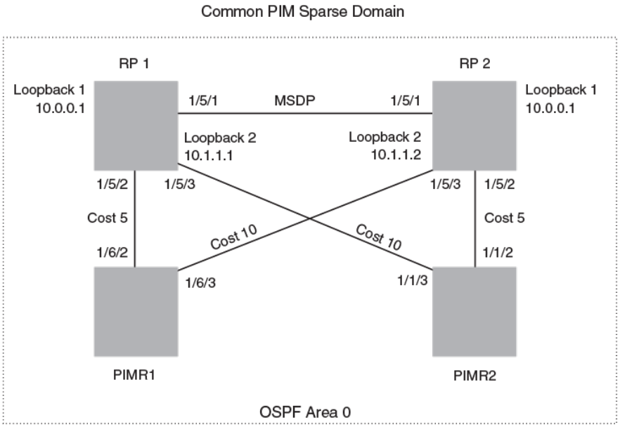
FIGURE 9 Example of a MDSP Anycast RP network
RP 1 conguration
The following commands provide the conguration for the RP 1 router in Figure 9.
RP1(config)#router ospf
RP1(config-ospf-router)# area 0
RP1(config-ospf-router)# exit
RP1(config)# interface loopback 1
RP1(config-lbif-1)# ip ospf area 0
RP1(config-lbif-1)# ip ospf passive
RP1(config-lbif-1)# ip address 10.0.0.1/32
RP1(config-lbif-1)# ip pim-sparse
RP1(config-lbif-1)# exit
RP1(config)# interface loopback 2
RP1(config-lbif-2)# ip ospf area 0
RP1(config-lbif-2)# ip ospf passive
RP1(config-lbif-2)# ip address 10.1.1.1/32
RP1(config-lbif-2)# exit
RP1(config)# interface ethernet 1/5/1
RP1(config-if-e1000-1/5/1)# ip ospf area 0
RP1(config-if-e1000-1/5/1)# ip address 192.1.1.1/24
RP1(config-if-e1000-1/5/1)# ip pim-sparse
RP1(config)# interface ethernet 1/5/2
RP1(config-if-e1000-1/5/2)# ip ospf area 0
RP1(config-if-e1000-1/5/2)# ip ospf cost 5
RP1(config-if-e1000-1/5/2)# ip address 192.2.1.1/24
RP1(config-if-e1000-1/5/2)# ip pim-sparse
RP1(config)# interface ethernet 1/5/3
RP1(config-if-e1000-1/5/3)# ip ospf area 0
RP1(config-if-e1000-1/5/3)# ip ospf cost 10
RP1(config-if-e1000-1/5/3)# ip address 192.3.1.1/24
FOR BROCADE CONTROLLED RELEASE ONLY
MSDP Anycast RP
Brocade FastIron IP Multicast Conguration Guide, 08.0.50
124 53-1004455-01
RP1(config-if-e1000-1/5/3)# ip pim-sparse
RP1(config-if-e1000-1/5/3)# exit
RP1(config)# router pim
RP1(config-pim-router)# rp-candidate loopback 1
RP1(config-pim-router)# exit
RP1(config)# router msdp
RP1(config-msdp-router)# msdp-peer 10.1.1.2 connect-source loopback 2
RP1(config-msdp-router)# originator-id loopback 2
RP 2 conguration
The following commands provide the conguration for the RP 2 router in Figure 9.
RP2(config)#router ospf
RP2(config-ospf-router)# area 0
RP2(config-ospf-router)# exit
RP2(config)# interface loopback 1
RP2(config-lbif-1)# ip ospf area 0
RP2(config-lbif-1)# ip ospf passive
RP2(config-lbif-1)# ip address 10.0.0.1/32
RP2(config-lbif-1)# ip pim-sparse
RP2(config-lbif-1)# exit
RP2(config)# interface loopback 2
RP2(config-lbif-2)# ip ospf area 0
RP2(config-lbif-2)# ip ospf passive
RP2(config-lbif-2)# ip address 10.1.1.2/32
RP2(config-lbif-2)# exit
RP2(config)# interface ethernet 1/5/1
RP2(config-if-e1000-1/5/1)# ip ospf area 0
RP2(config-if-e1000-1/5/1)# ip address 192.1.1.2/24
RP2(config-if-e1000-1/5/1)# ip pim-sparse
RP2(config)# interface ethernet 1/5/2
RP2(config-if-e1000-1/5/2)# ip ospf area 0
RP2(config-if-e1000-1/5/2)# ip ospf cost 5
RP2(config-if-e1000-1/5/2)# ip address 192.5.2.1/24
RP2(config-if-e1000-1/5/2)# ip pim-sparse
RP2(config)# interface ethernet 1/5/3
RP2(config-if-e1000-1/5/3)# ip ospf area 0
RP2(config-if-e1000-1/5/3)# ip ospf cost 10
RP2(config-if-e1000-1/5/3)# ip address 192.6.1.2/24
RP2(config-if-e1000-1/5/3)# ip pim-sparse
RP2(config-if-e1000-1/5/3)# exit
RP2(config)# router pim
RP2(config-pim-router)# rp-candidate loopback 1
RP2(config-pim-router)# exit
RP2(config)# router msdp
RP2(config-msdp-router)# msdp-peer 10.1.1.1 connect-source loopback 2
RP2(config-msdp-router)# originator-id loopback 2
PIMR1 conguration
The following commands provide the conguration for the PIMR1 router in Figure 9.
PIMR1(config)#router ospf
PIMR1(config-ospf-router)# area 0
PIMR1(config-ospf-router)# exit
PIMR1(config)# interface ethernet 1/6/2
PIMR1(config-if-e1000-1/6/2)# ip ospf area 0
PIMR1(config-if-e1000-1/6/2)# ip ospf cost 5
PIMR1(config-if-e1000-1/6/2)# ip address 192.2.1.2/24
PIMR1(config-if-e1000-1/6/2)# ip pim-sparse
PIMR1(config)# interface ethernet 1/6/3
PIMR1(config-if-e1000-1/6/3)# ip ospf area 0
PIMR1(config-if-e1000-1/6/3)# ip ospf cost 10
PIMR1(config-if-e1000-1/6/3)# ip address 192.6.1.1/24
PIMR1(config-if-e1000-1/6/3)# ip pim-sparse
PIMR1(config-if-e1000-1/6/3)# exit
PIMR1(config)# router pim
FOR BROCADE CONTROLLED RELEASE ONLY
MSDP Anycast RP
Brocade FastIron IP Multicast Conguration Guide, 08.0.50
53-1004455-01 125
PIMR1(config-pim-router)# rp-address 10.0.0.1
PIMR1(config-pim-router)# exit
PIMR2 conguration
The following commands provide the conguration for the PIMR2 router in Figure 9.
PIMR2(config)#router ospf
PIMR2(config-ospf-router)# area 0
PIMR2(config-ospf-router)# exit
PIMR2(config)# interface ethernet 1/1/2
PIMR2(config-if-e1000-1/1/2)# ip ospf area 0
PIMR2(config-if-e1000-1/1/2)# ip ospf cost 5
PIMR2(config-if-e1000-1/1/2)# ip address 192.5.2.2/24
PIMR2(config-if-e1000-1/1/2)# ip pim-sparse
PIMR2(config)# interface ethernet 1/1/3
PIMR2(config-if-e1000-1/1/3)# ip ospf area 0
PIMR2(config-if-e1000-1/1/3)# ip ospf cost 10
PIMR2(config-if-e1000-1/1/3)# ip address 192.3.1.2/24
PIMR2(config-if-e1000-1/1/3)# ip pim-sparse
PIMR2(config-if-e1000-1/1/3)# exit
PIMR2(config)# router pim
PIMR2(config-pim-router)# rp-address 10.0.0.1
PIMR2(config-pim-router)# exit
PIM Anycast RP
PIM Anycast RP is a method of providing load balancing and fast convergence to PIM RPs in an IPv4 multicast domain. The RP address
of the Anycast RP is a shared address used among multiple PIM routers, known as PIM RP. The PIM RP routers create an Anycast RP
set. Each router in the Anycast RP set is congured using two IP addresses; a shared RP address in their loopback address and a
separate, unique ip address. The loopback address must be reachable by all PIM routers in the multicast domain. The separate, unique ip
address is congured to establish static peering with other PIM routers and communication with the peers.
When the source is activated in a PIM Anycast RP domain, the PIM First Hop (FH) will register the source to the closet PIM RP. The PIM
RP follows the same MSDP Anycast RP operation by decapsulating the packet and creating the (s,g) state. If there are external peers in
the Anycast RP set, the router will re-encapsulate the packet with the local peering address as the source address of the encapsulation.
The router will unicast the packet to all Anycast RP peers. The re-encapsulation of the data register packet to Anycast RP peers ensures
source state distribution to all RPs in a multicast domain.
Conguring PIM Anycast RP
A new PIM CLI is introduced for PIM Anycast RP under the router pim sub mode. The PIM CLI species mapping of the RP and the
Anycast RP peers.
To congure PIM Anycast RP, enter the following command.
device(config)#router pim
device(config-pim-router)#rp-address 100.1.1.1
device(config-pim-router)#anycast-rp 100.1.1.1 my-anycast-rp-set-acl
Syntax: [no] anycast-rp rp-address anycast-rp-set-acl
The rp address parameter species a shared RP address used among multiple PIM routers.
The anycast-rp-set-acl parameter species a host based simple acl used to species the address of the Anycast RP set, including a
local address.
FOR BROCADE CONTROLLED RELEASE ONLY
PIM Anycast RP
Brocade FastIron IP Multicast Conguration Guide, 08.0.50
126 53-1004455-01
The following example is a conguration of PIM Anycast RP 100.1.1.1.The example avoids using loopback 1 interface when conguring
PIM Anycast RP because the loopback 1 address could be used as a router-id. A PIM First Hop router will register the source with the
closest RP. The rst RP that receives the register will re-encapsulate the register to all other Anycast RP peers. Please refer to Figure 10
as described in the conguration of PIM Anycast RP 100.1.1.1.
device(config)#interface loopback 2
device(config-lbif-2)#ip address 100.1.1.1/24
device(config-lbif-2)#ip pim-sparse
device(config-lbif-2)#interface loopback 3
device(config-lbif-3)#ip address 1.1.1.1/24
device(config-lbif-3)#ip pim-sparse
device(config-lbif-3)#router pim
device(config-pim-router)#rp-address 100.1.1.1
device(config-pim-router)#anycast-rp 100.1.1.1 my-anycast-rp-set
device(config-pim-router)#ip access-list standard my-anycast-rp-set
device(config-std-nacl)#permit host 1.1.1.1
device(config-std-nacl)#permit host 2.2.2.2
device(config-std-nacl)#permit host 3.3.3.3
The RP shared address 100.1.1.1 is used in the PIM domain. IP addresses 1.1.1.1, 2.2.2.2, and 3.3.3.3 are listed in the ACL that forms
the self inclusive Anycast RP set. Multiple anycast-rp instances can be congured on a system; each peer with the same or dierent
Anycast RP set.
NOTE
The PIM software supports up to eight PIM Anycast-RP routers. All deny statements in the anycast_rp_set acl and additional
routers more than eight listed in an access list are ignored.
The example shown in the following gure is a PIM Anycast-enabled network with 3 RPs, 1 PIM-FH router connecting to its active
source and local receiver. Loopback 2 in RP1, RP2, and RP3 have the same IP addresses 100.1.1.1. Loopback 3 in RP1, RP2, and
RP3 each have separate IP addresses congured to communicate with their peers in the Anycast RP set.
FIGURE 10 Example of a PIM Anycast RP network
Displaying information for a PIM Anycast RP interface
To display information for a PIM Anycast RP interface, enter the following command.
device(config)#show ip pim anycast-rp
Number of Anycast RP: 1
Anycast RP: 100.1.1.1
ACL ID: 200
ACL Name: my-anycast-rp-set
ACL Filter: SET
Peer List:
1.1.1.1
FOR BROCADE CONTROLLED RELEASE ONLY
PIM Anycast RP
Brocade FastIron IP Multicast Conguration Guide, 08.0.50
53-1004455-01 127

2.2.2.2
3.3.3.3
Syntax: show ip pim [vrf vrf-name ] anycast-rp
The following table describes the parameters of the show ip pim anycast-rp command:
TABLE 19 Display of show ip pim anycast-rp
This eld... Displays...
Number of Anycast RP: The Number of Anycast RP species the number of Anycast RP sets in
the multicast domain.
Anycast RP: The Anycast RP address species a shared RP address used among
multiple PIM routers.
ACL ID: The ACL ID species the ACL ID assigned.
ACL Name The ACL Name species the name of the Anycast RP set.
ACL Filter The ACL Filter species the ACL lter state SET or UNSET.
Peer List The Peer List species host addresses that are permitted in the Anycast
RP set.
NOTE
MSDP and Anycast RP do not interoperate. If transitioning from MSDP to Anycast RP or vice versa, all RPs in the network must
be congured for the same method of RP peering; either Anycast RP or MSDP.
Static multicast routes
Congure static multicast routes to control the network paths, administrative distance, and precedence for multicast routes.
Static multicast routes allow you to control the network path used by multicast trac. Static multicast routes are especially useful when
the unicast and multicast topologies of a network are dierent. By conguring static multicast routes you don't have to make the
topologies similar.
NOTE
In IP multicasting, source IP addresses are unicast addresses while destination IP addresses are multicast (group) addresses.
Therefore, in IP multicasting, a route lookup is done for source IP address, rather than its destination IP address.
You can congure more than one static multicast route. The device always uses the most specic route that matches a multicast source
address. Thus, if you want to congure a multicast static route for a specic multicast source and also congure another multicast static
route for all other sources, you can congure two static routes
Congure the distance keyword in the ip mroute command to specify the administrative distance, which the device uses to determine
the best path for a route. When comparing multiple paths for a route, the device prefers the path with the lower administrative distance.
To ensure that the default static route is used, congure a low administrative distance value. However, the device prefers directly
connected routes over other routes, no matter what the administrative distance.
Congure the route-precedence command to specify a precedence table that dictates how routes are selected for multicast.
IGMP Proxy
IGMP Proxy provides a means for routers to receive any or all multicast trac from an upstream device if the router is not able to run
PIM and runs only IGMP. IGMP Proxy supports IGMP v1, v2, and v3.
FOR BROCADE CONTROLLED RELEASE ONLY
Static multicast routes
Brocade FastIron IP Multicast Conguration Guide, 08.0.50
128 53-1004455-01
IGMP Proxy enables the router to issue IGMP host messages on behalf of hosts that the router discovered through standard PIM
interfaces. The router acts as a proxy for its hosts and performs the host portion of the IGMP task on the upstream interface as follows:
• When queried, the router sends group membership reports for the groups learned.
• When one of its hosts joins a multicast address group to which none of its other hosts belong, the router sends unsolicited
membership reports to that group.
• When the last of its hosts in a particular multicast group leaves the group, the router sends an unsolicited leave group
membership report to group (multicast IP address 224.0.0.2).
IGMP proxy conguration notes
When using IGMP Proxy, you must do the following.
1. Congure PIM on all multicast client ports to build the group membership table. The group membership table will be reported
by the proxy interface. Refer to Globally enabling and disabling PIM on page 75.
2. Enable IP multicast on an interface to an upstream router that will be the IGMP proxy interface and congure IGMP Proxy on
that interface.
IGMP proxy limitations
• IGMP Proxy cannot be enabled on the same interface on which PIM SM or PIM DM is enabled.
• IGMP Proxy is only supported in a PIM Dense environment where there are IGMP clients connected to the Brocade device. The
Brocade device does not send IGMP reports on an IGMP proxy interface for remote clients connected to a PIM
neighbor,because it is not aware of groups that the remote clients are interested in. Static groups on the other PIM interfaces are
included in proxy reports.
• PIM DM must be enabled in passive mode. This is a change from the previous implementation; to be backward compatible,
PIM-DM passive mode is enabled in passive mode indirectly if PIM-DM is not enabled explicitly.
Conguring IGMP Proxy
Perform the following steps to congure IGMP Proxy.
1. Congure router PIM globally.
device(config)# router pim
2. Congure an IP address on the interface (physical, virtual routing, or tunnel interface) that will serve as the IGMP proxy for an
upstream device by entering commands such as the following.
device(config)# interface ethernet 1/1/3
device(config-if-e1000-1/1/3)# ip address 10.95.5.1/24
3. Enable PIM passive on the interface.
device(config-if-e1000-1/1/3)# ip pim passive
4. Enable IGMP Proxy on the interface.
device(config-if-e1000-1/1/3)# ip igmp proxy
Syntax: [no] ip igmp proxy
FOR BROCADE CONTROLLED RELEASE ONLY
IGMP Proxy
Brocade FastIron IP Multicast Conguration Guide, 08.0.50
53-1004455-01 129

Filtering groups in proxy report messages
Once IGMP Proxy is congured and the router receives a query on an IGMP Proxy interface, the router sends a report in response to the
query before the IGMP maximum response time expires.
You can lter out groups in proxy report messages by specifying an access list name or number.
Brocade(config-if-e1000-1/1/3)# ip igmp proxy group-filter ACL1
Syntax: [no] ip igmp proxy group-lter access_list
To remove the group lter association without disabling the proxy, please apply the command ip igmp proxy without the group lter
option.
Displaying IGMP Proxy information
Use the show ip igmp proxy command to see information about the proxy groups and interfaces on the default VRF. For other VRF
instances, use the same command with the vrf option. For example, show ip igmp proxy vrfvrf_name .
Brocade#sh ip igmp proxy
Proxy instance name: default-vrf
Total proxy groups: 4
Address Mode Source ref flags
count count
----------------------------------------------------
225.1.1.1 exclude 0 0 0
225.1.1.2 exclude 0 0 0
225.1.1.3 exclude 0 0 0
225.1.1.4 exclude 0 0 0
Proxy interfaces
----------------
Name Oper Cfg Unsoli Filter Filter
Version Robust Interval Acl Id Name
-----------------------------------------------------
e1/1/3 2 2 1 0
Syntax: show ip igmp proxy
The report shows the following information.
TABLE 20 Output of show ip igmp proxy
Field Description
Address Group address.
Mode Multicast group mode. Can be "exclude" or "include."
Source count Number sources in the given mode. A group in IGMP v2 has exclude
mode with zero sources.
ref count Number of proxy interfaces where the responses (query, state, change, etc)
are scheduled.
ags Can be "0" or "1." "1" indicates that the group state has changed and it
needs to be reevaluated before a response is generated. "0" indicates that
no change in state response is scheduled.
Name Interface name.
Oper version Current querier version or congured version.
Cfg Robust Congured robustness value.
Unsoli Interval Unsolitcited report interval in seconds.
Filter Acl Id Number of the access list.
FOR BROCADE CONTROLLED RELEASE ONLY
IGMP Proxy
Brocade FastIron IP Multicast Conguration Guide, 08.0.50
130 53-1004455-01

TABLE 20 Output of show ip igmp proxy (continued)
Field Description
Filter Name Name of the access list.
Use the show ip igmp proxy summary command to see summary information.
Brocade# show ip igmp proxy summary
Proxy instances:
-----------------------------------
Inst-Name Total Grps
-----------------------------------
default-vrf 4
The report shows the following information.
TABLE 21 Output of show ip igmp proxy summary
Field Description
Inst-Name Number of the proxy instance.
Total Grps NUmber of proxy groups.
Syntax: show ip igmp proxy summary
Use the show ip igmp proxy stats command to see information about queries and reports on a specific
interface.
Brocade# show ip igmp proxy stats
Intf genQv1 genQv2 genQv3 GrpQ SrcQ Rprtv1 Rprtv2 Rprtv3 leave
RX RX RX RX RX TX TX TX TX
--------------------------------------------------------------------------------
v3000 0 0 0 0 0 0 0 0 0
Syntax: show ip igmp proxy stats
The report shows the following information.
TABLE 22 Output of show ip igmp proxy stats
Field Description
Intf Interface
genQv1 RX IGMP v1 general query received on proxy interface.
genQv2 RX IGMP v2 general query received on proxy interface.
genQv3 RX IGMP v3 general query received on proxy interface.
GrpQ RX Group query received.
SrcQ RX Source query received.
Rprtv1 TX IGMP v1 report generated.
Rprtv2 TX IGMP 2 report generated.
Rprtv3 TX IGMP v3 report generated.
leave TX IGMP v2 leave generated.
IGMP V3
The Internet Group Management Protocol (IGMP) allows an IPV4 system to communicate IP Multicast group membership information to
its neighboring routers. The routers in turn limit the multicast of IP packets with multicast destination addresses to only those interfaces
on the router that are identied as IP Multicast group members.
FOR BROCADE CONTROLLED RELEASE ONLY
IGMP V3
Brocade FastIron IP Multicast Conguration Guide, 08.0.50
53-1004455-01 131
In IGMP V2, when a router sent a query to the interfaces, the clients on the interfaces respond with a membership report of multicast
groups to the router. The router can then send trac to these groups, regardless of the trac source. When an interface no longer needs
to receive trac from a group, it sends a leave message to the router which in turn sends a group-specic query to that interface to see if
any other clients on the same interface is still active.
In contrast, IGMP V3 provides selective ltering of trac based on trac source. A router running IGMP V3 sends queries to every
multicast enabled interface at the specied interval. These general queries determine if any interface wants to receive trac from the
router. The following are the three variants of the Query message:
• A "General Query" is sent by a multicast router to learn the complete multicast reception state of the neighboring interfaces. In a
General Query, both the Group Address eld and the Number of Sources (N) eld are zero.
• A "Group-Specic Query" is sent by a multicast router to learn the reception state, with respect to a *single* multicast address, of
the neighboring interfaces. In a Group-Specic Query, the Group Address eld contains the multicast address of interest, and
the Number of Sources (N) eld contains zero.
• A "Group-and-Source-Specic Query" is sent by a multicast router to learn if any neighboring interface desires reception of
packets sent to a specied multicast address, from any of a specied list of sources. In a Group-and-Source-Specic Query, the
Group Address eld contains the multicast address of interest, and the Source Address [i] elds contain the source address(es)
of interest.
The hosts respond to these queries by sending a membership report that contains one or more of the following records that are
associated with a specic group:
• Current-State Record that indicates from which sources the interface wants to receive and not receive trac. The record
contains source address of interfaces and whether or not trac will be received or included (IS_IN) or not received or excluded
(IS_EX) from that source.
The following messages are generated by hosts, not the response Query. These messages are generated when there is a change in the
group member state.
• Filter-mode-change record. If the interface changes its current state from IS_IN to IS_EX, a TO_EX record is included in the
membership report. Likewise, if an interface’s current state changes from IS_EX to IS_IN, a TO_IN record appears in the
membership report.
IGMP V2 Leave report is equivalent to a TO_IN (empty) record in IGMP V3. This record means that no trac from this group will be
received regardless of the source.
An IGMP V2 group report is equivalent to an IS_EX (empty) record in IGMP V3. This record means that all trac from this group will be
received regardless of source.
• Source-List-Change Record. If the interface wants to add or remove trac sources from its membership report, the
membership report can have an ALLOW record, which contains a list of new sources from which the interface wishes to receive
trac. It can also contains a BLOCK record, which lists current trac sources from which the interfaces wants to stop receiving
trac.
In response to membership reports from the interfaces, the router sends a Group-Specic or a Group-and-Source Specic query to the
multicast interfaces. For example, a router receives a membership report with a Source-List-Change record to block old sources from an
interface. The router sends Group-and-Source Specic Queries to the source and group (S,G) identied in the record. If none of the
interfaces is interested in the (S,G), it is removed from (S,G) list for that interface on the router.
Each IGMP V3-enabled router maintains a record of the state of each group and each physical port within a virtual routing interface. This
record contains the group, group-timer, lter mode, and source records information for the group or interface. Source records contain
information on the source address of the packet and source timer. If the source timer expires when the state of the group or interface is in
Include mode, the record is removed.
FOR BROCADE CONTROLLED RELEASE ONLY
IGMP V3
Brocade FastIron IP Multicast Conguration Guide, 08.0.50
132 53-1004455-01
Default IGMP version
IGMP V3 is available for Brocade devices; however, these routers are shipped with IGMP V2-enabled. You must enable IGMP V3
globally or per interface.
Also, you can specify what version of IGMP you want to run on a device globally, on each interface (physical port or virtual routing
interface), and on each physical port within a virtual routing interface. If you do not specify an IGMP version, IGMP V2 will be used.
Compatibility with IGMP V1 and V2
Dierent multicast groups, interfaces, and routers can run their own version of IGMP. Their version of IGMP is reected in the
membership reports that the interfaces send to the router. Routers and interfaces must be congured to recognized the version of IGMP
you want them to process.
An interface or router sends the queries and reports that include its IGMP version specied on it. It may recognize a query or report that
has a dierent version. For example, an interface running IGMP V2 can recognize IGMP V3 packets, but cannot process them. Also, a
router running IGMP V3 can recognize and process IGMP V2 packet, but when that router sends queries to an IGMP V2 interface, the
downgraded version is supported, no the upgraded version.
If an interface continuously receives queries from routers that are running versions of IGMP that are dierent from what is on the
interface, the interface logs warning messages in the syslog every ve minutes. Reports sent by interfaces to routers that contain dierent
versions of IGMP do not trigger warning messages; however, you can see the versions of the packets using the show ip igmp trac
command.
The version of IGMP can be specied globally, per interface (physical port or virtual routing interface), and per physical port within a
virtual routing interface. The IGMP version set on a physical port within a virtual routing interface supersedes the version set on a physical
or virtual routing interface. Likewise, the version on a physical or virtual routing interface supersedes the version set globally on the
device. The sections below present how to set the version of IGMP.
Globally enabling the IGMP version
To globally identify the IGMP version on a Brocade device, enter the following command.
device(config)# ip igmp version 3
Syntax: [no] ip igmp version version-number
Enter 1, 2, or 3 for version-number . Version 2 is the default version.
Enabling the IGMP version per interface setting
To specify the IGMP version for a physical port, enter a command such as the following.
device(config)# interface ethernet 1/1/5
device(config-if-1/1/5)# ip igmp version 3
To specify the IGMP version for a virtual routing interface on a physical port, enter a command such as the following.
device(config)# interface ve 3
device(config-vif-1)# ip igmp version 3
Syntax: [no] ip igmp version version-number
Enter 1, 2, or 3 for version-number . Version 2 is the default version.
FOR BROCADE CONTROLLED RELEASE ONLY
IGMP V3
Brocade FastIron IP Multicast Conguration Guide, 08.0.50
53-1004455-01 133
Enabling the IGMP version on a physical port within a virtual routing
interface
To specify the IGMP version recognized by a physical port that is a member of a virtual routing interface, enter a command such as the
following.
device(config)# interface ve 3
device(config-vif-3)# ip igmp version 2
device(config-vif-3)# ip igmp port-version 3 ethernet 1/1/3 to ethernet 1/1/7 ethernet 1/2/9
In this example, the second line sets IGMP V2 on virtual routing interface 3. However, the third line set IGMP V3 on ethernet ports 1/1/3
through 1/1/7 and 1/2/9. All other ports in this virtual routing interface are congured with IGMP V2.
Syntax: [no] ip igmp port-version version-number ethernet unit/slot/port
Enter 1, 2, or 3 for version-number . IGMP V2 is the default version.
The ethernet unit/slot/port parameter species which physical port within a virtual routing interface is being congured.
Enabling membership tracking and fast leave
NOTE
The IGMP V3 fast leave feature is supported in include mode, but does not work in the exclude mode.
IGMP V3 provides membership tracking and fast leave of clients. In IGMP V2, only one client on an interface needs to respond to a
router’s queries; therefore, some of the clients may be invisible to the router, making it impossible for the switch to track the membership
of all clients in a group. Also, when a client leaves the group, the switch sends group specic queries to the interface to see if other clients
on that interface need the data stream of the client who is leaving. If no client responds, the switch waits three seconds before it stops the
trac.
IGMP V3 contains the tracking and fast leave feature that you enable on virtual routing interfaces. Once enabled, all physical ports on
that virtual routing interface will have the feature enabled. IGMP V3 requires all clients to respond to general and group specic queries
so that all clients on an interface can be tracked. Fast leave allows clients to leave the group without the three second waiting period, if
the following conditions are met:
• If the interface, to which the client belongs, has IGMP V3 clients only. Therefore, all physical ports on a virtual routing interface
must have IGMP V3 enabled and no IGMP V1 or V2 clients can be on the interface. (Although IGMP V3 can handle V1 and
V2 clients, these two clients cannot be on the interface in order for fast leave to take eect.)
• No other client on the interface is receiving trac from the group to which the client belongs.
Every group on the physical interface of a virtual routing interface keeps its own tracking record. It can track by (source, group).
For example, two clients (Client A and Client B) belong to group1 but each is receiving trac streams from dierent sources. Client A
receives a stream from (source_1, group1) and Client B receives it from (source_2, group1). Now, if Client B leaves, the trac stream
(source_2, group1) will be stopped immediately. The show ip igmp group tracking command displays that clients in a group that are
being tracked.
If a client sends a leave message, the client is immediately removed from the group. If a client does not send a report during the specied
group membership time (the default is 140 seconds), that client is removed from the tracking list.
To enable the tracking and fast leave feature, enter commands such as the following.
device(config)# interface ve 13
device(config-vif-13)# ip igmp tracking
Syntax: [no] ip igmp tracking
FOR BROCADE CONTROLLED RELEASE ONLY
IGMP V3
Brocade FastIron IP Multicast Conguration Guide, 08.0.50
134 53-1004455-01
Creating a static IGMP group
You can congure one or more physical ports to be a permanent (static) member of an IGMP group based on the range or count.
To congure two static groups starting from 226.0.0.1, enter either this command:
Device(config)# interface ethernet 1/1/5
Device(config-if-e1000-1/1/5)# ip igmp static-group 226.0.0.1 count 2
Or this command:
Device(config)# interface ethernet 1/1/5
Device(config-if-e1000-1/1/5)# ip igmp static-group 226.0.0.1 to 226.0.0.2
Syntax: [no] ip igmp static-group ip-address [ count count-number | to ip-address ]
Enter the IP address of the static IGMP group for ip-address. The count-number range is 2-256.
To congure two static groups on virtual ports starting from 226.0.0.1, enter either this command:
Device(config)# interface ethernet 1/1/5
Device(config-if-e1000-1/1/5)# ip igmp static-group 226.0.0.1 count 2 ethernet 1/1/5
Or this command:
Device(config)# interface ve 10
Device(config-vif-10)# ip igmp static-group 226.0.0.1 to 226.0.0.2 ethernet 1/1/5
Syntax: [no] ip igmp static-group ip-address [ count count-number | to ip-address ] ethernet unit/slot/port
Enter the IP address of the static IGMP group for ip-address. The count-number range is 2-256.
Enter the ID of the physical port of the VLAN that will be a member of the group for ethernet unit/slot/port.
NOTE
IGMPv3 does not support static IGMP group members.
NOTE
Static IGMP groups are supported only in Layer 3 mode.
Setting the query interval
The IGMP query interval period denes how often a switch will query an interface for group membership. Possible values are 2-3600
seconds and the default value is 125 seconds, but the value you enter must be a little more than twice the group membership time.
To modify the default value for the IGMP query interval, enter the following.
device(config)# ip igmp query-interval 120
Syntax: [no] ip igmp query-interval 2-3600
The interval must be a little less than one half of the group membership time.
Setting the group membership time
Group membership time denes how long a group will remain active on an interface in the absence of a group report. Possible values are
from 5 - 26000 seconds and the default value is 260 seconds.
To dene an IGMP membership time of 240 seconds, enter the following.
device(config)# ip igmp group-membership-time 240
FOR BROCADE CONTROLLED RELEASE ONLY
IGMP V3
Brocade FastIron IP Multicast Conguration Guide, 08.0.50
53-1004455-01 135
Syntax: [no] ip igmp group-membership-time 5-26000
Setting the maximum response time
The maximum response time denes the maximum number of seconds that a client can wait before it replies to the query sent by the
router. Possible values are 1 - 25. The default is 10.
To change the IGMP maximum response time, enter a command such as the following at the global CONFIG level of the CLI.
device(config)# ip igmp max-response-time 8
Syntax: [no] ip igmp max-response-time num
The num parameter species the maximum number of seconds for the response time. Enter a value from 1 - 25. The default is 10.
Displaying IGMPv3 information
The sections below present the show commands available for IGMP V3.
Displaying IGMP group status
You can display the status of all IGMP multicast groups on a device by entering the following command.
device# show ip igmp group
Total 2 entries
------------------------------------------------------
Idx Group Address Port Intf Mode Timer Srcs
---+----------------+------+------+---------+-----+----
1 232.0.0.1 e1/6/2 v30 include 0 7
2 226.0.0.1 e1/6/2 v30 exclude 240 2
e1/6/3 e1/6/3 include 0 3
Total number of groups 2
To display the status of one IGMP multicast group, enter a command such as the following.
device# show ip igmp group 239.0.0.1 detail
Total 2 entries
-----------------------------------------------------
Idx Group Address Port Intf Mode Timer Srcs
---+----------------+------+------+-------+-----+----
1 226.0.0.1 e1/6/2 v30 exclude 218 2
S: 40.40.40.12
S: 40.40.40.11
S: 40.40.40.10
S: 40.40.40.2 (Age: 218)
S: 40.40.40.3 (Age: 218)
226.0.0.1 e1/6/3 e1/6/3 include 0 3
S: 30.30.30.3 (Age: 165)
S: 30.30.30.2 (Age: 165)
S: 30.30.30.1 (Age: 165)
If the tracking and fast leave feature is enabled, you can display the list of clients that belong to a particular group by entering commands
such as the following.
device# show ip igmp group 224.1.10.1 tracking
Total 2 entries
-----------------------------------------------------
Idx Group Address Port Intf Mode Timer Srcs
---+----------------+------+------+-------+-----+----
1 226.0.0.1 e1/6/2 v30 exclude 253 3
S: 40.40.40.12
S: 40.40.40.11
S: 40.40.40.10
FOR BROCADE CONTROLLED RELEASE ONLY
IGMP V3
Brocade FastIron IP Multicast Conguration Guide, 08.0.50
136 53-1004455-01

S: 40.40.40.2 (Age: 253)
C: 10.10.10.1 (Age: 253)
S: 40.40.40.3 (Age: 253)
C: 10.10.10.1 (Age: 253)
226.0.0.1 e1/6/3 e1/6/3 include 0 3
S: 30.30.30.3 (Age: 196)
C: 10.2.0.1 (Age: 196)
S: 30.30.30.2 (Age: 196)
C: 10.2.0.1 (Age: 196)
S: 30.30.30.1 (Age: 196)
C: 10.2.0.1 (Age: 196)
Syntax: show ip igmp [vrf [vrf-name ] group [ group-address [ detail ] [tracking ] ]
If you want a report for a specic multicast group, enter that group’s address for group-address . Omit the group-address if you want a
report for all multicast groups.
The vrf parameter species that you want to display IGMP group information for the VRF specied by the vrf-name variable.
Enter detail if you want to display the source list of the multicast group.
Enter tracking if you want information on interfaces that have tracking enabled.
IGMP V2 and V3 statistics displayed on the report for each interface.
TABLE 23 Output of show ip igmp group
This eld Displays
Group The address of the multicast group
Port The physical port on which the multicast group was received.
Intf The virtual interface on which the multicast group was received.
Timer Shows the number of seconds the interface can remain in exclude mode.
An exclude mode changes to include mode if it does not receive an
"IS_EX" or "TO_EX" message during a certain period of time. The default
is 140 seconds.
Mode Indicates current mode of the interface: include or exclude. If the interface
is in Include mode, it admits trac only from the source list. If an interface
is in exclude mode, it denies trac from the source list and accepts the
rest.
Srcs Identies the source list that will be included or excluded on the interface.
If IGMP V2 group is in exclude mode with a #_src of 0, the group
excludes trac from 0 (zero) source list, which means that all trac
sources are included.
Clearing the IGMP group membership table
To clear the IGMP group membership table, enter the following command.
device# clear ip igmp cache
Syntax: clear ip igmp [vrf vrf-name ] cache
This command clears the IGMP membership for the default router instance or for a specied VRF.
Use the vrf option to clear the trac information for a VRF instance specied by the vrf-name variable.
FOR BROCADE CONTROLLED RELEASE ONLY
IGMP V3
Brocade FastIron IP Multicast Conguration Guide, 08.0.50
53-1004455-01 137

Displaying static IGMP groups
The following command displays static IGMP groups for the "eng" VRF.
device#show ip igmp vrf eng static
Group Address Interface Port List
----------------+---------+---------
229.1.0.12 1/4/1 ethe 1/4/1
229.1.0.13 1/4/1 ethe 1/4/1
229.1.0.14 1/4/1 ethe 1/4/1
229.1.0.92 1/4/1 ethe 1/4/1
Syntax: show ip igmp [ vrf vrf-name ] static
The vrf parameter species that you want to display static IGMP group information for the VRF specied by the vrf-name variable.
TABLE 24 Output of show ip igmp vrf static
This eld Displays
Group Address The address of the multicast group.
Interface Port List The physical ports on which the multicast groups are received.
Displaying the IGMP status of an interface
You can display the status of a multicast enabled port by entering a command such as the following.
device# show ip igmp interface
---------+------+---------+---------------+---------+-----+-----+---------
Intf/Port|Groups| Version |Querier | Timer |V1Rtr|V2Rtr|Tracking
| |Oper Cfg| |OQrr GenQ| | |
---------+------+----+----+---------------+----+----+-----+-----+---------
e1/6/3 1 3 3 Self 0 94 No No Disabled
e1/6/4 0 2 - Self 0 94 No No Disabled
v30 1 3 3 Disabled
e1/6/2 3 - Self 0 20 No No
v40 0 3 3 Disabled
e1/6/2 3 - Self 0 20 No No
v50 0 2 - Disabled
e1/2/1 2 - Self 0 29 No No
e1/6/8 2 - 50.1.1.10 46 0 No Yes
e1/6/1 2 - Self 0 115 No Yes
Syntax: show ip igmp [ vrf vrf-name ] interface [ ve number [ group A.B.C.D ] | ethernet unit/slot/port | tunnel num ]
The vrf parameter species that you want to display IGMP interface information for the VRF specied by the vrf-name variable.
Enter ve and its number, or ethernet and its unit/slot/port to display information for a specic virtual routing interface, or ethernet
interface.
The tunnelnum parameter species a GRE tunnel interface that is being congured. The GRE tunnel interface is enabled under the router
PIM conguration.
Entering an address for group-address displays information for a specied group on the specied interface.
The report shows the following information:
TABLE 25 Output of show ip igmp interface
This eld Displays
Intf The virtual interface on which IGMP is enabled.
Port The physical port on which IGMP is enabled.
Groups The number of groups that this interface or port has membership.
FOR BROCADE CONTROLLED RELEASE ONLY
IGMP V3
Brocade FastIron IP Multicast Conguration Guide, 08.0.50
138 53-1004455-01

TABLE 25 Output of show ip igmp interface (continued)
This eld Displays
Version
Oper The IGMP version that is operating on the interface.
Cfg The IGMP version that is congured for this interface.
Querier Where the Querier resides:
The IP address of the router where the querier is located
or
Self - if the querier is on the same router as the intf or port.
Max response
oQrr Other Querier present timer.
GenQ General Query timer
V1Rtr Whether IGMPv1 is present on the intf or port.
V2Rtr Whether IGMPv2 is present on the intf or port.
Tracking Fast tracking status:
Enabled
or
Disabled
Displaying IGMP trac status
To display the trac status on each virtual routing interface, enter the following command.
device# show ip igmp traffic
Recv QryV2 QryV3 G-Qry GSQry MbrV2 MbrV3 Leave IsIN IsEX ToIN ToEX ALLOW BLK
v5 29 0 0 0 0 0 0 0 0 0 0 0 0
v18 15 0 0 0 0 30 0 60 0 0 0 0 0
v110 0 0 0 0 0 97 0 142 37 2 2 3 2
Send QryV1 QryV2 QryV3 G-Qry GSQry
v5 0 2 0 0 0
v18 0 0 30 30 0
v110 0 0 30 44 11
Syntax: show ip igmp [vrf vrf-name ] trac
The vrf parameter species that you want to display IGMP trac information for the VRF specied by the vrf-name variable.
The report shows the following information:
TABLE 26 Output of show ip igmp vrf trac
This eld Displays
QryV2 Number of general IGMP V2 query received or sent by the virtual routing
interface.
QryV3 Number of general IGMP V3 query received or sent by the virtual routing
interface.
G-Qry Number of group specic query received or sent by the virtual routing
interface.
GSQry Number of source specic query received or sent by the virtual routing
interface.
MbrV2 The IGMP V2 membership report.
MbrV3 The IGMP V3 membership report.
FOR BROCADE CONTROLLED RELEASE ONLY
IGMP V3
Brocade FastIron IP Multicast Conguration Guide, 08.0.50
53-1004455-01 139

TABLE 26 Output of show ip igmp vrf trac (continued)
This eld Displays
Leave Number of IGMP V2 "leave" messages on the interface. (See ToEx for
IGMP V3.)
IsIN Number of source addresses that were included in the trac.
IsEX Number of source addresses that were excluded in the trac.
ToIN Number of times the interface mode changed from exclude to include.
ToEX Number of times the interface mode changed from include to exclude.
ALLOW Number of times that additional source addresses were allowed or denied
on the interface:
BLK Number of times that sources were removed from an interface.
Clearing IGMP trac statistics
To clear statistics for IGMP trac, enter the following command.
device# clear ip igmp traffic
Syntax: clear ip igmp [ vrf vrf-name] trac
This command clears all the multicast trac information on all interfaces on the device.
Use the vrf option to clear the trac information for a VRF instance specied by the vrf-name variable. T
Displaying IGMP settings
To display global IGMP settings or IGMP settings for a specied VRF. To display global IGMP settings, enter the following command.
Brocade#show ip igmp settings
IGMP Global Configuration
Query Interval : 125s Configured Interval : 125
Max Response Time : 10s
Group Membership Time : 260s
Operating Version : 2 Configured Version : 0
Robustness Variable : 2
Router Alert Check : Enabled
Last Member Query Interval: 1 Last Member Query Count: 2
Older Host Present Timer : 260
Maximum Group Address : 4096
Syntax: show ip igmp [vrf vrf-name ] settings
The vrf parameter species that you want to display IGMP settings information for the VRF specied by the vrf-name variable.
The report shows the following information:
TABLE 27 Output of show ip igmp settings
This eld Displays
Query Interval How often the router will query an interface for group membership.
Congured Query Interval The query interval that has been congured for the router.
Max Response Time The length of time in seconds that the router will wait for an IGMP (V1 or
V2) response from an interface before concluding that the group member
on that interface is down and removing it from the group.
Group Membership Time The length of time in seconds that a group will remain active on an
interface in the absence of a group report.
FOR BROCADE CONTROLLED RELEASE ONLY
IGMP V3
Brocade FastIron IP Multicast Conguration Guide, 08.0.50
140 53-1004455-01

TABLE 27 Output of show ip igmp settings (continued)
This eld Displays
Congured Version The IGMP version congured on the router.
Operating Version The IGMP version operating on the router.
Robustness Variable The Robustness Variable allows tuning for the expected packet loss on a
network. If a network is expected to be lossy, the Robustness Variable may
be increased. IGMP is robust to (Robustness Variable -1) packet losses.
The Robustness Variable must not be zero, and should not be one.
Default: 2
Router Alert Check IGMP (v2/v3) messages have a router-alert option in the IP header. By
default this is validated by the router and it drops the packets without the
router-alert option. If this check is disabled, IGMP messages without the
router-alert option are accepted.
Last Member Query Interval The Last Member Query Interval is the Max Response Time used to
calculate the Max Resp Code inserted into Group-Specic Queries sent in
response to Leave Group messages. It is also the Max Response Time
used in calculating the Max Resp Code for Group-and-Source-Specic
Query messages. Default: 10 (1 second)
Last Member Query Count The Last Member Query Count is the number of Group-Specic Queries
sent before the router assumes there are no local members. The Last
Member Query Count is also the number of Group-and-Source-Specic
Queries sent before the router assumes there are no listeners for a
particular source. Default: the Robustness Variable.
Older Host Present Timer The Older Host Present Interval is the time-out for transitioning a group
back to IGMPv3 mode when an older version report is sent for that group.
When an older version report is received, routers set their Older Host
Present Timer to Older Host Present Interval.
This value must be ((the Robustness Variable) times (the Query Interval))
plus (one Query Response Interval).
Maximum Group Address This value indicates the maximum number of group address that can be
accepted by the router.
Source-specic multicast
Using the Any-Source Multicast (ASM) service model, sources and receivers register with a multicast address. The protocol uses regular
messages to maintain a correctly congured broadcast network where all sources can send data to all receivers and all receivers get
broadcasts from all sources.
With Source-specic multicast (SSM), the "channel" concept is introduced where a "channel" consists of a single source and multiple
receivers who specically register to get broadcasts from that source. Consequently, receivers are not burdened with receiving data they
have no interest in, and network bandwidth requirements are reduced because the broadcast need only go to a sub-set of users. The
address range 232/8 has been assigned by the Internet Assigned Numbers Authority (IANA) for use with SSM.
IGMP V3 and source specic multicast protocols
When IGMP V3 and PIM Sparse (PIM-SM) is enabled, the source specic multicast service (SSM) can be congured. SSM simplies
PIM-SM by eliminating the RP and all protocols related to the RP. IGMPv3 and PIM-SM must be enabled on any ports that you want
SSM to operate.
FOR BROCADE CONTROLLED RELEASE ONLY
IGMP V3
Brocade FastIron IP Multicast Conguration Guide, 08.0.50
53-1004455-01 141
Conguring PIM SSM group range
PIM Source Specic Multicast (SSM) is a subset of the PIM SM protocol. In PIM SSM mode, the shortest path tree (SPT) is created at
the source. The SPT is created between the receiver and source, but the SPT is built without the help of the RP. The router closest to the
interested receiver host is notied of the unicast IP address of the source for the multicast trac. PIM SSM goes directly to the source-
based distribution tree without the need of the RP connection. PIM SSM is dierent from PIM SM because it forms its own SPT, without
forming a shared tree. The multicast address group range is 232.0.0.0/8.
To congure a single SSM group address, enter the following command under the router pim conguration:
device(config)#router pim
device(config-pim-router)#ssm-enable range 232.1.1.1/8
Syntax: [no] ssm-enable range group-address address-mask
The group-address parameter species the multicast address for the SSM address range. If this is not congured, the range will default
to 232/8 as assigned by the Internet Assigned Numbers Authority (IANA) for use with SSM.
The address-mask parameter species the mask for the SSM address range.
To disable SSM, use the [no] form of this command.
Displaying source-specic multicast conguration information
To display PIM Sparse conguration information, use the show ip pim sparse command as described in Displaying basic PIM Sparse
conguration information on page 94.
Conguring multiple SSM group ranges
The ssm-enable rangeacl-id/acl-name command allows you to congure multiple SSM group ranges using an ACL.
Conguration Considerations
• The existing ssm-enable rangegroup-addressaddress-mask command will continue to exist.
• The ACL must be congured with the SSM group address in the permit clause of the ssm-enable rangeacl-id or acl-name
command. If the ssm-enable rangegroup-addressaddress-mask command permits a clause, then that group will also operate
in the PIM-SM mode.
• If the ssm-enable rangeacl-id or acl-name command is congured with a non-existent or empty ACL, then the SSM group will
operate in PIM-SM mode (non PIM-SSM mode). However when an ACL is added or updated, then the group will exist in a
PIM-SSM mode. By default, an empty ACL will deny all.
• By default, the group address mentioned in the IGMPv2 ssm-mapping ACL will decide if the group address is a PIM-SSM
group or non PIM-SSM group. Therefore, if a user wants to prevent a group from operating in PIM-SSM mode, then the user’s
conguration must consistently deny the group in all conguration options for PIM-SSM range.
• ACL of any type (named or unnamed, standard or extended) can be used to specify the SSM group range. If an extended ACL
is used, then the destination ip address should be used to specify the group address. Any conguration in the source address of
an extended ACL is ignored. Only permit statements are considered in the ACL conguration. Any deny statements in the ACL
clause are also ignored.
To congure multiple SSM group address using an ACL, enter the following command under the router pim conguration:
device(config)#router pim
device(config-pim-router)#ssm-enable range xyz
FOR BROCADE CONTROLLED RELEASE ONLY
IGMP V3
Brocade FastIron IP Multicast Conguration Guide, 08.0.50
142 53-1004455-01
The example displayed above congures PIM so that it uses the group addresses allowed by ACL, xyz as its PIM SSM range.
Syntax: [no] ssm-enable range acl-id or acl-name
The acl-id/acl-name parameter species the ACL id or name used to congure multiple SSM group ranges.
To disable the SSM mapping range ACL, use the [no] form of this command.
NOTE
The ssm-enable rangeacl-id acl-name or command also supports IPv6 trac. The ssm-enable rangeacl-id acl-name or
command must be congured under the IPv6 router pim conguration to support IPv6.
Displaying information for PIM SSM range ACL
To display information for PIM SSM range ACL conguration enter the following command at any CLI level:
device#show ip pim sparse
Global PIM Sparse Mode Settings
Maximum Mcache : 0 Current Count : 0
Hello interval : 30 Neighbor timeout : 105
Join/Prune interval : 60 Inactivity interval : 180
Register Suppress Time : 60 Register Probe Time : 10
SPT Threshold : 1 Hardware Drop Enabled : Yes
Bootstrap Msg interval : 60 Candidate-RP Msg interval : 60
Register Stop Delay : 60 Register Suppress interval : 60
SSM Enabled : Yes
SSM Group Range : 224.1.1.1/24
SSM Group Range ACL : xyz
Route Precedence : mc-non-default mc-default uc-non-default uc-default
NOTE
The show ipv6 pim sparse command also displays PIM SSM range ACL
conguration.
IGMPv2 SSM mapping
The PIM-SSM feature requires all IGMP hosts to send IGMPv3 reports. Where you have an IGMPv2 host, this can create a compatibility
problem. In particular, the reports from an IGMPv2 host contain a Group Multicast Address but do not contain source addresses. The
IGMPv3 reports contain both the Group Multicast Address and one or more source addresses. This feature converts IGMPv2 reports
into IGMPv3 reports through use of the ip igmp ssm-map commands and a properly congured ACL.
The ACL used with this feature lters for the Group Multicast Address. The ACL is then associated with one or more source addresses
using the ip igmp ssm-map command. When the ip igmp ssm-map enable command is congured, IGMPv3 reports are sent for
IGMPv2 hosts.
The following sections describe how to congure the ACL and the ip igmp ssm-map commands to use the IGMPv2 SSM mapping
feature:
•Conguring an ACL for IGMPv2 SSM mapping
•Conguring the IGMPv2 SSM Mapping Commands
NOTE
IGMPv2 SSM Mapping is not supported for IGMP static groups.
FOR BROCADE CONTROLLED RELEASE ONLY
IGMP V3
Brocade FastIron IP Multicast Conguration Guide, 08.0.50
53-1004455-01 143
Conguring an ACL for IGMPv2 SSM mapping
You can use either a standard or extended ACL to identify the group multicast address you want to add source addresses to when
creating a IGMPv3 report.
For standard ACLs, you must create an ACL with a permit clause and the ip-source-address variable must contain the group multicast
address. This can be congured directly with a subnet mask or with the host keyword in which case a subnet mask of all zeros (0.0.0.0) is
implied.
In the following example, access-list 20 is congured for the group multicast address: 224.1.1.0 with a subnet mask of 0.0.0.255.
device(config)# access-list 20 permit 224.1.1.0 0.0.0.225
In the following example, access-list 20 is congured for the group multicast address: 239.1.1.1 by including the host keyword.
device(config)# access-list 20 host 239.1.1.1
For extended ACLs, the source address variable must contain either 000 or the any keyword. Additionally, the extended ACL must be
congured with a permit clause and the host keyword. This can be congured directly with a subnet mask or with the host keyword in
which case a subnet mask of all zeros (0.0.0.0) is implied.
The ip-destination-address variable must contain the group multicast address.
In the following example, access-list 100 is congured for the group multicast address: 232.1.1.1 with a subnet mask of 0.0.0.255.
device(config)# access-list 20 permit 224.1.1.0 0.0.0.225
In the following example, access-list 100 is congured for the group multicast address: 232.1.1.1.
device(config)# access-list 100 permit any host 232.1.1.1
Conguring the IGMPv2 SSM mapping commands
The ip ssm-map commands are used to enable the IGMPv2 mapping feature and to dene the maps between IGMPv2 Group
addresses and multicast source addresses as described in the following sections.
Enabling IGMPv2 SSM mapping
To enable the IGMPv2 mapping feature enter the command as shown in the following.
device(config)# ip igmp ssm-map enable
Syntax: [no] ip igmp ssm-map enable
The no option is used to turn o the IGMPv2 mapping feature that has previously been enabled.
Conguring the map between a IGMPv2 group address and a multicast source
To congure a map between an IGMPv2 Group address and a multicast source address use the ip igmp ssm-map static command, as
shown in the following.
device(config)# ip igmp ssm-map 20 1.1.1.1
Syntax: [no] ip igmp ssm-map aci-id source-address
Theacl-id variable species the ACL ID that contains the group multicast address.
The source-address variable species the source address that you want to map to the group multicast address specied in the ACL.
The no option is used to delete a previously congured SSM map.
FOR BROCADE CONTROLLED RELEASE ONLY
IGMP V3
Brocade FastIron IP Multicast Conguration Guide, 08.0.50
144 53-1004455-01
Example conguration
In the following example conguration, one extended ACL and two standard ACLs are dened with group multicast addresses. The ip
igmp ssm-map commands are congured to map the ACLs to source addresses and to enable the feature on the router.
device(config)# access-list 20 host 239.1.1.1
device(config)# access-list 20 permit 224.1.1.0 0.0.0.225
device(config)# access-list 100 permit any host 232.1.1.1
device(config)# ip igmp ssm-map 20 1.1.1.1
device(config)# ip igmp ssm-map 20 2.2.2.2
device(config)# ip igmp ssm-map 100 1.1.1.1
device(config)# ip igmp ssm-map enable
Displaying an IGMP SSM mapping information
The show ip igmp ssm-map command displays the association between a congured ACL and source address mapped to it, as shown
in the following.
device# show ip igmp ssm-map
+---------+-----------------+
| Acl id | Source Address |
+---------+-----------------+
20 1.1.1.1
100 1.1.1.1
20 2.2.2.2
20 2.2.2.3
20 2.2.2.4
20 2.2.2.5
20 2.2.2.6
Syntax: show ip igmp [vrf vrf-name ] ssm-map
The show ip igmp ssm-map group-address displays the ACL ID that has the specied multicast group address in its permit list and lists
the source addresses mapped to the specied multicast group address, as shown in the following.
device# show ip igmp ssm-map 232.1.1.1
+---------+-----------------+
| Acl id | Source Address |
+---------+-----------------+
20 1.1.1.1
100 1.1.1.1
20 2.2.2.2
20 2.2.2.3
20 2.2.2.4
20 2.2.2.5
20 2.2.2.6
Syntax: show ip igmp ssm-map group-address
FOR BROCADE CONTROLLED RELEASE ONLY
IGMP V3
Brocade FastIron IP Multicast Conguration Guide, 08.0.50
53-1004455-01 145
Brocade FastIron IP Multicast Conguration Guide, 08.0.50
146 53-1004455-01
IPv6 Multicast Protocols
• IPv6 PIM Sparse ........................................................................................................................................................................................... 147
• IPv6 PIM convergence on MAC movement.......................................................................................................................................175
• PIM Anycast RP..............................................................................................................................................................................................176
• Multicast Listener Discovery and source-specic multicast protocols....................................................................................178
• IPv6 Multicast Boundaries......................................................................................................................................................................... 187
IPv6 PIM Sparse
IPv6 Protocol Independent Multicast (PIM) Sparse is supported. IPv6 PIM Sparse provides multicasting that is especially suitable for
widely distributed multicast environments.
In an IPv6 PIM Sparse network, an IPv6 PIM Sparse router that is connected to a host that wants to receive information for a multicast
group must explicitly send a join request on behalf of the receiver (host).
FIGURE 11 Example IPv6 PIM Sparse domain
FOR BROCADE CONTROLLED RELEASE ONLY
Brocade FastIron IP Multicast Conguration Guide, 08.0.50
53-1004455-01 147
PIM Sparse router types
Routers that are congured with PIM Sparse interfaces also can be congured to ll one or more of the following roles:
• BSR - The Bootstrap Router (BSR) distributes RP information to the other PIM Sparse routers within the domain. Each PIM
Sparse domain has one active BSR. For redundancy, you can congure ports on multiple routers as candidate BSRs. The PIM
Sparse protocol uses an election process to select one of the candidate BSRs as the BSR for the domain. The BSR with the
highest BSR priority (a user-congurable parameter) is elected. If the priorities result in a tie, then the candidate BSR interface
with the highest IP address is elected. In the example in Figure 11 on page 147, PIM Sparse router B is the BSR. Port 1/2/2 is
congured as a candidate BSR.
• RP - The Rendezvous Points (RP) is the meeting point for PIM Sparse sources and receivers. A PIM Sparse domain can have
multiple RPs, but each PIM Sparse multicast group address can have only one active RP. PIM Sparse routers learn the
addresses of RPs and the groups for which they are responsible from messages that the BSR sends to each of the PIM Sparse
routers. In the example in Figure 11 on page 147, PIM Sparse router B is the RP. Port 1/2/2 is congured as a candidate
Rendezvous Point (RP).
To enhance overall network performance, the device uses the RP to forward only the rst packet from a group source to the group
receivers. After the rst packet, the device calculates the shortest path between the receiver and the source (the Shortest Path Tree, or
SPT) and uses the SPT for subsequent packets from the source to the receiver. The device calculates a separate SPT for each source-
receiver pair.
NOTE
It is recommended that you congure the same ports as candidate BSRs and
RPs.
RP paths and SPT paths
Figure 11 on page 147 shows two paths for packets from the source for group fec0:1111::1 and a receiver for the group. The source is
attached to PIM Sparse router A and the recipient is attached to PIM Sparse router C. PIM Sparse router B is the RP for this multicast
group. As a result, the default path for packets from the source to the receiver is through the RP. However, the path through the RP
sometimes is not the shortest path. In this case, the shortest path between the source and the receiver is over the direct link between
router A and router C, which bypasses the RP (router B).
To optimize PIM trac, the protocol contains a mechanism for calculating the Shortest Path Tree (SPT) between a given source and a
receiver. PIM Sparse routers can use the SPT as an alternative to using the RP for forwarding trac from a source to a receiver. By
default, the device forwards the rst packet it receives from a given source to a given receiver using the RP path, but subsequent packets
from that source to that receiver through the SPT. In Figure 11 on page 147, router A forwards the rst packet from group fec0:1111::1
source to the destination by sending the packet to router B, which is the RP. Router B then sends the packet to router C. For the second
and all future packets that router A receives from the source for the receiver, router A forwards them directly to router C using the SPT
path.
RFC 3513 and RFC 4007 compliance for IPv6 multicast scope-based
forwarding
The IPv6 multicast implementation recognizes scopes and conforms to the scope denitions in RFC 3513. Per RFC 3513, scopes 0
and 3 are reserved and packets are not forwarded with an IPv6 destination multicast address of scopes 0 and 3. Additionally, scopes 1
and 2 are dened as Node-Local and Link-Local and are not forwarded. Thus, the implementation forwards only those packets with an
IPv6 multicast destination address with scope 4 or higher.
FOR BROCADE CONTROLLED RELEASE ONLY
IPv6 PIM Sparse
Brocade FastIron IP Multicast Conguration Guide, 08.0.50
148 53-1004455-01
RFC 4007 denes ‘scope zones’ and requires that the forwarding of packets received on any interface of a particular scope zone be
restricted to that scope zone. Currently, the device supports one zone for each scope, and the default zone for scope 4 and higher
consists of all interfaces in the system. Thus, the default zones for scope 4 and higher are the same size.
Conguring PIM Sparse
To congure the device for IPv6 PIM Sparse, perform the following tasks:
• Enable the IPv6 PIM Sparse of multicast routing.
•Congure VRF then enable IPv6 Protocol Independent Multicast Sparse mode (PIM-SM) for a specied VRF, if applicable.
•Congure an IPv6 address on the interface.
• Enable IPv6 PIM Sparse.
• Identify the interface as an IPv6 PIM Sparse border, if applicable.
• Identify the device as a candidate PIM Sparse Bootstrap Router (BSR), if applicable.
• Identify the device as a candidate PIM Sparse Rendezvous Point (RP), if applicable.
• Specify the IP address of the RP (if you want to statically select the RP).
NOTE
It is recommended that you congure the same device as both the BSR and the
RP.
IPv6 PIM-Sparse mode
To congure a device for IPv6 PIM Sparse, perform the following tasks:
• Identify the Layer 3 switch as a candidate sparse Rendezvous Point (RP), if applicable.
• Specify the IPv6 address of the RP (to congure statically).
The following example enables IPv6 PIM-SM routing. Enter the following command at the conguration level to enable IPv6 PIM-SM
globally.
device(config)# ipv6 router pim
device(config-ipv6-pim-router)#
To enable IPv6 PIM Sparse mode on an interface, enter commands such as the following.
device(config)# interface ethernet 1/2/2
device(config-if-e10000-1/2/2)# ipv6 address a000:1111::1/64
device(config-if-e10000-1/2/2)# ipv6 pim-sparse
Syntax: [no] ipv6 pim-sparse
Use the no option to remove IPv6 PIM sparse conguration from the interface.
The commands in this example add an IPv6 interface to port 1/2/2, then enable IPv6 PIM Sparse on the interface.
Conguring IPv6 PIM-SM on a virtual routing interface
You can enable IPv6 PIM-SM on a virtual routing interface by entering commands such as the following.
device(config)# interface ve 15
device(config-vif-15)# ipv6 address a000:1111::1/64
device(config-vif-15)# ipv6 pim-sparse
FOR BROCADE CONTROLLED RELEASE ONLY
IPv6 PIM Sparse
Brocade FastIron IP Multicast Conguration Guide, 08.0.50
53-1004455-01 149
Enabling IPv6 PIM-SM for a specied VRF
To enable IPv6 PIM-SM for the VRF named "blue", create the VRF named "blue", enable it for IPv6 routing, and then enable IPv6 PIM-
SM for the VRF, as shown in the following example.
device(config)# vrf blue
device(config-vrf-blue)# rd 11:1
device(config-vrf-blue)# address-family ipv6
device(config-vrf-blue-ipv6)# router pim
device(config-pim-router)# ipv6 router pim vrf blue
device(config-ipv6-pim-router-vrf-blue)
Syntax: [no] ipv6 router pim [ vrf vrf-name ]
The vrf parameter allows you to congure IPv6 PIM-SM on the virtual routing instance (VRF) specied by the vrf-name variable. All PIM
parameters available for the default router instance are congurable for a VRF-based PIM instance.
Use the no option to remove all conguration for PIM multicast on the specied VRF.
Conguring BSRs
In addition to the global and interface parameters congured in the prior sections, you must identify an interface on at least one device as
a candidate PIM Sparse bootstrap router (BSR) and a candidate PIM Sparse rendezvous point (RP).
NOTE
You can congure the device as only a candidate BSR or an RP, but it is recommended that you congure the same interface
on the same device as both a BSR and an RP.
To congure the device as a candidate BSR, enter commands such as the following.
Device(config)# ipv6 router pim
Device(config-ip6-pim-router)# bsr-candidate ethernet 1/1/3 32 64
This command congures Ethernet interface 1/1/3 as the BSR candidate with a mask length of 32 and a priority of 64.
To congure the device as a candidate BSR for a specied VRF, enter the commands as shown in the following example.
Device(config)# ipv6 router pim vrf blue
Device(config-ipv6-pim-router-vrf-blue)# bsr-candidate ethernet 1/1/3 32 64
Syntax: [no] bsr-candidate { ethernet unit/slot/port | loopback num | ve num | tunnel num } hash-mask-length [ priority ]
Use the no form of the command to remove the candidate BSR conguration for a specied VRF.
The ethernet unit/slot/port, loopback num, ve num, and tunnel num parameters specify the interface. The device will advertise the IP
address of the specied interface as a candidate BSR.
• Enter ethernet unit/slot/port for a physical interface (port).
• Enter ve num for a virtual interface.
• Enter loopback num for a loopback interface.
• Enter tunnel num for a GRE tunnel interface.
The hash-mask-length variable species the number of bits in a group address that are signicant when calculating the group-to-RP
mapping. You can specify a value from 1 through 32.
The priority variable species the BSR priority. You can specify a value from 0 through 255. When the election process for BSR takes
place, the candidate BSR with the highest priority becomes the BSR. The default is 0.
FOR BROCADE CONTROLLED RELEASE ONLY
IPv6 PIM Sparse
Brocade FastIron IP Multicast Conguration Guide, 08.0.50
150 53-1004455-01
Setting the BSR message interval
The BSR message interval timer denes the interval at which the BSR sends RP candidate data to all IPv6-enabled routers within the
IPv6 PIM Sparse domain. The default is 60 seconds.
To set the IPv6 PIM BSR message interval timer to 16 seconds, enter commands such as the following.
device(config)# ipv6 router pim
device(config-ipv6-pim-router)# bsr-msg-interval 16
To set the IPv6 PIM BSR message interval timer to 16 seconds for a specied VRF, enter the commands as shown in the following
example.
device(config)# ipv6 router pim vrf blue
device(config-ipv6-pim-router-vrf-blue)# bsr-msg-interval 16
Syntax: [no] bsr-msg-interval num
The num parameter species the number of seconds and can be from 10 - 65535. The default is 60.
Use the no option to disable a timer that has been congured.
Conguring candidate RP
Enter a command such as the following to congure the device as a candidate RP.
Device(config)# ipv6 router pim
Device(config-ipv6-pim-router)# rp-candidate ethernet 1/2/2
To congure the device as a candidate RP for a specied VRF, enter the commands as shown in the following example.
Device(config)# ipv6 router pim vrf blue
Device(config-ipv6-pim-router-vrf-blue)# rp-candidate ethernet 1/2/2
Syntax: [no] rp-candidate { ethernet unit/slot/port | loopback num | ve num | tunnel num }
The ethernet unit/slot/port, loopback num, ve num, and tunnel num parameters specify the interface. The device will advertise the
specied interface IP address as a candidate RP.
• Enter ethernet unit/slot/port for a physical interface (port).
• Enter loopback num for a loopback interface.
• Enter ve num for a virtual interface.
• Enter tunnel num for a GRE tunnel interface.
To add address ranges for which the device is a candidate RP, enter commands such as the following.
Device(config)# ipv6 router pim
Device(config-ipv6-pim-router)# rp-candidate add ff02::200:2 64
To add address ranges for a specied VRF for which the device is a candidate RP, enter commands such as the following.
Device(config)# ipv6 router pim vrf blue
Device(config-ipv6-pim-router-vrf-blue)# rp-candidate add ff02::200:2 64
Syntax: [no] rp-candidate add group-ipv6address mask-bits
You can delete the congured RP candidate group ranges by entering commands such as the following.
Device(config)# ipv6 router pim
Device(config-ipv6-pim-router)# rp-candidate delete ff02::200:1 128
FOR BROCADE CONTROLLED RELEASE ONLY
IPv6 PIM Sparse
Brocade FastIron IP Multicast Conguration Guide, 08.0.50
53-1004455-01 151
You can delete the congured RP candidate group ranges for a specied VRF by entering commands such as the following:
Device(config)# ipv6 router pim vrf blue
Device(config-ipv6-pim-router-vrf-blue)# rp-candidate delete ff02::200:1 128
Syntax: [n]o rp-candidate delete group-ipv6address mask-bits
The usage for the group-ipv6address mask-bits parameter is the same as for the rp-candidate add command.
Statically specifying the RP
It is recommended that you use the IPv6 PIM Sparse mode RP election process so that a backup RP can automatically take over if the
active RP router becomes unavailable. However, if you do not want the RP to be selected by the RP election process but instead you
want to explicitly identify the RP by its IPv6 address, use the rp-address command.
If you explicitly specify the RP, the device uses the specied RP for all group-to-RP mappings and overrides the set of candidate RPs
supplied by the BSR.
NOTE
Specify the same IP address as the RP on all IPv6 PIM Sparse routers within the IPv6 PIM Sparse domain. Make sure the
device is on the backbone or is otherwise well-connected to the rest of the network.
To specify the IPv6 address of the RP, enter commands such as the following.
device(config)# ipv6 router pim
device(config-ipv6-pim-router)# rp-address 31::207
The command in the previous example identies the router interface at IPv6 address 31:207 as the RP for the IPv6 PIM Sparse
domain. The device will use the specied RP and ignore group-to-RP mappings received from the BSR.
To specify the IPv6 address of the RP for a specied VRF, enter commands such as the following.
device(config)# ipv6 router pim vrf blue
device(config-ipv6-pim-router-vrf-blue)# rp-address 31::207
Syntax: [no] rp-address ipv6-addr
The ipv6-addr parameter species the IPv6 address of the RP.
Updating IPv6 PIM Sparse forwarding entries with a new RP conguration
If you make changes to your static RP conguration, the entries in the IPv6 PIM Sparse multicast forwarding table continue to use the
old RP conguration until they are aged out.
The clear IPv6 pim rp-map command allows you to update the entries in the static multicast forwarding table immediately after making
RP conguration changes. This command is meant to be used with the rp-address command.
To update the entries in an IPv6 PIM Sparse static multicast forwarding table with a new RP conguration, enter the following command
at the privileged EXEC level of the CLI.
device(config)# clear ipv6 pim rp-map
Syntax: clear ipv6 pim [ vrf vrf_name ] rp-map
Embedded Rendezvous Point
Global deployment of IPv4 multicast relies on Multicast Source Discovery Protocol (MSDP) to convey information about the active
sources. Because IPv6 provides more address space, the RP address can be included in the multicast group address.
FOR BROCADE CONTROLLED RELEASE ONLY
IPv6 PIM Sparse
Brocade FastIron IP Multicast Conguration Guide, 08.0.50
152 53-1004455-01
NOTE
The IPv6 group address must be part of the FF70:/12
prex.
Embedded RP support is enabled by default. You can disable it using the following commands.
device(config)# ipv6 router pim
device(config-ipv6-pim-router)# no rp-embedded
To disable embedded RP support for a specied VRF, enter the following commands.
device(config)# ipv6 router pim vrf blue
device(config-ipv6-pim-router-vrf-blue)# no rp-embedded
Syntax: [no] rp-embedded
Changing the Shortest Path Tree threshold
In a typical IPv6 PIM Sparse domain, there may be two or more paths from a designated router (DR) for a multicast source to an IPv6
PIM group receiver:
• Path through the RP - This is the path the device uses the rst time it receives trac for an IPv6 PIM group. However, the path
through the RP may not be the shortest path from the device to the receiver.
• Shortest Path - Each IPv6 PIM Sparse router that is a DR for an IPv6 receiver calculates a short path tree (SPT) towards the
source of the IPv6 multicast trac. The rst time the device congured as an IPv6 PIM router receives a packet for an IPv6
group, it sends the packet to the RP for that group, which in turn will forward it to all the intended DRs that have registered with
the RP. The rst time the device is a recipient, it receives a packet for an IPv6 group and evaluates the shortest path to the
source and initiates a switchover to the SPT. Once the device starts receiving data on the SPT, the device proceeds to prune
itself from the RPT.
By default, the device switches from the RP to the SPT after receiving the rst packet for a given IPv6 PIM Sparse group. The device
maintains a separate counter for each IPv6 PIM Sparse source-group pair.
You can change the number of packets the device receives using the RP before switching to using the SPT.
To change the number of packets the device receives using the RP before switching to the SPT, enter commands such as the following.
device(config)# ipv6 router pim
device(config-ipv6-pim-router)# spt-threshold 1000
To change the number of packets the device receives using the RP before switching to the SPT for a specied VRF, enter commands
such as the following.
device(config)# ipv6 router pim vrf blue
device(config-ipv6-pim-router-vrf-blue)# spt-threshold 1000
Syntax: [no] spt-threshold num
The num parameter species the number of packets. If you enter a specic number of packets, the device does not switch over to using
the SPT until it has sent the number of packets you specify using the RP.
Setting the RP advertisement interval
To specify how frequently the candidate RP congured on the device sends candidate RP advertisement messages to the BSR, enter
commands such as the following.
device(config)# ipv6 router pim
device(config-ipv6-pim-router)# rp-adv-interval 180
FOR BROCADE CONTROLLED RELEASE ONLY
IPv6 PIM Sparse
Brocade FastIron IP Multicast Conguration Guide, 08.0.50
53-1004455-01 153
To specify how frequently the candidate RP congured on the device sends candidate RP advertisement messages to the BSR for a
specied VRF, enter commands such as the following.
device(config)# ipv6 router pim vrf blue
device(config-ipv6-pim-router-vrf-blue)# rp-adv-interval 180
Syntax: rp-adv-interval seconds
The seconds parameter species the number of seconds in a range from 10 through 65535. The default is 60 seconds.
Changing the PIM Join and Prune message interval
By default, the device sends PIM Sparse Join or Prune messages every 60 seconds. These messages inform other PIM Sparse routers
about clients who want to become receivers (Join) or stop being receivers (Prune) for PIM Sparse groups.
NOTE
Use the same Join or Prune message interval on all the PIM Sparse routers in the PIM Sparse domain. If the routers do not all
use the same timer interval, the performance of PIM Sparse can be adversely aected.
To change the Join or Prune interval, enter commands such as the following:
Device(config)# ipv6 router pim
Device(config-ipv6-pim-router)# message-interval 30
To change the Join or Prune interval for a specied VRF, enter the commands as shown in the following example:
Device(config)# ipv6 router pim vrf blue
Device(config-ipv6-pim-router-vrf-blue)# message-interval 30
Syntax: [no] message-interval seconds
The seconds parameter species the number of seconds and can be from 10 through 18724 seconds. The default is 60 seconds.
Modifying neighbor timeout
Neighbor timeout is the interval after which a PIM router will consider a neighbor to be absent. If the timer expires before receiving a new
hello message, the PIM router will time out the neighbor.
To apply an IPv6 PIM neighbor timeout value of 50 seconds to all ports on the router operating with PIM, enter the commands such as
the following.
device(config)# ipv6 router pim
device(config-ipv6-pim-router)# nbr-timeout 50
To apply an IPv6 PIM neighbor timeout value of 50 seconds for a specied VRF operating with PIM, enter the commands such as the
following.
device(config)# ipv6 router pim vrf blue
device(config-ipv6-pim-router-vrf-blue)# nbr-timeout 50
Syntax: [no] nbr-timeout seconds
The seconds parameter species the number of seconds. The valid range is from 35 through 65535 seconds. The default is 105.
Setting the prune wait interval
The prune-wait command allows you to set the amount of time the PIM router should wait for a join override before pruning an
Outgoing Interface List Optimization (OIF) from the entry.
FOR BROCADE CONTROLLED RELEASE ONLY
IPv6 PIM Sparse
Brocade FastIron IP Multicast Conguration Guide, 08.0.50
154 53-1004455-01
To change the default join override time to 2 seconds, enter commands such as the following.
device(config)# ipv6 router pim
device(config-ipv6-pim-router)# prune-wait 2
To change the default join override time to 2 seconds for a specied VRF, enter commands such as the following.
device(config)# ipv6 router pim vrf blue
device(config-ipv6-pim-router-vrf-blue)# prune-wait 2
Syntax: [no] prune-wait seconds
The seconds parameter species the number of seconds. The valid range is from 0 through 30 seconds. The default is 3 seconds.
Setting the register suppress interval
The register-suppress-time command allows you to set the amount of time the PIM router uses to periodically trigger the NULL
register message.
NOTE
The register suppress time conguration applies only to the rst hop PIM
router.
To change the default register suppress time to 90 seconds, enter commands such as the following:
device(config)# ipv6 router pim
device(config-ipv6-pim-router)# register-suppress-time 90
To change the default register suppress time to 90 seconds for a specied VRF, enter commands such as the following:
device(config)# ipv6 router pim vrf blue
device(config-ipv6-pim-router-vrf-blue)# register-suppress-time 90
Syntax: [no] register-suppress-time seconds
The seconds parameter species the number of seconds. The valid range is from 60 through 120 seconds. The default is 60 seconds.
Setting the register probe time
The register-probe-time command allows you to set the amount of time the PIM router waits for a register-stop from an RP before it
generates another NULL register to the PIM RP. The register probe time conguration applies only to the rst hop PIM router.
NOTE
Once a PIM rst hop router successfully registers with a PIM RP, the PIM rst hop router will not default back to the data
registration. All subsequent registers will be in the form of the NULL registration.
To change the default register probe time to 20 seconds, enter commands such as following.
device(config)# ipv6 router pim
device(config-ipv6-pim-router)# register-probe-time 20
To change the default register probe time to 20 seconds for a specied VRF, enter commands such as the following.
device(config)# ipv6 router pim vrf blue
device(config-ipv6-pim-router-vrf-blue)# register-probe-time 20
Syntax: [no] register-probe-time seconds
The seconds parameter species the number of seconds. The valid range is from 10 through 50 seconds. The default is 10 seconds.
FOR BROCADE CONTROLLED RELEASE ONLY
IPv6 PIM Sparse
Brocade FastIron IP Multicast Conguration Guide, 08.0.50
53-1004455-01 155
Setting the inactivity timer
The router deletes a forwarding entry if the entry is not used to send multicast packets. The IPv6 PIM inactivity timer denes how long a
forwarding entry can remain unused before the router deletes it.
To apply an IPv6 PIM inactivity timer of 160 seconds to all IPv6 PIM interfaces, enter the following.
device(config)# ipv6 router pim
device(config-ipv6-pim-router)# inactivity-timer 160
To apply an IPv6 PIM inactivity timer of 160 seconds for a specied VRF, enter the commands as shown in the following example.
device(config)# ipv6 router pim vrf blue
device(config-ipv6-pim-router-vrf-blue)# inactivity-timer 160
Syntax: [no] inactivity-timer seconds
The seconds parameter species the number of seconds. The valid range is 60 through 3600 seconds. The default is 180 seconds.
Changing the hello timer
The hello timer denes the interval at which periodic hellos are sent out to PIM interfaces. Routers use hello messages to inform
neighboring routers of their presence. To change the hello timer, enter a command such as the following.
device(config)# ipv6 router pim
device(config-ipv6-pim-router)# hello-timer 62
To change the hello timer for a specied VRF, enter the commands as shown in the following example.
device(config)# ipv6 router pim vrf blue
device(config-ipv6-pim-router-vrf-blue)# hello-timer 62
Syntax: [n]o hello-timer seconds
The seconds parameter species the number of seconds. The valid range is 10 through 3600 seconds. The default is 30 seconds.
Enabling Source-specic Multicast
Using the Any-Source Multicast (ASM) service model, sources and receivers register with a multicast address. The protocol uses regular
messages to maintain a correctly congured broadcast network where all sources can send data to all receivers and all receivers get
broadcasts from all sources.
With Source-specic Multicast (SSM), the "channel" concept is introduced where a "channel" consists of a single source and multiple
receivers that specically register to get broadcasts from that source. Consequently, receivers are not burdened with receiving data they
have no interest in, and network bandwidth requirements are reduced because the broadcast need only go to a subset of users. The
address range 30:/12 has been assigned by the Internet Assigned Numbers Authority (IANA) for use with SSM.
SSM simplies IPv6 PIM-SM by eliminating the RP and all protocols related to the RP.
Conguring Source-specic Multicast
IPv6 PIM-SM must be enabled on any ports on which you want SSM to operate. Enter the ssm-enable command under the IPv6 router
PIM level to globally enable SSM ltering.
device(config)# ipv6 router pim
device(config-ipv6-pim-router)# ssm-enable
FOR BROCADE CONTROLLED RELEASE ONLY
IPv6 PIM Sparse
Brocade FastIron IP Multicast Conguration Guide, 08.0.50
156 53-1004455-01
To enable SSM for a specied VRF and user-dened address range, enter the commands as shown in the following.
device(config)# ipv6 router pim vrf blue
device(config-ipv6-pim-router-vrf-blue)# ssm-enable ff44::/32
Syntax: [no] ssm-enable [ range address-range ]
The rangeaddress-range option allows you to dene the SSM range of IPv6 multicast addresses.
Conguring a DR priority
The DR priority option lets a network administrator give preference to a particular router in the DR election process by giving it a
numerically higher DR priority. To set a DR priority higher than the default value of 1, use the ipv6 pim dr-priority command as shown in
the example below.
device(config-if-e10000-3/2/4)# ipv6 pim dr-priority 50
To set a DR priority higher than the default value of 1 on a virtual Ethernet interface, use the ipv6 pim dr-priority command as shown in
the following.
device(config)# interface ve 10
device(config-vif-10)# ipv6 pim dr-priority 50
Syntax: [no] ipv6 pim dr-priority priority-value
The priority-value variable is the value that you want to set for the DR priority. The range of values is from 0 through 65535. The default
value is 1.
The no option removes the command and sets the DR priority back to the default value of 1.
The following information may be useful for troubleshooting:
• If more than one router has the same DR priority on a subnet (as in the case of default DR priority on all), the router with the
numerically highest IP address on that subnet will get elected as the DR.
• The DR priority information is used in the DR election only if all the PIM routers connected to the subnet support the DR priority
option. If there is at least one PIM router on the subnet that does not support this option, then the DR election falls back to the
backwards compatibility mode in which the router with the numerically highest IP address on the subnet is declared the DR
regardless of the DR priority values.
Passive Multicast Route Insertion
To prevent unwanted multicast trac from being sent to the CPU, IPv6 PIM routing and Passive Multicast Route Insertion (PMRI) can be
used together to ensure that multicast streams are only forwarded out ports with interested receivers and unwanted trac is dropped in
hardware on Layer 3 routers.
PMRI enables a Layer 3 switch running IPv6 PIM Sparse to create an entry for a multicast route (for example, (S,G)), with no directly
attached clients or when connected to another PIM router (transit network).
When a multicast stream has no output interfaces, the Layer 3 switch can drop packets in hardware if the multicast trac meets the
following conditions in IPv6 PIM-SM.
• The route has no OIF.
• The directly connected source passes source RPF check and completes data registration with the RP, or the non-directly
connected source passes source RPF check.
If the OIF is inserted after the hardware-drop entries are installed, the hardware entries will be updated to include the OIFs.
FOR BROCADE CONTROLLED RELEASE ONLY
IPv6 PIM Sparse
Brocade FastIron IP Multicast Conguration Guide, 08.0.50
53-1004455-01 157
NOTE
Disabling hardware-drop does not immediately take away existing hardware-drop entries, they will go through the normal route
aging processing when the trac stops.
Conguring PMRI
PMRI is enabled by default. To disable PMRI, enter the following commands.
device(config)# ipv6 router pim
device(config-ipv6-pim-router)# hardware-drop-disable
To disable PMRI for a specied VRF, enter the commands as shown in the following example.
device(config)# ipv6 router pim vrf blue
device(config-ipv6-pim-router-vrf-blue)# hardware-drop-disable
Syntax: [no] hardware-drop-disable
Displaying hardware-drop
Use the show ipv6 pim sparse command to display if the hardware-drop feature has been enabled or disabled.
Brocade# show ipv6 pim sparse
Global PIM Sparse Mode Settings
Maximum Mcache : 4096 Current Count : 7
Hello interval : 30 Neighbor timeout : 105
Join/Prune interval : 60 Inactivity interval : 180
Hardware Drop Enabled : Yes Prune Wait Interval : 3
Bootstrap Msg interval : 60 Candidate-RP Msg interval : 60
Register Suppress Time : 60 Register Probe Time : 10
Register Stop Delay : 10 Register Suppress interval : 60
SSM Enabled : Yes SPT Threshold : 1
SSM Group Range : ff3x::/32
Route Precedence : mc-non-default mc-default uc-non-default uc-default
Embedded RP Enabled : Yes
Displaying system values
To display default, maximum, current, and congured values for system maximum parameters, use the show default values command.
The following output example does not show complete output; it shows only PIM6 hardware mcache values.
device(config)#show default values
System Parameters Default Maximum Current Configured
pim6-hw-mcache 512 1024 1024 1024
Displaying PIM Sparse conguration information and statistics
You can display the following PIM Sparse information:
• Basic PIM Sparse conguration information
• IPv6 interface information
• Group information
• BSR information
• Candidate RP information
• RP-to-group mappings
FOR BROCADE CONTROLLED RELEASE ONLY
IPv6 PIM Sparse
Brocade FastIron IP Multicast Conguration Guide, 08.0.50
158 53-1004455-01

• RP information for an IPv6 PIM Sparse group
• RP set list
• Multicast neighbor information
• The IPv6 PIM multicast cache
• IPv6 PIM RPF
• IPv6 PIM counters
• IPv6 PIM resources
• IPv6 PIM trac statistics
Displaying basic PIM Sparse conguration information
Enter the show ipv6 pim sparse command at any CLI level to display IPv6 PIM Sparse conguration information.
Brocade# show ipv6 pim sparse
Global PIM Sparse Mode Settings
Maximum Mcache : 4096 Current Count : 7
Hello interval : 30 Neighbor timeout : 105
Join/Prune interval : 60 Inactivity interval : 180
Hardware Drop Enabled : Yes Prune Wait Interval : 3
Bootstrap Msg interval : 60 Candidate-RP Msg interval : 60
Register Suppress Time : 60 Register Probe Time : 10
Register Stop Delay : 10 Register Suppress interval : 60
SSM Enabled : Yes SPT Threshold : 1
SSM Group Range : ff30::/32
Route Precedence : mc-non-default mc-default uc-non-default uc-default
Embedded RP Enabled : Yes
Syntax: show ipv6 pim [ vrf vrf-name ] sparse
The vrf parameter allows you to congure IPv6 PIM on the virtual routing instance (VRF) specied by the vrf-name variable.
The following table displays the output from the show ipv6 pim sparse command.
TABLE 28 Output from the show ipv6 pim sparse command
Field Description
Global PIM Sparse mode settings
Maximum mcache Maximum number of multicast cache entries.
Current Count Number of multicast cache entries used.
Hello interval How frequently the device sends IPv6 PIM Sparse hello messages to its
IPv6 PIM Sparse neighbors. This eld shows the number of seconds
between hello messages. IPv6 PIM Sparse routers use hello messages to
discover one another.
Neighbor timeout Number of seconds the device waits for a hello message from a neighbor
before determining that the neighbor is no longer present and is not
removing cached IPv6 PIM Sparse forwarding entries for the neighbor.
Default is 105 seconds.
Join or Prune interval How frequently the device sends IPv6 PIM Sparse Join or Prune
messages for the multicast groups it is forwarding. This eld shows the
number of seconds between Join or Prune messages.
The device sends Join or Prune messages on behalf of multicast receivers
that want to join or leave an IPv6 PIM Sparse group. When forwarding
packets from IPv6 PIM Sparse sources, the device sends the packets only
on the interfaces on which it has received join requests in Join or Prune
messages for the source group.
FOR BROCADE CONTROLLED RELEASE ONLY
IPv6 PIM Sparse
Brocade FastIron IP Multicast Conguration Guide, 08.0.50
53-1004455-01 159

TABLE 28 Output from the show ipv6 pim sparse command (continued)
Field Description
Inactivity interval Number of seconds a forwarding entry can remain unused before the
router deletes it. Default is 180 sec.
Hardware Drop Enabled Indicates whether hardware drop is enabled or disabled.
To prevent unwanted multicast trac from being sent to the CPU, PIM
Routing and Passive Multicast Route Insertion (PMRI) can be used
together to ensure that multicast streams are only forwarded out ports with
interested receivers and unwanted trac is dropped in the hardware on
Layer 3 Switches.
Prune Wait Interval Number of seconds a PIM device waits before stopping trac to neighbor
devices that do not want the trac. Range is from zero to three seconds.
Default is three seconds.
Bootstrap Msg interval How frequently the BSR congured on the device sends the RP set to the
RPs within the IPv6 PIM Sparse domain. The RP set is a list of candidate
RPs and their group prexes. The group prex of a candidate RP indicates
the range of IPv6 PIM Sparse group numbers for which it can be an RP.
NOTE
This eld contains a value only if an interface on the device is
elected to be the BSR. Otherwise, the eld is blank.
Candidate-RP Msg interval Number of seconds the candidate RP congured on the Layer 3 switch
sends candidate RP advertisement messages to the BSR. Default is 60
seconds.
Register Suppress Time This is the mean interval between receiving a Register-Stop and allowing
registers to be sent again. A lower value means more frequent register
bursts at RP, while a higher value means longer join latency for new
receivers. Default: 60 seconds.
Register Probe Time Number of seconds the PIM router waits for a register-stop from an RP
before it generates another NULL register to the PIM RP. Default is 10
seconds.
Register Stop Delay Register stop message. Default is 10 seconds.
Register Suppress interval Number of seconds that it takes the designated router to send Register-
encapsulated data to the RP after receiving a Register-Stop message.
Default is 60 seconds.
SSM Enabled If yes, source-specic multicast is congured globally on this router.
SPT threshold Number of packets the device sends using the path through the RP before
switching to the SPT path. Default is 1 packet.
SSM Group Range Source-specic multicast group range.
Route Precedence The route precedence congured to control the selection of routes based
on the four route types:
• Non-default route from the mRTM
• Default route from the mRTM
• Non-default route from the uRTM
• Default route from the uRTM
Embedded RP Enabled Indicates whether the embedded RP is enabled or disabled.
FOR BROCADE CONTROLLED RELEASE ONLY
IPv6 PIM Sparse
Brocade FastIron IP Multicast Conguration Guide, 08.0.50
160 53-1004455-01

Displaying IPv6 PIM interface information
You can display IPv6 PIM multicast interface information using the show ipv6 pim interface command.
device# show ipv6 pim interface ethernet 1/1/7
Flags : SM - Sparse Mode v2
---------+---------------------------------------------------+----+---+---+---------+-------
+----------------
Interface|Global Address |Mode|St |TTL|Multicast| VRF | DR |
Override
| + Designated Router Port | | |Thr|Boundary | | Prio |
Interval
---------+---------------------------------------------------+----+---+---+---------+-------
+----------------
e1/1/1 a141::1 SM Ena 1 None default 1 3000ms
+ Itself
Total Number of Interfaces : 1
Syntax: show ipv6 pim [ vrfvrf-name ] interface [ ethernet unit/slot/port | loopback num | ve num ]
The vrf option allows you to display multicast boundary information for the VRF instance identied by the vrf-name variable.
The ethernet unit/slot/port parameter species the physical port.
The loopback num parameter species the loopback port.
The ve num parameter species a virtual interface.
The following table displays the output from the show ip pim interface ethernet command.
TABLE 29 Output from the show ipv6 pim interface ethernet command
Field Description
Interface Name of the interface.
Global Address IP address of the interface.
Port Port number of the designated router.
Mode PIM mode.
St State.
TTL Thr Time to live threshold.
Multicast Boundary Multicast boundary, if one exists.
VRF Name of the VRF.
DR Prio Designated router priority.
Override Interval Override interval in milliseconds.
Displaying a list of multicast groups
To display IPv6 PIM group information, enter the show ipv6 pim group command at any CLI level.
device# show ipv6 pim group
Total number of groups: 1
1 Group ff7e:a40:2001:3e8:27:0:1:2
Group member at e1/3/1: v31
Syntax: show ipv6 pim [ vrf vrf-name ] group
The vrf parameter allows you to display IPv6 PIM group information for the VRF instance identied by the vrf-name variable.
The following table displays the output from the show ipv6 pim group command.
FOR BROCADE CONTROLLED RELEASE ONLY
IPv6 PIM Sparse
Brocade FastIron IP Multicast Conguration Guide, 08.0.50
53-1004455-01 161

TABLE 30 Output from the show ipv6 pim group command
Field Description
Total number of Groups Lists the total number of IPv6 multicast groups the device is forwarding.
Group The multicast group address.
Group member at Interface unit/slot/port.
Displaying BSR information
To display information on a device that has been elected as the BSR, enter the show ipv6 pim bsr command at the CLI level.
Brocade# show ipv6 pim bsr
PIMv2 Bootstrap information for Vrf Instance : default-vrf
------------------------------------------------------------------
This system is the Elected BSR
BSR address: 2006:1001::1. Hash Mask Length 64. Priority 32.
Next bootstrap message in 00:01:00
Configuration:
Candidate loopback 1 (Address 2006:1001::1). Hash Mask Length 64. Priority 32.
Next Candidate-RP-advertisment in 00:00:50
RP: 2006:1001::1
group prefixes:
ff00:: / 8
Candidate-RP-advertisement period: 60
Candidate-RP-advertisement period: 60
Candidate-RP-advertisement period: 60
The following example shows information displayed on a device that is not the BSR. Notice that some elds shown in the previous
example do not appear in the following example.
Brocade# show ipv6 pim bsr
PIMv2 Bootstrap information for Vrf Instance : default-vrf
------------------------------------------------------------
BSR address: 2006:1001::1. Hash Mask Length 64. Priority 32.
This system is not a Candidate-RP.
This system is not a Candidate-RP.
Syntax: show ipv6 pim [ vrf vrf-name ] bsr
The vrf parameter allows you to display IPv6 PIM BSR information for the VRF instance identied by the vrf-name variable.
The following table displays the output from the show ipv6 pim bsr command.
TABLE 31 Output from the show ipv6 pim bsr command
Field Description
BSR address The IPv6 address of the interface congured as the IPv6 PIM Sparse
Bootstrap Router (BSR).
BSR priority The priority assigned to the interface for use during the BSR election
process. During BSR election, the priorities of the candidate BSRs are
compared and the interface with the highest BSR priority becomes the
BSR.
Hash mask length The number of signicant bits in the IPv6 multicast group comparison
mask. This mask determines the IPv6 multicast group numbers for which
the device can be a BSR. The default is 32 bits, which allows the device to
be a BSR for any valid IPv6 multicast group number.
NOTE
This eld appears only if this device is a candidate
BSR.
FOR BROCADE CONTROLLED RELEASE ONLY
IPv6 PIM Sparse
Brocade FastIron IP Multicast Conguration Guide, 08.0.50
162 53-1004455-01

TABLE 31 Output from the show ipv6 pim bsr command (continued)
Field Description
Next bootstrap message in Indicates how many seconds will pass before the BSR sends its next
Bootstrap message.
NOTE
This eld appears only if this device is the
BSR.
Next Candidate-RP-advertisement message in Indicates how many seconds will pass before the BSR sends its next
candidate RP advertisement message.
NOTE
This eld appears only if this device is a candidate
BSR.
RP Indicates the IPv6 address of the Rendezvous Point (RP).
NOTE
This eld appears only if this device is a candidate
BSR.
group prexes Indicates the multicast groups for which the RP listed by the previous eld
is a candidate RP.
NOTE
This eld appears only if this device is a candidate
BSR.
Candidate-RP-advertisement period Indicates how frequently the BSR sends candidate RP advertisement
messages.
NOTE
This eld appears only if this device is a candidate
BSR.
Displaying candidate RP information
To display candidate RP information, enter the show ipv6 rp-candidate command at any CLI level.
device# show ipv6 pim rp-candidate
Next Candidate-RP-advertisement in 00:00:10
RP: 1be::11:21
group prefixes:
ff00:: / 8
Candidate-RP-advertisement period: 60
This example shows information displayed on a device that is a candidate RP. The following example shows the message displayed on a
device that is not a candidate RP.
device# show ipv6 pim rp-candidate
This system is not a Candidate-RP.
Syntax: show ipv6 pim [ vrf vrf-name ] rp-candidate
The vrf parameter allows you to display IPv6 candidate RP information for the VRF instance identied by the vrf-name variable.
The following table displays the output from the show ipv6 pim rp-candidate command.
FOR BROCADE CONTROLLED RELEASE ONLY
IPv6 PIM Sparse
Brocade FastIron IP Multicast Conguration Guide, 08.0.50
53-1004455-01 163

TABLE 32 Output from the show ipv6 pim rp-candidate command
Field Description
Candidate-RP-advertisement in Indicates how many seconds will pass before the BSR sends its next RP
message.
NOTE
This eld appears only if this device is a candidate
RP.
RP Indicates the IPv6 address of the Rendezvous Point (RP).
NOTE
This eld appears only if this device is a candidate
RP.
group prexes Indicates the multicast groups for which the RP listed by the previous eld
is a candidate RP.
NOTE
This eld appears only if this device is a candidate
RP.
Candidate-RP-advertisement period Indicates how frequently the BSR sends candidate RP advertisement
messages.
NOTE
This eld appears only if this device is a candidate
RP.
Displaying RP-to-group mappings
To display RP-to-group-mappings, enter the show ipv6 pim rp-map command at any CLI level.
Brocade#show ipv6 pim rp-map
Number of group-to-RP mappings: 3
-------------------------------------------------------------------------------
S.No Group address RP address
-------------------------------------------------------------------------------
1 ff07::c:1 3200:12::32
2 ff07::c:2 3200:12::32
3 ff07::c:3 3200:12::32
Number of group-to-RP mappings: 3
Brocade#
Syntax: show ipv6 pim [ vrf vrf-name ] rp-map
The vrf parameter allows you to display IPv6 RP-to-group-mappings for the VRF instance identied by the vrf-name variable.
The following table displays the output from the show ipv6 rp-map command.
TABLE 33 Output from the show ipv6 pim rp-map command
Field Description
Index The index number of the table entry in the display.
Group address Indicates the IPv6 PIM Sparse multicast group address using the listed
RP.
RP address Indicates the Iv6 address of the Rendezvous Point (RP) for the listed PIM
Sparse group.
FOR BROCADE CONTROLLED RELEASE ONLY
IPv6 PIM Sparse
Brocade FastIron IP Multicast Conguration Guide, 08.0.50
164 53-1004455-01

Displaying RP information for an IPv6 PIM Sparse group
To display RP information for an IPv6 PIM Sparse group, enter the following command at any CLI level.
device# show ipv6 pim rp-hash ff1e::1:2
RP: 2001:3e8:255:255::17, v2
Info source: 2001:3e8:255:255::17, via bootstrap
Syntax: show ipv6 pim [ vrf vrf-name ] rp-hash group-addr
The vrf parameter allows you to display RP information for a PIM Sparse group for the VRF instance identied by the vrf-name variable.
The group-addr parameter is the address of an IPv6 PIM Sparse IP multicast group.
The following table displays the output from the show ipv6 pim rp-hash group-addr command.
TABLE 34 Output from the show ipv6 pin rp-hash group-addr command
Field Description
RP Indicates the IPv6 address of the Rendezvous Point (RP) for the specied
IPv6 PIM Sparse group.
Following the IPv6 address is the port or virtual interface through which
this device learned the identity of the RP.
Info source Indicates the IPv6 address on which the RP information was received.
Following the IPv6 address is the method through which this device
learned the identity of the RP.
Displaying the RP set list
To display the RP set list, enter the show ipv6 pim rp-set command at any CLI level.
device# show ipv6 pim rp-set
Static RP
---------
Static RP count: 1
100::1
Number of group prefixes Learnt from BSR: 0
No RP-Set present
Syntax: show ipv6 pim [ vrf vrf-name ] rp-set
The vrf parameter allows you to display the RP set for the VRF instance identied by the vrf-name variable.
The following table displays the output from the show ipv6 pim rp-set command.
TABLE 35 Output from the show ipv6 pim rp-set command
Field Description
Number of group prexes The number of IPv6 PIM Sparse group prexes for which the RP is
responsible.
Group prex Indicates the multicast groups for which the RP listed by the previous eld
is a candidate RP.
RPs expected or received Indicates how many RPs were expected and received in the latest
Bootstrap message.
RP num Indicates the RP number. If there are multiple RPs in the IPv6 PIM Sparse
domain, a line of information for each of them is listed, and they are
numbered in ascending numerical order.
priority The RP priority of the candidate RP. During the election process, the
candidate RP with the highest priority is elected as the RP.
age The age (in seconds) of this RP-set.
FOR BROCADE CONTROLLED RELEASE ONLY
IPv6 PIM Sparse
Brocade FastIron IP Multicast Conguration Guide, 08.0.50
53-1004455-01 165

TABLE 35 Output from the show ipv6 pim rp-set command (continued)
Field Description
NOTE
If this device is not a BSR, this eld contains zero. Only the
BSR ages the RP-set.
Displaying multicast neighbor information
To display information about IPv6 PIM neighbors, enter the show ipv6 pim neighbor command at any CLI level.
Device#show ipv6 pim neighbor
-------+--------+--------------------------+--------+---+
PPort |PhyPort |Neighbor |Holdtime|T |
| | |sec |Bit|
-------+--------+--------------------------+--------+---+-
vv503 e2/1/11 fe80::204:ff:fe05:6 105 1
+ 2006:503::1001
vv503 2/1/11 fe80::768e:f8ff:fe2c:cb80 105 1
+ 2006:503::1004
Total Number of Neighbors : 2
[output continued]
+---------+---------+-----+----------+--------+----+
|PropDelay|Override |Age |UpTime |VRF |Prio
|msec |msec |sec | | |
+---------+---------+-----+----------+--------+----+
500 3000 25 06:50:10 default 1
500 3000 12 06:50:10 default 1
Syntax: show ipv6 pim [ vrf vrf-name ] neighbor
The vrf vrf-name keyword allows you to display the IPv6 PIM neighbors for the VRF instance identied by the vrf-name variable.
The following table displays the output from the show ipv6 pim neighbor command.
TABLE 36 Output from the show ipv6 pim neighbor command
Field Description
Port The routing interface through which the device is connected to the
neighbor.
Phyport The physical interface through which the device is connected to the
neighbor.
Neighbor The IPv6 interface of the IPv6 PIM neighbor interface.
Holdtime sec Indicates how many seconds the neighbor wants this device to hold the
entry for this neighbor in memory. The neighbor sends the Hold Time in
its hello packets.
• If the device receives a new hello packet before the Hold Time
received in the previous packet expires, the device updates its
table entry for the neighbor.
• If the device does not receive a new hello packet from the
neighbor before the Hold time expires, the device assumes the
neighbor is no longer available and removes the entry for the
neighbor.
T Bit Species the ability of the sending router to disable joins suppression.
PropDelay msec Expected propagation delay over the local link.
FOR BROCADE CONTROLLED RELEASE ONLY
IPv6 PIM Sparse
Brocade FastIron IP Multicast Conguration Guide, 08.0.50
166 53-1004455-01

TABLE 36 Output from the show ipv6 pim neighbor command (continued)
Field Description
Override msec Default delay interval over which to randomize, when scheduling a delayed
join message.
Age sec The number of seconds since the device received the last hello message
from the neighbor.
UpTime The number of seconds the PIM neighbor has been up. This timer starts
when the device receives the rst hello messages from the neighbor.
VRF
Prio The DR priority that is used in the DR election process. This can be a
congured value or the default value of 1.
Displaying the IPv6 PIM multicast cache
To display the IPv6 PIM multicast cache, enter the show ipv6 pim mcache command at any CLI level.
device#show ipv6 pim mcache
IP Multicast Mcache Table
Entry Flags : SM - Sparse Mode, SSM - Source Specific Multicast, DM - Dense Mode
RPT - RPT Bit, SPT - SPT Bit, LSRC - Local Source, LRCV - Local Receiver
HW - HW Forwarding Enabled, FAST - Resource Allocated, TAG - Need For Replication Entry
REGPROB - Register In Progress, REGSUPP - Register Suppression Timer
MSDPADV - Advertise MSDP, NEEDRTE - Route Required for Src/RP, PRUN - DM Prune Upstream
Interface Flags: IM - Immediate, IH - Inherited, WA - Won Assert
MJ - Membership Join, MI - Membership Include, ME - Membership Exclude
BR - Blocked RPT, BA - Blocked Assert, BF - Blocked Filter, BI - Blocked IIF
Total entries in mcache: 4
1 (*, ff05::4422) RP 2006:1001::1, in v503 (tag e2/1/11), Uptime 1d 00:27:26 (SM)
upstream neighbor fe80::204:ff:fe05:6 (2006:503::1001)
Flags (0x002604a2) SM RPT LRCV TAG
slow ports: ethe 3/1/1
AgeSltMsk: 0, L2 FID: 8192, DIT: NotReq, profile: none
Forwarding_oif: 1, Immediate_oif: 1, Blocked_oif: 0
L3 (SW) 1:
e3/1/1(VL170), 1d 00:27:26/0, Flags: MJ
2 (2006:170::1010, ff34::500) in v170 (tag e3/1/1), Uptime 00:37:51, Rate 0 (SM)
Source is directly connected. RP 2006:1001::1
Flags (0x20429ce1) SM SPT REG L2REG LSRC HW FAST TAG
fast ports: ethe 2/1/11
AgeSltMsk: 1, L2 FID: 4188, DIT: 1 , AvgRate: 0, profile: none
Forwarding_oif: 1, Immediate_oif: 1, Blocked_oif: 0
L3 (HW) 1:
TR(e2/1/11,e2/1/11)(VL503), 00:37:26/183, Flags: IM
Src-Vlan: 170
Syntax: show ipv6 pim mcache [ multicast cache entries source/group address | multicast cache ipv6-group-address ]
Syntax: show ipv6 pim [ vrf vrf-name ] mcache [ source-address | group-address | counts | dense | dit-idx dit-idx | g_entries | receiver
| sg_entries | sparse | ssm ]
The vrf option allows you to display the IPv6 PIM multicast cache for the VRF instance identied by the vrf-name variable.
The source-address parameter selects the multicast cache source address.
The group-address parameter selects the multicast cache group address.
The counts keyword indicates the count of entries.
The dense keyword displays only the PIM Dense Mode entries.
The dit-idx variable allows you to display all entries that match a specied dit.
The g_entries keyword displays only the (*, G) entries.
FOR BROCADE CONTROLLED RELEASE ONLY
IPv6 PIM Sparse
Brocade FastIron IP Multicast Conguration Guide, 08.0.50
53-1004455-01 167

The receiver keyword allows you to display all entries that egress a specied interface.
The sg_entries keyword displays only the (S, G) entries.
The sparse keyword displays only the PIM Sparse Mode entries.
The ssm keyword displays only the SSM entries.
The following table describes the output parameters of the show ipv6 pim vrf mcache command.
TABLE 37 Output parameters of the show ipv6 pim mcache command
Field Description
Total entries in mcache Shows the total number of PIM mcache entries.
upstream neighbor Shows the upstream neighbor for the Source/RP based on the type of
entry.
For (*,G) it shows the upstream neighbor towards the RP. For (S,G) entries
it
shows the upstream neighbor towards the source.
Flags Show the ags associated with the forward entry.
slow ports ethe Shows the forwarding port ID of the mcache entry which is in the software
forwarding path.
AgeSltMsk Shows the slot number on which MP expects ingress trac.
L2 FID Shows the hardware resource allocated for the trac switched to receivers
in the ingress VLAN.
DIT Shows the hardware resource allocated for routed receivers.
AvgRate Shows the average data trac rate for the mcache entry
prole Shows the prole ID associated with the stream.
Forwarding_oif Shows the number of outgoing interfaces of the mcache entry.
immediate_oifs Shows the local immediate outgoing interface of the mcache entry.
blocked_oifs Shows the PIM Sparse mode blocked outgoing interfaces.
L3 (SW) 1 Shows whether the trac is switched or routed out of the interface.
L3 (HW) 1 The forwarding entries by using hardware.
Src-Vlan VLAN associated with the ingress interface.
Displaying IPv6 PIM RPF
The show ipv6 pim rpf command displays what PIM sees as the reverse path to the source. While there may be multiple routes back to
the source, the one displayed by the show ipv6 pim rpf command is the one that PIM thinks is best.
device# show ipv6 pim rpf 2008:165::1010
upstream nbr 2006:503::1001 on v503
Syntax: show ipv6 pim [ vrf vrf-name ] rpf ip-address
The vrf parameter allows you to display what PIM sees as the reverse path to the source for a VRF instance specied by the vrf-name
variable.
The ip-address variable species the source address for RPF check.
FOR BROCADE CONTROLLED RELEASE ONLY
IPv6 PIM Sparse
Brocade FastIron IP Multicast Conguration Guide, 08.0.50
168 53-1004455-01

Displaying IPv6 PIM counters
You can display the number of default-vlan-id changes that have occurred since the applicable VRF was created and how many times a
tagged port was placed in a VLAN since the applicable VRF was created, as shown in the following example.
Brocade#show ipv pim vrf eng counter
Event Callback:
DFTVlanChange : 0 VlanPort : 0
LP to MP IPCs:
SM_REGISTER : 8315 MCAST_CREATE : 0
S_G_AGEOUT : 3 WRONG_IF : 0
ABOVE_THRESHOLD: 0 MCAST_FIRST_DATA : 3
SET KAT : 3 SET KAT INFINITY : 3
MP to LP IPCs:
INIT : 25 INSERT_VPORT : 30
DELETE_VPORT : 186 DELETE_VIF : 162
MOVE_VPORT : 0 DEL_ENTRY : 16
INSERT_SOURCE : 0 DELETE_SOURCE : 0
RESET_SRC_LIST : 0 MOVE_TNNL_PORT : 0
FLAG_CHANGE : 6 FDB_VIDX_CHANGE: 0
OIF_FLAG_CHANGE :0
Error Counters:
PIM_PKT_DRP : 0 PIM_PKT_DRP(Glb) : 0
MCGRP_PKT_DRP: 0 MCGRP_PKT_DRP(Gl): 0
RPSET_MAXED : 0
Syntax: show ipv6 pim [ vrf vrf-name ] counter
The vrf parameter allows you to display IPv6 PIM counters for the VRF instance identied by the vrf-name variable.
The following table displays the output from the show ipv6 vrf eng counter command.
TABLE 38 Output from the show ipv6 pim vrf eng counter command
Field Description
DFTVlanChange The number of default-vlan-id changes that have occurred since the
applicable VRF was created.
VlanPort The number of times that a tagged port was placed in a VLAN since the
applicable VRF was created.
Displaying the IPv6 PIM resources
To display the hardware resource information, such as hardware allocation, availability, and limit for software data structure, enter the show
ipv6 pim resource command.
Brocade#show ipv6 pim vrf white res
Global PIM Parameters :-
GLOBAL Ipv6 MULTICAST CLASS Size:23573 bytes
GLOBAL Ipv6 PIM CLASS Size:2162 bytes
MULTICAST IPV6 CLASS Num alloc:2, System max:17, Size:1346 bytes
PIM IPV6 CLASS Num alloc:2, System max:17, Size:50485
Vrf Instance : white
--------------------------------------
alloc in-use avail get-fail limit get-mem size init
NBR list 64 2 62 0 512 73 96 64
RP set list 256 1 255 0 1536 12824 49 256
Static RP 64 0 64 0 64 0 42 64
LIF Entry 512 0 512 0 512 0 47 512
Anycast RP 64 0 64 0 64 0 190 64
timer 64 0 64 0 14848 65 64 64
prune 32 0 32 0 7424 0 34 32
pimsm J/P elem 1024 0 1024 0 48960 640448 29 128
Timer Data 512 2 510 0 14848 1409 28 64
mcache SLIB Sync 1120 2 1118 0 64960 9502 34 280
mcache 896 2 894 0 12992 5570 1144 56
graft if no mcache 197 0 197 0 45704 0 64 197
FOR BROCADE CONTROLLED RELEASE ONLY
IPv6 PIM Sparse
Brocade FastIron IP Multicast Conguration Guide, 08.0.50
53-1004455-01 169

HW replic vlan 1000 2 998 0 116000 170179 66 500
HW replic port 1024 2 1022 0 59392 170179 81 256
pim/dvm intf. group 64 0 64 0 14848 0 24 64
pim/dvm global group 512 0 512 0 14848 6700 46 64
repl entry(Global) 1024 2 1022 0 237568 40644 49 1024
MLD Resources(All Vrfs):
groups 1024 0 1024 0 4096 7100 328 256
phy-ports 2048 0 2048 0 4096 7600 148 256
exist-phy-port 1792 0 1792 0 12992 196484 62 56
group-query 56 0 56 0 12992 0 84 56
Hardware-related Resources:
Total (S,G) entries 2
Total SW FWD entries 0
Total sw w/Tag MVID entries 0
Total sw w/Tag invalid MVID entries 0
Total HW FWD entries 2
Total hw w/Tag MVID entries 2
Total hw w/Tag invalid MVID entries 0
Brocade#
Syntax: show ipv6 pim [ all-vrf | [ vrf vrf-name ] ] resource
The vrf parameter allows you to display hardware resource information for the VRF instance identied by the vrf-name variable.
The following table displays the output from the show ipv6 pim resource command.
TABLE 39 Output from the show ipv6 pim resource command
Field Description
Num alloc Number of allocated PIM resources.
System max Maximum number of VRF resources.
Size Internal size.
alloc Number of nodes of that data that are currently allocated in memory.
in-use Number of allocated nodes in use.
avail Number of allocated nodes are not in use.
get-fail Number of allocated notes that failed.
limit Maximum number of nodes that can be allocated for a data structure. This
may or may not be congurable, depending on the data structure
get-mem Current memory allocation.
size Unit size.
init Initial number.
To display usage and fail-count information for SG entries on each VRF, use the show ipv6 pim all-vrf hw-resource command.
device# show ipv6 pim all-vrf hw-resource
VRF In-Use Fail
default-vrf 3072 8
blue 3072 0
-------------------------------
Total usage 6144
System-max limit for SG entries: 6144
Syntax: show ipv6 pim [ all-vrf | [ vrf vrf-name ] ] hw-resource
The vrf parameter allows you to display hardware resource information for the VRF instance identied by the vrf-name variable.
The following table displays the output from the show ipv6 pim all-vrf hw-resource command.
FOR BROCADE CONTROLLED RELEASE ONLY
IPv6 PIM Sparse
Brocade FastIron IP Multicast Conguration Guide, 08.0.50
170 53-1004455-01

TABLE 40 Output from the show ipv6 pim all-vrf hw-resource command
Field Description
VRF Name of the VRF.
Usage Number of allocated SG entries in this VRF.
Fail Number of failures while allocating SG entries in this VRF (due to system-
max limit).
Total usage Total number of SG entries in the system (All-VRFs).
System-max limit for SG entries Congured system limit using the pim6-hw-mcache command.
Displaying PIM trac statistics
To display IPv6 PIM trac statistics, enter the show ipv6 pim trac command at any CLI level.
device# show ipv6 pim traffic
Port HELLO JOIN-PRUNE ASSERT REGISTER REGISTER BOOTSTRAP CAND. RP Err
GRAFT(DM) STOP(SM) MSGS (SM) ADV. (SM)
-------+---------+-----------+---------+---------+---------+---------+---------+---
Rx Rx Rx Rx Rx Rx Rx Rx
------+---------+-----------+---------+---------+---------+---------+---------+---
v170 0 0 0 0 0 0 0 0
v501 0 0 0 0 0 0 0 0
v503 3302 2524 0 0 0 0 0 0
Port HELLO JOIN-PRUNE ASSERT REGISTER REGISTER BOOTSTRAP CAND. RP Err
GRAFT(DM) STOP(SM) MSGS (SM) ADV. (SM)
-------+---------+-----------+---------+---------+---------+---------+---------+---
Tx Tx Tx Tx Tx Tx Tx
------+---------+-----------+---------+---------+---------+---------+---------+---
v170 3576 0 0 0 0 0 0
v501 1456 0 0 0 0 0 0
v503 1456 1314 0 0 0 2 0
Syntax: show ipv6 pim [ vrf vrf-name ] trac
The vrf parameter allows you to display IPv6 trac statistics for the VRF instance identied by the vrf-name variable.
The following table displays the output from the show ipv6 pim trac command.
TABLE 41 Output from the show ipv6 pim trac command
Field Description
Port The port or virtual interface on which the IPv6 PIM interface is congured.
Hello The number of IPv6 PIM Hello messages sent or received on the
interface.
Join-Prune The number of Join or Prune messages sent or received on the interface.
NOTE
Unlike PIM dense, PIM Sparse uses the same messages for
Joins and Prunes.
Assert The number of Assert messages sent or received on the interface.
Register Graft (DM) The number of Register messages sent or received on the interface.
Regiser Stop (SM) The number of Register Stop messages sent or received on the interface.
Bootstrap Msgs (SM) The number of bootstrap messages sent or received on the interface.
Cand. RP Adv. (SM) The total number of Candidate-RP-Advertiment messages sent or
received on the interface.
Err The total number of MLD messages discarded, including a separate
counter for those that failed the checksum comparison.
FOR BROCADE CONTROLLED RELEASE ONLY
IPv6 PIM Sparse
Brocade FastIron IP Multicast Conguration Guide, 08.0.50
53-1004455-01 171
Clearing the IPv6 PIM forwarding cache
You can clear the IPv6 PIM forwarding cache using the clear ipv6 pim cache command.
device# clear ipv6 pim cache
Syntax: clear ipv6 pim [ vrf vrf-name ] cache
Use the vrf parameter to clear the IPv6 PIM forwarding cache for a VRF instance specied by the vrf-name variable.
Clearing the IPv6 PIM message counters
You can clear the IPv6 PIM message counters using the clear ipv6 pim counters command.
device# clear ipv6 pim counters
Syntax: clear ipv6 pim [ vrf vrf-name ] counters
Use the vrf parameter to clear the IPv6 PIM message counters for a VRF instance specied by the vrf-name variable.
Updating PIM Sparse forwarding entries witha new RP conguration
If you make changes to your static RP conguration, the entries in the IPv6 PIM Sparse multicast forwarding table continue to use the
old RP conguration until they are aged out.
The clear IPv6 pim rp-map command allows you to update the entries in the static multicast forwarding table immediately after making
RP conguration changes. This command is meant to be used with rp-address command.
To update the entries in an IPv6 PIM Sparse static multicast forwarding table with a new RP conguration, enter the clear ipv6 pim rp-
map command at the privileged EXEC level of the CLI.
device(config)# clear ipv6 pim rp-map
Syntax: clear ipv6 pim [ vrf vrf-name ] rp-map
Use the vrf parameter to clear the IPv6 PIM Sparse static multicast forwarding table for a VRF instance specied by the vrf-name
variable.
Clearing the IPv6 PIM trac
To clear counters on IPv6 PIM trac, enter the clear ipv6 pim trac command.
device# clear ipv6 pim traffic
Syntax: clear ipv6 pim [ vrf vrf-name ] trac
Use the vrf par meter to clear counters on IPv6 PIM trac for a VRF instance specied by the vrf-name variable.
Dening the maximum number of IPv6 PIM cache entries
You can use the max-mcache command to dene the maximum number of repeated PIM trac being sent from the same source
address and being received by the same destination address. To dene the maximum for the default VRF, enter the max-mcache
command.
Device(config)# ipv6 router pim
Device(config-ipv6-pim-router)# max-mcache 999
FOR BROCADE CONTROLLED RELEASE ONLY
IPv6 PIM Sparse
Brocade FastIron IP Multicast Conguration Guide, 08.0.50
172 53-1004455-01
Syntax: [no] max-mcache num
The num variable species the maximum number of IPv6 multicast cache entries for PIM in the default VRF. If not dened by this
command, the maximum value is determined by the system max command parameter, pim6-hw-mcache, or by available system
resources.
To dene the maximum number of IPv6 PIM cache entries for a specied VRF, use the following command.
Device(config)# ipv6 router pim vrf blue
Device(config-ipv6-pim-router-vrf-blue)# max-mcache 999
Syntax: [no] ipv6 router pim [ vrf vrf-name ]
The vrf parameter specied with the ipv6 router pim command allows you to congure the max-mcache command for a virtual routing
instance (VRF) specied by the variable vrf-name.
The vrf parameter specied with the router pim command allows you to congure the max-mcache command for a virtual routing
instance (VRF) specied by the variable vrf-name.
The num variable species the maximum number of multicast cache entries for PIM in the specied VRF. If not dened by this
command, the maximum value is determined by the system max command parameter, pim6-hw-mcache, or by available system
resources.
There is a system-max command parameter change with the following new runtime command:
Syntax: system-max pim6-hw-mcache
The system-max pim6-hw-mcache command sets the maximum number of SG entries that are allowed in the hardware.
Conguring a static multicast route within a VRF
You can congure a static multicast route within a virtual routing instance (VRF).
1. Congure a VRF.
Device(config)# vrf vpn1
2. Congure the VRF address family for IPv6 and enter IPv6 address family conguration mode.
Device (config-vrf-vpn1)#address-family ipv6
3. Congure the destination IPv6 address.
Device (config-vrf-vpn1-ipv6)#ipv6 mroute 2001:0DB8:0:1::1/120 5100::192:1:1:1
Conguring the route precedence by specifying the route types
Precedence tables specify how routes are selected for multicast
PIM must be enabled at the global level.
Congure the none keyword to ll up the precedence table and ignore certain types of routes.
1. Enable PIM at the global level.
Device(config)# ipv6 router pim
FOR BROCADE CONTROLLED RELEASE ONLY
IPv6 PIM Sparse
Brocade FastIron IP Multicast Conguration Guide, 08.0.50
53-1004455-01 173
2. Congure a precedence table.
Device(config-ipv6-pim-router)# route-precedence mc-non-default uc-non-default mc-default uc-default
Congures a precedence table for multicast route selection that rst looks for a non-default route from the mRTM, then a non-
default route from the uRTM, then a default route from the mRTM, and then a default route from the uRTM.
3. Congure the none keyword to ll up the precedence table in order to ignore certain types of route.
Device(config-ipv6-pim-router)# route-precedence mc-non-default mc-default uc-non-default none
Congures a precedence table for multicast route selection that ignores the default route from uRTM .
4. Return to global level.
Device(config-ipv6-pim-router)# exit
5. Enable PIM for a VRF.
Device(config)# ipv6 router pim vrf blue
6. Congure a precedence table for the VRF.
Device (config-ipv6-pim-router-vrf-blue)# route-precedence mc-non-default uc-non-default mc-default
uc-default
Congures a precedence table that species a non-default route from the mRTM, then a non-default route from the uRTM,
then a default route from the mRTM, and then a default route from the uRTM for the specied VRF,.
7. Congure the none keyword to ll up the precedence table.
Device(config-ipv6-pim-router-vrf-blue)# route-precedence mc-non-default mc-default uc-non-default
none
Congures a precedence table that species the unicast default route for multicast for the specied VRF.
The following examples show how to congure the route precedence and display the route-precedence setting.
Device(config-ipv6-pim-router)#route-precedence mc-non-default mc-default uc-non-default uc-default
Device(config-ipv6-pim-router)#show ipv6 pim sparse
Global PIM Sparse Mode Settings
Maximum Mcache : 12992 Current Count : 2
Hello interval : 30 Neighbor timeout : 105
Join/Prune interval : 60 Inactivity interval : 180
Hardware Drop Enabled : Yes Prune Wait Interval : 3
Bootstrap Msg interval : 60 Candidate-RP Msg interval : 60
Register Suppress Time : 60 Register Probe Time : 10
Register Stop Delay : 10 Register Suppress interval : 60
SSM Enabled : No SPT Threshold : 1
Route Precedence : mc-non-default mc-default uc-non-default uc-default
Embedded RP Enabled : Yes
Device(config-ipv6-pim-router)#route-precedence admin-distance
Device(config-ipv6-pim-router)#show ipv6 pim sparse
Global PIM Sparse Mode Settings
Maximum Mcache : 12992 Current Count : 2
Hello interval : 30 Neighbor timeout : 105
Join/Prune interval : 60 Inactivity interval : 180
Hardware Drop Enabled : Yes Prune Wait Interval : 3
Bootstrap Msg interval : 60 Candidate-RP Msg interval : 60
Register Suppress Time : 60 Register Probe Time : 10
Register Stop Delay : 10 Register Suppress interval : 60
SSM Enabled : No SPT Threshold : 1
Route Precedence : admin-distance
Embedded RP Enabled : Yes
Device(config-ipv6-pim-router)
FOR BROCADE CONTROLLED RELEASE ONLY
IPv6 PIM Sparse
Brocade FastIron IP Multicast Conguration Guide, 08.0.50
174 53-1004455-01
Conguring IPv6 PIM neighbor ltering
Congure an ACL and apply it to an interface to control neighbor access.
1. Congure an ACL named f10.
Device(config)#ipv6 access-list f10
Identify the ACL as an ASCII string.
Congures an ACL and enters ACL conguration mode.
2. Congure ACL f10 to deny access to the device fe80::102.
Device(config-ipv6-access-list f10)#deny ipv6 host fe80::102 any
NOTE
In this case, fe80::102 is is the link-local address of the interface.
3. Congure ACL f10 to permit access to all other devices.
Device(config-ipv6-access-list f10)#permit ipv6 any any
4. Return to global conguration mode.
Device(config-ipv6-access-list f10)#exit
5. Congure an Ethernet interface.
Device(config)#interface ethernet 1/3/2
Congures an interface and enters interface conguration mode.
6. Congure a lter that applies ACL f10 to the interface.
Device(config-if-e1000-1/3/2)#ipv6 pim neighbor-filter f10
Prevents the host that is specied in ACL f10, fe80::102, from becoming an IPv6 PIM neighbor on the interface.
IPv6 PIM convergence on MAC movement
PIM convergence occurs when the PIM module is notied of a topology change.
The notication is triggered upon a change in port status, Reverse Path Forwarding (RPF) failure in the hardware, or by the unicast routing
module if there is a change in the Layer 3 topology. If the topology change occurs without setting o any of the two events or if the Layer
3 topology change is not notied by the unicast routing module, PIM convergence does not take place.
If there is a change in the source trac at the Layer 2 interface level, the RPF check fails because only loose RPF check is supported
(loose RPF check detects the change in the source trac only at the Layer 3 interface level). A notication for a change in the source
trac at the Layer 2 interface level can be triggered by establishing a signaling process for MAC address movement. The MAC address
movement notication triggers RPF check on MAC movement for directly connected sources. The MAC address movement notication
can be triggered by conguring the ipv6 multicast-routing rpf-check mac-movement command. The MAC address movement
notication triggers a notication to the PIM module which results in convergence. IPv6 PIM convergence is supported only in PIM
Sparse mode and is not supported in PIM Dense mode.
PIM convergence on MAC movement is supported on the Brocade ICX 7250, ICX 7450, and Brocade ICX 7750.
FOR BROCADE CONTROLLED RELEASE ONLY
IPv6 PIM convergence on MAC movement
Brocade FastIron IP Multicast Conguration Guide, 08.0.50
53-1004455-01 175
NOTE
PIM convergence on MAC movement is applicable only in a topology where the multicast source port and PIM routers are in
the same Layer 2 domain.
PIM Anycast RP
PIM Anycast RP is a method of providing load balancing and fast convergence to PIM RPs in an IPv6 multicast domain. The RP address
of the Anycast RP is a shared address used among multiple PIM routers, known as PIM RP. The PIM RP routers create an Anycast RP
set. Each router in the Anycast RP set is congured using two IPv6 addresses: a shared RP address in their loopback address and a
separate, unique IPv6 address. The loopback address must be reachable by all PIM routers in the multicast domain. The separate,
unique IP address is congured to establish static peering with other PIM routers and communication with the peers.
When the source is activated in a PIM Anycast RP domain, the PIM First Hop (FH) will register the source to the closet PIM RP. The PIM
RP follows the same MSDP Anycast RP operation by decapsulating the packet and creating the (s,g) state. If there are external peers in
the Anycast RP set, the router will re-encapsulate the packet with the local peering address as the source address of the encapsulation.
The router will unicast the packet to all Anycast RP peers. The re-encapsulation of the data register packet to Anycast RP peers ensures
source state distribution to all RPs in a multicast domain.
Conguring PIM Anycast RP
A new PIM CLI is introduced for PIM Anycast RP under the router pim submode. The PIM CLI species mapping of the RP and the
Anycast RP peers.
To congure PIM Anycast RP, enter the following commands.
device(config)# ipv6 router pim
device(config-ipv6-pim-router)# rp-address 1001::1
device(config-ipv6-pim-router)# anycast-rp 1001::1 my-anycast-rp-set-acl
To congure PIM Anycast RP for a specied VRF, enter the commands as shown in the following example.
device(config)# ipv6 router pim vrf blue
device(config-ipv6-pim-router-vrf-blue)# rp-address 1001::1
device(config-ipv6-pim-router-vrf-blue)# anycast-rp 1001::1 my-anycast-rp-set-acl
Syntax: [no] anycast-rp rp-address my-anycast-rp-set-acl
The rp address parameter species a shared RP address used among multiple PIM routers.
The my-anycast-rp-set-acl parameter species a host-based simple ACL used to specify the address of the Anycast RP set, including a
local address.
The following example is a conguration of PIM Anycast RP 1001:1.The example avoids using the loopback 1 interface when
conguring PIM Anycast RP because the loopback 1 address could be used as a router-id. A PIM First Hop router will register the
source with the closest RP. The rst RP that receives the register will re-encapsulate the register to all other Anycast RP peers. Refer to
the gure “Example of a PIM Anycast RP network” as described in the conguration of PIM Anycast RP 1001:1.
device(config)# interface loopback 2
device(config-lbif-2)# ipv6 address 1001::1/96
device(config-lbif-2)# ipv6 pim-sparse
device(config-lbif-2)# interface loopback 3
device(config-lbif-3)# ipv6 address 1:1:1::1/96
device(config-lbif-3)# ipv6 pim-sparse
device(config-lbif-3)# ipv6 router pim
device(config-ipv6-pim-router)# rp-address 1001::1
device(config-ipv6-pim-router)# anycast-rp 1001::1 my-anycast-rp-set
device(config-ipv6-pim-router)# ipv6 access-list my-anycast-rp-set
FOR BROCADE CONTROLLED RELEASE ONLY
PIM Anycast RP
Brocade FastIron IP Multicast Conguration Guide, 08.0.50
176 53-1004455-01
device(config-std-nacl)# permit ipv6 host 1:1:1::1 any
device(config-std-nacl)# permit ipv6 host 2:2:2::2 any
device(config-std-nacl)# permit ipv6 host 3:3:3::3 any
The RP shared address 1001:1 is used in the PIM domain. IPv6 addresses 1:1:1::1, 2:2:2::2, and 3:3:3::3 are listed in the ACL that
forms the self-inclusive Anycast RP set. Multiple Anycast RP instances can be congured on a system; each peer with the same or
dierent Anycast RP set.
NOTE
The PIM Anycast CLI applies to only PIM routers running RP. All deny statements in the anycast_rp_set ACL are ignored.
The example shown in the gure “Example of a PIM Anycast RP network”is a PIM Anycast-enabled network with three RPs and one
PIM-FH router connecting to its active source and local receiver. Loopback 2 in RP1, RP2, and RP3 each have the same IP addresses
1001:1. Loopback 3 in RP1, RP2, and RP3 each have separate IP address congured to communicate with their peers in the Anycast
RP set.
FIGURE 12 Example of a PIM Anycast RP network
Displaying information for an IPv6 PIM Anycast RP interface
To display information for an IPv6 PIM Anycast RP interface, enter the show ipv6 pim anycast-rp command.
device(config)# show ipv6 pim anycast-rp
Number of Anycast RP: 1
Anycast RP: 1001::1
ACL ID: 200
ACL Name: my-anycast-rp-set
ACL Filter: SET
Peer List:
1:1:1::1
2:2:2::2
3:3:3::3
Syntax: show ipv6 pim [ vrf vrf-name ] anycast-rp
The vrf parameter allows you to display information for an IPv6 Anycast RP interface for the VRF instance identied by the vrf-name
variable.
The following table describes the parameters of the show ipv6 pim anycast-rp command.
TABLE 42 Output from the show ipv6 pim anycast-rp command
Field Description
Number of Anycast RP Species the number of Anycast RP sets in the multicast domain.
FOR BROCADE CONTROLLED RELEASE ONLY
PIM Anycast RP
Brocade FastIron IP Multicast Conguration Guide, 08.0.50
53-1004455-01 177

TABLE 42 Output from the show ipv6 pim anycast-rp command (continued)
Field Description
Anycast RP Species a shared RP address used among multiple PIM routers.
ACL ID Species the ACL ID assigned.
ACL Name Species the name of the Anycast RP set.
ACL Filter Species the ACL lter state SET or UNSET.
Peer List Species host addresses that are permitted in the Anycast RP set.
Multicast Listener Discovery and source-specic
multicast protocols
Multicast Listener Discovery Version 2 (MLDv2) protocol is supported. IPv6 routers use the MLDv2 protocol to discover multicast
listeners, or nodes that wish to receive multicast packets on directly attached links. MLDv2 supports source ltering, the ability of a node
to send reports on trac that is from a specic address source or from all multicast addresses except the specied address sources. The
information is then provided to the source-specic multicast (SSM) routing protocols such as PIM-SSM.
The IPv6 router stores a list of multicast addresses for each attached link. For each multicast address, the IPv6 router stores a lter mode
and a source list. The lter mode is set to INCLUDE if all nodes in the source list for a multicast address are in the INCLUDE state. If the
lter mode is INCLUDE, then only trac from the addresses in the source list is allowed. The lter mode is set to EXCLUDE if at least
one of the nodes in the source list is in an EXCLUDE state. If the lter mode is EXCLUDE, trac from nodes in the source list is denied
and trac from other sources is allowed.
The source list and lter mode are created when the IPv6 querier router sends a query. The querier router is the one with the lowest
source IPv6 address. It sends out any of the following queries:
• General query - The querier sends this query to learn all multicast addresses that need to be listened to on an interface.
• Address specic query - The querier sends this query to determine if a specic multicast address has any listeners.
• Address specic and source specic query - The querier sends this query to determine if specied sources of a specic
multicast address have any listeners.
In response to these queries, multicast listeners send the following reports:
• Current state - This report species the source list for a multicast address and whether the lter mode for that source list is
INCLUDE or EXCLUDE.
• Filter-mode change - This report species if there has been a change to the lter mode for the source list and provides a new
source list.
• Source list change - This report species the changes to the source list.
MLDv1 is compatible with IGMPv2 and MLDv2 is compatible with IGMPv3.
Enabling MLDv2
The default MLD version when PIM Sparse Mode (PIM-SM) is enabled on an interface is MLDv1. You must congure the ipv6 mld
version 2 command to enable MLDv2.
To enable MLDv2, enter the following command at the interface level.
device(config)# ipv6 router pim
device(config-if-e10000-1/1/1)# ipv6 mld version 2
FOR BROCADE CONTROLLED RELEASE ONLY
Multicast Listener Discovery and source-specic multicast protocols
Brocade FastIron IP Multicast Conguration Guide, 08.0.50
178 53-1004455-01
Syntax: [no] ipv6 mld version 2
Conguring MLD parameters for default and non-default VRFs
MLD allows you to congure the following parameters on default and non-default VRFs:
• Group membership time - Setting the group membership time on page 179
• Max group address - Dening the maximum number of MLD group addresses on page 179
• Max response time - Setting the maximum response time on page 180
• Query interval - Setting the query interval on page 180
• Last listener query count - Setting the last listener query interval on page 180
• Last listener query interval - Setting the last listener query interval on page 180
• Robustness - Setting the robustness on page 181
• Version - Setting the version on page 181
Setting the group membership time
You can set the group membership time for the default VRF or for a specied VRF. Group membership time denes how long a group
will remain active on an interface in the absence of a group report. Possible values are from 5 through 26,000 seconds and the default
value is 260 seconds.
To dene an MLD group membership time of 2000 seconds, enter the following command.
device(config)# ipv6 mld group-membership-time 2000
Syntax: [no] ipv6 mld group-membership-time 5-26000
To dene an MLD group membership time of 2000 seconds for a specied VRF, enter the following commands.
device(config)# ipv6 router pim vrf blue
device(config-ipv6-pim-router-vrf-blue)# ipv6 mld group-membership-time 2000
Syntax: [no] ipv6 router pim [ vrf vrf-name ]
The vrf parameter species the virtual routing instance (VRF) specied by the variable vrf-name .
Dening the maximum number of MLD group addresses
You can use the following run-time command to set the maximum number of MLD addresses for the default VRF or for a specied
VRF. To dene this maximum for the default VRF, enter the following command.
device(config)# ipv6 mld max-group-address 1000
Syntax: [no] ipv6 mld max-group-address num
The num variable species the maximum number of MLD group addresses you want to make available for the default VRF. If not
dened by this command, the maximum value is determined by available system resources.
To dene this maximum for a specied VRF, enter the following commands.
device(config)# ipv6 router pim vrf blue
device(config-vrf-blue)# address-family ipv6
device(config-vrf-blue-ipv6)# ipv6 mld max-group-address 1000
Syntax: [no] vrf vrf-name
FOR BROCADE CONTROLLED RELEASE ONLY
Multicast Listener Discovery and source-specic multicast protocols
Brocade FastIron IP Multicast Conguration Guide, 08.0.50
53-1004455-01 179
Syntax:[no] address-family ipv6
Syntax: [no] ipv6 mld max-group-address num
The vrf parameter species the virtual routing instance (VRF) specied by the variable vrf-name .
Setting the maximum response time
You can dene the maximum amount of time a multicast listener has to respond to queries by entering a command such as the
following.
device(config)# ipv6 mld max-response-time 5
Syntax: [no] ipv6 mld max-response-time seconds
The seconds variable species the MLD maximum response time in seconds. You can specify from 1 through 25 seconds. The default
is 10 seconds.
To dene the maximum amount of time a multicast listener has to respond to queries for a specied VRF, enter the following
commands.
device(config)# ipv6 router pim vrf blue
device(config-ipv6-pim-router-vrf-blue)# ipv6 mld max-response-time 5
Syntax: [no] ipv6 router pim [ vrfvrf-name ]
The vrf parameter species the virtual routing instance (VRF) specied by the variable vrf-name .
Setting the query interval
You can dene the frequency at which MLD query messages are sent. For example, if you want queries to be sent every 50 seconds,
enter a command such as the following.
device(config)# ipv6 mld query-interval 50
Syntax: [no] ipv6 mld query-interval seconds
The seconds variable species the MLD query interval in seconds. You can specify from 2 through 3600 seconds. The default value is
125 seconds.
To dene the frequency at which MLD query messages are sent for a specied VRF, enter the following commands.
device(config)# ipv6 router pim vrf blue
device(config-ipv6-pim-router-vrf-blue)# ipv6 mld query-interval 50
Syntax: [no] ipv6 router pim [ vrf vrf-name ]
The vrf parameter species the virtual routing instance (VRF) specied by the variable vrf-name .
Setting the last listener query interval
The Last Listener Query Interval is the Maximum Response Delay inserted into Multicast-Address-Specic Queries sent in response to
Done messages, and is also the amount of time between Multicast- Address-Specic Query messages. When the device receives an
MLDv1 leave message or an MLDv2 state change report, it sends out a query and expects a response within the time specied by this
value. Using a lower value allows members to leave groups more quickly. You can set the last listener query interval by entering a
command such as the following.
device(config)# ipv6 mld llqi 5
FOR BROCADE CONTROLLED RELEASE ONLY
Multicast Listener Discovery and source-specic multicast protocols
Brocade FastIron IP Multicast Conguration Guide, 08.0.50
180 53-1004455-01
Syntax: [no] ipv6 mld llqi seconds
The seconds variable sets the last listener query interval in seconds. You can specify from 1 through 25 seconds. The default is 1.
To set the last listener query interval for a specied VRF, enter the following commands.
device(config)# ipv6 router pim vrf blue
device(config-ipv6-pim-router-vrf-blue)# ipv6 mld llqi 5
Syntax: [no] ipv6 router pim [ vrf vrf-name ]
The vrf parameter species the virtual routing instance (VRF) specied by the variable vrf-name .
Setting the robustness
You can specify the number of times that the switch sends each MLD message from this interface. Use a higher value to ensure high
reliability from MLD. You can set the robustness by entering a command such as the following.
device(config)# ipv6 mld robustness 3
Syntax: ipv6 mld robustness seconds
The seconds variable sets the MLD robustness in seconds. You can specify from 2 through 7 seconds. The default is 2 seconds.
To set the robustness for a specied VRF, enter the following commands.
device(config)# ipv6 router pim vrf blue
device(config-ipv6-pim-router-vrf-blue)# ipv6 mld robustness 3
Syntax: [no] ipv6 router pim [ vrf vrf-name ]
The vrf parameter species the virtual routing instance (VRF) specied by the variable vrf-name .
Setting the version
You can use this command to set the MLD version (1 or 2) globally. You can select the version of MLD by entering a command such as
the following.
device(config)# ipv6 mld version 1
Syntax: ipv6 mld version version-number
The version-number variable sets the MLD version. You can specify 1 or 2 for the MLD version.The default version is 2.
To set the global MLD version for a specied VRF, enter the following commands.
device(config)# ipv6 router pim vrf blue
device(config-ipv6-pim-router-vrf-blue)# ipv6 mld version 1
Syntax: [no] ipv6 router pim [ vrf vrf-name ]
The vrf parameter species the virtual routing instance (VRF) specied by the variable vrf-name .
Conguring MLD parameters at the interface level
The following MLD parameters can be congured at the interface level:
• Port- version - Specifying a port version on page 182
• Static-group - Specifying a static group on page 182
• Tracking - Enabling MLD tracking on an interface on page 182
FOR BROCADE CONTROLLED RELEASE ONLY
Multicast Listener Discovery and source-specic multicast protocols
Brocade FastIron IP Multicast Conguration Guide, 08.0.50
53-1004455-01 181
• Version - Setting the version on an interface on page 183
Specifying a port version
To set the MLD version on a virtual Ethernet interface, enter the following commands as shown in the example.
device(config)# interface ve 10
device(config-vif-10)# ipv6 mld port-version 2
Syntax: ipv6 mld port-version version-number
Enter 1 or 2 for version-number . Be sure to enter 2 if you want to use source ltering.
Specifying a static group
A multicast group is usually learned when an MLDv1 report is received. You can congure one or more static groups without having to
receive an MLDv1 report.
To congure two static groups, starting from 0d::1, without having to receive an MLDv1 report on a virtual Ethernet interface, enter
either this command:
Device(config-if-e1000-1/1/5)# ipv6 mld static-group ff0d::1 count 2
Or this command:
Device(config-if-e1000-1/1/5)# ipv6 mld static-group ff0d::1 to ff0d::2
To congure two static groups on virtual ports starting from 0d::1, enter either this command:
Device(config)# interface ve 10
Device(config-vif-10)# ipv6 mld static-group ff0d::1 count 2 ethernet 1/1/5
Or this command:
Device(config)# interface ve 10
Device(config-vif-10)# ipv6 mld static-group ff0d::1 to ff0d::2 ethernet 1/1/5
Syntax: ipv6 mld static-group multicast-group-address [ count count-number | to multicast-group-address ] [ ethernet unit/slot/port
[ ethernet unit/slot/port | to unit/slot/port ] * ]
Enter the IPv6 multicast group address for the multicast-group-address.
The count-number range is 2-256.
Enter the number of the port that will be included in this static group for the ethernet unit/slot/port parameter. The asterisk (*) in the
syntax means that you can enter as many port numbers as you want to include in the static group. For a virtual routing interface (ve),
specify the physical Ethernet ports on which to add the group address.
Enabling MLD tracking on an interface
When MLD tracking is enabled, a Layer 3 switch tracks all clients that send membership reports. When a Leave message is received
from the last client, the device immediately stops forwarding to the physical port (without waiting 3 seconds to conrm that no other
clients still want the trac). To enable MLD tracking on a virtual interface, enter the following commands.
device(config)# interface ve 10
device(config-vif-10)# ipv6 mld tracking
Syntax: ipv6 mld tracking
FOR BROCADE CONTROLLED RELEASE ONLY
Multicast Listener Discovery and source-specic multicast protocols
Brocade FastIron IP Multicast Conguration Guide, 08.0.50
182 53-1004455-01

Setting the version on an interface
You can use this command to set the MLD version (1 or 2) on an interface. You can select the version of MLD by entering a command
such as the following.
device(config)# interface ve 10
device(config-vif-10)# ipv6 mld version 2
Syntax: ipv6 mld version version-number
The version-number variable sets the MLD version on an interface. You can specify 1 or 2 for the MLD version.The default version is 2.
Displaying MLD group information
To display the list of multicast groups, enter a command such as the following.
device #show ipv6 mld group
Total 2 groups
--------------------------------------------------------------------------------------
Idx Group Address Port Intf GrpCmpV Mode Timer Srcs
----+----------------------------------------+------+------+-------+-------+-----+----
1 ff05::4422 e3/1/1 v170 Ver1 exclude 221 0
2 ff3f::300 e3/1/1 v170 Ver2 include 0 1
Total number of groups 2
Syntax: show ipv6 mld [ vrf vrf-name ] group
The vrf parameter allows you to display the list of IPv6 MLD groups for the VRF instance identied by the vrf-name variable.
The following table displays the output from the show ipv6 mld group command.
TABLE 43 Output from the show ipv6 mld group command
Field Description
IDX Index for the MLD group.
Group Address IPv6 address of the multicast group.
Port The physical port to which the group belongs.
Intf The routing interface to which the port belongs.
GrpCmpV The version of the MLD group report message.
Mode Indicates if the lter mode of the multicast group is in INCLUDE or
EXCLUDE.
Timer The number of seconds the interface can remain in its current mode.
Total number of groups The total number of MLD groups.
Displaying MLD denitions for an interface
To display the MLD parameters on an interface, including the various timers, the current querying router, and whether or not MLD is
enabled, enter the following command.
Brocade#show ipv6 mld interface
---------+------+---------+---------------------------------------+--
Intf/Port|Groups| Version | Querier | Timer |V1Rtr| Tracking
| |Oper Cfg| |OQrr GenQ| |
---------+------+----+----+---------------------------------------+--
e1/1/1 0 2 - Self 0 0 No Disabled
v40 0 2 - Disabled
e3/1/1 1 2 - Self 0 0 No
e2/1/1 1 2 - Self 0 0 No
e1/1/1 1 2 - Self 0 0 No
FOR BROCADE CONTROLLED RELEASE ONLY
Multicast Listener Discovery and source-specic multicast protocols
Brocade FastIron IP Multicast Conguration Guide, 08.0.50
53-1004455-01 183

v50 0 2 - Disabled
e1/1/2 0 2 - Self 0 0 No
v220 0 2 - Disabled
e1/1/1 3 2 - Self 0 12 No
Syntax: show ipv6 mld [ vrf vrf-name ] interface [ ethernet unit/slot/port | ve num [ group A.B.C.D ] ]
The vrf parameter allows you to display MLD parameters on an interface for the VRF instance identied by the vrf-name variable.
Enter ve and its number, or ethernet and its port address to display MLD information for a specic virtual routing interface or an Ethernet
interface.
The following table displays the output from the show ipv6 mld interface command.
TABLE 44 Output from the show ipv6 mld interface command
Field Description
version Version of the MLD being used.
query int Query interval in seconds.
max resp time Number of seconds multicast groups have to respond to queries.
group mem time Number of seconds multicast groups can be members of this group before aging out.
(details) The following is displayed for each interface:
• The port ID
• The default MLD version being used
• The multicast protocol used
• IPV6 address of the multicast interface
• If the interface has groups, the group source list, IPv6 multicast address, and the lter mode are
displayed.
To display the MLD parameters on an interface for a specied VRF, enter the following command as shown in the example below.
device(config)# show ipv6 mld vrf public interface
---------+------+---------+---------------------------------------+---------+-----+---------
Intf/Port|Groups| Version |Querier | Timer |V1Rtr|Tracking
| | Oper Cfg| | OQrr GenQ| |
---------+------+----+----+---------------------------------------+----+----+-----+---------
v6 0 2 - Disabled
e1/5/1 2 - fe80::20c:dbff:fee2:5000 11 0 No
v61 0 2 - Disabled
e1/1/1 2 - Self 0 122 No
Displaying MLD settings
To display MLD settings for the "eng" VRF, enter the following command.
device# show ipv6 mld vrf eng settings
MLD Global Configuration
Query Interval : 125s Configured Interval : 125s
Max Response Time : 10s
Group Membership Time : 260s
Operating Version : 2 Configured Version : 0
Robustness Variable : 2
Last Member Query Interval: 1s Last Member Query Count: 2
Older Host Present Timer : 260s
Syntax: show ipv6 mld [ vrf vrf-name ] settings
The vrf parameter species that you want to display information for MLD settings for the VRF specied by the vrf-name variable.
The following table displays the output from the show ipv6 mld vrf eng settings command.
FOR BROCADE CONTROLLED RELEASE ONLY
Multicast Listener Discovery and source-specic multicast protocols
Brocade FastIron IP Multicast Conguration Guide, 08.0.50
184 53-1004455-01

TABLE 45 Output from the show ipv6 mld vrf eng settings command
Field Description
Query Interval How often the router will query an interface for group membership.
Congured Interval The interval that has been congured for the router.
Max Response Time The length of time in seconds that the router will wait for an IGMP (V1 or
V2) response from an interface before concluding that the group member
on that interface is down and removing it from the group.
Group Membership Time The length of time in seconds that a group will remain active on an
interface in the absence of a group report.
Operating Version The IGMP version operating on the router.
Congured Version The IGMP version congured on the router.
Robustness Variable Used to ne-tune for unexpected loss on the subnet. The value is used to
calculate the group interval.
Last Member Query Interval Indicates when a leave is received; a group-specic query is sent. The last
member query count is the number of queries with a time interval of
(LMQT) is sent.
Last Member Query Count Species the number of group-specic queries when a leave is received.
Displaying static MLD groups
The following command displays static MLD groups for the "cs" VRF.
device# show ipv6 mld vrf cs static
Group Address Interface Port List
----------------------------------------+---------+---------
ff1e:1::1 v3 ethe 1/2/10
ff1e:a::7f v3 ethe 1/2/10
Syntax: show ipv6 mld [ vrf vrf-name ] static
The vrf parameter species that you want to display static MLD group information for the VRF specied by the vrf-name variable.
The following table displays the output from the show ipv6 mld vrf cs static command.
TABLE 46 Output from the show ipv6 mld vrf cs static command
Field Description
Group Address The address of the multicast group.
Interface Port List The physical ports on which the multicast groups are received.
Displaying MLD trac
To display information on MLD trac, enter a command such as the following.
device# show ipv6 mld traffic
Recv QryV1 QryV2 G-Qry GSQry MbrV1 MbrV2 Leave IS_IN IS_EX ToIN ToEX ALLO BLK
e1/3/1 0 0 0 0 0 0 0 0 0 0 0 0 0
e1/3/2 0 0 0 0 0 0 0 0 0 0 0 0 0
e1/6/18 0 0 0 0 0 176 0 110 0 0 0 66 0
e1/6/19 0 0 0 0 0 176 0 110 0 0 0 66 0
e1/6/20 0 0 0 0 0 176 0 110 0 0 0 66 0
e1/6/25 0 0 0 0 0 176 0 110 0 0 0 66 0
l1 0 0 0 0 0 0 0 0 0 0 0 0 0
Send QryV1 QryV2 G-Qry GSQry
e1/3/1 0 0 0 0
e1/3/2 0 0 0 0
e1/6/18 0 10 10 0
FOR BROCADE CONTROLLED RELEASE ONLY
Multicast Listener Discovery and source-specic multicast protocols
Brocade FastIron IP Multicast Conguration Guide, 08.0.50
53-1004455-01 185

e1/6/19 0 10 10 0
e1/6/20 0 10 10 0
e1/6/25 0 10 10 0
l1 0 0 0 0
R2#
The report has a Receive and a Send section.
Syntax: show ipv6 mld [ vrf vrf-name ] trac
The vrf parameter species that you want to display information on MLD trac for the VRF specied by the vrf-name variable.
The following table displays the output from the show ipv6 mld trac command.
TABLE 47 Output from the show ipv6 mld trac command
Field Description
QryV1 Number of general MLDv1 queries received or sent by the virtual routing
interface.
QryV2 Number of general MLDv2 queries received or sent by the virtual routing
interface.
G-Qry Number of group-specic queries received or sent by the virtual routing
interface.
GSQry Number of source specic queries received or sent by the virtual routing
interface.
MbrV1 Number of MLDv1 membership reports received.
MbrV2 Number of MLDv2 membership reports received.
Leave Number of MLDv1 "leave" messages on the interface. (See 2_Ex for
MLDv2.)
Is_IN Number of source addresses that were included in the trac.
Is_EX Number of source addresses that were excluded in the trac.
ToIN Number of times the interface mode changed from exclude to include.
ToEX Number of times the interface mode changed from include to exclude.
ALLOW Number of times that additional source addresses were allowed or denied
on the interface.
BLK Number of times that sources were removed from an interface.
Clearing IPv6 MLD trac
To clear counters on IPv6 MLD trac, enter the following command.
device# clear ipv6 mld traffic
Syntax: clear ipv6 mld [ vrf vrf-name ] trac
Use the vrf option to clear counters on IPv6 MLD trac for a VRF instance specied by the vrf-name variable.
Clearing the IPv6 MLD group membership table cache
You can clear the IPv6 PIM group membership table cache using the following command.
device# clear ipv6 pim cache
Syntax: clear ipv6 pim [ vrf vrf-name ] cache
Use the vrf option to clear the IPv6 PIM group membership table cache for a VRF instance specied by the vrf-name variable.
FOR BROCADE CONTROLLED RELEASE ONLY
Multicast Listener Discovery and source-specic multicast protocols
Brocade FastIron IP Multicast Conguration Guide, 08.0.50
186 53-1004455-01
IPv6 Multicast Boundaries
The Multicast Boundary feature is designed to selectively allow or disallow multicast ows to congured interfaces.
The ipv6 multicast-boundary command allows you to congure a boundary on PIM enabled interface by dening which multicast
groups may not forward packets over a specied interface. This includes incoming and outgoing packets. By default, all interfaces that
are enabled for multicast are eligible to participate in a multicast ow provided they meet the multicast routing protocol’s criteria for
participating in a ow.
Conguration considerations
• Only one ACL can be bound to any interface.
• Normal ACL restrictions apply as to how many software ACLs can be created, but there is no hardware restrictions on ACLs
with this feature.
• Creation of a static MLD client is allowed for a group on a port that may be prevented from participation in the group on account
of an ACL bound to the port’s interface. In such a situation, the ACL would prevail and the port will not be added to the relevant
entries.
• Either standard or extended ACLs can be used with the multicast boundary feature. When a standard ACL is used, the address
specied is treated as a group address and NOT a source address.
• When a boundary is applied to an ingress interface, all packets destined to a multicast group that is ltered out will be dropped
by software. Currently, there is no support to drop such packets in hardware.
• The ipv6 multicast-boundary command may not stop clients from receiving multicast trac if the lter is applied on the egress
interface up-stream from RP.
Conguring multicast boundaries
To dene boundaries for PIM enabled interfaces, enter commands such as the following.
device(config)# interface ethernet 1/1/2
device(config-if-e1000-1/1/2)#ipv6 multicast-boundary MyBrocadeAccessList
Syntax: [no] ipv6 multicast-boundary acl-spec
Use the acl-spec parameter to dene the number or name identifying an access list that controls the range of group addresses aected
by the boundary.
Use the no ipv6 multicast boundary command to remove the boundary on a PIM enabled interface.
The ACL, MyBrocadeAccessList can be congured using standard ACL syntax. Some examples of how ACLs can be used to lter
multicast trac are as follows:
ACL to permit multicast trac
To permit multicast trac for group 1e::300 and deny all other trac, enter the following commands.
Brocade(config)# ipv6 access-list abc
Brocade(config-ipv6-access-list abc)# permit ipv6 any host ff1e::300
Brocade(config-ipv6-access-list abc)# deny ipv6 any any
FOR BROCADE CONTROLLED RELEASE ONLY
IPv6 Multicast Boundaries
Brocade FastIron IP Multicast Conguration Guide, 08.0.50
53-1004455-01 187
To permit multicast data trac from source 5555::14 for group 55::5514 and deny all other trac, enter the following commands.
Brocade(config)# ipv6 access-list ex2
Brocade(config-ipv6-access-list ex2)# permit ipv6 host 5555::14 host ff55::5514
Brocade(config-ipv6-access-list ex2)# deny ipv6 any any
ACL to deny multicast trac
To deny multicast data trac for group 55::55 and permit all other trac, enter the following commands.
Brocade(config)# ipv6 access-list ex1
Brocade(config-ipv6-access-list ex1)# deny ipv6 any host ff55::55
Brocade(config-ipv6-access-list ex1)# permit ipv6 any any
Displaying multicast boundaries
To display multicast boundary information, use the show ipv6 pim interface command. In this example, abc is the name of the access
list.
Device# show ipv6 pim interface ethernet 1/1/7
Flags : SM - Sparse Mode v2
---------+---------------------------------------------------+----+---+---+---------+
Interface|Global Address |Mode|St |TTL|Multicast|
| + Designated Router Port | | |Thr|Boundary |
---------+---------------------------------------------------+----+---+---+---------+
e1/1/1 a141::1 SM Ena 1 abc
[output continued]
-------+----------------
VRF | DR | Override
| Prio | Interval
-------+----------------
default 1 3000ms
+ Itself
Total Number of Interfaces : 1
FOR BROCADE CONTROLLED RELEASE ONLY
IPv6 Multicast Boundaries
Brocade FastIron IP Multicast Conguration Guide, 08.0.50
188 53-1004455-01

IP Multicast Switch Port Extender
Stacking
• Switch Port Extender and IP Multicast.................................................................................................................................................. 189
• IP multicast hardware entry optimization..............................................................................................................................................195
Switch Port Extender and IP Multicast
In a Switch Port Extender (SPX) stacking conguration, forwarding decisions always occur in the Control Bridge (CB) units, even for trac
that ingresses on a Port Extender (PE) port.
In the upstream direction (from a PE to a CB), the packets are tagged with an E-Tag to identify the ingress PE port. In the downstream
direction (from a CB to a PE), the packets are tagged with an E-Tag to identify the egress PE ports. E-channel identiers (E-CIDs)
contained in the E-Tag header are used to identify a single or a set of PE ports.
NOTE
For details on SPX conguration and terminology, refer to the FastIron Ethernet Switch Port Extender Conguration
Guide.
Multicast E-CID and IEE 802.1BR
The point-to-multipoint E-channels used for remote replication are identied by an E-CID with a value in the range of 0x1000 to
0x3FFF (values less than this are reserved for E-CIDs associated with point-to-point E-channels).
Multicast E-CID Manager
IEEE 802.1BR facilitates the use of multicast E-CIDs (point-to-multipoint) for replication of multicast packets by PE units.
The Multicast E-CID Manager maintains the ME-CIDs and hides the management, programming, and other issues from the applications.
The Multicast E-CID Manager allocates and manages ME-CIDs on CB and PE units. The sharing of ME-CIDs is enabled by default. The
following are the responsibilities of the Multicast E-CID Manager:
• Allocate, update, and delete ME-CIDs.
• ME-CID-based forwarding entry management on PE units.
Considerations for multicast forwarding on PE units
• The PE unit performs local replication of multi-destination trac. The PE unit can perform replication within a VLAN, but not
across VLANs.
• In an SPX domain, the following actions are not supported in a VLAN or VE on which multicast snooping or multicast routing is
enabled:
– Connecting a PIM router to a PE port
– Connecting a multicast (IGMP or MLD) querier switch to a PE port.
• Multi-destination trac forwarding and replication on PE units is performed using forwarding entries in the Layer 2 table.
• A lookup is performed using a multicast E-CID in the E-tag header.
FOR BROCADE CONTROLLED RELEASE ONLY
Brocade FastIron IP Multicast Conguration Guide, 08.0.50
53-1004455-01 189
• Forwarding cache entries are set up, updated, or torn down based on the E-channel register Control and Status Protocol (CSP)
messages from the CB unit.
• SPX multicast deployment can be used to route the multicast trac back to the ingress PE port.
Layer 2 multicast in an SPX conguration
Layer 2 multicast trac forwarding behaves dierently in an SPX stack conguration.
In releases prior to FastIron 8.0.40, Layer 2 forwarding lookup occurred on the ingress packet process of the unit. With the introduction
of SPX stacking, Layer 2 forwarding lookup for the trac that ingresses on a PE port always occurs on the CB. For multi-destination
trac, the CB sends a single copy of the packet to the PE unit, while the PE unit takes care of local replication. The E-CID of the source
PE port is carried in the E-Tag header (as the ingress E-CID) so that the source PE unit can perform source port pruning.
The following gure illustrates how multicast trac forwarding occurs on Layer 2 devices.
FOR BROCADE CONTROLLED RELEASE ONLY
Switch Port Extender and IP Multicast
Brocade FastIron IP Multicast Conguration Guide, 08.0.50
190 53-1004455-01
FIGURE 13 Multicast trac forwarding on Layer 2 devices
The following explains Layer 2 multicast forwarding.
• The Multicast E-CID Manager on the CB sets up the multicast E-CID forwarding path on the PE using the 802.1BR Control
and Status Protocol (CSP).
• A lookup is performed on the PE unit using the multicast E-CID in the packet 802.1BR E-tag header.
• Multi-destination trac sent by the CB on its cascade ports or LAG ports is always VLAN tagged.
• The PE removes the VLAN tag while replicating the trac on an untagged VLAN port.
Layer 2 multicast scaling numbers
The following table lists the SPX stacking scaling numbers with IPv4 and IPv6 multicast snooping optimization turned on.
FOR BROCADE CONTROLLED RELEASE ONLY
Switch Port Extender and IP Multicast
Brocade FastIron IP Multicast Conguration Guide, 08.0.50
53-1004455-01 191

TABLE 48 Layer 2 multicast scaling numbers with optimization turned on
System parameter Scaling number
IGMP Groups 8192
IGMP Mcache 8192
MLD Groups 8192
MLD Mcache 8192
The following table lists the SPX stacking scaling numbers with IPv4 and IPv6 multicast snooping optimization turned o. This is the
default behavior.
TABLE 49 Layer 2 multicast scaling number with optimization turned o
System parameter Scaling number
IGMP Groups 8192
IGMP Mcache 10241
MLD Groups 8192
MLD Mcache 10241
Layer 3 multicast in an SPX conguration
In a Layer 3 multicast SPX stacking conguration, Layer 3 forwarding lookup for the trac that ingresses on a PE port is always
performed in the CB.
For multi-destination trac, the CB sends a single copy of the packet for each VLAN to be replicated to the PE unit, while the PE unit
performs local replication within the VLAN.
The following gure describes multicast trac forwarding on Layer 3 devices.
1With PE ports being OIFs (receiver ports) and a maximum of 8 SPX ports on each CB unit. This number can be higher with a lesser number of SPX
ports on each CB unit.
FOR BROCADE CONTROLLED RELEASE ONLY
Switch Port Extender and IP Multicast
Brocade FastIron IP Multicast Conguration Guide, 08.0.50
192 53-1004455-01
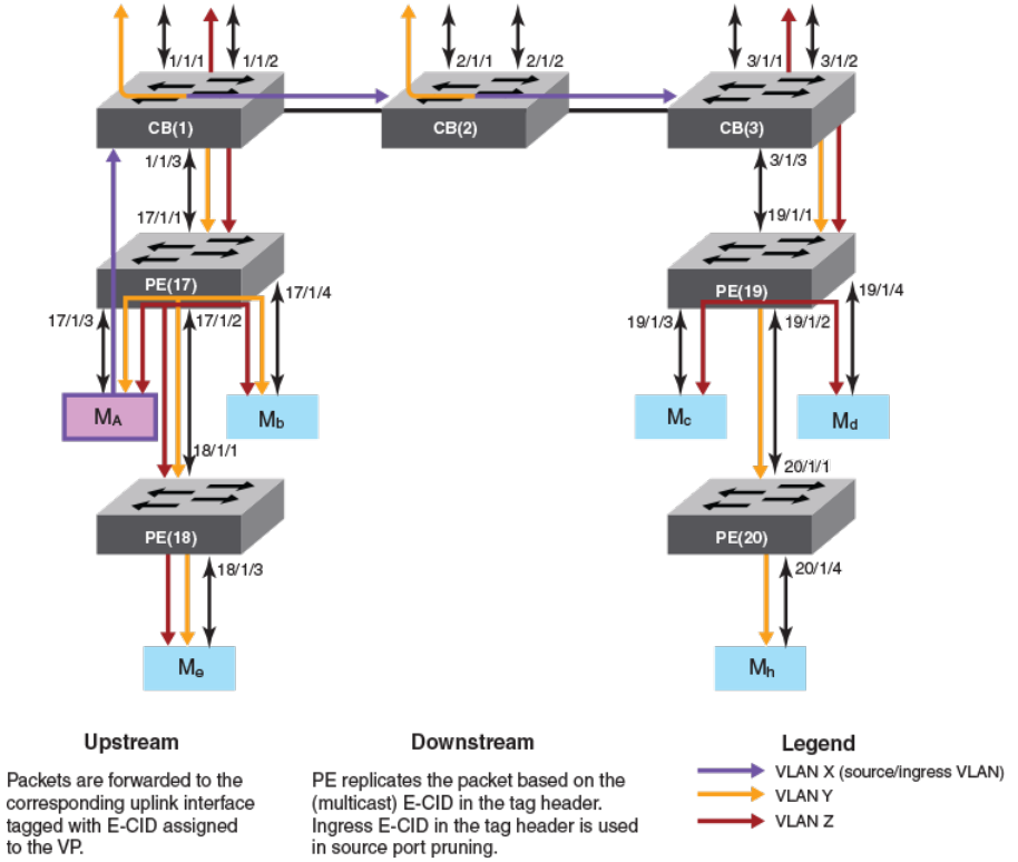
FIGURE 14 Multicast trac forwarding on Layer 3 devices
The following describes Layer 3 multicast forwarding in an SPX conguration.
• The Multicast E-CID Manager on the Control Bridge sets up the multicast E-CID forwarding path on the PE using Control and
Status Protocol (CSP).
• A lookup is performed on the PE unit using the multicast E-CID in the E-Tag header.
• Multi-destination trac sent by a CB on its cascade ports or LAGs is always VLAN tagged.
• The PE unit removes the VLAN tag while replicating the trac on an untagged VLAN port.
• The PE unit can perform local replication within the VLAN.
• The CB sends a copy of the packet for each VLAN with multicast E-CIDs.
• The CB tracks inactivity of PIM mcache entries.
Layer 3 multicast scaling numbers
The following table details the SPX stacking scaling numbers with IPv4 and IPv6 multicast snooping optimization turned on.
FOR BROCADE CONTROLLED RELEASE ONLY
Switch Port Extender and IP Multicast
Brocade FastIron IP Multicast Conguration Guide, 08.0.50
53-1004455-01 193

TABLE 50 Multicast scaling numbers with optimization turned on
System parameter Scaling number
IGMP Groups 8192
PIMv4 Mcache 6144
MSDP Peers 64
MSDP SA cache 4096
MLD Groups 8192
PIMv6 Mcache 2048
The following table details the SPX stacking scaling numbers with IPv4 and IPv6 multicast snooping optimization turned o. This is the
default behavior.
TABLE 51 Multicast scaling numbers with optimization turned o
System parameter Scaling number
IGMP Groups 8192
PIMv4 Mcache 10242
MSDP Peers 64
MSDP SA cache 4096
MLD Groups 8192
PIMv6 Mcache 10242
Displaying multicast SPX information
You can view ME-CID topology and summary information using a variety of show commands.
Use the following commands to verify multicast SPX information.
Enter the User EXEC or Privileged EXEC mode to run the multicast SPX show commands.
The following example of the show spx multicast cache command displays the SPX multicast cache information.
device# show spx multicast cache
1 E-CID: 5120 UpTime: 00:03:05 LastUpdate: 00:02:29
HWSltMsk: 0x1, L2MC: 1025(Shr), SetID: 0x31255948
Ports 5:
17/1/1 (00:03:05) 17/1/3 (00:02:37) 17/1/5 (00:03:05) 17/1/7 (00:03:05)
17/1/10(00:02:29)
2 E-CID: 6451 UpTime: 00:01:31 LastUpdate: 00:00:44
HWSltMsk: 0x1, L2MC: 1025(Shr), SetID: 0x31255948
Ports 5:
17/1/1 (00:01:20) 17/1/3 (00:00:44) 17/1/5 (00:01:20) 17/1/7 (00:01:31)
17/1/10(00:01:31)
3 E-CID: 9276 UpTime: 00:00:07 LastUpdate: 00:00:07
HWSltMsk: 0x1, L2MC: 1027(Shr), SetID: 0x31739250
Ports 2:
17/1/2 (00:00:07) 17/1/14(00:00:07)
2With PE ports being OIFs (receiver ports) and a maximum of 8 SPX ports on each CB unit. This number can be higher with a lesser number of SPX
ports on each CB unit.
FOR BROCADE CONTROLLED RELEASE ONLY
Switch Port Extender and IP Multicast
Brocade FastIron IP Multicast Conguration Guide, 08.0.50
194 53-1004455-01
The following example of the show spx multicast optimization command displays the multicast replication resource optimization details.
device# show spx multicast optimization 2
Total L2MCs Allocated: 2; Available: 7166; Failed: 0
Index L2MC SetId Users Set
1. 1027 0x31739250 1 {<17/1/14>,<17/1/2>,}
2. 1025 0x31255948 2 {<17/1/10>,<17/1/7>,<17/1/5>,<17/1/3>,
<17/1/1>,}
Sharability Coefficient: 50%
The following example of the show spx multicast resource command displays the multicast memory pool details.
device# show spx multicast resource
alloc in-use avail get-fail limit get-mem size init
fwd mcache 64 3 61 0 14848 3 62 64
tx port info 256 12 244 0 59392 12 23 256
IP multicast hardware entry optimization
IP multicast (IPMC) entries are used to replicate Layer 3 multicast packets in the hardware. Each multicast route entry points to the IPMC
entry to replicate this ow at the hardware level.
If multiple route entries share the same Output Interfaces (OIFs) for replication, a single IPMC entry is shared with all the route entries.
IPMC entry optimization reduces the usage of IPMC entries in the hardware, which in turn helps scalability in environments with a large
number of multicast trac ows. However, in a stacking setup, replication sharing may cause a momentary trac drop in certain
scenarios. This trac drop occurs for existing receivers of a multicast ow. Trac drops take place because when a ow moves from a
shared IPMC to a new IPMC, the new IPMC needs to be programmed on all the stack units. IPMC programming on all the stack units
does not occur at the same time. IPMC information is synchronized to the stack units, and it must be programmed locally on the specic
units. Because the IPMC programming must be handled locally, the programming of IPMC entries is delayed on stack units.
Layer 2 multicast packets also share the IPMC entries in the same way. Momentary trac loss does not occur on non-SPX stack for
Layer 2 multicast trac. However, an SPX stack uses IPMC entries for Layer 2 multicast replication, hence a momentary trac loss may
occur if the ow moves to a new IPMC because of sharing.
How disabling IP multicast hardware entry optimization works
If a network environment does not have a large number of trac ows, and is sensitive to trac drops, IPMC optimization can be
disabled globally. When you disable IPMC optimization, a separate IPMC is allocated for each multicast trac ow, even though they
have the same OIF combinations. When the OIF of a ow changes, the same IPMC is used to program the modied OIFs. Because the
IPMC entries remain the same, existing receivers that have not changed on the stack units continue to receive trac and there are no
trac drops.
IPMC optimization can be disabled for IPv4 and IPv6 multicast ows independently. When IPMC optimization is disabled through the
CLI, all the multicast ows (across all VRFs) are deleted and must be re-programmed. As these ows are relearned, separate IPMC
entries are allocated for each ow. This behavior continues even when IPMC optimization is re-enabled.
Disabling multicast hardware entry optimization
You can disable Layer 2 and Layer 3 multicast hardware entry optimization for IPv4 and IPv6 multicast ows. The following commands
need to be run only on the active unit.
1. Enter the congure terminal command to access global conguration mode.
device# configure terminal
FOR BROCADE CONTROLLED RELEASE ONLY
IP multicast hardware entry optimization
Brocade FastIron IP Multicast Conguration Guide, 08.0.50
53-1004455-01 195
2. Enter the no ip multicast-routing optimization command followed by the oif-list and all keywords to disable Layer 3 IPMC
sharing for IPv4 multicast ows. To disable Layer 3 IPMC sharing for IPv6 multicast ows, enter the no ipv6 multicast-routing
optimization command followed by the oif-list and all keywords.
device(config)# no ip multicast-routing optimization oif-list all
device(config)# no ipv6 multicast-routing optimization oif-list all
3. Enter the no ip multicast optimization command followed by the oif-list and all keywords to disable Layer 2 IPMC sharing for
IPv4 multicast ows. To disable Layer 2 IPMC sharing for IPv6 multicast ows, enter the no ipv6 multicast optimization
command followed by the oif-list and all keywords.
device(config)# no ip multicast optimization oif-list all
device(config)# no ipv6 multicast optimization oif-list all
NOTE
Entry optimization is disabled by default on the ICX 7750 for Layer 2 and Layer 3 multicast
trac.
FOR BROCADE CONTROLLED RELEASE ONLY
IP multicast hardware entry optimization
Brocade FastIron IP Multicast Conguration Guide, 08.0.50
196 53-1004455-01
