Ruckus Brocade FastIron Management Configuration Guide, 08.0.60 Fast Iron Guide 08060 Managementguide
FastIron 08.0.60 Management Configuration Guide fastiron-08060-managementguide
2017-12-13
User Manual: Ruckus FastIron 08.0.60 Management Configuration Guide
Open the PDF directly: View PDF ![]() .
.
Page Count: 204 [warning: Documents this large are best viewed by clicking the View PDF Link!]
- Brocade FastIron Management Configuration Guide, 08.0.60
- Preface
- About This Document
- Configuration Fundamentals
- Management port overview
- Web Management Interface
- Management VRFs
- Additional OOB management configuration options
- System clock
- Basic system parameter configuration
- Displaying and modifying system parameter default settings
- Basic port parameter configuration
- About port regions
- Specifying a port address
- Static MAC entry configuration
- Multi-port static MAC address
- Assigning port names
- Displaying the port name for an interface
- Port speed and duplex mode modification
- Enabling auto-negotiation maximum port speed advertisement
- Force mode configuration
- MDI and MDIX configuration
- Disabling or re-enabling a port
- Enabling and disabling support for 100BaseFX
- Changing the Gbps fiber negotiation mode
- Flow control configuration
- Symmetric flow control
- PHY FIFO Rx and Tx depth configuration
- Interpacket Gap (IPG) on a Brocade switch
- IPG on FastIron Stackable devices
- Port priority (QoS) modification
- Dynamic configuration of Voice over IP (VoIP) phones
- Port flap dampening configuration
- Port loop detection
- Types of loop detection
- Recovering disabled ports
- Port loopback detection configuration notes
- Enabling loop detection
- Configuring a global loop detection interval
- Configuring the device to automatically re-enable ports
- Specifying the recovery time interval
- Clearing loop-detection
- Displaying loop-detection information
- Displaying loop detection resource information
- Displaying loop detection configuration status on an interface
- Syslog message due to disabled port in loop detection
- Shutdown prevention for loop-detection on an interface
- Periodic log message generation for shutdown prevention
- Syslog for port shutdown prevention
- Replacing a primary IPv4 address automatically
- Ethernet loopback
- Disabling the automatic learning of MAC addresses
- Changing the MAC age time and disabling MAC address learning
- Clearing MAC address entries
- Defining MAC address filters
- Monitoring MAC address movement
- Overview of 40 Gbps breakout ports
- CLI banner configuration
- Automatic execution of commands in batches
- CLI command history
- Displaying a console message when an incoming Telnet session is detected
- Cut-through switching
- Fanless mode support on ICX 7150
- Jumbo frame support
- Wake-on-LAN support across VLANs
- Network Time Protocol Version 4 (NTPv4)
- Network Time Protocol Version 4 Overview
- Configuring NTP
- Enabling NTP
- Disabling NTP
- Enabling NTP authentication
- Defining an authentication key
- Specifying a source interface
- Enable or disable the VLAN containment for NTP
- Configuring the NTP client
- Configuring the master
- Configuring the NTP peer
- Configuring NTP on an interface
- Configuring the broadcast client
- Configuring the broadcast destination
- Displaying NTP status
- Displaying NTP associations
- Displaying NTP associations details
- Configuration Examples
- NTP server and client mode configuration
- NTP client mode configuration
- NTP strict authentication configuration
- NTP loose authentication configuration
- NTP interface context for the broadcast server or client mode
- NTP broadcast client configuration
- NTP over management VRF
- Cisco Discovery Protocol
- Foundry Discovery Protocol
- LLDP and LLDP-MED
- LLDP terms used in this chapter
- LLDP overview
- LLDP-MED overview
- General LLDP operating principles
- MIB support
- Syslog messages
- LLDP configuration
- LLDP configuration notes and considerations
- Enabling and disabling LLDP
- Enabling support for tagged LLDP packets
- Changing a port LLDP operating mode
- Configuring LLDP processing on 802.1x blocked port
- Maximum number of LLDP neighbors
- Enabling LLDP SNMP notifications and Syslog messages
- Changing the minimum time between LLDP transmissions
- Changing the interval between regular LLDP transmissions
- Changing the holdtime multiplier for transmit TTL
- Changing the minimum time between port reinitializations
- LLDP TLVs advertised by the Brocade device
- LLDP-MED configuration
- LLDP-MED attributes advertised by the Brocade device
- LLDP port ID subtype configuration for E-911
- Resetting LLDP statistics
- Clearing cached LLDP neighbor information
- Power over Ethernet
- Power over Ethernet overview
- Enabling and disabling Power over Ethernet
- Disabling support for PoE legacy power-consuming devices
- Enabling the detection of PoE power requirements advertised through CDP
- Setting the maximum power level for a PoE power-consuming device
- Setting the power class for a PoE power-consuming device
- Setting the inline power priority for a PoE port
- Resetting PoE parameters
- Displaying Power over Ethernet information
- Inline power on PoE LAG ports
- Decouple PoE and datalink operations on PoE ports
- SNMP
- SNMP overview
- SNMP community strings
- User-based security model
- SNMP parameter configuration
- Defining SNMP views
- SNMP version 3 traps
- Defining an SNMP group and specifying which view is notified of traps
- Defining the UDP port for SNMP v3 traps
- Trap MIB changes
- SNMP MAC-notification trap support
- Specifying an IPv6 host as an SNMP trap receiver
- SNMP v3 over IPv6
- Specifying an IPv6 host as an SNMP trap receiver
- Viewing IPv6 SNMP server addresses
- Displaying SNMP Information
- SNMP v3 configuration examples

Supporting FastIron Software Release 08.0.60
CONFIGURATION GUIDE
Brocade FastIron
Management Conguration Guide, 08.0.60
Part Number: 53-1004918-03
Publication Date: 11 August 2017
© 2017, Brocade Communications Systems, Inc. All Rights Reserved.
Brocade, the B-wing symbol, and MyBrocade are registered trademarks of Brocade Communications Systems, Inc., in the United States and in other
countries. Other brands, product names, or service names mentioned of Brocade Communications Systems, Inc. are listed at www.brocade.com/en/legal/
brocade-Legal-intellectual-property/brocade-legal-trademarks.html. Other marks may belong to third parties.
Notice: This document is for informational purposes only and does not set forth any warranty, expressed or implied, concerning any equipment,
equipment feature, or service oered or to be oered by Brocade. Brocade reserves the right to make changes to this document at any time, without
notice, and assumes no responsibility for its use. This informational document describes features that may not be currently available. Contact a Brocade
sales oce for information on feature and product availability. Export of technical data contained in this document may require an export license from the
United States government.
The authors and Brocade Communications Systems, Inc. assume no liability or responsibility to any person or entity with respect to the accuracy of this
document or any loss, cost, liability, or damages arising from the information contained herein or the computer programs that accompany it.
The product described by this document may contain open source software covered by the GNU General Public License or other open source license
agreements. To nd out which open source software is included in Brocade products, view the licensing terms applicable to the open source software, and
obtain a copy of the programming source code, please visit http://www.brocade.com/support/oscd.
Brocade FastIron Management Conguration Guide, 08.0.60
2 Part Number: 53-1004918-03

Contents
Preface...................................................................................................................................................................................................................................9
Document conventions............................................................................................................................................................................................................................9
Notes, cautions, and warnings.....................................................................................................................................................................................................9
Text formatting conventions.........................................................................................................................................................................................................9
Command syntax conventions.................................................................................................................................................................................................10
Brocade resources..................................................................................................................................................................................................................................10
Document feedback.............................................................................................................................................................................................................................. 10
Contacting Brocade Technical Support......................................................................................................................................................................................... 11
Brocade customers.......................................................................................................................................................................................................................11
Brocade OEM customers.......................................................................................................................................................................................................... 11
About This Document..................................................................................................................................................................................................... 13
Supported hardware...............................................................................................................................................................................................................................13
What’s new in this document ............................................................................................................................................................................................................ 13
How command information is presented in this guide............................................................................................................................................................13
Conguration Fundamentals......................................................................................................................................................................................... 15
Management port overview................................................................................................................................................................................................................15
Displaying information about management ports........................................................................................................................................................... 16
Web Management Interface............................................................................................................................................................................................................... 17
Management VRFs................................................................................................................................................................................................................................ 17
Source interface and management VRF compatibility.................................................................................................................................................. 18
Supported management applications...................................................................................................................................................................................18
Conguring a global management VRF.............................................................................................................................................................................. 20
Conguring the OOB management port to be a member of a management VRF..........................................................................................21
Displaying management VRF information......................................................................................................................................................................... 22
Additional OOB management conguration options..............................................................................................................................................................24
Conguring an IPv6 default gateway to support OOB management.....................................................................................................................24
Controlling trac on management ports in a VLAN or VRF...................................................................................................................................... 25
Conguring the OOB management port to be a member of a management VLAN...................................................................................... 25
System clock.............................................................................................................................................................................................................................................26
Daylight saving time..................................................................................................................................................................................................................... 26
Time zones.......................................................................................................................................................................................................................................26
Setting the clock parameters for the device....................................................................................................................................................................... 27
Basic system parameter conguration.......................................................................................................................................................................................... 28
Entering system administration information.......................................................................................................................................................................29
User-login details in Syslog messages and traps............................................................................................................................................................ 29
Cancelling an outbound Telnet session................................................................................................................................................................................30
Displaying and modifying system parameter default settings............................................................................................................................................. 30
System default settings conguration considerations....................................................................................................................................................31
Modifying system parameter default values...................................................................................................................................................................... 31
Displaying system parameter default values......................................................................................................................................................................31
Basic port parameter conguration.................................................................................................................................................................................................35
About port regions........................................................................................................................................................................................................................ 35
Specifying a port address...........................................................................................................................................................................................................36
Static MAC entry conguration................................................................................................................................................................................................36
Multi-port static MAC address.................................................................................................................................................................................................37
Brocade FastIron Management Conguration Guide, 08.0.60
Part Number: 53-1004918-03 3
Assigning port names..................................................................................................................................................................................................................37
Displaying the port name for an interface........................................................................................................................................................................... 38
Port speed and duplex mode modication........................................................................................................................................................................ 39
Enabling auto-negotiation maximum port speed advertisement..............................................................................................................................41
Force mode conguration..........................................................................................................................................................................................................42
MDI and MDIX conguration....................................................................................................................................................................................................43
Disabling or re-enabling a port................................................................................................................................................................................................ 44
Enabling and disabling support for 100BaseFX............................................................................................................................................................. 44
Changing the Gbps ber negotiation mode.......................................................................................................................................................................45
Flow control conguration..........................................................................................................................................................................................................46
Symmetric ow control................................................................................................................................................................................................................48
PHY FIFO Rx and Tx depth conguration..........................................................................................................................................................................51
Interpacket Gap (IPG) on a Brocade switch........................................................................................................................................................................ 52
IPG on FastIron Stackable devices.........................................................................................................................................................................................53
Port priority (QoS) modication...............................................................................................................................................................................................54
Dynamic conguration of Voice over IP (VoIP) phones.................................................................................................................................................54
Port ap dampening conguration.........................................................................................................................................................................................55
Port loop detection........................................................................................................................................................................................................................58
Replacing a primary IPv4 address automatically.......................................................................................................................................................................63
Ethernet loopback...................................................................................................................................................................................................................................63
Ethernet loopback operational modes..................................................................................................................................................................................63
Ethernet loopback conguration considerations.............................................................................................................................................................. 64
Conguring Ethernet loopback in VLAN-unaware mode.............................................................................................................................................65
Conguring Ethernet loopback in VLAN-aware mode..................................................................................................................................................66
Ethernet loopback syslog messages.....................................................................................................................................................................................67
Disabling the automatic learning of MAC addresses...............................................................................................................................................................67
MAC address learning conguration notes and feature limitations .........................................................................................................................67
Changing the MAC age time and disabling MAC address learning.................................................................................................................................. 67
Disabling the automatic learning of MAC addresses......................................................................................................................................................68
Displaying the MAC address table......................................................................................................................................................................................... 68
Clearing MAC address entries...........................................................................................................................................................................................................69
Dening MAC address lters............................................................................................................................................................................................................. 69
Monitoring MAC address movement.............................................................................................................................................................................................69
Conguring the MAC address movement threshold rate.............................................................................................................................................70
Viewing the MAC address movement threshold rate conguration.........................................................................................................................70
Conguring an interval for collecting MAC address move notications.................................................................................................................71
Viewing MAC address movement statistics for the interval history..........................................................................................................................72
Overview of 40 Gbps breakout ports.............................................................................................................................................................................................72
Conguring 40 Gbps breakout ports....................................................................................................................................................................................73
Conguring sub-ports................................................................................................................................................................................................................. 74
Displaying information for breakout ports...........................................................................................................................................................................76
Removing breakout conguration...........................................................................................................................................................................................76
CLI banner conguration..................................................................................................................................................................................................................... 78
Setting a message of the day banner....................................................................................................................................................................................78
Requiring users to press the Enter key after the message of the day banner......................................................................................................79
Setting a privileged EXEC CLI level banner........................................................................................................................................................................79
Automatic execution of commands in batches.......................................................................................................................................................................... 80
Conguration considerations for creating and running commands in batches................................................................................................... 80
Conguring automatic execution of commands in batches........................................................................................................................................ 81
CLI command history............................................................................................................................................................................................................................82
Brocade FastIron Management Conguration Guide, 08.0.60
4 Part Number: 53-1004918-03
CLI command history persistence limitations................................................................................................................................................................... 82
Displaying and clearing command log history.................................................................................................................................................................. 83
Displaying a console message when an incoming Telnet session is detected............................................................................................................. 83
Cut-through switching...........................................................................................................................................................................................................................83
Fanless mode support on ICX 7150 ............................................................................................................................................................................................ 85
Jumbo frame support........................................................................................................................................................................................................................... 85
Wake-on-LAN support across VLANs..........................................................................................................................................................................................85
Prerequisites.................................................................................................................................................................................................................................... 86
Network Time Protocol Version 4 (NTPv4)................................................................................................................................................................89
Network Time Protocol Version 4 Overview............................................................................................................................................................................... 89
Limitations........................................................................................................................................................................................................................................ 91
Network Time Protocol leap second .................................................................................................................................................................................... 91
NTP and SNTP.............................................................................................................................................................................................................................. 92
NTP server....................................................................................................................................................................................................................................... 92
NTP Client........................................................................................................................................................................................................................................ 93
NTP peer...........................................................................................................................................................................................................................................93
NTP broadcast server..................................................................................................................................................................................................................94
NTP broadcast client....................................................................................................................................................................................................................94
NTP associations...........................................................................................................................................................................................................................94
Synchronizing time........................................................................................................................................................................................................................96
Authentication..................................................................................................................................................................................................................................96
VLAN and NTP.............................................................................................................................................................................................................................. 96
Conguring NTP..................................................................................................................................................................................................................................... 96
Enabling NTP..................................................................................................................................................................................................................................96
Disabling NTP.................................................................................................................................................................................................................................97
Enabling NTP authentication....................................................................................................................................................................................................97
Dening an authentication key................................................................................................................................................................................................. 97
Specifying a source interface....................................................................................................................................................................................................98
Enable or disable the VLAN containment for NTP.........................................................................................................................................................98
Conguring the NTP client........................................................................................................................................................................................................ 98
Conguring the master................................................................................................................................................................................................................99
Conguring the NTP peer..........................................................................................................................................................................................................99
Conguring NTP on an interface......................................................................................................................................................................................... 100
Conguring the broadcast client...........................................................................................................................................................................................100
Conguring the broadcast destination...............................................................................................................................................................................100
Displaying NTP status..............................................................................................................................................................................................................101
Displaying NTP associations.................................................................................................................................................................................................102
Displaying NTP associations details...................................................................................................................................................................................102
Conguration Examples...........................................................................................................................................................................................................104
NTP server and client mode conguration......................................................................................................................................................................104
NTP client mode conguration.............................................................................................................................................................................................104
NTP strict authentication conguration.............................................................................................................................................................................104
NTP loose authentication conguration............................................................................................................................................................................104
NTP interface context for the broadcast server or client mode...............................................................................................................................104
NTP broadcast client conguration.....................................................................................................................................................................................105
NTP over management VRF.................................................................................................................................................................................................105
Cisco Discovery Protocol............................................................................................................................................................................................. 111
Cisco Discovery Protocol overview.............................................................................................................................................................................................. 111
Enabling CDP packet interception................................................................................................................................................................................................ 111
Brocade FastIron Management Conguration Guide, 08.0.60
Part Number: 53-1004918-03 5
Displaying CDP packet information.............................................................................................................................................................................................112
Clearing CDP statistics and neighbor information.................................................................................................................................................................113
Foundry Discovery Protocol........................................................................................................................................................................................115
Foundry Discovery Protocol overview........................................................................................................................................................................................ 115
Enabling FDP........................................................................................................................................................................................................................................ 115
Verifying FDP........................................................................................................................................................................................................................................ 116
Clearing FDP statistics and neighbor information................................................................................................................................................................. 118
LLDP and LLDP-MED................................................................................................................................................................................................. 119
LLDP terms used in this chapter...................................................................................................................................................................................................119
LLDP overview..................................................................................................................................................................................................................................... 120
Benets of LLDP........................................................................................................................................................................................................................121
LLDP-MED overview.........................................................................................................................................................................................................................121
Benets of LLDP-MED...........................................................................................................................................................................................................122
LLDP-MED class....................................................................................................................................................................................................................... 123
General LLDP operating principles..............................................................................................................................................................................................123
LLDP operating modes...........................................................................................................................................................................................................123
LLDP packets.............................................................................................................................................................................................................................. 124
TLV support.................................................................................................................................................................................................................................. 124
MIB support........................................................................................................................................................................................................................................... 127
Syslog messages.................................................................................................................................................................................................................................128
LLDP conguration.............................................................................................................................................................................................................................128
LLDP conguration notes and considerations...............................................................................................................................................................128
Enabling and disabling LLDP................................................................................................................................................................................................129
Enabling support for tagged LLDP packets....................................................................................................................................................................129
Changing a port LLDP operating mode...........................................................................................................................................................................129
Conguring LLDP processing on 802.1x blocked port............................................................................................................................................131
Maximum number of LLDP neighbors ............................................................................................................................................................................131
Enabling LLDP SNMP notications and Syslog messages.....................................................................................................................................132
Changing the minimum time between LLDP transmissions...................................................................................................................................133
Changing the interval between regular LLDP transmissions...................................................................................................................................133
Changing the holdtime multiplier for transmit TTL......................................................................................................................................................133
Changing the minimum time between port reinitializations......................................................................................................................................134
LLDP TLVs advertised by the Brocade device..............................................................................................................................................................134
LLDP-MED conguration................................................................................................................................................................................................................140
Enabling LLDP-MED............................................................................................................................................................................................................... 141
Enabling SNMP notications and Syslog messages for LLDP-MED topology changes...........................................................................141
Changing the fast start repeat count...................................................................................................................................................................................141
Dening a location id.................................................................................................................................................................................................................142
Dening an LLDP-MED network policy...........................................................................................................................................................................148
LLDP-MED attributes advertised by the Brocade device..................................................................................................................................................149
LLDP-MED capabilities...........................................................................................................................................................................................................150
Extended power-via-MDI information...............................................................................................................................................................................150
Displaying LLDP statistics and conguration settings................................................................................................................................................152
LLDP conguration summary.............................................................................................................................................................................................. 152
Displaying LLDP statistics......................................................................................................................................................................................................153
Displaying LLDP neighbors...................................................................................................................................................................................................154
Displaying LLDP neighbors detail.......................................................................................................................................................................................155
Displaying LLDP conguration details.............................................................................................................................................................................. 155
LLDP port ID subtype conguration for E-911.....................................................................................................................................................................157
Brocade FastIron Management Conguration Guide, 08.0.60
6 Part Number: 53-1004918-03
Conguring the LLDP port ID subtype to advertise....................................................................................................................................................158
Resetting LLDP statistics................................................................................................................................................................................................................. 158
Clearing cached LLDP neighbor information.......................................................................................................................................................................... 159
Power over Ethernet .....................................................................................................................................................................................................161
Power over Ethernet overview........................................................................................................................................................................................................ 161
Power over Ethernet terms used in this chapter............................................................................................................................................................161
Power over Ethernet 802.1br stack support.................................................................................................................................................................. 162
Methods for delivering Power over Ethernet...................................................................................................................................................................162
PoE autodiscovery..................................................................................................................................................................................................................... 164
Power class................................................................................................................................................................................................................................... 165
Power over Ethernet cabling requirements......................................................................................................................................................................166
Supported powered devices.................................................................................................................................................................................................. 166
Installing PoE rmware ............................................................................................................................................................................................................166
PoE and CPU utilization...........................................................................................................................................................................................................170
Enabling and disabling Power over Ethernet............................................................................................................................................................................171
Disabling support for PoE legacy power-consuming devices..........................................................................................................................................172
Enabling the detection of PoE power requirements advertised through CDP...........................................................................................................173
Command syntax for PoE power requirements.............................................................................................................................................................173
Setting the maximum power level for a PoE power-consuming device.......................................................................................................................173
Considerations for setting power levels.............................................................................................................................................................................173
Conguring power levels command syntax.....................................................................................................................................................................174
Setting the power class for a PoE power-consuming device............................................................................................................................................174
Setting the power class command syntax........................................................................................................................................................................175
Setting the inline power priority for a PoE port ...................................................................................................................................................................... 175
Command syntax for setting the inline power priority for a PoE port...................................................................................................................176
Resetting PoE parameters............................................................................................................................................................................................................... 176
Changing a PoE port power priority from low to high ................................................................................................................................................176
Changing a port power class from 2 to 3........................................................................................................................................................................ 177
Displaying Power over Ethernet information............................................................................................................................................................................177
Displaying PoE operational status ......................................................................................................................................................................................177
Displaying PoE data specic to PD ports ....................................................................................................................................................................... 178
Displaying detailed information about PoE power supplies..................................................................................................................................... 179
Inline power on PoE LAG ports..................................................................................................................................................................................................... 182
Restriction...................................................................................................................................................................................................................................... 183
Conguring inline power on PoE ports in a LAG.......................................................................................................................................................... 183
Decouple PoE and datalink operations on PoE ports.......................................................................................................................................................... 184
Restriction...................................................................................................................................................................................................................................... 184
Decoupling of PoE and datalink operations on PoE LAG ports.............................................................................................................................184
Decoupling of PoE and datalink operations on regular PoE ports........................................................................................................................ 185
SNMP............................................................................................................................................................................................................................... 187
SNMP overview....................................................................................................................................................................................................................................187
SNMP community strings................................................................................................................................................................................................................187
Encryption of SNMP community strings ........................................................................................................................................................................ 188
Adding an SNMP community string.................................................................................................................................................................................. 188
Displaying the SNMP community strings........................................................................................................................................................................189
User-based security model............................................................................................................................................................................................................. 190
Conguring your NMS............................................................................................................................................................................................................. 190
Conguring SNMP version 3 on Brocade devices......................................................................................................................................................190
Dening the engine id...............................................................................................................................................................................................................191
Brocade FastIron Management Conguration Guide, 08.0.60
Part Number: 53-1004918-03 7
Dening an SNMP group........................................................................................................................................................................................................191
Dening an SNMP user account..........................................................................................................................................................................................192
SNMP parameter conguration.....................................................................................................................................................................................................193
Specifying an SNMP trap receiver...................................................................................................................................................................................... 194
Specifying a single trap source............................................................................................................................................................................................. 194
Setting the SNMP trap holddown time............................................................................................................................................................................. 195
Disabling SNMP traps..............................................................................................................................................................................................................195
SNMP ifIndex...............................................................................................................................................................................................................................196
Dening SNMP views........................................................................................................................................................................................................................196
SNMP version 3 traps....................................................................................................................................................................................................................... 197
Dening an SNMP group and specifying which view is notied of traps........................................................................................................... 197
Dening the UDP port for SNMP v3 traps..................................................................................................................................................................... 198
Trap MIB changes...................................................................................................................................................................................................................... 198
SNMP MAC-notication trap support............................................................................................................................................................................... 199
Specifying an IPv6 host as an SNMP trap receiver.....................................................................................................................................................201
SNMP v3 over IPv6..................................................................................................................................................................................................................201
Specifying an IPv6 host as an SNMP trap receiver ....................................................................................................................................................202
Viewing IPv6 SNMP server addresses............................................................................................................................................................................. 202
Displaying SNMP Information........................................................................................................................................................................................................202
Displaying the Engine ID......................................................................................................................................................................................................... 202
Displaying SNMP groups........................................................................................................................................................................................................203
Displaying user information....................................................................................................................................................................................................203
Interpreting varbinds in report packets.............................................................................................................................................................................. 203
SNMP v3 conguration examples................................................................................................................................................................................................204
Example 1......................................................................................................................................................................................................................................204
Example 2......................................................................................................................................................................................................................................204
Brocade FastIron Management Conguration Guide, 08.0.60
8 Part Number: 53-1004918-03

Preface
• Document conventions...................................................................................................................................................................................... 9
• Brocade resources............................................................................................................................................................................................ 10
• Document feedback.........................................................................................................................................................................................10
• Contacting Brocade Technical Support....................................................................................................................................................11
Document conventions
The document conventions describe text formatting conventions, command syntax conventions, and important notice formats used in
Brocade technical documentation.
Notes, cautions, and warnings
Notes, cautions, and warning statements may be used in this document. They are listed in the order of increasing severity of potential
hazards.
NOTE
A Note provides a tip, guidance, or advice, emphasizes important information, or provides a reference to related information.
ATTENTION
An Attention statement indicates a stronger note, for example, to alert you when trac might be interrupted or the device might
reboot.
CAUTION
A Caution statement alerts you to situations that can be potentially hazardous to you or cause damage to hardware,
rmware, software, or data.
DANGER
A Danger statement indicates conditions or situations that can be potentially lethal or extremely hazardous to you. Safety
labels are also attached directly to products to warn of these conditions or situations.
Text formatting conventions
Text formatting conventions such as boldface, italic, or Courier font may be used to highlight specic words or phrases.
Format Description
bold text Identies command names.
Identies keywords and operands.
Identies the names of GUI elements.
Identies text to enter in the GUI.
italic text Identies emphasis.
Identies variables.
Identies document titles.
Courier font Identies CLI output.
Brocade FastIron Management Conguration Guide, 08.0.60
Part Number: 53-1004918-03 9
Format Description
Identies command syntax examples.
Command syntax conventions
Bold and italic text identify command syntax components. Delimiters and operators dene groupings of parameters and their logical
relationships.
Convention Description
bold text Identies command names, keywords, and command options.
italic text Identies a variable.
value In Fibre Channel products, a xed value provided as input to a command option is printed in plain text, for
example, --show WWN.
[ ] Syntax components displayed within square brackets are optional.
Default responses to system prompts are enclosed in square brackets.
{ x | y | z } A choice of required parameters is enclosed in curly brackets separated by vertical bars. You must select
one of the options.
In Fibre Channel products, square brackets may be used instead for this purpose.
x | yA vertical bar separates mutually exclusive elements.
< > Nonprinting characters, for example, passwords, are enclosed in angle brackets.
... Repeat the previous element, for example, member[member...].
\ Indicates a “soft” line break in command examples. If a backslash separates two lines of a command
input, enter the entire command at the prompt without the backslash.
Brocade resources
Visit the Brocade website to locate related documentation for your product and additional Brocade resources.
White papers, data sheets, and the most recent versions of Brocade software and hardware manuals are available at www.brocade.com.
Product documentation for all supported releases is available to registered users at MyBrocade.
Click the Support tab and select Document Library to access product documentation on MyBrocade or www.brocade.com. You can
locate documentation by product or by operating system.
Release notes are bundled with software downloads on MyBrocade. Links to software downloads are available on the MyBrocade landing
page and in the Document Library.
Document feedback
Quality is our rst concern at Brocade, and we have made every eort to ensure the accuracy and completeness of this document.
However, if you nd an error or an omission, or you think that a topic needs further development, we want to hear from you. You can
provide feedback in two ways:
• Through the online feedback form in the HTML documents posted on www.brocade.com
• By sending your feedback to documentation@brocade.com
Provide the publication title, part number, and as much detail as possible, including the topic heading and page number if applicable, as
well as your suggestions for improvement.
Brocade resources
Brocade FastIron Management Conguration Guide, 08.0.60
10 Part Number: 53-1004918-03

Contacting Brocade Technical Support
As a Brocade customer, you can contact Brocade Technical Support 24x7 online or by telephone. Brocade OEM customers should
contact their OEM/solution provider.
Brocade customers
For product support information and the latest information on contacting the Technical Assistance Center, go to www.brocade.com and
select Support.
If you have purchased Brocade product support directly from Brocade, use one of the following methods to contact the Brocade
Technical Assistance Center 24x7.
Online Telephone
Preferred method of contact for non-urgent issues:
• Case management through the MyBrocade portal.
• Quick Access links to Knowledge Base, Community, Document
Library, Software Downloads and Licensing tools
Required for Sev 1-Critical and Sev 2-High issues:
• Continental US: 1-800-752-8061
• Europe, Middle East, Africa, and Asia Pacic: +800-AT FIBREE
(+800 28 34 27 33)
•Toll-free numbers are available in many countries.
• For areas unable to access a toll-free number:
+1-408-333-6061
Brocade OEM customers
If you have purchased Brocade product support from a Brocade OEM/solution provider, contact your OEM/solution provider for all of
your product support needs.
• OEM/solution providers are trained and certied by Brocade to support Brocade® products.
• Brocade provides backline support for issues that cannot be resolved by the OEM/solution provider.
• Brocade Supplemental Support augments your existing OEM support contract, providing direct access to Brocade expertise.
For more information, contact Brocade or your OEM.
• For questions regarding service levels and response times, contact your OEM/solution provider.
Contacting Brocade Technical Support
Brocade FastIron Management Conguration Guide, 08.0.60
Part Number: 53-1004918-03 11
Brocade FastIron Management Conguration Guide, 08.0.60
12 Part Number: 53-1004918-03

About This Document
• Supported hardware......................................................................................................................................................................................... 13
• What’s new in this document .......................................................................................................................................................................13
• How command information is presented in this guide...................................................................................................................... 13
Supported hardware
This guide supports the following product families:
• ICX 7150 Series
• ICX 7250 Series
• ICX 7450 Series
• ICX 7750 Series
For information about the specic models and modules supported in a product family, refer to the hardware installation guide for that
product family.
What’s new in this document
The following table includes descriptions of new information added to this guide for the FastIron 08.0.60 software release.
TABLE 1 Summary of enhancements in FastIron release 08.0.60
Feature Description Location
Support for the Ruckus ICX 7150 Introduced support for Ruckus ICX 7150. Changes occur throughout the text.
Fanless mode support on ICX 7150 Fanless mode enables the device to operate with
the fans disabled while providing a PoE budget of
150 watts.
Fanless mode support on ICX 7150 on page
85
How command information is presented in this guide
For all new content supported in FastIron release 08.0.20 and later, command information is documented in a standalone command
reference guide.
In the Brocade FastIron Command Reference, the command pages are in alphabetical order and follow a standard format to present
syntax, parameters, mode, usage guidelines, examples, and command history.
NOTE
Many commands introduced before FastIron release 08.0.20 are also included in the guide.
Brocade FastIron Management Conguration Guide, 08.0.60
Part Number: 53-1004918-03 13
Brocade FastIron Management Conguration Guide, 08.0.60
14 Part Number: 53-1004918-03

Conguration Fundamentals
• Management port overview...........................................................................................................................................................................15
• Web Management Interface..........................................................................................................................................................................17
• Management VRFs...........................................................................................................................................................................................17
• Additional OOB management conguration options.........................................................................................................................24
• System clock....................................................................................................................................................................................................... 26
• Basic system parameter conguration..................................................................................................................................................... 28
• Displaying and modifying system parameter default settings........................................................................................................30
• Basic port parameter conguration............................................................................................................................................................35
• Replacing a primary IPv4 address automatically.................................................................................................................................63
• Ethernet loopback..............................................................................................................................................................................................63
• Disabling the automatic learning of MAC addresses..........................................................................................................................67
• Changing the MAC age time and disabling MAC address learning.............................................................................................67
• Clearing MAC address entries......................................................................................................................................................................69
•Dening MAC address lters........................................................................................................................................................................69
• Monitoring MAC address movement........................................................................................................................................................69
• Overview of 40 Gbps breakout ports....................................................................................................................................................... 72
• CLI banner conguration................................................................................................................................................................................78
• Automatic execution of commands in batches.....................................................................................................................................80
• CLI command history......................................................................................................................................................................................82
• Displaying a console message when an incoming Telnet session is detected........................................................................83
• Cut-through switching..................................................................................................................................................................................... 83
• Fanless mode support on ICX 7150 .......................................................................................................................................................85
• Jumbo frame support......................................................................................................................................................................................85
• Wake-on-LAN support across VLANs.................................................................................................................................................... 85
Management port overview
The management port is an out-of-band (OOB) port that customers can use to manage their devices without interfering with the in-band
ports. The management port is widely used to download images and congurations, for Telnet sessions and for Web management.
The MAC address for the management port is derived from the base MAC address of the unit, plus the number of ports in the base
module. For example, on a 48-port standalone device, the base MAC address is 0000.0034.2200. The management port MAC
address for this device would be 0000.0034.2200 plus 0x30, or 0000.0034.2230. The 0x30 in this case equals the 48 ports on the
base module.
The MAC address for the management port is derived as if the management port is the last port on the management module where it is
located. For example, on a 2 X 10G management module, the MAC address of the management port is that of the third port on that
module.
NOTE
In previous releases, the OOB management port could not be a member of the management VRF or VLAN. When a
management VLAN was congured, the OOB interface was disabled, disabling switch access. This posed a risk to managing
the switch in case in-band ports are busy forwarding packets a line rate. Now if a management VLAN is congured, the OOB
management interface is automatically part of the management VLAN (treated as an untagged port). Support is also provided
for trac over the management VRF. This provides secure management access to the device through outbound trac through
a VRF that is specied as global management VRF, thereby isolating management trac from network data trac.
Brocade FastIron Management Conguration Guide, 08.0.60
Part Number: 53-1004918-03 15
NOTE
Refer to "Conguring the OOB management port to be a member of a management VRF" and "Conguring the OOB
management port to be a member of a management VLAN."
Only packets that are specically addressed to the management port MAC address or the broadcast MAC address are processed by the
Layer 2 switch or Layer 3 switch. All other packets are ltered out. No packet received on a management port is sent to any in-band
ports, and no packets received on in-band ports are sent to a management port.
For Brocade ICX devices, all features that can be congured from the global conguration mode can also be congured from the
interface level of the management port. Features that are congured through the management port take eect globally, not on the
management port itself.
For switches, any in-band port may be used for management purposes. A router sends Layer 3 packets using the MAC address of the
port as the source MAC address.
For stacking devices, each stack unit has one OOB management port. Only the management port on the active controller will actively
send and receive packets. If a new active controller is elected, the new active controller management port will become the active
management port. In this situation, the MAC address of the old active controller and the MAC address of the new controller will be
dierent.
Displaying information about management ports
Management port information can be displayed using several command-line interface (CLI) command options.
Before entering the commands in this task, ensure that the management port is congured.
The steps in this task can be performed in any order.
1. To display the current management port conguration use the show running cong interface management command with a
specied port number.
device> show running-config interface management 1
interface management 1
ip address 10.44.9.64 255.255.255.0
2. To display more detailed interface conguration information about the management port, use the show interfaces management
command with a specied port number.
device(config)# show interfaces management 1
GigEthernetmgmt1 is up, line protocol is up
Port up for 4 day(s) 1 hour(s) 43 minute(s) 8 second(s)
Hardware is GigEthernet, address is 0000.0076.544a (bia 0000.0076.544a)
Configured speed auto, actual 1Gbit, configured duplex fdx, actual fdx
Configured mdi mode AUTO, actual none
(output truncated)
3. To display summary management interface information, enter the show interfaces brief management command with a
specied port number.
device# show interfaces brief management 1
Port Link State Dupl Speed Trunk Tag Pri MAC Name
mgmt1 Up None Full 1G None No 0 0000.0076.544a
Management port overview
Brocade FastIron Management Conguration Guide, 08.0.60
16 Part Number: 53-1004918-03
4. To display management port statistics, enter the show statistics management command with a specied port number.
device# show statistics management 1
Port Link State Dupl Speed Trunk Tag Pvid Pri MAC Name
mgmt1 Up None Full 1G None No None 0 0000.0076.544a
Port mgmt1 Counters:
InOctets 3210941 OutOctets 1540
InPkts 39939 OutPackets 22
InBroadcastPkts 4355 OutbroadcastPkts 0
InMultiastPkts 35214 OutMulticastPkts 6
InUnicastPkts 370 OutUnicastPkts 16
(output truncated)
5. To display summary management interface statistics, enter the show statistics brief management command with a specied
port number.
device# show statistics brief management 1
Port In Packets Out Packets Trunk In Errors Out Errors
mgmt1 39946 22 0 0
Total 39945 22 0 0
Web Management Interface
The Web Management Interface is a browser-based interface that allows administrators to manage and monitor a single Brocade device
or a group of Brocade devices connected together.
For many of the features on a Brocade device, the Web Management Interface can be used as an alternate to the CLI for creating new
congurations, modifying existing ones, and monitoring the trac on a device.
For more information on how to log in and use the Web Management Interface, refer to the Brocade FastIron Web Management
Interface User Guide.
Management VRFs
Virtual routing and forwarding (VRF) allows routers to maintain multiple routing tables and forwarding tables on the same router. A
management VRF can be congured to control the ow of management trac as described in this section.
NOTE
For information on conguring Multi-VRF, sometimes called VRF-Lite or Multi-VRF CE, refer to the Brocade FastIron Layer 3
Routing Conguration Guide.
A management VRF is used to provide secure management access to the device by sending inbound and outbound management trac
through the VRF specied as a global management VRF and through the out-of-band management port, thereby isolating management
trac from the network data trac.
By default, the inbound trac is unaware of VRF and allows incoming packets from any VRF, including the default VRF. Outbound trac
is sent only through the default VRF. The default VRF consists of an out-of-band management port and all the LP ports that do not
belong to any other VRFs.
Any VRF, except the default VRF, can be congured as a management VRF. When a management VRF is congured, the management
trac is allowed through the ports belonging to the specied VRF and the out-of-band management port. The management trac
through the ports belonging to the other VRFs and the default VRF are dropped, and the rejection statistics are incremented.
Management VRFs
Brocade FastIron Management Conguration Guide, 08.0.60
Part Number: 53-1004918-03 17
If the management VRF is not congured, the management applications follows default behavior. The management VRF is congured
the same way for IPv4 and IPv6 management trac.
The management VRF is supported by the following management applications:
• SNMP server
• SNMP trap generator
• Telnet server
• SSH server
• Telnet client
• RADIUS client
• TACACS+ client
• TFTP
• SCP
• Syslog
NOTE
Any ping or traceroute commands use the VRF specied in the command or the default VRF if no VRF is specied.
Source interface and management VRF compatibility
A source interface must be congured for management applications. When a source interface is congured, management applications
use the lowest congured IP address of the specied interface as the source IP address in all the outgoing packets. If the congured
interface is not part of the management VRF, the response packet does not reach the destination. If the compatibility check fails while
either the management VRF or the source interface is being congured, the following warning message is displayed. However, the
conguration command is accepted.
The source-interface for Telnet, TFTP is not part of the management-vrf
Supported management applications
This section explains the management VRF support provided by the management applications. The following applications are
supported:
• SNMP server—When the management VRF is congured, the SNMP server receives SNMP requests and sends SNMP
responses only through the ports belonging to the management VRF and through the out-of-band management port. Any
change in the management VRF conguration becomes immediately eective for the SNMP server.
• SNMP trap generator—When the management VRF is congured, the SNMP trap generator sends traps to trap hosts through
the ports belonging to the management VRF and through the out-of-band management port. Any change in the management
VRF conguration takes eect immediately for the SNMP trap generator.
NOTE
The SNMP source interface conguration command snmp-server trap-source must be compatible with the
management VRF conguration.
• Telnet client— To allow the incoming Telnet connection requests only from the management VRF and not from the out-of-band
management port, enter the telnet strict-management-vrf command.
Management VRFs
Brocade FastIron Management Conguration Guide, 08.0.60
18 Part Number: 53-1004918-03
SNMP server
When the management VRF is congured, the SNMP server receives SNMP requests and sends SNMP responses only through the
ports belonging to the management VRF and through the out-of-band management port.
Any change in the management VRF conguration becomes immediately eective for the SNMP server.
SNMP trap generator
When the management VRF is congured, the SNMP trap generator sends traps to trap hosts through the ports belonging to the
management VRF and through the out-of-band management port.
Any change in the management VRF conguration takes eect immediately for the SNMP trap generator.
NOTE
The SNMP source interface conguration command snmp-server trap-source must be compatible with the management VRF
conguration.
SSH server
When the management VRF is congured, the incoming SSH connection requests are allowed only from the ports belonging to the
management VRF and from the out-of-band management port. Management VRF enforcement occurs only while a connection is
established.
To allow the incoming SSH connection requests only from the management VRF and not from the out-of-band management port, enter
the following command.
device(config)# ip ssh strict-management-vrf
The ip ssh strict-management-vrf command is applicable only when the management VRF is congured. If not, the command issues
the following warning message.
Warning - Management-vrf is not configured.
For the SSH server, changing the management VRF conguration or conguring the ip ssh strict-management-vrf command does not
aect the existing SSH connections. The changes are be applied only to new incoming connection requests.
Telnet client
To allow the incoming Telnet connection requests only from the management VRF and not from the out-of-band management port,
enter the following command.
device(config)# telnet strict-management-vrf
Syntax: telnet strict-management-vrf
RADIUS client
When the management VRF is congured, the RADIUS client sends RADIUS requests or receives responses only through the ports
belonging to the management VRF and through the out-of-band management port.
Any change in the management VRF conguration takes eect immediately for the RADIUS client.
NOTE
The RADIUS source interface conguration command ip radius source-interface must be compatible with the management
VRF conguration.
Management VRFs
Brocade FastIron Management Conguration Guide, 08.0.60
Part Number: 53-1004918-03 19
TACACS+ client
When the management VRF is congured, the TACACS+ client establishes connections with TACACS+ servers only through the ports
belonging to the management VRF and the out-of-band management port.
For the TACACS+ client, a change in the management VRF conguration does not aect the existing TACACS+ connections. The
changes are applied only to new TACACS+ connections.
NOTE
The TACACS+ source interface conguration command ip tacacs source-interface must be compatible with the management
VRF conguration.
TFTP
When the management VRF is congured, TFTP sends or receives data and acknowledgments only through ports belonging to the
management VRF and through the out-of-band management port.
Any change in the management VRF conguration takes eect immediately for TFTP. You cannot change in the management VRF
conguration while TFTP is in progress.
NOTE
The TFTP source interface conguration command ip tftp source-interface must be compatible with the management VRF
conguration.
SCP
SCP uses SSH as the underlying transport. The behavior of SCP is similar to the SSH server.
Syslog
When the management VRF is congured, the Syslog module sends log messages only through the ports belonging to the
management VRF and the out-of-band management port.
Any change in the management VRF conguration takes eect immediately for Syslog.
NOTE
The Syslog source interface conguration command ip syslog source-interface must be compatible with the management
VRF conguration.
Conguring a global management VRF
To congure a VRF as a global management VRF, enter the following command.
device(config)# management-vrf mvrf
Syntax: [no] management-vrf vrf-name
The vrf-name parameter must specify the name of a pre-congured VRF. If the VRF is not pre-congured, command execution fails,
and the following error message is displayed.
Error - VRF <vrf-name>
doesn't exist
Management VRFs
Brocade FastIron Management Conguration Guide, 08.0.60
20 Part Number: 53-1004918-03
When the management VRF is congured, the following Syslog message is displayed.
SYSLOG: VRF <vrf-name>
has been configured as management-vrf
Enter the no form of the command to remove the management VRF. When the management VRF is deleted, the following Syslog
message is displayed.
SYSLOG: VRF <vrf-name>
has been un-configured as management-vrf
Conguration notes
Consider the following conguration notes:
• If a management VRF is already congured, you must remove the existing management VRF conguration before conguring
a new one. If not, the system displays the following error message.
device(config)# management-vrf red
Error - VRF mvrf already configured as management-vrf
• If you try to delete a management VRF that was not congured, the system displays the following error message.
device(config)# no management-vrf red
Error - VRF red is not the current management-vrf
• If a VRF is currently congured as the management VRF, it cannot be deleted or modied. Attempting to do so causes the
system to return the following error message.
device(config)# no vrf mvrf
Error - Cannot modify/delete a VRF which is configured as management-vrf
Conguring the OOB management port to be a member of a
management VRF
This task congures the out-of-band (OOB) management port to be member of a user-specied (nondefault) management VRF.
1. Enter global conguration mode.
device# configure terminal
device (config)#
2. In global conguration mode, create a nondefault VRF instance and exit.
device(config)# vrf MGMT_IP
defice(config-vrf-MGMT_IP)# exit-vrf
device(config)#
3. In global conguration mode, enter the management-vrf command and specify the VRF instance.
device(config)# management-vrf MGMT_IP
device(config)#
4. In global conguration mode, enter the interface management command and specify the only supported interface number.
device(config)# interface management 1
device(config-if-mgmt-1)#
Management VRFs
Brocade FastIron Management Conguration Guide, 08.0.60
Part Number: 53-1004918-03 21

5. In management interface conguration mode, enter the vrf forwarding command and specify the management VLAN, to
enable VRF forwarding on the OOB management port.
device(config-if-mgmt-1)# vrf forwarding MGMT_IP
Displaying management VRF information
To display IP Information for a specied VRF, enter the following command at any level of the CLI.
device(config)# show vrf mvrf
VRF mvrf, default RD 1100:1100, Table ID 11
Configured as management-vrf
IP Router-Id: 1.0.0.1
Interfaces:
ve3300 ve3400
Address Family IPv4
Max Routes: 641
Number of Unicast Routes: 2
Address Family IPv6
Max Routes: 64
Number of Unicast Routes: 2
Syntax: show vrf vrf-name
The vrf-name parameter species the VRF for which you want to display IP information.
TABLE 2 show vrf output descriptions
This eld Displays
VRF vrf-name The name of the VRF.
default RD The default route distinguisher for the VRF.
Table ID The table ID for the VRF.
Routes The total number of IPv4 and IPv6 Unicast routes congured on this VRF.
Congured as management-vrf Indicates that the specied VRF is congured as a management VRF.
IP Router-Id The 32-bit number that uniquely identies the router.
Number of Unicast Routes The number of Unicast routes congured on this VRF.
The show who command displays information about the management VRF from which the Telnet or SSH connection has been
established.
device(config)# show who
Console connections:
established, monitor enabled, privilege super-user, in config mode
1 minutes 47 seconds in idle
Telnet server status: Enabled
Telnet connections (inbound):
1 established, client ip address 10.53.1.181, user is lab, privilege super-user
using vrf default-vrf.
2 minutes 46 seconds in idle
2 established, client ip address 10.20.20.2, user is lab, privilege super-user
using vrf mvrf.
16 seconds in idle
3 closed
4 closed
5 closed
Telnet connections (outbound):
6 established, server ip address 10.20.20.2, from Telnet session 2, , privilege super-user
using vrf mvrf.
12 seconds in idle
7 closed
Management VRFs
Brocade FastIron Management Conguration Guide, 08.0.60
22 Part Number: 53-1004918-03

8 closed
9 closed
10 closed
SSH server status: Enabled
SSH connections:
1 established, client ip address 10.53.1.181, privilege super-user
using vrf default-vrf.
you are connecting to this session
3 seconds in idle
2 established, client ip address 10.20.20.2, privilege super-user
using vrf mvrf.
48 seconds in idle
3 closed
4 closed
5 closed
6 closed
7 closed
8 closed
9 closed
10 closed
11 closed
12 closed
13 closed
14 closed
15 closed
16 closed
Syntax: show who
To display packet and session rejection statistics due to failure in management VRF validation, enter the following command.
device(config)# show management-vrf
Management VRF name : sflow
Management Application Rx Drop Pkts Tx Drop Pkts
SNMP Engine 0 11
RADIUS Client 0 0
TFTP Client 0 0
Traps - 0
SysLogs - 0
TCP Connection rejects:
Telnet : 0
SSH (Strict): 685
TACACS+ Client : 0
Syntax: show management-vrf
TABLE 3 show management-vrf output descriptions
This eld Displays
Management VRF name Displays the congured management VRF name.
Management Application Displays the management application names.
Rx Drop Pkts Displays the number of packets dropped in the inbound trac.
Tx Drop Pkts Displays the number of packets dropped in the outbound trac.
TCP Connection rejects Displays the number of TCP connections per application rejected due to
management VRF validation.
Make sure that the management VRF is congured before executing the show management-vrf command. If not, the system displays
the following error message.
Error - Management VRF is not configured.
Management VRFs
Brocade FastIron Management Conguration Guide, 08.0.60
Part Number: 53-1004918-03 23
To clear the management VRF rejection statistics, enter the following command.
device(config)# clear management-vrf-stats
Syntax: clear management-vrf-stats
Additional OOB management conguration options
The following features are introduced with FastIron 8.0.50.
Conguring an IPv6 default gateway to support OOB management
An IPv6 default gateway can be congured globally as well as on a management VLAN, with the latter conguration supporting multiple
gateways. Both options are illustrated.
A default gateway is the rst hop to the network in which management devices are located. In addition to an IPv4 default gateway (whose
IP address is congured by means of the ip default-gateway command), an IPv6 default gateway is recommended for the following
reasons:
• Although IPv6 discovers neighbors and routes dynamically, in some cases Router Advertisement (RA) and Router Solicitation
(RS) operations are disabled and a default gateway is required to send trac.
• Management devices (for example, TFTP servers, Telnet or SSH clients) are not members of the same subnet as the
management IPv6 address.
If a management VLAN is not congured, the device can have only one IPv6 default gateway in the global conguration.
If a management VLAN is congured (by means of the default-ipv6-gateway command in VLAN conguration mode), the device can
have a maximum of 5 IPv6 default gateways with a metric (1 through 5) under the management VLAN.
Multiple gateways can have the same metric value.
The best default gateway is rst chosen as the device whose neighbors are reachable (in the sequence of metric values). Otherwise, the
gateway with the highest priority (the lowest metric value) is chosen.
If a static default gateway is congured, that gateway takes precedence over the best default gateway congured by means of RA. If the
static default-gateway conguration is removed, the best default gateway learned by RA is restored.
Congured gateway addresses and the default gateway address must be in same subnet.
To congure a global (single) IPv6 default gateway without the management VLAN conguration, by means of the ipv6 default-gateway
command in global conguration mode:
device# configure terminal
device(config)# ipv6 default-gateway 2620:100:c:fe23:10:37:65:129
To congure the maximum of 5 IPv6 default gateways with the management VLAN conguration, and specify metrics for each, by
means of the default-ipv6-gateway command in VLAN conguration mode:
device# configure terminal
device(config)# vlan 66
device(config-vlan-66)# default-ipv6-gateway 2620:100:c:fe23:10:37:65:129 3
device(config-vlan-66)# default-ipv6-gateway 2620:100:c:fe23:10:37:65:129 2
device(config-vlan-66)# default-ipv6-gateway 2620:100:c:fe23:10:37:65:130 2
device(config-vlan-66)# default-ipv6-gateway 2620:100:c:fe23:10:37:65:131 1
device(config-vlan-66)# default-ipv6-gateway 2620:100:c:fe23:10:37:65:132 5
Additional OOB management conguration options
Brocade FastIron Management Conguration Guide, 08.0.60
24 Part Number: 53-1004918-03
Controlling trac on management ports in a VLAN or VRF
Prior to FastIron 8.0.50, management trac on both in-band and out-of-band (OOB) management interfaces depended on
membership in the management VLAN or VRF. Now you can exclude these interfaces for management trac, which includes IPv6
Router Advertisement (RA) trac on a Layer 2 image, and IPv6 RA, HTTP, NTP, SSH, and Telnet trac on a Layer 3 image.
Use the management exclude command in global conguration mode to exclude trac types as in the following examples.
To exclude inband IPv6 RA trac on a switch image:
device(config)# management exclude ipv6ra inband
To exclude OOB IPv6 RA trac on a switch image:
device(config)# management exclude ipv6ra oob
To exclude all OOB trac on a switch or router image:
device(config)# management exclude all inband
To exclude SSH OOB trac on a router image:
device(config)# management exclude ssh oob
Use the show management trac exclusion command to conrm a conguration, as in the following example:
device# show management traffic exclusion
Port App
Inband all
oob all
NOTE
The management exclude command is mutually exclusive with respect to either the ip ssh strict-management-vrf or the
telnet strict-management-vrf commands. If the management exclude command is also congured, outbound SSH or Telnet
connections are not blocked. If the management interface VRF and the management VRF are the same, then the ip ssh strict-
management-vrf and telnet strict-management-vrf commands do not stop a connection initiated from an OOB management
interface. In this case, the user must execute the management exclude all oob, management exclude ssh oob, or
management exclude telnet oob command, as appropriate, to stop a connection.
Conguring the OOB management port to be a member of a
management VLAN
This task congures the out-of-band (OOB) management port to be member of a user-specied (nondefault) VLAN.
1. Enter global conguration mode.
device# configure terminal
device(config)#
2. In global conguration mode, create a VLAN and enter VLAN conguration mode.
device(config)# vlan 20
device(config-vlan-20)#
Additional OOB management conguration options
Brocade FastIron Management Conguration Guide, 08.0.60
Part Number: 53-1004918-03 25
3. In VLAN conguration mode, enter the management-vlan command to specify this VLAN as the OOB management VLAN
and automatically assign it as an untagged interface.
device(config-vlan-20)# management-vlan
Out of band management interface untagged with VLAN 100
Management VLAN Configured. Clearing IPv4 ARP, IPv6 Neighbor
System clock
On a Brocade device, you can manually set the system clock with the time and date you specify. The system clock settings are retained
across power cycles.
The operation of the device does not depend on the date and time. A Brocade device will function properly despite incorrect date and
time value. However, since logging, error detection, and troubleshooting use the date and time, you should set the clock correctly. Time
values are limited to between January 1, 1970 and December 31, 2035.
If NTP servers are congured, the NTP server automatically updates and overrides the system clock.
Daylight saving time
Some countries around the world have adopted adding an extra hour of daylight to the evenings during the summer time to make use of
extra light. The extra hour is removed at the start of the winter. Daylight saving is more eective in countries further away from equator.
By default, the Brocade device does not change the system time for daylight savings time, you must manually congure the summer-
time settings. When used, daylight savings are implemented in three sets of dates and times:
• USA—Summer time starts at 2:00am on the second Sunday of March and ends at 2:00am on the rst Sunday of November.
• Europe—Summer time starts at 2:00am on the last Sunday of March and ends at 2:00am on the last Sunday of October.
• Rest of the world—Summer time starts at 2:00am on the last Sunday of March and ends at 2:00am on the last Sunday of
October, but some countries have dierent start and end dates depending on the longitude.
Daylight Saving Time, for the U.S. and its territories, is not observed in Hawaii, Guam, Puerto Rico, the Virgin Islands and the state of
Arizona (not the Navajo Indian Reservation, which does observe). Navajo Nation participates in the Daylight Saving Time policy, due to its
large size and location in three states.
Due to variations in the dates when daylight savings time is implemented, you can manually congure the date and time of the start and
end of summer-time. An oset of minutes can also be congured.
Time zones
Time zone settings aect the local time and potential summer time changes for a specic region. Time zones are measured by the time
ahead or behind Greenwich Mean Time (GMT) and expressed as Universal Time Coordinated (UTC) with a positive or negative sign and a
number representing hours.
The time zone setting has the following characteristics:
• The time zone setting does not adjust for Daylight Savings Time; the summer-time settings must be manually congured.
• Changing the time zone on a device updates the local time zone setup and is reected in local time calculations.
• By default, all devices are in the Greenwich Mean Time (GMT) time zone (0,0).
• Time zone settings persist across failover for high availability.
• Time zone settings are not aected by Network Time Protocol (NTP) server synchronization.
System clock
Brocade FastIron Management Conguration Guide, 08.0.60
26 Part Number: 53-1004918-03

The usual GMT plus or minus hours conguration is supported. To make time zone conguration simpler, some geographical regions
have been assigned a time zone identier. The following tables display the time zone identiers with their descriptions for Europe, USA,
and Australian time zones.
TABLE 4 European Time Zones
Time Zone Description
GMT Greenwich Mean Time, UTC
BST British Summer Time, UTC + 1 hour
IST Irish Summer Time, UTC + 1 hour
WET Western Europe Time, UTC
WEST Western Europe Summer Time, UTC + 1 hour
CET Central Europe Time, UTC + 1 hour
CEST Central Europe Summer Time, UTC + 2 hours
EET Eastern Europe Time, UTC + 2 hour
EEST Eastern Europe Summer Time, UTC + 3 hours
MSK Moscow Standard Time, UTC + 3 hours
MSD Moscow Summer Time, UTC + 4 hours
TABLE 5 USA Time Zones
Time Zone Description
eastern Eastern Standard Time, UTC + 5 hours
michigan UTC + 5 hours
central Central Standard Time, UTC + 6 hours
east-indiana UTC + 6 hours
mountain Mountain Standard Time, UTC + 7 hours
arizona UTC + 7 hours
pacic Pacic Standard Time, UTC + 8 hours
alaska Alaska Standard Time, UTC + 9 hours
aleutian UTC + 10 hours
hawaii Hawaii Standard Time, UTC + 13 hours
samoa UTC - 11 hours
TABLE 6 Australian Time Zones
Time Zone Description
WST Western Standard Time, UTC + 8 hours
CST Central Standard Time, UTC + 9.5 hours
EST Eastern Standard Time, UTC + 10 hours
Setting the clock parameters for the device
The date and time values set on a device are used for logging, error detection, and troubleshooting.
The following procedure sets the local clock date and time. An active NTP server, if congured, automatically updates and overrides the
local clock time. Time values are limited to between January 1, 1970 and December 31, 2035.
System clock
Brocade FastIron Management Conguration Guide, 08.0.60
Part Number: 53-1004918-03 27
NOTE
You should set the clock only if there are no NTP servers congured. Time synchronization from NTP servers overrides the
local clock.
1. In Privileged EXEC mode, set the clock date and time.
device# clock set 09:57:35 07-28-16
The time and date are entered in the format hours:minutes:seconds month-day-year. In this example, the clock is set to 9:57am
on July 28, 2016.
2. Enter Privileged EXEC mode.
device# configure terminal
3. Set the time zone for the device.
device(config)# clock timezone us mountain
The time zone is set by geographical area and then region. In this example, the time zone is set to the USA mountain standard
time zone.
4. Optionally set the summer-time start and end dates for the selected time zone.
device(config)# clock summer-time zone us mountain start 02-28-16 02:00:00 end 10-30-16 02:00:00
offset 30
In this example, summer time starts at 2:30am on February 28 , 2016 and ends at 2:30am on October 30, 2016
5. To display clock and time zone settings, use the show clock command.
device# show clock
09:59:38.863 Mountain Thu Jul 28 2016
Time source is Set Clock
Summer time starts 02:00:00 Mountain Sun Feb 28 2016 offset 30 mins
Summer time ends 02:00:00 Mountain Sun Oct 30 2016 offset 30 mins
Basic system parameter conguration
Brocade devices are congured at the factory with default parameters that allow you to begin using the basic features of the system
immediately. However, many of the advanced features such as VLANs or routing protocols for the device must rst be enabled at the
system (global) level before they can be congured. If you use the Command Line Interface (CLI) to congure system parameters, you
can nd these system level parameters at the global conguration mode of the CLI.
NOTE
Before assigning or modifying any router parameters, you must assign the IP subnet (interface) addresses for each port.
NOTE
For information about conguring IP addresses, DNS resolver, and other IP-related parameters, refer to the "IP Addressing" or
"IPv6 Addressing" chapters in the Brocade FastIron Layer 3 Routing Conguration Guide.
NOTE
For information about the Syslog buer and messages, refer to the Syslog messages chapter of the Brocade FastIron
Monitoring Conguration Guide.
Basic system parameter conguration
Brocade FastIron Management Conguration Guide, 08.0.60
28 Part Number: 53-1004918-03
Entering system administration information
You can congure a system name, contact, and location for a Brocade device and save the information locally in the conguration le for
future reference. This information is not required for system operation but is suggested. When you congure a system name, the name
replaces the default system name in the CLI command prompt.
The name, contact, and location each can be up to 255 alphanumeric characters.
Here is an example of how to congure a system name, system contact, and location.
device(config)# hostname zappa
device(config)# snmp-server contact Support Services
device(config)# snmp-server location Centerville
device(config)# end
device# write memory
Syntax:hostname string
Syntax: snmp-server contact string
Syntax: snmp-server location string
The text strings can contain blanks. The SNMP text strings do not require quotation marks when they contain blanks but the host name
does.
NOTE
The chassis name command does not change the CLI prompt. Instead, the command assigns an administrative ID to the
device.
User-login details in Syslog messages and traps
Brocade devices send Syslog messages and SNMP traps when a user logs into or out of the User EXEC or Privileged EXEC level of the
CLI. The feature applies to users whose access is authenticated by an authentication-method list based on a local user account, RADIUS
server, or TACACS/TACACS+ server.
To view the user-login details in the Syslog messages and traps, you must enable the logging enable user-login command.
device(config)# logging enable user-login
Syntax: [no] logging enable user-login
NOTE
The Privileged EXEC level is sometimes called the "Enable" level, because the command for accessing this level is enable.
Examples of Syslog messages for CLI access
When a user whose access is authenticated by a local user account, a RADIUS server, or a TACACS or TACACS+ server logs into or out
of the CLI User EXEC or Privileged EXEC mode, the software generates a Syslog message and trap containing the following information:
• The time stamp
• The user name
• Whether the user logged in or out
• The CLI level the user logged into or out of (User EXEC or Privileged EXEC level)
Basic system parameter conguration
Brocade FastIron Management Conguration Guide, 08.0.60
Part Number: 53-1004918-03 29
NOTE
Messages for accessing the User EXEC level apply only to access through Telnet. The device does not authenticate initial
access through serial connections but does authenticate serial access to the Privileged EXEC level. Messages for accessing the
Privileged EXEC level apply to access through the serial connection or Telnet.
The following examples show login and logout messages for the User EXEC and Privileged EXEC levels of the CLI.
device# show logging
Syslog logging: enabled (0 messages dropped, 0 flushes, 0 overruns)
Buffer logging: level ACDMEINW, 12 messages logged
level code: A=alert C=critical D=debugging M=emergency E=error
I=informational N=notification W=warning
Static Log Buffer:
Dec 15 19:04:14:A:Fan 1, fan on right connector, failed
Dynamic Log Buffer (50 entries):
Oct 15 18:01:11:info:dg logout from USER EXEC mode
Oct 15 17:59:22:info:dg logout from PRIVILEGE EXEC mode
Oct 15 17:38:07:info:dg login to PRIVILEGE EXEC mode
Oct 15 17:38:03:info:dg login to USER EXEC mode
Syntax: show logging
The rst message (the one on the bottom) indicates that user "dg" logged in to the CLI User EXEC level on October 15 at 5:38 PM and
3 seconds (Oct 15 17:38:03). The same user logged into the Privileged EXEC level four seconds later.
The user remained in the Privileged EXEC mode until 5:59 PM and 22 seconds. (The user could have used the CONFIG modes as well.
Once you access the Privileged EXEC level, no further authentication is required to access the CONFIG levels.) At 6:01 PM and 11
seconds, the user ended the CLI session.
Removing user-login details from the Syslog messages and traps
If you want to disable the logging of user-login details from the system log, enter the following commands.
device(config)# no logging enable user-login
device(config)# write memory
device(config)# end
device# reload
Cancelling an outbound Telnet session
If you want to cancel a Telnet session from the console to a remote Telnet server (for example, if the connection is frozen), you can
terminate the Telnet session by doing the following.
1. At the console, press Ctrl+^ (Ctrl+Shift-6).
2. Press the X key to terminate the Telnet session.
Pressing Ctrl+^ twice in a row causes a single Ctrl+^ character to be sent to the Telnet server. After you press Ctrl+^ , pressing
any key other than X or Ctrl+^ returns you to the Telnet session.
Displaying and modifying system parameter default
settings
Brocade devices have default table sizes for the system parameters shown in the following display outputs. The table sizes determine the
maximum number of entries the tables can hold. You can adjust individual table sizes to accommodate your conguration needs.
Displaying and modifying system parameter default settings
Brocade FastIron Management Conguration Guide, 08.0.60
30 Part Number: 53-1004918-03
The tables you can congure, as well as the default values and valid ranges for each table, dier depending on the Brocade device you
are conguring. To display the adjustable tables on your Brocade device, use the show default values command. The following shows
example outputs.
System default settings conguration considerations
• Changing the table size for a parameter recongures the device memory. Whenever you recongure the memory on a Brocade
device, you must save the change to the startup-cong le, then reload the software to place the change into eect.
•Congurable tables and their defaults and maximum values dier on Brocade IPv4 devices versus IPv6-capable devices.
Modifying system parameter default values
Information for the congurable tables appears under the columns that are shown in bold type in the above examples. To simplify
conguration, the command parameter you enter to congure the table is used for the table name. For example, to increase the capacity
of the IP route table, enter the following commands.
device(config)# system-max ip-route 120000
device(config)# write memory
device(config)# exit
device# reload
Syntax: system-max ip-route num
The num parameter species the maximum number of routes in the IP route table. The minimum value is 4096. The maximum value is
15168. The default is 12000 IP routes.
NOTE
If you accidentally enter a value that is not within the valid range of values, the CLI will display the valid range for you.
To increase the number of IP subnet interfaces you can congure on each port on a device running Layer 3 code from 24 to 64, enter
the following commands.
device(config)# system-max ip-subnet-port 64
device(config)# write memory
device(config)# exit
device# reload
Syntax: system-max ip-subnet-port num
The num parameter species the maximum number of subnet addresses per port and can be from 24 - 128. The default is 24.
Displaying system parameter default values
To display the congurable tables and their defaults and maximum values, enter the show default values command at any level of the
CLI.
The following shows an example output of the show default values command on a FastIron Layer 2 device.
device#show default values
sys log buffers:50 mac age time:300 sec telnet sessions:5
System Parameters Default Maximum Current Configured
igmp-max-group-addr 4096 8192 1024
ip-filter-sys 2048 4096 4096
l3-vlan 32 1024 1024
mac 32768 32768 32768
vlan 64 4095 4095
spanning-tree 32 255 255
mac-filter-port 32 256 256
Displaying and modifying system parameter default settings
Brocade FastIron Management Conguration Guide, 08.0.60
Part Number: 53-1004918-03 31
mac-filter-sys 64 512 512
view 10 65535 65535
rmon-entries 1024 32768 32768
mld-max-group-addr 8192 32768 32768
igmp-snoop-mcache 512 8192 8192
mld-snoop-mcache 512 8192 8192
The following shows an example output of the show default values command on a FastIron Layer 2 ICX 7450 device.
device#show default values
sys log buffers:50 mac age time:300 sec telnet sessions:5
System Parameters Default Maximum Current
igmp-max-group-addr 4096 8192 4096
ip-filter-port 2045 2045 2045
ip-filter-sys 2048 8192 2048
l3-vlan 32 1024 32
mac 65536 65536 65536
vlan 64 4095 64
spanning-tree 32 254 32
mac-filter-port 32 256 32
mac-filter-sys 64 512 64
view 10 65535 10
rmon-entries 1024 32768 1024
mld-max-group-addr 8192 32768 8192
igmp-snoop-mcache 512 8192 512
mld-snoop-mcache 512 8192 512
The following shows an example output on a FastIron IPV4 device running Layer 3 software.
device#show default values
sys log buffers:50 mac age time:300 sec telnet sessions:5
ip arp age:10 min bootp relay max hops:4 ip ttl:64 hops
ip addr per intf:24
when multicast enabled :
igmp group memb.:260 sec igmp query:125 sec hardware drop: enabled
when ospf enabled :
ospf dead:40 sec ospf hello:10 sec ospf retrans:5 sec
ospf transit delay:1 sec
when bgp enabled :
bgp local pref.:100 bgp keep alive:60 sec bgp hold:180 sec
bgp metric:10 bgp local as:1 bgp cluster id:0
bgp ext. distance:20 bgp int. distance:200 bgp local distance:200
System Parameters Default Maximum Current
ip-arp 6000 64000 6000
ip-static-arp 512 6000 512
multicast-route 64 8192 64
dvmrp-route 2048 32000 2048
dvmrp-mcache 512 4096 512
pim-mcache 1024 4096 1024
igmp-max-group-addr 4096 8192 4096
ip-cache 10000 32768 10000
ip-filter-port 1015 1015 1015
ip-filter-sys 2048 8192 2048
l3-vlan 32 1024 32
ip-qos-session 1024 16000 1024
mac 16384 32768 16384
ip-route 80000 262144 80000
ip-static-route 64 2048 64
vlan 64 4095 64
spanning-tree 32 255 32
mac-filter-port 16 256 16
mac-filter-sys 32 512 32
ip-subnet-port 24 128 24
session-limit 65536 160000 65536
view 10 65535 10
virtual-interface 255 512 255
hw-ip-next-hop 2048 6144 2048
hw-logical-interface 4096 4096 4096
hw-ip-mcast-mll 1024 4096 1024
hw-traffic-condition 50 1024 50
rmon-entries 2048 32768 2048
Displaying and modifying system parameter default settings
Brocade FastIron Management Conguration Guide, 08.0.60
32 Part Number: 53-1004918-03
mld-max-group-addr 8192 32768 8192
igmp-snoop-mcache 512 8192 512
mld-snoop-mcache 512 8192 512
msdp-sa-cache 4096 8192 4096
The following shows an example output on a FastIron IPV4 ICX 7450 device running Layer 3 software.
device#show default values
sys log buffers:50 mac age time:300 sec telnet sessions:5
ip arp age:10 min bootp relay max hops:4 ip ttl:64 hops
ip addr per intf:24
when multicast enabled :
igmp group memb.:260 sec igmp query:125 sec hardware drop: enabled
when ospf enabled :
ospf dead:40 sec ospf hello:10 sec ospf retrans:5 sec
ospf transit delay:1 sec
when bgp enabled :
bgp local pref.:100 bgp keep alive:60 sec bgp hold:180 sec
bgp metric:10 bgp local as:1 bgp cluster id:0
bgp ext. distance:20 bgp int. distance:200 bgp local distance:200
System Parameters Default Maximum Current
ip-arp 4000 64000 64000
ip-static-arp 512 6000 6000
multicast-route 64 8192 8192
pim-mcache 1024 4096 4096
igmp-max-group-addr 4096 8192 8192
ip-cache 10000 32768 32768
ip-filter-port 2045 2045 2045
ip-filter-sys 2048 8192 8192
l3-vlan 32 1024 1024
ip-qos-session 1024 16000 16000
mac 65536 65536 65536
ip-route 5120 7168 6500
ip-static-route 64 2048 2048
vlan 64 4095 4095
spanning-tree 32 254 254
mac-filter-port 16 256 256
mac-filter-sys 32 512 512
ip-subnet-port 24 128 128
session-limit 8192 16384 16384
view 10 65535 65535
virtual-interface 255 512 512
hw-traffic-condition 896 896 896
rmon-entries 1024 32768 32768
mld-max-group-addr 8192 32768 32768
igmp-snoop-mcache 512 8192 8192
mld-snoop-mcache 512 8192 8192
ip6-route 580 1348 187
ip6-static-route 37 269 37
ip6-cache 93 674 93
gre-tunnels 16 64 64
hw-ip-route-tcam 8192 8192 8192
The following shows an example output on a ICX 7750 device.
device# show default values
sys log buffers:50 mac age time:300 sec telnet sessions:5
ip arp age:10 min bootp relay max hops:4 ip ttl:64 hops
ip addr per intf:24
when multicast enabled :
igmp group memb.:260 sec igmp query:125 sec hardware drop: enabled
when ospf enabled :
ospf dead:40 sec ospf hello:10 sec ospf retrans:5 sec
Displaying and modifying system parameter default settings
Brocade FastIron Management Conguration Guide, 08.0.60
Part Number: 53-1004918-03 33

ospf transit delay:1 sec
when bgp enabled :
bgp local pref.:100 bgp keep alive:60 sec bgp hold:180 sec
bgp metric:10 bgp local as:1 bgp cluster id:0
bgp ext. distance:20 bgp int. distance:200 bgp local distance:200
System Parameters Default Maximum Current Configured
ip-arp 8192 64000 64000 64000
ip-static-arp 512 1024 512 512
ip-cache 8192 32768 32768 32768
ip-filter-port 2047 2047 2047 2047
ip-filter-sys 3072 8192 3072 3072
l3-vlan 32 1024 32 32
ip-qos-session 1024 16000 1024 1024
mac 32768 32768 32768 32768
ip-route 98304 131072 98304 98304
ip-static-route 64 2048 64 64
vlan 64 4095 4095 4095
spanning-tree 128 254 254 254
mac-filter-port 32 256 32 32
mac-filter-sys 64 512 64 64
ip-subnet-port 24 128 24 24
session-limit 65536 160000 65536 65536
view 10 65535 10 10
virtual-interface 255 512 255 255
hw-ip-next-hop 17408 17408 17408 17408
hw-traffic-condition 50 1024 50 50
rmon-entries 2048 32768 2048 2048
igmp-snoop-mcache 512 6144 6144 6144
mld-snoop-mcache 512 6144 6144 6144
ip6-route 5120 7168 5120 5120
ip6-static-route 64 1024 64 64
ip6-cache 1024 2048 1024 1024
msdp-sa-cache 1024 4096 1024 1024
gre-tunnels 16 64 16 16
ip-vrf 128 128 128 128
ip-route-default-vrf 65536 131072 10000 10000
ip6-route-default-vr 2048 7168 310 310
ip-route-vrf 4096 131072 1500 1500
ip6-route-vrf 1024 7168 800 800
pim-hw-mcache 1024 6144 6144 6144
pim6-hw-mcache 512 2048 1024 1024
igmp-snoop-group-add 4096 8192 8192 8192
mld-snoop-group-addr 4096 8192 8192 8192
mac-notification-buf 4000 16000 4000 4000
The following table denes the system parameters in the show default values command output.
TABLE 7 System parameters in show default values command
Parameter Denition
dvmrp-mcache PIM and DVMRP multicast cache ows stored in CAM
dvmrp-route DVMRP routes
hw-ip-mcast-mll Multicast output interfaces (clients)
hw-ip-next-hop IP next hops and routes, including unicast next hops and multicast route entries
hw-logical-interface Hardware logical interface pairs (physical port and VLAN pairs)
hw-trac-conditioner Trac policies
ip-arp ARP entries
ip-cache IP forwarding cache entries
ip-lter-port IP ACL entries per port
ip-lter-sys IP ACL entries per system
ip-qos-session Layer 4 session table entries
Displaying and modifying system parameter default settings
Brocade FastIron Management Conguration Guide, 08.0.60
34 Part Number: 53-1004918-03

TABLE 7 System parameters in show default values command (continued)
Parameter Denition
ip-route Learned IP routes
ip-static-arp Static IP ARP entries
ip-static-route Static IP routes
ip-subnet-port IP subnets per port
l3-vlan Layer 3 VLANs
mac MAC entries
mac-lter-port MAC address lter entries per port
mac-lter-sys MAC address lter entries per system
multicast-route Multicast routes
pim-mcache PIM multicast cache entries
rmon-entries RMON control table entries
session-limit Session entries
spanning-tree Spanning tree instances
view SNMP views
virtual-interface Virtual routing interfaces
vlan VLANs
mld-max-group-addr MLD group limit
igmp-snoop-mcache IGMP snooping cache entries
mld-snoop-mcache MLD snooping cache entries
Basic port parameter conguration
All Brocade ports are pre-congured with default values that allow the device to be fully operational at initial startup without any additional
conguration. However, in some cases, changes to the port parameters may be necessary to adjust to attached devices or other network
requirements.
About port regions
This section describes port regions on FastIron devices.
ICX 7150 device port regions
ICX 7150 device has only one port region. All ports belong to region 0.
ICX 7250 device port regions
ICX 7250 device has only one port region. All ports belong to region 0.
ICX 7450 device port regions
Brocade ICX 7450 24 port has only one port region.
Brocade ICX 7450 48 port has two port regions.
Basic port parameter conguration
Brocade FastIron Management Conguration Guide, 08.0.60
Part Number: 53-1004918-03 35
ICX 7750 device port regions
ICX 7750 device has only one port region.
Brocade ICX 7750 has only one port region. All ports belong to region 0.
Specifying a port address
You can specify a port address for an uplink (data) port, stacking port, or a management port.
Specifying a data port
The port address format is unit/slot/port, where:
•unit—Species the unit ID . If the device is not part of a stack, the unit ID is 1.
•slot—Species the slot number.
•port—Species the port number in the slot.
This example shows how to specify port 2 in slot 1 of a device that is not part of a stack:
device(config)# interface ethernet 1/1/2
Specifying a stacking port
The port address format is stack unit/slot/port, where:
•unit—Species the stack unit ID. Range is usually from 1 to 8.
•slot—Species the slot number. Stacking ports are in slot 2.
•port—Species the port number in the slot. Dedicated stacking ports are 1, 2, 6, and 7.
This example shows how to specify stacking port 2 in slot 2 of unit 3 in a stack:
device(config)# interface ethernet 3/2/2
Specifying a management port
The management port number is always 1. This example shows how to specify the management port from global conguration mode:
device(config)# interface management 1
Static MAC entry conguration
Static MAC addresses can be assigned to Brocade devices.
You can manually input the MAC address of a device to prevent it from being aged out of the system address table.
This option can be used to prevent trac for a specic device, such as a server, from ooding the network with trac when it is down.
Additionally, the static MAC address entry is used to assign higher priorities to specic MAC addresses.
You can specify trac priority (QoS) and VLAN membership (VLAN ID) for the MAC Address as well as specify the device type of either
router or host.
The default and maximum congurable MAC table sizes can dier depending on the device. To determine the default and maximum
MAC table sizes for your device, display the system parameter values. Refer to the Displaying and modifying system parameter default
settings section.
Basic port parameter conguration
Brocade FastIron Management Conguration Guide, 08.0.60
36 Part Number: 53-1004918-03
Multi-port static MAC address
Many applications, such as Microsoft NLB, Juniper IPS, and Netscreen Firewall, use the same MAC address to announce load-balancing
services. As a result, a switch must be able to learn the same MAC address on several ports. Multi-port static MAC allows you to
statically congure a MAC address on multiple ports using a single command.
Multi-port static MAC address conguration notes
• This feature is applicable for Layer 2 trac.
• This feature can be used to congure unicast as well as IPv4 and IPv6 multicast MAC addresses on one or more ports.
However, when a multicast MAC address is congured, the corresponding MAC address entry cannot be used for IGMP
snooping. For IPv4 multicast addresses (range 0100.5e00.000 to 0100.5e7f.) and IPv6 multicast addresses (range
3333.0000.0000 to 3333..), use IGMP/MLD snooping. Other multicast addresses can also be congured on the ports
using this feature.
• FastIron devices support a maximum of 15 multi-port static MAC addresses.
• Hosts or physical interfaces normally join multicast groups dynamically, but you can also statically congure a host or an
interface to join a multicast group.
Conguring a multi-port static MAC address
For example, to add a static entry for a server with a MAC address of 0000.0063.67 and a priority of 7, enter the following command.
If the system has only default VLAN, the command has to be issued from the global conguration mode.
device(config)# static-mac-address 0000.0063.67ff ethernet 1/4/2 ethernet 1/4/3 ethernet 1/4/4 priority 7
If the system has multiple VLANs, the command has to be issued from the VLAN conguration mode.
device(config-vlan-30)# static-mac-address 0000.0063.67ff ethernet 1/1/1
To specify a range of ports, enter the following command.
device(config)# static-mac-address 0000.0063.67ff ethernet 1/4/2 to 1/4/6 priority 7
Syntax: [no] static-mac-address mac-addr ethernet [ slotnum/]portnum ethernet [ slotnum/]portnum ethernet [ slotnum/]portnum....
[ priority num ]
or
Syntax: [no] static-mac-address mac-addr ethernet [slotnum/]portnum to ethernet [slotnum/]portnum [prioritynum]
The slotnum parameter is required on chassis devices.
The portnum parameter is a valid port number.
The priority num is optional and can be a value from 0 - 7 (0 is lowest priority and 7 is highest priority). The default priority is 0.
Assigning port names
You can assign text strings as port names, which help you identify ports with meaningful names. You can assign port names to individual
ports or to a group of ports. You can assign a port name to physical ports, virtual interfaces, and loopback interfaces.
Basic port parameter conguration
Brocade FastIron Management Conguration Guide, 08.0.60
Part Number: 53-1004918-03 37
Assigning a port name
To assign a name to a port, enter commands such as the following:
device(config)# interface ethernet 2
device(config-if-e1000-2)# port-name Marsha
Syntax: port-name text
The text parameter is an alphanumeric string. The name can be up to 255 characters long. The name can contain blanks. You do not
need to use quotation marks around the string, even when it contains blanks. The port name can contain special characers as well, but
the percentage character (%), if it appears at the end of the port name, is dropped.
Assigning the same name to multiple ports
To assign a name to a range of ports, enter commands such as the following:
Brocade (config)# interface ethernet 1/1/1 to 1/1/10
Brocade (config-mif-1/1/1-1/1/10)# port-name connected-to-the nearest device
Syntax: [no] port-name text
To remove the assigned port name, use no form of the command.
The text parameter is an alphanumeric string, up to 255 characters long. The name can contain blanks. You do not need to use quotation
marks around the string, even when it contains blanks.
You can also specify the individual ports, separated by space.
To assign a name to multiple specic ports, enter commands such as the following:
Brocade (config)# interface ethernet 1/1/1 ethernet 1/1/5 ethernet 1/1/7
Brocade (config-mif-1/1/1, 1/1/5, 1/1/7)# port-name connected-to-the nearest device
Displaying the port name for an interface
You can use the show interface brief command to display the name assigned to the port. If any of the ports have long port names, they
are truncated. To show full port names, use the show interfaces brief wide command.
Brocade# show interfaces brief
Port Link State Dupl Speed Trunk Tag Pvid Pri
MAC Name
1/1/23 Up Forward Full 1G None No 1 0 748e.f82d.7a16 connected-
1/1/47 Up Forward Full 1G None No 1 0 748e.f82d.7a2e
mgmt1 Up None Full 1G None No None 0 748e.f82d.7a00
In this output, the port name for interface 1/1/23 is truncated.
Use the show interface brief wide command to avoid truncating long port names.
To display the complete port name for an interface, enter the following command.
Brocade# show interface brief wide
Port Link State Dupl Speed Trunk Tag Pvid Pri
MAC Name
1/1/23 Up Forward Full 1G None No 1 0 748e.f82d.7a16 connected-
to-the nearest device
1/1/47 Up Forward Full 1G None No 1 0 748e.f82d.7a2e
mgmt1 Up None Full 1G None No None 0 748e.f82d.7a00
Syntax: show interface brief [ wide ] [ ethernet stack-unit/slot/port | loopback port | management port | slot port | tunnel port | ve port ]
The ethernet stack-unit/slot/port parameter species the Ethernet port for which you want to display the interface information.
Basic port parameter conguration
Brocade FastIron Management Conguration Guide, 08.0.60
38 Part Number: 53-1004918-03

The loopback option species the loopback port for which you want to display the interface information.
The management option species the management port for which you want to display the interface information.
The slot option species all the ports in a slot for which you want to display the interface information.
The tunnel option species the tunnel port for which you want to display the interface information.
The ve option species the virtual routing (VE) port for which you want to display the interface information.
The following table describes the output parameters of the show interface brief wide command.
TABLE 8 Output parameters of the show interface brief wide command
Field Description
Port Species the port number.
Link Species the link state.
Port-State Species the current port state.
Speed Species the link speed.
Tag Species if the port is tagged or not.
Pvid Species the port VLAN ID.
Pri Species the priority.
MAC Species the MAC address.
Name Species the port name.
To display the complete port name for an Ethernet interface, enter a command such as the following.
Brocade# show interface brief wide ethernet 1/1/23
PPort Link State Dupl Speed Trunk Tag Pvid Pri MAC Name
1/1/23 Up Forward Full 1G None No 1 0 748e.f82d.7a16 connected-to-ICX
Syntax: show interface brief wide ethernet stack-unit/slot/port
Port speed and duplex mode modication
The Gigabit Ethernet copper ports are designed to auto-sense and auto-negotiate the speed and duplex mode of the connected device.
If the attached device does not support this operation, you can manually enter the port speed to operate at either 10, 100, or 1000
Mbps. This conguration is referred to as force mode. The default and recommended setting is 10/100/1000 auto-sense. Port duplex
mode and port speed are modied by the same command
NOTE
You can modify the port speed of copper ports only; this feature does not apply to ber ports.
NOTE
For optimal link operation, copper ports on devices that do not support 803.3u must be congured with like parameters, such
as speed (10,100,1000), duplex (half, full), MDI/MDIX, and Flow Control.
Port speed and duplex mode conguration
The following example sets the port speed of copper interface 8 on a FastIron device to 100 Mbps operating in full-duplex mode using
the speed-duplex value command.
device(config)# interface ethernet 1/1/8
device(config-if-e1000-1/1/8)# speed-duplex 100-full
Basic port parameter conguration
Brocade FastIron Management Conguration Guide, 08.0.60
Part Number: 53-1004918-03 39

The value variable can be one of the following values:
•10-full - 10 Mbps, full duplex
•10-half - 10 Mbps, half duplex
•100-full - 100 Mbps, full duplex
•100-half - 100 Mbps, half duplex
•1000-full - 1 Gbps, full duplex
•1000-full-master - 1 Gbps, full duplex, master
•1000-full-slave - 1 Gbps, full duplex, slave
•10g-full - 10 Gbps, full duplex
•10g-full-master - 10 Gbps, full duplex, master
•10g-full-slave - 10 Gbps, full duplex, slave
•2500-full - 2.5 Gbps, full duplex
•2500-full-master - 2.5 Gbps, full duplex, master
•2500-full-slave - 2.5 Gbps, full duplex, slave
•auto - auto-negotiation
Use the no form of the command to restore the default.
NOTE
On ICX 7450, speed-duplex 1000-full must be congured on both of the SFP sides for the front 4x10G module to link-up
the port as 1G speed.
TABLE 9 Port speed matrix
auto110-half 10-full2100-half 100-full 1000-
full
1000-
full-
master3
1000-
full-
slave3
2500-
full
2500-
full-
master3
2500-
full-
slave3
10G-full
1G Cu
(xed
ports)
Y
(default)
Y
NOTE
On ICX
7150
and
ICX
7250,
1G
copper
uplink
ports
do not
support
half
duplex.
Y Y
NOTE
On ICX
7150
and
ICX
7250,
1G
copper
uplink
ports
do not
support
half
duplex.
Y Y Y Y N N N N
1If a port is congured with speed auto and the peer port is congured for (non autoneg) full-duplex, "duplex mismatch" occurs resulting in the local
port selecting half-duplex mode. In this case, packet collisions and receive errors will occur. In the case of ICX 7250, in the event of a duplex
mismatch, the local port will force to full duplex instead of half duplex.
2In the case of speed mismatch i.e. connecting ports are set to dierent forced mode speeds like (100-full and 10-full) or (100-half and 10-half), the
ports may or may not come up. This conguration is invalid.
3In the case of specic master/slave selection, if the local port is selected as master, the peer port should either be set to slave (and vice-versa) or
auto.
Basic port parameter conguration
Brocade FastIron Management Conguration Guide, 08.0.60
40 Part Number: 53-1004918-03

TABLE 9 Port speed matrix (continued)
auto110-half 10-full2100-half 100-full 1000-
full
1000-
full-
master3
1000-
full-
slave3
2500-
full
2500-
full-
master3
2500-
full-
slave3
10G-full
2.5G Cu
(xed
ports)
N N N N Y4 5Y Y Y Y
(default)
Y Y N
10G Cu
(xed
ports)
Y
(default)
N N N Y Y Y Y N N N Y
1G Fiber
+ GBIC
SFP
Y
(default)
N Y N Y Y N N N N N N
10G Fiber
+ GBIC
SFP
N N N N N Y
(default)
N N N N N N
1G Fiber
+ 100-fx
N N N N Y
(default)
N N N N N N N
1G Fiber
+ 1G SFP
N N N N N Y
(default)
N N N N N N
1G Fiber
+ 10G
SFPP(not
recomme
nded)
N N N N N Y N N N N N N
10G Fiber
+ SFPP
N N N N N N N N N N N Y
(default)
Enabling auto-negotiation maximum port speed advertisement
NOTE
For optimal link operation, link ports on devices that do not support 802.3u must be congured with like parameters, such as
speed (10,100,1000), duplex (half, full), MDI/MDIX, and Flow Control.
Maximum Port speed advertisement is an enhancement to the auto-negotiation feature, a mechanism for accommodating multi-speed
network devices by automatically conguring the highest performance mode of inter-operation between two connected devices.
Maximum port speed advertisement enables you to congure an auto-negotiation maximum speed that Gbps copper ports on the
Brocade device will advertise to the connected device. You can congure a port to advertise a maximum speed of either 100 Mbps or
10 Mbps. When the maximum port speed advertisement feature is congured on a port that is operating at 100 Mbps maximum speed,
the port will advertise 10/100 Mbps capability to the connected device. Similarly, if a port is congured at 10 Mbps maximum speed,
the port will advertise 10 Mbps capability to the connected device.
1If a port is congured with speed auto and the peer port is congured for (non autoneg) full-duplex, "duplex mismatch" occurs resulting in the local
port selecting half-duplex mode. In this case, packet collisions and receive errors will occur. In the case of ICX 7250, in the event of a duplex
mismatch, the local port will force to full duplex instead of half duplex.
2In the case of speed mismatch i.e. connecting ports are set to dierent forced mode speeds like (100-full and 10-full) or (100-half and 10-half), the
ports may or may not come up. This conguration is invalid.
3In the case of specic master/slave selection, if the local port is selected as master, the peer port should either be set to slave (and vice-versa) or
auto.
4ICX 7450-32ZP 2.5G ports can connect to ICX 7450-32ZP 2.5G ports at 100 Mbps when "speed-duplex 100-full" is congured on both sides.
5ICX 7450-32ZP 2.5G ports can connect to 1G copper ports on ICX switches at 100 Mbps when "speed-duplex 100-full" is congured on both
sides and the 1G copper ports have EEE enabled.
Basic port parameter conguration
Brocade FastIron Management Conguration Guide, 08.0.60
Part Number: 53-1004918-03 41
The maximum port speed advertisement feature operates independently of logical LAG congurations. Although Brocade recommends
that you use the same cable types and auto-negotiation conguration on all members of a LAG, you could utilize the auto-negotiation
features conducive to your cabling environment. For example, in certain circumstances, you could congure each port in a LAG to have
its own auto-negotiation maximum port speed advertisement conguration.
Maximum port speed advertisement application notes
• The maximum port speed advertisement works only when auto-negotiation is enabled (CLI command speed-duplex auto ). If
auto-negotiation is OFF, the device will reject the maximum port speed advertisement conguration.
• When the maximum port speed advertisement is enabled on a port, the device will reject any conguration attempts to set the
port to a forced speed mode (100 Mbps or 1000 Mbps).
• When maximum port speed advertisement is enabled on a port, the device will reject any conguration attempts to set the port
to a forced speed mode (100 Mbps or 1000 Mbps).
Conguring maximum port speed advertisement
NOTE
This feature is not supported on Brocade ICX 7750.
To congure a maximum port speed advertisement of 10 Mbps on a port that has auto-negotiation enabled, enter a command such as
the following at the Global CONFIG level of the CLI.
device(config)
# link-config gig copper autoneg-control 10m ethernet 1
To congure a maximum port speed advertisement of 100 Mbps on a port that has auto-negotiation enabled, enter the following
command at the Global CONFIG level of the CLI.
device(config)
# link-config gig copper autoneg-control 100m ethernet 2
Syntax: [no] link-cong gig copper autoneg-control { 100m-auto | 10m-auto } ethernet stack-id/slot/port [ to stack-id/slot/port |
[ ethernet stack-id/slot/port to stack-id/slot/port | ethernet stack-id/slot/port ] ... ]
You can enable maximum port speed advertisement on one or two ports at a time.
To disable maximum port speed advertisement after it has been enabled, enter the no form of the command.
Force mode conguration
You can manually congure a 10/100 Mbps port to accept either full-duplex (bi-directional) or half-duplex (uni-directional) trac.
NOTE
You can modify the port duplex mode of copper ports only. This feature does not apply to ber ports.
Port duplex mode and port speed are modied by the same command.
Force mode conguration syntax
To change the port speed of interface 1/1/8 from the default of 10/100/1000 auto-sense to 10 Mbps operating at full-duplex, enter
the following.
device(config)# interface ethernet 1/1/8
device(config-if-e1000-1/1/8)# speed-duplex 10-full
Basic port parameter conguration
Brocade FastIron Management Conguration Guide, 08.0.60
42 Part Number: 53-1004918-03
Syntax: speed-duplex value
The value can be one of the following:
• 10-full
• 10-half
• 100-full
• 100-half
• 1000-full (Fiber)
• 1000-full master
• 1000-full slave
• 10g-full
• auto (default)
NOTE
On Brocade ICX 7450 and Brocade ICX 7250-24G, the command options 10-half and 100-half are not supported on 1G
ber ports with mini-GBIC (SFPs) for copper.
Force Mode Conguration Considerations
The following considerations apply to the force mode conguration.
• When a local partner issues a speed-dup 100-full or speed-dup 10-full command, if the remote partner does not issue the
same commands it becomes 100-half or 10-half, and may receive collision errors. The local partner may receive InErrors such
as CRC, Fragment or Bad packets.
• When a local partner issues a speed-dup 100-full or speed-dup 10-full command, if the remote partner issues the same
command, the port may or may not come up, since both sides enter the force mode and want to force the partner to accept
these conditions. If both sides come up, they may not receive any In or Out Errors.
• When a local partner is a force mode conguration such as 100-full/half or 10-full-half and the remote partner is also a force
mode conguration, if another force mode in a local or remote partner such as 10-full is entered, the remote or local partner link
may or may not come up. This is an IEEE force mode standard. To resolve force mode changing, it is recommended that you
change to auto mode rst on one side before switching to another force mode conguration.
MDI and MDIX conguration
Brocade devices support automatic Media Dependent Interface (MDI) and Media Dependent Interface Crossover (MDIX) detection on all
Gbps Ethernet Copper ports.
MDI/MDIX is a type of Ethernet port connection using twisted pair cabling. The standard wiring for end stations is MDI, whereas the
standard wiring for hubs and switches is MDIX. MDI ports connect to MDIX ports using straight-through twisted pair cabling. For
example, an end station connected to a hub or a switch uses a straight-through cable. MDI-to-MDI and MDIX-to-MDIX connections use
crossover twisted pair cabling. So, two end stations connected to each other, or two hubs or switches connected to each other, use
crossover cable.
The auto MDI/MDIX detection feature can automatically correct errors in cable selection, making the distinction between a straight-
through cable and a crossover cable insignicant.
MDI and MDIX conguration notes
• This feature applies to copper ports only.
Basic port parameter conguration
Brocade FastIron Management Conguration Guide, 08.0.60
Part Number: 53-1004918-03 43
• The mdi-mdix mdi and mdi-mdix mdix commands work independently of auto-negotiation. Thus, these commands work
whether auto-negotiation is turned ON or OFF.
MDI and MDIX conguration syntax
The auto MDI/MDIX detection feature is enabled on all Gbps copper ports by default. For each port, you can disable auto MDI/MDIX,
designate the port as an MDI port, or designate the port as an MDIX port.
To turn o automatic MDI/MDIX detection and dene a port as an MDI only port.
device(config-if-e1000-2)# mdi-mdix mdi
To turn o automatic MDI/MDIX detection and dene a port as an MDIX only port.
device(config-if-e1000-2)# mdi-mdix mdix
To turn on automatic MDI/MDIX detection on a port that was previously set as an MDI or MDIX port.
device(config-if-e1000-2)# mdi-mdix auto
Syntax: mdi-mdix[ mdi | mdix | auto ]
After you enter the mdi-mdix command, the Brocade device resets the port and applies the change.
To display the MDI/MDIX settings, including the congured value and the actual resolved setting (for mdi-mdix auto), enter the command
show interface at any level of the CLI.
Disabling or re-enabling a port
A port can be made inactive (disable) or active (enable) by selecting the appropriate status option. The default value for a port is enabled.
To disable port 1/1/8 of a Brocade device, enter the following.
device(config)# interface ethernet 1/1/8
device(config-if-e1000-1/1/8)# disable
You also can disable or re-enable a virtual interface. To do so, enter commands such as the following.
device(config)# interface ve v1
device(config-vif-1)# disable
To re-enable a virtual interface, enter the enable command in the interface conguration mode.
device(config-vif-1)# enable
Enabling and disabling support for 100BaseFX
Some Brocade devices support 100BaseFX ber transceivers. After you physically install a 100BaseFX transceiver, you must enter a
CLI command to enable it. For information about supported SFP and SFP+ transceivers on ICX devices, refer to the Brocade Optics
Family Datasheet on the Brocade website.
Enabling and disabling 100BaseFX on Chassis-based and stackable devices
NOTE
The following procedure applies to Stackable devices and to Chassis-based 100/1000 Fiber interface modules only. The CLI
syntax for enabling and disabling 100BaseFX support on these devices diers than on a Compact device. Make sure you refer
to the appropriate procedures.
Basic port parameter conguration
Brocade FastIron Management Conguration Guide, 08.0.60
44 Part Number: 53-1004918-03
FastIron devices support the following types of SFPs for 100BaseFX:
•Multimode SFP—maximum distance is 2 kilometers
•Long Reach (LR)—maximum distance is 40 kilometers
•Intermediate Reach (IR) —maximum distance is 15 kilometers
For information about supported SFP and SFP+ transceivers on FastIron devices, refer to the Brocade Optics Family Datasheet on the
Brocade website.
NOTE
Connect the 100BaseFX ber transceiver after conguring both sides of the link. Otherwise, the link could become unstable,
uctuating between up and down states.
To enable support for 100BaseFX on a ber port or on a stackable switch, enter commands such as the following.
device(config)# interface ethernet 1/1/6
device(config-if-1/1/6)# 100-fx
The above commands enable 100BaseFX on port 6 in slot 1.
Syntax: [no] 100-fx
To disable 100BaseFX support on a ber port, enter the no form of the command. You must disable 100BaseFX support before
inserting a dierent type of module In the same port. Otherwise, the device will not recognize trac traversing the port.
Changing the Gbps ber negotiation mode
The globally congured Gbps negotiation mode is the default mode for all Gbps ber ports. You can override the globally congured
default and set individual ports to the following:
• neg-full-auto—The port rst tries to perform a handshake with the other port to exchange capability information. If the other port
does not respond to the handshake attempt, the port uses the manually congured conguration information (or the defaults if
an administrator has not set the information). This is the default.
• auto-gig—The port tries to perform a handshake with the other port to exchange capability information.
•neg-o—The port does not try to perform a handshake. Instead, the port uses conguration information manually congured by
an administrator.
To change the mode for individual ports, enter commands such as the following.
device(config)# interface ethernet 1/1/1 to 1/1/4
device(config-mif-1/1/1-1/1/4)# gig-default auto-gig
This command overrides the global setting and sets the negotiation mode to auto-Gbps for ports 1 - 4.
NOTE
When Gbps negotiation mode is turned o using the gig-default neg-o command, the Brocade device may inadvertently
take down both ends of a link. This is a hardware limitation for which there is currently no workaround.
Conguration considerations for Gbps ber negotiation mode
For Fiber ports, the conguration is considered invalid if the Gbps negotiation mode is enabled on one end of the link and Gbps
negotiation mode is turned o at the other end.
The following tables provide a list of invalid congurations on ber ports.
Basic port parameter conguration
Brocade FastIron Management Conguration Guide, 08.0.60
Part Number: 53-1004918-03 45

TABLE 10 List of invalid congurations
ICX 7450 / ICX 7250 (1G ber port) conguration Link Partner - ICX 7450 / ICX 7250 conguration
100-fx 1000-full
100-fx neg-o
TABLE 11 List of invalid congurations
ICX 7450 / ICX 7750 (10G ber port) conguration Link Partner - ICX 7450 / ICX 7250 (1G ber port) conguration
1000-full + neg-o 1000-full
1000-full (with default auto-gig) neg-o
TABLE 12 List of invalid congurations
ICX 7450 / ICX 7750 (10G ber port) conguration Link Partner - ICX 7450 / ICX 7750 / ICX 7250 (10G ber port)
conguration
1000-full (with default auto-gig) 1000-full and neg-o
Flow control conguration
Flow control (802.3x) is a QoS mechanism created to manage the ow of data between two full-duplex Ethernet devices. Specically, a
device that is oversubscribed (is receiving more trac than it can handle) sends an 802.3x PAUSE frame to its link partner to temporarily
reduce the amount of data the link partner is transmitting. Without ow control, buers would overow, packets would be dropped, and
data retransmission would be required.
All FastIron devices support asymmetric ow control, meaning they can receive PAUSE frames but cannot transmit them. In addition,
devices also support symmetric ow control, meaning they can both receive and transmit 802.3x PAUSE frames.
Flow control conguration notes
• Auto-negotiation of ow control is not supported on 10 Gbps and 40 Gbps ports, ber ports, and copper or ber combination
ports.
• When any of the ow control commands are applied to a port that is up, the port will be disabled and re-enabled.
• For 10 Gbps and 40 Gbps ports, the show interface command with the appropriate parameters shows whether Flow Control is
enabled or disabled, depending on the conguration.
• When ow-control is enabled, the hardware can only advertise PAUSE frames. It does not advertise Asym.
• On ICX 7750 devices the default packet-forwarding method is cut-through, in which port ow control (IEEE 802.3x) is not
supported but priority-based ow control (PFC) is supported. You can congure the store-and- forward command in global
conguration mode to enable the store-and-forward method for packet-forwarding.
NOTE
You must save the conguration and reload for the change to take eect. See the description of the store-and-
forward command in the FastIron Command Reference for more information.
Disabling or re-enabling ow control
You can congure the Brocade device to operate with or without ow control. Flow control is enabled by default globally and on all full-
duplex ports. You can disable and re-enable ow control at the Global CONFIG level for all ports. When ow control is enabled globally,
you can disable and re-enable it on individual ports.
Basic port parameter conguration
Brocade FastIron Management Conguration Guide, 08.0.60
46 Part Number: 53-1004918-03
To disable ow control, enter the no ow-control command.
device(config)# no flow-control
To turn the feature back on, enter the ow-control command.
device(config)# flow-control
Syntax: [no] ow-control
NOTE
For optimal link operation, link ports on devices that do not support 803.3u must be congured with like parameters, such as
speed (10,100,1000), duplex (half, full), MDI/MDIX, and Flow Control.
Negotiation and advertisement of ow control
By default, when ow control is enabled globally and auto-negotiation is on, ow control is enabled, and advertised on 10/100/1000M
ports. If auto-negotiation is o or if the port speed was congured manually, then ow control is not negotiated with or advertised to the
peer.
To disable ow control capability on a port, enter the following commands.
device(config)# interface ethernet 1/1/21
device(config-if-e1000-1/1/21)# no flow-control
To enable ow control negotiation, enter the following commands.
device(config)# interface ethernet 1/1/21
device(config-if-e1000-1/1/21)# flow-control neg-on
After ow control negotiation is enabled using the ow-control neg-on command option, ow control is enabled or disabled depending
on the peer advertisement.
Commands may be entered in interface (single port) or multiple interface (multiple ports at once) mode.
device(config)# interface ethernet 1/1/21
device(config-if-e1000-1/1/21)# no flow-control
This command disables ow control on port 1/1/21.
device(config)# interface ethernet 1/1/11 to 1/1/15
device(config-mif-1/1/11-1/1/15)# no flow-control
This command disables ow control on ports 1/1/11 to 1/1/15.
Displaying ow-control status
The show interface command with the appropriate parameters displays conguration, operation, and negotiation status where applicable.
For example, on a FastIron Stackable device, issuing the command for 10/100/1000M port 1/1/21 displays the following output.
device# show interfaces ethernet 1/1/21
GigabitEthernet1/1/21 is up, line protocol is up
Port up for 30 minutes 20 seconds
Hardware is GigabitEthernet, address is 0000.0004.4014 (bia 0000.0004.4014)
Configured speed auto, actual 100Mbit, configured duplex fdx, actual fdx
Configured mdi mode AUTO, actual MDIX
Member of L2 VLAN ID 1, port is untagged, port state is LISTENING
BPDU Guard is disabled, Root Protect is disabled
STP configured to ON, priority is level0
Flow Control is config enabled, oper enabled, negotiation disabled
Mirror disabled, Monitor disabled
Basic port parameter conguration
Brocade FastIron Management Conguration Guide, 08.0.60
Part Number: 53-1004918-03 47

Not member of any active trunks
Not member of any configured trunks
No port name
Inter-Packet Gap (IPG) is 96 bit times
300 second input rate: 0 bits/sec, 0 packets/sec, 0.00% utilization
300 second output rate: 0 bits/sec, 0 packets/sec, 0.00% utilization
0 packets input, 0 bytes, 0 no buffer
Received 0 broadcasts, 0 multicasts, 0 unicasts
0 input errors, 0 CRC, 0 frame, 0 ignored
0 runts, 0 giants
5 packets output, 320 bytes, 0 underruns
Transmitted 0 broadcasts, 5 multicasts, 0 unicasts
0 output errors, 0 collisions
NOTE
The port up/down time is required only for physical ports and not for loopback/ve/ tunnel ports.
• If ow control negotiation is enabled (and a neighbor advertises "Pause-Not Capable"), the display shows:
Flow Control is config enabled, oper disabled, negotiation enabled
• If ow control negotiation is enabled (and a neighbor advertises "Pause-Capable"), the display shows:
Flow Control is config enabled, oper enabled, negotiation enabled
• If ow control is enabled, and ow control negotiation is disabled, the display shows:
Flow Control is config enabled, oper enabled, negotiation disabled
• If ow control is disabled, the display shows:
Flow control is config disabled, oper disabled
Symmetric ow control
In addition to asymmetric ow control, Brocade devices support symmetric ow control, meaning they can both receive and transmit
802.3x PAUSE frames.
Symmetric ow control is best enabled when an application has a requirement for a lossless service class in an Internet Small Computer
System Interface (iSCSI) environment. Symmetric ow control is supported on standalone units as well as on all units in a traditional
stack. Once this feature is enabled, ingress buer limits take eect, while egress buer limits are ignored. The ingress buer limit, dictates
ow control behavior.
About XON and XOFF thresholds
An 802.3x PAUSE frame is generated when the buer limit at the ingress port reaches or exceeds the port’s upper watermark threshold
(XOFF limit). The PAUSE frame requests that the sender stop transmitting trac for a period of time. The time allotted enables the
egress and ingress queues to be cleared. When the ingress queue falls below the port’s lower watermark threshold (XON limit), an
802.3x PAUSE frame with a quanta of 0 (zero) is generated. The PAUSE frame requests that the sender resume sending trac normally.
Each 1G, 10G, and 40G port is congured with a default total number of buers as well as a default XOFF and XON threshold. The
defaults are dierent for 1G ports versus 10G or 40G ports. Also, the default XOFF and XON thresholds are dierent for jumbo mode
versus non-jumbo mode. The defaults are shown in About XON and XOFF thresholds.
TABLE 13 XON and XOFF default thresholds
Limit when Jumbo disabled / % of buer limit Limit when Jumbo enabled / % of buer limit
1G ports
Total buers 272 272
Basic port parameter conguration
Brocade FastIron Management Conguration Guide, 08.0.60
48 Part Number: 53-1004918-03

TABLE 13 XON and XOFF default thresholds (continued)
Limit when Jumbo disabled / % of buer limit Limit when Jumbo enabled / % of buer limit
XOFF 240 / 91% 216 / 82%
XON 200 / 75% 184 / 70%
10G ports
Total buers 416 416
XOFF 376 / 91% 336 / 82%
XON 312 / 75% 288 / 70%
40G ports
Total buers 960 960
XOFF 832 (87%) 832 (87%)
XON 720 (75%) 720 (75%)
If necessary, you can change the total buer limits and the XON and XOFF default thresholds. Refer to Changing the total buer limits on
page 51 and Changing the XON and XOFF thresholds on page 50, respectively.
Conguration notes and feature limitations for symmetric ow control
Note the following conguration notes and feature limitations before enabling symmetric ow control.
• Symmetric ow control is supported on all 1G,10G, and 40G data ports on ICX devices.
• Symmetric ow control is not supported on stacked ports or across units in a stack. If you are using symmetric ow control on
stacked ports or across units in a stack be aware that:
– It is unrealistic to infer that lossless service exists across stacked units.
– Symmetric ow control is not priority aware; oversubscription of one priority may cause the dropping of higher priority
controls in stacked links. The loss of these priority controls results in a broken stack.
– The system depends on buer resources to ensure quality of service. Under symmetric ow control, persistent congestions
may leave a buer resource vulnerable to exhaustion. An example is where bandwidth of ingress ports is greater than
egress ports — a packet receives on a 10G port, but then forwards the packet to a 1G port. If the buers are exhausted,
there is no guarantee of quality of service. The end result is an unstable system with apping protocols.
– In a stacked environment, pause frames are not propagated from one stack unit to another, as a result they may hold
buers up to a core limit due to multiple port congestions. Under this condition, the stack may break.
– Not propagating pause frames also prevents head-of-line (HOL) blocking conditions for stacked ports, which are normally
used as aggregation links. Stacked ports or trunks are ow control disabled for both transmit and receive, HOL blocking
may occur when symmetric ow control is enabled. This means that a peer can stop transmitting trac streams unrelated
to the congestion stream.
• To use this feature, 802.3x ow control must be enabled globally and per interface on ICX devices. By default, 802.3x ow
control is enabled, but can be disabled with the no ow-control command.
• The following QoS features are not supported together with symmetric ow control:
– Dynamic buer allocation—CLI commands (qd-descriptor and qd-buer)
–Buer proles—CLI command (buer-prole port-region)
– DSCP-based QoS—CLI command (trust dscp)
Basic port parameter conguration
Brocade FastIron Management Conguration Guide, 08.0.60
Part Number: 53-1004918-03 49
NOTE
Although the above QoS features are not supported with symmetric ow control, the CLI will still accept these commands. The
last command issued will be the one placed into eect on the device. For example, if trust dscp is enabled after symmetric-
ow-control is enabled, symmetric ow control will be disabled and trust dscp will be placed into eect. Make sure you do not
enable incompatible QoS features when symmetric ow control is enabled on the device.
Enabling and disabling symmetric ow control
By default, symmetric ow control is disabled and tail drop mode is enabled. However, because ow control is enabled by default on all
full-duplex ports, these ports will always honor received 802.3x Pause frames, whether or not symmetric ow control is enabled.
To enable symmetric ow control globally on all full-duplex data ports of a standalone unit, enter the symmetric-ow-control enable
command.
device(config)# symmetric-flow-control enable
To enable symmetric ow control globally on all full-duplex data ports of a particular unit in a traditional stack, enter the symmetric-ow-
control enable command with the appropriate paramters.
device(config)# symmetric-flow-control enable unit 4
Syntax: [no] symmetric-ow-control enable [ unit stack-unit ]
The stack-unit parameter species one of the units in a stacking system. Master/Standby/Members are examples of a stack-unit
To disable symmetric ow control once it has been enabled, use the no form of the command.
Changing the XON and XOFF thresholds
This section describes how to change the XON and XOFF thresholds described in About XON and XOFF thresholds on page 48.
To change the thresholds for all 1G ports, enter a command such as the following.
device(config)# symmetric-flow-control set 1 xoff 91 xon 75
To change the thresholds for all 10G ports, enter a command such as the following.
device(config)# symmetric-flow-control set 2 xoff 91 xon 75
In the above conguration examples, when the XOFF limit of 91% is reached or exceeded, the Brocade device will send PAUSE frames
to the sender telling it to stop transmitting data temporarily. When the XON limit of 75% is reached, the Brocade device will send PAUSE
frames to the sender telling it to resume sending data.
Syntax: symmetric-ow-control set { 1 | 2 } xo % xon %
symmetric-ow-control set 1 sets the XOFF and XON limits for 1G ports.
symmetric-ow-control set 2 sets the XOFF and XON limits for 10G ports.
For xo % , the % minimum value is 60% and the maximum value is 95%.
For xon % , the % minimum value is 50% and the maximum value is 90%.
Use the show symmetric command to view the default or congured XON and XOFF thresholds. Refer to Displaying symmetric ow
control status on page 51.
Basic port parameter conguration
Brocade FastIron Management Conguration Guide, 08.0.60
50 Part Number: 53-1004918-03
Changing the total buer limits
This section describes how to change the total buer limits described in About XON and XOFF thresholds on page 48. You can change
the limits for all 1G ports and for all 10G ports.
To change the total buer limit for all 1G ports, enter a command such as the following.
device(config)# symmetric-flow-control set 1 buffers 320
Total buffers modified, 1G: 320, 10G: 128
To change the total buer limit for all 10G ports, enter a command such as the following.
device(config)# symmetric-flow-control set 2 buffers 128
Total buffers modified, 1G: 320, 10G: 128
Syntax: symmetric-ow-control set { 1 | 2 } buers value
symmetric-ow-control set 1 buers value sets the total buer limits for 1G ports. The default value is 272. You can specify a number
from 64 - 320.
symmetric-ow-control set 2 buers value sets the total buer limits for 10G ports. The default value is 416. You can specify a number
from 64 - 1632.
Use the show symmetric command to view the default or congured total buer limits. Refer to Displaying symmetric ow control status
on page 51.
Displaying symmetric ow control status
The show symmetric-ow-control command displays the status of symmetric ow control as well as the default or congured total
buer limits and XON and XOFF thresholds.
device(config)# show symmetric
Symmetric Flow Control Information:
-----------------------------------
Symmetric Flow Control is enabled on units: 2 3
Buffer parameters:
1G Ports:
Total Buffers : 272
XOFF Limit : 240(91%)
XON Limit : 200(75%)
10G Ports:
Total Buffers : 416
XOFF Limit : 376(91%)
XON Limit : 312(75%)
Syntax: show symmetric-ow-control
PHY FIFO Rx and Tx depth conguration
PHY devices on Brocade devices contain transmit and receive synchronizing FIFOs to adjust for frequency dierences between clocks.
The phy-fo-depth command allows you to congure the depth of the transmit and receive FIFOs. There are 4 settings (0-3) with 0 as
the default. A higher setting indicates a deeper FIFO.
The default setting works for most connections. However, if the clock dierences are greater than the default will handle, CRCs and errors
will begin to appear on the ports. Raising the FIFO depth setting will adjust for clock dierences.
Brocade recommends that you disable the port before applying this command, and re-enable the port. Applying the command while
trac is owing through the port can cause CRC and other errors for any packets that are actually passing through the PHY while the
command is being applied.
Basic port parameter conguration
Brocade FastIron Management Conguration Guide, 08.0.60
Part Number: 53-1004918-03 51
Syntax: [no] phy-fo-depth setting
•setting is a value between 0 and 3. (0 is the default.)
This command can be issued for a single port from the IF cong mode or for multiple ports from the MIF cong mode.
NOTE
Higher settings give better tolerance for clock dierences with the partner phy, but may marginally increase latency as well.
Interpacket Gap (IPG) on a Brocade switch
IPG is the time delay, in bit time, between frames transmitted by the device. You congure IPG in interface conguration mode. The
command you use depends on the interface type on which IPG is being congured.
The default interpacket gap is 96 bits-time, which is 9.6 microseconds for 10 Mbps Ethernet, 960 nanoseconds for 100 Mbps
Ethernet, 96 nanoseconds for 1 Gbps Ethernet, and 9.6 nanoseconds for 10 Gbps Ethernet.
The CLI syntax for IPG diers on FastIron standalone devices compared to FastIron stackable devices.
IPG conguration commands are based on "port regions". All ports within the same port region should have the same IPG conguration.
If a port region contains two or more ports, changes to the IPG conguration for one port are applied to all ports in the same port region.
When you enter a value for IPG, the CLI displays the ports to which the IPG conguration is applied.
When you enter a value for IPG, the device applies the closest valid IPG value for the port mode to the interface. For example, if you
specify 120 for a 1 Gbps Ethernet port in 1 Gbps mode, the device assigns 112 as the closest valid IPG value to program into the
software.
IPG on a FastIron standalone switch conguration notes
The CLI syntax for IPG diers on standalone devices compared to stackable devices.
Enter the ipg-gmii command in interface conguration mode.
device(config-if-e1000-7/1)# ipg-gmii 120
IPG 120(112) has been successfully configured for port 7/1
• When you enter a value for IPG, the device applies the closest valid IPG value for the port mode to the interface. For example, if
you specify 120 for a 1 Gbps Ethernet port in 1 Gbps mode, the device assigns 112 as the closest valid IPG value to program
into hardware.
Conguring IPG on a Gbps Ethernet port
On a Gbps Ethernet port, you can congure IPG for 10/100 mode and for Gbps Ethernet mode.
10/100M mode
To congure IPG on a Gbps Ethernet port for 10/100M mode, enter the following command.
device(config)# interface ethernet 7/1
device(config-if-e1000-7/1)# ipg-mii 120
IPG 120(120) has been successfully configured for ports 7/1 to 7/12
Syntax: [no] ipg-mii bit-time
Enter 12-124 for bit time . The default is 96 bit time.
Basic port parameter conguration
Brocade FastIron Management Conguration Guide, 08.0.60
52 Part Number: 53-1004918-03
1G mode
To congure IPG on a Gbps Ethernet port for 1-Gbps Ethernet mode, enter commands such as the following.
device(config)# interface ethernet 7/1
device(config-if-e1000-7/1)# ipg-gmii 120
IPG 120(112) has been successfully configured for ports 0/7/1 to 7/12
Syntax: [no] ipg-gmii bit-time
Enter 48 - 112 for bit time . The default is 96 bit time.
Conguring IPG on a 10 Gbps Ethernet interface
To congure IPG on a 10 Gbps Ethernet interface, enter commands such as the following.
device(config)# interface ethernet 9/1
device(config-if-e10000-9/1)# ipg-xgmii 120
IPG 120(128) has been successfully configured for port 9/1
Syntax: [no] ipg-xgmii bit-time
Enter 96-192 for bit time . The default is 96 bit time.
IPG on FastIron Stackable devices
On ICX devices, you can congure an IPG for each port. An IPG is a congurable time delay between successive data packets.
You can congure an IPG with a range from 48-120 bit times in multiples of 8, with a default of 96. The IPG may be set from either the
interface conguration level or the multiple interface level.
IPG conguration notes
• When an IPG is applied to a trunk group, it applies to all ports in the trunk group. When you are creating a new trunk group, the
IPG setting on the primary port is automatically applied to the secondary ports.
• This feature is supported on 10/100/1000M ports.
Conguring IPG on a 10/100/1000M port
To congure an IPG of 112 on Ethernet interface 0/1/21, for example, enter the following command.
device(config)# interface ethernet 0/1/21
device(config-if-e1000-0/1/21)# ipg 112
For multiple interface levels, to congure IPG for ports 0/1/11 and 0/1/14 through 0/1/17, enter the following commands.
device(config)# interface ethernet 0/1/11 ethernet 0/1/14 to 0/1/17
device(config-mif-0/1/11,0/1/14-0/1/17)# ipg 104
Syntax: [no] ipg value
For value , enter a number in the range from 48-120 bit times in multiples of 8. The default is 96.
As a result of the above conguration, the output from the show interface Ethernet 0/1/21 command is as follows.
device# show interfaces ethernet 0/1/21
GigabitEthernet 0/1/21 is up, line protocol is up
Port up for 40 seconds
Hardware is GigabitEthernet, address is 0000.0004.4014 (bia 0000.0004.4014)
Configured speed auto, actual 100Mbit, configured duplex fdx, actual fdx
Basic port parameter conguration
Brocade FastIron Management Conguration Guide, 08.0.60
Part Number: 53-1004918-03 53
Configured mdi mode AUTO, actual MDIX
Member of L2 VLAN ID 1, port is untagged, port state is FORWARDING
BPDU Guard is disabled, Root Protect is disabled
STP configured to ON, priority is level0
Flow Control is config enabled, oper enabled, negotiation disabled
Mirror disabled, Monitor disabled
Not member of any active trunks
Not member of any configured trunks
No port name
Inter-Packet Gap (IPG) is 112 bit times
IP MTU 10222 bytes
300 second input rate: 0 bits/sec, 0 packets/sec, 0.00% utilization
300 second output rate: 248 bits/sec, 0 packets/sec, 0.00% utilization
0 packets input, 0 bytes, 0 no buffer
Received 0 broadcasts, 0 multicasts, 0 unicasts
0 input errors, 0 CRC, 0 frame, 0 ignored
0 runts, 0 giants
80 packets output, 5120 bytes, 0 underruns
Transmitted 0 broadcasts, 80 multicasts, 0 unicasts
0 output errors, 0 collisions
Port priority (QoS) modication
You can give preference to the inbound trac on specic ports by changing the Quality of Service (QoS) level on those ports. For
information and procedures, refer to "Quality of Service" chapter in the Brocade FastIron Trac Management Conguration Guide.
Dynamic conguration of Voice over IP (VoIP) phones
You can congure a FastIron device to automatically detect and re-congure a VoIP phone when it is physically moved from one port to
another within the same device. To do so, you must congure a voice VLAN ID on the port to which the VoIP phone is connected. The
software stores the voice VLAN ID in the port database for retrieval by the VoIP phone.
The dynamic conguration of a VoIP phone works in conjunction with the VoiP phone discovery process. Upon installation, and
sometimes periodically, a VoIP phone will query the Brocade device for VoIP information and will advertise information about itself, such
as, device ID, port ID, and platform. When the Brocade device receives the VoIP phone query, it sends the voice VLAN ID in a reply
packet back to the VoIP phone. The VoIP phone then congures itself within the voice VLAN.
As long as the port to which the VoIP phone is connected has a voice VLAN ID, the phone will congure itself into that voice VLAN. If
you change the voice VLAN ID, the software will immediately send the new ID to the VoIP phone, and the VoIP phone will re-congure
itself with the new voice VLAN.
VoIP conguration notes
• This feature works with any VoIP phone that:
– Runs CDP
– Sends a VoIP VLAN query message
– Can congure its voice VLAN after receiving the VoIP VLAN reply
• Automatic conguration of a VoIP phone will not work if one of the following applies:
– You do not congure a voice VLAN ID for a port with a VoIP phone
– You remove the congured voice VLAN ID from a port without conguring a new one
– You remove the port from the voice VLAN
• Make sure the port is able to intercept CDP packets (cdp run command).
Basic port parameter conguration
Brocade FastIron Management Conguration Guide, 08.0.60
54 Part Number: 53-1004918-03
• Some VoIP phones may require a reboot after conguring or re-conguring a voice VLAN ID. For example, if your VoIP phone
queries for VLAN information only once upon boot up, you must reboot the VoIP phone before it can accept the VLAN
conguration. If your phone is powered by a PoE device, you can reboot the phone by disabling then re-enabling the port.
Enabling dynamic conguration of a Voice over IP (VoIP) phone
You can create a voice VLAN ID for a port, or for a group of ports.
To create a voice VLAN ID for a port, enter commands such as the following.
device(config)# interface ethernet 1/1/2
device(config-if-e1000-1/1/2)# voice-vlan 1001
To create a voice VLAN ID for a group of ports, enter commands such as the following.
device(config)# interface ethernet 1/1/1 to 1/1/8
device(config-mif-1/1/1-1/1/8)# voice-vlan 1001
To remove a voice VLAN ID, use the no form of the command.
Viewing voice VLAN congurations
You can view the conguration of a voice VLAN for a particular port or for all ports.
To view the voice VLAN conguration for a port, specify the port number with the show voice-vlan command. The following example
shows the command output results.
device# show voice-vlan ethernet 1/1/2
Voice vlan ID for port 1/1/2: 1001
The following example shows the message that appears when the port does not have a congured voice VLAN.
device# show voice-vlan ethernet 1/1/2
Voice vlan is not configured for port 1/1/2.
To view the voice VLAN for all ports, use the show voice-vlan command. The following example shows the command output results.
device# show voice-vlan
Port ID Voice-vlan
1/1/2 1001
1/1/8 150
1/1/15 200
Port ap dampening conguration
Port Flap Dampening increases the resilience and availability of the network by limiting the number of port state transitions on an
interface.
If the port link state toggles from up to down for a specied number of times within a specied period, the interface is physically disabled
for the specied wait period. Once the wait period expires, the port link state is re-enabled. However, if the wait period is set to zero (0)
seconds, the port link state will remain disabled until it is manually re-enabled.
Port ap dampening conguration notes
• When a ap dampening port becomes a member of a trunk group, that port, as well as all other member ports of that trunk
group, will inherit the primary port conguration. This means that the member ports will inherit the primary port ap dampening
conguration, regardless of any previous conguration.
• The Brocade device counts the number of times a port link state toggles from "up to down", and not from "down to up".
Basic port parameter conguration
Brocade FastIron Management Conguration Guide, 08.0.60
Part Number: 53-1004918-03 55
• The sampling time or window (the time during which the specied toggle threshold can occur before the wait period is activated)
is triggered when the rst "up to down" transition occurs.
• "Up to down" transitions include UDLD-based toggles, as well as the physical link state.
Conguring port ap dampening on an interface
This feature is congured at the interface level.
device(config)# interface ethernet 1/2/1
device(config-if-e10000-1/2/1)# link-error-disable 10 3 10
Syntax: [no] link-error-disable toggle-threshold sampling-time-in-sec wait-time-in-sec
The toggle-threshold is the number of times a port link state goes from up to down and down to up before the wait period is activated.
Enter a value from 1 - 50.
The sampling-time-in-sec is the amount of time during which the specied toggle threshold can occur before the wait period is
activated. The default is 0 seconds. Enter 1 - 65535 seconds.
The wait-time-in-sec is the amount of time the port remains disabled (down) before it becomes enabled. Enter a value from 0 - 65535
seconds; 0 indicates that the port will stay down until an administrative override occurs.
Conguring port ap dampening on a trunk
You can congure the port ap dampening feature on the primary port of a trunk using the link-error-disable command. Once
congured on the primary port, the feature is enabled on all ports that are members of the trunk. You cannot congure port ap
dampening on port members of the trunk.
Enter commands such as the following on the primary port of a trunk.
device(config)# interface ethernet 1/2/1
device(config-if-e10000-1/2/1)# link-error-disable 10 3 10
Re-enabling a port disabled by port ap dampening
A port disabled by port ap dampening is automatically re-enabled once the wait period expires; however, if the wait period is set to zero
(0) seconds, you must re-enable the port by entering the following command on the disabled port.
device(config)# interface ethernet 1/2/1
device(config-if-e10000-1/2/1)# no link-error-disable 10 3 10
Displaying ports congured with port ap dampening
Ports that have been disabled due to the port ap dampening feature are identied in the output of the show link-error-disable
command. The following shows an example output.
device# show link-error-disable
Port 1/2/1 is forced down by link-error-disable.
Use the show link-error-disable all command to display the ports with the port ap dampening feature enabled.
For FastIron stackable devices, the output of the command shows the following.
device# show link-error-disable all
Port1/8/1 is configured for link-error-disable
threshold:1, sampling_period:10, waiting_period:0
Port1/8/2 is configured for link-error-disable
threshold:1, sampling_period:10, waiting_period:0
Port1/8/3 is configured for link-error-disable
Basic port parameter conguration
Brocade FastIron Management Conguration Guide, 08.0.60
56 Part Number: 53-1004918-03
threshold:1, sampling_period:10, waiting_period:0
Port1/8/4 is configured for link-error-disable
threshold:1, sampling_period:10, waiting_period:0
Port1/8/5 is configured for link-error-disable
threshold:4, sampling_period:10, waiting_period:2
Port1/8/9 is configured for link-error-disable
threshold:2, sampling_period:20, waiting_period:0
For standalone devices, the output of the command shows the following.
device# show link-error-disable all
Port -----------------Config--------------- ------Oper----
# Threshold Sampling-Time Shutoff-Time State Counter
----- --------- ------------- ------------ ----- -------
1/1/11 3 120 600 Idle N/A
1/1/12 3 120 500 Down 424
In standalone devices, the show interface command indicates if the port ap dampening feature is enabled on the port.
device# show interface ethernet 1/1/15
GigabitEthernet1/1/15 is up, line protocol is up
Link Error Dampening is Enabled
Port up for 6 seconds
Hardware is GigabitEthernet, address is 0000.0000.010e (bia 0000.0000.010e)
Configured speed auto, actual 1Gbit, configured duplex fdx, actual fdx
Configured mdi mode AUTO, actual MDIX
device# show interface ethernet 1/1/17
GigabitEthernet1/1/17 is ERR-DISABLED, line protocol is down
Link Error Dampening is Enabled
Port down for 40 seconds
Hardware is GigabitEthernet, address is 0000.0000.010e (bia 0000.0000.010e)
Configured speed auto, actual unknown, configured duplex fdx, actual unknown
The line "Link Error Dampening" displays "Enabled" if port ap dampening is enabled on the port or "Disabled" if the feature is disabled
on the port. The feature is enabled on the ports in the two examples above. Also, the characters "ERR-DISABLED" is displayed for the
"GbpsEthernet" line if the port is disabled because of link errors.
In addition to the show commands above, the output of the show interface brief command indicates if a port is down due to link errors.
device# show interface brief ethernet 1/1/17
Port Link State Dupl Speed Trunk Tag Priori MAC Name
1/1/17 ERR-DIS None None None 15 Yes level0 0000.0000.010e
The ERR-DIS entry under the "Link" column indicates the port is down due to link errors.
NOTE
If a port name is longer than ve characters, the port name is truncated in the output of the show interface brief command.
Syslog messages for port ap dampening
The following Syslog messages are generated for port ap dampening.
• If the threshold for the number of times that a port link toggles from "up" to "down" then "down" to "up" has been exceeded, the
following Syslog message is displayed.
0d00h02m10s:I:ERR_DISABLE: Link flaps on port ethernet 1/1/16 exceeded threshold; port in err-
disable state
• If the wait time (port is down) expires and the port is brought up the following Syslog message is displayed.
0d00h02m41s:I:ERR_DISABLE: Interface ethernet 1/1/16, err-disable recovery timeout
Basic port parameter conguration
Brocade FastIron Management Conguration Guide, 08.0.60
Part Number: 53-1004918-03 57
Port loop detection
This feature allows the Brocade device to disable a port that is on the receiving end of a loop by sending test packets. You can congure
the time period during which test packets are sent.
Types of loop detection
There are two types of loop detection; Strict Mode and Loose Mode. In Strict Mode, a port is disabled only if a packet is looped back to
that same port. Strict Mode overcomes specic hardware issues where packets are echoed back to the input port. In Strict Mode, loop
detection must be congured on the physical port.
In Loose Mode, loop detection is congured on the VLAN of the receiving port. Loose Mode disables the receiving port if packets
originate from any port or VLAN on the same device. The VLAN of the receiving port must be congured for loop detection in order to
disable the port.
Recovering disabled ports
Once a loop is detected on a port, it is placed in Err-Disable state. The port will remain disabled until one of the following occurs:
• You manually disable and enable the port at the Interface Level of the CLI.
• You enter the command clear loop-detection . This command clears loop detection statistics and enables all Err-Disabled
ports.
• The device automatically re-enables the port. To set your device to automatically re-enable Err-Disabled ports, refer to
Conguring the device to automatically re-enable ports on page 59.
Port loopback detection conguration notes
• Loopback detection packets are sent and received on both tagged and untagged ports. Therefore, this feature cannot be used
to detect a loop across separate devices.
The following information applies to Loose Mode loop detection:
• With Loose Mode, two ports of a loop are disabled.
•Dierent VLANs may disable dierent ports. A disabled port aects every VLAN using it.
• Loose Mode oods test packets to the entire VLAN. This can impact system performance if too many VLANs are congured
for Loose Mode loop detection.
NOTE
Brocade recommends that you limit the use of Loose Mode. If you have a large number of VLANS, conguring loop detection
on all of them can signicantly aect system performance because of the ooding of test packets to all congured VLANs. An
alternative to conguring loop detection in a VLAN-group of many VLANs is to congure a separate VLAN with the same
tagged port and conguration, and enable loop detection on this VLAN only.
NOTE
When loop detection is used with Layer 2 loop prevention protocols, such as spanning tree (STP), the Layer 2 protocol takes
higher priority. Loop detection cannot send or receive probe packets if ports are blocked by Layer 2 protocols, so it does not
detect Layer 2 loops when STP is running because loops within a VLAN have been prevented by STP. Loop detection running
in Loose Mode can detect and break Layer 3 loops because STP cannot prevent loops across dierent VLANs. In these
instances, the ports are not blocked and loop detection is able to send out probe packets in one VLAN and receive packets in
another VLAN. In this way, loop detection running in Loose Mode disables both ingress and egress ports.
Basic port parameter conguration
Brocade FastIron Management Conguration Guide, 08.0.60
58 Part Number: 53-1004918-03
Enabling loop detection
Use the loop-detection command to enable loop detection on a physical port (Strict Mode) or a VLAN (Loose Mode). Loop detection is
disabled by default. The following example shows a Strict Mode conguration.
device(config)# interface ethernet 1/1/1
device(config-if-e1000-1/1/1)# loop-detection
The following example shows a Loose Mode conguration.
device(config)# vlan20
device(config-vlan-20)# loop-detection
By default, the port will send test packets every one second, or the number of seconds specied by the loop-detection-interval
command. Refer to Conguring a global loop detection interval on page 59.
Syntax: [no] loop-detection
Use the [no] form of the command to disable loop detection.
Conguring a global loop detection interval
The loop detection interval species how often a test packet is sent on a port. When loop detection is enabled, the loop detection time
unit is 0.1 second, with a default of 10 (one second). The range is from 1 (one tenth of a second) to 100 (10 seconds). You can use the
show loop-detection status command to view the loop detection interval.
To congure the global loop detection interval, enter a command similar to the following.
device(config)# loop-detection-interval 50
This command sets the loop-detection interval to 5 seconds (50 x 0.1).
To revert to the default global loop detection interval of 10, enter one of the following.
device(config)# loop-detection-interval 10
OR
device(config)# no loop-detection-interval 50
Syntax: [no] loop-detection-interval number
where number is a value from 1 to 100. The system multiplies your entry by 0.1 to calculate the interval at which test packets will be
sent.
Conguring the device to automatically re-enable ports
To congure the Brocade device to automatically re-enable ports that were disabled because of a loop detection, enter the errdisable
recovery cause loop-detection command.
device(config)# errdisable recovery cause loop-detection
The above command will cause the Brocade device to automatically re-enable ports that were disabled because of a loop detection. By
default, the device will wait 300 seconds before re-enabling the ports. You can optionally change this interval to a value from 10 to
65535 seconds. Refer to Specifying the recovery time interval on page 60.
Syntax: [no] errdisable recovery cause loop-detection
Use the [no] form of the command to disable this feature.
Basic port parameter conguration
Brocade FastIron Management Conguration Guide, 08.0.60
Part Number: 53-1004918-03 59
Specifying the recovery time interval
The recovery time interval species the number of seconds the Brocade device will wait before automatically re-enabling ports that were
disabled because of a loop detection. (Refer to Conguring the device to automatically re-enable ports on page 59.) By default, the
device will wait 300 seconds. To change the recovery time interval, enter a command such as the following.
device(config)# errdisable recovery interval 120
The above command congures the device to wait 120 seconds (2 minutes) before re-enabling the ports.
To revert back to the default recovery time interval of 300 seconds (5 minutes), enter one of the following commands.
device(config)# errdisable recovery interval 300
OR
device(config)# no errdisable recovery interval 120
Syntax: [no] errdisable recovery interval seconds
where seconds is a number from 10 to 65535.
Clearing loop-detection
To clear loop detection statistics and re-enable all ports that are in Err-Disable state because of a loop detection, enter the clear loop-
detection command.
device# clear loop-detection
Displaying loop-detection information
Use the show loop-detection status command to display loop detection status, as shown.
device# show loop-detection status
loop detection packets interval: 10 (unit 0.1 sec)
Number of err-disabled ports: 3
You can re-enable err-disable ports one by one by "disable" then "enable"
under interface config, re-enable all by "clear loop-detect", or
configure "errdisable recovery cause loop-detection" for automatic recovery
index port/vlan status #errdis sent-pkts recv-pkts
1 1/1/13 untag, LEARNING 0 0 0
2 1/1/15 untag, BLOCKING 0 0 0
3 1/1/17 untag, DISABLED 0 0 0
4 1/1/18 ERR-DISABLE by itself 1 6 1
5 1/1/19 ERR-DISABLE by vlan 12 0 0 0
6 vlan12 2 ERR-DISABLE ports 2 24 2
If a port is errdisabled in Strict mode, it shows "ERR-DISABLE by itself". If it is errdisabled due to its associated vlan, it shows "ERR-
DISABLE by vlan ?"
The following command displays the current disabled ports, including the cause and the time.
device# show loop-detection disable
Number of err-disabled ports: 3
You can re-enable err-disable ports one by one by "disable" then "enable"
under interface config, re-enable all by "clear loop-detect", or
configure "errdisable recovery cause loop-detection" for automatic recovery
index port caused-by disabled-time
1 1/1/18 itself 00:13:30
2 1/1/19 vlan 12 00:13:30
3 1/1/20 vlan 12 00:13:30
Basic port parameter conguration
Brocade FastIron Management Conguration Guide, 08.0.60
60 Part Number: 53-1004918-03

This example shows the disabled ports, the cause, and the time the port was disabled. If loop-detection is congured on a physical port,
the disable cause will show "itself". For VLANs congured for loop-detection, the cause will be a VLAN.
The following command shows the hardware and software resources being used by the loop-detection feature.
Vlans configured loop-detection use 1 HW MAC
Vlans not configured but use HW MAC: 1 10
alloc in-use avail get-fail limit get-mem size init
configuration pool 16 6 10 0 3712 6 15 16
linklist pool 16 10 6 0 3712 10 16 16
Displaying loop detection resource information
Use the show loop-detection resource command to display the hardware and software resource information on loop detection.
device# show loop-detection resource
Vlans configured loop-detection use 1 HW MAC
Vlans not configured but use HW MAC: 1 10
alloc in-use avail get-fail limit get-mem size init
configuration pool 16 6 10 0 3712 6 15 16
linklist pool 16 10 6 0 3712 10 16 16
Syntax: show loop-detection resource
The following table describes the output elds for this command.
TABLE 14 Field denitions for the show loop-detection resource command
Field Description
alloc Memory allocated
in-use Memory in use
avail Available memory
get-fail The number of get requests that have failed
limit The maximum memory allocation
get-mem The number of get-memory requests
size The size
init The number of requests initiated
Displaying loop detection conguration status on an interface
Use the show interface command to display the status of loop detection conguration on a particular interface.
Brocade# show interface ethernet 1/2/1
10GigabitEthernet1/2/1 is up, line protocol is up
Port up for 1 day 22 hours 43 minutes 5 seconds
Hardware is 10GigabitEthernet, address is 0000.0089.1100 (bia 0000.0089.1118)
Configured speed 10Gbit, actual 10Gbit, configured duplex fdx, actual fdx
Member of 9 L2 VLANs, port is tagged, port state is FORWARDING
BPDU guard is Disabled, ROOT protect is Disabled
Link Error Dampening is Disabled
STP configured to ON, priority is level0
Loop Detection is ENABLED
Flow Control is enabled
Mirror disabled, Monitor disabled
Member of active trunk ports 1/2/1,1/2/2, primary port
Member of configured trunk ports 1/2/1,1/2/2, primary port
No port name
IPG XGMII 96 bits-time
MTU 1500 bytes, encapsulation ethernet
ICL port for BH1 in cluster id 1
300 second input rate: 2064 bits/sec, 3 packets/sec, 0.00% utilization
Basic port parameter conguration
Brocade FastIron Management Conguration Guide, 08.0.60
Part Number: 53-1004918-03 61
300 second output rate: 768 bits/sec, 1 packets/sec, 0.00% utilization
171319 packets input, 12272674 bytes, 0 no buffer
Received 0 broadcasts, 63650 multicasts, 107669 unicasts
0 input errors, 0 CRC, 0 frame, 0 ignored
0 runts, 0 giants
51094 packets output, 3925313 bytes, 0 underruns
Transmitted 2 broadcasts, 42830 multicasts, 8262 unicasts
0 output errors, 0 collisions
Relay Agent Information option: Disabled
Syslog message due to disabled port in loop detection
The following message is logged when a port is disabled due to loop detection. This message also appears on the console.
loop-detection: port 1/1/10 vlan 12, detect, putting into err-disable state
Shutdown prevention for loop-detection on an interface
The shutdown prevention for loop-detection functionality allows users to disable the shutdown of a port when the loop detection probe
packet is received on an interface.
The shutdown prevention provides control over deciding which port is allowed to enter into an error-disabled state and go into a
shutdown state when a loop is detected. This function can also be used as a test tool to detect Layer 2 and Layer 3 loops in network
current data packet ow.
Shutdown prevention for loop-detection does not allow any corrective action to be taken on the loop. There could be network instability
due to the presence of network loops, if adequate corrective measures are not taken by the network administrator.
To enable shutdown prevention for loop detection, follow these steps.
1. Enter global conguration mode.
device# configure terminal
2. Specify the interface on which you would like to enable the loop-detection shutdown-disable command.
device(config)# interface ethernet 1/1/7
3. Enable shutdown prevention for loop detection on Ethernet interface 1/1/7.
device(config-if-e1000-1/1/7)# loop-detection shutdown-disable
Periodic log message generation for shutdown prevention
Generates periodic log messages for shutdown prevention.
You can raise a periodic syslog that provides information about loops in the network. When a loop is detected because of a loop
detection protocol data unit (PDU), on a loop detection shutdown-disabled interface, the interface will never be put into an error-disabled
state, but it will generate a periodic log message indicating that the interface is in the shutdown-disabled mode. The periodic syslog is by
default generated at an interval of ve minutes. You can change this interval as required.
You can globally specify the interval at which the loop-detection syslog message is generated if the loop detection shutdown-disable
command is congured on the port. This conguration applies to all the ports that have shutdown prevention for loop detection
congured.
During a log interval duration window, a log message will be displayed for the rst loop detection PDU received on the interface. This
means that there will be only one log message per port in an interval window.
Basic port parameter conguration
Brocade FastIron Management Conguration Guide, 08.0.60
62 Part Number: 53-1004918-03
To congure the periodic log message generation for shutdown prevention, follow these steps.
1. Enter global conguration mode.
2. Enter the loop-detection syslog-interval <num> command.
The following command will set the syslog-interval to 1 hr.
Brocade (config)# loop-detection-syslog-interval 60
Syslog for port shutdown prevention
Describes the syslog for port shutdown prevention.
<14>0d01h38m44s:<product type>: port <port-num> detect loop, ignoring shut down event in shutdown-disable mode.
Replacing a primary IPv4 address automatically
Beginning with FastIron 8.0.50, you no longer need to remove the primary IPv4 address before you congure a new primary address.
Use the replace keyword in the ip address command to remove a congured IP address.
A secondary address must be removed before the replace keyword can be congured. This option is supported on a router image only.
Changing the subnet mask is not supported.
ATTENTION
Trac and protocols on the congured interface are aected during the IP address change.
Prior to FastIron 8.0.50, an IP address congured globally is the IP address of the management port. On a switch, even if the IP address
is congured in interface conguration mode, the address is congured globally. Now, whenever the IP address is congured on the
management interface (in management interface conguration mode), a message indicates that the global IP address is also being
congured accordingly, as in the following example.
device(config)# interface ethernet 1/1/1
device(config-if-e1000-1/1/1)# ip address 192.168.10.1/24 replace
Ethernet loopback
The Ethernet loopback functionality provides a means to gauge the network continuity and performance of an Ethernet port.
The testing of network continuity is achieved by enabling the remote Ethernet device to swap the source MAC address with the
destination MAC address and send the incoming frames back to the source. The looping of the incoming trac back to the source allows
to verify the maximum rate of frame transmission without any frame loss.
By enabling Ethernet loopback on multiple remote devices, the network performance of an entire Metro Ethernet Network (MEN) can be
analyzed using a single trac generator device installed at the network core. However, the loopback support is limited to a LAN segment.
Ethernet loopback operational modes
The Ethernet loopback functionality can be enabled on an interface and can be bound either to a specic interface port or to a port and
one or more associated VLANs.
Ethernet loopback can be congured in the following modes:
• VLAN-unaware mode
Ethernet loopback
Brocade FastIron Management Conguration Guide, 08.0.60
Part Number: 53-1004918-03 63
• VLAN-aware mode
In VLAN-unaware mode, the Ethernet loopback conguration is at the interface level and all the frames received on the ports are looped
back irrespective of any VLAN. The port does not need to be explicitly assigned as a member of any VLAN. In VLAN-aware mode, the
ports must be a part of the associated VLAN and all the frames received on the ports that are associated with a specic VLAN are
looped back. The VLANs to which the port is not associated with the loopback function will continue to process trac normally, allowing
non-disruptive loopback testing.
A classication of the trac ow can also be congured in VLAN-aware and VLAN-unaware modes. The loopback can be congured as
ow-aware by specifying the source MAC address and destination MAC address on the interface. In the ow-aware conguration, only
the frames received with a specic source MAC address and destination MAC address are looped back. During the loopback, the source
MAC address and destination MAC address of the packets are swapped.
Ethernet loopback-enabled ports can send the incoming frames back to the source in the ow-unaware mode also. If the source MAC
address and destination MAC address are not specied, all the frames received on the port are looped back and the port does not
distinguish between control and data trac and Ethernet address types (unicast, multicast, or broadcast). This makes the ow-unaware
mode disruptive because control trac is also looped back and aects other services operating on this port. However, this mode is
eective when the trac source device is directly connected to the port .
Ethernet loopback can be congured in the following combinations:
• VLAN-unaware
• VLAN-unaware and ow-aware
• VLAN-aware
• VLAN-aware and ow-aware
NOTE
The ow-unaware conguration is not supported on the Brocade ICX 7750, Brocade ICX 7450, and Brocade ICX 7250.
Ethernet loopback conguration considerations
The conguration considerations for Ethernet loopback are as follows:
• An interface port cannot be congured in both ow-aware and ow-unaware modes simultaneously.
• An interface port cannot be congured in both VLAN-aware and VLAN-unaware modes simultaneously.
• The source MAC address and destination MAC address which dene the ow-aware conguration must be unicast MAC
addresses.
• The source MAC address congured in the ow-aware conguration must be unique across the network.
• Ports can be added or removed in dierent Ethernet loopback modes.
• A ow-aware conguration can be added on an in-service Ethernet loopback port.
• A ow-aware conguration on a port cannot be removed from an in-service Ethernet loopback port.
• The Ethernet loopback conguration is persistent across reboots if the conguration is saved. This will help to measure
switching time at reload time from a remote device.
• Ethernet loopback cannot be enabled when one or more of the following features are congured:
– ACL
– 802.1X port security
–Trac shaping
– Dual mode
Ethernet loopback
Brocade FastIron Management Conguration Guide, 08.0.60
64 Part Number: 53-1004918-03
– Rate limiting
• Ethernet loopback depends on ACL entry availability because it uses ACL resources.
• MAC learning is supported for a packet that is looped back in devices.
• Static MAC conguration is not allowed globally when Ethernet loopback is congured in the system.
• When Ethernet loopback is enabled, the packets are looped back at the rate received. However, the packets can be dropped
potentially when the device is oversubscribed.
• Ethernet loopback is supported on the physical interface and LAG interface.
• Ethernet loopback can be enabled only on an existing LAG.
• An Ethernet loopback-enabled LAG cannot be undeployed.
• An Ethernet loopback-enabled port cannot be added to an existing LAG.
• VLAN priority remarking is not allowed on an Ethernet loopback-enabled port.
• The state of the port (up or down) does not aect the Ethernet loopback functionality.
• Ethernet loopback conguration is not allowed on mult-range VLAN (MVLAN), VLAN Group, or VLAN Range.
• Ethernet loopback cannot be congured on a set of VLANs that share a Layer 2 topology (Topology Group).
• Ethernet loopback must be congured in a loop-free network for better results.
•Conguring Ethernet loopback on an MCT ICL port is not recommended as it may impact MCT operations.
Conguring Ethernet loopback in VLAN-unaware mode
The following steps congure Ethernet loopback in VLAN-unaware mode.
1. Enter the congure terminal command to enter global conguration mode.
device# configure terminal
2. Enter the interface ethernet command to enter interface conguration mode.
device(config)# interface ethernet 1/1/1
3. (Optional) Enter the ethernet loopback test-mac command to congure the port as ow-aware.
Once congured and when Ethernet loopback is enabled, only the frames received with the specic source MAC address and
destination MAC address are looped back. Skip this step to congure ow-unaware mode.
NOTE
On Brocade ICX 7750, Brocade ICX 7450, and Brocade ICX 7250 devices, conguring the ethernet loopback test-
mac command is mandatory because these devices support only ow-aware mode.
device(config-if-e1000-1/1/1)# ethernet loopback test-mac 1111.2222.3333 4444.5555.5555
4. Enter the ethernet loopback command to enable Ethernet loopback.
device(config-if-e1000-1/1/1)# ethernet loopback
The following example congures Ethernet loopback in VLAN-unaware mode as ow-aware.
device# configure terminal
device(config)# interface ethernet 1/1/1
device(config-if-e1000-1/1/1)# ethernet loopback test-mac 1111.2222.3333 4444.5555.5555
device(config-if-e1000-1/1/1)# ethernet loopback
Ethernet loopback
Brocade FastIron Management Conguration Guide, 08.0.60
Part Number: 53-1004918-03 65
The following example congures Ethernet loopback in VLAN-unaware mode as ow-unaware.
device# configure terminal
device(config)# interface ethernet 1/1/1
device(config-if-e1000-1/1/1)# ethernet loopback
Conguring Ethernet loopback in VLAN-aware mode
The following steps congure Ethernet loopback in VLAN-aware mode.
1. Enter the congure terminal command to enter global conguration mode.
device# configure terminal
2. Enable acl-per-port-per-vlan conguration.
device(config)# enable acl-per-port-per-vlan
NOTE
Reboot the device to enable the conguration.
3. (Optional) Enter the ethernet loopback test-mac command from interface conguration mode to congure the port as ow-
aware and exit interface conguration mode.
Once congured and when Ethernet loopback is enabled, only the frames received with the specic source MAC address and
destination MAC address are looped back. Skip this step to congure ow-unaware mode.
NOTE
On Brocade ICX 7750, Brocade ICX 7450, and Brocade ICX 7250 devices, conguring the ethernet loopback test-
mac command is mandatory because these devices support only ow-aware mode. In other supported platforms, the
ethernet loopback test-mac command is optional because you can congure ow-aware or ow-unaware mode.
device(config)# interface ethernet 1/1/1
device(config-if-e1000-1/1/1)# ethernet loopback test-mac 1111.2222.3333 4444.5555.5555
device(config-if-e1000-1/1/1)# exit
4. Enter the VLAN conguration mode using the vlan command.
device(config)# vlan 100
5. Enter the ethernet loopback command by specifying the Ethernet interface to enable Ethernet loopback on one or a set of
ports in a specic VLAN (VLAN-aware mode).
device(config-vlan-100)# ethernet loopback ethernet 1/1/1
The following example congures Ethernet loopback in VLAN-aware mode as ow-aware.
device(config)# enable acl-per-port-per-vlan
device(config)# interface ethernet 1/1/1
device(config-if-e1000-1/1/1)# ethernet loopback test-mac 1111.2222.3333 4444.5555.5555
device(config-if-e1000-1/1/1)# exit
device(config)# vlan 100
device(config-vlan-100)# ethernet loopback ethernet 1/1/1
The following example congures Ethernet loopback in VLAN-aware mode as ow-unaware.
device(config)# vlan 100
device(config-vlan-100)# ethernet loopback ethernet 1/1/1
Ethernet loopback
Brocade FastIron Management Conguration Guide, 08.0.60
66 Part Number: 53-1004918-03

The following example congures Ethernet loopback in VLAN-aware mode as ow-unaware on a set of ports.
device(config)# vlan 100
device(config-vlan-100)# ethernet loopback ethernet 1/1/1 to 1/1/10
Ethernet loopback syslog messages
The syslog messages in the following table are generated when Ethernet loopback is congured or uncongured.
TABLE 15 Ethernet loopback syslog messages
Event Syslog output
Ethernet loopback enabled in the
VLAN-aware mode
<14>0d00h56m26s:BROCADE-6430 PORT: 1/1/7 VLAN 10 enabled for ethernet loop back
Ethernet loopback disabled in the
VLAN-unaware mode
<14>0d00h56m26s:BROCADE-6430 PORT: 1/1/7 VLAN N/A enabled for ethernet loop back
Disabling the automatic learning of MAC addresses
By default, when a packet with an unknown Source MAC address is received on a port, the Brocade device learns this MAC address on
the port.
You can prevent a physical port from learning MAC addresses by entering the following command.
device(config)#interface ethernet 3/1/1
device(config-if-e1000-3/1/1)#mac-learn-disable
Syntax: [no] mac-learn disable
Use the no form of the command to allow a physical port to learn MAC addresses.
MAC address learning conguration notes and feature limitations
• This command is not available on virtual routing interfaces. Also, if this command is congured on the primary port of a trunk,
MAC address learning will be disabled on all the ports in the trunk.
• Entering the mac-learn-disable command on tagged ports disables MAC learning for that port in all VLANs to which that port
is a member. For example, if tagged port 3/1/1 is a member of VLAN 10, 20, and 30 and you issue the mac-learn-disable
command on port 3/1/1, port 3/1/1 will not learn MAC addresses, even if it is a member of VLAN 10, 20, and 30.
Changing the MAC age time and disabling MAC
address learning
To change the MAC address age timer, enter a command such as the following.
device(config)# mac-age-time 60
• On ICX Series devices, you can congure the MAC address age timer to 0 or a value from 60-86400 (seconds). If you set the
MAC age time to 0, aging is disabled.
Changing the MAC age time and disabling MAC address learning
Brocade FastIron Management Conguration Guide, 08.0.60
Part Number: 53-1004918-03 67
• If the total MAC addresses in the system is more than 16000, Brocade recommends a MAC age timer greater than 60
seconds. If the total MAC addresses in the system is more than 64000, Brocade recommends a MAC age timer greater than
120 seconds.
NOTE
Usually, the actual MAC age time is from one to two times the congured value. For example, if you set the MAC age timer to
60 seconds, learned MAC entries age out after remaining unused for between 60 - 120 seconds. However, if all of the
following conditions are met, then the MAC entries age out after a longer than expected duration:
• The MAC age timer is greater than 630 seconds.
• The number of MAC entries is over 6000.
• All MAC entries are learned from the same packet processor.
• All MAC entries age out at the same time.
Disabling the automatic learning of MAC addresses
By default, when a packet with an unknown Source MAC address is received on a port, the Brocade device learns this MAC address on
the port.
You can prevent a physical port from learning MAC addresses by entering the following command.
device(config)#interface ethernet 3/1/1
device(config-if-e1000-3/1/1)#mac-learn-disable
Syntax: [no] mac-learn disable
Use the no form of the command to allow a physical port to learn MAC addresses.
MAC address learning conguration notes and feature limitations
• This command is not available on virtual routing interfaces. Also, if this command is congured on the primary port of a trunk,
MAC address learning will be disabled on all the ports in the trunk.
• Entering the mac-learn-disable command on tagged ports disables MAC learning for that port in all VLANs to which that port
is a member. For example, if tagged port 3/1/1 is a member of VLAN 10, 20, and 30 and you issue the mac-learn-disable
command on port 3/1/1, port 3/1/1 will not learn MAC addresses, even if it is a member of VLAN 10, 20, and 30.
Displaying the MAC address table
To display the MAC table, enter the show mac-address command.
device#show mac-address
Total active entries from all ports = 3
Total static entries from all ports = 1
MAC-Address Port Type VLAN
0000.0034.1234 15 Static 1
0000.0038.2f24 14 Dynamic 1
0000.0038.2f00 13 Dynamic 1
0000.0086.b159 10 Dynamic 1
In the output of the show mac-address command, the Type column indicates whether the MAC entry is static or dynamic. A static entry
is one you create using the static-mac-address command. A dynamic entry is one that is learned by the software from network trac.
NOTE
The show mac-address command output does not include MAC addresses for management ports, since these ports do not
support typical MAC learning and MAC-based forwarding.
Changing the MAC age time and disabling MAC address learning
Brocade FastIron Management Conguration Guide, 08.0.60
68 Part Number: 53-1004918-03
Clearing MAC address entries
You can remove learned MAC address entries from the MAC address table. The types of MAC address that can be removed are as
follows:
• All MAC address entries
• All MAC address entries for a specied Ethernet port
• All MAC address entries for a specied VLAN
• All specied MAC address entry in all VLANs
For example, to remove entries for the MAC address 0000.0080.00d0 in all VLANs, enter the following command at the Privilege
EXEC level of the CLI.
device#clear mac-address 0000.0080.00d0
Syntax: clear mac-address { mac-address | ethernet port-num | vlan vlan-num }
If you enter clear mac-address without any parameter, the software removes all MAC address entries.
Use the mac-address parameter to remove a specic MAC address from all VLANs. Specify the MAC address in the following format:
HHHH.HHHH.HHHH.
Use the ethernet port-num parameter to remove all MAC addresses for a specic Ethernet port.
Use the vlan-num parameter to remove all MAC addresses for a specic VLAN.
Dening MAC address lters
MAC layer ltering enables you to build access lists based on MAC layer headers in the Ethernet/IEEE 802.3 frame. You can lter on the
source and destination MAC addresses. The lters apply to incoming trac only.
You congure MAC address lters globally, then apply them to individual interfaces. To apply MAC address lters to an interface, you add
the lters to that interface MAC address lter group.
The device takes the action associated with the rst matching lter. If the packet does not match any of the lters in the access list, the
default action is to drop the packet. If you want the system to permit trac by default, you must specically indicate this by making the
last entry in the access list a permit lter. An example is given below.
Syntax: mac lter last-index-number permit any any
For devices running Layer 3 code, the MAC address lter is applied to all inbound Ethernet packets, including routed trac. This includes
those port associated with a virtual routing interface. However, the lter is not applied to the virtual routing interface. It is applied to the
physical port.
When you create a MAC address lter, it takes eect immediately. You do not need to reset the system. However, you do need to save
the conguration to ash memory to retain the lters across system resets.
Monitoring MAC address movement
MAC address movement notication allows you to monitor the movement of MAC addresses that migrate from port to port. It enables
you to distinguish between legitimate movement and malicious movement by allowing you to dene malicious use as a threshold
number of times a MAC address moves within a specic interval.
Monitoring MAC address movement
Brocade FastIron Management Conguration Guide, 08.0.60
Part Number: 53-1004918-03 69
Malicious use typically involves many MAC address moves, while legitimate use usually involves a single move. Malicious movement is
often the result of MAC address spoong, in which a malicious user masquerades as a legitimate user by changing his own MAC
address to that of a legitimate user. As a result, the MAC address moves back and forth between the ports where the legitimate and
malicious users are connected. A legitimate use might be to spoof the MAC address of a failed device in order to continue access using a
dierent device.
You can monitor MAC address movements in the following ways:
• Threshold-rate notications allow you to congure the maximum number of movements over a specied interval for each MAC
address before a notication is sent. For example you could dene the malicious move rate as three moves every 30 seconds.
• Interval-history notications are best suited for a statistical analysis of the number of MAC address movements for a congured
time interval. For example, you may want to nd out how many MAC addresses have moved in the system over a given interval
or how many times a specic MAC address has moved during that interval. However, it is not possible to get this information for
every MAC address if there are a lot of MAC addresses that moved during the interval. Consequently, the number of MAC
addresses that can have a recorded history is limited.
NOTE
MAC address move notication does not detect MAC movements across an MCT cluster between MCT peers. It only detects
MAC movements locally within a cluster MCT peer.
Conguring the MAC address movement threshold rate
To enable notication of MAC address moves, enter the mac-movement notication threshold-rate command at the global
conguration level. This command enables a corresponding SNMP trap. Notication is triggered when a threshold number of MAC
address moves occurs within a specied period for the same MAC address. This command sets the threshold level and the sampling
interval.
Avoid threshold rates and sampling intervals that are too small. If you choose a small threshold and a sampling interval that is also small,
an unneccessarily high number of traps could occur.
The following example enables notication of MAC address moves and sends an SNMP trap when any MAC address moves to a
dierent port ve times in a 10-second interval.
device(config)# mac-movement notification threshold-rate 5 sampling-interval 10
To disable notication of MAC address moves and disable the SNMP trap, use the no form of the command, as shown in the following
example.
device(config)# no mac-movement notification threshold-rate 5 sampling-interval 10
Syntax: [no] mac-movement notication threshold-rate move-count sampling-interval interval
The move-count variable indicates the number of times a MAC address can move within the specied period until an SNMP trap is sent.
It has no default value.
The interval variable species the sampling period in seconds. It has no defaut value.
Viewing the MAC address movement threshold rate conguration
To display the conguration of the MAC address movement threshold rate, enter the show notication mac-movement threshold-rate
command at the privileged EXEC level. This command also displays ongoing statistics for the current sampling interval.
device# show notification mac-movement threshold-rate
Threshold-Rate Mac Movement Notification is ENABLED
Configured Threshold-Rate : 5 moves
Configured Sampling-Interval : 30 seconds
Monitoring MAC address movement
Brocade FastIron Management Conguration Guide, 08.0.60
70 Part Number: 53-1004918-03

Number of entries in the notification table : 100
MAC-Address from-Port to-Port Last Move-Time Vlan-id
-------------- --------- ------- -------------- -------
0000.0000.0022 7/1/1 7/2/2 Apr 29 18:29:35 10
0000.0000.0021 7/1/1 7/2/2 Apr 29 18:29:35 10
0000.0000.0020 7/1/1 7/2/2 Apr 29 18:29:35 10
0000.0000.001f 7/1/1 7/2/2 Apr 29 18:29:35 10
(output truncated)
Syntax: show notication mac-movement threshold-rate
The following table denes the elds in the output of the show notication mac-movement threshold-rate command.
TABLE 16 Field denitions for the show notication mac-movement threshold-rate command
Field Description
Threshold-Rate Mac Movement Notication is Species whether the MAC movement notication threshold rate is
enabled.
Congured Threshold-Rate The rate in MAC address moves per sampling interval after which a
notication is issued. The range is from 1 through 50000.
Congured Sampling-Interval The sampling interval in seconds over which the number of MAC address
moves is measured. The range is from 1 through 86400, which is the
number of seconds in a day.
Number of entries in the notication table One entry for each time a MAC address notication threshold was
reached.
MAC-Address The MAC address that has moved to a dierent port.
from-Port The port from which the MAC address moved.
to-Port The port to which the MAC address moved.
Last Move-Time The time of the last move occurred. It uses the system up time If there is
no time server congured.
Vlan-id The VLAN for the port where the MAC address movement was detected.
Conguring an interval for collecting MAC address move notications
To congure an interval for collecting statistical data about MAC address moves, enter the mac-movement notication interval-history
command at the privileged EXEC level. This command enables a corresponding SNMP trap. This history includes statistical information
such as the number of MAC addresses that move over the specied period, the total number of MAC address moves, which MAC
addresses have moved, and how many times a MAC address has moved.
The software places an upper limit on the number of MAC addresses for which MAC address-specic data is reported. This limit is
necessary to do this because it is not possible to report on all MAC addresses when many move.
The following example congures a history interval of 10 seconds.
device(config)# mac-movement notification interval-history 10
To disable the feature and the corresponding SNMP trap, enter the no version of the command, as shown in the following example.
device(config)# no mac-movement notification interval-history 10
Syntax: [no] mac-movement notication interval-history interval
The interval variable represents the amount of time in seconds during which the MAC address movement notication data is collected. It
has no default value.
Monitoring MAC address movement
Brocade FastIron Management Conguration Guide, 08.0.60
Part Number: 53-1004918-03 71

Viewing MAC address movement statistics for the interval history
To display the collected history of MAC address movement notication, enter the show notication mac-movement interval-history
command at the privileged EXEC level. This command displays how the history interval is congured in addition to the MAC address
move data itself.
device# show notification mac-movement interval-history
Interval-History Mac Movement Notification is ENABLED
Configured Interval : 30 seconds
Number of macs that moved in the interval : 100
Total number of moves in the interval : 98654
MAC-Address from-Port to-Port Interval Move-Count Last Move-Time Vlan-id
-------------- -------- ------ ------------------- -------------- -------
0000.0000.0052 7/1/1 7/1/2 1000 May 15 01:13:20 10
0000.0000.0051 7/1/1 7/1/2 1002 May 15 01:13:20 10
0000.0000.0050 7/1/1 7/1/2 1012 May 15 01:13:20 10
0000.0000.004f 7/1/1 7/1/2 1018 May 15 01:13:20 10
0000.0000.004e 7/1/1 7/1/2 1012 May 15 01:13:20 10
(output truncated)
The following table denes the elds in the output of the show notication mac-movement interval-history command.
TABLE 17 Field denitions for the show notication mac-movement interval-history command
Field Description
Interval-History Mac Movement Notication is Species whether the interval-history data collection is enabled.
Congured Interval The interval over which the MAC address movement statistics were
collected.
Number of macs that moved in the interval The number of MAC addresses that moved during the congured interval,
regardless of how many times each address moved.
Total number of moves in the interval The total number of MAC address moves over the congured interval.
MAC-Address The MAC address that has moved to a dierent port.
from-Port The port from which the MAC address moved.
to-Port The port to which the MAC address moved.
Interval Move-Count The number of times the MAC address has moved within the interval.
Last Move-Time The time of the last MAC move occurred. It uses the system up time If
there is no time server congured.
Vlan-id The VLAN for the port where the MAC address movement was detected.
Overview of 40 Gbps breakout ports
A 40 Gbps breakout cable can be used on ICX 7750 standalone units to break out certain 40 Gbps ports into four 10 Gbps sub-ports.
The 40 Gbps breakout cable is available for use on ICX 7750-48C, ICX 7750-48F, and ICX 7750-26Q models. Stacking cannot be
enabled on ICX 7750 units that have breakout conguration on any 40 Gbps ports and any interface-level conguration must be
removed from a 40 Gbps port before it can be broken out into sub-ports.
NOTE
Breakout can be congured only when the device is in store-and-forward mode. Breakout is not supported in cut-through
mode.
Overview of 40 Gbps breakout ports
Brocade FastIron Management Conguration Guide, 08.0.60
72 Part Number: 53-1004918-03

Ports available for breakout are shown for each model in the following table. Refer to the Brocade ICX 7750 Switch Hardware
Installation Guide for information on installing breakout cables.
TABLE 18 ICX 7750 ports available for breakout
ICX 7750-48C ICX 7750-48F ICX 7750-26Q
Module 1 N/A N/A 1/1/5 through 1/1/16 (12 ports)
Module 2 1/2/1 through 1/2/6 (6 ports) 1/2/1 through 1/2/6 (6 ports) 1/2/1 through 1/2/6 (6 ports)
Module 3 1/3/1 through 1/3/6 (6 ports) 1/3/1 through 1/3/6 (6 ports) 1/3/1 through 1/3/6 (6 ports)
Conguring 40 Gbps breakout ports
Use the breakout ethernet command to divide available ICX 7750 40 Gbps ports into four 10 Gbps sub-ports when a breakout cable is
attached.
By default, all main 40 Gbps ports are congured to come up in 40 Gbps mode. Once ports are cabled for breakout, congure the ports
using the breakout ethernet command at the global conguration level.
NOTE
You should remove any interface-level conguration before conguring breakout.
NOTE
If the device is in cut-through mode and you attempt to congure breakout, an error is returned. Cut-through must be disabled
to return the unit to store-and-forward mode before breakout is congured.
The breakout ethernet command rst checks for existing conguration on the port. If existing conguration is detected, an error
message similar to the following is displayed to indicate that prior conguration must be removed.
Device# configure terminal
Device(config)# breakout ethernet 1/1/11
Error: Port 1/1/11 is tagged
Once any previous conguration is removed, the breakout ethernet command must be reissued. The resulting conguration must be
saved, and the unit must then be reloaded before the four 10 Gbps sub-ports are created and accessible.
Overview of 40 Gbps breakout ports
Brocade FastIron Management Conguration Guide, 08.0.60
Part Number: 53-1004918-03 73
For example, to congure ports 1/3/1 through 1/3/6 for breakout, issue the following commands:
Device# configure terminal
Device(config)# breakout ethernet 1/3/1 to ethernet 1/3/6
The following example congures breakout on port 1/1/5. On the rst conguration attempt, an error is returned. The interface-level
conguration is removed. Then the write-memory command is issued, followed by the reload command, to successfully congure the
port for breakout.
Device# configure terminal
Device(config)# breakout ethernet 1/1/5
Error: Port 1/1/5 has sflow forwarding
Device(config)# interface ethernet 1/1/5
Device(config-if-e40000-1/1/5)# no sflow forwarding
Device(config-if-e40000-1/1/5)# end
Device# write memory
Write startup-config done.
Device# configure terminal
Device(config)# breakout ethernet 1/1/5
Reload required. Please write memory and then reload or power cycle.
Device(config)# write memory
Write startup-config done.
Device(config)# Flash Memory Write (8192 bytes per dot) .
Copy Done.
Device(config)# end
Device# reload
Conguring sub-ports
After 40 Gbps ports are successfully congured and activated for breakout, the sub-ports are available for conguration.
NOTE
Sub-port conguration persists only as long as the original 40 Gbps port is congured for breakout. Once breakout is removed
and the device is reloaded, the sub-ports and their conguration are also removed.
NOTE
When a breakout cable is removed, the breakout conguration still exists. The user should manually issue the no breakout
command to change a breakout port to a regular port.
Once a 40 Gbps port is broken out, the conguration is saved (with the write memory command), and the unit is reloaded with the
updated conguration, four sub-ports are available for detailed conguration.
The sub-ports are congured like any other port; however, special four-tuple notation is required to reference them. Regular ports are
identied by three-tuple notation; that is, by three numbers separated by a forward slash to indicate unit, slot, and port. For example
1/2/3 designates unit 1/slot 2/port 3. To designate sub-ports, you must add a fourth identication number, for example, 1/2/3:4. The
four 10 Gbps sub-ports for port 1/2/3 can be represented as 1/2/3:1, 1/2/3:2, 1/2/3:3, and 1/2/3:4.
The following example shows no breakout on port 1/2/4, a 40 Gbps port that is up.
device# show interface brief
Port Link State Dupl Speed Trunk Tag Pvid Pri MAC Name
1/1/1 Down None None None None No 1 0 cc4e.2439.3700
1/1/2 Down None None None None No 1 0 cc4e.2439.3701
1/1/3 Down None None None None No 1 0 cc4e.2439.3702
1/1/4 Down None None None None No 1 0 cc4e.2439.3703
1/1/5 Down None None None None No 1 0 cc4e.2439.3704
1/1/6 Down None None None None No 1 0 cc4e.2439.3708
1/1/7 Down None None None None No 1 0 cc4e.2439.370c
1/1/8 Down None None None None No 1 0 cc4e.2439.3710
1/1/9 Down None None None None No 1 0 cc4e.2439.3714
1/1/10 Down None None None None No 1 0 cc4e.2439.3718
1/1/11 Down None None None None No 1 0 cc4e.2439.371c
Overview of 40 Gbps breakout ports
Brocade FastIron Management Conguration Guide, 08.0.60
74 Part Number: 53-1004918-03
1/1/12 Down None None None None No 1 0 cc4e.2439.3720
1/1/13 Down None None None None No 1 0 cc4e.2439.3724
1/1/14 Down None None None None No 1 0 cc4e.2439.3728
1/1/15 Down None None None None No 1 0 cc4e.2439.372c
1/1/16 Down None None None None No 1 0 cc4e.2439.3730
1/1/17 Down None None None None No 1 0 cc4e.2439.3734
1/1/18 Down None None None None No 1 0 cc4e.2439.3735
1/1/19 Down None None None None No 1 0 cc4e.2439.3736
1/1/20 Down None None None None No 1 0 cc4e.2439.3737
1/2/1 Down None None None None No 1 0 cc4e.2439.3715
1/2/2 Down None None None None No 1 0 cc4e.2439.3719
1/2/3 Down None None None None No 1 0 cc4e.2439.371d
1/2/4 Up Forward Full 40G None No 1 0 cc4e.2439.3721
1/2/5 Down None None None None No 1 0 cc4e.2439.3725
1/2/6 Down None None None None No 1 0 cc4e.2439.3729
mgmt1 Up None Full 1G None No None 0 cc4e.2439.3700
The following example breaks out port 1/2/4.
device(config)# breakout ethernet 1/2/4
Reload required. Please write memory and then reload or power cycle.
device(config)# end
device# write memory
Write startup-config done.
device# Flash Memory Write (8192 bytes per dot) .
Copy Done.
device# reload
The following example shows that port 1/2/4 has been congured for breakout into four 10 Gbps sub-ports.
device# show interface brief
Port Link State Dupl Speed Trunk Tag Pvid Pri MAC Name
1/1/1 Down None None None None No 1 0 cc4e.2439.3700
1/1/2 Down None None None None No 1 0 cc4e.2439.3701
1/1/3 Down None None None None No 1 0 cc4e.2439.3702
1/1/4 Down None None None None No 1 0 cc4e.2439.3703
1/1/5 Down None None None None No 1 0 cc4e.2439.3704
1/1/6 Down None None None None No 1 0 cc4e.2439.3708
1/1/7 Down None None None None No 1 0 cc4e.2439.370c
1/1/8 Down None None None None No 1 0 cc4e.2439.3710
1/1/9 Down None None None None No 1 0 cc4e.2439.3714
1/1/10 Down None None None None No 1 0 cc4e.2439.3718
1/1/11 Down None None None None No 1 0 cc4e.2439.371c
1/1/12 Down None None None None No 1 0 cc4e.2439.3720
1/1/13 Down None None None None No 1 0 cc4e.2439.3724
1/1/14 Down None None None None No 1 0 cc4e.2439.3728
1/1/15 Down None None None None No 1 0 cc4e.2439.372c
1/1/16 Down None None None None No 1 0 cc4e.2439.3730
1/1/17 Down None None None None No 1 0 cc4e.2439.3734
1/1/18 Down None None None None No 1 0 cc4e.2439.3735
1/1/19 Down None None None None No 1 0 cc4e.2439.3736
1/1/20 Down None None None None No 1 0 cc4e.2439.3737
1/2/1 Down None None None None No 1 0 cc4e.2439.3715
1/2/2 Down None None None None No 1 0 cc4e.2439.3719
1/2/3 Down None None None None No 1 0 cc4e.2439.371d
1/2/4:1 Up Forward Full 10G None No 1 0 cc4e.2439.3721
1/2/4:2 Up Forward Full 10G None No 1 0 cc4e.2439.3722
1/2/4:3 Up Forward Full 10G None No 1 0 cc4e.2439.3723
1/2/4:4 Up Forward Full 10G None No 1 0 cc4e.2439.3724
1/2/5 Down None None None None No 1 0 cc4e.2439.3725
1/2/6 Down None None None None No 1 0 cc4e.2439.3729
mgmt1 Up None Full 1G None No None 0 cc4e.2439.3700
The following example congures names for port 1/2/4 sub-ports.
device# configure terminal
device(config)# interface ethernet 1/2/4:1
device(config-if-e10000-1/2/2:1)# port-name subport1
device(config-if-e10000-1/2/2:1)# interface ethernet 1/2/4:2
Overview of 40 Gbps breakout ports
Brocade FastIron Management Conguration Guide, 08.0.60
Part Number: 53-1004918-03 75
device(config-if-e10000-1/2/2:2)# port-name subport2
device(config-if-e10000-1/2/2:2)# interface ethernet 1/2/4:3
device(config-if-e10000-1/2/2:3)# port-name subport3
device(config-if-e10000-1/2/2:3)# interface ethernet 1/2/4:4
device(config-if-e10000-1/2/2:4)# port-name subport4
device(config-if-e10000-1/2/2:4)# end
device(config)# end
device# end
Displaying information for breakout ports
Use the show breakout command to display breakout port status.
The show breakout command indicates which ports are congured for breakout and which breakout ports are in operation. The
command also displays ports that have been congured for breakout but that are not yet broken out into sub-ports, pending reload.
The following example displays breakout port information for an ICX 7750-48F. Port 1/2/1 is the only port with active sub-ports;
however, ports 1/2/2 and 1/2/4 are congured for breakout, pending reload.
Device# show breakout
Unit-Id: 1
Port Module Exist Module Conf Breakout-config Breakout-oper
1/2/1 yes no yes yes
1/2/2 yes no yes no
1/2/3 yes no no no
1/2/4 yes no yes no
1/2/5 yes no no no
1/2/6 yes no no no
1/3/1 yes no no no
1/3/2 yes no no no
1/3/3 yes no no no
1/3/4 yes no no no
1/3/5 yes no no no
1/3/6 yes no no no
Removing breakout conguration
Use the no breakout command as described to remove 40 Gbps breakout conguration.
Removing 4X10 Gbps sub-ports and restoring the original 40 Gbps port requires the same steps as conguring breakout.
Enter the no breakout command for an individual port or port range as shown in the following examples. However, for the restored 40
Gbps port conguration to take eect, you must also execute the write memory command and then use the reload command to update
the unit's conguration.
Overview of 40 Gbps breakout ports
Brocade FastIron Management Conguration Guide, 08.0.60
76 Part Number: 53-1004918-03
The following example checks for ports with active breakout conguration and then removes breakout from ports 1/3/1 through 1/3/6.
Device# show breakout
Unit-Id: 1
Port Module Exist Module Conf breakout_conf breakout_oper
1/1/5 Yes No Yes Yes
1/1/6 Yes No Yes Yes
1/1/7 Yes No Yes Yes
1/1/8 Yes No Yes Yes
1/1/9 Yes No Yes Yes
1/1/10 Yes No Yes Yes
1/1/11 Yes No Yes Yes
1/1/12 Yes No Yes Yes
1/1/13 Yes No Yes Yes
1/1/14 Yes No Yes Yes
1/1/15 Yes No Yes Yes
1/1/16 Yes No Yes Yes
1/2/1 Yes No Yes Yes
1/2/2 Yes No Yes Yes
1/2/3 Yes No Yes Yes
1/2/4 Yes No Yes Yes
1/2/5 Yes No Yes Yes
1/2/6 Yes No Yes Yes
1/3/1 Yes No Yes Yes
1/3/2 Yes No Yes Yes
1/3/3 Yes No Yes Yes
1/3/4 Yes No Yes Yes
1/3/5 Yes No Yes Yes
1/3/6 Yes No Yes Yes
Device# configure terminal
Device(config)# no breakout ethernet 1/3/1 to 1/3/6
Reload required. Please write memory and then reload or power cycle.
Device(config)# write memory
Write startup-config done.
Device(config)# Flash Memory Write (8192 bytes per dot) .
Copy Done.
Device(config)# end
Device# reload
NOTE
If there had been any conguration on any sub-ports (1/3/1:1 to 1/3/6:4), the no breakout command would have returned an
error. The conguration would then have to be removed from the sub-ports before breakout conguration could be removed.
The following example shows a failed attempt to remove breakout from port 1/1/5 as indicated by the error message. Conguration is
then removed from sub-port 1/1/5:1 before the breakout conguration is successfully removed.
Once the updated conguration is loaded, the ports are restored as full 40 Gbps ports. The former sub-port conguration is not retained
in memory.
device(config)# no breakout ethernet 1/1/5
Error: Port 1/1/5:1 is tagged
device(config)# vlan 200
device(config-vlan-200)# no tagged ethernet 1/1/5:1
Deleted tagged port(s) to port-vlan 200.
device(config)# end
device# configure terminal
device(config)# no breakout ethernet 1/1/5
Reload required. Please write memory and then reload or power cycle.
device(config)# end
device# write memory
Write startup-config done.
Overview of 40 Gbps breakout ports
Brocade FastIron Management Conguration Guide, 08.0.60
Part Number: 53-1004918-03 77

device# Flash Memory Write (8192 bytes per dot) .
Copy Done.
CLI banner conguration
Brocade devices can be congured to display a greeting message on users’ terminals when they enter the Privileged EXEC CLI level or
access the device through Telnet.
In addition, a Brocade device can display a message on the Console when an incoming Telnet CLI session is detected.
Setting a message of the day banner
You can congure the Brocade device to display a message on a user terminal when a Telnet CLI session is established.
For example, to display the message “Welcome to ICX!” when a Telnet CLI session is established.
Brocade(config)# banner motd $ (Press Return)
Enter TEXT message, End with the character '$'.
Welcome to ICX! $
A delimiting character is established on the rst line of the banner motd command. You begin and end the message with this delimiting
character. The delimiting character can be any character except “ (double-quotation mark) and cannot appear in the banner text. In this
example, the delimiting character is $ (dollar sign). The text in between the dollar signs is the contents of the banner. The banner text can
be up to 4000 characters long, which can consist of multiple lines.
To remove the banner, enter the no banner motd command.
NOTE
The banner delimiting-character command is equivalent to the banner motd delimiting-character command.
When you access the Web Management Interface, the banner is displayed.
NOTE
If you are using a Web client to view the message of the day, and your banners are very wide, with large borders, you may need
to set your PC display resolution to a number greater than the width of your banner. For example, if your banner is 100
characters wide and the display is set to 80 characters, the banner may distort, or wrap, and be dicult to read. If you set your
display resolution to 120 characters, the banner will display correctly.
CLI banner conguration
Brocade FastIron Management Conguration Guide, 08.0.60
78 Part Number: 53-1004918-03
Requiring users to press the Enter key after the message of the day banner
In earlier IronWare software releases, users were required to press the Enter key after the Message of the Day (MOTD) was displayed,
prior to logging in to the Brocade device on a console or from a Telnet session.
Now, this requirement is disabled by default. Unless congured, users do not have to press Enter after the MOTD banner is displayed.
For example, if the MOTD "Authorized Access Only" is congured, by default, the following messages are displayed when a user tries to
access the Brocade device from a Telnet session.
Authorized Access Only ...
Username:
The user can then login to the device.
However, if the requirement to press the Enter key is enabled, the following messages are displayed when accessing the switch from
Telnet.
Authorized Access Only ...
Press <Enter> to accept and continue the login process....
The user must press the Enter key before the login prompt is displayed.
Also, on the console, the following messages are displayed if the requirement to press the Enter key is disabled.
Press Enter key to login
Authorized Access Only ...
User Access Verification
Please Enter Login Name:
However, if the requirement to press the Enter key after a MOTD is enabled, the following messages are displayed when accessing the
switch on the console.
Press Enter key to login
Authorized Access Only ...
Press <Enter> to accept and continue the login process....
The user must press the Enter key to continue to the login prompt.
To enable the requirement to press the Enter key after the MOTD is displayed, enter a command such as the following.
Brocade(config)# banner motd require-enter-key
Syntax: [no] banner motd require-enter-key
Use the no form of the command to disable the requirement.
Setting a privileged EXEC CLI level banner
You can congure the Brocade device to display a message when a user enters the Privileged EXEC CLI level.
Example
You can configure the Brocade device to display a message when a user enters the Privileged EXEC CLI level.
As with the banner motd command, you begin and end the message with a delimiting character; in this example, the delimiting character
is #(pound sign). The delimiting character can be any character except “ (double-quotation mark) and cannot appear in the banner text.
The text in between the pound signs is the contents of the banner. Banner text can be up to 4000 characters, which can consist of
multiple lines.
Syntax: [no] banner exec_mode delimiting-character
CLI banner conguration
Brocade FastIron Management Conguration Guide, 08.0.60
Part Number: 53-1004918-03 79
To remove the banner, enter the no banner exec_mode command.
Automatic execution of commands in batches
The batch and execute functionality provides two separate but mutually inclusive features that help to automate execution of a group of
CLI commands in batches at a scheduled time, count, and interval.
The batch process allows you to create and save a group of CLI commands per batch ID using the batch buer command from global
conguration mode. The commands added in the batch are saved in the running conguration. The commands that are present at the
user EXEC mode, privileged EXEC mode, global conguration mode, and sub-level commands can be added to a batch.
The commands that are saved in the batch buer are applied on the device only if the execute batch command is issued from the
privileged EXEC mode. If any of the commands in a batch is invalid or fails, an error is displayed and the other commands in the batch
continue to run as per the schedule. The automatic execution of commands in batches helps to collect logs for a dened period.
The execution of command batches can be scheduled in the following ways:
• Now: Runs the commands in a batch immediately. You can also specify the count, interval, or a date and time until which the
commands must run. If the interval is not set, the commands will run at the default interval of 30 minutes.
• After: Schedules to run the commands in a batch after a specic duration.
• At: Schedules to run the commands in a batch at a specic time.
• Begin: Schedules to run the commands in a batch starting from the specied start-date. If the count, interval, and end-date are
not specied, the commands will run innitely at the default interval of 30 minutes. You can also specify the count, interval, or a
date and time until which the commands must run.
Conguration considerations for creating and running commands in
batches
• You can create only up to 4 batches of commands and each batch can have a maximum of 10 commands.
• The following list of commands cannot be issued using the batch process at the privileged EXEC mode:
–exit
–ping
–reload
–telnet
–quit
–traceroute
–ssh
• The following list of commands cannot be issued using the batch process at the global conguration mode:
–quit
–relative-utilization
–batch
• The maximum duration limit that can be congured to start batch buer execution is 49 days from the current system clock
time.
• If multiple commands that perform ash access are added in a batch, it is likely to give an error because the ash operation of
the rst command will hinder the subsequent command to access ash resulting in the failure of command execution.
• Batches scheduled for execution can be edited. That is, you can add, replace, or remove the commands in the batch buer. The
latest changes will be carried out at the time of batch execution.
Automatic execution of commands in batches
Brocade FastIron Management Conguration Guide, 08.0.60
80 Part Number: 53-1004918-03
• A change in the system date and time does not bear any impact on a batch buer that is already scheduled for execution.
• The show running-cong command, if added recursively in the same or multiple batches, will impact optimal utilization of
system resources.
• Any command that requires user intervention (for example, providing user credentials) will fail during batch execution.
• At a particular instance, a batch can be scheduled only once.
• A batch buer cannot be scheduled when the batch execution process for that batch is in progress.
• When a telnet or SSH session executing a batch command is closed, the corresponding batch execution will be cancelled.
Conguring automatic execution of commands in batches
The following steps congure a batch buer for a set of commands and automatically run the commands saved in the batch buer at
scheduled time.
1. Enter the congure terminal command to enter global conguration mode.
device# configure terminal
2. Enter the batch buer command to create and save a group of CLI commands per batch ID and exit global conguration
mode.
device(config)# batch buffer 1 &
configure terminal
hostname brocade &
device(config)# exit
The delimiting character (&) enables an onboard editor on which the list of CLI commands is added. The second occurrence of
the delimiting character closes the onboard editor. The commands that are saved in the batch buer are applied on the device
only if the execute batch command is issued.
3. (Optional) Enter the write memory and show conguration command to verify whether the commands added in the batch
buer are saved in the running conguration.
device# show configuration
!
!
batch buffer 1 ^C
configure terminal^C
hostname brocade^C
4. (Optional) Enter the show clock command to display the system clock. The system date and time must be considered while
scheduling the batch execution.
device# show clock
03:15:04.599 GMT+00 Tue Dec 22 2015
5. Enter the execute batch command to issue the commands that are saved in the batch immediately or at a scheduled time,
count, and interval.
device# execute batch 1 begin 12-22-15 03:20:00 end 12-31-2015 interval days 4
Automatic execution of commands in batches
Brocade FastIron Management Conguration Guide, 08.0.60
Part Number: 53-1004918-03 81
6. (Optional) Enter the show batch schedule command to view the schedule of the batches and status of execution.
device# show batch schedule
Printing the details of Timer
Batch buffer 1 timer is off
Batch buffer 2 timer is off
Batch buffer 3 timer is off
Batch buffer 4 timer is off
Printing Details of Start Timer
Batch buffer 1 start timer will be executed 0 days 0 hours 4 minutes 20 seconds from now
Batch buffer 2 start timer is off
Batch buffer 3 start timer is off
Batch buffer 4 start timer is off
Printing Details of Stop Timer
Batch buffer 1 stop timer will be executed 9 days 20 hours 44 minutes 19 seconds from now
Batch buffer 2 stop timer is off
Batch buffer 3 stop timer is off
Batch buffer 4 stop timer is off
CLI command history
CLI commands executed on the device from any console, Telnet, or SSH sessions are stored in the warm memory.
By default, the history list of commands that are executed without any parse errors is persistent and is available after a user-executed
reload or unexpected reload. Apart from the user-executed commands, data such as the username, session details, IP address, and time
at which the command is executed are also saved in the memory. A maximum of 1024 commands are stored, beyond which the latest
commands overwrite the oldest commands. The command log history can be viewed using the show cli-command-history command.
You can clear the allocated logging memory and remove the command history using the clear cli-command-history command.
CLI command history persistence is also supported in a stacking environment. In a stack, only the commands that are executed from an
active device are stored in the log and the same commands are sent to the stand-by device. The commands executed by other members
of a stack and stand-by devices are not stored.
NOTE
CLI command history persistence is always enabled and cannot be disabled.
NOTE
CLI command history persistence is not related to Syslog.
CLI command history persistence limitations
The following limitations apply to CLI command history persistence:
• The command history data is not retained after a power cycle; but is retained after a soft reboot or unexpected reload.
• The following commands are not stored in the command history:
– The commands to change the modes such as enable, exit, and congure terminal.
– Help commands such as "?" and "tab"
–username name password password-string
–enable super-user-password
–enable telnet password
–clear cli-command-history
CLI command history
Brocade FastIron Management Conguration Guide, 08.0.60
82 Part Number: 53-1004918-03
Displaying and clearing command log history
By default, the CLI commands executed on the device are stored in the memory. The command history persistence is always enabled
and cannot be disabled. The following steps allows you to view the command log history and clear the allocated logging memory to
remove the command history.
1. Enter the show cli-command-history command to display the history list of CLI commands executed on the device.
device# show cli-command-history
Slno Session User-name Ip-address Executed-time Command
1 console Un-authenticated user Jun 2 10:15:54 no crypto-ssl certificate zero*
2 console Un-authenticated user Jun 2 10:15:42 show files
3 console Un-authenticated user Jun 2 10:15:39 show web
4 console Un-authenticated user Jun 2 10:15:36 no web-management http
5 console Un-authenticated user Jun 2 10:15:20 show web
6 console Un-authenticated user Jun 2 10:14:53 write memory
36 telnet_5 Brocade 10.70.43.98 Jun 2 09:46:06 show ip
2. Enter the clear cli-command-history command to clear the allocated logging memory and remove the command log history.
device(config)# clear cli-command-history
Displaying a console message when an incoming
Telnet session is detected
You can congure the Brocade device to display a message on the Console when a user establishes a Telnet session.
This message indicates where the user is connecting from and displays a congurable text message.
Brocade(config)# banner incoming $ (Press Return)
Enter TEXT message, End with the character '$'.
Incoming Telnet Session!! $
When a user connects to the CLI using Telnet, the following message appears on the Console.
Telnet from 209.157.22.63
Incoming Telnet Session!!
As with the banner motd command, you begin and end the message with a delimiting character; in this example, the delimiting character
is $(dollar sign). The delimiting character can be any character except “ (double-quotation mark) and cannot appear in the banner text.
The text in between the dollar signs is the contents of the banner. Banner text can be up to 4000 characters, which can consist of
multiple lines.
Syntax: [no] banner incoming delimiting-character
To remove the banner, enter the no banner incoming command.
Cut-through switching
Brocade devices operate in cut-through switching mode, meaning it starts forwarding a frame even before the whole frame has been
received. The amount of time the device takes to start forwarding the packet (referred to as the switch's latency) is on the order of a few
microseconds only, regardless of the packet size. The Table provides the latency details.
Cut-through switching
Brocade FastIron Management Conguration Guide, 08.0.60
Part Number: 53-1004918-03 83

TABLE 19 Cut-through latency
Packet size in bytes 10G latency in microseconds (10G to 10G) 40G latency in microseconds(40G to 40G)
64 1.41 1.26
128 1.47 1.27
256 1.55 1.31
512 1.75 1.36
1024 1.73 1.46
1516 1.73 1.55
5000 1.73 1.66
9212 1.73 1.66
• If there is any over-subscription on the egress port, either due to speed mismatch or network topology, the device will buer the
packets and the forwarding behavior will be similar to store-and-forward mode.
• If an FCS error is determined when the packet is processed by the ingress pipe, it is dropped at the end of the ingress pipe.
When an FCS error is determined after the packet transmission to the egress port has begun, it is transmitted with a faulty CRC.
When an FCS error is determined during a packet transmission the packet truncated.
• Forwarding from fast speed ports to slower ports is equivalent to store-and-forward (has to be stored rst). Forwarding from
slower speed ports to faster ports is also equivalent to store-and-forward (to avoid underrun).
• Cut-through switching is not enabled on 1G ports.
• Cut-through minimum packet size is 128 bytes.
• Features that are based on the packet length are not supported since the packet is transmitted before being fully received.
The switching method for packet forwarding can be changed from the default cut-through mode to the store-and-forward mode using
the store-and-forward command. In the store-and-forward mode, the data packets are not forwarded until the device receives the whole
frame and checked its integrity. However, there are many factors to consider when selecting which switching method is best for your
environment and in some cases it is desirable to change from the default method and congure a device to store-and-forward.
NOTE
You must save the conguration and reload for the change to take eect.
The no form of store-and-forward command restores the default packet-forwarding method to cut-through.
The following table describes some of the dierences in how packets are handled depending on the switching method.
Feature Cut-through Store-and-forward
Forwarding Data forwarding starts before an entire packet is received Device waits for entire packet received before processing.
Latency Low latency, less than 1 micro second. Higher latency; latency depends on frame size.
FCS Errors FCS errors may be propagated from one device to another. FCS errors are checked and error packets are discarded in the
MAC receive.
MTU size MTU size is validated by MAC receive. Oversize packets are
marked as error packets but not dropped in the MAC receive.
MTU size is validated by MAC receive. Oversize packets are
dropped at the MAC layer.
Cut-through switching
Brocade FastIron Management Conguration Guide, 08.0.60
84 Part Number: 53-1004918-03
Fanless mode support on ICX 7150
Fanless mode enables the device to operate with the fans disabled while providing a PoE budget of 150 watts. That is, when fanless
mode is enabled, the fan speed is set to zero RPM, thus allowing the device to operate silently.
NOTE
Fanless mode is supported only on ICX 7150-24P and ICX 7150-48P devices.
Fanless mode can be enabled only if the PoE power allocation is less than or equal to 150W. If the PoE power allocation is more than
150W, you must unplug or remove the PoE interfaces manually and reduce PoE power allocation to less than or equal to 150W before
enabling the fanless mode.
Fanless mode does not depend on the variations in the PoE power allocation and is not triggered based on the thermal policy. Fanless
mode must be enabled manually using the chassis fanless-mode-enable command. If fanless mode is disabled, the fan speed is reset
to auto and the PoE budget is reinstated to the default value.
Jumbo frame support
Ethernet trac moves in units called frames. The maximum size of frames is called the Maximum Transmission Unit (MTU). When a
network device receives a frame larger than its MTU, the data is either fragmented or dropped. Historically, Ethernet has a maximum
frame size of 1500 bytes, so most devices use 1500 as their default MTU.
Jumbo frames are Ethernet frames with more than 1,500 bytes MTU. Conventionally, jumbo frames can carry up to 10200 bytes MTU.
Brocade FastIron devices support Layer 2 jumbo frames on 10/100, 100/100/1000, and 10GbE ports.
Brocade ICX 7xxx series devices support Layer 2 jumbo frames on 10/100, 100/100/1000, 40GbE and 10GbE ports.
Conventionally, jumbo frames can carry up to 9,000 bytes MTU. In cut-through mode, in jumbo mode, the MTU is 10200 which uses
20 buers. In non-jumbo mode MTU is 1522 which uses 3 buers. Support for jumbo frames can be enabled using the jumbo
command.
Wake-on-LAN support across VLANs
Wake-on-LAN (WOL) is an industry standard technology that allows you to turn on dormant PCs (WOL client) remotely.
The WoL technology makes use of specially formatted network packets (often referred to as a "magic" packet generated through a
software utility) that contains the target PC's MAC address to wake up the remote clients. The magic packet is mostly based on UDP and
is sent to clients that are enabled to respond to these packets. The WOL technology allows administrators to remotely power on the PC
and perform scheduled maintenance tasks even if the user has powered the system down. By remotely triggering the computer to wake
up, the administrator does not have to be physically present to perform maintenance tasks on each computer on the network.
The WOL technology works based on the principle that when the PC shuts down, the NIC continues to receive power, and keeps
listening on the network for the magic packet to arrive. The magic packet is mostly based on UDP. For example, the utility application
software sends a UDP packet on port (7) echo to trigger the wake-up of the remote machine. The client PCs on dierent subnets/
VLANs can be turned on remotely by a WOL server.
ICX devices natively support or switch the magic packets. However, by default, ICX devices do not forward requests for UDP applications
to dierent subnets or VLANs. So, the ICX device must be congured to forward the directed broadcasts for the magic packet to be sent
over the sleepy ports using the ip forward-protocol udp command.
Wake-on-LAN support across VLANs
Brocade FastIron Management Conguration Guide, 08.0.60
Part Number: 53-1004918-03 85
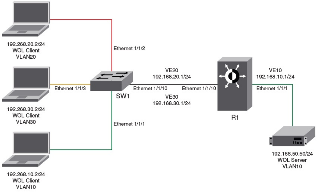
You must also congure a helper address on the VLAN of the WOL server to join the subnet of the desired clients using the ip helper-
address command. You must specify the broadcast address of each client network as this is the only way to send a packet to a PC that is
shut down. Because the PC is asleep, the PC will not respond to ARP requests as it does not own its IP when the PC is down.
Prerequisites
The following checks must be done before deploying WOL across several subnets to wake up the target client PC:
• Check the BIOS settings and ensure that Wake-On-LAN is enabled.
• Check the NIC Advanced Settings and ensure that Magic & Directed Packets are accepted.
• Connect the WOL server and the desktop or laptop client to the same VLAN.
• Invoke Wake Up PC from Software utility
FIGURE 1 Wake-on_LAN Network Diagram
Following is a sample conguration for Wake-On-LAN (WOL) support across dierent VLANs:
Router (inter-VLAN) conguration:
device(config)# vlan 10 name server_vlan by port
device(config-vlan-10)# tagged ethernet 1/1/10
device(config-vlan-10)# untagged ethernet 1/1/1
device(config-vlan-10)# router-interface ve 10
device(config-vlan-10)# exit
device(config)# vlan 20 name user_vlan by port
Wake-on-LAN support across VLANs
Brocade FastIron Management Conguration Guide, 08.0.60
86 Part Number: 53-1004918-03
device(config-vlan-20)# tagged ethernet 1/1/10
device(config-vlan-20)# router-interface ve 20
device(config-vlan-20)# exit
device(config)# vlan 30 name user_vlan by port
device(config-vlan-30)# tagged ethernet 1/1/10
device(config-vlan-30)# router-interface ve 30
device(config-vlan-30)# exit
device(config)# ip forward-protocol udp echo
device(config)# interface ethernet 1/1/1
device(config-if-e1000-1/1/1)# ip address 192.168.10.1 255.255.255.0
device(config-if-e1000-1/1/1)# ip helper-address 1 192.168.20.255
device(config-if-e1000-1/1/1)# ip helper-address 2 192.168.30.255
device(config-if-e1000-1/1/1)# interface ve 20
device(config-vif-20)# ip address 192.168.20.1 255.255.255.0
device(config-vif-20)# interface ve 30
device(config-vif-30)# ip address 192.168.30.1 255.255.255.0
Switch conguration:
device(config)# vlan 10 name server_vlan by port
device(config-vlan-10)# tagged ethernet 1/1/10
device(config-vlan-10)# untagged ethernet 1/1/1
device(config-vlan-10)# exit
device(config)# vlan 20 name user_vlan20 by port
device(config-vlan-20)# tagged ethe 1/1/10
device(config-vlan-20)# untagged ethe 1/1/2
device(config-vlan-20)# exit
device(config)# vlan 30 name user_vlan30 by port
device(config-vlan-30)# tagged ethernet 1/1/10
device(config-vlan-30)# untagged ethernet 1/1/3
Wake-on-LAN support across VLANs
Brocade FastIron Management Conguration Guide, 08.0.60
Part Number: 53-1004918-03 87
Brocade FastIron Management Conguration Guide, 08.0.60
88 Part Number: 53-1004918-03

Network Time Protocol Version 4 (NTPv4)
• Network Time Protocol Version 4 Overview..........................................................................................................................................89
•Conguring NTP................................................................................................................................................................................................96
Network Time Protocol Version 4 Overview
The NTPv4 feature synchronizes the local system clock in the device with the Coordinated Universal Time (UTC). The synchronization is
achieved by maintaining a loop-free timing topology computed as a shortest-path spanning tree rooted on the primary server. NTP does
not know about local time zones or daylight-saving time. A time server located anywhere in the world can provide synchronization to a
client located anywhere else in the world. It allows clients to use dierent time zone and daylight-saving properties. Primary servers are
synchronized by wire or radio to national standards such as GPS. Timing information is conveyed from primary servers to secondary
servers and clients in the network. NTP runs on UDP, which in turn runs on IP.
NTP has a hierarchical structure. NTP uses the concept of a stratum to describe how many NTP hops away a machine is from an
authoritative time source. A stratum 1 time server typically has an authoritative time source such as a radio or atomic clock, or a Global
Positioning System (GPS) time source directly attached. A stratum 2 time server receives its time through NTP from a stratum 1 time
server and so on. As the network introduces timing discrepancies, lower stratum devices are a factor less accurate. A hierarchical
structure allows the overhead of providing time to many clients to be shared among many time servers. Not all clients need to obtain
time directly from a stratum 1 reference, but can use stratum 2 or 3 references.
NTP operates on a client-server basis. The current implementation runs NTP as a secondary server and/or a NTP Client. As a secondary
server, the device operates with one or more upstream servers and one or more downstream servers or clients. A client device
synchronizes to one or more upstream servers, but does not provide synchronization to dependant clients. Secondary servers at each
lower level are assigned stratum numbers one greater than the preceding level. As stratum number increases, the accuracy decreases.
Stratum one is assigned to Primary servers.
NTP uses the concept of associations to describe communication between two machines running NTP. NTP associations are statistically
congured. On startup or on the arrival of NTP packets, associations are created. Multiple associations are created by the protocol to
communicate with multiple servers. NTP maintains a set of statistics for each of the server or the client it is associated with. The statistics
represent measurements of the system clock relative to each server clock separately. NTP then determines the most accurate and
reliable candidates to synchronize the system clock. The nal clock oset applied for clock adjustment is a statistical average derived
from the set of accurate sources.
When multiple sources of time (hardware clock, manual conguration) are available, NTP is always considered to be more authoritative.
NTP time overrides the time that is set by any other method.
NTPv4 obsoletes NTPv3 (RFC1305) and SNTP (RFC4330). SNTP is a subset of NTPv4. RFC 5905 describes NTPv4.
To keep the time in your network current, it is recommended that each device have its time synchronized with at least four external NTP
servers. External NTP servers should be synchronized among themselves to maintain time synchronization.
NOTE
Network Time Protocol (NTP) commands must be congured on each individual device.
Brocade FastIron Management Conguration Guide, 08.0.60
Part Number: 53-1004918-03 89
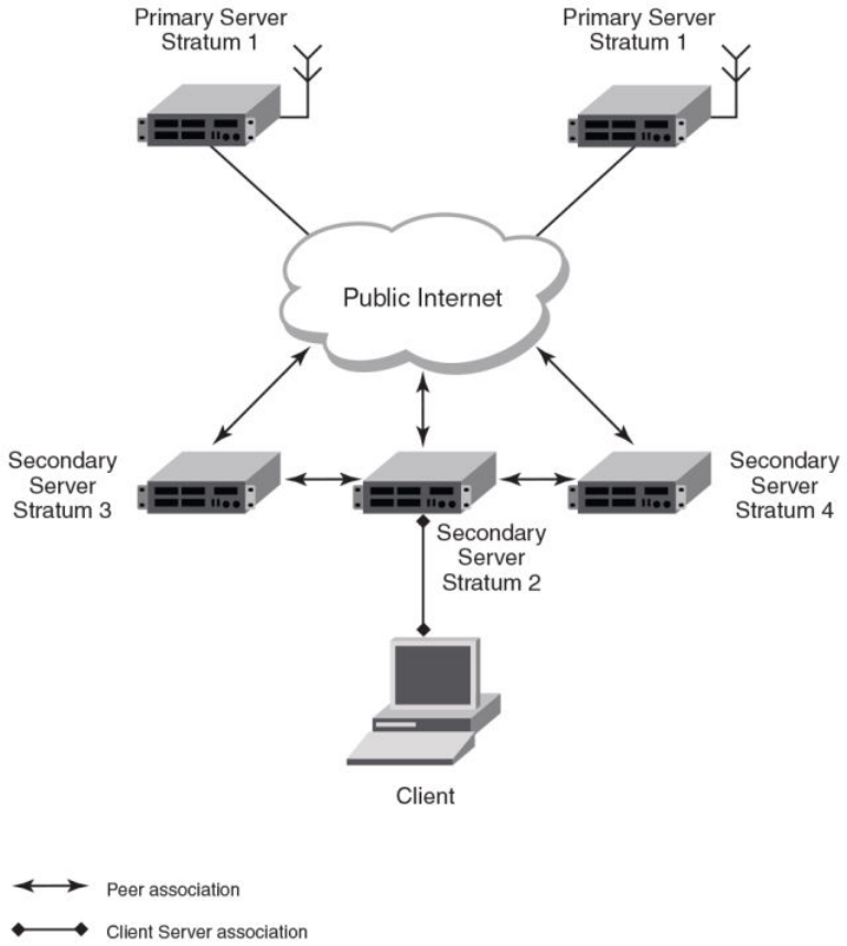
FIGURE 2 NTP Hierarchy
• NTP implementation conforms to RFC 5905.
• NTP can be enabled in server and client mode simultaneously.
• The NTP uses UDP port 123 for communicating with NTP servers/peers.
• NTP server and client can communicate using IPv4 or IPv6 address
• NTP implementation supports below association modes.
– Client
– Server
– Symmetric active/passive
– Broadcast server
– Broadcast client
• NTP supports maximum of 8 servers and 8 peers. The 8 peers includes statically congured and dynamically learned.
Network Time Protocol Version 4 Overview
Brocade FastIron Management Conguration Guide, 08.0.60
90 Part Number: 53-1004918-03
• NTP can operate in authenticate or non-authenticate mode. Only symmetric key authentication is supported.
• By default, NTP operates in default VLAN and it can be changed.
Limitations
• FastIron devices cannot operate as primary time server (or stratum 1). It only serves as secondary time server (stratum 2 to 15).
• NTP server and client cannot communicate using hostnames.
• NTP is not supported on VRF enabled interface.
• Autokey public key authentication is not supported.
• The NTP version 4 Extension elds are not supported. The packets containing the extension elds are discarded.
• The NTP packets having control (6) or private (7) packet mode is not supported. NTP packets with control and private modes
will be discarded.
• On reboot or switchover, all the NTP state information will be lost and time synchronization will start fresh.
• NTP multicast server/client and manycast functionalities are not supported.
• NTP versions 1 and 2 are not supported.
• NTP MIB is not supported.
Network Time Protocol leap second
A leap second is a second added to Coordinated Universal Time (UTC) in order to keep it synchronized with astronomical time (UT1).
There are two main reasons that cause leap seconds to occur. The rst is that the atomic second dened by comparing cesium clocks to
the Ephemeris Time (ET) scale was incorrect, as the duration of the ephemeris second was slightly shorter than the mean solar second
and this characteristic was passed along to the atomic second. The second reason for leap seconds is that the speed of the Earth's
rotation is not constant. It sometimes speeds up, and sometimes slows down, but when averaged over long intervals the trend indicates
that it is gradually slowing. This gradual decrease in the rotational rate is causing the duration of the mean solar second to gradually
increase with respect to the atomic second.
Leap seconds are added in order to keep the dierence between UTC and astronomical time (UT1) to less than 0.9 seconds. The
International Earth Rotation and Reference Systems Service (IERS), measures Earth's rotation and publishes the dierence between UT1
and UTC. Usually leap seconds are added when UTC is ahead of UT1 by 0.4 seconds or more.
How Brocade supports leap second handling for NTP
The obvious question raised is what happens during the NTP leap second itself.
Specically, a positive leap second is inserted between second 23:59:59 of a chosen UTC calendar date (the last day of a month, usually
June 30 or December 31) and second 00:00:00 of the following date. This extra second is displayed on UTC clocks as 23:59:60. On
clocks that display local time tied to UTC, the leap second may be inserted at the end of some other hour (or half-hour or quarter-hour),
depending on the local time zone. When ever there is a leap second the NTP server noties by setting the NTP leap second bits.
On Brocade devices when ever there is a negative leap second, the clock is set once second backward of the following date as described
here. On positive leap second the clock suppress second 23:59:59 of the last day of a chosen month, so that second 23:59:58 of that
date would be followed immediately by second 00:00:00 of the following date.
Network Time Protocol Version 4 Overview
Brocade FastIron Management Conguration Guide, 08.0.60
Part Number: 53-1004918-03 91
NTP and SNTP
SNTP can be implemented for time synchronization on Brocade devices but NTP can also be used for time synchronization in all
devices with both router and switch images.
NTP and SNTP implementations cannot operate at the same time; one of them must be disabled.
NTP server
A NTP server will provide the correct network time on your device using the Network time protocol (NTP). Network Time Protocol can be
used to synchronize the time on devices across a network. A NTP time server is used to obtain the correct time from a time source and
adjust the local time in each connecting device.
The NTP server functionality is enabled when you use the ntp command, provided SNTP conguration is already removed.
When the NTP server is enabled, it will start listening on the NTP port for client requests and responds with the reference time. Its
stratum number will be the upstream time server's stratum + 1. The stratum 1 NTP server is the time server which is directly attached to
the authoritative time source.
The device cannot be congured as primary time server with stratum 1. It can be congured as secondary time server with stratum 2 to
15 to serve the time using the local clock.
The NTP server is stateless and will not maintain any NTP client information.
System as an Authoritative NTP Server
The NTP server can operate in master mode to serve time using the local clock, when it has lost synchronization. Serving local clock can
be enabled using the master command. In this mode, the NTP server stratum number is set to the congured stratum number. When the
master command is congured and the device was never synchronized with an upstream time server and the clock setting is invalid, the
server will respond to client's request with the stratum number set to 16. While the device is operating in the master mode and serving
the local clock as the reference time, if synchronization with the upstream server takes place it will calibrate the local clock using the NTP
time. The stratum number will switch to that of the synchronized source +1. And when synchronization is lost, the device switches back to
local clock time with stratum number as specied manually (or the default).
NOTE
Local time and time zone has to be congured before conguring the master command.
• The following scenarios are observed when the master command is not congured and the NTP upstream servers are
congured:
• If the synchronization with the NTP server/peer is active, the system clock is synchronized and the reference time is the NTP
time.
• If the NTP server/peer is congured but not reachable and if the local clock is valid, the server will respond to client's request
with the stratum number set to 16.
• If there is no NTP server/peer congured and if the local clock is valid, the server will respond to client's request with the stratum
number set to 16.
• If there is no NTP server/peer congured and if the local clock is invalid, the system clock is not synchronized.
The following scenarios are observed when the master command is congured and the NTP upstream servers are also congured:
• If the synchronization with the time server/peer is active, system clock is synchronized and the reference time is the NTP time.If
the NTP server/peer is congured but not reachable, the system clock is synchronized. If the local time is valid then the
reference time is the local clock time.
Network Time Protocol Version 4 Overview
Brocade FastIron Management Conguration Guide, 08.0.60
92 Part Number: 53-1004918-03
• If the NTP server/peer is not congured, the system clock is synchronized. If the local clock is valid, then the reference time is
the local clock time.
• If the NTP server/peer is not congured and the local clock is invalid, system clock is not synchronized.
NOTE
Use the master command with caution. It is very easy to override valid time sources using this command, especially if a low
stratum number is congured. Conguring multiple machines in the same network with the master command can cause
instability in timekeeping if the machines do not agree on the time.
NTP Client
An NTP client gets time responses from an NTP server or servers, and uses the information to calibrate its clock. This consists of the
client determining how far its clock is o and adjusting its time to match that of the server. The maximum error is determined based on
the round-trip time for the packet to be received.
The NTP client can be enabled when we enter the ntp command and congure one or more NTP servers/peers.
The NTP client maintains the server and peer state information as association. The server and peer association is mobilized at the startup
or whenever user congures. The statically congured server/peer associations are not demobilized unless user removes the
conguration. The symmetric passive association is mobilized upon arrival of NTP packet from peer which is not statically congured.
The associations will be demobilized on error or time-out.
NTP peer
NTP peer mode is intended for congurations where a group of devices operate as mutual backups for each other. If one of the devices
loses a reference source, the time values can ow from the surviving peers to all the others. Each device operates with one or more
primary reference sources, such as a radio clock, or a subset of reliable NTP secondary servers. When one of the devices lose all
reference sources or simply cease operation, the other peers automatically recongures so that time values can ow from the surviving
peers to others.
When the NTP server or peer is congured with burst mode, client will send burst of up to 8 NTP packets in each polling interval. The
burst number of packets in each interval increases as the polling interval increases from minimum polling interval towards maximum
interval.
The NTP peer can operate in:
• Symmetric Active-When the peer is congured using the peer command.
• Symmetric Passive-Dynamically learned upon arrival of a NTP packet from the peer which is not congured. The symmetric
passive association is removed on timeout or error.
The following scenarios are observed when the upstream server is not reachable after retries:
• If the NTP server/peer is congured and the master command is not congured, then the system clock is synchronized. When
the system clock is synchronized, the server will respond to client's request with the stratum number set to +1. And when the
system clock is unsynchronized, the server will respond to client's request with the stratum number set to 16.
• If the NTP server/peer is congured and the master command is congured, then the system clock is synchronized. When the
system clock is synchronized, the reference time is the local clock time. If the local clock is valid then the server will respond to
client's request with the specied stratum number if it is congured otherwise with the default stratum number.
The following scenarios are observed when you remove the last NTP server/peer under the conditions - the NTP server/peer is
congured, master command is not congured, system clock is synchronized and the reference time is the NTP time:
• If the local clock is not valid, the system clock is not synchronized.
Network Time Protocol Version 4 Overview
Brocade FastIron Management Conguration Guide, 08.0.60
Part Number: 53-1004918-03 93
• If the local clock is valid, the system clock is synchronized and the reference time is the local clock. The server will respond to
the client's request with the specied stratum number if it is congured otherwise with the default stratum number.
NOTE
To create a symmetric active association when a passive association is already formed, disable NTP, congure peer association
and then enable NTP again.
NTP broadcast server
An NTP server can also operate in a broadcast mode. Broadcast servers send periodic time updates to a broadcast address, while
multicast servers send periodic updates to a multicast address. Using broadcast packets can greatly reduce the NTP trac on a network,
especially for a network with many NTP clients.
The interfaces should be enabled with NTP broadcasting. The NTP broadcast server broadcasts the
NTP packets periodically (every 64 sec) to subnet broadcast IP address of the congured interface.
• NTP broadcast packets are sent to the congured subnet when the NTP broadcast server is congured on the interface which is
up and the IP address is congured for the broadcast subnet under the following conditions:
– The local clock is valid and the system clock is synchronized
– The local clock is valid and the system clock is not synchronized
– Authentication key is congured, the system clock is synchronized and the local clock is valid
• NTP broadcast packets are not sent in the following cases:
– NTP broadcast server is congured on the interface which is down even if the system clock is synchronized and the local
clock is valid.
– NTP broadcast server is congured on the interface which is up and no IP address is congured for the broadcast subnet
even if the system clock is synchronized and the local clock is valid.
– NTP broadcast server is congured on the interface which is not present and no IP address is congured for the broadcast
subnet even if the system clock is synchronized and the local clock is valid.
– NTP broadcast server without authentication key is congured on the interface which is up and the IP address is congured
for the broadcast subnet even when NTP authentication is enforced and the system clock is synchronized and the local
clock is valid.
NTP broadcast client
An NTP broadcast client listens for NTP packets on a broadcast address. When the rst packet is received, the client attempts to quantify
the delay to the server, to better quantify the correct time from later broadcasts. This is accomplished by a series of brief interchanges
where the client and server act as a regular (non-broadcast) NTP client and server. Once interchanges occur, the client has an idea of the
network delay and thereafter can estimate the time based only on broadcast packets.
NTP associations
Networking devices running NTP can be congured to operate in variety of association modes when synchronizing time with reference
time sources. A networking device can obtain time information on a network in two ways-by polling host servers and by listening to NTP
broadcasts. That is, there are two types of associations-poll-based and broadcast-based.
Network Time Protocol Version 4 Overview
Brocade FastIron Management Conguration Guide, 08.0.60
94 Part Number: 53-1004918-03
NTP poll-based associations
The following modes are the NTP polling based associations:
1. Server mode
2. Client mode
3. Symmetric Active/Passive
The server mode requires no prior client conguration. The server responds to client mode NTP packets. Use the master
command to set the device to operate in server mode when it has lost the synchronization.
When the system is operating in the client mode, it polls all congured NTP servers and peers. The device selects a host from
all the polled NTP servers to synchronize with. Because the relationship that is established in this case is a client-host
relationship, the host will not capture or use any time information sent by the local client device. This mode is most suited for
le-server and workstation clients that are not required to provide any form of time synchronization to other local clients. Use the
server and peer to individually specify the time server that you want the networking device to consider synchronizing with and to
set your networking device to operate in the client mode.
Symmetric active/passive mode is intended for congurations where group devices operate as mutual backups for each other.
Each device operates with one or more primary reference sources, such as a radio clock, or a subset of reliable NTP secondary
servers. If one of the devices lose all reference sources or simply cease operation, the other peers automatically recongures.
This helps the ow of time value from the surviving peers to all the others.
When a networking device is operating in the symmetric active mode, it polls its assigned time-serving hosts for the current
time and it responds to polls by its hosts. Because symmetric active mode is a peer-to-peer relationship, the host will also retain
time-related information of the local networking device that it is communicating with. When many mutually redundant servers
are interconnected via diverse network paths, the symmetric active mode should be used. Most stratum 1 and stratum 2
servers on the Internet adopt the symmetric active form of network setup. The FastIron device operates in symmetric active
mode, when the peer information is congured using the peer command and specifying the address of the peer. The peer is
also congured in symmetric active mode in this way by specifying the FastIron device information. If the peer is not specically
congured, a symmetric passive association is activated upon arrival of a symmetric active message.
The specic mode that you should set for each of your networking devices depends primarily on the role that you want them to
assume as a timekeeping device (server or client) and the device's proximity to a stratum 1 timekeeping server. A networking
device engages in polling when it is operating as a client or a host in the client mode or when it is acting as a peer in the
symmetric active mode. An exceedingly large number of ongoing and simultaneous polls on a system can seriously impact the
performance of a system or slow the performance of a given network. To avoid having an excessive number of ongoing polls on
a network, you should limit the number of direct, peer-to-peer or client-to-server associations. Instead, you should consider
using NTP broadcasts to propagate time information within a localized network.
NTP broadcast-based associations
The broadcast-based NTP associations should be used in congurations involving potentially large client population. Broadcast-based
NTP associations are also recommended for use on networks that have limited bandwidth, system memory, or CPU resources.
The devices operating in the broadcast server mode broadcasts the NTP packets periodically which can be picked up by the devices
operating in broadcast client mode. The broadcast server is congured using the broadcast command.
A networking device operating in the broadcast client mode does not engage in any polling. Instead, the device receives the NTP
broadcast server packets from the NTP broadcast servers in the same subnet. The NTP broadcast client forms a temporary client
association with the NTP broadcast server. A broadcast client is congured using the broadcast client command. For broadcast client
mode to work, the broadcast server and the clients must be located on the same subnet.
Network Time Protocol Version 4 Overview
Brocade FastIron Management Conguration Guide, 08.0.60
Part Number: 53-1004918-03 95
Synchronizing time
After the system peer is chosen, the system time is synchronized based on the time dierence with system peer:
• If the time dierence with the system peer is 128 msec and < 1000 sec, the system clock is stepped to the system peer
reference time and the NTP state information is cleared.
Authentication
The time kept on a machine is a critical resource, so it is highly recommended to use the encrypted authentication mechanism.
The NTP can be congured to provide cryptographic authentication of messages with the clients/peers, and with its upstream time
server. Symmetric key scheme is supported for authentication. The scheme uses MD5 keyed hash algorithm.
The authentication can be enabled using the authenticate command. The set of symmetric key and key string is specied using the
authentication-key command.
If authentication is enabled, NTP packets not having a valid MAC address are dropped.
If the NTP server/peer is congured without authentication keys, the NTP request is not sent to the congured server/peer.
NOTE
The same set or subset of key id and key string should be installed on all NTP devices.
VLAN and NTP
When VLAN is congured,
• NTP time servers should be reachable through the interfaces which belong to the congured VLAN. Otherwise, NTP packets
are not transmitted. This is applicable to both the unicast and the broadcast server/client.
• NTP broadcast packets are sent only on the interface which belongs to the congured VLAN.
• The received unicast or broadcast NTP packet are dropped if the interface on which packet has been received does not belong
to the congured VLAN
Conguring NTP
NTP services are disabled on all interfaces by default.
Prerequisites:
• Before you begin to congure NTP, you must use the clock set command to set the time on your device to within 1000
seconds of the coordinated Universal Time (UTC).
• Disable SNTP by removing all the SNTP congurations.
Enabling NTP
NTP and SNTP implementations cannot operate simultaneously. By default, SNTP is enabled. To disable SNTP and enable NTP, use
the ntp command in conguration mode. This command enables the NTP client and server mode if SNTP is disabled.
Brocade(config)# ntp
Brocade(config-ntp)#
Syntax: [no] ntp
Conguring NTP
Brocade FastIron Management Conguration Guide, 08.0.60
96 Part Number: 53-1004918-03
Use the no form of the command to disable NTP and remove the NTP conguration.
NOTE
The no ntp command removes all the conguration which are congured statistically and learned associations from NTP
neighbors.
NOTE
You cannot congure the ntp command if SNTP is enabled. If SNTP is enabled, conguring the ntp command will display the
following message:"SNTP is enabled. Disable SNTP before using NTP for time synchronization"
Disabling NTP
To disable the NTP server and client mode, use the disable command in NTP conguration mode. Disabling the NTP server or client
mode will not remove the congurations.
Brocade(config-ntp)# disable
Syntax: [no] disable [ serve ]
If the serve keyword is specied, then NTP will not serve the time to downstream devices. The serve keyword disables the NTP server
mode functionalities. If the serve keyword is not specied, then both NTP client mode and NTP server mode functionalities are disabled.
Use the no form of the command to enable NTP client and server mode. To enable the client mode, use the no disable command. To
enable the client and server mode, use the no disable serve command. The no disable command enables both client and server, if the
client is already enabled and server is disabled at that time "no disable server " enables the server.
NOTE
The disable command disables the NTP server and client mode; it does not remove the NTP conguration.
Enabling NTP authentication
To enable Network Time Protocol (NTP) strict authentication, use the authenticate command. To disable the function, use the no form of
this command.
By default, authentication is disabled.
Brocade(config-ntp)# [no] authenticate
Syntax: [no] authenticate
Dening an authentication key
To dene an authentication key for Network Time Protocol (NTP), use the authentication-key command. To remove the authentication
key for NTP, use the no form of this command.
By default, authentication keys are not congured.
Brocade(config-ntp)# authentication-key key-id 1 md5 moof
Syntax: [no] authentication-key key-id [ md5 | sha1 ] key-string
The valid key-id parameter is 1 to 65535.
MD5 is the message authentication support that is provided using the Message Digest 5 Algorithm.
The sha1 keyword species that the SHA1 keyed hash algorithm is used for NTP authentication.
Conguring NTP
Brocade FastIron Management Conguration Guide, 08.0.60
Part Number: 53-1004918-03 97
NOTE
If JITC is enabled, only the sha1 option is available.
The key-string option is the value of the MD5 or SHA1 key. The maximum length of the key string may be dened up to 16 characters.
Up to 32 keys may be dened.
Specifying a source interface
When the system sends an NTP packet, the source IP address is normally set to the address of the interface through which the NTP
packet is sent. Use the source-interface command to congure a specic interface from which the IP source address will be taken. To
remove the specied source address, use the no form of this command.
This interface will be used for the source address for all packets sent to all destinations. If a source address is to be used for a specic
association, use the source keyword in the peer or server command.
NOTE
If the source-interface is not congured, then the lowest IP address in the outgoing interface will be used in the NTP packets.
Source IP address of a tunnel interface is not supported.
Brocade(config-ntp)# source-interface ethernet 1/3/1
Syntax: [no] source-interface ethernet { port | loopback num | ve num }
Specify the port parameter in the format stack-unit/slotnum/portnum.
The loopback num parameter species the loopback interface number.
The ve num parameter species the virtual port number.
Enable or disable the VLAN containment for NTP
To enable or disable the VLAN containment for NTP, use the access-control vlan command. To remove the specied NTP VLAN
conguration, use the no form of this command.
NOTE
The management interface is not part of any VLAN. When conguring the VLAN containment for NTP, it will not use the
management interface to send or receive the NTP packets.
Brocade(config-ntp)# access-control vlan 100
Syntax: [no] access-control vlan vlan-id
The vlan-id parameter species the VLAN ID number.
Conguring the NTP client
To congure the device in client mode and specify the NTP servers to synchronize the system clock, use the server command. A
maximum 8 NTP servers can be congured. To remove the NTP server conguration, use the no form of this command.
By default, no servers are congured.
Brocade(config-ntp)#server 1.2.3.4 key 1234
Syntax: [no] server { ipv4-address | ipv6-address } [ version num ] [ key key-id ] [ minpoll interval ] [ maxpoll interval ] [ burst ]
The ipv4-address or ipv6-address parameter is the IP address of the server providing the clock synchronization.
Conguring NTP
Brocade FastIron Management Conguration Guide, 08.0.60
98 Part Number: 53-1004918-03
The version num option denes the Network Time Protocol (NTP) version number. Valid values are 3 or 4. If the num option is not
specied, the default is 4.
The key key-id option denes the authentication key. By default, no authentication key is congured.
The minpoll interval option is the shortest polling interval. The range is from 4 through 17. Default is 6. The interval argument is power of
2 (4=16s, 5=32s, 6=64s, 7=128s, 8=256s, 9=512s, and so on).
The maxpoll interval option is the longest polling interval. The range is 4 through 17. Default is 10. The interval argument is calculated by
the power of 2 (4=16s, 5=32s, 6=64s, 7=128s, 8=256s, 9=512s, and so on).
The burst option sends a burst of packets to the server at each polling interval.
Conguring the master
To congure the FastIron device as a Network Time Protocol (NTP) master clock to which peers synchronize themselves when an
external NTP source is not available, use the master command. The master clock is disabled by default. To disable the master clock
function, use the no form of this command.
NOTE
This command is not eective, if the NTP is enabled in client-only mode.
Brocade(config-ntp)# master stratum 5
Syntax: [no] master [ stratum number ]
The number variable is a number from 2 to 15. It indicates the NTP stratum number that the system will claim.
Conguring the NTP peer
To congure the software clock to synchronize a peer or to be synchronized by a peer, use the peer command. A maximum of 8 NTP
peers can be congured. To disable this capability, use the no form of this command.
This peer command is not eective if the NTP is enabled in client-only mode.
NOTE
If the peer is a member of symmetric passive association, then conguring the peer command will fail.
Brocade(config-ntp)# peer 1.2.3.4 key 1234
Syntax: [no] peer { ipv4-address | ipv6-address } [ version num [ key key-id ] [ minpoll interval ] [ maxpoll interval ] [ burst ]
The ipv4-address or ipv6-address parameter is the IP address of the peer providing the clock synchronization.
The version num option denes the Network Time Protocol (NTP) version number. Valid values are 3 and 4. If this option is not specied,
then the default is 4.
The key key-id option denes the authentication key. By default, no authentication key is congured.
The minpoll interval option is the shortest polling interval. The range is from 4 through 17. Default is 6. The interval argument is power of
2 (4=16s, 5=32s, 6=64s, 7=128s, 8=256s, 9=512s, and so on).
The maxpoll interval option is the longest polling interval. The range is 4 through 17. Default is 10. The interval argument is calculated by
the power of 2 (4=16s, 5=32s, 6=64s, 7=128s, 8=256s, 9=512s, and so on).
The burst option sends a burst of packets to the peer at each polling interval.
Conguring NTP
Brocade FastIron Management Conguration Guide, 08.0.60
Part Number: 53-1004918-03 99
NOTE
When the NTP server/peer is congured, the master command is not congured; on conguring the clock set command the
system clock is not synchronized. When the master command is congured, on conguring the clock set command the
system clock is synchronized and the reference time will be the local clock.
To have active peers at both the ends, you need to disable NTP, congure the peers and enable the NTP using the no disable command.
Conguring NTP on an interface
To congure the NTP interface context, use the ntp-interface command. The broadcast server or client is congured on selected
interfaces. To remove the NTP broadcast congurations on the specied interface, use the no form of this command.
NOTE
The ntp-interface command is a mode change command, and will not be included in to the show run output unless there is
conguration below that interface.
Brocade(config-ntp)# ntp-interface ethernet 1/2/13
Brocade(config-ntp-if-e1000-1/2/13)# exit
Brocade(config-ntp)# ntp-interface management 1
Brocade(config-ntp-mgmt-1)# exit
Brocade(config-ntp)# ntp-interface ve 100
Brocade(config-ntp-ve-100)#
Syntax: [no] ntp-interface { management 1 | ethernet port | ve id }
The management 1 parameter is the management port 1.
The ethernet port parameter species the ethernet port number. Specify the port parameter in the format stack-unit/slotnum/portnum.
The ve id parameter species the virtual port number.
Conguring the broadcast client
To congure a device to receive Network Time Protocol (NTP) broadcast messages on a specied interface, use the broadcast client
command. NTP broadcast client can be enabled on maximum of 16 ethernet interfaces. If the interface is operationally down or NTP is
disabled, then the NTP broadcast server packets are not received. To disable this capability, use the no form of this command.
Brocade(config-ntp mgmt-1)# broadcast client
Syntax: [no] broadcast client
Conguring the broadcast destination
To congure the options for broadcasting Network Time Protocol (NTP) trac, use the ntp broadcast destination command. The NTP
broadcast server can be enabled on maximum 16 ethernet interfaces and four subnet addresses per interface. If the interface is
operationally down or there is no ip address congured for the subnet address, then the NTP broadcast server packets are not sent. To
disable this capability, use the no form of this command.
By default, the broadcast mode is not enabled.
NOTE
This command is not eective, if the NTP server is disabled.
Brocade(config)#int m1
Brocade(config-if-mgmt-1)#ip address 10.20.99.173/24
Brocade(config-if-mgmt-1)#ntp
Conguring NTP
Brocade FastIron Management Conguration Guide, 08.0.60
100 Part Number: 53-1004918-03

Brocade(config-ntp)#ntp-interface m1
Brocade(config-ntp -mgmt-1)# broadcast destination 10.20.99.0 key 2
Syntax: [no] broadcast destination ip-address [ key key-id ] [ version num ]
The ip-address parameter is the IPv4 subnet address of the device to send NTP broadcast messages to.
The key key-id option denes the authentication key. By default, no authentication key is congured.
The version num option denes the Network Time Protocol (NTP) version number. If this option is not specied, then the default value is
4.
Displaying NTP status
Use the show ntp status command to display the NTP status.
Brocade#show ntp status
Clock is synchronized, stratum 4, reference clock is 10.20.99.174
precision is 2**-16
reference time is D281713A.80000000 (03:21:29.3653007907 GMT+00 Thu Dec 01 2011)
clock offset is -2.3307 msec, root delay is 24.6646 msec
root dispersion is 130.3376 msec, peer dispersion is 84.3335 msec
system poll interval is 64, last clock update was 26 sec ago
NTP server mode is enabled, NTP client mode is enabled
NTP master mode is disabled, NTP master stratum is 8
NTP is not in panic mode
The following table provides descriptions of the show ntp status command output.
TABLE 20 NTP status command output descriptions
Field Description
synchronized Indicates the system clock is synchronized to NTP server or peer.
stratum Indicates the stratum number that this system is operating. Range 2..15.
reference IPv4 address or rst 32 bits of the MD5 hash of the IPv6 address of the
peer to which clock is synchronized.
precision Precision of the clock of this system in Hz.
reference time Reference time stamp.
clock oset Oset of clock (in milliseconds) to synchronized peer.
root delay Total delay (in milliseconds) along path to root clock.
root dispersion Dispersion of root path.
peer dispersion Dispersion of root path.
system poll interval Poll interval of the local system.
last update Time the router last updated its NTP information.
server mode Status of the NTP server mode for this device.
client mode Status of the NTP client mode for this device.
master Status of the master mode.
master stratum Stratum number that will be used by this device when master is enabled
and no upstream time servers are accessible.
panic mode Status of the panic mode.
Conguring NTP
Brocade FastIron Management Conguration Guide, 08.0.60
Part Number: 53-1004918-03 101

Displaying NTP associations
Use the show ntp associations command to display detailed association information of the NTP server or peers.
Brocade# show ntp associations
address ref clock st when poll reach delay offset disp
*~172.19.69.1 172.24.114.33 3 25 64 3 2.89 0.234 39377
~2001:235::234
INIT 16 - 64 0 0.00 0.000 15937
* synced, # selected, + candidate, - outlayer, x falseticker, ~ configured
The following table provides descriptions of the show ntp associations command output.
TABLE 21 NTP associations command output descriptions
Field Description
* The peer has been declared the system peer and lends its variables to the
system variables.
# This peer is a survivor in the selection algorithm.
+ This peer is a candidate in the combine algorithm.
- This peer is discarded as outlier in the clustering algorithm.
x This peer is discarded as 'falseticker' in the selection algorithm.
~ The server or peer is statically congured.
address IPv4 or IPv6 address of the peer.
ref clock IPv4 address or rst 32 bits of the MD5 hash of the IPv6 address of the
peer to which clock is synchronized.
St Stratum setting for the peer.
when Time, in seconds, since last NTP packet was received from peer.
poll Polling interval (seconds).
reach Peer reachability (bit string, in octal).
delay Round-trip delay to peer, in milliseconds.
oset Relative time dierence between a peer clock and a local clock, in
milliseconds.
disp Dispersion.
Displaying NTP associations details
Use the show ntp associations detail command to display all the NTP servers and peers association information.
Brocade# show ntp association detail
2001:1:99:30::1 configured server, sys peer, stratum 3
ref ID 204.235.61.9, time d288dc3b.f2a17891 (10:23:55.4070668433 Pacific Tue Dec 06 2011)
our mode client, peer mode server, our poll intvl 10, peer poll intvl 10,
root delay 0.08551025 msec, root disp 0.09309387, reach 17, root dist 0.17668502
delay 0.69961487 msec, offset -13.49459670 msec, dispersion 17.31550718,
precision 2**-16, version 4
org time d288df70.a91de561 (10:37:36.2837308769 Pacific Tue Dec 06 2011)
rcv time d288df70.a0c8d19e (10:37:36.2697515422 Pacific Tue Dec 06 2011)
xmt time d288df70.a086e4de (10:37:36.2693194974 Pacific Tue Dec 06 2011)
filter delay 1.7736 0.9933 0.8873 0.6699 0.7709 0.7712 0.7734 6.7741
filter offset -17.9936 33.0014 -13.6604 -13.4494 -14.4481 -16.4453 -18.4423 -22.0025
filter disp 15.6660 0.0030 17.7730 17.7700 17.6670 17.6640 17.6610 16.6635
filter epoch 55824 56866 55686 55688 55690 55692 55694 55759
Conguring NTP
Brocade FastIron Management Conguration Guide, 08.0.60
102 Part Number: 53-1004918-03

Use the show ntp associations detail command with the appropriate parameters to display the NTP servers and peers association
information for a specic IP address.
Brocade# show ntp association detail 1.99.40.1
1.99.40.1 configured server, candidate, stratum 3
ref ID 216.45.57.38, time d288de7d.690ca5c7 (10:33:33.1762436551 Pacific Tue Dec 06 2011)
our mode client, peer mode server, our poll intvl 10, peer poll intvl 10,
root delay 0.02618408 msec, root disp 0.10108947, reach 3, root dist 0.23610585
delay 0.92163588 msec, offset 60.77749188 msec, dispersion 70.33842156,
precision 2**-16, version 4
org time d288defa.b260a71f (10:35:38.2992678687 Pacific Tue Dec 06 2011)
rcv time d288defa.a2efbd41 (10:35:38.2733620545 Pacific Tue Dec 06 2011)
xmt time d288defa.a2ae54f8 (10:35:38.2729334008 Pacific Tue Dec 06 2011)
filter delay 0.000 6.7770 6.7773 6.7711 6.7720 6.7736 6.7700 0.9921
filter offset 0.000 19.0047 19.1145 19.2245 19.3313 17.4410 15.4463 60.7777
filter disp 16000.000 16.0005 15.9975 15.9945 15.9915 15.8885 15.8855 0.0030
filter epoch 55683 55683 55685 55687 55689 55691 55693 56748
Syntax: show ntp association detail { ipv4-address | ipv6-address }
The following table provides descriptions of the show ntp associations detail command output.
TABLE 22 NTP associations detail command output descriptions
Field Description
server Indicates server is statically congured.
symmetric active peer Indicates peer is statically congured.
symmetric passive peer Indicates peer is dynamically congured.
sys_peer This peer is the system peer
candidate This peer is chosen as candidate in the combine algorithm.
reject This peer is rejected by the selection algorithm
falsetick This peer is dropped as falseticker by the selection algorithm
outlyer This peer is dropped as outlyer by the clustering algorithm
Stratum Stratum number
ref ID IPv4 address or hash of IPv6 address of the upstream time server to
which the peer is synchronized.
Time Last time stamp that the peer received from its master.
our mode This system's mode relative to peer (active/passive/client/server/bdcast/
bdcast client).
peer mode Mode of peer relative to this system.
our poll intvl This system's poll interval to this peer.
peer poll intvl Poll interval of peer to this system
root delay The delay along path to root (the nal stratum 1 time source).
root disp Dispersion of path to root.
reach peer The peer reachability (bit string in octal).
Delay Round-trip delay to peer.
oset Oset of a peer clock relative to this clock.
Dispersion Dispersion of a peer clock.
precision Precision of a peer clock.
version Peer NTP version number.
org time Originate time stamp of the last packet.
rcv time Receive time stamp of the last packet.
xmt time Transmit time stamp of the last packet.
Conguring NTP
Brocade FastIron Management Conguration Guide, 08.0.60
Part Number: 53-1004918-03 103

TABLE 22 NTP associations detail command output descriptions (continued)
Field Description
lter delay Round-trip delay in milliseconds of last 8 samples.
lter oset Clock oset in milliseconds of last 8 samples.
lter error Approximate error of last 8 samples.
Conguration Examples
The following sections list conguration examples to congure the Brocade device.
NTP server and client mode conguration
Sample CLI commands to congure the Brocade device in NTP server and client modes.
Brocade(config-ntp)# server 10.1.2.3 minpoll 5 maxpoll 10
Brocade(config-ntp)# server 11::1/64
Brocade(config-ntp)# peer 10.100.12.18
Brocade(config-ntp)# peer 10.100.12.20
Brocade(config-ntp)# peer 10.100.12.67
Brocade(config-ntp)# peer 10.100.12.83
NTP client mode conguration
Sample CLI commands to congure the Brocade device in NTP client mode.
Brocade(config-ntp)# server 10.1.2.3 minpoll 5 maxpoll 10
Brocade(config-ntp)# server 11::1/24
Brocade(config-ntp)# peer 10.100.12.83
Brocade(config-ntp)# disable serve
NTP strict authentication conguration
Sample CLI commands to congure the Brocade device in strict authentication mode.
Brocade(config-ntp)# authenticate
Brocade(config-ntp)# authentication-key key-id 1 md5 key123
Brocade(config-ntp)# server 10.1.2.4 key 1
NTP loose authentication conguration
Sample CLI commands to congure the Brocade device in loose authentication mode. This allows some of the servers or clients to use
the authentication keys.
Brocade(config-ntp)# authentication-key key-id 1 md5 key123
Brocade(config-ntp)# server 10.1.2.4 key 1
Brocade(config-ntp)# server 10.1.2.7
NTP interface context for the broadcast server or client mode
Sample CLI commands to enter the NTP interface context.
Brocade(config)#int management 1
Brocade(config-if-mgmt-1)#ip address 10.20.99.173/24
Brocade(config-if-mgmt-1)#ntp
Conguring NTP
Brocade FastIron Management Conguration Guide, 08.0.60
104 Part Number: 53-1004918-03
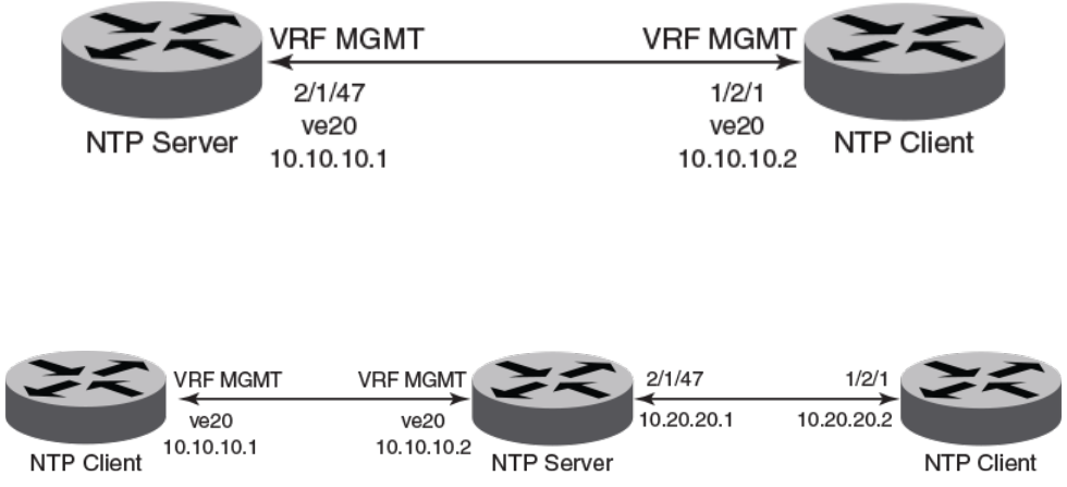
Brocade(config-ntp)# ntp-interface management 1
Brocade(config-ntp-mgmt-1)# broadcast destination 10.23.45.128
Brocade(config-ntp)# ntp-interface ethernet 1/1/3
Brocade(config-ntp-if-e1000-1/1/3)# broadcast destination 10.1.1.0 key 1
Brocade(config-ntp)# ntp-interface ve 100
Brocade(config-ntp-ve-100)# broadcast destination 10.2.2.0 key 23
NTP broadcast client conguration
Sample CLI commands to congure the NTP broadcast client.
Brocade(config-ntp)# ntp-interface management 1
Brocade(config-ntp-mgmt-1)# broadcast client
Brocade(config-ntp)# ntp-interface ethernet 1/1/5
Brocade(config-ntp-if-e1000-1/1/5)# broadcast client
Brocade(config-ntp)# ntp-interface ve 100
Brocade(config-ntp-ve-100)# broadcast client
NTP over management VRF
Network Time Protocol (NTP) trac can be segregated from network trac using the management VRF.
VRF (Virtual Routing and Forwarding) is a technology that divides network trac into dierent logical VRF domains. Using VRF, multiple
routing tables and Forwarding Tables (FTs) can exist in one routing device with one routing table for each VRF instance. A VRF-capable
router can function as a group of multiple virtual routers on the same physical router. VRF, in conjunction with virtual private network
(VPN) solutions, guarantees privacy of information and isolation of trac within a logical VRF domain.
When NTP is congured over Management VRF, the NTP trac is routed through Management VRF. NTP over Management VRF is
used to provide secure management access to the device by sending outbound NTP trac through the VRF specied as a global
management VRF and this isolates NTP trac from the network data trac.
The following diagrams illustrate some potential use case scenarios for NTP over Management VRF:
FIGURE 3 Use case 1: Management VRF forwarding with one client and one server on ve
In this scenario, NTP over Management VRF is implemented on both an NTP server and an NTP client device using virtual Ethernet
(VE) interfaces.
FIGURE 4 Use case 2: NTP server over Management VRF with one client using Management VRF and another client using Ethernet
In this scenario, the NTP server has one client using Management VRF and one client using an Ethernet port.
Conguring NTP
Brocade FastIron Management Conguration Guide, 08.0.60
Part Number: 53-1004918-03 105
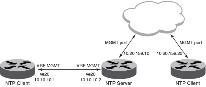
FIGURE 5 Use case 3: NTP server over Management VRF with one client on Management VRF and one client on Management port
In this scenario, the NTP server has one client using Management VRF and one client on a management port.
NTP over Management VRF limitations
Some limitations exist when running Network Time Protocol (NTP) over a management VRF.
Be aware of the following limitations before implementing NTP over a management VRF.
• The communication channel between the NTP client and server is through the InBand data port only. An Out-Of-Band (OOB)
management port is not supported.
• One external NTP server must exist to synchronize an NTP client with an NTP server.
• If you congure NTP in a VRF, ensure that the NTP server and clients can reach each other through the congured VRFs.
• A source interface must be congured to support the management VRF.
• Management VRF for NTP broadcast clients are supported only on one interface, using the source-interface command,
because the outgoing port is determined by the routing table.
• Management VRF for peers is supported only on “symmetric active” not on "symmetric passive" NTP association modes
because the Management VRF is related to the NTP source-interface command.
Conguring NTP over management VRF on an NTP server
To implement NTP over Management VRF, a Network Time Protocol (NTP) server device must be congured to communicate with NTP
client devices.
A Virtual Routing and Forwarding (VRF) instance named MGMT must be congured. The example after the task steps displays this
conguration.
NTP over management VRF allows NTP trac to be isolated from network trac. In this task, the following diagram represents the use
case. An NTP server is congured to run NTP over Management VRF with just one client and running over Virtual Ethernet (VE)
interfaces.
Conguring NTP
Brocade FastIron Management Conguration Guide, 08.0.60
106 Part Number: 53-1004918-03

1. Enter global conguration mode.
device# configure terminal
2. Congure a port-based VLAN and enter VLAN conguration mode.
device(config)# vlan 10 by port
3. Add an untagged port to the VLAN.
device(config-vlan-10)# untagged ethernet 2/1/47
4. Attach a router interface to VE interface 20.
device(config-vlan-10)# router-interface ve 20
5. Exit to global conguration mode.
device(config-vlan-10)# exit
6. Congures the VRF named mgmt as a global management VRF.
device(config)# management-vrf MGMT
7. Enters virtual interface mode for interface ve 20.
device(config)# interface ve 20
8. Congure the VRF named mgmt as a forwarding VRF.
device(config-if-ve-20)# vrf forwarding MGMT
9. Congure an IP address on the interface.
device(config-if-ve-20)# ip address 10.10.10.1 255.255.255.0
10. Exit to global conguration mode.
device(config-if-ve-20)# exit
11. Enables the Network Time Protocol (NTP) client and server mode.
device(config)# ntp
12. Congures the device as an NTP master clock to which peers synchronize themselves when an external NTP source is not
available.
device(config-ntp)# master
Conguring NTP
Brocade FastIron Management Conguration Guide, 08.0.60
Part Number: 53-1004918-03 107

The following example congures NTP over management VRF on an NTP server including the initial VRF conguration.
configure terminal
vrf MGMT
rd 3:3
address-family ipv4
ip route 0.0.0.0/0 10.10.10.1
exit-address-family
exit-vrf
vlan 10 by port
untagged ethernet 2/1/47
router-interface ve 20
exit
management-vrf MGMT
interface ve 20
vrf forwarding MGMT
ip address 10.10.10.1 255.255.255.0
exit
ntp
master
After conguring the NTP server, congure the NTP client devices.
Conguring NTP over management VRF on an NTP client
To implement NTP over Management VRF, an Network Time Protocol (NTP) client device must be congured to communicate with an
NTP server device.
A Virtual Routing and Forwarding (VRF) instance named mgmt must be congured. The example after the task steps displays this
conguration.
NTP over management VRF allows NTP trac to be isolated from network trac. In this task, the following diagram represents the use
case. An NTP client is congured to run NTP over Management VRF and communicate with an NTP server device. Congure this task
with appropriate interface modications on all other NTP clients that are to communicate with the NTP server.
1. Enter global conguration mode.
device# configure terminal
2. Congure a port-based VLAN and enter VLAN conguration mode.
device(config)# vlan 10 by port
3. Add an untagged port to the VLAN.
device(config-vlan-10)# untagged ethernet 1/2/1
4. Attach a router interface to virtual ethernet (ve) interface 20.
device(config-vlan-10)# router-interface ve 20
Conguring NTP
Brocade FastIron Management Conguration Guide, 08.0.60
108 Part Number: 53-1004918-03
5. Exit to global conguration mode.
device(config-vlan-10)# exit
6. Congures the VRF named mgm as a global management VRF.
device(config)# management-vrf mgmt
7. Enters virtual interface mode for interface ve 20.
device(config)# interface ve 20
8. Congure the VRF named mgmt as a forwarding VRF.
device(config-if-ve-20)# vrf forwarding mgmt
9. Congure an IP address on the interface.
device(config-if-ve-20)# ip address 10.10.10.2 255.255.255.0
10. Exit to global conguration mode.
device(config-if-ve-20)# exit
11. Enables the Network Time Protocol (NTP) client and server mode.
device(config)# ntp
12. Identies the source interface for the NTP server.
device(config-ntp)# source-interface ve 20
13. Identies the IP address of the VE interface through which the management VRF is running.
device(config-ntp)# server 10.10.10.1
The following example congures NTP over management VRF on an NTP client including the initial VRF conguration.
configure terminal
vrf mgmt
rd 3:3
address-family ipv4
ip route 0.0.0.0/0 10.10.10.2
exit-address-family
exit-vrf
vlan 10 by port
untagged ethernet 1/2/1
router-interface ve 20
exit
management-vrf mgmt
interface ve 20
vrf forwarding mgmt
ip address 10.10.10.2 255.255.255.0
exit
ntp
source-interface ve 20
server 10.10.10.1
Conguring NTP
Brocade FastIron Management Conguration Guide, 08.0.60
Part Number: 53-1004918-03 109
Conguration example for NTP over management VRF using IPv6
NTP over management VRF conguration supports IPv6 addresses.
NTP over management VRF allows NTP trac to be isolated from network trac. Conguration must be performed on one NTP server
device and one or more NTP client devices.
NTP Server
The following example congures NTP over management VRF on an NTP server. This conguration uses IPv6 addressing.
vrf mgmt_ipv6
rd 3:3
address-family ipv6
ip route 0:0::0:0/0 10:10:10:1
exit-address-family
exit-vrf
interface ethernet 1/2/1
vrf forwarding mgmt_ipv6
ipv6 address 10:10::10:2/64
exit
management-vrf mgmt_ipv6
ntp
master
NTP Client
The following example congures NTP over management VRF on an NTP client. This conguration uses IPv6 addressing.
vrf mgmt_ipv6
rd 3:3
address-family ipv6
ip route 0:0::0:0/0 10:10:10:2
exit-address-family
exit-vrf
interface ethernet 2/1/47
vrf forwarding mgmt_ipv6
ipv6 address 10:10::10:1/64
exit
management-vrf mgmt_ipv6
ntp
source-interface ethernet 2/1/47
server 10:10::10:2
Conguring NTP
Brocade FastIron Management Conguration Guide, 08.0.60
110 Part Number: 53-1004918-03

Cisco Discovery Protocol
• Cisco Discovery Protocol overview.........................................................................................................................................................111
• Enabling CDP packet interception...........................................................................................................................................................111
• Displaying CDP packet information........................................................................................................................................................112
• Clearing CDP statistics and neighbor information............................................................................................................................113
Cisco Discovery Protocol overview
Using multicast announcements to share information about Cisco devices, Cisco Discovery Protocol (CDP) is a proprietary Layer 2
protocol that is equivalent to the Brocade protocol Foundry Discovery Protocol (FDP).
Cisco Discovery Protocol (CDP) packets are used by Cisco devices to advertise themselves to other Cisco devices. By default, Brocade
devices forward these packets without examining their contents. You can congure a Brocade device to intercept and display the contents
of CDP packets. This feature is useful for learning device and interface information for Cisco devices in the network.
Brocade devices support intercepting and interpreting CDP version 1 and CDP version 2 packets.
NOTE
The Brocade device can interpret only the information elds that are common to both CDP version 1 and CDP version 2.
NOTE
When you enable interception of CDP packets, the Brocade device drops the packets. As a result, Cisco devices will no longer
receive the packets.
CDP support was replaced with the IEEE 802.1AB standard Link Layer Discovery Protocol (LLDP) that is implemented by multiple
vendors and is functionally similar to CDP. It is used to share information about other directly connected Cisco equipment, such as the
operating system version and IP address. CDP can also be used for On-Demand Routing, which is a method of including routing
information in CDP announcements so that dynamic routing protocols do not need to be used in simple networks.
Enabling CDP packet interception
A Brocade device can be enabled to intercept and display Cisco Discovery Protocol (CDP) packets.
CDP packet interception is disabled by default on all interfaces. CDP packet interception can be enabled globally to apply to all interfaces.
If CDP packet interception is to be disabled for an individual interface, the conguration is applied in interface conguration mode. This
task shows how to enable CDP globally, disable CDP on one interface and reenable CDP on the interface.
1. Enter global conguration mode.
device# configure terminal
2. Globally enable CDP packet interception.
device(config)# cdp run
3. Enter interface conguration mode.
device(config)# interface ethernet 1/1/2
Brocade FastIron Management Conguration Guide, 08.0.60
Part Number: 53-1004918-03 111
4. Disable CDP packet interception on Ethernet interface 1/1/2.
device(config-if-e1000-1/1/2)# no cdp enable
5. Reenable CDP packet interception on Ethernet interface 1/1/2.
device(config-if-e1000-1/1/2)# cdp enable
The following example enables CDP packet interception globally and disables CDP packet interception on Ethernet interface 1/1/2.
device# configure terminal
device(config)# cdp run
device(config)# interface ethernet 1/1/2
device(config-if-e1000-1/1/2)# no cdp enable
Displaying CDP packet information
After enabling CDP packet interception, you can view CDP packet information.
Ensure that CDP has been enabled.
You can display the following CDP information:
• Cisco neighbors
• CDP entries for all Cisco neighbors or a specic neighbor
• CDP packet statistics
NOTE
The commands used to display CDP information are the same as those used to display FDP information. In the following steps
we are only displaying CDP information that a Brocade device has intercepted. You will normally see Foundry Discovery
Protocol (FDP) information in addition to CDP information.
1. To display CDP entries for all neighbors, enter the following command:
device# show fdp entry *
Device ID: Router
Entry address(es):
IP address: 10.95.6.143
Platform: cisco RSP4, Capabilities: Router
Interface: Eth 1/1/2, Port ID (outgoing port): FastEthernet5/0/0
Holdtime : 124 seconds
Version :
Cisco Internetwork Operating System Software
IOS (tm) RSP Software (RSP-JSV-M), Version 12.0(5)T1, RELEASE SOFTWARE
(fc1)
Copyright (c) 1986-1999 by cisco Systems, Inc.
Compiled Thu 19-Aug-99 04:12 by cmong
Displaying CDP packet information
Brocade FastIron Management Conguration Guide, 08.0.60
112 Part Number: 53-1004918-03
2. To display CDP entries for a specic device, specify the device ID.
device# show fdp entry Router1
Device ID: Router1
Entry address(es):
IP address: 10.95.6.143
Platform: cisco RSP4, Capabilities: Router
Interface: Eth 1/1/2, Port ID (outgoing port): FastEthernet5/0/0
Holdtime : 156 seconds
Version :
Cisco Internetwork Operating System Software
IOS (tm) RSP Software (RSP-JSV-M), Version 12.0(5)T1, RELEASE SOFTWARE
(fc1)
Copyright (c) 1986-1999 by cisco Systems, Inc.
Compiled Thu 19-Aug-99 04:12 by cmong
3. To display CDP packet statistics, enter the following command:
device# show fdp traffic
CDP counters:
Total packets output: 0, Input: 3
Hdr syntax: 0, Chksum error: 0, Encaps failed: 0
No memory: 0, Invalid packet: 0, Fragmented: 0
Clearing CDP statistics and neighbor information
Cisco Discovery Protocol (CDP) update information and statistics can be cleared.
Before clearing CDP information ensure that CDP is enabled.
You can clear the following CDP information:
• Information received in CDP updates
• CDP statistics
NOTE
The same commands clear information for both FDP and CDP.
1. To clear the information received in CDP updates from neighboring devices, enter the following command:
device# clear fdp table
2. To clear CDP statistics, enter the following command:
device# clear fdp counters
Clearing CDP statistics and neighbor information
Brocade FastIron Management Conguration Guide, 08.0.60
Part Number: 53-1004918-03 113
Brocade FastIron Management Conguration Guide, 08.0.60
114 Part Number: 53-1004918-03

Foundry Discovery Protocol
• Foundry Discovery Protocol overview...................................................................................................................................................115
• Enabling FDP...................................................................................................................................................................................................115
• Verifying FDP...................................................................................................................................................................................................116
• Clearing FDP statistics and neighbor information............................................................................................................................118
Foundry Discovery Protocol overview
The Foundry Discovery Protocol (FDP) enables Brocade devices to advertise themselves to other Brocade devices on the network.
When you enable FDP on a Brocade device, the device periodically advertises information including the following:
• Hostname (device ID)
• Product platform and capability
• Software version
• VLAN and Layer 3 protocol address information for the port sending the update. IP information is supported.
NOTE
FDP is not supported on port extender (PE) ports.
A Brocade device running FDP sends FDP updates on Layer 2 to MAC address 00-00-00-CC-CC-CC. Other Brocade devices
listening on that address receive the updates and can display the information in the updates. Brocade devices can send and receive FDP
updates on ethernet interfaces.
FDP is disabled by default.
NOTE
If FDP is not enabled on a Brocade device that receives an FDP update or the device is running a software release that does
not support FDP, the update passes through the device at Layer 2.
Enabling FDP
A Brocade device can be enabled to send FDP packets.
FDP is disabled by default on all interfaces. FDP can be enabled globally to apply to all interfaces. If FDP is to be disabled for an
individual interface, the conguration is applied in interface conguration mode. This task shows how to enable FDP globally, set some
optional FDP parameters, disable FDP on one interface and reenable FDP on the interface.
NOTE
FDP is not supported on port extender (PE) ports.
1. Enter global conguration mode.
device# configure terminal
2. Globally enable FDP.
device(config)# fdp run
Brocade FastIron Management Conguration Guide, 08.0.60
Part Number: 53-1004918-03 115
3. Change the FDP update timer to send an FDP update every 120 seconds.
device(config)# fdp timer 120
By default, FDP sends an update every 60 seconds.
4. Change the FDP hold time to 360 seconds.
device(config)# fdp holdtime 360
By default, the FDP hold time is 180 seconds.
5. Enter interface conguration mode.
device(config)# interface ethernet 1/1/4
6. Disable FDP on Ethernet interface 1/1/4.
device(config-if-e1000-1/1/4)# no fdp enable
7. Reenable FDP on Ethernet interface 1/1/4.
device(config-if-e1000-1/1/4)# fdp enable
The following example enables FDP globally and sets the FDP timer and hold time. FDP is disabled on Ethernet interface 1/1/4.
device# configure terminal
device(config)# fdp run
device(config)# fdp timer 120
device(config)# fdp holdtime 360
device(config)# interface ethernet 1/1/4
device(config-if-e1000-1/1/4)# no fdp enable
The following example enables FDP globally and sets the FDP timer and hold time. FDP is disabled on Ethernet interface 1/4.
device# configure terminal
device(config)# fdp run
device(config)# fdp timer 120
device(config)# fdp holdtime 360
device(config)# interface ethernet 1/4
device(config-if-e1000-1/4)# no fdp enable
Verifying FDP
After enabling FDP you can verify the conguration and view FDP information.
Ensure that FDP has been enabled.
You can display the following Foundry Discovery Protocol (FDP) information:
• FDP entries for Brocade neighbors
• Individual FDP entries
• FDP information for an interface on the device you are managing
• FDP packet statistics
NOTE
Foundry Discovery Protocol (FDP) packets are blocked at PE interfaces, even when FDP pass-through is congured. However,
the packets are still forwarded upstream for processing in the CB. Although FDP neighbors can be displayed within the
Campus Fabric domain, for example, with the show fdp neighbor command, no FDP packets are forwarded to non-SPX
devices (that is, to devices that are connected to PEs but that are not part of the Campus Fabric domain).
Verifying FDP
Brocade FastIron Management Conguration Guide, 08.0.60
116 Part Number: 53-1004918-03
NOTE
If the Brocade device has intercepted CDP updates, then the CDP information is also displayed.
1. To display a summary list of all the Brocade neighbors that have sent FDP updates to this Brocade device enter the following
command:
device# show fdp neighbors
Capability Codes: R - Router, T - Trans Bridge, B - Source Route Bridge
S - Switch, H - Host, I - IGMP, r - Repeater
(*) indicates a CDP device
Device ID Local Int Holdtm Capability Platform Port ID
-------------- ------------ ------ ---------- ------------ ----------
deviceB Eth 1/2/9 178 Router FastIron Rou Eth 1/2/9
2. To display detailed information about all the Brocade neighbors that have sent FDP updates to this Brocade device enter the
following command:
device# show fdp neighbors detail
Device ID: FastIronB configured as default VLAN1, tag-type8100
Entry address(es):
IP address: 192.168.0.13
IPv6 address (Global): c:a:f:e:c:a:f:e
Platform: FastIron Router, Capabilities: Router
Interface: Eth 1/2/9
Port ID (outgoing port): Eth 1/2/9 is TAGGED in following VLAN(s):
9 10 11
Holdtime : 176 seconds
Version :
Foundry, Inc. Router, IronWare Version 07.6.01b1T53 Compiled on Aug 29
2002 at 10:35:21 labeled as B2R07601b1
3. To display detailed FDP entry information for a specic Brocade neighbor device, enter the following command:
device# show fdp entry FastIronB
Device ID: FastIronB configured as default VLAN1, tag-type8100
Entry address(es):
Platform: FastIron Router, Capabilities: Router
Interface: Eth 1/2/9
Port ID (outgoing port): Eth 1/2/9 is TAGGED in following VLAN(s):
9 10 11
Holdtime : 176 seconds
Version :
Foundry, Inc. Router, IronWare Version 07.6.01b1T53 Compiled on Aug 29
2002 at 10:35:21 labeled as B2R07601b1
4. To display FDP information for a specic Ethernet interface, enter the following:
device# show fdp interface ethernet 1/2/3
FastEthernet1/2/3 is up, line protocol is up
Encapsulation ethernet
Sending FDP packets every 5 seconds
Holdtime is 180 seconds
This example shows information for a specic Ethernet interface indicating how often the port sends FDP updates and how
long neighbors that receive the updates, can hold them before discarding them.
Verifying FDP
Brocade FastIron Management Conguration Guide, 08.0.60
Part Number: 53-1004918-03 117
5. To display FDP and CDP packet statistics, enter the following command:
device# show fdp traffic
CDP/FDP counters:
Total packets output: 6, Input: 5
Hdr syntax: 0, Chksum error: 0, Encaps failed: 0
No memory: 0, Invalid packet: 0, Fragmented: 0
Internal errors: 0
Clearing FDP statistics and neighbor information
FDP update information and statistics can be cleared.
Before clearing FDP information ensure that FDP is enabled.
You can clear the following FDP and CDP information:
• Information received in FDP and CDP updates
• FDP and CDP statistics
NOTE
The same commands clear information for both FDP and CDP.
1. To clear the information received in FDP updates from neighboring devices, enter the following command:
device# clear fdp table
2. To clear FDP and CDP statistics, enter the following command:
device# clear fdp counters
Clearing FDP statistics and neighbor information
Brocade FastIron Management Conguration Guide, 08.0.60
118 Part Number: 53-1004918-03

LLDP and LLDP-MED
• LLDP terms used in this chapter.............................................................................................................................................................119
• LLDP overview................................................................................................................................................................................................120
• LLDP-MED overview...................................................................................................................................................................................121
• General LLDP operating principles.........................................................................................................................................................123
• MIB support......................................................................................................................................................................................................127
• Syslog messages............................................................................................................................................................................................128
• LLDP conguration....................................................................................................................................................................................... 128
• LLDP-MED conguration.......................................................................................................................................................................... 140
• LLDP-MED attributes advertised by the Brocade device.............................................................................................................149
• LLDP port ID subtype conguration for E-911............................................................................................................................... 157
• Resetting LLDP statistics............................................................................................................................................................................158
• Clearing cached LLDP neighbor information.....................................................................................................................................159
LLDP terms used in this chapter
Endpoint device - An LLDP-MED device located at the network edge, that provides some aspect of IP communications service based
on IEEE 802 LAN technology. An Endpoint device is classied in one of three class types (I, II, or III) and can be an IP telephone,
softphone, VoIP gateway, or conference bridge, among others.
Link Layer discovery protocol (LLDP) - The Layer 2 network discovery protocol described in the IEEE 802.1AB standard, Station and
Media Access Control Connectivity Discovery. This protocol enables a station to advertise its capabilities to, and to discover, other
LLDP-enabled stations in the same 802 LAN segments.
LLDP agent - The protocol entity that implements LLDP for a particular IEEE 802 device. Depending on the congured LLDP
operating mode, an LLDP agent can send and receive LLDP advertisements (frames), or send LLDP advertisements only, or receive
LLDP advertisements only.
LLDP media endpoint devices (LLDP-MED) - The Layer 2 network discovery protocol extension described in the ANSI/TIA-1057
standard, LLDP for Media Endpoint Devices. This protocol enables a switch to congure and manage connected Media Endpoint
devices that need to send media streams across the network (for example, IP telephones and security cameras).
LLDPDU (LLDP Data Unit) - A unit of information in an LLDP packet that consists of a sequence of short variable length information
elements, known as TLVs. LLDP pass-through is not supported in conformance to IEEE standard.
MIB (Management Information Base) - A virtual database that identies each manageable object by its name, syntax, accessibility, and
status, along with a text description and unique object identier (OID). The database is accessible by a Network Management Station
(NMS) using a management protocol such as the Simple Network Management Protocol (SNMP).
Network connectivity device - A forwarding 802 LAN device, such as a router, switch, or wireless access point.
Station - A node in a network.
TLV (Type-Length-Value) - An information element in an LLDPDU that describes the type of information being sent, the length of the
information string, and the value (actual information) that will be transmitted.
TTL (Time-to-Live) - Species the length of time that the receiving device should maintain the information acquired through LLDP in its
MIB.
Brocade FastIron Management Conguration Guide, 08.0.60
Part Number: 53-1004918-03 119
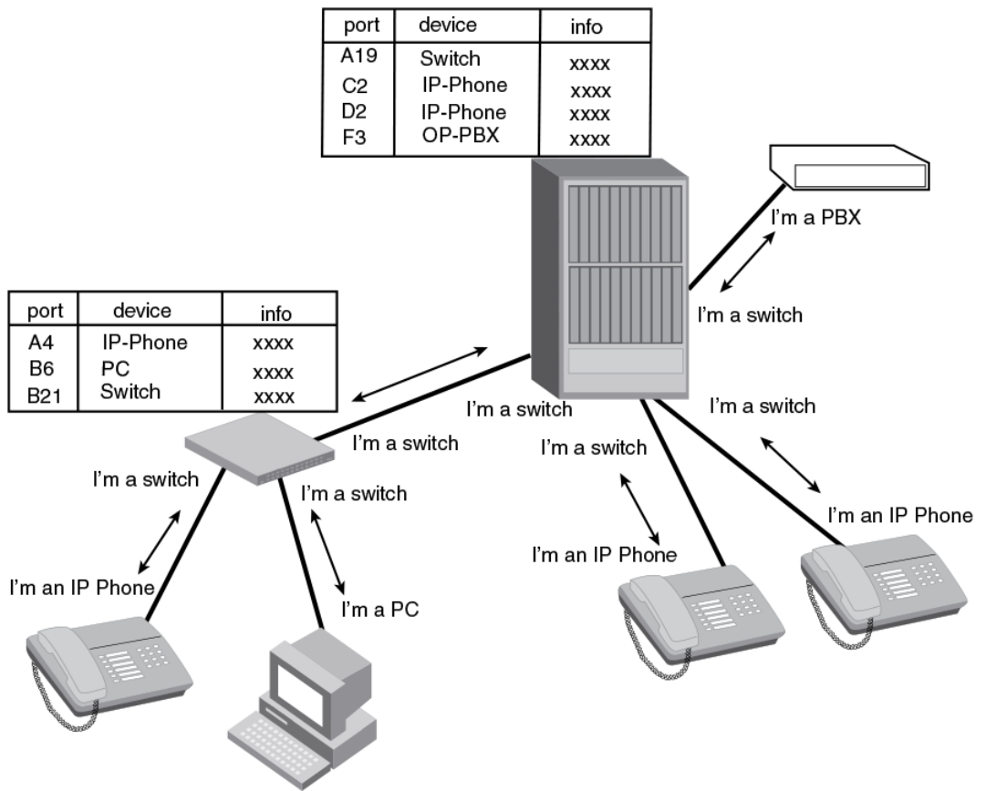
LLDP overview
LLDP enables a station attached to an IEEE 802 LAN/MAN to advertise its capabilities to, and to discover, other stations in the same
802 LAN segments.
The information distributed by LLDP (the advertisement) is stored by the receiving device in a standard Management Information Base
(MIB), accessible by a Network Management System (NMS) using a management protocol such as the Simple Network Management
Protocol (SNMP). The information also can be viewed from the CLI, using show LLDP commands.
The following diagram illustrates LLDP connectivity
FIGURE 6 LLDP connectivity
LLDP overview
Brocade FastIron Management Conguration Guide, 08.0.60
120 Part Number: 53-1004918-03
Benets of LLDP
LLDP provides the following benets:
• Network Management:
–Simplies the use of and enhances the ability of network management tools in multi-vendor environments
– Enables discovery of accurate physical network topologies such as which devices are neighbors and through which ports
they connect
– Enables discovery of stations in multi-vendor environments
• Network Inventory Data:
– Supports optional system name, system description, system capabilities and management address
– System description can contain the device product name or model number, version of hardware type, and operating
system
– Provides device capability, such as switch, router, or WLAN access point
• Network troubleshooting:
– Information generated by LLDP can be used to detect speed and duplex mismatches
– Accurate topologies simplify troubleshooting within enterprise networks
– Can discover devices with miscongured or unreachable IP addresses
LLDP-MED overview
LLDP-MED is an extension to LLDP. This protocol enables advanced LLDP features in a Voice over IP (VoIP) network. Whereas LLDP
enables network discovery between Network Connectivity devices, LLDP-MED enables network discovery between Network
Connectivity devices and media Endpoints such as, IP telephones, softphones, VoIP gateways and conference bridges.
The following diagram illustrates LLDP-MED connectivity.
LLDP-MED overview
Brocade FastIron Management Conguration Guide, 08.0.60
Part Number: 53-1004918-03 121
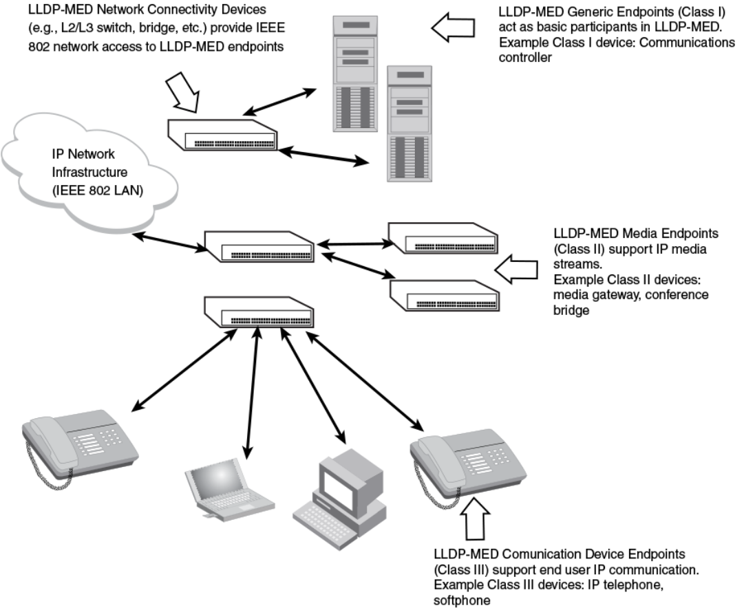
FIGURE 7 LLDP-MED connectivity
Benets of LLDP-MED
LLDP-MED provides the following benets:
• Vendor-independent management capabilities, enabling dierent IP telephony systems to interoperate in one network.
• Automatically deploys network policies, such as Layer 2 and Layer 3 QoS policies and Voice VLANs.
• Supports E-911 Emergency Call Services (ECS) for IP telephony
• Collects Endpoint inventory information
• Network troubleshooting
– Helps to detect improper network policy conguration
LLDP-MED overview
Brocade FastIron Management Conguration Guide, 08.0.60
122 Part Number: 53-1004918-03
LLDP-MED class
An LLDP-MED class species an Endpoint type and its capabilities. An Endpoint can belong to one of three LLDP-MED class types:
•Class 1 (Generic endpoint) - A Class 1 Endpoint requires basic LLDP discovery services, but does not support IP media nor
does it act as an end-user communication appliance. A Class 1 Endpoint can be an IP communications controller, other
communication-related server, or other device requiring basic LLDP discovery services.
•Class 2 (Media endpoint) - A Class 2 Endpoint supports media streams and may or may not be associated with a particular
end user. Device capabilities include media streaming, as well as all of the capabilities dened for Class 1 Endpoints. A Class 2
Endpoint can be a voice/media gateway, conference, bridge, media server, etc.
•Class 3 (Communication endpoint) - A Class 3 Endpoint supports end user IP communication. Capabilities include aspects
related to end user devices, as well as all of the capabilities dened for Class 1 and Class 2 Endpoints. A Class 3 Endpoint can
be an IP telephone, softphone (PC-based phone), or other communication device that directly supports the end user.
Discovery services dened in Class 3 include location identier (ECS/E911) information and inventory management.
The LLDP-MED device class is advertised when LLDP-MED is enabled on a port.
General LLDP operating principles
LLDP and LLDP-MED use the services of the Data Link sublayers, Logical Link Control and Media Access Control, to transmit and
receive information to and from other LLDP Agents (protocol entities that implement LLDP).
LLDP is a one-way protocol. An LLDP agent can transmit and receive information to and from another LLDP agent located on an
adjacent device, but it cannot solicit information from another LLDP agent, nor can it acknowledge information received from another
LLDP agent.
LLDP operating modes
When LLDP is enabled on a global basis, by default, each port on the Brocade device will be capable of transmitting and receiving LLDP
packets. You can disable a port’s ability to transmit and receive LLDP packets, or change the operating mode to one of the following:
• Transmit LLDP information only
• Receive LLDP information only
LLDP transmit mode
An LLDP agent sends LLDP packets to adjacent LLDP-enabled devices. The LLDP packets contain information about the transmitting
device and port.
An LLDP agent initiates the transmission of LLDP packets whenever the transmit countdown timing counter expires, or whenever LLDP
information has changed. When a transmit cycle is initiated, the LLDP manager extracts the MIB objects and formats this information
into TLVs. The TLVs are inserted into an LLDPDU, addressing parameters are prepended to the LLDPDU, and the information is sent
out LLDP-enabled ports to adjacent LLDP-enabled devices.
LLDP receive mode
An LLDP agent receives LLDP packets from adjacent LLDP-enabled devices. The LLDP packets contain information about the
transmitting device and port.
General LLDP operating principles
Brocade FastIron Management Conguration Guide, 08.0.60
Part Number: 53-1004918-03 123
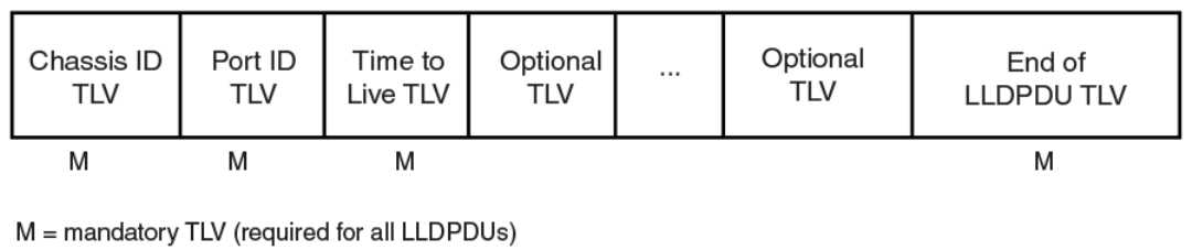
When an LLDP agent receives LLDP packets, it checks to ensure that the LLDPDUs contain the correct sequence of mandatory TLVs,
then validates optional TLVs. If the LLDP agent detects any errors in the LLDPDUs and TLVs, it drops them in software. TLVs that are
not recognized but do not contain basic formatting errors, are assumed to be valid and are assigned a temporary identication index and
stored for future possible alter retrieval by network management. All validated TLVs are stored in the neighbor database.
LLDP packets
LLDP agents transmit information about a sending device/port in packets called LLDP Data Units (LLDPDUs). All the LLDP information
to be communicated by a device is contained within a single 1500 byte packet. A device receiving LLDP packets is not permitted to
combine information from multiple packets.
As shown in the following gure, each LLDPDU has three mandatory TLVs, an End of LLDPDU TLV, plus optional TLVs as selected by
network management.
FIGURE 8 LLDPDU packet format
Each LLDPDU consists of an untagged Ethernet header and a sequence of short, variable length information elements known as type,
length, value (TLV).
TLVs have Type, Length, and Value elds, where:
•Type identies the kind of information being sent
•Length indicates the length (in octets) of the information string
•Value is the actual information being sent (for example, a binary bit map or an alpha-numeric string containing one or more
elds).
TLV support
This section lists the LLDP and LLDP-MED TLV support.
LLDP TLVs
There are two types of LLDP TLVs, as specied in the IEEE 802.3AB standard.
Basic management TLVs consist of both optional general system information TLVs as well as mandatory TLVs.
Mandatory TLVs cannot be manually congured. They are always the rst three TLVs in the LLDPDU, and are part of the packet header.
General system information TLVs are optional in LLDP implementations and are dened by the Network Administrator.
Brocade devices support the following Basic Management TLVs:
• Chassis ID (mandatory)
General LLDP operating principles
Brocade FastIron Management Conguration Guide, 08.0.60
124 Part Number: 53-1004918-03
• Port ID (mandatory)
• Time to Live (mandatory)
• Port description
• System name
• System description
• System capabilities
• Management address
• End of LLDPDU
Organizationally-specic TLVs are optional in LLDP implementations and are dened and encoded by individual organizations or
vendors. These TLVs include support for, but are not limited to, the IEEE 802.1 and 802.3 standards and the TIA-1057 standard.
Brocade devices support the following Organizationally-specic TLVs:
•802.1 organizationally-specic TLVs
– Port VLAN ID
– VLAN name TLV
•802.3 organizationally-specic TLVs
– MAC/PHY conguration/status
– Power through MDI
– Link aggregation
– Maximum frame size
LLDP-MED TLVs
Brocade devices honor and send the following LLDP-MED TLVs, as dened in the TIA-1057 standard:
• LLDP-MED capabilities
• Network policy
• Location identication
• Extended power-via-MDI
Mandatory TLVs
When an LLDP agent transmits LLDP packets to other agents in the same 802 LAN segments, the following mandatory TLVs are
always included:
• Chassis ID
• Port ID
• Time to Live (TTL)
This section describes the above TLVs in detail.
Chassis ID
The Chassis ID identies the device that sent the LLDP packets.
There are several ways in which a device may be identied. A chassis ID subtype, included in the TLV and shown in the following table,
indicates how the device is being referenced in the Chassis ID eld.
General LLDP operating principles
Brocade FastIron Management Conguration Guide, 08.0.60
Part Number: 53-1004918-03 125

TABLE 23 Chassis ID subtypes
ID subtype Description
0 Reserved
1 Chassis component
2 Interface alias
3 Port component
4 MAC address
5 Network address
6 Interface name
7 Locally assigned
8 - 255 Reserved
Brocade devices use chassis ID subtype 4, the base MAC address of the device. Other third party devices may use a chassis ID subtype
other than 4. The chassis ID will appear similar to the following on the remote device, and in the CLI display output on the Brocade
device (show lldp local-info ).
Chassis ID (MAC address): 0000.0033.e2c0
The chassis ID TLV is always the rst TLV in the LLDPDU.
Port ID
The Port ID identies the port from which LLDP packets were sent.
There are several ways in which a port may be identied, as shown in the following table. A port ID subtype, included in the TLV, indicates
how the port is being referenced in the Port ID eld.
TABLE 24 Port ID subtypes
ID subtype Description
0 Reserved
1 Interface alias
2 Port component
3 MAC address
4 Network address
5 Interface name
6 Agent circuit ID
7 Locally assigned
8 - 255 Reserved
Brocade devices use port ID subtype 3, the permanent MAC address associated with the port. Other third party devices may use a port
ID subtype other than 3. The port ID appears similar to the following on the remote device, and in the CLI display output on the Brocade
device (show lldp local-info).
Port ID (MAC address): 0000.0033.e2d3
The LLDPDU format is shown in LLDP packets on page 124.
The Port ID TLV format is shown below.
General LLDP operating principles
Brocade FastIron Management Conguration Guide, 08.0.60
126 Part Number: 53-1004918-03
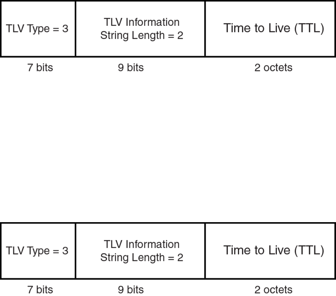
FIGURE 9 Port ID TLV packet format
TTL value
The Time to Live (TTL) Value is the length of time the receiving device should maintain the information acquired by LLDP in its MIB.
The TTL value is automatically computed based on the LLDP conguration settings. The TTL value will appear similar to the following
on the remote device, and in the CLI display output on the Brocade device (show lldp local-info).
Time to live: 40 seconds
If the TTL eld has a value other than zero, the receiving LLDP agent is notied to completely replace all information associated with the
LLDP agent/port with the information in the received LLDPDU.
If the TTL eld value is zero, the receiving LLDP agent is notied that all system information associated with the LLDP agent/port is to
be deleted. This TLV may be used, for example, to signal that the sending port has initiated a port shutdown procedure.
The LLDPDU format is shown in LLDP packets on page 124.
The TTL TLV format is shown below.
FIGURE 10 TTL TLV packet format
MIB support
Brocade devices support the following standard management information base (MIB) modules:
• LLDP-MIB
• LLDP-EXT-DOT1-MIB
• LLDP-EXT-DOT3-MIB
• LLDP-EXT-MED-MIB
MIB support
Brocade FastIron Management Conguration Guide, 08.0.60
Part Number: 53-1004918-03 127

Syslog messages
Syslog messages for LLDP provide management applications with information related to MIB data consistency and general status.
These Syslog messages correspond to the lldpRemTablesChange SNMP notications. Refer to Enabling LLDP SNMP notications and
Syslog messages on page 132.
Syslog messages for LLDP-MED provide management applications with information related to topology changes. These Syslog
messages correspond to the lldpXMedTopologyChangeDetected SNMP notications. Refer to Enabling SNMP notications and Syslog
messages for LLDP-MED topology changes on page 141.
LLDP conguration
This section describes how to enable and congure LLDP.
The following table lists the LLDP global-level tasks and the default behavior/value for each task.
TABLE 25 LLDP global conguration tasks and default behavior /value
Global task Default behavior / value when LLDP is enabled
Enabling LLDP on a global basis Disabled
Specifying the maximum number of LLDP neighbors per device Automatically set to 392 neighbors per device
Specifying the maximum number of LLDP neighbors per port Automatically set to 4 neighbors per port
Enabling SNMP notications and Syslog messages Disabled
Changing the minimum time between SNMP traps and Syslog messages Automatically set to 2 seconds when SNMP notications and Syslog
messages for LLDP are enabled
Enabling and disabling TLV advertisements When LLDP transmit is enabled, by default, the Brocade device will
automatically advertise LLDP capabilities, except for the system
description, VLAN name, and power-via-MDI information, which may be
congured by the system administrator.
Also, if desired, you can disable the advertisement of individual TLVs.
Changing the minimum time between LLDP transmissions Automatically set to 2 seconds
Changing the interval between regular LLDP transmissions Automatically set to 30 seconds
Changing the holdtime multiplier for transmit TTL Automatically set to 4
Changing the minimum time between port reinitializations Automatically set to 2 seconds
LLDP conguration notes and considerations
• LLDP is supported on Ethernet interfaces only.
• By default, if a port is 802.1X-enabled, the transmission and reception of LLDP packets will only take place while the port is
authorized. The lldp-pass-through command overrides this behavior.
• Cisco Discovery Protocol (CDP) and Brocade Discovery Protocol (FDP) run independently of LLDP. Therefore, these discovery
protocols can run simultaneously on the same device.
• By default, the Brocade device limits the number of neighbors per port to four, and staggers the transmission of LLDP packets
on dierent ports, in order to minimize any high-usage spikes to the CPU.
• By default, the Brocade device forwards LLDP packets even though LLDP is not congured on the device. This ensures
consistency with other protocols and allows transparent forwarding, though it amounts to noncompliance with IEEE Standards.
• Ports that are in blocking mode (spanning tree) can still receive LLDP packets from a forwarding port.
Syslog messages
Brocade FastIron Management Conguration Guide, 08.0.60
128 Part Number: 53-1004918-03
• Auto-negotiation status indicates what is being advertised by the port for 802.3 auto-negotiation.
Enabling and disabling LLDP
LLDP is enabled by default on individual ports. However, to run LLDP, you must rst enable it on a global basis (on the entire device).
To enable LLDP globally, enter the following command at the global CONFIG level of the CLI.
device(config)#lldp run
Syntax:[no] lldp run
Enabling support for tagged LLDP packets
By default, Brocade devices do not accept tagged LLDP packets from other vendors’ devices. To enable support, apply the command
lldp tagged-packets process at the Global CONFIG level of the CLI. When enabled, the device will accept incoming LLDP tagged
packets if the VLAN tag matches any of the following:
• a congured VLAN on the port
• the default VLAN for a tagged port
• the congured untagged VLAN for a dual-mode port
To enable support for tagged LLDP packets, enter the following command.
device(config)#lldp tagged-packets process
Syntax: [no] lldptagged-packets process
Changing a port LLDP operating mode
When LLDP is enabled on a global basis, by default, each port on the Brocade device will be capable of transmitting and receiving LLDP
packets. You can disable a port’s ability to transmit and receive LLDP packets, or change the operating mode to one of the following:
• Transmit LLDP information only
• Receive LLDP information only
You can congure a dierent operating mode for each port on the Brocade device. For example, you could disable the receipt and
transmission of LLDP packets on port e 1/2/1, congure port e 1/2/3 to only receive LLDP packets, and congure port e 1/2/5 to
only transmit LLDP packets.
The following sections show how to change the operating mode.
Enabling and disabling receive and transmit mode
To disable the receipt and transmission of LLDP packets on individual ports, enter a command such as the following at the Global
CONFIG level of the CLI.
device(config)#no lldp enable ports e 1/2/4 e 1/2/5
The above command disables LLDP on ports 1/2/4 and 1/2/5. These ports will not transmit nor receive LLDP packets.
To enable LLDP on a port after it has been disabled, enter the following command.
device(config)#lldp enable ports e 1/2/4
Syntax: [no] lldp enable ports ethernet port-list | all
LLDP conguration
Brocade FastIron Management Conguration Guide, 08.0.60
Part Number: 53-1004918-03 129
Use the [no] form of the command to disable the receipt and transmission of LLDP packets on a port.
NOTE
When a port is congured to both receive and transmit LLDP packets and the MED capabilities TLV is enabled, LLDP-MED is
enabled as well. LLDP-MED is not enabled if the operating mode is set to receive only or transmit only.
Enabling and disabling receive only mode
When LLDP is enabled on a global basis, by default, each port on the Brocade device will be capable of transmitting and receiving LLDP
packets. To change the LLDP operating mode from receive and transmit mode to receive only mode, simply disable the transmit mode.
Enter a command such as the following at the Global CONFIG level of the CLI.
device(config)#no lldp enable transmit ports e 1/2/4 e 1/2/5 e 1/2/6
The above command changes the LLDP operating mode on ports 1/2/4, 1/2/5, and 1/2/6 from transmit and receive mode to receive
only mode.
To change a port LLDP operating mode from transmit only to receive only, rst disable the transmit only mode, then enable the receive
only mode. Enter commands such as the following.
device(config)#no lldp enable transmit ports e 1/2/7 e 1/2/8 e 1/2/9
device(config)#lldp enable receive ports e 1/2/7 e 1/2/8 e 1/2/9
The above commands change the LLDP operating mode on ports 1/2/7, 1/2/8, and 1/2/9, from transmit only to receive only. Note
that if you do not disable the transmit only mode, you will congure the port to both transmit and receive LLDP packets.
NOTE
LLDP-MED is not enabled when you enable the receive only operating mode. To enable LLDP-MED, you must congure the
port to both receive and transmit LLDP packets. Refer to Changing a port LLDP operating mode.
Syntax:[no] lldp enable receive ports ethernet port-list | all
Use the [no] form of the command to disable the receive only mode.
Enabling and disabling transmit only mode
When LLDP is enabled on a global basis, by default, each port on the Brocade device will be capable of transmitting and receiving LLDP
packets. To change the LLDP operating mode to transmit only mode, simply disable the receive mode. Enter a command such as the
following at the Global CONFIG level of the CLI.
device(config)#no lldp enable receive ports e 1/2/4 e 1/2/5 e 1/2/6
The above command changes the LLDP operating mode on ports 1/2/4, 1/2/5, and 1/2/6 from transmit and receive mode to
transmit only mode. Any incoming LLDP packets will be dropped in software.
To change a port LLDP operating mode from receive only to transmit only, rst disable the receive only mode, then enable the transmit
only mode. For example, enter commands such as the following at the Global CONFIG level of the CLI.
device(config)#no lldp enable receive ports e 1/2/7 e 1/2/8
device(config)#lldp enable transmit ports e 1/2/7 e 1/2/8
The above commands change the LLDP operating mode on ports 1/2/7 and 1/2/8 from receive only mode to transmit only mode.
Any incoming LLDP packets will be dropped in software. Note that if you do not disable receive only mode, you will congure the port to
both receive and transmit LLDP packets.
LLDP conguration
Brocade FastIron Management Conguration Guide, 08.0.60
130 Part Number: 53-1004918-03
NOTE
LLDP-MED is not enabled when you enable the transmit only operating mode. To enable LLDP-MED, you must congure the
port to both receive and transmit LLDP packets. Refer to Changing a port LLDP operating mode.
Syntax: [no] lldp enabletransmit ports ethernet port-list | all
Use the [no] form of the command to disable the transmit only mode.
Conguring LLDP processing on 802.1x blocked port
This feature adds support for reception and transmission of Link Layer Discovery Protocol (LLDP) packets over an 802.1x blocked port.
The default behavior is to drop received LLDP packets and not to transmit LLDP packets over an 802.1x disabled port. To receive or
transmit LLDP packets over 802.1x blocked port or in other words to enable the LLDP processing on 802.1x blocked ports, use the
lldp-pass-through conguration command.
To enable the LLDP processing on all 802.1x blocked ports, enter the following command at the 802.1X conguration mode:
Brocade(config-dot1x)# lldp-pass-through all
Syntax: [no] lldp-pass-through all
To enable LLDP processing on a specic 802.1x blocked port, enter the following command at the 802.1X conguration mode:
Brocade(config-dot1x)# lldp-pass-through ethernet 1/1/1
Syntax: [no] lldp-pass-through ethernet port
Specify the port variable in the format unit/slot/port.
The no form of these commands disables LLDP processing on 802.1x blocked ports.
For more information on LLDP and 801.1x, refer IEEE 802.1AB and IEEE 802.1x.
NOTE
If lldp-pass-through is disabled, the neighboring information is lost only after LLDP timeout period (default is 120).
Maximum number of LLDP neighbors
You can change the limit of the number of LLDP neighbors for which LLDP data will be retained, per device as well as per port.
Specifying the maximum number of LLDP neighbors per device
You can change the maximum number of neighbors for which LLDP data will be retained for the entire system.
For example, to change the maximum number of LLDP neighbors for the entire device to 26, enter the following command.
device(config)#lldp max-total-neighbors 26
Syntax: [no] lldp max-total-neighbors value
Use the [no] form of the command to remove the static conguration and revert to the default value of 392.
where value is a number between 16 and 8192. The default number of LLDP neighbors per device is 392.
Use the show lldp command to view the conguration.
LLDP conguration
Brocade FastIron Management Conguration Guide, 08.0.60
Part Number: 53-1004918-03 131
Specifying the maximum number of LLDP neighbors per port
You can change the maximum number of LLDP neighbors for which LLDP data will be retained for each port. By default, the maximum
number is four and you can change this to a value between one and 64.
For example, to change the maximum number of LLDP neighbors to six, enter the following command.
device(config)#lldp max-neighbors-per-port 6
Syntax: [no] lldp max-neighbors-per-port value
Use the [no] form of the command to remove the static conguration and revert to the default value of four.
where value is a number from 1 to 64. The default is number of LLDP neighbors per port is four.
Use the show lldp command to view the conguration.
Enabling LLDP SNMP notications and Syslog messages
SNMP notications and Syslog messages for LLDP provide management applications with information related to MIB data updates and
general status.
When you enable LLDP SNMP notications, corresponding Syslog messages are enabled as well. When you enable LLDP SNMP
notications, the device will send traps and corresponding Syslog messages whenever there are changes to the LLDP data received
from neighboring devices.
LLDP SNMP notications and corresponding Syslog messages are disabled by default. To enable them, enter a command such as the
following at the Global CONFIG level of the CLI.
device(config)#lldp enable snmp notifications ports e 1/4/2 to 1/4/6
The above command enables SNMP notications and corresponding Syslog messages on ports 1/4/2 through 1/4/6. By default, the
device will send no more than one SNMP notication and Syslog message within a ve second period. If desired, you can change this
interval. Refer to Specifying the minimum time between SNMP traps and Syslog messages on page 132.
Syntax: [no] lldp enablesnmp notications ports ethernet port-list | all
Specifying the minimum time between SNMP traps and Syslog messages
When SNMP notications and Syslog messages for LLDP are enabled, the device will send no more than one SNMP notication and
corresponding Syslog message within a ve second period. If desired, you can throttle the amount of time between transmission of
SNMP traps (lldpRemTablesChange) and Syslog messages from ve seconds up to a value equal to one hour (3600 seconds).
NOTE
Because LLDP Syslog messages are rate limited, some LLDP information given by the system will not match the current
LLDP statistics (as shown in the show lldp statistics command output).
To change the minimum time interval between traps and Syslog messages, enter a command such as the following.
device(config)#lldp snmp-notification-interval 60
When the above command is applied, the LLDP agent will send no more than one SNMP notication and Syslog message every 60
seconds.
Syntax: [no] lldp snmp-notication-interval seconds
where seconds is a value between 5 and 3600. The default is 5 seconds.
LLDP conguration
Brocade FastIron Management Conguration Guide, 08.0.60
132 Part Number: 53-1004918-03
Changing the minimum time between LLDP transmissions
The LLDP transmit delay timer limits the number of LLDP frames an LLDP agent can send within a specied time frame. When you
enable LLDP, the system automatically sets the LLDP transmit delay timer to two seconds. If desired, you can change the default
behavior from two seconds to a value between 1 and 8192 seconds.
NOTE
The LLDP transmit delay timer must not be greater than one quarter of the LLDP transmission interval (CLI command lldp
transmit-interval ).
The LLDP transmit delay timer prevents an LLDP agent from transmitting a series of successive LLDP frames during a short time
period, when rapid changes occur in LLDP. It also increases the probability that multiple changes, rather than single changes, will be
reported in each LLDP frame.
To change the LLDP transmit delay timer, enter a command such as the following at the Global CONFIG level of the CLI.
device(config)#lldp transmit-delay 7
The above command causes the LLDP agent to wait a minimum of seven seconds after transmitting an LLDP frame and before
sending another LLDP frame.
Syntax: [no] lldp transmit-delay seconds
where seconds is a value between 1 and 8192. The default is two seconds. Note that this value must not be greater than one quarter of
the LLDP transmission interval (CLI command lldp transmit-interval ).
Changing the interval between regular LLDP transmissions
The LLDP transmit interval species the number of seconds between regular LLDP packet transmissions. When you enable LLDP, by
default, the device will wait 30 seconds between regular LLDP packet transmissions. If desired, you can change the default behavior
from 30 seconds to a value between 5 and 32768 seconds.
To change the LLDP transmission interval, enter a command such as the following at the Global CONFIG level of the CLI.
device(config)#lldp transmit-interval 40
The above command causes the LLDP agent to transmit LLDP frames every 40 seconds.
Syntax:[no] lldp transmit-interval seconds
where seconds is a value from 5 to 32768. The default is 30 seconds.
NOTE
Setting the transmit interval or transmit holdtime multiplier, or both, to inappropriate values can cause the LLDP agent to
transmit LLDPDUs with TTL values that are excessively high. This in turn can aect how long a receiving device will retain the
information if it is not refreshed.
Changing the holdtime multiplier for transmit TTL
The holdtime multiplier for transmit TTL is used to compute the actual time-to-live (TTL) value used in an LLDP frame. The TTL value is
the length of time the receiving device should maintain the information in its MIB. When you enable LLDP, the device automatically sets
the holdtime multiplier for TTL to four. If desired, you can change the default behavior from four to a value between two and ten.
To compute the TTL value, the system multiplies the LLDP transmit interval by the holdtime multiplier. For example, if the LLDP
transmit interval is 30 and the holdtime multiplier for TTL is 4, then the value 120 is encoded in the TTL eld in the LLDP header.
LLDP conguration
Brocade FastIron Management Conguration Guide, 08.0.60
Part Number: 53-1004918-03 133
To change the holdtime multiplier, enter a command such as the following at the Global CONFIG level of the CLI.
device(config)#lldp transmit-hold 6
Syntax:[no] lldp transmit-hold value
where value is a number from 2 to 10. The default value is 4.
NOTE
Setting the transmit interval or transmit holdtime multiplier, or both, to inappropriate values can cause the LLDP agent to
transmit LLDPDUs with TTL values that are excessively high. This in turn can aect how long a receiving device will retain the
information if it is not refreshed.
Changing the minimum time between port reinitializations
The LLDP re-initialization delay timer species the minimum number of seconds the device will wait from when LLDP is disabled on a
port, until it will honor a request to re-enable LLDP on that port. When you enable LLDP, the system sets the re-initialization delay timer
to two seconds. If desired, you can change the default behavior from two seconds to a value between one and ten seconds.
To set the re-initialization delay timer, enter a command such as the following at the Global CONFIG level of the CLI.
device(config)#lldp reinit-delay 5
The above command causes the device to wait ve seconds after LLDP is disabled, before attempting to honor a request to re-enable it.
Syntax: [no] lldp reinit-delay seconds
where seconds is a value from 1 - 10. The default is two seconds.
LLDP TLVs advertised by the Brocade device
When LLDP is enabled on a global basis, the Brocade device will automatically advertise the following information, except for the
features noted:
General system information:
• Management address
• Port description
• System capabilities
• System description (not automatically advertised)
• System name
802.1 capabilities:
• VLAN name (not automatically advertised)
• Untagged VLAN ID
802.3 capabilities:
• Link aggregation information
• MAC/PHY conguration and status
• Maximum frame size
• Power-via-MDI information (not automatically advertised)
The above TLVs are described in detail in the following sections.
LLDP conguration
Brocade FastIron Management Conguration Guide, 08.0.60
134 Part Number: 53-1004918-03
NOTE
The system description, VLAN name, and power-via-MDI information TLVs are not automatically enabled. The following
sections show how to enable these advertisements.
General system information for LLDP
Except for the system description, the Brocade device will advertise the following system information when LLDP is enabled on a global
basis:
• Management address
• Port description
• System capabilities
• System description (not automatically advertised)
• System name
Management address
A management address is normally an IPv4 or IPv6 address that can be used to manage the device. Management address advertising
has two modes: default, or explicitly congured. The default mode is used when no addresses are congured to be advertised for a given
port. If any addresses are congured to be advertised for a given port, then only those addresses are advertised. This applies across
address types, so for example, if just one IPv4 address is explicitly congured to be advertised for a port, then no IPv6 addresses will be
advertised for that port (since none were congured to be advertised), even if IPv6 addresses are congured within the system.
If no management address is explicitly congured to be advertised, the Brocade device will use the rst available IPv4 address and the
rst available IPv6 address (so it may advertise IPv4, IPv6 or both). A Layer 3 switch will select the rst available address of each type
from those congured on the following types of interfaces, in the following order of preference:
• Physical port on which LLDP will be transmitting the packet
• Virtual router interface (VE) on a VLAN that the port is a member of
• Dedicated management port
• Loop back interface
• Virtual router interface (VE) on any other VLAN
• Other physical port
• Other interface
For IPv6 addresses, link-local and anycast addresses will be excluded from these searches.
If no IP address is congured on any of the above, the port's current MAC address will be advertised.
To advertise a IPv4 management address, enter a command such as the following:
device(config)# lldp advertise management-address ipv4 10.157.2.1 ports e 1/1/4
The management address will appear similar to the following on the remote device, and in the CLI display output on the Brocade device
(show lldp local-info ):
Management address (IPv4): 10.157.2.1
Syntax:[no] lldp advertise management-address ipv4 ipv4 address ports ethernet port list | all
To support an IPv6 management address, there is a similar command that has equivalent behavior as the IPv4 command.
LLDP conguration
Brocade FastIron Management Conguration Guide, 08.0.60
Part Number: 53-1004918-03 135
To advertise an IPv6 management address, enter a command such as the following:
device(config)#lldp advertise management-address ipv6 2001:DB8::90 ports e 1/2/7
Syntax:[no] lldp advertise management-address ipv6 ipv6 address ports ethernet port list | all
ipv4 address or ipv6 address or both are the addresses that may be used to reach higher layer entities to assist discovery by network
management. In addition to management addresses, the advertisement will include the system interface number associated with the
management address.
For port list , specify the ports in the format unit/slot/port. You can list all of the ports individually; use the keyword to specify a range of
ports, or a combination of both. To apply the conguration to all ports on the device, use the keyword all instead of listing the ports
individually.
Port description
The port description TLV identies the port from which the LLDP agent transmitted the advertisement. The port description is taken
from the ifDescr MIB object from MIB-II.
By default, the port description is automatically advertised when LLDP is enabled on a global basis. To disable advertisement of the port
description, enter a command such as the following.
device(config)#no lldp advertise port-description ports e 1/2/4 to 1/2/12
The port description will appear similar to the following on the remote device, and in the CLI display output on the Brocade device (show
lldp local-info ).
Port description: "GigabitEthernet20"
Syntax:[no] lldp advertise port-description ports ethernet port-list | all
System capabilities
The system capabilities TLV identies the primary functions of the device and indicates whether these primary functions are enabled. The
primary functions can be one or more of the following (more than one for example, if the device is both a bridge and a router):
• Repeater
• Bridge
• WLAN access point
• Router
• Telephone
• DOCSIS cable device
• Station only (devices that implement end station capability)
• Other
System capabilities for Brocade devices are based on the type of software image in use (for example, Layer 2 switch or Layer 3 router).
The enabled capabilities will be the same as the available capabilities, except that when using a router image (base or full Layer 3), if the
global route-only feature is turned on, the bridge capability will not be included, since no bridging takes place.
By default, the system capabilities are automatically advertised when LLDP is enabled on a global basis. To disable this advertisement,
enter a command such as the following.
device(config)#no lldp advertise system-capabilities ports e 1/2/4 to 1/2/12
LLDP conguration
Brocade FastIron Management Conguration Guide, 08.0.60
136 Part Number: 53-1004918-03
The system capabilities will appear similar to the following on the remote device, and in the CLI display output on the Brocade device
(show lldp local-info).
System capabilities : bridge
Enabled capabilities: bridge
Syntax: [no] lldp advertise system-capabilities ports ethernet port-list | all
System description
The system description is the network entity, which can include information such as the product name or model number, the version of
the system hardware type, the software operating system level, and the networking software version. The information corresponds to the
sysDescr MIB object in MIB-II.
To advertise the system description, enter a command such as the following.
device(config)# lldp advertise system-description ports e 1/2/4 to 1/2/12
The system description will appear similar to the following on the remote device, and in the CLI display output on the Brocade device
(show lldp local-info ).
+ System description : "Brocade Communications, Inc.,ICX7450_L3_SOFT_PACKAGE,
SW: Version 08.0.40q030T213 Compiled on Thu Jul 16 06:27:06 2015 labeled as ICXR08040
NOTE
The contents of the show command output will vary depending on which TLVs are congured to be advertised.
Syntax:[no] lldp advertise system-description ports ethernet port-list | all
System name
The system name is the system administratively assigned name, taken from the sysName MIB object in MIB-II. The sysName MIB
object corresponds to the name dened with the CLI command hostname.
By default, the system name is automatically advertised when LLDP is enabled on a global basis. To disable this advertisement, enter a
command such as the following.
device(config)# no lldp advertise system-name ports e 1/2/4 to 1/2/12
The system name will appear similar to the following on the remote device, and in the CLI display output on the Brocade device (show
lldp local-info ).
System name: "ICX7450SP-ADV Router"
Syntax:[no] lldp advertise system-name ports ethernet port-list | all
802.1 capabilities
Except for the VLAN name, the Brocade device will advertise the following 802.1 attributes when LLDP is enabled on a global basis:
• VLAN name (not automatically advertised)
• Untagged VLAN ID
LLDP conguration
Brocade FastIron Management Conguration Guide, 08.0.60
Part Number: 53-1004918-03 137
VLAN name
The VLAN name TLV contains the name and VLAN ID of a VLAN congured on a port. An LLDPDU may include multiple instances of
this TLV, each for a dierent VLAN.
To advertise the VLAN name, enter a command such as the following.
device(config)#lldp advertise vlan-name vlan 99 ports e 1/2/4 to 1/2/12
The VLAN name will appear similar to the following on the remote device, and in the CLI display output on the Brocade device (show
lldp local-info ).
VLAN name (VLAN 99): "Voice-VLAN-99"
Syntax:[no] lldp advertise vlan-name vlan vlan ID ports ethernet port-list | all
Forvlan ID , enter the VLAN ID to advertise.
Untagged VLAN ID
The port VLAN ID TLV advertises the Port VLAN Identier (PVID) that will be associated with untagged or priority-tagged frames. If the
port is not an untagged member of any VLAN (i.e., the port is strictly a tagged port), the value zero will indicate that.
By default, the port VLAN ID is automatically advertised when LLDP is enabled on a global basis. To disable this advertisement, enter a
command such as the following.
device(config)#no lldp advertise port-vlan-id ports e 1/2/4 to 1/2/12
The untagged VLAN ID will appear similar to the following on the remote device, and in the CLI display output on the Brocade device
(show lldp local-info ).
Port VLAN ID: 99
Syntax: [no] lldp advertise port-vlan-id ports ethernet port-list | all
802.3 capabilities
Except for Power-via-MDI information, the Brocade device will advertise the following 802.3 attributes when LLDP is enabled on a
global basis:
• Link aggregation information
• MAC/PHY conguration and status
• Maximum frame size
• Power-via-MDI information (not automatically advertised)
Link aggregation TLV
The link-aggregation time, length, value (TLV) indicates the following:
• Whether the link is capable of being aggregated
• Whether the link is currently aggregated
• The primary trunk port
Brocade devices advertise link aggregation information about standard link aggregation (LACP) as well as static trunk conguration.
LLDP conguration
Brocade FastIron Management Conguration Guide, 08.0.60
138 Part Number: 53-1004918-03
By default, link-aggregation information is automatically advertised when LLDP is enabled on a global basis. To disable this
advertisement, enter a command such as the following.
device(config)#no lldp advertise link-aggregation ports e 1/2/12
Syntax: [no] lldp advertise link-aggregation ports ethernet port-list | all
The link aggregation advertisement will appear similar to the following on the remote device, and in the CLI display output on the
Brocade device (show lldp local-info ).
Link aggregation: not capable
MAC and PHY conguration status
The MAC and PHY conguration and status TLV includes the following information:
• Auto-negotiation capability and status
• Speed and duplex mode
• Flow control capabilities for auto-negotiation
• maximum port speed advertisement
• If applicable, indicates if the above settings are the result of auto-negotiation during link initiation or of a manual set override
action
The advertisement reects the eects of the following CLI commands:
• speed-duplex
•ow-control
• gig-default
•link-cong
By default, the MAC/PHY conguration and status information are automatically advertised when LLDP is enabled on a global basis. To
disable this advertisement, enter a command such as the following.
device(config)#no lldp advertise mac-phy-config-status ports e 1/2/4 to 1/2/12
The MAC/PHY conguration advertisement will appear similar to the following on the remote device, and in the CLI display output on
the Brocade device (show lldp local-info ).
+ 802.3 MAC/PHY : auto-negotiation enabled
Advertised capabilities: 10baseT-HD, 10baseT-FD, 100baseTX-HD, 100baseTX-FD,
fdxSPause, fdxBPause, 1000baseT-HD, 1000baseT-FD
Operational MAU type: 100BaseTX-FD
Syntax:[no] lldp advertise mac-phy-cong-status ports ethernet port-list | all
Maximum frame size
The maximum frame size TLV provides the maximum 802.3 frame size capability of the port. This value is expressed in octets and
includes the four-octet Frame Check Sequence (FCS). The default maximum frame size is 1522. The advertised value may change
depending on whether the aggregated-vlan or jumbo CLI commands are in eect.
By default, the maximum frame size is automatically advertised when LLDP is enabled on a global basis. To disable this advertisement,
enter a command such as the following.
device(config)#no lldp advertise max-frame-size ports e 1/2/4 to 1/2/12
LLDP conguration
Brocade FastIron Management Conguration Guide, 08.0.60
Part Number: 53-1004918-03 139

The maximum frame size advertisement will appear similar to the following on the remote device, and in the CLI display output on the
Brocade device (show lldp local-info ).
Maximum frame size: 1522 octets
Syntax:[no] lldp advertise max-frame-size ports ethernet port-list | all
Power-via-MDI
The power-via-MDI TLV provides general information about Power over Ethernet (POE) capabilities and status of the port. It indicates
the following:
• POE capability (supported or not supported)
• POE status (enabled or disabled)
• Power Sourcing Equipment (PSE) power pair - indicates which pair of wires is in use and whether the pair selection can be
controlled. The Brocade implementation always uses pair A, and cannot be controlled.
• Power class - Indicates the range of power that the connected powered device has negotiated or requested.
NOTE
The power-via-MDI TLV described in this section applies to LLDP. There is also a power-via-MDI TLV for LLDP-MED
devices, which provides extensive POE information. Refer to Extended power-via-MDI information on page 150.
To advertise the power-via-MDI information, enter a command such as the following.
device(config)#lldp advertise power-via-mdi ports e 1/2/4 to 1/2/12
The power-via-MDI advertisement will appear similar to the following on the remote device, and in the CLI display output on the Brocade
device (show lldp local-info ).
+ 802.3 Power via MDI: PSE port, power enabled, class 0
Power Pair : A (not controllable)
Syntax:[no] lldp advertise power-via-mdi ports ethernet port-list | all
LLDP-MED conguration
This section provides the details for conguring LLDP-MED.
The following table lists the global and interface-level tasks and the default behavior/value for each task.
TABLE 26 LLDP-MED conguration tasks and default behavior / value
Task Default behavior / value
Global CONFIG-level tasks
Enabling LLDP-MED on a global basis Disabled
Enabling SNMP notications and Syslog messages for LLDP-MED
topology change
Disabled
Changing the Fast Start Repeat Count The system automatically sets the fast start repeat count to 3 when a
Network Connectivity Device receives an LLDP packet from an Endpoint
that is newly connected to the network.
LLDP-MED conguration
Brocade FastIron Management Conguration Guide, 08.0.60
140 Part Number: 53-1004918-03

TABLE 26 LLDP-MED conguration tasks and default behavior / value (continued)
Task Default behavior / value
NOTE
The LLDP-MED fast start mechanism is only intended to run
on links between Network Connectivity devices and Endpoint
devices. It does not apply to links between LAN infrastructure
elements, including between Network Connectivity devices, or
to other types of links.
Interface-level tasks
Dening a location ID Not congured
Dening a network policy Not congured
Enabling LLDP-MED
When LLDP is enabled globally, LLDP-MED is enabled if the LLDP-MED capabilities TLV is also enabled. By default, the LLDP-MED
capabilities TLV is automatically enabled. To enable LLDP, refer to Enabling and disabling LLDP on page 129.
NOTE
LLDP-MED is not enabled on ports where the LLDP operating mode is receive only or transmit only. LLDP-MED is enabled
on ports that are congured to both receive and transmit LLDP packets and have the LLDP-MED capabilities TLV enabled.
Enabling SNMP notications and Syslog messages for LLDP-MED
topology changes
SNMP notications and Syslog messages for LLDP-MED provide management applications with information related to topology
changes. For example, SNMP notications can alert the system whenever a remote Endpoint device is connected to or removed from a
local port.
SNMP notications identify the local port where the topology change occurred, as well as the device capability of the remote Endpoint
device that was connected to or removed from the port.
When you enable LLDP-MED SNMP notications, corresponding Syslog messages are enabled as well. When you enable LLDP-MED
SNMP notications, the device will send traps and Syslog messages when an LLDP-MED Endpoint neighbor entry is added or
removed.
SNMP notications and corresponding Syslog messages are disabled by default. To enable them, enter a command such as the
following at the Global CONFIG level of the CLI.
device(config)#lldp enable snmp med-topo-change-notifications ports e 1/4/4 to 1/4/6
Syntax:[no] lldp enable snmp med-topo-change-notications ports ethernet port-list | all
Changing the fast start repeat count
The fast start feature enables a Network Connectivity Device to initially advertise itself at a faster rate for a limited time when an LLDP-
MED Endpoint has been newly detected or connected to the network. This feature is important within a VoIP network, for example, where
rapid availability is crucial for applications such as emergency call service location (E911).
The fast start timer starts when a Network Connectivity Device receives the rst LLDP frame from a newly detected Endpoint.
LLDP-MED conguration
Brocade FastIron Management Conguration Guide, 08.0.60
Part Number: 53-1004918-03 141
The LLDP-MED fast start repeat count species the number of LLDP packets that will be sent during the LLDP-MED fast start period.
By default, the device will send three packets at one-second intervals. If desired, you can change the number of packets the device will
send per second, up to a maximum of 10.
NOTE
The LLDP-MED fast start mechanism is only intended to run on links between Network Connectivity devices and Endpoint
devices. It does not apply to links between LAN infrastructure elements, including between Network Connectivity devices, or to
other types of links.
To change the LLDP-MED fast start repeat count, enter commands such as the following.
device(config)#lldp med fast-start-repeat-count 5
The above command causes the device to send ve LLDP packets during the LLDP-MED fast start period.
Syntax: [no] lldp medfast-start-repeat-count value
where value is a number from 1 to 10, which species the number of packets that will be sent during the LLDP-MED fast start period.
The default is 3.
Dening a location id
The LLDP-MED Location Identication extension enables the Brocade device to set the physical location that an attached Class III
Endpoint will use for location-based applications. This feature is important for applications such as IP telephony, for example, where
emergency responders need to quickly determine the physical location of a user in North America that has just dialed 911.
For each port, you can dene one or more of the following location ID formats:
• Geographic location (coordinate-based)
• Civic address
• Emergency Call Services (ECS) Emergency Location Identication Number (ELIN)
The above location ID formats are dened in the following sections.
Coordinate-based location
Coordinate-based location is based on the IETF RFC 3825 [6] standard, which species a Dynamic Host Conguration Protocol
(DHCP) option for the coordinate-based geographic location of a client.
When you congure an Endpoint location information using the coordinate-based location, you specify the latitude, longitude, and
altitude, along with resolution indicators (a measure of the accuracy of the coordinates), and the reference datum (the map used for the
given coordinates).
To congure a coordinate-based location for an Endpoint device, enter a command such as the following at the Global CONFIG level of
the CLI.
device(config)#lldp med location-id coordinate-based latitude
-78.303 resolution 20 longitude 34.27 resolution 18 altitude meters 50 resolution 16 wgs84
Syntax: [no] lldp med location-id coordinate-based latitude degrees resolution bits longitude degrees resolution bits altitude oors
number resolution bits | meters number resolution bits datum
latitude degrees is the angular distance north or south from the earth equator measured through 90 degrees. Positive numbers indicate
a location north of the equator and negative numbers indicate a location south of the equator.
resolution bits species the precision of the value given for latitude. A smaller value increases the area within which the device is located.
For latitude, enter a number between 1 and 34.
LLDP-MED conguration
Brocade FastIron Management Conguration Guide, 08.0.60
142 Part Number: 53-1004918-03
longitude degrees is the angular distance from the intersection of the zero meridian. Positive values indicate a location east of the prime
meridian and negative numbers indicate a location west of the prime meridian.
resolution bits species the precision of the value given for longitude. A smaller value increases the area within which the device is
located. For longitude resolution, enter a number between 1 and 34.
altitude oors number is the vertical elevation of a building above the ground, where 0 represents the oor level associated with the
ground level at the main entrance and larger values represent oors that are above (higher in altitude) oors with lower values. For
example, 2 for the 2nd oor. Sub-oors can be represented by non-integer values. For example, a mezzanine between oor 1 and oor
2 could be represented as 1.1. Similarly, the mezzanines between oor 4 and oor 5 could be represented as 4.1 and 4.2 respectively.
Floors located below ground level could be represented by negative values.
resolution bits species the precision of the value given for altitude. A smaller value increases the area within which the device is located.
For oors resolution, enter the value 0 if the oor is unknown, or 30 if a valid oor is being specied.
altitude meters number is the vertical elevation in number of meters, as opposed to oors.
resolution bits species the precision of the value given for altitude. A smaller value increases the area within which the device is located.
For meters resolution, enter a value from 0 to 30.
Datum is the map used as the basis for calculating the location. Specify one of the following:
•wgs84 - (geographical 3D) - World Geodesic System 1984, CRS Code 4327, Prime Meridian Name: Greenwich
•nad83-navd88 - North American Datum 1983, CRS Code 4269, Prime Meridian Name: Greenwich; The associated vertical
datum is the North American Vertical Datum of 1988 (NAVD88). Use this datum when referencing locations on land. If land is
near tidal water, use nad83-mllw (below).
•nad83-mllw - North American Datum 1983, CRS Code 4269, Prime Meridian Name: Greenwich; The associated vertical
datum is mean lower low water (MLLW). Use this datum when referencing locations on water, sea, or ocean.
Example coordinate-based location conguration
The following shows an example coordinate-based location conguration for the Sears Tower, at the following location.
103rd Floor233 South Wacker DriveChicago, IL 60606
device(config)#lldp med location-id coordinate-based latitude 41.87884 resolution 18 longitude 87.63602
resolution 18 altitude floors 103 resolution 30 wgs84
The above conguration shows the following:
• Latitude is 41.87884 degrees north (or 41.87884 degrees).
• Longitude is 87.63602 degrees west (or 87.63602 degrees).
• The latitude and longitude resolution of 18 describes a geo-location area that is latitude 41.8769531 to latitude 41.8789062
and extends from -87.6367188 to -87.6347657 degrees longitude. This is an area of approximately 373412 square feet
(713.3 ft. x 523.5 ft.).
• The location is inside a structure, on the 103rd oor.
• The WGS 84 map was used as the basis for calculating the location.
Example coordinate-based location advertisement
The coordinate-based location advertisement will appear similar to the following on the remote device, and in the CLI display output on
the Brocade device (show lldp local-info ).
+ MED Location ID
Data Format: Coordinate-based
Latitude Resolution : 20 bits
LLDP-MED conguration
Brocade FastIron Management Conguration Guide, 08.0.60
Part Number: 53-1004918-03 143

Latitude Value : -78.303 degrees
Longitude Resolution : 18 bits
Longitude Value : 34.27 degrees
Altitude Resolution : 16 bits
Altitude Value : 50. meters
Datum : WGS 84
Conguring civic address location
When you congure a media Endpoint location using the address-based location, you specify the location the entry refers to, the country
code, and the elements that describe the civic or postal address.
To congure a civic address-based location for LLDP-MED, enter commands such as the following at the global conguration mode of
the CLI.
device(config)# lldp med location-id civic-address refers-to client country US elem 1 CA elem 3 "San Jose"
elem 6 "120 Holger Way" elem 24 95134 elem 27 5 elem 28 551 elem 29 office elem 23 "John Doe"
Syntax: [no] lldp med location-id civic-address refers-to elem country country code elem CA type value [ elem CA type value ] [ elem
CA type value ] ....
refers-to elem describes the location that the entry refers to. Specify one of the following:
• client
• dhcp-server
• network-element
where dhcp-server or network-element should only be used if it is known that the Endpoint is in close physical proximity to the DHCP
server or network element.
country code is the two-letter ISO 3166 country code in capital ASCII letters.
• CA - Canada
• DE - Germany
• JP - Japan
• KR - Korea
• US - United States
CA type is a value from 0 - 255, that describes the civic address element. For example, a CA type of 24 species a postal or zip code.
Valid elements and their types are listed in the following table.
value is the actual value of the elem CA type , above. For example, 95134 for the postal or zip code. Acceptable values are also listed in
the following table.
NOTE
If the value of an element contains one or more spaces, use double quotation marks (") at the beginning and end of the string.
For example, elem 3 "San Jose" .
TABLE 27 Elements used with civic address
Civic Address (CA) type Description Acceptable values / examples
0 Language The ISO 639 language code used for presenting
the address information.
1 National subdivisions (state, canton, region,
province, or prefecture)
Examples:
Canada - Province
Germany - State
LLDP-MED conguration
Brocade FastIron Management Conguration Guide, 08.0.60
144 Part Number: 53-1004918-03

TABLE 27 Elements used with civic address (continued)
Civic Address (CA) type Description Acceptable values / examples
Japan - Metropolis
Korea - Province
United States - State
2 County, parish, gun (JP), or district (IN) Examples:
Canada - County
Germany - County
Japan - City or rural area
Korea - County
United States - County
3 City, township, or shi (JP) Examples:
Canada - City or town
Germany - City
Japan - Ward or village
Korea - City or village
United States - City or town
4 City division, borough, city district, ward, or chou
(JP)
Examples:
Canada - N/A
Germany - District
Japan - Town
Korea - Urban district
United States - N/A
5 Neighborhood or block Examples:
Canada - N/A
Germany - N/A
Japan - City district
Korea - Neighborhood
United States - N/A
6 Street Examples:
Canada - Street
Germany - Street
Japan - Block
Korea - Street
United States - Street
16 Leading street direction N (north), E (east), S (south), W (west), NE, NW,
SE, SW
17 Trailing street sux N (north), E (east), S (south), W (west), NE, NW,
SE, SW
LLDP-MED conguration
Brocade FastIron Management Conguration Guide, 08.0.60
Part Number: 53-1004918-03 145

TABLE 27 Elements used with civic address (continued)
Civic Address (CA) type Description Acceptable values / examples
18 Street sux Acceptable values for the United States are listed
in the United States Postal Service Publication
28 [18], Appendix C.
Example: Ave, Place
19 House number The house number (street address)
Example: 1234
20 House number sux A modier to the house number. It does not
include parts of the house number.
Example: A, 1/2
21 Landmark or vanity address A string name for a location. It conveys a
common local designation of a structure, a
group of buildings, or a place that helps to locate
the place.
Example: UC Berkeley
22 Additional location information An unstructured string name that conveys
additional information about the location.
Example: west wing
23 Name (residence and oce occupant) Identies the person or organization associated
with the address.
Example: Textures Beauty Salon
24 Postal / zip code The valid postal / zip code for the address.
Example: 95054-1234
25 Building (structure) The name of a single building if the street
address includes more than one building or if the
building name is helpful in identifying the
location.
Example: Law Library
26 Unit (apartment, suite) The name or number of a part of a structure
where there are separate administrative units,
owners, or tenants, such as separate companies
or families who occupy that structure. Common
examples include suite or apartment
designations.
Example: Apt 27
27 Floor Example: 4
28 Room number The smallest identiable subdivision of a
structure.
Example: 7A
29 Placetype The type of place described by the civic
coordinates. For example, a home, oce, street,
or other public space.
Example: Oce
30 Postal community name When the postal community name is dened,
the civic community name (typically CA type 3)
is replaced by this value.
Example: Alviso
LLDP-MED conguration
Brocade FastIron Management Conguration Guide, 08.0.60
146 Part Number: 53-1004918-03

TABLE 27 Elements used with civic address (continued)
Civic Address (CA) type Description Acceptable values / examples
31 Post oce box (P.O. box) When a P.O. box is dened, the street address
components (CA types 6, 16, 17, 18, 19, and
20) are replaced with this value.
Example: P.O. Box 1234
32 Additional code An additional country-specic code that
identies the location. For example, for Japan,
this is the Japan Industry Standard (JIS) address
code. The JIS address code provides a unique
address inside of Japan, down to the level of
indicating the oor of the building.
128 Script The script (from ISO 15924 [14]) used to
present the address information.
Example: Latn
NOTE
If not manually congured, the
system assigns the default value
Latn
255 Reserved
Example civic address location advertisement
The Civic address location advertisement will appear similar to the following on the remote device, and in the CLI display output on the
Brocade device (show lldp local-info).
+ MED Location ID
Data Format: Civic Address
Location of: Client
Country : "US"
CA Type : 1
CA Value : "CA"
CA Type : 3
CA Value : "San Jose"
CA Type : 6
CA Value : "120 Holger Way"
CA Type : 24
CA Value : "95134"
CA Type : 27
CA Value : "5"
CA Type : 28
CA Value : "551"
CA Type : 29
CA Value : "office"
CA Type : 23
CA Value : "John Doe"
Conguring emergency call service
The Emergency Call Service (ECS) location is used specically for Emergency Call Services applications.
When you congure a media Endpoint location using the emergency call services location, you specify the Emergency Location
Identication Number (ELIN) from the North America Numbering Plan format, supplied to the Public Safety Answering Point (PSAP) for
ECS purposes.
To congure an ECS-based location for LLDP-MED, enter a command such as the following at the Global CONFIG level of the CLI.
device(config)#lldp med location-id ecs-elin 4083335745
LLDP-MED conguration
Brocade FastIron Management Conguration Guide, 08.0.60
Part Number: 53-1004918-03 147
Syntax: [no] lldp med location-id ecs-elin number ports ethernet port-list | all
number is a number from 10 to 25 digits in length.
Example ECS ELIN location advertisements
The ECS ELIN location advertisement will appear similar to the following on the remote device, and in the CLI display output on the
Brocade device (show lldp local-info ).
+ MED Location ID
Data Format: ECS ELIN
Value : 4083335745
Dening an LLDP-MED network policy
An LLDP-MED network policy denes an Endpoint VLAN conguration (VLAN type and VLAN ID) and associated Layer 2 and Layer 3
priorities that apply to a specic set of applications on a port.
NOTE
This feature applies to applications that have specic real-time network policy requirements, such as interactive voice or video
services. It is not intended to run on links other than between Network Connectivity devices and Endpoints, and therefore does
not advertise the multitude of network policies that frequently run on an aggregated link.
To dene an LLDP-MED network policy for an Endpoint, enter a command such as the following.
device(config)#lldp med network-policy application voice tagged vlan 99 priority 3 dscp 22 port e 1/2/6
The network policy advertisement will appear similar to the following on the remote device, and in the CLI display output on the Brocade
device (show lldp local-info ).
+ MED Network Policy
Application Type : Voice
Policy Flags : Known Policy, Tagged
VLAN ID : 99
L2 Priority : 3
DSCP Value : 22
NOTE
Endpoints will advertise a policy as "unknown" in the show lldp neighbor detail command output, if it is a policy that is required
by the Endpoint and the Endpoint has not yet received it.
LLDP-MED network policy conguration syntax
The CLI syntax for dening an LLDP-MED network policy diers for tagged, untagged, and priority tagged trac. Refer to the
appropriate syntax, below.
For tagged trac
Syntax: [no] lldp med network-policy application application type taggedvlan vlan ID priority 0-7 dscp 0-63 ports ethernet port-list |
all
For untagged trac
Syntax:[no] lldp med network-policy application application type untagged dscp 0-63 ports ethernet port-list | all
LLDP-MED conguration
Brocade FastIron Management Conguration Guide, 08.0.60
148 Part Number: 53-1004918-03
For priority-tagged trac
Syntax:[no] lldp med network-policy application application type priority-tagged priority 0-7 dscp 0-63 ports ethernet port-list | all
application type indicates the primary function of the applications dened by this network policy. Application type can be one of the
following:
•guest-voice - Limited voice service for guest users and visitors with their own IP telephony handsets or similar devices that
support interactive voice services.
•guest-voice-signaling - Limited voice service for use in network topologies that require a dierent policy for guest voice
signaling than for guest voice media.
•softphone-voice - Softphone voice service for use with multi-media applications that work in association with VoIP technology,
enabling phone calls direct from a PC or laptop. Softphones do not usually support multiple VLANs, and are typically
congured to use an untagged VLAN or a single tagged data-specic VLAN. Note that when a network policy is dened for use
with an untagged VLAN, the Layer 2 priority eld is ignored and only the DSCP value is relevant.
•streaming-video - Applies to broadcast- or multicast-based video content distribution and similar applications that support
streaming video services requiring specic network policy treatment. Video applications that rely on TCP without buering
would not be an intended use of this application type.
•video-conferencing - Applies to dedicated video conferencing equipment and similar devices that support real-time interactive
video/audio services.
•video-signaling - For use in network topologies that require a separate policy for video signaling than for video media. Note
that this application type should not be advertised if all the same network policies apply as those advertised in the video
conferencing policy TLV.
•voice - For use by dedicated IP telephony handsets and similar devices that support interactive voice services.
•voice-signaling - For use in network topologies that require a dierent policy for voice signaling than for voice media. Note that
this application type should not be advertised if all the same network policies apply as those advertised in the voice policy TLV.
•tagged vlan vlan id species the tagged VLAN that the specied application type will use.
•untagged indicates that the device is using an untagged frame format.
•priority-tagged indicates that the device uses priority-tagged frames. In this case, the device uses the default VLAN (PVID) of
the ingress port.
•priority 0 -7 indicates the Layer 2 priority value to be used for the specied application type. Enter 0 to use the default priority.
•dscp 0 - 63 species the Layer 3 Dierentiated Service codepoint priority value to be used for the specied application type.
Enter 0 to use the default priority.
LLDP-MED attributes advertised by the Brocade
device
LLDP-MED attributes are only advertised on a port if LLDP-MED is enabled (which is done by enabling the LLDP-MED capabilities
TLV), the port operating mode is receive and transmit (the default), and the port has received an LLDP-MED advertisement from an
Endpoint. By default, the Brocade device will automatically advertise the following LLDP-MED attributes when the above criteria are met:
• LLDP-MED capabilities
• Location ID
• Network policy
• Power-via-MDI information
LLDP-MED attributes advertised by the Brocade device
Brocade FastIron Management Conguration Guide, 08.0.60
Part Number: 53-1004918-03 149
NOTE
Although the Location ID and Network policy attributes are automatically advertised, they will have no eect until they are
actually dened.
LLDP-MED capabilities
When enabled, LLDP-MED is enabled, and the LLDP-MED capabilities TLV is sent whenever any other LLDP-MED TLV is sent. When
disabled, LLDP-MED is disabled and no LLDP-MED TLVs are sent.
The LLDP-MED capabilities advertisement includes the following information:
• The supported LLDP-MED TLVs
• The device type (Network Connectivity device or Endpoint (Class 1, 2, or 3))
By default, LLDP-MED information is automatically advertised when LLDP-MED is enabled. To disable this advertisement, enter a
command such as the following.
device(config)#no lldp advertise med-capabilities ports e 1/2/4 to 1/2/12
NOTE
Disabling the LLDP-MED capabilities TLV disables LLDP-MED.
To re-enable the LLDP-MED Capabilities TLV (and LLDP-MED) after it has been disabled, enter a command such as the following.
device(config)#lldp advertise med-capabilities ports e 1/2/4 to 1/2/12
The LLDP-MED capabilities advertisement will appear similar to the following on the remote device, and in the CLI display output on the
Brocade device (show lldp local-info ).
+ MED capabilities: capabilities, networkPolicy, location, extendedPSE MED device type : Network
Connectivity
Syntax: [no] lldp advertisemed-capabilities ports ethernet port-list | all
Extended power-via-MDI information
The extended Power-via-MDI TLV enables advanced power management between LLDP-MED Endpoints and Network Connectivity
Devices.
This TLV provides signicantly more information than the 802.1AB Power-via-MDI TLV referenced in 802.3 capabilities on page 138.
For example, this TLV enables an Endpoint to communicate a more precise required power level, thereby enabling the device to allocate
less power to the Endpoint, while making more power available to other ports.
The LLDP-MED Power-via-MDI TLV advertises an Endpoint IEEE 802.3af power-related information, including the following:
•Power type - indicates whether the LLDP-MED device transmitting the LLPDU is a power sourcing device or a powered
device:
–Power sourcing device/equipment (PSE) - This is the source of the power, or the device that integrates the power onto the
network. Power sourcing devices/equipment have embedded POE technology. In this case, the power sourcing device is
the Brocade POE device.
–Powered device (PD) - This is the Ethernet device that requires power and is situated on the other end of the cable
opposite the power sourcing device.
•Power source - The power source being utilized by a PSE or PD, for example, primary power source, backup power source, or
unknown.
LLDP-MED attributes advertised by the Brocade device
Brocade FastIron Management Conguration Guide, 08.0.60
150 Part Number: 53-1004918-03

For Endpoint devices, the power source information indicates the power capability of the Network Connectivity Device it is attached to.
When the Network Connectivity device advertises that it is using its primary power source, the Endpoint should expect to have
uninterrupted access to its available power. Likewise, if the Network Connectivity device advertises that it is using backup power, the
Endpoint should not expect continuous power. The Endpoint may additionally choose to power down non-essential subsystems or to
conserve power as long as the PSE is advertising that it is operating on backup power.
NOTE
Brocade devices always advertise the power source as "unknown".
•Power priority - The in-line power priority level for the PSE or PD:
– 3 - low
– 2 - high
– 1 - critical
– unknown
•Power level - The total power, in tenths of watts, required by a PD from a PSE, or the total power a PSE is capable of sourcing
over a maximum length cable based on its current conguration.
If the exact power is not known for a PSE or PD, it will advertise the power level associated with its 802.3af power class listed in the
following table.
TABLE 28 802.3af power classes
Power class Minimum power level output at the PSE Maximum power levels at the PD
0 15.4 watts 0.44 - 12.95 watts
1 4.0 watts 0.44 - 3.84 watts
2 7.0 watts 3.84 - 6.49 watts
3 15.4 watts 6.49 - 12.95 watts
For a PD (Endpoint device), the power level represents the maximum power it can consume during normal operations in its current
conguration, even if its actual power draw at that instance is less than the advertised power draw.
For a PSE (Network Connectivity device), the power level represents the amount of power that is available on the port at the time. If the
PSE is operating in reduced power (i.e., it is using backup power), the reduced power capacity is advertised as long as the condition
persists.
By default, LLDP-MED power-via-MDI information is automatically advertised when LLDP-MED is enabled, the port is a POE port, and
POE is enabled on the port. To disable this advertisement, enter a command such as the following.
device(config)#no lldp advertise med-power-via-mdi ports e 1/2/4 to 1/2/12
The LLDP-MED power-via-MDI advertisement will appear similar to the following on the remote device, and in the CLI display output on
the Brocade device (show lldp local-info ).
+ MED Extended Power via MDI
Power Type : PSE device
Power Source : Unknown Power Source
Power Priority : Low (3)
Power Value : 6.5 watts (PSE equivalent: 7005 mWatts)
Syntax:[no] lldp advertise med-power-via-mdi ports ethernet port-list | all
LLDP-MED attributes advertised by the Brocade device
Brocade FastIron Management Conguration Guide, 08.0.60
Part Number: 53-1004918-03 151

Displaying LLDP statistics and conguration settings
You can use the following CLI show commands to display information about LLDP settings and statistics:
•show lldp - Displays a summary of the LLDP conguration settings.
•show lldp statistics - Displays LLDP global and per-port statistics.
•show lldp neighbors - Displays a list of the current LLDP neighbors.
•show lldp neighbors detail - Displays the details of the latest advertisements received from LLDP neighbors.
•show lldp local-info - Displays the details of the LLDP advertisements that will be transmitted on each port.
This above show commands are described in this section.
LLDP conguration summary
To display a summary of the LLDP conguration settings on the device, enter the show lldp command at any level of the CLI.
The following shows an example report.
device#show lldp
LLDP transmit interval : 10 seconds
LLDP transmit hold multiplier : 4 (transmit TTL: 40 seconds)
LLDP transmit delay : 1 seconds
LLDP SNMP notification interval : 5 seconds
LLDP reinitialize delay : 1 seconds
LLDP-MED fast start repeat count : 3
LLDP maximum neighbors : 392
LLDP maximum neighbors per port : 4
Syntax: show lldp
The following table describes the information displayed by the show lldp statistics command.
Field Description
LLDP transmit interval The number of seconds between regular LLDP packet transmissions.
LLDP transmit hold multiplier The multiplier used to compute the actual time-to-live (TTL) value of an
LLDP advertisement. The TTL value is the transmit interval multiplied by
the transmit hold multiplier.
LLDP transmit delay The number of seconds the LLDP agent will wait after transmitting an
LLDP frame and before transmitting another LLDP frame.
LLDP SNMP notication interval The number of seconds between transmission of SNMP LLDP traps
(lldpRemTablesChange) and SNMP LLDP-MED traps
(lldpXMedTopologyChangeDetected).
LLDP reinitialize delay The minimum number of seconds the device will wait from when LLDP is
disabled on a port, until a request to re-enable LLDP on that port will be
honored.
LLDP-MED fast start repeat count The number of seconds between LLDP frame transmissions when an
LLDP-MED Endpoint is newly detected.
LLDP maximum neighbors The maximum number of LLDP neighbors for which LLDP data will be
retained, per device.
LLDP maximum neighbors per port The maximum number of LLDP neighbors for which LLDP data will be
retained, per port.
LLDP-MED attributes advertised by the Brocade device
Brocade FastIron Management Conguration Guide, 08.0.60
152 Part Number: 53-1004918-03

Displaying LLDP statistics
The show lldp statistics command displays an overview of LLDP neighbor detection on the device, as well as packet counters and
protocol statistics. The statistics are displayed on a global basis.
The following shows an example report.
device#show lldp statistics
Last neighbor change time: 23 hours 50 minutes 40 seconds ago
Neighbor entries added : 14
Neighbor entries deleted : 5
Neighbor entries aged out : 4
Neighbor advertisements dropped : 0
Port Tx Pkts Rx Pkts Rx Pkts Rx Pkts Rx TLVs Rx TLVs Neighbors
Total Total w/Errors Discarded Unrecognz Discarded Aged Out
1 60963 75179 0 0 0 0 4
2 0 0 0 0 0 0 0
3 60963 60963 0 0 0 0 0
4 60963 121925 0 0 0 0 0
5 0 0 0 0 0 0 0
6 0 0 0 0 0 0 0
7 0 0 0 0 0 0 0
8 0 0 0 0 0 0 0
9 0 0 0 0 0 0 0
10 60974 0 0 0 0 0 0
11 0 0 0 0 0 0 0
12 0 0 0 0 0 0 0
13 0 0 0 0 0 0 0
14 0 0 0 0 0 0 0
Syntax: show lldp statistics
NOTE
You can reset LLDP statistics using the CLI command clear LLDP statistics . Refer to Resetting LLDP statistics on page 158.
The following table describes the information displayed by the show lldp statistics command.
Field Description
Last neighbor change time The elapsed time (in hours, minutes, and seconds) since a neighbor last
advertised information. For example, the elapsed time since a neighbor
was last added, deleted, or its advertised information changed.
Neighbor entries added The number of new LLDP neighbors detected since the last reboot or
since the last time the clear lldp statistics all command was issued.
Neighbor entries deleted The number of LLDP neighbors deleted since the last reboot or since the
last time the clear lldp statistics all command was issued.
Neighbor entries aged out The number of LLDP neighbors dropped on all ports after the time-to-live
expired.
Note that LLDP entries age out naturally when a port cable or module is
disconnected or when a port becomes disabled. However, if a disabled
port is re-enabled, the system will delete the old LLDP entries.
Neighbor advertisements dropped The number of valid LLDP neighbors the device detected, but could not
add. This can occur, for example, when a new neighbor is detected and the
device is already supporting the maximum number of neighbors possible.
This can also occur when an LLDPDU is missing a mandatory TLV or is
not formatted correctly.
Port The local port number.
Tx Pkts Total The number of LLDP packets the port transmitted.
Rx Pkts Total The number of LLDP packets the port received.
LLDP-MED attributes advertised by the Brocade device
Brocade FastIron Management Conguration Guide, 08.0.60
Part Number: 53-1004918-03 153

Field Description
Rx Pkts w/Errors The number of LLDP packets the port received that have one or more
detectable errors.
Rx Pkts Discarded The number of LLDP packets the port received then discarded.
Rx TLVs Unrecognz The number of TLVs the port received that were not recognized by the
LLDP local agent. Unrecognized TLVs are retained by the system and can
be viewed in the output of the show LLDP neighbors detail command or
retrieved through SNMP.
Rx TLVs Discarded The number of TLVs the port received then discarded.
Neighbors Aged Out The number of times a neighbor information was deleted because its TTL
timer expired.
Displaying LLDP neighbors
The show lldp neighbors command displays a list of the current LLDP neighbors per port.
The following shows an example report.
device# show lldp neighbors
Lcl Port Chassis ID Port ID Port Description System Name
1 0000.0034.0fc0 0000.0034.0fc0 GigabitEthernet9/1 FastIron ICX 7~
1 0000.0001.4000 0000.0001.4000 GigabitEthernet0/1/1 FastIron ICX 7~
3 0000.0011.0200 0000.0011.0203 GigabitEthernet4 FastIron ICX 7~
4 0000.0011.0200 0000.0011.0202 GigabitEthernet3 FastIron ICX 7~
4 0000.0011.0200 0000.0011.0210 GigabitEthernet17 FastIron ICX 7~
15 0000.0011.0200 0000.0011.020f GigabitEthernet16 FastIron ICX 7~
16 0000.0011.0200 0000.0011.020e GigabitEthernet15 FastIron ICX 7~
17 0000.0011.0200 0000.0011.0211 GigabitEthernet18 FastIron ICX 7~
Syntax:show lldp neighbors
The following table describes the information displayed by the show lldp neighbors command.
Field Description
Lcl Port The local LLDP port number.
Chassis ID The identier for the chassis.
Brocade devices use the base MAC address of the device as the Chassis
ID.
Port ID The identier for the port.
Brocade devices use the permanent MAC address associated with the
port as the port ID.
Port Description The description for the port.
Brocade devices use the ifDescr MIB object from MIB-II as the port
description.
System Name The administratively-assigned name for the system.
Brocade devices use the sysName MIB object from MIB-II, which
corresponds to the CLI hostname command setting.
NOTE
A tilde (~) at the end of a line indicates that the value in the
eld is too long to display in full and is truncated.
LLDP-MED attributes advertised by the Brocade device
Brocade FastIron Management Conguration Guide, 08.0.60
154 Part Number: 53-1004918-03

Displaying LLDP neighbors detail
The show lldp neighbors detail command displays the LLDP advertisements received from LLDP neighbors.
The following shows an example show lldp neighbors detail report.
NOTE
The show lldp neighbors detail output will vary depending on the data received. Also, values that are not recognized or do not
have a recognizable format, may be displayed in hexadecimal binary form.
device#show lldp neighbors detail ports e 1/1/9
Local port: 1/1/9
Neighbor: 0000.0018.cc03, TTL 101 seconds
+ Chassis ID (network address): 10.43.39.151
+ Port ID (MAC address): 0000.0018.cc03
+ Time to live: 120 seconds
+ Port description : "LAN port"
+ System name : "regDN 1015,MITEL 5235 DM"
+ System description : "regDN 1015,MITEL 5235 DM,h/w rev 2,ASIC rev 1,f/w\
Boot 02.01.00.11,f/w Main 02.01.00.11"
+ System capabilities : bridge, telephone
Enabled capabilities: bridge, telephone
+ Management address (IPv4): 10.43.39.151
+ 802.3 MAC/PHY : auto-negotiation enabled
Advertised capabilities: 10BaseT-HD, 10BaseT-FD, 100BaseTX-HD,
100BaseTX-FD
Operational MAU type : 100BaseTX-FD
+ MED capabilities: capabilities, networkPolicy, extendedPD
MED device type : Endpoint Class III
+ MED Network Policy
Application Type : Voice
Policy Flags : Known Policy, Tagged
VLAN ID : 300
L2 Priority : 7
DSCP Value : 7
+ MED Extended Power via MDI
Power Type : PD device
Power Source : Unknown Power Source
Power Priority : High (2)
Power Value : 6.2 watts (PSE equivalent: 6656 mWatts)
+ MED Hardware revision : "PCB Version: 2"
+ MED Firmware revision : "Boot 02.01.00.11"
+ MED Software revision : "Main 02.01.00.11"
+ MED Serial number : ""
+ MED Manufacturer : "Mitel Corporation"
+ MED Model name : "MITEL 5235 DM"
+ MED Asset ID : ""
A backslash (\) at the end of a line indicates that the text continues on the next line.
Except for the following eld, the elds in the above output are described in the individual TLV advertisement sections in this chapter.
Field Description
Neighbor The source MAC address from which the packet was received, and the
remaining TTL for the neighbor entry.
Syntax: show lldp neighbors detail [ ports ethernet port-list | all ]
If you do not specify any ports or use the keyword all, by default, the report will show the LLDP neighbor details for all ports.
Displaying LLDP conguration details
The show lldp local-info command displays the local information advertisements (TLVs) that will be transmitted by the LLDP agent.
LLDP-MED attributes advertised by the Brocade device
Brocade FastIron Management Conguration Guide, 08.0.60
Part Number: 53-1004918-03 155
NOTE
The show lldp local-info output will vary based on LLDP conguration settings.
The following shows an example report.
device# show lldp local-info ports e 1/1/20
Local port: 1/1/20
+ Chassis ID (MAC address): 0000.0033.e2c0
+ Port ID (MAC address): 0000.0033.e2d3
+ Time to live: 40 seconds
+ System name: "ICX7450SP-ADV Router"
+ Port description: "GigabitEthernet20"
+ System description : "Brocade Communications, Inc. ICX_ADV_ROUTER_SOFT_PACKAGE,
SW: Version 08.0.40q030T213 Compiled on Thu Jul 16 06:27:06 2015 labeled as ICXR08040"
+ System capabilities : bridge
Enabled capabilities: bridge
+ 802.3 MAC/PHY : auto-negotiation enabled
Advertised capabilities: 10BaseT-HD, 10BaseT-FD, 100BaseTX-HD,
100BaseTX-FD, fdxSPause, fdxBPause, 1000BaseT-HD,
1000BaseT-FD
Operational MAU type: 100BaseTX-FD
+ 802.3 Power via MDI: PSE port, power enabled, class 2
Power Pair : A (not controllable)
+ Link aggregation: not capable
+ Maximum frame size: 1522 octets
+ MED capabilities: capabilities, networkPolicy, location, extendedPSE
MED device type : Network Connectivity
+ MED Network Policy
Application Type : Voice
Policy Flags : Known Policy, Tagged
VLAN ID : 99
L2 Priority : 3
DSCP Value : 22
+ MED Network Policy
Application Type : Video Conferencing
Policy Flags : Known Policy, Tagged
VLAN ID : 100
L2 Priority : 5
DSCP Value : 10
+ MED Location ID
Data Format: Coordinate-based location
Latitude Resolution : 20 bits
Latitude Value : -78.303 degrees
Longitude Resolution : 18 bits
Longitude Value : 34.27 degrees
Altitude Resolution : 16 bits
Altitude Value : 50. meters
Datum : WGS 84
+ MED Location ID
Data Format: Civic Address
Location of: Client
Country : "US"
CA Type : 1
CA Value : "CA"
CA Type : 3
CA Value : "San Jose"
CA Type : 6
CA Value : "120 Holger Way"
CA Type : 24
CA Value : "95134"
CA Type : 27
CA Value : "5"
CA Type : 28
CA Value : "551"
CA Type : 29
CA Value : "office"
CA Type : 23
CA Value : "John Doe"
+ MED Location ID
Data Format: ECS ELIN
LLDP-MED attributes advertised by the Brocade device
Brocade FastIron Management Conguration Guide, 08.0.60
156 Part Number: 53-1004918-03
Value : "4083335745"
+ MED Extended Power via MDI
Power Type : PSE device
Power Source : Unknown Power Source
Power Priority : Low (3)
Power Value : 6.5 watts (PSE equivalent: 7005 mWatts) + Port VLAN ID: 99
+ Management address (IPv4): 10.1.1.121
+ VLAN name (VLAN 99): "Voice-VLAN-99"
NOTE
The contents of the show output will vary depending on which TLVs are congured to be advertised.
A backslash (\) at the end of a line indicates that the text continues on the next line.
The elds in the above output are described in the individual TLV advertisement sections in this chapter.
Syntax: show lldp local-info [ ports ethernet port-list | all ]
If you do not specify any ports or use the keyword all , by default, the report will show the local information advertisements for all ports.
LLDP port ID subtype conguration for E-911
The Link Layer Discovery Protocol (LLDP) port ID subtype conguration determines the information that is advertised as the port ID. To
support Enhanced 9-1-1 (E-911), the LLDP port ID subtype can be congured to advertise information about the physical location of a
port.
NOTE
By default, the LLDP port ID subtype to advertise is set to 3, and the MAC address is advertised as the port ID. Conguration
of an alternate LLDP port ID subtype to advertise is also supported.
E-911 (or E911) is a system that is used in North America to link people who dial 911 requesting emergency call services with the
appropriate public resources.
The E-911 system routes a 911 call to the Public Service Answering Point (PSAP) that has jurisdiction over the physical location of the
911 caller. To connect the caller with the correct PSAP, the E-911 system must know the location of the caller. An Automatic Location
Information (ALI) database is maintained on behalf of local governments and can be used to determine the location (street address) of a
caller based on the caller ID.
However, in some situations the street address alone is not sucient to rapidly locate the 911 caller. For example, when the 911 caller is
an employee in a large oce complex and the emergency services arrive at the street address, they would need additional information to
quickly locate the caller; for example, it would be helpful to know that the call originated from Cube 2500 on Floor 5 in Building 2.
In a VoIP network, the physical location of a caller can be tracked by associating physical location information with the network port
through which the caller accesses the network.
Brocade network device ports can advertise physical location information by way of the LLDP port ID subtype that is advertised.
The following LLDP port ID subtypes are supported:
• 1—Interface alias as dened in RFC 2863 and stored in the ifAlias MIB object.
• 3—MAC address.
• 5—Interface name as dened in RFC 2863 and stored in the ifName MIB object.
• 7—Locally assigned identier as dened in RFC 2863. Brocade devices advertise the information stored in the ifIndex MIB
object.
Port ID subtypes 1, 5, and 7 can be congured to hold information about the physical location of the port.
The LLDP port ID subtype to be advertised is congured using the lldp advertise port-id-subtype command.
LLDP port ID subtype conguration for E-911
Brocade FastIron Management Conguration Guide, 08.0.60
Part Number: 53-1004918-03 157
Conguring the LLDP port ID subtype to advertise
The Link Layer Discovery Protocol (LLDP) port ID subtype determines the specic information that is advertised as the port ID. You can
congure the LLDP port ID subtype to advertise for a specic port, for a range of ports, or for all LLDP-capable ports.
The LLDP port ID subtype advertises previously congured information. To ensure that the physical location of a port is available for
advertisement when the port ID subtype to advertise is set to 1, 5, or 7, the port location is congured by using the lldp med location-id
civic-address, lldp med location-id coordinate-based, or lldp med location-id ecs-elin command.
By default, the LLDP port ID subtype to advertise is set to 3 and the MAC address is advertised as the port ID. Complete the following
steps to congure the advertisement of an alternate port ID subtype.
1. From privileged EXEC mode, enter global conguration mode.
device# configure terminal
2. Specify the LLDP port ID subtype to advertise.
Port ID subtype 1 advertises the interface alias (taken from the ifAlias MIB object) as the port ID. The following example shows
how to advertise port ID subtype 1 for interface 1/2/4.
device(config)# lldp advertise port-id-subtype 1 ports ethernet 1/2/4
3. To view the port ID information that is advertised, use a show command such as show lldp neighbors detail on an LLDP
neighbor device. In the following example, the advertised port ID is "Building2Floor5Cube2500".
device# show lldp neighbors detail
Local port: 1/2/4
Neighbor: 748e.f8f9.55b1, TTL 94 seconds
+ Chassis ID (MAC address): 748e.f8f9.5580
+ Port ID (interface alias): Building2Floor5Cube2500
+ Time to live: 120 seconds
+ System name : "ICX7750-48F Router"
+ Port description : "40GigabitEthernet6/2/1"
+ System capabilities : bridge, router
Enabled capabilities: bridge, router
+ 802.3 MAC/PHY : auto-negotiation supported, but disabled
Operational MAU type : Other
+ Link aggregation: not capable
+ Maximum frame size: 1522 octets
+ Port VLAN ID: 1
+ Management address (IPv4): 10.20.159.105
The Port ID shown in this example (Building2Floor5Cube2500) was previously congured by using the port-name command
in interface conguration mode.
Resetting LLDP statistics
To reset LLDP statistics, enter the clear lldp statistics command at the Global CONFIG level of the CLI. The Brocade device will clear the
global and per-port LLDP neighbor statistics on the device (refer to Displaying LLDP statistics on page 153).
device#clear lldp statistics
Syntax: clear lldp statistics [ ports ethernet port-list | all ]
If you do not specify any ports or use the keyword all , by default, the system will clear lldp statistics on all ports.
Resetting LLDP statistics
Brocade FastIron Management Conguration Guide, 08.0.60
158 Part Number: 53-1004918-03
Clearing cached LLDP neighbor information
The Brocade device clears cached LLDP neighbor information after a port becomes disabled and the LLDP neighbor information ages
out. However, if a port is disabled then re-enabled before the neighbor information ages out, the device will clear the cached LLDP
neighbor information when the port is re-enabled.
If desired, you can manually clear the cache. For example, to clear the cached LLDP neighbor information for port e 1/1/20, enter the
following command at the Global CONFIG level of the CLI.
device#clear lldp neighbors ports e 1/1/20
Syntax: clear lldp neighbors [ ports ethernet port-list | all ]
If you do not specify any ports or use the keyword all , by default, the system will clear the cached LLDP neighbor information for all
ports.
Clearing cached LLDP neighbor information
Brocade FastIron Management Conguration Guide, 08.0.60
Part Number: 53-1004918-03 159
Brocade FastIron Management Conguration Guide, 08.0.60
160 Part Number: 53-1004918-03

Power over Ethernet
• Power over Ethernet overview...................................................................................................................................................................161
• Enabling and disabling Power over Ethernet...................................................................................................................................... 171
• Disabling support for PoE legacy power-consuming devices.................................................................................................... 172
• Enabling the detection of PoE power requirements advertised through CDP..................................................................... 173
• Setting the maximum power level for a PoE power-consuming device................................................................................. 173
• Setting the power class for a PoE power-consuming device.......................................................................................................174
• Setting the inline power priority for a PoE port ................................................................................................................................. 175
• Resetting PoE parameters..........................................................................................................................................................................176
• Displaying Power over Ethernet information.......................................................................................................................................177
• Inline power on PoE LAG ports................................................................................................................................................................182
• Decouple PoE and datalink operations on PoE ports.....................................................................................................................184
Power over Ethernet overview
This section provides an overview of the requirements for delivering power over the LAN as dened by the Institute of Electrical and
Electronics Engineers Inc. (IEEE) in specications 802.3af (PoE) and 802.3at (PoE+ and High PoE).
Brocade PoE devices provide Power over Ethernet, compliant with the standards described in the IEEE 802.3af specication for
delivering inline power. Brocade devices are compliant with both the 802.3af and 802.3at specications. The 802.3af specication
dened the original standard for delivering power over existing network cabling infrastructure, enabling multicast-enabled full streaming
audio and video applications for converged services, such as Voice over IP (VoIP), Wireless Local Area Access (WLAN) points, IP
surveillance cameras, and other IP technology devices. The 802.3at specication expands the standards to support higher power levels
for more demanding powered devices, such as video IP phones, pan-tilt-zoom cameras, and high-power outdoor antennas for wireless
access points. Except where noted, this document uses the term PoE to refer to PoE, PoE+, and High PoE.
For a list of the FastIron devices and modules that support PoE, PoE+, High PoE, Power over HDBaseT (PoH), or a combination, refer to
the Brocade FastIron Features and Standards Support Matrix.
PoE technology eliminates the need for an electrical outlet and dedicated UPS near IP powered devices. With power-sourcing equipment
such as a BrocadeFastIron PoE device, power is consolidated and centralized in wiring closets, improving the reliability and resilience of
the network.
Power over Ethernet terms used in this chapter
The following terms are introduced in this chapter:
•High PoE - Covered by IEEE 802.3at 2009, provides up to 60 Watts of power.
•IP powered device (PD) or power-consuming device - The Ethernet device that requires power. It is situated on the end of the
cable opposite the power-sourcing equipment.
•PoE+ - Covered by IEEE 802.at, provides up to 25.5 Watts of power.
•PoH - Covered by IEEE 802.3at 2009 and sometimes called power over HDBaseT, provides up to 95 Watts of power to
power-consuming devices.
•Power-sourcing device or Power-sourcing equipment (PSE) - The source of the power, or the device that integrates the power
onto the network. Power sourcing devices and equipment have embedded PoE technology. The Brocade FastIron PoE device
is a power sourcing device.
Brocade FastIron Management Conguration Guide, 08.0.60
Part Number: 53-1004918-03 161
Power over Ethernet 802.1br stack support
You can congure and monitor PoE functionality from the core ICX 7750 stack. This feature is supported on ICX 7750 and ICX 7450
devices.
PoE can now be managed and monitored from a single point for all connected port extenders with the PoE driver running on an ICX
7450 and the conguration and monitoring run from an ICX 7750 device.
Methods for delivering Power over Ethernet
There are two methods for delivering Power over Ethernet (PoE) as dened in the 802.3af and 802.3at specications:
•Endspan - Power is supplied through the Ethernet ports on a power-sourcing device. With the Endspan solution, power can be
carried over the two data pairs (Alternative A) or the two spare pairs (Alternative B).
•Midspan - Power is supplied by an intermediate power-sourcing device placed between the switch and the PD. With the
Midspan solution, power is carried over the two spare pairs (Alternative B).
With both methods, power is transferred over four conductors, between the two pairs. 802.3af- and 802.3at-compliant PDs are able to
accept power from either set of pairs.
Brocade PoE devices use the Endspan method, compliant with the 802.3af and 802.3at standards.
The Endspan and Midspan methods are described in more detail in the following sections.
NOTE
All 802.3af- and 802.3at-compliant power-consuming devices are required to support both application methods dened in
the 802.3af and 802.3at specication.
PoE endspan method
The PoE Endspan method uses the Ethernet switch ports on power-sourcing equipment, such as a BrocadeFastIron PoE switch, which
has embedded PoE technology to deliver power over the network.
With the Endspan solution, there are two supported methods of delivering power. In Alternative A, four wires deliver data and power over
the network. Specically, power is carried over the live wire pairs that deliver data as illustrated in the following gure. In Alternative B, the
four wires of the spare pairs are used to deliver power over the network. Brocade PoE devices support Alternative A.
The Endspan method is shown in the following illustration.
Power over Ethernet overview
Brocade FastIron Management Conguration Guide, 08.0.60
162 Part Number: 53-1004918-03
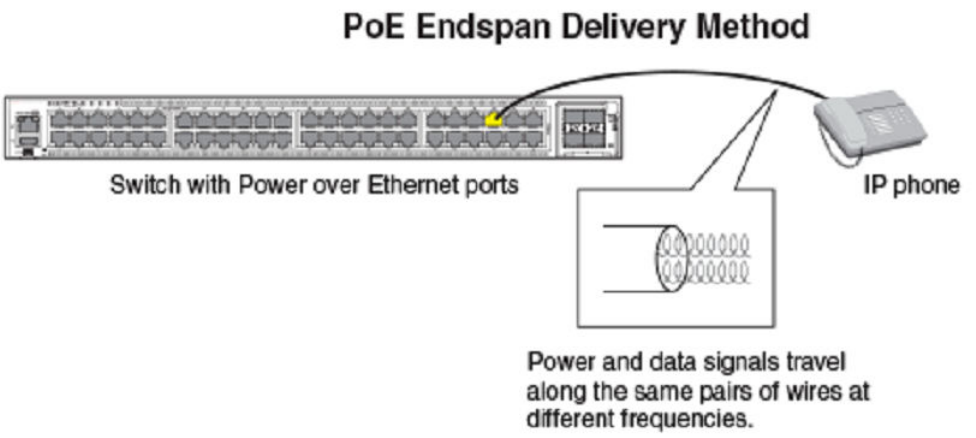
PoE midspan method
The PoE Midspan method uses an intermediate device, usually another PD, to inject power into the network. The intermediate device is
positioned between the switch and the PD and delivers power over the network using the spare pairs of wires (Alternative B). The
intermediate device has multiple channels (typically 6 to 24), and each of the channels has data input and a data-plus-power RJ-45
output connector.
The Midspan method is illustrated in the following gure.
Power over Ethernet overview
Brocade FastIron Management Conguration Guide, 08.0.60
Part Number: 53-1004918-03 163
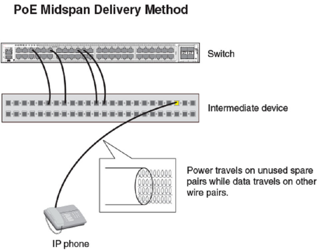
PoE autodiscovery
PoE autodiscovery is a detection mechanism that identies whether an installed device is 802.3af- or 802.3at-compatible. When you
plug a device into an Ethernet port that is capable of providing inline power, the autodiscovery mechanism detects whether the device
requires power and how much power is needed. The autodiscovery mechanism also has a disconnect protection mechanism that shuts
down the power once a PD has been disconnected from the network or when a faulty PD has been detected. This feature enables safe
installation and prevents high-voltage damage to equipment.
PoE autodiscovery is achieved by periodically transmitting current or test voltages that can detect when a PD is attached to the network.
When an 802.3af- or 802.3at-compatible device is plugged into a PoE, PoE+, or PoH port, the PD reects test voltage back to the
power-sourcing device (the Brocade device), ultimately causing the power to be switched on. Devices not compatible with 802.3af do
not reect test voltage back to the power-sourcing device.
Power over Ethernet overview
Brocade FastIron Management Conguration Guide, 08.0.60
164 Part Number: 53-1004918-03

Power class
A power class determines the amount of power a PD receives from power-sourcing equipment. When a valid PD is detected, the
Brocade PoE device performs power classication by inducing a specic voltage and measuring the current consumption of the PD.
Depending on the measured current, the appropriate class is assigned to the PD. PDs that do not support classication are assigned a
class of 0 (zero). The following table shows the dierent power classes and their respective power consumption needs.
TABLE 29 Power classes for PDs
Class Usage Power (watts) from Power-Sourcing Device
Standard PoE PoE+ High PoE Power over HDBaseT
(PoH)
0 default 15.4 15.4 15.4 15.4
1 optional 4 4 4 4
2 optional 7 7 7 7
3 optional 15.4 15.4 15.4 15.4
4 optional N/A 306606 795
Power specications
The 802.3af (PoE) standard limits power to 15.4 watts (44 to 50 volts) from the power-sourcing device, in compliance with safety
standards and existing wiring limitations. Though limited by the 802.3af standard, 15.4 watts of power was ample for most PDs, which
consumed an average of 5 to 12 watts of power (IP phones, wireless LAN access points, and network surveillance cameras each
consume an average of 3.5 to 9 watts of power). The 802.3at 2008 (PoE+) standard nearly doubles the power, providing 30 watts (52
to 55 volts) from the power-sourcing device. The 802.3at 2009 (High PoE) standard increases available power again, to 60 watts for
High PoE and 95 watts for Power over HDBase-T (PoH).
NOTE
PoH ports on Brocade devices allocate 95 watts for PoE+, High PoE, and PoH PDs.
The PoE power supply provides power to the PoE circuitry block and ultimately to PoE power-consuming devices. The number of PoE
power-consuming devices that one PoE power supply can support depends on the number of watts required by each power-consuming
device and the capacity of the power supply or power supplies. Each PoE or PoE+ port supports a maximum of 15.4 or 30 watts of
power per power-consuming device. Each PoH port supports a maximum of 95 watts of power (lower wattage can be negotiated
through LLDP messages).
As an example, if each PoE power-consuming device attached to a FastIron PoE device is budgeted to consume 30 watts of power, one
720- or 748-watt power supply can power up to 24 PoE ports. FastIron platforms support either a second power supply or an external
power supply (EPS) to augment PoE power budget, depending on the product. Refer to the power supply specications in the Brocade
FastIron hardware installation guide for the appropriate FastIron device.
By default, a FastIron device pre-allocates power of 15.4 for a physically operational PoE congured port, 30 watts for a PoE+
congured port, and 95 watts for a PoH port.
6First eight ports of Brocade ICX 7450-24P or ICX 7450-48P supply 95w unless PD negotiates lower power requirement through LLDP protocol
messages.
7Maximum power required for High PoE is 60 watts.
Power over Ethernet overview
Brocade FastIron Management Conguration Guide, 08.0.60
Part Number: 53-1004918-03 165
Power over Ethernet cabling requirements
The 802.3af and 802.3at standards currently support PoE and PoE+ on 10/100/1000-Mbps Ethernet ports operating over standard
Category 5 unshielded twisted pair (UTP) cable or better. If your network uses cabling categories less than Category 5, you cannot
implement PoE without rst upgrading your cables to Category 5 UTP cable or better. PoH has the following cabling requirements
based on distance:
• Cat 5e - 25 meters
• Cat 6/6a - 55 meters
• Cat 7 - 100 meters.
Supported powered devices
Brocade PoE devices support a wide range of IP powered devices, including the following:
• Voice over IP (VoIP) phones
• Wireless LAN access points
• IP surveillance cameras
The following sections briey describe these IP powered devices.
VoIP
Voice over IP (VoIP) is the convergence of traditional telephony networks with data networks. VoIP uses the existing data network
infrastructure as the transport system for both services. Voice is traditionally transported on a network that uses circuit-switching
technology, but data networks are built on packet-switching technology. To achieve this convergence, technology has been developed to
take a voice signal, which originates as an analog signal, and transport it within a digital medium. This is done by devices such as VoIP
telephones that receive the originating tones and place them in UDP packets. The size and frequency of these UDP packets depends on
the coding / decoding (CODEC) technology that has been implemented in the VoIP telephone or device. The VoIP control packets use
TCP/IP format.
IP surveillance cameras
IP surveillance technology provides digital streaming of video over Ethernet, providing real-time, remote access to video feeds from
cameras.
The main benet of using IP surveillance cameras on the network is that you can view surveillance images from any computer on the
network. If you have access to the Internet, you can securely connect from anywhere in the world to view a chosen facility or even a single
camera from your surveillance system. By using a Virtual Private Network (VPN) or the company intranet, you can manage password-
protected access to images from the surveillance system. Similar to secure payment over the Internet, images and information are kept
secure and can be viewed only by approved personnel.
Installing PoE rmware
This section lists the PoE rmware le types supported and the procedure to install them on ICX devices.
Firmware image le types
The following table lists PoE rmware les. The rmware les are specic to each device and cannot be used in any other device.
Power over Ethernet overview
Brocade FastIron Management Conguration Guide, 08.0.60
166 Part Number: 53-1004918-03

TABLE 30 PoE Firmware les
Product PoE Firmware
ICX 7250 icx72xx_poeplus_01.6.1.b009.fw
ICX 7450 icx74xx_poh_01.6.1.b009.fw
Installing PoE rmware with TFTP
PoE rmware is stored in the PoE controller of the FastIron switch. You can install PoE rmware from the TFTP server on a FastIron
switch using CLI commands. To do so, you should have a valid rmware image on the TFTP server.
You can install PoE rmware only on one device at a time. To install PoE rmware on stacked units, you need to install it individually on
every device in the stack.
NOTE
The PoE rmware upgrade feature is not supported in FIPS mode on Brocade devices.
NOTE
Installation of PoE rmware interrupts PoE services on the individual device or module as it is upgraded. PoE service restarts
once PoE rmware installation is complete.
1. Place the PoE rmware on a TFTP server to which the Brocade device has access.
Power over Ethernet overview
Brocade FastIron Management Conguration Guide, 08.0.60
Part Number: 53-1004918-03 167
2. Copy the PoE rmware from the TFTP server into the switch as shown in the following examples. Be sure to use the correct le
image for the platform.
To install PoE rmware on ICX platforms, use the inline power install-rmware stack-unit command.
device# inline power install-firmware stack-unit 1 tftp 10.120.54.161 icx74xx_poh_01.6.1.b009.fw
To install rmware on a stack, you need to install rmware on one switch at a time with the inline power install-rmware stack-
unit command.
deviceFamily_Stack# inline power install-firmware stack-unit 3 tftp 10.20.65.51
icx74xx_poh_01.6.1.b009.fw
The process of PoE installation begins. You should see output similar to the following.
Family_Stack# Flash Memory Write (8192 bytes per dot) ..............
tftp download successful stackId = 3 file name = poe-fw
Sending PoE Firmware to Stack Unit 3.
Flash Memory Write (8192 bytes per dot) ...................
PoE: Power disabled on port 3/1/1 because of power management.
PoE: Power disabled on port 3/1/2 because of power management.
PoE: Power disabled on port 3/1/3 because of power management.
PoE: Power disabled on port 3/1/4 because of power management.
PoE: Power disabled on port 3/1/5 because of power management.
PoE: Power disabled on port 3/1/6 because of power management.
PoE: Power disabled on port 3/1/7 because of power management.
PoE: Power disabled on port 3/1/8 because of power management.
PoE: Power disabled on port 3/1/9 because of power management.
PoE: Power disabled on port 3/1/10 because of power management.
PoE: Power disabled on port 3/1/11 because of power management.
PoE: Power disabled on port 3/1/12 because of power management.
PoE: Power disabled on port 3/1/13 because of power management.
PoE: Power disabled on port 3/1/14 because of power management.
PoE: Power disabled on port 3/1/15 because of power management.
PoE: Power disabled on port 3/1/16 because of power management.
PoE: Power disabled on port 3/1/17 because of power management.
PoE: Power disabled on port 3/1/18 because of power management.
PoE: Power disabled on port 3/1/19 because of power management.
PoE: Power disabled on port 3/1/20 because of power management.
PoE: Power disabled on port 3/1/21 because of power management.
PoE: Power disabled on port 3/1/22 because of power management.
PoE: Power disabled on port 3/1/23 because of power management.
PoE: Power disabled on port 3/1/24 because of power management.
U3-MSG: PoE Warning: Upgrading firmware in slot 1....DO NOT HOTSWAP OR POWER DOWN THE MODULE.
U3-MSG: PoE Info: FW Download on slot 1...sending download command...
U3-MSG: PoE Info: FW Download on slot 1...TPE response received.
U3-MSG: PoE Info: FW Download on slot 1...sending erase command...
U3-MSG: PoE Info: FW Download on slot 1...erase command...accepted.
U3-MSG: PoE Info: FW Download on slot 1...erasing firmware memory...
U3-MSG: PoE Info: FW Download on slot 1...erasing firmware memory...completed
U3-MSG: PoE Info: FW Download on slot 1...sending program command...
U3-MSG: PoE Info: FW Download on slot 1...sending program command...accepted.
U3-MSG: PoE Info: FW Download on slot 1...programming firmware...takes around 12 minutes....
U3-MSG: PoE Info: Firmware Download on slot 1.....10 percent completed.
U3-MSG: PoE Info: Firmware Download on slot 1.....20 percent completed.
U3-MSG: PoE Info: Firmware Download on slot 1.....30 percent completed.
U3-MSG: PoE Info: Firmware Download on slot 1.....40 percent completed.
U3-MSG: PoE Info: Firmware Download on slot 1.....50 percent completed.
U3-MSG: PoE Info: Firmware Download on slot 1.....60 percent completed.
U3-MSG: PoE Info: Firmware Download on slot 1.....70 percent completed.
U3-MSG: PoE Info: Firmware Download on slot 1.....80 percent completed.
U3-MSG: PoE Info: Firmware Download on slot 1.....90 percent completed.
U3-MSG: PoE Info: Firmware Download on slot 1.....100 percent completed.
U3-MSG: PoE Info: FW Download on slot 1...programming firmware...completed.
U3-MSG: PoE Info: FW Download on slot 1...upgrading firmware...completed. Module will be reset.
U3-MSG: PoE Info: Resetting module in slot 1....completed.
PoE: Failed power allocation of 30000 mwatts on port 3/1/13. Will retry when more power budget.
PoE: Failed power allocation of 30000 mwatts on port 3/1/14. Will retry when more power budget.
PoE: Failed power allocation of 30000 mwatts on port 3/1/15. Will retry when more power budget.
Power over Ethernet overview
Brocade FastIron Management Conguration Guide, 08.0.60
168 Part Number: 53-1004918-03
PoE: Failed power allocation of 30000 mwatts on port 3/1/16. Will retry when more power budget.
PoE: Failed power allocation of 30000 mwatts on port 3/1/17. Will retry when more power budget.
PoE: Failed power allocation of 30000 mwatts on port 3/1/18. Will retry when more power budget.
PoE: Failed power allocation of 30000 mwatts on port 3/1/19. Will retry when more power budget.
PoE: Failed power allocation of 30000 mwatts on port 3/1/20. Will retry when more power budget.
PoE: Failed power allocation of 30000 mwatts on port 3/1/21. Will retry when more power budget.
PoE: Failed power allocation of 30000 mwatts on port 3/1/22. Will retry when more power budget.
PoE: Failed power allocation of 30000 mwatts on port 3/1/23. Will retry when more power budget.
PoE: Failed power allocation of 30000 mwatts on port 3/1/24. Will retry when more power budget.
3. After the rmware is downloaded into the controller, the controller resets and reboots with the new PoE rmware, You should
see output similar to the following.
[MEMBER]local-3@ICX7450-24P Router>Download request from active unit 1 mac = 748e.f8dc.b39c
Downloading - poe.fw
Done.
PoE Info: Programming Brocade defaults.....
PoE Info: Programming Brocade defaults. Step 1: Writing port defaults on module in slot 1....
PoE Info: Programming Brocade Defaults: Step 2: Writing PM defaults on module in slot 1.
PoE Info: Programming Brocade defaults. Step 3: Writing user byte 0xf0 on module in slot 1.
PoE Info: Programming Brocade defaults. Step 4: Saving settings on module in slot 1.
PoE Info: Programming Brocade defaults....completed.
[MEMBER]local-3@ICX7450-24P Router>
NOTE
If you are attempting to transfer a le using TFTP but have received an error message, refer to the Diagnostic error
codes and remedies for TFTP transfers section.
Upgrading the PoE rmware le using SCP
To use the PoE feature, download the PoE rmware le. You can then install it using SCP as shown in the following procedure.
NOTE
In a stack, you must install the PoE rmware on each individual member unit.
1. Place the PoE rmware le on an SCP-enabled host to which the Brocade device has access.
2. Copy the PoE rmware le from the SCP-enabled host into the switch by entering the following command on the SCP-enabled
host.
C:/>pscp icx74xx_poh_01.6.1.b009.fw host1@10.10.1.1:firmware:stackid:1
The process of PoE rmware installation begins.
Power over Ethernet overview
Brocade FastIron Management Conguration Guide, 08.0.60
Part Number: 53-1004918-03 169
3. In the FastIron device CLI, you should see output similar to the following.
device(config)# scp download successful stackId = 1 file name = poe-fw
Sending PoE Firmware to Stack Unit 1.
PoE Warning: Upgrading firmware in slot 1....DO NOT SWITCH OVER OR POWER DOWN
THE UNIT.
PoE Info: FW Download on slot 1...sending download command...
PoE Info: FW Download on slot 1...TPE response received.
PoE Info: FW Download on slot 1...sending erase command...
PoE Info: FW Download on slot 1...erase command...accepted.
PoE Info: FW Download on slot 1...erasing firmware memory...
PoE Info: FW Download on slot 1...erasing firmware memory...completed
PoE Info: FW Download on slot 1...sending program command...
PoE Info: FW Download on slot 1...sending program command...accepted.
PoE Info: FW Download on slot 1...programming firmware...takes around 6
minutes....
Brocade(config)# U1-MSG: PoE Info: Firmware Download on slot 1.....10 percent
completed.
U1-MSG: PoE Info: Firmware Download on slot 1.....20 percent completed.
U1-MSG: PoE Info: Firmware Download on slot 1.....30 percent completed.
U1-MSG: PoE Info: Firmware Download on slot 1.....40 percent completed.
U1-MSG: PoE Info: Firmware Download on slot 1.....50 percent completed.
U1-MSG: PoE Info: Firmware Download on slot 1.....60 percent completed.
U1-MSG: PoE Info: Firmware Download on slot 1.....70 percent completed.
U1-MSG: PoE Info: Firmware Download on slot 1.....80 percent completed.
U1-MSG: PoE Info: Firmware Download on slot 1.....90 percent completed.
U1-MSG: PoE Info: Firmware Download on slot 1.....100 percent completed.
PoE Info: FW Download on slot 1...programming firmware...completed.
PoE Info: FW Download on slot 1...upgrading firmware...completed. Module will
be reset.
4. After the rmware le is loaded into the device, the device resets and reboots with the new PoE rmware. You should see output
similar to the following.
PoE Info: Resetting in slot 1....
PoE Info: Resetting module in slot 1....completed.
PoE Info: Programming Brocade defaults.....
PoE Info: Programming Brocade defaults. Step 1: Writing port defaults on
module in slot 1....
PoE Info: Programming Brocade Defaults: Step 2: Writing PM defaults on module
in slot 1.
PoE Info: Programming Brocade defaults. Step 3: Writing user byte 0xf0 on
module in slot 1.
PoE Info: Programming Brocade defaults. Step 4: Saving settings on module in
slot 1.
PoE Info: Programming Brocade defaults....completed
PoE and CPU utilization
Depending on the number of PoE-congured ports that have active power devices, there may be a slight and noticeable increase of up
to 15 percent in CPU utilization. This is normal behavior for PoE and in typical scenarios does not aect the functionality of other
features on the switch.
Power over Ethernet overview
Brocade FastIron Management Conguration Guide, 08.0.60
170 Part Number: 53-1004918-03
Enabling and disabling Power over Ethernet
To enable a port to receive inline power for power-consuming devices, use the inline power command for the appropriate port. Here is
an example.
device# configure terminal
device(config)# interface ethernet 1/1/1
device(config-if-e1000-1/1/1)# inline power
Once you have entered the commands to enable inline power, the console displays the following message.
device(config-if-e1000-1/1/1)# PoE Info: Power enabled on port 1/1/1.
The following example disables inline power on a range of ports.
device# configure terminal
device(config)# interface ethernet 1/1/1 to 1/1/48
device(config-mif-1/1/1-1/1/48)# no inline power
PoE: Power disabled on port 1/1/1 because of admin off.
PoE: Power disabled on port 1/1/2 because of admin off.
PoE: Power disabled on port 1/1/3 because of admin off.
PoE: Power disabled on port 1/1/4 because of admin off.
PoE: Power disabled on port 1/1/5 because of admin off.
PoE: Power disabled on port 1/1/6 because of admin off.
PoE: Power disabled on port 1/1/7 because of admin off.
PoE: Power disabled on port 1/1/8 because of admin off.
PoE: Power disabled on port 1/1/9 because of admin off.
PoE: Power disabled on port 1/1/10 because of admin off.
PoE: Power disabled on port 1/1/11 because of admin off.
PoE: Power disabled on port 1/1/12 because of admin off.
PoE: Power disabled on port 1/1/13 because of admin off.
PoE: Power disabled on port 1/1/14 because of admin off.
PoE: Power disabled on port 1/1/15 because of admin off.
PoE: Power disabled on port 1/1/16 because of admin off.
PoE: Power disabled on port 1/1/17 because of admin off.
PoE: Power disabled on port 1/1/18 because of admin off.
PoE: Power disabled on port 1/1/19 because of admin off.
PoE: Power disabled on port 1/1/20 because of admin off.
PoE: Power disabled on port 1/1/21 because of admin off.
PoE: Power disabled on port 1/1/22 because of admin off.
PoE: Power disabled on port 1/1/23 because of admin off.
PoE: Power disabled on port 1/1/24 because of admin off.
PoE: Power disabled on port 1/1/25 because of admin off.
PoE: Power disabled on port 1/1/26 because of admin off.
PoE: Power disabled on port 1/1/27 because of admin off.
PoE: Power disabled on port 1/1/28 because of admin off.
PoE: Power disabled on port 1/1/29 because of admin off.
PoE: Power disabled on port 1/1/30 because of admin off.
PoE: Power disabled on port 1/1/31 because of admin off.
PoE: Power disabled on port 1/1/32 because of admin off.
PoE: Power disabled on port 1/1/33 because of admin off.
PoE: Power disabled on port 1/1/34 because of admin off.
PoE: Power disabled on port 1/1/35 because of admin off.
PoE: Power disabled on port 1/1/36 because of admin off.
PoE: Power disabled on port 1/1/37 because of admin off.
PoE: Power disabled on port 1/1/38 because of admin off.
PoE: Power disabled on port 1/1/39 because of admin off.
PoE: Power disabled on port 1/1/40 because of admin off.
PoE: Power disabled on port 1/1/41 because of admin off.
PoE: Power disabled on port 1/1/42 because of admin off.
PoE: Power disabled on port 1/1/43 because of admin off.
PoE: Power disabled on port 1/1/44 because of admin off.
PoE: Power disabled on port 1/1/45 because of admin off.
PoE: Power disabled on port 1/1/46 because of admin off.
PoE: Power disabled on port 1/1/47 because of admin off.
PoE: Power disabled on port 1/1/48 because of admin off.
Enabling and disabling Power over Ethernet
Brocade FastIron Management Conguration Guide, 08.0.60
Part Number: 53-1004918-03 171
NOTE
Inline power should not be congured between two switches, as it may cause unexpected behavior.
NOTE
FastIron PoE and PoE+ devices can automatically detect whether a power-consuming device is 802.3af- or 802.3at-
compliant.
Disabling support for PoE legacy power-consuming
devices
Brocade PoE devices automatically support most legacy power-consuming devices (devices not compliant with 802.3af 802.3at), as
well as all 802.3af- and 802.3at-compliant devices. You can disable and re-enable support for legacy PoE power-consuming devices
on a global basis (on the entire device). When you disable legacy support, 802.3af- and 802.3at-compliant devices are not aected.
To disable support for legacy power-consuming devices on a non-stackable device, enter the following command from the global cong
mode of the CLI.
device(config)# no legacy-inline-power
To disable support for legacy power-consuming devices on a stackable device, enter the following command from the stack unit cong
model of the CLI.
device(config-unit-2)# no legacy-inline-power
NOTE
The no legacy-inline-power command does not require a software reload if it is entered prior to connecting the PDs. If the
command is entered after the PDs are connected, the conguration must be saved (write memory ) and the software reloaded
after the change is placed into eect.
NOTE
By default, the inline-power command reserves 30 watts. On Power over HDBaseT (PoH) ports, inline-power reserves 95
watts.
To re-enable support for legacy power-consuming devices after it has been disabled, enter the legacy-inline-power command (without
the no parameter).
Use the show running-cong command to view whether support for PoE legacy power-consuming devices is enabled or disabled.
The following example turns o legacy inline power for a single stack unit.
device(config)# no legacy-inline-power
The following example turns o legacy inline power support on the entire stack.
device# configure terminal
device(config)# stack unit 12
device(config)# no legacy-inline-power
Disabling support for PoE legacy power-consuming devices
Brocade FastIron Management Conguration Guide, 08.0.60
172 Part Number: 53-1004918-03
Enabling the detection of PoE power requirements
advertised through CDP
Many power-consuming devices, such as Cisco VoIP phones and other vendors’ devices, use the Cisco Discovery Protocol (CDP) to
advertise their power requirements to power-sourcing devices, such as Brocade PoE devices. Brocade power-sourcing equipment is
compatible with Cisco and other vendors’ power consuming devices and can detect and process power requirements for these devices
automatically.
NOTE
If you congure a port with a maximum power level or a power class for a power-consuming device, the power level or power
class takes precedence over the CDP power requirement. If you want a device to adhere to the CDP power requirement, do not
congure a power level or power class on the associated port.
Command syntax for PoE power requirements
To enable the Brocade device to detect CDP power requirements, enter the following commands.
device# configure terminal
device(config)# cdp run
Use the no form of the command to disable the detection of CDP power requirements.
Setting the maximum power level for a PoE power-
consuming device
When PoE is enabled on a port to which a power-consuming device, or PD, is attached, by default, a Brocade PoE device supplies 15.4
watts of power at the RJ-45 jack, minus any power loss through the cables. A PoE+ device supplies either 15.4 or 30 watts of power
(depending on the type of PD connected to the port), minus any power loss through the cables. A PoH device supplies 15.4, 30, or 95
watts of power (depending on the type of PD connected to the port), minus any power loss through the cables.
As an example, a PoE port with a default maximum power level of 15.4 watts receives a maximum of 12.95 watts of power after 2.45
watts of power loss through the cable. This is compliant with the IEEE 802.3af and 802.3at specications for delivering inline power.
Devices that are congured to receive less PoE power, for example, 4.0 watts of power, experience a lower rate of power loss through the
cable.
If desired, you can manually congure the maximum amount of power that the Brocade PoE device supplies at the RJ-45 jack.
Considerations for setting power levels
Consider the following when enabling this feature:
• There are two ways to congure the power level for a PoE, PoE+, or High PoE power-consuming device. The rst method is
discussed in this section. The other method is provided in the section Setting the power class for a PoE power-consuming
device on page 174. For each PoE port, you can congure either a maximum power level or a power class. You cannot
congure both. You can, however, congure a maximum power level on one port and a power class on another port.
• The Brocade PoE, PoE+, or High PoE device adjusts the power on a port only if there are available power resources. If power
resources are not available, the following message is displayed on the console and in the Syslog:
PoE: Failed power allocation of 30000 mwatts on port 1/1/21. Will retry when more power budget.
Setting the maximum power level for a PoE power-consuming device
Brocade FastIron Management Conguration Guide, 08.0.60
Part Number: 53-1004918-03 173

• If you are not using High PoE or PoH devices in any of the rst 8 ports of the ICX7450-48P or ICX7450-24P, Brocade
recommends that you limit the power on those ports using the inline power power-limit command. Limiting power with the
inline power power-by-class 4 command does not work for the ICX7450 because Class 4 encompasses 30-95W. However,
Class 4 on units that do not support PoH or High Power is still 30W.
• FastIron devices pre-allocate power as per the congured maximum power for a physically operational PoE, PoE+, or High PoE
congured port.
Conguring power levels command syntax
To congure the maximum power level for a power-consuming device, use the inline power power-limit command as shown in the
following example.
device# configure terminal
device(config)# interface ethernet 1/1/1
device(config-if-e1000-1/1/1)# inline power power-limit 14000
These commands enable inline power on interface ethernet 1 in slot 1 of unit 1 and set the PoE power level to 14,000 milliwatts (14
watts).
Syntax: inline power power-limit power-level
The power level variable is the maximum power level in number of milliwatts. The following values are supported:
•PoE - Enter a value from 1000 through 15,400. The default is 15,400.
•PoE+ - Enter a value from 1000 through 30,000. The default is 30,000.
•PoH - Enter a value from 1000 through 95,000. The default is 95,000. Value is always adjusted to nearest multiple of 5.
NOTE
Do not congure a power level higher than the default listed. Setting the power level higher than the default could damage the
PD.
For information about resetting the maximum power level, refer to Resetting PoE parameters on page 176.
Setting the power class for a PoE power-consuming
device
A power class species the maximum amount of power that a Brocade PoE, PoE+, or PoH device supplies to a power-consuming
device. The following table shows the dierent power classes and their respective maximum power allocations.
TABLE 31 Power classes for PDs
Class Usage Power (watts) from Power-Sourcing Device
Standard PoE PoE+ Power over HDBaseT (PoH)
0 default 15.4 15.4 15.4
1 optional 4 4 4
2 optional 7 7 7
3 optional 15.4 15.4 15.4
4 optional 15.4 30 95
Setting the power class for a PoE power-consuming device
Brocade FastIron Management Conguration Guide, 08.0.60
174 Part Number: 53-1004918-03
Refer to Considerations for setting power levels on page 173 for essential information. Consider the following points when setting the
power class for a PoE power-consuming device.
• The power class includes any power loss through the cables. For example, a PoE port with a power class of 3 (15.4 watts)
receives a maximum of 12.95 watts of power after 2.45 watts of power loss through the cable. This is compliant with the IEEE
802.3af and 802.3at specications for delivering inline power. Devices that are congured to receive less PoE power, for
example, class 1 devices (4.0 watts), experience a lower rate of power loss through the cable.
• The Brocade PoE, PoE+, or PoH device adjusts the power on a port only if there are available power resources. If power
resources are not available, the following message is displayed on the console and in the Syslog:
PoE: Failed power allocation of 30000 mwatts on port 1/1/21. Will retry when more power budget.
Setting the power class command syntax
To congure the power class for a PoE power consuming device, enter commands such as the following.
device# configure terminal
device(config)# interface ethernet 1/1/1
device(config-if-e1000-1/1/1)# inline power power-by-class 4
Warning: Inline power configuration on port 1/1/1 has been modified.
device(config-if-e1000-1/1/1)# show inline power 1
Power Capacity: Total is 720000 mWatts. Current Free is 690000 mWatts.
Power Allocations: Requests Honored 3 times
Port Admin Oper ---Power(mWatts)--- PD Type PD Class Pri Fault/
State State Consumed Allocated Error
--------------------------------------------------------------------------
1/1/1 On On 14460 30000 802.3af Class 3 3 n/a
These commands enable inline power on interface ethernet 1 in slot 1 of unit 1 and set the power class to 2.
For information about resetting the power class, refer to Resetting PoE parameters on page 176.
Setting the inline power priority for a PoE port
In a conguration where PoE power-consuming devices collectively have a greater demand for power than the PoE power supply or
supplies can provide, the FastIron PoE device must place the PoE ports that it cannot power in standby or denied mode (waiting for
power) until the available power increases. The available power increases when one or more PoE ports are powered down, or, if
applicable, when an additional PoE power supply is installed in the FastIron PoE device.
When PoE ports are in standby or denied mode (waiting for power) and the FastIron PoE device receives additional power resources, by
default, the device allocates newly available power to the standby ports in priority order, with the highest priority ports rst, followed by
the next highest priority ports, and so on. Within a given priority, standby ports are considered in ascending order, by slot number and
then by port number, provided enough power is available for the ports. For example, PoE port 1/1/11 should receive power before PoE
port 1/2/1. However, if PoE port 1/1/11 needs 12 watts of power and PoE port 1/2/1 needs 10 watts of power, but only 11 watts of
power become available on the device, the FastIron PoE device allocates the power to port 1/2/1 because it does not have sucient
power for port 1/1/11.
You can congure an inline power priority on PoE ports, so that ports with a higher inline power priority take precedence over ports with a
low inline power priority. For example, if a new PoE port comes online and the port is congured with a high priority, if necessary (if power
is already fully allocated to power consuming devices), the FastIron PoE device removes power from a PoE port or ports that have a
lower priority and allocates the power to the PoE port that has the higher value.
Setting the inline power priority for a PoE port
Brocade FastIron Management Conguration Guide, 08.0.60
Part Number: 53-1004918-03 175
Ports that are congured with the same inline power priority are given precedence based on the slot number and port number in
ascending order, provided enough power is available for the port. For example, if both PoE port 1/1/2 and PoE port 1/2/1 have a high
inline power priority value, PoE port 1/1/2 receives power before PoE port 1/2/1. However, if PoE port 1/1/2 needs 12 watts of power
and PoE port 1/2/1 needs 10 watts of power, but only 11 watts of power become available on the device, the FastIron PoE device
allocates the power to PoE port 1/2/1 because it does not have sucient power for port 1/1/2. By default, all ports are congured with
a low inline power priority.
Command syntax for setting the inline power priority for a PoE port
To congure an inline power priority for a PoE port on a FastIron PoE device, use the inline power priority command as shown in the
following example.
device# configure terminal
device(config)# interface ethernet 1/1/1
device(config-if-e1000-1/1/1)# inline power
decouple-datalink Decouple PoE from data link operational behavior
power-by-class Allocate power based on class of the power devices
power-limit Allocate power based on specified limit
priority Priority class for the purpose of power management
<cr>
device(config-if-e1000-1/1/1)# inline power priority
DECIMAL Priority value 1..3 (highest..lowest)
<cr>
device(config-if-e1000-1/1/1)# inline power priority 1
Warning: Inline power configuration on port 1/1/1 has been modified.
In the previous example, the command enables inline power on interface ethernet 1 in slot 1 of unit 1 and sets the inline power priority
level to high.
Use the inline power command without a priority number to reset a port priority to the default (low) priority.
Use the no inline power command to disable the port from receiving inline power.
For information about resetting the inline power priority, refer to "Resetting PoE parameters."
To view the inline power priority for all PoE ports, issue the show inline power command from the Privileged exec level of the CLI. Refer
to "Displaying PoE operational status."
Resetting PoE parameters
You can override or reset PoE port parameters including power priority, power class, and maximum power level. To do so, you must
specify each PoE parameter in the CLI command line.
Changing a PoE port power priority from low to high
To change a PoE port power priority from low (the default value) to high and keep the current maximum congured power level of 3000,
enter commands such as the following.
device# configure terminal
device(config)# interface ethernet 1/1/1
device(config-if-e1000-1/1/1)# inline power priority 2 power-limit 3000
You must specify both the inline power priority and the maximum power level (power-limit command), even though you are keeping the
current congured maximum power level at 3000. If you do not specify the maximum power level, the device will apply the default value.
Also, you must specify the inline power priority before specifying the power limit.
Resetting PoE parameters
Brocade FastIron Management Conguration Guide, 08.0.60
176 Part Number: 53-1004918-03
Changing a port power class from 2 to 3
To change a port power class from 2 (7 watts maximum) to 3 (15.4 watts maximum) and keep the current congured power priority of 2,
enter commands such as the following.
device# configure terminal
device(config)# interface ethernet 1/1/1
device(config-if-e1000-1/1/1)# inline power priority 2 power-by-class 3
You must specify both the power class and the inline power priority, even though you are not changing the power priority. If you do not
specify the power priority, the device will apply the default value of 3 (low priority). Also, you must specify the inline power priority before
specifying the power class.
The following example sets PoE parameters on interface 2/1/1 in stack unit 12.
device# configure terminal
device(config)# stack unit 12
device(config)# interface ethernet 2/1/1
device(config-if-e1000-2/1/1)# inline power priority 3 power-limit 14000
Displaying Power over Ethernet information
The show commands described in this section are available for viewing PoE operational status, PD data, and PoE power supply status.
Displaying PoE operational status
The show inline power command displays operational information about Power over Ethernet.
You can view the PoE operational status for the entire device, for a specic PoE module only, or for a specic interface only. In addition,
you can use the show inline power detail command to display in-depth information about PoE power supplies. To display PoE data
specic to PD ports, use the show inline power pd command.
The following example displays show inline power command output for a PoE device.
device# show inline power
Power Capacity: Total is 720000 mWatts. Current Free is 384000 mWatts.
Power Allocations: Requests Honored 146 times
Port Admin Oper ---Power(mWatts)--- PD Type PD Class Pri Fault/
State State Consumed Allocated Error
--------------------------------------------------------------------------
1/1/1 On On 6385 7000 802.3af Class 2 3 n/a
1/1/2 On On 6479 7000 802.3af Class 2 3 n/a
1/1/3 On On 6479 7000 802.3af Class 2 3 n/a
1/1/4 On On 6573 7000 802.3af Class 2 3 n/a
1/1/5 On On 6479 7000 802.3af Class 2 3 n/a
1/1/6 On On 6479 7000 802.3af Class 2 3 n/a
1/1/7 On On 6385 7000 802.3af Class 2 3 n/a
1/1/8 On On 6385 7000 802.3af Class 2 3 n/a
1/1/9 On On 6385 7000 802.3af Class 2 3 n/a
1/1/10 On On 6479 7000 802.3af Class 2 3 n/a
1/1/11 On On 6385 7000 802.3af Class 2 3 n/a
1/1/12 On On 6385 7000 802.3af Class 2 3 n/a
1/1/13 On On 6291 7000 802.3af Class 2 3 n/a
1/1/14 On On 6385 7000 802.3af Class 2 3 n/a
1/1/15 On On 5915 7000 802.3af Class 2 3 n/a
1/1/16 On On 6385 7000 802.3af Class 2 3 n/a
1/1/17 On On 6479 7000 802.3af Class 2 3 n/a
1/1/18 On On 6573 7000 802.3af Class 2 3 n/a
Displaying Power over Ethernet information
Brocade FastIron Management Conguration Guide, 08.0.60
Part Number: 53-1004918-03 177
1/1/19 On On 6479 7000 802.3af Class 2 3 n/a
1/1/20 On On 6573 7000 802.3af Class 2 3 n/a
1/1/21 On On 6479 7000 802.3af Class 2 3 n/a
1/1/22 On On 6479 7000 802.3af Class 2 3 n/a
1/1/23 On On 6479 7000 802.3af Class 2 3 n/a
1/1/24 On On 6479 7000 802.3af Class 2 3 n/a
1/1/25 On On 6385 7000 802.3af Class 2 3 n/a
1/1/26 On On 6385 7000 802.3af Class 2 3 n/a
1/1/27 On On 6385 7000 802.3af Class 2 3 n/a
1/1/28 On On 6385 7000 802.3af Class 2 3 n/a
1/1/29 On On 6385 7000 802.3af Class 2 3 n/a
1/1/30 On On 6385 7000 802.3af Class 2 3 n/a
1/1/31 On On 6385 7000 802.3af Class 2 3 n/a
1/1/32 On On 6385 7000 802.3af Class 2 3 n/a
1/1/33 On On 6291 7000 802.3af Class 2 3 n/a
1/1/34 On On 6291 7000 802.3af Class 2 3 n/a
1/1/35 On On 6291 7000 802.3af Class 2 3 n/a
1/1/36 On On 6291 7000 802.3af Class 2 3 n/a
1/1/37 On On 6291 7000 802.3af Class 2 3 n/a
1/1/38 On On 6385 7000 802.3af Class 2 3 n/a
1/1/39 On On 6291 7000 802.3af Class 2 3 n/a
1/1/40 On On 6291 7000 802.3af Class 2 3 n/a
1/1/41 On On 6385 7000 802.3af Class 2 3 n/a
1/1/42 On On 6479 7000 802.3af Class 2 3 n/a
1/1/43 On On 6385 7000 802.3af Class 2 3 n/a
1/1/44 On On 6479 7000 802.3af Class 2 3 n/a
1/1/45 On On 6291 7000 802.3af Class 2 3 n/a
1/1/46 On On 6385 7000 802.3af Class 2 3 n/a
1/1/47 On On 6385 7000 802.3af Class 2 3 n/a
1/1/48 On On 6385 7000 802.3af Class 2 3 n/a
--------------------------------------------------------------------------
Total 306950 336000
Displaying PoE data specic to PD ports
The show inline power pd command displays operational information specic to the PD ports.
This command displays information about the number of PD ports available, how much PD power is available to PSE, how much PD
power is currently switched to PSE, and the PD port level status.
If a PD module is present, then the command displays the following global power information for the PD ports:
• Total PD power available to PSE
• Total PD power switched to PSE
In the absence of valid PSU power, the total PD power switched is equal to that available to PSE, as shown in the following example.
device# show inline power pd
Number of PD Ports: 2
Total PD Power Available to PSE: 22400
Total PD Power Switched to PSE: 22400
Port Oper Oper Fault/
State Mode Error
--------------------------------
1/2/1 On 802.3at n/a
1/2/2 On 802.3at n/a
The following shows an example of the show inline power pd display output on a PoE device with the internal PSU up and no PD ports
on.
device# show inline power pd
Number of PD Ports: 2
Total PD Power Available to PSE: 0
Total PD Power Switched to PSE: 0
Displaying Power over Ethernet information
Brocade FastIron Management Conguration Guide, 08.0.60
178 Part Number: 53-1004918-03
Port Oper Oper Fault/
State Mode Error
--------------------------------
1/2/1 Off n/a n/a
1/2/2 Off n/a n/a
The following shows an example of the show inline power pd display output on a PoE device with the internal PSU up and one PD port
on in the AT mode.
device# show inline power pd
Number of PD Ports: 2
Total PD Power Available to PSE: 0
Total PD Power Switched to PSE: 0
Port Oper Oper Fault/
State Mode Error
--------------------------------
1/2/1 On 802.3at n/a
1/2/2 Off n/a n/a
The following shows an example of the show inline power pd display output on a PoE device with the internal PSU down and two PD
ports on in the AT mode.
device# show inline power pd
Number of PD Ports: 2
Total PD Power Available to PSE: 22400
Total PD Power Switched to PSE: 22400
Port Oper Oper Fault/
State Mode Error
--------------------------------
1/2/1 On 802.3at n/a
1/2/2 On 802.3at n/a
Displaying detailed information about PoE power supplies
The show inline power detail command displays detailed operational information about the PoE power supplies in FastIron PoE
switches.
The following is an example of show inline power detail command output for an ICX 7250 stack.
device# show inline power detail
Power Supply Data On stack 1:
++++++++++++++++++
Power Supply Data:
++++++++++++++++++
Power Supply #1:
Max Curr: 13.3 Amps
Voltage: 54.0 Volts
Capacity: 720 Watts
Power Supply #2:
Max Curr: 6.6 Amps
Voltage: 54.0 Volts
Capacity: 360 Watts
Power Supply #3:
Max Curr: 6.6 Amps
Voltage: 54.0 Volts
Capacity: 360 Watts
POE Details Info. On Stack 1 :
Displaying Power over Ethernet information
Brocade FastIron Management Conguration Guide, 08.0.60
Part Number: 53-1004918-03 179
General PoE Data:
+++++++++++++++++
Firmware
Version
----------------
01.2.1 Build 003
Cumulative Port State Data:
+++++++++++++++++++++++++++
#Ports #Ports #Ports #Ports #Ports #Ports #Ports
Admin-On Admin-Off Oper-On Oper-Off Off-Denied Off-No-PD Off-Fault
-------------------------------------------------------------------------
48 0 0 48 0 47 1
Cumulative Port Power Data:
+++++++++++++++++++++++++++
#Ports #Ports #Ports Power Power
Pri: 1 Pri: 2 Pri: 3 Consumption Allocation
-----------------------------------------------
0 0 48 0.0 W 0.0 W
The following example provides details on an ICX 7250 connected to an EPS.
device# show chassis
The stack unit 1 chassis info:
Power supply 1 (NA - AC - PoE) present, status ok
Power supply 1 Fan Air Flow Direction: Front to Back
Power supply 2 (NA - DC - PoE) present, status ok
Fan 1 ok, speed (manual): [[1]]<->2
Fan 2 ok, speed (manual): [[1]]<->2
Fan controlled temperature:
Rule 1/2 (MGMT THERMAL PLANE): 49.0 deg-C
Rule 2/2 (PoE THERMAL PLANE): 40.5 deg-C
Fan speed switching temperature thresholds:
Rule 1/2 (MGMT THERMAL PLANE):
Speed 1: NM<----->93 deg-C
Speed 2: 82<----->105 deg-C (shutdown)
Rule 2/2 (PoE THERMAL PLANE):
Speed 1: NM<----->58 deg-C
Speed 2: 49<----->105 deg-C (shutdown)
Fan 1 Air Flow Direction: Front to Back
Fan 2 Air Flow Direction: Front to Back
Slot 1 Current Temperature: 49.0 deg-C (Sensor 1), 39.5 deg-C (Sensor 2)
Slot 2 Current Temperature: NA
Warning level.......: 100.0 deg-C
Shutdown level......: 105.0 deg-C
Boot Prom MAC : cc4e.24b4.906c
Management MAC: cc4e.24b4.906c
device# show inline power
Power Capacity: Total is 720000 mWatts. Current Free is 0 mWatts.
Power Allocations: Requests Honored 82 times
Port Admin Oper ---Power(mWatts)--- PD Type PD Class Pri Fault/
State State Consumed Allocated Error
--------------------------------------------------------------------------
1/1/1 On On 28264 30000 802.3at Class 4 3 n/a
1/1/2 On On 28921 30000 802.3at Class 4 3 n/a
1/1/3 On On 28170 30000 802.3at Class 4 3 n/a
Displaying Power over Ethernet information
Brocade FastIron Management Conguration Guide, 08.0.60
180 Part Number: 53-1004918-03
1/1/4 On On 28170 30000 802.3at Class 4 3 n/a
1/1/5 On On 28452 30000 802.3at Class 4 3 n/a
1/1/6 On On 28170 30000 802.3at Class 4 3 n/a
1/1/7 On On 28452 30000 802.3at Class 4 3 n/a
1/1/8 On On 28358 30000 802.3at Class 4 3 n/a
1/1/9 On On 28170 30000 802.3at Class 4 3 n/a
1/1/10 On On 28170 30000 802.3at Class 4 3 n/a
1/1/11 On On 28170 30000 802.3at Class 4 3 n/a
1/1/12 On On 28170 30000 802.3at Class 4 3 n/a
1/1/13 On On 28264 30000 802.3at Class 4 3 n/a
1/1/14 On On 28264 30000 802.3at Class 4 3 n/a
1/1/15 On On 26010 30000 802.3at Class 4 3 n/a
1/1/16 On On 28358 30000 802.3at Class 4 3 n/a
1/1/17 On On 28546 30000 802.3at Class 4 3 n/a
1/1/18 On On 28640 30000 802.3at Class 4 3 n/a
1/1/19 On On 28640 30000 802.3at Class 4 3 n/a
1/1/20 On On 28640 30000 802.3at Class 4 3 n/a
1/1/21 On On 28640 30000 802.3at Class 4 3 n/a
1/1/22 On On 28640 30000 802.3at Class 4 3 n/a
1/1/23 On On 28452 30000 802.3at Class 4 3 n/a
1/1/24 On On 28640 30000 802.3at Class 4 3 n/a
--------------------------------------------------------------------------
Total 679371 720000
device# show inline power detail
Power Supply Data On stack 1:
++++++++++++++++++
Power Supply Data:
++++++++++++++++++
Power Supply #1:
Max Curr: 6.6 Amps
Voltage: 54.0 Volts
Capacity: 360 Watts
Power Supply #2:
Max Curr: 6.6 Amps
Voltage: 54.0 Volts
Capacity: 360 Watts
POE Details Info. On Stack 1 :
General PoE Data:
+++++++++++++++++
Firmware
Version
----------------
01.6.1 Build 009
Cumulative Port State Data:
+++++++++++++++++++++++++++
#Ports #Ports #Ports #Ports #Ports #Ports #Ports
Admin-On Admin-Off Oper-On Oper-Off Off-Denied Off-No-PD Off-Fault
-------------------------------------------------------------------------
24 0 24 0 0 0 0
Cumulative Port Power Data:
+++++++++++++++++++++++++++
#Ports #Ports #Ports Power Power
Pri: 1 Pri: 2 Pri: 3 Consumption Allocation
-----------------------------------------------
0 0 24 679.371 W 720.0 W
Displaying Power over Ethernet information
Brocade FastIron Management Conguration Guide, 08.0.60
Part Number: 53-1004918-03 181
The following is an example of show inline power detail command output for an ICX 7150 device.
device# show inline power detail
Power Supply Data On unit 1:
++++++++++++++++++
Power Supply Data:
++++++++++++++++++
power supply 1 is not present
Power Supply #2:
Max Curr: 13.8 Amps
Voltage: 54.0 Volts
Capacity: 748 Watts
POE Details Info. On Unit 1 :
General PoE Data:
+++++++++++++++++
Firmware
Version
----------------
01.6.7 Build 013
Hardware
Version
-----------------
V1R3
Cumulative Port State Data:
+++++++++++++++++++++++++++
#Ports #Ports #Ports #Ports #Ports #Ports #Ports
Admin-On Admin-Off Oper-On Oper-Off Off-Denied Off-No-PD Off-Fault
-------------------------------------------------------------------------
30 2 7 25 0 23 2
Cumulative Port Power Data:
+++++++++++++++++++++++++++
#Ports #Ports #Ports Power Power
Pri: 1 Pri: 2 Pri: 3 Consumption Allocation
-----------------------------------------------
1 0 29 43.900 W 470.000 W
Inline power on PoE LAG ports
The inline power on Power over Ethernet (PoE) LAG ports feature allows you to enable inline power on PoE LAG ports with the
introduction of a new inline power ethernet command, available in global conguration mode.
Without the inline power ethernet command, you cannot enable inline power on any secondary LAG ports because the interface
conguration mode is not available for LAG secondary ports to run the inline power command.
You can congure inline power in interface conguration mode on a port that is not a member of a LAG. If that port then becomes part of
a LAG, you can use the inline power ethernet command to congure inline power parameters on any other port in that LAG.
LAG operational changes can aect the PoE power state unless the decouple-datalink keyword is used as a command option when
conguring inline power on the LAG ports. For more information, refer to “Decouple the PoE and datalink operations on PoE ports.”
After conguring inline power on PoE ports, you can verify the conguration using the show running-cong command. If you have
congured inline power on a regular PoE port in either global conguration or interface conguration mode, the inline power
conguration commands display under the interface conguration level. If a regular PoE port becomes a PoE LAG port, or a PoE LAG
Inline power on PoE LAG ports
Brocade FastIron Management Conguration Guide, 08.0.60
182 Part Number: 53-1004918-03

port is congured under global conguration mode, the inline power conguration commands display under the global conguration
level. If a LAG is removed, the inline power conguration commands for all ports display under the interface conguration level.
WARNING
If you downgrade to a release earlier than 08.0.01, there is no backwards compatibility for the inline power ethernet command
or the decouple-datalink keyword.
Restriction
If you want to keep decoupling in place on a PoE port when you congure the inline power ethernet command to change its other
parameters, for example, priority, you must also congure the decouple-datalink keyword.
Conguring inline power on PoE ports in a LAG
Perform the following steps to congure and deploy a link aggregation group (LAG) on the required PoE ports on both the Brocade
power sourcing equipment (PSE) and the PD. This task also enables inline power on the PoE ports.
1. Congure a LAG.
device(config)# lag "mylag" static id 5
This command congured a static LAG named mylag with an ID of 5.
2. Congure ports into the LAG membership.
device(config-lag-mylag)# ports ethernet 1/1/1 to 1/1/4
This command entered the four ports, 1/1/1, 1/1/2, 1/1/3, and 1/1/4, into LAG membership.
3. Congure a primary port for the LAG.
device(config-lag-mylag)# primary-port 1/1/1
4. Deploy the LAG.
device(config-lag-mylag)# deploy
This command deployed the mylag LAG.
5. Congure inline power on the primary port with the power-by-class option.
device(config)# inline power ethernet 1/1/1 power-by-class 3
This command congured inline power on the primary port,1/1/1, with power-by-class option 3. The range is 1 (lowest) to 3
(highest). The default is 1.
6. Congure inline power on a secondary port with the default option.
device(config)# inline power ethernet 1/1/2
This command congured inline power on port 1/1/2 with the default option.
7. Congure inline power on a secondary port with the power management option.
device(config)# inline power ethernet 1/1/3 priority 2
This command congured inline power on port 1/1/3 with power management option 2.
Inline power on PoE LAG ports
Brocade FastIron Management Conguration Guide, 08.0.60
Part Number: 53-1004918-03 183
8. Congure inline power on a secondary port, specifying the actual power value.
device(config)# inline power ethernet 1/1/4 power-limit 12000
This command congured inline power on the port 1/1/4, specifying an power value of 12000 mWatts.
Decouple PoE and datalink operations on PoE ports
Although PoE and datalink operations are functionally independent of each other, some datalink operations aect the operational
behavior of PoE ports. The Decoupling of PoE and Datalink Operations feature allows you to override the current default behavior.
The following are some example datalink operations that can aect the operational state of the PoE on PoE ports:
• Using disable or enable CLI on the power sourcing equipment (PSE) port interface
• Adding or deleting a tagged PSE port from a VLAN or VLAN group
• The PSE port enters an ErrDisable state
• Adding or deleting a PSE port from a LAG and deploying it
When the optional decouple-datalink keyword is congured using the inline power or inline power ethernet command, the datalink
operational behavior on a PoE port does not aect the power state of the powered device (PD) that is connecting to the port. You can
also congure the power limits and power-management priority. The inline power command is available in interface conguration mode
for most PoE ports, and the inline power ethernet command is available in global conguration mode for LAG ports.
The feature Decoupling of Inline Power and Datalink Operations on PoE Ports is useful when a PoE port is powering a PD that serves a
PSE device.
Restriction
If you want to keep decoupling in place on a PoE port when you congure the inline power ethernet command to change its other
parameters, for example, priority, you must also congure the decouple-datalink keyword.
Decoupling of PoE and datalink operations on PoE LAG ports
Perform the following steps to decouple the behavior of the Power over Ethernet (PoE) and the datalink operations for PoE Link
Aggregation Group (LAG) ports.
This task provides a method of overriding the current default behavior of datalink operations that aect the operation of PoE ports. If you
use the optional decouple-datalink keyword when enabling inline power with the inline power ethernet command, the datalink
operational behavior on a PoE port does not aect the power state of the powered device (PD) that is connecting to the port.
Congure this task on the Brocade PSE for any PoE ports that require the decoupling of inline power and datalink operations. Any Layer
2 features can then be congured and deployed on these PoE ports. To avoid the disruption of inline power after the LAG ports are
powered up, perform the following conguration steps in order.
1. Congure inline power on the primary port with the power-by-class option.
device(config)# inline power ethernet 1/1/1 decouple-datalink power-by-class 3
This command congured inline power on the primary port,1/1/1, with power-by-class option 3 and decouples the datalink
operations and the inline power for this port.
Decouple PoE and datalink operations on PoE ports
Brocade FastIron Management Conguration Guide, 08.0.60
184 Part Number: 53-1004918-03
2. Congure inline power on a secondary port with the default option.
device(config)# inline power ethernet 1/1/2 decouple-datalink
This command congured inline power on port 1/1/2 and decouples the datalink operations and the inline power for this port.
3. Congure inline power on a secondary port with the power-management priority option.
device(config)# inline power ethernet 1/1/3 decouple-datalink priority 2
This command congured inline power on port 1/1/3 with power-management priority 2 and decouples the datalink
operations and the inline power for this port.
4. Congure inline power on a secondary port, specifying the actual power value.
device(config)# inline power ethernet 1/1/4 decouple-datalink power-limit 12000
This command congured inline power on the port 1/1/4, specifying a power value of 12000 mWatts, and decoupled the
datalink operations and the inline power for this port.
5. Congure a LAG.
device(config)# lag "mylag" static id 5
This command congured a static LAG named mylag with an ID of 5.
6. Congure ports into the LAG membership.
device(config-lag-mylag)# ports ethernet 1/1/1 to 1/1/4
This command entered the four ports, 1/1/1, 1/1/2, 1/1/3, and 1/1/4, into the LAG membership.
7. Congure a primary port for the LAG.
device(config-lag-mylag)# primary-port 1/1/1
This command congured port 1/1/1 as the primary port.
8. Deploy the LAG.
device(config-lag-mylag)# deploy
LAG mylag deployed successfully!
This command deployed the mylag LAG.
Decoupling of PoE and datalink operations on regular PoE ports
Use this procedure to decouple PoE and datalink operations on regular PoE ports.
While PoE and datalink operations are functionally independent of each other, some datalink operations aect the operational behavior of
PoE ports. When the optional decouple-datalink keyword is congured using the inline power command, the datalink operational
behavior on a PoE port does not aect the power state of the powered device (PD) that is connecting to the port. You can also congure
the power limits and power-management priority. The inline power command is available in interface conguration mode for most PoE
ports and the inline power ethernet command is available in global conguration mode for LAG ports.
Perform the following steps to enable inline power and decouple the behavior of the Power over Ethernet (PoE) and the datalink
operations for regular PoE ports. This task provides a method of overriding the current default behavior of datalink operations that aect
the operation of PoE ports. If you use the optional decouple-datalink keyword when enabling inline power using the inline power
command, the datalink operational behavior on a PoE port does not aect the power state of the powered device (PD) that is connecting
to the port.
Decouple PoE and datalink operations on PoE ports
Brocade FastIron Management Conguration Guide, 08.0.60
Part Number: 53-1004918-03 185
NOTE
To enable inline power and decouple PoE and datalink operations on PoE LAG ports, refer to “Decoupling of PoE and datalink
operations on PoE LAG ports.”
Perform this task on the Brocade PSE for any PoE ports that require the decoupling of PoE operations and datalink operations. Any
Layer 2 features can then be congured and deployed on these PoE ports.
1. Enable interface conguration for a PoE port.
device(config)# interface ethernet 1/1/1
2. Congure inline power on the Ethernet 1/1/1 port with the power-by-class option.
device(config-if-e1000-1/1/1)# inline power decouple-datalink power-by-class 3
This command congured inline power on the PoE port, Ethernet 1/1/1, with power-by-class option 3 and decouples the
datalink operations from the PoE operations for this port.
3. Enable interface conguration for Ethernet 1/1/2 port.
device(config-if-e1000-1/1/1)# interface ethernet 1/1/2
4. Congure inline power on Ethernet 1/1/2 port with the default option.
device(config-if-e1000-1/1/2)# inline power decouple-datalink
This command congured inline power on Ethernet 1/1/2 port and decouples the datalink operations from the PoE operations
for this port.
5. Enable interface conguration for Ethernet 1/1/3 port.
device(config-if-e1000-1/1/2)# interface ethernet 1/1/3
6. Congure inline power on Ethernet port 1/1/3 with the power-management priority option.
device(config-if-e1000-1/1/3)# inline power decouple-datalink priority 2
This command congured inline power on port 1/1/3 with power-management priority 2 and decouples the datalink
operations from the PoE operations for this port.
7. Enables interface conguration for Ethernet 1/1/4 port.
device(config-if-e1000-1/1/3)# interface ethernet 1/1/4
8. Congure inline power on Ethernet 1/1/4 port, specifying the actual power value.
device(config-if-e1000-1/1/4)# inline power decouple-datalink power-limit 12000
This command congured inline power on Ethernet port 1/1/4 port, species an actual power value of12000 mWatts, and
decouples the datalink operations and the PoE operations for this port.
Decouple PoE and datalink operations on PoE ports
Brocade FastIron Management Conguration Guide, 08.0.60
186 Part Number: 53-1004918-03

SNMP
• SNMP overview...............................................................................................................................................................................................187
• SNMP community strings.......................................................................................................................................................................... 187
• User-based security model........................................................................................................................................................................190
• SNMP parameter conguration............................................................................................................................................................... 193
•Dening SNMP views...................................................................................................................................................................................196
• SNMP version 3 traps..................................................................................................................................................................................197
• Displaying SNMP Information.................................................................................................................................................................. 202
• SNMP v3 conguration examples.......................................................................................................................................................... 204
SNMP overview
SNMP is a set of protocols for managing complex networks. SNMP sends messages, called protocol data units (PDUs), to dierent parts
of a network. SNMP-compliant devices, called agents, store data about themselves in Management Information Bases (MIBs) and return
this data to the SNMP requesters.
There are several methods you can use to secure SNMP access. They included the following:
• Using ACLs to restrict SNMP access
• Restricting SNMP access to a specic IP address
• Restricting SNMP access to a specic VLAN
• Disabling SNMP access
This section presents additional methods for securing SNMP access to Brocade devices.
Restricting SNMP access using ACL, VLAN, or a specic IP address constitute the rst level of defense when the packet arrives at a
Brocade device. The next level uses one of the following methods:
• Community string match In SNMP versions 1 and 2
• User-based model in SNMP version 3
SNMP views are incorporated in community strings and the user-based model.
SNMP community strings
SNMP versions 1 and 2 use community strings to restrict SNMP access.
• To access a read-only management session using the Web Management Interface, enter the default username and password
which are “get” and “public” respectively in the Web.
• To access a read-write management session using the Web Management Interface, congure a read-write community string
using the CLI. Then log on using "set" as the user name and the read-write community string you congure as the password.
You can congure as many additional read-only and read-write community strings as you need. The number of strings you can congure
depends on the memory on the device. There is no practical limit.
The Web Management Interface supports only one read-write session at a time. When a read-write session is open on the Web
Management Interface, subsequent sessions are read-only, even if the session login is “set” with a valid read-write password.
Brocade FastIron Management Conguration Guide, 08.0.60
Part Number: 53-1004918-03 187
NOTE
As an alternative to the SNMP community strings, you can secure Web management access using local user accounts or
ACLs.
Encryption of SNMP community strings
The software automatically encrypts SNMP community strings. Users with read-only access or who do not have access to management
functions in the CLI cannot display the strings. For users with read-write access, the strings are encrypted in the CLI but are shown in the
clear in the Web Management Interface.
Encryption is enabled by default. You can disable encryption for individual strings or trap receivers if desired. Refer to the next section for
information about encryption.
Adding an SNMP community string
You can assign SNMP community strings, and indicate if the string is encrypted or clear. By default, the string is encrypted.
To add an encrypted community string, enter commands such as the following.
device(config)# snmp-server community private rw
device(config)# write memory
Syntax: snmp-server community [ 0 | 1 ] string ro | rw [ view viewname ] [ standard-ACL-name | standard-ACL-id ]
The string parameter species the community string name. The string can be up to 32 characters long.
The ro | rw parameter species whether the string is read-only (ro) or read-write (rw).
NOTE
If you issue a no snmp-server community public ro command and then enter a write memory command to save that
conguration, the read-only "public" community string is removed and will have no SNMP access. If for some reason the
device is brought down and then brought up, the "no snmp-server community public ro" command is restored in the system
and the read-only "public" community string has no SNMP access.
The 0 | 1 parameter aects encryption for display of the string in the running-cong and the startup-cong le. Encryption is enabled by
default. When encryption is enabled, the community string is encrypted in the CLI regardless of the access level you are using. In the
Web Management Interface, the community string is encrypted at the read-only access level but is visible at the read-write access level.
The encryption option can be omitted (the default) or can be one of the following:
•0 - Disables encryption for the community string you specify with the command. The community string is shown as clear text in
the running-cong and the startup-cong le. Use this option if you do not want the display of the community string to be
encrypted.
•1 - Assumes that the community string you enter is encrypted, and decrypts the value before using it.
NOTE
If you want the software to assume that the value you enter is the clear-text form, and to encrypt display of that form, do not
enter 0 or 1 . Instead, omit the encryption option and allow the software to use the default behavior.
NOTE
If you specify encryption option 1, the software assumes that you are entering the encrypted form of the community string. In
this case, the software decrypts the community string you enter before using the value for authentication. If you accidentally
enter option 1 followed by the clear-text version of the community string, authentication will fail because the value used by the
software will not match the value you intended to use.
SNMP community strings
Brocade FastIron Management Conguration Guide, 08.0.60
188 Part Number: 53-1004918-03
The command in the example above adds the read-write SNMP community string "private". When you save the new community string to
the startup-cong le (using the write memory command), the software adds the following command to the le.
snmp-server community 1
encrypted-string
rw
To add a non-encrypted community string, you must explicitly specify that you do not want the software to encrypt the string. Here is an
example.
device(config)#snmp-server community 0 private rw
device(config)#write memory
The command in this example adds the string "private" in the clear, which means the string is displayed in the clear. When you save the
new community string to the startup-cong le, the software adds the following command to the le.
snmp-server community 0 private rw
The view viewname parameter is optional. It allows you to associate a view to the members of this community string. Enter up to 32
alphanumeric characters. If no view is specied, access to the full MIB is granted. The view that you want must exist before you can
associate it to a community string. Here is an example of how to use the view parameter in the community string command.
device(config)#snmp-s community myread ro view sysview
The command in this example associates the view "sysview" to the community string named "myread". The community string has read-
only access to "sysview". For information on how to create views, refer to SNMP v3 conguration examples on page 204.
The standard-ACL-name | standard-ACL-id parameter is optional. It allows you to specify which ACL group will be used to lter
incoming SNMP packets. You can enter either the ACL name or its ID. Here are some examples.
device(config)#snmp-s community myread ro view sysview 2
device(config)#snmp-s community myread ro view sysview myACL
The command in the rst example indicates that ACL group 2 will lter incoming SNMP packets; whereas, the command in the second
example uses the ACL group called "myACL" to lter incoming packets.
NOTE
To make conguration changes, including changes involving SNMP community strings, you must rst congure a read-write
community string using the CLI. Alternatively, you must congure another authentication method and log on to the CLI using a
valid password for that method.
Displaying the SNMP community strings
To display the congured community strings, enter the following command at any CLI level.
device#show snmp server
Contact: Marshall
Location: Copy Center
Community(ro): public
Community(rw): private
Traps
Cold start: Enable
Link up: Enable
Link down: Enable
Authentication: Enable
Locked address violation: Enable
Power supply failure: Enable
Fan failure: Enable
Temperature warning: Enable
STP new root: Enable
STP topology change: Enable
ospf: Enable
SNMP community strings
Brocade FastIron Management Conguration Guide, 08.0.60
Part Number: 53-1004918-03 189
Total Trap-Receiver Entries: 4
Trap-Receiver IP Address Community
1 10.95.6.211
2 10.95.5.21
Syntax: show snmp server
NOTE
If display of the strings is encrypted, the strings are not displayed. Encryption is enabled by default.
User-based security model
SNMP version 3 (RFC 2570 through 2575) introduces a User-Based Security model (RFC 2574) for authentication and privacy
services.
SNMP version 1 and version 2 use community strings to authenticate SNMP access to management modules. This method can still be
used for authentication. In SNMP version 3, the User-Based Security model of SNMP can be used to secure against the following
threats:
•Modication of information
• Masquerading the identity of an authorized entity
• Message stream modication
• Disclosure of information
SNMP version 3 also supports View-Based Access Control Mechanism (RFC 2575) to control access at the PDU level. It denes
mechanisms for determining whether or not access to a managed object in a local MIB by a remote principal should be allowed. For
more information, refer to SNMP v3 conguration examples on page 204.)
Conguring your NMS
In order to use the SNMP version 3 features.
1. Make sure that your Network Manager System (NMS) supports SNMP version 3.
2. Congure your NMS agent with the necessary users.
3. Congure the SNMP version 3 features in Brocade devices.
Conguring SNMP version 3 on Brocade devices
Follow the steps given below to congure SNMP version 3 on Brocade devices.
1. Enter an engine ID for the management module using the snmp-server engineid command if you will not use the default
engine ID.Refer to Dening the engine id on page 191.
2. Create views that will be assigned to SNMP user groups using the snmp-server view command. refer to SNMP v3
conguration examples on page 204 for details.
3. Create ACL groups that will be assigned to SNMP user groups using the access-list command.
4. Create user groups using the snmp-server group command.Refer to Dening an SNMP group on page 191.
5. Create user accounts and associate these accounts to user groups using the snmp-server user command.Refer to Dening an
SNMP user account on page 192.
If SNMP version 3 is not congured, then community strings by default are used to authenticate access.
User-based security model
Brocade FastIron Management Conguration Guide, 08.0.60
190 Part Number: 53-1004918-03
Dening the engine id
A default engine ID is generated during system start up. To determine what the default engine ID of the device is, enter the show snmp
engineid command and nd the following line:
Local SNMP Engine ID: 800007c70300e05290ab60
See the section Displaying the Engine ID on page 202 for details.
The default engine ID guarantees the uniqueness of the engine ID for SNMP version 3. If you want to change the default engine ID, enter
the snmp-server engineid local command.
device(config)#snmp-server engineid local 800007c70300e05290ab60
Syntax: [no] snmp-server engineid local hex-string
The local parameter indicates that engine ID to be entered is the ID of this device, representing an SNMP management entity.
NOTE
Each user localized key depends on the SNMP server engine ID, so all users need to be recongured whenever the SNMP
server engine ID changes.
NOTE
Since the current implementation of SNMP version 3 does not support Notication, remote engine IDs cannot be congured at
this time.
The hex-string variable consists of 11 octets, entered as hexadecimal values. There are two hexadecimal characters in each octet. There
should be an even number of hexadecimal characters in an engine ID.
The default engine ID has a maximum of 11 octets:
• Octets 1 through 4 represent the agent's SNMP management private enterprise number as assigned by the Internet Assigned
Numbers Authority (IANA). The most signicant bit of Octet 1 is "1". For example, "000007c7" is the ID for Brocade
Communications, Inc. in hexadecimal. With Octet 1 always equal to "1", the rst four octets in the default engine ID is always
"800007c7" (which is 1991 in decimal).
• Octet 5 is always 03 in hexadecimal and indicates that the next set of values represent a MAC address.
• Octets 6 through 11 form the MAC address of the lowest port in the management module.
NOTE
Engine ID must be a unique number among the various SNMP engines in the management domain. Using the default engine
ID ensures the uniqueness of the numbers.
Dening an SNMP group
SNMP groups map SNMP users to SNMP views. For each SNMP group, you can congure a read view, a write view, or both. Users who
are mapped to a group will use its views for access control.
To congure an SNMP user group, enter a command such as the following.
device(config)#snmp-server group admin v3 auth read all write all
Syntax:[no] snmp-server group groupname { v1 | v2c | v3 { auth | noauth | priv } } [ access { standard-ACL-id | ipv6 ipv6-ACL-name } ]
[ read viewname ] [ write viewname ]
User-based security model
Brocade FastIron Management Conguration Guide, 08.0.60
Part Number: 53-1004918-03 191
NOTE
This command is not used for SNMP version 1 and SNMP version 2. In these versions, groups and group views are created
internally using community strings. (refer to SNMP community strings on page 187.) When a community string is created, two
groups are created, based on the community string name. One group is for SNMP version 1 packets, while the other is for
SNMP version 2 packets.
The group groupname parameter denes the name of the SNMP group to be created.
The v1 , v2c , or v3 parameter indicates which version of SNMP is used. In most cases, you will be using v3, since groups are
automatically created in SNMP versions 1 and 2 from community strings.
The auth | noauth parameter determines whether or not authentication will be required to access the supported views. If auth is selected,
then only authenticated packets are allowed to access the view specied for the user group. Selecting noauth means that no
authentication is required to access the specied view. Selecting priv means that an authentication password will be required from the
users.
The access standard-ACL-id parameter is optional. It allows incoming SNMP packets to be ltered based on the standard ACL attached
to the group.
The ipv6 ipv6-ACL-name option congures IPv6 ACL for SNMP group and allows incoming SNMP packets to be ltered based on the
IPv6 ACL attached to the group.
The read viewname | write viewname parameter is optional. It indicates that users who belong to this group have either read or write
access to the MIB.
The viewname variable is the name of the view to which the SNMP group members have access. If no view is specied, then the group
has no access to the MIB.
The value of viewname is dened using the snmp-server view command. The SNMP agent comes with the "all" default view, which
provides access to the entire MIB; however, it must be specied when creating the group. The "all" view also allows SNMP version 3 to
be backwards compatibility with SNMP version 1 and version 2.
NOTE
If you will be using a view other than the "all" view, that view must be congured before creating the user group. Refer to the
section SNMP v3 conguration examples on page 204, especially for details on the include | exclude parameters.
Dening an SNMP user account
The snmp-server user command does the following:
• Creates an SNMP user.
•Denes the group to which the user will be associated.
•Denes the type of authentication to be used for SNMP access by this user.
•Species one of the following encryption types used to encrypt the privacy password:
– Data Encryption Standard (DES) - A symmetric-key algorithm that uses a 56-bit key.
– Advanced Encryption Standard (AES) - The 128-bit encryption standard adopted by the U.S. government. This standard is
a symmetric cipher algorithm chosen by the National Institute of Standards and Technology (NIST) as the replacement for
DES.
Here is an example of how to create an SNMP User account.
device(config)#snmp-s user bob admin v3 access 2 auth md5 bobmd5 priv des bobdes
The CLI for creating SNMP version 3 users has been updated as follows.
User-based security model
Brocade FastIron Management Conguration Guide, 08.0.60
192 Part Number: 53-1004918-03
Syntax: no snmp-server user name groupname v3 [ [ access standard-ACL-id ] [ [ encrypted ] [auth md5 md5-password | sha sha-
password ] [ priv [ encrypted ] des des-password-key | aes aes-password-key ] ] ]
The name parameter denes the SNMP user name or security name used to access the management module.
The groupname parameter identies the SNMP group to which this user is associated or mapped. All users must be mapped to an
SNMP group. Groups are dened using the snmp-server group command.
NOTE
The SNMP group to which the user account will be mapped should be congured before creating the user accounts; otherwise,
the group will be created without any views. Also, ACL groups must be congured before conguring user accounts.
The v3 parameter is required.
The access standard-ACL-id parameter is optional. It indicates that incoming SNMP packets are ltered based on the ACL attached to
the user account.
NOTE
The ACL specied in a user account overrides the ACL assigned to the group to which the user is mapped. If no ACL is
entered for the user account, then the ACL congured for the group will be used to lter packets.
The encrypted parameter means that the MD5 or SHA password will be a digest value. MD5 has 16 octets in the digest. SHA has 20.
The digest string has to be entered as a hexadecimal string. In this case, the agent need not generate any explicit digest. If the encrypted
parameter is not used, the user is expected to enter the authentication password string for MD5 or SHA. The agent will convert the
password string to a digest, as described in RFC 2574.
The auth md5 | sha parameter is optional. It denes the type of encryption that the user must have to be authenticated. Choose between
MD5 or SHA encryption. MD5 and SHA are two authentication protocols used in SNMP version 3.
The md5-password and sha-password dene the password the user must use to be authenticated. These password must have a
minimum of 8 characters. If the encrypted parameter is used, then the digest has 16 octets for MD5 or 20 octets for SHA.
NOTE
Once a password string is entered, the generated conguration displays the digest (for security reasons), not the actual
password.
The priv [encrypted] parameter is optional after you enter the md5 or sha password. The priv parameter species the encryption type
(DES or AES) used to encrypt the privacy password. If the encrypted keyword is used, do the following:
• If DES is the privacy protocol to be used, enter des followed by a 16-octet DES key in hexadecimal format for the des-
password-key . If you include the encrypted keyword, enter a password string of at least 8 characters.
• If AES is the privacy protocol to be used, enter aes followed by the AES password key. For a small password key, enter 12
characters. For a big password key, enter 16 characters. If you include the encrypted keyword, enter a password string
containing 32 hexadecimal characters.
SNMP parameter conguration
Use the procedures in this section to perform the following conguration tasks:
• Specify a Simple Network Management Protocol (SNMP) trap receiver.
• Specify a source address and community string for all traps sent by the device.
• Change the holddown time for SNMP traps
• Disable individual SNMP traps. (All traps are enabled by default.)
SNMP parameter conguration
Brocade FastIron Management Conguration Guide, 08.0.60
Part Number: 53-1004918-03 193
• Disable traps for CLI access that is authenticated by a local user account, a RADIUS server, or a TACACS/TACACS+ server.
Specifying an SNMP trap receiver
You can specify a trap receiver to ensure that all SNMP traps sent by the Brocade device go to the same SNMP trap receiver or set of
receivers, typically one or more host devices on the network. When you specify the host, you also specify a community string. The
Brocade device sends all the SNMP traps to the specied hosts and includes the specied community string. Administrators can
therefore lter for traps from a Brocade device based on IP address or community string.
When you add a trap receiver, the software automatically encrypts the community string you associate with the receiver when the string is
displayed by the CLI or Web Management Interface. If you want the software to show the community string in the clear, you must
explicitly specify this when you add a trap receiver. In either case, the software does not encrypt the string in the SNMP traps sent to the
receiver.
To specify the host to which the device sends all SNMP traps, use one of the following methods.
To add a trap receiver and encrypt the display of the community string, enter commands such as the following.
To specify an SNMP trap receiver and change the UDP port that will be used to receive traps, enter a command such as the following.
device(config)# snmp-server host 10.2.2.2 0 mypublic port 200
device(config)# write memory
Syntax: snmp-server host ip-addr { 0 | 1 } string [ port value ]
The ip-addr parameter species the IP address of the trap receiver.
The 0 | 1 parameter species whether you want the software to encrypt the string (1 ) or show the string in the clear (0 ). The default is 0 .
The string parameter species an SNMP community string congured on the Brocade device. The string can be a read-only string or a
read-write string. The string is not used to authenticate access to the trap host but is instead a useful method for ltering traps on the
host. For example, if you congure each of your Brocade devices that use the trap host to send a dierent community string, you can
easily distinguish among the traps from dierent Brocade devices based on the community strings.
The command in the example above adds trap receiver 10.2.2.2 and congures the software to encrypt display of the community string.
When you save the new community string to the startup-cong le (using the write memory command), the software adds the following
command to the le.
snmp-server host 10.2.2.2 1
encrypted-string
To add a trap receiver and congure the software to encrypt display of the community string in the CLI and Web Management Interface,
enter commands such as the following.
device(config)# snmp-server host 10.2.2.2 0 FastIron-12
device(config)# write memory
The port value parameter allows you to specify which UDP port will be used by the trap receiver. This parameter allows you to congure
several trap receivers in a system. With this parameter, a network management application can coexist in the same system. Brocade
devices can be congured to send copies of traps to more than one network management application.
Specifying a single trap source
You can specify a single trap source to ensure that all SNMP traps sent by the Layer 3 switch use the same source IP address. For
conguration details, refer to "Specifying a single source interface for specied packet types" section in the Brocade FastIron Layer 3
Routing Conguration Guide.
SNMP parameter conguration
Brocade FastIron Management Conguration Guide, 08.0.60
194 Part Number: 53-1004918-03
Setting the SNMP trap holddown time
When a Brocade device starts up, the software waits for Layer 2 convergence (STP) and Layer 3 convergence (OSPF) before beginning
to send SNMP traps to external SNMP servers. Until convergence occurs, the device might not be able to reach the servers, in which
case the messages are lost.
By default, a Brocade device uses a one-minute holddown time to wait for the convergence to occur before starting to send SNMP traps.
After the holddown time expires, the device sends the traps, including traps such as "cold start" or "warm start" that occur before the
holddown time expires.
You can change the holddown time to a value from one second to ten minutes.
To change the holddown time for SNMP traps, enter a command such as the following at the global CONFIG level of the CLI.
device(config)# snmp-server enable traps holddown-time 30
The command in this example changes the holddown time for SNMP traps to 30 seconds. The device waits 30 seconds to allow
convergence in STP and OSPF before sending traps to the SNMP trap receiver.
Syntax: [no] snmp-server enable traps holddown-time seconds
The secs parameter species the number of seconds and can be from 1 - 600 (ten minutes). The default is 60 seconds.
Disabling SNMP traps
Brocade devices come with SNMP trap generation enabled by default for all traps. You can selectively disable one or more of the
following traps.
NOTE
By default, all SNMP traps are enabled at system startup.
SNMP Layer 2 traps
The following traps are generated on devices running Layer 2 software:
• SNMP authentication keys
• Power supply failure
• Fan failure
• Cold start
• Link up
• Link down
• Bridge new root
• Bridge topology change
• Locked address violation
SNMP Layer 3 traps
The following traps are generated on devices running Layer 3 software:
• SNMP authentication key
• Power supply failure
• Fan failure
SNMP parameter conguration
Brocade FastIron Management Conguration Guide, 08.0.60
Part Number: 53-1004918-03 195
• Cold start
• Link up
• Link down
• Bridge new root
• Bridge topology change
• Locked address violation
• BGP4
• OSPF
• VRRP
• VRRP-E
To stop link down occurrences from being reported, enter the following.
device(config)# no snmp-server enable traps link-down
Syntax: [no] snmp-server enable traps trap-type
SNMP ifIndex
On Brocade IronWare devices, SNMP Management Information Base (MIB) uses Interface Index (ifIndex) to assign a unique value to
each port on a module or slot. The number of indexes that can be assigned per module is 64. On all IronWare devices, the system
automatically assign 64 indexes to each module on the device. This value is not congurable.
Dening SNMP views
SNMP views are named groups of MIB objects that can be associated with user accounts to allow limited access for viewing and
modication of SNMP statistics and system conguration. SNMP views can also be used with other commands that take SNMP views
as an argument. SNMP views reference MIB objects using object names, numbers, wildcards, or a combination of the three. The
numbers represent the hierarchical location of the object in the MIB tree. You can reference individual objects in the MIB tree or a subset
of objects from the MIB tree.
To congure the number of SNMP views available on the Brocade device, enter the following command.
device(config)#system-max view 15
Syntax: system-maxview number-of-views
This command species the maximum number of SNMPv2 and v3 views that can be congured on a device. The number of views can
be from 10 - 65536. The default is 10 views.
To add an SNMP view, enter one of the following commands.
device(config)#snmp-server view Maynes system included
device(config)#snmp-server view Maynes system.2 excluded
device(config)#snmp-server view Maynes 2.3.*.6 included
device(config)#write mem
NOTE
The snmp-server view command supports the MIB objects as dened in RFC 1445.
Syntax: [no] snmp-serverview name mib_tree included | excluded
The name parameter can be any alphanumeric name you choose to identify the view. The names cannot contain spaces.
Dening SNMP views
Brocade FastIron Management Conguration Guide, 08.0.60
196 Part Number: 53-1004918-03
The mib_tree parameter is the name of the MIB object or family. MIB objects and MIB sub-trees can be identied by a name or by the
numbers called Object Identiers (OIDs) that represent the position of the object or sub-tree in the MIB hierarchy. You can use a wildcard
(*) in the numbers to specify a sub-tree family.
The included | excluded parameter species whether the MIB objects identied by the mib_family parameter are included in the view or
excluded from the view.
NOTE
All MIB objects are automatically excluded from any view unless they are explicitly included; therefore, when creating views
using the snmp-server view command, indicate which portion of the MIB you want users to access.
For example, you may want to assign the view called "admin" a community string or user group. The "admin" view will allow access to the
Brocade MIBs objects that begin with the 1.3.6.1.4.1.1991 object identier. Enter the following command.
device(config)#snmp-server view admin 1.3.6.1.4.1.1991 included
You can exclude portions of the MIB within an inclusion scope. For example, if you want to exclude the snAgentSys objects, which begin
with 1.3.6.1.4.1.1991.1.1.2 object identier from the admin view, enter a second command such as the following.
device(config)#snmp-server view admin 1.3.6.1.4.1.1991.1.1.2 excluded
NOTE
Note that the exclusion is within the scope of the inclusion.
To delete a view, use the no parameter before the command.
SNMP version 3 traps
Brocade devices support SNMP notications in SMIv2 format. This allows notications to be encrypted and sent to the target hosts in a
secure manner.
Dening an SNMP group and specifying which view is notied of traps
The SNMP group command allows conguration of a viewname for notication purpose, similar to the read and write view. The default
viewname is "all", which allows access to the entire MIB.
To congure an SNMP user group, rst congure SNMPv3 views using the snmp-server view command. Refer to SNMP v3
conguration examples on page 204. Then enter a command such as the following.
device(config)#snmp-server group admin v3 auth read all write all
notify all
Syntax:[no] snmp-server group groupname { v1 | v2c | v3 { auth | noauth | priv } } [ access { standard-ACL-id | ipv6 ipv6-ACL-name } ]
[ notify viewname ] [ read viewname ] [ write viewname ]
The group groupname parameter denes the name of the SNMP group to be created.
The v1 , v2c , or v3 parameter indicates which version of SNMP to use. In most cases, you will use v3, since groups are automatically
created in SNMP versions 1 and 2 from community strings.
The auth | noauth parameter determines whether or not authentication will be required to access the supported views. If auth is selected,
then only authenticated packets are allowed to access the view specied for the user group. Selecting noauth means that no
authentication is required to access the specied view. Selecting priv means that an authentication password will be required from the
users.
SNMP version 3 traps
Brocade FastIron Management Conguration Guide, 08.0.60
Part Number: 53-1004918-03 197
The access standard-ACL-id allows incoming SNMP packets to be ltered based on the standard ACL attached to the group.
The ipv6 ipv6-ACL-name option congures IPv6 ACL for SNMP group and allows incoming SNMP packets to be ltered based on the
IPv6 ACL attached to the group.
The read viewname | write viewname parameter is optional. It indicates that users who belong to this group have either read or write
access to the MIB.
The notify view allows administrators to restrict the scope of varbind objects that will be part of the notication. All of the varbinds need
to be in the included view for the notication to be created.
The viewname variable is the name of the view to which the SNMP group members have access. If no view is specied, then the group
has no access to the MIB.
Dening the UDP port for SNMP v3 traps
The SNMP host command enhancements allow conguration of notications in SMIv2 format, with or without encryption, in addition to
the previously supported SMIv1 trap format.
You can dene a port that receives the SNMP v3 traps by entering a command such as the following.
device(config)#snmp-server host 192.168.4.11 version v3 auth security-name port 4/1
Syntax: [no] snmp-server host ip-addr | ipv6-addr version [v1 | v2c community-string | v3 auth | noauth | priv security-name ] [ port
trap-UDP-port-number ]
The ip-addr parameter species the IP address of the host that will receive the trap.
For version , indicate one of the following
For SNMP version 1, enter v1 and the name of the community string ( community-string ). This string is encrypted within the system.
NOTE
If the congured version is v2c, then the notication is sent out in SMIv2 format, using the community string, but in cleartext
mode. To send the SMIv2 notication in SNMPv3 packet format, congure v3 with auth or privacy parameters, or both, by
specifying a security name. The actual authorization and privacy values are obtained from the security name.
For SNMP version 2c, enter v2 and the name of the community string. This string is encrypted within the system.
For SNMP version 3, enter one of the following depending on the authorization required for the host:
• – v3 auth security-name : Allow only authenticated packets.
–v3 no auth security-name : Allow all packets.
–v3 priv security-name : A password is required
For port trap-UDP-port-number , specify the UDP port number on the host that will receive the trap.
Trap MIB changes
To support the SNMP V3 trap feature, the Brocade Enterprise Trap MIB was rewritten in SMIv2 format, as follows:
• The MIB name was changed from FOUNDRY-SN-TRAP-MIB to FOUNDRY-SN-NOTIFICATION-MIB
• Individual notications were changed to NOTIFICATION-TYPE instead of TRAP-TYPE.
• As per the SMIv2 format, each notication has an OID associated with it. The root node of the notication is snTraps (OID
enterprise.foundry.0). For example, OID for snTrapRunningCongChanged is {snTraps.73}. Earlier, each trap had a trap ID
associated with it, as per the SMIv1 format.
SNMP version 3 traps
Brocade FastIron Management Conguration Guide, 08.0.60
198 Part Number: 53-1004918-03
Backward compatibility with SMIv1 trap format
The Brocade device will continue to support creation of traps in SMIv1 format, as before. To allow the device to send notications in
SMIv2 format, congure the device as described above. The default mode is still the original SMIv1 format.
SNMP MAC-notication trap support
The SNMP MAC-notication trap functionality allows an SNMPv3 trap to be sent to the SNMP manager when MAC addresses are
added or deleted in the device. The SNMP manager or management software can then use these traps to dene a security policy based
on the requirement of the enterprise where the device is installed. With this functionality, management software can easily monitor
Brocade devices and build a security policy for enterprise networks.
Access ports can be manually congured to enable the MAC-notication feature. While enabling MAC-notication on a particular port,
you can congure the interval at which the trap messages will be sent to management software, and the buer size which maintains
maximum trap events that can be maintained in the system. Ports enabled for MAC-notication will send SNMP traps to management
software for various MAC address events such as addition, deletion, and MAC address movement.
The access devices in an enterprise network typically connect to the end host, and MAC-notication can be deployed on such devices on
the access port only. An access port by denition is a port that connects to an end host and typically does not result in a network loop.
Requirements and limitations for MAC-notication trap support
The following requirements and limitations apply to MAC-notication trap support:
•MAC-notication is only supported on access ports.
• The network administrator must ensure that there are no loops in the ports enabled for MAC-notication, because high volume
and frequent MAC address movement is not expected on the access port.
• The expected MAC scaling with the MAC-notication functionality is 800 MAC addresses per system, on the access ports
where it is enabled. An extra buer queue size is reserved to absorb any burst.
• The MAC-notication could be bursty in nature. This could be due to a set of hosts that could join at a specic time or a security
policy change that could move a set of MAC addresses from one VLAN to another. Such bursty events need to be queued,
resulting in delayed notications to the management software.
• The number of events that can be queued is nite.
• All queued events are notied during the notication interval. The notication interval should be tuned based on the
requirements of the enterprise. However, a very aggressive timer coupled with bursty trac could load the system and result in a
loss of MAC-notication events.
• Static and control MAC events are not considered for MAC-notication event generation.
•MAC-notication is supported at an interface level on a device. When enabled, each MAC address addition or deletion is logged
as an event in a buer-queue.
•MAC-notication is currently not supported on MCT (Multi Chassis Trunking).
Conguring SNMP traps for MAC-notication
The MAC-notication functionality is enabled by default when the device boots up. To congure the MAC-notication functionality on the
device, follow these steps:
1. Use the mac-notication interval command with the specied interval value to enable MAC-notication.
2. Use the interface ethernet command with the specied Ethernet interface to enable MAC-notication on the individual
interface.
SNMP version 3 traps
Brocade FastIron Management Conguration Guide, 08.0.60
Part Number: 53-1004918-03 199

3. Use the snmp-server enable traps mac-notication command to enable MAC-notication on the specied interface.
4. Use the system-max mac-notication-buer command to change the value of the MAC-notication buer size.
The following example shows enabling SNMP traps for MAC-notication on Ethernet interface 1/1/5:
device(config)# mac-notification interval 30
device(config)# interface ethernet 1/1/5
device(config-if-e1000-1/1/5)# snmp-server enable traps mac-notification
device(config-if-e1000-1/1/5)# exit
device (config)# system-max mac-notification-buffer 4000
Use the show interfaces ethernet command to check whether a MAC-notication SNMP trap is enabled or disabled on an interface. You
can also use the show mac-notication command to view other statistics such as the congured interval, the number of traps sent, and
the number of events sent.
MAC-notication events
NOTE
MAC-notications for LAG should be enabled on the primary port.
When enabled, each MAC address addition or deletion is logged as an event in a buer-queue. Each event is 11 bytes long and contains
information about the following:
Value Description
MAC address The MAC address added or deleted on the device.
VLAN The VLAN to which the MAC address is associated. The valid range is 1 to 4094.
Interface The interface on which the MAC address is added or deleted.
Action The event that occurred.
The following table lists the various events that can occur, along with the VLAN interface values and their interpretation for each event:
TABLE 32 MAC address notication events and values
Event Action
Value
Description Expected action by
management software
VLAN and port
values
ADD-MAC 1 This event is generated when a new MAC address is
learnt.
Management software should
add the MAC address to its
forwarding table.
(VLAN, Port)
REMOVE-MAC
2
This event is generated when the MAC address ages
out.
Management software should
delete the MAC address from
its forwarding table.
(VLAN, Port)
REMOVE-ALL-
MAC-ON-SYSTEM
3 This event is generated when all the MAC addresses on
the system are ushed, for example, by using the clear
mac command.
Management software should
clear all the MAC addresses
from its forwarding table.
(0, 0)
REMOVE-ALL-
MAC-ON-PORT
4 This event is generated when all the MAC addresses on
a particular port are ushed, for example, when the link
goes down.
Management software should
clear all the MAC addresses
learnt on this particular port
from its forwarding table.
(0, Port)
REMOVE-ALL-
MAC-ON-VLAN
5 This event is generated when the MAC addresses learnt
on all ports, in a particular VLAN are ushed, for
example, by using the no vlan command.
Management software should
clear all the MAC addresses
learnt on this particular VLAN
from its forwarding table.
(VLAN, 0)
SNMP version 3 traps
Brocade FastIron Management Conguration Guide, 08.0.60
200 Part Number: 53-1004918-03

TABLE 32 MAC address notication events and values (continued)
Event Action
Value
Description Expected action by
management software
VLAN and port
values
REMOVE-ALL-
MAC-ON-VLAN-
PORT
6 This event is generated when the MAC addresses, are
ushed for a particular port in a particular VLAN, for
example by a protocol ush event.
Management software should
clear all the MAC addresses
learnt on this particular VLAN
and port from its forwarding
table.
(VLAN, Port)
MAC-MOVE 7 This event is generated when the MAC address moves
from an old port to a new port in the same VLAN.
Management software should
move the MAC address from
the old port to the specied
new port learnt in its
forwarding table.
(VLAN, new port)
Working with MAC-notication events
• Each event stored in the buer queue is in the order in which the event occurred in the system.
• The number of events that can be stored in the buer queue is by default 4000. This value is congurable up to 16000
through the command line interface.
• An out-of-band buer full event trap is sent to the management software in the event of a buer full. The system then ushes
the existing buer queue.
• You can congure a periodic interval at which point a MAC-notication trap should be sent to the management software. The
interval can range from 1 to 3600 seconds. The default is 3 seconds.
• Each trap message sent on the notication interval can have one or more MAC-notication events taken from the buer queue
in the rst-in rst-out order.
• One or more SNMP trap messages can be sent on the expiry of a MAC-notication interval. However, the maximum number of
trap messages that can be sent is limited to 5.
Specifying an IPv6 host as an SNMP trap receiver
You can specify an IPv6 host as a trap receiver to ensure that all SNMP traps sent by the device will go to the same SNMP trap receiver
or set of receivers, typically one or more host devices on the network. To do so, enter a command such as the following.
device(config)#snmp-server host ipv6 2001:DB8:89::13
Syntax: snmp-serverhost ipv6 ipv6-address
The ipv6-address must be in hexadecimal format using 16-bit values between colons as documented in RFC 2373.
SNMP v3 over IPv6
Some FastIron devices support IPv6 for SNMP version 3.
Restricting SNMP Access to an IPv6 Node
You can restrict SNMP access so that the Brocade device can only be accessed by the IPv6 host address that you specify. To do so,
enter a command such as the following .
device(config)#snmp-client ipv6 2001:DB8:89::23
Syntax: snmp-clientipv6 ipv6-address
SNMP version 3 traps
Brocade FastIron Management Conguration Guide, 08.0.60
Part Number: 53-1004918-03 201
The ipv6-address must be in hexadecimal format using 16-bit values between colons as documented in RFC 2373.
Specifying an IPv6 host as an SNMP trap receiver
You can specify an IPv6 host as a trap receiver to ensure that all SNMP traps sent by the Brocade device will go to the same SNMP trap
receiver or set of receivers, typically one or more host devices on the network. To do so, enter the snmp-server host ipv6 command .
device(config)#snmp-server host ipv6 2001:DB8:89::13
Syntax: snmp-serverhost ipv6 ipv6-address
The ipv6-address must be in hexadecimal format using 16-bit values between colons as documented in RFC 2373.
Viewing IPv6 SNMP server addresses
Many of the existing show commands display IPv6 addresses for IPv6 SNMP servers. The following example shows output for the
show snmp server command.
device#show snmp server
Contact:
Location:
Community(ro): .....
Traps
Warm/Cold start: Enable
Link up: Enable
Link down: Enable
Authentication: Enable
Locked address violation: Enable
Power supply failure: Enable
Fan failure: Enable
Temperature warning: Enable
STP new root: Enable
STP topology change: Enable
vsrp: Enable
Total Trap-Receiver Entries: 4
Trap-Receiver IP-Address Port-Number Community
1 10.147.201.100
162 .....
2 2001:DB8::200
162 .....
3 10.147.202.100
162 .....
4 2001:DB8::200
162 .....
Displaying SNMP Information
This section lists the commands for viewing SNMP-related information.
Displaying the Engine ID
To display the engine ID of a management module, enter a command such as the following.
device#show snmp engineid
Local SNMP Engine ID: 800007c70300e05290ab60
Engine Boots: 3
Engine time: 5
Syntax: show snmp engineid
Displaying SNMP Information
Brocade FastIron Management Conguration Guide, 08.0.60
202 Part Number: 53-1004918-03

The engine ID identies the source or destination of the packet.
The engine boots represents the number of times that the SNMP engine reinitialized itself with the same engine ID. If the engineID is
modied, the boot count is reset to 0.
The engine time represents the current time with the SNMP agent.
Displaying SNMP groups
To display the denition of an SNMP group, enter a command such as the following.
device#show snmp group
groupname = exceptifgrp
security model = v3
security level = authNoPriv
ACL id = 0
IPv6 ACL name: ipv6acl
readview = exceptif
writeview =
none
Syntax: show snmp group
The value for security level can be one of the following.
Security level Authentication
none If the security model shows v1 or v2, then security level is blank. User
names are not used to authenticate users; community strings are used
instead.
noauthNoPriv Displays if the security model shows v3 and user authentication is by user
name only.
authNoPriv Displays if the security model shows v3 and user authentication is by user
name and the MD5 or SHA algorithm.
Displaying user information
To display the denition of an SNMP user account, enter a command such as the following.
device#show snmp user
username = bob
ACL id = 2
group = admin
security model = v3
group ACL id = 0
authtype = md5
authkey = 3aca18d90b8d172760e2dd2e8f59b7fe
privtype = des, privkey = 1088359afb3701730173a6332d406eec
engine ID= 800007c70300e052ab0000
Syntax: show snmp user
Interpreting varbinds in report packets
If an SNMP version 3 request packet is to be rejected by an SNMP agent, the agent sends a report packet that contains one or more
varbinds. The varbinds contain additional information, showing the cause of failures. An SNMP manager application decodes the
description from the varbind. The following table presents a list of varbinds supported by the SNMP agent.
Displaying SNMP Information
Brocade FastIron Management Conguration Guide, 08.0.60
Part Number: 53-1004918-03 203

Varbind object Identier Description
1. 3. 6. 1. 6. 3. 11. 2. 1. 3. 0 Unknown packet data unit.
1. 3. 6. 1. 6. 3. 12. 1. 5. 0 The value of the varbind shows the engine ID that needs to be used in the
snmp-server engineid command
1. 3. 6. 1. 6. 3. 15. 1. 1. 1. 0 Unsupported security level.
1. 3. 6. 1. 6. 3. 15. 1. 1. 2. 0 Not in time packet.
1. 3. 6. 1. 6. 3. 15. 1. 1. 3. 0 Unknown user name. This varbind may also be generated:
• If the congured ACL for this user lters out this packet.
• If the group associated with the user is unknown.
1. 3. 6. 1. 6. 3. 15. 1. 1. 4. 0 Unknown engine ID. The value of this varbind would be the correct
authoritative engineID that should be used.
1. 3. 6. 1. 6. 3. 15. 1. 1. 5. 0 Wrong digest.
1. 3. 6. 1. 6. 3. 15. 1. 1. 6. 0 Decryption error.
SNMP v3 conguration examples
The following sections present examples of how to congure SNMP v3.
Example 1
device(config)#snmp-s group admingrp v3 priv read all write all notify all
device(config)#snmp-s user adminuser admingrp v3 auth md5
auth password
priv
privacy password
device(config)#snmp-s host
dest-ip
version v3 privacy adminuser
Example 2
device(config)#snmp-server view internet internet included
device(config)#snmp-server view system system included
device(config)#snmp-server community ..... ro
device(config)#snmp-server community ..... rw
device(config)#snmp-server contact isc-operations
device(config)#snmp-server location sdh-pillbox
device(config)#snmp-server host 128.91.255.32 .....
device(config)#snmp-server group ops v3 priv read internet write system
device(config)#snmp-server group admin v3 priv read internet write internet
device(config)#snmp-server group restricted v3 priv read internet
device(config)#snmp-server user ops ops v3 encrypted auth md5 ab8e9cd6d46e7a270b8c9549d92a069 priv
encrypted des 0e1b153303b6188089411447dbc32de
device(config)#snmp-server user admin admin v3 encrypted auth md5 0d8a2123f91bfbd8695fef16a6f4207b priv
encrypted des 18e0cf359fce4fcd60df19c2b6515448
device(config)#snmp-server user restricted restricted v3 encrypted auth md5
261fd8f56a3ad51c8bcec1e4609f54dc priv encrypted des d32e66152f89de9b2e0cb17a65595f43
SNMP v3 conguration examples
Brocade FastIron Management Conguration Guide, 08.0.60
204 Part Number: 53-1004918-03
