Ruckus FastIron Stacking Configuration Guide, 08.0.70 Fast Iron Guide 08070 Switchstackingguide
2017-12-21
User Manual: Ruckus FastIron 08.0.70 Stacking Configuration Guide
Open the PDF directly: View PDF ![]() .
.
Page Count: 206 [warning: Documents this large are best viewed by clicking the View PDF Link!]
- Ruckus FastIron Stacking Configuration Guide, 08.0.70
- Preface
- About This Guide
- Stacking Overview
- Building a Stack
- Planning to build a traditional stack
- Planning to build a stack with 802.1br switch port extender capability
- Traditional stack construction methods
- Verifying a traditional stack configuration
- Displaying information on stack connections
- Traditional Stacking by Device
- ICX 7150 stack configuration overview
- ICX 7250 stack configuration overview
- ICX 7250 stacking topologies
- ICX 7250 stacking configuration notes
- Reconfiguring ICX 7250 1-Gbps ports as 10-Gbps ports
- Changing default ports on the ICX 7250
- ICX 7250 trunk configuration
- ICX 7250 secure-setup example
- Displaying basic information for an ICX 7250 stack
- Displaying detailed information for an ICX 7250 stack
- ICX 7450 stack configuration overview
- ICX 7650 stack configuration overview
- ICX 7750 stack configuration overview
- ICX 7750 stacking topologies
- Installing the ICX 7750 in a remote stack
- ICX 7750 stacking configuration notes
- ICX 7750 secure-setup example
- ICX 7750 trunk formation during secure-setup
- Removing stacking ports from an ICX 7750
- Creating an ICX 7750 stacking trunk in a production environment
- Converting an ICX 7750 trunk to a port connection in a live stack
- Restoring a data port from an ICX 7750 trunk in a live stack
- Displaying basic information for an ICX 7750 stack
- Displaying details for an ICX 7750 stack
- Configuring an ICX 7650 stacking trunk on a live system
- Converting a stacking trunk to stacking ports on a live system
- Hitless Stacking
- Hitless stacking overview
- Hitless stacking behavior
- Supported hitless stacking events
- Non-supported hitless stacking events
- Supported hitless stacking protocols and services
- Hitless stacking configuration notes and feature limitations
- What happens during a hitless stacking switchover or failover
- Standby controller role in hitless stacking
- Support during stack formation, stack merge, and stack split
- Hitless stacking failover
- Hitless stacking switchover
- Displaying information about hitless stacking
- Syslog messages for hitless stacking failover and switchover
- Traditional Stack Management
- Managing a traditional stack through one IP address
- Enabling or disabling stacking mode
- Controlling the stack through the CLI
- Configuring default ports on FastIron devices
- Traditional stack management MAC address
- Traditional stack device roles and elections
- Traditional stack unit priority
- Traditional stack software images
- Stack mismatches
- Configuring stacking trunks in a live environment
- Adding, removing, or replacing units in a traditional stack
- Renumbering stack units
- Reloading a stack unit
- Managing traditional stack partitioning
- Merging traditional stacks
- Unconfiguring a traditional stack
- Syslog, SNMP, and traps for stack units
- Displaying traditional stack information
- Displaying stacking topology
- Displaying running configuration information
- How the show running-config command displays configured stacking ports
- Displaying software version information
- Displaying traditional stack flash information
- Displaying traditional stack memory information
- Displaying traditional stack chassis information
- Displaying stack module information
- Displaying general or detailed information about stack members
- Displaying IPC statistics for a stack
- Displaying reliable IPC statistics for stack units
- Displaying information about stack neighbors
- Displaying stack port information
- Displaying stacking port statistics
- Displaying stacking port interface information
- Displaying ICX 7650 rear module information
- MIB support for traditional stack configurations
- Traditional Stack Troubleshooting
- Problems commonly diagnosed with stack formation
- Background problem diagnosis
- Troubleshooting an unsuccessful stack build
- Troubleshooting secure-setup
- Troubleshooting unit replacement issues
- Checking hardware after an upgrade failure
- Troubleshooting image copy issues
- Configuration, startup configuration files, and stacking flash
- Port down and aging
- rear-module
- show rear-module

Supporting FastIron Software Release 08.0.70
CONFIGURATION GUIDE
Ruckus FastIron Stacking Configuration
Guide, 08.0.70
Part Number: 53-1005299-01
Publication Date: 21 December 2017
Copyright Notice and Proprietary Information
© 2018 ARRIS Enterprises, LLC. All rights reserved.
No part of this documentation may be used, reproduced, transmitted, or translated, in any form or by any means, electronic, mechanical,
manual, optical, or otherwise, without prior written permission of or as expressly provided by under license from ARRIS.
Destination Control Statement
Technical data contained in this publication may be subject to the export control laws of the United States of America. Disclosure to
nationals of other countries contrary to United States law is prohibited. It is the reader’s responsibility to determine the applicable regulations
and to comply with them.
Disclaimer
THIS DOCUMENTATION AND ALL INFORMATION CONTAINED HEREIN (“MATERIAL”) IS PROVIDED FOR GENERAL INFORMATION
PURPOSES ONLY. ARRIS and RUCKUS WIRELESS, INC. AND THEIR LICENSORS MAKE NO WARRANTY OF ANY KIND, EXPRESS OR
IMPLIED, WITH REGARD TO THE MATERIAL, INCLUDING, BUT NOT LIMITED TO, THE IMPLIED WARRANTIES OF MERCHANTABILITY,
NON-INFRINGEMENT AND FITNESS FOR A PARTICULAR PURPOSE, OR THAT THE MATERIAL IS ERROR-FREE, ACCURATE OR
RELIABLE. ARRIS and RUCKUS RESERVE THE RIGHT TO MAKE CHANGES OR UPDATES TO THE MATERIAL AT ANY TIME.
Limitation of Liability
IN NO EVENT SHALL ARRIS or RUCKUS BE LIABLE FOR ANY DIRECT, INDIRECT, INCIDENTAL, SPECIAL OR CONSEQUENTIAL
DAMAGES, OR DAMAGES FOR LOSS OF PROFITS, REVENUE, DATA OR USE, INCURRED BY YOU OR ANY THIRD PARTY, WHETHER
IN AN ACTION IN CONTRACT OR TORT, ARISING FROM YOUR ACCESS TO, OR USE OF, THE MATERIAL.
Trademarks
Ruckus Wireless, Ruckus, the bark logo, BeamFlex, ChannelFly, Dynamic PSK, FlexMaster, ICX, Simply Better Wireless, SmartCell,
SmartMesh, SmartZone, Unleashed, ZoneDirector and ZoneFlex are trademarks of Ruckus Wireless, Inc. in the United States and in other
countries. Other trademarks may belong to third parties.
Ruckus FastIron Stacking Configuration Guide, 08.0.70
2 Part Number: 53-1005299-01

Contents
Preface..........................................................................................................................................................................................................7
Document Conventions..........................................................................................................................................................................7
Notes, Cautions, and Warnings.......................................................................................................................................................7
Command Syntax Conventions..............................................................................................................................................................7
Document Feedback..............................................................................................................................................................................8
Ruckus Product Documentation Resources........................................................................................................................................... 8
Online Training Resources...................................................................................................................................................................... 8
Contacting Ruckus Customer Services and Support..............................................................................................................................9
What Support Do I Need?...............................................................................................................................................................9
Open a Case...................................................................................................................................................................................9
Self-Service Resources................................................................................................................................................................... 9
About This Guide........................................................................................................................................................................................ 11
Supported hardware............................................................................................................................................................................ 11
What’s new in this document................................................................................................................................................................11
Stacking Overview.......................................................................................................................................................................................13
Traditional stacking...............................................................................................................................................................................13
Network management and stack configuration............................................................................................................................. 14
Switching and routing advantages................................................................................................................................................ 14
Campus Fabric.................................................................................................................................................................................... 14
Brocade stackable models...................................................................................................................................................................16
Traditional stacking terminology............................................................................................................................................................17
Stack unit roles............................................................................................................................................................................. 17
Stacking terms..............................................................................................................................................................................17
Building a Stack.......................................................................................................................................................................................... 19
Planning to build a traditional stack...................................................................................................................................................... 19
Software requirements.................................................................................................................................................................. 19
Traditional stack requirements.......................................................................................................................................................19
Brocade traditional stacking topologies.........................................................................................................................................19
FastIron stacking distances and optics by device..........................................................................................................................19
Traditional stacking configuration guidelines.................................................................................................................................. 24
Planning to build a stack with 802.1br switch port extender capability..................................................................................................24
Traditional stack construction methods................................................................................................................................................ 25
The secure-setup utility................................................................................................................................................................. 25
Using secure-setup to configure a traditional stack in a ring topology............................................................................................26
Scenario 2 - Automatically configuring a three-member traditional stack in a ring topology........................................................... 34
Scenario 3 - Manually configuring a three member traditional stack in a ring topology...................................................................38
Verifying a traditional stack configuration.............................................................................................................................................. 39
Displaying information on stack connections........................................................................................................................................ 41
Traditional Stacking by Device..................................................................................................................................................................... 43
ICX 7150 stack configuration overview.................................................................................................................................................43
ICX 7150 stacking ports................................................................................................................................................................44
ICX 7150 stacking topologies........................................................................................................................................................46
ICX 7150 configuration notes........................................................................................................................................................ 49
ICX 7150 secure-setup example................................................................................................................................................... 49
Ruckus FastIron Stacking Configuration Guide, 08.0.70
Part Number: 53-1005299-01 3
ICX 7150 stacking trunks.............................................................................................................................................................. 51
Converting stacking ports to data ports on ICX 7150 devices....................................................................................................... 56
Displaying information about an ICX 7150 stack............................................................................................................................57
ICX 7250 stack configuration overview.................................................................................................................................................59
ICX 7250 stacking topologies........................................................................................................................................................60
ICX 7250 stacking configuration notes.......................................................................................................................................... 62
Reconfiguring ICX 7250 1-Gbps ports as 10-Gbps ports.............................................................................................................. 62
Changing default ports on the ICX 7250........................................................................................................................................63
ICX 7250 trunk configuration.........................................................................................................................................................63
ICX 7250 secure-setup example................................................................................................................................................... 64
Displaying basic information for an ICX 7250 stack....................................................................................................................... 65
Displaying detailed information for an ICX 7250 stack................................................................................................................... 66
ICX 7450 stack configuration overview.................................................................................................................................................68
ICX 7450 stacking topologies........................................................................................................................................................69
ICX 7450 stacking configuration notes.......................................................................................................................................... 72
Configuring 10-Gbps stacking ports on the ICX 7450................................................................................................................... 72
Creating stacking trunks on the ICX 7450..................................................................................................................................... 75
ICX 7450 secure-setup examples................................................................................................................................................. 77
Displaying basic information for an ICX 7450 stack....................................................................................................................... 86
Displaying details for an ICX 7450 stack........................................................................................................................................87
ICX 7650 stack configuration overview.................................................................................................................................................88
ICX 7650 stacking ports................................................................................................................................................................89
ICX 7650 stacking topologies........................................................................................................................................................90
ICX 7650 configuration notes........................................................................................................................................................ 92
ICX 7650 rear-module options...................................................................................................................................................... 92
Forming an ICX 7650 stack...........................................................................................................................................................96
Displaying information for an ICX 7650 stack.............................................................................................................................. 116
ICX 7750 stack configuration overview...............................................................................................................................................119
ICX 7750 stacking topologies......................................................................................................................................................120
Installing the ICX 7750 in a remote stack.....................................................................................................................................124
ICX 7750 stacking configuration notes........................................................................................................................................ 127
ICX 7750 secure-setup example................................................................................................................................................. 128
ICX 7750 trunk formation during secure-setup............................................................................................................................ 128
Removing stacking ports from an ICX 7750................................................................................................................................ 132
Creating an ICX 7750 stacking trunk in a production environment...............................................................................................132
Converting an ICX 7750 trunk to a port connection in a live stack............................................................................................... 132
Restoring a data port from an ICX 7750 trunk in a live stack....................................................................................................... 133
Displaying basic information for an ICX 7750 stack..................................................................................................................... 133
Displaying details for an ICX 7750 stack......................................................................................................................................134
Configuring an ICX 7650 stacking trunk on a live system....................................................................................................................136
Converting a stacking trunk to stacking ports on a live system........................................................................................................... 140
Hitless Stacking.........................................................................................................................................................................................141
Hitless stacking overview................................................................................................................................................................... 141
Hitless stacking behavior....................................................................................................................................................................141
Supported hitless stacking events ..................................................................................................................................................... 143
Non-supported hitless stacking events...............................................................................................................................................143
Supported hitless stacking protocols and services............................................................................................................................. 143
Hitless stacking configuration notes and feature limitations.................................................................................................................145
What happens during a hitless stacking switchover or failover............................................................................................................145
Real-time synchronization among all units in a stack................................................................................................................... 146
Ruckus FastIron Stacking Configuration Guide, 08.0.70
4 Part Number: 53-1005299-01
Standby controller role in hitless stacking........................................................................................................................................... 146
Standby controller election..........................................................................................................................................................147
Runtime configuration mismatch................................................................................................................................................. 147
Support during stack formation, stack merge, and stack split............................................................................................................ 148
Hitless stacking failover...................................................................................................................................................................... 150
Enabling hitless stacking failover................................................................................................................................................. 150
Hitless stacking failover example.................................................................................................................................................151
Hitless stacking switchover................................................................................................................................................................ 151
Executing a hitless stacking switchover.......................................................................................................................................152
Hitless stacking switchover examples......................................................................................................................................... 152
Displaying information about hitless stacking......................................................................................................................................155
Displaying information about stack failover.................................................................................................................................. 156
Displaying hitless stacking status................................................................................................................................................ 156
Displaying pending device roles.................................................................................................................................................. 156
Displaying information about link synchronization status..............................................................................................................156
Syslog messages for hitless stacking failover and switchover............................................................................................................. 157
Traditional Stack Management.................................................................................................................................................................. 159
Managing a traditional stack through one IP address..........................................................................................................................159
Enabling or disabling stacking mode.................................................................................................................................................. 159
Disabling stacking mode............................................................................................................................................................. 160
Traditional stack unit identification .............................................................................................................................................. 160
Controlling the stack through the CLI................................................................................................................................................. 160
Logging in through the console port............................................................................................................................................161
CLI command syntax for stack units........................................................................................................................................... 161
Traditional stack CLI commands................................................................................................................................................. 161
Configuring default ports on FastIron devices.....................................................................................................................................163
Traditional stack management MAC address......................................................................................................................................163
Manually allocating the traditional stack MAC address................................................................................................................ 163
Traditional stack device roles and elections........................................................................................................................................ 165
Active controller.......................................................................................................................................................................... 165
Standby controller.......................................................................................................................................................................166
Bootup role.................................................................................................................................................................................166
Active controller and standby controller elections........................................................................................................................ 166
Active controller and standby controller resets............................................................................................................................ 167
Standby controller selection based on priority configuration........................................................................................................ 167
Standby controller election criteria...............................................................................................................................................168
Traditional stack unit priority............................................................................................................................................................... 168
Changing the priority of a stack unit............................................................................................................................................ 169
Traditional stack software images.......................................................................................................................................................170
Confirming traditional stack software versions.............................................................................................................................170
Stack mismatches..............................................................................................................................................................................170
Advanced feature privilege mismatch.......................................................................................................................................... 171
Minor mismatch for stack units................................................................................................................................................... 171
Major mismatch for stack units................................................................................................................................................... 172
Configuration mismatch for stack units....................................................................................................................................... 172
Memory allocation failure.............................................................................................................................................................173
Auto Image Copy for stack units................................................................................................................................................. 174
Copying the flash image to a stack unit from the active controller................................................................................................175
Configuring stacking trunks in a live environment................................................................................................................................175
Displaying multi-trunk stacking configuration...............................................................................................................................176
Ruckus FastIron Stacking Configuration Guide, 08.0.70
Part Number: 53-1005299-01 5
Error messages encountered when configuring a stacking trunk................................................................................................. 176
Adding, removing, or replacing units in a traditional stack...................................................................................................................177
Installing a new unit in a traditional stack using secure-setup...................................................................................................... 177
Installing a new unit using static configuration............................................................................................................................. 177
Removing a unit from a traditional stack......................................................................................................................................178
Replacing traditional stack units.................................................................................................................................................. 178
Moving a unit to another stack.................................................................................................................................................... 179
Removing an active controller from a powered stack...................................................................................................................179
Renumbering stack units....................................................................................................................................................................179
Configuration notes for renumbering stack units .........................................................................................................................180
Reloading a stack unit........................................................................................................................................................................180
Managing traditional stack partitioning................................................................................................................................................181
Merging traditional stacks.................................................................................................................................................................. 181
Unconfiguring a traditional stack........................................................................................................................................................ 182
Syslog, SNMP, and traps for stack units.............................................................................................................................................183
Configuring SNMP for a traditional stack.....................................................................................................................................183
SNMP engine IDs for stackable devices...................................................................................................................................... 183
Displaying traditional stack information...............................................................................................................................................183
Displaying stacking topology.......................................................................................................................................................184
Displaying running configuration information................................................................................................................................184
How the show running-config command displays configured stacking ports...............................................................................185
Displaying software version information.......................................................................................................................................186
Displaying traditional stack flash information................................................................................................................................187
Displaying traditional stack memory information.......................................................................................................................... 188
Displaying traditional stack chassis information .......................................................................................................................... 188
Displaying stack module information........................................................................................................................................... 189
Displaying general or detailed information about stack members.................................................................................................190
Displaying IPC statistics for a stack.............................................................................................................................................192
Displaying reliable IPC statistics for stack units............................................................................................................................192
Displaying information about stack neighbors............................................................................................................................. 194
Displaying stack port information................................................................................................................................................ 194
Displaying stacking port statistics................................................................................................................................................194
Displaying stacking port interface information..............................................................................................................................195
Displaying ICX 7650 rear module information.............................................................................................................................. 196
MIB support for traditional stack configurations..................................................................................................................................196
Traditional Stack Troubleshooting.............................................................................................................................................................. 197
Problems commonly diagnosed with stack formation.........................................................................................................................197
Background problem diagnosis..........................................................................................................................................................197
Manually triggering stack diagnosis.............................................................................................................................................197
Suppressing background stack diagnostic warnings...................................................................................................................198
Troubleshooting an unsuccessful stack build......................................................................................................................................198
Troubleshooting secure-setup............................................................................................................................................................ 200
Troubleshooting unit replacement issues............................................................................................................................................ 201
Checking hardware after an upgrade failure........................................................................................................................................201
Troubleshooting image copy issues....................................................................................................................................................202
Configuration, startup configuration files, and stacking flash...............................................................................................................202
Port down and aging..........................................................................................................................................................................203
rear-module........................................................................................................................................................................................204
show rear-module.............................................................................................................................................................................. 205
Ruckus FastIron Stacking Configuration Guide, 08.0.70
6 Part Number: 53-1005299-01
Preface
• Document Conventions.............................................................................................................................................7
• Command Syntax Conventions................................................................................................................................. 7
• Document Feedback.................................................................................................................................................8
• Ruckus Product Documentation Resources.............................................................................................................. 8
• Online Training Resources......................................................................................................................................... 8
• Contacting Ruckus Customer Services and Support................................................................................................. 9
Document Conventions
The following tables list the text and notice conventions that are used throughout this guide.
TABLE 1 Text conventions
Convention Description Example
monospace Identifies command syntax
examples. device(config)# interface ethernet 1/1/6
bold User interface (UI) components such
as screen or page names, keyboard
keys, software buttons, and field
names
On the Start menu, click All Programs.
italics
Publication titles Refer to the
Ruckus Small Cell Release Notes
for more information
Notes, Cautions, and Warnings
Notes, cautions, and warning statements may be used in this document. They are listed in the order of increasing severity of potential
hazards.
NOTE
A NOTE provides a tip, guidance, or advice, emphasizes important information, or provides a reference to related information.
CAUTION
A CAUTION statement alerts you to situations that can be potentially hazardous to you or cause damage to hardware, firmware,
software, or data.
DANGER
A DANGER statement indicates conditions or situations that can be potentially lethal or extremely hazardous to you. Safety labels
are also attached directly to products to warn of these conditions or situations.
Command Syntax Conventions
Bold and italic text identify command syntax components. Delimiters and operators define groupings of parameters and their logical
relationships.
Convention Description
bold text Identifies command names, keywords, and command options.
Ruckus FastIron Stacking Configuration Guide, 08.0.70
Part Number: 53-1005299-01 7
Convention Description
italic
text Identifies a variable.
[ ] Syntax components displayed within square brackets are optional.
Default responses to system prompts are enclosed in square brackets.
{ x | y | z }A choice of required parameters is enclosed in curly brackets separated by vertical bars. You must select
one of the options.
x | yA vertical bar separates mutually exclusive elements.
< > Nonprinting characters, for example, passwords, are enclosed in angle brackets.
... Repeat the previous element, for example,
member
[
member
...].
\ Indicates a “soft” line break in command examples. If a backslash separates two lines of a command input,
enter the entire command at the prompt without the backslash.
Document Feedback
Ruckus is interested in improving its documentation and welcomes your comments and suggestions.
You can email your comments to Ruckus at: docs@ruckuswireless.com
When contacting us, please include the following information:
• Document title and release number
• Document part number (on the cover page)
• Page number (if appropriate)
• For example:
– Ruckus Small Cell Alarms Guide SC Release 1.3
– Part number: 800-71306-001
– Page 88
Ruckus Product Documentation Resources
Visit the Ruckus website to locate related documentation for your product and additional Ruckus resources.
Release Notes and other user documentation are available at https://support.ruckuswireless.com/documents. You can locate
documentation by product or perform a text search. Access to Release Notes requires an active support contract and Ruckus Support
Portal user account. Other technical documentation content is available without logging into the Ruckus Support Portal.
White papers, data sheets, and other product documentation are available at https://www.ruckuswireless.com.
Online Training Resources
To access a variety of online Ruckus training modules, including free introductory courses to wireless networking essentials, site surveys,
and Ruckus products, visit the Ruckus Training Portal at https://training.ruckuswireless.com.
Preface
Document Feedback
Ruckus FastIron Stacking Configuration Guide, 08.0.70
8 Part Number: 53-1005299-01
Contacting Ruckus Customer Services and Support
The Customer Services and Support (CSS) organization is available to provide assistance to customers with active warranties on their
Ruckus Networks products, and customers and partners with active support contracts.
For product support information and details on contacting the Support Team, go directly to the Support Portal using https://
support.ruckuswireless.com, or go to https://www.ruckuswireless.com and select Support.
What Support Do I Need?
Technical issues are usually described in terms of priority (or severity). To determine if you need to call and open a case or access the self-
service resources use the following criteria:
• Priority 1 (P1)—Critical. Network or service is down and business is impacted. No known workaround. Go to the Open a Case
section.
• Priority 2 (P2)—High. Network or service is impacted, but not down. Business impact may be high. Workaround may be available.
Go to the Open a Case section.
• Priority 3 (P3)—Medium. Network or service is moderately impacted, but most business remains functional. Go to the Self-Service
Resources section.
• Priority 4 (P4)—Low. Request for information, product documentation, or product enhancements. Go to the Self-Service
Resources section.
Open a Case
When your entire network is down (P1), or severely impacted (P2), call the appropriate telephone number listed below to get help:
• Continental United States: 1-855-782-5871
• Canada: 1-855-782-5871
• Europe, Middle East, Africa, and Asia Pacific, toll-free numbers are available at https://support.ruckuswireless.com/contact-us and
Live Chat is also available.
Self-Service Resources
The Support Portal at https://support.ruckuswireless.com/contact-us offers a number of tools to help you to research and resolve problems
with your Ruckus products, including:
•Technical Documentation—https://support.ruckuswireless.com/documents
•Community Forums—https://forums.ruckuswireless.com/ruckuswireless/categories
•Knowledge Base Articles—https://support.ruckuswireless.com/answers
•Software Downloads and Release Notes—https://support.ruckuswireless.com/software
•Security Bulletins—https://support.ruckuswireless.com/security
Using these resources will help you to resolve some issues, and will provide TAC with additional data from your troubleshooting analysis if
you still require assistance through a support case or RMA. If you still require help, open and manage your case at https://
support.ruckuswireless.com/case_management
Preface
Contacting Ruckus Customer Services and Support
Ruckus FastIron Stacking Configuration Guide, 08.0.70
Part Number: 53-1005299-01 9
Ruckus FastIron Stacking Configuration Guide, 08.0.70
10 Part Number: 53-1005299-01

About This Guide
• Supported hardware................................................................................................................................................11
• What’s new in this document...................................................................................................................................11
Supported hardware
The following devices from the Ruckus FastIron product family support stacking in FastIron release 08.0.70 and later releases:
• ICX 7150 Series (ICX 7150)
• ICX 7250 Series (ICX 7250)
• ICX 7450 Series (ICX 7450)
• ICX 7650 Series (ICX 7650)
• ICX 7750 Series (ICX 7750)
For information about the specific models and modules supported in a product family, refer to the hardware installation guide for that
product family.
What’s new in this document
The following tables provide descriptions of new information added to this guide for FastIron software release 08.0.70.
TABLE 2 Summary of enhancements in FastIron release 08.0.70
Feature Description Location
ICX 7650 stacking Stacking support has been added for all FastIron ICX
7650 models.
Refer to ICX 7650 stack configuration overview
on page 88.
ICX 7750 LR4 support Beginning with this release, all stacking ports on all
ICX 7750 models support LR4 40-Gbps optics.
Refer to FastIron stacking distances and optics by
device on page 19, Long-distance stacking
ports on page 21, and ICX 7750 stack
configuration overview on page 119.
Ruckus FastIron Stacking Configuration Guide, 08.0.70
Part Number: 53-1005299-01 11
Ruckus FastIron Stacking Configuration Guide, 08.0.70
12 Part Number: 53-1005299-01
Stacking Overview
• Traditional stacking..................................................................................................................................................13
• Campus Fabric........................................................................................................................................................14
• Brocade stackable models...................................................................................................................................... 16
• Traditional stacking terminology...............................................................................................................................17
Traditional stacking
A stack is a group of devices that operate as a single chassis.
A Brocade traditional stack contains from two to 12 units configured in a ring or linear topology. The units in a traditional stack are from the
same model family; that is, a traditional stack contains only ICX 7150, ICX 7250, ICX 7450, or ICX 7750 units.
The members of a traditional stack may be located together. For example, Top-of-rack switches can form a stack that acts as a single
switch to manage data center access. Stack members can be physically separated, and the distance between stacking members depends
on the type of connector cables used.
Certain fiber optic options increase the potential distance between stacks, which allows members of the same stack to reside in different
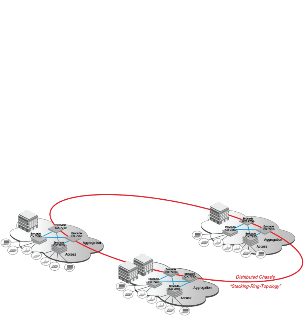
wiring closets, on different floors of one building, or in different buildings across the campus as illustrated in the following figure. Refer to
FastIron stacking distances and optics by device on page 19 for more information.
Brocade stackable devices are connected either through dedicated stacking ports or through ports that can be configured for either
stacking or data. The location of stacking ports and configuration options differ by device type. Refer to the section on each device type for
more information.
FIGURE 1 Distributed campus stacking topology
Ruckus FastIron Stacking Configuration Guide, 08.0.70
Part Number: 53-1005299-01 13
Network management and stack configuration
Even when all the switches within a stack are physically distributed, you can manage them as a single entity, enabling one-touch
configuration changes via a single IP address.
The active controller manages the other stack units. It maintains the information database for all stack members and downloads software
images as needed to all stack units. Each stack also has a standby controller for stack redundancy, and the stack can fail over seamlessly
to the standby.
Configuring the stack through the stack secure-setup utility is straightforward and secure. Custom configuration can be combined with
automated setup if, for example, you want to add units, move stacking ports, create trunks, or transform a default stacking port into a data
uplink port.
Switching and routing advantages
Packet switching between ports on stack units is handled by the hardware. All protocols operate with traditional stacking in the same way
as on a chassis system.
You can use stack connections to link distributed switches instead of standard inter-switch links with Layer 2 Spanning Tree Protocol (STP)
or Layer 3 routing. Using stack connections has significant advantages:
• Layer 2 simplicity. Stack links do not need to be considered as part of the overall network topology, which means that they can be
used to provide resiliency, and Layer 3 routing is not needed to manage traffic flows.
• No closed links. Because the stack links are internal to the switches, they are not seen as part of a Layer 2 network. This means
that all links can remain open and can be used to carry traffic simultaneously, maximizing throughput.
• Fast failover. The rapid detection and recovery techniques used on stack links mean that failure of a link or a switch results in
hitless failover, with no impact on user services.
The next section describes Switch Port Extender technology, which is based on an ICX 7750 core stack. Refer to the
Brocade FastIron
Switch Port Extender Configuration Guide
for more information.
Campus Fabric
Campus Fabric is sometimes referred to as Switch Port Extender (SPX).
Campus Fabric creates a more scalable architecture based on IEEE 802.1BR standards. Brocade Campus Fabric architecture adds
Brocade ICX 7450 or ICX 7250 devices configured as port extenders (PEs), or PE units, to a set of Brocade ICX 7750 stack units
configured as the control bridge. The ICX 7750 control bridge (CB) provides a single point of management for the extended network. Active
and standby controller functions are retained and continue to provide hitless recovery as well as extended administrative functions. Campus
Fabric greatly increases the number of access devices that the network can support. The distributed CB at the center of Campus Fabric
architecture manages PE units and hundreds to thousands of ports at the network edge.
PE units are standards-based devices. Typically lower in cost, PE units rely on the CB for most network functions. As the network expands,
new PE units can be detected and added to the network automatically using defined Campus Fabric communication protocols. PE units
also inherit Premium-license features from the CB, which further reduces cost.
Campus Fabric architecture simplifies network management by unifying core, aggregation, and access functions. As illustrated in the
following figure, a core stack (distributed chassis) serving as the CB connects to downstream Campus Fabric (PE) units that aggregate large
numbers of access devices.
Stacking Overview
Campus Fabric
Ruckus FastIron Stacking Configuration Guide, 08.0.70
14 Part Number: 53-1005299-01
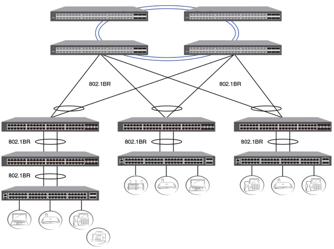
FIGURE 2 Campus Fabric domain build-out from an ICX 7750 CB stack
The following figure depicts three separate campuses, each with its own Campus Fabric domain, interconnected with a high-speed
backbone.
Stacking Overview
Campus Fabric
Ruckus FastIron Stacking Configuration Guide, 08.0.70
Part Number: 53-1005299-01 15
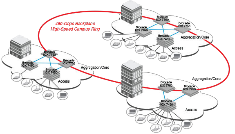
FIGURE 3 Distributed campus network formed from connected Campus Fabric domains
Brocade stackable models
All ICX 7450, ICX 7650, and ICX 7750 devices and some ICX 7250 and ICX 7150 devices can be members of a Brocade traditional stack.
ICX 7750 devices installed in a traditional stack can also be configured as an 802.1br control bridge that manages ICX 7450, ICX 7250, or
ICX 7150 devices configured as port extender (PE) units. Refer to the
Brocade FastIron Campus Fabric Configuration Guide
for information
on 802.1br configuration.
Refer to the following sections for information on the ICX 7150:
•ICX 7150 stack configuration overview on page 43
•ICX 7150 stacking topologies on page 46
•Planning to build a stack with 802.1br switch port extender capability on page 24.
Refer to the following sections for information on the ICX 7250:
•ICX 7250 stack configuration overview on page 59
•ICX 7250 stacking topologies on page 60
•Planning to build a stack with 802.1br switch port extender capability on page 24.
Refer to the following sections for information on the ICX 7450:
•ICX 7450 stack configuration overview on page 68
•ICX 7450 stacking topologies on page 69
•Planning to build a stack with 802.1br switch port extender capability on page 24.
Refer to the following sections for information on the ICX 7650:
•ICX 7650 stack configuration overview on page 88
•ICX 7650 stacking topologies on page 90.
Stacking Overview
Brocade stackable models
Ruckus FastIron Stacking Configuration Guide, 08.0.70
16 Part Number: 53-1005299-01
Refer to the following sections for information on the ICX 7750:
•ICX 7750 stack configuration overview on page 119
•ICX 7750 stacking topologies on page 120
•Configuring an ICX 7750 traditional stack on page 119
•Planning to build a stack with 802.1br switch port extender capability on page 24.
For information about physical installation of each type of device, refer to the appropriate hardware installation guide.
Traditional stacking terminology
Certain terms and roles specific to stacking are used throughout this guide. This section describes the roles stack units may assume as well
as terms key to understanding stacking.
NOTE
Refer to the
Ruckus FastIron Campus Fabric Configuration Guide
for terms specific to IEEE 802.1br and switch port extender
(SPX) capability.
Stack unit roles
• Active controller: Handles stack management and configures all system- and interface-level features.
– Future active controller: The unit that will take over as active controller after the next reload, if its priority has been changed to
the highest priority. When a priority for a stack unit is changed to be higher than the existing active controller, the takeover
does not occur immediately to prevent disruptions in stack operation.
• Standby controller: The stack member with the highest priority after the active controller. The standby controller takes over if the
current active controller fails.
• Stack member: A unit functioning in the stack in a capacity other than active controller or standby controller.
• Stack unit: Any device functioning within the stack, including the active controller and standby controller.
– Upstream stack unit: An upstream unit is connected to the first stacking port on the active controller. (The left port as you face
the stacking ports.)
– Downstream stack unit: A downstream unit is connected to the second stacking port on the active controller. (The right port
as you face the stacking ports.)
NOTE
The terms "upstream port" and "downstream port" have special meanings in an 802.1br SPX configuration. Refer to the
Ruckus
FastIron Campus Fabric Configuration Guide
for more information.
Stacking terms
• Bootup role: The role a unit takes during the boot sequence. This role can be standalone, active controller, standby controller, or
stack member. The active controller or a standalone unit can access the full range of the CLI. Until a stack is formed, the local
consoles on the standby controller and stack members provide access to a limited form of the CLI, such as the show stack
command and a few debug commands. When the stack is formed, all local consoles are directed to the active controller, which
can access the entire CLI. The last line of output from the show version command indicates the role of a unit (except for
standalone units) as shown in the following example:
My stack unit ID = 1, bootup role = active
Stacking Overview
Traditional stacking terminology
Ruckus FastIron Stacking Configuration Guide, 08.0.70
Part Number: 53-1005299-01 17
• Clean unit: A unit that contains no startup flash configuration or runtime configuration. To erase old configuration information, enter
the erase startup-cong command and reset the unit.
• Control path: A path across stacking links dedicated to carrying control traffic such as commands to program hardware or
software image data for upgrades. A stack unit must join the control path to operate fully in the stack.
• Default ports: FastIron devices use the default-ports command to define stacking port candidates.
• Dynamic configuration: A unit configuration that is dynamically learned by a new stack unit from the active controller. A dynamic
configuration disappears when the unit leaves the stack.
• Interprocessor Communications (IPC): The process by which proprietary packets are exchanged between stack unit CPUs.
• IronStack: A set of Ruckus stackable units (maximum of twelve) and their connected stacking links so that all units can be
accessed through their common connections. A single unit can manage the entire stack, and configurable entities, such as VLANs
and trunk groups, can have members on multiple stack units.
• Non-Functioning stack unit: A stack unit that is recognized as a stack member, and is communicating with the active controller
over the Control Path, but is in a non-functioning state. A non-functioning stack unit will drop or discard traffic from non-stacked
ports. This may be caused by an image or configuration mismatch.
• Reserved / provisional unit: A unit configuration number that has no physical unit associated with it.
• Secure-setup: A software utility that establishes a secure stack.
• Sequential connection: Stack unit IDs, beginning with the active controller, are sequential. For example, 1, 3, 4, 6, 7 is sequential if
active controller is 1. 1, 7, 6, 4, 3 are non-sequential in a linear topology, but become sequential in a ring topology when counted
from the other direction as: 1, 3, 4, 6, 7. Gaps in numbering are allowed.
• Stack path: A data path formed across the stacking links to determine the set of stack members that are present in the stack
topology, and their locations in the stack.
• Stack slot: A
slot
in a stack is synonymous with a
line model
in a chassis.
• Stack topology: A contiguously-connected set of stack units in an IronStack that are currently communicating with each other. All
units that are present in the stack topology appear in output from the show stack command.
• Stacking link: A cable that connects a stacking port on one unit to a stacking port on another unit.
• Stacking port: A physical interface on a stack unit that connects a stacking link. Stacking ports are point-to-point links that
exchange proprietary packets. Stacking ports cannot be configured for any other purpose while operating as stacking ports. The
number of available stacking ports depends on the platform. Some ports can be configured as either stacking ports or regular
data ports. Refer to the hardware installation guide for the specific device for more information.
• Standalone unit: A unit that is not enabled for stacking, or an active controller without any standby controller or stack members.
• Static configuration: A configuration that remains in the database of the active controller even if the unit it refers to is removed from
the stack. Static configurations are derived from the startup configuration file during the boot sequence, are manually entered, or
are converted from dynamic configurations after a write memory command is issued.
• Trunked stacking port (trunk): A trunk consists of multiple stacking ports and is treated as one logical link. It provides more
bandwidth and better resilience than individually connected ports.
• Unit replacement: The process of swapping out a unit with a clean unit. No configuration change is required.
Stacking Overview
Traditional stacking terminology
Ruckus FastIron Stacking Configuration Guide, 08.0.70
18 Part Number: 53-1005299-01

Building a Stack
• Planning to build a traditional stack......................................................................................................................... 19
• Planning to build a stack with 802.1br switch port extender capability.....................................................................24
• Traditional stack construction methods....................................................................................................................25
• Verifying a traditional stack configuration................................................................................................................. 39
• Displaying information on stack connections........................................................................................................... 41
Planning to build a traditional stack
Before you begin to build a traditional stack, you should be familiar with supported stacking software requirements, topologies, and
recommendations.
Software requirements
All units in a traditional stack must be running the same software version.
Maximum configuration file size for any stack is 1 MB.
Traditional stack requirements
Traditional stacks must contain devices of the same type or product line. For example, a traditional stack cannot combine ICX 7150, ICX
7250, ICX 7450, or ICX 7750 devices. However, a traditional stack can contain any combination of devices from the same product line, for
example, any combination of ICX 7250 devices.
NOTE
A core stack for an 802.1br (SPX) configuration is a traditional stack that contains only ICX 7750 devices, although the stack may
contain different types of ICX 7750 devices. Refer to the
Brocade FastIron Campus Fabric Configuration Guide
for more
information.
Brocade traditional stacking topologies
Brocade traditional stacking technology supports linear and ring topologies.
Although Brocade stackable units may be connected in a simple linear topology, Brocade recommends a ring topology because it offers the
best redundancy and the most resilient operation. Unicast switching follows the shortest path in a ring topology. When the ring is broken,
the stack recalculates the forwarding path and then resumes the flow of traffic within a few seconds.
In a ring topology, all stack members must have two stacking ports; however, in a linear topology, both end units use only one stacking
port, leaving the other port available as a data port.
FastIron stacking distances and optics by device
Because Brocade devices use Ethernet for the inter-switch stack connections, the deployment options are greatly increased. If standard
copper stacking cables are used, the inter-switch connections can be up to 5 meters, which is usually sufficient for locally distributed
stacks, such as in Top-of-Rack (ToR) applications. For broader distribution, fiber-optic cables should be used, allowing a stack to be
deployed across multiple physical locations, such as in the wiring closets of an office building, or in different buildings on a campus.
Ruckus FastIron Stacking Configuration Guide, 08.0.70
Part Number: 53-1005299-01 19

Cables that support different distances can be combined in the same stack. For example, you can use LR4 Single Mode Fiber (SMF) optics
at both ends of a stacking connection, and the maximum distance is extended to 10 kilometers. Other stacking ports in the same stack can
use other optics, such as SR4, at both ends. The maximum distance for such a connection is 100 meters.
NOTE
The same optics (for example, LR4) must be used on both ends of a connection. If the optics do not match on both ends, the
ports will not come up.
The following table shows copper and fiber-optic options approved for stacking and stacking distance combinations.
TABLE 3 Copper and fiber-optic options and stacking distances
Device Stacking port Copper options Fiber-optic options Fiber-optic maximum
stacking distance
ICX 7750 6 X 40-Gbps
Front and rear stacking
and uplink 1
0.5- or 1-meter passive copper
1-, 3-, or 5-meter QSFP-QSFP
active direct-attach copper, 10-
meter QSFP-QSFP AOC
40G-QSFP-SR4 100 meters
40G-QSFP-BiDi
40G-QSFP-LM4 140 meters
40G-QSFP-eSR4 300 meters
40G-QSFP-LR4 10 kilometers
ICX 7650 4 X 40-Gbps stacking or
uplink, or 2 X 100-Gbps
stacking or uplink on slot 3
40 Gbps:
0.5- or 1-meter passive copper
1-, 3-, or 5-meter QSFP-QSFP
active direct-attach copper
100 Gbps: 2
0.5-, 1-, 3-, or 5-meter QSFP28 to
QSFP28 Passive Copper Cable
40G-QSFP+-SR4 100 meters
40G-QSFP+-BiDi
40G-QSFP+-LR4 10 kilometers
100G-QSFP28-LR4-10KM, 3.5W
100G-QSFP28-LR4-10KM, 4.5W
100G-QSFP28-LR4L-2KM, 4W 2 kilometers
100G-QSFP28-CWDM4-2KM
100G-QSFP28-SR43100 meters
ICX 7450 (rear) 1 X 40-Gbps stacking and
uplink on slots 3 and 4 4
0.5- or 1-meter passive copper
1-, 3-, or 5-meter QSFP-QSFP
active direct-attach copper
40G-QSFP-LR4 10 kilometers
40G-QSFP-SR4 100 meters
40G-QSFP-eSR4 300 meters
ICX 7450 (front) 4 X 10-Gbps stacking on
slot 2 with the
icx7400-4x10GF module
only
1-, 3-, or 5-meter SFP+ active
direct-attach copper, 10-meter SFP
+ AOC
10G-SFPP-USR 100 meters
10G-SFPP-SR 300 meters
10G-SFPP-LR 10 kilometers
ICX 7250 4 X 10-Gbps stacking
from dedicated or uplink
ports
4 X 10F SFP+ Uplink
Ports: No-PHY
4 X 10F SFP+ Stacking
Ports: With re-timer
capability
1-, 3-, or 5-meter active cables 10GE SR SFP+ 300 meters
10GE USR SFP+ 100 meters
10GE LR SFP+ 10 kilometers
1For data uplink only, the following 40-Gbps optics are available on ICX 7750 devices: 40G-QSFP-ER4
210-meter QSFP28 to QSFP28 AOC Cable is supported on ICX 7650 devices for data uplink only.
3Finisar Supplier only for Stacking with MPN # FTLC9551REPM-B3
4For data uplink only, the following 40-Gbps optics are available on ICX 7450 devices: 40G-QSFP-BiDi, 40G-QSFP-LM4, 40G-QSFP-ER4
Building a Stack
Planning to build a traditional stack
Ruckus FastIron Stacking Configuration Guide, 08.0.70
20 Part Number: 53-1005299-01

TABLE 3 Copper and fiber-optic options and stacking distances (continued)
Device Stacking port Copper options Fiber-optic options Fiber-optic maximum
stacking distance
ICX 7150 Standard 2 X 10-Gbps
stacking
4 X 10-Gbps stacking
from dedicated or uplink
ports if an ICX 7150-48ZP
is present
2 X 10-Gbps stacking only
on ICX 7150-C12P
devices
Up to 4 X 10F SFP+ uplink
Ports: No-PHY
Up to 4 X 10F SFP+
stacking ports: With re-
timer capability
1-, 3-, or 5-meter active cables 10GE SR SFP+ 300 meters
10GE USR SFP+ 100 meters
10GE LR SFP+ 10 kilometers
Long-distance stacking ports
Only certain FastIron stacking devices support long-distance stacking. The following table lists FastIron devices and ports that support 100-
Gbps long-distance data and stacking connections.
TABLE 4 FastIron long-distance 100-Gbps ports
Product and model Ports that support 1 X 100-Gbps optics Long-distance stacking ports
ICX 7650 (all models) 1/3/1, 1/3/261/3/1, 1/3/2
NOTE
For a list of 100-Gbps optics available for FastIron devices, refer to "FastIron stacking distances and optics by device" in this
guide.
FastIron models and 40-Gbps ports that can be used for long-distance data and stacking connections are listed in the following table.
TABLE 5 FastIron long-distance 40-Gbps ports
Product and model Ports that support 1 X 40-Gbps optics Long-distance stacking ports
ICX 7450 (all models) 1/3/1, 1/4/171/3/1, 1/4/1
ICX 7650 (all models) 1/3/1, 1/3/2, 1/3/3, 1/3/461/3/1, 1/3/2, 1/3/3, 1/3/4
ICX 7750-26Q 1/1/1 through 1/1/20; 1/2/1 through 1/2/6; 1/3/1 through 1/3/6 1/2/1 through 1/2/6; 1/3/1 through 1/3/6
ICX 7750-48F 1/2/1 through 1/2/6; 1/3/1 through 1/3/6 1/2/1 through 1/2/6; 1/3/1 through 1/3/6
ICX 7750-48C 1/2/1 through 1/2/6; 1/3/1 through 1/3/6 1/2/1 through 1/2/6; 1/3/1 through 1/3/6
NOTE
For a list of 40-Gbps optics available per FastIron device, refer to FastIron stacking distances and optics by device on page 19.
6When ICX 7650-48F/P/ZP devices are configured in stacking mode, front panel slot 2 also supports 2 X 40-Gbps or 1 X 100-Gbps modules with their
respective Ruckus-qualified optical hardware.
7ICX 7450-24/24P devices also support a 1 X 40-Gbps module in front panel slot 2 (port 1/2/1).
Building a Stack
Planning to build a traditional stack
Ruckus FastIron Stacking Configuration Guide, 08.0.70
Part Number: 53-1005299-01 21

NOTE
Not all long-distance stacking ports are default stacking ports. If you are using only long-distance stacking ports, you may not be
able to use the stack secure-setup utility to configure your stack because the secure-setup utility probes for other potential stack
members only on default stacking ports. Check device-specific information.
LR optics can be used on ICX 7450 4 X 10-Gbps ports when a 4X10GF module is present. LR optics can also used on ICX 7150 ports
when either a 4X10GF module or 2X10GF module is present. LR optics can support distances up to 10 kilometers for data or stacking. The
following table summarizes LR support on ICX 7150 and ICX 7450 devices.
TABLE 6 FastIron long-distance 2X10-Gbps and 4X10-Gbps ports
Product and model 10-Gbps ports that support LR optics Long-distance stacking ports
ICX 7150-48ZP 1/2/1 through 1/2/8 1/2/1 through 1/2/4
ICX 7150-48, ICX 7150-48P, ICX
7150-48PF, ICX 7150-24, ICX 7150-24P
1/2/1 through 1/2/4 1/2/1 through 1/2/4
ICX 7150-C12P (2X10GF module) 1/3/1 and 1/3/2 1/3/1 and 1/3/2
ICX 7450 front (all models, with 4X10GF
module)
1/2/1 through 1/2/4 1/2/1 through 1/2/4
ICX 7450 back (all models, with 4X10GF
module)
1/3/1 through 1/3/4 and 1/4/1 through 1/4/4 (data only) 1/3/1 through 1/3/4 and 1/4/1 through
1/4/4
For general information on all long-distance stacking options for all FastIron stacking models, refer to FastIron stacking distances and optics
by device on page 19. For details on setting up for long-distance stacking on ICX 7750 devices, refer to Installing the ICX 7750 in a remote
stack on page 124.
Displaying information on supported distances
Use the show media command to display information on stacking connections and supported distances. You can specify any interface
within a stack or SPX configuration as shown in the following examples. You can also designate a stack to display all media attached to the
stack. Without parameters, the show media command displays all media attached to the device.
The following example displays information for an interface with an LR4 optic.
ICX7750-48F Router# show media ethernet 4/2/6
Port 4/2/6: Type : 40GE-LR4 10km (QSFP+ LC)
Vendor: BROCADE Version: 2
Part# : 57-1000263-01 Serial#: LDJ21325C230002
The following command output is for an interface with a 40-Gbps active copper optic with a maximum distance of 10 meters.
ICX7750-48F Switch# show media ethernet 3/2/1
Port 3/2/1: Type : 40GE-Active Copper 10m (QSFP+)
Vendor: BROCADE Version: A
Part# : 57-1000306-01 Serial#: NEA11510000003S
The following output is for an interface with a 40-Gbps ESR4 optic.
ICX7750-48F Switch# show media ethernet 1/2/3
Port 1/2/3: Type : 40GE-ESR4 300m (QSFP+)
Vendor: BROCADE Version: A
Part# : 57-1000296-01 Serial#: LVA115150000004
The following example displays information about the media attached to the device.
device# show media
Port 1/1/1 : Type : 1G M-C (Gig-Copper)
Port 1/1/2 : Type : 1G M-C (Gig-Copper)
Building a Stack
Planning to build a traditional stack
Ruckus FastIron Stacking Configuration Guide, 08.0.70
22 Part Number: 53-1005299-01
Port 1/1/3 : Type : 1G M-C (Gig-Copper)
Port 1/1/4 : Type : 1G M-C (Gig-Copper)
Port 1/1/5 : Type : 1G M-C (Gig-Copper)
Port 1/1/6 : Type : 1G M-C (Gig-Copper)
Port 1/1/7 : Type : 1G M-C (Gig-Copper)
Port 1/1/8 : Type : 1G M-C (Gig-Copper)
Port 1/1/9 : Type : 1G M-C (Gig-Copper)
Port 1/1/10: Type : 1G M-C (Gig-Copper)
Port 1/1/11: Type : 1G M-C (Gig-Copper)
Port 1/1/12: Type : 1G M-C (Gig-Copper)
Port 1/1/13: Type : 1G M-C (Gig-Copper)
Port 1/1/14: Type : 1G M-C (Gig-Copper)
Port 1/1/15: Type : 1G M-C (Gig-Copper)
Port 1/1/16: Type : 1G M-C (Gig-Copper)
Port 1/1/17: Type : 1G M-C (Gig-Copper)
Port 1/1/18: Type : 1G M-C (Gig-Copper)
Port 1/1/19: Type : 1G M-C (Gig-Copper)
Port 1/1/20: Type : 1G M-C (Gig-Copper)
Port 1/1/21: Type : 1G M-C (Gig-Copper)
Port 1/1/22: Type : 1G M-C (Gig-Copper)
Port 1/1/23: Type : 1G M-C (Gig-Copper)
Port 1/1/24: Type : 1G M-C (Gig-Copper)
Port 1/2/1 : Type : 10GE SR 300m (SFP +)
Port 1/2/2 : Type : EMPTY
Port 1/2/3 : Type : 1G Twinax 1m (SFP)
Port 1/2/4 : Type : 1G Twinax 1m (SFP)
The following example shows output for the specified stack.
device# show media stack 1
Port 1/1/1 : Type : EMPTY
Port 1/1/2 : Type : EMPTY
Port 1/1/3 : Type : EMPTY
Port 1/1/4 : Type : EMPTY
Port 1/1/5 : Type : EMPTY
Port 1/1/6 : Type : EMPTY
Port 1/1/7 : Type : EMPTY
Port 1/1/8 : Type : EMPTY
Port 1/1/9:1 : Type : 4x10GE Active Copper 1m (QSFP+)
Port 1/1/9:2 : Type : 4x10GE Active Copper 1m (QSFP+)
Port 1/1/9:3 : Type : 4x10GE Active Copper 1m (QSFP+)
Port 1/1/9:4 : Type : 4x10GE Active Copper 1m (QSFP+)
Port 1/1/10 : Type : EMPTY
Port 1/1/11:1: Type : 4x10GE Active Copper 1m (QSFP+)
Port 1/1/11:2: Type : 4x10GE Active Copper 1m (QSFP+)
Port 1/1/11:3: Type : 4x10GE Active Copper 1m (QSFP+)
Port 1/1/11:4: Type : 4x10GE Active Copper 1m (QSFP+)
Port 1/1/12 : Type : EMPTY
Port 1/1/13 : Type : EMPTY
Port 1/1/14 : Type : EMPTY
Port 1/1/15 : Type : EMPTY
Port 1/1/16 : Type : EMPTY
Port 1/1/17 : Type : EMPTY
Port 1/1/18 : Type : EMPTY
Port 1/1/19 : Type : EMPTY
Port 1/1/20 : Type : EMPTY
Port 1/2/1 : Type : EMPTY
Port 1/2/2 : Type : EMPTY
Port 1/2/3 : Type : EMPTY
Port 1/2/4 : Type : EMPTY
Port 1/2/5 : Type : EMPTY
Port 1/2/6 : Type : EMPTY
Port 1/3/1 : Type : 40GE-SR4 100m (QSFP+)
Port 1/3/2 : Type : EMPTY
Port 1/3/3 : Type : EMPTY
Port 1/3/4 : Type : EMPTY
Port 1/3/5 : Type : EMPTY
Port 1/3/6 : Type : EMPTY
Building a Stack
Planning to build a traditional stack
Ruckus FastIron Stacking Configuration Guide, 08.0.70
Part Number: 53-1005299-01 23
Traditional stacking configuration guidelines
Before you configure your traditional stack, consider the following guidelines:
• Plan the number of units and how the stacking ports on the units will be connected. For more information, refer to the hardware
installation guide for your device.
• The stack should be physically cabled in a linear or ring topology. Connect only those units that will be active in the stack.
• Make sure all units intended for the stack are running the same software version. On any of the console ports in the stack, use the
show version command to view all units, or the show version unit
unit-number
command to view an individual unit.
NOTE
If you are running a router image and there is a potential loop in your topology, you must configure the Spanning Tree Protocol in
the would-be active controller. Otherwise, excessive looping packets may affect stack formation. The Spanning Tree Protocol is
enabled by default in switch images.
NOTE
If STP is not enabled, there may be a loop issue when multiple cables are used to connect a standalone unit to a stack. The loop
does not affect stack formation. The loop issue disappears after the multiple links are converted to stacking trunks when the
standalone unit is integrated to the stack. However, temporary looping may cause some data traffic interruption. If you are
concerned about potential traffic interruption due to looping, you can connect a single cable to the new unit. After the unit reloads
and becomes a member, you can connect all cables and then run the stack secure-setup utility to make sure these links are
converted to stacking trunks.
• When you have a stack of eight or more units, you may need to increase the trap hold time from the default (60 seconds) to five
minutes (300 seconds). This will prevent the loss of initial boot traps. To increase the trap hold time, use the following command.
device# configure terminal
device(config)# snmp-server enable traps holddown-time 300
Planning to build a stack with 802.1br switch port
extender capability
If you are planning to create an 802.1br SPX configuration with an ICX 7750 core stack, there are a few considerations.
In general, Brocade traditional stacking and 802.1br SPX configuration are independent. Here are a few details to keep in mind:
• Only ICX 7750 devices can serve as the control bridge (CB). The CB can be a standalone unit or a stack of multiple units.
• ICX 7150, ICX 7250, and ICX 7450 devices can be configured as PE units attached to the CB. PE units can be attached to any
CB unit.
• While a traditional stack may include up to 12 units, a CB stack of no more than four units is recommended.
• ICX 7750 breakout ports can be used with an 802.1br SPX configuration; however, they can be enabled only in a standalone ICX
7750 unit.
• SPX runs over LLDP protocol at Layer 2. When you enable SPX with the spx cb-enable command, the lldp run command is also
executed if LLDP has not previously been enabled.
• You will need to plan a server location from which images and manifest files can be downloaded to PE units.
• In general, ICX 7750 devices in the CB retain all capabilities. The feature set of ICX 7450 devices operating as PE units, however,
may be affected.
Building a Stack
Planning to build a stack with 802.1br switch port extender capability
Ruckus FastIron Stacking Configuration Guide, 08.0.70
24 Part Number: 53-1005299-01
For detailed information on 802.1br SPX configuration, including protocol considerations, refer to the
Brocade FastIron Switch Port
Extender Configuration Guide
.
Traditional stack construction methods
NOTE
The principles outlined in stack construction scenarios apply to all ICX devices. Figures used to illustrate a certain stack topology
are not necessarily representative of other devices. For illustrations specific to a particular device, refer to the stack configuration
section for that device, which also contains device-specific stacking considerations and configuration examples.
There are three ways to build a traditional stack.
1. The secure-setup utility. Secure-setup gives you control over the design of your stack topology and provides security through
password verification. For the secure-setup procedure, refer to Using secure-setup to configure a traditional stack in a ring
topology on page 26.
2. Automatic stack configuration. With this method, you enter all configuration information, including the module type and the
priorities of all members into the unit you decide will be the active controller and set its priority to be the highest. When you enable
stacking on the active controller, the stack then forms automatically. This method requires that you start with clean units (except for
the active controller) that do not contain startup or runtime configurations. Refer to Scenario 2 - Automatically configuring a three-
member traditional stack in a ring topology on page 34.
3. Manual stack configuration. With this method, you configure every unit individually and enable stacking on each unit. Once the
units are connected together, they automatically operate as a traditional stack. With this method, the unit with the highest priority
becomes the active controller, and ID assignment is determined by the sequence in which you physically connect the units. Refer
to Scenario 3 - Manually configuring a three member traditional stack in a ring topology on page 38.
The secure-setup utility
NOTE
Secure-setup works for units within a single stack. It does not work across stacks.
NOTE
Long distance stacking ports are not default stacking ports. If you are using only long distance stacking ports, you cannot use the
stack secure-setup utility to configure your stack because the secure-setup utility probes for other potential stack members only
on default stacking ports.
Secure-setup lets you easily configure your entire stack through the active controller, which propagates the configuration to all stack
members. Secure-setup is the most secure way to build a traditional stack. It gives you the most control over how your stack is built. For
example, secure-setup offers three security features that prevent unauthorized devices from accessing or joining a traditional stack:
• Authentication of secure-setup packets provides verification that these packets are from a genuine Ruckus stack unit. MD5-based
port verification confirms stacking ports.
• A superuser password is required to allow password-protected devices to become members of a traditional stack.
• The stack disable command prevents a unit from listening for or sending stacking packets. When a unit is stack-disabled, no
other device in the network can force the unit to join a traditional stack.
Secure-setup can also be used to add units to an existing traditional stack and to change the stack IDs of stack members.
Building a Stack
Traditional stack construction methods
Ruckus FastIron Stacking Configuration Guide, 08.0.70
Part Number: 53-1005299-01 25
Secure-setup and the active controller
When secure-setup is issued on a unit that is not already the active controller, the unit becomes the active controller. If this unit does not
already have an assigned priority and if no other unit in the stack has a priority higher than 128, secure-setup assigns the unit a priority of
128 by default. However, if another unit in the stack has a priority of 128 or higher, secure-setup gives the active controller a priority equal to
the highest priority unit in the stack (which is by default the standby controller). When the active controller and the standby controller have
identical priorities, during a reset, the old active controller cannot reassume its role from the standby controller (which became the active
controller at the reset).
If the previous active controller again becomes active and you want it to resume the role of active controller, you should set the priority for
the standby controller to a priority lower than 128. If you do not want the previous active controller to remain the active controller, you can
set the same priority for both active and standby controllers (equal to or higher than128).
Using secure-setup to configure a traditional stack in a ring topology
The following figure shows three ICX 7750 stacking units connected in a ring. The secure-setup example that follows is for 12 ICX 7750
units in a ring topology. However, the procedure can be used for any stackable ICX device and any size traditional stack.
FIGURE 4 Traditional stack with ring topology
1. Connect the devices using the stacking ports and stack cabling. For more information, refer to the appropriate hardware
installation guides.
2. Power on the units.
3. Connect your console to the intended active controller. The unit through which you run secure-setup becomes the active controller
by default.
4. Issue the stack enable command on the intended active controller.
device# configure terminal
device(config)# stack enable
device(config)# exit
Building a Stack
Traditional stack construction methods
Ruckus FastIron Stacking Configuration Guide, 08.0.70
26 Part Number: 53-1005299-01
5. Enter the stack secure-setup command. As shown in the following example, this command triggers a Ruckus proprietary
discovery protocol that begins the discovery process in both upstream and downstream directions. The discovery process
produces a list of upstream and downstream devices that are available to join the stack. Secure-setup can detect up to 11 units in
each direction (22 units total); however, you must select a total number of units that is less than the maximum stack size for the
device because the controller is also part of the stack.
NOTE
During the secure-setup process, after one minute of inactivity, authentication for stack members expires, forcing you to
restart the process.
NOTE
To exit the secure-setup, enter ^C at any time.
The following example shows the suggested discovered topology.
ICX7750-48F Router# stack secure-setup
ICX7750-48F Router# Discovering the stack topology...
Current Discovered Topology - RING
Available UPSTREAM units
Hop(s) Id Type Mac Address
1 new ICX7750-48XGF cc4e.246d.8d80
2 new ICX7750-48XGF cc4e.246d.9b00
3 new ICX7750-48XGF cc4e.246d.9c80
4 new ICX7750-20QXG cc4e.2439.2a80
5 new ICX7750-20QXG cc4e.2439.3700
6 new ICX7750-20QXG cc4e.2439.3880
7 new ICX7750-20QXG cc4e.2439.2d00
8 new ICX7750-48XGC cc4e.2439.1a00
9 new ICX7750-48XGC cc4e.2439.1680
10 new ICX7750-48XGC cc4e.2439.1d80
11 new ICX7750-48XGC cc4e.2439.1280
Available DOWNSTREAM units
Hop(s) Id Type Mac Address
1 new ICX7750-48XGC cc4e.2439.1280
2 new ICX7750-48XGC cc4e.2439.1d80
3 new ICX7750-48XGC cc4e.2439.1680
4 new ICX7750-48XGC cc4e.2439.1a00
5 new ICX7750-20QXG cc4e.2439.2d00
6 new ICX7750-20QXG cc4e.2439.3880
7 new ICX7750-20QXG cc4e.2439.3700
8 new ICX7750-20QXG cc4e.2439.2a80
9 new ICX7750-48XGF cc4e.246d.9c80
10 new ICX7750-48XGF cc4e.246d.9b00
11 new ICX7750-48XGF cc4e.246d.8d80
Do you accept the topology (RING) (y/n)?: y
You are prompted to accept the topology.
Building a Stack
Traditional stack construction methods
Ruckus FastIron Stacking Configuration Guide, 08.0.70
Part Number: 53-1005299-01 27
6. Enter y to accept the topology. You should see output similar to the following.
Selected Topology:
Active Id Type Mac Address
1 ICX7750-48XGF cc4e.246d.9e00
Selected UPSTREAM units
Hop(s) Id Type Mac Address
1 2 ICX7750-48XGF cc4e.246d.8d80
2 3 ICX7750-48XGF cc4e.246d.9b00
3 4 ICX7750-48XGF cc4e.246d.9c80
4 5 ICX7750-20QXG cc4e.2439.2a80
5 6 ICX7750-20QXG cc4e.2439.3700
6 7 ICX7750-20QXG cc4e.2439.3880
7 8 ICX7750-20QXG cc4e.2439.2d00
8 9 ICX7750-48XGC cc4e.2439.1a00
9 10 ICX7750-48XGC cc4e.2439.1680
10 11 ICX7750-48XGC cc4e.2439.1d80
11 12 ICX7750-48XGC cc4e.2439.1280
Selected DOWNSTREAM units
Hop(s) Id Type Mac Address
1 12 ICX7750-48XGC cc4e.2439.1280
2 11 ICX7750-48XGC cc4e.2439.1d80
3 10 ICX7750-48XGC cc4e.2439.1680
4 9 ICX7750-48XGC cc4e.2439.1a00
5 8 ICX7750-20QXG cc4e.2439.2d00
6 7 ICX7750-20QXG cc4e.2439.3880
7 6 ICX7750-20QXG cc4e.2439.3700
8 5 ICX7750-20QXG cc4e.2439.2a80
9 4 ICX7750-48XGF cc4e.246d.9c80
10 3 ICX7750-48XGF cc4e.246d.9b00
11 2 ICX7750-48XGF cc4e.246d.8d80
Building a Stack
Traditional stack construction methods
Ruckus FastIron Stacking Configuration Guide, 08.0.70
28 Part Number: 53-1005299-01
7. If the Brocade device supports stacking trunks, the system next displays available trunk options in turn and requests your input on
how many ports to include. The range is presented in parentheses, and the current setting is presented in square brackets. For
example, (1-3) [ 1 ] indicates that the current connection is a single-port link, and you have the option of electing a 2-port or a 3-
port trunk instead. When prompted, enter the desired trunk size as shown in the following example.
Confirm Stacking Links...
UPSTREAM Unit: Id new at 4 hop(s) ICX7750-20QXG cc4e.2439.2a80
Enter the desired links(1-3)[1]: 3
UPSTREAM Unit: Id new at 6 hop(s) ICX7750-20QXG cc4e.2439.3880
Enter the desired links(1-3)[1]: 3
UPSTREAM Unit: Id new at 10 hop(s) ICX7750-48XGC cc4e.2439.1d80
Enter the desired links(1-2)[1]: 2
UPSTREAM Unit: Id new at 11 hop(s) ICX7750-48XGC cc4e.2439.1280
Enter the desired links(1-2)[1]: 2
Once you have specified trunk sizes, you should see system output similar to the following example, and you are prompted to
confirm the stack unit IDs.
Selected Topology:
Active Id Type Mac Address
1 ICX7750-48XGF cc4e.246d.9e00
Selected UPSTREAM units
Hop(s) Id Type Mac Address
1 2 ICX7750-48XGF cc4e.246d.8d80
2 3 ICX7750-48XGF cc4e.246d.9b00
3 4 ICX7750-48XGF cc4e.246d.9c80
4 5 ICX7750-20QXG cc4e.2439.2a80
5 6 ICX7750-20QXG cc4e.2439.3700
6 7 ICX7750-20QXG cc4e.2439.3880
7 8 ICX7750-20QXG cc4e.2439.2d00
8 9 ICX7750-48XGC cc4e.2439.1a00
9 10 ICX7750-48XGC cc4e.2439.1680
10 11 ICX7750-48XGC cc4e.2439.1d80
11 12 ICX7750-48XGC cc4e.2439.1280
Selected DOWNSTREAM units
Hop(s) Id Type Mac Address
1 12 ICX7750-48XGC cc4e.2439.1280
2 11 ICX7750-48XGC cc4e.2439.1d80
3 10 ICX7750-48XGC cc4e.2439.1680
4 9 ICX7750-48XGC cc4e.2439.1a00
5 8 ICX7750-20QXG cc4e.2439.2d00
6 7 ICX7750-20QXG cc4e.2439.3880
7 6 ICX7750-20QXG cc4e.2439.3700
8 5 ICX7750-20QXG cc4e.2439.2a80
9 4 ICX7750-48XGF cc4e.246d.9c80
10 3 ICX7750-48XGF cc4e.246d.9b00
11 2 ICX7750-48XGF cc4e.246d.8d80
Do you accept the unit id's (y/n)?: y
Building a Stack
Traditional stack construction methods
Ruckus FastIron Stacking Configuration Guide, 08.0.70
Part Number: 53-1005299-01 29
8. Review the topology and the unit IDs that are displayed. When prompted, enter y if you want to accept the assigned unit IDs.
NOTE
You can also enter n to decline the assigned unit IDs. The system then prompts you to enter different IDs, warns that
changing the unit IDs manually may modify stack configuration, and recommends that you save the configuration and
reload it after the stack is ready.
9. The active controller automatically checks all prospective stack members to see if they are password-protected. If a unit is
password- protected, enter the password before you to add the unit. If you do not know the password, take one of the following
actions:
• Discontinue secure-setup by entering ^C.
• Obtain the device password from the administrator.
• Skip this unit and continue the secure-setup for your stack. The password-protected device and all devices connected behind
it will not be included in the setup process.
In the following example, the second unit is password-protected, so you are asked for the password.
device# stack secure-setup
device# Discovering the stack topology...
Verifying password for the password protected units...
Found UPSTREAM units
Hop(s) Id Type MAC Address
1 2 ICX7750-48XGF cc4e.246d.8d80
2 3 ICX7750-48XGF cc4e.246d.9b00
Enter password for ICX7750-48XGF located at 2 hop(s): ****
Enter the number of the desired UPSTREAM units (1-2)[1]: 2
Selected Topology:
Active Id Type MAC Address
1 ICX7750-48XGF cc4e.246d.9e00
Selected UPSTREAM units
Hop(s) Id Type MAC Address
1 2 ICX7750-48XGF cc4e.246d.8d80
2 3 ICX7750-48XGF cc4e.246d.9b00
Do you accept the unit id's (y/n)?: y
Building a Stack
Traditional stack construction methods
Ruckus FastIron Stacking Configuration Guide, 08.0.70
30 Part Number: 53-1005299-01
10. Enter y to accept these recommendations, or enter n to reject the recommendations.
NOTE
You can use secure-setup to renumber the units in your stack. Refer to Renumbering stack units on page 179.
After you accept the unit IDs, an active controller is elected, the stack is formed, and a standby controller is designated. You
should see output similar to the following example.
ICX7750-48F Router#T=18m45.7: Election, was alone --> active, ID=1, pri=128,
12U(1-12), A=u1, nbr#=11 11, reason: u6: SecureS, ,
T=18m49.7: Election, was active, no change, ID=1, pri=128, 12U(1-12), A=u1,
nbr#=11 11, reason: u1: stk-po-chg, ,
T=18m52.3: reset unit 2: u2 bo-id=1
T=18m52.3: reset unit 3: u3 bo-id=1
T=18m52.3: reset unit 5: u5 bo-id=1
T=18m52.3: reset unit 6: u6 bo-id=1
T=18m52.3: reset unit 7: u7 bo-id=1
T=18m52.3: reset unit 8: u8 bo-id=1
T=18m52.3: reset unit 9: u9 bo-id=1
T=18m52.3: reset unit 10: u10 bo-id=1
T=18m52.3: reset unit 11: u11 bo-id=1
T=18m52.3: reset unit 12: u12 bo-id=1
Reset extra units due to path: 4
Config changed due to add/del units. Do write mem if you want to keep it
T=18m55.3: Unit 1 loses all neighbors.
T=18m55.4: Active U1 deletes U2 and its config because it is learned.
T=18m55.6: Active U1 deletes U3 and its config because it is learned.
T=18m55.8: Active U1 deletes U4 and its config because it is learned.
T=18m55.9: Active U1 deletes U5 and its config because it is learned.
T=18m56.0: Active U1 deletes U6 and its config because it is learned.
T=18m56.1: Active U1 deletes U7 and its config because it is learned.
T=18m56.2: Active U1 deletes U8 and its config because it is learned.
T=18m56.3: Active U1 deletes U9 and its config because it is learned.
T=18m56.4: Active U1 deletes U10 and its config because it is learned.
T=18m56.6: Active U1 deletes U11 and its config because it is learned.
T=18m56.7: Active U1 deletes U12 and its config because it is learned.
ICX7750-48F Router# T=19m55.7: Election, was active, no change, ID=1, pri=128,
3U(1-3), A=u1, nbr#=2 0, reason: u3: port-dw, ,
T=19m55.8: Synchronize webauth files to u2
T=19m55.8: Synchronize webauth files to u3
T:19m57.1: Done hot swap: active controller u1 sets u2 to Ready.
T:19m57.1: Done hot swap: active controller u1 sets u3 to Ready.
Config changed due to add/del units. Do write mem if you want to keep it
Stack unit 2 Power supply 1 is up
Stack unit 2 Power supply 2 is down
Stack unit 3 Power supply 1 is up
Stack unit 3 Power supply 2 is down
T=20m2.4: Election, was active, no change, ID=1, pri=128, 3U(1-3), A=u1, nbr#=2 0,
reason: u1: port-up, ,
T=20m3.6: 1/2/4 goes down. delete direction 1, trigger election
T=20m7.3: Election, was active, no change, ID=1, pri=128, 12U(1-12), A=u1,
nbr#=11 11, reason: u12: port-up, ,
T=20m7.6: Synchronize webauth files to u10
T=20m7.6: Synchronize webauth files to u11
Detect stack unit 12 has different startup config flash, will synchronize it
T=20m7.6: Synchronize webauth files to u12
Detect stack unit 4 has different startup config flash, will synchronize it
T=20m7.6: Synchronize webauth files to u4
T=20m7.6: Synchronize webauth files to u5
T=20m7.6: Synchronize webauth files to u6
T=20m7.6: Synchronize webauth files to u7
T=20m7.7: Synchronize webauth files to u8
T=20m8.3: Synchronize webauth files to u9
T:20m8.8: Done hot swap: active controller u1 sets u10 to Ready.
T:20m9.0: Done hot swap: active controller u1 sets u11 to Ready.
T:20m9.3: Done hot swap: active controller u1 sets u12 to Ready.
T:20m9.9: Done hot swap: active controller u1 sets u4 to Ready.
Building a Stack
Traditional stack construction methods
Ruckus FastIron Stacking Configuration Guide, 08.0.70
Part Number: 53-1005299-01 31
T:20m10.2: Done hot swap: active controller u1 sets u5 to Ready.
T:20m10.5: Done hot swap: active controller u1 sets u6 to Ready.
T:20m10.9: Done hot swap: active controller u1 sets u7 to Ready.
T:20m11.4: Done hot swap: active controller u1 sets u8 to Ready.
Stack unit 12 Power supply 1 is up
Stack unit 12 Power supply 2 is down
Stack unit 10 Power supply 1 is up
Stack unit 10 Power supply 2 is down
Config changed due to add/del units. Do write mem if you want to keep it
T:20m13.1: Done hot swap: active controller u1 sets u9 to Ready.
T=20m16.9: Election, was active, no change, ID=1, pri=128, 12U(1-12), A=u1,
nbr#=11 11, reason: u1: stk-po-chg, ,
Config changed due to add/del units. Do write mem if you want to keep it
ICX7750-48F Router#T=21m16.9: Assigned unit 2 to be standby
cT=21m18.9: start running config sync to standby u2
T=21m19.3: Running config sync to standby u2 is complete
11. Enter the show stack command to verify that all units are in the ready state.
The following show stack command output shows the resulting 12-unit ICX 7750 ring topology. All units are ready.
ICX7750-48F Router# show stack
T=23m12.5: alone: standalone, D: dynamic cfg, S: static, A=10, B=11, C=12
ID Type Role Mac Address Pri State Comment
1 S ICX7750-48XGF active cc4e.246d.9e00 128 local Ready
2 D ICX7750-48XGF standby cc4e.246d.8d80 0 remote Ready
3 D ICX7750-48XGF member cc4e.246d.9b00 0 remote Ready
4 D ICX7750-48XGF member cc4e.246d.9c80 0 remote Ready
5 D ICX7750-20QXG member cc4e.2439.2a80 0 remote Ready
6 D ICX7750-20QXG member cc4e.2439.3700 0 remote Ready
7 D ICX7750-20QXG member cc4e.2439.3880 0 remote Ready
8 D ICX7750-20QXG member cc4e.2439.2d00 0 remote Ready
9 D ICX7750-48XGC member cc4e.2439.1a00 0 remote Ready
10 D ICX7750-48XGC member cc4e.2439.1680 0 remote Ready
11 D ICX7750-48XGC member cc4e.2439.1d80 0 remote Ready
12 D ICX7750-48XGC member cc4e.2439.1280 0 remote Ready
active
+---+ +---+ +---+ +---+ +---+ +---+
-2/1| 1 |2/4--2/1| C |2/4==2/1| B |2/4==2/1| A |2/4--2/1| 9 |2/4--2/1| 8 |2/4-
| +---+ +---+ +---+ +---+ +---+ +---+ |
| |
| standby |
| +---+ +---+ +---+ +---+ +---+ +---+ |
-2/4| 2 |2/1--2/4| 3 |2/1--2/4| 4 |2/1==2/4| 5 |2/1--2/4| 6 |2/1==2/4| 7 |2/1-
+---+ +---+ +---+ +---+ +---+ +---+
Standby u2 - protocols ready, can failover
Current stack management MAC is cc4e.246d.9e00
For ICX devices, an equal sign (=) is used to indicate connections between trunk ports as shown in the previous example.
NOTE
In the previous example, D indicates a dynamic configuration. After you perform a write memory, the D changes to an
S, for static configuration.
Building a Stack
Traditional stack construction methods
Ruckus FastIron Stacking Configuration Guide, 08.0.70
32 Part Number: 53-1005299-01
12. If you need additional information on individual ports, enter the show stack stack-ports command as shown in the following
example.
device# show stack stack-ports
active
+-+ +-+ +-+ +-+ +-+ +-+
=2/1|4|2/6==2/6|3|2/1==2/1|2|2/6==2/6|1|2/1==2/1|7|2/6==2/6|6|2/1=
| +-+ +-+ +-+ +-+ +-+ +-+ |
| |
| standby |
| +-+ |
--------------------------------------------------------2/1|5|2/6=
+-+
U# Stack-port1 Stack-port2
1 up (1/2/1-1/2/5) up (1/2/6-1/2/10)
up ports: 1/2/1, 1/2/2, 1/2/3, 1/2/4, 1/2/5
U# Stack-port1 Stack-port2
1 up (1/2/1-1/2/5) up (1/2/6-1/2/10)
up ports: 1/2/1, 1/2/2, 1/2/3, 1/2/4, 1/2/5
up ports: 1/2/6, 1/2/7, 1/2/8, 1/2/9, 1/2/10
2 up (2/2/1-2/2/5) up (2/2/6-2/2/10)
up ports: 2/2/1, 2/2/2, 2/2/3, 2/2/4, 2/2/5
up ports: 2/2/6, 2/2/7, 2/2/8, 2/2/9, 2/2/10
3 up (3/2/1-3/2/5) up (3/2/6-3/2/10)
up ports: 3/2/1, 3/2/2, 3/2/3, 3/2/4, 3/2/5
up ports: 3/2/6, 3/2/7, 3/2/8, 3/2/9, 3/2/10
4 up (4/2/1-4/2/5) up (4/2/6-4/2/10)
up ports: 4/2/1, 4/2/2, 4/2/3, 4/2/4, 4/2/5
up ports: 4/2/6, 4/2/7, 4/2/8, 4/2/9, 4/2/10
5 up (5/2/1-5/2/5) up (5/2/6-5/2/10)
up ports: 5/2/1, 5/2/2, 5/2/3, 5/2/4, 5/2/5
up ports: 5/2/6, 5/2/7, 5/2/8, 5/2/9, 5/2/10
6 up (6/2/1-6/2/5) up (6/2/6-6/2/10)
up ports: 6/2/1, 6/2/2, 6/2/3, 6/2/4, 6/2/5
up ports: 6/2/6, 6/2/7, 6/2/8, 6/2/9, 6/2/10
7 up (7/2/1-7/2/5) up (7/2/6-7/2/10)
up ports: 7/2/1, 7/2/2, 7/2/3, 7/2/4, 7/2/5
up ports: 7/2/6, 7/2/7, 7/2/8, 7/2/9, 7/2/10
13. Once all of the stack units are active, enter the write memory command on the active controller. This command initiates
configuration synchronization, which copies the configuration file of the active controller to the rest of the stack units.
NOTE
The secure-setup process may modify your configuration with information about new units, stacking ports, and so on.
For this reason, it is very important to save this information by issuing the write memory command. If you do not do
this, you may lose your configuration information the next time the stack reboots.
The secure-setup process for your stack is now complete.
Invalid stacking trunk errors and network loops
Invalid stacking trunk errors are displayed when stack ports have been assigned incorrectly or do not match physical connections, or when
trunk connections are incorrect.
NOTE
You can verify the connections for each unit based on the MAC address.
When connecting a standalone unit to a stack using data ports, be sure to issue the stack disable command first on the standalone unit
before using the secure-setup utility to add the unit. Otherwise, the secure-setup utility will issue an invalid stacking trunk error and will not
be able to discover the unit.
Building a Stack
Traditional stack construction methods
Ruckus FastIron Stacking Configuration Guide, 08.0.70
Part Number: 53-1005299-01 33
When incorrect connections are detected, the secure-setup utility displays a message similar to the following.
ICX7750-48F Router# stack secure-setup
ICX7750-48F Router# Discovering the stack topology...
Invalid Stacking Trunk connection at Unit with mac cc4e.2439.1280, port 1/3/5
Please check connection and then re-try...
ICX7750-48F Router#
If a stack is incorrectly constructed and contains loop connections, secure-setup cannot be performed. A message similar to the following
is displayed when this occurs.
ICX7750-48F Router# stack secure
CPU utilization too high: 81 percent. Check loops in the network and try again...
Scenario 2 - Automatically configuring a three-member traditional stack
in a ring topology
If you are adding clean units without a startup or run-time configuration to a stack, you may elect to use the automatic setup process.
Complete the following steps to configure a three-member traditional stack in a ring topology using the automatic setup process.
NOTE
FastIron stackable devices determine stacking port candidates through the default-ports setting if configured. A FastIron
stackable device with the default port configuration is still considered a clean unit. To ensure that the device remains a clean unit,
do not enter the write memory command on the device.
1. Power on the devices.
2. This process requires clean devices (except for the active controller) that do not contain any configuration information. To change a
device to a clean device, enter the erase startup-cong command and reset the device. When all of the devices are clean,
continue with the next step.
NOTE
The physical connections must be sequential and must match the stack configuration.
3. Log in to the device that you want to be the active controller.
4. Configure the rest of the units by assigning ID numbers and module information for each unit. The stack ID can be any number
from 1 through 12 for ICX 7150, ICX 7250, ICX 7450, and ICX 7750 devices.
ICX7750-26Q Router# configure terminal
ICX7750-26Q Router(config)# stack unit 2
ICX7750-26Q Router(config-unit-2)# module 1 icx7750-20-qxg-port-management-module
ICX7750-26Q Router(config-unit-2)# module 2 icx7750-qsfp-6port-qsfp-240g-module
ICX7750-26Q Router(config-unit-2)# module 3 icx7750-6q-6port-qsfp-240g-module
ICX7750-26Q Router(config-unit-2)# stack unit 3
ICX7750-26Q Router(config-unit-3)# module 1 icx7750-20-qxg-port-management-module
ICX7750-26Q Router(config-unit-3)# module 2 icx7750-qsfp-6port-qsfp-240g-module
ICX7750-26Q Router(config-unit-3)# module 3 icx7750-6q-6port-qsfp-240g-module
ICX7750-26Q Router(config-unit-3)#
Building a Stack
Traditional stack construction methods
Ruckus FastIron Stacking Configuration Guide, 08.0.70
34 Part Number: 53-1005299-01
5. After configuring the last stack unit (unit 3 in this example), create any stacking trunks needed for your configuration.
NOTE
Each ICX 7750 stack unit can support two stacking trunks.
NOTE
If you configure stacking trunks on some, but not all, stack units, make sure both ends of a link have the same number
of trunk ports. If the two ends do not have the same number of ports, the stack is likely to exhibit packet-forwarding
problems.
In the following example, the stack-trunk command is used to configure a trunk on stack unit 2 and stack unit 3.
ICX7750-20Q Router(config)# stack unit 2
ICX7750-20Q Router(config-unit-2)# module 1 icx7750-20-qxg-port-management-module
ICX7750-20Q Router(config-unit-2)# module 3 icx7750-6q-6port-qsfp-240g-module
ICX7750-20Q Router(config-unit-2)# stack-trunk 2/2/1 to 2/2/3
ICX7750-20Q Router(config-unit-2)# stack unit 3
ICX7750-20Q Router(config-unit-3)# module 1 icx7750-20-qxg-port-management-module
ICX7750-20Q Router(config-unit-2)# module 3 icx7750-6q-6port-qsfp-240g-module
ICX7750-20Q Router(config-unit-3)# stack-trunk 3/2/4 to 3/2/6
ICX7750-20Q Router(config-unit-3)# exit
The show running-cong command displays the configuration for all three stack units. Stack unit 1 has no trunks configured. By
default, all the units have two stacking ports, x/2/1 and x/2/4. Stack units 2 and 3 are both configured with a three-port stack.
ICX7750-20Q Router(config)# show run
!
stack unit 1
module 1 icx7750-20-qxg-port-management-module
module 2 icx7750-qsfp-6port-qsfp-240g-module
module 3 icx7750-6q-6port-qsfp-240g-module
stack-port 1/2/1 1/2/4
stack unit 2
module 1 icx7750-20-qxg-port-management-module
module 2 icx7750-qsfp-6port-qsfp-240g-module
module 3 icx7750-6q-6port-qsfp-240g-module
stack-trunk 2/2/1 to 2/2/3
stack-port 2/2/1 2/2/4
stack unit 3
module 1 icx7750-20-qxg-port-management-module
module 2 icx7750-qsfp-6port-qsfp-240g-module
module 3 icx7750-6q-6port-qsfp-240g-module
stack-trunk 3/2/4 to 3/2/6
stack-port 3/2/1 3/2/4
6. Assign a priority to the active controller using the priority command. The priority may be set from 0 through 255, where 255 is the
highest priority.
ICX7750-26Q Router(config)# stack unit 1
ICX7750-26Q Router(config-unit-1)# priority 255
Priority change needs 120 seconds to take effect.
7. Assign a priority to the unit that will act as standby controller.
8. Enter the write memory command to save your settings.
9. Enter the stack enable command.
ICX7750-26Q Router(config-unit-1)# stack unit 2
ICX7750-26Q Router(config-unit-2)# priority 240
ICX7750-26Q Router(config-unit-2)# exit
ICX7750-26Q Router(config)# write memory
ICX7750-26Q Router(config)# stack enable
Building a Stack
Traditional stack construction methods
Ruckus FastIron Stacking Configuration Guide, 08.0.70
Part Number: 53-1005299-01 35
10. Physically connect the devices in a stack topology. This triggers an election during which the stack is automatically configured. For
more information about cabling the devices, refer to the appropriate hardware installation guide.
NOTE
When you are configuring individual stack units, you can skip ID numbers. However, the sequence in which the units are
connected must match the order in which you configure them.
11. Verify your final stack configuration by entering the show running-cong command.
ICX7750-26Q Router(config)# show running-config
Current configuration:
!
ver 08.0.40b1T203
!
stack unit 1
module 1 icx7750-20-qxg-port-management-module
module 2 icx7750-qsfp-6port-qsfp-240g-module
module 3 icx7750-6q-6port-qsfp-240g-module
priority 255
stack-port 1/2/1 1/2/4
stack unit 2
module 1 icx7750-20-qxg-port-management-module
module 2 icx7750-qsfp-6port-qsfp-240g-module
module 3 icx7750-6q-6port-qsfp-240g-module
priority 240
stack-trunk 2/2/1 to 2/2/3
stack-port 2/2/1 2/2/4
stack unit 3
module 1 icx7750-20-qxg-port-management-module
module 2 icx7750-qsfp-6port-qsfp-240g-module
module 3 icx7750-6q-6port-qsfp-240g-module
stack-trunk 3/2/4 to 3/2/6
stack-port 3/2/1 3/2/4
stack enable
stack mac 748e.f8f9.6300
12. To see information about your stack, enter the show stack command.
ICX7750-26Q Router# show stack
T=11h33m28.5: alone: standalone, D: dynamic cfg, S: static
ID Type Role Mac Address Pri State Comment
1 S ICX7750-20QXG active 748e.f8f9.6300 255 local Ready
2 S ICX7750-20QXG standby cc4e.2438.7280 240 remote Ready
3 S ICX7750-20QXG member cc4e.2438.7500 0 remote Ready
active standby
+---+ +---+ +---+
-2/1| 1 |2/4--2/1| 3 |2/4==2/1| 2 |2/4-
| +---+ +---+ +---+ |
| |
|-------------------------------------|
Standby u2 - protocols ready, can failover
Current stack management MAC is 748e.f8f9.6300
Building a Stack
Traditional stack construction methods
Ruckus FastIron Stacking Configuration Guide, 08.0.70
36 Part Number: 53-1005299-01
13. To display detailed information on each stack unit, enter the show version command.
ICX7750-26Q Router# show version
Copyright (c) 1996-2015 Brocade Communications Systems, Inc. All rights reserved.
UNIT 1: compiled on Jul 31 2015 at 18:37:27 labeled as SWR08040b1
(20197181 bytes) from Primary SWR08040b1.bin
SW: Version 08.0.40b1T203
UNIT 2: compiled on Jul 31 2015 at 18:37:27 labeled as SWR08040b1
(20197181 bytes) from Primary SWR08040b1.bin
SW: Version 08.0.40b1T203
UNIT 3: compiled on Jul 31 2015 at 18:37:27 labeled as SWR08040b1
(20197181 bytes) from Primary SWR08040b1.bin
SW: Version 08.0.40b1T203
Compressed Boot-Monitor Image size = 1835008, Version:10.1.01T205 (swz10101)
Compiled on Fri Jun 27 22:01:35 2014
HW: Stackable ICX7750-26Q
Internal USB: Serial #: 40D509003CF9007D
Vendor: UNIGEN, Total size = 1910 MB
==========================================================================
UNIT 1: SL 1: ICX7750-20QXG 20-port Management Module
Serial #:CRK2234J00J
License: ICX7750_L3_SOFT_PACKAGE (LID: etmHHIJlFFl)
P-ASIC 0: type B850, rev 03 Chip BCM56850_A2
==========================================================================
UNIT 1: SL 2: ICX7750-QSFP 6-port QSFP 240G Module
==========================================================================
UNIT 1: SL 3: ICX7750-6Q 6-port QSFP 240G Module
Serial #:4J04N
==========================================================================
UNIT 2: SL 1: ICX7750-20QXG 20-port Management Module
Serial #:CRK2246J01Y
License: ICX7750_L3_SOFT_PACKAGE (LID: etmHHJLlFGa)
==========================================================================
UNIT 2: SL 2: ICX7750-QSFP 6-port QSFP 240G Module
==========================================================================
UNIT 2: SL 3: ICX7750-6Q 6-port QSFP 240G Module
Serial #:CRK2246J010
==========================================================================
UNIT 3: SL 1: ICX7750-20QXG 20-port Management Module
Serial #:CRK2246J023
License: ICX7750_L3_SOFT_PACKAGE (LID: etmHHJLlFHI)
==========================================================================
UNIT 3: SL 2: ICX7750-QSFP 6-port QSFP 240G Module
==========================================================================
UNIT 3: SL 3: ICX7750-6Q 6-port QSFP 240G Module
Serial #:CRK2246J01C
==========================================================================
1500 MHz Power PC processor (version 8023/0022) 88 MHz bus
8192 KB boot flash memory
2048 MB code flash memory
3840 MB DRAM
STACKID 1 system uptime is 11 hour(s) 33 minute(s) 33 second(s)
STACKID 2 system uptime is 13 minute(s) 38 second(s)
STACKID 3 system uptime is 11 minute(s) 40 second(s)
The system : started=warm start reloaded=by "reload"
Configuration tips for building a stack using the automatic setup process
Remember the following tips when using the automatic setup process for building a stack:
• If a new unit configuration matches other unit configurations, the active controller gives this unit the lowest
sequential
ID. For
example, in a stack configuration that contains eight ICX 7750 configurations, but only units 1, 4, and 8 are currently active, if you
place a new ICX 7750 unit between units 4 and 8, the new unit will be assigned unit ID 5. This unit assignment occurs because
unit 5 is the lowest
sequential
ID that comes directly after active unit 4, even though it might match unused inactive unit IDs 2, 3,
5, 6, and 7.
Building a Stack
Traditional stack construction methods
Ruckus FastIron Stacking Configuration Guide, 08.0.70
Part Number: 53-1005299-01 37
• In a ring topology, the same new unit might assume either ID if either direction produces sequential IDs. For example, in a four-
member stack where IDs 2 and 4 are reserved, a new unit could assume the ID 2 or the ID 4, to create the ID sequence 1, 2, 3 or
the sequence 1, 3, 4.
Scenario 3 - Manually configuring a three member traditional stack in a
ring topology
If you are connecting units that have been individually configured for stacking and want unit IDs to be assigned based on physical
sequence, you may want to configure the stack manually.
Complete the following steps to configure a three-member traditional stack in a ring topology using the manual configuration process. In
this example, device 1 is the active controller, and device 2 is the standby controller. In this example, unit 3 boots up as a member, based
on the configured priorities for units 1 and 2.
1. Power on the devices. Do not connect the stacking cables at this point.
2. Assign a priority of 255 to unit 1 and a priority of 240 to unit 2 using the priority command. It is not mandatory to set a lower
priority for the third unit. Enter the stack enable command on each device.
Unit 1
device# configure terminal
device(config)# stack unit 1
device(config-unit-1)# priority 255
device(config-unit-1)# stack enable
Enable stacking. This unit actively participates in stacking
device(config-unit-1)# write memory
Write startup-config done.
Flash Memory Write (8192 bytes per dot) .Flash to Flash Done.
device(config-unit-1)# end
Unit 2
device# configure terminal
device(config)# stack suggested-id 2
device(config)# stack unit 1
device(config-unit-1)# priority 240
device(config-unit-1)# stack enable
Enable stacking. This unit actively participates in stacking
device(config-unit-1)# end
Unit 3
device# configure terminal
device(config)# stack suggested-id 3
device(config)# stack enable
Enable stacking. This unit actively participates in stacking
Write startup-config done.
Flash Memory Write (8192 bytes per dot) .Flash to Flash Done.
device(config-unit-1)# end
Building a Stack
Traditional stack construction methods
Ruckus FastIron Stacking Configuration Guide, 08.0.70
38 Part Number: 53-1005299-01
3. Connect the devices in a stack topology. The active controller retains its ID. The rest of the units are assigned unique ID numbers
depending on the sequence in which you connected them.
For more information about cabling the devices, refer to the appropriate hardware installation guide.
NOTE
This method does not guarantee sequential stack IDs if you do not configure the optional stack suggested-id command
on each standalone unit. If you want to change stack IDs to make them sequential, you can use secure-setup. Refer to
Renumbering stack units on page 179.
NOTE
You can configure the stack suggested-id command in a standalone unit before using the stack enable command to
cause the unit to join the stack. A unit is assigned the suggested ID if no other unit in the stack has that ID.
Verifying a traditional stack configuration
Log in to the active controller and verify the stack information by entering the show running-cong and show stack or show stack detail
commands. If your stack is configured properly, you should see the following:
• One active controller, one standby controller, and stack members
• All stack members with a status of Ready
The following output shows a sample configuration of a traditional stack.
ICX7750-48C Router# show stack
T=11m47.4: alone: standalone, D: dynamic cfg, S: static
ID Type Role Mac Address Pri State Comment
1 S ICX7750-48XGC active cc4e.2439.1680 0 local Ready
2 D ICX7750-48XGC standby cc4e.2439.1a00 0 remote Ready
active standby
+---+ +---+
2/1| 1 |2/4==2/4| 2 |2/1
+---+ +---+
Standby u2 - protocols ready, can failover or manually switch over
Current stack management MAC is cc4e.2439.1680
ICX7750-48C Router#
ICX7750-48C Router# show run
Current configuration:
!
ver 08.0.30aT203
!
stack unit 1
module 1 icx7750-48-xgc-port-management-module
module 2 icx7750-qsfp-6port-qsfp-240g-module
stack-trunk 1/2/4 to 1/2/6
stack-port 1/2/1 1/2/4
stack unit 2
module 1 icx7750-48-xgc-port-management-module
module 2 icx7750-qsfp-6port-qsfp-240g-module
stack-trunk 2/2/4 to 2/2/6
stack-port 2/2/1 2/2/4
stack enable
stack mac cc4e.2439.1680
!!
ip dns domain-list englab.brocade.com
ip dns server-address 10.31.2.10
!!
hitless-failover enable
!!
interface management 1
ip address 10.21.242.124 255.255.255.128 dynamic
!!
Building a Stack
Verifying a traditional stack configuration
Ruckus FastIron Stacking Configuration Guide, 08.0.70
Part Number: 53-1005299-01 39
end
ICX7750-48C Router#
The output from the show stack command contains a visual diagram of the stack. In the following example, the dashed line between ports
1/2/1 and 2/2/4 indicates that this stack is configured in a ring topology. The double dashed lines (equal signs) between all units indicate
stack trunk connections. If a single dashed line were present, it would indicate a connection through a single stacking port.
active
+---+ +---+ +---+
=2/1 | 1 |2/4==2/1| 3 |2/4==2/1| 2 |2/4=
| +---+ +---+ +---+ |
| |
|--------------------------------------|
If the link between ports 1/2/1 and 2/2/4 is lost, the stack topology changes to linear, and the diagram changes to resemble the following
diagram.
active
+---+ +---+ +---+
2/1| 1 |2/4==2/1| 3 |2/4==2/1| 2 |2/4
+---+ +---+ +---+
For more detailed information, you can enter the show stack detail command. The following example shows detailed information for a
three-unit stack connected in a ring topology. Two of the units are connected by stack trunks.
ICX7750-26Q Router# show stack detail
T=18m33.4: alone: standalone, D: dynamic cfg, S: static
ID Type Role Mac Address Pri State Comment
1 S ICX7750-20QXG active 748e.f8f9.6300 0 local Ready
2 D ICX7750-20QXG member cc4e.2438.7280 0 remote Ready
3 D ICX7750-20QXG standby cc4e.2438.7500 0 remote Ready
active standby
+---+ +---+ +---+
=2/1| 1 |2/4==2/1| 3 |2/4--2/1| 2 |2/4=
| +---+ +---+ +---+ |
| |
|-------------------------------------|
Will assign standby in 11 sec due to all ready
Standby u3 - protocols ready, can failover
Current stack management MAC is 748e.f8f9.6300
Image-Auto-Copy is Enabled.
Stack Port Status Neighbors
Unit# Stack-port1 Stack-port2 Stack-port1 Stack-port2
1 up (1/2/1-1/2/2) up (1/2/4-1/2/6) U2 (2/2/4-2/2/5) U3 (3/2/1-3/2/3)
2 up (2/2/1) up (2/2/4-2/2/5) U3 (3/2/4) U1 (1/2/1-1/2/2)
3 up (3/2/1-3/2/3) up (3/2/4) U1 (1/2/4-1/2/6) U2 (2/2/1)
Unit# System uptime
1 18 minute(s) 33 second(s)
2 17 minute(s) 30 second(s)
3 18 minute(s) 46 second(s)
To check the software version installed on each stack unit, enter the show version command. The software versions should match. If they
do not match, refer to "Stack mismatches."
ICX7750-26Q Router# show version
Copyright (c) 1996-2015 Brocade Communications Systems, Inc. All rights reserved.
UNIT 1: compiled on Jul 31 2015 at 18:37:27 labeled as SWR08040b1
(20197181 bytes) from Primary SWR08040b1.bin
SW: Version 08.0.40b1T203
UNIT 2: compiled on Jul 31 2015 at 18:37:27 labeled as SWR08040b1
(20197181 bytes) from Primary SWR08040b1.bin
SW: Version 08.0.40b1T203
UNIT 3: compiled on Jul 31 2015 at 18:37:27 labeled as SWR08040b1
Building a Stack
Verifying a traditional stack configuration
Ruckus FastIron Stacking Configuration Guide, 08.0.70
40 Part Number: 53-1005299-01
(20197181 bytes) from Primary SWR08040b1.bin
SW: Version 08.0.40b1T203
Compressed Boot-Monitor Image size = 1835008, Version:10.1.01T205 (swz10101)
Compiled on Fri Jun 27 22:01:35 2014
NOTE
For field descriptions of the show running-cong command, refer to “Displaying running configuration information.”
NOTE
For field descriptions of the show stack , show stack detail , and show version commands, refer to “Displaying traditional stack
information.”
Displaying information on stack connections
You can check the data connections between stack units with the show stack connection command.
When the show stack connection command output includes the message *** error: one-way, this may indicate a stack port to non-
stack-port connection. When this occurs, the side of the connection that is incorrectly configured as a stack port must be converted to a
data port.
Building a Stack
Displaying information on stack connections
Ruckus FastIron Stacking Configuration Guide, 08.0.70
Part Number: 53-1005299-01 41
In the following example, the show stack connection command output indicates that CPU-to-CPU connections are working properly
between all 12 members of the stack.
ICX7750-48F Router# show stack connection
Probing the topology. Please wait ...
ICX7750-48F Router#
active
+---+ +---+ +---+ +---+ +---+ +---+
-2/1| 1 |2/4--3/1| C |3/4==2/1| B |2/4==2/1| A |2/4--2/1| 9 |2/4--2/1| 8 |2/4-
| +---+ +---+ +---+ +---+ +---+ +---+ |
| |
| standby |
| +---+ +---+ +---+ +---+ +---+ +---+ |
-2/4| 2 |2/1--2/4| 3 |2/1--2/4| 4 |2/1==2/4| 5 |2/1--2/4| 6 |2/1==2/4| 7 |2/1-
+---+ +---+ +---+ +---+ +---+ +---+
trunk probe results: 12 links
Link 1: u1 -- u2, num=1
1: 1/2/1 (P0) <---> 2/2/4 (P1)
Link 2: u1 -- u12, num=1
1: 1/2/4 (P1) <---> 12/3/1 (P0)
Link 3: u2 -- u3, num=1
1: 2/2/1 (P0) <---> 3/2/4 (P1)
Link 4: u3 -- u4, num=1
1: 3/2/1 (P0) <---> 4/2/4 (P1)
Link 5: u4 -- u5, num=2
1: 4/2/1 (T0) <---> 5/2/4 (T1)
2: 4/2/2 (T0) <---> 5/2/5 (T1)
Link 6: u5 -- u6, num=1
1: 5/2/1 (P0) <---> 6/2/4 (P1)
Link 7: u6 -- u7, num=3
1: 6/2/1 (T0) <---> 7/2/4 (T1)
2: 6/2/2 (T0) <---> 7/2/5 (T1)
3: 6/2/3 (T0) <---> 7/2/6 (T1)
Link 8: u7 -- u8, num=1
1: 7/2/1 (P0) <---> 8/2/4 (P1)
Link 9: u8 -- u9, num=1
1: 8/2/1 (P0) <---> 9/2/4 (P1)
Link 10: u9 -- u10, num=1
1: 9/2/1 (P0) <---> 10/2/4 (P1)
Link 11: u10 -- u11, num=2
1: 10/2/1 (T0) <---> 11/2/4 (T1)
2: 10/2/2 (T0) <---> 11/2/5 (T1)
Link 12: u11 -- u12, num=2
1: 11/2/1 (T0) <---> 12/3/4 (T1)
2: 11/2/2 (T0) <---> 12/3/5 (T1)
CPU to CPU packets are fine between 12 units.
Building a Stack
Displaying information on stack connections
Ruckus FastIron Stacking Configuration Guide, 08.0.70
42 Part Number: 53-1005299-01

Traditional Stacking by Device
• ICX 7150 stack configuration overview.................................................................................................................... 43
• ICX 7250 stack configuration overview.................................................................................................................... 59
• ICX 7450 stack configuration overview.................................................................................................................... 68
• ICX 7650 stack configuration overview.................................................................................................................... 88
• ICX 7750 stack configuration overview.................................................................................................................. 119
•Configuring an ICX 7650 stacking trunk on a live system....................................................................................... 136
• Converting a stacking trunk to stacking ports on a live system.............................................................................. 140
ICX 7150 stack configuration overview
The following table provides an overview of ICX 7150 stacking capabilities.
TABLE 7 ICX 7150 traditional stacking capabilities
Stacking capability ICX 7150 Additional information
Topologies supported Ring and linear Refer to ICX 7150 stacking topologies on page
46.
Maximum stack size 12 Traditional stacking only. Any combination of ICX
7150 devices may be stacked.
Maximum stacking distance 10 Kilometers Refer to FastIron stacking distances and optics
by device on page 19 for more information.
Stacking ports Four 1-Gbps or 10-Gbps stacking ports on fixed
module on front panel.
NOTE
ICX 7150-C12P devices have two 1-
Gbps or 10-Gbps stacking ports.
On most ICX 7150 models, module 3 on the front
panel contains four ports that can be used as
stacking or uplink ports.
On ICX 7150-C12P devices, module 3 on the
front panel contains two ports that can be used
as stacking or uplink ports.
On ICX 7150-48ZP devices, module 2 on the
front panel contains four ports that can be used
as stacking or uplink ports.
Refer to ICX 7150 stacking topologies on page
46 for module and port locations.
Default ports On most models, ports 1/3/1 and 1/3/3.
On ICX 7150-C12P devices, ports 1/3/1 and
1/3/2.
On ICX 7150-48ZP devices, ports 1/2/1 and
1/2/3.
Default stacking ports cannot be changed on ICX
7150 devices.
Refer to ICX 7150 stacking topologies on page
46 for port locations.
Reconfigurable ports Supported Use the no stack-port command to reconfigure
one stack port as a data uplink port.
Default stacking ports cannot be changed.
Once licensed, stacking ports will come up
automatically as 10-Gbps.
You can manually reconfigure 1-Gbps ports to
licensed 10-Gbps ports and vice versa using the
speed-duplex command. Refer to
Brocade
FastIron Software Licensing Guide
for
information.
Ruckus FastIron Stacking Configuration Guide, 08.0.70
Part Number: 53-1005299-01 43

TABLE 7 ICX 7150 traditional stacking capabilities (continued)
Stacking capability ICX 7150 Additional information
Stack trunks Supported Refer to ICX 7150 stacking trunks on page 51.
ICX 7150-C12P devices do not support stacking
trunks.
Hitless switchover and hitless failover Supported Refer to Hitless stacking on page 141.
License requirements A 10-Gbps license is required to support
stacking, except on ICX 7150-48ZP devices.
Two 10-Gbps ports are standard on ICX
7150-48ZP devices, and any additional 10-Gbps
ports require a license. On other ICX 7150
models, all 10-Gbps ports require a license.
Licenses are available for additional 10-Gbps
ports except on ICX 7150-C12P devices, which
has only two available ports. Refer to the
Brocade
FastIron Software Licensing Guide
for
information.
Configuration options Manual and automatic, including Secure-setup Refer to Traditional stack construction methods
on page 25.
Access methods TFTP, SCP Software images, boot images, and signatures
can be downloaded to a stack using TFTP and
SCP. Refer to the
Brocade FastIron Software
Upgrade Guide
for more information.
Traditional stacking CLI All stacking CLI is available on the ICX 7150
unless otherwise noted on the command
reference page.
Refer to Traditional stack CLI commands on page
161.
ICX 7150 stacking ports
Depending on the model, up to eight SFP+ ports on the front panel of the ICX 7150 device support stacking. The ports can also be used as
uplink (data) ports. The following figures show the location and numbering for stacking ports. The numbering for the ports is in three-tuple
format (
x
/
y
/
z
) and refers to StackID/Slot/Port.
ICX 7150-C12P devices have two stacking ports on the front panel as shown in the following figure.
Traditional Stacking by Device
ICX 7150 stack configuration overview
Ruckus FastIron Stacking Configuration Guide, 08.0.70
44 Part Number: 53-1005299-01
FIGURE 5 ICX 7150-C12P stacking ports
ICX 7150-24 and ICX 7150-24P devices have four stacking ports on the front panel as shown in the following figure.
FIGURE 6 ICX 7150 stacking port location on 24-port and some 48-port models
ICX 7150-48, ICX 7150-48P, and ICX 7150-48PF devices have four stacking ports in the same location on the front panel as ICX 7150 24-
port models.
Traditional Stacking by Device
ICX 7150 stack configuration overview
Ruckus FastIron Stacking Configuration Guide, 08.0.70
Part Number: 53-1005299-01 45
The exception among 48-port models is the ICX 7150-48PZ, which has eight SPF+ ports on the front panel as shown in the following
figure. Four of these ports, ports 1/2/1 through 1/2/4, can be used as stacking or data uplink ports. The remaining four, 1/2/5 through
1/2/8, can be used only as data uplink ports.
FIGURE 7 ICX 7150-48ZP stacking ports
ICX 7150 stacking topologies
The following figures show examples of supported stacking topologies for the ICX 7150-C12P.
FIGURE 8 ICX 7150-C12P linear stack
Traditional Stacking by Device
ICX 7150 stack configuration overview
Ruckus FastIron Stacking Configuration Guide, 08.0.70
46 Part Number: 53-1005299-01
FIGURE 9 ICX 7150-C12P stack ring topology
The following figures show examples of supported topologies for ICX 7150 24-port models.
FIGURE 10 ICX 7150 24-port model, linear stack
Traditional Stacking by Device
ICX 7150 stack configuration overview
Ruckus FastIron Stacking Configuration Guide, 08.0.70
Part Number: 53-1005299-01 47
FIGURE 11 ICX 7150 24-port stack ring topology
The following figures show examples of supported topologies for the ICX 7150-48ZP.
FIGURE 12 ICX 7150-48ZP linear stack
Traditional Stacking by Device
ICX 7150 stack configuration overview
Ruckus FastIron Stacking Configuration Guide, 08.0.70
48 Part Number: 53-1005299-01
FIGURE 13 ICX 7150-48ZP stack ring topology
ICX 7150 configuration notes
In ICX 7150 devices, the LAG hashing scheme is different from other ICX platforms. As a result, the user may observe uneven distribution of
packets when the traffic pattern is sequential or incremental in the same step, for example, when both the source and the destination IP
address are incremented in the same step.
ICX 7150 secure-setup example
Use the stack secure-setup command to form a correctly connected stack automatically. For more information on stack construction, refer
to Traditional stack construction methods on page 25.
Traditional Stacking by Device
ICX 7150 stack configuration overview
Ruckus FastIron Stacking Configuration Guide, 08.0.70
Part Number: 53-1005299-01 49
The following example enables stacking and configures a three-unit ICX 7150 stack.
ICX7150-24 Router# configure terminal
ICX7150-24 Router(config)# stack enable
Enable stacking. This unit actively participates in stacking
ICX7150-24 Router(config)# end
ICX7150-24 Router# stack secure
ICX7150-24 Router# Discovering the stack topology...
Current Discovered Topology - RING
Available UPSTREAM units
Hop(s) Id Type Mac Address
1 new ICX7150-48P 748e.f882.e418
2 new ICX7150-24P cc4e.24b4.729c
Available DOWNSTREAM units
Hop(s) Id Type Mac Address
1 new ICX7150-24P cc4e.24b4.729c
2 new ICX7150-48P 748e.f882.e418
Do you accept the topology (RING) (y/n)?: y
Confirm Stacking Links...
DOWNSTREAM Unit: Id new at 1 hop(s) ICX7150-24P cc4e.24b4.729c
Enter the desired links(1-2)[1]: 2
Selected Topology:
Active Id Type Mac Address
1 ICX7150-24 00e0.5200.0100
Selected UPSTREAM units
Hop(s) Id Type Mac Address
1 2 ICX7150-48P 748e.f882.e418
2 3 ICX7150-24P cc4e.24b4.729c
Selected DOWNSTREAM units
Hop(s) Id Type Mac Address
1 3 ICX7150-24P cc4e.24b4.729c
2 2 ICX7150-48P 748e.f882.e418
Do you accept the unit id's (y/n)?: y
ICX7150-24 Router#T=25m21.5: Election, was alone --> active, ID=1, pri=128, 3U(1-3), A=u1, nbr#=2 2,
reason: u2: port-up, ,
T=25m22.6: Election, was active, no change, ID=1, pri=128, 3U(1-3), A=u1, nbr#=2 2, reason: u1: stk-po-
chg, ,
T=25m25.6: reset unit 2: u2 bo-id=1
T=25m25.6: reset unit 3: u3 bo-id=1
T=25m30.7: Active U1 deletes U2 and its config because it is learned.
T=25m30.8: Active U1 deletes U3 and its config because it is learned.
T=28m55.2: Election, was active, no change, ID=1, pri=128, 3U(1-3), A=u1, nbr#=0 2, reason: u3: port-up, ,
T=28m56.4: Election, was active, no change, ID=1, pri=128, 3U(1-3), A=u1, nbr#=0 2, reason: u3: port-up, ,
T=28m58.5: Election, was active, no change, ID=1, pri=128, 3U(1-3), A=u1, nbr#=2 2, reason: u2: port-up, ,
Detect stack member 2 POE capable
Detect stack member 3 POE capable
T:29m2.0: Done hot swap: active controller u1 sets u2 to Ready.
2000 log entries of PoE Event Trace Log Buffer is allocated on unit 1 for unit 3
T:29m2.3: Done hot swap: active controller u1 sets u3 to Ready.
PoE: Stack unit 2 Power supply 1 with 370000 mwatts capacity is up
PoE: Stack unit 3 Power supply 1 with 370000 mwatts capacity is up
ICX7150-24 Router#T=30m2.6: Assigned unit 2 to be standby
Traditional Stacking by Device
ICX 7150 stack configuration overview
Ruckus FastIron Stacking Configuration Guide, 08.0.70
50 Part Number: 53-1005299-01

ICX 7150 stacking trunks
All ports on both ends of a trunk must be configured at the same speed. The lead port in a stacking trunk must be a default stacking port.
The default stacking ports come up automatically as 10-Gbps ports (assuming they are licensed). Additional 10-Gbps ports require a
license.
NOTE
Two 10-Gbps stacking ports are standard on ICX 7150-48ZP devices.
Stacking trunks can be configured as part of the secure-setup process. Trunks can also be added when a link is down or on a production
unit as described later in this section.
The following table lists ports that can be combined as stacking trunks.
TABLE 8 ICX 7150 stacking trunk options
Model Default stacking ports Additional stacking ports Two-port trunks
ICX 7150-C12P 1/3/1, 1/3/2 None Not supported
ICX 7150-24
ICX 7150-24P
1/3/1, 1/3/3 1/3/2, 1/3/4 1/3/1-1/3/2, 1/3/3-1/3/4
ICX 7150-48
ICX 7150-48P
ICX 7150-48PF
1/3/1, 1/3/3 1/3/2, 1/3/4 1/3/1-1/3/2, 1/3/3-1/3/4
ICX 7150-48ZP 1/2/1, 1/2/3 1/2/2, 1/2/4 1/2/1-1/2/2, 1/2/3-1/2/4
Creating ICX 7150 stacking trunks while the link is down
Follow these steps to create a trunk while the link is down.
NOTE
Use the stack-port command while the link is down to remove stacking trunks and restore individual stacking ports.
1. Enter global configuration mode.
ICX7150-24 Router(config)# configure terminal
2. (Optional) Use the show stack command to check the stack topology and status.
ICX7150-24 Router(config)# show stack
T=36m46.7: alone: standalone, D: dynamic cfg, S: static
ID Type Role Mac Address Pri State Comment
1 S ICX7150-24 active 00e0.5200.0100 128 local Ready
2 S ICX7150-48P standby 748e.f882.e418 0 remote Ready
standby active
+---+ +---+
3/3| 2 |3/1==3/1| 1 |3/3
+---+ +---+
Will assign standby in 56 sec due to all ready
Standby u2 - protocols ready, can failover
Current stack management MAC is 00e0.5200.0100
The example shows a two-unit stack with both units in the Ready state. The units are connected by a trunk through stack ports
1/3/1 and 2/3/1.
Traditional Stacking by Device
ICX 7150 stack configuration overview
Ruckus FastIron Stacking Configuration Guide, 08.0.70
Part Number: 53-1005299-01 51
3. Enter stack unit configuration mode on the active controller.
ICX7150-24 Router(config)# stack unit 1
ICX7150-24 Router(config-unit-1)#
4. Enter the stack-trunk command followed by the range of ports to include in the trunk.
ICX7150-24 Router(config-unit-1)# stack-trunk 1/3/3 to 1/3/4
The example creates a two-port stacking trunk containing ports 1/3/3 and 1/3/4.
5. Create a stacking trunk for the same number of ports at the other end of the planned connection if the trunk has not been created.
ICX7150-24 Router(config-unit-1)# stack-trunk 2/3/3 to 2/3/4
The example creates a stacking trunk from ports 2/3/3 and 2/3/4.
6. (Optional) Enter the show stack command again to check the configuration.
ICX7150-24 Router(config-unit-1)# show stack
T=40m31.8: alone: standalone, D: dynamic cfg, S: static
ID Type Role Mac Address Pri State Comment
1 S ICX7150-24 active 00e0.5200.0100 128 local Ready
2 S ICX7150-48P standby 748e.f882.e418 0 remote Ready
standby active
+---+ +---+
3/3| 2 |3/1==3/1| 1 |3/3
+---+ +---+
Standby u2 - protocols ready, can failover
Current stack management MAC is 00e0.5200.0100
ICX7150-24 Router(config-unit-1)#sh run
Current configuration:
!
ver 08.0.61b1T213
!
stack unit 1
module 1 icx7150-24-port-management-module
module 2 icx7150-2-copper-port-2g-module
module 3 icx7150-4-sfp-plus-port-40g-module
priority 128
stack-trunk 1/3/1 to 1/3/2
stack-trunk 1/3/3 to 1/3/4
stack-port 1/3/1 1/3/3
stack unit 2
module 1 icx7150-48p-poe-port-management-module
module 2 icx7150-2-copper-port-2g-module
module 3 icx7150-4-sfp-plus-port-40g-module
stack-trunk 2/3/1 to 2/3/2
stack-trunk 2/3/3 to 2/3/4
stack-port 2/3/1 2/3/3
stack enable
stack mac 00e0.5200.0100
!
!
The example shows the stack with the existing trunk (1/31 to 1/3/2 connected to 2/3/1 to 2/3/2) and the trunk added on each unit
(1/3/3 to 1/3/4 and 2/3/3 to 2/3/4). To create a ring topology, the new trunk on the two stack units could be connected physically.
Traditional Stacking by Device
ICX 7150 stack configuration overview
Ruckus FastIron Stacking Configuration Guide, 08.0.70
52 Part Number: 53-1005299-01
The following example creates a trunk on stack unit 1 while the link is down.
ICX7150-24 Router(config)# configure terminal
ICX7150-24 Router(config)# show stack
T=36m46.7: alone: standalone, D: dynamic cfg, S: static
ID Type Role Mac Address Pri State Comment
1 S ICX7150-24 active 00e0.5200.0100 128 local Ready
2 S ICX7150-48P standby 748e.f882.e418 0 remote Ready
standby active
+---+ +---+
3/3| 2 |3/1==3/1| 1 |3/3
+---+ +---+
Will assign standby in 56 sec due to all ready
Standby u2 - protocols ready, can failover
Current stack management MAC is 00e0.5200.0100
ICX7150-24 Router(config)#Debug: Jan 1 00:38:24
Config changed due to add/del units. Do write mem if you want to keep it
ICX7150-24 Router(config)# stack unit 1
ICX7150-24 Router(config-unit-1)# stack-trunk 1/3/3 to 1/3/4
ICX7150-24 Router(config-unit-1)# show stack
T=40m31.8: alone: standalone, D: dynamic cfg, S: static
ID Type Role Mac Address Pri State Comment
1 S ICX7150-24 active 00e0.5200.0100 128 local Ready
2 S ICX7150-48P standby 748e.f882.e418 0 remote Ready
standby active
+---+ +---+
3/3| 2 |3/1==3/1| 1 |3/3
+---+ +---+
Standby u2 - protocols ready, can failover
Current stack management MAC is 00e0.5200.0100
ICX7150-24 Router(config-unit-1)#sh run
Current configuration:
!
ver 08.0.61b1T213
!
stack unit 1
module 1 icx7150-24-port-management-module
module 2 icx7150-2-copper-port-2g-module
module 3 icx7150-4-sfp-plus-port-40g-module
priority 128
stack-trunk 1/3/1 to 1/3/2
stack-trunk 1/3/3 to 1/3/4
stack-port 1/3/1 1/3/3
stack unit 2
module 1 icx7150-48p-poe-port-management-module
module 2 icx7150-2-copper-port-2g-module
module 3 icx7150-4-sfp-plus-port-40g-module
stack-trunk 2/3/1 to 2/3/2
stack-port 2/3/1 2/3/3
stack enable
stack mac 00e0.5200.0100
!
!
disable-hw-ip-checksum-check lag lg1 to lg64 lag lg65 to lg128 lag lg129 to lg192 lag lg193 to lg256 lag
lg257 to lg320 lag lg321 to lg384 lag lg385 to lg448 lag lg449 to lg512
hitless-failover enable
!
!
end
Creating ICX 7150 stacking trunks on a live system
Follow these steps to create a trunk on a live system.
Traditional Stacking by Device
ICX 7150 stack configuration overview
Ruckus FastIron Stacking Configuration Guide, 08.0.70
Part Number: 53-1005299-01 53
NOTE
Use the multi-stack-port command to remove stacking trunks and restore stacking ports on a live system.
1. Enter global configuration mode.
ICX7150-24 Router(config)# configure terminal
2. (Optional) Use the show stack command to check the stack topology and status.
ICX7150-24 Router(config-unit-1)# show stack
T=35m51.5: alone: standalone, D: dynamic cfg, S: static
ID Type Role Mac Address Pri State Comment
1 S ICX7150-24 active 00e0.5200.0100 128 local Ready
2 S ICX7150-48P standby 748e.f882.e418 0 remote Ready
3 D ICX7150-24P member cc4e.24b4.729c 0 remote Ready
active standby
+---+ +---+ +---+
-3/1| 1 |3/3==3/3| 3 |3/1--3/3| 2 |3/1-
| +---+ +---+ +---+ |
| |
|-------------------------------------|
Will assign standby in 56 sec due to all ready
Standby u2 - protocols ready, can failover
Current stack management MAC is 00e0.5200.0100
The example shows a three-unit stack with all units in the Ready state. The units are connected in a ring formation, but there is no
trunk between units 1 and 2. The trunk is formed in the following steps.
3. Enter stack unit configuration mode.
ICX7150-24 Router(config)# stack unit 1
ICX7150-24 Router(config-unit-1)#
4. Enter the multi-stack-trunk command followed by the range of ports to include in the trunk on the connecting stack units.
ICX7150-24 Router(config-unit-1)# multi-stack-trunk 1/3/1 to 1/3/2 and 2/3/1 to 2/3/2
The example creates a two-port stacking trunk containing ports 1/3/1 and 1/3/2 on stack unit 1 and ports 2/3/1 and 2/3/2 on
stack unit 2.
Traditional Stacking by Device
ICX 7150 stack configuration overview
Ruckus FastIron Stacking Configuration Guide, 08.0.70
54 Part Number: 53-1005299-01
5. (Optional) Enter the show stack command and the show stack connection command to check the configuration.
ICX7150-24 Router(config-unit-1)# show stack
T=35m51.5: alone: standalone, D: dynamic cfg, S: static
ID Type Role Mac Address Pri State Comment
1 S ICX7150-24 active 00e0.5200.0100 128 local Ready
2 S ICX7150-48P standby 748e.f882.e418 0 remote Ready
3 D ICX7150-24P member cc4e.24b4.729c 0 remote Ready
active standby
+---+ +---+ +---+
=3/1| 1 |3/3==3/3| 3 |3/1--3/3| 2 |3/1=
| +---+ +---+ +---+ |
| |
|-------------------------------------|
Will assign standby in 56 sec due to all ready
Standby u2 - protocols ready, can failover
Current stack management MAC is 00e0.5200.0100
ICX7150-24 Router# show stack connection
Probing the topology. Please wait ...
ICX7150-24 Router#
active standby
+---+ +---+ +---+
=3/1| 1 |3/3==3/3| 3 |3/1--3/3| 2 |3/1=
| +---+ +---+ +---+ |
| |
|-------------------------------------|
trunk probe results: 3 links
Link 1: u1 -- u2, num=1
1: 1/3/1 (T0) <---> 2/3/1 (T0)
2: 1/3/2 (T0) <---> 2/3/2 (T0)
Link 2: u1 -- u3, num=2
1: 1/3/3 (T1) <---> 3/3/3 (T1)
2: 1/3/4 (T1) <---> 3/3/4 (T1)
Link 3: u2 -- u3, num=1
1: 2/3/3 (P1) <---> 3/3/1 (P0)
CPU to CPU packets are fine between 3 units.
The example shows the stack with the added trunk forming a ring through stacking ports 1/3/1 to 1/3/2 and 2/3/1 to 2/3/2.
Traditional Stacking by Device
ICX 7150 stack configuration overview
Ruckus FastIron Stacking Configuration Guide, 08.0.70
Part Number: 53-1005299-01 55
The following example creates a trunk on a live link.
ICX7150-24 Router# configure terminal
ICX7150-24 Router(config)# stack unit 1
ICX7150-24 Router(config-unit-1)# multi-stack-trunk 1/3/1 to 1/3/2 and 2/3/1 to 2/3/2
ICX7150-24 Router(config-unit-1)# show stack
T=35m51.5: alone: standalone, D: dynamic cfg, S: static
ID Type Role Mac Address Pri State Comment
1 S ICX7150-24 active 00e0.5200.0100 128 local Ready
2 S ICX7150-48P standby 748e.f882.e418 0 remote Ready
3 D ICX7150-24P member cc4e.24b4.729c 0 remote Ready
active standby
+---+ +---+ +---+
=3/1| 1 |3/3==3/3| 3 |3/1--3/3| 2 |3/1=
| +---+ +---+ +---+ |
| |
|-------------------------------------|
Will assign standby in 56 sec due to all ready
Standby u2 - protocols ready, can failover
Current stack management MAC is 00e0.5200.0100
ICX7150-24 Router# show stack connection
Probing the topology. Please wait ...
ICX7150-24 Router#
active standby
+---+ +---+ +---+
=3/1| 1 |3/3==3/3| 3 |3/1--3/3| 2 |3/1=
| +---+ +---+ +---+ |
| |
|-------------------------------------|
trunk probe results: 3 links
Link 1: u1 -- u2, num=1
1: 1/3/1 (T0) <---> 2/3/1 (T0)
2: 1/3/2 (T0) <---> 2/3/2 (T0)
Link 2: u1 -- u3, num=2
1: 1/3/3 (T1) <---> 3/3/3 (T1)
2: 1/3/4 (T1) <---> 3/3/4 (T1)
Link 3: u2 -- u3, num=1
1: 2/3/3 (P1) <---> 3/3/1 (P0)
CPU to CPU packets are fine between 3 units.
Converting stacking ports to data ports on ICX 7150 devices
Follow these steps to convert a stacking port to a data port on an ICX 7150 device.
1. Enter global configuration mode.
ICX7150-24 Router# configure terminal
2. Enter configuration mode for the stack unit.
ICX7150-24 Router(config)# stack unit 1
ICX7150-24 Router(config-unit-1)#
The example enters configuration mode on stack unit 1.
3. Use the no stack-port command to remove stacking from one stacking port to convert it to a data port.
ICX7150-24 Router(config-unit-1)# no stack-port 1/3/3
Remove stack-port 1/3/3. The remaining stack-port is 1/3/1.
Traditional Stacking by Device
ICX 7150 stack configuration overview
Ruckus FastIron Stacking Configuration Guide, 08.0.70
56 Part Number: 53-1005299-01
The following example converts stacking port 1/3/3 to a data port.
ICX7150-24 Router# configure terminal
ICX7150-24 Router(config)# stack unit 1
ICX7150-24 Router(config-unit-1)# no stack-port 1/3/3
Remove stack-port 1/3/3. The remaining stack-port is 1/3/1.
ICX7150-24 Router(config-unit-1)# show stack
T=41m15.7: alone: standalone, D: dynamic cfg, S: static
ID Type Role Mac Address Pri State Comment
1 S ICX7150-24 active 00e0.5200.0100 128 local Ready
2 S ICX7150-48P standby 748e.f882.e418 0 remote Ready
standby active
+---+ +---+
3/3| 2 |3/1==3/1| 1 |
+---+ +---+
Will assign standby in 58 sec due to all ready
Standby u2 - protocols ready, can failover
Current stack management MAC is 00e0.5200.0100
Displaying information about an ICX 7150 stack
1. Enter the show stack unit to display stack topology and the roles of individual stack members.
ICX7150-24 Router# show stack
T=34m53.4: alone: standalone, D: dynamic cfg, S: static
ID Type Role Mac Address Pri State Comment
1 S ICX7150-24 active 00e0.5200.0100 128 local Ready
2 D ICX7150-48P standby 748e.f882.e418 0 remote Ready
3 D ICX7150-24P member cc4e.24b4.729c 0 remote Ready
active standby
+---+ +---+ +---+
-3/1| 1 |3/3==3/3| 3 |3/1--3/3| 2 |3/1-
| +---+ +---+ +---+ |
| |
|-------------------------------------|
Standby u2 - protocols ready, can failover
Current stack management MAC is 00e0.5200.0100
The example displays information for a three-unit stack configured in a ring. Three different ICX 7150 models are stacked together.
Stack unit 1 is the active controller, and unit 2 is the standby controller. Units 1 and 3 are connected by a trunk through ports 1/3/3
and 3/3/3. Units 1 and 2 are connected by a link through ports 1/3/1 and 2/3/1. The MAC address, stack priority, and state of
each unit are also listed.
Traditional Stacking by Device
ICX 7150 stack configuration overview
Ruckus FastIron Stacking Configuration Guide, 08.0.70
Part Number: 53-1005299-01 57
2. Enter the show stack detail command for more detailed information on the stack.
ICX7150-24 Router# show stack detail
T=20h8m23.6: alone: standalone, D: dynamic cfg, S: static
ID Type Role Mac Address Pri State Comment
1 S ICX7150-24 active 00e0.5200.0100 128 local Ready
2 D ICX7150-48P standby 748e.f882.e418 0 remote Ready
3 D ICX7150-24P member cc4e.24b4.729c 0 remote Ready
active standby
+---+ +---+ +---+
-3/1| 1 |3/3==3/3| 3 |3/1--3/3| 2 |3/1-
| +---+ +---+ +---+ |
| |
|-------------------------------------|
Standby u2 - protocols ready, can failover
Current stack management MAC is 00e0.5200.0100
Image-Auto-Copy is Enabled.
Stack Port Status Neighbors
Unit# Stack-port1 Stack-port2 Stack-port1 Stack-port2
1 up (1/3/1) up (1/3/3-1/3/4) U2 (2/3/1) U3 (3/3/3-3/3/4)
2 up (2/3/1) up (2/3/3) U1 (1/3/1) U3 (3/3/1)
3 up (3/3/1) up (3/3/3-3/3/4) U2 (2/3/3) U1 (1/3/3-1/3/4)
Unit# System uptime
1 20 hour(s) 8 minute(s) 23 second(s)
2 7 minute(s) 47 second(s)
3 7 minute(s) 47 second(s)
The system started at 00:01:49 GMT+00 Thu Jan 01 1970
The example adds information on stack port status for each unit, identifies the connecting ports and neighbors, and indicates up
time for each unit. It also indicates that Image Auto-Copy, used to update stack system software, is enabled.
3. Enter the show stack connection command for a summary of stack topology and links.
ICX7150-24 Router# show stack connection
Probing the topology. Please wait ...
ICX7150-24 Router#
active standby
+---+ +---+ +---+
=3/1| 1 |3/3==3/3| 3 |3/1--3/3| 2 |3/1=
| +---+ +---+ +---+ |
| |
|-------------------------------------|
trunk probe results: 3 links
Link 1: u1 -- u2, num=1
1: 1/3/1 (T0) <---> 2/3/1 (T0)
2: 1/3/2 (T0) <---> 2/3/2 (T0)
Link 2: u1 -- u3, num=2
1: 1/3/3 (T1) <---> 3/3/3 (T1)
2: 1/3/4 (T1) <---> 3/3/4 (T1)
Link 3: u2 -- u3, num=1
1: 2/3/3 (P1) <---> 3/3/1 (P0)
CPU to CPU packets are fine between 3 units.
The example shows stack connections for a similar stack, including port details for the trunk connections. This stack includes a
second trunk between units 1 and 2 (as opposed to a single link in the previous show stack detail output) that forms the ring
topology.
Traditional Stacking by Device
ICX 7150 stack configuration overview
Ruckus FastIron Stacking Configuration Guide, 08.0.70
58 Part Number: 53-1005299-01

4. Enter the show running-cong command to display the active configuration of the stack.
ICX7150-24 Router# show running-config
Current configuration:
!
ver 08.0.61b1T213
!
stack unit 1
module 1 icx7150-24-port-management-module
module 2 icx7150-2-copper-port-2g-module
module 3 icx7150-4-sfp-plus-port-40g-module
priority 128
stack-trunk 1/3/3 to 1/3/4
stack-port 1/3/1 1/3/3
stack unit 2
module 1 icx7150-48p-poe-port-management-module
module 2 icx7150-2-copper-port-2g-module
module 3 icx7150-4-sfp-plus-port-40g-module
stack-port 2/3/1 2/3/3
stack unit 3
module 1 icx7150-24p-poe-port-management-module
module 2 icx7150-2-copper-port-2g-module
module 3 icx7150-4-sfp-plus-port-40g-module
stack-trunk 3/3/3 to 3/3/4
stack-port 3/3/1 3/3/3
stack enable
stack mac 00e0.5200.0100
!
!
disable-hw-ip-checksum-check lag lg1 to lg64 lag lg65 to lg128 lag lg129 to lg192 lag lg193 to
lg256
lag lg257 to lg320 lag lg321 to lg384 lag lg385 to lg448 lag lg449 to lg512
hitless-failover enable
!
!
end
The example shows the running configuration for a similar three-unit stack; however, this stack has no trunk configured on unit 2.
Stacking and hitless-failover are enabled. Stacking trunks and ports for each unit are displayed. The modules installed in each unit
are also displayed.
ICX 7250 stack configuration overview
The following table provides an overview of ICX 7250 stacking capabilities.
TABLE 9 ICX 7250 traditional stacking capability
Stacking capability ICX 7250 Additional information
Topologies supported Ring and linear Refer to ICX 7250 stacking topologies on page
60.
Maximum stack size 12 Traditional stacking only. Any combination of
stackable ICX 7250 devices may be stacked.
Maximum stacking distance 10 Kilometers Refer to FastIron stacking distances and optics
by device on page 19 for more information.
Stacking ports Four 10-Gbps stacking ports (from eight available
ports) on fixed module on front panel
Module 2 on front panel contains four stacking
ports and four uplink ports, which can be used as
alternative ports for stacking. Refer to ICX 7250
stacking topologies on page 60 for module and
port locations.
Traditional Stacking by Device
ICX 7250 stack configuration overview
Ruckus FastIron Stacking Configuration Guide, 08.0.70
Part Number: 53-1005299-01 59

TABLE 9 ICX 7250 traditional stacking capability (continued)
Stacking capability ICX 7250 Additional information
Default ports Two ports: 1/2/1 and 1/2/3
NOTE
Default stacking ports can be
changed to 1/2/5 and 1/2/7. Use the
default-ports command to change
the default ports.
Refer to ICX 7250 stacking topologies on page
60 for port locations.
Reconfigurable ports Supported Use the stack-port command to reconfigure one
stack port as a data uplink port.
Use the default-ports command to move
stacking ports.
Once licensed, stacking ports come up as 10-
Gbps ports automatically.
You can manually reconfigure 1-Gbps ports to
10-Gbps ports when licensed using the speed-
duplex command.
Refer to Traditional stack CLI commands on page
161.
Stack trunks Supported Refer to ICX 7250 trunk configuration on page
63.
Hitless switchover and hitless failover Supported Refer to Hitless stacking on page 141.
License requirements A POD license is required for 10-Gbps ports.
(Trunks cannot be formed with the pre-installed
two-port license.)
The pre-installed license is for two 10-Gbps ports
(supports stacking ports 1/2/1 and 1/2/3).
Licenses are available for eight 10-Gbps ports.
Refer to the
Brocade FastIron Software Licensing
Guide
for information.
Configuration options Manual and automatic, including Secure-setup Refer to Traditional stack construction methods
on page 25.
Access methods TFTP, SCP Software images, boot images, and signatures
can be downloaded to a stack using TFTP and
SCP. Refer to the
Brocade FastIron Software
Upgrade Guide
for more information.
Traditional stacking CLI All stacking CLI is available on the ICX 7250
unless otherwise noted on the command
reference page.
Refer to Traditional stack CLI commands on page
161.
ICX 7250 stacking topologies
Up to 12 ICX 7250-24, ICX 7250-24P, ICX 7250-48, or ICX 7250-48P units can be connected in a linear or ring topology. Any of these
models can be mixed in the same stack. Stacking ports are located on the front panel as shown in the following figures.
NOTE
The ICX 7250-24G is not stackable.
From one to four 10-Gbps ports (from eight available 10-Gbps ports) can be used for stacking on the ICX 7250. All stacking ports must
have an active license installed to be properly configured. Active stacking ports can be configured in one of two sets of ports on the front
panel; however, stacking ports cannot be mixed between the two sets of ports because of operational constraints. Available ports are
numbered 1/2/1 through 1/2/8 as shown in the following figure.
Default stacking ports on the ICX 7250 are 1/2/1 and 1/2/3. The default stacking ports may be reassigned to ports 1/2/5 and 1/2/7 as
described in Changing default ports on the ICX 7250 on page 63.
Traditional Stacking by Device
ICX 7250 stack configuration overview
Ruckus FastIron Stacking Configuration Guide, 08.0.70
60 Part Number: 53-1005299-01
FIGURE 14 ICX 7250 stacking ports
The following figures show ICX 7250 units connected in a linear stack and a ring stack.
FIGURE 15 ICX 7250-24P linear stack
Traditional Stacking by Device
ICX 7250 stack configuration overview
Ruckus FastIron Stacking Configuration Guide, 08.0.70
Part Number: 53-1005299-01 61
FIGURE 16 ICX 7250-24P ring stack
ICX 7250 stacking configuration notes
All ICX 7250 platforms except the ICX 7250-24G support stacking on 10-Gbps links. The ICX 7250 requires a POD license for ports to
operate at 10 Gbps. Otherwise, the ports support only 1 Gbps. These 1-Gbps ports do not support stacking.
If a port is configured to operate at 1 Gbps in the startup configuration, it would continue to operate at 1 Gbps after a license is installed,
unless it is re-configured to operate at 10 Gbps. Refer to Reconfiguring ICX 7250 1-Gbps ports as 10-Gbps ports on page 62. However, if
no user configuration is present for the ports, they will automatically be configured as 10-Gbps ports when a license is installed.
If an ICX 7250 stack is formed on licensed ports and the license is later removed, the stack breaks afer reload because the stack ports
return to 1-Gbps mode. To form the stack again, the license must be downloaded to each device.
Of the eight 10-Gbps SFP+ ports potentially available on the ICX 7250 as stacking or uplink ports, a maximum of four ports can be used
simultaneously for stacking. These ports can operate as separate ports, or they can be configured as two-port trunks. Refer to ICX 7250
trunk configuration on page 63 for more information. All eight ports are available as uplink data ports when not used for stacking.
When stacking is configured, all stack ports and trunks must be either in the port range of 1/2/1 through 1/2/4 or in the port range 1/2/5
through 1/2/8. Ports 1/2/1 through 1/2/8 support both active cables and 10-Gbps SFP+ optics. Ports 1/2/5 through 1/2/8 have re-timers
that support active cables. Any of these ports can be used for long-distance stacking if appropriate SFP's and cables are used. When any
units in the stack are cross-cabled to a unit with stacking on ports 1/2/1 through 1/2/4, active cables should be used throughout the stack.
Reconfiguring ICX 7250 1-Gbps ports as 10-Gbps ports
A port previously configured as a 1-Gbps port must be reconfigured to operate at 10 Gbps. Stacking on the ICX 7250 is only available on
10-Gbps ports in module 2.
NOTE
A license is required for 10-Gbps ports on the ICX 7250. Refer to the
Brocade FastIron Software Licensing Guide
for additional
information.
NOTE
Once a 10-Gbps port license is installed, previously unconfigured ports that are covered by the license come up automatically as
10-Gbps ports. Ports must then be configured for stacking. Refer to ICX 7250 stacking configuration notes on page 62.
Traditional Stacking by Device
ICX 7250 stack configuration overview
Ruckus FastIron Stacking Configuration Guide, 08.0.70
62 Part Number: 53-1005299-01
Use the speed-duplex command to reconfigure port speed on a 1-Gbps port.
In the following example, port 1/2/1, a 1-Gbps port, is reconfigured as a 10-Gbps port.
ICX7250-48P Router# configure terminal
ICX7250-48P Router(config)# interface ethernet 1/2/1
ICX7250-48P Router(config-if-e10000-1/2/1)# speed-duplex 10g-full
Changing default ports on the ICX 7250
Use the default-ports command to change default stacking ports on the ICX 7250.
When a port is not configured as a stacking port or a stacking trunk, it is an available uplink or data port.
When stacking is enabled, the default stacking ports on the ICX 7250 are ports 1/2/1 and 1/2/3. All other ports in module 2 can be used as
uplinks. You can change the default stacking ports to 1/2/5 and 1/2/7 as shown in the following example.
device# configure terminal
device(config)# stack unit 1
device(config-unit-1)# default-ports 1/2/5 1/2/7
Return the stacking ports to the original defaults using the no default-ports command as shown in the second example.
device# configure terminal
device(config)# stack unit 1
device(config-unit-1)# no default-ports
ICX 7250 trunk configuration
When a 10-port license is installed, two stacking trunks containing two ports each can be configured on each ICX 7250 unit.
Stacked trunks can be formed using the following port combinations only:
• Stack ports 1/2/1 and 1/2/2
• Stack ports 1/2/3 and 1/2/4
• Stack ports 1/2/5 and 1/2/6
• Stack ports 1/2/7 and 1/2/8
The following example designates ports 1/2/1 and 1/2/3 as stacking default ports and then creates two trunks.
ICX7250-24P Router(config)# stack unit 1
ICX7250-24P Router(config-unit-1)# default-ports 1/2/1 1/2/3
ICX7250-24P Router(config-unit-1)# stack-trunk 1/2/1 to 1/2/2
ICX7250-24P Router(config-unit-1)# stack-trunk 1/2/3 to 1/2/4
The following example reassigns ports 1/2/5 and 1/2/7 as stacking default ports and creates two trunks.
ICX7250-24P Router(config)# stack unit 1
ICX7250-24P Router(config-unit-1)# default-ports 1/2/5 1/2/7
ICX7250-24P Router(config-unit-1)# stack-trunk 1/2/5 to 1/2/6
ICX7250-24P Router(config-unit-1)# stack-trunk 1/2/7 to 1/2/8
Creating ICX 7250 trunks in a production environment
The stack-trunk command cannot be used in a live environment. Instead, use the multi-stack-trunk command to configure both ends of a
trunk simultaneously.
Traditional Stacking by Device
ICX 7250 stack configuration overview
Ruckus FastIron Stacking Configuration Guide, 08.0.70
Part Number: 53-1005299-01 63
The following example creates a multi-stack-trunk cross-cabled connection between unit 1 and unit 2 on ports 1/2/7 through 1/2/8 and
ports 2/2/5 through 2/2/6.
ICX7250-48 Router(config-unit-1)# multi-stack-trunk 1/2/7 to 1/2/8 and 2/2/5 to 2/2/6
ICX7250-48 Router(config-unit-1)# show stack
T=15d23h18m0.7: alone: standalone, D: dynamic cfg, S: static
ID Type Role Mac Address Pri State Comment
1 S ICX7250-48 active cc4e.24b4.23e8 0 local Ready
2 S ICX7250-24P member cc4e.24b4.8aa8 0 remote Ready
3 S ICX7250-24 standby cc4e.24b4.8cc4 0 remote Ready
4 S ICX7250-48P member cc4e.24b4.2d84 0 remote Ready
active standby
+---+ +---+ +---+ +---+
=2/5| 1 |2/7==2/5| 2 |2/7--2/5| 4 |2/7--2/5| 3 |2/7=
| +---+ +---+ +---+ +---+ |
| |
|--------------------------------------------------|
Standby u3 - protocols ready, can failover or manually switch over
Current stack management MAC is cc4e.24b4.23e8
The double lines between unit 1 and unit 2 in the previous output indicate a trunk connection with 2 ports form each unit.
ICX 7250 secure-setup example
Use the stack secure-setup command to form a correctly connected stack automatically. For more information on stack construction, refer
to Traditional stack construction methods on page 25.
In the following example, the stack secure-setup command is used to form a 3-unit ICX 7250 stack in a ring topology with a stacking trunk
connection.
ICX7250-24 Router# stack secure-setup
ICX7250-24 Router# Discovering the stack topology...
Current Discovered Topology - RING
Available UPSTREAM units
Hop(s) Id Type Mac Address
1 3 ICX7250-24 cc4e.24b4.7740
2 2 ICX7250-24 cc4e.24b4.75d8
Available DOWNSTREAM units
Hop(s) Id Type Mac Address
1 2 ICX7250-24 cc4e.24b4.75d8
2 3 ICX7250-24 cc4e.24b4.7740
Do you accept the topology (RING) (y/n)?: y
Confirm Stacking Links...
Traditional Stacking by Device
ICX 7250 stack configuration overview
Ruckus FastIron Stacking Configuration Guide, 08.0.70
64 Part Number: 53-1005299-01
UPSTREAM Unit: Id 3 at 1 hop(s) ICX7250-24 cc4e.24b4.7740
Enter the desired links(1-2)[1]: 2
Selected Topology:
Active Id Type Mac Address
1 ICX7250-24 cc4e.24b4.7278
Selected UPSTREAM units
Hop(s) Id Type Mac Address
1 3 ICX7250-24 cc4e.24b4.7740
2 2 ICX7250-24 cc4e.24b4.75d8
Selected DOWNSTREAM units
Hop(s) Id Type Mac Address
1 2 ICX7250-24 cc4e.24b4.75d8
2 3 ICX7250-24 cc4e.24b4.7740
Do you accept the unit id's (y/n)?: y
The following example shows secure-setup of 12 units in a ring stack.
ICX7250-24P Router# stack secure-setup
ICX7250-24P Router# Discovering the stack topology...
Available UPSTREAM units
Hop(s) Id Type Mac Address
1 2 ICX7250-24P cc4e.24b4.7bc0
2 3 ICX7250-24P cc4e.24b4.7efc
3 4 ICX7250-24 cc4e.24b4.8670
4 5 ICX7250-24 cc4e.24b4.84c0
5 6 ICX7250-24 cc4e.24b4.8064
6 7 ICX7250-24 cc4e.24b4.83a0
7 8 ICX7250-48 cc4e.24b4.2514
8 9 ICX7250-48 cc4e.24b4.2820
9 10 ICX7250-24 cc4e.24b4.8988
10 11 ICX7250-48P cc4e.24b4.2f28
11 12 ICX7250-48P cc4e.24b4.2eb0
No new core units found...
Selected Topology:
Active Id Type Mac Address
1 ICX7250-24P cc4e.24b4.7c50
Selected UPSTREAM units
Hop(s) Id Type Mac Address
1 2 ICX7250-24P cc4e.24b4.7bc0
2 3 ICX7250-24P cc4e.24b4.7efc
3 4 ICX7250-24 cc4e.24b4.8670
4 5 ICX7250-24 cc4e.24b4.84c0
5 6 ICX7250-24 cc4e.24b4.8064
6 7 ICX7250-24 cc4e.24b4.83a0
7 8 ICX7250-48 cc4e.24b4.2514
8 9 ICX7250-48 cc4e.24b4.2820
9 10 ICX7250-24 cc4e.24b4.8988
10 11 ICX7250-48P cc4e.24b4.2f28
11 12 ICX7250-48P cc4e.24b4.2eb0
Do you accept the unit id's (y/n)?: y
Displaying basic information for an ICX 7250 stack
Enter the show stack command at the device level to display general information about the stack, including unit IDs, device type, role, MAC
address, priority, status, and connections.
Traditional Stacking by Device
ICX 7250 stack configuration overview
Ruckus FastIron Stacking Configuration Guide, 08.0.70
Part Number: 53-1005299-01 65
The following show stack command output display details for the 3-unit stack and the 12-unit stack formed in the previous secure-setup
examples.
ICX7250-24 Router# show stack
T=15h50m28.8: alone: standalone, D: dynamic cfg, S: static
ID Type Role Mac Address Pri State Comment
1 S ICX7250-24 active cc4e.24b4.7278 128 local Ready
2 S ICX7250-24 standby cc4e.24b4.75d8 128 remote Ready
3 S ICX7250-24 member cc4e.24b4.7740 0 remote Ready
active standby
+---+ +---+ +---+
| 1 |2/3--2/3| 2 |2/1--2/3| 3 |
+---+ +---+ +---+
Standby u2 - protocols ready, can failover or manually switch over
Current stack management MAC is cc4e.24b4.7278
The following show stack command output displays information for the 12-unit stack.
ICX7250-24P Router# show stack
T=8h40m5.7: alone: standalone, D: dynamic cfg, S: static, A=10, B=11, C=12
ID Type Role Mac Address Pri State Comment
1 S ICX7250-24P active cc4e.24b4.7c50 200 local Ready
2 S ICX7250-24P member cc4e.24b4.7bc0 128 remote Ready
3 S ICX7250-24P member cc4e.24b4.7efc 0 remote Ready
4 S ICX7250-24 member cc4e.24b4.8670 0 remote Ready
5 S ICX7250-24 member cc4e.24b4.84c0 0 remote Ready
6 S ICX7250-24 member cc4e.24b4.8064 0 remote Ready
7 S ICX7250-24 member cc4e.24b4.83a0 0 remote Ready
8 S ICX7250-48 member cc4e.24b4.2514 0 remote Ready
9 S ICX7250-48 member cc4e.24b4.2820 0 remote Ready
10 S ICX7250-24 member cc4e.24b4.8988 0 remote Ready
11 S ICX7250-48P member cc4e.24b4.2f28 0 remote Ready
12 S ICX7250-48P standby cc4e.24b4.2eb0 200 remote Ready
standby
+---+ +---+ +---+ +---+ +---+ +---+
2/7| C |2/5==2/5| B |2/7==2/5| A |2/7==2/1| 9 |2/3==2/3| 8 |2/1==2/1| 7 |2/3=
+---+ +---+ +---+ +---+ +---+ +---+ |
|
active |
+---+ +---+ +---+ +---+ +---+ +---+ |
-2/7| 1 |2/5==2/7| 2 |2/5==2/3| 3 |2/1==2/3| 4 |2/1==2/1| 5 |2/3==2/3| 6 |2/1=
+---+ +---+ +---+ +---+ +---+ +---+
Standby u12 - protocols ready, can failover or manually switch over
Current stack management MAC is cc4e.24b4.7c50
Displaying detailed information for an ICX 7250 stack
Use the show stack detail command to display information on all units in the stack, including their role, MAC address, priority, status, and
stack connections.
The following show stack detail command output provides information on an ICX 7250 stack containing 3 units.
ICX7250-24 Router# show stack detail
T=15h50m34.3: alone: standalone, D: dynamic cfg, S: static
ID Type Role Mac Address Pri State Comment
1 S ICX7250-24 active cc4e.24b4.7278 128 local Ready
2 S ICX7250-24 standby cc4e.24b4.75d8 128 remote Ready
3 S ICX7250-24 member cc4e.24b4.7740 0 remote Ready
active standby
+---+ +---+ +---+
| 1 |2/3--2/3| 2 |2/1--2/3| 3 |
+---+ +---+ +---+
Standby u2 - protocols ready, can failover or manually switch over
Current stack management MAC is cc4e.24b4.7278
Traditional Stacking by Device
ICX 7250 stack configuration overview
Ruckus FastIron Stacking Configuration Guide, 08.0.70
66 Part Number: 53-1005299-01
Image-Auto-Copy is Enabled.
Stack Port Status Neighbors
Unit# Stack-port1 Stack-port2 Stack-port1 Stack-port2
1 none up (1/2/3) none U2 (2/2/3)
2 up (2/2/1) up (2/2/3) U3 (3/2/3) U1 (1/2/3)
3 none up (3/2/3) none U2 (2/2/1)
Unit# System uptime
1 15 hour(s) 50 minute(s) 34 second(s)
2 15 hour(s) 50 minute(s) 42 second(s)
3 15 hour(s) 50 minute(s) 27 second(s)
The following output is for an ICX 7250 stack containing 12 units.
ICX7250-24P Router# show stack detail
T=8h31m0.8: alone: standalone, D: dynamic cfg, S: static, A=10, B=11, C=12
ID Type Role Mac Address Pri State Comment
1 S ICX7250-24P active cc4e.24b4.7c50 200 local Ready
2 S ICX7250-24P member cc4e.24b4.7bc0 128 remote Ready
3 S ICX7250-24P member cc4e.24b4.7efc 0 remote Ready
4 S ICX7250-24 member cc4e.24b4.8670 0 remote Ready
5 S ICX7250-24 member cc4e.24b4.84c0 0 remote Ready
6 S ICX7250-24 member cc4e.24b4.8064 0 remote Ready
7 S ICX7250-24 member cc4e.24b4.83a0 0 remote Ready
8 S ICX7250-48 member cc4e.24b4.2514 0 remote Ready
9 S ICX7250-48 member cc4e.24b4.2820 0 remote Ready
10 S ICX7250-24 member cc4e.24b4.8988 0 remote Ready
11 S ICX7250-48P member cc4e.24b4.2f28 0 remote Ready
12 S ICX7250-48P standby cc4e.24b4.2eb0 200 remote Ready
standby
+---+ +---+ +---+ +---+ +---+ +---+
2/7| C |2/5==2/5| B |2/7==2/5| A |2/7==2/1| 9 |2/3==2/3| 8 |2/1==2/1| 7 |2/3=
+---+ +---+ +---+ +---+ +---+ +---+ |
|
active |
+---+ +---+ +---+ +---+ +---+ +---+ |
-2/7| 1 |2/5==2/7| 2 |2/5==2/3| 3 |2/1==2/3| 4 |2/1==2/1| 5 |2/3==2/3| 6 |2/1=
+---+ +---+ +---+ +---+ +---+ +---+
Standby u12 - protocols ready, can failover or manually switch over
Current stack management MAC is cc4e.24b4.7c50
Image-Auto-Copy is Enabled.
Stack Port Status Neighbors
Unit# Stack-port1 Stack-port2 Stack-port1 Stack-port2
1 up (1/2/5-1/2/6) dn (1/2/7) U2 (2/2/7-2/2/8) none
2 up (2/2/5-2/2/6) up (2/2/7-2/2/8) U3 (3/2/3-3/2/4) U1 (1/2/5-1/2/6)
3 up (3/2/1-3/2/2) up (3/2/3-3/2/4) U4 (4/2/3-4/2/4) U2 (2/2/5-2/2/6)
4 up (4/2/1-4/2/2) up (4/2/3-4/2/4) U5 (5/2/1-5/2/2) U3 (3/2/1-3/2/2)
5 up (5/2/1-5/2/2) up (5/2/3-5/2/4) U4 (4/2/1-4/2/2) U6 (6/2/3-6/2/4)
6 up (6/2/1-6/2/2) up (6/2/3-6/2/4) U7 (7/2/3-7/2/4) U5 (5/2/3-5/2/4)
7 up (7/2/1-7/2/2) up (7/2/3-7/2/4) U8 (8/2/1-8/2/2) U6 (6/2/1-6/2/2)
8 up (8/2/1-8/2/2) up (8/2/3-8/2/4) U7 (7/2/1-7/2/2) U9 (9/2/3-9/2/4)
9 up (9/2/1-9/2/2) up (9/2/3-9/2/4) U10 (10/2/7-10/2/8) U8 (8/2/3-8/2/4)
10 up (10/2/5-10/2/6) up (10/2/7-10/2/8) U11 (11/2/7-11/2/8) U9 (9/2/1-9/2/2)
11 up (11/2/5-11/2/6) up (11/2/7-11/2/8) U12 (12/2/5-12/2/6) U10 (10/2/5-10/2/6)
12 up (12/2/5-12/2/6) dn (12/2/7) U11 (11/2/5-11/2/6) none
Unit# System uptime
1 8 hour(s) 31 minute(s) 0 second(s)
2 8 hour(s) 30 minute(s) 59 second(s)
3 8 hour(s) 30 minute(s) 59 second(s)
4 8 hour(s) 30 minute(s) 59 second(s)
5 8 hour(s) 31 minute(s) 0 second(s)
6 8 hour(s) 30 minute(s) 58 second(s)
7 8 hour(s) 30 minute(s) 58 second(s)
8 8 hour(s) 30 minute(s) 57 second(s)
9 8 hour(s) 30 minute(s) 59 second(s)
Traditional Stacking by Device
ICX 7250 stack configuration overview
Ruckus FastIron Stacking Configuration Guide, 08.0.70
Part Number: 53-1005299-01 67

10 8 hour(s) 30 minute(s) 58 second(s)
11 29 minute(s) 59 second(s)
12 30 minute(s) 3 second(s)
ICX 7450 stack configuration overview
The following table provides an overview of ICX 7450 stacking capabilities. From FastIron release 08.0.30, 4 x 10-Gbps stacking is available
from module 2 as an option.
TABLE 10 ICX 7450 traditional stacking capability
Stacking capability ICX 7450 Additional information
Topologies supported Ring and linear Refer to ICX 7450 stacking topologies on page
69.
Maximum stack size 12 (configured in a traditional stack) Traditional stacking and SPX configurations. Any
combination of ICX 7450 devices may be
stacked. When a stand-alone ICX 7450 is
configured as a PE unit attached to an ICX 7750
control bridge in an 802.1br SPX configuration,
scaling is increased. Refer to the
Brocade
FastIron Switch Port Extender Configuration
Guide
for more information.
Maximum stacking distance 100 meters, 300 meters, or 10 kilometers,
depending on optic
Refer to FastIron stacking distances and optics
by device on page 19 for more information.
Stacking ports Two 40-Gbps ports in rear
or
4 X 10-Gbps ports as an option on front
NOTE
40-Gbps stacking and 4 X 10-Gbps
stacking cannot be used
simultaneously in the same stack.
Modules 3 and 4, one port each. Four 10-Gbps
ports are available as an option when a 4X10GF
module is installed in slot 2. Refer to ICX 7450
stacking topologies on page 69 for module
locations.
Default ports Two ports: 1/3/1 and 1/4/1
NOTE
Default ports can be changed to
1/2/1 and 1/2/3 if a 4X10GF module
is installed in slot 2. Use the default-
ports command to change the
default ports.
NOTE
Default ports are handled differently
on PE units in an SPX configuration.
Refer to ICX 7450 stacking topologies on page
69 for port locations. Refer to Configuring 10
Gbps stacking ports on the ICX 7450 on page
72 for more information. Refer to Planning to
build a stack with 802.1br switch port extender
capability on page 24 for more information about
configuring ICX 7450 devices in an SPX
configuration.
Reconfigurable ports Use the default-ports and stack-port
commands to reconfigure ports.
Stacking ports can be reconfigured as data ports.
The default-ports command allows you to
choose between two sets of stacking ports. The
stack-port command allows you to use one or
two ports of the chosen set. Refer to
configuration examples and Traditional stack CLI
commands on page 161.
Stack trunks Two trunks are possible:
1/2/1 to 1/2/2 and 1/2/3 to 1/2/4
Supported on 10-Gbps ports only when a
4X10GF module is present in slot 2. Refer to
Creating stacking trunks on the ICX 7450 on
page 75 for more information.
Traditional Stacking by Device
ICX 7450 stack configuration overview
Ruckus FastIron Stacking Configuration Guide, 08.0.70
68 Part Number: 53-1005299-01
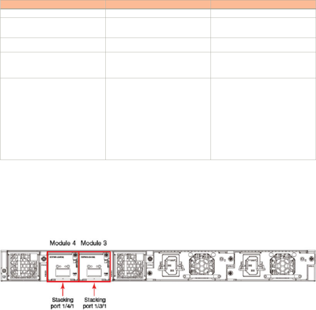
TABLE 10 ICX 7450 traditional stacking capability (continued)
Stacking capability ICX 7450 Additional information
Hitless switchover and hitless failover Supported Refer to Hitless stacking on page 141.
License requirements No license required for stack-port configuration Premium feature requires trust-based license.
Refer to the
Brocade FastIron Software Licensing
Guide
for information.
Configuration options Manual and automatic, including Secure-setup Refer to Traditional stack construction methods
on page 25.
Access methods TFTP, SCP Software images, boot images, and signatures
can be downloaded to a stack using TFTP and
SCP. Refer to the
Brocade FastIron Software
Upgrade Guide
for more information.
Traditional stacking CLI These commands are not available on the ICX
7450, except as noted:
connect
default-ports, except when a 4X10GF module is
present in slot 2
multi-stack-port, except when a 4X10GF
module is present in slot 2
multi-stack-trunk, except when a 4X10GF
module is present in slot 2
stack-trunk, except when a 4X10GF module is
present in slot 2
Refer to Traditional stack CLI commands on page
161.
ICX 7450 stacking topologies
Up to 12 ICX 7450 units of any kind can be connected in a linear or ring topology. Default stacking ports are located on the rear panel as
shown in the following figures. The default port numbers are 1/3/1 and 1/4/1 (unit/slot/port); that is, they are the single port located in
modules 3 and 4 of the ICX 7450 as shown.
The following figure shows the default stacking ports for the ICX 7450. These ports may also be used as data ports.
FIGURE 17 ICX 7450 1 X 40-Gbps default stacking ports
The following figure shows the 4X10GF module and port numbers.
Traditional Stacking by Device
ICX 7450 stack configuration overview
Ruckus FastIron Stacking Configuration Guide, 08.0.70
Part Number: 53-1005299-01 69
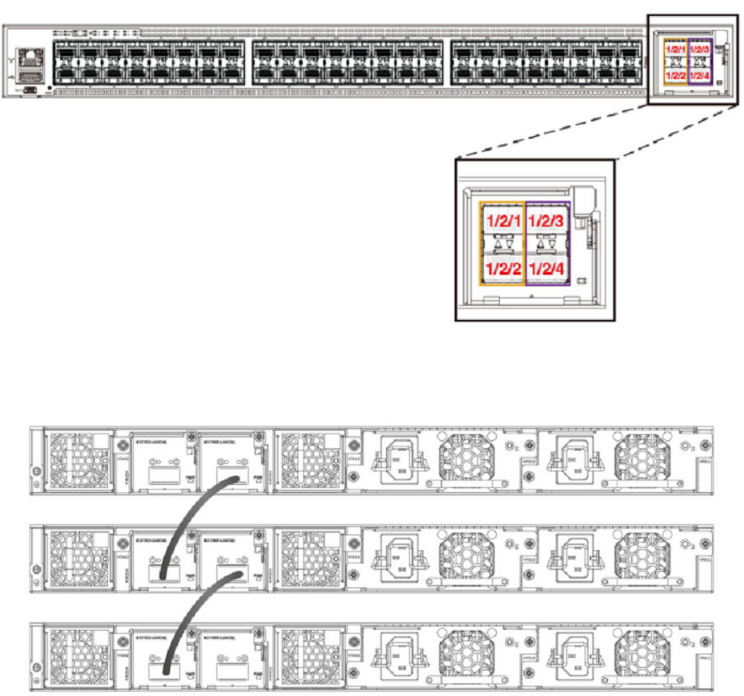
FIGURE 18 ICX 7450 module 2 ports available for stacking
The following figure shows ICX 7450 units connected from 1 X 40-Gbps ports on the rear in a linear stack.
FIGURE 19 ICX 7450 1 X 40-Gbps linear stack
The following figure shows ICX 7450 units connected from 1 X 40-Gbps ports on the rear in a ring stack.
NOTE
The secure-setup utility starts discovery with the lowest numbered port. Assuming the top unit is the Active Controller, the cabling
depicted is recommended so that units are discovered and numbered sequentially, starting from the Active Controller at the top.
Refer to ICX 7450 stacking configuration notes on page 72 for more information on secure-setup discovery.
Traditional Stacking by Device
ICX 7450 stack configuration overview
Ruckus FastIron Stacking Configuration Guide, 08.0.70
70 Part Number: 53-1005299-01
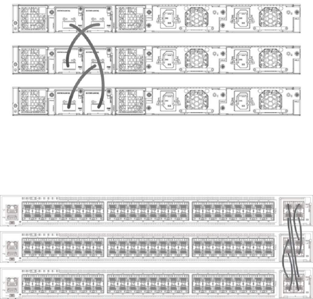
FIGURE 20 ICX 7450 1 X 40-Gbps ring stack
The following figure shows the ICX 7450 connected from the front in a ring stack.
NOTE
The secure-setup utility starts discovery with the lowest numbered port. Assuming the top unit is the Active Controller, the cabling
depicted is recommended so that units are discovered and numbered sequentially, starting from the Active Controller at the top.
Refer to ICX 7450 stacking configuration notes on page 72 for more information on secure-setup discovery.
FIGURE 21 ICX 7450 4 X 10-Gbps ring stack
The following figure shows the ICX 7450 connected from the front in a linear stack.
Traditional Stacking by Device
ICX 7450 stack configuration overview
Ruckus FastIron Stacking Configuration Guide, 08.0.70
Part Number: 53-1005299-01 71
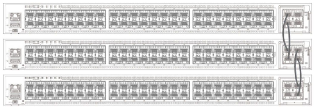
FIGURE 22 ICX 7450 4 X 10-Gbps linear stack
ICX 7450 stacking configuration notes
• The 1 X 40-Gbps module supports stacking only when installed in rear panel slot 3 or 4.
• The ICX 7450 supports 10-Gbps stacking when a 4X10GF module is present in slot 2. Each unit must be individually configured
with default stacking ports as 1/2/1 and 1/2/3 and reloaded to join a stack, or to use secure setup. Refer to Configuring 10-Gbps
stacking ports on the ICX 7450 on page 72 for more information on 4 X 10-Gbps ports.
• Stack ports can be configured using the stack-ports command.
• ICX 7450 units support stack trunks only on a 4 X 10-Gbps (4X10GF) module installed in slot 2.
• The 4X10GF ports can also support MACsec but not simultaneously. Refer to Converting ICX 7450 slot 2 ports for MACsec or
stacking on page 73 for more information on converting 4 X 10-Gbps ports to or from MACsec.
• An IPsec module can be installed as an add-on in slot 2, 3, or 4 of an ICX 7450 device. Only one IPsec module should be installed
in a stacking unit, and only one IPsec module is active in the stack at any time. A second IPsec module may be present in another
stack unit; however, the second card does not provide active redundancy if the active IPsec module fails.
• The secure-setup utility starts stack discovery on the stack port with the lowest port number, and that number is always on
module 3 on an ICX 7450 40-Gbps stack. As a result, the switch unit IDs are allocated sequentially (1 , 2, 3, and so on) from the
Active controller down to the stack port with the lowest port number (port 1/3/1 in an ICX 7450 40-Gbps stack).
• When the secure-setup utility is used to configure an ICX 7450 stack, endpoints or ports of ending units that are not used for
stacking are left as data ports, except on active units, where both ports 1/3/1 and 1/4/1 (or both ports 1/2/1 and 1/2/3 with 4 X
10-Gbps stacking) become stack ports as a result of the stack enable command being executed.
Configuring 10-Gbps stacking ports on the ICX 7450
By default, the ICX 7450 uses 40-Gbps ports in slots 3 and 4 as stacking ports. When a 4X10GF module is installed in slot 2 on the front
panel of an ICX 7450, 10-Gbps stacking can be configured.
NOTE
Stacking and MACsec cannot be configured on these 10 Gbps ports at the same time. Refer to Converting ICX 7450 slot 2 ports
for MACsec or stacking on page 73 for more information.
Traditional Stacking by Device
ICX 7450 stack configuration overview
Ruckus FastIron Stacking Configuration Guide, 08.0.70
72 Part Number: 53-1005299-01
To configure stacking on 10-Gbps ports in a 4X10GF module installed in slot 2, change the default stacking ports as shown in the following
example.
ICX7450-48F Router# configure terminal
ICX7450-48F Router(config)# stack unit 1
ICX7450-48F Router(config-unit-1)# default-ports 1/2/1 1/2/3
Reload required. Please write memory and then reload or power cycle.
ICX7450-48F Router(config-unit-1)# write memory
Write startup-config done.
ICX7450-48F Router(config-unit-1)# end
ICX7450-48F Router# reload
When the default-ports command is issued, the following error messages may be returned if Slot 2 does not contain a 4 X 10-Gbps
module.
Error - Module <module_number> is not a 4x10GF module.
Error- Module <module_number> is not present.
Error- Invalid default ports "<port_1> and <port_2>" on ICX7450.
Once the default stacking ports are configured, the configuration is written to memory, and the unit is reloaded, it is ready to join an existing
stack or to be configured for stacking using secure-setup or manual stack construction.
NOTE
Automatic stack configuration (described in "Traditional stack construction methods") and unit replacement features do not work
with ICX 7450 4X10GF stacking. For unit replacement to work, you must use the same model as the one you are replacing, and
the new unit must be a clean unit. Refer to Traditional stacking terminology on page 17 for a definition of clean unit. Suppose the
stack is using a 4X10GF module installed in slot 2, and you want to replace a unit. To configure the new unit with the same
configuration, you must configure the default ports, write memory, and reload. As a result, the new unit is no longer a clean unit
because it has startup configuration flash, and the unit replacement feature will not automatically integrate this unit into a stack.
You must use secure-setup or the manual stack construction method described in Traditional stack construction methods on
page 25 to add the new unit to the stack. If you use the manual stack construction method, you must configure the stack
suggested-id with the same ID in the replacement unit before you enable the stack.
Converting ICX 7450 slot 2 ports for MACsec or stacking
When a 4x10GF module is installed in slot 2 of the ICX 7450, it is enabled for MACsec even if the ports have not been configured. To use
these ports for stacking, you must reconfigure them.
NOTE
The ICX 7450 can support 4 X 10-Gbps stacking from slot 2 or 40-Gbps stacking from rear ports; however, it cannot support
both at the same time.
By default, if a 4X10GF module is present in slot 2, it is enabled for MACsec. No reload or power-cycle is required to enable or disable
MACsec on slot 2 interfaces. However, to use the slot 2 ports for stacking, the default ports must be changed, and the unit must be
reloaded as described in Configuring 10-Gbps stacking ports on the ICX 7450 on page 72.
If the 4X10GF module in slot 2 is programmed for stacking during bootup, MACsec cannot be configured on the ports until the stacking
default ports have been changed to rear panel ports and the unit has been reloaded or turned off and on.
MACsec and stacking cannot be configured at the same time on slot 2 interfaces. However, 4X10GF modules installed in slots 3 and 4 on
the rear panel of the ICX 7450 can support MACsec at the same time that slot 2 is configured for 4X10GF stacking.
The following error message is displayed when MACsec is configured on slot 2 and you try to set the stacking default ports to slot 2.
Error - Please remove MACsec configuration from port <port_id> before using 4x10GF for stacking
Traditional Stacking by Device
ICX 7450 stack configuration overview
Ruckus FastIron Stacking Configuration Guide, 08.0.70
Part Number: 53-1005299-01 73
If you try to use the stack enable command, the command is blocked, and the following message is displayed.
Error - Please remove MACsec configuration from port <port_id> before using 4x10GF for stacking
The following error message is displayed if stacking is configured on these ports and you enter the enable-mka ethernet command for any
of the ports.
Error: MACsec is not allowed when 4x10GF module is used for stacking.
Please use "default-ports" command to change the default stacking ports
The following example reconfigures stacking ports on slot 2 for use as MACsec ports.
ICX7450-48 Router#
ICX7450-48 Router# show running-config
Current configuration:
!
ver 08.0.30q070T213
!
stack unit 1
module 1 icx7450-48-port-management-module
module 2 icx7400-xgf-4port-40g-module
module 3 icx7400-qsfp-1port-40g-module
module 4 icx7400-qsfp-1port-40g-module
default-ports 1/2/1 1/2/3
!
!
!
!
!
!
!
!
ip dns domain-list englab.brocade.com
ip dns server-address 10.31.2.10
!
!
!
--More--, next page: Space, next line: Return key, quit: Control-c^C
ICX7450-48 Router#
ICX7450-48 Router#
ICX7450-48 Router#
ICX7450-48 Router# configure terminal
ICX7450-48 Router(config)#
ICX7450-48 Router(config)# dot1x-mka
ICX7450-48 Router(config-dot1x-mka)# enable-mka ethernet 1/2/1
<cr>
ICX7450-48 Router(config-dot1x-mka)# enable-mka ethernet 1/2/1
Error: MACsec is not allowed when 4x10GF module is used for stacking.
Please use "default-ports" command to change the default stacking ports
ICX7450-48 Router(config-dot1x-mka)# exit
ICX7450-48 Router(config)# stack unit 1
ICX7450-48 Router(config-unit-1)#
ICX7450-48 Router(config-unit-1)# default-ports 1/3/1 1/4/1
1/3/1 and 1/4/1 are default, so they won't show up in "show run"
ICX7450-48 Router(config-unit-1)# show running-config
Current configuration:
!
ver 08.0.30q070T213
!
stack unit 1
module 1 icx7450-48-port-management-module
module 2 icx7400-xgf-4port-40g-module
module 3 icx7400-qsfp-1port-40g-module
module 4 icx7400-qsfp-1port-40g-module
!
!
!
!
!
Traditional Stacking by Device
ICX 7450 stack configuration overview
Ruckus FastIron Stacking Configuration Guide, 08.0.70
74 Part Number: 53-1005299-01
!
!
!
ip dns domain-list englab.brocade.com
ip dns server-address 10.31.2.10
!
!
!
dot1x-mka-enable
--More--, next page: Space, next line: Return key, quit: Control-c^C
ICX7450-48 Router(config-unit-1)#
ICX7450-48 Router(config-unit-1)# dot1x-mka
ICX7450-48 Router(config-dot1x-mka)# enable-mka ethernet 1/2/1
Reload required. Please write memory and then reload or power cycle.
Error: This 4x10GF module has been used for stacking. To enable MACsec on it, a reload is required
ICX7450-48 Router(config-dot1x-mka)# write memory
Write startup-config done.
ICX7450-48 Router(config-dot1x-mka)# Flash Memory Write (8192 bytes per dot) .
Copy Done.
ICX7450-48 Router(config-dot1x-mka)# reload
ICX7450-48 Router(config-dot1x-mka)# exit
ICX7450-48 Router(config)# exit
ICX7450-48 Router# reload
Creating stacking trunks on the ICX 7450
The ICX 7450 supports two stacking trunks per stack unit when the 4X10GF module in slot 2 is used for stacking.
You can configure one or two stacking trunks on an ICX 7450 stand-alone after changing default stacking ports to 1/2/1 and 1/2/3 as
shown in the following example. Each stacking trunk can have two ports. Potential stacking trunks contain the stacking port and the next
sequential port (1/2/1 through 1/2/2 and 1/2/3 through 1/2/4).
Traditional Stacking by Device
ICX 7450 stack configuration overview
Ruckus FastIron Stacking Configuration Guide, 08.0.70
Part Number: 53-1005299-01 75
The following example configures two stacking trunks.
ICX7450-24P Router#
ICX7450-24P Router#
ICX7450-24P Router# configure terminal
ICX7450-24P Router(config)# stack unit 1
ICX7450-24P Router(config-unit-1)#
ICX7450-24P Router(config-unit-1)# default-ports 1/2/1 1/2/3
Reload required. Please write memory and then reload or power cycle.
ICX7450-24P Router(config-unit-1)#
ICX7450-24P Router(config-unit-1)# stack-trunk 1/2/1 to 1/2/2
ICX7450-24P Router(config-unit-1)# stack-trunk 1/2/3 to 1/2/4
ICX7450-24P Router(config-unit-1)#
ICX7450-24P Router(config-unit-1)# show running-config
Current configuration:
!
ver 08.0.30q071T213
!
stack unit 1
module 1 icx7450-24p-poe-port-management-module
module 2 icx7400-xgf-4port-40g-module
module 4 icx7400-xgf-4port-40g-module
default-ports 1/2/1 1/2/3
stack-trunk 1/2/1 to 1/2/2
stack-trunk 1/2/3 to 1/2/4
!
ip dns domain-list englab.brocade.com
ip dns server-address 10.31.2.10
!
ICX7450-24P Router(config-unit-1)# exit
ICX7450-24P Router(config)# write memory
memory To startup config file
ICX7450-24P Router(config)# write memory
There is no startup config file, unable to save legacy config
ICX7450-24P Router(config)# Flash Memory Write (8192 bytes per dot) .
Write startup-config done.
Copy Done.
ICX7450-24P Router(config)# exit
ICX7450-24P Router# reload
Are you sure? (enter 'y' or 'n'):
NOTE
Default ports 1/3/1 and 1/4/1, which are 40-Gbps ports on the rear panel of the ICX 7450, do not support stacking trunks.
Creating stacking trunks on live stacks
Use the multi-stack trunk command to add or remove a stacking trunk on a live ICX 7450 stack. The following example creates two
stacking trunks.
device# configure terminal
device(config)# stack unit 1
device(config-unit-1)# multi-stack-trunk 1/2/1 to 1/2/2 and 2/2/1 to 2/2/2
device(config-unit-1)# end
device(config)# end
device#
NOTE
You can use the multi-stack-port command to create individual ports on a live stack. Available ports on slot 2 are 1/2/1 and
1/2/3.
Traditional Stacking by Device
ICX 7450 stack configuration overview
Ruckus FastIron Stacking Configuration Guide, 08.0.70
76 Part Number: 53-1005299-01
ICX 7450 secure-setup examples
Use the stack secure-setup command to automatically form a correctly connected stack. For more information on stack construction, refer
to Traditional stack construction methods on page 25.
In the following example, the stack secure-setup command is used to form a 12-unit ICX 7450 stack in a ring topology.
ICX7450-48P Router# configure terminal
ICX7450-48P Router(config)# stack enable
Enable stacking. This unit actively participates in stacking
stacking is enable. optical monitoring for stacking ports 1/3/1, 1/4/1 is not available.
ICX7450-48P Router(config)# exit
ICX7450-48P Router# stack secure-setup
ICX7450-48P Router# Discovering the stack topology...
Current Discovered Topology - RING
Available UPSTREAM units
Hop(s) Id Type Mac Address
1 new ICX7450-48F cc4e.2489.a220
2 new ICX7450-48F cc4e.246d.1838
3 new ICX7450-48P cc4e.246d.2938
4 new ICX7450-24P cc4e.246d.0520
5 new ICX7450-24P cc4e.2489.8a38
6 new ICX7450-48P cc4e.2489.b388
7 new ICX7450-48F cc4e.246d.1478
8 new ICX7450-48P cc4e.2489.8640
9 new ICX7450-48F cc4e.246d.1df8
10 new ICX7450-48F cc4e.246d.1b78
11 new ICX7450-48F cc4e.246d.1c78
Available DOWNSTREAM units
Hop(s) Id Type Mac Address
1 new ICX7450-48F cc4e.246d.1c78
2 new ICX7450-48F cc4e.246d.1b78
3 new ICX7450-48F cc4e.246d.1df8
4 new ICX7450-48P cc4e.2489.8640
5 new ICX7450-48F cc4e.246d.1478
6 new ICX7450-48P cc4e.2489.b388
7 new ICX7450-24P cc4e.2489.8a38
8 new ICX7450-24P cc4e.246d.0520
9 new ICX7450-48P cc4e.246d.2938
10 new ICX7450-48F cc4e.246d.1838
11 new ICX7450-48F cc4e.2489.a220
Do you accept the topology (RING) (y/n)?: y
Selected Topology:
Active Id Type Mac Address
1 ICX7450-48P cc4e.2489.b188
Selected UPSTREAM units
Hop(s) Id Type Mac Address
1 2 ICX7450-48F cc4e.2489.a220
2 3 ICX7450-48F cc4e.246d.1838
3 4 ICX7450-48P cc4e.246d.2938
4 5 ICX7450-24P cc4e.246d.0520
5 6 ICX7450-24P cc4e.2489.8a38
6 7 ICX7450-48P cc4e.2489.b388
7 8 ICX7450-48F cc4e.246d.1478
8 9 ICX7450-48P cc4e.2489.8640
9 10 ICX7450-48F cc4e.246d.1df8
10 11 ICX7450-48F cc4e.246d.1b78
11 12 ICX7450-48F cc4e.246d.1c78
Selected DOWNSTREAM units
Hop(s) Id Type Mac Address
1 12 ICX7450-48F cc4e.246d.1c78
2 11 ICX7450-48F cc4e.246d.1b78
Traditional Stacking by Device
ICX 7450 stack configuration overview
Ruckus FastIron Stacking Configuration Guide, 08.0.70
Part Number: 53-1005299-01 77
3 10 ICX7450-48F cc4e.246d.1df8
4 9 ICX7450-48P cc4e.2489.8640
5 8 ICX7450-48F cc4e.246d.1478
6 7 ICX7450-48P cc4e.2489.b388
7 6 ICX7450-24P cc4e.2489.8a38
8 5 ICX7450-24P cc4e.246d.0520
9 4 ICX7450-48P cc4e.246d.2938
10 3 ICX7450-48F cc4e.246d.1838
11 2 ICX7450-48F cc4e.2489.a220
Do you accept the unit id's (y/n)?: y
ICX7450-48P Router#T=13m8.4: Election, was alone --> active, ID=1, pri=128, 12U(1-12), A=u1, nbr#=11 11,
reason: u7: SecureS, ,
Config changed due to add/del units. Do write mem if you want to keep it
T=13m13.9: reset unit 2: u2 bo-id=1
T=13m13.9: reset unit 3: u3 bo-id=1
T=13m13.9: reset unit 4: u4 bo-id=1 SS or UR
T=13m13.9: reset unit 5: u5 bo-id=1 SS or UR
T=13m13.9: reset unit 6: u6 bo-id=1 SS or UR
T=13m13.9: reset unit 7: u7 bo-id=1 SS or UR
T=13m13.9: reset unit 8: u8 bo-id=1 SS or UR
T=13m13.9: reset unit 9: u9 bo-id=1 SS or UR
T=13m13.9: reset unit 10: u10 bo-id=1 SS or UR
T=13m13.9: reset unit 11: u11 bo-id=1 SS or UR
T=13m13.9: reset unit 12: u12 bo-id=1 SS or UR
T=13m23.8: Election, was active, no change, ID=1, pri=128, 12U(1-12), A=u1,
nbr#=11 11, reason: u7: port-up, ,
T=13m26.8: reset unit 2: u2 bo-id=1
T=13m26.8: reset unit 3: u3 bo-id=1
T=13m26.8: reset unit 4: u4 bo-id=1
T=13m26.8: reset unit 5: u5 bo-id=1
T=13m26.8: reset unit 6: u6 bo-id=1
T=13m26.8: reset unit 7: u7 bo-id=1
T=13m26.8: reset unit 8: u8 bo-id=1
T=13m26.8: reset unit 9: u9 bo-id=1
T=13m26.8: reset unit 10: u10 bo-id=1
T=13m26.8: reset unit 11: u11 bo-id=1
T=13m26.8: reset unit 12: u12 bo-id=1
T=13m28.5: Unit 1 loses all neighbors.
T=13m28.9: Active U1 deletes U2 and its config because it is learned.
T=13m29.5: Active U1 deletes U3 and its config because it is learned.
T=13m29.9: Active U1 deletes U4 and its config because it is learned.
T=13m30.1: Active U1 deletes U5 and its config because it is learned.
T=13m30.1: Active U1 deletes U6 and its config because it is learned.
T=13m30.1: Active U1 deletes U7 and its config because it is learned.
T=13m30.2: Active U1 deletes U8 and its config because it is learned.
T=13m30.7: Active U1 deletes U9 and its config because it is learned.
T=13m31.2: Active U1 deletes U10 and its config because it is learned.
T=13m31.6: Active U1 deletes U11 and its config because it is learned.
T=13m32.1: Active U1 deletes U12 and its config because it is learned.
Config changed due to add/del units. Do write mem if you want to keep it
ICX7450-48P Router#T=15m36.4: Election, was active, no change, ID=1, pri=128,
10U(1,4-12), A=u1, nbr#=0 9, reason: u4: port-up, ,
T=15m38.1: Synchronize webauth files to u7
Detect stack member 7 POE capable
T=15m38.2: Synchronize webauth files to u8
T=15m38.3: Synchronize webauth files to u9
T=15m38.3: Synchronize webauth files to u10
Detect stack member 9 POE capable
T=15m38.3: Synchronize webauth files to u11
T=15m38.3: Synchronize webauth files to u12
T=15m39.2: Synchronize webauth files to u4
T=15m39.2: Synchronize webauth files to u5
Detect stack member 4 POE capable
Detect stack member 5 POE capable
T=15m39.2: Synchronize webauth files to u6
Detect stack member 6 POE capable
T:15m39.5: Done hot swap: active controller u1 sets u7 to Ready.
Traditional Stacking by Device
ICX 7450 stack configuration overview
Ruckus FastIron Stacking Configuration Guide, 08.0.70
78 Part Number: 53-1005299-01
T:15m39.7: Done hot swap: active controller u1 sets u8 to Ready.
T:15m39.9: Done hot swap: active controller u1 sets u9 to Ready.
T:15m40.4: Done hot swap: active controller u1 sets u10 to Ready.
T:15m40.9: Done hot swap: active controller u1 sets u11 to Ready.
T:15m41.4: Done hot swap: active controller u1 sets u12 to Ready.
Config changed due to add/del units. Do write mem if you want to keep it
Stack unit 10 Power supply 1 is up
Stack unit 10 Power supply 2 is down
Stack unit 8 Power supply 1 is up
Stack unit 8 Power supply 2 is down
T:15m43.2: Done hot swap: active controller u1 sets u4 to Ready.
T:15m43.6: Done hot swap: active controller u1 sets u5 to Ready.
T:15m44.1: Done hot swap: active controller u1 sets u6 to Ready.
Stack unit 7 Power supply 1 is down
PoE: Stack unit 7 Power supply 2 with 748000 mwatts capacity is up
PoE: Stack unit 9 Power supply 1 with 748000 mwatts capacity is up
Stack unit 9 Power supply 2 is down
Stack unit 11 Power supply 1 is up
Stack unit 11 Power supply 2 is down
PoE: Stack unit 5 Power supply 1 with 258000 mwatts capacity is up
PoE: Stack unit 5 Power supply 2 with 258000 mwatts capacity is up
Stack unit 12 Power supply 1 is up
Stack unit 12 Power supply 2 is down
PoE: Stack unit 4 Power supply 1 with 748000 mwatts capacity is up
Stack unit 4 Power supply 2 is down
PoE: Stack unit 6 Power supply 1 with 748000 mwatts capacity is up
Stack unit 6 Power supply 2 is down
T=16m44.4: Assigned unit 4 to be standby
T=16m46.4: start running config sync to standby u4
T=16m47.0: Running config sync to standby u4 is complete
T=17m30.5: Election, was active, no change, ID=1, pri=128, 12U(1-12), A=u1,
nbr#=11 11, reason: u2: port-up, ,
T=17m34.6: Synchronize webauth files to u2
T=17m35.1: Synchronize webauth files to u3
Config changed due to add/del units. Do write mem if you want to keep it
T:17m37.2: Done hot swap: active controller u1 sets u2 to Ready.
T:17m39.1: Done hot swap: active controller u1 sets u3 to Ready.
T=17m39.2: Election, was active, no change, ID=1, pri=128, 12U(1-12), A=u1,
nbr#=11 11, reason: u3: port-up, ,
Stack unit 2 Power supply 1 is up
Stack unit 2 Power supply 2 is down
Stack unit 3 Power supply 1 is up
Stack unit 3 Power supply 2 is down
Config changed due to add/del units. Do write mem if you want to keep it
In the next example, show stack command output displays details for the 12-unit stack just formed.
ICX7450-48P Router# show stack
T=18m12.1: alone: standalone, D: dynamic cfg, S: static, A=10, B=11, C=12
ID Type Role Mac Address Pri State Comment
1 S ICX7450-48P active cc4e.2489.b188 128 local Ready
2 D ICX7450-48F member cc4e.2489.a220 0 remote Ready
3 D ICX7450-48F member cc4e.246d.1838 0 remote Ready
4 D ICX7450-48P standby cc4e.246d.2938 0 remote Ready
5 D ICX7450-24P member cc4e.246d.0520 0 remote Ready
6 D ICX7450-24P member cc4e.2489.8a38 0 remote Ready
7 D ICX7450-48P member cc4e.2489.b388 0 remote Ready
8 D ICX7450-48F member cc4e.246d.1478 0 remote Ready
9 D ICX7450-48P member cc4e.2489.8640 0 remote Ready
10 D ICX7450-48F member cc4e.246d.1df8 0 remote Ready
11 D ICX7450-48F member cc4e.246d.1b78 0 remote Ready
12 D ICX7450-48F member cc4e.246d.1c78 0 remote Ready
active
+---+ +---+ +---+ +---+ +---+ +---+
-3/1| 1 |4/1--3/1| C |4/1--3/1| B |4/1--3/1| A |4/1--3/1| 9 |4/1--3/1| 8 |4/1-
| +---+ +---+ +---+ +---+ +---+ +---+ |
Traditional Stacking by Device
ICX 7450 stack configuration overview
Ruckus FastIron Stacking Configuration Guide, 08.0.70
Part Number: 53-1005299-01 79
| |
| standby |
| +---+ +---+ +---+ +---+ +---+ +---+ |
-4/1| 2 |3/1--4/1| 3 |3/1--4/1| 4 |3/1--4/1| 5 |3/1--4/1| 6 |3/1--4/1| 7 |3/1-
+---+ +---+ +---+ +---+ +---+ +---+
Will assign standby in 28 sec due to all ready
Standby u4 - wait for standby assignment due to election
Current stack management MAC is cc4e.2489.b188
The following example configures an ICX 7450 to use 4 X 10-Gbps ports for stacking. First, default ports are reassigned, a write memory
command is executed, and the unit is reloaded. When the unit reboots, the 4 X 10-Gbps default ports are configured, and the stack secure
setup utility can be executed to form the stack.
ICX7450-24 Router> enable
No password has been assigned yet...
ICX7450-24 Router# configure terminal
ICX7450-24 Router(config)# stack enable
Enable stacking. This unit actively participates in stacking
stacking is enable. optical monitoring for stacking ports 1/2/1, 1/2/3 is not available.
ICX7450-24 Router(config)# stack unit 1
ICX7450-24 Router(config-unit-1)# default-ports 1/2/1 1/2/3
Reload required. Please write memory and then reload or power cycle.
ICX7450-24 Router(config-unit-1)#
ICX7450-24 Router(config-unit-1)# end
ICX7450-24 Router# write memory
There is no startup config file, unable to save legacy config
ICX7450-24 Router#
ICX7450-24 Router# write memory
Flash access in progress. Please try later
ICX7450-24 Router# Flash Memory Write (8192 bytes per dot) .
Write startup-config done.
Copy Done.
ICX7450-24 Router#
ICX7450-24 Router#
ICX7450-24 Router# reload
Sent SIGTERM to all processesn'):
Sent SIGKILL to all processes
Requesting system reboot
Restarting system.
After the unit reloads, run the secure setup utility with the stack secure-setup command to form the stack.
ICX7450-24 Router#
ICX7450-24 Router# configure terminal
ICX7450-24 Router(config)# show run
Current configuration:
!
ver 08.0.30q101T213
!
stack unit 1
module 1 icx7450-24-port-management-module
module 2 icx7400-xf-4port-40g-module
module 3 icx7400-xf-4port-40g-module
module 4 icx7400-qsfp-1port-40g-module
default-ports 1/2/1 1/2/3
!
!
!
!
!
!
!
!
ip dns domain-list englab.brocade.com
ip dns server-address 10.31.2.10
!
Traditional Stacking by Device
ICX 7450 stack configuration overview
Ruckus FastIron Stacking Configuration Guide, 08.0.70
80 Part Number: 53-1005299-01
!
!
--More--, next page: Space, next line: Return key, quit: Control-c^C
ICX7450-24 Router(config)# exit
ICX7450-24 Router# stack secure-setup
ICX7450-24 Router# Discovering the stack topology...
Available UPSTREAM units
Hop(s) Id Type Mac Address
1 new ICX7450-48F cc4e.246d.1c78
2 new ICX7450-48F cc4e.246d.1b78
3 new ICX7450-48F cc4e.246d.1ff8
4 new ICX7450-48P cc4e.2489.8640
5 new ICX7450-48F cc4e.246d.1478
6 new ICX7450-48P cc4e.2489.b388
7 new ICX7450-48P cc4e.2489.b188
8 new ICX7450-48P cc4e.246d.2938
9 new ICX7450-48F cc4e.246d.1838
10 new ICX7450-48P cc4e.246d.23b8
11 new ICX7450-24P cc4e.246d.0520
Enter the number of the desired UPSTREAM units (0-11)[0]: 11
Confirm Stacking Links...
UPSTREAM Unit: Id new at 1 hop(s) ICX7450-48F cc4e.246d.1c78
Enter the desired links(1-2)[1]: 2
UPSTREAM Unit: Id new at 2 hop(s) ICX7450-48F cc4e.246d.1b78
Enter the desired links(1-2)[1]: 2
UPSTREAM Unit: Id new at 3 hop(s) ICX7450-48F cc4e.246d.1ff8
Enter the desired links(1-2)[1]: 2
UPSTREAM Unit: Id new at 4 hop(s) ICX7450-48P cc4e.2489.8640
Enter the desired links(1-2)[1]: 2
UPSTREAM Unit: Id new at 5 hop(s) ICX7450-48F cc4e.246d.1478
Enter the desired links(1-2)[1]: 2
UPSTREAM Unit: Id new at 6 hop(s) ICX7450-48P cc4e.2489.b388
Enter the desired links(1-2)[1]: 2
UPSTREAM Unit: Id new at 7 hop(s) ICX7450-48P cc4e.2489.b188
Enter the desired links(1-2)[1]: 2
UPSTREAM Unit: Id new at 8 hop(s) ICX7450-48P cc4e.246d.2938
Enter the desired links(1-2)[1]: 2
UPSTREAM Unit: Id new at 9 hop(s) ICX7450-48F cc4e.246d.1838
Enter the desired links(1-2)[1]: 2
UPSTREAM Unit: Id new at 10 hop(s) ICX7450-48P cc4e.246d.23b8
Enter the desired links(1-2)[1]: 2
UPSTREAM Unit: Id new at 11 hop(s) ICX7450-24P cc4e.246d.0520
Enter the desired links(1-2)[1]: 2
Selected Topology:
Active Id Type Mac Address
1 ICX7450-24F cc4e.246c.ffd0
Traditional Stacking by Device
ICX 7450 stack configuration overview
Ruckus FastIron Stacking Configuration Guide, 08.0.70
Part Number: 53-1005299-01 81
Selected UPSTREAM units
Hop(s) Id Type Mac Address
1 2 ICX7450-48F cc4e.246d.1c78
2 3 ICX7450-48F cc4e.246d.1b78
3 4 ICX7450-48F cc4e.246d.1ff8
4 5 ICX7450-48P cc4e.2489.8640
5 6 ICX7450-48F vcc4e.246d.1478
6 7 ICX7450-48P cc4e.2489.b388
7 8 ICX7450-48P cc4e.2489.b188
8 9 ICX7450-48P cc4e.246d.2938
9 10 ICX7450-48F cc4e.246d.1838
10 11 ICX7450-48P cc4e.246d.23b8
11 12 ICX7450-24P cc4e.246d.0520
Do you accept the unit id's (y/n)?: y
ICX7450-24 Router#T=5m2.9: Election, was alone --> active, ID=1, pri=128, 12U(1-12), A=u1, nbr#=11 0,
reason: u12: port-up, ,
The period is 25
T=5m6.9: Election, was active, no change, ID=1, pri=128, 12U(1-12), A=u1, nbr#=11 0, reason: u1: stk-po-
chg, ,
T=5m10.0: reset unit 2: u2 bo-id=1
T=5m10.0: reset unit 3: u3 bo-id=1
T=5m10.0: reset unit 4: u4 bo-id=1
T=5m10.0: reset unit 5: u5 bo-id=1
T=5m10.0: reset unit 6: u6 bo-id=1
T=5m10.0: reset unit 7: u7 bo-id=1
T=5m10.0: reset unit 8: u8 bo-id=1
T=5m10.0: reset unit 9: u9 bo-id=1
T=5m10.0: reset unit 10: u10 bo-id=1
T=5m10.0: reset unit 11: u11 bo-id=1
T=5m10.0: reset unit 12: u12 bo-id=1
Config changed due to add/del units. Do write mem if you want to keep it
T=5m15.0: Unit 1 loses all neighbors.
T=5m18.0: Active U1 deletes U2 and its config because it is learned.
T=5m21.0: Active U1 deletes U3 and its config because it is learned.
T=5m23.8: Active U1 deletes U4 and its config because it is learned.
T=5m26.6: Active U1 deletes U5 and its config because it is learned.
T=5m29.5: Active U1 deletes U6 and its config because it is learned.
T=5m30.5: Active U1 deletes U7 and its config because it is learned.
T=5m31.5: Active U1 deletes U8 and its config because it is learned.
T=5m32.5: Active U1 deletes U9 and its config because it is learned.
T=5m33.5: Active U1 deletes U10 and its config because it is learned.
T=5m34.5: Active U1 deletes U11 and its config because it is learned.
T=5m35.0: Active U1 deletes U12 and its config because it is learned.
T=7m5.1: Election, was active, no change, ID=1, pri=128, 3U(1-3), A=u1, nbr#=2 0, reason: u3: port-up, ,
The period is 25
Detect stack unit 2 has different startup config flash, will synchronize it
T=7m5.5: Synchronize webauth files to u2
Detect stack unit 3 has different startup config flash, will synchronize it
T=7m5.5: Synchronize webauth files to u3
T:7m6.7: Done hot swap: active controller u1 sets u2 to Ready.
T:7m6.8: Done hot swap: active controller u1 sets u3 to Ready.
T=7m7.5: Synchronize startup config to u2
Flash Memory Write (8192 bytes per dot) .
Write startup-config done.
T=7m8.5: Synchronize startup config to u3
Flash Memory Write (8192 bytes per dot) .
Write startup-config done.
Stack unit 3 Power supply 1 is up
Stack unit 3 Power supply 2 is down
Stack unit 2 Power supply 1 is up
Stack unit 2 Power supply 2 is down
Config changed due to add/del units. Do write mem if you want to keep it
T=7m10.7: Election, was active, no change, ID=1, pri=128, 12U(1-12), A=u1, nbr#=11 0, reason: u12: port-
up, ,
Detect stack unit 9 has different startup config flash, will synchronize it
T=7m11.6: Synchronize webauth files to u9
Detect stack unit 12 has different startup config flash, will synchronize it
T=7m11.6: Synchronize webauth files to u12
Traditional Stacking by Device
ICX 7450 stack configuration overview
Ruckus FastIron Stacking Configuration Guide, 08.0.70
82 Part Number: 53-1005299-01
Detect stack member 9 POE capable
Detect stack member 12 POE capable
Detect stack unit 10 has different startup config flash, will synchronize it
T=7m11.6: Synchronize webauth files to u10
Detect stack unit 11 has different startup config flash, will synchronize it
T=7m11.6: Synchronize webauth files to u11
Detect stack unit 4 has different startup config flash, will synchronize it
T=7m11.7: Synchronize webauth files to u4
Detect stack member 11 POE capable
Detect stack unit 6 has different startup config flash, will synchronize it
T=7m11.7: Synchronize webauth files to u6
Detect stack unit 5 has different startup config flash, will synchronize it
T=7m11.7: Synchronize webauth files to u5
Detect stack unit 7 has different startup config flash, will synchronize it
T=7m11.7: Synchronize webauth files to u7
Detect stack unit 8 has different startup config flash, will synchronize it
T=7m11.7: Synchronize webauth files to u8
Detect stack member 5 POE capable
Detect stack member 7 POE capable
Detect stack member 8 POE capable
T:7m12.9: Done hot swap: active controller u1 sets u9 to Ready.
T:7m13.1: Done hot swap: active controller u1 sets u10 to Ready.
T:7m13.3: Done hot swap: active controller u1 sets u11 to Ready.
T:7m13.5: Done hot swap: active controller u1 sets u12 to Ready.
T=7m13.7: Synchronize startup config to u9
T:7m13.9: Done hot swap: active controller u1 sets u4 to Ready.
Flash Memory Write (8192 bytes per dot) .
Write startup-config done.
T:7m14.0: Done hot swap: active controller u1 sets u5 to Ready.
T:7m14.2: Done hot swap: active controller u1 sets u6 to Ready.
T:7m14.7: Done hot swap: active controller u1 sets u7 to Ready.
T:7m15.2: Done hot swap: active controller u1 sets u8 to Ready.
PoE: Stack unit 9 Power supply 1 with 748000 mwatts capacity is up
Stack unit 9 Power supply 2 is down
T=7m15.7: Synchronize startup config to u4
PoE: Stack unit 5 Power supply 1 with 748000 mwatts capacity is up
Stack unit 5 Power supply 2 is down
Flash Memory Write (8192 bytes per dot) .
Write startup-config done.
Config changed due to add/del units. Do write mem if you want to keep it
PoE: Stack unit 12 Power supply 1 with 258000 mwatts capacity is up
PoE: Stack unit 12 Power supply 2 with 258000 mwatts capacity is up
Stack unit 8 Power supply 1 is down
PoE: Stack unit 8 Power supply 2 with 748000 mwatts capacity is up
T=7m16.7: Synchronize startup config to u5
Flash Memory Write (8192 bytes per dot) .
Write startup-config done.
T=7m16.8: Election, was active, no change, ID=1, pri=128, 12U(1-12), A=u1, nbr#=11 0, reason: u1: stk-po-
chg, ,
T=7m17.7: Synchronize startup config to u6
Flash Memory Write (8192 bytes per dot) .
Write startup-config done.
Stack unit 10 Power supply 1 is up
Stack unit 10 Power supply 2 is down
Stack unit 7 Power supply 1 is down
PoE: Stack unit 7 Power supply 2 with 748000 mwatts capacity is up
Stack unit 11 Power supply 1 is down
PoE: Stack unit 11 Power supply 2 with 748000 mwatts capacity is up
T=7m18.7: Synchronize startup config to u7
Flash Memory Write (8192 bytes per dot) .
Write startup-config done.
T=7m19.7: Synchronize startup config to u8
Flash Memory Write (8192 bytes per dot) .
Write startup-config done.
Stack unit 6 Power supply 1 is up
Stack unit 6 Power supply 2 is down
Stack unit 4 Power supply 1 is up
Stack unit 4 Power supply 2 is down
T=7m20.7: Synchronize startup config to u10
Flash Memory Write (8192 bytes per dot) .
Write startup-config done.
Traditional Stacking by Device
ICX 7450 stack configuration overview
Ruckus FastIron Stacking Configuration Guide, 08.0.70
Part Number: 53-1005299-01 83
T=7m21.7: Synchronize startup config to u11
Flash Memory Write (8192 bytes per dot) .
Write startup-config done.
Config changed due to add/del units. Do write mem if you want to keep it
T=7m22.7: Synchronize startup config to u12
Flash Memory Write (8192 bytes per dot) .
Write startup-config done.
T=8m18.1: Assigned unit 2 to be standby
T=8m20.1: start running config sync to standby u2
T=8m21.0: Running config sync to standby u2 is complete
ICX7450-24 Router#
The following example provides show stack command output for the ICX 7450 10-Gbps stack formed in the previous example.
ICX7450-24 Router# show stack
T=10m34.8: alone: standalone, D: dynamic cfg, S: static, A=10, B=11, C=12
ID Type Role Mac Address Pri State Comment
1 S ICX7450-24F active cc4e.246c.ffd0 128 local Ready
2 D ICX7450-48F standby cc4e.246d.1c78 0 remote Ready
3 D ICX7450-48F member cc4e.246d.1b78 0 remote Ready
4 D ICX7450-48F member cc4e.246d.1ff8 0 remote Ready
5 D ICX7450-48P member cc4e.2489.8640 0 remote Ready
6 D ICX7450-48F member cc4e.246d.1478 0 remote Ready
7 D ICX7450-48P member cc4e.2489.b388 0 remote Ready
8 D ICX7450-48P member cc4e.2489.b188 0 remote Ready
9 D ICX7450-48P member cc4e.246d.2938 0 remote Ready
10 D ICX7450-48F member cc4e.246d.1838 0 remote Ready
11 D ICX7450-48P member cc4e.246d.23b8 0 remote Ready
12 D ICX7450-24P member cc4e.246d.0520 0 remote Ready
+---+ +---+ +---+ +---+ +---+ +---+
| C |2/1==2/1| B |2/3==2/3| A |2/1==2/1| 9 |2/3==2/3| 8 |2/1==2/1| 7 |2/3=
+---+ +---+ +---+ +---+ +---+ +---+ |
|
active standby |
+---+ +---+ +---+ +---+ +---+ +---+ |
-2/3| 1 |2/1==2/1| 2 |2/3==2/3| 3 |2/1==2/1| 4 |2/3==2/3| 5 |2/1==2/1| 6 |2/3=
+---+ +---+ +---+ +---+ +---+ +---+
Standby u2 - protocols ready, can failover
Current stack management MAC is cc4e.246c.ffd0
ICX7450-24 Router#
The following show stack connection output provides details on the ICX 7450 10-Gbps stack formed in the previous example.
ICX7450-24 Router# show stack connection
Probing the topology. Please wait ...
ICX7450-24 Router#
+---+ +---+ +---+ +---+ +---+ +---+
| C |2/1==2/1| B |2/3==2/3| A |2/1==2/1| 9 |2/3==2/3| 8 |2/1==2/1| 7 |2/3=
+---+ +---+ +---+ +---+ +---+ +---+ |
|
active standby |
+---+ +---+ +---+ +---+ +---+ +---+ |
-2/3| 1 |2/1==2/1| 2 |2/3==2/3| 3 |2/1==2/1| 4 |2/3==2/3| 5 |2/1==2/1| 6 |2/3=
+---+ +---+ +---+ +---+ +---+ +---+
trunk probe results: 11 links
Link 1: u1 -- u2, num=2
1: 1/2/1 (T0) <---> 2/2/1 (T0)
2: 1/2/2 (T0) <---> 2/2/2 (T0)
Link 2: u2 -- u3, num=2
1: 2/2/3 (T1) <---> 3/2/3 (T1)
2: 2/2/4 (T1) <---> 3/2/4 (T1)
Link 3: u3 -- u4, num=2
1: 3/2/1 (T0) <---> 4/2/1 (T0)
2: 3/2/2 (T0) <---> 4/2/2 (T0)
Traditional Stacking by Device
ICX 7450 stack configuration overview
Ruckus FastIron Stacking Configuration Guide, 08.0.70
84 Part Number: 53-1005299-01
Link 4: u4 -- u5, num=2
1: 4/2/3 (T1) <---> 5/2/3 (T1)
2: 4/2/4 (T1) <---> 5/2/4 (T1)
Link 5: u5 -- u6, num=2
1: 5/2/1 (T0) <---> 6/2/1 (T0)
2: 5/2/2 (T0) <---> 6/2/2 (T0)
Link 6: u6 -- u7, num=2
1: 6/2/3 (T1) <---> 7/2/3 (T1)
2: 6/2/4 (T1) <---> 7/2/4 (T1)
Link 7: u7 -- u8, num=2
1: 7/2/1 (T0) <---> 8/2/1 (T0)
2: 7/2/2 (T0) <---> 8/2/2 (T0)
Link 8: u8 -- u9, num=2
1: 8/2/3 (T1) <---> 9/2/3 (T1)
2: 8/2/4 (T1) <---> 9/2/4 (T1)
Link 9: u9 -- u10, num=2
1: 9/2/1 (T0) <---> 10/2/1 (T0)
2: 9/2/2 (T0) <---> 10/2/2 (T0)
Link 10: u10 -- u11, num=2
1: 10/2/3 (T1) <---> 11/2/3 (T1)
2: 10/2/4 (T1) <---> 11/2/4 (T1)
Link 11: u11 -- u12, num=2
1: 11/2/1 (T0) <---> 12/2/1 (T0)
2: 11/2/2 (T0) <---> 12/2/2 (T0)
CPU to CPU packets are fine between 12 units.
The following example provides output for the show stack detail command for the ICX 7450 10-Gbps stack formed in the previous
example.
ICX7450-24 Router# show stack detail
detail show detailed information about the stack system
ICX7450-24 Router# show stack detail
T=10m55.8: alone: standalone, D: dynamic cfg, S: static, A=10, B=11, C=12
ID Type Role Mac Address Pri State Comment
1 S ICX7450-24F active cc4e.246c.ffd0 128 local Ready
2 D ICX7450-48F standby cc4e.246d.1c78 0 remote Ready
3 D ICX7450-48F member cc4e.246d.1b78 0 remote Ready
4 D ICX7450-48F member cc4e.246d.1ff8 0 remote Ready
5 D ICX7450-48P member cc4e.2489.8640 0 remote Ready
6 D ICX7450-48F member cc4e.246d.1478 0 remote Ready
7 D ICX7450-48P member cc4e.2489.b388 0 remote Ready
8 D ICX7450-48P member cc4e.2489.b188 0 remote Ready
9 D ICX7450-48P member cc4e.246d.2938 0 remote Ready
10 D ICX7450-48F member cc4e.246d.1838 0 remote Ready
11 D ICX7450-48P member cc4e.246d.23b8 0 remote Ready
12 D ICX7450-24P member cc4e.246d.0520 0 remote Ready
+---+ +---+ +---+ +---+ +---+ +---+
| C |2/1==2/1| B |2/3==2/3| A |2/1==2/1| 9 |2/3==2/3| 8 |2/1==2/1| 7 |2/3=
+---+ +---+ +---+ +---+ +---+ +---+ |
|
active standby |
+---+ +---+ +---+ +---+ +---+ +---+ |
-2/3| 1 |2/1==2/1| 2 |2/3==2/3| 3 |2/1==2/1| 4 |2/3==2/3| 5 |2/1==2/1| 6 |2/3=
+---+ +---+ +---+ +---+ +---+ +---+
Standby u2 - protocols ready, can failover
Current stack management MAC is cc4e.246c.ffd0
Image-Auto-Copy is Enabled.
Stack Port Status Neighbors
Unit# Stack-port1 Stack-port2 Stack-port1 Stack-port2
1 up (1/2/1-1/2/2) dn (1/2/3) U2 (2/2/1-2/2/2) none
2 up (2/2/1-2/2/2) up (2/2/3-2/2/4) U1 (1/2/1-1/2/2) U3 (3/2/3-3/2/4)
3 up (3/2/1-3/2/2) up (3/2/3-3/2/4) U4 (4/2/1-4/2/2) U2 (2/2/3-2/2/4)
4 up (4/2/1-4/2/2) up (4/2/3-4/2/4) U3 (3/2/1-3/2/2) U5 (5/2/3-5/2/4)
5 up (5/2/1-5/2/2) up (5/2/3-5/2/4) U6 (6/2/1-6/2/2) U4 (4/2/3-4/2/4)
6 up (6/2/1-6/2/2) up (6/2/3-6/2/4) U5 (5/2/1-5/2/2) U7 (7/2/3-7/2/4)
7 up (7/2/1-7/2/2) up (7/2/3-7/2/4) U8 (8/2/1-8/2/2) U6 (6/2/3-6/2/4)
Traditional Stacking by Device
ICX 7450 stack configuration overview
Ruckus FastIron Stacking Configuration Guide, 08.0.70
Part Number: 53-1005299-01 85
8 up (8/2/1-8/2/2) up (8/2/3-8/2/4) U7 (7/2/1-7/2/2) U9 (9/2/3-9/2/4)
9 up (9/2/1-9/2/2) up (9/2/3-9/2/4) U10 (10/2/1-10/2/2) U8 (8/2/3-8/2/4)
10 up (10/2/1-10/2/2) up (10/2/3-10/2/4) U9 (9/2/1-9/2/2) U11 (11/2/3-11/2/4)
11 up (11/2/1-11/2/2) up (11/2/3-11/2/4) U12 (12/2/1-12/2/2) U10 (10/2/3-10/2/4)
12 up (12/2/1-12/2/2) none U11 (11/2/1-11/2/2) none
Unit# System uptime
1 10 minute(s) 55 second(s)
2 4 minute(s) 38 second(s)
3 4 minute(s) 39 second(s)
4 4 minute(s) 37 second(s)
5 4 minute(s) 39 second(s)
6 4 minute(s) 37 second(s)
7 4 minute(s) 37 second(s)
8 4 minute(s) 38 second(s)
9 4 minute(s) 39 second(s)
10 4 minute(s) 37 second(s)
11 4 minute(s) 37 second(s)
12 4 minute(s) 38 second(s)
ICX7450-24 Router#
The following show stack neighbors command output provides information on neighbors for the ICX 7450 10-Gbps stack formed in the
previous example.
ICX7450-24 Router# show stack neighbors
U# Stack-port1 Stack-port2
1 (1/2/1-1/2/2) to U2 (2/2/1-2/2/2) (1/2/3) to none
2 (2/2/1-2/2/2) to U1 (1/2/1-1/2/2) (2/2/3-2/2/4) to U3 (3/2/3-3/2/4)
3 (3/2/1-3/2/2) to U4 (4/2/1-4/2/2) (3/2/3-3/2/4) to U2 (2/2/3-2/2/4)
4 (4/2/1-4/2/2) to U3 (3/2/1-3/2/2) (4/2/3-4/2/4) to U5 (5/2/3-5/2/4)
5 (5/2/1-5/2/2) to U6 (6/2/1-6/2/2) (5/2/3-5/2/4) to U4 (4/2/3-4/2/4)
6 (6/2/1-6/2/2) to U5 (5/2/1-5/2/2) (6/2/3-6/2/4) to U7 (7/2/3-7/2/4)
7 (7/2/1-7/2/2) to U8 (8/2/1-8/2/2) (7/2/3-7/2/4) to U6 (6/2/3-6/2/4)
8 (8/2/1-8/2/2) to U7 (7/2/1-7/2/2) (8/2/3-8/2/4) to U9 (9/2/3-9/2/4)
9 (9/2/1-9/2/2) to U10 (10/2/1-10/2/2 (9/2/3-9/2/4) to U8 (8/2/3-8/2/4)
10 (10/2/1-10/2/2 to U9 (9/2/1-9/2/2) (10/2/3-10/2/4 to U11 (11/2/3-11/2/4
11 (11/2/1-11/2/2 to U12 (12/2/1-12/2/2 (11/2/3-11/2/4 to U10 (10/2/3-10/2/4
12 (12/2/1-12/2/2 to U11 (11/2/1-11/2/2 none to none
ICX7450-24 Router#
Displaying basic information for an ICX 7450 stack
Enter the show stack command at the device level to display general information about the stack, including unit IDs, device type, role, MAC
address, priority, status, and connections.
The following show stack command output is for a 12-unit ICX 7450 linear topology.
ICX7450-24 Router# show stack
T=17h38m45.2: alone: standalone, D: dynamic cfg, S: static, A=10, B=11, C=12
ID Type Role Mac Address Pri State Comment
1 S ICX7450-24F active cc4e.246c.ff80 128 local Ready
2 S ICX7450-24F standby cc4e.246d.02c8 0 remote Ready
3 S ICX7450-24F member cc4e.246c.ffd0 0 remote Ready
4 S ICX7450-24P member cc4e.246d.0520 0 remote Ready
5 S ICX7450-48F member cc4e.246d.1c78 0 remote Ready
6 S ICX7450-48F member cc4e.246d.1b78 0 remote Ready
7 S ICX7450-48F member cc4e.246d.1df8 0 remote Ready
8 S ICX7450-48P member cc4e.2489.8640 0 remote Ready
9 S ICX7450-48F member cc4e.246d.1478 0 remote Ready
10 D ICX7450-24P member cc4e.246d.0638 0 remote Ready
11 D ICX7450-24P member cc4e.246d.0778 0 remote Ready
12 D ICX7450-48P member cc4e.246d.2938 0 remote Ready
active standby
+---+ +---+ +---+ +---+ +---+ +---+
3/1| 1 |4/1--3/1| 2 |4/1--3/1| 3 |4/1--3/1| 4 |4/1--3/1| 5 |4/1--3/1| 6 |4/1-
+---+ +---+ +---+ +---+ +---+ +---+ |
|
Traditional Stacking by Device
ICX 7450 stack configuration overview
Ruckus FastIron Stacking Configuration Guide, 08.0.70
86 Part Number: 53-1005299-01
|
+---+ +---+ +---+ +---+ +---+ +---+ |
| C |3/1--4/1| B |3/1--4/1| A |3/1--4/1| 9 |3/1--4/1| 8 |3/1--4/1| 7 |3/1-
+---+ +---+ +---+ +---+ +---+ +---+
Will assign standby in 53 sec due to all ready
Standby u2 - wait for standby assignment due to election
Current stack management MAC is cc4e.246c.ff80
Displaying details for an ICX 7450 stack
Use the show stack detail command to display information on all units in the stack, including their role, MAC address, priority, status, and
stack connections.
The following show stack detail command output provides information on a full ICX 7450 stack containing 12 units, with six different
models among them.
ICX7450-24 Router# show stack detail
T=17h38m45.2: alone: standalone, D: dynamic cfg, S: static, A=10, B=11, C=12
ID Type Role Mac Address Pri State Comment
1 S ICX7450-24F active cc4e.246c.ff80 128 local Ready
2 S ICX7450-24F standby cc4e.246d.02c8 0 remote Ready
3 S ICX7450-24F member cc4e.246c.ffd0 0 remote Ready
4 S ICX7450-24P member cc4e.246d.0520 0 remote Ready
5 S ICX7450-48F member cc4e.246d.1c78 0 remote Ready
6 S ICX7450-48F member cc4e.246d.1b78 0 remote Ready
7 S ICX7450-48F member cc4e.246d.1df8 0 remote Ready
8 S ICX7450-48P member cc4e.2489.8640 0 remote Ready
9 S ICX7450-48F member cc4e.246d.1478 0 remote Ready
10 D ICX7450-24P member cc4e.246d.0638 0 remote Ready
11 D ICX7450-24P member cc4e.246d.0778 0 remote Ready
12 D ICX7450-48P member cc4e.246d.2938 0 remote Ready
active standby
+---+ +---+ +---+ +---+ +---+ +---+
3/1| 1 |4/1--3/1| 2 |4/1--3/1| 3 |4/1--3/1| 4 |4/1--3/1| 5 |4/1--3/1| 6 |4/1-
+---+ +---+ +---+ +---+ +---+ +---+ |
|
|
+---+ +---+ +---+ +---+ +---+ +---+ |
| C |3/1--4/1| B |3/1--4/1| A |3/1--4/1| 9 |3/1--4/1| 8 |3/1--4/1| 7 |3/1-
+---+ +---+ +---+ +---+ +---+ +---+
Will assign standby in 53 sec due to all ready
Standby u2 - wait for standby assignment due to election
Current stack management MAC is cc4e.246c.ff80
Image-Auto-Copy is Enabled.
Stack Port Status Neighbors
Unit# Stack-port1 Stack-port2 Stack-port1 Stack-port2
1 dn (1/3/1) up (1/4/1) none U2 (2/3/1)
2 up (2/3/1) up (2/4/1) U1 (1/4/1) U3 (3/3/1)
3 up (3/3/1) up (3/4/1) U2 (2/4/1) U4 (4/3/1)
4 up (4/3/1) up (4/4/1) U3 (3/4/1) U5 (5/3/1)
5 up (5/3/1) up (5/4/1) U4 (4/4/1) U6 (6/3/1)
6 up (6/3/1) up (6/4/1) U5 (5/4/1) U7 (7/3/1)
7 up (7/3/1) up (7/4/1) U6 (6/4/1) U8 (8/3/1)
8 up (8/3/1) up (8/4/1) U7 (7/4/1) U9 (9/3/1)
9 up (9/3/1) up (9/4/1) U8 (8/4/1) U10 (10/3/1)
10 up (10/3/1) up (10/4/1) U9 (9/4/1) U11 (11/3/1)
11 up (11/3/1) up (11/4/1) U10 (10/4/1) U12 (12/3/1)
12 up (12/3/1) none U11 (11/4/1) none
Unit# System uptime
1 17 hours 38 minutes 45 seconds
Traditional Stacking by Device
ICX 7450 stack configuration overview
Ruckus FastIron Stacking Configuration Guide, 08.0.70
Part Number: 53-1005299-01 87

2 17 hours 38 minutes 43 seconds
3 17 hours 38 minutes 45 seconds
4 17 hours 38 minutes 44 seconds
5 17 hours 38 minutes 44 seconds
6 17 hours 38 minutes 44 seconds
7 17 hours 38 minutes 44 seconds
8 17 hours 38 minutes 45 seconds
9 17 hours 38 minutes 43 seconds
10 17 hours 32 minutes 24 seconds
11 1 minutes 9 seconds
12 1 minutes 9 seconds
ICX 7650 stack configuration overview
The following table provides an overview of ICX 7650 stacking capabilities.
TABLE 11 ICX 7650 traditional stacking capabilities
Stacking capability ICX 7650 Additional information
Topologies supported Ring and linear NOTE
ICX 7650 devices can operate in a
stack only when the rear module
(Module 3) is in Stacking Mode.
Stacking is not available when the
rear module is configured in Uplink
Mode. Refer to ICX 7650 rear-module
options on page 92 for more
information.
Refer to ICX 7650 stacking topologies on page
90 for sample linear and ring topologies.
Maximum stack size 12 Traditional stacking only. Any combination of ICX
7650 devices may be stacked.
Maximum stacking distance 10 Kilometers Refer to FastIron stacking distances and optics
by device on page 19 for more information.
Stacking ports ICX 7650 devices support 40-Gbps and 100-
Gbps stacking.
Module 3 supports 4 X 40-Gbps stacking or 2 X
100-Gbps stacking (the default).
Stacking port speeds can be changed to 40-
Gbps with the rear-module stack-40G
command. Refer to Changing ICX 7650 stacking
speed on page 93 for instructions.
Refer to ICX 7650 stacking ports on page 89 for
module and port locations.
Default ports For 100-Gbps stacking: Ports x/3/1 and x/3/2
For 40-Gbps stackikng: Ports x/3/1 and x/3/3
Refer to ICX 7650 stacking ports on page 89 for
module and port locations.
Reconfigurable ports Supported The rear-module command can be used to
change stacking port speeds or to reconfigure
stacking ports as uplink ports and vice versa.
NOTE
Default stacking ports are specific to
stacking port speed settings and
cannot be reconfigured.
Stack trunks Supported 2 X 40-Gbps bidirectional trunks are supported
on ports 1/3/1 to 1/3/2 and ports 1/3/3 to 1/3/4.
Traditional Stacking by Device
ICX 7650 stack configuration overview
Ruckus FastIron Stacking Configuration Guide, 08.0.70
88 Part Number: 53-1005299-01
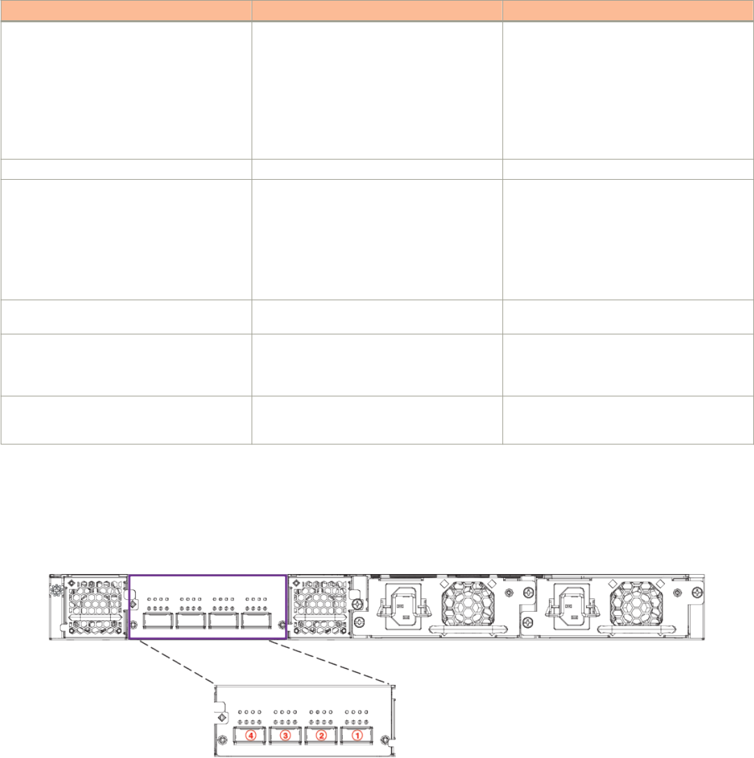
TABLE 11 ICX 7650 traditional stacking capabilities (continued)
Stacking capability ICX 7650 Additional information
NOTE
When stacking port speed changes,
existing stacking trunk configuration
may be removed.
Refer to Configuring an ICX 7650 trunk manually
on a non-production system on page 100 and
Configuring an ICX 7650 stacking trunk on a live
system on page 105.
Hitless switchover and hitless failover Supported Refer to Hitless stacking on page 141.
License requirements Premium Layer 3, MACsec Static routing and RIP are the only Layer 3
protocols available without a license. All other
Layer 3 protocols require a Premium Layer 3
license.
A separate license is required for MACsec.
Refer to the
Brocade FastIron Software Licensing
Guide
for information.
Configuration options Manual and automatic, including Secure-setup Refer to Traditional stack construction methods
on page 25.
Access methods TFTP, SCP Software images, boot images, and signatures
can be downloaded to a stack using TFTP and
SCP. Refer to the
Brocade FastIron Software
Upgrade Guide
for more information.
Traditional stacking CLI All stacking CLI is available on the ICX 7650
unless otherwise noted on the command
reference page.
Refer to Traditional stack CLI commands on page
161.
ICX 7650 stacking ports
ICX 7650 devices support stacking through Module 3 on the rear panel, shown in the following figure.
FIGURE 23 ICX 7650 rear-module 40-Gbps stacking ports
The rear module is fixed, and its ports can be configured for stacking or uplink. By default, the rear module supports 100-Gbps stacking on
ports 1 and 2 (1/3/1 and 1/3/2). When 100-Gbps stacking is enabled, ports 3 and 4 are not used. Stacking trunks are not supported on
100-Gbps connections.
Traditional Stacking by Device
ICX 7650 stack configuration overview
Ruckus FastIron Stacking Configuration Guide, 08.0.70
Part Number: 53-1005299-01 89
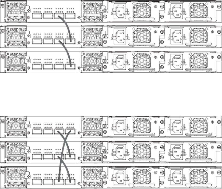
The rear-module stacking configuration can be changed to support four 40-Gbps stacking ports, with the default stacking ports configured
on ports 1 and 3 (1/3/1 and 1/3/3). Stacking trunks can be configured on 40-Gbps connections.
NOTE
Rear-module ports can also be configured as data uplink ports. Refer to ICX 7650 rear-module options on page 92 for more
information.
ICX 7650 stacking topologies
All ICX 7650 models support stacking from Module 3 on the rear panel. ICX 7650 stacks containing any combination of ICX 7650 models
can be connected in linear or ring configurations.
ICX 7650 100-Gbps linear stack
The following figure depicts a three-unit stack of ICX 7650 devices configured in a 100-Gbps linear stack.
FIGURE 24 ICX 7650 100-Gbps linear stack
ICX 7650 100-Gbps ring stack
The following figure depicts a three-unit stack of ICX 7650 devices configured in a 100-Gbps ring stack.
FIGURE 25 ICX 7650 100-Gbps ring stack
Traditional Stacking by Device
ICX 7650 stack configuration overview
Ruckus FastIron Stacking Configuration Guide, 08.0.70
90 Part Number: 53-1005299-01
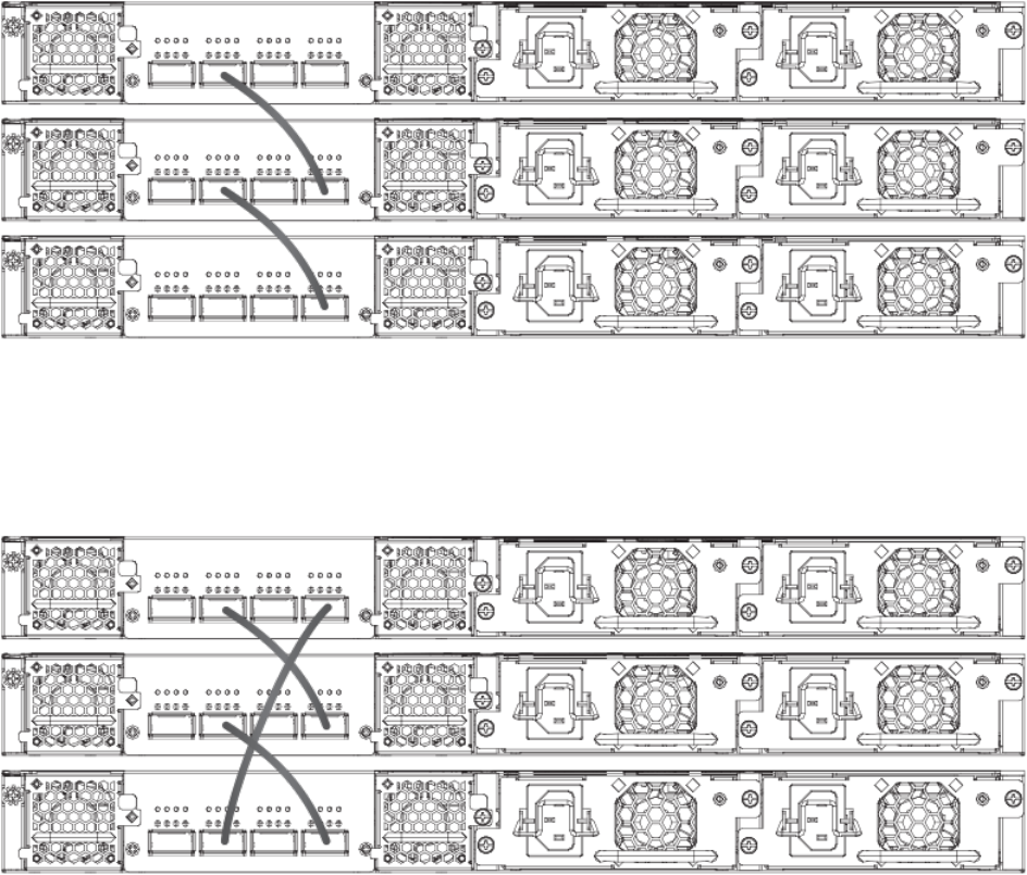
ICX 7650 40-Gbps linear stack
The following figure depicts a three-unit stack of ICX 7650 devices configured in a 40-Gbps linear stack.
FIGURE 26 ICX 7650 40-Gbps linear stack
ICX 7650 40-Gbps ring stack
The following figure depicts a three-unit stack of ICX 7650 devices configured in a 40-Gbps ring stack.
FIGURE 27 ICX 7650 40-Gbps ring stack
ICX 7650 40-Gbps trunk
The following figure depicts a three-unit stack of ICX 7650 devices configured in a 40-Gbps stack with a trunk.
Traditional Stacking by Device
ICX 7650 stack configuration overview
Ruckus FastIron Stacking Configuration Guide, 08.0.70
Part Number: 53-1005299-01 91
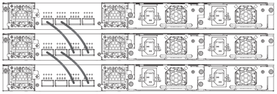
ICX 7650 configuration notes
Consider these items when configuring an ICX 7650 stack:
• Optics and stacking ports differ for 100-Gbps and 40-Gbps stacking. Connections remain down if you attempt to configure
stacking with a port speed mismatch. It is the user's responsibility to change the optics.
• To join a stack, a new ICX 7650 unit must be preconfigured to match the rear-module configuration of the existing stack.
• You cannot issue a rear-module stack command unless the data uplink configuration has been removed from the ports.
• When a stack has been formed, you cannot configure the rear module for uplink mode without removing the stacking
configuration from all stack members and rebooting the units.
• Stack units must be configured with matching High-Gig Ethernet settings.
• When the rear module is operating in uplink mode, you can configure stacking offline; however, stacking elections are blocked.
When you execute the write memory command, you will be prompted to save or erase the stacking configuration. If you elect to
erase the stacking configuration, all the stacking configuration, including the stacking.boot file configuration, is removed. If you
elect to save the stacking configuration, it is saved to the stacking.boot file.
• Stacking or uplink mode settings must be saved with the write memory command and do not become active until the reload
command is issued for the stack or standalone unit.
• If uplink mode is active on the ICX 7650 rear module, Module 2 cannot be used for uplink.
• A configuration mismatch with the physical module installed as Module 2 can cause a stacking unit to become non-operational.
The mismatch can be resolved by removing the unit from the stack so that the active controller relearns its configuration or by
correcting module information. Refer to Resolving Module 2 mismatches in an ICX 7650 stack on page 114 for more information.
For additional information on Module 2, refer to the
ICX 7650 Switch Hardware Installation Guide
.
ICX 7650 rear-module options
NOTE
ICX 7650 devices cannot operate in a stack when the rear module is configured for data uplink. Stacking election mechanisms
and all stacking operations, including IPC communications, are blocked in uplink mode.
The following operating modes can be configured on the ICX 7650 fixed rear module (Module 3):
• 2 X 100-Gbps stacking (the default)
• 4 X 40-Gbps stacking
Traditional Stacking by Device
ICX 7650 stack configuration overview
Ruckus FastIron Stacking Configuration Guide, 08.0.70
92 Part Number: 53-1005299-01
• 2 X 100-Gbps data uplink
• 2 X 40-Gbps data uplink
Changing ICX 7650 stacking speed
Be sure to connect stacking ports using optics that are compatible with the planned port speed. Be sure that the correct ports are
connected. Be sure that speeds match on both ends of the stacking connection.
1. To change the rear-module stacking speed from 100 Gbps to 40 Gbps, enter the following commands on each affected unit.
device# configure terminal
device(config)# rear-module stack-40g
device(config)# write memory
device(config)# exit
device# reload
The example sets ICX 7650 speeds on ports x/3/1 through x/3/4 to 40 Gbps and configures default stacking ports x/3/1 and x/
3/3. The change takes effect when the reload command is executed.
2. To remove the 40-Gbps stacking configuration and return the rear-module stacking speed to the default of 100 Gbps, enter the
following commands on each affected unit.
device# configure terminal
device(config)# no rear-module stack-40g
device(config)# write memory
device(config)# exit
device# reload
The example configures ICX 7650 stacking ports x/3/1 and x/3/2 for 100 Gbps. (Ports 3 and 4 are not used.) The change takes
effect when the reload command is executed.
NOTE
If 40-Gbps stacking trunks are configured, the configuration is removed.
NOTE
Different stacking ports are used for the two speeds. Be sure cables are connected correctly and correct optics are used
before changing the stacking speed.
Converting stacking ports to data uplink ports
Be sure port connections are correct before changing modes or speeds. Be sure local and remote ports operate in the same mode and at
the same speed.
NOTE
ICX 7650 devices cannot operate in a stack when the rear module is configured for data uplink. Stacking election mechanisms
and all stacking operations, including IPC communications, are blocked in uplink mode.
When the rear module operates in stacking mode and has active member units attached to it, you cannot convert the rear module to uplink
mode. To change the rear module to uplink mode, you must first unconfigure the stack.
Traditional Stacking by Device
ICX 7650 stack configuration overview
Ruckus FastIron Stacking Configuration Guide, 08.0.70
Part Number: 53-1005299-01 93
Follow these steps to convert the rear module (Module 3) of an ICX 7650 device from stacking to uplink mode.
1. (Optional) Enter the show stack command to check for active stack configuration.
ICX7650-48F Router# show stack
T=7m25.5: alone: standalone, D: dynamic cfg, S: static
ID Type Role Mac Address Pri State Comment
1 S ICX7650-48F active 94fd.2e05.1a10 0 local Ready
2 D ICX7650-48P member 00e0.5200.0100 0 remote Ready
active
+---+ +---+
3/3| 2 |3/1--3/1| 1 |3/3
+---+ +---+
There is no standby. Will assign a standby in 39 sec
Current stack management MAC is 94fd.2e05.1a10
2. On the active controller for the stack, enter the stack uncongure all command, and enter y when prompted to remove the
stacking configuration from all stack members.
ICX7650-48F Router# stack unconfigure all
Will dismantle the entire stack and recover pre-stacking startup config. Are you sure? (enter 'y' or
'n'):
y Removed "stack enable" from startup-config
All units recover startup-config. Reset others
"stack enable" is removed from runtime config of this unit.
ICX7650-48F Router# Remove stack enable. This unit will not actively participate in stacking.
The example removes the stacking configuration from all stack members.
3. In global configuration mode on each unit, enter the rear-module command with the desired uplink speed.
NOTE
You must enter the write memory command and then reload for the configuration takes effect. This removes module two
from operation as well as ports 1/3/1 and 1/3/4. The following system warning is issued.
ICX7650-48F Router(config)# rear uplink-100g
ICX-7650 rear module setting changes requires a reload to take effect!!!
The rear module would operate in uplink mode with 100Gbps speed after reload.
After reload, rear module ports will be configured as uplink ports, and module 2 will be
unused.
Existing configurations for ports in module 2 may be removed.
4. Enter the write memory command to save the configuration.
5. Enter the reload command in privileged EXEC mode to apply the new configuration.
Any configuration is removed from module 2, and it is not in use after the reload. Ports 1/3/1 and 1/3/4 are also unused after the
reload.
Traditional Stacking by Device
ICX 7650 stack configuration overview
Ruckus FastIron Stacking Configuration Guide, 08.0.70
94 Part Number: 53-1005299-01
The following example unconfigures the stack and configures one ICX 7650 rear module for data uplink at 100 Gbps on ports 1/3/1 and
1/3/2. (Ports 1/3/3 and 1/3/4 are not used.)
ICX7650-48F Router# stack unconfigure all
Will dismantle the entire stack and recover pre-stacking startup config. Are you sure? (enter 'y' or 'n'):
y Removed "stack enable" from startup-config
All units recover startup-config. Reset others
"stack enable" is removed from runtime config of this unit.
ICX7650-48F Router# Remove stack enable. This unit will not actively participate in stacking.
ICX7650-48F Router(config)# rear-module uplink-100g
ICX-7650 rear module setting changes requires a reload to take effect!!!
The rear module would operate in uplink mode with 100Gbps speed after reload.
ICX7650-48F Router(config)# write memory
Flash Memory Write (8192 bytes per dot)
.
Write startup-config done.
Copy Done.
ICX7650-48F Router(config)# exit
ICX7650-48F Router# reload
The following example unconfigures the stack and configures one ICX 7650 rear module for data uplink at 40 Gbps on ports 1/3/1 through
1/3/4.
ICX7650-48F Router# stack unconfigure all
Will dismantle the entire stack and recover pre-stacking startup config. Are you sure? (enter 'y' or 'n'):
y Removed "stack enable" from startup-config
All units recover startup-config. Reset others
"stack enable" is removed from runtime config of this unit.
ICX7650-48F Router# Remove stack enable. This unit will not actively participate in stacking.
ICX7650-48F Router(config)# rear-module uplink-40g
ICX-7650 rear module setting changes requires a reload to take effect!!!
The rear module would operate in uplink mode with 40Gbps speed after reload.
ICX7650-48F Router(config)# write memory
Flash Memory Write (8192 bytes per dot)
.
Write startup-config done.
Copy Done.
ICX7650-48F Router(config)# exit
ICX7650-48F Router# reload
Converting data uplink ports to stacking ports
Be sure port connections are correct before changing modes or speeds. Be sure local and remote ports operate in the same mode and at
the same speed.
NOTE
ICX 7650 devices cannot operate in a stack when the rear module is configured for data uplink. Stacking election mechanisms
and all stacking operations, including IPC communications, are blocked in uplink mode.
Follow these steps to convert the rear module (Module 3) of an ICX 7650 device from uplink to stacking mode.
1. Enter global configuration mode.
ICX7650-48P Router# configure terminal
2. Enter the no rear-module command to restore the rear-module default (100-Gbps stacking mode).
ICX7650-48P Router(config)# no rear-module
3. Enter the write memory command to save the change.
ICX7650-48P Router(config)# write memory
Traditional Stacking by Device
ICX 7650 stack configuration overview
Ruckus FastIron Stacking Configuration Guide, 08.0.70
Part Number: 53-1005299-01 95
4. Reload the unit to put the mode change into effect.
ICX7650-48P Router(config)# exit
ICX7650-48P Router# reload
The following example removes the data uplink configuration from an ICX 7650 device, restores the default (100-Gbps stacking), saves the
configuration, and reloads the unit so that it operates in 100-Gbps stacking mode.
NOTE
For information on changing the stacking speed, refer to Changing ICX 7650 stacking speed on page 93.
ICX7650-48P Router(config)# no rear-module
stack-40g set ICX-7650 rear module as 40G stack ports uplink-100g set ICX-7650 rear module as 100G uplink
ports
uplink-40g set ICX-7650 rear module as 40G uplink ports
ICX7650-48P Router(config)# no rear-module
ICX7650-48F Router(config)# write memory
Flash Memory Write (8192 bytes per dot)
.
Write startup-config done.
Copy Done.
ICX7650-48F Router(config)# exit
ICX7650-48F Router# reload
ICX7650-48F Router# show rear-module
The rear module operates in stacking mode with 100G speed.
The rear module is configured in stacking mode with 100G speed.
ICX7650-48F Router#
Forming an ICX 7650 stack
Be sure the rear module on all ICX 7650 units is cabled correctly before configuring stacking.
You can use the stack secure-setup command as outlined in this procedure to configure a stack with an automatic utility. Other options for
configuring a stack are also available. For more information on stack construction and secure-setup, refer to Traditional stack construction
methods on page 25.
1. (Optional) Use the show rear-module command to verify that the rear module is operating in a stacking mode. The default mode
is 100-Gbps stacking.
ICX7650-48P Router# show rear-module
The rear module operates in stacking mode with 100G speed.
The rear module is configured in stacking mode with 100G speed.
The example shows the unit is operating in default mode (100-Gbps stacking).
2. If necessary, reconfigure the rear module for each unit in the stack to operate in the desired stacking mode. This may require
removing the data uplink configuration. Refer to ICX 7650 rear-module options on page 92 for more information.
3. Enable stacking on each unit you plan to include in the stack.
ICX7650-48P Router# configure terminal
ICX7650-48P Router(config)# stack enable
Enable stacking. This unit actively participates in stacking
4. Enter the stack secure-setup command to configure the stack automatically. Respond to system prompts to confirm the stack
configuration and to specify options such as the number of units in the stack, preferred unit IDs, the formation of multiple links as
stacking trunks, and the creation of a ring topology.
Traditional Stacking by Device
ICX 7650 stack configuration overview
Ruckus FastIron Stacking Configuration Guide, 08.0.70
96 Part Number: 53-1005299-01
ICX 7650 secure-setup examples
The following example enables stacking on units with the rear module in default 100-Gbps stacking mode and uses the secure-setup utility
to configure 100-Gbps stacking on four units connected in a ring.
ICX7650-48P Router# show rear-module
The rear module operates in stacking mode with 100G speed.
The rear module is configured in stacking mode with 100G speed.
ICX7650-48P Router#
ICX7650-48P Router# configure terminal
ICX7650-48P Router(config)# stack enable
Enable stacking. This unit actively participates in stacking
ICX7650-48P Router(config)# end
ICX7650-48P Router#
ICX7650-48P Router# stack secure-setup
ICX7650-48P Router#Discovering the stack topology...
Current Discovered Topology - RING
Available UPSTREAM units
Hop(s) Id Type Mac Address
1 new ICX7650-48ZP 609c.9f52.32e3
2 new ICX7650-48ZP 609c.9f52.2743
3 new ICX7650-48P 609c.9f52.6353
Available DOWNSTREAM units
Hop(s) Id Type Mac Address
1 new ICX7650-48P 609c.9f52.6353
2 new ICX7650-48ZP 609c.9f52.2743
3 new ICX7650-48ZP 609c.9f52.32e3
Do you accept the topology (RING) (y/n)?: y
Selected Topology:
Active Id Type Mac Address
1 ICX7650-48P 609c.9f52.5a9b
Selected UPSTREAM units
Hop(s) Id Type Mac Address
1 2 ICX7650-48ZP 609c.9f52.32e3
2 3 ICX7650-48ZP 609c.9f52.2743
3 4 ICX7650-48P 609c.9f52.6353
Selected DOWNSTREAM units
Hop(s) Id Type Mac Address
1 4 ICX7650-48P 609c.9f52.6353
2 3 ICX7650-48ZP 609c.9f52.2743
3 2 ICX7650-48ZP 609c.9f52.32e3
Do you accept the unit id's (y/n)?: y
ICX7650-48P Router#T=6m12.0: Election, was alone --> active, ID=1, pri=128, 4U(1-4), A=u1, nbr#=3 3,
reason:
u4: SecureS, ,
T=6m13.0: Election, was active, no change, ID=1, pri=128, 4U(1-4), A=u1, nbr#=3 3, reason: u1: stk-po-
chg, ,
T=6m16.0: reset unit 2: u2 bo-id=1
T=6m16.0: reset unit 3: u3 bo-id=1
T=6m16.0: reset unit 4: u4 bo-id=1
Debug: Sep 7 01:53:03
Config changed due to add/del units. Do write mem if you want to keep it
Debug: Sep 7 01:53:06 T=6m21.0: Unit 1 loses all neighbors.
T=6m21.0: Active U1 deletes U2 and its config because it is learned.
T=6m21.1: Active U1 deletes U3 and its config because it is learned.
T=6m21.1: Active U1 deletes U4 and its config because it is learned.
ICX7650-48P Router#T=6m21.1: Active U1 deletes U4 and its config because it is learned.T=8m47.4: Election,
was active, no change, ID=1, pri=128, 2U(1,4), A=u1, nbr#=0 1, reason: u4: port-up, ,
T=8m49.0: Election, was active, no change, ID=1, pri=128, 2U(1,4), A=u1, nbr#=0 1, reason: u4: port-up, ,
Detect stack member 4 POE capable
Debug: Sep 7 01:55:34 Detect stack unit 4 has different startup config flash, will synchronize it
Traditional Stacking by Device
ICX 7650 stack configuration overview
Ruckus FastIron Stacking Configuration Guide, 08.0.70
Part Number: 53-1005299-01 97
Debug: Sep 7 01:55:34 T=8m49.1: Synchronize webauth files to u4
2000 log entries of PoE Event Trace Log Buffer is allocated on unit 1 for unit 4
T:8m50.8: Done hot swap: active controller u1 sets u4 to Ready.
Stack unit 4 Power supply 1 is down
PoE: Stack unit 4 Power supply 2 with 748000 mwatts capacity is up
Debug: Sep 7 01:55:39
Config changed due to add/del units. Do write mem if you want to keep it
T=9m0.7: Election, was active, no change, ID=1, pri=128, 3U(1,3-4), A=u1, nbr#=0 2, reason: u3: port-up, ,
Detect stack member 3 POE capable
Debug: Sep 7 01:55:47 T=9m2.2: Synchronize webauth files to u3
2000 log entries of PoE Event Trace Log Buffer is allocated on unit 1 for unit 3
T:9m3.9: Done hot swap: active controller u1 sets u3 to Ready.
T=9m4.7: Election, was active, no change, ID=1, pri=128, 4U(1-4), A=u1, nbr#=3 3, reason: u2: port-up, ,
Detect stack member 2 POE capable
Debug: Sep 7 01:55:50 T=9m5.0: Synchronize webauth files to u2
2000 log entries of PoE Event Trace Log Buffer is allocated on unit 1 for unit 2
T:9m6.9: Done hot swap: active controller u1 sets u2 to Ready.
Stack unit 3 Power supply 1 is down
PoE: Stack unit 3 Power supply 2 with 748000 mwatts capacity is up
U4-MSG: PoE Info: Resetting module in slot 1....completed.
Debug: Sep 7 01:55:55
Config changed due to add/del units. Do write mem if you want to keep it
Stack unit 2 Power supply 1 is down
PoE: Stack unit 2 Power supply 2 with 748000 mwatts capacity is up
T=9m10.8: Election, was active, no change, ID=1, pri=128, 4U(1-4), A=u1, nbr#=3 3, reason: u1: stk-po-
chg, ,
Debug: Sep 7 01:56:01
Config changed due to add/del units. Do write mem if you want to keep it
PoE Info: PoE module 1 of Unit 4 on ports 4/1/1 to 4/1/48 detected. Initializing....
PoE Info: PoE module 1 of Unit 4 initialization is done.
U3-MSG: PoE Info: Resetting module in slot 1....completed.
U2-MSG: PoE Info: Resetting module in slot 1....completed.
T=10m25.9: Assigned unit 4 to be standby
PoE Info: PoE module 1 of Unit 3 on ports 3/1/1 to 3/1/48 detected. Initializing....
PoE Info: PoE module 1 of Unit 3 initialization is done.
PoE Info: PoE module 1 of Unit 2 on ports 2/1/1 to 2/1/48 detected. Initializing....
PoE Info: PoE module 1 of Unit 2 initialization is done.
PoE: Power enabled on port 2/1/1.
PoE: Power enabled on port 2/1/9.
Debug: Sep 7 01:57:13 T=10m28.0: start running config sync to standby u4
Debug: Sep 7 01:57:33 T=10m47.5: Running config sync to standby u4 is complete
Invalid input -> T=6m21.1: Active U1 deletes U4 and its config because it is learned.
ICX7650-48P Router#
ICX7650-48P Router# show stack
T=11m7.2: alone: standalone, D: dynamic cfg, S: static
ID Type Role Mac Address Pri State Comment
1 S ICX7650-48P active 609c.9f52.5a9b 128 local Ready
2 D ICX7650-48ZP member 609c.9f52.32e3 0 remote Ready
3 D ICX7650-48ZP member 609c.9f52.2743 0 remote Ready
4 D ICX7650-48P standby 609c.9f52.6353 128 remote Ready
active standby
+---+ +---+ +---+ +---+
-3/1| 1 |3/2--3/1| 4 |3/2--3/2| 3 |3/1--3/1| 2 |3/2-
| +---+ +---+ +---+ +---+ |
| |
|--------------------------------------------------|
Standby u4 - sent role but not acked
Role history: N: standalone, A: active, S: standby, M: member
U1: N->A
Current stack management MAC is 609c.9f52.5a9b
ICX7650-48P Router#
Traditional Stacking by Device
ICX 7650 stack configuration overview
Ruckus FastIron Stacking Configuration Guide, 08.0.70
98 Part Number: 53-1005299-01
Creating a 40-Gbps stack with secure-setup
The following example creates a 40-Gbps linear stack with two members. A trunk is created based on user entry between ports 1/3/1 and
2/3/1.
ICX7650-48P Router# configure terminal
ICX7650-48P Router(config)# rear-module
stack-40g set ICX-7650 rear module as 40G stack ports
uplink-100g set ICX-7650 rear module as 100G uplink ports
uplink-40g set ICX-7650 rear module as 40G uplink ports
ICX7650-48P Router(config)# rear-module stack-40g
ICX-7650 rear module setting changes requires a reload to take effect!!!
The rear module operates in stacking mode with 40Gbps speed after reload.
ICX7650-48P Router(config)# end
ICX7650-48P Router# write memory
ICX7650-48P Router# reload
.
ICX7650-48P Router# stack secure-setup
ICX7650-48P Router#Discovering the stack topology...
Available UPSTREAM units
Hop(s) Id Type Mac Address
1 new ICX7650-48P 609c.9f52.74c3
Enter the number of the desired UPSTREAM units (0-1)[0]: 1
Confirm Stacking Links...
UPSTREAM Unit: Id new at 1 hop(s) ICX7650-48P 609c.9f52.74c3
Enter the desired links(1-2)[1]: 2
Selected Topology:
Active Id Type Mac Address
1 ICX7650-48P 609c.9f52.5eb9
Selected UPSTREAM units
Hop(s) Id Type Mac Address
1 2 ICX7650-48P 609c.9f52.74c3
Do you accept the unit id's (y/n)?: y
ICX7650-48P Router#T=14m3.7: Election, was alone --> active, ID=1, pri=128, 2U(1-2), A=u1, nbr#=1 0,
reason: u2: port-up, ,
T=14m5.9: reset unit 2: u2 bo-id=1
T=14m10.9: Unit 1 loses all neighbors.
T=14m10.9: Active unit 1 deletes u2 but keeps its static config.
T=16m42.4: Election, was active, no change, ID=1, pri=128, 2U(1-2), A=u1, nbr#=1 0, reason: u2:
enable, ,
Detect stack member 2 POE capable
Detect stack unit 2 has different startup config flash, will synchronize it
T=16m41.7: Synchronize webauth files to u2
2000 log entries of PoE Event Trace Log Buffer is allocated on unit 1 for unit 2
T:16m43.1: Done hot swap: active controller u1 sets u2 to Ready.
T=16m44.7: Synchronize startup config to u2
Flash Memory Write (8192 bytes per dot)
.
Write startup-config done.
Stack unit 2 Power supply 1 is down
PoE: Stack unit 2 Power supply 2 with 748000 mwatts capacity is up
U2-MSG: PoE Info: Resetting module in slot 1....completed.
PoE Info: PoE module 1 of Unit 2 on ports 2/1/1 to 2/1/48 detected. Initializing....
PoE Info: PoE module 1 of Unit 2 initialization is done.
T=17m43.3: Assigned unit 2 to be standby
T=17m45.3: start running config sync to standby u2
T=17m46.2: Running config sync to standby u2 is complete
ICX7650-48P Router# show stack
T=21m12.2: alone: standalone, D: dynamic cfg, S: static
Traditional Stacking by Device
ICX 7650 stack configuration overview
Ruckus FastIron Stacking Configuration Guide, 08.0.70
Part Number: 53-1005299-01 99
ID Type Role Mac Address Pri State Comment
1 S ICX7650-48P active 609c.9f52.5eb9 128 local Ready
2 S ICX7650-48P standby 609c.9f52.74c3 10 remote Ready
standby active
+---+ +---+
3/3| 2 |3/1==3/1| 1 |3/3
+---+ +---+
Standby u2 - protocols ready, can failover
Role history: N: standalone, A: active, S: standby, M: member
U1: N->A
Current stack management MAC is 609c.9f52.5eb9
ICX7650-48P Router#
Configuring an ICX 7650 trunk manually on a non-production system
Stacking trunks can be configured on ICX 7650 devices operating in 40-Gbps stacking mode.
The secure-setup process includes the option to form trunks when multiple links are possible. Refer to ICX 7650 secure-setup examples on
page 97. You may also opt to configure a trunk manually.
Follow these steps to create a trunk manually on an ICX 7650 stack that is not live.
NOTE
Stacking trunks can be configured only when the rear module is operating in 40-Gbps stacking mode. Refer to ICX 7650 rear-
module options on page 92 for more information.
Traditional Stacking by Device
ICX 7650 stack configuration overview
Ruckus FastIron Stacking Configuration Guide, 08.0.70
100 Part Number: 53-1005299-01
NOTE
Trunk configuration may be removed when you change stacking speeds.
1. (Optional) Verify that stacking is enabled and that the rear module is operating in 40-Gbps stacking mode.
ICX7650-48P Router# show running-config
Current configuration:
!
ver 08.0.70q20T228
!
stack unit 1
module 1 icx7650-48p-port-management-module
module 2 icx7600-qsfp-2port-80g-module
module 3 icx7650-qsfp-4port-160g-module
priority 128
stack mac 609c.9f52.5eb9
!
!
rear-module stack-40g
!
!
hitless-failover enable
!
!
end
ICX7650-48P Router# show stack
***** Warning! stack is not enabled. *****
T=21h4m4.2: alone: standalone, D: dynamic cfg, S: static
ID Type Role Mac Address Pri State Comment
1 S ICX7650-48P alone 609c.9f52.5eb9 128 local None:0
+---+
3/1| 1 |3/3
+---+
Role history: N: standalone, A: active, S: standby, M: member
U1: N->A->N
The example shows that the unit is operating in 40-Gbps stacking mode, but stacking is not enabled. No stacking links are
configured to other units.
2. If necessary, enable stacking on the device.
ICX7650-48P Router# configure terminal
ICX7650-48P Router(config)# stack enable
Enable stacking. This unit actively participates in stacking
3. Enter stack unit configuration mode to configure trunks.
ICX7650-48P Router(config)# stack unit 1
ICX7650-48P Router(config-unit-1)#
ICX7650-48P Router(config-unit-1)# stack-trunk 1/3/1 to 1/3/2
ICX7650-48P Router(config-unit-1)# stack-trunk 1/3/3 to 1/3/4
The example configures two stacking trunks on stack unit 1.
4. Enter the write memory command to save the trunk configuration.
ICX7650-48P Router(config-unit-1)# end
ICX7650-48P Router# write memory
Traditional Stacking by Device
ICX 7650 stack configuration overview
Ruckus FastIron Stacking Configuration Guide, 08.0.70
Part Number: 53-1005299-01 101
5. Repeat the previous steps to enable stacking and configure trunks as needed on all units in the stack.
ICX7650-48P Router# configure terminal <---------- Enable stacking and repeat trunk configuration
on all units where needed.
ICX7650-48P Router(config)# stack enable
Enable stacking. This unit actively participates in stacking
ICX7650-48P Router(config)# stack unit 2
ICX7650-48P Router(config-unit-1)#
ICX7650-48P Router(config-unit-1)# stack-trunk 2/3/1 to 2/3/2
ICX7650-48P Router(config-unit-1)# end
ICX7650-48P Router# write memory
The example shows stack unit 2 being enabled for stacking and configured with a single stacking trunk.
6. (Optional) Confirm that the stack has formed based on the stacking links configured.
ICX7650-48P Router# show stack
T=21h9m2.2: alone: standalone, D: dynamic cfg, S: static
ID Type Role Mac Address Pri State Comment
1 S ICX7650-48P active 609c.9f52.5eb9 128 local Ready
2 D ICX7650-48P member 609c.9f52.74c3 128 remote Ready
active
+---+ +---+
3/3| 2 |3/1==3/1| 1 |3/3
+---+ +---+
There is no standby. Will assign a standby in 4 sec
Role history: N: standalone, A: active, S: standby, M: member
U1: N->A->N->A
Current stack management MAC is 609c.9f52.5eb9
ICX7650-48P Router#T=21h9m7.3: Assigned unit 2 to be standby
T=21h9m9.3: start running config sync to standby u2
T=21h9m9.8: Running config sync to standby u2 is complete
The example shows a two-unit stack has formed with a single stacking trunk connection.
Traditional Stacking by Device
ICX 7650 stack configuration overview
Ruckus FastIron Stacking Configuration Guide, 08.0.70
102 Part Number: 53-1005299-01
The following example manually configures a two-unit ICX 7650 stack with a stacking trunk from ports 1/3/1 and 1/3/2 to ports 2/3/1 and
2/3/2.
ICX7650-48P Router# show running-config
Current configuration:
!
ver 08.0.70q20T228
!
stack unit 1
module 1 icx7650-48p-port-management-module
module 2 icx7600-qsfp-2port-80g-module
module 3 icx7650-qsfp-4port-160g-module
priority 128
stack mac 609c.9f52.5eb9
!
!
rear-module stack-40g
!
!
hitless-failover enable
!
!
end
ICX7650-48P Router# show stack
***** Warning! stack is not enabled. *****
T=21h4m4.2: alone: standalone, D: dynamic cfg, S: static
ID Type Role Mac Address Pri State Comment
1 S ICX7650-48P alone 609c.9f52.5eb9 128 local None:0
+---+
3/1| 1 |3/3
+---+
Role history: N: standalone, A: active, S: standby, M: member
U1: N->A->N
Current stack management MAC is 609c.9f52.5eb9
ICX7650-48P Router# configure terminal
ICX7650-48P Router(config)# stack enable
Enable stacking. This unit actively participates in stacking
ICX7650-48P Router(config)# stack unit 1
ICX7650-48P Router(config-unit-1)#
ICX7650-48P Router(config-unit-1)# stack-trunk 1/3/1 to 1/3/2
ICX7650-48P Router(config-unit-1)# end
ICX7650-48P Router# write memory
Flash Memory Write (8192 bytes per dot)
.
Copy Done.
ICX7650-48P Router# show running-config
Current configuration:
!
ver 08.0.70q20T228
!
stack unit 1
module 1 icx7650-48p-port-management-module
module 2 icx7600-qsfp-2port-80g-module
module 3 icx7650-qsfp-4port-160g-module
priority 128
stack-trunk 1/3/1 to 1/3/2
stack-port 1/3/1 1/3/3
stack enable
Traditional Stacking by Device
ICX 7650 stack configuration overview
Ruckus FastIron Stacking Configuration Guide, 08.0.70
Part Number: 53-1005299-01 103
stack mac 609c.9f52.5eb9
!
!
rear-module stack-40g
!
!
hitless-failover enable
!
!
end
!
!
ICX7650-48P Router# configure terminal <---------- Enable stacking and repeat trunk configuration
on all units where needed.
ICX7650-48P Router(config)# stack enable
Enable stacking. This unit actively participates in stacking
ICX7650-48P Router(config)# stack unit 2
ICX7650-48P Router(config-unit-1)#
ICX7650-48P Router(config-unit-1)# stack-trunk 2/3/1 to 2/3/2
ICX7650-48P Router(config-unit-1)# end
ICX7650-48P Router# write memory
Flash Memory Write (8192 bytes per dot)
.
Copy Done.
==============
Detect stack unit 2 has different startup config flash, will synchronize it
All entries are cleared on unit 1 for unit 2
T:21h8m5.6: Done hot swap: active controller u1 sets u2 to Ready.
T=21h8m5.6: Synchronize startup config to u2
T=21h8m58.9: Election, was active, no change, ID=1, pri=128, 2U(1-2), A=u1, nbr#=1 0, reason: u1:
stk-po-chg, ,
Flash Memory Write (8192 bytes per dot)
.
Stack unit 2 Power supply 1 is down
PoE: Stack unit 2 Power supply 2 with 748000 mwatts capacity is up
Config changed due to add/del units. Do write mem if you want to keep it
U2-MSG: PoE Info: Resetting module in slot 1....completed.
PoE Info: PoE module 1 of Unit 2 on ports 2/1/1 to 2/1/48 detected. Initializing....
PoE Info: PoE module 1 of Unit 2 initialization is done.
ICX7650-48P Router# show stack
T=21h9m2.2: alone: standalone, D: dynamic cfg, S: static
ID Type Role Mac Address Pri State Comment
1 S ICX7650-48P active 609c.9f52.5eb9 128 local Ready
2 D ICX7650-48P member 609c.9f52.74c3 128 remote Ready
active
+---+ +---+
3/3| 2 |3/1==3/1| 1 |3/3
+---+ +---+
There is no standby. Will assign a standby in 4 sec
Role history: N: standalone, A: active, S: standby, M: member
U1: N->A->N->A
Current stack management MAC is 609c.9f52.5eb9
ICX7650-48P Router#T=21h9m7.3: Assigned unit 2 to be standby
T=21h9m9.3: start running config sync to standby u2
T=21h9m9.8: Running config sync to standby u2 is complete
Traditional Stacking by Device
ICX 7650 stack configuration overview
Ruckus FastIron Stacking Configuration Guide, 08.0.70
104 Part Number: 53-1005299-01
Configuring an ICX 7650 stacking trunk on a live system
Follow these steps to convert stacking ports on both ends of a link to a stacking trunk on an ICX 7650 production stack.
1. (Optional) Enter the show stack command to verify stack configuration.
ICX7650-48ZP Router# show stack
T=20h23m43.6: alone: standalone, D: dynamic cfg, S: static
ID Type Role Mac Address Pri State Comment
1 S ICX7650-48ZP active 609c.9f52.2cd5 128 local Ready
2 S ICX7650-48F standby 609c.9f52.4643 128 remote Ready
active standby
+---+ +---+
-3/3| 1 |3/1--3/1| 2 |3/3-
| +---+ +---+ |
| |
|------------------------|
Standby u2 - protocols ready, can failover or manually switch over
Role history: N: standalone, A: active, S: standby, M: member
U1: M->S->A, U2: A->S
Current stack management MAC is 609c.9f52.2cd5
The example shows a two-unit live stack configured in a ring with no trunks.
2. (Optional) Enter the show running-cong command for additional information on the stack.
ICX7650-48ZP Router# show running-config | inc stack
stack unit 1
stack-port 1/3/1 1/3/3
stack unit 2
stack-port 2/3/1 2/3/3
stack enable
stack rconsole-off
stack mac 609c.9f52.2cd5
rear-module stack-40g
The example includes only stacking information in the show running-cong command output. The output confirms that the ICX
7650 stack is operating in 40-Gbps stacking mode.
3. Enter stack unit configuration mode.
ICX7650-48ZP Router# configure terminal
ICX7650-48ZP Router(config)#stack unit 1
ICX7650-48ZP Router(config-unit-1)#
4. Enter the multi-stack-trunk command followed by the set of ports on either end of the live connection to include in the stacking
trunk.
ICX7650-48ZP Router(config-unit-1)# multi-stack-trunk 1/3/1 to 1/3/2 and 2/3/1 to 2/3/2
SYSLOG: <14> Sep 7 19:13:52 System: Interface ethernet 1/3/2, state down
SYSLOG: <14> Sep 7 19:13:52 System: Interface ethernet 2/3/2, state down
T=20h25m17.5: Election, was active, no change, ID=1, pri=128, 2U(1-2), A=u1, nbr#=1 1, reason: u1:
stk-po-chg, ,
SYSLOG: <14> Sep 7 19:13:52 Stack: Stack unit 1 has been elected as ACTIVE unit of the stack system
SYSLOG: <14> Sep 7 19:13:53 System: Interface ethernet 1/3/2, state up
SYSLOG: <14> Sep 7 19:13:53 System: Interface ethernet 2/3/2, state up
ICX7650-48ZP Router(config-unit-1)# end
The example configures a stacking trunk from ports 1/3/1 to 1/3/2 on one end of the connection to ports 2/3/1 and 2/3/2 on the
other end.
Traditional Stacking by Device
ICX 7650 stack configuration overview
Ruckus FastIron Stacking Configuration Guide, 08.0.70
Part Number: 53-1005299-01 105
5. Enter the write memory command in privileged Exec mode to save the configuration.
ICX7650-48ZP Router(config-unit-1)# end
SYSLOG: <14> Sep 7 19:13:57 Security: running-config was potentially changed by operator from
console
ICX7650-48ZP Router# write memory
Automatic copy to member units: 2
ICX7650-48ZP Router#
SYSLOG: <14> Sep 7 19:13:59 Security: startup-config was changed by operator from console
Flash Memory Write (8192 bytes per dot)
.
Write startup-config done.
Copy Done.
The example saves the 40-Gbps trunk configuration.
6. (Optional) Enter the show stack command to confirm the formation of the trunk.
ICX7650-48ZP Router# show stack
T=20h24m41.8: alone: standalone, D: dynamic cfg, S: static
ID Type Role Mac Address Pri State Comment
1 S ICX7650-48ZP active 609c.9f52.2cd5 128 local Ready
2 S ICX7650-48F standby 609c.9f52.4643 128 remote Ready
active standby
+---+ +---+
-3/3| 1 |3/1==3/1| 2 |3/3-
| +---+ +---+ |
| |
|------------------------|
Will assign standby in 47 sec due to all ready
Standby u2 - protocols ready, can failover
Role history: N: standalone, A: active, S: standby, M: member
U1: M->S->A, U2: A->S
Current stack management MAC is 609c.9f52.2cd5
The example shows a trunk is present.
Traditional Stacking by Device
ICX 7650 stack configuration overview
Ruckus FastIron Stacking Configuration Guide, 08.0.70
106 Part Number: 53-1005299-01
The following example configures both potential 40-Gbps trunks on a live stack.
ICX7650-48ZP Router# show stack
T=20h23m43.6: alone: standalone, D: dynamic cfg, S: static
ID Type Role Mac Address Pri State Comment
1 S ICX7650-48ZP active 609c.9f52.2cd5 128 local Ready
2 S ICX7650-48F standby 609c.9f52.4643 128 remote Ready
active standby
+---+ +---+
-3/3| 1 |3/1--3/1| 2 |3/3-
| +---+ +---+ |
| |
|------------------------|
Standby u2 - protocols ready, can failover or manually switch over
Role history: N: standalone, A: active, S: standby, M: member
U1: M->S->A, U2: A->S
Current stack management MAC is 609c.9f52.2cd5
ICX7650-48ZP Router#
ICX7650-48ZP Router#
ICX7650-48ZP Router#
ICX7650-48ZP Router#show running-config | inc stack
stack unit 1
stack-port 1/3/1 1/3/3
stack unit 2
stack-port 2/3/1 2/3/3
stack enable
stack rconsole-off
stack mac 609c.9f52.2cd5
rear-module stack-40g
ICX7650-48ZP Router# configure terminal
ICX7650-48ZP Router(config)# stack unit 1
ICX7650-48ZP Router(config-unit-1)# multi-stack-trunk 1/3/1 to 1/3/2 and 2/3/1 to 2/3/2
ICX7650-48ZP Router(config-unit-1)#
SYSLOG: <14> Sep 7 19:13:52 System: Interface ethernet 1/3/2, state down
SYSLOG: <14> Sep 7 19:13:52 System: Interface ethernet 2/3/2, state down
T=20h25m17.5: Election, was active, no change, ID=1, pri=128, 2U(1-2), A=u1, nbr#=1 1, reason: u1: stk-po-
chg, ,
SYSLOG: <14> Sep 7 19:13:52 Stack: Stack unit 1 has been elected as ACTIVE unit of the stack system
SYSLOG: <14> Sep 7 19:13:53 System: Interface ethernet 1/3/2, state up
SYSLOG: <14> Sep 7 19:13:53 System: Interface ethernet 2/3/2, state up
ICX7650-48ZP Router(config-unit-1)# end
SYSLOG: <14> Sep 7 19:13:57 Security: running-config was potentially changed by operator from console
ICX7650-48ZP Router# write memory
Automatic copy to member units: 2
ICX7650-48ZP Router#
SYSLOG: <14> Sep 7 19:13:59 Security: startup-config was changed by operator from console
Flash Memory Write (8192 bytes per dot)
.
Write startup-config done.
Copy Done.
ICX7650-48ZP Router# show stack
T=20h24m41.8: alone: standalone, D: dynamic cfg, S: static
ID Type Role Mac Address Pri State Comment
1 S ICX7650-48ZP active 609c.9f52.2cd5 128 local Ready
2 S ICX7650-48F standby 609c.9f52.4643 128 remote Ready
active standby
+---+ +---+
-3/3| 1 |3/1==3/1| 2 |3/3-
| +---+ +---+ |
| |
Traditional Stacking by Device
ICX 7650 stack configuration overview
Ruckus FastIron Stacking Configuration Guide, 08.0.70
Part Number: 53-1005299-01 107
|------------------------|
Will assign standby in 47 sec due to all ready
Standby u2 - protocols ready, can failover
Role history: N: standalone, A: active, S: standby, M: member
U1: M->S->A, U2: A->S
Current stack management MAC is 609c.9f52.2cd5
ICX7650-48ZP Router# configure terminal
ICX7650-48ZP Router(config)#stack unit 1
ICX7650-48ZP Router(config-unit-1)# multi-stack-trunk 1/3/3 to 1/3/4 and 2/3/3 to 2/3/4
SYSLOG: <14> Sep 7 19:14:39 System: Interface ethernet 1/3/4, state down
ICX7650-48ZP Router(config-unit-1)#
SYSLOG: <14> Sep 7 19:14:39 System: Interface ethernet 2/3/4, state down
T=20h26m4.5: Election, was active, no change, ID=1, pri=128, 2U(1-2), A=u1, nbr#=1 1, reason: u1: stk-po-
chg, ,
SYSLOG: <14> Sep 7 19:14:39 Stack: Stack unit 1 has been elected as ACTIVE unit of the stack system
ICX7650-48ZP Router(config-unit-1)#
SYSLOG: <14> Sep 7 19:14:40 System: Interface ethernet 1/3/4, state up
SYSLOG: <14> Sep 7 19:14:40 System: Interface ethernet 2/3/4, state up
ICX7650-48ZP Router(config-unit-1)# end
SYSLOG: <14> Sep 7 19:14:41 Security: running-config was potentially changed by operator from console
ICX7650-48ZP Router#
ICX7650-48ZP Router# write memory
Automatic copy to member units: 2
ICX7650-48ZP Router#
SYSLOG: <14> Sep 7 19:14:42 Security: startup-config was changed by operator from console
Flash Memory Write (8192 bytes per dot)
.
Write startup-config done.
Copy Done.
ICX7650-48ZP Router# show stack
T=20h25m20.2: alone: standalone, D: dynamic cfg, S: static
ID Type Role Mac Address Pri State Comment
1 S ICX7650-48ZP active 609c.9f52.2cd5 128 local Ready
2 S ICX7650-48F standby 609c.9f52.4643 128 remote Ready
active standby
+---+ +---+
=3/3| 1 |3/1==3/1| 2 |3/3=
| +---+ +---+ |
| |
|------------------------|
Will assign standby in 56 sec due to all ready
Standby u2 - protocols ready, can failover
Role history: N: standalone, A: active, S: standby, M: member
U1: M->S->A, U2: A->S
Current stack management MAC is 609c.9f52.2cd5
ICX7650-48ZP Router# show running-config | inc stack
stack unit 1
stack-trunk 1/3/1 to 1/3/2
stack-trunk 1/3/3 to 1/3/4
stack-port 1/3/1 1/3/3
stack unit 2
stack-trunk 2/3/1 to 2/3/2
stack-trunk 2/3/3 to 2/3/4
stack-port 2/3/1 2/3/3
stack enable
stack rconsole-off
stack mac 609c.9f52.2cd5
rear-module stack-40g
ICX7650-48ZP Router#
Traditional Stacking by Device
ICX 7650 stack configuration overview
Ruckus FastIron Stacking Configuration Guide, 08.0.70
108 Part Number: 53-1005299-01
Removing an ICX 7650 trunk on a live system
Follow these steps to remove a stacking trunk and convert connections to individual links at both ends of the connection on an ICX 7650
production stack.
1. (Optional) Enter the show stack command to verify the stack configuration.
ICX7650-48ZP Router# show stack
T=20h18m50.1: alone: standalone, D: dynamic cfg, S: static
ID Type Role Mac Address Pri State Comment
1 S ICX7650-48ZP active 609c.9f52.2cd5 128 local Ready
2 S ICX7650-48F standby 609c.9f52.4643 128 remote Ready
active standby
+---+ +---+
=3/3| 1 |3/1==3/1| 2 |3/3=
| +---+ +---+ |
| |
|------------------------|
Will assign standby in 54 sec due to startup synced
Standby u2 - protocols ready, can failover
Role history: N: standalone, A: active, S: standby, M: member
U1: M->S->A, U2: A->S
Current stack management MAC is 609c.9f52.2cd5
The example shows a two-unit stack in a ring configuration with two trunks configured between the two units.
2. (Optional) Enter the show running-cong command for additional information on the stack.
ICX7650-48ZP Router# show running-config | inc stack
stack unit 1
stack-trunk 1/3/1 to 1/3/2
stack-trunk 1/3/3 to 1/3/4
stack-port 1/3/1 1/3/3
stack unit 2
stack-trunk 2/3/1 to 2/3/2
stack-trunk 2/3/3 to 2/3/4
stack-port 2/3/1 2/3/3
stack enable
stack rconsole-off
stack mac 609c.9f52.2cd5
rear-module stack-40g
ICX7650-48ZP Router# show stack
T=20h19m18.0: alone: standalone, D: dynamic cfg, S: static
ID Type Role Mac Address Pri State Comment
1 S ICX7650-48ZP active 609c.9f52.2cd5 128 local Ready
2 S ICX7650-48F standby 609c.9f52.4643 128 remote Ready
active standby
+---+ +---+
=3/3| 1 |3/1==3/1| 2 |3/3=
| +---+ +---+ |
| |
|------------------------|
Will assign standby in 26 sec due to startup synced
Standby u2 - protocols ready, can failover
Role history: N: standalone, A: active, S: standby, M: member
U1: M->S->A, U2: A->S
Current stack management MAC is 609c.9f52.2cd5
The example shows specific port-to-port connections for the stacking trunks and confirms that the stack is operating in 40-Gbps
stacking mode.
Traditional Stacking by Device
ICX 7650 stack configuration overview
Ruckus FastIron Stacking Configuration Guide, 08.0.70
Part Number: 53-1005299-01 109
3. Enter stack unit configuration mode.
ICX7650-48ZP Router# configure terminal
ICX7650-48ZP Router(config)#stack unit 1
ICX7650-48ZP Router(config-unit-1)#
4. Enter the multi-stack-port command followed by the set of ports on either end of the live trunk to convert to stacking ports.
ICX7650-48ZP Router(config-unit-1)# multi-stack-port 1/3/1 and 2/3/1
ICX7650-48ZP Router(config-unit-1)# end
ICX7650-48ZP Router(config-unit-1)#T=20h20m35.3: Election, was active, no change, ID=1, pri=128,
2U(1-2), A=u1, nbr#=1 1, reason: u1: stk-po-chg, ,
SYSLOG: <14> Sep 7 19:09:10 Stack: Stack unit 1 has been elected as ACTIVE unit of the stack syste
SYSLOG: <14> Sep 7 19:09:12 System: Interface ethernet 1/3/2, state down
SYSLOG: <14> Sep 7 19:09:12 System: Interface ethernet 2/3/2, state down
ICX7650-48ZP Router#
SYSLOG: <14> Sep 7 19:09:12 Security: running-config was potentially changed by operator from
console
ICX7650-48ZP Router#
ICX7650-48ZP Router#
SYSLOG: <14> Sep 7 19:09:12 System: Interface ethernet 2/3/2, state up
SYSLOG: <14> Sep 7 19:09:13 System: Interface ethernet 1/3/2, state up
ICX7650-48ZP Router#
The example removes a stacking trunk and converts these ports to stacking ports on both ends of the link: ports 1/3/1, 1/3/2,
2/3/1, and 2/3/2.
5. Repeat the previous steps if you are removing two live trunks.
ICX7650-48ZP Router# configure terminal
ICX7650-48ZP Router(config)# stack unit 1
ICX7650-48ZP Router(config-unit-1)# multi-stack-port 1/3/3 and 2/3/3
ICX7650-48ZP Router(config-unit-1)#enT=20h21m28.8: Election, was active, no change, ID=1, pri=128,
2U(1-2),
A=u1, nbr#=1 1, reason: u1: stk-po-chg, ,
SYSLOG: <14> Sep 7 19:10:04 Stack: Stack unit 1 has been elected as ACTIVE unit of the stack system
d
ICX7650-48ZP Router#
SYSLOG: <14> Sep 7 19:10:04 Security: running-config was potentially changed by operator from
console
ICX7650-48ZP Router#
The example removes the stacking trunk configuration at both ends of the remaining trunk and converts these ports to stacking
ports: 1/3/3, 1/3/4, 2/3/3, and 2/3/4.
Traditional Stacking by Device
ICX 7650 stack configuration overview
Ruckus FastIron Stacking Configuration Guide, 08.0.70
110 Part Number: 53-1005299-01
6. Enter the write memory command in privileged EXEC mode to save the configuration.
ICX7650-48ZP Router# write memory
Automatic copy to member units: 2
SYSLOG: <14> Sep 7 19:10:05 System: Interface ethernet 1/3/4, state down
SYSLOG: <14> Sep 7 19:10:05 System: Interface ethernet 2/3/4, state down
SYSLOG: <14> Sep 7 19:10:06 Security: startup-config was changed by operator from console
Flash Memory Write (8192 bytes per dot)
.
Write startup-config done.
Copy Done.
ICX7650-48ZP Router#
SYSLOG: <14> Sep 7 19:10:06 System: Interface ethernet 2/3/4, state up
ICX7650-48ZP Router#
SYSLOG: <14> Sep 7 19:10:06 System: Interface ethernet 1/3/4, state up
sh stack
T=20h20m45.4: alone: standalone, D: dynamic cfg, S: static
ID Type Role Mac Address Pri State Comment
1 S ICX7650-48ZP active 609c.9f52.2cd5 128 local Ready
2 S ICX7650-48F standby 609c.9f52.4643 128 remote Ready
active standby
+---+ +---+
-3/3| 1 |3/1--3/1| 2 |3/3-
| +---+ +---+ |
| |
|------------------------|
Will assign standby in 55 sec due to all ready
Standby u2 - protocols ready, can failover
Role history: N: standalone, A: active, S: standby, M: member
U1: M->S->A, U2: A->S
Current stack management MAC is 609c.9f52.2cd5
ICX7650-48ZP Router#
The example saves the 40-Gbps stacking configuration with no trunks present.
7. (Optional) Enter the show stack command to confirm the configuration.
ICX7650-48ZP Router# show stack
T=20h20m45.4: alone: standalone, D: dynamic cfg, S: static
ID Type Role Mac Address Pri State Comment
1 S ICX7650-48ZP active 609c.9f52.2cd5 128 local Ready
2 S ICX7650-48F standby 609c.9f52.4643 128 remote Ready
active standby
+---+ +---+
-3/3| 1 |3/1--3/1| 2 |3/3-
| +---+ +---+ |
| |
|------------------------|
Will assign standby in 55 sec due to all ready
Standby u2 - protocols ready, can failover
Role history: N: standalone, A: active, S: standby, M: member
U1: M->S->A, U2: A->S
Current stack management MAC is 609c.9f52.2cd5
The example confirms that the two-unit stack is operating in a ring with individual stacking links and no stacking trunks.
Traditional Stacking by Device
ICX 7650 stack configuration overview
Ruckus FastIron Stacking Configuration Guide, 08.0.70
Part Number: 53-1005299-01 111
The following example removes two stacking trunks from a live two-unit 40-Gbps stacking ring and converts the related ports to stacking
ports.
ICX7650-48ZP Router# show stack
T=20h18m50.1: alone: standalone, D: dynamic cfg, S: static
ID Type Role Mac Address Pri State Comment
1 S ICX7650-48ZP active 609c.9f52.2cd5 128 local Ready
2 S ICX7650-48F standby 609c.9f52.4643 128 remote Ready
active standby
+---+ +---+
=3/3| 1 |3/1==3/1| 2 |3/3=
| +---+ +---+ |
| |
|------------------------|
Will assign standby in 54 sec due to startup synced
Standby u2 - protocols ready, can failover
Role history: N: standalone, A: active, S: standby, M: member
U1: M->S->A, U2: A->S
Current stack management MAC is 609c.9f52.2cd5
ICX7650-48ZP Router# show running-config | inc stack
stack unit 1
stack-trunk 1/3/1 to 1/3/2
stack-trunk 1/3/3 to 1/3/4
stack-port 1/3/1 1/3/3
stack unit 2
stack-trunk 2/3/1 to 2/3/2
stack-trunk 2/3/3 to 2/3/4
stack-port 2/3/1 2/3/3
stack enable
stack rconsole-off
stack mac 609c.9f52.2cd5
rear-module stack-40g
ICX7650-48ZP Router# show stack
T=20h19m18.0: alone: standalone, D: dynamic cfg, S: static
ID Type Role Mac Address Pri State Comment
1 S ICX7650-48ZP active 609c.9f52.2cd5 128 local Ready
2 S ICX7650-48F standby 609c.9f52.4643 128 remote Ready
active standby
+---+ +---+
=3/3| 1 |3/1==3/1| 2 |3/3=
| +---+ +---+ |
| |
|------------------------|
Will assign standby in 26 sec due to startup synced
Standby u2 - protocols ready, can failover
Role history: N: standalone, A: active, S: standby, M: member
U1: M->S->A, U2: A->S
Current stack management MAC is 609c.9f52.2cd5
X7650-48ZP Router# configure terminal
ICX7650-48ZP Router(config)# stack unit 1
ICX7650-48ZP Router(config-unit-1)# multi-stack-port 1/3/1 and 2/3/1
ICX7650-48ZP Router(config-unit-1)# end
ICX7650-48ZP Router(config-unit-1)#T=20h20m35.3: Election, was active, no change, ID=1, pri=128, 2U(1-2),
A=u1, nbr#=1 1, reason: u1: stk-po-chg, ,
SYSLOG: <14> Sep 7 19:09:10 Stack: Stack unit 1 has been elected as ACTIVE unit of the stack syste
SYSLOG: <14> Sep 7 19:09:12 System: Interface ethernet 1/3/2, state down
SYSLOG: <14> Sep 7 19:09:12 System: Interface ethernet 2/3/2, state down
Traditional Stacking by Device
ICX 7650 stack configuration overview
Ruckus FastIron Stacking Configuration Guide, 08.0.70
112 Part Number: 53-1005299-01
ICX7650-48ZP Router#
SYSLOG: <14> Sep 7 19:09:12 Security: running-config was potentially changed by operator from console
ICX7650-48ZP Router#
ICX7650-48ZP Router#
SYSLOG: <14> Sep 7 19:09:12 System: Interface ethernet 2/3/2, state up
SYSLOG: <14> Sep 7 19:09:13 System: Interface ethernet 1/3/2, state up
ICX7650-48ZP Router#
ICX7650-48ZP Router#
ICX7650-48ZP Router# show stack
T=20h19m52.8: alone: standalone, D: dynamic cfg, S: static
ID Type Role Mac Address Pri State Comment
1 S ICX7650-48ZP active 609c.9f52.2cd5 128 local Ready
2 S ICX7650-48F standby 609c.9f52.4643 128 remote Ready
active standby
+---+ +---+
=3/3| 1 |3/1--3/1| 2 |3/3=
| +---+ +---+ |
| |
|------------------------|
Will assign standby in 54 sec due to all ready
Standby u2 - protocols ready, can failover
Role history: N: standalone, A: active, S: standby, M: member
U1: M->S->A, U2: A->S
Current stack management MAC is 609c.9f52.2cd5
ICX7650-48ZP Router#
ICX7650-48ZP Router#
ICX7650-48ZP Router# show running-config | inc stack
stack unit 1
stack-trunk 1/3/3 to 1/3/4
stack-port 1/3/1 1/3/3
stack unit 2
stack-trunk 2/3/3 to 2/3/4
stack-port 2/3/1 2/3/3
stack enable
stack rconsole-off
stack mac 609c.9f52.2cd5
rear-module stack-40g
ICX7650-48ZP Router# configure terminal
ICX7650-48ZP Router(config)# stack unit 1
ICX7650-48ZP Router(config-unit-1)# multi-stack-port 1/3/3 and 2/3/3
ICX7650-48ZP Router(config-unit-1)#enT=20h21m28.8: Election, was active, no change, ID=1, pri=128, 2U(1-2),
A=u1, nbr#=1 1, reason: u1: stk-po-chg, ,
SYSLOG: <14> Sep 7 19:10:04 Stack: Stack unit 1 has been elected as ACTIVE unit of the stack system
d
ICX7650-48ZP Router#
SYSLOG: <14> Sep 7 19:10:04 Security: running-config was potentially changed by operator from console
ICX7650-48ZP Router#
ICX7650-48ZP Router#
ICX7650-48ZP Router# write memory
Automatic copy to member units: 2
SYSLOG: <14> Sep 7 19:10:05 System: Interface ethernet 1/3/4, state down
SYSLOG: <14> Sep 7 19:10:05 System: Interface ethernet 2/3/4, state down
SYSLOG: <14> Sep 7 19:10:06 Security: startup-config was changed by operator from console
Flash Memory Write (8192 bytes per dot)
.
Write startup-config done.
Copy Done.
ICX7650-48ZP Router#
SYSLOG: <14> Sep 7 19:10:06 System: Interface ethernet 2/3/4, state up
Traditional Stacking by Device
ICX 7650 stack configuration overview
Ruckus FastIron Stacking Configuration Guide, 08.0.70
Part Number: 53-1005299-01 113
SYSLOG: <14> Sep 7 19:10:06 System: Interface ethernet 1/3/4, state up
ICX7650-48ZP Router# show stack
T=20h20m45.4: alone: standalone, D: dynamic cfg, S: static
ID Type Role Mac Address Pri State Comment
1 S ICX7650-48ZP active 609c.9f52.2cd5 128 local Ready
2 S ICX7650-48F standby 609c.9f52.4643 128 remote Ready
active standby
+---+ +---+
-3/3| 1 |3/1--3/1| 2 |3/3-
| +---+ +---+ |
| |
|------------------------|
Will assign standby in 55 sec due to all ready
Standby u2 - protocols ready, can failover
Role history: N: standalone, A: active, S: standby, M: member
U1: M->S->A, U2: A->S
Current stack management MAC is 609c.9f52.2cd5
Resolving Module 2 mismatches in an ICX 7650 stack
When an ICX 7650 stack unit rejoins a stack with a different module type installed as Module 2, a configuration mismatch occurs, and the
active controller places the stack unit in non-operational mode.
Follow these steps to correct a module configuration mismatch in an ICX 7650 stack.
1. Enter the show stack command to confirm that a unit has become non-operational due to a configuration mismatch.
ICX7650-48P Router# show stack
T=1d4h22m36.1: alone: standalone, D: dynamic cfg, S: static
ID Type Role Mac Address Pri State Comment
1 S ICX7650-48P active 609c.9f52.6353 128 local Ready
2 S ICX7650-48P standby 609c.9f52.5a9b 0 remote Ready
3 S ICX7650-48ZP member 609c.9f52.32e3 0 remote NON-OP: config mismatch
4 S ICX7650-48ZP member 609c.9f52.2743 0 remote Ready
active standby
+---+ +---+ +---+ +---+
-3/1| 1 |3/2--3/2| 4 |3/1--3/1| 3 |3/2--3/2| 2 |3/1-
| +---+ +---+ +---+ +---+ |
| |
|--------------------------------------------------|
Standby u2 - protocols ready, can failover
Current stack management MAC is 609c.9f52.6353
The example shows a configuration mismatch on stack unit 3.
Traditional Stacking by Device
ICX 7650 stack configuration overview
Ruckus FastIron Stacking Configuration Guide, 08.0.70
114 Part Number: 53-1005299-01
2. Use one of the following options to resolve an identified configuration mismatch:
• Option 1: In global configuration mode, enter the no stack unit command followed by the stack number of the offending
device to remove the unit from the stack and allow it to rejoin.
ICX7650-48P Router# configure terminal
ICX7650-48P Router(config)# no stack unit 3
ICX7650-48P Router(config)#T=1d4h28m30.3: Election, was active, no change, ID=1, pri=128,
4U(1-4),
A=u1, nbr#=3 3, reason: u2: unit-removal, ,
Detect stack member 3 POE capable
All entries are cleared on unit 1 for unit 3
T:1d4h27m36.1: Done hot swap: active controller u1 sets u3 to Ready.
The example removes stack unit 3 from the stack and shows the unit rejoining the stack with the correct configuration.
• Option 2: In stack unit configuration mode for the non-operational unit, enter the no module 2 command to remove the
incorrect module configuration, which allows the correct module information to be learned.
ICX7650-48P Router# configure terminal
ICX7650-48P Router(config)# stack unit 3
ICX7650-48P Router(config-unit-3)# no module 2
3. (Optional) Enter the show module command to verify that the new configuration for Module 2 has been learned.
ICX7650-48P Router(config-unit-3)# show module
Module Status Ports Starting MAC
U1:M1 ICX7650-48P POE 48-port Management Module OK 48 609c.9f52.6353
U1:M2 ICX7600-2X40GQ 2-port 80G Module OK 2 609c.9f52.6384
U1:M3 ICX7650-2X100G 2-port 200G Module OK 2 609c.9f52.6388
U2:M1 ICX7650-48P POE 48-port Management Module OK 48 609c.9f52.5a9b
U2:M2 ICX7600-2X40GQ 2-port 80G Module OK 2 609c.9f52.5acc
U2:M3 ICX7650-2X100G 2-port 200G Module OK 2 609c.9f52.5ad0
U3:M1 ICX7650-48ZP POE 48-port Management Module OK 48 609c.9f52.32e3
U3:M2 ICX7600-2X40GQ 2-port 80G Module OK 2 609c.9f52.3314
U3:M3 ICX7650-2X100G 2-port 200G Module OK 2 609c.9f52.3318
U4:M1 ICX7650-48ZP POE 48-port Management Module OK 48 609c.9f52.2743
U4:M2 ICX7600-2X40GQ 2-port 80G Module OK 2 609c.9f52.2774
U4:M3 ICX7650-2X100G 2-port 200G Module OK 2 609c.9f52.2778
The example displays the updated configuration of Module 2 in stack unit 3 as a 2-port 80-Gbps module.
4. (Optional) Enter the show stack command to confirm that the stack unit has returned to operation.
ICX7650-48P Router(config-unit-3)# show stack
T=1d4h54m37.4: alone: standalone, D: dynamic cfg, S: static
ID Type Role Mac Address Pri State Comment
1 S ICX7650-48P active 609c.9f52.6353 128 local Ready
2 S ICX7650-48P standby 609c.9f52.5a9b 0 remote Ready
3 S ICX7650-48ZP member 609c.9f52.32e3 0 remote Ready
4 S ICX7650-48ZP member 609c.9f52.2743 0 remote Ready
active standby
+---+ +---+ +---+ +---+
-3/1| 1 |3/2--3/2| 4 |3/1--3/1| 3 |3/2--3/2| 2 |3/1-
| +---+ +---+ +---+ +---+ |
| |
|--------------------------------------------------|
Will assign standby in 49 sec due to all ready
Standby u2 - protocols ready, can failover
NOTE
Correcting a Module 2 mismatch in a standalone unit involves more steps. You must remove the original module from
the configuration, enter the correct configuration for the module, save the configuration with the write memory
command, install the new module, and reload the device.
Traditional Stacking by Device
ICX 7650 stack configuration overview
Ruckus FastIron Stacking Configuration Guide, 08.0.70
Part Number: 53-1005299-01 115
Displaying information for an ICX 7650 stack
1. Enter the show stack command in privileged EXEC mode to display basic information on a stack.
ICX7650-48P Router# show stack
T=2d4h16m5.9: alone: standalone, D: dynamic cfg, S: static
ID Type Role Mac Address Pri State Comment
1 S ICX7650-48P active 609c.9f52.56f9 128 local Ready
2 S ICX7650-48F standby 609c.9f52.4b1b 128 remote Ready
active standby
+---+ +---+
-3/2| 1 |3/1--3/1| 2 |3/2-
| +---+ +---+ |
| |
|------------------------|
Standby u2 - protocols ready, can failover or manually switch over
Role history: N: standalone, A: active, S: standby, M: member
U1: M->S->A
The previous example displays information for a two-unit stack with no trunk. A single link between ports 1/3/1 and 2/3/1 and
between 2/3/2 and 1/3/2 create a ring.
ICX7650-48ZP Router# show stack
T=1d1h34m59.5: alone: standalone, D: dynamic cfg, S: static
ID Type Role Mac Address Pri State Comment
1 S ICX7650-48ZP active 609c.9f52.2cd5 128 local Ready
2 S ICX7650-48F standby 609c.9f52.4643 128 remote Ready
active standby
+---+ +---+
=3/3| 1 |3/1==3/1| 2 |3/3=
| +---+ +---+ |
| |
|------------------------|
Standby u2 - protocols ready, can failover or manually switch over
Current stack management MAC is 609c.9f52.2cd5
The previous example shows a two-unit stack with 40-Gbps trunks. The stack connections form a ring.
ICX7650-48P Router# show stack
T=4h24m40.8: alone: standalone, D: dynamic cfg, S: static
ID Type Role Mac Address Pri State Comment
1 S ICX7650-48P standby 609c.9f52.5a9b 128 remote Ready
2 S ICX7650-48ZP member 609c.9f52.32e3 0 remote Ready
3 S ICX7650-48ZP member 609c.9f52.2743 0 remote Ready
4 S ICX7650-48P active 609c.9f52.6353 128 local Ready
active standby
+---+ +---+ +---+ +---+
-3/1| 4 |3/2--3/2| 3 |3/1--3/1| 2 |3/2--3/1| 1 |3/2-
| +---+ +---+ +---+ +---+ |
| |
|--------------------------------------------------|
Standby u1 - protocols ready, can failover or manually switch over
Role history: N: standalone, A: active, S: standby, M: member
U2: M->S->M
Current stack management MAC is 609c.9f52.5a9b
The previous example shows a four-unit stack with 100-Gbps connections that form a ring. Only ports x/3/1 and x/3/2 are used to
form connections.
Traditional Stacking by Device
ICX 7650 stack configuration overview
Ruckus FastIron Stacking Configuration Guide, 08.0.70
116 Part Number: 53-1005299-01
2. Enter the show stack detail command for additional information on the stack.
ICX7650-48ZP Router# show stack detail
T=1d1h35m6.2: alone: standalone, D: dynamic cfg, S: static
ID Type Role Mac Address Pri State Comment
1 S ICX7650-48ZP active 609c.9f52.2cd5 128 local Ready
2 S ICX7650-48F standby 609c.9f52.4643 128 remote Ready
active standby
+---+ +---+
=3/3| 1 |3/1==3/1| 2 |3/3=
| +---+ +---+ |
| |
|------------------------|
Standby u2 - protocols ready, can failover or manually switch over
Current stack management MAC is 609c.9f52.2cd5
Image-Auto-Copy is Enabled.
Stack Port Status Neighbors
Unit# Stack-port1 Stack-port2 Stack-port1 Stack-port2
1 up (1/3/1-1/3/2) up (1/3/3-1/3/4) U2 (2/3/1-2/3/2) U2 (2/3/3-2/3/4)
2 up (2/3/1-2/3/2) up (2/3/3-2/3/4) U1 (1/3/1-1/3/2) U1 (1/3/3-1/3/4)
Unit# System uptime
1 1 day(s) 1 hour(s) 35 minute(s) 6 second(s)
2 1 day(s) 1 hour(s) 35 minute(s) 6 second(s)
The system started at 22:45:37 GMT+00 Thu Sep 07 2017
The example provides additional detail on the 40-Gbps stack. Additional information shows that ports 1/3/1 and 1/3/2 to 2/3/1
and 2/3/2 form one trunk. Ports 2/3/3 and 2/3/4 to 1/3/3 and 1/3/4 form the second trunk.
3. Enter the show stack connection command for a summary of stack topology and links.
ICX7650-48ZP Router# show stack connection
Probing the topology. Please wait ...
ICX7650-48ZP Router#
active standby
+---+ +---+
=3/3| 1 |3/1==3/1| 2 |3/3=
| +---+ +---+ |
| |
|------------------------|
trunk probe results: 2 links
Link 1: u1 -- u2, num=2
1: 1/3/1 (T0) <---> 2/3/1 (T0)
2: 1/3/2 (T0) <---> 2/3/2 (T0)
Link 2: u1 -- u2, num=2
1: 1/3/3 (T1) <---> 2/3/3 (T1)
2: 1/3/4 (T1) <---> 2/3/4 (T1)
CPU to CPU packets are fine between 2 units.
The example provides a summary of connections for the 40-Gbps stack in the previous example.
Traditional Stacking by Device
ICX 7650 stack configuration overview
Ruckus FastIron Stacking Configuration Guide, 08.0.70
Part Number: 53-1005299-01 117
4. Enter the show running-cong command to display information on the active configuration of the stack.
ICX7650-48P Router# show running-config
Current configuration:
!
ver 08.0.70q20T228
!
stack unit 1
module 1 icx7650-48p-port-management-module
module 2 icx7600-qsfp-2port-80g-module
module 3 icx7650-qsfp-4port-160g-module
priority 128
stack mac 609c.9f52.5eb9
!!
rear-module stack-40g
!
!
hitless-failover enable
!!
end
The example shows a standalone unit configured for operation in 40-Gbps stacking mode.
ICX7650-48F Router# show running-config
Current configuration:
!
ver 08.0.70q23T233
!
stack unit 1
module 1 icx7650-48zp-port-management-module
module 2 icx7600-qsfp-2port-80g-module
module 3 icx7650-qsfp-4port-160g-module
priority 128
stack-trunk 1/3/1 to 1/3/2
stack-port 1/3/1
stack unit 2
module 1 icx7650-48f-sf-port-management-module
module 2 icx7600-qsfp-2port-80g-module
module 3 icx7650-qsfp-4port-160g-module
priority 128
stack-trunk 2/3/1 to 2/3/2
stack-port 2/3/1
stack enable
stack rconsole-off
stack mac 609c.9f52.4642
!
!
global-stp
!
!
vlan 1 name DEFAULT-VLAN by port
spanning-tree
!
vlan 400 by port
tagged ethe 1/2/1 to 1/2/2 ethe 2/2/1 to 2/2/2
router-interface ve 10
multicast active
!
!
system-max igmp-snoop-mcache 8192
system-max igmp-snoop-group-addr 8192
!
!
rear-module stack-40g
!
jumbo
enable acl-per-port-per-vlan
ip route 0.0.0.0/0 10.21.242.1
!
!
hitless-failover enable
Traditional Stacking by Device
ICX 7650 stack configuration overview
Ruckus FastIron Stacking Configuration Guide, 08.0.70
118 Part Number: 53-1005299-01

!
!
interface loopback 1
ip address 100.100.100.100 255.255.255.128
!
interface management 1
ip address 10.21.242.23 255.255.255.128
!
interface ethernet 1/2/1
optical-monitor 11
!
interface ethernet 1/2/2
optical-monitor 11
!
interface ve 10
ip address 192.85.1.1 255.255.255.128
!
!
alias stat40=sh stat br e 1/2/1 e 1/2/2 e 2/2/1 e 2/2/2
alias statst=sh stat stack-port
end
ICX7650-48F Router#
The example shows a two-unit ICX 7650 stack operating in 40-Gbps stacking mode with one of two possible stacking trunks
configured on each unit.
ICX 7750 stack configuration overview
The following table provides an overview of ICX 7750 stacking capabilities.
TABLE 12 ICX 7750 traditional stacking capability
Stacking capability ICX 7750 Additional information
Topologies supported Ring and linear Refer to ICX 7750 stacking topologies on page
120.
Maximum stack size 12 Traditional stacking only.
Maximum stacking distance 10 kilometers Refer to FastIron stacking distances and optics
by device on page 19 and Installing the ICX 7750
in a remote stack on page 124 for more
information.
ICX 7750 model combinations Allowed ICX 7750-48C, ICX 7750-48F, and ICX 7750-26Q
models can be combined in the same stack.
Stacking ports 12 total ports available simultaneously:
Six 40-Gbps ports, Module 2: 1/2/1 to 1/2/6
(Front)
and
Six 40-Gbps ports, Module 3: 1/3/1 to 1/3/6
(Rear)
Refer to "Default ports" in this table for
information on using Module 2 (right front) and
Module 3 (rear) simultaneously for stacking.
Default ports Ports 1/2/1 and 1/2/4 Default ports can be changed to any of the
following combinations:
• 1/3/1 and 1/3/4
• 1/2/1 and 1/3/1
• 1/2/5 and 1/3/5
• 1/2/5 and 1/2/6
• 1/3/5 and 1/3/6
Traditional Stacking by Device
ICX 7750 stack configuration overview
Ruckus FastIron Stacking Configuration Guide, 08.0.70
Part Number: 53-1005299-01 119

TABLE 12 ICX 7750 traditional stacking capability (continued)
Stacking capability ICX 7750 Additional information
Reconfigurable ports Use the default-ports and stack-port
commands to reconfigure ports.
Refer to "Default ports" in this table.
Trunking Up to two stack trunks NOTE
Refer to ICX 7750 trunk formation
during secure-setup on page 128 or
Creating an ICX 7750 stacking trunk
in a production environment on page
132.
NOTE
To set up long-distance stacking
trunks on 48-port units, refer to
Installing the ICX 7750 in a remote
stack on page 124.
Possible 6-port trunks:
1/2/1 through 1/2/6
1/3/1 through 1/3/6
Possible 3-port trunks:
1/2/1 through 1/2/3
1/2/4 through 1/2/6
1/3/1 through 1/3/3
1/3/4 through 1/3/6
Possible 2-port trunks:
1/2/1 through 1/2/2
1/2/4 through 1/2/5
1/3/1 through 1/3/2
1/3/4 through 1/3/5
Hitless switchover and hitless failover Supported Refer to Hitless stacking on page 141.
License requirements No license required for stack-port configuration.
No license required for Premium features.
For more information on ICX 7750 license
options, refer to the
Brocade FastIron Software
Licensing Guide
.
Configuration options Manual and automatic, including Secure-setup Refer to Traditional stack construction methods
on page 25.
Access methods TFTP, SCP Software images, boot images, and signatures
can be downloaded to a stack using TFTP and
SCP applications. Refer to the
Brocade FastIron
Software Upgrade Guide
for more information.
Traditional stacking CLI All traditional stacking CLI is supported. Refer to Traditional stack CLI commands on page
161 for more information.
ICX 7750 stacking topologies
The following figures show available ICX 7750 stacking ports on the front and rear panel. Available front panel stacking ports are 1/2/1
through 1/2/6. Default stacking ports are 1/2/1 and 1/2/4.
Traditional Stacking by Device
ICX 7750 stack configuration overview
Ruckus FastIron Stacking Configuration Guide, 08.0.70
120 Part Number: 53-1005299-01
FIGURE 28 ICX 7750 default stacking ports on front panel
FIGURE 29 ICX 7750-26Q default front panel stacking ports
Available stacking ports on the ICX 7750 rear panel are ports 1/3/1 through 1/3/6. Default ports can be changed from front panel ports
1/2/1 and 1/2/4 to rear panel ports 1/3/1 and 1/3/4.
Traditional Stacking by Device
ICX 7750 stack configuration overview
Ruckus FastIron Stacking Configuration Guide, 08.0.70
Part Number: 53-1005299-01 121
FIGURE 30 ICX 7750 default stacking ports on rear panel
The following figure shows an ICX 7750 linear stack.
FIGURE 31 ICX 7750 linear stack from rear panel
The following figures show ICX 7750 ring stacks from the front and rear panels. Default stacking ports are located on the front panel, but
they can be changed to the rear panel using the default-ports command.
Traditional Stacking by Device
ICX 7750 stack configuration overview
Ruckus FastIron Stacking Configuration Guide, 08.0.70
122 Part Number: 53-1005299-01
FIGURE 32 ICX 7750 ring stack from front panel
FIGURE 33 ICX 7750 ring stack from rear panel
Traditional Stacking by Device
ICX 7750 stack configuration overview
Ruckus FastIron Stacking Configuration Guide, 08.0.70
Part Number: 53-1005299-01 123
FIGURE 34 ICX 7750 fully populated ring stack from rear panel with three-port stacking trunks
Installing the ICX 7750 in a remote stack
The ICX 7750-26Q, ICX 7750-48C, and ICX 7750-48F can support stacking distances of 10 kilometers.
To achieve maximum stacking distance, these ICX 7750 models must use Brocade LR4 fiber optics. LR4 optics require high-power
operating mode and an advanced thermal profile to control the fan cooling system. As a result, LR4 optics can be used for stacking only on
specific ICX 7750 ports: 1/2/5 and 1/2/6 on module 2 (front panel) or 1/3/5 and 1/3/6 on module 3 (rear panel). Before port 1/3/5 or 1/3/6
can be used for long-distance stacking, it must first be configured as a default stacking port using the default-ports command.
NOTE
The ICX 7750-26Q supports LR4 optics on module 2 ports 1/2/1 through 1/2/6. The stacking cable must be attached to default
stacking port 1/2/1 or 1/2/4 (refer to the following figure). Port and trunk configuration are otherwise the same as for any ICX 7750
stack.
Once the selected ports have been set to default, trunks can be configured using the stack-trunks command. A ring topology can be
configured for remote stacking; however, the ring must contain an even number of stacking units when only four ports are used per
stacking unit. Apart from these exceptions, port and trunk configuration is the same as for any ICX 7750 stack.
Port locations for potential stacking ports are shown in the following figures. Although different models are depicted, the port locations are
the same on all ICX 7750 units.
Traditional Stacking by Device
ICX 7750 stack configuration overview
Ruckus FastIron Stacking Configuration Guide, 08.0.70
124 Part Number: 53-1005299-01
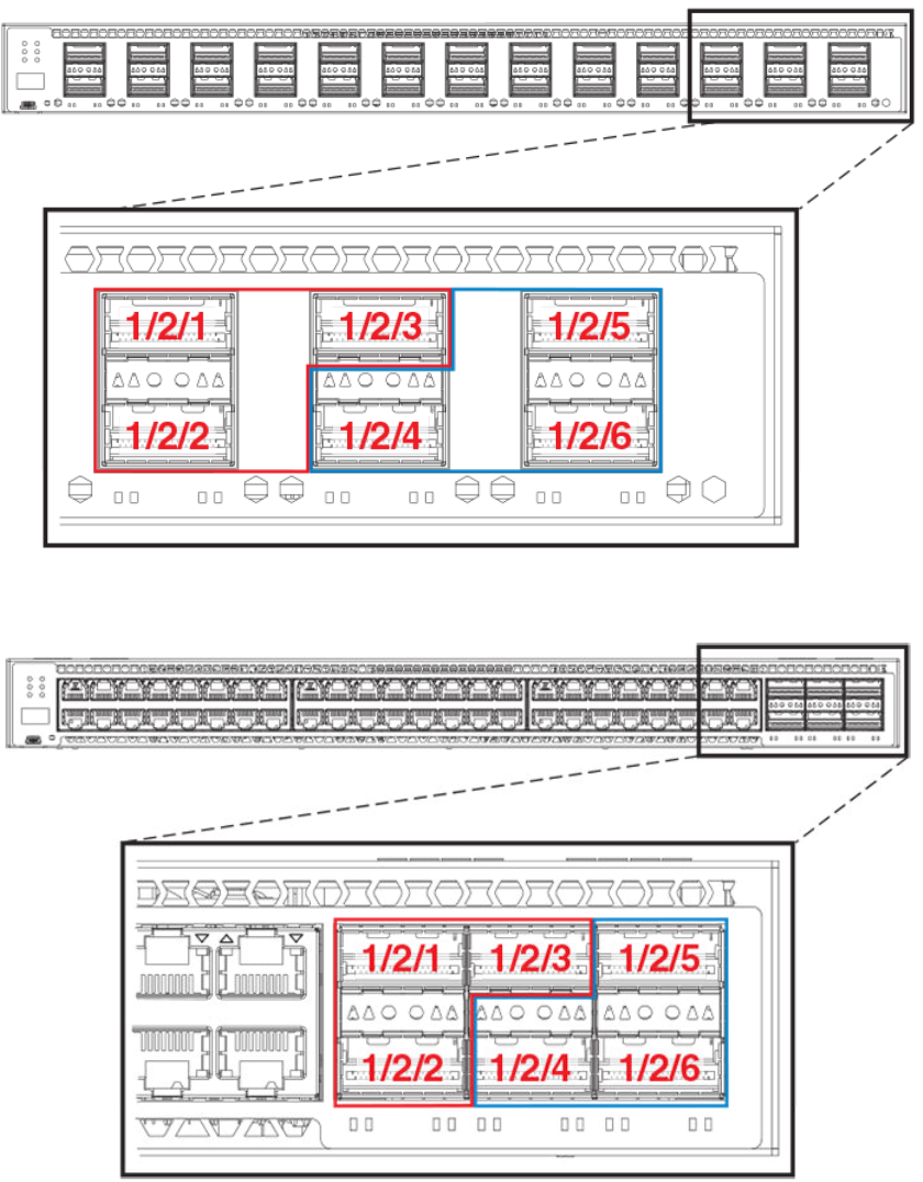
FIGURE 35 Module 2 front panel stacking ports (ICX 7750-26Q)
FIGURE 36 Module 2 front panel stacking ports (ICX 7750-48C)
Traditional Stacking by Device
ICX 7750 stack configuration overview
Ruckus FastIron Stacking Configuration Guide, 08.0.70
Part Number: 53-1005299-01 125
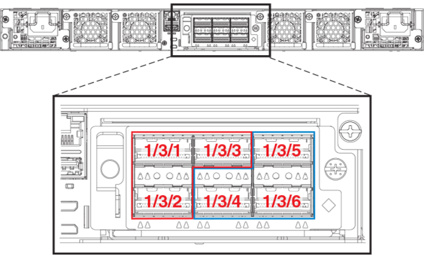
FIGURE 37 Module 3 rear panel stacking ports (ICX 7750-48C)
The following example resets default ports to 1/2/5 and 1/2/6 in preparation for long-distance stacking before stacking is enabled and
secure-setup is run. The resulting configuration is displayed as output of the show stack command.
ICX7750-20Q Router(config)# stack unit 1
ICX7750-20Q Router(config-unit-1)# default-ports 1/2/5 1/2/6
ICX7750-20Q Router(config-unit-1)# stack enable
Enable stacking. This unit actively participates in stacking
stacking is enabled. optical monitoring for stacking ports 1/2/5, 1/2/6 is not available.
ICX7750-20Q Router(config-unit-1)# exit
ICX7750-20Q Router# stack secure-setup
ICX7750-20Q Router# Discovering the stack topology...
Current Discovered Topology - RING
Available UPSTREAM units
Hop(s) Id Type Mac Address
1 new ICX7750-48XGF cc4e.246d.9e00
Available DOWNSTREAM units
Hop(s) Id Type Mac Address
1 new ICX7750-48XGF cc4e.246d.9e00
Do you accept the topology (RING) (y/n)?: y
Selected Topology:
Active Id Type Mac Address
1 ICX7750-20QXG cc4e.2439.3880
Selected UPSTREAM units
Hop(s) Id Type Mac Address
1 2 ICX7750-48XGF cc4e.246d.9e00
Selected DOWNSTREAM units
Hop(s) Id Type Mac Address
1 2 ICX7750-48XGF cc4e.246d.9e00
Do you accept the unit id's (y/n)?: y
ICX7750-20Q Router#T=9m54.9: Election, was alone --> active, ID=1, pri=128, 2U(1-2), A=u1, nbr#=1 1,
Traditional Stacking by Device
ICX 7750 stack configuration overview
Ruckus FastIron Stacking Configuration Guide, 08.0.70
126 Part Number: 53-1005299-01
reason: u2: port-up, ,
T=9m55.7: Election, was active, no change, ID=1, pri=128, 2U(1-2), A=u1, nbr#=1 1, reason: u2: port-up, ,
T=9m58.6: reset unit 2: u2 bo-id=1
Debug: Jan 1 00:10:17
Config changed due to add/del units. Do write mem if you want to keep it
Debug: Jan 1 00:10:18 T=10m1.6: Unit 1 loses all neighbors.
T=10m1.6: Active U1 deletes U2 and its config because it is learned.
T=11m13.3: Election, was active, no change, ID=1, pri=128, 2U(1-2), A=u1, nbr#=1 1, reason: u2: port-up, ,
Debug: Jan 1 00:11:30 T=11m13.3: Synchronize webauth files to u2
T=11m14.0: Election, was active, no change, ID=1, pri=128, 2U(1-2), A=u1, nbr#=1 1, reason: u1: stk-po-
chg, ,
T:11m14.6: Done hot swap: active controller u1 sets u2 to Ready.
Debug: Jan 1 00:11:36
Config changed due to add/del units. Do write mem if you want to keep it
Stack unit 2 Power supply 1 is up
Stack unit 2 Power supply 2 is down
T=12m14.7: Assigned unit 2 to be standby
Debug: Jan 1 00:12:33 T=12m16.7: start running config sync to standby u2
Debug: Jan 1 00:12:34 T=12m16.8: Running config sync to standby u2 is complete
ICX7750-20Q Router# show stack
T=30m17.8: alone: standalone, D: dynamic cfg, S: static
ID Type Role Mac Address Pri State Comment
1 S ICX7750-20QXG active cc4e.2439.3880 128 local Ready
2 D ICX7750-48XGF standby cc4e.246d.9e00 0 remote Ready
active standby
+---+ +---+
-2/6| 1 |2/5--2/5| 2 |2/6-
| +---+ +---+ |
| |
|------------------------|
Standby u2 - protocols ready, can failover
Current stack management MAC is cc4e.2439.3880
Refer to FastIron stacking distances and optics by device on page 19 for information on Brocade cable options and distances supported by
different FastIron models.
ICX 7750 stacking configuration notes
• If an ICX 7750 has a 40-Gbps port configured for break-out into sub-ports, any attempt to enable the unit for stacking will fail.
Remove the break-out configuration before enabling stacking on the unit. Refer to the
Brocade FastIron Management
Configuration Guide
for more information on break-out cable configuration.
• When adding a new unit on a linear stack, make sure that the last unit of the existing stack has both stack ports configured.
• Unused stacking ports can be used as data ports. For example, you can elect to use only one default port as a stacking port and
use the other default port as a data port. Furthermore, when an ICX 7750 stacking module is not configured for stacking, its
stacking ports can be used as data ports.
• Only ports recognized as default ports can be used as stacking ports. Before a unit can use non-default stacking ports, the
default-ports command must be configured on the local console for the unit so the unit can be discovered by the secure-setup
utility used to form a stack.
• Default ports cannot be changed on a live stack. The following example shows the error message displayed if you attempt to do
so.
ICX7750-48F Router# configure terminal
ICX7750-48F Router(config)# stack unit 8
ICX7750-48F Router(config-unit-8)# default-ports 8/3/1 8/3/4
New default-ports 8/3/1 8/3/4 result in removing both old stack ports. Abort
Traditional Stacking by Device
ICX 7750 stack configuration overview
Ruckus FastIron Stacking Configuration Guide, 08.0.70
Part Number: 53-1005299-01 127
• When module 3 on the rear of ICX 7750 devices is used for stacking, before performing secure-setup, change the default ports on
the respective units as shown in the following example. Otherwise, the secure-setup utility will not be able to discover the stacking
ports in module 3, and invalid stack trunk messages will be displayed.
ICX7750-48F Router# configure terminal
ICX7750-48F Router(config)# stack unit 1
ICX7750-48F Router(config-unit-1)# default-ports 1/3/1 1/3/4
NOTE
For more information on invalid stacking trunk error and network loops, refer to Invalid stacking trunk errors on page 33.
• To configure a stack trunk manually on a stack unit, use the stack-trunk command. However, in a live production environment,
use the multi-stack-trunk command as described in Creating an ICX 7750 stacking trunk in a production environment on page
132.
• Only ports that are in sequential order can be configured as a stacking trunk.
• A default port, either port 1/2/1 or 1/2/4 in module 2 or port 1/3/1 or 1/3/4 in module 3, is always the first sequential port in a
trunk.
• A trunk may contain two or three ports. For example, a two-port trunk on slot 3 (module 3) may contain ports 1/3/1 and 1/3/2,
and a three-port trunk may contain ports 1/3/1, 1/3/2, and 1/3/3. A second trunk on slot 3 may contain ports 1/3/4 and 1/3/5, or
it may contain all three ports, 1/3/4, 1/3/5, and 1/3/6.
ICX 7750 secure-setup example
You can use the stack secure-setup command to configure a stack with a special automatic utility. Other options for configuring a stack
are also available. For more information on stack construction and secure-setup, refer to Traditional stack construction methods on page
25. A full example of ICX 7750 secure-setup is presented in Using secure-setup to configure a traditional stack in a ring topology on page
26.
The following topics cover specific ICX 7750 configuration issues, such as trunk configuration.
ICX 7750 trunk formation during secure-setup
In FastIron release 08.0.20 and later releases, stack trunks are formed automatically in homogeneous stacks. During ICX 7750 secure-
setup, the system prompts you to enter the desired number of links in a trunk, after it displays the available options, from 1 to 3, when all
three stack trunk ports are available.
In the following excerpt from stack secure-setup output, only two stack trunk ports are available, so options are shown as 1-2. To form a
two-port trunk, you would enter "2" at the prompt. To use a single stacking port without forming a stack trunk, you would enter "1" at the
prompt.
Confirm Stacking Links...
UPSTREAM Unit: Id 12 at 11 hop(s) ICX7750-48XGC cc4e.2439.1280
Enter the desired links(1-2)[1]: 2
In the next excerpt, 3 ports are available to form a trunk. You may elect to enter "2" for a two-port trunk or "3" for a full three-port trunk as
shown.
Confirm Stacking Links...
UPSTREAM Unit: Id 7 at 6 hop(s) ICX7750-20QXG cc4e.2439.3880
Enter the desired links(1-3)[1]: 3
Traditional Stacking by Device
ICX 7750 stack configuration overview
Ruckus FastIron Stacking Configuration Guide, 08.0.70
128 Part Number: 53-1005299-01
It is also possible to modify trunk configuration when you add stack trunks. In the following excerpt, an existing trunk configuration is
modified during secure-setup. Available options are shown as 2-3 [2] where a two-port trunk is currently configured. In the example, "3" is
entered to modify the configuration and create a three-port trunk.
Confirm Stacking Links...
UPSTREAM Unit: Id 5 at 4 hop(s) ICX7750-20QXG cc4e.2439.2a80
Enter the desired links(2-3)[2]: 3
Selected Topology:
Active Id Type Mac Address
1 ICX7750-48XGF cc4e.246d.9e00
Selected UPSTREAM units
The following output shows secure-setup for a 12-unit ICX 7750 ring that includes some two-port and some three-port stack trunk
designations.
ICX7750-48F Router# stack secure-setup
ICX7750-48F Router# Discovering the stack topology...
Current Discovered Topology - RING
Available UPSTREAM units
Hop(s) Id Type Mac Address
1 new ICX7750-48XGF cc4e.246d.8d80
2 new ICX7750-48XGF cc4e.246d.9b00
3 new ICX7750-48XGF cc4e.246d.9c80
4 new ICX7750-20QXG cc4e.2439.2a80
5 new ICX7750-20QXG cc4e.2439.3700
6 new ICX7750-20QXG cc4e.2439.3880
7 new ICX7750-20QXG cc4e.2439.2d00
8 new ICX7750-48XGC cc4e.2439.1a00
9 new ICX7750-48XGC cc4e.2439.1680
10 new ICX7750-48XGC cc4e.2439.1d80
11 new ICX7750-48XGC cc4e.2439.1280
Available DOWNSTREAM units
Hop(s) Id Type Mac Address
1 new ICX7750-48XGC cc4e.2439.1280
2 new ICX7750-48XGC cc4e.2439.1d80
3 new ICX7750-48XGC cc4e.2439.1680
4 new ICX7750-48XGC cc4e.2439.1a00
5 new ICX7750-20QXG cc4e.2439.2d00
6 new ICX7750-20QXG cc4e.2439.3880
7 new ICX7750-20QXG cc4e.2439.3700
8 new ICX7750-20QXG cc4e.2439.2a80
9 new ICX7750-48XGF cc4e.246d.9c80
10 new ICX7750-48XGF cc4e.246d.9b00
11 new ICX7750-48XGF cc4e.246d.8d80
Do you accept the topology (RING) (y/n)?: y
Confirm Stacking Links...
UPSTREAM Unit: Id new at 4 hop(s) ICX7750-20QXG cc4e.2439.2a80
Enter the desired links(1-3)[1]: 3
UPSTREAM Unit: Id new at 6 hop(s) ICX7750-20QXG cc4e.2439.3880
Enter the desired links(1-3)[1]: 3
UPSTREAM Unit: Id new at 10 hop(s) ICX7750-48XGC cc4e.2439.1d80
Traditional Stacking by Device
ICX 7750 stack configuration overview
Ruckus FastIron Stacking Configuration Guide, 08.0.70
Part Number: 53-1005299-01 129
Enter the desired links(1-2)[1]: 2
UPSTREAM Unit: Id new at 11 hop(s) ICX7750-48XGC cc4e.2439.1280
Enter the desired links(1-2)[1]: 2
Selected Topology:
Active Id Type Mac Address
1 ICX7750-48XGF cc4e.246d.9e00
Selected UPSTREAM units
Hop(s) Id Type Mac Address
1 2 ICX7750-48XGF cc4e.246d.8d80
2 3 ICX7750-48XGF cc4e.246d.9b00
3 4 ICX7750-48XGF cc4e.246d.9c80
4 5 ICX7750-20QXG cc4e.2439.2a80
5 6 ICX7750-20QXG cc4e.2439.3700
6 7 ICX7750-20QXG cc4e.2439.3880
7 8 ICX7750-20QXG cc4e.2439.2d00
8 9 ICX7750-48XGC cc4e.2439.1a00
9 10 ICX7750-48XGC cc4e.2439.1680
10 11 ICX7750-48XGC cc4e.2439.1d80
11 12 ICX7750-48XGC cc4e.2439.1280
Selected DOWNSTREAM units
Hop(s) Id Type Mac Address
1 12 ICX7750-48XGC cc4e.2439.1280
2 11 ICX7750-48XGC cc4e.2439.1d80
3 10 ICX7750-48XGC cc4e.2439.1680
4 9 ICX7750-48XGC cc4e.2439.1a00
5 8 ICX7750-20QXG cc4e.2439.2d00
6 7 ICX7750-20QXG cc4e.2439.3880
7 6 ICX7750-20QXG cc4e.2439.3700
8 5 ICX7750-20QXG cc4e.2439.2a80
9 4 ICX7750-48XGF cc4e.246d.9c80
10 3 ICX7750-48XGF cc4e.246d.9b00
11 2 ICX7750-48XGF cc4e.246d.8d80
Do you accept the unit id's (y/n)?: y
ICX7750-48F Router#T=18m45.7: Election, was alone --> active, ID=1, pri=128,
12U(1-12), A=u1, nbr#=11 11, reason: u6: SecureS, ,
T=18m49.7: Election, was active, no change, ID=1, pri=128, 12U(1-12), A=u1,
nbr#=11 11, reason: u1: stk-po-chg, ,
T=18m52.3: reset unit 2: u2 bo-id=1
T=18m52.3: reset unit 3: u3 bo-id=1
T=18m52.3: reset unit 5: u5 bo-id=1
T=18m52.3: reset unit 6: u6 bo-id=1
T=18m52.3: reset unit 7: u7 bo-id=1
T=18m52.3: reset unit 8: u8 bo-id=1
T=18m52.3: reset unit 9: u9 bo-id=1
T=18m52.3: reset unit 10: u10 bo-id=1
T=18m52.3: reset unit 11: u11 bo-id=1
T=18m52.3: reset unit 12: u12 bo-id=1
Reset extra units due to path: 4
Config changed due to add/del units. Do write mem if you want to keep it
T=18m55.3: Unit 1 loses all neighbors.
T=18m55.4: Active U1 deletes U2 and its config because it is learned.
T=18m55.6: Active U1 deletes U3 and its config because it is learned.
T=18m55.8: Active U1 deletes U4 and its config because it is learned.
T=18m55.9: Active U1 deletes U5 and its config because it is learned.
T=18m56.0: Active U1 deletes U6 and its config because it is learned.
T=18m56.1: Active U1 deletes U7 and its config because it is learned.
T=18m56.2: Active U1 deletes U8 and its config because it is learned.
T=18m56.3: Active U1 deletes U9 and its config because it is learned.
T=18m56.4: Active U1 deletes U10 and its config because it is learned.
T=18m56.6: Active U1 deletes U11 and its config because it is learned.
T=18m56.7: Active U1 deletes U12 and its config because it is learned.
ICX7750-48F Router# T=19m55.7: Election, was active, no change, ID=1, pri=128,
3U(1-3), A=u1, nbr#=2 0, reason: u3: port-dw, ,
Traditional Stacking by Device
ICX 7750 stack configuration overview
Ruckus FastIron Stacking Configuration Guide, 08.0.70
130 Part Number: 53-1005299-01
T=19m55.8: Synchronize webauth files to u2
T=19m55.8: Synchronize webauth files to u3
T:19m57.1: Done hot swap: active controller u1 sets u2 to Ready.
T:19m57.1: Done hot swap: active controller u1 sets u3 to Ready.
Config changed due to add/del units. Do write mem if you want to keep it
Stack unit 2 Power supply 1 is up
Stack unit 2 Power supply 2 is down
Stack unit 3 Power supply 1 is up
Stack unit 3 Power supply 2 is down
T=20m2.4: Election, was active, no change, ID=1, pri=128, 3U(1-3), A=u1, nbr#=2 0,
reason: u1: port-up, ,
T=20m3.6: 1/2/4 goes down. delete direction 1, trigger election
T=20m7.3: Election, was active, no change, ID=1, pri=128, 12U(1-12), A=u1,
nbr#=11 11, reason: u12: port-up, ,
T=20m7.6: Synchronize webauth files to u10
T=20m7.6: Synchronize webauth files to u11
Detect stack unit 12 has different startup config flash, will synchronize it
T=20m7.6: Synchronize webauth files to u12
Detect stack unit 4 has different startup config flash, will synchronize it
T=20m7.6: Synchronize webauth files to u4
T=20m7.6: Synchronize webauth files to u5
T=20m7.6: Synchronize webauth files to u6
T=20m7.6: Synchronize webauth files to u7
T=20m7.7: Synchronize webauth files to u8
T=20m8.3: Synchronize webauth files to u9
T:20m8.8: Done hot swap: active controller u1 sets u10 to Ready.
T:20m9.0: Done hot swap: active controller u1 sets u11 to Ready.
T:20m9.3: Done hot swap: active controller u1 sets u12 to Ready.
T:20m9.9: Done hot swap: active controller u1 sets u4 to Ready.
T:20m10.2: Done hot swap: active controller u1 sets u5 to Ready.
T:20m10.5: Done hot swap: active controller u1 sets u6 to Ready.
T:20m10.9: Done hot swap: active controller u1 sets u7 to Ready.
T:20m11.4: Done hot swap: active controller u1 sets u8 to Ready.
Stack unit 12 Power supply 1 is up
Stack unit 12 Power supply 2 is down
Stack unit 10 Power supply 1 is up
Stack unit 10 Power supply 2 is down
Config changed due to add/del units. Do write mem if you want to keep it
T:20m13.1: Done hot swap: active controller u1 sets u9 to Ready.
T=20m16.9: Election, was active, no change, ID=1, pri=128, 12U(1-12), A=u1,
nbr#=11 11, reason: u1: stk-po-chg, ,
Config changed due to add/del units. Do write mem if you want to keep it
ICX7750-48F Router#T=21m16.9: Assigned unit 2 to be standby
cT=21m18.9: start running config sync to standby u2
T=21m19.3: Running config sync to standby u2 is complete
The following show stack command output shows the resulting 12-unit ICX 7750 ring topology.
ICX7750-48F Router# show stack
T=23m12.5: alone: standalone, D: dynamic cfg, S: static, A=10, B=11, C=12
ID Type Role Mac Address Pri State Comment
1 S ICX7750-48XGF active cc4e.246d.9e00 128 local Ready
2 D ICX7750-48XGF standby cc4e.246d.8d80 0 remote Ready
3 D ICX7750-48XGF member cc4e.246d.9b00 0 remote Ready
4 D ICX7750-48XGF member cc4e.246d.9c80 0 remote Ready
5 D ICX7750-20QXG member cc4e.2439.2a80 0 remote Ready
6 D ICX7750-20QXG member cc4e.2439.3700 0 remote Ready
7 D ICX7750-20QXG member cc4e.2439.3880 0 remote Ready
8 D ICX7750-20QXG member cc4e.2439.2d00 0 remote Ready
9 D ICX7750-48XGC member cc4e.2439.1a00 0 remote Ready
10 D ICX7750-48XGC member cc4e.2439.1680 0 remote Ready
11 D ICX7750-48XGC member cc4e.2439.1d80 0 remote Ready
12 D ICX7750-48XGC member cc4e.2439.1280 0 remote Ready
active
+---+ +---+ +---+ +---+ +---+ +---+
-2/1| 1 |2/4--2/1| C |2/4==2/1| B |2/4==2/1| A |2/4--2/1| 9 |2/4--2/1| 8 |2/4-
Traditional Stacking by Device
ICX 7750 stack configuration overview
Ruckus FastIron Stacking Configuration Guide, 08.0.70
Part Number: 53-1005299-01 131
| +---+ +---+ +---+ +---+ +---+ +---+ |
| |
| standby |
| +---+ +---+ +---+ +---+ +---+ +---+ |
-2/4| 2 |2/1--2/4| 3 |2/1--2/4| 4 |2/1==2/4| 5 |2/1--2/4| 6 |2/1==2/4| 7 |2/1-
+---+ +---+ +---+ +---+ +---+ +---+
Standby u2 - protocols ready, can failover
Current stack management MAC is cc4e.246d.9e00
Removing stacking ports from an ICX 7750
Use the no stack-port command to remove stack ports from a unit, for example, to change a ring topology to a linear topology.
In the following example, one stacking port, port 3/2/4, is removed from stack unit 3.
ICX7750-48F Router# stack unit 3
ICX7750-48F Router(config-unit-3)# no stack-port 3/2/1
Remove stacking port 3/2/1. The remaining stacking port is 3/2/4
The no stack-port command cannot be used when a trunk is configured. You must first remove the trunk before removing the stacking
port.
In the following example, an attempt to remove a stack port that is part of a configured trunk results in an error message.
ICX7750-48F Router(config)# stack unit 10
ICX7750-48F Router(config-unit-10)# no stack-port 10/2/1
Please remove stack-trunk 10/2/1 to 10/2/2 before removing stacking port 10/2/1
using "stack-trunk" or "multi-stack-trunk" command.
Creating an ICX 7750 stacking trunk in a production environment
The stack-trunk command cannot be used to form a trunk manually in a live environment. Instead, use the multi-stack-trunk command.
The multi-stack-trunk command configures both ends of a trunk, based on the range of ports you specify for each side.
NOTE
Configure the same size trunk on either side.
In the following example, a port connection is converted to a two-port trunk connection between stack unit 4 and stack unit 5.
ICX7750-48F Router# configure terminal
ICX7750-48F Router(config)# stack unit 4
ICX7750-48F Router(config-unit-4)# multi-stack-trunk 4/2/1 to 4/2/2 and 5/2/4 to 5/2/5
stack unit 4
module 1 icx7750-48-xgf-port-management-module
module 2 icx7750-qsfp-6port-qsfp-240g-module
module 3 icx7750-6q-6port-qsfp-240g-module
stack-trunk 4/2/1 to 4/2/2
stack-port 4/2/1 4/2/4
stack unit 5
module 1 icx7750-20-qxg-port-management-module
module 2 icx7750-qsfp-6port-qsfp-240g-module
stack-trunk 5/2/4 to 5/2/5
stack-port 5/2/1 5/2/4
Converting an ICX 7750 trunk to a port connection in a live stack
To remove a trunk and create a port connection on a live stack, use the multi-stack-port command.
NOTE
Only primary ports (stack module ports 1 and 4) can be designated in the multi-stack-port command.
Traditional Stacking by Device
ICX 7750 stack configuration overview
Ruckus FastIron Stacking Configuration Guide, 08.0.70
132 Part Number: 53-1005299-01
The following code excerpt displays configuration information for stack units 6 and 7.
stack unit 6
module 1 icx7750-20-qxg-port-management-module
module 2 icx7750-qsfp-6port-qsfp-240g-module
stack-trunk 6/2/1 to 6/2/3
stack-port 6/2/1 6/2/4
stack unit 7
module 1 icx7750-20-qxg-port-management-module
module 2 icx7750-qsfp-6port-qsfp-240g-module
stack-trunk 7/2/4 to 7/2/6
stack-port 7/2/1 7/2/4
In the following example, the stack trunk between units 6 and 7 is removed.
ICX7750-48F Router# configure terminal
ICX7750-48F Router(config)# stack unit 6
ICX7750-48F Router(config-unit-6)# multi-stack-port 6/2/1 and 7/2/4
NOTE
The no form of the multi-stack-port command removes port configuration on the designated ports.
Restoring a data port from an ICX 7750 trunk in a live stack
The stack-multi-trunk command can be used to remove a stacking port for configuration as a data port.
Use the following procedure in a production environment to reduce the size of a trunk and make an end port in the trunk available for
configuration as a data port.
The following example reconfigures a six-port trunk between module 2 of stack units 1 and 2.
1. From the active controller for the stack, enter stack-unit configuration mode for a device at one end of the trunk.
ICX7750-48F Router(config)# stack unit 1
2. In stack-unit configuration mode, enter the multi-stack-trunk command. Specify the new, smaller port range for the trunk on both
ends (stack-unit 1 and stack-unit 2 in the following example). Be sure the port numbers are correct and the size of the trunk is the
same on both ends.
ICX7750-48F Router(config-unit-1)# multi-stack-trunk 1/2/1 to 1/2/5 and 2/2/1 to 2/2/5
The end port of the trunk on each stack unit is dropped from the trunk and is available for configuration on each of the units.
3. Configure one or both of the ports as appropriate.
In the following example, port 2/2/6, which was previously part of a six-port trunk between stack unit 1 and stack unit 2, is ready to
configure as a data port.
ICX7750-48F Router(config)# interface ethernet 2/2/6
Error - command not allowed for stacking port: 2/2/6
ICX7750-48F Router(config)# stack unit 1
ICX7750-48F Router(config-unit-1)# multi-stack-trunk 1/2/1 to 1/2/5 and 2/2/1 to 2/2/5
ICX7750-48F Router(config-unit-1)#interface ehternet 2/2/6
ICX7750-48F Router(config-if-e40000-2/2/6)#
Displaying basic information for an ICX 7750 stack
Enter the show stack command at the device level to display general information about the stack, including unit IDs, device type, role, MAC
address, priority, status, and connections.
Traditional Stacking by Device
ICX 7750 stack configuration overview
Ruckus FastIron Stacking Configuration Guide, 08.0.70
Part Number: 53-1005299-01 133
The following show stack command output is for a 12-unit ICX 7750 ring. Units 10, 11, and 12 are represented as A, B, and C in the
topology diagram.
show stack
alone: standalone, D: dynamic cfg, S: static, A=10, B=11, C=12
ID Type Role Mac Address Pri State Comment
1 S ICX7750-48XGF active cc4e.246d.9e00 128 local Ready
2 S ICX7750-48XGF standby cc4e.246d.8d80 0 remote Ready
3 S ICX7750-48XGF member cc4e.246d.9b00 0 remote Ready
4 S ICX7750-48XGF member cc4e.246d.9c80 0 remote Ready
5 S ICX7750-20QXG member cc4e.2439.2a80 0 remote Ready
6 S ICX7750-20QXG member cc4e.2439.3700 0 remote Ready
7 S ICX7750-20QXG member cc4e.2439.3880 0 remote Ready
8 S ICX7750-20QXG member cc4e.2439.2d00 0 remote Ready
9 S ICX7750-48XGC member cc4e.2439.1a00 0 remote Ready
10 S ICX7750-48XGC member cc4e.2439.1680 0 remote Ready
11 S ICX7750-48XGC member cc4e.2439.1d80 0 remote Ready
12 S ICX7750-48XGC member cc4e.2439.1280 0 remote Ready
active
+---+ +---+ +---+ +---+ +---+ +---+
-2/1| 1 |2/4--2/1| C |2/4--2/1| B |2/4==2/1| A |2/4--2/1| 9 |2/4--2/1| 8 |2/4=
| +---+ +---+ +---+ +---+ +---+ +---+ |
| |
| standby |
| +---+ +---+ +---+ +---+ +---+ +---+ |
-2/4| 2 |2/1==2/4| 3 |2/1--2/4| 4 |2/1==2/4| 5 |2/1--2/4| 6 |2/1==2/4| 7 |2/1=
+---+ +---+ +---+ +---+ +---+ +---+
Standby u2 - protocols ready, can failover
Current stack management MAC is cc4e.246d.9e00
Displaying details for an ICX 7750 stack
Enter the show stack detail command to display information for the stack, including device type, role, MAC address, priority, status, and
connections.
Traditional Stacking by Device
ICX 7750 stack configuration overview
Ruckus FastIron Stacking Configuration Guide, 08.0.70
134 Part Number: 53-1005299-01
The following show stack detail output provides information on a 12-unit stack containing three different ICX 7750 models connected in a
ring.
ICX7750-48F Router# show stack detail
alone: standalone, D: dynamic cfg, S: static, A=10, B=11, C=12
ID Type Role Mac Address Pri State Comment
1 S ICX7750-48XGF active cc4e.246d.9e00 128 local Ready
2 S ICX7750-48XGF standby cc4e.246d.8d80 0 remote Ready
3 S ICX7750-48XGF member cc4e.246d.9b00 0 remote Ready
4 S ICX7750-48XGF member cc4e.246d.9c80 0 remote Ready
5 S ICX7750-20QXG member cc4e.2439.2a80 0 remote Ready
6 S ICX7750-20QXG member cc4e.2439.3700 0 remote Ready
7 S ICX7750-20QXG member cc4e.2439.3880 0 remote Ready
8 S ICX7750-20QXG member cc4e.2439.2d00 0 remote Ready
9 S ICX7750-48XGC member cc4e.2439.1a00 0 remote Ready
10 S ICX7750-48XGC member cc4e.2439.1680 0 remote Ready
11 S ICX7750-48XGC member cc4e.2439.1d80 0 remote Ready
12 S ICX7750-48XGC member cc4e.2439.1280 0 remote Ready
active
+---+ +---+ +---+ +---+ +---+ +---+
-2/1| 1 |2/4--2/1| C |2/4--2/1| B |2/4==2/1| A |2/4--2/1| 9 |2/4--2/1| 8 |2/4=
| +---+ +---+ +---+ +---+ +---+ +---+ |
| |
| standby |
| +---+ +---+ +---+ +---+ +---+ +---+ |
-2/4| 2 |2/1==2/4| 3 |2/1--2/4| 4 |2/1==2/4| 5 |2/1--2/4| 6 |2/1==2/4| 7 |2/1=
+---+ +---+ +---+ +---+ +---+ +---+
Standby u2 - protocols ready, can failover
Current stack management MAC is cc4e.246d.9e00
Image-Auto-Copy is Enabled.
Stack Port Status Neighbors
Unit# Stack-port1 Stack-port2 Stack-port1 Stack-port2
1 up (1/2/1) up (1/2/4) U2 (2/2/4) U12 (12/2/1)
2 up (2/2/1-2/2/2) up (2/2/4) U3 (3/2/4-3/2/5) U1 (1/2/1)
3 up (3/2/1) up (3/2/4-3/2/5) U4 (4/2/4) U2 (2/2/1-2/2/2)
4 up (4/2/1-4/2/2) up (4/2/4) U5 (5/2/4-5/2/5) U3 (3/2/1)
5 up (5/2/1) up (5/2/4-5/2/5) U6 (6/2/4) U4 (4/2/1-4/2/2)
6 up (6/2/1-6/2/3) up (6/2/4) U7 (7/2/4-7/2/6) U5 (5/2/1)
7 up (7/2/1-7/2/2) up (7/2/4-7/2/6) U8 (8/2/4-8/2/5) U6 (6/2/1-6/2/3)
8 up (8/2/1) up (8/2/4-8/2/5) U9 (9/2/4) U7 (7/2/1-7/2/2)
9 up (9/2/1) up (9/2/4) U10 (10/2/4) U8 (8/2/1)
10 up (10/2/1-10/2/2 up (10/2/4) U11 (11/2/4-11/2/ U9 (9/2/1)
11 up (11/2/1) up (11/2/4-11/2/5 U12 (12/2/4) U10 (10/2/1-10/2/
12 up (12/2/1) up (12/2/4) U1 (1/2/4) U11 (11/2/1)
Unit# System uptime
1 17 hours 20 minutes 8 seconds
2 17 hours 20 minutes 13 seconds
3 17 hours 20 minutes 13 seconds
4 17 hours 20 minutes 12 seconds
5 17 hours 20 minutes 13 seconds
6 17 hours 20 minutes 13 seconds
7 17 hours 20 minutes 13 seconds
8 17 hours 20 minutes 11 seconds
9 17 hours 20 minutes 13 seconds
10 17 hours 20 minutes 15 seconds
11 17 hours 20 minutes 13 seconds
12 17 hours 20 minutes 11 seconds
Traditional Stacking by Device
ICX 7750 stack configuration overview
Ruckus FastIron Stacking Configuration Guide, 08.0.70
Part Number: 53-1005299-01 135
Configuring an ICX 7650 stacking trunk on a live
system
Follow these steps to convert stacking ports on both ends of a link to a stacking trunk on an ICX 7650 production stack.
1. (Optional) Enter the show stack command to verify stack configuration.
ICX7650-48ZP Router# show stack
T=20h23m43.6: alone: standalone, D: dynamic cfg, S: static
ID Type Role Mac Address Pri State Comment
1 S ICX7650-48ZP active 609c.9f52.2cd5 128 local Ready
2 S ICX7650-48F standby 609c.9f52.4643 128 remote Ready
active standby
+---+ +---+
-3/3| 1 |3/1--3/1| 2 |3/3-
| +---+ +---+ |
| |
|------------------------|
Standby u2 - protocols ready, can failover or manually switch over
Role history: N: standalone, A: active, S: standby, M: member
U1: M->S->A, U2: A->S
Current stack management MAC is 609c.9f52.2cd5
The example shows a two-unit live stack configured in a ring with no trunks.
2. (Optional) Enter the show running-cong command for additional information on the stack.
ICX7650-48ZP Router# show running-config | inc stack
stack unit 1
stack-port 1/3/1 1/3/3
stack unit 2
stack-port 2/3/1 2/3/3
stack enable
stack rconsole-off
stack mac 609c.9f52.2cd5
rear-module stack-40g
The example includes only stacking information in the show running-cong command output. The output confirms that the ICX
7650 stack is operating in 40-Gbps stacking mode.
3. Enter stack unit configuration mode.
ICX7650-48ZP Router# configure terminal
ICX7650-48ZP Router(config)#stack unit 1
ICX7650-48ZP Router(config-unit-1)#
Traditional Stacking by Device
Configuring an ICX 7650 stacking trunk on a live system
Ruckus FastIron Stacking Configuration Guide, 08.0.70
136 Part Number: 53-1005299-01
4. Enter the multi-stack-trunk command followed by the set of ports on either end of the live connection to include in the stacking
trunk.
ICX7650-48ZP Router(config-unit-1)# multi-stack-trunk 1/3/1 to 1/3/2 and 2/3/1 to 2/3/2
SYSLOG: <14> Sep 7 19:13:52 System: Interface ethernet 1/3/2, state down
SYSLOG: <14> Sep 7 19:13:52 System: Interface ethernet 2/3/2, state down
T=20h25m17.5: Election, was active, no change, ID=1, pri=128, 2U(1-2), A=u1, nbr#=1 1, reason: u1:
stk-po-chg, ,
SYSLOG: <14> Sep 7 19:13:52 Stack: Stack unit 1 has been elected as ACTIVE unit of the stack system
SYSLOG: <14> Sep 7 19:13:53 System: Interface ethernet 1/3/2, state up
SYSLOG: <14> Sep 7 19:13:53 System: Interface ethernet 2/3/2, state up
ICX7650-48ZP Router(config-unit-1)# end
The example configures a stacking trunk from ports 1/3/1 to 1/3/2 on one end of the connection to ports 2/3/1 and 2/3/2 on the
other end.
5. Enter the write memory command in privileged Exec mode to save the configuration.
ICX7650-48ZP Router(config-unit-1)# end
SYSLOG: <14> Sep 7 19:13:57 Security: running-config was potentially changed by operator from
console
ICX7650-48ZP Router# write memory
Automatic copy to member units: 2
ICX7650-48ZP Router#
SYSLOG: <14> Sep 7 19:13:59 Security: startup-config was changed by operator from console
Flash Memory Write (8192 bytes per dot)
.
Write startup-config done.
Copy Done.
The example saves the 40-Gbps trunk configuration.
6. (Optional) Enter the show stack command to confirm the formation of the trunk.
ICX7650-48ZP Router# show stack
T=20h24m41.8: alone: standalone, D: dynamic cfg, S: static
ID Type Role Mac Address Pri State Comment
1 S ICX7650-48ZP active 609c.9f52.2cd5 128 local Ready
2 S ICX7650-48F standby 609c.9f52.4643 128 remote Ready
active standby
+---+ +---+
-3/3| 1 |3/1==3/1| 2 |3/3-
| +---+ +---+ |
| |
|------------------------|
Will assign standby in 47 sec due to all ready
Standby u2 - protocols ready, can failover
Role history: N: standalone, A: active, S: standby, M: member
U1: M->S->A, U2: A->S
Current stack management MAC is 609c.9f52.2cd5
The example shows a trunk is present.
Traditional Stacking by Device
Configuring an ICX 7650 stacking trunk on a live system
Ruckus FastIron Stacking Configuration Guide, 08.0.70
Part Number: 53-1005299-01 137
The following example configures both potential 40-Gbps trunks on a live stack.
ICX7650-48ZP Router# show stack
T=20h23m43.6: alone: standalone, D: dynamic cfg, S: static
ID Type Role Mac Address Pri State Comment
1 S ICX7650-48ZP active 609c.9f52.2cd5 128 local Ready
2 S ICX7650-48F standby 609c.9f52.4643 128 remote Ready
active standby
+---+ +---+
-3/3| 1 |3/1--3/1| 2 |3/3-
| +---+ +---+ |
| |
|------------------------|
Standby u2 - protocols ready, can failover or manually switch over
Role history: N: standalone, A: active, S: standby, M: member
U1: M->S->A, U2: A->S
Current stack management MAC is 609c.9f52.2cd5
ICX7650-48ZP Router#
ICX7650-48ZP Router#
ICX7650-48ZP Router#
ICX7650-48ZP Router#show running-config | inc stack
stack unit 1
stack-port 1/3/1 1/3/3
stack unit 2
stack-port 2/3/1 2/3/3
stack enable
stack rconsole-off
stack mac 609c.9f52.2cd5
rear-module stack-40g
ICX7650-48ZP Router# configure terminal
ICX7650-48ZP Router(config)# stack unit 1
ICX7650-48ZP Router(config-unit-1)# multi-stack-trunk 1/3/1 to 1/3/2 and 2/3/1 to 2/3/2
ICX7650-48ZP Router(config-unit-1)#
SYSLOG: <14> Sep 7 19:13:52 System: Interface ethernet 1/3/2, state down
SYSLOG: <14> Sep 7 19:13:52 System: Interface ethernet 2/3/2, state down
T=20h25m17.5: Election, was active, no change, ID=1, pri=128, 2U(1-2), A=u1, nbr#=1 1, reason: u1: stk-po-
chg, ,
SYSLOG: <14> Sep 7 19:13:52 Stack: Stack unit 1 has been elected as ACTIVE unit of the stack system
SYSLOG: <14> Sep 7 19:13:53 System: Interface ethernet 1/3/2, state up
SYSLOG: <14> Sep 7 19:13:53 System: Interface ethernet 2/3/2, state up
ICX7650-48ZP Router(config-unit-1)# end
SYSLOG: <14> Sep 7 19:13:57 Security: running-config was potentially changed by operator from console
ICX7650-48ZP Router# write memory
Automatic copy to member units: 2
ICX7650-48ZP Router#
SYSLOG: <14> Sep 7 19:13:59 Security: startup-config was changed by operator from console
Flash Memory Write (8192 bytes per dot)
.
Write startup-config done.
Copy Done.
ICX7650-48ZP Router# show stack
T=20h24m41.8: alone: standalone, D: dynamic cfg, S: static
ID Type Role Mac Address Pri State Comment
1 S ICX7650-48ZP active 609c.9f52.2cd5 128 local Ready
2 S ICX7650-48F standby 609c.9f52.4643 128 remote Ready
active standby
+---+ +---+
-3/3| 1 |3/1==3/1| 2 |3/3-
| +---+ +---+ |
| |
Traditional Stacking by Device
Configuring an ICX 7650 stacking trunk on a live system
Ruckus FastIron Stacking Configuration Guide, 08.0.70
138 Part Number: 53-1005299-01
|------------------------|
Will assign standby in 47 sec due to all ready
Standby u2 - protocols ready, can failover
Role history: N: standalone, A: active, S: standby, M: member
U1: M->S->A, U2: A->S
Current stack management MAC is 609c.9f52.2cd5
ICX7650-48ZP Router# configure terminal
ICX7650-48ZP Router(config)#stack unit 1
ICX7650-48ZP Router(config-unit-1)# multi-stack-trunk 1/3/3 to 1/3/4 and 2/3/3 to 2/3/4
SYSLOG: <14> Sep 7 19:14:39 System: Interface ethernet 1/3/4, state down
ICX7650-48ZP Router(config-unit-1)#
SYSLOG: <14> Sep 7 19:14:39 System: Interface ethernet 2/3/4, state down
T=20h26m4.5: Election, was active, no change, ID=1, pri=128, 2U(1-2), A=u1, nbr#=1 1, reason: u1: stk-po-
chg, ,
SYSLOG: <14> Sep 7 19:14:39 Stack: Stack unit 1 has been elected as ACTIVE unit of the stack system
ICX7650-48ZP Router(config-unit-1)#
SYSLOG: <14> Sep 7 19:14:40 System: Interface ethernet 1/3/4, state up
SYSLOG: <14> Sep 7 19:14:40 System: Interface ethernet 2/3/4, state up
ICX7650-48ZP Router(config-unit-1)# end
SYSLOG: <14> Sep 7 19:14:41 Security: running-config was potentially changed by operator from console
ICX7650-48ZP Router#
ICX7650-48ZP Router# write memory
Automatic copy to member units: 2
ICX7650-48ZP Router#
SYSLOG: <14> Sep 7 19:14:42 Security: startup-config was changed by operator from console
Flash Memory Write (8192 bytes per dot)
.
Write startup-config done.
Copy Done.
ICX7650-48ZP Router# show stack
T=20h25m20.2: alone: standalone, D: dynamic cfg, S: static
ID Type Role Mac Address Pri State Comment
1 S ICX7650-48ZP active 609c.9f52.2cd5 128 local Ready
2 S ICX7650-48F standby 609c.9f52.4643 128 remote Ready
active standby
+---+ +---+
=3/3| 1 |3/1==3/1| 2 |3/3=
| +---+ +---+ |
| |
|------------------------|
Will assign standby in 56 sec due to all ready
Standby u2 - protocols ready, can failover
Role history: N: standalone, A: active, S: standby, M: member
U1: M->S->A, U2: A->S
Current stack management MAC is 609c.9f52.2cd5
ICX7650-48ZP Router# show running-config | inc stack
stack unit 1
stack-trunk 1/3/1 to 1/3/2
stack-trunk 1/3/3 to 1/3/4
stack-port 1/3/1 1/3/3
stack unit 2
stack-trunk 2/3/1 to 2/3/2
stack-trunk 2/3/3 to 2/3/4
stack-port 2/3/1 2/3/3
stack enable
stack rconsole-off
stack mac 609c.9f52.2cd5
rear-module stack-40g
ICX7650-48ZP Router#
Traditional Stacking by Device
Configuring an ICX 7650 stacking trunk on a live system
Ruckus FastIron Stacking Configuration Guide, 08.0.70
Part Number: 53-1005299-01 139
Converting a stacking trunk to stacking ports on a
live system
1.
2. NOTE
3. •
•
4. a)
b)
device(mode)# command executable
Command output
Traditional Stacking by Device
Converting a stacking trunk to stacking ports on a live system
Ruckus FastIron Stacking Configuration Guide, 08.0.70
140 Part Number: 53-1005299-01

Hitless Stacking
• Hitless stacking overview.......................................................................................................................................141
• Hitless stacking behavior....................................................................................................................................... 141
• Supported hitless stacking events ........................................................................................................................ 143
• Non-supported hitless stacking events.................................................................................................................. 143
• Supported hitless stacking protocols and services................................................................................................ 143
• Hitless stacking configuration notes and feature limitations....................................................................................145
• What happens during a hitless stacking switchover or failover............................................................................... 145
• Standby controller role in hitless stacking.............................................................................................................. 146
• Support during stack formation, stack merge, and stack split................................................................................148
• Hitless stacking failover......................................................................................................................................... 150
• Hitless stacking switchover....................................................................................................................................151
• Displaying information about hitless stacking......................................................................................................... 155
• Syslog messages for hitless stacking failover and switchover................................................................................ 157
Hitless stacking overview
Hitless stacking is supported on FastIron units in a traditional stack. It is a High Availability feature set that ensures sub-second or no loss of
data traffic during the following events:
• Active controller failure or role change
• Software failure
• Addition or removal of units in a stack
• Removal or disconnection of the stacking cable between the active controller and the standby controller
During such events, the standby controller takes over the active role, and the system continues to forward traffic seamlessly, as if no failure
or topology change has occurred. In software releases that do not support hitless stacking, events such as these could cause most of the
units in a stack to reset, affecting data traffic.
FastIron stackable units support the following hitless stacking features:
Hitless stacking switchover - A manually-controlled (CLI-driven) or automatic switchover of the active controller and standby controller
without reloading the stack and without any packet loss to the services and protocols that are supported by hitless stacking. A switchover
is activated by the CLI command stack switch-over command. A switchover may also be activated by the priority command, depending
on the configured priority value.
Hitless stacking failover - An automatic, forced switchover of the active controller and standby controller because of a failure or abnormal
termination of the active controller. During a failover, the active controller abruptly leaves the stack, and the standby controller immediately
assumes the active role. As with a switchover, a failover occurs without the stack being reloaded. Unlike a switchover, a failover generally
occurs without warning and is likely to result in sub-second packet loss (although packets traversing the stacking link may be lost).
Hitless stacking failover is enabled by default beginning with Fastiron release 08.0.20.
Hitless stacking behavior
Hitless stacking is enabled by default for FastIron release 08.0.20 and later releases. In previous releases, the hitless-failover command
must be set to enable in the configuration.
Ruckus FastIron Stacking Configuration Guide, 08.0.70
Part Number: 53-1005299-01 141
If you install a FastIron 08.0.20 or later image on a new system with no previous configuration, the hitless-failover command is enabled by
default.
If you upgrade to FastIron release 08.0.20 or later from a previous version that has hitless-failover enabled, hitless-failover is retained as
the default.
If you upgrade to FastIron release 08.0.20 or later on a system with an earlier release that does not have hitless-failover enabled in its
configuration, the previous configuration is retained.
Hitless stacking can be disabled using the no hitless-failover enable command. When hitless failover is disabled, the following limitations
are in effect:
• If a failover occurs, every unit in the stack reloads.
• Manual switchover is not allowed. If the stack switch-over command is entered, the following message appears on the console:
Switch-over is not allowed. Reason: hitless-failover not configured.
• Internal switchover resulting from a priority change is blocked until the entire stack is reloaded or hitless stacking is enabled. A
priority change triggers an election, but the newly elected winner does not immediately assume its role.
• If there is no active controller after a reload, the bootup standby assumes the active role after reloading every unit in the stack,
including itself.
• During a stack merge, the active controller with the highest priority wins the election and reloads every unit of the losing stack.
NOTE
Synchronization between the active controller, standby controller, and stack members occurs whether or not hitless stacking is
enabled.
If hitless stacking has been disabled, enable hitless stacking failover as described in "Enabling hitless stacking failover." As soon as hitless
stacking is enabled, the following behavior takes effect immediately:
• If a failover occurs, the stack does not reload.
• Manual switchover (CLI command stack switch-over) is allowed.
• If a priority change occurred while hitless stacking was disabled and the configured priority value requires a switchover, the system
starts a 60-second timer before performing a switchover. After the switchover, the highest priority standby controller becomes the
active controller.
• If there is no active controller after a reload, the bootup standby controller assumes the active controller role in approximately 120
seconds without a reload.
• During a stack merge, the active controller with the larger number of units wins the election and reloads every unit of the losing
stack.
• If two stacks have the same number of units, the failover unit (in a two-unit stack) and then priority, system up time, ID and finally
the MAC address are compared.
• If two stacks have the same number of units and the same priority, then the stack with the longest system up time (by 30 seconds
or more) wins the election. Otherwise, the smallest ID is compared next, followed by MAC address. If the losing active controller
has the highest priority, it becomes the standby controller after reloading and relearning the protocols. It becomes the active
controller after an internal switchover.
NOTE
If the active controllers of two merging stacks have different hitless stacking settings (for example, hitless stacking is enabled in
one stack and disabled in the other), the winning controller retains its hitless stacking setting and runtime configuration for the
merged stack.
You can use the show stack command to check whether hitless stacking is enabled.
Hitless Stacking
Hitless stacking behavior
Ruckus FastIron Stacking Configuration Guide, 08.0.70
142 Part Number: 53-1005299-01

Supported hitless stacking events
The following events are supported by hitless stacking:
• Failover
• Switchover
• Priority change
• Role change
Non-supported hitless stacking events
The following events are not supported by hitless stacking. These events require a software reload, affecting data traffic.
• Unit ID change - When a stack is formed or when a unit is renumbered using secure-setup.
• Stack merge - When the old active controller comes back up, it reboots. If it has fewer members than the present active controller,
it loses the election, regardless of its priority. If it has a higher priority, it becomes the standby controller after the reboot and is
synchronized with the active controller. Next, a switchover occurs, and it again becomes the active controller.
• Stack upgrade - Software cannot be upgraded on stack units without impact on traffic, unless the upgrade is performed through
ISSU. Refer to the
Brocade FastIron Software Upgrade Guide
for more information.
Supported hitless stacking protocols and services
The following table highlights the impact of a hitless switchover or failover on the major functions of the system.
NOTE
Services and protocols that are not listed in the following table encounter disruptions, but resume normal operation once the new
active controller is back up and running.
TABLE 13 Supported hitless stacking protocols and services
Traffic type Supported protocols and services Impact
Layer 2 switched traffic, including
unicast and multicast
+
System-level
+
Layer 4
• 802.1p and 802.1Q
• 802.3ad - LACP
• 802.3af - PoE
• 802.3at - PoE+
• DSCP honoring and
Diffserv
• Dual-mode VLAN
• IGMP v1, v2, and v3
snooping
• Layer 2 switching (VLAN
and 802.1Q-in-Q)
• MLD v1 and v2 snooping
• MRP
• Multiple Spanning Tree
(MSTP)
• Physical port/link state
• PIM SM snooping
Layer 2 switched traffic is not affected during a hitless stacking event. All
existing switched traffic flows continue without interruption.
New switched flows are not learned by the switch during the switchover
process and are flooded to the VLAN members in hardware. After the new
active controller becomes operational, new switched flows are learned and
forwarded accordingly. The Layer 2 control protocol states are not
interrupted during the switchover process.
Hitless Stacking
Supported hitless stacking protocols and services
Ruckus FastIron Stacking Configuration Guide, 08.0.70
Part Number: 53-1005299-01 143

TABLE 13 Supported hitless stacking protocols and services (continued)
Traffic type Supported protocols and services Impact
• Port mirroring and
monitoring
• Port trunking
• Rapid Spanning Tree
(RSTP)
• Spanning Tree (STP)
• ToS-based QoS
• Policy Based Routing
•Traffic policies
• UDLD
• VSRP
Layer 3 IPv4 routed traffic (unicast) • IPv4 unicast forwarding
• Static routes
• OSPF v2
• OSPF v2 with ECMP
• VRRP
• VRRP-E
• BGP4+
Layer 3 routed traffic for supported protocols is not affected during a hitless
stacking event.
Other Layer 3 protocols that are not supported will be interrupted during the
switchover or failover.
If BGP4+ graceful restart or OSPF graceful restart is enabled, traffic
converges to normalcy after the new active module becomes operational.
For details about OSPF graceful restart and BGP4+ graceful restart, refer to
the
Brocade FastIron Layer 3 Routing Configuration Guide
.
Layer 3 IPv6 routed traffic (unicast
and multicast)
• IPv6 Unicast forwarding
• OSPF V3
• VRRP V3
• VRRP-E V3
• BGP 4+
OSPF (V2 or V3) has graceful restart enabled by default. Existing traffic
flows will not be disturbed. To achieve hitless functionality, "non-stop
routing" must be enabled under OSPF.
Management traffic N/A All existing management sessions (SNMP, Telnet, HTTP, HTTPS, FTP, TFTP,
SSH, and so on) are interrupted during the switchover process. Sessions
are terminated and can be re-established after the new active controller
takes over.
Security • ACLs
• Dos attack prevention
(TCP syn/ICMP)
• DHCP snooping
• Dynamic ARP inspection
• IP source guard
• MAC filter
• MAC port security
Supported security protocols and services are not affected during a
switchover or failover, with the following exceptions:
• IPsec, when enabled on an ICX 7450 stack, does not support
hitless stacking because IPsec sessions must be re-established
by device firmware. Stacking split, merge, and member reload
follow normal stacking behaviors.
• Media Access Control Security (MACsec), 802.1ae, when
configured on an ICX 7450 stack, does not support hitless
stacking because MACsec sessions must be re-established by
device firmware.
• 802.1X is affected if re-authentication does not occur in a specific
time window.
• MAC authentication is affected if re-authentication does not occur
in a variable-length time window.
• In some cases, a few IP source guard packets may be permitted
or dropped.
• If 802.1X and MAC authentication are enabled together on the
same port, both will be affected during a switchover or failover.
Hitless stacking support for these features applies to ports with
802.1X only or multi-device port authentication only.
• For MAC port security, secure MAC addresses are synchronized
between the active and standby controllers, so they are hitless.
Hitless Stacking
Supported hitless stacking protocols and services
Ruckus FastIron Stacking Configuration Guide, 08.0.70
144 Part Number: 53-1005299-01

TABLE 13 Supported hitless stacking protocols and services (continued)
Traffic type Supported protocols and services Impact
However, denied MAC addresses are lost during a switchover or
failover but may be relearned if traffic is present.
Configured ACLs will operate in a hitless manner. That is, the system will
continue to permit and deny traffic during the switchover or failover process.
However, dynamic ACLs are not supported for hitless switchover and
failover.
After a switchover or failover, the new active controller will re-authenticate
802.1X or MAC authentication sessions that were being forwarded in
hardware.
Other services to management • AAA
• DHCP
• sFlow
• SNMP v1, v2, and v3
• SNMP traps
• SNTP
• Traceroute
Supported protocols and services are not affected during a switchover or
failover.
DNS lookups will continue after a switchover or failover. This information is
not synchronized.
Ping traffic will be minimally affected.
Hitless stacking configuration notes and feature
limitations
• Layer 3 multicast traffic is supported by hitless stacking.
• After a switchover or failover, the syslog may contain invalid (non-existent) port numbers in messages such as “Interface
portnum
state up.” This is because some messages from the old active controller remain in the syslog after a switchover or failover.
• Failover for devices connected to the management port is not supported. For example, if during a failover, an end station is
connected to the stack through the management port of the active controller, the connection is shut down. After the failover, the
management port on the new active controller will work.
• The following describes hitless stacking limitations with software-based licensing for BGP:
– To enable BGP on a stack unit, you should have an appropriate BGP license installed on all the stack units.
– If the active controller has a BGP license but any other unit in the stack does not have one, you cannot enable BGP on the
stack unit.
– If the active controller is not running BGP, a stack unit is operational regardless of whether the active controller or stack units
have a BGP license.
– If the active controller is running BGP and a unit without a BGP license joins the stack, the unit is put into a non-operational
state. However, If the user installs a valid BGP license to a non-operational unit, the unit immediately becomes operational. If
the user disables BGP instead, the active controller returns the non-operational units to operation.
What happens during a hitless stacking switchover
or failover
This section describes the internal events that enable a controlled or forced switchover to take place in a hitless manner as well as the
events that occur during the switchover.
Hitless Stacking
What happens during a hitless stacking switchover or failover
Ruckus FastIron Stacking Configuration Guide, 08.0.70
Part Number: 53-1005299-01 145
Real-time synchronization among all units in a stack
Hitless stacking requires the active controller, standby controller, and stack members to be fully synchronized at all times. This is
accomplished by baseline and dynamic synchronization of all units in a stack.
When a stack is first booted and becomes operational, baseline synchronization occurs across all of the units in the stack. The active
controller copies the current state of its CPU to all units of the stack, including the standby controller. The information received from the
active controller is programmed locally in the hardware on all units. The information includes:
• Startup and runtime configuration (CLI) - These files are copied to the standby controller only.
• Layer 2 protocols - Layer 2 protocols such as STP, RSTP, MRP, and VSRP run concurrently on both the active controller and
standby controller.
• Hardware Abstraction Layer (HAL) - This includes the prefix-based routing table, next hop information for outgoing interfaces, and
tunnel information.
• Layer 3 IP forwarding information - This includes the routing table, IP cache table, and ARP table as well as static and connected
routes. Layer 3 routing protocols are not copied to any of the units in the stack but remain in standby state on the standby
controller until a switchover occurs. Peer adjacency is restored after a switchover. If BGP4 or OSPF graceful restart is enabled
during a switchover, the standby controller (new active controller) initiates a graceful restart, and a new set of routes is relearned.
The new set of routes will be the same as the old routes, unless the network has changed.
• OSPFv2 and OSPFv3 non-stop routing support - For more information, refer to the
Brocade FastIron Layer 3 Routing
Configuration Guide
.
When control protocols are synchronized and protocol synchronization timers have expired, the standby controller is placed in hot-standby
mode, ready to take over as the active controller. If a switchover occurs, the standby controller takes over without interrupting data traffic.
After baseline synchronization, any new events that occur on the active controller are dynamically synchronized on the standby controller.
Such events include:
• CLI, HTTP, and SNMP configurations
• Link events
• Interrupts
• Layer 2 and Layer 3 forwarding table updates
• Dynamic user authentication updates such as 802.1X or multi-device port authentication
After a switchover, the new active controller receives updates from the stack members and sends verification information to the stack
members to ensure that they are synchronized.
NOTE
The events described previously occur internally and do not create or affect the external network topology.
NOTE
If there is no active controller after a reload, the bootup standby assumes the active role in approximately 60 seconds without a
reload. A bootup standby is the device that was the standby controller before the reload. It may not be the current standby
controller.
Standby controller role in hitless stacking
In software releases that do not support hitless stacking, the standby controller functions as a dummy device, meaning it provides limited
access to CLI commands such as show, stack, and a few debug commands. The active controller can access the full range of the CLI. The
standby controller synchronizes its configuration with the active controller at each reset.
Hitless Stacking
Standby controller role in hitless stacking
Ruckus FastIron Stacking Configuration Guide, 08.0.70
146 Part Number: 53-1005299-01
With the introduction of hitless stacking, the standby controller shadows the active controller. The role or behavior of the standby controller
with hitless stacking is as follows:
• The local console on the standby controller still accepts only show, stack, and a few debug commands.
• The runtime configuration on the standby controller is synchronized with the active controller whenever there is a configuration
change.
• Protocols are configured in the runtime configuration, but no protocol packets are sent out on the standby controller.
• The state of every unit is known, including the state of the active controller. The show commands display current information such
as STP or port states.
• When a failover occurs, the standby controller uses its current runtime configuration. The configuration could be different from the
active controller if the last configuration transmission was lost.
• After a failover, the new active controller (the old standby controller) programs all other units in hardware, based on its runtime
configuration.
Standby controller election
Candidates for standby controller must meet the following criteria:
• The unit is operational, and the image and module configuration match those of the active controller.
• The runtime configuration matches that of the active controller.
If more than one unit in the stack meets these criteria, the standby controller is chosen according to the following criteria, in the order
shown:
• Priority - The unit with the highest priority value.
• Current standby - The unit that is currently the standby controller.
• Bootup master - The unit that was the active controller before the stack was reloaded.
• Bootup standby - The unit that was the standby controller before the stack was reloaded.
Once the standby controller is identified, the following internal events take place.
1. The standby controller is assigned by the active controller 30 to 60 seconds after election (60 seconds if the active controller boots
up in less than 120 seconds).
2. The standby controller receives and processes the runtime configuration sent by the active controller.
3. The standby controller learns the protocols within 70 seconds.
When the standby controller is fully synchronized, the system is ready for a switchover or failover.
Runtime configuration mismatch
In some cases, such as a runtime configuration mismatch between the active controller and candidate standby controller, the standby
controller cannot be assigned by the active controller unless the candidate standby controller is reloaded.
As shown in the following example, the show stack command output indicates whether there is a runtime configuration mismatch.
device# show stack
alone: standalone, D: dynamic config, S: static config
ID Type Role MAC Address Pri State Comment
1 S ICX7750-48XGC active 0000.0001.0000 30 local Ready
2 d ICX7750-48XGC member 0000.0002.0000 20 remote Ready, standby if reload
active
+---+ +---+
-2/1| 2 |2/2--2/1| 1 |2/2-
+---+ +---+
Hitless Stacking
Standby controller role in hitless stacking
Ruckus FastIron Stacking Configuration Guide, 08.0.70
Part Number: 53-1005299-01 147
Note: There is no standby. Reason: u2: diff runtime config
Current stack management MAC is 0000.0001.0000
Note: no "stack mac" config. My MAC will change after failover.
Support during stack formation, stack merge, and
stack split
The following figure illustrates hitless stacking support during stack formation. Operational stages 1 and 2 are also shown.
FIGURE 38 Hitless stacking support during stack formation
The following figure illustrates hitless stacking support during a stack merge.
Hitless Stacking
Support during stack formation, stack merge, and stack split
Ruckus FastIron Stacking Configuration Guide, 08.0.70
148 Part Number: 53-1005299-01
FIGURE 39 Hitless stacking support during a stack merge
The following figure illustrates hitless stacking support in a stack split.
Hitless Stacking
Support during stack formation, stack merge, and stack split
Ruckus FastIron Stacking Configuration Guide, 08.0.70
Part Number: 53-1005299-01 149
FIGURE 40 Hitless stacking support in a stack split
Hitless stacking failover
Hitless stacking failover provides automatic failover from the active controller to the standby controller without resetting any of the units in
the stack and with sub-second or no packet loss to hitless stacking-supported services and protocols.
For a description of the events that occur during a hitless failover, refer to What happens during a hitless stacking switchover or failover on
page 145.
For a description of this feature’s impact on major system functions, refer to Supported hitless stacking protocols and services on page
143.
For an example of hitless failover operation, refer to Hitless stacking failover example on page 151.
For feature limitations and configuration notes, refer to Hitless stacking configuration notes and feature limitations on page 145.
Enabling hitless stacking failover
NOTE
Hitless stacking failover is enabled by default in FastIron release 08.0.20 and later releases.
To enable hitless stacking failover, enter the following command at the global CONFIG level of the CLI:
device# configure terminal
device(config)# hitless-failover enable
The command takes effect immediately. Hitless switchover is allowed, and in the event of a failover, the standby controller takes over the
active role without reloading the stack.
Hitless Stacking
Hitless stacking failover
Ruckus FastIron Stacking Configuration Guide, 08.0.70
150 Part Number: 53-1005299-01
NOTE
Use the no form of the hitless-failover enable command to disable hitless stacking failover once it has been enabled.
Hitless stacking failover example
FIGURE 41 Hitless stacking failover when the active controller fails
Hitless stacking switchover
Hitless stacking switchover is a manually-controlled (CLI-driven) or automatic switchover of the active controller and standby controller
without reloading the stack and without any packet loss to the services and protocols that are supported by hitless stacking. A switchover
is activated by the stack switch-over CLI command. A switchover may also be activated by the priority command, depending on the
configured priority value.
By default, hitless switchover is allowed on systems with FastIron release 08.0.20 or later installed, as long as hitless failover is configured,
and the priority of the two controllers is the same. Hitless switchover behavior is described in Hitless stacking behavior on page 141.
Hitless switchover can be used by a system administrator to perform maintenance on a controller that has been functioning as the active
controller.
For a description of the events that occur during a hitless stacking switchover, refer to What happens during a hitless stacking switchover or
failover on page 145.
For a description of how hitless stacking switchover affects major system functions, refer to Supported hitless stacking protocols and
services on page 143.
Hitless Stacking
Hitless stacking switchover
Ruckus FastIron Stacking Configuration Guide, 08.0.70
Part Number: 53-1005299-01 151
For examples of hitless stacking switchover operation, refer to Hitless stacking switchover examples on page 152.
Executing a hitless stacking switchover
The following must be in effect before a hitless switchover (to the standby controller) is allowed:
• Hitless stacking is enabled.
• The stack has a standby controller.
• The standby controller has learned the protocols.
• The standby controller has the same priority as the active controller.
• More than 120 seconds have passed since the previous switchover or failover.
You can use the show stack command to check these criteria.
To perform a switchover, enter the following command.
device# stack switch-over
Standby unit 8 will become active controller, and unit 1 will become standby
Are you sure? (enter 'y' or 'n'): y
Unit 1 is no longer the active controller
Hitless stacking switchover examples
The following examples illustrate hitless stacking failover and switchover operation during a CLI-driven switchover or priority change.
The following figure illustrates a hitless stacking switchover triggered by the stack switch-over command.
FIGURE 42 Manual switchover
Hitless Stacking
Hitless stacking switchover
Ruckus FastIron Stacking Configuration Guide, 08.0.70
152 Part Number: 53-1005299-01
The following figure illustrates a hitless stacking switchover when the active controller goes down and then comes back up. The stack in this
example has user-configured priorities.
FIGURE 43 Hitless stacking switchover when the active controller comes back up
The following figure illustrates a hitless stacking switchover after the network administrator increases the priority value of the standby
controller.
Hitless Stacking
Hitless stacking switchover
Ruckus FastIron Stacking Configuration Guide, 08.0.70
Part Number: 53-1005299-01 153
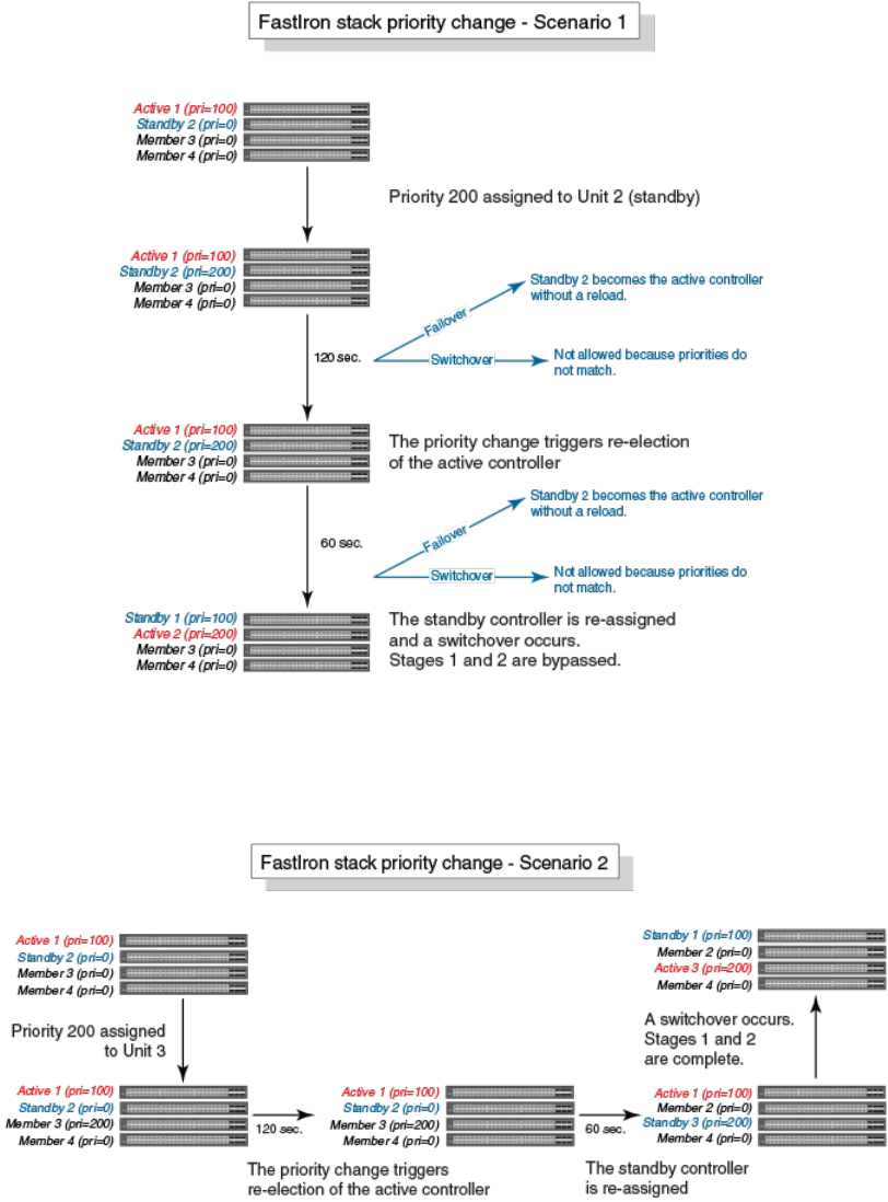
FIGURE 44 Scenario 1 - Hitless stacking switchover after a priority change
The following figure illustrates a hitless stacking switchover after the network administrator increases the priority value of one of the stack
members.
FIGURE 45 Scenario 2 - Hitless stacking switchover after a priority change
The following figure illustrates a hitless stacking switchover after the network administrator increases the priority value for two of the stack
members.
Hitless Stacking
Hitless stacking switchover
Ruckus FastIron Stacking Configuration Guide, 08.0.70
154 Part Number: 53-1005299-01
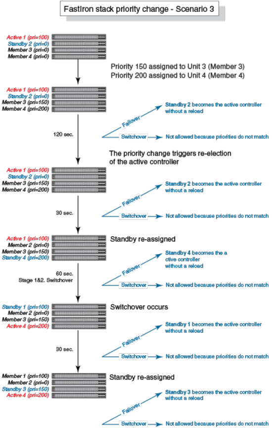
FIGURE 46 Scenario 3 - Hitless stacking switchover after a priority change
Displaying information about hitless stacking
Use the show stack command to view information pertinent to a hitless stacking switchover or failover. The command output illustrates the
active controller and standby controller, as well as the readiness of the standby controller to take over the role of active controller, if needed.
ICX7750-26Q Router# show stack
T=11h25m50.2: alone: standalone, D: dynamic cfg, S: static
ID Type Role Mac Address Pri State Comment
1 S ICX7750-20QXG active 748e.f8f9.6300 255 local Ready
2 S ICX7750-20QXG standby cc4e.2438.7280 240 remote Ready
3 S ICX7750-20QXG member cc4e.2438.7500 0 remote Ready
active standby
+---+ +---+ +---+
Hitless Stacking
Displaying information about hitless stacking
Ruckus FastIron Stacking Configuration Guide, 08.0.70
Part Number: 53-1005299-01 155
-2/1| 1 |2/4--2/1| 3 |2/4--2/1| 2 |2/4-
| +---+ +---+ +---+ |
| |
|-------------------------------------|
Standby u2 - protocols ready, can failover
Current stack management MAC is 748e.f8f9.6300
Displaying information about stack failover
Use the show stack failover command to view information about rapid failover.The show stack failover command provides information on
the current standby controller and its status as shown in the following example.
device# show stack failover
Current standby is unit 2. state=ready
Standby u2 - protocols ready, can failover
Displaying hitless stacking status
The show stack command indicates whether hitless stacking is enabled. The following example shows that hitless stacking is disabled.
ICX7750-26Q Router(config-unit-1)# show stack
T=17m47.9: alone: standalone, D: dynamic cfg, S: static
ID Type Role Mac Address Pri State Comment
1 S ICX7750-20QXG active 748e.f8f9.6300 0 local Ready
2 D ICX7750-20QXG member cc4e.2438.7280 0 remote Ready
3 D ICX7750-20QXG standby cc4e.2438.7500 0 remote Ready
active standby
+---+ +---+ +---+
=2/1| 1 |2/4==2/1| 3 |2/4--2/1| 2 |2/4=
| +---+ +---+ +---+ |
| |
|-------------------------------------|
Standby u3 - No hitless failover. Reason: hitless-failover not configured
Displaying pending device roles
When hitless stacking is disabled, a priority change triggers an election, but the newly-elected winner does not assume its role until the
entire stack is reloaded or hitless stacking is enabled. You can use the show stack command to view pending device roles. The “Role”
column displays the current role for each unit. The “Comment” column displays the role that will take effect after a reload or when hitless
stacking is enabled.
ICX7750-26Q Router(config-unit-1)#show stack
T=17m47.9: alone: standalone, D: dynamic cfg, S: static
ID Type Role Mac Address Pri State Comment
1 S ICX7750-20QXG active 748e.f8f9.6300 0 local Ready, member if reloaded
2 D ICX7750-20QXG member cc4e.2438.7280 128 remote Ready, standby if reloaded
3 D ICX7750-20QXG standby cc4e.2438.7500 200 remote Ready, active if reloaded
Displaying information about link synchronization status
Use the show stack link-sync status command to view the status of the link synchronization.
ICX7750-26Q Router# show stack link-sync status
STACKING_LINK_GLOBAL_CTRL messages sent: 0, received: 0
STACKING_LINK_INDIVIDUAL_CTRL messages sent: 0, received: 0
STACKING_LINK_STATUS messages sent: 235, received: 225
STACKING_POE_SCTRL messages sent: 0, received: 0
STACKING_POE_STATUS messages sent: 0, received: 0
global_ctrl_dest: 0
Hitless Stacking
Displaying information about hitless stacking
Ruckus FastIron Stacking Configuration Guide, 08.0.70
156 Part Number: 53-1005299-01

individual_ctrl_dest: 0
status_dest: 2
Syslog messages for hitless stacking failover and
switchover
Syslog messages are generated for the following events:
• Switchover
• Failover
• Standby controller assignment
The following table lists the supported syslog messages for hitless stacking failover and switchover.
TABLE 14 Supported syslog messages for hitless stacking faiilover and switchover
Message level Message Explanation
Informational Stack: Stack unit u
nit_number
has been assigned
as STANDBY unit of the stack system
Indicates that the unit has been assigned as the
standby controller.
Informational Stack: Stack is operational due to SWITCH-
OVER
Indicates that a switchover has occurred.
Informational Stack: Stack is operational due to FAIL-OVER Indicates that a failover has occurred.
To view the system log or the traps logged on an SNMP trap receiver, enter the show log command at any level of the CLI. The following
sample output shows what the log may look like after a switchover or assignment of the standby controller.
Brocade# show log
Syslog logging: enabled (0 messages dropped, 1 flushes, 0 overruns)
Buffer logging: level ACDMEINW, 8 messages logged
level code: A=alert C=critical D=debugging M=emergency E=error
I=informational N=notification W=warningDynamic Log Buffer (50 lines):
0d00h05m34s:I:System: Interface ethernet mgmt1, state up
0d00h05m33s:I:Stack: Stack unit 8 has been assigned as STANDBY unit of the stack system
0d00h05m33s:I:Stack: Stack is operational due to SWITCH-OVER
0d00h05m32s:I:Stack: Stack unit 1 has been elected as ACTIVE unit of the stack system
0d00h05m29s:W:System:Stack unit 2 Fan speed changed automatically to 2
0d00h05m25s:W:System:Stack unit 5 Fan speed changed automatically to 2
0d00h05m00s:I:System: Interface ethernet mgmt1, state down
0d00h05m00s:I:Security: Telnet server enabled by from session
The following sample output shows what the log may look like after a failover of the active controller.
Brocade# show log
Syslog logging: enabled (0 messages dropped, 0 flushes, 0 overruns)
Buffer logging: level ACDMEINW, 12 messages logged
level code: A=alert C=critical D=debugging M=emergency E=error
I=informational N=notification W=warning
Dynamic Log Buffer (50 lines):
0d00h04m41s:I:Stack: Stack unit 3 has been assigned as STANDBY unit of the stack system
0d00h04m12s:I:System: Interface ethernet mgmt1, state up
0d00h04m10s:I:System: Interface ethernet mgmt1, state down
0d00h04m10s:I:System: Interface ethernet mgmt1, state up
0d00h04m09s:I:STP: VLAN 1 Bridge is RootBridge: 800000e052010000 (MgmtPriChg)
0d00h04m09s:I:System: Management MAC address changed to 0000.0001.0000
0d00h04m09s:I:Stack: Stack is operational due to FAIL-OVER
0d00h04m08s:I:Stack: Stack unit 1 has been elected as ACTIVE unit of the stack system
0d00h04m08s:I:STP: VLAN 1 Port 8/1/1 STP State -> DISABLED (PortDown)
0d00h04m08s:I:STP: VLAN 1 Port 8/1/1 STP State -> FORWARDING (PortDown)
Hitless Stacking
Syslog messages for hitless stacking failover and switchover
Ruckus FastIron Stacking Configuration Guide, 08.0.70
Part Number: 53-1005299-01 157
0d00h04m08s:I:System: Interface ethernet 1/2/2, state down
0d00h04m06s:I:System: Interface ethernet 8/2/2, state down
Hitless Stacking
Syslog messages for hitless stacking failover and switchover
Ruckus FastIron Stacking Configuration Guide, 08.0.70
158 Part Number: 53-1005299-01

Traditional Stack Management
• Managing a traditional stack through one IP address.............................................................................................159
• Enabling or disabling stacking mode..................................................................................................................... 159
• Controlling the stack through the CLI.....................................................................................................................160
•Configuring default ports on FastIron devices........................................................................................................ 163
• Traditional stack management MAC address.........................................................................................................163
• Traditional stack device roles and elections............................................................................................................165
• Traditional stack unit priority.................................................................................................................................. 168
• Traditional stack software images.......................................................................................................................... 170
• Stack mismatches.................................................................................................................................................170
•Configuring stacking trunks in a live environment...................................................................................................175
• Adding, removing, or replacing units in a traditional stack...................................................................................... 177
• Renumbering stack units.......................................................................................................................................179
• Reloading a stack unit........................................................................................................................................... 180
• Managing traditional stack partitioning...................................................................................................................181
• Merging traditional stacks......................................................................................................................................181
•Unconfiguring a traditional stack............................................................................................................................182
• Syslog, SNMP, and traps for stack units................................................................................................................ 183
• Displaying traditional stack information.................................................................................................................. 183
• MIB support for traditional stack configurations..................................................................................................... 196
Managing a traditional stack through one IP address
Your Ruckus traditional stack can be managed through a single IP address. You can manage the stack using this IP address even if you
remove the active controller or any member from the stack. You can also connect to the active controller through Telnet or SSH using this
address. All management functions, such as SNMP, use this IP address to acquire MIB information and other management data.
Enabling or disabling stacking mode
When a unit is stack-enabled or joins a stack either actively or passively, it reserves priority queue 7 for stacking traffic control, assigns
buffers for the stacking ports, and configures the first two 10-Gbps ports as stacking ports.
NOTE
Designated stacking ports cannot contain any configuration information, such as VLAN membership. If configuration information
exists, stack enable will fail. You must remove all configuration information from the port and re-issue the stack enable command.
To enable stacking mode on a new unit before you add it to the stack, enter the following command.
device(config)# stack enable
Enable stacking. This unit actively participates in stacking
To see the configuration of the stack at any time, enter the show running-cong command. Refer to Displaying running configuration
information on page 184 for details.
Ruckus FastIron Stacking Configuration Guide, 08.0.70
Part Number: 53-1005299-01 159
Disabling stacking mode
To remove stacking capability, enter the no stack enable command. This prevents the unit from actively sending out probe messages;
however, the unit could still be called to join a stack by an active controller. To prevent this, enter the stack disable command in device
configuration mode.
The stack disable command prevents a unit from sending or listening for any stacking probe messages. In this mode, the unit cannot be
forced to join a stack.
device# configure terminal
device(config)# stack disable
To restore the capability of the device to send and receive stacking probe messages, enter the no stack disable command in device
configuration mode.
Traditional stack unit identification
Stack units are identified by numbers 1 though 12 on ICX 7150, ICX 7250, ICX 7450, and ICX 7750 devices (1 through 8 on some legacy
devices). You can display stack unit IDs by entering the show stack command.
A new device (one that has not been connected in a traditional stack or that has not been manually assigned a stack unit number) ships
with a default number of 1. Once you enable stacking and the unit becomes part of a traditional stack, its default stack unit number
changes to the lowest available number in the stack. You can configure the stack suggested-id command in a standalone unit before it
joins a stack to assign this unit the suggested ID.
Stack units must each have a unique identification number. Every stack member, including any standalone units, retains its stack unit
number unless that number is already being used in the stack, or until you manually renumber the unit using secure-setup. For more
information about how to renumber stack IDs using secure-setup, refer to Renumbering stack units on page 179.
Controlling the stack through the CLI
A Ruckus traditional stack can be configured and managed using the command line interface (CLI). You can access the traditional stack
and the command CLI in two ways:
• Through a direct serial connection to the console port
• Through a local or remote Telnet session using the stack IP address
You can initiate a local Telnet or SNMP connection by attaching a cable to a port and specifying the assigned management station IP
address.
The stacking commands in the CLI are organized into the following levels:
•Global - Commands issued in global mode are applied to the entire stack.
•Configuration mode - In this mode, you can make configuration changes to the entire stack. To save changes across reloads, you
must save them to the active controller startup-config file. The configuration mode contains sub-levels for individual units and
ports, VLANs, routing protocols, and other configuration areas.
•Stack unit configuration mode - Commands issued in this mode apply to the specified stack unit. Configuration information
resides in the active controller.
NOTE
By default, any user who can open a serial or Telnet connection to the traditional stack can access all of these CLI levels. To
secure access, you can configure Enable passwords or local user accounts, or you can configure the active controller to use a
RADIUS or TACACS/TACACS+ server for authentication. Refer to the
Brocade FastIron Security Configuration Guide
.
Traditional Stack Management
Controlling the stack through the CLI
Ruckus FastIron Stacking Configuration Guide, 08.0.70
160 Part Number: 53-1005299-01
Logging in through the console port
When a device becomes a stack member in a traditional stack, it establishes a remote connection to a virtual console port on the active
controller. Input and output are relayed between the physical console port on the stack member and the virtual console port on the active
controller. Because each stack member connects to an independent virtual console port on the active controller, the console ports on
multiple stack units may be used simultaneously.
When a stack unit establishes communication with the active controller, it also establishes a remote console session to the active controller.
In a normally functioning traditional stack, a console cable may be connected to any of the stack units and provide access to the same
commands on the active controller.
To establish a remote console session, enter the rconsole command followed by the stack unit ID.
device# rconsole 1
You can terminate a session between stack members in any of these ways:
• Enter the logout command at any level.
• Enter the exit command from the User EXEC level.
NOTE
For rconsole connections from stack units to the active controller, the escape sequence and other methods of terminating the
session are not available.
NOTE
Error messages that are generated during a reload of the active controller do not appear on rconsole connections from stack
units to the active controller. To see these error messages, you must connect a console cable to the active controller itself.
The following example shows how to establish a remote console session to a stack member and obtain status information. Notice that the
show stack command on the stack members displays different information from what is shown when the show stack command is entered
on the active controller.
A remote console session is established with stack unit 2 in the following example.
device# rconsole 2
Connecting to unit 2... (Press Ctrl-O X to exit)
rconsole-2@device# show stack
ID Type Role Mac Address Prio State Comment
2 D ICX7750-48XGF standby cc4e.246d.8d800 0 local Ready
rconsole-2@device# exit
rconsole-2@device> exit
Disconnected. Returning to local session...
CLI command syntax for stack units
CLI syntax that refers to stack units must contain all of the following parameters:
•
stack-unit
- If the device is operating as a standalone, the stack-unit is 1. Stack unit IDs can be any number from 1 through 8.
•
slotnum
- This refers to a specific group of ports on each device.
•
portnum
- This must be a valid port number.
Traditional stack CLI commands
For more information about a specific traditional stacking command, refer to its command reference page in the
FastIron Command
Reference
.
Traditional Stack Management
Controlling the stack through the CLI
Ruckus FastIron Stacking Configuration Guide, 08.0.70
Part Number: 53-1005299-01 161

TABLE 15 Traditional stack configuration commands
Configuration command Location of command description
default-ports Configuring default ports on FastIron devices on page 163, the overview
section for a specific device, or the configuration notes for the device
hitless-failover enable Enabling hitless stacking failover on page 150
priority Traditional stack unit priority on page 168
stack enable Enabling or disabling stacking mode on page 159
stack disable Enabling or disabling stacking mode on page 159
stack mac [mac-address] Traditional stack management MAC address on page 163
stack persistent-mac-timer Command deprecated in FastIron release 08.0.20
stack suppress-warning Suppressing background stack diagnostic warnings on page 198
stack-port Configuring default ports on FastIron devices on page 163
TABLE 16 Traditional stack executive commands
Executive command Location of command description
clear stack ipc Troubleshooting an unsuccessful stack build on page 198
copy flash flash Copying the flash image to a stack unit from the active controller on page
175
image-auto-copy disable Disabling Auto Image Copy on page 174
kill console "Configuring TACACS/TACACS+ for devices in a traditional stack" in the
Brocade FastIron Security Configuration Guide
rconsole Logging in through the console port on page 161
reload Reloading a stack unit on page 180
stack secure-setup The secure-setup utility on page 25
stack unconfigure Unconfiguring a traditional stack on page 182
stack switch-over Executing a hitless stacking switchover on page 152
TABLE 17 Traditional stack show commands
Show command Location of command description
show chassis Displaying traditional stack chassis information on page 188
show flash Displaying traditional stack flash information on page 187
show interfaces stack-ports Displaying stacking port interface information on page 195
show memory Displaying traditional stack memory information on page 188
show module Displaying stack module information on page 189
show running-config Displaying running configuration information on page 184
show stack Displaying general or detailed information about stack members on page
190
Displaying information about hitless stacking on page 155
show stack connection Displaying stacking topology on page 184
show stack detail Displaying general or detailed information about stack members on page
190
show stack failover Displaying information about stack failover on page 156
show stack flash Displaying traditional stack flash information on page 187
show stack ipc Troubleshooting an unsuccessful stack build on page 198
Traditional Stack Management
Controlling the stack through the CLI
Ruckus FastIron Stacking Configuration Guide, 08.0.70
162 Part Number: 53-1005299-01

TABLE 17 Traditional stack show commands (continued)
Show command Location of command description
show stack link-sync status Displaying information about link synchronization status on page 156
show stack neighbors Displaying information about stack neighbors on page 194
show stack rel-ipc stats Displaying reliable IPC statistics for stack units on page 192
show stack rel-ipc stats unit # Displaying IPC statistics for a stack on page 192
show stack resource
FastIron Command Reference Guide
show stack stack-ports Displaying stack port information on page 194
show statistics stack-ports Displaying stacking port statistics on page 194
show version Displaying software version information on page 186
Configuring default ports on FastIron devices
FastIron stackable devices typically ship with two default stacking ports configured. Use the stack-port command if you want to select only
one of these factory default ports as the stacking port. If you do not configure stack-port, both default ports will operate as stacking ports.
Use the default-ports command to designate ports other than the factory default ports as stacking ports. You must designate any
additional potential stacking ports using the default-ports command on each unit that will be included in the stack before building a stack.
Once you have designated these ports using the default-ports command on all units, you can use any construction method to build a
stack. The active controller then learns the port configuration for each unit.
NOTE
You cannot change the setting for a default port if the port is in use.
Refer to the section on a specific device in "Traditional Stacking by Device" for more information.
Traditional stack management MAC address
The traditional stack is identified in the network by a single MAC address, usually the MAC address of the active controller (the default). If a
new active controller is elected, the MAC address of the new active controller (by default) becomes the MAC address for the entire stack.
However, you can manually configure your stack to use a specified MAC address.
In a traditional stack, the management MAC address is generated by the software and is always the MAC address of the first port of the
active controller. This ensures that the management MAC address remains consistent across stack reboots and helps prevent frequent
topology changes that result from protocol enable, disable, and configuration changes.
When you are configuring Layer 2 protocols, such as STP, RSTP, and MSTP, on stack units, the management MAC address of the active
controller acts as the Bridge ID.
Manually allocating the traditional stack MAC address
Beginning with FastIron release 08.0.20, when a stack is enabled, “hitless-failover enable” configuration is added, and a default stack MAC
address is assigned if none is configured. The address assigned is the MAC address of the unit as shown in the output of the show stack
command.
If necessary, you can manually configure your traditional stack to use a specific MAC address.
Traditional Stack Management
Traditional stack management MAC address
Ruckus FastIron Stacking Configuration Guide, 08.0.70
Part Number: 53-1005299-01 163
NOTE
The stack mac command may be useful for administration purposes; however, it should be used with caution to prevent
duplication of MAC addresses.
ICX7750-26Q Router# configure terminal
ICX7750-26Q Router(config)# stack mac 0000.0000.0011
ICX7750-26Q Router(config)# show running-config
Current configuration:
!
ver 08.0.40b1T203
!
stack unit 1
module 1 icx7750-20-qxg-port-management-module
module 2 icx7750-qsfp-6port-qsfp-240g-module
module 3 icx7750-6q-6port-qsfp-240g-module
priority 255
stack-port 1/2/1 1/2/4
stack unit 2
module 1 icx7750-20-qxg-port-management-module
module 2 icx7750-qsfp-6port-qsfp-240g-module
module 3 icx7750-6q-6port-qsfp-240g-module
priority 240
stack-port 2/2/1 2/2/4
stack enable
stack mac 0000.0000.0011
!
To configure a stack MAC address manually, enter the following command in device configuration mode.
device# configure terminal
device(config)# stack mac 0000.0000.0011
The MAC address is a hexadecimal number in the format xxxx.xxxx.xxxx.
NOTE
Enter the no form of this command to revert to the use of the active controllers' MAC address.
The following example shows the stack MAC address being configured manually as confirmed in the show running-cong command
output.
ICX7750-26Q Router# configure terminal
ICX7750-26Q Router(config)# stack mac 0000.0000.0011
ICX7750-26Q Router(config)# show running-config
Current configuration:
!
ver 08.0.40b1T203
!
stack unit 1
module 1 icx7750-20-qxg-port-management-module
module 2 icx7750-qsfp-6port-qsfp-240g-module
module 3 icx7750-6q-6port-qsfp-240g-module
priority 255
stack-port 1/2/1 1/2/4
stack unit 2
module 1 icx7750-20-qxg-port-management-module
module 2 icx7750-qsfp-6port-qsfp-240g-module
module 3 icx7750-6q-6port-qsfp-240g-module
priority 240
stack-port 2/2/1 2/2/4
stack enable
stack mac 0000.0000.0011
!
To display the stack MAC address, enter the show chassis command.
ICX7450-48F Router# show chassis
The stack unit 1 chassis info:
Traditional Stack Management
Traditional stack management MAC address
Ruckus FastIron Stacking Configuration Guide, 08.0.70
164 Part Number: 53-1005299-01
Power supply 1 (AC - Regular) present, status ok
Model Number: 23-0000144-02
Serial Number: 0L8
Firmware Ver: A
Power supply 1 Fan Air Flow Direction: Front to Back
Power supply 2 not present
Fan 1 ok, speed (auto): [[1]]<->2
Fan 2 ok, speed (auto): [[1]]<->2
Fan controlled temperature: 62.5 deg-C
Fan speed switching temperature thresholds:
Speed 1: NM<----->63 deg-C
Speed 2: 53<-----> 80 deg-C (shutdown)
Fan 1 Air Flow Direction: Front to Back
Fan 2 Air Flow Direction: Front to Back
Slot 1 Current Temperature: 44.5 deg-C (Sensor 1), 62.5 deg-C (Sensor 2), 52.0 deg-C (Sensor 3), 41.5 deg-C
(Sensor 4), 54.5 deg-C (Sensor 5)
Slot 2 Current Temperature: 41.0 deg-C (Sensor 1)
Slot 3 Current Temperature: 45.0 deg-C (Sensor 1)
Slot 4 Current Temperature: 45.0 deg-C (Sensor 1)
Warning level.......: 70.0 deg-C
Shutdown level......: 80.0 deg-C
Boot Prom MAC : cc4e.246d.1378
Management MAC: cc4e.246d.1378
NOTE
For field descriptions of the show chassis command, refer to Displaying traditional stack chassis information on page 188.
Traditional stack device roles and elections
There are three distinct roles played by units that are part of a traditional stack:
• Active controller
• Standby controller
• Stack member
Active controller
The active controller contains the saved and running configuration files for each stack member. The configuration files include the system-
level settings for the stack and the interface-level settings for each stack member, as well as MIB counters and port status. The standby
controller also has a synchronized copy of the active controller startup-config file in case the active controller fails.
When a stack is formed, the console function for each stack member is automatically redirected to the active controller console. The active
controller console port handles all stack management functions, as well as ping activity, Telnet sessions, and TFTP image downloads for
every stack member. If you connect to the console port on a stack member that is not the active controller, you are automatically directed
through the console of the active controller.
The active controller synchronizes its startup configuration with the standby controller and the rest of the stack members. You can recover
the previous flash configuration of the standby controller and the stack members by issuing the stack unconfigure command. For an
example of this command and the output generated, refer to Unconfiguring a traditional stack on page 182.
The active controller may reset the rest of the stack members, if necessary. However, if the active controller itself must be reset because of a
role or ID change, you must issue the reset command.
Traditional Stack Management
Traditional stack device roles and elections
Ruckus FastIron Stacking Configuration Guide, 08.0.70
Part Number: 53-1005299-01 165
If the active controller fails, the standby controller waits 30 seconds and then takes over as active controller, resetting itself and all other
stack members. If the old active controller becomes operational, it may or may not resume its role as active controller, depending on the
configured priorities.
Standby controller
In addition to the active controller, another stack member is elected as the standby controller. If the active controller fails, the standby
controller takes over after a default interval of 30 seconds. If hitless stacking failover is enabled, the standby controller can take over
immediately without reloading any unit.
The standby controller synchronizes its configuration with the active controller at each reset.
Bootup role
When a stack unit boots, it boots in a particular role, active controller, standby controller, or stack member, or as a standalone device. When
the bootup role is standby controller or stack member, the CLI available to the unit is limited to show and stack commands. A unit in the
role of standby controller or stack member does not act without instructions from the active controller.
The last line of the show version output identifies the unit role unless the unit is in standalone mode.
My stack unit ID = 1, bootup role = active
My stack unit ID = 3, bootup role = standby
NOTE
To convert a standby controller or stack member to a standalone device, use the stack unconfigure me command (refer to
Unconfiguring a traditional stack on page 182).
Active controller and standby controller elections
Whenever there is a topology change in the stack (a reset, unit failure, or the addition or removal of members), elections are held to
determine the status of the active controller and standby controller. The results of the election take effect after the next stack reset.
Certain conditions, in a particular order, determine which units serve as active controller and standby controller after an election. The
hierarchy of factors achieves a predictable winner, regardless of the boot up sequence for a unit.
Active and standby controller elections are determined in a slightly different way when hitless failover (the default) is enabled. The order
reduces traffic interruptions during unit reset.
• Boot as active controller - Indicates that a unit was previously active controller before the current boot sequence and will again
assume the role of active controller when two standalone units are combined into a stack. When a third standalone unit joins the
stack, the current active controller becomes subject to the other factors in this list. You can upgrade your current active controller
to "boot as active controller" status by executing the write memory command. The system interprets the write memory action as
a directive to maintain the current active controller role regardless of resets or a new unit joining the stack.
• Greater number of members - The unit that has control over the greater number of stack members.
• Failover unit - In a two-unit stack, the unit that is active controller after a failover and has an up time of more than 10 minutes,
when the second unit has an up time of less than three minutes.
• Priority - The unit with the highest priority value.
• Longer up time - The unit with the longest up time if the up time is at least 30 seconds longer than for any other unit. When up
times are compared, there is no effect if the difference is less than 30 seconds.
• Lowest boot stack ID - The unit that has the lowest boot stack ID. Unit ID 1 is the lowest. The unit ID may be 1 through 8 (or 1
through 12 for ICX 7150, ICX 7250, ICX 7450, or ICX 7750 devices).
Traditional Stack Management
Traditional stack device roles and elections
Ruckus FastIron Stacking Configuration Guide, 08.0.70
166 Part Number: 53-1005299-01
• MAC address - The member with the lowest MAC address.
When hitless failover is disabled, the following factors, in the order shown, are used to determine active and standby controllers.
• Boot as active controller - Indicates that a unit was previously active controller before the current boot sequence and will again
assume the role of active controller when two standalone units are combined into a stack. When a third standalone unit joins the
stack, the current active controller becomes subject to the other factors in this list. You can upgrade your current active controller
to "boot as active controller" status by executing the write memory command. The system interprets the write memory action as
a directive to maintain the current active controller role regardless of resets or a new unit joining the stack.
• Priority - The unit with the highest priority value.
• Greater number of members - The unit that has control over the greater number of stack members.
• Longer up time - An up time that is more than 30 seconds longer than the next one in size is considered. Where up times are
compared, there is no effect if the difference is less than 30 seconds.
• Lowest boot stack ID - The unit that has the lowest boot stack ID. Unit ID 1 is the lowest. The unit ID may be 1 through 8 (or 1
through 12 for ICX 7150, ICX 7250, ICX 7450, or ICX 7750 devices).
• MAC address - The member with the lowest MAC address.
Active controller and standby controller resets
If hitless stacking failover is enabled, when an active controller is reset or removed from the stack, the standby controller takes over
immediately.
NOTE
Hitless stacking failover is enabled by default in FastIron release 08.0.20 and later releases.
If hitless stacking failover is not enabled, the stack behaves differently when a failover occurs. When hitless stacking failover is not enabled
and the active controller is reset or removed from the stack, the entire stack reloads, and active controller and standby controller elections
are initiated. If the unit that previously functioned as the active controller is no longer part of the stack, the standby controller unit becomes
the active controller. After a reset, if no stack member qualifies as active controller, the existing standby controller waits 120 seconds and
then assumes the role of active controller.
If both the active and the standby controllers are removed, the rest of the stack continues to function because the other stack members are
operating on whatever is programmed in the hardware. However, the stack members are not able to learn any new addresses. In this case,
the following message is displayed every few minutes.
Stack member is non-operational because of no Active or standby controller
You can recover to standalone mode by "stack unconfigure me"
Use the stack uncongure me command to restore the units as standalone devices with a pre-stacking configuration.
Standby controller selection based on priority configuration
You can choose a standby controller by configuring a stack unit with the second highest priority or with the same priority as the active
controller. If the two stack units have the same priority configured, the standby controller takes over when the active controller fails. If the
original active controller becomes active again, it does not win back its active role, which helps to minimize traffic interruption on the stack.
However, if the original active controller has the higher priority and hitless failover is enabled, the active controller regains its role without
resetting other stack units. If hitless failover is disabled, the active controller resets the other stack units after it regains control.
Traditional Stack Management
Traditional stack device roles and elections
Ruckus FastIron Stacking Configuration Guide, 08.0.70
Part Number: 53-1005299-01 167
Two-unit stack controller selection scenario
In a two-unit stack, you can ensure that one unit resumes the active-controller role after a reset by assigning it a higher priority. However,
assigning the two units the same priority reduces the number of resets during failover.
The following steps occur on failover when hitless failover is enabled and both members of a two-unit stack are configured with the same
priority:
1. Unit 1 (the active-controller) resets.
2. The stack fails over to the standby controller (Unit 2).
3. Unit 1 returns to operation with the role of stack member.
4. Unit 2 (now acting as controller) sends a stack merge request to Unit 1.
5. Unit 1 resets and rejoins the stack as the standby controller.
If the active controller has a higher priority than the standby controller in a two-unit stack, the following steps occur:
1. Unit 1 (the active-controller) resets.
2. The stack fails over to the standby controller (Unit 2).
3. Unit 1 returns to operation.
4. Unit 2 (now acting as controller) sends a stack merge request to Unit 1.
5. Unit 1 resets and rejoins the stack as the active controller.
6. Unit 2 resets and returns to the stack as standby controller.
Standby controller election criteria
Standby controller election is based on the following criteria:
• The highest priority
• Bootup as active controller
• Bootup as standby controller
• The lowest boot stack ID
• The lowest MAC address
Because standby election candidates must have startup configurations that have been synchronized with the active controller, if the active
controller does not have a startup-config.txt file, no standby controller is elected. Once the write memory command is executed on the
active controller, the startup-config.txt file is written and synchronized to all stack members, and a standby controller can be elected.
Traditional stack unit priority
A unit with a higher priority is more likely to be elected active controller. The priority value can be from 0 through 255, with a priority of 255
being the highest. The default priority value assigned to the active controller and standby controller is 128.
You can assign the highest priority value to the stack unit you want to function as the active controller. When you enter a new priority value
for a stack unit, that value takes effect immediately but does not affect the current active controller until the next reset. However, with hitless
stacking failover enabled, the stack unit with the highest priority will become the active controller in about five minutes.
NOTE
Hitless stacking failover is enabled by default.
Traditional Stack Management
Traditional stack unit priority
Ruckus FastIron Stacking Configuration Guide, 08.0.70
168 Part Number: 53-1005299-01
You can give your active controller and standby controllers the same priority or different priorities (active controller highest, standby
controller second-highest). If the active controller and standby controller have the same priority, when the active controller fails and a
standby controller with more members attached takes over, the original active controller is not able to resume its role.
However, if the priority of the active controller is higher than the priority of the standby controller, and if hitless stacking failover is disabled,
the old active controller will regain its role and will reset the other units. If hitless stacking failover is enabled, the old active controller (with
the higher priority) will become a standby controller, and later, the system will perform an internal switchover to make the old active
controller the active controller without resetting other units.
As an example, suppose both the active controller and standby controller have the same priority. If there are more than two units in a stack
and the active controller leaves and comes back, it cannot win back the active role because the new active controller now has more
members, and the old active controller has none.
If hitless stacking failover is enabled (the default) and there are only two units in a stack, both the old active controller and the new active
controller have no members, so the unit with the higher priority wins the active role. If the active and standby controller have the same
priority, then the unit with the longer up time wins. If the old active controller stops responding or reloads, the standby controller takes over
immediately. When the old active controller reloads and comes back as an active controller, there are two active controllers, which causes
the stacks to merge. The old active controller loses the active controller election regardless of its priority because the new active controller is
a failover unit (assuming it has an up time of more than 10 minutes and the other unit has an up time of less than three minutes, due to
reset). Consequently, the old active controller is reloaded by the new active controller and boots up as a member. Then it is assigned the
standby controller role. If the former active controller has a higher priority, the system triggers an internal switchover to make it the new
active controller. If the former active controller has an equal priority, it remains the standby controller.
When the active controller and standby controller have the same priority, the system allows a stack switchover as long as hitless stacking
failover is enabled. Hitless stacking failover allows the active controller and standby controller to switch roles without traffic interruption.
If you want to assign the same priority to the active controller and the standby controller, you must do so after the stack is formed. This
prevents the intended standby controller from becoming the active controller during stack construction.
Changing the priority of a stack member triggers an election that takes effect immediately unless the active controller role changes and
hitless stacking failover is disabled, in which case the member priority changes do not take effect until after the next stack reload. With
hitless stacking failover, the stack unit with the highest priority becomes the active controller without reload.
To display stack member priority values, enter the show stack command.
ICX7750-48XGC# configure terminal
ICX7750-48XGC(config)# stack unit 3
ICX7750-48XGC(config-unit-3)# show stack
alone: standalone, D: dynamic config, S: static config
ID Type Role Mac Address Pri State Comment
1 S ICX7750-48XGC active 0000.00eb.a900 128 local Ready
2 S ICX7750-48XGC standby 0000.004f.4243 0 remote Ready, member after reload
3 S ICX7750-48XGC member 0000.005d.a100 200 remote Ready, active after reload
Changing the priority of a stack unit
To change the priority value for a stack unit, enter the priority command at the stack unit configuration level. The priority can be a value
from 0 through 255, where 255 is the highest priority.
device# configure terminal
device(config)# stack unit 1
device(config-unit-1)# priority 128
Traditional Stack Management
Traditional stack unit priority
Ruckus FastIron Stacking Configuration Guide, 08.0.70
Part Number: 53-1005299-01 169
Traditional stack software images
Consider the notes in this section when upgrading from a pre-stacking release to a stacking release or when reverting from a stacking
release to a pre-stacking release.
Refer to the release notes and to the
Brocade FastIron Software Upgrade Guide
for instructions about upgrading the software.
Confirming traditional stack software versions
All units in a traditional stack must be running the same software image. To confirm this, check the software version on all devices that you
want to add to a traditional stack. Upgrade any units that are running older versions of the software before you build the stack.
To check the software version for each stack member, perform the following steps.
1. Use Telnet or SSH or connect to any of the console ports in the stack.
2. Enter the show version command. Output similar to the following is displayed.
ICX7750-26Q Router# show version
Copyright (c) 1996-2015 Brocade Communications Systems, Inc. All rights reserved.
UNIT 1: compiled on Jul 31 2015 at 18:37:27 labeled as SWR08040b1
(20197181 bytes) from Primary SWR08040b1.bin
SW: Version 08.0.40b1T203
UNIT 2: compiled on Jul 31 2015 at 18:37:27 labeled as SWR08040b1
(20197181 bytes) from Primary SWR08040b1.bin
SW: Version 08.0.40b1T203
UNIT 3: compiled on Jul 31 2015 at 18:37:27 labeled as SWR08040b1
(20197181 bytes) from Primary SWR08040b1.bin
SW: Version 08.0.40b1T203
Compressed Boot-Monitor Image size = 1835008, Version:10.1.01T205 (swz10101)
Compiled on Fri Jun 27 22:01:35 2014
NOTE
If any unit in the traditional stack is running an incorrect version of the software, it will appear as non-operational. You
must install the correct software version on that unit for it to operate properly in the stack.
Stack mismatches
When a stack mismatch occurs, the active controller can put any stack member into a non-operational state, which disables all of the ports
except the stacking ports. Stack mismatches can occur for a variety of reasons.
NOTE
After a stack mismatch, the active controller can still download an image to the non-operational unit.
Traditional Stack Management
Traditional stack software images
Ruckus FastIron Stacking Configuration Guide, 08.0.70
170 Part Number: 53-1005299-01
The active controller generates a log message whenever it puts a stack unit into a non-operational state. The following examples describe
the types of mismatches and the related log message:
• Advanced feature mismatch - The active controller is enabled for advanced features (such as BGP), and the stack unit is not
enabled.
Stack: Unit 2 0000.0020.0100 doesn’t have the matching advanced feature privileges
• Image mismatch - A stack unit is running a different software image than the active controller is running.
Stack: Unit 2 0000.0020.0100 image mismatch
•Configuration mismatch - The module configuration for a stack unit does not match the reserved configuration on the active
controller.
Stack: Unit 2 0000.0020.0100 config mismatch
• Memory allocation mismatch - The active controller does not have enough memory to accommodate the stack unit.
Stack: Malloc failure for unit 2.0000.0020.0100
Advanced feature privilege mismatch
Advanced feature privileges must be enabled to run features such as BGP. For advanced features to operate across the stack, both the
active controller and standby controller must be enabled for advanced features. A unit that is not enabled for these features is put into a
non-operational state.
If the active controller is
not
enabled for advanced features, these features will not operate on the stack.
Minor mismatch for stack units
With a minor mismatch, an operating stack can still exist, but traffic is dropped from all ports except the stacking ports for units with the
mismatched software. You can download the correct image to the mismatched devices from the active controller. A minor software
mismatch means that there is no IPC or election algorithm change, but there is a release version disparity. Minor software mismatches can
occur with patch release upgrades. The system logs and displays a message similar to the following.
Warning! put stack unit 2 to non-operational reason=image mismatch
The show stack command displays output similar to the following.
T=1h10m1.8: alone: standalone, D: dynamic cfg, S: static
ID Type Role Mac Address Pri State Comment
1 S ICX7750-20QXG active 748e.f8f9.6300 0 local Ready
2 S ICX7750-20QXG member cc4e.2438.7280 0 remote NON-OP: image mismatch
3 S ICX7750-20QXG standby cc4e.2438.7500 0 remote Ready
active standby
+---+ +---+ +---+
=2/1| 1 |2/4==2/1| 3 |2/4--2/1| 2 |2/4=
| +---+ +---+ +---+ |
| |
|-------------------------------------
Normally, the system recovers from a minor image mismatch using the Auto Image Copy feature. However, if the feature has been disabled
or if the configuration of a stack unit does not match the configuration of the active controller, the stack unit does not function. In this
example, unit 2 is non-operational due to an image mismatch. To correct this situation, use the copy ash ash command. Refer to
Copying the flash image to a stack unit from the active controller on page 175.
Traditional Stack Management
Stack mismatches
Ruckus FastIron Stacking Configuration Guide, 08.0.70
Part Number: 53-1005299-01 171
Major mismatch for stack units
A major mismatch indicates an Interprocessor Communications (IPC)-related data structure change, an election algorithm change, or a
version of the software that does not support stacking. This can happen when the software undergoes a major change (such as a change
from 05.0.00 to 05.1.00). When a major mismatch occurs, the system logs and displays a message similar to the following.
Warning! Recv 424 IPC in 1m from 0000.001b.a900 e1/1/25: wrong version 5 !=6. Please make sure all units
run the same image.
In a major mismatch, the stack cannot be built and will not operate. You must download the correct version of the software to the
mismatched units individually.
Configuration mismatch for stack units
Generally, when a stack unit is added to or removed from the stack, its static configuration is not overwritten by the active controller.
However, the active controller deletes the dynamic configuration for a unit if it leaves the stack.
A configuration mismatch occurs when the base module configuration for a replacement stack unit does not match the runtime
configuration on the active controller. If the configuration on the active controller is static, it cannot be overwritten by the new configuration,
and a configuration mismatch occurs.
Configuration mismatches can occur during manual setup when a unit is moved from one stack to another stack or when the ID of a unit is
changed by secure-setup.
When you renumber identical units using secure-setup, the configurations are not mapped to the new units (because they match exactly).
However, if you switch the IDs of units that are not identical, a configuration mismatch occurs.
When a configuration mismatch occurs, port-related functions on all ports are disabled on the mismatched unit (except for the stacking
ports). All other functions are unaffected. For example, the active controller can still copy the unit's image or reset the unit.
Recovering from a stack unit configuration mismatch
When a configuration mismatch occurs, the active controller logs and displays a configuration mismatch message and puts the
mismatched unit into a non-operational state. In the following example, the original stack unit 3 has failed, and a replacement unit has been
installed that does not match the configuration of the original unit. You should see the following message.
Warning! put stack unit 3 to non-operational reason= config mismatch
Traditional Stack Management
Stack mismatches
Ruckus FastIron Stacking Configuration Guide, 08.0.70
172 Part Number: 53-1005299-01
Complete the following steps to recover from a configuration mismatch.
1. Enter the show stack command to see the status of the stack, and the show running-cong command to see the configurations
of the stack units.
ICX7750-26Q Router# show stack
T=1h38m40.5: alone: standalone, D: dynamic cfg, S: static
ID Type Role Mac Address Pri State Comment
1 S ICX7750-20QXG active 748e.f8f9.6300 0 local Ready
2 D ICX7750-20QXG member cc4e.2438.7280 0 remote Ready
3 S ICX7750-20QXG member cc4e.2438.7500 0 remote NON-OP: config mismatch
ICX7750-26Q Router# show running-config
Current configuration:
!
ver 08.0.40b1T203
!
stack unit 1
module 1 icx7750-20-qxg-port-management-module
module 2 icx7750-qsfp-6port-qsfp-240g-module
module 3 icx7750-6q-6port-qsfp-240g-module
stack-trunk 1/2/1 to 1/2/2
stack-trunk 1/2/4 to 1/2/6
stack-port 1/2/1 1/2/4
stack unit 2
module 1 icx7750-20-qxg-port-management-module
module 2 icx7750-qsfp-6port-qsfp-240g-module
module 3 icx7750-6q-6port-qsfp-240g-module
stack-trunk 2/2/4 to 2/2/5
stack-port 2/2/1 2/2/4
stack unit 3
module 1 icx7750-48-xgc-port-management-module
module 2 icx7750-qsfp-6port-qsfp-240g-module
stack-port 3/2/1 3/2/4
stack enable
stack mac 748e.f8f9.6300
!
2. To resolve the mismatch, you must remove the configuration for stack unit 3. Use the no stack unit command in configuration
mode.
device# configure terminal
device(config)# no stack unit 3
This removes configuration related to unit 3.
If you are unable to remove the configuration because of a multi-slot trunk configuration or other configuration identified by system
output, you must first manually remove the problem configuration.
When you have successfully deleted the mismatched stack unit, a re-election is triggered, and the active controller learns the
correct module configuration from the standby controller or from other stack members. No reload is required.
Memory allocation failure
A memory allocation (malloc) failure occurs when the active controller does not have enough memory to run a stack unit. This failure may
occur if you configure a large number of VLANs (for example, 4000) or STP instances (for example, 255) in the router image. A memory
allocation failure message means that the active controller is low on memory after allocating these resources and does not have enough
remaining memory to control a stack member. You can correct this by reducing the number of VLANs or STP instances.
NOTE
After you make configuration changes, such as the number of VLANs or STP instances, you must reset the stack.
Traditional Stack Management
Stack mismatches
Ruckus FastIron Stacking Configuration Guide, 08.0.70
Part Number: 53-1005299-01 173
Auto Image Copy for stack units
The Auto Image Copy feature ensures that all units in a stack are running the same flash image after a stack merge. This feature also
enables automatic reload of the stack units. It prevents the image mismatch that occurs when one or more member units join the stack with
a different running image and signature than the active controller and standby controller.
Auto Image Copy is enabled by default on devices, and the user does not have to manually copy the active controller’s running image to the
mismatched members.
Auto Image Copy limitations
The following limitations apply to the Auto Image Copy feature:
• Auto Image Copy is applicable only to those stack units that are in a non-operational image mismatch state.
• Auto Image Copy does not work if there is a major image mismatch, when the image version of the IPC is different from the stack
unit version.
• Auto Image Copy does not work if the user has copied a different image into the flash, creating a mismatch in versions between
the flash and the running image on the active controller for the stack.
Verifying Auto Image Copy
Use the show stack detail command to check for any units in the mismatch state after the stack is formed. The following example shows
that stack unit 2 is not operational, due to an image mismatch.
T=1h10m1.8: alone: standalone, D: dynamic cfg, S: static
ID Type Role Mac Address Pri State Comment
1 S ICX7750-20QXG active 748e.f8f9.6300 0 local Ready
2 S ICX7750-20QXG member cc4e.2438.7280 0 remote NON-OP: image mismatch
3 S ICX7750-20QXG standby cc4e.2438.7500 0 remote Ready
active standby
+---+ +---+ +---+
=2/1| 1 |2/4==2/1| 3 |2/4--2/1| 2 |2/4=
| +---+ +---+ +---+ |
| |
|-------------------------------------
Disabling Auto Image Copy
Auto Image Copy is enabled by default. However, if you wish to disable this feature, enter the following command in global configuration
mode.
device(config)# image-auto-copy disable
Use the no image-auto-copy disable command to enable Auto Image Copy. This restarts Auto Image Copy immediately and ensures that
all stack units have the same image.
NOTE
You can use the show running-cong or the show stack detail command to see if Auto Image Copy is disabled.
Traditional Stack Management
Stack mismatches
Ruckus FastIron Stacking Configuration Guide, 08.0.70
174 Part Number: 53-1005299-01
Copying the flash image to a stack unit from the active controller
You can replace a bad image on a stack unit or an image that does not match the active controller's image by copying the correct flash
image from the active controller.
NOTE
In most cases, you do not have to manually copy the flash image to a mismatched stack unit. For more information, refer to Auto
Image Copy for stack units on page 174.
To copy the flash image to a stack unit from the active controller primary or secondary flash, enter the following command at the device
prompt.
device# copy flash flash unit-id-pri 2
Syntax: copy ash ash [ primary | secondary | unit-id-pri
unit-num
|unit-id-sec
unit-num
]
•primary - Copy secondary to primary
•secondary - Copy primary to secondary
•unit-id-pri - Copy active primary image to unit ID
•unit-id-sec - Copy active secondary image to unit ID
The unit-id-pri and unit-id-sec keywords are used to copy images to a stack member from the active controller primary and secondary
flash, respectively. For
unit-num
, enter a valid stack unit number from 1 through 12.
Configuring stacking trunks in a live environment
To create or modify a trunk in a production environment, use the multi-stack-trunk command. The multi-stack-trunk command is used to
ensure that a stack trunk is formed on two directly connected stack units at the same time. The multi-stack-trunk command can only be
enabled on the active controller unit.
By configuring a multi-stack trunk on two sets of connected stack ports, a trunk-to-port connection is avoided. A trunk-to-port connection
is formed when one side of the ports forms a trunk, and the other side of the ports does not. A trunk-to-port connection can result in
dropped packets and can potentially break a stacking link.
The following example shows a trunk being formed between stack units 1 and 2 and another trunk being formed between stack units 2 and
3.
device(config)# stack unit 1
device(config-unit-1)# multi-stack-trunk 1/2/3 to 1/2/4 and 2/2/1 to 2/2/2
device(config-unit-1)# stack unit 2
device(config-unit-2)# multi-stack-trunk 2/2/3 to 2/2/4 and 3/2/1 to 3/2/2
Use the no form of the multi-stack-trunk command to disable the configuration of the two connected stack trunk ports.
A stack trunk cannot be removed if the primary port is down. The primary ports of the stack trunk must be connected and operational to
use the no multi-stack-trunk command. If the primary stack trunk ports are not connected and are not operational, the command is
rejected, and the following error message is displayed.
Error- Primary trunk port 1/2/3 is not UP; removing the trunk might break the stack
Traditional Stack Management
Configuring stacking trunks in a live environment
Ruckus FastIron Stacking Configuration Guide, 08.0.70
Part Number: 53-1005299-01 175
Displaying multi-trunk stacking configuration
The multi-stack-trunk command is used on live stacks and is effectively a combination of two stack-trunk commands to ensure that a
trunk-to-trunk connection is created on both ends of a stack link simultaneously. When the multi-stack trunk command is used to create a
trunk, the configuration is saved as stack trunk ports, and the running configuration displays the stack trunk details on both ends under the
heading stack unit <unit> configuration. Use the show running-cong command to display the related configuration under
stack-trunk andstack-port as shown in the following example.
In the following code sample, a two-port trunk is created between stack units 1 and 2.
ICX7750-48C Router(config-unit-1)# multi-stack-trunk 1/2/4 to 1/2/6 and 2/2/4 to 2/2/6
For the multi-stack trunk created in the previous example, the running or startup configuration displays the following configuration for the
show running-cong command.
ICX7750-48C Router# show running-config
Current configuration:
!
ver 08.0.30aT203
!
stack unit 1
module 1 icx7750-48-xgc-port-management-module
module 2 icx7750-qsfp-6port-qsfp-240g-module
stack-trunk 1/2/4 to 1/2/6
stack-port 1/2/1 1/2/4
stack unit 2
module 1 icx7750-48-xgc-port-management-module
module 2 icx7750-qsfp-6port-qsfp-240g-module
stack-trunk 2/2/4 to 2/2/6
stack-port 2/2/1 2/2/4
stack enable
Error messages encountered when configuring a stacking trunk
The following error messages may occur when you configure a trunk on a FastIron traditional stack:
• If you form a multi-trunk connection on two sets of stack ports that are not directly connected on neighboring units, the multi-
stack-trunk command is rejected, and an error message similar to the follow example is displayed.
Error! 1/2/3 has no connection. Please use "stack-trunk".
• When a unit joins or leaves a stack, or a stack trunk is configured using the stack-trunk command, a stack election is triggered.
The multi-stack-trunk command triggers a stack election among the stack units and reprograms (or removes) the stack trunk
port in the hardware. A timer is set on all units to coordinate a stack election. Traffic is generally interrupted for less than 5 seconds
for the system to detect the port down event and reprogram hardware. You must wait for the stack election to be completed
before entering another command. If you do not wait for the stack election to finish, the following warning message is displayed.
Stack port or trunk change is in progress, please try later.
• You cannot enter the stack switch-over command until the stack election is completed or until the multi-stack-trunk command
configuration is complete. If you enter the stack switch-over command too early, the following warning message is displayed.
Please try later, reason: during stack port or trunk deployment.
• You cannot use the stack-port command to remove a stacking port if the port is part of a stack trunk. You must first remove the
stack trunk and then remove the stack port. Use the stack-trunk command or the multi-stack-trunk command to remove the
Traditional Stack Management
Configuring stacking trunks in a live environment
Ruckus FastIron Stacking Configuration Guide, 08.0.70
176 Part Number: 53-1005299-01
stack trunk. If you attempt to remove the stack port before removing the stack trunk, an error message similar to the following
example is displayed.
Please remove stack-trunk 1/2/3 - 1/2/4 using "stack-trunk" or "multi-stack-trunk" command before
removing stack port 1/2/3.
Adding, removing, or replacing units in a traditional
stack
You can add, remove, or replace traditional stack units using secure-setup or manually using static configuration. The recommended
method is to connect units to the stack before you supply power to the units; however, you can also connect powered units.
Installing a new unit in a traditional stack using secure-setup
This method can be applied to clean units or units that have existing configurations.
1. Connect the new unit to the stack by connecting the appropriate stacking ports.
2. Run secure-setup on the active controller, and assign an ID to the new unit. The active controller resets the new unit.
3. Once the new unit boots and joins the stack, enter the write memory command on the active controller.
Installing a new unit using static configuration
If the new unit is a clean unit and the connection is sequential, you can add the unit to a stack using the static setup process.
1. Enter the module configuration of the new unit into the active controller configuration.
2. Connect the new unit to the stack using the 10-Gbps stacking ports. The sequence in which you connect the unit must match the
sequence in the active controller configuration. The active controller automatically resets the unit.
3. Once the new unit boots and joins the stack, enter the write memory command on the active controller. You should see a
message similar to the following example.
Done hot swap: Set stack unit 3 to Fully-Operational:16
Configuration notes
Configuration of a new unit can be learned in the following ways.
• If the active controller has no configuration information for the new unit, it learns the new unit's configuration. This is a dynamic
configuration that disappears if the new unit leaves the stack. To retain the configuration on the active controller (to make it a static
configuration), you must execute the write memory command on the active controller.
• If the active controller has configuration information for a new unit that matches the base module (module 1) of the new unit, the
new unit may be placed in the operational or configuration mismatch (non-operational) state depending on the matching of other
modules. For example, if the active controller has configuration information for another module (such as module 3), but the new
unit has no module 3, the new unit will be operational. However, if the new unit has a module 3, but it does not match the
configured module type, the new unit will be non-operational due to configuration mismatch.
• A user can return a configuration-mismatched unit to operation by configuring the no stack unit command for the non-operational
unit from the active controller. This removes the entire stack configuration so the active controller can learn the configuration-
mismatched unit as a new unit. The active controller triggers an election and learns the unit. Refer to Recovering from a stack unit
configuration mismatch on page 172.
Traditional Stack Management
Adding, removing, or replacing units in a traditional stack
Ruckus FastIron Stacking Configuration Guide, 08.0.70
Part Number: 53-1005299-01 177
Removing a unit from a traditional stack
To remove a unit from the stack, disconnect the cables from the stacking ports. This can be done whether the units are powered on or
powered off. When you remove a unit that is powered on, it is still in stacking-enabled mode. To remove the stacking files, enter the stack
uncongure me or stack uncongure clean command.
The stack uncongure me command returns a unit to the state it had before joining a stack and recovers its startup configuration. The
stack uncongure clean command removes the unit's startup configuration. When you issue either command, the unit operates as a
standalone unit once it reboots.
When a unit is removed from a stack, the active controller deletes the unit configuration if it has been dynamically learned. Refer to
Traditional stacking terminology on page 17 for definitions of static and dynamic configurations.
Replacing traditional stack units
Use one of the following methods to replace older stack units. The first section describes how to replace an individual unit. The following
sections explain how to replace multiple units and how to use secure-setup.
Replacing one traditional stack unit with a clean traditional stack unit
If the stack unit ID numbering is sequential, you can swap a failed unit with an identical clean unit using this procedure.
1. Remove the old unit from the stack.
2. Make sure that the hardware (module) configuration of the replacement unit is identical to the hardware configuration of the failed
unit.
3. Connect the new unit to the stack using the same stacking ports as the old unit.
4. If the replacement unit configuration matches the configuration retained on the active controller, the active controller resets the new
unit. The new unit automatically becomes active in the stack, and the stack keeps its original topology.
Replacing multiple traditional stack units with multiple clean traditional stack units
If you are replacing multiple old units with clean units, the active controller replaces the unit with the lowest ID first. For example, if you
remove units 5 and 6, the active controller assigns ID 5 to the first new device you install. If you wanted this particular unit to replace unit 6
instead of unit 5, you must use secure-setup.
Using secure-setup to replace traditional stack units
You must use secure-setup to replace traditional stack units in the following cases:
• The replacement is not a clean unit.
• The connection is not sequential.
• You do not want the active controller to trigger an automatic replacement.
Use the following steps.
1. Remove the old stack unit from the stack.
2. Connect the new unit to the existing stack using the same stacking ports as the old unit.
3. Run secure‐setup to select the ID of the old unit for the new unit. The active controller resets the unit, and it joins the stack.
Traditional Stack Management
Adding, removing, or replacing units in a traditional stack
Ruckus FastIron Stacking Configuration Guide, 08.0.70
178 Part Number: 53-1005299-01
NOTE
Adding, removing, or replacing a stack unit that is not at the end of a linear topology may cause the other units in the
stack to reset if these units lose their path to the active controller during the change. Adding or removing a unit in a ring
topology should not cause the other units to reset because each unit can still find a path to the active controller.
Moving a unit to another stack
Moving a member from one stack to another stack can cause non-sequential ID assignment. The active controller will honor the original ID
of the newly added unit if the ID is not already in use. The active controller assigns a new ID if the original ID is already in use. To prevent
non-sequential stack ID assignments, configure the unit as a clean unit before adding it to the stack.
Removing an active controller from a powered stack
To remove an active controller from a powered stack, disconnect the active controller. The standby controller waits for 30 seconds and then
assumes the role of active controller. If hitless failover is enabled on the stack, the standby controller takes over immediately. A single active
controller device functions as a standalone unit even if it is still stacking-enabled. You do not have to issue a stack uncongure me
command for an active controller.
Renumbering stack units
You can use the stack secure-setup command to renumber stack units in a previously constructed stack. The most effective way to
number your stack members is sequentially. You can skip numbers, but stack ID numbers should still be sequential. Sequential numbering
makes it easier to replace stack units or to troubleshoot issues.
NOTE
In a ring topology, 1, 2, 4, 5, and 1, 5, 4, 2 are both sequential.
In the following example, three units make up a stack, but two of the units are numbered 5 and 6 (the active controller is numbered 1).
Because this stack only contains three units, you can renumber the other units so that they are unit 2 and unit 3.
ICX7750-48XGC# stack secure-setup
ICX7750-48XGC# Discovering the stack topology...
Available UPSTREAM units
Hop(s) Type MAC Address
1 ICX7750-48XGC 0000.00d5.2100
2 ICX7750-48XGC 0000.005d.9940
Enter the number of the desired UPSTREAM units (1-2)[1]: 2
Selected topology:
Active id Type MAC Address
1 ICX7750-48XGC 0000.0039.2d40
Selected UPSTREAM units
Hop(s) id Type MAC Address
1 5 ICX7750-48XGC 0000.00d5.2100
2 6 ICX7750-48XGC 0000.005d.9940
Do you accept the unit ids? (y/n)?: n
Enter an unused id for the UPSTREAM ICX7750-48XGC unit a 1 hop(s) (1-8)[5]: 2
Enter an unused id for the UPSTREAM ICX7750-48XGC unit at 2 hop(s) (1-8) [6]: 3
ICX7750-48XGC# Election, was active, no role change, assigned-ID=1
reset unit 2: diff bootup id=5
reset unit 3: diff bootup id=6
Election, was active, no role change, assigned-ID=1
ICX7750-48XGC# show stack
ID Type Role MAC Address Pri State Comment
1 S ICX7750-48XGC active 0000.0039.2d40 128 local Ready
Traditional Stack Management
Renumbering stack units
Ruckus FastIron Stacking Configuration Guide, 08.0.70
Part Number: 53-1005299-01 179
2 S ICX7750-48XGC standby 0000.00d5.2100 0 remote Ready
3 S ICX7750-48XGC member 0000.005d.9940 0 remote Ready
Configuration notes for renumbering stack units
• Renumbering may cause loss of a unit configuration if the stack unit base module does not match the configuration on the active
controller. However, secure-setup renumbering never changes the interface configuration. For example, if you switch the IDs of
identical units 2 and 3, the active controller does not change 2/1/5 to 3/1/5 and vice versa.
• If you assign an ID with an associated configuration to a stack unit with a different configuration, secure-setup changes the static
configuration into a dynamic configuration so it can be overwritten by the learned configuration.
• Swapping IDs for two or more identical units (for example, if units 2, 3, and 4 are identical, changing 2 to 3, 3 to 4, and 4 to 2)
does not affect unit configuration except that the units are reset and assume the new IDs.
• If you swap IDs for two units that are not identical (for example, unit 2 has 48 ports, and unit 3 has 24 ports), you may cause a
configuration mismatch. If this happens, the active controller removes the configurations and resets both units. When both units
boot with new IDs, the active controller learns their module types and creates new
unit
configurations for both. However, all
interface configuration
information related to units 2 and 3 is removed.
• When you renumber identical units using secure-setup, the configurations are not mapped to the new units (because the
configurations match exactly). However, if you switch IDs on units that are not identical, a configuration mismatch occurs. Refer to
Recovering from a stack unit configuration mismatch on page 172.
• When you assign an unused ID to a stack unit, the unit is reset with the new ID. All unit and interface configuration information
related to the old stack ID is deleted. The active controller learns the configuration for the new unit.
• Secure-setup does not swap configuration information for units that have had their IDs changed. For example, it does not change
the 2/1/3 interface configuration or VLAN membership information into 3/1/3 information if the unit ID changes from 2 to 3.
• If the configuration for a unit being replaced does not match the new unit type, the active controller removes the unit configuration
and associated interface configuration.
• All configurations learned following mismatches or the addition of new units are dynamic configurations. To convert them into
static configurations, execute a write memory command on the active controller. This command preserves the configuration if a
unit is removed from the stack.
Reloading a stack unit
Use the reload command to reload one or more stack units, for example, when necessary to repair a malfunctioning unit. Stack units can
be reloaded only if they are not the active controller. When hitless stacking failover is enabled, the active controller is automatically reloaded.
When the reload command is entered on the active controller without the unit-id parameter as shown in the following example, the entire
stack reloads.
NOTE
device# reload
Syntax: reload [ after
duration
| at
time
| cancel | unit-id
unit-list
]
•after - Schedules reloading after a specified length of time (
duration
in seconds, entered as a value from 1 to 4096)
•at - Schedules reloading at an exact later time (
time
, entered in the format: hh:mm:ss, where hh represents hours from 01 to 24,
mm represents minutes, from 00 to 59, and ss represents seconds, from 0 to 59)
•cancel - Cancels scheduled reload
Traditional Stack Management
Reloading a stack unit
Ruckus FastIron Stacking Configuration Guide, 08.0.70
180 Part Number: 53-1005299-01
•unit-id - Designates stack member or members to reload. The
unit-list
variable can be a single ID, a list of IDs, a range of IDs, or a
combination, such as 2,4-6,8. Values must be separated by a comma, with no space.
If you need to reload the active controller, use the stack switch-over command. When switchover occurs, the original active controller can
be reloaded using the reload unit-id command.
Managing traditional stack partitioning
Ring topology stacks do not partition when a stack member fails. Operation is interrupted briefly while the stack recalculates a new path.
Ring topologies are more stable than linear topologies because they provide redundant pathways in case of accidental failure.
When a unit in a traditional stack with a linear topology fails, the traditional stack divides (partitions) into two or more separate stacks that all
have the same configuration. This may cause an IP address conflict in the network. To keep the stacks separate, change the IP address of
each new stack.
When a stack breaks into partitions, the partition with the active controller remains operational. If a partition contains the standby controller,
this partition becomes operational because the standby controller assumes the active role and reloads the partition units. However, if hitless
failover is enabled, the partition units are not reloaded. A partition without an active controller or standby controller does not function. To
reconfigure these units to act in standalone mode, you must first enter a stack uncongure me command on each unit.
To reverse the partitioning, reconnect all of the units into the original stack topology using the stacking ports. This is the same as merging
stacks. If the original active controller again has the highest priority, it regains its role. If two partition active controllers have the same priority,
the active controller with the most stack members is elected. This process helps minimize traffic interruption.
Merging traditional stacks
Traditional stacks may be merged, but the total number of stack units must not exceed the maximum stack supported by the device. For
example, you could combine two stacks of ICX 7750 devices with four units each into a single stack of eight units.
NOTE
You cannot use secure-setup to merge stacks because secure-setup does not work across stack boundaries.
You can merge stacks by connecting them together using the stacking ports. Before doing this, make sure that no stacking ports (for
example, ports on an end unit in a linear stack topology) have been reconfigured as data ports.
When stacks are merged, an election is held among the active controllers. The winning controller retains its configuration and the IDs of all
of its original stack members. The remaining stack units lose their configuration and are reset. If the IDs of the losing stack units conflict with
the IDs of the winning units, they may change, and the IDs will no longer be sequential.
NOTE
You can use secure-setup to renumber the members in the newly merged stack. Refer to Renumbering stack units on page 179
for more information.
The following examples show how stack merging works:
• If a stack partitions into multiple stacks because of a connection failure, you can fix the connection and the stack partitions will
merge back into the original stack with no change to stack IDs because all stack IDs are distinct.
• In a linear stack topology, the end units of the stack have only one stacking port configured. Before you can merge two linear
stacks, you must reconfigure the end units so that both ports are stacking ports.
Traditional Stack Management
Merging traditional stacks
Ruckus FastIron Stacking Configuration Guide, 08.0.70
Part Number: 53-1005299-01 181
Unconfiguring a traditional stack
The stack uncongure command is a runtime command that returns stack units to their pre-stacking state. When a stack unit is
unconfigured, its stacking flash is removed, and its startup-config.txt flash file is recovered. These actions apply to all units to which this
command is applied, regardless of the role of the unit in the stack.
When the stack uncongure command is applied to the active controller, it removes stack enable from the runtime configuration but not
from the startup configuration. If you want to remove the stack enable command from the active controller permanently, you must enter the
write memory command after the stack uncongure command.
When the stack uncongure command is applied to the standby controller or a stack member (besides the active controller), it removes
stack enable from the recovered startup-config.txt file and resets the unit.
NOTE
When a stack member becomes a standalone unit after the stack uncongure command, it could become a clean unit if it had
no startup configuration flash. When a clean unit matches the active controller’s static configuration, the active controller
integrates the clean unit into the stack. Thus, the standalone unit is reloaded to be a member of the stack. Users can avoid this
problem by disconnecting the member unit from the stack and issuing the stack uncongure me command on the unit to
change it to a standalone unit.
To remove the configuration from a specific traditional stack unit or from the entire stack, enter a command similar to the following.
device# stack unconfigure me
Syntax: stack uncongure [
stack-unit
| all | me | clean ]
•
stack-unit
- Unconfigures the stack member with this ID
•all - Unconfigures every unit including this unit
•me - Unconfigures this unit only
•clean - Removes all startup configuration files including v4 and v5 and makes this a clean unit
NOTE
The stack uncongure me command can be entered from any unit; however, stack uncongure all and stack uncongure
stack-unit
commands can be issued only on the active controller.
The following example shows a session where stack unit 2 is unconfigured.
ICX7750-48XGC# show stack
alone: standalone, D: dynamic config, S: static config
ID Type Role MAC Address Pri State Comment
1 S ICX7750-48XGC active 0000.00eb.a900 128 local Ready
2 S ICX7750-48XGC standby 0000.004f.4243 0 remote Ready
3 S ICX7750-48XGC member 0000.0001.0100 0 remote Ready
ICX7750-48XGC# stack unconfigure 2
Will recover pre-stacking startup config of this unit, and reset it. Are you sure? (enter 'y' or 'n'): y
Stack 2 deletes stack bootup flash and recover startup-config.txt from .old
ICX7750-48XGC# show stack
alone: standalone, D: dynamic config, S: static config
ID Type Role MAC Address Pri State Comment
1 S ICX7750-48XGC active 0000.00eb.a900 128 local Ready
2 S ICX7750-48XGC member 0000.0000.0000 0 reserved
3 S ICX7750-48XGC standby 0000.0001.0100 0 remote Ready
When the stack uncongure 2 command is issued, stack unit 2 recovers the startup-config.txt from the startup-config.old configuration file
that was saved when this unit downloaded its configuration from the active controller. As the output shows, stack member 2 has been
removed from the stack, and ID 2 is now reserved for a replacement unit. Stack member 3 is now the standby controller.
Traditional Stack Management
Unconfiguring a traditional stack
Ruckus FastIron Stacking Configuration Guide, 08.0.70
182 Part Number: 53-1005299-01
Syslog, SNMP, and traps for stack units
Syslog messages from stack units are forwarded to, and can be viewed from, the active controller.
All stack units support SNMP gets, sets, and traps, which are managed by the active controller. An SNMP trap is sent from a stack unit to
the stack active controller and forwarded from the active controller to an SNMP-configured server. An external network management station
can execute SNMP gets and sets for MIBs and collect information about any port on the stack.
SNMP traps can be configured for the insertion or removal of a stack unit or uplink module, and for optic identification.
For more information about syslog messages, refer to the
Brocade FastIron Management Configuration Guide
.
Configuring SNMP for a traditional stack
SNMP server and feature configuration is the same for a traditional stack as for standalone units. In a traditional stack, SNMP gets and sets
are processed by the active controller for the standby controller and all stack members. SNMP traps generated by the standby controller
and stack members are propagated to the configured SNMP server through the active controller. For more information about how to
configure an SNMP server for FastIron devices, refer to the
Brocade FastIron Management Configuration Guide
.
SNMP engine IDs for stackable devices
NOTE
Beginning with FastIron release 08.0.20, when a stack is enabled, "hitless-failover enable" configuration is added, and a default
stack MAC address is assigned if none is configured. The MAC address of the unit is displayed in show stack command output.
For Ruckus stacking devices, if an engine ID is not manually created or a stack MAC address is not specified and saved, the stack loses its
engine ID when the active controller fails and the standby controller takes over because the standby controller creates a new engine ID at
bootup. To prevent this from happening, create a new engine ID or a new stack MAC address to save the engine ID to the startup
configuration. This should be done before the SNMPv3 user is created.
If a new active controller is elected (for example, the standby controller becomes the active controller), you will see the following results:
• If you have configured the engine ID and saved it to the startup configuration file, the new stack configuration uses the saved
engine ID.
• If you have not configured an engine ID, but a stack MAC address is configured, the new stack configuration retains the original
engine ID because it is based on the stack MAC address.
• If you have not configured an engine ID and no stack MAC address is configured, the new stack configuration uses the default
engine ID. The default engine ID is based on the stack's own management MAC address for the new active controller. Because
the engine ID has changed, any SNMPv3 clients must be reconfigured with the new engine ID.
Displaying traditional stack information
This section describes the show commands for a traditional stack and includes output examples and field descriptions.
Traditional Stack Management
Displaying traditional stack information
Ruckus FastIron Stacking Configuration Guide, 08.0.70
Part Number: 53-1005299-01 183

Displaying stacking topology
The show stack connection command displays the topology and a detailed connection report. It also displays connection errors or
hardware failures as shown in the following sample output.
ICX7750-48F Router# show stack connection
Probing the topology. Please wait ...
ICX7750-48F Router#
active
+---+ +---+ +---+ +---+ +---+ +---+
-2/1| 1 |2/4--3/1| C |3/4==2/1| B |2/4==2/1| A |2/4--2/1| 9 |2/4--2/1| 8 |2/4-
| +---+ +---+ +---+ +---+ +---+ +---+ |
| |
| standby |
| +---+ +---+ +---+ +---+ +---+ +---+ |
-2/4| 2 |2/1--2/4| 3 |2/1--2/4| 4 |2/1==2/4| 5 |2/1--2/4| 6 |2/1==2/4| 7 |2/1-
+---+ +---+ +---+ +---+ +---+ +---+
trunk probe results: 12 links
Link 1: u1 -- u2, num=1
1: 1/2/1 (P0) <---> 2/2/4 (P1)
Link 2: u1 -- u12, num=1
1: 1/2/4 (P1) <---> 12/3/1 (P0)
Link 3: u2 -- u3, num=1
1: 2/2/1 (P0) <---> 3/2/4 (P1)
Link 4: u3 -- u4, num=1
1: 3/2/1 (P0) <---> 4/2/4 (P1)
Link 5: u4 -- u5, num=2
1: 4/2/1 (T0) <---> 5/2/4 (T1)
2: 4/2/2 (T0) <---> 5/2/5 (T1)
Link 6: u5 -- u6, num=1
1: 5/2/1 (P0) <---> 6/2/4 (P1)
Link 7: u6 -- u7, num=3
1: 6/2/1 (T0) <---> 7/2/4 (T1)
2: 6/2/2 (T0) <---> 7/2/5 (T1)
3: 6/2/3 (T0) <---> 7/2/6 (T1)
Link 8: u7 -- u8, num=1
1: 7/2/1 (P0) <---> 8/2/4 (P1)
Link 9: u8 -- u9, num=1
1: 8/2/1 (P0) <---> 9/2/4 (P1)
Link 10: u9 -- u10, num=1
1: 9/2/1 (P0) <---> 10/2/4 (P1)
Link 11: u10 -- u11, num=2
1: 10/2/1 (T0) <---> 11/2/4 (T1)
2: 10/2/2 (T0) <---> 11/2/5 (T1)
Link 12: u11 -- u12, num=2
1: 11/2/1 (T0) <---> 12/3/4 (T1)
2: 11/2/2 (T0) <---> 12/3/5 (T1)
CPU to CPU packets are fine between 12 units.
TABLE 18 Field definitions for the show stack connection command
Field Description
T0 Identifies Trunk 0
T1 Identifies Trunk 1
Displaying running configuration information
The show running-cong command displays information about the current stack configuration.
ICX7750-48C Router#
ICX7750-48C Router# show running-config
Current configuration:
!
ver 08.0.30aT203
!
stack unit 1
Traditional Stack Management
Displaying traditional stack information
Ruckus FastIron Stacking Configuration Guide, 08.0.70
184 Part Number: 53-1005299-01

module 1 icx7750-48-xgc-port-management-module
module 2 icx7750-qsfp-6port-qsfp-240g-module
stack-trunk 1/2/4 to 1/2/6
stack-port 1/2/1 1/2/4
stack unit 2
module 1 icx7750-48-xgc-port-management-module
module 2 icx7750-qsfp-6port-qsfp-240g-module
stack-trunk 2/2/4 to 2/2/6
stack-port 2/2/1 2/2/4
stack enable
stack mac cc4e.2439.1680
!!
ip dns domain-list englab.brocade.com
ip dns server-address 10.31.2.10
!!
hitless-failover enable
!!
interface management 1
ip address 10.21.242.124 255.255.255.128 dynamic
!!
end
ICX7750-48C Router#
TABLE 19 Field descriptions for the show running-config command
Field Description
ver Software version the stack is running
stack unit # The stack identification number for this unit
module # Identifies the configuration for each module installed in the stack unit
priority Indicates the priority assigned to the stack unit
stack-port Lists stacking ports configured on the stack unit
stack-trunk Indicates the trunk configuration
stack enable Indicates whether the stack is enabled
stack mac Specifies the mac address for the stack
ip dns domain-list Indicates the DNS domain for the stack
ip dns server-address Indicates the address of the DNS server for the stack
hitless-failover enable/disabled Indicates whether hitless failover is enabled
interface management 1 Indicates management port
ip address Indicates the IP address that identifies the stack
How the show running-config command displays configured stacking
ports
The stacking ports may be displayed in three different ways in the output from the show running-cong command.
1. When stacking is enabled, the output shows both stacking ports.
stack unit 1
module 1 icx7750-48-xgc-port-management-module
module 2 icx7750-qsfp-6port-qsfp-240g-module
stack-port 1/2/1 1/2/4
2. When stacking is not enabled, neither stacking port is displayed.
stack unit 1
module 1 icx7750-48-xgc-port-management-module
module 2 icx7750-qsfp-6port-qsfp-240g-module
Traditional Stack Management
Displaying traditional stack information
Ruckus FastIron Stacking Configuration Guide, 08.0.70
Part Number: 53-1005299-01 185
3. If one stacking port is configured, that port is displayed, whether or not stacking is enabled.
stack unit 1
module 1 icx7750-48-xgc-port-management-module
module 2 icx7750-qsfp-6port-qsfp-240g-module
stack-port 1/2/1
Displaying software version information
The show version command shows the software version that the stack is running. The last line of the output shows the bootup ID and role
for the unit. Output resembles the following example.
ICX7750-26Q Router# show version
Copyright (c) 1996-2015 Brocade Communications Systems, Inc. All rights reserved.
UNIT 1: compiled on Aug 3 2015 at 11:45:48 labeled as SWR08040b1
(20194935 bytes) from Primary SWR08040b1.bin
SW: Version 08.0.40b1T203
UNIT 2: compiled on Aug 3 2015 at 11:45:48 labeled as SWR08040b1
(20194935 bytes) from Primary SWR08040b1.bin
SW: Version 08.0.40b1T203
UNIT 3: compiled on Aug 3 2015 at 11:45:48 labeled as SWR08040b1
(20194935 bytes) from Primary SWR08040b1.bin
SW: Version 08.0.40b1T203
Compressed Boot-Monitor Image size = 1835008, Version:10.1.01T205 (swz10101)
Compiled on Fri Jun 27 22:01:35 2014
HW: Stackable ICX7750-26Q
Internal USB: Serial #: 40D509003CF9007D
Vendor: UNIGEN, Total size = 1910 MB
==========================================================================
UNIT 1: SL 1: ICX7750-20QXG 20-port Management Module
Serial #:CRK2234J00J
License: ICX7750_L3_SOFT_PACKAGE (LID: etmHHIJlFFl)
P-ASIC 0: type B850, rev 03 Chip BCM56850_A2
==========================================================================
UNIT 1: SL 2: ICX7750-QSFP 6-port QSFP 240G Module
==========================================================================
UNIT 1: SL 3: ICX7750-6Q 6-port QSFP 240G Module
Serial #:4J04N
==========================================================================
UNIT 2: SL 1: ICX7750-20QXG 20-port Management Module
Serial #:CRK2246J01Y
License: ICX7750_L3_SOFT_PACKAGE (LID: etmHHJLlFGa)
==========================================================================
UNIT 2: SL 2: ICX7750-QSFP 6-port QSFP 240G Module
==========================================================================
UNIT 2: SL 3: ICX7750-6Q 6-port QSFP 240G Module
Serial #:CRK2246J010
==========================================================================
UNIT 3: SL 1: ICX7750-20QXG 20-port Management Module
Serial #:CRK2246J023
License: ICX7750_L3_SOFT_PACKAGE (LID: etmHHJLlFHI)
==========================================================================
UNIT 3: SL 2: ICX7750-QSFP 6-port QSFP 240G Module
==========================================================================
UNIT 3: SL 3: ICX7750-6Q 6-port QSFP 240G Module
Serial #:CRK2246J01C
==========================================================================
1500 MHz Power PC processor (version 8023/0022) 88 MHz bus
8192 KB boot flash memory
2048 MB code flash memory
3840 MB DRAM
STACKID 1 system uptime is 2 minute(s) 29 second(s)
STACKID 2 system uptime is 1 minute(s) 26 second(s)
STACKID 3 system uptime is 2 minute(s) 41 second(s)
The system : started=warm start reloaded=by "reload"
My stack unit ID = 1, bootup role = active
Traditional Stack Management
Displaying traditional stack information
Ruckus FastIron Stacking Configuration Guide, 08.0.70
186 Part Number: 53-1005299-01

The show version unit
unit-num
command displays the software version running on an individual unit. The command output is similar to
the following example.
ICX7750-26Q Router# show version unit 1
Copyright (c) 1996-2015 Brocade Communications Systems, Inc. All rights
reserved.
UNIT 1: compiled on Aug 3 2015 at 11:45:48 labeled as SWR08040b1
(20194935 bytes) from Primary SWR08040b1.bin
SW: Version
08.0.40b1T203
1)
Compiled on Thu Apr 10 01:01:43 2014
HW: Stackable ICX7750-26Q
Internal USB: Serial #: 40E41502FFFD02B7
Vendor: UB90QBK, Total size = 1910 MB
==========================================================================
UNIT 1: SL 1: ICX7750-20QXG 20-port Management Module
Serial #:CRK2234J00J
License: ICX7750_L3_SOFT_PACKAGE (LID: etmHHIJlFFl)
P-ASIC 0: type B850, rev 03 Chip BCM56850_A2
==========================================================================
UNIT 1: SL 2: ICX7750-QSFP 6-port QSFP 240G Module
==========================================================================
1500 MHz Power PC processor (version 8023/0022) 88 MHz bus
8192 KB boot flash memory
2048 MB code flash memory
3840 MB DRAM
STACKID 1 system uptime is 3 day(s) 6 hour(s) 7 minute(s) 22 second(s)
The system : started=warm start reloaded=by "reload"
Displaying traditional stack flash information
Use the show ash command to display flash memory information for all members of a stack or for a specified stack member.
The following example shows output from the active controller for the entire stack (the stack has three members).
ICX7750-26Q Router# show flash
Stack unit 1:
Compressed Pri Code size = 20197181, Version:08.0.40T203 (SWR08040b1.bin)
Compressed Sec Code size = 20194299, Version:08.0.40T203 (SWR08040.bin)
Compressed Boot-Monitor Image size = 1835008, Version:10.1.01T205
Code Flash Free Space = 837304320
Stack unit 2:
Compressed Pri Code size = 20197181, Version:08.0.40T203 (SWR08040b1.bin)
Compressed Sec Code size = 20194299, Version:08.0.40T203 (SWR08040.bin)
Compressed Boot-Monitor Image size = 1835008, Version:10.1.05T205
Code Flash Free Space = 838119424
Stack unit 3:
Compressed Pri Code size = 20197181, Version:08.0.40T203 (SWR08040b1.bin)
Compressed Sec Code size = 20194299, Version:08.0.40T203 (SWR08040.bin)
Compressed Boot-Monitor Image size = 1835008, Version:10.1.03T205
Code Flash Free Space = 838475776
The following example shows output for stack member 3 only.
ICX7750-26Q Router# show flash 3
Stack unit 3:
Compressed Pri Code size = 20197181, Version:08.0.40T203 (SWR08040b1.bin)
Compressed Sec Code size = 20194299, Version:08.0.40T203 (SWR08040.bin)
Compressed Boot-Monitor Image size = 1835008, Version:10.1.03T205
Code Flash Free Space = 838475776
TABLE 20 Field definitions for the show flash command
Field Description
Compressed Pri Code size The compressed size, version, and image name for the Primary Code
Traditional Stack Management
Displaying traditional stack information
Ruckus FastIron Stacking Configuration Guide, 08.0.70
Part Number: 53-1005299-01 187

TABLE 20 Field definitions for the show flash command (continued)
Field Description
Compressed Sec Code size The compressed size, version, and image name for the Secondary Code
Compressed Boot-Monitor Image size The compressed size and version for the BootROM Code
Code Flash Free Space The amount of available free space in Flash memory
Displaying traditional stack memory information
The show memory command displays information about stack units. The following example shows output for a stack with three units.
ICX7750-26Q Router# show memory
Stack unit 1:
Total DRAM: 4026531840 bytes
Dynamic memory: 3853291520 bytes total, 3162103808 bytes free, 16% used
Stack unit 2:
Total DRAM: 4026531840 bytes
Dynamic memory: 3853291520 bytes total, 3178409984 bytes free, 15% used
Stack unit 3:
Total DRAM: 4026531840 bytes
Dynamic memory: 3853291520 bytes total, 3160649728 bytes free, 16% used
ICX7750-26Q Router#
TABLE 21 Field definitions for the show memory command
Field Description
Total DRAM The size (in bytes) of DRAM
Dynamic memory The total number of bytes in dynamic memory, including the number of
bytes that are available (free or unused) and the percentage of memory
used.
Displaying traditional stack chassis information
The show chassis command displays chassis information for each stack unit. Output resembles the following example for the first unit in a
stack.
ICX7750-48F Switch# show chassis
The stack unit 1 chassis info:
Power supply 1 present, status failed
Power supply 2 (AC - Regular) present, status ok
Model Number: 3I50
Serial Number: P148121227
Firmware Ver: 1.41
Power supply 2 Fan Air Flow Direction: Front to Back
Fan 1 ok, speed (auto): [[1]]<->2
Fan 2 ok, speed (auto): [[1]]<->2
Fan 3 ok, speed (auto): [[1]]<->2
Fan 4 ok, speed (auto): [[1]]<->2
Fan controlled temperature: 49.5 deg-C
Fan speed switching temperature thresholds:
Speed 1: NM<----->58 deg-C
Speed 2: 50<-----> 82 deg-C (shutdown)
Fan 1 Air Flow Direction: Front to Back
Fan 2 Air Flow Direction: Front to Back
Fan 3 Air Flow Direction: Front to Back
Fan 4 Air Flow Direction: Front to Back
CPU Temperature Readings:
Traditional Stack Management
Displaying traditional stack information
Ruckus FastIron Stacking Configuration Guide, 08.0.70
188 Part Number: 53-1005299-01

Current temperature : 33.5 deg-C
Left Fan Temperature Readings:
Current temperature : 49.5 deg-C
Right Fan Temperature Readings:
Current temperature : 42.5 deg-C
Module Fan Temperature Readings:
Current temperature : 47.0 deg-C
Left PSU Temperature Readings:
Current temperature : 39.0 deg-C
Right PSU Temperature Readings:
Current temperature : 34.0 deg-C
Left Front Temperature Readings:
Current temperature : 37.0 deg-C
Middle Front Temperature Readings:
Current temperature : 38.0 deg-C
Right Front Temperature Readings:
Current temperature : 33.0 deg-C
Back 40G module Temperature Readings:
Current temperature : 44.5 deg-C
Warning level.......: 70.0 deg-C
Shutdown level......: 82.0 deg-C
Boot Prom MAC : 748e.f8f9.2500
Management MAC: 748e.f8f9.2500
TABLE 22 Field definitions for the show chassis command
Field Description
Power supply 1 The status of the primary power supply
Power supply 2 The status of the secondary power supply, if present
Fan 1 through Fan 4 The status of the cooling fans, including speed, temperature reading,
temperature range, and airflow direction
Fan controlled temperature Measured temperature reading
Fan speed switching temperature thresholds (Speed 1, Speed 2) Operating ranges for fan speeds 1 and 2, with the shutdown temperature
indicated at the upper end of the temperature range for speed 2
Current temperature (by component) Current temperature readings, in degrees Centigrade, for CPU, left fan, right
fan, module fan, left power supply, right power supply, left front, middle
front, right front, and back 40 Gbps module
Back 40G module Temperature Readings For the rear 40 Gbps module, current temperature, warning level
temperature, and shutdown level temperature
Exhaust Side Temperature Readings From the air exhaust side of the chassis, the current temperature reading,
the warning level temperature setting, and the shutdown level temperature
setting
Intake Side Temperature Readings The current temperature reading from the air intake side of the chassis
Boot Prom MAC The MAC address of the boot prom
Management MAC For the active controller only, the management MAC address
Displaying stack module information
The show module command displays information about stack unit modules. Output resembles the following.
ICX7750-26Q Router# show module
Module Status Ports Starting MAC
U1:M1 ICX7750-20QXG 20-port Management Module OK 56 748e.f8f9.6300
U1:M2 ICX7750-QSFP 6-port QSFP 240G Module OK 24 748e.f8f9.6315
U1:M3 ICX7750-6Q 6-port QSFP 240G Module OK 24 748e.f8f9.631b
U2:M1 ICX7750-20QXG 20-port Management Module OK 56 cc4e.2438.7280
U2:M2 ICX7750-QSFP 6-port QSFP 240G Module OK 24 cc4e.2438.7295
U2:M3 ICX7750-6Q 6-port QSFP 240G Module OK 24 cc4e.2438.729b
U3:M1 ICX7750-20QXG 20-port Management Module OK 56 cc4e.2438.7500
U3:M2 ICX7750-QSFP 6-port QSFP 240G Module OK 24 cc4e.2438.7515
U3:M3 ICX7750-6Q 6-port QSFP 240G Module OK 24 cc4e.2438.751b
Traditional Stack Management
Displaying traditional stack information
Ruckus FastIron Stacking Configuration Guide, 08.0.70
Part Number: 53-1005299-01 189

TABLE 23 Field definitions for the show module command
Field Description
Module Identifies the module by stack unit ID, module number, and module type
Status The status of this module
Ports The number of ports in this module
Starting MAC The starting MAC address for this module
Displaying general or detailed information about stack members
You can display information about any member in a traditional stack by entering show commands from the active controller console port. If
you enter show commands from a unit that is not the active controller, the information may not be displayed correctly.
The show stack command displays general information about a traditional stack, for all members, for a specified member, or for all
members with additional detail.
The following output covers the entire stack and includes role history for each unit, beginning with the initial role the unit held.
ICX7750-20Q Router# show stack
T=29m36.7: alone: standalone, D: dynamic cfg, S: static
ID Type Role Mac Address Pri State Comment
1S ICX7750-20QXG standby 748e.f8f9.6300 128 remote Ready
2S ICX7750-20QXG member cc4e.2438.7280 0 remote Ready
4S ICX7750-20QXG active cc4e.2438.7500 128 local Ready
active standby
+---+ +---+ +---+
-2/1| 4 |2/4--2/1| 2 |2/4--2/1| 1 |2/4-
| +---+ +---+ +---+ |
| |
|-------------------------------------|
Standby u1 -protocols ready, can failover or manually switch over
Role history: N: standalone, A: active, S: standby, M: member
U1: N->A->S->M->S, U2: M->S->A->S->M, U4: M->S->A
If you add a stack member ID, output is displayed for that member only.
ICX7750-26Q Router# show stack 1
T=12m6.2: alone: standalone, D: dynamic cfg, S: static
ID Type Role Mac Address Pri State Comment
1 S ICX7750-20QXG active 748e.f8f9.6300 0 local Ready
ICX7750-26Q Router# show stack 2
T=12m16.3: alone: standalone, D: dynamic cfg, S: static
ID Type Role Mac Address Pri State Comment
2 D ICX7750-20QXG member cc4e.2438.7280 0 remote Ready
ICX7750-26Q Router# show stack 3
T=12m20.6: alone: standalone, D: dynamic cfg, S: static
ID Type Role Mac Address Pri State Comment
3 D ICX7750-20QXG standby cc4e.2438.7500 0 remote Ready
If you add the detail keyword to the show stack command, output resembles the following example.
ICX7750-26Q Router# show stack detail
T=18m33.4: alone: standalone, D: dynamic cfg, S: static
ID Type Role Mac Address Pri State Comment
1 S ICX7750-20QXG active 748e.f8f9.6300 0 local Ready
2 D ICX7750-20QXG member cc4e.2438.7280 0 remote Ready
3 D ICX7750-20QXG standby cc4e.2438.7500 0 remote Ready
active standby
Traditional Stack Management
Displaying traditional stack information
Ruckus FastIron Stacking Configuration Guide, 08.0.70
190 Part Number: 53-1005299-01

+---+ +---+ +---+
=2/1| 1 |2/4==2/1| 3 |2/4--2/1| 2 |2/4=
| +---+ +---+ +---+ |
| |
|-------------------------------------|
Will assign standby in 11 sec due to all ready
Standby u3 - protocols ready, can failover
Current stack management MAC is 748e.f8f9.6300
Image-Auto-Copy is Enabled.
Stack Port Status Neighbors
Unit# Stack-port1 Stack-port2 Stack-port1 Stack-port2
1 up (1/2/1-1/2/2) up (1/2/4-1/2/6) U2 (2/2/4-2/2/5) U3 (3/2/1-3/2/3)
2 up (2/2/1) up (2/2/4-2/2/5) U3 (3/2/4) U1 (1/2/1-1/2/2)
3 up (3/2/1-3/2/3) up (3/2/4) U1 (1/2/4-1/2/6) U2 (2/2/1)
Unit# System uptime
1 18 minute(s) 33 second(s)
2 17 minute(s) 30 second(s)
3 18 minute(s) 46 second(s)
TABLE 24 Field descriptions for the show stack command
Field Description
alone: Standalone This device is operating as a standalone device.
S: static configuration The configuration for this unit is static (has been saved with a write memory
command).
D: dynamic configuration The configuration for this unit is dynamic and may be overwritten by a new
stack unit. To change to a static configuration, enter the write memory
command.
ID The stack identification number for this unit
Type The model of this unit
Role The role of this unit within the stack
MAC address The MAC address of this unit
Pri (Priority) The priority assigned to this unit
State The operational state of this unit
Comments Additional information about this unit (optional)
Role history Tracks up to six role changes per stack unit. The initial state is always
displayed. Overflow is indicated by ellipses (...). Standby to member role
changes are not displayed. Role history also does not display the transition
after bootup of a non-active controller unit from member to standby.
NOTE
The active controller removes the dynamic configuration of a unit when the unit leaves the stack. However, if there is a static trunk
configuration associated with the unit, the active controller cannot remove the dynamic configuration. In this case, you must
remove the static trunk and use the no stack unit
stack-unit
command to manually remove the configuration.
TABLE 25 Field descriptions for the show stack detail command
Field Description
Stack Port Status Indicates stacking port status for each stack unit
Neighbors Identifies stack neighbors (by unit ID) for each stack unit
Unit # The stack identification number for this unit
Stack-port 1 Indicates the port state (up or down) and identifies the port by number
(stack-ID/slot/port)
Traditional Stack Management
Displaying traditional stack information
Ruckus FastIron Stacking Configuration Guide, 08.0.70
Part Number: 53-1005299-01 191

TABLE 25 Field descriptions for the show stack detail command (continued)
Field Description
Stack-port 2 Indicates the port state (up or down) and identifies the port by number
(stack-ID/slot/port)
Displaying IPC statistics for a stack
To display IPC statistics for the stack, enter the show stack ipc stats command as shown in the following example.
ICX7750-26Q Router# show stack ipc stats
V80, G4, src=748e.f8f9.6300, max_pkt_size=10264, delay_buf=10264
Recv: SkP0: 10823, P1: 12954, sum: 23777, since t=2163.7 ago
Message types have callbacks:
Send message types:
[1]=9086, [5]=10922, [6]=3, [7]=809,
[9]=630, [13]=209, [22]=17, [24]=644,
[28]=29, [31]=1880, [40]=15, [60]=4,
[77]=130,
Recv message types:
[1]= 0:3295, 1:4896, [5]= 0:5269, 1:5622, [6]= 0:1, 1:2,
[7]= 0:398, 1:411, [9]= 0:996, 1:1139, [13]= 0:544, 1:559,
[23]= 0:319, 1:325, [34]= 0:1,
Statistics:
send pkt num : 24369, recv pkt num : 23777,
send msg num : 24369, recv msg num : 23777,
send frag pkt num : 0, recv frag pkt num : 0,
pkt buf alloc : 24376, : 0,
send_delay_msg : 0, send_delay_pkt : 0,
fwd_stby_msg : 0, fwd_stby_pkt : 0,
Reliable-mail send success receive duplic T (us)
target ID 2 2 0 0 82226
target MAC 0 0 0 0 82226
unrel target ID 5 0
unrel target MAC 4 0
There is 0 current jumbo IPC session
Possible errors:
ICX7750-26Q Router#
Displaying reliable IPC statistics for stack units
Use the show stack rel-ipc stats command to display session statistics for stack units. The following example shows reliable IPC statistics
for stack unit 3.
ICX7750-26Q Router# show stack rel-ipc stats unit 3
Unit 3 statistics:
Msgs: sent 907 recv 384, Pkt sends failed: 0, KA: sent 1522 recv 1522
Message types sent:
[9]=846, [13]=2, [15]=31, [59]=1,
[76]=3, [87]=24,
Message types received:
[9]=366, [13]=1, [15]=17,
Session: base-channel, to U3, channel 0
buf size: xmt=4194312, rcv=65544, max msg=32776
State: established (last 19 minute(s) 16 second(s) ago) cnt: 1
Remote resets: 0, Reset packets sent: 0
Connection statistics (for current connection, if established):
Msgs sent: 520, Msgs rcvd: 308
Traditional Stack Management
Displaying traditional stack information
Ruckus FastIron Stacking Configuration Guide, 08.0.70
192 Part Number: 53-1005299-01
Atomic batches sent: 0, Atomic batches rcvd: 0
Pkts sent: 1325, Pkts rcvd: 945
Msg bytes sent: 262915, Msg bytes rcvd: 131550
Pkt bytes sent: 631680, Pkt bytes rcvd: 247560
Keepalive sent: 231, Keepalive rcvd: 231
Keepalive age: 0, Keepalive NBR age : 1
Flushes requested: 10, Suspends: 0, Resumes: 0
Packets sent with data (DAT), ACKs, and window updates (WND):
Other: 259, ACK: 300, WND: 6, ACK+WND: 0
DAT: 753, DAT+ACK: 7, DAT+WND 0, DA+AC+WND 0
Data retransmits done: 430, Zero-window probes sent: 9
Dup ACK pkts rcvd: 40, Pkts rcvd w/dup data: 0
Pkts rcvd w/data past window: 0
Session: ACL, to U3, channel 3
buf size: xmt=409608, rcv=131080, max msg=1472
State: established (last 19 minute(s) 16 second(s) ago) cnt: 1
Remote resets: 0, Reset packets sent: 0
Connection statistics (for current connection, if established):
Msgs sent: 291, Msgs rcvd: 58
Atomic batches sent: 0, Atomic batches rcvd: 0
Pkts sent: 681, Pkts rcvd: 205
Msg bytes sent: 277656, Msg bytes rcvd: 82128
Pkt bytes sent: 349288, Pkt bytes rcvd: 84820
Keepalive sent: 231, Keepalive rcvd: 231
Keepalive age: 0, Keepalive NBR age : 1
Flushes requested: 0, Suspends: 0, Resumes: 0
Packets sent with data (DAT), ACKs, and window updates (WND):
Other: 232, ACK: 12, WND: 1, ACK+WND: 2
DAT: 429, DAT+ACK: 5, DAT+WND 0, DA+AC+WND 0
Data retransmits done: 272, Zero-window probes sent: 5
Dup ACK pkts rcvd: 20, Pkts rcvd w/dup data: 0
Pkts rcvd w/data past window: 0
Session: sync-reliable, to U3, channel 4
buf size: xmt=153608, rcv=10248, max msg=1472
State: established (last 16 minute(s) 38 second(s) ago) cnt: 1
Remote resets: 0, Reset packets sent: 0
Connection statistics (for current connection, if established):
Msgs sent: 53, Msgs rcvd: 1
Atomic batches sent: 0, Atomic batches rcvd: 0
Pkts sent: 256, Pkts rcvd: 35
Msg bytes sent: 77380, Msg bytes rcvd: 1460
Pkt bytes sent: 270984, Pkt bytes rcvd: 1884
Keepalive sent: 200, Keepalive rcvd: 200
Keepalive age: 0, Keepalive NBR age : 1
Flushes requested: 0, Suspends: 0, Resumes: 0
Packets sent with data (DAT), ACKs, and window updates (WND):
Other: 201, ACK: 1, WND: 0, ACK+WND: 0
DAT: 54, DAT+ACK: 0, DAT+WND 0, DA+AC+WND 0
Data retransmits done: 41, Zero-window probes sent: 0
Dup ACK pkts rcvd: 17, Pkts rcvd w/dup data: 0
Pkts rcvd w/data past window: 0
Session: rcon-svr-to-3, to U3, channel 12
buf size: xmt=4008, rcv=8008, max msg=2668
State: established (last 19 minute(s) 14 second(s) ago) cnt: 1
Remote resets: 0, Reset packets sent: 0
Connection statistics (for current connection, if established):
Msgs sent: 31, Msgs rcvd: 17
Atomic batches sent: 0, Atomic batches rcvd: 0
Pkts sent: 300, Pkts rcvd: 49
Msg bytes sent: 3592, Msg bytes rcvd: 155
Pkt bytes sent: 21836, Pkt bytes rcvd: 996
Keepalive sent: 231, Keepalive rcvd: 231
Keepalive age: 0, Keepalive NBR age : 1
Flushes requested: 23, Suspends: 0, Resumes: 0
Packets sent with data (DAT), ACKs, and window updates (WND):
Other: 237, ACK: 14, WND: 0, ACK+WND: 0
DAT: 49, DAT+ACK: 0, DAT+WND 0, DA+AC+WND 0
Data retransmits done: 26, Zero-window probes sent: 0
Traditional Stack Management
Displaying traditional stack information
Ruckus FastIron Stacking Configuration Guide, 08.0.70
Part Number: 53-1005299-01 193

Dup ACK pkts rcvd: 10, Pkts rcvd w/dup data: 0
Pkts rcvd w/data past window: 0
Displaying information about stack neighbors
The show stack neighbors command displays information about stack member neighbors.
ICX7750-26Q Router# show stack neighbors
U# Stack-port1 Stack-port2
1 (1/2/1-1/2/2) to U2 (2/2/4-2/2/5) (1/2/4-1/2/6) to U3 (3/2/1-3/2/3)
2 (2/2/1) to U3 (3/2/4) (2/2/4-2/2/5) to U1 (1/2/1-1/2/2)
3 (3/2/1-3/2/3) to U1 (1/2/4-1/2/6) (3/2/4) to U2 (2/2/1)
TABLE 26 Field descriptions for the show stack neighbors command
Field Description
U# The stack identification number for this unit
Stack-port1 Identifies the neighbor stack unit for stack-port1 for this unit ID
Stack-port2 Identifies the neighbor stack unit for stack-port2 for this unit ID
Displaying stack port information
The show stack stack-ports command displays information about stack port status. Equal signs (=) in command output show connections
between trunk ports.
ICX7750-26Q Router# show stack stack-ports
active standby
+---+ +---+ +---+
=2/1| 1 |2/4==2/1| 3 |2/4--2/1| 2 |2/4=
| +---+ +---+ +---+ |
| |
|-------------------------------------|
U# Stack-port1 Stack-port2
1 up (1/2/1-1/2/2) up (1/2/4-1/2/6)
up ports: 1/2/1
up ports: 1/2/4
2 up (2/2/1) up (2/2/4-2/2/5)
up ports: 2/2/4
3 up (3/2/1-3/2/3) up (3/2/4)
up ports: 3/2/1
TABLE 27 Field descriptions for the show stack stack-ports command
Field Description
ID The stack identification number for this unit
Stack-port1 Indicates port state (up or down) and identifies the port by number (stack-
ID/slot/port)
Stack-port 2 Indicates port state (up or down) and identifies the port by number (stack-
ID/slot/port)
Displaying stacking port statistics
The show statistics stack-ports command displays information about all stacking ports in a traditional stack topology.
device# show statistics stack-ports
Port In Packets Out Packets In Errors Out Errors
Traditional Stack Management
Displaying traditional stack information
Ruckus FastIron Stacking Configuration Guide, 08.0.70
194 Part Number: 53-1005299-01

1/2/1 22223 4528 0 0
1/2/2 35506 3844 0 0
2/2/1 3161 34173 0 0
2/2/2 24721 3676 0 0
3/2/1 3048 23881 0 0
3/2/2 13540 2857 0 0
4/2/1 2862 13537 0 0
4/2/2 3626 3184 0 0
5/2/1 3183 3621 0 0
5/2/2 3265 13508 0 0
6/2/1 14020 3655 0 0
6/3/1 3652 17705 0 0
7/2/1 17705 3658 0 0
7/3/1 4047 21802 0 0
TOTAL 154559 153629 0 0
TABLE 28 Field definitions for the show statistics stack-ports command
Field Description
Port The stack identification number for this unit
In Packets The number of incoming packets on this port
Out Packets The number of outgoing packets on this port
In Errors The number of incoming errors on this port
Out Errors The number of outgoing errors on this port
Displaying stacking port interface information
The show interfaces stack-ports command displays information about the stacking ports for all members in a stack.
ICX7750-26Q Router# show interfaces stack-ports
Port Link State Dupl Speed Trunk Tag Pvid Pri MAC Name
1/2/1 Up Forward Full 40G None No N/A 0 748e.f8f9.6315
1/2/2 Down None None None None No N/A 0 748e.f8f9.6319
1/2/4 Up Forward Full 40G None No N/A 0 748e.f8f9.6321
1/2/5 Down None None None None No N/A 0 748e.f8f9.6325
1/2/6 Down None None None None No N/A 0 748e.f8f9.6329
2/2/1 Up Forward Full 40G None No N/A 0 cc4e.2438.7295
2/2/4 Up Forward Full 40G None No N/A 0 cc4e.2438.72a1
2/2/5 Down None None None None No N/A 0 cc4e.2438.72a5
3/2/1 Up Forward Full 40G None No N/A 0 cc4e.2438.7515
3/2/2 Down None None None None No N/A 0 cc4e.2438.7519
3/2/3 Down None None None None No N/A 0 cc4e.2438.751d
3/2/4 Up Forward Full 40G None No N/A 0 cc4e.2438.7521
TABLE 29 Field descriptions for the show interfaces stack-ports command
Field Description
Port Specifies the stack identification number for this unit
Link Identifies the configuration for modules on this unit
State Indicates that a priority has been assigned to this stack unit
Dupl Indicates whether the port is configured as half- or full-duplex
Speed Indicates the port speed
Trunk Indicates whether the port is part of a trunk
Tag Indicates whether the port is tagged or untagged
Pvid Port VLAN ID, if applicable
Pri Specifies port priority
MAC Provides the MAC address of the port
Traditional Stack Management
Displaying traditional stack information
Ruckus FastIron Stacking Configuration Guide, 08.0.70
Part Number: 53-1005299-01 195

TABLE 29 Field descriptions for the show interfaces stack-ports command (continued)
Field Description
Name Displays the optional name assigned to the port if present
NOTE
If a unit is provisional (that is, if it is reserved and does not have a physical unit associated with the unit ID), its interface MAC
address shows as 0000.0000.0000.
Displaying ICX 7650 rear module information
Enter the show rear-module command in Privileged-Exec mode to display operational and status information on the ICX 7650 rear module
ports.
The following example...
device# show rear-module
MIB support for traditional stack configurations
All statistics about packets received and sent, RMON, jumbo frames (greater than 1518 bytes), runts, giants, and other instances are
gathered through the stack interfaces and are accessible through SNMP. MIB support for traditional stack configurations is the same as for
a standard interface. Information includes types of modules, including optics modules.
Traditional Stack Management
MIB support for traditional stack configurations
Ruckus FastIron Stacking Configuration Guide, 08.0.70
196 Part Number: 53-1005299-01

Traditional Stack Troubleshooting
• Problems commonly diagnosed with stack formation............................................................................................ 197
• Background problem diagnosis............................................................................................................................. 197
• Troubleshooting an unsuccessful stack build......................................................................................................... 198
• Troubleshooting secure-setup............................................................................................................................... 200
• Troubleshooting unit replacement issues............................................................................................................... 201
• Checking hardware after an upgrade failure...........................................................................................................201
• Troubleshooting image copy issues....................................................................................................................... 202
•Configuration, startup configuration files, and stacking flash.................................................................................. 202
• Port down and aging.............................................................................................................................................203
• rear-module...........................................................................................................................................................204
• show rear-module................................................................................................................................................. 205
Problems commonly diagnosed with stack formation
The most common reason for an unsuccessful stack build is a hardware configuration mismatch, a software configuration mismatch, or a
combination of both.
After a stack forms, the system performs background problem diagnosis, which helps to reveal common problems with stack formation.
For information on background diagnostics and manual control, refer to Background problem diagnosis on page 197.
The following common problems may be encountered when building stacks:
• Ports on the same trunk connect to different units.
• Ports on the same trunk connect to different trunks on the same unit.
• Sub-ports of the 4 x 10-Gbps module are down.
• One end of a 10-Gbps port is up, but the other end is down.
• Communication problems exist between units in the stack.
A common connection error is that the two cables of a trunk go to different units or to different trunks on the same unit. A stack may still
form in these cases, but the incorrect connection may cause an internal forwarding loop, or the unit may have forwarding problems.
Background problem diagnosis
After a stack forms, the system periodically probes the topology to check connections between units in the stack. This diagnosis, which is
run in the background, can detect user connection errors and hardware failures. Related error messages are provided approximately every
20 minutes. No messages are displayed if no problem is detected.
Manually triggering stack diagnosis
You can manually trigger the diagnosis using the show stack connection command. This command can provide additional detail on
connections that are identified as problems in the diagnostic report. The command can also be used when periodic diagnostic warnings
have been suppressed.
Ruckus FastIron Stacking Configuration Guide, 08.0.70
Part Number: 53-1005299-01 197
NOTE
Periodic background stack diagnosis is performed every minute. When you manually trigger stack diagnosis, the system may print
the following message:
There is a trunk probe going on. Please try later.
Suppressing background stack diagnostic warnings
You can control the automatic background stacking diagnosis that runs periodically when stacking is enabled.
To stop periodic output of background diagnostic reports, enter the stack suppress-warning command at the configuration level on the
active controller.
To start receiving diagnostic warnings again, enter the no form of the command.
Troubleshooting an unsuccessful stack build
If you are unable to build a stack (for example, the show stack command does not display any stack units), perform the following steps.
1. Enter the show run command on each unit to make sure the configuration contains “stack enable.” If it does not, enter the stack
enable command on the unit. Before a stack is formed, you can still access the console port on each device. Once a stack is
successfully formed, you are redirected to the active controller.
NOTE
If you are building a stack using secure-setup, you do not have to enter the stack enable command on each unit.
2. Check that all of your stacking port connections are secure and working properly. Enter show interfaces stack on each device to
confirm that the stacking port links are up and the ports are in the forward state.
device# show interfaces stack
Port Link State Dupl Speed Trunk Tag P MAC Name
1/2/1 Up Forward Full 10G None No 1 0000.00eb.a902
1/2/2 Up Forward Full 10G None No 1 0000.00eb.a904
3. Confirm that all of the devices are running the same software image.
4. Use the show log command to display any IPC version mismatch messages. These messages appear in one minute when
receiving mismatched probe packets, and then once every 10 minutes.
Traditional Stack Troubleshooting
Troubleshooting an unsuccessful stack build
Ruckus FastIron Stacking Configuration Guide, 08.0.70
198 Part Number: 53-1005299-01
5. Use the show stack ipc command to see if any traffic has been sent or received. Enter clear stack ipc to clear the traffic statistics
and then enter show stack ipc again so you can easily see differences in traffic flow.
ICX7750-26Q Router# show stack ipc
V80, G4, src=748e.f8f9.6300, max_pkt_size=10264, delay_buf=10264
Recv: SkP0: 13788, P1: 16488, sum: 30276, since t=3028.1 ago
Message types have callbacks:
Send message types:
[1]=12422, [5]=12600, [6]=3, [7]=1145,
[9]=875, [13]=294, [22]=17, [24]=644,
[28]=41, [31]=2651, [40]=15, [60]=4,
[77]=188,
Recv message types:
[1]= 0:4609, 1:6737, [5]= 0:6106, 1:6459, [6]= 0:1, 1:2,
[7]= 0:566, 1:579, [9]= 0:1413, 1:1597, [13]= 0:773, 1:789,
[23]= 0:319, 1:325, [34]= 0:1,
Statistics:
send pkt num : 30890, recv pkt num : 30276,
send msg num : 30890, recv msg num : 30276,
send frag pkt num : 0, recv frag pkt num : 0,
pkt buf alloc : 30897, : 0,
send_delay_msg : 0, send_delay_pkt : 0,
fwd_stby_msg : 0, fwd_stby_pkt : 0,
Reliable-mail send success receive duplic T (us)
target ID 2 2 0 0 82226
target MAC 0 0 0 0 82226
unrel target ID 5 0
unrel target MAC 4 0
There is 0 current jumbo IPC session
Possible errors:
If the "Send message types" field is empty, stack enable has not been configured. If the number of "Recv IPC packets" increases,
but there are no "Recv message types," then the packets are being dropped for various reasons, including the wrong IPC version,
or a checksum error. The "Possible errors" field lists reasons for packet loss.
NOTE
A small "***state not ready" count is normal, but if it continues to increase, a problem is indicated.
6. If the results of a show stack command show other stack members, but lists them as non-operational, this could be due to an
image mismatch, or a configuration mismatch. In the event of an image mismatch, you can download the correct images to the
entire stack from the active controller.
NOTE
If your intended stacking ports are connected in a ring topology, they will not all appear to be in the forwarding state
because of Spanning Tree Protocol, but secure-setup can still build the stack.
7. Check to be sure you do not have any stacking to non-stacking connections. The following message indicates that you may have
a connection between a stacking port and a non-stacking port.
Warning! Proc ???? packet in 2m from 0012.f2222.8300, Wrong dev/port: dev=4, port=18, DSA=4971100
497--E
You might have stacking to non-stacking port connections
This message appears every 10 minutes after the first display. If you see this message only once and your connections are correct,
your stack should be operating properly. Only repeat displays of this message indicate a problem.
Traditional Stack Troubleshooting
Troubleshooting an unsuccessful stack build
Ruckus FastIron Stacking Configuration Guide, 08.0.70
Part Number: 53-1005299-01 199
8. If you run out of flash memory while performing a write memory, your stack devices may contain very large startup-config.v4 or
startup-config.old files, which are preserved for recovery purposes. Enter the show dir command at the privileged EXEC level to
see all flash files. If you identify these old files and they are not needed, you can delete them by entering the ash delete
command at the privileged EXEC level as shown in the following example.
ICX7450-48F Router# show dir
Type Size Name
----------------------
F 27615428 primary
F 27851652 secondary
F 21 sil_logs
F 2361 startup-config.backup
F 2361 startup-config.old
F 2442 startup-config.txt
F 256 secondary.sig
F 256 bootrom.sig
F 77002 debug.boot
55551779 bytes 9 File(s) in FI root
1766779193 bytes free in FI root
1766779193 bytes free in /
ICX7450-48F Router# flash delete
ASCII string flash file name to delete
ICX7450-48F Router# flash delete startup-config.old
Troubleshooting secure-setup
Secure-setup can be used to form linear and ring stack topologies. For information about the procedure, refer to The secure-setup utility on
page 25. During this procedure, if secure-setup does not detect all the units that should be detected, perform the following checks:
• Make sure that all the cables are properly connected.
• Make sure that all the relevant ports are in the UP state.
• Make sure that all the units are running the same image.
• Issue the stack enable command only on the unit that will serve as the active controller.
• Make sure that stack disable is not configured on any prospective members (for example, by entering the show running-cong
command on the unit).
• Make sure that the connection is sequential (refer to the definition of sequential connection in Traditional stacking terminology on
page 17).
If secure-setup times out (this may happen due to inactivity), you will not be able to make any changes in your configuration or stack
topology until you restart the session by entering the stack secure-setup command.
The stack unit discovery process is triggered when secure-setup is initiated. However, if the stack unit is placed in a topology where another
unit in the stack is already running the discovery process, the current discovery process is terminated. If this is the case, a message similar
to the following one is displayed.
"Topology discovery is already in progress originated from mac-address. Please try later."
This means a discovery process is already active and was initiated from the unit with the MAC address mentioned in the message. You will
need to re-issue secure-setup.
If there is already an active discovery process, secure-setup may not discover all the intended units. If this is the case, you will need to
restart the secure-setup process.
Traditional Stack Troubleshooting
Troubleshooting secure-setup
Ruckus FastIron Stacking Configuration Guide, 08.0.70
200 Part Number: 53-1005299-01
Troubleshooting unit replacement issues
If you are unsuccessful in building a stack using the automatic setup process (refer to Scenario 2 - Configuring a three-member traditional
stack in a ring topology using the automatic setup process on page 34), or cannot add or replace a unit in a stack, verify the following
items.
• The number of units in your stack does not exceed the maximum allowed (12 units for ICX 7150, ICX 7250, ICX 7450, and ICX
7750 stacks).
• The replacement unit is a clean unit (does not contain a startup-config.txt file).
• The replacement unit running configuration does not contain the stack enable command.
• The replacement unit running configuration does not contain the stack disable command.
• The configurations for the stack ports on the active controller match the physical connections to the unit.
Checking hardware after an upgrade failure
You can perform a few basic checks if you suspect a hardware failure.
When the system resets as the result of an upgrade failure, you may see output similar to the following example.
###### LOGS ####################
Sent SIGTERM to all processes
Sent SIGKILL to all processes
Requesting system reboot
Restarting system.
Brocade Bootloader: 10.1.05b008T215 (Jul 08 2015 - 07:49:47)
Validate Shmoo parameters stored in flash ..... OK
Restoring Shmoo parameters from flash .....
Running simple memory test ..... OK
ICX7450-48 Fiber (Non-POE), A1
SYS CPLD VER: 0xe, Released Ver: 0
CPLD1 VER: 0xf, Released Ver: 0
CPLD2 VER: 0xf, Released Ver: 0
Enter 'b' to stop at boot monitor: 0
1. To stop the reset and open the boot prompt, enter b.
2. At the boot prompt, enter the hwinfo command to display basic hardware information as shown in the following example.
ICX7450-Boot> hwinfo
SKU : 48 Fiber (Non-POE), A1
System CPLD Version : 0xe
CPLD1 Version : 0xf
CPLD2 Version : 0xf
CPLD Chip Select : 1
Bank Select : 0
Watchdog PCA9561 Enabled : 0
Watchdog Enabled : 0x30
Booted from : 1
Uboot partition 1 Failure Record : 0
Uboot partition 2 Failure Record : 0
Reset Cause : WARM_RESET (CPU_RESET_REQ)
Write Protect NOR Enabled : 0
Write Protect RCW Enabled : 0
Write Protect PCA9561 Enabled : 0
Traditional Stack Troubleshooting
Checking hardware after an upgrade failure
Ruckus FastIron Stacking Configuration Guide, 08.0.70
Part Number: 53-1005299-01 201
3. To verify installed image files, enter the show_image command at the boot prompt as shown in the following example.
ICX7450-Boot> show_image
===========================
Primary : SPS08030b(28590276)
Secondary: SPR08030b(31547588)
4. To reset hardware and memory, enter the powercycle command at the boot prompt. This causes the system to execute a cold
boot as shown in the following example.
ICX77xx-Boot> powercycle
Bootloader Version: 10.1.01T205 (Jun 11 2014 - 16:29:55)
SVR: 0x82180111, PVR: 0x80230022
Sidewinder:48C,A1
SYS CPLD VER: 0xe, Released Ver: 0
Enter 'b' to stop at boot monitor: 0
bootdelay: ===
Booting image from Secondary
## Booting kernel from Legacy Image at 0300a200 ...
Created: 2015-02-19 6:23:46 UTC
Data Size: 17787567 Bytes = 17 MiB
Load Address: 00000000
Entry Point: 00000000
Verifying Checksum ... OK
Uncompressing Kernel Image ... OK
setup_arch: bootmem
Troubleshooting image copy issues
The copy tftp ash command copies the image to all stack units including the active controller. The copy ash ash command copies the
image from the primary or secondary flash on the active controller to the primary or secondary flash image of a stack member. If you are
unable to copy an image to one or more stack units, check the following:
• Make sure the unit is actually part of the stack. Use the show stack command.
• If a unit joins a stack after the image copy command was issued, you will need to copy the image to this unit separately.
Configuration, startup configuration files, and
stacking flash
Stacking system behavior is defined by the runtime configuration, which can be displayed using the show run command. The write
memory command stores the runtime configuration in a flash file called startup-config.txt. During bootup, the system reads and applies the
startup-config.txt file to the runtime configuration. The startup-config.txt file can be shown using the show cong command.
The stacking system installs a stacking.boot file on each unit that tells the unit what its role is during the boot process. The stacking.boot file
is generated whenever there is an election that defines the roles for all units.
When an active controller is booted or a write memory command is issued, the active controller synchronizes its startup-config.txt file to
every stack unit. The original startup-config.txt files in the standby controller and other stack members are renamed to startup-config.old. If
you issue the stack uncongure me command on the standby controller or stack member directly, these units recover their original startup-
config.txt files and reboot as standalone devices. If you enter the stack uncongure all command from the active controller, all devices
recover their old startup-config.txt files and become standalone devices. When this happens, the startup-config.old file is renamed to
startup-config.txt, and the stacking.boot file is removed.
Traditional Stack Troubleshooting
Troubleshooting image copy issues
Ruckus FastIron Stacking Configuration Guide, 08.0.70
202 Part Number: 53-1005299-01
Whenever a stack unit configuration parameter, such as the priority setting, is changed, an election is held to determine the active controller,
and the result is written into the stacking.boot file. A prompt message appears on the console that recommends you use the write memory
command. For an active controller role change to take effect, you must reset the entire stack.
If you do not use the write memory command but reset the stack, the stack units continue to operate in their roles as defined by the
stacking.boot file. After the reset, each unit readjusts based on the current runtime configuration. However, you may observe different
results depending on what has not been saved. If you have renumbered the stack unit IDs, you may see a configuration mismatch because
your changes no longer match the active controller configuration.
If you change priorities to elect an active controller, the new active controller assumes its role after a reboot, whether or not you have used
the write memory command. If you do not save your priority change before the next reboot, the reboot triggers an election that may result
in a different winner based on the priority in the unsaved configuration. The new winner assumes the active controller role after the next
reboot.
If you change the stacking port configuration and do not save your changes, you may encounter connectivity errors. To recover from a
configuration error, define the correct stacking port by running secure-setup.
NOTE
You should always execute the write memory command after making stacking-related configuration changes such as changing
priority or changing stacking ports. If you do not want to keep the changes, change the configuration back to the previous
version, and then execute the write memory command. Do not discard configuration changes by using a reset without executing
the write memory command.
Port down and aging
Aging is only used as a safeguard. If a unit is powered down or the stacking link is removed, the system immediately detects that the port is
down and knows that its neighbor is gone. That unit is immediately removed from the active controller.
If a stacking port does not receive keep-alive messages from its neighbor within 60 seconds, it ages out the neighbor. When a unit is no
longer stack-enabled or when one stacking port becomes a non-stacking port, it sends a notification that the port is no longer a stacking
port. When the neighboring port receives the notification from its neighbor, it immediately removes the neighbor.
The following message is logged and displayed when a port is aged out.
Warning! my mac=0000.004f.4243, age out up-stream
Traditional Stack Troubleshooting
Port down and aging
Ruckus FastIron Stacking Configuration Guide, 08.0.70
Part Number: 53-1005299-01 203
rear-module
Defines the operating mode of ports on the rear module.
Syntax
rear-module { stack-40g | uplink-100g | uplink-40g}
no rear-module { stack-40g | uplink-100g | uplink-40g}
Command Default
By default, the rear module is used for stacking with two 100-Gbps ports.
Parameters
stack-40g
Configures the rear module for stacking with four 40-Gbps ports.
uplink-100g
Configures the rear module for two 100-Gbps uplink ports.
uplink-40g
Configures the rear module for two 40-Gbps uplink ports.
Modes
Global configuration mode
Usage Guidelines
The command applies to ICX 7650 devices only.
Use the no form of the command to return the module to default operation.
100-Gbps and 40-Gbps operation require different optics. If optics do not match the configuration, the port link is down.
Local and remote ports connected through the rear module must operate in the same mode.
The rear-module command stacking options are allowed only when no uplink configuration is present on the rear module.The
rear-module command cannot be used to configure uplink ports once the stack is formed. Refer to the
FastIron Stacking
Configuration Guide
for information on enabling stacking or removing configuration.
You are, however, allowed to enter stacking configuration while the rear module operates in uplink mode. The stacking
configuration remains offline, and stacking election is blocked. Once you enter the write memory command, the system prompts
you to save or erase the stacking configuration.
You must execute the write memory and reload commands for any change to the rear-module setting to take effect.
Traditional Stack Troubleshooting
rear-module
Ruckus FastIron Stacking Configuration Guide, 08.0.70
204 Part Number: 53-1005299-01

Examples
The following example configures the rear module to operate in 40-Gbps stacking mode.
device# configure terminal
device(config)# rear-module stack-40G
device(config)# exit
device# write memory
device# reload
The following example returns the rear module to 100-Gbps stacking mode (the default).
device# configure terminal
device(config)# no rear-module stack-40G
device(config)# exit
device# write memory
device# reload
History
Release version Command history
08.0.70 This command was introduced.
show rear-module
Displays operational status and configuration of the rear module.
show rear-module
Privileged Exec mode
The command applies to ICX 7650 devices only.
The following example shows an ICX 7650 unit with the rear module operating in default mode (100-Gbps stacking).
ICX7650-48P Router# show rear-module
The rear module operates in stacking mode with 100G speed.
The rear module is configured in stacking mode with 100G speed.
Release version Command history
08.0.70 This command was introduced.
Traditional Stack Troubleshooting
show rear-module
Ruckus FastIron Stacking Configuration Guide, 08.0.70
Part Number: 53-1005299-01 205

© 2018 ARRIS Enterprises, LLC. All rights reserved.
350 West Java Dr. Sunnyvale, CA 94089. USA
www.ruckuswireless.com
