Ruckus Brocade FastIron GS And STK Hardware Installation Guide Fast Iron Series Installguide
FastIron GS Series Hardware Installation Guide fastiron-gs-installguide
2017-06-15
User Manual: Ruckus FastIron GS Series Hardware Installation Guide
Open the PDF directly: View PDF ![]() .
.
Page Count: 118 [warning: Documents this large are best viewed by clicking the View PDF Link!]
- Contents
- Preface
- Document conventions
- Text formatting conventions
- Command syntax conventions
- Notes, cautions, and warnings
- A Caution statement alerts you to situations that can be potentially hazardous to you or cause damage to hardware, firmware, software, or data.
- A Danger statement indicates conditions or situations that can be potentially lethal or extremely hazardous to you. Safety labels are also attached directly to products to warn of these conditions or situations.
- Brocade resources
- Contacting Brocade Technical Support
- Document feedback
- What’s new in this document
- Product overview
- POE applications
- Hardware features
- Unpacking a system
- Summary of installation tasks
- Installation precautions
- Preparing the installation site
- Installing a redundant power supply
- Figure 1 AC power supply front panel
- Installing an AC power supply
- 1. If necessary, remove the power supply locking screw located in the center rear of the device (refer to Figure 2). If you are replacing a power supply, you will need to remove the existing power supply. Use the handle to pull the old power supply o...
- 2. To remove the cover plate from the empty power supply slot, press inward on the latches on each side to unlock the plate (Figure 2), then remove the plate.
- Figure 2 Power supply locking screw, latches, and cover plate
- 3. Remove the new power supply from the packaging.
- 4. With one hand, hold the bar on the front panel of the power supply. Use your other hand to support the underside of the power supply while you insert it into the empty slot. Press gently until the connectors on the back of the supply fully engage ...
- Figure 3 Inserting the power supply
- Figure 4 Installing the AC power cord
- 1. If necessary, remove the power supply locking screw located in the center rear of the device (refer to Figure 2). If you are replacing a power supply, you will need to remove the existing power supply. Use the handle to pull the old power supply o...
- Installing a DC power supply
- Figure 5 DC power supply front panel
- 1. If necessary, before installing a power supply, remove the power supply locking screw located in the center rear of the device, and remove the cover plate (illustrated in Figure 6 on an AC device). If you are replacing an existing power supply, pu...
- Figure 6 Power supply locking screw and cover plate latches
- 2. If the empty power supply bay has a cover plate, unlock it by pressing inward on the two latches at the edges of the cover plate (refer to Figure 6), then remove the plate.
- 3. Remove the new power supply from the packaging.
- 4. Prepare the positive, negative, and ground wires by stripping about 1/4 in. of insulation off the end of each one. (Use 10 AWG wire.)
- 5. Loosen the three screws used to hold the wires in the connectors, as shown in Figure 9.
- 6. With one hand, grasp the handle on the front panel of the power supply. Use your other hand to support the underside of the power supply while you insert it in the empty slot. Press gently so that the connectors on the back of the supply are fully...
- Figure 7 Inserting the DC power supply
- Figure 8 Engaging the DC power supply connectors
- Figure 9 DC power supply connector
- Figure 10 Connecting the wires to a DC power supply
- Figure 6 Power supply locking screw and cover plate latches
- Installing the device
- Desktop installation
- Rack mount installation
- 1. Remove the rack mount kit from the shipping carton. The kit contains two mounting brackets.
- 2. Align the brackets with the screw holes on the sides of the device, then use 12-24 screws to attach the mounting brackets. Refer to the appropriate illustration, depending on which brackets you are installing:
- Figure 11 Attaching the short mounting brackets
- Figure 12 Attaching the long mounting brackets
- Figure 13 Installing the device in a rack
- 1. Remove the rack mount kit from the shipping carton. The kit contains two mounting brackets.
- Installing FastIron GS-STK stackable devices
- Powering on the system
- Verifying proper operation
- Attaching a PC or terminal
- 1. Use a straight-through cable to connect a PC or terminal to the male DB-9 serial port connector.
- 1. Make sure the cable is securely connected to your PC and to the Brocade device.
- 2. Check the settings in your terminal emulation program. In addition to the session settings listed above, make sure the terminal emulation session is running on the same serial port you attached to the Brocade device.
- Figure 17 Serial port pin and signalling details
- Figure 18 Serial port pin assignments with connection options to a terminal or PC
- EPREM Upgrade for FastIron GS Devices
- Upgrade kit contents
- Upgrading hardware
- Remove the cover from the device
- 1. Remove any power cables from the device.
- Table 1
- 2. If the device is mounted in an equipment rack, remove it from the rack and place the device in a static-free work area.
- 3. Put on the supplied ESD wrist strap and follow the instructions that came with the strap to ground yourself before you begin.
- 4. Remove the cover from the device as follows (refer to Figure 1 on page 50):
- Figure 1 Removing cover screws on an FGS device.
- Figure 2 Removing the cover from an FGS device.
- Table 1
- 1. Remove the EEPROM from the package and align the lead pins over the EEPROM socket. Refer to Figure 3 on page 52 for the EEPROM socket location on FGS devices.
- 1. Remove any power cables from the device.
- Remove the cover from the device
- Upgrading software
- Upgrade kit contents
- Upgrading hardware
- 1. Remove all power cables from the device.
- 2. Remove the device from the equipment rack, if necessary, and place the device in a static-free work area.
- 3. Put on the supplied ESD wrist strap and attach the clip end to a metal surface (such as an equipment rack) to act as ground.
- 4. Disassemble the device as follows (refer to Figure 1 on page 54):
- Figure 1 Removing Cover Screws on FGS Devices.
- Figure 2 Removing the cover from FGS Devices
- 6. Remove the EEPROM from the package and align the lead pins over the EEPROM socket. Refer to Figure 3 on page 56 for the EEPROM socket and Memory DIMM locations on FGS devices.
- 7. Align the semicircular indentation on the EEPROM with the semicircular cut-out on the EEPROM socket and gently push the EEPROM into the socket.
- Figure 3 EEPROM and Memory DIMM Locations on FGS Devices
- Figure 4 FGS memory DIMM
- Figure 5 Replacing the memory DIMM
- Figure 6 Remove cover plate from 10 Gbps module slot
- Figure 7 Install the CX4 Module
- 1. Remove all power cables from the device.
- Upgrading Software
- Assigning permanent passwords
- Table 1 Summary of Network Connectivity Tasks
- 1. At the opening CLI prompt, enter the following command to change to the Privileged level of the EXEC mode:
- Assigning a password to an IronStack
- Recovering from a lost password
- 1. Start a CLI session over the serial interface to the Brocade device.
- 2. Reboot the device.
- 3. While the system is booting, before the initial system prompt appears, enter b to enter the boot monitor mode.
- 4. Enter no password at the prompt. (You cannot abbreviate this command.)
- 5. Enter boot system flash primary at the prompt. This command causes the device to bypass the system password check.
- 6. After the console prompt reappears, assign a new password.
- 1. Start a CLI session over the serial interface to the Brocade device.
- Configuring IP addresses
- Devices running base layer 3 software
- Devices running layer 2 software
- 1. At the opening CLI prompt, enter enable.
- 2. Enter the following command at the Privileged EXEC level prompt (for example, FastIron Switch#), then press Enter. This command erases the factory test configuration if still present:
- 3. Access the configuration level of the CLI by entering the following command:
- 4. Configure the IP address and mask for the switch.
- 5. Set a default gateway address for the switch.
- 1. At the opening CLI prompt, enter enable.
- Devices running stacking software
- Connecting network devices
- Connectors and cable specifications
- Connecting to Ethernet or fast Ethernet Hubs
- Connecting to workstations, servers, or routers
- Connecting a network device to a fiber port
- 1. Put on the ESD wrist strap and ground yourself by attaching the clip end to a metal surface (such as an equipment rack) to act as ground.
- 1. Remove the protective covering from the fiber-optic port connectors and store the covering for future use.
- 2. Before cabling a fiber optic module, Brocade strongly recommends cleaning the cable connectors and the port connectors. For more information, refer to “Cleaning the fiber-optic connectors” on page 68.
- 3. Gently insert the cable connectors (a tab on each connector should face upward) into the port connectors until the tabs lock into place.
- 4. Observe the link and active LEDs to determine if the network connections are functioning properly. Refer to Table 2 on page 70.
- Using a CX4 transceiver
- Testing connectivity
- Troubleshooting network connections
- Device specifications
- Power supply specifications
- Managing temperature settings
- Removing MAC address entries
- Hardware maintenance schedule
- Replacing a power supply
- Installation precautions and warnings
- Determining which power supply failed
- AC power supplies
- DC power supplies
- Installing or replacing a 2-port 10 Gbps module
- Removing a 2-port 10 Gbps module
- Installing a 2-port 10 Gbps module
- 1. Remove power to the FGS or FGS-STK device. For AC power supplies, turn the switch to the OFF position. For DC power supplies, turn off the DC power source or disconnect it from the power supply.
- 2. If necessary, remove the faceplate for the 2-port 10 Gbps module located in the lower left-hand corner of the front panel. Use a #2 Phillips-head screwdriver or flathead screwdriver to loosen the two captive screws that secure it in place. Place t...
- 3. Remove the new 10-Gigabit Ethernet module and faceplate from its protective packaging.
- 4. Install the 10-Gigabit module in the device as shown in Figure 2:
- Figure 2 Installing a 2-Port 10 Gbps Module
- 1. Remove power to the FGS or FGS-STK device. For AC power supplies, turn the switch to the OFF position. For DC power supplies, turn off the DC power source or disconnect it from the power supply.
- Installing or replacing a POE daughter card
- Disassembling the device
- 1. Remove power to the Brocade device. For AC power supplies, turn the switch to the OFF position. For DC power supplies, turn off the DC power source or disconnect the cables from the power supply.
- Installing a POE daughter card
- 1. Disassemble the device as instructed in the section “Disassembling the device” on page 97.
- 2. If you are replacing the POE daughter card, remove the existing card from the connector slot on the main board. Figure 6 and Figure 7 show the locations of the POE daughter cards on the main board of the FGS624P-POE and the FGS648P-POE.
- 3. Install the new POE daughter card:
- Figure 5 POE Daughter Card
- Figure 6 Installing a POE Daughter Card in the FGS624P-POE or FGS624P-POE-STK device
- Figure 7 Installing a POE Daughter Card in the FGS648P-POE and FGS648P-POE-STK devices.
- 1. Disassemble the device as instructed in the section “Disassembling the device” on page 97.
- Reassembling the device
- Disassembling the device
- Replacing a fiber optic module
- Removing a fiber optic module
- 1. Put on the ESD wrist strap and ground yourself by attaching the clip end to a metal surface (such as an equipment rack).
- 2. Disconnect the copper or fiber cable connector from the port connector.
- 3. Insert the protective covering into the port connectors.
- 4. Pull the copper or fiber optic module out of the port by pulling the bail latch forward, away from the front panel of the module. This unlocks the module from the front panel. On 1000BaseSX ports, the bail latch is enclosed in a black sleeve, and ...
- 5. Grasping the bail latch, pull the copper or fiber optic module out of the port.
- 6. Store the copper or fiber optic module in a safe, static-free place or in an anti-static bag.
- 7. Install a new copper or fiber optic module in the port. For information about performing this task, refer to “Installing a new fiber optic module”.
- 1. Put on the ESD wrist strap and ground yourself by attaching the clip end to a metal surface (such as an equipment rack).
- Installing a new fiber optic module
- Cabling a fiber optic module
- 1. Remove the protective covering from the fiber optic port connectors and store the covering for future use.
- 2. Before cabling a fiber optic module, Brocade strongly recommends cleaning the cable connectors and the port connectors. Refer to “Cleaning the fiber optic connectors” on page 101.
- 3. Gently insert the cable connector (a tab on each connector should face upward) into the port connector until the tabs lock into place.
- 4. Observe the link and active LEDs to determine if the network connections are functioning properly. For more information about the LED indicators, refer to Table 2 on page 70.
- 1. Remove the protective covering from the fiber optic port connectors and store the covering for future use.
- Removing a fiber optic module
- Cleaning the fiber optic connectors
- U.S.A.
- Industry Canada statement
- Europe and Australia
- Japan
- Japan power cord
- Korea
- Russia
- China
- Cautions
- Warnings

Part Number: 53-1002186-03
Publication Date: 15 June 2017
Brocade FastIron GS and GS-STK Hardware
Installation Guide
HARDWARE INSTALLATION GUIDE
Copyright © 2017, Brocade Communications Systems, Inc. All Rights Reserved.
Brocade, Brocade Assurance, the B-wing symbol, ClearLink, DCX, Fabric OS, HyperEdge, ICX, MLX, MyBrocade, OpenScript, VCS, VDX, Vplane, and
Vyatta are registered trademarks, and Fabric Vision is a trademark of Brocade Communications Systems, Inc., in the United States and/or in other
countries. Other brands, products, or service names mentioned may be trademarks of others.
Notice: This document is for informational purposes only and does not set forth any warranty, expressed or implied, concerning any equipment, equipment
feature, or service offered or to be offered by Brocade. Brocade reserves the right to make changes to this document at any time, without notice, and
assumes no responsibility for its use. This informational document describes features that may not be currently available. Contact a Brocade sales office
for information on feature and product availability. Export of technical data contained in this document may require an export license from the United States
government.
The authors and Brocade Communications Systems, Inc. assume no liability or responsibility to any person or entity with respect to the accuracy of this
document or any loss, cost, liability, or damages arising from the information contained herein or the computer programs that accompany it.
The product described by this document may contain open source software covered by the GNU General Public License or other open source license
agreements. To find out which open source software is included in Brocade products, view the licensing terms applicable to the open source software, and
obtain a copy of the programming source code, please visit http://www.brocade.com/support/oscd.

Brocade FastIron GS and GS-STK Hardware Installation Guide 3
Part Number: 53-1002186-03
Contents
Preface
Document conventions . . . . . . . . . . . . . . . . . . . . . . . . . . . . . . . . . . . . . . . . . . . . . . . . . . . . . . . . . . . . . . . . . . . . . . . . . . . . . . . . . . . . . . . . . . . . . . . . . .7
Text formatting conventions . . . . . . . . . . . . . . . . . . . . . . . . . . . . . . . . . . . . . . . . . . . . . . . . . . . . . . . . . . . . . . . . . . . . . . . . . . . . . . . . . . . . . . . . . . 7
Command syntax conventions. . . . . . . . . . . . . . . . . . . . . . . . . . . . . . . . . . . . . . . . . . . . . . . . . . . . . . . . . . . . . . . . . . . . . . . . . . . . . . . . . . . . . . . .7
Notes, cautions, and warnings . . . . . . . . . . . . . . . . . . . . . . . . . . . . . . . . . . . . . . . . . . . . . . . . . . . . . . . . . . . . . . . . . . . . . . . . . . . . . . . . . . . . . . . .7
Brocade Resources. . . . . . . . . . . . . . . . . . . . . . . . . . . . . . . . . . . . . . . . . . . . . . . . . . . . . . . . . . . . . . . . . . . . . . . . . . . . . . . . . . . . . . . . . . . . . . . . . . . . . .8
Contacting Brocade Technical Support . . . . . . . . . . . . . . . . . . . . . . . . . . . . . . . . . . . . . . . . . . . . . . . . . . . . . . . . . . . . . . . . . . . . . . . . . . . . . . . . . . . .9
Document feedback . . . . . . . . . . . . . . . . . . . . . . . . . . . . . . . . . . . . . . . . . . . . . . . . . . . . . . . . . . . . . . . . . . . . . . . . . . . . . . . . . . . . . . . . . . . . . . . . . . . . .9
About this Document
What’s new in this document . . . . . . . . . . . . . . . . . . . . . . . . . . . . . . . . . . . . . . . . . . . . . . . . . . . . . . . . . . . . . . . . . . . . . . . . . . . . . . . . . . . . . . . . . . . 11
Product Overview
Product overview
. . . . . . . . . . . . . . . . . . . . . . . . . . . . . . . . . . . . . . . . . . . . . . . . . . . . . . . . . . . . . . . . . . . . . . . . . . . . . . . . . . . . . . . . 13
POE applications
. . . . . . . . . . . . . . . . . . . . . . . . . . . . . . . . . . . . . . . . . . . . . . . . . . . . . . . . . . . . . . . . . . . . . . . . . . . . . . . . . . . . . . . . 14
Hardware features
. . . . . . . . . . . . . . . . . . . . . . . . . . . . . . . . . . . . . . . . . . . . . . . . . . . . . . . . . . . . . . . . . . . . . . . . . . . . . . . . . . . . . . . 15
FGS624P and FGS624P-POE devices
. . . . . . . . . . . . . . . . . . . . . . . . . . . . . . . . . . . . . . . . . . . . . . . . . . . . . . . . . . . . . . . . . . 15
FGS624XGP and FGS624XGP-POE devices
. . . . . . . . . . . . . . . . . . . . . . . . . . . . . . . . . . . . . . . . . . . . . . . . . . . . . . . . . . . . . 15
FGS648P and FGS648P-POE devices
. . . . . . . . . . . . . . . . . . . . . . . . . . . . . . . . . . . . . . . . . . . . . . . . . . . . . . . . . . . . . . . . . . 16
Control features
. . . . . . . . . . . . . . . . . . . . . . . . . . . . . . . . . . . . . . . . . . . . . . . . . . . . . . . . . . . . . . . . . . . . . . . . . . . . . . . . . . . . . 17
Network interfaces
. . . . . . . . . . . . . . . . . . . . . . . . . . . . . . . . . . . . . . . . . . . . . . . . . . . . . . . . . . . . . . . . . . . . . . . . . . . . . . . . . . . 19
Power supplies
. . . . . . . . . . . . . . . . . . . . . . . . . . . . . . . . . . . . . . . . . . . . . . . . . . . . . . . . . . . . . . . . . . . . . . . . . . . . . . . . . . . . . . 25
Cooling system and fans
. . . . . . . . . . . . . . . . . . . . . . . . . . . . . . . . . . . . . . . . . . . . . . . . . . . . . . . . . . . . . . . . . . . . . . . . . . . . . . 27
Installing FastIron GS and FastIron GS-STK Devices
Unpacking a system
. . . . . . . . . . . . . . . . . . . . . . . . . . . . . . . . . . . . . . . . . . . . . . . . . . . . . . . . . . . . . . . . . . . . . . . . . . . . . . . . . . . . . . 29
Package contents
. . . . . . . . . . . . . . . . . . . . . . . . . . . . . . . . . . . . . . . . . . . . . . . . . . . . . . . . . . . . . . . . . . . . . . . . . . . . . . . . . . . . 29
General requirements
. . . . . . . . . . . . . . . . . . . . . . . . . . . . . . . . . . . . . . . . . . . . . . . . . . . . . . . . . . . . . . . . . . . . . . . . . . . . . . . . . 29
Summary of installation tasks
. . . . . . . . . . . . . . . . . . . . . . . . . . . . . . . . . . . . . . . . . . . . . . . . . . . . . . . . . . . . . . . . . . . . . . . . . . . . . . 29
Installation precautions
. . . . . . . . . . . . . . . . . . . . . . . . . . . . . . . . . . . . . . . . . . . . . . . . . . . . . . . . . . . . . . . . . . . . . . . . . . . . . . . . . . . . 30
General precautions
. . . . . . . . . . . . . . . . . . . . . . . . . . . . . . . . . . . . . . . . . . . . . . . . . . . . . . . . . . . . . . . . . . . . . . . . . . . . . . . . . . 30
Lifting precautions
. . . . . . . . . . . . . . . . . . . . . . . . . . . . . . . . . . . . . . . . . . . . . . . . . . . . . . . . . . . . . . . . . . . . . . . . . . . . . . . . . . . 31
Power precautions
. . . . . . . . . . . . . . . . . . . . . . . . . . . . . . . . . . . . . . . . . . . . . . . . . . . . . . . . . . . . . . . . . . . . . . . . . . . . . . . . . . . 31
Preparing the installation site
. . . . . . . . . . . . . . . . . . . . . . . . . . . . . . . . . . . . . . . . . . . . . . . . . . . . . . . . . . . . . . . . . . . . . . . . . . . . . . . 33
Cabling infrastructure
. . . . . . . . . . . . . . . . . . . . . . . . . . . . . . . . . . . . . . . . . . . . . . . . . . . . . . . . . . . . . . . . . . . . . . . . . . . . . . . . . 33
Installation location
. . . . . . . . . . . . . . . . . . . . . . . . . . . . . . . . . . . . . . . . . . . . . . . . . . . . . . . . . . . . . . . . . . . . . . . . . . . . . . . . . . . 34
Installing a redundant power supply
. . . . . . . . . . . . . . . . . . . . . . . . . . . . . . . . . . . . . . . . . . . . . . . . . . . . . . . . . . . . . . . . . . . . . . . . . . 34
Installing an AC power supply
. . . . . . . . . . . . . . . . . . . . . . . . . . . . . . . . . . . . . . . . . . . . . . . . . . . . . . . . . . . . . . . . . . . . . . . . . . . 34
Installing a DC power supply
. . . . . . . . . . . . . . . . . . . . . . . . . . . . . . . . . . . . . . . . . . . . . . . . . . . . . . . . . . . . . . . . . . . . . . . . . . . . 36
Installing the device
. . . . . . . . . . . . . . . . . . . . . . . . . . . . . . . . . . . . . . . . . . . . . . . . . . . . . . . . . . . . . . . . . . . . . . . . . . . . . . . . . . . . . . 40
Desktop installation
. . . . . . . . . . . . . . . . . . . . . . . . . . . . . . . . . . . . . . . . . . . . . . . . . . . . . . . . . . . . . . . . . . . . . . . . . . . . . . . . . . . 40
Rack mount installation
. . . . . . . . . . . . . . . . . . . . . . . . . . . . . . . . . . . . . . . . . . . . . . . . . . . . . . . . . . . . . . . . . . . . . . . . . . . . . . . . 40
Installing FastIron GS-STK stackable devices
. . . . . . . . . . . . . . . . . . . . . . . . . . . . . . . . . . . . . . . . . . . . . . . . . . . . . . . . . . . . . . 43
Powering on the system
. . . . . . . . . . . . . . . . . . . . . . . . . . . . . . . . . . . . . . . . . . . . . . . . . . . . . . . . . . . . . . . . . . . . . . . . . . . . . . . . . . 45
Powering off the system
. . . . . . . . . . . . . . . . . . . . . . . . . . . . . . . . . . . . . . . . . . . . . . . . . . . . . . . . . . . . . . . . . . . . . . . . . . . . . . . 46
4Brocade FastIron GS and GS-STK Hardware Installation Guide
Part Number: 53-1002186-03
Verifying proper operation
. . . . . . . . . . . . . . . . . . . . . . . . . . . . . . . . . . . . . . . . . . . . . . . . . . . . . . . . . . . . . . . . . . . . . . . . . . . . . . . . . 46
Observing the power status LEDs
. . . . . . . . . . . . . . . . . . . . . . . . . . . . . . . . . . . . . . . . . . . . . . . . . . . . . . . . . . . . . . . . . . . . . . . 46
Attaching a PC or terminal
. . . . . . . . . . . . . . . . . . . . . . . . . . . . . . . . . . . . . . . . . . . . . . . . . . . . . . . . . . . . . . . . . . . . . . . . . . . . . . . . . 46
EPREM Upgrade for FastIron GS Devices
Upgrade kit contents
. . . . . . . . . . . . . . . . . . . . . . . . . . . . . . . . . . . . . . . . . . . . . . . . . . . . . . . . . . . . . . . . . . . . . . . . . . . . . . . . . . . . . 49
Upgrading hardware
. . . . . . . . . . . . . . . . . . . . . . . . . . . . . . . . . . . . . . . . . . . . . . . . . . . . . . . . . . . . . . . . . . . . . . . . . . . . . . . . . . . . . . 49
Remove the cover from the device
. . . . . . . . . . . . . . . . . . . . . . . . . . . . . . . . . . . . . . . . . . . . . . . . . . . . . . . . . . . . . . . . . . . . . . . 50
Upgrading software
. . . . . . . . . . . . . . . . . . . . . . . . . . . . . . . . . . . . . . . . . . . . . . . . . . . . . . . . . . . . . . . . . . . . . . . . . . . . . . . . . . . . . . 52
Stacking Upgrade for the FastIron GS
Upgrade kit contents
. . . . . . . . . . . . . . . . . . . . . . . . . . . . . . . . . . . . . . . . . . . . . . . . . . . . . . . . . . . . . . . . . . . . . . . . . . . . . . . . . . . . . 53
Upgrading hardware
. . . . . . . . . . . . . . . . . . . . . . . . . . . . . . . . . . . . . . . . . . . . . . . . . . . . . . . . . . . . . . . . . . . . . . . . . . . . . . . . . . . . . . 54
Upgrading Software
. . . . . . . . . . . . . . . . . . . . . . . . . . . . . . . . . . . . . . . . . . . . . . . . . . . . . . . . . . . . . . . . . . . . . . . . . . . . . . . . . . . . . . 59
Connecting Network Devices and Checking Connectivity
Assigning permanent passwords
. . . . . . . . . . . . . . . . . . . . . . . . . . . . . . . . . . . . . . . . . . . . . . . . . . . . . . . . . . . . . . . . . . . . . . . . . . . . 61
Assigning a password to an IronStack
. . . . . . . . . . . . . . . . . . . . . . . . . . . . . . . . . . . . . . . . . . . . . . . . . . . . . . . . . . . . . . . . . . . . 62
Recovering from a lost password
. . . . . . . . . . . . . . . . . . . . . . . . . . . . . . . . . . . . . . . . . . . . . . . . . . . . . . . . . . . . . . . . . . . . . . . . 62
Configuring IP addresses
. . . . . . . . . . . . . . . . . . . . . . . . . . . . . . . . . . . . . . . . . . . . . . . . . . . . . . . . . . . . . . . . . . . . . . . . . . . . . . . . . . 63
Devices running base layer 3 software
. . . . . . . . . . . . . . . . . . . . . . . . . . . . . . . . . . . . . . . . . . . . . . . . . . . . . . . . . . . . . . . . . . . . 63
Devices running layer 2 software
. . . . . . . . . . . . . . . . . . . . . . . . . . . . . . . . . . . . . . . . . . . . . . . . . . . . . . . . . . . . . . . . . . . . . . . . 65
Devices running stacking software
. . . . . . . . . . . . . . . . . . . . . . . . . . . . . . . . . . . . . . . . . . . . . . . . . . . . . . . . . . . . . . . . . . . . . . . 66
Connecting network devices
. . . . . . . . . . . . . . . . . . . . . . . . . . . . . . . . . . . . . . . . . . . . . . . . . . . . . . . . . . . . . . . . . . . . . . . . . . . . . . . 66
Connectors and cable specifications
. . . . . . . . . . . . . . . . . . . . . . . . . . . . . . . . . . . . . . . . . . . . . . . . . . . . . . . . . . . . . . . . . . . . . . 66
Connecting to Ethernet or fast Ethernet Hubs
. . . . . . . . . . . . . . . . . . . . . . . . . . . . . . . . . . . . . . . . . . . . . . . . . . . . . . . . . . . . . . 66
Connecting to workstations, servers, or routers
. . . . . . . . . . . . . . . . . . . . . . . . . . . . . . . . . . . . . . . . . . . . . . . . . . . . . . . . . . . . . 67
Connecting a network device to a fiber port
. . . . . . . . . . . . . . . . . . . . . . . . . . . . . . . . . . . . . . . . . . . . . . . . . . . . . . . . . . . . . . . .68
Using a CX4 transceiver
. . . . . . . . . . . . . . . . . . . . . . . . . . . . . . . . . . . . . . . . . . . . . . . . . . . . . . . . . . . . . . . . . . . . . . . . . . . . . . . 69
Testing connectivity
. . . . . . . . . . . . . . . . . . . . . . . . . . . . . . . . . . . . . . . . . . . . . . . . . . . . . . . . . . . . . . . . . . . . . . . . . . . . . . . . . . . . . . 69
Pinging an IP address
. . . . . . . . . . . . . . . . . . . . . . . . . . . . . . . . . . . . . . . . . . . . . . . . . . . . . . . . . . . . . . . . . . . . . . . . . . . . . . . . . 70
Observing LEDs
. . . . . . . . . . . . . . . . . . . . . . . . . . . . . . . . . . . . . . . . . . . . . . . . . . . . . . . . . . . . . . . . . . . . . . . . . . . . . . . . . . . . . 70
Tracing a Route
. . . . . . . . . . . . . . . . . . . . . . . . . . . . . . . . . . . . . . . . . . . . . . . . . . . . . . . . . . . . . . . . . . . . . . . . . . . . . . . . . . . . . 71
Troubleshooting network connections
. . . . . . . . . . . . . . . . . . . . . . . . . . . . . . . . . . . . . . . . . . . . . . . . . . . . . . . . . . . . . . . . . . . . . . . . 71
Using Virtual Cable Testing to diagnose a cable
. . . . . . . . . . . . . . . . . . . . . . . . . . . . . . . . . . . . . . . . . . . . . . . . . . . . . . . . . . . . . 71
Digital Optical Monitoring
. . . . . . . . . . . . . . . . . . . . . . . . . . . . . . . . . . . . . . . . . . . . . . . . . . . . . . . . . . . . . . . . . . . . . . . . . . . . . . 72
Hardware Specifications
Device specifications
. . . . . . . . . . . . . . . . . . . . . . . . . . . . . . . . . . . . . . . . . . . . . . . . . . . . . . . . . . . . . . . . . . . . . . . . . . . . . . . . . . . . . 75
Physical dimensions and weight
. . . . . . . . . . . . . . . . . . . . . . . . . . . . . . . . . . . . . . . . . . . . . . . . . . . . . . . . . . . . . . . . . . . . . . . . . 75
Environmental considerations
. . . . . . . . . . . . . . . . . . . . . . . . . . . . . . . . . . . . . . . . . . . . . . . . . . . . . . . . . . . . . . . . . . . . . . . . . . . 75
Cooling
. . . . . . . . . . . . . . . . . . . . . . . . . . . . . . . . . . . . . . . . . . . . . . . . . . . . . . . . . . . . . . . . . . . . . . . . . . . . . . . . . . . . . . . . . . . . 76
Regulatory compliance
. . . . . . . . . . . . . . . . . . . . . . . . . . . . . . . . . . . . . . . . . . . . . . . . . . . . . . . . . . . . . . . . . . . . . . . . . . . . . . . . 77
Power source interruptions
. . . . . . . . . . . . . . . . . . . . . . . . . . . . . . . . . . . . . . . . . . . . . . . . . . . . . . . . . . . . . . . . . . . . . . . . . . . . . 77
Mean Time Between Failure
. . . . . . . . . . . . . . . . . . . . . . . . . . . . . . . . . . . . . . . . . . . . . . . . . . . . . . . . . . . . . . . . . . . . . . . . . . . . 78
Power draw specifications
. . . . . . . . . . . . . . . . . . . . . . . . . . . . . . . . . . . . . . . . . . . . . . . . . . . . . . . . . . . . . . . . . . . . . . . . . . . . . 78
Pinouts and signalling
. . . . . . . . . . . . . . . . . . . . . . . . . . . . . . . . . . . . . . . . . . . . . . . . . . . . . . . . . . . . . . . . . . . . . . . . . . . . . . . . . 79
Cable specifications
. . . . . . . . . . . . . . . . . . . . . . . . . . . . . . . . . . . . . . . . . . . . . . . . . . . . . . . . . . . . . . . . . . . . . . . . . . . . . . . . . . 80
Power cords
. . . . . . . . . . . . . . . . . . . . . . . . . . . . . . . . . . . . . . . . . . . . . . . . . . . . . . . . . . . . . . . . . . . . . . . . . . . . . . . . . . . . . . . . 81
Warranty
. . . . . . . . . . . . . . . . . . . . . . . . . . . . . . . . . . . . . . . . . . . . . . . . . . . . . . . . . . . . . . . . . . . . . . . . . . . . . . . . . . . . . . . . . . . 81
Brocade FastIron GS and GS-STK Hardware Installation Guide 5
Part Number: 53-1002186-03
Power supply specifications
. . . . . . . . . . . . . . . . . . . . . . . . . . . . . . . . . . . . . . . . . . . . . . . . . . . . . . . . . . . . . . . . . . . . . . . . . . . . . . . . 82
Overview
. . . . . . . . . . . . . . . . . . . . . . . . . . . . . . . . . . . . . . . . . . . . . . . . . . . . . . . . . . . . . . . . . . . . . . . . . . . . . . . . . . . . . . . . . . . 82
Key features
. . . . . . . . . . . . . . . . . . . . . . . . . . . . . . . . . . . . . . . . . . . . . . . . . . . . . . . . . . . . . . . . . . . . . . . . . . . . . . . . . . . . . . . . 82
Physical dimensions and weight
. . . . . . . . . . . . . . . . . . . . . . . . . . . . . . . . . . . . . . . . . . . . . . . . . . . . . . . . . . . . . . . . . . . . . . . . . 83
Environmental considerations
. . . . . . . . . . . . . . . . . . . . . . . . . . . . . . . . . . . . . . . . . . . . . . . . . . . . . . . . . . . . . . . . . . . . . . . . . . . 83
Power supply consumption
. . . . . . . . . . . . . . . . . . . . . . . . . . . . . . . . . . . . . . . . . . . . . . . . . . . . . . . . . . . . . . . . . . . . . . . . . . . . 83
Input connector and plug
. . . . . . . . . . . . . . . . . . . . . . . . . . . . . . . . . . . . . . . . . . . . . . . . . . . . . . . . . . . . . . . . . . . . . . . . . . . . . . 84
Regulatory compliance
. . . . . . . . . . . . . . . . . . . . . . . . . . . . . . . . . . . . . . . . . . . . . . . . . . . . . . . . . . . . . . . . . . . . . . . . . . . . . . . . 86
Safety warnings
. . . . . . . . . . . . . . . . . . . . . . . . . . . . . . . . . . . . . . . . . . . . . . . . . . . . . . . . . . . . . . . . . . . . . . . . . . . . . . . . . . . . . 87
Electrical specifications
. . . . . . . . . . . . . . . . . . . . . . . . . . . . . . . . . . . . . . . . . . . . . . . . . . . . . . . . . . . . . . . . . . . . . . . . . . . . . . . . 87
Managing the FGS and FGS-STK Device
Managing temperature settings
. . . . . . . . . . . . . . . . . . . . . . . . . . . . . . . . . . . . . . . . . . . . . . . . . . . . . . . . . . . . . . . . . . . . . . . . . . . . . 89
Using the temperature sensor
. . . . . . . . . . . . . . . . . . . . . . . . . . . . . . . . . . . . . . . . . . . . . . . . . . . . . . . . . . . . . . . . . . . . . . . . . . . 89
Displaying the temperature
. . . . . . . . . . . . . . . . . . . . . . . . . . . . . . . . . . . . . . . . . . . . . . . . . . . . . . . . . . . . . . . . . . . . . . . . . . . . . 89
Displaying temperature messages
. . . . . . . . . . . . . . . . . . . . . . . . . . . . . . . . . . . . . . . . . . . . . . . . . . . . . . . . . . . . . . . . . . . . . . . 90
Changing the temperature warning and shutdown levels
. . . . . . . . . . . . . . . . . . . . . . . . . . . . . . . . . . . . . . . . . . . . . . . . . . . . . . 90
Changing the device temperature polling interval
. . . . . . . . . . . . . . . . . . . . . . . . . . . . . . . . . . . . . . . . . . . . . . . . . . . . . . . . . . . . 91
Removing MAC address entries
. . . . . . . . . . . . . . . . . . . . . . . . . . . . . . . . . . . . . . . . . . . . . . . . . . . . . . . . . . . . . . . . . . . . . . . . . . . . 91
Maintaining the FGS and FGS-STK Hardware
Hardware maintenance schedule
. . . . . . . . . . . . . . . . . . . . . . . . . . . . . . . . . . . . . . . . . . . . . . . . . . . . . . . . . . . . . . . . . . . . . . . . . . . . 93
Replacing a power supply
. . . . . . . . . . . . . . . . . . . . . . . . . . . . . . . . . . . . . . . . . . . . . . . . . . . . . . . . . . . . . . . . . . . . . . . . . . . . . . . . . 93
Installation precautions and warnings
. . . . . . . . . . . . . . . . . . . . . . . . . . . . . . . . . . . . . . . . . . . . . . . . . . . . . . . . . . . . . . . . . . . . . 94
Determining which power supply failed
. . . . . . . . . . . . . . . . . . . . . . . . . . . . . . . . . . . . . . . . . . . . . . . . . . . . . . . . . . . . . . . . . . . 94
AC power supplies
. . . . . . . . . . . . . . . . . . . . . . . . . . . . . . . . . . . . . . . . . . . . . . . . . . . . . . . . . . . . . . . . . . . . . . . . . . . . . . . . . . . 94
DC power supplies
. . . . . . . . . . . . . . . . . . . . . . . . . . . . . . . . . . . . . . . . . . . . . . . . . . . . . . . . . . . . . . . . . . . . . . . . . . . . . . . . . . . 94
Installing or replacing a 2-port 10 Gbps module
. . . . . . . . . . . . . . . . . . . . . . . . . . . . . . . . . . . . . . . . . . . . . . . . . . . . . . . . . . . . 95
Removing a 2-port 10 Gbps module
. . . . . . . . . . . . . . . . . . . . . . . . . . . . . . . . . . . . . . . . . . . . . . . . . . . . . . . . . . . . . . . . . . . . . 95
Installing a 2-port 10 Gbps module
. . . . . . . . . . . . . . . . . . . . . . . . . . . . . . . . . . . . . . . . . . . . . . . . . . . . . . . . . . . . . . . . . . . . . . 96
Installing or replacing a POE daughter card
. . . . . . . . . . . . . . . . . . . . . . . . . . . . . . . . . . . . . . . . . . . . . . . . . . . . . . . . . . . . . . . . . . . . 96
Disassembling the device
. . . . . . . . . . . . . . . . . . . . . . . . . . . . . . . . . . . . . . . . . . . . . . . . . . . . . . . . . . . . . . . . . . . . . . . . . . . . . . 97
Installing a POE daughter card
. . . . . . . . . . . . . . . . . . . . . . . . . . . . . . . . . . . . . . . . . . . . . . . . . . . . . . . . . . . . . . . . . . . . . . . . . . 98
Reassembling the device
. . . . . . . . . . . . . . . . . . . . . . . . . . . . . . . . . . . . . . . . . . . . . . . . . . . . . . . . . . . . . . . . . . . . . . . . . . . . . . 99
Replacing a fiber optic module
. . . . . . . . . . . . . . . . . . . . . . . . . . . . . . . . . . . . . . . . . . . . . . . . . . . . . . . . . . . . . . . . . . . . . . . . . . . . . 100
Removing a fiber optic module
. . . . . . . . . . . . . . . . . . . . . . . . . . . . . . . . . . . . . . . . . . . . . . . . . . . . . . . . . . . . . . . . . . . . . . . . . 100
Installing a new fiber optic module
. . . . . . . . . . . . . . . . . . . . . . . . . . . . . . . . . . . . . . . . . . . . . . . . . . . . . . . . . . . . . . . . . . . . . . 101
Cabling a fiber optic module
. . . . . . . . . . . . . . . . . . . . . . . . . . . . . . . . . . . . . . . . . . . . . . . . . . . . . . . . . . . . . . . . . . . . . . . . . . . 101
Cleaning the fiber optic connectors
. . . . . . . . . . . . . . . . . . . . . . . . . . . . . . . . . . . . . . . . . . . . . . . . . . . . . . . . . . . . . . . . . . . . . . . . . 101
Regulatory Statements
U.S.A.
. . . . . . . . . . . . . . . . . . . . . . . . . . . . . . . . . . . . . . . . . . . . . . . . . . . . . . . . . . . . . . . . . . . . . . . . . . . . . . . . . . . . . . . . . . . . . . . . 103
Industry Canada statement
. . . . . . . . . . . . . . . . . . . . . . . . . . . . . . . . . . . . . . . . . . . . . . . . . . . . . . . . . . . . . . . . . . . . . . . . . . . . . . . 103
Europe and Australia
. . . . . . . . . . . . . . . . . . . . . . . . . . . . . . . . . . . . . . . . . . . . . . . . . . . . . . . . . . . . . . . . . . . . . . . . . . . . . . . . . . . . 103
Japan
. . . . . . . . . . . . . . . . . . . . . . . . . . . . . . . . . . . . . . . . . . . . . . . . . . . . . . . . . . . . . . . . . . . . . . . . . . . . . . . . . . . . . . . . . . . . . . . . 103
Japan power cord
. . . . . . . . . . . . . . . . . . . . . . . . . . . . . . . . . . . . . . . . . . . . . . . . . . . . . . . . . . . . . . . . . . . . . . . . . . . . . . . . . . . . . . . 104
Korea
. . . . . . . . . . . . . . . . . . . . . . . . . . . . . . . . . . . . . . . . . . . . . . . . . . . . . . . . . . . . . . . . . . . . . . . . . . . . . . . . . . . . . . . . . . . . . . . . 104
Russia
. . . . . . . . . . . . . . . . . . . . . . . . . . . . . . . . . . . . . . . . . . . . . . . . . . . . . . . . . . . . . . . . . . . . . . . . . . . . . . . . . . . . . . . . . . . . . . . 104
China
. . . . . . . . . . . . . . . . . . . . . . . . . . . . . . . . . . . . . . . . . . . . . . . . . . . . . . . . . . . . . . . . . . . . . . . . . . . . . . . . . . . . . . . . . . . . . . . . 106
6Brocade FastIron GS and GS-STK Hardware Installation Guide
Part Number: 53-1002186-03
Cautions and Warnings
Cautions
. . . . . . . . . . . . . . . . . . . . . . . . . . . . . . . . . . . . . . . . . . . . . . . . . . . . . . . . . . . . . . . . . . . . . . . . . . . . . . . . . . . . . . . . . . . . . . 109
Warnings
. . . . . . . . . . . . . . . . . . . . . . . . . . . . . . . . . . . . . . . . . . . . . . . . . . . . . . . . . . . . . . . . . . . . . . . . . . . . . . . . . . . . . . . . . . . . . 116

Brocade FastIron GS and GS-STK Hardware Installation Guide 7
Part Number: 53-1002186-03
Preface
•
Document conventions . . . . . . . . . . . . . . . . . . . . . . . . . . . . . . . . . . . . . . . . . . . . . . . . . . . . . . . . . . . . . . . . . . . . . . . . . . . . . . . . 7
•
Brocade resources . . . . . . . . . . . . . . . . . . . . . . . . . . . . . . . . . . . . . . . . . . . . . . . . . . . . . . . . . . . . . . . . . . . . . . . . . . . . . . . . . . . . 8
•
Contacting Brocade Technical Support . . . . . . . . . . . . . . . . . . . . . . . . . . . . . . . . . . . . . . . . . . . . . . . . . . . . . . . . . . . . . . . . . . 9
•
Document feedback. . . . . . . . . . . . . . . . . . . . . . . . . . . . . . . . . . . . . . . . . . . . . . . . . . . . . . . . . . . . . . . . . . . . . . . . . . . . . . . . . . . 9
Document conventions
The document conventions describe text formatting conventions, command syntax conventions, and important notice formats used in
Brocade technical documentation.
Text formatting conventions
Text formatting conventions such as boldface, italic, or Courier font may be used in the flow of the text to highlight specific words or
phrases.
Command syntax conventions
Bold and italic text identify command syntax components. Delimiters and operators define groupings of parameters and their logical
relationships.
Format Description
bold text Identifies command names
Identifies keywords and operands
Identifies the names of user-manipulated GUI elements
Identifies text to enter at the GUI
italic text Identifies emphasis
Identifies variables
Identifies document titles
Courier font
Identifies CLI output
Identifies command syntax examples
Convention Description
bold text Identifies command names, keywords, and command options.
italic text Identifies a variable.
value In Fibre Channel products, a fixed value provided as input to a command option is
printed in plain text, for example, --show WWN.
[ ] Syntax components displayed within square brackets are optional.
Default responses to system prompts are enclosed in square brackets.
8Brocade FastIron GS and GS-STK Hardware Installation Guide
Part Number: 53-1002186-03
Preface
Brocade resources
Notes, cautions, and warnings
Notes, cautions, and warning statements may be used in this document. They are listed in the order of increasing severity of potential
hazards.
NOTE
A Note provides a tip, guidance, or advice, emphasizes important information, or provides a reference to related information.
ATTENTION
An Attention statement indicates a stronger note, for example, to alert you when traffic might be interrupted or the device might
reboot.
Brocade resources
Visit the Brocade website to locate related documentation for your product and additional Brocade resources.
You can download additional publications supporting your product at www.brocade.com. Select the Brocade Products tab to locate your
product, then click the Brocade product name or image to open the individual product page. The user manuals are available in the
resources module at the bottom of the page under the Documentation category.
To get up-to-the-minute information on Brocade products and resources, go to MyBrocade. You can register at no cost to obtain a user
ID and password.
Release notes are available on MyBrocade under Product Downloads.
White papers, online demonstrations, and data sheets are available through the Brocade website.
{ x | y | z } A choice of required parameters is enclosed in curly brackets separated by
vertical bars. You must select one of the options.
In Fibre Channel products, square brackets may be used instead for this purpose.
x | yA vertical bar separates mutually exclusive elements.
< > Nonprinting characters, for example, passwords, are enclosed in angle brackets.
... Repeat the previous element, for example, member[member...].
\ Indicates a “soft” line break in command examples. If a backslash separates two
lines of a command input, enter the entire command at the prompt without the
backslash.
CAUTION
A Caution statement alerts you to situations that can be potentially hazardous to you or cause damage to hardware, firmware,
software, or data.
DANGER
A Danger statement indicates conditions or situations that can be potentially lethal or extremely hazardous to you. Safety
labels are also attached directly to products to warn of these conditions or situations.

Brocade FastIron GS and GS-STK Hardware Installation Guide 9
Part Number: 53-1002186-03
Preface
Contacting Brocade Technical Support
Contacting Brocade Technical Support
As a Brocade customer, you can contact Brocade Technical Support 24x7 online, by telephone, or by e-mail. Brocade OEM customers
contact their OEM/Solutions provider.
Brocade customers
For product support information and the latest information on contacting the Technical Assistance Center, go to
http://www.brocade.com/services-support/index.html.
If you have purchased Brocade product support directly from Brocade, use one of the following methods to contact the Brocade
Technical Assistance Center 24x7.
Brocade OEM customers
If you have purchased Brocade product support from a Brocade OEM/Solution Provider, contact your OEM/Solution Provider for all of
your product support needs.
•
OEM/Solution Providers are trained and certified by Brocade to support Brocade® products.
•
Brocade provides backline support for issues that cannot be resolved by the OEM/Solution Provider.
•
Brocade Supplemental Support augments your existing OEM support contract, providing direct access to Brocade expertise.
For more information, contact Brocade or your OEM.
•
For questions regarding service levels and response times, contact your OEM/Solution Provider.
Document feedback
To send feedback and report errors in the documentation you can use the feedback form posted with the document or you can e-mail the
documentation team.
Quality is our first concern at Brocade and we have made every effort to ensure the accuracy and completeness of this document.
However, if you find an error or an omission, or you think that a topic needs further development, we want to hear from you. You can
provide feedback in two ways:
•
Through the online feedback form in the HTML documents posted on www.brocade.com.
•
By sending your feedback to documentation@brocade.com.
Provide the publication title, part number, and as much detail as possible, including the topic heading and page number if applicable, as
well as your suggestions for improvement.
Online Telephone E-mail
Preferred method of contact for nonurgent
issues:
•
My Cases through MyBrocade
•
Software downloads and licensing tools
•
Knowledge Base
Required for Sev 1-Critical and Sev
2-High issues:
•
Continental US: 1-800-752-8061
•
Europe, Middle East, Africa, and Asia Pacific:
+800-AT FIBREE (+800 28 34 27 33)
•
For areas unable to access toll free number:
+1-408-333-6061
•
Toll-free numbers are available in many countries.
support@brocade.com
Please include:
•
Problem summary
•
Serial number
•
Installation details
•
Environment description
10 Brocade FastIron GS and GS-STK Hardware Installation Guide
Part Number: 53-1002186-03
Preface
Document feedback

Brocade FastIron GS and GS-STK Hardware Installation Guide 11
Part Number: 53-1002186-03
About this Document
•
What’s new in this document . . . . . . . . . . . . . . . . . . . . . . . . . . . . . . . . . . . . . . . . . . . . . . . . . . . . . . . . . . . . . . . . . . . . . . . . . . 11
What’s new in this document
There is no enhancements in this edition.
12 Brocade FastIron GS and GS-STK Hardware Installation Guide
Part Number: 53-1002186-03
About this Document
What’s new in this document

Brocade FastIron GS and GS-STK Hardware Installation Guide 13
Part Number: 53-1002186-03
Product Overview
Product overview
Table 2 lists the upgrade kits available to convert your FGS device into an FGS-STK device:
TABLE 1 FastIron GS and GS-STK Models
Standard Models Stackable Models
FGS624P
24 port device, POE and stacking upgradeable
FGS624P-STK
24 port stackable device, POE upgradeable
FGS648P
48 port device, POE and stacking upgradeable
FGS648P-STK
48 port stackable device, POE upgradeable
FGS624P-DC
24 port DC device, POE and stacking upgradeable
FGS624P-DC-STK
24 port DC power stackable device, POE upgradeable
FGS648P-DC
48 port DC device, POE and stacking upgradeable
FGS648P-DC-STK
48 port DC power stackable device, POE upgradeable
FGS624P-POE
24 port POE device, stacking upgradeable
FGS624P-POE-STK
24 port stackable device with POE
FGS648P-POE
48 port POE device, stacking upgradeable
FGS648P-POE-STK
48 port stackable device with POE
FGS624P-POE-DC
24 port DC device with POE, stacking upgradeable
FGS624P-POE-DC-STK
24 port DC power stackable device with POE
FGS648P-POE-DC
48 port DC device with POE, stacking upgradeable
FGS648P-POE-DC-STK
48 port DC power stackable device with POE
FGS624XGP
24 port device with one 10G Ethernet port, POE and
stacking upgradeable
FGS624XGP-STK
24 port stackable device with one 10G Ethernet port,
POE upgradeable
FGS624XGP-DC
24 port DC device with one 10G Ethernet port, POE
and stacking upgradeable
FGS624XGP-DC-STK
24 port DC stacking device with one 10G Ethernet port,
POE upgradeable
FGS624XGP-POE
24 port device with one 10G Ethernet port and POE,
stacking upgradeable
FGS624XGP-POE-STK
24 port stacking device with one 10G Ethernet port and
POE
FGS624XGP-POE-DC
24 port DC device with one 10G Ethernet port and
POE, stacking upgradeable
FGS624XGP-POE-DC-STK
24 port DC stacking device with one 10G Ethernet port
and POE

14 Brocade FastIron GS and GS-STK Hardware Installation Guide
Part Number: 53-1002186-03
Product Overview
POE applications
All FGS and FGS-STK devices provide high port density and Gigabit Ethernet (GbE) uplinks within a compact form factor. Standard FGS
models ship from the factory with 128 MB of SDRAM. FGS-STK models ship from the factory with 256 MB of SDRAM. Since all
devices that will run the stacking software must have 256 MB of memory, the stacking upgrade kit includes the stacking EEPROM and
128 MB of additional memory to fulfill this requirement. For information about how to upgrade your standard FGS model see “EPREM
Upgrade for FastIron GS Devices”
You can order FGS and FGS-STK devices with Power over Ethernet (PoE) factory installed, or you can upgrade your device to include
PoE at a later date. You can also upgrade your FGS devices to support stacking by ordering the stacking upgrade kit. For more
information refer to “Stacking Upgrade for the FastIron GS” on page 53.
FGS-STK devices ship with full stacking support included. For information about how to connect stackable devices into an IronStack,
refer to “Installing FastIron GS-STK stackable devices” on page 43.
FGS and FGS-STK POE devices provide electrical power over existing Ethernet cables, supporting the need for integrated data, voice,
and video applications.
POE applications
Brocade FGS POE devices provide Power over Ethernet (POE), compliant with the standards described in the IEEE 802.3af specification
for delivering in-line power. The 802.3af specification defines the standard for delivering power over existing network cabling
infrastructure, offering multicast-enabled full streaming audio and video applications for converged services, such as Voice over IP (VoIP),
WLAN access points, IP surveillance cameras, and other IP technology devices.
POE technology eliminates the need for an electrical outlet and dedicated UPS near IP powered devices. With power sourcing devices,
such as Brocade FGS624P-POE and FGS648P-POE models, power is consolidated and centralized in the wiring closets, improving the
reliability and resiliency of the network. Because POE can provide power over Ethernet cable, power is continuous, even in the event of a
power failure.
For more information about POE and how to configure it on FGS and FGS-STK devices, refer to the <Italic>FastIron Configuration
Guide.
TABLE 2 Stacking Upgrade Kits for FGS Devices
FGS Upgrade Kits with
CX4 Module:
FGS624-STK-CXU
FGS648-STK-CXU
Kit contents:
•
Electrostatic Discharge (ESD) protection kit
•
One 2-port 10GbE CX4 module
•
256 MB memory DIMM
•
Stacking EEPROM
•
One 0.5 m CX4 cable
•
Upgrade installation instructions
•
Software and documentation CD
•
Upgrade label
FGS Upgrade Kits
without CX4 Module:
FGS624-STK-U
FGS648-STK-U
Kit contents:
•
Electrostatic Discharge (ESD) protection kit
•
256 MB memory DIMM
•
Stacking EEPROM
•
One 0.5 m CX4 cable
•
Upgrade installation instructions
•
Software and documentation CD
•
Upgrade label
Brocade FastIron GS and GS-STK Hardware Installation Guide 15
Part Number: 53-1002186-03
Product Overview
Hardware features
Hardware features
This section describes the physical characteristics of the Brocade FGS and FGS-STK models. For details about physical dimensions,
power supply specifications, and pinouts, refer to “Hardware Specifications” on page 67.
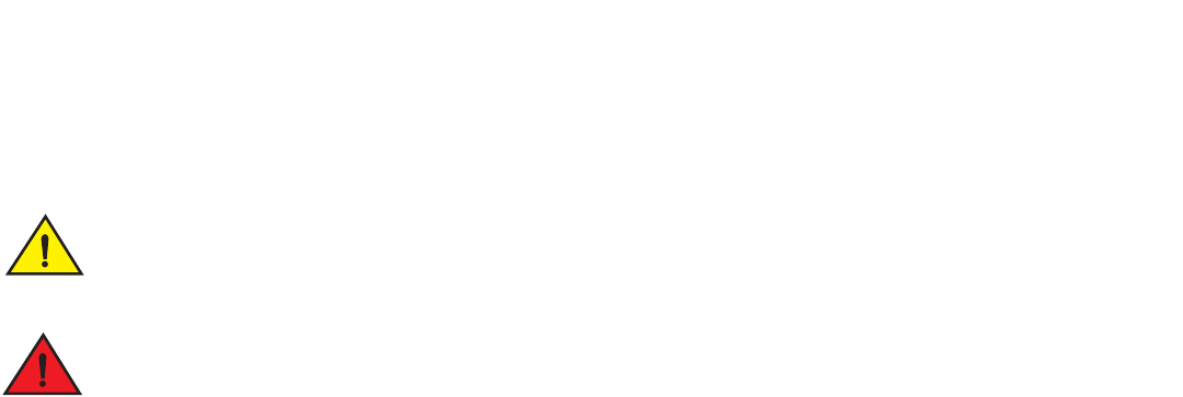
FGS624P and FGS624P-POE devices
FGS624P devices are POE-upgradeable. You can upgrade your device by installing a POE daughter card.
FGS624P-POE devices ship with the POE daughter card installed.
Figure 1 shows the FGS624P and FGS624P-POE devices.
FIGURE 1 FGS624P and RGS624P-POE Devices
FGS624P and FGS624P-POE models contain the following ports:
•
24 10/100/1000 Mbps copper ports that support 100Base-TX and 1000Base-T RJ-45 connectors.
•
Four 100/1000 Gbps fiber ports for mini-GBIC optical transceivers (also called Small Form Factor Pluggable (SFP)
MultiSource Agreement (MSA)-compliant optical transceivers).
NOTE
Copper ports 1 – 4 and fiber ports 1F – 4F are combination ports, meaning either the copper port or its corresponding fiber
port can be active, but they cannot both be active at the same time. You can use a combination of fiber and copper ports, or
all four copper, or all four fiber ports, as needed. For more information, refer to “Combination ports” on page 21.
•
Two 10 Gbps ports (optional). Refer to “10 Gbps ports” on page 21.
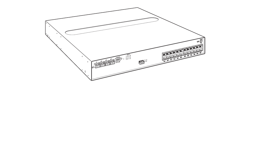
FGS624XGP and FGS624XGP-POE devices
FGS624XGP models are POE-upgradeable. You can upgrade your device by installing a POE daughter card.
FGS624XGP-POE models ship with the POE daughter card installed.
Figure 2 shows the FGS624XGP and FGS624XGP-POE devices.
Slot 3
16 Brocade FastIron GS and GS-STK Hardware Installation Guide
Part Number: 53-1002186-03
Product Overview
Hardware features
FIGURE 2 FGS624XGP and FGS624XGP-POE Devices
FGS624XGP and FGS624XGP-POE models contain the following ports:
•
24 10/100/1000 copper ports that support 100Base-TX and 1000Base-T RJ-45 connectors.
•
Four 100/1000 Gigabit Fiber uplink ports (1F – 4F) for mini-GBIC optical transceivers (also called Small Form Factor
Pluggable (SFP) Multisource Agreement (MSA)-compliant optical transceivers)
NOTE
Copper ports 1 – 4 and fiber ports 1F – 4F are combination ports, meaning either the copper port or its corresponding fiber
port can be active, but they cannot both be active at the same time. You can use a combination of fiber and copper ports, or
all four copper, or all four fiber ports, as needed. For more information, refer to “Combination ports” on page 21.
•
One built-in 10 Gbps port. Refer to “10 Gbps ports” on page 21.
•
Two additional10-GbE ports (optional). Refer to “10 Gbps ports” on page 21.
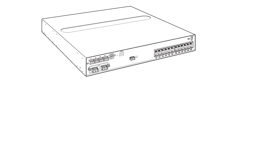
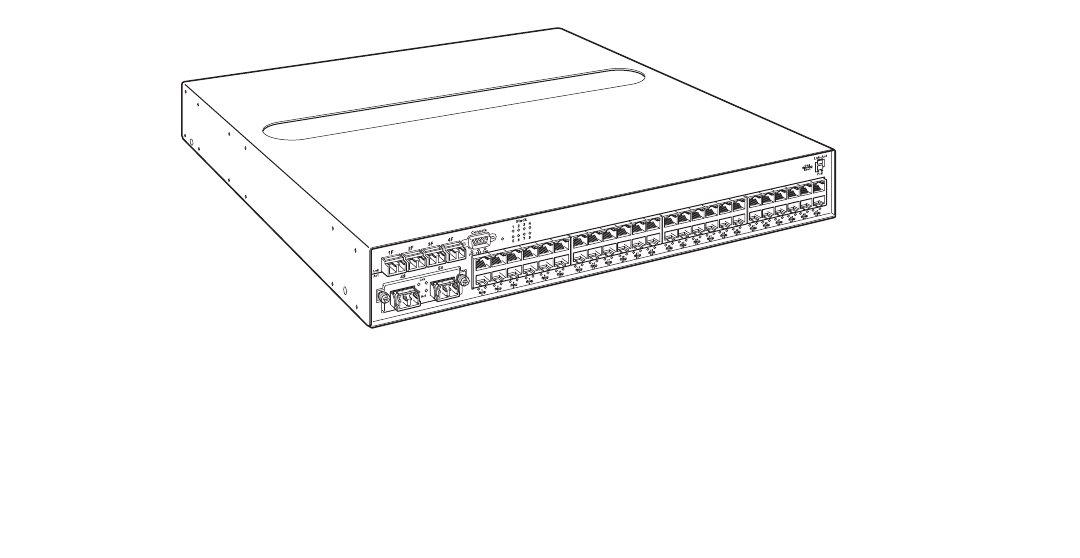
FGS648P and FGS648P-POE devices
FGS648P devices are POE-upgradeable. You can upgrade your device by installing one or two POE daughter cards. A single POE
daughter card supports 24 POE ports. Two POE daughter cards support 48 POE ports.
FGS648P-POE devices ship with the POE daughter cards installed.
Figure 3 shows the FGS648P and FGS648P-POE devices.
Slot 3
Slot 1
26
25
FGS-2XG
Brocade FastIron GS and GS-STK Hardware Installation Guide 17
Part Number: 53-1002186-03
Product Overview
Hardware features
FIGURE 3 FGS648P and FGS648P-POE Devices
FGS648P and FGS648P-POE models contain the following ports:
•
48 10/100/1000 copper ports that support 100Base-TX and 1000Base-T RJ-45 connectors
•
Four 100/1000 Gigabit Fiber uplink ports (1F – 4F) for mini-GBIC (SFP) MSA-compliant optical transceivers
NOTE
Copper ports 1 – 4 and fiber ports 1F – 4F are combination ports, meaning either the copper port or its corresponding fiber
port can be active, but they cannot both be active at the same time. You can use a combination of fiber and copper ports, or
all four copper, or all four fiber ports, as needed. For more information, refer to “Combination ports” on page 21.
•
Two 10 Gbps ports (optional). Refer to “10 Gbps ports” on page 21.
Control features
All FGS front panels have the following control features:
•
Serial management interface (the port labeled Console)
•
Reset button
•
10/100/1000 ports with RJ-45 copper connectors
•
100/1000 ports with mini-GBIC slots for SFP MSA-compliant fiber transceivers
•
FGS624XGP and FGS624XGP-POE models have one 10-Gigabit Ethernet port for XFP MSA compliant fiber connectors
•
Optionally, two10 Gigabit Ethernet ports for XFP MSA-compliant fiber connectors
•
LEDs for ports, power supplies, and stacking
The following illustrations show the front panels of the FGS models.
FGS-2XG
18 Brocade FastIron GS and GS-STK Hardware Installation Guide
Part Number: 53-1002186-03
Product Overview
Hardware features
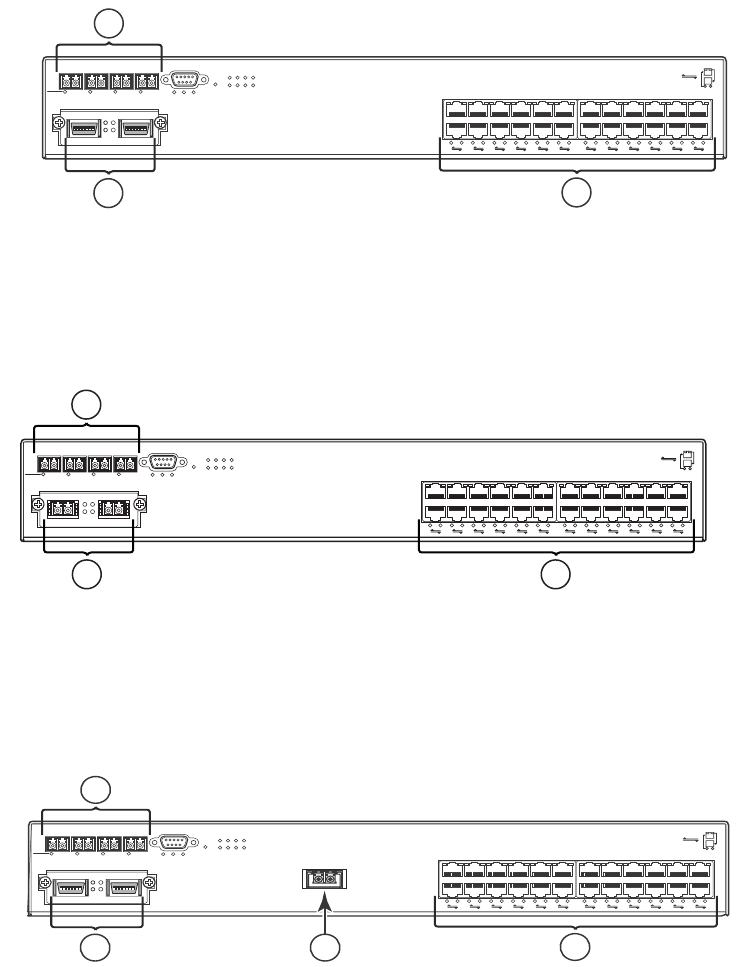
FIGURE 4 FGS624P and FGS624P-POE front panel
FIGURE 5 FGS624P-STK and FGS624P-POE-STK Front Panel
FIGURE 6 FGS624XGP-STK and FGS624XGP-POE-STK Front Panel
1
1 Gigabit Ethernet ports 1-4
2 Optional 2-port 10 Gbps module, ports 25 and 26
3 Gigabit Ethernet copper ports 1-24
1 Gigabit fiber ports 1-4
2 2-port 10 Gbps Ethernet CX4 module, ports 25 and 26
3 Gigabit Ethernet ports 1-24
1 Gigabit fiber ports 1-4
2 2-port 10Gbps Ethernet CX4 module, ports 25and 26
3 10 Gbps Ethernet XFP
4 Gigabit Ethernet copper ports 1-24
1F 2F 3F 4F Console
Lnk
Act PS1 PS2 Pwr 5678
1
1
2
23
Stack
4
3
4
5
6
7
8
9
10
11
12
13
14
15
16
17
18
19
20
21
22
23
24
Odd
Even
PoE
Lnk-Act
25 26
Lnk FGS-2XGC
Act
1
23
1F 2F 3F 4F Console
Lnk
Act PS1 PS2 Pwr 5678
1
1
2
23
Stack
4
3
4
5
6
7
8
9
10
11
12
13
14
15
16
17
18
19
20
21
22
23
24
Odd
Even
PoE
Lnk-Act
25 26
Lnk FGS-2XG
Act
1
2 3
1F 2F 3F 4F Console
Lnk
Act PS1 PS2 Pwr
5678
1
1
2
23
Stack
4
3
4
5
6
7
8
9
10
11
12
13
14
15
16
17
18
19
20
21
22
23
24
Odd
Even
PoE
Lnk-Act
25 26
Lnk
FGS-2XGC
Act
1
24
3
Brocade FastIron GS and GS-STK Hardware Installation Guide 19
Part Number: 53-1002186-03
Product Overview
Hardware features
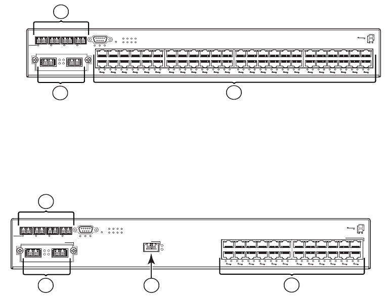
FIGURE 7 FGS648P-STK and FGS648P-POE-STK Front Panel
FIGURE 8 FGS624XGP and FGS624XGP-POE Front Panel
Serial management interface (Console port)
The serial management interface (the port labelled Console) enables you to configure and manage the device using a third-party terminal
emulation application on a directly-connected PC. A straight-through EIA/TIA DB-9 serial cable (M or F) ships with the device. The
console port is located in the left corner of the front panel.
Reset button
The reset button allows you to restart the system without switching the power supplies off and on, or using the CLI or Web management
interface. The button is located to the right of the console port and is recessed to prevent it from being pushed accidentally.
Network interfaces
Table 3 describes the network interfaces supported on the FGS and FGS-STK devices. For network interface specifications, refer to
Table 18 on page 73.
1 Gigabit fiber ports 1F-4F
2 Optional 2-port 10 Gigabit Ethernet module, ports 49 and 50
3 Gigabit Ethernet copper ports 1-48
1 Gigabit fiber ports (slot 1, ports 1F-4F)
2 Optional 2-port 10 Gbps module (slot 2, ports 1 and 2
3 1-port 10 Gbps module (slot 3, port 1)
4 Gigabit copper ports (slot 1, ports 1-24)
49
1F 2F 3F 4F Console
50
Lnk
Act PS1 PS2 Pwr
5678
1
1
2
23
Stack
4
3
4
5
6
7
8
9
10
11
12
13
14
15
16
17
18
19
20
21
22
23
24
25
26
27
28
29
30
31
32
33
34
35
36
37
38
39
40
41
42
43
44
45
46
47
48
Odd
Even
PoE
Lnk-Act
Lnk
Act
1
23
1F 2F 3F 4F Console
Lnk
Act PS1 PS2 Pwr
5678
1
1
2
23
Stack
4
3
4
5
6
7
8
9
10
11
12
13
14
15
16
17
18
19
20
21
22
23
24
Odd
Even
PoE
Lnk-Act
Lnk
FGS-2XG
Act
Lnk
Act
Slot 2
12 Slot 3
Slot 1
1
24
3

20 Brocade FastIron GS and GS-STK Hardware Installation Guide
Part Number: 53-1002186-03
Product Overview
Hardware features
Viewing the media types installed in the ports
The show media command displays the types of media (copper or fiber) installed in the ports. The following example is show media
output:
The “Show Media Description” column in Table 3 shows the text that is displayed by the show media command for each connector type.
10/100/1000 Mbps ports
10/100/1000 copper ports use auto-sensing and auto-negotiating to determine the speed (10 Mbps, 100 Mbps, or 1000 Mbps) and
mode (full-duplex or half-duplex) of the port at the other end of the link, and adjust port speed accordingly.
10/100/1000 ports on FGS devices support RJ-45 copper connectors. The output of the show media command displays C next to the
ports that have copper connectors installed.
Gigabit copper ports on the FGS and FGS-STK models support auto MDI or MDIX detection. For more information about this feature,
refer to "Configuring MDI or MDIX" in the <Italic>FastIron Configuration Guide.
100/1000 Mbps ports
100/1000 fiber ports (ports 1F – 4F) on FGS and FGS-STK devices support the SFP fiber connectors listed in Table 3.
TABLE 3 Network Interfaces
Interface Show Media Description
1000Base-BX-D M-GBXD
1000Base-BX-U M-GBXU
1000Base-LHA M-LHA
1000Base-LHB M-LHB
1000Base-LX M-LX
1000Base-SX M-SX
1000Base-SX2 M-SX2
1000Base-T C
100Base-BX M-FBX
100Base-FX M-FX
10GBase-ER XG-ER
10GBase-LR XG-LR
10GBase-SR XG-SR
10GBase-ZR XG-ZR
10GBase-ZRD XG-ZRD
CX4 10GbE module CX4
10GbE XFP and CX4 module CX4
1310-MMF 10GbE 1310-NM
FastIron(config)#show media
0/1/1:M-SX 0/1/2: C 0/1/3: C 0/1/4: C 0/1/5: C 0/1/6: C 0/1/7: C 0/1/8: C 0/1/9:
C 0/1/10: C 0/1/11: C 0/1/12: C 0/1/13: C 0/1/14: C 0/1/15: C 0/1/16: C 0/1/17:
C 0/1/18: C 0/1/19: C 0/1/20: C 0/1/21: C 0/1/22: C 0/1/23: C 0/1/24: C
0/2/1:XG-LMR 0/2/2:1310-NM
Brocade FastIron GS and GS-STK Hardware Installation Guide 21
Part Number: 53-1002186-03
Product Overview
Hardware features
Combination ports
Copper ports 1 – 4 and fiber ports 1F – 4F are combination ports, meaning either the copper port or its corresponding fiber port can be
active, but both cannot be active at the same time. You can use a combination of fiber and copper ports, all four copper, or all four fiber
ports, as needed.
If you attach both the copper and fiber connectors for a port to the network, the fiber connectors take precedence. These ports support
true media automatic detection, meaning the device will select the fiber or copper connector based on link availability. If a fiber link cannot
be established, the device will select the copper media.
10 Gbps ports
This section describes the 10 Gbps modules.
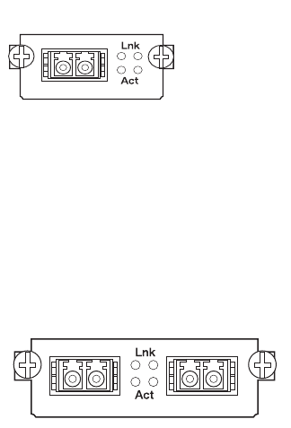
1-port 10 Gbps module
The 1-port 10 Gbps module is factory installed in the FGS624XGP and FGS624XGP-POE (shown in Figure 4) and in the XGP -STK
models. This module is not field-upgradeable. This module is a 10 Gbps fiber uplink for 10-XFP MSA-compliant optical transceiver.
Figure 9 shows the 1-port 10 Gbps module. This module supports the 10 Gbps connector types (10GBase) listed in Table 3.
FIGURE 9 1-port 10 Gbps module
2-port 10 Gbps module
The 2-port 10 Gbps module (part number FGS-2XG) is optional for FGS and FGS-STK devices. You can order the device with one
2-port 10-Gigabit module installed at the factory, or you can upgrade your device at a later time.
Figure 10 shows the 2-port 10 Gbps module. This module supports the 10 Gbps connector types (10GBase) listed in Table 3.
FIGURE 10 2-Port 10 Gbps module
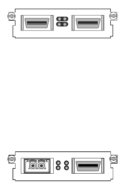
2-port CX4 module
The 2-port CX4 module (part number FGS-2XGC) is optional for FGS and FGS-STK devices. You can order the device with a 2-port
CX4 module installed at the factory, or you can upgrade your device at a later time. Figure 11 shows a 2-port CX4 module.
22 Brocade FastIron GS and GS-STK Hardware Installation Guide
Part Number: 53-1002186-03
Product Overview
Hardware features
FIGURE 11 10 Gbps 2-Port CX4 Module
When this module is installed, the show media command returns the following display:
FGS648 Switch# show media
0/2/1:CX4 0/2/2:CX4
2-port 10 Gbps hybrid interface module
The 2-port 10 Gbps hybrid interface module (part number FGS-1XG1XGC) contains a CX4 port and an XFP port. You can order the
device with one a 2-port hybrid module installed at the factory, or you can upgrade your device. This module contains two 2-port 10
Gbps hybrid uplinks; one for a 10-Gigabit XFP MSA-compliant optical transceiver and one for a 2-port CX4 10-Gigabit XFP
MSA-compliant optical transceiver. Figure 12 shows the hybrid interface module.
FIGURE 12 2-port Hybrid 10GbE and CX4 Module
When this module is installed, the show media command returns the following display:
FGS648 Switch# show media
0/2/1:<depends on transceiver installed> 0/2/2:CX4
10 Gbps Ethernet XFP transceiver (FGS624XGP models only)
FGX624XGP devices support a 10GbE XFP transceiver specifically in port 1, slot 3. This transceiver contains two 2-port CX4 uplinks for
10-Gigabit XFP MSA-compliant optical transceivers (part number FGS-2XGC).
Link and Activity LEDs on the module faceplates indicate operational status:
•
If the Lnk LED is on, the port is connected. If the Lnk LED is off, no connection exists, or the link is down.
•
If the Act LED is on or blinking, traffic is being transmitted and received on the port. If the Act LED is off, no traffic is being
transmitted or received on the port.
Cable specifications for CX4 ports
The following cable specifications apply to the CX4 ports in the 10GbE interface modules (FGS-2XGC and FGS-1XG and 1XGC):
•
Support for 802.3ak or 10 Gigabit Ethernet CX4 standard
•
Support of up to 15m in length
•
Requires latch-style receptacle or SFF-8470 plug
Lnk
Act
Lnk
Act
Lnk
Act
Lnk
Act
Brocade FastIron GS and GS-STK Hardware Installation Guide 23
Part Number: 53-1002186-03
Product Overview
Hardware features
•
Recommended CX4 cable: Manufactured by WL Gore, part number IBN6600-15, CX4 Assembly - 26AWG SPC 15.0m
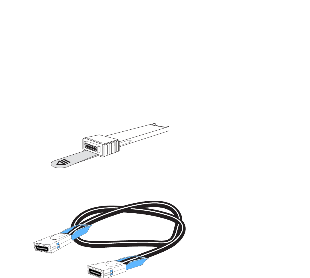
CX4 10Gbps XFP transceiver
FGS devices support a twin-axial 10G copper CX4 XFP transceiver that can be installed in any 10G port.
NOTE
For a link to operate properly, both sides must use identical CX4 transceivers.
The show media command identifies the CX4 as XG-CX4 as shown here:
The CX4 transceiver requires a 15 meter CX4-grade cable, which may be purchased from Brocade. Refer to part number
CAB-CX4-0050 when ordering.
Figure 13 shows the CX4 transceiver. Figure 14 shows the CX4-grade cable.
FIGURE 13 CX4 Transceiver
FIGURE 14 CX4 Transceiver Cable
LEDs for network interfaces and power supplies
The fiber and copper ports on FGS devices provide status information through the LEDs listed in Table 4.
•
The 10/100/1000 copper ports (1 – 24 or 1 – 48) use the LEDs located on the top left and top right of the upper copper
connectors. These are combined Link or Activity (Lnk or Act) LEDs. The LED on the left side is for the upper copper connector.
The LED on the right side is for the lower copper connector.
FGS624P Switch#show media
0/1/1: C 0/1/2:M-SX 0/1/3: C 0/1/4: C 0/1/5: C 0/1/6: C 0/1/7: C 0/1/8: C 0/1/9:
C 0/1/10: C 0/1/11: C 0/1/12: C 0/1/13: C 0/1/14: C 0/1/15: C 0/1/16: C 0/1/17:
C 0/1/18: C 0/1/19: C 0/1/20: C 0/1/21: C 0/1/22: C 0/1/23: C 0/1/24: C
0/2/1:XG-SR 0/2/2:XG-SR 0/3/1:XG-CX4

24 Brocade FastIron GS and GS-STK Hardware Installation Guide
Part Number: 53-1002186-03
Product Overview
Hardware features
•
The 100/1000 fiber ports (1F – 4F) use the LEDs located beneath the fiber connectors. These are combined Link or Activity
(Lnk or Act) LEDs.
•
The POE ports (1 – 24) use the round LEDs located beneath the copper ports. The first (left-most) LED is for port 1, the second
LED is for port 2, the third LED is for port 3, and so forth.
•
The 10 Gbps fiber ports use the LEDs located beside them.
•
FGS-STK devices use the Stack LEDs (1 – 8) located to the right of the console port.
•
Power supplies use the Pwr, PS1, and PS2 LEDs on the left side of the front panel, under the console port.
TABLE 4 LEDs
LED Position State Meaning
10/100/1000 Copper Port LEDs
Lnk or Act Located along the top
of the copper ports
Left for upper copper
connector
Right for lower copper
connector
On The link is up.
Off The link is down.
Blinking The port is transmitting or receiving traffic
100/1000 Fiber Port LEDs
Lnk or Act Bottom left On The link is up.
Off The link is down.
Blinking The port is transmitting or receiving traffic.
10 Gbps Port LEDs
Lnk Located beside the 10
Gbps port.
This is the top-most
LED.
On The port is connected.
Off No fiber port connection exists or the link is down.
Act Located beside the 10
Gbps port.
This is the
bottom-most LED.
On or
Blinking
Traffic is being transmitted or received on the fiber
port.
Off No traffic is being transmitted or received on the
fiber port.
POE Port LEDs
POE Located along the
bottom of the copper
ports
Left for upper port
Right for lower port
On (Green) The port is enabled, a power-consuming device
has been detected, and the module is supplying
power to the device.
Off The port is not providing in-line power.
Power Supply LEDs
Power Right-most LED
beneath the console
port
On The device is powered on and has enough power
to operate.
Off The device is not powered on, or has been
powered on but does not have sufficient power to
operate.
Brocade FastIron GS and GS-STK Hardware Installation Guide 25
Part Number: 53-1002186-03
Product Overview
Hardware features
Fiber optic modules
Table 18 in the chapter “Hardware Specifications”lists the types of fiber optic modules (SFPs and XFPs) supported on Brocade FGS and
FGS-STK devices.
Table 3 describes the output of the show media command for each media type.
Power supplies
Each FGS or FGS-STK device comes with one alternating-current (AC) power supply (part number RPS-FGS) or direct-current (DC)
power supply (part number RPSDC-FGS), depending on how it was ordered from the factory. All models have two power supply slots,
enabling you to install a second power supply for redundancy (if applicable) or for additional POE power. You can use any combination of
AC and DC supplies in the same device.
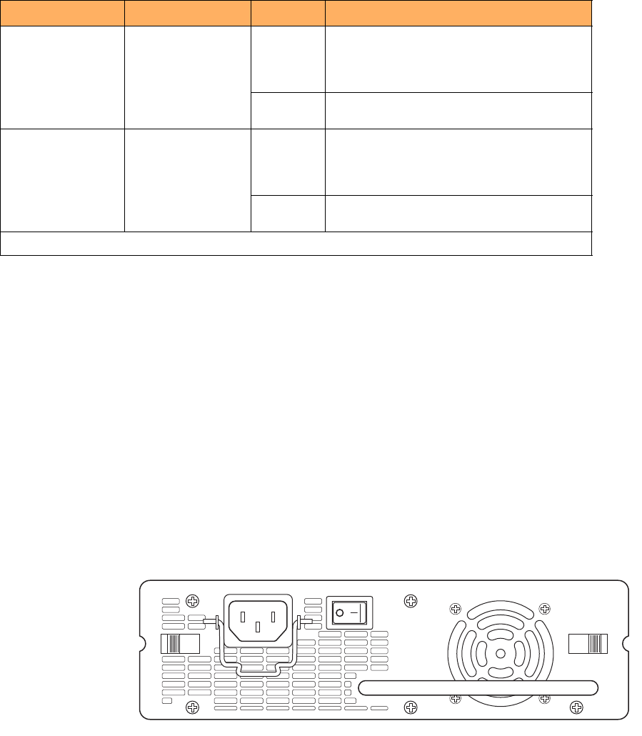
Figure 15 shows the front panel of the AC power supply used with FastIron GS and GS-STK devices.
FIGURE 15 RPS-FGS AC power supply front panel
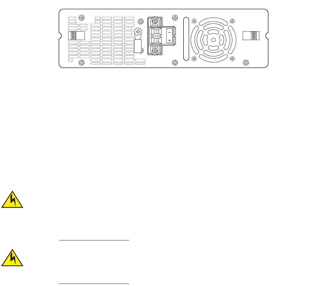
Figure 16 shows the front panel of the DC power supply used with FastIron GS and GS-STK devices.
PS1 Left-most LED
beneath the console
port
On Power supply 1 is installed and is functioning
normally. Power supply 1 is located in the
right-hand bay (when you are facing the rear of the
device).
Off Power supply 1 is not installed or is not providing
power.
PS2 Middle LED beneath
the console port
On Power supply 2 is installed and is functioning
normally. Power supply 2 is located in the
left-hand bay (when you are facing the rear of the
device).
Off Power supply 2 is not installed or is not providing
power.
Stacking LEDs
TABLE 4 LEDs (Continued)
LED Position State Meaning
26 Brocade FastIron GS and GS-STK Hardware Installation Guide
Part Number: 53-1002186-03
Product Overview
Hardware features
FIGURE 16 RPSDC-FGS DC power supply front panel
The power supplies are auto-sensing and auto-switching, and provide 600 watts of total output power, including +12VDC @ 10A to the
system and -48VDC@ 10A for Power over Ethernet applications. The power supplies provide 100-240 VAC input, 50-60Hz @ 8A to
3.2A.
Power supplies can be swapped in or out of the device while the device is running, and without opening the device. If the device contains
redundant power supplies, you can remove one of the supplies without interrupting operation because the remaining power supply
provides enough power for all of the ports.
For power supply hardware specifications, refer to “Hardware Specifications” on page 67.
NOTE
A FastIron GS or GS-STK POE device with dual power supplies may not provide redundancy, depending on how much power
the POE ports are consuming. Refer to “Power specifications for POE” on page 26.
Disconnect the power supply cable from the power source (outlet) before you install it in or remove it from
the device. Failure to do this can result in damage to the power supply or the device, or both. (The device
can be running while a power supply is being installed or removed, but the power supply itself should not
be connected to a power source.)
The FGS power supply is designed exclusively for use with FGS and FGS-STK devices. Installing the power
supply in a device other than an FGS or FGS-STK will cause extensive damage to your equipment.
Power specifications for POE
The implementation of the 802.3af standard limits power to 15.4W (44V to 57V) from the power sourcing device. This limit complies
with safety standards and existing wiring limitations. Though limited by the 802.3af standard, 15.4 watts of power is ample, as most
powered devices consume an average of 5 to 12 watts of power. IP phones, wireless LAN access points, and network surveillance
cameras each consume an average of 3.5 to 9 watts of power.

Brocade FastIron GS and GS-STK Hardware Installation Guide 27
Part Number: 53-1002186-03
Product Overview
Hardware features
Brocade 48-volt power supplies provide power to the POE daughter card, and ultimately to POE power-consuming devices. The
number of POE power-consuming devices that one 48-volt power supply can support depends on the number of watts required by each
device. Each 48-volt power supply provides 480 watts of power for POE, and each POE port supports a maximum of 15.4 watts of
power per POE power-consuming device. For example, if each POE power-consuming device attached to the FGS consumes 12 watts
of power, one 48-volt supply will power up to 40 POE ports. You can install a second 48-volt supply for additional POE power.
NOTE
If your FastIron GS or GS-STK POE device has 48 ports and only one power supply, and each POE-enabled port needs 15.4
watts, then a maximum of 31 ports can supply power to connected devices.
For power supply specifications, refer to “Hardware Specifications” on page 67. For POE configuration procedures, refer the
<Italic>FastIron Configuration Guide.
Precautions
The following precautions apply to the FastIron GS or GS-STK POE with 48 ports:
•
If your FastIron GS or GS-STK POE device has 48 ports and two power supplies, and the POE ports are consuming more than
480 watts of power, a single power supply failure will cause both power supplies to shut down.
•
If your FastIron GS or GS-STK POE device has 48 ports and only one power supply, and the power consuming devices
connected to POE-enabled ports consume a total of more than 480 watts of power, the power supply may shut down.
Cooling system and fans
FGS and FGS-STK devices have two single-speed fans that operate simultaneously. If one fan fails, it does not affect the operation of the
other fan. For more information about fans and the cooling system, refer to “Cooling” on page 68.
28 Brocade FastIron GS and GS-STK Hardware Installation Guide
Part Number: 53-1002186-03
Product Overview
Hardware features

Brocade FastIron GS and GS-STK Hardware Installation Guide 29
Part Number: 53-1002186-03
Installing FastIron GS and FastIron
GS-STK Devices
The procedures in this manual are intended for qualified service personnel.
Unpacking a system
TInformation about configuring IP addresses and connecting network devices is in the chapter “Connecting Network Devices and
Checking Connectivity” on page 61.
FastIron GS and FastIron GS-STK devices ship with all of the items listed below. Please review the list and verify the contents of your
shipping container. If any items are missing, please contact the place of purchase.
Package contents
The following items are shipped in with FGS and FGS-STK devices:
•
Brocade FastIron GS or FastIron GS-STK device with one AC or DC power supply installed
•
115V AC US power cable (for AC-sourced devices - DC power supplies do not ship with a power cable)
•
Rack mount brackets and mounting screws
•
One .5 meter CX4 stacking cable (FastIron GS-STK models only)
•
CD-ROM with software images and user documentation (including this guide)
•
EIA /TIA DB-9 serial cable (F or F)
•
Warranty card and registration card
General requirements
To manage the system, you will need to connect a management station, such as a PC running a terminal emulation application. Use the
DB-9 serial cable for this connection.
Use the serial connection to perform basic configuration tasks, such as assigning an IP address and network mask. This information is
required to manage the system using the Web management interface or IronView Network Manager, or using the CLI through Telnet.
Summary of installation tasks
Follow the steps listed below to install your FGS or FGS-STK device.
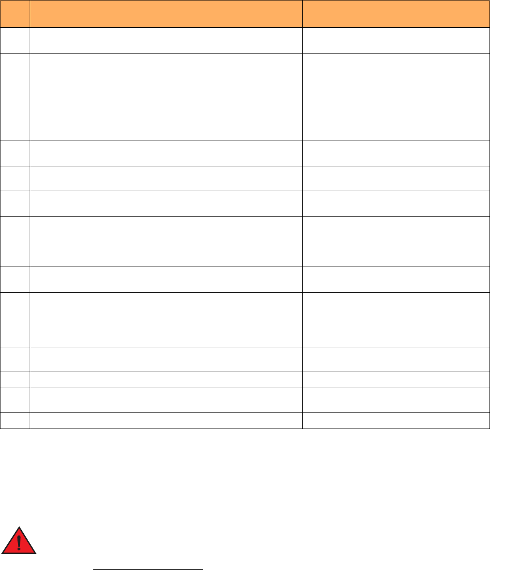
30 Brocade FastIron GS and GS-STK Hardware Installation Guide
Part Number: 53-1002186-03
Installing FastIron GS and FastIron GS-STK Devices
Installation precautions
Installation precautions
Follow these precautions when installing a Brocade device.
General precautions
All fiber-optic interfaces use Class 1 lasers.
TABLE 1 Summary of Installation Tasks
Task
No.
Task Where to Find More Information
1 Ensure that the physical environment where the device will be installed has the
proper cabling and ventilation.
“Preparing the installation site” on page 33
2 Optionally install an additional power supply. It may be easier to do this
before mounting the device, although power supplies are “hot swappable”,
and can be installed or removed after the device is mounted and powered-on.
NOTE: Always disconnect the power supply from the power source (outlet)
before you install or remove it from the device. Otherwise, the power
supply or the device could be damaged. (The device can be running
while a power supply is installed or removed, but the power supply
itself must be disconnected from the power source.)
“Installing a redundant power supply” on page 34
4 Install the Brocade device on a desktop or in an equipment rack. Devices may
also be wall-mounted.
“Installing the device” on page 40
5 Install and connect FastIron GS-STK stackable devices “Installing FastIron GS-STK stackable devices” on
page 43
6 When the device is installed, plug the power cord into a nearby power source
that adheres to the regulatory requirements outlined in this manual.
“Powering on the system” on page 45
7 Verify that the system LEDs are registering the proper LED state after the
system is powered-on.
“Verifying proper operation” on page 46
8 Attach a terminal or PC to the Brocade device. This enables you to configure
the device through the Command Line Interface (CLI).
“Attaching a PC or terminal” on page 46
9 No default password is assigned to the CLI. For additional access security,
assign a password.
“Assigning permanent passwords” on page 61
10 Before attaching equipment to the device, you must configure an interface IP
address to the subnet on which it will be located. Initial IP address
configuration is performed using the CLI with a direct serial connection.
Subsequent IP address configuration can be performed using the Web
management interface.
“Configuring IP addresses” on page 63
11 Once you power-on the device and assign IP addresses, the system is ready
to accept network equipment.
“Connecting network devices” on page 66
12 Test connectivity by pinging other devices and tracing routes. “Testing connectivity” on page 69
13 Continue configuration using the CLI or the Web management interface. You
also can use IronView Network Manager to manage the device.
<Italic>Foundry IronView Network Management
User’s Guide
14 Secure access to the device. <Italic>FastIron Configuration Guide
Brocade FastIron GS and GS-STK Hardware Installation Guide 31
Part Number: 53-1002186-03
Installing FastIron GS and FastIron GS-STK Devices
Installation precautions
Do not install the device in an environment where the operating ambient temperature might exceed 40
°
C
(104
°
F).
Make sure that air flow around the front, sides, and back of the device is not restricted.
Never leavec tools inside the device.
Lifting precautions
Make sure the rack or cabinet housing the device is adequately secured to prevent it from becoming
unstable or falling over.
Do not use the handles on the power supply units to lift or carry a Brocade device.
Mount the devices you install in a rack or cabinet as low as possible. Place the heaviest device at the
bottom and progressively place lighter devices above.
Power precautions
The following precautions apply to FastIron GS POE and FastIron GS-STK POE 48-port devices:
•
If your FastIron GS or GS-STK POE device has 48 ports and only one power supply, and each POE-enabled port needs 15.4
watts, then a maximum of 31 ports can supply power to connected devices.
•
If your FastIron GS or GS-STK POE device has 48 ports and two power supplies, and the POE ports are consuming more than
480 watts of power, a single power supply failure will cause both power supplies to shut down.
•
If your FastIron GS or GS-STK POE device has 48 ports and only one power supply, and the power consuming devices
connected to POE-enabled ports consume a total of more than 480 watts of power, the power supply may shut down.
Use a separate branch circuit for each AC power cord, to provide redundancy in case one of the circuits
fails.
32 Brocade FastIron GS and GS-STK Hardware Installation Guide
Part Number: 53-1002186-03
Installing FastIron GS and FastIron GS-STK Devices
Installation precautions
Ensure that the device does not overload the power circuits, wiring, and over-current protection. To
determine the possibility of overloading the supply circuits, add the ampere (amp) ratings of all devices
installed on the same circuit as the device. Compare this total with the rating limit for the circuit. The
maximum ampere ratings are usually printed on the devices near the input power connectors.
All devices with DC power supplies are intended for installation in restricted access areas only. A
restricted access area is where access can be gained only by service personnel through the use of a
special tool, lock and key, or other means of security, and is controlled by the authority responsible for the
location.
For a DC system (DC power supply part number RPSDC-FGS), use a grounding wire of at least 10
American Wire Gauge (AWG). The 10 AWG wire should be attached to an agency-approved crimp
connector, crimped with the proper tool.
For the DC input circuit to the system (DC power supply part number RPSDC-FGS), make sure there is a
Listed 30 amp circuit breaker, minimum -48Vdc, double pole, on the input to the terminal block. The
input wiring for connection to the product should be Listed copper wire, 10 AWG, marked VW-1, and rated
minimum 90 degrees Celsius.
Make sure you insert the power supply right-side up. It is possible to insert the supply upside down,
although the supply will not engage with the power backplane when upside down. The power supply is
right-side up when the power connector is on the left and the fan vent is on the right.
Remove the power cord from a power supply before you install it in or remove it from the device.
Otherwise, the power supply or the device could be damaged. (The device can be running while a power
supply is being installed or removed, but the power supply itself should not be connected to a power
source.)
Brocade FastIron GS and GS-STK Hardware Installation Guide 33
Part Number: 53-1002186-03
Installing FastIron GS and FastIron GS-STK Devices
Preparing the installation site
The FGS power supply is designed exclusively for use with the FGS devices. The power supply produces
extensive power to support 802.3af applications. Installing the power supply in a device other than the
FGS will cause extensive damage to your equipment.
Disconnect the power cord from all power sources to completely remove power from the device.
Make sure to choose the appropriate circuit device depending on the number of AC power supplies
installed in the device. The minimum current draw for the system is one AC power supply.
Power supplies are hot swappable. However, Brocade recommends that you disconnect the power supply
from AC power before installing or removing the supply. The device can be running while a power supply
is being installed or removed, but the power supply itself should not be connected to a power source.
Otherwise, you could be injured or the power supply or other parts of the device could be damaged.
Make sure that the power source circuits are properly grounded, then use the power cord supplied with
the device to connect it to the power source.
If the installation requires a different power cord than the one supplied with the device, make sure you
use a power cord displaying the mark of the safety agency that defines the regulations for power cords in
your country. The mark is your assurance that the power cord can be used safely with the device.
Preparing the installation site
Cabling infrastructure
Ensure that the proper cabling is installed at the site. Refer to “Device specifications” on page 67 or visit www.brocade.com for a
summary of supported cabling types and their specifications.
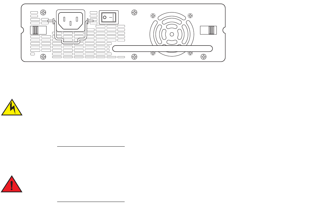
34 Brocade FastIron GS and GS-STK Hardware Installation Guide
Part Number: 53-1002186-03
Installing FastIron GS and FastIron GS-STK Devices
Installing a redundant power supply
Installation location
Before installing the device, plan its location and orientation relative to other devices and equipment. Allow at least 7.62cm (3 inches) of
space at the front of the device for the twisted-pair, fiber-optic, and power cabling. Also, allow a minimum of 3 in. of space between the
sides and the back of the device and walls or other obstructions.
Installing a redundant power supply
FGS and FGS-STK devices ship with one AC or DC power supply installed. You can install a second supply for added power or
redundancy. Figure 1 shows the front panel of an AC power supply.
FIGURE 1 AC power supply front panel
If you plan to install a second power supply, it may be easier to install it before mounting the device, although the power supplies are “hot
swappable” and can be installed or removed after the device is mounted and powered on.
Always disconnect the power supply from the power source (outlet) before you install it in or remove it
from the device. Otherwise, the power supply or the device could be damaged. The device can be running
while a power supply is being installed or removed, but the power supply itself should be disconnected
from the power source.
Installing an AC power supply
Before beginning the installation, refer to the precautions in “Power precautions” on page 31.
Use the following procedures to install AC power supplies in FastIron GS and GS-STK devices. You will need a #2 Phillips-head
screwdriver to perform these procedures.
To install an AC power supply, do the following:
1. If necessary, remove the power supply locking screw located in the center rear of the device (refer to Figure 2). If you are
replacing a power supply, you will need to remove the existing power supply. Use the handle to pull the old power supply out of
the device.
2. To remove the cover plate from the empty power supply slot, press inward on the latches on each side to unlock the plate
(Figure 2), then remove the plate.
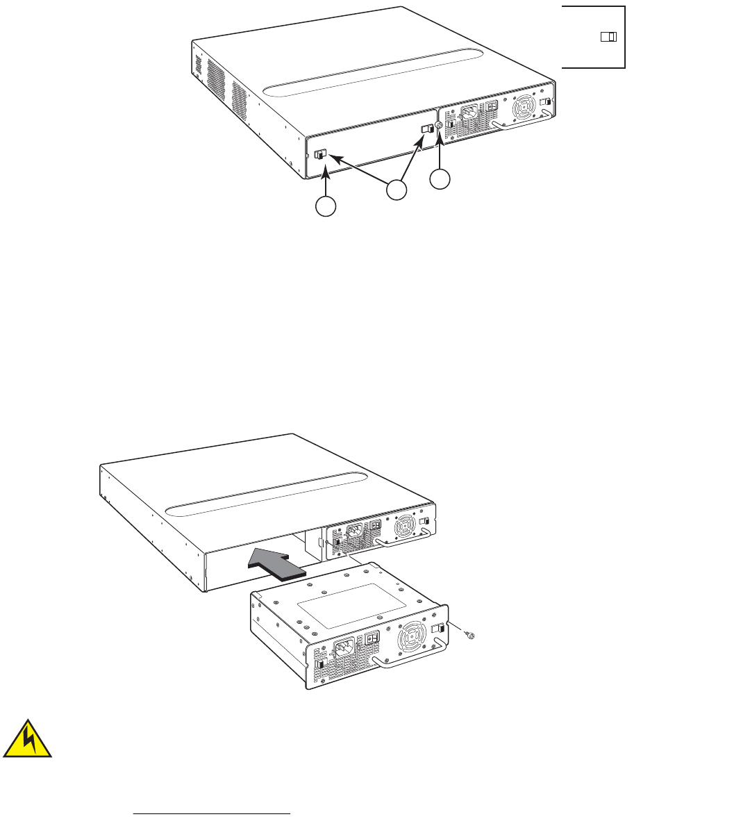
Brocade FastIron GS and GS-STK Hardware Installation Guide 35
Part Number: 53-1002186-03
Installing FastIron GS and FastIron GS-STK Devices
Installing a redundant power supply
FIGURE 2 Power supply locking screw, latches, and cover plate
3. Remove the new power supply from the packaging.
4. With one hand, hold the bar on the front panel of the power supply. Use your other hand to support the underside of the power
supply while you insert it into the empty slot. Press gently until the connectors on the back of the supply fully engage with the
pins on the power backplane.
FIGURE 3 Inserting the power supply
Make sure you insert the power supply right-side up. It is possible to insert the supply upside down,
although the supply will not engage with the power backplane. The power supply is right-side up when the
power connector is on the left and the fan vent is on the right.
5. Press the two latches near the edges of the supply outward to lock the supply in place.
1 Cover plate
2 Cover plate latches
3 Power supply locking screw
1
3
2
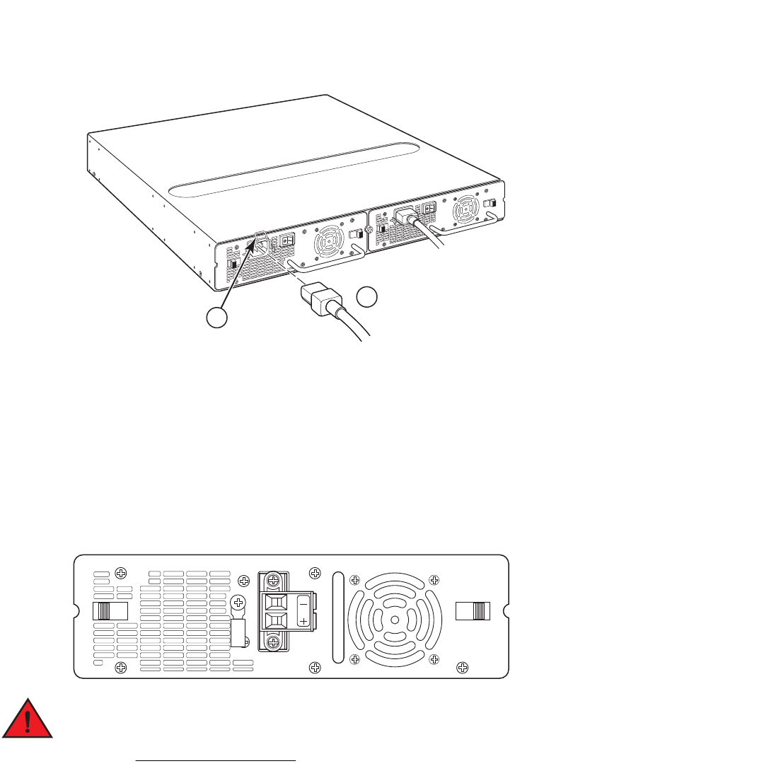
36 Brocade FastIron GS and GS-STK Hardware Installation Guide
Part Number: 53-1002186-03
Installing FastIron GS and FastIron GS-STK Devices
Installing a redundant power supply
6. Replace the power supply locking screw.
7. Install the power cord, and secure it wIth the retaining bail, as shown in Figure 4.
NOTE
The edges of the power supply panels will extend approximately .25 in.beyond the side of the device.
FIGURE 4 Installing the AC power cord
Installing a DC power supply
Use the following procedures to install DC power supplies in a FastIron GS or FastIron GS-STK device. Figure 5 shows the front panel of
a DC power supply.
FIGURE 5 DC power supply front panel
Before beginning the installation, refer to the precautions in “Power precautions” on page 31.
1 Cord retaining bail
2 AC power cord
1
2
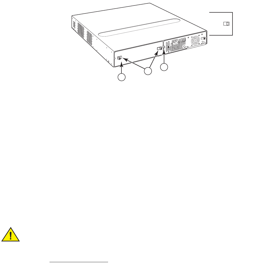
Brocade FastIron GS and GS-STK Hardware Installation Guide 37
Part Number: 53-1002186-03
Installing FastIron GS and FastIron GS-STK Devices
Installing a redundant power supply
1. If necessary, before installing a power supply, remove the power supply locking screw located in the center rear of the device,
and remove the cover plate (illustrated in Figure 6 on an AC device). If you are replacing an existing power supply, pull the old
power supply gently out of the device, using the handle.
FIGURE 6 Power supply locking screw and cover plate latches
2. If the empty power supply bay has a cover plate, unlock it by pressing inward on the two latches at the edges of the cover plate
(refer to Figure 6), then remove the plate.
3. Remove the new power supply from the packaging.
4. Prepare the positive, negative, and ground wires by stripping about 1/4 in. of insulation off the end of each one. (Use 10 AWG
wire.)
5. Loosen the three screws used to hold the wires in the connectors, as shown in Figure 9.
NOTE
The handle on the front panel of the power supply may block access to the negative and positive terminal screws. You may
need to temporarily remove the receptacle for the positive and negative terminals if you can not access the screws used to
hold the wires in the connectors.
6. With one hand, grasp the handle on the front panel of the power supply. Use your other hand to support the underside of the
power supply while you insert it in the empty slot. Press gently so that the connectors on the back of the supply are fully engaged
with the pins on the power backplane. Refer to Figure 7.
Make sure you insert the power supply right-side up. It is possible to insert the supply upside down,
although the supply will not engage with the power backplane. The power supply is right-side up when the
power connector is on the left and the fan vent is on the right.
1 Cover plate
2 Cover plate latches
3 Power supply locking screw
Power Supply locking screw
1
3
2
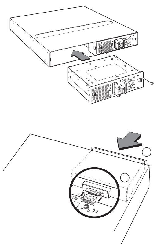
38 Brocade FastIron GS and GS-STK Hardware Installation Guide
Part Number: 53-1002186-03
Installing FastIron GS and FastIron GS-STK Devices
Installing a redundant power supply
FIGURE 7 Inserting the DC power supply
FIGURE 8 Engaging the DC power supply connectors
7. Press the two latches on the supply outward to lock the supply in place.
8. If you removed the receptacle for the positive and negative terminals, re-position it and secure the screws.
1 Power supply
2 Connectors
2
1
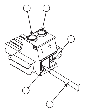
Brocade FastIron GS and GS-STK Hardware Installation Guide 39
Part Number: 53-1002186-03
Installing FastIron GS and FastIron GS-STK Devices
Installing a redundant power supply
FIGURE 9 DC power supply connector
9. Connect the ground, positive, and negative wires as follows:
•
Slip the 10 AWG ground wire into the opening under the negative (—) mark until the wire is fully in place, then use the
crimper to crimp the lug snugly onto the wire. Gently pull the lug away from the wire to verify that the lug is securely
fastened.
•
Connect the -48 VDC lead to the negative (—) terminal and tighten the negative terminal screw.
•
Connect the 48 RTN lead to the positive (+) terminal and tighten the positive terminal screw.
•
Figure 10 shows how to connect the wires on a DC power supply.
1 Negative terminal screw
2 Positive terminal screw
3 48 RTN lead
4 -48 VDC lead
5 10 AWG wire
1
4
5
2
3
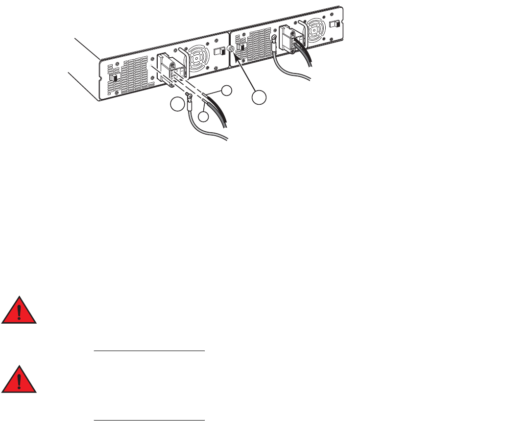
40 Brocade FastIron GS and GS-STK Hardware Installation Guide
Part Number: 53-1002186-03
Installing FastIron GS and FastIron GS-STK Devices
Installing the device
FIGURE 10 Connecting the wires to a DC power supply
10. Tug gently on each wire to make sure it is securely fastened in the connector.
11. Replace the power supply locking screw.
Installing the device
You can install Brocade devices on a desktop or in an equipment rack.
Make sure the rack or cabinet housing the device is adequately secured to prevent it from becoming
unstable or falling over.
Mount devices in a rack or cabinet as low as possible. Place the heaviest device at the bottom and
progressively lighter devices above.
Desktop installation
1. Set the device on a flat desktop, table, or shelf. Make sure that adequate ventilation is provided for the system – a 3-in. clearance
is recommended on each side.
2. Proceed to “Powering on the system” on page 45.
Rack mount installation
For rack mount installation, Brocade recommends that you use a Telco equipment rack.
1Ground
2 Power supply locking screw
+
–
12
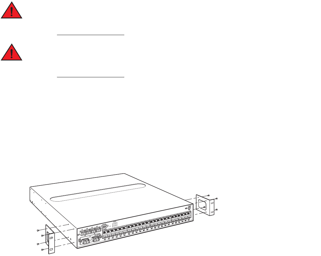
Brocade FastIron GS and GS-STK Hardware Installation Guide 41
Part Number: 53-1002186-03
Installing FastIron GS and FastIron GS-STK Devices
Installing the device
The Brocade device is compatible with two rack mount kits; a kit with short mounting brackets that ships with the device, and a kit with
long mounting brackets (19 inches), which you can order separately from Brocade (part number 70166-000). Use the long mounting
brackets to prevent the Brocade device from sagging when installed in a non-compliant (non-Telco) equipment rack.
In addition to the rack mount kit, you will need the following tools for installation:
•
#2 Phillips-head screwdriver
•
Four 12-24 screws to mount the Brocade device to the rack.
Make sure the rack or cabinet housing the device is adequately secured to prevent it from becoming
unstable or falling over.
Mount the devices in the lowest position possible in a rack or cabinet. Place the heaviest device at the
bottom and progressively place lighter devices above.
To install the rack mount brackets and mount the device in a rack, do the following:
1. Remove the rack mount kit from the shipping carton. The kit contains two mounting brackets.
2. Align the brackets with the screw holes on the sides of the device, then use 12-24 screws to attach the mounting brackets.
Refer to the appropriate illustration, depending on which brackets you are installing:
•
Figure 11 shows how to attach the short mounting brackets.
•
Figure 12 shows how to attach the long mounting brackets.
FIGURE 11 Attaching the short mounting brackets
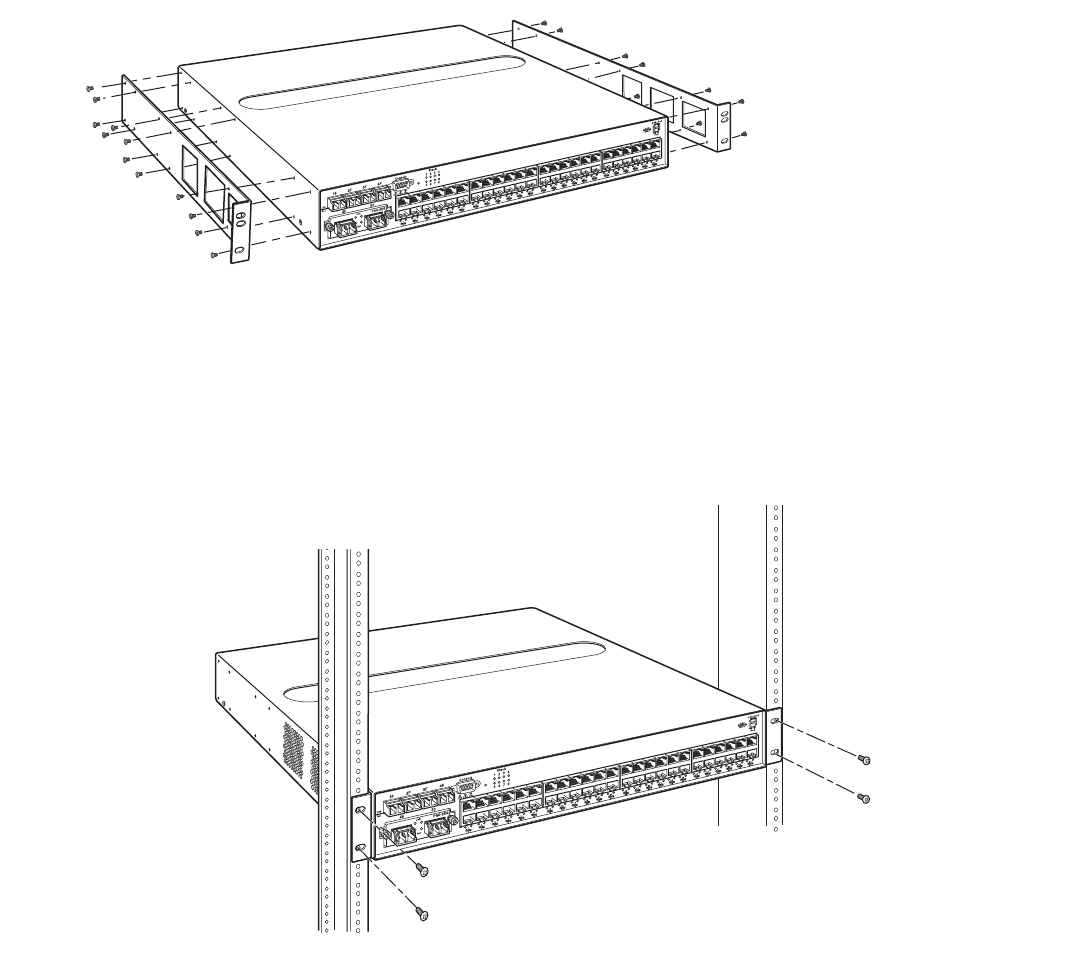
42 Brocade FastIron GS and GS-STK Hardware Installation Guide
Part Number: 53-1002186-03
Installing FastIron GS and FastIron GS-STK Devices
Installing the device
FIGURE 12 Attaching the long mounting brackets
3. Mount the device in the rack as illustrated in Figure 13.
NOTE
Although Figure 13 shows a device with short mounting brackets, the procedure for securing a device with long mounting
brackets is the same.
FIGURE 13 Installing the device in a rack
NOTE
If you are installing a device with two power supplies into a Telco rack, you must remove one of the power supplies in order to
slide the device into the rack. The back panels of the power supplies overhang the device by approximately .25 inches, making it
impossible to insert into a standard Telco rack with both power supplies installed.
4. Proceed to “Powering on the system” on page 45.
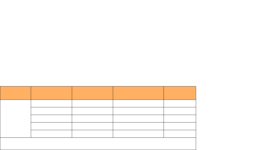
Brocade FastIron GS and GS-STK Hardware Installation Guide 43
Part Number: 53-1002186-03
Installing FastIron GS and FastIron GS-STK Devices
Installing the device
Installing FastIron GS-STK stackable devices
Install your stackable devices in the same manner as standalone devices. When you have installed all of your stack devices in a rack or on
a table, you will need to cable them together into a stack topology.
IronStack technology supports linear and ring stack topologies. Figure 14 and Figure 15 on page 44 show four devices connected in a
linear and ring topology, respectively. Although these illustrations show four devices, you can connect up to eight devices in a single stack.
NOTE
Since you can use either of the two 10Gb ports as stacking ports in any order, your cabling configuration may differ from that
shown in these illustrations.
Use the .5 meter CX4 cables that shipped with each FGS-STK device to connect a linear stack topology. For a ring topology, you will
need an additional, longer (3.0 meter) CX4 cable.
NOTE
The total maximum stacking distance in linear and ring stack topologies is 3,281 feet (1,000 meters ). This length can consist of
multiple inter-switch stacking connections adding up to 1,000 meters. A single inter-switch stacking connection should not
exceed 1,000 meters.
For XFP cabling, Table 2 lists the recommended cable lengths for various connection distances.
TABLE 2 XFP Optical Link Cable Distances
Data Rate Fiber Type Modal Bandwidth @
850nm (Mhz-km)
Worst case distance range
specified (m)
Typical range
(m)
9.95-10.3125
Gbps
62.5/125um MMF 160 2 - 26
62.5/1.25um MMF 200 2 - 33
50/125um MMF 400 2 - 66
50/123um MMF 500 2 - 82
50/125um MMF 2000 2 - 300 >400
Average distance range is between 2 - 33 meters. Brocade recommends using the 2000 bandwidth version for
distances greater than 80 meters.
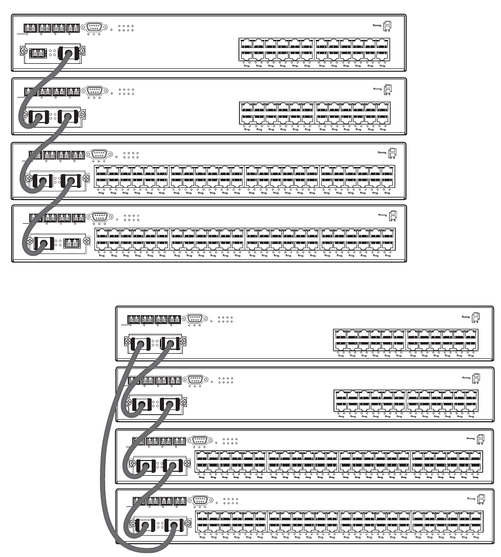
44 Brocade FastIron GS and GS-STK Hardware Installation Guide
Part Number: 53-1002186-03
Installing FastIron GS and FastIron GS-STK Devices
Installing the device
FIGURE 14 Linear stack topology
FIGURE 15 Ring stack topology
When you have completed the cabling for your IronStack devices, refer to the <Italic>FastIron Configuration Guide for stack configuration
and management information.
1F 2F 3F 4F Console
Lnk
Act PS1 PS2 Pwr 5678
1
1
2
23
Stack
4
3
4
5
6
7
8
9
10
11
12
13
14
15
16
17
18
19
20
21
22
23
24
Odd
Even
PoE
Lnk-Act
25 26
Lnk FGS-2XG
Act
49
1F 2F 3F 4F Console
50
Lnk
Act PS1 PS2 Pwr
5678
1
1
2
23
Stack
4
3
4
5
6
7
8
9
10
11
12
13
14
15
16
17
18
19
20
21
22
23
24
25
26
27
28
29
30
31
32
33
34
35
36
37
38
39
40
41
42
43
44
45
46
47
48
Odd
Even
PoE
Lnk-Act
Lnk
Act
1F 2F 3F 4F Console
Lnk
Act PS1 PS2 Pwr 5678
1
1
2
23
Stack
4
3
4
5
6
7
8
9
10
11
12
13
14
15
16
17
18
19
20
21
22
23
24
Odd
Even
PoE
Lnk-Act
25 26
Lnk FGS-2XG
Act
49
1F 2F 3F 4F Console
50
Lnk
Act PS1 PS2 Pwr
5678
1
1
2
23
Stack
4
3
4
5
6
7
8
9
10
11
12
13
14
15
16
17
18
19
20
21
22
23
24
25
26
27
28
29
30
31
32
33
34
35
36
37
38
39
40
41
42
43
44
45
46
47
48
Odd
Even
PoE
Lnk-Act
Lnk
Act
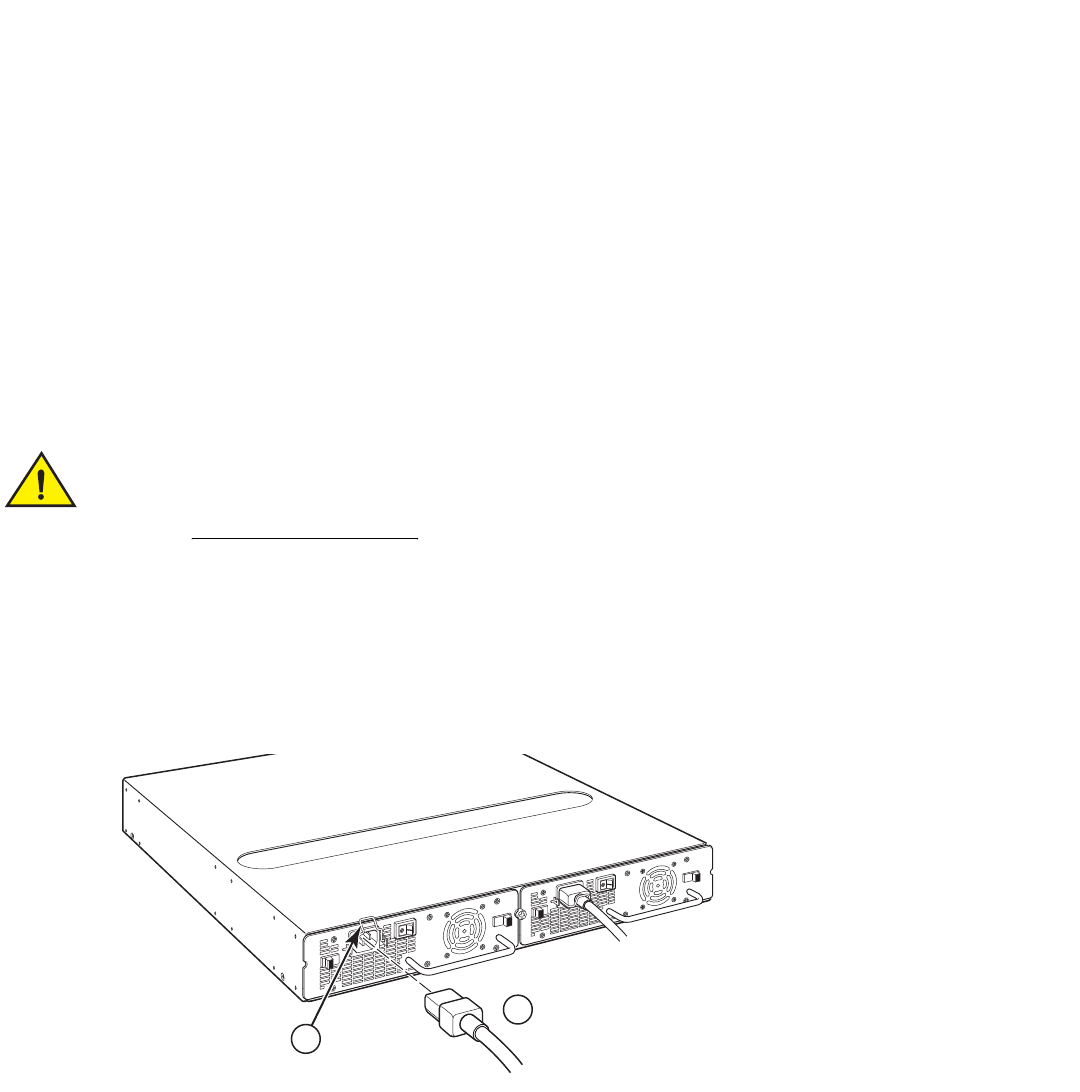
Brocade FastIron GS and GS-STK Hardware Installation Guide 45
Part Number: 53-1002186-03
Installing FastIron GS and FastIron GS-STK Devices
Powering on the system
NOTE
If you plan to upgrade your existing FGS devices to support stacking, you will need to install an upgrade kit. Refer to “Stacking
Upgrade for the FastIron GS” on page 53.
Powering on the system
Note the following before powering on the system:
•
The power socket should be installed near the equipment and should be easily accessible.
•
If the outlet is not rated 115/120V, stop and get the appropriate cable for the outlet.
•
If your installation requires a different power cord than that supplied with the device, make sure you obtain a power cord
displaying the mark of the safety agency that defines the regulations for power cords in your country. The mark is your
assurance that the power cord can be used safely with the device.
After you complete the physical installation of the system, you can power on the system.
1. Ensure that all power supplies are fully and properly inserted and all empty power supply slots are covered.
Never leave tools inside the device.
2. For DC supplies, connect the power source to the wires to activate the circuit.
3. For AC supplies:
•
Remove the power cord from the shipping package.
•
Attach the AC power cable to the AC connector on the rear panel and secure with retaining bale, as shown in Figure 16.
FIGURE 16 Attaching the AC power cable
2
•
Insert the power cable plug into a properly grounded 115V/120V electrical outlet.
•
Turn the power switch to the ON position.
1 Power cable retaining bale
2 AC power cable
1
2

46 Brocade FastIron GS and GS-STK Hardware Installation Guide
Part Number: 53-1002186-03
Installing FastIron GS and FastIron GS-STK Devices
Verifying proper operation
4. If your device has more than one power supply installed, repeat this procedure for each power supply.
5. Verify the device is working properly (refer to “Verifying proper operation” on page 46.)
Powering off the system
•
To turn an AC system OFF, press the power supply switch to the OFF position or unplug the power cords.
•
To turn a DC system OFF, disconnect the power source to the wires to de-activate the circuit.
Verifying proper operation
After you have installed any additional power supplies and powered on the system, verify that the device is working properly:
1. Verify that the LED for each power supply is a solid green.
2. Verify proper operation by observing the LEDs:
•
All port LEDs should flash momentarily, usually in sequence, while the device performs diagnostics. After the diagnostics
are complete, the LEDs will be dark except for those that are attached by cables to other devices. If the links on these cables
are good and the connected device is powered on, the link LEDs will light.
•
Table 3 provides more details on specific LED conditions after system start-up.
Observing the power status LEDs
Table 3 lists the device front panel LEDs that show power status. The power supplies do not have LEDs.
The software regularly polls the hardware for power status information. You can display the status information from any management
session using the show device CLI command. In addition, the software automatically generates a Syslog message and SNMP trap if a
status change occurs.
Attaching a PC or terminal
To assign an IP address, you must have access to the Command Line Interface (CLI). The CLI is a text-based interface that can be
accessed through a direct serial connection to the device or through Telnet connections.
TABLE 3 LEDs for Power
LED Position State Meaning
Pwr (Power) Right-most LED
beneath the
Console port
On The device is powered on and has enough power to operate.
Off The device is not powered on, or has been powered on but does not
have sufficient power to operate.
PS1 Left-most LED
beneath the
Console port
On Power supply 1 is installed and is functioning normally. Power supply
1 is located in the right-hand bay (when you are facing the rear of the
device).
Off Power supply 1 is not installed or is not providing power.
PS2 Middle LED
beneath the
Console port
On Power supply 2 is installed and is functioning normally. Power supply
2 is located in the left-hand bay (when you are facing the rear of the
device).
Off Power supply 2 is not installed or is not providing power.
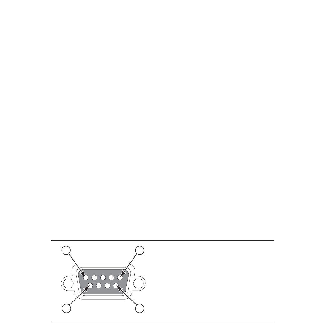
Brocade FastIron GS and GS-STK Hardware Installation Guide 47
Part Number: 53-1002186-03
Installing FastIron GS and FastIron GS-STK Devices
Attaching a PC or terminal
You will need to assign an IP address using the CLI. You can access the CLI by attaching management station through a serial cable to
the Console port. After you assign an IP address, you can access the system through Telnet, the Web management interface, or IronView
Network Manager.
To attach a management station using the serial port:
1. Use a straight-through cable to connect a PC or terminal to the male DB-9 serial port connector.
NOTE
You need to run a terminal emulation program on the PC.
2. Open the terminal emulation program and set the session parameters as follows:
•
Baud: 9600 bps
•
Data bits: 8
•
Parity: None
•
Stop bits: 1
•
Flow control: None
•
When you establish the serial connection to the system, press Enter to display the CLI prompt in the terminal emulation
window. For example:
•
FastIron>
•
FastIron-PREM>
•
When you see one of these prompts, you are connected to the system and can proceed to “Assigning permanent
passwords” on page 61.
•
You can customize the prompt by changing the system name. Refer to the <Italic>FastIron Configuration Guide.
If you do not see a prompt:
1. Make sure the cable is securely connected to your PC and to the Brocade device.
2. Check the settings in your terminal emulation program. In addition to the session settings listed above, make sure the terminal
emulation session is running on the same serial port you attached to the Brocade device.
The EIA /TIA 232 serial communication port serves as a connection point for management by a PC or SNMP workstation. Brocade
switches and Layer 3 Switches come with a standard male DB-9 connector, shown in Figure 17.
FIGURE 17 Serial port pin and signalling details
Pin Assignment
DB-9 mal
Pin Number Switch Signal
6
1 Reserved
2 TXD (output)
3 RXD (input)
4 Reserved
5 GND
6 Reserved
7 Reserved
8 Reserved
9 Reserved
1 5
9
e
48 Brocade FastIron GS and GS-STK Hardware Installation Guide
Part Number: 53-1002186-03
Installing FastIron GS and FastIron GS-STK Devices
Attaching a PC or terminal
Most PC serial ports also require a cable with a female DB-9 connector.
Terminal connections will vary, requiring either a DB-9 or DB-25 connector, male or female.
Serial cable options between a Brocade switch or router and a PC or terminal are shown in Figure 18.
NOTE
As indicated in Figure 17 and Figure 18, some of the wires should not be connected. If you do connect the wires that are labeled
“Reserved”, you might get unexpected results with some terminals.
FIGURE 18 Serial port pin assignments with connection options to a terminal or PC
1
2
3
4
5
6
7
8
9
1
2
3
4
5
6
7
8
9
8
3
2
20
7
6
4
5
22
1
2
3
4
5
6
7
8
9
DB-9 to DB-9
Female Switch Terminal or PC
Reserved
Reserved
Reserved
Reserved
DB-9 to DB-25
Female Switch Terminal or PC
Reserved
Reserved
Reserved
Reserved
Brocade FastIron GS and GS-STK Hardware Installation Guide 49
Part Number: 53-1002186-03
EPREM Upgrade for FastIron GS
Devices
These installation instructions describe how to upgrade your standalone FastIron GS device to support Edge Layer 3 features (software
release FGS 04.3.01 and later).
If you have any questions about performing this upgrade, please contact your place of purchase or Brocade at 1.877.TURBOCALL
(887.2622) inside the United States or 408.207.1600 outside the United States. You also can send email to support@foundrynet.com.
Upgrade kit contents
Before beginning the upgrade, verify the contents of your upgrade kit. If any items are missing, contact your place of purchase. Upgrade
kits for FGS 24-port and 48-port devices contain the following items:
•
Electrostatic Discharge (ESD) protection kit
•
Edge Layer 3 EEPROM
•
Installation Instructions
Upgrading hardware
You need a Phillips-head screwdriver and a static-free work area to perform this upgrade.
Table 0.1:
WARNING A warning calls your attention to a possible hazard that can cause injury or death.
ACHTUNG "Achtung" weist auf eine mögliche Gefährdung hin, die zu Verletzungen oder Tod führen
können.
AVERTISSEMENT Un avertissement attire votre attention sur un risque possible de blessure ou de décès.
ADVERTENCIA Una advertencia le llama la atención sobre cualquier posible peligro que pueda ocasionar
daños personales o la muerte.
Table 0.2:
WARNING The procedures in this manual are for qualified service personnel.
ACHTUNG Die Verfahren in diesem Handbuch sind nur für qualifiziertes Wartungspersonal gedacht.
AVERTISSEMENT Les procédures décrites dans ce manuel doivent être effectuées par le personnel de
service qualifié uniquement.
ADVERTENCIA Los procedimientos de este manual se han hecho para personal de servicio cualificado.
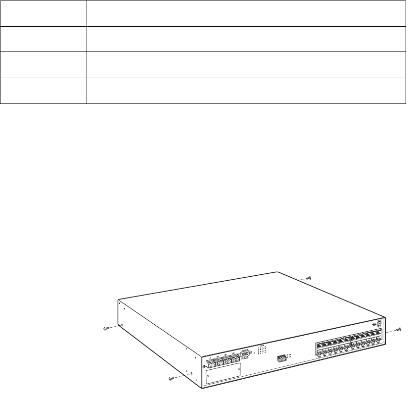
50 Brocade FastIron GS and GS-STK Hardware Installation Guide
Part Number: 53-1002186-03
EPREM Upgrade for FastIron GS Devices
Upgrading hardware
Remove the cover from the device
1. Remove any power cables from the device.
2. If the device is mounted in an equipment rack, remove it from the rack and place the device in a static-free work area.
3. Put on the supplied ESD wrist strap and follow the instructions that came with the strap to ground yourself before you begin.
4. Remove the cover from the device as follows (refer to Figure 1 on page 50):
•
Use a Phillips-head screwdriver to remove the two screws in the bottom corners of each side, refer to Figure 1. If rack
mounting ears are installed, remove the four screws that hold each ear to the device.
•
Turn the device so that the front (where the port connectors are) is facing you.
•
Slide the cover backwards to free the lip edge of the cover from the front plate. Make sure the cover is completely free of
the front panel.
FIGURE 1 Removing cover screws on an FGS device.
5. Remove the cover by sliding it to the rear of the device and then lifting it off, as shown in Figure 2.
TABLE 1
WARNING Disconnect the power cord from all power sources to completely remove power from the
device.
ACHTUNG Ziehen Sie das Stromkabel aus allen Stromquellen, um sicherzustellen, dass dem Gerät
kein Strom zugeführt wird.
AVERTISSEMENT Débranchez le cordon d'alimentation de toutes les sources d'alimentation pour couper
complètement l'alimentation du dispositif.
ADVERTENCIA Para desconectar completamente la corriente del instrumento, desconecte el cordón de
corriente de todas las fuentes de corriente.
Slot 3
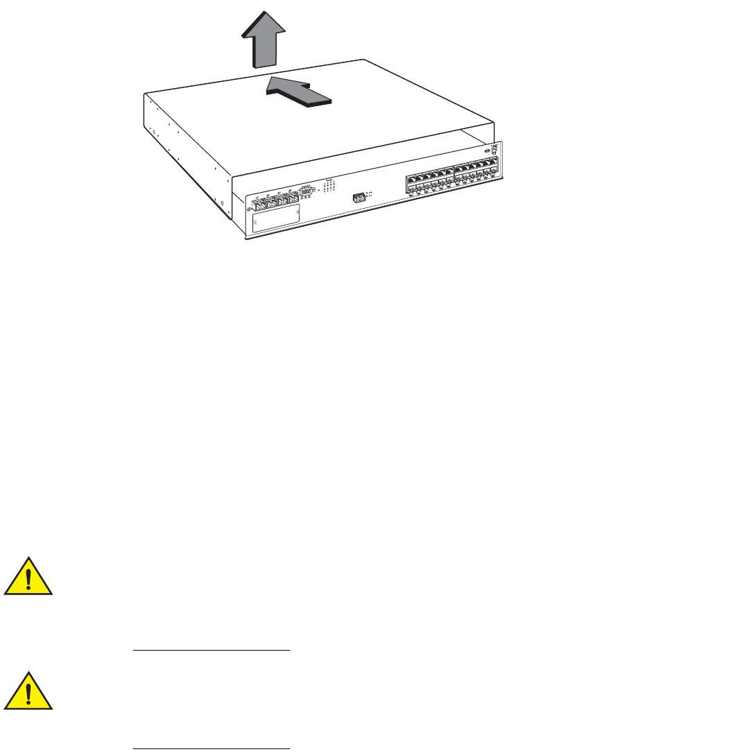
Brocade FastIron GS and GS-STK Hardware Installation Guide 51
Part Number: 53-1002186-03
EPREM Upgrade for FastIron GS Devices
Upgrading hardware
FIGURE 2 Removing the cover from an FGS device.
Installing the EEPROM
1. Remove the EEPROM from the package and align the lead pins over the EEPROM socket. Refer to Figure 3 on page 52 for the
EEPROM socket location on FGS devices.
The semicircular indentation on the EEPROM is located on the same end as pin 1.
.
2. Align the semicircular indentation on the EEPROM with the semicircular cut-out on the EEPROM socket and gently push the
EEPROM into the appropriate socket (for FGS 624 and 648 devices the socket number is U37.
Make sure you insert the EEPROM so that lead pin 1 goes into the correct hole as shown in the
appropriate illustrations. If you accidentally insert the EEPROM backwards, the device will not work and
may be damaged when you power it on.
Do not push too hard. If the EEPROM does not readily go into the socket, stop pushing and verify that the
lead pins are straight and aligned over the holes. Straighten any crooked pins, then try again.
Slot 3
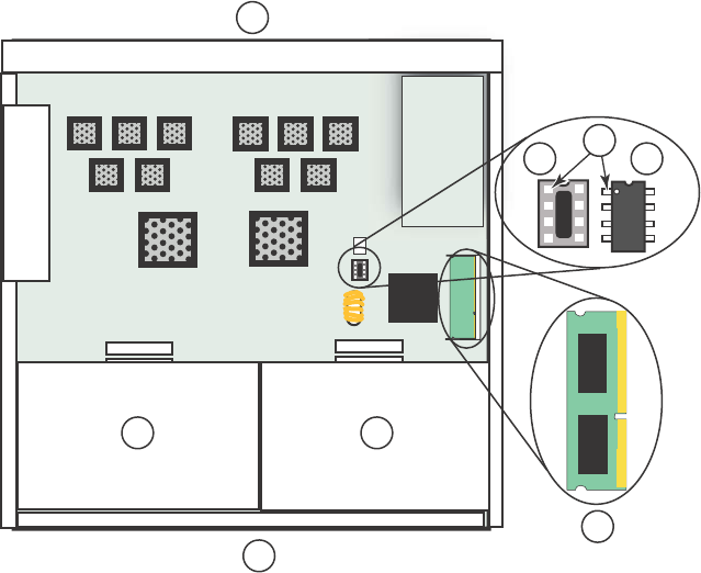
52 Brocade FastIron GS and GS-STK Hardware Installation Guide
Part Number: 53-1002186-03
EPREM Upgrade for FastIron GS Devices
Upgrading software
FIGURE 3 EEPROM Socket Locations on FGS 624 and 648 Devices
3. Replace the cover:
•
Hold the cover on each side at the center and align the front of the cover with the end of the serial interface on the front
panel, so that the cover extends slightly past the front panel of the device.
•
Slide the cover backwards until it is fully flush with the top of the device and slides into place.
•
Re-insert the cover screws.
4. If applicable, re-attach the rack mounting ears.
5. Reinstall the device in the equipment rack, if applicable.
6. Re-insert any power cables and power on the device.
Your EPREM upgrade is now complete. Refer to the <Italic>FastIron Configuration Guide for information about the Edge Layer 3 features
available with release 04.3.01.
Upgrading software
After you install your Edge Layer 3 EEPROM, you will need to upgrade your software. Refer to the release notes for more information.
1 Device front panel
2 Power supplies
3 Device rear panel
4 Pin 1 and socket hole 1
5 EEPROM socket
6EEPROM
7Memory DIMM
1
2
3
7
2
4
5 6
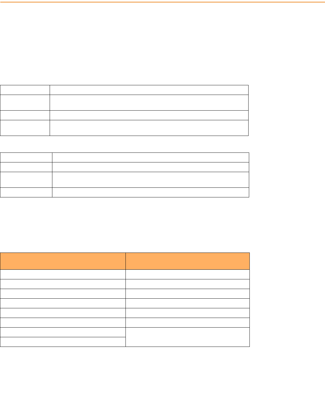
Brocade FastIron GS and GS-STK Hardware Installation Guide 53
Part Number: 53-1002186-03
Stacking Upgrade for the FastIron GS
To upgrade your device, you will need to replace the current 128 MB memory with 256 MB memory, and install the stacking EEPROM.
One upgrade kit also includes a CX4 module for units that do not already have this module installed. Refer to “Upgrade kit contents” on
page 53 for the contents of each kit.
If you have any questions about performing this upgrade, please contact your place of purchase or Brocade at 800-752-8061 inside the
United States or +800-ATFIBREE (+800 28 34 27 33) outside the United States. You also can send email to
IPsupport@brocade.com.
Upgrade kit contents
Before beginning the upgrade, verify the contents of your upgrade kit. If any items are missing, contact your place of purchase. The
upgrade kits contain the following items:
Table 0.1:
WARNING A warning calls your attention to a possible hazard that can cause injury or death.
ACHTUNG "Achtung" weist auf eine mögliche Gefährdung hin, die zu Verletzungen oder Tod führen
können.
AVERTISSEMENT Un avertissement attire votre attention sur un risque possible de blessure ou de décès.
ADVERTENCIA Una advertencia le llama la atención sobre cualquier posible peligro que pueda ocasionar
daños personales o la muerte.
Table 0.2:
WARNING The procedures in this manual are for qualified service personnel.
ACHTUNG Die Verfahren in diesem Handbuch sind nur für qualifiziertes Wartungspersonal gedacht.
AVERTISSEMENT Les procédures décrites dans ce manuel doivent être effectuées par le personnel de
service qualifié uniquement.
ADVERTENCIA Los procedimientos de este manual se han hecho para personal de servicio cualificado.
TABLE 1 Upgrade kit contents
Kit with CX4 Module:
FGS624-STK-CXU, FGS648-STK-CXU,
Kit without CX4 Module:
FGS624-STK-U, FGS648-STK-U
Electrostatic Discharge (ESD) protection kit Electrostatic Discharge (ESD) protection kit
CX4 10Gb Module Stacking EEPROM
Stacking EEPROM 256 MB Memory DIMM
256 MB Memory DIMM CD-ROM with software and documentation
CD-ROM with software and documentation Installation Instructions
Installation Instructions .5 meter CX4 cable
.5 meter CX4 cable Upgrade label
Upgrade label
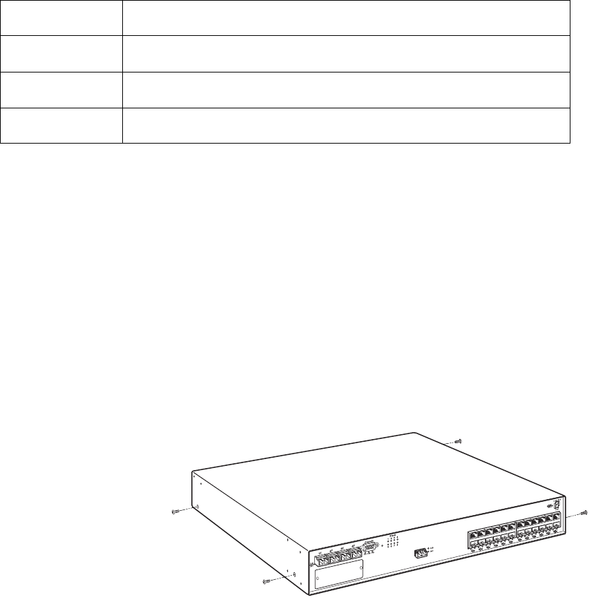
54 Brocade FastIron GS and GS-STK Hardware Installation Guide
Part Number: 53-1002186-03
Stacking Upgrade for the FastIron GS
Upgrading hardware
Upgrading hardware
You need a Phillips-head screwdriver and an ESD wrist strap to perform this procedure. You also need a static-free work area.
To perform the upgrade:
1. Remove all power cables from the device.
2. Remove the device from the equipment rack, if necessary, and place the device in a static-free work area.
3. Put on the supplied ESD wrist strap and attach the clip end to a metal surface (such as an equipment rack) to act as ground.
4. Disassemble the device as follows (refer to Figure 1 on page 54):
•
Use a Phillips-head screwdriver to remove the two screws in the bottom corners of each side. If rack mounting ears are
installed, remove the four screws that hold each ear to the device. Refer to Figure 1.
•
Turn the device so that the front (where the port connectors are) is facing you.
•
Slide the cover backwards to free the lip edge of the cover from the front plate. Make sure the cover is completely free of
the front panel.
FIGURE 1 Removing Cover Screws on FGS Devices.
5. Remove the cover by sliding it back slightly and then lifting it off as shown in Figure 2.
Table 0.3:
WARNING Disconnect the power cord from all power sources to completely remove power from the
device.
ACHTUNG Ziehen Sie das Stromkabel aus allen Stromquellen, um sicherzustellen, dass dem Gerät
kein Strom zugeführt wird.
AVERTISSEMENT Débranchez le cordon d'alimentation de toutes les sources d'alimentation pour couper
complètement l'alimentation du dispositif.
ADVERTENCIA Para desconectar completamente la corriente del instrumento, desconecte el cordón de
corriente de todas las fuentes de corriente.
Slot 3
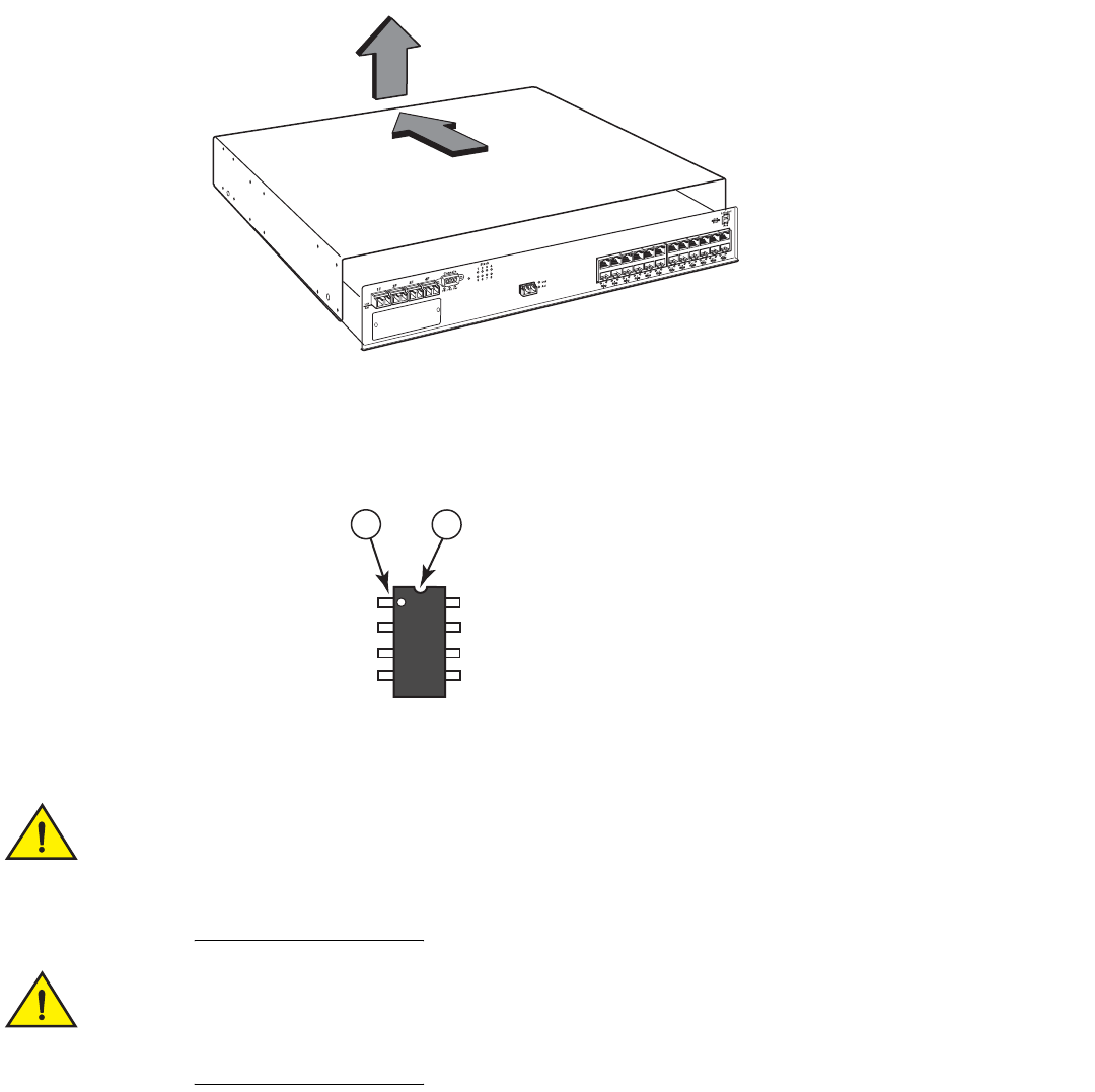
Brocade FastIron GS and GS-STK Hardware Installation Guide 55
Part Number: 53-1002186-03
Stacking Upgrade for the FastIron GS
Upgrading hardware
FIGURE 2 Removing the cover from FGS Devices
6. Remove the EEPROM from the package and align the lead pins over the EEPROM socket. Refer to Figure 3 on page 56 for
the EEPROM socket and Memory DIMM locations on FGS devices.
•
The semicircular indentation on the EEPROM is located on the same end as pin 1.
.
7. Align the semicircular indentation on the EEPROM with the semicircular cut-out on the EEPROM socket and gently push the
EEPROM into the socket.
Make sure you insert the EEPROM so that pin 1 goes into the correct hole as shown in the illustrations. If
you accidentally insert the EEPROM backwards, the device will not work and may be damaged when you
power it on.
Do not push too hard. If the EEPROM does not readily go into the socket, stop pushing and verify that the
lead pins are straight and aligned over the holes. Straighten any crooked pins, then try again.
Slot 3
12
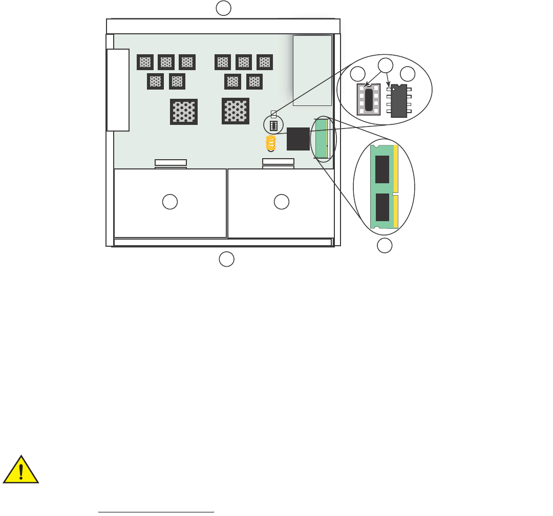
56 Brocade FastIron GS and GS-STK Hardware Installation Guide
Part Number: 53-1002186-03
Stacking Upgrade for the FastIron GS
Upgrading hardware
FIGURE 3 EEPROM and Memory DIMM Locations on FGS Devices
8. To replace the memory DIMM, refer to Figure 5 on page 57. Open the DIMM holder by pushing the tabs apart. Lift the old
DIMM up and pull it out of the holder.
Memory DIMMs are not interchangeable between FGS and FLS devices. Make sure you are installing the
correct DIMM for your device (refer to Figure 4).
1
2
3
7
2
4
5 6
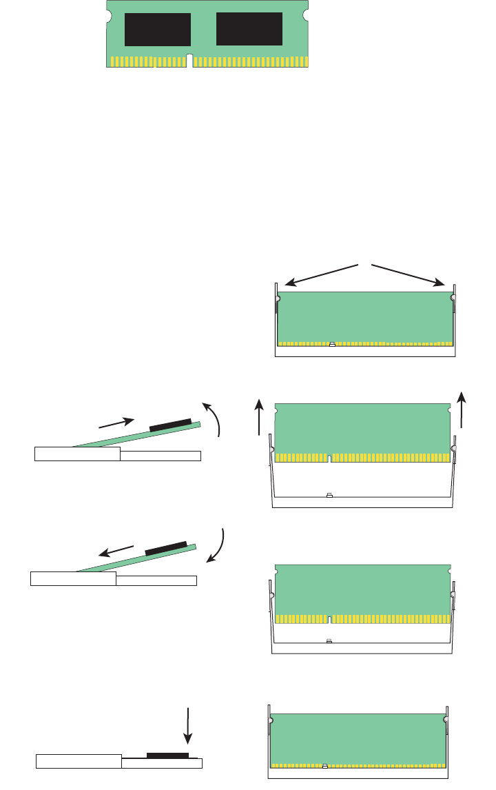
Brocade FastIron GS and GS-STK Hardware Installation Guide 57
Part Number: 53-1002186-03
Stacking Upgrade for the FastIron GS
Upgrading hardware
FIGURE 4 FGS memory DIMM
9. Slide the new DIMM into the holder at an angle (refer to the illustration) and push the connector end into the holder until it snaps
into place.
10. Push straight down on the DIMM to lock it into place in the holder.
FIGURE 5 Replacing the memory DIMM
1. Push memory socket tabs away from DIMM
2. Pull old DIMM up and out of holder at an angle
(see side view)
3. Slide new DIMM gently into holder at an angle
until you feel the connector end snap into place
4. Press DIMM into holder until it is flat and the tabs
on each side click into place
Side view
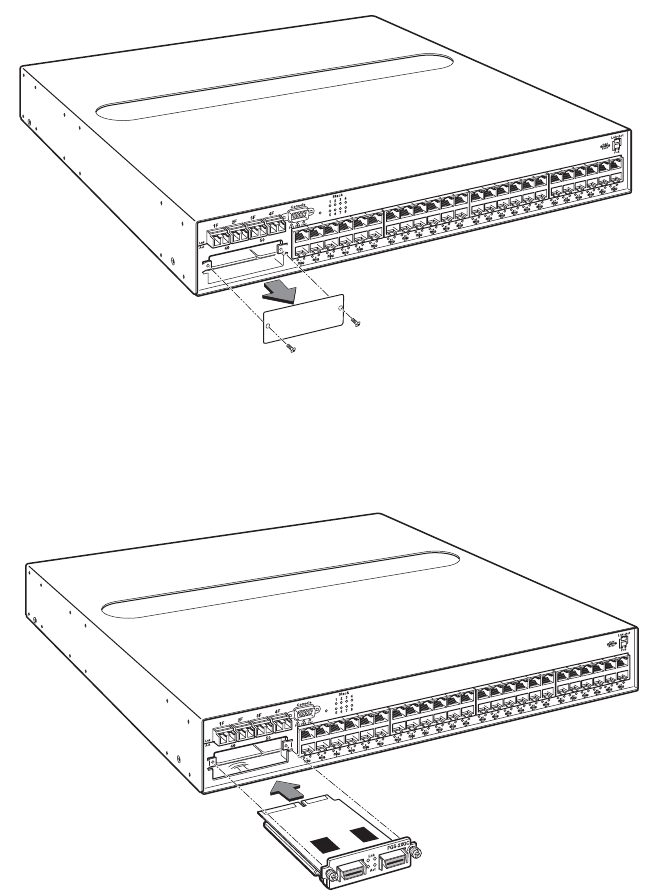
58 Brocade FastIron GS and GS-STK Hardware Installation Guide
Part Number: 53-1002186-03
Stacking Upgrade for the FastIron GS
Upgrading hardware
11. If you are also installing a CX4 10GB module, proceed to step 12 and step 13. If you are not installing a CX4 module, proceed
to step 14.
12. Remove the cover plate from the module slot on the front panel, as shown in Figure 6.
FIGURE 6 Remove cover plate from 10 Gbps module slot
13. Insert the CX4 module into the slot, push gently to engage the connectors, and tighten the thumbscrews on the module
faceplate, as shown in Figure 7.
FIGURE 7 Install the CX4 Module
14. Replace the cover as follows:
•
Hold the cover on each side at the center and align the front of the cover with the end of the serial interface on the front
panel, so that the cover extends slightly past the front panel of the device.
•
Slide the cover backwards until it is fully flush with the top of the device.
•
Re-insert the cover screws.
15. If applicable, re-attach the rack mounting ears.
X4-2XG
Brocade FastIron GS and GS-STK Hardware Installation Guide 59
Part Number: 53-1002186-03
Stacking Upgrade for the FastIron GS
Upgrading Software
16. Reinstall the device in an equipment rack, if necessary.
17. Reconnect power cables to the device.
Your memory and stacking EEPROM hardware upgrade is now complete. Proceed to the next section which has procedures for
upgrading your software.
Refer to “Installing FastIron GS-STK stackable devices” on page 43
for information on how to cable your devices for stacking, and the
<Italic>FastIron Configuration Guide for information about how to operate your device in an IronStack.
Upgrading Software
After you install your EEPROM and memory upgrade components, you will need to upgrade your software to version 05.0.01 or later.
Refer to the procedures in the release notes.
60 Brocade FastIron GS and GS-STK Hardware Installation Guide
Part Number: 53-1002186-03
Stacking Upgrade for the FastIron GS
Upgrading Software

Brocade FastIron GS and GS-STK Hardware Installation Guide 61
Part Number: 53-1002186-03
Connecting Network Devices and
Checking Connectivity
Assigning permanent passwords
The procedures in this manual are intended for qualified service personnel.
Table 1 lists the tasks you must perform to connect your Brocade device, and shows you where to find troubleshooting information for
any problems that may arise.
By default, the CLI is not protected by passwords. To secure CLI access, Brocade strongly recommends assigning passwords.
NOTE
You cannot assign a password using the Web management interface. You can assign passwords using IronView Network
Manager if an enable password for a Super User has been configured on the device.
The CLI contains the following access levels:
•
User EXEC – The level you enter when you first start a CLI session. At this level, you can view some system information but you
cannot configure system or port parameters.
•
Privileged EXEC – Also called the Enable level, and can be secured by a password. At this level, you can perform tasks such as
manage files on the flash module, save the system configuration to flash, and clear caches.
•
CONFIG – This level lets you configure the system IP address, and switching and routing features. To access the CONFIG
mode, you must already be logged into the Privileged level of the EXEC mode (the Enable level).
You can set the following levels of Enable passwords:
•
Super User – Allows complete read-and-write access to the system. This is generally for system administrators and is the only
password level that allows you to configure passwords.
NOTE
You must set a super user password before you can set other types of passwords.
•
Port Configuration – Allows read-and-write access for specific ports but not for global (system-wide) parameters.
TABLE 1 Summary of Network Connectivity Tasks
Task Task Description Where to Find More Information
1 Secure access to the CLI by assigning passwords. “Assigning permanent passwords” on page 61
2 Configure IP addresses for the management, Ethernet,
virtual, and loopback interfaces.
“Configuring IP addresses” on page 63
3 Connect your device to another networking device. “Connecting network devices” on page 66
4 Test a port for connectivity to other networking devices
using the ping and traceroute commands.
“Testing connectivity” on page 69
5 Troubleshoot any problems that may arise. “Troubleshooting network connections” on
page 71

62 Brocade FastIron GS and GS-STK Hardware Installation Guide
Part Number: 53-1002186-03
Connecting Network Devices and Checking Connectivity
Assigning permanent passwords
•
Read Only – Allows access to the Privileged EXEC mode and CONFIG mode but only with read access.
To set passwords:
1. At the opening CLI prompt, enter the following command to change to the Privileged level of the EXEC mode:
FGS 624> enable
2. Access the CONFIG level of the CLI by entering the following command:
FGS 624
# configure terminal
FGS 624(config)
#
3. Enter the following command to set the super-user password:
FGS 624(config)
#
enable super-user-password <text>
NOTE
You must set the super user password before you can set other types of passwords.
4. Enter the following commands to set the port configuration and read-only passwords:
FGS 624(config)# enable port-config-password <text>
FGS 624(config)# enable read-only-password <text>
NOTE
If you forget your super user password, refer to “Recovering from a lost password”.
Syntax: enable super-user-password | read-only-password | port-config-password <text>
Passwords can be up to 32 characters long.
Assigning a password to an IronStack
If you have connected devices in a stack topology, you need only assign a password to the device that will be the Active Controller for the
stack. The Active Controller is generally the first device you connect in a stack topology and is assigned the highest priority in the stack.
For more information on stack priorities, device stack roles, and ID numbers, refer to the <Italic>FastIron Configuration Guide.
Recovering from a lost password
By default, the CLI does not require passwords. However, if someone has configured a password for the device but the password has
been lost, you can regain super-user access to the device using the following procedure.
NOTE
Recovery from a lost password requires direct access to the serial port and a system reset.
To recover from a lost password:
1. Start a CLI session over the serial interface to the Brocade device.
2. Reboot the device.
3. While the system is booting, before the initial system prompt appears, enter b to enter the boot monitor mode.
4. Enter no password at the prompt. (You cannot abbreviate this command.)
5. Enter boot system flash primary at the prompt. This command causes the device to bypass the system password check.
6. After the console prompt reappears, assign a new password.

Brocade FastIron GS and GS-STK Hardware Installation Guide 63
Part Number: 53-1002186-03
Connecting Network Devices and Checking Connectivity
Configuring IP addresses
Configuring IP addresses
You must configure at least one IP address using the serial connection to the CLI before you can manage the system using the other
management interfaces. In addition, Brocade routers require an IP subnet address for the subnet in which you plan to place them in your
network.
Brocade devices support both classical IP network masks (Class A, B, and C subnet masks, and so on) and Classless Interdomain Routing
(CIDR) network prefix masks.
•
To enter a classical network mask, enter the mask in IP address format. For example, enter
“209.157.22.99 255.255.255.0” for an IP address with a Class-C subnet mask.
•
To enter a prefix number for a network mask, enter a forward slash ( / ) and the number of bits in the mask immediately after the
IP address. For example, enter “209.157.22.99/24” for an IP address that has a network mask with 24 significant (“mask”) bits.
By default, the CLI displays network masks in classical IP address format (example: 255.255.255.0). You can change the display to the
prefix format. Refer to the <Italic>FastIron Configuration Guide.
Devices running base layer 3 software
You can configure an IP address on the following types of Base Layer 3 Switch interfaces:
•
Ethernet port
•
Virtual routing interface (also called a Virtual Ethernet or “VE”)
•
Loopback interface
By default, you can configure up to 24 IP addresses on each interface. On Compact Base Layer 3 Switches, you can increase this
amount to up to 64 IP subnet addresses per port by increasing the size of the subnet-per-interface table.
Once you configure a virtual routing interface on a VLAN, you cannot configure Layer 3 interface parameters on individual ports in the
VLAN. Instead, you must configure the parameters on the virtual routing interface itself.
Brocade devices support both classical IP network masks (Class A, B, and C subnet masks, and so on) and Classless Interdomain Routing
(CIDR) network prefix masks.
•
To enter a classical network mask, enter the mask in IP address format. For example, enter
“209.157.22.99 255.255.255.0” for an IP address with a Class-C subnet mask.
•
To enter a prefix network mask, enter a forward slash ( / ) and the number of bits in the mask immediately after the IP address.
For example, enter “209.157.22.99/24” for an IP address that has a network mask with 24 significant bits (ones).
By default, the CLI displays network masks in classical IP address format (example: 255.255.255.0). You can change the display to
prefix format.
Assigning an IP address to an Ethernet port
To assign an IP address to port 0/1/1, enter the following commands:
FastIron(config)#interface ethernet 0/1/1
FastIron(config-if-0/1/1)#ip address 192.45.6.1 255.255.255.0
NOTE
You also can enter the IP address and mask in CIDR format, as follows:
FastIron
(config-if-0/1/1)# ip address 192.45.6.1/24

64 Brocade FastIron GS and GS-STK Hardware Installation Guide
Part Number: 53-1002186-03
Connecting Network Devices and Checking Connectivity
Configuring IP addresses
Syntax: [no] ip address <ip-addr> <ip-mask> [ospf-ignore | ospf-passive | secondary]
or
Syntax: [no] ip address <ip-addr>/<mask-bits> [ ospf-ignore | ospf-passive | secondary]
The ospf-ignore | ospf-passive parameters modify the switch defaults for adjacency formation and interface advertisement. Use one of
these parameters if you are configuring multiple IP subnet addresses on the interface but you want to prevent OSPF from running on
some of the subnets.
•
ospf-passive – This option disables adjacency formation with OSPF neighbors. By default, when OSPF is enabled on an
interface, the software forms OSPF router adjacencies between each primary IP address on the interface and the OSPF
neighbor attached to the interface.
•
ospf-ignore – This option disables OSPF adjacency formation and also disables advertisement of the interface into OSPF. The
subnet is completely ignored by OSPF.
NOTE
The ospf-passive option disables adjacency formation but does not disable advertisement of the interface into OSPF. To disable
advertisement in addition to disabling adjacency formation, you must use the ospf-ignore option.
Use the secondary parameter if you have already configured an IP address within the same subnet on the interface.
NOTE
When you configure more than one address in the same subnet, all but the first address are secondary addresses and do not form
OSPF adjacencies.
Assigning an IP address to a loopback interface
Loopback interfaces are always up, regardless of the states of physical interfaces. They can add stability to the network because they are
not subject to route flap problems that can occur due to unstable links between a Base Layer 3 Switch and other devices. You can
configure up to four loopback interfaces on an FGS device.
You can add up to 24 IP addresses to each loopback interface.
NOTE
If you configure the Brocade device to use a loopback interface to communicate with a BGP4 neighbor, you also must configure
a loopback interface on the neighbor and configure the neighbor to use that loopback interface to communicate with the Brocade
device. To add a loopback interface, enter commands such as those shown in the following example:
FastIron(config-bgp-router)# exit
FastIron(config)# interface loopback 1
FastIron(config-lbif-1)# ip address 10.0.0.1/24
Syntax: interface loopback <num>
The <num> parameter specifies the virtual interface number. You can specify from 1 to the maximum number of virtual interfaces
supported on the device. To display the maximum number of virtual interfaces supported on the device, enter the show default values
command. The maximum is listed in the System Parameters section, in the Current column of the virtual-interface row.
Assigning an IP address to a virtual interface
A virtual interface is a logical port associated with a Layer 3 Virtual LAN (VLAN) configured on a device. You can configure routing
parameters on the virtual interface to enable the switch to route protocol traffic from one Layer 3 VLAN to the other, without using an
external router.

Brocade FastIron GS and GS-STK Hardware Installation Guide 65
Part Number: 53-1002186-03
Connecting Network Devices and Checking Connectivity
Configuring IP addresses
This section describes how to configure an IP address on a virtual interface.
NOTE
The Brocade FGS device uses the lowest MAC address on the device (the MAC address of port 1 or 1/1) as the MAC address
for all ports within all virtual interfaces you configure on the device.
To add a virtual interface to a VLAN and configure an IP address on the interface, enter commands such as the following:
FastIron
(config)# vlan 2 name IP-Subnet_1.1.2.0/24
FastIron
(config-vlan-2)# untag e1 to 4
FastIron
(config-vlan-2)# router-interface ve1
FastIron
(config-vlan-2)# interface ve1
FastIron
(config-vif-1)# ip address 1.1.2.1/24
The first two commands in this example create a Layer 3 protocol-based VLAN name “IP-Subnet_1.1.2.0/24” and add a range of
untagged ports to the VLAN. The router-interface command creates virtual interface 1 as the routing interface for the VLAN. The last
two commands change to the interface configuration level for the virtual interface and assign an IP address to the interface.
Syntax: router-interface ve <num>
Syntax: interface ve <num>
Deleting an IP address
To delete an IP address, enter a command such as the following:
FastIron(config-if-e1000-1)# no ip address 1.1.2.1
This command deletes IP address 1.1.2.1. You do not need to enter the subnet mask.
To delete all IP addresses from an interface, enter the following command:
FastIron(config-if-e1000-1)# no ip address *
Syntax: no ip address <ip-addr> | *
Devices running layer 2 software
To configure an IP Address on a device running Layer 2 software:
1. At the opening CLI prompt, enter enable.
FastIron
> enable
2. Enter the following command at the Privileged EXEC level prompt (for example, FastIron Switch#), then press Enter. This
command erases the factory test configuration if still present:
FastIron
# erase startup-config
Use the erase startup-config command only for new systems. If you enter this command on a system you
have already configured, the command erases the configuration. If you accidentally do erase the
configuration on a configured system, enter the write memory command to save the running configuration
to the startup-config file.

66 Brocade FastIron GS and GS-STK Hardware Installation Guide
Part Number: 53-1002186-03
Connecting Network Devices and Checking Connectivity
Connecting network devices
3. Access the configuration level of the CLI by entering the following command:
FastIron
# configure terminal
Privileged EXEC Level
FastIron
(config)#
Global CONFIG Level
4. Configure the IP address and mask for the switch.
FastIron(config)# ip address 192.22.3.44 255.255.255.0
5. Set a default gateway address for the switch.
FastIron(config)# ip default-gateway 192.22.3.1
NOTE
You do not need to assign a default gateway address for single subnet networks.
Syntax: enable [<password>]
Syntax: configure terminal
Syntax: [no] ip address <ip-addr> <ip-mask>
or
Syntax: [no] ip address <ip-addr>/<mask-bits>
Syntax: ip default-gateway <ip-addr>
Devices running stacking software
FGS-STK devices that are members of an IronStack are managed by the device that is the Active Controller of the stack. There are
several ways to assign an IP address to the Active Controller. For more information about configuring devices in a stack, refer to chapter
4 in the <Italic>FastIron Configuration Guide:
Connecting network devices
Brocade devices support connections to other vendors’ routers, switches, and hubs, as well other Brocade devices.
Connectors and cable specifications
Refer to “Cable specifications” on page 73 for cable lengths and types supported on FGS and FGS-STK devices. For port pinouts, refer
to “10/100/1000 Gigabit port pinouts” on page 72.
Connecting to Ethernet or fast Ethernet Hubs
For copper connections to Ethernet hubs, a 10/100Base-TX or 1000Base-T switch, or another Brocade device, a crossover cable is
required (Figure 1 and Figure 2). If the hub is equipped with an uplink port, it will require a straight-through cable instead of a crossover
cable.
NOTE
The 802.3ab standard (automatic MDI or MDIX detection) calls for automatic negotiation of the connection between two
1000Base-T ports. Therefore, a crossover cable may not be required; a straight-through cable may work as well. For more
information about this feature, refer to the <Italic>FastIron Configuration Guide.
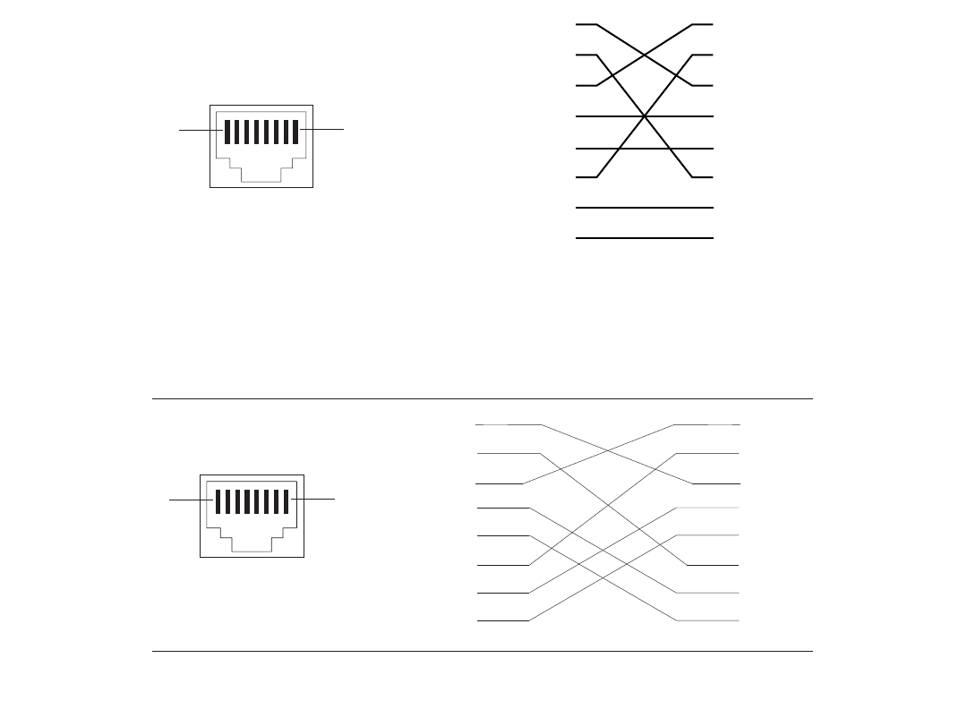
Brocade FastIron GS and GS-STK Hardware Installation Guide 67
Part Number: 53-1002186-03
Connecting Network Devices and Checking Connectivity
Connecting network devices
FIGURE 1 UTP Crossover Cable
FIGURE 2 Cat-5 Crossover Cable for 1000Base-T
NOTE
The 802.3ab standard calls for automatic negotiation of the connection between two 1000Base-T ports. Consequently, a
crossover cable may not be required; a straight-through cable may work as well.
Connecting to workstations, servers, or routers
Straight-through UTP cabling is required for direct UTP attachment to workstations, servers, or routers using network interface cards
(NICs).
Fiber cabling is required for direct attachment to Gigabit NICs or switches and routers through fiber ports. Refer to “Connecting a network
device to a fiber port” on page 68.
Automatic MDI or MDIX detection
All 10/100 and Gigabit Ethernet Copper ports on FGS and FGS-STK devices support automatic Media Dependent Interface (MDI) and
Media Dependent Interface Crossover (MDIX) detection. This feature is enabled on all 10/100 and Gigabit copper ports by default. For
each port, you can disable auto MDI or MDIX, designate the port as an MDI port, or designate the port as an MDIX port.
11
22
33
66
4
5
7
11
22
33
6
8
44
5
7
8
18
UTP Crossover Cable 10/100BaseTX
- Unused
Unused - - Unused
Unused -
Unused -
Unused -
- Unused
- Unused
1
2
3
4
5
6
7
8
1
2
3
4
5
6
7
8
18
Cat-5 Crossover Cable
1000BaseT

68 Brocade FastIron GS and GS-STK Hardware Installation Guide
Part Number: 53-1002186-03
Connecting Network Devices and Checking Connectivity
Connecting network devices
For more information about this feature and how configure it, refer to the <Italic>FastIron Configuration Guide.
Connecting a network device to a fiber port
For direct attachment from the Brocade device to a Gigabit NIC, switch, or router, fiber cabling with an LC connector is required.
To connect the Brocade device to another network device using a fiber port, you must do the following:
•
Install a fiber optic module (SFP transceiver or mini-GBIC for Gigabit Ethernet ports, or XFP-MSA transceiver for 10-Gigabit
Ethernet ports)
•
Cable the fiber optic module
The following sections provide information about performing these tasks.
Installing a fiber optic module
You must install a fiber optic module (SFP or XFP transceiver) in each Gigabit Ethernet and 10-Gigabit Ethernet fiber port you want to
use.
You can install a new fiber optic module in a port while the Brocade device is powered on and running.
To install a fiber optic module, you will need an ESD wrist strap with a plug for connection to a metal surface.
For safety reasons, the ESD wrist strap should contain a series 1 meg ohm resistor.
To install a fiber optic module:
1. Put on the ESD wrist strap and ground yourself by attaching the clip end to a metal surface (such as an equipment rack) to act as
ground.
2. Remove the new module from its protective packaging.
3. Gently insert the fiber optic module into the port until the module clicks into place. The module is keyed to prevent incorrect
insertion.
Cabling a fiber optic module
To cable a fiber optic module:
1. Remove the protective covering from the fiber-optic port connectors and store the covering for future use.
2. Before cabling a fiber optic module, Brocade strongly recommends cleaning the cable connectors and the port connectors. For
more information, refer to “Cleaning the fiber-optic connectors” on page 68.
3. Gently insert the cable connectors (a tab on each connector should face upward) into the port connectors until the tabs lock into
place.
4. Observe the link and active LEDs to determine if the network connections are functioning properly. Refer to Table 2 on page 70.
Cleaning the fiber-optic connectors
To avoid problems with the connection between the fiber optic module (SFP (mini-GBIC) or XFP) and the fiber cable connectors, Brocade
strongly recommends cleaning both connectors each time you disconnect and reconnect them. In particular, dust can accumulate in the
connectors and cause problems such as reducing the optic launch power.
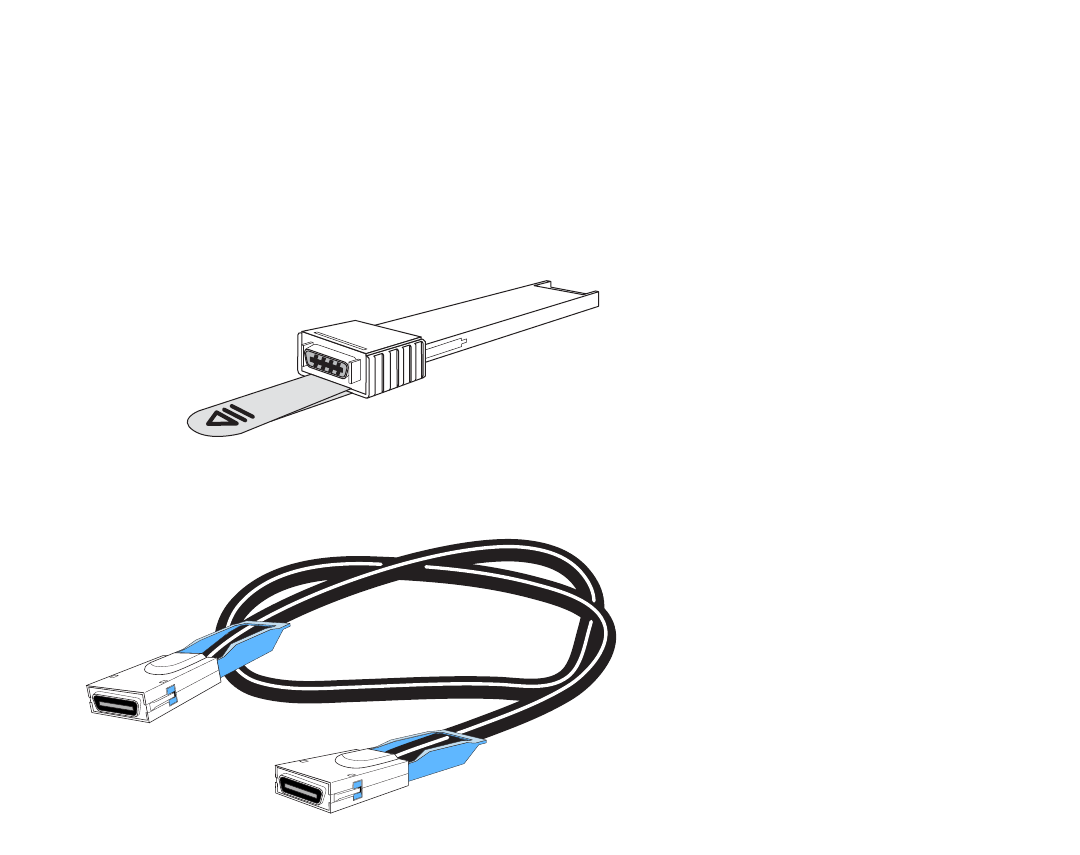
Brocade FastIron GS and GS-STK Hardware Installation Guide 69
Part Number: 53-1002186-03
Connecting Network Devices and Checking Connectivity
Testing connectivity
To clean the fiber cable connectors, Brocade recommends using the fiber-optic cleaner that shipped with your Brocade device. You can
also purchase this type of cleaner from the following Website:
http://www.fisfiber.com
When not using an SFP or XFP connector, make sure to keep the protective covering on.
Using a CX4 transceiver
FGS and FGS-STK devices support a twin-axial 10G copper CX4 XFP transceiver that can be installed in any 10G port.
NOTE
For a link to operate properly, both sides must use identical CX4 transceivers.
The CX4 transceiver requires a 15 meter CX4-grade cable, which may be purchased from Brocade. Refer to part number
CAB-CX4-0050 when ordering.
NOTE
The CX4 transceiver is not hot-swappable.
Testing connectivity
After you install the network cables, you can test network connectivity to other devices by pinging those devices. You also can observe
the LEDs related to network connection and perform trace routes.

70 Brocade FastIron GS and GS-STK Hardware Installation Guide
Part Number: 53-1002186-03
Connecting Network Devices and Checking Connectivity
Testing connectivity
Pinging an IP address
To verify that a Brocade device can reach another device through the network, enter a command such as the following at any level of the
CLI on the Brocade device:
FastIron> ping 192.33.4.7
Syntax: ping <ip-addr> | <hostname> [source <ip-addr>] [count <num>] [timeout <msec>] [ttl <num>] [size <byte>] [quiet]
[numeric] [no-fragment] [verify] [data <1-to-4 byte hex>] [brief]
NOTE
If you address the ping to the IP broadcast address, the device lists the first four responses to the ping.
Observing LEDs
After you install the network cables, you can observe certain LEDs to determine if the network connections are functioning properly.
Table 2 describes the LEDs related to network connections, the desired state of each LED, possible abnormal states of each LED, and
what to do if an LED indicates an abnormal state.
If a problem persists after taking these actions, contact Brocade technical support.
TABLE 2 Network Connection-Related LED States
LED Desired
State
Meaning Abnormal
State
Meaning /Action
Link (Lnk) On (Green) A link is established with
the remote port.
Off A link is not established with the remote port. You can do the
following:
•
Verify that the connection to the other network device has
been properly made. Also, make certain that the other
network device is powered on and operating correctly.
•
Verify that the transmit port on the Brocade device is
connected to the receive port on the other network device,
and that the receive port on the Brocade device is
connected to the transmit port on the other network device.
If you are not certain, remove the two cable connectors
from the port connector and reinsert them in the port
connector, reversing their order.
•
Dust may have accumulated in the cable connector or port
connector. For information about cleaning the connectors,
refer to “Cleaning the fiber-optic connectors” on page 68.
•
If the other actions do not resolve the problem, try using a
different port or a different cable.
Active (Act) On or
blinking
(Yellow)
The port is transmitting
and receiving user
packets.
Off for an
extended
period.
The port is not transmitting or receiving user packets. You can
do the following:
•
Check the Link LED to make sure the link is still established
with the remote port. If not, take the actions described in
the Meaning or Action column for the Link LED.
•
Verify that the port has not been disabled through a
configuration change. You can use the CLI. If you have
configured an IP address on the device, you also can use
the Web management interface or IronView Network
Manager.

Brocade FastIron GS and GS-STK Hardware Installation Guide 71
Part Number: 53-1002186-03
Connecting Network Devices and Checking Connectivity
Troubleshooting network connections
Tracing a Route
To determine the path through which a Brocade FGS or FGS-STK device can reach another device, enter a command such as the
following at any level of the CLI on the Brocade device:
FGS 624> traceroute 192.33.4.7
Syntax: traceroute <host-ip-addr> [maxttl <value>] [minttl <value>] [numeric] [timeout <value>]
[source-ip <ip-addr>]
The CLI displays trace route information for each hop as soon as the information is received. Traceroute requests display all responses to
a given TTL. In addition, if there are multiple equal-cost routes to the destination, the Brocade device displays up to three responses by
default.
Troubleshooting network connections
•
For the indicated port, verify that both ends of the cabling (at the Brocade device and the connected device) are snug.
•
Verify that the Brocade device and the connected device are both powered on and operating correctly.
•
Verify that you have used the correct cable type for the connection:
•
For twisted-pair connections to an end node, use straight-through cabling.
•
For fiber-optic connections, verify that the transmit port on the device is connected to the receive port on the connected
device, and that the receive port on the device is connected to the transmit port on the connected device.
•
Verify that the port has not been disabled through a configuration change. You can use the CLI. If you have configured an IP
address on the device, you also can use the Web management interface or IronView Network Manager.
•
For copper ports, you can test the cable using Virtual Cable Testing. Refer to “Using Virtual Cable Testing to diagnose a cable”.
•
If the other procedures do not resolve the problem, try using a different port or a different cable.
Using Virtual Cable Testing to diagnose a cable
NOTE
Virtual Cable Testing is not supported for FGS-STK devices running software version 05.0.01.
FGS devices support Virtual Cable Test (VCT) technology. VCT technology enables you to diagnose a conductor (wire or cable) by
sending a pulsed signal into the conductor, then examining the reflection of that pulse. This method of cable analysis is referred to as Time
Domain Reflectometry (TDR). By examining the reflection, the Brocade device can detect and report cable statistics such as local and
remote link pair, cable length, and link status.
Configuration notes
•
This feature is supported on copper ports only. It is not supported on fiber ports.
•
The port to which the cable is connected must be enabled when you issue the command to diagnose the cable. If the port is
disabled, the command is rejected.
•
If the port is operating at 100 Mbps half-duplex, the TDR test on one pair will fail.
•
If the remote pair is set to forced 100 Mbps, any change in MDI or MDIX may cause the device to interpret the Multilevel
Threshold-3 (MLT-3) as a reflected pulse, in which case, the device will report a faulty condition. In this case, Brocade
recommends that you run the TDR test a few times for accurate results.

72 Brocade FastIron GS and GS-STK Hardware Installation Guide
Part Number: 53-1002186-03
Connecting Network Devices and Checking Connectivity
Troubleshooting network connections
Command syntax
To diagnose a cable using TDR, enter a command such as the following at the Privileged EXEC level of the CLI:
FGS 624# phy cable-diag tdr 1
This command diagnoses the cable attached to port 1.
Syntax: phy cable-diag tdr <port-num>
Viewing the results of the cable analysis
To display the results of the cable analysis, enter a command such as the following at the Privileged EXEC level of the CLI:
Syntax: show cable-diag tdr <port-num>
Table 3 defines the fields shown in the command output.
Digital Optical Monitoring
NOTE
Digital Optical Monitoring is not supported for FGS-STK devices running release 05.0.01.
TABLE 3 Cable Statistics
This Line... Displays...
Port The port that was tested.
Speed The port’s current line speed.
Local pair The local link name.
Pair Length The cable length when terminated, or the distance to the point of fault when the
line is not up.
Remote pair The remote link name.
Pair status The status of the link. This field displays one of the following:
•
Terminated: The link is up.
•
Shorted: A short is detected in the cable.
•
Open: An opening is detected in the cable.
•
ImpedMis: The impedance is mismatched.
•
Failed: The TDR test failed.
FGS 624#show cable-diag tdr 1
Port Speed Local pair Pair Length Remote pair Pair status
--------- ----- ---------- ----------- ----------- -----------
01 1000M Pair A <50M Pair B Terminated
Pair B <50M Pair A Terminated
Pair C <50M Pair D Terminated
Pair D <50M Pair C Terminated
Brocade FastIron GS and GS-STK Hardware Installation Guide 73
Part Number: 53-1002186-03
Connecting Network Devices and Checking Connectivity
Troubleshooting network connections
You can configure your Foundry device to monitor optical transceivers in the system, either globally or by specified port. When this
feature is enabled, the system monitors the temperature and signal power levels for the optical transceivers in the specified ports.
Console messages and syslog messages are sent when optical operating conditions fall below or rise above the XFP or SFP
manufacturer’s recommended thresholds. For more information about digital optical monitoring, refer to the <Italic>FastIron Configuration
Guide.
74 Brocade FastIron GS and GS-STK Hardware Installation Guide
Part Number: 53-1002186-03
Connecting Network Devices and Checking Connectivity
Troubleshooting network connections

Brocade FastIron GS and GS-STK Hardware Installation Guide 75
Part Number: 53-1002186-03
Hardware Specifications
Device specifications
Physical dimensions and weight
Table 1 lists the physical dimensions and weight of FastIron GS and GS-STK devices and modules.
Environmental considerations
For optimal performance, operate or store your Brocade FGS or FGS-STK device in compliance with the following environmental
conditions.
TABLE 1 Physical Dimensions and Weight of FGS and FGS-STK Devices and Modules
Platform Height Width Depth Weight
FGS624P
and
FGS624P-POE
6.68 cm
2.63 in
44.45 cm
17.5 in
49.78 cm
19.6 in
•
11.36 kg (25 lbs) fully
loaded, including dual
redundant power supplies
•
7.94 kg (17.5 lbs) device
only
FGS648P and
FGS648P-POE
6.68 cm
2.63 in
44.45 cm
17.5 in
49.78 cm
19.6 in
•
13.15 kg (29 lbs) fully
loaded, including dual
redundant power supplies
•
7.94 kg (17.5 lbs) device
only
FGS624P-STK
and
FGS624P-POE-S
TK
6.68 cm
2.63 in
44.45 cm
17.5 in
49.78 cm
19.6 in
•
13.15 kg (29.25 lbs) fully
loaded, including dual
redundant power supplies
and 2XGC module
•
7.94 kg (17.5 lbs) device
only
FGS648P-STK
and
FGS648POE-STK
6.68 cm
2.63 in
44.45 cm
17.5 in
49.78 cm
19.6 in
•
13.15 kg ( 29.25 lbs) fully
loaded, including dual
redundant power supplies
and 2XGC module
•
7.94 kg (17.5 lbs) device
only
FGS-2XG module 1.9 cm
.75 in
8.26 cm
3.25 in
15.24 cm
6 in
•
6.4 oz or .18 kg (.40 lbs)
FGS2XGC module 1.27 cm
.5 in
8.26 cm
3.25 in
15.24 cm
6 in
•
4 oz or .11 kg (.25 lb )
FGS1XG and FGS
1XGC modules
1.27 cm
.5 in
8.26 cm
3.25 in
15.24 cm
6 in
•
4.8 oz or .14 kg (.30 lb )
TABLE 2 Environmental Conditions for the Device
Description Range
Operating Environment
Operating temperature 32
°
– 104
°
F (0
°
– 40
°
C)
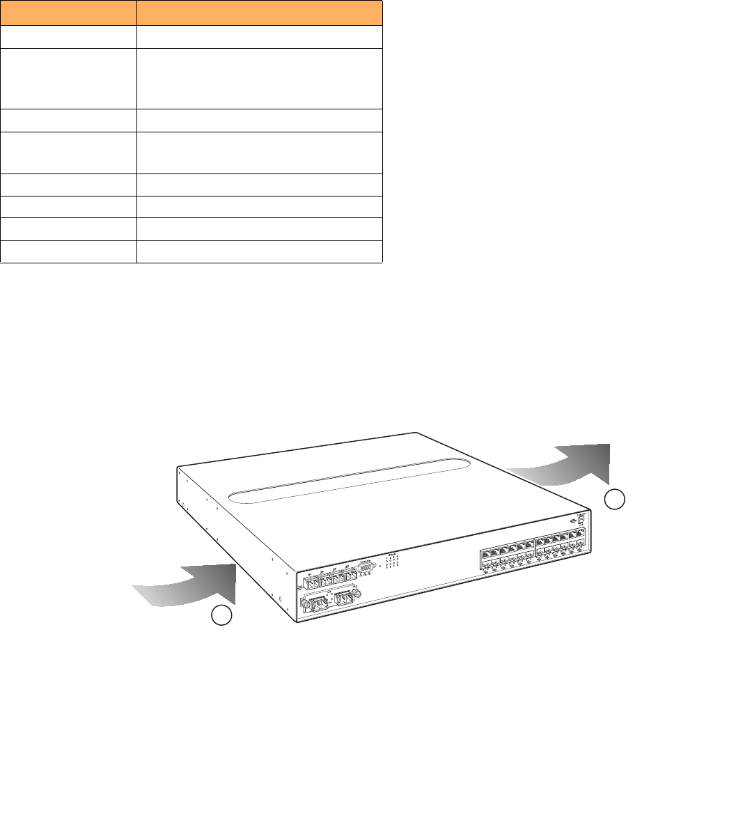
76 Brocade FastIron GS and GS-STK Hardware Installation Guide
Part Number: 53-1002186-03
Hardware Specifications
Device specifications
Cooling
FGS or FGS-STK devices have two single-speed fans that operate simultaneously to cool the CPU, main memory, and voltage
regulators. If one fan fails, it does not affect the operation of the other fan. The fans use either a push or pull configuration to move the air
from the left side of the device to the right side of the device as shown in Figure 1
FIGURE 1 Device air flow
2
•
Total cooling capacity: 120 watts
•
Total air flow: 80 LFM
•
Fan operating noise: < 51 dB-A.
NOTE
Operating noise is based on the ISO 7779 standard.
Operating altitude 6,600 feet maximum
Relative humidity 5 to 95%, @ 104
°
F (40
°
C), non-condensing
or
5 to 95% non-condensing for DC power supply
Operating noise 47 – 51 dB
Maximum heat
dissipation
328 BTU/Hr with 2-port 10-Gigabit uplinks
280 BTU/Hr without 2-port 10-Gigabit uplinks
Storage Environment
Storage temperature -23
°
to 158
°
F, -25
°
to 70
°
C
Storage humidity 95% maximum, non-condensing
Storage altitude 15,000 feet ( 3,000 meter) maximum
1 Air intake
Air outflow
TABLE 2 Environmental Conditions for the Device (Continued)
Description Range
26
25
X4-2XG
1
2

Brocade FastIron GS and GS-STK Hardware Installation Guide 77
Part Number: 53-1002186-03
Hardware Specifications
Device specifications
Regulatory compliance
Table 3 lists the Electromagnetic Compatibility (EMC), Immunity standards, and safety agency approvals for FastIron GS and FastIron
GS-STK switches.
Power source interruptions
Table 4 shows how the FastIron GS and GS-STK devices protect against power surges and power drops.
TABLE 3 Device Regulatory Compliance
Description Certifications
Electromagnetic Emissions FCC Part 15, Subpart B (Class A)
EN 55022 (CE mark) (Class A)
ICES-003 (Canada) (Class A)
AS/NZ 55022 (Australia) (Class A)
VCCI (Japan) (Class A)
EN 61000-3-2
EN 61000-3-3
KN 22
EN61000-6-3
CISPR 22 Class A
FCC Class A
VCCI Class A
EN55022 Class A
Harmonic Current Emissions (Class A) - EN61000-3-2, with
Amendment 14 (1999)
EN61000-3-3 Voltage Fluctuations and Flicker
Immunity EN 55024
EN61000-6-1
EN61000-4-5. The power supply is tested to 1kV (differential
mode) and 2kV (common mode)
Safety EN 60950-1
CAN or CS-C22.2 No. 60950-1
EN 60825-1, Safety of Laser Products - Part 1
EN 60825-2, Safety of Laser Products - Part 2
IEC 60950-1
UL 60950-1
TABLE 4 Device Power Surge and Drop Protection
Property Protection Mechanism
Power surge MOV and Spark Gap protection
Power drop (<=1 second) An AC loss of >15ms will cause the power supply to shut
down due to input under-voltage
Maximum power draw 96 watts with 2-port 10-Gigabit uplinks
82 watts without 2-port 10-Gigabit uplinks

78 Brocade FastIron GS and GS-STK Hardware Installation Guide
Part Number: 53-1002186-03
Hardware Specifications
Device specifications
Mean Time Between Failure
Table 5 lists the Mean Time Between Failure (MTBF) for the FastIron GS, FastIron GS-STK, and 10 Gbps uplink modules. The MTBF is
the average estimated time, in hours, before a hardware failure may occur.
Power draw specifications
Table 6 lists the typical and maximum power draw specifications for FGS and FGS-STK models.
TABLE 5 MTBF for the FastIron GS and GS-STK and 10 Gbps Modules
Configuration/Module Temperature MTBF (hours)
Without POE With POE
24-port POE ready + 4 SFPs + 2-port 10 Gbps
module + 2 XFPs + 1 power supply
40 Deg. Celsius 150,879 142,217
24-port POE ready + 4 SFPs + 2-port 10 Gbps
module + 2 XFPs + 2 powers supplies
40 Deg. Celsius 267,411 241,356
48-port POE ready + 4 SFPs + 2-port 10 Gbps
module + 2 XFPs + 1 power supply
40 Deg. Celsius 133,825 120,775
48-port POE ready + 4 SFPs + 2-port 10 Gbps
module + 2 XFPs + 2 power supplies
40 Deg. Celsius 218,140 196,401
2-port 10 Gbps XFP module 40 Deg. Celsius 1,597,580 N/A
2-port 10 Gbps CX4 module 40 Deg. Celsius N/A 29,673,590
1-port 10 Gbps XFP + 1-port 10 Gbps CX4 module 40 Deg. Celsius N/A 2,364,614
1-port 10 Gbps XFP module 40 Deg. Celsius N/A 2,501,219
TABLE 6 Power Supply Draw Specifications
Model Typical Maximum
FGS 24-Port
•
without uplink: 3.5A @12V = 42W
•
with 2CX4+1XFP: 4.4A @ 12V = 53W
•
with 2XFP+1XFP: 4.3A @ 12V = 53W
•
with Combo+1XFP: 4.2A @ 12V = 53W
•
without uplink: 1.7A @ 12V/PS1 + 1.7A
@ 12V/PS2 = 48W
•
with 2CX4+1XFP: 2.2A @ 12V/PS1 +
2.2A @ 12V/PS2 = 63W
•
with 2XFP+1XFP: 2.1A @ 12V/PS1 +
2.2A @ 12V/PS2 = 67W
•
with Combo+1XFP: 2.0A @ 12V/PS1 +
2.1A @ 12V/PS2 = 65W
FGS 48-Port
•
without uplink: 6.8A @12V = 82W
•
with 2CX4: 7.4A @12V = 89W
•
with 2XFP: 7.3A @12V = 89W
•
with Combo: 7.4A @12V= 89W
•
without uplink: 3.4A @ 12V/PS1 + 3.4A
@ 12V/PS2 = 94W
•
with 2CX4: 3.7A @ 12V/PS1 + 3.7A @
12V/PS2 = 102W
•
with 2XFP: 3.6A @ 12V/PS1 + 3.6A @
12V/PS2 = 106W
•
with Combo: 3.7A @ 12V/PS1 + 3.7A
@ 12V/PS2 = 104W
FGS-STK
24-Port
•
with 2CX4+1XFP: 4.4A @ 12V = 53W
•
with 2CX4+1XFP: 2.2A @ 12V/PS1 +
2.2A @ 12V/PS2 = 63W
FGS-STK
48-Port
•
with 2CX4: 7.4A @12V = 89W
•
with 2CX4: 3.7A @ 12V/PS1 + 3.7A @
12V/PS2 = 102W
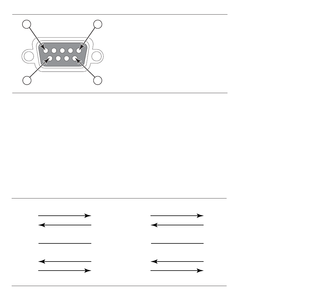
Brocade FastIron GS and GS-STK Hardware Installation Guide 79
Part Number: 53-1002186-03
Hardware Specifications
Device specifications
Pinouts and signalling
This section lists the pinouts for the DB-9 connector and RJ-45 port jacks.
Serial (Console) port pinouts
The Console port is a standard male DB-9 connector, as shown in Figure 2.
FIGURE 2 Serial port pin and signalling details
Most PC serial ports require a cable with a female DB-9 connector. However, terminal connections will vary, requiring a cable with either a
DB-9 or DB-25 connector, male or female.
Serial cable options between the FastIron GS or GS-STK and a PC or terminal are shown in Figure 3.
NOTE
As indicated in Figure 2 and Figure 3, some of the wires should not be connected. If you do connect the wires that are labeled
“Reserved”, you might get unexpected results with some terminals.
FIGURE 3 Console port pin assignments with connection options to a terminal or PC
Pin Assignment
DB-9 mal
Pin Number Switch Signal
6
1 Reserved
2 TXD (output)
3 RXD (input)
4 Reserved
5 GND
6 Reserved
7 Reserved
8 Reserved
9 Reserved
1 5
9
e
1
2
3
4
5
6
7
8
9
1
2
3
4
5
6
7
8
9
8
3
2
20
7
6
4
5
22
1
2
3
4
5
6
7
8
9
DB-9 to DB-9
Female Switch Terminal or PC
Reserved
Reserved
Reserved
Reserved
DB-9 to DB-25
Female Switch Terminal or PC
Reserved
Reserved
Reserved
Reserved
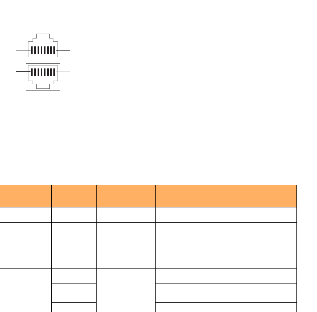
80 Brocade FastIron GS and GS-STK Hardware Installation Guide
Part Number: 53-1002186-03
Hardware Specifications
Device specifications
10/100/1000 Gigabit port pinouts
Table 4 lists the pin assignment and signalling for 10/100/1000 ports.
FIGURE 4 Pin assignment and signalling for 10/100/1000 ports
Cable specifications
Table 7 lists the cable specifications for the cables used with the 10/100/1000 Gigabit, and 10-Gigabit Ethernet ports.
NOTE
Cable installation and network configuration will affect overall transmission capability. The numbers provided here represent the
accepted recommendations of the various standards. For network-specific recommendations, consult your local Brocade reseller
or system engineer.
TABLE 7 Cable Length Summary
Cable Type Connector Type Core Diameter
(microns)
Modal Bandwidth
(MHz*km) or
Wavelength (nm)
Range (meters)
1000Base-BX-D Single-mode Fiber
(SMF)
LC connector for SFP
module
9 1490 nm 2 – 10000 (10km)
1000Base-BX-U SMF LC connector for SFP
module
9 1310 nm 2 – 10000 (10km)
1000Base-LHA SMF LC connector for SFP
module
9 1550 nm 2 – 70000 (70km)
1000Base-LHB SMF LC connector for SFP
module
9 1550 nm 2 – 120000
(120km)
1000Base-LX Multi-mode Fiber
(MMF)
LC connector for SFP
module
62.5 500 2 – 550
MMF 50 400 2 – 550
MMF 50 500 2 – 550
SMF 9 1300 nm 2 – 10000
1
2
3
4
5
6
7
8
1
2
3
4
5
6
7
8
81
18
Pin Number
Pin Assignment MDI-X ports MDI-X ports
Pin Number
100BaseTX and 1000BaseT
RD+
RD-
TD+
Not used
TD-
Not used
Not used
Not used
RD+
RD-
TD+
CMT
TD-
CMT
CMT
CMT
10BaseT

Brocade FastIron GS and GS-STK Hardware Installation Guide 81
Part Number: 53-1002186-03
Hardware Specifications
Device specifications
Power cords
All Brocade devices ship with US-compatible power cords unless otherwise specified at the time of order. United Kingdom- and
European-compatible power cords are also available.
For power cord specifications, refer to “Input connector and plug” on page 84
Warranty
FastIron GS and GS-STK switches come with a 5-year limited lifetime warranty. The software comes with a 90-day warranty.
1000Base-SX MMF LC connector for SFP
module
62.5/125 200 .5 – 275
MMF 62.5/125 500 .5 – 550
MMF 50/125 900 .5 – 595
MMF 50/125 1500 .5 – 740
MMF 50/125 2000 .5 – 860
1000Base-SX 2 MMF LC connector for SFP
module
62.5 500 up to 2000 (2 km)
1000Base-T Copper RJ-45 jack for standard
unshielded twisted pair
(UTP or Category 5)
n/a n/a up to 100 meters
100Base-BX SMF LC connector for SFP
module
9 1310/1490 10000 (10 km)
100Base-FX MMF LC connector for SFP
module
62.5 500 up to 2000 (2 km)
100Base-TX Copper RJ-45 jack for standard
unshielded twisted pair
(UTP or Category 5)
n/a n/a up to 100 meters
10GBase-CX4 Infiniband 4x
copper
XAUI connector n/a n/a up to 15
10GBase-ER SMF LC connector for XFP
module
9 1550 nm up to 40000 (40
km)
10GBase-LR SMF LC connector for XFP
module
9 1310 nm 2 – 10000
(10km)
10GBase-SR MMF LC connector for XFP
module
62.5/125 160 2 – 26
MMF 62.5/125 200 2 – 33
MMF 50/125 400 2 – 66
MMF 50/125 500 2 – 82
MMF 50/125 2000 2 – 300
10GBase-ZR SMF LC connector for XFP
module
9 1550 nm up to 80000 (80
km)
10GBase-ZRD SMF LC connector for XFP
module
9 1530.33 – 1561.42
nm
up to 80000 (80
km)
TABLE 7 Cable Length Summary (Continued)
Cable Type Connector Type Core Diameter
(microns)
Modal Bandwidth
(MHz*km) or
Wavelength (nm)
Range (meters)

82 Brocade FastIron GS and GS-STK Hardware Installation Guide
Part Number: 53-1002186-03
Hardware Specifications
Power supply specifications
Power supply specifications
This section contains the following information for the power supplies that ship with FGS and FGS-STK devices.
Overview
Each FGS or FGS-STK switch comes with one alternating-current (AC) or direct-current (DC) power supply, depending on how it was
ordered from the factory. All models have two power supply slots, enabling you to install a second power supply for redundancy (if
applicable) or for more POE power. DC supplies are available for some devices, in which you can use any combination of AC and DC
supplies in the same device. The following power supplies may be installed in your FGS switch:
•
RPS-FGS (AC power supply)
•
RPSDC-FGS (DC power supply)
The power supplies used with POE devices produce extensive power to support 802.3af applications.
Installing the power supply in a device other than a POE device will cause extensive damage to your
equipment.
The power supplies can be swapped in or out of the device while the device is running. You can remove
and insert a power supply without opening the device. If the device contains two power supplies and the
power supplies are redundant, you can remove one of the power supplies without interrupting operation.
The remaining power supply provides enough power for all the ports.
NOTE
A FastIron GS or GS-STK POE device with dual power supplies may not provide redundancy, depending on how much power
the POE ports are consuming. Refer to “Power specifications for POE” on page 26.
Remove the power cord from a power supply before you install it in or remove it from the device.
Otherwise, the power supply or the device could be damaged. The device can be running while a power
supply is being installed or removed, but the power supply itself should not be connected to a power
source.
All power supplies are auto-sensing and auto-switching.
Key features
Refer to “Power supplies” on page 25 for the key features of the FGS power supplies.
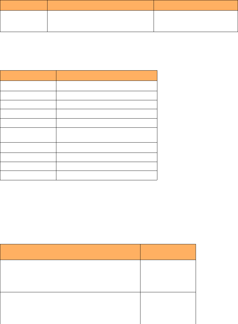
Brocade FastIron GS and GS-STK Hardware Installation Guide 83
Part Number: 53-1002186-03
Hardware Specifications
Power supply specifications
Physical dimensions and weight
Environmental considerations
For optimal performance, operate or store the power supplies in compliance with the following environmental conditions.
Power supply consumption
Table 10 lists the maximum power supply consumption for each FastIron GS model.
Table 11 lists the maximum power supply consumption for each FastIron GS-STK model.
TABLE 8 Physical Dimensions and Weight of Power Supplies
Power Supply Dimensions Weight
RPS-FGS
RPSDC-FGS
6.25 cm (H) x 22.03 cm (W) x 19.30 cm (D)
2.46 in (H) x 8.67 in (W) x 7.6 in (D)
3.016 kg (6.65 lbs)
2.72 kg (6 lbs)
TABLE 9 Power Supply Operating and Storage Environment
Description Range
Operating Environment
Operating temperature 32
°
– 104
°
F (0
°
– 40
°
C)
Relative humidity 0 – 95%, non-condensing
Operating altitude Up to 10,000 feet above sea level
Operating noise 47 – 51 dBA
Cooling
•
AC: internal fans, 50mm
•
DC: internal fan, 60 mm
Storage Environment
Storage temperature -40
°
to 185
°
F, -40
°
to 85
°
C
Storage humidity 95% maximum, non-condensing
Storage altitude Up to 15,000 feet above sea level
TABLE 10 Maximum Power Supply Consumption for FGS Models
Model Maximum Power
Consumption
FGS624
without uplink
with 2 CX4+iXFP
with 2 XFP+1XFP
with Combo+1XFP
48 W
63 W
67 W
65 W
FGS648
without uplink
with 2 CX4
with 2XFP
with Combo
94 W
102 W
106 W
104 W

84 Brocade FastIron GS and GS-STK Hardware Installation Guide
Part Number: 53-1002186-03
Hardware Specifications
Power supply specifications
Input connector and plug
Table 12 lists the input connectors for the power supplies.
FGS624 power drawn from outlet with 1 power supply
without uplink
with 2 CX4+1XFP
with 2XFP+1XFP
with Combo+1XFP
99 W
121 W
121 W
121 W
FGS648 power drawn from outlet with 1 power supply
without uplink
with 2 CX4
with 2XFP
with Combo
162 W
170 W
170 W
170 W
FGS624 power drawn from outlet with 2 power supplies
(PS efficiency goes down as load increases)
without uplink
with 2CX4+1XFP
with 2XFP+1XFP
with Combo+1XFP
127 W
161 W
161 W
161 W
FGS648 power drawn from outlet with 2 power supplies
(PS efficiency goes down as load decreases)
without uplink
with 2 CX4
with 2XFP
with Combo
192 W
204 W
204 W
204 W
TABLE 11 Maximum Power Supply Consumption for FGS-STK Models
Model Maximum Power
Consumption
FGS624-STK
with 2 CX4+1XFP 63 W
FGS648-STK
with 2 CX4 102 W
FGS624-STK power drawn from outlet with 1 power supply
with 2 CX4+1XFP 121 W
FGS648-STK power drawn from outlet with 1 power supply
with 2 CX4 170 W
FGS624-STK power drawn from outlet with 2 power supplies (PS
efficiency goes down as load increases)
with 2CX4+1XFP 161 W
FGS648-STK power drawn from outlet with 2 power supplies (PS
efficiency goes down as load decreases)
with 2 CX4 204 W
TABLE 10 Maximum Power Supply Consumption for FGS Models (Continued)
Model Maximum Power
Consumption
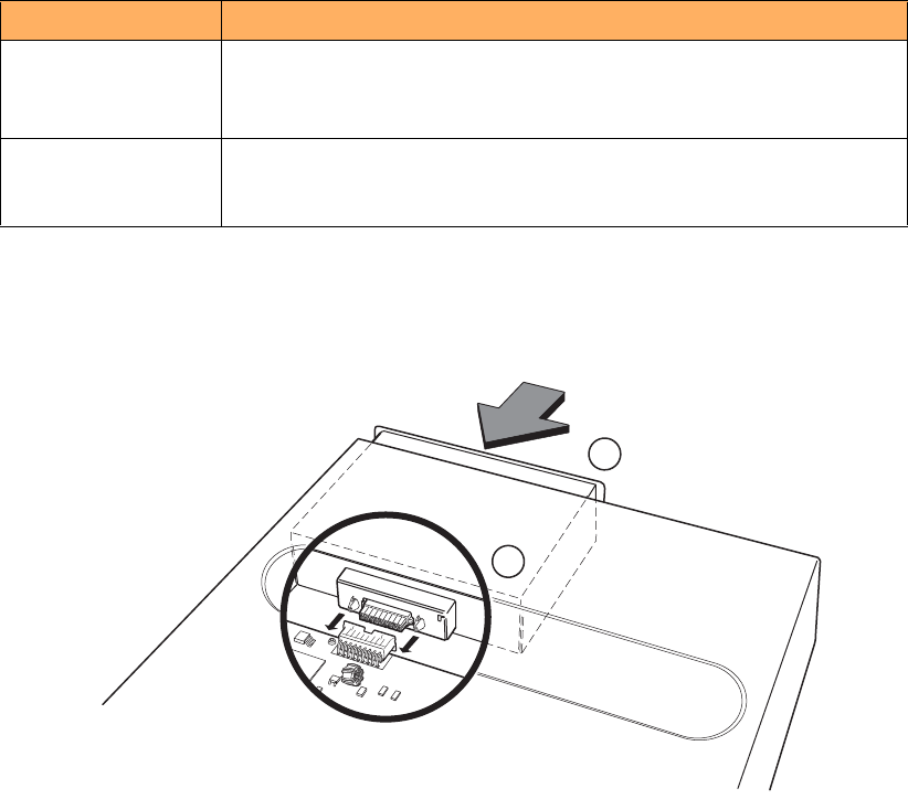
Brocade FastIron GS and GS-STK Hardware Installation Guide 85
Part Number: 53-1002186-03
Hardware Specifications
Power supply specifications
Figure 5 shows the power plug and connector for AC power supplies.
FIGURE 5 AC power cable plug and input connector
TABLE 12 Input Connector for Power Supplies
Power Supply Input Connector Properties
RPS-FGS Standard IEC type (IEC 320)
C14 type: UL/CSA 15A/250V, VDE 10A/250V
Orientation: Ground pin down
RPSDC-FGS 2-position Phoenix Contact
The power supply is connected to Earth Ground using wire attached to the ground
stud on the power supply rear panel.
1Power supply
2 Connector
2
1
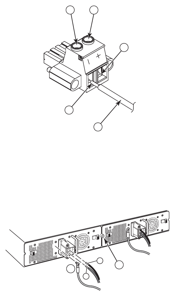
86 Brocade FastIron GS and GS-STK Hardware Installation Guide
Part Number: 53-1002186-03
Hardware Specifications
Power supply specifications
FIGURE 6 DC power connector
FIGURE 7 Connecting DC power supply
Regulatory compliance
The power supplies comply with the conducted and radiated test, immunity, and safety standards as listed in Table 13.
1 Negative terminal screw
2 Positive terminal screw
3 48 RTN lead
4 -48 VDC lead
5 10 AWG wire
1 Ground
2 Power supply locking screw
1
4
5
2
3
+
–
12

Brocade FastIron GS and GS-STK Hardware Installation Guide 87
Part Number: 53-1002186-03
Hardware Specifications
Power supply specifications
Safety warnings
The power supplies are marked with an electrical hazard label and with the safety warnings shown in Table 14.
Electrical specifications
Table 15 lists the electrical specifications for the power supplies.
TABLE 13 Power Supply Regulatory Compliance
Description Certifications
Electromagnetic Emissions FCC Part 15, Subpart B (Class A)
EN 55022 (CE mark) (Class A)
ICES-003 (Canada) (Class A)
AS/NZ 55022 (Australia) (Class A)
VCCI (Japan) (Class A)
EN 61000-3-2
EN 61000-3-3
KN 22
EN61000-6-3
CISPR 22 Class A
FCC Class A
VCCI Class A
EN55022 Class A
Harmonic Current Emissions (Class A) -
EN61000-3-2, with Amendment 14
(1999)
EN61000-3-3 Voltage Fluctuations and
Flicker
Immunity EN 55024
EN61000-6-1
EN61000-4-5. The power supply is tested
to 1kV (differential mode) and 2kV
(common mode)
Safety CSA/cUL
UL
CE
TUV
TABLE 14 Safety Warning Labels on Power Supplies
No operator serviceable parts inside. Refer servicing to qualified personnel.
ATTENZIONE Non aprire. Rivolgersi a personale qualificado.
CUIDADO Partes adentro no reparables por el operador. Refiera reparo a
personal autorizado.
ATTENTION Entretien et répartions internes ne sont autorisés qu’au personnel
technique qualifié.
ACHTUNG Zugang zur Bedienung nicht erförderlich. Wartung nur durch
qualifiziertes Personal.
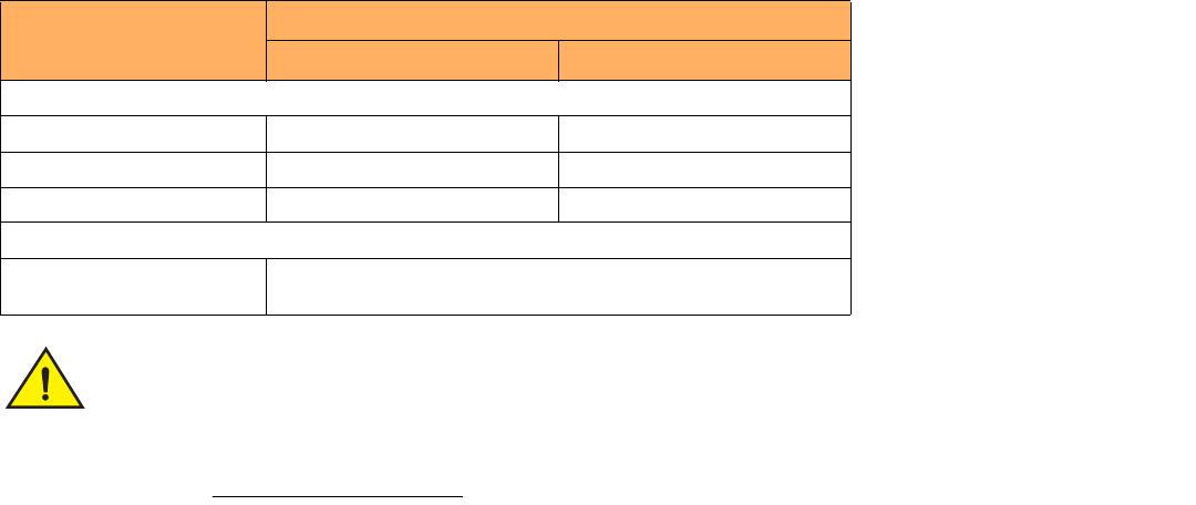
88 Brocade FastIron GS and GS-STK Hardware Installation Guide
Part Number: 53-1002186-03
Hardware Specifications
Power supply specifications
The FGS power supply is designed exclusively for use with FGS and FGS-STK devices. The power supply
produces extensive power to support 802.3af applications. Installing the power supply in a device other
than the FGS will cause extensive damage to your equipment.
TABLE 15 Power Supply Electrical Specifications
Description Ranges
AC DC
Input Specifications
Input voltage range 100 to 240 VAC -40 to -60 VDC
Input current 8 Amps 18 Amps
Inrush current < 11.25 Amps peak maximum < 26 Amps peak maximum
Output Specifications
Output power 600 watts of total output power, including +12VDC @ 10A to the system
and -48VDC @ 10 A for Power over Ethernet applications

Brocade FastIron GS and GS-STK Hardware Installation Guide 89
Part Number: 53-1002186-03
Managing the FGS and FGS-STK
Device
Managing temperature settings
This section describes how to display temperature settings on the FGS or FGS-STK device, and how to change the temperature warning
levels.
Using the temperature sensor
FGS and FGS-STK devices come with two built-in temperature sensors; one at the air intake to monitor the incoming air temperature, and
the other at the exhaust, to measure the air temperature as it exits the device. The temperature sensors cause the device to generate a
Syslog message and SNMP trap if the temperature exceeds a specified warning level
The software reads the temperature sensors according to the device poll time, (60 seconds by default). If the temperature equals or
exceeds the warning temperature the software generates a Syslog message and SNMP trap.
You can use the CLI to do the following:
•
Display the temperature of the device
•
Change the warning temperature levels
•
Change the device poll time
Displaying the temperature
By default, the software polls the temperature sensor every 60 seconds to get the current temperature. This poll rate is controlled by the
device poll time, which also controls how often the software polls other system components.
To display the temperature of a device, enter the show chassis command at any level of the CLI.
The following output is from from a standalone FGS device:
The following output is for an IronStack:
FastIron>show chassis
power supply 1 <NA - AC - Regular> present, status ok
power supply 2 not present
Fan 1 ok
Fan 2 ok
Exhaust Side Temperature Readings:
Current temperature : 28.5 degrees Celsius
Warning level.......: 45.0 degrees Celsius
Shutdown level......: 55.0 degrees Celsius
Intake Side Temperature Readings:
Current temperature : 29.0 degrees Celsius
Boot Prom MAC: 00e0.5200.0100
90 Brocade FastIron GS and GS-STK Hardware Installation Guide
Part Number: 53-1002186-03
Managing the FGS and FGS-STK Device
Managing temperature settings
Displaying temperature messages
The software sends a Syslog message and an SNMP trap if the temperature crosses the warning threshold. The following methods
describe how to view the system log on the device. If you have configured the device to use a Syslog server or SNMP trap receiver, refer
to the documentation for the server or receiver.
To display the system log, enter the following command at any CLI level. The following example is for a standalone device. To display
system logs for IronStack devices, enter the show log command for individual stack units.
Changing the temperature warning and shutdown levels
The default warning temperature is 45.0 C degrees. You can change the warning temperature using the following command. The valid
range is 0 – 125 C degrees.
FGS648P Switch#show chassis
The stack unit 1 chassis info:
Power supply 1 (NA - AC - Regular) present, status ok
Power supply 2 not present
Fan 1 ok
Fan 2 ok
Exhaust Side Temperature Readings:
Current temperature : 35.5 deg-C
Warning level.......: 80.0 deg-C
Shutdown level......: 90.0 deg-C
Intake Side Temperature Readings:
Current temperature : 33.5 deg-C
Boot Prom MAC: 0012.f2de.9440
Management MAC: 0000.0000.0011
The stack unit 2 chassis info:
Power supply 1 (NA - AC - Regular) present, status ok
Power supply 2 not present
Fan 1 ok
Fan 2 ok
--More--, next page: Space, next line: Return key, quit: Control-c
FastIron#show log
Syslog logging: enabled (0 messages dropped, 0 flushes, 0 overruns)
Buffer logging: level ACDMEINW, 8 messages logged
level code: A=alert C=critical D=debugging M=emergency E=error
I=informational N=notification W=warning
Static Log Buffer:
Dynamic Log Buffer (50 entries):
at 0 days 0 hours 2 minutes 0 seconds, level alert
Temperature 48.0 C degrees, warning level 45.0 C degrees
at 0 days 0 hours 1 minutes 0 seconds, level alert
Temperature 50.0 C degrees, warning level 45.0 C degrees
Brocade FastIron GS and GS-STK Hardware Installation Guide 91
Part Number: 53-1002186-03
Managing the FGS and FGS-STK Device
Removing MAC address entries
To change the temperature at which the device sends a warning, enter a command such as the following at the Privileged EXEC level of
the CLI:
FastIron# temperature warning 47
Syntax: temperature warning <value>
The <value> can be 0 – 125.
For IronStack devices
To change the temperature warning level for an FGS-STK device in an IronStack, enter a command similar to the following:
FGS624 Switch# temperature warning 2 82
Syntax: temperature warning <unit-id> <value>
Changing the temperature shutdown level
To change the temperature at which the device sends a warning, enter a command similar to the following:
FastIron#temperature shutdown 47
Syntax: temperature shutdown <value>
The <value> can be 0 – 125.
For IronStack devices
To change the temperature shutdown level for an FGS-STK device in an IronStack, enter a command similar to the following:
FGS624 Switch#temperature shutdown 2 90
Syntax: temperature shutdown <unit-id> <value>
Changing the device temperature polling interval
The software reads the temperature sensors and polls other hardware sensors according to the value set for the device poll time, which is
60 seconds by default. You can change the device poll time using the CLI.
To change the device poll time for standalone devices or for devices in an IronStack, enter a command similar to the following at the
global CONFIG level:
FastIron(config)# chassis poll-time 200
Syntax: chassis poll-time <value>
The <value> can be 0 – 65535.
Removing MAC address entries
You can remove the following types of learned MAC address entries from the MAC address table:
•
All MAC address entries
•
All MAC address entries for a specified Ethernet port
•
All MAC address entries for a specified VLAN
92 Brocade FastIron GS and GS-STK Hardware Installation Guide
Part Number: 53-1002186-03
Managing the FGS and FGS-STK Device
Removing MAC address entries
•
A specified MAC address entry in all VLANs
For example, to remove entries for the MAC address 000d.cb80.00d in all VLANs, enter the following command at the Privileged EXEC
level of the CLI:
FastIron# clear mac-address 000d.cb80.00d0
Syntax: clear mac-address <mac-address> | ethernet <port-num> | vlan <number>
If you enter the clear mac-address command without any parameters, the software removes all MAC entries.
Use the <mac-address> parameter to remove a specified MAC address from all VLANs. Specify the MAC address in the following format:
HHHH.HHHH.HHHH.
Use the ethernet <port-num> parameter to remove all MAC addresses for a specified Ethernet port.
Use the vlan <number> parameter to remove all MAC addresses for a specified VLAN.
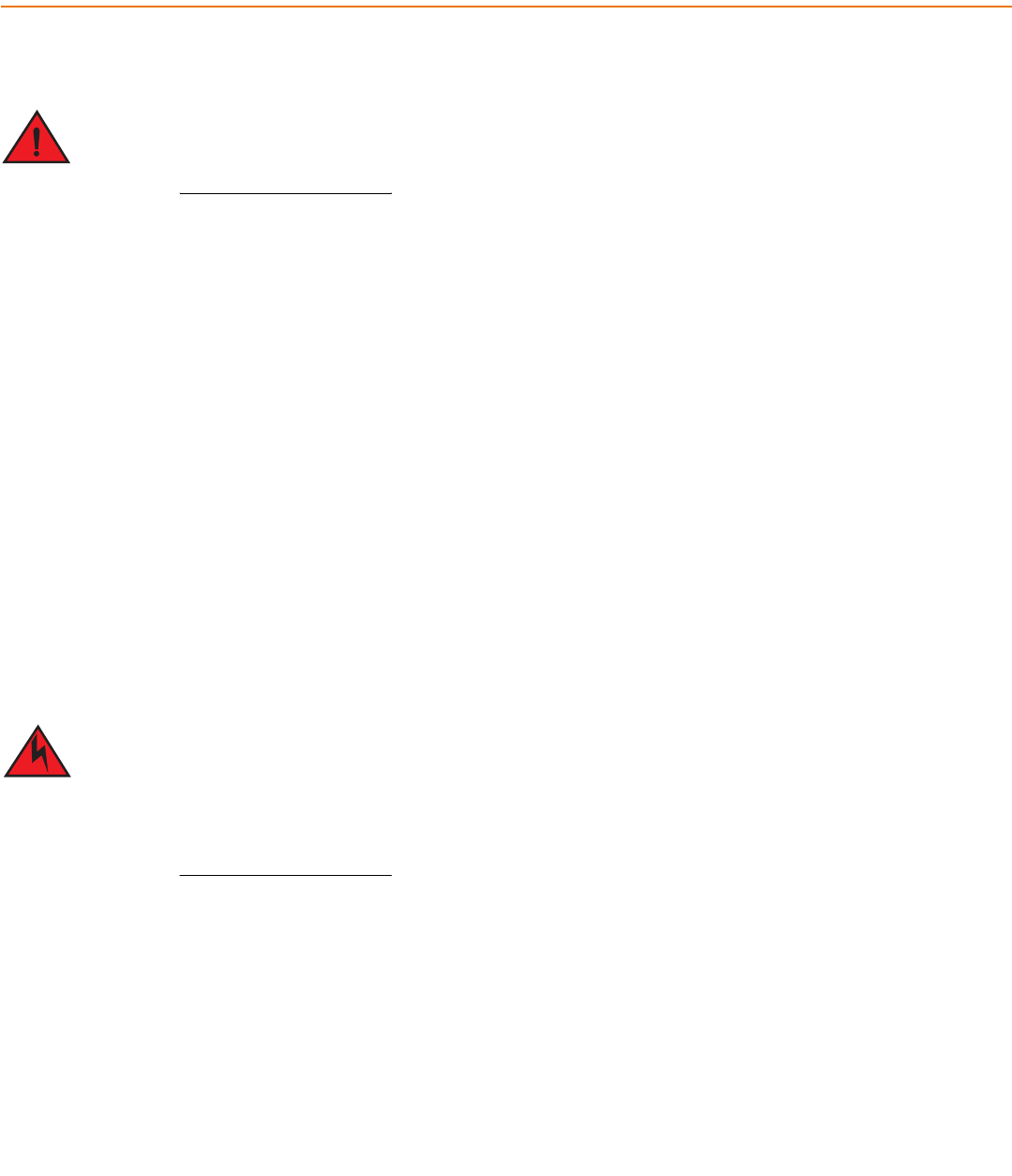
Brocade FastIron GS and GS-STK Hardware Installation Guide 93
Part Number: 53-1002186-03
Maintaining the FGS and FGS-STK
Hardware
Hardware maintenance schedule
TThe procedures in this manual are for qualified service personnel.
The FGS and FGS-STK hardware components require minimal maintenance. Brocade recommends cleaning the fiber optic connectors
on fiber optic ports and the connected fiber cable each time you disconnect the cable.
You can replace the following hardware components as needed:
•
2-port 10-Gigabit Ethernet module
•
Copper and fiber optic modules (SFPs (mini-GBICs) and XFP transceivers)
•
POE daughter card
•
Power supplies
Replacing a power supply
You can replace a power supply while the FGS or FGS-STK device is powered on and running. The power supplies are located in slots at
the rear of the FGS and FGS-STK device.
This section provides information about the following topics:
•
Installation precautions and warnings
•
Determining which power supply has failed, if necessary
•
Replacing a power supply
Power supplies are hot swappable. However, Brocade recommends that you disconnect the power supply
from AC power before installing or removing the supply. The device can be running while a power supply is
being installed or removed, but the power supply itself should not be connected to a power source.
Otherwise, you could be injured or the power supply or other parts of the device could be damaged.
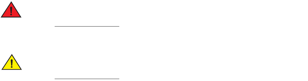
94 Brocade FastIron GS and GS-STK Hardware Installation Guide
Part Number: 53-1002186-03
Maintaining the FGS and FGS-STK Hardware
Replacing a power supply
Installation precautions and warnings
Follow these precautions when installing a power supply in the FGS and FGS-STK device.
Before beginning the installation, refer to the precautions in “Power precautions” on page 31.
Do not install the device in an environment where the operating ambient temperature might exceed
40 Deg. Celsius C (104 Deg. F).
Never leave tools inside the device.
Determining which power supply failed
If you are replacing a power supply that has failed and you are not sure which supply has failed, enter the following command at any CLI
command prompt:
This command displays status information for the power supplies and the fans. The power supplies are numbered from left to right.
These numbers assume you are facing the front of the device, not the rear.
If the display indicates “Installed (Failed)” for any of the slots, the power supply installed in that particular slot has failed.
AC power supplies
If you need to install or replace an AC power supply, refer to the procedures on “Installing an AC power supply” on page 34.
DC power supplies
if you need to install or replace a DC power supply, refer to “Installing a DC power supply” on page 36.
FastIron>show chassis
power supply 1 <NA - AC - Regular> present, status ok
power supply 2 not present
Fan 1 ok
Fan 2 ok
Exhaust Side Temperature Readings:
Current temperature : 28.5 degrees Celsius
Warning level.......: 45.0 degrees Celsius
Shutdown level......: 55.0 degrees Celsius
Intake Side Temperature Readings:
Current temperature : 29.0 degrees Celsius
Boot Prom MAC: 00e0.5200.0100
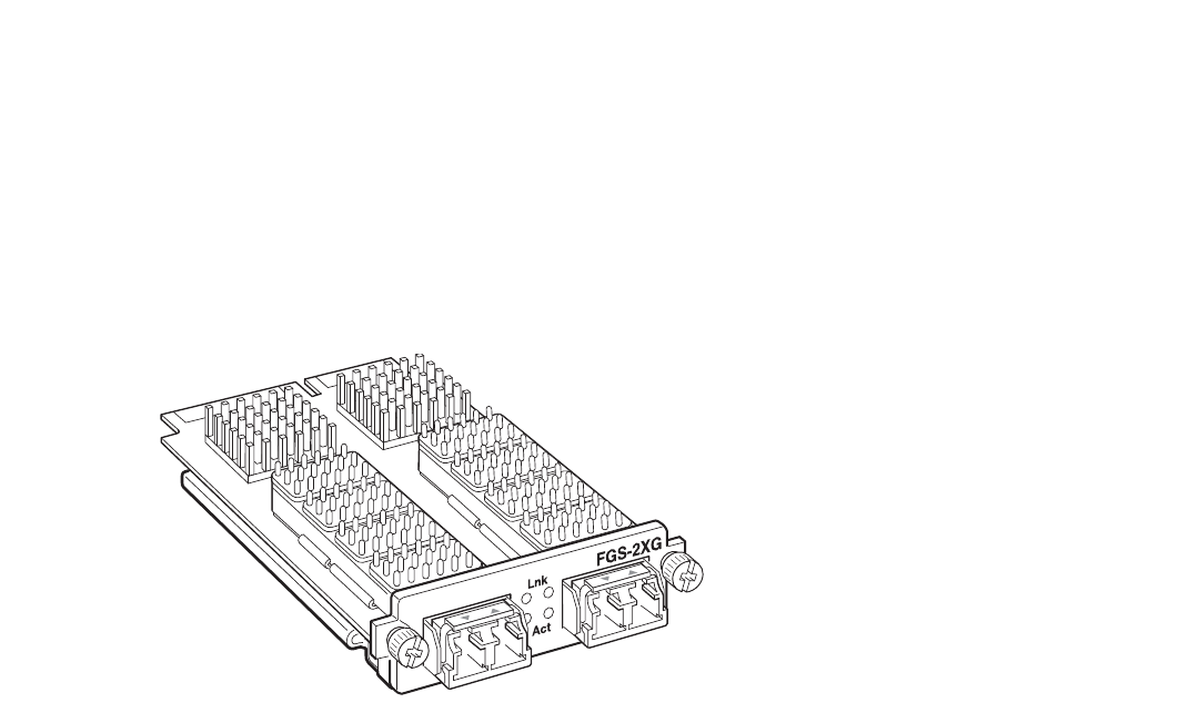
Brocade FastIron GS and GS-STK Hardware Installation Guide 95
Part Number: 53-1002186-03
Maintaining the FGS and FGS-STK Hardware
Replacing a power supply
Installing or replacing a 2-port 10 Gbps module
The 2-port 10-Gigabit Ethernet module is optional. You can order the FGS or FGS-STK with a 2-port 10-Gigabit module installed at the
factory, or you can upgrade your device later.
NOTE
The 1-port 10-Gigabit module on FGS624XGP, FGS624XGP-STK, FGS624XGP-POE and FGS648XGP-POE-STK models
is not field replaceable or upgradeable.
This section provides the steps for installing, removing, and replacing the 2-port 10-Gigabit Ethernet module. You will need the following
tools to perform these procedures:
•
#2 Phillips-head screwdriver or flathead screwdriver for captive screws
•
Electrostatic Discharge (ESD) kit
Figure 1 shows a 2-port 10 Gbps module.
FIGURE 1 2-Port 10 Gbps Module
Removing a 2-port 10 Gbps module
1. Remove power to the FGS or FGS-STK device. For AC power supplies, turn the switch to the OFF position. For DC power
supplies, turn off the DC power source or disconnect it from the power supply.
2. Remove the 10-Gigabit module from the device:
•
Use a #2 Phillips-head screwdriver or flathead screwdriver to loosen and remove the two captive screws on the 10-Gigabit
module.
•
Gently pull on the 10 Gbps module to disconnect it from the backplane connector. Once disconnected, remove the 10
Gbps module completely from the device.
3. Place the 10-Gigabit module in an anti-static bag for storage.
4. Do one of the following:
•
Insert a new 10-Gigabit module as instructed in the section “Installing a 2-port 10 Gbps module”.
•
If you are removing the module without replacing it, place the blank faceplate over the opening where the 10 Gbps module
was installed. Use the two captive screws to fasten the faceplate in place.
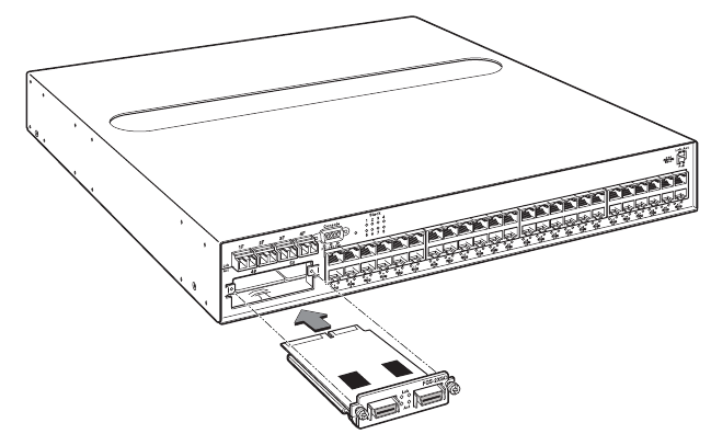
96 Brocade FastIron GS and GS-STK Hardware Installation Guide
Part Number: 53-1002186-03
Maintaining the FGS and FGS-STK Hardware
Installing or replacing a POE daughter card
Installing a 2-port 10 Gbps module
Follow these procedures and refer to Figure 2 when installing a 10-Gigabit Ethernet Module:
1. Remove power to the FGS or FGS-STK device. For AC power supplies, turn the switch to the OFF position. For DC power
supplies, turn off the DC power source or disconnect it from the power supply.
2. If necessary, remove the faceplate for the 2-port 10 Gbps module located in the lower left-hand corner of the front panel. Use a
#2 Phillips-head screwdriver or flathead screwdriver to loosen the two captive screws that secure it in place. Place the blank
faceplate in a safe place for future use.
3. Remove the new 10-Gigabit Ethernet module and faceplate from its protective packaging.
4. Install the 10-Gigabit module in the device as shown in Figure 2:
•
Properly place and align the 10-Gigabit Ethernet module inside the device.
•
Push the module firmly toward the back of the device until the front panel is flush with the rest of the device. This action
causes the module connector to lock into the backplane connector.
•
Use a #2 Phillips-head screwdriver or flathead screwdriver to fasten the two captive screws on the 10-Gigabit module.
Affix the screws loosely at first, then tighten them once you are sure the module is properly positioned.
FIGURE 2 Installing a 2-Port 10 Gbps Module
5. After installing the module, power on the system and verify that the module is working properly. Refer to the section “Observing
LEDs” on page 70.
Installing or replacing a POE daughter card
This section provides instructions for installing or replacing a Power Over Ethernet (POE) daughter card in the FGS or FGS-STK device.
•
The FGS624P, FGS624P-STK, FGS624P-POE, and FGS624P-POE-STK have one connector slot on the main board for a
single POE daughter card, which provides support for POE power-consuming devices on all 24 10/100/1000 ports.
•
The FGS648P, FGS648P-STK, FGS648P-POE, and FGS648P-POE-STK have two connector slots on the main board for
two POE daughter cards. A single POE daughter card provides support for POE power-consuming devices on 24
10/100/1000 ports. As you look at the front of the device, a POE daughter card in the left-most connector slot provides POE
for ports 1 – 24, and the right-most connector slot provides POE for ports 25 – 48.
X4-2XG
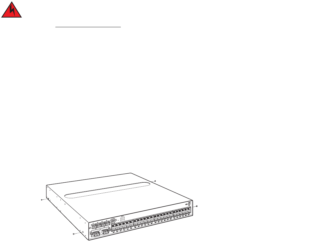
Brocade FastIron GS and GS-STK Hardware Installation Guide 97
Part Number: 53-1002186-03
Maintaining the FGS and FGS-STK Hardware
Installing or replacing a POE daughter card
To install or replace a POE daughter card, you must have the following on hand:
•
A POE daughter card (part number FGS-24GCPOE), which you can order from Brocade.
•
An ESD wrist strap with a plug for connection to the FGS device.
For safety reasons, the ESD wrist strap should contain a series 1 meg ohm resistor.
•
A #2 Phillips-head screwdriver.
Disassembling the device
This section provides instructions for disassembling the device so that you can install, remove, or replace a POE daughter card.
1. Remove power to the Brocade device. For AC power supplies, turn the switch to the OFF position. For DC power supplies, turn
off the DC power source or disconnect the cables from the power supply.
2. Put on an Electrostatic Discharge (ESD) wrist strap and attach the clip end to a metal surface (such as an equipment rack) to act
as ground.
3. Remove the device cover and faceplate:
•
If the device was mounted in a rack, remove the two mounting brackets from the device. Figure 13 on page 42 shows the
location of the mounting brackets and screws.
•
Use a #2 Phillips-head screwdriver to remove the two screws on each side of the cover. (There are four screws altogether
as shown in Figure 3.)
FIGURE 3 Removing the Screws for the Top Cover
•
Gently slide the cover towards the back of the unit and lift it off of the device as shown in Figure 4.
FGS-2XG
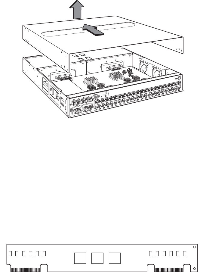
98 Brocade FastIron GS and GS-STK Hardware Installation Guide
Part Number: 53-1002186-03
Maintaining the FGS and FGS-STK Hardware
Installing or replacing a POE daughter card
FIGURE 4 Removing the Cover
4. Proceed to “Installing a POE daughter card”.
Installing a POE daughter card
To replace or install the POE daughter card, do the following:
1. Disassemble the device as instructed in the section “Disassembling the device” on page 97.
2. If you are replacing the POE daughter card, remove the existing card from the connector slot on the main board. Figure 6 and
Figure 7 show the locations of the POE daughter cards on the main board of the FGS624P-POE and the FGS648P-POE.
3. Install the new POE daughter card:
•
Remove the POE daughter card from its packaging. The POE daughter card is keyed to prevent improper insertion, as
shown in Figure 5.
FIGURE 5 POE Daughter Card
•
Locate the connector slots for the POE daughter card on the main board (Figure 6 and Figure 7).
•
Insert the POE daughter card into the connector slot on the main board as shown in Figure 6 for the FGS624P-POE and
Figure 7 for the FGS648P-POE.
Figure 6 shows the location of the POE daughter card on the main board of the FGS624P-POE or FGS624P-POE-STK
device.
FGS-2XG
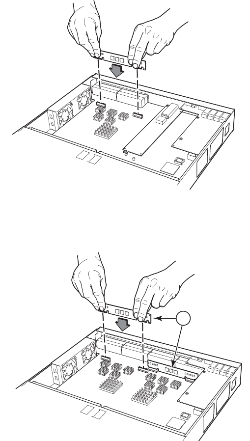
Brocade FastIron GS and GS-STK Hardware Installation Guide 99
Part Number: 53-1002186-03
Maintaining the FGS and FGS-STK Hardware
Installing or replacing a POE daughter card
FIGURE 6 Installing a POE Daughter Card in the FGS624P-POE or FGS624P-POE-STK device
Figure 7 shows the location of the POE daughter cards on the main board of the FGS648P-POE and FGS648P-POE-STK
devices.
FIGURE 7 Installing a POE Daughter Card in the FGS648P-POE and FGS648P-POE-STK devices.
4. Re-assemble the device as instructed in the section “Reassembling the device”.
5. Power ON the device and observe the console. The following message will appear:
Info: PoE module detected in slot 1. Initializing....
6. Enable POE and configure POE parameters. Refer to the <Italic>FastIron Configuration Guide for information.
Reassembling the device
Reassemble the device using the following steps:
1. Replace the cover.
2. Re-fasten the screws on each side of the cover.
1
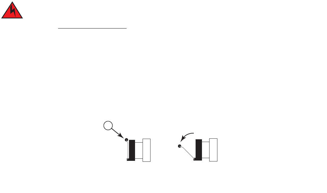
100 Brocade FastIron GS and GS-STK Hardware Installation Guide
Part Number: 53-1002186-03
Maintaining the FGS and FGS-STK Hardware
Replacing a fiber optic module
3. If the device is rack-mounted, replace the mounting brackets.
Replacing a fiber optic module
You can remove an SFP or XFP module from a port and replace it with a new one while the FGS is powered on and running.
This section describes the following tasks:
•
Removing a copper or fiber optic module
•
Installing a new copper or fiber optic module
•
Cabling a fiber optic module
Removing a fiber optic module
You can remove a copper or fiber SFP (also called a mini-GBIC) or an XFP module from a port while the FGS is powered on and running.
Before removing a copper or fiber optic module, have the following on hand:
•
An ESD wrist strap with a plug for connection to the ESD connector on the FGS.
For safety reasons, the ESD wrist strap should contain a series 1 meg ohm resistor.
•
The protective covering you removed from the module when you initially installed the module.
To remove a copper or fiber optic module from a Gigabit Ethernet or 10-Gigabit Ethernet port, do the following:
1. Put on the ESD wrist strap and ground yourself by attaching the clip end to a metal surface (such as an equipment rack).
2. Disconnect the copper or fiber cable connector from the port connector.
3. Insert the protective covering into the port connectors.
4. Pull the copper or fiber optic module out of the port by pulling the bail latch forward, away from the front panel of the module.
This unlocks the module from the front panel. On 1000BaseSX ports, the bail latch is enclosed in a black sleeve, and on
1000BaseLX ports, the bail latch is enclosed in a blue sleeve.
NOTE
The bail latch may be attached to either the top or the bottom of the mini-GBIC.
5. Grasping the bail latch, pull the copper or fiber optic module out of the port.
1Bail latch
1
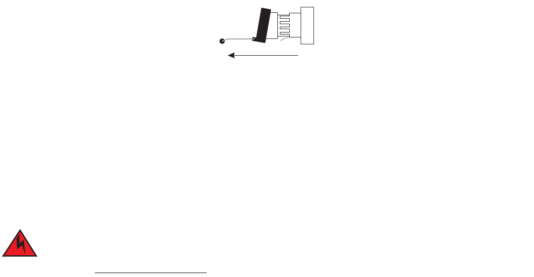
Brocade FastIron GS and GS-STK Hardware Installation Guide 101
Part Number: 53-1002186-03
Maintaining the FGS and FGS-STK Hardware
Cleaning the fiber optic connectors
6. Store the copper or fiber optic module in a safe, static-free place or in an anti-static bag.
7. Install a new copper or fiber optic module in the port. For information about performing this task, refer to “Installing a new fiber
optic module”.
Installing a new fiber optic module
You must install a fiber optic module (SFP or XFP transceiver) in each Gigabit Ethernet and 10-Gigabit Ethernet fiber port you want to
use.
You can install a new copper or fiber optic module in a port while the Brocade device is powered on and running.
To install a fiber optic module, you will need an ESD wrist strap with a plug for connection to a metal surface.
For safety reasons, the ESD wrist strap should contain a series 1 meg ohm resistor.
To install a copper or fiber optic module, do the following:
1. Put on the ESD wrist strap and ground yourself by attaching the clip end to a metal surface (such as an equipment rack) to act as
ground.
2. Remove the new module from its protective packaging.
3. Gently insert the copper or fiber optic module into the port until the module clicks into place. The module is keyed to prevent
incorrect insertion.
Cabling a fiber optic module
To cable a fiber optic module, do the following:
1. Remove the protective covering from the fiber optic port connectors and store the covering for future use.
2. Before cabling a fiber optic module, Brocade strongly recommends cleaning the cable connectors and the port connectors.
Refer to “Cleaning the fiber optic connectors” on page 101.
3. Gently insert the cable connector (a tab on each connector should face upward) into the port connector until the tabs lock into
place.
4. Observe the link and active LEDs to determine if the network connections are functioning properly. For more information about
the LED indicators, refer to Table 2 on page 70.
Cleaning the fiber optic connectors
To avoid problems with the connection between the fiber optic module (SFP (mini-GBIC) or XFP) and the fiber cable connectors, Brocade
strongly recommends cleaning both connectors each time you disconnect and reconnect them. In particular, dust can accumulate in the
connectors and cause problems such as reducing the optic launch power.
102 Brocade FastIron GS and GS-STK Hardware Installation Guide
Part Number: 53-1002186-03
Maintaining the FGS and FGS-STK Hardware
Cleaning the fiber optic connectors
To clean the fiber cable connectors, Brocade recommends using the fiber-optic reel-type cleaner that shipped with your Brocade device.
You can also purchase this type of cleaner from the following Website:
http://www.fisfiber.com
When not using an SFP or XFP connector, make sure to keep the protective covering on.
Brocade FastIron GS and GS-STK Hardware Installation Guide 103
Part Number: 53-1002186-03
Regulatory Statements
U.S.A.
This equipment has been tested and found to comply with the limits for a Class A digital device pursuant to Part 15 of the FCC Rules.
These limits are designed to provide reasonable protection against harmful interference when the equipment is operated in a commercial
environment. This equipment generates, uses, and can radiate radio frequency energy and, if not installed and used in accordance with the
instruction manual, may cause harmful interference to radio communications. Operation of this equipment in a residential area is likely to
cause harmful interference in which case the user will be required to correct the interference at his own expense.
Changes or modifications made to this device that are not expressly approved by Brocade could void the
user’s authority to operate the equipment.
Industry Canada statement
Cet appareil numérique de la classe A est conforme à la norme NMB-003 du Canada.
English translation of above statement
This Class A digital apparatus complies with Canadian ICES-003.
Europe and Australia
This is a Class A product. In a domestic environment this product may cause radio interference in which case the user may be required to
take adequate measures.
Japan
English translation of above statement
This is Class A product based on the standard of the Voluntary Control Council For Interference by Information Technology Equipment
(VCCI). If this equipment is used in a domestic environment, radio disturbance may arise. When such trouble occurs, the user may be
required to take corrective actions.
104 Brocade FastIron GS and GS-STK Hardware Installation Guide
Part Number: 53-1002186-03
Regulatory Statements
Japan power cord
Japan power cord
English translation of above statement
ATTENTION: Never use the power cord packed with your equipment for other products.
Korea
Translation: Class A device (Broadcasting Communication Device for Office Use): This device obtained EMC registration for office use
(Class A), and may be used in places other than home. Sellers and/or users need to take note of this.
Russia
For the FGS624P
For the FGS648P
A
급 기기 ( 업무용 방송통신기기 ): 이 기기는 업무용 (A 급 ) 으로 전자파적합등록
을
한 기기이오니 판매자 또는 사용자는 이 점을 주의하시기 바라며 , 가정외의 지역
에
서 사용하는 것을 목적으로 합니다
.
ʿ̨̛̯̖̬̙̖̦̖̔̏̔ ̨̨̛̭̯̖̯̭̯̏̏́ ʺ̡̨̛̛̦̥̭̏́̚ ˀ̨̛̛̭̭:
ʪ̶̡̛̖̣̬̌̌́ ̨̨̛̭̯̖̯̭̯̏̏́ ζ ʪ-ˁʿʪ-3178 ̨̯ 15.09.2009 ̨̐̔̌,
̛̖̜̭̯̯̖̣̦̔̏̽̌ ̨̔ 15.09.2014 ̨̐̔̌, ̨̛̛̬̖̭̯̬̬̦̌̐̏̌̌̚ ̏ ˇ̨̖̖̬̣̦̥̔̌̽
̖̦̯̭̯̖̌̐̏ ̛̭̏́̚ 25.09.2009 ̨̐̔̌

Brocade FastIron GS and GS-STK Hardware Installation Guide 105
Part Number: 53-1002186-03
Regulatory Statements
Russia
English translation of above statements
Verification of conformity by Mincomsvyaz (Ministry of communication) of Russia: Declaration of conformity No. D-SPD-XXXX of
DD.MM.YYYY, valid till DD.MM.YYYY, registered in Federal Communication Agency on DD.MM.YYYY
ʿ̨̛̯̖̬̙̖̦̖̔̏̔ ̨̨̛̭̯̖̯̭̯̏̏́ ʺ̡̨̛̛̦̥̭̏́̚ ˀ̨̛̛̭̭:
ʪ̶̡̛̖̣̬̌̌́ ̨̨̛̭̯̖̯̭̯̏̏́ ζ ʪ-ˁʿʪ-3177 ̨̯ 15.09.2009 ̨̐̔̌, ̛̖̜̭̯̯̖̣̦̔̏̽̌ ̨̔
15.09.2014 ̨̐̔̌, ̨̛̛̬̖̭̯̬̬̦̌̐̏̌̌̚ ̏ ˇ̨̖̖̬̣̦̥̔̌̽ ̖̦̯̭̯̖̌̐̏ ̛̭̏́̚ 25.09.2009
̨̐̔̌
106 Brocade FastIron GS and GS-STK Hardware Installation Guide
Part Number: 53-1002186-03
Regulatory Statements
China
China
汉文 “仅适用于非热带气候条件下安全使用。”
藏文
蒙古
文
壮文
Dan hab yungh youq gij dienheiq diuzgen mbouj dwg diegndat
haenx ancienz sawjyungh.
安全
说明
和标
记
维文
汉文 仅适用于海拔2000m以下地区安全使用。
藏文
蒙古
文
壮文
Dan hab yungh youq gij digih haijbaz 2000m doxroengz
haenx ancienz sawjyungh.
安全
说明
和标
记
维文
在维修的时候一定要断开所有电源 (English translation“disconnect all power sources before service”)
For non tropical use:
For altitude 2000 meter and below:
China-CCC Warning statements
English translation of above statement
This is a Class A product. In a domestic environment this product may cause radio interference, in
which case the user may be required to take adequate measures.
Warning for Class A:
Brocade FastIron GS and GS-STK Hardware Installation Guide 109
Part Number: 53-1002186-03
Cautions and Warnings
The cautions and warnings that appear in this manual are listed below in English, German, French, and Spanish.
Cautions
A caution calls your attention to a possible hazard that can damage equipment.
“Vorsicht” weist auf die Gefahr einer möglichen Beschädigung des Gerätes in.
Une mise en garde attire votre attention sur un risque possible d'endommagement de l'équipement. Ci-dessous, vous trouverez les
mises en garde utilisées dans ce manuel.
Un mensaje de precaución le advierte sobre un posible peligro que pueda dañar el equipo. Las siguientes son precauciones utilizadas en
este manual.
Table 0.1:
CAUTION The FGS power supply is designed exclusively for use with the FGS devices. The power
supply produces extensive power to support 802.3af applications. Installing the power
supply in a device other than the FGS will cause extensive damage to your equipment.
VORSICHT Das Netzgerät FGS ist für den ausschließlichen Gebrauch in Model FGS konzipiert.
Installation des Netzgerätes in anderen Geräten als FGS verursacht erheblichen Schaden an
Ihrer Anlage.
MISE EN GARDE Le bloc d’alimentation FGS est conçu exclusivement pour être utilisé avec les dispositifs
FGS. Le bloc d’alimentation produit une alimentation très importante pour prendre en
charge les applications 802.3af. Si vous l’installez dans un dispositif autre que les FGS, il
endommagera gravement votre équipement.
PRECAUCIÓN El suministro de corriente alterna del FGS está diseñado exclusivamente para uso con los
dispositivos FGS. El suministro de corriente produce suficiente energía para abastecer a las
aplicaciones 802.3af. Si se instala el suministro de corriente en un dispositivo que no sea el
FGS, se producirán daños de consideración al equipo.

110 Brocade FastIron GS and GS-STK Hardware Installation Guide
Part Number: 53-1002186-03
Cautions and Warnings
Cautions
Table 0.2:
CAUTION Remove the power cord from a power supply before you install it in or remove it from the
device. Otherwise, the power supply or the device could be damaged as a result. (The
device can be running while a power supply is being installed or removed, but the power
supply itself should not be connected to a power source.)
VORSICHT Nehmen Sie vor dem Anschließen oder Abtrennen des Geräts das Stromkabel vom Netzteil
ab. Ansonsten könnten das Netzteil oder das Gerät beschädigt werden. (Das Gerät kann
während des Anschließens oder Annehmens des Netzteils laufen. Nur das Netzteil sollte
nicht an eine Stromquelle angeschlossen sein.)
MISE EN GARDE Enlevez le cordon d'alimentation d'un bloc d'alimentation avant de l'installer ou de l'enlever
du dispositif. Sinon, le bloc d'alimentation ou le dispositif risque d'être endommagé. (Le
dispositif peut être en train de fonctionner lorsque vous installez ou enlevez un bloc
d'alimentation, mais le bloc d'alimentation lui-même ne doit pas être connecté à une source
d'alimentation.)
PRECAUCIÓN Retire el cordón de corriente del suministro de corriente antes de instalarlo o retírarlo del
instrumento. De no hacerse así, el suministro de corriente o el instrumento podrían resultar
dañados. (El instrumento puede estar encendido mientras se instala o retira un suministro de
corriente, pero el suministro de corriente en sí no deberá conectado a la corriente).
Table 0.3:
CAUTION Do not install the device in an environment where the operating ambient temperature might
exceed 40° C (104° F).
VORSICHT Das Gerät darf nicht in einer Umgebung mit einer Umgebungsbetriebstemperatur von über
40° C (104° F) installiert werden.
MISE EN GARDE N'installez pas le dispositif dans un environnement où la température d'exploitation
ambiante risque de dépasser 40° C (104° F).
PRECAUCIÓN No instale el instrumento en un entorno en el que la temperatura ambiente de operación
pueda exceder los 40°C (104°F).
Table 0.4:
CAUTION Make sure the air flow around the front, sides, and back of the device is not restricted.
VORSICHT Stellen Sie sicher, dass an der Vorderseite, den Seiten und an der Rückseite der Luftstrom
nicht behindert wird.
MISE EN GARDE Vérifiez que rien ne restreint la circulation d'air devant, derrière et sur les côtés du dispositif
et qu'elle peut se faire librement.
PRECAUCIÓN Asegúrese de que el flujo de aire en las inmediaciones de las partes anterior, laterales y
posterior del instrumento no esté restringido.

Brocade FastIron GS and GS-STK Hardware Installation Guide 111
Part Number: 53-1002186-03
Cautions and Warnings
Cautions
Table 0.5:
CAUTION Use a separate branch circuit for each AC power cord, which provides redundancy in case
one of the circuits fails.
VORSICHT Es empfiehlt sich die Installation eines separaten Stromkreiszweiges für jede
Wechselstrom-Elektroschnur als Redundanz im Fall des Ausfalls eines Stromkreises.
MISE EN GARDE Utilisez un circuit de dérivation différent pour chaque cordon d’alimentation C.A. Ainsi, il y
aura un circuit redondant en cas de panne d’un des circuits.
PRECAUCIÓN Use un circuito derivado separado para cada cordón de alimentación de CA, con lo que se
proporcionará redundancia en caso de que uno de los circuitos falle.
Table 0.6:
CAUTION Ensure that the device does not overload the power circuits, wiring, and over-current
protection. To determine the possibility of overloading the supply circuits, add the ampere
(amp) ratings of all devices installed on the same circuit as the device. Compare this total
with the rating limit for the circuit. The maximum ampere ratings are usually printed on the
devices near the input power connectors.
VORSICHT Stromkreise, Verdrahtung und Überlastschutz dürfen nicht durch das Gerät überbelastet
werden. Addieren Sie die Nennstromleistung (in Ampere) aller Geräte, die am selben
Stromkreis wie das Gerät installiert sind. Somit können Sie feststellen, ob die Gefahr einer
Überbelastung der Versorgungsstromkreise vorliegt. Vergleichen Sie diese Summe mit der
Nennstromgrenze des Stromkreises. Die Höchstnennströme (in Ampere) stehen
normalerweise auf der Geräterückseite neben den Eingangsstromanschlüssen.
MISE EN GARDE Assurez-vous que le dispositif ne risque pas de surcharger les circuits d'alimentation, le
câblage et la protection de surintensité. Pour déterminer le risque de surcharge des circuits
d'alimentation, additionnez l'intensité nominale (ampères) de tous les dispositifs installés sur
le même circuit que le dispositif en question. Comparez alors ce total avec la limite de
charge du circuit. L'intensité nominale maximum en ampères est généralement imprimée
sur chaque dispositif près des connecteurs d'entrée d'alimentation.
PRECAUCIÓN Verifique que el instrumento no sobrecargue los circuitos de corriente, el cableado y la
protección para sobrecargas. Para determinar la posibilidad de sobrecarga en los circuitos
de suministros, añada las capacidades nominales de corriente (amp) de todos los
instrumentos instalados en el mismo circuito que el instrumento. Compare esta suma con el
límite nominal para el circuito. Las capacidades nominales de corriente máximas están
generalmente impresas en los instrumentos, cerca de los conectores de corriente de
entrada.

112 Brocade FastIron GS and GS-STK Hardware Installation Guide
Part Number: 53-1002186-03
Cautions and Warnings
Cautions
Table 0.7:
CAUTION All devices with DC power supplies are intended for installation in restricted access areas
only. A restricted access area is where access can be gained only by service personnel
through the use of a special tool, lock and key, or other means of security, and is controlled
by the authority responsible for the location.
VORSICHT Alle Geräte mit DC-Netzteil sind nur für die Installation in Bereichen mit beschränktem
Zugang gedacht. Ein Bereich mit beschränktem Zugang ist ein Bereich, zu dem nur
Wartungspersonal mit Spezialwerkzeug, Schlüssel oder anderen Sicherheitsvorrichtungen
Zugang hat. Dieser Zugang wird von für den Bereich zuständigen Personen überwacht.
MISE EN GARDE Tous les dispositifs avec bloc d'alimentation C.C. sont conçus pour l'installation dans des
zones à accès réglementé uniquement. Une zone à accès réglementé est une zone dont
l'accès n'est possible qu'au personnel de service utilisant un verrou, une clé ou un outil
spécial, ou d'autres moyens de sécurité, et qui est contrôlée par les autorités responsables
du site.
PRECAUCIÓN Todos los instrumentos con suministros de corriente continua han sido diseñados
únicamente para instalación en áreas restringidas. Se entiende como área de acceso
restringido un lugar al que solo puede acceder personal de servicio mediante el uso de una
herramienta especial, llave y cerrojo u otro medio de seguridad similar, y que esté
controlado por la autoridad responsable de esa ubicación.
Table 0.8:
CAUTION For a DC system (DC power supply part number RPSDC-FGS), use a grounding wire of at
least 10 American Wire Gauge (AWG). The 10 AWG wire should be attached to an
agency-approved crimp connector, crimped with the proper tool.
VORSICHT Für ein Gleichstromsystem (Gleichstromnetzteile mit der Teilenr RPSDC-FGS) ist ein
Erdungsdraht (wenigstens 10 AWG) erforderlich. Der 10 AWG-Draht sollte an einen
behördlich genehmigten Crimpverbinder angebracht werden, der mit einem
ordnungsgemäßen Werkzeug gecrimpt wurde.
MISE EN GARDE Pour les systèmes C.C. (références du bloc d’alimentation C.C. RPSDC-FGS), utilisez un fil
de mise à la terre d’au moins 10 AWG (American Wire Gauge). Ce fil de 10 AWG doit être
relié à un connecteur à sertissage homologué, serti avec l’outil approprié. Le connecteur à
sertissage doit permettre la sécurisation aux deux vis de borne de terre sur le boîtier.
PRECAUCIÓN Para un sistema de CC (suministro de corriente continua con No. de referencia
RPSDC-FGS), utilice un cable de conexión a tierra de calibre de cable norteamericano (AWG)
número 10. El cable 10 AWG deberá acoplarse a un conector engarzado aprobado, y
engarzado con la herramienta apropiada.

Brocade FastIron GS and GS-STK Hardware Installation Guide 113
Part Number: 53-1002186-03
Cautions and Warnings
Cautions
Table 0.9:
CAUTION For the DC input circuit to the system (DC power supply part number RPSDC-FGS), make
sure there is a 30 amp circuit breaker, minimum -48Vdc, double pole, on the input to the
terminal block. The input wiring for connection to the product should be copper wire, 10
AWG, marked VW-1, and rated minimum 90 degrees celcius.
VORSICHT Für den Eingangs-Gleichstromkreis zum System (Gleichstromnetzteile mit der Teilenr.
RPSDC-FGS) ist ein 30 A (Minimum), -48 V DC, doppelpolig, am Eingang zur
Reihenklemme zu installieren. Bei der Eingangsverdrahtung zum Anschluss des Produkts
sollte es sich um einen 10 AWG-Kupferdraht (VW-1) und einer Mindestnenntemperatur
von 32° handeln.
MISE EN GARDE Pour le circuit d’alimentation C.C du système (références du bloc d’alimentation C.C.
RPSDC-FGS), assurez-vous de la présence d’un disjoncteur de 30 ampères, minimum –
48 V C.C., double coupure, sur l’entrée vers le bloc d’alimentation. Les câbles
d’alimentation pour le produit doivent être en fils de cuivre, 10 AWG (American Wire
Gauge), marqués VW-1 et classés 90 degrés Celsius.
PRECAUCIÓN Para el circuito de entrada de CC al sistema (suministro de corriente continua con No. de
referencia RPSDC-FGS), verifique que existe un cortacircuitos catalogado de 30
amperios, como mínimo, -48 VCC, bipolar, en la entrada al bloque terminal. El cableado
de entrada para la conexión al producto deberá ser de cable de cobre catalogado, 10
AWG, marcado con VW-1, y tener una capacidad nominal mínima para 90 grados
centígrados.
Table 0.10:
CAUTION Make sure you insert the power supply right-side up. It is possible to insert the supply
upside down, although the supply will not engage with the power backplane when upside
down. The power supply is right-side up when the power connector is on the left and the fan
vent is on the right.
VORSICHT Sicher Sie sicher, dass Sie das Netzteil mit der richtigen Seite nach oben weisend einstecken.
Man kann die Karte auch umgekehrt einstecken. Allerdings rastet das umgekehrte Netzteil
nicht in die Netzstrom-Rückwandplatine ein. Die rechte Seite des Netzteils weist nach oben,
wenn sich der Stromanschlussstecker links und der Ventilatorschlitz rechts befindet.
MISE EN GARDE Assurez-vous d'insérer le bloc d'alimentation dans le bon sens. Il est possible de l'insérer " la
tête en bas ", mais le bloc d'alimentation ne s'enclenchera pas dans la face arrière
d'alimentation s'il est inséré à l'envers. Le bloc d'alimentation est dans le bon sens lorsque le
connecteur se trouve sur le côté gauche et le ventilateur sur la droite.
PRECAUCIÓN Verifique que inserta el suministro de corriente con la cara correcta hacia arriba. Es posible
insertar el suministro hacia abajo, pese a que este no se conectará con el enchufe posterior
de esta forma. El suministro de potencia estará con la cara correcta hacia arriba cuando el
conector de corriente quede a la izquierda y la abertura del ventilador queda a la derecha.

114 Brocade FastIron GS and GS-STK Hardware Installation Guide
Part Number: 53-1002186-03
Cautions and Warnings
Cautions
Table 0.11:
CAUTION Use the erase startup-config command only for new systems. If you enter this command
on a system you have already configured, the command erases the configuration. If you
accidentally do erase the configuration on a configured system, enter the write memory
command to save the running configuration to the startup-config file.
VORSICHT Verwenden Sie den Befehl "Erase startup-config" (Löschen Startup-Konfig) nur für neue
Systeme. Wenn Sie diesen Befehl in ein bereits konfiguriertes System eingeben, löscht der
Befehl die Konfiguration. Falls Sie aus Versehen die Konfiguration eines bereits
konfigurierten Systems löschen, geben Sie den Befehl "Write Memory" (Speicher schreiben)
ein, um die laufende Konfiguration in der Startup-Konfig-Datei zu speichern.
MISE EN GARDE N'utilisez la commande erase startup-config que pour les nouveaux systèmes. Si vous
entrez cette commande sur un système que vous avez déjà configuré, elle efface la
configuration. Si vous effacez la configuration par accident sur un système configuré, entrez
la commande write memory pour enregistrer la configuration actuelle dans le fichier
startup-config.
PRECAUCIÓN Use el comando erase startup-config (borrar configuración de inicio) para sistemas nuevos
solamente. Si usted introduce este comando en un sistema que ya ha configurado, el
comando borrará la configuración. Si usted borra accidentalmente la configuración en un
sistema ya configurado, introduzca el comando write memory (escribir memoria) para
guardar la configuración en ejecución en el archivo startup-config.
Table 0.12:
CAUTION Never leave tools inside the device.
VORSICHT Lassen Sie keine Werkzeuge im Chassis zurück.
MISE EN GARDE Ne laissez jamais d'outils à l'intérieur du châssis.
PRECAUCIÓN No deje nunca herramientas en el interior del chasis.
Table 0.13:
CAUTION To avoid high voltage shock, do not open the device while the power is on.
VORSICHT Zur Vermeidung eines Elektroschocks durch Hochspannung darf das Gerät im
eingeschalteten Zustand nicht geöffnet werden.
MISE EN GARDE Pour éviter tout risque d'électrocution, ne pas ouvrir cet appareil lorsqu'il est sous tension.
PRECAUCIÓN Para evitar la electrocución por alto voltaje, no abra el dispositivo mientras esté conectado a
la corriente eléctrica.

Brocade FastIron GS and GS-STK Hardware Installation Guide 115
Part Number: 53-1002186-03
Cautions and Warnings
Cautions
Table 0.14:
CAUTION Remove the power cord from a power supply before you install it in or remove it from the
device. Otherwise, the power supply or the device could be damaged as a result. (The
device can be running while a power supply is being installed or removed, but the power
supply itself should not be connected to a power source.)
VORSICHT Vor dem Installieren einer Stromversorgung im Gerät bzw. vor dem Herausnehmen einer
Stromversorgung aus dem Gerät das Netzkabel von der Stromversorgung trennen.
Geschieht das nicht, kann dies zur Beschädigung der Stromversorgung bzw. des Geräts
führen. (Die Stromversorgung kann im laufenden Gerätebetrieb herausgenommen bzw.
installiert werden, sollte dabei aber nicht an einer Stromquelle angeschlossen sein.)
MISE EN GARDE Débrancher le cordon secteur de l'alimentation avant de le la raccorder à l'équipement ou de
le la déconnecter de celui-ci, faute de quoi le circuit d'alimentation de l'équipement pourrait
être endommagé. (L'équipement peut fonctionner pendant la dépose ou le remplacement
d'une alimentation électrique, mais il est important que celle-ci ne soit pas raccordée au
secteur.)
PRECAUCIÓN Desenchufe el cable eléctrico de una fuente de alimentación antes de proceder a montarla o
a desmontarla del dispositivo. En caso contrario, la fuente de alimentación o el dispositivo
podrían sufrir daños. (Aunque el dispositivo podrá mantenerse en funcionamiento durante la
instalación o desinstalación de la fuente de alimentación, dicha fuente de alimentación no
deberá estar conectada a una toma de corriente).
Table 0.15:
CAUTION Make sure you insert the EEPROM so that lead pin 1 goes into the correct hole as shown in
the appropriate illustrations. If you accidentally insert the EEPROM backwards, the device
will not work and may be damaged when you power it on.
VORSICHT Beim Einsatz des EEPROM darauf achten, dass Anschlussstift 1 gemäß den
entsprechenden Abbildungen in das richtige Loch eingeführt wird. Wird das EEPROM aus
Versehen verkehrt herum eingesetzt, funktioniert das Gerät nicht und kann beim Einschalten
beschädigt werden.
MISE EN GARDE Veiller à insérer l'EEPROM de façon à placer la broche 1 dans l'orifice correct (voir les
illustrations appropriées). En cas d'inversion de l'EEPROM lors de son insertion,
l'équipement ne fonctionnera pas et risque d'être endommagé à la mise sous tension.
PRECAUCIÓN Asegúrese de introducir la EEPROM de modo que el pin 1 del cable quede insertado en el
orificio correcto, tal y como se muestra en las ilustraciones correspondientes. Si
accidentalmente introdujera la EEPROM al revés, el dispositivo no funcionaría y podría
dañarse al encenderlo.

116 Brocade FastIron GS and GS-STK Hardware Installation Guide
Part Number: 53-1002186-03
Cautions and Warnings
Warnings
Warnings
A warning calls your attention to a possible hazard that can cause injury or death. The following are the warnings used in this manual.
"Achtung" weist auf eine mögliche Gefährdung hin, die zu Verletzungen oder Tod führen können. Sie finden die folgenden Warnhinweise
in diesem Handbuch:
Table 0.16:
CAUTION Do not push too hard. If the EEPROM does not readily go into the socket, stop pushing and
verify that the lead pins are straight and aligned over the holes. Straighten any crooked pins,
then try again.
VORSICHT Nicht zu fest drücken. Wenn sich das EEPROM nicht leicht einführen lässt, nicht drücken,
sondern überprüfen, ob die Anschlussstifte gerade und über den Löchern ausgerichtet sind.
Alle nicht gerade ausgerichteten Stifte gerade ausrichten und dann den Vorgang
wiederholen.
MISE EN GARDE Ne pas appuyer excessivement sur l'EEPROM. Si elle ne s'insère pas aisément dans son
emplacement, vérifier immédiatement que les broches de guidage sont bien droites et
alignées en face des orifices correspondants. Si nécessaire, redresser toute broche tordue
avant d'essayer à nouveau.
PRECAUCIÓN No ejerza demasiada presión. Si la EEPROM no entra fácilmente en la toma, deje de
presionar y compruebe que los pines del cable estén rectos y alineados sobre los orificios.
Rectifique los pines torcidos e inténtelo de nuevo.
Table 0.17:
CAUTION If you do not install a module in a slot, you must keep the slot panel in place. If you run the
device with an uncovered slot, the system will overheat.
VORSICHT Falls kein Modul im Steckplatz installiert wird, muss die Steckplatztafel angebracht werden.
Wenn ein Steckplatz nicht abgedeckt wird, läuft das System heiß.
MISE EN GARDE Si vous n’installez pas de module dans un slot, vous devez laisser le panneau du slot en
place. Si vous faites fonctionner le châssis avec un slot découvert, le système surchauffera.
PRECAUCIÓN Si no instala un módulo en la ranura, deberá mantener el panel de ranuras en su lugar. Si
pone en funcionamiento el chasis con una ranura descubierta, el sistema sufrirá
sobrecalentamiento.
Table 0.18:
CAUTION Changes or modifications made to this device that are not expressly approved by the party
responsible for compliance could void the user's authority to operate the equipment.
VORSICHT Falls dieses Gerät verändert oder modifiziert wird, ohne die ausdrückliche Genehmigung
der für die Einhaltung der Anforderungen verantwortlichen Partei einzuholen, kann dem
Benutzer der weitere Betrieb des Gerätes untersagt werden.
MISE EN GARDE Les éventuelles modifications apportées à cet équipement sans avoir été expressément
approuvées par la partie responsable d'en évaluer la conformité sont susceptibles d'annuler
le droit de l'utilisateur à utiliser cet équipement.
PRECAUCIÓN Si se realizan cambios o modificaciones en este dispositivo sin la autorización expresa de la
parte responsable del cumplimiento de las normas, la licencia del usuario para operar este
equipo puede quedar anulada.

Brocade FastIron GS and GS-STK Hardware Installation Guide 117
Part Number: 53-1002186-03
Cautions and Warnings
Warnings
Un avertissement attire votre attention sur un risque possible de blessure ou de décès. Ci-dessous, vous trouverez les avertissements
utilisés dans ce manuel.
Una advertencia le llama la atención sobre cualquier posible peligro que pueda ocasionar daños personales o la muerte. A continuación se
dan las advertencias utilizadas en este manual.
Table 0.19:
WARNING The procedures in this manual are for qualified service personnel.
ACHTUNG Die Verfahren in diesem Handbuch sind nur für qualifiziertes Wartungspersonal gedacht.
AVERTISSEMENT Les procédures décrites dans ce manuel doivent être effectuées par le personnel de service
qualifié uniquement.
ADVERTENCIA Los procedimientos de este manual se han hecho para personal de servicio cualificado.
Table 0.20:
WARNING All fiber optic interfaces use Class 1 lasers.
ACHTUNG Alle Glasfaser-Schnittstellen verwenden Laser der Klasse 1.
AVERTISSEMENT Toutes les interfaces en fibres optiques utilisent des lasers de classe 1.
ADVERTENCIA Todas las interfaces de fibra óptica utilizan láser de clase 1.
Table 0.21:
WARNING Make sure the rack or cabinet housing the device is adequately secured to prevent it from
becoming unstable or falling over.
ACHTUNG Stellen Sie sicher, dass das Gestell oder der Schrank für die Unterbringung des Geräts auf
angemessene Weise gesichert ist, so dass das Gestell oder der Schrank nicht wackeln oder
umfallen kann.
AVERTISSEMENT Vérifiez que le bâti ou le support abritant le dispositif est bien fixé afin qu'il ne devienne pas
instable ou qu'il ne risque pas de tomber.
ADVERTENCIA Verifique que el bastidor o armario que alberga el instrumento está asegurado
correctamente para evitar que pueda hacerse inestable o que caiga.
Table 0.22:
WARNING Mount the devices you install in a rack or cabinet as low as possible. Place the heaviest
device at the bottom and progressively place lighter devices above.
ACHTUNG Montieren Sie die Geräte im Gestell oder Schrank so tief wie möglich. Platzieren Sie das
schwerste Gerät ganz unten, während leichtere Geräte je nach Gewicht (je schwerer desto
tiefer) darüber untergebracht werden.
AVERTISSEMENT Montez les dispositifs que vous installez dans un bâti ou support aussi bas que possible.
Placez le dispositif le plus lourd en bas et le plus léger en haut, en plaçant tous les dispositifs
progressivement de bas en haut du plus lourd au plus léger.
ADVERTENCIA Monte los instrumentos que instale en un bastidor o armario lo más bajos posible. Ponga el
instrumento más pesado en la parte inferior y los instrumentos progresivamente más
livianos más arriba.

118 Brocade FastIron GS and GS-STK Hardware Installation Guide
Part Number: 53-1002186-03
Cautions and Warnings
Warnings
Table 0.23:
WARNING Disconnect the power cord from all power sources to completely remove power from the
device.
ACHTUNG Ziehen Sie das Stromkabel aus allen Stromquellen, um sicherzustellen, dass dem Gerät
kein Strom zugeführt wird.
AVERTISSEMENT Débranchez le cordon d'alimentation de toutes les sources d'alimentation pour couper
complètement l'alimentation du dispositif.
ADVERTENCIA Para desconectar completamente la corriente del instrumento, desconecte el cordón de
corriente de todas las fuentes de corriente.
Table 0.24:
WARNING Make sure that the power source circuits are properly grounded, then use the power cord
supplied with the device to connect it to the power source.
ACHTUNG Stellen Sie sicher, dass die Stromkreise ordnungsgemäß geerdet sind. Benutzen Sie dann
das mit dem Gerät gelieferte Stromkabel, um es an die Srromquelle anzuschließen.
AVERTISSEMENT Vérifiez que les circuits de sources d'alimentation sont bien mis à la terre, puis utilisez le
cordon d'alimentation fourni avec le dispositif pour le connecter à la source d'alimentation.
ADVERTENCIA Verifique que circuitos de la fuente de corriente están conectados a tierra correctamente;
luego use el cordón de potencia suministrado con el instrumento para conectarlo a la fuente
de corriente.
Table 0.25:
WARNING Do not use the handles on the power supply units to lift or carry a Brocade device.
ACHTUNG Die Griffe an den Netzteilen dürfen nicht zum Anheben oder Tragen eines Brocadegeräte
verwendet werden.
AVERTISSEMENT N'utilisez pas les poignées des unités de bloc d'alimentation pour soulever ou porter un
dispositif en châssis.
ADVERTENCIA No use las asas de las unidades de suministro de corriente para alzar o transportar un
instrumento de Brocade.

Brocade FastIron GS and GS-STK Hardware Installation Guide 119
Part Number: 53-1002186-03
Cautions and Warnings
Warnings
Table 0.26:
WARNING If the installation requires a different power cord than the one supplied with the device, make
sure you use a power cord displaying the mark of the safety agency that defines the
regulations for power cords in your country. The mark is your assurance that the power
cord can be used safely with the device.
ACHTUNG Falls für die Installation ein anderes Stromkabel erforderlich ist (wenn das mit dem Gerät
gelieferte Kabel nicht passt), müssen Sie sicherstellen, dass Sie ein Stromkabel mit dem
Siegel einer Sicherheitsbehörde verwenden, die für die Zertifizierung von Stromkabeln in
Ihrem Land zuständig ist. Das Siegel ist Ihre Garantie, dass das Stromkabel sicher mit Ihrem
Gerät verwendet werden kann.
AVERTISSEMENT Si l'installation nécessite un cordon d'alimentation autre que celui fourni avec le dispositif,
assurez-vous d'utiliser un cordon d'alimentation portant la marque de l'organisation
responsable de la sécurité qui définit les normes et régulations pour les cordons
d'alimentation dans votre pays. Cette marque vous assure que vous pouvez utiliser le
cordon d'alimentation avec le dispositif en toute sécurité.
ADVERTENCIA Si la instalación requiere un cordón de corriente distinto al que se ha suministrado con el
instrumento, verifique que usa un cordón de corriente que venga con la marca de la agencia
de seguridad que defina las regulaciones para cordones de corriente en su país. Esta marca
será su garantía de que el cordón de corriente puede ser utilizado con seguridad con el
instrumento.
Table 0.27:
WARNING Power supplies are hot swappable. However, Brocade recommends that you disconnect
the power supply from AC power before installing or removing the supply. The device can
be running while a power supply is being installed or removed, but the power supply itself
should not be connected to a power source. Otherwise, you could be injured or the power
supply or other parts of the device could be damaged.
ACHTUNG Netzteile können unter Strom stehend ausgetauscht werden. Allerdings empfiehlt Brocade,
dass Sie das Netzteil vom Netzstrom abtrennen, bevor Sie das Netzteil anschließen oder
abtrennen. Das Gerät kann während des Anschließens oder Abnehmens des Netzteils
laufen. Nur das Netzteil sollte nicht an eine Stromquelle angeschlossen sein. Ansonsten
können Sie verletzt oder das Netzteil bzw. andere Geräteteile beschädigt werden.
AVERTISSEMENT Les blocs d'alimentation peuvent être changés à chaud. Cependant, Brocade vous
conseille de débrancher le bloc d'alimentation de l'alimentation C.A. avant d'installer ou
d'enlever le bloc d'alimentation. Le dispositif peut être en cours de fonctionnement
pendant que vous installez ou enlevez un bloc d'alimentation, mais le bloc d'alimentation
lui-même ne doit pas être connecté à une source d'alimentation. Sinon, vous risquez d'être
blessé ou le bloc d'alimentation ou d'autres pièces du dispositif risquent d'être
endommagés.
ADVERTENCIA Los suministros de corriente pueden intercambiarse sin necesidad de ajustes. No obstante,
Brocade recomienda que desconecte el suministro de corriente de la toma de corriente
alterna antes de instalar o retirar el suministro. El instrumento puede estar activado cuando
se esté instalando o retirando un suministro de corriente, pero el suministro de corriente en
sí no deberá estar conectado a la fuente de corriente. De no hacerlo así, podría sufrir daños
personales o el suministro de corriente u otras piezas podrían resultar dañadas.

120 Brocade FastIron GS and GS-STK Hardware Installation Guide
Part Number: 53-1002186-03
Cautions and Warnings
Warnings
Table 0.28:
WARNING Before beginning the installation, refer to the precautions in “Power precautions” on
page 31.
ACHTUNG Vor der Installation siehe Vorsichtsmaßnahmen unter“Power precautions”
(Vorsichtsmaßnahmen in Bezug auf elektrische Ablagen) auf den Seiten 4.
AVERTISSEMENT Avant de commencer l'installation, consultez les précautions décrites dans “Power
precautions” (Précautions quant à l'alimentation), pages 4.
ADVERTENCIA Antes de comenzar la instalación, consulte las precauciones en la sección “Power
precautions”(Precauciones sobre corriente) que se encuentra en las páginas 4.
Table 0.29:
WARNING For safety reasons, the ESD wrist strap should contain a series 1 meg ohm resistor.
ACHTUNG Aus Sicherheitsgründen sollte ein EGB-Armband zum Schutz von elektronischen
gefährdeten Bauelementen mit einem 1 Megaohm-Reihenwiderstand ausgestattet sein.
AVERTISSEMENT Pour des raisons de sécurité, la dragonne ESD doit contenir une résistance de série 1
méga ohm.
ADVERTENCIA Por razones de seguridad, la correa de muñeca ESD deberá contener un resistor en serie
de 1 mega ohmio.
Table 0.30:
WARNING A fully populated device is heavy.
ACHTUNG Ein voll bestücktes Gehäuse ist schwer.
AVERTISSEMENT Les châssis sont lourds quand ils sont entièrement remplis.
ADVERTENCIA Un chasis muy concurrido es muy pesado.
