Ruckus Brocade Mobility RFS4000, RFS6000 And RFS7000 System Reference Guide, 5.3.0.0 RFS Controller Guide 5300 Systemguide
Mobility 5.3.0.0 RFS Controller System Reference Guide mobility-5300-controller-systemguide
2017-05-10
User Manual: Ruckus Mobility 5.3.0.0 RFS Controller System Reference Guide
Open the PDF directly: View PDF ![]() .
.
Page Count: 844 [warning: Documents this large are best viewed by clicking the View PDF Link!]
- Contents
- About This Document
- Overview
- Web UI Features
- Quick Start
- Dashboard
- Device Configuration
- In this chapter
- Basic Configuration
- Basic Device Configuration
- License Configuration
- Assigning Certificates
- RF Domain Overrides
- Profile Overrides
- Controller Cluster Configuration Overrides (Controllers Only)
- Access Point Adoption Overrides (Access Points Only)
- Access Point Radio Power Overrides (Access Points Only)
- Profile Interface Override Configuration
- Overriding a Profile’s Network Configuration
- Overriding a Profile’s Security Configuration
- Overriding a Profile’s VRRP Configuration
- Overriding a Profile’s Critical Resources Configuration
- Overriding a Profile’s Services Configuration
- Overriding a Profile’s Management Configuration
- Overriding a Profile’s Advanced Configuration
- Auto Provisioning Policies
- br300 Devices
- Critical Resource Policy
- Wireless Configuration
- Profile Configuration
- In this chapter
- General Profile Configuration
- Profile Cluster Configuration (Controllers Only)
- Controller Cluster Profile Configuration and Deployment Considerations
- Profile Adoption Configuration (APs Only)
- Profile Interface Configuration
- Profile Network Configuration
- Setting a Profile’s DNS Configuration
- ARP
- L2TPV3 Configuration
- Quality of Service (QoS) Configuration
- Spanning Tree
- Routing Configuration
- Dynamic Routing (OSPF)
- Forwarding Database
- Bridge VLAN
- Cisco Discovery Protocol Configuration
- Link Layer Discovery Protocol Configuration
- Miscellaneous Network Configuration
- Profile Network Configuration and Deployment Considerations
- Profile Security Configuration
- Defining Security Settings
- Setting the Certificate Revocation List (CRL) Configuration
- Configuring ISAKMP Policies
- Configuring Transform Sets
- Setting the Profile’s VPN Configuration
- Setting the Profile’s NAT Configuration
- Bridge NAT Configuration
- Profile Security Configuration and Deployment Considerations
- VRRP Configuration
- Critical Resources Configuration
- Profile Services Configuration
- Profile Management Configuration
- Advanced Profile Configuration
- RF Domain Configuration
- Security Configuration
- Services Configuration
- Management Access
- Diagnostics
- Operations
- Statistics
- In this chapter
- System Statistics
- RF Domain Statistics
- Access Point Statistics
- Wireless Controller Statistics
- Device Health
- Inventory
- Device
- Cluster Peers
- Adopted AP Statistics
- AP Adoption History
- Pending Adoptions
- AP Detection
- Wireless Clients
- Wireless LANs
- Critical Resource
- Radios
- Mesh
- Interfaces
- Power Status
- Network
- DHCP Server
- Firewall
- IPsec
- Viewing Certificate Statistics
- Controller WIPS Statistics
- Advanced WIPS
- Sensor Server
- Captive Portal Statistics
- Network Time
- Wireless Client Statistics

53-1002620-01
14 May 2012
®
Brocade Mobility RFS4000,
RFS6000, and RFS7000
System Reference Guide
Supporting software release 5.3.0.0 and later

Copyright © 2012 Brocade Communications Systems, Inc. All Rights Reserved.
Brocade, Brocade Assurance, the B-wing symbol, DCX, Fabric OS, MLX, SAN Health, VCS, and VDX are registered trademarks, and
AnyIO, Brocade One, CloudPlex, Effortless Networking, ICX, NET Health, OpenScript, and The Effortless Network are trademarks of
Brocade Communications Systems, Inc., in the United States and/or in other countries. Other brands, products, or service names
mentioned may be trademarks of their respective owners.
Notice: This document is for informational purposes only and does not set forth any warranty, expressed or implied, concerning
any equipment, equipment feature, or service offered or to be offered by Brocade. Brocade reserves the right to make changes to
this document at any time, without notice, and assumes no responsibility for its use. This informational document describes
features that may not be currently available. Contact a Brocade sales office for information on feature and product availability.
Export of technical data contained in this document may require an export license from the United States government.
The authors and Brocade Communications Systems, Inc. shall have no liability or responsibility to any person or entity with
respect to any loss, cost, liability, or damages arising from the information contained in this book or the computer programs that
accompany it.
The product described by this document may contain “open source” software covered by the GNU General Public License or other
open source license agreements. To find out which open source software is included in Brocade products, view the licensing
terms applicable to the open source software, and obtain a copy of the programming source code, please visit
http://www.brocade.com/support/oscd.
Brocade Communications Systems, Incorporated
Document History
Corporate and Latin American Headquarters
Brocade Communications Systems, Inc.
130 Holger Way
San Jose, CA 95134
Tel: 1-408-333-8000
Fax: 1-408-333-8101
E-mail: info@brocade.com
Asia-Pacific Headquarters
Brocade Communications Systems China HK, Ltd.
No. 1 Guanghua Road
Chao Yang District
Units 2718 and 2818
Beijing 100020, China
Tel: +8610 6588 8888
Fax: +8610 6588 9999
E-mail: china-info@brocade.com
European Headquarters
Brocade Communications Switzerland Sàrl
Centre Swissair
Tour B - 4ème étage
29, Route de l'Aéroport
Case Postale 105
CH-1215 Genève 15
Switzerland
Tel: +41 22 799 5640
Fax: +41 22 799 5641
E-mail: emea-info@brocade.com
Asia-Pacific Headquarters
Brocade Communications Systems Co., Ltd. (Shenzhen WFOE)
Citic Plaza
No. 233 Tian He Road North
Unit 1308 – 13th Floor
Guangzhou, China
Tel: +8620 3891 2000
Fax: +8620 3891 2111
E-mail: china-info@brocade.com
Title Publication number Summary of changes Date
Brocade Mobility RFS4000, RFS6000,
and RFS7000 System Reference Guide
53-1002312-01 New Additions for software
version 5.1.0.0
June 2011
Brocade Mobility RFS4000, RFS6000,
and RFS7000 System Reference Guide
53-1002487-01 New Additions for software
version 5.2.0.0
November 2011
Brocade Mobility RFS4000, RFS6000,
and RFS7000 System Reference Guide
53-1002620-01 New Additions for software
version 5.3.0.0
May 2012

Brocade Mobility RFS4000, RFS6000, and RFS7000 System Reference Guide iii
53-1002620-01
Contents
About This Document
In this chapter . . . . . . . . . . . . . . . . . . . . . . . . . . . . . . . . . . . . . . . . . . . . xi
Supported hardware and software . . . . . . . . . . . . . . . . . . . . . . . . . . . xi
Document conventions. . . . . . . . . . . . . . . . . . . . . . . . . . . . . . . . . . . . . xi
Text formatting . . . . . . . . . . . . . . . . . . . . . . . . . . . . . . . . . . . . . . . . xi
Notes, cautions, and warnings . . . . . . . . . . . . . . . . . . . . . . . . . . xii
Related publications . . . . . . . . . . . . . . . . . . . . . . . . . . . . . . . . . . . . . . xii
Getting technical help . . . . . . . . . . . . . . . . . . . . . . . . . . . . . . . . . . . . . xii
Chapter 1 Overview
Chapter 2 Web UI Features
In this chapter . . . . . . . . . . . . . . . . . . . . . . . . . . . . . . . . . . . . . . . . . . . . 3
Accessing the Web UI . . . . . . . . . . . . . . . . . . . . . . . . . . . . . . . . . . . . . . 3
Browser and System Requirements . . . . . . . . . . . . . . . . . . . . . . . 3
Connecting to the Web UI . . . . . . . . . . . . . . . . . . . . . . . . . . . . . . . 3
Glossary of Icons Used . . . . . . . . . . . . . . . . . . . . . . . . . . . . . . . . . . . . . 4
Global Icons . . . . . . . . . . . . . . . . . . . . . . . . . . . . . . . . . . . . . . . . . . 5
Dialog Box Icons. . . . . . . . . . . . . . . . . . . . . . . . . . . . . . . . . . . . . . . 5
Table Icons . . . . . . . . . . . . . . . . . . . . . . . . . . . . . . . . . . . . . . . . . . . 6
Status Icons . . . . . . . . . . . . . . . . . . . . . . . . . . . . . . . . . . . . . . . . . . 6
Configurable Objects . . . . . . . . . . . . . . . . . . . . . . . . . . . . . . . . . . . 7
Configuration Objects . . . . . . . . . . . . . . . . . . . . . . . . . . . . . . . . . . 9
Configuration Operation Icons . . . . . . . . . . . . . . . . . . . . . . . . . . 10
Access Type Icons . . . . . . . . . . . . . . . . . . . . . . . . . . . . . . . . . . . . 10
Administrative Role Icons . . . . . . . . . . . . . . . . . . . . . . . . . . . . . . 11
Device Icons . . . . . . . . . . . . . . . . . . . . . . . . . . . . . . . . . . . . . . . . .12
Chapter 3 Quick Start
In this chapter . . . . . . . . . . . . . . . . . . . . . . . . . . . . . . . . . . . . . . . . . . . 13
Using the Initial Setup Wizard . . . . . . . . . . . . . . . . . . . . . . . . . . . . . .13
Creating a managed WLAN. . . . . . . . . . . . . . . . . . . . . . . . . . . . . . . . .22
Assumptions. . . . . . . . . . . . . . . . . . . . . . . . . . . . . . . . . . . . . . . . .22
Design. . . . . . . . . . . . . . . . . . . . . . . . . . . . . . . . . . . . . . . . . . . . . . 23
Using the Controller GUI to Configure the WLAN . . . . . . . . . . . .23
Chapter 4 Dashboard
In this chapter . . . . . . . . . . . . . . . . . . . . . . . . . . . . . . . . . . . . . . . . . . . 79
iv Brocade Mobility RFS4000, RFS6000, and RFS7000 System Reference Guide
53-1002620-01
Summary . . . . . . . . . . . . . . . . . . . . . . . . . . . . . . . . . . . . . . . . . . . . . . .79
Device Listing . . . . . . . . . . . . . . . . . . . . . . . . . . . . . . . . . . . . . . . . 80
System Screen . . . . . . . . . . . . . . . . . . . . . . . . . . . . . . . . . . . . . . . 81
Network View . . . . . . . . . . . . . . . . . . . . . . . . . . . . . . . . . . . . . . . . . . . . 89
Chapter 5 Device Configuration
In this chapter . . . . . . . . . . . . . . . . . . . . . . . . . . . . . . . . . . . . . . . . . . . 93
Basic Configuration. . . . . . . . . . . . . . . . . . . . . . . . . . . . . . . . . . . . . . .94
Basic Device Configuration. . . . . . . . . . . . . . . . . . . . . . . . . . . . . . . . .96
License Configuration . . . . . . . . . . . . . . . . . . . . . . . . . . . . . . . . . . . . .98
Assigning Certificates . . . . . . . . . . . . . . . . . . . . . . . . . . . . . . . . . . . .100
Certificate Management . . . . . . . . . . . . . . . . . . . . . . . . . . . . . .102
RSA Key Management . . . . . . . . . . . . . . . . . . . . . . . . . . . . . . . .110
Certificate Creation . . . . . . . . . . . . . . . . . . . . . . . . . . . . . . . . . .115
Generating a Certificate Signing Request . . . . . . . . . . . . . . . .117
RF Domain Overrides . . . . . . . . . . . . . . . . . . . . . . . . . . . . . . . . . . . .119
Profile Overrides . . . . . . . . . . . . . . . . . . . . . . . . . . . . . . . . . . . . . . . .125
Controller Cluster Configuration Overrides (Controllers Only).127
Access Point Adoption Overrides (Access Points Only) . . . . . .130
Access Point Radio Power Overrides (Access Points Only) . . .131
Profile Interface Override Configuration. . . . . . . . . . . . . . . . . .134
Overriding a Profile’s Network Configuration . . . . . . . . . . . . . .168
Overriding a Profile’s Security Configuration . . . . . . . . . . . . . .206
Overriding a Profile’s VRRP Configuration . . . . . . . . . . . . . . . .242
Overriding a Profile’s Critical Resources Configuration. . . . . .246
Overriding a Profile’s Services Configuration. . . . . . . . . . . . . .249
Overriding a Profile’s Management Configuration. . . . . . . . . .251
Overriding a Profile’s Advanced Configuration. . . . . . . . . . . . .256
Auto Provisioning Policies . . . . . . . . . . . . . . . . . . . . . . . . . . . . . . . . .263
Configuring an Auto Provisioning Policy . . . . . . . . . . . . . . . . . .265
br300 Devices . . . . . . . . . . . . . . . . . . . . . . . . . . . . . . . . . . . . . . . . . .269
Managing br-300 Devices . . . . . . . . . . . . . . . . . . . . . . . . . . . . .270
Critical Resource Policy. . . . . . . . . . . . . . . . . . . . . . . . . . . . . . . . . . . 276
Managing Critical Resource Policies. . . . . . . . . . . . . . . . . . . . .277
Managing Event Policies . . . . . . . . . . . . . . . . . . . . . . . . . . . . . .278
Managing MINT Policies . . . . . . . . . . . . . . . . . . . . . . . . . . . . . .279
Chapter 6 Wireless Configuration
In this chapter . . . . . . . . . . . . . . . . . . . . . . . . . . . . . . . . . . . . . . . . . .281
Wireless LAN Policy . . . . . . . . . . . . . . . . . . . . . . . . . . . . . . . . . . . . . .282
Basic WLAN Configuration. . . . . . . . . . . . . . . . . . . . . . . . . . . . .284
Configuring WLAN Security . . . . . . . . . . . . . . . . . . . . . . . . . . . .286
Brocade Mobility RFS4000, RFS6000, and RFS7000 System Reference Guide v
53-1002620-01
WPA-TKIP Deployment Considerations . . . . . . . . . . . . . . . . . . . . . .297
Configuring WLAN Firewall Support . . . . . . . . . . . . . . . . . . . . .305
Configuring Client Settings . . . . . . . . . . . . . . . . . . . . . . . . . . . .310
Configuring WLAN Accounting Settings . . . . . . . . . . . . . . . . . .312
Configuring Client Load Balancing Settings . . . . . . . . . . . . . . .314
Configuring Advanced WLAN Settings . . . . . . . . . . . . . . . . . . .315
Configuring WLAN QoS Policies . . . . . . . . . . . . . . . . . . . . . . . . . . . .318
Configuring a WLAN’s QoS WMM Settings . . . . . . . . . . . . . . . .321
Configuring Rate Limit Settings . . . . . . . . . . . . . . . . . . . . . . . .325
Configuring Multimedia Optimizations . . . . . . . . . . . . . . . . . . .330
Radio QoS Policy . . . . . . . . . . . . . . . . . . . . . . . . . . . . . . . . . . . . . . . .332
Configuring Radio QoS Policies. . . . . . . . . . . . . . . . . . . . . . . . .334
Radio QoS Configuration and Deployment Considerations . .342
AAA Policy. . . . . . . . . . . . . . . . . . . . . . . . . . . . . . . . . . . . . . . . . . . . . .343
Association ACL . . . . . . . . . . . . . . . . . . . . . . . . . . . . . . . . . . . . . . . . .352
Association ACL Deployment Considerations . . . . . . . . . . . . .354
Smart RF Policy . . . . . . . . . . . . . . . . . . . . . . . . . . . . . . . . . . . . . . . . .355
Smart RF Configuration and Deployment Considerations . . .366
Chapter 7 Profile Configuration
In this chapter . . . . . . . . . . . . . . . . . . . . . . . . . . . . . . . . . . . . . . . . . .367
General Profile Configuration . . . . . . . . . . . . . . . . . . . . . . . . . . . . . .370
General Profile Configuration and
Deployment Considerations . . . . . . . . . . . . . . . . . . . . . . . . . . .372
Profile Cluster Configuration (Controllers Only). . . . . . . . . . . . . . . .373
Controller Cluster Profile Configuration
and Deployment Considerations . . . . . . . . . . . . . . . . . . . . . . . . . . .375
Profile Adoption Configuration (APs Only) . . . . . . . . . . . . . . . . . . . . 376
Profile Interface Configuration . . . . . . . . . . . . . . . . . . . . . . . . . . . . .377
Ethernet Port Configuration . . . . . . . . . . . . . . . . . . . . . . . . . . .377
Virtual Interface Configuration . . . . . . . . . . . . . . . . . . . . . . . . .384
Port Channel Configuration. . . . . . . . . . . . . . . . . . . . . . . . . . . .388
Access Point Radio Configuration. . . . . . . . . . . . . . . . . . . . . . .394
WAN Backhaul Override Configuration. . . . . . . . . . . . . . . . . . .402
Profile Interface Deployment Considerations . . . . . . . . . . . . .406
vi Brocade Mobility RFS4000, RFS6000, and RFS7000 System Reference Guide
53-1002620-01
Profile Network Configuration . . . . . . . . . . . . . . . . . . . . . . . . . . . . .407
Setting a Profile’s DNS Configuration. . . . . . . . . . . . . . . . . . . .407
ARP . . . . . . . . . . . . . . . . . . . . . . . . . . . . . . . . . . . . . . . . . . . . . . .408
L2TPV3 Configuration . . . . . . . . . . . . . . . . . . . . . . . . . . . . . . . . 410
Quality of Service (QoS) Configuration . . . . . . . . . . . . . . . . . . . 417
Spanning Tree . . . . . . . . . . . . . . . . . . . . . . . . . . . . . . . . . . . . . .418
Routing Configuration. . . . . . . . . . . . . . . . . . . . . . . . . . . . . . . .421
Dynamic Routing (OSPF) . . . . . . . . . . . . . . . . . . . . . . . . . . . . . .423
Forwarding Database. . . . . . . . . . . . . . . . . . . . . . . . . . . . . . . . .432
Bridge VLAN . . . . . . . . . . . . . . . . . . . . . . . . . . . . . . . . . . . . . . . .433
Cisco Discovery Protocol Configuration. . . . . . . . . . . . . . . . . .437
Link Layer Discovery Protocol Configuration . . . . . . . . . . . . . .438
Miscellaneous Network Configuration . . . . . . . . . . . . . . . . . . .440
Profile Network Configuration and
Deployment Considerations . . . . . . . . . . . . . . . . . . . . . . . . . . .441
Profile Security Configuration. . . . . . . . . . . . . . . . . . . . . . . . . . . . . .441
Defining Security Settings . . . . . . . . . . . . . . . . . . . . . . . . . . . . .442
Setting the Certificate Revocation List (CRL) Configuration . .443
Configuring ISAKMP Policies . . . . . . . . . . . . . . . . . . . . . . . . . . .444
Configuring Transform Sets. . . . . . . . . . . . . . . . . . . . . . . . . . . .448
Setting the Profile’s VPN Configuration . . . . . . . . . . . . . . . . . .450
Setting the Profile’s NAT Configuration . . . . . . . . . . . . . . . . . .465
Bridge NAT Configuration . . . . . . . . . . . . . . . . . . . . . . . . . . . . .472
Profile Security Configuration and
Deployment Considerations . . . . . . . . . . . . . . . . . . . . . . . . . . .475
VRRP Configuration. . . . . . . . . . . . . . . . . . . . . . . . . . . . . . . . . . . . . . 476
Critical Resources Configuration . . . . . . . . . . . . . . . . . . . . . . . . . . .480
Profile Services Configuration . . . . . . . . . . . . . . . . . . . . . . . . . . . . .483
Profile Services Configuration and
Deployment Considerations . . . . . . . . . . . . . . . . . . . . . . . . . . .485
Profile Management Configuration . . . . . . . . . . . . . . . . . . . . . . . . .486
Profile Management Configuration and
Deployment Considerations . . . . . . . . . . . . . . . . . . . . . . . . . . .491
Advanced Profile Configuration . . . . . . . . . . . . . . . . . . . . . . . . . . . .491
Configuring MINT . . . . . . . . . . . . . . . . . . . . . . . . . . . . . . . . . . . .491
Advanced Profile Miscellaneous Configuration . . . . . . . . . . . .496
Chapter 8 RF Domain Configuration
In this chapter . . . . . . . . . . . . . . . . . . . . . . . . . . . . . . . . . . . . . . . . . .499
About RF Domains . . . . . . . . . . . . . . . . . . . . . . . . . . . . . . . . . . . . . .499
Managing RF Domains . . . . . . . . . . . . . . . . . . . . . . . . . . . . . . . . . . .500
RF Domain Basic Configuration . . . . . . . . . . . . . . . . . . . . . . . .502
RF Domain Sensor Configuration . . . . . . . . . . . . . . . . . . . . . . .505
RF Domain Overrides. . . . . . . . . . . . . . . . . . . . . . . . . . . . . . . . .506
RF Domain Deployment Considerations . . . . . . . . . . . . . . . . .509
Chapter 9 Security Configuration
In this chapter . . . . . . . . . . . . . . . . . . . . . . . . . . . . . . . . . . . . . . . . . .511
Brocade Mobility RFS4000, RFS6000, and RFS7000 System Reference Guide vii
53-1002620-01
Wireless Firewall . . . . . . . . . . . . . . . . . . . . . . . . . . . . . . . . . . . . . . . .511
Configuring a Firewall Policy . . . . . . . . . . . . . . . . . . . . . . . . . . .512
Configuring IP Firewall Rules. . . . . . . . . . . . . . . . . . . . . . . . . . .523
Configuring MAC Firewall Rules . . . . . . . . . . . . . . . . . . . . . . . .526
Firewall Deployment Considerations . . . . . . . . . . . . . . . . . . . .529
Wireless Client Roles . . . . . . . . . . . . . . . . . . . . . . . . . . . . . . . . . . . .530
Configuring a Client’s Role Policy . . . . . . . . . . . . . . . . . . . . . . .530
Intrusion Prevention . . . . . . . . . . . . . . . . . . . . . . . . . . . . . . . . . . . . .539
Configuring a WIPS Policy . . . . . . . . . . . . . . . . . . . . . . . . . . . . .540
Configuring an Advanced WIPS Policy . . . . . . . . . . . . . . . . . . .550
Configuring a WIPS Device Categorization Policy . . . . . . . . . .554
Intrusion Detection Deployment Considerations. . . . . . . . . . .557
Chapter 10 Services Configuration
In this chapter . . . . . . . . . . . . . . . . . . . . . . . . . . . . . . . . . . . . . . . . . .559
Configuring Captive Portal Policies . . . . . . . . . . . . . . . . . . . . . . . . .559
Configuring a Captive Portal Policy. . . . . . . . . . . . . . . . . . . . . .559
Creating DNS Whitelists . . . . . . . . . . . . . . . . . . . . . . . . . . . . . .568
Captive Portal Deployment Considerations . . . . . . . . . . . . . . .570
Setting the Controller’s DHCP Configuration. . . . . . . . . . . . . . . . . . 571
Defining DHCP Pools . . . . . . . . . . . . . . . . . . . . . . . . . . . . . . . . .573
Defining DHCP Server Global Settings . . . . . . . . . . . . . . . . . . .581
DHCP Class Policy Configuration . . . . . . . . . . . . . . . . . . . . . . .583
DHCP Deployment Considerations . . . . . . . . . . . . . . . . . . . . . .584
Setting the Controller’s RADIUS Configuration . . . . . . . . . . . . . . . .585
Creating RADIUS Groups . . . . . . . . . . . . . . . . . . . . . . . . . . . . . .586
Defining User Pools . . . . . . . . . . . . . . . . . . . . . . . . . . . . . . . . . .589
Configuring RADIUS Server Policies . . . . . . . . . . . . . . . . . . . . .592
RADIUS Deployment Considerations . . . . . . . . . . . . . . . . . . . .603
Chapter 11 Management Access
In this chapter . . . . . . . . . . . . . . . . . . . . . . . . . . . . . . . . . . . . . . . . . .605
Viewing Management Access Policies . . . . . . . . . . . . . . . . . . . . . . .605
Adding or Editing a Management Access Policy . . . . . . . . . . .608
Management Access Deployment Considerations . . . . . . . . . . . . .619
Chapter 12 Diagnostics
In this chapter . . . . . . . . . . . . . . . . . . . . . . . . . . . . . . . . . . . . . . . . . .621
Fault Management . . . . . . . . . . . . . . . . . . . . . . . . . . . . . . . . . . . . . .621
Snapshots . . . . . . . . . . . . . . . . . . . . . . . . . . . . . . . . . . . . . . . . . . . . .625
Core Snapshots . . . . . . . . . . . . . . . . . . . . . . . . . . . . . . . . . . . . .625
Panic Snapshots . . . . . . . . . . . . . . . . . . . . . . . . . . . . . . . . . . . .626
Crash Files . . . . . . . . . . . . . . . . . . . . . . . . . . . . . . . . . . . . . . . . . . . . .628
Advanced Diagnostics. . . . . . . . . . . . . . . . . . . . . . . . . . . . . . . . . . . .629
UI Debugging . . . . . . . . . . . . . . . . . . . . . . . . . . . . . . . . . . . . . . .629
viii Brocade Mobility RFS4000, RFS6000, and RFS7000 System Reference Guide
53-1002620-01
Chapter 13 Operations
In this chapter . . . . . . . . . . . . . . . . . . . . . . . . . . . . . . . . . . . . . . . . . .633
Device Operations . . . . . . . . . . . . . . . . . . . . . . . . . . . . . . . . . . . . . . .633
Managing Firmware and Config Files . . . . . . . . . . . . . . . . . . . .633
Managing File Transfers . . . . . . . . . . . . . . . . . . . . . . . . . . . . . .636
Using the Controller File Browser . . . . . . . . . . . . . . . . . . . . . . .638
Using the AP Upgrade Browser . . . . . . . . . . . . . . . . . . . . . . . . .639
Certificates . . . . . . . . . . . . . . . . . . . . . . . . . . . . . . . . . . . . . . . . . . . .643
Certificate Management . . . . . . . . . . . . . . . . . . . . . . . . . . . . . .643
RSA Key Management . . . . . . . . . . . . . . . . . . . . . . . . . . . . . . . .651
Certificate Creation . . . . . . . . . . . . . . . . . . . . . . . . . . . . . . . . . .655
Generating a Certificate Signing Request . . . . . . . . . . . . . . . .656
Smart RF . . . . . . . . . . . . . . . . . . . . . . . . . . . . . . . . . . . . . . . . . . . . . .658
Managing Smart RF for an RF Domain. . . . . . . . . . . . . . . . . . .659
Chapter 14 Statistics
In this chapter . . . . . . . . . . . . . . . . . . . . . . . . . . . . . . . . . . . . . . . . . .663
System Statistics . . . . . . . . . . . . . . . . . . . . . . . . . . . . . . . . . . . . . . .663
Health . . . . . . . . . . . . . . . . . . . . . . . . . . . . . . . . . . . . . . . . . . . . .663
Inventory . . . . . . . . . . . . . . . . . . . . . . . . . . . . . . . . . . . . . . . . . . .665
Adopted Devices . . . . . . . . . . . . . . . . . . . . . . . . . . . . . . . . . . . .667
Pending Adoptions . . . . . . . . . . . . . . . . . . . . . . . . . . . . . . . . . . .668
Licenses . . . . . . . . . . . . . . . . . . . . . . . . . . . . . . . . . . . . . . . . . . .669
RF Domain Statistics. . . . . . . . . . . . . . . . . . . . . . . . . . . . . . . . . . . . .671
Health . . . . . . . . . . . . . . . . . . . . . . . . . . . . . . . . . . . . . . . . . . . . .671
Inventory . . . . . . . . . . . . . . . . . . . . . . . . . . . . . . . . . . . . . . . . . . 674
Access Points . . . . . . . . . . . . . . . . . . . . . . . . . . . . . . . . . . . . . .676
AP Detection . . . . . . . . . . . . . . . . . . . . . . . . . . . . . . . . . . . . . . . .677
Wireless Clients . . . . . . . . . . . . . . . . . . . . . . . . . . . . . . . . . . . . .678
Wireless LANs. . . . . . . . . . . . . . . . . . . . . . . . . . . . . . . . . . . . . . .679
Radio. . . . . . . . . . . . . . . . . . . . . . . . . . . . . . . . . . . . . . . . . . . . . .681
Mesh . . . . . . . . . . . . . . . . . . . . . . . . . . . . . . . . . . . . . . . . . . . . . .684
SMART RF. . . . . . . . . . . . . . . . . . . . . . . . . . . . . . . . . . . . . . . . . .685
WIPS . . . . . . . . . . . . . . . . . . . . . . . . . . . . . . . . . . . . . . . . . . . . . .687
Captive Portal. . . . . . . . . . . . . . . . . . . . . . . . . . . . . . . . . . . . . . .689
Historical Data . . . . . . . . . . . . . . . . . . . . . . . . . . . . . . . . . . . . . .690
Brocade Mobility RFS4000, RFS6000, and RFS7000 System Reference Guide ix
53-1002620-01
Access Point Statistics . . . . . . . . . . . . . . . . . . . . . . . . . . . . . . . . . . .692
Health . . . . . . . . . . . . . . . . . . . . . . . . . . . . . . . . . . . . . . . . . . . . .692
Inventory . . . . . . . . . . . . . . . . . . . . . . . . . . . . . . . . . . . . . . . . . . .694
Device . . . . . . . . . . . . . . . . . . . . . . . . . . . . . . . . . . . . . . . . . . . . .696
AP Upgrade. . . . . . . . . . . . . . . . . . . . . . . . . . . . . . . . . . . . . . . . .697
AP Detection . . . . . . . . . . . . . . . . . . . . . . . . . . . . . . . . . . . . . . . .698
Wireless Client . . . . . . . . . . . . . . . . . . . . . . . . . . . . . . . . . . . . . .699
Wireless LANs. . . . . . . . . . . . . . . . . . . . . . . . . . . . . . . . . . . . . . .701
Policy Based Routing . . . . . . . . . . . . . . . . . . . . . . . . . . . . . . . . .702
Radios. . . . . . . . . . . . . . . . . . . . . . . . . . . . . . . . . . . . . . . . . . . . .703
Mesh . . . . . . . . . . . . . . . . . . . . . . . . . . . . . . . . . . . . . . . . . . . . . .715
Interfaces . . . . . . . . . . . . . . . . . . . . . . . . . . . . . . . . . . . . . . . . . . 716
PPPoE . . . . . . . . . . . . . . . . . . . . . . . . . . . . . . . . . . . . . . . . . . . . .721
L2TP V3 . . . . . . . . . . . . . . . . . . . . . . . . . . . . . . . . . . . . . . . . . . .723
VRRP . . . . . . . . . . . . . . . . . . . . . . . . . . . . . . . . . . . . . . . . . . . . . .724
Critical Resources . . . . . . . . . . . . . . . . . . . . . . . . . . . . . . . . . . .726
Network. . . . . . . . . . . . . . . . . . . . . . . . . . . . . . . . . . . . . . . . . . . .727
Firewall . . . . . . . . . . . . . . . . . . . . . . . . . . . . . . . . . . . . . . . . . . . .736
VPN . . . . . . . . . . . . . . . . . . . . . . . . . . . . . . . . . . . . . . . . . . . . . . . 743
Certificates . . . . . . . . . . . . . . . . . . . . . . . . . . . . . . . . . . . . . . . . .746
WIPS . . . . . . . . . . . . . . . . . . . . . . . . . . . . . . . . . . . . . . . . . . . . . . 749
Sensor Servers. . . . . . . . . . . . . . . . . . . . . . . . . . . . . . . . . . . . . .752
Captive Portal. . . . . . . . . . . . . . . . . . . . . . . . . . . . . . . . . . . . . . .752
Network Time . . . . . . . . . . . . . . . . . . . . . . . . . . . . . . . . . . . . . . .754
Load Balancing . . . . . . . . . . . . . . . . . . . . . . . . . . . . . . . . . . . . .757
Wireless Controller Statistics . . . . . . . . . . . . . . . . . . . . . . . . . . . . . .758
Device Health . . . . . . . . . . . . . . . . . . . . . . . . . . . . . . . . . . . . . . .758
Inventory . . . . . . . . . . . . . . . . . . . . . . . . . . . . . . . . . . . . . . . . . . .760
Device . . . . . . . . . . . . . . . . . . . . . . . . . . . . . . . . . . . . . . . . . . . . .762
Cluster Peers . . . . . . . . . . . . . . . . . . . . . . . . . . . . . . . . . . . . . . .764
Adopted AP Statistics. . . . . . . . . . . . . . . . . . . . . . . . . . . . . . . . .765
AP Adoption History . . . . . . . . . . . . . . . . . . . . . . . . . . . . . . . . . .766
Pending Adoptions . . . . . . . . . . . . . . . . . . . . . . . . . . . . . . . . . . .767
AP Detection . . . . . . . . . . . . . . . . . . . . . . . . . . . . . . . . . . . . . . . .768
Wireless Clients . . . . . . . . . . . . . . . . . . . . . . . . . . . . . . . . . . . . .769
Wireless LANs. . . . . . . . . . . . . . . . . . . . . . . . . . . . . . . . . . . . . . .770
Critical Resource . . . . . . . . . . . . . . . . . . . . . . . . . . . . . . . . . . . .772
Radios. . . . . . . . . . . . . . . . . . . . . . . . . . . . . . . . . . . . . . . . . . . . .773
Mesh . . . . . . . . . . . . . . . . . . . . . . . . . . . . . . . . . . . . . . . . . . . . . .776
Interfaces . . . . . . . . . . . . . . . . . . . . . . . . . . . . . . . . . . . . . . . . . .777
Power Status . . . . . . . . . . . . . . . . . . . . . . . . . . . . . . . . . . . . . . .782
Network. . . . . . . . . . . . . . . . . . . . . . . . . . . . . . . . . . . . . . . . . . . .784
DHCP Server. . . . . . . . . . . . . . . . . . . . . . . . . . . . . . . . . . . . . . . .792
Firewall . . . . . . . . . . . . . . . . . . . . . . . . . . . . . . . . . . . . . . . . . . . .795
IPsec . . . . . . . . . . . . . . . . . . . . . . . . . . . . . . . . . . . . . . . . . . . . . .803
Viewing Certificate Statistics. . . . . . . . . . . . . . . . . . . . . . . . . . .806
Controller WIPS Statistics . . . . . . . . . . . . . . . . . . . . . . . . . . . . .809
Advanced WIPS . . . . . . . . . . . . . . . . . . . . . . . . . . . . . . . . . . . . .811
Sensor Server. . . . . . . . . . . . . . . . . . . . . . . . . . . . . . . . . . . . . . .816
Captive Portal Statistics . . . . . . . . . . . . . . . . . . . . . . . . . . . . . . 817
Network Time . . . . . . . . . . . . . . . . . . . . . . . . . . . . . . . . . . . . . . .818
x Brocade Mobility RFS4000, RFS6000, and RFS7000 System Reference Guide
53-1002620-01
Wireless Client Statistics . . . . . . . . . . . . . . . . . . . . . . . . . . . . . . . . .822
Health . . . . . . . . . . . . . . . . . . . . . . . . . . . . . . . . . . . . . . . . . . . . .822
Details. . . . . . . . . . . . . . . . . . . . . . . . . . . . . . . . . . . . . . . . . . . . .825
Traffic . . . . . . . . . . . . . . . . . . . . . . . . . . . . . . . . . . . . . . . . . . . . .827
WMM TSPEC. . . . . . . . . . . . . . . . . . . . . . . . . . . . . . . . . . . . . . . .829

Brocade Mobility RFS4000, RFS6000, and RFS7000 System Reference Guide xi
53-1002620-01
About This Document
In this chapter
•Supported hardware and software. . . . . . . . . . . . . . . . . . . . . . . . . . . . . . . . . . xi
•Document conventions . . . . . . . . . . . . . . . . . . . . . . . . . . . . . . . . . . . . . . . . . . . xi
•Related publications . . . . . . . . . . . . . . . . . . . . . . . . . . . . . . . . . . . . . . . . . . . . xii
•Getting technical help . . . . . . . . . . . . . . . . . . . . . . . . . . . . . . . . . . . . . . . . . . . xii
Supported hardware and software
The following hardware platforms are supported by this release of this guide:
•Brocade Mobility RFS4000 Controller software release 5.3 and later
•Brocade Mobility RFS6000 Controller software release 5.3 and later
•Brocade Mobility RFS7000 Controller software release 5.3 and later
Document conventions
This section describes text formatting conventions and important notice formats used in this
document.
Text formatting
The narrative-text formatting conventions that are used are as follows:
bold text Identifies command names
Identifies the names of user-manipulated GUI elements
Identifies keywords
Identifies text to enter at the GUI or CLI
italic text Provides emphasis
Identifies variables
Identifies document titles
code text Identifies CLI output
xii Brocade Mobility RFS4000, RFS6000, and RFS7000 System Reference Guide
53-1002620-01
For readability, command names in the narrative portions of this guide are presented in mixed
lettercase: for example, controllerShow. In actual examples, command lettercase is often all
lowercase. Otherwise, this manual specifically notes those cases in which a command is case
sensitive.
.Notes, cautions, and warnings
The following notices and statements are used in this manual. They are listed below in order of
increasing severity of potential hazards.
NOTE
A note provides a tip, guidance or advice, emphasizes important information, or provides a reference
to related information.
CAUTION
A Caution statement alerts you to situations that can be potentially hazardous to you or cause
damage to hardware, firmware, software, or data.
DANGER
A Danger statement indicates conditions or situations that can be potentially lethal or extremely
hazardous to you. Safety labels are also attached directly to products to warn of these conditions
or situations.
Related publications
The following Brocade Communications Systems, Inc. documents supplement the information in
this guide and can be located at http://www.brocade.com/ethernetproducts.
•Brocade Mobility RFS4000, RFS6000, and RFS7000 System Reference Guide
(this document) - Describes configuration of the Brocade wireless controllers using the Web UI.
•Brocade Mobility RFS4000, RFS6000 and RFS7000 CLI Reference Guide - Describes the
Command Line Interface (CLI) and Management Information Base (MIB) commands used to
configure the Brocade controllers.
If you find errors in the guide, send an e-mail to documentation@brocade.com.
Getting technical help
To contact Technical Support, go to http://www.brocade.com/services-support/index.page for the
latest e-mail and telephone contact information.

Brocade Mobility RFS4000, RFS6000, and RFS7000 System Reference Guide 1
53-1002620-01
Chapter
1
Overview
Brocade’ family of wireless controllers with the 802.11n Access Points enable the centralized
distribution of high performance, secure and resilient wireless voice and data services to remote
locations with the scalability required to meet the needs of large distributed enterprises.
A Brocade RFS family controller provides a single platform capable of delivering wireless voice and
data inside and outside the enterprise for small, medium and large enterprise deployments.
Improve operational efficiency and reduce the cost of mobility with a powerful comprehensive
feature set including adaptive AP, which delivers unmatched performance, security, reliability and
scalability to enable networks for business mobility at a low TCO.
Wireless controllers provide local centralized management and control of 802.11n Access Points
and the Brocade Mobility APs provide the necessary core switching and routing to eliminate
additional routing and switching infrastructure.
802.11n is the next generation WLAN standard that provides improved performance and coverage
compared with previous 802.11 specifications. 802.11n provides enhancements to support
throughput up to 450 Mbps. With these enhancements Brocade' next generation 802.11n Access
Points offer client data-rates of up to 300Mbps.
A Brocade Mobility managed network uses 802.11n Access Points and peer controllers to adapt to
the dynamic circumstances of their deployment environment. The Brocade Mobility architecture
provides a customized site-specific deployment, supporting the best path and routes based on the
user, location, the application and the best route available (both wireless and wired). A Brocade
Mobility managed network assures end-to-end quality, reliability and security without latency and
performance degradation. A Brocade Mobility managed network supports rapid application
delivery, mixed-media application optimization and quality assurance.
Deploying a new Brocade Mobility network does not require the replacement of an existing Brocade
wireless infrastructure. Brocade Mobility enables the simultaneous use of existing architectures
from Brocade and other vendors, even if those other architectures are centralized models. A
wireless network administrator can retain and optimize legacy infrastructure while evolving to
Brocade Mobility as required. Adaptive Access Points can operate in a dependent environment and
are field-upgradable to Brocade Mobility. Controllers can be upgraded to the Brocade Mobility
operating system with ease.
The Brocade Mobility architecture is designed for 802.11n networking. It leverages the best
aspects of independent and dependent architectures to create a smart network that meets the
connectivity, quality and security needs of each user deployment and their application
requirements, based on the availability of network resources, including wired networks.
By distributing intelligence and control between the wireless controllers and Access Points, a
Brocade Mobility managed network can route data directly using the best path, as determined by
factors including the user, the location, the application and available wireless and wired resources.
As a result, the additional load placed on the wired network from 802.11n is significantly reduced,
as traffic does not require an unnecessary backhaul to a central controller.

2 Brocade Mobility RFS4000, RFS6000, and RFS7000 System Reference Guide
53-1002620-01
1
Within a Brocade Mobility managed network, up to 80% of the network traffic can remain on the
wireless mesh, and never touch the wired network, so the 802.11n load impact on the wired
network is negligible. In addition, latency and associated costs are reduced while reliability and
scalability are increased. A Brocade Mobility managed network enables the creation of dynamic
wireless traffic flows, so any bottleneck is avoided, and the destination is reached without latency
or performance degradation. This behavior delivers a significantly better quality of experience for
the end user.
The same distributed intelligence enables more resilience and survivability, since the Access Points
keep users connected and traffic flowing with full QoS, security and mobility even if the connection
to the wireless controller is interrupted due to a wired network or backhaul problem.
Even when the network is fully operational, outside RF interference sources or unbalanced wireless
network loading can be automatically corrected by the Brocade Mobility Smart RF system. Smart
RF senses interference or potential client connectivity problems and makes the required changes
to channel and Access Point radio power while minimizing the impact to latency sensitive
applications like VoIP. Using Smart RF, the managed network can continuously adjust Access Point
power and channel assignments for self-recovery if an AP fails or a coverage hole is detected.
Additionally, integrated Access Point sensors in conjunction with AirDefense Network Assurance
alerts administrators of interference and network coverage problems, which shortens response
times and boosts overall reliability and availability of the Brocade Mobility managed network.
Network traffic optimization protects Brocade Mobility managed networks from broadcast storms
and minimizes congestion on the wired network. Brocade Mobility networks provide VLAN load
balancing, WAN traffic shaping and optimizations in dynamic host configuration protocol (DHCP)
responses and Internet group management protocol (IGMP) snooping for multicast traffic flows in
wired and wireless networks. Thus, users benefit from an extremely reliable network that adapts to
meet their needs and delivers mixed-media applications.
Firmware and configuration updates are supported within the managed network, from one Access
Point to another, over the air or wire, and can be centrally managed by the controller. Controllers no
longer need to push firmware and configurations to each individual Access Point, reducing
unnecessary network congestion.
Brocade Mobility uses remote Authentication Dial-in User Service (RADIUS) synchronization
capabilities between the core and the access layer. If the central authentication mechanism is not
available, users can authenticate using the controller local RADIUS resources, and continue
network support with secure access.

Brocade Mobility RFS4000, RFS6000, and RFS7000 System Reference Guide 3
53-1002620-01
Chapter
2
Web UI Features
In this chapter
•Accessing the Web UI . . . . . . . . . . . . . . . . . . . . . . . . . . . . . . . . . . . . . . . . . . . . 3
•Glossary of Icons Used . . . . . . . . . . . . . . . . . . . . . . . . . . . . . . . . . . . . . . . . . . . 4
Brocade Mobility software contains a Web UI allowing network administrators to manage and view
Brocade Wireless controller settings, configuration and status. This Graphical User Interface (GUI)
allows full control of all managed features.
Wireless controllers also include a Command Line Interface (CLI) for managing and viewing
settings, configuration and status.
Accessing the Web UI
Brocade wireless controllers use a UI accessed using any supported Web browser on a client
connected to the subnet the Web UI is configured on.
Browser and System Requirements
To access the UI, a browser supporting Flash Player 10 is recommended. The system accessing the
GUI should have a minimum of 512Mb or RAM for the UI to display and function properly. The
Brocade Mobility UI is based on Flex, and does not use Java as its underlying framework.
The following browsers have been validated with the Brocade Mobility Web UI:
•Firefox 3.6
•Internet Explorer 7.x
•Internet Explorer 8.x
NOTE
Throughout the Web UI leading and trailing spaces are not allowed in any text fields. In addition, the
“?” character is also not supported in text fields.
Connecting to the Web UI
Connect one end of an Ethernet cable to any of the five LAN ports on the front of the RFS4011 and
connect the other end to a computer with a working Web browser.
Set the computer to use an IP address between 192.168.0.10 and 192.168.0.250 on the
connected port. Set a subnet / network mask of 255.255.255.0.
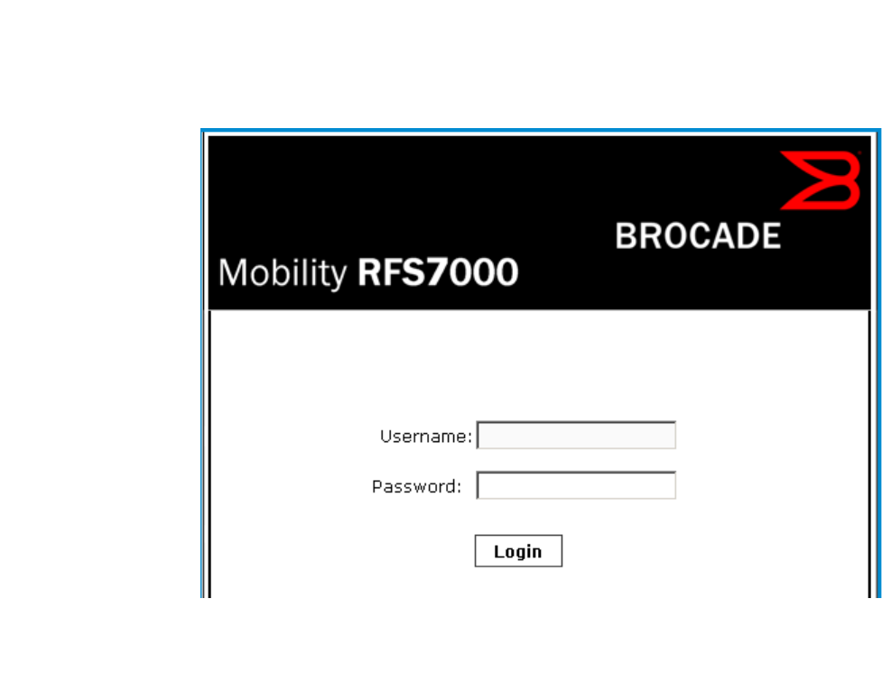
Once the computer has an IP address, point the Web broswer to: https://192.168.0.1/ and the
following login screen will display.
4 Brocade Mobility RFS4000, RFS6000, and RFS7000 System Reference Guide
53-1002620-01
2
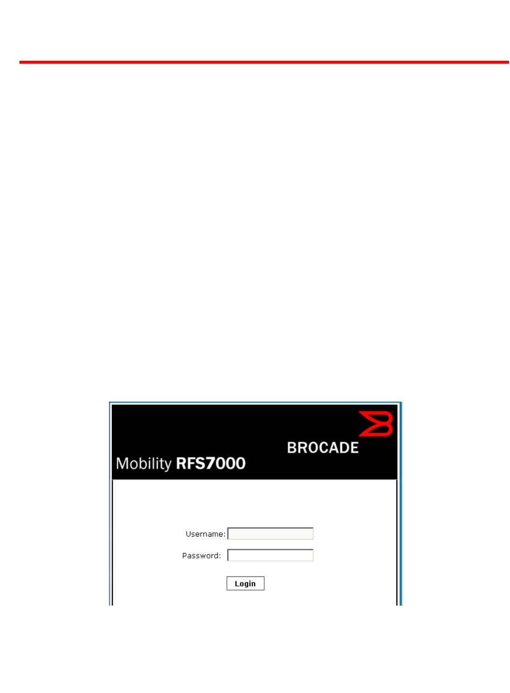
FIGURE 1 Web UI Login Screen
Enter the default username admin in the Username field.
Enter the default password admin123 in the Password field.
Click the Login button to load the management interface.
If this is the first time the UI has been accessed, a dialogue displays to begin an initial setup wizard.
For more information on using the initial setup wizard see Using the Initial Setup Wizard on page
3-13.
Glossary of Icons Used
The UI uses a number of icons used to interact with the system, gather information, and obtain
status for the entities managed by the system. This chapter is a compendium of the icons used.
This chapter is organized as follows:
•Global Icons
•Dialog Box Icons
•Table Icons
•Status Icons
•Configurable Objects
•Configuration Objects
•Configuration Operation Icons
•Access Type Icons
•Administrative Role Icons
Brocade Mobility RFS4000, RFS6000, and RFS7000 System Reference Guide 5
53-1002620-01
2
•Device Icons
Global Icons
Glossary of Icons Used
This section lists global icons available throughout the controller interface.
Dialog Box Icons
Glossary of Icons Used
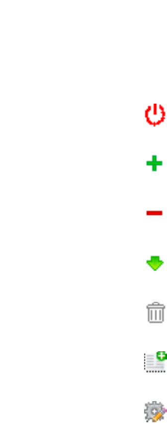
Logoff – Select this icon to log out of the managed system. This icon is always available
and is located at the top right corner of the UI.
Add – Select this icon to add a row in a table. When selected, a new row is created in the
table or a dialog box displays where you can enter values for a particular list.
Delete – Select this icon to remove a row from a table. When selected, the selected row is
deleted.
More Information – Select this icon to display a pop up with supplementary information
that may be available for an item.
Trash – Select this icon to remove a row from a table. When selected, the row is
immediately deleted.
Create new policy – Select this icon to create a new policy. Policies define different
configuration parameters that can be applied to individual device configurations, device
profiles and RF Domains.
Edit policy – Select this icon to edit an existing policy. To edit a policy, select a policy and
this icon.

6 Brocade Mobility RFS4000, RFS6000, and RFS7000 System Reference Guide
53-1002620-01
2
These icons indicate the current state of various controls in a dialog. These icons enables you to
gather, at a glance, the status of all the controls in a dialog. The absence of any of these icons next
to a control indicates the value in that control has not been modified from its last saved
configuration.
Table Icons
Glossary of Icons Used
The following two override icons are status indicators for transactions:
Status Icons
Glossary of Icons Used
Entry Updated – Indicates a value has been modified from its last saved configuration.
Entry Update – States that an override has been applied to a device’s profile
configuration.
Mandatory Field – Indicates this control value is a mandatory configuration item. You
will not be allowed to proceed further without providing all mandatory values in this
dialog.
Error in Entry – Indicates there is an error in a value entered in this control. A small red
popup provides a likely cause of the error.
Table Row Overridden – Indicates a change (profile configuration override) has been
made to a table row and the change will not be implemented until saved. This icon
represents a change from this device’s profile assigned configuration.
Table Row Added – Indicates a new row has been added to a table and the change is
not implemented until saved. This icon represents a change from this device’s profile
assigned configuration.

Brocade Mobility RFS4000, RFS6000, and RFS7000 System Reference Guide 7
53-1002620-01
2
These icons indicate device status, operations on the wireless controller, or any other action that
requires a status returned to the user.
Configurable Objects
Glossary of Icons Used
These icons represent configurable items within the controller’s UI.
Fatal Error – States there is an error causing a managed device to stop functioning.
Error – Indicates an error exits requiring intervention. A managed action has failed, but
the error is not system wide.
Warning – States a particular action has completed, but errors were detected that did
not prevent the process from completing. Intervention might still be required to resolve
subsequent warnings.
Success – Indicates everything is well within the managed network or a process has
completed successfully without error.
Information – This icon always precedes information displayed to the user. This may
either be a message displaying progress for a particular process, or just be a message
from the system.
Device Configuration – Represents a configuration file supporting a device category
(AP, Wireless Controller etc.).
Provisioning Policy – Represents a provisioning policy. Adoption policies are a set of
configuration parameters that define how APs and wireless clients are adopted by a
controller.
Critical Resource Policy – States a critical resource policy has been applied. Critical
resources are resources whose availability is essential to the managed network. If any
of these resources is unavailable, an administrator is notified.
Wireless LANs – States an action impacting a managed WLAN has occurred.
WLAN QoS Policy – States a quality of service policy (QoS) configuration has been
impacted.

8 Brocade Mobility RFS4000, RFS6000, and RFS7000 System Reference Guide
53-1002620-01
2
Radio QoS Policy – Indicates a radio’s QoS configuration has been impacted.
AAA Policy – Indicates an Authentication, Authorization and Accounting (AAA) policy
has been impacted. AAA policies define RADIUS authentication and accounting
parameters.
Association ACL – Indicates an Access Control List (ACL) configuration has been
impacted. An ACL is a set of configuration parameters either allowing or denying
access to managed resources.
Smart RF Policy – States a Smart RF policy has been impacted. Smart RF enables
neighboring APs to take over for an AP if it becomes unavailable. This is accomplished
by increasing the power of radios on nearby APs to cover the hole created by the
non-functioning AP.
Profile – States a device profile configuration has been impacted. A profile is a
collection of configuration parameters used to configure a device or a feature.
Bridging Policy – Indicates a bridging policy configuration has been impacted. A
Bridging Policy defines which VLANs are bridged, and how local VLANs are bridged
between the wired and wireless sides of the managed network.
RF Domain – States an RF Domain configuration has been impacted.
Firewall Policy – Indicates a firewall policy has been impacted. Firewalls provide a
barrier that prevents unauthorized access to resources while allowing authorized
access to external and internal controller resources.
IP Firewall Rules – Indicates an IP firewall rule has been applied. An IP based firewall
rule implements restrictions based on the IP address in a received packet.
MAC Firewall Rules – States a MAC based firewall rule has been applied. A MAC based
firewall rule implements firewall restrictions based on the MAC address in a received
packet.
Wireless Client Role – Indicates a wireless client role has been applied to a managed
client. The role could be either sensor or client.
WIPS Policy – States the conditions of a WIPS policy have been invoked. WIPS prevents
unauthorized access to the managed network by checking for (and removing) rogue
APs and wireless clients.

Brocade Mobility RFS4000, RFS6000, and RFS7000 System Reference Guide 9
53-1002620-01
2
Configuration Objects
Glossary of Icons Used
Advanced WIPS Policy – States the conditions of an advanced WIPS policy have been
invoked.
Device Categorization – Indicates a device categorization policy has been applied. This
is used by the intrusion prevention system to categorize APs or wireless clients as
either sanctioned or unsanctioned devices. This enables devices to bypass the
intrusion prevention system.
Captive Portal – States a captive portal is being applied. Captive portal is used to
provide hotspot services to wireless clients.
DNS Whitelist – A DNS whitelist is used in conjunction with captive portal to provide
hotspot services to wireless clients.
DHCP Server Policy – Indicates a DHCP server policy is being applied. DHCP provides IP
addresses to wireless clients. A DHCP server policy configures how DHCP provides IP
addresses.
RADIUS Group – Indicates the configuration of RADIUS group has been defined and
applied. A RADIUS group is a collection of RADIUS users with the same set of
permissions.
RADIUS User Pools – States a RADIUS user pool has been applied. RADIUS user pools
are a set of IP addresses that can be assigned to an authenticated RADIUS user.
RADIUS Server Policy – Indicates a RADIUS server policy has been applied. A RADIUS
server policy is a set of configuration attributes used when a RADIUS server is
configured for AAA.
Management Policy – Indicates a management policy has been applied. Management
policies configure access control, authentication, traps and administrator permissions.

10 Brocade Mobility RFS4000, RFS6000, and RFS7000 System Reference Guide
53-1002620-01
2
These configuration icons are used to define the following:
Configuration Operation Icons
Glossary of Icons Used
The following operations icons are used to define configuration operations:
Access Type Icons
Glossary of Icons Used
Configuration – Indicates an item capable of being configured by a controller interface.
View Events / Event History – Defines a list of events. Click this icon to view events or
view the event history.
Core Snapshots – Indicates a core snapshot has been generated. A core snapshot is a
file that records status when a process fails on the wireless controller.
Panic Snapshots – Indicates a panic snapshot has been generated. A panic snapshot
is a file that records statu when the wireless controller fails without recovery.
UI Debugging – Select this icon/link to view current NETCONF messages.
View UI Logs – Select this icon/link to view the different logs generated by the UI, FLEX
and the error logs.
Revert – When selected, any changes made after the last saved configuration are
restored back to the last saved configuration.
Commit – When selected, all changes made to the configuration are written to the
system. Once committed, changes cannot be reverted.
Save – When selected, changes are saved to the configuration.

Brocade Mobility RFS4000, RFS6000, and RFS7000 System Reference Guide 11
53-1002620-01
2
The following icons display a user access type:
Administrative Role Icons
Glossary of Icons Used
The following icons identify the different administrative roles allowed on the system:
Web UI – Defines a Web UI controller access permission. A user with this permission is
permitted to access an associated device’s Web UI.
Telnet – Defines a TELNET access permission. A user with this permission is permitted
to access an associated device using TELNET.
SSH – Indicates a SSH access permission. A user with this permission is permitted to
access an associated device using SSH.
Console – Indicates a console access permission. A user with this permission is
permitted to access an associated device using the device’s serial console.
Superuser – Indicates superuser privileges. A superuser has complete access to all
configuration aspects of the connected device.
System – States system user privileges. A system user is allowed to configure general
settings, such as boot parameters, licenses, auto install, image upgrades etc.
Network – Indicates network user privileges. A network user is allowed to configure
wired and wireless parameters, such as IP configuration, VLANs,
L2/L3 security, WLANs and radios.
Security – Indicates security user privileges. A security level user is allowed to
configure all security related parameters.
12 Brocade Mobility RFS4000, RFS6000, and RFS7000 System Reference Guide
53-1002620-01
2
Device Icons
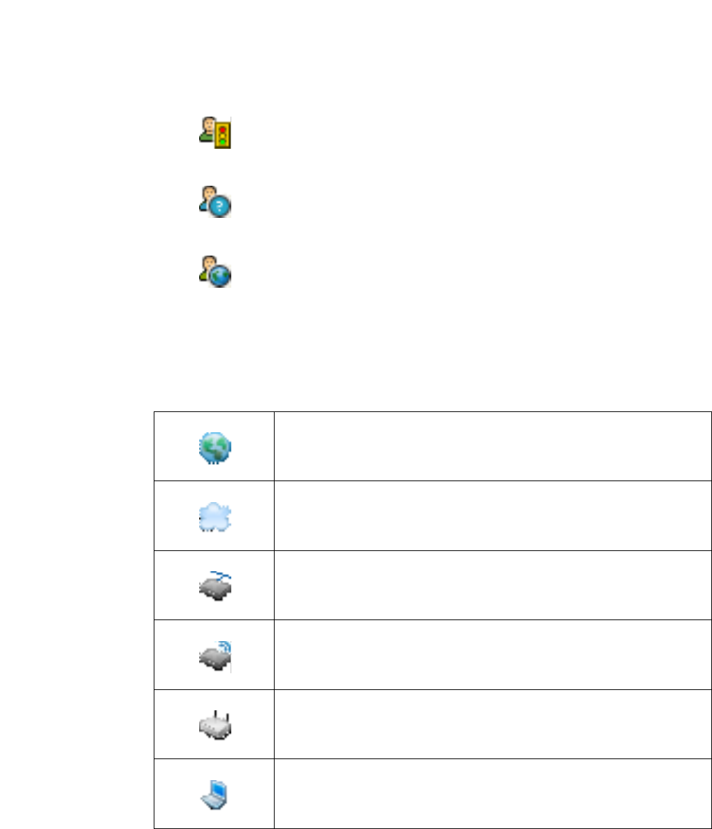
Glossary of Icons Used
The following icons represent the different device types managed by the system:
Monitor – Defines a monitor role. This role provides no configuration privileges. A user
with this role can view the system configuration but cannot modify it.
Help Desk – Indicates help desk privileges. A help desk user is allowed to use
troubleshooting tools like sniffers, execute service commands, view or retrieve logs and
reboot the controller.
Web User – Indicates a web user privilege. A Web user is allowed accessing the
device’s Web UI.
System – This icon represents the entire Brocade Mobility supported system.
Cluster – This icon represents a cluster. A cluster is a set of wireless controllers
working collectively to provide redundancy and load sharing.
Wireless Controller – This icon indicates a RFS6000 or a RFS7000 wireless controller
that’s part of the managed network.
Wireless Controller – This icon indicates a RFS4000 wireless controller that’s part of
the managed network.
Access Point – This icon indicates any access point that’s part of the managed
network.
Wireless Client – This icon defines any wireless client connection within the managed
network.
Brocade Mobility RFS4000, RFS6000, and RFS7000 System Reference Guide 13
53-1002620-01
Chapter
3
Quick Start
In this chapter
•Using the Initial Setup Wizard. . . . . . . . . . . . . . . . . . . . . . . . . . . . . . . . . . . . . 13
•Creating a managed WLAN. . . . . . . . . . . . . . . . . . . . . . . . . . . . . . . . . . . . . . . 22
Brocade Mobility supported controllers utilize an initial settings wizard to streamline the process of
getting the controller on the network for the first time. The wizard defines configure location,
network and WLAN settings and assists in discovery of access points. For instructions on how to
use the initial setup wizard, see Using the Initial Setup Wizard on page 3-13.
Using the Initial Setup Wizard
Once the controller is deployed and powered on, complete the following to get up and running and
access management functions:
Connect one end of an Ethernet cable to a port on the front of the controller and connect the other
end to a computer with a working Web browser.
Set the computer to use an IP address between 192.168.0.10 and 192.168.0.250 on the
connected port. Set a subnet/network mask of 255.255.255.0.
Once the computer has an IP address, point the Web broswer to: https://192.168.0.1/, the
following login screen will display.
FIGURE 2 Web UI Login screen
Enter the default username admin in the Username field.
14 Brocade Mobility RFS4000, RFS6000, and RFS7000 System Reference Guide
53-1002620-01
3
Enter the default password admin123 in the Password field.
Select the Login button to load the management interface.
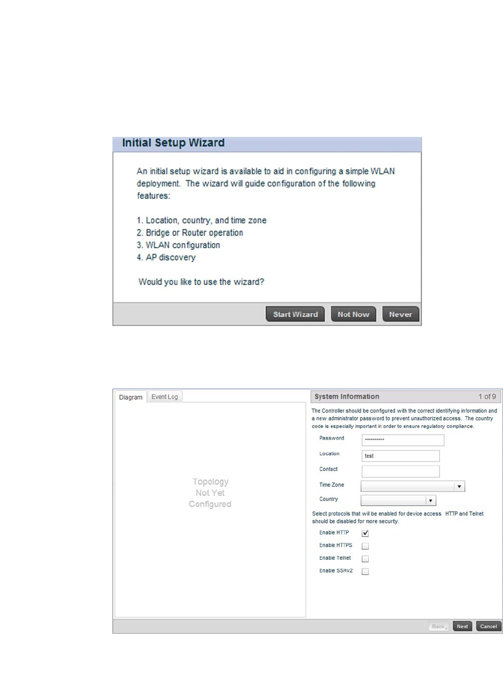
If this is the first time the management interface has been accessed, a dialogue displays to start
the initial setup wizard. Select the Start Wizard button.
FIGURE 3 Initial Setup Wizard
Change the default Password and enter a Location, and Contact name. Select a Time Zone and
Country for the controller.
FIGURE 4 Initial Setup Wizard - System Information screen
Select each of the protocols (access methods) you would like to permit for the controller.
Select the Next button to continue to the Topology Selection screen.
Brocade Mobility RFS4000, RFS6000, and RFS7000 System Reference Guide 15
53-1002620-01
3
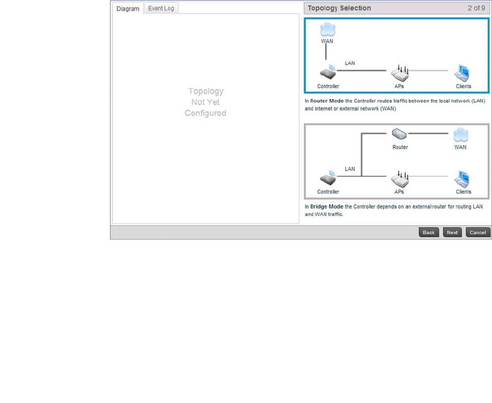
FIGURE 5 Initial Setup Wizard - Topology Selection screen
Select a network topology for the controller deployment. The mode selected will result in a specific
screen flow for the remainder of the initial setup wizard.
For the purposes of this example, select Router Mode.
Select the Next button to continue to the LAN Configuration screen.
Router Mode Using Router Mode, the controller routes traffic between the local network (LAN)
and internet or external network (WAN).
Bridge Mode Using Bridge Mode, the controller uses an external router for LAN and WAN traffic.
Routing is generally used for one device, whereas bridging is typically used with a
larger density network.

16 Brocade Mobility RFS4000, RFS6000, and RFS7000 System Reference Guide
53-1002620-01
3
FIGURE 6 Initial Setup Wizard - LAN Configuration screen
The LAN Configuration screen is partitioned into LAN Interface, DHCP Address Assignment and
Domain Name Server (DNS) fields.
a. Refer to the LAN Interface field for LAN IP address, subnet and VLAN configuration
parameters.
For the purposes of this example, select Use DHCP and uncheck Configure VLANs
Manually.
LAN IP Address / Subnet Enter an IP Address and a subnet for the controller’s LAN interface. If the Use DHCP
checkbox is enabled, this field will not be configurable.
Use DHCP Select the Use DHCP checkbox to enable automatic network configuration using a
DHCP server. If this option is enabled, the LAN IP Address/Subnet, DHCP Address
Assignment and Domain Name fields are populated by the DHCP server.
What VLAN ID should be
used for the LAN
interface
Set the VLAN ID to associate with the LAN Interface. The default setting is VLAN 1.
Configure VLANs
Manually
Select the Configure VLANs Manually checkbox to enable advanced manual VLAN
configuration.
For more information, see Virtual Interface Configuration on page 7-384.
Advanced VLAN
Configuration
Select the Advanced VLAN Configuration button to set associations between VLANs
and controller physical interfaces.
Brocade Mobility RFS4000, RFS6000, and RFS7000 System Reference Guide 17
53-1002620-01
3
b. Refer to the DHCP Address Assignment field to set DHCP server settings for the LAN
interface.
c. Refer to the Domain Name Server (DNS) field to set DNS server settings on the LAN
interface.
Select Next to save the LAN configuration settings and move to the WAN Configuration screen.
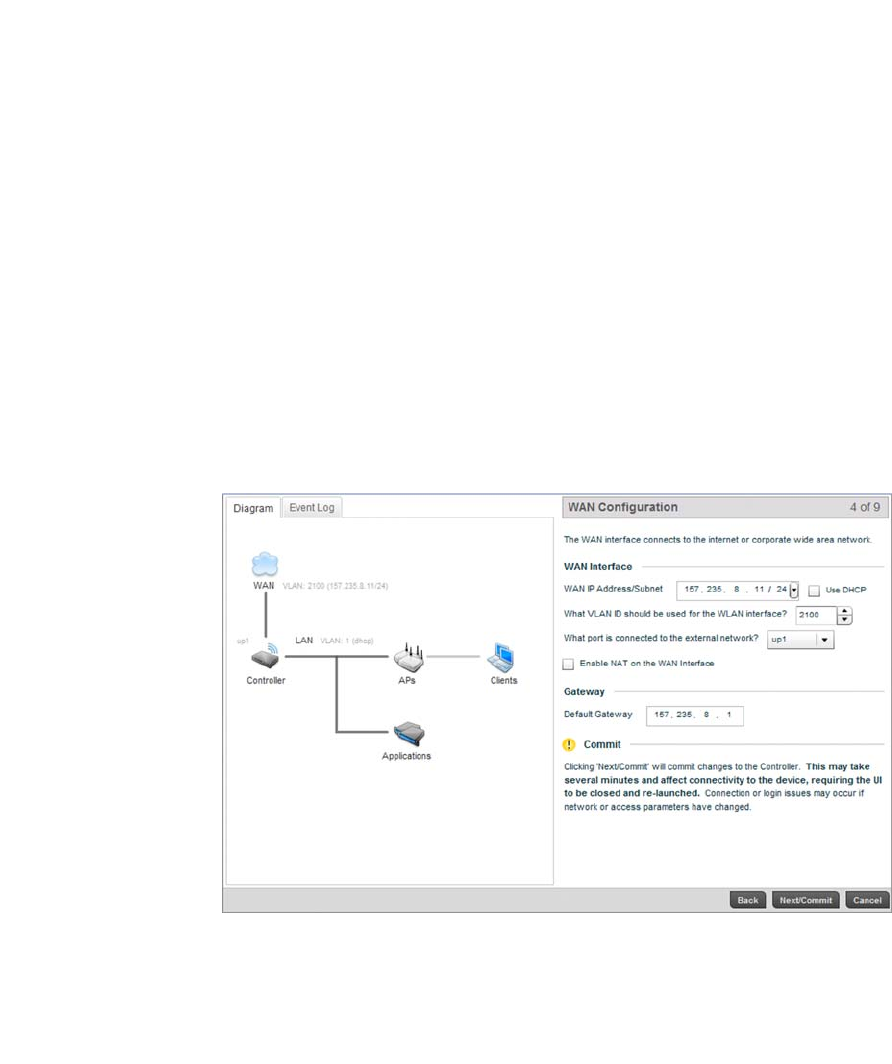
The WAN Configuration screen is partitioned into WAN Interface and Gateway fields.
a. Refer to the WAN Interface field to set the WAN IP address, subnet and VLAN
configuration.
Use the Controller to
assign IP addresses to
devices
Select the Use the Controller to assign IP addresses to devices checkbox to
enable the onboard DHCP server to provide IP and DNS information to clients on the
LAN interface.
IP Address Range Enter a starting and ending IP Address range for client assignments on the LAN
interface. It’s good practice to avoid assigning IP addresses from
x.x.x.1 - x.x.x.10 and x.x.x.255 as they are often reserved for standard network
services.
Primary DNS Enter an IP Address for the main DNS server for the controller LAN interface.
Secondary DNS Enter an IP Address for the backup DNS server for the LAN interface.
WAN IP Address/Subnet Enter an IP Address and a subnet for the controller’s WAN interface. If the Use DHCP
checkbox is enabled, this field will not be configurable.
Use DHCP Select the Use DHCP checkbox to enable an automatic network configuration using
a DHCP Server. If this option is enabled, the WAN IP Address/Subnet and Gateway
fields are populated by the DHCP server.
18 Brocade Mobility RFS4000, RFS6000, and RFS7000 System Reference Guide
53-1002620-01
3
b. Refer to the Gateway field to set the Default Gateway.
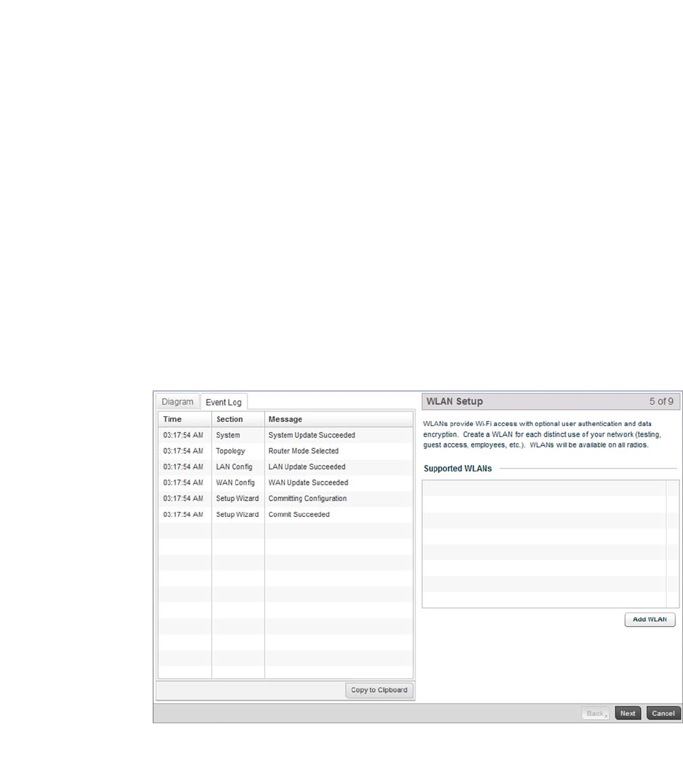
Select Next to save the WAN configuration settings and move to the WLAN Setup screen.
Use The WLAN Setup screen to enable managed WLANs.
FIGURE 7 Initial Setup Wizard - WLAN Setup screen
Select the Add WLAN button to display a screen used to define WLAN settings.
What VLAN ID should be
used for the WLAN
interface
Set the VLAN ID to associate with the WLAN Interface. The default setting is VLAN
2100.
For more information, see Virtual Interface Configuration on page 7-384.
What port is connected
to the external network?
Select the physical controller port connected to the WAN interface. The list of
available ports varies based on controller model.
Enable NAT on the WAN
Interface
Click the Enable NAT on WAN Interface checkbox to enable Network Address
Translation (NAT) allowing traffic to pass between the controller WAN and LAN
interfaces.
Default Gateway Enter an IP Address for the controller’s default gateway on the WAN interface. If the
Use DHCP checkbox is enabled, this field will not be configurable.
Brocade Mobility RFS4000, RFS6000, and RFS7000 System Reference Guide 19
53-1002620-01
3
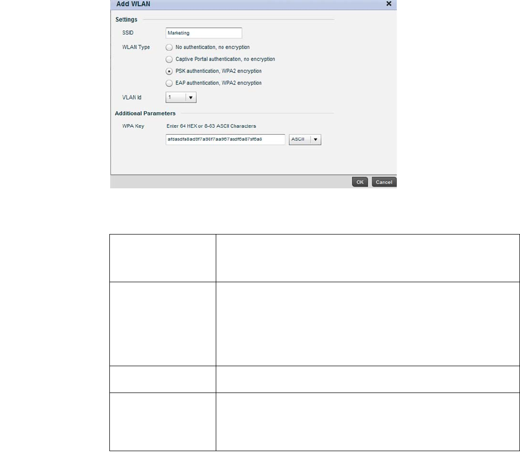
FIGURE 8 Initial Setup Wizard
Set the following parameters for new WLAN configurations:
Select OK to exit, then select Next to continue to the RADIUS Authentication screen.
SSID Enter or modify the Services Set Identification (SSID) associated with the WLAN.
The WLAN name is auto-generated using the SSID until changed by the user. The
maximum number of characters is 32. Do not use any of these characters (< > | " &
\ ? ,).
WLAN Type Select a basic authentication and encryption scheme for the WLAN. Available
options include:
No authentication, no encryption
Captive portal authentication, no encryption
PSK authentication, WPA2 encryption
EAP authentication, WPA2 encryption
For more information, see Configuring WLAN Security on page 6-286.
VLAN Id Select a VLAN to associate with WLAN traffic. Each configured VLAN is available for
selection.
WPA Key Enter either an alphanumeric string of 8 to 63 ASCII characters or 64 HEX
characters as the primary string both transmitting and receiving authenticators
must share. The alphanumeric string allows character spaces. The wireless
controller converts the string to a numeric value. This passphrase saves the
administrator from entering the 256-bit key each time keys are generated.
20 Brocade Mobility RFS4000, RFS6000, and RFS7000 System Reference Guide
53-1002620-01
3
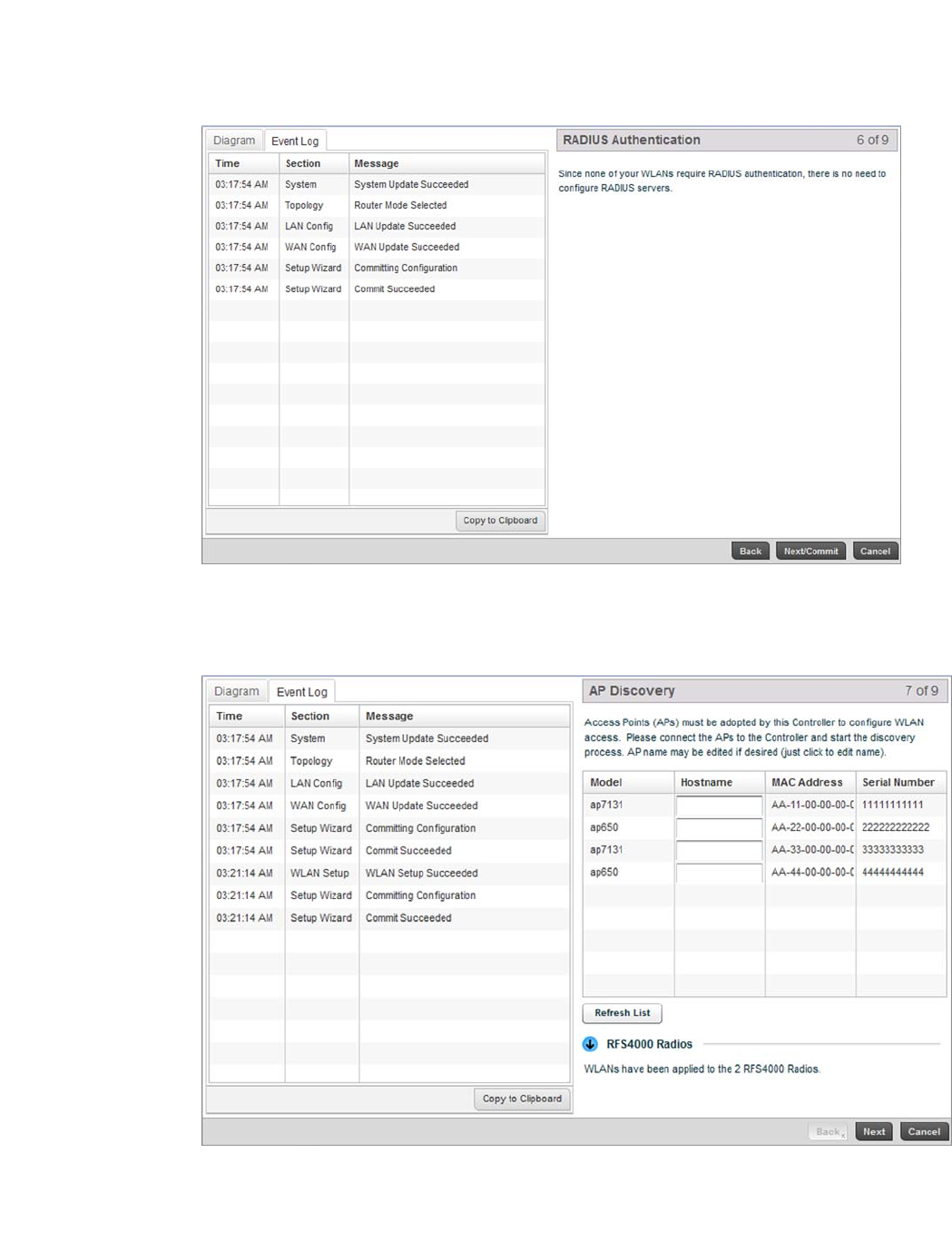
FIGURE 9 Initial Setup Wizard - RADIUS Authentication screen
Within this example, there’s no action required since no WLANs require RADIUS authentication.
Select Next/Commit to continue to the AP Discovery screen.
FIGURE 10 Initial Setup Wizard - AP Discovery screen
The AP Discovery screen displays a list of Access Points discovered by the controller. If you have
connected any APs to the controller select the Refresh List button to update the list of known APs.
Brocade Mobility RFS4000, RFS6000, and RFS7000 System Reference Guide 21
53-1002620-01
3
Optionally, define a Hostname for each known AP.
NOTE
If using a RFS4011model controller, configured WLANs are automatically applied to the internal
radios.
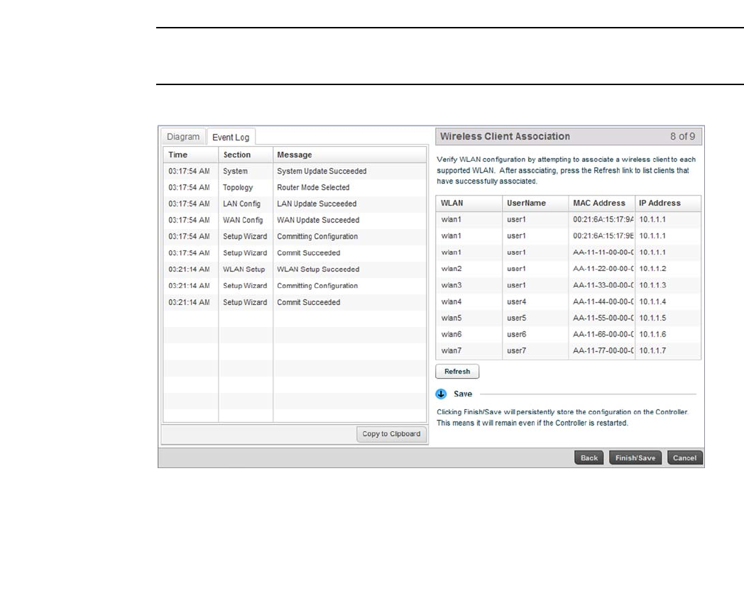
Select the Next button to move to the Wireless Client Association screen.
FIGURE 11 Initial Setup Wizard - Wireless Client Association screen
The Wireless Client Association screen displays adopted clients and the WLANs they are associated
with.
To verify the WLAN configuration, associate a wireless client with each configured WLAN. After
associating, click the Refresh button to update the list of associated wireless clients.
Select the Finish/Save button to complete the wizard and display a summary of changes.
22 Brocade Mobility RFS4000, RFS6000, and RFS7000 System Reference Guide
53-1002620-01
3
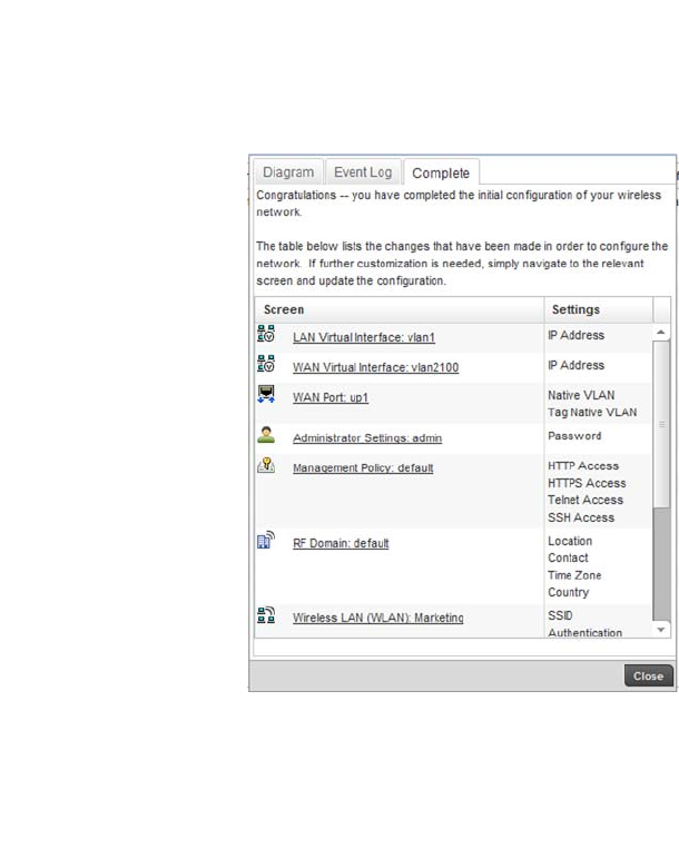
FIGURE 12 Initial Setup Wizard
The summary screen displays a table listing all changes made to the controller configuration by the
wizard. It lists both the screens and the associated settings that have been modified.
Once you have reviewed the changes, select the Close button to exit the wizard and return the Web
UI.
Creating a managed WLAN
This section describes the activities required to configure a managed WLAN. Instructions are
provided using both the controller CLI and GUI to allow an administrator to configure the WLAN
using the desired interface.
It’s assumed you have a Brocade Mobility RFS4000 wireless controller with the latest build
available from Brocade. It is also assumed you have one an Brocade Mobility 71XX Access Point
model Access Point and one Brocade Mobility 650 Access Point model Access Point, both with the
latest firmware from Brocade.
Upon completion, you’ll have created a WLAN on a Brocade Mobility RFS4000 model wireless
controller using a DHCP server to allocate IP addresses to associated wireless clients.
Assumptions
Creating a managed WLAN
Verify the following conditions have been satisfied before attempting the WLAN configuration
activities described in this section.
It’s assumed the wireless controller has the latest firmware version available from Brocade.
Brocade Mobility RFS4000, RFS6000, and RFS7000 System Reference Guide 23
53-1002620-01
3
It’s assumed the Brocade Mobility 71XX Access Point and Brocade Mobility 650 Access Point
Access Points also have the latest firmware version available from Brocade.
It’s assumed there are no previous configurations on the wireless controller or Access Point, and
default factory configurations are running on the devices.
It’s assumed you have administrative access to the RFS4000 wireless controller and Access Point
GUI and CLI.
It’s assumed the individual administrating the network is a professional network installer.
Design
Creating a managed WLAN
This section defines the network design being implemented.
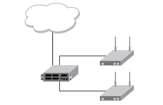
FIGURE 13 Network Design
This is a fairly simple deployment scenario, with Access Points connected directly to the wireless
controller. One wireless controller port is connected to an external network.
On the Brocade Mobility RFS4000 wireless controller, the GE1 interface is connected to an external
network. Interfaces GE3 and GE4 are used by the access points.
On the external network, the controller is assigned an IP address of 192.168.10.188. The wireless
controller acts as a DHCP server for the wireless clients connecting to it, and assigns IP addresses
in the range of 172.16.11.11 to 172.16.11.200. The rest of IPs in the range are reserved for
devices requiring static IP addresses.
To define the WLAN configuration using either controller GUI refer to:
•Using the Controller GUI to Configure the WLAN
Using the Controller GUI to Configure the WLAN
Creating a managed WLAN
The following instructions are for configuring a (non default) WLAN using the controller’s graphical
user interface (GUI).
RFS4000
(DHCP Server)
172.16.11.x
AP650
(DHCP Client)
AP7131
(DHCP Client)
External Network

24 Brocade Mobility RFS4000, RFS6000, and RFS7000 System Reference Guide
53-1002620-01
3
Use a serial console cable when connecting to the wireless controller for the first time. Set the
following configuration parameters when using a serial connection.
•Bits per second: 19200
•Data Bit: 8
•Parity: None
•Stop Bit: 1
•Flow Control: None
When the wireless controller is started for the first time, its interfaces are not configured. Access to
the wireless controller is only available through the serial console. To use the wireless controller’s
GUI, one of the other controller ports must be enabled and configured. The following section,
demonstrates how to configure access to the GUI.
The tasks required to create a controller WLAN using the GUI include:
•Configuring Access to the GUI Using the GE1 Port
•Logging into the Controller for the First Time
•Creating a RF Domain
•Creating a Wireless Controller Profile
•Creating a WLAN Configuration
•Creating an AP Profile
•Completing and testing the configurations
Configuring Access to the GUI Using the GE1 Port
Using the Controller GUI to Configure the WLAN
Before you can access the wireless controller’s GUI, the controller must have an IP address
defined. The GE interface has to be configured with an IP address (using the CLI) before an
administrator can access the GUI.
Logging into the Wireless Controller for the First Time
When you power on the wireless controller for the first time, you are prompted to replace the
existing administrative password. The credentials for logging into the wireless controller for the first
time include:
•User Name: admin
•Password: admin123
Ensure the new password created is strong enough to provide adequate security for the managed
network.
Configuring the Controller’s GE1 Interface
Navigate to the GE1 interface using the following commands:
Brocade Mobility RFS4000-571428>enable
Brocade Mobility RFS4000-571428#
Brocade Mobility RFS4000-571428#configure terminal
Enter configuration commands, one per line. End with CNTL/Z.
Brocade Mobility RFS4000, RFS6000, and RFS7000 System Reference Guide 25
53-1002620-01
3
Brocade Mobility RFS4000-571428(config)#
Brocade Mobility RFS4000-571428(config)#self
Brocade Mobility RFS4000-571428(config-device-03-14-28-57-14-28)#
Create a VLAN and assign the IP address 172.16.0.1 to it.
Brocade Mobility RFS4000-571428(config-device-03-14-28-57-14-28)#interface vlan 1
Brocade Mobility RFS4000-571428(config-device-03-14-28-57-14-28-if-vlan1)#ip address
172.16.0.1
Brocade Mobility RFS4000-571428(config-device-03-14-28-57-14-28-if-vlan1)#commit write
Brocade Mobility RFS4000-571428(config-device-03-14-28-57-14-28)#
Configure the GE 1 port to use the VLAN 1.
Brocade Mobility RFS4000-571428(config-device-03-14-28-57-14-28)#interface ge 1
Brocade Mobility RFS4000-571428(config-device-03-14-28-57-14-28-if-ge1)#
Brocade Mobility RFS4000-571428(config-device-03-14-28-57-14-28-if-ge1)#switch port access
vlan 1
The above command assigns the IP address 172.16.0.1, with the mask 255.255.255.0 to ME1.
Exit the ME1 context.
Brocade Mobility RFS4000-571428(config-device-03-14-28-57-14-28-if-me1)#exit
Brocade Mobility RFS4000-571428(config-device-03-14-28-57-14-28)#
Brocade Mobility RFS4000-571428(config-device-03-14-28-57-14-28)#commit write
The system used to access the wireless controller must be configured as follows:
•IP Address: 172.16.0.10
•Mask: 255.255.255.0
Connect the device’s Ethernet interface to the ME interface of the wireless controller.
Launch a browser and enter the following:
•https://172.16.0.1/
The controller’s login screen displays.
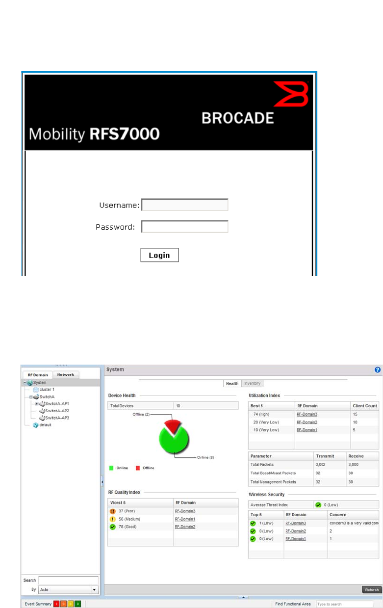
26 Brocade Mobility RFS4000, RFS6000, and RFS7000 System Reference Guide
53-1002620-01
3
FIGURE 14 Login Screen
Logging into the Controller for the First Time
Using the Controller GUI to Configure the WLAN
The following screen displays upon successfully changing the login password:
FIGURE 15 GUI Main screen
Creating a RF Domain
Using the Controller GUI to Configure the WLAN
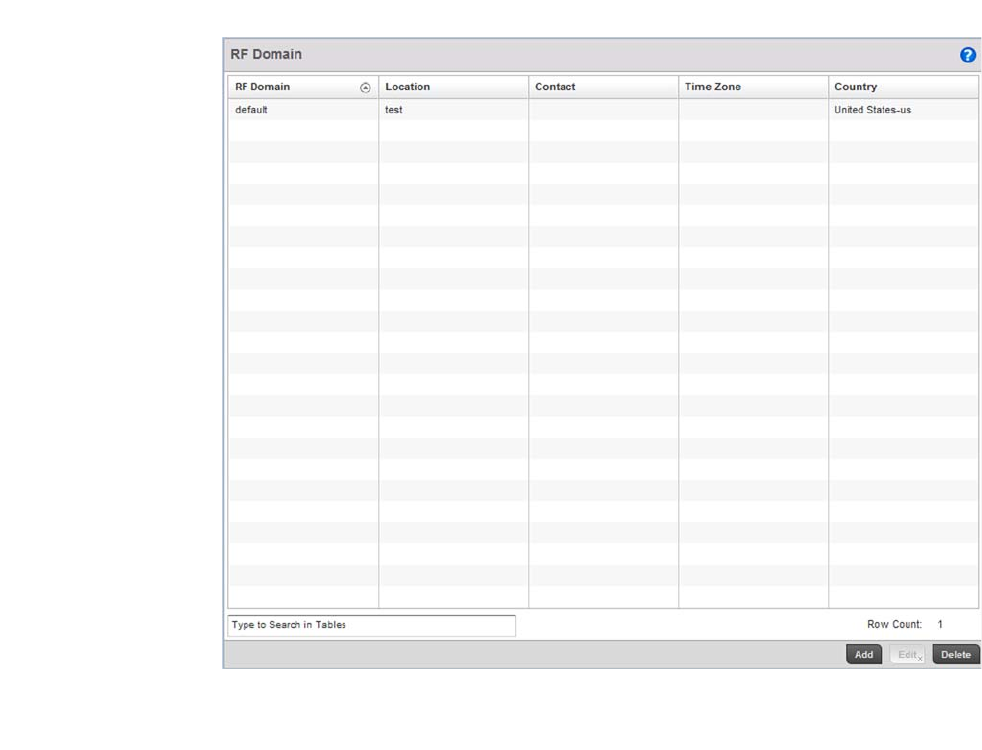
Brocade Mobility RFS4000, RFS6000, and RFS7000 System Reference Guide 27
53-1002620-01
3
A RF Domain is a collection of configuration settings specific to devices located at the same
physical deployment, such as a building or a floor. Create a RF Domain and assign the country code
where the devices are deployed. This is a mandatory step, and devices will not function as intended
if this step is omitted.
To create a RF Domain:
Select Configuration > RF Domain.
FIGURE 16 RF Domain screen
Select the Add button at the bottom of the screen to create a new RF Domain configuration.
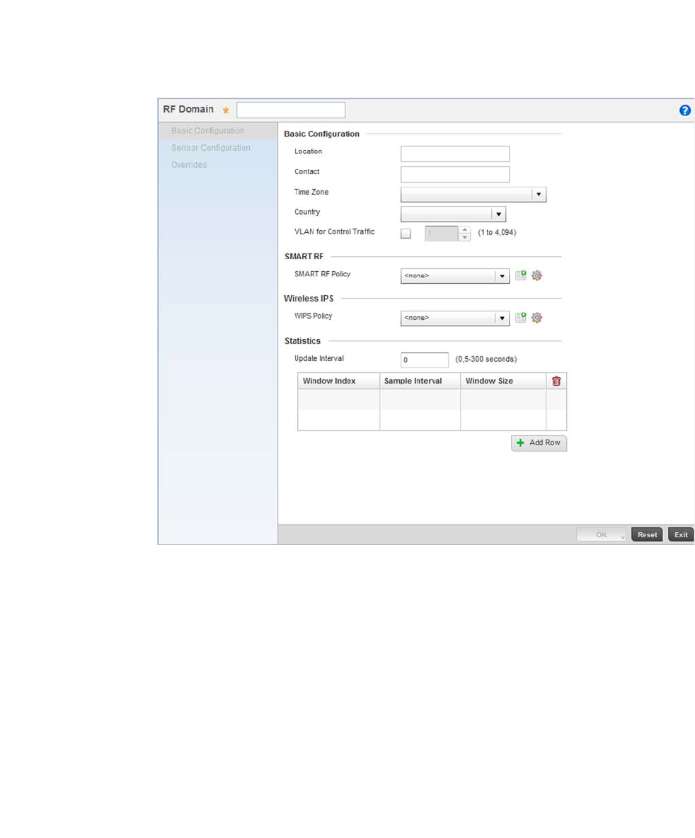
28 Brocade Mobility RFS4000, RFS6000, and RFS7000 System Reference Guide
53-1002620-01
3
FIGURE 17 RF Domain screen - New RF Domain
Provide the following information to define the RF Domain configuration:
Select OK to save the updates. Select Exit button to close the screen, then click the Commit icon at
the top right of the screen to apply the updates to the controller’s running configuration.
RF Domain Assign the RF Domain a name representative of its intended function. The name
cannot exceed 32 characters. The name cannot be changed as part of the edit
process. For this scenario, use:
RFDOMAIN_UseCase1
Time Zone Assign the RF Domain a time zone representative of its deployment location. For this
scenario, use:
(GMT - 08:00) America/Los_Angeles
Country Define the two-digit country code for the RF Domain. The country code must be set
accurately to avoid the policy’s illegal operation, as device radios transmit in specific
channels unique to the country of operation. For this scenario, use:
United States - us
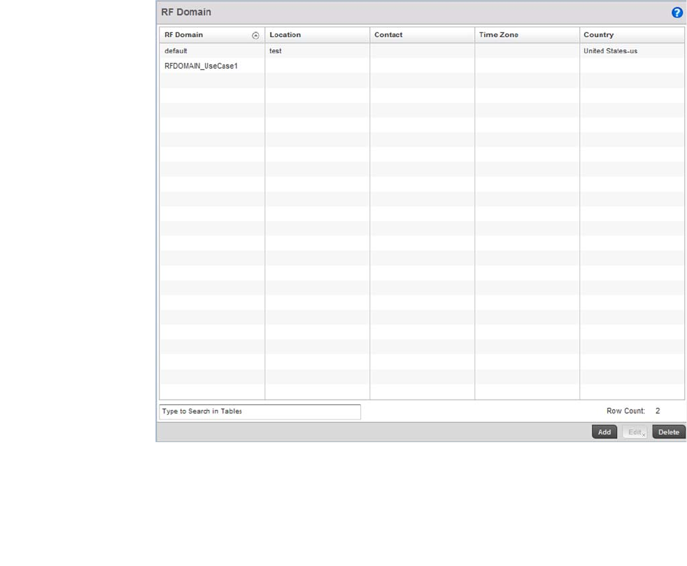
Brocade Mobility RFS4000, RFS6000, and RFS7000 System Reference Guide 29
53-1002620-01
3
FIGURE 18 New RF Domain Configuration
Configure the Wireless Controller to use the RF Domain
To configure the wireless controller’s physical deployment location, use the RF Domain
configuration you just created.
Select Configuration > Devices > Device Configuration.
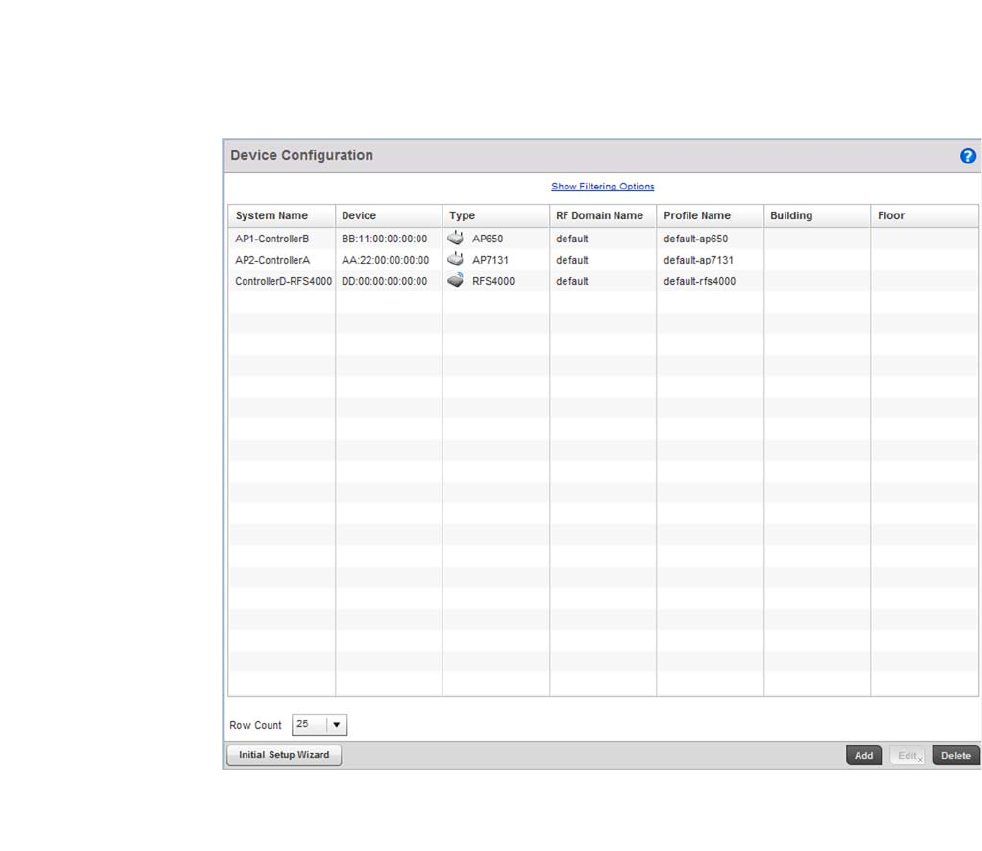
30 Brocade Mobility RFS4000, RFS6000, and RFS7000 System Reference Guide
53-1002620-01
3
FIGURE 19 Device Configuration screen
Select the Brocade Mobility RFS4000 wireless controller. Select the Edit button.
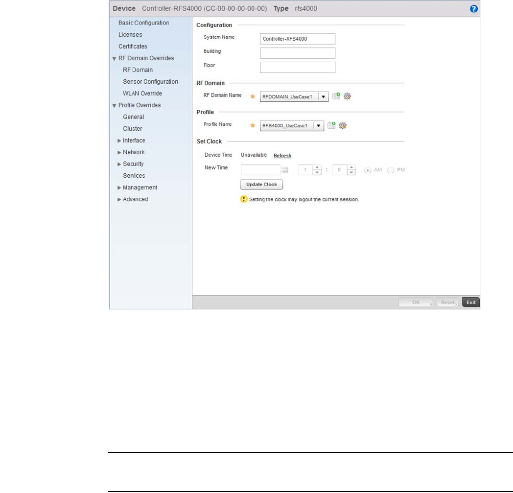
Brocade Mobility RFS4000, RFS6000, and RFS7000 System Reference Guide 31
53-1002620-01
3
FIGURE 20 Brocade Mobility RFS4000 Device screen
Set a name for the RF Domain to which this Brocade Mobility RFS4000 controller belongs. For this
use case scenario, use:
RFDOMAIN_UseCase1
Leave the rest of the fields undefined.
Select OK button to save the changes. Select Exit button to close the screen, then click the Commit
icon at the top right of the screen to apply the updates to the controller’s running configuration.
Repeat the steps 1 through 4 to configure the Brocade Mobility 650 Access Point.
NOTE
The wireless controller and Access Points must use the same country code for the Access Points to
be successfully adopted by the controller.
The following image displays after the Brocade Mobility RFS4000, Brocade Mobility 650
Access Point and Brocade Mobility 71XX Access Point have been configured to use the
RFDOMAIN_UseCase1 RF Domain.
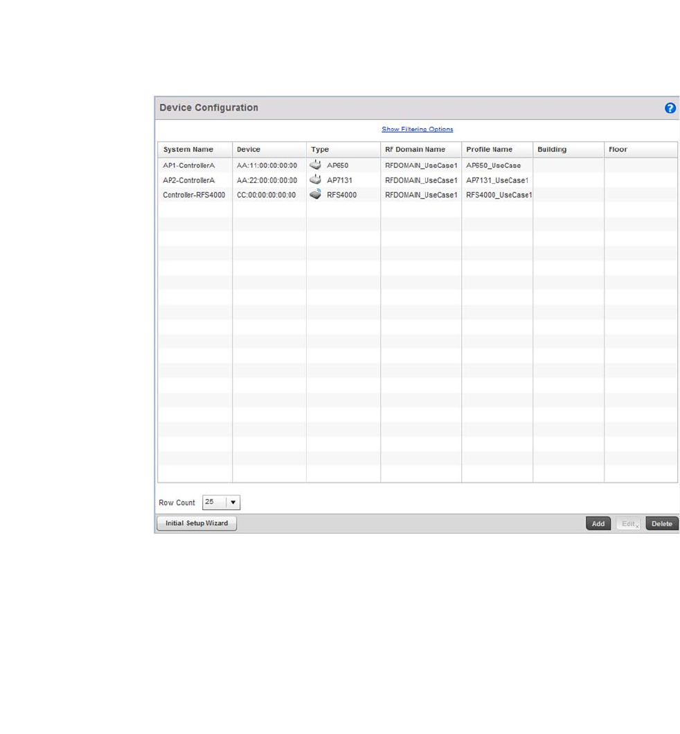
32 Brocade Mobility RFS4000, RFS6000, and RFS7000 System Reference Guide
53-1002620-01
3
FIGURE 21 Device Configuration screen after configuring Brocade Mobility RFS4000 and
Brocade Mobility 650 Access Point
Creating a Wireless Controller Profile
Using the Controller GUI to Configure the WLAN
The first step in creating a WLAN is to create a profile defining the configuration parameters that
must be applied to the wireless controller.
To create a profile:
Select Configuration > Profiles.
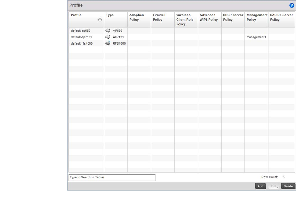
Brocade Mobility RFS4000, RFS6000, and RFS7000 System Reference Guide 33
53-1002620-01
3
FIGURE 22 Profiles screen
Select the Add button at the bottom right of the screen.
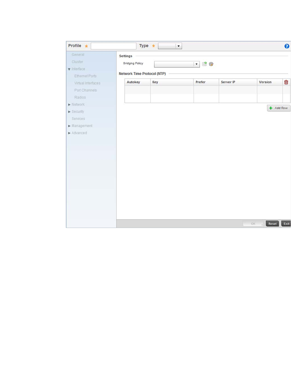
34 Brocade Mobility RFS4000, RFS6000, and RFS7000 System Reference Guide
53-1002620-01
3
FIGURE 23 New Brocade Mobility RFS4000 Profile
Define the name of the profile and the device type it supports.
Select OK to save the changes. Select the Exit button to close this screen, then click the Commit
icon at the top right of the screen to apply the updates to the controller’s running configuration.
This creates a profile with the name Brocade Mobility RFS4000_UseCase1. Any configuration
made under this profile is available for use when it’s applied to a device.
Configure a VLAN
Create the VLAN used with this WLAN.
Using the Brocade Mobility RFS4000_UseCase1 profile, expand the Configuration > Profiles >
Interface menu item to display its submenu options.
Profile Define the name of the Brocade Mobility RFS4000 profile being created. For this
scenario, use:
Brocade Mobility RFS4000_UseCase1
Type Specify the device type. For this scenario, use:
Brocade Mobility RFS4000
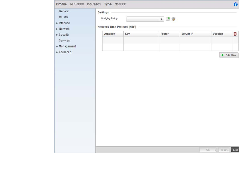
Brocade Mobility RFS4000, RFS6000, and RFS7000 System Reference Guide 35
53-1002620-01
3
FIGURE 24 Brocade Mobility RFS4000 Profile screen
Select Virtual Interfaces.
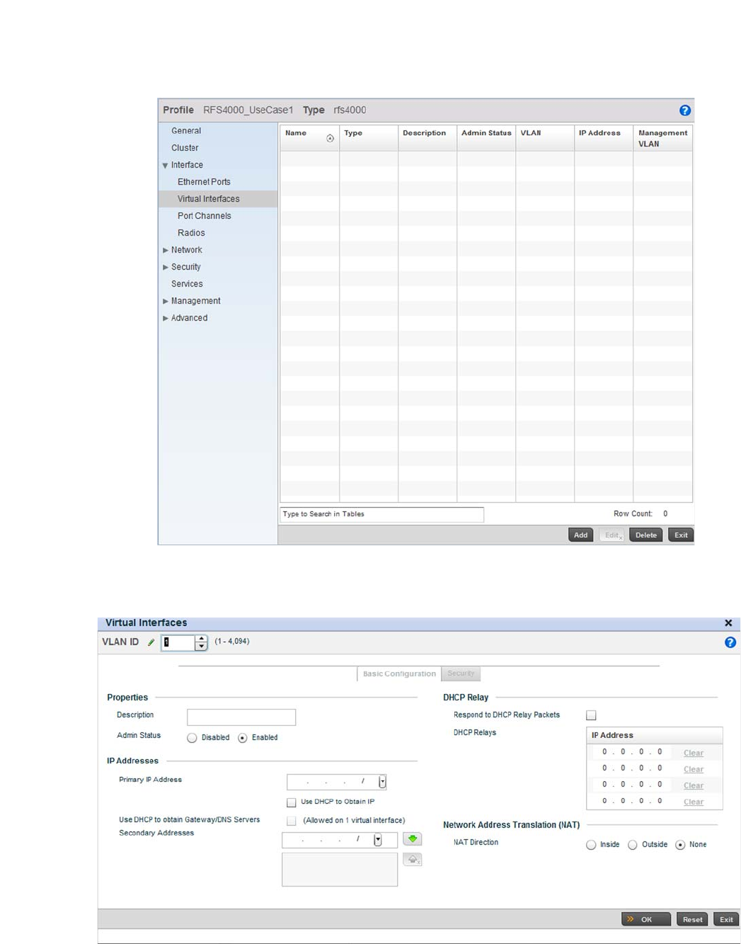
36 Brocade Mobility RFS4000, RFS6000, and RFS7000 System Reference Guide
53-1002620-01
3
FIGURE 25 Virtual Interfaces screen
Click the Add button located at the bottom left of the screen.
FIGURE 26 Virtual Interface screen
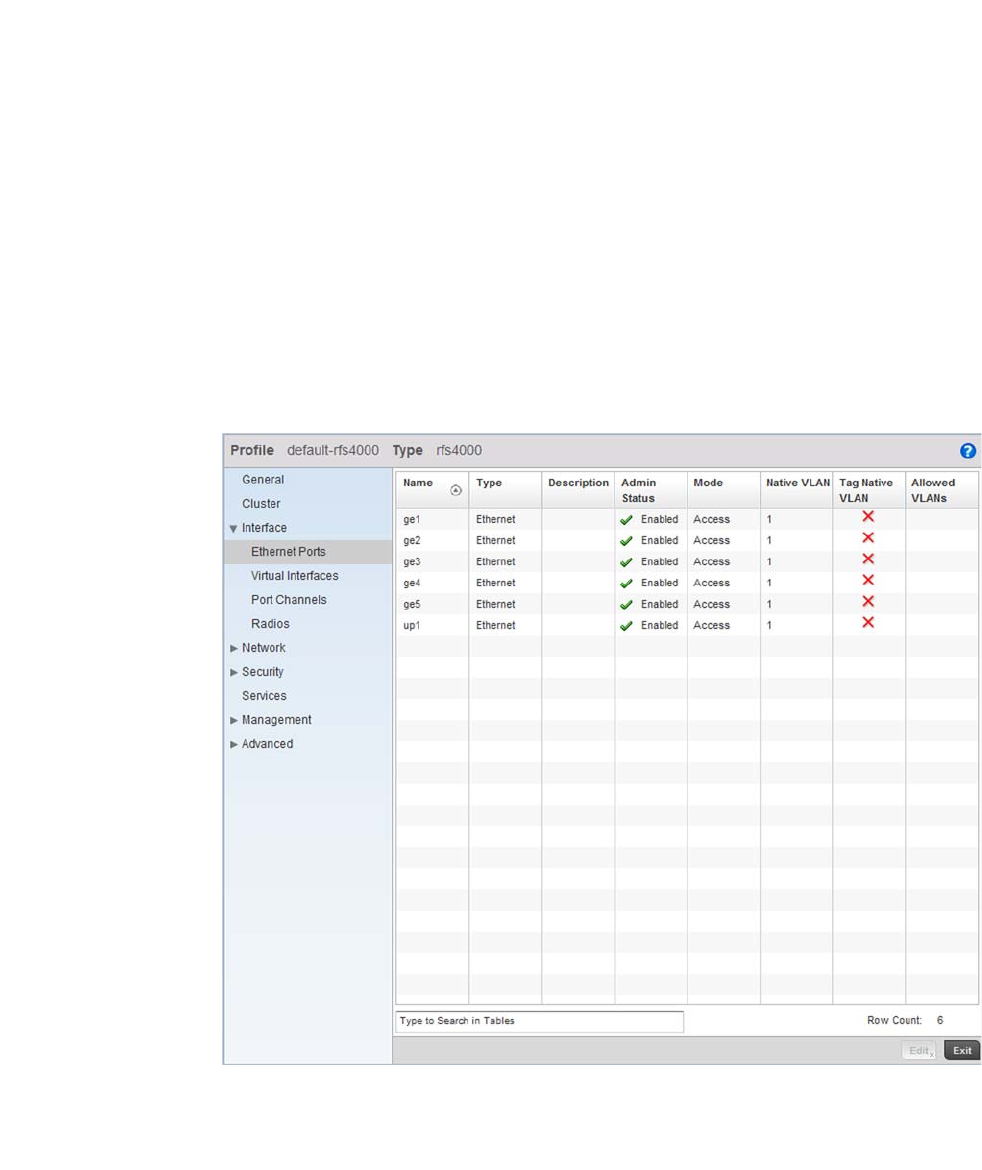
Brocade Mobility RFS4000, RFS6000, and RFS7000 System Reference Guide 37
53-1002620-01
3
Set a VLAN ID (within the top of the screen) and a Primary IP Address. For this use case scenario,
use a VLAN ID of 2 and a Primary IP Address of 172.16.11.1/24. This assigns an IP address of
172.16.11.1 with a mask of 255.255.255.0 to VLAN2.
Select OK to save the changes. Select Exit to close the screen, then click the Commit icon at the top
right of the screen to apply the updates to the controller’s running configuration.
The next step is to assign this newly created VLAN to a physical interface. In this case, VLAN 2
is mapped to GE3 and GE4 to support the Brocade Mobility 650 Access Point and an Brocade
Mobility 71XX Access Point Access Points. The Brocade Mobility 650 Access Point is connected
to the gigabit interface GE3, and the Brocade Mobility 71XX Access Point to the interface GE4.
Configure the Physical Interfaces
To configure the GE3 port on behalf of the Brocade Mobility 650 Access Point:
Using the RFS7000_UseCase1 profile, expand the Configuration > Profiles > Interface menu item
to display its submenu options.
Select Ethernet Ports.
FIGURE 27 Ethernet Port Configuration screen
By default, all ports are enabled and VLAN 1 is assigned as the Native VLAN. To change the Native
VLAN value to VLAN 2, select the GE 3 controller interface and select the Edit button.
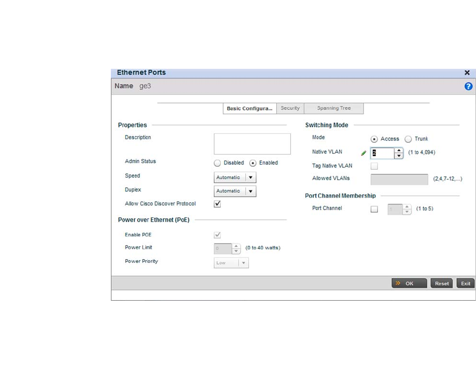
38 Brocade Mobility RFS4000, RFS6000, and RFS7000 System Reference Guide
53-1002620-01
3
FIGURE 28 Interface GE 3 Configuration
Use the spinner control to set a Native VLAN value of 2 for this use case scenario.
Do not change any other values.
Click the OK button to save the changes. Select Exit to close the screen, then click the Commit icon
at the top right of the screen to apply the updates to the controller’s running configuration.
Repeat the steps 3 through 5 to map VLAN 2 to the GE 4 interface.
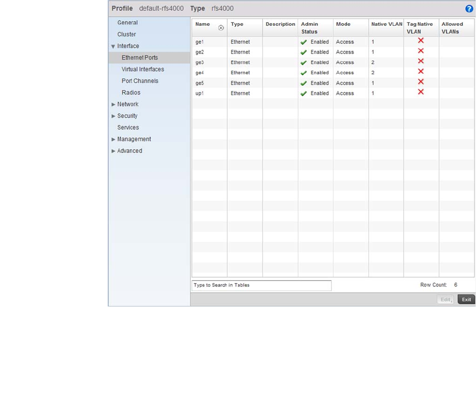
Brocade Mobility RFS4000, RFS6000, and RFS7000 System Reference Guide 39
53-1002620-01
3
FIGURE 29 Physical Interfaces GE3 and GE4
Configuring the Wireless Controller to use the Appropriate Profile
Before the wireless controller can be configured further, the profile must be applied to the wireless
controller. To do so:
Navigate to the Brocade Mobility RFS4000 by selecting Configuration > Devices > Device
Configuration.
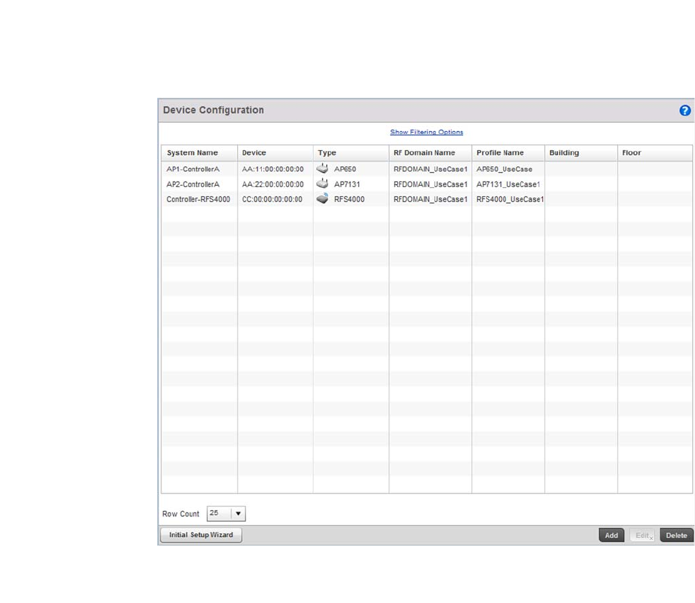
40 Brocade Mobility RFS4000, RFS6000, and RFS7000 System Reference Guide
53-1002620-01
3
FIGURE 30 Device Configuration screen
Select the Brocade Mobility RFS4000 from the list and select the Edit button.
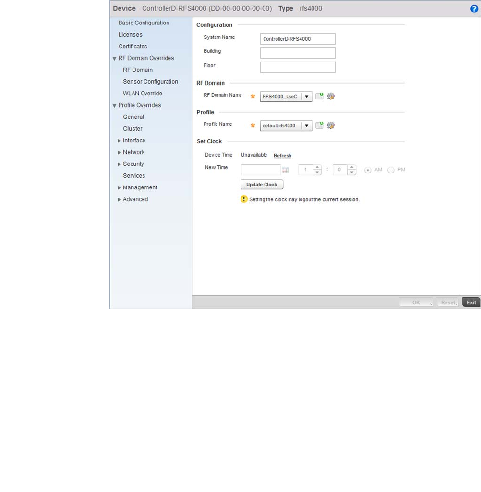
Brocade Mobility RFS4000, RFS6000, and RFS7000 System Reference Guide 41
53-1002620-01
3
FIGURE 31 Brocade Mobility RFS4000 Configuration
Provide a profile name for the Brocade Mobility RFS4000 device profile. For this use case scenario,
use:
Brocade Mobility RFS4000_UseCase1
Select OK to save the changes. Select Exit to close this screen, then click the Exit button to close
this screen. Select the Commit icon to save it to the controller’s running configuration.
Creating a WLAN Configuration
Using the Controller GUI to Configure the WLAN
Complete the following steps to create a WLAN:
Select Configuration > Wireless > Wireless LANs to navigate to the WLAN screen.
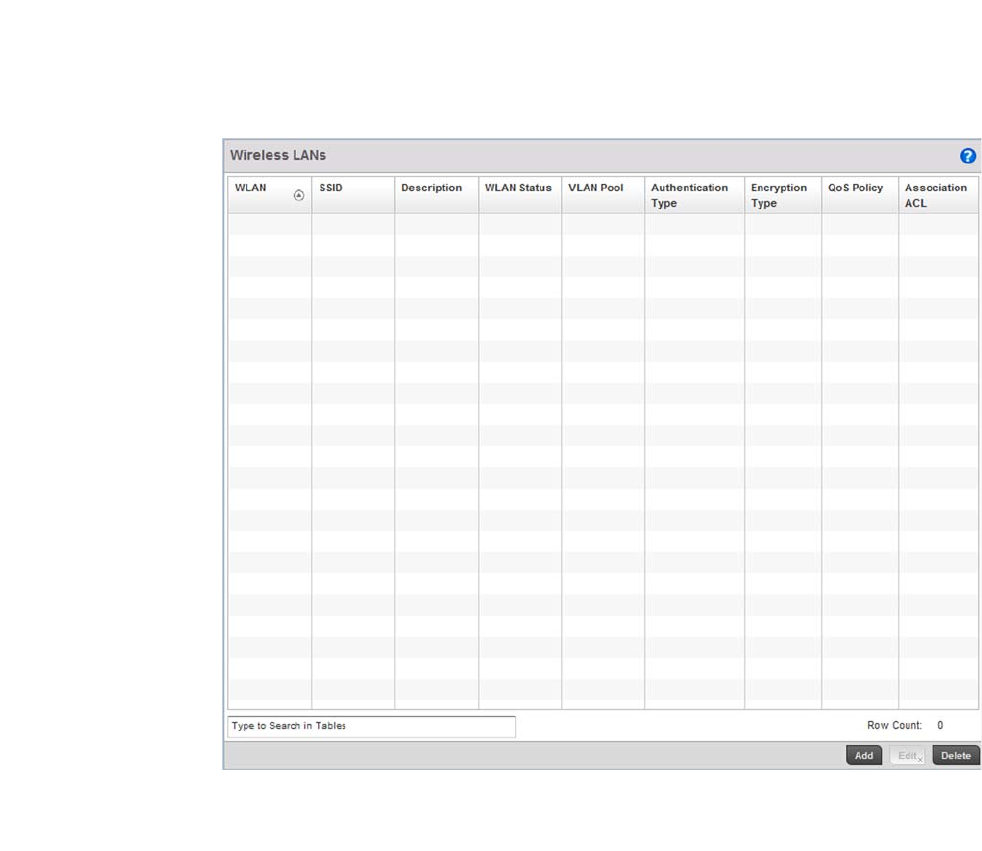
42 Brocade Mobility RFS4000, RFS6000, and RFS7000 System Reference Guide
53-1002620-01
3
FIGURE 32 Wireless LANs screen
Select the Add button to create a new WLAN.
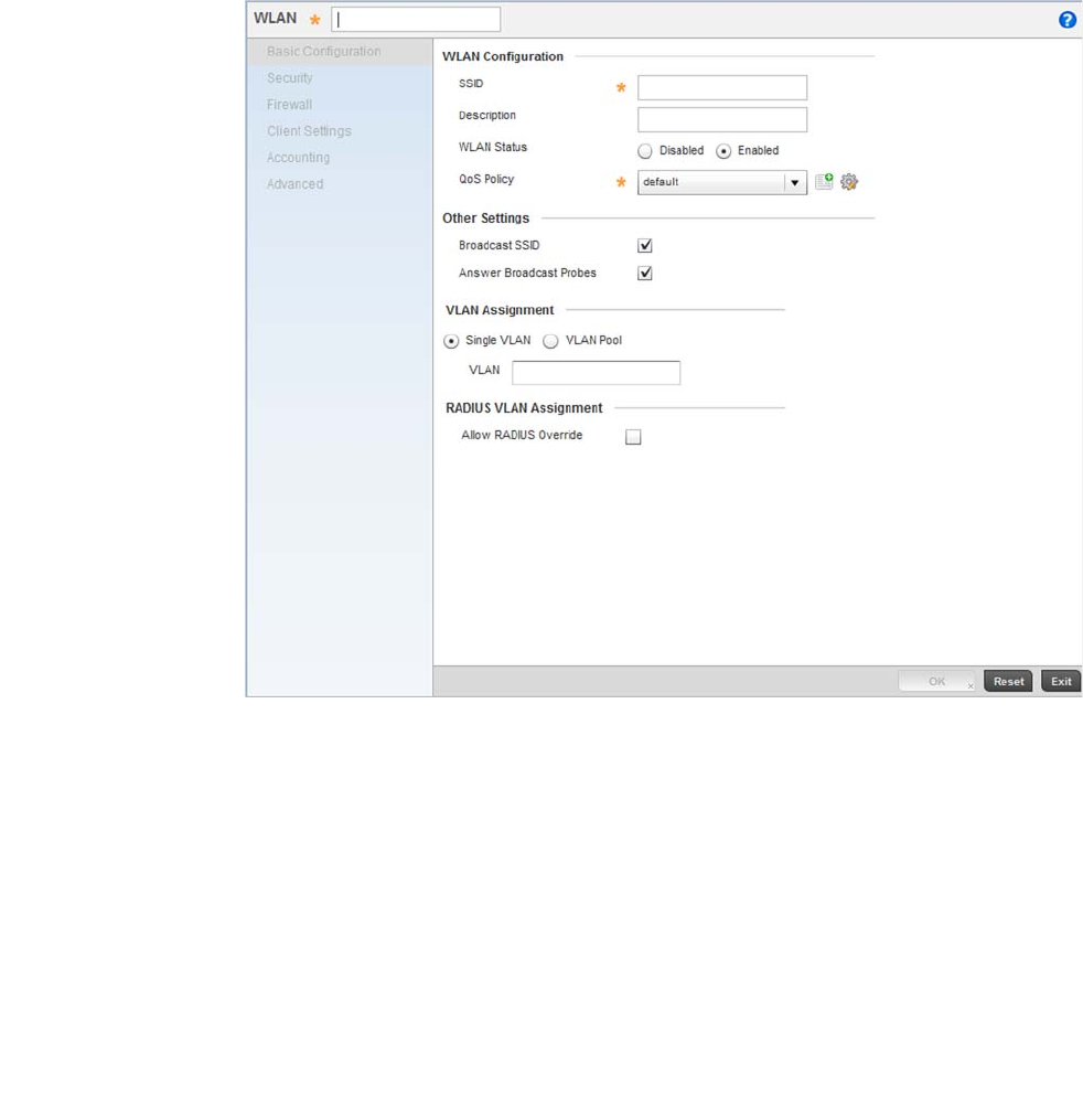
Brocade Mobility RFS4000, RFS6000, and RFS7000 System Reference Guide 43
53-1002620-01
3
FIGURE 33 WLAN Configuration screen
Provide the following information to define the controller WLAN configuration.
Select OK to save the changes. Select Exit to close this screen, then select the Commit icon to save
it to the controller running configuration.
WLAN Define the name of the WLAN. For this scenario, use 1.
SSID Provide the Service Set Identifier (SSID) for the WLAN. This is the ID used when
Access Points and wireless clients need to associate with the WLAN. For this
scenario, use:
WLAN_USECASE_01
VLAN Define the VLAN to associate with WLAN_USECASE_01. For this scenario, use:
VLAN 2
Single VLAN Ensure this option is selected to restrict WLAN_USECASE_01’s VLAN usage to VLAN
2.
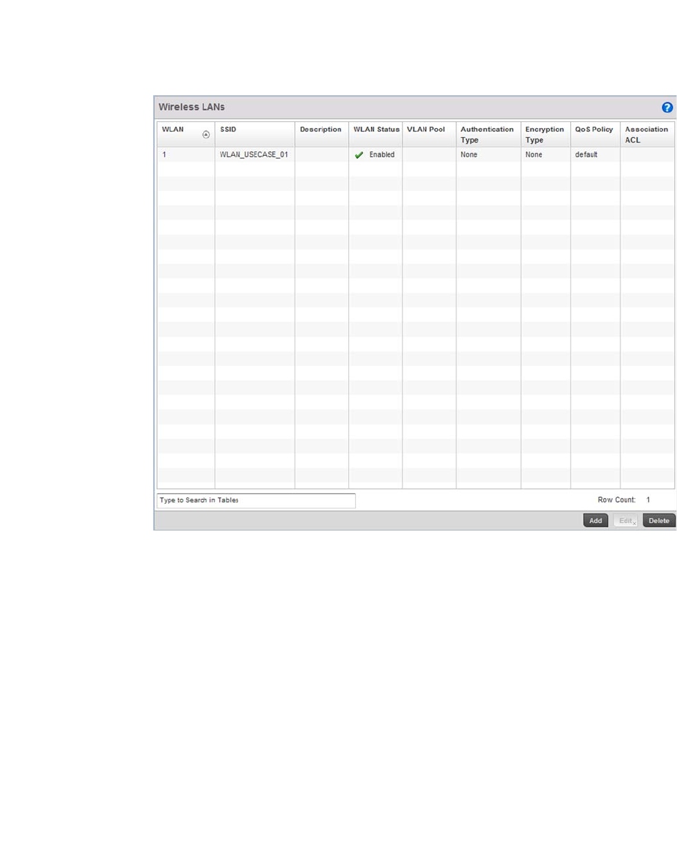
44 Brocade Mobility RFS4000, RFS6000, and RFS7000 System Reference Guide
53-1002620-01
3
FIGURE 34 After configuring the WLAN
Creating an AP Profile
Using the Controller GUI to Configure the WLAN
An AP profile provides a means of applying common settings to Access Points of a similar type. The
profile significantly reduces the time in configuring the access points in a large deployment.
•Creating a Brocade Mobility 650 Access Point Profile
•Creating a Brocade Mobility 71XX Access Point Profile
Creating a Brocade Mobility 650 Access Point Profile
Creating an AP Profile
An Brocade Mobility 650 Access Point’s firmware is updated directly by its associated wireless
controller. This process is automatic and no intervention is required. To create a profile for use with
an Brocade Mobility 650 Access Point:
Navigate to the Profile screen by selecting Configuration > Profiles.
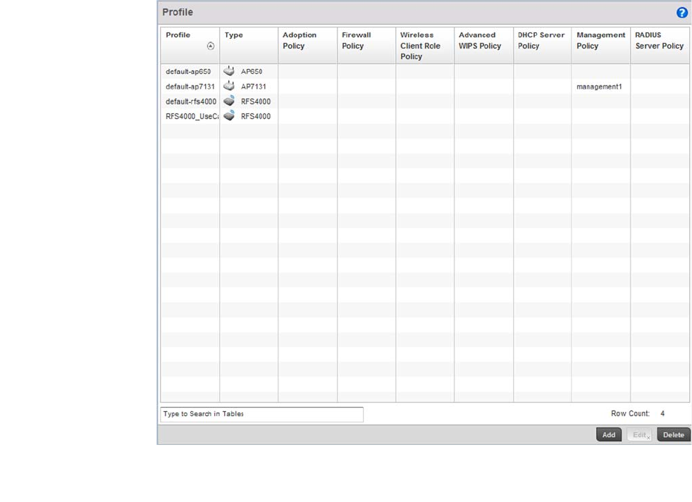
Brocade Mobility RFS4000, RFS6000, and RFS7000 System Reference Guide 45
53-1002620-01
3
FIGURE 35 Profiles screen
Select the Add button located at the bottom right of the screen.
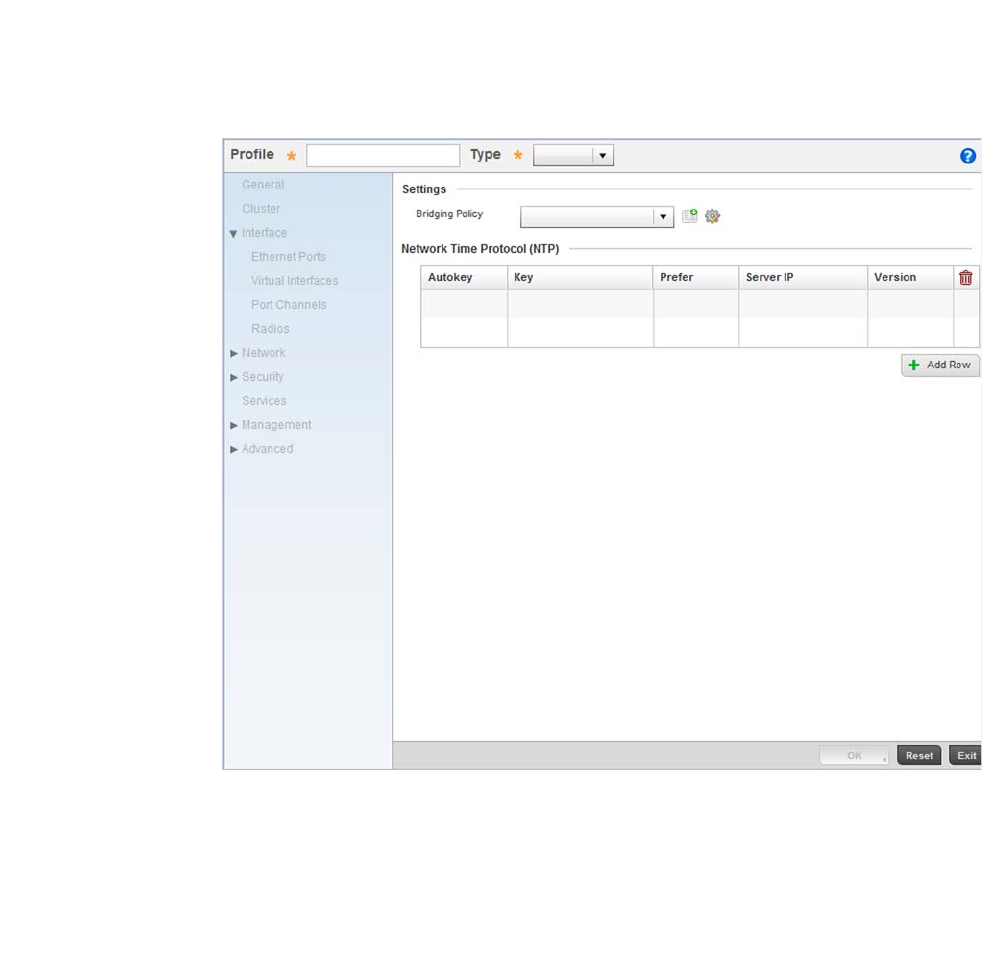
46 Brocade Mobility RFS4000, RFS6000, and RFS7000 System Reference Guide
53-1002620-01
3
FIGURE 36 New Brocade Mobility 650 Access Point Profile
Provide a Profile Name for the new Brocade Mobility 650 Access Point profile. For this scenario,
use: Brocade Mobility 650 Access Point_UseCase1.
Define the device Type for this profile. For this use case scenario, use: Brocade Mobility 650 Access
Point.
Select OK to save the changes.
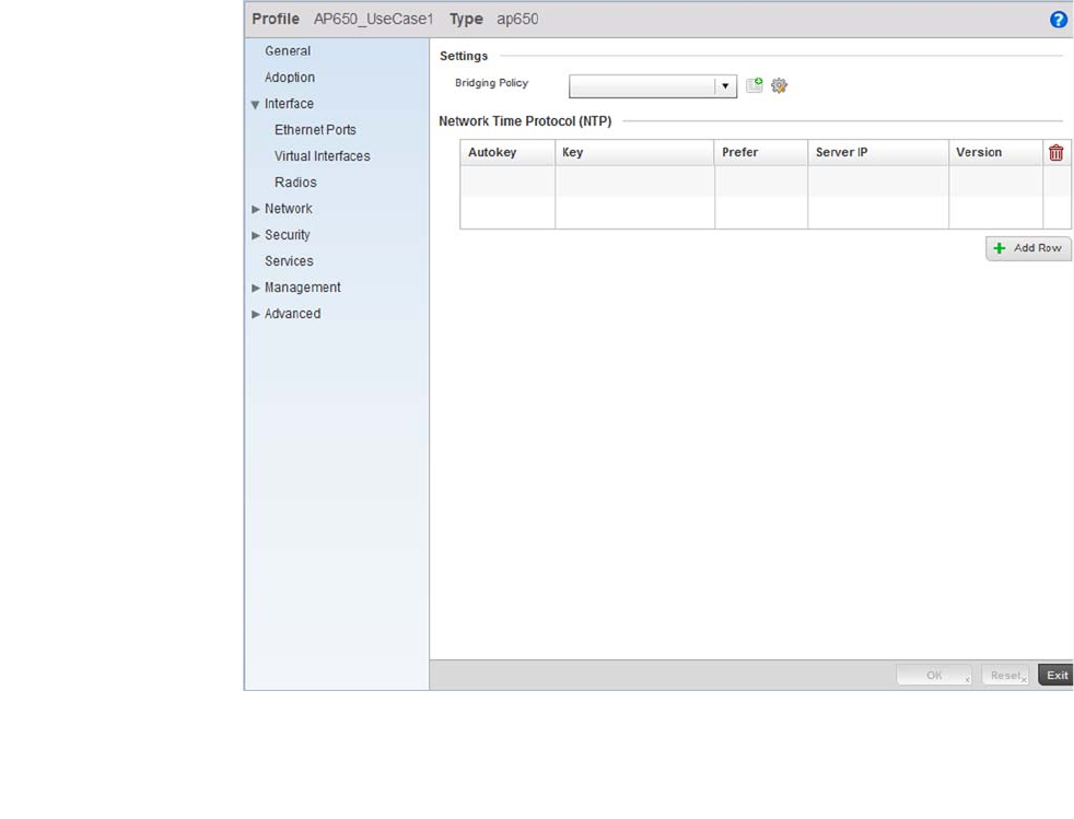
Brocade Mobility RFS4000, RFS6000, and RFS7000 System Reference Guide 47
53-1002620-01
3
FIGURE 37 Brocade Mobility 650 Access Point Profile
Select the Interface menu item to expand it and display its submenu items.
Select Virtual Interfaces.
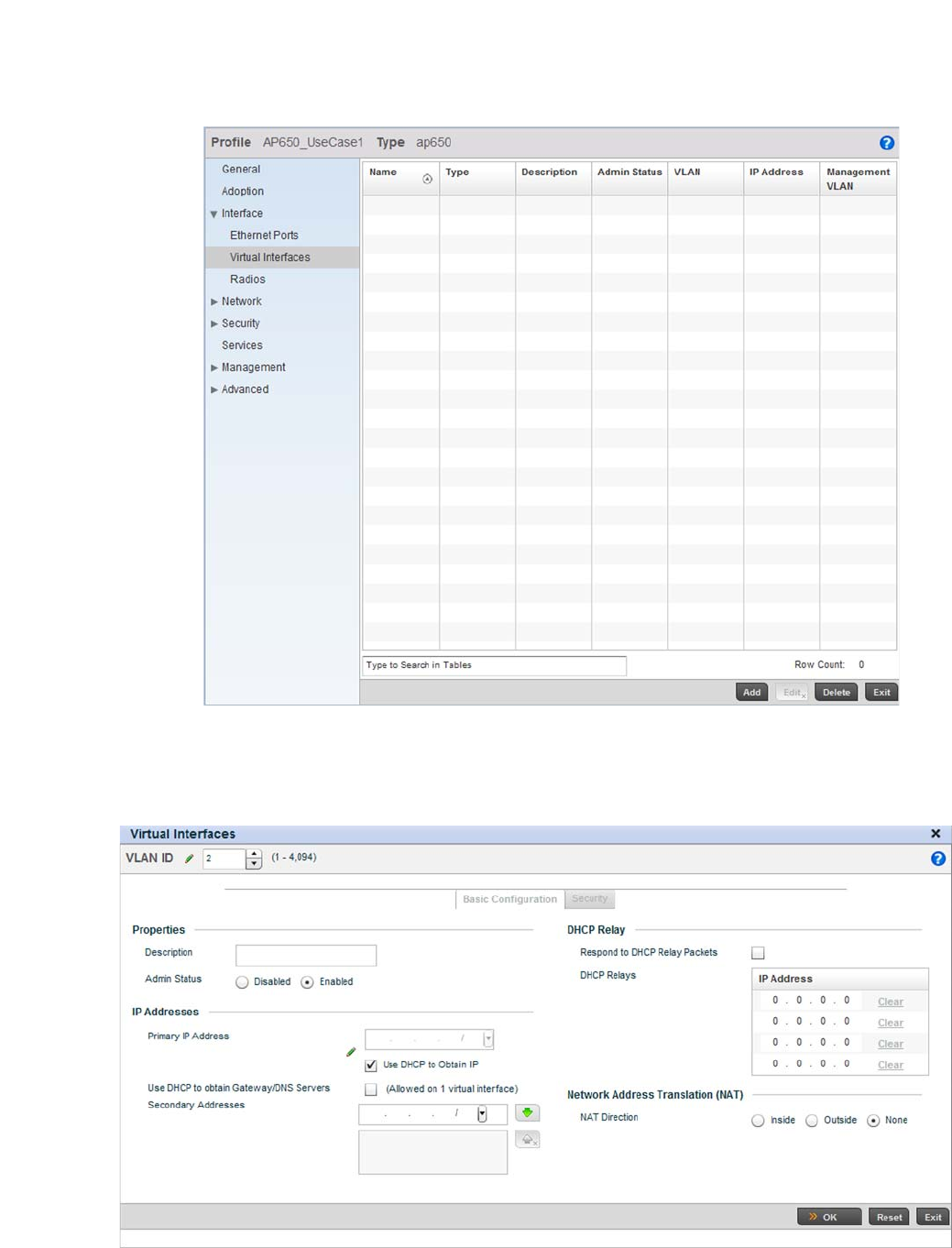
48 Brocade Mobility RFS4000, RFS6000, and RFS7000 System Reference Guide
53-1002620-01
3
FIGURE 38 Configuring Virtual Interfaces for an Brocade Mobility 650 Access Point profile.
Select the Add button at the bottom of the screen. A screen displays for adding a new virtual
interface configuration for the profile.
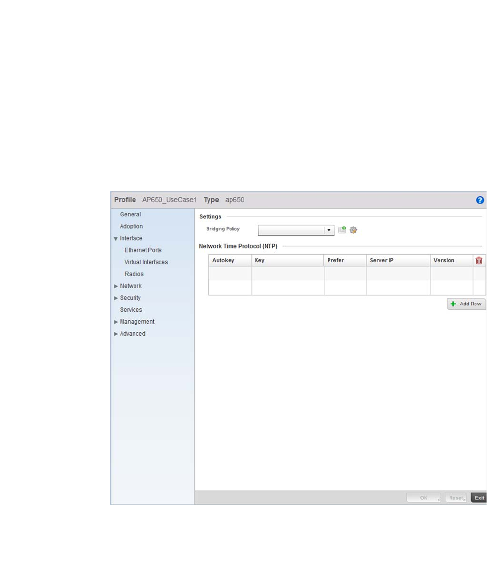
Brocade Mobility RFS4000, RFS6000, and RFS7000 System Reference Guide 49
53-1002620-01
3
FIGURE 39 Virtual Interface screen
Define a VLAN ID for the Brocade Mobility 650 Access Point profile. For this scenario, set it as VLAN
2.
For the Primary IP Address assignment, select the Use DHCP to Obtain IP option.
Select the OK button to save the changes. Click the Exit button to close the screen, then click the
Commit icon at the top right of the screen to apply the updates to the controller’s running
configuration.
Configure the Physical Interface
The next step is to map this newly created VLAN to a physical interface. In this case, VLAN 2 is
mapped to the GE1 port of the Brocade Mobility 650 Access Point.
To configure the GE1 port:
Select and display the Brocade Mobility 650 Access Point_UseCase1 profile by navigating to
Configuration > Profiles and selecting the profile from amongst those displayed.
FIGURE 40 Brocade Mobility 650 Access Point Profile screen
From within the Profiles screen, select and expand the Interface menu to display its submenu
items.
Select Ethernet Ports.
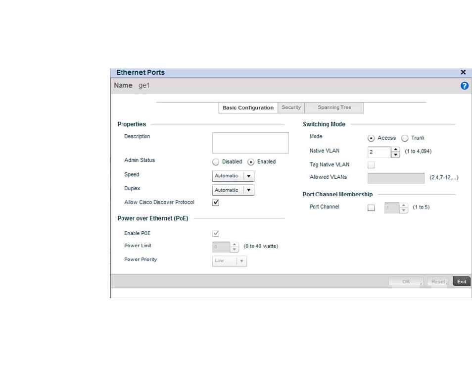
50 Brocade Mobility RFS4000, RFS6000, and RFS7000 System Reference Guide
53-1002620-01
3
FIGURE 41 Interface GE1 Configuration screen
Use the spinner control to define the Native VLAN. For this scenario, select 2. No other value on the
screen requires configuration.
Select OK to save the changes. Select Exit to close the screen, then click the Commit icon at the top
right of the screen to apply the updates to the controller’s running configuration.
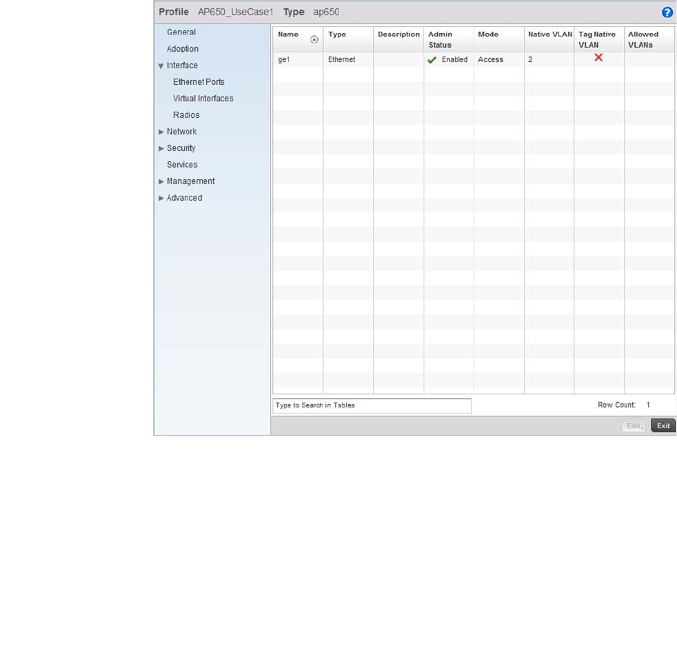
Brocade Mobility RFS4000, RFS6000, and RFS7000 System Reference Guide 51
53-1002620-01
3
FIGURE 42 Brocade Mobility 650 Access Point Profiles screen after configuring the GE1 Physical
Interface
Configure the Brocade Mobility 650 Access Point Radios
Each configured WLAN must be assigned an Access Point radio before wireless clients can connect
to it. To configure the Brocade Mobility 650 Access Point’s radios:
Select and display the Brocade Mobility 650 Access Point_UseCase1 profile by navigating to
Configuration > Profiles and selecting the profile from amongst those displayed.
From within the Profiles screen, select and expand the Interface menu to display its submenu
items.
Select Radios.
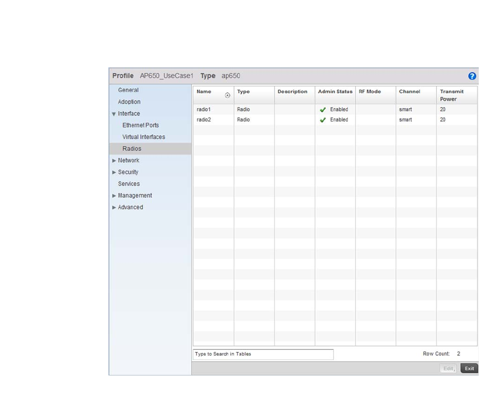
52 Brocade Mobility RFS4000, RFS6000, and RFS7000 System Reference Guide
53-1002620-01
3
FIGURE 43 Radios Screen
Select Radio1, then select the Edit button.
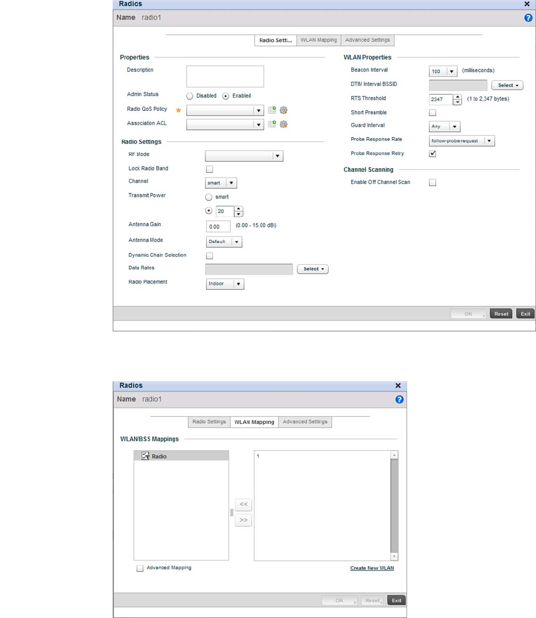
Brocade Mobility RFS4000, RFS6000, and RFS7000 System Reference Guide 53
53-1002620-01
3
FIGURE 44 Radio 1 Configuration screen
Select the WLAN Mapping tab.
FIGURE 45 Radio 1 Configuration - WLAN Mapping screen.
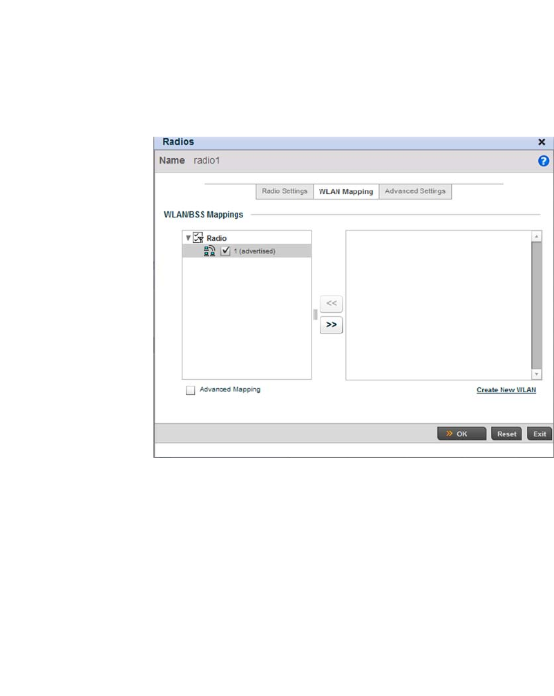
54 Brocade Mobility RFS4000, RFS6000, and RFS7000 System Reference Guide
53-1002620-01
3
From the list on the right of the screen, select the WLAN to assign to this radio. Select the << button
to assign the selected WLAN to Radio 1.
FIGURE 46 WLAN assigned to Radio1
Click the OK button to save the changes. Select Exit to exit the screen, then click the Commit button
to write this change to the configuration.
Configure the Brocade Mobility 650 Access Point’s Radio 2 by repeating steps 3 through 7.
Configure the Brocade Mobility 650 Access Point to use the Profile
Before the Brocade Mobility 650 Access Point can be used as a managed device, the profile must
be applied to the AP.
To apply the profile to the Access Point:
Navigate to the Brocade Mobility 650 Access Point by selecting Configuration > Devices > Device
Configuration.
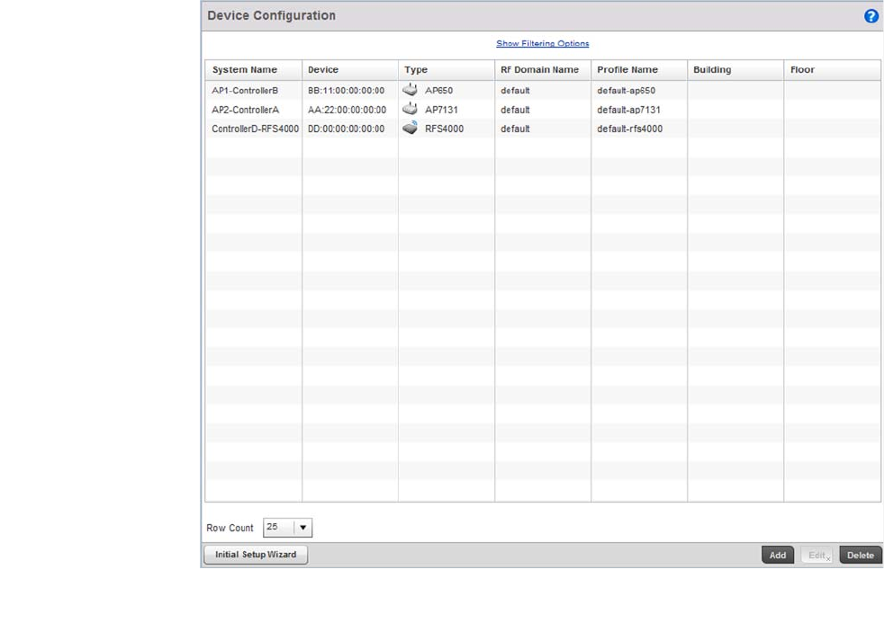
Brocade Mobility RFS4000, RFS6000, and RFS7000 System Reference Guide 55
53-1002620-01
3
FIGURE 47 Device Configuration screen
Select Brocade Mobility 650 Access Point from amongst the devices displayed and select the Edit
button.
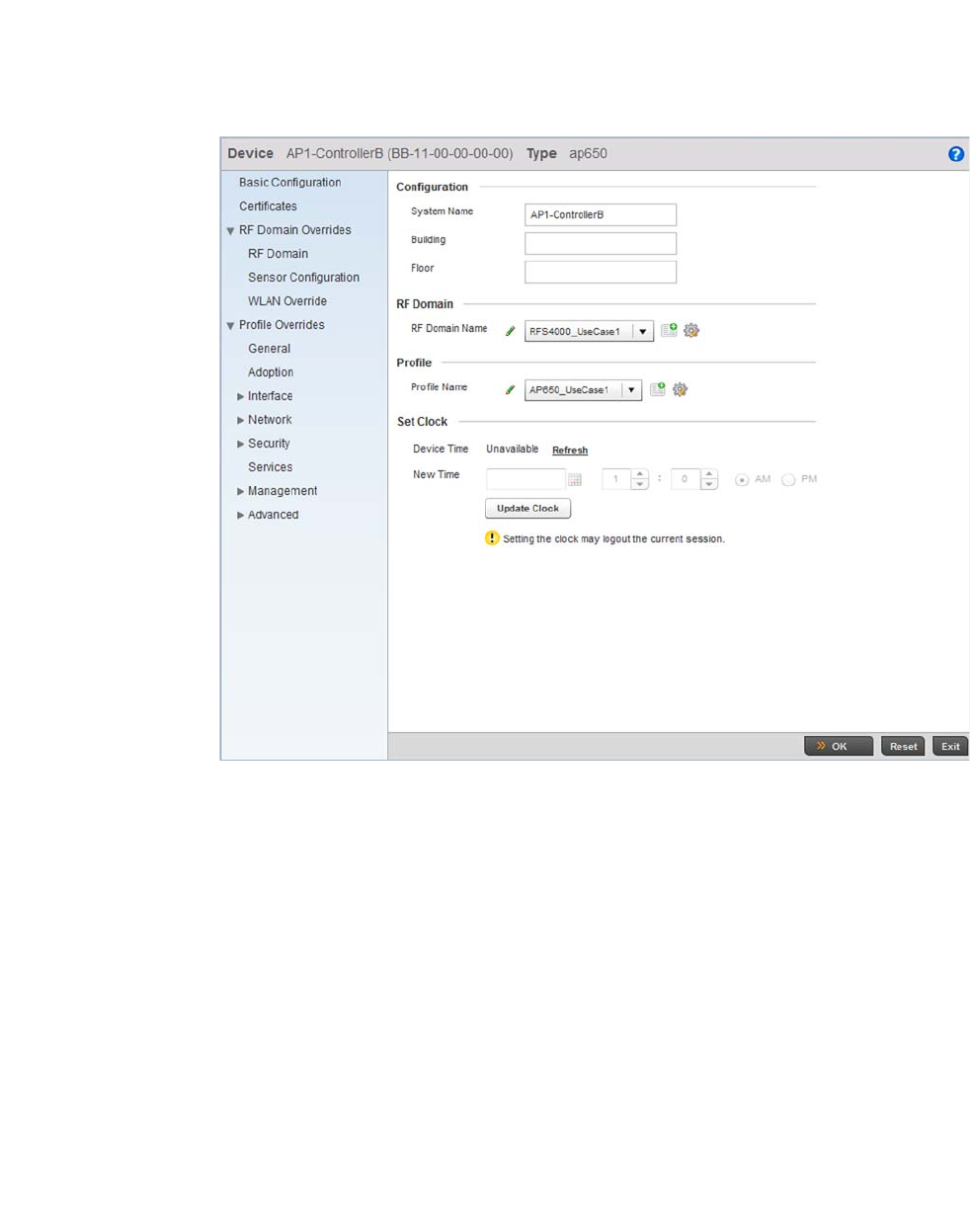
56 Brocade Mobility RFS4000, RFS6000, and RFS7000 System Reference Guide
53-1002620-01
3
FIGURE 48 Brocade Mobility 650 Access Point Configuration
Define a Profile Name to use with this Brocade Mobility 650 Access Point. This applies the
properties defined in the profile to the selected Brocade Mobility 650 Access Point. For this use
case scenario, use Brocade Mobility 650 Access Point_UseCase1.
Select OK to save the changes. Select Exit to close the screen, then click the Commit icon at the top
right of the screen to apply the updates to the controller’s running configuration.
Creating a Brocade Mobility 71XX Access Point Profile
Creating an AP Profile
An Brocade Mobility 71XX Access Point is a standalone access point that provides small and
medium businesses a cost effective device that consolidates a wired and wireless network
infrastructure in a single device. It integrates a router, gateway, firewall and other services to
simplify and reduce the overall cost of ownership by eliminating the need to maintain multiple
devices.
To create an Brocade Mobility 71XX Access Point profile:
Navigate to the Profiles screen by selecting Configuration > Profiles > Manage Profiles.
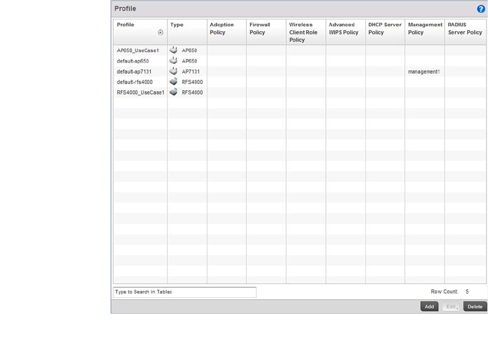
Brocade Mobility RFS4000, RFS6000, and RFS7000 System Reference Guide 57
53-1002620-01
3
FIGURE 49 Profiles screen
To create a new profile, select the Add button at the bottom right of the screen.
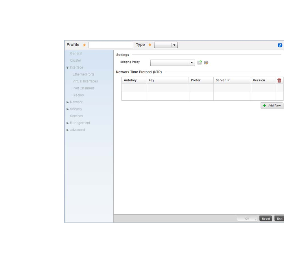
58 Brocade Mobility RFS4000, RFS6000, and RFS7000 System Reference Guide
53-1002620-01
3
FIGURE 50 New Brocade Mobility 71XX Access Point Profile Creation
Define a name for the new br-7131 profile. For the purposes of this use case scenario, use Brocade
Mobility 71XX Access Point_UseCase1.
Ensure the device type is set as br-7131 from the Type drop-down menu.
Select OK to save the changes.
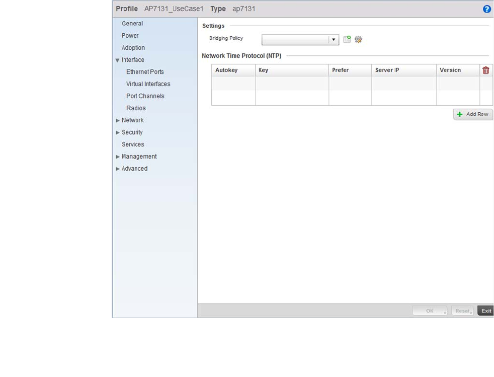
Brocade Mobility RFS4000, RFS6000, and RFS7000 System Reference Guide 59
53-1002620-01
3
FIGURE 51 Brocade Mobility 71XX Access Point Profile
Select the Interface menu item to expand it and display its sub menu options.
Select Virtual Interfaces.
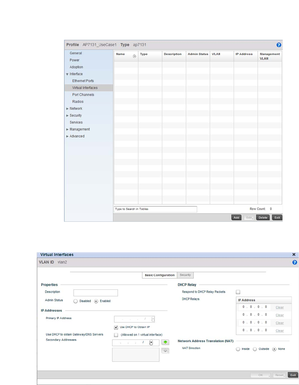
60 Brocade Mobility RFS4000, RFS6000, and RFS7000 System Reference Guide
53-1002620-01
3
FIGURE 52 Configuring a Virtual Interface for the Brocade Mobility 71XX Access Point Profile.
Select the Add button at the bottom left of the screen.
FIGURE 53 Virtual Interface screen
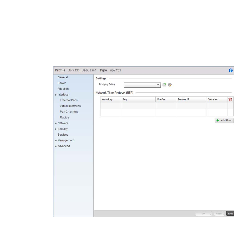
Brocade Mobility RFS4000, RFS6000, and RFS7000 System Reference Guide 61
53-1002620-01
3
Define the VLAN ID for the br-7131 profile as VLAN 2.
Select the Use DHCP to Obtain IP option for setting the Primary IP Address.
Select OK to save the changes. Select Exit to close the screen, then click the Commit icon at the top
right of the screen to apply the updates to the controller’s running configuration.
Configure the Physical Interface
To configure the GE1 port:
Select and display the br-7131_UseCase1 profile by navigating to Configuration > Profiles and
selecting the profile from amongst those displayed.
FIGURE 54 Brocade Mobility 71XX Access Point Profile Screen
Select the Interface menu option and expand it to display its submenu options.
Select Ethernet Ports.
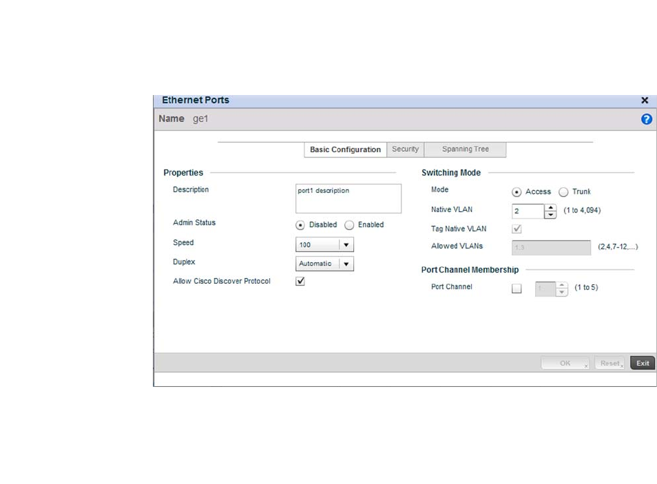
62 Brocade Mobility RFS4000, RFS6000, and RFS7000 System Reference Guide
53-1002620-01
3
FIGURE 55 Interface GE1 Configuration screen
Use the spinner control to define the Native VLAN as 2. No other values require configuration within
the screen.
Select OK to save the changes. Select Exit to close the screen, then click the Commit icon at the top
right of the screen to apply the updates to the controller’s running configuration.
Repeat the steps in this section to configure the GE2 interface as well.
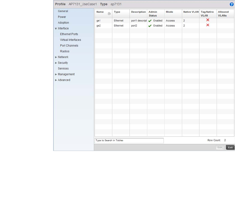
Brocade Mobility RFS4000, RFS6000, and RFS7000 System Reference Guide 63
53-1002620-01
3
FIGURE 56 After configuring the Physical Interfaces on the Brocade Mobility 71XX Access Point
Profile
Configure the Brocade Mobility 71XX Access Point’s Radios
There are up to three radios within a br-7131 series Access Point (depending on the model
purchased). However, the third br-7131 radio acts as a sensor and not available for WLAN support.
Therefore, a mximunm of two radios are available on a br-7131 for WLAN support.
Each WLAN must be assigned an Access Point before wireless clients can connect to it. To
configure an Brocade Mobility 71XX Access Point radios:
Select and display the br-7131_UseCase1 profile by navigating to Configuration > Profiles and
selecting the profile from amongst those displayed.
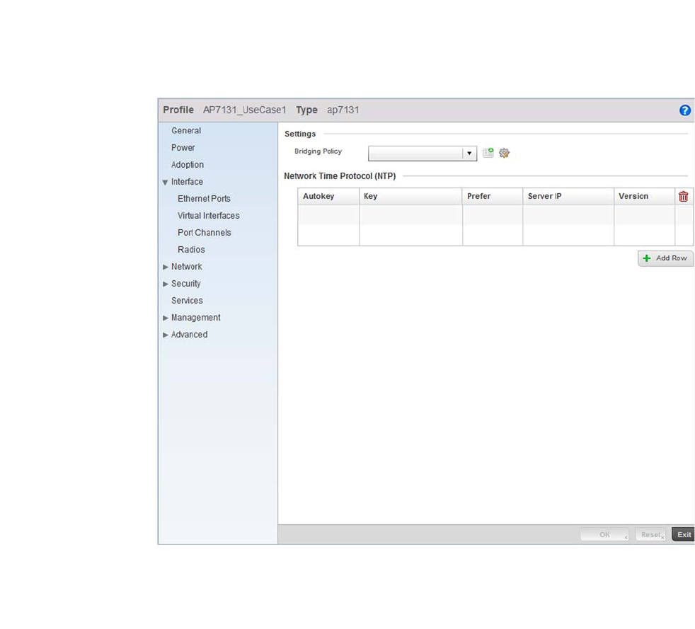
64 Brocade Mobility RFS4000, RFS6000, and RFS7000 System Reference Guide
53-1002620-01
3
FIGURE 57 br-7131 Profile screen
Select the Interface menu item and expand it to display its submenu options.
Select Radios.
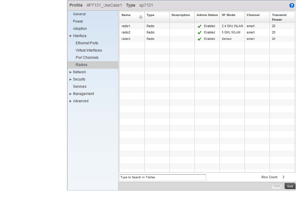
Brocade Mobility RFS4000, RFS6000, and RFS7000 System Reference Guide 65
53-1002620-01
3
FIGURE 58 Radios screen
Select Radio1 and select the Edit button.
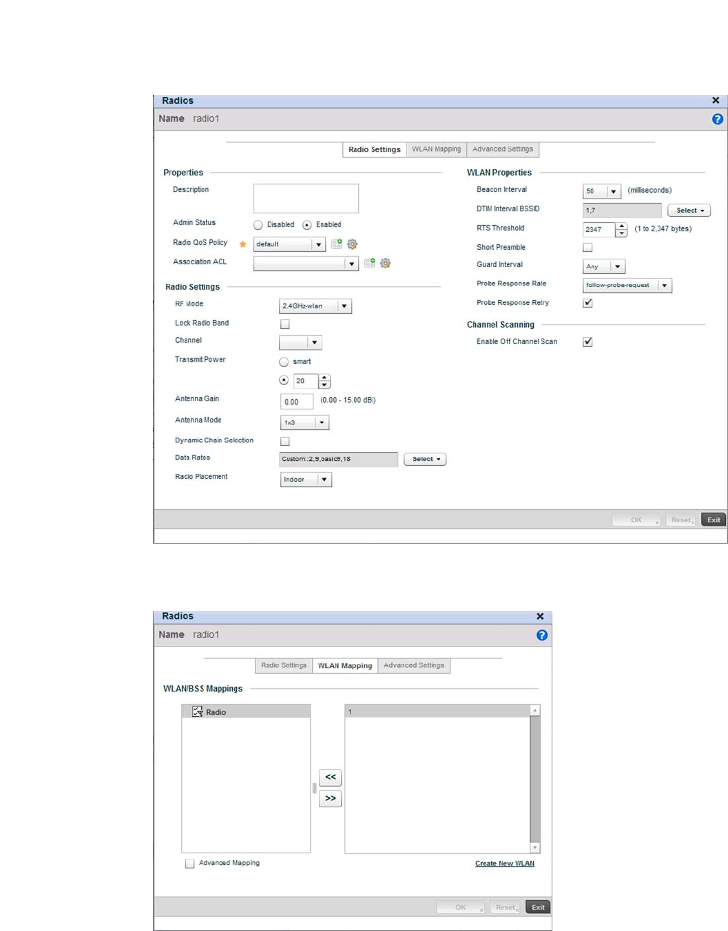
66 Brocade Mobility RFS4000, RFS6000, and RFS7000 System Reference Guide
53-1002620-01
3
FIGURE 59 Radio 1 Configuration screen
Select the WLAN Mapping tab.
FIGURE 60 Radio 1 Configuration - WLAN Mapping screen
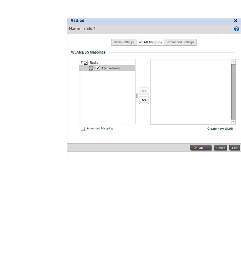
Brocade Mobility RFS4000, RFS6000, and RFS7000 System Reference Guide 67
53-1002620-01
3
From the list on the right of the screen, select a WLAN to assign to this radio. Select the << button
to assign the selected WLAN to Radio 1.
FIGURE 61 WLAN assigned to Radio1
Select OK to save the changes. Select Exit to exit the screen, then click the Commit icon at the top
right of the screen to apply the updates to the controller’s running configuration.
Configure the br-7131’s Radio 2 by repeating steps 3 through 7.
Configure the Brocade Mobility 71XX Access Point to use the above profile
Before the Brocade Mobility 71XX Access Point can be utilized as a managed device with a WLAN,
the profile must be applied to the access point.
To apply the profile to the Access Point:
Navigate to the Brocade Mobility 71XX Access Point profile by selecting Configuration > Devices >
Device Configuration.
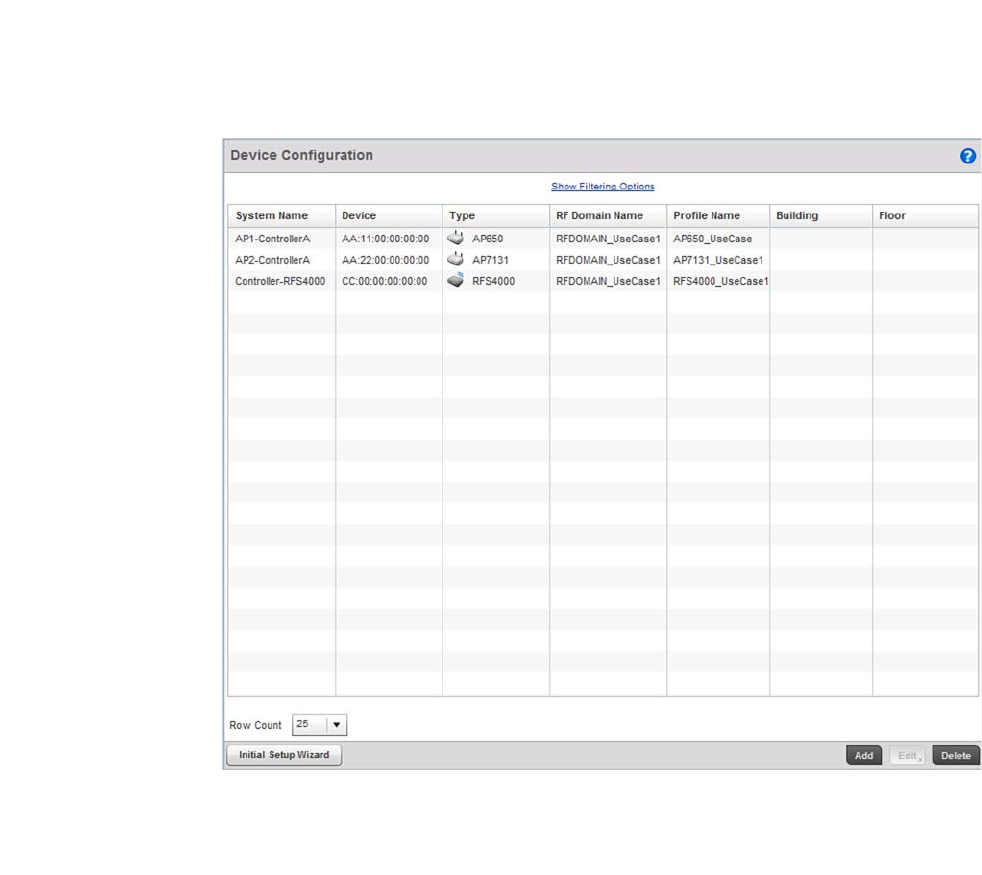
68 Brocade Mobility RFS4000, RFS6000, and RFS7000 System Reference Guide
53-1002620-01
3
FIGURE 62 Device Configuration screen
Select the Brocade Mobility 71XX Access Point from amongst the list of devices displayed and
select Edit button.
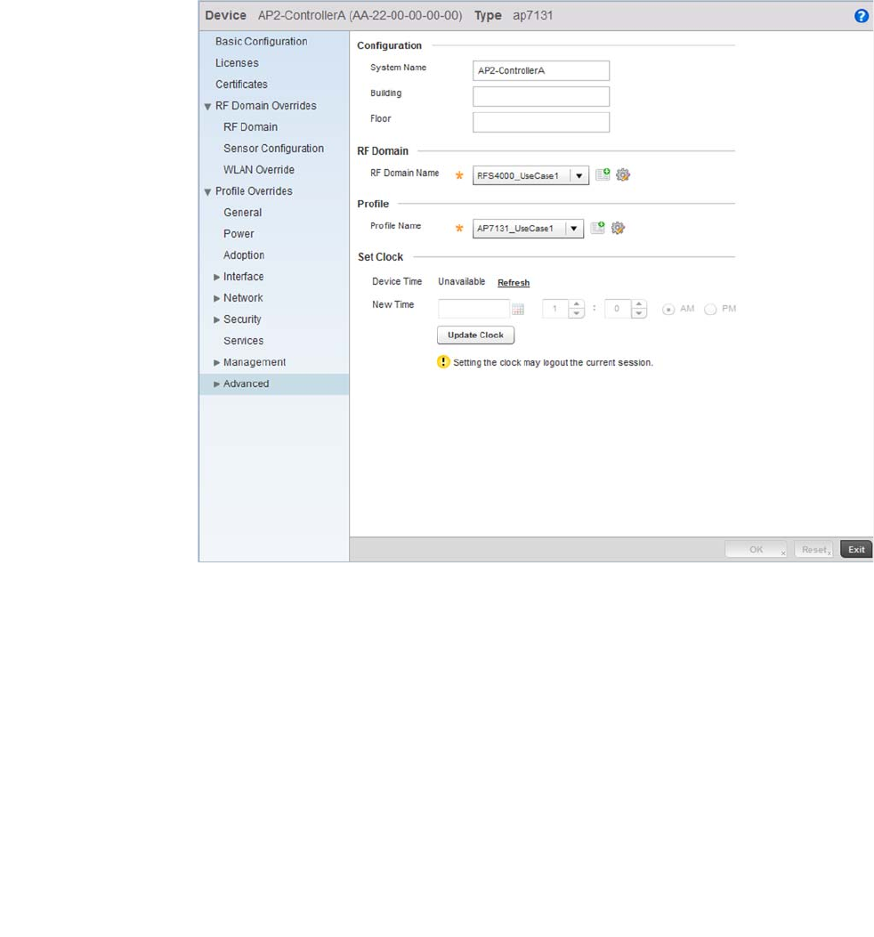
Brocade Mobility RFS4000, RFS6000, and RFS7000 System Reference Guide 69
53-1002620-01
3
FIGURE 63 Brocade Mobility 71XX Access Point Profile Configuration screen
Select the Profile Name of Brocade Mobility 71XX Access Point_UseCase1 from the drop-down
menu..
Select OK to save the changes. Select Exit to close this screen, then click the Commit icon at the
top right of the screen to apply the updates to the controller’s running configuration.
Creating a DHCP Server Policy
Using the Controller GUI to Configure the WLAN
The DHCP Server Policy sets the parameters required to run a DHCP server on the wireless
controller and assign IP addresses automatically to device that associate. Configuring DHCP
enables the reuse of a limited set of available IP addresses.
To create a DHCP server policy:
Select Configuration > Services > DHCP Server Policy.
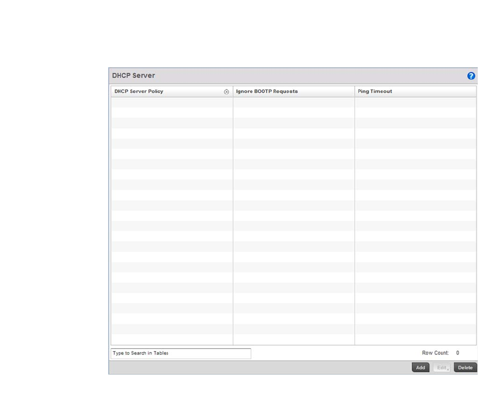
70 Brocade Mobility RFS4000, RFS6000, and RFS7000 System Reference Guide
53-1002620-01
3
FIGURE 64 DHCP Server Policy screen
Select the Add button to create a new DHCP Policy.
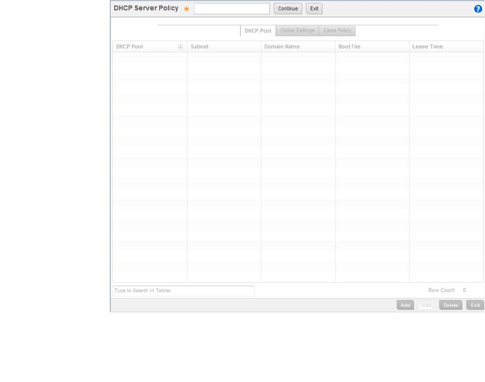
Brocade Mobility RFS4000, RFS6000, and RFS7000 System Reference Guide 71
53-1002620-01
3
FIGURE 65 DHCP Server Policy screen
Define a DHCP Server Policy. For the purposes of this use case scenario, use:
DHCP_POLICY_UseCase1.
Select the Continue button to create this policy and enable the tabs required to configure its
parameters.
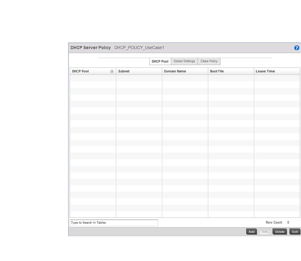
72 Brocade Mobility RFS4000, RFS6000, and RFS7000 System Reference Guide
53-1002620-01
3
FIGURE 66 DHCP Pool screen
Select Add to create a new DHCP Pool. A DHCP Pool contains a range of IP addresses assigned to
wireless clients and APs.
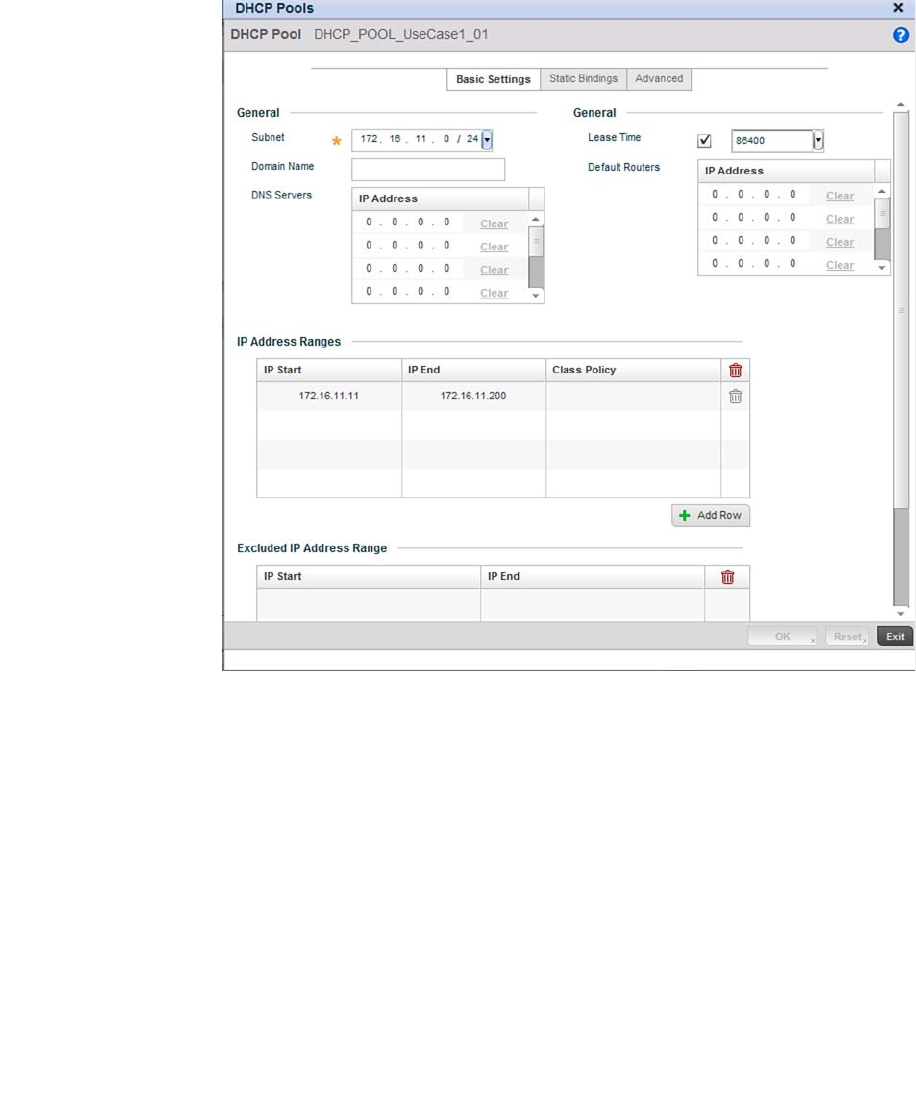
Brocade Mobility RFS4000, RFS6000, and RFS7000 System Reference Guide 73
53-1002620-01
3
FIGURE 67 New DHCP Pool screen
Define the following parameters for the DHCP Pool configuration:
Select OK to save the configuration. Select Exit to exit the screen, then click the Commit icon at the
top right of the screen to apply the updates to the controller’s running configuration.
Select the Exit button to return to the DHCP Server Policy screen.
DHCP Pool Define the name of the DHCP Pool. For this scenario, use:
DHCP_POOL_UseCase1_01
Subnet Assign the network on which this DHCP Server Policy is applied. For this scenario,
use:
Value: 172.16.11.0/24
IP Address Range Provide the IP address range for this DHCP Pool. Select the Add Row button below
this table to add a row. For this use case, use:
IP Start: 172.16.11.11
IP End: 172.16.11.200
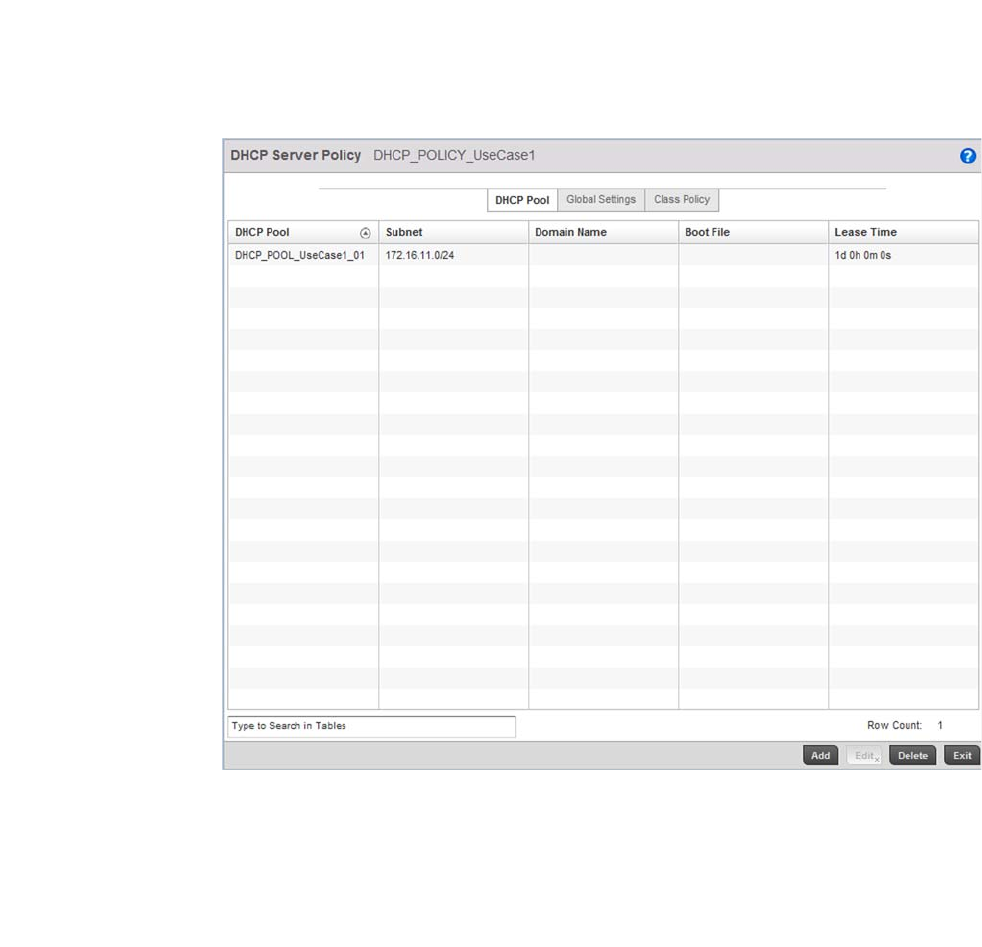
74 Brocade Mobility RFS4000, RFS6000, and RFS7000 System Reference Guide
53-1002620-01
3
FIGURE 68 After creating the DHCP Server Policy
Configure the Brocade Mobility RFS4000 Wireless Controller to use the DHCP Server Policy
For the DHCP server to be enabled, the DHCP Server Policy must be applied to the device acting as
a DHCP server for the network. There cannot be more than one DHCP server in the same network.
Select Configuration > Devices > Device Configuration.
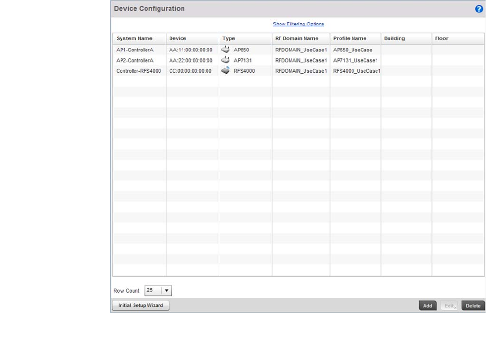
Brocade Mobility RFS4000, RFS6000, and RFS7000 System Reference Guide 75
53-1002620-01
3
FIGURE 69 Device Configuration screen
Select the Brocade Mobility RFS4000 from the list and select Edit.
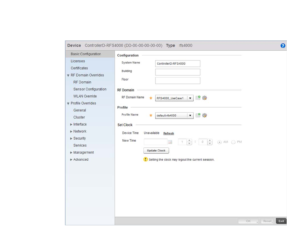
76 Brocade Mobility RFS4000, RFS6000, and RFS7000 System Reference Guide
53-1002620-01
3
FIGURE 70 Brocade Mobility RFS4000 Device Context screen
From the menu on the left, select Services.
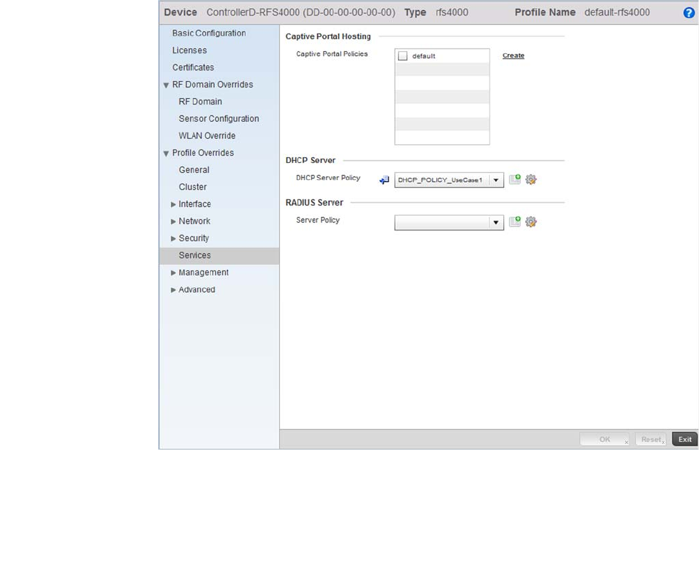
Brocade Mobility RFS4000, RFS6000, and RFS7000 System Reference Guide 77
53-1002620-01
3
FIGURE 71 Brocade Mobility RFS4000 Device Context screen
From the DHCP Server Policy drop-down menu, select the name of the DHCP Server Policy. For this
use case scenario, select DHCP_POLICY_UseCase1.
Select OK to save the changes. Select Exit to exit out of the Brocade Mobility RFS4000 wireless
controller device context. Select Commit to save these changes to the configuration.
Completing and testing the configurations
Using the Controller GUI to Configure the WLAN
For a wireless client to successfully associate itself with the WLAN that you created, it must be
configured. The following information must be used.
•SSID: WLAN_USECASE_01
•Country: Same as configured above in section Creating a RF Domain on page 3-26. In this
example, the country code is set to US.
•Mode: Infrastructure
As the WLAN is set to beaconing, use the wireless client’s wireless discovery client to discover the
configured WLAN and associate to it.

78 Brocade Mobility RFS4000, RFS6000, and RFS7000 System Reference Guide
53-1002620-01
3

Brocade Mobility RFS4000, RFS6000, and RFS7000 System Reference Guide 79
53-1002620-01
Chapter
4
Dashboard
In this chapter
•Summary . . . . . . . . . . . . . . . . . . . . . . . . . . . . . . . . . . . . . . . . . . . . . . . . . . . . . 79
•Network View . . . . . . . . . . . . . . . . . . . . . . . . . . . . . . . . . . . . . . . . . . . . . . . . . . 89
The wireless controller dashboard enables wireless network administrators to review and
troubleshoot the operation of the devices comprising the managed network. Additionally, the
dashboard allows the review of the current network topology, the assessment of the network’s
component health and a diagnostic review of device performance.
By default, the Dashboard screen displays the System Dashboard, which is the top level in the
device hierarchy.
Summary
The Dashboard displays device information organized by device association and inter-connectivity
between the connected Access Points and wireless clients.
To review dashboard information, select Dashboard > Summary.
The Dashboard displays the Health tab by default.

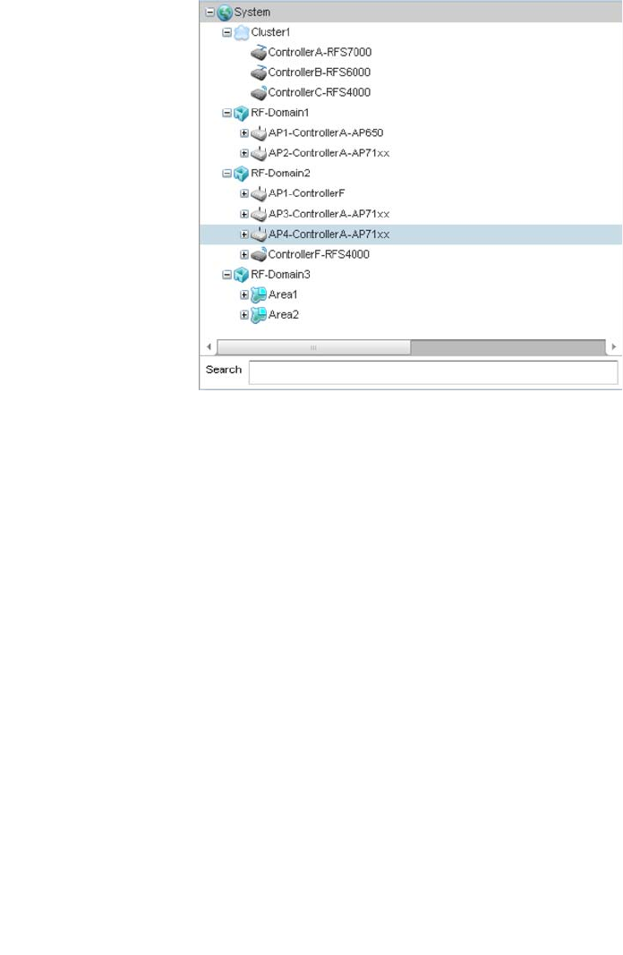
Brocade Mobility RFS4000, RFS6000, and RFS7000 System Reference Guide 81
53-1002620-01
4
FIGURE 73 Dashboard Menu Tree
The Search text box, at the bottom, enables you to filter (search amongst) RF Domains. The By
drop-down menu refines the search. You can further refine a search using the following:
•Auto – The search is automatically set to device type.
•Name – The search is performed for the device name specified in the Search text box.
•WLAN – The search is performed for the WLAN specified in the Search text box.
•IP Address – The search is performed for the IP Address specified in the Search text box.
•MAC Address – The search is performed for the MAC Address specified in the Search text box.
System Screen
The System screen displays the status of the managed network. The screen is partitioned into the
following tabs:
•Health – The Health tab displays information about the state of the system being managed.
•Inventory – The Inventory tab displays information on the physical devices being managed by
the system.
Health
Health
The Health tab displays device performance status for managed devices and includes their
member RF Domains.
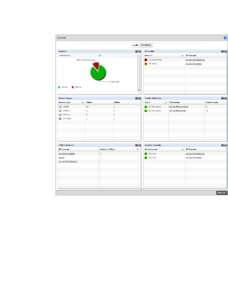
82 Brocade Mobility RFS4000, RFS6000, and RFS7000 System Reference Guide
53-1002620-01
4
FIGURE 74 System Dashboard screen - Health tab
The Health screen is partitioned into the following fields:
•Devices
•RF Quality Index
•Utilization
•Devices
•Clients
•Radios
•Client on Channels
Devices
Health
The Devices field displays graphical status of the devices managed by this controller.
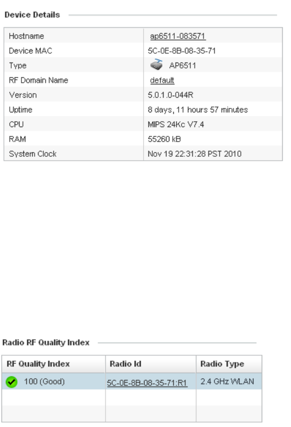
Brocade Mobility RFS4000, RFS6000, and RFS7000 System Reference Guide 83
53-1002620-01
4
FIGURE 75 System Dashboard screen - Health tab - Device Health field
The Devices field displays the total device count managed by this wireless controller and their
status (online vs. offline) in pie chart format. Use this information to determine whether the
number of offline devices requires troubleshooting to improve the performance of the controller
managed network.
RF Quality Index
Health
The RF Quality Index displays RF quality per RF Domain. It’s a measure of the overall effectiveness
of the RF environment displayed in percentage. It’s a function of the connect rate in both
directions, retry rate and error rate.
FIGURE 76 System Dashboard screen - Health tab - RF Quality Index field
The RF Quality field displays an average quality index supporting all the RF Domains on the wireless
controller. The table lists the bottom five (5) RF quality values for RF Domains supported on the
wireless controller.
The quality is measured as:
•0-20 – Very poor quality
•20-40 – Poor quality
•40-60 – Average quality
•60-100 – Good quality
Select an RF Domain to view its performance statistics.
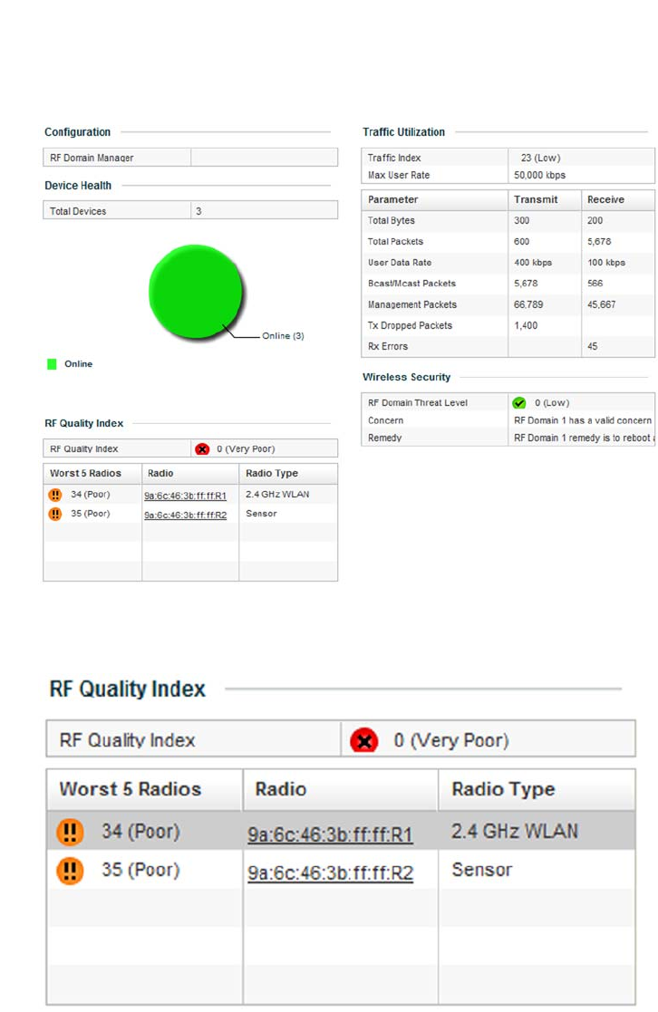
84 Brocade Mobility RFS4000, RFS6000, and RFS7000 System Reference Guide
53-1002620-01
4
FIGURE 77 RF Quality Index - RF Domains
Select a RF Domain to review poorly performing radios.
FIGURE 78 RF Quality Index - Worst Performing Radios
The following screen displays.
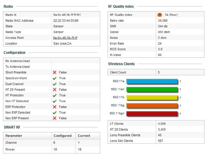
Brocade Mobility RFS4000, RFS6000, and RFS7000 System Reference Guide 85
53-1002620-01
4
FIGURE 79 RF Quality Index - Radio Statistics
Use this diagnostic information to determine what measures can be taken to improve radio
performance in respect to wireless client load and the radio bands supported.
For information on RF Domains, and how to create one for use with the managed network, see
About RF Domains on page 8-499 and Managing RF Domains on page 8-500.
Utilization
Health
The Utilization field displays RF medium efficiency. Traffic utilization is the percentage of current
throughput relative to the maximum possible throughput for a managed RF Domain.
The Utilization field displays a list of up to five RF Domains in relation to the number of associated
wireless clients. It also displays a table of the packets types transmitted.
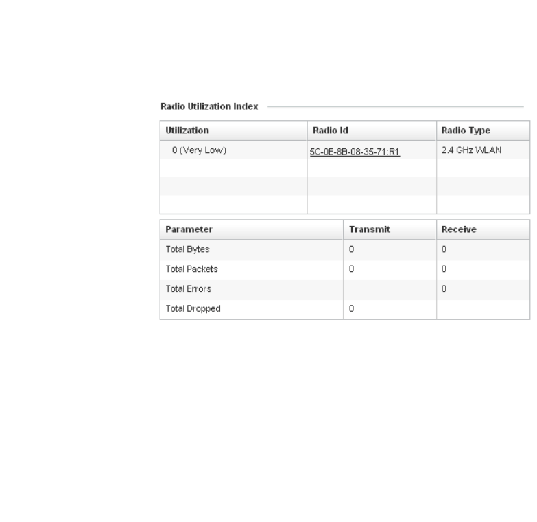
86 Brocade Mobility RFS4000, RFS6000, and RFS7000 System Reference Guide
53-1002620-01
4
FIGURE 80 System Dashboard screen - Health tab - Utilization field
Inventory
System Screen
The System screen’ s Inventory tab displays information on devices managed by this system. The
screen provides a complete overview of the number and state of devices managed by the system.
Information is displayed in easy to read tables and graphs. This screen also provides links for more
detailed information.
To navigate to this screen, select Dashboard > Dashboard > RF Domain > Network.
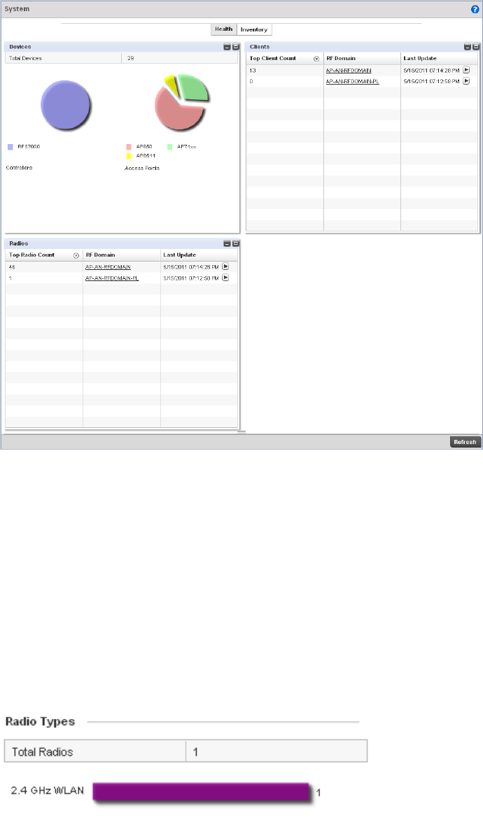
Brocade Mobility RFS4000, RFS6000, and RFS7000 System Reference Guide 87
53-1002620-01
4
FIGURE 81 System screen - Inventory tab
The information within the Inventory tab is partitioned into the following fields:
•Devices
•Clients
•Radios
•Client on Channels
Devices
Inventory
The Devices field displays a ratio of peer controllers and managed Access Points. The information
is displayed in pie chart format.
FIGURE 82 System screen - Inventory tab - Device Types field
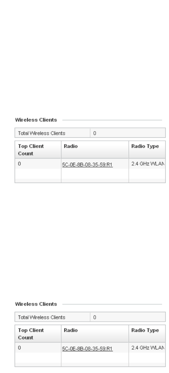
88 Brocade Mobility RFS4000, RFS6000, and RFS7000 System Reference Guide
53-1002620-01
4
The Device Type field displays a numerical representation of the different controllers models and
connected Access Points in the current system. Does this device distribution adequately support
the number and types of Access Points and their client load.
Clients
Inventory
The Clients field displays information about the wireless clients managed by the controller’s
connected Access Point radios.
FIGURE 83 System screen - Inventory tab - Wireless Clients field
Information in the Wireless Clients field displays in two tables. The first lists the total number of
wireless clients managed by this system. The second lists the top five RF Domains in respect to the
number of connected clients.
Each RF Domain can be selected and analyzed in respect to its performance. For information on RF
Domains, and how to create one for use with the managed network, see About RF Domains on
page 8-499 and Managing RF Domains on page 8-500.
Radios
Inventory
The Radios field displays information about the different radios managed by this system.
FIGURE 84 System screen - Inventory tab - Radios field
Information in the Radio area is presented in two tables. The first lists the total number of Radios
managed by this system, the second lists the top five RF Domains in terms of the number of
available radios.
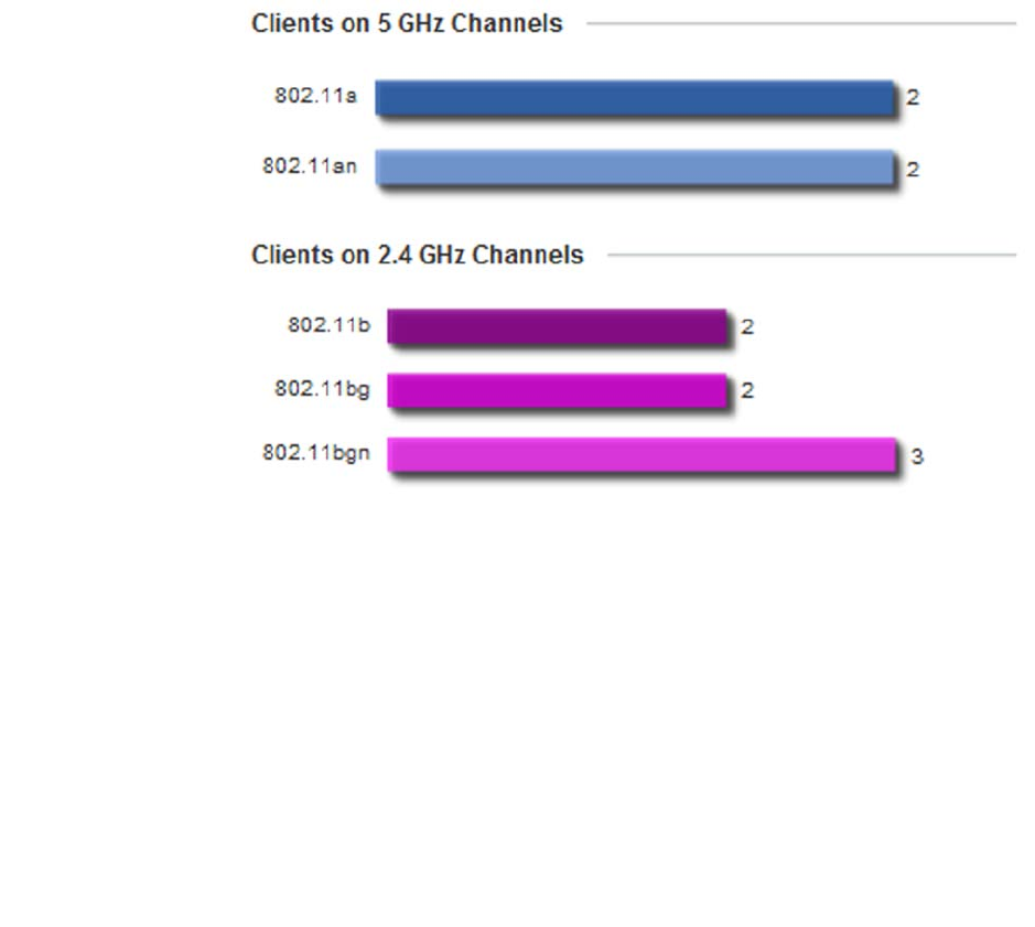
Brocade Mobility RFS4000, RFS6000, and RFS7000 System Reference Guide 89
53-1002620-01
4
Client on Channels
Inventory
The Client on Channels field displays bar-graphs of wireless clients classified by channel and radio
band.
FIGURE 85 System screen - Inventory tab - Clients on Channels field
Wireless Clients are displayed as either operating in the 5 GHz or 2.4 GHz channel. Information is
further classified by radio band. For the 5 GHz channel, information is classified by either the
802.11a or 802.11an bands. For the 2.4 GHz channel, information is classified by either the
802.11b, 802.11bg or 802.11bgn bands. Does this client distributions adequately support the
requirements of the radio coverage area?
Network View
The wireless controller’s Network View functionality displays device association connectivity
amongst the wireless controller, access point and wireless clients. This association is represented
by a number of different graphs.
To review the wireless controller’s Network Topology, select Dashboard > Overview > Network.
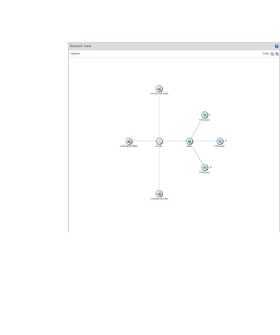
90 Brocade Mobility RFS4000, RFS6000, and RFS7000 System Reference Guide
53-1002620-01
4
FIGURE 86 Network View Topology
The screen displays icons for the different views available to the system. Apart from device specific
icons, the following three icons are available:
•default – Displays information about the default RF Domain.
•system – Displays information about the current system.
•cluster – Displays information about clusters managed by this system.
Use these icons to navigate quickly within top level groupings.
The middle field displays a Network View, or graphical representation of the network. This field
changes to display a graphical network map.
Select the Settings link (the blue link near the top of the screen) to define how devices are
displayed within the Network View.
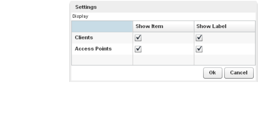
Brocade Mobility RFS4000, RFS6000, and RFS7000 System Reference Guide 91
53-1002620-01
4
FIGURE 87 Network View - Settings field
Select either or both of the Access Point and Client options to display them in the Network View.
Similarly, select the Show Label option to display hardware MAC address as an appended label.
Select OK to save the updates
.

92 Brocade Mobility RFS4000, RFS6000, and RFS7000 System Reference Guide
53-1002620-01
4

Brocade Mobility RFS4000, RFS6000, and RFS7000 System Reference Guide 93
53-1002620-01
Chapter
5
Device Configuration
In this chapter
•Basic Configuration . . . . . . . . . . . . . . . . . . . . . . . . . . . . . . . . . . . . . . . . . . . . . 94
•Basic Device Configuration . . . . . . . . . . . . . . . . . . . . . . . . . . . . . . . . . . . . . . . 96
•License Configuration . . . . . . . . . . . . . . . . . . . . . . . . . . . . . . . . . . . . . . . . . . . 98
•Assigning Certificates . . . . . . . . . . . . . . . . . . . . . . . . . . . . . . . . . . . . . . . . . . 100
•RF Domain Overrides . . . . . . . . . . . . . . . . . . . . . . . . . . . . . . . . . . . . . . . . . . 119
•Profile Overrides . . . . . . . . . . . . . . . . . . . . . . . . . . . . . . . . . . . . . . . . . . . . . . 125
•Auto Provisioning Policies . . . . . . . . . . . . . . . . . . . . . . . . . . . . . . . . . . . . . . . 263
•br300 Devices . . . . . . . . . . . . . . . . . . . . . . . . . . . . . . . . . . . . . . . . . . . . . . . . 269
•Critical Resource Policy . . . . . . . . . . . . . . . . . . . . . . . . . . . . . . . . . . . . . . . . . 276
Devices managed by the controller can either be assigned unique configurations or have existing
RF Domain or Profile configurations modified (overridden) to support a requirement that dictates a
device’s configuration be customized from the configuration shared by its peer devices.
When a device is initially managed by the controller, it requires several basic configuration
parameters be set (system name, deployment location etc.). Additionally, the number of permitted
device licenses (purchased directly from Brocade) needs to be accessed to determine whether a
new Access Point (AP) or Adaptive Access Point (AAP) can be adopted.
Refer to the following to set a device’s basic configuration, license and certificate usage:
•Basic Configuration
•Basic Device Configuration
•License Configuration
•Assigning Certificates
RF Domains allow administrators to assign configuration data to multiple devices deployed in a
common coverage area (floor, building or site). In such instances, there’s many configuration
attributes these devices share as their general client support roles are quite similar. However,
device configurations may need periodic refinement (overrides) from their original RF Domain
administered design. For more information, see RF Domain Overrides on page 5-119.
Profiles enable administrators to assign a common set of configuration parameters and policies to
controllers and Access Points. Profiles can be used to assign shared or unique network, wireless
and security parameters to wireless controllers and Access Points across a large, multi segment,
site. The configuration parameters within a profile are based on the hardware model the profile
was created to support. The controller supports both default and user defined profiles
implementing new features or updating existing parameters to groups of wireless controllers or
Access Points.

94 Brocade Mobility RFS4000, RFS6000, and RFS7000 System Reference Guide
53-1002620-01
5
However, device profile configurations may need periodic refinement from their original
administered configuration. Consequently, a device profile could be applied an override from the
configuration shared amongst numerous peer devices deployed within a particular site. For more
information, see Profile Overrides on page 5-125.
Adoption is the process an Access Point uses to discover controllers available in the network, pick
the most desirable controller, establish an association, obtain its configuration and consider itself
provisioned.
At adoption, an Access Point solicits and receives multiple adoption responses from controllers
available on the network. Modify existing adoption policies or create a new one as needed to meet
the adoption requirements of a device and its assigned controller profile. For more information, see
Auto Provisioning Policies on page 5-263.
Lastly, use Configuration > Devices to define and manage a critical resource policy. A critical
resource policy defines a list of device IP addresses on the network (gateways, routers etc.). The
support of these IP address is interpreted as critical to the health of the managed network. These
devices addresses are pinged regularly by the controller. If there’s a connectivity issue, an event is
generated stating a critical resource is unavailable. For more information, see Critical Resource
Policy on page 5-276.
Basic Configuration
To assign a Basic Configuration:
1. Select the Configuration tab from the Web UI.
2. Select Devices from the Configuration tab.
3. The Device Configuration screen displays a list of managed devices or other controllers.
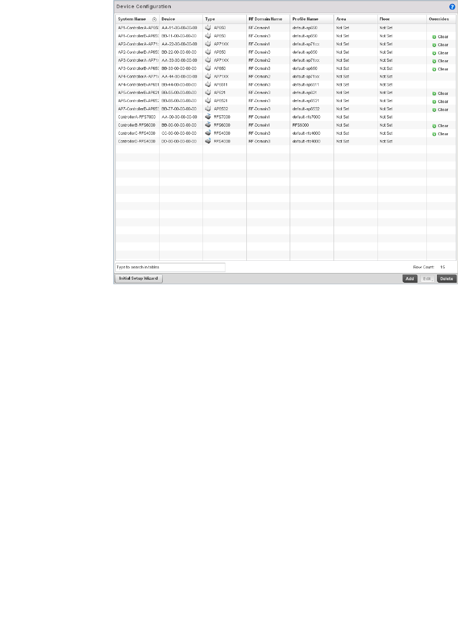
Brocade Mobility RFS4000, RFS6000, and RFS7000 System Reference Guide 95
53-1002620-01
5
FIGURE 88 Device Configuration screen
Refer to the following device settings to determine whether a configuration update or RF Domain or
Profile change is warranted:
System Name Displays the name assigned to the device when the basic configuration was defined.
This is also the device name that appears within the RF Domain or Profile the device
supports.
Device Displays the device’s factory assigned MAC address used as hardware identifier. The
MAC address cannot be revised with the device’s configuration.
Type Displays the Brocade device model for the listed Access Point or wireless controller.
RF Domain Name Lists RF Domain memberships for each listed device. Devices can either belong to a
default RF Domain based on model type, or be assigned a unique RF Domain
supporting a specific configuration customized to that device model.
Profile Name Lists the profile each listed device is currently a member of. Devices can either
belong to a default profile based on model type, or be assigned a unique profile
supporting a specific configuration customized to that model.
Area List the physical area where the controller or access point is deployed. This can be a
building, region, campus or other area that describes the deployment location.
Floor List the building Floor name representative of the location within the area or building
the controller or Access Point was physically deployed. Assigning a building Floor
name is helpful when grouping devices in RF Domains and Profiles, as devices on
the same physical building floor may need to share specific configuration
parameters in respect to radio transmission and interference requirements specific
to that location.
Overrides The Overrides column contains an option to clear all profile overrides for any devices
that contain overrides. To clear an override, select the clear button to the right of the
device.

96 Brocade Mobility RFS4000, RFS6000, and RFS7000 System Reference Guide
53-1002620-01
5
4. Select Add to create a new device. Select Edit to modify an existing device and select Delete to
remove an existing device.
Basic Device Configuration
Setting a device’s Basic Configuration is required to assign a device name, deployment location,
and system time. Similarly, the Basic Configuration screen is where Profile and RF Domain
assignments are made. RF Domains allow administrators to assign configuration data to multiple
devices deployed in a common coverage area, such as in a floor, building or site. Each RF Domain
contains policies that can determine a Smart RF or WIPS configuration.
Profiles enable administrators to assign a common set of configuration parameters and policies to
controllers and Access Points. Profiles can be used to assign common or unique network, wireless
and security parameters to wireless controllers and Access Points across a large, multi segment,
site. The configuration parameters within a profile are based on the hardware model the profile
was created to support. The controller supports both default and user defined profiles
implementing new features or updating existing parameters to groups of wireless controllers or
Access Points. The central benefit of a profile is its ability to update devices collectively without
having to modify individual device configurations one at a time.
NOTE
Once devices have been assigned membership in either a profile or RF Domain, an administrator
must be careful not to assign the device a configuration update that removes it from membership
from the RF Domain or profile. A RF Domain or profile configuration must be re-applied to a device
once its configuration has been modified in a manner that differentiates it from the configuration
shared by the devices comprising the RF Domain or profile.
To assign a device a Basic Configuration:
1. Select the Configuration tab from the Web UI.
2. Select Devices from the Configuration tab.
The Device Configuration screen displays a list of managed devices or peer controllers. The
listed devices can either be other controllers or Access Points within the managed network.
3. Select a target device (by double-clicking it) from amongst those displayed.
Devices can also be selected directly from the Device Browser in the lower, left-hand, side of
the UI.
4. The Basic Configuration screen displays by default.
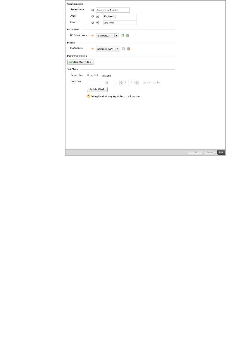
Brocade Mobility RFS4000, RFS6000, and RFS7000 System Reference Guide 97
53-1002620-01
5
FIGURE 89 Basic Configuration screen
5. Set the following configuration settings for the target device:
6. Use the RF Domain drop-down menu to select an existing RF Domain for device membership.
If a RF Domain configuration does not exist suiting the deployment requirements of the target
device, select the Create icon to create a new RF Domain configuration, or select the Edit icon
to modify the configuration of a selected RF Domain. For more information, see About RF
Domains on page 8-499 or Managing RF Domains on page 8-500.
7. Use the Profile drop-down menu to select an existing RF Domain for device membership.
If a profile configuration does not exist suiting the deployment requirements of the target
device, select the Create icon to create a new profile configuration, or select the Edit icon to
modify the configuration of a selected profile. For more information, see General Profile
Configuration on page 7-370.
System Name Provide the selected device a system name up to 64 characters. This is the device name
that appears within the RF Domain or Profile the device supports.
Area Assign the device an Area name representative of the location the controller or Access
Point was physically deployed. The name cannot exceed 64 characters. Assigning an
area name is helpful when grouping devices in RF Domains and profiles, as devices in
the same physical deployment location may need to share specific configuration
parameters in respect to radio transmission and interference requirements specific to
that location.
Floor Assign the target a device a building Floor name representative of the location the
Access Point was physically deployed. The name cannot exceed 64 characters.
Assigning a building Floor name is helpful when grouping devices
in Profiles, as devices on the same physical building floor may need to share specific
configuration parameters in respect to radio transmission and interference
requirements specific to that location.

98 Brocade Mobility RFS4000, RFS6000, and RFS7000 System Reference Guide
53-1002620-01
5
8. If necessary, click the Clear Overrides button to remove all existing overrides from the device.
9. Refer to the Set Clock parameter to update the system time of the target device.
10. Refer to the Device Time parameter to assess the device’s current time, or whether the device
time is unavailable. Select Refresh as required to update the device’s reported system time.
11. Use the New Time parameter to set the calendar day, hour and minute for the target device.
Use the AM and PM radio buttons to refine whether the updated time is for the morning or
afternoon/evening.
12. When completed, select Update Clock to commit the updated time to the target device.
13. Select OK to save the changes made to the device’s Basic Configuration. Selecting Reset
reverts the screen to its last saved configuration.
License Configuration
Licenses are purchased directly from Brocade for the number of permissible Access Point (AP) and
Adaptive Access Point (AAP) adoptions per controller or managed cluster.
NOTE
The Licenses screen is only available to wireless controllers capable of sustaining device
connections, and thus require license support to provide the terms for the maximum number of
allowed device connections. The License screen is not available for Access Points.
The Licenses screen also contains a facility where new licenses can be applied to increase the
number of device adoptions permitted, or to allow the use of the advanced security or advanced
WIPS features.
To configure a device’s a license configuration:
1. Select the Configuration tab from the Web UI.
2. Select Devices from the Configuration tab.
The Device Configuration screen displays a list of managed devices or peer controllers. The
listed devices can either be other controllers or Access Points within the managed network.
3. Select a target device (by double-clicking it) from amongst those displayed within the Device
Configuration screen.
Devices can also be selected directly from the Device Browser in the lower, left-hand, side of
the UI.
4. Select Licenses from the Device menu options.
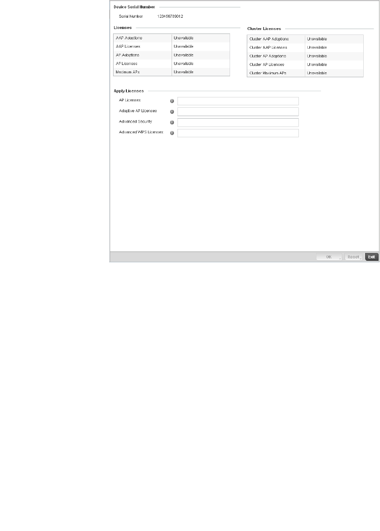
Brocade Mobility RFS4000, RFS6000, and RFS7000 System Reference Guide 99
53-1002620-01
5
FIGURE 90 Device Licenses screen
The License screen displays a Device Serial Number of the controller used for generating the
license key.
5. Review the Licenses table, to assess the specific number of AP and AAP adoptions permitted,
as dictated by the terms of the current license.
AAP Adoptions Lists the total number of AAP adoptions currently made by the target controller. If the
installed license count is 10 AAPs and the number of AAP adoptions is 5, 5 additional
AAPs can still be adopted under the terms of the current license. The total number of
AAPs adoptions varies by controller platform, as well as the terms of the license.
AAP Licenses Lists the number of AAPs available for adoption by the controller under the restrictions
of the current license. This number applies to dependent mode adaptive APs only, and
not independent mode APs.
AP Adoptions Lists the total number of AP adoptions currently made by the target controller. If the
installed license count is 20 APs and the number of AP adoptions is 10, 10 additional
APs can still be adopted under the terms of the current license. The total number of APs
adoptions varies by controller platform, as well as the terms of the license.
AP Licenses Lists the number of APs available for adoption by the controller under the restrictions of
the current license. This number applies to independent mode APs only, and not
dependent mode AAPs.
Maximum APs Lists the maximum number of APs that can be supported by the listed controller under
the terms of the license.

100 Brocade Mobility RFS4000, RFS6000, and RFS7000 System Reference Guide
53-1002620-01
5
6. Review the Cluster Licenses table, to assess the specific number of AP and AAP adoptions per
controller cluster, as dictated by the terms of the current license.
7. Re fer to t h e Apply Licenses field to apply licenses to APs and AAPs counts, as well as the
provisioning of advanced security and advanced WIPS features:
8. Select OK to save the changes made to the applied licenses. Selecting Reset reverts the
screen to its last saved configuration.
Assigning Certificates
A controller certificate links identity information with a public key enclosed in the certificate.
A certificate authority (CA) is a network authority that issues and manages security credentials and
public keys for message encryption. The CA signs all digital certificates it issues with its own private
key. The corresponding public key is contained within the certificate and is called a CA certificate. A
browser must contain the CA certificate in its Trusted Root Library so it can trust certificates signed
by the CA's private key.
Depending on the public key infrastructure, the digital certificate includes the owner's public key,
the certificate expiration date, the owner's name and other public key owner information.
Each certificate is digitally signed by a trustpoint. The trustpoint signing the certificate can be a
certificate authority, corporation or individual. A trustpoint represents a CA/identity pair containing
the identity of the CA, CA-specific configuration parameters, and an association with an enrolled
identity certificate.
Cluster AAP Adoptions Lists the total number of AAP adoptions currently made by the target controller’s cluster
membership (includes all controller members). If the installed license count is 100 AAPs
and the number of AAP adoptions is 50, 50 additional AAPs can still be adopted under
the terms of the current AAP licenses, pooled by the cluster members.
Cluster AAP Licenses Lists the number of AAPs available for adoption by the cluster member controllers under
the restrictions of the licenses combined amongst the cluster members.
Cluster AP Adoptions Lists the total number of AP adoptions currently made by the target controller’s cluster
membership (includes all controller members). If the installed license count is 100 APs
and the number of AP adoptions is 40, 60 additional APs can still be adopted under the
terms of the current AP licenses pooled by the cluster members.
Cluster AP Licenses Lists the number of APs available for adoption by the cluster member controllers under
the restrictions of the licenses accumulated amongst the cluster members.
Cluster AP Maximum
APs
Lists the maximum number of cluster AP adoptions that can be supported by the listed
controller or Access Point Controller under the terms of the license.
AP Licenses Enter the Brocade provided license key required to adopt a specified number of APs to
the controller. The available number of AP licences varies by controller platform.
Adaptive AP Licenses Enter the Brocade provided license key required to install a specified number of AAPs to
the controller. The available number of AAP licences varies by controller platform.
Advanced Security Enter the Brocade provided license key required to install the Role Based Firewall
feature and increases the number of IPSec VPN tunnels. The number of IPSec tunnels
varies by controller platform.
Advanced WIPS
Licenses
Enter the Brocade provided license key required to install an advanced WIPS feature for
client terminations and event sanctioning.
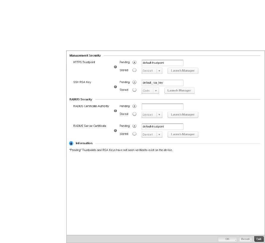
Brocade Mobility RFS4000, RFS6000, and RFS7000 System Reference Guide 101
53-1002620-01
5
SSH keys are a pair of cryptographic keys used to authenticate users instead of, or in addition to, a
username/password. One key is private and the other is public key. Secure Shell (SSH) public key
authentication can be used by a client to access managed resources, if properly configured. A RSA
key pair must be generated on the client. The public portion of the key pair resides with the
controller, while the private portion remains on a secure local area of the client.
To configure a controller’s certificate usage:
1. Select the Configuration tab from the Web UI.
2. Select Devices from the Configuration tab.
The Device Configuration screen displays a list of managed devices or peer controllers. The
listed devices can either be other controllers or Access Points within the managed network.
3. Select Certificates from the Device menu.
FIGURE 91 Device Certificates screen

102 Brocade Mobility RFS4000, RFS6000, and RFS7000 System Reference Guide
53-1002620-01
5
4. Set the following Management Security certificate configurations:
NOTE
Pending trustpoints and RSA keys are typically not verified as existing on a device.
5. Set the following RADIUS Security certificate configurations:
6. Select OK to save the changes made to the certificate configurations. Selecting Reset reverts
the screen to its last saved configuration.
For more information on the certification activities support by the controller, refer to the
following:
•Certificate Management
•RSA Key Management
•Certificate Creation
•Generating a Certificate Signing Request
Certificate Management
Assigning Certificates
If not wanting to use an existing certificate or key with a selected device, an existing stored
certificate can be leveraged from a different managed device for use with the target device. Device
certificates can be imported and exported to and from the controller to a secure remote location for
archive and retrieval as required for their application to other managed devices.
To configure trustpoints for use with certificates:
1. Select Launch Manager from either the HTTPS Trustpoint, SSH RSA Key, RADIUS Certificate
Authority or RADIUS Server Certificate parameters.
HTTPS Trustpoint Either use the default-trustpoint or select the Stored radio button to enable a
drop-down menu where an existing certificate/trustpoint can be leveraged. To
leverage an existing device certificate for this device, select the Launch Manager
button. For more information, see Certificate Management on page 5-102.
SSH RSA Key Either use the default_rsa_key or select the Stored radio button to enable a
drop-down menu where an existing certificate can be leveraged. To leverage an
existing key for use with this target device, select the Launch Manager button. For
more information, see RSA Key Management on page 5-110.
RADIUS Certificate
Authority
Either use the default-trustpoint or select the Stored radio button to enable a
drop-down menu where an existing certificate can be leveraged. To leverage an
existing certificate for this device, select the Launch Manager button.
RADIUS Server
Certificate
Either use the default-trustpoint or select the Stored radio button to enable a
drop-down menu where an existing certificate/trustpoint can be leveraged. To
leverage an existing trustpoint for this device, select the Launch Manager button.
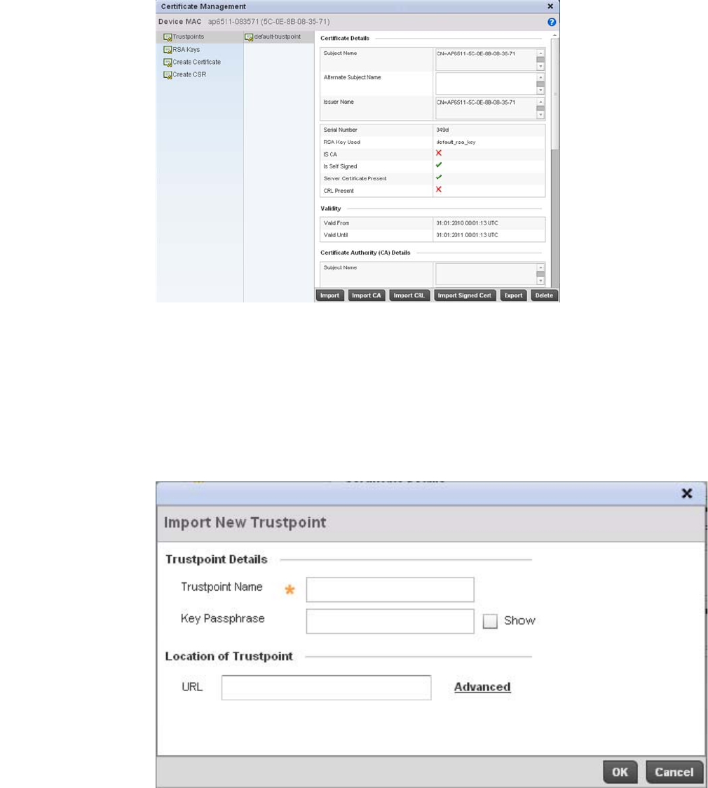
Brocade Mobility RFS4000, RFS6000, and RFS7000 System Reference Guide 103
53-1002620-01
5
FIGURE 92 Certificate Management - Trustpoints screen
2. The Certificate Management screen displays with the Trustpoints portion displayed by default.
3. Select a device from amongst those displayed to review its certificate information.
4. Refer to the Certificate Details to review the certificate’s properties, self-signed credentials,
validity duration and CA information.
5. To optionally import a certificate to the controller, select the Import button from the Certificate
Management screen.
FIGURE 93 Certificate Management - Import New Trustpoint screen

104 Brocade Mobility RFS4000, RFS6000, and RFS7000 System Reference Guide
53-1002620-01
5
6. Define the following configuration parameters required for the Import of the trustpoint.
7. Se le ct OK to import the defined trustpoint. Select Cancel to revert the screen to its last saved
configuration.
8. To optionally import a CA certificate to the controller, select the Import CA button from the
Certificate Management screen.
A CA is a network authority that issues and manages security credentials and public keys for
message encryption. The CA signs all digital certificates it issues with its own private key. The
corresponding public key is contained within the certificate and is called a CA certificate.
Trustpoint Name Enter the 32 character maximum name assigned to the target trustpoint. The trustpoint
signing the certificate can be a certificate authority, corporation or individual.
Key Passphrase Define the key used by both the controller and the server (or repository) of the target
trustpoint. Select the Show textbox to expose the actual characters used in the key.
Leaving the Show checkbox unselected displays the passphrase as a series of asterisks
“*”.
URL Provide the complete URL to the location of the trustpoint. If needed, select Advanced
to expand the dialog to display network address information to the location of the target
trustpoint. The number of additional fields that populate the screen is also dependent
on the selected protocol.
Protocol Select the protocol used for importing the target trustpoint. Available options include:
tftp
ftp
sftp
http
cf
usb1
usb2
Port Use the spinner control to set the port. This option is not valid for cf, usb1, and usb2.
IP Address Enter IP address of the server used to import the trustpoint This option is not valid for cf,
usb1, and usb2.
Hostname Provide the hostname of the server used to import the trustpoint. This option is not valid
for cf, usb1, and usb2.
Path Specify the path to the trustpoint. Enter the complete relative path to the file on the
server.
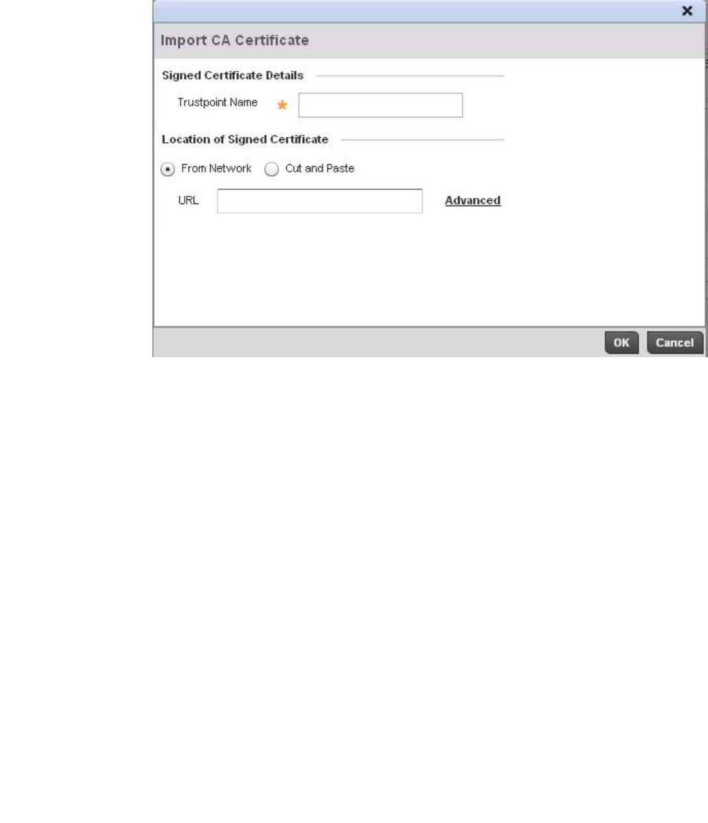
Brocade Mobility RFS4000, RFS6000, and RFS7000 System Reference Guide 105
53-1002620-01
5
FIGURE 94 Certificate Management - Import CA Certificate screen
9. Define the following configuration parameters required for the Import of the CA certificate:
Trustpoint Name Enter the 32 character maximum name assigned to the target trustpoint signing the
certificate. A trustpoint represents a CA/identity pair containing the identity of the CA,
CA-specific configuration parameters, and an association with an enrolled identity
certificate.
Key Passphrase Define the key used by both the controller and the server (or repository) of the target
trustpoint. Select the Show textbox to expose the actual characters used in the key.
Leaving the Show checkbox unselected displays the passphrase as a series of asterisks
-*-.
URL Provide the complete URL to the location of the trustpoint. If needed, select Advanced to
expand the dialog to display network address information to the location of the target
trustpoint. The number of additional fields that populate the screen is also dependent
on the selected protocol.
Advanced / Basic Click the Advanced or Basic link to switch between a basic URL and an advanced
location to specify trustpoint location.
Protocol Select the protocol used for importing the target CA certificate. Available options
include:
tftp
ftp
sftp
http
cf
usb1
usb2
Port Use the spinner control to set the port. This option is not valid for cf, usb1, and usb2.
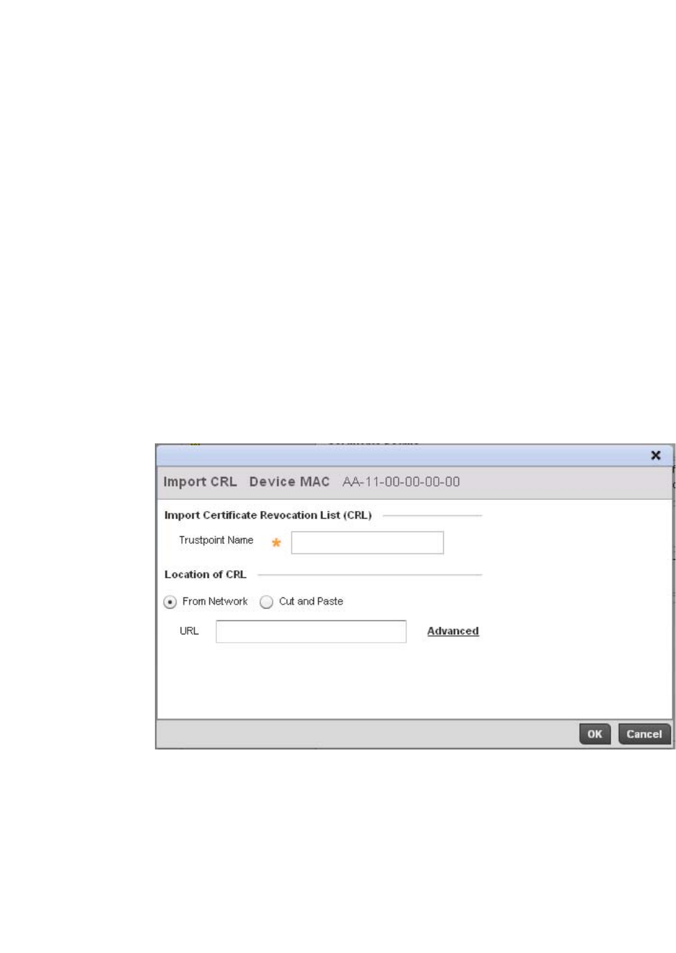
106 Brocade Mobility RFS4000, RFS6000, and RFS7000 System Reference Guide
53-1002620-01
5
10. Select OK to import the defined CA certificate. Select Cancel to revert the screen to its last
saved configuration.
11. To optionally import a CRL to the controller, select the Import CRL button from the Certificate
Management screen.
If a certificate displays within the Certificate Management screen with a CRL, that CRL can be
imported into the controller. A certificate revocation list (CRL) is a list of certificates that have
been revoked or are no longer valid. A certificate can be revoked if the CA had improperly
issued a certificate, or if a private-key is compromised. The most common reason for
revocation is the user no longer being in sole possession of the private key.
12. For information on creating a CRL that can be used with a trustpoint, refer to Setting the
Certificate Revocation List (CRL) Configuration on page 7-443.
FIGURE 95 Certificate Management - Import CRL screen
Define the following configuration parameters required for the Import of the CRL
IP Address Enter IP address of the server used to import the CA certificate. This option is not valid
for cf, usb1, and usb2.
Host Provide the hostname of the server used to import the CA certificate. This option is not
valid for cf, usb1, and usb2.
Path / File Specify the path or filename of the CA certificate. Enter the complete relative path to the
file on the server.
Trustpoint Name Enter the 32 character maximum name assigned to the target trustpoint signing the
certificate. A trustpoint represents a CA/identity pair containing the identity of the CA,
CA-specific configuration parameters, and an association with an enrolled identity
certificate.
From Network Select the From Network radio button to provide network address information to the
location of the target CRL. The number of additional fields that populate the screen is
also dependent on the selected protocol. This is the default setting.
Cut and Paste Select the Cut and Paste radio button to simply copy an existing CRL into the cut and
past field. When pasting a CRL, no additional network address information is required.

Brocade Mobility RFS4000, RFS6000, and RFS7000 System Reference Guide 107
53-1002620-01
5
13. Select OK to import the CRL. Select Cancel to revert the screen to its last saved configuration.
14. To import a signed certificate to the controller, select the Import Signed Cert button from the
Certificate Management screen.
Signed certificates (or root certificates) avoid the use of public or private CAs. A self-signed
certificate is an identity certificate signed by its own creator, thus the certificate creator also
signs off on its legitimacy. The lack of mistakes or corruption in the issuance of self signed
certificates is central.
Self-signed certificates cannot be revoked which may allow an attacker who has already
gained controller access to monitor and inject data into a connection to spoof an identity if a
private key has been compromised. However, CAs have the ability to revoke a compromised
certificate, preventing its further use.
URL Provide the complete URL to the location of the CRL. If needed, select Advanced to
expand the dialog to display network address information to the location of the CRL. The
number of additional fields that populate the screen is also dependent on the selected
protocol.
Protocol Select the protocol used for importing the CRL. Available options include:
tftp
ftp
sftp
http
cf
usb1
usb2
Port Use the spinner control to set the port. This option is not valid for cf, usb1 and usb2.
IP Address Enter IP address of the server used to import the CRL. This option is not valid for cf,
usb1 and usb2.
Hostname Provide the hostname of the server used to import the CRL. This option is not valid for cf,
usb1 and usb2.
Path Specify the path to the CRL. Enter the complete relative path to the file on the server.
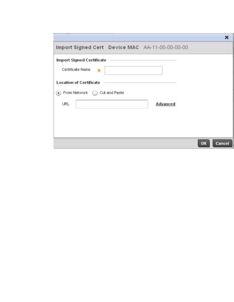
108 Brocade Mobility RFS4000, RFS6000, and RFS7000 System Reference Guide
53-1002620-01
5
FIGURE 96 Certificate Management - Import Signed Cert screen
15. Define the following configuration parameters required for the Import of the CA certificate:
Certificate Name Enter the 32 character maximum trustpoint name with which the certificate should be
associated.
From Network Select the From Network radio button to provide network address information to the
location of the signed certificate. The number of additional fields that populate the
screen is also dependent on the selected protocol. This is the default setting.
Cut and Paste Select the Cut and Paste radio button to simply copy an existing signed certificate into
the cut and past field. When pasting a signed certificate, no additional network address
information is required.
URL Provide the complete URL to the location of the signed certificate. If needed, select
Advanced to expand the dialog to display network address information to the location
of the signed certificate. The number of additional fields that populate the screen is also
dependent on the selected protocol.
Protocol Select the protocol used for importing the target signed certificate. Available options
include:
tftp
ftp
sftp
http
cf
usb1
usb2
Port Use the spinner control to set the port. This option is not valid for cf, usb1, and usb2.
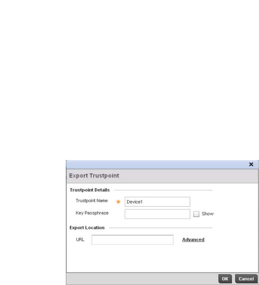
Brocade Mobility RFS4000, RFS6000, and RFS7000 System Reference Guide 109
53-1002620-01
5
16. Select OK to import the signed certificate. Select Cancel to revert the screen to its last saved
configuration
17. To optionally export a trustpoint from the controller to a remote location, select the Export
button from the Certificate Management screen.
Once a certificate has been generated on the controller’s authentication server, export the self
signed certificate. A digital CA certificate is different from a self signed certificate. The CA
certificate contains the public and private key pairs. The self certificate only contains a public
key. Export the self certificate for publication on a Web server or file server for certificate
deployment or export it in to an active directory group policy for automatic root certificate
deployment.
18. Additionally export the key to a redundant RADIUS server so it can be imported without
generating a second key. If there’s more than one RADIUS authentication server, export the
certificate and don’t generate a second key unless you want to deploy two root certificates.
FIGURE 97 Certificate Management - Export Trustpoint screen
IP Address Enter IP address of the server used to import the signed certificate. This option is not
valid for cf, usb1 and usb2.
Host Provide the hostname of the server used to import the signed certificate. This option is
not valid for cf, usb1 and usb2.
Path / File Specify the path to the signed certificate. Enter the complete relative path to the file on
the server.

110 Brocade Mobility RFS4000, RFS6000, and RFS7000 System Reference Guide
53-1002620-01
5
19. Define the following configuration parameters required for the Export of the trustpoint.
20. Select OK to export the defined trustpoint. Select Cancel to revert the screen to its last saved
configuration.
21. To optionally delete a trustpoint, select the Delete button from within the Certificate
Management screen. Provide the trustpoint name within the Delete Trustpoint screen and
optionally select the Delete RSA Key checkbox to remove the RSA key along with the trustpoint.
Select OK to proceed with the deletion, or Cancel to revert to the Certificate Management
screen
RSA Key Management
Assigning Certificates
Refer to the RSA Keys screen to review existing RSA key configurations that have been applied to
managed devices. If an existing key does not meet the needs of a pending certificate request,
generate a new key or import/export an existing key to and from a remote location.
Rivest, Shamir, and Adleman (RSA) is an algorithm for public key cryptography. It’s an algorithm
that can be used for certificate signing and encryption. When a device trustpoint is created, the
RSA key is the private key used with the trustpoint.
To review existing device RSA key configurations, generate additional keys or import/export keys to
and from remote locations:
Trustpoint Name Enter the 32 character maximum name assigned to the target trustpoint. The trustpoint
signing the certificate can be a certificate authority, corporation or individual.
Key Passphrase Define the key used by both the controller and the server (or repository) of the target
trustpoint. Select the Show textbox to expose the actual characters used in the key.
Leaving the Show checkbox unselected displays the passphrase as a series of asterisks
“*”.
URL Provide the complete URL to the location of the trustpoint. If needed, select Advanced
to expand the dialog to display network address information to the location of the target
trustpoint. The number of additional fields that populate the screen is also dependent
on the selected protocol.
Protocol Select the protocol used for exporting the target trustpoint. Available options include:
tftp
ftp
sftp
http
cf
usb1
usb2
Port Use the spinner control to set the port. This option is not valid for cf, usb1, and usb2.
IP Address Enter IP address of the server used to export the trustpoint. This option is not valid for cf,
usb1 and usb2.
Host Provide the hostname of the server used to export the trustpoint. This option is not valid
for cf, usb1 and usb2.
Path / File Specify the path to the trustpoint. Enter the complete relative path to the file on the
server.
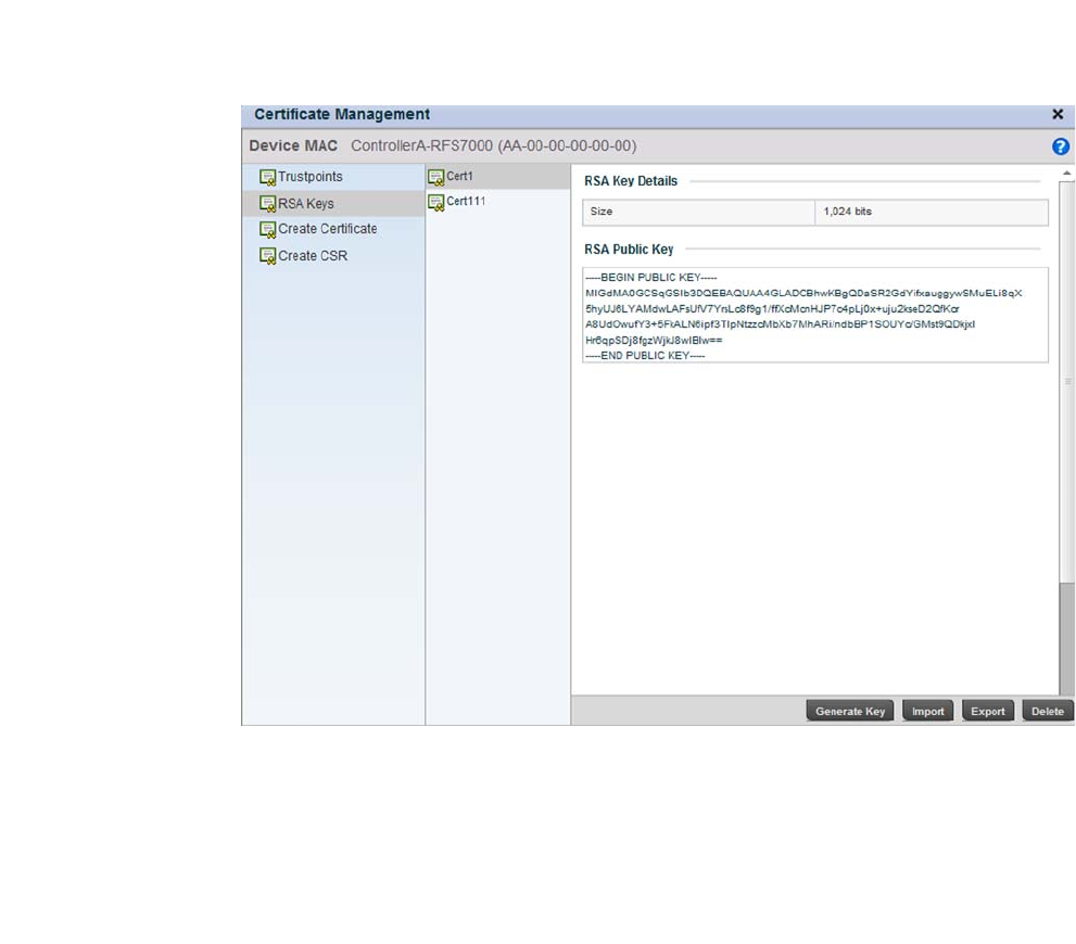
Brocade Mobility RFS4000, RFS6000, and RFS7000 System Reference Guide 111
53-1002620-01
5
1. Select the Launch Manager button from either the SSH RSA Key, RADIUS Certificate Authority
or RADIUS Server Certificate parameters (within the Certificate Management screen).
2. Select RSA Keys from the upper, left-hand, side of the Certificate Management screen.
FIGURE 98 Certificate Management - RSA Keys screen
3. Select a listed device to review its current RSA key configuration.
Each key can have its size and character syntax displayed. Once reviewed, optionally generate
a new RSA key, import a key from a selected device, export a key from the controller to a
remote location or delete a key from a selected device.
4. Select Generate Key to create a new key with a defined size.
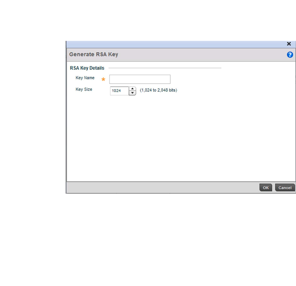
112 Brocade Mobility RFS4000, RFS6000, and RFS7000 System Reference Guide
53-1002620-01
5
FIGURE 99 Certificate Management - Generate RSA Keys screen
5. Define the following configuration parameters required for the Import of the key:
6. Select OK to generate the RSA key. Select Cancel to revert the screen to its last saved
configuration.
7. To optionally import a CA certificate to the controller, select the Import button from the
Certificate Management > RSA Keys screen.
Key Name Enter the 32 character maximum name assigned to the RSA key.
Key Size Use the spinner control to set the size of the key (between 1,024 - 2,048 bits). Brocade
recommends leaving this value at the default setting of 1024 to ensure optimum
functionality.
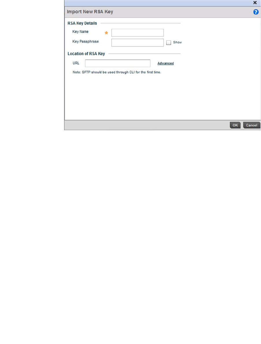
Brocade Mobility RFS4000, RFS6000, and RFS7000 System Reference Guide 113
53-1002620-01
5
FIGURE 100 Certificate Management - Import New RSA Key screen
8. Define the following configuration parameters required for the Import of the RSA key:
Key Name Enter the 32 character maximum name assigned to identify the RSA key.
Key Passphrase Define the key used by both the controller and the server (or repository) of the target
RSA key. Select the Show textbox to expose the actual characters used in the
passphrase. Leaving the Show checkbox unselected displays the passphrase as a series
of asterisks “*”.
URL Provide the complete URL to the location of the RSA key. If needed, select Advanced to
expand the dialog to display network address information to the location of the target
key. The number of additional fields that populate the screen is also dependent on the
selected protocol.
Advanced / Basic Click the Advanced or Basic link to switch between a basic URL and an advanced
location to specify key location.
Protocol Select the protocol used for importing the target key. Available options include:
tftp
ftp
sftp
http
cf
usb1
usb2
Port Use the spinner control to set the port. This option is not valid for cf, usb1, and usb2.
IP Address Enter IP address of the server used to import the RSA key. This option is not valid for cf,
usb1, and usb2.
Host Provide the hostname of the server used to import the RSA key. This option is not valid
for cf, usb1, and usb2.
Path / File Specify the path to the RSA key. Enter the complete relative path to the key on the
server.
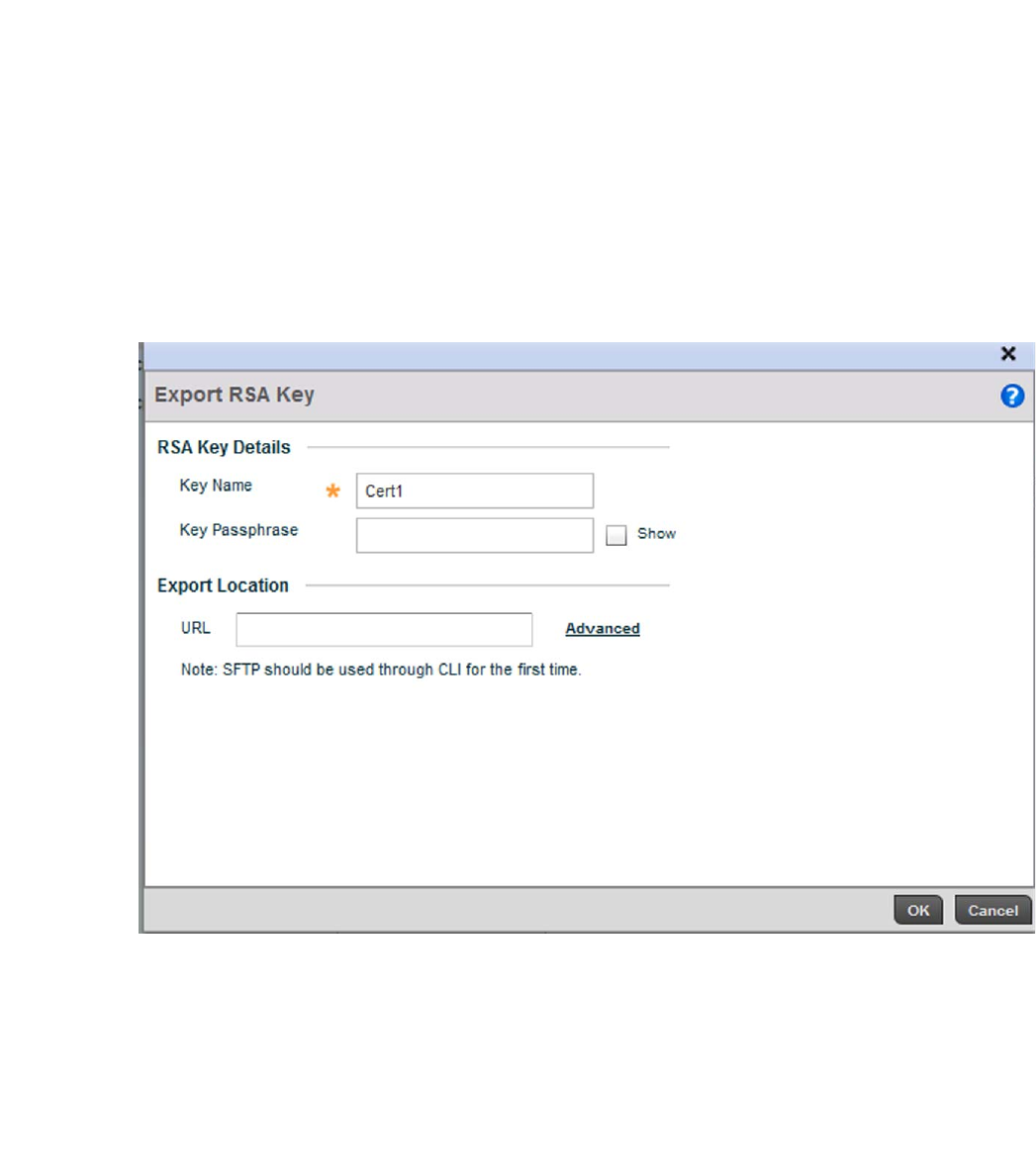
114 Brocade Mobility RFS4000, RFS6000, and RFS7000 System Reference Guide
53-1002620-01
5
9. Select OK to import the defined RSA key. Select Cancel to revert the screen to its last saved
configuration.
10. To optionally export a RSA key from the controller to a remote location, select the Export button
from the Certificate Management > RSA Keys screen.
Export the key to a redundant RADIUS server so it can be imported without generating a
second key. If there’s more than one RADIUS authentication server, export the certificate and
don’t generate a second key unless you want to deploy two root certificates.
FIGURE 101 Certificate Management - Export RSA Key screen
11. Define the following configuration parameters required for the Export of the RSA key.
Key Name Enter the 32 character maximum name assigned to the RSA key.
Key Passphrase Define the key passphrase used by both the controller and the server. Select the Show
textbox to expose the actual characters used in the passphrase. Leaving the Show
checkbox unselected displays the passphrase as a series of asterisks “*”.
URL Provide the complete URL to the location of the key. If needed, select Advanced to
expand the dialog to display network address information to the location of the target
key. The number of additional fields that populate the screen is also dependent on the
selected protocol.

Brocade Mobility RFS4000, RFS6000, and RFS7000 System Reference Guide 115
53-1002620-01
5
12. Select OK to export the defined RSA key. Select Cancel to revert the screen to its last saved
configuration.
13. To optionally delete a key, select the Delete button from within the Certificate Management >
RSA Keys screen. Provide the key name within the Delete RSA Key screen and select the Delete
Certificates checkbox to remove the certificate the key supported. Select OK to proceed with
the deletion, or Cancel to revert back to the Certificate Management screen.
Certificate Creation
Assigning Certificates
The Certificate Management screen provides the facility for creating new self-signed certificates.
Self signed certificates (often referred to as root certificates) do not use public or private CAs. A self
signed certificate is a certificate signed by its own creator, with the certificate creator responsible
for its legitimacy.
To create a self-signed certificate that can be applied to a managed device:
1. Select the Launch Manager button from either the SSH RSA Key, RADIUS Certificate Authority
or RADIUS Server Certificate parameters (within the Certificate Management screen).
2. Select Create Certificate from the upper, left-hand, side of the Certificate Management screen.
Protocol Select the protocol used for exporting the RSA key. Available options include:
tftp
ftp
sftp
http
cf
usb1
usb2
Port Use the spinner control to set the port. This option is not valid for cf, usb1, and usb2.
IP Address Enter IP address of the server used to export the RSA key. This option is not valid for cf,
usb1 and usb2.
Host Provide the hostname of the server used to export the RSA key. This option is not valid
for cf, usb1 and usb2.
Path / File Specify the path to the key. Enter the complete relative path to the key on the server.
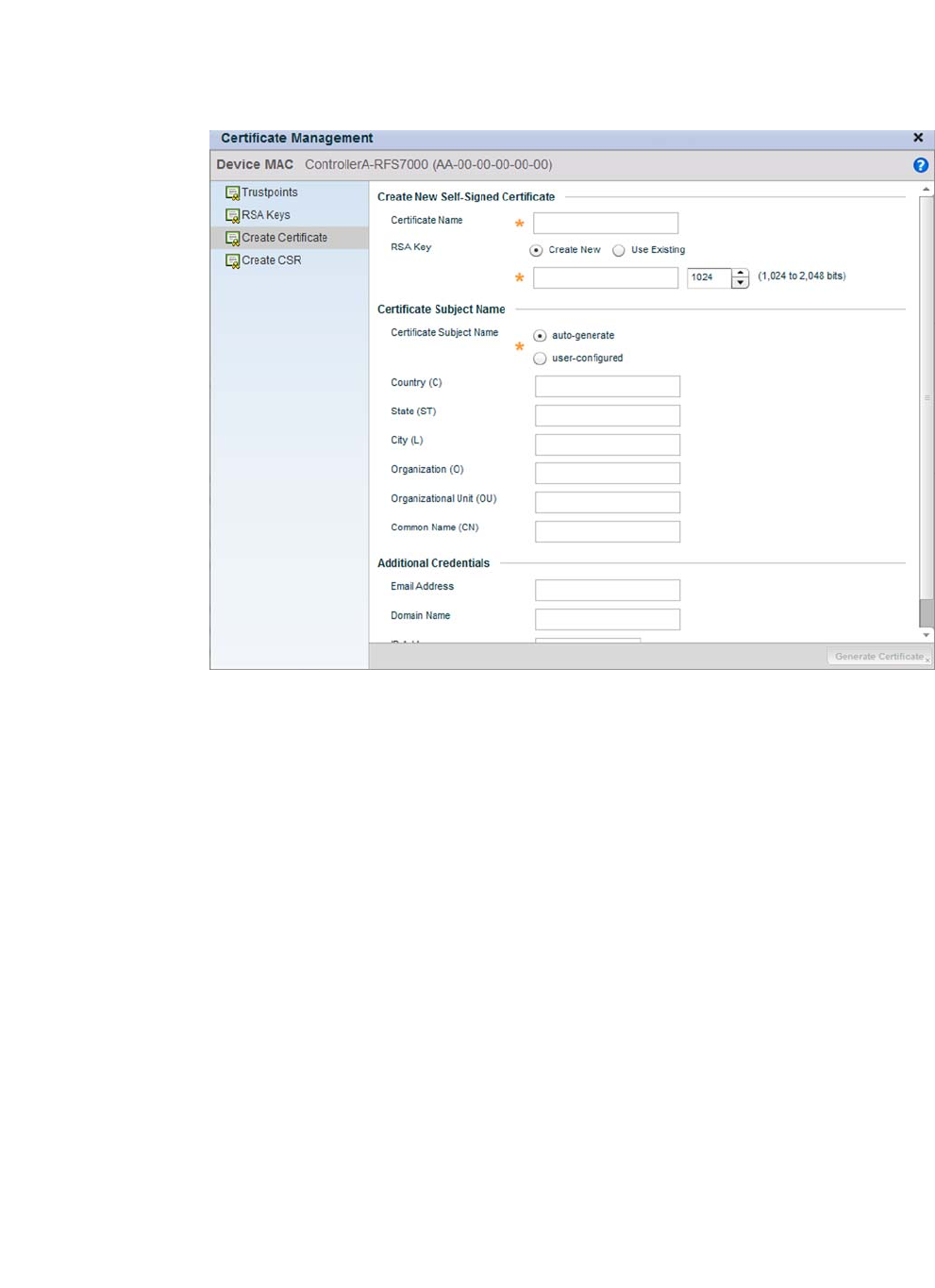
116 Brocade Mobility RFS4000, RFS6000, and RFS7000 System Reference Guide
53-1002620-01
5
FIGURE 102 Certificate Management - Create Certificate screen
3. Define the following configuration parameters required to Create New Self-Signed Certificate:
4. Set the following Certificate Subject Name parameters required for the creation of the
certificate:
Certificate Name Enter the 32 character maximum name assigned to identify the name of the trustpoint
associated with the certificate. A trustpoint represents a CA/identity pair containing the
identity of the CA, CA-specific configuration parameters, and an association with an
enrolled identity certificate.
Use an Existing RSA Key Select the radio button and use the drop-down menu to select the existing key used by
both the controller and the server (or repository) of the target RSA key.
Create a New RSA Key To create a new RSA key, select the radio button to define a 32 character name used to
identify the RSA key. Use the spinner control to set the size of the key (between 1,024 -
2,048 bits). Brocade recommends leaving this value at the default setting of 1024 to
ensure optimum functionality. For more information on creating a new RSA key, see
RSA Key Management on page 5-110.
Certificate Subject
Name
Select either the auto-generate radio button to automatically create the certificate's
subject credentials or select user-defined to manually enter the credentials of the self
signed certificate. The default setting is auto-generate.
Country (C) Define the Country used in the certificate. The field can be modified by the user to other
values. This is a required field and must not exceed 2 characters.
State (ST) Enter a State/Prov. for the state or province name used in the certificate. This is a
required field.
City (L) Enter a City to represent the city name used in the certificate. This is a required field.

Brocade Mobility RFS4000, RFS6000, and RFS7000 System Reference Guide 117
53-1002620-01
5
5. Select the following Additional Credentials required for the generation of the self signed
certificate:
6. Select the Generate Certificate button at the bottom of the Certificate Management > Create
Certificate screen to produce the certificate.
Generating a Certificate Signing Request
Assigning Certificates
A certificate signing request (CSR) is a request to a certificate authority to apply for a digital identity
certificate. The CSR is a block of encrypted text generated on the server the certificate is used on.
It contains the organization name, common name (domain name), locality and country.
A RSA key must be either created or applied to the certificate request before the certificate can be
generated. A private key is not included in the CSR, but is used to digitally sign the completed
request. The certificate created with a particular CSR only worked with the private key generated
with it. If the private key is lost, the certificate is no longer functional.The CSR can be accompanied
by other identity credentials required by the certificate authority, and the certificate authority
maintains the right to contact the applicant for additional information.
If the request is successful, the CA sends an identity certificate digitally signed with the private key
of the CA.
To create a CSR:
1. Select the Launch Manager button from either the SSH RSA Key, RADIUS Certificate Authority
or RADIUS Server Certificate parameters (within the Certificate Management screen).
2. Select Create CSR from the upper, left-hand, side of the Certificate Management screen.
Organization (O) Define an Organization for the organization used in the certificate. This is a required
field.
Organizational Unit (OU) Enter an Org. Unit for the name of the organization unit used in the certificate. This is a
required field.
Common Name (CN) If there’s a common name (IP address) for the organizational unit issuing the certificate,
enter it here.
Email Address Provide an email address used as the contact address for issues relating to this
certificate request.
Domain Name) Enter a fully qualified domain name (FQDN) is an unambiguous domain name that
specifies the node's position in the DNS tree hierarchy absolutely. To distinguish an
FQDN from a regular domain name, a trailing period is added. For example,
somehost.example.com. An FQDN differs from a regular domain name by its
absoluteness, since a suffix is not added.
IP Address Specify the IP address used as the controller destination for certificate requests.
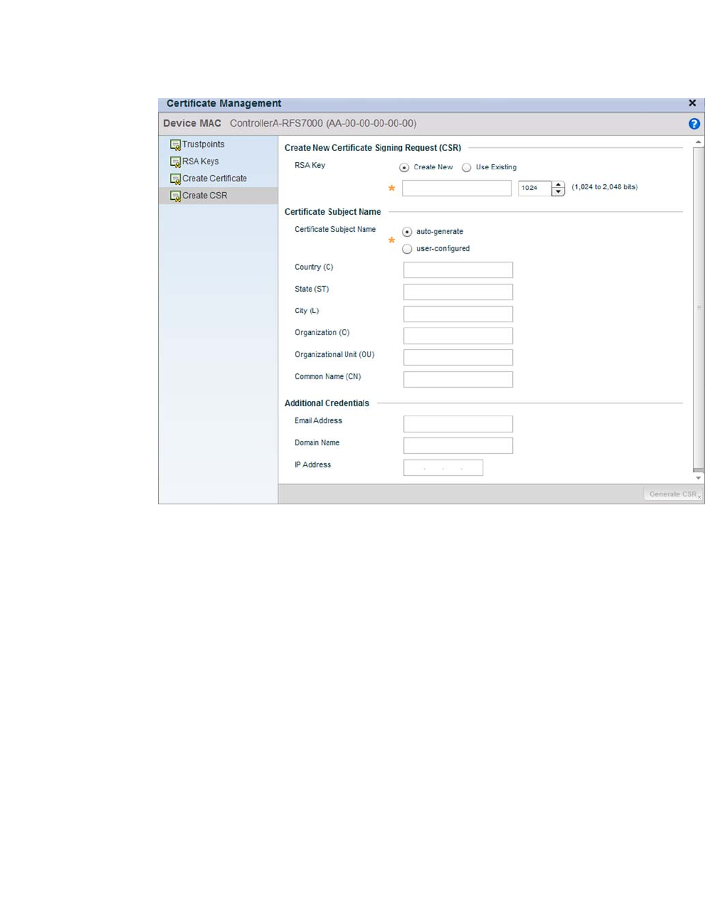
118 Brocade Mobility RFS4000, RFS6000, and RFS7000 System Reference Guide
53-1002620-01
5
FIGURE 103 Certificate Management - Create CSR screen
3. Define the following configuration parameters required to Create New Certificate Signing
Request (CSR):
4. Set the following Certificate Subject Name parameters required for the creation of the
certificate:
Use an Existing RSA Key Select the radio button and use the drop-down menu to set the key used by both the
controller and the server (or repository) of the target RSA key.
Create a New RSA Key To create a new RSA key, select the radio button to define 32 character name used to
identify the RSA key. Use the spinner control to set the size of the key (between 1,024 -
2,048 bits). Brocade recommends leaving this value at the default setting of 1024 to
ensure optimum functionality. For more information on creating a new RSA key, see
RSA Key Management on page 5-110.
Certificate Subject
Name
Select either the auto-generate radio button to automatically create the certificate's
subject credentials or select user-defined to manually enter the credentials of the self
signed certificate. The default setting is auto-generate.
Country (C) Define the Country used in the CSR. The field can be modified by the user to other
values. This is a required field and must not exceed 2 characters.
State (ST) Enter a State/Prov. for the state or province name used in the CSR. This is a required
field.
City (L) Enter a City to represent the city name used in the CSR. This is a required field.

Brocade Mobility RFS4000, RFS6000, and RFS7000 System Reference Guide 119
53-1002620-01
5
5. Select the following Additional Credentials required for the generation of the CSR:
6. Select the Generate CSR button to produce the CSR.
RF Domain Overrides
Use RF Domain Overrides to define configurations overriding the configuration set by the target
device’s original RF Domain assignment.
RF Domains allow administrators to assign configuration data to multiple devices deployed in a
common coverage area (floor, building or site). In such instances, there’s many configuration
attributes these devices share, since their general client support roles are quite similar. However,
device configurations may need periodic refinement from their original RF Domain administered
design.
A controller configuration contains (at a minimum) one default RF Domain, but can optionally use
additional user defined RF Domains:
•Default RF Domain - Automatically assigned to each controllers and associated Access Points
by default. A default RF Domain is unique to a specific controller Brocade Mobility RFS4000,
RFS6000, or RFS7000 Series controller or access point (br-650, br7131,or br6511) model.
•User Defined RF Domains - Created by administrators and manually assigned to individual
controllers or Access Points, but can be automatically assigned to Access Points using
adoption policies.
Each controller and Access Point is assigned only one RF Domain at a time. However, a user
defined RF Domain can be assigned to multiple controllers or Access Points as required. User
defined RF Domains can be manually assigned to controllers and Access Points or automatically
assigned to Access Points using an auto provisioning policy. The more devices assigned a single RF
Domain, the greater the likelihood that one of the device’s configurations will require an override
that deviates that device’s configuration from the original RF Domain assignment shared by the
others.
To review the RF Domain’s original configuration requirements and the options available for a
target device, refer to Managing RF Domains on page 8-500.
To define a device’s RF Domain override configuration:
Organization (O) Define an Organization for the organization used in the CSR. This is a required field.
Organizational Unit (OU) Enter an Org. Unit for the name of the organization unit used in the CSR. This is a
required field.
Common Name (CN) If there’s a common name (IP address) for the organizational unit issuing the certificate,
enter it here.
Email Address Provide an email address used as the contact address for issues relating to this CSR.
Domain Name) Enter a fully qualified domain name (FQDN) is an unambiguous domain name that
specifies the node's position in the DNS tree hierarchy absolutely. To distinguish an
FQDN from a regular domain name, a trailing period is added. ex:
somehost.example.com. An FQDN differs from a regular domain name by its
absoluteness; as a suffix is not added.
IP Address Specify the controller IP address used as the controller destination for certificate
requests.
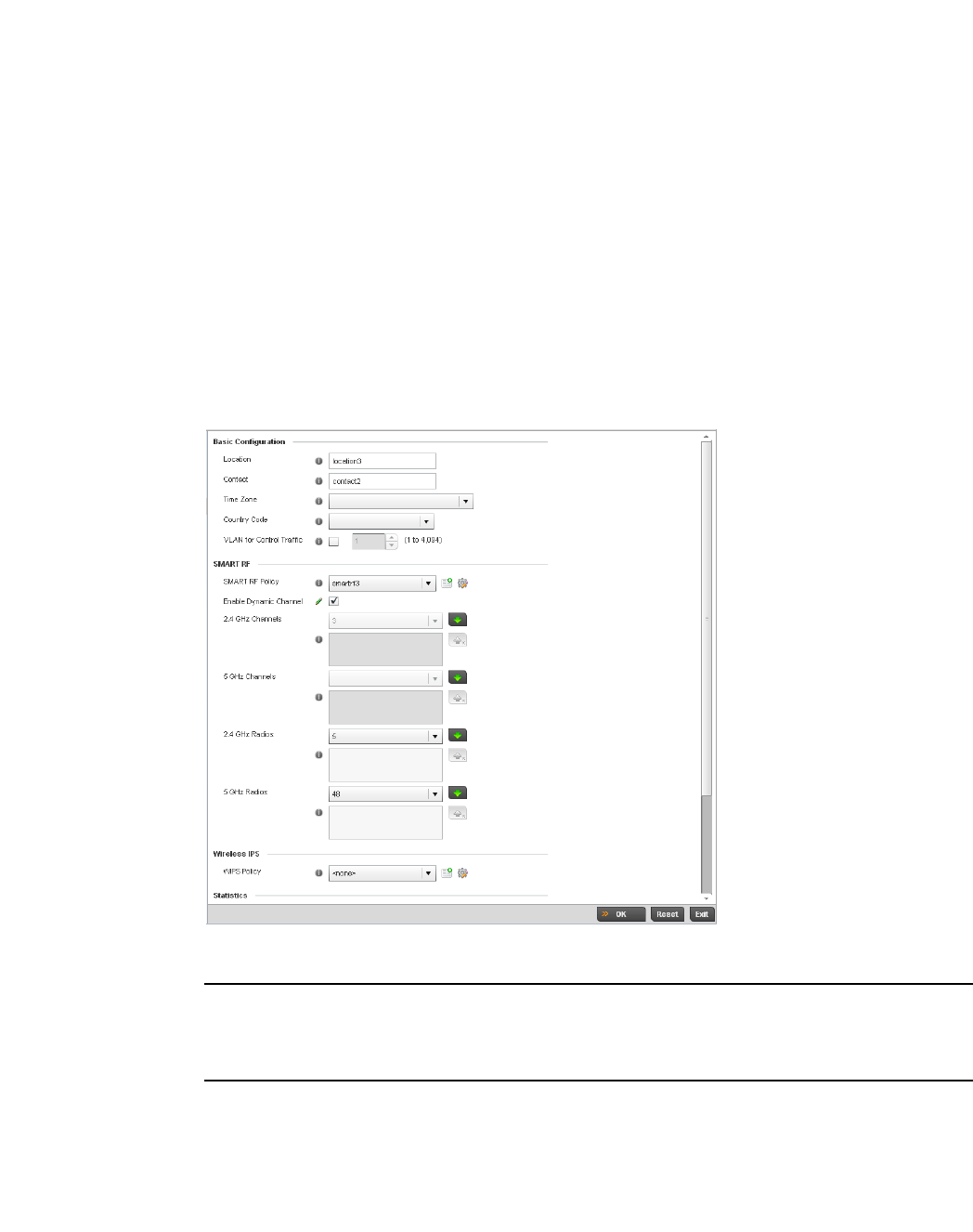
120 Brocade Mobility RFS4000, RFS6000, and RFS7000 System Reference Guide
53-1002620-01
5
1. Select the Configuration tab from the Web UI.
2. Select Devices from the Configuration tab.
3. The Device Configuration screen displays a list of managed devices or peer controllers. The
listed devices can either be other controllers or Access Points within the managed network.
4. Select a target device (by double-clinking it) from amongst those displayed within the Device
Configuration screen.
Devices can also be selected directly from the Device Browser in the lower, left-hand, side of
the UI.
5. Expand the RF Domain Overrides menu option to display its sub-menu options.
6. Select RF Domain.
FIGURE 104 RF Domain Overrides screen
NOTE
A blue override icon (to the left of a parameter) defines the parameter as having an override applied.
To remove an override go to the Basic Configuration section of the device and click the Clear
Overrides button. This will remove all overrides from the device.
7. Re fer to t h e Basic Configuration field to review the basic settings defined for the target device’s
RF Domain configuration, and optionally assign/remove overrides to and from specific
parameters.
Location Displays the location set for the device as part of its RF Domain configuration.
Contact Displays the contact information set for the device as part of its RF Domain
configuration.

Brocade Mobility RFS4000, RFS6000, and RFS7000 System Reference Guide 121
53-1002620-01
5
8. Refer to the Smart RF section to configure Smart RF policy and dynamic channel settings.
9. Select the Create icon to define a new Smart RF policy that can be applied to the RF Domain,
or select the Edit icon to modify or override an existing Smart RF policy.
For an overview of Smart RF and instructions on how to create a Smart RF policy that can be
used with a RF Domain, see Smart RF Policy on page 6-355.
10. Use the WIPS Policy drop-down menu to apply a WIPS policy to the RF Domain.
The wireless controller supports the Wireless Intrusion Protection System (WIPS) to provide
continuous protection against wireless threats and act as an additional layer of security
complementing wireless VPNs and encryption and authentication policies. The wireless
controller supports WIPS through the use of dedicated sensor devices designed to actively
detect and locate unauthorized AP devices. After detection, they use mitigation techniques to
block devices using manual termination, air lockdown or port suppression.
11. Select the Create icon to define a new WIPS policy that can be applied to the RF Domain, or
select the Edit icon to modify or override an existing WIPS policy.
For an overview of WIPS and instructions on how to create a WIPS policy that can be used with
a RF Domain, see Intrusion Prevention on page 9-539.
12. Refer to the Statistics field to set the following data:
Time Zone Displays the time zone set for the device as part of its RF Domain configuration.
Country Code Displays the country code set for the device as part of its RF Domain configuration.
VLAN for Control Traffic Displays the VLAN for Control Traffic setting for the device as part of its RF Domain
configuration.
Smart RF Policy Use the Smart RF Policy drop-down menu to apply a Smart RF policy to the RF Domain.
When a radio fails or is faulty, a Smart RF policy can provide automatic recovery by
instructing neighboring Access Point radios to increase their transmit power to
compensate for the coverage loss.
Enable Dynamic
Channel
Check this box to enable dynamic channel switching for Smart RF radios.
2.4 GHz Channels Select channels from the pull-down menu and click the down arrow to move it to the list
of channels used for 2.4GHz Smart RF radios.
5 GHz Channels Select channels from the pull-down menu and click the down arrow to move it to the list
of channels used for 5GHz Smart RF radios.
2.4 GHz Radios Select radios from the drop-down menu and click the down arrow to move it to the list of
channels used for 2.4GHz Smart RF radios.
5 GHz Radios Select radios from the drop-down menu and click the down arrow to move it to the list of
channels used for 5GHz Smart RF radios.
NoC Update Interval Set a NoC Update interval of 0, or between 5-300 seconds for updates from the RF
Domain manager to the controller.
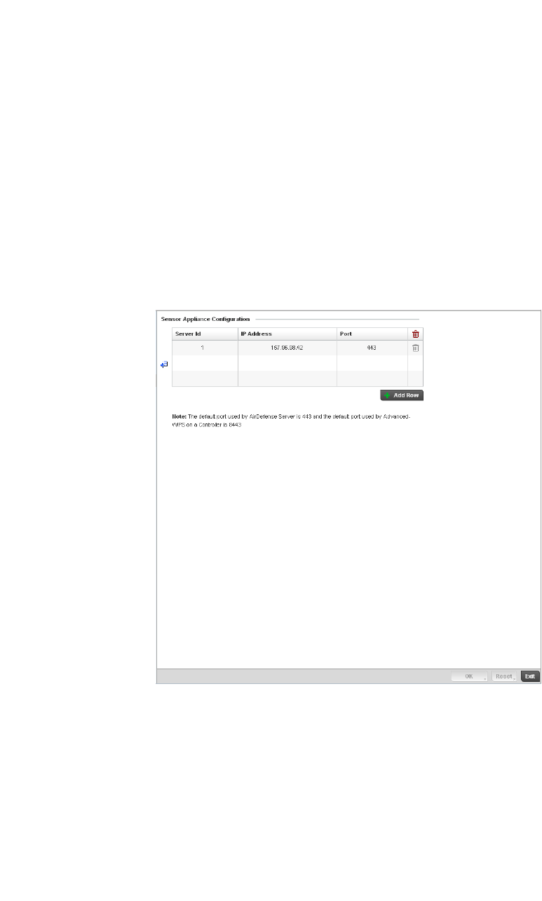
122 Brocade Mobility RFS4000, RFS6000, and RFS7000 System Reference Guide
53-1002620-01
5
13. Select OK to save the changes and overrides made to the RF Domain configuration. Selecting
Reset reverts the screen to its last saved configuration.
14. Select Sensor Configuration from within the expanded RF Domain Overrides menu.
FIGURE 105 Sensor Appliance Configuration Override screen
15. Define a Sensor Appliance Configuration for dedicating a WIPS server resource for client
terminations and WIPS event logging.
16. Optionally set up to 3 overrides for the listed device’s sensor server assignment:
Window Index Use the spinner control to set a numerical index used as an identifier for each RF
Domain statistics defined.
Sample Interval Use the spinner control to define the interval (in seconds) used by the controller to
capture windowed statistics supporting the listed RF Domain configuration. The default
is 5 seconds.
Window Size Use the spinner control to set the number of samples used by the controller to define RF
Domain statistics. The default value is 6 samples.
Server Id Use the spinner control set a numerical index for the sensor server to differentiate it
from other servers. Up to 3 sensor server resources can be defined. Select the Add
Row + button as needed to add additional servers.
IP Address Set the IP addresses of up to 3 sensor servers for supporting WIPS events on behalf
of the selected device.
Port Assign the port number of the sensor server using the spinner control. The default
port is port 443.
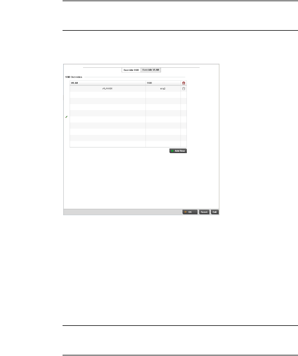
Brocade Mobility RFS4000, RFS6000, and RFS7000 System Reference Guide 123
53-1002620-01
5
NOTE
A blue override icon (to the left of a parameter) defines the parameter as having an override applied.
To remove an override go to the Basic Configuration section of the device and click the Clear
Overrides button. This will remove all overrides from the device.
17. Select OK to save the changes and overrides made to the Sensor Appliance Configuration.
Selecting Reset reverts the screen to its last saved configuration.
18. Select WLAN Override from within the expanded RF Domain Overrides.
FIGURE 106 WLAN Override screen - Override SSID tab
The WLAN Override screen displays with the Override SSID tab displayed by default.
19. Optionally define up to 3 overrides for the listed device’s WLAN SSID assignment:
20. Select the Add Row + button as needed to add additional WLAN SSID overrides.
NOTE
A blue override icon (to the left of a parameter) defines the parameter as having an override applied.
To remove an override go to the Basic Configuration section of the device and click the Clear
Overrides button. This will remove all overrides from the device.
WLAN Optionally use the drop-down menu to change the WLAN assignment for the listed
device. Select either the Create icon to define a new WLAN’s configuration, or select
the Edit icon to modify an existing WLAN configuration. For additional information on
either creating or editing a WLAN’s configuration, see Basic WLAN Configuration on
page 6-284.
SSID Optionally change the SSID associated with the WLAN. The WLAN name is
auto-generated using the SSID until changed (overridden). The maximum number of
characters used for the SSID is 32.
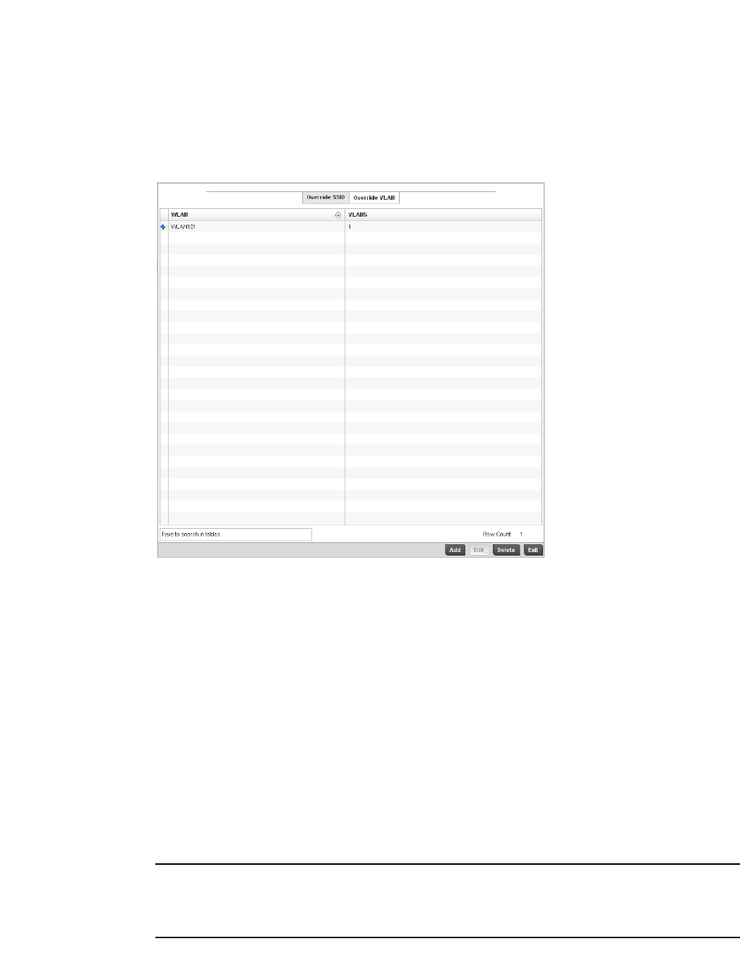
124 Brocade Mobility RFS4000, RFS6000, and RFS7000 System Reference Guide
53-1002620-01
5
21. Select OK to save the changes and overrides. Selecting Reset reverts the screen to its last
saved configuration.
22. Select the Override VLAN tab to review any VLAN assignment overrides that may have been or
optionally add or edit override configurations.
FIGURE 107 WLAN Override screen - Override VLAN tab
The Override VLANs tab displays the VLANs assigned to the WLAN on the device. Select Add to
create a new client limit configuration for a specific WLAN and VLAN or Edit to modify an
existing configuration.
23. Optionally define a VLAN’s wireless client limit override configuration.
NOTE
A blue override icon (to the left of a parameter) defines the parameter as having an override applied.
To remove an override go to the Basic Configuration section of the device and click the Clear
Overrides button. This will remove all overrides from the device.
24. Select OK to save the changes and overrides. Selecting Reset reverts the screen to its last
saved configuration.
WLAN If adding a new VLAN client limit assignment, select the target WLAN from the drop-down
menu. Select the Create icon to create a new controller WLAN configuration, or select
the Edit icon to modify an existing controller WLAN. Refer to Wireless LAN Policy on
page 6-282 to define a new controller WLAN that can be applied to a managed device.
VLANS Use the spinner control to set a VLAN ID (between 1 - 4094). Refer to Basic WLAN
Configuration on page 6-284 to define whether a single VLAN or VLAN pool is used with
a WLAN.
Wireless Client Limit Use the spinner control to set the client limit on the listed VLAN. The default setting is 0,
implying the maximum client count is unlimited.

Brocade Mobility RFS4000, RFS6000, and RFS7000 System Reference Guide 125
53-1002620-01
5
Profile Overrides
Profiles enable administrators to assign a common set of configuration parameters and policies to
controllers and Access Points. Profiles can be used to assign shared or unique network, wireless
and security parameters to wireless controllers and Access Points across a large, multi segment,
site. The configuration parameters within a profile are based on the hardware model the profile
was created to support. The controller supports both default and user defined profiles
implementing new features or updating existing parameters to groups of Wireless Controllers or
Access Points. The central benefit of a profile is its ability to update devices collectively without
having to modify individual device configurations. Power and Adoption overrides apply specifically
to Access Points, while Cluster configuration overrides apply to only controller configurations.
However, device profile configurations may need periodic refinement from their original
administered design. Consequently, a device profile could require modification from a profile
configuration shared amongst numerous devices deployed within a particular site.
Use Profile Overrides to define configurations overriding the parameters set by the target device’s
original profile assignment.
To review a profile’s original configuration requirements and the options available for a target
device, refer to General Profile Configuration on page 7-370.
To define a device’s general profile override configuration:
1. Select the Configuration tab from the Web UI.
2. Select Devices from the Configuration tab.
The Device Configuration screen displays a list of managed devices or peer controllers. The listed
devices can either be other controllers or Access Points within the managed network.
3. Select a target device (by double-clinking it) from amongst those displayed within the Device
Configuration screen.
Devices can also be selected directly from the Device Browser in the lower, left-hand, side of the UI.
4. Select Profile Overrides from the Device menu to expand it into sub menu options.
5. Select General if it doesn’t display by default.
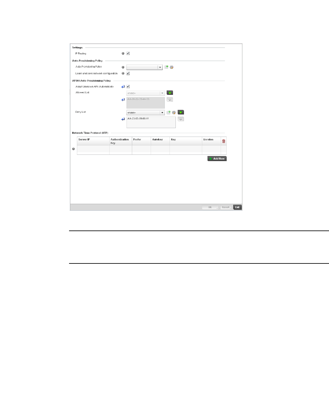
126 Brocade Mobility RFS4000, RFS6000, and RFS7000 System Reference Guide
53-1002620-01
5
FIGURE 108 Profile Overrides - General screen
NOTE
A blue override icon (to the left of a parameter) defines the parameter as having an override applied.
To remove an override go to the Basic Configuration section of the device and click the Clear
Overrides button. This will remove all overrides from the device.
6. In the Settings section check the IP Routing checkbox to enable routing for the device.
7. Re fer to t h e Auto Provisioning Policy section to select an Auto Provisioning Policy or create a
new one.
8. Select + Add Row below the Network Time Protocol (NTP) table to define (or override) the
configurations of NTP server resources the controller uses it obtain its system time. Set the
following parameters to define the NTP configuration:
Auto Provisioning Policy Select an Auto Provisioining Policy from the pulldown menu. To create a new Auto
Provisioning Policy click the create icon. For more information on creating an auto
provisioning policy that can be applied to a controller profile, see Auto Provisioning
Policies on page 5-263.
Learn and save network
configuration
Check the Learn and save network configuration checkbox to enable the device to learn
and save network information.
Server IP Set the IP address of each server added as a potential NTP resource.
Authentication Key Select the number of the associated Authentication Key for the NTP resource.
Prefer Select the radio button to designate this particular NTP resource as preferred. If using
multiple NTP resources, preferred resources will be given first opportunity to connect to
the controller and provide NTP calibration.

Brocade Mobility RFS4000, RFS6000, and RFS7000 System Reference Guide 127
53-1002620-01
5
9. Select OK to save the changes and overrides made to the general profile configuration. Select
Reset to revert to the last saved configuration.
Controller Cluster Configuration Overrides (Controllers Only)
A redundancy group (cluster) is a set of controllers (nodes) uniquely defined by a controllers profile
configuration. Within the redundancy group, members discover and establish connections to other
controller members and provide wireless network self-healing support in the event of cluster
member failure.
A cluster’s AP load balance is typically distributed evenly amongst the controllers in the cluster.
Define how often this profile is load balanced for AP radio distribution as often as you feel required,
as radios can come and go and controller members can join and exit the cluster. For information on
setting a profile’s original cluster configuration (before applying an override), see Profile Cluster
Configuration (Controllers Only) on page 7-373.
As cluster memberships increase or decrease and their load requirements change, a controller’s
profile may need an override applied to best suit a site’s cluster requirements.
NOTE
There is a limit of 2 controllers that can be configured in a cluster.
To apply an override (if required) to a controller profile cluster configuration:
1. Select the Configuration tab from the Web UI.
2. Select Devices from the Configuration tab.
The Device Configuration screen displays a list of managed devices or peer controllers. The
listed devices can either be other controllers or Access Points within the managed network.
3. Select a target device (by double-clinking it) from amongst those displayed within the Device
Configuration screen.
Devices can also be selected directly from the Device Browser in the lower, left-hand, side of
the UI.
4. Select Profile Overrides from the Device menu to expand it into sub menu options.
5. Select Cluster.
NOTE
A blue override icon (to the left of a parameter) defines the parameter as having an override applied.
To remove an override go to the Basic Configuration section of the device and click the Clear
Overrides button. This will remove all overrides from the device.
AutoKey Select the radio button to enable an autokey configuration for the controller and NTP
resource. The default setting is disabled.
Key If an autokey is not being used, manually enter a 64 character maximum key the
controller and NTP resource share to securely interoperate.
Version Use the spinner control to specify the version number used by this NTP server resource.
The default setting is 0.
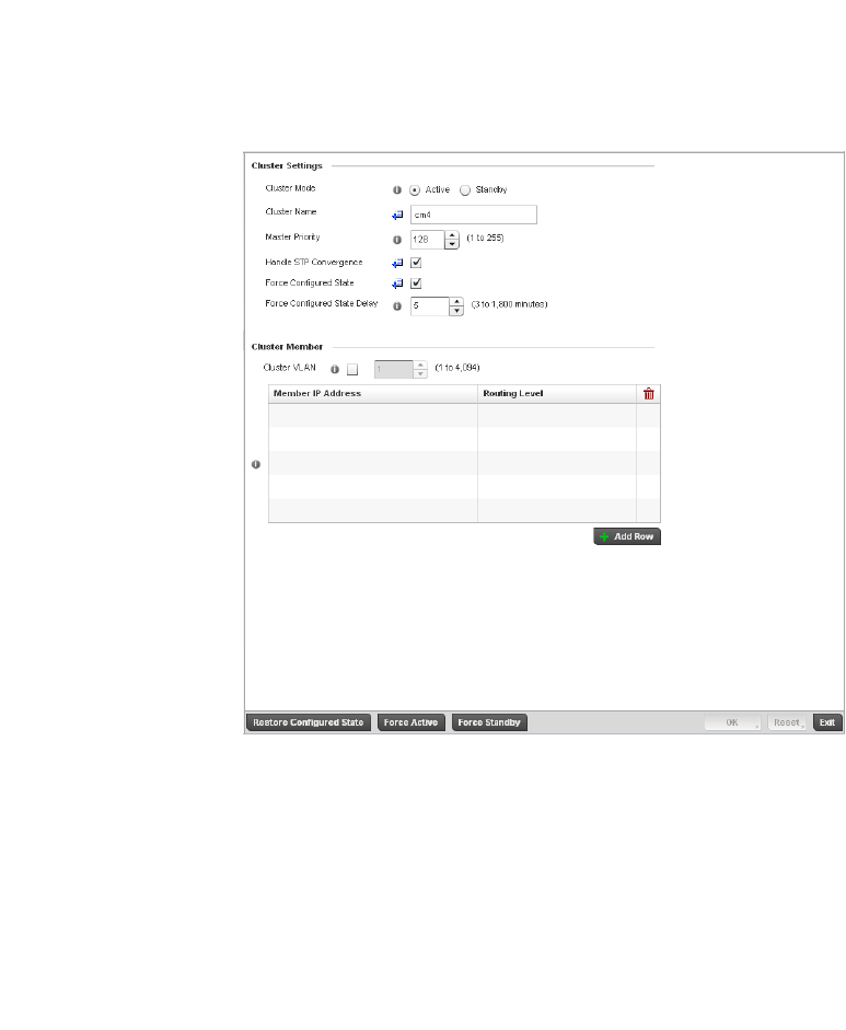
128 Brocade Mobility RFS4000, RFS6000, and RFS7000 System Reference Guide
53-1002620-01
5
FIGURE 109 Profile Overrides - Controller Cluster screen
6. Optionally define the following Cluster Settings and overrides:
Cluster Mode A member can be in either an Active or Standby mode. All active member controllers
can adopt Access Points. Standby members only adopt Access Points when an active
member has failed or sees an Access Point not adopted by a controller. The default
cluster mode is Active and enabled for use with the controller profile.
Cluster Name Define a name for the cluster name unique to its configuration or profile support
requirements. The name cannot exceed 64 characters.
Master Priority Set a priority value between 1 and 255 with the higher value being given higher
priority. This configuration is the device’s priority to become cluster master. In cluster
environment one device from cluster members is elected as cluster master. This
configuration is the device’s priority to become cluster master. The default value is
128.

Brocade Mobility RFS4000, RFS6000, and RFS7000 System Reference Guide 129
53-1002620-01
5
7. Within the Cluster Member field, select the Cluster VLAN checkbox to enable a spinner control
to designate the controller VLAN where cluster members are reachable. Specify a VLAN in the
range of
1 - 4094.
Specify the IP addresses of the VLAN’s cluster members using the IP Address table.
8. Select an Auto-Provisioning Policy from the pulldown menu. To create a new Auto-Provisioning
Policy click the create icon.
9. Define the following br-300 parameters:
10. Select OK to save the changes and overrides made to the profile’s cluster configuration. Select
Reset to revert to the last saved configuration.
Handle STP Convergence Select the radio button to enable Spanning Tree Protocol (STP) convergence for the
controller. In general, this protocol is enabled in layer 2 networks to prevent network
looping. Spanning Tree is a network layer protocol that ensures a loop-free topology
in a mesh network of inter-connected layer 2 controllers. The spanning tree protocol
disables redundant connections and uses the least costly path to maintain a
connection between any two controllers in the network. If enabled, the network
forwards data only after STP convergence. Enabling STP convergence delays the
redundancy state machine execution until the STP convergence is completed (the
standard protocol value for STP convergence is 50 seconds). Delaying the state
machine is important to load balance APs at startup. The default setting is disabled.
Force Configured State Select the radio button to allow this controller to take over for an active controller
member if it were to fail. A standby controller in the cluster takes over APs adopted
by the failed active controller. If the failed active controller were to come back up, the
active controller starts a timer based on the Auto Revert Delay interval. At the
expiration of the Auto Revert Delay, the standby controller releases all adopted APs
and goes back to a monitoring mode. The Auto Revert Delay timer is stopped and
restarted if the active controller goes down and comes up during the Auto Revert
Delay interval. The default value is disabled.
Force Configured State
Delay
Specify a delay interval in minutes (1 - 1,800). This is the interval a standby
controller waits before releasing adopted APs and goes back to a monitoring mode
when an active controller becomes active again after a failure. The default interval is
5 seconds.
Adopt Un-Configured Check this box to allow unconfigured br-300 Access Points to be adopted by the
cluster.
Adopt List Select an br-300 list from the pull-down menu to specify which br-300s are adopted
by the cluster. If a suitable list is not present, click the create button to create a new
list.
Deny List Select an br-300 list from the pull-down menu to specify which br-300s are denied
adoption by the cluster. If a suitable list is not present, click the create button to
create a new list.

130 Brocade Mobility RFS4000, RFS6000, and RFS7000 System Reference Guide
53-1002620-01
5
Access Point Adoption Overrides (Access Points Only)
Adoption is the process an Access Point uses to discover controllers available in the network, pick
the most desirable controller, establish an association with the controller and optionally obtain an
image upgrade, obtains its configuration and considers itself provisioned. This is a configurable
activity that can be supported within a device profile and applied to other Access Points supported
by the profile. Individual attributes of an Access Point profile auto provisioning policy can be
overridden as specific parameters require modification.
At adoption, an Access Point solicits and receives multiple adoption responses from controllers
available on the network. These adoption responses contain loading policy information the Access
Point uses to select the optimum controller for adoption. By default, an auto provisioning policy
generally distributes AP adoption evenly amongst available controllers. Modify existing adoption
policies or create a new one as needed to meet the adoption requirements of a device and their
assigned controller profile.
NOTE
A device configuration does not need to be present for an auto provisioning policy to take effect.
Once adopted, and the device’s configuration is defined and applied by the controller, the auto
provisioning policy mapping does not have impact on subsequent adoptions by the same device.
An auto provisioning policy enables an administrator to define adoption rules for the supported
Brocade Access Points capable of being adopted by a wireless controller.
To define an Access Point’s adoption configuration or apply an override:
1. Select the Devices from the Web UI.
2. Select Profiles from the Configuration tab.
3. Select Profile Overrides to expand its sub-menu items.
4. Select Adoption.
A screen displays where an Access Point’s adoption configuration can be defined and overridden
for a controller profile.
NOTE
A blue override icon (to the left of a parameter) defines the parameter as having an override applied.
To remove an override go to the Basic Configuration section of the device and click the Clear
Overrides button. This will remove all overrides from the device.
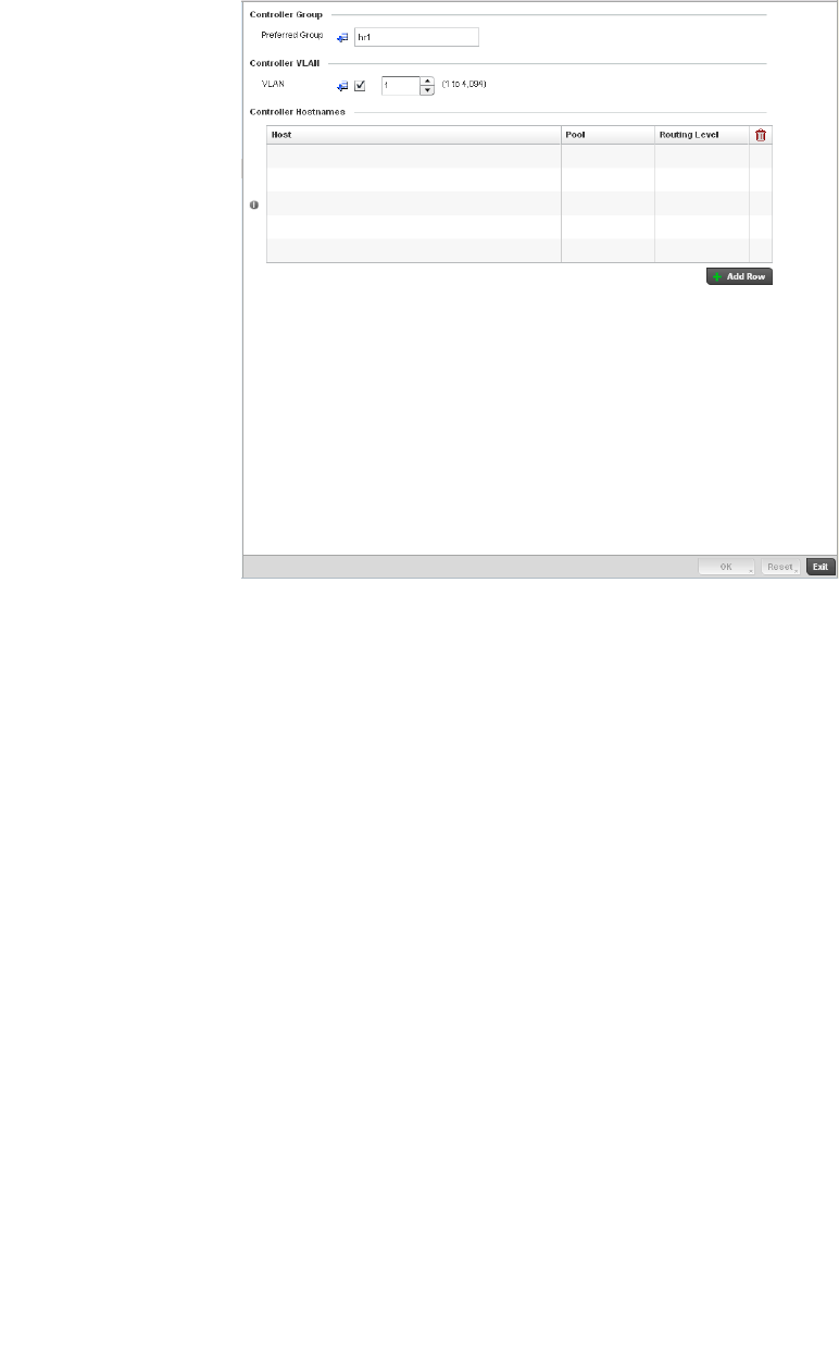
Brocade Mobility RFS4000, RFS6000, and RFS7000 System Reference Guide 131
53-1002620-01
5
FIGURE 110 Access Point Adoption Override screen
5. Define or override the Preferred Group used as optimal group of controllers for the Access
Point’s adoption. The name of the preferred group cannot exceed 64 characters.
6. Select the checkbox to define or override a VLAN the Access Point’s associating controller is
reachable on.
VLANs 0 and 4,095 are reserved and cannot be used by a controller VLAN.
7. En te r Controller Hostnames as needed to define or override controller resources for Access
Point adoption.
Select + Add Row as needed to populate the table with IP Addresses or Hostnames of controllers
used as Access Point adoption resources into the managed network.
8. Select OK to save the changes and overrides made to the Access Point profile adoption
configuration. Select Reset to revert to the last saved configuration.
Access Point Radio Power Overrides (Access Points Only)
A controller profile can manage the transmit output power of the Access Point radios it supports
within the managed network.
Host Use the drop-down menu to specify whether the controller adoption resource is
defined as a (non DNS) IP Address or a Hostname. Once defined, provide the
numerical IP or Hostname. A Hostname cannot exceed 64 characters.
Pool Use the spinner controller to set a pool of either 1 or 2. This is the pool the target
controller belongs to.
Remote Select the checkbox if the controller IP address or hostname provided within the host
field resides within a remote RF Domain. This setting is enabled by default.

132 Brocade Mobility RFS4000, RFS6000, and RFS7000 System Reference Guide
53-1002620-01
5
NOTE
The Power option only appears within the Profile Overrides menu tree if an Access Point is selected
from within the main Devices screen. Power management is configured differently for controllers, so
the Power screen only displays on br-6511, br-7131 model Access Points.
Use the Power screen to set or override one of two power modes (3af or Auto) for a managed
Access Point. When automatic is selected, the Access Point safely operates within available power.
Once the power configuration is determined, the Access Point configures its operating power
characteristics based on its model and power configuration.
An Access Point uses a complex programmable logic device (CPLD). The CPLD determines proper
supply sequencing, the maximum power available and other status information. One of the primary
functions of the CPLD is to determine the Access Point’s maximum power budget. When an Access
Point is powered on (or performing a cold reset), the CPLD determines the maximum power
provided by the POE device and the budget available to the Access Point. The CPLD also
determines the access point hardware SKU and the number of radios. If the Access Point’s POE
resource cannot provide sufficient power to run the access point (with all intended interfaces
enabled), some of the following interfaces could be disabled or modified:
•The Access Point’s transmit and receive algorithms could be negatively impacted
•The Access Point’s transmit power could be reduced due to insufficient power
•The Access Point’s WAN port configuration could be changed (either enabled or disabled)
To define an Access Point’s power configuration or apply an override to an existing parameter:
1. Select the Devices tab from the Web UI.
2. Select Profile Overrides to expand its sub menu items.
3. Select Power.
A screen displays where an Access Point’s power configuration can be defined or overridden for a
controller profile.
NOTE
A blue override icon (to the left of a parameter) defines the parameter as having an override applied.
To remove an override go to the Basic Configuration section of the device and click the Clear
Overrides button. This will remove all overrides from the device.
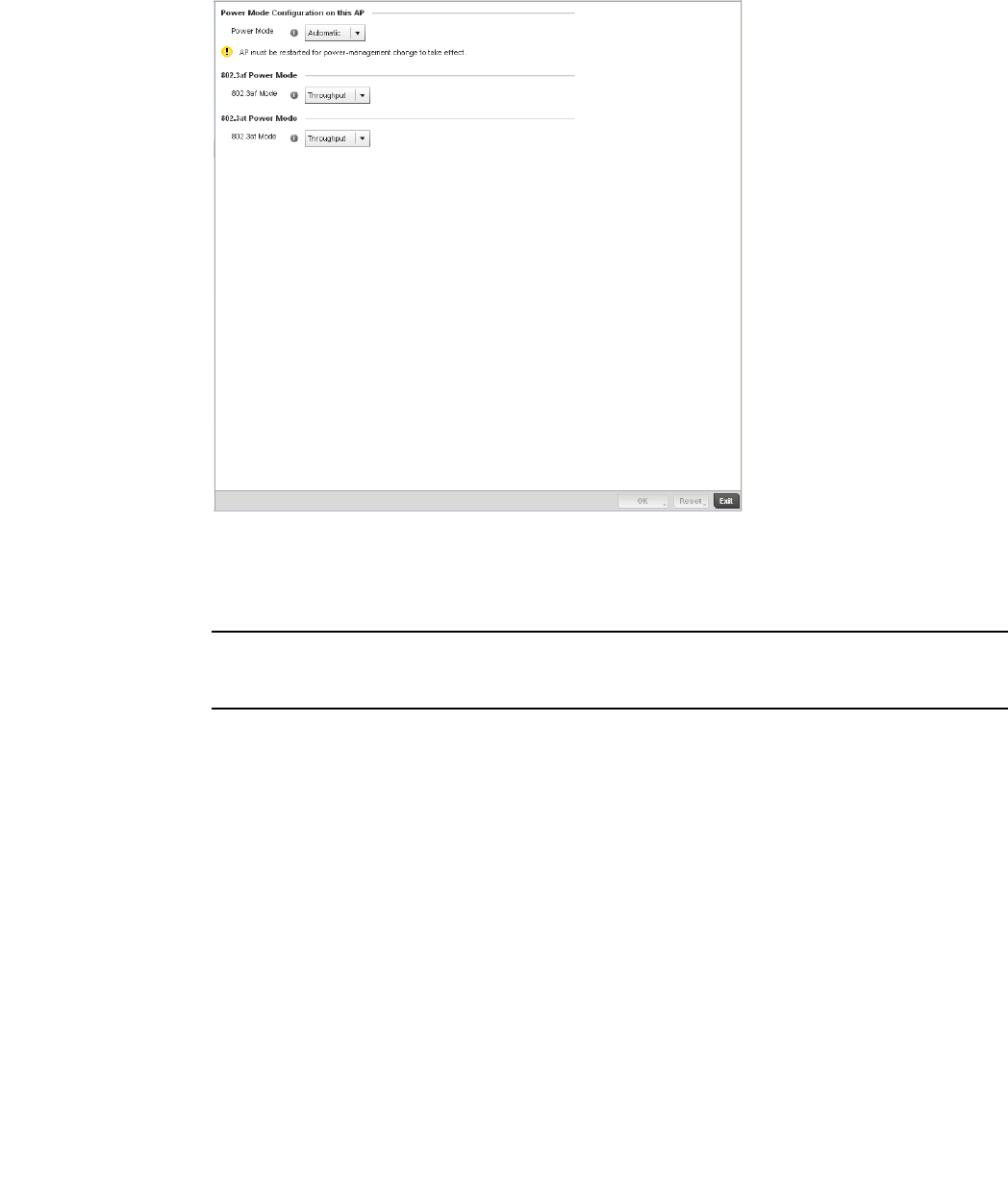
Brocade Mobility RFS4000, RFS6000, and RFS7000 System Reference Guide 133
53-1002620-01
5
FIGURE 111 Access Point Profile Power Override screen
4. Use the Power Mode drop-down menu to set or override the Power Mode Configuration on this
AP.
NOTE
Single radio model Access Point’s always operate using a full power configuration. The power
management configurations described in this section do not apply to single radio models.
When an Access Point is powered on for the first time, the system determines the power
budget available to the Access Point. Using the Automatic setting, the Access Point
automatically determines the best power configuration based on the available power budget.
Automatic is the default setting.
If 802.3af is selected, the Access Point assumes 12.95 watts are available. If the mode is
changed, the Access Point requires a reset to implement the change. If 802.3at is selected,
the Access Point assumes 23 - 26 watts are available.
5. Set or override the Access Point radio’s 802.3af Power Mode and the radio’s 802.3at Power
Mode.
Use the drop-down menu to define a mode of either Range or Throughput.
Select Throughput to transmit packets at the radio’s highest defined basic rate (based on the
radio’s current basic rate settings). This option is optimal in environments where the
transmission range is secondary to broadcast/multicast transmission performance. Select
Range when range is preferred over performance for broadcast/multicast (group) traffic. The
data rates used for range are the lowest defined basic rates. Throughput is the default setting
for both 802.3af and 802.3at.
6. Select OK to save the changes and overrides made to the Access Point power configuration.
Select Reset to revert to the last saved configuration.

134 Brocade Mobility RFS4000, RFS6000, and RFS7000 System Reference Guide
53-1002620-01
5
Profile Interface Override Configuration
A controller profile’s interface configuration can be defined to support separate physical Ethernet
configurations both unique and specific to RFS4000, RFS6000, and RFS7000 Series controllers.
Ports vary depending on controller platform, but controller models do have some of the same
physical interfaces.
A controller requires its Virtual Interface be configured for layer 3 (IP) access or layer 3 service on a
VLAN. A controller’s Virtual Interface defines which IP address is associated with each VLAN ID the
controller is connected to.
If the profile is configured to support an Access Point radio, an additional Radios option is
available, unique to the Access Point’s radio configuration.
Each profile interface configuration can have overrides applied to customize the configuration to a
unique controller deployment. However, once an override is applied to this configuration it becomes
independent from the profile that may be shared by a group of devices in a specific deployment
and my need careful administration until a profile can be re-applied to the target controller. For
more information, refer to the following:
•Ethernet Port Override Configuration
•Virtual Interface Override Configuration
•Port Channel Override Configuration
•Radio Override Configuration
Ethernet Port Override Configuration
Profile Interface Override Configuration
The ports available on a controller vary depending on the platform. The following ports are available
on RFS4000, RFS6000 and RFS7000 model controllers:
•RFS4000 - ge1, ge2, ge3, ge4, ge5, up1
•RFS6000 - ge1, ge2, ge3, ge4, ge5, ge6, ge7, ge8, me1, up1
•RFS7000 - ge1, ge2, ge3, ge4, me1
GE ports are available on the RFS4000, RFS6000, and RFS7000 series platforms. GE ports on the
RFS4000 and RFS6000 are RJ-45 supporting 10/100/1000Mbps. GE ports on the RFS7000 can
be RJ-45 or fiber ports supporting 10/100/1000Mbps.
ME ports are available on RFS6000 and RFS7000 platforms. ME ports are out-of-band
management ports used to manage the controller via CLI or Web UI, even when the other ports on
the controller are unreachable.
UP ports are available on RFS4000 and RFS6000 platforms. An UP port is used to connect the
controller to the backbone network. An UP port supports either RJ-45 or fiber. The UP port is the
preferred means to connect to the backbone as it has a non-blocking 1gbps connection unlike the
GE ports.
To set a controller profile’s Ethernet port configuration and potentially apply overrides to the
profile’s configuration:
1. Select the Configuration tab from the Web UI.
2. Select Devices from the Configuration tab.
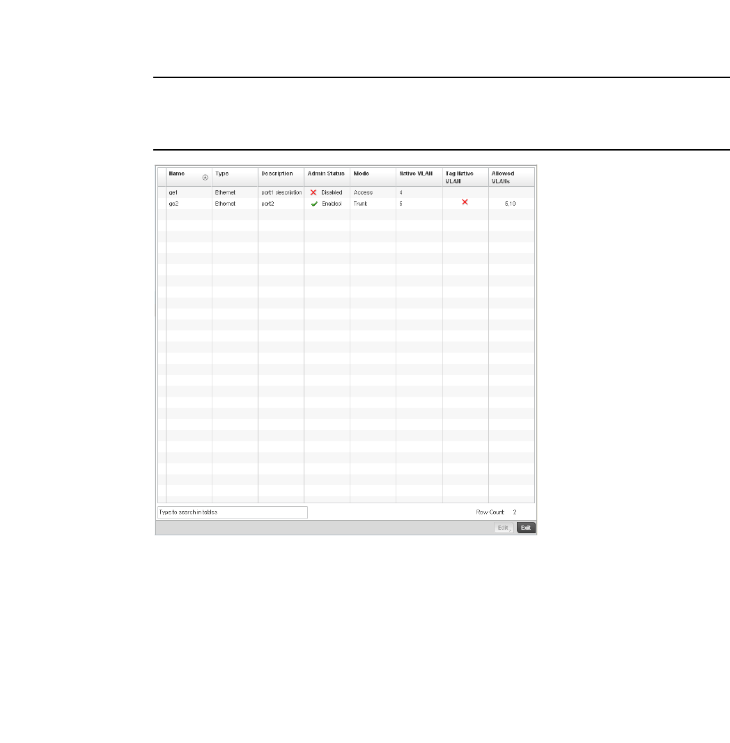
Brocade Mobility RFS4000, RFS6000, and RFS7000 System Reference Guide 135
53-1002620-01
5
The Device Configuration screen displays a list of managed devices or peer controllers. The
listed devices can either be other controllers or Access Points within the managed network.
3. Select a target device (by double-clinking it) from amongst those displayed within the Device
Configuration screen.
Devices can also be selected directly from the Device Browser in the lower, left-hand, side of
the UI.
4. Select Profile Overrides from the Device menu to expand it into sub menu options.
5. Select Interface to expand its sub menu options.
6. Select Ethernet Ports.
NOTE
A blue override icon (to the left of a parameter) defines the parameter as having an override applied.
To remove an override go to the Basic Configuration section of the device and click the Clear
Overrides button. This will remove all overrides from the device.
FIGURE 112 Profiles Overrides - Ethernet Ports screen
7. Refer to the following to assess port status and performance:
Name Displays the physical controller port name reporting runtime data and statistics.
Supported ports vary depending on controller model.
RFS4000 - ge1, ge2, ge3, ge4, ge5, up1
RFS6000 - ge1, ge2, ge3, ge4, ge5, ge6, ge7, ge8, me1, up1
RFS7000 - ge1, ge2, ge3, ge4, me1
Type Displays the physical controller port type. Cooper is used on RJ45 Ethernet ports and
Optical materials are used on fiber optic gigabit Ethernet ports.
Description Displays an administrator defined description for each listed controller port.
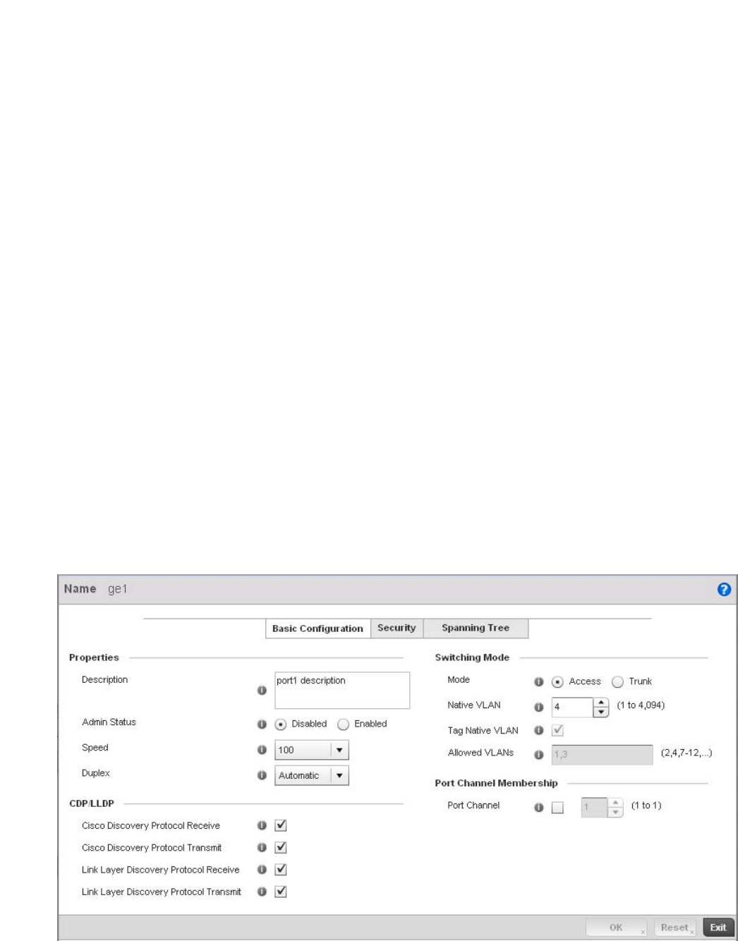
136 Brocade Mobility RFS4000, RFS6000, and RFS7000 System Reference Guide
53-1002620-01
5
8. To edit or override the configuration of an existing controller port, select it from amongst those
displayed and select the Edit button. The Ethernet port Basic Configuration screen displays by
default.
FIGURE 113 Profile Overrides - Ethernet Ports Basic Configuration screen
Admin Status A green checkmark defines the port as active and currently enabled with the controller
profile. A red “X” defines the port as currently disabled and not available for use. The
interface status can be modified with the port configuration as needed.
Mode Displays the profile’s switching mode as either Access or Trunk (as defined within the
Ethernet Port Basic Configuration screen). If Access is selected, the listed port accepts
packets only from the native VLAN. Frames are forwarded untagged with no 802.1Q
header. All frames received on the port are expected as untagged and mapped to the
native VLAN. If set to Trunk, the port allows packets from a list of VLANs added to the
trunk. A port configured as Trunk supports multiple 802.1Q tagged VLANs and one
Native VLAN which can be tagged or untagged.
Native VLAN Lists the numerical VLAN ID (1 - 4094) set for the native VLAN. The native VLAN allows
an Ethernet device to associate untagged frames to a VLAN when no 802.1Q frame is
included in the frame. Additionally, the native VLAN is the VLAN untagged traffic is
directed over when using a port in trunk mode.
Tag Native VLAN A green checkmark defines the native VLAN as tagged. A red “X” defines the native
VLAN as untagged. When a frame is tagged, the 12 bit frame VLAN ID is added to the
802.1Q header so upstream Ethernet devices know which VLAN ID the frame belongs
to. The device reads the 12 bit VLAN ID and forwards the frame to the appropriate VLAN.
When a frame is received with no 802.1Q header, the upstream device classifies the
frame using the default or native VLAN assigned to the Trunk port. A native VLAN allows
an Ethernet device to associate untagged frames to a VLAN when no 802.1Q frame is
included in the frame.
Allowed VLANs Displays those VLANs allowed to send packets over the listed controller port. Allowed
VLANs are only listed when the mode has been set to Trunk.

Brocade Mobility RFS4000, RFS6000, and RFS7000 System Reference Guide 137
53-1002620-01
5
9. Set or override the following Ethernet port Properties:
10. Enable or disable the following CDP/LLDP parameters used to configure Cisco Discovery
Protocol and Link Layer Discovery Protocol for this profile’s Ethernet port configuration:
11. Set or override the following Power Over Ethernet (PoE) parameters used with this profile’s
Ethernet port configuration:
Description Enter a brief description for the controller port (64 characters maximum). The
description should reflect the port’s intended function to differentiate it from others with
similar configurations or perhaps just the name of the physical port.
Admin Status Select the Enabled radio button to define this port as active to the controller profile it
supports. Select the Disabled radio button to disable this physical controller port in the
controller profile. It can be activated at any future time when needed.
Speed Select the speed at which the port can receive and transmit the data. Select either 10
Mbps, 100 Mbps, 1000 Mbps. Select either of these options to establish a 10, 100 or
1000 Mbps data transfer rate for the selected half duplex or full duplex transmission
over the port. These options are not available if Auto is selected. Select Automatic to
enable the controller port to automatically exchange information about data
transmission speed and duplex capabilities. Auto negotiation is helpful when in an
environment where different devices are connected and disconnected on a regular
basis. Automatic is the default setting.
Duplex Select either half, full or automatic as the duplex option. Select Half duplex to send
data over the port, then immediately receive data from the same direction in which the
data was transmitted. Like a full-duplex transmission, a half-duplex transmission can
carry data in both directions, just not at the same time. Select Full duplex to transmit
data to and from the controller port at the same time. Using full duplex, the port can
send data while receiving data as well. Select Automatic to enable to the controller to
dynamically duplex as port performance needs dictate. Automatic is the default setting.
Cisco Discovery Protocol
Receive
Select this box to allow the Cisco discovery protocol to be received on this controller
port. If enabled, the port sends out periodic interface updates to a multicast address to
advertise its presence to neighbors. This option is enabled by default.
Cisco Discovery Protocol
Transmit
Select this box to allow the Cisco discovery protocol to be transmitted on this controller
port. If enabled, the port sends out periodic interface updates to a multicast address to
advertise its presence to neighbors.
Link Layer Discovery
Protocol Receive
Select this box to allow the Link Layer discovery protocol to be received on this controller
port. If enabled, the port sends out periodic interface updates to a multicast address to
advertise its presence to neighbors. This option is enabled by default.
Link Layer Discovery
Protocol Transmit
Select this box to allow the Link Layer discovery protocol to be transmitted on this
controller port. If enabled, the port sends out periodic interface updates to a multicast
address to advertise its presence to neighbors.
Enable POE Select the check box to configure the selected port to use Power over Ethernet. To
disable PoE on a port, uncheck this option. Power over Ethernet is supported on
RFS4000 and RFS6000 model controllers only. When enabled, the controller supports
802.3af PoE on each of its ge ports. The PoE allows users to monitor port power
consumption and configure power usage limits and priorities for each ge port.
Power Limit Use the spinner control to set the total watts available for Power over Ethernet on the
controller ge port. Set a value between 0 - 40 watts.
Power Priority Set the power priority for the listed port to either to either Critical, High or Low. This is
the priority assigned to this port versus the power requirements of the other supports
available on the controller.

138 Brocade Mobility RFS4000, RFS6000, and RFS7000 System Reference Guide
53-1002620-01
5
12. Define or override the following Switching Mode parameters applied to the Ethernet port
configuration:
13. Optionally select the Port Channel checkbox from the Port Channel Membership area and
define or override a setting between 1 - 8 using the spinner control. This sets the channel
group for the port.
14. Select OK to save the changes and overrides made to the profile’s Ethernet Port Basic
Configuration. Select Reset to revert to the last saved configuration.
15. Select the Security tab.
Mode Select either the Access or Trunk radio button to set the VLAN switching mode over the
port. If Access is selected, the port accepts packets only form the native VLANs. Frames
are forwarded out the port untagged with no 802.1Q header. All frames received on the
port are expected as untagged and are mapped to the native VLAN. If the mode is set to
Trunk, the port allows packets from a list of VLANs you add to the trunk. A port
configured as Trunk supports multiple 802.1Q tagged VLANs and one Native VLAN
which can be tagged or untagged. Access is the default mode.
Native VLAN Use the spinner control to define a numerical Native VLAN ID between
1 - 4094. The native VLAN allows an Ethernet device to associate untagged frames to a
VLAN when no 802.1Q frame is included in the frame. Additionally, the native VLAN is
the VLAN which untagged traffic will be directed over when using a port in trunk mode.
The default VLAN is 1.
Tag Native VLAN Select the check box to tag the native VLAN. Controllers support the IEEE 802.1Q
specification for tagging frames and coordinating VLANs between devices. IEEE 802.1Q
adds four bytes to each frame identifying the VLAN ID for upstream devices that the
frame belongs. If the upstream Ethernet device does not support IEEE 802.1Q tagging, it
does not interpret the tagged frames. When VLAN tagging is required between devices,
both devices must support tagging and be configured to accept tagged VLANs. When a
frame is tagged, the 12 bit frame VLAN ID is added to the 802.1Q header so upstream
Ethernet devices know which VLAN ID the frame belongs to. The device reads the 12 bit
VLAN ID and forwards the frame to the appropriate VLAN. When a frame is received with
no 802.1Q header, the upstream device classifies the frame using the default or native
VLAN assigned to the Trunk port. The native VLAN allows an Ethernet device to associate
untagged frames to a VLAN when no 802.1Q frame is included in the frame. This feature
is disabled by default.
Allowed VLANs Selecting Trunk as the mode enables the Allowed VLANs parameter. Add VLANs that
exclusively send packets over the listed port.
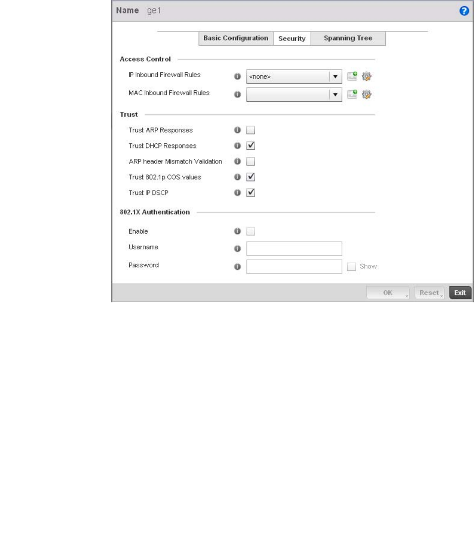
Brocade Mobility RFS4000, RFS6000, and RFS7000 System Reference Guide 139
53-1002620-01
5
FIGURE 114 Profile Overrides - Ethernet Ports Security screen
16. Refer to the Access Control field. As part of the port’s security configuration, Inbound IP and
MAC address firewall rules are required.
Use the Inbound IP Firewall Rules and Inbound MAC Firewall Rules drop-down menus to select
or override the firewall rules applied to this profile’s Ethernet port configuration.
The firewall inspects IP and MAC traffic flows and detects attacks typically not visible to
traditional wired firewall appliances.
If a firewall rule does not exist suiting the data protection needs of the target port
configuration, select the Create icon to define a new rule configuration or the Edit icon to
update or override an existing configuration. For more information, see Wireless Firewall on
page 9-511.
17. Refer to the Trust field to define or override the following:
Trust ARP Responses Select the check box to enable ARP trust on this controller port. ARP packets received
on this port are considered trusted, and the information from these packets is used to
identify rogue devices within the managed network. The default value is disabled.
Trust DHCP Responses Select the check box to enable DHCP trust on this port. If enabled, only DHCP
responses are trusted and forwarded on this port, and a DHCP server can be
connected only to a DHCP trusted port. The default value is enabled.
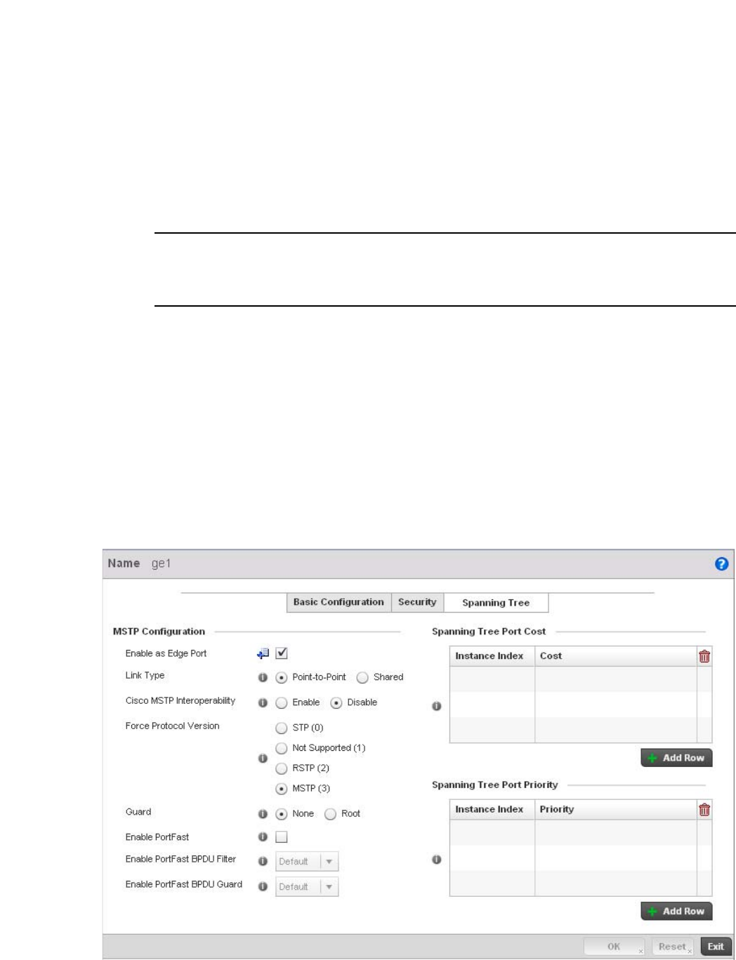
140 Brocade Mobility RFS4000, RFS6000, and RFS7000 System Reference Guide
53-1002620-01
5
NOTE
Some vendor solutions with VRRP enabled send ARP packets with Ethernet SMAC as a physical MAC
and inner ARP SMAC as VRRP MAC. If this configuration is enabled, a packet is allowed, despite a
conflict existing.
18. Set the following 802.1X Authentication settings for the WLAN’s QoS policy:
19. Select OK to save the changes and overrides made to the Ethernet port’s security
configuration. Select Reset to revert to the last saved configuration.
20. Select the Spanning Tree tab.
ARP header Mismatch
Validation
Select the check box to enable a mismatch check for the source MAC in both the ARP
and Ethernet header. The default value is enabled.
Trust 8021p COS values Select the check box to enable 802.1p COS values on this port. The default value is
enabled.
Trust IP DSCP Select the check box to enable IP DSCP values on this port. The default value is
enabled.
Enable Check this box to enable 802.1X authentication on the selected Ethernet Port.
Username Specify the configured username on the RADIUS server configured for
authentication on this Ethernet port. This option is only available when the Enable
checkbox is selected.
Password Specify the password for the configured username used for authentication on this
Ethernet port. This option is only available when the Enable checkbox is selected.

Brocade Mobility RFS4000, RFS6000, and RFS7000 System Reference Guide 141
53-1002620-01
5
FIGURE 115 Profile Overrides - Ethernet Ports Spanning Tree screen
21. Set or override the following parameters for the port’s MSTP configuration:
22. Refer to the Spanning Tree Port Cost table.
Define or override an Instance Index using the spinner control and then set the Cost. The
default path cost depends on the user defined speed of the port.The cost helps determine the
role of the port in the MSTP network. The designated cost is the cost for a packet to travel from
this port to the root in the MSTP configuration. The slower the media, the higher the cost.
23. Select + Add Row as needed to include additional indexes.
24. Refer to the Spanning Tree Port Priority table.
Enable as Edge Port Select the check box to define this port as an edge port. Using an edge (private) port,
you can isolate devices to prevent connectivity over this port.
Link Type Select either the Point-to-Point or Shared radio button. Selecting Point-to-Point
indicates the port should be treated as connected to a point-to-point link. Selecting
Shared indicates this port should be treated as having a shared connection. A port
connected to a hub is on a shared link, while one connected to a controller is a
point-to-point link.
Enable Cisco MSTP
Interoperability
Select either the Enable or Disable radio buttons. This enables interoperability with
Cisco’s version of MSTP over the port, which is incompatible with standard MSTP.
Force Protocol Version Sets the protocol version to either STP(0), Not Supported(1), RSTP(2) or MSTP(3). MSTP
is the default setting.
Guard Determines whether the port enforces root bridge placement. Setting the guard to Root
ensures the port is a designated port. Typically, each guard root port is a designated
port, unless two or more ports (within the root bridge) are connected together. If the
bridge receives superior (BPDUs) on a guard root-enabled port, the guard root moves the
port to a root-inconsistent STP state. This state is equivalent to a listening state. No data
is forwarded across the port. Thus, the guard root enforces the root bridge position.
Enable PortFast Select the check box to enable drop-down menus for both the Enable Portfast BPDU
Filter and Enable Portfast BPDU guard options for the controller port.
PortFast BPDU Filter Select enable to invoke a BPDU filter for this portfast enabled port. Enabling the BPDU
filter feature ensures this PortFast enabled port does not transmit or receive BPDUs.
PortFast BPDU Guard Select enable to invoke a BPDU guard for this portfast enabled port. Enabling the BPDU
Guard feature means this portfast-enabled port will shutdown on receiving a BPDU.
Speed Default Path Cost
<=100000 bits/sec 200000000
<=1000000 bits/sec 20000000
<=10000000 bits/sec 2000000
<=100000000 bits/sec 200000
<=1000000000 bits/sec 20000
<=10000000000 bits/sec 2000
<=100000000000 bits/sec 200
<=1000000000000 bits/sec 20
>1000000000000 bits/sec 2

142 Brocade Mobility RFS4000, RFS6000, and RFS7000 System Reference Guide
53-1002620-01
5
Define or override an Instance Index using the spinner control and then set the Priority. The
lower the priority, a greater likelihood of the port becoming a designated port. Thus applying an
higher override value impacts the port’s likelihood of becoming a designated port.
25. Select + Add Row needed to include additional indexes.
26. Select OK to save the changes and overrides made to the Ethernet Port Spanning Tree
configuration. Select Reset to revert to the last saved configuration.
Virtual Interface Override Configuration
Profile Interface Override Configuration
A controller Virtual Interface is required for layer 3 (IP) access to the controller or provide layer 3
service on a VLAN. The Virtual Interface defines which IP address is associated with each VLAN ID
the controller is connected to. A Virtual Interface is created for the default VLAN (VLAN 1) to enable
remote controller administration. A Virtual Interface is also used to map VLANs to IP address
ranges. This mapping determines the destination for controller routing.
To review existing Virtual Interface configurations and either create a new Virtual Interface
configuration, modify (override) an existing configuration or delete an existing configuration:
1. Select the Configuration tab from the Web UI.
2. Select Devices from the Configuration tab.
The Device Configuration screen displays a list of managed devices or peer controllers. The
listed devices can either be other controllers or Access Points within the managed network.
3. Select a target device (by double-clinking it) from amongst those displayed within the Device
Configuration screen.
Devices can also be selected directly from the Device Browser in the lower, left-hand, side of
the UI.
4. Select Profile Overrides from the Device menu to expand it into sub menu options.
5. Select Interface to expand its sub menu options.
6. Select Virtual Interfaces.
NOTE
A blue override icon (to the left of a parameter) defines the parameter as having an override applied.
To remove an override go to the Basic Configuration section of the device and click the Clear
Overrides button. This will remove all overrides from the device.
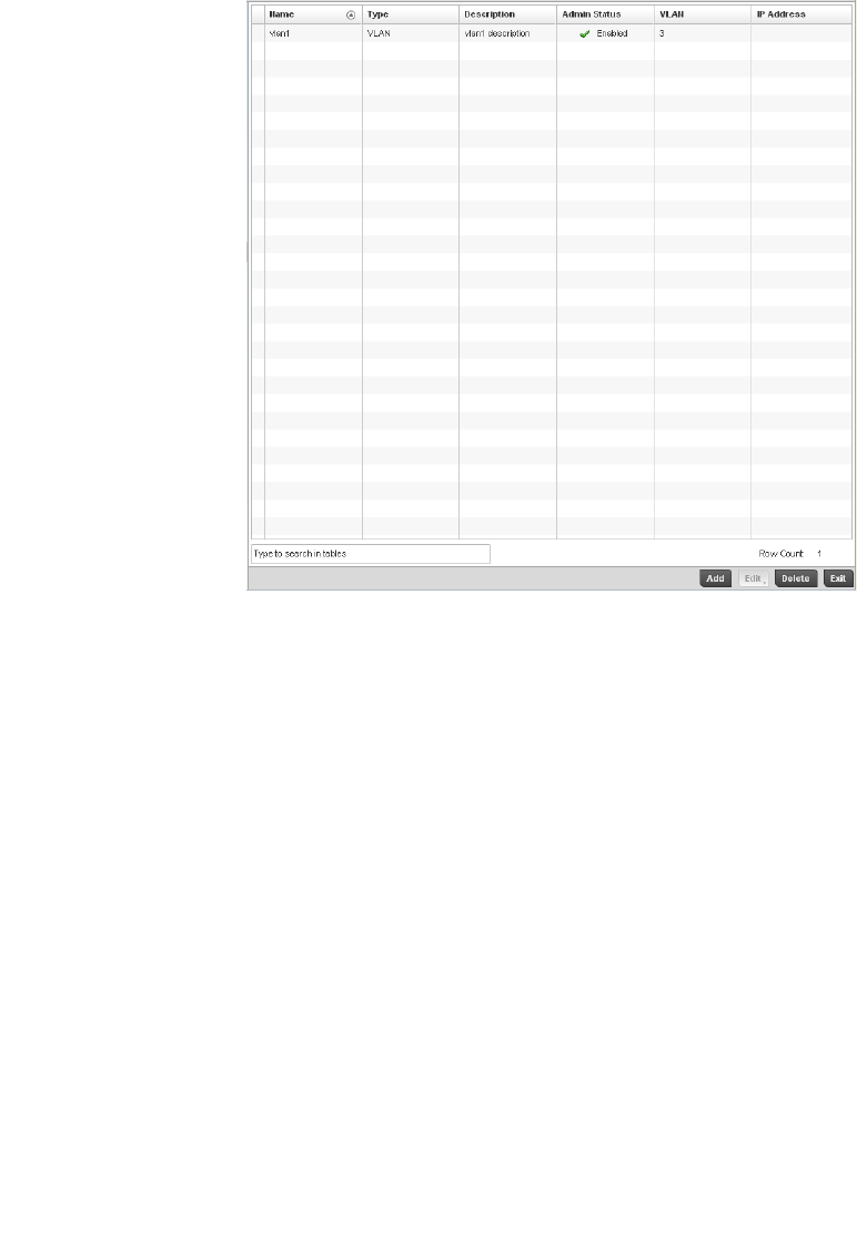
Brocade Mobility RFS4000, RFS6000, and RFS7000 System Reference Guide 143
53-1002620-01
5
FIGURE 116 Profile Overrides - Virtual Interfaces screen
7. Review the following parameters unique to each virtual interface configuration to determine
whether a parameter override is warranted:
Once the configurations of existing Virtual Interfaces have been reviewed, determine whether a
new interface requires creation, or an existing Virtual Interface requires edit (override) or
deletion.
8. Select Add to define a new Virtual Interface configuration, Edit to modify or override the
configuration of an existing Virtual Interface or Delete to permanently remove a selected
Virtual Interface.
Name Displays the name of each listed Virtual Interface assigned when it was created. The
name is between 1 - 4094, and cannot be modified as part of a Virtual Interface edit.
Type Displays the type of Virtual Interface for each listed interface.
Description Displays the description defined for the Virtual Interface when it was either initially
created or edited.
Admin Status A green checkmark defines the listed Virtual Interface configuration as active and
enabled with its supported controller profile. A red “X” defines the Virtual Interface as
currently disabled. The interface status can be modified when a new Virtual Interface is
created or an existing one modified.
VLAN Displays the numerical VLAN ID associated with each listed interface.
IP Address Defines whether DHCP was used to obtain the primary IP address used by the Virtual
Interface configuration.
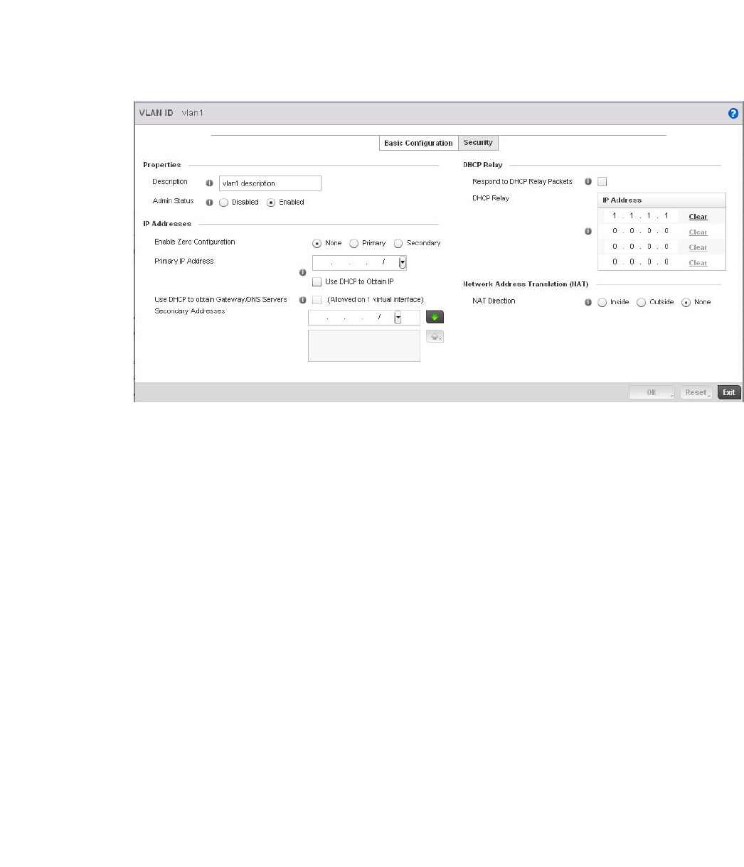
144 Brocade Mobility RFS4000, RFS6000, and RFS7000 System Reference Guide
53-1002620-01
5
FIGURE 117 Profile Overrides - Virtual Interfaces Basic Configuration screen
9. The Basic Configuration screen displays by default regardless of a whether a new Virtual
Interface is being created or an existing one is being modified.
10. If creating a new Virtual Interface, use the VLAN ID spinner control to define a numeric VLAN ID
between 1 - 4094.
11. Define or override the following parameters from within the Properties field:
12. Set or override the following network information from within the IP Addresses field:
Description Provide or edit a description (up to 64 characters) for the Virtual Interface that helps
differentiate it from others with similar configurations.
Admin Status Either select the Disabled or Enabled radio button to define this interface’s current
status within the managed network. When set to Enabled, the Virtual Interface is
operational and available to the controller. The default value is disabled.
Enable Zero
Configuration
Define the IP address for the VLAN associated Virtual Interface.
Primary IP Address Define the IP address for the VLAN associated Virtual Interface.
Use DHCP to Obtain IP Select this option to allow DHCP to provide the IP address for the Virtual Interface.
Selecting this option disables the Primary IP address field.
Use DHCP to obtain
Gateway/DNS Servers
Select this option to allow DHCP to obtain a default gateway address, and DNS resource
for one virtual interface. This setting is disabled by default and only available when the
Use DHCP to Obtain IP option is selected.
Secondary Addresses Use the Secondary Addresses parameter to define additional IP addresses to associate
with VLAN IDs. The address provided in this field is used if the primary IP address is
unreachable.
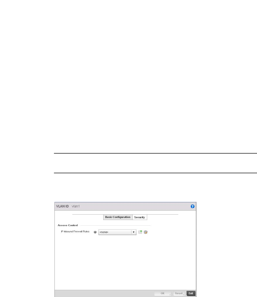
Brocade Mobility RFS4000, RFS6000, and RFS7000 System Reference Guide 145
53-1002620-01
5
13. Refer to the DHCP Relay field to set or override the DHCP relay server configuration used with
the controller Virtual Interface.
14. Define or override the Network Address Translation (NAT) direction.
Select either the Inside, Outside or None radio buttons.
•Inside - The inside network is transmitting data over the network its intended destination.
On the way out, the source IP address is changed in the header and replaced by the
(public) IP address.
•Outside - Packets passing through the NAT on the way back to the managed LAN are
searched against to the records kept by the NAT engine. There the destination IP address
is changed back to the specific internal private class IP address in order to reach the LAN
over the switch managed network.
•None - No NAT activity takes place. This is the default setting.
NOTE
Refer to Setting the Profile’s NAT Configuration on page 7-465 for instructions on creating a profile’s
NAT configuration.
15. Select the OK button to save the changes and overrides to the Basic Configuration screen.
Select Reset to revert to the last saved configuration.
16. Select the Security tab.
FIGURE 118 Profile Overrides - Virtual Interfaces Security screen
Respond to DHCP Relay
Packets
Select the Respond to DHCP Relay Packets option to allow the controller’s onboard
DHCP server to respond to relayed DHCP packets on this interface.
DHCP Relay IP Address Provide IP addresses for DHCP server relay resources.
The interface VLAN and gateway should have their IP addresses set. The interface VLAN
and gateway interface should not have DHCP client or DHCP Server enabled. DHCP
packets cannot be relayed to an onboard DHCP Server. The interface VLAN and gateway
interface cannot be the same.
When changing from a default DHCP address to a fixed IP address, set a static route
first. This is critical when the controller is being accessed from a subnet not directly
connected to the controller and the default route was set from DHCP.

146 Brocade Mobility RFS4000, RFS6000, and RFS7000 System Reference Guide
53-1002620-01
5
17. Use the Inbound IP Firewall Rules drop-down menu to select the firewall rule configuration to
apply to this Virtual Interface.
The firewall inspects and packet traffic to and from connected clients.
If a firewall rule does not exist suiting the data protection needs of this Virtual Interface, select
the Create icon to define a new firewall rule configuration or the Edit icon to modify or override
an existing configuration. For more information, see Wireless Firewall on page 9-511.
18. Use the VPN Crypto Map drop-down menu to select or override the Crypto Map configuration
applied to this Virtual Interface.
Crypto Map entries are sets of configuration parameters for encrypting packets that pass
through the VPN Tunnel. If a Crypto Map configuration does not exist suiting the needs of this
Virtual Interface, select the Create icon to define a new Crypto Map configuration or the Edit
icon to modify an existing configuration. For more information, see Overriding a Profile’s VPN
Configuration on page 5-217.
19. Select the OK button located at the bottom right of the screen to save the changes and
overrides to the Security screen. Select Reset to revert to the last saved configuration.
Port Channel Override Configuration
Profile Interface Override Configuration
Controller profiles can be customized port channel configurations as part of their interface
configuration. Existing port channel profile configurations can be overridden as the become
obsolete for specific device deployments.
To define or override a port channel configuration on a controller profile:
1. Select the Configuration tab from the Web UI.
2. Select Devices from the Configuration tab.
The Device Configuration screen displays a list of managed devices or peer controllers. The
listed devices can either be other controllers or Access Points within the managed network.
3. Select a target device (by double-clicking it) from amongst those displayed within the Device
Configuration screen.
Devices can also be selected directly from the Device Browser in the lower, left-hand, side of
the UI.
4. Select Profile Overrides from the Device menu to expand it into sub menu options.
5. Select Interface to expand its sub menu options.
6. Select Port Channels.
The Port Channels screen displays.
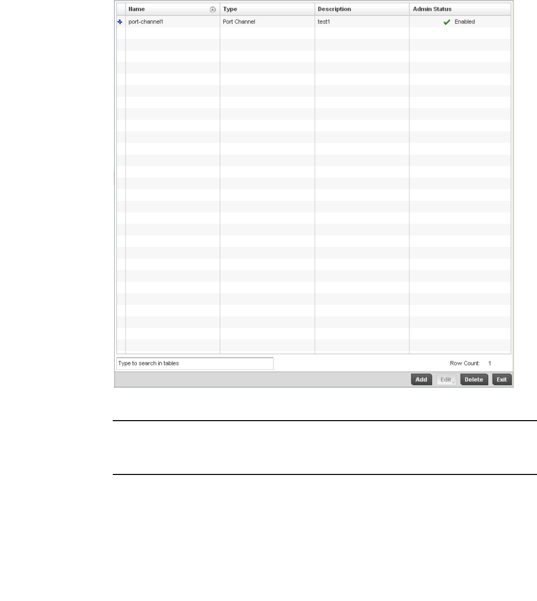
Brocade Mobility RFS4000, RFS6000, and RFS7000 System Reference Guide 147
53-1002620-01
5
FIGURE 119 Profile Overrides - Port Channels screen
NOTE
A blue override icon (to the left of a parameter) defines the parameter as having an override applied.
To remove an override go to the Basic Configuration section of the device and click the Clear
Overrides button. This will remove all overrides from the device.
7. Refer to the following to review existing port channel configurations and status to determine
whether a parameter requires an override:
Name Displays the port channel’s numerical identifier assigned when it was created. The
numerical name cannot be modified as part of the edit process.
Type Displays whether the type is port channel.
Description Lists a a short description (64 characters maximum) describing the port channel or
differentiating it from others with similar configurations.
Admin Status A green checkmark defines the listed port channel as active and currently enabled with
the controller profile. A red “X” defines the port channel as currently disabled and not
available for use. The interface status can be modified with the port channel
configuration as required
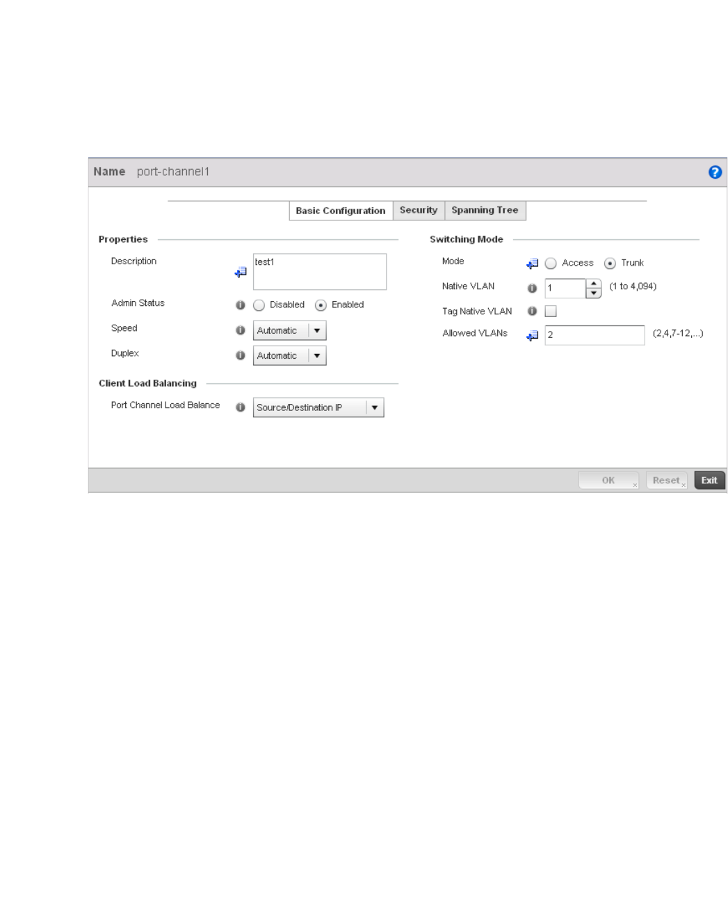
148 Brocade Mobility RFS4000, RFS6000, and RFS7000 System Reference Guide
53-1002620-01
5
8. To edit or override the configuration of an existing port channel, select it from amongst those
displayed and select the Edit button. The port channel Basic Configuration screen displays by
default.
FIGURE 120 Profile Overrides - Port Channels Basic Configuration screen
9. Set or override the following port channel Properties:
10. Use the Port Channel Load Balance drop-down menu from the Client Load Balancing section to
define whether port channel load balancing is conducted using a Source/Destination IP or a
Source/Destination MAC. Source/Destination IP is the default setting.
Description Enter a brief description for the controller port channel (64 characters maximum).
Admin Status Select the Enabled radio button to define this port channel as active to the controller
profile it supports. Select the Disabled radio button to disable this port channel
configuration in the controller profile. It can be activated at any future time when
needed. The default setting is disabled.
Speed Select the speed at which the port channel can receive and transmit data. Select either
10 Mbps, 100 Mbps or 1000 Mbps to establish a 10, 100 or 1000 Mbps data transfer
rate for the selected half duplex or full duplex transmission. These options are not
available if Auto is selected. Select Automatic to allow the port channel to automatically
exchange information about data transmission speeds and duplex capabilities. Auto
negotiation is helpful in an environment where different devices are connected and
disconnected on a regular basis. Automatic is the default setting.
Duplex Select either half, full or automatic as the duplex option. Select Half duplex to send
data over the port channel, then immediately receive data from the same direction in
which the data was transmitted. Like a full-duplex transmission, a half-duplex
transmission can carry data in both directions, just not at the same time. Select Full
duplex to transmit data to and from the port channel at the same time. Using full duplex,
the port channel can send data while receiving data as well. Select Automatic to
enable to the controller to dynamically duplex as port channel performance needs
dictate. Automatic is the default setting.

Brocade Mobility RFS4000, RFS6000, and RFS7000 System Reference Guide 149
53-1002620-01
5
11. Define or override the following Switching Mode parameters to apply to the port channel
configuration:
12. Select OK to save the changes and overrides to the port channel Basic Configuration. Select
Reset to revert to the last saved configuration.
13. Select the Security tab.
Mode Select either the Access or Trunk radio button to set the VLAN switching mode over the
port channel. If Access is selected, the port channel accepts packets only from the
native VLAN. Frames are forwarded untagged with no 802.1Q header. All frames
received on the port are expected as untagged and are mapped to the native VLAN. If
the mode is set to Trunk, the port channel allows packets from a list of VLANs you add to
the trunk. A port channel configured as Trunk supports multiple 802.1Q tagged VLANs
and one Native VLAN which can be tagged or untagged. Access is the default setting.
Native VLAN Use the spinner control to define a numerical Native VLAN ID between
1 - 4094. The native VLAN allows an Ethernet device to associate untagged frames to a
VLAN when no 802.1Q frame is included in the frame. Additionally, the native VLAN is
the VLAN untagged traffic will be directed over when using trunk mode. The default
value is 1.
Tag the Native VLAN Select the checkbox to tag the native VLAN. Controllers support the IEEE 802.1Q
specification for tagging frames and coordinating VLANs between devices. IEEE 802.1Q
adds four bytes to each frame identifying the VLAN ID for upstream devices that the
frame belongs. If the upstream Ethernet device does not support IEEE 802.1Q tagging, it
does not interpret the tagged frames. When VLAN tagging is required between devices,
both devices must support tagging and be configured to accept tagged VLANs. When a
frame is tagged, a 12 bit frame VLAN ID is added to the 802.1Q header, so upstream
Ethernet devices know which VLAN ID the frame belongs to. The device reads the 12 bit
VLAN ID and forwards the frame to the appropriate VLAN. When a frame is received with
no 802.1Q header, the upstream device classifies the frame using the default or native
VLAN assigned to the Trunk port. The native VLAN allows an Ethernet device to associate
untagged frames to a VLAN when no 802.1Q frame is included in the frame. This setting
is disabled by default.
Allowed VLANs Selecting Trunk as the mode enables the Allowed VLANs parameter. Add VLANs that
exclusively send packets over the port channel.
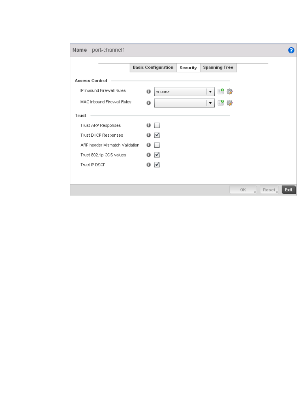
150 Brocade Mobility RFS4000, RFS6000, and RFS7000 System Reference Guide
53-1002620-01
5
FIGURE 121 Profile Overrides - Port Channels Security screen
14. Refer to the Access Control field. As part of the port channel’s security configuration, Inbound
IP and MAC address firewall rules are required.
Use the Inbound IP Firewall Rules and Inbound MAC Firewall Rules drop-down menus to select
or override the firewall rules to apply to this profile’s port channel configuration.
The firewall inspects IP and MAC traffic flows and detects attacks typically not visible to
traditional wired firewall appliances.
If a firewall rule does not exist suiting the data protection needs of the target port channel
configuration, select the Create icon to define a new rule configuration, or the Edit icon to
modify (override) an existing firewall rule configuration. For more information, see Wireless
Firewall on page 9-511.
15. Refer to the Trust section to define or override the following:
Trust ARP Responses Select the check box to enable ARP trust on this port channel. ARP packets received
on this controller port are considered trusted, and information from these packets is
used to identify rogue devices within the managed network. The default value is
disabled.
Trust DHCP Responses Select the check box to enable DHCP trust. If enabled, only DHCP responses are
trusted and forwarded on this port channel, and a DHCP server can be connected
only to a DHCP trusted port. The default value is enabled.
ARP header Mismatch
Validation
Select the check box to enable a mismatch check for the source MAC in both the ARP
and Ethernet header. The default value is enabled.
Trust 802.1p COS values Select the check box to enable 802.1p COS values on this port channel. The default
value is enabled.
Trust IP DSCP Select the check box to enable IP DSCP values on this port channel. The default value
is disabled.
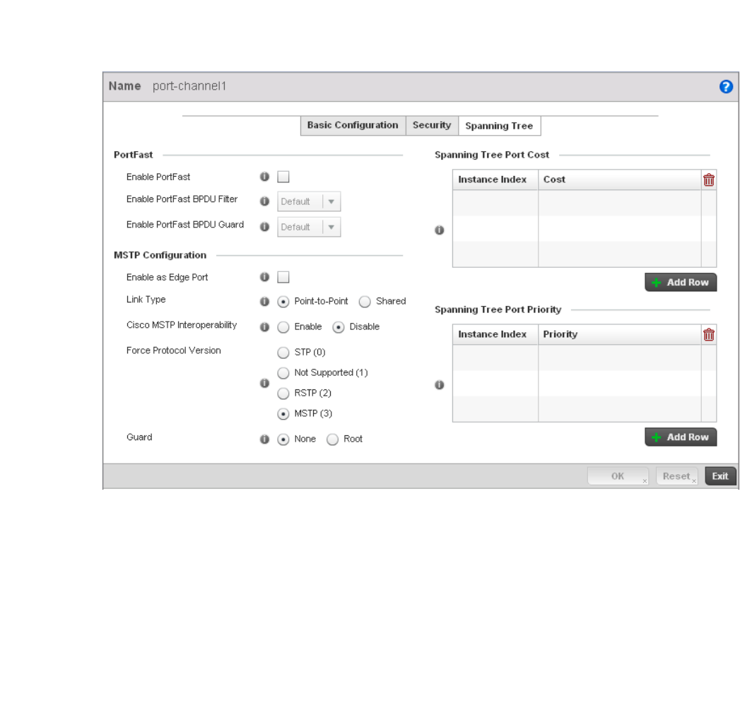
Brocade Mobility RFS4000, RFS6000, and RFS7000 System Reference Guide 151
53-1002620-01
5
16. Select OK to save the changes and overrides to the security configuration. Select Reset to
revert to the last saved configuration.
17. Select the Spanning Tree tab.
FIGURE 122 Profile Overrides - Port Channels Spanning Tree screen
18. Define or override the following PortFast parameters for the port channel’s MSTP
configuration:
Enable PortFast Select the check box to enable drop-down menus for both the Enable Portfast BPDU
Filter and Enable Portfast BPDU guard options for the controller port. This setting is
disabled by default.
PortFast BPDU Filter Select enable to invoke a BPDU filter for this portfast enabled port channel. Enabling the
BPDU filter feature ensures this port channel does not transmit or receive any BPDUs.
The default setting is None.
PortFast BPDU Guard Select enable to invoke a BPDU guard for this portfast enabled port channel. Enabling
the BPDU Guard feature means this port will shutdown on receiving a BPDU. Hence no
BPDUs are processed. The default setting is None.

152 Brocade Mobility RFS4000, RFS6000, and RFS7000 System Reference Guide
53-1002620-01
5
19. Set or override the following MSTP Configuration parameters for the port channel:
20. Refer to the Spanning Tree Port Cost table.
Define or override an Instance Index using the spinner control and then set the Cost. The
default path cost depends on the user defined port speed.The cost helps determine the role of
the port channel in the MSTP network. The designated cost is the cost for a packet to travel
from this port to the root in the MSTP configuration. The slower the media, the higher the cost.
Select + Add Row as needed to include additional indexes.
Refer to the Spanning Tree Port Priority table.
Define or override an Instance Index using the spinner control and then set the Priority. The
lower the priority, a greater likelihood of the port becoming a designated port.
21. Select + Add Row as needed to include additional indexes.
22. Select OK to save the changes and overrides made to the Ethernet Port Spanning Tree
configuration. Select Reset to revert to the last saved configuration.
Enable as Edge Port Select the check box to define this port as an edge port. Using an edge (private) port,
you can isolate devices to prevent connectivity over this port channel. This setting is
disabled by default.
Link Type Select either the Point-to-Point or Shared radio button. Selecting Point-to-Point
indicates the port should be treated as connected to a point-to-point link. Selecting
Shared indicates this port should be treated as having a shared connection. A port
connected to a hub is on a shared link, while one connected to a controller is a
point-to-point link. Point-to-Point is the default setting.
Cisco MSTP
Interoperability
Select either the Enable or Disable radio buttons. This enables interoperability with
Cisco’s version of MSTP, which is incompatible with standard MSTP. This setting is
disabled by default.
Force Protocol Version Sets the protocol version to either STP(0), Not Supported(1), RSTP(2) or MSTP(3).
MSTP is the default setting.
Guard Determines whether the port channel enforces root bridge placement. Setting the
guard to Root ensures the port is a designated port. Typically, each guard root port is
a designated port, unless two or more ports (within the root bridge) are connected
together. If the bridge receives superior (BPDUs) on a guard root-enabled port, the
guard root moves the port to a root-inconsistent STP state. This state is equivalent to
a listening state. No data is forwarded across the port. Thus, the guard root enforces
the root bridge position.
Speed Default Path Cost
<=100000 bits/sec 200000000
<=1000000 bits/sec 20000000
<=10000000 bits/sec 2000000
<=100000000 bits/sec 200000
<=1000000000 bits/sec 20000
<=10000000000 bits/sec 2000
<=100000000000 bits/sec 200
<=1000000000000 bits/sec 20
>1000000000000 bits/sec 2

Brocade Mobility RFS4000, RFS6000, and RFS7000 System Reference Guide 153
53-1002620-01
5
Radio Override Configuration
Profile Interface Override Configuration
Access Points can have their radio profile configurations overridden once their radios have
successfully associated to the managed network.
To define a radio configuration override from the Access Point’s associated controller:
1. Select Devices from the Configuration tab.
The Device Configuration screen displays a list of managed devices or peer controllers. The
listed devices can either be other controllers or Access Points within the managed network.
2. Select a target Access Point (by double-clicking it) from amongst those displayed within the
Device Configuration screen.
Devices can also be selected directly from the Device Browser in the lower, left-hand, side of
the UI.
3. Select Profile Overrides from the Device menu to expand it into sub menu options.
4. Select Interface to expand its sub menu options.
5. Select Radios.
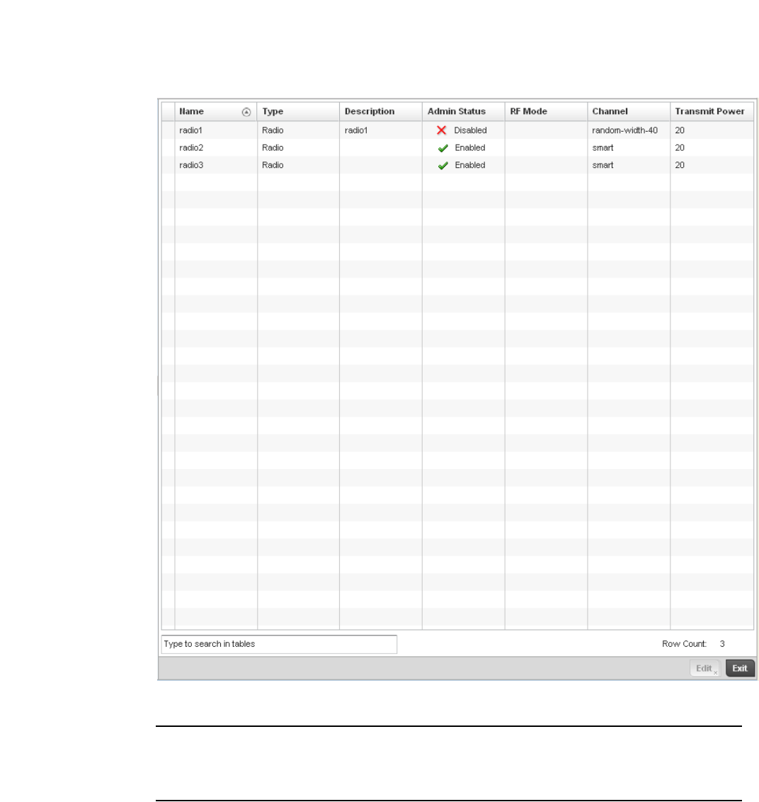
154 Brocade Mobility RFS4000, RFS6000, and RFS7000 System Reference Guide
53-1002620-01
5
FIGURE 123 Profile Overrides - Access Point Radios screen
NOTE
A blue override icon (to the left of a parameter) defines the parameter as having an override applied.
To remove an override go to the Basic Configuration section of the device and click the Clear
Overrides button. This will remove all overrides from the device.

Brocade Mobility RFS4000, RFS6000, and RFS7000 System Reference Guide 155
53-1002620-01
5
6. Review the following radio configuration data to determine whether a radio configuration
requires modification or override to better support the managed network:
7. If required, select a radio configuration and select the Edit button to modify or override
portions of its configuration.
Name Displays whether the reporting radio is the Access Point’s radio1, radio2 or radio3.
Legacy br-7131 models contain either a single or a dual radio configuration. Newer
br-7131N model Access Points support single, dual or triple radio configurations. An
Brocade Mobility 650 Access Point model Access Point is available in either single or
dual radio models.
Type Displays the type of radio housed by each listed Access Point.
Description Displays a brief description of the radio provided by the administrator when the radio’s
configuration was added or modified.
Admin Status A green checkmark defines the listed Virtual Interface configuration as active and
enabled with its supported controller profile. A red “X” defines the Virtual Interface as
currently disabled. The interface status can be modified when a new Virtual Interface is
created or an existing one modified.
RF Mode Displays whether each listed radio is operating in the 802.11a/n or
802.11b/g/n radio band. If the radio is a dedicated sensor, it will be listed as a sensor to
define the radio as not providing typical WLAN support. The radio band is set from within
the Radio Settings tab.
Channel Lists the channel setting for the radio. Smart is the default setting. If set to smart, the
Access Point scans non-overlapping channels listening for beacons from other Access
Points. After the channels are scanned, it selects the channel with the fewest Access
Points. In the case of multiple access points on the same channel, it will select the
channel with the lowest average power level. The column displays smart if set for
dynamic Smart RF support.
Transmit Power Lists the transmit power for each radio displayed as a value in miliwatts.
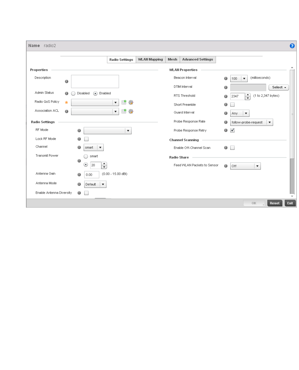
156 Brocade Mobility RFS4000, RFS6000, and RFS7000 System Reference Guide
53-1002620-01
5
FIGURE 124 Profile Overrides - Access Point Radio Settings tab
The Radio Settings tab displays by default.
8. Define or override the following radio configuration parameters from within the Properties field:
Description Provide or edit a description (1 - 64 characters in length) for the radio that helps
differentiate it from others with similar configurations.
Admin Status Either select the Active or Shutdown radio button to define this radio’s current status
within the managed network. When defined as Active, the Access Point is operational
and available for client support within the managed network.
Radio QoS Policy Use the drop-down menu to specify an existing QoS policy to apply to the Access Point
radio in respect to its intended radio traffic. If there’s no existing suiting the radio’s
intended operation, select the Create icon to define a new QoS policy that can be
applied to this controller profile. For more information, see Radio QoS Policy on page
6-332.
Association ACL Use the drop-down menu to specify an existing Association ACL policy to apply to the
Access Point radio. An Association ACL is a policy-based Access Control List (ACL) that
either prevents or allows wireless clients from connecting to a managed Access Point
radio. An ACL is a sequential collection of permit and deny conditions that apply to
controller packets. When a packet is received on an interface, the controller compares
the fields in the packet against any applied ACLs to verify the packet has the required
permissions to be forwarded, based on the criteria specified in the access lists. If a
packet does not meet any of the criteria specified in the ACL, the packet is dropped.
Select the Create icon to define a new Association ACL that can be applied to this
controller profile. For more information, see Association ACL on page 6-352.

Brocade Mobility RFS4000, RFS6000, and RFS7000 System Reference Guide 157
53-1002620-01
5
9. Set or override the following profile Radio Settings for the selected Access Point radio.
RF Mode Set the mode to either 2.4 GHz WLAN or 5 GHz WLAN support depending on the
radio’s intended client support. Set the mode to Sensor if using the radio for rogue
device detection. To a radio as a detector, disable Sensor support on the other Access
Point radio.
Lock RF Mode Select the check box to lock Smart RF for this radio. The default setting is disabled.
Channel Use the drop-down menu to select the channel of operation for the radio. Only a trained
installation professional should define the radio channel. Select Smart for the radio to
scan non-overlapping channels listening for beacons from other Access Points. After
channels are scanned, the radio selects the channel with the fewest Access Points. In
the case of multiple Access Points on the same channel, it selects the channel with the
lowest average power level. The default value is Smart.
Transmit Power Set the transmit power of the selected Access Point radio. If using a dual or three radio
model Access Point, each radio should be configured with a unique transmit power in
respect to its intended client support function. If using Smart RF select the Smart RF
check box to let Smart RF determine the transmit power. A setting of 0 defines the radio
as using Smart RF to determine its output power. 20 dBm is the default value.
Antenna Gain Set the antenna between 0.00 - 15.00 dBm. The access point’s Power Management
Antenna Configuration File (PMACF) automatically configures the access point’s radio
transmit power based on the antenna type, its antenna gain (provided here) and the
deployed country’s regulatory domain restrictions. Once provided, the access point
calculates the power range. Antenna gain relates the intensity of an antenna in a given
direction to the intensity that would be produced ideally by an antenna that radiates
equally in all directions (isotropically), and has no losses. Although the gain of an
antenna is directly related to its directivity, its gain is a measure that takes into account
the efficiency of the antenna as well as its directional capabilities. Brocade
recommends that only a professional installer set the antenna gain. The default value is
0.00.
Antenna Mode Set the number of transmit and receive antennas on the Access Point. 1x1 is used for
transmissions over just the single “A” antenna, 1x3 is used for transmissions over the
“A” antenna and all three antennas for receiving. 2x2 is used for transmissions and
receipts over two antennas for dual antenna models. The default setting is dynamic
based on the Access Point model deployed and its transmit power settings.
Enable Antenna
Diversity
Select this box to enable antenna diversity on supported antennas. Antenna diversity
uses two or more antennas to increase signal quality and strength. This option is
disabled by default.
Wireless Client Power Select this box to specify the transmit power on supported wireless clients. If this is
enabledset a client power level between 0 to 20 dBm. This option is disabled by default.
Dynamic Chain
Selection
Select this box for the radio to dynamically change the number of transmit chains. This
option is enabled by default.

158 Brocade Mobility RFS4000, RFS6000, and RFS7000 System Reference Guide
53-1002620-01
5
10. Set or override the following profile WLAN Properties for the selected Access Point radio:
Rate Use the Select button to set rate options depending on the 802.11 protocols selected. If
the radio band is set to Sensor or Detector, the Data Rates drop-down menu is not
enabled, as the rates are fixed and not user configurable. If 2.4 GHz is selected as the
radio band, select separate 802.11b, 802.11g and 802.11n rates and define how they
are used in combination. If 5 GHz is selected as the radio band, select separate
802.11a and 802.11n rates then define how they are used together. When using
802.11n (in either the 2.4 or 5 GHz band), Set a MCS (modulation and coding scheme)
in respect to the radio’s channel width and guard interval. A MCS defines (based on RF
channel conditions) an optimal combination of 8 data rates, bonded channels, multiple
spatial streams, different guard intervals and modulation types. Clients can associate as
long as they support basic MCS (as well as non-11n basic rates).
Radio Placement Use the drop-down menu to specify whether the radio is located Indoors or Outdoors.
The placement should depend on the country of operation selected and its regulatory
domain requirements for radio emissions.The default setting is Indoors.
Max Clients Use the spinner control to set a maximum permissible number of clients to connect with
this radio. The available range is between 0 - 256 clients. The default value is 256.
Beacon Interval Set the interval between radio beacons in milliseconds (either 50, 100 or 200). A
beacon is a packet broadcast by adopted radios to keep the network synchronized.
Included in a beacon is information such as the WLAN service area, the radio address,
the broadcast destination addresses, a time stamp, and indicators about traffic and
delivery (such as a DTIM). Increase the DTIM/beacon settings (lengthening the time) to
let nodes sleep longer and preserve battery life. Decrease these settings (shortening the
time) to support streaming-multicast audio and video applications that are
jitter-sensitive.The default value is 100 milliseconds.
DTIM Interval BSSID Set a DTIM Interval to specify a period for Delivery Traffic Indication Messages (DTIM). A
DTIM is periodically included in a beacon frame transmitted from adopted radios. The
DTIM indicates broadcast and multicast frames (buffered at the Access Point) are soon
to arrive. These are simple data frames that require no acknowledgement, so nodes
sometimes miss them. Increase the DTIM/ beacon settings (lengthening the time) to let
nodes sleep longer and preserve their battery life. Decrease these settings (shortening
the time) to support streaming multicast audio and video applications that are
jitter-sensitive.
RTS Threshold Specify a Request To Send (RTS) threshold (between 1 - 2,347 bytes) for use by the
WLAN's adopted Access Point radios. RTS is a transmitting station's signal that requests
a Clear To Send (CTS) response from a receiving client. This RTS/CTS procedure clears
the air where clients are contending for transmission time. Benefits include fewer data
collisions and better communication with nodes that are hard to find (or hidden)
because of other active nodes in the transmission path.
Control RTS/CTS by setting an RTS threshold. This setting initiates an RTS/CTS
exchange for data frames larger than the threshold, and sends (without RTS/CTS) any
data frames smaller than the threshold.
Consider the trade-offs when setting an appropriate RTS threshold for the WLAN's
Access Point radios. A lower RTS threshold causes more frequent RTS/CTS exchanges.
This consumes more bandwidth because of additional latency (RTS/CTS exchanges)
before transmissions can commence. A disadvantage is the reduction in data-frame
throughput. An advantage is quicker system recovery from electromagnetic interference
and data collisions. Environments with more wireless traffic and contention for
transmission make the best use of a lower RTS threshold.
A higher RTS threshold minimizes RTS/CTS exchanges, consuming less bandwidth for
data transmissions. A disadvantage is less help to nodes that encounter interference
and collisions. An advantage is faster data-frame throughput. Environments with less
wireless traffic and contention for transmission make the best use of a higher RTS
threshold.

Brocade Mobility RFS4000, RFS6000, and RFS7000 System Reference Guide 159
53-1002620-01
5
11. Select the Enable Off Channel Scan check box in the Channel Scanning section to enable
scanning across all channels using this radio. Channel scans use Access Point resources and
can be time consuming, so only enable when your sure the radio can afford the bandwidth be
directed towards to the channel scan and does not negatively impact client support.
12. Select a mode from the Feed WLAN Packets to Sensor check box in the Radio Share section to
enable this feature. Select either Inline or Promiscuous mode to allow the packets the radio is
switching to also be used by the WIPS analysis module. This feature can be enabled in two
modes: an inline mode where the wips sensor receives the packets from the radios with radio
operating in normal mode. A promiscuous mode where the radio is configured to a mode
where it receives all packets on the channel whether the destination addres is the radio or not,
and the wips module can analyze them.
13. Select the WLAN Mapping tab.
Short Preamble If using an 802.11bg radio, select this checkbox for the radio to transmit using a short
preamble. Short preambles improve throughput. However, some devices (SpectraLink
phones) require long preambles. The default value is disabled.
Guard Interval Use the drop-down menu to specify a Long or Any guard interval. The guard interval is
the space between characters being transmitted. The guard interval eliminates
inter-symbol interference (ISI). ISI occurs when echoes or reflections from one character
interfere with another character. Adding time between transmissions allows echo's and
reflections to settle before the next character is transmitted. A shorter guard interval
results in shorter character times which reduces overhead and increases data rates by
up to 10%.The default value is Long.
Probe Response Rate Use the drop-down menu to specify the data transmission rate used for the transmission
of probe responses. Options include, highest-basic, lowest-basic and
follow-probe-request (default setting).
Probe Response Retry Select the check box to retry probe responses if they are not acknowledged by the target
wireless client. The default value is enabled.
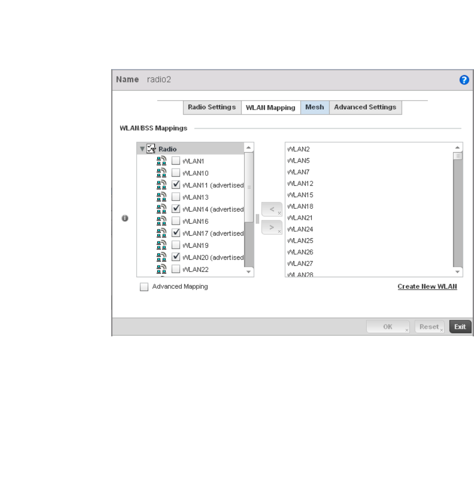
160 Brocade Mobility RFS4000, RFS6000, and RFS7000 System Reference Guide
53-1002620-01
5
FIGURE 125 Profile Overrides - Access Point Radio WLAN Mapping tab
14. Refer to the WLAN/BSS Mappings field to set or override WLAN BSSID assignments for an
existing Access Point deployment.
Administrators can assign each WLAN its own BSSID. If using a single-radio access point, there
are 8 BSSIDs available. If using a dual-radio access point there are 8 BSSIDs for the
802.11b/g/n radio and 8 BSSIDs for the 802.11a/n radio.
15. Select Advanced Mapping to enable WLAN mapping to a specifc BSS ID.
16. Select OK to save the changes and overrides to the WLAN Mapping. Select Reset to revert to
the last saved configuration.
17. Select the MeshConnex tab.
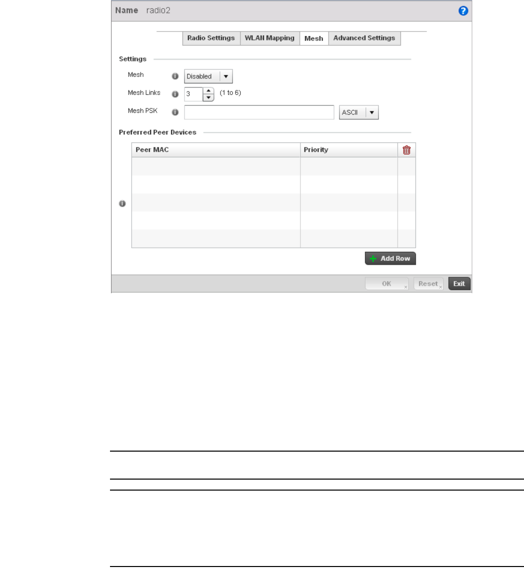
Brocade Mobility RFS4000, RFS6000, and RFS7000 System Reference Guide 161
53-1002620-01
5
FIGURE 126 Profile Overrides - Access Point Radio Mesh tab
18. Refer to the Settings field to define or override basic mesh settings for the Access Point radio.
NOTE
Only single hop mesh links are supported at this time.
NOTE
The mesh encryption key is configurable from the Command Line Interface (CLI) using the command
'mesh psk'. Administrators must ensure that this key is configured on the AP when it is being staged
for mesh, and also added to the mesh client as well as to the portal APs configuration on the
controller. For more information about the CLI please see the Brocade Mobility RFS4000, RFS6000
and RFS7000 CLI Reference Guide.
19. Refer to the Preferred Peer Device table to add mesh peers. For each peer being added enter
its MAC Address and a Priority between 1 and 6. The lower the priority number the higher
priority it'll be given when connecting to mesh infrastructure.
Mesh Use the pulldown to set the mesh mode for this radio. Available options are Disabled,
Portal or Client. Setting the mesh mode to Disabled deactivates all mesh activity on this
radio. Setting the mesh mode to Portal turns the radio into a mesh portal. This will start
the radio beaconing immediately and will accept connections from other mesh nodes.
Setting the mesh mode to client enables the radio to operate as a mesh client that will
scan for and connect to mesh portals or nodes that are connected to portals.
Mesh Links Specify the number of mesh links allowed by the radio. The radio can have between 1-6
mesh links when the radio is configured as a Portal.
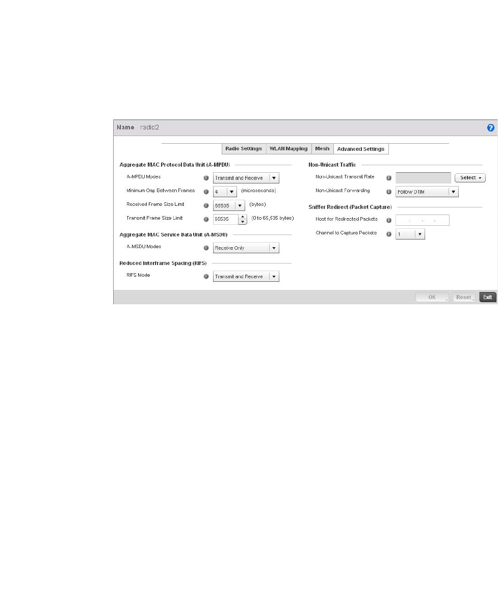
162 Brocade Mobility RFS4000, RFS6000, and RFS7000 System Reference Guide
53-1002620-01
5
20. Select the + Add Row button to add preffered peer devices for the radio to connect to in mesh
mode.
21. Select the Advanced Settings tab.
FIGURE 127 Profile Overrides - Access Point Radio Advanced Settings tab
22. Refer to the Aggregate MAC Protocol Data Unit (A-MPDU) field to define or override how MAC
service frames are aggregated by the Access Point radio.
23. Use the A-MSDU Modes drop-down menu in the Aggregate MAC Service Data Unit (A-MSDU)
section to set or override the supported A-MSDU mode.
Available modes include Receive Only and Transmit and Receive. Transmit and Receive is the
default value. Using Transmit and Receive, frames up to 4 KB can be sent and received. The
buffer limit is not configurable.
24. Define a RIFS Mode using the drop-down menu in the Reduced Interframe Spacing (RIFS)
section. This value determines whether interframe spacing is applied to Access Point
transmissions or received packets, or both or none. The default mode is Transmit and Receive.
Consider setting this value to None for high priority traffic to reduce packet delay.
A-MPDU Modes Use the drop-down menu to define the A-MPDU mode supported. Options include
Transmit Only, Receive Only, Transmit and Receive and None. The default value is
Transmit and Receive. Using the default value, long frames can be both sent and
received (up to 64 KB). When enabled, define either a transmit or receive limit (or both).
Minimum Gap Between
Frames
Use the drop-down menu to define the minimum gap between A-MPDU frames (in
microseconds). The default value is 4 microseconds.
Received Frame Size
Limit
If a support mode is enabled allowing A-MPDU frames to be received, define an
advertised maximum limit for received A-MPDU aggregated frames. Options include
8191, 16383, 32767 or 65535 bytes. The default value is 65535 bytes.
Transmit Frame Size
Limit
Use the spinner control to set limit on transmitted A-MPDU aggregated frames. The
available range is between 0 - 65,535 bytes). The default value is 65535 bytes.

Brocade Mobility RFS4000, RFS6000, and RFS7000 System Reference Guide 163
53-1002620-01
5
25. Set or override the following Non-Unicast Traffic values for the profile’s supported Access Point
radio and its connected wireless clients:
26. Refer to the Sniffer Redirect (Packet Capture) field to define or override the radio’s captured
packet configuration.
27. Select OK to save or override the changes to the Advanced Settings screen. Select Reset to
revert to the last saved configuration.
WAN Backhaul Override Configuration
Profile Interface Override Configuration
A Wireless Wide Area Network (WWAN) card is a specialized network interface card that allows a
network device to connect, transmit and receive data over a Cellular Wide Area Network. The
AP71xx, RFS4000 and RFS6000 all have a PCI Express card slot that supports 3G WWAN cards.
The WWAN card uses point to point protocol (PPP) to connect to the Internet Service Provider (ISP)
and gain access to the Internet. PPP is the protocol used for establishing internet links over dial-up
modems, DSL connections, and many other types of point-to-point communications. PPP packages
your system’s TCP/IP packets and forwards them to the serial device where they can be put on the
network. PPP is a full-duplex protocol that can be used on various physical media, including twisted
pair or fiber optic lines or satellite transmission. It uses a variation of High Speed Data Link Control
(HDLC) for packet encapsulation.
To define a WAN Backhaul configuration override:
1. Select Devices from the Configuration tab.
The Device Configuration screen displays a list of managed devices or peer controllers. The
listed devices can either be other controllers or Access Points within the managed network.
2. Select a target Access Point (by double-clicking it) from amongst those displayed within the
Device Configuration screen.
Devices can also be selected directly from the Device Browser in the lower, left-hand, side of
the UI.
3. Select Profile Overrides from the Device menu to expand it into sub menu options.
4. Select Interface to expand its sub menu options.
5. Select WAN Backhaul.
Non-Unicast Transmit
Rate
Use the Select drop-down menu to launch a sub screen to define the data rate for
broadcast and multicast frame transmissions. Seven different rates are available if the
not using the same rate for each BSSID, each with a separate menu.
Non-Unicast Forwarding Define whether client broadcast and multicast packets should always follow DTIM, or
only follow DTIM when using Power Save Aware mode. The default setting is Follow DTIM.
Host for Redirected
Packets
If packets are re-directed from a controller’s connected Access Point radio, define an IP
address of a resource (additional host system) used to capture the re- directed packets.
This address is the numerical (non DNS) address of the host used to capture the
re-directed packets.
Channel to Capture
Packets
Use the drop-down menu to specify the channel used to capture re-directed packets.
The default value is channel 1.
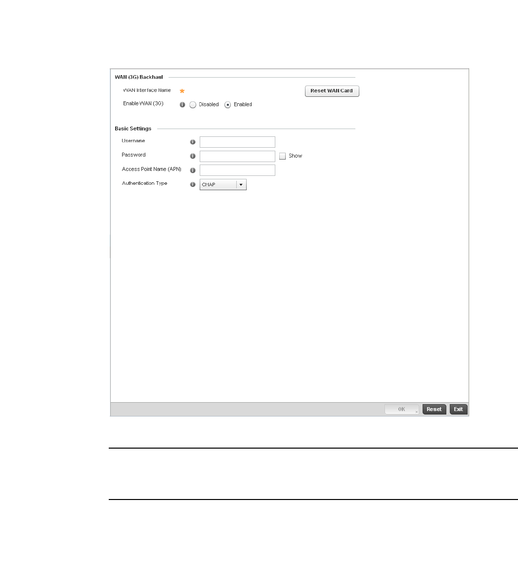
164 Brocade Mobility RFS4000, RFS6000, and RFS7000 System Reference Guide
53-1002620-01
5
FIGURE 128 Profile Overrides -WAN Backhaul screen
NOTE
A blue override icon (to the left of a parameter) defines the parameter as having an override applied.
To remove an override go to the Basic Configuration section of the device and click the Clear
Overrides button. This will remove all overrides from the device.
6. Refer to the WAN (3G) Backhaul configuration to specify WAN card settings:
WAN Interface Name Displays the WAN Interface name for the WAN 3G Backhaul card.
Reset WAN Card If the WAN Card becomes unresponsive or is experiencing other errors click the Reset
WAN Card button to power cycle and reboot the WAN card.
Enable WAN (3G) Check this box to enable 3G WAN card support on the device. A supported 3G card must
be connected to the device for this feature to work.

Brocade Mobility RFS4000, RFS6000, and RFS7000 System Reference Guide 165
53-1002620-01
5
7. Define or override the following authentication parameters from within the Basic Settings field:
8. Select OK to save or override the changes to the Advanced Settings screen. Select Reset to
revert to the last saved configuration.
PPPoE Override Configuration
Profile Interface Override Configuration
PPP over Ethernet (PPPoE) is a data-link protocol for dialup connections. PPPoE allows the access
point to use a broadband modem (DSL, cable modem, etc.) for access to high-speed data and
broadband networks. Most DSL providers are currently supporting (or deploying) the PPPoE
protocol. PPPoE uses standard encryption, authentication, and compression methods as specified
by the PPPoE protocol. PPPoE enables Brocade Mobility supported controllers and access points to
establish a point-to-point connection to an ISP over existing Ethernet interface.
To provide this point-to-point connection, each PPPoE session learns the Ethernet address of a
remote PPPoE client, and establishes a session. PPPoE uses both a discover and session phase to
identify a client and establish a point-to-point connection. By using such a connection, a Wireless
WAN failover is available to maintain seamless network access if the access point’s Wired WAN
were to fail.
NOTE
Devices with PPPoE enabled continue to support VPN, NAT, PBR and 3G failover over the PPPoE
interface. Multiple PPPoE sessions are supported using a single user account user account if
RADIUS is configured to allow simultaneous access.
NOTE
PPPoE is supported on br-7131 models and is not available br-6511 model access points.
When PPPoE client operation is enabled, it discovers an available server and establishes a PPPoE
link for traffic slow. When a wired WAN connection failure is detected, traffic flows through the
WWAN interface in fail-over mode (if the WWAN network is configured and available). When the
PPPoE link becomes accessible again, traffic is redirected back through the access point’s wired
WAN link.
When the access point initiates a PPPoE session, it first performs a discovery to identify the
Ethernet MAC address of the PPPoE client and establish a PPPoE session ID. In discovery, the
PPPoE client discovers a server to host the PPPoE connection.
To create a PPPoE point-to-point configuration
1. Select Devices from the Configuration tab.
Username Provide your username for authentication support by your cellular data carrier.
Password Provide your password for authentication support by your cellular data carrier.
Access Point Name
(APN)
Enter the name of the cellular data provider if necessary. This setting is needed in areas
with multiple cellular data providers using the same protocols such as Europe, the
middle east and Asia.
Authentication Type Use the pull-down menu to specify authentication type used by your cellular data
provider. Supported authentication types are None, PAP, CHAP, MSCHAP, and
MSCHAP-v2.
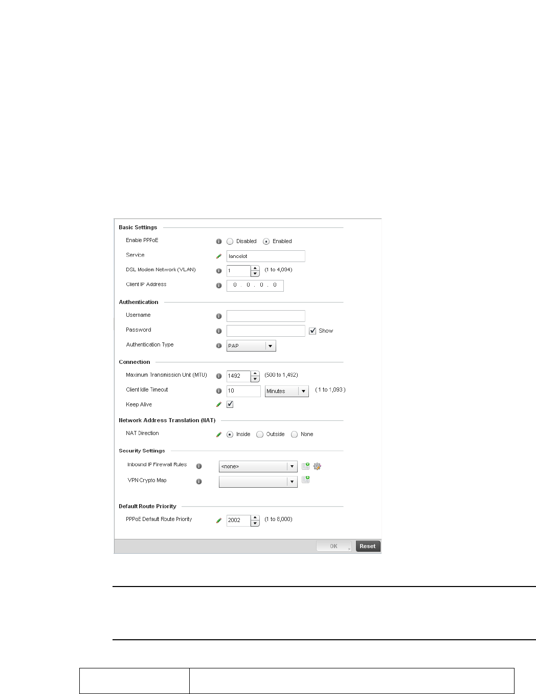
166 Brocade Mobility RFS4000, RFS6000, and RFS7000 System Reference Guide
53-1002620-01
5
The Device Configuration screen displays a list of managed devices or peer controllers. The
listed devices can either be other controllers or Access Points within the managed network.
2. Select a target Access Point (by double-clicking it) from amongst those displayed within the
Device Configuration screen.
3. Devices can also be selected directly from the Device Browser in the lower, left-hand, side of
the UI.
4. Select Profile Overrides from the Device menu to expand it into sub menu options.
5. Select Interface to expand its sub menu options.
6. Select PPPoE.
FIGURE 129 Profile Overrides -PPPoE screen
NOTE
A blue override icon (to the left of a parameter) defines the parameter as having an override applied.
To remove an override go to the Basic Configuration section of the device and click the Clear
Overrides button. This will remove all overrides from the device.
7. Use the Basic Settings field to enable PPPoE and define a PPPoE client
Enable PPPoE Select Enable to support a high speed client mode point-to-point connection using the
PPPoE protocol. The default setting is disabled.

Brocade Mobility RFS4000, RFS6000, and RFS7000 System Reference Guide 167
53-1002620-01
5
8. Define the following Authentication parameters for PPPoE client interoperation:
9. Define the following Connection settings for the PPPoE point-to-point connection with the
PPPoE client:
10. Set the Network Address Translation (NAT) direction for the PPPoE configuration.
Network Address Translation (NAT) converts an IP address in one network to a different IP
address or set of IP addresses in another network. The access point router maps its local
(Inside) network addresses to WAN (Outside) IP addresses, and translates the WAN IP
addresses on incoming packets to local IP addresses. NAT is useful because it allows the
authentication of incoming and outgoing requests, and minimizes the number of WAN IP
addresses needed when a range of local IP addresses is mapped to each WAN IP address. The
default setting is None (neither inside or outside).
11. Define the following Security Settings for the PPPoE configuration:
12. Use the spinner control to set the Default Route Priority for the default route learnt using
PPPoE.
Service Enter the 128 character maximum PPPoE client service name provided by the service
provider.
DSL Modem Network
(VLAN)
Use the spinner control to set the PPPoE VLAN (client local network) connected to the
DSL modem. This is the local network connected to DSL modem. The available range is
1 - 4,094. The default VLAN is VLAN1
Client IP Address Provide the numerical (non hostname) IP address of the PPPoE client.
Username Provide the 64 character maximum username used for authentication support by the
PPPoE client.
Password Provide the 64 character maximum password used for authentication by the PPPoE
client.
Authentication Type Use the drop-down menu to specify authentication type used by the PPPoE client, and
whose credentials must be shared by its peer access point. Supported authentication
options include None, PAP, CHAP, MSCHAP, and MSCHAP-v2.
Maximum Transmission
Unit (MTU)
Set the PPPoE client maximum transmission unit (MTU) from 500 - 1,492. The MTU is
the largest physical packet size in bytes a network can transmit. Any messages larger
than the MTU are divided into smaller packets before being sent. A PPPoE client should
be able to maintain its point-to-point connection for this defined MTU size. The default
MTU is 1,492.
Client Idle Timeout Set a timeout in either Seconds (1 - 65,535), Minutes (1 - 1,093) or Hours. The access
point uses the defined timeout so it does not sit idle waiting for input from the PPPoE
client and server that may never come. The default setting is 10 minutes.
Keep Alive Select this option to ensure the point-to-point connect to the PPPoE client is
continuously maintained and not timed out. This setting is disabled by default.
Inbound IP Firewall
Rules
Use the drop-down menu to select a firewall (set of IP access connection rules) to apply
to the PPPoE client connection. If a firewall rule does not exist suiting the data
protection needs of the PPPoE client connection, select the Create icon to define a
new rule configuration or the Edit icon to modify an existing rule. For more information,
see Wireless Firewall on page 9-511.
VPN Crypto Map Use the drop-down menu to apply an existing crypt map configuration to this PPPoE
interface.

168 Brocade Mobility RFS4000, RFS6000, and RFS7000 System Reference Guide
53-1002620-01
5
Select from 1 - 8,000. The default setting is 2,000.
13. Select OK to save the changes to the PPPoE screen. Select Reset to revert to the last saved
configuration. Saved configurations are persistent across reloads.
Overriding a Profile’s Network Configuration
Setting a profile’s network configuration is a large task comprised of numerous controller
administration activities. Each of the configuration activities described below can have an override
applied to the original profile configuration. Applying an override removes the device from the
profile configuration that may be shared by other devices and requires careful administration to
ensure this one device still supports the deployment requirements within the managed network.
A profile’s network configuration process consists of the following:
•Overriding a Profile’s DNS Configuration
•Overriding a Profile’s ARP Configuration
•Overriding a Profile’s Quality of Service (QoS) Configuration
•Overriding a Profile’ Spanning Tree Configuration
•Overriding a Profile’s Routing Configuration
•Overriding a Profile’s Forwarding Database Configuration
•Overriding a Profile’s Bridge VLAN Configuration
•Overriding a Profile’s Miscellaneous Network Configuration
Overriding a Profile’s DNS Configuration
Overriding a Profile’s Network Configuration
Domain Naming System (DNS) DNS is a hierarchical naming system for resources connected to the
Internet or a private network. Primarily, the controller’s DNS resources translate domain names into
IP addresses. If one DNS server doesn't know how to translate a particular domain name, it asks
another one until the correct IP address is returned. DNS enables access to resources using
human friendly notations. DNS converts human friendly domain names into notations used by
different networking equipment for locating resources.
As a resource is accessed (using human-friendly hostnames), it’s possible to access the resource
even if the underlying machine friendly notation name changes. Without DNS you need to
remember a series of numbers (123.123.123.123) instead of a domain name
(www.domainname.com).
The controller maintains its own DNS facility that can assist in domain name translation. A DNS
assignment can be overridden as needed, but removes the device configuration from the managed
profile that may be shared with other similar device models.
To define the controller’s DNS configuration or apply overrides to an existing configuration:
1. Select Devices from the Configuration tab.
The Device Configuration screen displays a list of managed devices or peer controllers. The
listed devices can either be other controllers or Access Points within the managed network.
2. Select a target device (by double-clicking it) from amongst those displayed within the Device
Configuration screen.
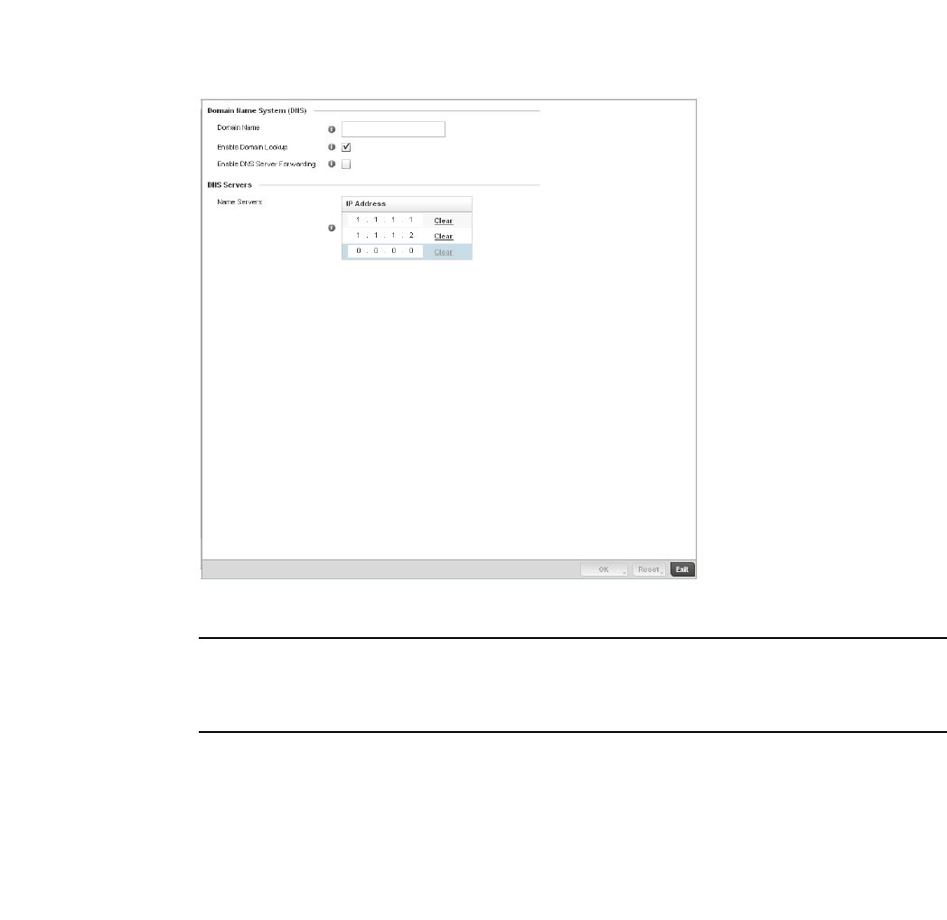
Brocade Mobility RFS4000, RFS6000, and RFS7000 System Reference Guide 169
53-1002620-01
5
Devices can also be selected directly from the Device Browser in the lower, left-hand, side of
the UI.
3. Select Profile Overrides from the Device menu to expand it into sub menu options.
4. Select Network to expand its sub menu options.
5. Select DNS.
FIGURE 130 Profile Overrides - Network DNS screen
NOTE
A blue override icon (to the left of a parameter) defines the parameter as having an override applied.
To remove an override go to the Basic Configuration section of the device and click the Clear
Overrides button. This will remove all overrides from the device.
6. Set or override the following controller Domain Name System (DNS) configuration data:
Domain Name Provide or override the default Domain Name used to resolve DNS names. The name
cannot exceed 64 characters.
Enable Domain Lookup Select the check box to enable DNS on the controller. When enabled, the controller can
convert human friendly domain names into numerical IP destination addresses. The
check box is selected by default.
DNS Server Forwarding Click to enable the forwarding DNS queries to external DNS servers if a DNS query
cannot be processed by the controller’s own DNS resources. This feature is disabled by
default.

170 Brocade Mobility RFS4000, RFS6000, and RFS7000 System Reference Guide
53-1002620-01
5
7. Set or override the following controller DNS Server configuration data:
Select OK to save the changes and overrides made to the DNS configuration. Select Reset to revert
to the last saved configuration.
Overriding a Profile’s ARP Configuration
Overriding a Profile’s Network Configuration
Address Resolution Protocol (ARP) is a protocol for mapping an IP address to a hardware MAC
address recognized on the managed network. ARP provides protocol rules for making this
correlation and providing address conversion in both directions. This ARP assignment can be
overridden as needed, but removes the device configuration from the managed profile that may be
shared with other similar device models.
When an incoming packet destined for a host arrives at the controller, the controller gateway uses
ARP to find a physical host or MAC address that matches the IP address. ARP looks in its ARP
cache and, if it finds the address, provides it so the packet can be converted to the right packet
length and format and sent to the destination. If no entry is found for the IP address, ARP
broadcasts a request packet in a special format to all the machines on the LAN to see if one
machine knows that it has that IP address associated with it. A machine that recognizes the IP
address as its own returns a reply so indicating. ARP updates the ARP cache for future reference
and then sends the packet to the MAC address that replied.
To define an ARP supported configuration on the controller:
1. Select Devices from the Configuration tab.
The Device Configuration screen displays a list of managed devices or peer controllers. The
listed devices can either be other controllers or Access Points within the managed network.
2. Select a target device (by double-clicking it) from amongst those displayed within the Device
Configuration screen.
Devices can also be selected directly from the Device Browser in the lower, left-hand, side of
the UI.
3. Select Profile Overrides from the Device menu to expand it into sub menu options.
4. Select Network to expand its sub menu options.
5. Select ARP.
NOTE
A blue override icon (to the left of a parameter) defines the parameter as having an override applied.
To remove an override go to the Basic Configuration section of the device and click the Clear
Overrides button. This will remove all overrides from the device.
Name Servers Provide a list of up to three DNS servers to forward DNS queries if the controller’s DNS
resources are unavailable. The DNS name servers are used to resolve IP addresses. Use
the Clear link next to each DNS server to clear the DNS name server’s IP address from
the list.
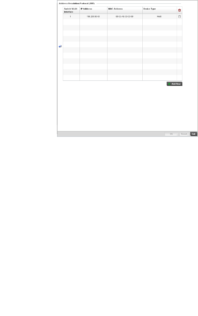
Brocade Mobility RFS4000, RFS6000, and RFS7000 System Reference Guide 171
53-1002620-01
5
FIGURE 131 Profile Overrides - Network ARP screen
6. Set or override the following parameters to define the controller’s ARP configuration:
7. To add additional ARP overrides click on the + Add Row button and enter the configuration
information in the table above.
8. Select the OK button to save the changes and overrides to the ARP configuration. Select Reset
to revert to the last saved configuration.
Overriding a Profile’s L2TPV3 Configuration
Overriding a Profile’s Network Configuration
L2TP V3 is an IETF standard used for transporting different types of layer 2 frames in an IP network
(and access point profile). L2TP V3 defines control and encapsulation protocols for tunneling layer
2 frames between two IP nodes.
Use L2TP V3 to create tunnels for transporting layer 2 frames. L2TP V3 enables Brocade Mobility
supported controllers and access points to create tunnels for transporting Ethernet frames to and
from bridge VLANs and physical ports. L2TP V3 tunnels can be defined between Brocade Mobility
devices and other vendor devices supporting the L2TP V3 protocol.
Switch VLAN Interface Use the spinner control to select a switch VLAN interface for an address requiring
resolution.
IP Address Define the IP address used to fetch a MAC Address.
MAC Address Displays the target MAC address that’s subject to resolution. This is the MAC used for
mapping an IP address to a MAC address that’s recognized on the managed network.
Device Type Specify the device type the ARP entry supports. Host is the default setting.

172 Brocade Mobility RFS4000, RFS6000, and RFS7000 System Reference Guide
53-1002620-01
5
Multiple pseudowires can be created within an L2TP V3 tunnel. Brocade Mobility supported access
points support an Ethernet VLAN pseudowire type exclusively.
NOTE
A pseudowire is an emulation of a layer 2 point-to-point connection over a packet-switching network
(PSN). A pseudowire was developed out of the necessity to encapsulate and tunnel layer 2 protocols
across a layer 3 network.
Ethernet VLAN pseudowires transport Ethernet frames to and from a specified VLAN. One or more
L2TP V3 tunnels can be defined between tunnel end points. Each tunnel can have one or more
L2TP V3 sessions. Each tunnel session corresponds to one pseudowire. An L2TP V3 control
connection (a L2TP V3 tunnel) needs to be established between the tunneling entities before
creating a session.
For optimal pseudowire operation, both the L2TP V3 session originator and responder need to
know the psuedowire type and identifier. These two parameters are communicated during L2TP V3
session establishment. An L2TP V3 session created within an L2TP V3 connection also specifies
multiplexing parameters for identifying a pseudowire type and ID.
The working status of a pseudowire is reflected by the state of the L2TP V3 session. If a L2TP V3
session is down, the pseudowire associated with it must be shut down. The L2TP V3 control
connection keep-alive mechanism can serve as a monitoring mechanism for the pseudowires
associated with a control connection.
NOTE
If connecting an Ethernet port to another Ethernet port, the pseudowire type must be Ethernet port,
if connecting an Ethernet VLAN to another Ethernet VLAN, the pseudowire type must be Ethernet
VLAN.
To define an L2TPV3 configuration for an access point profile:
1. Select Devices from the Configuration tab.
The Device Configuration screen displays a list of managed devices or peer controllers. The
listed devices can either be other controllers or Access Points within the managed network.
2. Select a target device (by double-clicking it) from amongst those displayed within the Device
Configuration screen.
Devices can also be selected directly from the Device Browser in the lower, left-hand, side of
the UI.
3. Select Profile Overrides from the Device menu to expand it into sub menu options.
4. Expand the Network menu and select L2TPv3.
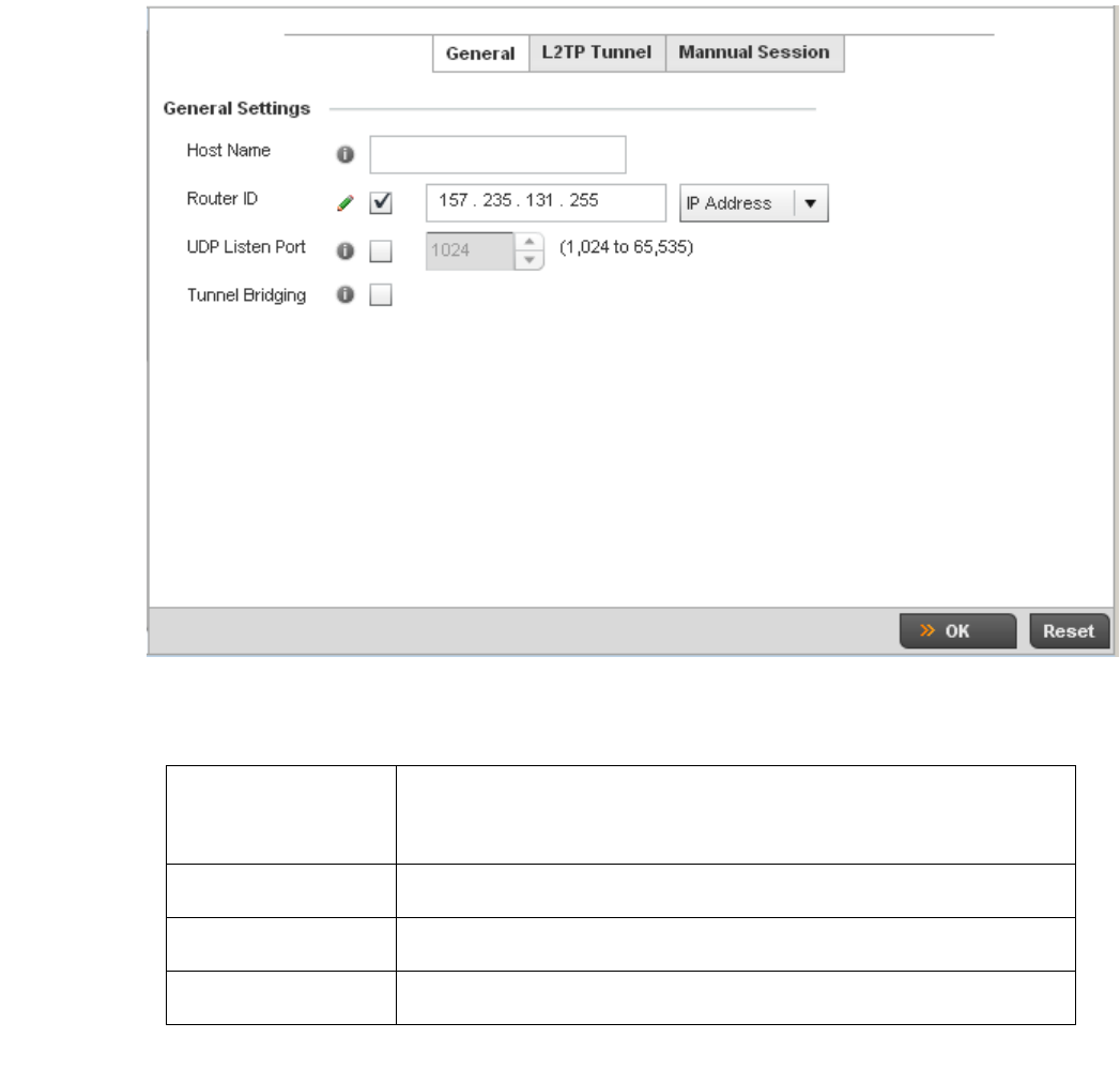
Brocade Mobility RFS4000, RFS6000, and RFS7000 System Reference Guide 173
53-1002620-01
5
FIGURE 132 Network - L2TPv3 screen, General tab
5. Set the following General Settings for an L2TPv3 profile configuration:
6. Select the L2TP Tunnel tab.
Host Name Define a 64 character maximum host name to specify the name of the host that’s sent
tunnel messages. Tunnel establishment involves exchanging 3 message types (SCCRQ,
SCCRP and SCCN) with the peer. Tunnel IDs and capabilities are exchanged during the
tunnel establishment with the host.
Router ID Set either the numeric IP address or the integer used as an identifier for tunnel AVP
messages. AVP messages assist in the identification of a tunnelled peer.
UDP Listen Port Select this option to set the port used for listening to incoming traffic. Select a port in
the range of 1,024 - 65,353.
Device Type Select this option to enable or disable bridge packets between two tunnel end points.
This setting is disabled by default.
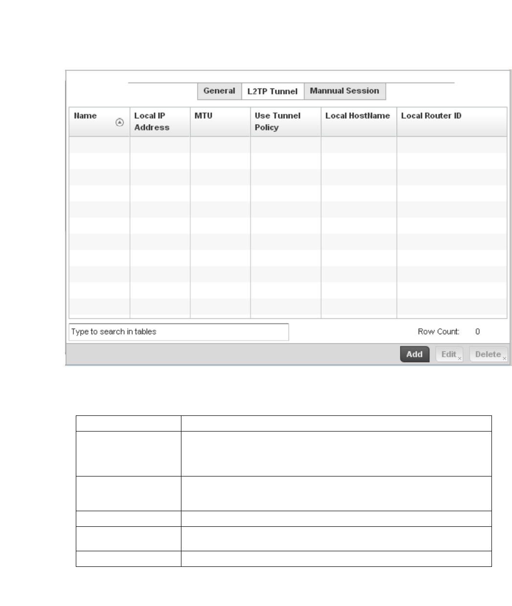
174 Brocade Mobility RFS4000, RFS6000, and RFS7000 System Reference Guide
53-1002620-01
5
FIGURE 133 Network - L2TPv3 screen, T2TP tunnel tab
7. Review the following L2TPv3 tunnel configuration data:
8. Either select Add to create a new L2TPv3 tunnel configuration, Edit to modify an existing tunnel
configuration or Delete to remove a tunnel from those available to this profile.
Name Displays the name of each listed L2TPv3 tunnel assigned upon creation.
Local IP Address Lists the IP address assigned as the local tunnel end point address, not the interface IP
address. This IP is used as the tunnel source IP address. If this parameter is not
specified, the source IP address is chosen automatically based on the tunnel peer IP
address.
MTU Displays the maximum transmission unit (MTU) size for each listed tunnel. The MTU is
the size (in bytes) of the largest protocol data unit that the layer can pass between
tunnel peers.
Use Tunnel Policy Lists the L2TPv3 tunnel policy assigned to each listed tunnel.
Local Hostname Lists the tunnel specific hostname used by each listed tunnel. This is the host name
advertised in tunnel establishment messages.
Local Router ID Specifies the router ID sent in the tunnel establishment messages.
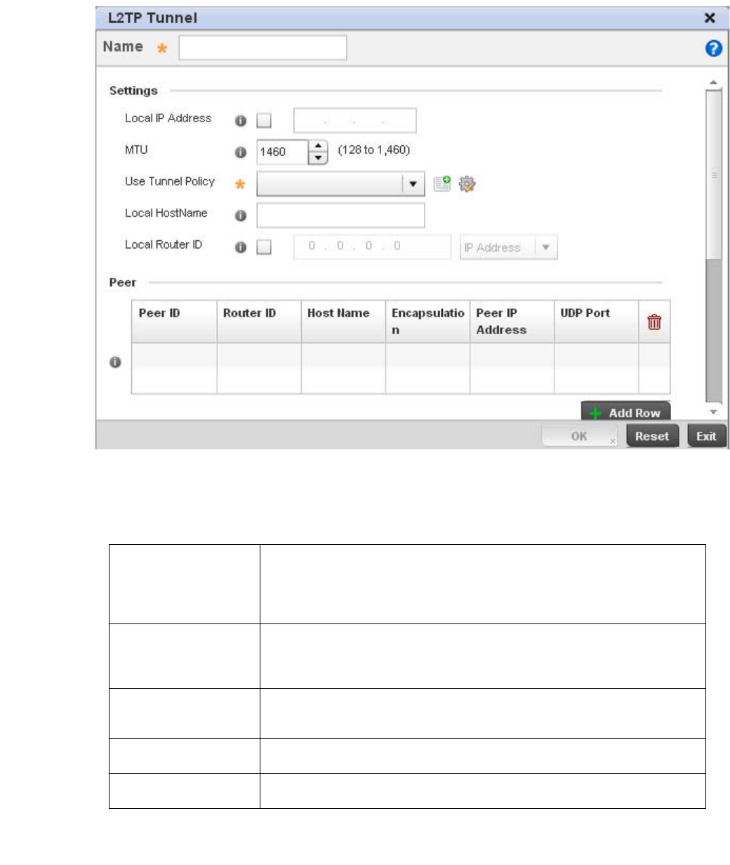
Brocade Mobility RFS4000, RFS6000, and RFS7000 System Reference Guide 175
53-1002620-01
5
FIGURE 134 Network - L2TPv3 screen, Add T2TP Tunnel Configuration
9. If creating a new tunnel configuration, assign it a 31 character maximum Name.
10. Define the following Settings required for the L2TP tunnel configuration:
11. Refer to the Peer table to review the configurations of the peers available for tunnel
connection.
Local IP Address Enter the IP address assigned as the local tunnel end point address, not the interface IP
address. This IP is used as the tunnel source IP address. If this parameter is not
specified, the source IP address is chosen automatically based on the tunnel peer IP
address. This parameter is applicable when establishing the tunnel and responding to
incoming tunnel create requests.
MTU Set the maximum transmission unit (MTU). The MTU is the size (in bytes) of the largest
protocol data unit the layer can pass between tunnel peers. Define a MTU between 128
- 1,460 bytes. The default setting is 1,460. A larger MTU means processing fewer
packets for the same amount of data.
Use Tunnel Policy Select the L2TPv3 tunnel policy. The policy consists of user defined values for protocol
specific parameters which can be used with different tunnels. If none is available a new
policy can be created or an existing one can be modified.
Local Hostname Provide the tunnel specific hostname used by this tunnel. This is the host name
advertised in tunnel establishment messages.
Local Router ID Specify the router ID sent in tunnel establishment messages with a potential peer
device.
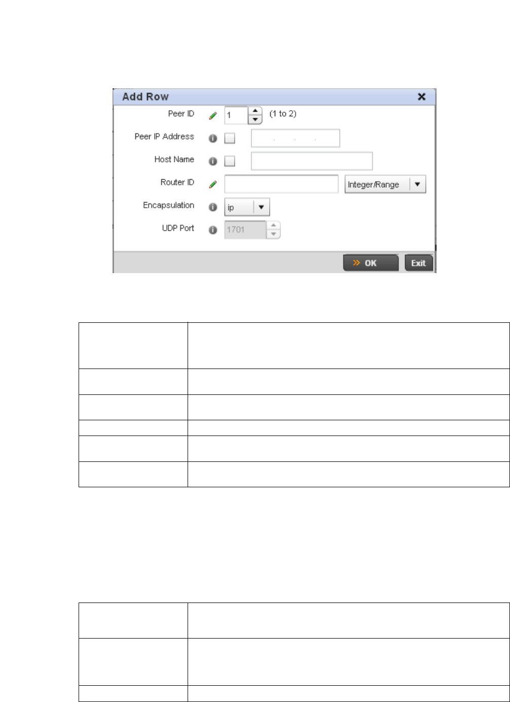
176 Brocade Mobility RFS4000, RFS6000, and RFS7000 System Reference Guide
53-1002620-01
5
Select + Add Row to populate the table with a maximum of two peer configurations.
FIGURE 135 Network - L2TPv3 screen, Add T2TP Peer Configuration
12. Define the following Peer parameters:
13. Select OK to save the peer configuration.
14. Refer to the Session table to review the configurations of the peers available for tunnel
connection.
15. Select + Add Row to populate the table with configurable session parameters for this tunnel
configuration.
16. Define the following Session parameters:
Peer ID Define the primary peer ID used to set the primary and secondary peer for tunnel
failover. If the peer is not specified, tunnel establishment does not occur. However, if a
peer tries to establish a tunnel with this access point, it creates the tunnel if the
hostname and/or Router ID matches.
Peer IP Address Select this option to enter the numeric IP address used as the tunnel destination peer
address for tunnel establishment.
Host Name Assign the peer a hostname that can be used as matching criteria in the tunnel
establishment process.
Router ID Specify the router ID sent in tunnel establishment messages with this specific peer.
Encapsulation Select either IP or UDP as the peer encapsulation protocol. The default setting is IP. UDP
uses a simple transmission model without implicit handshakes.
UDP Port If UDP encapsulation is selected, use the spinner control to define the UDP
encapsulation port.
Name Enter a 31 character maximum session name. There is no idle timeout for a tunnel. A
tunnel is not usable without a session and a subsequent session name.The tunnel is
closed when the last session tunnel session is closed.
Pseudowire ID Define a psuedowire ID for this session. A pseudowire is an emulation of a layer 2
point-to-point connection over a packet-switching network (PSN). A pseudowire was
developed out of the necessity to encapsulate and tunnel layer 2 protocols across a
layer 3 network.
Traffic Source Type Lists the type of traffic tunnelled in this session.
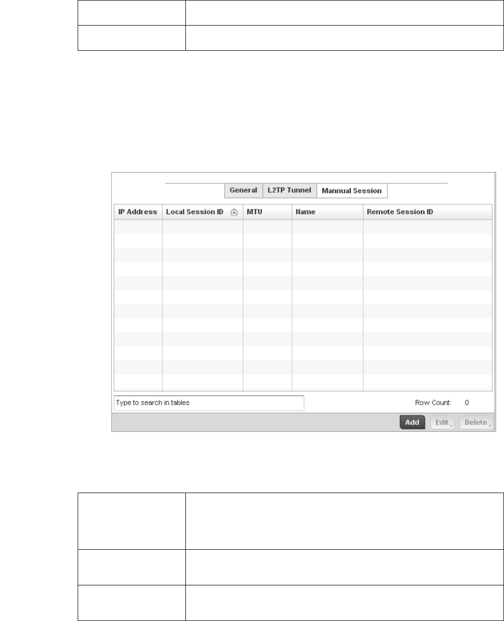
Brocade Mobility RFS4000, RFS6000, and RFS7000 System Reference Guide 177
53-1002620-01
5
17. Select OK to save the changes within the T2TP Tunnel screen. Select Reset to revert the screen
to its last saved configuration.
18. Select the Manual Session tab.
After a successful tunnel connection and establishment, individual sessions can be created.
Each session is a single data stream. After successful session establishment, data
corresponding to that session (pseudowire) can be transferred. If a session is down, the
pseudowire associated with it is shut down as well.
FIGURE 136 Network - L2TPv3 screen, Manual Session tab
19. Refer to the following manual session configurations to determine whether one should be
created or modified:
Traffic Source Value Define a VLAN range to include in the tunnel session. Available VLAN ranges are from 1
- 4,094.
Native VLAN Select this option to provide a VLAN ID that will not be tagged in tunnel establishment
and packet transfer.
IP Address Lists the IP address assigned as the local tunnel end point address, not the interface IP
address. This IP is used as the tunnel source IP address. If this parameter is not
specified, the source IP address is chosen automatically based on the tunnel peer IP
address. This parameter is applicable when establishing the session and responding to
incoming requests.
Local Session ID Displays the numeric identifier assigned to each listed tunnel session. This is the
pseudowire ID for the session. This pseudowire ID is sent in a session establishment
message to the L2TP peer.
MTU Displays each sessions’s maximum transmission unit (MTU). The MTU is the size (in
bytes) of the largest protocol data unit the layer can pass between tunnel peers in this
session. A larger MTU means processing fewer packets for the same amount of data.
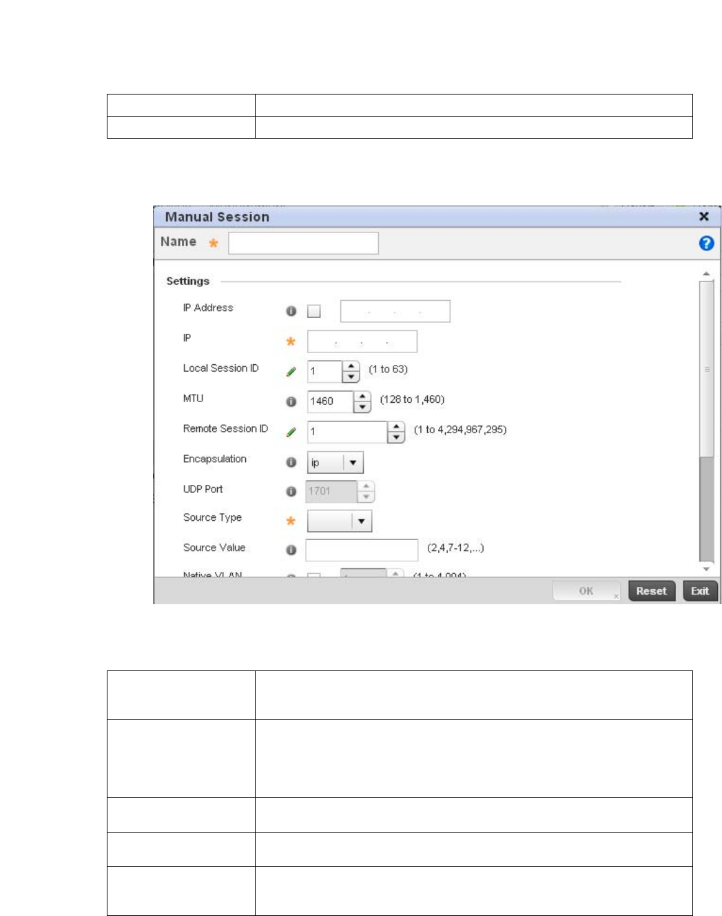
178 Brocade Mobility RFS4000, RFS6000, and RFS7000 System Reference Guide
53-1002620-01
5
20. Select Add to create a new manual session, Edit to modify an existing session configuration or
Delete to remove a selected manual session.
FIGURE 137 Network - L2TPv3 screen, Add T2TP Peer Configuration
21. Set the following session parameters:
Name Lists the name assigned to each listed manual session.
Remote Session ID Lists the remote session ID passed in the establishment of the tunnel session.
Name Define a 31 character maximum name of this tunnel session. After a successful tunnel
connection and establishment, the session is created. Each session name represents a
single data stream.
IP Address Specify the IP address used to be as tunnel source ip address. If not specified, the
tunnel source IP address is selected automatically based on the tunnel peer IP address.
This address is applicable only for initiating the tunnel. When responding to incoming
tunnel create requests, it would use the IP address on which it had received the tunnel
create request.
IP Set the IP address of an L2TP tunnel peer. This is the peer allowed to establish the
tunnel.
Local Session ID Set the numeric identifier for the tunnel session. This is the pseudowire ID for the
session. This pseudowire ID is sent in session establishment message to the L2TP peer.
MTU Define the session maximum transmission unit (MTU) as the size (in bytes) of the
largest protocol data unit the layer can pass between tunnel peers in this session. A
larger MTU means processing fewer packets for the same amount of data.

Brocade Mobility RFS4000, RFS6000, and RFS7000 System Reference Guide 179
53-1002620-01
5
22. Select the + Add Row button to set the following:
23. Select OK to save the changes to the session configuration. Select Reset to revert to the last
saved configuration.
Overriding a Profile’s Quality of Service (QoS) Configuration
Overriding a Profile’s Network Configuration
The controller uses different Quality of Service (QoS) screens to define WLAN and device radio QoS
configurations for controller profiles.
QoS values are required to provide priority of service to some packets over others. For example,
VoIP packets get higher priority than data packets to provide a better quality of service for high
priority voice traffic.
The profile QoS screen maps the 6-bit Differentiated Service Code Point (DSCP) code points to the
older
3-bit IP Precedent field located in the Type of Service byte of an IP header. DSCP is a protocol for
specifying and controlling network traffic by class so that certain traffic types get precedence.
DSCP specifies a specific per-hop behavior that is applied to a packet. This QoS assignment can be
overridden as needed, but removes the device configuration from the managed profile that may be
shared with other similar device models.
To define an QoS configuration for controller DSCP mappings:
1. Select Devices from the Configuration tab.
The Device Configuration screen displays a list of managed devices or peer controllers. The listed
devices can either be other controllers or Access Points within the managed network.
2. Select a target device (by double-clicking it) from amongst those displayed within the Device
Configuration screen.
Devices can also be selected directly from the Device Browser in the lower, left-hand, side of
the UI.
Remote Session ID Use the spinner control to set the remote session ID passed in the establishment of the
tunnel session. Assign an ID in the range of
1 - 4,294,967,295.
Encapsulation Select either IP or UDP as the peer encapsulation protocol. The default setting is IP. UDP
uses a simple transmission model without implicit handshakes.
UDP Port If UDP encapsulation is selected, use the spinner control to define the UDP
encapsulation port. This is the port where the L2TP service is running.
Source VLAN Define the VLAN range (1 - 4,094) to include in the tunnel. Tunnel session data includes
VLAN tagged frames.
Native VLAN Select this option to define the native VLAN that will not be tagged.
Cookie Size Set the size of the cookie field within each L2TP data packet. Options include 0, 4 and
8. The default setting is 0.
Value 1 Set the cookie value first word.
Value 2 Set the cookie value second word.
End Point Define whether the tunnel end point is local or remote.
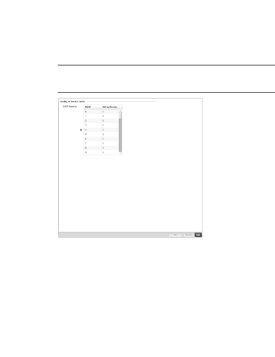
180 Brocade Mobility RFS4000, RFS6000, and RFS7000 System Reference Guide
53-1002620-01
5
3. Select Profile Overrides from the Device menu to expand it into sub menu options.
4. Select Network to expand its sub menu options.
5. Select Quality of Service.
NOTE
A blue override icon (to the left of a parameter) defines the parameter as having an override applied.
To remove an override go to the Basic Configuration section of the device and click the Clear
Overrides button. This will remove all overrides from the device.
FIGURE 138 Profile Overrides - Network QoS screen
6. Set or override the following parameters for IP DSCP mappings for untagged frames:
7. Use the spinner controls within the 802.1p Priority field for each DSCP row to change or
override the priority value.
DSCP Lists the DSCP value as a 6-bit parameter in the header of every IP packet used for
packet classification.
802.1p Priority Assign a 802.1p priority as a 3-bit IP precedence value in the Type of Service field of the
IP header used to set the priority. The valid values for this field are 0-7. Up to 64 entries
are permitted. The priority values are:
0 – Best Effort
1 – Background
2 – Spare
3 – Excellent Effort
4 – Controlled Load
5 – Video
6 – Voice
7 – Network Control

Brocade Mobility RFS4000, RFS6000, and RFS7000 System Reference Guide 181
53-1002620-01
5
8. Select the OK button located to save the changes and overrides. Select Reset to revert to the
last saved configuration.
Overriding a Profile’ Spanning Tree Configuration
Overriding a Profile’s Network Configuration
Spanning Tree is a network layer protocol that ensures a loop-free topology in a mesh network of
inter-connected layer 2 controllers. The spanning tree protocol disables redundant connections and
uses the least costly path to maintain a connection between any two controllers in the network.
Spanning tree protocol allows a network design that has one or more redundant links that provide
a backup path if an active link fails. This switchover is automatic and does not require any human
intervention.
Physical layer redundancy may also be provided using spanning tree. Spanning tree is a link
management protocol that is part of the IEEE 802.1 standard for media access control bridges.
Using the Dikstra algorithm, STP provides link path redundancy between Ethernet devices while
preventing undesirable loops in a network that can be created when multiple active paths exist
between Ethernet controllers and bridges.
To establish path redundancy, STP creates a tree that spans all of the controllers in an extended
network, forcing redundant paths into a blocked, state. STP allows only one active path at a time
between any two network devices but establishes the redundant links as a backup if the preferred
link should fail. If STP costs change, or if one network segment in the STP becomes unreachable,
the spanning tree algorithm reconfigures the spanning tree topology and re-establishes the link by
activating the standby path. Without spanning tree, multiple paths in the Ethernet network would
be active resulting in an endless loop of traffic on the LAN.
Spanning Tree can be used to provide link path redundancy when controllers are connected to one
or more external Ethernet switches. Spanning Tree can only support one active path per VLAN
between Ethernet devices. If multiple paths per VLAN exist, redundant paths are blocked.
Multiple Spanning Tree Protocol (MSTP) is a VLAN-aware protocol and algorithm to create and
maintain a loop-free network. It allows the configuration of multiple spanning tree instances. This
ensures a loop-free topology for one or more VLANs. It allows the network administrator to provide
a different path for each group of VLANs to better utilize redundancy.
Using MSTP, the network can be divided into regions. Each controller within a region uses the same
VLAN to instance mapping. The entire network runs a spanning tree instance called the Common
Spanning Tree instance (CST) that interconnects regions as well as legacy (STP and RSTP) bridges.
The regions run on a local instance for each configured MSTP instance.
This Spanning Tree assignment can be overridden as needed, but removes the device
configuration from the managed profile that may be shared with other similar device models.
To define or override a profile’s spanning tree configuration:
1. Select Devices from the Configuration tab.
The Device Configuration screen displays a list of managed devices or peer controllers. The
listed devices can either be other controllers or Access Points within the managed network.
2. Select a target device (by double-clicking it) from amongst those displayed within the Device
Configuration screen.
3. Devices can also be selected directly from the Device Browser in the lower, left-hand, side of
the UI.
4. Select Profile Overrides from the Device menu to expand it into sub menu options.
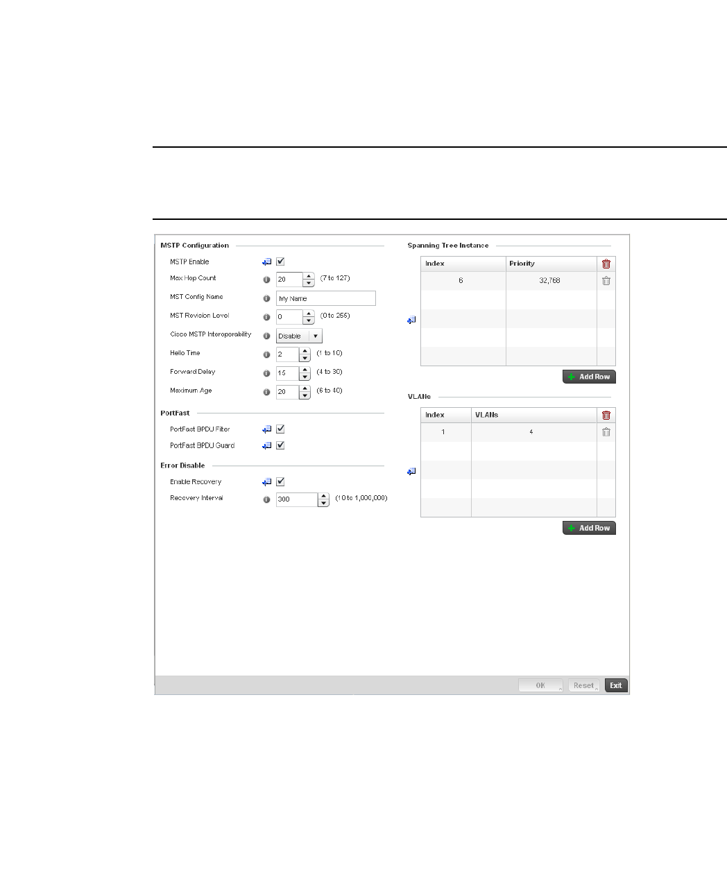
182 Brocade Mobility RFS4000, RFS6000, and RFS7000 System Reference Guide
53-1002620-01
5
5. Select Network to expand its sub menu options.
6. Select Spanning Tree.
NOTE
A blue override icon (to the left of a parameter) defines the parameter as having an override applied.
To remove an override go to the Basic Configuration section of the device and click the Clear
Overrides button. This will remove all overrides from the device.
FIGURE 139 Profile Overrides - Network Spanning Tree screen
7. Set or override the following MSTP Configuration parameters:
MSTP Enable Enables the Multiple Spanning Tree Protocol (MSTP) feature. Select the check box to
enable spanning tree for this device. This feature is disabled by default.
Max. Hop Count Set the maximum number of hops used when creating a Spanning Tree. This value
represents the maximum allowed hops for a BPDU (Bridge Protocol Data Unit) in an
MSTP region. This value is used by all the MSTP instances. Enter a value between 7 -
127, or use the spinner control to set the value. The default setting is 20.
MST Config Name Enter a name for the MST region. This is used when configuring multiple regions within
the network. Each controller running MSTP is configured with a unique MST region
name. This helps when keeping track of MSTP configuration changes. The name cannot
exceed 64 characters.

Brocade Mobility RFS4000, RFS6000, and RFS7000 System Reference Guide 183
53-1002620-01
5
8. Define or override the following PortFast configuration parameters:
9. Set or override the following Error Disable recovery parameters:
10. Set or override the Spanning Tree Instance configuration.
Define a numerical index for each instance to assign each a unique priority. The Priority is
assigned to an individual bridge based on whether it is selected as the root bridge. The lower
the priority, the greater likelihood the bridge becoming the root for this instance.
11. Use the + Add Row button to create a new row in the table. To delete a row, select the row’s
delete icon.
12. Refer to the VLANs table to associate a VLAN ID with the Instance index. You can add multiple
VLANs to an instance.
MST Revision Level Assign a MST revision level (0 - 255) to the MSTP region to which the device belongs.
Each controller is configured with a unique MSTP name and revision number. This helps
when keeping track of MSTP configuration changes. Increment this number with each
configuration change. The revision level specifies the revision level of the current
configuration. The default setting
is 0.
Cisco MSTP
Interoperability
Select Enable or Disable from the drop-down menu. This enables interoperability with
Cisco’s version of MSTP, which is incompatible with standard MSTP. The default setting
is disabled.
Hello Time The hello time is the time interval (in seconds) the device waits between BPDU
transmissions. A low value leads to excessive traffic on the network, whereas a higher
value delays the detection of a topology change. Set a hello time between 1 - 10
seconds. You can also use the spinner control next to the text-box to increase or
decrease the value. The default setting is 2.
Forward Delay The forward delay is the maximum time (in seconds) the root device waits before
changing states (from a listening state to a learning state to a forwarding state). Set a
value between 4 -30. You can also use the spinner control next to the text-box to
increase or decrease the value. The default is 15.
Maximum Age The max-age is the maximum time (in seconds) for which, if a bridge is the root bridge, a
message is considered valid. This prevents frames from looping indefinitely. The
max-age should be greater than twice the value of hello time plus one, but less than
twice the value of forward delay minus one. Configure this value sufficiently high, so a
frame generated by root can be propagated to the leaf nodes without exceeding the max
age. Set the value between 6 - 40. You can also use the spinner control next to the
text-box to increase or decrease the value. The default setting is 20.
PortFast BPDU Filter Select the check box to enable BPDU filter for all portfast enabled ports.The Spanning
Tree Protocol sends BPDUs from all the ports. Enabling the BPDU filter ensures PortFast
enabled ports do not transmit or receive BPDUs.
PortFast BPDU Guard Select the check box to enable BPDU guard for all portfast enabled ports. When the
BPDU Guard feature is set for bridge, all portfast-enabled ports that have BPDU set to
default shutdown the port upon receiving a BPDU. Thus no BPDUs are processed.
Enable Recovery Select this check box to enable an error disable timeout caused by a BPDU guard. This
option is disabled by default.
Recovery Interval Define an interval (between 10 - 1,000,000) after which a recovering port is enabled.
The default recovery interval is 300.

184 Brocade Mobility RFS4000, RFS6000, and RFS7000 System Reference Guide
53-1002620-01
5
Use the + Add Row button to create a new row in the table. To delete a row, select the row’s
delete icon.
13. Select OK to save or override the changes. Select Reset to revert to the last saved
configuration.
Overriding a Profile’s Routing Configuration
Overriding a Profile’s Network Configuration
Routing is the process of selecting IP paths in a network to send access point managed network
traffic. Use the Routing screen to set Destination IP and Gateway addresses enabling assignment
of static IP addresses for requesting clients without creating numerous host pools with manual
bindings. This eliminates the need for a long configuration file and reduces the resource space
required to maintain address pools.
To create or override a profile’s static routes:
1. Select Devices from the Configuration tab.
The Device Configuration screen displays a list of managed devices or peer controllers. The
listed devices can either be other controllers or Access Points within the managed network.
2. Select a target device (by double-clicking it) from amongst those displayed within the Device
Configuration screen.
Devices can also be selected directly from the Device Browser in the lower, left-hand, side of
the UI.
3. Select Profile Overrides from the Device menu to expand it into sub menu options.
4. Select Network to expand its sub menu options.
5. Select Routing.
NOTE
A blue override icon (to the left of a parameter) defines the parameter as having an override applied.
To remove an override go to the Basic Configuration section of the device and click the Clear
Overrides button. This will remove all overrides from the device.
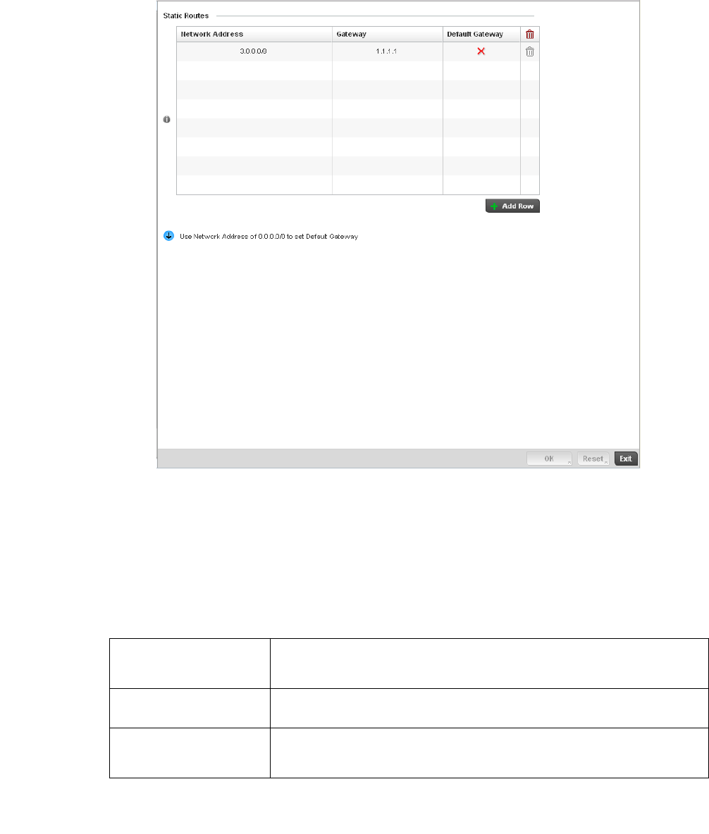
Brocade Mobility RFS4000, RFS6000, and RFS7000 System Reference Guide 185
53-1002620-01
5
FIGURE 140 Static Routes screen
Select IP Routing to enable static routes using IP addresses. This option is enabled by default.
Select Add Row + as needed to include single rows with in the static IPv4 route table.
Add IP addresses and network masks in the Network column.
Provide the Gateway used to route traffic.
Refer to the Default Route Priority field and set the following parameters:
Select the OK button located at the bottom right of the screen to save the changes. Select Reset to
revert to the last saved configuration.
Static Default Route
Priority
Use the spinner control to set the priority value (1 - 8,000) for the default static route.
This is weight assigned to this route versus others that have been defined. The default
setting is 100.
DHCP Client Default
Route Priority
Use the spinner control to set the priority value (1 - 8,000) for the default route learnt
from the DHCP client. The default setting is 1000.
Enable Routing Failure When selected, all default gateways are monitored for activity. The system will failover
to a live gateway if the current gateway becomes unusable. This feature is enabled by
default.

186 Brocade Mobility RFS4000, RFS6000, and RFS7000 System Reference Guide
53-1002620-01
5
Dynamic Routing (OSPF)
Overriding a Profile’s Network Configuration
Open Shortest Path First (OSPF) is a link-state interior gateway protocol (IGP). OSPF routes IP
packets within a single routing domain (autonomous system), like an enterprise LAN. OSPF gathers
link state information from neighbor routers and constructs a network topology. The topology
determines the routing table presented to the Internet Layer which makes routing decisions based
solely on the destination IP address found in IP packets.
OSPF detects changes in the topology, like a link failure, and plots a new loop-free routing
structure. It computes the shortest path for each route using a shortest path first algorithm. Link
state data is maintained on each router and is periodically updated on all OSPF member routers.
OSPF uses a route table managed by the link cost (external metrics) defined for each routing
interface. The cost could be the distance of a router (round-trip time), link throughput or link
availability. Setting a cost value provides a dynamic way to load balancing traffic between routes of
equal cost.
An OSPF network can be subdivided into routing areas to simplify administration and optimize
traffic utilization. Areas are logical groupings of hosts and networks, including routers having
interfaces connected to an included network. Each area maintains a separate link state database
whose information may be summarized towards the rest of the network by the connecting router.
Areas are identified by 32-bit IDs, expressed either in decimal, or octet-based dot-decimal notation.
Areas can defined as:
stub area - A stub area is an area which does not receive route advertisements external to the
autonomous system (AS) and routing from within the area is based entirely on a default route.
totally-stub - A totally stubby area does not allow summary routes and external routes. A default
route is the only way to route traffic outside of the area. When there’s only one route out of the
area, fewer routing decisions are needed, lowering system resource utilization.
non-stub - A non-stub area imports autonomous system external routes and send them to other
areas. However. it still cannot receive external routes from other areas.
nssa - NSSA is an extension of a stub that allows the injection of limited external routes into a stub
area. If selecting NSSA, no external routes, except a default route, enter the area.
totally nssa - Totally nssa is an NSSA using 3 and 4 summary routes are not flooded into this type of
area. It is also possible to declare an area both totally stubby and not-so-stubby, which means that
the area will receive only the default route from area 0.0.0.0, but can also contain an autonomous
system boundary router (ASBR) that accepts external routing information and injects it into the
local area, and from the local area into area 0.0.0.0.
A router running OSPF sends hello packets to discover neighbors and elect a designated router. The
hello packet includes link state information and list of neighbors. OSPF is savvy with layer 2
topologies. If on a point-to-point link, OSPF knows it is sufficient, and the link stays up. If on a
broadcast link, the router waits for election before determining if the link is functional.
To define a dynamic routing configuration:
1. Select Devices from the Configuration tab.
The Device Configuration screen displays a list of managed devices or peer controllers. The
listed devices can either be other controllers or Access Points within the managed network.
2. Select a target device (by double-clicking it) from amongst those displayed within the Device
Configuration screen.
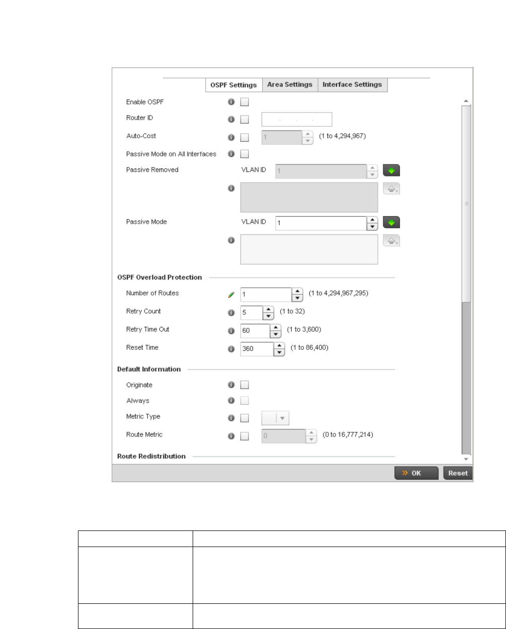
Brocade Mobility RFS4000, RFS6000, and RFS7000 System Reference Guide 187
53-1002620-01
5
Devices can also be selected directly from the Device Browser in the lower, left-hand, side of
the UI.
3. Select Profile Overrides from the Device menu to expand it into sub menu options.
4. Expand the Network menu and select Dynamic Routing.
FIGURE 141 OSPF Settings screen
5. Enable/disable OSPF and provide the following dynamic routing settings:
Enable OSPF Select this option to enable OSPF for this access point. OSPF is disabled by default.
Router ID Select this option to define a router ID (numeric IP address) for this access point. This
ID must be established in every OSPF instance. If not explicitly configured, the highest
logical IP address is duplicated as the router identifier. However, since the router
identifier is not an IP address, it does not have to be a part of any routable subnet in
the network.
Auto-Cost Select this option to specify the reference bandwidth (in Mbps) used to calculate the
OSPF interface cost if OSPF is either STUB or NSSA. The default setting is 1.

188 Brocade Mobility RFS4000, RFS6000, and RFS7000 System Reference Guide
53-1002620-01
5
6. Set the following OSPF Overload Protection settings:
7. Set the following Default Information:
8. Refer to the Route Redistribution table to set the types of routes that can be used by OSPF.
Select the + Add Row button to populate the table. Set the Route Type used to define the
redistributed route. Options include connected, kernal and static.
Select the Metric Type option to define the exterior metric type (1 or 2) used with the route
redistribution. Select the Metric option to define route metric used with the redistributed route.
9. Use the OSPF Network table to define networks (IP addresses) to connect using dynamic
routes.
Select the + Add Row button to populate the table. Add the IP address and mask of the
Network(s) participating in OSPF. Additionally, define the OSPF area (IP address) to which the
network belongs.
10. Set an OSPF Default Route Priority (1 - 8,000) as the priority of the default route learnt from
OSPF.
Select the Area Settings tab.
11. An OSPF Area contains a set of routers exchanging Link State Advertisements (LSAs) with
others in the same area. Areas limit LSAs and encourage aggregate routes.
Passive Mode on All
Interfaces
When selected, all layer 3 interfaces are set as an OSPF passive interface. This
setting is disabled by default.
Passive Removed If enabling Passive Mode on All Interfaces, use the spinner control to select VLANs (by
numeric ID) as OSPF non passive interfaces. Multiple VLANs can be added to the list.
Passive Mode If disabling Passive Mode on All Interfaces, use the spinner control to select VLANs (by
numeric ID) as OSPF passive interfaces. Multiple VLANs can be added to the list.
Number of Routes Use the spinner controller to set the maximum number of OSPN routes permitted. The
available range is from 1 - 4,294,967,295.
Retry Count Set the maximum number of retries (OSPF resets) permitted before the OSPF process
is shut down. The available range is from 1 - 32. The default setting is 5.
Retry Time Out Set the duration (in seconds) the OSPF process remains off before initiating its next
retry. The available range is from 1 - 3,600 seconds. The default is 60 seconds.
Reset Time Set the reset time (in seconds) that, when exceeded, changes the retry count is zero.
The available range is from 1 - 86,400. The default is 360 seconds.
Originate Select this option to make the default route a distributed route. This setting is
disabled by default.
Always Enabling this settings continuously maintains a default route, even when no routes
appear in the routing table. This setting is disabled by default.
Metric Type Select this option to define the exterior metric type (1 or 2) used with the default
route.
Route Metric Select this option to define route metric used with the default route. OSPF uses path
cost as its routing metric. It’s defined by the speed (bandwidth) of the interface
supporting given route.
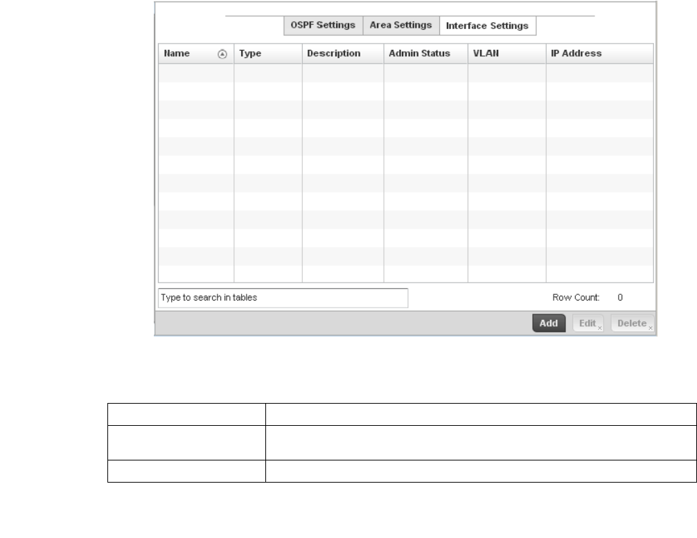
Brocade Mobility RFS4000, RFS6000, and RFS7000 System Reference Guide 189
53-1002620-01
5
FIGURE 142 OSPF Area Settings screen
12. Review existing Area Settings configurations using:
13. Select Add to create a new OSPF configuration, Edit to modify an existing configuration or
Delete to remove a configuration.
Area ID Displays either the IP address or integer representing the OSPF area.
Authentication Type Lists the authentication schemes used to validate the credentials of dynamic route
connections.
Type Lists the OSPF area type in each listed configuration.
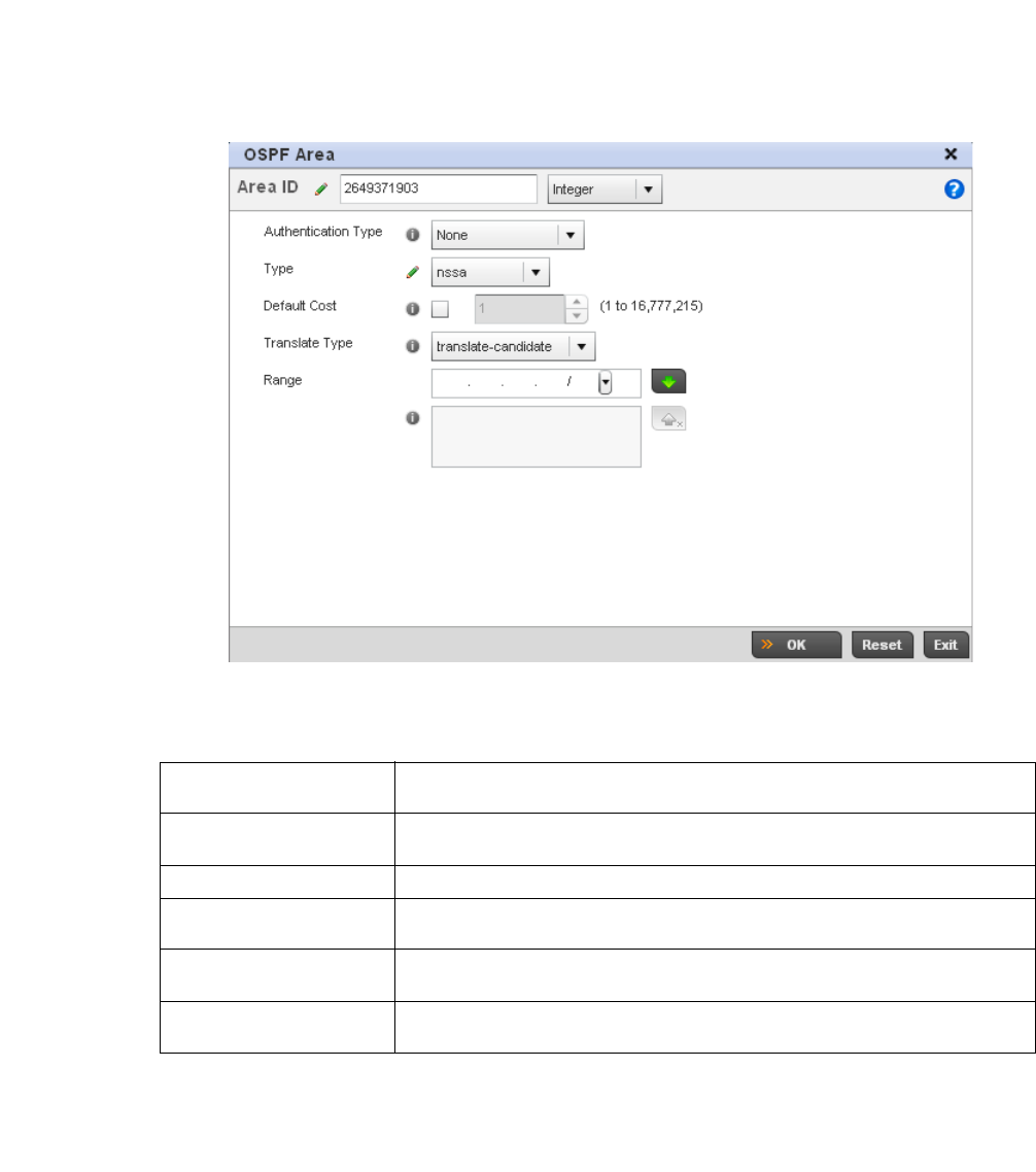
190 Brocade Mobility RFS4000, RFS6000, and RFS7000 System Reference Guide
53-1002620-01
5
FIGURE 143 OSPF Area Configuration screen
14. Set the OSPF Area configuration.
15. Select the OK button to save the changes to the area configuration. Select Reset to revert to
the last saved configuration.
16. Select the Interface Settings tab.
Area ID Use the drop down menu and specify either an IP address or Integer for the OSPF
area.
Authentication Type Select either None, simple-password or message-digest as credential validation
scheme used with the OSPF dynamic route. The default setting is None.
Type Set the OSPF area type as either stub, totally-stub, nssa, totally-nssa or non-stub.
Default Cost Select this option to set the default summary cost advertised if creating a stub. Set a
value from 1 - 16, 777,215.
Translate Type Define how messages are translated. Options include translate-candidate, translate
always and translate-never. The default setting is translate-candidate.
Range Specify a range of addresses for routes matching address/mask for OSPF
summarization.
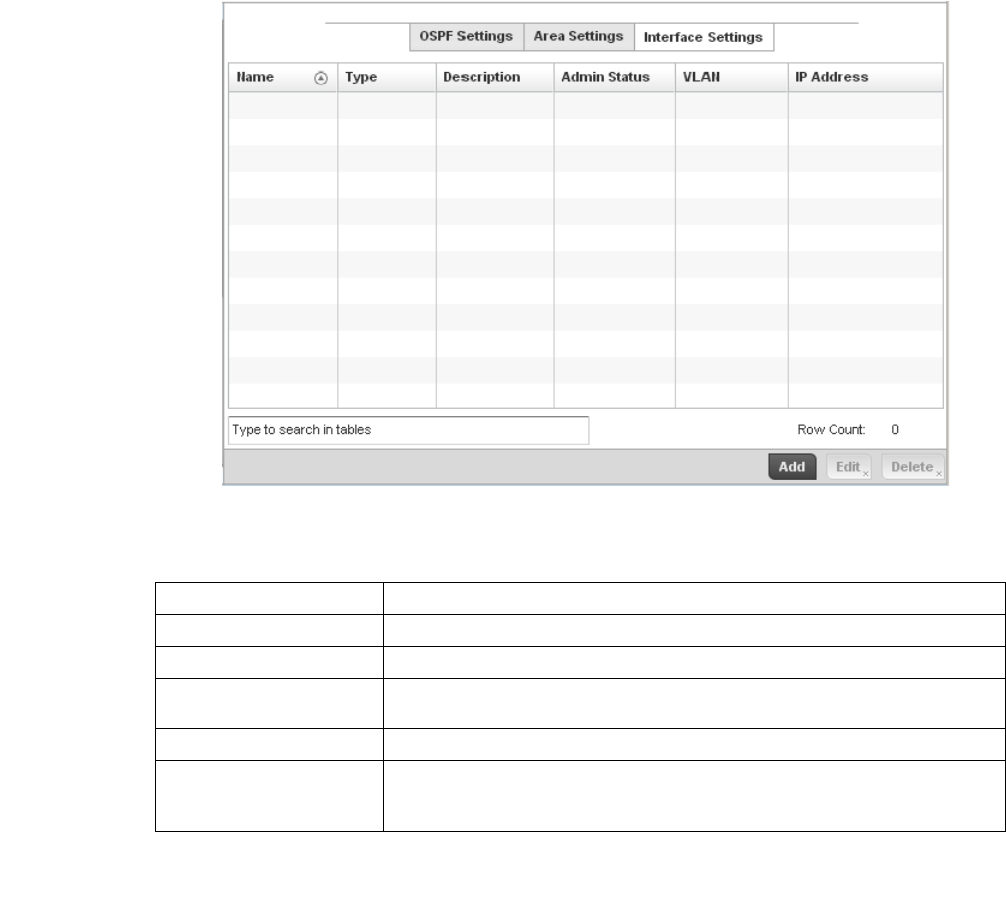
Brocade Mobility RFS4000, RFS6000, and RFS7000 System Reference Guide 191
53-1002620-01
5
FIGURE 144 OSPF Interface Settings screen
17. Review existing Interface Settings using:
18. Select the Add button to define a new set of virtual interface basic settings, or Edit to update
the settings of an existing virtual interface configuration.
Name Displays the name defined for the interface configuration.
Type Displays the type of interface.
Description Lists each interface’s 32 character maximum description.
Admin Status Displays whether Admin Status privileges have been enabled or disabled for the OSPF
route’s virtual interface connection.
VLAN Lists the VLAN IDs set for each listed OSPF route virtual interface.
IP Address Displays the IP addresses defined as virtual interfaces for dynamic OSPF routes. Zero
config and DHCP can be used to generate route addresses, or a primary and
secondary address can be manually provided.
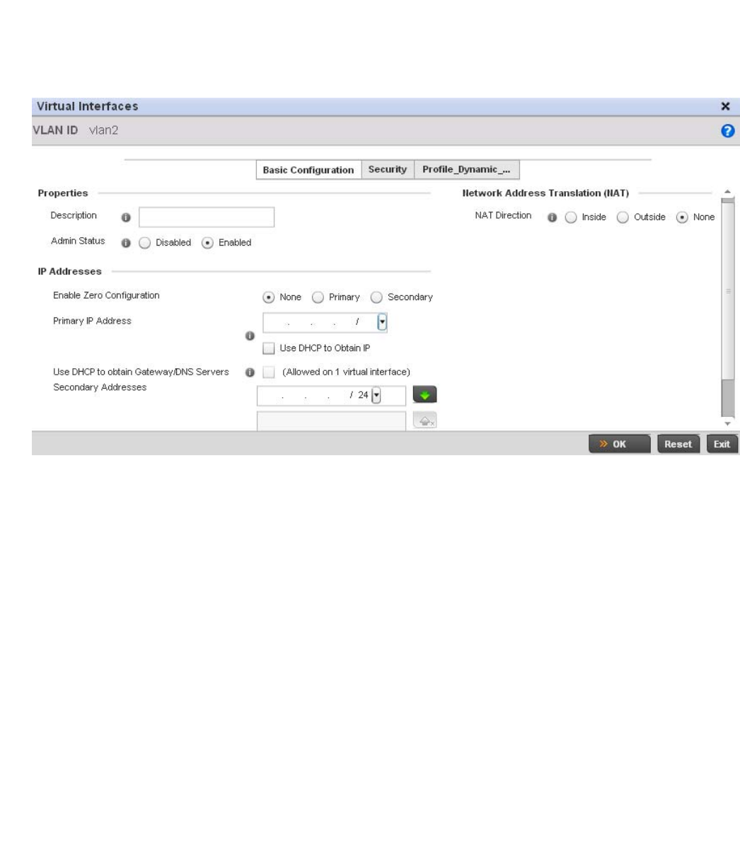
192 Brocade Mobility RFS4000, RFS6000, and RFS7000 System Reference Guide
53-1002620-01
5
FIGURE 145 OSPF Virtual Interface - Basic Configuration screen
19. Within the Properties field, enter a 32 character maximum Description to help differentiate the
virtual interface configuration used with this OSPF route. Enable/disable admin privileges as
need. They’re disabled by default.
20. Use the IP Addresses Area to set how route addresses are created for the virtual configuration.
Zero Configuration can be enabled and set as the Primary or Secondary means of providing IP
addresses for the OSPF virtual route.
21. Select Use DHCP to Obtain IP to use the access point’s DHCP server resource as the means of
providing requested IP addresses to the OSPF route’s virtual interface.
22. Select Use DHCP to Obtain Gateway/DNS Servers to learn default gateway, name servers and
the domain name on just this interface. Once selected, specify an IP address and mask in dot
decimal format.
23. Define the NAT Direction as either Inside, Outside or None. Network Address Translation (NAT),
is an Internet standard that enables a (LAN) to use IP addresses for internal traffic (inside) and
a second set of addresses for external (outside) traffic.
24. Select OK to save the changes to the basic configuration. Select Reset to revert to the last
saved configuration.
25. Select the Security tab.
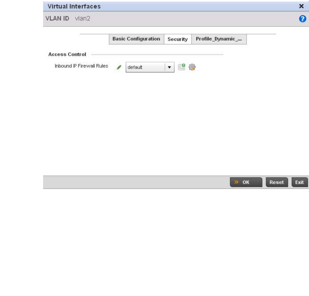
Brocade Mobility RFS4000, RFS6000, and RFS7000 System Reference Guide 193
53-1002620-01
5
FIGURE 146 OSPF Virtual Interface - Security screen
26. Use the Inbound IP Firewall Rules drop-down menu to select the IP access and deny rules to
apply to the OSPF dynamic route.
Either select an existing IP firewall policy or use the default set of IP firewall rules. The firewall
inspects OSPF route traffic flows and detects potential attacks on the dynamic route not visible
to traditional wired firewall appliances. Select the Create icon to define a new set of IP firewall
rules that can be applied to the OSPF route configuration. Selecting Edit allows for the
modification of an existing IP firewall rules configuration. For more information, see Wireless
Firewall on page 9-511.
27. Select OK to save the changes to the OSPF route security configuration. Select Reset to revert
to the last saved configuration.
28. Select the Profile_Dynamic_Routing tab.
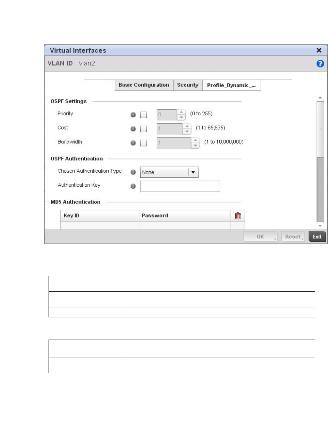
194 Brocade Mobility RFS4000, RFS6000, and RFS7000 System Reference Guide
53-1002620-01
5
FIGURE 147 OSPF Virtual Interface - Profile_Dynamic_Routing screen
29. Set the following OSPF Settings:
30. Set the following OSPF Authentication settings for the dynamic route:
31. Select the + Add Row button (at the bottom of the MD5 Authentication table) to add the Key ID
and Password used for an MD5 validation of authenticator credentials.
Use the spinner control to set the OSPF message digest authentication key ID. The available
range is from 1 - 255. The password is the OSPF key either displayed as series or asterisks or
in plain text (by selecting Show).
Priority Select this option to set the OSPF priority used in dynamic route election. Use the
spinner control to set the value from 0 - 255.
Cost Select this option to set the cost of the OSPF interface. Use the spinner control to set
the value from 1 - 65,353.
Bandwidth Set the OSPF interface bandwidth (in Kbps) from 1 - 10,000,000.
Chosen Authentication
Type
Select the authentication type used to validate credentials within the OSPF dynamic
route. Options include simple-password, message-digest, null and None.
Authentication Key Enter and confirm the authentication key required by connecting nodes using the
OSPF dynamic route.

Brocade Mobility RFS4000, RFS6000, and RFS7000 System Reference Guide 195
53-1002620-01
5
32. Select OK to save the changes to the Profile_Dynamic_Route configuration. Select Reset to
revert to the last saved configuration
Overriding a Profile’s Forwarding Database Configuration
Overriding a Profile’s Network Configuration
A Forwarding Database is used to forward or filter packets on behalf of the controller. The bridge
reads the packet’s destination MAC address and decides to either forward the packet or drop
(filter) it. If it’s determined the destination MAC is on a different network segment, it forwards the
packet to the segment. If the destination MAC is on the same network segment, the packet is
dropped (filtered). As nodes transmit packets through the bridge, the bridge updates its forwarding
database with known MAC addresses and their locations on the network. This information is then
used to decide to filter or forward the packet.
This forwarding database assignment can be overridden as needed, but removes the device
configuration from the managed profile that may be shared with other similar device models.
To define or override a profile’s forwarding database configuration:
1. Select Devices from the Configuration tab.
The Device Configuration screen displays a list of managed devices or peer controllers. The
listed devices can either be other controllers or Access Points within the managed network.
2. Select a target device (by double-clicking it) from amongst those displayed within the Device
Configuration screen.
Devices can also be selected directly from the Device Browser in the lower, left-hand, side of
the UI.
3. Select Profile Overrides from the Device menu to expand it into sub menu options.
4. Select Network to expand its sub menu options.
5. Select Forwarding Database.
NOTE
A blue override icon (to the left of a parameter) defines the parameter as having an override applied.
To remove an override go to the Basic Configuration section of the device and click the Clear
Overrides button. This will remove all overrides from the device.
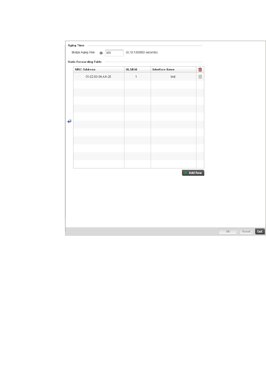
196 Brocade Mobility RFS4000, RFS6000, and RFS7000 System Reference Guide
53-1002620-01
5
FIGURE 148 Profile Overrides - Network Forwarding Database screen
6. Define or override a Bridge Aging Time between 0, 10-1,000,000 seconds.
The aging time defines the length of time an entry will remain in the a bridge’s forwarding table
before being deleted due to lack of activity. If an entry replenishments a destination generating
continuous traffic, this timeout value will never be invoked. However, if the destination
becomes idle, the timeout value represents the length of time that must be exceeded before
an entry is deleted from the forwarding table. The default setting is 300 seconds.
7. Use the + Add Row button to create a new row within the MAC address table.
8. Set or override a destination MAC Address. The bridge reads the controller packet’s destination
MAC address and decides to forward the packet or drop (filter) it. If it’s determined the
destination MAC is on a different network, it forwards the packet to the segment. If the
destination MAC is on the same network segment, the packet is dropped (filtered).
9. Define or override the target VLAN ID if the destination MAC is on a different network segment.
10. Provide an Interface Name used as the target destination interface for the target MAC address.
11. Select OK to save the changes and overrides. Select Reset to revert to the last saved
configuration.
Overriding a Profile’s Bridge VLAN Configuration
Overriding a Profile’s Network Configuration

Brocade Mobility RFS4000, RFS6000, and RFS7000 System Reference Guide 197
53-1002620-01
5
A Virtual LAN (VLAN) is separately administrated virtual network within the same physical managed
network. VLANs are broadcast domains defined within switches to allow control of broadcast,
multicast, unicast, and unknown unicast within a Layer 2 device.
Administrators often need to route traffic to interoperate between different VLANs. Bridging VLANs
are only for non-routable traffic, like tagged VLAN frames destined to some other device which will
untag it. When a data frame is received on a port, the VLAN bridge determines the associated VLAN
based on the port of reception. Using forwarding database information, the Bridge VLAN forwards
the data frame on the appropriate port(s). VLAN's are useful to set separate networks to isolate
some computers from others, without actually having to have separate cabling and Ethernet
switches. Controllers can do this on their own, without need for the computer or other gear to know
itself what VLAN it's on (this is called port-based VLAN, since it's assigned by port of the switch).
Another common use is to put specialized devices like VoIP Phones on a separate network for
easier configuration, administration, security, or quality of service.
Two main VLAN bridging modes are available in Brocade Mobility:
•Tunnel Mode: In tunnel mode, the traffic at the AP is always forwarded through the best path.
The APs decides the best path to reach the destination and appropriately forwards the
packets.Setting the VLAN to tunnel mode will ensure that packets are Bridge packets between
local ethernet ports, any local radios, and tunnels to other APs and wireless controller.
•Local Mode: Local mode is typically configured in remote branch offices where traffic on
remote private LAN segment needs to be bridged locally. Local mode implies that the wired
and the wireless traffic are to be bridged locally.
To define a bridge VLAN configuration or override for a device profile:
1. Select Devices from the Configuration tab.
The Device Configuration screen displays a list of managed devices or peer controllers. The
listed devices can either be other controllers or Access Points within the managed network.
2. Select a target device (by double-clicking it) from amongst those displayed within the Device
Configuration screen.
Devices can also be selected directly from the Device Browser in the lower, left-hand, side of
the UI.
3. Select Profile Overrides from the Device menu to expand it into sub menu options.
4. Select Network to expand its sub menu options.
5. Select Bridge VLAN.
NOTE
A blue override icon (to the left of a parameter) defines the parameter as having an override applied.
To remove an override go to the Basic Configuration section of the device and click the Clear
Overrides button. This will remove all overrides from the device.
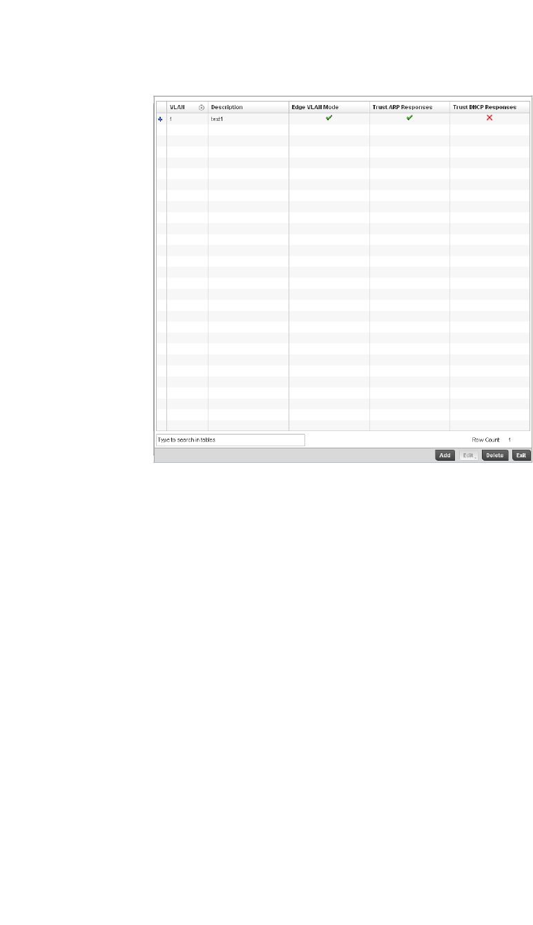
198 Brocade Mobility RFS4000, RFS6000, and RFS7000 System Reference Guide
53-1002620-01
5
FIGURE 149 Profile Overrides - Network Bridge VLAN screen
6. Review the following VLAN configuration parameters to determine whether an override is
warranted:
7. Se le ct Add to define a new Bridge VLAN configuration, Edit to modify or override an existing
Bridge VLAN configuration or Delete to remove a VLAN configuration.
VLAN Lists the numerical identifier defined for the Bridge VLAN when it was initially created.
The available range is from 1 - 4095. This value cannot be modified during the edit
process.
Description Lists a description of the VLAN assigned when it was created or modified. The
description should be unique to the VLAN’s specific configuration and help
differentiate it from other VLANs with similar configurations.
Edge VLAN Mode Defines whether the VLAN is currently in edge VLAN mode. A green checkmark defines
the VLAN as extended. An edge VLAN is the VLAN where hosts are connected. For
example, if VLAN 10 is defined with wireless clients, and VLAN 20 is where the default
gateway resides, VLAN 10 should be marked as an edge VLAN and VLAN 20 shouldn’t
be marked as an edge VLAN. When defining a VLAN as edge VLAN, the firewall
enforces additional checks on hosts in that VLAN. For example, a host cannot move
from an edge VLAN to another VLAN and still keep firewall flows active.
Trust ARP Response When ARP trust is enabled, a green checkmark displays. When disabled, a red “X”
displays. Trusted ARP packets are used to update the IP-MAC Table to prevent IP spoof
and arp-cache poisoning attacks.
Trust DHCP Responses When DHCP trust is enabled, a green checkmark displays. When disabled, a red “X”
displays. When enabled, DHCP packets from a DHCP server are considered trusted
and permissible. DHCP packets are used to update the DHCP Snoop Table to prevent
IP spoof attacks.
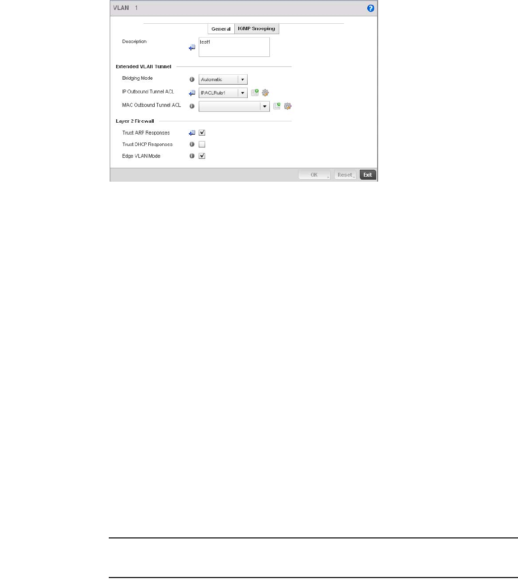
Brocade Mobility RFS4000, RFS6000, and RFS7000 System Reference Guide 199
53-1002620-01
5
FIGURE 150 Profile Overrides - Network Bridge VLAN screen, General tab
8. The General tab displays by default.
9. If adding a new Bridge VLAN configuration, use the spinner control to define or override a VLAN
ID between 1 - 4094. This value must be defined and saved before the General tab can
become enabled and the remainder of the settings defined. VLAN IDs 0 and 4095 are
reserved and unavailable.
10. Set or override the following General Bridge VLAN parameters:
11. Set or override the following Extended VLAN Tunnel parameters:
NOTE
Local and Automatic bridging modes do not work with ACLs. ACLs can only be used with tunnel or
isolated-tunnel modes.
Description If creating a new Bridge VLAN, provide a description (up to 64 characters) unique to
the VLAN’s specific configuration to help differentiate it from other VLANs with similar
configurations.
Bridging Mode Specify one of the following bridging mode for use on the VLAN.
•Automatic: Select automatic mode to let the controller determine the best
bridging mode for the VLAN.
•Local: Select Local to use local bridging mode for bridging traffic on the VLAN.
•Tunnel: Select Tunnel to use a shared tunnel for bridging traffic on the VLAN.
•isolated-tunnel: Select isolated-tunnel to use a dedicated tunnel for bridging
traffic on the VLAN.
IP Outbound Tunnel ACL Select an IP Outbound Tunnel ACL for outbound traffic from the pulldown menu. If an
appropriate outbound IP ACL is not available click the create button to make a new
one.
MAC Outbound Tunnel
ACL
Select a MAC Outbound Tunnel ACL for outbound traffic from the pulldown menu. If an
appropriate outbound MAC ACL is not available click the create button to make a new
one.
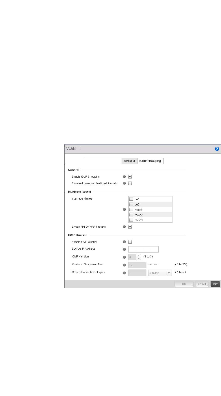
200 Brocade Mobility RFS4000, RFS6000, and RFS7000 System Reference Guide
53-1002620-01
5
12. Set or override the following Layer 2 Firewall parameters:
13. Select the OK button to save the changes and overrides to the General tab. Select Reset to
revert to the last saved configuration.
14. Select the IGMP Snooping tab to define or override the VLAN’s IGMP configuration.
FIGURE 151 Profile Overrides - Network Bridge VLAN screen, IGMP Snooping
15. Define or override the following IGMP Snooping parameters for the Bridge VLAN configuration:
The Internet Group Management Protocol (IGMP) is a protocol used for managing members of
IP multicast groups. The controller listens to IGMP network traffic and forwards the IGMP
multicast packets to radios on which the interested hosts are connected. On the wired side of
the network, the controller floods all the wired interfaces. This feature reduces unnecessary
flooding of multicast traffic in the network.
Trust ARP Response Select the checkbox to use trusted ARP packets to update the DHCP Snoop Table to
prevent IP spoof and arp-cache poisoning attacks. This feature is disabled by default.
Trust DHCP Responses Select the checkbox to use DHCP packets from a DHCP server as trusted and
permissible within the managed network. DHCP packets are used to update the DHCP
Snoop Table to prevent IP spoof attacks. This feature is disabled by default.
Edge VLAN Mode Select the checkbox to enable edge VLAN mode. When selected, the edge controller’s
IP address in the VLAN is not used for normal operations, as its now designated to
isolate devices and prevent connectivity. This feature is enabled by default.
Enable IGMP Snooping Select the check box to enable IGMP snooping on the controller. If disabled, snooping
on a per VLAN basis is also disabled. This feature is enabled by default. If disabled, the
settings under bridge configuration are overridden. For example, if IGMP snooping is
disabled, but the bridge VLAN is enabled, the effective setting is disabled.
Forward Unknown
Multicast Packets
Select the check box to enable the controller to forward multicast packets from
unregistered multicast groups. If disabled (the default setting), the unknown multicast
forward feature is also disabled for individual VLANs.

Brocade Mobility RFS4000, RFS6000, and RFS7000 System Reference Guide 201
53-1002620-01
5
16. Within the Multicast Router section, check the boxes of those interfaces used by the controller
as a multicast router interface. Multiple controller interfaces can be selected and overridden.
Optionally select the Snoop PIM-DVMRP Packets box to snoop packets across the selected
interface(s). This option is enabled by default.
17. Set or override the following IGMP Querier parameters for the profile’s bridge VLAN
configuration:
18. Select the OK button to save the changes and overrides to the IGMP Snooping tab. Select
Reset to revert to the last saved configuration.
Overriding a Profile’s Cisco Discovery Protocol Configuration
Overriding a Profile’s Network Configuration
The Cisco Discovery Protocol (CDP) is a proprietary Data Link Layer network protocol implemented
in Cisco networking equipment and used to share information about network devices.
To override Cisco Discovery Protocol (CDP)configuration:
1. Select Devices from the Configuration tab.
The Device Configuration screen displays a list of managed devices or peer controllers. The
listed devices can either be other controllers or Access Points within the managed network.
2. Select a target device (by double-clicking it) from amongst those displayed within the Device
Configuration screen.
Devices can also be selected directly from the Device Browser in the lower, left-hand, side of
the UI.
3. Select Profile Overrides from the Device menu to expand it into sub menu options.
4. Select Network to expand its sub menu options.
5. Select Cisco Discovery Protocol.
Enable IGMP Querier Select the check box to enable IGMP querier. IGMP snoop querier is used to keep host
memberships alive. It’s primarily used in a network where there’s a multicast
streaming server and hosts subscribed to the server and no IGMP querier present. The
controller can perform the IGMP querier role. An IGMP querier sends out periodic
IGMP query packets. Interested hosts reply with an IGMP report packet. IGMP
snooping is only conducted on wireless radios. IGMP multicast packets are flooded on
wired ports. IGMP multicast packet are not flooded on the wired port. IGMP
membership is also learnt on it and only if present, then it is forwarded on that port. A
Brocade br-7131 model access point can also be an IGMP querier.
Source IP Address Define an IP address applied as the source address in the IGMP query packet. This
address is used as the default VLAN querier IP address.
IGMP Version Use the spinner control to set the IGMP version compatibility to either version 1, 2 or
3. The default setting is 3.
Maximum Response Time Specify the maximum time (between 1 - 25 seconds) before sending a responding
report. When no reports are received from a radio, radio information is removed from
the snooping table. The controller only forwards multicast packets to radios present in
the snooping table. For IGMP reports from wired ports, the controller forwards these
reports to the multicast router ports. The default setting is 10 seconds.
Other Querier Timer Expiry Specify an interval in either Seconds (60 - 300) or Minutes (1 - 5) used as a timeout
interval for other querier resources. The default setting is 1 minute.
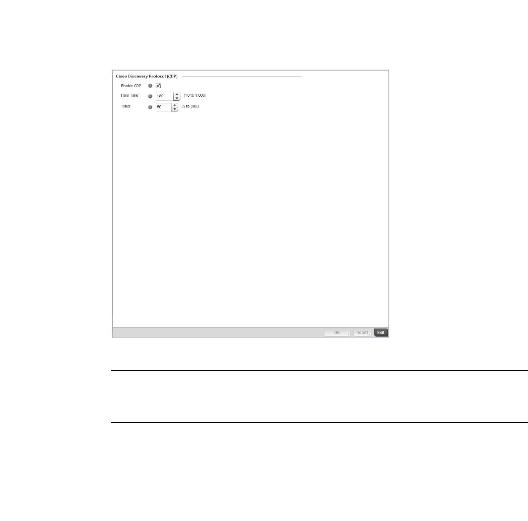
202 Brocade Mobility RFS4000, RFS6000, and RFS7000 System Reference Guide
53-1002620-01
5
FIGURE 152 Profile Overrides - Network Cisco Discovery Protocol screen
NOTE
A blue override icon (to the left of a parameter) defines the parameter as having an override applied.
To remove an override go to the Basic Configuration section of the device and click the Clear
Overrides button. This will remove all overrides from the device.
6. Check the Enable CDP box to enable Cisco Discovery Protocol on the device.
7. Re fer to t h e Hold Time field and use the spinner control to define a hold time between 10 -
1800 seconds for transmitted CDP Packets. The default value is 180 seconds.
8. Refer to the Timer field and use the spinner control to define a interval between 5 - 900
seconds to transmit CDP Packets. The default value is 60 seconds.
9. Select the OK button to save the changes and overrides. Select Reset to revert to the last
saved configuration.
Overriding a Profile’s Link Layer Discovery Protocol Configuration
Overriding a Profile’s Network Configuration
The Link Layer Discovery Protocol (LLDP) or IEEE 802.1AB is a vendor-neutral Data Link Layer
protocol used by network devices for advertising of (announcing) their identity, capabilities, and
interconnections
on a IEEE 802 LAN network. The protocol is formally referred to by the IEEE as Station and Media
Access Control Connectivity Discovery. Both LLDP snooping and ability to generate and transmit
LLDP packets will be provided.

Brocade Mobility RFS4000, RFS6000, and RFS7000 System Reference Guide 203
53-1002620-01
5
Information obtained via CDP and LLDP snooping is available in the UI. In addition, information
obtained via CDP / LLDP snooping is provided by an AP during the adoption process, so the L2
switch device name detected by the AP can be used as a criteria in the auto provisioning policy.
To override Link Layer Discovery Protocol (LLDP)configuration:
1. Select Devices from the Configuration tab.
The Device Configuration screen displays a list of managed devices or peer controllers. The
listed devices can either be other controllers or Access Points within the managed network.
2. Select a target device (by double-clicking it) from amongst those displayed within the Device
Configuration screen.
Devices can also be selected directly from the Device Browser in the lower, left-hand, side of
the UI.
3. Select Profile Overrides from the Device menu to expand it into sub menu options.
4. Select Network to expand its sub menu options.
5. Select Link Layer Discovery Protocol.
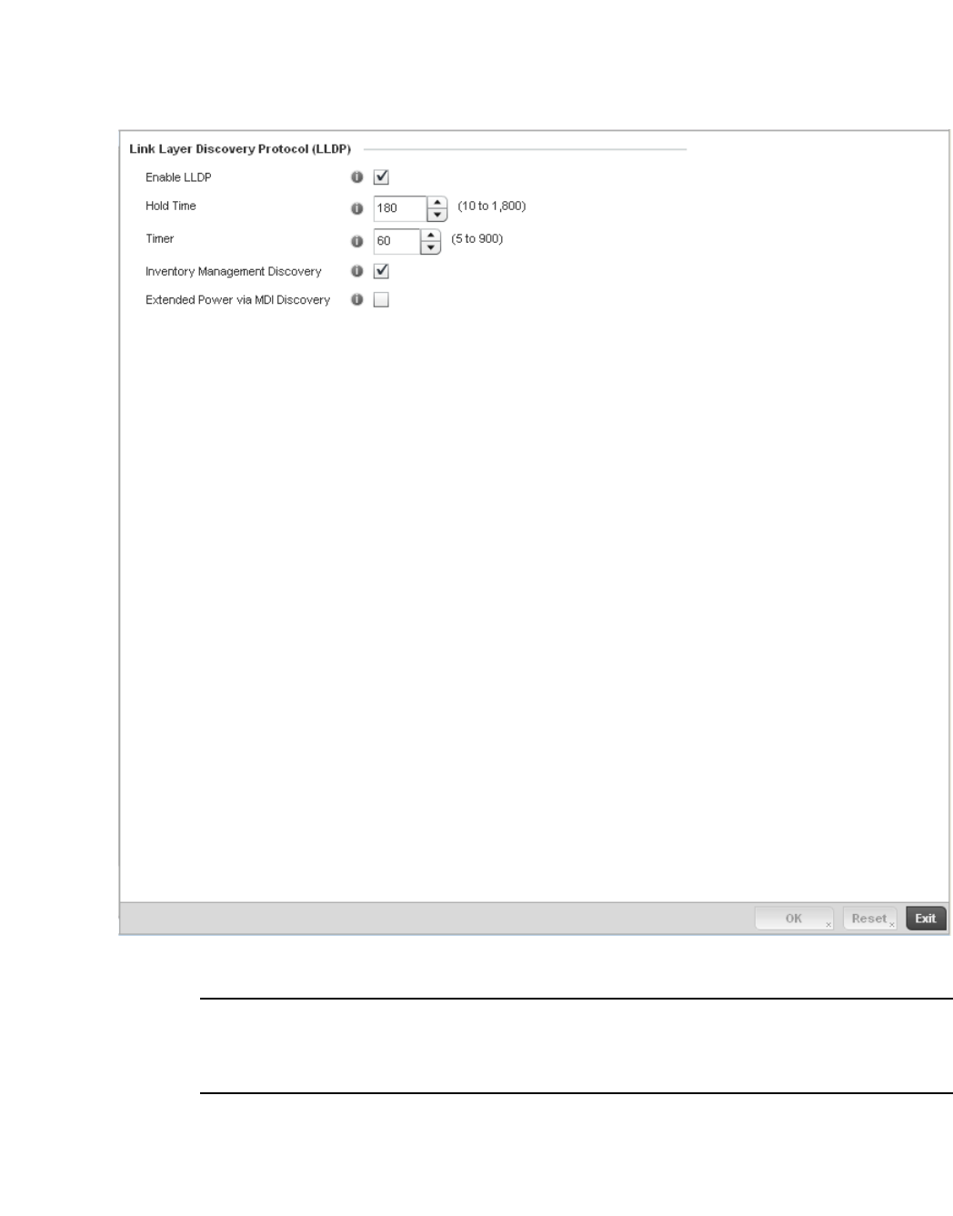
204 Brocade Mobility RFS4000, RFS6000, and RFS7000 System Reference Guide
53-1002620-01
5
FIGURE 153 Profile Overrides - Network Link Layer Discovery Protocol screen
NOTE
A blue override icon (to the left of a parameter) defines the parameter as having an override applied.
To remove an override go to the Basic Configuration section of the device and click the Clear
Overrides button. This will remove all overrides from the device.
6. Check the Enable LLDP box to enable Link Layer Discovery Protocol on the device.
7. Re fer to t h e Hold Time field and use the spinner control to define a hold time between 10 -
1800 seconds for transmitted LLDP Packets. The default value is 180 seconds.
8. Refer to the Timer field and use the spinner control to define the interval between 5 - 900
seconds to transmit LLDP Packets. The default value is 60 seconds.

Brocade Mobility RFS4000, RFS6000, and RFS7000 System Reference Guide 205
53-1002620-01
5
9. Check the Inventory Mangement Discovery box to enable this feature. Inventory Management
Discovery is used to track and identify inventory attributes including manufacturer, model, or
software version.
10. Select the Extended Power via MDI Discovery box to enable this feature. Extended Power via
MDI Discovery provides detailed power information through end points and other connected
devices.
11. Select the OK button to save the changes and overrides. Select Reset to revert to the last
saved configuration.
Overriding a Profile’s Miscellaneous Network Configuration
Overriding a Profile’s Network Configuration
A controller profile can be configured to include a hostname in a DHCP lease for a requesting
device and its profile. This helps an administrator track the leased DHCP IP address by hostname
for the controller supported device profile. When numerous DHCP leases are assigned, an
administrator can better track the leases when hostnames are used instead of devices.
To include a hostnames in DHCP request:
1. Select Devices from the Configuration tab.
The Device Configuration screen displays a list of managed devices or peer controllers. The
listed devices can either be other controllers or Access Points within the managed network.
2. Select a target device (by double-clicking it) from amongst those displayed within the Device
Configuration screen.
Devices can also be selected directly from the Device Browser in the lower, left-hand, side of
the UI.
3. Select Profile Overrides from the Device menu to expand it into sub menu options.
4. Select Network to expand its sub menu options.
5. Select Miscellaneous.
NOTE
A blue override icon (to the left of a parameter) defines the parameter as having an override applied.
To remove an override go to the Basic Configuration section of the device and click the Clear
Overrides button. This will remove all overrides from the device.
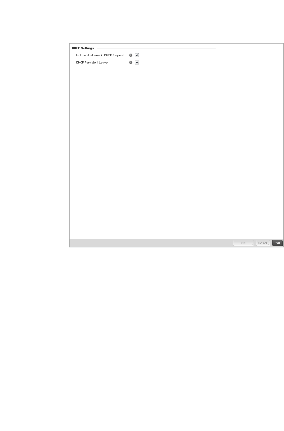
206 Brocade Mobility RFS4000, RFS6000, and RFS7000 System Reference Guide
53-1002620-01
5
FIGURE 154 Profile Overrides - Network Miscellaneous screen
6. Refer to the DHCP Settings section to configure miscellaneous DHCP Settings.
7. To enable critical resource monitoring for the device, select a Critical Resource Policy from the
pull-down menu in the Critical Resource Monitoring section. If a new critical resource
monitoring policy is needed click the Create button and specify the Ping Interval, IP Address,
Ping Mode and VLAN for the devices being monitored.
8. Select the OK button to save the changes and overrides. Select Reset to revert to the last
saved configuration.
Overriding a Profile’s Security Configuration
A controller or Access Point profile can have its own firewall policy, wireless client role policy, WEP
shared key authentication, NAT policy and VPN policy (controller only) applied. If an existing firewall,
client role or NAT policy is unavailable, an administrator can be navigated from the Configuration >
Profiles section of the controller UI to the Configuration > Security portion of the UI to create the
Include Hostname in
DHCP Request
Select the Include Hostname in DHCP Request checkbox to include a hostname in a
DHCP lease for a requesting device. This feature is disabled by default.
DHCP Persisten Lease Check this box to enable a persistent DHCP lease for the device. A persistent DHCP
lease assigns the same IP Address and other network information to the device each
time it renews its DHCP lease.

Brocade Mobility RFS4000, RFS6000, and RFS7000 System Reference Guide 207
53-1002620-01
5
required security policy configuration. Once created, a policy’s configuration can have an override
applied to meet the changing data protection requirements of a device’s environment. However, in
doing so the device must now be managed separately from the profile configuration shared by
other devices within the managed network.
For more information on applying an override to an existing device profile, refer to the following
sections:
•Overriding a Profile’s General Security Settings
•Overriding a Profile’s Certificate Revocation List (CRL) Configuration
•Overriding a Profile’s ISAKMP Configuration
•Overriding a Profile’s Transform Set Configuration
•Overriding a Profile’s VPN Configuration
•Overriding a Profile’s NAT Configuration
Overriding a Profile’s General Security Settings
Overriding a Profile’s Security Configuration
A controller profile can leverage existing firewall, wireless client role and WIPS policies and apply
them to the profile’s configuration. This affords each controller profile a truly unique combination of
data protection policies best meeting the data protection requirements of that controller profile.
However, as deployment requirements arise, an individual device may need some or all of its
general security configuration overridden from that defined in the profile.
To configure a profile’s security settings and overrides:
1. Select Devices from the Configuration tab.
The Device Configuration screen displays a list of managed devices or peer controllers. The
listed devices can either be other controllers or Access Points within the managed network.
2. Select a target device (by double-clicking it) from amongst those displayed within the Device
Configuration screen.
Devices can also be selected directly from the Device Browser in the lower, left-hand, side of
the UI.
3. Select Profile Overrides from the Device menu to expand it into sub menu options.
4. Select Security to expand its sub menu options.
5. Select General.
NOTE
A blue override icon (to the left of a parameter) defines the parameter as having an override applied.
To remove an override go to the Basic Configuration section of the device and click the Clear
Overrides button. This will remove all overrides from the device.
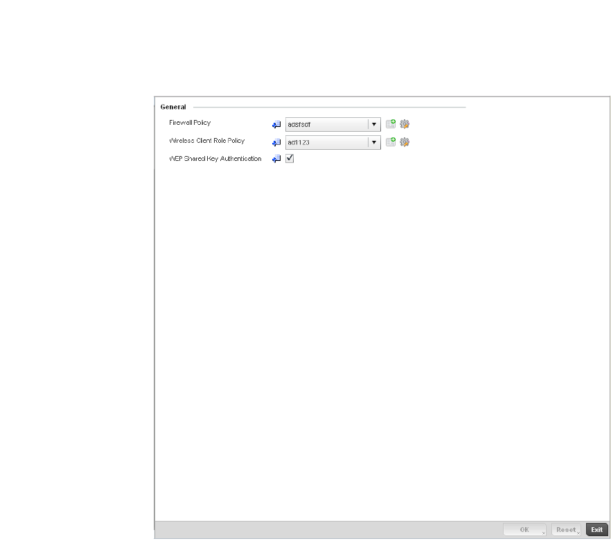
208 Brocade Mobility RFS4000, RFS6000, and RFS7000 System Reference Guide
53-1002620-01
5
FIGURE 155 Profile Overrides - General Security screen

Brocade Mobility RFS4000, RFS6000, and RFS7000 System Reference Guide 209
53-1002620-01
5
6. Refer to the General field to assign or override the following:
7. Select an Advanced WIPS Policy from the drop-down menu in the Wireless IDS/IPS section.
Define an advanced WIPS configuration to optionally remove (terminate) unwanted device
connections, and sanction (allow) or unsanaction (disallow) specific events within the
managed network.
If an existing Advanced WIPS policy does not meet the profile’s data protection requirements,
select the Create icon to create a new configuration that can be applied to the profile. An
existing policy can also be selected and overridden as needed using the Edit icon. For more
information, see Configuring an Advanced WIPS Policy on page 9-550.
8. Select OK to save the changes or overrides. Select Reset to revert to the last saved
configuration.
Overriding a Profile’s Certificate Revocation List (CRL) Configuration
Overriding a Profile’s Security Configuration
A certificate revocation list (CRL) is a list of certificates that have been revoked or are no longer
valid. A certificate can be revoked if the certificate authority (CA) had improperly issued a
certificate, or if a private-key is compromised. The most common reason for revocation is the user
no longer being in sole possession of the private key.
To define a Certificate Revocation configuration or override:
1. Select Devices from the Configuration tab.
The Device Configuration screen displays a list of managed devices or peer controllers. The
listed devices can either be other controllers or Access Points within the managed network.
Firewall Policy Use the drop-down menu to select an existing Firewall Policy to use as an additional
security mechanism with this controller profile. All devices using this controller profile
and Access Point must meet the requirements of the firewall policy to access the
managed network. A firewall is a mechanism enforcing access control, and is
considered a first line of defense in protecting proprietary information within the
wireless controller managed network. The means by which this is accomplished
varies, but in principle, a firewall can be thought of as mechanisms both blocking and
permitting data traffic within the wireless controller managed network. If an existing
Firewall policy does not meet your requirements, select the Create icon to create a
new firewall policy that can be applied to this profile. An existing policy can also be
selected and overridden as needed using the Edit icon. For more information, see
Wireless Firewall on page 9-511 and Configuring a Firewall Policy on page
9-512.
Wireless Client Role Policy Use the drop-down menu to select a client role policy the controller uses to
strategically filter client connections based on a pre-defined set of filter rules and
connection criteria. If an existing Wireless Client Role policy does not meet your
requirements, select the Create icon to create a new configuration that can be
applied to this profile. An existing policy can also be selected and overridden as
needed using the Edit icon. For more information, see Wireless Client Roles on
page 9-530.
WEP Shared Key
Authentication
Select the check box to require devices using this profile to use a WEP key to access
the managed network using this profile. The wireless controller, other proprietary
routers, and clients use the key algorithm to convert an ASCII string to the same
hexadecimal number. Clients without adapters need to use WEP keys manually
configured as hexadecimal numbers. This option is disabled by default.
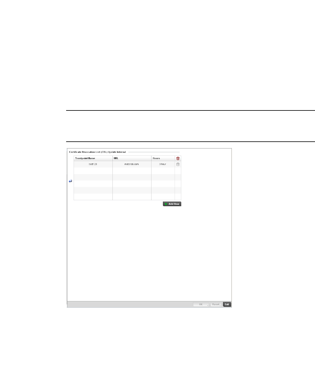
210 Brocade Mobility RFS4000, RFS6000, and RFS7000 System Reference Guide
53-1002620-01
5
2. Select a target device (by double-clicking it) from amongst those displayed within the Device
Configuration screen.
Devices can also be selected directly from the Device Browser in the lower, left-hand, side of
the UI.
3. Select Profile Overrides from the Device menu to expand it into sub menu options.
4. Select Security to expand its sub menu options.
5. Select Certificate Revocation.
NOTE
A blue override icon (to the left of a parameter) defines the parameter as having an override applied.
To remove an override go to the Basic Configuration section of the device and click the Clear
Overrides button. This will remove all overrides from the device.
FIGURE 156 Profile Overrides - Certificate Revocation screen
6. Select the + Add Row button to add a column within the Certificate Revocation List (CRL)
Update Interval table to quarantine certificates from use in the managed network.
Additionally, a certificate can be placed on hold for a user defined period. If, for instance, a
private key was found and nobody had access to it, its status could be reinstated.
a. Provide the name of the trustpoint in question within the Trustpoint Name field. The name
cannot exceed 32 characters.
b. Enter the resource ensuring the trustpoint’s legitimacy within the URL field.
c. Use the spinner control to specify an interval (in hours) after which a device copies a CRL
file from an external server and associates it with a trustpoint.

Brocade Mobility RFS4000, RFS6000, and RFS7000 System Reference Guide 211
53-1002620-01
5
7. Se le ct OK to save the changes and overrides made within the Certificate Revocation screen.
Select Reset to revert to the last saved configuration.
Overriding a Profile’s ISAKMP Configuration
Overriding a Profile’s Security Configuration
ISAKMP (also known as IKE) is the negotiation protocol enabling two hosts to agree on how to build
an IPSec security association. To configure the security appliance for virtual private networks, set
global parameters that apply system wide and define policies peers negotiate to establish a VPN
tunnel.
The ISAKMP protocol is an IPSec standard protocol used to ensure security for VPN negotiation,
and remote host or network access. ISAKMP provides an automatic means of negotiation and
authentication for communication between two or more parties. ISAKMP manages IPSec keys
automatically.
The ISAKMP screen displays by default. The ISAKMP screen lists those ISAKMP policies created
thus far. Use the ISAKMP Policy screen to configure the Internet Security Association and Key
Management Protocol (ISAKMP) for creating a VPN. ISAKMP is a framework for authentication and
key exchange. It defines the procedures and packet formats to establish, negotiate, modify and
delete Security Associations (SA). Any of these policies can be selected and applied to the
controller.
A VPN tunnel is negotiated in two phases. The first phase creates an ISAKMP SA that’s a control
channel. The data channel is negotiated using this control channel. ISAKMP policy parameters are
not negotiated and the transform set is for negotiating the data channel (IPsec SAs).
To define an ISAKMP configuration or apply overrides:
1. Select Devices from the Configuration tab.
The Device Configuration screen displays a list of managed devices or peer controllers. The
listed devices can either be other controllers or Access Points within the managed network.
2. Select a target device (by double-clicking it) from amongst those displayed within the Device
Configuration screen.
Devices can also be selected directly from the Device Browser in the lower, left-hand, side of
the UI.
3. Select Profile Overrides from the Device menu to expand it into sub menu options.
4. Select Security to expand its sub menu options.
5. Select ISAKMP Policy.
NOTE
A blue override icon (to the left of a parameter) defines the parameter as having an override applied.
To remove an override go to the Basic Configuration section of the device and click the Clear
Overrides button. This will remove all overrides from the device.
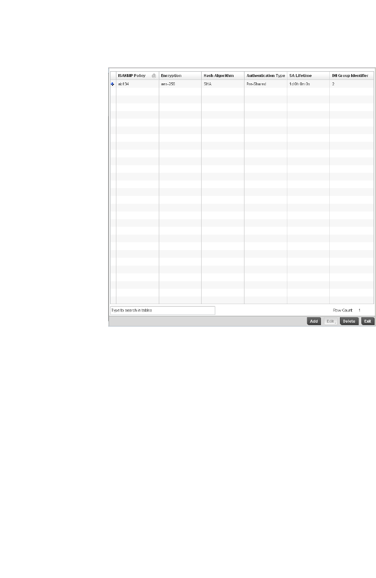
212 Brocade Mobility RFS4000, RFS6000, and RFS7000 System Reference Guide
53-1002620-01
5
FIGURE 157 Profile Overrides - ISAKMP Policy screen
6. Refer to the following configuration data for existing ISAKMP policies:
7. Se le ct Add to create a new ISAKMP policy, Edit to modify or override the attributes of a selected
existing policy or Delete to remove obsolete policies from the list of those available to the
controller.
If adding or editing an existing ISAKMP policy, the following screen displays.
ISAKMP Policy Displays the name assigned to the ISAKMP policy when it was initially created. The
name cannot be modified as part of the edit process.
Encryption Lists the encryption type used for encrypting packets with this ISAKMP policy.
Hash Algorithm Displays the MD5 or SHA hashing algorithm used in the ISAKMP policy.
Authentication Type Lists the key sharing mechanism used for establishing a secure connection
between two peers using this ISAKMP policy.
SA Lifetime Lists the lifetime in either seconds, minutes, hours or days for the security
association (SA) used by this ISAKMP policy.
DH Group Identifier Displays the Diffie-Hellman (DH) group identifier used by this ISAKMP policy. DH is a
cryptographic protocol that allows 2 entities that have no prior knowledge of each
other to jointly derive and establish a shared secret key over an unsecured
communication channel. This secret key can then be used to initiate a secure
connection between the two entities.
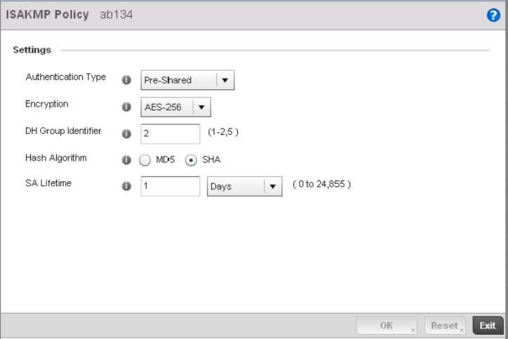
Brocade Mobility RFS4000, RFS6000, and RFS7000 System Reference Guide 213
53-1002620-01
5
When ISAKMP negotiations begin, the peer initiating the negotiation sends its policies to the
remote peer. The remote peer searches for a match with its own policies using the defined
priority scheme. A ISAKMP policy matches when they have the same encryption, hash,
authentication and Diffie-Hellman settings. The ISAKMP lifetime must also be less than or
equal to the lifetime in the policy sent. If the lifetimes do not match, the shorter lifetime
applies. If no match exists, ISAKMP refuses negotiation.
FIGURE 158 ISAKMP Policy Add screen

214 Brocade Mobility RFS4000, RFS6000, and RFS7000 System Reference Guide
53-1002620-01
5
8. Set or override the following configuration parameters for the new or modified ISAKMP policy:
ISAKMP Policy If creating a new ISAKMP policy, assign it a name to help differentiate it from others
that may have a similar configuration. The policy name cannot exceed 64
characters. The name cannot be modified as part of the edit process.
Authentication Type Set the key sharing mechanism used for establishing a secure connection between
two peers using this ISAKMP policy. Use the drop-down menu to select one the
following two authentication options:
Pre-Shared – Select this option to use a key shared between the VPN endpoints.
Pre-Shared is the default setting.
RSA Signature – Uses a RSA signature as the authentication key. Ensure digital
certificates and RSA keys have been installed on the target system before using this
option.
Encryption Use the drop-down menu to select the encryption algorithm to use. Select from the
drop-down list.
DES – DES stands for Data Encryption Standard. It uses a 56-bit key for encryption.
This standard is deprecated and replaced by the 3DES standard. It is provided for
backward compatibility.
3DES - 3DES or Triple DES is a encryption standard that replaced DES. It provides a
simple method of increasing the key size of the DES algorithm to protect from brute
force attacks. It uses a set of three (3) standard 56-bit DES keys to provide
increased key length for encryption.
AES – AES stands for Advanced Encryption Standard or the Rijndael Encryption
Algorithm that was adopted as the new FIPS standard in the year 2002. It is a
symmetric-key encryption standard that uses three (3) block ciphers of length 128,
192, 256 bits. This option represents the AES-128 bit block cipher.
AES-192 – AES stands for Advanced Encryption Standard or the Rijndael Encryption
Algorithm that was adopted as the new FIPS standard in the year 2002. It is a
symmetric-key encryption standard that uses three (3) block ciphers of length 128,
192, 256 bits. This option represents the AES-192 bit block cipher.
AES-256 – AES stands for Advanced Encryption Standard or the Rijndael Encryption
Algorithm that was adopted as the new FIPS standard in the year 2002. It is a
symmetric-key encryption standard that uses three (3) block ciphers of length 128,
192, 256 bits. This option represents the AES-256 bit block cipher. AES -256 is the
default setting.
DH Group Identifier Set the Diffie-Hellman (DH) group identifier used by this ISAKMP policy. DH is a
cryptographic protocol that allows 2 entities that have no prior knowledge of each
other to jointly derive and establish a shared secret key over an unsecured
communication channel. This secret key can then be used to initiate a secure
connection between the two entities.
The valid values are 1, 2 and 5 and indicates the group used for the key exchange.
The default setting is 2.
Hash Value Set the hash algorithm. Select from:
MD5 – MD5 or Message-Digest algorithm 5 is a popular 128-bit hash-function. It is
commonly used for checking the integrity of files.
SHA – Secure Hash Algorithm (SHA) is a NIST certified FIPS hash algorithm. SHA is
the default setting.
SA Lifetime Set the lifetime in seconds for the security association (SA) used by this ISAKMP
policy. This is the lifetime of the ISAKMP SA. The lifetime for
ESP/AH SAs are configured separately.
Days – Sets the SA duration in days (1 - 24,856).
Hours – Sets the SA duration in hours (1 - 596,524).
Minutes – Sets the SA duration in minutes (1 - 35, 791, 395).
Seconds – Sets the SA duration in seconds (60 - 2,147,483,646). The default
setting is 86,400 seconds.

Brocade Mobility RFS4000, RFS6000, and RFS7000 System Reference Guide 215
53-1002620-01
5
9. Select OK to save the changes or overrides. Select Reset to revert to the last saved
configuration.
Overriding a Profile’s Transform Set Configuration
Overriding a Profile’s Security Configuration
Use the Transform Set screen to configure and manage transform sets. A Transform Set is a set of
parameters that transform an IP packet from clear text to cipher text. The transform set is an
acceptable combination of security protocols, algorithms and other settings that are applied to
IPSec protected traffic.
With manually established security associations, there’s no negotiation with the peer. Both sides
must specify the same transform set, regardless of whether the SA is manual or automatic. For
manual SAs, the ISAKMP policy does not apply. If you change a Transform Set definition, the
change is only applied to Crypto Map entries that reference the Transform Set. If a transform-set is
changed, the existing SAs are removed.
To define a transform set configuration or override that can be applied to a controller profile:
1. Select Devices from the Configuration tab.
The Device Configuration screen displays a list of managed devices or peer controllers. The
listed devices can either be other controllers or Access Points within the managed network.
2. Select a target device (by double-clicking it) from amongst those displayed within the Device
Configuration screen.
Devices can also be selected directly from the Device Browser in the lower, left-hand, side of
the UI.
3. Select Profile Overrides from the Device menu to expand it into sub menu options.
4. Select Security to expand its sub menu options.
5. Select Transform Set.
NOTE
A blue override icon (to the left of a parameter) defines the parameter as having an override applied.
To remove an override go to the Basic Configuration section of the device and click the Clear
Overrides button. This will remove all overrides from the device.
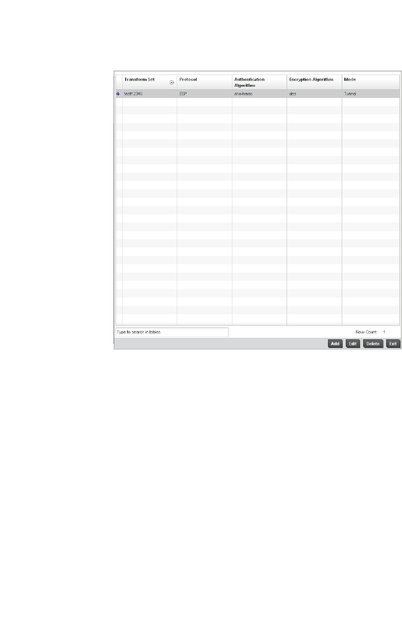
216 Brocade Mobility RFS4000, RFS6000, and RFS7000 System Reference Guide
53-1002620-01
5
FIGURE 159 Profile Overrides - Transform Set screen
6. Refer to the following contents displayed for existing Transform Set configurations to determine
whether a new Transform Set configuration is required, or if an existing configuration can be
used with or without modification or override:
7. Se le ct Add to create a new Transform Set configuration, Edit to modify or override the
attributes of a selected Transform set or Delete to remove obsolete Transform Set from the list
of those available to the controller.
If adding or editing an existing Transform Set, the following screen displays:
Transform Set Lists the name of each Transform Set defined when it was initially created. The
name cannot be modified if editing the configuration of an existing Transform Set.
Protocol Displays the AH or ESP protocol used with the Transform Set. AH provides
authentication only, while ESP provides a stronger combination of data
confidentiality and authentication.
Authentication
Algorithm
Lists the authentication used to validate identity.
Encryption Algorithm Lists the encryption type used for encrypting packets.
Mode Displays the Tunnel or Transport mode used for packet organization with respect to
header location and the scope of ESP or AH protection boundary. The tunnel mode
should be used for site-to-site VPN and transport should be used for remote VPN
configurations.
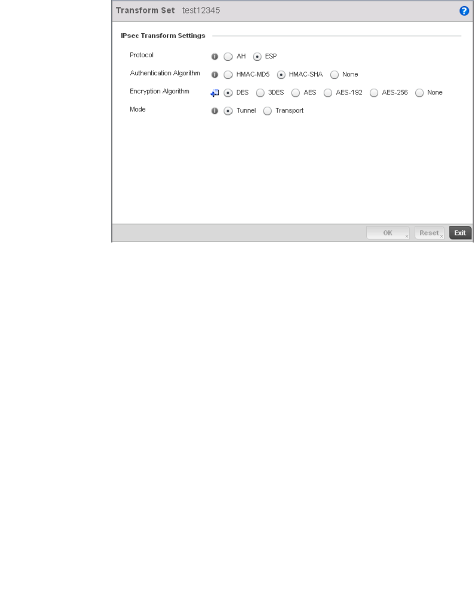
Brocade Mobility RFS4000, RFS6000, and RFS7000 System Reference Guide 217
53-1002620-01
5
FIGURE 160 Transform Set Configuration screen
8. Set or override the following configuration parameters for the Transform Set:
9. Select OK to save the updated or overrides. Select Reset to revert to the last saved
configuration.
Overriding a Profile’s VPN Configuration
Overriding a Profile’s Security Configuration
Transform Set If creating a new Transform Set, assign it a name to help differentiate it from others
that may have a similar configuration. The name cannot exceed 64 characters. The
name cannot be modified as part of the edit process.
Protocol Select the radio button of the IPSec protocol used with the Transform Set. AH
provides data authentication only. ESP provides data confidentiality and well as
authentication. ESP is the default setting.
Authentication
Algorithm
Set the authentication algorithm used to validate identity.
HMAC-MD5 – Use the Message Digest 5 (MD5) as the HMAC algorithm.
HMAC-SHA – Use the Secure Hash Algorithm (SHA) as the HMAC algorithm.
HMAC-SHA is the default setting.
None – Applies no authentication. If the protocol is AH, None cannot be selected.
Encryption Algorithm The encryption algorithm radio button only displays when ESP is selected as the
Transform Set protocol. By default, the Transform set uses AES-256.
It’s a symmetric-key encryption standard that uses a block ciphers length 256 bits.
AES -256 is the default setting. Selecting None applies no encryption. When the
protocol is ESP, encryption and authentication cannot both be set to None.
Mode Set the mode used for packet organization with respect to header location and the
scope of ESP or AH protection boundary. Use Tunnel for site-to-site VPN and
Transport mode for remote VPN configurations. The default mode is Tunnel.

218 Brocade Mobility RFS4000, RFS6000, and RFS7000 System Reference Guide
53-1002620-01
5
IPSec VPN provides a secure tunnel between two networked peer access points or controllers.
Administrators can define which packets are sent within the tunnel, and how they’re protected.
When a tunnelled peer sees a sensitive packet, it creates a secure tunnel and sends the packet
through the tunnel to its remote peer destination.
Tunnels are sets of security associations (SA) between two peers. SAs define the protocols and
algorithms applied to sensitive packets and specify the keying mechanisms used by tunnelled
peers. SAs are unidirectional and exist in both the inbound and outbound direction. SAs are
established per the rules and conditions of defined security protocols (AH or ESP).
Use crypto maps to configure IPSec VPN SAs. Crypto maps combine the elements comprising IPSec
SAs. Crypto maps also include transform sets. A transform set is a combination of security
protocols, algorithms and other settings applied to IPSec protected traffic. One crypto map is
utilized for each IPsec peer, however for remote VPN deployments one crypto map is used for all
the remote IPsec peers.
Internet Key Exchange (IKE) protocol is a key management protocol standard used in conjunction
with IPSec. IKE enhances IPSec by providing additional features, flexibility, and configuration
simplicity for the IPSec standard. IKE automatically negotiates IPSec SAs, and enables secure
communications without time consuming manual pre-configuration.
To define a profile’s VPN settings:
Select Devices from the Configuration tab.
Select a target device (by double-clicking it) from amongst those displayed within the Device
Configuration screen.
Select Profile Overrides from the Device menu to expand it into sub menu options.
Expand the Security menu and select VPN.
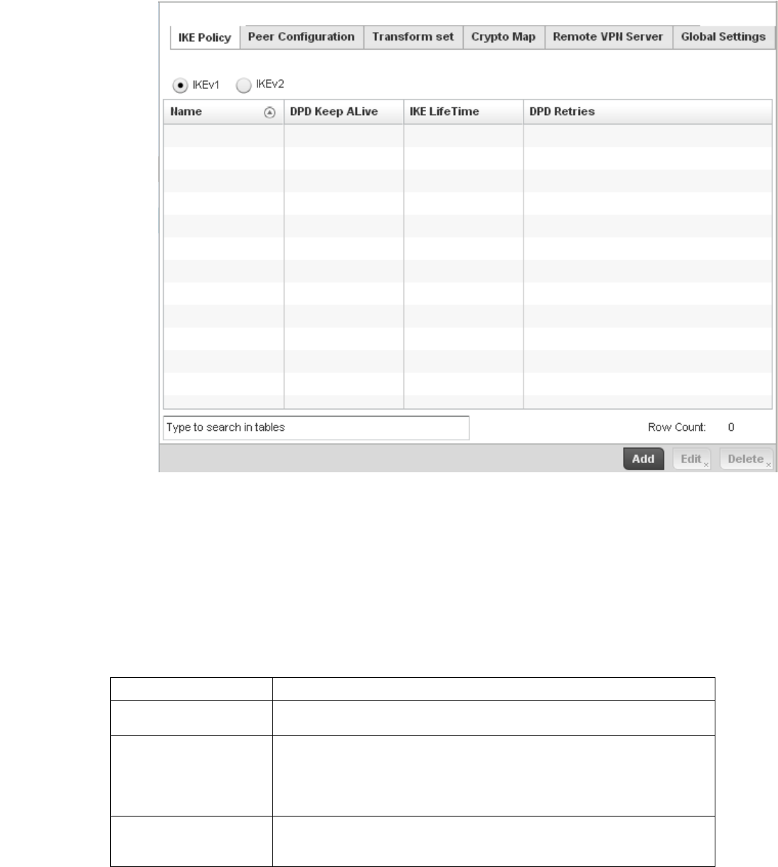
Brocade Mobility RFS4000, RFS6000, and RFS7000 System Reference Guide 219
53-1002620-01
5
FIGURE 161 Profile Security - VPN IKE Policy screen
Select either the IKEv1 or IKEv2 radio button to enforce VPN peer key exchanges using either IKEv1
or IKEv2.
IKEv2 provides improvements from the original IKEv1 design (improved cryptographic
mechanisms, NAT and firewall traversal, attack resistance etc.) and is recommended in most
deployments. The appearance of the IKE Policy screens differ depending on the selected IKEv1
or IKEv2 mode.
Refer to the following to determine whether an IKE Policy requires creation, modification or
removal:
Name Displays the 32 character maximum name assigned to the IKE policy.
DPD Keep Alive Lists each policy’s IKE keep alive message interval defined for IKE VPN tunnel dead
peer detection.
IKE LifeTime Displays each policy’s lifetime for an IKE SA. The lifetime defines how long a
connection (encryption/authentication keys) should last, from successful key
negotiation to expiration. Two peers need not exactly agree on the lifetime, though if
they do not, there is some clutter for a superseded connection on the peer defining
the lifetime as longer.
DPD Retries Lists each policy’s number maximum number of keep alive messages sent before a
VPN tunnel connection is defined as dead by the peer. This screen only appears when
IKEv1 is selected.
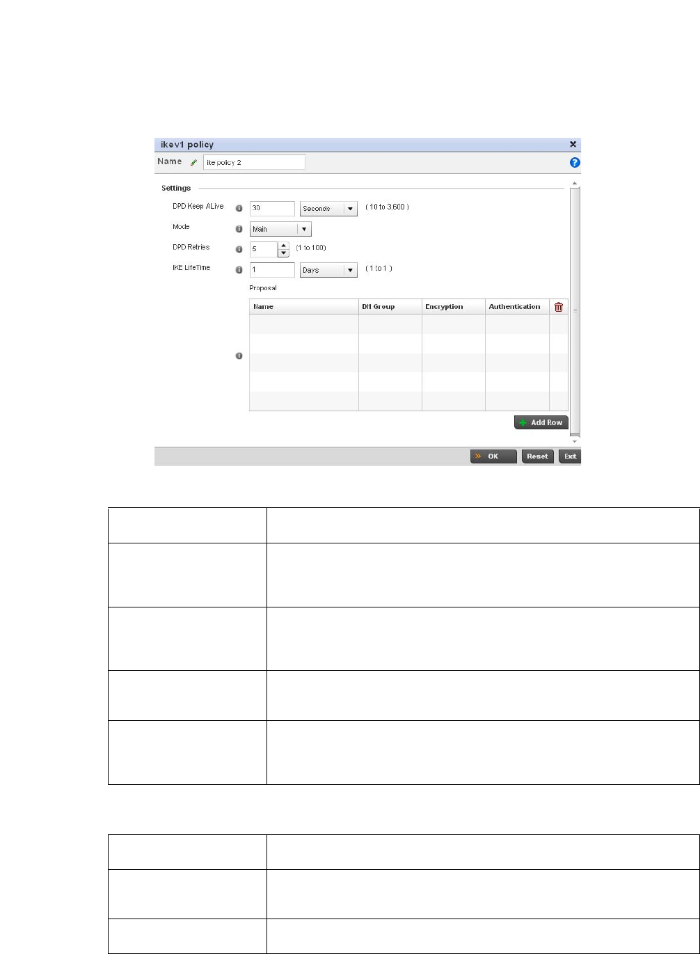
220 Brocade Mobility RFS4000, RFS6000, and RFS7000 System Reference Guide
53-1002620-01
5
Select Add to define a new IKe Policy configuration, Edit to modify an existing configuration or
Delete to remove an existing configuration.
FIGURE 162 Profile Security - VPN IKE Policy create/modify screen (IKEv1 example)
Select + Add Row to define the network address of a target peer and its security settings.
Name If creating a new IKE policy, assign it a 32 character maximum name to help
differentiate this IKE configuration from others with a similar parameters.
DPD Keep Alive Configure the IKE keep alive message interval used for dead peer detection on the
remote end of the IPSec VPN tunnel. Set this value in either Seconds (10 - 3,600),
Minutes (1 - 60) or Hours (1). The default setting is 30 seconds. This setting is
required for both IKEv1 and IKEV2.
Mode If using IKEv1, use the drop-down menu to define the IKE mode as either Main or
Aggressive. IPSEC has two modes in IKEv1 for key exchanges. Aggressive mode
requires 3 messages be exchanged between the IPSEC peers to setup the SA, Main
requires 6 messages. The default setting is Main.
DPD Retries Use the spinner control to set the maximum number of keep alive messages sent
before a VPN tunnel connection is defined as dead. The available range is from 1 -
100. The default setting is 5.
IKE LifeTime Set the lifetime defining how long a connection (encryption/authentication keys)
should last from successful key negotiation to expiration. Set this value in either
Seconds (600 - 86,400), Minutes (10 - 1,440), Hours (1 - 24) or Days (1). This setting
is required for both IKEv1 and IKEV2.
Name If creating a new IKE policy, assign the target peer (tunnel destination) a 32 character
maximum name to distinguish it from others with a similar configuration.
DH Group Use the drop-down menu to define a Diffie-Hellman (DH) identifier used by the VPN
peers to derive a shared secret password without having to transmit. Options include
2, 5 and 14. The default setting is 5.
Encryption Select an encryption method used by the tunnelled peers to securely interoperate.
Options include 3DES, AES, AES-192 and AES-256. The default setting is AES-256.
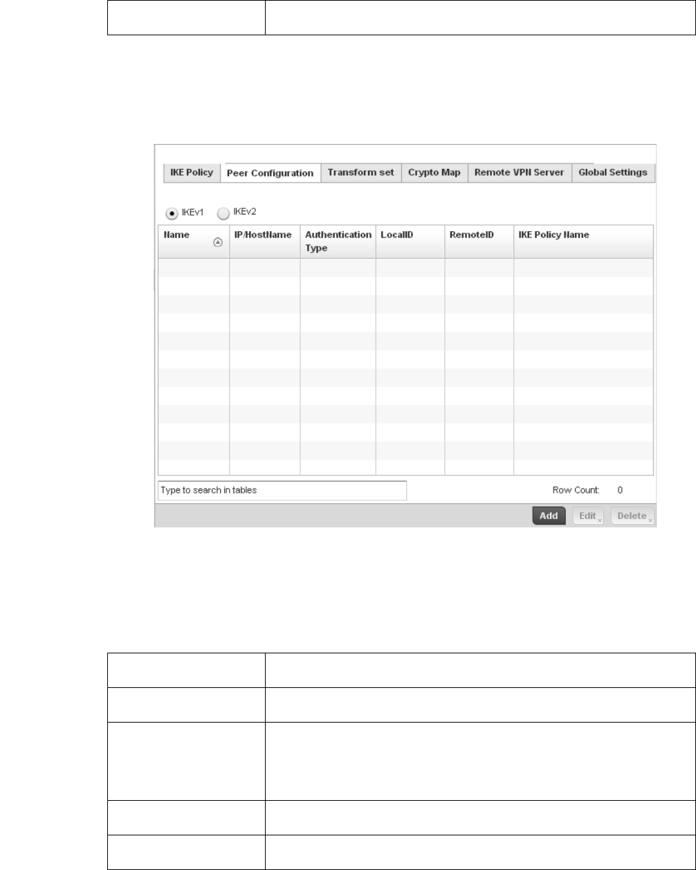
Brocade Mobility RFS4000, RFS6000, and RFS7000 System Reference Guide 221
53-1002620-01
5
Select OK to save the changes made within the IKE Policy screen. Select Reset to revert to the last
saved configuration. Select the Delete Row icon as needed to remove a peer configuration.
Select the Peer Configuration tab to assign additional network address and IKE settings to the an
intended VPN tunnel peer destination.
FIGURE 163 Profile Security - VPN Peer Destination screen (IKEv1 example)
Select either the IKEv1 or IKEv2 radio button to enforce VPN key exchanges using either IKEv1 or
IKEv2.
Refer to the following to determine whether a new VPN Peer Configuration requires creation, an
existing configuration requires modification or a configuration requires removal.
Authentication Select an authentication hash algorithm used by the peers to exchange credential
information. Options include SHA and MD5. The default setting is SHA.
Name Lists the 32 character maximum name assigned to each listed peer configuration
upon creation.
IP/Hostname Displays the IP address (or host address FQDN) of the IPSec VPN peer targeted for
secure tunnel connection and data transfer.
Authentication Type Lists whether the peer configuration has been defined to use pre-shared key (PSK) or
RSA. Rivest, Shamir, and Adleman (RSA) is an algorithm for public key cryptography.
It’s the first algorithm known to be suitable for signing, as well as encryption. If using
IKEv2, this screen displays both local and remote authentication, as both ends of the
VPN connection require authentication.
LocalID Lists the access point’s local identifier used within this peer configuration for an IKE
exchange with the target VPN IPSec peer.
RemoteID Displays the means the target remote peer is to be identified (string, FQDN etc.) within
the VPN tunnel.
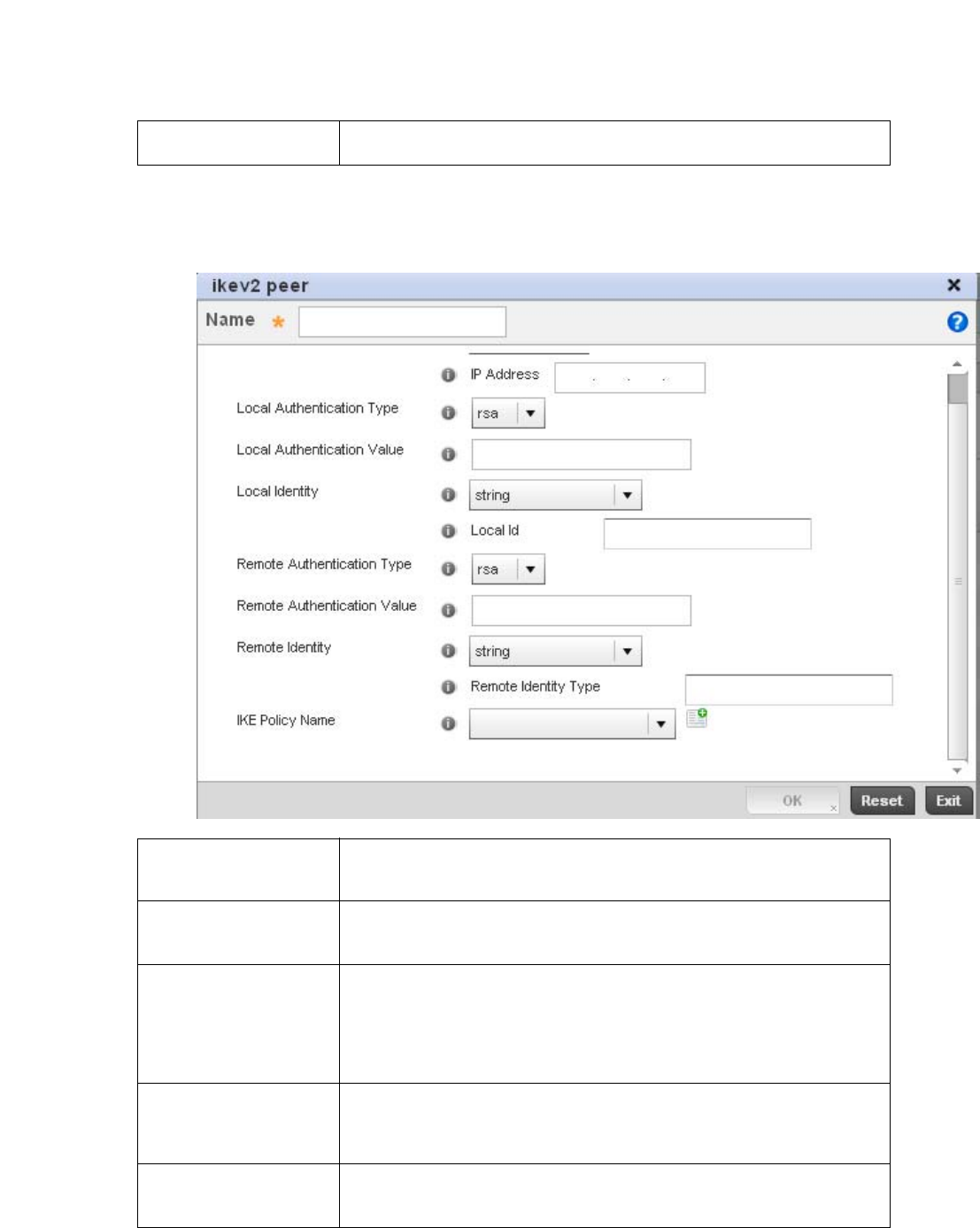
222 Brocade Mobility RFS4000, RFS6000, and RFS7000 System Reference Guide
53-1002620-01
5
Select Add to define a new peer configuration, Edit to modify an existing configuration or Delete to
remove an existing peer configuration. The parameters that can de defined for the peer
configuration vary depending on whether IKEv1 or IKEv2 was selected.
IKE Policy Name Lists the IKEv1 or IKE v2 policy used with each listed peer configuration. If a policy
requires creation, select the Create button.
Name If creating a new peer configuration (remote gateway) for VPN tunnel connection,
assign it a 32 character maximum name to distinguish it from other with similar
attributes.
IP Type or
Select IP/Hostname
Enter either the IP address or FQDN hostname of the IPSec VPN peer used in the
tunnel setup. If IKEv1 is used, this value is titled IP Type, if IKEv2 is used, this
parameter is titled Select IP/Hostname.
Authentication Type Select either pre-shared key (PSK) or RSA. Rivest, Shamir, and Adleman (RSA) is an
algorithm for public key cryptography. It’s the first algorithm known to be suitable for
signing, as well as encryption If using IKEv2, this screen displays both local and
remote authentication options, as both ends of the VPN connection require
authentication. RSA is the default value for both local and remote authentication
(regardless of IKEv1 or IKEv2).
Authentication Value Define the authentication string (shared secret) that must be shared by both ends of
the VPN tunnel connection. The string must be between 8 - 21 characters long. If
using IKEv2, both a local and remote string must be specified for handshake
validation and both ends (local and remote) of the VPN connection.
Local Identity Select the access point’s local identifier used with this peer configuration for an IKE
exchange with the target VPN IPSec peer. Options include IP Address, Distinguished
Name, FQDN, email and string. The default setting is string.
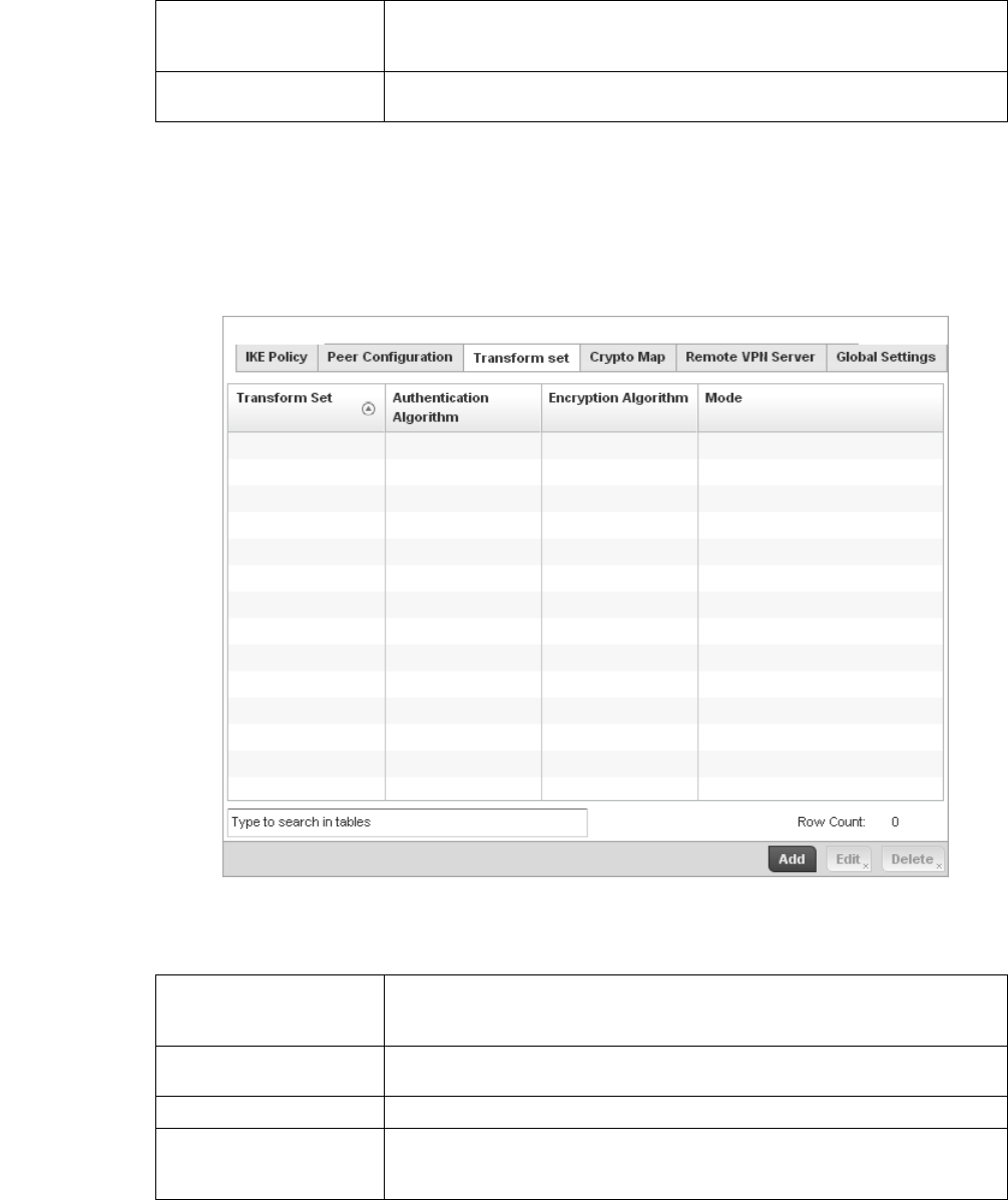
Brocade Mobility RFS4000, RFS6000, and RFS7000 System Reference Guide 223
53-1002620-01
5
Select OK to save the changes made within the Peer Configuration screen. Select Reset to revert to
the last saved configuration.
Select the Transform Set tab.
Create or modify Transform Set configurations to specify how traffic is protected within crypto
ACL defining the traffic that needs to be protected.
FIGURE 164 Profile Security - VPN Transform Set screen
Review the following attributes of existing Transform Set configurations:
Remote Identity Select the access point’s remote identifier used with this peer configuration for an IKE
exchange with the target VPN IPSec peer. Options include IP Address, Distinguished
Name, FQDN, email and string. The default setting is string.
IKE Policy Name Select the IKEv1 or IKE v2 policy name (and settings) to apply to this peer
configuration. If a policy requires creation, select the Create icon.
Name Lists the 32 character maximum name assigned to each listed transform set upon
creation. Again, a transform set is a combination of security protocols, algorithms and
other settings applied to IPSec protected traffic.
Authentication Algorithm Lists each transform sets’s authentication scheme used to validate identity
credentials. The authentication scheme is either HMAC-SHA or HMAC-MD5.
Encryption Algorithm Displays each transform set’s encryption method for protecting transmitted traffic.
Mode Displays either Tunnel or Transport as the IPSec tunnel type used with the transform
set. Tunnel is used for site-to-site VPN and Transport should be used for remote VPN
deployments.
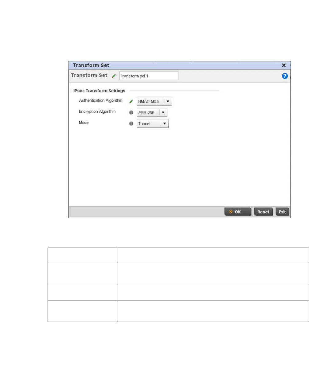
224 Brocade Mobility RFS4000, RFS6000, and RFS7000 System Reference Guide
53-1002620-01
5
Select Add to define a new transform set configuration, Edit to modify an existing configuration or
Delete to remove an existing transform set.
FIGURE 165 Profile Security - VPN Transform Set create/modify screen
Define the following settings for the new or modified transform set configuration:
Select OK to save the changes made within the Transform Set screen. Select Reset to revert to the
last saved configuration
Select the Crypto Map tab.
Use crypto maps (as applied to IPSec VPN) to combine the elements used to create IPSec SAs
(including transform sets).
Name If creating a new transform set, define a 32 character maximum name to differentiate
this configuration from others with similar attributes.
Authentication Algorithm Set the transform sets’s authentication scheme used to validate identity credentials.
Use the drop-down menu to select either HMAC-SHA or HMAC-MD5. The default
setting is HMAC-SHA.
Encryption Algorithm Set the transform set encryption method for protecting transmitted traffic. Options
include DES, 3DES, AES, AES-192 and AES-256. The default setting is AES-256.
Mode Use the drop-down menu to select either Tunnel or Transport as the IPSec tunnel type
used with the transform set. Tunnel is used for site-to-site VPN and Transport should
be used for remote VPN deployments.
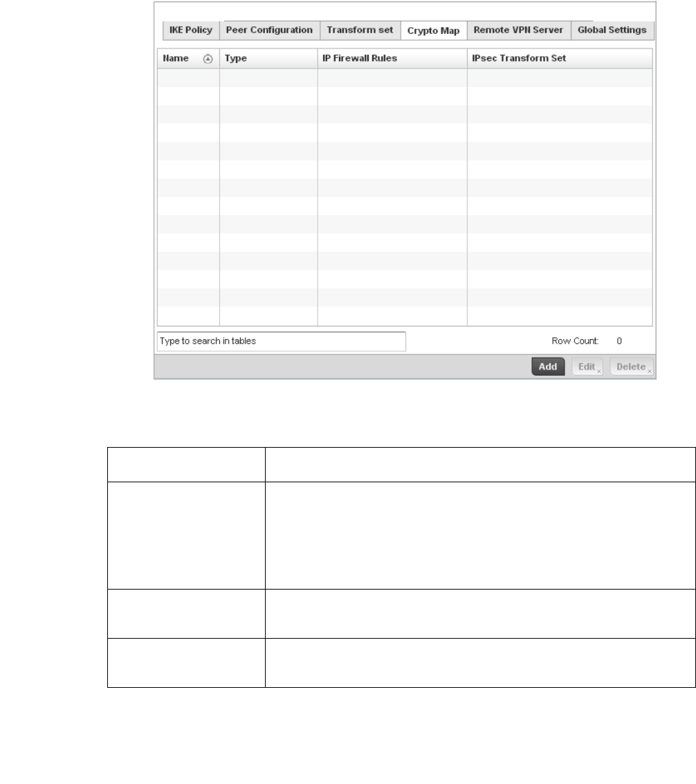
Brocade Mobility RFS4000, RFS6000, and RFS7000 System Reference Guide 225
53-1002620-01
5
FIGURE 166 Profile Security - VPN Crypto Map screen
Review the following Crypto Map configuration parameters to assess their relevance:
If requiring a new crypto map configuration, select the Add button. If updating the configuration of
an existing crypto map, select it from amongst those available and select the Edit button.
If adding a new crypto map, assign it a name up to 32 characters in length as a unique identifier.
Select the Continue button to proceed to the VPN Crypto Map screen.
Name Lists the 32 character maximum name assigned for each crypto map upon creation.
This name cannot be modified as part of the edit process.
Type Displays the site-to-site-manual, site-to-site-auto or remote VPN configuration defined
for each listed cyrpto map configuration. With site-to-site deployments, an IPSEC
Tunnel is deployed between two gateways, each at the edge of two different remote
networks. With remote VPN, an access point located at remote branch defines a
tunnel with a security gateway. This facilitates the endpoints in the branch office to
communicate with the destination endpoints (behind the security gateway) in a
secure manner.
IP Firewall Rules Lists the IP firewall rules defined for each displayed crypto map configuration. Each
firewall policy contains a unique set of access/deny permissions applied to the VPN
tunnel and its peer connection.
IPSec Transform Set Displays the transform set (encryption and has algorithms) applied to each listed
crypto map configuration. Thus, each crypto map can be customized with its own data
protection and peer authentication schemes.
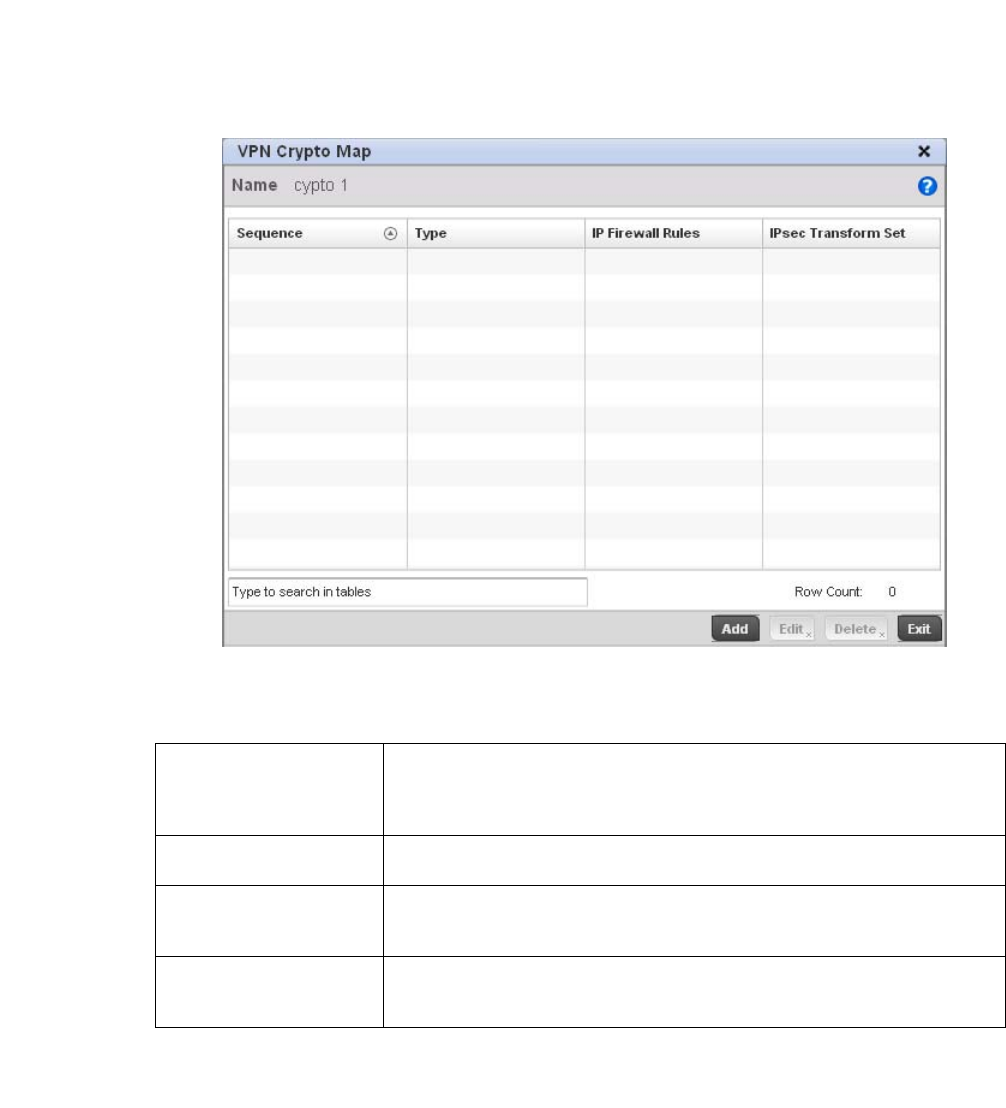
226 Brocade Mobility RFS4000, RFS6000, and RFS7000 System Reference Guide
53-1002620-01
5
FIGURE 167 Profile Security - VPN Crypto Map screen
Review the following before determining whether to add or modify a crypto map configuration
f requiring a new crypto map configuration, select the Add button. If updating the configuration of
an existing crypto map, select it from amongst those available and select the Edit button.
Sequence Each crypto map configuration uses a list of entries based on a sequence number.
Specifying multiple sequence numbers within the same crypto map, provides the
flexibility to connect to multiple peers from the same interface, based on the
sequence number (from 1 - 1,000).
Type Displays the site-to-site-manual, site-to-site-auto or remote VPN configuration defined
for each listed cyrpto map configuration.
IP Firewall Rules Lists the IP firewall rules defined for each displayed crypto map configuration. Each
firewall policy contains a unique set of access/deny permissions applied to the VPN
tunnel and its peer connection.
IPSec Transform Set Displays the transform set (encryption and hash algorithms) applied to each listed
crypto map configuration. Thus, each crypto map can be customized with its own data
protection and peer authentication schemes.
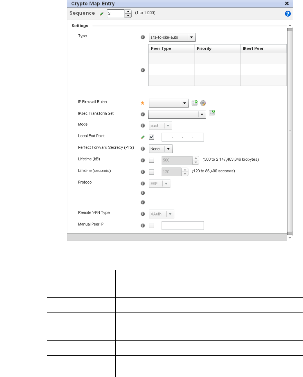
Brocade Mobility RFS4000, RFS6000, and RFS7000 System Reference Guide 227
53-1002620-01
5
FIGURE 168 Profile Security - VPN Crypto Map Entry screen
\Define the following to parameters to set the crypto map configuration:
Sequence Each crypto map configuration uses a list of entries based on a sequence number.
Specifying multiple sequence numbers within the same crypto map extends
connection flexibility to multiple peers on the same interface, based on this selected
sequence number (from 1 - 1,000).
Type Define the site-to-site-manual, site-to-site-auto or remote VPN configuration defined
for each listed cyrpto map configuration.
IP Firewall Rules Use the drop-down menu to select the access list (ACL) used to protect IPSec VPN
traffic. New access/deny rules can be defined for the crypto map by selecting the
Create icon, or an existing set of firewall rules can be modified by selecting the Edit
icon.
IPSec Transform Set Select the transform set (encryption and hash algorithms) to apply to this crypto map
configuration.
Mode Use the drop-down menu to define which mode (pull or push) is used to assign a
virtual IP. This setting is relevant for IKEv1 only, since IKEv2 always uses the
configuration payload in pull mode. The default setting is push.

228 Brocade Mobility RFS4000, RFS6000, and RFS7000 System Reference Guide
53-1002620-01
5
Select OK to save the updates made to the Crypto Map Entry screen. Selecting Reset reverts the
screen to its last saved setting.
Select Remote VPN Server.
Use this screen to define the server resources used to secure (authenticate) a remote VPN
connection with a target peer.
Local End Point Select this radio button to define an IP address as a local tunnel end point address.
This setting represents an alternative to an interface IP address.
Perfect Forward Secrecy
(PFS)
PFS is key-establishment protocol, used to secure VPN communications. If one
encryption key is compromised, only data encrypted by that specific key is
compromised. For PFS to exist, the key used to protect data transmissions must not
be used to derive any additional keys. Options include None, 2, 5 and 14. The default
setting is None.
Lifetime (kB) Select this option to define a connection volume lifetime (in kilobytes) for the duration
of an IPSec VPN security association. Once the set volume is exceeded, the
association is timed out. Use the spinner control to set the volume from 500 -
2,147,483,646 kilobytes.
Lifetime (seconds) Select this option to define a lifetime (in seconds) for the duration of an IPSec VPN
security association. Once the set value is exceeded, the association is timed out. The
available range is from 120 - 86,400 seconds. The default setting is 120 seconds.
Protocol Select the security protocol used with the VPN IPSec tunnel connection. SAs are
unidirectional, existing in each direction and established per security protocol.
Options include ESP and AH. The default setting is ESP.
Remote VPN Type Define the remote VPN type as either None or XAuth. XAuth (extended authentication)
provides additional authentication validation by permitting an edge device to request
extended authentication information from an IPSec host. This forces the host to
respond with additional authentication credentials. The edge device respond with a
failed or passed message. The default setting is XAuth.
Manual Peer IP Select this option to define the IP address of an additional encryption/decryption
peer.
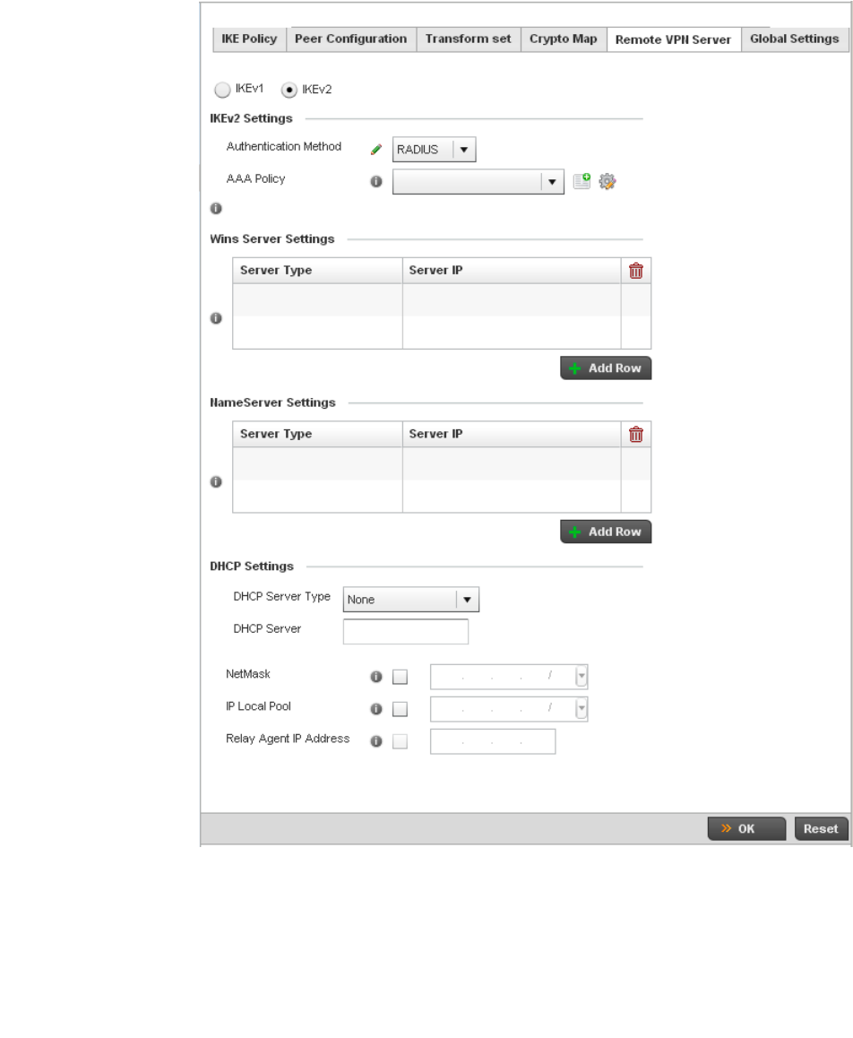
Brocade Mobility RFS4000, RFS6000, and RFS7000 System Reference Guide 229
53-1002620-01
5
FIGURE 169 Profile Security - Remote VPN Server screen (IKEv2 example)
Select either the IKEv1 or IKEv2 radio button to enforce peer key exchanges over the remote VPN
server using either IKEv1 or IKEv2.
IKEv2 provides improvements from the original IKEv1 design (improved cryptographic
mechanisms, NAT and firewall traversal, attack resistance etc.) and is recommended in most
deployments. The appearance of the screen differs depending on the selected IKEv1 or IKEv2
mode.

230 Brocade Mobility RFS4000, RFS6000, and RFS7000 System Reference Guide
53-1002620-01
5
Set the following IKEv1 or IKe v2 Settings:
Refer to the Wins Server Settings field and specify primary and secondary server resources for
validating RADIUS authentication requests on behalf of a remote VPN client. These external WINS
server resources are available to validate RADIUS resource requests.
Refer to the Name Server Settings field and specify primary and secondary server resources for
validating RADIUS authentication requests on behalf of a remote VPN client. These external name
server resources are available to validate RADIUS resource requests.
Select the IP Local Pool option to define an IP address and mask for a virtual IP pool used to IP
addresses to remote VPN clients.
If using IKEv2 specify these additional settings (required for IKEv2 only):
Select OK to save the updates made to the Remote VPN Server screen. Selecting Reset reverts the
screen to its last saved configuration.
Select the Global Settings tab.
The Global Settings screen provides options for Dead Peer Detection (DPD). DPD represents
the actions taken upon the detection of a dead peer within the IPSec VPN tunnel connection.
Authentication Method Use the drop-down menu to specify the authentication method used to validate the
credentials of the remote VPN client. Options include Local (on board RADIUS
resource if supported) and RADIUS (designated external RADIUS resource). If
selecting Local, select the + Add Row button and specify a User Name and
Password for authenticating remote VPN client connections with the local RADIUS
resource. The default setting is Local. AP6521 and AP6511 model access points do
not have a local RADIUS resource and must use an external RADIUS server resource.
AAA Policy Select the AAA policy used with the remote VPN client. AAA policies define RADIUS
authentication and accounting parameters. The access point can optionally use AAA
server resources (when using RADIUS as the authentication method) to provide user
database information and user authentication data.
DHCP Server Type Specify whether the DHCP server is specified as an IP address, Hostname (FQDN) or
None (a different classification will be defined). Dynamic Host Configuration Protocol
(DHCP) allows hosts on an IP network to request and be assigned IP addresses as
well as discover information about the network where they reside.
DHCP Server Depending on the DHCP server type selected, enter either the numerical IP address,
hostname or other (if None is selected as the server type).
NetMask Specify the netmask for remote VPN clients.
IP Local Pool Select the IP Local Pool option to define an IP address and mask for a virtual IP
pool used to IP addresses to remote VPN clients.
Relay Agent IP Address Select this option to define DHCP relay agent IP address.
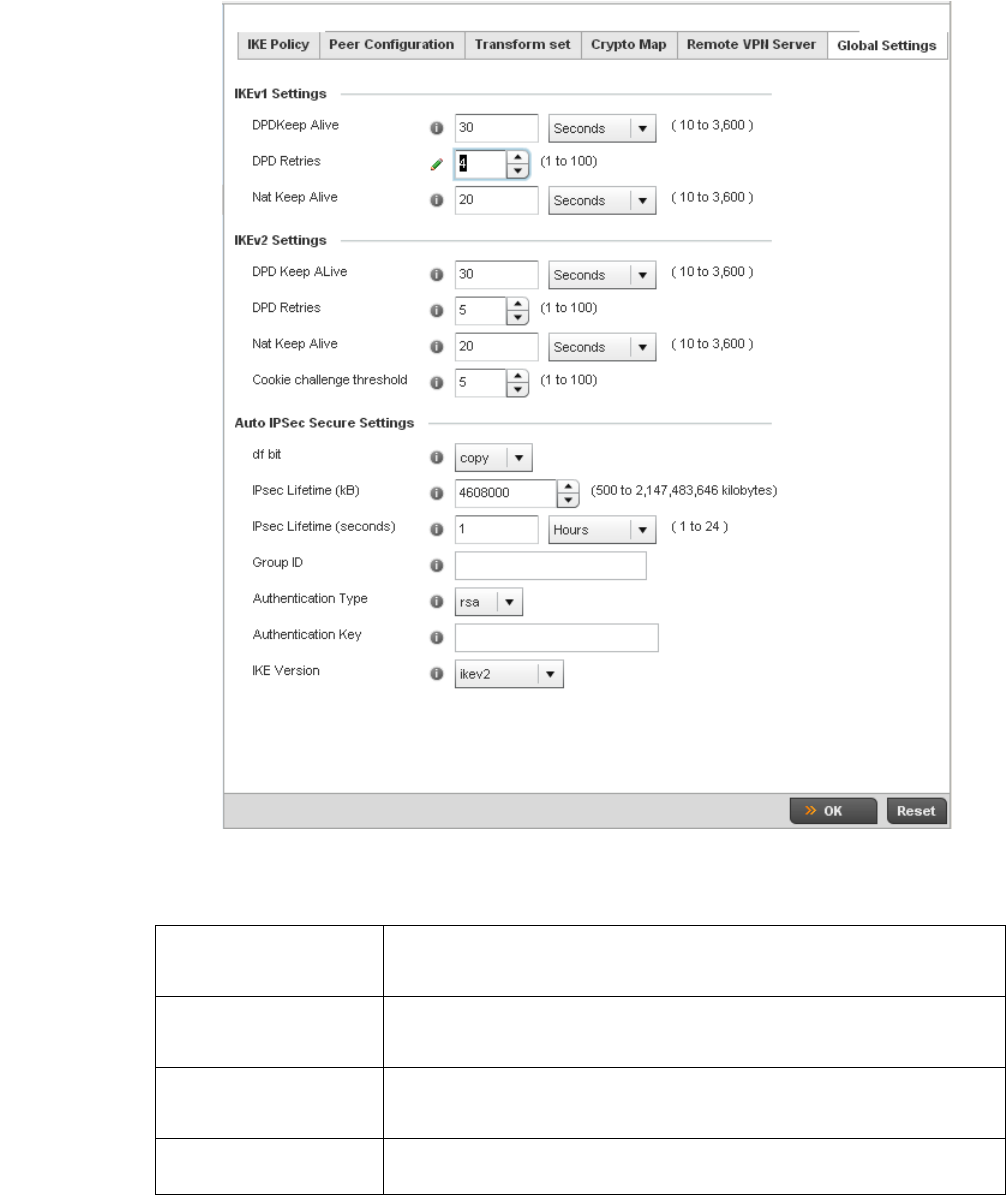
Brocade Mobility RFS4000, RFS6000, and RFS7000 System Reference Guide 231
53-1002620-01
5
FIGURE 170 Profile Security - Global VPN Settings screen
Define the following settings IKE Dead Peer Detection:
DPD Keep Alive Define the interval (or frequency) of IKE keep alive messages for dead peer detection.
Options include Seconds (10 - 3,600), Minutes (1 - 60) and Hours (1). The default
setting is 30 seconds.
DPD Retries Use the spinner control to define the number of keep alive messages sent before to
an IPSec VPN client before the tunnel connection is defined as dead. The available
range is from 1 - 100. The default number of messages is 5.
NAT Keep Alive Define the interval (or frequency) of NAT keep alive messages for dead peer detection.
Options include Seconds (10 - 3,600), Minutes (1 - 60) and Hours (1). The default
setting is 20 seconds.
Cookie Challenge
Threshold
Use the spinner control to define the threshold (1 - 100) that, when exceeded,
enables the cookie challenge mechanism.

232 Brocade Mobility RFS4000, RFS6000, and RFS7000 System Reference Guide
53-1002620-01
5
Refer to the Auto IPsec Secure Settings field to define the following IPSec security, lifetime and
authentication settings:
Select OK to save the updates made to the Global Settings screen. Selecting Reset reverts the
screen to its last saved configuration.
Overriding a Profile’s NAT Configuration
Overriding a Profile’s Security Configuration
Network Address Translation (NAT) is a technique to modify network address information within IP
packet headers in transit across a traffic routing device. This enables mapping one IP address to
another to protect wireless controller managed network address credentials. With typical
deployments, NAT is used as an IP masquerading technique to hide private IP addresses behind a
single, public facing, IP address.
NAT is a process of modifying network address information in IP packet headers while in transit
across a traffic routing device for the purpose of remapping one IP address to another. In most
deployments NAT is used in conjunction with IP masquerading which hides RFC1918 private IP
addresses behind a single public IP address.
NAT can provide a controller profile outbound Internet access to wired and wireless hosts
connected to either a thick access point (such as an AP71xx, AP71xx or AP-5131 model) or a
RFS4000, RFS6000, or RFS7000 Series wireless controller. Many-to-one NAT is the most common
NAT technique for outbound Internet access. Many-to-one NAT allows a thick access point or
wireless controller to translate one or more internal private IP addresses to a single, public facing,
IP address assigned to a 10/100/1000 Ethernet port or 3G card.
To define a NAT configuration or override that can be applied to a controller profile:
1. Select Devices from the Configuration tab.
The Device Configuration screen displays a list of managed devices or peer controllers. The
listed devices can either be other controllers or Access Points within the managed network.
df bit Select the DF bit handling technique used for the ESP encapsulating header. Options
include Clear, set and copy. The default setting is Copy.
IPsec Lifetime (kb) Set a connection volume lifetime (in kilobytes) for the duration of an IPSec VPN
security association. Once the set volume is exceeded, the association is timed out.
Use the spinner control to set the volume from 500 - 2,147,483,646 kilobytes. The
default settings is 4,608,000 kilobytes.
IPsec Lifetime (seconds) Set a lifetime (in seconds) for the duration of an IPSec VPN security association. Once
the set value is exceeded, the association is timed out. The available range either
Seconds (120 - 86,400), Minutes (2 - 1,440), Hours (1 - 24) or Days (1). The default
setting is 3,600 seconds.
Group ID Define a 1 - 128 character identifier for an IKE exchange supporting auto IPSec
secure peers.
Authentication Type Use the drop-down menu to select either RSA or PSK (Pre Shared Key) as the
authentication type for secure peer authentication. Rivest, Shamir, and Adleman
(RSA) is an algorithm for public key cryptography. It’s the first algorithm known to be
suitable for signing, as well as encryption. The default setting is RSA.
Authentication Key Enter the 8 - 21 character shared key (password) used for auto IPSec secure peer
authentication.
IKE Version Use the drop-down menu to select the IKE version used for auto IPSec secure
authentication with the IPSec gateway and other controllers.
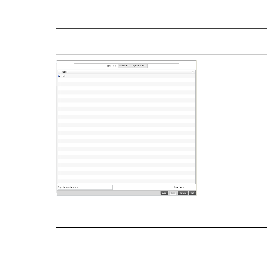
Brocade Mobility RFS4000, RFS6000, and RFS7000 System Reference Guide 233
53-1002620-01
5
2. Select a target device (by double-clicking it) from amongst those displayed within the Device
Configuration screen.
Devices can also be selected directly from the Device Browser in the lower, left-hand, side of
the UI.
3. Select Profile Overrides from the Device menu to expand it into sub menu options.
4. Select Security to expand its sub menu options.
5. Select NAT.
NOTE
A blue override icon (to the left of a parameter) defines the parameter as having an override applied.
To remove an override go to the Basic Configuration section of the device and click the Clear
Overrides button. This will remove all overrides from the device.
FIGURE 171 Profile Overrides - NAT Pool screen
6. The NAT Pool displays by default. The NAT Pool screen lists those NAT policies created thus far.
Any of these policies can be selected and applied to a controller profile.
NOTE
A blue override icon (to the left of a parameter) defines the parameter as having an override applied.
To remove an override go to the Basic Configuration section of the device and click the Clear
Overrides button. This will remove all overrides from the device.
7. S elect Add to create a new NAT policy that can be applied to a controller profile. Select Edit to
modify or override the attributes of a existing policy or select Delete to remove obsolete NAT
policies from the list of those available to a controller profile.
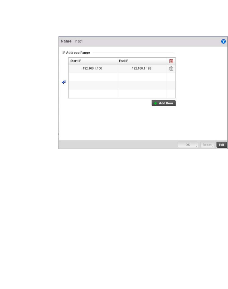
234 Brocade Mobility RFS4000, RFS6000, and RFS7000 System Reference Guide
53-1002620-01
5
FIGURE 172 NAT Pool screen
8. If adding a new NAT policy or editing the configuration of an existing policy, define the following
parameters:
9. Select the + Add Row button as needed to append additional rows to the IP Address Range
table.
10. Select OK to save the changes or overrides made to the profile’s NAT Pool configuration. Select
Reset to revert to the last saved configuration.
11. Select the Static NAT tab.
The Source tab displays by default.
Name If adding a new NAT policy, provide a name to help distinguish it from others with
similar configurations. The length cannot exceed 64 characters.
Prefix Length Use the spinner control to set the netmask (between 1 - 30) of the network the pool
address belongs to.
IP Address Range Define a range of IP addresses that are hidden from the public Internet. NAT modifies
network address information in the defined IP range while in transit across a traffic
routing device. NAT only provides IP address translation and does not provide a
firewall. A branch deployment with NAT by itself will not block traffic from being
potentially routed through a NAT device. Consequently, NAT should be deployed with a
stateful firewall.
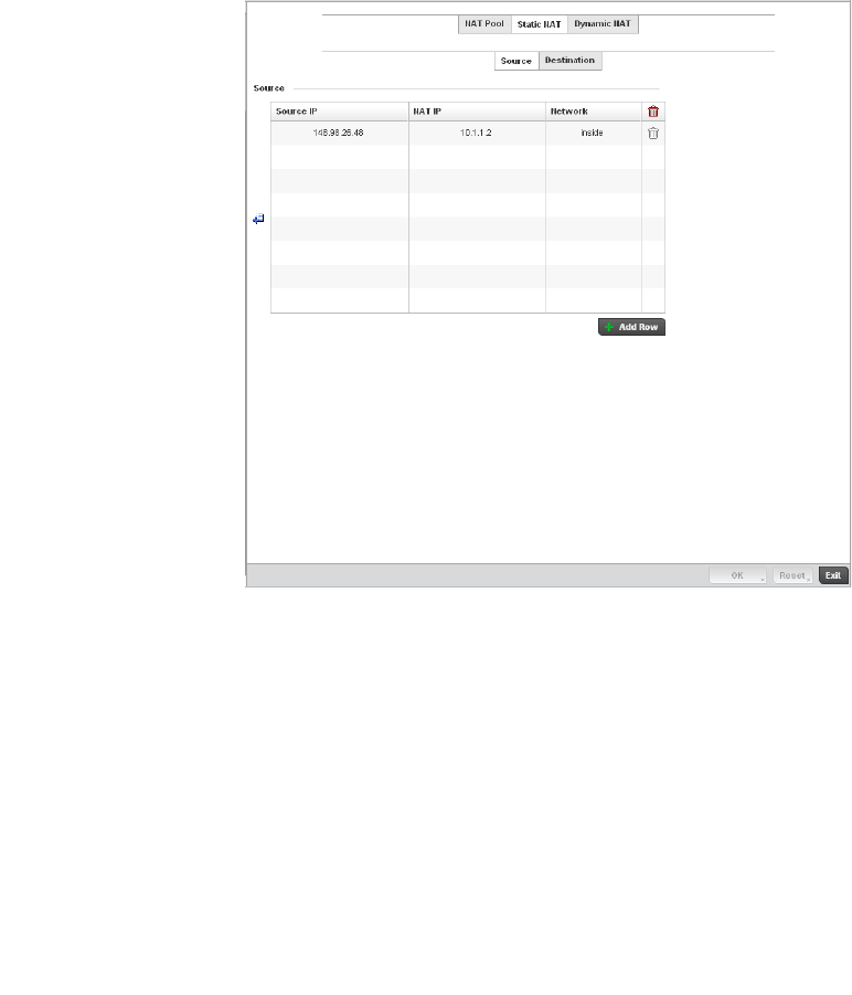
Brocade Mobility RFS4000, RFS6000, and RFS7000 System Reference Guide 235
53-1002620-01
5
FIGURE 173 Profile Overrides - Static NAT screen
12. To map a source IP address from an internal network to a NAT IP address click the + Add Row
button. Enter the internal network IP address in Source IP field. Enter the NAT IP address in the
NAT IP field.
13. Use the Network drop-down menu to set the NAT type either Inside or Outside. Select Inside to
create a permanent, one-to-one mapping between an address on an internal network and a
perimeter or external network. To share a Web server on a perimeter interface with the
Internet, use static address translation to map the actual address to a registered IP address.
Static address translation hides the actual address of the server from users on insecure
interfaces. Casual access by unauthorized users becomes much more difficult. Static NAT
requires a dedicated address on the outside network for each host. Inside NAT is the default
setting.
14. Select the Destination tab to view destination NAT configurations and define packets passing
through the NAT on the way back to the managed LAN are searched against to the records kept
by the NAT engine. The destination IP address is changed back to the specific internal private
class IP address to reach the LAN over the managed network.
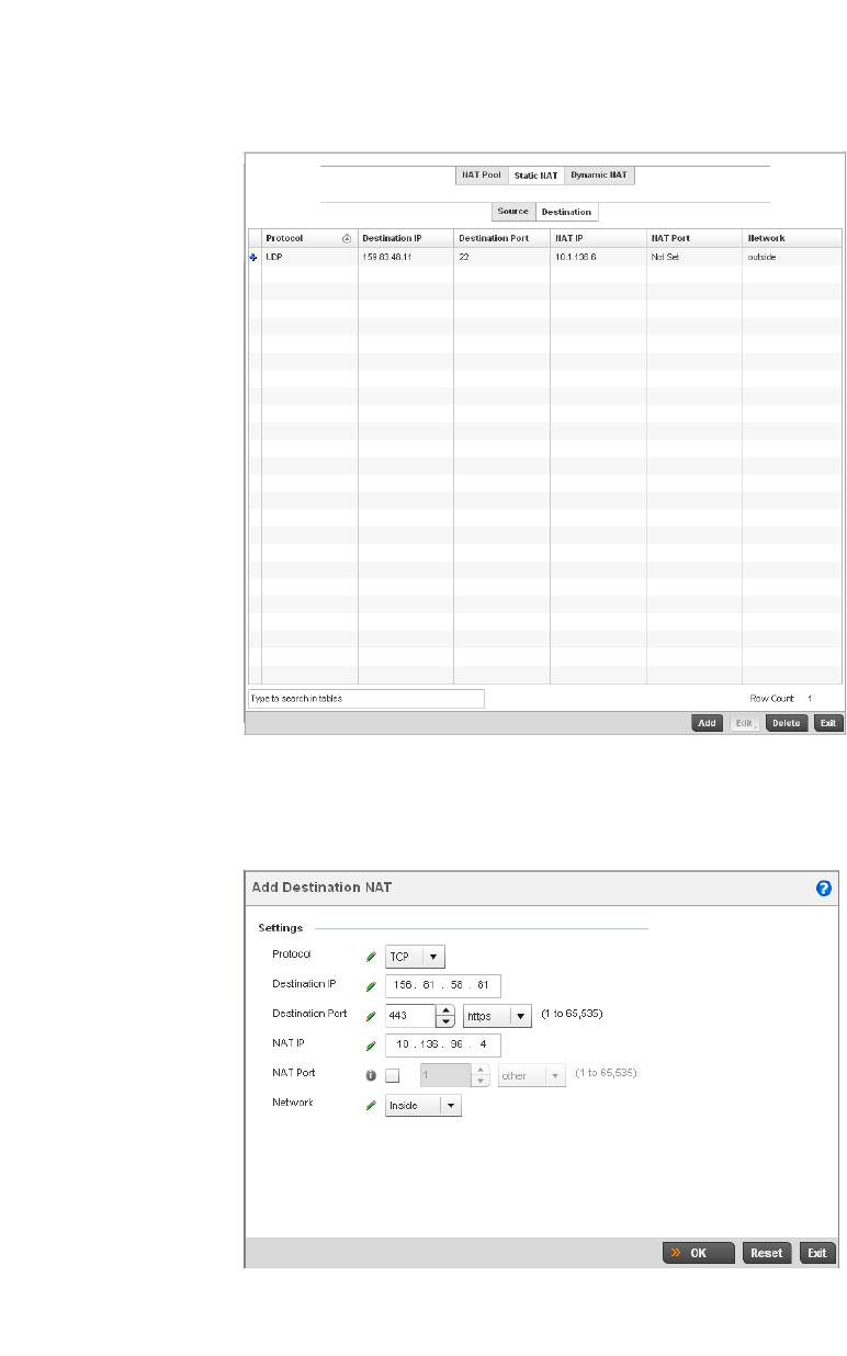
236 Brocade Mobility RFS4000, RFS6000, and RFS7000 System Reference Guide
53-1002620-01
5
FIGURE 174 NAT Destination screen
15. Select Add to create a new NAT destination configuration, Edit to modify or override the
attributes of an existing configuration or Delete to permanently remove a NAT destination.
FIGURE 175 NAT Destination Add screen
16. Set or override the following Destination configuration parameters:

Brocade Mobility RFS4000, RFS6000, and RFS7000 System Reference Guide 237
53-1002620-01
5
Static NAT creates a permanent, one-to-one mapping between an address on an internal
network and a perimeter or external network. To share a Web server on a perimeter interface
with the Internet, use static address translation to map the actual address to a registered IP
address. Static address translation hides the actual address of the server from users on
insecure interfaces. Casual access by unauthorized users becomes much more difficult. Static
NAT requires a dedicated address on the outside network for each host.
17. Select OK to save the changes or overrides made to the static NAT configuration. Select Reset
to revert to the last saved configuration.
18. Select the Dynamic NAT tab.
Dynamic NAT configurations translate the IP address of packets going out from one interface to
another interface based on configured conditions. Dynamic NAT requires packets be switched
through a NAT router to generate translations in the controller translation table.
Protocol Select the protocol for use with static translation. TCP, UDP and Any are available
options. TCP is a transport layer protocol used by applications requiring guaranteed
delivery. It’s a sliding window protocol handling both timeouts and retransmissions.
TCP establishes a full duplex virtual connection between two endpoints. Each
endpoint is defined by an IP address and a TCP port number. The User Datagram
Protocol (UDP) offers only a minimal transport service, non-guaranteed datagram
delivery, and provides applications direct access to the datagram service of the IP
layer. UDP is used by applications not requiring the level of service of TCP or are
using communications services (multicast or broadcast delivery) not available from
TCP. The default setting is Any.
Destination IP Enter the local address used at the (source) end of the static NAT configuration. This
address (once translated) will not be exposed to the outside world when the
translation address is used to interact with the remote destination.
Destination Port Use the spinner control to set the local port number used at the (source) end of the
static NAT configuration. The default value is port 1.
NAT IP Enter the IP address of the matching packet to the specified value. The IP address
modified can be either source or destination based on the direction specified.
NAT Port Enter the port number of the matching packet to the specified value. This option is
valid only if the direction specified is destination.
Network Select Inside or Outside NAT as the network direction. Inside is the default
setting.
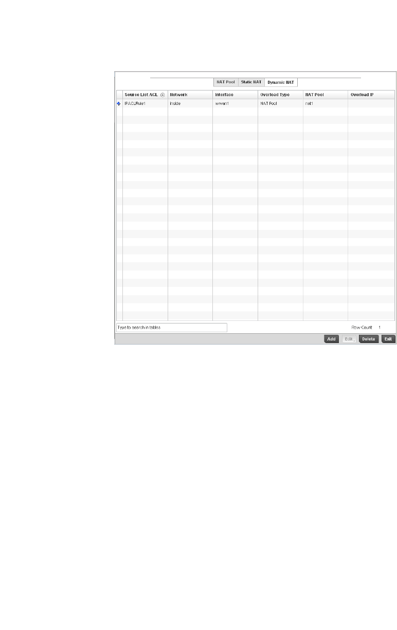
238 Brocade Mobility RFS4000, RFS6000, and RFS7000 System Reference Guide
53-1002620-01
5
FIGURE 176 Profile Overrides - Dynamic NAT screen
19. Refer to the following to determine whether a new Dynamic NAT configuration requires
creation, edit or deletion:
20. Select Add to create a new Dynamic NAT configuration, Edit to modify or override an existing
configuration or Delete to permanently remove a configuration.
Source List ACL Lists an ACL name to define the packet selection criteria for the NAT configuration.
NAT is applied only on packets which match a rule defined in the access-list. These
addresses (once translated) are not exposed to the outside world when the
translation address is used to interact with the remote destination.
Network Displays Inside or Outside NAT as the network direction for the dynamic NAT
configuration.
Interface Lists the VLAN (between 1 - 4094) used as the communication medium between
the source and destination points within the NAT configuration.
Overload Type Select the check box of Overload Type used with the listed IP ACL rule. Options
include NAT Pool, One Global Address and Interface IP Address. Interface IP
Address is the default setting.
NAT Pool Displays the name of an existing NAT pool used with the dynamic NAT configuration.
Overload IP If One Global IP Address is selected as the Overload Type, define an IP address used
a filter address for the IP ACL rule.
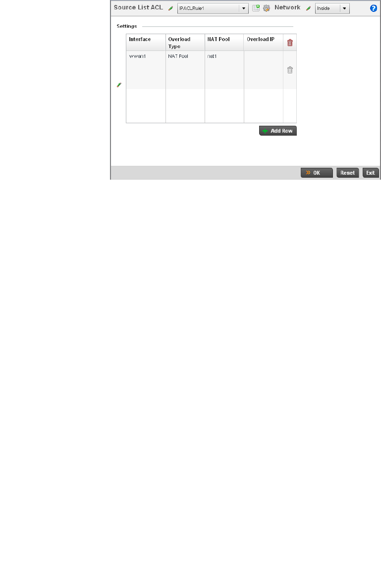
Brocade Mobility RFS4000, RFS6000, and RFS7000 System Reference Guide 239
53-1002620-01
5
FIGURE 177 Dynamic NAT Add screen
21. Set or override the following to define the Dynamic NAT configuration:
22. Select OK to save the changes or overrides made to the dynamic NAT configuration. Select
Reset to revert to the last saved configuration.
Overriding a Profile’s Bridge NAT Configuration
Overriding a Profile’s Security Configuration
Use Bridge NAT to manage Internet traffic originating at a remote site. In addition to traditional NAT
functionality, Bridge NAT provides a means of configuring NAT for bridged traffic through an access
point. NAT rules are applied to bridged traffic through the access point, and matching packets are
NATed to the WAN link instead of being bridged on their way to the router.
Source List ACL Use the drop-down menu to select an ACL name to define the packet selection
criteria for NAT. NAT is applied only on packets which match a rule defined in the
access-list. These addresses (once translated) will not be exposed to the outside
world when the translation address is used to interact with the remote destination.
Network Select Inside or Outside NAT as the network direction for the dynamic NAT
configuration. Inside is the default setting.
Interface Use the drop-down menu to select the wireless WAN or VLAN ID(between 1 - 4094)
used as the communication medium between the source and destination points
within the NAT configuration. Ensure the VLAN selected represents the intended
network traffic within the NAT supported configuration. VLAN1 is available by
default.
Overload Type Select the check box of Overload Type used with the listed IP ACL rule. Options
include NAT Pool, One Global Address and Interface IP Address. Interface IP
Address is the default setting.
NAT Pool Provide the name of an existing NAT pool for use with the dynamic NAT
configuration.
Overload IP If One Global IP Address is selected as the Overload Type, define an IP address used
a filter address for the IP ACL rule.
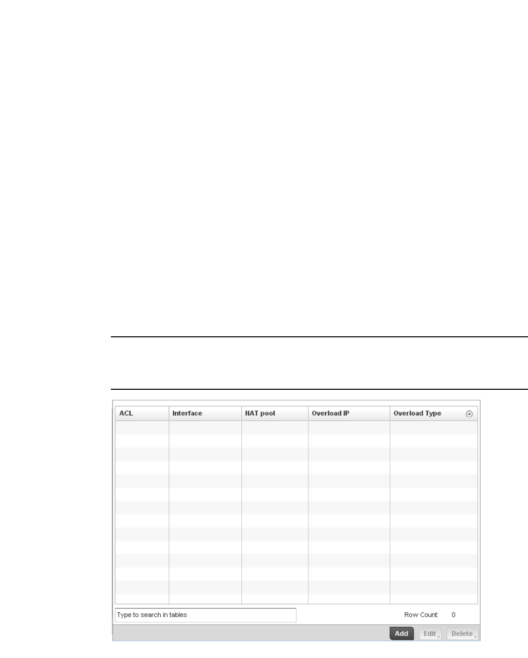
240 Brocade Mobility RFS4000, RFS6000, and RFS7000 System Reference Guide
53-1002620-01
5
Using Bridge NAT, a tunneled VLAN (extended VLAN) is created between the NoC and a remote
location. When a remote client needs to access the Internet, Internet traffic is routed to the NoC,
and from there routed to the Internet. This increases the access time for the end user on the client.
To resolve latency issues, Bridge NAT identifies and segregates traffic heading towards the NoC and
outwards towards the Internet. Traffic towards the NoC is allowed over the secure tunnel. Traffic
towards the Internet is switched to a local WLAN link with access to the Internet.
To define a NAT configuration or override that can be applied to a controller profile:
1. Select Devices from the Configuration tab.
The Device Configuration screen displays a list of managed devices or peer controllers. The
listed devices can either be other controllers or Access Points within the managed network.
2. Select a target device (by double-clicking it) from amongst those displayed within the Device
Configuration screen.
Devices can also be selected directly from the Device Browser in the lower, left-hand, side of
the UI.
3. Select Profile Overrides from the Device menu to expand it into sub menu options.
4. Select Security to expand its sub menu options.
5. Select Bridge NAT.
NOTE
A blue override icon (to the left of a parameter) defines the parameter as having an override applied.
To remove an override go to the Basic Configuration section of the device and click the Clear
Overrides button. This will remove all overrides from the device.
FIGURE 178 Security Bridge NAT screen
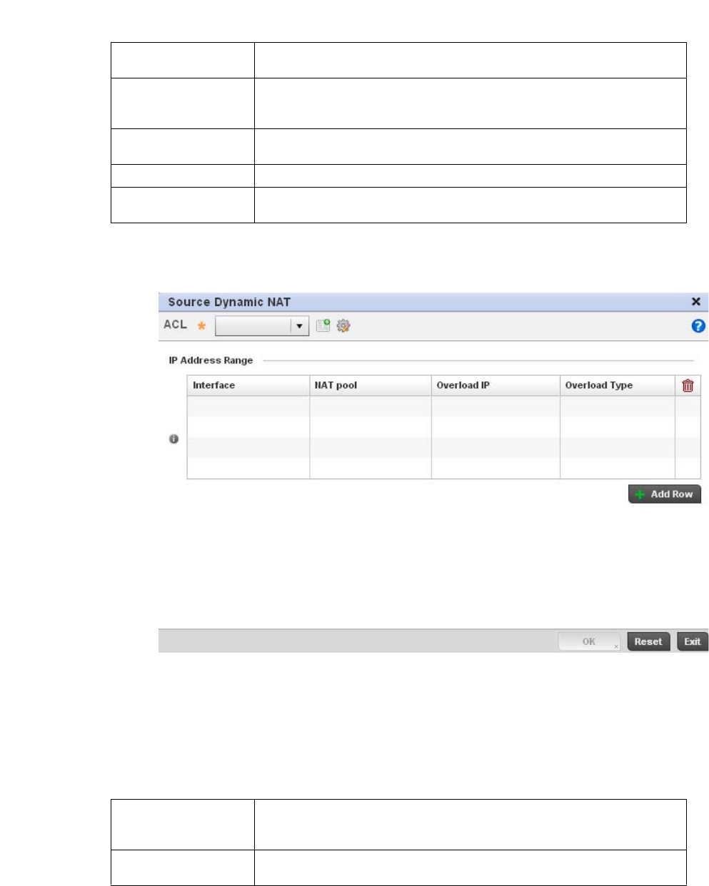
Brocade Mobility RFS4000, RFS6000, and RFS7000 System Reference Guide 241
53-1002620-01
5
6. Review the following Bridge NAT configurations to determine whether a new Bridge NAT
configuration requires creation or an existing configuration modified or removed.
7. S elect Add to create a new Bridge VLAN configuration, Edit to modify an existing configuration
or Delete to remove a configuration.
FIGURE 179 Security Source Dynamic NAT screen
8. Select the ACL whose IP rules are to be applied to this policy based forwarding rule. A new ACL
can be defined by selecting the Create icon, or an existing set of IP ACL rules can be modified
by selecting the Edit icon.
9. Use the IP Address Range table to configure IP addresses and address ranges that can used
to access the Internet.
ACL Lists the ACL applying IP address access/deny permission rules to the Bridge NAT
configuration.
Interface Lists the communication medium (outgoing layer 3 interface) between source and
destination points. This is either the access point’s pppoe1 or wwan1 interface or
the VLAN used as the redirection interface between the source and destination.
NAT Pool Lists the names of existing NAT pools used with the Bridge NAT configuration. This
displays only when Overload Type is NAT Pool.
Overload IP Lists the address used globally for numerous local addresses.
Overload Type Lists the overload type used with the listed IP ACL rule. Set as either NAT Pool, One
Global Address or Interface IP Address.
Interface Lists the outgoing layer 3 interface on which traffic is re-directed. The interface can
be an access point WWAN or PPPoE interface. Traffic can also be redirected to a
designated VLAN.
NAT Pool Displays the NAT pool used by this Bridge NAT entry. A value is only displayed only
when Overload Type has been set to NAT Pool.
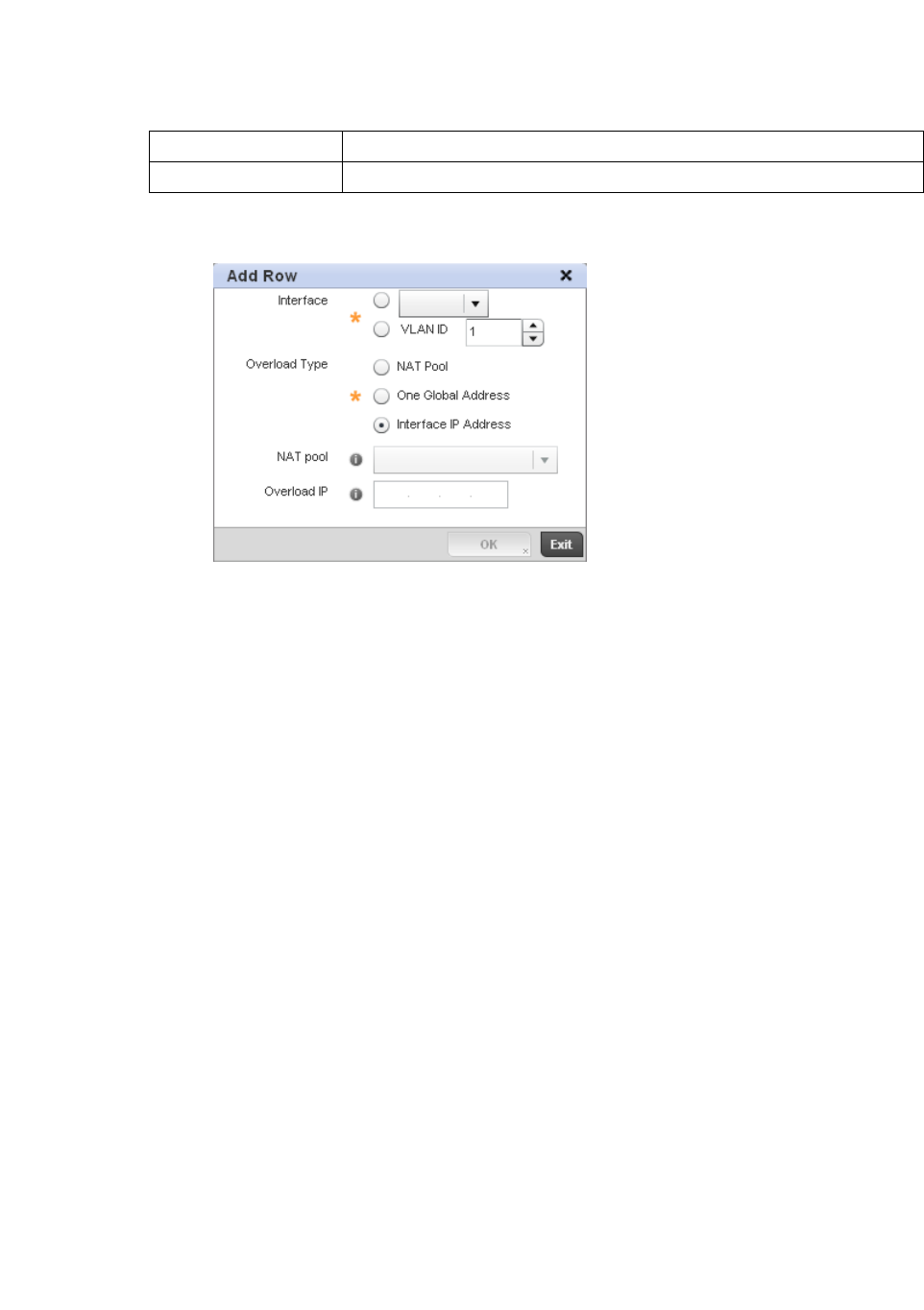
242 Brocade Mobility RFS4000, RFS6000, and RFS7000 System Reference Guide
53-1002620-01
5
10. Select + Add Row to set the IP address range settings for the Bridge NAT configuration.
FIGURE 180 Security Source Dynamic NAT screen
11. Select OK to save the changes made within the Add Row and Source Dynamic NAT screen.
Select Reset to revert to the last saved configuration.
Overriding a Profile’s VRRP Configuration
A default gateway is a critical resource for connectivity. However, it’s prone to a single point of
failure. Thus, redundancy for the default gateway is required by the access point. If WAN backhaul
is available on a br-7131, and a router failure occurs, then the access point should act as a router
and forward traffic on to its WAN link.
Define an external Virtual Router Redundancy Protocol (VRRP) configuration when router
redundancy is required in a wireless network requiring high availability.
Central to the configuration of VRRP is the election of a VRRP master. A VRRP master (once
elected) performs the following functions:
Responds to ARP requests
Forwards packets with a destination link layer MAC address equal to the virtual router MAC address
Rejects packets addressed to the IP address associated with the virtual router, if it is not the IP
address owner
Accepts packets addressed to the IP address associated with the virtual router, if it is the IP
address owner or accept mode is true.
Those nodes that lose the election process enter a backup state. In the backup state they monitor
the master for any failures, and in case of a failure one of the backups, in turn, becomes the
master and assumes the management of the designated virtual IPs. A backup does not respond to
an ARP request, and discards packets destined for a virtual IP resource.
To define the configuration of a VVRP group:
1. Select Devices from the Configuration tab.
Overload IP Lists whether the single global address supporting numerous local addresses.
Overload Type Displays the override type for this policy based forwarding rule.
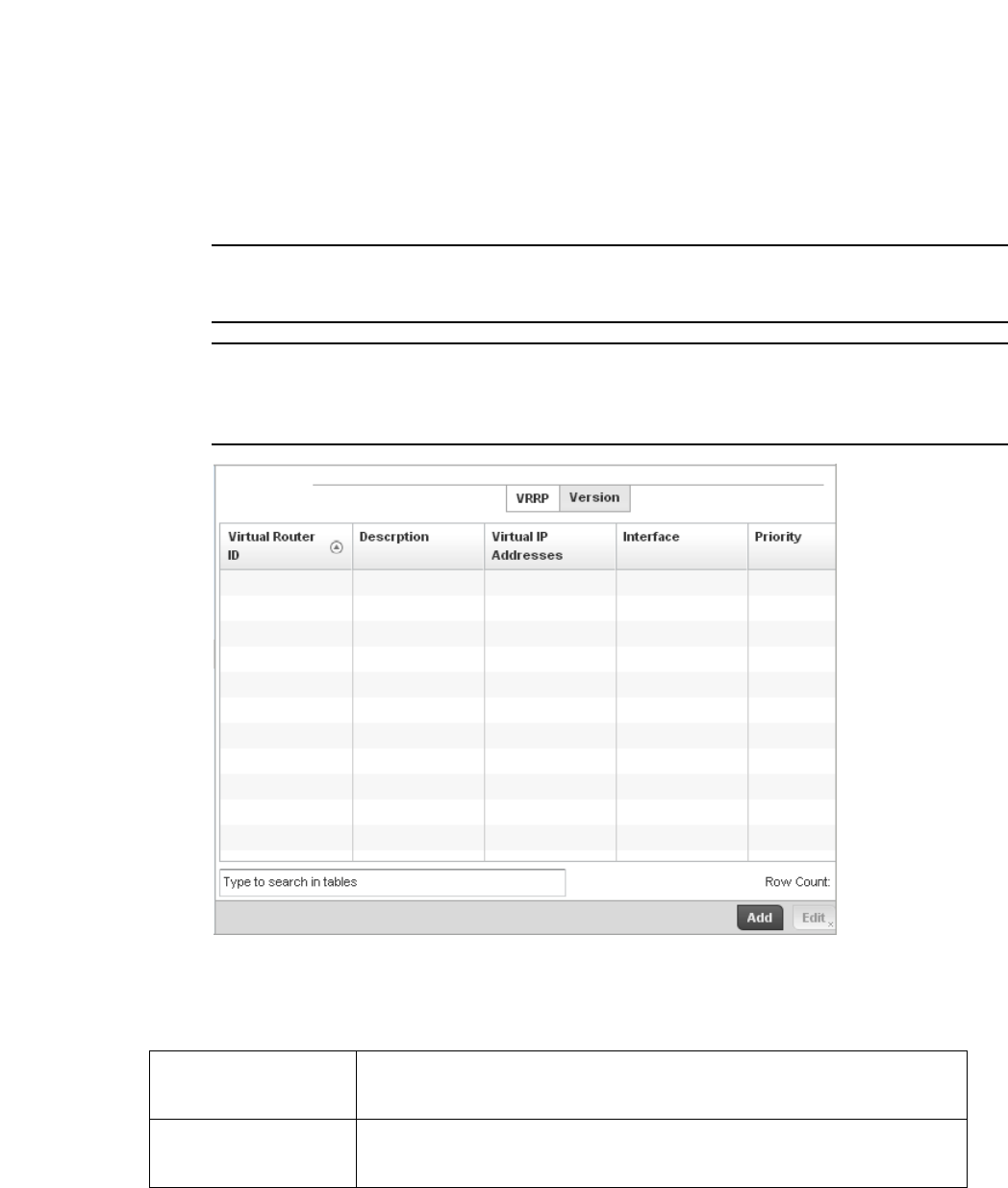
Brocade Mobility RFS4000, RFS6000, and RFS7000 System Reference Guide 243
53-1002620-01
5
The Device Configuration screen displays a list of managed devices or peer controllers. The
listed devices can either be other controllers or Access Points within the managed network.
2. Select a target device (by double-clicking it) from amongst those displayed within the Device
Configuration screen.
Devices can also be selected directly from the Device Browser in the lower, left-hand, side of
the UI.
3. Select Profile Overrides from the Device menu to expand it into sub menu options.
4. Select VRRP.
NOTE
VRRP support is only available on br-7131 model access points, and is not available on br-6511
models.
NOTE
A blue override icon (to the left of a parameter) defines the parameter as having an override applied.
To remove an override go to the Basic Configuration section of the device and click the Clear
Overrides button. This will remove all overrides from the device.
FIGURE 181 Profile Overrides - VRRP screen
5. Review the following VRRP configuration data to assess if a new VRRP configuration is required
of is an existing VRRP configuration requires modification or removal:
Virtual Router ID Lists a numerical index (1 - 254) used to differentiate VRRP configurations. The index is
assigned when a VRRP configuration is initially defined. This ID identifies the virtual
router a packet is reporting status for.
Description Displays a description assigned to the VRRP configuration when it was either created or
modified. The description is implemented to provide additional differentiation beyond
the numerical virtual router ID.
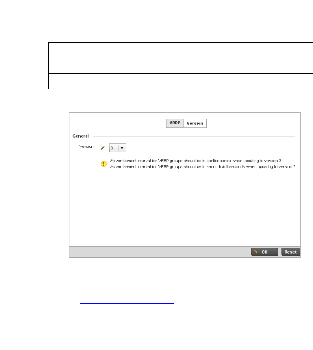
244 Brocade Mobility RFS4000, RFS6000, and RFS7000 System Reference Guide
53-1002620-01
5
6. Select the Version tab to define the VRRP version scheme used with the configuration.
FIGURE 182 VVRP screen - Version tab
VRRP version 3 (RFC 5798) and 2 (RFC 3768) are selectable to set the router redundancy.
Version 3 supports sub-second (centisecond) VRRP failover and support services over virtual
IP. For more information on the VRRP protocol specifications (available publicly) refer to
http://www.ietf.org/rfc/rfc3768.txt (version 2) and
http://www.ietf.org/rfc/rfc5798.txt (version 3).
7. From within VRRP tab, select Add to create a new VRRP configuration or Edit to modify the
attributes of an existing VRRP configuration. If necessary, existing VRRP configurations can be
selected and permanently removed by selecting Delete.
If adding or editing a VRRP configuration, the following screen displays:
Virtual IP Addresses Lists the virtual interface IP address used as the redundant gateway address for the
virtual route.
Interface Displays the interfaces selected on the access point to supply VRRP redundancy
failover support.
Priority Lists a numerical value (from 1 - 254) used for the virtual router master election
process. The higher the numerical value, the higher the priority in the election process.
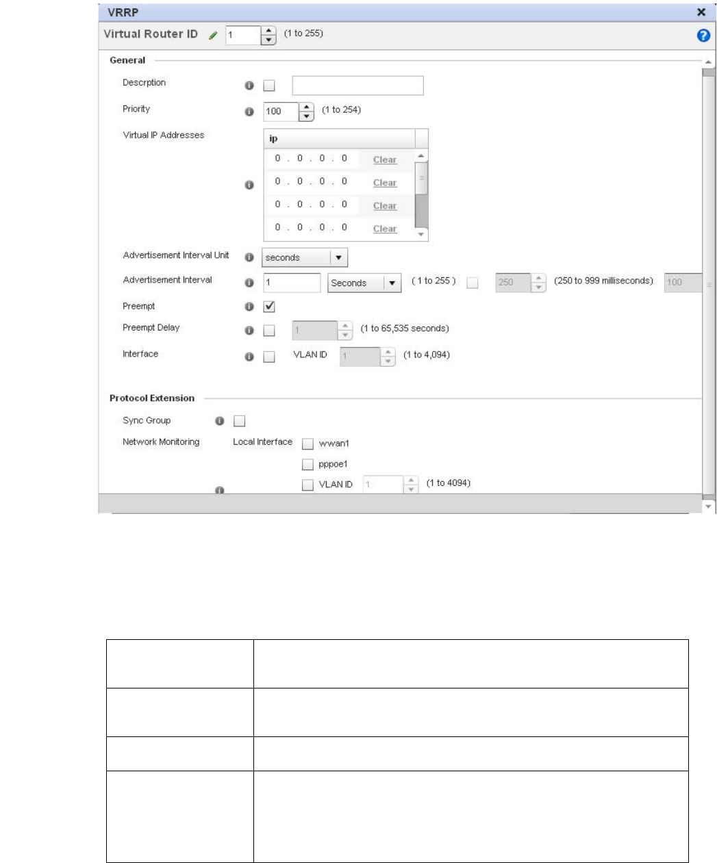
Brocade Mobility RFS4000, RFS6000, and RFS7000 System Reference Guide 245
53-1002620-01
5
FIGURE 183 VVRP screen
8. If creating a new VRRP configuration, assign a Virtual Router ID from (1 - 255). In addition to
functioning as numerical identifier, the ID identifies the access point’s virtual router a packet is
reporting status for.
9. Define the following VRRP General parameters:
Description In addition to an ID assignment, a virtual router configuration can be assigned a textual
description (up to 64 characters) to further distinguish it from others with a similar
configuration.
Priority Use the spinner control to set a VRRP priority setting from 1 - 254. The access point
uses the defined setting as criteria in selection of a virtual router master. The higher the
value, the greater the likelihood of this virtual router ID being selected as the master.
Virtual IP Addresses Provide up to 8 IP addresses representing the Ethernet switches, routers or security
appliances defined as virtual router resources to the br-7131 access point.
Advertisement Interval
Unit
Select either seconds, milliseconds or centiseconds as the unit used to define VRRP
advertisements. Once an option is selected, the spinner control becomes enabled for
that Advertisement Interval option. The default interval unit is seconds. If changing
the VRRP group version from 2 to 3, ensure the advertisement interval is in
centiseconds. Use VRRP group version 2 when the advertisement interval is either in
seconds or milliseconds.

246 Brocade Mobility RFS4000, RFS6000, and RFS7000 System Reference Guide
53-1002620-01
5
10. Refer to the Protocol Extension field to define the following:
11. Select OK to save the changes made to the VRRP configuration. Select Reset to revert to the
last saved configuration.
Overriding a Profile’s Critical Resources Configuration
Critical resources are device IP addresses or interface destinations on the network interopreted as
critical to the health of the network. The critical resource feature allows for the continuous
monitoring of these addresses. A critical resource, if not available, can result in the network
suffering performance degradation. A critical resource can be a gateway, a AAA server, a WAN
interface or any hardware or service on which the stability of the network depends. Critical
resources are pinged regularly by the access point. If there’s a connectivity issue, an event is
generated stating a critical resource is unavailable. By default, there’s no enabled critical resource
policy and one needs to be created and implemented.
Critical resources can be monitored directly through the interfaces on which they’re discovered. For
example, a critical resource on the same subnet as the access point can be monitored by its IP
address. However, a critical resource located on a VLAN must continue to monitored on that VLAN.
Advertisement Interval Once a Advertisement Interval Unit has been selected, use the spinner control to set the
Interval at which the VRRP master sends out advertisements on each of its configured
VLANs. The default setting is 1 second.
Preempt Select this option to ensure a high priority backup router is available to preempt a lower
priority backup router resource. The default setting is enabled. When selected, the
Preempt Delay option becomes enabled to set the actual delay interval for pre-emption.
This settings determines if a node with a higher priority can takeover all the Virtual IPs
from the nodes with a lower priority.
Preempt Delay If the Preempt option is selected, use the spinner control to set the delay interval (in
seconds) for pre-emption.
Interface Select this value to enable/disable VRRP operation and define the br-7131 VLAN (1 -
4,094) interface where VRRP will be running. These are the interfaces monitored to
detect a link failure.
Sync Group Select the option to assign a VRRP sync group to this VRRP ID’s group of virtual IP
addresses. This triggers VRRP failover if an advertisement is not received from the
virtual masters that are part of this VRRP sync group. This setting is disabled b y
default.
Network Monitoring:
Local Interface
Select the wwan1, pppoe1 and VLAN ID(s) as needed to extend VRRP monitoring to
these local access point interfaces. Once selected, these interfaces can be assigned an
increasing or decreasing level or priority for virtual routing within the VRRP group.
Network Monitoring:
Critical Resources
Assign the priority level for the selected local interfaces. Backup virtual routers can
increase or decrease their priority in case the critical resources connected to the
master router fail, and then transition to the master state themselves. Additionally, the
master virtual router can lower its priority if the critical resources connected to it fails,
so the backup can transition to the master state. This value can only be set on the
backup or master router resource, not both. Options include None, increment-priority,
decrement priority.
Network Monitoring:
Delta Priority
Use this setting to decrement the configured priority (by the set value) when the
monitored interface is down. When critical resource monitoring, the configured value is
incremented by the value defined.
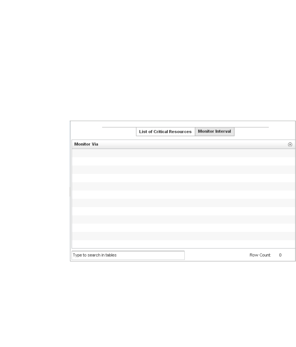
Brocade Mobility RFS4000, RFS6000, and RFS7000 System Reference Guide 247
53-1002620-01
5
Critical resource can be configured for access points and wireless controllers using their respective
profiles.
To define critical resources:
1. Select Devices from the Configuration tab.
The Device Configuration screen displays a list of managed devices or peer controllers. The
listed devices can either be other controllers or Access Points within the managed network.
2. Select a target device (by double-clicking it) from amongst those displayed within the Device
Configuration screen.
Devices can also be selected directly from the Device Browser in the lower, left-hand, side of
the UI.
3. Select Profile Overrides from the Device menu to expand it into sub menu options.
4. Select Critical Resources.
FIGURE 184 Critical Resources screen - List of Critical Resources tab
The screen lists the destination IP addresses or interfaces (VLAN, WWAN, or PPPoE) used for
critical resource connection. IP addresses can be monitored directly by the access point or
controller, whereas a VLAN, WWAN or PPPoE must be monitored behind an interface.
5. Ensure the Activate Critical Resources Policy button is selected to enable the parameters
within the screen for configuration. This option needs to remain selected to apply the
configuration to the access point profile.
6. Click the Add button at the bottom of the screen to add a new critical resource and connection
method, or select and existing resource and select Edit to update the resource’s configuration.
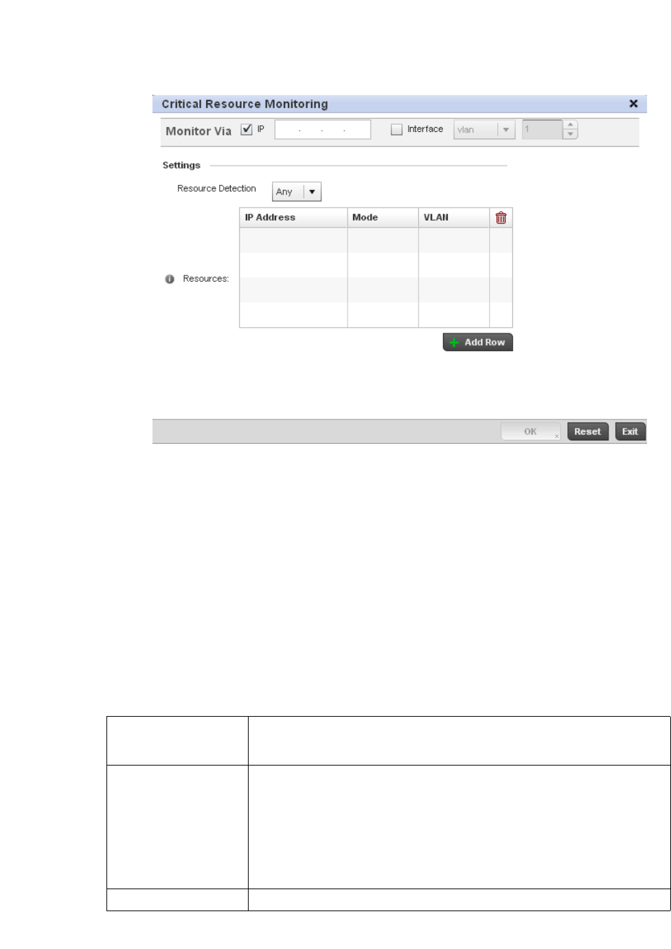
248 Brocade Mobility RFS4000, RFS6000, and RFS7000 System Reference Guide
53-1002620-01
5
FIGURE 185 Critical Resources screen - Adding a Critical Resource
7. S e l e c t t h e IP checkbox (within the Monitor Via field at the top of the screen) to monitor a critical
resource directly (within the same subnet) using the provided critical resource IP address as a
network identifier.
8. Select the Interface checkbox (within the Monitor Via field at the top of the screen) to monitor a
critical resource using either the critical resource’s VLAN, WWAN1 or PPPoE1 interface. If VLAN
is selected, a spinner control is enabled to define the destination VLAN ID used as the
interface for the critical resource.
9. Use the Resource Detection drop-down menu to define how critical resource event messages
are generated. Options include Any and All. If selecting Any, an event is generated when the
state of any single critical resource changes. If selecting All, an event is generated when the
state of all monitored critical resources change.
10. Select + Add Row to define the following for critical resource configurations:
11. Select the Monitor Interval tab.
IP Address Provide the IP address of the critical resource. This is the address used by the access
point to ensure the critical resource is available. Up to four addresses can be
defined.
Mode Set the ping mode used when the availability of a critical resource is validated. Select
from:
•arp-only – Use the Address Resolution Protocol (ARP) for only pinging the critical
resource. ARP is used to resolve hardware addresses when only the network
layer address is known.
•arp-and-ping – Use both ARP and Internet Control Message Protocol (ICMP) for
pining the critical resource and sending control messages (device not
reachable, requested service not available, etc.).
VLAN Define the VLAN on which the critical resource is available using the spinner control.
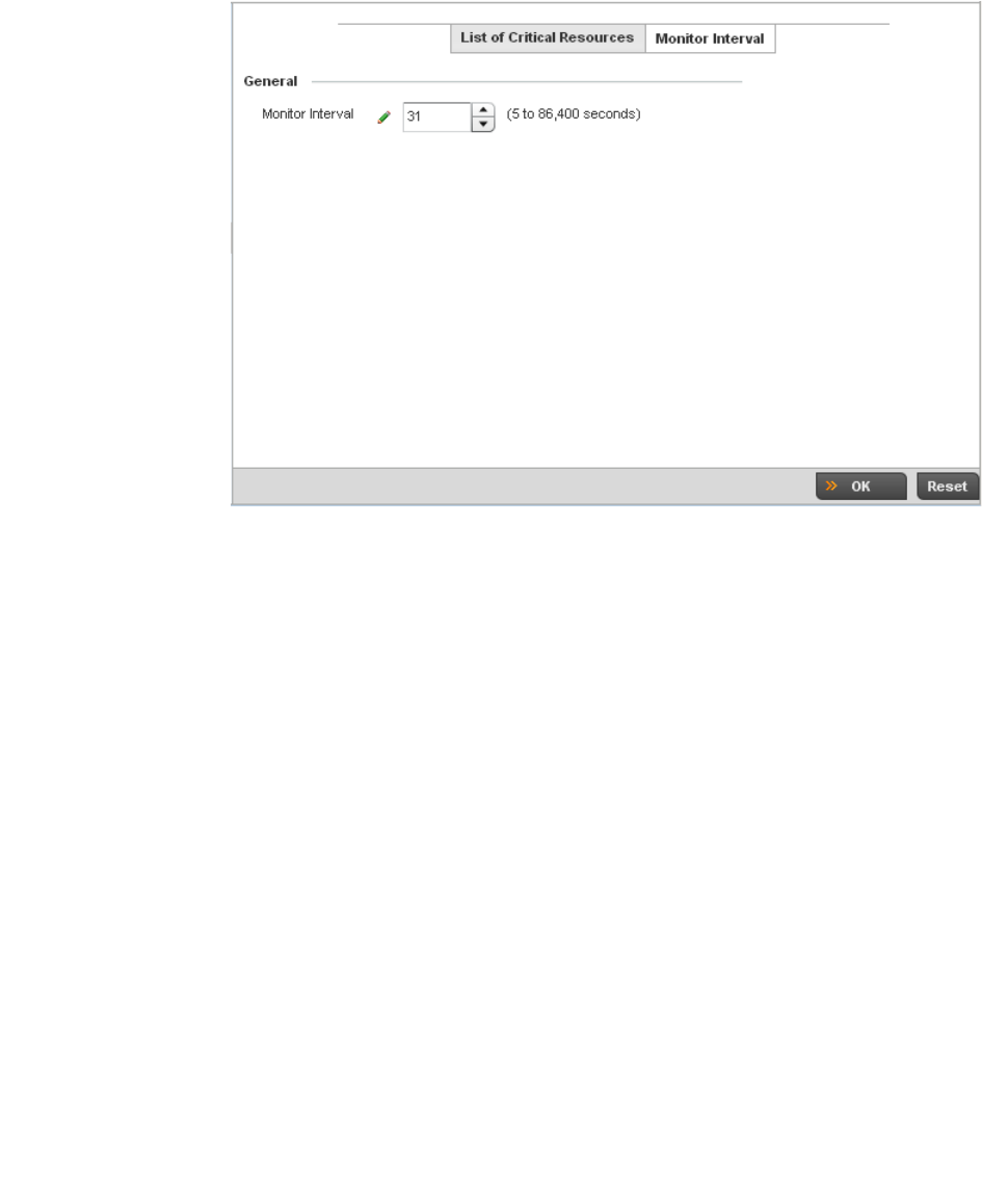
Brocade Mobility RFS4000, RFS6000, and RFS7000 System Reference Guide 249
53-1002620-01
5
FIGURE 186 Critical Resources screen - Monitor Interval tab
12. Set the duration between two successive pings from the access point to critical resource.
Define this value in seconds from 5 - 86,400. The default setting is 30 seconds.
13. Select OK to save the changes to the critical resource configuration and monitor interval.
Select Reset to revert to the last saved configuration.
Overriding a Profile’s Services Configuration
A controller profile can contain specific guest access (captive portal), DHCP server and RADIUS
server configurations supported by the controller’s own internal resources. These controller access,
IP assignment and user authorization resources can be defined uniquely as controller profile
requirements dictate.
To define or override a profile’s services configuration:
1. Select Devices from the Configuration tab.
The Device Configuration screen displays a list of managed devices or peer controllers. The
listed devices can either be other controllers or Access Points within the managed network.
2. Select a target device (by double-clicking it) from amongst those displayed within the Device
Configuration screen.
Devices can also be selected directly from the Device Browser in the lower, left-hand, side of
the UI.
3. Select Profile Overrides from the Device menu to expand it into sub menu options.
4. Select Services.
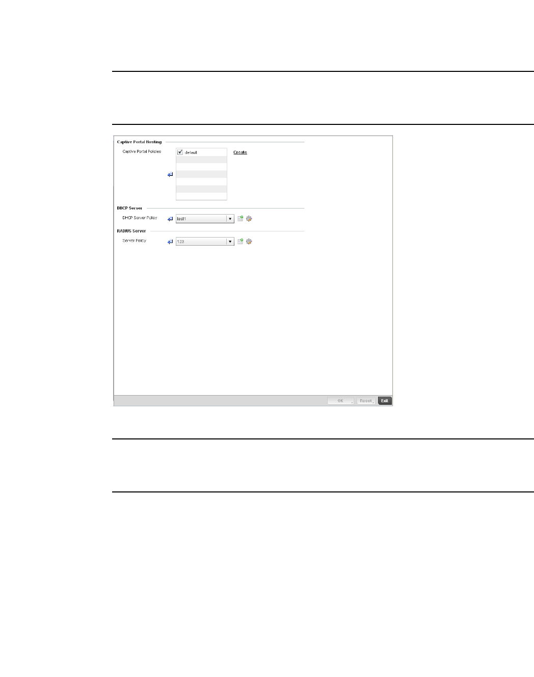
250 Brocade Mobility RFS4000, RFS6000, and RFS7000 System Reference Guide
53-1002620-01
5
NOTE
A blue override icon (to the left of a parameter) defines the parameter as having an override applied.
To remove an override go to the Basic Configuration section of the device and click the Clear
Overrides button. This will remove all overrides from the device.
FIGURE 187 Profile Overrides - Services screen
NOTE
A blue override icon (to the left of a parameter) defines the parameter as having an override applied.
To remove an override go to the Basic Configuration section of the device and click the Clear
Overrides button. This will remove all overrides from the device.
5. Refer to the Captive Portal Hosting section to set or override a controller guest access
configuration (captive portal) for use with this profile.
A captive portal is guest access policy for providing guests temporary and restrictive access to
the managed wireless network. The primary means of securing such controller guest access is
a hotspot.
A captive portal policy’s hotspot configuration provides secure authenticated controller access
using a standard Web browser. Hotspots provides authenticated access by capturing and
re-directing a wireless user's Web browser session to a captive portal login page where the
user must enter valid credentials to access to the managed wireless network. Once logged into
the managed hotspot, additional Agreement, Welcome and Fail pages provide the
administrator with a number of options on the hotspot’s screen flow and user appearance.
Either select an existing captive portal policy, use the default captive portal policy or select the
Create link to create a new captive portal configuration that can be applied to this profile. For
more information, see Configuring a Captive Portal Policy on page 10-559.

Brocade Mobility RFS4000, RFS6000, and RFS7000 System Reference Guide 251
53-1002620-01
5
6. Use the DHCP Server Policy drop-down menu assign this controller profile a DHCP server policy.
If an existing DHCP policy does not meet the profile’s requirements, select the Create icon to
create a new policy configuration that can be applied to this profile or the Edit icon to modify
the parameters of an existing DHCP Server policy.
Dynamic Host Configuration Protocol (DHCP) allows hosts on an IP network to request and be
assigned IP addresses as well as discover information about the managed network where they
reside. Each subnet can be configured with its own address pool. Whenever a DHCP client
requests an IP address, the DHCP server assigns an IP address from that subnet’s address
pool. When the controller’s onboard DHCP server allocates an address for a DHCP client, the
client is assigned a lease, which expires after an pre-determined interval. Before a lease
expires, wireless clients (to which leases are assigned) are expected to renew them to continue
to use the addresses. Once the lease expires, the client is no longer permitted to use the
leased IP address. The controller profile’s DHCP server policy ensures all IP addresses are
unique, and no IP address is assigned to a second client while the first client's assignment is
valid (its lease has not expired).
7. Either select an existing captive portal policy or select the Create button to create a new
captive portal configuration that can be applied to this profile. For more information, see
Configuring a Captive Portal Policy on page 10-559.
8. Use the RADIUS Server Policy drop-down menu to select an existing RADIUS server policy to
use as a user validation security mechanism with this controller profile.
A controller profile can have its own unique RADIUS server policy to authenticate users and
authorize access to the managed network. A profile’s RADIUS policy provides the centralized
management of controller authentication data (usernames and passwords). When an client
attempts to associate to the controller, the controller sends the authentication request to the
RADIUS server. A br-7131 model Access Point is also equipped with its own RADIUS server.
9. If an existing RADIUS server policy does not meet your requirements, select the Create icon to
create a new policy or the Edit icon to modify the parameters of an existing policy. For more
information, see Setting the Controller’s RADIUS Configuration on page 10-585.
10. Select OK to save the changes or overrides made to the profile’s services configuration. Select
Reset to revert to the last saved configuration.
Overriding a Profile’s Management Configuration
The controller has mechanisms to allow/deny management access to the managed network for
separate interfaces and protocols (HTTP, HTTPS, Telnet, SSH or SNMP). These management access
configurations can be applied strategically to controller profiles as controller resource permissions
dictate for the profile. Additionally, overrides can be applied to customize a device’s management
configuration, if deployment requirements change an a devices configuration must be modified
from its original device profile configuration.
Additionally, an administrator can define a profile with unique configuration file and device
firmware upgrade support. In a clustered environment, these operations can be performed on one
controller, then propagated to each member of the cluster and onwards to devices managed by
each cluster member.
To define or override a profile’s management configuration:
1. Select Devices from the Configuration tab.
The Device Configuration screen displays a list of managed devices or peer controllers. The
listed devices can either be other controllers or Access Points within the managed network.
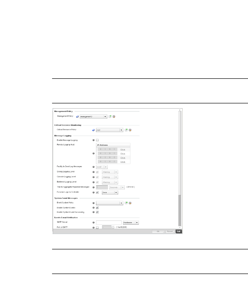
252 Brocade Mobility RFS4000, RFS6000, and RFS7000 System Reference Guide
53-1002620-01
5
2. Select a target device (by double-clicking it) from amongst those displayed within the Device
Configuration screen.
Devices can also be selected directly from the Device Browser in the lower, left-hand, side of
the UI.
3. Select Profile Overrides from the Device menu to expand it into sub menu options.
4. Select Management.
NOTE
A blue override icon (to the left of a parameter) defines the parameter as having an override applied.
To remove an override go to the Basic Configuration section of the device and click the Clear
Overrides button. This will remove all overrides from the device.
FIGURE 188 Profile Overrides - Management Settings screen
NOTE
A blue override icon (to the left of a parameter) defines the parameter as having an override applied.
To remove an override go to the Basic Configuration section of the device and click the Clear
Overrides button. This will remove all overrides from the device.
5. Refer to the Management Policy field to set or override a controller management configuration
for use with this profile. A default management policy is also available if no existing policies are
usable.

Brocade Mobility RFS4000, RFS6000, and RFS7000 System Reference Guide 253
53-1002620-01
5
Use the drop-down menu to select an existing management policy to apply to this controller
profile. If no management policies exist meeting the data access requirements of this
controller profile, select the Create icon to access a series of screens used to define
administration, access control and SNMP configurations. Select an existing policy and select
the Edit icon to modify the configuration of an existing management policy. For more
information, see Management Access on page 11-605.
6. Use to the Critical Resource Policy pulldown to set or override a critical resource policy for use
with this profile. For more information on defining a critical resource policy, see Critical
Resource Policy on page 5-276.
7. R e fe r to t he Message Logging section to define how the controller profile logs system events.
It’s important to log individual events to discern an overall pattern that may be negatively
impacting controller performance using the configuration defined for this profile.
Enable Message Logging Select the check box to enable the controller profile to log system events to a user
defined log file or a syslog server. Selecting this check box enables the rest of the
parameters required to define the profile’s logging configuration. This option is
disabled by default.
Remote Logging Host Use this table to define numerical (non DNS) IP addresses for up to three external
resources where logged system events can be sent on behalf of the controller
profile. Select Clear as needed to remove an IP address.
Facility to Send Log
Messages
Use the drop-down menu to specify the local server facility (if used) for the controller
profile event log transfer.
Syslog Logging Level Event severity coincides with the syslog logging level defined for the profile. Assign a
numeric identifier to log events based on criticality. Severity levels include 0 -
Emergency, 1 - Alert, 2 - Critical, 3 - Errors,
4 - Warning, 5 - Notice, 6 - Info and 7 - Debug. The default logging level is 4.
Console Logging Level Event severity coincides with the syslog logging level defined for the profile. Assign a
numeric identifier to log events based on criticality. Severity levels include 0 -
Emergency, 1 - Alert, 2 - Critical, 3 - Errors,
4 - Warning, 5 - Notice, 6 - Info and 7 - Debug. The default logging level is 4.
Buffered Logging Level Event severity coincides with the syslog logging level defined for the profile. Assign a
numeric identifier to log events based on criticality. Severity levels include 0 -
Emergency, 1 - Alert, 2 - Critical, 3 - Errors,
4 - Warning, 5 - Notice, 6 - Info and 7 - Debug. The default logging level is 4.
Time to Aggregate
Repeated Messages
Define the increment (or interval) system events are logged on behalf of this
controller profile. The shorter the interval, the sooner the event is logged. Either
define an interval in Seconds (0 - 60) or Minutes (0 -1). The default value is 0
seconds.
Forward Logs to Controller Select the checkbox to define a log level for forwarding event logs to the control. Log
levels include Emergency, Alert, Critical, Error, Warning, Notice, Info and Debug. The
default logging level is Error.

254 Brocade Mobility RFS4000, RFS6000, and RFS7000 System Reference Guide
53-1002620-01
5
8. Refer to the System Event Messages section to define or override how controller system
messages are logged and forwarded on behalf of the controller profile.
9. Refer to the Events E-mail Notification section to define or override how system event
notification e-mails are sent.
10. Select OK to save the changes and overrides made to the profile’s Management Settings.
Select Reset to revert to the last saved configuration.
11. Select Firmware from the Management menu.
Event System Policy Select an Event System Policy from the drop-down menu. If an appropriate policy
does not exist click the create button to make a new policy.
Enable System Events Select the Enable System Events check box to allow the controller profile to capture
system events and append them to a log file. It’s important to log individual events to
discern an overall pattern that may be negatively impacting controller performance.
This setting is enabled by default.
Enable System Event
Forwarding
Select the Enable System Event Forwarding radio button to enable the forwarding of
system events to another controller or cluster member. This setting is enabled by
default.
SMTP Server Specify either the Hostname or IP Address of the outgoing SMTP server where
notification e-mails will be sent from.
Port of SMTP If a non-standard SMTP port is used on the outgoing SMTP server check this box and
specify a port between 1 and 65,535 for the outgoing SMTP server to use.
Sender E-mail Address Specify the e-mail address that notification e-mails will be sent from. This will be the
from address on notification e-mails.
Username for SMTP Server Specify the username of the sender on the outgoing SMTP server. Many SMTP
servers require users to authenticate with an username and password before
sending e-mail through the server.
Password for SMTP Server Specify the password associated with the username of the sender on the outgoing
SMTP server. Many SMTP servers require users to authenticate with an username
and password before sending e-mail through the server.
Persist Configuration
Across Reloads
Use the pull-down menu to configure whether configuration overrides should persist
when the device configuration is reloaded. Available options are Enabled, Disabled
and Secure.
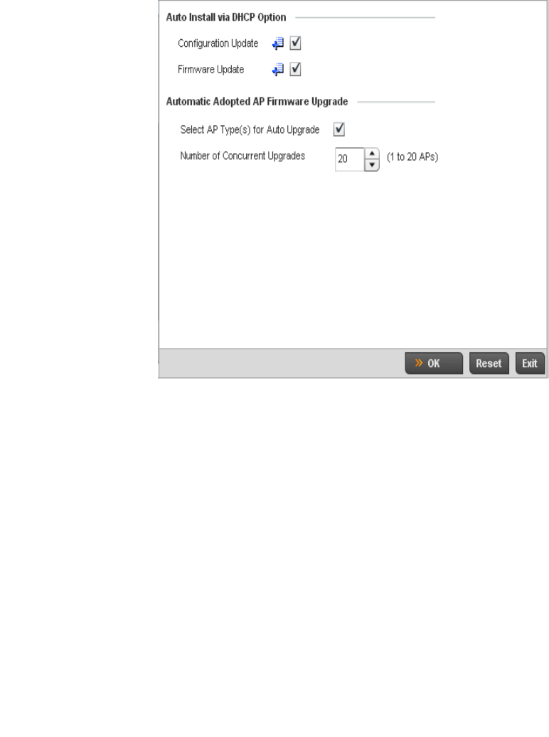
Brocade Mobility RFS4000, RFS6000, and RFS7000 System Reference Guide 255
53-1002620-01
5
FIGURE 189 Profile Overrides - Management Firmware screen
12. Refer to the Auto Install via DHCP Option section to configure automatic configuration file and
firmware updates.
13. Refer to the Legacy Device Firmware Management field to define or whether br-650 and
br-7131 model devices can upgrade to newer firmware versions or downgrade to legacy
firmware versions.
Enable Configuration
Update
Select the Enable Configuration Update check box (from within the Automatic
Configuration Update field) to enable automatic configuration file updates for the
controller profile from a location external to the controller.
If enabled (the setting is disabled by default), provide a complete path to the target
configuration file used in the update.
Enable Firmware Update Select this option to enable automatic controller firmware upgrades (for this
controller profile) from a user defined remote location. This value is disabled by
default.
Migration Firmware from
br-7131 4.x path
Provide a complete path to the target firmware used to support a legacy
br-7131 firmware update. The length of the path cannot exceed 253 characters.
Legacy br-650 Auto Upgrade Check this box to enable automatic firmware upgrades for all legacy br-650 Access
Points connected to the controller.
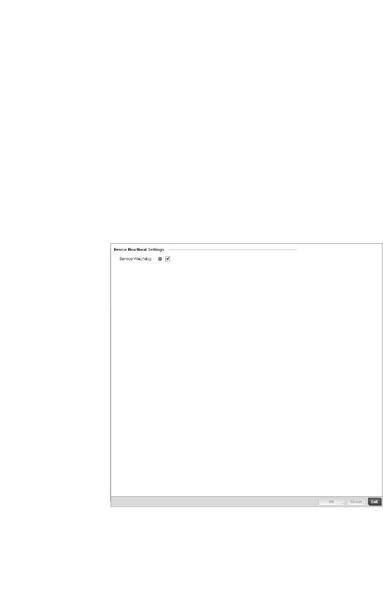
256 Brocade Mobility RFS4000, RFS6000, and RFS7000 System Reference Guide
53-1002620-01
5
14. Use the parameters within the Automatic Adopted AP Firmware Upgrade section to define an
automatic firmware upgrade from a controller based file.
15. Select OK to save the changes and overrides made to the profile’s Management Firmware
configuration. Select Reset to revert to the last saved configuration.
16. Select Heartbeat from the Management menu.
FIGURE 190 Profile Overrides - Management Heartbeat screen
17. Select the Service Watchdog option to implement heartbeat messages to ensure other
associated devices are up and running and capable of effectively interoperating with the
controller. The Service Watchdog is enabled by default.
18. Select OK to save the changes and overrides made to the profile maintenance Heartbeat tab.
Select Reset to revert to the last saved configuration.
Overriding a Profile’s Advanced Configuration
A profile’s advanced configuration is comprised of defining its MINT protocol configuration and the
profile’s NAS identifier and port ID attributes. MINT provides secure controller profile
communications at the transport layer. Using MINT, a device can be configured to only
communicate with other authorized (MINT enabled) devices. Therefore, MINT is well designed for
Allow Controller Upgrade Select the access point model to upgrade to a newer firmware version using its
associated Virtual Controller AP’s most recent firmware file for that model. This
parameter is enabled by default.
Number of Concurrent
Upgrades.
Use the spinner control to define the maximum number (1 - 20) of adopted APs that
can receive a firmware upgrade at the same time. The default value is 10. Keep in
mind that during a firmware upgrade, the AP is offline and unable to perform its
normal wireless client support function until the upgrade process is complete.

Brocade Mobility RFS4000, RFS6000, and RFS7000 System Reference Guide 257
53-1002620-01
5
controller profile support, wherein a group of managed devices share the same configuration
attributes. However, a profile’s advanced configuration may require an override as a particular
device’s configuration requires a specific parameter be updated in a manner that deviates the
configuration from that the configuration shared by the devices using the profile
To set or override a profile’s advanced configuration:
1. Select the Devices from the Web UI.
2. Select Profile Overrides to expand its menu items
3. Select Advanced to expand its sub menu items.
MINT provides the means to secure controller profile communications at the transport layer.
Using MINT, a device can be configured to only communicate with other authorized (MINT
enabled) devices.
managed devices can communicate with each other exclusively over a MINT security domain.
Keys can also be generated externally using any application (like openssl). These keys must be
present on the managed device managing the domain for key signing to be integrated with the
UI. A MAP device that needs to communicate with another first negotiates a security context
with that device.
The security context contains the transient keys used for encryption and authentication. A
secure network requires users to know about certificates and PKI. However, administrators do
not need to define security parameters for Access Points to be adopted (secure WISPe being
an exception, but that isn-t a commonly used feature). Also, users can replace any device on
the network or move devices around and they continue to work. Default security parameters for
MiNT are such that these scenarios continue to function as expected, with minimal user
intervention required only when a new network is deployed.
To define or override a controller profile’s MINT configuration:
4. Select MINT Protocol from the Advanced menu item.
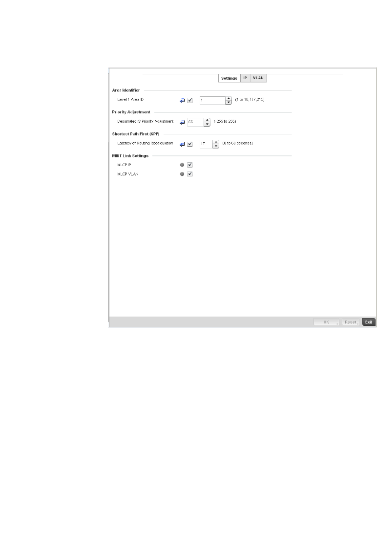
258 Brocade Mobility RFS4000, RFS6000, and RFS7000 System Reference Guide
53-1002620-01
5
FIGURE 191 Advanced Profile Overrides MINT screen - Settings tab
5. The Settings tab displays by default.
6. Refer to the Area Identifier field to define or override the Level 1 and Level 2 Area IDs used by
the profile’s MINT configuration.
7. Define or override the following Device Heartbeat Settings in respect to devices supported by
the controller profile:
8. Select the Latency of Routing Recalculation check box (within the Shortest Path First (SPF)
field) to enable the spinner control used for defining or overriding a latency period between 0 -
60 seconds. The default setting has the check box disabled.
Level 1 Area ID Select the box to enable a spinner control for setting the Level 1 Area ID between 1 -
16,777,215. The default value is disabled.
Designated IS Priority
Adjustment
Use the spinner control to set a Designated IS Priority Adjustment setting
between -255 and 255. This is the value added to the base level DIS priority to
influence the Designated IS (DIS) election. A value of +1 or greater increases
DISiness. The default setting is 0.
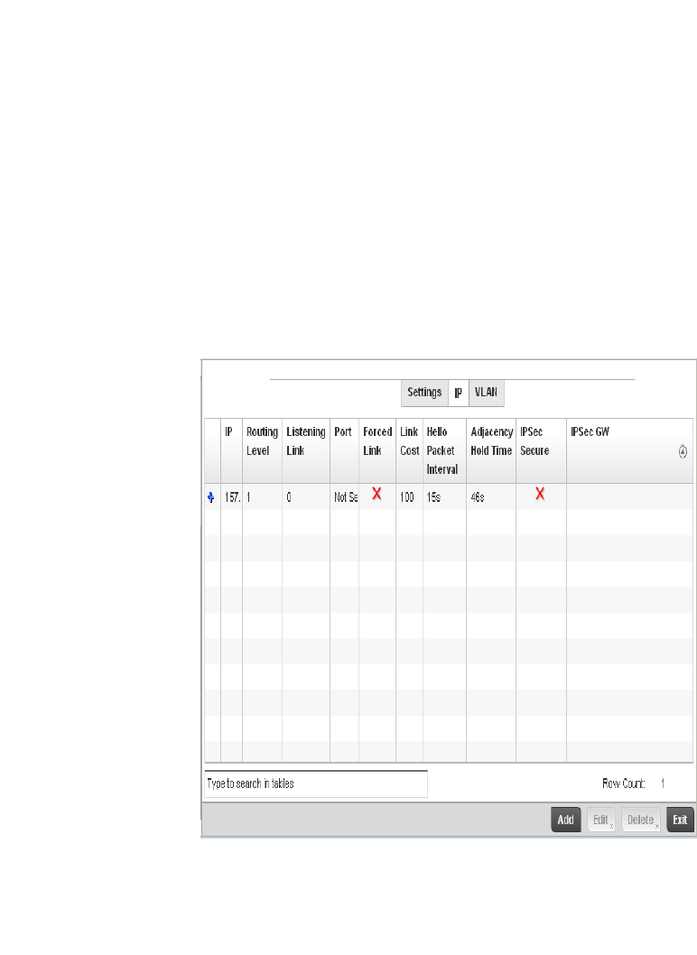
Brocade Mobility RFS4000, RFS6000, and RFS7000 System Reference Guide 259
53-1002620-01
5
9. Define or override the following MINT Link Settings in respect to devices supported by the
controller profile:
10. Select OK to save the changes and overrides made to the Settings tab. Select Reset to revert to
the last saved configuration.
11. Select the IP tab to display the link IP network address information shared by the devices
managed by the controller’s MINT configuration.
FIGURE 192 Advanced Profile MINT screen - IP tab
12. The IP tab displays the IP address, Routing Level, Listening Link, Port, Forced Link, Link Cost,
Hello Packet Interval and Adjacency Hold Time managed devices use to securely communicate
amongst one another. Select Add to create a new Link IP configuration or Edit to override an
existing MINT configuration.
MLCP IP Check this box to enable MINT Link Creation Protocol (MLCP) by IP Address. MINT
Link Creation Protocol is used to create one UDP/IP link from the device to a
neighbor. That neighboring device does not need to be a controller or switch it can be
another AP which would have a path to the controller or switch.
MLCP VLAN Check this box to enable MINT Link Creation Protocol (MLCP) by VLAN. MINT Link
Creation Protocol is used to create one VLAN link from the device to a neighbor. That
neighboring device does not need to be a controller or switch it can be another AP
which would have a path to the controller or switch.
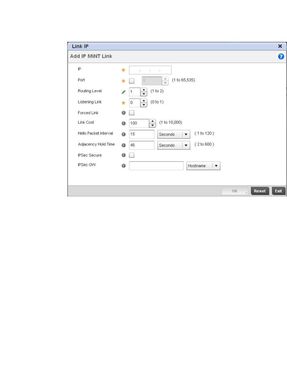
260 Brocade Mobility RFS4000, RFS6000, and RFS7000 System Reference Guide
53-1002620-01
5
FIGURE 193 Advanced Profile MINT screen - IP tab
13. Set the following Link IP parameters to complete the MINT network address configuration:
14. Select the VLAN tab to display the link IP VLAN information shared by the devices managed by
the controller’s MINT configuration.
IP Define or override the IP address used by peer controllers for interoperation when
supporting the MINT protocol.
Port To specify a custom port for MiNT links, check this box and use the spinner control to
define or override the port number between 1 and 65,535.
Routing Level Use the spinner control to define or override a routing level of either 1 or 2.
Listening Link Specify a listening link of either 0 or 1. UDP/IP links can be created by configuring a
matching pair of links, one on each end point. However, that is error prone and
doesn’t scale. So UDP/IP links can also listen (in the TCP sense), and dynamically
create connected UDP/IP links when contacted. The typical configuration is for the
controller to have a listening UDP/IP link on the switch’s IP address S.S.S.S, and for
all the APs to have a regular UDP/IP link to S.S.S.S.
Forced Link Check this box to specify the MiNT link as a forced link.
Link Cost Use the spinner control to define or override a link cost between 1 - 10,000. The
default value is 100.
Hello Packet Interval Set or override an interval in either Seconds (1 - 120) or Minutes (1 - 2) for the
transmission of hello packets. The default interval is 15 seconds.
Adjacency Hold Time Set or override a hold time interval in either Seconds (2 - 600) or Minutes (1 - 10) for
the transmission of hello packets. The default interval is 46 seconds.
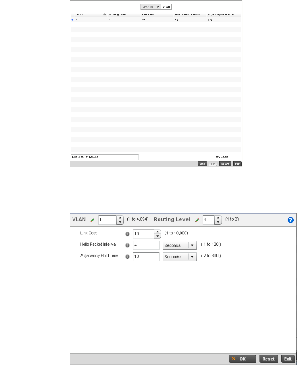
Brocade Mobility RFS4000, RFS6000, and RFS7000 System Reference Guide 261
53-1002620-01
5
FIGURE 194 Advanced Profile MINT screen - VLAN tab
15. The VLAN tab displays the VLAN, Routing Level, Link Cost, Hello Packet Interval and Adjacency
Hold Time managed devices use to securely communicate amongst one another. Select Add to
create a new VLAN link configuration or Edit to override an existing MINT configuration.
FIGURE 195 Advanced Profile MINT screen - VLAN tab
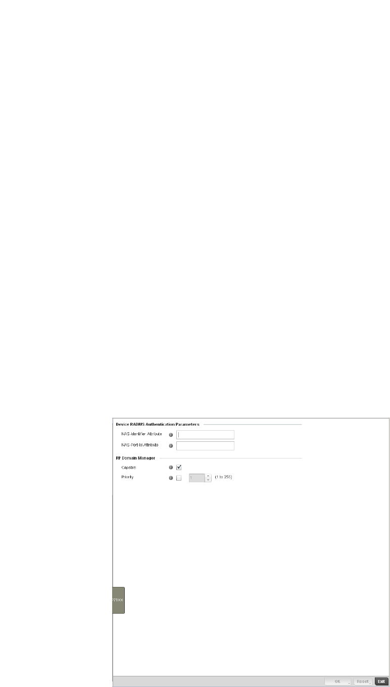
262 Brocade Mobility RFS4000, RFS6000, and RFS7000 System Reference Guide
53-1002620-01
5
16. Set the following VLAN parameters to complete the MINT configuration:
17. Select OK to save the updates and overrides to the MINT Protocol configuration. Select Reset
to revert to the last saved configuration.
Advanced Profile Miscellaneous Configuration
Overriding a Profile’s Advanced Configuration
Refer to the advanced profile’s Miscellaneous menu item to set or override a profile’s NAS
configuration. The profile database on the RADIUS server consists of user profiles for each
connected network access server (NAS) port. Each profile is matched to a username representing
a physical port. When the wireless controller authorizes users, it queries the user profile database
using a username representative of the physical NAS port making the connection. Access Point
LED behavior and RF Domain management can also be defined from within the Miscellaneous
screen.
1. Select Miscellaneous from the Advanced menu item
FIGURE 196 Advanced Profile Overrides - Miscellaneous screen
VLAN Define a VLAN ID between 1 - 4,094 used by peer controllers for interoperation when
supporting the MINT protocol.
Routing Level Use the spinner control to define or override a routing level of either 1 or 2.
Link Cost Use the spinner control to define or override a link cost between 1 - 10,000. The
default value is 100.
Hello Packet Interval Set or override an interval in either Seconds (1 - 120) or Minutes (1 - 2) for the
transmission of hello packets. The default interval is 15 seconds.
Adjacency Hold Time Set or override a hold time interval in either Seconds (2 - 600) or Minutes (1 - 10) for
the transmission of hello packets. The default interval is 46 seconds.

Brocade Mobility RFS4000, RFS6000, and RFS7000 System Reference Guide 263
53-1002620-01
5
2. Set a NAS-Identifier Attribute up to 253 characters in length.
This is the RADIUS NAS-Identifier attribute that typically identifies the Access Point or controller
of controller where a RADIUS message originates.
3. Set a NAS-Port-Id Attribute up to 253 characters in length.
This is the RADIUS NAS port ID attribute which identifies the device port where a RADIUS
message originates.
4. Select the Capable check box (within the RF Domain Manager section) to designate this
specific profile managed device as being capable of being the RF Domain manager for a
particular RF Domain. The default value is enabled.
5. Select the Priority check box (within the RF Domain Manager section) to set a priority value for
this specific profile managed device. Once enabled, use the spinner control to set a device
priority between 1 - 255. The higher the number set, the higher the priority in the RF Domain
manager election process.
6. Select OK to save the changes made to the profile’s Advanced Miscellaneous configuration.
Select Reset to revert to the last saved configuration.
Auto Provisioning Policies
Wireless devices running Brocade Mobility can adopt other wireless devices. For example, a
wireless controller can adopt an number of access points. When a device is adopted the device
configuration is determined by the adopting device. Since multiple configuration policies are
supported an adopting device needs a way of determining which of the multiple configuration
policies should be used for a given adoptee. Auto Provisioning Policies provide a way to determine a
configuration policy to be used for an adoptee based on some of its properties. For example, a
configuration policy could be assigned based on a MAC address, IP address, CDP snoop strings,
etc.
Once created an auto provisioning policy can be used in profiles or device configuration objects. An
auto provisioning policy contains a set of ordered by precedence rules that either deny or allow
adoption based on a potential adoptee properties and a catch-all variable that determines if the
adoption should be allowed when none of the rules were matched. All rules (both deny and allow)
are evaluated sequentially starting with the rule with the lowest precedence value. The evaluation
stops as soon as a rule has been matched, no attempt is made to find a better match further down
in the set.
The evaluation is performed using various matching criteria. The matching criteria supported in
Brocade Mobility are:
MAC Matches the MAC address of a device attempting to be adopted. Either a single
MAC address or a range of MAC addresses can be specified.
VLAN Matches when adoption over a Layer 2 link matches the VLAN ID of an adoption
request. Note that this is a VLAN ID as seen by the recipient of the request, in
case of multiple hops over different VLANs this may different from VLAN ID set
by the sender. A single VLAN ID is specified in the rule. This rule is ignored for
adoption attempts over Layer 3.
IP Address Matches when adoption is using a Layer 3 link matches the source IP address
of an adoption request. In case of NAT the IP address may be different from
what the sender has used. A single IP, IP range or IP/mask is specified in the
rule. This rule is ignored for adoption attempts over Layer 2.

264 Brocade Mobility RFS4000, RFS6000, and RFS7000 System Reference Guide
53-1002620-01
5
Auto Provisioning is the process an Access Point uses to discover controllers available in the
network, pick the most desirable controller, establish an association, optionally obtain an image
upgrade and obtain its configuration.
At adoption, an Access Point solicits and receives multiple adoption responses from controllers
available on the network. These adoption responses contain loading policy information the Access
Point uses to select the optimum controller for adoption. By default, an auto provisioning policy
generally distributes AP adoption evenly amongst available controllers. Modify existing adoption
policies or create a new one as needed to meet the adoption requirements of a device and their
assigned controller profile.
NOTE
A device configuration does not need to be present for an auto provisioning policy to take effect.
Once adopted, and the device’s configuration is defined and applied by the controller, the auto
provisioning policy mapping does not have impact on subsequent adoptions by the same device.
An auto provisioning policy enables an administrator to define adoption rules for the supported
Brocade Access Points capable of adoption by a wireless controller.
Auto provisioning policies set the different restrictions on how an AP gets adopted to a wireless
controller managed network.
To review existing Auto Provisioning Policy configurations:
1. Select Configuration > Devices > Auto Provisioning Policy.
2. The Adoption screen displays by default.
Serial Number Matches exact serial number (case insensitive).
Model Matches exact model name (case insensitive).
DHCP Option Matches the value found in DHCP vendor option 191 (case insensitive). DHCP
vendor option 191 can be setup to communicate various configuration
parameters to an AP. The value of the option in a string in the form of tag=value
separated by a semicolon, e.g. ’tag1=value1;tag2=value2;tag3=value3’. The
access point includes the value of tag ’rf-domain’, if present. This value is
matched against the auto provisioning policy.
FQDN Matches a substring to Fully Qualified Domain Name of a device (case
insensitive).
CDP Matches a substring in a list of CDP snoop strings (case insensitive). For
example, if an access point snooped 3 devices: controller1.moto.com,
controller2.moto.com and controller3.moto.com, ’controller1’, ’moto’,
’moto.com’, are examples of the substrings that will match.
LLDP Matches a substring in a list of LLDP snoop strings (case insensitive). For
example, if an access point snooped 3 devices: controller1.moto.com,
controller2.moto.com and controller3.moto.com, ’controller1’, ’moto’,
’moto.com’, are examples of the substrings that will match.
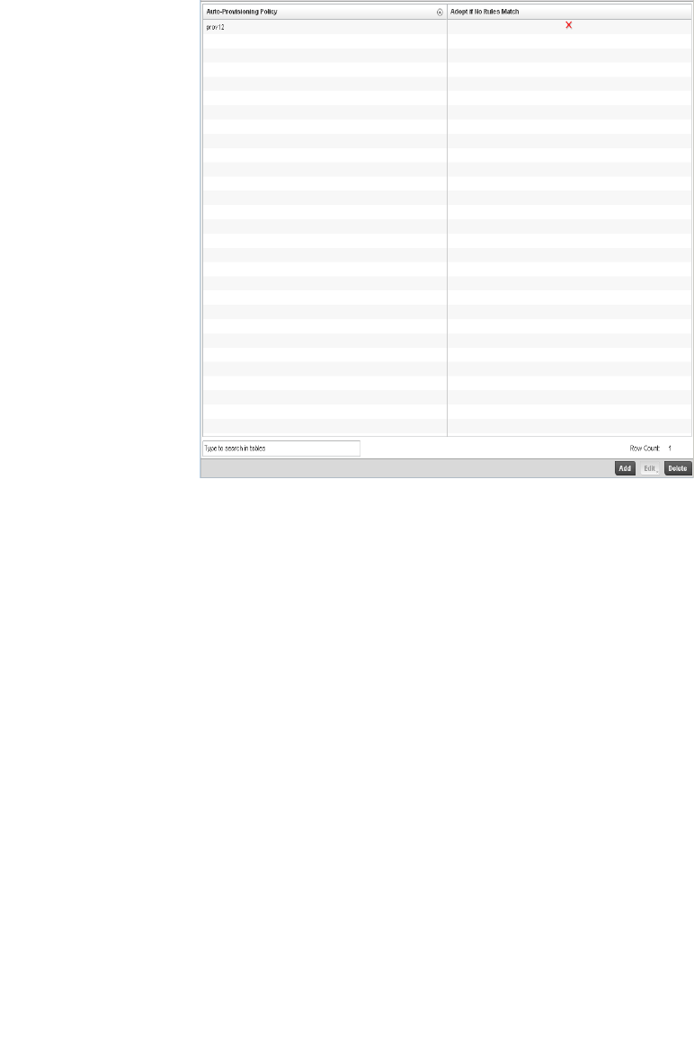
Brocade Mobility RFS4000, RFS6000, and RFS7000 System Reference Guide 265
53-1002620-01
5
FIGURE 197 Adoption screen
3. Use the Auto Provisioning screen to determine whether an existing policy can be used as is, a
new Auto Provisioning Policy requires creation or an existing policy requires edit or deletion.
4. Review the following Auto Provisioning parameters:
5. Select Add to create a new Auto Provisioning Policy, Edit to revise an existing Auto Provisioning
Policy or Delete to permanently remove a policy. For instructions on either adding or editing an
Auto Provisioning Policy, see Configuring an Auto Provisioning Policy on page 5-265.
Configuring an Auto Provisioning Policy
Controller Cluster Configuration Overrides (Controllers Only)
Individual Auto Provisioning Policies can be created or refined as unique deployment requirements
dictate changes in the number of Access Point radios within a specific radio coverage area.
To add a new Auto Provisioning Policy or edit an existing Auto Provisioning Policy configuration:
1. From the Adoption screen, either select Add or select an existing Auto Provisioning Policy and
select Edit.
Auto Provisioning Policy Lists the name of each Auto Provisioning Policy when it was created. It cannot
be modified as part of the Auto Provisioning Policy edit process.
Adopt if No Rules Match Displays whether this policy will adopt devices if no adoption rules apply.
Double-click within this column to launch the edit screen where rules can be
defined fro device adoption. This feature is enabled by default.
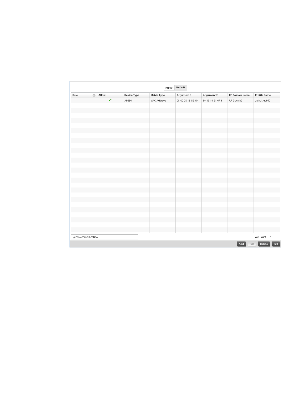
266 Brocade Mobility RFS4000, RFS6000, and RFS7000 System Reference Guide
53-1002620-01
5
2. If adding a new Auto Provisioning Policy, provide a name in the Auto Provisioning Policy field.
The name must not exceed 32 characters. Select Continue to enable the remaining
parameters of the Auto Provisioning Policy screen.
3. The Rules tab displays by default.
FIGURE 198 Auto Provisioning Policy screen - Rules tab
4. Review the following Auto Provisioning Policy rule data to determine whether a rule can be
used as is, requires edit or whether new rules need to be defined.
Rule Precedence Displays the precedence (sequence) the Adoption Policies rules are applied. Rules with
the lowest precedence receive the highest priority. This value is set (between 1 - 1000)
when adding a new Auto Provisioning Policy rule configuration.
Device Type Sets the br-650, br-7131, or br-6511 Access Point model for which this policy applies.
Adoption rules are specific to the selected model.
Match Type Lists the matching criteria used in the policy. This is like a filter and further refines the
APs that can be adopted. The Match Type can be one of the following:
MAC Address – The filter type is a MAC Address of the selected Access Point model.
IP Address – The filter type is the IP address of the selected Access Point model.
VLAN – The filter type is a VLAN.
Serial Number – The filter type is the serial number of the selected Access Point model.
Model Number – The filter type is the Access Point model number.
DHCP Option – The filter type is the DHCP option value of the selected Access Point
model.
Argument 1 The number of arguments vary on the Match Type. This column lists the first argument
value. This value is not set as part of the rule creation or edit process.
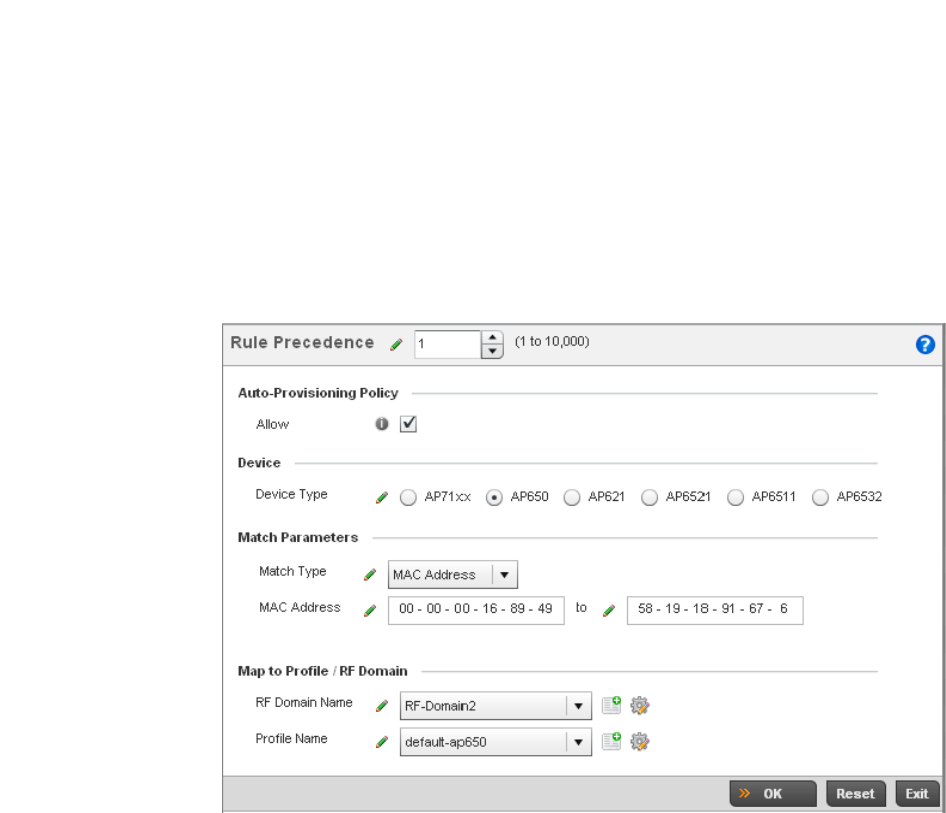
Brocade Mobility RFS4000, RFS6000, and RFS7000 System Reference Guide 267
53-1002620-01
5
5. If a rule requires addition or modification, select either Add or Edit to define the required
parameters using the Rule screen.
FIGURE 199 Auto Provisioning Policy Rule screen
Argument 2 The number of arguments vary on the Match Type. This column lists the second argument
value. This value is not set as part of the rule creation or edit process.
RF Domain Name Sets the name of the RF Domain to which the device is adopted automatically. Select the
Create icon to define a new RF Domain configuration or select the Edit icon to revise an
existing configuration. For more information, see to Managing RF Domains on page
8-500.
Profile Name Defines the name of the profile used when the Auto Provisioning Policy is applied to a
device. Select the Create icon to define a new Profile configuration or select the Edit
icon to revise an existing configuration. For more information, see General Profile
Configuration on page 7-370.
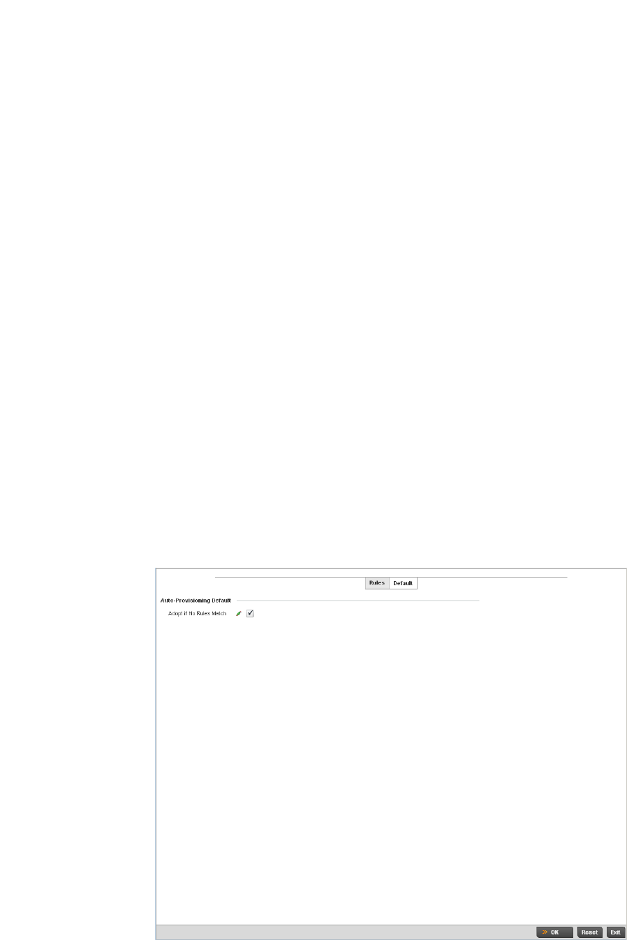
268 Brocade Mobility RFS4000, RFS6000, and RFS7000 System Reference Guide
53-1002620-01
5
6. Specify the following parameters in the Rule screen:
7. Select the Default tab to define the Auto Provisioning Policy’s rule matching adoption
configuration.
FIGURE 200 Auto Provisioning Policy screen - Default tab
Rule Precedence Use the spinner control to specify the precedence (sequence) that the Adoption Policies
rules are applied. Rules with the lowest precedence receive the highest priority. This
value is set (between 1 - 1000) when adding a new Auto Provisioning Policy rule
configuration.
Device Type Set the br-650, br7131,or br6511 Access Point model for which this policy applies.
Adoption rules are specific to the selected model.
Match Type Set the matching criteria used in the policy. This is like a filter and further refines the APs
that can be adopted. The Match Type can be one of the following:
MAC Address – The filter type is a MAC Address of the selected Access Point model.
IP Address – The filter type is the IP address of the selected Access Point model.
VLAN – The filter type is a VLAN.
Serial Number – The filter type is the serial number of the selected Access Point model.
Model Number – The filter type is the Access Point model number.
DHCP Option – The filter type is the DHCP option value of the selected Access Point
model.
RF Domain Name Set the name of the RF Domain to which the device is adopted automatically. Select the
Create icon to define a new RF Domain configuration or select the Edit icon to revise an
existing configuration. For more information, see to General Profile Configuration on page
7-370.
Profile Name Define the name of the profile used when the Auto Provisioning Policy is applied to a
device. Select the Create icon to define a new Profile configuration or select the Edit
icon to revise an existing configuration. For more information, see General Profile
Configuration on page 7-370.

Brocade Mobility RFS4000, RFS6000, and RFS7000 System Reference Guide 269
53-1002620-01
5
8. Select the Adopt if No Rules Match checkbox to have the controller adopt when no matching
filter rules apply. This setting is enabled by default.
9. Select OK to save the updates to the Auto Provisioning Policy screen. Selecting Reset reverts
the screen to the last saved configuration.
br300 Devices
Begining with Brocade Mobility 5.2 adoption of br-300 Access Points are supported in a limited
capacity. The following is a list of br-300 and Brocade Mobility 5.2 features and functionality that
are not supported on br-300 in Brocade Mobility 5.2:
•Self Healing
•Enhanced Beacon and Probe Table
•Adoption and upgrade of pre-WiOS br-300 devices
•Layer 3 Mobility
•WLAN bandwidth allocation
•802.11k
•Smart-RF
•RF Domain Support
In addition to the above unsupported features, Brocade Mobility 5.2 does not support custom
profiles for br-300 devices. If a configuration other than the default br-300 profile is needed for any
devices, those devices must each be configured manually.
To define br-300 Device Configuration:
1. Select Configuration > Devices > br-300 Devices.
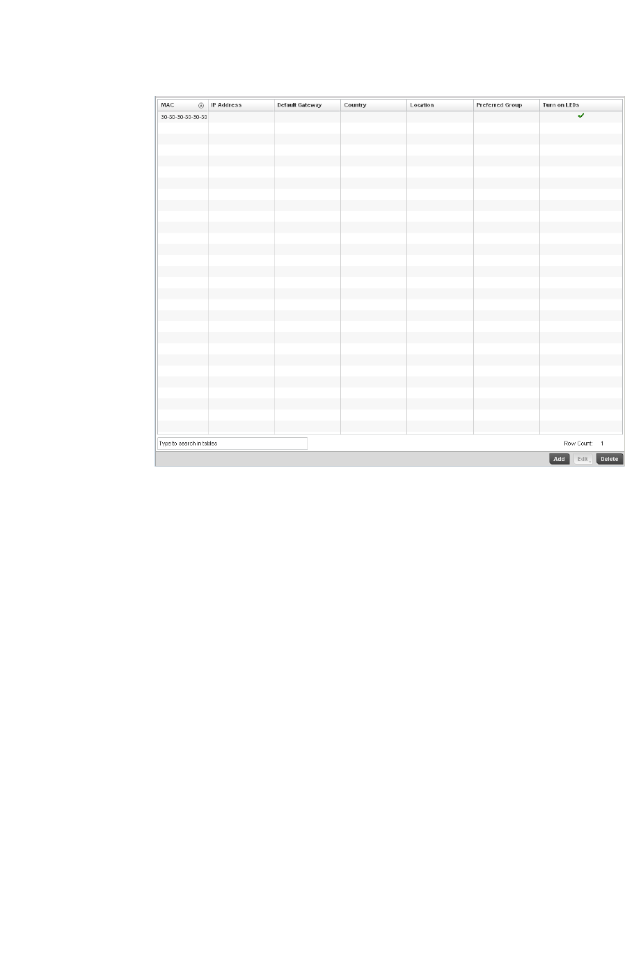
270 Brocade Mobility RFS4000, RFS6000, and RFS7000 System Reference Guide
53-1002620-01
5
FIGURE 201 br-300 Devices screen
2. Refer to the following information about configured br-300 access points:
3. Select Add to create a new policy or Edit to modify an existing br-300 configuration. For more
information, refer to Managing br-300 Devices on page 5-270.
Managing br-300 Devices
To add or edit an br-300 Device Configuration:
1. Select Configuration > Devices > br-300 Devices.
2. Select an existing br-300 profile and click Edit or click Add to create a new br-300 profile.
MAC Displays the Media Access Control (MAC) or hardware address for each known and
configured br-300 unit.
IP Address Displays the current IP address assigned to each known and configured br-300 unit.
Default Gateway Displays the default gateway IP address for each known and configured unit in the br-300
properties.
Country Display the two-digit country code set for the policy. The country code must be set
accurately to avoid the policy’s illegal operation, as device radios transmit in specific
channels unique to their defined country of operation.
Location Displays the location defined for the device as part of its configuration.
Preferred Controller Displays the name of the controller that has been configured as the preferred controller
in the br-300 properties..
Turn on LEDs The Turn on LEDs field will display a green check mark if LEDs are enabled on the br-300
and will display a red X if the br-300 LEDs are not enabled.
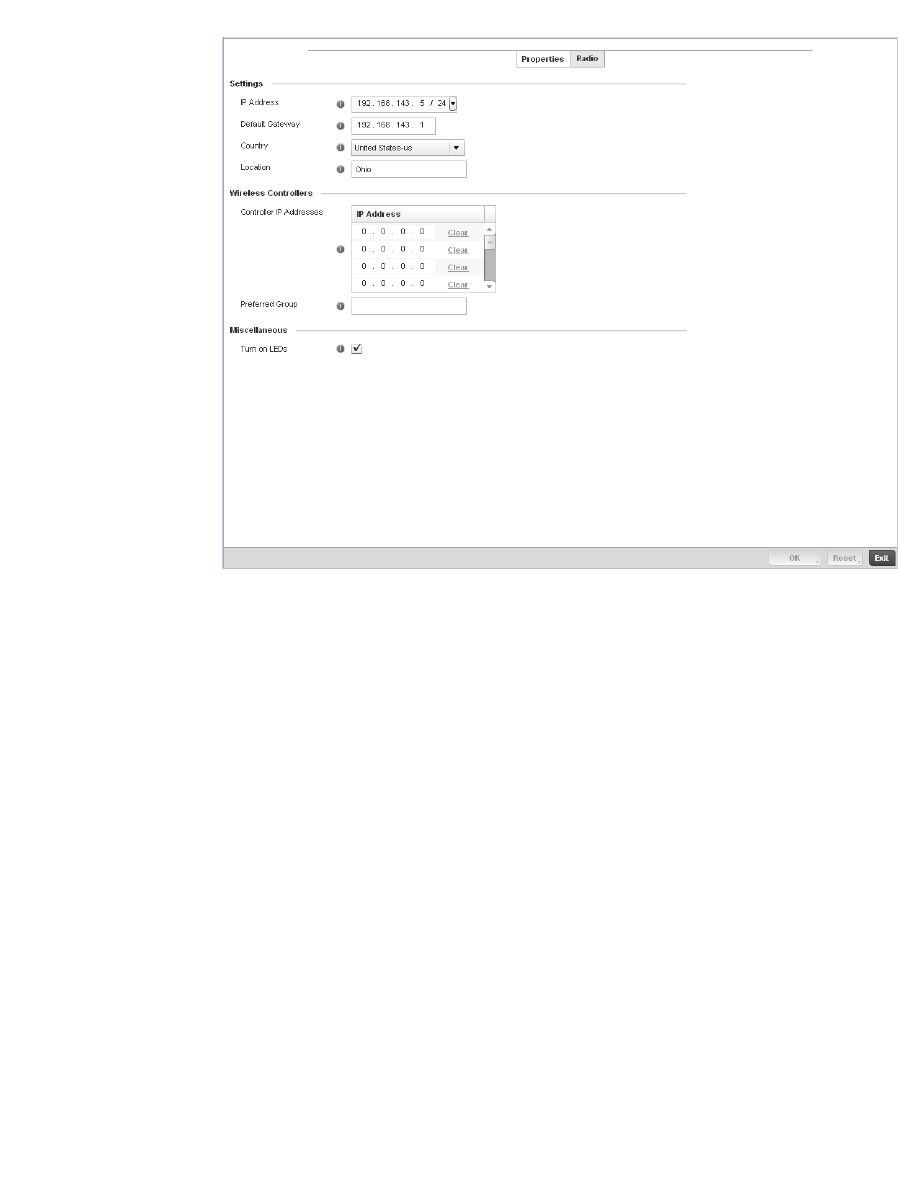
Brocade Mobility RFS4000, RFS6000, and RFS7000 System Reference Guide 271
53-1002620-01
5
3. The Properties tab displays.
FIGURE 202 br-300 Devices Properties screen
4. Refer to the Settings section and configure the following:
5. Refer to the Wireless Controllers section and configure the following:
6. Refer to the Miscelaneous section and configure the following:
7. Select the Radio tab.
IP Address Specify the IP Address and mask to assign to the br-300.
Default Gateway Specify the IP address of the default gateway used by the br-300 to communicate with
the controller.
Country Use the pull-down menu to specify the country name and country code where the br-300
will operate. The country code must be set accurately to avoid illegal operation, as device
radios transmit in specific channels unique to their defined country of operation.
Location Enter a descriptive location name for where the br-300 is deployed.
Controller IP
Address
Enter the IP addresses of wireless controllers on the network that the br-300 can be
adopted by.
Preferred Controller Specify the name of the wireless controller that the br-300 will try and adopt to first.
Turn on LEDs Check this box to light the br-300 LEDs. This can be useful in locating a specific br-300 in
a large deployment.
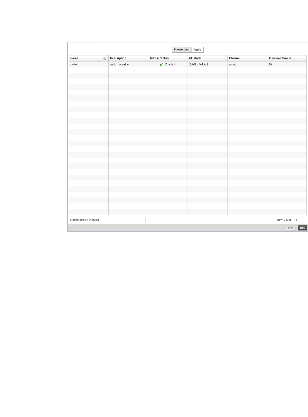
272 Brocade Mobility RFS4000, RFS6000, and RFS7000 System Reference Guide
53-1002620-01
5
FIGURE 203 br-300 Devices Radios screen
8. Refer to the Radios tab for the following information:
9. If required, select a radio configuration and select the Edit button to modify its configuration.
10. The Radio Settings tab displays.
Name Displays whether the reporting radio is the br-300’s radio1 or radio2.
Description Displays a brief description of the radio provided by the administrator when the radio’s
configuration was added or modified.
Admin Status A green checkmark defines the listed Virtual Interface configuration as active and
enabled with its supported controller profile. A red X defines the Virtual Interface as
currently disabled. The interface status can be modified when a new Virtual Interface is
created or an existing one modified.
RF Mode Displays whether each listed radio is operating in the 802.11a/n or 802.11b/g/n radio
band. If the radio is a dedicated sensor, it will be listed as a sensor to define the radio as
not providing typical WLAN support. The radio band is set from within the Radio Settings
tab.
Channel Lists the channel setting for the radio. Smart is the default setting. If set to smart, the
Access Point scans non-overlapping channels listening for beacons from other Access
Points. After the channels are scanned, it selects the channel with the fewest Access
Points. In the case of multiple Access Points on the same channel, it will select the
channel with the lowest average power level.
Transmit Power Lists the transmit power for each radio.
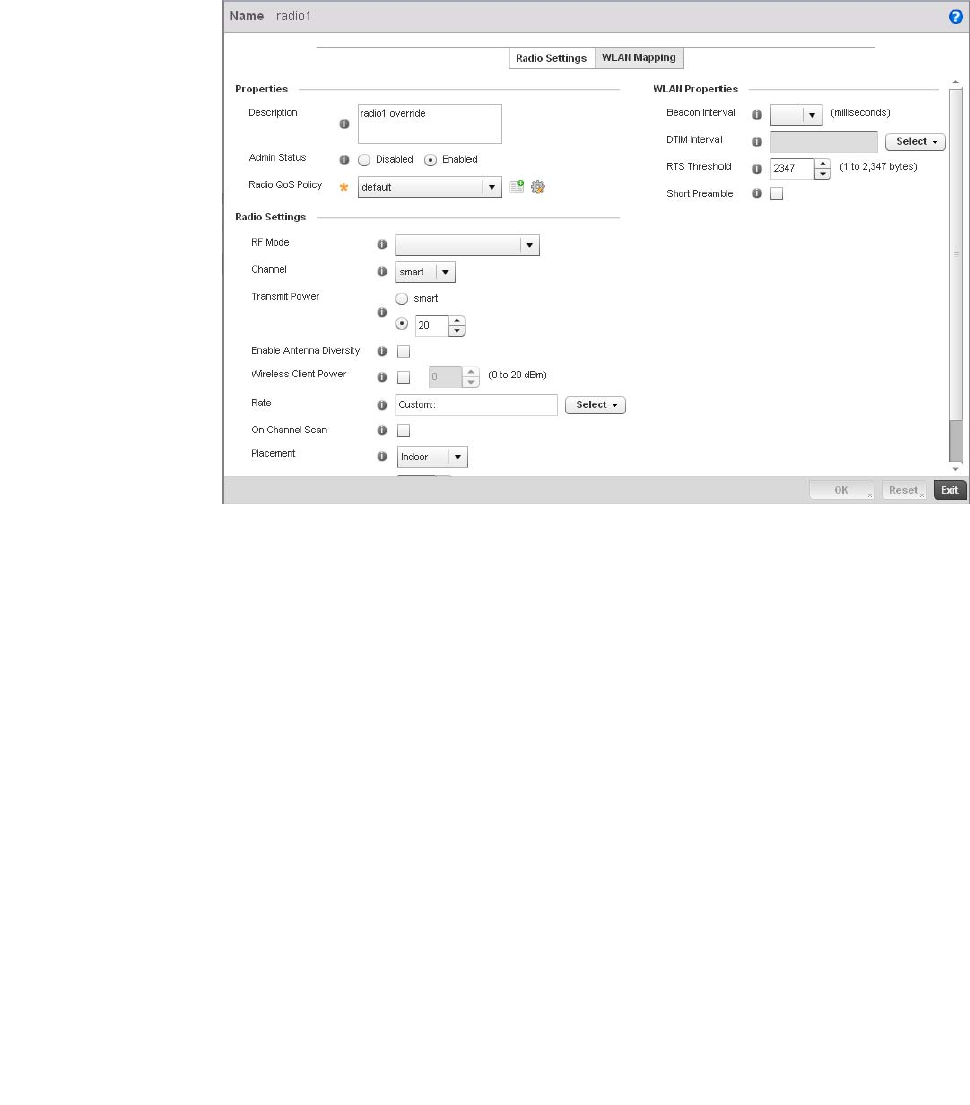
Brocade Mobility RFS4000, RFS6000, and RFS7000 System Reference Guide 273
53-1002620-01
5
FIGURE 204 br-300 Devices Radios Edit screen
11. Configure the following Radio Settings:
Description Provide or edit a description (1 - 64 characters in length) for the radio that helps
differentiate it from others with similar configurations.
Admin Status Either select the Active or Shutdown radio button to define this radio’s current status
within the controller managed network. When defined as Active, the Access Point is
operational and available for client support within the controller managed network.
Radio QoS Policy Use the drop-down menu to specify an existing QoS policy to apply to the Access Point
radio in respect to its intended radio traffic. If there’s no existing suiting the radio’s
intended operation, select the Create icon to define a new QoS policy that can be applied
to this controller profile.
RF Mode Set the mode to either 2.4 GHz WLAN or 5 GHz WLAN support depending on the radio’s
intended client support. Set the mode to Sensor if using the radio for rogue device
detection. The radio cannot support rogue detection when one of the Access Point's other
radios is functioning as a WIPS sensor. To a radio as a detector, disable Sensor support
on the other Access Point radio.
Channel Use the drop-down menu to select the channel for the radio. Only a trained installation
professional should define the radio channel. Select Smart for the radio to scan
non-overlapping channels listening for beacons from other Access Points. After the
channels are scanned, the radio selects the channel with the fewest Access Points. In the
case of multiple Access Points on the same channel, it will select the channel with the
lowest average power level. The default value is Smart.
Transmit Power Set the transmit power of the selected Access Point radio. If using a dual or three radio
model Access Point, each radio should be configured with a unique transmit power in
respect to its intended client support function. If using Smart RF select the Smart RF
radio button to let Smart RF determine the transmit power. A setting of 0 defines the
radio as using SMART RF to determine its output power. 20 dBm is the default value.

274 Brocade Mobility RFS4000, RFS6000, and RFS7000 System Reference Guide
53-1002620-01
5
Enable Antenna
Diversity
Select this box to enable antenna diversity on supported antennas. Antenna diversity
uses two or more antennas to increase signal quality and strength. This option is disabled
by default.
Rate Use the Select button to set rate options depending on the 802.11 protocols selected. If
the radio band is set to Sensor or Detector, the Data Rates drop-down menu is not
enabled, as the rates are fixed and not user configurable. If 2.4 GHz is selected as the
radio band, select separate 802.11b, 802.11g and 802.11n rates and define how they
are used in combination. If 5 GHz is selected as the radio band, select separate 802.11a
and 802.11n rates then define how they are used together. When using 802.11n (in
either the 2.4 or 5 GHz band), Set a MCS (modulation and coding scheme) in respect to
the radio’s channel width and guard interval. A MCS defines (based on RF channel
conditions) an optimal combination of 8 data rates, bonded channels, multiple spatial
streams, different guard intervals and modulation types. Clients can associate as long as
they support basic MCS (as well as non-11n basic rates).
Placement Use the drop-down menu to specify whether the radio is located Indoors or Outdoors. The
placement should depend on the country of operation selected and its regulatory domain
requirements for radio emissions. The default setting is Indoors.
Maximum Clients Use the spinner control to set a maximum permissible number of clients to connect with
this radio. The available range is between 0 - 256 clients. The default value is 256.
Beacon Interval Set the interval between radio beacons in milliseconds (either 50, 100 or 200). A
beacon is a packet broadcast by adopted radios to keep the network synchronized.
Included in a beacon is information such as the WLAN service area, the radio address,
the broadcast destination addresses, a time stamp, and indicators about traffic and
delivery such as a DTIM. Increase the DTIM/beacon settings (lengthening the time) to let
nodes sleep longer and preserve battery life. Decrease these settings (shortening the
time) to support streaming-multicast audio and video applications that are
jitter’sensitive. The default value is 100 milliseconds.
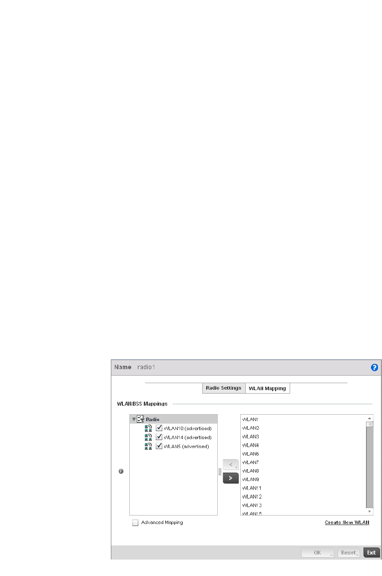
Brocade Mobility RFS4000, RFS6000, and RFS7000 System Reference Guide 275
53-1002620-01
5
12. Click the WLAN Mapping tab.
FIGURE 205 br-300 Devices Radios Edit screen
DTIM Interval Set a DTIM Interval to specify a period for Delivery Traffic Indication Messages (DTIM). A
DTIM is periodically included in a beacon frame transmitted from adopted radios. The
DTIM indicates broadcast and multicast frames (buffered at the Access Point) are soon to
arrive. These are simple data frames that require no acknowledgement, so nodes
sometimes miss them. Increase the DTIM/ beacon settings (lengthening the time) to let
nodes sleep longer and preserve their battery life. Decrease these settings (shortening
the time) to support streaming multicast audio and video applications that are
jitter-sensitive.
RTS Threshold Specify a Request To Send (RTS) threshold (between 1 - 2,347 bytes) for use by the
WLAN’s adopted Access Point radios. RTS is a transmitting station’s signal that requests
a Clear To Send (CTS) response from a receiving client. This RTS/CTS procedure clears
the air where clients are contending for transmission time. Benefits include fewer data
collisions and better communication with nodes that are hard to find (or hidden) because
of other active nodes in the transmission path.<br>Control RTS/CTS by setting an RTS
threshold. This setting initiates an RTS/CTS exchange for data frames larger than the
threshold, and sends (without RTS/CTS) any data frames smaller than the
threshold.<br>Consider the trade-offs when setting an appropriate RTS threshold for the
WLAN’s Access Point radios. A lower RTS threshold causes more frequent RTS/CTS
exchanges. This consumes more bandwidth because of additional latency (RTS/CTS
exchanges) before transmissions can commence. A disadvantage is the reduction in
data-frame throughput. An advantage is quicker system recovery from electromagnetic
interference and data collisions. Environments with more wireless traffic and contention
for transmission make the best use of a lower RTS threshold.<br>A higher RTS threshold
minimizes RTS/CTS exchanges, consuming less bandwidth for data transmissions. A
disadvantage is less help to nodes that encounter interference and collisions. An
advantage is faster data-frame throughput. Environments with less wireless traffic and
contention for transmission make the best use of a higher RTS threshold.
Short Preamble If using an 802.11bg radio, select this checkbox for the radio to transmit using a short
preamble. Short preambles improve throughput. However, some devices (SpectraLink
phones) require long preambles. The default value is disabled.
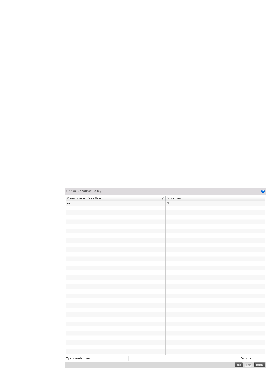
276 Brocade Mobility RFS4000, RFS6000, and RFS7000 System Reference Guide
53-1002620-01
5
13. Refer to the WLAN/BSS Mappings field to set or override WLAN BSSID assignments for an
existing Access Point deployment. Administrators can assign each WLAN its own BSSID. If
using a single-radio Access Point, there are 8 BSSIDs available. If using a dual-radio Access
Point there are 8 BSSIDs for the 802.11b/g/n radio and 8 BSSIDs for the 802.11a/n radio.
14. Select Advanced Mapping to enable WLAN mapping to a specifc BSS ID.
15. Select OK to save the changes and overrides to the WLAN Mapping. Select Reset to revert to
the last saved configuration.
Critical Resource Policy
A Critical Resource Policy defines a list of device IP addresses on the network (gateways, routers
etc.). The support of these defined IP address is interopreted as critical to the health of the
managed network. These devices addresses are pinged regularly by the wireless controller. If
there’s a connectivity issue, an event is generated stating a critical resource is unavailable. There’s
no restoration of the critical device involved.
To define a Critical Resource Policy:
1. Select Configuration > Devices > Critical Resource Policies.
FIGURE 206 Critical Resource Policy screen
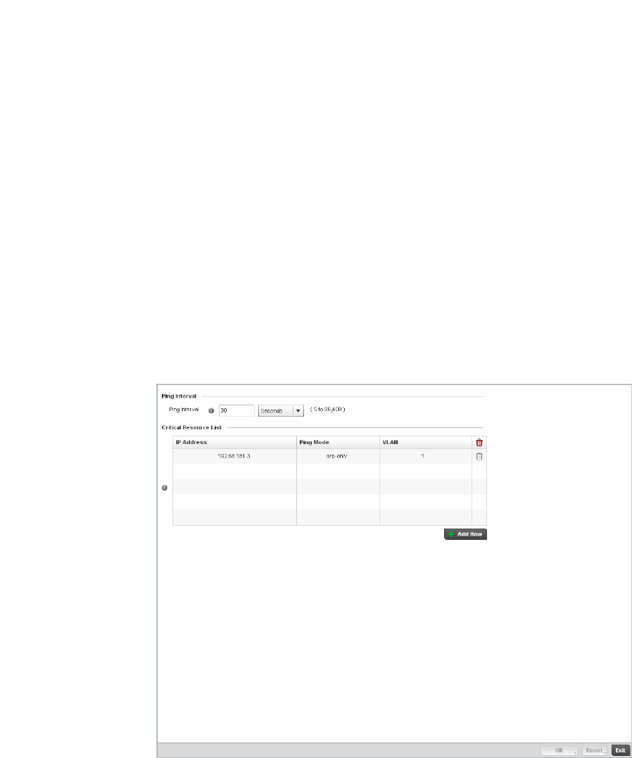
Brocade Mobility RFS4000, RFS6000, and RFS7000 System Reference Guide 277
53-1002620-01
5
2. Refer to the following to help determine whether a new Critical Resource Policy should be
created or an existing policy modified:
1. Select Add to create a new policy or Edit to modify an existing Critical Resource Policy
configuration. For more information, refer to Managing Critical Resource Policies on page
5-277.
Managing Critical Resource Policies
Critical Resource Policy
The controller provides some flexibility to define new IP addresses interpreted as critical resources
or remove addresses no longer defined as critical.
To add or modify a Critical Resource Policy:
1. Select Add or Edit (after selecting an existing policy) from the Critical Resource Policy screen.
2. If adding a new policy, enter a name in the Critical Resource Policy field. Click the OK button
(which flashes after inputting a policy name) to fill in the rest of the information for creating a
Critical Resource Policy. The following screen displays.
FIGURE 207 Critical Resource Policy Configuration screen
Critical Resource
Policy Name
Displays the name of the policy assigned when it was initially created. The policy is a
collection of critical resources grouped logically.
Ping Interval The interval between 2 pings to the critical resource. Ping is used to check if connection
to the critical resource is working.

278 Brocade Mobility RFS4000, RFS6000, and RFS7000 System Reference Guide
53-1002620-01
5
3. Set the following Critical Resource Policy parameters:
4. Click the Add Row button at the bottom of the Critical Resource List table to add a new critical
resource. To edit an existing critical resource, select the row and edit the values.
5. Select OK to save the changes. Select Reset to revert to the last saved configuration. Delete
obsolete rows as needed.
Managing Event Policies
Critical Resource Policy
Event Policies enable an administrator to create specific notification mechanisms using one, some
or all of the SNMP, syslog, controller forwarding or email notification options available to the
controller. Each listed event can have customized notification settings defined and saved as part of
an event policy. Thus, policies can be configured and administrated in respect to specific sets of
client association, authentication/encryption and performance events. Once policies are defined,
they can be mapped to device profiles strategically as the likelihood of an event applies to
particular devices.
When initially displayed, the Event Policy screen lists existing policies. Existing policies can have
their event notification configurations modified as device profile requirements warrant. New
policies can be added as needed.
To add or modify an Event Policy:
1. Select Add or Edit (after selecting an existing policy) from the Event Policy screen.
2. If adding a new policy, enter a name in the Policy Name field. Click the OK button (which
flashes after inputting a policy name) to fill in the rest of the information for creating a Event
Policy. The following screen displays.
Ping Interval Set the duration between two successive pings to the critical device.
Select from:
Days – Measured in days.
Hours – Measured in hours.
Minutes – Measured in minutes
Seconds – Measured in seconds
The default interval is 30 seconds.
IP Address Set the IP address of the critical resource. This is the address the device is assigned
and is used by the wireless controller to check if the critical resource is available.
Ping Mode Set the ping mode used when the availability of a critical resource is validated. Select
from:
arp-only – Use the Address Resolution Protocol (ARP) only for pinging the critical
resource. ARP is used to resolve hardware addresses when only the network layer
address is known.
arp-icmp – Use both Address Resolution Protocol (ARP) and Internet Control
Message Protocol (ICMP) for pining the critical resource and sending the control
messages (device not reachable, requested service not available, etc).
VLAN Define the VLAN on which the critical resource is available. Enter the VLAN number in
the text provided or select the VLAN using the spinner control.
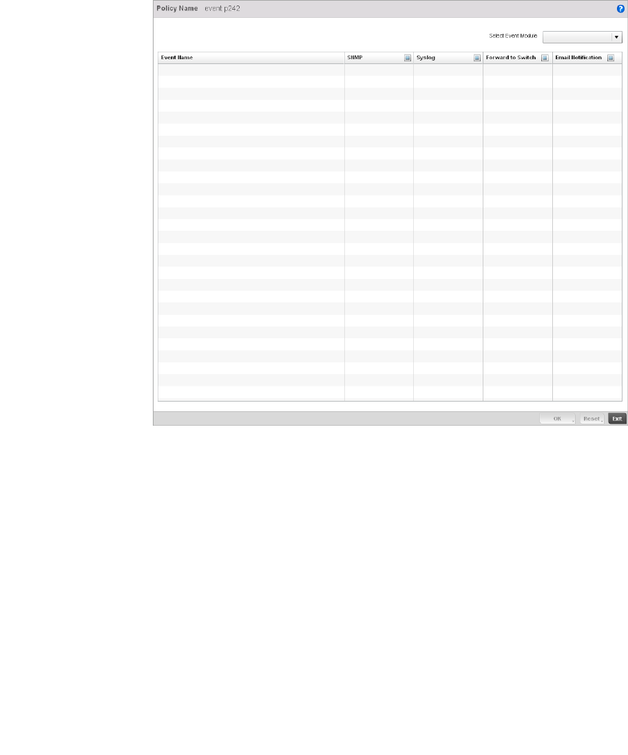
Brocade Mobility RFS4000, RFS6000, and RFS7000 System Reference Guide 279
53-1002620-01
5
FIGURE 208 Event Policy Configuration screen
3. Refer to the Select Event Module drop-down menu on the top right-hand side of the screen,
and select controller event module used to track the occurance of each list event.
Review each event and select (or deselect) the SNMP, Syslog, Forward to Switch or Email
Notification option as required for the event and applicable device profile. Map an existing
policy to a device profile as needed. Select Profile from the Map drop-down menu in the
lower-left hand side of the screen. Expand the list of device profiles available, and apply the
event policy as required.
4. Select OK to save the changes. Select Reset to revert to the last saved configuration. Delete
obsolete rows as needed.
Managing MINT Policies
Critical Resource Policy
To add or modify a MINT Policy:
1. Select Devices > MINT Policy to display the MINT Policy screen.
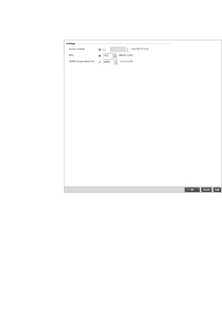
280 Brocade Mobility RFS4000, RFS6000, and RFS7000 System Reference Guide
53-1002620-01
5
FIGURE 209 MINT Policy Configuration screen
2. Configure the following parameters to configure the MINT policy:
3. Select OK to save the changes. Select Reset to revert to the last saved configuration.
Level 2 Area ID Define a Level 2 Area ID for the Mint Policy. The Level 2 Area ID is the global mint area
identifier. This area identifier separates two overlapping mint networks and need only
be configured if the administrator has two mint networks that share the same packet
broadcast domain.
MTU Specify a MTU value for the mint policy between 900 and 1,500. The MTU setting
specifies the maximum packet size that will be used for mint packets. Larger packets
will be fragmented so they fit within this packet size limit. The administrator may want
to configure this parameter if the mint backhaul network requires or recommends
smaller packet sizes. The default value is 1500.
UDP/IP Encapsulation
Port
Specify the port to use for UDP/IP encapsulation between 2 and 65,534. This value
specifies an alternate UDP port to be used by mint packets and must be an even
number. This port number will be used by mint control packets, and this port value
plus 1 will be used to carry mint data packets. The default value is 24576.

Brocade Mobility RFS4000, RFS6000, and RFS7000 System Reference Guide 281
53-1002620-01
Chapter
6
Wireless Configuration
In this chapter
•Wireless LAN Policy . . . . . . . . . . . . . . . . . . . . . . . . . . . . . . . . . . . . . . . . . . . . 282
•WPA-TKIP Deployment Considerations. . . . . . . . . . . . . . . . . . . . . . . . . . . . . 297
•Configuring WLAN QoS Policies . . . . . . . . . . . . . . . . . . . . . . . . . . . . . . . . . . 318
•Radio QoS Policy . . . . . . . . . . . . . . . . . . . . . . . . . . . . . . . . . . . . . . . . . . . . . . 332
•AAA Policy. . . . . . . . . . . . . . . . . . . . . . . . . . . . . . . . . . . . . . . . . . . . . . . . . . . . 343
•Association ACL . . . . . . . . . . . . . . . . . . . . . . . . . . . . . . . . . . . . . . . . . . . . . . . 352
•Smart RF Policy . . . . . . . . . . . . . . . . . . . . . . . . . . . . . . . . . . . . . . . . . . . . . . . 355
A Wireless Local Area Network (WLAN) is a data-communications system and wireless local area
network that flexibly extends the functionalities of a wired LAN. A WLAN links two or more
computers or devices using spread-spectrum or OFDM modulation based technology. A wireless
controller managed WLAN does not require lining up devices for line-of-sight transmission, and are
thus, desirable for wireless controller managed wireless networking. Roaming users can be handed
off from one wireless controller connected access point to another, like a cellular phone system.
WLANs can therefore be configured around the needs of specific user groups, even when they are
not in physical proximity.
WLANs can be used to provide an abundance of services, including data communications (allowing
mobile devices to access applications), email, file and print services or even specialty applications
(such as guest access control and asset tracking).
Each wireless controller WLAN configuration contains encryption, authentication and QoS policies
and conditions for user connections. Connected access point radios transmit periodic beacons for
each BSS. A beacon advertises the SSID, security requirements, supported data rates of the
wireless network to enable clients to locate and connect to the wireless controller managed WLAN.
WLANs are mapped to radios on each connected br-650, br7131,or br6511 (adaptive mode)
access point. A WLAN can be advertised from a single access point radio or can span multiple
access points and radios. WLAN configurations can be defined to only provided service to specific
areas of a site. For example a guest access WLAN may only be mapped to a 2.4GHz radio in a lobby
or conference room providing limited coverage while a data WLAN is mapped to all 2.4GHz and
5GHz radios at the branch site providing complete coverage.
Brocade RFS4000 and RFS6000 model wireless controllers support a maximum of 32 WLANs. The
Brocade RFS7000 model wireless controller supports up to 256 WLANs.
The controller’s wireless configuration is comprised the following policies:
•Wireless LAN Policy
•Configuring WLAN QoS Policies
•Radio QoS Policy
•AAA Policy
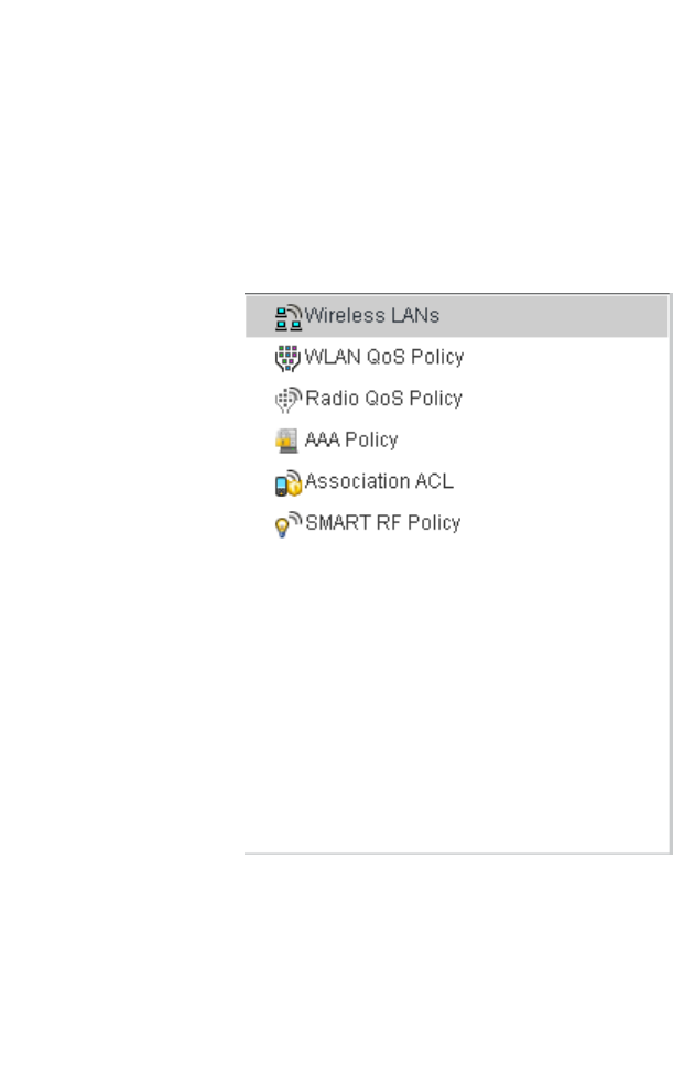
282 Brocade Mobility RFS4000, RFS6000, and RFS7000 System Reference Guide
53-1002620-01
6
•Association ACL
•Smart RF Policy
These parameters can be separately selected within the Configuration > Wireless pane located in
top, left-hand, side of the controller UI.
FIGURE 210 Configuration > Wireless pane
Wireless LAN Policy
To review the attributes of existing controller WLANs and, if necessary, modify their configurations:
1. Select Configuration > Wireless > Wireless LANs to display a high-level display of the existing
WLANs.
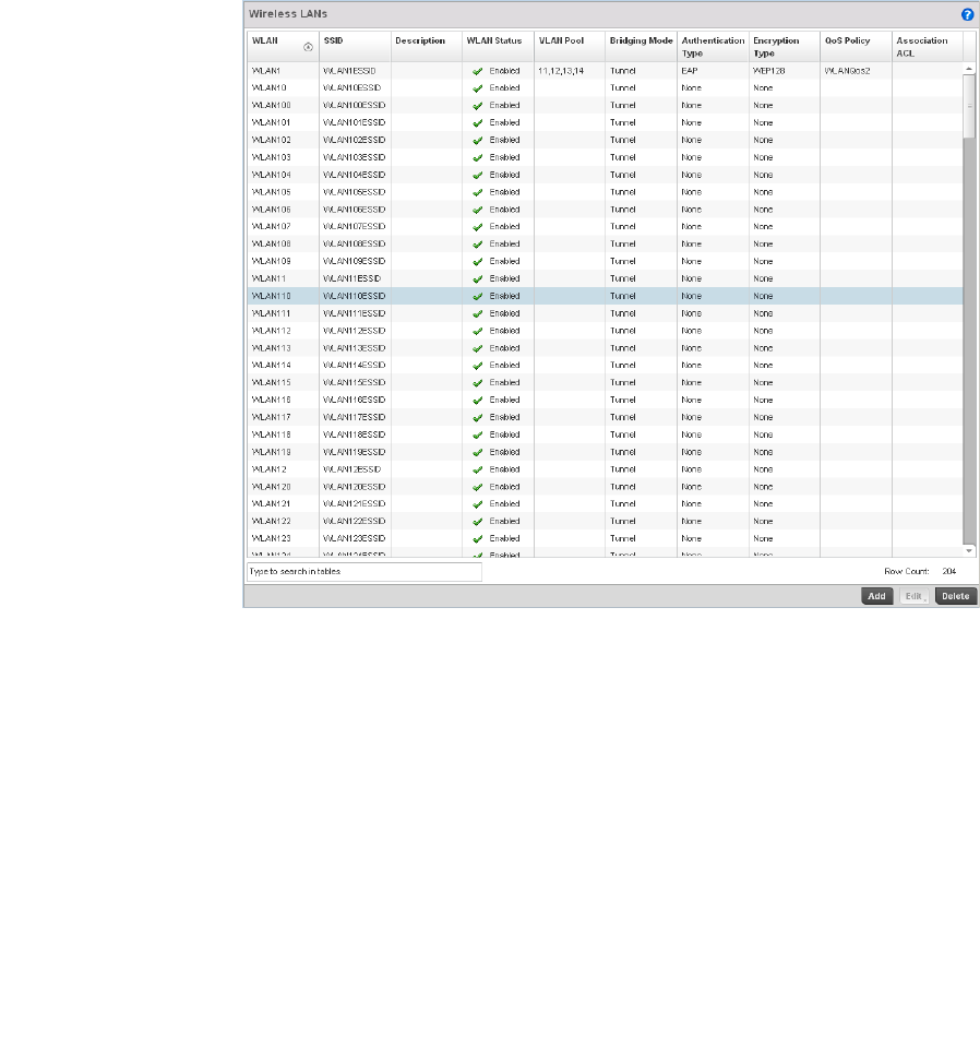
Brocade Mobility RFS4000, RFS6000, and RFS7000 System Reference Guide 283
53-1002620-01
6
FIGURE 211 Wireless LANs screen
2. Refer to the following (read only) information to assess the attributes of the each WLAN
available to the wireless controller:
WLAN Displays the name of each WLAN available on the wireless controller. Each WLAN can
be selected and its SSID and client management properties modified.
SSID Displays the name of the SSID assigned to the WLAN when it was created or last
modified. Optionally, select a WLAN and click the Edit button to update the SSID.
Description Displays the brief description defined for each listed WLAN when it was either created
or modified.
WLAN Status Lists each WLAN’s current status as either Active or Shutdown. A green checkmark
defines the WLAN as available to clients on all radios where it has been mapped. A red
“X” defines the WLAN as shutdown, meaning even if the WLAN is mapped to radios, it’s
not available for clients to associate.
VLAN Pool Lists each WLANs current VLAN mapping. The wireless controller permits mapping a
WLAN to more than one VLANs. When a client associates with a WLAN, the client is
assigned a VLAN by means of load balance distribution. The VLAN is picked from a pool
assigned to the WLAN. Keep in mind however, typical deployments only map a single
VLAN to a WLAN. The use of a pool is strictly optional.

284 Brocade Mobility RFS4000, RFS6000, and RFS7000 System Reference Guide
53-1002620-01
6
Use the wireless controller’s sequential set of WLAN screens to define a unique configuration for
each WLAN. Refer to the following to set WLAN configurations:
•Basic WLAN Configuration
•Configuring WLAN Security
•Configuring WLAN Firewall Support
•Configuring Client Settings
•Configuring WLAN Accounting Settings
•Configuring Client Load Balancing Settings
•Configuring Advanced WLAN Settings
Basic WLAN Configuration
Wireless LAN Policy
When creating or modifying a wireless controller WLAN, the first screen that displays as part of the
WLAN configuration screen flow is the Basic Configuration screen. Use this screen to enable a
WLAN and define its SSID, client behavior and VLAN assignments.
1. Select Configuration > Wireless > Wireless LAN Policy to display a high-level display of the
existing WLANs available to the wireless controller managed network.
2. Select the Add button to create an additional WLAN, or select an existing WLAN then Edit to
modify the properties of the existing WLAN.
Brocade Mobility RFS4000 and RFS6000 model wireless controllers support a maximum of 32
WLANs. The Brocade Mobility RFS7000 model wireless controller supports up to 256 WLANs.
Authentication Type Displays the name of the authentication scheme this WLAN is using to secure its client
membership transmissions. None is listed if authentication is not used within this
WLAN. Refer to the Encryption type column if no authentication is used to verify there is
some sort of data protection used with the WLAN or risk using this WLAN with no
protection at all.
Encryption Type Displays the name of the encryption scheme this WLAN is using to secure its client
membership transmissions. None is listed if encryption is not used within this WLAN.
Refer to the Authentication type column if no encryption is used to verify there is some
sort of data protection used with the WLAN or risk using this WLAN with no protection
at all.
QoS Policy Lists the QoS policy applied to each listed WLAN. A QoS policy needs to be custom
selected (or created) for each WLAN in respect to the WLAN’s intended client traffic
and the voice, video or normal data traffic it supports.
Association ACL Lists the Association ACL policy applied to each listed WLAN. An Association ACL is a
policy-based Access Control List (ACL) that either prevents or allows wireless clients
from connecting to a managed WLAN. The mapping of an Association ACL is strictly
optional.
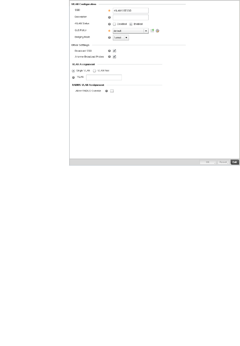
Brocade Mobility RFS4000, RFS6000, and RFS7000 System Reference Guide 285
53-1002620-01
6
FIGURE 212 WLAN Policy Basic Configuration screen
3. Refer to the WLAN Configuration field to define the following:
WLAN If adding a new WLAN, enter its name in the space provided. Spaces between words
are not permitted. The name could be a logical representation of the WLAN coverage
area (engineering, marketing etc.). If editing an existing WLAN, the WLAN’s name
appears at the top of the screen and cannot be modified. The name cannot exceed 32
characters.
SSID Enter or modify the Services Set Identification (SSID) associated with the WLAN. The
maximum number of characters that can be used for the SSID is 32.
Description Provide a textual description for the WLAN to help differentiate it from others with
similar configurations. The description can be up to 64 characters.
WLAN Status Select the Enabled radio button to make this WLAN active and available to clients on
all radios where it has been mapped. Select the Disabled radio button to make this
WLAN inactive, meaning even if the WLAN is mapped to radios, it’s not available for
clients to associate and use.
QoS Policy Use the drop-down menu to assign an existing QoS policy to the WLAN or select the
Create icon to define a new QoS policy or select the Edit icon to modify the
configuration of the selected QoS Policy. QoS helps ensure each WLAN receives a fair
share of the controller’s overall bandwidth, either equally or per the proportion
configured. For information on creating a QoS policy that can be applied to WLAN, see
Configuring WLAN QoS Policies on page 6-318.
Bridging Policy Use the pull-down menu to specify a bridging policy for the WLAN. Available bridging
policy modes are Local, Tunnel or split-tunnel.

286 Brocade Mobility RFS4000, RFS6000, and RFS7000 System Reference Guide
53-1002620-01
6
4. Refer to the Other Settings field to define broadcast behavior within this specific wireless
controller managed WLAN.
5. Refer to the VLAN Assignment field to add or remove VLANs for the selected WLAN, and define
the number of clients permitted. Remember, users belonging to separate VLANs can share the
same WLAN. It’s not necessary to create a new WLAN for every VLAN in the network.
6. Select the Allow Radius Override check box in the RADIUS VLAN Assignment to allow an Access
Point to override the WLAN configuration based VLAN assigned to a wireless client and use the
VLAN assigned by a RADIUS Server. If, as part of the authentication process, the RADIUS server
returns a client’s VLAN-ID in a RADIUS Access-Accept packet, and this feature is enabled, all
client traffic is forward on that VLAN. If disabled, the RADIUS server returned VLAN-ID is
ignored and the VLAN configuration (defined above) is used.
7. S elect OK when completed to update the WLAN’s basic configuration. Select Reset to revert
the screen back to the last saved configuration.
WLAN Basic Configuration Deployment Considerations
Basic WLAN Configuration
Before defining a WLAN’s basic configuration, refer to the following deployment guidelines to
ensure the configuration is optimally effective:
•Brocade recommends one VLAN be deployed for secure WLANs, while separate VLANs be
defined for each WLAN using a legacy encryption scheme or providing guest access.
Configuring WLAN Security
Wireless LAN Policy
A managed WLAN can be assigned a security policy supporting authentication, captive portal
(hotspot) or encryption schemes.
The controller supports a security screen where each available security option can be defined from
one central location.
Broadcast SSID Select this check box to enable the wireless controller to broadcast SSIDs within
beacons. If a hacker tries to isolate and hack a client SSID via a client, the ESSID will
display since the ESSID is in the beacon. This feature is enabled by default.
Answer Broadcast
Probes
Select this check box to associate a client with a blank SSID (regardless of which SSID
the wireless controller is currently using). This feature is enabled by default.
Single VLAN Select the Single VLAN radio button to assign just one VLAN to this WLAN. Enter the
name of the VLAN within the VLAN parameter field that displays when the Single VLAN
radio button is selected. Utilizing a single VLAN per WLAN is a more typical deployment
scenario than using a VLAN pool.
VLAN Pool Select the VLAN Pool radio button to display a table with VLAN and wireless client
columns (representing configurable options). Define the VLANs available to this WLAN.
Additionally, define the number of wireless clients supported by each VLAN. Use the
radio button’s on the left-hand side of the table to enable or disable each VLAN and
wireless client configuration for the WLAN. Select the + Add button to add additional
VLANs to the WLAN.
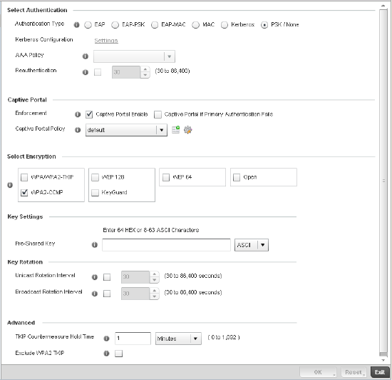
Brocade Mobility RFS4000, RFS6000, and RFS7000 System Reference Guide 287
53-1002620-01
6
FIGURE 213 WLAN Policy Security screen
Authentication ensures only known and trusted users or devices access a wireless controller
managed WLAN. Authentication is enabled per WLAN to verify the identity of both users and
devices. Authentication is a challenge and response procedure for validating user credentials such
as username, password and sometimes secret-key information.
A client must authenticate to an Access Point to receive resources from the wireless controller
managed network. The wireless controller supports EAP, EAP PSK, EAP-MAC, Kerberos, MAC and
PSK/None authentication options.
Refer to the following to configure an authentication scheme for a wireless controller managed
WLAN:
•802.1x EAP, EAP PSK and EAP MAC
•MAC Authentication
•Kerberos
•PSK / None
Secure guest access to the managed network is referred to as captive portal. A captive portal is
guest access policy for providing guests temporary and restrictive access to the managed wireless
network. The primary means of securing such controller guest access is the use of a hotspot.
Existing captive portal policies can be applied to a WLAN to provide secure guest access.
A captive portal policy’s hotspot configuration provides secure authenticated controller access
using a standard Web browser. Hotspots provides authenticated access by capturing and
re-directing a wireless user's Web browser session to a captive portal login page where the user
must enter valid credentials to access to the managed wireless network. Once logged into the
managed hotspot, additional Agreement, Welcome and Fail pages provide the administrator with a
number of options on the hotspot’s screen flow and user appearance.

288 Brocade Mobility RFS4000, RFS6000, and RFS7000 System Reference Guide
53-1002620-01
6
Refer to Captive Portal on page 6-293 for information on assigning a captive portal policy to a
WLAN. A captive portal is a guest access configuration policy that can applied to a WLAN to provide
strategic access to the WLAN and managed network.
Encryption is central for WLAN security, as it provides data privacy for traffic forwarded over a
wireless controller managed WLAN. When the 802.11 specification was introduced, Wired
Equivalent Privacy (WEP) was the primary encryption mechanism. WEP has since been interpreted
as flawed in many ways, and is not considered an effective standalone encryption scheme for
securing a wireless controller WLAN. WEP is typically used WLAN deployments designed to support
legacy clients. New device deployments should use either WPA or WPA2 encryption.
Encryption applies a specific algorithm to alter its appearance and prevent unauthorized hacking.
Decryption applies the algorithm in reverse, to restore the data to its original form. A sender and
receiver must employ the same encryption/decryption method to interoperate. When both TKIP
and CCMP are both enabled a mix of clients are allowed to associate with the WLAN. Some use
TKIP, others use CCMP. Since broadcast traffic needs to be understood by all clients, the broadcast
encryption type in this scenario is TKIP.
The wireless controller supports WPA/WPA2-TKIP, WPA2-CCMP, WEP 64, WEP 128 and Keyguard
encryption options.
Refer to the following to configure an encryption scheme for a wireless controller managed WLAN:
•WPA/WPA2-TKIP
•WPA2-CCMP
•WEP 64
•WEP 128
•Keyguard
802.1x EAP, EAP PSK and EAP MAC
Configuring WLAN Security
The Extensible Authentication Protocol (EAP) is the de-facto standard authentication method used
to provide secure authenticated access to wireless controller managed WLANs. EAP provides
mutual authentication, secured credential exchange, dynamic keying and strong encryption.
802.1X EAP can be deployed with WEP, WPA or WPA2 encryption schemes to further protect user
information forwarded over wireless controller managed WLANs.
The EAP process begins when an unauthenticated supplicant (client device) tries to connect with
an authenticator (in this case, the authentication server). An Access Point passes EAP packets from
the client to an authentication server on the wired side of the access point. All other packet types
are blocked until the authentication server (typically, a RADIUS server) verifies the client’s identity.
802.1X EAP provides mutual authentication over the WLAN during authentication. The 802.1X EAP
process uses credential verification to apply specific policies and restrictions to WLAN users to
ensure access is only provided to specific wireless controller resources.
802.1X requires a 802.1X capable RADIUS server to authenticate users and a 802.1X client
installed on each devices accessing the EAP supported WLAN. An 802.1X client is included with
most commercial operating systems, including Microsoft Windows, Linux and Apple OS X.
The RADIUS server authenticating 802.1X EAP users can reside either internally or externally to the
RFS4000, RFS6000 or RFS7000 model wireless controller. User account creation and
maintenance can be provided centrally using RFMS or individually maintained on each device. If an
external RADIUS server is used, EAP authentication requests are forwarded.
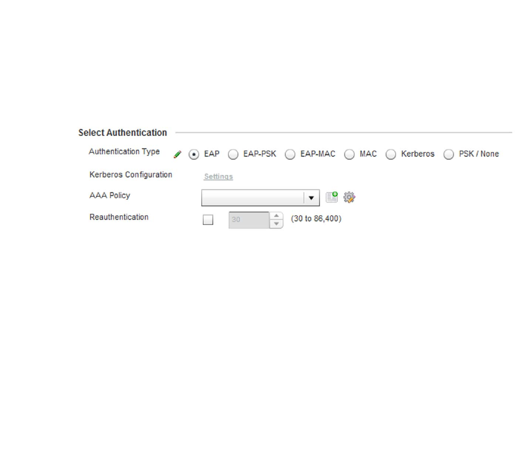
Brocade Mobility RFS4000, RFS6000, and RFS7000 System Reference Guide 289
53-1002620-01
6
When using PSK with EAP, the controller sends a packet requesting a secure link using a
pre-shared key. The controller and authenticating device must use the same authenticating
algorithm and passcode during authentication. EAP-PSK is useful when transitioning from a PSK
network to one that supports EAP. The only encryption types supported with this are TKIP, CCMP
and TKIP-CCMP.
To configure EAP on a wireless controller managed WLAN:
1. Select Configuration > Wireless > Wireless LAN Policy to display a high-level display of the
existing WLANs available to the wireless controller managed network.
2. Select the Add button to create an additional WLAN, or select and existing WLAN and Edit to
modify the security properties of an existing WLAN.
3. Select Security.
4. Select EAP, EAP PSK or EAP-MAC as the Authentication Type.
Either option enables the radio buttons for various encryption option as an additional measure
of security with the WLAN that can be used with EAP.
FIGURE 214 EAP, EAP PSK or EAP MAC Authentication screen
5. Either select an existing AAA Policy from the drop-down menu or select the Create icon to the
right of the AAA Policy parameter to display a screen where new AAA policies can be created.
Select the Edit icon to modify the configuration of the selected AAA policy.
Authentication, authorization, and accounting (AAA) is a framework for intelligently controlling
access to the wireless client managed network, enforcing user authorization policies and
auditing and tracking usage. These combined processes are central for securing wireless client
resources and wireless network data flows. For information on defining a new AAA policy that
can be applied to managed WLAN supporting EAP, EAP PSK or EAP MAC, see AAA Policy on
page 6-343.
6. Select the Reauthentication check box to force EAP supported clients to reauthenticate. Use
the spinner control set the number of seconds (between 30 - 86,400) that, once exceeded,
forces the EAP supported client to reauthenticate with the controller to use the resources
supported by the WLAN.
7. S elect OK when completed to update the WLAN’s EAP configuration. Select Reset to revert the
screen back to the last saved configuration.
EAP, EAP PSK and EAP MAC Deployment Considerations
802.1x EAP, EAP PSK and EAP MAC

290 Brocade Mobility RFS4000, RFS6000, and RFS7000 System Reference Guide
53-1002620-01
6
Before defining a 802.1x EAP, EAP PSK or EAP MAC supported configuration on a wireless
controller WLAN, refer to the following deployment guidelines to ensure the configuration is
optimally effective:
•Brocade recommends a valid certificate be issued and installed on devices providing 802.1X
EAP. The certificate should be issued from an Enterprise or public certificate authority to allow
802.1X clients to validate the identity of the authentication server prior to forwarding
credentials.
•If using an external RADIUS server for EAP authentication, Brocade recommends the round trip
delay over the WAN does not exceed 150ms. Excessive delay over a WAN can cause
authentication and roaming issues and impact wireless client performance. If experiencing
excessive delays, consider using the wireless controllers own RADIUS resources.
MAC Authentication
Configuring WLAN Security
MAC is a device level authentication method used to augment other security schemes when legacy
devices are deployed using static WEP.
MAC authentication can be used for device level authentication by permitting WLAN access based
on device MAC address. MAC authentication is typically used to augment WLAN security options
that do not use authentication (such as static WEP, WPA-PSK and WPA2-PSK) MAC authentication
can also be used to assign VLAN memberships, Firewall policies and time and date restrictions.
MAC authentication can only identify devices, not users. MAC authentication only references a
client wireless interface card MAC address when authenticating the device, it does not distinguish
the device’s user credentials. MAC authentication is somewhat poor as a standalone data
protection technique, as MAC addresses can be easily spoofed by hackers who can provide a
device MAC address to mimic a trusted device within the wireless controller managed network.
With Brocade RFS4000, RFS6000 and RFS7000 model wireless controllers, MAC authentication is
enabled per WLAN profile, augmented with the use of a RADIUS server to authenticate each device.
A device’s MAC address can be authenticated against the local RADIUS server built into the device
or centrally (from a datacenter). For RADIUS server compatibility, the format of the MAC address
can be forwarded to the RADIUS server in non-delimited and or delimited formats:
To configure MAC on a wireless controller managed WLAN:
1. Select Configuration > Wireless > Wireless LAN Policy to display a high-level display of the
existing WLANs available to the wireless controller managed network.
2. Select the Add button to create an additional WLAN, or select and existing WLAN and Edit to
modify the security properties of an existing WLAN.
3. Select Security.
4. Select MAC as the Authentication Type.
Selecting MAC enables the radio buttons for each encryption option as an additional measure
of security for the WLAN.
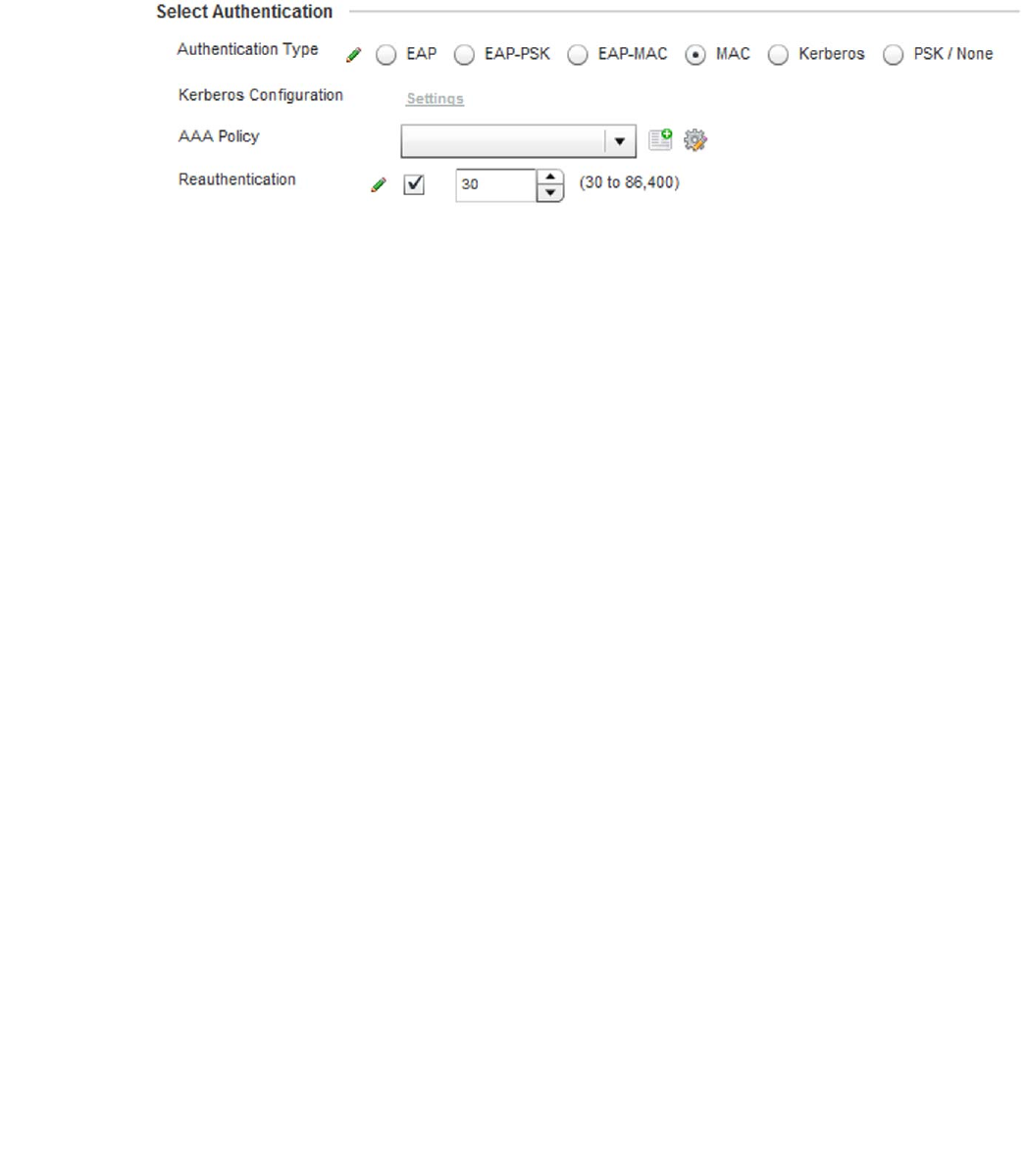
Brocade Mobility RFS4000, RFS6000, and RFS7000 System Reference Guide 291
53-1002620-01
6
FIGURE 215 MAC Authentication screen
5. Either select an existing AAA Policy from the drop-down menu or select the Create icon to the
right of the AAA Policy parameter to display a screen where new AAA policies can be created. A
default AAA policy is also available if configuring a WLAN for the first time and there’s no
existing policies. Select the Edit icon to modify the configuration of a selected AAA policy.
Authentication, authorization, and accounting (AAA) is a framework for intelligently controlling
access to the wireless client managed network, enforcing user authorization policies and
auditing and tracking usage. These combined processes are central for securing wireless client
resources and wireless network data flows. For information on defining a new AAA policy that
can be applied to managed WLAN supporting MAC, see AAA Policy on page 6-343.
6. Select the Reauthentication check box to force MAC supported clients to reauthenticate. Use
the spinner control set the number of minutes (between 30 - 86,400) that, once exceeded,
forces the EAP supported client to reauthenticate with the controller to use the resources
supported by the WLAN.
7. S elect OK when completed to update the WLAN’s MAC configuration. Select Reset to revert the
screen back to the last saved configuration.
MAC Authentication Deployment Considerations
MAC Authentication
Before defining a MAC authentication configuration on a wireless controller WLAN, refer to the
following deployment guidelines to ensure the configuration is optimally effective:
•MAC authentication can only be used to identify end-user devices, not the users themselves.
•MAC authentication is somewhat poor as a standalone data protection technique, as MAC
addresses can be easily spoofed by hackers who can provision a MAC address on their device
to mimic a trusted device.
Kerberos
Configuring WLAN Security
Kerberos (designed and developed by MIT) provides strong authentication for client/server
applications using secret-key cryptography. Using Kerberos, a client must prove its identity to a
server (and vice versa) across an insecure network connection.
Once a client and server use Kerberos to validate their identity, they encrypt all communications to
assure privacy and data integrity. Kerberos can only be used on the access point with Brocade
802.11b clients.
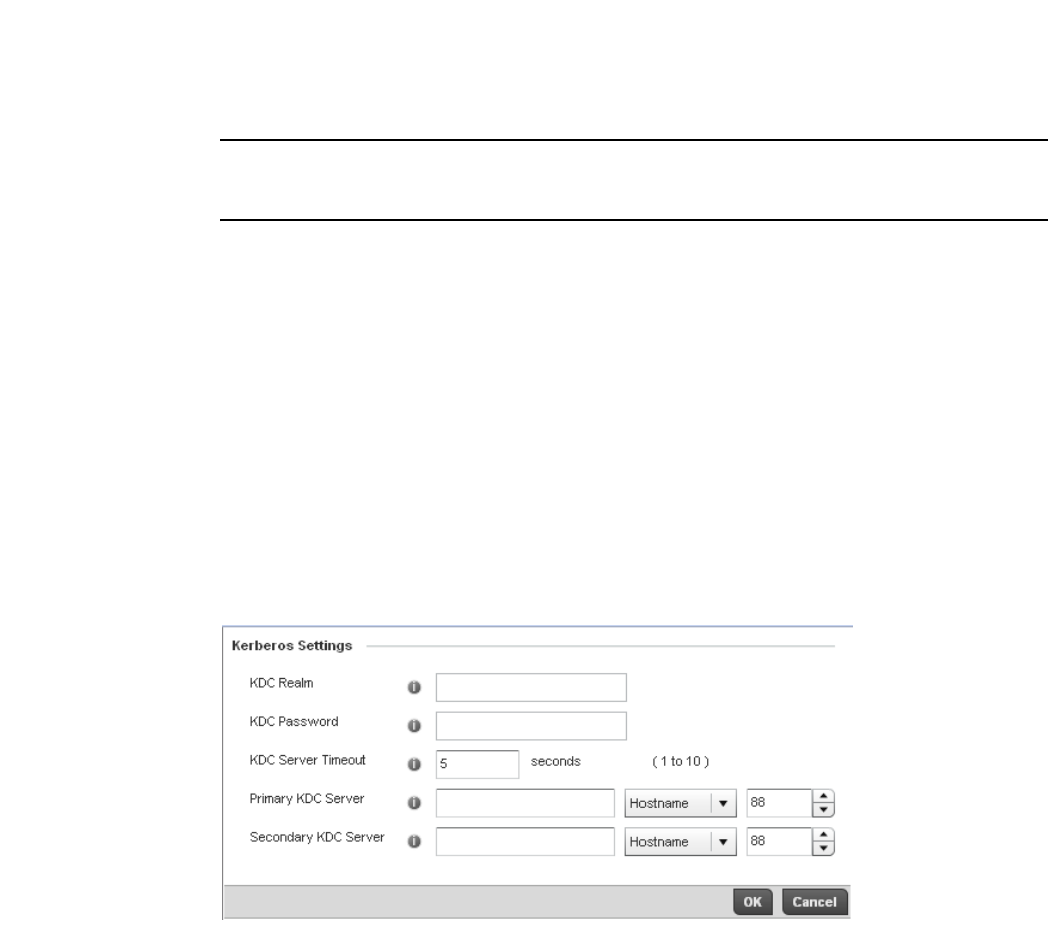
292 Brocade Mobility RFS4000, RFS6000, and RFS7000 System Reference Guide
53-1002620-01
6
NOTE
Kerberos makes no provisions for host security. Kerberos assumes that it is running on a trusted
host with an untrusted network. If host security is compromised, Kerberos is compromised as well.
Kerberos uses Network Time Protocol (NTP) for synchronizing the clocks of its Key Distribution
Center (KDC) server(s).
To configure Kerberos on a wireless controller managed WLAN:
1. Select Configuration > Wireless > Wireless LAN Policy to display a high-level display of the
existing WLANs available to the wireless controller managed network.
2. Select the Add button to create an additional WLAN, or select and existing WLAN and Edit to
modify the security properties of an existing WLAN.
3. Select Security.
4. Select Kerberos as the Authentication Type.
When Kerberos is selected, the AAA Policy and Reauthentication parameters become disabled,
and a Settings link displays on the right-hand side of the screen.
5. Select the Settings link to define the configuration of the Kerberos supported WLAN.
KDC Specify a name that is case-sensitive, for example, BROCADE.COM. The name is the
name domain/realm name of the KDC server. A name functions similarly to a DNS
domain name. In theory, the name is arbitrary. However, in practice a Kerberos realm is
named by upper casing the DNS domain name associated with hosts in the realm. The
name must not exceed 127 characters.

Brocade Mobility RFS4000, RFS6000, and RFS7000 System Reference Guide 293
53-1002620-01
6
6. Select OK when completed to update the WLAN’s Kerberos authentication configuration.
Select Reset to revert the screen back to the last saved configuration.
Kerberos Deployment Considerations
Before defining a Kerberos supported configuration on a wireless controller WLAN, refer to the
following deployment guidelines to ensure the configuration is optimally effective:
•Brocade proprietary authentication techniques such as Kerberos can also be enabled on
WLANs supporting legacy KeyGuard supported Symbol clients.
•A Kerberos server's response to an access point contains the client’s message and encryption
key derived from an EAP-TLS session key. The access point generates a multicast/global
authentication key by generating a random number or selecting it from an existing value. On
receiving the Kerberos server message, the forwards a success message to wireless client.
Consequently, round trip times can be negatively impacted by network congestion.
PSK / None
Configuring WLAN Security
Open-system authentication can be referred to as no authentication, since no actual
authentication takes place. A client requests (and is granted) authentication with no credential
exchange.
NOTE
Although None implies no authentication, this option is also used when
pre-shared keys are used for encryption (thus the /PSK in the description).
Captive Portal
Configuring WLAN Security
A captive portal is guest access policy for providing guests temporary and restrictive access to the
managed wireless network. The primary means of securing such controller guest access is the use
of a hotspot. For an overview of the Captive Portal process and information on how to define a
captive portal policy that can be applied to a WLAN, see Configuring Captive Portal Policies on page
10-559.
KDC Password Provide the password required to access the KDC server. The password must not
exceed 127 characters.
KDC Server Timeout Specify the time (1 -10 seconds) for the retransmission of Kerberos authentication
request packets. If this time is exceeded, the authentication session is retried. The
default is 5 seconds.
Primary KDC Server Specify a numerical (non-DNS) IP address or hostname for the primary Key Distribution
Center (KDC). The KDC implements an authentication service and a ticket granting
service, whereby an authorized user is granted a ticket encrypted with the user's
password. The KDC has a copy of every user’s password. Specify the port on which the
primary KDC resides. The default port is Port 88.
Secondary KDC Server Optionally, specify a numerical (non-DNS) IP address or hostname for a secondary
remote KDC. Kerberos implementations can use an administration server allowing
remote manipulation of the Kerberos database. This administration server usually runs
on the KDC. Specify the port on which the secondary KDC resides. The default port is
Port 88.
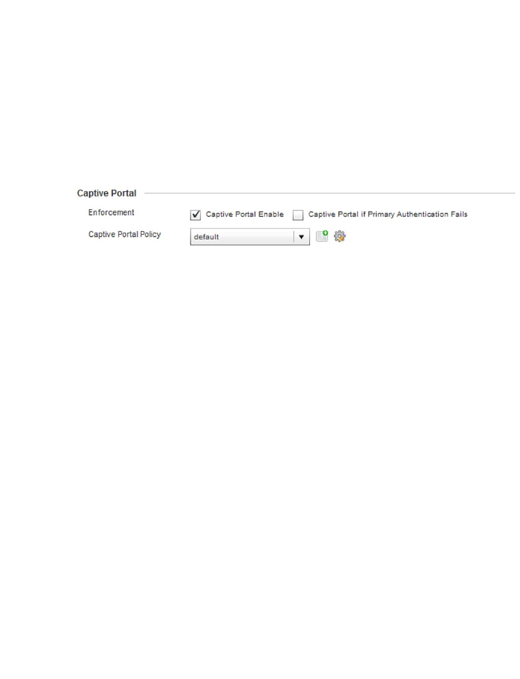
294 Brocade Mobility RFS4000, RFS6000, and RFS7000 System Reference Guide
53-1002620-01
6
To assign a captive portal policy to a managed WLAN:
1. Select Configuration > Wireless > Wireless LAN Policy to display a high-level display of the
existing WLANs available to the wireless controller managed network.
2. Select the Add button to create an additional WLAN or select an existing WLAN and select Edit
to modify the properties of an existing wireless controller WLAN.
3. Select Security.
4. Refer to the Captive Portal section within the WLAN Policy security screen
FIGURE 216 WLAN Policy Security screen - Captive Portal Field
5. Select the Captive Portal Enable option if authenticated guest access is required with the
selected WLAN. This feature is disabled by default.
6. Select the Captive Portal if Primary Authentication Fails check box to enable the captive portal
policy if the primary authentication is unavailable.
7. Select the Captive Portal Policy to use with the WLAN from the drop-down menu. If no relevant
policies exist, select the Create icon to define a new policy to use with this WLAN or the Edit
icon to update the configuration of an existing Captive Portal policy. For more information, see
Configuring Captive Portal Policies on page 10-559.
8. Select OK when completed to update the Captive Portal configuration. Select Reset to revert
the WLAN Policy Security screen back to the last saved configuration.
WPA/WPA2-TKIP
Configuring WLAN Security
Wi-Fi Protected Access (WPA) is an encryption scheme specified in the IEEE Wireless Fidelity (Wi-Fi)
standard, 802.11i. WPA provides more sophisticated data encryption than WEP. WPA is designed
for corporate networks and small-business environments where more wireless traffic allows
quicker discovery of encryption keys by an unauthorized person.
The encryption method is Temporal Key Integrity Protocol (TKIP). TKIP addresses WEP’s
weaknesses with a re-keying mechanism, a per-packet mixing function, a message integrity check,
and an extended initialization vector, however TKIP also has vulnerabilities.
Wi-Fi Protected Access 2 (WPA2) is an enhanced version of WPA. WPA2 uses the Advanced
Encryption Standard (AES) instead of TKIP. AES supports 128-bit, 192-bit and 256-bit keys.
WPA/WPA2 also provide strong user authentication based on 802.1x EAP.
To configure WPA/WPA2 encryption on a wireless controller managed WLAN:
1. Select Configuration > Wireless > Wireless LAN Policy to display a high-level display of the
existing WLANs available to the wireless controller managed network.
2. Select the Add button to create an additional WLAN or select an existing WLAN and select Edit
to modify the properties of an existing wireless controller WLAN.
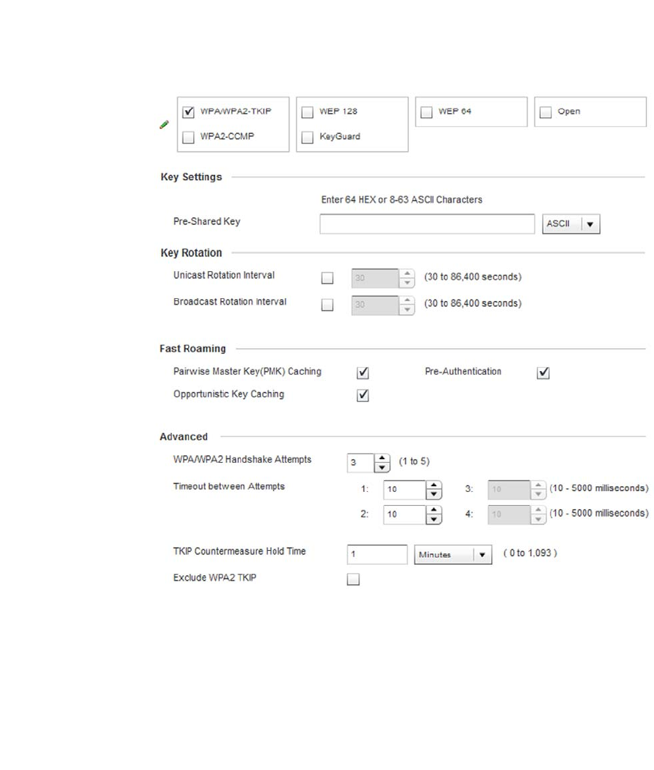
Brocade Mobility RFS4000, RFS6000, and RFS7000 System Reference Guide 295
53-1002620-01
6
3. Select Security.
4. Select the WPA/WPA2-TKIP radio button from within the Select Encryption field.
The screen populates with the parameters required to define a WLAN WPA/WPA2-TKIP
configuration for the new or existing WLAN.
FIGURE 217 WPA/WPA2-TKIP screen
5. Define Key Settings.
6. Define Key Rotation values.
Unicast messages are addressed to a single device on the network. Broadcast messages are
addressed to multiple devices. When using WPA2, a wireless client can use 2 keys, one unicast
key, for its own traffic to and from an access point, and one broadcast key, the common key for
all the clients in that subnet.
Pre-Shared Key Enter either an alphanumeric string of 8 to 63 ASCII characters or 64 HEX characters
as the primary string both transmitting and receiving authenticators must share. The
alphanumeric string allows character spaces. The wireless controller converts the
string to a numeric value. This passphrase saves the administrator from entering the
256-bit key each time keys are generated.

296 Brocade Mobility RFS4000, RFS6000, and RFS7000 System Reference Guide
53-1002620-01
6
Brocade recommends rotating the keys so a potential hacker would not have enough data
using a single key to attack the deployed encryption scheme.
7. D e f i ne t h e Fast Roaming configuration used with the WPA/WPA2-TKIP policy.
Using 802.11i can speed up the roaming process from one AP to another. Instead of doing a
complete 802.1x authentication each time a client roams between APs, 802.11i allows a client
to re-use previous PMK authentication credentials and perform a four-way handshake. This
speeds up the roaming process. In addition to reusing PMKs on previously visited APs,
Opportunistic Key Caching allows multiple APs to share PMKs amongst themselves. This allows
a client to roam to an AP it has not previously visited and reuse a PMK from another AP to skip
802.1x authentication.
Unicast Rotation
Interval
Define an interval for unicast key transmission in seconds (30 -86,400). Some clients
have issues using unicast key rotation, so ensure you know which kind of clients are
impacted before using unicast keys. This feature is disabled by default.
Broadcast Rotation
Interval
When enabled, the key indices used for encrypting/decrypting broadcast traffic will be
alternatively rotated based on the defined interval Define an interval for broadcast key
transmission in seconds (30-86,400). Key rotation enhances the broadcast traffic
security on the WLAN. This feature is disabled by default.
Pairwise Master Key
Caching
Select Pairwise Master Key (PMK) caching to store a PMK derived from 802.1x
authentication between a client device and its authenticator. When a client roams
between devices, the client’s credentials no longer need to be completely
reauthenticated (a process taking up to 100 milliseconds). With voice sessions, the
connection would likely be terminated if not using a PMK. PMK cache entries are
stored for a finite amount of time, as configured on the wireless client. When a device
initially associates, full 802.1X authentication occurs, and the PMK is cached by the
access point and device. If the device roams to a different access point, then roams
back, the device already authenticated on the access point, providing faster
re-association. This feature is enabled by default.
Opportunistic Key
Caching
Opportunistic Key Caching is an extension of PMK caching, allowing a wireless
controller to use a PMK derived with a client on one access point with the same client
when it roams to another access point. Upon roaming, the client does not have to
conduct 802.1x authentication, and can start sending and receiving data sooner.
When a device initially associates, full 802.1X authentication occurs and the PMK is
cached by the wireless controller and the device. When an authenticated device roams
to a different access point managed by the same wireless controller, the device will be
already authenticated on the access point providing faster re-association. This feature
is enabled by default.
Pre-Authentication Selecting the Pre-Authentication option enables an associated client to carry out an
802.1x authentication with another wireless controller (or device) before it roams to it.
This enables the roaming client to send and receive data sooner by not having to
conduct an 802.1x authentication after roaming. With pre authentication, a client can
perform an 802.1X authentication with other detected access points while still
connected to its current access point. When a device roams to a neighboring access
point, the device is already authenticated on the access point providing faster
re-association. This feature is disabled by default.

Brocade Mobility RFS4000, RFS6000, and RFS7000 System Reference Guide 297
53-1002620-01
6
8. Set the following Advanced settings for the WPA/WPA2-TKIP encryption scheme
9. Select OK when completed to update the WLAN’s WPA/WPA2-TKIP encryption configuration.
Select Reset to revert the screen back to its last saved configuration.
NOTE
WPA-TKIP is not supported on radios configured to exclusively use 802.11n.
WPA-TKIP Deployment Considerations
Before defining a WPA-TKIP supported configuration on a wireless controller WLAN, refer to the
following deployment guidelines to ensure the configuration is optimally effective:
• Brocade recommends TKIP only be enabled for legacy device support when WPA2-CCMP
support is not available.
•Though TKIP offers better security than WEP, it can be vulnerable to certain attacks.
•When both TKIP and CCMP are both enabled a mix of clients are allowed to associate with the
WLAN. Some use TKIP, others use CCMP. Since broadcast traffic needs to be understood by all
clients, the broadcast encryption type in this scenario is TKIP.
WPA2-CCMP
Configuring WLAN Security
WPA2 is a newer 802.11i standard that provides even stronger wireless security than Wi-Fi
Protected Access (WPA) and WEP. CCMP is the security standard used by the Advanced Encryption
Standard (AES). AES serves the same function TKIP does for WPA-TKIP. CCMP computes a Message
Integrity Check (MIC) using the proven Cipher Block Chaining (CBC) technique. Changing just one
bit in a message produces a totally different result.
WPA2/CCMP is based on the concept of a Robust Security Network (RSN), which defines a
hierarchy of keys with a limited lifetime (similar to TKIP). Like TKIP, the keys the administrator
provides are used to derive other keys. Messages are encrypted using a 128-bit secret key and a
128-bit block of data. The end result is an encryption scheme as secure as any the wireless
controller provides for its associated clients.
To configure WPA2-CCMP encryption on a wireless controller managed WLAN:
1. Select Configuration > Wireless > Wireless LAN Policy to display a high-level display of the
existing WLANs available to the wireless controller managed network.
TKIP Countermeasure
Hold Time
The TKIP countermeasure hold-time is the time during which the use of the WLAN is
disabled if TKIP countermeasures have been invoked on the WLAN. Use the drop-down
menu to define a value in either Hours (0-18), Minutes (0-1,092) or Seconds
(0-65,535). The default setting is 60 seconds.
Exclude WPA2 TKIP Select this option for an Access Point to advertise and enable support for only
WPA-TKIP. This option can be used if certain older clients are not compatible with the
newer WPA2-TKIP information elements. Enabling this option allows backwards
compatibility for clients that support WPA-TKIP and WPA2-TKIP but do not support
WPA2-CCMP. Brocade recommends enabling this feature if WPA-TKIP or WPA2-TKIP
supported clients operate in a WLAN populated by WPA2-CCMP enabled clients. This
feature is disabled by default.
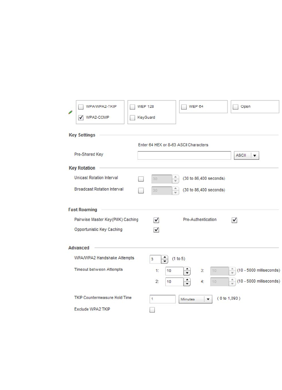
298 Brocade Mobility RFS4000, RFS6000, and RFS7000 System Reference Guide
53-1002620-01
6
2. Select the Add button to create an additional WLAN or select an existing WLAN and choose Edit
to modify the properties of an existing wireless controller WLAN.
3. Select Security.
4. Select the WPA2-CCMP check box from within the select Select Encryption field.
The screen populates with the parameters required to define a WPA2-CCMP configuration for
the new or existing WLAN.
FIGURE 218 WPA2-CCMP screen
5. Define Key Settings.
a. Define Key Rotation values.
Pre-Shared Key Enter either an alphanumeric string of 8 to 63 ASCII characters or 64 HEX
characters as the primary string both transmitting and receiving authenticators
must share. The alphanumeric string allows character spaces. The wireless
controller converts the string to a numeric value. This passphrase saves the
administrator from entering the 256-bit key each time keys are generated.

Brocade Mobility RFS4000, RFS6000, and RFS7000 System Reference Guide 299
53-1002620-01
6
Unicast messages are addressed to a single device on the network. Broadcast messages are
addressed to multiple devices. When using WPA2-CCMP, a wireless client can use 2 keys: one
unicast key, for its own traffic to and from an AP, and one broadcast key, the common key for
all the clients in that subnet.
Brocade recommends rotating these keys so a potential hacker would not have enough data
using a single key to attack the deployed encryption scheme.
6. Define the Fast Roaming configuration used with the WPA2-CCMP policy.
Using 802.11i can speed up the roaming process from one AP to another. Instead of doing a
complete 802.1x authentication each time a client roams between APs, 802.11i allows a client
to re-use previous PMK authentication credentials and perform a four-way handshake.
This speeds up the roaming process. In addition to reusing PMKs on previously visited APs,
Opportunistic Key Caching allows multiple APs to share PMKs amongst themselves. This allows
a client to roam to an AP it has not previously visited and reuse a PMK from another AP to skip
802.1x authentication.
Unicast Rotation
Interval
Define an interval for unicast key transmission in seconds (30 -86,400). Some
clients have issues using unicast key rotation, so ensure you know which king of
clients are impacted before using unicast keys. This value is disabled by default.
Broadcast Rotation
Interval
When enabled, the key indices used for encrypting/decrypting broadcast traffic will
be alternatively rotated based on the defined interval Define an interval for
broadcast key transmission in seconds (30-86,400). Key rotation enhances the
broadcast traffic security on the WLAN. This value is disabled by default.
Pairwise Master Key
(PMK) Caching
Select Pairwise Master Key (PMK) Caching to store a PMK derived from
802.1x authentication between a client device and its authenticator. When a client
roams between devices, the client’s credentials no longer need to be completely
reauthenticated (a process taking up to 100 milliseconds). With voice sessions, the
connection would likely be terminated if not using a PMK. PMK cache entries are
stored for a finite amount of time, as configured on the wireless client. When a
device initially associates, full 802.1X authentication occurs, and the PMK is
cached by the access point and device. If the device roams to a different access
point, then roams back, the device already authenticated on the access point,
providing faster re-association. This feature is enabled by default.
Opportunistic Key
Caching
Opportunistic Key Caching is an extension of PMK caching, allowing a wireless
controller to use a PMK derived with a client on one access point with the same
client when it roams to another access point. Upon roaming, the client does not
have to conduct 802.1x authentication, and can start sending and receiving data
sooner. When a device initially associates, full 802.1X authentication occurs and
the PMK is cached by the wireless controller and the device. When an authenticated
device roams to a different access point managed by the same wireless controller,
the device will be already authenticated on the access point providing faster
re-association. This feature is enabled by default.
Pre-Authentication Selecting the Pre-Authentication option enables an associated client to carry out an
802.1x authentication with another wireless controller (or device) before it roams to
it. This enables the roaming client to send and receive data sooner by not having to
conduct an 802.1x authentication after roaming. With pre authentication, a wireless
client can perform an 802.1X authentication with other detected access points
while still connected to its current access point. When a device roams to a
neighboring AP, the device is already authenticated on the access point providing
faster re-association. This feature is enabled by default.

300 Brocade Mobility RFS4000, RFS6000, and RFS7000 System Reference Guide
53-1002620-01
6
7. Set the following Advanced for the WPA2-CCMP encryption scheme.
8. Select OK when completed to update the WLAN’s WPA2-CCMP encryption configuration. Select
Reset to revert back to its last saved configuration.
WPA2-CCMP Deployment Considerations
WPA2-CCMP
Before defining a WPA2-CCMP supported configuration on a wireless controller WLAN, refer to the
following deployment guidelines to ensure the configuration is optimally effective:
•Brocade recommends WPA2-CCMP be configured for all new (non visitor) WLANs requiring
encryption, as it’s supported by the majority of the hardware and client vendors using Brocade
wireless networking equipment.
•WPA2-CCMP supersedes WPA-TKIP and implements all the mandatory elements of the 802.11i
standard. WPA2-CCMP introduces a new AES-based algorithm called CCMP which replaces
TKIP and WEP and is considered significantly more secure.
WEP 64
Configuring WLAN Security
Wired Equivalent Privacy (WEP) is a security protocol specified in the IEEE Wireless Fidelity (Wi -Fi)
standard. WEP is designed to provide a WLAN with a level of security and privacy comparable to
that of a wired LAN.
WEP can be used with open, shared, MAC and 802.1 X EAP authentications. WEP is optimal for
WLANs supporting legacy deployments when also used with 802.1X EAP authentication to provide
user and device authentication and dynamic WEP key derivation and periodic key rotation. 802.1X
provides authentication for devices and also reduces the risk of a single WEP key being
deciphered. If 802.1X support is not available on the legacy device, MAC authentication should be
enabled to provide device level authentication.
WEP 64 uses a 40 bit key concatenated with a 24-bit initialization vector (IV) to form the RC4 traffic
key. WEP 64 is a less robust encryption scheme than WEP 128 (containing a shorter WEP algorithm
for a hacker to potentially duplicate), but networks that require more security are at risk from a
WEP flaw. WEP is only recommended if there are client devices that are incapable of using higher
forms of security. The existing 802.11 standard alone offers administrators no effective method to
update keys.
To configure WEP 64 encryption on a managed WLAN:
1. Select Configuration > Wireless > Wireless LAN Policy to display a high-level display of the
existing WLANs available to the wireless controller managed network.
TKIP Countermeasure
Hold Time
The TKIP countermeasure hold-time is the time during which the use of the WLAN is
disabled if TKIP countermeasures have been invoked on the WLAN. Use the
drop-down menu to define a value in either Hours (0-18), Minutes (0-1,092) or
Seconds (0-65,535). The default setting is 60 seconds.
Exclude WPA2-TKIP Select this option for an Access Point to advertise and enable support for only
WPA-TKIP. Select this option if certain older clients are not compatible with the
newer WPA2-TKIP information elements. Enabling this option allows backwards
compatibility for clients that support WPA-TKIP and WPA2-TKIP but do not support
WPA2-CCMP. Brocade recommends enabling this feature if WPA-TKIP or WPA2-TKIP
supported clients operate in a WLAN populated by WPA2-CCMP enabled clients.
This feature is disabled by default.
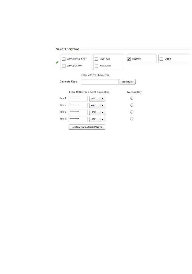
Brocade Mobility RFS4000, RFS6000, and RFS7000 System Reference Guide 301
53-1002620-01
6
2. Select the Add button to create an additional WLAN or select Edit to modify the properties of an
existing wireless controller WLAN.
3. Select Security.
4. Select the WEP 64 check box from within the Select Encryption field.
The screen populates with the parameters required to define a WEP 64 configuration for the
WLAN.
FIGURE 219 WEP 64 screen
5. Configure the following WEP 64 settings:
Default WEP 64 keys are as follows:
•Key 1 1011121314
•Key 2 2021222324
•Key 3 3031323334
•Key 4 4041424344
6. Select OK when completed to update the WLAN’s WEP 64 encryption configuration. Select
Reset to revert the screen back to its last saved configuration.
WEP 64 Deployment Considerations
Before defining a WEP 64 supported configuration on a wireless controller WLAN, refer to the
following deployment guidelines to ensure the configuration is optimally effective:
Generate Keys Specify a 4 to 32 character Pass Key and click the Generate button. The pass key
can be any alphanumeric string. The wireless controller, other proprietary routers,
and Brocade clients use the algorithm to convert an ASCII string to the same
hexadecimal number. Clients without Brocade adapters need to use WEP keys
manually configured as hexadecimal numbers.
Keys 1-4 Use the Key #1-4 fields to specify key numbers. For WEP 64 (40-bit key), the keys
are 10 hexadecimal characters in length. Select one of these keys for default
activation by clicking its radio button.
Restore Default WEP
Keys
If you feel it necessary to restore the WEP algorithm back to its default settings, click
the Restore Default WEP Keys button.

302 Brocade Mobility RFS4000, RFS6000, and RFS7000 System Reference Guide
53-1002620-01
6
•Brocade recommends additional layers of security (beyond WEP) be enabled to minimize the
likelihood of data loss and security breaches. WEP enabled WLANs should be mapped to an
isolated VLAN with Firewall policies restricting access to hosts and suspicious network
applications.
•WEP enabled WLANs should only be permitted access to resources required by legacy devices.
•If WEP support is needed for WLAN legacy device support, 802.1X EAP authentication should
be also configured in order for the WLAN to provide authentication and dynamic key derivation
and rotation.
WEP 128
Configuring WLAN Security
Wired Equivalent Privacy (WEP) is a security protocol specified in the IEEE Wireless Fidelity (Wi -Fi)
standard. WEP is designed to provide a WLAN with a level of security and privacy comparable to
that of a wired LAN.
WEP can be used with open, shared, MAC and 802.1 X EAP authentications. WEP is optimal for
WLANs supporting legacy deployments when also used with 802.1X EAP authentication to provide
user and device authentication and dynamic WEP key derivation and periodic key rotation. 802.1X
provides authentication for devices and also reduces the risk of a single WEP key being
deciphered. If 802.1X support is not available on the legacy device, MAC authentication should be
enabled to provide device level authentication.
WEP 128 uses a 104 bit key which is concatenated with a 24-bit initialization vector (IV) to form the
RC4 traffic key. WEP may be all a small-business user needs for the simple encryption of wireless
data. However, networks that require more security are at risk from a WEP flaw. WEP is only
recommended if there are client devices that are incapable of using higher forms of security. The
existing 802.11 standard alone offers administrators no effective method to update keys.
WEP 128 provides a more robust encryption algorithm than WEP 64 by requiring a longer key
length and pass key. Thus, making it harder to hack through the replication of WEP keys.
To configure WEP 128 encryption on a wireless controller managed WLAN:
1. Select Configuration > Wireless > Wireless LAN Policy to display a high-level display of the
existing WLANs available to the wireless controller managed network.
2. Select the Add button to create an additional WLAN or select Edit to modify the properties of an
existing wireless controller WLAN.
3. Select Security.
4. Select the WEP 128 check box from within the Select Encryption field.
The screen populates with the parameters required to define a WEP 128 configuration for the
WLAN.
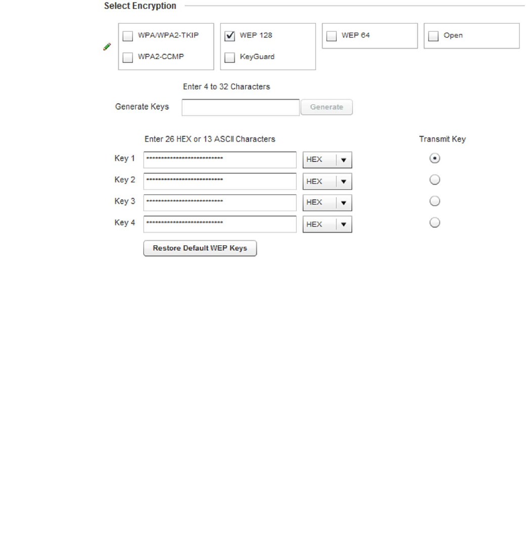
Brocade Mobility RFS4000, RFS6000, and RFS7000 System Reference Guide 303
53-1002620-01
6
FIGURE 220 WEP 128 screen
5. Configure the following WEP 128 settings:
Default WEP 128 keys are as follows:
•Key 1 101112131415161718191A1B1C
•Key 2 202122232425262728292A2B2C
•Key 3 303132333435363738393A3B3C
•Key 4 404142434445464748494A4B4C
6. Select OK when completed to update the WLAN’s WEP 128 encryption configuration. Select
Reset to revert the screen back to its last saved configuration.
WEP 128 Deployment Considerations
WEP 128
Before defining a WEP 128 supported configuration on a wireless controller WLAN, refer to the
following deployment guidelines to ensure the configuration is optimally effective:
Generate Keys Specify a 4 to 32 character Pass Key and click the Generate button. The pass key
can be any alphanumeric string. The wireless controller, other proprietary routers,
and Brocade clients use the algorithm to convert an ASCII string to the same
hexadecimal number. Clients without Brocade adapters need to use WEP keys
manually configured as hexadecimal numbers.
Keys 1-4 Use the Key #1-4 areas to specify key numbers. For WEP 128 (104-bit key), the keys
are 26 hexadecimal characters in length. Select one of these keys for default
activation by clicking its radio button.
Restore Default WEP
Keys
If you feel it necessary to restore the WEP algorithm back to its default settings, click
the Restore Default WEP Keys button.
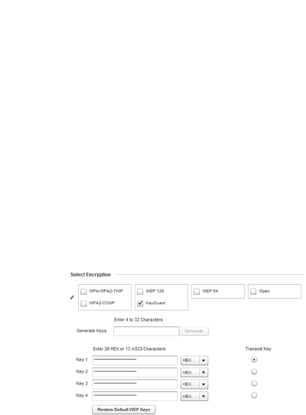
304 Brocade Mobility RFS4000, RFS6000, and RFS7000 System Reference Guide
53-1002620-01
6
•Brocade recommends additional layers of security (beyond WEP) be enabled to minimize the
likelihood of data loss and security breaches. WEP enabled WLANs should be mapped to an
isolated VLAN with Firewall policies restricting access to hosts and suspicious network
applications.
•WEP enabled WLANs should only be permitted access to resources required by legacy devices.
•If WEP support is needed for WLAN legacy device support, 802.1X EAP authentication should
be also configured in order for the WLAN to provide authentication and dynamic key derivation
and rotation.
Keyguard
Configuring WLAN Security
Keyguard is a form of WEP, and could be all a small business needs for the simple encryption of
wireless data.
KeyGuard is a proprietary encryption method developed by Brocade. KeyGuard is Brocade's
enhancement to WEP encryption, and was developed before the finalization of WPA-TKIP. The
Keyguard encryption implementation is based on the IEEE Wi-Fi standard, 802.11i.
To configure Keyguard encryption on a wireless controller managed WLAN:
1. Select Configuration > Wireless > Wireless LAN Policy to display a high-level display of the
existing WLANs available to the wireless controller managed network.
2. Select the Add button to create an additional WLAN or select Edit to modify the properties of an
existing wireless controller WLAN.
3. Select Security.
4. Select the Keyguard check box from within the Select Encryption field.
The screen populates with the parameters required to define a KeyGuard configuration for the
WLAN.
FIGURE 221 WLAN KeyGuard Configuration screen

Brocade Mobility RFS4000, RFS6000, and RFS7000 System Reference Guide 305
53-1002620-01
6
5. Configure the following Keyguard settings:
Default WEP Keyguard keys are as follows:
•Key 1 101112131415161718191A1B1C
•Key 2 202122232425262728292A2B2C
•Key 3 303132333435363738393A3B3C
•Key 4 404142434445464748494A4B4C
6. Select OK when completed to update the WLAN’s Keyguard encryption configuration. Select
Reset to revert the screen back to its last saved configuration.
KeyGuard Deployment Considerations
Keyguard
Before defining a Keyguard configuration on a WLAN, refer to the following deployment guidelines
to ensure the configuration is optimally effective:
•Brocade proprietary authentication techniques, such as Kerberos, can also be enabled on
WLANs supporting other Brocade proprietary techniques, such as KeyGuard.
• A wireless controller WLAN using KeyGuard to support legacy Brocade devices should also use
largely limited to the support of just those legacy clients using KeyGuard.
Configuring WLAN Firewall Support
Wireless LAN Policy
A Firewall is a mechanism enforcing access control, and is considered a first line of defense in
protecting proprietary information within the Brocade wireless controller managed network. The
means by which this is accomplished varies, but in principle, a Firewall can be thought of as
mechanisms both blocking and permitting data traffic within the wireless controller managed
network. For an overview of Firewalls, see Wireless Firewall on page 9-511.
managed WLANs use Firewalls like Access Control Lists (ACLs) to filter/mark packets based on the
WLAN from which they arrive, as opposed to filtering packets on Layer 2 ports. An ACL contains an
ordered list of Access Control Entries (ACEs). Each ACE specifies an action and a set of conditions
(rules) a packet must satisfy to match the ACE. The order of conditions in the list is critical because
the wireless controller stops testing conditions after the first match.
Generate Keys Specify a 4 to 32 character Pass Key and click the Generate button. The pass key
can be any alphanumeric string. The wireless controller or other proprietary routers.
Brocade clients use the algorithm to convert an ASCII string to the same
hexadecimal number. Clients without Brocade adapters need to use keys manually
configured as hexadecimal numbers.
Keys 1-4 Use the Key #1-4 areas to specify key numbers. For Keyguard (104-bit key), the keys
are 26 hexadecimal characters in length. Select one of these keys for default
activation by clicking its radio button.
Restore Default WEP
Keys
If you feel it necessary to restore the Keyguard algorithm back to its default settings,
click the Restore Default WEP Keys button. This may be the case if the latest
defined algorithm has been compromised and no longer provides its former
measure of data security.
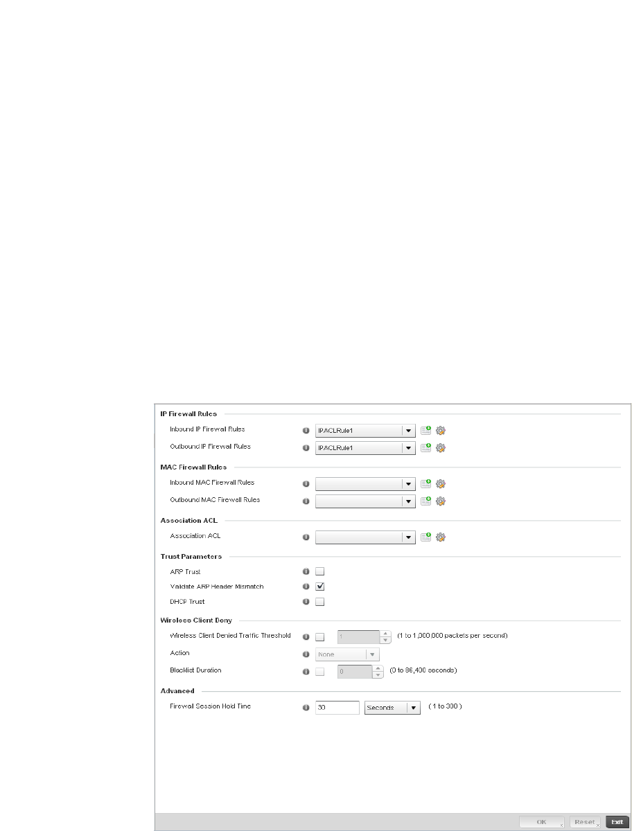
306 Brocade Mobility RFS4000, RFS6000, and RFS7000 System Reference Guide
53-1002620-01
6
IP based Firewall rules are specific to source and destination IP addresses and the unique rules
and precedence orders assigned. Both IP and non-IP traffic on the same Layer 2 interface can be
filtered by applying both an IP ACL and a MAC.
Additionally, the controller allows administrators to filter Layer 2 traffic on a physical Layer 2
interface using MAC addresses. A MAC Firewall rule uses source and destination MAC addresses
for matching operations, where the result is a typical allow, deny or mark designation to WLAN
controller packet traffic.
Keep in mind IP and non-IP traffic on the same Layer 2 interface can be filtered by applying both an
IP ACL and a MAC ACL to the interface.
To review access policies, create a new policy or edit the properties of an existing policy:
1. Select Configuration > Wireless LANs > Wireless LAN Policy to display a high-level display of the
existing WLANs available to the wireless controller managed network.
2. Select the Add button to create a new WLAN or Edit to modify the properties of an existing
wireless controller WLAN.
3. Select Firewall from the Wireless LAN Policy options.
FIGURE 222 WLAN Policy Firewall screen
The screen displays editable fields for IP Firewall Rules, MAC Firewall Rules, Trust Parameters
and Client Deny Limits.
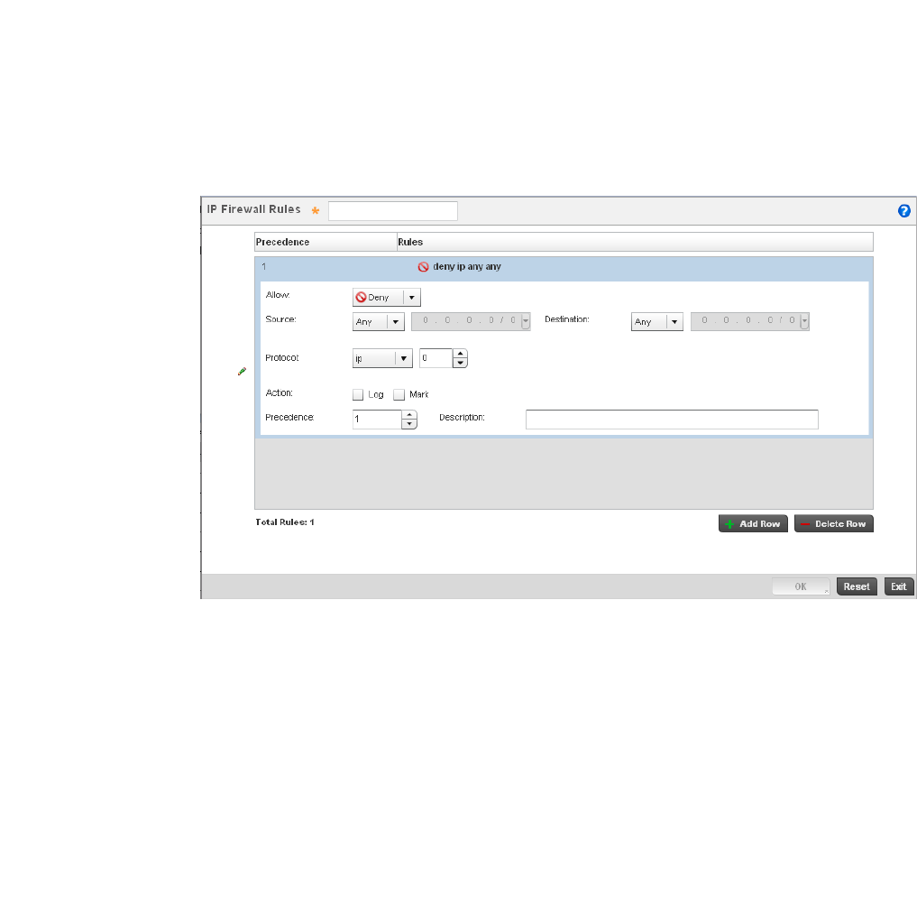
Brocade Mobility RFS4000, RFS6000, and RFS7000 System Reference Guide 307
53-1002620-01
6
Select an existing Inbound IP Firewall Rule and Outbound IP Firewall Rule using the drop-down
menu. If no rules exist, select the Create icon to display a screen where Firewall rules can be
created. Select the Edit icon to modify the configuration of a selected Firewall policy
configuration.
4. If creating a new rule, provide a name up to 64 characters in length.
5. Select the + Add Row button.
6. Select the added row to expand it into configurable parameters.
FIGURE 223 IP Firewall Rules screen
7. Define the following parameters for either the inbound or outbound IP Firewall Rules:
Allow Every IP Firewall rule is made up of matching criteria rules. The action defines what
to do with the packet if it matches the specified criteria. The following actions are
supported:
Deny— Instructs the Firewall to prohibit a packet from reaching its destination.
Permit—Instructs the Firewall to allow a packet to proceed to its destination.
Source and
Destination
Enter both Source and Destination IP addresses. The wireless controller uses
the source IP address, destination IP address and IP protocol type as basic
matching criteria. The wireless controller's access policy filter can also include other
parameters specific to a protocol type (like source and destination port for TCP/UDP
protocol. Provide a subnet mask if needed.
Protocol Select the protocol used with the IP access policy from the drop-down menu. IP is
selected by default. Selecting ICMP displays an additional set of ICMP specific
Options for ICMP Type and code. Selecting either TCP or UDP displays an additional
set of specific TCP/UDP source and destinations port options.
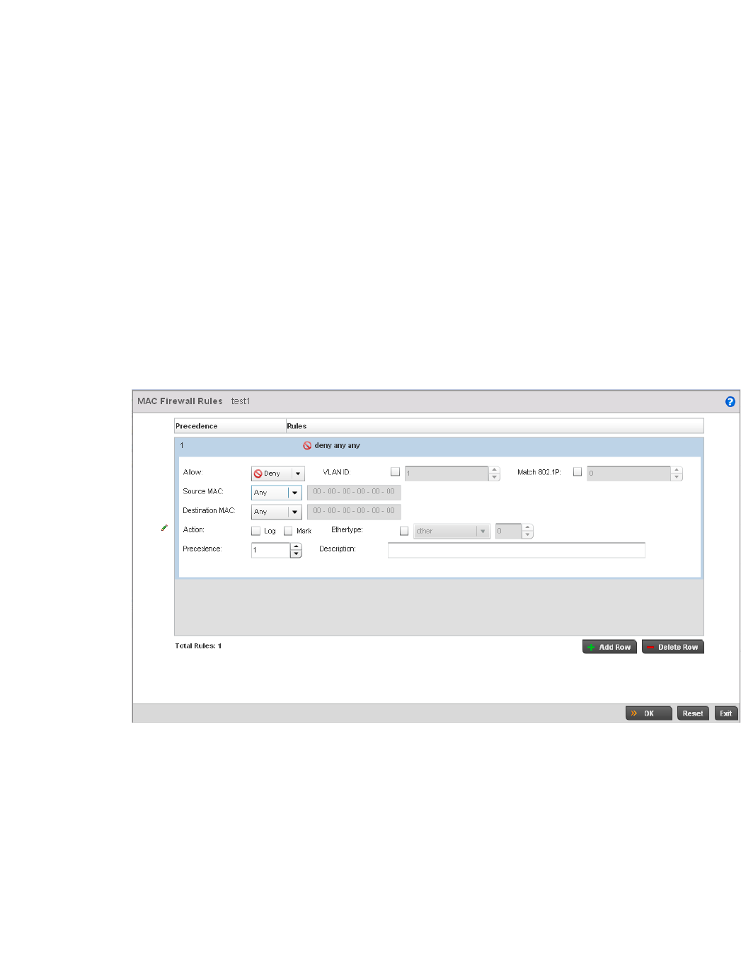
308 Brocade Mobility RFS4000, RFS6000, and RFS7000 System Reference Guide
53-1002620-01
6
8. Select existing inbound and outbound MAC Firewall Rules using the drop-down menu. If no
rules exist, select Create to display a screen where Firewall rules can be created.
9. Select the + Add Row button.
10. Select the added row to expand it into configurable parameters.
FIGURE 224 MAC Firewall Rules screen
11. Define the following parameters for either the inbound or outbound MAC Firewall Rules:
Action The following actions are supported:
Log—Creates a log entry that a Firewall rule has allowed a packet to either be denied
or permitted.
Mark—Modifies certain fields inside the packet, then permits them. Therefore, mark
is an action with an implicit permit.
Mark, Log — Conducts both mark and log functions.
Precedence Use the spinner control to specify a precedence for this IP policy between
1-1500. Rules with lower precedence are always applied first to packets.
Description Provide a description up to characters long for rule to help differentiate it from
others with similar configurations.
Allow Every IP Firewall rule is made up of matching criteria rules. The action defines what
to do with the packet if it matches the specified criteria. The following actions are
supported:
Deny— Instructs the Firewall to not to allow a packet to proceed to its destination.
Permit—Instructs the Firewall to allows a packet to proceed to its destination.
VLAN ID Enter a VLAN ID representative of the shared SSID each user employs to
interoperate within the managed network (once authenticated by the local RADIUS
server). The VLAN ID can be between 1 - 4094.
Match 802.1P Configures IP DSCP to 802.1p priority mapping for untagged frames. Use the
spinner control to define a setting between 0-7.

Brocade Mobility RFS4000, RFS6000, and RFS7000 System Reference Guide 309
53-1002620-01
6
12. If creating an new Association ACL, provide a name specific to its function. Avoid naming it
after a WLAN it may support. The name cannot exceed 32 characters.
13. Save the changes to the new MAC rule or reset to the last saved configuration as needed.
14. Set the following Trust Parameters:
15. Set the following Wireless Client Deny configuration:
16. Set a Firewall Session Hold Time in either Seconds (1 - 300) or Minutes (1 - 5). This is the hold
time for caching user credentials and Firewall state information when a client roams. The
default setting is 30 seconds.
17. Select OK when completed to update this WLAN’s Firewall settings. Select Reset to revert the
screen back to its last saved configuration.
Source and
Destination MAC
Enter both Source and Destination MAC addresses. The wireless controller uses
the source IP address, destination MAC address as basic matching criteria. Provide
a subnet mask if using a mask.
Action The following actions are supported:
Log—Creates a log entry that a Firewall rule has allowed a packet to either be denied
or permitted.
Mark—Modifies certain fields inside the packet and then permits them. Therefore,
mark is an action with an implicit permit.
Mark, Log — Conducts both mark and log functions.
Ethertype Use the drop-down menu to specify an Ethertype of either ipv6, arp, wisp, monitor
8021q. An EtherType is a two-octet field within an Ethernet frame. It is used to
indicate which protocol is encapsulated in the payload of an Ethernet frame.
Precedence Use the spinner control to specify a precedence for this MAC Firewall rule between
1-1500. Access policies with lower precedence are always applied first to packets.
Description Provide a description (up to 64 characters) for the rule to help differentiate the it
from others with similar configurations.
ARP Trust Select the check box to enable ARP Trust on this WLAN. ARP packets received on
this managed WLAN are considered trusted and information from these packets is
used to identify rogue devices within the managed network. This setting is disabled
by default.
Validate ARP Header
Mismatch
Select this option to verify the mismatch for source MAC in the ARP and Ethernet
headers. By default, mismatch verification is enabled.
DHCP Trust Select the check box to enable DHCP trust on this WLAN. This setting is disabled by
default.
Wireless Client Denied
Traffic Threshold
If enabled, any associated client which exceeds the thresholds configured for storm
traffic is either deauthenticated or blacklisted depending on the selected Action.
The threshold range is 1-1000000 packets per second. This feature is disabled by
default.
Action If enabling a wireless client threshold, use the drop-down menu to determine
whether clients are deauthenticated when the threshold is exceeded or blacklisted
from controller connectivity for a user defined interval. Selecting None applies no
consequence to an exceeded threshold.
Blacklist Duration Select the checkbox and define a setting between 0 - 86,400 seconds. Once the
blacklist duration has been exceeded, offending clients can reauthenticate with the
controller.
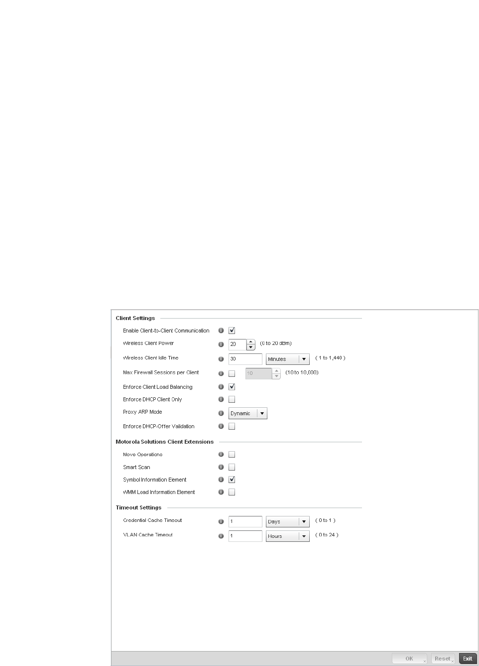
310 Brocade Mobility RFS4000, RFS6000, and RFS7000 System Reference Guide
53-1002620-01
6
WLAN Firewall Deployment Considerations
Before defining an access control configuration on a wireless controller WLAN, refer to the following
deployment guidelines to ensure the configuration is optimally effective:
• IP and non-IP traffic on the same Layer 2 interface can be filtered by applying both an IP ACL
and a MAC ACL to the interface.
Configuring Client Settings
Wireless LAN Policy
Each managed WLAN can maintain its own client setting configuration. These include wireless
client inactivity timeouts and broadcast configurations.
1. Select Configuration > Wireless > Wireless LAN Policy to display a high-level display of the
existing WLANs available to the wireless controller managed network.
2. Select the Add button to create an additional WLAN, or select and existing WLAN and Edit to
modify the properties of an existing WLAN.
3. Select the Client Settings tab.
FIGURE 225 WLAN Policy Client Settings screen

Brocade Mobility RFS4000, RFS6000, and RFS7000 System Reference Guide 311
53-1002620-01
6
4. Define the following Client Settings for the WLAN:
5. Define the following Brocade Client Extensions for the WLAN:
6. Define the following Timeout Settings for the WLAN:
Disallow Client-to-Client
Communication
Select this option to disallow client to client communication within this WLAN. The
default is enabled, meaning clients are allowed to exchange packets with other clients.
It does not necessarily prevent clients on other WLANs from sending packets to this
WLAN, but as long as this setting also disabled on that WLAN, the clients are not
permitted to interoperate.
Wireless Client Power Use this parameter to set the maximum transmit power (between 0 - 20 dBm)
communicated to wireless clients for transmission within the managed network. The
default value is 20 dBm.
Wireless Client Idle
Time
Set the maximum amount of time wireless clients are allowed to be idle within this
WLAN. Set the idle time in either Seconds (60 - 86,400), Minutes (1 - 1,440), Hours (0
- 24) or Days (0 - 1). When this setting is exceeded, the client is no longer able to
access controller resources and must re-authenticate. The default value is 1,800
seconds.
Max Firewall Sessions
per Client
Select this option to set the maximum amount of sessions (between 10 - 10,000)
clients within the managed network over the Firewall. When enabled, this parameter
limits the number of simultaneous sessions allowed by the Firewall per wireless client.
This feature is disabled by default.
Enforce Client Load
Balancing
Select the checkbox to distribute all the managed clients evenly amongst the Access
Point radios associated with the controller. This feature is disabled by default.
Enforce DHCP Client
Only
Select the checkbox to enforce that the firewall only allows packets from clients if they
used DHCP to obtain an IP address, disallowing static IP addresses. This feature is
disabled by default.
Proxy ARP Mode Use the drop-down menu to define the proxy ARP mode as either Strict or Dynamic.
Proxy ARP is the technique used by the AP to answer ARP requests intended for another
system. By faking its identity, the AP accepts responsibility for routing packets to the
actual destination. Dynamic is the default value.
Enforce DHCP-Offer
Validation
Select the checkbox to enforce DHCP offer validation. The default setting is disabled.
Move Operation Select the checkbox to enable the use of Fast Roaming (HFSR) for clients on this
WLAN. This feature applies only to certain Brocade client devices. This feature is
disabled by default.
Smart Scan Enable a smart scan to refine a clients channel scans to just a few channels as
opposed to all available channels. This feature is disabled by default.
Symbol Information
Element
Select the checkbox to support the Symbol Information Element with legacy Symbol
Technology clients. The default setting is enabled.
WMM Load Information
Element
Select the checkbox to support a WMM Load Information Element in radio
transmissions with legacy Brocade clients. The default setting is disabled.
Credential Cache
Timeout
Set a timeout period for the credential cache in Days, Hours, Minutes or Seconds.
VLAN Cache Timeout Set a timeout period for the VLAN cache in Days, Hours, Minutes or Seconds.

312 Brocade Mobility RFS4000, RFS6000, and RFS7000 System Reference Guide
53-1002620-01
6
7. S elect OK when completed to update the WLAN’s client setting configuration. Select Reset to
revert the screen back to the last saved configuration.
WLAN Client Setting Deployment Considerations
Configuring Client Settings
Before defining a WLAN’s client settings, refer to the following deployment guidelines to ensure the
configuration is optimally effective:
•Clients on the same WLAN associated to an AAP can communicate locally at the AP Level
without going through the controller. If this is undesirable, an Access Point's Client-to-Client
Communication option should be disabled.
•When the wireless client idle time setting is exceeded, the client is no longer able to access
controller WLAN resources and must re-authenticate. The default value is 1,800 seconds.
Configuring WLAN Accounting Settings
Accounting is the method of collecting and sending security server information for billing, auditing,
and reporting user data; such as start and stop times, executed commands (such as PPP), number
of packets and number of bytes. Accounting enables wireless network administrators to track the
services users are accessing and the network resources they are consuming. When accounting is
enabled, the network access server reports and logs user activity to a RADIUS security server in the
form of accounting records. Each accounting record is comprised of AV pairs and is stored on the
controller’s access control server. The data can be analyzed for network management, client billing,
and/or auditing. Accounting methods must be defined through AAA.
Accounting can be enabled and applied to managed WLANs, to uniquely log accounting events
specific to the controller WLAN. Accounting logs contain information about the use of remote
access services by users. This information is of great assistance in partitioning local versus remote
users and how to best accommodate each. Remote user information can be archived to a location
outside of the controller for periodic network and user permission administration.
To configure WLAN accounting settings:
1. Select Configuration > Wireless LANs > Wireless LAN Policy to display a high-level display of the
existing WLANs available to the wireless controller managed network.
2. Select the Add button to create an additional WLAN or select Edit to modify the properties of an
existing wireless controller WLAN.
3. Select Accounting.
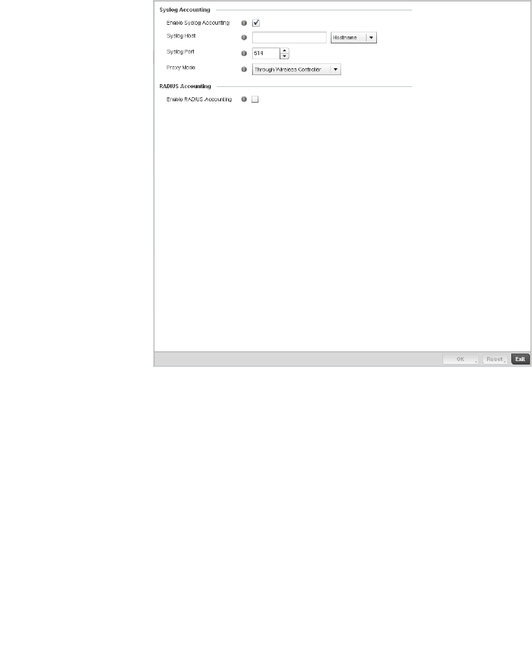
Brocade Mobility RFS4000, RFS6000, and RFS7000 System Reference Guide 313
53-1002620-01
6
FIGURE 226 WLAN Policy Accounting screen
4. Set the following System Log Accounting information:
5. Select the Enable RADIUS Accounting check box to use an external RADIUS resource for AAA
accounting. When the check box is selected, a AAA Policy field displays. Either use the default
AAA policy with the WLAN, or select Create to define a new AAA configuration that can be
applied to the WLAN. This setting is disabled by default.
6. Select OK when completed to update this WLAN’s accounting settings. Select Reset to revert
the screen to its last saved configuration.
Accounting Deployment Considerations
Before defining a AAA configuration on a controller WLAN, refer to the following deployment
guidelines to ensure the configuration is optimally effective:
•When using RADIUS authentication, Brocade recommends the WAN port round trip delay not
exceed 150ms. Excessive delay over a WAN can cause authentication and roaming issues.
When excessive delays exists, a distributed RADIUS service should be used.
•Brocade recommends authorization policies be implemented when users need to be restricted
to specific WLANs, or time and date restrictions need to be applied.
Enable Syslog
Accounting
Use this option for the controller or Access Point to generate accounting records in
standard syslog format (RFC 3164). The feature is disabled by default.
Syslog Host Specify the IP address or hostname of the external syslog host where accounting
records are routed.
Syslog Port Use the spinner control to set the destination UDP port number of the external
syslog host where the accounting records are routed.
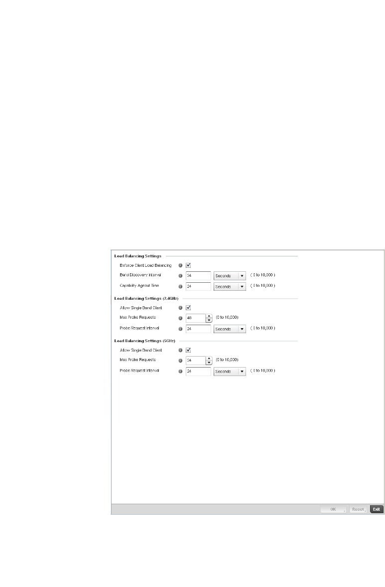
314 Brocade Mobility RFS4000, RFS6000, and RFS7000 System Reference Guide
53-1002620-01
6
•Authorization policies can also apply bandwidth restrictions and assign Firewall policies to
users and devices.
Configuring Client Load Balancing Settings
Wireless LAN Policy
To configure advanced settings on a wireless controller managed WLAN:
1. Select Configuration > Wireless LANs > Wireless LAN Policy to display a high-level display of the
existing WLANs available to the wireless controller managed network.
2. Select the Add button to create an additional WLAN or select Edit to modify the properties of an
existing wireless controller WLAN.
3. Select Client Load Balancing.
FIGURE 227 WLAN Policy Client Load Balancing screen
4. Refer to the Load Balancing Settings section to configure load balancing for the WLAN.
Enforce Client Load
Balancing
Select this option to enable client load balancing for the selected WLAN.

Brocade Mobility RFS4000, RFS6000, and RFS7000 System Reference Guide 315
53-1002620-01
6
5. Refer to the Load Balancing Settings (2.4GHz) section to configure load balancing for the 2.4
GHz WLAN.
6. Refer to the Load Balancing Settings (5GHz) section to configure load balancing for the 5 GHz
WLAN.
7. S elect OK when completed to update this WLAN’s advanced settings. Select Reset to revert the
screen back to its last saved configuration.
Configuring Advanced WLAN Settings
Wireless LAN Policy
To configure advanced settings on a wireless controller managed WLAN:
1. Select Configuration > Wireless LANs > Wireless LAN Policy to display a high-level display of the
existing WLANs available to the wireless controller managed network.
2. Select the Add button to create an additional WLAN or select Edit to modify the properties of an
existing wireless controller WLAN.
3. Select Advanced.
Allowed Single Band
Clients
Select this option to enable association for single band clients on the 2.4GHz
frequency, even if load balancing is available.
Max Probe Requests Enter a value between 0 and 10,000 for the maximum number of probe requests for
clients using the 2.4GHz frequency. The default value is 60.
Probe Request Interval Enter a value in seconds between 0 and 10,000 to configure the time interval for
client probe requests beyond which it is allowed to associate for clients on the
2.4GHz network.
Band Discovery
Interval
Enter a value in seconds between 0 and 10,000 to configure the time interval to
discover client’s band capability before associating it
Allowed Single Band
Clients
Select this option to enable association for single band clients on the 5GHz
frequency, even if load balancing is available.
Max Probe Requests Enter a value between 0 and 10,000 for the maximum number of probe requests for
clients using the 5GHz frequency. The default value is 60.
Probe Request Interval Enter a value in seconds between 0 and 10,000 to configure the time interval for
client probe requests beyond which it is allowed to associate for clients on the 5GHz
network.
Band Discovery
Interval
Enter a value in seconds between 0 and 10,000 to configure the time interval to
discover client’s band capability before associating it
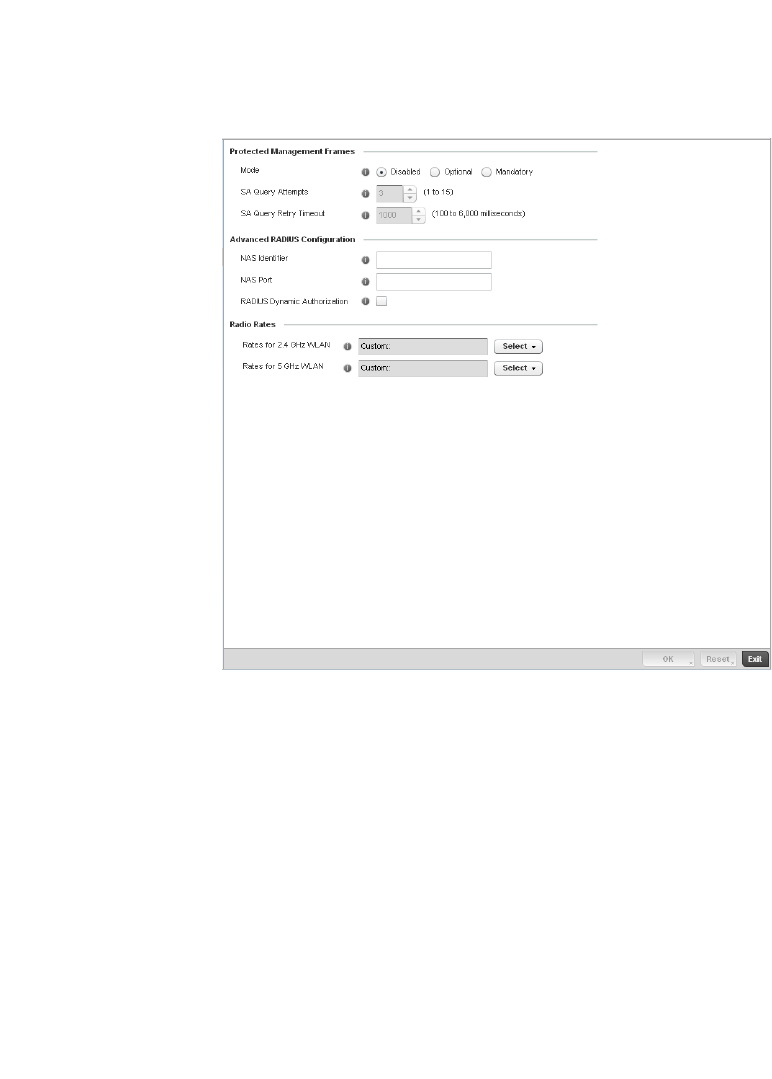
316 Brocade Mobility RFS4000, RFS6000, and RFS7000 System Reference Guide
53-1002620-01
6
FIGURE 228 WLAN Policy Advanced screen
4. Refer to the Protected Management Frames field to set a frame protection mode and security
association for the WLAN’s advanced configuration.
During a security association (SA) negotiation, the wireless controller and recipient gateways
agree to use a particular transform set to protect data flow. A transform set is a combination of
security protocols and algorithms. During an IPSec security association negotiation, peers
agree to use a particular transform set for protecting the wireless controller managed data
flow.
Mode Select a radio button option to determine whether management frames are
continually or optionally protected. Disabled is the default setting.
SA Query Attempts Use the spinner control to set the number of security association query attempts
between 1-15. The default value is 3.
SA Query Retry
Timeout
The timeout value is the configurable interval used to timeout association requests
that exceed the defined interval. Set the timeout value between 100-6000
milliseconds. The default value is 1000 milliseconds.
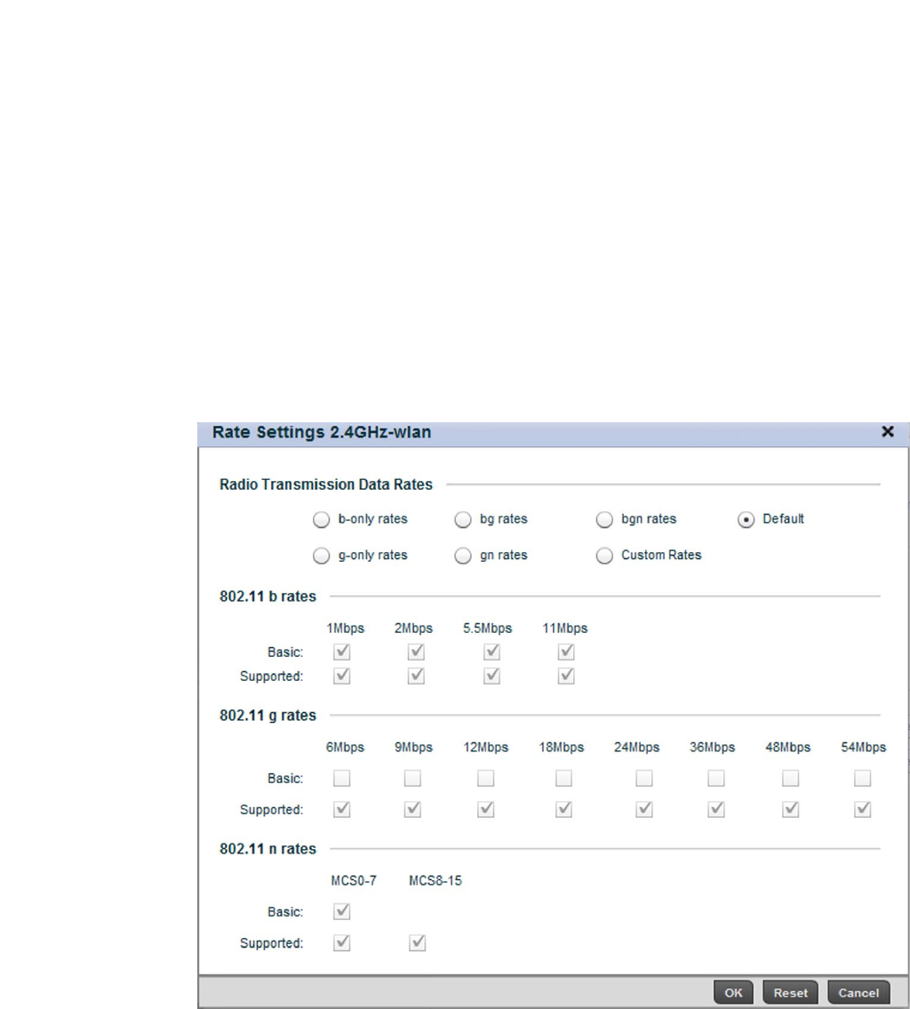
Brocade Mobility RFS4000, RFS6000, and RFS7000 System Reference Guide 317
53-1002620-01
6
5. Refer to the Advanced RADIUS Configuration field to set the WLAN’s NAS configuration and
RADIUS Dynamic Authorization.
6. Refer to the Radio Rates field to define selected data rates for both the 2.4 and 5.0 GHz
bands.
FIGURE 229 Advanced WLAN Rate Settings 2.4 GHz screen
NAS Identifier Specify what should be included in the RADIUS NAS-Identifier field for
authentication and accounting packets relating to this WLAN. Configuring a value
here is optional, and defaults are used if this is not configured per WLAN.
NAS Port The profile database on the RADIUS server consists of user profiles for each
connected network access server (NAS) port. Each profile is matched to a
username representing a physical port. When the wireless controller authorizes
users, it queries the user profile database using a username representative of the
physical NAS port making the connection. Set the numeric port value between
0-4,294,967,295.
RADIUS Dynamic
Authorization
Select the check box to enable a mechanism that extends the RADIUS protocol to
support unsolicited messages sent from the RADIUS server. These messages allow
wireless network administrators to issue change of authorization (CoA) messages,
which affect session authorization, or Disconnect Message (DM), which cause a
session to be terminated immediately. This feature is disabled by default.
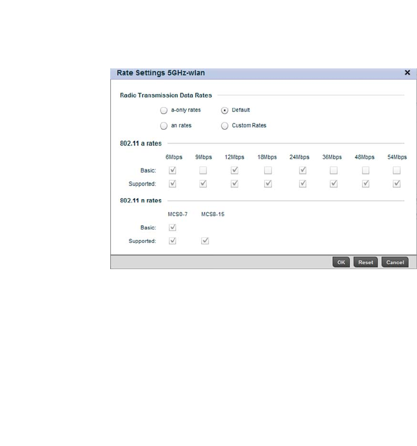
318 Brocade Mobility RFS4000, RFS6000, and RFS7000 System Reference Guide
53-1002620-01
6
FIGURE 230 Advanced WLAN Rate Settings 5 GHz screen
Define both minimum Basic and optimal Supported rates as required for the 802.11b rates,
802.11g rates and 802.11n rates supported by the 2.4 GHz band and 802.11a and 802.11n
rates supported by the 5.0 GHz radio band. These are the rates wireless client traffic is
supported within this WLAN.
If supporting 802.11n, select a Supported MCS index. Set a MCS (modulation and coding
scheme) in respect to the radio’s channel width and guard interval. A MCS defines (based on
RF channel conditions) an optimal combination of 8 data rates, bonded channels, multiple
spatial streams, different guard intervals and modulation types. Clients can associate as long
as they support basic MCS (as well as non-11n basic rates).
The selected rates apply to associated client traffic within this WLAN only.
7. S elect OK when completed to update this WLAN’s advanced settings. Select Reset to revert the
screen back to its last saved configuration.
Configuring WLAN QoS Policies
Wireless LAN Policy
QoS provides a data traffic prioritization scheme. QoS reduces congestion from excessive traffic. If
there is enough bandwidth for all users and applications (unlikely because excessive bandwidth
comes at a very high cost), then applying QoS has very little value. QoS provides policy enforcement
for mission-critical applications and/or users that have critical bandwidth requirements when the
wireless controller’s bandwidth is shared by different users and applications.
QoS helps ensure each WLAN on the wireless controller receives a fair share of the overall
bandwidth, either equally or as per the proportion configured. Packets directed towards clients are
classified into categories such as Video, Voice and Data. Packets within each category are
processed based on the weights defined for each WLAN.
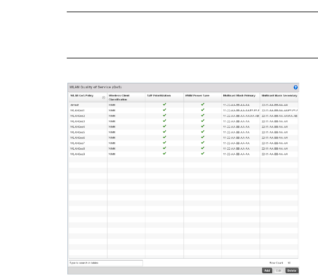
Brocade Mobility RFS4000, RFS6000, and RFS7000 System Reference Guide 319
53-1002620-01
6
The Quality of Service screen displays a list of QoS policies available to wireless controller managed
WLANs. Each QoS policy has its own radio button that can be selected to edit its properties. If none
of the exiting QoS policies supports an ideal QoS configuration for the intended data traffic of this
WLAN, select the Add button to create new policy. Select the radio button of an existing WLAN and
select Ok to map the QoS policy to the WLAN displayed in the banner of the screen.
Use the WLAN Quality of Service (QoS) Policy screen to add a new QoS policy or edit the attributes
of an existing policy.
NOTE
WLAN QoS configurations differ significantly from QoS policies configured for radios. WLAN QoS
configurations are designed to support the data requirements of wireless clients, including the data
types they support and their wireless controller managed network permissions. Radio QoS policies
are specific to the transmit and receive char act is tics of the connected radio’s themselves,
independent from the wireless clients these access point radios support.
1. Select Configuration > Wireless > WLAN QoS Policy to display existing QoS policies available to
WLANs.

320 Brocade Mobility RFS4000, RFS6000, and RFS7000 System Reference Guide
53-1002620-01
6
2. Refer to the following read-only information on each listed QoS policy to determine whether an
existing policy can be used as is, an existing policy requires edit or a new policy requires
creation:
NOTE
When using a wireless client classification other than WMM, only legacy rates are supported on that
WLAN.
3. Either select the Add button to define a new WLAN QoS policy, or select an existing WLAN QoS
policy and select Edit to modify its existing configuration. Existing QoS policies can be selected
and deleted as needed.
WLAN QoS Policy Displays the name assigned to this WLAN QoS policy when it was initially created.
The assigned policy name cannot be modified as part of the edit process.
Wireless Client
Classification
Lists each policy’s Wireless Client Classification as defined for this WLAN's intended
traffic. The Classification Categories are the different WLAN-WMM options available
to a radio. Classification types include:
WMM – Implies WiFi Multimedia QoS extensions are enabled on this radio. This
allows different traffic streams between the wireless client and the access point to
be prioritized according to the type of traffic (voice, video etc). The WMM
classification is required to support the high throughput data rates required of
802.11n device support.
Voice – Optimized for voice traffic. Implies all traffic on this WLAN is prioritized as
voice traffic on the radio.
Video – Optimized for video traffic. Implies all traffic on this WLAN is prioritized as
video traffic on the radio.
Normal – Optimized for best effort traffic. Implies all traffic on this WLAN is
prioritized as best effort traffic on the radio.
Low – Optimized for background traffic. Implies all traffic on this WLAN is low
priority on the radio.
Non-Unicast – Optimized for non-Unicast traffic. Implies all traffic on this WLAN is
designed for broadcast or multicast.
SVP Prioritization A green checkmark defines the policy as having Spectralink Voice Prioritization
(SVP) enabled to allow the wireless controller to identify and prioritize traffic from
Spectralink/Polycomm phones using the SVP protocol. Phones using regular WMM
and SIP are not impacted by SVP prioritization. A red “X” defines the QoS policy as
not supporting SVP prioritization.
WMM Power Save Enables support for the WMM based power-save mechanism, also known as
Unscheduled Automatic Power Save Delivery (U-APSD). This is primarily used by
voice devices that are WMM capable. The default setting is enabled.
Multicast Mask
Primary
Displays the primary multicast mask defined for each listed QoS policy. Normally all
multicast and broadcast packets are buffered until the periodic DTIM interval
(indicated in the 802.11 beacon frame), when clients in power save mode wake to
check for frames. However, for certain applications and traffic types, the
administrator may want the frames transmitted immediately, without waiting for the
DTIM interval. By configuring a primary and secondary multicast mask, an
administrator can indicate which frames are transmitted immediately. Setting
masks is optional and only needed if there are traffic types requiring special
handling.
Multicast Mask
Secondary
Displays the secondary multicast mask defined for each listed QoS policy.

Brocade Mobility RFS4000, RFS6000, and RFS7000 System Reference Guide 321
53-1002620-01
6
A Quality of Service (QoS) policy screen displays for the new or selected WLAN. The screen
displays the WMM tab by default, but additional tabs also display for WLAN and wireless client
rate limit configurations. For more information, refer to the following:
•Configuring a WLAN’s QoS WMM Settings
•Configuring Rate Limit Settings
•Configuring Multimedia Optimizations
Configuring a WLAN’s QoS WMM Settings
Using WMM, end-user satisfaction is maintained in a wider variety of environments and traffic
conditions. WMM makes it possible for both home networks and Enterprises to decide which data
streams are most important and assign them a higher traffic priority.
WMM’s prioritization capabilities are based on the four access categories. The higher the access
category, the higher the probability to transmit this kind of traffic over the wireless controller
managed WLAN. ACs were designed to correspond to 802.1d priorities to facilitate interoperability
with QoS policy management mechanisms. WMM enabled wireless controllers/ access points
coexist with legacy devices
(not WMM-enabled).
Packets not assigned to a specific access category are categorized by default as having best effort
priority. Applications assign each data packet to a given access category packets are then added to
one of four independent transmit queues (one per access category - voice, video, best effort or
background) in the client. The client has an internal collision resolution mechanism to address
collision among different queues, which selects the frames with the highest priority to transmit.
The same mechanism deals with external collision, to determine which client should be granted the
opportunity to transmit (TXOP). The collision resolution algorithm responsible for traffic
prioritization is probabilistic and depends on two timing parameters that vary for each access
category.
•The minimum interframe space, or Arbitrary Inter-Frame Space Number (AIFSN)
•The contention window, sometimes referred to as the random backoff wait
Both values are smaller for high-priority traffic. The value of the contention window varies through
time. Initially the contention window is set to a value that depends on the AC. As frames with the
highest AC tend to have the lowest backoff values, they are more likely to get a TXOP.
After each collision the contention window is doubled until a maximum value (also dependent on
the AC) is reached. After successful transmission, the contention window is reset to its initial, AC
dependant value. The AC with the lowest backoff value gets the TXOP.
To configure a WMM configuration for a wireless controller managed WLAN:
1. Select Configuration > Wireless > WLAN QoS Policy to display existing QoS Policies available to
the wireless controller managed network.
2. Select the Add button to create a new QoS policy or Edit to modify the properties of an existing
WLAN QoS policy.
The WMM tab displays by default.
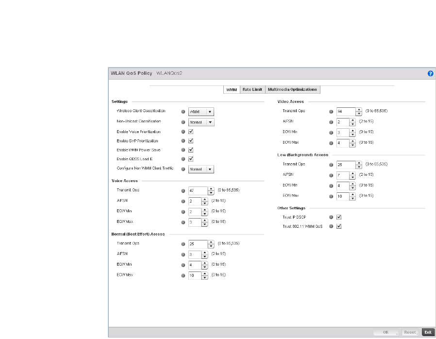
322 Brocade Mobility RFS4000, RFS6000, and RFS7000 System Reference Guide
53-1002620-01
6

Brocade Mobility RFS4000, RFS6000, and RFS7000 System Reference Guide 323
53-1002620-01
6
3. Configure the following in respect to the WLAN’s intended WMM radio traffic and user
requirements:
Wireless Client
Classification
Use the drop-down menu to select the Wireless Client Classification for this WLAN's
intended traffic. The Classification Categories are the different WLAN-WMM options
available to the radio. The Wireless Client Classification types are:
WMM – Implies WiFi Multimedia QoS extensions are enabled on this radio. This
allows different traffic streams between the wireless client and the access point to
be prioritized according to the type of traffic (voice, video etc). The WMM
classification is required to support the high throughput data rates required of
802.11n device support.
Voice – Optimized for voice traffic. Implies all traffic on this WLAN is prioritized as
voice traffic on the radio.
Video – Optimized for video traffic. Implies all traffic on this WLAN is prioritized as
video traffic on the radio.
Normal – Optimized for best effort traffic. Implies all traffic on this WLAN is
prioritized as best effort traffic on the radio.
Low – Optimized for background traffic. Implies all traffic on this WLAN is low
priority on the radio.
Non-Unicast – Optimized for non-Unicast traffic. Implies all traffic on this WLAN is
designed for broadcast or multiple desitnations.
Non-Unicast
Classification
Use the drop-down menu to select the Non-Unicast Classification for this WLAN's
intended traffic. The Non-Unicast Classification types are:
Voice – Optimized for voice traffic. Implies all traffic on this WLAN is prioritized as
voice traffic on the radio.
Video – Optimized for video traffic. Implies all traffic on this WLAN is prioritized as
video traffic on the radio.
Normal – Optimized for best effort traffic. Implies all traffic on this WLAN is
prioritized as best effort traffic on the radio.
Low – Optimized for background traffic. Implies all traffic on this WLAN is low
priority on the radio.
Enable Voice
Prioritization
Select this option if Voice traffic is prioritized on the WLAN. This gives priority to
voice and voice management packets and is supported only on certain legacy
Brocade VOIP phones. This feature is disabled by default.
Enable SVP
Prioritization
Enabling Spectralink Voice Prioritization (SVP) allows the wireless controller to
identify and prioritize traffic from Spectralink/Polycomm phones. This gives priority
to voice, with voice management packets supported only on certain legacy Brocade
VOIP phones. If the Wireless Client Classification is WMM, non WMM devices
recognized as voice devices have all their traffic transmitted at voice priority.
Devices are classified as voice, when they emit SIP, SCCP, or H323 traffic. Thus,
selecting this option has no effect on devices supporting WMM. This feature is
disabled by default.

324 Brocade Mobility RFS4000, RFS6000, and RFS7000 System Reference Guide
53-1002620-01
6
4. Set the following Voice Access settings for the WLAN’s QoS policy:
5. Set the following Normal (Best Effort) Access settings for the WLAN’s QoS policy:
Enable WMM Power
Save
Enables support for the WMM based power-save mechanism, also known as
Unscheduled Automatic Power Save Delivery (U-APSD). This is primarily used by
voice devices that are WMM capable. The default setting is enabled.
Enable QBSS Load IE Check this box to enable QoS Basis Service Set (QBSS) information element (IE) in
beacons and probe response packets advertised by access points. The default
value is enabled.
Configure Non WMM
Client Traffic
Use the drop-down menu to select the Non-WMM client traffic Classification. The
Non-WMM Classification types are:
Voice – Optimized for voice traffic. Implies all traffic on this WLAN is prioritized as
voice traffic on the radio.
Video – Optimized for video traffic. Implies all traffic on this WLAN is prioritized as
video traffic on the radio.
Normal – Optimized for best effort traffic. Implies all traffic on this WLAN is
prioritized as best effort traffic on the radio.
Low – Optimized for background traffic. Implies all traffic on this WLAN is low
priority on the radio.
Transmit Ops Use the slider to set the maximum duration a device can transmit after obtaining a
transmit opportunity. The default value is 47.
AIFSN Set the current Arbitrary Inter-frame Space Number (AIFSN) between 2-15.
Higher-priority traffic voice categories should have lower AIFSNs than lower-priority
traffic categories. This will cause lower-priority traffic to wait longer before
attempting access. The default value is 2.
ECW Min The ECW Min is combined with the ECW Max to create the contention value in the
form of a numerical range. From this range, a random number is selected for the
back off mechanism. Lower values are used for higher priority traffic. The available
range to the wireless controller is from 0-15. The default value is 2.
ECW Max The ECW Max is combined with the ECW Min to create the contention value in the
form of a numerical range. From this range, a random number is selected for the
back off mechanism. Lower values are used for higher priority traffic. The available
range to the wireless controller is from 0-15. The default value is 3.
Transmit Ops Use the slider to set the maximum duration a device can transmit after obtaining a
transmit opportunity. The default value is 0.
AIFSN Set the current AIFSN between 2-15. The default value is 3.
ECW Min The ECW Min is combined with the ECW Max to create the contention value in the
form of a numerical range. From this range, a random number is selected for the
back off mechanism. Higher values are used for lower priority traffic (like Normal).
The available range to the wireless controller is from 0-15. The default value is 4.
ECW Max The ECW Max is combined with the ECW Min to create the contention value in the
form of a numerical range. From this range, a random number is selected for the
back off mechanism. Higher values are used for lower priority traffic (like Normal).
The available range to the wireless controller is from 0-15. The default value is 10.

Brocade Mobility RFS4000, RFS6000, and RFS7000 System Reference Guide 325
53-1002620-01
6
6. Set the following Video Access settings for the WLAN’s QoS policy:
7. Set the following Low (Background) Access settings for the WLAN’s QoS policy:
8. Set the following Other Settings for the WLAN’s QoS policy:
9. Select OK when completed to update this WLAN’s QoS settings. Select Reset to revert the
screen back to its last saved configuration.
Configuring Rate Limit Settings
Excessive traffic can cause performance issues or bring down the network entirely. Excessive
traffic can be caused by numerous sources including network loops, faulty devices or malicious
software such as a worm or virus that has infected on one or more devices at the branch. Rate
limiting limits the maximum rate sent to or received from the wireless network (and WLAN) per
wireless client. It prevents any single user from overwhelming the wireless network. It can also
provide differential service for service providers. The uplink and downlink rate limits are usually
configured on a RADIUS server using Brocade vendor specific attributes. The controller extracts the
rate limits from RADIUS server’s response. When such attributes are not present, the settings
Transmit Ops Use the slider to set the maximum duration a device can transmit after obtaining a
transmit opportunity. The default values is 94.
AIFSN Set the current Arbitrary Inter-frame Space Number (AIFSN) between 2-15.
Higher-priority traffic video categories should have lower AIFSNs than lower-priority
traffic categories. This will cause lower-priority traffic to wait longer before
attempting access. The default value is 2.
ECW Min The ECW Min is combined with the ECW Max to create the contention value in the
form of a numerical range. From this range, a random number is selected for the
back off mechanism. Lower values are used for higher priority traffic (like video).
The available range to the wireless controller is from 0-15. The default value is 3.
ECW Max The ECW Max is combined with the ECW Min to create the contention value in the
form of a numerical range. From this range, a random number is selected for the
back off mechanism. Lower values are used for higher priority traffic (like video).
The available range to the wireless controller is from 0-15. The default value is 4.
Transmit Ops Use the slider to set the maximum duration a device can transmit after obtaining a
transmit opportunity. For higher-priority traffic categories, this value should be set to
a low number. The default value is 0.
AIFSN Set the current AIFSN between 2-15. The default value is 7.
ECW Min The ECW Min is combined with the ECW Max to create the contention value in the
form of a numerical range. From this range, a random number is selected for the
back off mechanism. Higher values are used for lower priority traffic (like Low). The
available range to the wireless controller is from 0-15. The default value is 4.
ECW Max The ECW Max is combined with the ECW Min to create the contention value in the
form of a numerical range. From this range, a random number is selected for the
back off mechanism. Higher values are used for lower priority traffic (like Low). The
available range to the wireless controller is from 0-15. The default value is 10.
Trust IP DSCP Select this option to trust IP DSCP values for WLANs. The default value is enabled.
Trust 802.11 WMM
QoS
Select this option to trust 802.11 WMM QoS values for WLANs. The default value
enabled.
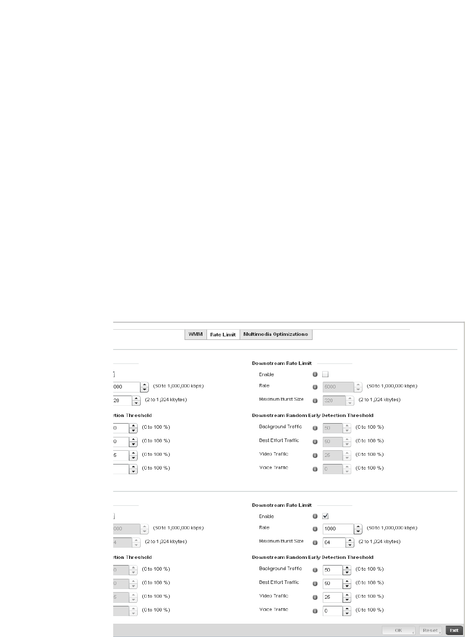
326 Brocade Mobility RFS4000, RFS6000, and RFS7000 System Reference Guide
53-1002620-01
6
defined on the controller are applied. An administrator can set separate QoS rate limit
configurations for data transmitted from the managed network (upstream) and data transmitted
from a WLAN’s wireless clients back to their associated access point radios and controller
(downstream).
Before defining rate limit thresholds for WLAN upstream and downstream traffic, Brocade
recommends you define the normal number of ARP, broadcast, multicast and unknown unicast
packets that typically transmit and receive from each supported WMM access category. If
thresholds are defined too low, normal network traffic (required by end-user devices) will be
dropped by the controller resulting in intermittent outages and performance problems.
A controller’s connected wireless clients can also have QoS rate limit settings defined in both the
upstream and downstream direction.
To configure a QoS rate limit configuration for a managed WLAN:
1. Select Configuration > Wireless > WLAN QoS Policy to display existing QoS policies available to
WLANs.
2. Either select the Add button to define a new WLAN QoS policy, or select an existing WLAN QoS
policy and select Edit to modify its existing configuration.
3. Select the Rate Limit tab.
FIGURE 231 QoS Policy WLAN Rate Limit screen

Brocade Mobility RFS4000, RFS6000, and RFS7000 System Reference Guide 327
53-1002620-01
6
4. Configure the following parameters in respect to the intended WLAN Upstream Rate Limit, or
traffic from the controller to associated access point radios and their associated wireless
clients:
5. Set the following WLAN Upstream Random Early Detection Threshold settings for each access
category. An early random drop is done when a traffic stream falls below the set threshold.
Enable Select the Enable check box to enable rate limiting for data transmitted from the
controller to its connected access point radios and associated wireless clients.
Enabling this option does not invoke rate limiting for data traffic in the downstream
direction. This feature is disabled by default.
Rate Define an upstream rate limit between 50 - 1,000,000 kbps. This limit constitutes a
threshold for the maximum the number of packets transmitted or received over the
WLAN (from all access categories). Traffic that exceeds the defined rate is dropped
by the controller and a log message is generated. The default setting is 5000 kbps.
Maximum Burst Size Set a maximum burst size between 2 - 1024 kbytes. The smaller the burst, the less
likely the upstream packet transmission will result in congestion for the WLAN’s
client destinations. By trending the typical number of ARP, broadcast, multicast and
unknown unicast packets over a period of time, the average rate for each access
category can be obtained. Once a baseline is obtained, administrators should then
add a 10% margin (minimally) to allow for traffic bursts at the site. The default burst
size is 64 kbytes.
Background Traffic Set a percentage value for background traffic in the upstream direction. This is a
percentage of the maximum burst size for low priority traffic. Background traffic
exceeding the defined threshold is dropped by the controller and a log message is
generated. Background traffic consumes the least bandwidth of any access
category, so this value can be set to a lower value once a general upstream rate is
known by the network administrator (using a time trend analysis). The default
threshold is 50%.
Best Effort Traffic Set a percentage value for best effort traffic in the upstream direction. This is a
percentage of the maximum burst size for normal priority traffic. Best effort traffic
exceeding the defined threshold is dropped by the controller and a log message is
generated. Best effort traffic consumes little bandwidth, so this value can be set to
a lower value once a general upstream rate is known by the network administrator
(using a time trend analysis). The default threshold is 50%.
Video Traffic Set a percentage value for video traffic in the upstream direction. This is a
percentage of the maximum burst size for video traffic. Video traffic exceeding the
defined threshold is dropped by the controller and a log message is generated.
Video traffic consumes significant bandwidth, so this value can be set to a higher
value once a general upstream rate is known by the network administrator (using a
time trend analysis). The default threshold is 25%.
Voice Traffic Set a percentage value for voice traffic in the upstream direction. This is a
percentage of the maximum burst size for voice traffic. Voice traffic exceeding the
defined threshold is dropped by the controller and a log message is generated.
Voice applications consume significant bandwidth, so this value can be set to a
higher value once a general upstream rate is known by the network administrator
(using a time trend analysis). The default threshold is 0%.

328 Brocade Mobility RFS4000, RFS6000, and RFS7000 System Reference Guide
53-1002620-01
6
6. Configure the following parameters in respect to the intended WLAN Downstream Rate Limit,
or traffic from wireless clients to associated Access Point radios and the controller:
7. Set the following WLAN Downstream Random Early Detection Threshold settings for each
access category. An early random drop is done when the amount of tokens for a traffic stream
falls below the set threshold.
Enable Select the Enable radio button to enable rate limiting for data transmitted from the
controller to its connected access point radios and associated wireless clients.
Enabling this option does not invoke rate limiting for data traffic in the upstream
direction. This feature is disabled by default.
Rate Define an upstream rate limit between 50 - 1,000,000 kbps. This limit constitutes a
threshold for the maximum the number of packets transmitted or received over the
WLAN (from all access categories). Traffic that exceeds the defined rate is dropped
by the controller and a log message is generated. The default setting is 5000 kbps.
Maximum Burst Size Set a maximum burst size between 2 - 1024 kbytes. The smaller the burst, the less
likely the downstream packet transmission will result in congestion for the WLANs
wireless client destinations. By trending the typical number of ARP, broadcast,
multicast and unknown unicast packets over a period of time, the average rate for
each access category can be obtained. Once a baseline is obtained, administrators
should then add a minimum of a 10% margin to allow for traffic bursts at the site.
The default burst size is 64 kbytes.
Background Traffic Set a percentage value for background traffic in the downstream direction. This is a
percentage of the maximum burst size for low priority traffic. Background traffic
exceeding the defined threshold is dropped by the controller and a log message is
generated. Background traffic consumes the least bandwidth of any access
category, so this value can be set to a lower value once a general downstream rate
is known by the network administrator (using a time trend analysis). The default
threshold is 50%.
Best Effort Traffic Set a percentage value for best effort traffic in the downstream direction. This is a
percentage of the maximum burst size for normal traffic. Best effort traffic
exceeding the defined threshold is dropped by the controller and a log message is
generated. Best effort traffic consumes little bandwidth, so this value can be set to
a lower value once a general downstream rate is known by the network
administrator (using a time trend analysis). The default threshold is 50%.
Video Traffic Set a percentage value for video traffic in the downstream direction. This is a
percentage of the maximum burst size for video traffic. Video traffic exceeding the
defined threshold is dropped by the controller and a log message is generated.
Video traffic consumes significant bandwidth, so this value can be set to a higher
value once a general downstream rate is known by the network administrator (using
a time trend analysis). The default threshold is 25%.
Voice Traffic Set a percentage value for voice traffic in the downstream direction. This is a
percentage of the maximum burst size for voice traffic. Voice traffic exceeding the
defined threshold is dropped by the controller and a log message is generated.
Voice applications consume significant bandwidth, so this value can be set to a
higher value once a general upstream rate is known by the network administrator
(using a time trend analysis). The default threshold is 0%. 0% means no early
random drops will occur.

Brocade Mobility RFS4000, RFS6000, and RFS7000 System Reference Guide 329
53-1002620-01
6
8. Configure the following parameters in respect to the intended Wireless Client Upstream Rate
Limit:
9. Set the following Wireless Client Upstream Random Early Detection Threshold settings for each
access category:
10. Configure the following parameters in respect to the intended Wireless Client Downstream
Rate Limit, or traffic from a controller to associated access point radios and the wireless client:
Enable Select the Enable radio button to enable rate limiting for data transmitted from the
client to its associated access point radio and connected wireless controller.
Enabling this option does not invoke client rate limiting for data traffic in the
downstream direction. This feature is disabled by default.
Rate Define an upstream rate limit between 50 - 1,000,000 kbps.This limit constitutes a
threshold for the maximum the number of packets transmitted or received (from all
access categories). Traffic that exceeds the defined rate is dropped by the client and
a log message is generated. The default rate is 1,000 kbps.
Maximum Burst Size Set a maximum burst size between 2 - 1024 kbytes. The smaller the burst, the less
likely the upstream packet transmission will result in congestion for the wireless
client. The default burst size is 64 kbytes.
Background Traffic Set a percentage value for background traffic in the upstream direction. This is a
percentage of the maximum burst size for low priority traffic. Background traffic
exceeding the defined threshold is dropped by the client and a log message is
generated. The default threshold is 50%.
Best Effort Traffic Set a percentage value for best effort traffic in the upstream direction. This is a
percentage of the maximum burst size for normal traffic. Best effort traffic
exceeding the defined threshold is dropped by the client and a log message is
generated. The default threshold is 50%.
Video Traffic Set a percentage value for video traffic in the upstream direction. This is a
percentage of the maximum burst size for video traffic. Video traffic exceeding the
defined threshold is dropped by the client and a log message is generated. The
default threshold is 25%.
Voice Traffic Set a percentage value for voice traffic in the downstream direction. This is a
percentage of the maximum burst size for voice traffic. Voice traffic exceeding the
defined threshold is dropped by the client and a log message is generated. The
default threshold is 0%.0% implies no early random drops will occur.
Enable Select the Enable radio button to enable rate limiting for data transmitted from
connected wireless clients to the controller. Enabling this option does not invoke
rate limiting for data traffic in the upstream direction. This feature is disabled by
default.
Rate Define a downstream rate limit between 50 - 1,000,000 kbps.This limit constitutes
a threshold for the maximum the number of packets transmitted or received by the
client. Traffic that exceeds the defined rate is dropped and a log message is
generated. The default rate is
1,000 kbytes.
Maximum Burst Size Set a maximum burst size between 2 - 64 kbytes. The smaller the burst, the less
likely the downstream packet transmission will result in congestion for the wireless
client. The default burst size is 6 kbytes.

330 Brocade Mobility RFS4000, RFS6000, and RFS7000 System Reference Guide
53-1002620-01
6
11. Set the following Wireless Client sDownstream Random Early Detection Threshold settings for
each access category:
12. Select OK when completed to update this WLAN’s QoS rate limit settings. Select Reset to revert
the screen back to its last saved configuration.
WLAN QoS Deployment Considerations
Before defining a QoS configuration on a wireless controller WLAN, refer to the following
deployment guidelines to ensure the configuration is optimally effective:
•WLAN QoS configurations differ significantly from QoS policies configured for wireless
controller associated access point radios. WLAN QoS configurations are designed to support
the data requirements of wireless clients, including the data types they support and their
wireless controller managed network permissions. Radio QoS policies are specific to the
transmit and receive characteristics of the connected radio’s themselves, independent from
the wireless clients these access point radios support.
•Enabling WMM support on a wireless controller’s WLAN only advertises WMM capability to
wireless clients. The wireless clients must be also able to support WMM and use the
parameters correctly while accessing the wireless network to truly benefit.
•Rate limiting is disabled by default on all controller managed WLANs. To enable rate limiting, a
threshold must be defined for WLAN.
•Before enabling rate limiting on a controller managed WLAN, a baseline for each traffic type
should be performed. Once a baseline has been determined, a minimum 10% margin should
be added to allow for traffic bursts.
•The bandwidth required for real-time applications such as voice and video are very fairly easy
to calculate as the bandwidth requirements are consistent and can be realistically trended
over time. Applications such as Web, database and email are harder to estimate, since
bandwidth usage varies depending on how the applications are utilized.
Configuring Multimedia Optimizations
To configure multimedia optimizations for a controller managed WLAN:
Background Traffic Set a percentage value for background traffic in the downstream direction. This is a
percentage of the maximum burst size for low priority traffic. Background traffic
exceeding the defined threshold is dropped by the client and a log message is
generated. The default is 50%.
Best Effort Traffic Set a percentage value for best effort traffic in the downstream direction. This is a
percentage of the maximum burst size for normal traffic. Best effort traffic
exceeding the defined threshold is dropped by the client and a log message is
generated. The default is 50%.
Video Traffic Set a percentage value for video traffic in the downstream direction. This is a
percentage of the maximum burst size for video traffic. Video traffic exceeding the
defined threshold is dropped by the client and a log message is generated. The
default is 25%.
Voice Traffic Set a percentage value for voice traffic in the downstream direction. This is a
percentage of the maximum burst size for voice traffic. Voice traffic exceeding the
defined threshold is dropped by the client and a log message is generated. The
default threshold is 0%.0% means no early random drops will occur.
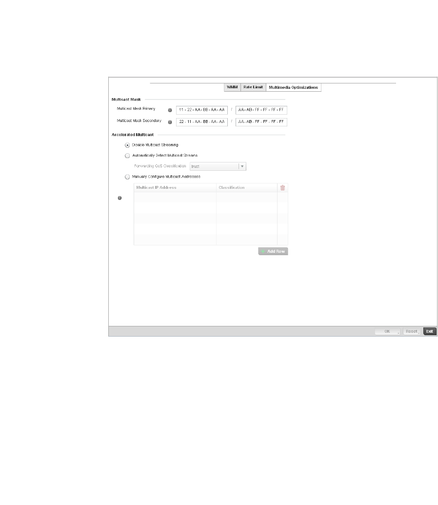
Brocade Mobility RFS4000, RFS6000, and RFS7000 System Reference Guide 331
53-1002620-01
6
1. Select Configuration > Wireless > WLAN QoS Policy to display existing QoS policies available to
WLANs.
2. Either select the Add button to define a new WLAN QoS policy, or select an existing WLAN QoS
policy and select Edit to modify its existing configuration.
3. Select the Multimedia Optimizations tab.
FIGURE 232 QoS Policy Multimedia Optimizations screen
4. Configure the following parameters in respect to the intended Multicast Mask:
Multicast Mask
Primary
Configure the primary multicast mask defined for each listed QoS policy. Normally
all multicast and broadcast packets are buffered until the periodic DTIM interval
(indicated in the 802.11 beacon frame), when clients in power save mode wake to
check for frames. However, for certain applications and traffic types, an
administrator may want the frames transmitted immediately, without waiting for the
DTIM interval. By configuring a primary and secondary multicast mask, an
administrator can indicate which frames are transmitted immediately. Setting
masks is optional and only needed if there are traffic types requiring special
handling.
Multicast Mask
Secondary
Set a secondary multicast mask for the WLAN QoS policy. Normally all multicast and
broadcast packets are buffered until the periodic DTIM interval (indicated in the
802.11 beacon frame), when clients in power save mode wake to check for frames.
However, for certain applications and traffic types, an administrator may want the
frames transmitted immediately, without waiting for the DTIM interval. By
configuring a primary and secondary multicast mask, an administrator can indicate
which frames are transmitted immediately. Setting masks is optional and only
needed if there are traffic types requiring special handling.

332 Brocade Mobility RFS4000, RFS6000, and RFS7000 System Reference Guide
53-1002620-01
6
5. Set the following Accellerated Multicast settings:
6. Select OK when completed to update this WLAN’s Multimedia Optimizations settings. Select
Reset to revert the screen back to its last saved configuration.
WLAN QoS Deployment Considerations
Before defining a QoS configuration on a wireless controller WLAN, refer to the following
deployment guidelines to ensure the configuration is optimally effective:
•WLAN QoS configurations differ significantly from QoS policies configured for wireless
controller associated access point radios. WLAN QoS configurations are designed to support
the data requirements of wireless clients, including the data types they support and their
wireless controller managed network permissions. Radio QoS policies are specific to the
transmit and receive characteristics of the connected radio’s themselves, independent from
the wireless clients these access point radios support.
•Enabling WMM support on a wireless controller’s WLAN only advertises WMM capability to
wireless clients. The wireless clients must be also able to support WMM and use the
parameters correctly while accessing the wireless network to truly benefit.
•Rate limiting is disabled by default on all controller managed WLANs. To enable rate limiting, a
threshold must be defined for WLAN.
•Before enabling rate limiting on a controller managed WLAN, a baseline for each traffic type
should be performed. Once a baseline has been determined, a minimum 10% margin should
be added to allow for traffic bursts.
•The bandwidth required for real-time applications such as voice and video are very fairly easy
to calculate as the bandwidth requirements are consistent and can be realistically trended
over time. Applications such as Web, database and email are harder to estimate, since
bandwidth usage varies depending on how the applications are utilized.
Radio QoS Policy
Without a dedicated QoS policy, a controller managed network operates on a best-effort delivery
basis, meaning all traffic has equal priority and an equal chance of being delivered in a timely
manner. When congestion occurs, all traffic has an equal chance of being dropped!
Disable Multicast
Streaming
Select this option to disable all Multicast Streaming on the WLAN.
Automatically Detect
Multicast Streams
Select this option to allow the administrator to have multicast packets that are
being bridged converted to unicast to provide better overall airtime utilization and
performance. The administrator can either have the system automatically detect
multicast streams and convert all detected multicast streams to unicast, or specify
which multicast streams are to be converted to unicast. When the stream is
converted and being queued up for transmission, there are a number of
classification mechanisms that can be applied to the stream and the administrator
can select what type of classification they would want.
Manually Configure
Multicast Addresses
Select this option and specify a list of multicast addresses and classifications.
Packets are accelerated when the destination addresses matches.
Brocade Mobility RFS4000, RFS6000, and RFS7000 System Reference Guide 333
53-1002620-01
6
When configuring a QoS policy for a controller radio, select specific network traffic, prioritize it, and
use congestion-management and congestion-avoidance techniques to provide deployment
cusomizations best suited to each QoS policy’s intended wireless client base.
Brocade controllers and their associated access point radios and wireless clients support several
Quality of Service (QoS) techniques enabling real-time applications (such as voice and video) to
co-exist simultaneously with lower priority background applications (such as Web, Email and file
transfers). A well designed QoS policy should:
•Classify and mark data traffic to accurately prioritize and segregate it (by access category)
throughout the controller managed network.
•Minimize the network delay and jitter for latency sensitive traffic.
•Ensure higher priority traffic has a better likelihood of delivery in the event of network
congestion.
•Prevent the ineffective utilization of access points degrading session quality by configuring
admission control mechanisms within each radio QoS policy
Within a Brocade controller managed network, wireless clients supporting low and high priority
traffic contend with one another for controller access and data resources. The IEEE 802.11e
amendment has defined Enhanced Distributed Channel Access (EDCA) mechanisms stating high
priority traffic can access the controller controller managed network sooner then lower priority
traffic. The EDCA defines four traffic classes (or access categories); voice (highest), video (next
highest), best effort and background (lowest).The EDCA has defined a time interval for each traffic
class, known as the Transmit Opportunity (TXOP). The TXOP prevents traffic of a higher priority from
completely dominating the wireless medium, thus ensuring lower priority traffic is still supported by
the controller and its connected radios.
IEEE 802.11e includes an advanced power saving technique called Unscheduled Automatic Power
Save Delivery (U-APSD) that provides a mechanism for wireless clients to retrieve packets buffered
by an access point. U-APSD reduces the amount of signaling frames sent from a client to retrieve
buffered data from an access point. U-APSD also allows access points to deliver buffered data
frames as bursts, without backing-off between data frames. These improvements are useful for
voice clients, as they provide improved battery life and call quality.
The Wi-Fi alliance has created Wireless Multimedia (WMM) and WMM Power Save (WMM-PS)
certification programs to ensure interoperability between 802.11e WLAN infrastructure
implementations and wireless clients. A Brocade controller managed wireless network supports
both WMM and WMM-Power Save techniques. WMM and WMM-PS (U-APSD) are enabled by default
in each controller WLAN profile.
Enabling WMM support on a controller managed WLAN just advertises the WLAN’s WMM capability
and radio configuration to wireless clients. The wireless clients must be also able to support WMM
and use the values correctly while accessing the controller’s WLAN to benefit.
WMM includes advanced parameters (CWMin, CWMax, AIFSN and TXOP) specifing back-off
duration and inter-frame spacing when accessing the controller managed network. These
parameters are relevant to both connected access point radios and their wireless clients.
Parameters impacting access point transmissions to their clients are controlled using per radio
WMM settings, while parameters used by wireless clients are controlled by a WLAN’s WMM
settings.

334 Brocade Mobility RFS4000, RFS6000, and RFS7000 System Reference Guide
53-1002620-01
6
Brocade RFS4000, RFS6000 and RFS7000 model controllers include a Session Initiation Protocol
(SIP), Skinny Call Control Protocol (SCCP) and Application Layer Gateway (ALGs) enabling devices to
identify voice streams and dynamically set voice call bandwidth. Controllers use the data to provide
prioritization and admission control to these devices without requiring TSPEC or WMM client
support.
Brocade controllers support static QoS mechanisms per WLAN to provide prioritization of WLAN
traffic when legacy (non WMM) clients are deployed. A controller and br-650 access point allow
flexible WLAN mapping with a static WMM access control value. When enabled on a WLAN, traffic
forwarded from a controller to a client is prioritized and forwarded based on the WLAN’s WMM
access control setting.
NOTE
Statically setting a WLAN WMM access category value only prioritizes traffic from the controller to
the client.
Wireless network administrators can also assign weights to each WLAN in relation to user priority
levels. The lower the weight, the lower the priority. Use a weighted round robin technic que to
achieve different QoS levels across the WLANs supported by the controller.
The controller provides the means to rate-limit bandwidth for WLAN sessions. This form of per-user
rate limiting enables administrators to define uplink and downlink bandwidth limits for users and
clients. This sets the level of traffic a user or client can forward and receive over the WLAN. If the
user or client exceeds the limit, the controller drops the excessive traffic.
Rate limits can be applied to WLANs using groups defined on the controller or externally from a
RADIUS server using Brocade Vendor Specific Attributes (VSAs). Rate limits can be applied to users
authenticating to the controller using 802.1X, hotspot authentication and devices using MAC
authentication.
Configuring Radio QoS Policies
Radio QoS Policy
To configure a radio’s QoS policy:
1. .Select Configuration > Wireless > Radio QoS Policy to display existing Radio QoS policies.
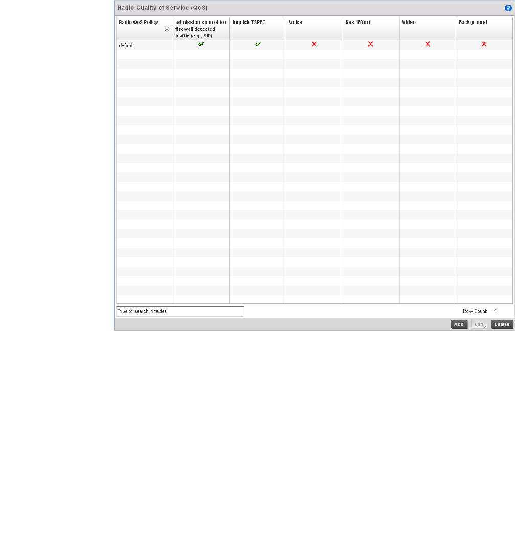
Brocade Mobility RFS4000, RFS6000, and RFS7000 System Reference Guide 335
53-1002620-01
6
FIGURE 233 Radio QoS Policy screen
The Radio QoS Policy screen lists those radio QoS policies created thus far. Any of these
policies can be selected and applied to a controller managed Access Point radio.
2. Refer to the following information listed for each existing Radio QoS policy:
Radio QoS Policy Displays the name of each Radio QoS policy. This is the name set for each listed
policy when it was created and cannot be modified as part of the policy edit
process.
Admission Controll for
Firewall Detected
Traffic (e.g., SIP)
A green checkmark defines the policy as applying radio QoS settings to traffic
detected by the controllers Firewall used with this Radio QoS policy. A red “X”
defines the policy as having Firewall detection disabled. When enabled, the Firewall
simulates the reception of frames for voice traffic when the voice traffic was
originated via SIP or SCCP control traffic. If a client exceeds configured values, the
call is stopped and/or received voice frames are forwarded at the next non
admission controlled traffic class priority. This applies to clients that do not send
TPSEC frames only.
Implicit TPSEC A green checkmark defines the policy as requiring wireless clients to send their
traffic specifications to a controller managed Access Point before they can transmit
or receive data. If enabled, this setting applies to just this radio’s QoS policy. When
enabled, the Access Point simulates the reception of frames for any traffic class by
looking at the amount of traffic the client is receiving and sending. If the client
sends more traffic than has been configured for an admission controlled traffic
class, the traffic is forwarded at the priority of the next non admission controlled
traffic class. This applies to clients that do not send TPSEC frames only.
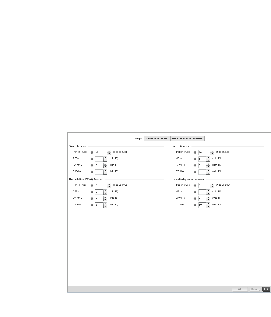
336 Brocade Mobility RFS4000, RFS6000, and RFS7000 System Reference Guide
53-1002620-01
6
3. Either select Add to create a new radio QoS policy, or select one of the existing policies listed
and select the Edit button to modify its configuration.
FIGURE 234 Radio QoS Policy WMM screen
The Radio QoS Policy screen displays the WMM tab by default. Use the WMM tab to define the
access category configuration (CWMin, CWMax, AIFSN and TXOP values) in respect to the type
of wireless data planned for this new or updated WLAN radio QoS policy.
Voice A green checkmark indicates that Voice prioritization QoS is enabled on the radio. A
red X indicates that Voice prioritization QoS is disabled on the radio.
Best Effort A green checkmark indicates that Best Effort QoS is enabled on the radio. A red X
indicates that Best Effort QoS is disabled on the radio.
Video A green checkmark indicates that Video prioritization QoS is enabled on the radio. A
red X indicates that Video prioritization QoS is disabled on the radio.
Background A green checkmark indicates that Background prioritization QoS is enabled on the
radio. A red X indicates that Background prioritization QoS is disabled on the radio.

Brocade Mobility RFS4000, RFS6000, and RFS7000 System Reference Guide 337
53-1002620-01
6
4. Set the following Voice Access settings for the Radio QoS policy:
5. Set the following Normal (Best Effort) Access settings for the radio QoS policy:
6. Set the following Video Access settings for the Radio QoS policy:
Transmit Ops Use the slider to set the maximum duration a device can transmit after obtaining a
transmit opportunity. When controller resources are shared between a Voice over IP
(VoIP) call and a low priority file transfer, bandwidth is normally exploited by the file
transfer, thus reducing call quality or even causing the call to disconnect. With voice
QoS, a VoIP call (a real-time session), receives priority, maintaining a high level of
voice quality. For higher-priority traffic categories (like voice), the Transmit Ops value
should be set to a low number. The default value is 47.
AIFSN Set the current AIFSN between 1-15. Higher-priority traffic voice categories should
have lower AIFSNs than lower-priority traffic categories. This will cause lower-priority
traffic to wait longer before attempting access. The default value is 1.
ECW Min The ECW Min is combined with the ECW Max to create a contention value in the
form of a numerical range. From this range, a random number is selected for the
back off mechanism. Lower values are used for higher priority traffic. The available
range to the controller is from 0-15. The default value is 2.
Power Save The ECW Max is combined with the ECW Min to create a contention value in the
form of a numerical range. From this range, a random number is selected for the
back off mechanism. Lower values are used for higher priority traffic. The available
range to the controller is from 0-15. The default value is 3.
Transmit Ops Use the slider to set the maximum duration a device can transmit after obtaining a
transmit opportunity. For higher-priority traffic categories, this value should be set to
a low number. The default value is 0.
AIFSN Set the current AIFSN between1-15. Higher-priority traffic voice categories should
have lower AIFSNs than lower-priority traffic categories. This will cause lower-priority
traffic to wait longer before attempting access. The default value is 7.
ECW Min The ECW Min is combined with the ECW Max to create a contention value in the
form of a numerical range. From this range, a random number is selected for the
back off mechanism. Higher values are used for lower priority traffic (like Normal).
The available range to the controller is from
0-15. The default value is 4.
Power Save The ECW Max is combined with the ECW Min to create a contention value in the
form of a numerical range. From this range, a random number is selected for the
back off mechanism. Higher values are used for lower priority traffic (like Normal).
The available range to the controller is from
0-15. The default value is 10.
Transmit Ops Use the spinner control to set the maximum duration a radio can transmit after
obtaining a transmit opportunity. For higher-priority traffic categories (like video),
this value should be set to a low number. The default value
is 94.

338 Brocade Mobility RFS4000, RFS6000, and RFS7000 System Reference Guide
53-1002620-01
6
7. Set the following Low (Best Effort) Access settings for the radio QoS policy:
8. Select OK when completed to update the radio QoS settings for this policy. Select Reset to
revert the WMM screen back to its last saved configuration.
9. Select the Admission Control tab to configure an admission control configuration for selected
radio QoS policy. Admission control requires clients send their traffic specifications (TSPEC) to
a controller managed Access Point before they can transmit or receive data within the
controller managed network.
The name of the Radio QoS policy for which the admission control settings apply displays in the
banner of the QoS Policy screen.
AIFSN Set the current AIFSN between 1-15. Higher-priority traffic video categories should
have lower AIFSNs than lower-priority traffic categories. This will cause lower-priority
traffic to wait longer before attempting access. The default value is 1.
ECW Min The ECW Min is combined with the ECW Max to create a contention value in the
form of a numerical range. From this range, a random number is selected for the
back off mechanism. Lower values are used for higher priority traffic (like video).
The available range to the controller is from
0-15. The default value is 3.
ECW Max The ECW Max is combined with the ECW Min to create a contention value in the
form of a numerical range. From this range, a random number is selected for the
back off mechanism. Lower values are used for higher priority traffic (like video).
The available range to the controller is from
0-15. The default value is 4.
Transmit Ops Use the slider to set the maximum duration a device can transmit after obtaining a
transmit opportunity. For higher-priority traffic categories, this value should be set to
a low number. The default value is 0.
AIFSN Set the current AIFSN between 1-15. Higher-priority traffic voice categories should
have lower AIFSNs than lower-priority traffic categories. This will cause lower-priority
traffic to wait longer before attempting access. The default value is 3.
ECW Min The ECW Min is combined with the ECW Max to create a contention value in the
form of a numerical range. From this range, a random number is selected for the
back off mechanism. Higher values are used for lower priority traffic (like Low). The
available range to the controller is from 0-15. The default value is 4.
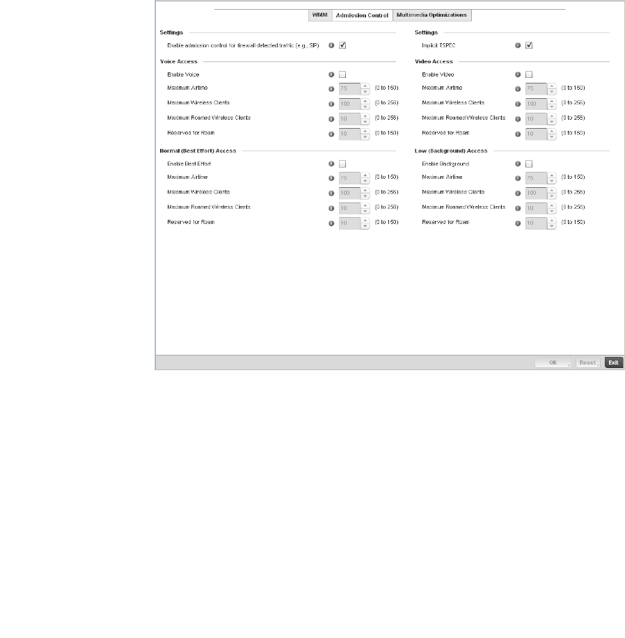
Brocade Mobility RFS4000, RFS6000, and RFS7000 System Reference Guide 339
53-1002620-01
6
FIGURE 235 Radio QoS Policy Admission Control screen
10. Select the Enable admission control for firewall Detected Traffic (e.g, SIP) check box to apply
Radio QoS settings to traffic detected by the controller Firewall. This feature is enabled by
default.
11. Select the Implicit TPSEC check box to require wireless clients to send their traffic
specifications to a controller managed Access Point before they can transmit or receive data. If
enabled, this setting applies to just this radio’s QoS policy. This feature is enabled by default.
12. Set the following Voice Access admission control settings for this radio QoS policy:
Enable Voice Select the check box to enable admission control for this policy’s voice traffic. Only
voice traffic admission control is enabled, not any of the other access categories
(each access category must be separately enabled and configured). The default is
75.
Maximum Airtime Set the maximum airtime (in the form of a percentage of the radio’s bandwidth)
allotted to admission control for voice supported client traffic. The available
percentage range is from 0-150%, with 150% being available to account for
over-subscription. This value helps ensure the radio’s bandwidth is available for
high bandwidth voice traffic (if anticipated on the wireless medium) or other access
category traffic if voice support is not prioritized. Voice traffic requires longer radio
airtime to process, so set a longer airtime value if this radio QoS policy is intended
to support voice. The default value is 75.

340 Brocade Mobility RFS4000, RFS6000, and RFS7000 System Reference Guide
53-1002620-01
6
13. Set the following Normal (Best Effort) Access admission control settings for this radio QoS
policy
Maximum Wireless
Clients
Set the number of voice supported wireless clients allowed to exist (and consume
bandwidth) within the radio’s QoS policy. Select from an available range of 0-256
clients. Consider setting this value proportionally to the number of other QoS
policies supporting the voice access category, as wireless clients supporting voice
use a greater proportion of controller resources than lower bandwidth traffic (like
low and best effort categories). The default value is 100 clients.
Maximum Roamed
Wireless Clients
Set the number of voice supported wireless clients allowed to roam to a different
controller managed access point radio. Select from a range of 0-256 clients. The
default value is 10 roamed clients.
Reserved for Roam Set the roam utilization (in the form of a percentage of the radio’s bandwidth)
allotted to admission control for voice supported clients who have roamed to a
different controller managed access point radio. The available percentage range is
from 0-150%, with 150% available to account for over-subscription. The default
value is 10.
Enable Best Effort Select the check box to enable admission control for this policy’s video traffic. Only
normal background traffic admission control is enabled, not any of the other access
categories (each access category must be separately enabled and configured). This
feature is disabled by default.
Maximum Airtime Set the maximum airtime (in the form of a percentage of the radio’s bandwidth)
allotted to admission control for normal background client traffic. The available
percentage range is from 0-150%, with 150% being available to account for
over-subscription. This value helps ensure the radio’s bandwidth is available for
lower bandwidth normal traffic (if anticipated to proliferate the wireless medium).
Normal background traffic only needs a short radio airtime to process, so set an
intermediate airtime value if this radio QoS policy is reserved for background data
support. The default value is 75.
Maximum Wireless
Clients
Set the number of wireless clients supporting background traffic allowed to exist
(and consume bandwidth) within the radio’s QoS policy. Select from an available
range of 0-256 clients. The default value is 100 clients.
Maximum Roamed
Wireless Clients
Set the number of normal background supported wireless clients allowed to roam to
a different controller managed access point radio. Select from a range of 0-256
clients. The default value is 10 roamed clients.
Reserved for Roam Set the roam utilization (in the form of a percentage of the radio’s bandwidth)
allotted to admission control for normal background supported clients who have
roamed to a different controller managed radio. The available percentage range is
from 0-150%, with 150% available to account for over-subscription. The default
value is 10%.

Brocade Mobility RFS4000, RFS6000, and RFS7000 System Reference Guide 341
53-1002620-01
6
14. Set the following Video Access admission control settings for this radio QoS policy:
15. Set the following Low (Background) Access admission control settings for this radio QoS policy
16. Select the Multimedia Optimization tab to configure advanced multimedia QoS configuration
for selected radio QoS policy.
Enable Video Select the check box to enable admission control for this policy’s video traffic. Only
video traffic admission control is enabled, not any of the other access categories
(each access category must be separately enabled and configured). This feature is
disabled by default.
Maximum Airtime Set the maximum airtime (in the form of a percentage of the radio’s bandwidth)
allotted to admission control for video supported client traffic. The available
percentage range is from 0-150%, with 150% being available to account for
over-subscription. This value helps ensure the radio’s bandwidth is available for
high bandwidth video traffic (if anticipated on the wireless medium) or other access
category traffic if video support is not prioritized. Video traffic requires longer radio
airtime to process, so set a longer airtime value if this radio QoS policy is intended
to support video. The default value is 75.
Maximum Wireless
Clients
Set the number of video supported wireless clients allowed to exist (and consume
bandwidth) within the radio’s QoS policy. Select from an available range of 0-256
clients. Consider setting this value proportionally to the number of other QoS
policies supporting the video access category, as wireless clients supporting video
use a greater proportion of controller resources than lower bandwidth traffic (like
low and best effort categories).
Maximum Roamed
Wireless Clients
Set the number of video supported wireless clients allowed to roam to a different
controller managed access point radio. Select from a range of 0-256 clients. The
default value is 10 roamed clients.
Reserved for Roam Set the roam utilization (in the form of a percentage of the radio’s bandwidth)
allotted to admission control for video supported clients who have roamed to a
different controller managed radio. The available percentage range is from 0-150%,
with 150% accounting for over-subscription. The default value is 10.
Enable Background Select the check box to enable admission control for this policy’s lower priority best
effort traffic. Only low best effort traffic admission control is enabled, not any of the
other access categories (each access category must be separately enabled and
configured).
Maximum Airtime Set the maximum airtime (in the form of a percentage of the radio’s bandwidth)
allotted to admission control for low, best effort, client traffic. The available
percentage range is from 0-150%, with 150% being available to account for
over-subscription. Best effort traffic only needs a short radio airtime to process, so
set an intermediate airtime value if this radio QoS policy is reserved to support
background data. The default value is 75%.
Maximum Wireless
Clients
Set the number of low and best effort supported wireless clients allowed to exist
(and consume bandwidth) within the radio’s QoS policy. Select from an available
range of 0-256 clients. The default value is 100 clients.
Maximum Roamed
Wireless Clients
Set the number of low and best effort supported wireless clients allowed to roam to
a different controller managed access point radio. Select from a range of 0-256
clients. The default value is 10 roamed clients.
Reserved for Roam Set the roam utilization (in the form of a percentage of the radio’s bandwidth)
allotted to admission control for normal background supported clients who have
roamed to a different controller managed access point radio. The available
percentage range is from 0-150%, with 150% available to account for
over-subscription. The default value is 10%.
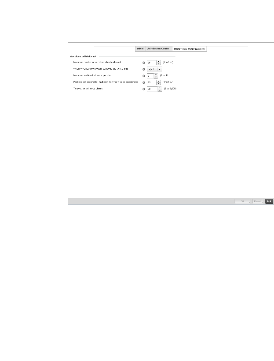
342 Brocade Mobility RFS4000, RFS6000, and RFS7000 System Reference Guide
53-1002620-01
6
FIGURE 236 Radio QoS Policy Multimedia Optimizations screen
17. Set the following Accelerated Multicast settings for this radio QoS policy:
18. Select OK to update the radio QoS admission control settings for this policy. Select Reset to
revert to the last saved configuration.
Radio QoS Configuration and Deployment Considerations
Radio QoS Policy
Before defining a radio QoS policy, refer to the following deployment guidelines to ensure the
configuration is optimally effective:
Maximum number of
wireless clients
allowed
Specify the maximum number of wireless clients (between 0 and 256) allowed to
use accellerated multicast. The default value is 25.
When wireless client
count exceeds the
above limit
When the wirless client count using accelerated multicast exceeds the maximum
number set the radio to either reject new wireless clients or to revert existing clients
to a non-accelerated state.
Maximum multicast
streams per client
Specify the maximum number of multicast streams (between 1 and 4) wireless
clients can use. The default value is 2.
Packets per second for
multicast flow for it to
be accelerated
Specify the threshold of multicast packets per second (between 1 and 500) that
triggers acceleration for wireless clients. The default value is 25.
Timeout for wireless
clients
Specify a timeout value in seconds (between 5 and 6,000) for wireless clients to
revert back to a non-accelerated state. The default value is 60.
Brocade Mobility RFS4000, RFS6000, and RFS7000 System Reference Guide 343
53-1002620-01
6
•To support QoS, each multimedia application, wireless client and WLAN is required to support
WMM.
•WMM enabled clients can co-exist with non-WMM clients on the same WLAN. Non-WMM
clients are always assigned a Best Effort access category.
•Brocade recommends default WMM values be used for all deployments. Changing these
values can lead to unexpected traffic blockages, and the blockages might be difficult to
diagnose.
•Overloading an Access Point radio with too much high priority traffic (especially voice)
degrades overall controller service quality for all users.
•TSPEC admission control is only available with newer voice over WLAN phones. Many legacy
voice devices do not support TPSEC or even support WMM traffic prioritization.
AAA Policy
Authentication, Authorization, and Accounting (AAA) provides the mechanism network
administrators define access control within the controller managed network.
The controller can interoperate with external RADIUS and LDAP Servers (AAA Servers) to provide
user database information and user authentication data. Each WLAN controller managed by the
controller can maintain its own unique AAA configuration.
AAA provides a modular way of performing the following services:
Authentication — Authentication provides a means for identifying users, including login and
password dialog, challenge and response, messaging support and (depending on the security
protocol), encryption. Authentication is the technique by which a user is identified before allowed
access to the controller managed network. Configure AAA authentication by defining a list of
authentication methods, and then applying the list to various interfaces. The list defines the
authentication schemes performed and their sequence. The list must be applied to an interface
before the defined authentication technique is conducted.
Authorization — Authorization occurs immediately after authentication. Authorization is a method
for remote access control, including authorization for services and individual user accounts and
profiles. Authorization functions through the assembly of attribute sets describing what the user is
authorized to perform. These attributes are compared to information contained in a database for a
given user and the result is returned to AAA to determine the user's actual capabilities and
restrictions. The database could be located locally on the controller or be hosted remotely on a
RADIUS server. Remote RADIUS servers authorize users by associating attribute-value (AV) pairs
with the appropriate user. Each authorization method must be defined through AAA. When AAA
authorization is enabled it’s applied equally to all interfaces on the controller managed network.
Accounting — Accounting is the method for collecting and sending security server information for
billing, auditing, and reporting user data; such as start and stop times, executed commands (such
as PPP), number of packets, and number of bytes. Accounting enables wireless network
administrators to track the services users are accessing and the network resources they are
consuming. When accounting is enabled, the network access server reports user activity to a
RADIUS security server in the form of accounting records. Each accounting record is comprised of
AV pairs and is stored on the controller’s access control server. The data can be analyzed for
network management, client billing, and/or auditing. Accounting methods must be defined through
AAA. When AAA accounting is activated for the controller, it’s applied equally to all interfaces on the
controller’s access servers.
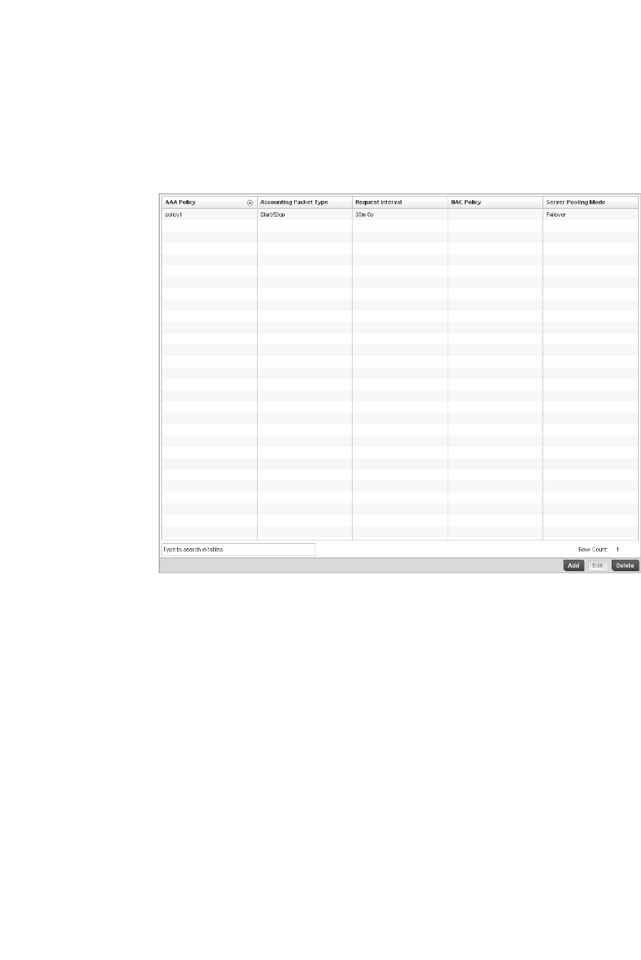
344 Brocade Mobility RFS4000, RFS6000, and RFS7000 System Reference Guide
53-1002620-01
6
To define unique controller WLAN AAA configurations:
1. Select Configuration > Wireless > AAA Policy to display existing AAA policies.
The Authentication, Authorization, and Accounting (AAA) screen lists those AAA policies created
thus far. Any of these policies can be selected and applied to the controller.
FIGURE 237 Authentication, Authorization, and Accounting (AAA) screen
2. Refer to the following information listed for each existingAAA policy:
3. To configure a new AAA policy, click the Add button.
AAA Policy Displays the name assigned to the AAA policy when it was initially created. The
name cannot be edited within a listed profile.
Accounting Packet
Type
Displays the accounting type set for the AAA policy. Options include:
Start Only - Sends a start accounting notice to initiate user accounting.
Start/Stop - Sends a start accounting notice at the beginning of a process and a
stop notice at the end of a process. The start accounting record is sent in the
background. The requested process begins regardless of whether the start
accounting notice is received by the accounting server.
Request Interval Lists each AAA policy’s interval a wireless controller uses to send a RADIUS
accounting request to the RADIUS server.
NAC Policy Lists the name Network Access Control (NAC) filter used to either include or exclude
clients from access the controller managed network.
Server Pooling Mode The server pooling mode controls how requests are transmitted across RADIUS
servers. Selecting Failover results in working down the list of servers if a server is
unresponsive and unavailable. The Load Balanced option uses all available servers
transmitting requests in round robin.
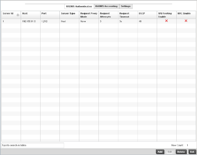
Brocade Mobility RFS4000, RFS6000, and RFS7000 System Reference Guide 345
53-1002620-01
6
FIGURE 238 AAA Policy - RADIUS Authentication screen
4. Refer to the following information about configured AAA Authenication policies.
Server ID Displays the numerical server index (1-6) for the accounting server when added to
the list available to the wireless controller.
Host Displays the IP address or hostname of the RADIUS authentication server.
Port Displays the port on which the RADIUS server listens to traffic within the wireless
controller managed network. The port range is 1 to 65,535. The default port is 1.
Server Type Displays the type of AAA server in use either Host, onboard-self, or
onboard-controller.
Request Proxy Mode Displays whether a request is transmitted directly through the server or proxied
through the access point or RF Domain manager.
Request Attempts Displays the number of attempts a client can retransmit a missed frame to the
RADIUS server before it times out of the authentication session. The available range
is between 1 and 10 attempts. The default is 3 attempts.
Request Timeout Displays the time between 1 and 60 seconds for the wireless controller’s
re-transmission of request packets. The default is 3 seconds. If this time is
exceeded, the authentication session is terminated.
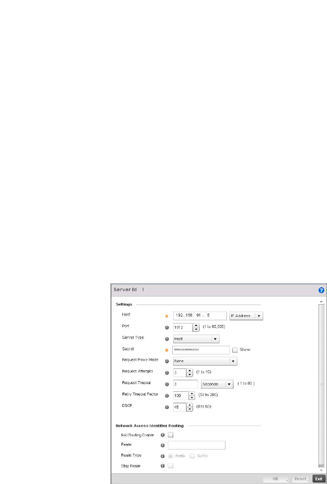
346 Brocade Mobility RFS4000, RFS6000, and RFS7000 System Reference Guide
53-1002620-01
6
5. Select an item from the table and click Edit or click Add to create a new policy.
FIGURE 239 AAA Policy - Add RADIUS Authentication Server
6. Define the following settings to add or modify new AAA RADIUS authentication server
configuration
DSCP Displays the DSCP value as a 6-bit parameter in the header of every IP packet used
for packet classification. The valid range is between 0 and 63 with a default value of
46.
NAI Routing Enable Displays NAI routing status. AAA servers identify clients using the NAI. The NAI is a
character string in the format of an e-mail address as either user or user@ but it
need not be a valid e-mail address or a fully qualified domain name. The NAI can be
used either in a specific or generic form. The specific form, which must contain the
user portion and may contain the @ portion, identifies a single user. The generic
form allows all users in a given or without a to be configured on a single command
line. Each user still needs a unique security association, but these associations can
be stored on a AAA server. The original purpose of the NAI was to support roaming
between dialup ISPs. Using NAI, each ISP need not have all the accounts for all of its
roaming partners in a single RADIUS database. RADIUS servers can proxy requests
to remote servers for each.
NAC Enable A green checkmark defines NAC as enabled, while a Red X defines NAC disabled
with this AAA policy.
Server ID Define the numerical server index (1-6) for the authentication server when added to
the list available to the wireless controller.
Host Specify the IP address or hostname of the RADIUS authentication server.
Port Define or edit the port on which the RADIUS server listens to traffic within the
wireless controller managed network. The port range is 1 to 65,535. The default
port is 1.
Server Type Select the type of AAA server in use either Host, onboard-self, or onboard-controller.
Secret Specify the secret used for authentication on the selected RADIUS server. By default
the secret will be displayed as asterisks. To show the secret in plain text, check the
Show box.

Brocade Mobility RFS4000, RFS6000, and RFS7000 System Reference Guide 347
53-1002620-01
6
7. Select the RADIUS Accounting tab and refer to the following information about configured
RADIUS Accounting profiles.
Request Proxy Mode Select the method of proxy that browsers communicate with the RADIUS
authentication server. The mode could either be None, Through Wireles Controller,
or Through RF Domain.
Request Attempts Specify the number of attempts a client can retransmit a missed frame to the
RADIUS server before it times out of the authentication session. The available range
is between 1 and 10 attempts. The default is 3 attempts.
Request Timeout Specify the time between 1 and 60 seconds for the wireless controller’s
re-transmission of request packets. If this time is exceeded, the authentication
session is terminated.
Retry Timeout Factor Specify the amount of time between 50 and 200 seconds between retry timeouts
for the wireless controller’s re-transmission of request packets. The default is 100.
DSCP Specify the DSCP value as a 6-bit parameter in the header of every IP packet used
for packet classification. The valid range is between 0 and 63 with a default value of
46.
NAI Routing Enable Check to enable NAI routing. AAA servers identify clients using the NAI. The NAI is a
character string in the format of an e-mail address as either user or user@ but it
need not be a valid e-mail address or a fully qualified domain name. The NAI can be
used either in a specific or generic form. The specific form, which must contain the
user portion and may contain the @ portion, identifies a single user. The generic
form allows all users in a given or without a to be configured on a single command
line. Each user still needs a unique security association, but these associations can
be stored on a AAA server. The original purpose of the NAI was to support roaming
between dialup ISPs. Using NAI, each ISP need not have all the accounts for all of its
roaming partners in a single RADIUS database. RADIUS servers can proxy requests
to remote servers for each.
Realm Enter the realm name in the field. The name cannot exceed 50 characters. When
the controller’s RADIUS server receives a request for a user name the server
references a table of usernames. If the user name is known, the server proxies the
request to the RADIUS server.
Realm Type Specify the type of realm that is being used, either a Prefix or a Suffix.
Strip Realm Check strip to remove information from the packet when NAI routing is enabled.
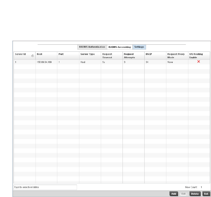
348 Brocade Mobility RFS4000, RFS6000, and RFS7000 System Reference Guide
53-1002620-01
6
FIGURE 240 AAA Policy - RADIUS Accounting screen
Server ID Displays the numerical server index (1-6) for the accounting server when added to
the list available to the wireless controller.
Host Displays the IP address or hostname of the RADIUS authentication server.
Port Displays the port on which the RADIUS server listens to traffic within the wireless
controller managed network. The port range is 1 to 65,535. The default port is 1.
Server Type Displays the type of AAA server in use either Host, onboard-self, or
onboard-controller.
Request Timeout Displays the time between 1 and 60 seconds for the wireless controller’s
re-transmission of request packets. If this time is exceeded, the authentication
session is terminated.
Request Attempts Displays the number of attempts a client can retransmit a missed frame to the
RADIUS server before it times out of the authentication session. The available range
is between 1 and 10 attempts. The default is 3 attempts.
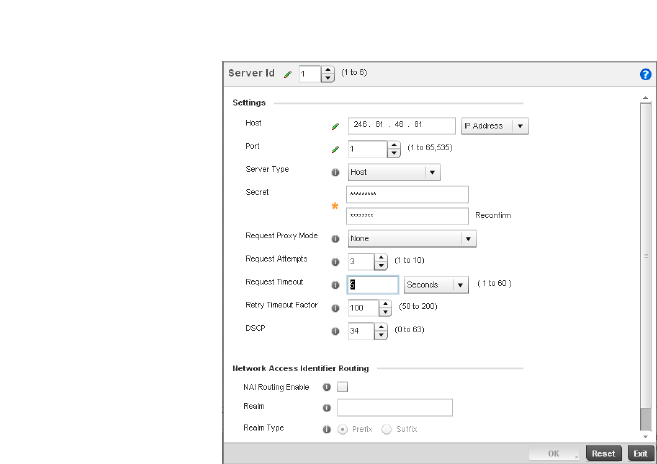
Brocade Mobility RFS4000, RFS6000, and RFS7000 System Reference Guide 349
53-1002620-01
6
8. To edit an existing accounting profile, select the profile and click Edit. To add a new policy click
Add.
FIGURE 241 AAA Policy - Add RADIUS Accounting Server
DSCP Displays the DSCP value as a 6-bit parameter in the header of every IP packet used
for packet classification. The valid range is between 0 and 63 with a default value of
46.
Request Proxy Mode Displays the method of proxy that browsers communicate with the RADIUS
authentication server. The mode could either be None, Through Wireless Controller,
or Through RF Domain Manager.
NAI Routing Enable Displays NAI routing status. AAA servers identify clients using the NAI. The NAI is a
character string in the format of an e-mail address as either user or user@ but it
need not be a valid e-mail address or a fully qualified domain name. The NAI can be
used either in a specific or generic form. The specific form, which must contain the
user portion and may contain the @ portion, identifies a single user. The generic
form allows all users in a given or without a to be configured on a single command
line. Each user still needs a unique security association, but these associations can
be stored on a AAA server. The original purpose of the NAI was to support roaming
between dialup ISPs. Using NAI, each ISP need not have all the accounts for all of its
roaming partners in a single RADIUS database. RADIUS servers can proxy requests
to remote servers for each.
Server ID Displays the numerical server index (1-6) for the accounting server when added to
the list available to the access point.
Host Specify the IP address or hostname of the RADIUS authentication server.
Port Define or edit the port on which the RADIUS server listens to traffic within the
controller managed network. The port range is 1 to 65,535. The default port is
1813.
Server Type Select the type of AAA server as either Host, onboard-self, or
onboard-controller.
Secret Specify the secret (password) used for authentication on the selected RADIUS
server. By default the secret is displayed as asterisks.

350 Brocade Mobility RFS4000, RFS6000, and RFS7000 System Reference Guide
53-1002620-01
6
9. Click the Settings tab and configure to the following information:
Request Proxy Mode Select the method of proxy that browsers communicate with the RADIUS
authentication server. The mode could either be None, Through Wireless Controller,
or Through RF Domain Manager.
Request Attempts Displays the number of attempts a client can retransmit a missed frame to the
RADIUS server before it times out of the authentication session. The available range
is between 1 and 10 attempts. The default is 3 attempts.
Request Timeout Specify the time for the access point’s re-transmission of request packets. The
default is 5 seconds. If this time is exceeded, the authentication session is
terminated.
Retry Timeout Factor Specify the amount of time between 50 and 200 seconds between retry timeouts
for the access points re-transmission of request packets. The default is 100.
DSCP Displays the DSCP value as a 6-bit parameter in the header of every IP packet used
for packet classification. The valid range is between 0 and 63 with a default value of
34.
NAI Routing Enable Displays NAI routing status. AAA servers identify clients using the NAI. The NAI is a
character string in the format of an e-mail address as either user or user@ but it
need not be a valid e-mail address or a fully qualified domain name. The NAI can be
used either in a specific or generic form. The specific form, which must contain the
user portion and may contain the @ portion, identifies a single user. The generic
form allows all users in a given or without a to be configured on a single command
line. Each user still needs a unique security association, but these associations can
be stored on a AAA server. The original purpose of the NAI was to support roaming
between dialup ISPs. Using NAI, each ISP need not have all the accounts for all of its
roaming partners in a single RADIUS database. RADIUS servers can proxy requests
to remote servers for each.
Realm Enter the realm name. The name cannot exceed 64 characters. When the access
point’s RADIUS server receives a request for a user name the server references a
table of usernames. If the user name is known, the server proxies the request to the
RADIUS server.
Realm Type Specify the realm as either Prefix or Suffix.
Strip Realm Select the radio button to remove information from the packet when NAI routing is
enabled.
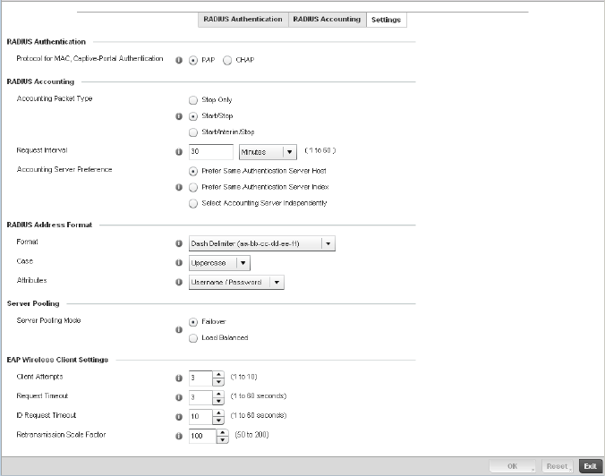
Brocade Mobility RFS4000, RFS6000, and RFS7000 System Reference Guide 351
53-1002620-01
6
FIGURE 242 AAA Policy - Settings screen
Protocol for MAC,
Captive-Portal
Authentication
The authentication protocol Password Authentication Protocol (PAP) or Challenge
Handshake Authentication Protocol (CHAP) when the server is used for any non-EAP
authentication. PAP is the default setting
Accounting Packet Type Set the type of RADIUS Accounting Request packets generated. Options include
Stop Only, Start/Stop, Start/Interim/Stop. Start/Stop is the default setting
Request Interval Set the periodicity of the interim accounting requests. The default is 30 minutes.
Accounting Server
Preference
Select the server preference for RADIUS Accounting. The options are:
Prefer Same Authentication Server Host - Uses the authentication server host name
as the host used for RADIUS accounting. This is the default setting.
Prefer Same Authentication Server Index - Uses the same index as the
authentication server for RADIUS accounting.
Select Accounting Server Independently - Allows users to specify a RADIUS
accounting server separate from the RADIUS authentication server.
Format Select the format of the MAC address used in the RADIUS accounting packets.
Case Lists whether the MAC address is sent using uppercase or lowercase letters. The
default setting is uppercase
Attributes Lists whether the format specified applies only to the username/password in
mac-auth or for all attributes that include a MAC address, such as calling-station-id
or called-station-id.
Server Pooling Mode Controls how requests are transmitted across RADIUS servers. Failover implies
traversing the list of servers if any server is unresponsive. Load Balanced means
using all servers in a round-robin fashion. The default setting is Failover.
Client Attempts Defines the number of times (1 - 10) an EAP request is transmitted to a Wireless
Client before giving up. The default setting is 3.

352 Brocade Mobility RFS4000, RFS6000, and RFS7000 System Reference Guide
53-1002620-01
6
Association ACL
An Association ACL is a policy-based ACL that either prevents or allows wireless clients from
connecting to a controller managed WLAN.
An Association ACL affords a system administrator the ability to grant or restrict client access by
specifying a wireless client MAC address or range of MAC addresses to either include or exclude
from controller connectivity.
Association ACLs are applied to WLANs as an additional access control mechanism. They can be
applied to WLANs from within a WLAN Policy’s Advanced configuration screen. For more
information on applying an existing Association ACL to a WLAN, see Configuring Advanced WLAN
Settings on page 6-315.
To define an Association ACL deployable with a controller WLAN:
1. Select Configuration > Wireless > Association ACL to display existing Association ACLs.
The Association Access Control List (ACL) screen lists those Association ACL policies created
thus far. Any of these policies can be selected and applied to the controller.
Request Timeout Defines the amount of time after which an EAP Request to a Wireless Client is
retried. The default setting is 3 seconds.
ID Request Timeout Defines the amount of time (1 - 60 seconds) after which an EAP ID Request to a
Wireless Client is retried. The default setting is 10 seconds.
Retransmission Scale
Factor
Configures the scaling of the retransmission attempts. Timeout at each attempt is a
function of the Request Timeout factor and Client Attempts number. 100 (default
setting) implies a constant timeout at each retry; smaller values indicate more
aggressive (shorter) timeouts, larger numbers indicate more conservative (longer)
timeouts on each successive attempt.
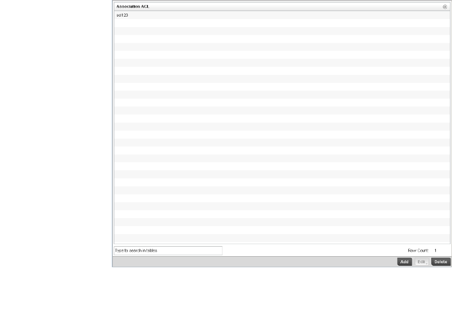
Brocade Mobility RFS4000, RFS6000, and RFS7000 System Reference Guide 353
53-1002620-01
6
FIGURE 243 Association Access Control List (ACL) screen
2. Select Add to define a new ACL configuration, Edit to modify an existing ACL configuration or
Delete to remove one.
A unique Association ACL screen displays for defining the new ACL or modifying a selected ACL.
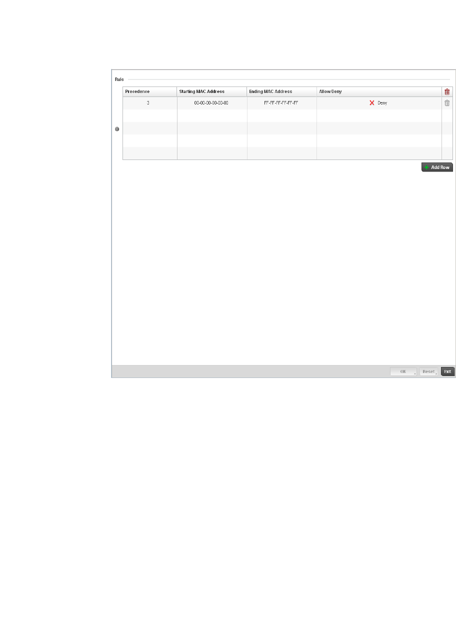
354 Brocade Mobility RFS4000, RFS6000, and RFS7000 System Reference Guide
53-1002620-01
6
FIGURE 244 Association Access Control List (ACL) screen
3. Select the + Add Row button to add an association ACL template.
4. Set the following parameters for the creation or modification of the Association ACL:
5. Select the + Add Row button to add MAC address ranges and allow/deny designations.
6. Select OK to update the Association ACL settings. Select Reset to revert to the last saved
configuration.
Association ACL Deployment Considerations
Association ACL
Association ACL If creating an new Association ACL, provide a name specific to its function. Avoid
naming it after a WLAN it may support. The name cannot exceed 32 characters.
Precedence The rules within a WLAN's ACL are applied to packets based on their precedence
values. Every rule has a unique sequential precedence value you define. You cannot
add two rules’s with the same precedence. The default precedence is 1, so be
careful to prioritize ACLs accordingly as they are added.
Starting MAC Address Provide a starting MAC address for clients requesting association.
Ending MAC Address Provide an ending MAC address for clients requesting association.
Allow/Deny Use the drop-down menu to either Allow or Deny access if a MAC address matches
this rule.

Brocade Mobility RFS4000, RFS6000, and RFS7000 System Reference Guide 355
53-1002620-01
6
Before defining an Association ACL configuration and applying it to a WLAN, refer to the following
deployment guidelines to ensure the configuration is optimally effective:
•Brocade recommends using the Association ACL screen strategically to name and configure
ACL policies meeting the requirements of the particular WLANs they may map to. However, be
careful not to name ACLs after specific WLANs, as individual ACL policies can be used by more
than one WLAN.
•You cannot apply more than one MAC based ACL to a Layer 2 interface. If a MAC ACL is already
configured on a Layer 2 interface, and a new MAC ACL is applied to the interface, the new ACL
replaces the previously configured one.
Smart RF Policy
Self Monitoring At Run Time RF Management (Smart RF) is a Brocade innovation designed to
simplify RF configurations for new deployments, while (over time) providing on-going deployment
optimization radio performance improvements.
A controller Smart RF policy can reduce deployment costs by scanning the RF environment to
determine the best channel and transmit power configuration for each wireless controller managed
radio. Smart RF policies can be applied to specific RF Domains, to apply site specific deployment
configurations and self-healing values to groups of devices within pre-defined physical RF coverage
areas.
Smart RF centralizes the decision process and makes intelligent RF configuration decisions using
information obtained from the RF environment. Smart RF helps reduce ongoing management and
maintenance costs through the periodic re-calibration of the managed network. Re-calibration can
be initiated manually or can be automatically scheduled to ensure the RF configuration is
optimized to factor for RF environment changes (such as new sources of interference, or
neighboring APs).
Smart RF also provides self-healing functions by monitoring the managed network in real-time and
provides automatic mitigation from potentially problematic events such as radio interference,
coverage holes and radio failures. Smart RF employs self-healing to enable a WLAN to better
maintain wireless client performance and site coverage during dynamic RF environment changes,
which typically require manual reconfiguration to resolve.
Smart RF is supported on any RF Domain manager. In standalone environments, the individual
controller manages the calibration and monitoring phases. In clustered environments, a single
controller is elected a Smart RF master and the remaining cluster members operate as Smart RF
clients. In cluster operation, the Smart RF master co-ordinates the calibration and configuration
and during the monitoring phase receives information from the Smart RF clients.
NOTE
RF planning must be performed to ensure overlapping coverage exists at a deployment site for
Smart RF to be a viable network performance tool. Smart RF can only provide recovery when Access
Points are deployed appropriately. Smart RF is not a solution, it's a temporary measure.
Administrators need to determine the root cause of RF deterioration and fix it. Smart RF
history/events can assist.
To define a Smart RF policy:
1. Select Configuration > Wireless > Smart RF Policy to display existing Smart RF policies.
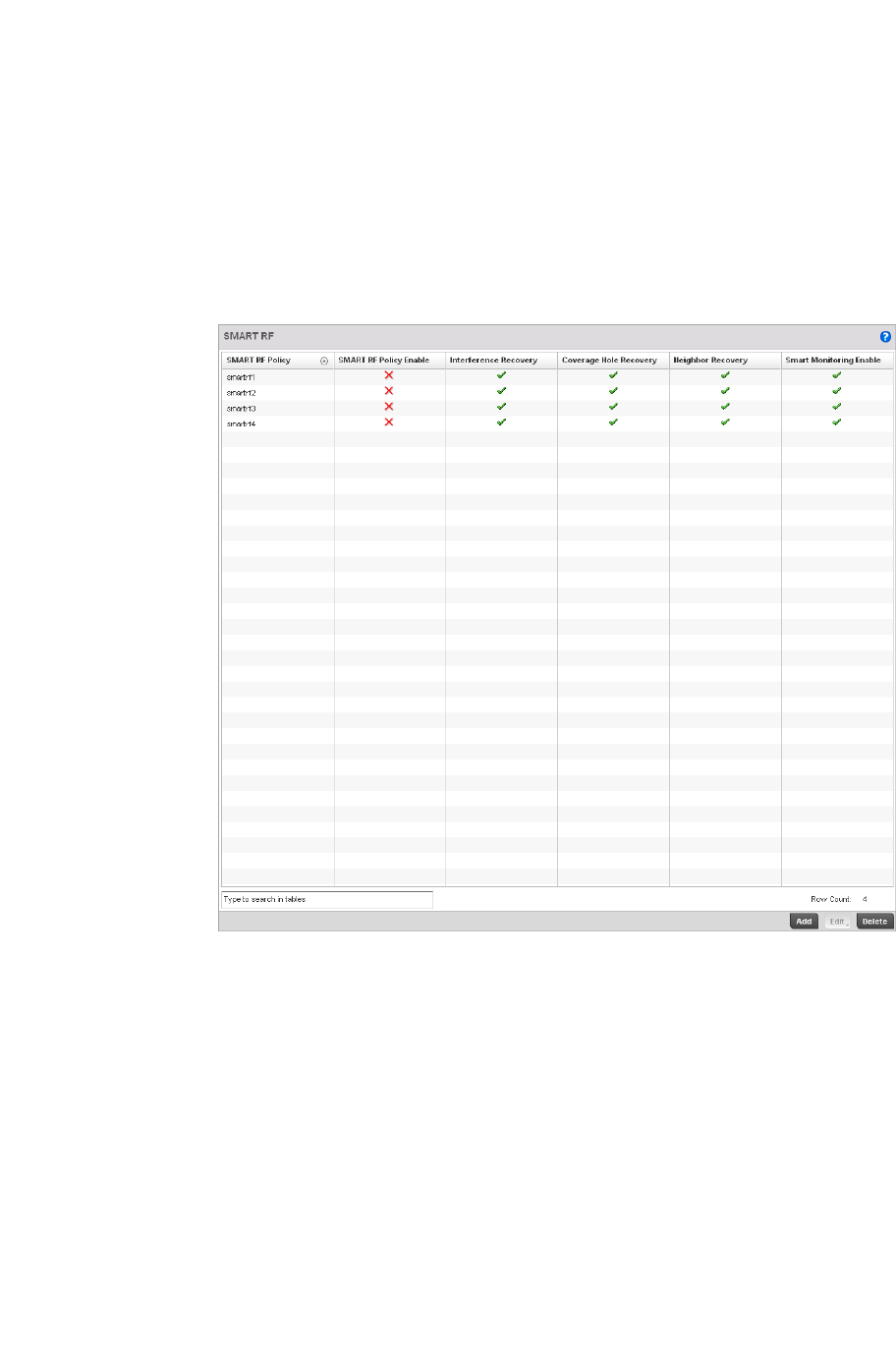
356 Brocade Mobility RFS4000, RFS6000, and RFS7000 System Reference Guide
53-1002620-01
6
The Smart RF screen lists those Smart RF policies created thus far. Any of these policies can
be selected and applied to the controller.
The user has the option of displaying the configurations of each Smart RF Policy defined thus
far, or referring to the Smart RF Browser and either selecting individual Smart RF polices or
selecting existing RF Domains to review which Smart RF policies have been applied. For more
information on how RF Domains function, and how to apply a Smart RF policy, see About RF
Domains on page 8-499 and Managing RF Domains on page 8-500.
FIGURE 245 Smart RF Policy screen
2. Refer to the following configuration data for existing Smart RF policies:
Smart RF Policy Displays the name assigned to the Smart RF policy when it was initially created. The
name cannot be modified as part of the edit process.
Smart RF Policy
Enable
Displays a green check mark if Smart RF has been enabled for the listed policy. A
red “X” designates the policy as being disabled.
Interference Recovery Displays a green check mark if interference recovery has been enabled for the listed
policy. A red “X” designates interference recovery being disabled.
Coverage Hole
Recovery
Displays a green check mark if coverage hole recovery has been enabled for the
listed policy. A red “X” designates coverage hole recovery being disabled.
Neighbor Recovery Displays a green check mark if neighbor recovery has been enabled for the listed
policy. A red “X” designates neighbor recovery being disabled.
Smart Monitoring
Enable
Displays a green check mark if smart monitoring has been enabled for the listed
policy. A red “X” designates smart monitoring being disabled.
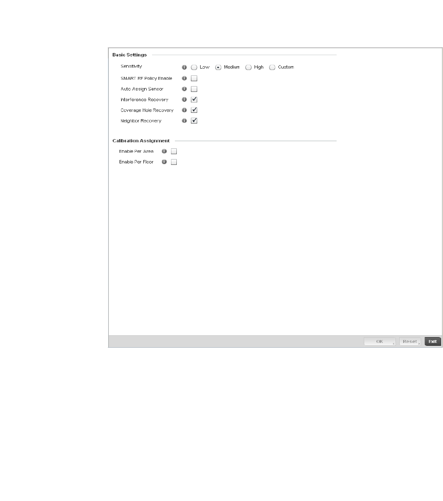
Brocade Mobility RFS4000, RFS6000, and RFS7000 System Reference Guide 357
53-1002620-01
6
3. Select Add to create a new Smart RF policy, Edit to modify the attributes of a existing policy or
Delete to remove obsolete policies from the list of those available.
The Basic Configuration screen displays by default for the new or modified Smart RF policy.
FIGURE 246 Smart RF Basic Configuration screen
4. Refer to the Basic Settings field to enable a Smart RF policy and define its sensitivity and
detector status.
Sensitivity Select a radio button corresponding to the desired Smart RF sensitivity. Options
include Low, Medium, High and Custom. Medium, is the default setting. Select the
Custom sensitivity option to enable the Interference Recovery, Coverage Hole
Recovery and Neighbor Recovery options as additional Smart RF recovery options.
SMART RF Policy
Enable
Select the Smart RF Policy Enable check box to enable this Smart RF policy for
immediate controller network support or inclusion with a RF Domain. Smart RF is
enabled by default.
Assign Auto Sensor Select the check box to enable Smart RF to select a radio as a sensor. Sensor radios
provide dedicated 24 x 7 dual-band 802.11a/b/g/n monitoring on a single radio to
perform real-time monitoring and self healing as needed. Sensor radios are
automatically defined and configured during calibration to provide real-time
monitoring for self-healing. Sensor radios are dedicated for monitoring only and do
not provide client services. This feature is disabled by default.

358 Brocade Mobility RFS4000, RFS6000, and RFS7000 System Reference Guide
53-1002620-01
6
5. Refer to the Calibration Assignment field to define whether Smart RF Calibration and radio
grouping is conducted by area or building. Both options are disabled by default.
6. Select OK to update the Smart RF Basic Configuration settings for this policy. Select Reset to
revert to the last saved configuration.
7. S elect Channel and Power.
Use the Channel and Power screen to refine Smart RF power settings over both 5 and 2.4 GHz
radios and select channel settings in respect to the device channel usage.
Interference Recovery Select the check box to enable Interference Recovery from neighboring radios and
other sources of WiFi and non-WiFi interference when excess noise and interference
is detected within the Smart RF supported radio coverage area. Smart RF provides
mitigation from interference sources by monitoring the noise levels and other RF
parameters on an Access Point radio’s current channel. When a noise threshold is
exceeded, Smart RF can select an alternative channel with less interference. To
avoid channel flapping, a hold timer is defined which disables interference
avoidance for a specific period of time upon detection. Interference Recovery is
enabled by default.
Coverage Hole
Recovery
Select the check box to enable Coverage Hole Recovery when a radio coverage hole
is detected within the Smart RF supported radio coverage area. When coverage hole
is detected, Smart RF first determines the power increase needed based on the
signal to noise ratio for a client as seen by the Access Point radio. If a client’s signal
to noise value is above the threshold, the transmit power is increased until the
signal to noise rate falls below the threshold.
Neighbor Recovery Select the check box to enable Neighbor Recovery when a failed radio is detected
within the Smart RF supported radio coverage area. Smart RF can provide
automatic recovery by instructing neighboring APs to increase their transmit power
to compensate for the coverage loss. Neighbor recovery is enabled by default when
the sensitivity setting is medium.
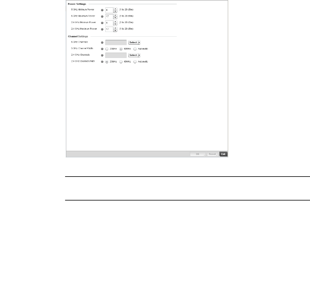
Brocade Mobility RFS4000, RFS6000, and RFS7000 System Reference Guide 359
53-1002620-01
6
FIGURE 247 Smart RF Channel and Power screen
NOTE
The Power Settings and Channel Settings parameters are only enabled when Custom or Medium is
selected as the Sensitivity setting from the Basic Configuration screen.
8. Refer to the Power Settings field to define Smart RF recovery settings for either the selected
5.0 GHz (802.11a) or 2.4 GHz (802.11bg) radio.
5.0 GHz Minimum
Power
Use the spinner control to select a 1 - 20 dBm minimum power level for Smart RF to
assign to a radio in the 5 GHz band. 4 dBm is the default setting.
5.0 GHz Maximum
Power
Use the spinner control to select a 1 - 20 dBm maximum power level Smart RF can
assign a radio in the 5 GHz band. 17 dBm is the default setting.
2.4 GHz Minimum
Power
Use the spinner control to select a 1 - 20 dBm minimum power level Smart RF can
assign a radio in the 2.4 GHz band. 4 dBm is the default setting.
2.4 GHz Maximum
Power
Use the spinner control to select a 1 - 20 dBm maximum power level Smart RF can
assign a radio in the 2.4 GHz band. 17 dBm is the default setting.

360 Brocade Mobility RFS4000, RFS6000, and RFS7000 System Reference Guide
53-1002620-01
6
9. Set the following Channel Settings for the 5.0 GHz and 2.4 GHz radios:
10. Select OK to update the Smart RF Channel and Power settings for this policy. Select Reset to
revert to the last saved configuration.
11. Select the Scanning Configuration tab.
5.0 GHz Channels Use the Select drop-down menu to select the 5 GHz channels used in Smart RF
scans.
5.0 Channel Width 20 and 40 MHz channel widths are supported by the 802.11a radio. 20/40 MHz
operation (the default setting for the 5 GHz radio) allows the Access Point to receive
packets from clients using 20 MHz of bandwidth while transmitting a packet using
40 MHz bandwidth. This mode is supported for 11n users on both the 2.4 and 5
GHz radios. If an 11n user selects two channels (a Primary and Secondary channel),
the system is configured for dynamic 20/40 operation. When 20/40 is selected,
clients can take advantage of wider channels. 802.11n clients experience improved
throughput using 40 MHz while legacy clients (either 802.11a or 802.11b/g
depending on the radio selected) can still be serviced without interruption using 20
MHz. Select Automatic to enable automatic assignment of channels to working
radios to avoid channel overlap and avoid interference from external RF sources.
40MHz is the default setting.
2.4 GHz Channels Set the 2.4 GHz channels used in Smart RF scans.
2.4 GHz Channel
Width
20 and 40 MHz channel widths are supported by the 802.11a radio. 20 MHz is the
default setting for 2.4 GHz radios. 20/40 MHz operation (the default setting for the
5 GHz radio) allows the Access Point to receive packets from clients using 20 MHz
of bandwidth while transmitting a packet using 40 MHz bandwidth. This mode is
supported for 11n users on both the 2.4 and 5 GHz radios. If an 11n user selects
two channels (a Primary and Secondary channel), the system is configured for
dynamic 20/40 operation. When 20/40 is selected, clients can take advantage of
wider channels. 802.11n clients experience improved throughput using 40 MHz
while legacy clients (either 802.11a or 802.11b/g depending on the radio selected)
can still be serviced without interruption using 20 MHz. Select Automatic to
enable automatic assignment of channels to working radios to avoid channel
overlap and avoid interference from external RF sources. 20MHz is the default
setting.
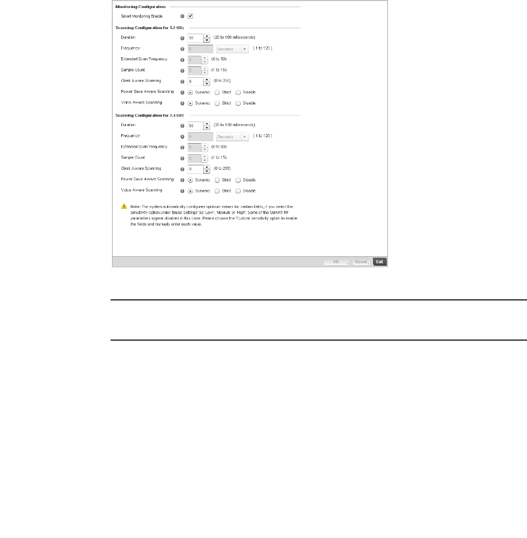
Brocade Mobility RFS4000, RFS6000, and RFS7000 System Reference Guide 361
53-1002620-01
6
FIGURE 248 Smart RF Scanning Configuration screen
NOTE
The monitoring and scanning parameters within the Scanning Configuration screen are only
enabled when Custom is selected as the Sensitivity setting from the Basic Configuration screen.
12. Enable or disable Smart Monitoring Enable by selecting the check box. The feature is enabled
by default.
When enabled, detector radios monitor their coverage areas for potential failed peers or
coverage area holes requiring transmission adjustments for coverage compensation.
13. Set the following Scanning Configurations for both the 2.4 and 5 GHz radio bands:
Duration Set a channel scan duration (between 20 - 150 milliseconds) Access Point radios
use to monitor devices within the managed network and, if necessary, perform self
healing and neighbor recovery to compensate for coverage area losses within a RF
Domain. The default setting is 50 milliseconds for both the 2.4 and 5 GHz bands.
Frequency Set the scan frequency using the drop-down menu. Set a scan frequency in either
Seconds (1 - 120) or Minutes (0 - 2). The default setting is 6 seconds for both the 5
and 2.4 GHz bands.
Extended Scan
Frequency
Use the spinner control to set an extended scan frequency between 0 - 50. This is
the frequency radios scan channels on other than their peer radios. The default
setting is 5 for both the 5 and 2.4 GHz bands.

362 Brocade Mobility RFS4000, RFS6000, and RFS7000 System Reference Guide
53-1002620-01
6
14. Select OK to update the Smart RF Scanning Configuration settings for this policy. Select Reset
to revert to the last saved configuration.
15. Select Advanced Configuration.
The Neighbor Recovery tab displays by default. Use the Neighbor, Interference and Coverage
Hole recovery tabs to define how 5 and 2.4 GHz radios compensate for failed neighbor radios,
interference impacting the Smart RF support controller network and detected coverage holes
requiring neighbor radio intervention.
16. Set the following Neighbor Recovery variables for the Smart RF configuration:
NOTE
The recovery parameters within the Neighbor Recovery, Interference and Coverage Hole Recovery
tabs are only enabled when Custom is selected as the Sensitivity setting from the Basic
Configuration screen.
Sample Count Use the spinner control to set a sample scan count value between 1 - 15. This is the
number of RF readings radios gather before they send the data to the Smart RF
master. The default setting is 5 for both the 5 and 2.4 GHz bands
Power Save Aware
Scanning
Select either the Dynamic, Strict or Disable radio button to define how power save
scanning is set for Smart RF. Strict disables smart monitoring as long as a power
save capable client is associated to a radio. Dynamic disables smart monitoring as
long as there is data buffered for a power save client at the radio. The default
setting is Dynamic for both the 5 and 2.4 GHz bands.
Voice Aware Select either the Dynamic, Strict or Disable radio button to define how voice aware
recognition is set for Smart RF. Strict disables smart monitoring as long as a voice
client is associated to a radio. Dynamic disables smart monitoring as long as there
is data buffered for a voice client at the radio. The default setting is Dynamic for
both the 5 and 2.4 GHz bands.
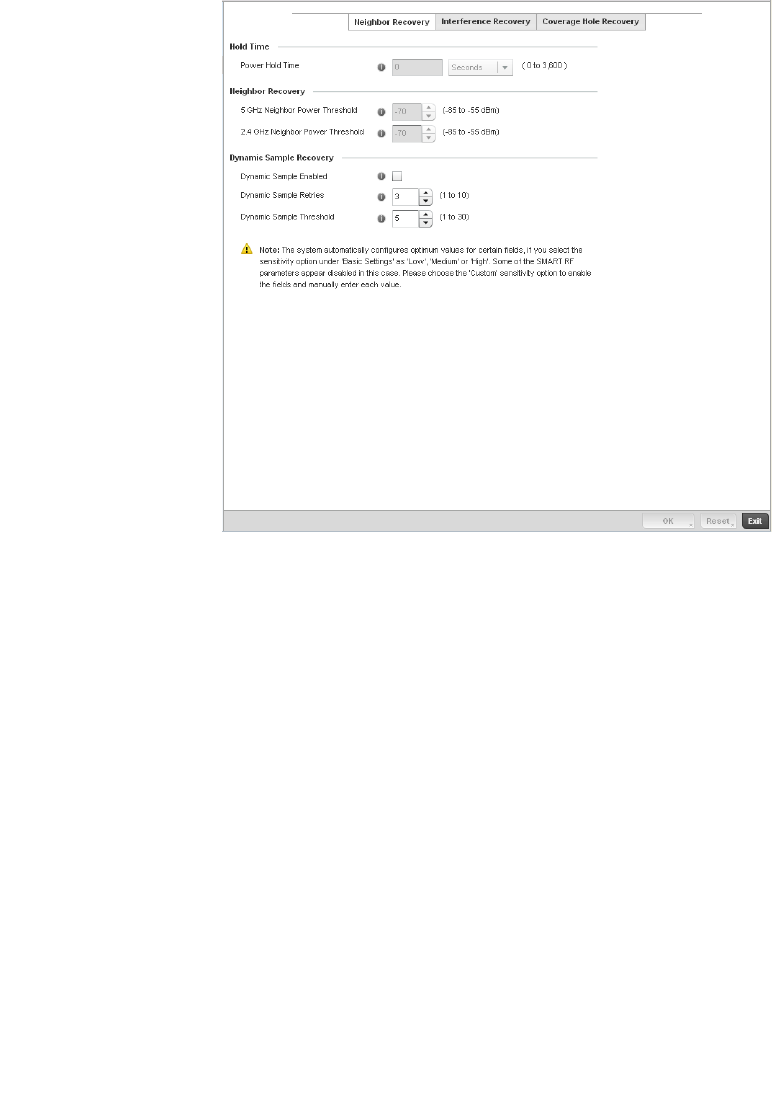
Brocade Mobility RFS4000, RFS6000, and RFS7000 System Reference Guide 363
53-1002620-01
6
FIGURE 249 Smart RF Advanced Configuration screen - Neighbor Recovery tab
17. Set the following Neighbor Recovery parameters:
18. Select OK to update the Smart RF Neighbor Recovery settings for this policy. Select Reset to
revert to the last saved configuration.
19. Select the Interference Recovery tab.
Power Hold Time Defines the minimum time between two radio power changes during neighbor
recovery. Set the time in either Seconds (0 - 3,600), Minutes (0 - 60) or Hours (0 -
1). The default setting is 0 seconds.
Channel Hold Time Defines the minimum time between channel changes during neighbor recovery. Set
the time in either Seconds (0 - 86,400), Minutes (0 - 1,440) or Hours (0 - 24) or
Days (0 - 1). The default setting is 3,600 seconds.
5.0 GHz Neighbor
Recovery Power
Threshold
Use the spinner control to set a value between -85 to -55 dBm the 5.0 GHz radio
uses as a maximum power increase threshold if the radio is required to increase its
output power to compensate for a failed radio within its wireless radio coverage
area. The default value is -70 dBm.
2.4 GHz Neighbor
Recovery Power
Threshold
Use the spinner control to set a value between -85 to -55 dBm the 2.4 GHz radio
uses as a maximum power increase threshold if the radio is required to increase its
output power to compensate for a failed radio within its wireless radio coverage
area. The default value is -70 dBm.
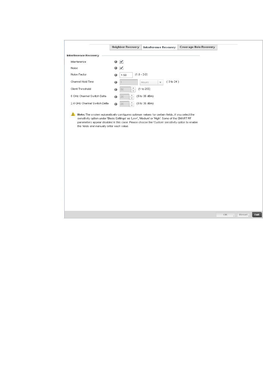
364 Brocade Mobility RFS4000, RFS6000, and RFS7000 System Reference Guide
53-1002620-01
6
FIGURE 250 Smart RF Advanced Configuration screen - Interference Recovery tab
20. Set the following Interference Recovery parameters:
Interference Select the check box to allow the Smart RF policy to scan for excess interference
from supported radio devices. WLANs are susceptible to sources of interference,
such as neighboring radios, cordless phones, microwave ovens and Bluetooth
devices. When interference for WiFi sources is detected, Smart RF supported
devices can change the channel and move to a cleaner channel. This feature is
enabled by default.
Noise Select the check box to allow the Smart RF policy to scan for excess noise from WiFi
devices. When detected, Smart RF supported devices can change their channel and
move to a cleaner channel. This feature is enabled by default.
Client Threshold Use the spinner to set a client threshold for the Smart RF policy between
1 - 255. If threshold number of clients are connected to a radio, it does not change
its channel even though it requires one, based on the interference recovery
determination made by the smart master. The default is 50.
5.0 GHz Channel
Switch Delta
Use the spinner to set a channel delta (between 5 - 35 dBm) for the 5.0 GHz radio.
This parameter is the difference between noise levels on the current channel and a
prospective channel. If the difference is below the configured threshold, the
channel will not change. The default setting is 20 dBm.
2.4 GHz Channel
Switch Delta
Use the spinner to set a channel delta (between 5 - 35 dBm) for the 2.4 GHz radio.
This parameter is the difference between noise levels on the current channel and a
prospective channel. If the difference is below the configured threshold, the
channel will not change. The default setting is 20 dBm.
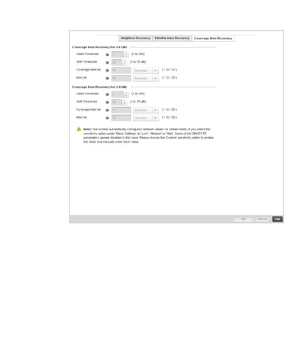
Brocade Mobility RFS4000, RFS6000, and RFS7000 System Reference Guide 365
53-1002620-01
6
21. Select OK to update the Smart RF Interference Recovery settings for this policy. Select Reset to
revert to the last saved configuration.
22. Select the Coverage Hole Recovery tab.
FIGURE 251 Smart RF Advanced Configuration screen - Coverage Hole Recovery tab
23. Set the following Coverage Hole Recovery for 2.4 GHz and 5 GHz parameters:
24. Select OK to update the Smart RF Coverage Hole Recovery settings for this policy. Select Reset
to revert to the last saved configuration.
Client Threshold Use the spinner to set a client threshold for the Smart RF policy between
1 - 255. This is the minimum number of clients a radio should have associated in
order for coverage hole recovery to trigger. The default setting is 1.
SNR Threshold Use the spinner control to set a signal to noise threshold (between 1 - 75 dB). This is
the signal to noise threshold for an associated client as seen by its associated AP
radio. When exceeded, the radio increases its transmit power in order to increase
coverage for the associated client. The default value is 20 dB.
Coverage Interval Define the interval coverage hole recovery should be initiated after a coverage hole
is detected. The default is 10 seconds for both the 2.4 and 5.0 GHz radios.
Interval Define the interval coverage hole recovery should be conducted after a coverage
hole is detected. The default is 30 seconds for both the 2.4 and 5.0 GHz radios.

366 Brocade Mobility RFS4000, RFS6000, and RFS7000 System Reference Guide
53-1002620-01
6
Smart RF Configuration and Deployment Considerations
Smart RF Policy
Before defining a Smart RF policy, refer to the following deployment guidelines to ensure the
configuration is optimally effective:
•The Smart RF calibration process impacts associated users and should not be run during
business or production hours. The calibration process should be performed during scheduled
maintenance intervals or non-business hours.
•For Smart RF to provide effective recovery, RF planning must be performed to ensure
overlapping coverage exists at the deployment site. Smart RF can only provide recovery when
Access Points are deployed appropriately. Smart RF is not a solution, it's a temporary measure.
Administrators need to determine the root cause of RF deterioration and fix it. Smart RF
history/events can assist.

Brocade Mobility RFS4000, RFS6000, and RFS7000 System Reference Guide 367
53-1002620-01
Chapter
7
Profile Configuration
In this chapter
•General Profile Configuration . . . . . . . . . . . . . . . . . . . . . . . . . . . . . . . . . . . . 370
•Profile Cluster Configuration (Controllers Only) . . . . . . . . . . . . . . . . . . . . . . 373
•Controller Cluster Profile Configuration and Deployment Considerations 375
•Profile Adoption Configuration (APs Only) . . . . . . . . . . . . . . . . . . . . . . . . . . 376
•Profile Interface Configuration . . . . . . . . . . . . . . . . . . . . . . . . . . . . . . . . . . . 377
•Profile Network Configuration. . . . . . . . . . . . . . . . . . . . . . . . . . . . . . . . . . . . 407
•Profile Security Configuration . . . . . . . . . . . . . . . . . . . . . . . . . . . . . . . . . . . . 441
•VRRP Configuration . . . . . . . . . . . . . . . . . . . . . . . . . . . . . . . . . . . . . . . . . . . . 476
•Critical Resources Configuration . . . . . . . . . . . . . . . . . . . . . . . . . . . . . . . . . 480
•Profile Services Configuration . . . . . . . . . . . . . . . . . . . . . . . . . . . . . . . . . . . 483
•Profile Management Configuration . . . . . . . . . . . . . . . . . . . . . . . . . . . . . . . 486
•Advanced Profile Configuration . . . . . . . . . . . . . . . . . . . . . . . . . . . . . . . . . . 491
Profiles enable administrators to assign a common set of configuration parameters and policies to
controllers and Access Points. Profiles can be used to assign common or unique network, wireless
and security parameters to Wireless Controllers and Access Points across a large, multi segment,
site. The configuration parameters within a profile are based on the hardware model the profile
was created to support. The controller supports both default and user defined profiles
implementing new features or updating existing parameters to groups of Wireless Controllers or
Access Points. The central benefit of a profile is its ability to update devices collectively without
having to modify individual device configurations.
Profiles assign configuration parameters, applicable policies and WLANs to one or more controllers
and Access Points, thus allowing smart administration across large wireless network segments.
However, individual devices can still be assigned unique configuration parameters that follow the
flat configuration model supported by Brocade in previous controller software releases. As
individual device updates are made, these device no longer share the profile based configuration
they originally supported. Changes made to the profile are automatically inherited by all assigned
devices, but not those devices who have had their configuration customized. These devices require
careful administration, as they no longer can be tracked and as profile members. Their customized
configurations overwrite their profile configurations until the profile can be re-applied to the device.

368 Brocade Mobility RFS4000, RFS6000, and RFS7000 System Reference Guide
53-1002620-01
7
Each controller and Access Point is automatically assigned a default profile unless an AP auto
provisioning policy is defined that specifically assigns the Access Point to a user defined profile. A
default profile for each supported model is automatically added to a device’s configuration file
when the device is discovered by the controller. Default profiles can also be manually added prior
to discovery when needed. Default profiles are ideal for single site deployments where controllers
and Access Points share a common configuration.
User defined profiles are manually created for each supported Wireless Controller and Access Point
model. User defined profiles can be manually assigned or automatically assigned to Access Points
using an AP Auto provisioning policy. AP Adoption policies provide the means to easily assign
profiles to Access Points based on model, serial number, VLAN ID, DHCP option, IP address
(subnet) and MAC address.
Brocade recommends using user defined profiles are useful in larger deployments using
centralized Wireless Controllers when groups of devices on different floors, buildings or sites share
a common configuration.
Each default and user defined profile contains policies and configuration parameters. Changes
made to these parameters are automatically inherited by the devices assigned to the profile.
Review the existing profiles available to the controller to determine whether a new profile requires
creation, or an existing profile requires edit or deletion.
To review the existing profiles available to the controller and its supported devices:
1. Select the Configuration tab from the Web UI.
2. Select Profiles from the Configuration tab.
3. Select Manage Profiles from the Configuration > Profiles menu.
Device Model Default Profile
Brocade Mobility 650
Access Point
default-br650
Brocade Mobility 6511
Access Point
default-br6511
Brocade Mobility 7131
Access Point
default-br7131
RFS4000 default-rfs4000
RFS6000 default-rfs6000
RFS7000 default-rfs7000
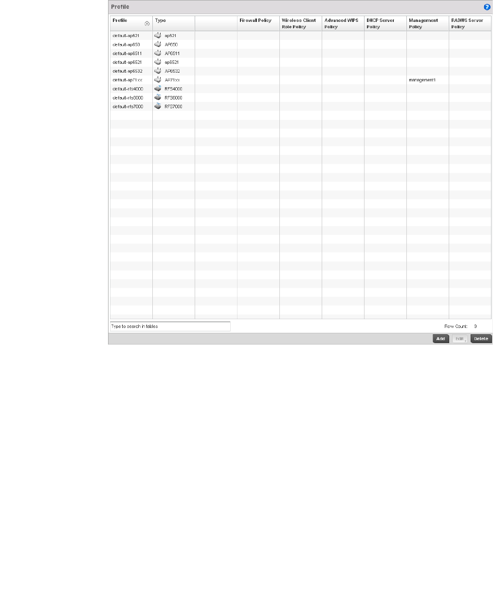
Brocade Mobility RFS4000, RFS6000, and RFS7000 System Reference Guide 369
53-1002620-01
7
FIGURE 252 Profile screen
4. Review the following information on existing controller profiles:
Profile Lists the user-assigned name defined for each profile when created. Profile names
cannot be edited with a profiles configuration.
Type Displays the device type (and subsequent device specific configuration) supported by
each listed profile. Available device types include:
Brocade Mobility 650 Access Point
br-6511
br-7131
RFS4000
RFS6000
RFS7000
Auto Provisioning Policy Displays the controller auto provisioning policy applied to this profile. At adoption, an AP
solicits and receives multiple adoption responses from controllers available on the
network. These adoption responses contain preference and loading policy information
the AP uses to select the optimum controller for adoption. By default, an auto
provisioning policy generally distributes AP adoption evenly amongst available
controllers. Modify existing adoption policies or create a new one as needed to meet the
adoption requirements of this particular controller profile.
Firewall Policy Displays the existing firewall policy, if any, assigned to each listed profile. Firewall
policies can be assigned when creating or editing a profile.

370 Brocade Mobility RFS4000, RFS6000, and RFS7000 System Reference Guide
53-1002620-01
7
5. Select the Add button to create a new controller profile, Edit to revise a selected profile
configuration or Delete to permanently remove a selected profile.
The following tasks comprise the controller’s required profile configuration activities:
•General Profile Configuration
•Profile Cluster Configuration (Controllers Only)
•Profile Adoption Configuration (APs Only)
•Profile Interface Configuration
•Profile Network Configuration
•Profile Security Configuration
•Profile Services Configuration
•Profile Management Configuration
•Advanced Profile Configuration
General Profile Configuration
Each controller profile requires a provisioning policy and clock synchronization settings as part of
its general configuration. Each profile can have a unique provisioning policy and system time.
Wireless Controllers and Access Points are automatically assigned a default profile unless an AP
provisioning policy has been defined that specifically assigns Access Points to a user defined
profile. During the general configuration process, a provisioning policy can be assigned to a specific
profile or a new provisioning policy can be created and applied to the profile. Adoption is the
process an AP uses to discover controllers available in the network, pick the most desirable
controller, establish an association and obtain its configuration.
Wireless Client Role
Policy
Lists the name of the wireless client role policy currently applied to the listed device. The
wireless client role policy contains the matching rules and IP and MAC Inbound and
Outbound policies used to filter traffic to and from clients. This policy can be applied to
both controllers and Access Points.
Advanced WIPS Policy Lists the name of the Advanced WIPS Policy used with each listed profile to (among
other things) block up to 100 client MAC address from controller connectivity.
DHCP Server Policy Lists the name of the DHCP Server Policy used with each listed profile. The controller’s
internal DHCP server groups wireless clients based on defined user-class option values.
Clients with a defined set of user class values are segregated by class. A DHCP server
can associate multiple classes to each pool. Each class in a pool is assigned an
exclusive range of IP addresses.
Management Policy Lists the name of Management policies applied to each listed controller profile. A
management policy is a mechanism to allow/deny management access to the controller
for separate interfaces and protocols (HTTP, HTTPS, Telnet, SSH or SNMP). Controller
management access can be enabled/disabled as required for each policy.
RADIUS Server Policy Displays the name of the RADIUS Server policy applied to each listed controller profile. A
RADIUS Server policy provides customized, profile specific, management of controller
authentication data (usernames and passwords).
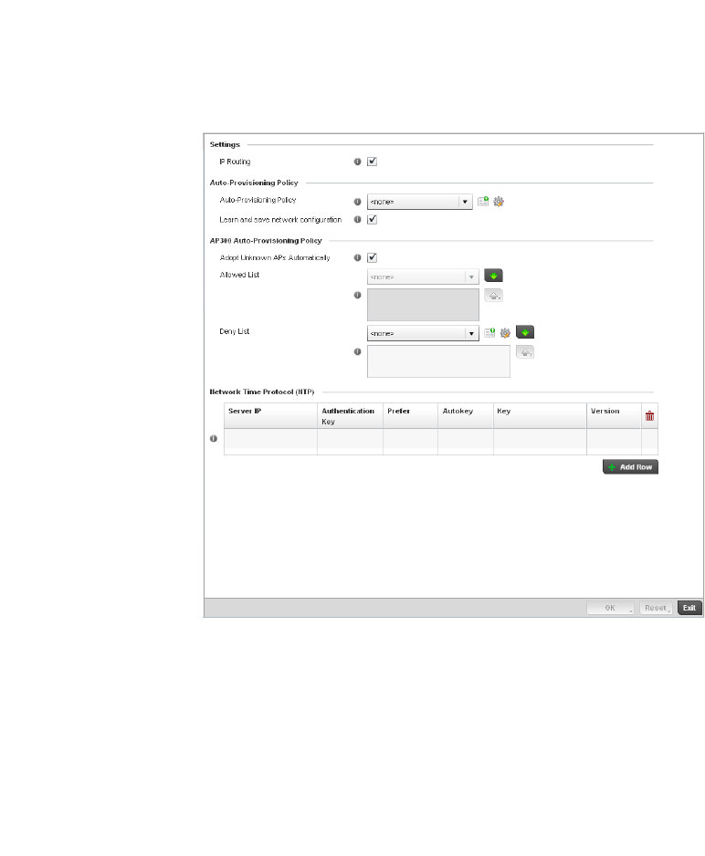
Brocade Mobility RFS4000, RFS6000, and RFS7000 System Reference Guide 371
53-1002620-01
7
Network Time Protocol (NTP) manages time and/or network clock synchronization within the
managed network. NTP is a client/server implementation. The Wireless Controller (an NTP client)
periodically synchronizes its clock with a master clock (an NTP server). For example, the Wireless
Controller resets its clock to 07:04:59 upon reading a time of 07:04:59 from its designated NTP
server.
Additionally, if the profile is supporting an Access Point, the profile’s general configuration provides
an option to disable the device’s LEDs.
To define a profile’s general configuration:
1. Select the Configuration tab from the Web UI.
2. Select Profiles from the Configuration tab.
3. Select Manage Profiles from the Configuration > Profiles menu.
4. Select General.
A General configuration screen displays for the new or existing controller profile.
FIGURE 253 General Profile - screen
5. If creating a new profile, provide a name (up to 32 characters) within the Profile parameter
field.
6. Use the Type drop-down menu to specify the Brocade AP or controller model for which the
profile applies.
Profiles can only be applied to the same device type selected when the profile is initially
created.
7. I n t h e Settings section check the IP Routing checkbox to enable routing for the device.

372 Brocade Mobility RFS4000, RFS6000, and RFS7000 System Reference Guide
53-1002620-01
7
8. Refer to the Provisioning Policy section to select a Provisioning Policy or create a new one.
9. Select + Add Row below the Network Time Protocol (NTP) table to define the configurations of
NTP server resources the controller uses it obtain system time. Set the following parameters to
define the NTP configuration:
10. Select OK to save the changes made to the general profile configuration. Select Reset to revert
to the last saved configuration.
General Profile Configuration and
Deployment Considerations
General Profile Configuration
Before defining a general profile configuration, refer to the following deployment guidelines to
ensure the configuration is optimally effective:
•A default profile is applied to the controller automatically, and default AP profiles are applied to
APs discovered by the controller.
•A central difference compared to the default-radio configurations in previous releases is that
default profiles are used as pointers of an AP’s configuration, not just templates from which
the configuration is copied. Therefore, even after adoption, if a change is made in one of the
parameters in a profile, the change is reflected across all APs using that profile.
•Each user defined profile requires a unique name.
•User defined Profiles can be automatically assigned to Access Points using AP adoption
policies.
•All Wireless Controllers and Access Points are automatically assigned a default profile based
on the hardware type selected when the profile is initially created.
Provisioning Policy Select a Provisioning Policy from the pulldown menu. To create a new Provisioning
Policy click the create icon. For more information on creating a provisioning policy that
can be applied to a controller profile, see Auto Provisioning Policies on page 5-263.
Learn and save network
configuration
Check the Learn and save network configuration checkbox to enable the device to
learn and save network information.
Server IP Set the IP address of each server added as a potential NTP resource.
Authentication Key Select the number of the associated Authentication Key for the NTP resource.
Prefer Select the check box to designate this particular NTP resource as preferred. If using
multiple NTP resources, preferred resources will be given first opportunity to connect
to the controller and provide NTP calibration.
AutoKey Select the check box to enable an autokey configuration for the controller and NTP
resource. The default setting is disabled.
Key If an autokey is not being used, manually enter a 64 character maximum key the
controller and NTP resource share to securely interoperate.
Version Use the spinner control to specify the version number used by this NTP server
resource. The default setting is 0.

Brocade Mobility RFS4000, RFS6000, and RFS7000 System Reference Guide 373
53-1002620-01
7
Profile Cluster Configuration (Controllers Only)
Configuration and network monitoring are two tasks a network administrator faces as a network
grows in terms of the number of managed nodes (controllers, routers, wireless devices etc.). Such
scalability requirements lead network administrators to look for managing and monitoring each
node from a single centralized management entity. The controller not only provides a centralized
management solution, it provides a centralized management profile that can be shared by any
single controller in the cluster. This eliminates dedicating a management entity to manage all
cluster members and eliminates a single point of failure.
A redundancy group (cluster) is a set of controllers (nodes) uniquely defined by the controller
profile’s configuration. Within the redundancy group, members discover and establish connections
to other controller members and provide wireless network self-healing support in the event of
cluster member failure.
NOTE
There is a limit of 2 controllers that can be configured in a cluster.
A cluster’s AP load balance is typically distributed evenly amongst the controllers in the cluster.
Define how often this profile is load balanced for AP radio distribution as often as you feel required,
as radios can come and go and controller members can join and exit the cluster.
To define a controller’s cluster configuration for use with a profile:
1. Select the Configuration tab from the Web UI.
2. Select Profiles from the Configuration tab.
3. Select Manage Profiles from the Configuration > Profiles menu.
4. Select Cluster.
A screen displays where the profile’s cluster and AP load balancing configuration can bet set.
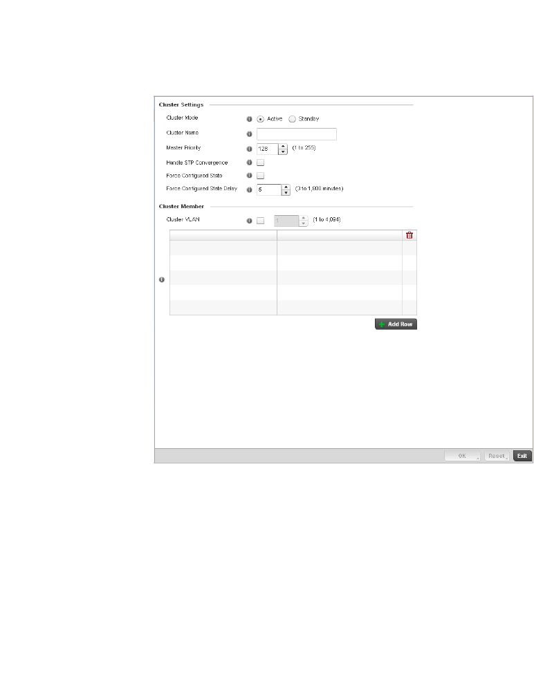
374 Brocade Mobility RFS4000, RFS6000, and RFS7000 System Reference Guide
53-1002620-01
7
FIGURE 254 Controller Profile - Cluster screen
5. Define the following Cluster Settings parameters to set this profile’s cluster mode and
deployment settings:
Cluster Mode A member can be in either an Active or Standby mode. All active member
controllers can adopt Access Points. Standby members only adopt Access Points
when an active member has failed or sees an Access Point not adopted by a
controller. The default cluster mode is Active and enabled for use with the
controller profile.
Cluster Name Define a name for the cluster name unique to its configuration or profile support
requirements. The name cannot exceed 64 characters.
Master Priority Set a priority value between 1 and 255 with the higher value being given higher
priority. This configuration is the device’s priority to become cluster master. In
cluster environment one device from the cluster is elected as the cluster master.
This configuration is the device’s priority to become cluster master. The default
value is 128.

Brocade Mobility RFS4000, RFS6000, and RFS7000 System Reference Guide 375
53-1002620-01
7
6. Within the Cluster Member field, select the Cluster VLAN checkbox to enable a spinner control
to designate the controller VLAN where cluster members are reachable. Specify a VLAN in the
range of
1 - 4094.
Specify the IP Addresses of the VLAN’s cluster members using the IP Address table.
7. Select an Auto-Provisioning Policy from the pulldown menu. To create a new Auto-Provisioning
Policy click the create icon.
8. Define the following br-300 parameters:
9. Select OK to save the changes made to the profile’s cluster configuration. Select Reset to
revert to the last saved configuration.
Controller Cluster Profile Configuration
and Deployment Considerations
Profile Cluster Configuration (Controllers Only)
Handle STP Convergence Select the check box to enable Spanning Tree Protocol (STP) convergence for the
controller. In general, this protocol is enabled in layer 2 networks to prevent
network looping. Spanning Tree is a network layer protocol that ensures a
loop-free topology in a mesh network of inter-connected layer 2 controllers. The
spanning tree protocol disables redundant connections and uses the least costly
path to maintain a connection between any two controllers in the network. If
enabled, the network forwards data only after STP convergence. Enabling STP
convergence delays the redundancy state machine execution until the STP
convergence is completed (the standard protocol value for STP convergence is 50
seconds). Delaying the state machine is important to load balance APs at startup.
The default setting is disabled.
Force Configured State Select the check box to enable this controller to take over for an active controller
member if it were to fail. A standby controller in the cluster takes over APs
adopted by the failed active controller. If the failed active controller were to come
back up, the active controller starts a timer based on the Auto Revert Delay
interval. At the expiration of the Auto Revert Delay, the standby controller
releases all adopted APs and goes back to a monitoring mode. The Auto Revert
Delay timer is stopped and restarted if the active controller goes down and
comes up during the Auto Revert Delay interval. The default value is disabled.
Force Configured State
Delay
Specify a delay interval in either Seconds (1 - 1,800) or Minutes (1 - 30). This is
the interval a standby controller waits before releasing adopted APs and goes
back to a monitoring mode when an active controller becomes active again after
a failure. The default interval is 5 seconds.
Adopt List Check this box to allow unconfigured br-300 Access Points to be adopted by the
cluster.
Adopted List Select an br-300 list from the pull-down menu to specify which br-300s are
adopted by the cluster. If a suitable list is not present, click the create button to
create a new list.
Deny List Select an br-300 list from the pull-down menu to specify which br-300s are
denied adoption by the cluster. If a suitable list is not present, click the create
button to create a new list.
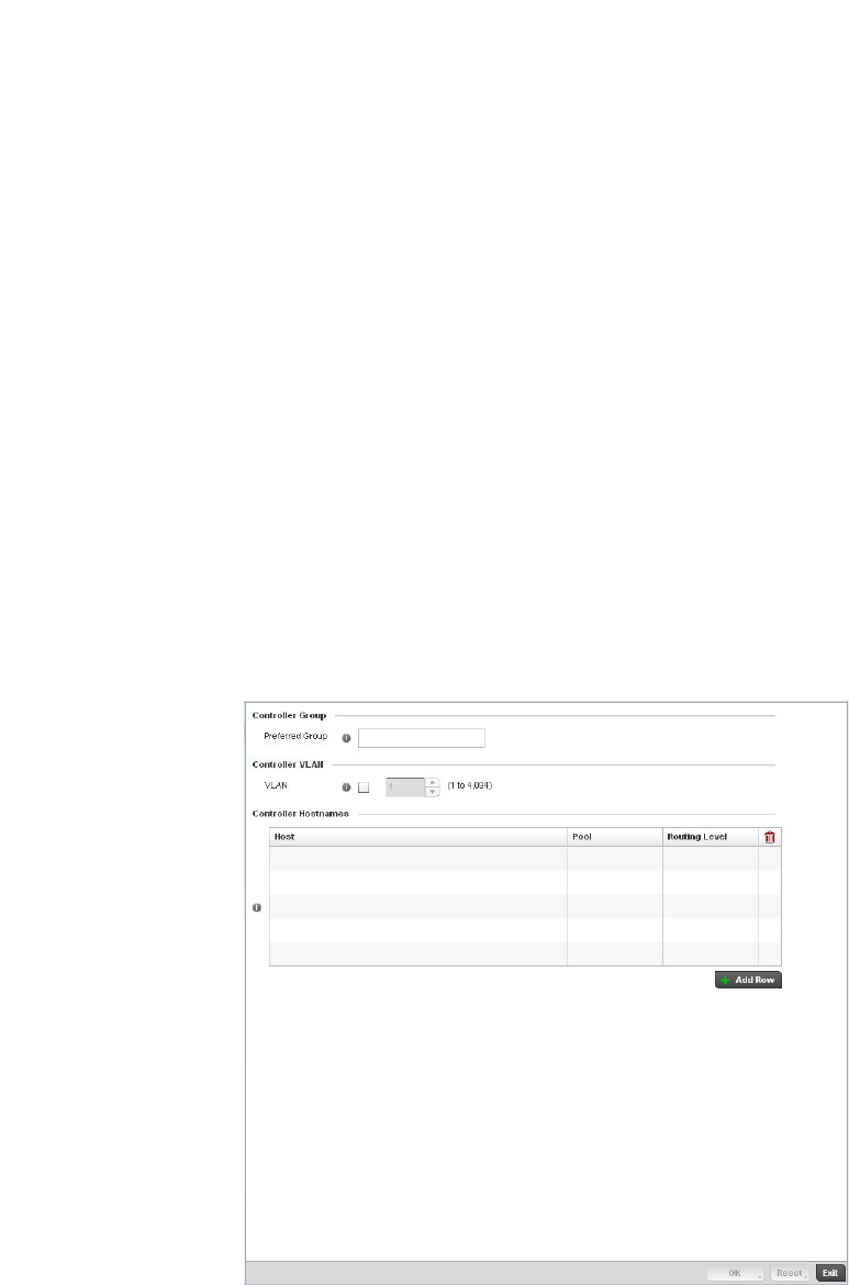
376 Brocade Mobility RFS4000, RFS6000, and RFS7000 System Reference Guide
53-1002620-01
7
Before defining a controller profile’s cluster configuration, refer to the following deployment
guidelines to ensure the configuration is optimally effective:
•A controller cannot adopt more APs than the hardware capacity allow. This is important when
the number of pooled AP and AAP licenses exceeds the aggregated AP and AAP capacity
available on remaining controller members after a cluster member has failed. A cluster
supported controller profile should be designed to ensure adequate AP and AAP capacity exists
to address failure scenarios involving both APs and AAPs.
•When clustering is enabled for a profile and a controller failure occurs, AP and AAP licenses are
persistent in the cluster even during controller reboots or power outages. If a cluster member
failure were to occur, Brocade recommends clustering remain enabled on all remaining cluster
members or the pooled member licenses will be lost.
Profile Adoption Configuration (APs Only)
1. Select the Configuration tab from the Web UI.
2. Select Profiles from the Configuration tab.
3. Select Manage Profiles from the Configuration > Profiles menu.
FIGURE 255 Provisioning Policy - Rule Precedence screen

Brocade Mobility RFS4000, RFS6000, and RFS7000 System Reference Guide 377
53-1002620-01
7
4. Set the following Provisioning Policy parameters:
Profile Interface Configuration
A controller profile’s interface configuration can be defined to support separate physical Ethernet
configurations that are both unique and specific to RFS4000, RFS6000, and RFS7000 Series
platforms. Ports vary depending on controller platform, but controller models do have some of the
same physical interfaces.
A controller requires its Virtual Interface be configured for layer 3 (IP) access or layer 3 service on a
VLAN. A controller’s Virtual Interface defines which IP address is associated with each VLAN ID the
controller is connected to.
If the profile is configured to support an Access Point radio, an additional Radios option is
available, unique to the Access Point’s radio configuration.
A profile’s Interface configuration process consists of the following:
•Ethernet Port Configuration
•Virtual Interface Configuration
•Port Channel Configuration
•Access Point Radio Configuration
Additionally, deployment considerations and guidelines for profile interface configurations are
available for review prior to defining a configuration that could significantly impact the performance
of the managed network. For more information, see Profile Interface Deployment Considerations
on page 7-406.
Ethernet Port Configuration
Profile Interface Configuration
The ports available on a controller vary depending on the platform. The following ports are
available:
•RFS4000 - ge1, ge2, ge3, ge4, ge5, up1
•RFS6000 - ge1, ge2, ge3, ge4, ge5, ge6, ge7, ge8, me1, up1
•RFS7000 - ge1, ge2, ge3, ge4, me1
GE ports are available on the RFS4000, RFS6000, and RFS7000 Series platforms. GE ports on the
RFS4000 and RFS6000 are RJ-45 supporting 10/100/1000Mbps. GE ports on the RFS7000 can
be RJ-45 or fiber ports supporting 10/100/1000Mbps.
Preferred Group Define the Preferred Group used as optimal group of controllers for the Access
Point’s adoption. The name of the preferred group cannot exceed 64 characters.
VLAN Select the checkbox to define a VLAN the Access Point’s associating controller is
reachable on. VLANs 0 and 4,095 are reserved and cannot be used by a
controller VLAN.
Controller Hostnames Enter Controller Hostnames as needed to define controller resources for Access
Point adoption. Select + Add Row as needed to populate the table with IP
Addresses or Hostnames of the controllers used as Access Point adoption
resources into the managed network.
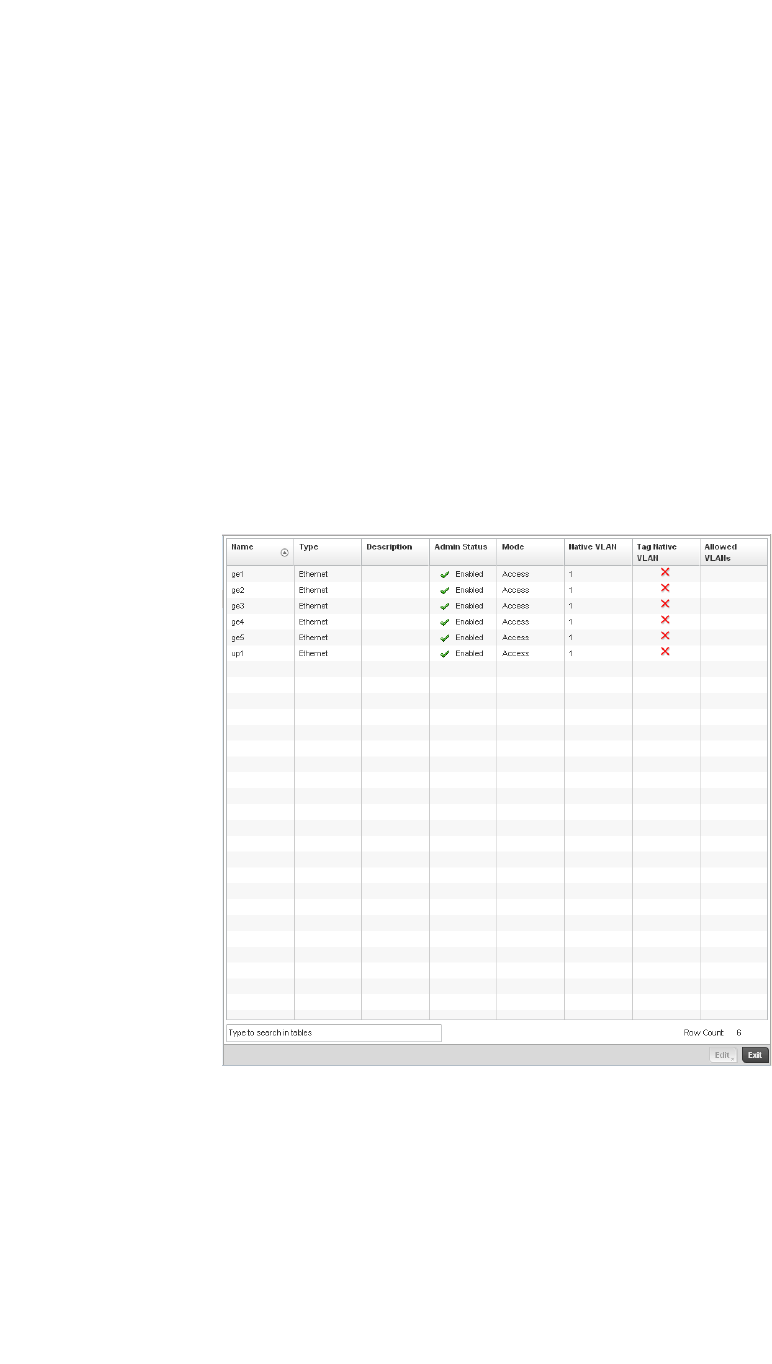
378 Brocade Mobility RFS4000, RFS6000, and RFS7000 System Reference Guide
53-1002620-01
7
ME ports are available on RFS6000 and RFS7000 platforms. ME ports are out-of-band
management ports used to manage the controller via CLI or Web UI, even when the other ports on
the controller are unreachable.
UP ports are available on RFS4000 and RFS6000 platforms. An UP port is used to connect the
controller to the backbone network. An UP port supports either RJ-45 or fiber. The UP port is the
preferred means to connect to the backbone as it has a non-blocking 1gbps connection unlike GE
ports.
To define a controller profile’s Ethernet port configuration:
1. Select Configuration > Profiles > Interface.
2. Expand the Interface menu to display its submenu options.
3. Select Ethernet Ports.
The Ethernet Ports screen displays configuration, runtime status and statistics regarding the
physical ports on the controller.
FIGURE 256 Ethernet Ports screen
4. Refer to the following to assess port status and performance:
Name Displays the physical controller port name reporting runtime data and statistics.
Supported ports vary depending on controller model.
RFS4000 - ge1, ge2, ge3, ge4, ge5, up1
RFS6000 - ge1, ge2, ge3, ge4, ge5, ge6, ge7, ge8, me1, up1
RFS7000 - ge1, ge2, ge3, ge4, me1
Type Displays the physical controller port type. Cooper is used on RJ45 Ethernet ports
and Optical materials are used on fiber optic gigabit Ethernet ports.
Description Displays an administrator defined description for each listed controller port.
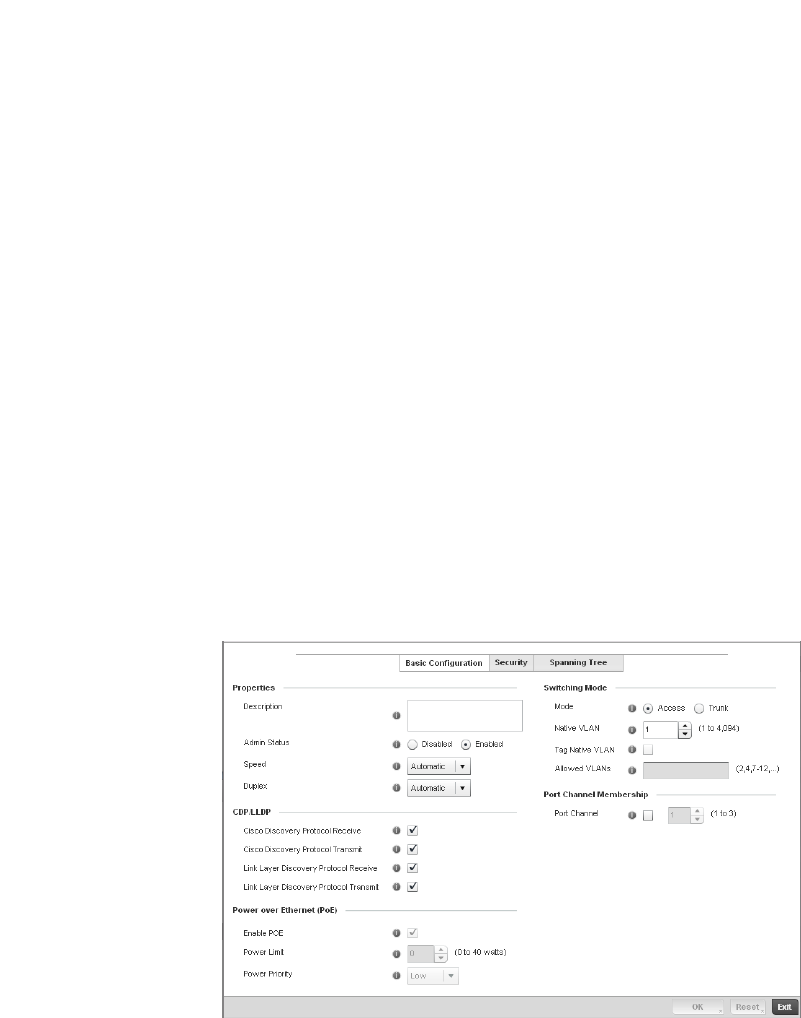
Brocade Mobility RFS4000, RFS6000, and RFS7000 System Reference Guide 379
53-1002620-01
7
5. To edit the configuration of an existing controller port, select it from amongst those displayed
and select the Edit button. The Ethernet port Basic Configuration screen displays by default.
FIGURE 257 Ethernet Ports - Basic Configuration screen
Admin Status A green checkmark defines the port as active and currently enabled with the
controller profile. A red “X” defines the port as currently disabled and not available
for use. The interface status can be modified with the port configuration as needed.
Mode Displays the profile’s switching mode as currently either Access or Trunk (as defined
within the Ethernet Port Basic Configuration screen). If Access is selected, the listed
port accepts packets only from the native VLAN. Frames are forwarded out the port
untagged with no 802.1Q header. All frames received on the port are expected as
untagged and mapped to the native VLAN. If set to Trunk, the port allows packets
from a list of VLANs added to the trunk. A port configured as Trunk supports multiple
802.1Q tagged VLANs and one Native VLAN which can be tagged or untagged.
Native VLAN Lists the numerical VLAN ID (1 - 4094) set for the native VLAN. The native VLAN
allows an Ethernet device to associate untagged frames to a VLAN when no 802.1Q
frame is included in the frame. Additionally, the native VLAN is the VLAN untagged
traffic is directed over when using a port in trunk mode.
Tag Native VLAN A green checkmark defines the native VLAN as tagged. A red “X” defines the native
VLAN as untagged. When a frame is tagged, the 12 bit frame VLAN ID is added to
the 802.1Q header so upstream Ethernet devices know which VLAN ID the frame
belongs to. The device reads the 12 bit VLAN ID and forwards the frame to the
appropriate VLAN. When a frame is received with no 802.1Q header, the upstream
device classifies the frame using the default or native VLAN assigned to the Trunk
port. A native VLAN allows an Ethernet device to associate untagged frames to a
VLAN when no 802.1Q frame is included in the frame.
Allowed VLANs Displays those VLANs allowed to send packets over the listed controller port. Allowed
VLANs are only listed when the mode has been set to Trunk.

380 Brocade Mobility RFS4000, RFS6000, and RFS7000 System Reference Guide
53-1002620-01
7
6. Set the following Ethernet port Properties:
7. Enable or disable the following CDP/LLDP parameters used to configure Cisco Discovery
Protocol and Link Layer Discovery Protocol for this profile’s Ethernet port configuration:
Set the following Power Over Ethernet (PoE) parameters for this profile’s Ethernet port
configuration:
Description Enter a brief description for the controller port (64 characters maximum). The
description should reflect the port’s intended function to differentiate it from others
with similar configurations or perhaps just the name of the physical port.
Admin Status Select the Enabled radio button to define this port as active to the controller profile
it supports. Select the Disabled radio button to disable this physical controller port
in the controller profile. It can be activated at any future time when needed.
Speed Select the speed at which the port can receive and transmit the data. Select either
10 Mbps, 100 Mbps, 1000 Mbps. Select either of these options to establish a 10,
100 or 1000 Mbps data transfer rate for the selected half duplex or full duplex
transmission over the port. These options are not available if Auto is selected. Select
Automatic to enable the controller port to automatically exchange information about
data transmission speed and duplex capabilities. Auto negotiation is helpful when in
an environment where different devices are connected and disconnected on a
regular basis. Automatic is the default setting.
Duplex Select either half, full or automatic as the duplex option. Select Half duplex to send
data over the port, then immediately receive data from the same direction in which
the data was transmitted. Like a full-duplex transmission, a half-duplex transmission
can carry data in both directions, just not at the same time. Select Full duplex to
transmit data to and from the controller port at the same time. Using Full duplex, the
port can send data while receiving data as well. Select Automatic to dynamically
duplex as port performance needs dictate. Automatic is the default setting.
Cisco Discovery Protocol
Receive
Select this box to allow the Cisco discovery protocol to be received on this controller
port. If enabled, the port sends out periodic interface updates to a multicast address
to advertise its presence to neighbors. This option is enabled by default.
Cisco Discovery Protocol
Transmit
Select this box to allow the Cisco discovery protocol to be transmitted on this
controller port. If enabled, the port sends out periodic interface updates to a
multicast address to advertise its presence to neighbors.
Link Layer Discovery
Protocol Receive
Select this box to allow the Link Layer discovery protocol to be received on this
controller port. If enabled, the port sends out periodic interface updates to a
multicast address to advertise its presence to neighbors. This option is enabled by
default.
Link Layer Discovery
Protocol Transmit
Select this box to allow the Link Layer discovery protocol to be transmitted on this
controller port. If enabled, the port sends out periodic interface updates to a
multicast address to advertise its presence to neighbors.
Enable POE Select the check box to configure the selected port to use Power over Ethernet. To
disable PoE on a port, uncheck this option. Power over Ethernet is supported on
RFS4000 and RFS6000 model controllers only. When enabled, the controller
supports 802.3af PoE on each of its ge ports. The PoE allows users to monitor port
power consumption and configure power usage limits and priorities for each ge port.
Power Limit Use the spinner control to set the total watts available for Power over Ethernet on the
defined controller ge port. Set a value between 0 - 40 watts.
Power Priority Set the power priority for the listed port to either to either Low, Medium or High. This
is the priory assigned to this port versus the power requirements of the other ports
on the controller.

Brocade Mobility RFS4000, RFS6000, and RFS7000 System Reference Guide 381
53-1002620-01
7
8. Define the following Switching Mode parameters to apply to the Ethernet port configuration:
9. Optionally select the Port Channel checkbox and define a setting between 1 - 3 using the
spinner control. This sets the channel group for the port.
10. Select OK to save the changes made to the Ethernet Port Basic Configuration. Select Reset to
revert to the last saved configuration.
11. Select the Security tab.
Mode Select either the Access or Trunk radio button to set the VLAN switching mode over
the port. If Access is selected, the port accepts packets only form the native VLANs.
Frames are forwarded out the port untagged with no 802.1Q header. All frames
received on the port are expected as untagged and are mapped to the native VLAN.
If the mode is set to Trunk, the port allows packets from a list of VLANs you add to
the trunk. A port configured as Trunk supports multiple 802.1Q tagged VLANs and
one Native VLAN which can be tagged or untagged. Access is the default mode.
Native VLAN Use the spinner control to define a numerical Native VLAN ID between 1 - 4094.
The native VLAN allows an Ethernet device to associate untagged frames to a VLAN
when no 802.1Q frame is included in the frame. Additionally, the native VLAN is the
VLAN which untagged traffic will be directed over when using a port in trunk mode.
The default VLAN is 1.
Tag Native VLAN Select the check box to tag the native VLAN. Controllers support the IEEE 802.1Q
specification for tagging frames and coordinating VLANs between devices. IEEE
802.1Q adds four bytes to each frame identifying the VLAN ID for upstream devices
that the frame belongs. If the upstream Ethernet device does not support IEEE
802.1Q tagging, it does not interpret the tagged frames. When VLAN tagging is
required between devices, both devices must support tagging and be configured to
accept tagged VLANs. When a frame is tagged, the 12 bit frame VLAN ID is added to
the 802.1Q header so upstream Ethernet devices know which VLAN ID the frame
belongs to. The device reads the 12 bit VLAN ID and forwards the frame to the
appropriate VLAN. When a frame is received with no 802.1Q header, the upstream
device classifies the frame using the default or native VLAN assigned to the Trunk
port. The native VLAN allows an Ethernet device to associate untagged frames to a
VLAN when no 802.1Q frame is included in the frame. This feature is disabled by
default.
Allowed VLANs Selecting Trunk as the mode enables the Allowed VLANs parameter. Add VLANs
that exclusively send packets over the listed port.
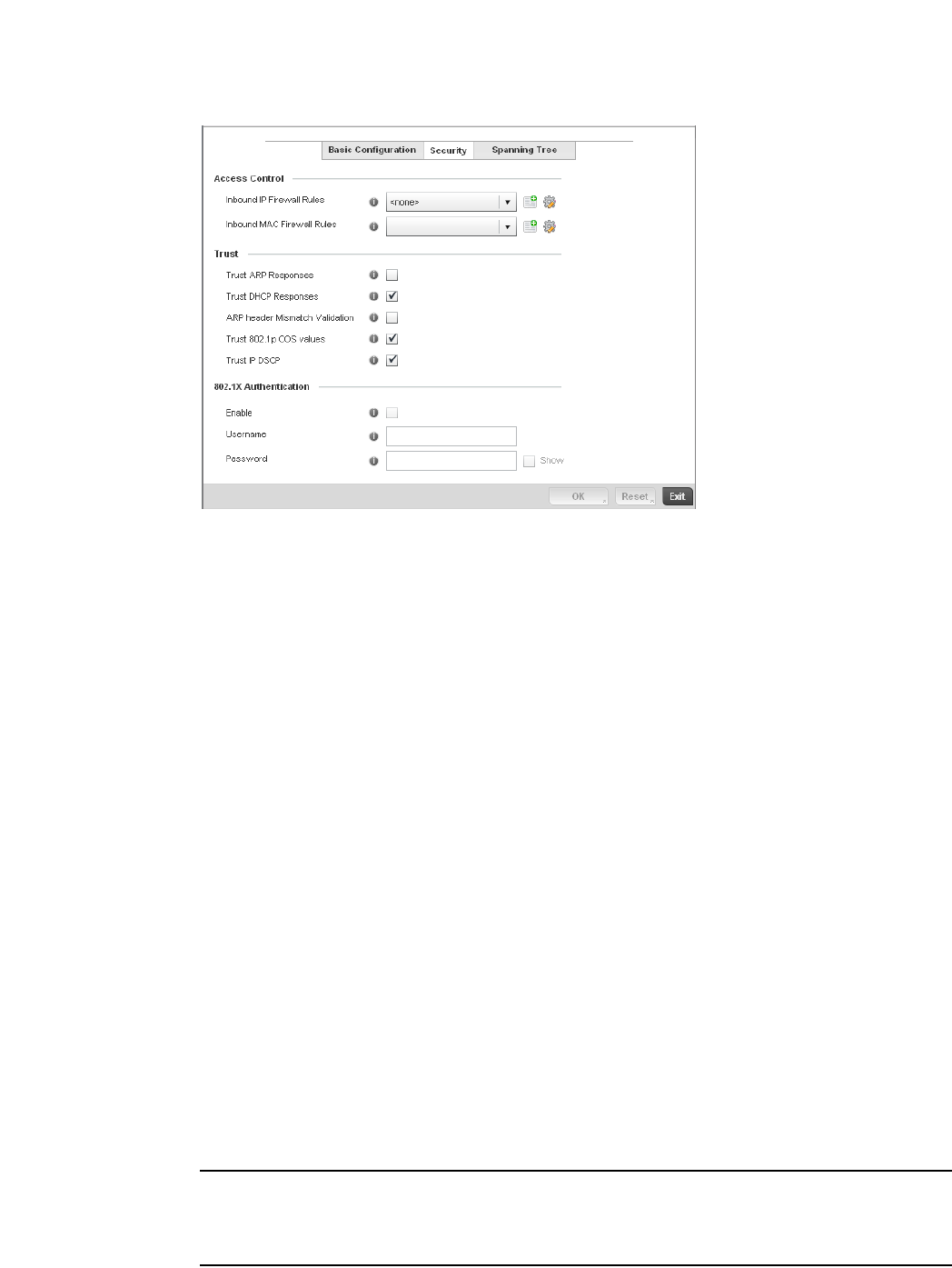
382 Brocade Mobility RFS4000, RFS6000, and RFS7000 System Reference Guide
53-1002620-01
7
FIGURE 258 Ethernet Ports - Security screen
12. Refer to the Access Control field. As part of the port’s security configuration, Inbound IP and
MAC address firewall rules are required.
Use the Inbound IP Firewall Rules and Inbound MAC Firewall Rules drop-down menus to select
the firewall rules to apply to this profile’s Ethernet port configuration.
The firewall inspects IP and MAC traffic flows and detects attacks typically not visible to
traditional wired firewall appliances.
13. If a firewall rule does not exist suiting the data protection needs of the target port
configuration, select the Create icon to define a new rule configuration. For more information,
see Wireless Firewall on page 9-511.
14. Refer to the Trust field to define the following:
NOTE
Some vendor solutions with VRRP enabled send ARP packets with Ethernet SMAC as a physical MAC
and inner ARP SMAC as VRRP MAC. If this configuration is enabled, a packet is allowed, despite a
conflict existing.
Trust ARP Responses Select the check box to enable ARP trust on this controller port. ARP packets
received on this controller port are considered trusted and information from these
packets is used to identify rogue devices within the managed network. The default
value is disabled.
Trust DHCP Responses Select the check box to enable DHCP trust on this port. If enabled, only DHCP
responses are trusted and forwarded on this port, and a DHCP server can be
connected only to a DHCP trusted port. The default value is enabled.
ARP header Mismatch
Validation
Select the check box to enable a mismatch check for the source MAC in both the
ARP and Ethernet header. The default value is enabled.
Trust 802.1p COS values Select the check box to enable 802.1p COS values on this port. The default value
is enabled.
Trust IP DSCP Select the check box to enable IP DSCP values on this port. The default value is
enabled.
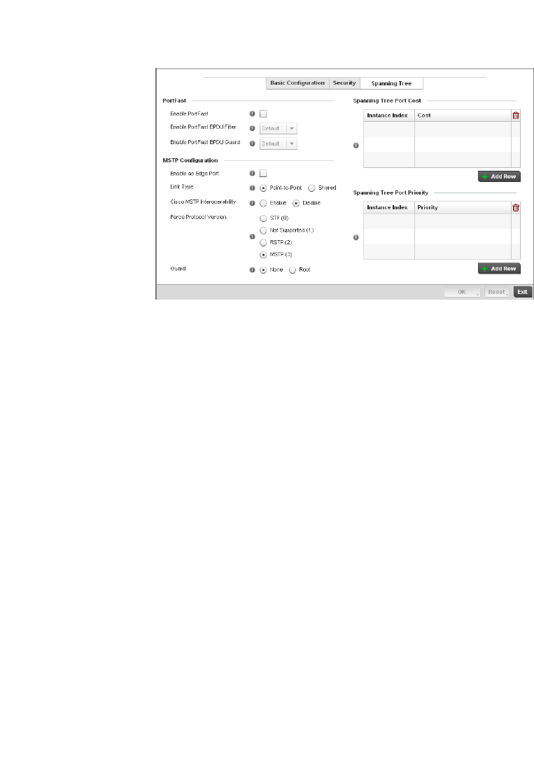
Brocade Mobility RFS4000, RFS6000, and RFS7000 System Reference Guide 383
53-1002620-01
7
15. Select OK to save the changes made to the Ethernet port’s security configuration. Select Reset
to revert to the last saved configuration.
16. Select the Spanning Tree tab.
FIGURE 259 Ethernet Ports - Spanning Tree screen
17. Define the following PortFast parameters for the port’s MSTP configuration:
18. Set the following MSTP Configuration parameters:
Enable PortFast Select the check box to enable drop-down menus for both the Enable Portfast BPDU
Filter and Enable Portfast BPDU guard options for the controller port.
PortFast BPDU Filter Select enable to invoke a BPDU filter for this portfast enabled port. Enabling the
BPDU filter feature ensures this PortFast enabled port does not transmit or receive
BPDUs.
PortFast BPDU Guard Select enable to invoke a BPDU guard for this portfast enabled port. Enabling the
BPDU Guard feature means this portfast-enabled port will shutdown on receiving a
BPDU. Thus, no BPDUs are processed.
Enable as Edge Port Select the check box to define this port as an edge port. Using an edge (private)
port, you can isolate devices to prevent connectivity over this port.
Link Type Select either the Point-to-Point or Shared radio button. Selecting Point-to-Point
indicates the port should be treated as connected to a point-to-point link. Selecting
Shared indicates this port should be treated as having a shared connection. A port
connected to a hub is on a shared link, while one connected to a controller is a
point-to-point link.
Cisco MSTP
Interoperability
Select either the Enable or Disable radio buttons. This enables interoperability with
Cisco’s version of MSTP over the port, which is incompatible with standard MSTP.
Force Protocol Version Sets the protocol version to either STP(0), Not Supported(1), RSTP(2) or MSTP(3).
MSTP is the default setting.
Guard Determines whether the port enforces root bridge placement. Setting the guard to
Root ensures the port is a designated port. Typically, each guard root port is a
designated port, unless two or more ports (within the root bridge) are connected
together. If the bridge receives superior (BPDUs) on a guard root-enabled port, the
guard root moves the port to a root-inconsistent STP state. This state is equivalent
to a listening state. No data is forwarded across the port. Thus, the guard root
enforces the root bridge position.

384 Brocade Mobility RFS4000, RFS6000, and RFS7000 System Reference Guide
53-1002620-01
7
19. Refer to the Spanning Tree Port Cost table.
Define an Instance Index using the spinner control, then set the Cost. The default path cost
depends on the speed of the port. The cost helps determine the role of the port in the MSTP
network. The designated cost is the cost for a packet to travel from this port to the root in the
MSTP configuration. The slower the media, the higher the cost.
20. Select + Add Row as needed to include additional indexes.
21. Refer to the Spanning Tree Port Priority table.
Define or override an Instance Index using the spinner control and then set the Priority. The lower
the priority, a greater likelihood of the port becoming a designated port. Thus applying an higher
override value impacts the port’s likelihood of becoming a designated port.
Select + Add Row needed to include additional indexes.
22. Select OK to save the changes made to the Ethernet Port Spanning Tree configuration. Select
Reset to revert to the last saved configuration.
Virtual Interface Configuration
Profile Interface Configuration
A controller Virtual Interface is required for layer 3 (IP) access to the controller or provide layer 3
service on a VLAN. The Virtual Interface defines which IP address is associated with each VLAN ID
the controller is connected to. A Virtual Interface is created for the default VLAN (VLAN 1) to enable
remote controller administration. A Virtual Interface is also used to map VLANs to IP address
ranges. This mapping determines the destination networks for controller routing.
To review existing Virtual Interface configurations and either create a new Virtual Interface
configuration, modify an existing configuration or delete an existing configuration:
1. Select Configuration > Profiles > Interface.
2. Expand the Interface menu to display its submenu options.
3. Select Virtual Interfaces.
Speed Default Path Cost
<=100000 bits/sec 200000000
<=1000000 bits/sec 20000000
<=10000000 bits/sec 2000000
<=100000000 bits/sec 200000
<=1000000000 bits/sec 20000
<=10000000000 bits/sec 2000
<=100000000000 bits/sec 200
<=1000000000000 bits/sec 20
>1000000000000 bits/sec 2
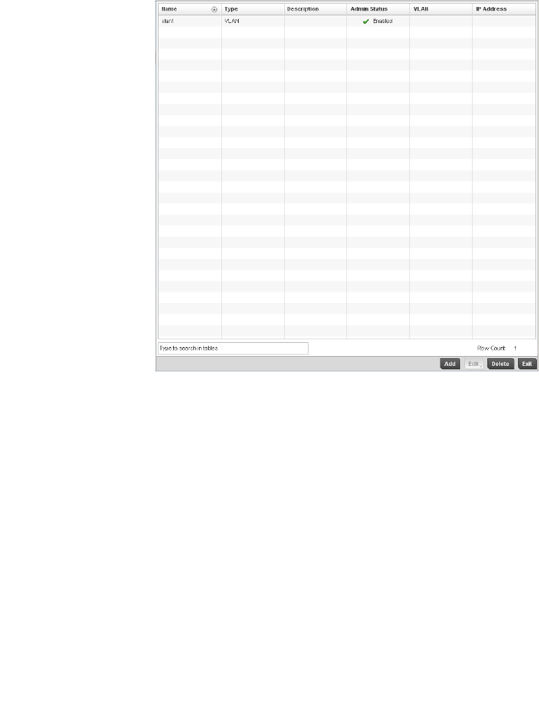
Brocade Mobility RFS4000, RFS6000, and RFS7000 System Reference Guide 385
53-1002620-01
7
FIGURE 260 Virtual Interfaces screen
4. Review the following parameters unique to each virtual interface configuration:
5. Select Add to define a new Virtual Interface configuration, Edit to modify the configuration of
an existing Virtual Interface or Delete to permanently remove a selected Virtual Interface.
Name Displays the name of each listed Virtual Interface assigned when it was created. The
name is between 1 - 4094, and cannot be modified as part of a Virtual Interface edit.
Type Displays the type of Virtual Interface for each listed interface.
Description Displays the description defined for the Virtual Interface when it was either initially
created or edited.
Admin Status A green checkmark defines the listed Virtual Interface configuration as active and
enabled with its supported controller profile. A red “X” defines the Virtual Interface as
currently disabled. The interface status can be modified when a new Virtual Interface
is created or an existing one modified.
VLAN Displays the numerical VLAN ID associated with each listed interface.
IP Address Defines whether DHCP was used to obtain the primary IP address used by the Virtual
Interface configuration.
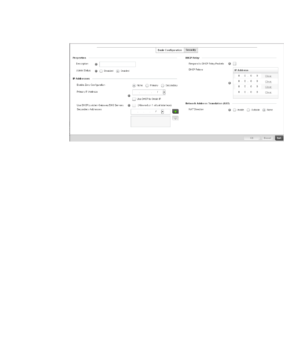
386 Brocade Mobility RFS4000, RFS6000, and RFS7000 System Reference Guide
53-1002620-01
7
FIGURE 261 Virtual Interfaces - Basic Configuration screen
The Basic Configuration screen displays by default, regardless of a whether a new Virtual
Interface is created or an existing one is being modified.
6. If creating a new Virtual Interface, use the VLAN ID spinner control to define a numeric ID
between
1 - 4094.
7. Define the following parameters from within the Properties field:
8. Set the following network information from within the IP Addresses field:
Description Provide or edit a description (up to 64 characters) for the Virtual Interface that helps
differentiate it from others with similar configurations.
Admin Status Either select the Disabled or Enabled radio button to define this interface’s current
status within the managed network. When set to Enabled, the Virtual Interface is
operational and available to the controller. The default value is disabled.
Enable Zero
Configuration
Define the IP address for the VLAN associated Virtual Interface.
Primary IP Address Define the IP address for the VLAN associated Virtual Interface.
Use DHCP to Obtain IP Select this option to allow DHCP to provide the IP address for the Virtual Interface.
Selecting this option disables the Primary IP address field.
Use DHCP to obtain
Gateway/DNS Servers
Select this option to allow DHCP to obtain a default gateway address, and DNS
resource for one virtual interface. This setting is disabled by default and only
available when the Use DHCP to Obtain IP option is selected.
Secondary Addresses Use the Secondary Addresses parameter to define additional IP addresses to
associate with VLAN IDs. The address provided in this field is used if the primary IP
address is unreachable.
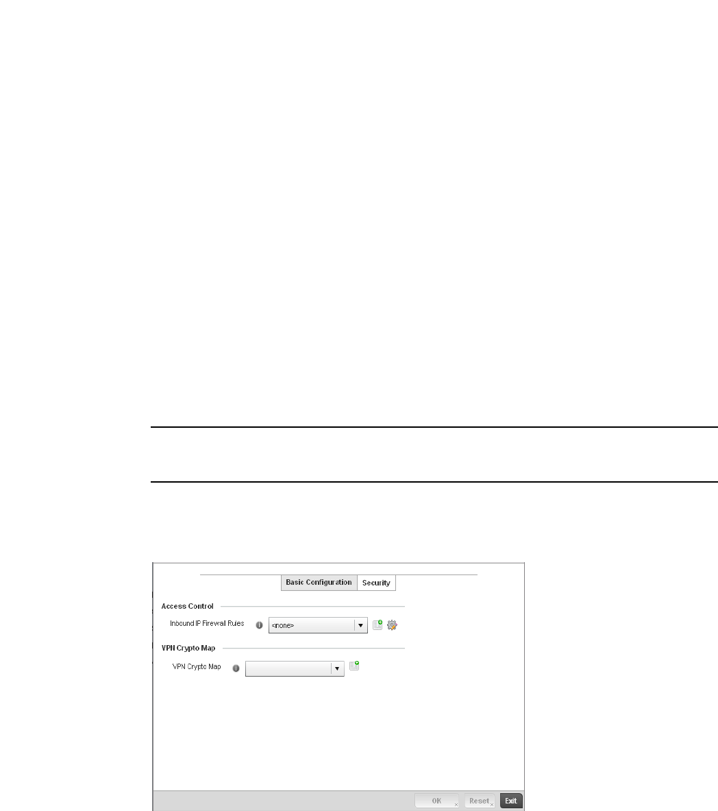
Brocade Mobility RFS4000, RFS6000, and RFS7000 System Reference Guide 387
53-1002620-01
7
9. Refer to the DHCP Relay field to set or override the DHCP relay server configuration used with
the controller Virtual Interface.
10. Define the Network Address Translation (NAT) direction.
Select either Inside, Outside or None.
•Inside - The inside network is transmitting data over the network its intended destination.
On the way out, the source IP address is changed in the header and replaced by the
(public) IP address.
•Outside - Packets passing through the NAT on the way back to the managed LAN are
searched against the records kept by the NAT engine. There, the destination IP address is
changed back to the specific internal private class IP address in order to reach the LAN
over the network.
•None - No NAT activity takes place. This is the default setting.
NOTE
Refer to Setting the Profile’s NAT Configuration on page 7-465 for instructions on creating a profile’s
NAT configuration.
11. Select OK button to save the changes to the Basic Configuration screen. Select Reset to revert
to the last saved configuration.
12. Select the Security tab.
FIGURE 262 Virtual Interfaces - Security screen
Respond to DHCP Relay
Packets
Select the Respond to DHCP Relay Packets option to allow the controller’s onboard
DHCP server to respond to relayed DHCP packets on this interface.
DHCP Relay IP Address Provide IP addresses for DHCP server relay resources.
The interface VLAN and gateway should have their IP addresses set. The interface
VLAN and gateway interface should not have DHCP client or DHCP Server enabled.
DHCP packets cannot be relayed to an onboard DHCP Server. The interface VLAN and
gateway interface cannot be the same.
When changing from a default DHCP address to a fixed IP address, set a static route
first. This is critical when the controller is being accessed from a subnet not directly
connected to the controller and the default route was set from DHCP.

388 Brocade Mobility RFS4000, RFS6000, and RFS7000 System Reference Guide
53-1002620-01
7
13. Use the Inbound IP Firewall Rules drop-down menu to select the firewall rule configuration to
apply to this Virtual Interface.
The firewall inspects and packet traffic to and from connected clients.
If a firewall rule does not exist suiting the data protection needs of this Virtual Interface, select
the Create icon to define a new firewall rule configuration or the Edit icon to modify an existing
configuration. For more information, see Wireless Firewall on page 9-511.
14. Use the VPN Crypto Map drop-down menu to select the Crypto Map configuration to apply to
this Virtual Interface.
Crypto Map entries are sets of configuration parameters for encrypting packets that pass
through the VPN Tunnel. If a Crypto Map configuration does not exist suiting the needs of this
Virtual Interface, select the Create icon to define a new Crypto Map configuration or the Edit
icon to modify an existing configuration. For more information, see Setting the Profile’s VPN
Configuration on page 7-450.
15. Select the OK button located at the bottom right of the screen to save the changes to the
Security screen. Select Reset to revert to the last saved configuration.
Port Channel Configuration
Profile Interface Configuration
Controller profiles can be applied customized port channel configurations as part of their Interface
configuration.
To define a port channel configuration for a controller profile:
1. Select Configuration > Profiles > Interface.
2. Expand the Interface menu to display its submenu options.
3. Select Port Channels.
The Port Channels screen displays.
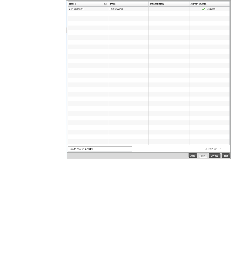
Brocade Mobility RFS4000, RFS6000, and RFS7000 System Reference Guide 389
53-1002620-01
7
FIGURE 263 Port Channels screen
4. Refer to the following to review existing port channel configurations and their current status:
5. To edit the configuration of an existing port channel, select it from amongst those displayed
and select the Edit button. The port channel Basic Configuration screen displays by default.
Name Displays the port channel’s numerical identifier assigned to it when it was created.
The numerical name cannot be modified as part of the edit process.
Type Displays whether the type is port channel.
Description Lists a a short description (64 characters maximum) describing the port channel or
differentiating it from others with similar configurations.
Admin Status A green checkmark defines the listed port channel as active and currently enabled
with the controller profile. A red “X” defines the port channel as currently disabled
and not available for use. The interface status can be modified with the port channel
configuration as required
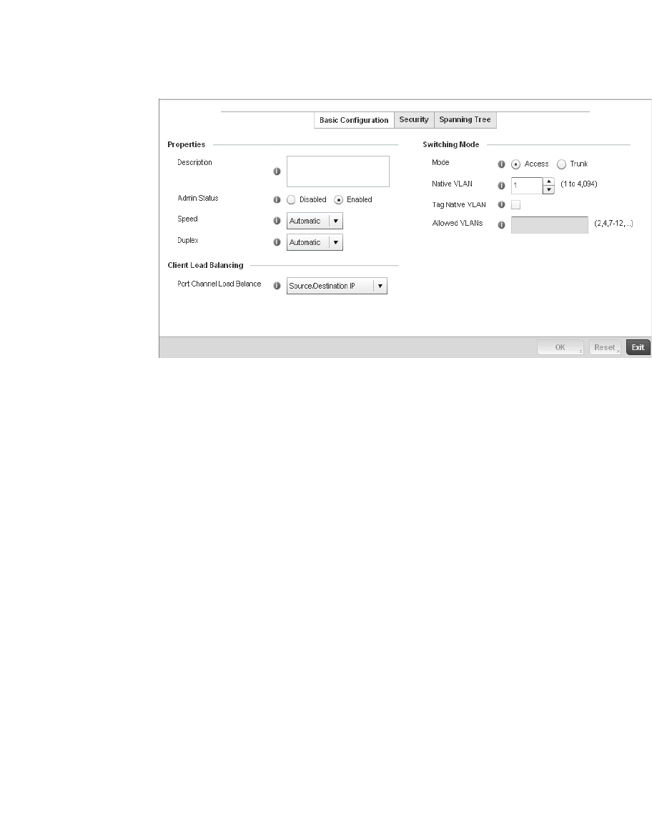
390 Brocade Mobility RFS4000, RFS6000, and RFS7000 System Reference Guide
53-1002620-01
7
FIGURE 264 Port Channels - Basic Configuration screen
6. Set the following port channel Properties:
7. Use the Port Channel Load Balance drop-down menu to define whether port channel load
balancing is conducted using a Source/Destination IP or a Source/Destination MAC.
Source/Destination IP is the default setting.
Description Enter a brief description for the controller port channel (64 characters maximum).
The description should reflect the port channel’s intended function.
Admin Status Select the Enabled radio button to define this port channel as active to the
controller profile it supports. Select the Disabled radio button to disable this port
channel configuration within the controller profile. It can be activated at any future
time when needed. The default setting is disabled.
Speed Select the speed at which the port channel can receive and transmit the data. Select
either 10 Mbps, 100 Mbps, 1000 Mbps. Select either of these options to establish a
10, 100 or 1000 Mbps data transfer rate for the selected half duplex or full duplex
transmission over the port. These options are not available if Auto is selected. Select
Automatic to enable the port channel to automatically exchange information about
data transmission speed and duplex capabilities. Auto negotiation is helpful when in
an environment where different devices are connected and disconnected on a
regular basis. Automatic is the default setting.
Duplex Select either Half, Full or Automatic as the duplex option. Select Half duplex to send
data over the port channel, then immediately receive data from the same direction in
which the data was transmitted. Like a Full duplex transmission, a Half duplex
transmission can carry data in both directions, just not at the same time. Select Full
duplex to transmit data to and from the port channel at the same time. Using Full
duplex, the port channel can send data while receiving data as well. Select Automatic
to enable to the controller to dynamically duplex as port channel performance needs
dictate. Automatic is the default setting.
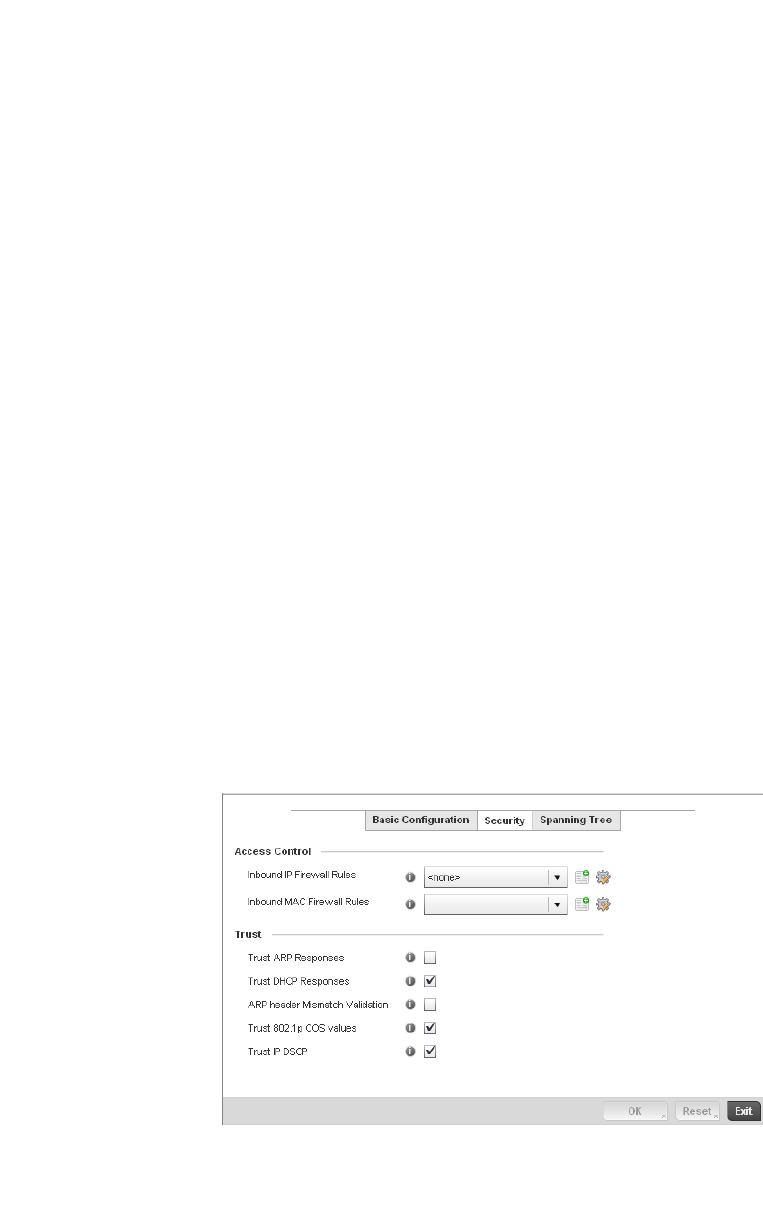
Brocade Mobility RFS4000, RFS6000, and RFS7000 System Reference Guide 391
53-1002620-01
7
8. Define the following Switching Mode parameters to apply to the port channel configuration:
9. Select OK to save the changes made to the port channel Basic Configuration. Select Reset to
revert to the last saved configuration.
10. Select the Security tab.
FIGURE 265 Port Channels - Security screen
11. Refer to the Access Control section. As part of the port channel’s security configuration,
Inbound IP and MAC address firewall rules are required.
Mode Select either the Access or Trunk radio button to set the VLAN switching mode over
the port channel. If Access is selected, the port channel accepts packets only form
the native VLANs. Frames are forwarded out the port untagged with no 802.1Q
header. All frames received on the port are expected as untagged and are mapped
to the native VLAN. If the mode is set to Trunk, the port channel allows packets from
a list of VLANs you add to the trunk. A port channel configured as Trunk supports
multiple 802.1Q tagged VLANs and one Native VLAN which can be tagged or
untagged. Access is the default setting.
Native VLAN Use the spinner control to define a numerical ID between 1 - 4094. The native VLAN
allows an Ethernet device to associate untagged frames to a VLAN when no 802.1Q
frame is included in the frame. Additionally, the native VLAN is the VLAN which
untagged traffic will be directed over when using trunk mode. The default value is 1.
Tag the Native VLAN Select the checkbox to tag the native VLAN. Controllers support the IEEE 802.1Q
specification for tagging frames and coordinating VLANs between devices. IEEE
802.1Q adds four bytes to each frame identifying the VLAN ID for upstream devices
that the frame belongs. If the upstream Ethernet device does not support IEEE
802.1Q tagging, it does not interpret the tagged frames. When VLAN tagging is
required between devices, both devices must support tagging and be configured to
accept tagged VLANs. When a frame is tagged, the 12 bit frame VLAN ID is added to
the 802.1Q header so upstream Ethernet devices know which VLAN ID the frame
belongs to. The device reads the 12 bit VLAN ID and forwards the frame to the
appropriate VLAN. When a frame is received with no 802.1Q header, the upstream
device classifies the frame using the default or native VLAN assigned to the Trunk
port. The native VLAN allows an Ethernet device to associate untagged frames to a
VLAN when no 802.1Q frame is included in the frame. This setting is disabled by
default.
Allowed VLANs Selecting Trunk as the mode enables the Allowed VLANs parameter. Add VLANs that
exclusively send packets over the port channel.
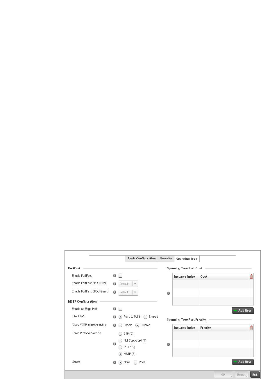
392 Brocade Mobility RFS4000, RFS6000, and RFS7000 System Reference Guide
53-1002620-01
7
Use the Inbound IP Firewall Rules and Inbound MAC Firewall Rules drop-down menus to select
firewall rules to apply to this profile’s port channel configuration.
The firewall inspects IP and MAC traffic flows and detects attacks typically not visible to
traditional wired firewall appliances.
If a firewall rule does not exist suiting the data protection needs of the target port channel
configuration, select the Create icon to define a new rule configuration or the Edit icon to
modify an existing firewall rule configuration. For more information, see Wireless Firewall on
page 9-511.
12. Refer to the Trust field to define the following:
13. Select OK to save the changes to the security configuration. Select Reset to revert to the last
saved configuration.
14. Select the Spanning Tree tab.
FIGURE 266 Port Channels - Spanning Tree screen
Trust ARP Responses Select the check box to enable ARP trust on this port channel. ARP packets
received on this controller port are considered trusted and information from these
packets is used to identify rogue devices within the managed network. The default
value is disabled.
Trust DHCP Responses Select the check box to enable DHCP trust. If enabled, only DHCP responses are
trusted and forwarded on this port channel, and a DHCP server can be connected
only to a DHCP trusted port. The default value is enabled.
ARP header Mismatch
Validation
Select the check box to enable a mismatch check for the source MAC in both the
ARP and Ethernet header. The default value is enabled.
Trust 802.1p COS values Select the check box to enable 802.1p COS values on this port channel. The
default value is enabled.
Trust IP DSCP Select the check box to enable IP DSCP values on this port channel. The default
value is disabled.

Brocade Mobility RFS4000, RFS6000, and RFS7000 System Reference Guide 393
53-1002620-01
7
15. Define the following PortFast parameters for the port channel’s MSTP configuration:
16. Set the following MSTP Configuration parameters for the port channel:
17. Refer to the Spanning Tree Port Cost table.
18. Define an Instance Index using the spinner control and then set the cost. The default path cost
depends on the user defined port speed.The cost helps determine the role of the port channel
in the MSTP network. The designated cost is the cost for a packet to travel from this port to the
root in the MSTP configuration. The slower the media, the higher the cost.
Enable PortFast Select the check box to enable drop-down menus for both the port Enable Portfast
BPDU Filter and Enable Portfast BPDU guard options. This setting is disabled by
default.
PortFast BPDU Filter Select Enable to invoke a BPDU filter for this portfast enabled port channel. Enabling
the BPDU filter feature ensures this port channel does not transmit or receive any
BPDUs. The default setting is None.
PortFast BPDU Guard Select Enable to invoke a BPDU guard for this portfast enabled port channel.
Enabling the BPDU Guard feature means this port will shutdown on receiving a
BPDU. Thus, no BPDUs are processed. The default setting is None.
Enable as Edge Port Select the check box to define this port as an edge port. Using an edge (private)
port, you can isolate devices to prevent connectivity over this port channel. This
setting is disabled by default.
Link Type Select either the Point-to-Point or Shared radio button. Selecting Point-to-Point
indicates the port should be treated as connected to a point-to-point link. Selecting
Shared indicates this port should be treated as having a shared connection. A port
connected to a hub is on a shared link, while one connected to a controller is a
point-to-point link. Point-to-Point is the default setting.
Cisco MSTP
Interoperability
Select either the Enable or Disable radio buttons. This enables interoperability with
Cisco’s version of MSTP, which is incompatible with standard MSTP. This setting is
disabled by default.
Force Protocol Version Sets the protocol version to either STP(0), Not Supported(1), RSTP(2) or MSTP(3).
MSTP is the default setting.
Guard Determines whether the port channel enforces root bridge placement. Setting the
guard to Root ensures the port is a designated port. Typically, each guard root port
is a designated port, unless two or more ports (within the root bridge) are
connected together. If the bridge receives superior (BPDUs) on a guard
root-enabled port, the guard root moves the port to a root-inconsistent STP state.
This state is equivalent to a listening state. No data is forwarded across the port.
Thus, the guard root enforces the root bridge position.
Speed Default Path Cost
<=100000 bits/sec 200000000
<=1000000 bits/sec 20000000
<=10000000 bits/sec 2000000
<=100000000 bits/sec 200000
<=1000000000 bits/sec 20000

394 Brocade Mobility RFS4000, RFS6000, and RFS7000 System Reference Guide
53-1002620-01
7
19. Select + Add Row as needed to include additional indexes.
20. Refer to the Spanning Tree Port Priority table.
21. Define or override an Instance Index using the spinner control and then set the Priority. The
lower the priority, a greater likelihood of the port becoming a designated port.
22. Select + Add Row needed to include additional indexes.
23. Select OK to save the changes made to the Ethernet Port Spanning Tree configuration. Select
Reset to revert to the last saved configuration.
Access Point Radio Configuration
Profile Interface Configuration
Access Points can have their radio configurations modified by their connected controller once their
radios have successfully associated. Take care not to modify an Access Point’s configuration using
its resident Web UI, CLI or SNMP interfaces when managed by a controller profile, or risk the
Access Point having a configuration independent from the profile until the profile can be uploaded
to the Access Point again.
To define a Access Point radio configuration from the Access Point’s associated controller:
1. Select Configuration > Profiles > Interface.
2. Expand the Interface menu to display its submenu options.
3. Select Radios.
<=10000000000 bits/sec 2000
<=100000000000 bits/sec 200
<=1000000000000 bits/sec 20
>1000000000000 bits/sec 2
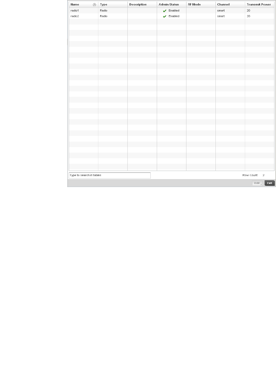
Brocade Mobility RFS4000, RFS6000, and RFS7000 System Reference Guide 395
53-1002620-01
7
FIGURE 267 Access Point - Radios screen
4. Review the following to determine whether a radio configuration requires modification to better
support the managed network:
Name Displays whether the reporting radio is the Access Point’s radio1, radio2 or radio3.
Legacy br-7131 models contain either a single or a dual radio configuration. Newer
br-7131N model Access Points support single, dual or triple radio configurations. An
Brocade Mobility 650 Access Point model Access Point is available in either single or
dual radio models.
Type Displays the type of radio housed by each listed Access Point.
Description Displays a brief description of the radio provided by the administrator when the
radio’s configuration was added or modified.
Admin Status A green checkmark defines the listed radio as active and enabled with its supported
controller profile. A red “X” defines the radio as currently disabled.
RF Mode Displays whether each listed radio is operating in the 802.11a/n or
802.11b/g/n radio band. If the radio is a dedicated sensor, it will be listed as a
sensor to define the radio as not providing WLAN support. The radio band is set from
within the Radio Settings tab.
Channel Lists the channel setting for the radio. Smart is the default setting. If set to smart,
the Access Point scans non-overlapping channels listening for beacons from other
Access Points. After the channels are scanned, it selects the channel with the fewest
Access Points. In the case of multiple access points on the same channel, it will
select the channel with the lowest average power level.
Transmit Power Lists the transmit power for each radio displayed as a value in miliwatts.
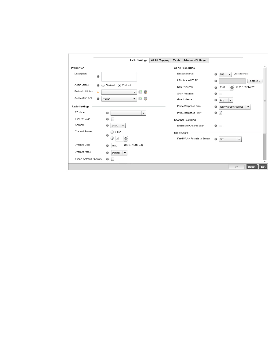
396 Brocade Mobility RFS4000, RFS6000, and RFS7000 System Reference Guide
53-1002620-01
7
5. If required, select a radio configuration and select the Edit button to modify its configuration.
FIGURE 268 Access Point Radio - Settings tab
6. The Radio Settings tab displays by default.
7. Define the following radio configuration parameters from within the Properties field:
Description Provide or edit a description (1 - 64 characters in length) for the radio that helps
differentiate it from others with similar configurations.
Admin Status Either select Active or Shutdown to define this radio’s current status within the
managed network. When defined as Active, the Access Point is operational and
available for client support within the managed network.
Radio QoS Policy Use the drop-down menu to specify an existing QoS policy to apply to the Access
Point radio in respect to its intended radio traffic. If there’s no existing suiting the
radio’s intended operation, select the Create icon to define a new QoS policy that
can be applied to this controller profile. For more information, see Radio QoS Policy
on page 6-332.
Association ACL Use the drop-down menu to specify an existing Association ACL policy to apply to the
Access Point radio. An Association ACL is a policy-based ACL that either prevents or
allows wireless clients from connecting to a managed Access Point radio. An ACL is a
sequential collection of permit and deny conditions that apply to controller packets.
When a packet is received on an interface, the controller compares the fields in the
packet against any applied ACLs to verify the packet has the required permissions to
be forwarded, based on the criteria specified in the access lists. If a packet does not
meet any of the criteria specified in the ACL, the packet is dropped. Select the
Create icon to define a new Association ACL that can be applied to this controller
profile. For more information, see Association ACL on page 6-352.

Brocade Mobility RFS4000, RFS6000, and RFS7000 System Reference Guide 397
53-1002620-01
7
8. Set the following profile Radio Settings for the selected Access Point radio.
RF Mode Set the mode to either 2.4 GHz WLAN or 5 GHz WLAN support depending on the
radio’s intended client support. Set the mode to Sensor if using the radio for rogue
device detection. To a radio as a detector, disable Sensor support on the other
Access Point radio.
Lock RF Mode Select the check box to lock Smart RF for this radio. The default setting is disabled.
Channel Use the drop-down menu to select the channel of operation for the radio. Only a
trained installation professional should define the radio channel.Select Smart for
the radio to scan non-overlapping channels listening for beacons from other Access
Points. After the channels are scanned, the radio selects the channel with the fewest
Access Points. In the case of multiple Access Points on the same channel, it will
select the channel with the lowest average power level. The default value is Smart.
Transmit Power Set the transmit power of the selected Access Point radio. If using a dual or three
radio model Access Point, each radio should be configured with a unique transmit
power in respect to its intended client support function. A setting of 0 defines the
radio as using Smart RF to determine its output power. 20 dBm is the default value.
Antenna Gain Set the antenna between 0.00 - 15.00 dBm. The access point’s Power Management
Antenna Configuration File (PMACF) automatically configures the access point’s
radio transmit power based on the antenna type, its antenna gain (provided here)
and the deployed country’s regulatory domain restrictions. Once provided, the
access point calculates the power range. Antenna gain relates the intensity of an
antenna in a given direction to the intensity that would be produced ideally by an
antenna that radiates equally in all directions (isotropically), and has no losses.
Although the gain of an antenna is directly related to its directivity, its gain is a
measure that takes into account the efficiency of the antenna as well as its
directional capabilities. Brocade recommends that only a professional installer set
the antenna gain. The default value is 0.00.
Antenna Mode Set the number of transmit and receive antennas on the Access Point. 1x1 is used
for transmissions over just the single “A” antenna, 1x3 is used for transmissions over
the “A” antenna and all three antennas for receiving. 2x2 is used for transmissions
and receipts over two antennas for dual antenna models. The default setting is
dynamic based on the Access Point model deployed and its transmit power settings.
Enable Antenna
Diversity
Select this box to enable antenna diversity on supported antennas. Antenna diversity
uses two or more antennas to increase signal quality and strength. This option is
disabled by default.
Data Rates Once the radio band is provided, the Data Rates drop-down menu populates with
rate options depending on the 2.4 or 5 GHz band selected. If the radio band is set to
Sensor or Detector, the Data Rates drop-down menu is not enabled, as the rates are
fixed and not user configurable. If 2.4 GHz is selected as the radio band, select
separate 802.11b, 802.11g and 802.11n rates and define how they are used in
combination. If 5 GHz is selected as the radio band, select separate 802.11a and
802.11n rates then define how they are used together. When using 802.11n (in
either the 2.4 or 5 GHz band), Set a MCS (modulation and coding scheme) in respect
to the radio’s channel width and guard interval. A MCS defines (based on RF channel
conditions) an optimal combination of 8 data rates, bonded channels, multiple
spatial streams, different guard intervals and modulation types. Clients can
associate as long as they support basic MCS (as well as non-11n basic rates).
Radio Placement Use the drop-down menu to specify whether the radio is located Indoors or Outdoors.
The placement should depend on the country of operation and its regulatory domain
requirements for radio emissions.The default setting is Indoors.
Max Clients Use the spinner control to set a maximum permissible number of clients to connect
with this radio. The available range is between 0 - 256 clients. The default value is
256.

398 Brocade Mobility RFS4000, RFS6000, and RFS7000 System Reference Guide
53-1002620-01
7
9. Set the following profile WLAN Properties for the selected Access Point radio.
Beacon Interval Set the interval between radio beacons in milliseconds (either 50, 100 or 200). A
beacon is a packet broadcast by adopted radios to keep the network synchronized.
Included in a beacon is information such as the WLAN service area, the radio
address, the broadcast destination addresses, a time stamp, and indicators about
traffic and delivery such as a DTIM. Increase the DTIM/beacon settings (lengthening
the time) to let nodes sleep longer and preserve battery life. Decrease these settings
(shortening the time) to support streaming-multicast audio and video applications
that are jitter-sensitive.The default value is 100 milliseconds.
DTIM Interval BSSID Set a DTIM Interval to specify a period for Delivery Traffic Indication Messages
(DTIM). A DTIM is periodically included in a beacon frame transmitted from adopted
radios. The DTIM period determines how often the beacon contains a DTIM, for
example, 1 DTIM for every 10 beacons. The DTIM indicates broadcast and multicast
frames (buffered at the Access Point) are soon to arrive. These are simple data
frames that require no acknowledgement, so nodes sometimes miss them. Increase
the DTIM/ beacon settings (lengthening the time) to let nodes sleep longer and
preserve their battery life. Decrease these settings (shortening the time) to support
streaming multicast audio and video applications that are jitter-sensitive.
RTS Threshold Specify a Request To Send (RTS) threshold (between 1 - 2,347 bytes) for use by the
WLAN's adopted Access Point radios. RTS is a transmitting station's signal that
requests a Clear To Send (CTS) response from a receiving client. This RTS/CTS
procedure clears the air where clients are contending for transmission time. Benefits
include fewer data collisions and better communication with nodes that are hard to
find (or hidden) because of other active nodes in the transmission path.
Control RTS/CTS by setting an RTS threshold. This setting initiates an RTS/CTS
exchange for data frames larger than the threshold, and sends (without RTS/CTS)
any data frames smaller than the threshold.
Consider the trade-offs when setting an appropriate RTS threshold for the WLAN's
Access Point radios. A lower RTS threshold causes more frequent RTS/CTS
exchanges. This consumes more bandwidth because of additional latency (RTS/CTS
exchanges) before transmissions can commence. A disadvantage is the reduction in
data-frame throughput. An advantage is quicker system recovery from
electromagnetic interference and data collisions. Environments with more wireless
traffic and contention for transmission make the best use of a lower RTS threshold.
A higher RTS threshold minimizes RTS/CTS exchanges, consuming less bandwidth
for data transmissions. A disadvantage is less help to nodes that encounter
interference and collisions. An advantage is faster data-frame throughput.
Environments with less wireless traffic and contention for transmission make the
best use of a higher RTS threshold.
Short Preamble If using an 802.11bg radio, select this checkbox for the radio to transmit using a
short preamble. Short preambles improve throughput. However, some devices
(SpectraLink phones) require long preambles. The default value is disabled.
Guard Interval Use the drop-down menu to specify a Long or Any guard interval. The guard interval is
the space between the packets being transmitted. The guard interval is there to
eliminate inter-symbol interference (ISI). ISI occurs when echoes or reflections from
one transmission interfere with another. Adding time between transmissions allows
echo's and reflections to settle before the next packet is transmitted. A shorter guard
interval results in a shorter times which reduces overhead and increases data rates
by up to 10%.The default value is Long.
Probe Response Rate Use the drop-down menu to specify the data transmission rate used for the
transmission of probe responses. Options include, highest-basic, lowest-basic and
follow-probe-request (default setting).
Probe Response Retry Select the check box to retry probe responses if they are not acknowledged by the
target wireless client. The default value is enabled.
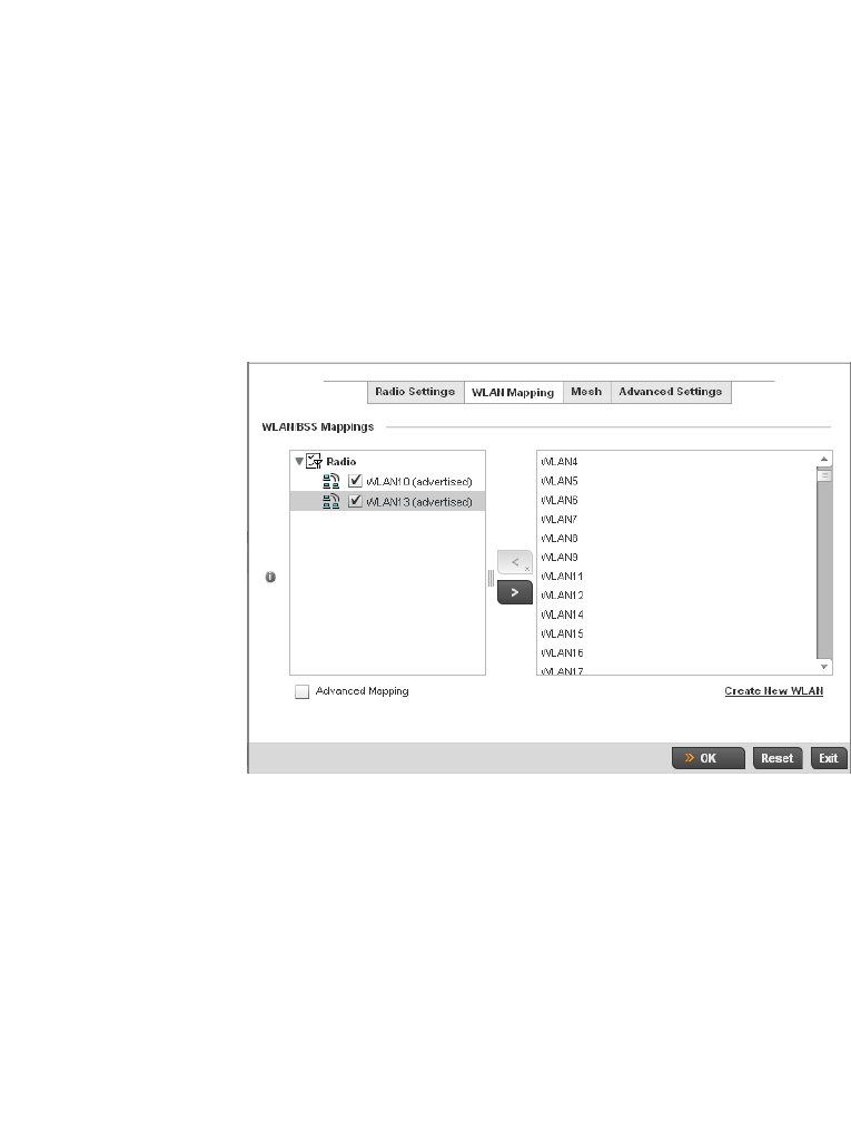
Brocade Mobility RFS4000, RFS6000, and RFS7000 System Reference Guide 399
53-1002620-01
7
10. Select the Enable Off Channel Scan check box to enable scanning across all channels using
this radio. Channel scans use Access Point resources and can be time consuming, so only
enable when your sure the radio can afford the bandwidth be directed towards to the channel
scan and does not negatively impact client support.
11. Select a mode from the Feed WLAN Packets to Sensor check box in the Radio Share section to
enable this feature. Select either Inline or Promiscuous mode to allow the packets the radio is
switching to also be used by the WIPS analysis module. This feature can be enabled in two
modes: an inline mode where the wips sensor receives the packets from the radios with radio
operating in normal mode. A promiscuous mode where the radio is configured to a mode
where it receives all packets on the channel whether the destination addres is the radio or not,
and the wips module can analyze them.
12. Select the WLAN Mapping tab.
FIGURE 269 Access Point Radio - WLAN Mapping screen
13. Refer to the WLAN/BSS Mappings field to set WLAN BSSID assignments for an existing Access
Point deployment.
Administrators can assign each WLAN its own BSSID. If using a single-radio access point, there
are 8 BSSIDs available. If using a dual-radio access point there are 8 BSSIDs for the
802.11b/g/n radio and 8 BSSIDs for the 802.11a/n radio.
14. Select Advanced Mapping to enable WLAN mapping to a specifc BSS ID.
15. Select the OK button located at the bottom right of the screen to save the changes to the WLAN
Mapping. Select Reset to revert to the last saved configuration.
16. Select the MeshConnex tab.
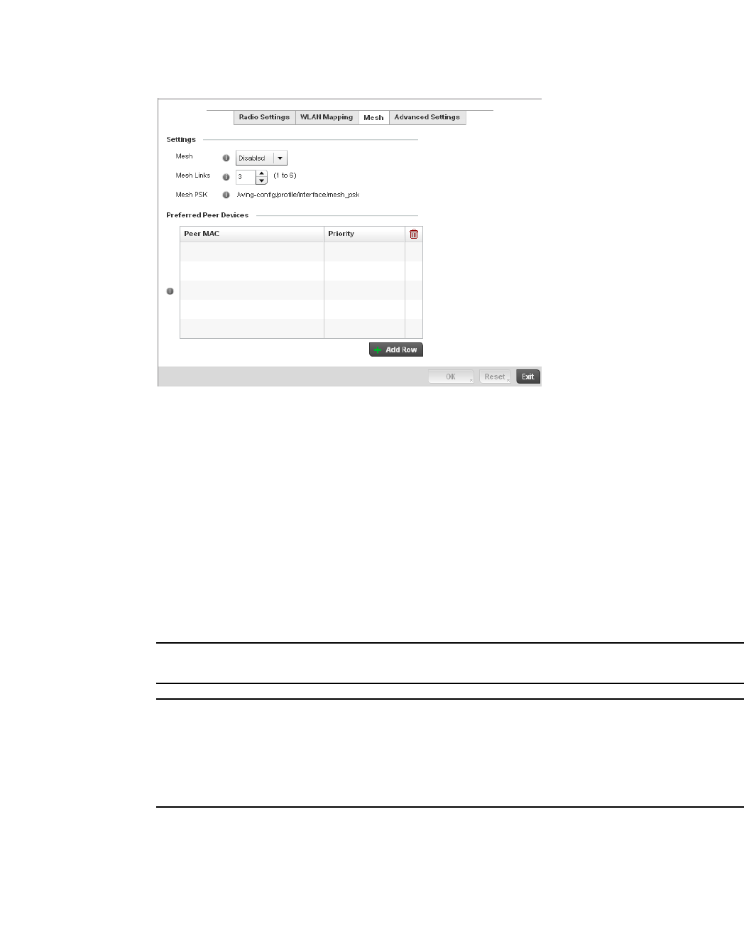
400 Brocade Mobility RFS4000, RFS6000, and RFS7000 System Reference Guide
53-1002620-01
7
FIGURE 270 Profile Overrides - Access Point Radio Mesh tab
17. Refer to the Advanced Settings field to define or override basic mesh settings for the Access
Point radio.
NOTE
Only single hop mesh links are supported at this time.
NOTE
The mesh encryption key is configurable from the Command Line Interface (CLI) using the command
'mesh psk'. Administrators must ensure that this key is configured on the AP when it is being staged
for mesh, and also added to the mesh client as well as to the portal APs configuration on the
controller. For more information about the CLI please see the Brocade Mobility RFS4000, RFS6000
and RFS7000 CLI Reference Guide.
18. Refer to the Preferred Peer Device table to add mesh peers. For each peer being added enter
its MAC Address and a Priority between 1 and 6. The lower the priority number the higher
priority it'll be given when connecting to mesh infrastructure.
19. Select the + Add Row button to add preffered peer devices for the radio to connect to in mesh
mode.
20. Select the Advanced Settings tab.
Mesh Use the pulldown to set the mesh mode for this radio. Available options are Disabled,
Portal or Client. Setting the mesh mode to Disabled deactivates all mesh activity on
this radio. Setting the mesh mode to Portal turns the radio into a mesh portal. This
will start the radio beaconing immediately and will accept connections from other
mesh nodes. Setting the mesh mode to client enables the radio to operate as a mesh
client that will scan for and connect to mesh portals or nodes that are connected to
portals.
Mesh Links Specify the number of mesh links allowed by the radio. The radio can have between
1-6 mesh links when the radio is configured as a Portal or Client.

Brocade Mobility RFS4000, RFS6000, and RFS7000 System Reference Guide 401
53-1002620-01
7
FIGURE 271 Access Point Radio - Advanced Settings screen
21. Refer to the Aggregate MAC Protocol Data Unit (A-MPDU) field to define how MAC service
frames are aggregated by the Access Point radio.
22. Use the A-MSDU Modes drop-down menu in the Aggregate MAC Service Data Unit (A-MSDU)
section to set or override the supported A-MSDU mode.
Available modes include Receive Only and Transmit and Receive. Transmit and Receive is the
default value. Using Transmit and Receive, frames up to 4 KB can be sent and received. The
buffer limit is not configurable.
23. Define a RIFS Mode using the drop-down menu in the Reduced Interframe Spacing (RIFS)
section. This value determines whether interframe spacing is applied to Access Point
transmissions or received packets, or both or none. The default mode is Transmit and Receive.
Consider setting this value to None for high priority traffic to reduce packet delay.
24. Set the following Non-Unicast Traffic values for the profile’s supported Access Point radio and
its connected wireless clients:
A-MPDU Modes Use the drop-down menu to define the A-MPDU mode supported. Options include
Transmit Only, Receive Only, Transmit and Receive and None. The default value is
Transmit and Receive. Using the default value, long frames can be both sent and
received (up to 64 KB). When enabled, define either a transmit or receive limit (or
both).
Minimum Gap Between
Frames
Use the drop-down menu to define the minimum gap between A-MPDU frames (in
microseconds). The default value is 4 microseconds.
Received Frame Size
Limit
If a support mode is enable allowing A-MPDU frames to be received, define an
advertised maximum limit for received A-MPDU aggregated frames. Options include
8191, 16383, 32767 or 65535 bytes. The default value is 65535 bytes.
Transmit Frame Size
Limit
Use the spinner control to set limit on transmitted A-MPDU aggregated frames. The
available range is between 0 - 65,535 bytes). The default value is 65535 bytes.
Broadcast/Multicast
Transmit Rate
Use the drop-down menu to define the data rate broadcast and multicast frames are
transmitted. Seven different rates are available if the not using the same rate for
each BSSID, each with a separate menu.
Broadcast/Multicast
Forwarding
Define whether client broadcast and multicast packets should always follow DTIM, or
only follow DTIM when using Power Save Aware mode. The default setting is Follow
DTIM.

402 Brocade Mobility RFS4000, RFS6000, and RFS7000 System Reference Guide
53-1002620-01
7
25. Refer to the Sniffer Redirect (Packet Capture) field to define the radio’s captured packet
configuration.
26. Select the OK button located at the bottom right of the screen to save the changes to the
Advanced Settings screen. Select Reset to revert to the last saved configuration.
WAN Backhaul Override Configuration
Profile Interface Configuration
A Wireless Wide Area Network (WWAN) card is a specialized network interface card that allows a
network device to connect, transmit and receive data over a Cellular Wide Area Network. The
AP71xx, RFS4000 and RFS6000 all have a PCI Express card slot that supports 3G WWAN cards.
The WWAN card uses point to point protocol (PPP) to connect to the Internet Service Provider (ISP)
and gain access to the Internet. PPP is the protocol used for establishing internet links over dial-up
modems, DSL connections, and many other types of point-to-point communications. PPP packages
your system’s TCP/IP packets and forwards them to the serial device where they can be put on the
network. PPP is a full-duplex protocol that can be used on various physical media, including twisted
pair or fiber optic lines or satellite transmission. It uses a variation of High Speed Data Link Control
(HDLC) for packet encapsulation.
To define a WAN Backhaul configuration override:
1. Select Devices from the Configuration tab.
The Device Configuration screen displays a list of managed devices or peer controllers. The
listed devices can either be other controllers or Access Points within the managed network.
2. Select a target Access Point (by double-clicking it) from amongst those displayed within the
Device Configuration screen.
Devices can also be selected directly from the Device Browser in the lower, left-hand, side of
the UI.
3. Select Profile Overrides from the Device menu to expand it into sub menu options.
4. Select Interface to expand its sub menu options.
5. Select WAN Backhaul.
Host for Redirected
Packets
If packets are re-directed from a controller’s connected Access Point radio, define an
IP address of a resource (additional host system) used to capture the re- directed
packets. This address is the numerical (non DNS) address of the host used to
capture the re-directed packets.
Channel to Capture
Packets
Use the drop-down menu to specify the channel used to capture re-directed packets.
The default value is channel 1.
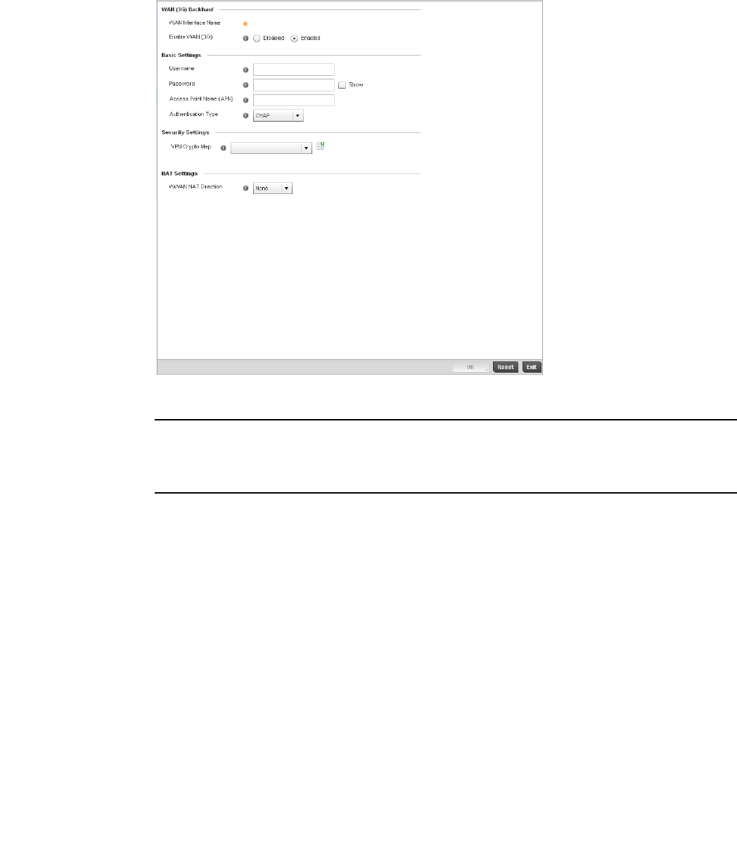
Brocade Mobility RFS4000, RFS6000, and RFS7000 System Reference Guide 403
53-1002620-01
7
FIGURE 272 Profile Overrides -WAN Backhaul screen
NOTE
A blue override icon (to the left of a parameter) defines the parameter as having an override applied.
To remove an override go to the Basic Configuration section of the device and click the Clear
Overrides button. This will remove all overrides from the device.
6. Refer to the WAN (3G) Backhaul configuration to specify WAN card settings:
7. Define or override the following authentication parameters from within the Basic Settings field:
8. Select OK to save or override the changes to the Advanced Settings screen. Select Reset to
revert to the last saved configuration.
WAN Interface Name Displays the WAN Interface name for the WAN 3G Backhaul card.
Reset WAN Card If the WAN Card becomes unresponsive or is experiencing other errors click the Reset
WAN Card button to power cycle and reboot the WAN card.
Enable WAN (3G) Check this box to enable 3G WAN card support on the device. A supported 3G card
must be connected to the device for this feature to work.
Username Provide your username for authentication support by your cellular data carrier.
Password Provide your password for authentication support by your cellular data carrier.
Access Point Name
(APN)
Enter the name of the cellular data provider if necessary. This setting is needed in
areas with multiple cellular data providers using the same protocols such as Europe,
the middle east and Asia.
Authentication Type Use the pull-down menu to specify authentication type used by your cellular data
provider. Supported authentication types are None, PAP, CHAP, MSCHAP, and
MSCHAP-v2.

404 Brocade Mobility RFS4000, RFS6000, and RFS7000 System Reference Guide
53-1002620-01
7
PPPoE Configuration
Profile Interface Configuration
PPP over Ethernet (PPPoE) is a data-link protocol for dialup connections. PPPoE allows the access
point to use a broadband modem (DSL, cable modem, etc.) for access to high-speed data and
broadband networks. Most DSL providers are currently supporting (or deploying) the PPPoE
protocol. PPPoE uses standard encryption, authentication, and compression methods as specified
by the PPPoE protocol. PPPoE enables Brocade Mobility supported controllers and access points to
establish a point-to-point connection to an ISP over existing Ethernet interface.
To provide this point-to-point connection, each PPPoE session learns the Ethernet address of a
remote PPPoE client, and establishes a session. PPPoE uses both a discover and session phase to
identify a client and establish a point-to-point connection. By using such a connection, a Wireless
WAN failover is available to maintain seamless network access if the access point’s Wired WAN
were to fail.
NOTE
Devices with PPPoE enabled continue to support VPN, NAT, PBR and 3G failover over the PPPoE
interface. Multiple PPPoE sessions are supported using a single user account user account if
RADIUS is configured to allow simultaneous access.
NOTE
PPPoE is supported on br-7131 models and is not available on br-6511 model access points.
When PPPoE client operation is enabled, it discovers an available server and establishes a PPPoE
link for traffic slow. When a wired WAN connection failure is detected, traffic flows through the
WWAN interface in fail-over mode (if the WWAN network is configured and available). When the
PPPoE link becomes accessible again, traffic is redirected back through the access point’s wired
WAN link.
When the access point initiates a PPPoE session, it first performs a discovery to identify the
Ethernet MAC address of the PPPoE client and establish a PPPoE session ID. In discovery, the
PPPoE client discovers a server to host the PPPoE connection.
To create a PPPoE point-to-point configuration
1. Select Devices from the Configuration tab.
The Device Configuration screen displays a list of managed devices or peer controllers. The
listed devices can either be other controllers or Access Points within the managed network.
2. Select a target Access Point (by double-clicking it) from amongst those displayed within the
Device Configuration screen.
3. Devices can also be selected directly from the Device Browser in the lower, left-hand, side of
the UI.
4. Select Profile Overrides from the Device menu to expand it into sub menu options.
5. Select Interface to expand its sub menu options.
6. Select PPPoE.
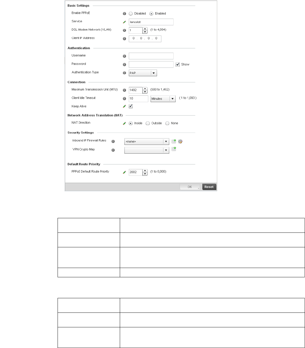
Brocade Mobility RFS4000, RFS6000, and RFS7000 System Reference Guide 405
53-1002620-01
7
FIGURE 273 Profile Overrides -PPPoE screen
7. Use the Basic Settings field to enable PPPoE and define a PPPoE client
8. Define the following Authentication parameters for PPPoE client interoperation:
Enable PPPoE Select Enable to support a high speed client mode point-to-point connection using the
PPPoE protocol. The default setting is disabled.
Service Enter the 128 character maximum PPPoE client service name provided by the service
provider.
DSL Modem Network
(VLAN)
Use the spinner control to set the PPPoE VLAN (client local network) connected to the
DSL modem. This is the local network connected to DSL modem. The available range is
1 - 4,094. The default VLAN is VLAN1
Client IP Address Provide the numerical (non hostname) IP address of the PPPoE client.
Username Provide the 64 character maximum username used for authentication support by the
PPPoE client.
Password Provide the 64 character maximum password used for authentication by the PPPoE
client.
Authentication Type Use the drop-down menu to specify authentication type used by the PPPoE client, and
whose credentials must be shared by its peer access point. Supported authentication
options include None, PAP, CHAP, MSCHAP, and MSCHAP-v2.

406 Brocade Mobility RFS4000, RFS6000, and RFS7000 System Reference Guide
53-1002620-01
7
9. Define the following Connection settings for the PPPoE point-to-point connection with the
PPPoE client:
10. Set the Network Address Translation (NAT) direction for the PPPoE configuration.
Network Address Translation (NAT) converts an IP address in one network to a different IP
address or set of IP addresses in another network. The access point router maps its local
(Inside) network addresses to WAN (Outside) IP addresses, and translates the WAN IP
addresses on incoming packets to local IP addresses. NAT is useful because it allows the
authentication of incoming and outgoing requests, and minimizes the number of WAN IP
addresses needed when a range of local IP addresses is mapped to each WAN IP address. The
default setting is None (neither inside or outside).
11. Define the following Security Settings for the PPPoE configuration:
12. Use the spinner control to set the Default Route Priority for the default route learnt using
PPPoE.
Select from 1 - 8,000. The default setting is 2,000.
13. Select OK to save the changes to the PPPoE screen. Select Reset to revert to the last saved
configuration. Saved configurations are persistent across reloads.
Profile Interface Deployment Considerations
Profile Interface Configuration
Before defining a profile’s interface configuration (supporting controller’s Ethernet port, Virtual
Interface, port channel and Access Point radio configurations) refer to the following deployment
guidelines to ensure these configuration are optimally effective:
•Power over Ethernet is supported on RFS4000 and RFS6000 model controllers only. When
enabled, the controller supports 802.3af PoE on each of its ge ports.
•When changing from a default DHCP address to a fixed IP address, set a static route first. This
is critical when the controller is being accessed from a subnet not directly connected to the
controller and the default route was set from DHCP.
Maximum Transmission
Unit (MTU)
Set the PPPoE client maximum transmission unit (MTU) from 500 - 1,492. The MTU is
the largest physical packet size in bytes a network can transmit. Any messages larger
than the MTU are divided into smaller packets before being sent. A PPPoE client should
be able to maintain its point-to-point connection for this defined MTU size. The default
MTU is 1,492.
Client Idle Timeout Set a timeout in either Seconds (1 - 65,535), Minutes (1 - 1,093) or Hours. The access
point uses the defined timeout so it does not sit idle waiting for input from the PPPoE
client and server that may never come. The default setting is 10 minutes.
Keep Alive Select this option to ensure the point-to-point connect to the PPPoE client is
continuously maintained and not timed out. This setting is disabled by default.
Inbound IP Firewall
Rules
Use the drop-down menu to select a firewall (set of IP access connection rules) to apply
to the PPPoE client connection. If a firewall rule does not exist suiting the data
protection needs of the PPPoE client connection, select the Create icon to define a
new rule configuration or the Edit icon to modify an existing rule. For more information,
see Wireless Firewall on page 9-511.
VPN Crypto Map Use the drop-down menu to apply an existing crypt map configuration to this PPPoE
interface.

Brocade Mobility RFS4000, RFS6000, and RFS7000 System Reference Guide 407
53-1002620-01
7
•Take care not to modify an Access Point’s configuration using its resident Web UI, CLI or SNMP
interfaces when managed by a controller profile, or risk the Access Point having a configuration
independent from the profile until the profile can be uploaded to the Access Point once again.
Profile Network Configuration
Setting a profile’s network configuration is a large task comprised of numerous controller
administration activities.
A profile’s network configuration process consists of the following:
•Setting a Profile’s DNS Configuration
•ARP
•Quality of Service (QoS) Configuration
•Spanning Tree
•Routing Configuration
•Forwarding Database
•Bridge VLAN
•Miscellaneous Network Configuration
Before beginning any of the profile network configuration activities described in the sections above,
review the configuration and deployment considerations available in Profile Network Configuration
and Deployment Considerations on page 7-441.
Setting a Profile’s DNS Configuration
Profile Network Configuration
Domain Naming System (DNS) DNS is a hierarchical naming system for resources connected to the
Internet or a private network. Primarily, the controller’s DNS resources translate domain names into
IP addresses. If one DNS server doesn't know how to translate a particular domain name, it asks
another one until the correct IP address is returned. DNS enables access to resources using
human friendly notations. DNS converts human friendly domain names into notations used by
different networking equipment for locating resources.
As a resource is accessed (using human-friendly hostnames), it’s possible to access the resource
even if the underlying machine friendly notation name changes. Without DNS, in the simplest
terms, you would need to remember a series of numbers (123.123.123.123) instead of an easy to
remember domain name (for example, www.domainname.com).
The controller maintains its own DNS facility that can assist in domain name translation.
To define the controller’s DNS configuration:
1. Select Configuration > Profiles > Network.
2. Expand the Network menu to display its submenu options.
3. Select DNS.
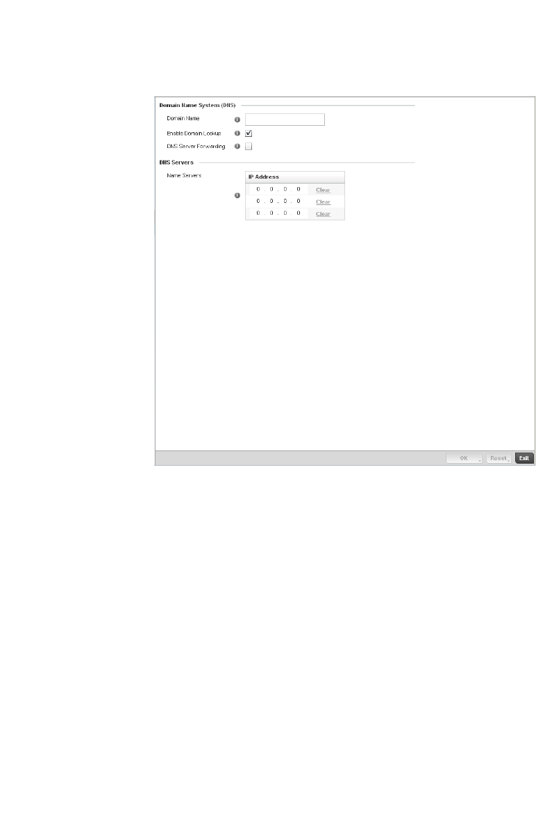
408 Brocade Mobility RFS4000, RFS6000, and RFS7000 System Reference Guide
53-1002620-01
7
FIGURE 274 DNS screen
4. Set or override the following controller Domain Name System (DNS) configuration data:
5. Set or override the following controller DNS Server configuration data:
6. Select OK to save the changes made to the DNS configuration. Select Reset to revert to the
last saved configuration.
ARP
Profile Network Configuration
Address Resolution Protocol (ARP) is a protocol for mapping an IP address to a hardware MAC
address recognized on the managed network. ARP provides protocol rules for making this
correlation and providing address conversion in both directions.
Domain Name Provide or override the default Domain Name used to resolve DNS names. The name
cannot exceed 64 characters.
Enable Domain Lookup Select the check box to enable DNS on the controller. When enabled, the controller can
convert human friendly domain names into numerical IP destination addresses. The
radio button is selected by default.
DNS Server Forwarding Click to enable the forwarding DNS queries to external DNS servers if a DNS query
cannot be processed by the controller’s own DNS resources. This feature is disabled by
default.
Name Servers Provide a list of up to three DNS servers to forward DNS queries if the controller’s DNS
resources are unavailable. The DNS name servers are used to resolve IP addresses. Use
the Clear link next to each DNS server to clear the DNS name server’s IP address from
the list.
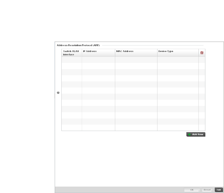
Brocade Mobility RFS4000, RFS6000, and RFS7000 System Reference Guide 409
53-1002620-01
7
When an incoming packet destined for a host arrives at the controller, the controller gateway uses
ARP to find a physical host or MAC address that matches the IP address. ARP looks in its ARP
cache and, if it finds the address, provides it so the packet can be converted to the right packet
length and format and sent to the destination. If no entry is found for the IP address, ARP
broadcasts a request packet in a special format to all the machines on the LAN to see if one
machine knows that it has that IP address associated with it. A machine that recognizes the IP
address as its own returns a reply so indicating. ARP updates the ARP cache for future reference
and then sends the packet to the MAC address that replied.
To define an ARP supported configuration on the controller:
1. Select Configuration > Profiles > Network.
2. Expand the Network menu to display its submenu options.
3. Select ARP.
4. Select + Add Row from the lower right-hand side of the screen to populate the ARP table with
rows used to define ARP network address information.
FIGURE 275 ARP screen

410 Brocade Mobility RFS4000, RFS6000, and RFS7000 System Reference Guide
53-1002620-01
7
5. Set the following parameters to define the controller’s ARP configuration:
6. To add additional ARP overrides click on the + Add Row button and enter the configuration
information in the table above.
7. Select the OK button located at the bottom right of the screen to save the changes to the ARP
configuration. Select Reset to revert to the last saved configuration.
L2TPV3 Configuration
Profile Network Configuration
L2TP V3 is an IETF standard used for transporting different types of layer 2 frames in an IP network
(and access point profile). L2TP V3 defines control and encapsulation protocols for tunneling layer
2 frames between two IP nodes.
Use L2TP V3 to create tunnels for transporting layer 2 frames. L2TP V3 enables Brocade Mobility
supported controllers and access points to create tunnels for transporting Ethernet frames to and
from bridge VLANs and physical ports. L2TP V3 tunnels can be defined between Brocade Mobility
devices and other vendor devices supporting the L2TP V3 protocol.
Multiple pseudowires can be created within an L2TP V3 tunnel. Brocade Mobility supported access
points support an Ethernet VLAN pseudowire type exclusively.
NOTE
A pseudowire is an emulation of a layer 2 point-to-point connection over a packet-switching network
(PSN). A pseudowire was developed out of the necessity to encapsulate and tunnel layer 2 protocols
across a layer 3 network.
Ethernet VLAN pseudowires transport Ethernet frames to and from a specified VLAN. One or more
L2TP V3 tunnels can be defined between tunnel end points. Each tunnel can have one or more
L2TP V3 sessions. Each tunnel session corresponds to one pseudowire. An L2TP V3 control
connection (a L2TP V3 tunnel) needs to be established between the tunneling entities before
creating a session.
For optimal pseudowire operation, both the L2TP V3 session originator and responder need to
know the psuedowire type and identifier. These two parameters are communicated during L2TP V3
session establishment. An L2TP V3 session created within an L2TP V3 connection also specifies
multiplexing parameters for identifying a pseudowire type and ID.
The working status of a pseudowire is reflected by the state of the L2TP V3 session. If a L2TP V3
session is down, the pseudowire associated with it must be shut down. The L2TP V3 control
connection keep-alive mechanism can serve as a monitoring mechanism for the pseudowires
associated with a control connection.
Switch VLAN Interface Use the spinner control to select a switch VLAN interface for an address requiring
resolution.
IP Address Define the IP address used to fetch a MAC Address.
MAC Address Displays the target MAC address that’s subject to resolution. This is the MAC used for
mapping an IP address to a MAC address that’s recognized on the managed network.
Device Type Specify the device type the ARP entry supports. Host is the default setting.
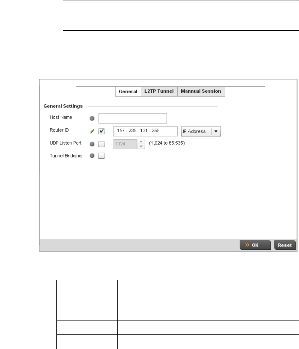
Brocade Mobility RFS4000, RFS6000, and RFS7000 System Reference Guide 411
53-1002620-01
7
NOTE
If connecting an Ethernet port to another Ethernet port, the pseudowire type must be Ethernet port,
if connecting an Ethernet VLAN to another Ethernet VLAN, the pseudowire type must be Ethernet
VLAN.
To define an L2TPV3 configuration for an access point profile:
1. Select Configuration > Profiles > Network.
2. Expand the Network menu to display its submenu options.
3. Expand the Network menu and select L2TPv3.
FIGURE 276 Network - L2TPv3 screen, General tab
4. Set the following General Settings for an L2TPv3 profile configuration:
Host Name Define a 64 character maximum host name to specify the name of the host that’s sent
tunnel messages. Tunnel establishment involves exchanging 3 message types (SCCRQ,
SCCRP and SCCN) with the peer. Tunnel IDs and capabilities are exchanged during the
tunnel establishment with the host.
Router ID Set either the numeric IP address or the integer used as an identifier for tunnel AVP
messages. AVP messages assist in the identification of a tunnelled peer.
UDP Listen Port Select this option to set the port used for listening to incoming traffic. Select a port in
the range of 1,024 - 65,353.
Device Type Select this option to enable or disable bridge packets between two tunnel end points.
This setting is disabled by default.
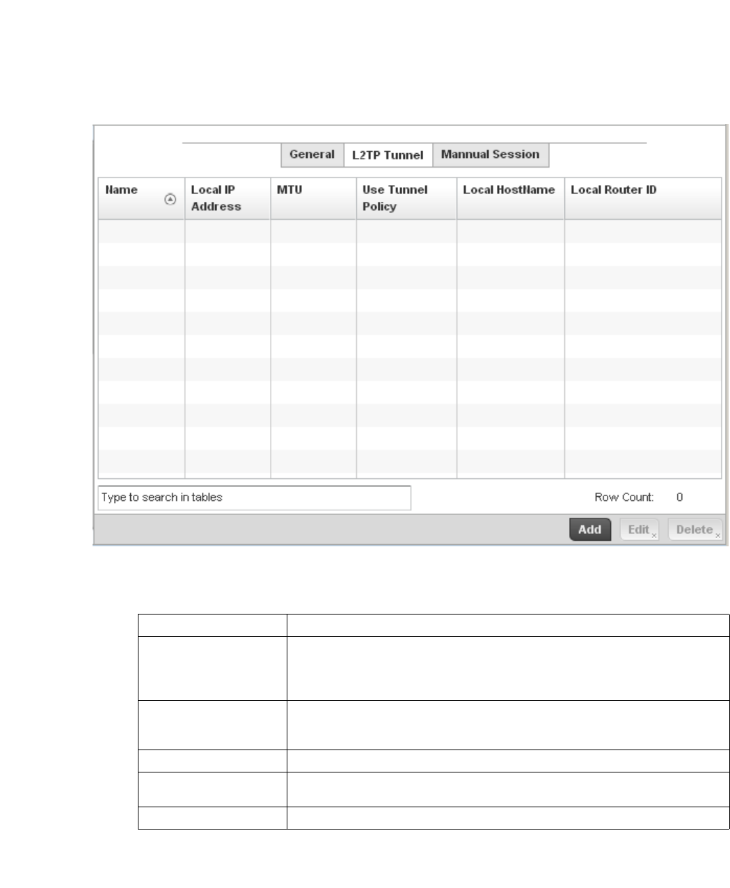
412 Brocade Mobility RFS4000, RFS6000, and RFS7000 System Reference Guide
53-1002620-01
7
5. Select the L2TP Tunnel tab.
FIGURE 277 Network - L2TPv3 screen, T2TP tunnel tab
6. Review the following L2TPv3 tunnel configuration data:
7. E i t h e r s e l e c t Add to create a new L2TPv3 tunnel configuration, Edit to modify an existing tunnel
configuration or Delete to remove a tunnel from those available to this profile.
Name Displays the name of each listed L2TPv3 tunnel assigned upon creation.
Local IP Address Lists the IP address assigned as the local tunnel end point address, not the interface IP
address. This IP is used as the tunnel source IP address. If this parameter is not
specified, the source IP address is chosen automatically based on the tunnel peer IP
address.
MTU Displays the maximum transmission unit (MTU) size for each listed tunnel. The MTU is
the size (in bytes) of the largest protocol data unit that the layer can pass between
tunnel peers.
Use Tunnel Policy Lists the L2TPv3 tunnel policy assigned to each listed tunnel.
Local Hostname Lists the tunnel specific hostname used by each listed tunnel. This is the host name
advertised in tunnel establishment messages.
Local Router ID Specifies the router ID sent in the tunnel establishment messages.
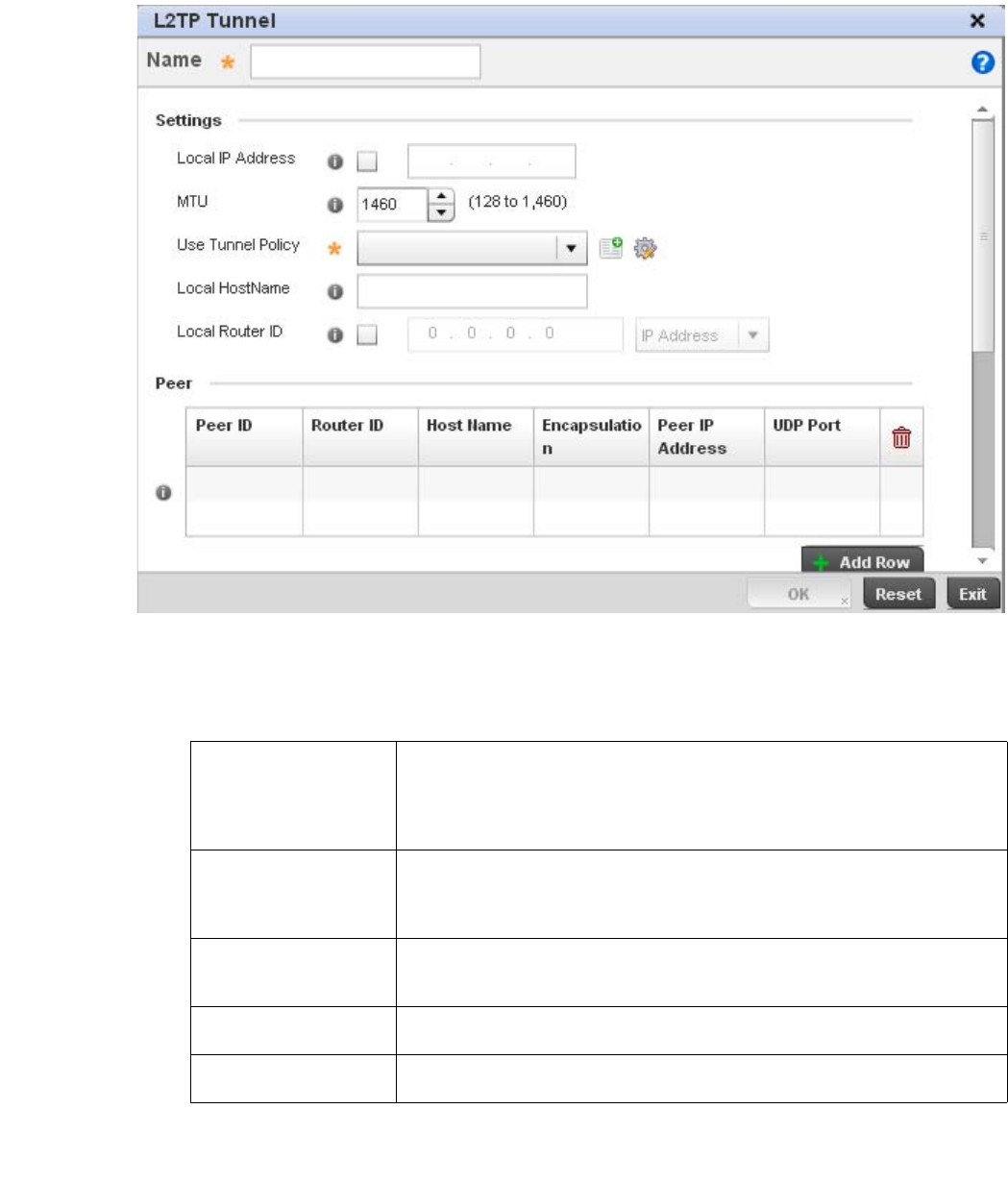
Brocade Mobility RFS4000, RFS6000, and RFS7000 System Reference Guide 413
53-1002620-01
7
FIGURE 278 Network - L2TPv3 screen, Add T2TP Tunnel Configuration
8. If creating a new tunnel configuration, assign it a 31 character maximum Name.
9. Define the following Settings required for the L2TP tunnel configuration:
10. Refer to the Peer table to review the configurations of the peers available for tunnel
connection.
Local IP Address Enter the IP address assigned as the local tunnel end point address, not the interface IP
address. This IP is used as the tunnel source IP address. If this parameter is not
specified, the source IP address is chosen automatically based on the tunnel peer IP
address. This parameter is applicable when establishing the tunnel and responding to
incoming tunnel create requests.
MTU Set the maximum transmission unit (MTU). The MTU is the size (in bytes) of the largest
protocol data unit the layer can pass between tunnel peers. Define a MTU between 128
- 1,460 bytes. The default setting is 1,460. A larger MTU means processing fewer
packets for the same amount of data.
Use Tunnel Policy Select the L2TPv3 tunnel policy. The policy consists of user defined values for protocol
specific parameters which can be used with different tunnels. If none is available a new
policy can be created or an existing one can be modified.
Local Hostname Provide the tunnel specific hostname used by this tunnel. This is the host name
advertised in tunnel establishment messages.
Local Router ID Specify the router ID sent in tunnel establishment messages with a potential peer
device.
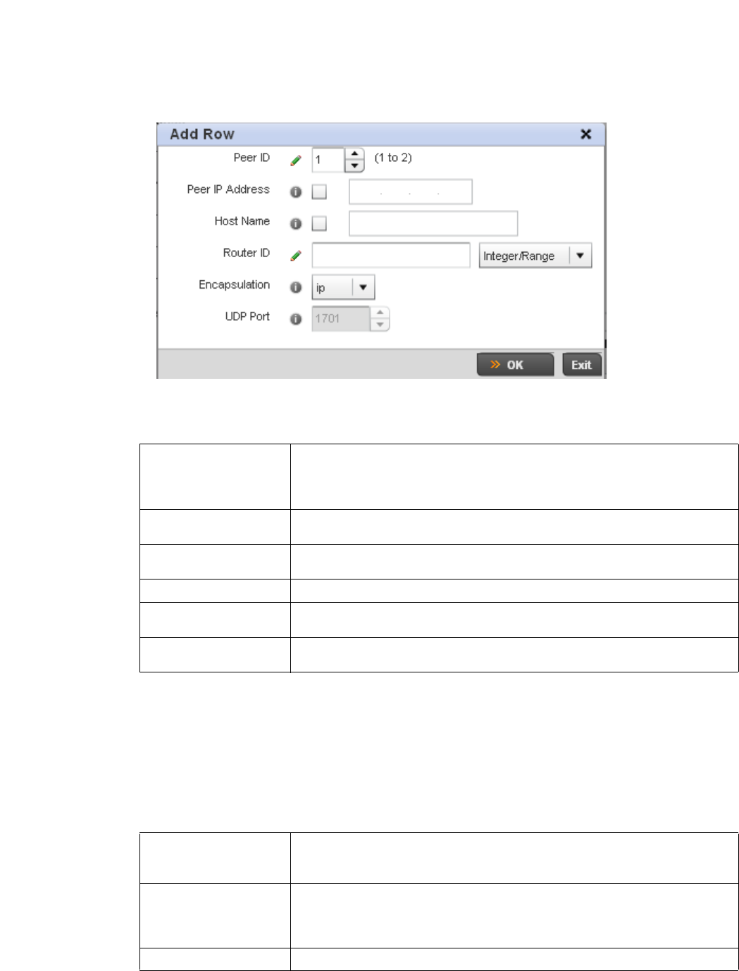
414 Brocade Mobility RFS4000, RFS6000, and RFS7000 System Reference Guide
53-1002620-01
7
11. Select + Add Row to populate the table with a maximum of two peer configurations.
FIGURE 279 Network - L2TPv3 screen, Add T2TP Peer Configuration
12. Define the following Peer parameters:
13. Select OK to save the peer configuration.
14. Refer to the Session table to review the configurations of the peers available for tunnel
connection.
15. Select + Add Row to populate the table with configurable session parameters for this tunnel
configuration.
16. Define the following Session parameters:
Peer ID Define the primary peer ID used to set the primary and secondary peer for tunnel
failover. If the peer is not specified, tunnel establishment does not occur. However, if a
peer tries to establish a tunnel with this access point, it creates the tunnel if the
hostname and/or Router ID matches.
Peer IP Address Select this option to enter the numeric IP address used as the tunnel destination peer
address for tunnel establishment.
Host Name Assign the peer a hostname that can be used as matching criteria in the tunnel
establishment process.
Router ID Specify the router ID sent in tunnel establishment messages with this specific peer.
Encapsulation Select either IP or UDP as the peer encapsulation protocol. The default setting is IP. UDP
uses a simple transmission model without implicit handshakes.
UDP Port If UDP encapsulation is selected, use the spinner control to define the UDP
encapsulation port.
Name Enter a 31 character maximum session name. There is no idle timeout for a tunnel. A
tunnel is not usable without a session and a subsequent session name.The tunnel is
closed when the last session tunnel session is closed.
Pseudowire ID Define a psuedowire ID for this session. A pseudowire is an emulation of a layer 2
point-to-point connection over a packet-switching network (PSN). A pseudowire was
developed out of the necessity to encapsulate and tunnel layer 2 protocols across a
layer 3 network.
Traf fic Source Type Lists the type of traffic tunnelled in this session.
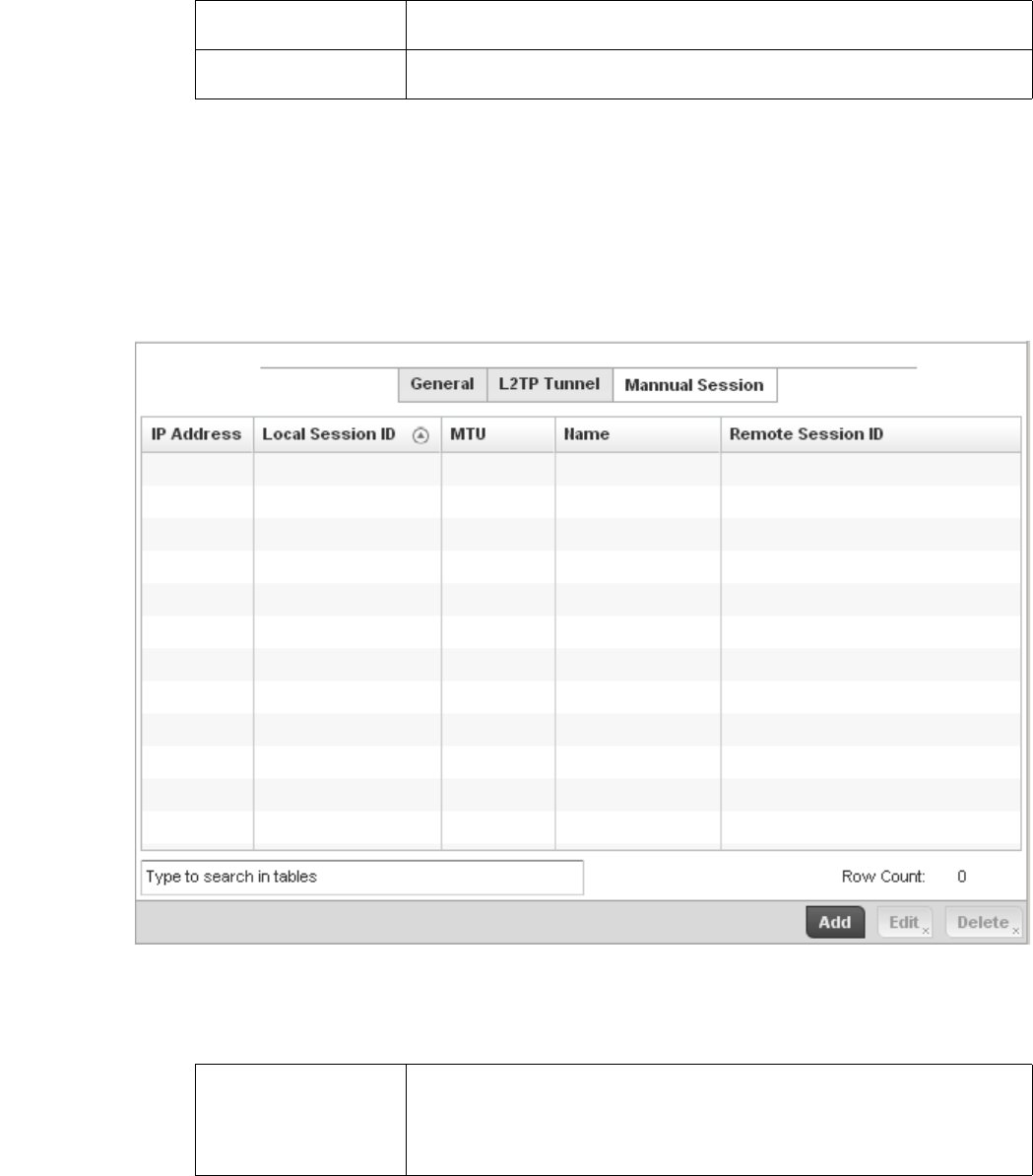
Brocade Mobility RFS4000, RFS6000, and RFS7000 System Reference Guide 415
53-1002620-01
7
17. Select OK to save the changes within the T2TP Tunnel screen. Select Reset to revert the screen
to its last saved configuration.
18. Select the Manual Session tab.
After a successful tunnel connection and establishment, individual sessions can be created.
Each session is a single data stream. After successful session establishment, data
corresponding to that session (pseudowire) can be transferred. If a session is down, the
pseudowire associated with it is shut down as well.
FIGURE 280 Network - L2TPv3 screen, Manual Session tab
19. Refer to the following manual session configurations to determine whether one should be
created or modified:
Traffic Source Value Define a VLAN range to include in the tunnel session. Available VLAN ranges are from 1
- 4,094.
Native VLAN Select this option to provide a VLAN ID that will not be tagged in tunnel establishment
and packet transfer.
IP Address Lists the IP address assigned as the local tunnel end point address, not the interface IP
address. This IP is used as the tunnel source IP address. If this parameter is not
specified, the source IP address is chosen automatically based on the tunnel peer IP
address. This parameter is applicable when establishing the session and responding to
incoming requests.
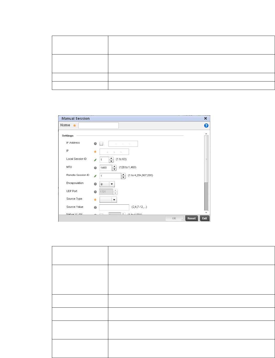
416 Brocade Mobility RFS4000, RFS6000, and RFS7000 System Reference Guide
53-1002620-01
7
20. Select Add to create a new manual session, Edit to modify an existing session configuration or
Delete to remove a selected manual session.
FIGURE 281 Network - L2TPv3 screen, Add T2TP Peer Configuration
21. Set the following session parameters:
Local Session ID Displays the numeric identifier assigned to each listed tunnel session. This is the
pseudowire ID for the session. This pseudowire ID is sent in a session establishment
message to the L2TP peer.
MTU Displays each sessions’s maximum transmission unit (MTU). The MTU is the size (in
bytes) of the largest protocol data unit the layer can pass between tunnel peers in this
session. A larger MTU means processing fewer packets for the same amount of data.
Name Lists the name assigned to each listed manual session.
Remote Session ID Lists the remote session ID passed in the establishment of the tunnel session.
Name Define a 31 character maximum name of this tunnel session. After a successful tunnel
connection and establishment, the session is created. Each session name represents a
single data stream.
IP Address Specify the IP address used to be as tunnel source ip address. If not specified, the
tunnel source IP address is selected automatically based on the tunnel peer IP address.
This address is applicable only for initiating the tunnel. When responding to incoming
tunnel create requests, it would use the IP address on which it had received the tunnel
create request.
IP Set the IP address of an L2TP tunnel peer. This is the peer allowed to establish the
tunnel.
Local Session ID Set the numeric identifier for the tunnel session. This is the pseudowire ID for the
session. This pseudowire ID is sent in session establishment message to the L2TP peer.
MTU Define the session maximum transmission unit (MTU) as the size (in bytes) of the
largest protocol data unit the layer can pass between tunnel peers in this session. A
larger MTU means processing fewer packets for the same amount of data.
Remote Session ID Use the spinner control to set the remote session ID passed in the establishment of the
tunnel session. Assign an ID in the range of
1 - 4,294,967,295.

Brocade Mobility RFS4000, RFS6000, and RFS7000 System Reference Guide 417
53-1002620-01
7
22. Select the + Add Row button to set the following:
23. Select OK to save the changes to the session configuration. Select Reset to revert to the last
saved configuration.
Quality of Service (QoS) Configuration
Profile Network Configuration
The controller uses different Quality of Service (QoS) screens to define WLAN and device radio QoS
configurations for controller profiles.
QoS values are required to provide priority of service to some packets over others. For example,
VoIP packets get higher priority than data packets to provide a better quality of service for high
priority voice traffic.
The profile QoS screen maps the 6-bit Differentiated Service Code Point (DSCP) code points to the
older
3-bit IP Precedent field located in the Type of Service byte of an IP header. DSCP is a protocol for
specifying and controlling network traffic by class so that certain traffic types get precedence.
DSCP specifies a specific per-hop behavior that is applied to a packet. This QoS assignment can be
overridden as needed, but removes the device configuration from the managed profile that may be
shared with other similar device models.
To define an QoS configuration for controller DSCP mappings:
1. Select Configuration > Profiles > Network.
2. Expand the Network menu to display its submenu options.
3. Select Quality of Service.
Encapsulation Select either IP or UDP as the peer encapsulation protocol. The default setting is IP. UDP
uses a simple transmission model without implicit handshakes.
UDP Port If UDP encapsulation is selected, use the spinner control to define the UDP
encapsulation port. This is the port where the L2TP service is running.
Source VLAN Define the VLAN range (1 - 4,094) to include in the tunnel. Tunnel session data includes
VLAN tagged frames.
Native VLAN Select this option to define the native VLAN that will not be tagged.
Cookie Size Set the size of the cookie field within each L2TP data packet. Options include 0, 4 and
8. The default setting is 0.
Value 1 Set the cookie value first word.
Value 2 Set the cookie value second word.
End Point Define whether the tunnel end point is local or remote.
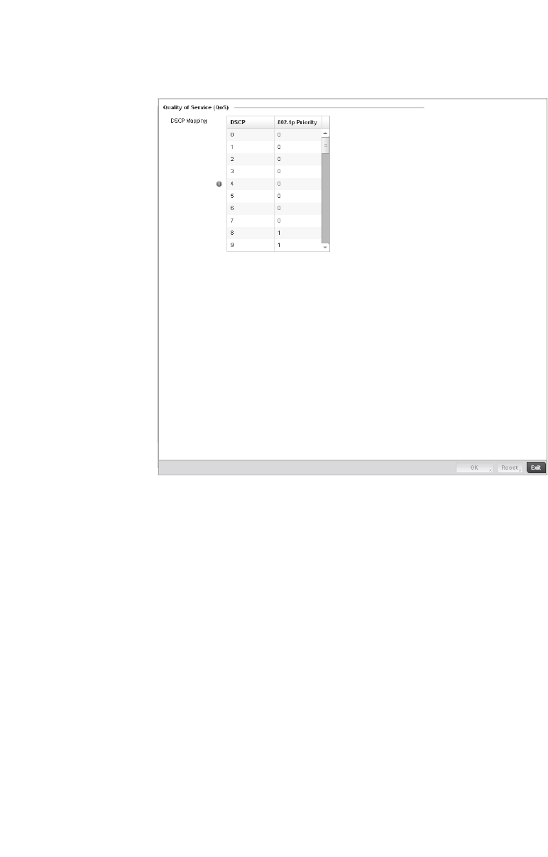
418 Brocade Mobility RFS4000, RFS6000, and RFS7000 System Reference Guide
53-1002620-01
7
FIGURE 282 Profile Overrides - Network QoS screen
4. Set or override the following parameters for IP DSCP mappings for untagged frames:
5. Use the spinner controls within the 802.1p Priority field for each DSCP row to change or
override the priority value.
6. Select the OK button located to save the changes and overrides. Select Reset to revert to the
last saved configuration.
Spanning Tree
Profile Network Configuration
DSCP Lists the DSCP value as a 6-bit parameter in the header of every IP packet used for
packet classification.
802.1p Priority Assign a 802.1p priority as a 3-bit IP precedence value in the Type of Service field of the
IP header used to set the priority. The valid values for this field are 0-7. Up to 64 entries
are permitted. The priority values are:
0 – Best Effort
1 – Background
2 – Spare
3 – Excellent Effort
4 – Controlled Load
5 – Video
6 – Voice
7 – Network Control

Brocade Mobility RFS4000, RFS6000, and RFS7000 System Reference Guide 419
53-1002620-01
7
Spanning Tree is a network layer protocol that ensures a loop-free topology in a mesh network of
inter-connected layer 2 controllers. The spanning tree protocol disables redundant connections and
uses the least costly path to maintain a connection between any two controllers in the network.
Spanning tree protocol allows a network design that has one or more redundant links that provide
a backup path if an active link fails. This switchover is automatic and does not require any human
intervention.
Physical layer redundancy may also be provided using spanning tree. Spanning tree is a link
management protocol that is part of the IEEE 802.1 standard for media access control bridges.
Using the Dikstra algorithm, STP provides link path redundancy between Ethernet devices while
preventing undesirable loops in a network that can be created when multiple active paths exist
between Ethernet controllers and bridges.
To establish path redundancy, STP creates a tree that spans all of the controllers in an extended
network, forcing redundant paths into a blocked, state. STP allows only one active path at a time
between any two network devices but establishes the redundant links as a backup if the preferred
link should fail. If STP costs change, or if one network segment in the STP becomes unreachable,
the spanning tree algorithm reconfigures the spanning tree topology and re-establishes the link by
activating the standby path. Without spanning tree, multiple paths in the Ethernet network would
be active resulting in an endless loop of traffic on the LAN.
Spanning Tree can be used to provide link path redundancy when the controllers are connected to
one or more external Ethernet switches. Spanning Tree can only support one active path per VLAN
between Ethernet devices. If multiple paths per VLAN exist, redundant paths are blocked.
Multiple Spanning Tree Protocol (MSTP) is a VLAN-aware protocol and algorithm to create and
maintain a loop-free network. It allows the configuration of multiple spanning tree instances. This
ensures a loop-free topology for one or more VLANs. It allows the administrator to define a different
path for each group of VLANs to better utilize redundancy.
Using MSTP, the network can be divided into regions. Each controller within a region uses the same
VLAN to instance mapping. The entire network runs a spanning tree instance called the Common
Spanning Tree instance (CST) that interconnects regions as well as legacy (STP and RSTP) bridges.
The regions run on a local instance for each configured MSTP instance.
To define a spanning tree supported configuration on the controller:
1. Select Configuration > Profiles > Network.
2. Expand the Network menu to display its submenu options.
3. Select Spanning Tree.
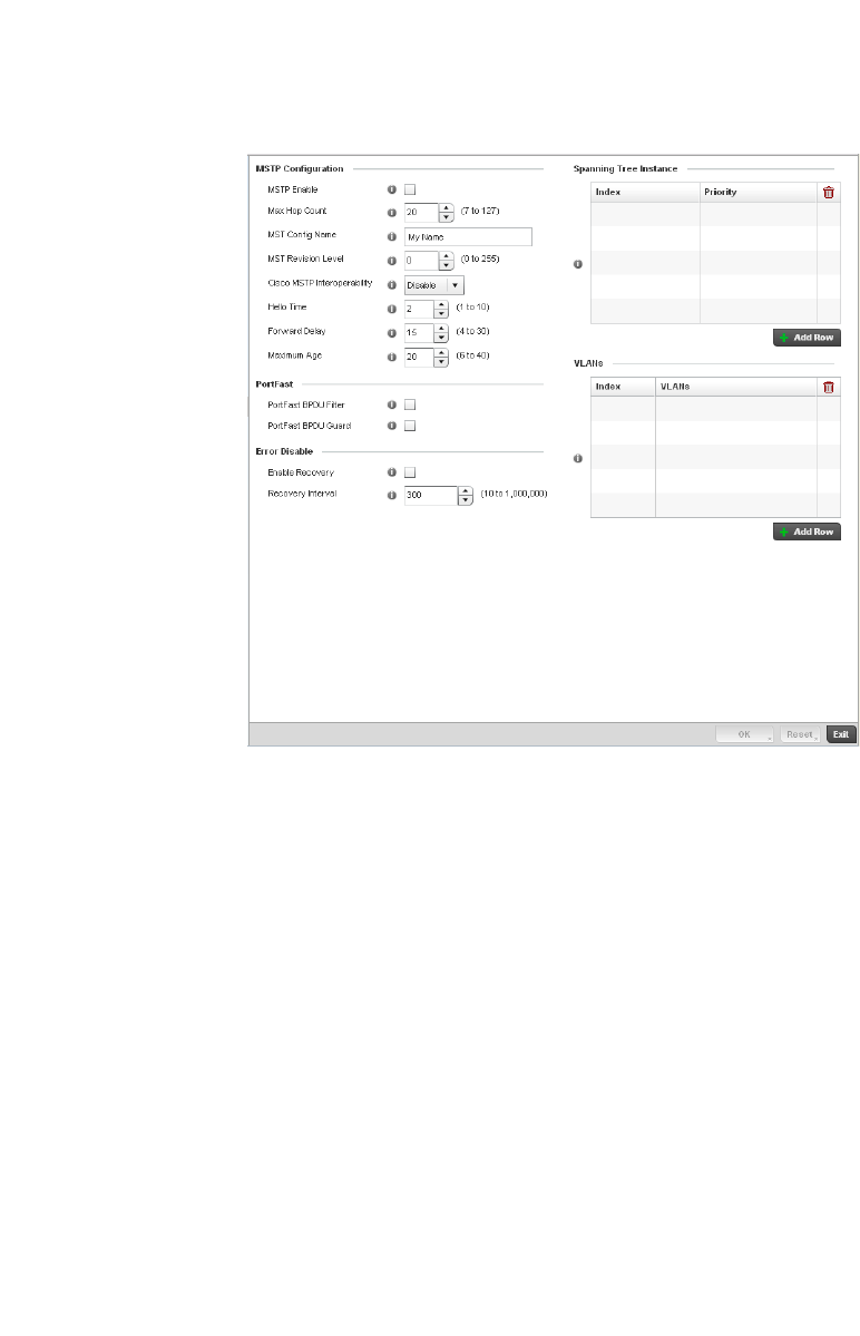
420 Brocade Mobility RFS4000, RFS6000, and RFS7000 System Reference Guide
53-1002620-01
7
FIGURE 283 Spanning Tree screen
4. Set the following MSTP Configuration parameters:
MSTP Enable Enables the Multiple Spanning Tree Protocol (MSTP) feature. Select the check box to
enable spanning tree for this device. This feature is disabled by default.
Max. Hop Count Set the maximum number of hops used when creating a Spanning Tree. This value
represents the maximum allowed hops for a BPDU (Bridge Protocol Data Unit) in an
MSTP region. This value is used by all the MSTP instances. Enter a value between 7 -
127, or use the spinner control to set the value. The default setting is 20.
MST Config Name Enter a name for the MST region. This is used when configuring multiple regions within
the network. Each controller running MSTP is configured with a unique MST region
name. This helps when keeping track of MSTP configuration changes. The name cannot
exceed 64 characters.
MST Revision Level Assign a MST revision level (0 - 255) to the MSTP region to which the device belongs.
Each controller is configured with a unique MSTP name and revision number. This helps
when keeping track of MSTP configuration changes. Increment this number with each
configuration change. The revision level specifies the revision level of the current
configuration. The default setting
is 0.
Cisco MSTP
Interoperability
Select Enable or Disable from the drop-down menu. This enables interoperability with
Cisco’s version of MSTP, which is incompatible with standard MSTP. The default setting
is disabled

Brocade Mobility RFS4000, RFS6000, and RFS7000 System Reference Guide 421
53-1002620-01
7
5. Define the following PortFast configuration parameters:
6. Set the following Error Disable recovery parameters:
7. Set the Spanning Tree Instance configuration.
Define a numerical index for each instance to assign each a unique priority. The Priority is
assigned to an individual bridge based on whether it is selected as the root bridge. The lower
the priority, the greater likelihood the bridge becoming the root for this instance.
8. Use the + Add Row button to create a new row in the table. To delete a row, select the row’s
delete icon.
9. Refer to the VLANs table to associate a VLAN ID with the Instance index. You can add multiple
VLANs to an instance.
10. Use the + Add Row button to create a new row in the table. To delete a row, select the row’s
delete icon.
11. Select OK to save the changes. Select Reset to revert to the last saved configuration.
Routing Configuration
Profile Network Configuration
Hello Time The hello time is the time interval (in seconds) the device waits between BPDU
transmissions. A low value leads to excessive traffic on the network, whereas a higher
value delays the detection of a topology change. Set a hello time between 1 - 10
seconds. You can also use the spinner control next to the text-box to increase or
decrease the value. The default setting is 2.
Forward Delay The forward delay is the maximum time (in seconds) the root device waits before
changing states (from a listening state to a learning state to a forwarding state). Set a
value between 4 -30. You can also use the spinner control next to the text-box to
increase or decrease the value. The default is 15.
Maximum Age The max-age is the maximum time (in seconds) for which, if a bridge is the root bridge, a
message is considered valid. This prevents frames from looping indefinitely. The
max-age should be greater than twice the value of hello time plus one, but less than
twice the value of forward delay minus one. Configure this value sufficiently high, so a
frame generated by root can be propagated to the leaf nodes without exceeding the max
age. Set the value from 6 - 40. Use the spinner control next to the text-box to increase or
decrease the value. The default setting is 20.
PortFast BPDU Filter Select the check box to enable BPDU filter for all portfast enabled ports.The Spanning
Tree Protocol sends BPDUs from all the ports. Enabling the BPDU filter feature ensures
PortFast enabled ports do not transmit or receive any BPDUs.
PortFast BPDU Guard Select the check box to enable BPDU guard for all portfast enabled ports. When the
BPDU Guard feature is set for bridge, all portfast-enabled ports of the bridge that have
BPDU set to default shutdown the port on receiving a BPDU. Hence no BPDUs are
processed.
Enable Recovery Select this check box to enable an error disable timeout caused by a BPDU guard. This
option is disabled by default.
Recovery Interval Define an interval (between 10 - 1,000,000) after which a recovering port is
enabled.The default recovery interval is 300.
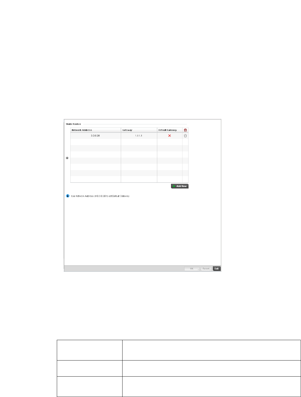
422 Brocade Mobility RFS4000, RFS6000, and RFS7000 System Reference Guide
53-1002620-01
7
Routing is the process of selecting IP paths in a network to send access point managed network
traffic. Use the Routing screen to set Destination IP and Gateway addresses enabling assignment
of static IP addresses for requesting clients without creating numerous host pools with manual
bindings. This eliminates the need for a long configuration file and reduces the resource space
required to maintain address pools.
To create or override a profile’s static routes:
1. Select Configuration > Profiles > Network.
2. Expand the Network menu to display its submenu options.
3. Select Routing.
FIGURE 284 Static Routes screen
4. Select IP Routing to enable static routes using IP addresses. This option is enabled by default.
5. Select Add Row + as needed to include single rows with in the static IPv4 route table.
6. Add IP addresses and network masks in the Network column.
7. P rov i d e t h e Gateway used to route traffic.
8. Refer to the Default Route Priority field and set the following parameters:
Static Default Route
Priority
Use the spinner control to set the priority value (1 - 8,000) for the default static route.
This is weight assigned to this route versus others that have been defined. The default
setting is 100.
DHCP Client Default
Route Priority
Use the spinner control to set the priority value (1 - 8,000) for the default route learnt
from the DHCP client. The default setting is 1000.
Enable Routing Failure When selected, all default gateways are monitored for activity. The system will failover
to a live gateway if the current gateway becomes unusable. This feature is enabled by
default.

Brocade Mobility RFS4000, RFS6000, and RFS7000 System Reference Guide 423
53-1002620-01
7
9. Select the OK button located at the bottom right of the screen to save the changes. Select
Reset to revert to the last saved configuration.
Dynamic Routing (OSPF)
Profile Network Configuration
Open Shortest Path First (OSPF) is a link-state interior gateway protocol (IGP). OSPF routes IP
packets within a single routing domain (autonomous system), like an enterprise LAN. OSPF gathers
link state information from neighbor routers and constructs a network topology. The topology
determines the routing table presented to the Internet Layer which makes routing decisions based
solely on the destination IP address found in IP packets.
OSPF detects changes in the topology, like a link failure, and plots a new loop-free routing
structure. It computes the shortest path for each route using a shortest path first algorithm. Link
state data is maintained on each router and is periodically updated on all OSPF member routers.
OSPF uses a route table managed by the link cost (external metrics) defined for each routing
interface. The cost could be the distance of a router (round-trip time), link throughput or link
availability. Setting a cost value provides a dynamic way to load balancing traffic between routes of
equal cost.
An OSPF network can be subdivided into routing areas to simplify administration and optimize
traffic utilization. Areas are logical groupings of hosts and networks, including routers having
interfaces connected to an included network. Each area maintains a separate link state database
whose information may be summarized towards the rest of the network by the connecting router.
Areas are identified by 32-bit IDs, expressed either in decimal, or octet-based dot-decimal notation.
Areas can defined as:
stub area - A stub area is an area which does not receive route advertisements external to the
autonomous system (AS) and routing from within the area is based entirely on a default route.
totally-stub - A totally stubby area does not allow summary routes and external routes. A default
route is the only way to route traffic outside of the area. When there’s only one route out of the
area, fewer routing decisions are needed, lowering system resource utilization.
non-stub - A non-stub area imports autonomous system external routes and send them to other
areas. However. it still cannot receive external routes from other areas.
nssa - NSSA is an extension of a stub that allows the injection of limited external routes into a stub
area. If selecting NSSA, no external routes, except a default route, enter the area.
totally nssa - Totally nssa is an NSSA using 3 and 4 summary routes are not flooded into this type of
area. It is also possible to declare an area both totally stubby and not-so-stubby, which means that
the area will receive only the default route from area 0.0.0.0, but can also contain an autonomous
system boundary router (ASBR) that accepts external routing information and injects it into the
local area, and from the local area into area 0.0.0.0.
A router running OSPF sends hello packets to discover neighbors and elect a designated router. The
hello packet includes link state information and list of neighbors. OSPF is savvy with layer 2
topologies. If on a point-to-point link, OSPF knows it is sufficient, and the link stays up. If on a
broadcast link, the router waits for election before determining if the link is functional.
To define a dynamic routing configuration:
1. Select Configuration > Profiles > Network.
2. Expand the Network menu to display its submenu options.
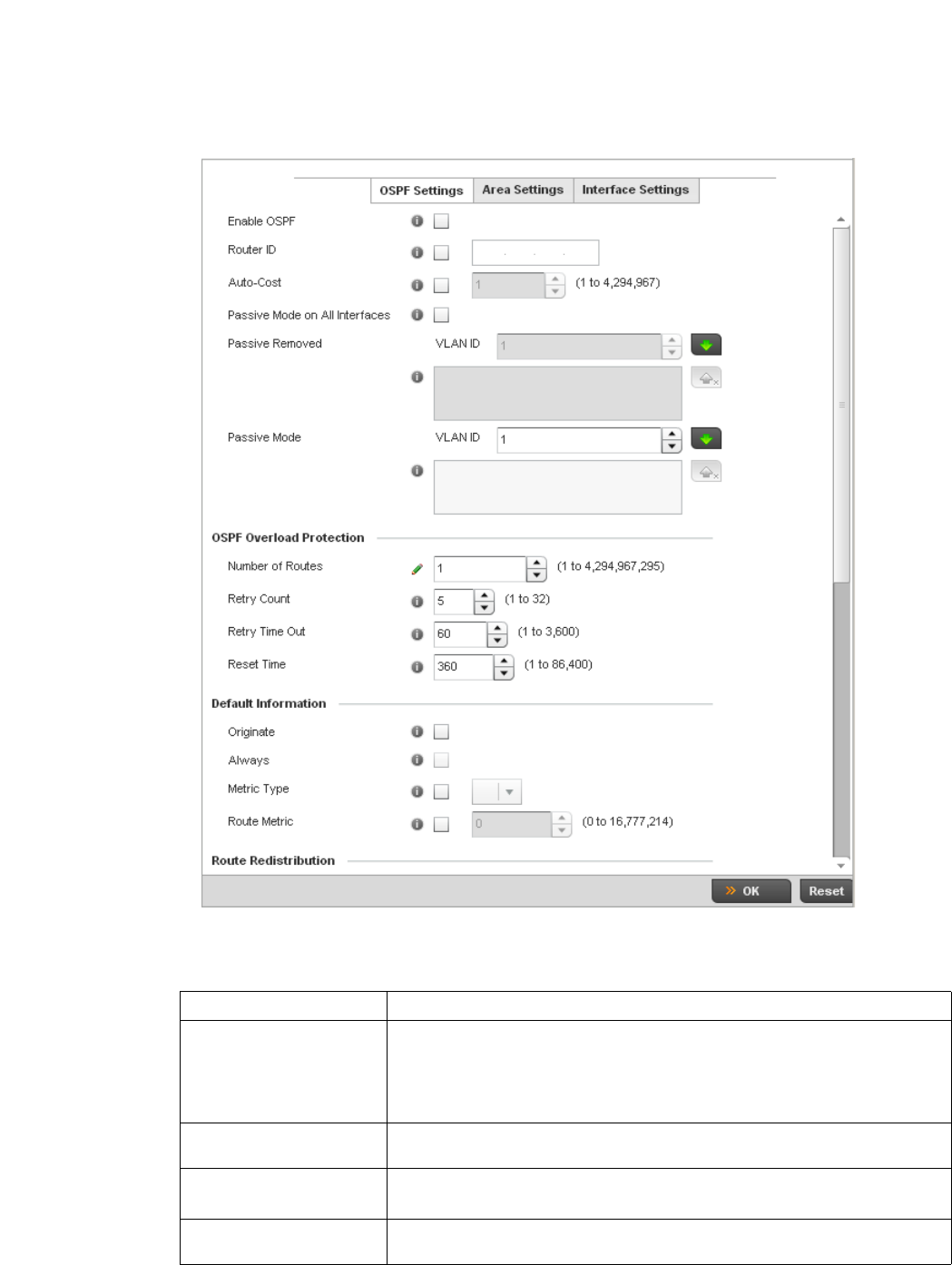
424 Brocade Mobility RFS4000, RFS6000, and RFS7000 System Reference Guide
53-1002620-01
7
3. Expand the Network menu and select Dynamic Routing.
FIGURE 285 OSPF Settings screen
4. Enable/disable OSPF and provide the following dynamic routing settings:
Enable OSPF Select this option to enable OSPF for this access point. OSPF is disabled by default.
Router ID Select this option to define a router ID (numeric IP address) for this access point. This
ID must be established in every OSPF instance. If not explicitly configured, the highest
logical IP address is duplicated as the router identifier. However, since the router
identifier is not an IP address, it does not have to be a part of any routable subnet in
the network.
Auto-Cost Select this option to specify the reference bandwidth (in Mbps) used to calculate the
OSPF interface cost if OSPF is either STUB or NSSA. The default setting is 1.
Passive Mode on All
Interfaces
When selected, all layer 3 interfaces are set as an OSPF passive interface. This
setting is disabled by default.
Passive Removed If enabling Passive Mode on All Interfaces, use the spinner control to select VLANs (by
numeric ID) as OSPF non passive interfaces. Multiple VLANs can be added to the list.

Brocade Mobility RFS4000, RFS6000, and RFS7000 System Reference Guide 425
53-1002620-01
7
5. Set the following OSPF Overload Protection settings:
6. Set the following Default Information:
7. R e fe r to t he Route Redistribution table to set the types of routes that can be used by OSPF.
Select the + Add Row button to populate the table. Set the Route Type used to define the
redistributed route. Options include connected, kernal and static.
Select the Metric Type option to define the exterior metric type (1 or 2) used with the route
redistribution. Select the Metric option to define route metric used with the redistributed route.
8. Use the OSPF Network table to define networks (IP addresses) to connect using dynamic
routes.
Select the + Add Row button to populate the table. Add the IP address and mask of the
Network(s) participating in OSPF. Additionally, define the OSPF area (IP address) to which the
network belongs.
9. Set an OSPF Default Route Priority (1 - 8,000) as the priority of the default route learnt from
OSPF.
Select the Area Settings tab.
10. An OSPF Area contains a set of routers exchanging Link State Advertisements (LSAs) with
others in the same area. Areas limit LSAs and encourage aggregate routes.
Passive Mode If disabling Passive Mode on All Interfaces, use the spinner control to select VLANs (by
numeric ID) as OSPF passive interfaces. Multiple VLANs can be added to the list.
Number of Routes Use the spinner controller to set the maximum number of OSPN routes permitted. The
available range is from 1 - 4,294,967,295.
Retry Count Set the maximum number of retries (OSPF resets) permitted before the OSPF process
is shut down. The available range is from 1 - 32. The default setting is 5.
Retry Time Out Set the duration (in seconds) the OSPF process remains off before initiating its next
retry. The available range is from 1 - 3,600 seconds. The default is 60 seconds.
Reset Time Set the reset time (in seconds) that, when exceeded, changes the retry count is zero.
The available range is from 1 - 86,400. The default is 360 seconds.
Originate Select this option to make the default route a distributed route. This setting is
disabled by default.
Always Enabling this settings continuously maintains a default route, even when no routes
appear in the routing table. This setting is disabled by default.
Metric Type Select this option to define the exterior metric type (1 or 2) used with the default
route.
Route Metric Select this option to define route metric used with the default route. OSPF uses path
cost as its routing metric. It’s defined by the speed (bandwidth) of the interface
supporting given route.
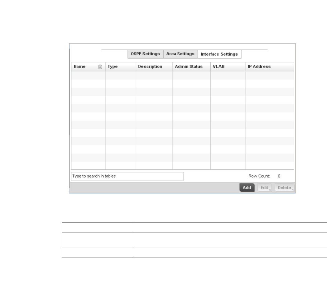
426 Brocade Mobility RFS4000, RFS6000, and RFS7000 System Reference Guide
53-1002620-01
7
FIGURE 286 OSPF Area Settings screen
11. Review existing Area Settings configurations using:
12. Select Add to create a new OSPF configuration, Edit to modify an existing configuration or
Delete to remove a configuration.
Area ID Displays either the IP address or integer representing the OSPF area.
Authentication Type Lists the authentication schemes used to validate the credentials of dynamic route
connections.
Type Lists the OSPF area type in each listed configuration.
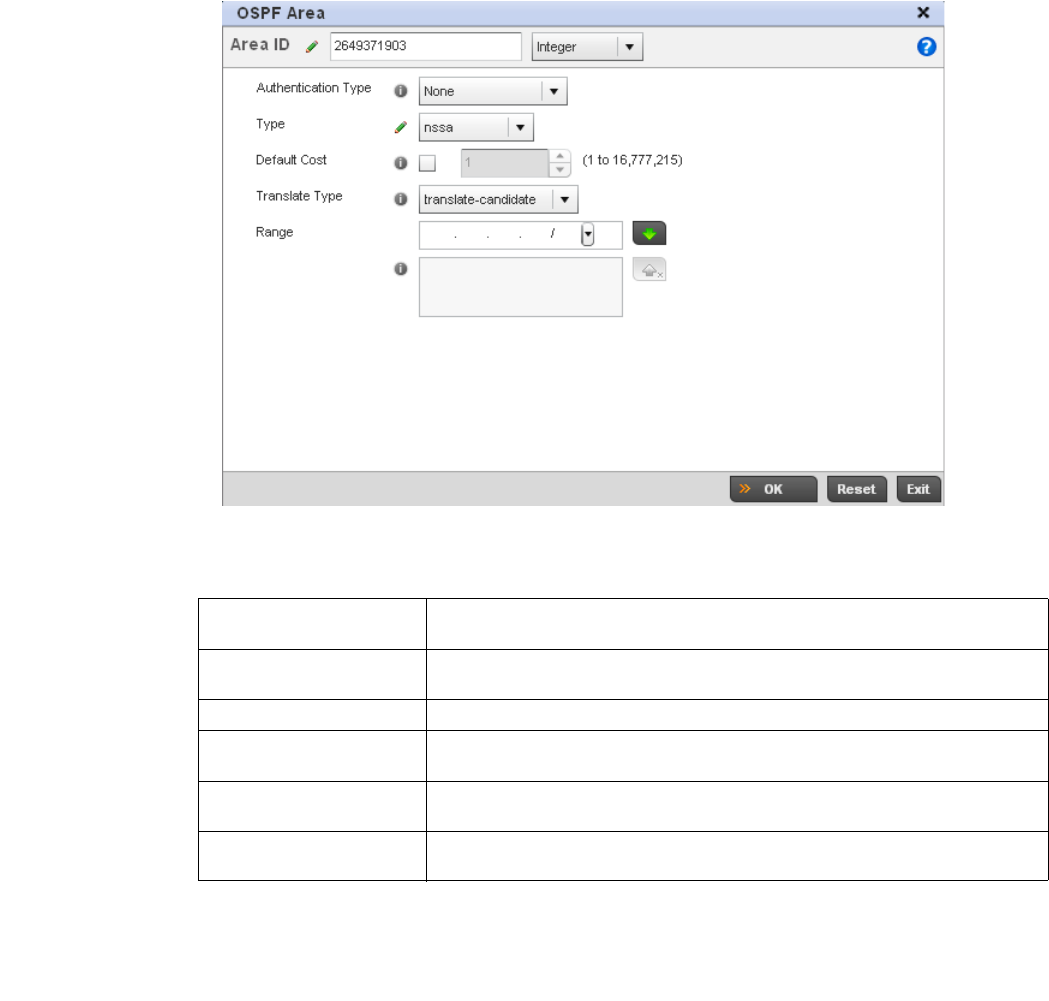
Brocade Mobility RFS4000, RFS6000, and RFS7000 System Reference Guide 427
53-1002620-01
7
FIGURE 287 OSPF Area Configuration screen
13. Set the OSPF Area configuration.
14. Select the OK button to save the changes to the area configuration. Select Reset to revert to
the last saved configuration.
15. Select the Interface Settings tab.
Area ID Use the drop down menu and specify either an IP address or Integer for the OSPF
area.
Authentication Type Select either None, simple-password or message-digest as credential validation
scheme used with the OSPF dynamic route. The default setting is None.
Type Set the OSPF area type as either stub, totally-stub, nssa, totally-nssa or non-stub.
Default Cost Select this option to set the default summary cost advertised if creating a stub. Set a
value from 1 - 16, 777,215.
Translate Type Define how messages are translated. Options include translate-candidate, translate
always and translate-never. The default setting is translate-candidate.
Range Specify a range of addresses for routes matching address/mask for OSPF
summarization.
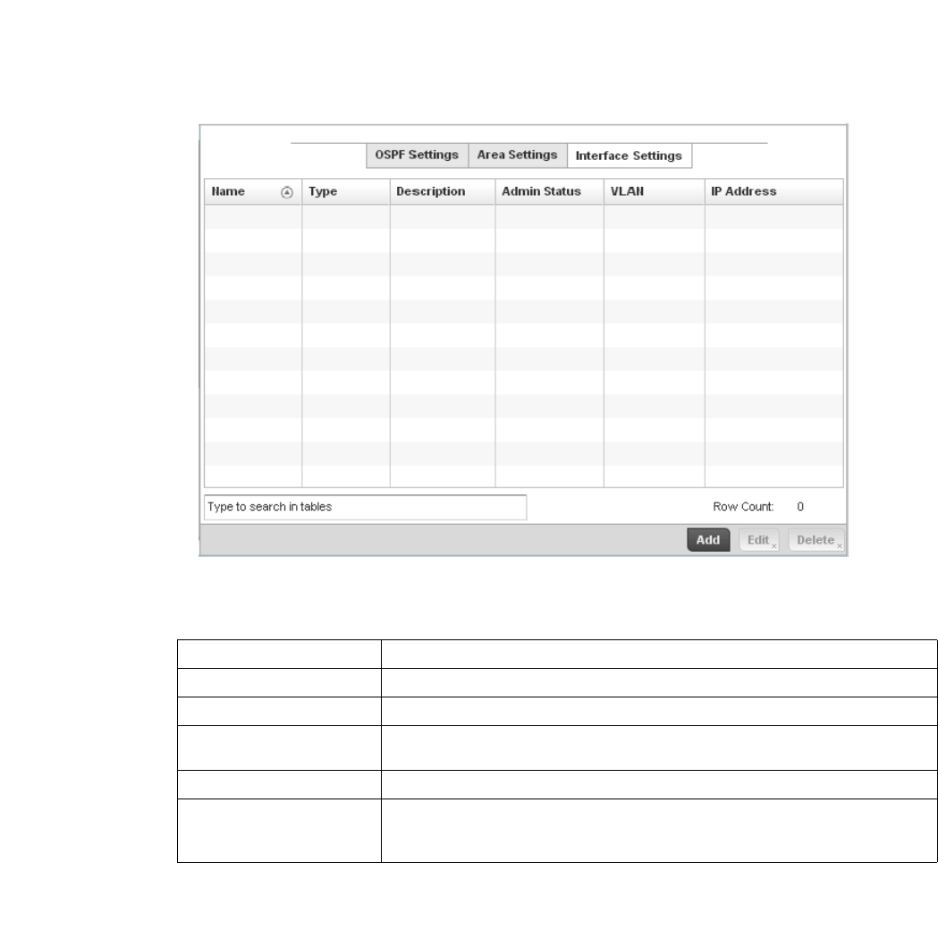
428 Brocade Mobility RFS4000, RFS6000, and RFS7000 System Reference Guide
53-1002620-01
7
FIGURE 288 OSPF Interface Settings screen
16. Review existing Interface Settings using:
17. Select the Add button to define a new set of virtual interface basic settings, or Edit to update
the settings of an existing virtual interface configuration.
Name Displays the name defined for the interface configuration.
Type Displays the type of interface.
Description Lists each interface’s 32 character maximum description.
Admin Status Displays whether Admin Status privileges have been enabled or disabled for the OSPF
route’s virtual interface connection.
VLAN Lists the VLAN IDs set for each listed OSPF route virtual interface.
IP Address Displays the IP addresses defined as virtual interfaces for dynamic OSPF routes. Zero
config and DHCP can be used to generate route addresses, or a primary and
secondary address can be manually provided.
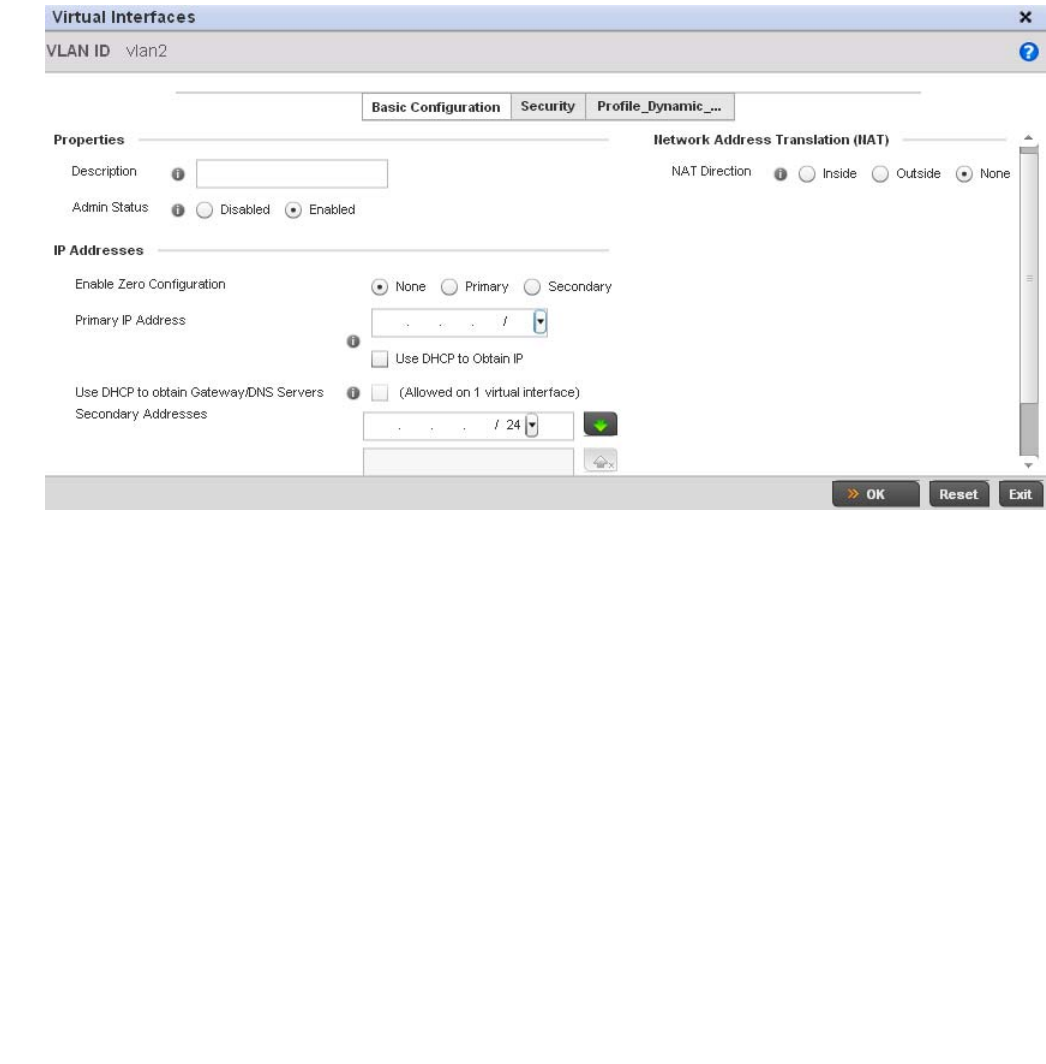
Brocade Mobility RFS4000, RFS6000, and RFS7000 System Reference Guide 429
53-1002620-01
7
FIGURE 289 OSPF Virtual Interface - Basic Configuration screen
18. Within the Properties field, enter a 32 character maximum Description to help differentiate the
virtual interface configuration used with this OSPF route. Enable/disable admin privileges as
need. They’re disabled by default.
19. Use the IP Addresses Area to set how route addresses are created for the virtual configuration.
Zero Configuration can be enabled and set as the Primary or Secondary means of providing IP
addresses for the OSPF virtual route.
20. Select Use DHCP to Obtain IP to use the access point’s DHCP server resource as the means of
providing requested IP addresses to the OSPF route’s virtual interface.
21. Select Use DHCP to Obtain Gateway/DNS Servers to learn default gateway, name servers and
the domain name on just this interface. Once selected, specify an IP address and mask in dot
decimal format.
22. Define the NAT Direction as either Inside, Outside or None. Network Address Translation (NAT),
is an Internet standard that enables a (LAN) to use IP addresses for internal traffic (inside) and
a second set of addresses for external (outside) traffic.
23. Select OK to save the changes to the basic configuration. Select Reset to revert to the last
saved configuration.
24. Select the Security tab.
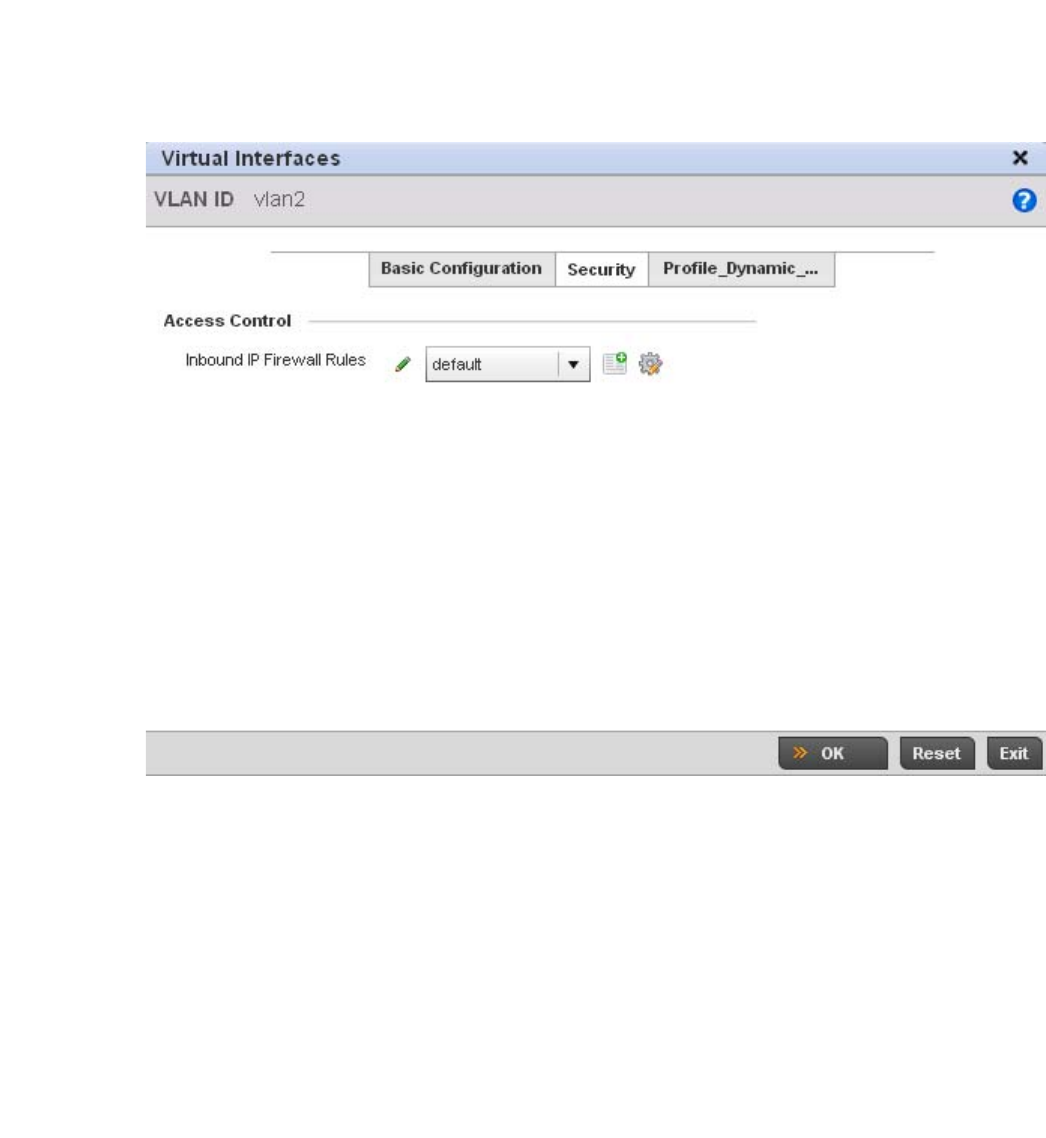
430 Brocade Mobility RFS4000, RFS6000, and RFS7000 System Reference Guide
53-1002620-01
7
FIGURE 290 OSPF Virtual Interface - Security screen
25. Use the Inbound IP Firewall Rules drop-down menu to select the IP access and deny rules to
apply to the OSPF dynamic route.
Either select an existing IP firewall policy or use the default set of IP firewall rules. The firewall
inspects OSPF route traffic flows and detects potential attacks on the dynamic route not visible
to traditional wired firewall appliances. Select the Create icon to define a new set of IP firewall
rules that can be applied to the OSPF route configuration. Selecting Edit allows for the
modification of an existing IP firewall rules configuration. For more information, see Wireless
Firewall on page 9-511.
26. Select OK to save the changes to the OSPF route security configuration. Select Reset to revert
to the last saved configuration.
27. Select the Profile_Dynamic_Routing tab.
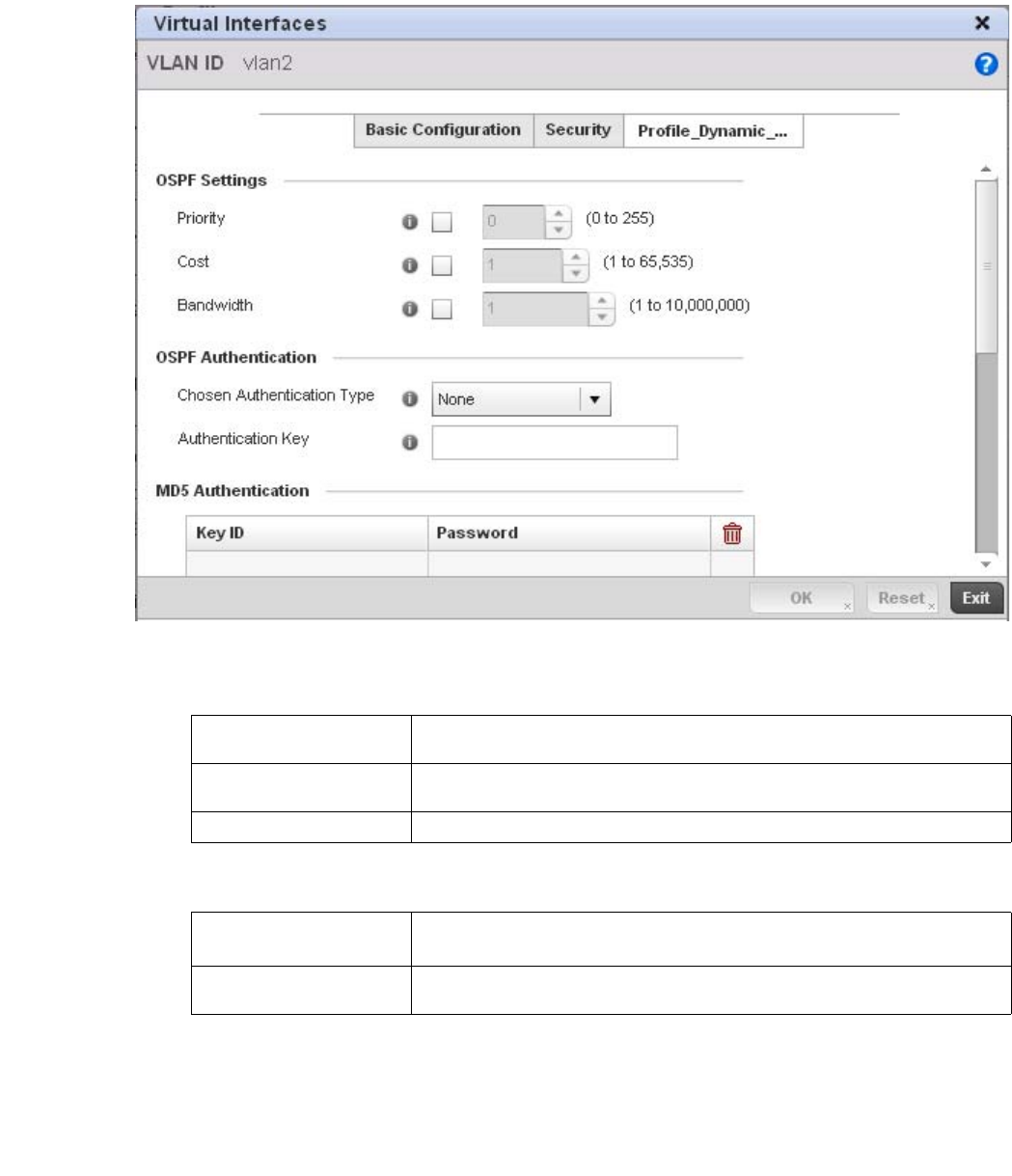
Brocade Mobility RFS4000, RFS6000, and RFS7000 System Reference Guide 431
53-1002620-01
7
FIGURE 291 OSPF Virtual Interface - Profile_Dynamic_Routing screen
28. Set the following OSPF Settings:
29. Set the following OSPF Authentication settings for the dynamic route:
30. Select the + Add Row button (at the bottom of the MD5 Authentication table) to add the Key ID
and Password used for an MD5 validation of authenticator credentials.
Use the spinner control to set the OSPF message digest authentication key ID. The available
range is from 1 - 255. The password is the OSPF key either displayed as series or asterisks or
in plain text (by selecting Show).
Priority Select this option to set the OSPF priority used in dynamic route election. Use the
spinner control to set the value from 0 - 255.
Cost Select this option to set the cost of the OSPF interface. Use the spinner control to set
the value from 1 - 65,353.
Bandwidth Set the OSPF interface bandwidth (in Kbps) from 1 - 10,000,000.
Chosen Authentication
Type
Select the authentication type used to validate credentials within the OSPF dynamic
route. Options include simple-password, message-digest, null and None.
Authentication Key Enter and confirm the authentication key required by connecting nodes using the
OSPF dynamic route.
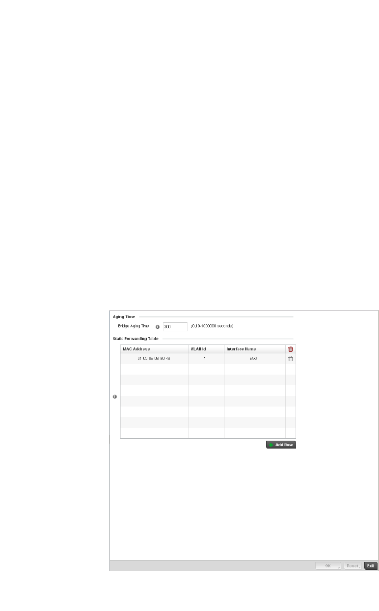
432 Brocade Mobility RFS4000, RFS6000, and RFS7000 System Reference Guide
53-1002620-01
7
31. Select OK to save the changes to the Profile_Dynamic_Route configuration. Select Reset to
revert to the last saved configuration
Forwarding Database
Profile Network Configuration
A Forwarding Database is used by a bridge to forward or filter packets on behalf of the controller.
The bridge reads the packet’s destination MAC address and decides to either forward the packet or
drop (filter) it. If it is determined the destination MAC is on a different network segment, it forwards
the packet to the segment. If the destination MAC is on the same network segment, the packet is
dropped (filtered). As nodes transmit packets through the bridge, the bridge updates its forwarding
database with known MAC addresses and their locations on the network. This information is then
used to filter or forward the packet.
To define a forwarding database configuration:
1. Select Configuration > Profiles > Network.
2. Expand the Network menu to display its submenu options.
3. Select Forwarding Database.
FIGURE 292 Forwarding Database screen
4. Define a Bridge Aging Time between 0, 10-1,000,000 seconds.
The aging time defines the length of time an entry will remain in the a bridge’s forwarding table
before being deleted due to lack of activity. If an entry replenishments a destination generating
continuous traffic, this timeout value will never be invoked. However, if the destination
becomes idle, the timeout value represents the length of time that must be exceeded before
an entry is deleted from the forwarding table. The default setting is 300 seconds.

Brocade Mobility RFS4000, RFS6000, and RFS7000 System Reference Guide 433
53-1002620-01
7
5. Use the + Add Row button to create a new row within the MAC address table.
6. Set a destination MAC Address address. The bridge reads the controller packet’s destination
MAC address and decides to forward the packet or drop (filter) it. If it’s determined the
destination MAC is on a different network, it forwards the packet to the segment. If the
destination MAC is on the same network segment, the packet is dropped (filtered).
7. Define the target VLAN ID if the destination MAC is on a different network segment.
8. Provide an Interface Name used as the target destination interface for the target MAC address.
9. Select OK to save the changes. Select Reset to revert to the last saved configuration.
Bridge VLAN
Profile Network Configuration
A Virtual LAN (VLAN) is separately administrated virtual network within the same physical managed
network. VLANs are broadcast domains defined to allow control of broadcast, multicast, unicast,
and unknown unicast within a Layer 2 device.
Administrators often need to route traffic to interoperate between different VLANs. Bridging VLANs
are only for non-routable traffic, like tagged VLAN frames destined to some other device which will
untag it. When a data frame is received on a port, the VLAN bridge determines the associated VLAN
based on the port of reception. Using forwarding database information, the Bridge VLAN forwards
the data frame on the appropriate port(s). VLAN's are useful to set separate networks to isolate
some computers from others, without actually having to have separate cabling and Ethernet
switches. Controllers can do this on their own, without need for the computer or other gear to know
itself what VLAN it's on (this is called port-based VLAN, since it's assigned by port of the switch).
Another common use is to put specialized devices like VoIP Phones on a separate network for
easier configuration, administration, security or service quality.
To define a bridge VLAN configuration:
1. Select Configuration > Profiles > Network.
2. Expand the Network menu to display its submenu options.
3. Select Bridge VLAN.
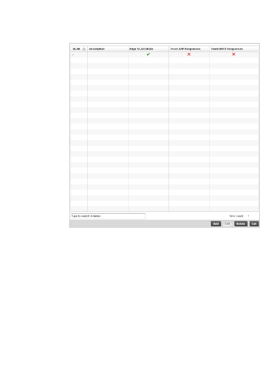
434 Brocade Mobility RFS4000, RFS6000, and RFS7000 System Reference Guide
53-1002620-01
7
FIGURE 293 Profile Overrides - Network Bridge VLAN screen
4. Review the following VLAN configuration parameters to determine whether an override is
warranted:
VLAN Lists the numerical identifier defined for the Bridge VLAN when it was initially created.
The available range is from 1 - 4095. This value cannot be modified during the edit
process.
Description Lists a description of the VLAN assigned when it was created or modified. The
description should be unique to the VLAN’s specific configuration and help
differentiate it from other VLANs with similar configurations.
Edge VLAN Mode Defines whether the VLAN is currently in edge VLAN mode. A green checkmark defines
the VLAN as extended. An edge VLAN is the VLAN where hosts are connected. For
example, if VLAN 10 is defined with wireless clients, and VLAN 20 is where the default
gateway resides, VLAN 10 should be marked as an edge VLAN and VLAN 20 shouldn’t
be marked as an edge VLAN. When defining a VLAN as edge VLAN, the firewall
enforces additional checks on hosts in that VLAN. For example, a host cannot move
from an edge VLAN to another VLAN and still keep firewall flows active.
Trust ARP Response When ARP trust is enabled, a green checkmark displays. When disabled, a red “X”
displays. Trusted ARP packets are used to update the IP-MAC Table to prevent IP spoof
and arp-cache poisoning attacks.
Trust DHCP Responses When DHCP trust is enabled, a green checkmark displays. When disabled, a red “X”
displays. When enabled, DHCP packets from a DHCP server are considered trusted
and permissible. DHCP packets are used to update the DHCP Snoop Table to prevent
IP spoof attacks.
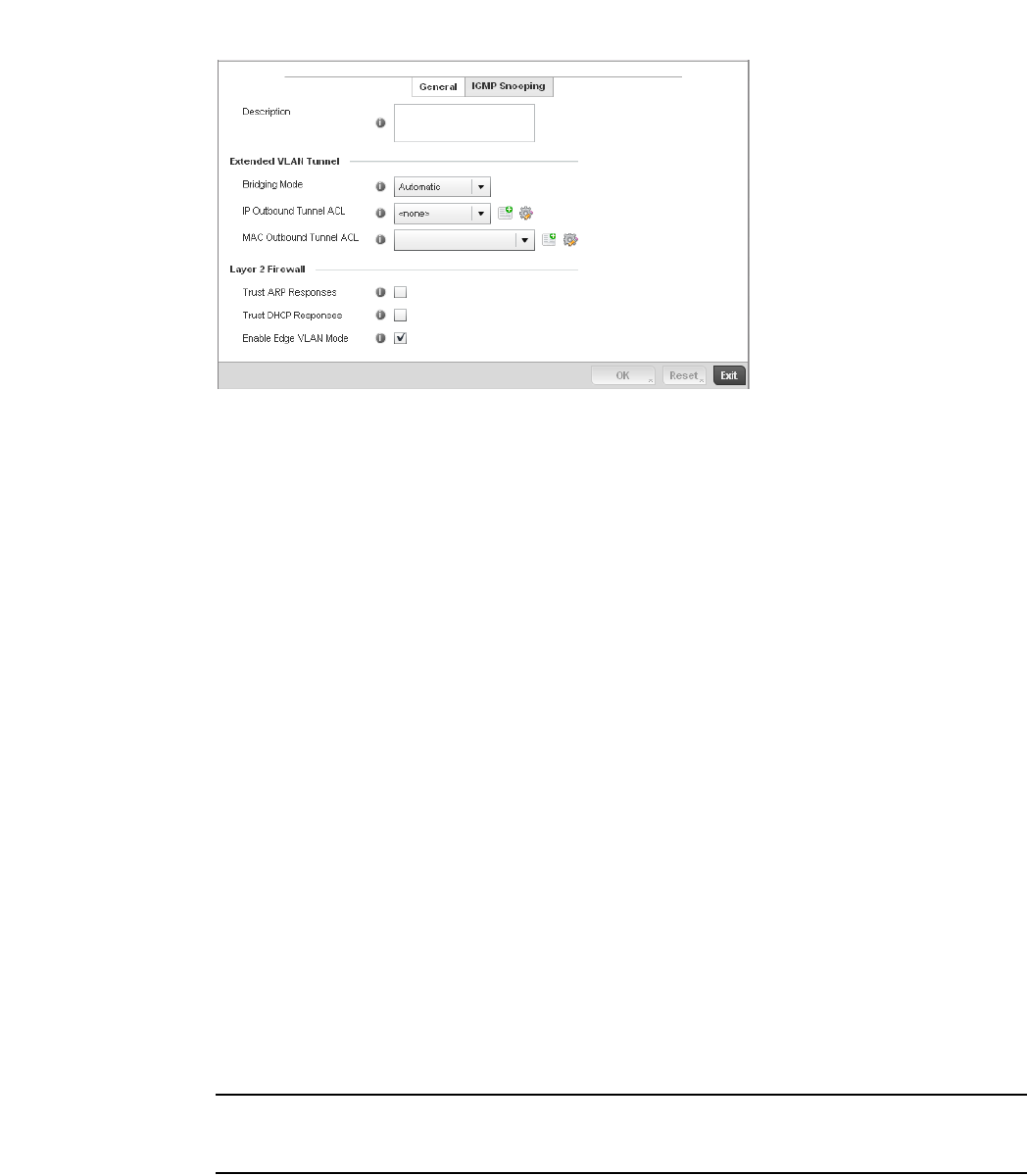
Brocade Mobility RFS4000, RFS6000, and RFS7000 System Reference Guide 435
53-1002620-01
7
5. Select Add to define a new Bridge VLAN configuration, Edit to modify or override an existing
Bridge VLAN configuration or Delete to remove a VLAN configuration.
FIGURE 294 Bridge VLAN screen
6. The General tab displays by default.
7. If adding a new Bridge VLAN configuration, use the spinner control to define or override a VLAN
ID between 1 - 4094. This value must be defined and saved before the General tab can
become enabled and the remainder of the settings defined. VLAN IDs 0 and 4095 are
reserved and unavailable.
8. Set or override the following General Bridge VLAN parameters:
9. Set or override the following Extended VLAN Tunnel parameters:
NOTE
Local and Automatic bridging modes do not work with ACLs. ACLs can only be used with tunnel or
isolated-tunnel modes.
Description If creating a new Bridge VLAN, provide a description (up to 64 characters) unique to
the VLAN’s specific configuration to help differentiate it from other VLANs with similar
configurations.
Bridging Mode Specify one of the following bridging mode for use on the VLAN.
•Automatic: Select automatic mode to let the controller determine the best
bridging mode for the VLAN.
•Local: Select Local to use local bridging mode for bridging traffic on the VLAN.
•Tunnel: Select Tunnel to use a shared tunnel for bridging traffic on the VLAN.
•isolated-tunnel: Select isolated-tunnel to use a dedicated tunnel for bridging
traffic on the VLAN.
IP Outbound Tunnel ACL Select an IP Outbound Tunnel ACL for outbound traffic from the pulldown menu. If an
appropriate outbound IP ACL is not available click the create button to make a new
one.
MAC Outbound Tunnel
ACL
Select a MAC Outbound Tunnel ACL for outbound traffic from the pulldown menu. If an
appropriate outbound MAC ACL is not available click the create button to make a new
one.
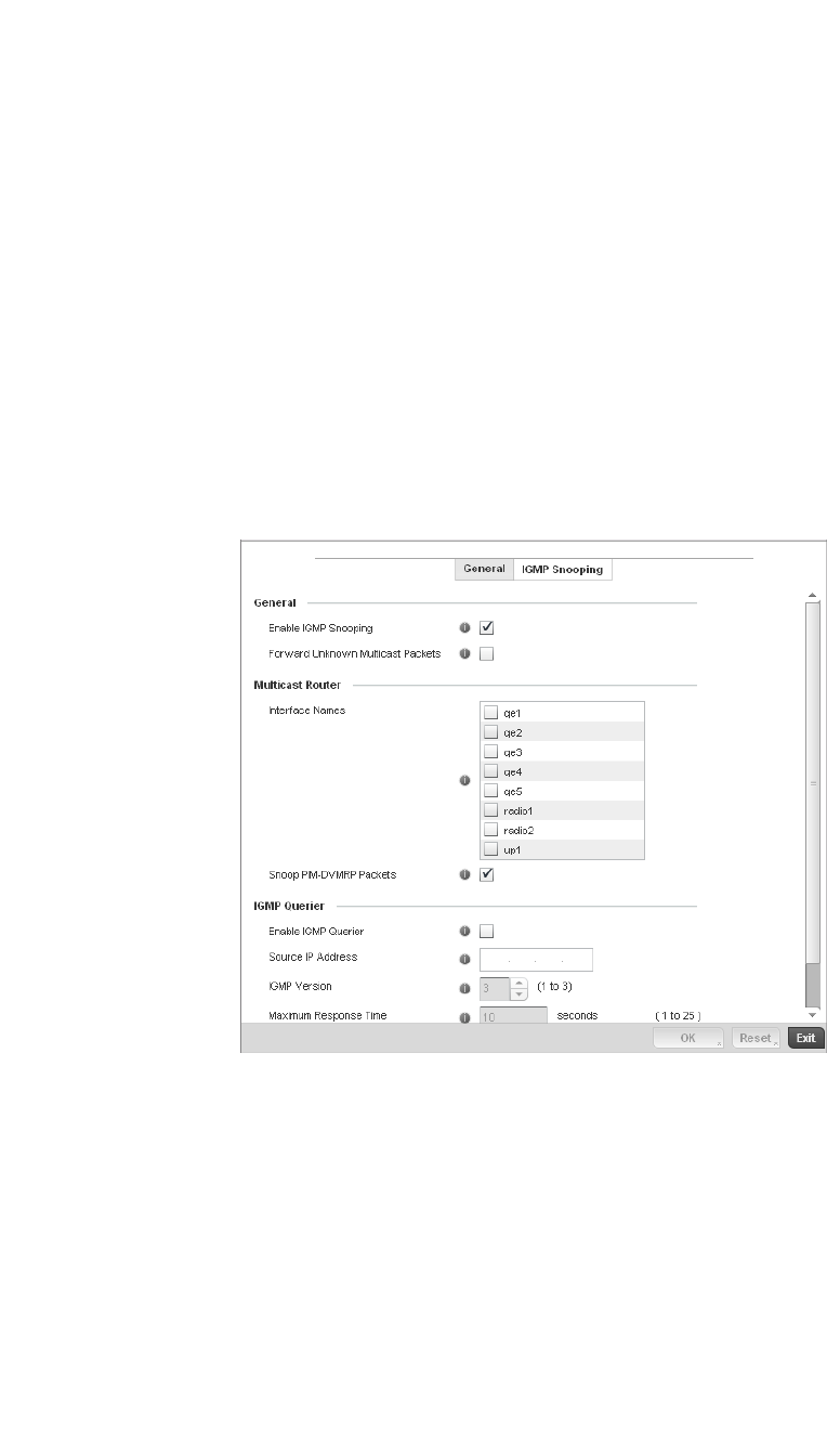
436 Brocade Mobility RFS4000, RFS6000, and RFS7000 System Reference Guide
53-1002620-01
7
10. Set or override the following Layer 2 Firewall parameters:
11. Select the OK button to save the changes to the General tab. Select Reset to revert to the last
saved configuration.
12. Select the IGMP Snooping tab to define the VLAN’s IGMP configuration.
FIGURE 295 Bridge VLAN screen - IGMP Snooping Tab
13. Define the following IGMP Snooping parameters for the Bridge VLAN configuration:
The Internet Group Management Protocol (IGMP) is a protocol used for managing members of
IP multicast groups. The controller listens to IGMP network traffic and forwards the IGMP
multicast packets to radios on which the interested hosts are connected. On the wired side of
the network, the controller floods all the wired interfaces. This feature reduces the
unnecessary flooding of multicast traffic in the network.
Trust ARP Response Select the checkbox to use trusted ARP packets to update the DHCP Snoop Table to
prevent IP spoof and arp-cache poisoning attacks. This feature is disabled by default.
Trust DHCP Responses Select the checkbox to use DHCP packets from a DHCP server as trusted and
permissible within the managed network. DHCP packets are used to update the DHCP
Snoop Table to prevent IP spoof attacks. This feature is disabled by default.
Edge VLAN Mode Select the checkbox to enable edge VLAN mode. When selected, the edge controller’s
IP address in the VLAN is not used for normal operations, as its now designated to
isolate devices and prevent connectivity. This feature is enabled by default.
Enable IGMP Snooping Select the check box to enable IGMP snooping on the controller. If disabled, snooping
on a per VLAN basis is also disabled. This feature is enabled by default. If disabled, the
settings under bridge configuration are overridden. For example, if IGMP snooping is
disabled, but the bridge VLAN is enabled, the effective setting is disabled.
Forward Unknown Unicast
Packets
Select the check box to enable the controller to forward multicast packets from
unregistered multicast groups. If disabled (the default setting), the unknown multicast
forward feature is also disabled for individual VLANs.

Brocade Mobility RFS4000, RFS6000, and RFS7000 System Reference Guide 437
53-1002620-01
7
14. Within the Multicast Router section, check the boxes of those interfaces used by the controller
as a multicast router interface. Multiple controller interfaces can be selected and overridden.
15. Optionally select the Snoop PIM-DVMRP Packets box to snoop packets across the selected
interface(s). This option is enabled by default.
16. Set the following IGMP Querier parameters for the profile’s bridge VLAN configuration:
17. Select the OK button located at the bottom right of the screen to save the changes to the IGMP
Snooping tab. Select Reset to revert to the last saved configuration.
Cisco Discovery Protocol Configuration
Profile Network Configuration
The Cisco Discovery Protocol (CDP) is a proprietary Data Link Layer network protocol implemented
in Cisco networking equipment and used to share information about network devices.
To override Cisco Discovery Protocol (CDP)configuration:
1. Select Devices from the Configuration tab.
The Device Configuration screen displays a list of managed devices or peer controllers. The
listed devices can either be other controllers or Access Points within the managed network.
2. Select a target device (by double-clicking it) from amongst those displayed within the Device
Configuration screen.
Devices can also be selected directly from the Device Browser in the lower, left-hand, side of
the UI.
3. Select Profile Overrides from the Device menu to expand it into sub menu options.
4. Select Network to expand its sub menu options.
5. Select Cisco Discovery Protocol.
Enable IGMP Querier Select the check box to enable IGMP querier. IGMP snoop querier is used to keep host
memberships alive. It’s primarily used in a network where there’s a multicast
streaming server and hosts subscribed to the server and no IGMP querier present. The
controller can perform the IGMP querier role. An IGMP querier sends out periodic
IGMP query packets. Interested hosts reply with an IGMP report packet. IGMP
snooping is only conducted on wireless radios. IGMP multicast packets are flooded on
wired ports. IGMP multicast packet are not flooded on the wired port. IGMP
membership is also learnt on it and only if present, then it is forwarded on that port. A
Brocade br-7131 model access point can also be an IGMP querier.
Source IP Address Define an IP address applied as the source address in the IGMP query packet. This
address is used as the default VLAN querier IP address.
IGMP Version Use the spinner control to set the IGMP version compatibility to either version 1, 2 or
3. The default setting is 3.
Maximum Response Time Specify the maximum time (between 1 - 25 seconds) before sending a responding
report. When no reports are received from a radio, radio information is removed from
the snooping table. The controller only forwards multicast packets to radios present in
the snooping table. For IGMP reports from wired ports, the controller forwards these
reports to the multicast router ports. The default setting is 10 seconds.
Other Querier Timer Expiry Specify an interval in either Seconds (60 - 300) or Minutes (1 - 5) used as a timeout
interval for other querier resources. The default setting is 1 minute.
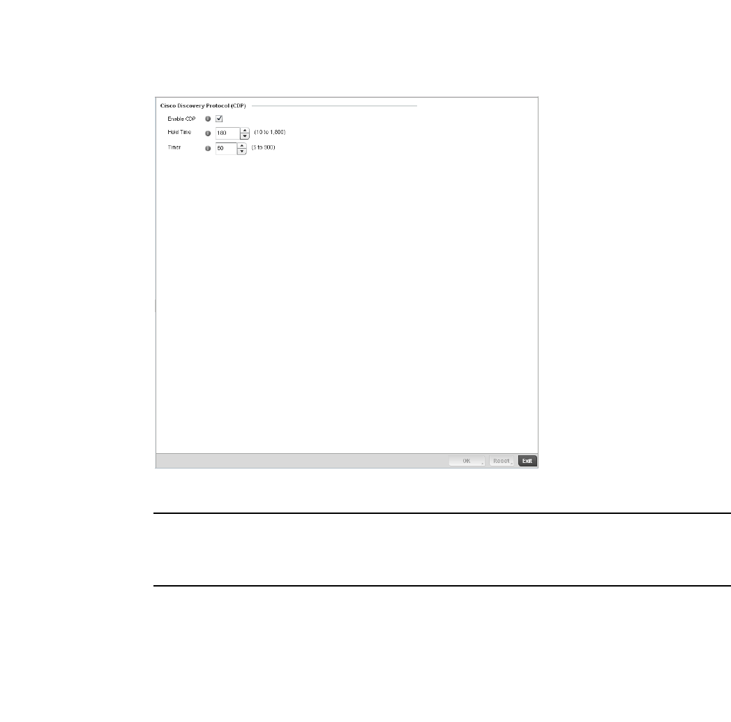
438 Brocade Mobility RFS4000, RFS6000, and RFS7000 System Reference Guide
53-1002620-01
7
FIGURE 296 Profile Overrides - Network Cisco Discovery Protocol screen
NOTE
A blue override icon (to the left of a parameter) defines the parameter as having an override applied.
To remove an override go to the Basic Configuration section of the device and click the Clear
Overrides button. This will remove all overrides from the device.
6. Check the Enable CDP box to enable Cisco Discovery Protocol on the device.
7. R e fe r to t he Hold Time field and use the spinner control to define a hold time between 10 -
1800 seconds for transmitted CDP Packets. The default value is 180 seconds.
8. Refer to the Timer field and use the spinner control to define a interval between 5 - 900
seconds to transmit CDP Packets. The default value is 60 seconds.
9. Select the OK button to save the changes and overrides. Select Reset to revert to the last
saved configuration.
Link Layer Discovery Protocol Configuration
Profile Network Configuration
The Link Layer Discovery Protocol (LLDP) or IEEE 802.1AB is a vendor-neutral Data Link Layer
protocol used by network devices for advertising of (announcing) their identity, capabilities, and
interconnections on a IEEE 802 LAN network. The protocol is formally referred to by the IEEE as
Station and Media Access Control Connectivity Discovery. Both LLDP snooping and ability to
generate and transmit LLDP packets will be provided.
Information obtained via CDP and LLDP snooping is available in the UI. In addition, information
obtained via CDP / LLDP snooping is provided by an AP during the adoption process, so the L2
switch device name detected by the AP can be used as a criteria in the provisioning policy.
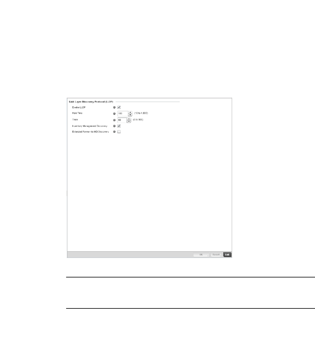
Brocade Mobility RFS4000, RFS6000, and RFS7000 System Reference Guide 439
53-1002620-01
7
To override Link Layer Discovery Protocol (LLDP)configuration:
1. Select Devices from the Configuration tab.
The Device Configuration screen displays a list of managed devices or peer controllers. The
listed devices can either be other controllers or Access Points within the managed network.
2. Select a target device (by double-clicking it) from amongst those displayed within the Device
Configuration screen.
Devices can also be selected directly from the Device Browser in the lower, left-hand, side of
the UI.
3. Select Profile Overrides from the Device menu to expand it into sub menu options.
4. Select Network to expand its sub menu options.
5. Select Link Layer Discovery Protocol.
FIGURE 297 Profile Overrides - Network Link Layer Discovery Protocol screen
NOTE
A blue override icon (to the left of a parameter) defines the parameter as having an override applied.
To remove an override go to the Basic Configuration section of the device and click the Clear
Overrides button. This will remove all overrides from the device.
6. Check the Enable LLDP box to enable Link Layer Discovery Protocol on the device.
7. R e fe r to t he Hold Time field and use the spinner control to define a hold time between 10 -
1800 seconds for transmitted LLDP Packets. The default value is 180 seconds.
8. Refer to the Timer field and use the spinner control to define the interval between 5 - 900
seconds to transmit LLDP Packets. The default value is 60 seconds.
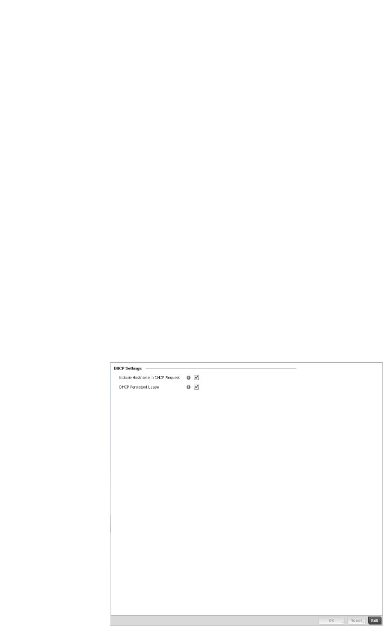
440 Brocade Mobility RFS4000, RFS6000, and RFS7000 System Reference Guide
53-1002620-01
7
9. Check the Inventory Mangement Discovery box to enable this feature. Inventory Management
Discovery is used to track and identify inventory attributes including manufacturer, model, or
software version.
10. Select the Extended Power via MDI Discovery box to enable this feature. Extended Power via
MDI Discovery provides detailed power information through end points and other connected
devices.
11. Select the OK button to save the changes and overrides. Select Reset to revert to the last
saved configuration.
Miscellaneous Network Configuration
Profile Network Configuration
A controller profile can be configured to include a hostname in a DHCP lease for a requesting
device and its profile. This helps an administrator track the leased DHCP IP address by hostname
for the controller supported device profile. When numerous DHCP leases are assigned, an
administrator can better track the leases when hostnames are used instead of devices.
To include a hostnames in DHCP request:
1. Select Configuration > Profiles > Network.
2. Expand the Network menu to display its submenu options
3. Select Miscellaneous.
FIGURE 298 Profile Miscellaneous screen

Brocade Mobility RFS4000, RFS6000, and RFS7000 System Reference Guide 441
53-1002620-01
7
4. Refer to the DHCP Settings section to configure miscellaneous DHCP Settings.
5. Select the OK button located at the bottom right of the screen to save the changes. Select
Reset to revert to the last saved configuration.
Profile Network Configuration and
Deployment Considerations
Profile Network Configuration
Before defining a profile’s network configuration, refer to the following deployment guidelines to
ensure the profile configuration is optimally effective:
•Administrators often need to route traffic to interoperate between different VLANs. Bridging
VLANs are only for non-routable traffic, like tagged VLAN frames destined to some other device
which will untag it. When a data frame is received on a port, the VLAN bridge determines the
associated VLAN based on the port of reception.
•Static routes while easy can be overwhelming within a large or complicated network. Each time
there is a change, someone must manually make changes to reflect the new route. If a link
goes down, even if there is a second path, the router would ignore it and consider the link
down.
•Static routes require extensive planning and have a high management overhead. The more
routers that exist in a network, the more routes needing to be configured. If you have N number
of routers and a route between each router is needed, then you must configure N x N routes.
Thus, for a network with nine routers, you’ll need a minimum of 81 routes (9 x 9 = 81).
Profile Security Configuration
A controller or Access Point profile can have its own firewall policy, wireless client role policy, WEP
shared key authentication, NAT policy and VPN policy (controller only) applied. If an existing firewall,
client role or NAT policy is unavailable, an administrator can be navigated from the Configuration >
Profiles section of the controller UI to the Configuration > Security portion of the UI to create the
required security policy configuration. Once created, separate policies can be applied to the
controller profile to best support the data protection and security requirements in respect to the
controller or Access Point model being supported by the profile.
For more information, refer to the following sections:
•Defining Security Settings
•Setting the Certificate Revocation List (CRL) Configuration
•Configuring ISAKMP Policies
•Configuring Transform Sets
•Setting the Profile’s VPN Configuration
Include Hostname in
DHCP Request
Select the Include Hostname in DHCP Request checkbox to include a hostname in a
DHCP lease for a requesting device. This feature is disabled by default.
DHCP Persisten Lease Check this box to enable a persistent DHCP lease for the device. A persistent DHCP
lease assigns the same IP Address and other network information to the device each
time it renews its DHCP lease.
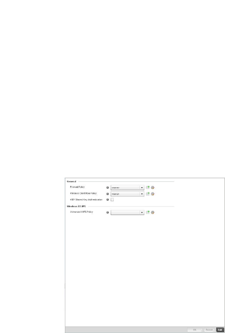
442 Brocade Mobility RFS4000, RFS6000, and RFS7000 System Reference Guide
53-1002620-01
7
•Setting the Profile’s NAT Configuration
Defining Security Settings
Profile Security Configuration
A controller profile can leverage existing firewall, wireless client role and WIPS policies and
configurations and apply them to the profile’s configuration. This affords each controller profile a
truly unique combination of data protection policies best meeting the data protection requirements
of that controller profile.
To define a profile’s security settings:
1. Select the Configuration tab from the Web UI.
2. Select Profiles from the Configuration tab.
3. Select Manage Profiles from the Configuration > Profiles menu.
4. Select Security.
5. Select Settings.
FIGURE 299 Security - Settings screen

Brocade Mobility RFS4000, RFS6000, and RFS7000 System Reference Guide 443
53-1002620-01
7
6. Refer to the General field to assign or create the following security policy’s to the profile:
NOTE
Advanced WIPS Policy is only supported on wireless controllers and requires a dedicated WIPS
sensor, but does not require a sensor license. Standard WIPS is available on all RF Domain
managers and supports on channel, off channel and dedicated sensor scanning modes.
Select an Advanced WIPS Policy from the drop-down menu.Define an advanced WIPS configuration
to optionally remove (terminate) unwanted device connections, and sanction (allow) or unsanaction
(disallow) specific events within the managed network.
If an existing Advanced WIPS policy does not meet the profile’s data protection requirements,
select the Create icon to create a new configuration that can be applied to the profile. An
existing policy can also be selected and edited as needed using the Edit icon. For more
information, see Configuring an Advanced WIPS Policy on page 9-550.
Select OK to save the changes made within the Settings screen. Select Reset to revert to the last
saved configuration.
Setting the Certificate Revocation List (CRL) Configuration
Profile Security Configuration
A certificate revocation list (CRL) is a list of certificates that have been revoked or are no longer
valid. A certificate can be revoked if the certificate authority (CA) had improperly issued a
certificate, or if a private-key is compromised. The most common reason for revocation is the user
no longer being in sole possession of the private key.
To define a CRL configuration that can be applied to a controller profile:
1. Select the Configuration tab from the Web UI.
Firewall Policy Use the drop-down menu to select an existing Firewall Policy to use as an additional
security mechanism with this controller profile. All devices using this controller profile
and Access Point must meet the requirements of the firewall policy to access the
managed network. A firewall is a mechanism enforcing access control, and is
considered a first line of defense in protecting proprietary information within the
wireless controller managed network. The means by which this is accomplished
varies, but in principle, a firewall can be thought of as mechanisms both blocking and
permitting data traffic within the wireless controller managed network. If an existing
Firewall policy does not meet your requirements, select the Create icon to create a
new firewall policy that can be applied to this profile. An existing policy can also be
selected and edited as needed using the Edit icon. For more information, see
Wireless Firewall on page 9-511 and Configuring a Firewall Policy on page 9-512.
Wireless Client Role Policy Use the drop-down menu to select a client role policy the controller uses to
strategically filter client connections based on a pre-defined set of filter rules and
connection criteria. If an existing Wireless Client Role policy does not meet your
requirements, select the Create icon to create a new configuration that can be
applied to this profile. An existing policy can also be selected and edited as needed
using the Edit icon. For more information, see Wireless Client Roles on page 9-530.
WEP Shared Key
Authentication
Select the check box to require devices using this profile to use a WEP key to access
the managed network using this profile. The wireless controller, other proprietary
routers, and Brocade Solutions clients use the key algorithm to convert an ASCII string
to the same hexadecimal number. Clients without Brocade Solutions adapters need to
use WEP keys manually configured as hexadecimal numbers. This option is disabled
by default.
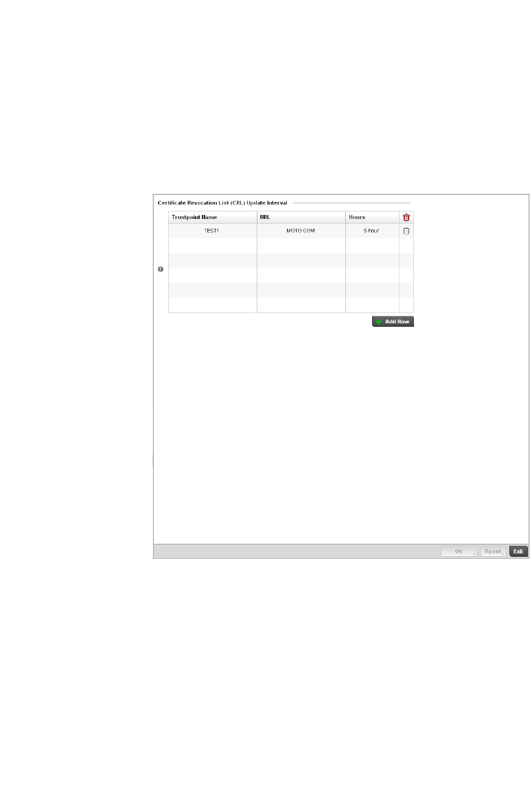
444 Brocade Mobility RFS4000, RFS6000, and RFS7000 System Reference Guide
53-1002620-01
7
2. Select Profiles from the Configuration tab.
3. Select Manage Profiles from the Configuration > Profiles menu.
4. Select Security.
5. Select Certificate Revocation.
FIGURE 300 Security - Certificate Revocation screen
6. Select the + Add Row button to add a column within the Certificate Revocation List (CRL)
Update Interval table to quarantine certificates from use in the managed network.
Additionally, a certificate can be placed on hold for a defined period. If, for instance, a private
key was found and nobody had access to it, its status could be reinstated.
b. Provide the name of the trustpoint in question within the Trustpoint Name field. The name
cannot exceed 32 characters.
c. Enter the resource ensuring the trustpoint’s legitimacy within the URL field.
d. Use the spinner control to specify an interval (in hours) after which a device copies a CRL
file from an external server and associates it with a trustpoint.
7. S elect OK to save the changes made within the Certificate Revocation screen. Select Reset to
revert to the last saved configuration.
Configuring ISAKMP Policies
Profile Security Configuration

Brocade Mobility RFS4000, RFS6000, and RFS7000 System Reference Guide 445
53-1002620-01
7
ISAKMP (also known as IKE) is the negotiation protocol enabling two hosts to agree on how to build
an IPSec security association. To configure the security appliance for virtual private networks, set
global parameters that apply system wide and define policies peers negotiate to establish a VPN
tunnel.
The ISAKMP protocol is an IPSec standard protocol used to ensure security for VPN negotiation,
and remote host or network access. ISAKMP provides an automatic means of negotiation and
authentication for communication between two or more parties. ISAKMP manages IPSec keys
automatically.
To configure ISAKMP on the wireless controller:
1. Select the Configuration tab from the Web UI.
2. Select Profiles from the Configuration tab.
3. Select Manage Profiles from the Configuration > Profiles menu.
4. Select Security.
5. Select ISAKMP Policy.
The ISAKMP screen displays by default. The ISAKMP screen lists those ISAKMP policies
created thus far. Use the ISAKMP Policy screen to configure the Internet Security Association
and Key Management Protocol (ISAKMP) for creating a VPN. ISAKMP is a framework for
authentication and key exchange. It defines the procedures and packet formats to establish,
negotiate, modify and delete Security Associations (SA). Any of these policies can be selected
and applied to the controller.
A VPN tunnel is negotiated in two phases. The first phase creates an ISAKMP SA that’s a
control channel. The data channel is negotiated using this control channel. ISAKMP policy
parameters are not negotiated and the transform set is for negotiating the data channel (IPsec
SAs).
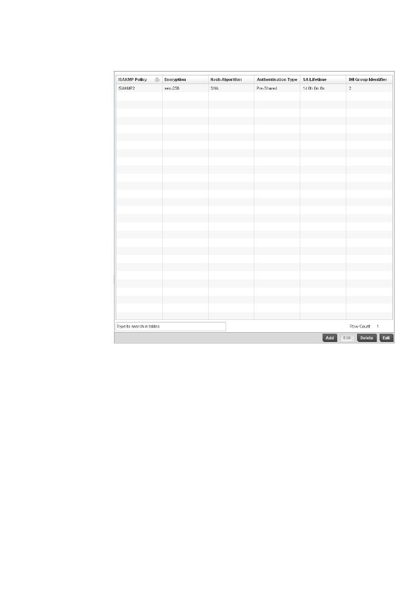
446 Brocade Mobility RFS4000, RFS6000, and RFS7000 System Reference Guide
53-1002620-01
7
FIGURE 301 Security - ISAKMP Policy screen
6. Refer to the following configuration data for existing ISAKMP policies:
7. S elect Add to create a new ISAKMP policy, Edit to modify the attributes of a selected existing
policy or Delete to remove obsolete policies from the list of those available to the controller.
If adding or editing an existing ISAKMP policy, the following screen displays.
When ISAKMP negotiations begin, the peer initiating the negotiation sends its policies to the
remote peer. The remote peer searches for a match with its own policies using the defined
priority scheme. A ISAKMP policy matches when they have the same encryption, hash,
authentication and Diffie-Hellman settings. The ISAKMP lifetime must also be less than or
equal to the lifetime in the policy sent. If the lifetimes do not match, the shorter lifetime
applies. If no match exists, ISAKMP refuses negotiation.
ISAKMP Policy Displays the name assigned to the ISAKMP policy when it was initially created. The
name cannot be modified as part of the edit process.
Encryption Lists the encryption type used for encrypting packets with this ISAKMP policy.
Hash Algorithm Displays the MD5 or SHA hashing algorithm used in the ISAKMP policy.
Authentication Type Lists the key sharing mechanism used for establishing a secure connection
between two peers using this ISAKMP policy.
SA Lifetime Lists the lifetime in either seconds, minutes, hours or days for the security
association (SA) used by this ISAKMP policy.
DH Group Identifier Displays the Diffie-Hellman (DH) group identifier used by this ISAKMP policy. DH is a
cryptographic protocol that allows 2 entities, that have no prior knowledge of each
other, to jointly derive and establish a shared secret key over an unsecured
communication channel. This secret key can then be used to initiate a secure
connection between the two entities.
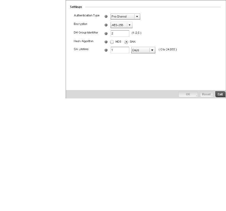
Brocade Mobility RFS4000, RFS6000, and RFS7000 System Reference Guide 447
53-1002620-01
7
FIGURE 302 ISAKMP Policy screen
8. Set the following configuration parameters for the new or modified ISAKMP policy:
ISAKMP Policy If creating a new ISAKMP policy, assign it name to help differentiate it from others
that may have a similar configuration. The policy name cannot exceed 64
characters. The name cannot be modified as part of the edit process.
Authentication Type Set the key sharing mechanism used for establishing a secure connection between
two peers using this ISAKMP policy. Use the drop-down menu to select one the
following two authentication options:
Pre-Shared – Select this option to use a key shared between the VPN endpoints.
Pre-Shared is the default setting.
RSA Signature – Uses a RSA signature as the authentication key. Ensure digital
certificates and RSA keys have been installed on the target system before using this
option.
Encryption Use the drop-down menu to select the encryption algorithm. Select from the
following options:
DES – DES stands for Data Encryption Standard. It uses a 56-bit key for encryption.
This standard is deprecated and replaced by the 3DES standard. It is provided for
backward compatibility.
3DES - 3DES or Triple DES is a encryption standard that replaced DES. It provides a
simple method of increasing the key size of the DES algorithm to protect from brute
force attacks. It uses a set of three (3) standard 56-bit DES keys to provide
increased key length for encryption.
AES – AES stands for Advanced Encryption Standard or the Rijndael Encryption
Algorithm that was adopted as the new FIPS standard in the year 2002. It is a
symmetric-key encryption standard that uses three (3) block ciphers of length 128,
192, 256 bits. This option represents the AES-128 bit block cipher.
AES-192 – This option represents the AES-192 bit block cipher.
AES-256 – This option represents the AES-256 bit block cipher. AES -256 is the
default setting.

448 Brocade Mobility RFS4000, RFS6000, and RFS7000 System Reference Guide
53-1002620-01
7
9. Select OK to save the ISAKMP policy configuration. Select Reset to revert to the last saved
configuration.
Configuring Transform Sets
Profile Security Configuration
Use the Transform Set screen to configure and manage transform sets. A Transform Set is a set of
parameters that transform an IP packet from clear text to cipher text. The transform set is an
acceptable combination of security protocols, algorithms and other settings that are applied to
IPSec protected traffic.
With manually established security associations, there’s no negotiation with the peer. Both sides
must specify the same transform set, regardless of whether the SA is manual or automatic. For
manual SAs, the ISAKMP policy does not apply. If you change a Transform Set definition, the
change is only applied to Crypto Map entries that reference the Transform Set. If a transform-set is
changed, the existing SAs are removed.
To define a transform set configuration that can be applied to a controller profile:
1. Select the Configuration tab from the Web UI.
2. Select Profiles from the Configuration tab.
3. Select Manage Profiles from the Configuration > Profiles menu.
4. Select Security.
5. Select Transform Set.
DH Group Identifier Set the Diffie-Hellman (DH) group identifier used by this ISAKMP policy. DH is a
cryptographic protocol that allows 2 entities that have no prior knowledge of each
other to jointly derive and establish a shared secret key over an unsecured
communication channel. This secret key can then be used to initiate a secure
connection between the two entities.
The valid values are 1, 2 and 5 and indicates the group used for the key exchange.
The default setting is 2.
Hash Algorithm Set the hash algorithm. Select from:
MD5 – MD5 or Message-Digest algorithm 5 is a popular 128-bit hash-function. It is
commonly used for checking the integrity of files.
SHA – Secure Hash Algorithm (SHA) is a NIST certified FIPS hash algorithm. SHA is
the default setting.
SA Lifetime Set the lifetime in seconds for the security association (SA) used by this ISAKMP
policy. This is the lifetime of the ISAKMP SA. The lifetime for
ESP/AH SAs are configured separately.
Days – Sets the SA duration in days (1 - 24,856).
Hours – Sets the SA duration in hours (1 - 596,524).
Minutes – Sets the SA duration in minutes (1 - 35, 791, 395).
Seconds – Sets the SA duration in seconds (60 - 2,147,483,646). The default
setting is 86,400 seconds.
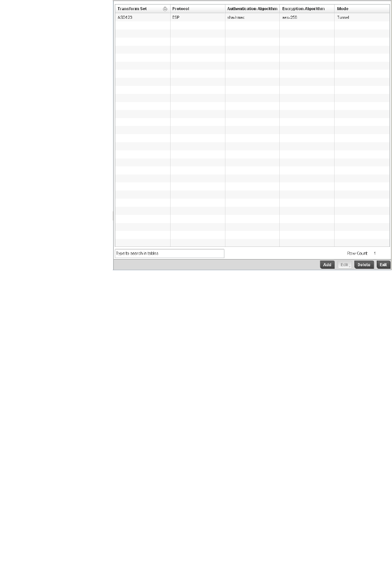
Brocade Mobility RFS4000, RFS6000, and RFS7000 System Reference Guide 449
53-1002620-01
7
FIGURE 303 Transform Set screen
6. Refer to the following for existing Transform Set configurations to determine whether a new
Transform Set configuration is required, or if an existing configuration can be used with or
without modification:
7. S elect Add to create a new Transform Set configuration, Edit to modify the attributes of a
selected Transform set or Delete to remove obsolete Transform Set from the list of those
available to the controller.
If adding or editing an existing Transform Set, the following screen displays:
Transform Set Lists the name of each Transform Set defined when it was initially created. The
name cannot be modified if editing the configuration of an existing Transform Set.
Protocol Displays the AH or ESP protocol used with the Transform Set. AH provides
authentication only, while ESP provides a stronger combination of data
confidentiality and authentication.
Authentication
Algorithm
Lists the authentication algorithm used to validate identity.
Encryption Algorithm Lists the encryption type used for encrypting packets.
Mode Displays the Tunnel or Transport mode used for packet organization with respect to
header location and the scope of ESP or AH protection boundary. The Tunnel mode
should be used for site-to-site VPN and Transport should be used for remote VPN
configurations.
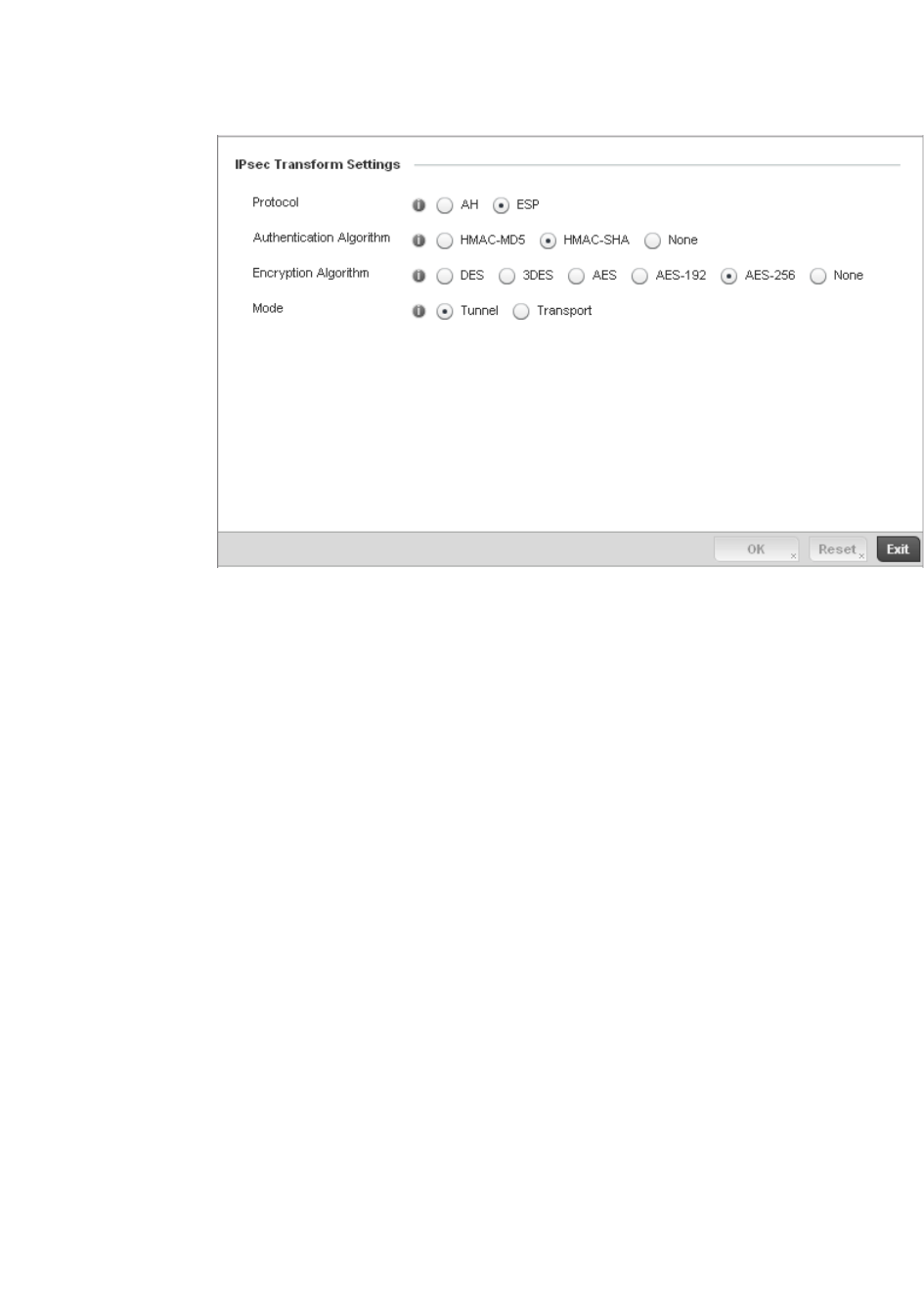
450 Brocade Mobility RFS4000, RFS6000, and RFS7000 System Reference Guide
53-1002620-01
7
FIGURE 304 Transform Set Configuration Add screen
8. Set the following configuration parameters for the new or modified Transform Set:
9. Select OK to save the Transform Set policy configuration. Select Reset to revert to the last
saved configuration.
Setting the Profile’s VPN Configuration
Profile Security Configuration
Transform Set If creating a new Transform Set, assign it a name to help differentiate it from others
that may have a similar configuration. The name cannot exceed 64 characters. The
name cannot be modified as part of the edit process.
Protocol Select the check box of the IPSec protocol used with the Transform Set. AH provides
data authentication only. ESP provides data confidentiality and well as
authentication. ESP is the default setting.
Authentication
Algorithm
Set the authentication algorithm used to validate identity.
HMAC-MD5 – Use the Message Digest 5 (MD5) as the HMAC algorithm.
HMAC-SHA – Use the Secure Hash Algorithm (SHA) as the HMAC algorithm.
HMAC-SHA is the default setting.
None – Applies no authentication. If the protocol is AH, None cannot be selected.
Encryption Algorithm The encryption algorithm check box only displays when ESP is selected as the
Transform Set protocol. By default, the Transform set uses AES-256.
AES stands for Advanced Encryption Standard. It’s a symmetric-key encryption
standard that uses a block ciphers length 256 bits. AES -256 is the default setting.
Selecting None applies no encryption. When the protocol is ESP, encryption and
authentication cannot both be set to None.
Mode Set the mode used for packet organization with respect to header location and the
scope of ESP or AH protection boundary. Use Tunnel for site-to-site VPN and
Transport mode for remote VPN configurations. The default mode is Tunnel.

Brocade Mobility RFS4000, RFS6000, and RFS7000 System Reference Guide 451
53-1002620-01
7
IPSec VPN provides a secure tunnel between two networked peer access points or controllers.
Administrators can define which packets are sent within the tunnel, and how they’re protected.
When a tunnelled peer sees a sensitive packet, it creates a secure tunnel and sends the packet
through the tunnel to its remote peer destination.
Tunnels are sets of security associations (SA) between two peers. SAs define the protocols and
algorithms applied to sensitive packets and specify the keying mechanisms used by tunnelled
peers. SAs are unidirectional and exist in both the inbound and outbound direction. SAs are
established per the rules and conditions of defined security protocols (AH or ESP).
Use crypto maps to configure IPSec VPN SAs. Crypto maps combine the elements comprising IPSec
SAs. Crypto maps also include transform sets. A transform set is a combination of security
protocols, algorithms and other settings applied to IPSec protected traffic. One crypto map is
utilized for each IPsec peer, however for remote VPN deployments one crypto map is used for all
the remote IPsec peers.
Internet Key Exchange (IKE) protocol is a key management protocol standard used in conjunction
with IPSec. IKE enhances IPSec by providing additional features, flexibility, and configuration
simplicity for the IPSec standard. IKE automatically negotiates IPSec SAs, and enables secure
communications without time consuming manual pre-configuration.
To define a profile’s VPN settings:
1. Select the Configuration tab from the Web UI.
2. Select Profiles from the Configuration tab.
3. Select Manage Profiles from the Configuration > Profiles menu.
4. Select Security.
5. Select VPN Configuration.
6. The Basic Settings tab displays by default. Refer to the Peer Settings table to add peer
addresses and keys for VPN tunnel destinations. Use the + Add Row function as needed to add
additional destinations and keys.
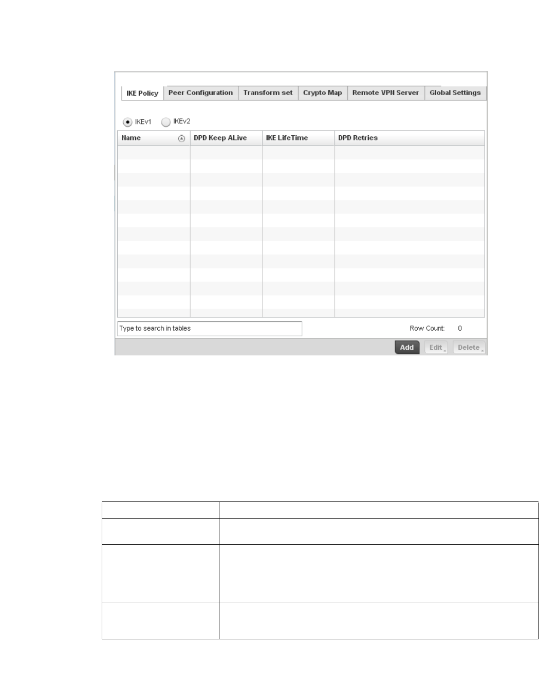
452 Brocade Mobility RFS4000, RFS6000, and RFS7000 System Reference Guide
53-1002620-01
7
FIGURE 305 Profile Security - VPN IKE Policy screen
Select either the IKEv1 or IKEv2 radio button to enforce VPN peer key exchanges using either IKEv1
or IKEv2.
IKEv2 provides improvements from the original IKEv1 design (improved cryptographic
mechanisms, NAT and firewall traversal, attack resistance etc.) and is recommended in most
deployments. The appearance of the IKE Policy screens differ depending on the selected IKEv1
or IKEv2 mode.
Refer to the following to determine whether an IKE Policy requires creation, modification or
removal:
Select Add to define a new IKe Policy configuration, Edit to modify an existing configuration or
Delete to remove an existing configuration.
Name Displays the 32 character maximum name assigned to the IKE policy.
DPD Keep Alive Lists each policy’s IKE keep alive message interval defined for IKE VPN tunnel dead
peer detection.
IKE LifeTime Displays each policy’s lifetime for an IKE SA. The lifetime defines how long a
connection (encryption/authentication keys) should last, from successful key
negotiation to expiration. Two peers need not exactly agree on the lifetime, though if
they do not, there is some clutter for a superseded connection on the peer defining
the lifetime as longer.
DPD Retries Lists each policy’s number maximum number of keep alive messages sent before a
VPN tunnel connection is defined as dead by the peer. This screen only appears when
IKEv1 is selected.
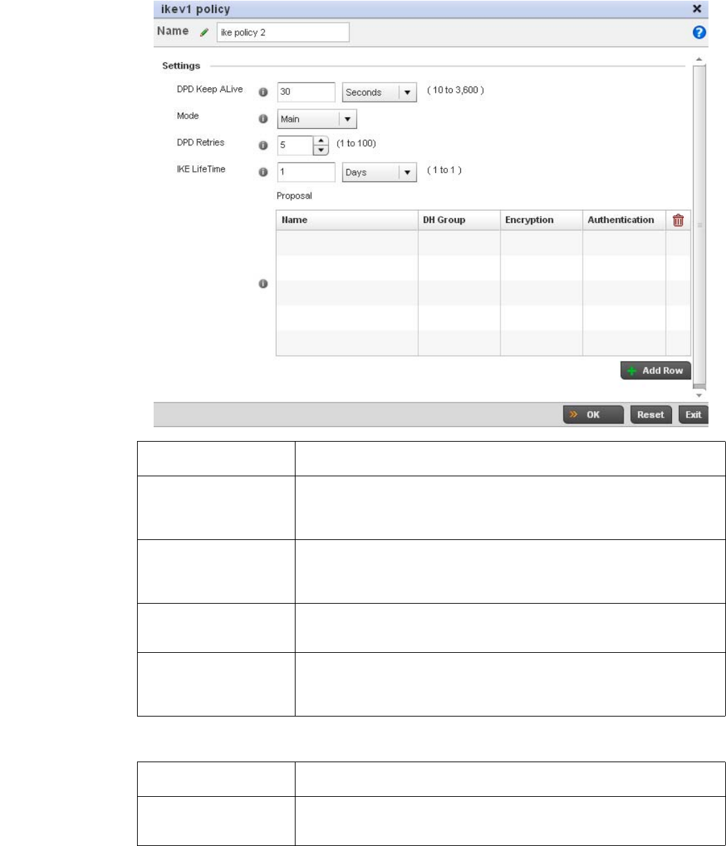
Brocade Mobility RFS4000, RFS6000, and RFS7000 System Reference Guide 453
53-1002620-01
7
Select + Add Row to define the network address of a target peer and its security settings.
Name If creating a new IKE policy, assign it a 32 character maximum name to help
differentiate this IKE configuration from others with a similar parameters.
DPD Keep Alive Configure the IKE keep alive message interval used for dead peer detection on the
remote end of the IPSec VPN tunnel. Set this value in either Seconds (10 - 3,600),
Minutes (1 - 60) or Hours (1). The default setting is 30 seconds. This setting is
required for both IKEv1 and IKEV2.
Mode If using IKEv1, use the drop-down menu to define the IKE mode as either Main or
Aggressive. IPSEC has two modes in IKEv1 for key exchanges. Aggressive mode
requires 3 messages be exchanged between the IPSEC peers to setup the SA, Main
requires 6 messages. The default setting is Main.
DPD Retries Use the spinner control to set the maximum number of keep alive messages sent
before a VPN tunnel connection is defined as dead. The available range is from 1 -
100. The default setting is 5.
IKE LifeTime Set the lifetime defining how long a connection (encryption/authentication keys)
should last from successful key negotiation to expiration. Set this value in either
Seconds (600 - 86,400), Minutes (10 - 1,440), Hours (1 - 24) or Days (1). This setting
is required for both IKEv1 and IKEV2.
Name If creating a new IKE policy, assign the target peer (tunnel destination) a 32 character
maximum name to distinguish it from others with a similar configuration.
DH Group Use the drop-down menu to define a Diffie-Hellman (DH) identifier used by the VPN
peers to derive a shared secret password without having to transmit. Options include
2, 5 and 14. The default setting is 5.
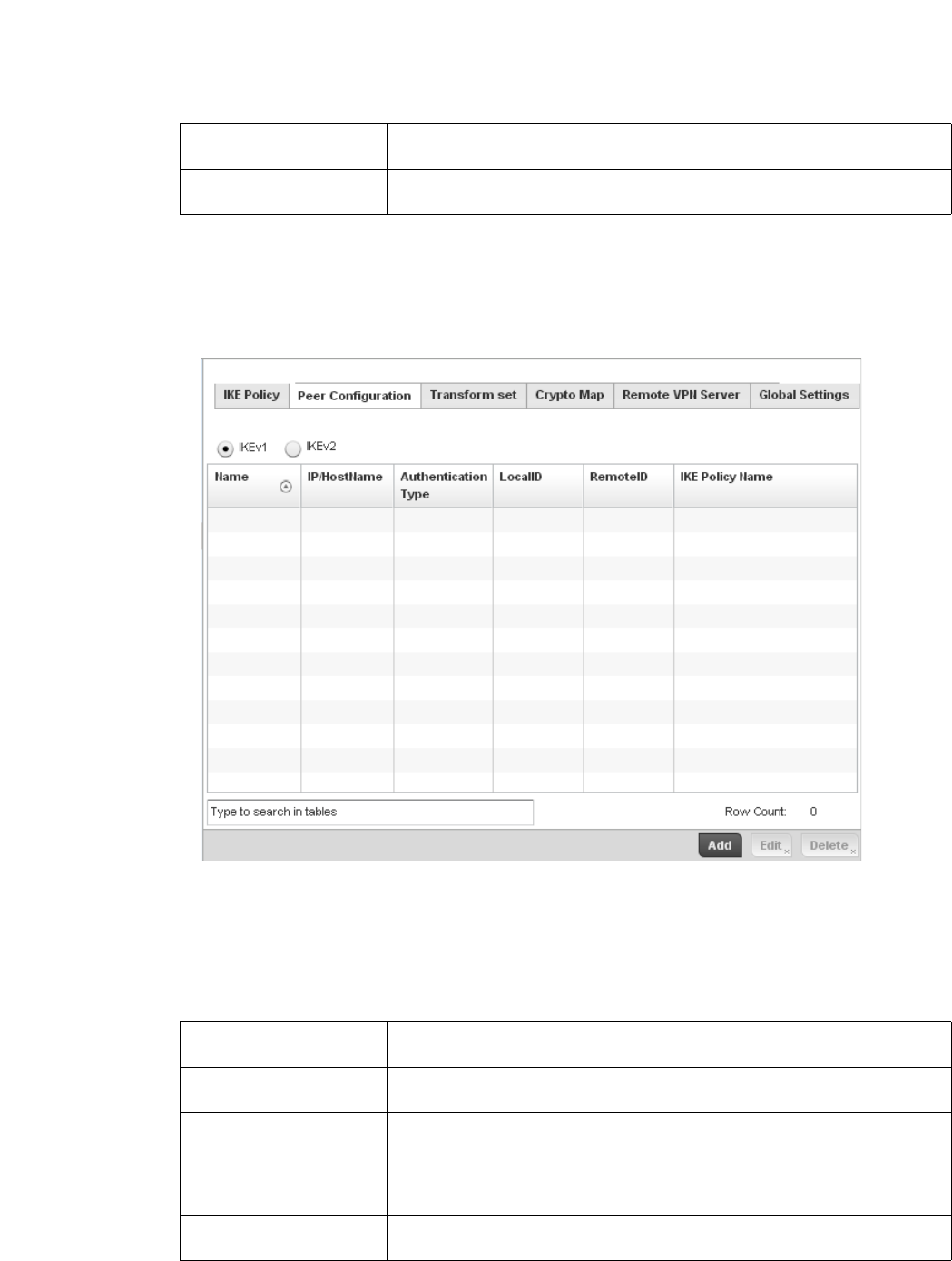
454 Brocade Mobility RFS4000, RFS6000, and RFS7000 System Reference Guide
53-1002620-01
7
Select OK to save the changes made within the IKE Policy screen. Select Reset to revert to the last
saved configuration. Select the Delete Row icon as needed to remove a peer configuration.
Select the Peer Configuration tab to assign additional network address and IKE settings to the an
intended VPN tunnel peer destination.
FIGURE 306 Profile Security - VPN Peer Destination screen (IKEv1 example)
Select either the IKEv1 or IKEv2 radio button to enforce VPN key exchanges using either IKEv1 or
IKEv2.
Refer to the following to determine whether a new VPN Peer Configuration requires creation, an
existing configuration requires modification or a configuration requires removal.
Encryption Select an encryption method used by the tunnelled peers to securely interoperate.
Options include 3DES, AES, AES-192 and AES-256. The default setting is AES-256.
Authentication Select an authentication hash algorithm used by the peers to exchange credential
information. Options include SHA and MD5. The default setting is SHA.
Name Lists the 32 character maximum name assigned to each listed peer configuration
upon creation.
IP/Hostname Displays the IP address (or host address FQDN) of the IPSec VPN peer targeted for
secure tunnel connection and data transfer.
Authentication Type Lists whether the peer configuration has been defined to use pre-shared key (PSK) or
RSA. Rivest, Shamir, and Adleman (RSA) is an algorithm for public key cryptography.
It’s the first algorithm known to be suitable for signing, as well as encryption. If using
IKEv2, this screen displays both local and remote authentication, as both ends of the
VPN connection require authentication.
LocalID Lists the access point’s local identifier used within this peer configuration for an IKE
exchange with the target VPN IPSec peer.
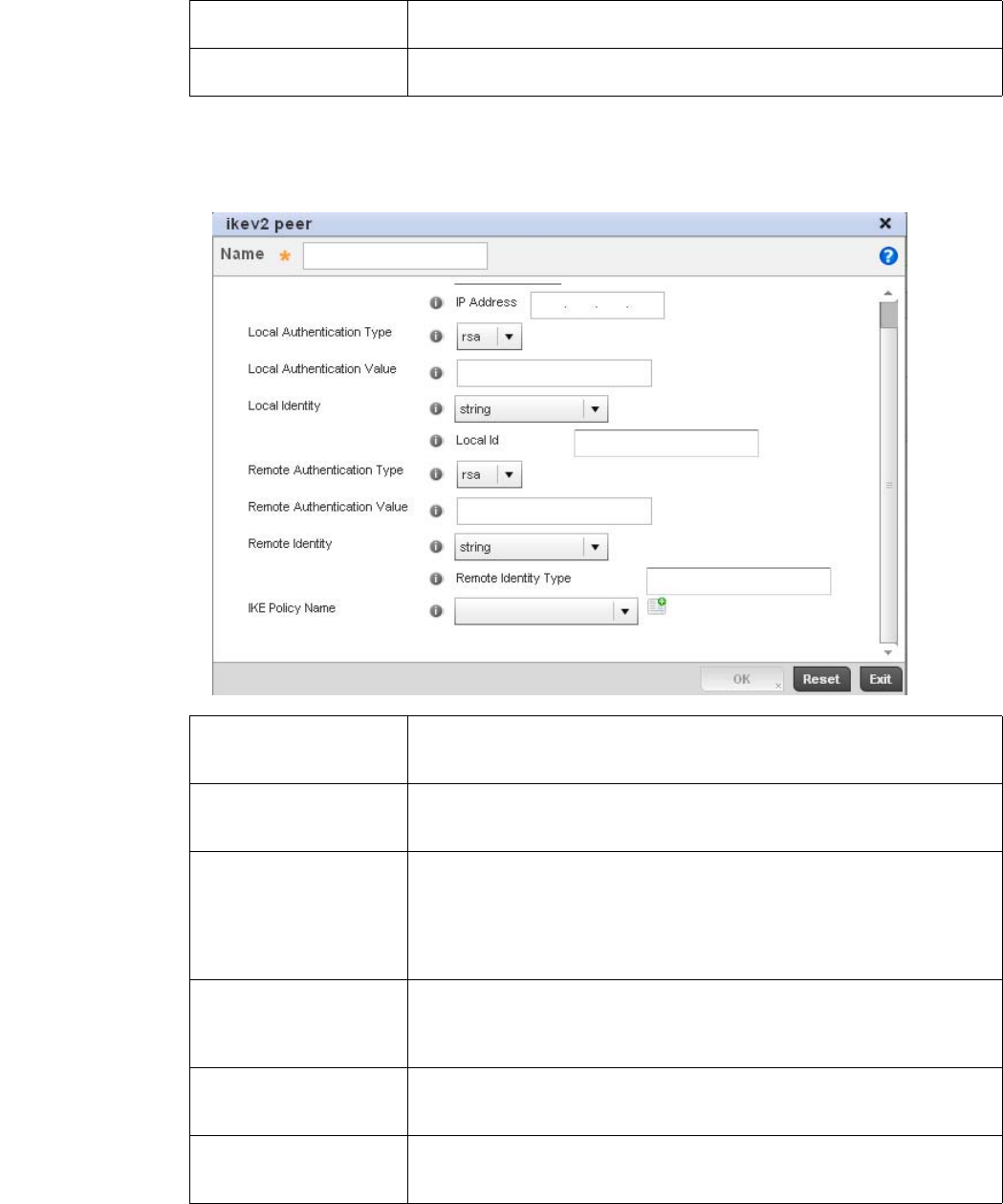
Brocade Mobility RFS4000, RFS6000, and RFS7000 System Reference Guide 455
53-1002620-01
7
Select Add to define a new peer configuration, Edit to modify an existing configuration or Delete to
remove an existing peer configuration. The parameters that can de defined for the peer
configuration vary depending on whether IKEv1 or IKEv2 was selected.
RemoteID Displays the means the target remote peer is to be identified (string, FQDN etc.) within
the VPN tunnel.
IKE Policy Name Lists the IKEv1 or IKE v2 policy used with each listed peer configuration. If a policy
requires creation, select the Create button.
Name If creating a new peer configuration (remote gateway) for VPN tunnel connection,
assign it a 32 character maximum name to distinguish it from other with similar
attributes.
IP Type or
Select IP/Hostname
Enter either the IP address or FQDN hostname of the IPSec VPN peer used in the
tunnel setup. If IKEv1 is used, this value is titled IP Type, if IKEv2 is used, this
parameter is titled Select IP/Hostname.
Authentication Type Select either pre-shared key (PSK) or RSA. Rivest, Shamir, and Adleman (RSA) is an
algorithm for public key cryptography. It’s the first algorithm known to be suitable for
signing, as well as encryption If using IKEv2, this screen displays both local and
remote authentication options, as both ends of the VPN connection require
authentication. RSA is the default value for both local and remote authentication
(regardless of IKEv1 or IKEv2).
Authentication Value Define the authentication string (shared secret) that must be shared by both ends of
the VPN tunnel connection. The string must be between 8 - 21 characters long. If
using IKEv2, both a local and remote string must be specified for handshake
validation and both ends (local and remote) of the VPN connection.
Local Identity Select the access point’s local identifier used with this peer configuration for an IKE
exchange with the target VPN IPSec peer. Options include IP Address, Distinguished
Name, FQDN, email and string. The default setting is string.
Remote Identity Select the access point’s remote identifier used with this peer configuration for an IKE
exchange with the target VPN IPSec peer. Options include IP Address, Distinguished
Name, FQDN, email and string. The default setting is string.
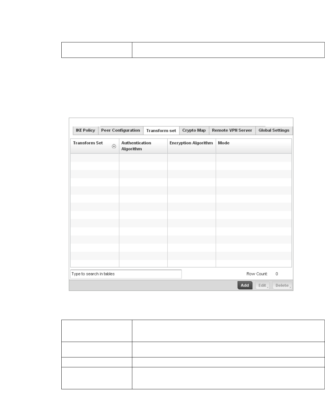
456 Brocade Mobility RFS4000, RFS6000, and RFS7000 System Reference Guide
53-1002620-01
7
Select OK to save the changes made within the Peer Configuration screen. Select Reset to revert to
the last saved configuration.
Select the Transform Set tab.
Create or modify Transform Set configurations to specify how traffic is protected within crypto
ACL defining the traffic that needs to be protected.
FIGURE 307 Profile Security - VPN Transform Set screen
Review the following attributes of existing Transform Set configurations:
Select Add to define a new transform set configuration, Edit to modify an existing configuration or
Delete to remove an existing transform set.
IKE Policy Name Select the IKEv1 or IKE v2 policy name (and settings) to apply to this peer
configuration. If a policy requires creation, select the Create icon.
Name Lists the 32 character maximum name assigned to each listed transform set upon
creation. Again, a transform set is a combination of security protocols, algorithms and
other settings applied to IPSec protected traffic.
Authentication Algorithm Lists each transform sets’s authentication scheme used to validate identity
credentials. The authentication scheme is either HMAC-SHA or HMAC-MD5.
Encryption Algorithm Displays each transform set’s encryption method for protecting transmitted traffic.
Mode Displays either Tunnel or Transport as the IPSec tunnel type used with the transform
set. Tunnel is used for site-to-site VPN and Transport should be used for remote VPN
deployments.
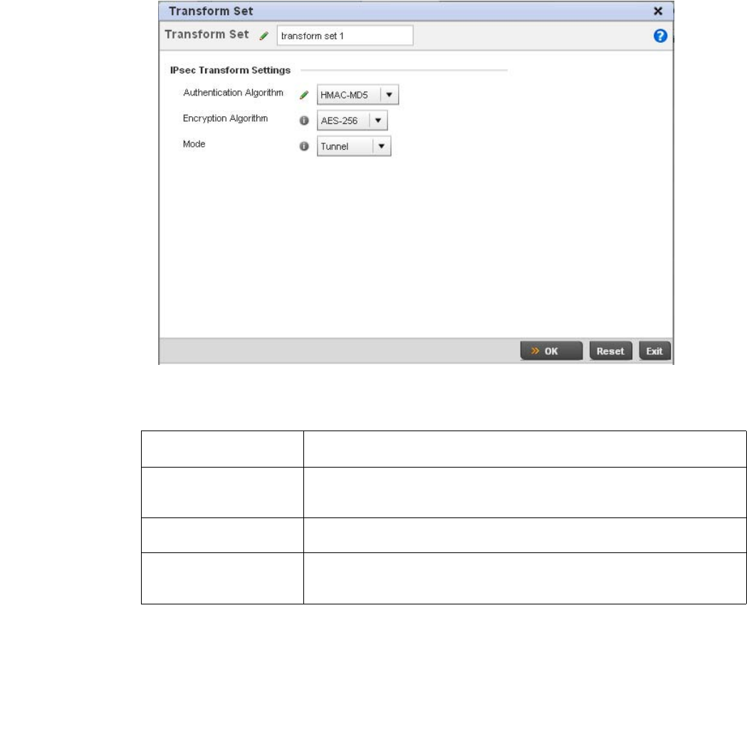
Brocade Mobility RFS4000, RFS6000, and RFS7000 System Reference Guide 457
53-1002620-01
7
FIGURE 308 Profile Security - VPN Transform Set create/modify screen
Define the following settings for the new or modified transform set configuration:
Select OK to save the changes made within the Transform Set screen. Select Reset to revert to the
last saved configuration
Select the Crypto Map tab.
Use crypto maps (as applied to IPSec VPN) to combine the elements used to create IPSec SAs
(including transform sets).
Name If creating a new transform set, define a 32 character maximum name to differentiate
this configuration from others with similar attributes.
Authentication Algorithm Set the transform sets’s authentication scheme used to validate identity credentials.
Use the drop-down menu to select either HMAC-SHA or HMAC-MD5. The default
setting is HMAC-SHA.
Encryption Algorithm Set the transform set encryption method for protecting transmitted traffic. Options
include DES, 3DES, AES, AES-192 and AES-256. The default setting is AES-256.
Mode Use the drop-down menu to select either Tunnel or Transport as the IPSec tunnel type
used with the transform set. Tunnel is used for site-to-site VPN and Transport should
be used for remote VPN deployments.
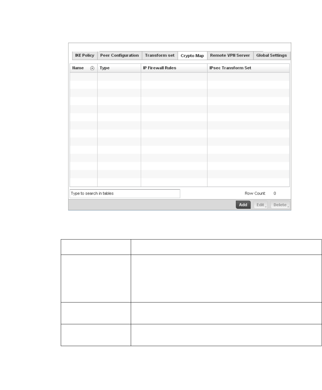
458 Brocade Mobility RFS4000, RFS6000, and RFS7000 System Reference Guide
53-1002620-01
7
FIGURE 309 Profile Security - VPN Crypto Map screen
Review the following Crypto Map configuration parameters to assess their relevance:
If requiring a new crypto map configuration, select the Add button. If updating the configuration of
an existing crypto map, select it from amongst those available and select the Edit button.
If adding a new crypto map, assign it a name up to 32 characters in length as a unique identifier.
Select the Continue button to proceed to the VPN Crypto Map screen.
Name Lists the 32 character maximum name assigned for each crypto map upon creation.
This name cannot be modified as part of the edit process.
Type Displays the site-to-site-manual, site-to-site-auto or remote VPN configuration defined
for each listed cyrpto map configuration. With site-to-site deployments, an IPSEC
Tunnel is deployed between two gateways, each at the edge of two different remote
networks. With remote VPN, an access point located at remote branch defines a
tunnel with a security gateway. This facilitates the endpoints in the branch office to
communicate with the destination endpoints (behind the security gateway) in a
secure manner.
IP Firewall Rules Lists the IP firewall rules defined for each displayed crypto map configuration. Each
firewall policy contains a unique set of access/deny permissions applied to the VPN
tunnel and its peer connection.
IPSec Transform Set Displays the transform set (encryption and has algorithms) applied to each listed
crypto map configuration. Thus, each crypto map can be customized with its own data
protection and peer authentication schemes.
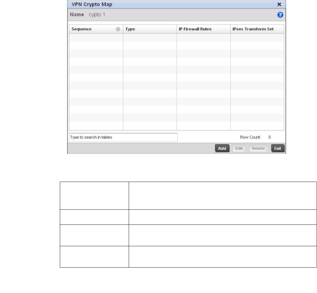
Brocade Mobility RFS4000, RFS6000, and RFS7000 System Reference Guide 459
53-1002620-01
7
FIGURE 310 Profile Security - VPN Crypto Map screen
Review the following before determining whether to add or modify a crypto map configuration
f requiring a new crypto map configuration, select the Add button. If updating the configuration of
an existing crypto map, select it from amongst those available and select the Edit button.
Sequence Each crypto map configuration uses a list of entries based on a sequence number.
Specifying multiple sequence numbers within the same crypto map, provides the
flexibility to connect to multiple peers from the same interface, based on the
sequence number (from 1 - 1,000).
Type Displays the site-to-site-manual, site-to-site-auto or remote VPN configuration defined
for each listed cyrpto map configuration.
IP Firewall Rules Lists the IP firewall rules defined for each displayed crypto map configuration. Each
firewall policy contains a unique set of access/deny permissions applied to the VPN
tunnel and its peer connection.
IPSec Transform Set Displays the transform set (encryption and hash algorithms) applied to each listed
crypto map configuration. Thus, each crypto map can be customized with its own data
protection and peer authentication schemes.
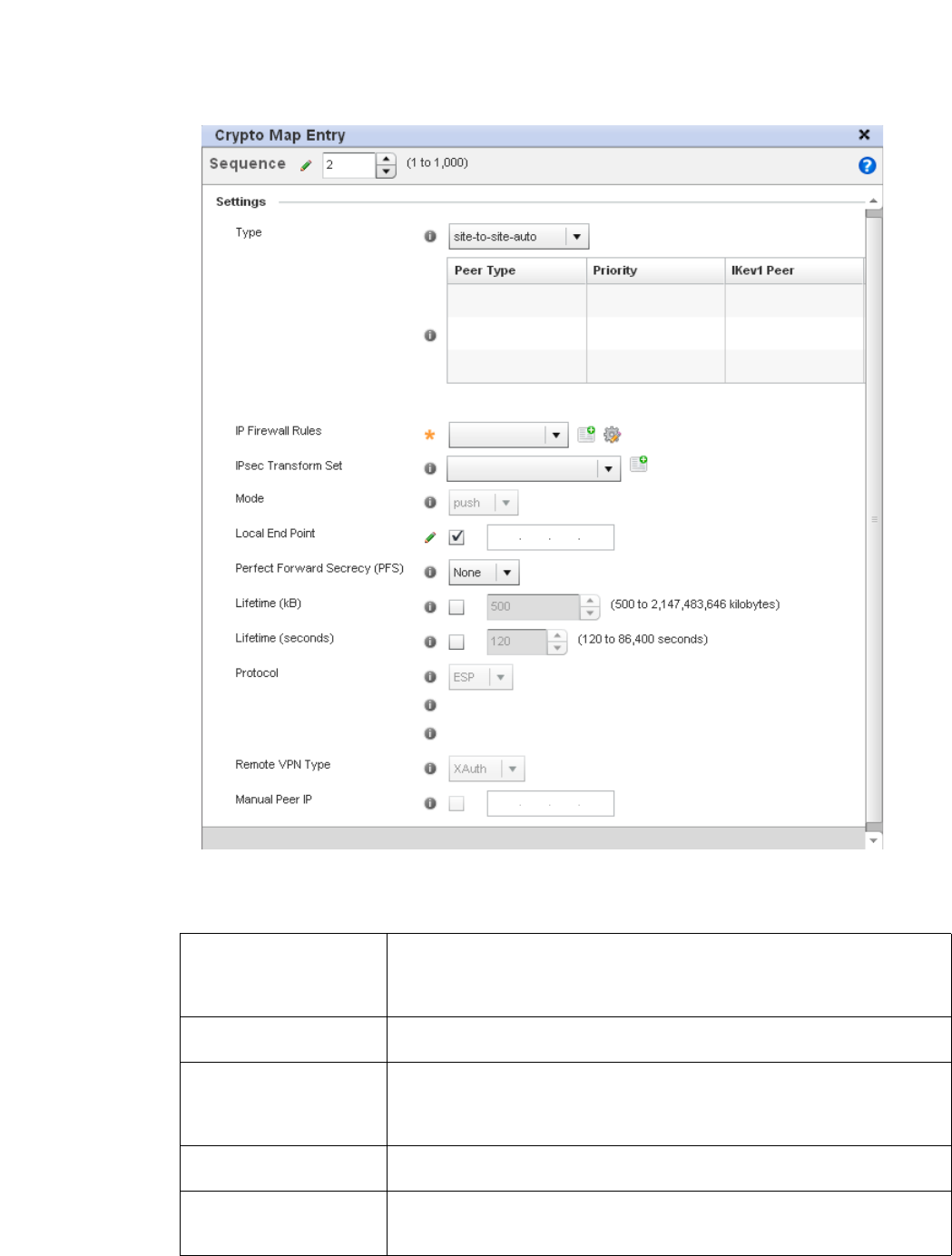
460 Brocade Mobility RFS4000, RFS6000, and RFS7000 System Reference Guide
53-1002620-01
7
FIGURE 311 Profile Security - VPN Crypto Map Entry screen
\Define the following to parameters to set the crypto map configuration:
Sequence Each crypto map configuration uses a list of entries based on a sequence number.
Specifying multiple sequence numbers within the same crypto map extends
connection flexibility to multiple peers on the same interface, based on this selected
sequence number (from 1 - 1,000).
Type Define the site-to-site-manual, site-to-site-auto or remote VPN configuration defined
for each listed cyrpto map configuration.
IP Firewall Rules Use the drop-down menu to select the access list (ACL) used to protect IPSec VPN
traffic. New access/deny rules can be defined for the crypto map by selecting the
Create icon, or an existing set of firewall rules can be modified by selecting the Edit
icon.
IPSec Transform Set Select the transform set (encryption and hash algorithms) to apply to this crypto map
configuration.
Mode Use the drop-down menu to define which mode (pull or push) is used to assign a
virtual IP. This setting is relevant for IKEv1 only, since IKEv2 always uses the
configuration payload in pull mode. The default setting is push.

Brocade Mobility RFS4000, RFS6000, and RFS7000 System Reference Guide 461
53-1002620-01
7
Select OK to save the updates made to the Crypto Map Entry screen. Selecting Reset reverts the
screen to its last saved setting.
Select Remote VPN Server.
Use this screen to define the server resources used to secure (authenticate) a remote VPN
connection with a target peer.
Local End Point Select this radio button to define an IP address as a local tunnel end point address.
This setting represents an alternative to an interface IP address.
Perfect Forward Secrecy
(PFS)
PFS is key-establishment protocol, used to secure VPN communications. If one
encryption key is compromised, only data encrypted by that specific key is
compromised. For PFS to exist, the key used to protect data transmissions must not
be used to derive any additional keys. Options include None, 2, 5 and 14. The default
setting is None.
Lifetime (kB) Select this option to define a connection volume lifetime (in kilobytes) for the duration
of an IPSec VPN security association. Once the set volume is exceeded, the
association is timed out. Use the spinner control to set the volume from 500 -
2,147,483,646 kilobytes.
Lifetime (seconds) Select this option to define a lifetime (in seconds) for the duration of an IPSec VPN
security association. Once the set value is exceeded, the association is timed out. The
available range is from 120 - 86,400 seconds. The default setting is 120 seconds.
Protocol Select the security protocol used with the VPN IPSec tunnel connection. SAs are
unidirectional, existing in each direction and established per security protocol.
Options include ESP and AH. The default setting is ESP.
Remote VPN Type Define the remote VPN type as either None or XAuth. XAuth (extended authentication)
provides additional authentication validation by permitting an edge device to request
extended authentication information from an IPSec host. This forces the host to
respond with additional authentication credentials. The edge device respond with a
failed or passed message. The default setting is XAuth.
Manual Peer IP Select this option to define the IP address of an additional encryption/decryption
peer.
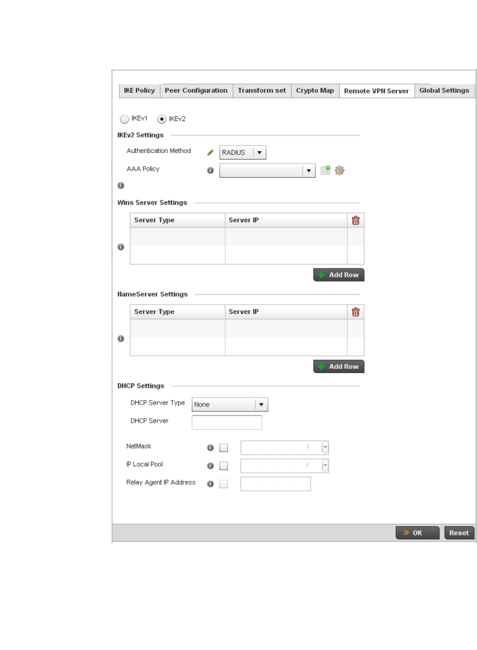
462 Brocade Mobility RFS4000, RFS6000, and RFS7000 System Reference Guide
53-1002620-01
7
FIGURE 312 Profile Security - Remote VPN Server screen (IKEv2 example)
Select either the IKEv1 or IKEv2 radio button to enforce peer key exchanges over the remote VPN
server using either IKEv1 or IKEv2.
IKEv2 provides improvements from the original IKEv1 design (improved cryptographic
mechanisms, NAT and firewall traversal, attack resistance etc.) and is recommended in most
deployments. The appearance of the screen differs depending on the selected IKEv1 or IKEv2
mode.

Brocade Mobility RFS4000, RFS6000, and RFS7000 System Reference Guide 463
53-1002620-01
7
Set the following IKEv1 or IKe v2 Settings:
Refer to the Wins Server Settings field and specify primary and secondary server resources for
validating RADIUS authentication requests on behalf of a remote VPN client. These external WINS
server resources are available to validate RADIUS resource requests.
Refer to the Name Server Settings field and specify primary and secondary server resources for
validating RADIUS authentication requests on behalf of a remote VPN client. These external name
server resources are available to validate RADIUS resource requests.
Select the IP Local Pool option to define an IP address and mask for a virtual IP pool used to IP
addresses to remote VPN clients.
If using IKEv2 specify these additional settings (required for IKEv2 only):
Select OK to save the updates made to the Remote VPN Server screen. Selecting Reset reverts the
screen to its last saved configuration.
Select the Global Settings tab.
The Global Settings screen provides options for Dead Peer Detection (DPD). DPD represents
the actions taken upon the detection of a dead peer within the IPSec VPN tunnel connection.
Authentication Method Use the drop-down menu to specify the authentication method used to validate the
credentials of the remote VPN client. Options include Local (on board RADIUS
resource if supported) and RADIUS (designated external RADIUS resource). If
selecting Local, select the + Add Row button and specify a User Name and
Password for authenticating remote VPN client connections with the local RADIUS
resource. The default setting is Local. AP6521 and AP6511 model access points do
not have a local RADIUS resource and must use an external RADIUS server resource.
AAA Policy Select the AAA policy used with the remote VPN client. AAA policies define RADIUS
authentication and accounting parameters. The access point can optionally use AAA
server resources (when using RADIUS as the authentication method) to provide user
database information and user authentication data.
DHCP Server Type Specify whether the DHCP server is specified as an IP address, Hostname (FQDN) or
None (a different classification will be defined). Dynamic Host Configuration Protocol
(DHCP) allows hosts on an IP network to request and be assigned IP addresses as
well as discover information about the network where they reside.
DHCP Server Depending on the DHCP server type selected, enter either the numerical IP address,
hostname or other (if None is selected as the server type).
NetMask Specify the netmask for remote VPN clients.
IP Local Pool Select the IP Local Pool option to define an IP address and mask for a virtual IP
pool used to IP addresses to remote VPN clients.
Relay Agent IP Address Select this option to define DHCP relay agent IP address.
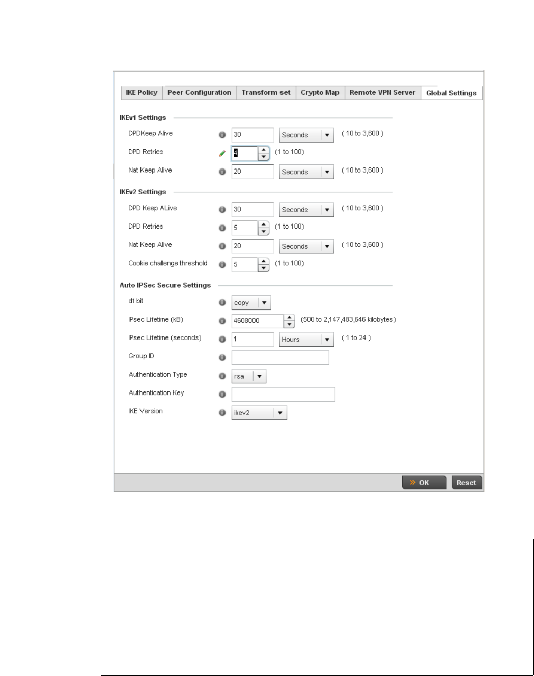
464 Brocade Mobility RFS4000, RFS6000, and RFS7000 System Reference Guide
53-1002620-01
7
FIGURE 313 Profile Security - Global VPN Settings screen
Define the following settings IKE Dead Peer Detection:
DPD Keep Alive Define the interval (or frequency) of IKE keep alive messages for dead peer detection.
Options include Seconds (10 - 3,600), Minutes (1 - 60) and Hours (1). The default
setting is 30 seconds.
DPD Retries Use the spinner control to define the number of keep alive messages sent before to
an IPSec VPN client before the tunnel connection is defined as dead. The available
range is from 1 - 100. The default number of messages is 5.
NAT Keep Alive Define the interval (or frequency) of NAT keep alive messages for dead peer detection.
Options include Seconds (10 - 3,600), Minutes (1 - 60) and Hours (1). The default
setting is 20 seconds.
Cookie Challenge
Threshold
Use the spinner control to define the threshold (1 - 100) that, when exceeded,
enables the cookie challenge mechanism.

Brocade Mobility RFS4000, RFS6000, and RFS7000 System Reference Guide 465
53-1002620-01
7
Refer to the Auto IPsec Secure Settings field to define the following IPSec security, lifetime and
authentication settings:
Select OK to save the updates made to the Global Settings screen. Selecting Reset reverts the
screen to its last saved configuration.
Setting the Profile’s NAT Configuration
Profile Security Configuration
Network Address Translation (NAT) is a technique to modify network address information within IP
packet headers in transit across a traffic routing device. This enables mapping one IP address to
another to protect wireless controller managed network address credentials. With typical
deployments, NAT is used as an IP masquerading technique to hide private IP addresses behind a
single, public facing, IP address.
NAT is a process of modifying network address information in IP packet headers while in transit
across a traffic routing device for the purpose of remapping one IP address to another. In most
deployments NAT is used in conjunction with IP masquerading which hides RFC1918 private IP
addresses behind a single public IP address.
NAT can provide a controller profile outbound Internet access to wired and wireless hosts
connected to either a thick access point (such as an AP-7131, AP-7131N or AP-5131 model) or a
wireless controller. Many-to-one NAT is the most common NAT technique for outbound Internet
access. Many-to-one NAT allows a thick access point or wireless controller to translate one or more
internal private IP addresses to a single, public facing, IP address assigned to a 10/100/1000
Ethernet port or 3G card.
To define a NAT configuration that can be applied to a controller profile:
1. Select the Configuration tab from the Web UI
2. Select Profiles from the Configuration tab.
df bit Select the DF bit handling technique used for the ESP encapsulating header. Options
include Clear, set and copy. The default setting is Copy.
IPsec Lifetime (kb) Set a connection volume lifetime (in kilobytes) for the duration of an IPSec VPN
security association. Once the set volume is exceeded, the association is timed out.
Use the spinner control to set the volume from 500 - 2,147,483,646 kilobytes. The
default settings is 4,608,000 kilobytes.
IPsec Lifetime (seconds) Set a lifetime (in seconds) for the duration of an IPSec VPN security association. Once
the set value is exceeded, the association is timed out. The available range either
Seconds (120 - 86,400), Minutes (2 - 1,440), Hours (1 - 24) or Days (1). The default
setting is 3,600 seconds.
Group ID Define a 1 - 128 character identifier for an IKE exchange supporting auto IPSec
secure peers.
Authentication Type Use the drop-down menu to select either RSA or PSK (Pre Shared Key) as the
authentication type for secure peer authentication. Rivest, Shamir, and Adleman
(RSA) is an algorithm for public key cryptography. It’s the first algorithm known to be
suitable for signing, as well as encryption. The default setting is RSA.
Authentication Key Enter the 8 - 21 character shared key (password) used for auto IPSec secure peer
authentication.
IKE Version Use the drop-down menu to select the IKE version used for auto IPSec secure
authentication with the IPSec gateway and other controllers.
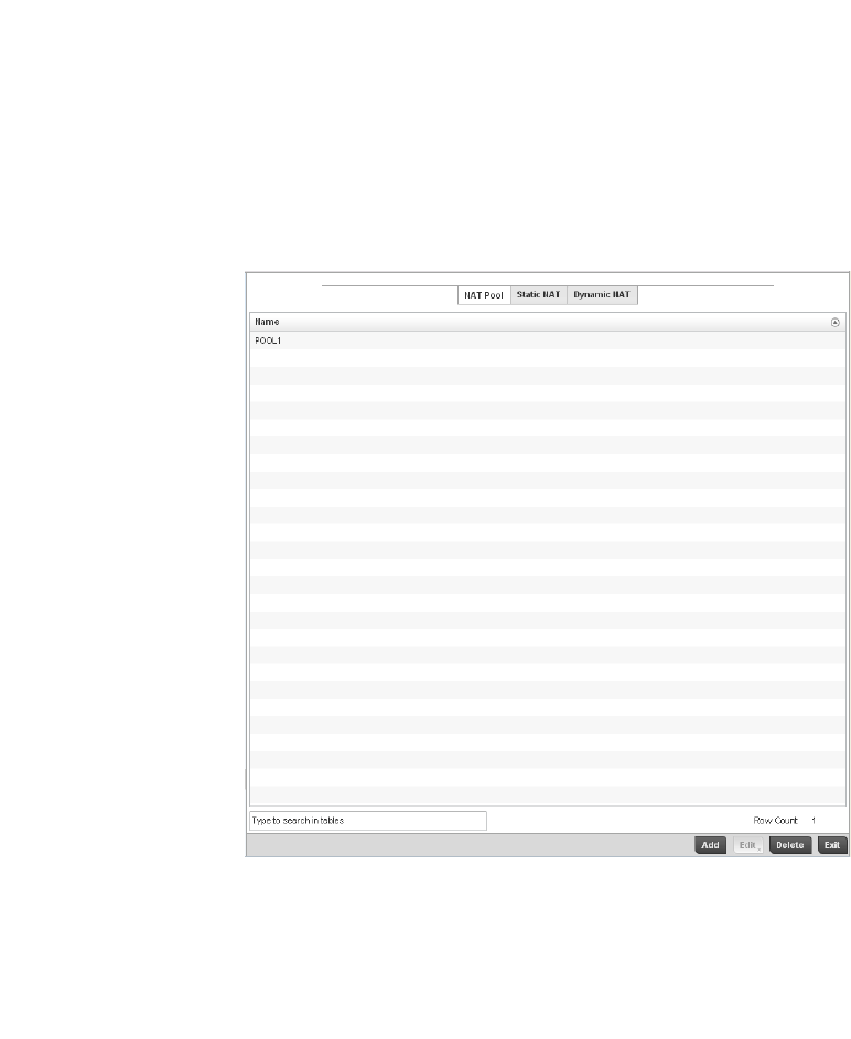
466 Brocade Mobility RFS4000, RFS6000, and RFS7000 System Reference Guide
53-1002620-01
7
3. Select Manage Profiles from the Configuration > Profiles menu.
4. Select Security.
5. Select NAT.
FIGURE 314 Security NAT screen
6. The NAT Pool displays by default. The NAT Pool screen lists those NAT policies created thus far.
Any of these policies can be selected and applied to a controller profile.
7. S elect Add to create a new NAT policy that can be applied to a controller profile. Select Edit to
modify the attributes of a existing policy or select Delete to remove obsolete NAT policies from
the list of those available to a controller profile.
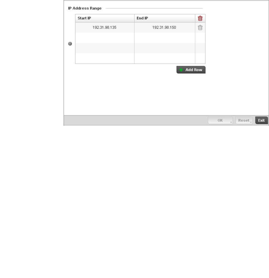
Brocade Mobility RFS4000, RFS6000, and RFS7000 System Reference Guide 467
53-1002620-01
7
FIGURE 315 Security NAT Pool screen
8. If adding a new NAT policy or editing the configuration of an existing policy, define the following
parameters:
9. Select the + Add Row button as needed to append additional rows to the IP Address Range
table.
10. Select OK to save the changes made to the profile’s NAT Pool configuration. Select Reset to
revert to the last saved configuration.
11. Select the Static NAT tab.
The Source tab displays by default.
Name If adding a new NAT policy, provide a name to help distinguish it from others with
similar configurations. The length cannot exceed 64 characters.
Prefix Length Use the spinner control to set the netmask (between 1 - 30) of the network the pool
address belongs to.
IP Address Range Define a range of IP addresses that are hidden from the public Internet. NAT modifies
network address information in the defined IP range while in transit across a traffic
routing device. NAT only provides IP address translation and does not provide a
firewall. A branch deployment with NAT by itself will not block traffic from being
potentially routed through a NAT device. Consequently, NAT should be deployed with a
stateful firewall.
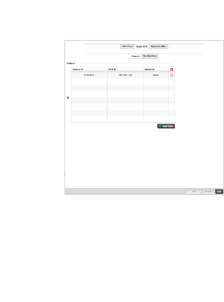
468 Brocade Mobility RFS4000, RFS6000, and RFS7000 System Reference Guide
53-1002620-01
7
FIGURE 316 Static NAT screen
12. To map a source IP address from an internal network to a NAT IP address click the + Add Row
button. Enter the internal network IP address in Source IP field. Enter the NAT IP address in the
NAT IP field.
13. Use the Network drop-down menu to set the NAT type either Inside or Outside. Select Inside to
create a permanent, one-to-one mapping between an address on an internal network and a
perimeter or external network. To share a Web server on a perimeter interface with the
Internet, use static address translation to map the actual address to a registered IP address.
Static address translation hides the actual address of the server from users on insecure
interfaces. Casual access by unauthorized users becomes much more difficult. Static NAT
requires a dedicated address on the outside network for each host. Inside NAT is the default
setting.
14. Select the Destination tab to view destination NAT configurations and define packets passing
through the NAT on the way back to the managed LAN are searched against to the records kept
by the NAT engine. The destination IP address is changed back to the specific internal private
class IP address to reach the LAN over the managed network.
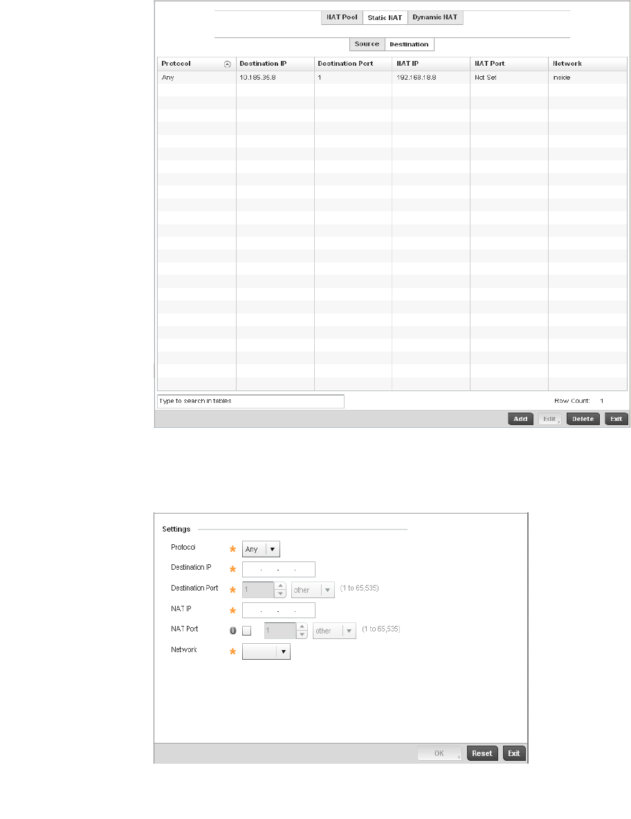
Brocade Mobility RFS4000, RFS6000, and RFS7000 System Reference Guide 469
53-1002620-01
7
FIGURE 317 NAT Destination screen
15. Select Add to create a new NAT destination configuration, Edit to modify the attributes of an
existing configuration or Delete to permanently remove a NAT destination.
FIGURE 318 NAT Destination Add screen
16. Set the following Destination configuration parameters:

470 Brocade Mobility RFS4000, RFS6000, and RFS7000 System Reference Guide
53-1002620-01
7
Static NAT creates a permanent, one-to-one mapping between an address on an internal
network and an external network. To share a Web server on an interface with the Internet, use
static address translation to map the actual address to a registered IP address. Static address
translation hides the actual server address from users on insecure interfaces. Casual access
by unauthorized users becomes much more difficult. Static NAT requires a dedicated address
on the outside network for each host.
17. Select OK to save the changes made to the static NAT configuration. Select Reset to revert to
the last saved configuration.
18. Select the Dynamic NAT tab.
Dynamic NAT configurations translate the IP address of packets going out from one interface to
another interface based on configured conditions. Dynamic NAT requires packets be switched
through a NAT router to generate translations in the controller translation table.
Protocol Select the protocol for use with static translation. TCP, UDP and Any are available
options. TCP is a transport layer protocol used by applications requiring guaranteed
delivery. It’s a sliding window protocol handling both timeouts and retransmissions.
TCP establishes a full duplex virtual connection between two endpoints. Each
endpoint is defined by an IP address and a TCP port number. The User Datagram
Protocol (UDP) offers only a minimal transport service, non-guaranteed datagram
delivery, and provides applications direct access to the datagram service of the IP
layer. UDP is used by applications not requiring the level of service of TCP or are
using communications services (multicast or broadcast delivery) not available from
TCP. The default setting is Any.
Destination IP Enter the local address used at the (source) end of the static NAT configuration. This
address (once translated) will not be exposed to the outside world when the
translation address is used to interact with the remote destination.
Destination Port Use the spinner control to set the local port used at the (source) end of the static
NAT configuration. The default port is 1.
NAT IP Enter the IP address of the matching packet to the specified value. The IP address
modified can be either source or destination based on the direction specified.
NAT Port Enter the port number of the matching packet to the specified value. This option is
valid only if the direction specified is destination.
Network Select Inside or Outside NAT as the network direction. Inside is the default
setting.
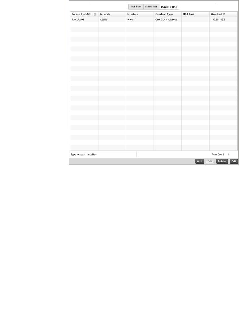
Brocade Mobility RFS4000, RFS6000, and RFS7000 System Reference Guide 471
53-1002620-01
7
FIGURE 319 Dynamic NAT screen
19. Refer to the following to determine whether a new Dynamic NAT configuration requires
creation, edit or deletion:
20. Select Add to create a new Dynamic NAT configuration, Edit to modify an existing configuration
or Delete to permanently remove a configuration.
Source List ACL Lists an ACL name to define the packet selection criteria for the NAT configuration.
NAT is applied only on packets which match a rule defined in the access-list. These
addresses (once translated) are not exposed to the outside world when the
translation address is used to interact with the remote destination.
Network Displays Inside or Outside NAT as the network direction for the dynamic NAT
configuration.
Interface Lists the VLAN (between 1 - 4094) used as the communication medium between
the source and destination points within the NAT configuration.
Overload Type Lists the Overload Type used with the listed IP ACL rule. Options include NAT Pool,
One Global Address and Interface IP Address. Interface IP Address is the default
setting.
NAT Pool Displays the name of an existing NAT pool used with the dynamic NAT configuration.
Overload IP Enables the use of one global address for numerous local addresses.
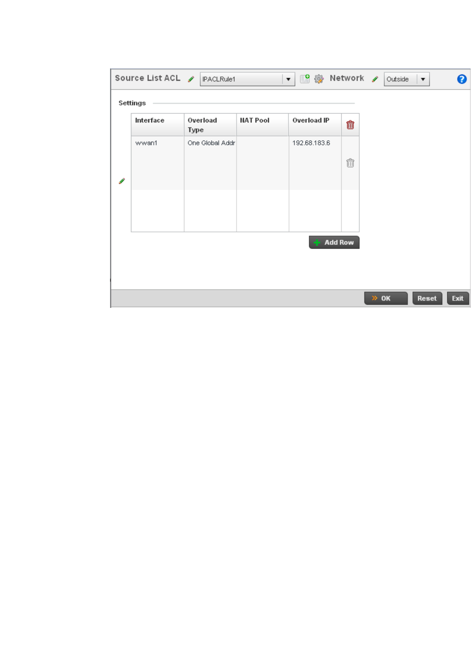
472 Brocade Mobility RFS4000, RFS6000, and RFS7000 System Reference Guide
53-1002620-01
7
FIGURE 320 Source ACL List screen
21. Set the following to define the Dynamic NAT configuration:
22. Select OK to save the changes made to the dynamic NAT configuration. Select Reset to revert
to the last saved configuration.
Bridge NAT Configuration
Profile Security Configuration
Source List ACL Use the drop-down menu to select an ACL name to define the packet selection
criteria for NAT. NAT is applied only on packets which match a rule defined in the
access-list. These addresses (once translated) will not be exposed to the outside
world when the translation address is used to interact with the remote destination.
Network Select Inside or Outside NAT as the network direction for the dynamic NAT
configuration. Inside is the default setting.
Interface Use the drop-down menu to select the VLAN (between 1 - 4094) used as the
communication medium between the source and destination points within the NAT
configuration. Ensure the VLAN selected represents the intended network traffic
within the NAT supported configuration. VLAN1 is available by default.
Overload Type Select the check box of Overload Type used with the listed IP ACL rule. Options
include NAT Pool, One Global Address and Interface IP Address. Interface IP
Address is the default setting.
NAT Pool Provide the name of an existing NAT pool for use with the dynamic NAT
configuration.
Overload IP Enables the use of one global address for numerous local addresses.
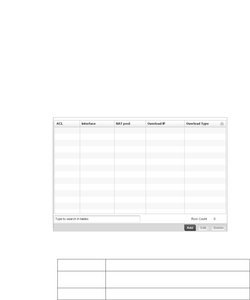
Brocade Mobility RFS4000, RFS6000, and RFS7000 System Reference Guide 473
53-1002620-01
7
Use Bridge NAT to manage Internet traffic originating at a remote site. In addition to traditional NAT
functionality, Bridge NAT provides a means of configuring NAT for bridged traffic through an access
point. NAT rules are applied to bridged traffic through the access point, and matching packets are
NATed to the WAN link instead of being bridged on their way to the router.
Using Bridge NAT, a tunneled VLAN (extended VLAN) is created between the NoC and a remote
location. When a remote client needs to access the Internet, Internet traffic is routed to the NoC,
and from there routed to the Internet. This increases the access time for the end user on the client.
To resolve latency issues, Bridge NAT identifies and segregates traffic heading towards the NoC and
outwards towards the Internet. Traffic towards the NoC is allowed over the secure tunnel. Traffic
towards the Internet is switched to a local WLAN link with access to the Internet.
To define a NAT configuration or override that can be applied to a controller profile:
1. Select the Configuration tab from the Web UI
2. Select Profiles from the Configuration tab.
3. Select Manage Profiles from the Configuration > Profiles menu
4. Select Security.
5. Select Bridge NAT.
FIGURE 321 Security Bridge NAT screen
6. Review the following Bridge NAT configurations to determine whether a new Bridge NAT
configuration requires creation or an existing configuration modified or removed.
ACL Lists the ACL applying IP address access/deny permission rules to the Bridge NAT
configuration.
Interface Lists the communication medium (outgoing layer 3 interface) between source and
destination points. This is either the access point’s pppoe1 or wwan1 interface or
the VLAN used as the redirection interface between the source and destination.
NAT Pool Lists the names of existing NAT pools used with the Bridge NAT configuration. This
displays only when Overload Type is NAT Pool.
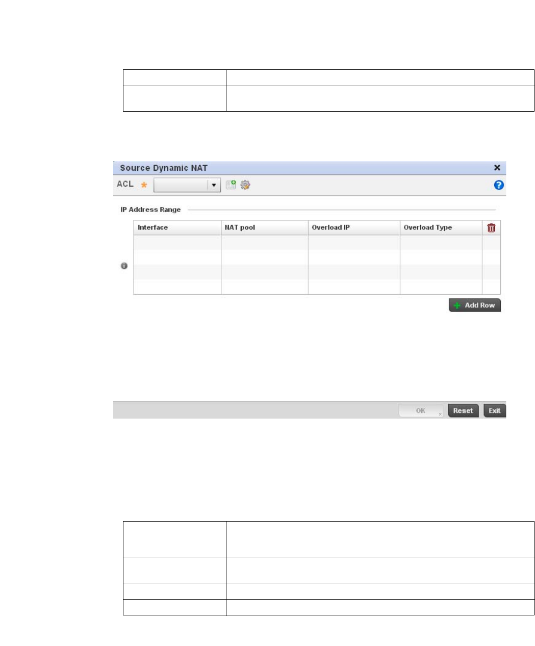
474 Brocade Mobility RFS4000, RFS6000, and RFS7000 System Reference Guide
53-1002620-01
7
7. S elect Add to create a new Bridge VLAN configuration, Edit to modify an existing configuration
or Delete to remove a configuration.
FIGURE 322 Security Source Dynamic NAT screen
8. Select the ACL whose IP rules are to be applied to this policy based forwarding rule. A new ACL
can be defined by selecting the Create icon, or an existing set of IP ACL rules can be modified
by selecting the Edit icon.
9. Use the IP Address Range table to configure IP addresses and address ranges that can used
to access the Internet.
10. Select + Add Row to set the IP address range settings for the Bridge NAT configuration.
Overload IP Lists the address used globally for numerous local addresses.
Overload Type Lists the overload type used with the listed IP ACL rule. Set as either NAT Pool, One
Global Address or Interface IP Address.
Interface Lists the outgoing layer 3 interface on which traffic is re-directed. The interface can
be an access point WWAN or PPPoE interface. Traffic can also be redirected to a
designated VLAN.
NAT Pool Displays the NAT pool used by this Bridge NAT entry. A value is only displayed only
when Overload Type has been set to NAT Pool.
Overload IP Lists whether the single global address supporting numerous local addresses.
Overload Type Displays the override type for this policy based forwarding rule.
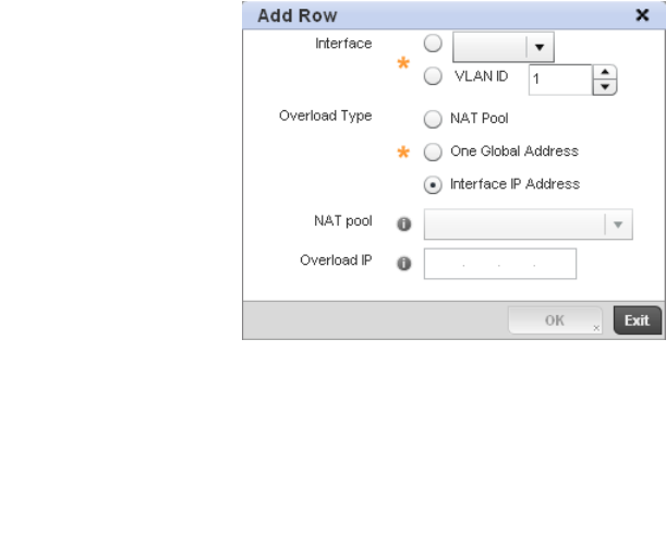
Brocade Mobility RFS4000, RFS6000, and RFS7000 System Reference Guide 475
53-1002620-01
7
FIGURE 323 Security Source Dynamic NAT screen
11. Select OK to save the changes made within the Add Row and Source Dynamic NAT screen.
Select Reset to revert to the last saved configuration.
Profile Security Configuration and
Deployment Considerations
Profile Security Configuration
Before defining a profile’s security configuration, refer to the following deployment guidelines to
ensure the profile configuration is optimally effective:
•Make sure the contents of the Certificate Revocation List are periodically audited to
ensure revoked certificates remained quarantined or validated certificates are reinstated.
•A RFS4000 model wireless controller ships with a baseline configuration supporting
many-to-one NAT between devices connected to GE1 - GE5 ports on VLAN 1, and the UP1
port assigned to VLAN 2100. A RFS4000 can be deployed within a small site using its
default configuration, and then be connected to a Internet service providing instant access
to the Internet.
•NAT alone does not provide a firewall. If deploying NAT on a controller profile, add a firewall
on the profile to block undesirable traffic from being routed. For outbound Internet access,
a stateful firewall can be configured to deny all traffic. If port address translation is
required, a stateful firewall should be configured to only permit the TCP or UDP ports being
translated.
•A RFS6000 model wireless controller ships with a minimum baseline configuration without
NAT enabled. A RFS6000 wireless controller requires VLAN configuration, IP addressing
and NAT rules be created before many-to-one NAT services can be defined.
•Brocade RFS4000 and RFS6000 model wireless controllers can provide outbound NAT
services for hosts connected to multiple VLANs. For small deployments, VLANs should be
terminated within a RFS4000 wireless controller providing site routing services. For
medium-scale deployments, VLANs are typically terminated on a L3 (IP layer) or L2
(Ethernet layer).

476 Brocade Mobility RFS4000, RFS6000, and RFS7000 System Reference Guide
53-1002620-01
7
VRRP Configuration
A default gateway is a critical resource for connectivity. However, it’s prone to a single point of
failure. Thus, redundancy for the default gateway is required by the access point. If WAN backhaul
is available on a br-7131, and a router failure occurs, then the access point should act as a router
and forward traffic on to its WAN link.
Define an external Virtual Router Redundancy Protocol (VRRP) configuration when router
redundancy is required in a wireless network requiring high availability.
Central to the configuration of VRRP is the election of a VRRP master. A VRRP master (once
elected) performs the following functions:
Responds to ARP requests
Forwards packets with a destination link layer MAC address equal to the virtual router MAC address
Rejects packets addressed to the IP address associated with the virtual router, if it is not the IP
address owner
Accepts packets addressed to the IP address associated with the virtual router, if it is the IP
address owner or accept mode is true.
Those nodes that lose the election process enter a backup state. In the backup state they monitor
the master for any failures, and in case of a failure one of the backups, in turn, becomes the
master and assumes the management of the designated virtual IPs. A backup does not respond to
an ARP request, and discards packets destined for a virtual IP resource.
To define the configuration of a VVRP group:
1. Select Devices from the Configuration tab.
2. The Device Configuration screen displays a list of managed devices or peer controllers. The
listed devices can either be other controllers or Access Points within the managed network.
3. Select a target device (by double-clicking it) from amongst those displayed within the Device
Configuration screen.
Devices can also be selected directly from the Device Browser in the lower, left-hand, side of
the UI.
4. Select Profile Overrides from the Device menu to expand it into sub menu options.
5. Select VRRP.
NOTE
VRRP support is only available on br-7131 model access points, and is not available on br-6511
models.
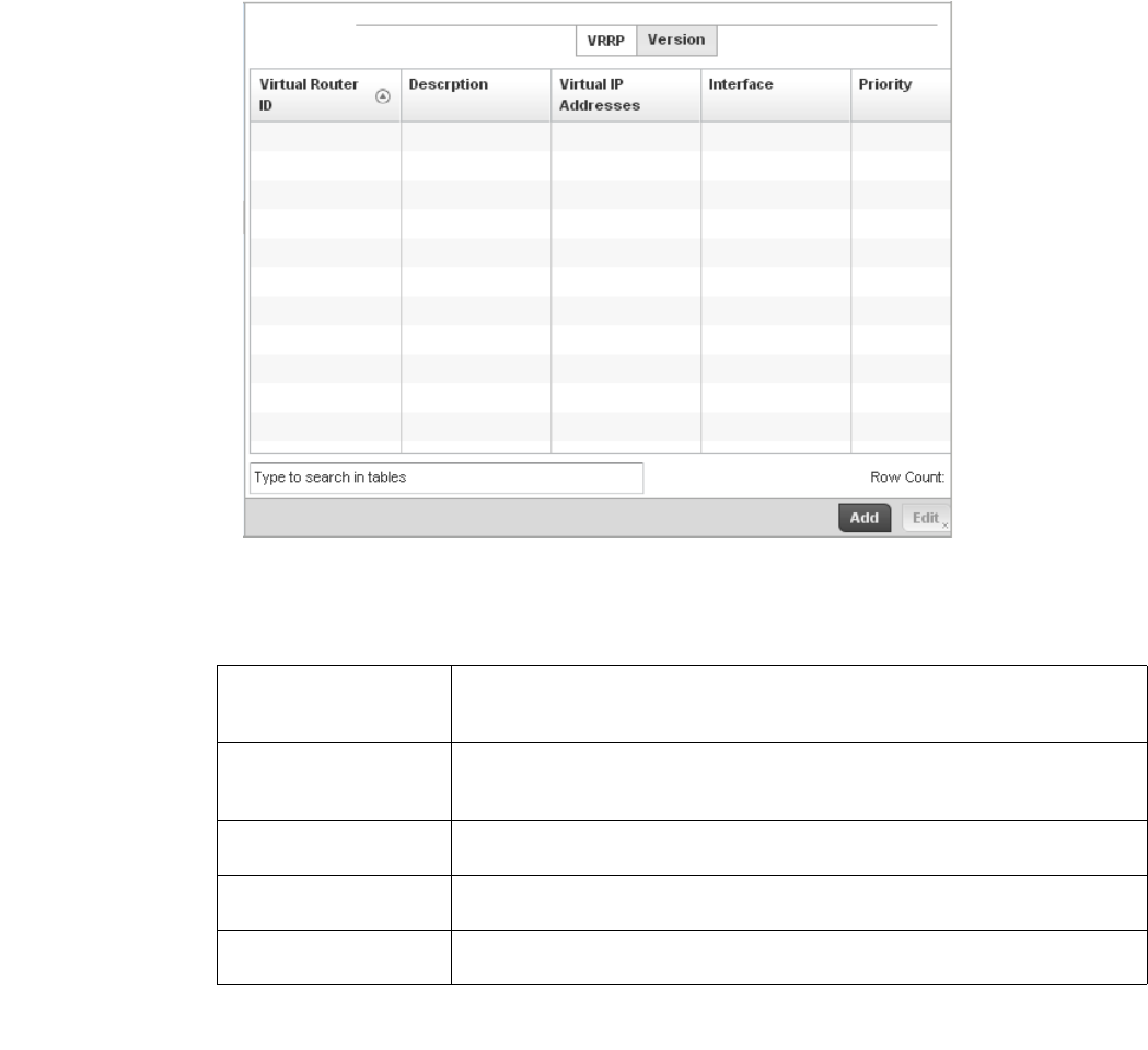
Brocade Mobility RFS4000, RFS6000, and RFS7000 System Reference Guide 477
53-1002620-01
7
FIGURE 324 Profile Overrides - VRRP screen
6. Review the following VRRP configuration data to assess if a new VRRP configuration is required
of is an existing VRRP configuration requires modification or removal:
7. Select the Version tab to define the VRRP version scheme used with the configuration.
Virtual Router ID Lists a numerical index (1 - 254) used to differentiate VRRP configurations. The index is
assigned when a VRRP configuration is initially defined. This ID identifies the virtual
router a packet is reporting status for.
Description Displays a description assigned to the VRRP configuration when it was either created or
modified. The description is implemented to provide additional differentiation beyond
the numerical virtual router ID.
Virtual IP Addresses Lists the virtual interface IP address used as the redundant gateway address for the
virtual route.
Interface Displays the interfaces selected on the access point to supply VRRP redundancy
failover support.
Priority Lists a numerical value (from 1 - 254) used for the virtual router master election
process. The higher the numerical value, the higher the priority in the election process.
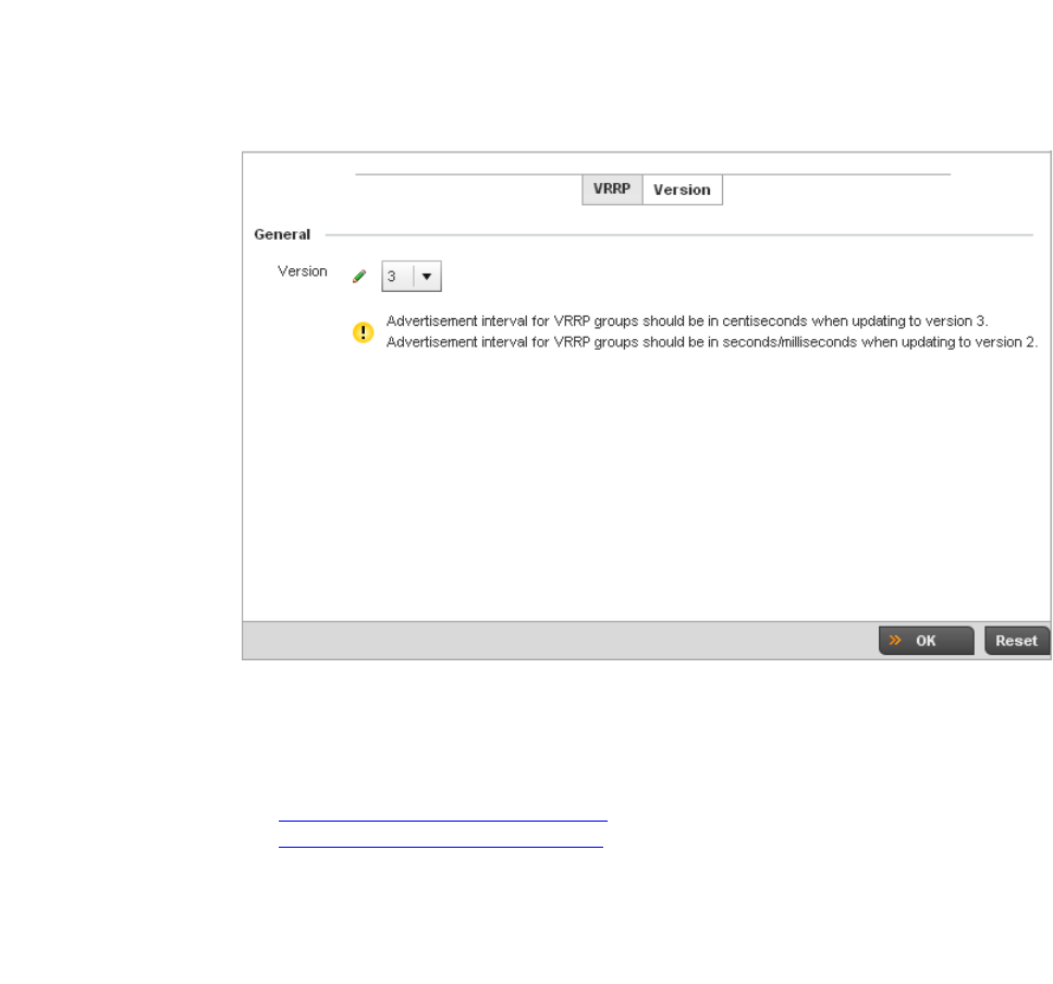
478 Brocade Mobility RFS4000, RFS6000, and RFS7000 System Reference Guide
53-1002620-01
7
FIGURE 325 VVRP screen - Version tab
VRRP version 3 (RFC 5798) and 2 (RFC 3768) are selectable to set the router redundancy.
Version 3 supports sub-second (centisecond) VRRP failover and support services over virtual
IP. For more information on the VRRP protocol specifications (available publicly) refer to
http://www.ietf.org/rfc/rfc3768.txt (version 2) and
http://www.ietf.org/rfc/rfc5798.txt (version 3).
8. From within VRRP tab, select Add to create a new VRRP configuration or Edit to modify the
attributes of an existing VRRP configuration. If necessary, existing VRRP configurations can be
selected and permanently removed by selecting Delete.
If adding or editing a VRRP configuration, the following screen displays:
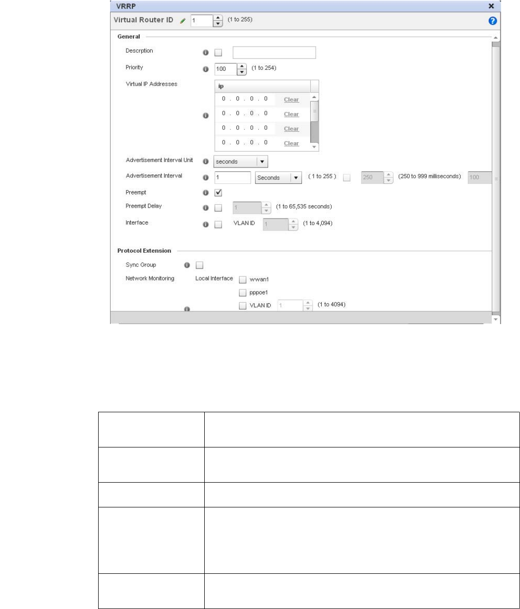
Brocade Mobility RFS4000, RFS6000, and RFS7000 System Reference Guide 479
53-1002620-01
7
FIGURE 326 VVRP screen
9. If creating a new VRRP configuration, assign a Virtual Router ID from (1 - 255). In addition to
functioning as numerical identifier, the ID identifies the access point’s virtual router a packet is
reporting status for.
10. Define the following VRRP General parameters:
Description In addition to an ID assignment, a virtual router configuration can be assigned a textual
description (up to 64 characters) to further distinguish it from others with a similar
configuration.
Priority Use the spinner control to set a VRRP priority setting from 1 - 254. The access point
uses the defined setting as criteria in selection of a virtual router master. The higher the
value, the greater the likelihood of this virtual router ID being selected as the master.
Virtual IP Addresses Provide up to 8 IP addresses representing the Ethernet switches, routers or security
appliances defined as virtual router resources to the br-7131 access point.
Advertisement Interval
Unit
Select either seconds, milliseconds or centiseconds as the unit used to define VRRP
advertisements. Once an option is selected, the spinner control becomes enabled for
that Advertisement Interval option. The default interval unit is seconds. If changing
the VRRP group version from 2 to 3, ensure the advertisement interval is in
centiseconds. Use VRRP group version 2 when the advertisement interval is either in
seconds or milliseconds.
Advertisement Interval Once a Advertisement Interval Unit has been selected, use the spinner control to set the
Interval at which the VRRP master sends out advertisements on each of its configured
VLANs. The default setting is 1 second.

480 Brocade Mobility RFS4000, RFS6000, and RFS7000 System Reference Guide
53-1002620-01
7
11. Refer to the Protocol Extension field to define the following:
12. Select OK to save the changes made to the VRRP configuration. Select Reset to revert to the
last saved configuration.
Critical Resources Configuration
Critical resources are device IP addresses or interface destinations on the network interopreted as
critical to the health of the network. The critical resource feature allows for the continuous
monitoring of these addresses. A critical resource, if not available, can result in the network
suffering performance degradation. A critical resource can be a gateway, a AAA server, a WAN
interface or any hardware or service on which the stability of the network depends. Critical
resources are pinged regularly by the access point. If there’s a connectivity issue, an event is
generated stating a critical resource is unavailable. By default, there’s no enabled critical resource
policy and one needs to be created and implemented.
Critical resources can be monitored directly through the interfaces on which they’re discovered. For
example, a critical resource on the same subnet as the access point can be monitored by its IP
address. However, a critical resource located on a VLAN must continue to monitored on that VLAN.
Critical resource can be configured for access points and wireless controllers using their respective
profiles.
To define critical resources:
Preempt Select this option to ensure a high priority backup router is available to preempt a lower
priority backup router resource. The default setting is enabled. When selected, the
Preempt Delay option becomes enabled to set the actual delay interval for pre-emption.
This settings determines if a node with a higher priority can takeover all the Virtual IPs
from the nodes with a lower priority.
Preempt Delay If the Preempt option is selected, use the spinner control to set the delay interval (in
seconds) for pre-emption.
Interface Select this value to enable/disable VRRP operation and define the br-7131 VLAN (1 -
4,094) interface where VRRP will be running. These are the interfaces monitored to
detect a link failure.
Sync Group Select the option to assign a VRRP sync group to this VRRP ID’s group of virtual IP
addresses. This triggers VRRP failover if an advertisement is not received from the
virtual masters that are part of this VRRP sync group. This setting is disabled b y
default.
Network Monitoring:
Local Interface
Select the wwan1, pppoe1 and VLAN ID(s) as needed to extend VRRP monitoring to
these local access point interfaces. Once selected, these interfaces can be assigned an
increasing or decreasing level or priority for virtual routing within the VRRP group.
Network Monitoring:
Critical Resources
Assign the priority level for the selected local interfaces. Backup virtual routers can
increase or decrease their priority in case the critical resources connected to the
master router fail, and then transition to the master state themselves. Additionally, the
master virtual router can lower its priority if the critical resources connected to it fails,
so the backup can transition to the master state. This value can only be set on the
backup or master router resource, not both. Options include None, increment-priority,
decrement priority.
Network Monitoring:
Delta Priority
Use this setting to decrement the configured priority (by the set value) when the
monitored interface is down. When critical resource monitoring, the configured value is
incremented by the value defined.
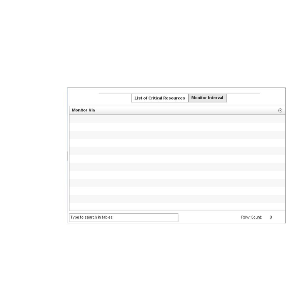
Brocade Mobility RFS4000, RFS6000, and RFS7000 System Reference Guide 481
53-1002620-01
7
1. Select Devices from the Configuration tab.
The Device Configuration screen displays a list of managed devices or peer controllers. The
listed devices can either be other controllers or Access Points within the managed network.
2. Select a target device (by double-clicking it) from amongst those displayed within the Device
Configuration screen.
Devices can also be selected directly from the Device Browser in the lower, left-hand, side of
the UI.
3. Select Profile Overrides from the Device menu to expand it into sub menu options.
4. Select Critical Resources.
FIGURE 327 Critical Resources screen - List of Critical Resources tab
The screen lists the destination IP addresses or interfaces (VLAN, WWAN, or PPPoE) used for
critical resource connection. IP addresses can be monitored directly by the access point or
controller, whereas a VLAN, WWAN or PPPoE must be monitored behind an interface.
5. Ensure the Activate Critical Resources Policy button is selected to enable the parameters
within the screen for configuration. This option needs to remain selected to apply the
configuration to the access point profile.
6. Click the Add button at the bottom of the screen to add a new critical resource and connection
method, or select and existing resource and select Edit to update the resource’s configuration.
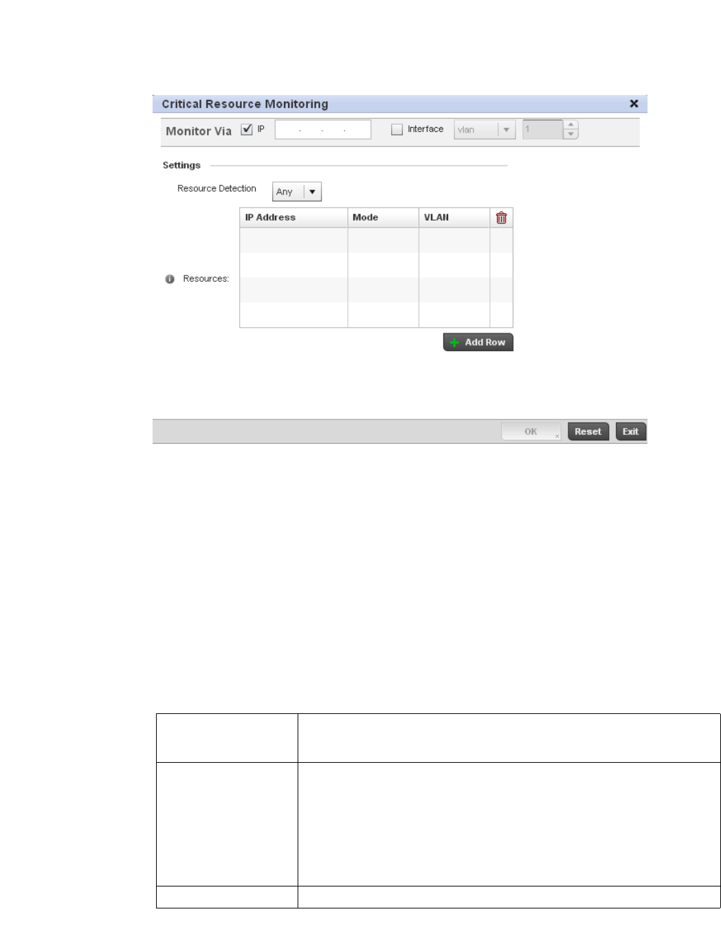
482 Brocade Mobility RFS4000, RFS6000, and RFS7000 System Reference Guide
53-1002620-01
7
FIGURE 328 Critical Resources screen - Adding a Critical Resource
7. S e l e c t t h e IP checkbox (within the Monitor Via field at the top of the screen) to monitor a critical
resource directly (within the same subnet) using the provided critical resource IP address as a
network identifier.
8. Select the Interface checkbox (within the Monitor Via field at the top of the screen) to monitor a
critical resource using either the critical resource’s VLAN, WWAN1 or PPPoE1 interface. If VLAN
is selected, a spinner control is enabled to define the destination VLAN ID used as the
interface for the critical resource.
9. Use the Resource Detection drop-down menu to define how critical resource event messages
are generated. Options include Any and All. If selecting Any, an event is generated when the
state of any single critical resource changes. If selecting All, an event is generated when the
state of all monitored critical resources change.
10. Select + Add Row to define the following for critical resource configurations:
11. Select the Monitor Interval tab.
IP Address Provide the IP address of the critical resource. This is the address used by the access
point to ensure the critical resource is available. Up to four addresses can be
defined.
Mode Set the ping mode used when the availability of a critical resource is validated. Select
from:
•arp-only – Use the Address Resolution Protocol (ARP) for only pinging the critical
resource. ARP is used to resolve hardware addresses when only the network
layer address is known.
•arp-and-ping – Use both ARP and Internet Control Message Protocol (ICMP) for
pining the critical resource and sending control messages (device not
reachable, requested service not available, etc.).
VLAN Define the VLAN on which the critical resource is available using the spinner control.
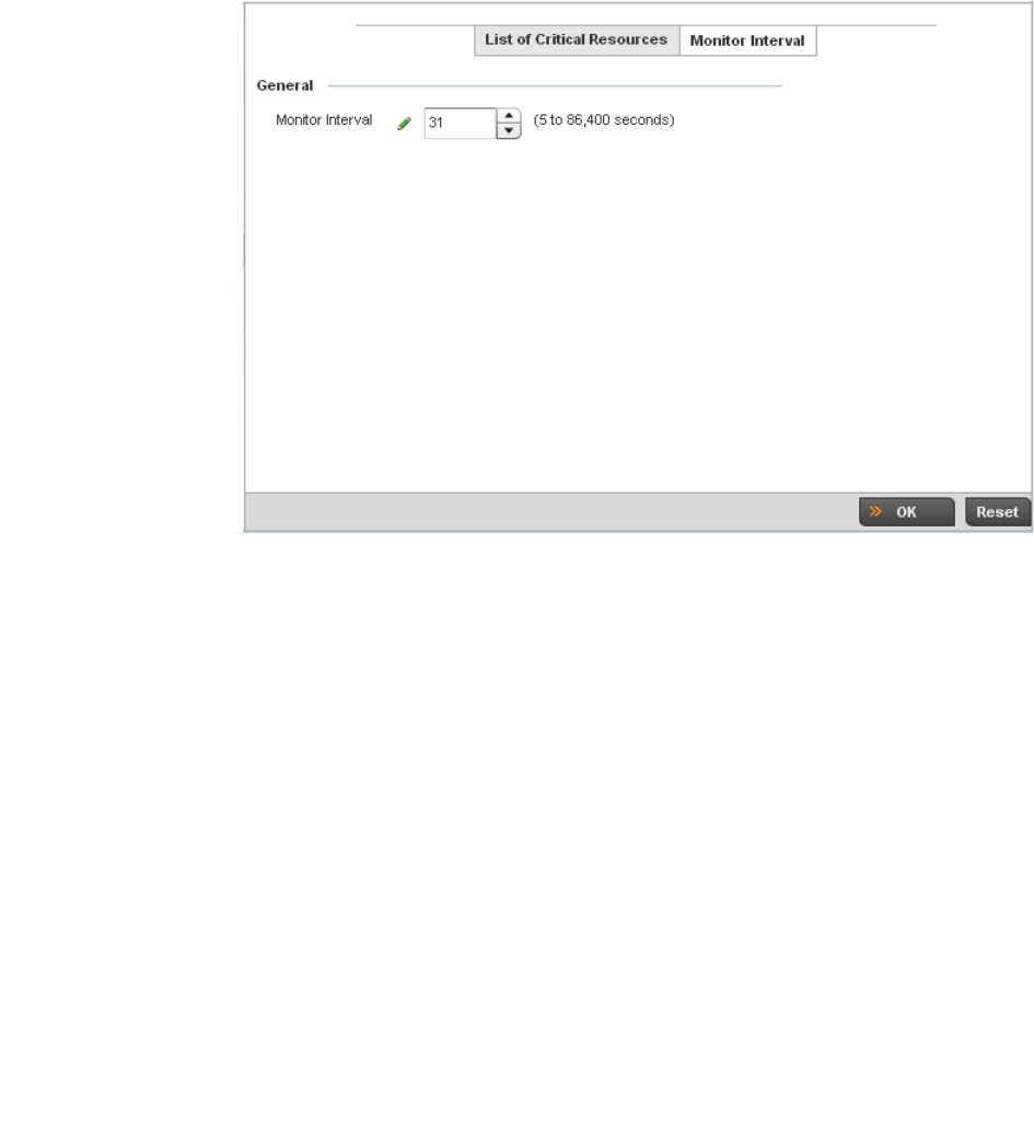
Brocade Mobility RFS4000, RFS6000, and RFS7000 System Reference Guide 483
53-1002620-01
7
FIGURE 329 Critical Resources screen - Monitor Interval tab
12. Set the duration between two successive pings from the access point to critical resource.
Define this value in seconds from 5 - 86,400. The default setting is 30 seconds.
13. Select OK to save the changes to the critical resource configuration and monitor interval.
Select Reset to revert to the last saved configuration.
Profile Services Configuration
A controller profile can contain specific guest access (captive portal), DHCP server and RADIUS
server configurations supported by the controller’s own internal resources. These controller access,
IP assignment and user authorization resources can be defined uniquely as controller profile
requirements dictate.
To define a profile’s services configuration:
1. Select the Configuration tab from the Web UI.
2. Select Profiles from the Configuration tab.
3. Select Manage Profiles from the Configuration > Profiles menu.
4. Select Services.
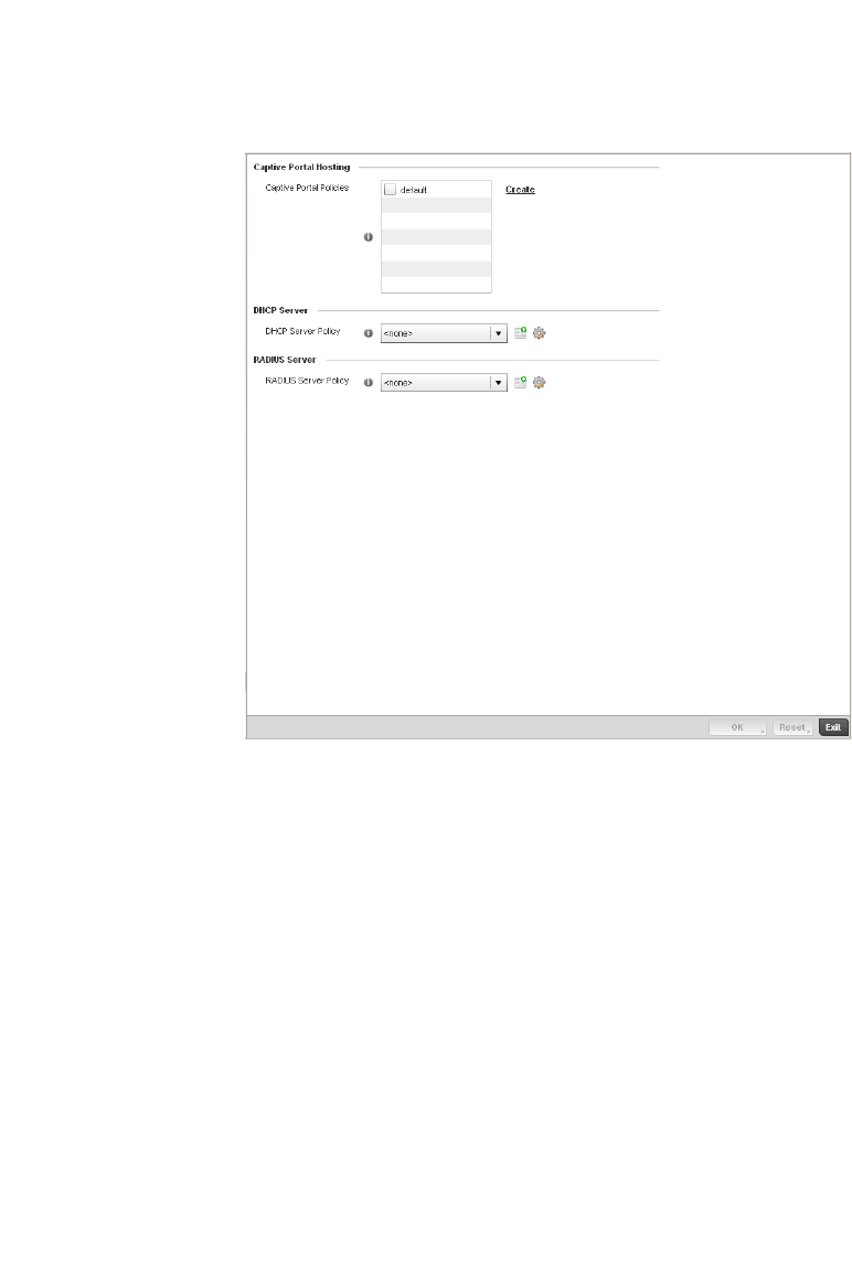
484 Brocade Mobility RFS4000, RFS6000, and RFS7000 System Reference Guide
53-1002620-01
7
FIGURE 330 Profile Services screen
5. Refer to the Captive Portal Hosting section to select or set a controller guest access
configuration (captive portal) for use with this profile.
A captive portal is guest access policy for providing guests temporary and restrictive access to
the managed wireless network. The primary means of securing such controller guest access is
a hotspot.
A captive portal policy’s hotspot configuration provides secure authenticated controller access
using a standard Web browser. Hotspots provides authenticated access by capturing and
re-directing a wireless user's Web browser session to a captive portal login page where the
user must enter valid credentials to access to the managed wireless network. Once logged into
the managed hotspot, additional Agreement, Welcome and Fail pages provide the
administrator with a number of options on the hotspot’s screen flow and user appearance.
Either select an existing captive portal policy, use the default captive portal policy or select the
Create link to create a new captive portal configuration that can be applied to this profile. For
morel information, see, Configuring Captive Portal Policies on page 10-559.
6. Use the DHCP Server Policy drop-down menu assign this controller profile a DHCP server policy.
If an existing DHCP policy does not meet the profile’s requirements, select the Create button to
create a new policy configuration that can be applied to this profile.
Dynamic Host Configuration Protocol (DHCP) allows hosts on an IP network to request and be
assigned IP addresses as well as discover information about the managed network where they
reside. Each subnet can be configured with its own address pool. Whenever a DHCP client
requests an IP address, the DHCP server assigns an IP address from that subnet’s address
pool. When the controller’s onboard DHCP server allocates an address for a DHCP client, the
client is assigned a lease, which expires after an pre-determined interval. Before a lease
expires, wireless clients (to which leases are assigned) are expected to renew them to continue

Brocade Mobility RFS4000, RFS6000, and RFS7000 System Reference Guide 485
53-1002620-01
7
to use the addresses. Once the lease expires, the client is no longer permitted to use the
leased IP address. The controller profile’s DHCP server policy ensures all IP addresses are
unique, and no IP address is assigned to a second client while the first client's assignment is
valid (its lease has not expired).
Either select an existing captive portal policy or select the Create button to create a new
captive portal configuration that can be applied to this profile. Existing policies can be modified
by selecting the Edit icon. For more information, see Setting the Controller’s DHCP
Configuration on page 10-571.
7. Use the RADIUS Server Policy drop-down menu to select an existing RADIUS server policy to
use as a user validation security mechanism with this controller profile.
A controller profile can have its own unique RADIUS server policy to authenticate users and
authorize access to the managed network. A profile’s RADIUS policy provides the centralized
management of controller authentication data (usernames and passwords). When an client
attempts to associate to the controller, the controller sends the authentication request to the
RADIUS server. A br-7131 model Access Point is also equipped with its own RADIUS server
capability.
If an existing RADIUS server policy does not meet your requirements, select the Create button
to create a new policy configuration that can be applied to this profile. Existing policies can be
modified by selecting the Edit icon. For more information, see Setting the Controller’s RADIUS
Configuration on page 10-585.
8. Select OK to save the changes made to the profile’s services configuration. Select Reset to
revert to the last saved configuration.
Profile Services Configuration and
Deployment Considerations
Profile Services Configuration
Before defining a profile’s captive portal, DHCP and RADIUS services configuration, refer to the
following deployment guidelines to ensure the profile configuration is optimally effective:
•A profile plan should consider the number of wireless clients allowed on the profile’s guest
(captive portal) network and the services provided, or if the profile should support guest
access at all.
•Controller profile configurations supporting a captive portal should include firewall policies to
ensure logical separation is provided between guest and internal networks so internal
networks and hosts are not reachable from managed guest devices.
•DHCP’s lack of an authentication mechanism means a DHCP server supported controller
profile cannot check if a client or user is authorized to use a given user class. This introduces a
vulnerability when using user class options. Ensure a profile using the controller’s internal
DHCP resources is also provisioned with a strong user authorization and validation
configuration.
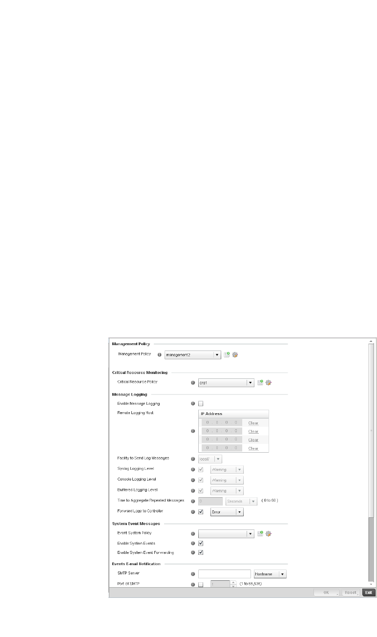
486 Brocade Mobility RFS4000, RFS6000, and RFS7000 System Reference Guide
53-1002620-01
7
Profile Management Configuration
The controller has mechanisms to allow/deny management access to the managed network for
separate interfaces and protocols (HTTP, HTTPS, Telnet, SSH or SNMP). These management access
configurations can be applied strategically to controller profiles as controller resource permissions
dictate for the profile.
Additionally, an administrator can define a profile with unique configuration file and device
firmware upgrade support. In a clustered environment, these operations can be performed on one
controller, then propagated to each member of the cluster and onwards to the devices managed by
each cluster member.
To define a profile’s management configuration:
1. Select the Configuration tab from the Web UI.
2. Select Profiles from the Configuration tab.
3. Select Manage Profiles from the Configuration > Profiles menu.
4. Select Management.
5. Expand the Management menu item to display additional Settings, Firmware and Heartbeat
Management options.
6. Select Settings from the Management menu.
FIGURE 331 Profile Management Settings screen
7. R e fe r to t he Management Policy field to select or set a controller management configuration
for use with this profile. A default management policy is also available if no existing policies are
usable.

Brocade Mobility RFS4000, RFS6000, and RFS7000 System Reference Guide 487
53-1002620-01
7
Use the drop-down menu to select an existing management policy to apply to this controller
profile. If no management policies exist meeting the data access requirements of this
controller profile, select the Create icon to access a series of screens used to define
administration, access control and SNMP configurations. Select an existing policy and select
the Edit icon to modify the configuration of an existing management policy. For more
information, see Viewing Management Access Policies on page 11-605.
8. Use to the Critical Resource Policy pulldown to set or override a critical resource policy for use
with this profile. For more information on defining a critical resource policy, see Managing
Critical Resource Policies on page 5-277.
9. Refer to the Message Logging field to define how the controller profile logs system events. It’s
important to log individual events to discern an overall pattern that may be negatively
impacting controller performance using the configuration defined for this profile.
Enable Message Logging Select the check box to enable the controller profile to log system events to a user
defined log file or a syslog server. Selecting this check box enables the rest of the
parameters required to define the profile’s logging configuration. This option is
disabled by default.
Remote Logging Host Use this table to define numerical (non DNS) IP addresses for up to three external
resources where logged system events can be sent on behalf of the controller
profile. Select Clear as needed to remove an IP address.
Facility to Send Log
Messages
Use the drop-down menu to specify the local server facility (if used) for the controller
profile event log transfer.
Syslog Logging Level Event severity coincides with the syslog logging level defined for the profile. Assign a
numeric identifier to log events based on criticality. Severity levels include 0 -
Emergency, 1 - Alert, 2 - Critical, 3 - Errors,
4 - Warning, 5 - Notice, 6 - Info and 7 - Debug. The default logging level is 4.
Console Logging Level Event severity coincides with the syslog logging level defined for the profile. Assign a
numeric identifier to log events based on criticality. Severity levels include 0 -
Emergency, 1 - Alert, 2 - Critical, 3 - Errors,
4 - Warning, 5 - Notice, 6 - Info and 7 - Debug. The default logging level is 4.
Buffered Logging Level Event severity coincides with the syslog logging level defined for the profile. Assign a
numeric identifier to log events based on criticality. Severity levels include 0 -
Emergency, 1 - Alert, 2 - Critical, 3 - Errors,
4 - Warning, 5 - Notice, 6 - Info and 7 - Debug. The default logging level is 4.
Time to Aggregate
Repeated Messages
Define the increment (or interval) system events are logged on behalf of this
controller profile. The shorter the interval, the sooner the event is logged. Either
define an interval in Seconds (0 - 60) or Minutes (0 -1). The default value is 0
seconds.
Forward Logs to Controller Select the checkbox to define a log level for forwarding event logs to the control. Log
levels include Emergency, Alert, Critical, Error, Warning, Notice, Info and Debug. The
default logging level is Error.

488 Brocade Mobility RFS4000, RFS6000, and RFS7000 System Reference Guide
53-1002620-01
7
10. Refer to the System Event Messages section to define or override how controller system
messages are logged and forwarded on behalf of the controller profile.
11. Refer to the Events E-mail Notification section to define or override how system event
notification emails are sent.
12. Select OK to save the changes made to the profile’s Management Settings. Select Reset to
revert to the last saved configuration.
13. Select Firmware from the Management menu.
Event System Policy Select an Event System Policy from the pull-down menu. If an appropriate policy does
not exist click the create button to make a new policy.
Enable System Events Select the Enable System Events check box to allow the controller profile to capture
system events and append them to a log file. It’s important to log individual events to
discern an overall pattern that may be negatively impacting controller performance.
This setting is enabled by default.
Enable System Event
Forwarding
Select the Enable System Event Forwarding box to enable the forwarding of system
events to another controller or cluster member. This setting is enabled by default.
SMTP Server Specify either the Hostname or IP Address of the outgoing SMTP server where
notification emails will be sent from.
Port of SMTP If a non-standard SMTP port is used on the outgoing SMTP server check this box and
specify a port between 1 and 65,535 for the outgoing SMTP server to use.
Sender Email Address Specify the email address that notification emails will be sent from. This will be the
from address on notification emails.
Username for SMTP Server Specify the username of the sender on the outgoing SMTP server. Many SMTP
servers require users to authenticate with an username and password before
sending email through the server.
Password for SMTP Server Specify the password associated with the username of the sender on the outgoing
SMTP server. Many SMTP servers require users to authenticate with an username
and password before sending email through the server.
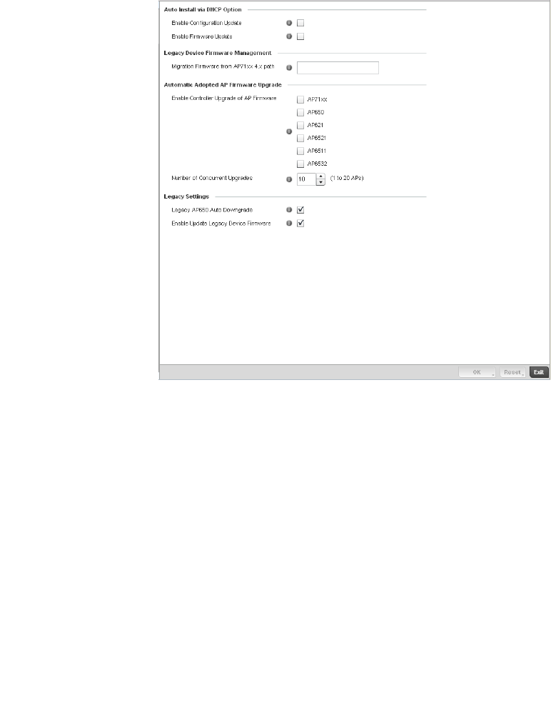
Brocade Mobility RFS4000, RFS6000, and RFS7000 System Reference Guide 489
53-1002620-01
7
FIGURE 332 Profile Management Firmware screen
14. Refer to the Auto Install via DHCP Option section to configure automatic configuration file and
firmware updates.
15. Refer to the Legacy Device Firmware Management field to define or whether Brocade Mobility
650 Access Point and Brocade Mobility 7131 model devices can upgrade to newer firmware
versions or downgrade to legacy firmware versions.
Enable Configuration
Update
Select the Enable Configuration Update radio button (from within the Automatic
Configuration Update field) to enable automatic configuration file updates for the
controller profile from a location external to the controller. If enabled (the setting is
disabled by default), provide a complete path to the target configuration file used in
the update.
Enable Firmware Upgrade Select this option to enable automatic controller firmware upgrades (for this
controller profile) from a user defined remote location. This value is disabled by
default.
Migration Firmware from
br-7131 4.x path
Provide a complete path to the target firmware used to support a legacy
br-7131 firmware update. The length of the path cannot exceed 253 characters.
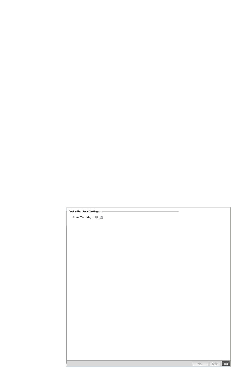
490 Brocade Mobility RFS4000, RFS6000, and RFS7000 System Reference Guide
53-1002620-01
7
16. Use the parameters within the Automatic Adopted AP Firmware Upgrade section to define an
automatic firmware upgrade from a controller based file.
17. Refer to the parameters within the Legacy Settings section to configure settings for legacy
devices.
18. Select OK to save the changes made to the profile’s Management Firmware configuration.
Select Reset to revert to the last saved configuration.
19. Select the Heartbeat option from the Management menu.
FIGURE 333 Profile Management Heartbeat screen
20. Select the Service Watchdog option to implement heartbeat messages to ensure other
associated devices are up and running and capable of effectively interoperating with the
controller. The Service Watchdog is enabled by default.
Enable Controller Upgrade
of AP Firmware
Select this radio button to enable adopted Access Point radios to upgrade to a newer
firmware version using its associated controller’s most recent resident firmware file
for that AP model. This parameter is disabled by default.
Number of Concurrent
Upgrades.
Use the spinner control to define the maximum number (1 - 20) of adopted APs that
can receive a firmware upgrade at the same time. Keep in mind that during a
firmware upgrade, the AP is offline and unable to perform its normal wireless client
support function until the upgrade process is complete.
Legacy br-650 Auto
Downgrade
Select this box to enable automatic downgrading of legacy br-650 Access Point
firmware.
Enable Update Legacy
Device Firmware
Select this box to update legacy device firmware when connected to the controller.

Brocade Mobility RFS4000, RFS6000, and RFS7000 System Reference Guide 491
53-1002620-01
7
21. Select OK to save the changes made to the profile maintenance Heartbeat tab. Select Reset to
revert to the last saved configuration.
Profile Management Configuration and
Deployment Considerations
Profile Management Configuration
Before defining a profile’s management configuration, refer to the following deployment guidelines
to ensure the profile configuration is optimally effective:
•Define controller profile management access configurations providing both encryption and
authentication. Management services like HTTPS, SSH and SNMPv3 should be used when
possible, as they provide data privacy and authentication.
•Brocade recommends SNMPv3 be used for management profile configurations, as it provides
both encryption and authentication.
Advanced Profile Configuration
A profile’s advanced configuration is comprised of defining its MINT protocol configuration and the
profile’s NAS identifier and port ID attributes. MINT provides secure controller profile
communications at the transport layer. Using MINT, a device can be configured to only
communicate with other authorized (MINT enabled) devices. Therefore, MINT is well designed for
controller profile support, wherein a group of managed devices share the same configuration
attributes.
Refer to the advanced profile’s Miscellaneous menu item to set the profile’s NAS configuration. The
profile database on the RADIUS server consists of user profiles for each connected network access
server (NAS) port.
To set a profile’s advanced configuration:
1. Select the Configuration tab from the Web UI.
2. Select Profiles from the Configuration tab.
3. Select Manage Profiles from the Configuration > Profiles menu.
4. Select Advanced and expand the menu item.
The following sub menu items are available as advanced profile configuration options:
•Configuring MINT
•Advanced Profile Miscellaneous Configuration
Configuring MINT
MINT provides the means to secure controller profile communications at the transport layer. Using
MINT, a device can be configured to only communicate with other authorized (MINT enabled)
devices.
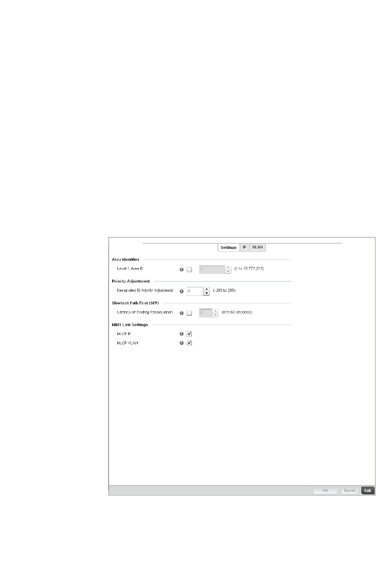
492 Brocade Mobility RFS4000, RFS6000, and RFS7000 System Reference Guide
53-1002620-01
7
managed devices can communicate with each other exclusively over a MINT security domain. Keys
can also be generated externally using any application (like openssl). These keys must be present
on the managed device managing the domain for key signing to be integrated with the UI. A MAP
device that needs to communicate with another first negotiates a security context with that device.
The security context contains the transient keys used for encryption and authentication. A secure
network requires users to know about certificates and PKI. However, administrators do not need to
define security parameters for Access Points to be adopted (secure WISPe being an exception, but
that isn-t a commonly used feature). Also, users can replace any device on the network or move
devices around and they continue to work. Default security parameters for MiNT are such that
these scenarios continue to function as expected, with minimal user intervention required only
when a new network is deployed.
To define a controller profile’s MINT configuration:
1. Select MINT Protocol from the Advanced Profile’s menu item.
FIGURE 334 Advanced Profile MINT screen - Settings tab
2. The Settings tab displays by default.
3. Refer to the Area Identifier field to define the Level 1 and Level 2 Area IDs used by the profile’s
MINT configuration.
Level 1 Area ID Select the check box to enable a spinner control for setting the Level 1 Area ID
between 1 - 4,294,967,295. The default value is disabled.
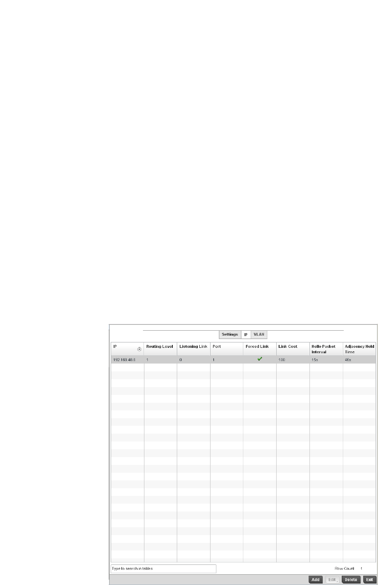
Brocade Mobility RFS4000, RFS6000, and RFS7000 System Reference Guide 493
53-1002620-01
7
4. Define the following Device Heartbeat Settings in respect to devices supported by the
controller profile:
5. Select the Latency of Routing Recalculation check box (within the Shortest Path First (SPF)
field) to enable the spinner control used for defining a latency period between 0 - 60 seconds.
The default setting has the check box disabled.
6. Define the following MINT Link Settings in respect to devices supported by the controller
profile:
7. S elect OK to save the changes made to the Settings tab. Select Reset to revert to the last
saved configuration.
8. Select the IP tab to display the link IP network address information shared by the devices
managed by the controller’s MINT configuration.
FIGURE 335 Advanced Profile MINT screen - IP tab
Designated IS Priority
Adjustment
Use the spinner control to set a Designated IS Priority Adjustment setting
between -255 and 255. This is the value added to the base level DIS priority to
influence the Designated IS (DIS) election. A value of +1 or greater increases
DISiness. The default setting is 0.
MLCP IP Check this box to enable MINT Link Creation Protocol (MLCP) by IP Address. MINT
Link Creation Protocol is used to create one UDP/IP link from the device to a
neighbor. That neighboring device does not need to be a controller or switch it can be
another AP which would have a path to the controller or switch.
MLCP VLAN Check this box to enable MINT Link Creation Protocol (MLCP) by VLAN. MINT Link
Creation Protocol is used to create one VLAN link from the device to a neighbor. That
neighboring device does not need to be a controller or switch it can be another AP
which would have a path to the controller or switch.
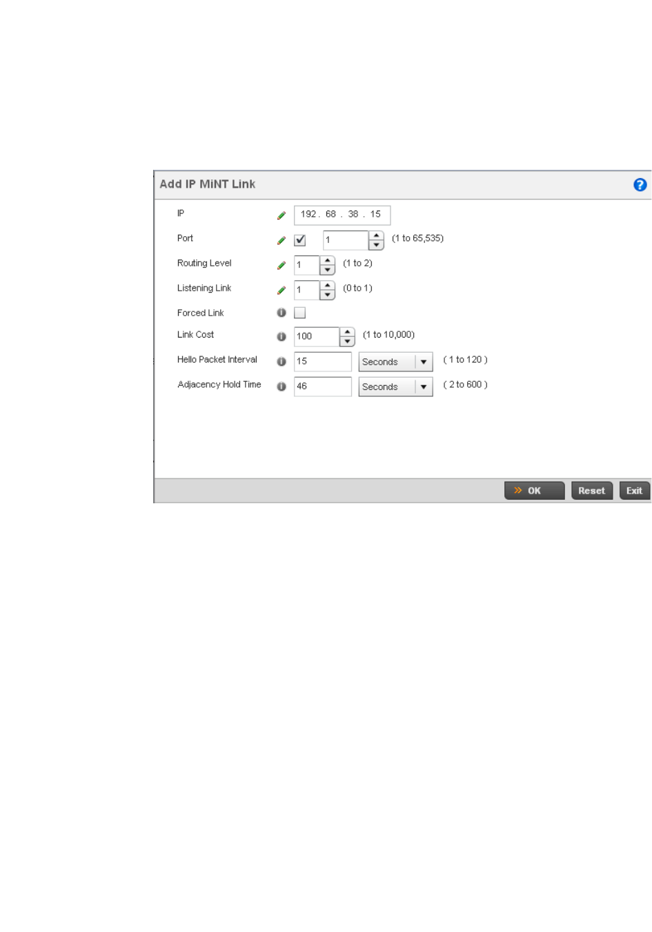
494 Brocade Mobility RFS4000, RFS6000, and RFS7000 System Reference Guide
53-1002620-01
7
9. The IP tab displays the IP address, routing level, link cost, hello packet interval and Adjacency
Hold Time managed devices use to securely communicate amongst one another within the
managed network. Select Add to create a new Link IP configuration or Edit to modify an existing
MINT configuration.
FIGURE 336 Advanced Profile MINT screen - IP Add tab
10. Set the following Link IP parameters to complete the MINT network address configuration:
11. Select the VLAN tab to display the link IP VLAN information shared by the devices managed by
the controller’s MINT configuration.
IP Define or override the IP address used by peer controllers for interoperation when
supporting the MINT protocol.
Port To specify a custom port for MiNT links, check this box and use the spinner control to
define or override the port number between 1 and 65,535.
Routing Level Use the spinner control to define or override a routing level of either 1 or 2.
Listening Link Specify a listening link of either 0 or 1. UDP/IP links can be created by configuring a
matching pair of links, one on each end point. However, that is error prone and
doesn’t scale. So UDP/IP links can also listen (in the TCP sense), and dynamically
create connected UDP/IP links when contacted. The typical configuration is for the
controller to have a listening UDP/IP link on the switch’s IP address S.S.S.S, and for
all the APs to have a regular UDP/IP link to S.S.S.S.
Forced Link Check this box to specify the MiNT link as a forced link.
Link Cost Use the spinner control to define or override a link cost between 1 - 10,000. The
default value is 100.
Hello Packet Interval Set or override an interval in either Seconds (1 - 120) or Minutes (1 - 2) for the
transmission of hello packets. The default interval is 15 seconds.
Adjacency Hold Time Set or override a hold time interval in either Seconds (2 - 600) or Minutes (1 - 10) for
the transmission of hello packets. The default interval is 46 seconds.
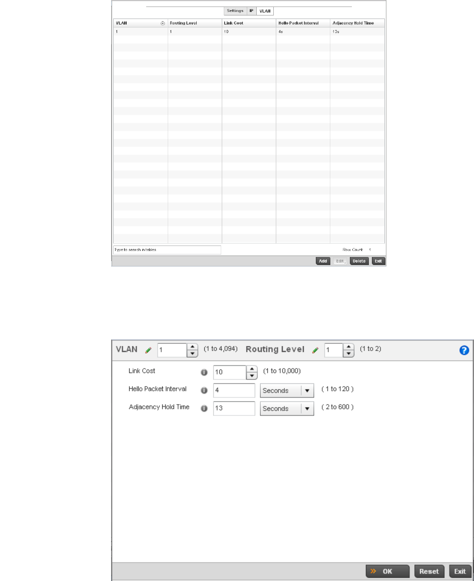
Brocade Mobility RFS4000, RFS6000, and RFS7000 System Reference Guide 495
53-1002620-01
7
FIGURE 337 Advanced Profile MINT screen - VLAN tab
12. The VLAN tab displays the VLAN, Routing Level, Link Cost, Hello Packet Interval and Adjacency
Hold Time managed devices use to securely communicate amongst one another. Select Add to
create a new VLAN link configuration or Edit to override an existing MINT configuration.
FIGURE 338 Advanced Profile MINT screen - VLAN tab
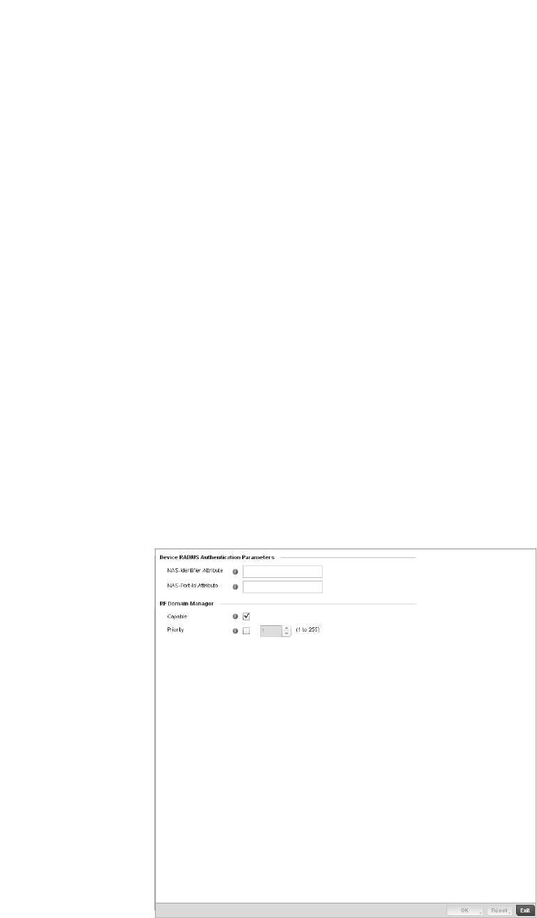
496 Brocade Mobility RFS4000, RFS6000, and RFS7000 System Reference Guide
53-1002620-01
7
13. Set the following VLAN parameters to complete the MINT configuration:
14. Select OK to save the updates and overrides to the MINT Protocol configuration. Select Reset
to revert to the last saved configuration.
Advanced Profile Miscellaneous Configuration
Advanced Profile Configuration
Refer to the advanced profile’s Miscellaneous menu item to set the profile’s NAS configuration. The
profile database on the RADIUS server consists of user profiles for each connected network access
server (NAS) port. Each profile is matched to a username representing a physical port. When the
wireless controller authorizes users, it queries the user profile database using a username
representative of the physical NAS port making the connection.
1. Select Miscellaneous from the Advanced Profile’s menu item.
FIGURE 339 Advanced Profile Miscellaneous screen
VLAN Define a VLAN ID between 1 - 4,094 used by peer controllers for interoperation when
supporting the MINT protocol.
Routing Level Use the spinner control to define or override a routing level of either 1 or 2.
Link Cost Use the spinner control to define or override a link cost between 1 - 10,000. The
default value is 100.
Hello Packet Interval Set or override an interval in either Seconds (1 - 120) or Minutes (1 - 2) for the
transmission of hello packets. The default interval is 15 seconds.
Adjacency Hold Time Set or override a hold time interval in either Seconds (2 - 600) or Minutes (1 - 10) for
the transmission of hello packets. The default interval is 46 seconds.

Brocade Mobility RFS4000, RFS6000, and RFS7000 System Reference Guide 497
53-1002620-01
7
2. Set a NAS-Identifier Attribute up to 253 characters in length.
This is the RADIUS NAS-Identifier attribute that typically identifies the Access Point or controller
of controller where a RADIUS message originates.
3. Set a NAS-Port-Id Attribute up to 253 characters in length.
This is the RADIUS NAS port ID attribute which identifies the device port where a RADIUS
message originates.
4. Select the Capable check box (within the RF Domain Manager field) to designate this specific
profile managed device as being capable of being the RF Domain manager for a particular RF
Domain. The default value is enabled.
5. Select the Priority check box (within the RF Domain Manager field) to set a priority value for this
specific profile managed device. Once enabled, use the spinner control to set a device priority
between 1 - 10,000. The higher the number set, the higher the priority in the RF Domain
manager election process.
6. Select OK to save the changes made to the profile’s Advanced Miscellaneous configuration.
Select Reset to revert to the last saved configuration.

498 Brocade Mobility RFS4000, RFS6000, and RFS7000 System Reference Guide
53-1002620-01
7

Brocade Mobility RFS4000, RFS6000, and RFS7000 System Reference Guide 499
53-1002620-01
Chapter
8
RF Domain Configuration
In this chapter
•About RF Domains. . . . . . . . . . . . . . . . . . . . . . . . . . . . . . . . . . . . . . . . . . . . . 499
•Managing RF Domains . . . . . . . . . . . . . . . . . . . . . . . . . . . . . . . . . . . . . . . . . 500
About RF Domains
A wireless controller configuration is composed of numerous elements including RF Domains,
profiles, policies, WLANs and device specific configurations. RF Domains are used to assign
regulatory, location and relevant policies to controllers. RF Domains are required, as each
controller must be assigned at least one default RF Domain.
RF Domains allow administrators to assign configuration data to multiple devices deployed in a
common coverage area, such as in a floor, building or site. Each RF Domain contains policies that
can determine a Smart RF or WIPS configuration.
RF Domains enable administrators to override WLAN SSID name and VLAN assignments. This
enables the deployment of a global WLAN across multiple sites and unique SSID name or VLAN
assignments to groups of Access Points servicing the global WLAN. This new WLAN override
technique eliminates the requirement for defining and managing a large number of individual
WLANs and profiles.
A controller configuration contains (at a minimum) one default RF Domain and can optionally use
additional user defined RF Domains:
•Default RF Domain - Automatically assigned to each controller and associated Access Point by
default.
•User Defined RF Domains - Created by administrators and manually assigned to individual
controllers or Access Points, but can be automatically assigned to Access Points using
adoption policies.
Each controller and Access Point is assigned to only one RF Domain at a time. However, a user
defined RF Domain can be assigned to multiple controllers or Access Points as required. User
defined RF Domains can be manually assigned to controllers and Access Points or automatically
assigned to Access Points using an AP provisioning policy.
Default RF Domains
Each controller utilizes a default RF Domain. Access Points are assigned to this default RF Domain
as they are discovered by the controller. The default RF Domain can be used for single site
deployments, where regional, regulatory and RF policies are common between devices. When
regional, regulatory or RF policies need to be device specific, user defined RF Domains are
recommended.

500 Brocade Mobility RFS4000, RFS6000, and RFS7000 System Reference Guide
53-1002620-01
8
A default RF Domain can also omit configuration parameters to prohibit regulatory configuration
from automatically being inherited by devices as they are discovered by the controller. This is
desirable in multi-site deployments with devices spanning multiple countries. Omitting specific
configuration parameters eliminates the risk of an incorrect country code from being automatically
assigned to a device.
User Defined RF Domains
Configure and deploy user defined RF Domains for single or multiple sites when controllers and
Access Points require unique regulatory and regional configurations, or unique Smart RF and WIPS
policies. User defined RF Domains can be used to:
•Assign unique Smart RF or WIPS policies to Access Points deployed on different floors or
buildings within in a site.
•Assign unique regional or regulatory configurations to controllers and Access Points deployed
in different states or countries.
•Assign unique WLAN SSIDs and/or VLAN IDs to sites assigned a common WLAN without having
to define individual WLANs for each site.
User defined RF Domains must be manually assigned to controllers, but can be manually or
automatically assigned to Access Points. Manual RF Domain assignment can be performed using
the controller CLI or UI applet by modifying each device's individual configuration and assigning a
specific RF Domain to the device. Automatic RF Domain assignments can be made using an AP
provisioning policy which can assign specific RF Domains to Access Points based on an Access
Points model, serial number, VLAN, DHCP option, IP address or MAC address.
Automatic RF Domain assignments are useful in large deployments, as they enable plug-n-play
Access Point deployments by automatically applying RF Domains to remote Access Points.
Managing RF Domains
Managing RF Domains entails configuring individual RF Domains as required and managing them
as a collective set.
To review the configurations of existing RF Domains:
1. Select Configuration > RF Domains from the Web UI
The RF Domain screen displays within the main portion of the controller Web UI, and the RF
Domain Browser displays in the lower, left-hand, portion of the controller Web UI.
2. Refer to the RF Domain screen to review high-level configuration data for existing RF Domain
policies.
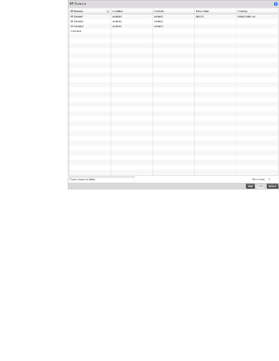
Brocade Mobility RFS4000, RFS6000, and RFS7000 System Reference Guide 501
53-1002620-01
8
FIGURE 340 RF Domain screen
3. Use the following (read only) information to determine whether a new RF Domain policy
requires creation, or an existing RF Domain requires edit or deletion:
4. Refer to the RF Domain Browser to expand each existing RF Domain policy and review the
device MAC addresses operating within the location defined and are using the configuration
defined for the policy.
RF Domain Lists each policy’s name, as assigned when it was created. The RF Domain name cannot
be changed as part of the edit process. Only one RF Domain can be assigned to a
controller or Access Point.
Location Displays the physical location assigned to the RF Domain policy. This name could be as
specific as the floor of a building, or as generic as an entire site. The location defines the
physical area where a common set of devices are deployed using the policy’s RF Domain
configuration.
Contact Lists the contact (or administrator) assigned to respond to events created by or
impacting the RF Domain.
Time Zone Displays the geographic time zone set for each RF Domain policy. RF Domains can
contain unique country codes and time zone information to controller and Access Points
deployed across different states or countries, thus making them ideal for managing
device configurations across different geographical deployments.
Country Code Display the two-digit country code set for the policy. The country code must be set
accurately to avoid illegal operation, as device radios transmit in specific channels
unique to their country of operation.
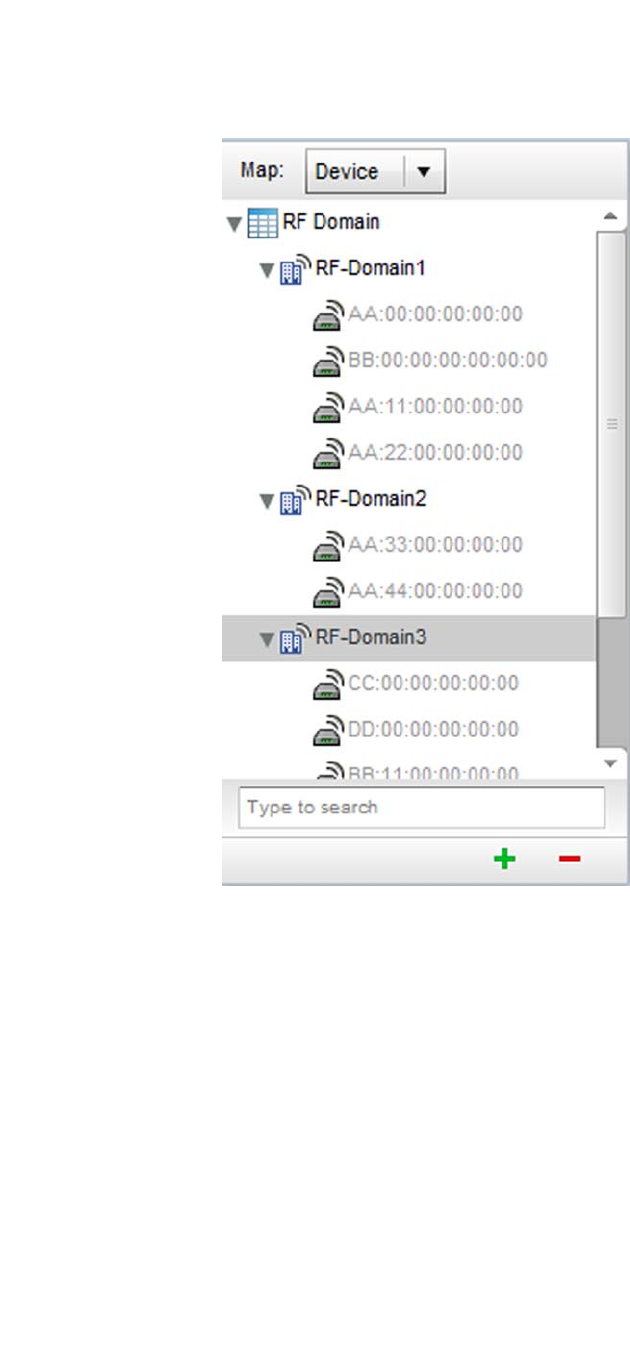
502 Brocade Mobility RFS4000, RFS6000, and RFS7000 System Reference Guide
53-1002620-01
8
FIGURE 341 RF Domain Browser
5. Once the data within the RF Domain screen and RF Domain Browser is reviewed, determine
whether a new policy requires creation, or if an existing policy requires edit or deletion. The
management of RF Domains entails the following:
•RF Domain Basic Configuration
•RF Domain Sensor Configuration
•RF Domain Overrides
RF Domain Basic Configuration
To set a RD Domain basic configuration:
1. Select Configuration > RF Domains from the Web UI
2. From the RF Domain screen, either select the Add button or highlight an existing RF Domain
and select Edit. An RF Domain configuration can be permanently removed by highlighting it
from the list and selecting Delete.
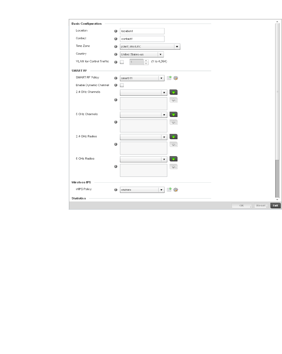
Brocade Mobility RFS4000, RFS6000, and RFS7000 System Reference Guide 503
53-1002620-01
8
An existing RF Domain can also be modified by selecting it directly from the RF Domain
Browser.
If adding or modifying an existing RF Domain, the RF Domain Basic Configuration screen
displays by default.
3. Define the following Basic Configuration parameters for the RF Domain:
RF Domain If creating a new RF Domain, assign it a name representative of its intended function.
The name cannot exceed 32 characters. The name cannot be changed as part of the
edit process.
Location Assign the physical location of the controller RF Domain. This name could be as specific
as the floor of a building, or as generic as an entire site. The location defines the
physical area where a common set of device configurations are deployed and managed
by the RF Domain policy.
Contact Provide the name of the contact (or administrator) assigned to respond to events
created by or impacting the RF Domain.
Time Zone Displays the geographic time zone set for each RF Domain policy. RF Domains can
contain unique country codes and time zone information to controller and Access Points
deployed across different states or countries, thus making them ideal for managing
device configurations across different geographical deployments.
Country Define the two-digit country code set for the RF Domain. The country code must be set
accurately to avoid the policy’s illegal operation, as device radios transmit in specific
channels unique to the country of operation.
VLAN for Traffic Control Select the check box to enable a spinner control used for specifying the VLAN (within a
range of 1 - 4,094) used for traffic control within this RF Domain.

504 Brocade Mobility RFS4000, RFS6000, and RFS7000 System Reference Guide
53-1002620-01
8
When a radio fails or is faulty, a Smart RF policy can used provide automatic recovery by
instructing neighboring Access Points to increase their transmit power to compensate for the
coverage loss.
Once correct Access Point placement has been established, Smart-RF can optionally be
leveraged for automatic detector radio selection. Smart-RF uses detector radios to monitor RF
events and can be used to ensure adequate detector coverage is available. Manual detector
radio selection can also be made using visualizations from the Brocade LANPlanner tool.
For an overview of Smart RF and instructions on how to create a Smart RF policy that can be
used with a RF Domain, see Smart RF Policy on page 6-355.
4. Define the following SMART RF parameters for the RF Domain:
5. Assign an existing Wireless IPS (WIPS) policy to the RF Domain, or if none exist create a new
one.
Use the WIPS Policy drop-down menu to navigate to existing WIPS policies and select the one
best suited to the function of the RF Domain. If none exist, select the Create icon and provide
the required parameters to define a WIPS configuration that can be used with the RF Domain.
An existing policy can be edited by selecting the policy from the drop-down menu and selecting
the Edit icon.
A WIPS policy provides protection against wireless threats and acts as a key layer of security
complementing wireless VPNs, encryption and authentication. a WIPS policy uses a dedicated
sensor for actively detecting and locating rogue AP devices. After detection, WIPS uses
mitigation techniques to block the devices by manual termination, air lockdown, or port
suppression.
For an overview of WIPS and instructions on how to create a WIPS policy that can be used with
a RF Domain, see Configuring a WIPS Policy on page 9-540.
6. Refer to the Statistics field to define how RF Domain stats and updated.
SMART RF Policy Assign an existing Smart RF Policy to the RF Domain, or if none exist create a new one.
Use the Smart RF Policy drop-down menu to navigate to existing Smart RF policies and
select the one best suited to the function of the RF Domain. If none exist, select the
Create icon and provide the required parameters to define a Smart RF configuration that
can be used with the RF Domain. An existing policy can be edited by selecting the policy
from the drop-down menu and selecting the Edit icon.
Enable Dynamic
Channel
Check this box to enable dynamic channel switching for Smart RF radios.
2.4GHz Channels Select channels from the pull-down menu and click the down arrow to move it to the list
of channels used for 2.4GHz Smart RF radios.
5GHz Channels Select channels from the pull-down menu and click the down arrow to move it to the list
of channels used for 5GHz Smart RF radios.
NoC Update Interval Set a NoC Update interval of 0, or between 5-3600 seconds for updates from the RF
Domain manager to the controller.
Update Interval Set a statistics Update interval of 0 or between 5-3600 seconds for updates retrieved
from the wireless controller.

Brocade Mobility RFS4000, RFS6000, and RFS7000 System Reference Guide 505
53-1002620-01
8
7. Refer to the Statistics field to set the following:
8. Select OK to save the changes to the Basic Configuration, or select Reset to Revert to the last
saved configuration.
RF Domain Sensor Configuration
The Brocade Wireless Intrusion Protection System (WIPS) protects the managed network, wireless
clients and Access Point radio traffic from attacks and unauthorized access. WIPS provides tools
for standards compliance and around-the-clock wireless network security in a distributed
environment. WIPS allows administrators to identify and accurately locate attacks, rogue devices
and network vulnerabilities in real time and permits both a wired and wireless lockdown of wireless
device connections upon acknowledgement of a threat.
In addition to dedicated Brocade AirDefense sensors, an Access Point radio can function as a
sensor and upload information to a dedicated WIPS server (external to the controller). Unique WIPS
server configurations can be used by RF Domains to ensure a WIPS server configuration is
available to support the unique data protection needs of individual RF Domains.
WIPS is not supported on a WLAN basis, rather sensor functionality is supported on the Access
Point radio(s) available to each managed WLAN. When an Access Point radio is functioning as a
WIPS sensor, it’s able to scan in sensor mode across all legal channels within 2.4 and 5.0 GHz.
Sensor support requires a AirDefense WIPS Server on the network. Sensor functionality is not
provided by the Access Point alone. The Access Point works in conjunction with a dedicated WIPS
server.
To define a WIPS server configuration used with a RF Domain:
1. From the RF Domain screen, either select the Add button or highlight an existing policy and
select Edit.
An existing policy can also be modified by selecting it directly from the RF Domain Browser.
2. Select the Sensor Configuration item from within the RF Domain screen.
Window Index Use the spinner control to set a numerical index used as an identifier for each RF
Domain statistics defined.
Sample Interval Use the spinner control to define the interval (in seconds) used by the controller to
capture windowed statistics supporting the listed RF Domain configuration. The default
is 5 seconds.
Window Size Use the spinner control to set the number of samples used by the controller to define RF
Domain statistics. The default value is 6 samples.
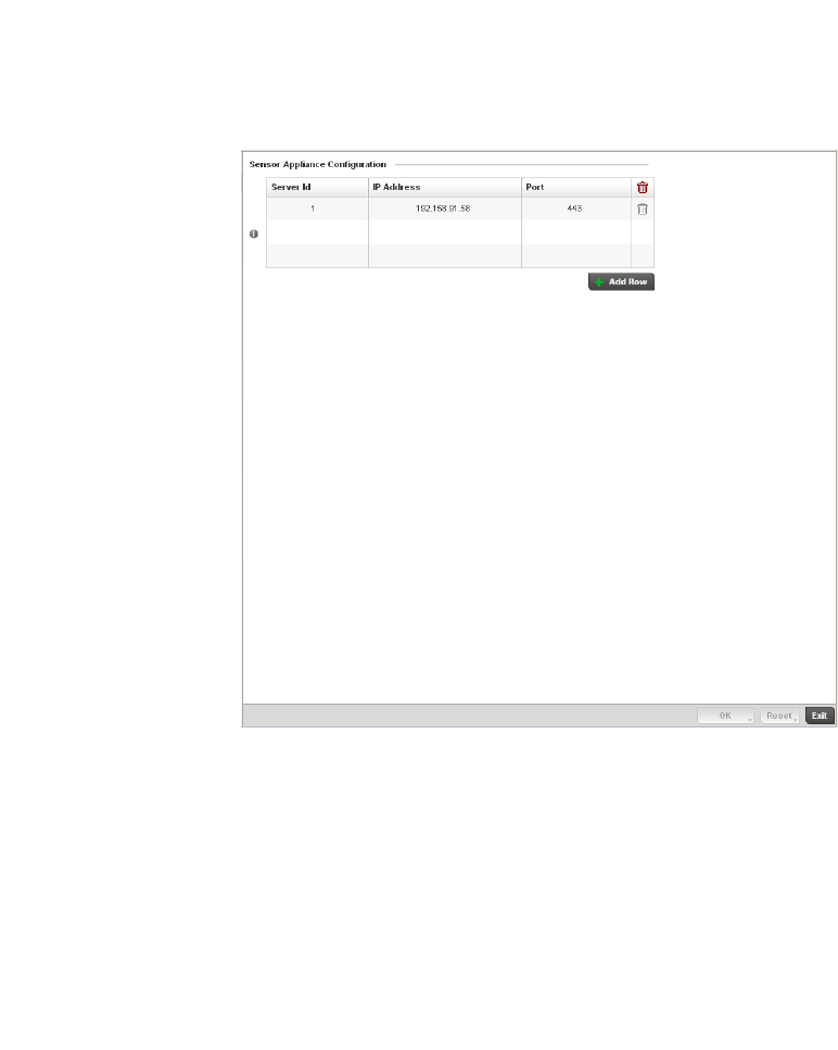
506 Brocade Mobility RFS4000, RFS6000, and RFS7000 System Reference Guide
53-1002620-01
8
FIGURE 342 RF Domain - Sensor WIPS screen
3. Either select the + Add Row button to create a new WIPS server configuration or highlight an
existing Sensor Server Configuration and select the Delete icon to remove it.
4. Use the spinner control to assign a numerical Server ID to each WIPS server defined. The
server with the lowest defined ID is the first reached by the controller. The default ID is 1.
5. Provide the numerical (non DNS) IP Address of each server used as a WIPS sensor server by
the RF Domain.
6. Use the spinner control to specify the Port of each WIPS server. The default port is 443.
7. S elect OK to save the changes to the AirDefense WIPS configuration, or select Reset to Revert
to the last saved configuration.
RF Domain Overrides
Within the managed network, each WLAN provides associated wireless clients with a Service Set
Identifier (SSID). This has limitations because it requires wireless clients associate with different
SSIDs to obtain QoS and security policies. However, a Brocade managed RF Domain can have
WLANs assigned and advertise a single SSID, but allow users to inherit different QoS or security
policies. Use the Override SSID screen to assign WLANs an override SSID as needed for the RF
Domain.
The controller allows the mapping of a WLAN to more than one VLAN. When a wireless client
associates with a WLAN, it is assigned a VLAN in such a way that users are load balanced across
VLANs. The VLAN is assigned from the pool representative of the WLAN. The controller tracks the
number of client users per VLAN, and assigns the least used/loaded VLAN to the wireless client.
This number is tracked on a per-WLAN basis.
To define an override SSID and override VLAN configuration to used with a RF Domain:
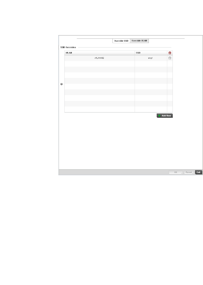
Brocade Mobility RFS4000, RFS6000, and RFS7000 System Reference Guide 507
53-1002620-01
8
1. From the RF Domain screen, either select the Add button or highlight an existing policy and
select Edit.
An existing policy can also be modified by selecting it directly from the RF Domain Browser.
2. Select the Overrides item from within the RF Domain screen.
FIGURE 343 RF Domain Override SSID screen
The Overrides screen is partitioned into two tabs, with the Override SSID screen displayed by
default.
3. Either select the + Add button to create a new Override SSID configuration. Highlight an
existing Sensor Server Configuration and select the Delete icon to remove it from the table.
4. Use the WLAN drop-down menu to select a existing WLAN to be supplied an override SSID.
If a WLAN configuration has not been defined, you’ll need to select the Create button and
define at least one complete WLAN configuration. For detailed information on the steps
required to create a WLAN, see Wireless LAN Policy on page 6-282.
5. Enter the name of the SSID to use as the override SSID.
6. Select OK to save the changes to the Override SSID configuration, or select Reset to Revert to
the last saved configuration.
7. Select the Override VLAN tab.
The Override VLAN screen lists those WLANs available for override.
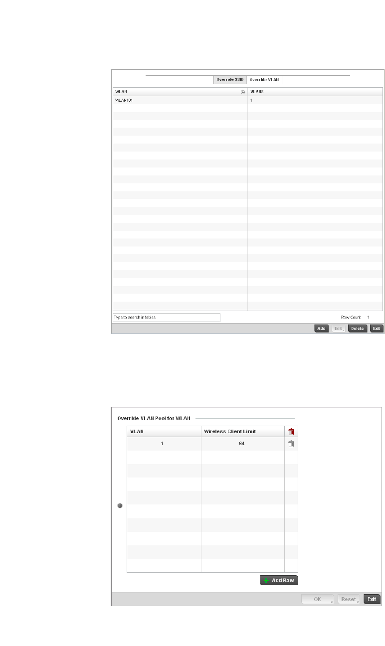
508 Brocade Mobility RFS4000, RFS6000, and RFS7000 System Reference Guide
53-1002620-01
8
FIGURE 344 RF Domain Override VLAN screen
8. Either select Add to define a new VLAN override configuration, choose an existing WLAN and
select Edit to change the override VLAN and limit or select Delete to remove a WLAN’s override
VLAN configuration.
FIGURE 345 RF Domain Override VLAN Add screen
9. Use the VLAN spinner control to change the add additional VLANs for the selected WLAN. By
default, VLAN 1 is configured for any selected WLAN.

Brocade Mobility RFS4000, RFS6000, and RFS7000 System Reference Guide 509
53-1002620-01
8
10. Use the Wireless Client Limit spinner control to set the client user limit for the VLAN. The
maximum allowed client limit is 8192 per VLAN. VLANs can be defined between 1 - 4094. The
default setting is 0.
11. Select OK to save the changes to the Override VLAN configuration, or select Reset to Revert to
the last saved configuration.
RF Domain Deployment Considerations
Before defining RF Domain policies, refer to the following deployment guidelines to ensure the
configurations are optimally effective:
•Each controller utilizes a default RF Domain. Access Points are assigned to this default RF
Domain as they are discovered by the controller. The default RF Domain can be used for single
site deployments, where regional, regulatory and RF policies are common between devices.
•User defined RF Domains must be manually assigned to controllers, but can be manually or
automatically assigned to Access Points.
•A Rogue AP detection configuration is a central component of an RF Domain policy, as it
provides the RF Domain policy with the means to filter potentially threatening devices from
operating with devices approved within the managed network.
•WIPS is not supported on a WLAN basis, rather sensor functionality is supported on the Access
Point radio(s) available to each managed WLAN.
•When planning sensor coverage, a minimum of 1 detector radio is recommended per 4 Access
Points deployed. To ensure effective placement, Brocade’ LANPlanner can be used to provide
predictive planning services and visualization to ensure adequate radio coverage is provided
based on site application and device requirements. LANPlanner provides visualization tools
ensuring adequate radio coverage for client radios and sensors. A physical site survey should
also be performed to verify client radio coverage, before a final deployment.
•Both default and user defined RF Domains contain policies and configuration parameters.
Changes made to policies or configuration parameters are automatically inherited by all the
controllers and Access Points assigned to the RF Domain.

510 Brocade Mobility RFS4000, RFS6000, and RFS7000 System Reference Guide
53-1002620-01
8

Brocade Mobility RFS4000, RFS6000, and RFS7000 System Reference Guide 511
53-1002620-01
Chapter
9
Security Configuration
In this chapter
•Wireless Firewall . . . . . . . . . . . . . . . . . . . . . . . . . . . . . . . . . . . . . . . . . . . . . . 511
•Wireless Client Roles. . . . . . . . . . . . . . . . . . . . . . . . . . . . . . . . . . . . . . . . . . . 530
•Intrusion Prevention . . . . . . . . . . . . . . . . . . . . . . . . . . . . . . . . . . . . . . . . . . . 539
When taking precautions to secure wireless traffic from a client to an access points and wireless
controller, the network administrator should not lose sight of the security solution in it's entirety,
since the chain is as weak as its weakest link. A wireless controller managed network provides
seamless data protection and user validation to protect and secure data at each vulnerable point
in the network. The controller supports a Layer 2 wired/wireless Firewall and Wireless Intrusion
Protection System (WIPS) capabilities at the WLAN, while additionally strengthened with a premium
multi-vendor overlay Security Solution from Air Defense with 24x7 dedicated protection. This
security is offered at the most granular level, with role-based and location based secure network
access control available to users based on identity as well as the security posture of the client
device.
Wireless Firewall
A Firewall is a mechanism enforcing access control, and is considered a first line of defense in
protecting proprietary information within the wireless controller managed network. The means by
which this is accomplished varies, but in principle, a Firewall can be thought of as mechanisms
both blocking and permitting data traffic within the wireless controller managed network. Firewalls
implement uniquely defined access control policies, so if you don't have an idea of what kind of
access to allow or deny, a Firewall is of little value, and in fact could provide a false sense of
network security.
With Brocade wireless controllers, Firewalls are configured to protect against unauthenticated
logins from outside the wireless controller managed network. This helps prevent hackers from
accessing wireless clients within the wireless controller managed network. Well designed Firewalls
block traffic from outside the wireless controller managed network, but permit wireless controller
authorized users to communicate freely with outside the wireless controller managed network.
Firewalls can be implemented in both hardware and software, or a combination of both. All
messages entering or leaving the wireless controller pass through the Firewall, which examines
each message and blocks those not meeting the security criteria (rules) defined.
Firewall rules define the traffic permitted or denied within the wireless controller managed
network. Rules are processed by a Firewall device from first to last. When a rule matches the
network traffic a wireless controller is processing, the Firewall uses that rule's action to determine
whether traffic is allowed or denied.

512 Brocade Mobility RFS4000, RFS6000, and RFS7000 System Reference Guide
53-1002620-01
9
Rules comprise conditions and actions. A condition describes a traffic stream of packets. Define
constraints on the source and destination device, the service (for example, protocols and ports),
and the incoming interface. An action describes what should occur to packets matching the
conditions set. For example, if the packet stream meets all conditions, traffic is permitted,
authenticated and sent to the destination device.
Additionally, IP and MAC rule based Firewall filtering can be deployed to apply Firewall policies to
traffic being bridged by centrally managed radios. IP and MAC filtering can be employed to permit
or restrict traffic exchanged between hosts, hosts residing on separate WLANs or hosts forwarding
traffic to wired devices.
For more information, refer to the following:
•Configuring a Firewall Policy
•Configuring IP Firewall Rules
•Configuring MAC Firewall Rules
•Firewall Deployment Considerations
Configuring a Firewall Policy
Wireless Firewall
To configure a Firewall on the wireless controller:
Select Configuration > Security > Wireless Firewall > Firewall Policy to display existing Firewall
policies.
The Wireless Firewall screen lists existing Firewall policies. An existing policy can be selected
and applied to the controller. The user has the option of displaying the configurations of each
Wireless Firewall Policy, or referring to the Wireless Firewall Browser and selecting individual
polices for review.
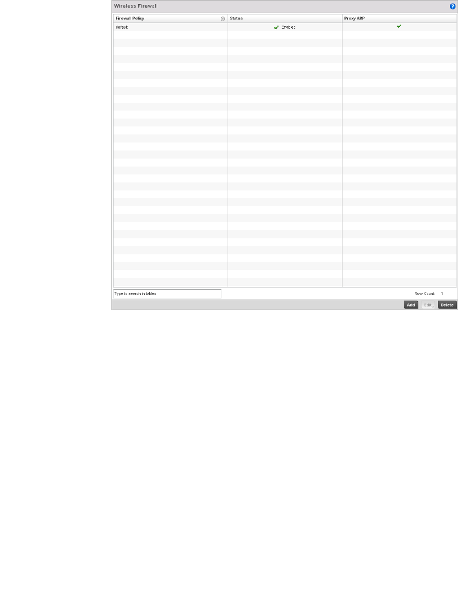
Brocade Mobility RFS4000, RFS6000, and RFS7000 System Reference Guide 513
53-1002620-01
9
FIGURE 346 Wireless Firewall Policy screen
Refer to the following configuration data for existing wireless Firewall policies:
Select Add to create a new Wireless Firewall policy, Edit to modify the attributes of an existing policy
or Delete to remove obsolete policies from the list of those available.
For information on adding and editing Wireless Firewall policies see Adding and Editing
Wireless Firewall Policies on page 9-513.
Adding and Editing Wireless Firewall Policies
Configuring a Firewall Policy
To add or edit a Firewall policy:
1. Select Configuration > Security > Wireless Firewall > Firewall Policy to display existing Firewall
policies.
Firewall Policy Displays the name assigned to the Wireless Firewall policy when created. The name
cannot be modified as part of the edit process.
Status Displays a green check mark if the Wireless Firewall policy has been enabled. A red
“X” designates the policy as disabled.
Proxy ARP Displays a green check mark if Proxy ARP routing has been enabled. A red “X”
designates Proxy ARP as disabled.

514 Brocade Mobility RFS4000, RFS6000, and RFS7000 System Reference Guide
53-1002620-01
9
2. Select Add to create a new Wireless Firewall policy. Select an existing policy and click Edit to
modify the attributes of that policy.
3. The Denial of Services tab displays by default.
4. When adding a new policy, first enter a name in the Firewall Policy box. The name must not
exceed 64 characters. Once a name has been specified, click OK to enable the other
parameters within the screen.
The Wireless Firewall Policy configuration is divided into the following tabs:
•Firewall Policy Denial of Service
•Firewall Policy Storm Control
•Firewall Policy Advanced Settings
Firewall Policy Denial of Service
Adding and Editing Wireless Firewall Policies
A denial of service (DoS) attack is an attempt to make a computer or network resource unavailable
to its intended users. Although the means to carry out a DoS attack will vary, it generally consists of
a concerted effort of one or more persons attempting to prevent a device, site or service from
functioning temporarily or indefinitely.
Most DoS attacks involve saturating the target device with external communications requests so it
cannot respond to legitimate traffic or respond so slowly the device becomes unavailable in
respect to its defined data rate. DoS attacks are implemented by either forcing targeted devices to
reset or consuming the devices resources so it can no longer provide service.
To define a Denial of Service configuration for a Firewall policy:
1. From the Firewall Policy configuration page, select the Denial of Service tab. The Denial of
Service tab displays by default.
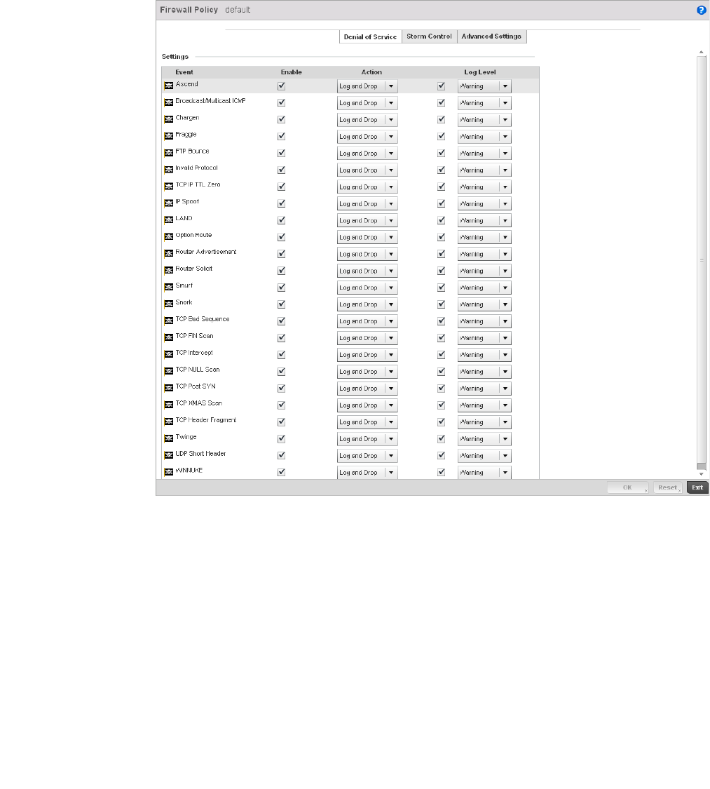
Brocade Mobility RFS4000, RFS6000, and RFS7000 System Reference Guide 515
53-1002620-01
9
FIGURE 347 Wireless Firewall Add/Edit Denial of Service screen
2. The Settings window contains a list of all of the Denial of Service (DoS) attacks that the
wireless controller’s Firewall has filters for. Each DoS filter contains the following four items:
Event The Event column lists the name of each Denial of Service attack.
Enable Checking the Enable box will set the Firewall Policy to filter the associated Denial of
Service attack based on the selection in the Action column.
Action If a Denial of Service filter is enabled, chose an action from the drop-down menu to
determine how the Firewall Policy treats the associated DoS attack.
Log and Drop - An entry for the associated DoS attack is added to the log and then
the packets are dropped.
Log Only - An entry for the associated DoS attack is added to the log. No further
action is taken.
Drop Only - The DoS packets is dropped. No further action is taken.
Log Level To enable logging to the system log, check the box in the Log Level column. Then
select a standard Syslog level from the Log Level
drop-down menu.

516 Brocade Mobility RFS4000, RFS6000, and RFS7000 System Reference Guide
53-1002620-01
9
Denial of Service Attacks Table
Refer to the following for a summary of each Denial of Service attack the Firewall can filter.
Ascend The Ascend DoS attacks are a series of attacks that target known vulnerabilities in
various versions of Ascend routers.
Broadcast/Multicast
ICMP
Broadcast or Multicast ICMP DoS attacks are a series of attacks that take
advantage of ICMP behavior in response to echo replies. These usually involve
spoofing the source address of the target and sending ICMP broadcast or multicast
echo requests to the rest of the network and in the process flooding the target
machine with replies.
Chargen The Chargen attack establishes a Telnet connection to port 19 and attempts to use
the character generator service to create a string of characters which is then
directed to the DNS service on port 53 to disrupt DNS services.
Fraggle The Fraggle DoS attack uses a list of broadcast addresses to send spoofed UDP
packets to each broadcast address’ echo port (port 7). Each of those addresses
that have port 7 open will respond to the request generating a lot of traffic on the
network. For those that do not have port 7 open they will send an unreachable
message back to the originator, further clogging the network with more traffic.
FTP Bounce The FTP Bounce DoS attack uses a vulnerability in the FTP “PORT” command as a
way to scan ports on a target machine by using another machine in the middle.
Invalid Protocol Attackers may use vulnerability in the endpoint implementation by sending invalid
protocol fields, or may misuse the misinterpretation of endpoint software. This can
lead to inadvertent leakage of sensitive network topology information, call hijacking,
or a DoS attack.
TCP IP TTL Zero The TCP IP TTL Zero DoS attack sends spoofed multicast packets onto the network
which have a Time To Live (TTL) of 0. This causes packets to loop back to the
spoofed originating machine, and can cause the network to overload.
IP Spoof IP Spoof is a category of Denial of Service attack that sends IP packets with forged
source addresses. This can hide the identity of the attacker.
LAND The LAND DoS attack sends spoofed packets containing the SYN flag to the target
destination using the target port and IP address as both the source and destination.
This will either crash the target system or result in high resource utilization slowing
down all other processes.
Option Route Enables the IP Option Route denial of service check in the controller’s firewall.
Router Advertisement In this attack, the attacker uses ICMP to redirect the network router function to
some other host. If that host can not provide router services, a DoS of network
communications occurs as routing stops. This can also be modified to single out a
specific system, so that only that system is subject to attack (because only that
system sees the 'false' router). By providing router services from a compromised
host, the attacker can also place themselves in a "man-in-the-middle' situation and
take control of any open channel at will (as mentioned earlier, this is often used with
TCP packet forgery and spoofing to intercept and change open TELNET sessions).

Brocade Mobility RFS4000, RFS6000, and RFS7000 System Reference Guide 517
53-1002620-01
9
Router Solicit The ICMP Router Solicitation scan is used to actively find routers on a network. Of
course, a hacker could set up a protocol analyzer to detect routers as they
broadcast routing information on the network. In some instances, however, routers
may not send updates. For example, if the local network does not have other
routers, the router may be configured to not send routing information packets onto
the local network.
ICMP offers a method for router discovery. Clients send ICMP router solicitation
multicasts onto the network, and routers must respond (as defined in RFC 1122).
(For more information about the process of ICMP router solicitation, see "Routing
Sequences for ICMP.")
By sending ICMP Router Solicitation packets (ICMP type 9) on the network and
listening for ICMP Router Discovery replies (ICMP type 10), hackers can build a list
of all of the routers that exist on a network segment. Hackers often use this scan to
locate routers that do not reply to ICMP echo requests
Smurf The Smurf DoS Attack sends ICMP echo requests to a list of broadcast addresses in
a row, and then repeats the requests, thus flooding the network.
Snork The Snork DoS attack uses UDP packet broadcasts to consume network and system
resources.
TCP Bad Sequence Enables a TCP Bad Sequence denial of service check in the controller’s firewall.
TCP FIN Scan Hackers use the TCP FIN scan to identify listening TCP port numbers based on how
the target device reacts to a transaction close request for a TCP port (even though
no connection may exist before these close requests are made). This type of scan
can get through basic firewalls and boundary routers that filter on incoming TCP
packets with the Finish (FIN) and ACK flag combination. The TCP packets used in
this scan include only the TCP FIN flag setting.
If the target device's TCP port is closed, the target device sends a TCP RST packet in
reply. If the target device's TCP port is open, the target device discards the FIN and
sends no reply.

518 Brocade Mobility RFS4000, RFS6000, and RFS7000 System Reference Guide
53-1002620-01
9
3. Select OK to update the Denial of Service settings. Select Reset to revert to the last saved
configuration.
TCP Intercept A SYN-flooding attack occurs when a hacker floods a server with a barrage of
requests for connection.
Because these messages have unreachable return addresses, the connections
cannot be established. The resulting volume of unresolved open connections
eventually overwhelms the server and can cause it to deny service to valid requests,
thereby preventing legitimate users from connecting to a Web site, accessing email,
using FTP service, and so on.
The TCP intercept feature helps prevent SYN-flooding attacks by intercepting and
validating TCP connection requests. In intercept mode, the TCP intercept software
intercepts TCP synchronization (SYN) packets from clients to servers that match an
extended access list. The software establishes a connection with the client on
behalf of the destination server, and if successful, establishes the connection with
the server on behalf of the client and knits the two half-connections together
transparently. Thus, connection attempts from unreachable hosts will never reach
the server. The software continues to intercept and forward packets throughout the
duration of the connection. The number of SYNs per second and the number of
concurrent connections proxied depends on the platform, memory, processor, and
other factors. In the case of illegitimate requests, the software’s aggressive
timeouts on half-open connections and its thresholds on TCP connection requests
protect destination servers while still allowing valid requests.
When establishing a security policy using TCP intercept, you can choose to intercept
all requests or only those coming from specific networks or destined for specific
servers. You can also configure the connection rate and threshold of outstanding
connections. Optionally operate TCP intercept in watch mode, as opposed to
intercept mode. In watch mode, the software passively watches the connection
requests flowing through the router. If a connection fails to get established in a
configurable interval, the software intervenes and terminates the connection
attempt.
TCP Null Scan Hackers use the TCP NULL scan to identify listening TCP ports. This scan also uses a
series of strangely configured TCP packets, which contain a sequence number of 0
and no flags. Again, this type of scan can get through some firewalls and boundary
routers that filter incoming TCP packets with standard flag settings.
If the target device's TCP port is closed, the target device sends a TCP RST packet in
reply. If the target device's TCP port is open, the target discards the TCP NULL scan,
sending no reply.
TCP Post SYN A remote attacker may be attempting to avoid detection by sending a SYN frame
with a different sequence number than the original SYN. This can cause an
Intrusion Detection System (IDS) to become unsynchronized with the data in a
connection. Subsequent frames sent during the connection are ignored by the IDS.
TCP XMAS Scan The TCP XMAS Scan floods the target system with TCP packets including the FIN,
URG, and PUSH flags. This is used to determine details about the target system and
can crash a system.
TCP Header Fragment Enables the TCP Header Fragment denial of service check in the controller’s
firewall.
Twinge The Twinge DoS attack sends ICMP packets and cycles through using all ICMP types
and codes. This can crash some Windows systems.
UDP Short Header Enables the UDP Short Header denial of service check in the controller’s firewall.
WINNUKE The WINNUKE DoS attack sends a large amount of data to UDP port 137 to crash
the NETBIOS service on windows and can also result on high CPU utilization on the
target machine.
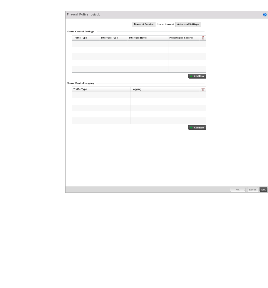
Brocade Mobility RFS4000, RFS6000, and RFS7000 System Reference Guide 519
53-1002620-01
9
Firewall Policy Storm Control
Adding and Editing Wireless Firewall Policies
The Firewall maintains a facility to control packet storms. Storms are packet bombardments that
exceed the high threshold value configured for an interface. During a storm, packets are throttled
until the rate falls below the configured rate, severely impacting performance for the RF Domain
manager interface. Thresholds are configured in terms of packets per second.
To define a Storm Control configuration for a Firewall policy:
1. From the Firewall Policy configuration page, select the Storm Control tab.
FIGURE 348 Wireless Firewall Add/Edit Storm Control screen
2. Refer to the Storm Control Settings field to set the following:
Traf fic Type Use the drop-down menu to define the traffic type for which the Storm Control
configuration applies. Options include ARP, Broadcast, Multicast and Unicast.
Interface Type Use the drop-down menu to define the controller interface for which the Storm
Control configuration is applied. Only the specified interface uses the defined
filtering criteria. Options include Ethernet, WLAN and Port Channel.
Interface Name Use the drop-down menu to refine the interface selection to a specific WLAN or
physical controller port. This helps with threshold configuration for potentially
impacted controller interfaces.
Packets per Second Select the check box to activate the spinner control used for specifying the packets
per second threshold for activating the Storm Control mechanism.
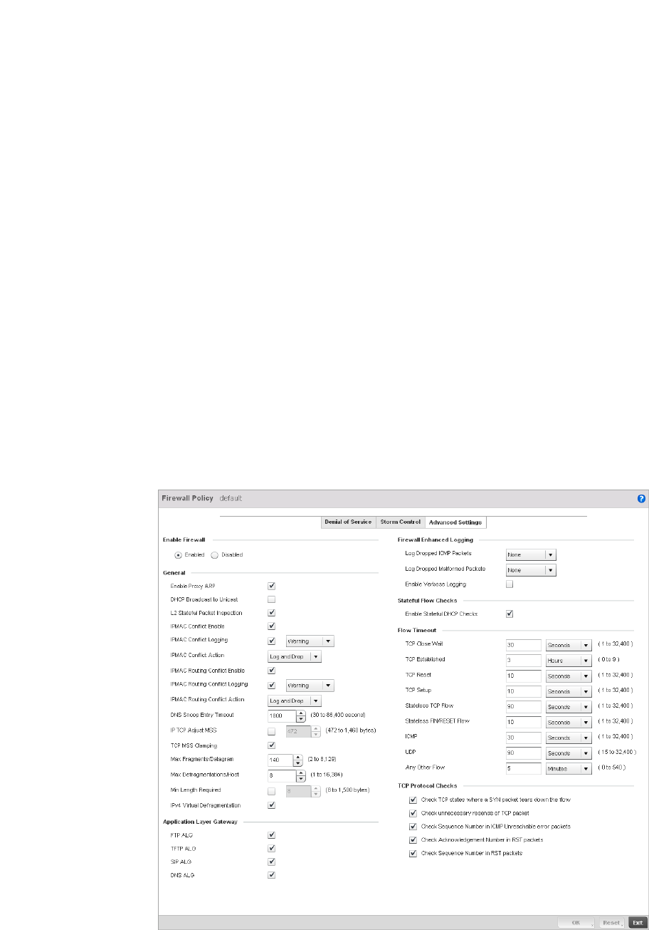
520 Brocade Mobility RFS4000, RFS6000, and RFS7000 System Reference Guide
53-1002620-01
9
3. Select + Add Row as needed to add additional Storm Control configurations for other traffic
types or interfaces. Select the Delete icon as required to remove selected rows.
4. Refer to the Storm Control Logging field to define how storm events are logged for the
controller.
5. Select + Add Row as needed to add additional Storm Control log entries for other interfaces.
Select the Delete icon as required to remove selected rows.
6. Select OK to update the Storm Control settings. Select Reset to revert to the last saved
configuration.
Firewall Policy Advanced Settings
Adding and Editing Wireless Firewall Policies
To define a Firewall policy Advanced Configuration:
1. Select the Advanced Settings tab from the Firewall Policy configuration page.
FIGURE 349 Wireless Firewall Add/Edit Advanced Settings screen
Traf fic Type Use the drop-down menu to define the traffic type for which the Storm Control
logging configuration applies. Options include ARP, Broadcast, Multicast and
Unicast.
Logging Select the check box to activate the spinner control used for specifying the standard
log level used if a Storm Control attack is detected. The default log level is Warning.

Brocade Mobility RFS4000, RFS6000, and RFS7000 System Reference Guide 521
53-1002620-01
9
2. Refer to the Enable Firewall radio buttons to define the Firewall as either Enabled or Disabled.
The Firewall is enabled by default.
If disabling the Firewall, a confirmation prompt displays stating NAT, wireless hotspot, proxy
ARP, deny-static-wireless-client and deny-wireless-client sending not permitted traffic
excessively will be disabled.
3. Select OK to continue disabling the hotspot.
4. Refer to the General field to enable or disable the following Firewall configuration parameters:
Enable Proxy ARP Select this check box to allow the Firewall Policy to use Proxy ARP responses for this
policy on behalf of another device. Proxy ARP allows the Firewall to handle ARP
routing requests for devices behind the Firewall. This feature is enabled by default.
DHCP Broadcast to
Unicast
Select this check box to enable the conversion of broadcast DHCP offers to unicast.
Converting DHCP broadcast traffic to unicast traffic can help reduce network traffic
loads.This feature is disabled by default.
L2 Stateful Packet
Inspection
Select the check box to enable stateful packet inspection for RF Domain manager
routed interfaces within the Layer 2 Firewall. This feature is disabled by default.
IPMAC Conflict Enable When multiple devices on the network have the same IP or MAC address this can
create routing issues for traffic being passed through the Firewall. To avoid these
issues, enable Conflict Detection to enable IP and MAC conflict detection. This
feature is disabled by default.
IPMAC Conflict Logging Select this option to enable logging for IP and MAC address conflict detection. This
feature is disabled by default.
IPMAC Conflict Action Use the drop-down menu to set the action taken when an attack is detected.
Options include Log Only, Drop Only or Log and Drop. The default setting is Log and
Drop.
IPMAC Routing Conflict
Enable
Select this option to enable IPMAC Routing Conflict detection. This is also known as
a Hole-196 attack in the network. This feature helps to detect if the client is sending
routed packets to the correct router-mac-address.
IPMAC Routing Conflict
Logging
Select enable logging for IPMAC Routing Conflict detection. This feature is disabled
by default.
IPMAC Routing Conflict
Action
Use the drop-down menu to set the action taken when an attack is detected.
Options include Log Only, Drop Only or Log and Drop. The default setting is Log and
Drop.
DNS Snoop Entry
Timeout
Select this option and set a timeout, in seconds, for DNS Snoop Entry. DNS Snoop
Entry stores information such as Client to IP Address and Client to Default
Gateway(s) and uses this information to detect if the client is sending routed
packets to a wrong MAC address.
IP TCP Adjust MSS Select this option and adjust the value for the maximum segment size (MSS) for TCP
segments on the router. Set a value between 472 bytes and 1,460 bytes to adjust
the MSS segment size. The default value is 472 bytes.
TCP Adjust MSS Select this option to enable TCP MSS Clamping. TCP MSS Clamping allows
configuration for the maximum segment size of packets at a global level.
Max
Fragments/Datagram
Set a value for the maximum number of fragments (between 2 and 8,129) allowed
in a datagram before it is dropped. The default value is 140 fragments.

522 Brocade Mobility RFS4000, RFS6000, and RFS7000 System Reference Guide
53-1002620-01
9
5. The Firewall policy allows traffic filtering at the application layer using the Application Layer
Gateway feature. The Application Layer Gateway provides filters for the following common
protocols:
6. Refer to the Firewall Enhanced Logging field to set the following parameters:
7. Select the Enable Stateful DHCP Checks check box to enable the stateful checks of DHCP
packet traffic through the Firewall. The default setting is enabled. When enabled, all DHCP
traffic flows are inspected.
8. Define Flow Timeout intervals for the following flow types impacting the Firewall:
Max
Defragmentations/Ho
st
Set a value for the maximum number of defragmentations, between 1 and 16,384
allowed per host before it is dropped. The default value is 8.
Min Length Required Select this option and set a minimum length, between 8 bytes and 1,500 bytes, to
enforce a minimum packet size before being subject to fragment based attack
prevention.
IPv4 Virtual
Defragmentation
Select this option to enable IPv4 Virtual Defragmentation, this helpsprevent IPv4
fragments based attacks such as tiny fragments or large number of ipv4 fragments.
FTP ALG Check this check box to allow FTP traffic through the Firewall using its default ports.
This feature is enabled by default.
TFTP ALG Check this check box to allow TFTP traffic through the Firewall using its default
ports. This feature is enabled by default.
SIP ALG Check this check box to allow SIP traffic through the Firewall using its default ports.
This feature is enabled by default.
DNS ALG Check the Enable box to allow DNS traffic through the Firewall using its default
ports. This feature is enabled by default.
Log Dropped ICMP
Packets
Use the drop-down menu to define how dropped ICMP packets are logged. Logging
can be rate limited for one log instance every 20 seconds. Options include Rate
Limited, All or None. The default setting is None.
Log Dropped
Malformed Packets
Use the drop-down menu to define how dropped malformed packets are logged.
Logging can be rate limited for one log instance every 20 seconds. Options include
Rate Limited, All or None. The default setting is None.
Enable Verbose
Logging
Check this box to enable verbose logging mode for the firewall.
TCP Close Wait Define a flow timeout value in either Seconds (1 - 32,400), Minutes
(1 - 540) or Hours (1 - 9). The default setting is 30 seconds.
TCP Established Define a flow timeout value in either Seconds (1 - 32,400), Minutes
(1 - 540) or Hours (1 - 9). The default setting is 10,800 seconds.
TCP Reset Define a flow timeout value in either Seconds (1 - 32,400), Minutes
(1 - 540) or Hours (1 - 9). The default setting is 10 seconds.
TCP Setup Define a flow timeout value in either Seconds (1 - 32,400), Minutes
(1 - 540) or Hours (1 - 9). The default setting is 10 seconds.
Stateless TCP Flow Define a flow timeout value in either Seconds (1 - 32,400), Minutes
(1 - 540) or Hours (1 - 9). The default setting is 90 seconds.

Brocade Mobility RFS4000, RFS6000, and RFS7000 System Reference Guide 523
53-1002620-01
9
9. Refer to the TCP Protocol Checks field to set the following parameters:
10. Select OK to update the Firewall Policy Advanced Settings. Select Reset to revert to the last
saved configuration.
Configuring IP Firewall Rules
Wireless Firewall
Controllers use IP based Firewalls like Access Control Lists (ACLs) to filter/mark packets based on
the IP from which they arrive, as opposed to filtering packets on Layer 2 ports.
IP based Firewall rules are specific to source and destination IP addresses and the unique rules
and precedence orders assigned. Both IP and non-IP traffic on the same Layer 2 interface can be
filtered by applying an IP ACL.
NOTE
Once defined, a set of IP Firewall rules must be applied to an interface to be a functional filtering
tool.
To add or edit an IP based Firewall Rule policy:
Stateless FIN/RESET
Flow
Define a flow timeout value in either Seconds (1 - 32,400), Minutes
(1 - 540) or Hours (1 - 9). The default setting is 10 seconds.
ICMP Define a flow timeout value in either Seconds (1 - 32,400), Minutes
(1 - 540) or Hours (1 - 9). The default setting is 30 seconds.
UDP Define a flow timeout value in either Seconds (1 - 32,400), Minutes
(1 - 540) or Hours (1 - 9). The default setting is 90 seconds.
Any Other Flow Define a flow timeout value in either Seconds (1 - 32,400), Minutes
(1 - 540) or Hours (1 - 9). The default setting is 5 seconds.
Check TCP states
where a SYN packet
tears down the flow
Select the check box to allow a SYN packet to delete an old flow in
TCP_FIN_FIN_STATE and TCP_CLOSED_STATE and create a new flow. The default
setting is enabled.
Check unnecessary
resends of TCP
packets
Select the check box to enable the checking of unnecessary resends of TCP
packets. The default setting is enabled.
Check Sequence
Number in ICMP
Unreachable error
packets
Select the check box to enable sequence number checks in ICMP unreachable error
packets when an established TCP flow is aborted.The default setting is enabled.
Check
Acknowledgment
Number in RST
packets
Select the check box to enable the checking of the acknowledgment number in RST
packets which aborts a TCP flow in the SYN state. The default setting is enabled.
Check Sequence
Number in RST
packets
Select the check box to check the sequence number in RST packets which abort an
established TCP flow. The default setting is enabled.
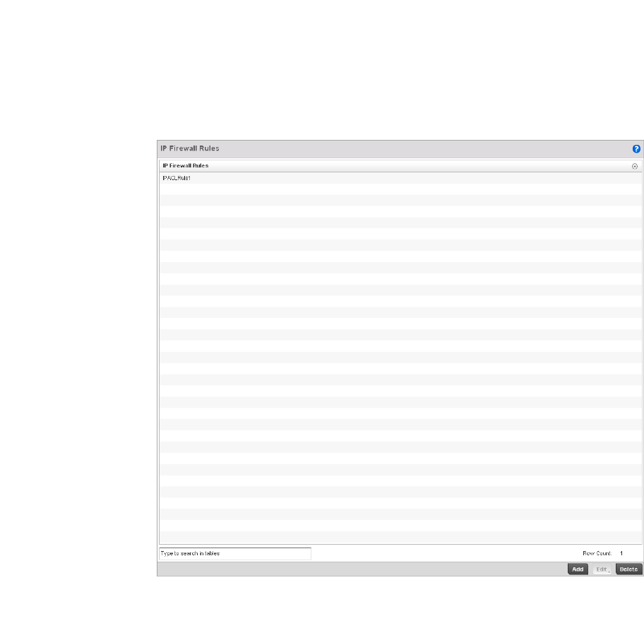
524 Brocade Mobility RFS4000, RFS6000, and RFS7000 System Reference Guide
53-1002620-01
9
1. Select Configuration > Security > Wireless Firewall > IP Firewall Rules to display existing IP
Firewall Rule policies.
FIGURE 350 IP Firewall Rules screen
2. Select + Add Row to create a new IP Firewall Rule. Select an existing policy and click Edit to
modify the attributes of that rule configuration.
3. Select the added row to expand it into configurable parameters for defining the IP based
Firewall rule.
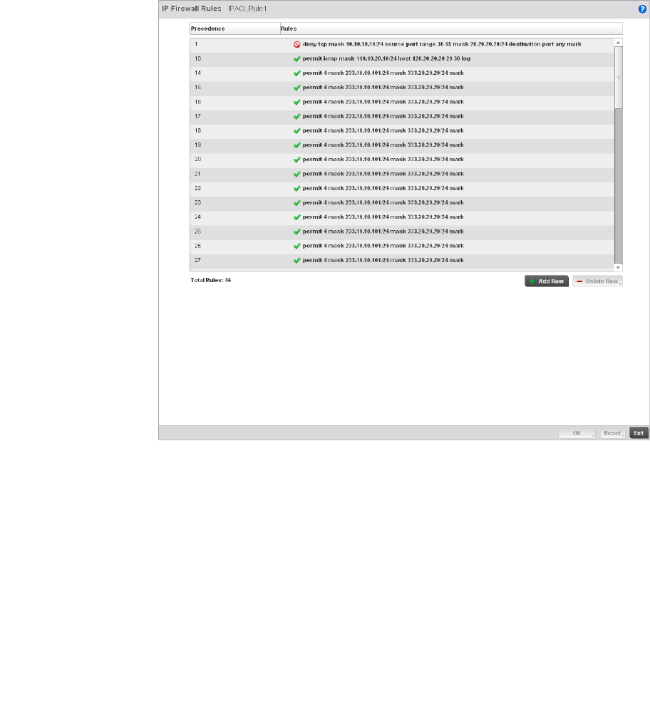
Brocade Mobility RFS4000, RFS6000, and RFS7000 System Reference Guide 525
53-1002620-01
9
FIGURE 351 IP Firewall Rules Add screen
4. If adding a new IP Firewall Rule, provide a name up to 32 characters.
5. Define the following parameters for the IP Firewall Rule:
Allow Every IP Firewall rule is made up of matching criteria rules. The action defines what
to do with the packet if it matches the specified criteria. The following actions are
supported:
Deny— Instructs the Firewall to not to allow a packet to proceed to its destination.
Permit—Instructs the Firewall to allow a packet to proceed to its destination.
Source / Destination Enter both Source and Destination IP addresses. The wireless controller uses the
source IP address, destination IP address and IP protocol type as basic matching
criteria. The wireless controller's access policy filter can also include other
parameters specific to a protocol type (like source and destination port for TCP/UDP
protocol. Provide a subnet mask if needed.
Protocol Select the protocol used with the IP rule from the drop-down menu. IP is selected by
default. Selecting ICMP displays an additional set of ICMP specific options for ICMP
type and code. Selecting either TCP or UDP displays an additional set of specific
TCP/UDP source and destinations port options.

526 Brocade Mobility RFS4000, RFS6000, and RFS7000 System Reference Guide
53-1002620-01
9
6. Select + Add Rowas needed to add additional IP Firewall Rule configurations. Select the -
Delete Row icon as required to remove selected IP Firewall Rules..
7. S elect OK when completed to update the IP Firewall rules. Select Reset to revert the screen
back to its last saved configuration.
Configuring MAC Firewall Rules
Wireless Firewall
Controllers can use MAC based Firewalls like Access Control Lists (ACLs) to filter/mark packets
based on the IP from which they arrive, as opposed to filtering packets on Layer 2 ports.
Optionally filter Layer 2 traffic on a physical Layer 2 interface using MAC addresses. A MAC Firewall
rule uses source and destination MAC addresses for matching operations, where the result is a
typical allow, deny or mark designation to RF Domain manager packet traffic.
NOTE
Once defined, a set of MAC Firewall rules must be applied to an interface to be a functional filtering
tool.
To add or edit a MAC based Firewall Rule policy:
1. Select Configuration > Security > Wireless Firewall > MAC Firewall Rules to display existing IP
Firewall Rule policies.
Action The following actions are supported:
Log—Events are logged to the controller for archive and analysis.
Mark—Modifies certain fields inside the packet and then permits them. Therefore,
mark is an action with an implicit permit.
- VLAN 802.1p priority.
- DSCP bits in the IP header.
- TOS bits in the IP header.
Mark, Log — Conducts both mark and log functions.
Precedence Use the spinner control to specify a precedence for this IP policy between
1-1500. Rules with lower precedence are always applied first to packets.
Description Provide a description up to characters long for rule to help differentiate it from
others with similar configurations.
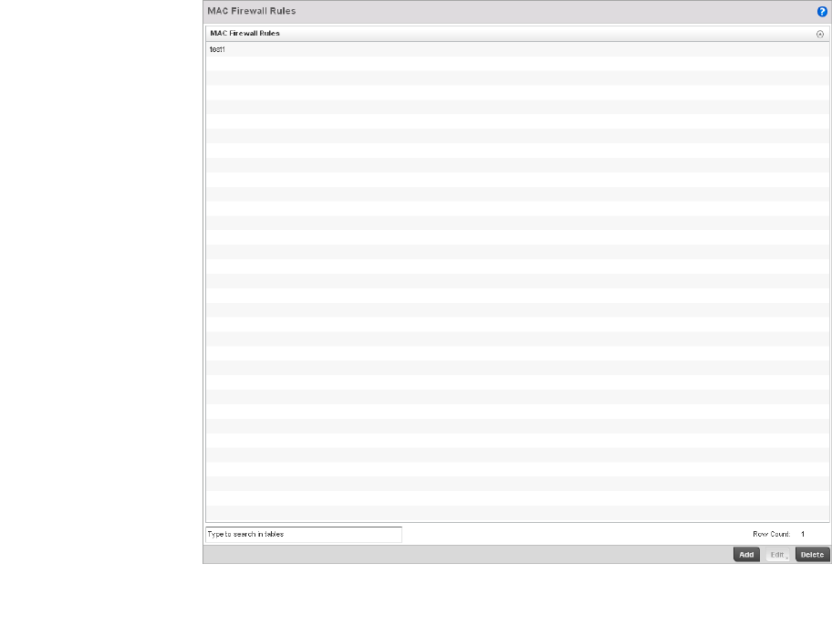
Brocade Mobility RFS4000, RFS6000, and RFS7000 System Reference Guide 527
53-1002620-01
9
FIGURE 352 MAC Firewall Rules screen
2. Select + Add Row to create a new MAC Firewall Rule. Select an existing policy and click Edit to
modify the attributes of that rule’s configuration.
3. Select the added row to expand it into configurable parameters for defining the MAC based
Firewall rule.
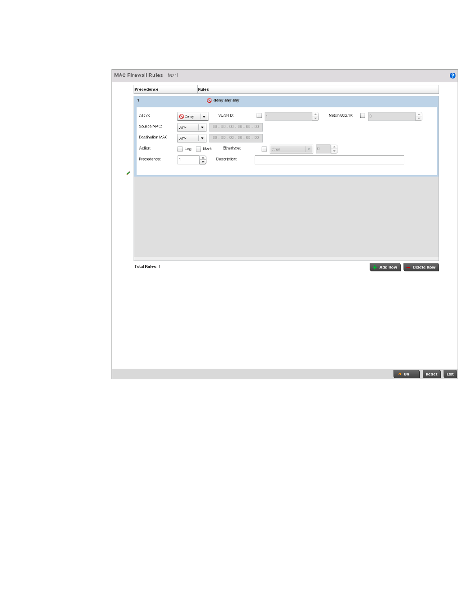
528 Brocade Mobility RFS4000, RFS6000, and RFS7000 System Reference Guide
53-1002620-01
9
FIGURE 353 MAC Firewall Rules screen
4. If adding a new MAC Firewall Rule, provide a name up to 32 characters.
5. Define the following parameters for the IP Firewall Rule:
Allow Every IP Firewall rule is made up of matching criteria rules. The action defines what
to do with the packet if it matches the specified criteria. The following actions are
supported:
Deny— Instructs the Firewall to prevent a packet from proceeding to its destination.
Permit—Instructs the Firewall to allow a packet to proceed to its destination.
VLAN ID Enter a VLAN ID representative of the shared SSID each user employs to
interoperate within the managed network (once authenticated by the local RADIUS
server). The VLAN ID can be between1 and 4094.
Match 802.1P Configures IP DSCP to 802.1p priority mapping for untagged frames. Use the
spinner control to define a setting between 0-7.
Source and
Destination MAC
Enter both Source and Destination MAC addresses. The wireless controller uses the
source IP address, destination MAC address as basic matching criteria. Provide a
subnet mask if using a mask.

Brocade Mobility RFS4000, RFS6000, and RFS7000 System Reference Guide 529
53-1002620-01
9
6. Select + Add Row as needed to add additional MAC Firewall Rule configurations. Select the -
Delete Row icon as required to remove selected MAC Firewall Rules.
7. S elect OK when completed to update the MAC Firewall Rules. Select Reset to revert the screen
back to its last saved configuration.
Firewall Deployment Considerations
Configuring a Firewall Policy
Before defining a Firewall configuration on the wireless controller, refer to the following deployment
guidelines to ensure the configuration is optimally effective:
•Firewalls implement access control policies, so if you don't have an idea of what kind of access
to allow or deny, a Firewall is of little value.
•It's important to recognize the Firewall's configuration is a mechanism for enforcing a wireless
controller managed network access policy.
•A role based Firewall requires an advanced security license to apply inbound and outbound
Firewall policies to users and devices
•Firewalls cannot protect against tunneling over application protocols to poorly secured wireless
clients.
•Firewalls should be deployed on WLANs implementing weak encryption to minimize access to
trusted networks and hosts in the event the WLAN is compromised.
•Firewalls should be enabled when providing managed Hotspot guest access. Firewall policies
should be applied to Hotspot enabled WLANs to prevent guest user traffic from being routed to
trusted networks and hosts.
Action The following actions are supported:
Log—Events are logged to the controller for archive and analysis.
Mark—Modifies certain fields inside the packet and then permits them. Therefore,
mark is an action with an implicit permit.
- VLAN 802.1p priority.
- DSCP bits in the IP header.
- TOS bits in the IP header.
Mark, Log — Conducts both mark and log functions.
Ethertype Use the drop-down menu to specify an Ethertype of either ipv6, arp, wisp, or monitor
8021q. An EtherType is a two-octet field within an Ethernet frame. It’s used to
indicate which protocol is encapsulated in the payload of an Ethernet frame.
Precedence Use the spinner control to specify a precedence for this MAC Firewall rule between
1-1500. Rules with lower precedence are always applied first to packets.
Description Provide a description (up to 64 characters) for the rule to help differentiate the it
from others with similar configurations.

530 Brocade Mobility RFS4000, RFS6000, and RFS7000 System Reference Guide
53-1002620-01
9
Wireless Client Roles
Define wireless client roles to filter clients from controller interoperation based on matching
policies. Matching policies (much like ACLs) are sequential collections of permit and deny
conditions that apply to packets received from controller connected clients. When a packet is
received from a client, the controller compares the fields in the packet against applied matching
policy rules to verify the packet has the required permissions to be forwarded, based on the criteria
specified. If a packet does not meet any of the criteria specified, the packet is dropped.
Additionally, wireless client connections are also managed by granting or restricting access by
specifying a range of IP or MAC addresses to include or exclude from controller connectivity. These
MAC or IP access control mechanisms are configured as Firewall Rules to further refine client filter
and matching criteria.
Configuring a Client’s Role Policy
Wireless Client Roles
To configure a wireless client’s role policy and matching criteria:
1. Select Configuration > Security > Wireless Client Roles.
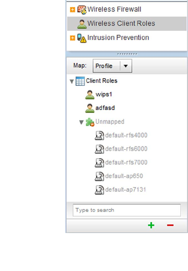
Brocade Mobility RFS4000, RFS6000, and RFS7000 System Reference Guide 531
53-1002620-01
9
FIGURE 354 Configuration > Security screen and Client Roles Browser
2. The Wireless Client Roles screen displays the name of those client role policies created thus
far. Either select Add to create a new Wireless Client Role policy, Edit to modify an existing
policy or Delete to remove a policy.
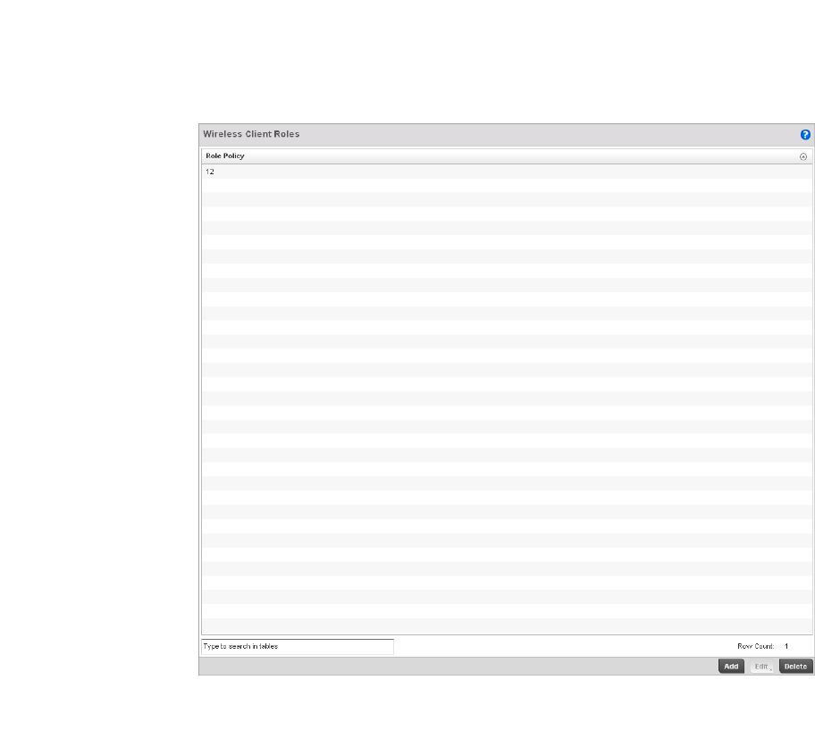
532 Brocade Mobility RFS4000, RFS6000, and RFS7000 System Reference Guide
53-1002620-01
9
FIGURE 355 Wireless IPS screen
3. The Roles tab displays by default. If no policies have been created, a default wireless client role
policy can be applied. The Roles screen lists existing policies. Any of these existing policies can
be selected and applied.
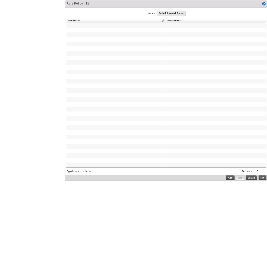
Brocade Mobility RFS4000, RFS6000, and RFS7000 System Reference Guide 533
53-1002620-01
9
FIGURE 356 Wireless IPS Roles screen
4. Refer to the following configuration data for existing Wireless IPS policies:
5. Select Add to create a new wireless client role policy, Edit to modify the attributes of a selected
policy or Delete to remove obsolete policies from the list of those available to the controller.
6. The Role Policy Roles screen displays with the Settings tab displayed by default.
Role Name Displays the name assigned to the client role policy when it was initially created.
Precedence Displays the precedence number associated with each role. Precedence numbers
determine the order a role is applied. Roles with lower numbers are applied before
those with higher numbers. Precedence numbers are assigned when a role is
created or modified, and two or more roles can share the same precedence.
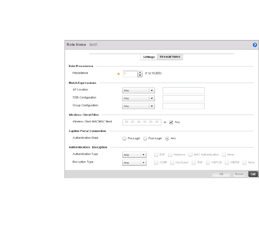
534 Brocade Mobility RFS4000, RFS6000, and RFS7000 System Reference Guide
53-1002620-01
9
FIGURE 357 Wireless Client Roles screen - Settings tab
7. If creating a new role, assign it name to help differentiate it from others that may have a similar
configuration. The role policy name cannot exceed 64 characters. The name cannot be
modified as part of the edit process.
8. Within the Role Precedence field, use the spinner control to set a numerical precedence value
between 1 - 10,000. Precedence determines the order a role is applied. Roles with lower
numbers are applied before those with higher numbers. While there’s no default precedence
for a role, two or more roles can share the same precedence.

Brocade Mobility RFS4000, RFS6000, and RFS7000 System Reference Guide 535
53-1002620-01
9
9. Refer to the Match Expressions field to create filter rules based on AP locations, SSIDs and
RADIUS group memberships.
10. Use the Wireless Client Filter parameter to define a wireless client MAC address filter that’s
applied to each role. Select the Any radio button to use any MAC address. The default setting is
Any.
11. Refer to the Captive Portal Connection parameter to define when wireless clients are
authenticated when making a captive portal authentication request to the controller.
Secure guest access to the controller is referred to as captive portal. A captive portal is guest
access policy for providing temporary and restrictive access to the managed wireless network.
The primary means of securing guest access is a hotspot. Existing captive portal policies can
be applied to a WLAN to provide secure guest access.
12. Select the Pre-Login check box to conduct captive portal client authentication before the client
is logged into the controller. Select Post-Login to have the client share authentication
credentials with the controller after it has logged into the managed network. Select Any (the
default setting) makes no distinction on whether authentication is conducted before or after
the client has logged in.
13. Use the Authentication / Encryption field to set the authentication and encryption filters
applied to this wireless client role. The options for both authentication and encryption are:
•Equals - The role is only applied when the authentication and encryption type matches the
exact method(s) specified by the radio button selections.
AP Location Use the drop-down menu to specify the location of an Access Point matched in a RF
Domain or the Access Point’s resident configuration. Select one of the following
filter options:
Exact - The role is only applied to APs with the exact location string specified in the
role.
Contains - The role is only applied to APs whose location contains the location string
specified in the role.
Does Not Contain - The role is only applied to APs whose location does not contain
the location string specified in the role.
Any - The role is applied to any AP location. This is the default setting.
SSID Configuration Use the drop-down menu to define a wireless client filter option based on how the
SSID is specified in a WLAN. Select one of the following options:
Exact -The role is only applied when the exact SSID string specified in the role.
Contains -The role is only applied when the SSID contains the string specified in the
role.
Does Not Contain - The role is applied when the SSID does not contain the string
specified in the role.
Any - The role is applied to any SSID Location. This is the default setting.
Group Configuration Use the drop-down menu to define a wireless client filter option based on how the
RADIUS group name matches the provided expression. Select one of the following
options:
Exact -The role is only applied when the exact Radius Group Name string is specified
in the role.
Contains - The role is applied when the Radius Group Name contains the string
specified in the role.
Does Not Contain - The role is applied when the Radius Group Name does not
contain the string specified in the role
Any - The role is applied to any RADIUS group name. This is the default setting.
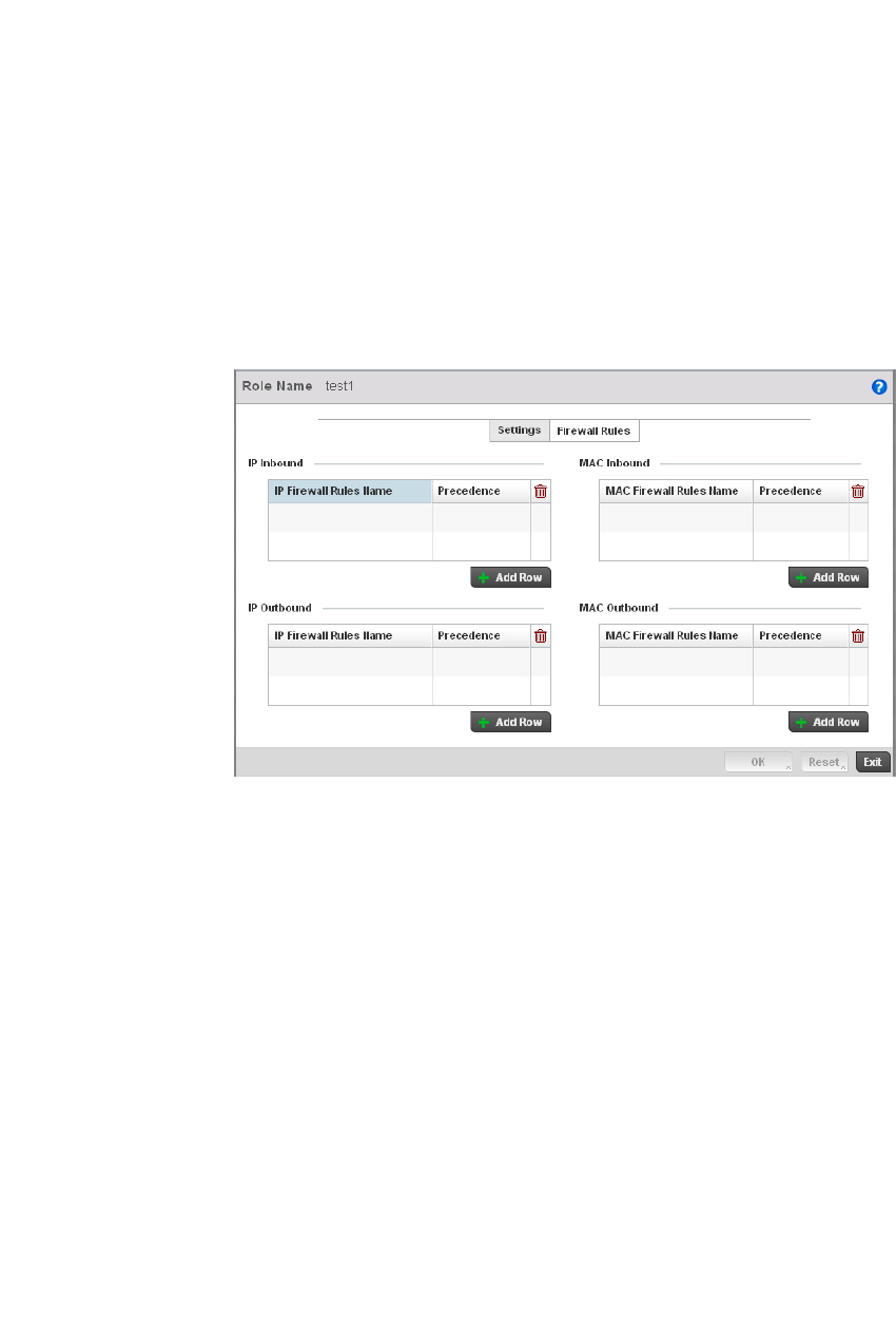
536 Brocade Mobility RFS4000, RFS6000, and RFS7000 System Reference Guide
53-1002620-01
9
•Not Equals - The role is only applied when the authentication and encryption type does not
match the exact method(s) specified by the radio button selections.
•Any - The role is applied to any type. This is the default setting for both authentication and
encryption.
14. Select OK to update the Settings screen. Select Reset to revert to the last saved configuration.
15. Select the Firewall Rules tab to set default Firewall rules for Inbound and Outbound IP and MAC
Firewall rules.
FIGURE 358 Wireless Client Roles screen - Default Firewall Rules tab
A Firewall is a mechanism enforcing access control, and is considered a first line of defense in
protecting proprietary information within the network. The means by which this is
accomplished varies, but in principle, a Firewall can be thought of as mechanisms both
blocking and permitting data traffic based on inbound and outbound IP and MAC rules.
IP based Firewall rules are specific to source and destination IP addresses and the unique
rules and precedence orders assigned. Both IP and non-IP traffic on the same Layer 2
interface can be filtered by applying both an IP ACL and a MAC.
Additionally, the controller allows administrators to filter Layer 2 traffic on a physical Layer 2
interface using MAC addresses. A MAC Firewall rule uses source and destination MAC
addresses for matching operations, where the result is a typical allow, deny or mark
designation to controller packet traffic.
16. Specify an IP Inbound or IP Outbound Firewall rule by selecting a rule from the drop-down
menu and use the spinner control to assign the rule Precedence. Rules with lower precedence
are always applied first to packets.
17. If no IP Inbound or Outbound rules exist meeting the required Firewall filtering criteria, select
the Create button to set the inbound or outbound rule criteria. Select the + Add Row button or
Delete icon as needed to add or remove IP Firewall rules. Define the following parameters to
create a new Inbound or Outbound IP Firewall rule:
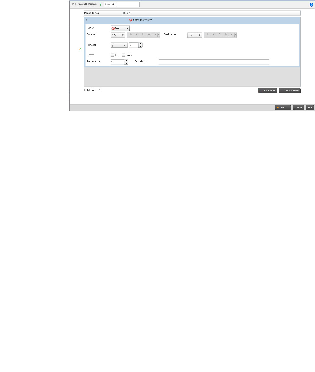
Brocade Mobility RFS4000, RFS6000, and RFS7000 System Reference Guide 537
53-1002620-01
9
18. Select OK to save the updates to the Inbound or Outbound IP Firewall rule. Select Reset to
revert to the last saved configuration.
IP Firewall Rules If creating a new IP Firewall rule, assign it a name (up to 64 characters) to help
differentiate it from others that may have similar configurations.
Allow Every IP Firewall rule is made up of matching criteria rules. The action defines what
to do with the packet if it matches the specified criteria. The following actions are
supported:
Deny— Instructs the Firewall to prohibit a packet from proceeding to its
destination.
Permit—Instructs the Firewall to allow a packet to proceed to its
destination.
Source / Destination Enter both Source and Destination IP addresses. The wireless controller uses the
source IP address, destination IP address and IP protocol type as basic matching
criteria. The wireless controller's access policy filter can also include other
parameters specific to a protocol type (like source and destination port for TCP/UDP
protocols).
Protocol Select the IP, ICMP, TCP or UDP protocol used with the IP access policy. IP is selected
by default. Selecting ICMP displays an additional set of ICMP specific options to set
the ICMP Type and Code. Selecting either TCP or UDP displays an additional set of
specific TCP/UDP source and destinations port options.
Action The following actions are supported:
Log—Logs the event when this rule is applied to a wireless clients association
attempt.
Mark—Modifies certain fields inside the packet and then permits them.
Therefore, mark is an action with an implicit permit.
- VLAN 802.1p priority.
- DSCP bits in the IP header.
- TOS bits in the IP header.
Mark, Log — Applies both log and mark actions.
Precedence Use the spinner control to specify a precedence for this IP policy between 1-1500.
Rules with lower precedence are always applied first. More than one rule can share
the same precedence value.
Description Provide a description of the rule to differentiate it from others with similar
configurations. This should be more descriptive then simply re-applying the name of
the rule.
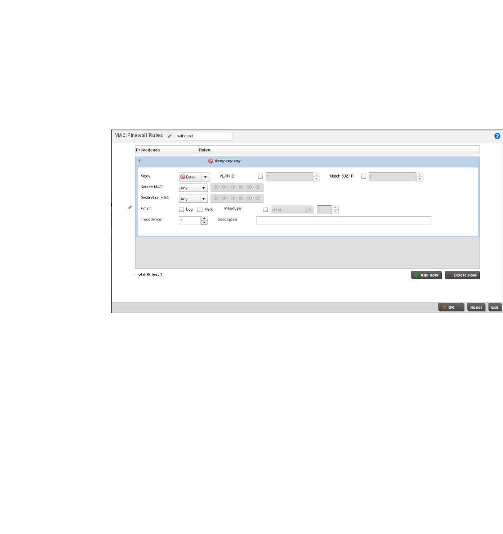
538 Brocade Mobility RFS4000, RFS6000, and RFS7000 System Reference Guide
53-1002620-01
9
19. If required, select existing Inbound and Outbound MAC Firewall Rules using the drop-down
menu. If no rules exist, select Create to display a screen where Inbound or Outbound Firewall
rules can be created.
20. Define the following parameters required to create an Inbound or Outbound MAC Firewall rule:
MAC Firewall Rules If creating a new MAC Firewall rule, assign it a name (up to 64 characters) to help
differentiate it from others that may have similar configurations.
Allow Every MAC Firewall rule is made up of matching criteria rules. The action defines
what to do with the packet if it matches the specified criteria. The following actions
are supported:
Deny— Instructs the Firewall to not to allow a packet to proceed to its
destination.
Permit—Instructs the Firewall to allow a packet to proceed to its
destination.
VLAN ID Enter a VLAN ID representative of the shared SSID each user employs to
interoperate within the network (once authenticated by the local RADIUS server).
The VLAN ID can be between1 and 4094.
Match 802.1P Configures IP DSCP to 802.1p priority mapping for untagged frames. Use the
spinner control to define a setting between 0-7.
Source / Destination
MAC
Enter both Source and Destination MAC addresses. The wireless controller uses the
addresses as basic matching criteria.
Action The following actions are supported:
Log—Logs the event when this rule is applied to a wireless clients association
attempt.
Mark—Modifies certain fields inside the packet and then permits them.
Therefore, mark is an action with an implicit permit.
- VLAN 802.1p priority.
- DSCP bits in the header.
- TOS bits in the header.
Mark, Log — Applies both log and mark actions.

Brocade Mobility RFS4000, RFS6000, and RFS7000 System Reference Guide 539
53-1002620-01
9
21. Select OK to save the updates to the MAC Firewall rule. Select Reset to revert to the last saved
configuration.
Intrusion Prevention
The wireless controller supports Wireless Intrusion Protection Systems (WIPS) to provide
continuous protection against wireless threats and act as an additional layer of security
complementing wireless VPNs and encryption and authentication policies. The wireless controller
supports WIPS through the use of dedicated sensor devices designed to actively detect and locate
unauthorized AP devices. After detection, they use mitigation techniques to block the devices by
manual termination or air lockdown.
Unauthorized APs are untrusted access points connected to a wireless controller managed LAN
that accept client associations. They can be deployed for illegal wireless access to a corporate
network, implanted with malicious intent by an attacker, or could just be misconfigured access
points that do not adhere to corporate policies. An attacker can install a unauthorized AP with the
same ESSID as the authorized WLAN, causing a nearby client to associate to it. The unauthorized
AP can then steal user credentials from the client, launch a man-in-the middle attack or take
control of wireless clients to launch denial-of-service attacks.
Brocade wireless controllers support unauthorized AP detection, location and containment natively.
A WIPS server can alternatively be deployed (in conjunction with the wireless controller) as a
dedicated solution within a separate enclosure. When used within a Brocade wireless controller
managed network and its associated access point radios, a WIPS deployment provides the
following enterprise class security management features and functionality:
•Threat Detection - Threat detection is central to a wireless security solution. Threat detection
must be robust enough to correctly detect threats and swiftly help protect the wireless
controller managed wireless network.
•Rogue Detection and Segregation - A WIPS supported wireless controller distinguishes itself by
both identifying and categorizing nearby APs. WIPS identifies threatening versus
non-threatening APs by segregating APs attached to the network (unauthorized APs) from
those not attached to the network (neighboring APs). The correct classification of potential
threats is critical in order for administrators to act promptly against rogues and not invest in a
manual search of neighboring APs to isolate the few attached to the network.
•Locationing - Administrators can define the location of wireless clients as they move
throughout a wireless controller managed site. This allows for the removal of potential rogues
though the identification and removal of their connected access points.
Ethertype Use the drop-down menu to specify an Ethertype. An EtherType is a two-octet field
within an Ethernet frame. It’s used to indicate which protocol is encapsulated in the
payload of an Ethernet frame.
Precedence Use the spinner control to specify a precedence for this MAC policy between
1-1500. Rules with lower precedence are always applied first to packets. More than
one rule can share the same precedence value.
Description Provide a description for the rule to differentiate the IP Firewall Rule from others
with similar configurations. This should be more descriptive then simply re-applying
the name of the rule.
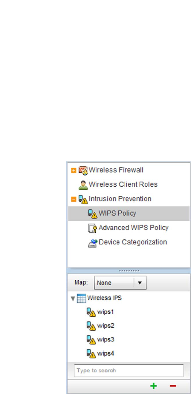
540 Brocade Mobility RFS4000, RFS6000, and RFS7000 System Reference Guide
53-1002620-01
9
•WEP Cloaking - WEP Cloaking protects organizations using the Wired Equivalent Privacy (WEP)
security standard to protect networks from common attempts used to crack encryption keys.
There are several freeware WEP cracking tools available and 23 known attacks against the
original 802.11 encryption standard; even 128-bit WEP keys take only minutes to crack. WEP
Cloaking module enables organizations to operate WEP encrypted networks securely and to
preserve their existing investment in mobile devices.
Configuring a WIPS Policy
Intrusion Prevention
To configure WIPS on the wireless controller:
1. Select Configuration > Security > Intrusion Prevention.
2. Expand the Intrusion Prevention option within the Configuration > Security menu to display the
WIPS Policy, Advanced WIPS Policy and Device Categorization items available.
FIGURE 359 Configuration > Security screen
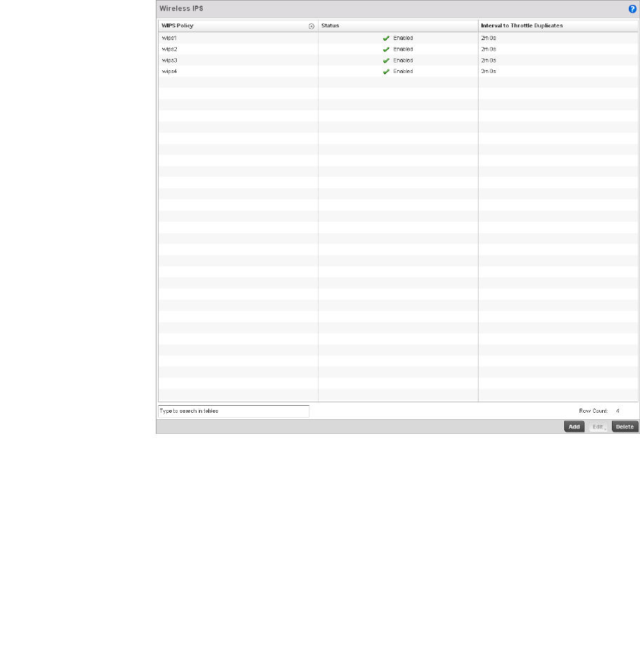
Brocade Mobility RFS4000, RFS6000, and RFS7000 System Reference Guide 541
53-1002620-01
9
3. The Wireless IPS screen displays by default. The Wireless IPS screen lists existing WIPS
policies if any are configured. Any of these existing WIPS policies can be selected and applied.
FIGURE 360 Wireless IPS screen
4. Refer to the following for existing Wireless IPS policies:
5. Select Add to create a new WIPS policy, Edit to modify the attributes of a selected policy or
Delete to remove obsolete policies from the list of those available to the controller.
6. If adding or editing an existing WIPS policy, the WIPS Policy screen displays with the settings
tab displayed by default.
WIPS Policy Displays the name assigned to the WIPS policy when it was initially created. The
name cannot be modified as part of the edit process.
Status Displays a green checkmark if the listed WIPS policy is enabled and ready for use
with a controller profile. A red “X” designated the listed WIPS policy as disabled.
Interval to Throttle
Duplicates
Displays the duration in seconds when traffic meeting the criteria defined in the
selected WIPS policy is prevented/throttled.
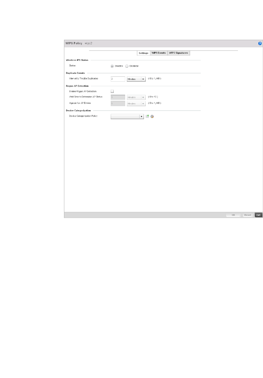
542 Brocade Mobility RFS4000, RFS6000, and RFS7000 System Reference Guide
53-1002620-01
9
FIGURE 361 WIPS Policy screen - Settings tab
7. If creating a new WIPS Policy, assign it name to help differentiate it from others that may have
a similar configuration. The policy name cannot exceed 64 characters. The name cannot be
modified as part of the edit process.
8. Within the Wireless IPS Status field, select either the Enabled or Disabled radio button to
either activate or de-activate the WIPS policy for use with a controller profile. The default
setting is disabled.
9. Enter the Interval to Throttle Packets in either Seconds (1 - 86,400), Minutes (1 - 1,400),
Hours
(1 - 24) or Days (1). This interval represents the duration event duplicates are not stored in
history. The default setting is 120 seconds.
10. Refer to the Rogue AP Detection field to define the following detection settings for this WIPS
policy:
Enable Rogue AP
Detection
Select the checkbox to enable the detection of unauthorized (unsanctioned) devices
fro this WIPS policy. The default setting is disabled.
Wait Time to
Determine AP Status
Define a wait time in either Seconds (10 - 600) or Minutes (1 - 10) before a detected
AP is interpreted as a rogue (uunsanctioned) device, and potentially removed from
controller management. The default interval is 1 minute.
Ageout for AP Entries Set the interval the WIPS policy uses to ageout rogue devices. Set the policy in
either Seconds (30 - 86,400), Minutes (1- 1,440), Hours (1 - 24) or Days (1). The
default setting is 5 minutes.
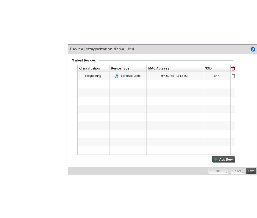
Brocade Mobility RFS4000, RFS6000, and RFS7000 System Reference Guide 543
53-1002620-01
9
11. Use the Device Categorization Policy drop-down menu to select a policy describing whether a
device is filtered as sanctioned, a client or Access Point and the MAC and SSID addresses used
as filtering mechanisms.
12. If a policy requires creation, select the Create button. If an existing policy requires modification,
select the Edit button and update the Device Categorization Policy as needed.
FIGURE 362 Device Categorization screen
13. Select OK to update the settings. Select Reset to revert to the last saved configuration.
14. Select the WIPS Events tab to enable events, filters and threshold values for this WIPS policy.
The Excessive tab displays by default.
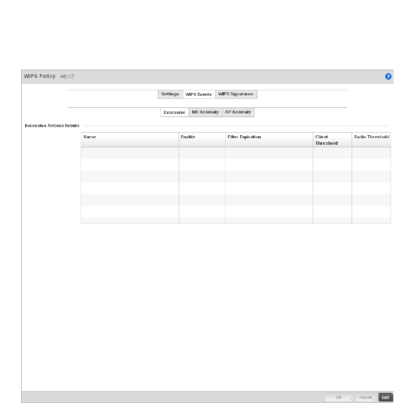
544 Brocade Mobility RFS4000, RFS6000, and RFS7000 System Reference Guide
53-1002620-01
9
FIGURE 363 WIPS Events screen - Excessive tab
The Excessive tab lists a series of events that can impact the performance of the managed
network. An administrator can enable or disable the filtering of each listed event and set the
thresholds required for the generation of the event notification and filtering action applied.
An Excessive Action Event is an event where an action is performed repetitively and
continuously. DoS attacks come under this category. Use the Excessive Action Events table to
select and configure the action taken when events are triggered.
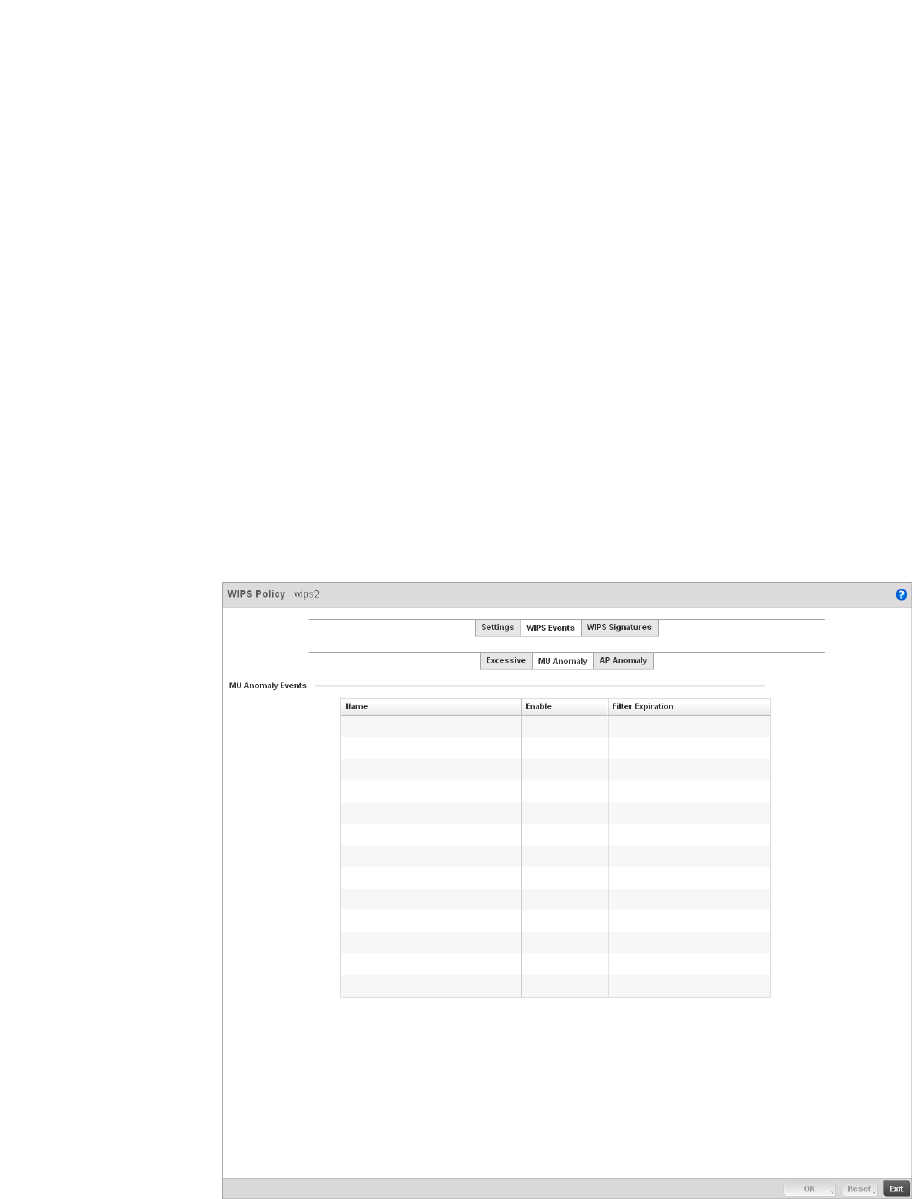
Brocade Mobility RFS4000, RFS6000, and RFS7000 System Reference Guide 545
53-1002620-01
9
15. Set the configurations of the following Excessive Action Events:
16. Select OK to save the updates to the to Excessive Actions configuration used by the WIPS
policy. Select Reset to revert to the last saved configuration.
17. Select the MU Anomaly tab:
FIGURE 364 WIPS Events screen - MU Anomaly tab
Name Displays the name of the excessive action event. This column lists the event being
tracked against the defined thresholds set for interpreting the event as excessive or
permitted.
Enable Displays whether tracking is enabled for each Excessive Action Event. Use the
drop-down menu to enable/disable events as required. A green checkmark defines
the event as enabled for tracking against its threshold values. A red “X” defines the
event as disabled and not tracked by the WIPS policy. Each event is disabled by
default.
Filter Expiration Set the duration the anomaly causing client is filtered. This creates a special ACL
entry and frames coming from the client are silently dropped. The default setting is
0 seconds.
This value is applicable across the RF Domain. If a station is detected performing an
attack and is filtered by one of the APs, the information is passed to the domain
controller. The domain controller then propagates this information to all APs and
controllers in the RF Domain.
Client Threshold Set the client threshold after which the filter is triggered and an event generated.
Radio Threshold Set the radio threshold after which an event is recorded to the events history.

546 Brocade Mobility RFS4000, RFS6000, and RFS7000 System Reference Guide
53-1002620-01
9
MU Anomaly events are suspicious events performed by wireless clients that can compromise
the security and stability of the network. Use this MU Anomaly screen to configure the intervals
clients can be filtered upon the generation of each defined event.
18. Set the configurations of the following MU Anomaly Events configurations:
19. Select OK to save the updates to the MU Anomaly configuration used by the WIPS policy. Select
Reset to revert to the last saved configuration.
20. Select the AP Anomaly tab.
Name Displays the name of the MU Anomaly event. This column lists the event being
tracked against the defined thresholds set for interpreting the event as excessive or
permitted.
Enable Displays whether tracking is enabled for each MU Anomaly event. Use the
drop-down menu to enable/disable events as required. A green checkmark defines
the event as enabled for tracking against its threshold values. A red “X” defines the
event as disabled and not tracked by the WIPS policy. Each event is disabled by
default.
Filter Expiration Set the duration the anomaly causing client is filtered. This creates a special ACL
entry and frames coming from the client are silently dropped. The default setting is
0 seconds. For each violation, define a time to filter value in seconds which
determines how long the controller ignores packets received from an attacking
device once a violation has been triggered. Ignoring frames from an attacking
device minimizes the effectiveness of the attack and the impact to the site until
permanent mitigation can be performed.
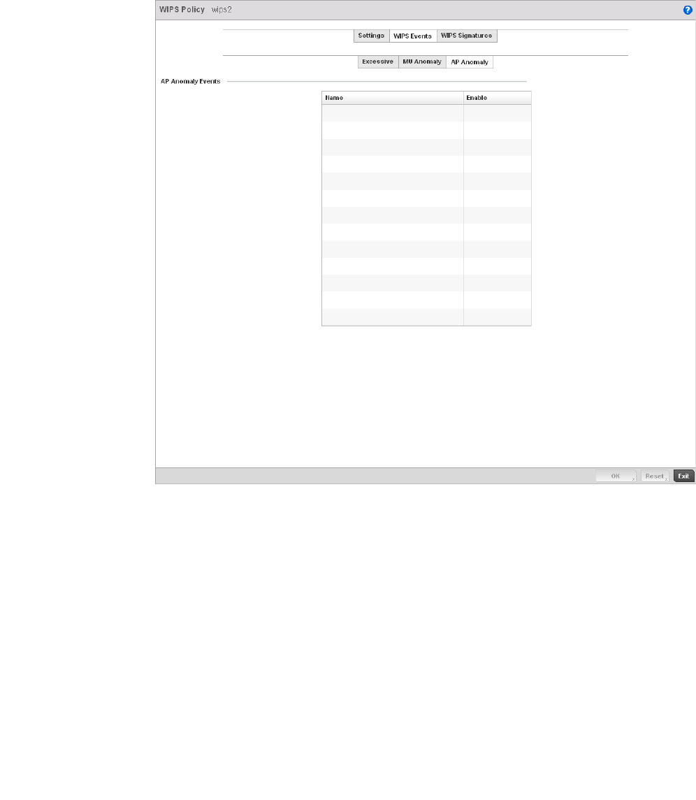
Brocade Mobility RFS4000, RFS6000, and RFS7000 System Reference Guide 547
53-1002620-01
9
FIGURE 365 WIPS Events screen - AP Anomaly tab
AP Anomaly events are suspicious frames sent by a neighboring APs. Use this screen to
determine whether an event is enabled for tracking.
21. Set the configurations of the following MU Anomaly Events configurations:
22. Select OK to save the updates to the AP Anomaly configuration used by the WIPS policy. Select
Reset to revert to the last saved configuration.
23. Select the WIPS Signatures tab.
Name Displays the name of the MU Anomaly event. This column lists the event being
tracked against the defined thresholds set for interpreting the event as excessive or
permitted.
Enable Displays whether tracking is enabled for each MU Anomaly event. Use the
drop-down menu to enable/disable events as required. A green checkmark defines
the event as enabled for tracking against its threshold values. A red “X” defines the
event as disabled and not tracked by the WIPS policy. Each event is disabled by
default.
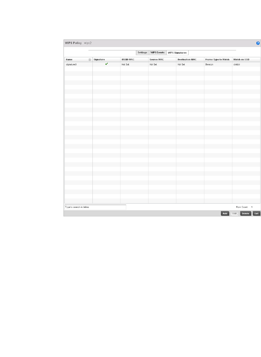
548 Brocade Mobility RFS4000, RFS6000, and RFS7000 System Reference Guide
53-1002620-01
9
FIGURE 366 WIPS Signatures screen
24. The WIPS Signatures tab displays the following read-only data:
25. Select Add to create a new WIPS signature, Edit to modify the attributes of a selected WIPS
signature or Delete to remove obsolete signatures from the list of those available to the
controller.
Name Lists the name assigned to each signature as it was created. A signature name
cannot be modified as part of the edit process.
Signature Displays whether the signature is enabled. A green checkmark defines the
signature as enabled. A red “X” defines the signature as disabled. Each signature is
disabled by default.
BSSID MAC Displays each BSS ID MAC address used for matching purposes.
Source MAC Displays each source MAC address of the packet examined for matching purposes.
Destination MAC Displays each destination MAC address of the packet examined for matching
purposes.
Frame Type to Match Lists the frame types specified for matching with the WIPS signature.
Match on SSID Lists each SSID used for matching purposes.
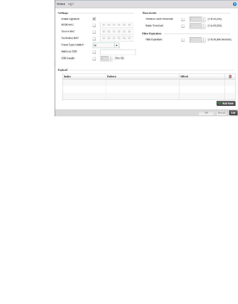
Brocade Mobility RFS4000, RFS6000, and RFS7000 System Reference Guide 549
53-1002620-01
9
FIGURE 367 WIPS Signatures Configuration screen
26. If adding anew WIPS signature, define a Name to distinguish it from others with similar
configurations. The name cannot exceed 64 characters.
27. Set the following network address information for a new or modified WIPS Signature:
28. Refer to Thresholds field to set the thresholds used as filtering criteria.
29. Set a Filter Expiration between 1 - 86,400 seconds that specifies the duration a client is
excluded from RF Domain manager radio association when responsible for triggering a WIPS
event.
30. Refer to the Payload table to set a numerical index pattern and offset for the WIPS signature.
Enable Signature Select the check box to enable the WIPS signature for use with the controller profile.
The default signature is enabled.
BSSID MAC Define a BSS ID MAC address used for matching purposes.
Source MAC Define a source MAC address for the packet examined for matching purposes.
Destination MAC Set a destination MAC address for the packet examined for matching purposes.
Frame Type to Match Use the drop-down menu to select a frame type matching with the WIPS signature.
Match on SSID Sets the SSID used for matching. Ensure it’s specified properly or the SSID won’t be
properly filtered.
SSID Length Set the character length of the SSID used for matching purposes. The maximum
length is 32 characters.
Client Threshold Specify the threshold limit per client that, when exceeded, signals the event. The
configurable range is from 1 - 65,535.
Radio Threshold Specify the threshold limit per radio that, when exceeded, signals the event. The
configurable range is from 1 - 65,535.
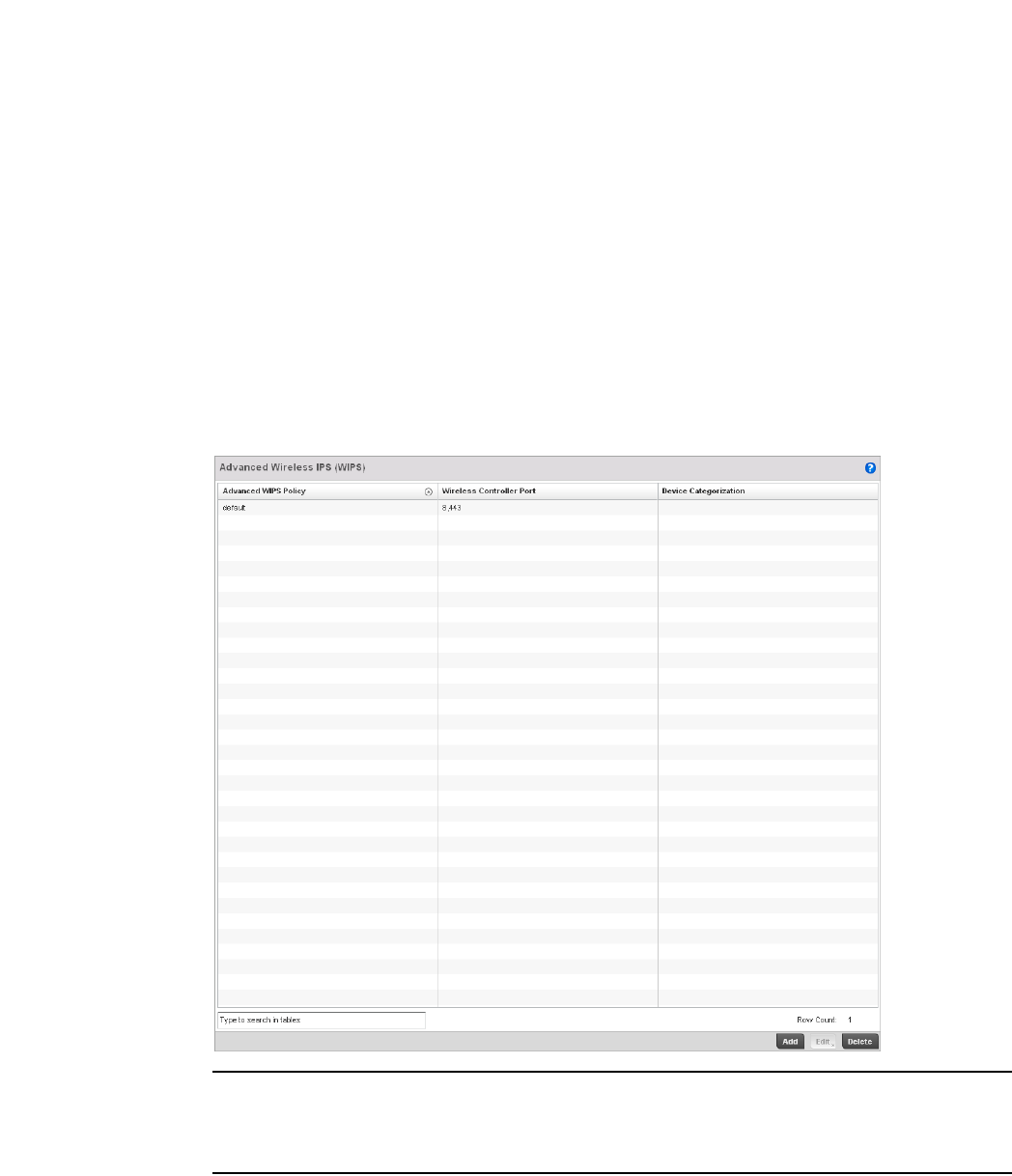
550 Brocade Mobility RFS4000, RFS6000, and RFS7000 System Reference Guide
53-1002620-01
9
31. Select OK to save the updates to the WIPS Signature configuration. Select Reset to revert to
the last saved configuration.
Configuring an Advanced WIPS Policy
Intrusion Prevention
Define an advanced WIPS configuration to optionally remove (terminate) unwanted device
connections, and sanction (allow) or unsanaction (disallow) specific events within the managed
network.
1. Select Configuration > Security > Intrusion Prevention.
2. Expand the Intrusion Prevention option within the Configuration > Security menu and select
Advanced WIPS.
NOTE
Advanced WIPS Policy is only supported on wireless controllers and requires a dedicated WIPS
sensor, but does not require a sensor license. Standard WIPS is available on all RF Domain
managers and supports on channel, off channel and dedicated sensor scanning modes.
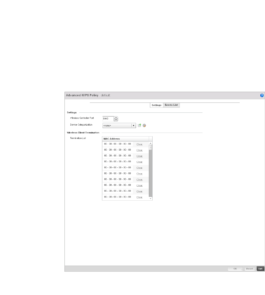
Brocade Mobility RFS4000, RFS6000, and RFS7000 System Reference Guide 551
53-1002620-01
9
3. Review to the following to determine whether a new Advanced WIPS policy requires creation or
edit.
4. Select Add to create a new Advanced WIPS policy, Edit to modify the attributes of an existing
policy or Delete to remove obsolete policies from the list of those available to the controller.
5. If creating a new Advanced WIPS policy, provide it a Name (up to 64 characters) to distinguish
this policy from others with similar configurations. Select OK to save the name and enable the
remaining parameters on the screen.
FIGURE 368 Advanced WIPS Policy screen - Settings tab
6. The Advanced WIPS screen displays the Settings tab by default.
Advanced WIPS Policy Lists the name of each Advanced WIPS Policy.
Wireless Controller
Port
Displays the port number where the advanced WIPS daemon resides.
Device Categorization Lists the device categorization currently being used by each WIPS policy to apply to
devices (authorized, unauthorized etc.)
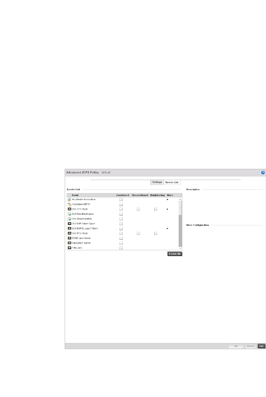
552 Brocade Mobility RFS4000, RFS6000, and RFS7000 System Reference Guide
53-1002620-01
9
7. Define the following Settings for the Advanced WIPS policy:
8. Refer to the Wireless Client Termination table to set list of up to 100 client MAC that are
blocked using this Advanced WIPS policy. This clients are removed from connection within the
managed network, so be sure they represent potential threats.
9. Select OK to save the updates to the Advanced WIPS Settings tab. Select Reset to revert to the
last saved configuration.
10. Select the Events List tab to display a screen where individual events can be enabled as
sanctioned or unsanctioned for the managed network.
FIGURE 369 Advanced WIPS Policy screen - Events List tab
Events are tracked based on an AP’s authorization. APs are either Sanctioned, Unsanctioned
or Neighboring. All of the events listed do not necessarily support all the three AP types.
Some events have extra configurable parameters. These events are identified by a small
triangle under the More column. Extra event parameters are displayed at the right of the
screen.
Wireless Controller
Port
Use the spinner control to set the port the advanced WIPS daemon listens over. The
default port is 8,443.
Device Categorization Set the device categorization as sanctioned, unsanctioned etc. Select the Create
icon to create a new Device Category configuration, or the Edit icon to modify the
configuration of an existing configuration. For information on creating or editing a
Device Categorization policy, see Configuring a WIPS Device Categorization Policy
on page 9-554.

Brocade Mobility RFS4000, RFS6000, and RFS7000 System Reference Guide 553
53-1002620-01
9
11. Select the radio button corresponding to the Sanctioned, Unsanctioned or Neighboring option
for each listed event.
12. Review a description of each event by highlighting it the table and revising the Description
displayed on the right-hand of the screen.
13. The Events List contains the following events to either authorize, unauthorize or interpret as
neighboring for the Advanced WIPS policy:
•Accidental Association - An authorized station has connected to an unauthorized or
ignored Access Point.
•Crackable WEP IV - A WEP IV has been detected that could lead to the discovery of the
WEP key.
•DoS CTS Flood - An excessive number of CTS frames has been detected.
•DoS Deauthentication - Attack in which deauthentication frames are sent to the wireless
client using the MAC address of the AP to which it is associated. This disrupts the client
connection and may lead it to associate to a fake AP spoofing the real ESSID.
•DoS Dissassociation - A flood of spoofed disassociation frames have been detected.
•DoS EAP Failure Spoof - A hacker is sending EAP failure messages to a client using the
spoofed MAC address of the Access Point.
•DoS EAPOL Logoff Storm - An excessive number of EAPOL Logoff messages has been
detected.
•DoS RTS Flood - An excessive number of RTS frames has been detected.
•ESSID Jack Attack - An active attempt to discover a wireless network's ESSID has been
detected.
•Fake DHCP Server - A rogue DHCP server is suspected of operating on the wireless
network.
•Fata-Jack - DoS attack using the Fata-Jack tool, which sends fake authentication failed
packets to the wireless client using the spoofed MAC address of the real AP. This leads the
client to drop itself from the WLAN.
•ID Theft EAPOL Success Spoof -Spoofed EAP success frames have been detected.
•ID Theft Out-Of-Sequence - Two devices using the same MAC address have been detected
operating in the airspace, resulting in detected wireless frames that are out of sequence.
•Invalid Channel Advertisement - An AP is advertising invalid channel.
•Invalid Management Frame - Illegal 802.11 management frame has been detected.
•IPX Detection - Unencrypted IPX traffic has been observed in the wireless network.
•Monkey Jack Attack - Link-layer Man-in-the-Middle attack in which the wireless client
associates with a fake access point which then forwards packets between the client and
the AP. The attacker may then deny service or perform other attacks on the stream of
packets traversing it.
•NULL Probe Response - Null probe response frames have been detected with destination
of an authorized station.
•STP Detection - Unencrypted STP traffic has been observed in the wireless network.
•Unsanctioned AP - Unauthorized activity includes events for devices participating in
unauthorized communication in your airspace.
•Windows Zero Config Memory Leak - Windows XP system memory leak has been detected.

554 Brocade Mobility RFS4000, RFS6000, and RFS7000 System Reference Guide
53-1002620-01
9
•WLAN Jack Attack - DoS attack in which the WLAN Jack tool is used to send
de-authentication frames to wireless clients using the spoofed MAC address of the real AP.
This leads the clients to de-authenticate and drop their wireless connections.
14. Select OK to save the updates to the Advanced WIPS Events List. Select Reset to revert to the
last saved configuration.
Configuring a WIPS Device Categorization Policy
Intrusion Prevention
Having devices properly classified can help suppress unnecessary unsanctioned AP alarms and
allow an administrator to focus on the alarms and devices actually behaving in a suspicious
manner. An intruder with a device erroneously authorized could potentially perform activities that
harm your organization while appearing to be legitimate. The controller enables devices to be
categorized as access points, then defined as sanctioned or unsanctioned for operation within the
managed network.
Sanctioned Access Points are generally known to you and conform with your organization’s security
policies. Unsanctioned devices have been detected as interoperating within the managed network,
but are not approved. These devices should be filtered to avoid jeopardizing the data managed by
the controller.
To categorize Access Points as sanctioned or unsanctioned within the managed network:
1. Select Configuration > Security > Intrusion Prevention.
2. Expand the Intrusion Prevention option within the Configuration > Security menu and select
Device Categorization.
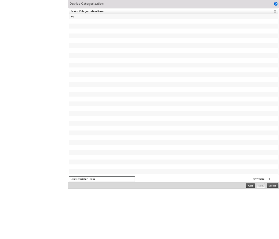
Brocade Mobility RFS4000, RFS6000, and RFS7000 System Reference Guide 555
53-1002620-01
9
FIGURE 370 WIPS Device Categorization screen
3. The Device Categorization screen lists those device authorization policies that have been
defined thus far.
4. Select Add to create a new Device Categorization policy, Edit to modify the attributes of a
selected existing policy or Delete to remove obsolete policies from the list of those available to
the controller.
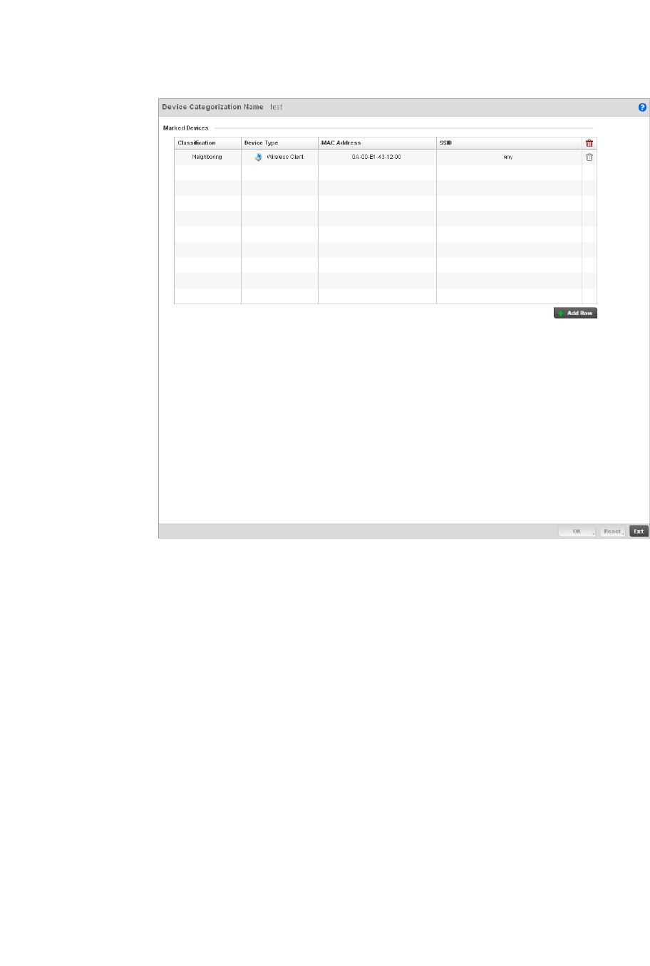
556 Brocade Mobility RFS4000, RFS6000, and RFS7000 System Reference Guide
53-1002620-01
9
FIGURE 371 WIPS Device Categorization Configuration screen
5. If creating a new Device Categorization policy, provide it a Name (up to 64 characters) to
distinguish this policy from others with similar configurations. Select OK to save the name and
enable the remaining parameters on the screen.
6. Select + Add Row to populate the Marked Devices field with parameters for adding an Access
Point’s MAC address, SSID, Access Point designation and controller network authorization.
Select the red (-) Delete Row icon as needed to remove an individual table entry.
7. Define the following parameters to add a device to a list of devices categorized as sanctioned
or unsanctioned for controller network operation:
Classification Use the drop-down menu to designate the target device as either sanctioned (True)
or unsanctioned (False). The default setting is False, categorizing this device as
unsanctioned. Thus, each added device requires authorization. A green checkmark
designates the device as sanctioned, while a red “X” defines the device as
unsanctioned.
Device Type Use the drop-down menu to designate the target device as either an Access Point
(True) or other (False). The default setting is False, categorizing this device as other
than an Access Point. A green checkmark designates the device as an Access Point,
while a red “X” defines the categorized device as other than an Access Point.
MAC Address Enter the factory coded MAC address of the target device. This address is hard
coded by the device manufacturer and cannot be modified. The MAC address will be
defined as sanctioned or unsanctioned as part of the device categorization process.
SSID Enter the SSID of the target device requiring categorization. The SSID cannot exceed
32 characters.

Brocade Mobility RFS4000, RFS6000, and RFS7000 System Reference Guide 557
53-1002620-01
9
8. Select OK to save the updates to the Marked Devices List. Select Reset to revert to the last
saved configuration.
Intrusion Detection Deployment Considerations
Before configuring WIPS support on the wireless controller, refer to the following deployment
guidelines to ensure the configuration is optimally effective:
•WIPS is best utilized when deployed in conjunction with a corporate or enterprise wireless
security policy. Since an organization’s security goals vary, the security policy should document
site specific concerns. The WIPS system can then be modified to support and enforce these
additional security policies
•WIPS reporting tools can minimize dedicated administration time. Vulnerability and activity
reports should automatically run and be distributed to the appropriate administrators. These
reports should highlight areas to be to investigated and minimize the need for network
monitoring.
•It's important to keep your WIPS system Firmware and Software up to date. A quarterly system
audit can ensure firmware and software versions are current.
•Only a trained wireless network administrator can determine the criteria used to authorize or
ignore devices. You may want to consider your organization’s overall security policy and your
tolerance for risk versus users’ need for network access. Some questions that may be useful in
deciding how to classify a device are:
•Does the device conform to any vendor requirements you have?
•What is the signal strength of the device? Is it likely the device is outside your physical
radio coverage area?
•Is the detected Access Point properly configured according to your organization’s security
policies?
•Brocade recommends a controller have visibility to all the VLANs deployed. If an external L3
device has been deployed for routing services, each VLAN should be 802.1Q tagged to the
controller to allow the controller to detect any unsanctioned APs physically connected to the
network.
•Brocade recommends trusted and known Access Points be added to an sanctioned AP list. This
will minimize the number of unsanctioned AP alarms received.

558 Brocade Mobility RFS4000, RFS6000, and RFS7000 System Reference Guide
53-1002620-01
9

Brocade Mobility RFS4000, RFS6000, and RFS7000 System Reference Guide 559
53-1002620-01
Chapter
10
Services Configuration
In this chapter
•Configuring Captive Portal Policies. . . . . . . . . . . . . . . . . . . . . . . . . . . . . . . . 559
•Setting the Controller’s DHCP Configuration . . . . . . . . . . . . . . . . . . . . . . . . 571
•Setting the Controller’s RADIUS Configuration . . . . . . . . . . . . . . . . . . . . . . 585
The controller natively supports services to provide guest user access to the controller managed
network, lease DHCP IP addresses to requesting clients and provide RADIUS client authentication.
Configuring Captive Portal Policies
A captive portal is guest access policy for providing guests temporary and restrictive access to the
controller managed wireless network. The primary means of securing such controller guest access
is the use of a hotspot.
A captive portal policy’s hotspot configuration provides secure authenticated controller access
using a standard Web browser. Hotspots provides authenticated access by capturing and
re-directing a wireless user's Web browser session to a captive portal login page where the user
must enter valid credentials to access to the controller managed wireless network. Once logged
into the controller managed hotspot, additional Agreement, Welcome and Fail pages provide the
administrator with a number of options on the hotspot’s screen flow and user appearance.
Hotspot authentication is used primarily for guest or visitor access to the controller managed
network, but is increasingly being used to provide authenticated access to private network
resources when 802.1X EAP is not a viable option. Hotspot authentication does not provide
end-user data encryption, but it can be used with static WEP, WPA-PSK or WPA2-PSK encryption.
Authentication for captive portal guest access applications is performed using a username and
password, authenticated by the controller’s integrated RADIUS server. Authentication for private
network access is provided either locally on the requesting wireless client, or centrally at a
datacenter.
The controller uses a Web provisioning tool to create guest user captive portal accounts directly on
the controller. The connection medium defined for the controller’s Web connection is either HTTP or
HTTPS. Both HTTP and HTTPS use a request and response procedure clients follow to disseminate
information to and from the controller and requesting wireless clients.
Configuring a Captive Portal Policy
To configure a controller’s guest access captive portal policy:
1. Select Configuration > Services.
The upper, left-hand, side of the user interface displays a Services menu pane where Captive
Portal, DHCP and RADIUS configuration options can be selected.
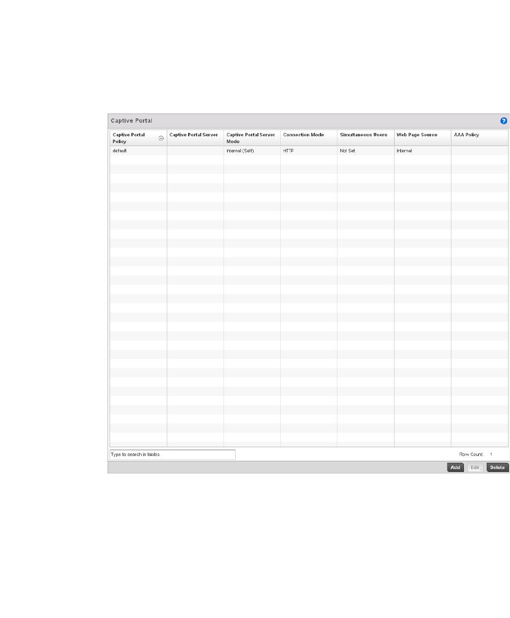
560 Brocade Mobility RFS4000, RFS6000, and RFS7000 System Reference Guide
53-1002620-01
10
2. Select Captive Portals.
The Captive Portal screen displays the configurations of existing policies. New policies can be
created, existing policies can be modified or existing policies deleted.
FIGURE 372 Captive Portal Policy screen
3. Refer to the following captive portal policy parameters to determine whether a new policy
requires creation, or an existing policy requires edit or deletion:
Captive Portal Policy Displays the name assigned to the captive portal guest access policy when it was
initially created. A policy name cannot be modified as part of the edit process.
Captive Portal Server Lists the IP address (non DNS hostname) of the external (fixed) server validating
guest user permissions for the listed captive portal policy. This item remains empty
if the controller is hosting the captive portal.
Captive Portal Server
Mode
Lists each policy’s hosting mode as either Internal (Self) or External (Fixed). If the
mode is Internal (Self), the controller is maintaining the captive portal internally,
while External (Fixed) means the captive portal is being supported on an external
server.
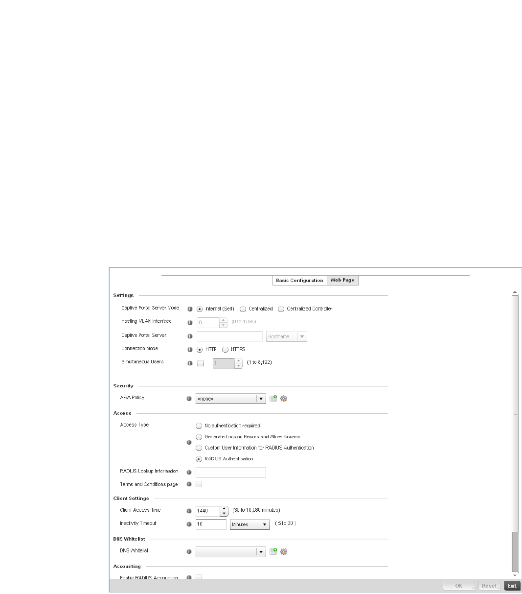
Brocade Mobility RFS4000, RFS6000, and RFS7000 System Reference Guide 561
53-1002620-01
10
4. Select Add to create a new captive portal policy, Edit to modify an existing policy or Delete to
remove an existing captive portal policy.
5. A Basic Configuration screen displays by default. Define the policy’s security, access and
whitelist basic configuration before actual HTML pages can be defined for guest user access
requests.
FIGURE 373 Captive Portal Policy Basic Configuration screen
Connection Mode Lists each policy’s connection mode as either HTTP or HTTPS. Both HTTP and HTTPS
use the same Uniform Resource Identifier (URI), so controller and client resources
can be identified. However. Brocade recommends the use of HTTPS, as it affords
transmissions some measure of data protection HTTP cannot provide.
Simultaneous Users Displays then number of users permitted at one time for each listed policy. A
controller managed captive portal can support between 0-8192 users
simultaneously.
Web Page Source Displays whether the controller’s captive portal HTML pages are maintained
Internally (on the controller), Externally (on an external system you define) or are
Advanced pages maintained and customized by the network administrator. Internal
is the default setting.
AAA Policy Lists each controller AAA policy used to authorize client guest access requests. The
controller’s security provisions provide a way to configure advanced AAA policies
that can be applied to captive portal policies. When a captive portal policy is created
or modified, a AAA policy must be defined and applied to effectively authorize,
authenticate and account user requests.

562 Brocade Mobility RFS4000, RFS6000, and RFS7000 System Reference Guide
53-1002620-01
10
6. Define the following for the captive portal policy:
7. Use the AAA Policy drop-down menu to select the controller Authentication, Authorization and
Accounting (AAA) policy used to validate user credentials and provide captive portal guest
access to the controller managed network.
8. If no AAA policies exist, one must be created by selecting the Create icon, or an existing AAA
policy can be selected and modified by selected it from the drop-down menu and selecting the
Edit icon. For information on creating a AAA policy that can be applied to a captive portal
configuration, see AAA Policy on page 6-343.
9. Set the following Access parameters to define hotspot access, RADIUS lookup information and
whether the hotspot’s login pages contain agreement terms that must be accepted before
access is granted to controller resources:
Captive Portal Policy If creating a new policy, assign a name representative of its access permissions,
location or intended wireless client user base. If editing an existing captive portal
policy, the policy name cannot be modified. The name cannot exceed 32 characters.
Captive Portal Server
Mode
Set the mode as either Internal (Self) or External (Fixed). Select the Internal (Self)
radio button for the controller to maintain the captive portal configuration (Web
pages) internally. Select the External (Fixed) radio button if the captive portal is
supported on an external server. The default value is Internal (Self).
Captive Portal Server Set a numeric IP address (or DNS hostname) for the server validating guest user
permissions for the captive portal policy. This option is only available if hosting the
captive portal on an External (Fixed) server resource.
Connection Mode Select either HTTP or HTTPS to define the connection medium used by the controller
and Web serve. Brocade recommends the use of HTTPs, as is affords the controller
some additional data protection HTTP cannot provide. The default value however is
HTTP.
Simultaneous Users Select the checkbox and use the spinner control to set between 1-8192 users
(client MAC addresses) allowed to simultaneously access and use the captive
portal.
Access Type Select the radio button for the authentication scheme applied to wireless clients
using the captive portal for guest access to the controller managed network.
Options include:
No authentication required - Clients can freely access the captive portal Web pages
without authentication.
Generate Logging Record and Allow Access - Access is provided without
authentication, but a record of the accessing client is logged.
Custom User Information for RADIUS Authentication - When selected, accessing
clients are required to provide a 1-32 character lookup data string used to
authenticate client access.
RADIUS Authentication - An accessing client’s user credentials require
authentication before access to the captive portal is granted. This is the default
setting.
RADIUS Lookup
Information
When Custom User Information for RADIUS Authentication is selected as the access
type, provide a 1-32 character lookup information string used as a customized
authentication mechanism.
Terms and Conditions
page
Select this option to include terms that must be adhered to for captive portal
access. These terms are included in the Agreement page when No authentication
required is selected as the access type, otherwise the terms appear in the Login
page. The default setting is disabled.
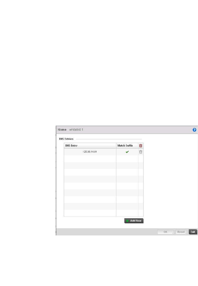
Brocade Mobility RFS4000, RFS6000, and RFS7000 System Reference Guide 563
53-1002620-01
10
10. Set the following Client Settings to define the duration clients are allowed captive portal access
and when they’re timed out due to inactivity:
11. Use the DNS White List parameter to create a set of allowed destination IP addresses. These
allowed DNS destination IP addresses are called a Whitelist.
To effectively host hotspot pages on an external Web server, the IP address of the destination
Web server(s) should be in the Whitelist.
12. Refer to the drop-down menu of existing DNS White List entries to select a policy to be applied
to this captive portal policy. If no DNS Whitelist entries exist, select the Create or Edit icons and
follow the sub-steps below:
a. If creating a new Whitelist, assign it a name up to 32 characters. Use the + Add button to
populate the Whitelist with Host and IP Index values.
FIGURE 374 Captive Portal Whitelist screen
b. Provide a numerical IP address or Hostname within the DNS Entry parameter for each
destination IP address or host included in the Whitelist.
c. Use the Match Suffix parameter to match any hostname or domain name as a suffix. The
default setting is disabled.
d. If necessary, select the radio button of an existing Whitelist entry and select the - Delete
icon to remove the entry from the Whitelist.
Client Access Time Use the spinner control to define the duration wireless clients are allowed access to
the controller managed network using the captive portal policy. Set an interval
between 30 - 10,800 minutes. The default interval is 1,440 minutes.
Inactivity Timeout Use the drop-down menu to specify an interval in either Minutes (5 - 30) or Seconds
(300 - 1,800) that, when exceeded, times out clients that have not transmitted a
packet within the captive portal.

564 Brocade Mobility RFS4000, RFS6000, and RFS7000 System Reference Guide
53-1002620-01
10
13. Set the following Accounting parameters to define how accounting is conducted for clients
entering and exiting the captive portal. Accounting is the method of collecting and sending
security server information for billing, auditing and reporting user data; such as captive portal
start and stop times, executed commands (such as PPP), number of packets and number of
bytes. Accounting enables wireless network administrators to track captive portal services
users are consuming.
14. Select OK to save the changes made within the Basic Configuration screen. Selecting Reset
reverts the settings back to the last saved configuration.
15. Select the Web Page tab to create controller maintained HTML pages requesting wireless
clients use to login and navigate within a controller managed hotspot.
16. The Login page displays by default.
Enable RADIUS
Accounting
Select this option to use an external RADIUS resource for AAA accounting. When
selected, a AAA Policy field displays. This setting is disabled by default.
Enable Syslog
Accounting
Select this option to log information about the use of remote access services by
users using an external syslog resource. This information is of great assistance in
partitioning local versus remote users. Remote user information can be archived to
a location outside of the controller for periodic network and user administration.
This feature is disabled by default.
Syslog Host Use the drop-down menu to determine whether an IP address or a host name is
used as a syslog host. The IP address or host name of an external server resource is
required to route captive portal syslog events to that destination for use as an
external controller resource.
Syslog Port Define the numerical syslog port the controller uses to route traffic with the external
syslog server. The default port is 514.
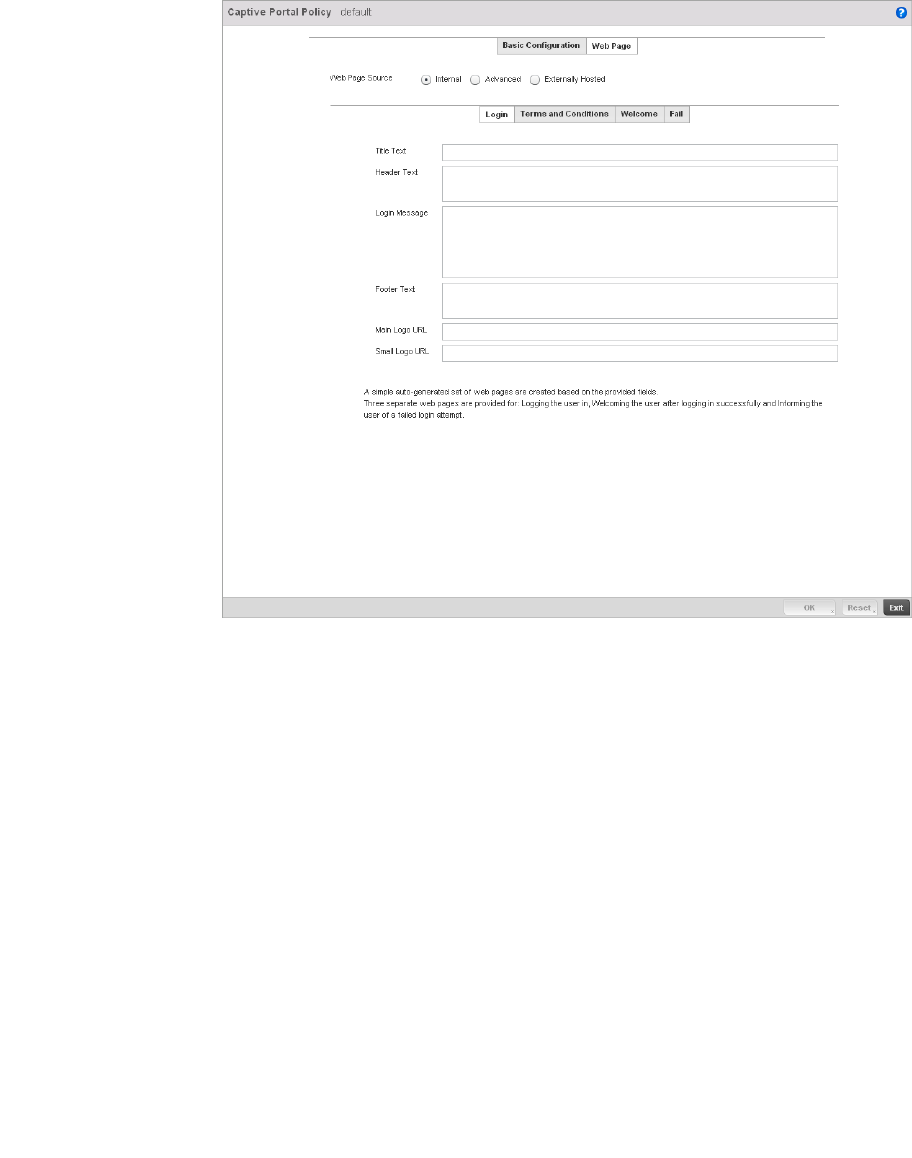
Brocade Mobility RFS4000, RFS6000, and RFS7000 System Reference Guide 565
53-1002620-01
10
FIGURE 375 Captive Portal Policy Internal Web Page screen
The Login screen prompts the user for a username and password to access the hotspot and
proceed to either the Terms and Conditions page (if used) or the Welcome page. The Terms
and Conditions page provides conditions that must be agreed to before guest access is
allowed for the captive portal policy. The Welcome page asserts a user has logged in
successfully and can access the controller managed hotspot. The Fail page asserts the hotspot
authentication attempt has failed, and the user is not allowed to access the Internet (using this
captive portal) and must provide the correct login information again to access the Internet.
17. Provide the following if creating pages maintained internally on the controller (when the
Internal radio button is selected as the Web Page Source). The Internal (internally hosted)
captive portal is the controller’s default setting.
18. The Login page displays by default. Configure the following for the Login, Terms and Conditions,
Welcome and Fail screens:.
Title Text Set the title text displayed on the Login, Agreement, Welcome and Fail pages when
wireless clients access each page. The text should be in the form of a page title
describing the respective function of each page and should be unique to each login,
agreement, welcome and fail function.
Header Text Provide header text unique to the function of each page.
Login Message Specify a message containing unique instructions or information for the users who
access the Login, Agreement, Welcome or Fail pages. In the case of the Agreement
page, the message can be the conditions requiring agreement before guest access
is permitted.
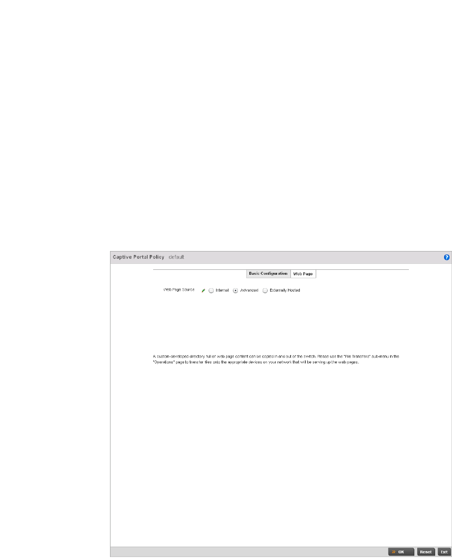
566 Brocade Mobility RFS4000, RFS6000, and RFS7000 System Reference Guide
53-1002620-01
10
19. Select OK to save the changes made within the Internal Pages screen. Selecting Reset reverts
the settings back to the last saved configuration.
20. Select Advanced to use a custom directory of Web pages copied to and from the controller for
captive portal support.
Footer Text Provide a footer message displayed on the bottom of each page. The footer text
should be any concluding message unique to each page before accessing the next
page in the succession of hotspot Web pages.
Main Logo URL The Main Logo URL is the URL for the main logo image displayed on the Login,
Agreement, Welcome and Fail pages. Use the Browse button to navigate to the
location of the target file.
Small Logo URL The Small Logo URL is the URL for a small logo image displayed on the Login,
Agreement, Welcome and Fail pages. Use the Browse button to navigate to the
location of the target file.

Brocade Mobility RFS4000, RFS6000, and RFS7000 System Reference Guide 567
53-1002620-01
10
21. Set the following external URL destinations for the captive portal policy’s hotspot pages.
22. If hosting the captive portal on a system external to the controller, select the Externally Hosted
radio button.
URL Define the complete URL for the location of the custom captive portal pages.
Advanced Select the Advanced link to display additional parameters for accessing the remote
server used to support the advanced captive portal. The following parameters are
required:
Protocol - Select the file transfer method used between the controller and the
resource maintaining the custom captive portal files.
Port - Use the spinner control to set the port used on the external Server
maintaining the custom captive portal files.
Host - Set the IP address or hostname of the destination server supporting the
captive portal’s advanced files set. Use the drop-down menu to specify whether an
IP address or hostname is used.
Path - Provide a complete and accurate path to the location where the captive
portal file set resides on the external server resource.
Export Select the Export button to upload target captive portal files to the designated
external resource. The exported files display within the File/s table.
Import Select the Import button to download target captive portal files from the
designated external resource to the controller. The imported files display within the
File/s table.
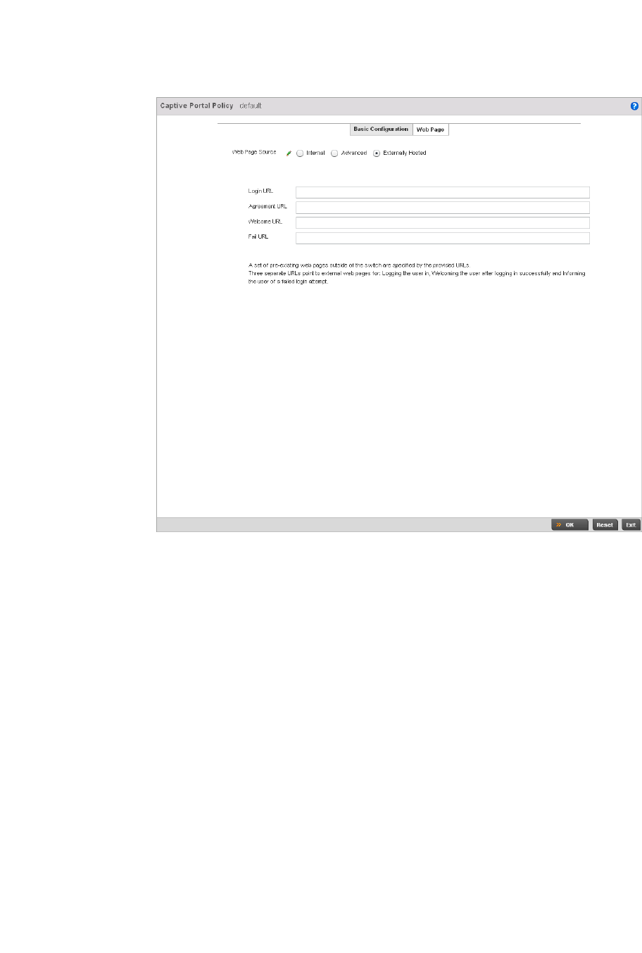
568 Brocade Mobility RFS4000, RFS6000, and RFS7000 System Reference Guide
53-1002620-01
10
FIGURE 376 Captive Portal Policy Externally Hosted Web Page screen
23. Select OK when completed to update the captive portal’s advanced configuration. Select Reset
to revert the screen back to its last saved configuration.
Creating DNS Whitelists
Before defining a captive portal configuration, refer to the following deployment guidelines to
ensure the configuration is optimally effective:
1. Select Configuration > Services.
Login URL Define the complete URL for the location of the Login page. The Login screen
prompts the user for a username and password to access the Terms and Conditions
or Welcome page.
Agreement URL Define the complete URL for the location of the Terms and Conditions page. The
Terms and Conditions page provides conditions that must be agreed to before
wireless client access is provided.
Welcome URL Define the complete URL for the location of the Welcome page. The Welcome page
asserts the user has logged in successfully and can access controller resources via
the captive portal.
Fail URL Define the complete URL for the location of the Fail page. The Fail page asserts
authentication attempt has failed, and the client cannot access the captive portal
and the client needs to provide correct login information to regain access.
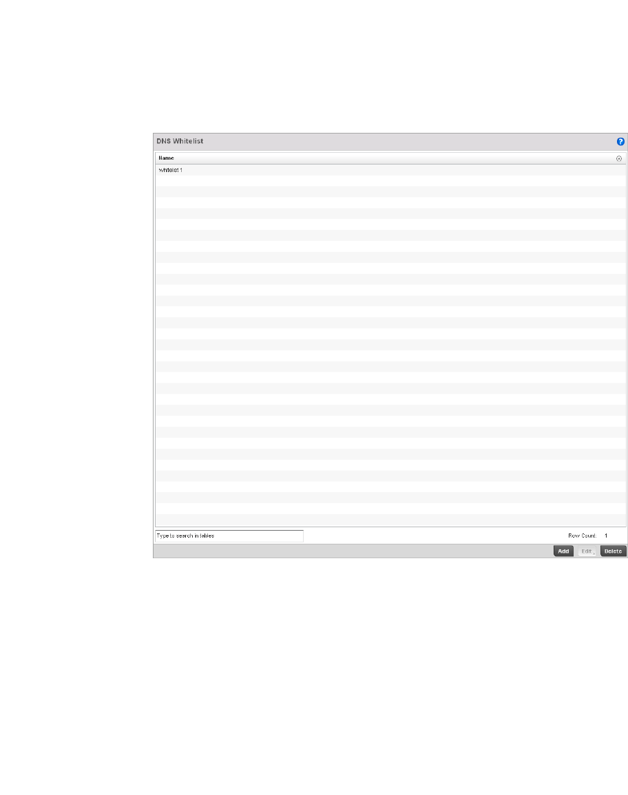
Brocade Mobility RFS4000, RFS6000, and RFS7000 System Reference Guide 569
53-1002620-01
10
The upper, left-hand, side of the user interface displays a Services menu pane where Captive
Portal, DHCP and RADIUS configuration options can be selected.
2. Select Captive Portals.
The Captive Portal screen displays the configurations of existing policies. New policies can be
created, existing policies can be modified or existing policies deleted.
3. Select DNS Whitelist
FIGURE 377 Captive Portal DNS Whitelist screen
4. Review the names of existing DNS Whitelists and click Add to create a new whitelist entry or
select an existing whitelist and click Edit to modfiy it.
5. Use the DNS Whitelist parameter to create a set of allowed destination IP addresses. These
allowed DNS destination IP addresses are called a Whitelist.
To effectively host hotspot pages on an external Web server, the IP address of the destination
Web server(s) should be in the Whitelist.
6. Refer to the drop-down menu of existing DNS White List entries to select a policy to be applied
to this captive portal policy. If no DNS Whitelist entries exist, select the Create or Edit icons and
follow the sub-steps below:
a. If creating a new Whitelist, assign it a name up to 32 characters. Use the + Add button to
populate the Whitelist with Host and IP Index values.
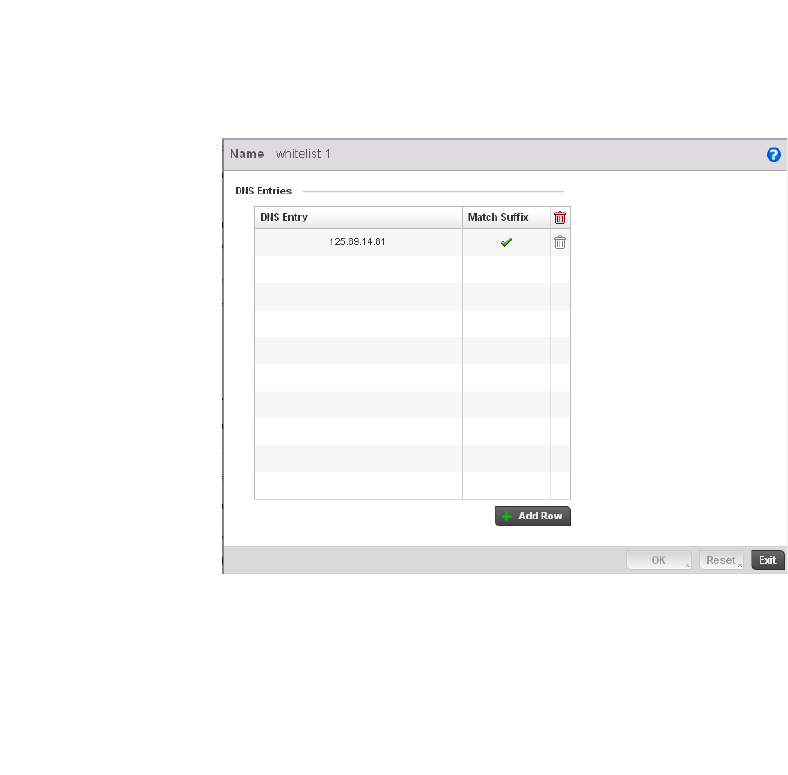
570 Brocade Mobility RFS4000, RFS6000, and RFS7000 System Reference Guide
53-1002620-01
10
FIGURE 378 Captive Portal Whitelist screen
b. Provide a numerical IP address or Hostname within the DNS Entry parameter for each
destination IP address or host included in the Whitelist.
c. Use the Match Suffix parameter to match any hostname or domain name as a suffix. The
default setting is disabled.
d. If necessary, select the radio button of an existing Whitelist entry and select the - Delete
icon to remove the entry from the Whitelist.
Captive Portal Deployment Considerations
Before defining a captive portal configuration, refer to the following deployment guidelines to
ensure the configuration is optimally effective:
•The architecture should consider the number of wireless clients allowed on the guest network
and the services provided. Each topology has benefits and disadvantages which should taken
into consideration to meet each deployment's requirements.
•Hotspot authentication uses secure HTTPS to protect user credentials, but doesn’t typically
provide encryption for user data once they have been authenticated. For private access
applications, Brocade recommends WPA2 (with a strong passphrase) be enabled to provide
strong encryption.
•Brocade recommends guest user traffic be assigned a dedicated VLAN, separate from other
internal networks.
•Controller guest access configurations should include firewall policies to ensure logical
separation is provided between guest and internal networks so internal networks and hosts
are not reachable from controller managed guest devices.
•Guest access services should be defined in a manner whereby end-user traffic doesn’t cause
network congestion.

Brocade Mobility RFS4000, RFS6000, and RFS7000 System Reference Guide 571
53-1002620-01
10
•Brocade recommends a valid certificate be issued and installed on all devices providing
Hotspot access to a controller managed WLAN and wireless network. The certificate should be
issued from a public certificate authority ensuring guests can access the Hotspot without
browser errors.
Setting the Controller’s DHCP Configuration
Dynamic Host Configuration Protocol (DHCP) allows hosts on an IP network to request and be
assigned IP addresses and discover information about the controller managed network where they
reside. Each subnet can be configured with its own address pool. Whenever a DHCP client requests
an IP address, the DHCP server assigns an IP address from that subnet’s address pool. When the
controller’s onboard DHCP server allocates an address for a DHCP client, the client is assigned a
lease, which expires after an pre-determined interval. Before a lease expires, wireless clients (to
which leases are assigned) are expected to renew them to continue to use the addresses. Once the
lease expires, the client is no longer permitted to use the leased IP address. The controller’s DHCP
server ensures all IP addresses are unique, and no IP address is assigned to a second client while
the first client's assignment is valid (its lease has not yet expired). Therefore, IP address
management is conducted by the controller’s DHCP server, not by an administrator.
The controller’s internal DHCP server groups wireless clients based on defined user-class options.
Clients with a defined set of user class values are segregated by class. A DHCP server can
associate multiple classes to each pool. Each class in a pool is assigned an exclusive range of IP
addresses. DHCP clients are compared against classes. If the client matches one of the classes
assigned to the pool, it receives an IP address from the range assigned to the class. If the client
doesn't match any of the classes in the pool, it receives an IP address from a default pool range (if
defined). Multiple IP addresses for a single VLAN allow the configuration of multiple IP addresses,
each belonging to different subnet. Class configuration allows a DHCP client to obtain an address
from the first pool to which the class is assigned.
NOTE
DHCP server updates are only implemented when the controller is restarted.
To access and review the controller’s internal DHCP server configuration:
1. Select Configuration > Services > DHCP Server Policy.
2. The DHCP Server screen displays. Clients with a defined set of user class values are
segregated by class. A DHCP server can associate multiple classes to each pool. Each class in
a pool is assigned an exclusive range of IP addresses. DHCP clients are then compared against
classes.
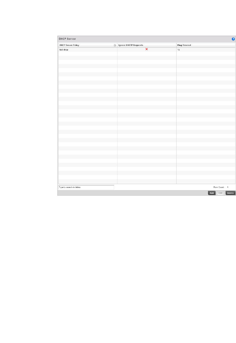
572 Brocade Mobility RFS4000, RFS6000, and RFS7000 System Reference Guide
53-1002620-01
10
FIGURE 379 DHCP Server Policy screen
3. Review the following DHCP server configurations (at a high level) to determine whether a new
server policy requires creation, an existing policy requires modification or an existing policy
requires deletion:
4. Select Add to create a new DHCP server policy, choose an existing policy and select the Edit
button to modify the policy’s properties or choose an existing policy and select Delete to
remove the policy from those available to the controller. Adding or Editing a DHCP server policy
displays the DHCP Server Policy screen by default.
DHCP Server Policy Lists the name assigned to each DHCP server policy when it was initially created.
The name assigned to a DHCP server policy cannot be modified as part of the policy
edit process. However, obsolete policies can be deleted as needed.
Ignore BOOTP
Requests
A green checkmark within this column means this policy has been set to ignore
BOOTP requests. A red “X” defines the policy as accepting BOOTP requests. BOOTP
(boot protocol) requests boot remote systems within the controller managed
network. BOOTP messages are encapsulated inside UDP messages and are
forwarded by the controller. This parameter can be changed within the DHCP Server
Global Settings screen.
Ping Timeout Lists the interval (from 1 -10 seconds) for a DHCP server ping timeout. The
controller uses the timeout to intermittently ping and discover whether a client
requested IP address is already in use. This parameter can be changed within the
DHCP Server Global Settings screen.
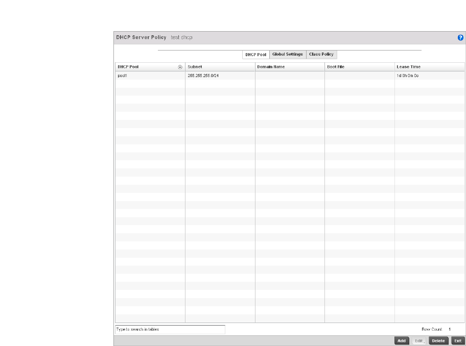
Brocade Mobility RFS4000, RFS6000, and RFS7000 System Reference Guide 573
53-1002620-01
10
Defining DHCP Pools
The controller has the ability to enable DHCP services for IP interfaces. A pool (or range) of IP
network addresses and DHCP options can be created for each IP interface configured on the
controller. This range of addresses can be made available to DHCP enabled wireless devices within
the controller managed network on either a permanent or leased basis. DHCP options are provided
to each DHCP client with a DHCP response and provide DHCP clients information required to
access network resources such as a default gateway, domain name, DNS server and WINS server
configuration. An option exists to identify the vendor and functionality of a DHCP client. The
information is a variable-length string of characters (or octets) that has a meaning specified by the
vendor of the DHCP client.
To define the parameters of a DHCP pool:
1. Select Configuration > Services > DHCP Server Policy. The DHCP Server Policy screen displays
the DHCP Pool tab by default.
FIGURE 380 DHCP Server Policy screen - DHCP Pool tab

574 Brocade Mobility RFS4000, RFS6000, and RFS7000 System Reference Guide
53-1002620-01
10
2. Review the following DHCP pool configurations to determine if an existing pool can be used as
is, a new one requires creation or edit, or a pool requires deletion:
3. Select Add to create a new DHCP pool, Edit to modify an existing pool’s properties or Delete to
remove a pool from amongst those available.
DHCP Pool Displays the name assigned to the network pool when created. The DHCP pool
name represents the group of IP addresses used to assign to DHCP clients upon
request. The name assigned cannot be modified as part of the edit process.
However, if the network pool configuration is obsolete it can be deleted.
Subnet Displays the network address and mask used by clients requesting DHCP resources.
Domain Name Displays the domain name defined used by the controller with this network pool.
The controller uses Domain Name Service (DNS) to convert human readable host
names into IP addresses. Host names are not case sensitive and can contain
alphabetic or numeric letters or a hyphen. A fully qualified domain name (FQDN)
consists of a host name plus a domain name. For example,
computername.domain.com.
Boot File Boot files (Boot Protocol) are used to boot remote systems over the controller
managed network. BOOTP messages are encapsulated inside UDP messages so
requests and replies can be forwarded by the controller. Each DHCP network pool
can use a different file as needed.
Lease Time If a lease time has been defined for a listed network pool, it displays in an interval
between 1 - 31,622,399 seconds. DHCP leases provide addresses for defined times
to various clients. If a client does not use the leased address for the defined time,
that IP address can be re-assigned to another DHCP supported client.
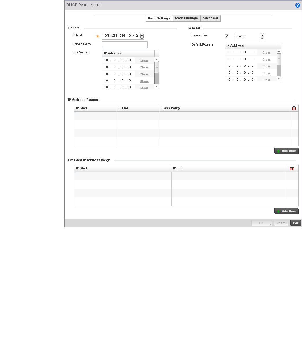
Brocade Mobility RFS4000, RFS6000, and RFS7000 System Reference Guide 575
53-1002620-01
10
FIGURE 381 DHCP Pools screen - Basic Settings tab
If adding or editing a DHCP pool, the DHCP Pool screen displays the Basic Settings tab by default.
Define the required parameters for the Basic Settings, Static Bindings and Advanced tabs to
complete the creation of the DHCP pool.
4. Set the following General parameters from within the Basic Settings tab:
DHCP Pool If adding a new pool, a name is required. The pool is the range of IP addresses
defined for DHCP assignment or lease. The name assigned cannot be modified as
part of the edit process. However, if the network pool configuration is obsolete it can
be deleted. The name cannot exceed 32 characters.
Subnet Define the IP address and Subnet Mask used for DHCP discovery and requests
between the controller’s DHCP Server and DHCP clients. The IP address and subnet
mask are required to match the addresses of the layer 3 interface for the addresses
to be supported through that interface.
Domain Name Provide the domain name used by the controller with this pool. Domain names are
not case sensitive and can contain alphabetic or numeric letters or a hyphen. A fully
qualified domain name (FQDN) consists of a host name plus a domain name. For
example, computername.domain.com.

576 Brocade Mobility RFS4000, RFS6000, and RFS7000 System Reference Guide
53-1002620-01
10
5. Use the IP Address Ranges field define the range of included (starting and ending IP
addresses) addresses for this particular pool.
a. Select the + Add Row button at the bottom of the IP addresses field to add a new range. At
any time you can select the radio button of an existing IP address range and select the
Delete icon to remove it from the list of those available.
b. Enter a viable range of IP addresses in the IP Start and IP End columns. This is the range
of addresses available for assignment to DHCP supported wireless clients within the
controller managed network.
c. Select the Create icon or Edit icon within the Class Policy column to display the DHCP
Server Policy screen if a class policy is not available from the drop-down menu.
d. Refer to the Excluded IP Address Range field and select the +Add Row button. Add ranges
of IP address to exclude from lease to requesting DHCP clients. Having ranges of
unavailable addresses is a good practice to ensure IP address resources are in reserve.
Select the Delete icon as needed to remove an excluded address range.
e. Select OK to save the updates to the DHCP Pool Basic Settings tab. Select Reset to revert
to the last saved configuration.
6. Select the Static Bindings tab from within the DHCP Pools screen.
A binding is a collection of configuration parameters, including an IP address, associated with,
or bound to, a DHCP client. Bindings are managed by DHCP servers. DHCP bindings
automatically map a device MAC address to an IP address using a pool of DHCP supplied
addresses. Static bindings provide the assignment of IP addresses without creating numerous
host pools with manual bindings. Static host bindings use a text file the DHCP server reads. It
eliminates the need for a lengthy configuration file and reduces the space required on the
controller to maintain address pools.
DNS Servers Define one or a group of Domain Name Servers (DNS) to translate domain names to
IP addresses. Select clear to remove any single IP address as needed. Up to 8 IP
addresses can be supported.
Lease Time DHCP leases provide addresses for defined times to various clients. If a client does
not use the leased address for the defined time, that IP address can be re-assigned
to another DHCP supported client. Select this option to assign a lease in either
Seconds (1 - 31, 622, 399), Minutes (1 - 527,040), Hours (1 - 8,784) or Days (1 -
366). The default setting is enabled, with a lease time of 1 day.
Default Routers After a DHCP client has booted, the client begins sending packets to its default
router. Set the IP address of one or a group of routers the controller uses to map
host names into IP addresses available to DHCP supported clients. Up to 8 default
router IP addresses are supported.
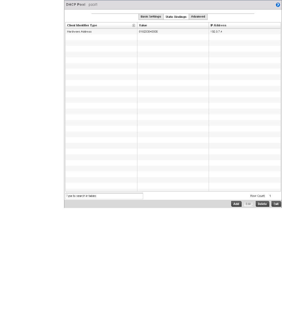
Brocade Mobility RFS4000, RFS6000, and RFS7000 System Reference Guide 577
53-1002620-01
10
FIGURE 382 DHCP Pools screen - Static Bindings tab
7. Review the following to determine if a static binding can be used as is, a new binding requires
creation or edit, or if a binding requires deletion:
8. Select Add to create a new static binding configuration, Edit to modify an existing static binding
configuration or Delete to remove a static binding from amongst those available.
Client Identifier Type Lists whether the reporting client is using a Hardware Address or Client Identifier as
its identifier type.
Value Lists the hardware address or client identifier value assigned to the client when
added or last modified.
IP Address Displays the IP address of the client on this interface that’s currently using the pool
name listed.
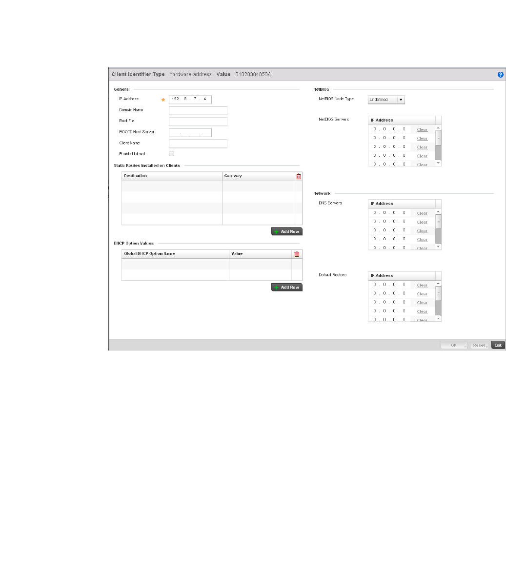
578 Brocade Mobility RFS4000, RFS6000, and RFS7000 System Reference Guide
53-1002620-01
10
FIGURE 383 Static Bindings Add screen
9. Define the following General parameters to complete the creation of the static binding
configuration:
IP Address Set the IP address of the client using this host pool.
Domain Name Provide a domain name of the current interface. Domain names aren’t case
sensitive and can contain alphabetic or numeric letters or a hyphen. A fully qualified
domain name (FQDN) consists of a host name plus a domain name. For example,
computername.domain.com
Boot File Enter the name of the boot file used with this pool. Boot files (Boot Protocol) can be
used to boot remote systems over the controller managed network. BOOTP
messages are encapsulated inside UDP messages so requests and replies can be
forwarded by the controller. Each DHCP network pool can use a different file as
needed
BOOTP Next Server Provide the numerical IP address of the server providing BOOTP resources.
Client Name Provide the name of the client requesting DHCP Server support.
Enable Unicast Unicast packets are sent from one location to another location (there's just one
sender, and one receiver). Select this option to allow the controller to forward
unicast messages to just a single device within this network pool.

Brocade Mobility RFS4000, RFS6000, and RFS7000 System Reference Guide 579
53-1002620-01
10
10. Define the following NetBIOS parameters to complete the creation of the static binding
configuration:
11. Refer to the Static Routes Installed on Clients field to set Destination IP and Gateway
addresses enabling assignment of static IP addresses without creating numerous host pools
with manual bindings. This eliminates the need for a long configuration file and reduces the
space required in NVRAM to maintain address pools. Select the + Add Row button to add
individual destinations. Select the Delete icon to remove it from the list of those available.
12. Refer to the DHCP Option Values table to set Global DHCP options. A set of global DHCP
options applies to all clients, whereas a set of subnet options applies only to the clients on a
specified subnet. If you configure the same option in more than one set of options, the
precedence of the option type decides which the DHCP server supports a client.
a. Select the + Add Row button to add individual options. Assign each a Global DHCP Option
Name to help differentiate it from others with similar configurations. At any time you can
select the radio button of an existing option and select the - Delete button to remove it
from the list of those available.
b. Assign a Value to each option with codes in the range 1 through 254. A vendor-specific
option definition only applies to the vendor class for which it is defined.
13. Within the Network section, define one or group of DNS Servers to translate domain names to
IP addresses. Up to 8 IP addresses can be provided.
14. Select OK when completed to update the static bindings configuration. Select Reset to revert
the screen back to its last saved configuration.
15. Select the Advanced tab to define additional NetBIOS and Dynamic DNS parameters.
NetBIOS Node Type Set the NetBios Node Type used with this particular pool. The node can have one of
the following types:
Broadcast - Uses broadcasting to query nodes on the network for the owner of a
NetBIOS name.
Peer-to-Peer - Uses directed calls to communicate with a known NetBIOS name
server (such as a WINS server), for the IP address of a NetBIOS machine.
Mixed - A mixed node using broadcasted queries to find a node, and failing that,
queries a known p-node name server for the address.
Hybrid - A combination of two or more nodes.
Undefined - No node type is applied.
NetBIOS Servers Specify a numerical IP address of a single or group of NetBIOS WINS servers
available to DHCP supported wireless clients. A maximum of 8 server IP addresses
can be assigned.
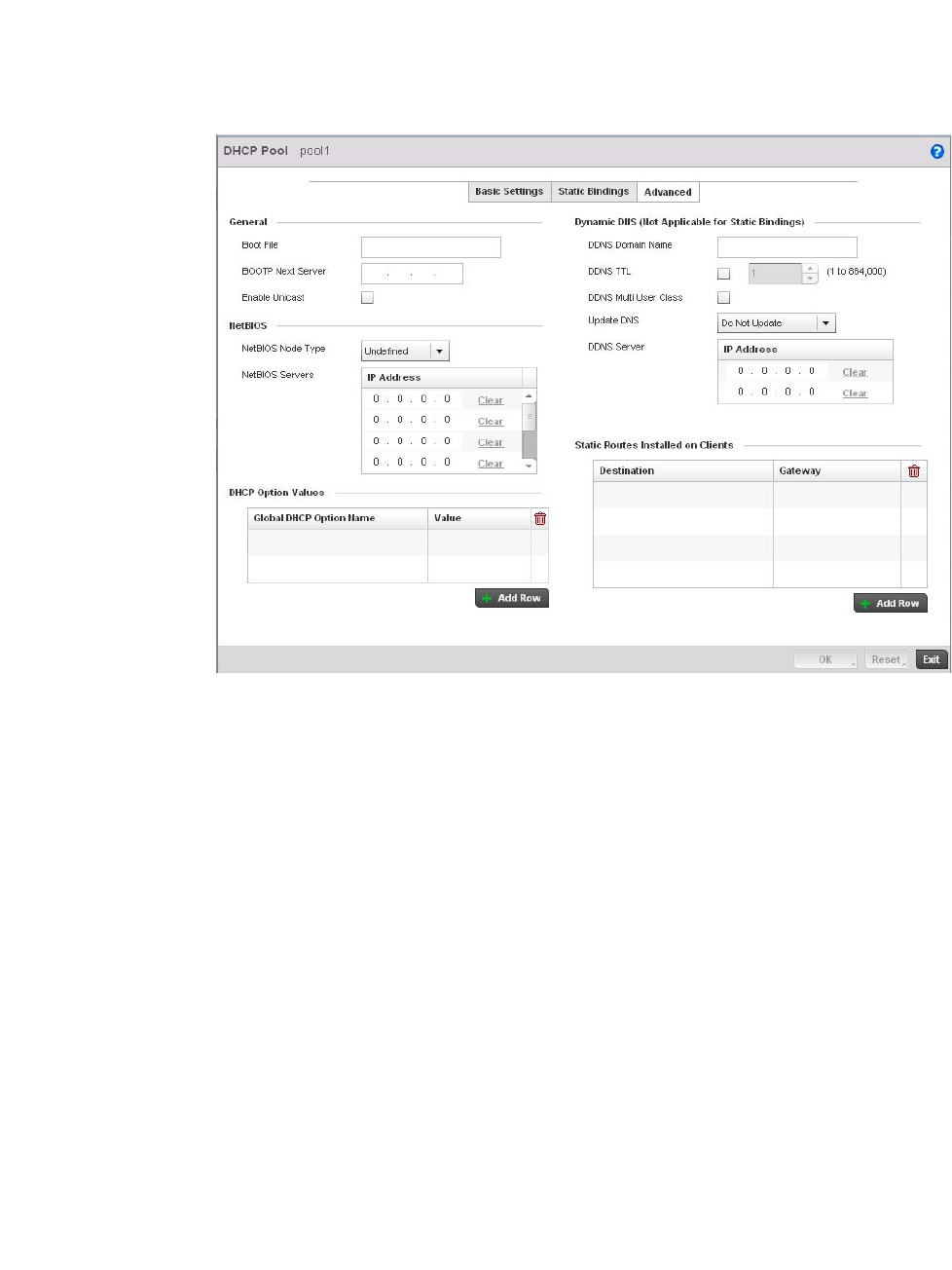
580 Brocade Mobility RFS4000, RFS6000, and RFS7000 System Reference Guide
53-1002620-01
10
FIGURE 384 DHCP Pools screen - Advanced tab
16. The addition or edit of the network pool’s advanced settings requires the following General
parameters be set:
17. Set the following NetBIOS parameters for the network pool:
Boot File Enter the name of the boot file used with this pool. Boot files (Boot Protocol) can be
used to boot remote systems over the controller managed network. BOOTP
messages are encapsulated inside UDP messages so requests and replies can be
forwarded by the controller. Each pool can use a different file as needed.
BOOTP Next Server Provide the numerical IP address of the server providing BOOTP resources.
Enable Unicast Unicast packets are sent from one location to another location (there's just one
sender, and one receiver). Select this option to allow the controller to forward
unicast messages to just a single device within the network pool.
NetBIOS Node Type Set the NetBIOS Node Type used with this pool. The following types are available:
Broadcast - Uses broadcasting to query nodes on the network for the owner of a
NetBIOS name.
Peer-to-Peer - Uses directed calls to communicate with a known NetBIOS name server,
such as a WINS server, for the IP address of a NetBIOS machine.
Mixed - Is a mixed node using broadcasted queries to find a node, and failing that,
queries a known p-node name server for the address.
Hybrid - Is a combination of two or more nodes.
Undefined - No NetBIOS Node Type is used.
NetBIOS Servers Specify a numerical IP address of a single or group of NetBIOS WINS servers available to
DHCP supported wireless clients.

Brocade Mobility RFS4000, RFS6000, and RFS7000 System Reference Guide 581
53-1002620-01
10
18. Define the following set of Dynamic DNS (Not Applicable for Static Bindings) parameters used
with the network pool configuration. DDNS enables the controller to notify a DNS server to
change, in real time (ad-hoc) the active DNS configuration of its configured hostnames,
addresses or other information stored in DNS.
19. Refer to the DHCP Option Values table to set global DHCP options applicable to all clients,
whereas a set of subnet options applies to just the clients on a specified subnet.
a. Select the + Add Row button to add individual options. Assign each a Global DHCP Option
Name to help differentiate it from others with similar configurations. At any time you can
select the radio button of an existing option and select the Delete icon to remove it from
the list of those available.
b. Assign a Value to each option with codes in the range 1 through 254. A vendor-specific
option definition only applies to the vendor class for which it’s defined.
20. Click the + Add Row button and enter a Destination and Gateway IP Address to add Static
Routes Installed on Clients.
21. Select OK to save the updates to the DHCP pool’s Advanced settings. Select Reset to revert the
screen back to its last saved configuration.
Defining DHCP Server Global Settings
Setting a DHCP server global configuration entails defining whether BOOTP requests are ignored
and setting DHCP global server options.
To define DHCP server global settings:
1. Select DHCP > Server Policy from within Services menu pane.
2. Select the Global Settings tab.
DDNS Domain Name Enter a domain name for DDNS updates representing the forward zone in the DNS
server. For example, test.net.
DDNS TTL Select this option to set a TTL (Time to Live) to specify the validity of DDNS records. The
maximum value configurable is 864000 seconds.
DDNS Multi User Class Select the check box to associate the user class option names with a multiple user
class. This allows the user class to transmit multiple option values to DHCP servers
supporting multiple user class options.
Update DNS Set if DNS is updated from a client or a server. Select either Do Not Update, Update from
Server or Update from Client. The default setting is Do Not Update, implying that no DNS
updates occur at all.
DDNS Server Specify a numerical IP address of one or two DDNS servers.
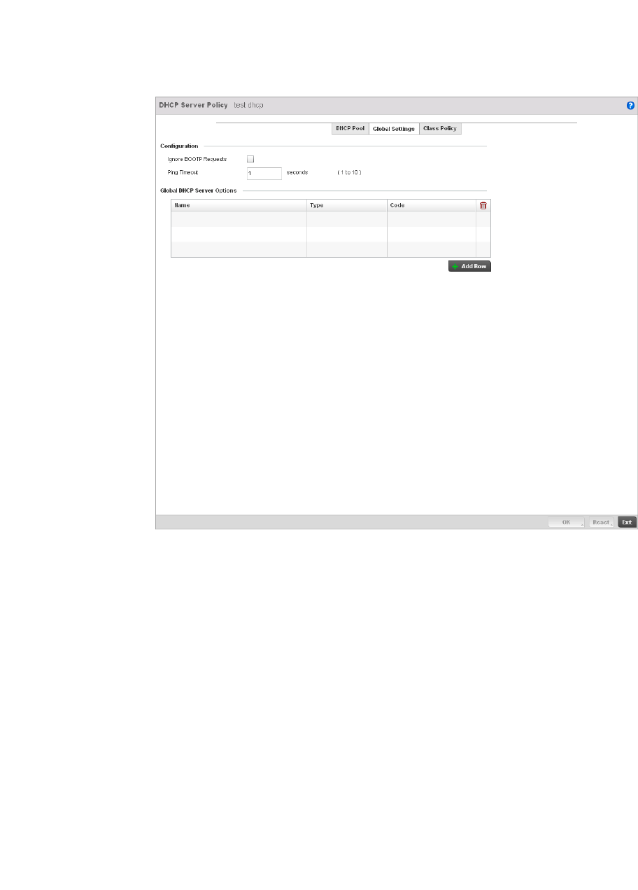
582 Brocade Mobility RFS4000, RFS6000, and RFS7000 System Reference Guide
53-1002620-01
10
FIGURE 385 DHCP Server Policy screen - Global Settings tab
3. Set the following parameters within the Configuration field:
4. Refer to the Global DHCP Server Options field.
a. Use the + Add Row button at the bottom of the field to add a new global DHCP server
option. At any time you can select the radio button of an existing global DHCP server option
and select the Delete icon to remove it from the list of those available.
b. Use the Type drop-down menu to specify whether the DHCP option is being defined as a
numerical IP address or ASCII string or Hex string. Highlight an entry from within the Global
Options screen and click the Remove button to delete the name and value.
5. Select OK to save the updates to the DHCP server global settings. Select Reset to revert the
screen back to its last saved configuration.
Ignore BOOTP Requests Select the checkbox to ignore BOOTP requests. BOOTP (boot protocol) requests boot
remote systems within the controller managed network. BOOTP messages are
encapsulated inside UDP messages and are forwarded by the controller. This feature is
disabled by default, so unless selected, BOOTP requests are forwarded.
Ping Timeout Set an interval (from 1 -10 seconds) for the DHCP server ping timeout. The controller
uses the timeout to intermittently ping and discover whether a client requested IP
address is already used.
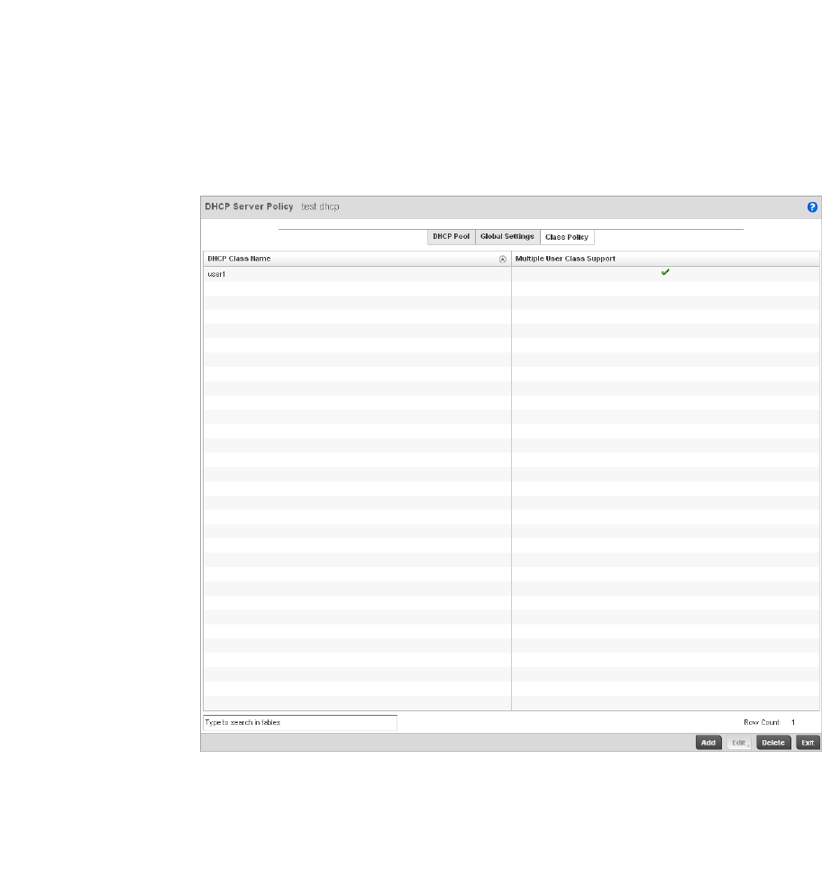
Brocade Mobility RFS4000, RFS6000, and RFS7000 System Reference Guide 583
53-1002620-01
10
DHCP Class Policy Configuration
The controller’s DHCP server assigns IP addresses to DHCP enabled wireless clients based on user
class option names. Clients with a defined set of user class option names are identified by their
user class name. The DHCP server can assign IP addresses from as many IP address ranges as
defined by the administrator. The DHCP user class associates a particular range of IP addresses to
a device in such a way that all devices of that type are assigned IP addresses from the defined
range.
Refer to the DHCP Class Policy screen to review existing DHCP class names and their current
multiple user class designations. Multiple user class options enable a user class to transmit
multiple option values to DHCP servers supporting multiple user class options. Either add a new
class policy, edit the configuration of an existing policy or permanently delete a policy as required.
To review DHCP class policies:
1. Select Configuration > Services.
2. Select the Class Policy tab.
3. Refer to the following to determine whether a new class policy requires creation, an existing
class policy requires edit or an existing policy requires deletion:
DHCP Class Name Displays client names grouped by the class name assigned when the class policy was
created.
Multiple User Class A green check mark in this column defines multiple user class support as enabled from
the listed DHCP class name. A red “X” defines multiple user class support as disabled
for the listed DHCP class name. Multiple user class support can be enabled/disabled for
existing class names by editing the class name’s configuration.
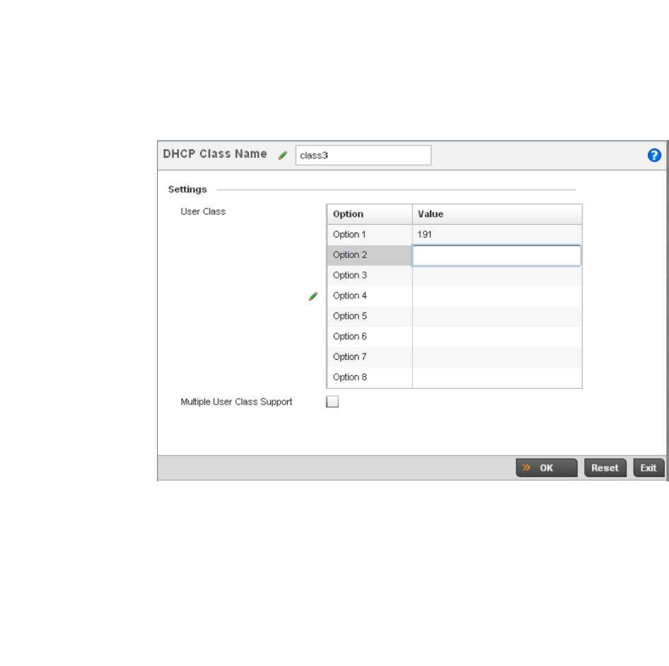
584 Brocade Mobility RFS4000, RFS6000, and RFS7000 System Reference Guide
53-1002620-01
10
4. Select Add to create a new DHCP class policy, Edit to update an existing policy or Delete to
remove an existing policy.
FIGURE 386 DHCP Class Name Add screen
5. If adding a new DHCP Class Name, assign a name representative of the device class
supported. The DHCP user class name should not exceed 32 characters.
6. Select a row within the Value column to enter a 32 character maximum value string.
7. Select the Multiple User Class check box to enable multiple option values for the user class.
This allows the user class to transmit multiple option values to DHCP servers supporting
multiple user class options.
8. Select OK to save the updates to this DHCP class policy. Select Reset to revert the screen back
to its last saved configuration.
DHCP Deployment Considerations
Before defining a controller’s internal DHCP server configuration, refer to the following deployment
guidelines to ensure the configuration is optimally effective:
•Brocade DHCP option 189 is required when Brocade Mobility 650 Access Point access points
are deployed over a layer 3 network and require layer 3 adoption. DHCP services are not
required for Brocade Mobility 650 Access Point access points connected to a VLAN that’s local
to the controller.
•DHCP’s lack of an authentication mechanism means a DHCP server cannot check if a client or
user is authorized to use a given user class. This introduces a vulnerability when using user
class options. For example, if a user class is used to assign a special parameter (for example, a
database server), there is no way to authenticate a client and it’s impossible to check if a client
is authorized to use this parameter.

Brocade Mobility RFS4000, RFS6000, and RFS7000 System Reference Guide 585
53-1002620-01
10
•Ensure traffic can pass on UDP ports 67 and 68 between the controller and the clients
receiving DHCP information to ensure optimum DHCP support for DHCP enabled wireless
clients.
Setting the Controller’s RADIUS Configuration
Remote Authentication Dial-In User Service (RADIUS) is a client/server protocol and software
enabling remote access servers to communicate with the switch to authenticate users and
authorize their access to the controller managed network. RADIUS is a distributed client/server
system that secures networks against unauthorized access. RADIUS clients send authentication
requests to the controller’s RADIUS server containing user authentication and network service
access information.
RADIUS enables centralized management of controller authentication data (usernames and
passwords). When an MU attempts to associate to the RADIUS supported controller, the controller
sends the authentication request to the RADIUS server. The authentication and encryption of
communications between the controller and server takes place through the use of a shared secret
password (not transmitted over the network).
The controller’s local RADIUS server stores the user database locally, and can optionally use a
remote user database. It ensures higher accounting performance. It allows the configuration of
multiple users, and assign policies for the group authorization.
The controller allows the enforcement of user-based policies. User policies include dynamic VLAN
assignment and access based on time of day.The controller uses a default trustpoint. A certificate
is required for EAP TTLS,PEAP and TLS RADIUS authentication (configured with the RADIUS
service).
Dynamic VLAN assignment is achieved based on the RADIUS server response. A user who
associates to WLAN1 (mapped to VLAN1) can be assigned a different VLAN after authentication
with the RADIUS server. This dynamic VLAN assignment overrides the WLAN's VLAN ID to which the
User associates.
To view RADIUS configurations:
Select Configuration tab from the main menu.
Select the Services tab from the Configuration menu.
The upper, left-hand side pane of the User interface displays the RADIUS option. The RADIUS Group
screen displays (by default).
For information on creating the groups, user pools and server policies needed to validate user
credentials against a server policy configuration, refer to the following:
•Creating RADIUS Groups
•Defining User Pools
•Configuring RADIUS Server Policies
•RADIUS Deployment Considerations
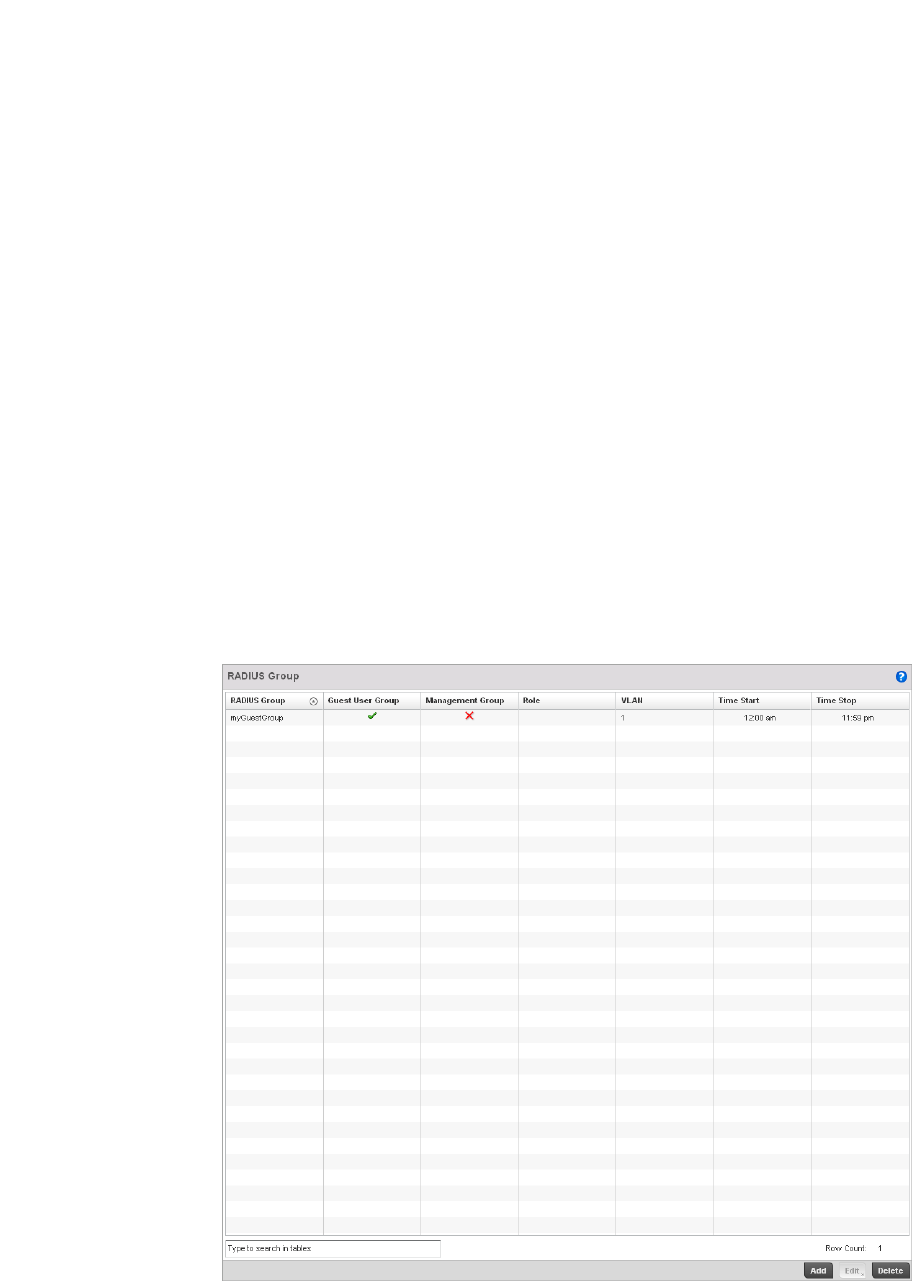
586 Brocade Mobility RFS4000, RFS6000, and RFS7000 System Reference Guide
53-1002620-01
10
Creating RADIUS Groups
The controller’s RADIUS server allows the configuration of user groups with common user policies.
User group names and associated users are stored in the controller’s local database. The user ID in
the received access request is mapped to the associated wireless group for authentication.The
configuration of groups allows the enforcement of the following policies that can control the access
of the user:
•Assign a VLAN to the user upon successful authentication
•Define a start and end of time in (HH:MM) when the user is allowed to authenticate
•Define the list of SSIDs to which a user belonging to this group is allowed to associate
•Define the days of the week the user is allowed to login
•Rate limit traffic
To access RADIUS Groups menu:
1. Select Configuration tab from the main menu.
2. Select the Services tab from the Configuration menu.
3. Select RADIUS > Groups from the Configuration > Services menu.
4. The browser displays a list of the existing groups.
FIGURE 387 RADIUS Group screen

Brocade Mobility RFS4000, RFS6000, and RFS7000 System Reference Guide 587
53-1002620-01
10
5. Select a group from the Group Browser to view the following read-only information for existing
groups:
6. To modify the settings of an existing group, select the group and click the Edit button.To delete
an obsolete group, select the group and click the Delete button.
Creating RADIUS Groups
To create a RADIUS group:
1. Select Configuration tab from the main menu.
2. Select the Services tab from the Configuration menu.
3. Select RADIUS > Groups from the Configuration > Services menu.
4. Click the Add to create a new RADIUS group, Edit to modify the configuration of an existing
group or Delete to permanently remove a selected group.
RADIUS Group Displays the group name or identifier assigned to each listed group when it was created.
The name cannot exceed 32 characters or be modified as part of the group edit process.
Guest User Group Specifies whether a user group only has guest access and temporary permissions to the
controller’s local RADIUS server. The terms of the guest access can be set uniquely for
each group. A red “X” designates the group as having permanent access to the local
RADIUS server. Guest user groups cannot be made management groups with unique
access and role permissions.
Management Group A green checkmark designates this RADIUS user group as a management group.
Management groups can be assigned unique access and role permissions.
Role If a group is listed as a management group, it may also have a unique role assigned.
Available roles include:
monitor - Read-only access.
helpdesk - Helpdesk/support access
network-admin - Wired and wireless access
security-admin - Grants full read/write access
system-admin - System administrator access
VLAN Displays the VLAN ID used by the group. The VLAN ID is representative of the shared
SSID each group member (user) employs to interoperate within the controller managed
network (once authenticated by the local RADIUS server).
Time Start Specifies the time users within each listed group can access the controller’s local
RADIUS resources.
Time Stop Specifies the time users within each listed group lose access to the controller’s local
RADIUS resources.
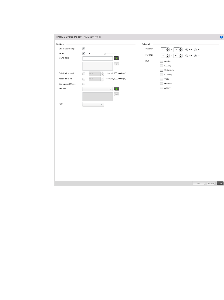
588 Brocade Mobility RFS4000, RFS6000, and RFS7000 System Reference Guide
53-1002620-01
10
FIGURE 388 RADIUS Group Policy Add screen
5. Define the following Settings to define the user group configuration:
RADIUS Group Policy If creating a new RADIUS group, assign it a name to help differentiate it from others with
similar configurations. The name cannot exceed 32 characters or be modified as part of
a RADIUS group edit process.
Guest User Group Select this option to assign only guest access and temporary permissions to the
controller’s local RADIUS server. Guest user groups cannot be made management
groups with unique access and role permissions.
VLAN Select this option to assign a specific VLAN to this RADIUS user group. Ensure Dynamic
VLAN assignment (Single VLAN) is enabled for the WLAN in order for the VLAN
assignment to work properly. For more information, see
Basic WLAN Configuration on page 6-284.
WLAN SSID Assign a list of SSIDs users within this RADIUS group are allowed to associate to. An
SSID cannot exceed 32 characters. Assign WLAN SSIDs representative of the
configurations a guest user will need to access. The parameter is not available if this
RADIUS group is a management group.
Rate Limit from Air Select the checkbox to set the rate limit to controller managed clients within this RADIUS
group. Use the spinner to set value from 100-1,000,000 kbps. Setting a value of 0
disables rate limiting

Brocade Mobility RFS4000, RFS6000, and RFS7000 System Reference Guide 589
53-1002620-01
10
6. Set the Schedule to configure access times and dates.
7. C l i c k t h e OK to save the changes. Select Reset to revert to the last saved configuration.
Defining User Pools
A user pool defines policies for individual user access to the controller’s internal RADIUS resources.
User or pools provide a convenient means of providing user access to the controller’s RADIUS
resources based on the pool’s unique permissions (either temporary or permanent). A pool can
contain a single user or group of users.
To configure a RADIUS user pool and unique user IDs:
1. Select Configuration from the main menu.
2. Select Services tab from the Configuration screen.
3. Select RADIUS > User Pools from the Configuration > Services menu.
Rate Limit to Air Select the checkbox to set the rate limit from clients within this RADIUS group. Use the
spinner to set value from 100-1,000,000 kbps. Setting a value of 0 disables rate
limiting.
Management Group Select this option to designate this RADIUS group as a management group. This feature
is disabled by default. If set as management group, assign a role to the members of the
group using the Access drop-down menu allowing varying levels of administrative
rights.
Role If a group is listed as a management group, it may also have a unique role assigned.
Available roles include:
monitor - Read-only access.
helpdesk - Helpdesk/support access
network-admin - Wired and wireless access
security-admin - Grants full read/write access
system-admin - System administrator access
Time Start Use the spinner control to set the time (in HH:MM format) RADIUS group members are
allowed to login and access the controller’s RADIUS server resources (for example,
14:45 = 2:45). Select either the AM or PM radio button to set the time as morning or
evening.
Time Stop Use the spinner control to set the time (in HH:MM format) RADIUS group members are
denied access to the controller’s RADIUS server resources (for example, 15:45 = 3:45).
Select either the AM or PM radio button to set the time as morning or evening. If
already logged in, the RADIUS group user is deauthenticated from the WLAN.
Days Select the day(s) of the week RADIUS group members can access controller RADIUS
resources.
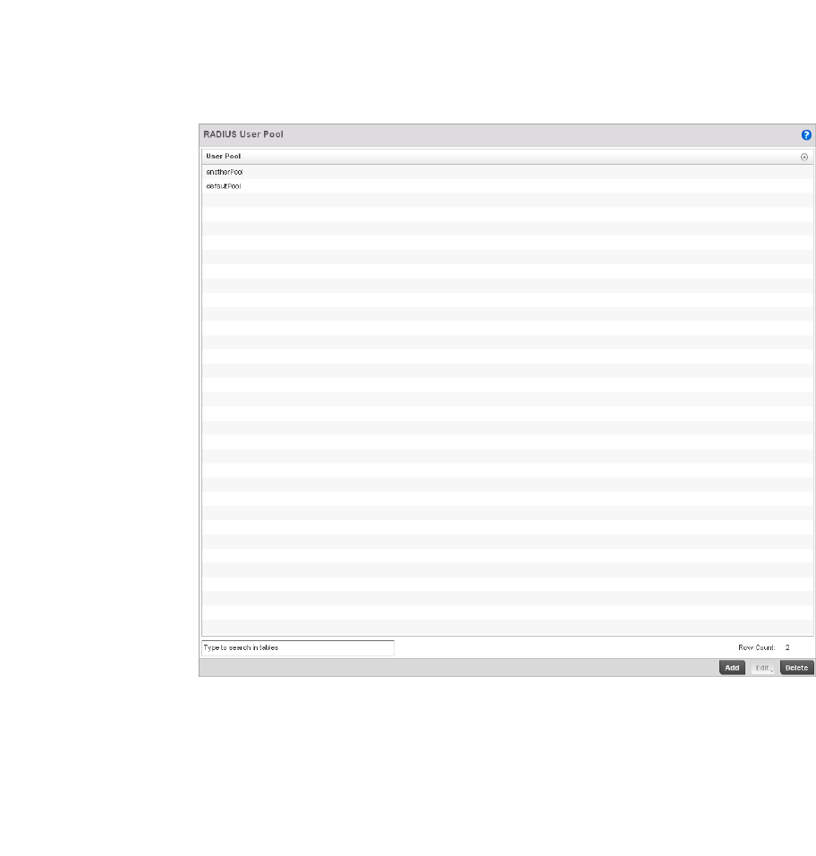
590 Brocade Mobility RFS4000, RFS6000, and RFS7000 System Reference Guide
53-1002620-01
10
FIGURE 389 RADIUS User Pool screen
4. The RADIUS User Pool screen lists the default pool along with any other admin created user
pool.
5. Select Add to create a new user pool, Edit to modify the configuration of an existing pool or
Delete to remove a selected pool.
6. If creating a new pool, assign it a name up to 32 characters and select Continue. The name
should be representative of the users comprising the pool and/or the temporary or permanent
access privileges assigned.
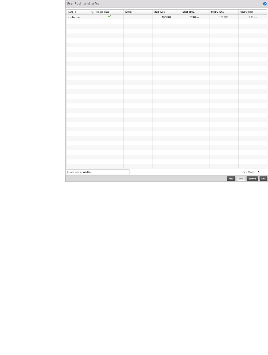
Brocade Mobility RFS4000, RFS6000, and RFS7000 System Reference Guide 591
53-1002620-01
10
FIGURE 390 RADIUS User Pool Add screen
7. Refer to the following User Pool configurations to discern when specific user IDs have access to
the controller’s RADIUS resources:
8. Select the Add button to add a new RADIUS user, Edit to modify the configuration of an existing
user or Delete to remove an existing user Id.
User Id Displays the unique alphanumeric string identifying this user. This is Id assigned to the
user when created and cannot be modified with the rest of the configuration.
Guest User Specifies (with a green check) the user has guest access and temporary permissions to
the controller’s local RADIUS server. The terms of the guest access can be set uniquely
for each user. A red “X” designates the user as having permanent access to the local
RADIUS server.
Group Displays the group name each configured user ID is a member.
Start Date Lists the month, day and year the listed user ID can access the controller’s internal
RADIUS server resources.
Start Time Lists the time the listed user ID can access the controller’s internal RADIUS server
resources. The time is only relevant to the range defined by the start and expiry date.
Expiry Date Lists the month, day and year the listed user Id can no longer access the controller’s
internal RADIUS server resources.
Expiry Time Lists the time the listed user Id losses access the controller’s internal RADIUS server
resources. The time is only relevant to the range defined by the start and expiry date.
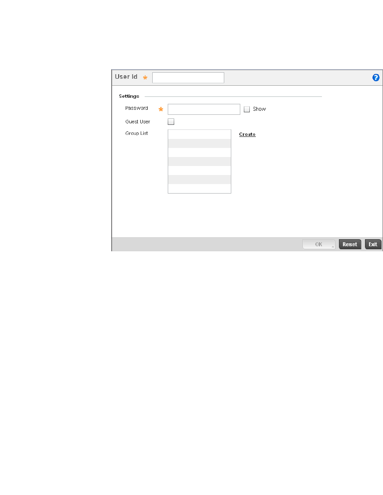
592 Brocade Mobility RFS4000, RFS6000, and RFS7000 System Reference Guide
53-1002620-01
10
FIGURE 391 RADIUS User screen
9. Refer the following fields in the User screen to create a new user Id with unique access
privileges:
10. Select OK to save the user Id’s group membership configuration. Select Reset to revert to the
last saved configuration.
Configuring RADIUS Server Policies
A RADIUS server policy is a unique authentication and authorization configuration for receiving user
connection requests, authenticating users and returning the configuration information necessary
for the RADIUS client to deliver service to the user. The client is the entity with authentication
information requiring validation. The controller’s RADIUS server has access to a database of
authentication information used to validate the client's authentication request.
The controller’s RADIUS server ensures the information is correct using authentication schemes
like PAP, CHAP or EAP. The user's proof of identification is verified, along with, optionally, other
information. A controller’s RADIUS server policy can also be configured to refer to an external LDAP
resource to verify the user's credentials.
To review RADIUS existing server policies, manage the creation of new policies of manage the
modification of existing policies:
User Id Assign a unique alphanumeric string identifying this user. The Id cannot exceed 64
characters in length.
Password Provide a password unique to this user Id. The password cannot exceed 32 characters in
length. Select the Show checkbox to expose the password’s actual character string,
leaving the option unselected displays the password as a string of asterisks (*).
Guest User Select the checkbox to designate this user as a guest with temporary access. The guest
user must be assigned unique access times to restrict their access.
Group List If the user Id has been defined as a guest, use the Group drop-down menu to assign
the user a group with temporary access privileges. If the user is defined as a permanent
user, select a group from the group list. If there’s no groups listed relevant to the user’s
intended access, select the Create link (or icon for guests) and create a new group
configuration suitable for the user Id’s membership. For more information, see Creating
RADIUS Groups on page 10-587.
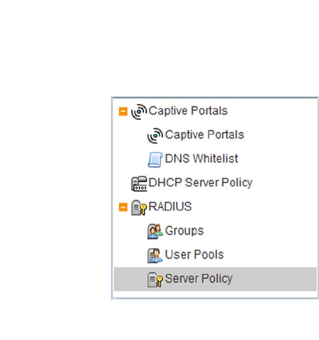
Brocade Mobility RFS4000, RFS6000, and RFS7000 System Reference Guide 593
53-1002620-01
10
1. Select Configuration from the main menu.
2. Select Services tab from the Configuration screen.
3. Select RADIUS > Server Policy from the Configuration > Services menu.
4. The Server Policy Browser lists existing server policies by either by group or randomly as
defined using the drop-down menu. A policy can be selected and modified at any time from the
browser.
FIGURE 392 Server Policy browser
5. Refer to the RADIUS Server screen to review high-level server policy configuration data.
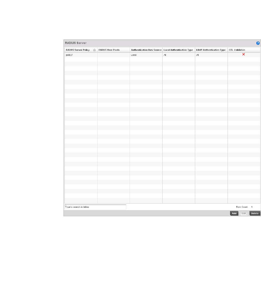
594 Brocade Mobility RFS4000, RFS6000, and RFS7000 System Reference Guide
53-1002620-01
10
FIGURE 393 Server Policy screen
6. Select a server policy from the Server Policy Browser to view the read only information of the
policy. The user has the option of adding a new policy, modifying an existing one, or deleting a
policy.
RADIUS Server Policy Lists the name assigned to the policy upon creation.
RADIUS User Pools Lists the user pools assigned to this server policy.
Authentication Data Source Specifies the RADIUS datasource for user authentication. Options include Local
for the controllers local user database or LDAP for a remote LDAP resource.

Brocade Mobility RFS4000, RFS6000, and RFS7000 System Reference Guide 595
53-1002620-01
10
7. Select either Add to create a new RADIUS server policy, Edit to modify an existing policy or
Delete to permanently remove a policy.
Local Authentication Type Lists the controllers local EAP authentication scheme used with this policy. The
following EAP authentication types are supported by the controller’s onboard
RADIUS server:
All – Enables both TTLS and PEAP.
TLS - Uses TLS as the EAP type
TLS and MD5 - The EAP type is TTLS with default authentication using MD5.
TTLS and PAP - The EAP type is TTLS with default authentication using PAP.
TTLS and MSCHAPv2 - The EAP type is TTLS with default authentication using
MSCHAPv2.
PEAP and GTC - The EAP type is PEAP with default authentication using GTC.
PEAP and MSCHAPv2 - The EAP type is PEAP with default authentication using
MSCHAPv2.
LDAP Authentication Type Lists the LDAP authentication scheme used with this policy. The following LDAP
authentication types are supported with the controller’s external LDAP resource:
All – Enables both TTLS and PAP and PEAP and GTC.
TTLS and PAP - The EAP type is TTLS with default authentication using PAP.
PEAP and GTC - The EAP type is PEAP with default authentication using GTC.
CRL Validation Specifies whether a Certificate Revocation List (CRL) check is made. A green
checkmark indicates CRL validation is enabled. A red “X” indicates it’s disabled.
A CRL is a list of revoked certificates issued and subsequently revoked by a
Certification Authority (CA). Certificates can be revoked for a number of reasons
including failure or compromise of a device using a certificate, a compromise of
a certificate key pair or errors within an issued certificate. The mechanism used
for certificate revocation depends on the CA.
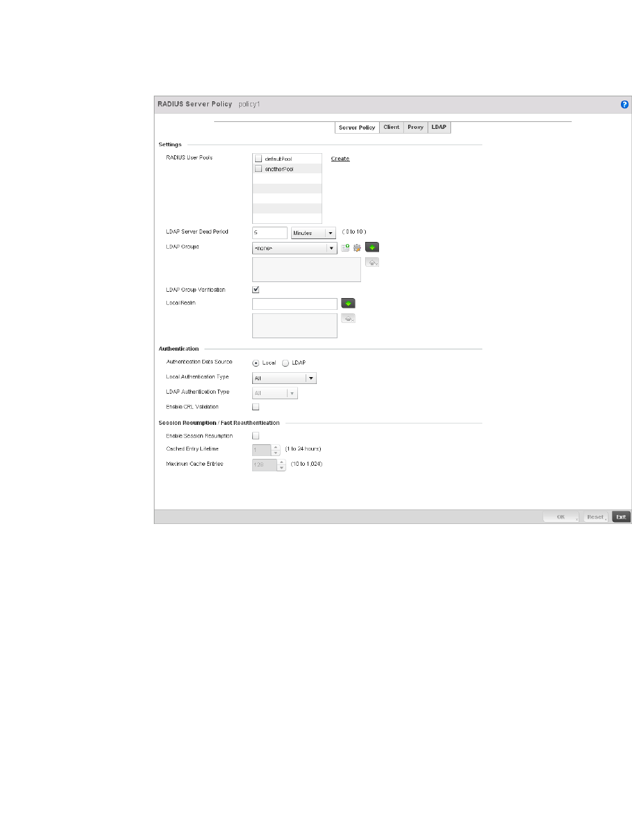
596 Brocade Mobility RFS4000, RFS6000, and RFS7000 System Reference Guide
53-1002620-01
10
FIGURE 394 RADIUS Server Policy screen - Server Policy tab
8. The Server Policy tab displays by default.
9. If creating a new policy, assign it a RADIUS Server Policy name up to 32 characters.
10. Set the following Settings required in the creation or modification of the server policy:.
RADIUS User Pools Select the user pools to apply to this server policy. Up to 32 policies can be
applied.
LDAP Server Dead Period Set an interval in either Seconds (0 - 600) or Minutes (0- 10) during which the
controller will not contact its LDAP server resource. A dead period is only
implemented when additional LDAP servers are configured and available.
LDAP Groups Use the drop-down menu to select LDAP groups to apply the server policy
configuration. Select the Create or Edit icons as needed to either create a new
group or modify an existing group. Use the arrow icons to add and remove
groups as required.
LDAP Group Verification Select the checkbox to set the LDAP group search configuration.
Local Realm Define the LDAP performing authentication using information from an LDAP
server. User information includes user name, password, and the groups to which
the user belongs.

Brocade Mobility RFS4000, RFS6000, and RFS7000 System Reference Guide 597
53-1002620-01
10
11. Set the following Authentication parameters to define server policy authorization settings.
12. Set the following Session Resumption/Fast Reauthentication settings to define how server
policy sessions are re-established once terminated and require cached data to resume:
13. Select OK to save the settings to the server policy configuration. Select Reset to revert to the
last saved configuration.
14. Refer to the following to add RADIUS clients, proxy server configurations, LDAP server
configurations and review deployment considerations impacting the effectiveness of the
controller’s RADIUS deployment:
•Configuring RADIUS Clients
•Configuring a RADIUS Proxy
•Configuring an LDAP Server Configuration
Authentication Data Source Select the RADIUS resource for user authentication with this server policy.
Options include Local for the controller’s local user database or LDAP for a
remote LDAP resource. The default setting is Local.
Local Authentication Type Use the drop-down menu to select the controllers local EAP authentication
scheme used with this policy. The following EAP authentication types are
supported by the controller’s onboard RADIUS server:
All – Enables both TTLS and PEAP.
TLS - Uses TLS as the EAP type
TLS and MD5 - The EAP type is TTLS with default authentication using MD5.
TTLS and PAP - The EAP type is TTLS with default authentication using PAP.
TTLS and MSCHAPv2 - The EAP type is TTLS with default authentication using
MSCHAPv2.
PEAP and GTC - The EAP type is PEAP with default authentication using GTC.
PEAP and MSCHAPv2 - The EAP type is PEAP with default authentication using
MSCHAPv2.
LDAP Authentication Type Use the drop-down menu to select the LDAP authentication scheme used with
this policy. The following LDAP authentication types are supported by the
controller’s external LDAP resource:
All – Enables both TTLS and PAP and PEAP and GTC.
TTLS and PAP - The EAP type is TTLS with default authentication using PAP.
PEAP and GTC - The EAP type is PEAP with default authentication using GTC.
Enable CRL Validation Select this option to enable a Certificate Revocation List (CRL) check is made.
Certificates can be checked and revoked for a number of reasons including
failure or compromise of a device using a certificate, a compromise of a
certificate key pair or errors within an issued certificate. This option is disabled
by default.
Enable Session Resumption Select the checkbox to control volume and the duration cached data is
maintained by the server policy upon the termination of a server policy
session.The availability and quick retrieval of the cached data speeds up
session resumption.
Cached Entry Lifetime Use the spinner control to set the lifetime (1 - 24 hours) cached data is
maintained by the RADIUS server policy. The default setting is 1 hour.
Maximum Cache Entries Use the spinner control to define the maximum number of entries maintained in
cache for this RADIUS server policy. The default setting is 128 entries.
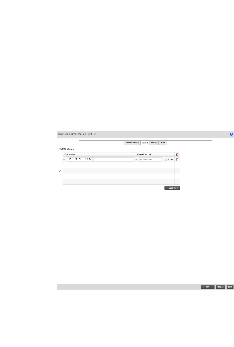
598 Brocade Mobility RFS4000, RFS6000, and RFS7000 System Reference Guide
53-1002620-01
10
Configuring RADIUS Clients
The controller uses a RADIUS client as a mechanism to communicate with a central server to
authenticate users and authorize access to the controller managed network.
The client and server share a secret. That shared secret followed by the request authenticator is
put through a MD5 hash to create a 16 octet value which is XORed with the password entered by
the user. If the user password is greater than 16 octets, additional MD5 calculations are
performed, using the previous ciphertext instead of the request authenticator. The server receives
a RADIUS access request packet and verifies the server possesses a shared secret for the client. If
the server does not possess a shared secret for the client, the request is dropped. If the client
received a verified access accept packet, the username and password are considered correct, and
the user is authenticated. If the client receives a verified access reject message, the username and
password are considered to be incorrect, and the user is not authenticated.
1. Select the Client tab from the RADIUS Server Policy screen.
FIGURE 395 RADIUS Server Policy screen - Client tab
2. Select the + Add Row button to add a table entry for a new client’s IP address, mask and
shared secret. To delete a client entry, select the Delete icon on the right-hand side of the table
entry.
3. Specify the IP Address and mask of the RADIUS client authenticating with the controller
managed RADIUS server.
4. Specify a Shared Secret for authenticating the RADIUS client.
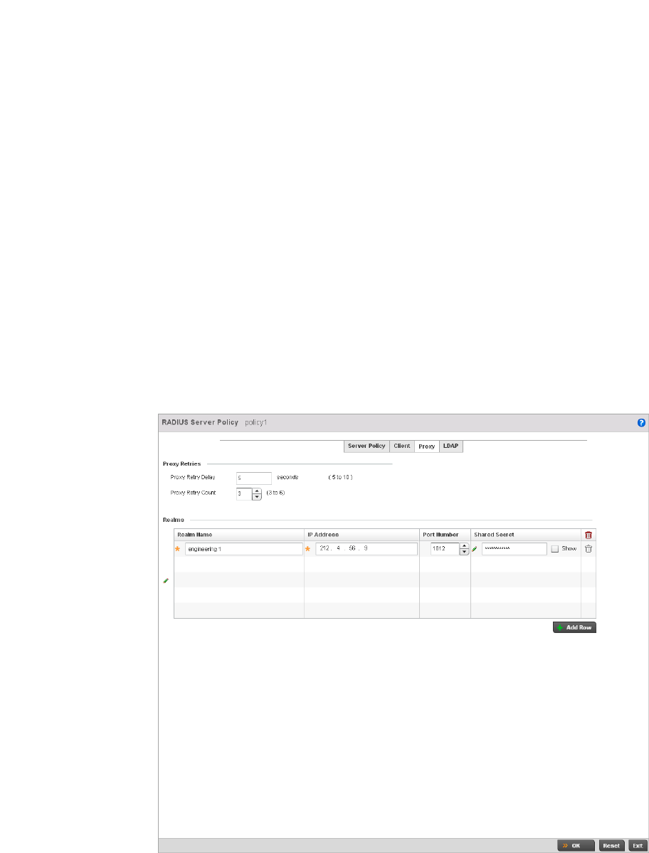
Brocade Mobility RFS4000, RFS6000, and RFS7000 System Reference Guide 599
53-1002620-01
10
5. Shared secrets verify RADIUS messages with RADIUS enabled device configured with the same
shared secret. Select the Show checkbox to expose the shared secret’s actual character string,
leaving the option unselected displays the shared secret as a string of asterisks (*).
6. Click OK button to save the server policy’s client configuration. Click the Reset button to revert
to the last saved configuration.
Configuring a RADIUS Proxy
A user’s access request is sent to a proxy server if it cannot be authenticated by the controller’s
local RADIUS resources. The proxy server checks the information in the user access request and
either accepts or rejects the request. If the proxy server accepts the request, it returns
configuration information specifying the type of connection service required to authenticate the
user.
The RADIUS proxy appears to act as a RADIUS server to the NAS, whereas the proxy appears to act
as a RADIUS client to the RADIUS server.
When the controller’s RADIUS server receives a request for a user name containing a realm, the
server references a table of configured realms. If the realm is known, the server proxies the
request to the RADIUS server. The behavior of the proxying server is configuration-dependent on
most servers. In addition, the proxying server can be configured to add, remove or rewrite requests
when they are proxied.
To define a proxy configuration:
1. Select the Proxy tab from the RADIUS Server Policy screen.
FIGURE 396 RADIUS Server Policy screen - Proxy tab

600 Brocade Mobility RFS4000, RFS6000, and RFS7000 System Reference Guide
53-1002620-01
10
2. Enter the Proxy server retry delay time in the Proxy Retry Delay field. Enter a value in seconds
within the range of 5-10 seconds. This is the interval the controller’s RADIUS server waits
before making an additional connection attempt. The default delay interval is 5 seconds.
3. Enter the Proxy server retry count value in the Proxy Retry Count field. Enter a value within the
range of 3-6 to define the number of retries sent to proxy server before giving up the request.
The default retry count is 3 attempts.
4. Select the + Add Row button to add a RADIUS server proxy realm name and network address.
To delete a proxy server entry, select the Delete icon on the right-hand side of the table entry.
5. Enter the realm name in the Realm Name field. The realm name cannot exceed 50 characters.
When the controller’s RADIUS server receives a request for a user name with a realm, the
server references a table of realms. If the realm is known, the server proxies the request to the
RADIUS server.
6. Enter the Proxy server IP address in the IP Address field. This is the address of server checking
the information in the user access request and either accepting or rejecting the request on
behalf of the controller’s RADIUS server.
7. Enter the TCP/IP port number for the server that acts as a data source for the proxy server in
the Port Number field. Use the spinner to select a value between 1024-65535. The default
port is 1812.
8. Enter the RADIUS client shared secret in the Shared Secret field for authenticating the RADIUS
proxy.
9. Select the Show checkbox to expose the shared secret’s actual character string, leaving the
option unselected displays the shared secret as a string of asterisks (*).
10. Click the OK button to save the changes. Click the Reset button to revert to the last saved
configuration.
Configuring an LDAP Server Configuration
Administrators have the option of using the controller’s RADIUS server to authenticate users
against an external LDAP server resource. Using an external LDAP user database allows the
centralization of user information and reduces administrative user management overhead making
the RADIUS authorization process more secure and efficient.
RADIUS is not just a database. It’s a protocol for asking intelligent questions to a user database
(like LDAP). LDAP however is just a database of user credentials that can be used optionally with
the controller’s RADIUS server to free up resources and manage user credentials from a secure
remote location. It’s the controller’s RADIUS resources that provide the tools to perform user
authentication and authorize users based on complex checks and logic. There’s no way to perform
such complex authorization checks from a LDAP user database alone.
To configure an LDAP server configuration for use with the controller’s RADIUS server:
1. Select the LDAP tab from the RADIUS Server screen.
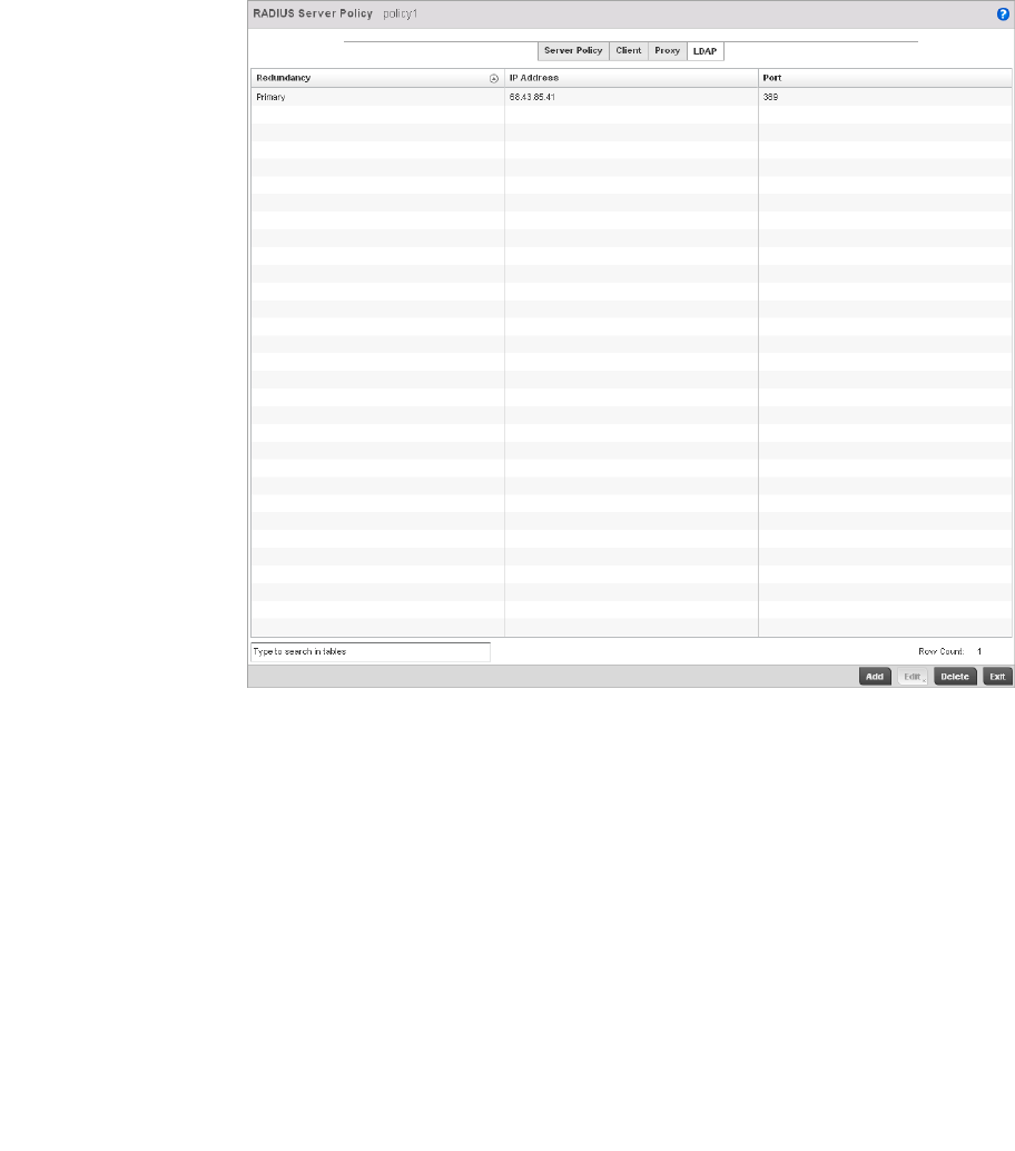
Brocade Mobility RFS4000, RFS6000, and RFS7000 System Reference Guide 601
53-1002620-01
10
FIGURE 397 RADIUS Server Policy screen - LDAP tab
2. Refer to the following to determine whether an LDAP server can be used as is, a server
configuration requires creation or modification or a configuration requires deletion and
permanent removal.
3. Click the Add button to add a new LDAP server configuration, Edit to modify an existing LDAP
server configuration or Delete to remove a LDAP server from the list of those available.
Redundancy Displays whether the listed LDAP server IP address has been defined as a
primary or secondary server resource. Designating at least one secondary
server is a good practice to ensure RADIUS user information is available if a
primary server were to become unavailable.
IP Address Displays the IP address of the external LDAP server acting as the data source for
the controller’s RADIUS server.
Port Lists the physical port number used by the controller’s RADIUS server to secure
a connection with the remote LDAP server resource.
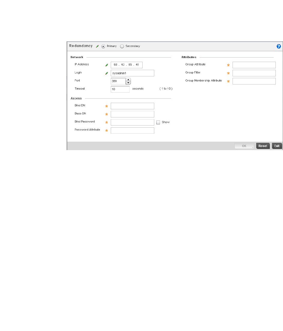
602 Brocade Mobility RFS4000, RFS6000, and RFS7000 System Reference Guide
53-1002620-01
10
FIGURE 398 LDAP Server Add screen
4. Set the following Network address information required for the connection to the external LDAP
server resource:.
5. Set the following Network address information required for the connection to the external LDAP
server resource:
Redundancy Define whether this LDAP server is a primary or secondary server resource.
Primary servers are always queried fro connection first. However, designating at
least one secondary server is a good practice to ensure RADIUS user
information is available if a primary server were to become unavailable.
IP Address Set the IP address of the external LDAP server acting as the data source for the
controller’s RADIUS server.
Login Define a unique login name used for accessing the controller’s remote LDAP
server resource. Consider using a unique login name for each LDAP server
provided to increase the security of the connection between the controller and
remote LDAP resource.
Port Use the spinner control to set the physical port number used by the controller’s
RADIUS server to secure a connection with the remote LDAP server resource.
Timeout Set an interval between 1 - 10 seconds the controller’s RADIUS server uses as a
wait period for a response from the target primary or secondary LDAP server
resource. The default setting is 10 seconds.
Bind DN Specify the distinguished name to bind with the LDAP server. The DN is the
name that uniquely identifies an entry in the LDAP directory. A DN is made up of
attribute value pairs, separated by commas.

Brocade Mobility RFS4000, RFS6000, and RFS7000 System Reference Guide 603
53-1002620-01
10
6. Set the following Attributes for LDAP groups to optimally refine group queries:
7. C l i c k t h e OK button to save the changes to the LDAP server configuration. Select Reset to
revert to the last saved configuration.
RADIUS Deployment Considerations
Before defining the controller’s internal RADIUS server configuration, refer to the following
deployment guidelines to ensure the configuration is optimally effective:
•Brocade recommends each RADIUS client use a different shared secret. If a shared secret is
compromised, only the one client poses a risk to the data managed by the controller as
opposed all the additional clients that potentially share the secret password.
•Consider using an LDAP server as a database of user credentials that can be used optionally
with the controller’s RADIUS server to free up resources and manage user credentials from a
secure remote location.
Base DN Specify a distinguished name (DN) that establishes the base object for the
search. The base object is the point in the LDAP tree at which to start searching.
LDAP DNs begin with the most specific attribute (usually some sort of name),
and continue with progressively broader attributes, often ending with a country
attribute. The first component of the DN is referred to as the Relative
Distinguished Name (RDN). It identifies an entry distinctly from any other entries
that have the same parent.
Bind Password Enter a valid password for the LDAP server. Select the Show checkbox to expose
the password’s actual character string, leaving the option unselected displays
the password as a string of asterisks (*). The password cannot 32 characters.
Password Attribute Enter the LDAP server password attribute. The password cannot exceed 64
characters.
Group Attribute LDAP systems have the facility to poll dynamic groups. In an LDAP dynamic
group an administrator can specify search criteria. All users matching the
search criteria are considered a member of this dynamic group. Specify a
group attribute used by the LDAP server. An attribute could be a group
name, group ID, password or group membership name.
Group Filter Specify the group filters used by the LDAP server. This filter is typically used
for security role-to-group assignments and specifies the property to look up
groups in the directory service.
Group Membership Attribute Specify the group member attribute sent to the LDAP server when
authenticating users.

604 Brocade Mobility RFS4000, RFS6000, and RFS7000 System Reference Guide
53-1002620-01
10

Brocade Mobility RFS4000, RFS6000, and RFS7000 System Reference Guide 605
53-1002620-01
Chapter
11
Management Access
In this chapter
•Viewing Management Access Policies . . . . . . . . . . . . . . . . . . . . . . . . . . . . . 605
•Management Access Deployment Considerations . . . . . . . . . . . . . . . . . . . 619
The controller has mechanisms to allow/deny Management Access for separate interfaces and
protocols (HTTP, HTTPS, Telnet, SSH or SNMP). Management access can be enabled/disabled as
required for unique policies. The controller’s Management Access functionality is not meant to
function as an ACL (in routers or other firewalls), where administrators specify and customize
specific IPs to access specific interfaces.
Brocade recommends disabling un-used and insecure interfaces as required within managed
access profiles. Disabling un-used management services can dramatically reduce an attack
footprint and free resources on devices managed by the controller.
Viewing Management Access Policies
Brocade controllers can be remotely managed using several interfaces including SNMP, CLI and
HTTP/HTTPS.
Controller Management Access policies display in the lower left-hand side of the screen. Existing
policies can be updated as controller management permissions change, or new policies can be
added as needed.
To view existing Management Access policies:
1. Select Configuration > Management > Management Policy to display the main Management
Policy screen and Management Browser.
2. Select a policy from the Management Browser or refer to the Management screen (displayed
by default) to review existing Management Access policy configurations at a higher level.
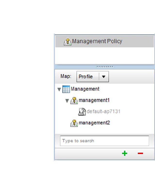
606 Brocade Mobility RFS4000, RFS6000, and RFS7000 System Reference Guide
53-1002620-01
11
FIGURE 399 Management Browser screen
3. The Management Policy screen displays existing management policies and their unique
protocol support configurations.
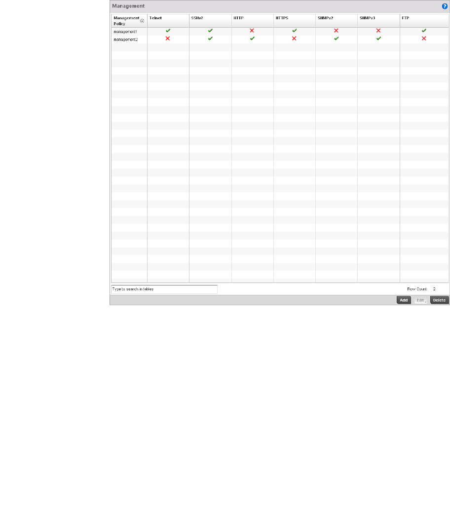
Brocade Mobility RFS4000, RFS6000, and RFS7000 System Reference Guide 607
53-1002620-01
11
FIGURE 400 Management Policy screen
4. Refer to the following Management Access policy configurations to discern whether these
existing policies can be used as is, require modification or a new policy requires creation:
A green check mark indicates controller device access is allowed using the listed protocol. A
red X indicates controller device access is denied using the listed protocol.
Management Policy Displays the name of the Management Access policy assigned when initially
created. The name cannot be updated when modifying a policy.
Telnet Telnet provides a command line interface to a remote host over TCP. Telnet provides
no encryption, but it does provide a measure of authentication.
SSHv2 SSH (Secure Shell) version 2, like Telnet, provides a command line interface to a
remote host. However, all SSH transmissions are encrypted, increasing their
security.
HTTP HTTP (Hypertext Transfer Protocol) provides access to the device’s GUI using a Web
browser. This protocol is not very secure.
HTTPS HTTPS (Hypertext Transfer Protocol Secure) provides fairly secure access to the
device’s GUI using a Web browser. Unlike HTTP, HTTPS uses encryption for
transmission, and is therefore more secure.

608 Brocade Mobility RFS4000, RFS6000, and RFS7000 System Reference Guide
53-1002620-01
11
5. If it’s determined a Management Access policy requires creation or modification, refer to
Adding or Editing a Management Access Policy on page 11-608. If necessary, select an
existing Management Access policy and select Delete to permanently remove it from the list of
those available.
Adding or Editing a Management Access Policy
Viewing Management Access Policies
To add a new Management Access policy, or edit an existing configuration:
1. Select Configuration > Management > Wireless LAN Policy to the main Management Policy
screen and Management Browser.
2. Existing policies can be modified by either selecting a policy from the Management Browser
and selecting the Edit button.
3. New policies can be created by selecting the Add button from the bottom right-hand side of the
Management screen.
4. A name must be supplied to the new policy before the Access Control, SNMP, SNMP Traps and
Administrators tabs become enabled and the policy’s configuration defined. The name cannot
exceed 32 characters.
SNMPv2 SNMP (Simple Network Management Protocol) exposes a device’s management
data so it can be managed remotely. Device data is exposed as variables that can
be accessed and modified. However, SNMP is generally used to monitor a system’s
performance and other parameters.
SNMPv3 SNMP (Simple Network Management Protocol) exposes a device’s management
data so it can be managed remotely. Device data is exposed as variables that can
be accessed and modified. However, SNMP is generally used to monitor a system’s
performance and other parameters.
FTP FTP (File Transfer Protocol) is a standard protocol for files transfers over a TCP/IP
network.
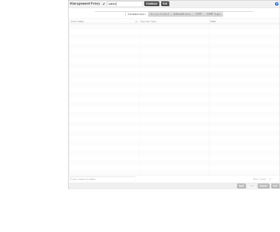
Brocade Mobility RFS4000, RFS6000, and RFS7000 System Reference Guide 609
53-1002620-01
11
FIGURE 401 Management Policy screen - New Policy Creation
5. Select OK to commit the new policy name.
Once the new name is defined, the screen’s four tabs become enabled, with the contents of
the Administrators tab displayed by default. Refer to the following to define the configuration of
the new controller Management Access policy:
•Creating an Administrator Configuration - Use the Administrators tab to create specific
controller users, assign them permissions to specific protocols and set specific
administrative roles for the managed network.
•Setting the Access Control Configuration - Use the Access Control tab to enable/disable
specific protocols and interfaces. Again, this kind of access control is not meant to
function as an ACL, but rather as a means to enable/disable specific protocols (HTTP,
HTTPS, Telnet etc.) for each Management Access policy.
•Setting the Authentication Configuration - Refer to the Authentication tab to set the
authentication scheme used to validate user credentials with this policy.
•Setting the SNMP Configuration - Refer to the SNMP tab to enable SNMPv2, SNMPv3 or
both and define specific community strings for this policy.
•SNMP Trap Configuration - Use the SNMP Traps tab to enable trap generation for the policy
and define trap receiver configurations.
For deployment considerations and recommendations impacting a controller’s Management
Access policy configuration, refer to Management Access Deployment Considerations on page
11-619.
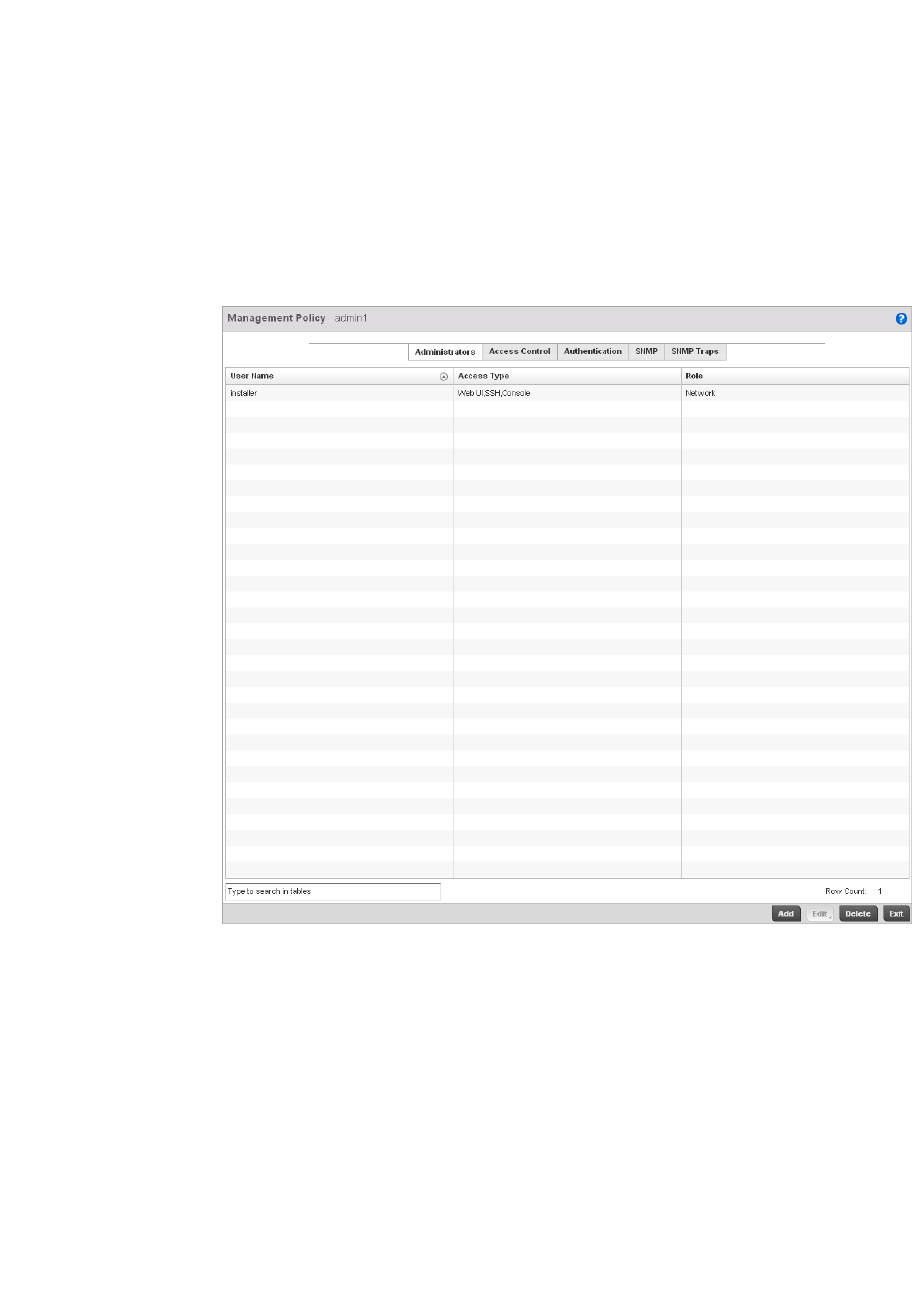
610 Brocade Mobility RFS4000, RFS6000, and RFS7000 System Reference Guide
53-1002620-01
11
Creating an Administrator Configuration
Adding or Editing a Management Access Policy
1. Use the Administrators tab to review existing administrators, their access medium and their
administrative role within the managed network. New administrators can be added, existing
administrative configurations modified or deleted as required.
FIGURE 402 Management Policy screen - Administrators tab
2. Refer to the following to review the high-level configurations of existing administrators:.
3. Select the Add button to create a new administrator configuration, Edit to modify an existing
configuration or Delete to permanently remove an Administrator from the list of those
available.
User Name Displays the name assigned to the administrator upon creation. The name cannot
be modified as part of the administrator configuration edit process.
Access Type Lists the Web UI, Telnet, SSH or Console access type assigned to each listed
administrator. A single administrator can have any one or all of these roles assigned
at the same time.
Role Lists the Superuser, System, Network, Security, Monitor, Help Desk or Web User
role assigned to each listed administrator. An administrator can only be assigned
one role at a time.
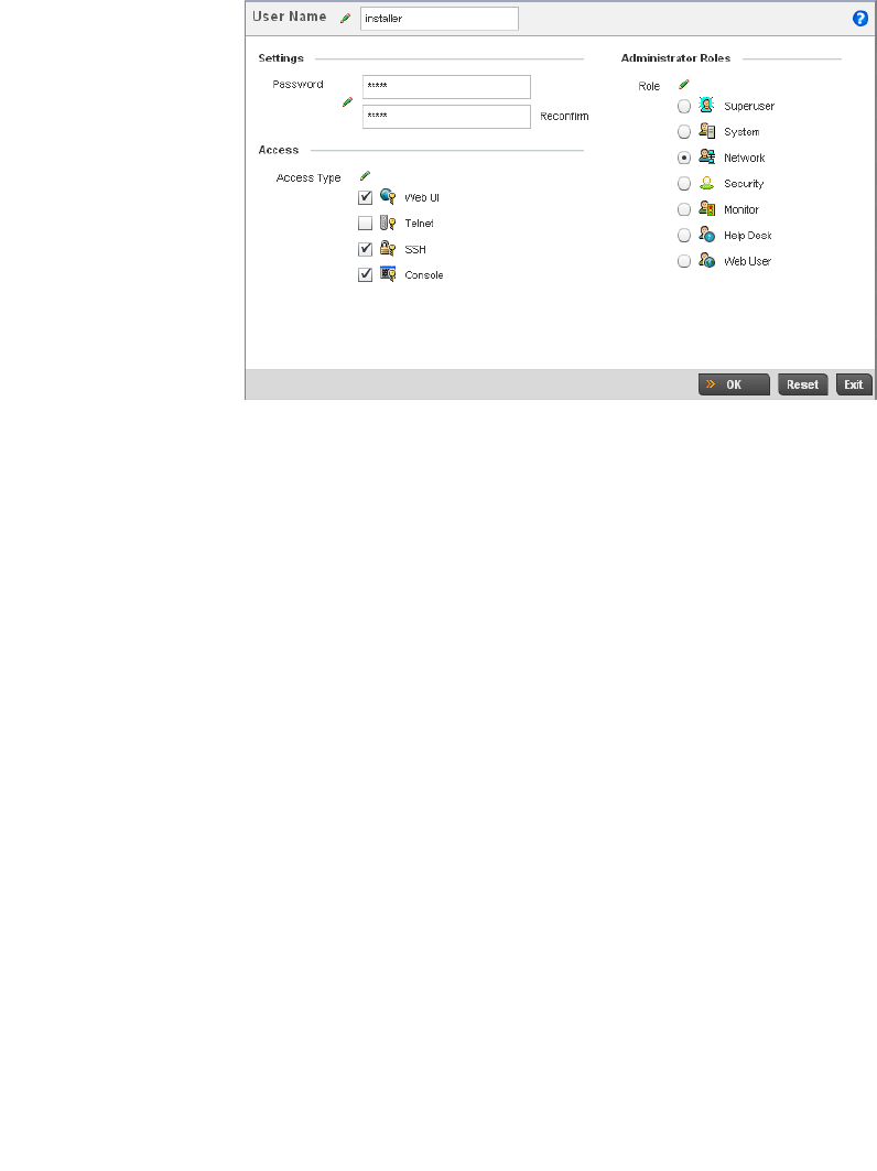
Brocade Mobility RFS4000, RFS6000, and RFS7000 System Reference Guide 611
53-1002620-01
11
FIGURE 403 Administrators screen
4. If creating a new administrator, enter a user name in the User Name field. This is a mandatory
field for new administrators and cannot exceed 32 characters. Optimally assign a name
representative of the user and role.
5. Provide a strong password for the administrator in the Password field, once provided,
Reconfirm the password to ensure its accurately entered. This is a mandatory field.
6. Select Access options to define the permitted access for the user. If required, all four options
can be selected and invoked simultaneously.
7. Select the Administrator Role for the administrator using this profile. Only one role can be
assigned.
Web UI Select this option to enable access to the device’s Web User Interface.
Telnet Select this option to enable access to the device using TELNET.
SSH Select this option to enable access to the device using SSH.
Console Select this option to enable access to the device’s console.
Superuser Select this option to assign complete administrative rights to the user. This entails all
the roles listed for all the other administrative roles.
System Select System to allow the administrator to configure general settings like NTP, boot
parameters, licenses, perform image upgrade, auto install, manager
redundancy/clustering and control access.
Network Select this option to allow the user to configure all wired and wireless parameters (IP
configuration, VLANs, L2/L3 security, WLANs, radios etc).
Security Select Security to set the administrative rights for a security administrator allowing
configuration of all security parameters.

612 Brocade Mobility RFS4000, RFS6000, and RFS7000 System Reference Guide
53-1002620-01
11
8. Select the OK button to save the administrator’s configuration. Select Reset to revert to the
last saved configuration.
Setting the Access Control Configuration
Adding or Editing a Management Access Policy
Refer to the Access Control tab to allow/deny management access to the managed network using
strategically selected protocols (HTTP, HTTPS, Telnet, SSH or SNMP). Access options can be either
enabled or disabled as required. Brocade recommends disabling unused interfaces to close
unnecessary security holes. The Access Control tab is not meant to function as an ACL (in routers or
other firewalls), where you can specify and customize specific IPs to access specific interfaces.
The following table demonstrates some interfaces provide better security than others:
To set an access control configuration for the Management Access policy:
1. Select the Access Control tab from the Management Policy screen.
Monitor Select Monitor to assign permissions without any administrative rights. The Monitor
option provides read-only permissions.
Help Desk Assign this role to someone who typically troubleshoots and debugs problems
reported by the customer. The Help Desk manager typically runs troubleshooting
utilities (like a sniffer), executes service commands, views/retrieves logs and reboots
the controller.
Web User Select Web User to assign the administrator privileges needed to add users for
authentication.
Access Type Encrypted Authenticated Default State
Telnet No Yes Disabled
HTTP No Yes Disabled
HTTPS Yes Yes Disabled
SSHv2 Yes Yes Disabled
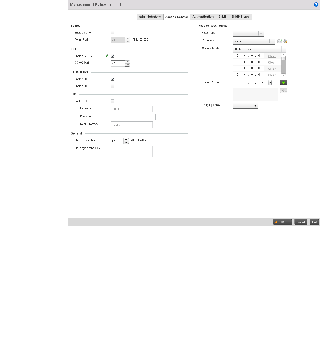
Brocade Mobility RFS4000, RFS6000, and RFS7000 System Reference Guide 613
53-1002620-01
11
FIGURE 404 Management Policy screen - Access Control tab
2. Set the following parameters required for Telnet access:
3. Set the following parameters required for SSH access:
Enable Telnet Select the checkbox to enable Telnet device access. Telnet provides a command
line interface to a remote host over TCP. Telnet provides no encryption, but it does
provide a measure of authentication. Telnet access is disabled by default.
Telnet Port Set the port on which Telnet connections are made (1 - 65,535). The default port is
23. Change this value using the spinner control next to this field or by entering the
port number in the field.
Enable SSHv2 Select the checkbox to enable SSH device access. SSH (Secure Shell) version 2,
like Telnet, provides a command line interface to a remote host. SSH transmissions
are encrypted and authenticated, increasing the security of transmission. SSH
access is disabled by default.
SSHv2 Port Set the port on which SSH connections are made. The default port is 22. Change
this value using the spinner control next to this field or by entering the port number
in the field.

614 Brocade Mobility RFS4000, RFS6000, and RFS7000 System Reference Guide
53-1002620-01
11
4. Set the following HTTP/HTTPS parameters:
NOTE
If the a RADIUS server is not reachable, HTTPS or SSH management access to the controller or
Access Point may be denied.
5. Set the following parameters required for FTP access:
6. Set the following General parameters::
7. Set the following Access Restriction parameters::
8. Select OK to update the access control configuration. Select Reset to the last saved
configuration.
Enable HTTP Select the checkbox to enable HTTP device access. HTTP provides limited
authentication and no encryption.
Enable HTTPS Select the checkbox to enable HTTPS device access. HTTPS (Hypertext Transfer
Protocol Secure) is more secure plain HTTP. HTTPS provides both authentication
and data encryption as opposed to just authentication.
Enable FTP Select the checkbox to enable FTP device access. FTP (File Transfer Protocol) is the
standard protocol for transferring files over a TCP/IP network. FTP requires
administrators enter a valid username and password authenticated locally on the
controller. FTP access is disabled by default.
FTP Username Specify a username required when logging in to the FTP server. The username
cannot exceed 32 characters.
FTP Password Specify a password required when logging in to the FTP server. Reconfirm the
password in the field provided to ensure it has been entered correctly. The
password cannot exceed 63 characters.
FTP Root Directory Provide the complete path to the root directory in the space provided. The default
setting has the root directory set to flash:/
Idle Session Timeout Specify a inactivity timeout for management connects (in seconds) between 0 -
1,440.
Message of the Day Enter message of the day text to be displayed at login for clients connecting via
Telnet or SSH.
Filter Type Select a filter type for access restriction, either ip-access-list, source-address, or
none.
IP Access List If the selected filter type is ip-access-list, select an ip access list from the drop-down
menu or select the create button to make a new one.
Source Hosts If the selected filter type is source-address, enter an IP Address or IP Addresses for
the source hosts.
Source Subnets If the selected filter type is source-address, enter a source subnet or subnets for the
source hosts.
Logging Policy If the selected filter type is source-address, enter a logging policy as none,
denied-only or All.
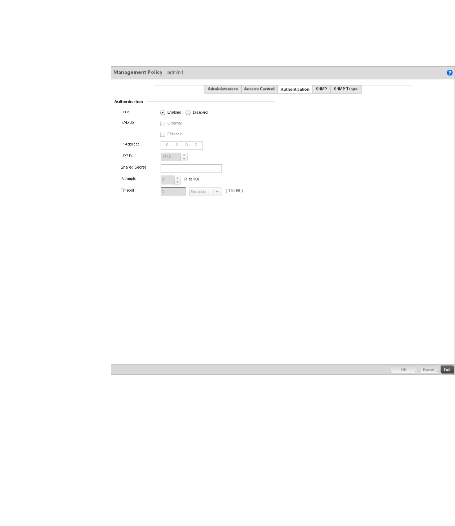
Brocade Mobility RFS4000, RFS6000, and RFS7000 System Reference Guide 615
53-1002620-01
11
Setting the Authentication Configuration
Adding or Editing a Management Access Policy
Refer to the Authentication tab to define how user credential validation is conducted on behalf of a
Management Access policy
To configure an external authentication resource:
1. Select the Authentication tab from the Management Policy screen.
FIGURE 405 Management Policy screen - Authentication tab
2. Define the following settings to authenticate management access requests:
Local Select whether the Access Point’s authentication server resource is centralized
(local) to the Access Point itself, or whether the Access Point shall use an external
authentication resource for validating user access.
RADIUS If local authentication is disable, set whether the RADIUS server type is External and
or Fallback.
IP Address Define the numerical IP address of the Access Point’s external RADIUS
authentication resource.
UDP Port Use the spinner control to set the port number where the RADIUS server is listening.
The default setting is 1812.

616 Brocade Mobility RFS4000, RFS6000, and RFS7000 System Reference Guide
53-1002620-01
11
3. Select OK to update the authentication configuration. Select Reset to the last saved
configuration.
Setting the SNMP Configuration
Adding or Editing a Management Access Policy
The controller can use the Simple Network Management Protocol (SNMP) to communicate with
devices within the managed network. SNMP is an application layer protocol that facilitates the
exchange of management information between the controller and a managed device. SNMP
enabled devices listen on port 162 (by default) for SNMP packets from the controller’s
management server. SNMP uses read-only and read-write community strings as an authentication
mechanism to monitor and configure supported devices. The read-only community string is used to
gather statistics and configuration parameters from a supported wireless device. The read-write
community string is used by a management server to set device parameters. SNMP is generally
used to monitor a system’s performance and other parameters.
To configure SNMP Management Access within the managed network:
1. Select the SNMP tab from the Management Policy screen.
Shared Secret Define a shared secret password between the Access Point and the RADIUS server
that must be provided to secure the external RADIUS resource.
Attempts Set the number of times an authentication request is sent to the RADIUS server
before giving up. The available range is 1- 10, with a default of 3.
Timeout Set a timeout setting in Seconds (1-60) after which requests to the RADIUS server
will be retries.
SNMP Version Encrypted Authenticated Default State
SNMPv2 No No Enabled
SNMPv3 Yes Yes Enabled
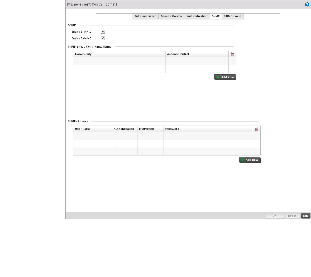
Brocade Mobility RFS4000, RFS6000, and RFS7000 System Reference Guide 617
53-1002620-01
11
FIGURE 406 Management Policy screen - SNMP tab
2. Enable or disable SNMPv2 and SNMPv3.
Enable SNMPv2 Select the checkbox to enable SNMPv2 support. SNMPv2 provides device
management using a hierarchical set of variables. SNMPv2 uses Get, GetNext, and
Set operations for data management. SNMPv2 is enabled by default.
Enable SNMPv3 Select the checkbox to enable SNMPv3 support. SNMPv3 adds security and remote
configuration capabilities to previous versions. The SNMPv3 architecture
introduces the User-based Security Model (USM) for message security and the
View-based Access Control Model (VACM) for access control. The architecture
supports the concurrent use of different security, access control and message
processing techniques. SNMPv3 is enabled by default.

618 Brocade Mobility RFS4000, RFS6000, and RFS7000 System Reference Guide
53-1002620-01
11
3. Set the SNMP v1/v2 Community String configuration. Use the + Add Row function as needed
to add additional SNMP v1/2 community strings, or select an existing community string’s radio
button and select the Delete icon to remove it.
4. Set the SNMPv3 Users configuration. Use the + Add Row function as needed to add additional
SNMP v3 user configurations, or select a SNMP user’s radio button and select the Delete icon
to remove the user.
5. Select OK to update the SNMP configuration. Select Reset to revert to the last saved
configuration.
SNMP Trap Configuration
Adding or Editing a Management Access Policy
The managed network can use SNMP trap receivers for fault notifications. SNMP traps are
unsolicited notifications triggered by thresholds (or actions), and are therefore an important fault
management tool.
A SNMP trap receiver is the destination of SNMP messages (external to the controller). A trap is like
a Syslog message, just over another protocol (SNMP). A trap is generated when a device
consolidates event information and transmits the information to an external repository. The trap
contains several standard items, such as the SNMP version, community etc.
SNMP trap notifications exist for most controller operations, but not all are necessary for day-to-day
operation.
To define a SNMP trap configuration for receiving events at a remote destination:
1. Select the SNMP Traps tab from the Management Policy screen.
Community Define a public or private community designation. By default, SNMPv2 community
strings on most devices are set to public for the read-only community string and
private for the read-write community string.
Access Control Set the access permission for each community string used by devices to retrieve or
modify information. The available options are:
Read Only -Allows a remote device to retrieve information
Read-Write - Allows a remote device to modify settings
User Name Use the drop-down menu to define a user name of snmpmanager, snmpoperator or
snmptrap.
Authentication Displays the authentication scheme used with the listed SNMPv3 user. The listed
authentication scheme ensures only trusted and authorized users and devices can
access the managed network.
Encryption Displays the encryption scheme used with the listed SNMPv3 user.
Password Provide the user’s password in the field provided. Select the Show check box to
display the actual character string used in the password, while leaving the check
box unselected protects the password and displays each character as “*”.
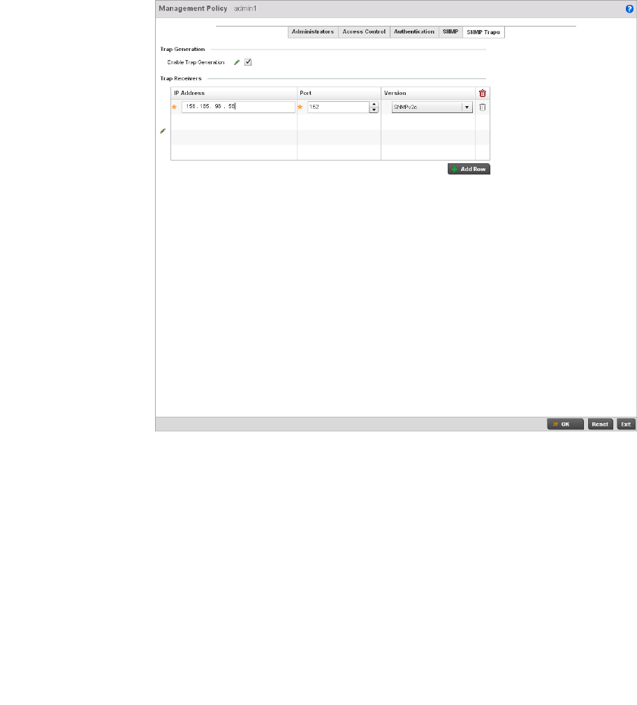
Brocade Mobility RFS4000, RFS6000, and RFS7000 System Reference Guide 619
53-1002620-01
11
FIGURE 407 Management Policy screen - SNMP Traps tab
2. Select the Enable Trap Generation checkbox to enable trap generation using the trap receiver
configuration defined. This feature is disabled by default.
3. Refer to the Trap Receiver table to set the configuration of the external resource dedicated to
receiving trap information on behalf of the controller. Select Add Row + as needed to add
additional trap receivers. Select the Delete icon to permanently remove a trap receiver.
4. Select OK to update the SNMP Trap configuration. Select Reset to revert to the last saved
configuration.
Management Access Deployment Considerations
Before defining a access control configuration as part of a Management Access policy, refer to the
following deployment guidelines to ensure the configuration is optimally effective:
•Unused management protocols should be disabled to reduce a potential attack against
managed resources.
IP Address Sets the IP address of the external server resource dedicated to receiving the SNMP
traps on behalf of the controller.
Port Set the port of the server resource dedicated to receiving SNMP traps. The default
port is port 162.
Version Sets the SNMP version to use to send SNMP traps. SNMPv2 is the default.

620 Brocade Mobility RFS4000, RFS6000, and RFS7000 System Reference Guide
53-1002620-01
11
•Use management interfaces providing encryption and authentication. Management services
like HTTPS, SSH and SNMPv3 should be used when possible, as they provide both data privacy
and authentication.
•By default, SNMPv2 community strings on most devices are set to public for the read-only
community string and private for the read-write community string. Legacy Brocade devices may
use other community strings by default.
•Brocade recommends SNMPv3 be used for device management, as it provides both
encryption, and authentication.
•Enabling SNMP traps can provide alerts for isolated attacks at both small managed radio
deployments or distributed attacks occurring across multiple managed sites.
•Whenever possible, Brocade recommends centralized RADIUS management be enabled on
controllers and Access Points. This provides better management and control of management
usernames and passwords and allows administrators to quickly change credentials in the
event of a security breach.

Brocade Mobility RFS4000, RFS6000, and RFS7000 System Reference Guide 621
53-1002620-01
Chapter
12
Diagnostics
In this chapter
•Fault Management . . . . . . . . . . . . . . . . . . . . . . . . . . . . . . . . . . . . . . . . . . . . 621
•Snapshots . . . . . . . . . . . . . . . . . . . . . . . . . . . . . . . . . . . . . . . . . . . . . . . . . . . 625
•Crash Files . . . . . . . . . . . . . . . . . . . . . . . . . . . . . . . . . . . . . . . . . . . . . . . . . . . 628
•Advanced Diagnostics . . . . . . . . . . . . . . . . . . . . . . . . . . . . . . . . . . . . . . . . . . 629
The controller’s resident diagnostic capabilities enable administrators to understand how managed
devices are performing and troubleshoot issues impacting network performance. Performance and
diagnostic information is collected and measured on Brocade controllers and Access Points for any
anomalies causing a key controller processes to potentially fail.
Numerous tools are available within the Diagnostics menu. Some allow event filtering, some allow
you to view logs and some allow you to manage files generated when major hardware or software
issues are detected.
Fault Management
Fault management enables user's administering multiple sites to assess how individual devices are
performing and review issues impacting the managed network. Use the controller’s Fault
Management screens to administrate errors generated by the controller, Access Point or wireless
clients managed by the controller.
1. Select Diagnostics > Fault Management.
2. The Filter Events screen displays by default. Use this screen to configure how events are
tracked. By default, all events are enabled, and an administrator has to turn off events that do
not require tracking.
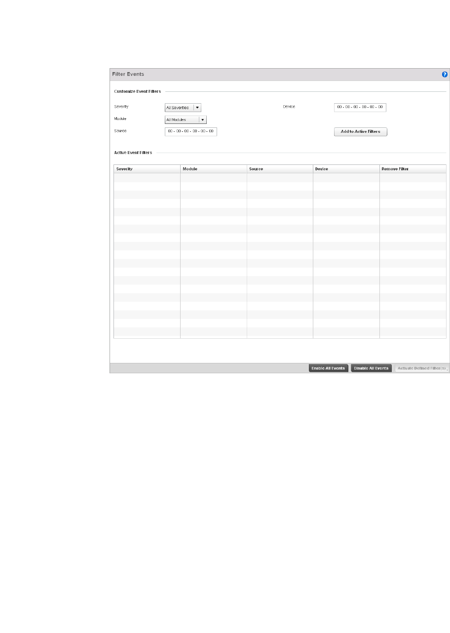
622 Brocade Mobility RFS4000, RFS6000, and RFS7000 System Reference Guide
53-1002620-01
12
FIGURE 408 Fault Management Filter Events screen
3. Use the Filter Events screen to create filters for managing displayed events. Events can be
filtered based on severity, the module received, source MAC, device MAC and client MAC
address.
4. Define the following Customize Event Filters parameters for the Fault Management
configuration:
Severity Set the filtering severity. Select from the following:
All Severities – All events are displayed irrespective of their severity
Critical – Only critical events are displayed
Error – Only errors and above are displayed
Warning – Only warnings and above are displayed
Informational – Only informational and above events are displayed
Module Select the module from which events are tracked. When a module is selected, events
from other modules are not tracked. Remember this when interested in events
generated by a particular controller module. Individual modules can be selected (such
as TEST, LOG, FSM etc.) or all modules can be tracked by selecting All Modules.
Source Set the MAC address of the source device to be tracked. Setting a MAC address of
00:00:00:00:00:00 allows all devices to be tracked.
Device Set the device MAC address for the device (such as an Access Point or wireless client)
from which the source MAC address is tracked. Setting a MAC address of
00:00:00:00:00:00 allows all devices.
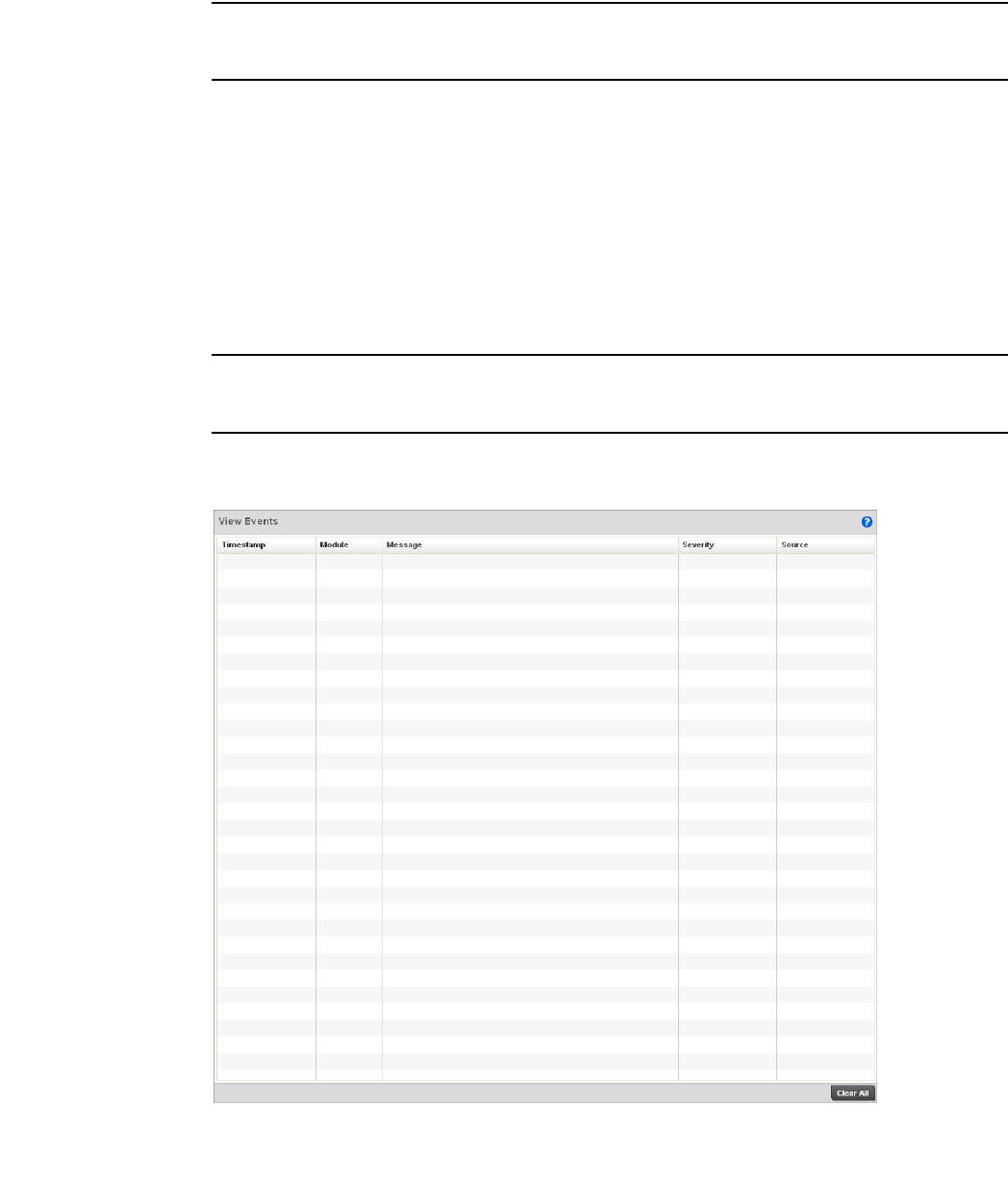
Brocade Mobility RFS4000, RFS6000, and RFS7000 System Reference Guide 623
53-1002620-01
12
NOTE
Leave the Source, Device and Mobile Unit fields to a default value of 00:00:00:00:00:00 to allow all
MAC addresses.
5. Select the Add to Active Filters button to create a new filter and add it to the Active Event Filters
table. When added, the filter uses the current configuration defined in the Customize Event
Filters field.
6. Refer to the Active Event Filters table to set the following parameters for the Fault Management
configuration:
a. To activate all the events in the Active Events Filters table, select the Enable All Events
button. Similarly, to stop event generation, select Disable All Events.
b. To enable an event in the Active Event Filters table, click the event to select it. Then, select
the Activate Defined Filter button.
NOTE
Filters cannot be persisted across sessions. They have to be created every time a new session is
established.
7. S elect View Events from the upper, left-hand, side of the Diagnostics > Fault Management
menu.
FIGURE 409 Fault Management View Events screen
8. Use the View Events screen to track and troubleshoot events using source and severity levels
defined in the Configure events screen.
624 Brocade Mobility RFS4000, RFS6000, and RFS7000 System Reference Guide
53-1002620-01
12
9. Define the following Customize Event Filters parameters for the Fault Management
configuration:
10. Select Clear All to clear the events displayed and begin new event data gathering.
11. Select Event History from the upper, left-hand, side of the Diagnostics > Fault Management
menu.
FIGURE 410 Fault Management Event History screen
12. Use the Event History screen to track and troubleshoot events using source and severity levels
defined in the Configure events screen.
Timestamp Displays the Timestamp (time zone specific) when the fault occurred.
Module Displays the module used to track the event. Events detected by other module are not
tracked.
Message Displays error or status messages for each event listed.
Severity Displays the severity of the event as defined for tracking from the Configuration screen.
Severity options include:
All Severities – All events are displayed irrespective of their severity
Critical – Only critical events are displayed
Error – Only errors and above are displayed
Warning – Only warnings and above are displayed
Informational – Only informational and above events are displayed
Source Displays the MAC address of the source device tracked by the controller and selected
module.

Brocade Mobility RFS4000, RFS6000, and RFS7000 System Reference Guide 625
53-1002620-01
12
13. Select a Device or RF Domain radio button and choose a Device or RF Domain from the
pull-down menu.
14. Define the following Customize Event Filters parameters for the Fault Management
configuration:
15. Clicking the Fetch Historical Events button retrieves all log history for the device in the Select
Device drop-down.
16. Select Clear All to clear the events displayed and begin new event data gathering.
Snapshots
Use the Snapshots screens to review panic and core dump files created when a controller or
managed device encounters a critical error or malfunction.
Core Snapshots
Snapshots
Refer to the Core Snapshots screen to review core dump files (system events and process failures
with a.core extension) and troubleshoot issues specific to the device on which the event was
generated. Core snapshots are issues impacting the controller core (distribution layer). Once
reviewed, core files can be deleted or transferred for archive. Core files can be sent to the Brocade
support team to expedite any issues that arise with the reporting device.
To review core snapshots impacting the managed network:
1. Select Diagnostics > Snapshots.
The Core Snapshots screen displays by default. This screen displays a list of device MAC
addresses impacted by core dumps.
2. Select a device from those displayed in the lower, left-hand, side of the controller UI.
Timestamp Displays the Timestamp (time zone specific) when the fault occurred.
Module Displays the module used to track the event. Events detected by other module are not
tracked.
Message Displays error or status messages for each event listed.
Severity Displays the severity of the event as defined for tracking from the Configuration screen.
Severity options include:
All Severities – All events are displayed irrespective of their severity
Critical – Only critical events are displayed
Error – Only errors and above are displayed
Warning – Only warnings and above are displayed
Informational – Only informational and above events are displayed
Source Displays the MAC address of the source device tracked by the controller and selected
module.
RF Domain Displays the RF Domain of the source device tracked by the controller and selected
module.
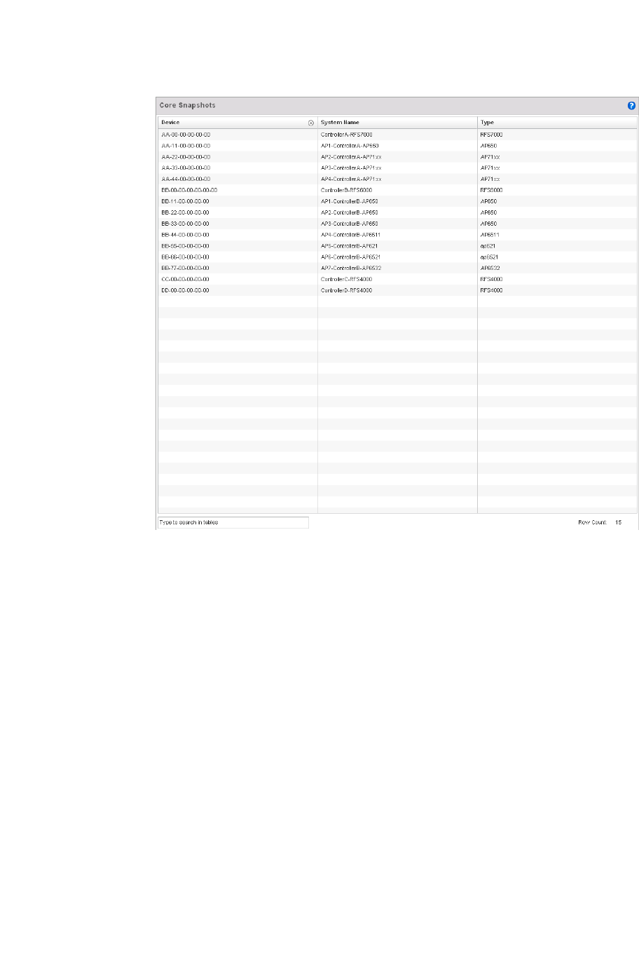
626 Brocade Mobility RFS4000, RFS6000, and RFS7000 System Reference Guide
53-1002620-01
12
FIGURE 411 Core Snapshots screen
3. The screen expands to display the following parameters for each reported core snapshot:
4. Select Copy to transfer core snapshot files to a secure location for archive.
5. Select Delete to clear the selected core file from the list of those displayed.
Panic Snapshots
Snapshots
Refer to the Panic Snapshots screen to view panic dump files used to troubleshoot issues specific
to the device on which it was generated. When necessary, panic files can be sent to the Brocade
support team to expedite issues that arise with the reporting device.
To review panic snapshots impacting the managed network:
1. Select Diagnostics > Snapshots.
File Name Displays the title of the process, separated by underscores. The file extension is always
.core for core files.
Size Displays the size of the core file in bytes.
Last Modified Displays the time the core file was last updated. This information may be useful in
troubleshooting issues and reporting core related events to the Brocade support team.
Actions Lists either Copy or Delete as the action applied to each listed file.
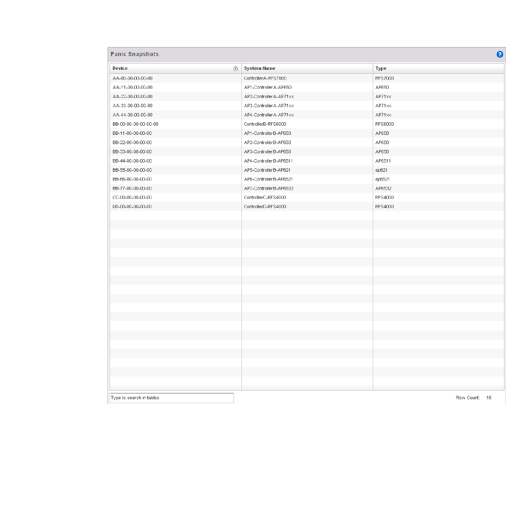
Brocade Mobility RFS4000, RFS6000, and RFS7000 System Reference Guide 627
53-1002620-01
12
2. Select Panic Snapshots from the upper, left-hand, side of the controller UI. A list of device MAC
addresses impacted by panic events displays.
3. Select a device from those displayed in the lower, left-hand, side of the controller UI.
FIGURE 412 Panic Snapshots screen
4. The screen expands to display the following parameters for each reported panic snapshot.:
Device Displays the factory encoded MAC address assigned to the device. This is a identifier
used as permanent device hardware address and cannot be modified by the controller
System Name Lists the name assigned to each listed managed device.
Type Displays the Brocade model of each device providing a panic to the controller.

628 Brocade Mobility RFS4000, RFS6000, and RFS7000 System Reference Guide
53-1002620-01
12
Crash Files
Use the Crash Files screen to review files created when an access point or controller encounters a
critical error or malfunction. Use crash files to troubleshoot issues specific to the device on which a
crash event was generated.These are issues impacting the core (distribution layer). Once reviewed,
files can be deleted or transferred for archive. Crash files can be sent to a support team to expedite
issues with the reporting device.
1. Select Diagnostics > Crash to display the crash file information..
Once a target device has been selected its crash file information displays in the viewer on the
right.
FIGURE 413 Crash file information
2. Refer to the following crash file information for the selected device.
File Name Displays the name of the file generated when a crash event occurred. This is the file
available to copy to an external location for archive and administration.
Size Lists the size of the crash file, as this information is often needed when copying files to a
location external to the access point.
Last Modified Displays the time stamp of the most recent update to the file.
Actions Displays the action taken by the access point in direct response to the detected crash
event.
Copy Select a listed crash file and select the Copy button to display a screen used to copy
(archive) the file to an external location.
Delete To remove a listed crash file from those displayed, select the file and select the Delete
button.
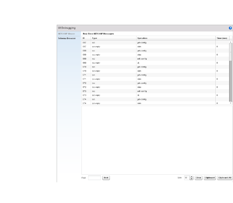
Brocade Mobility RFS4000, RFS6000, and RFS7000 System Reference Guide 629
53-1002620-01
12
Advanced Diagnostics
Refer to the controller’s Advanced UI Diagnostics facilities to review and troubleshoot any potential
issue with the controller’s resident User Interface (UI). The UI Diagnostics screen provides a large
number of diagnostic tools to enable you to effectively identify and correct issues with the
controller UI. Diagnostics can also be performed at the device level for the Access Point radios and
connected clients managed by the controller.
UI Debugging
Advanced Diagnostics
Use the UI Debugging screen to view debugging information for a selected device.
To review device debugging information:
1. Select Diagnostics > Advanced to display the UI Debugging menu options.
Once a target device has been selected its debugging information displays within the NETCONF
Viewer by default.
FIGURE 414 UI Debugging screen - NETCONF Viewer
2. Use the NETCONF Viewer to review NETCONF information. NETCONF is a tag-based
configuration protocol for Brocade wireless controllers. Messages are exchanged between the
UI and the wireless controller using XML tags.
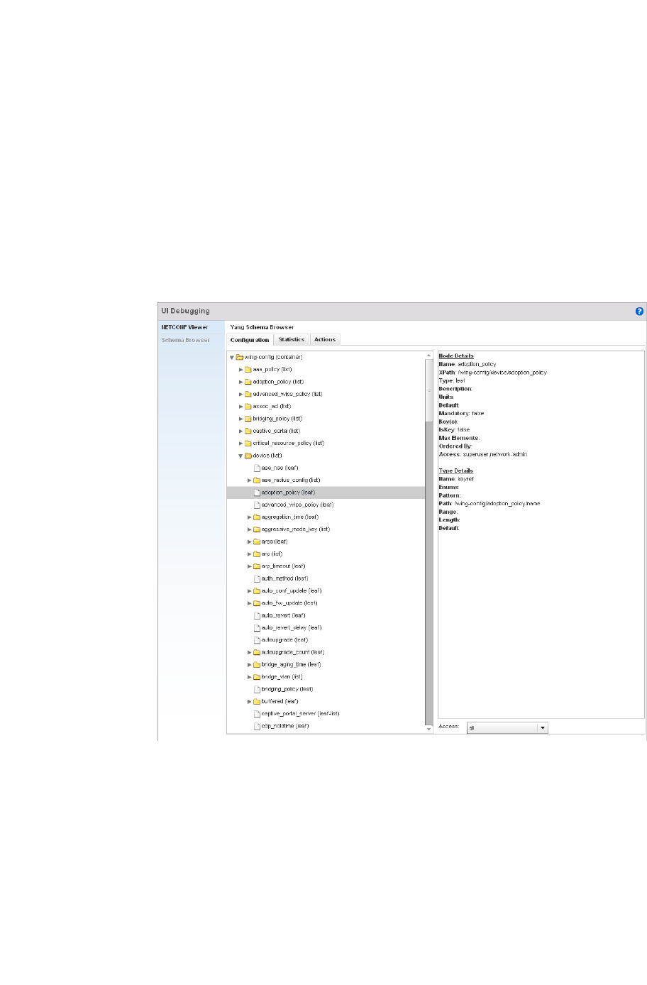
630 Brocade Mobility RFS4000, RFS6000, and RFS7000 System Reference Guide
53-1002620-01
12
3. The Real Time NETCONF Messages area lists an XML representation of any message
generated by the system. The main display area of the screen is updated in real time.
4. Refer to the Request Response and Time Taken fields on the bottom of the screen to assess
the time taken by the controller to receive and respond to requests. The time is displayed in
microseconds.
5. Use the Clear button to clear the contents of the Real Time NETCONF Messages area. Use the
Find parameter and the Next button to search for message variables in the Real Time
NETCONF Messages area.
6. Select Schema Browser to view configuration, statistics and an actions repository for a
selected device.
FIGURE 415 UI Debugging screen - Schema Browser Configuration tab
7. The Schema Browser is arranged into two panes (regardless of the Configuration, Statistics or
Actions tab selected). The left pane allows you to navigate the schema. Selecting a node on the
left pane displays the node information on the right pane. The Schema Browser does not
display information in real time. It only displays the data format used on the device when last
updated.
a. The Scheme Browser displays the Configuration tab by default. Expand a specific
configuration parameter to review the configuration settings defined for that device
parameter. The Configuration tab provides an ideal place to verify if device configurations
differ from default settings or have been erroneously changed in respect to the device’s
intended configuration profile.
b. Select the Statistics tab to assess performance data and statistics for a target device.
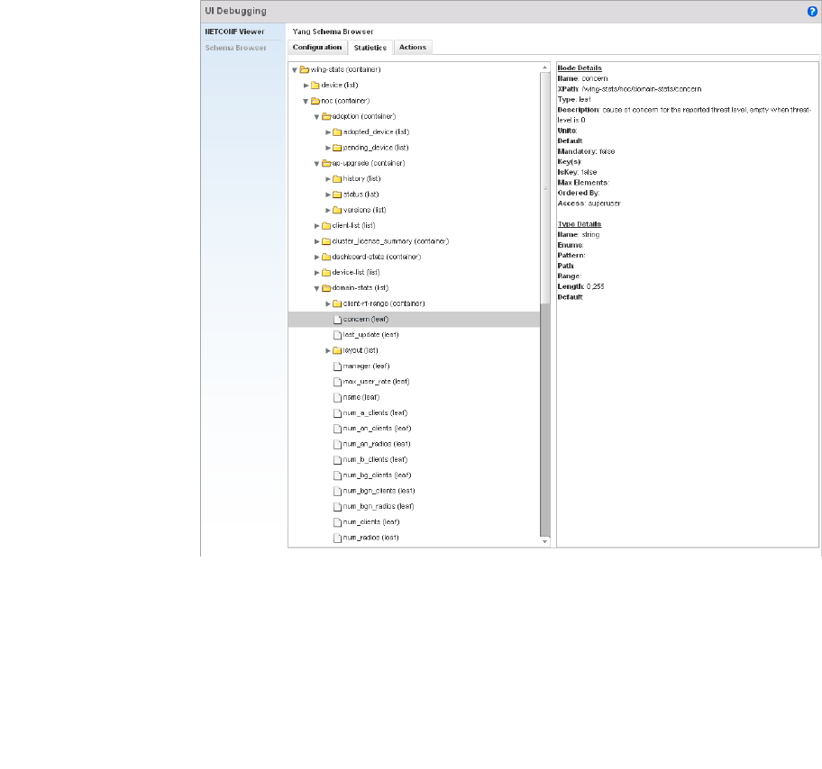
Brocade Mobility RFS4000, RFS6000, and RFS7000 System Reference Guide 631
53-1002620-01
12
FIGURE 416 UI Debugging screen - Schema Browser Statistics tab
Use the Statistics data to assess whether the device is optimally configured in respect to
its intended deployment objective. Often the roles of radio supported devices and wireless
clients change as additional devices and radios are added to the managed network.
Navigate amongst a target device’s statistical variables to assess whether the device
should be managed by a different controller profile or defined a unique configuration
different from the one currently defined.
c. Select the Actions tab to display schema for any action that can be configured based on an
event.
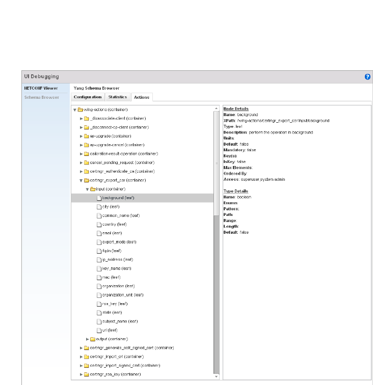
632 Brocade Mobility RFS4000, RFS6000, and RFS7000 System Reference Guide
53-1002620-01
12
FIGURE 417 UI Debugging screen - Schema Browser Actions tab
8. The left pane displays a hierarchical tree of the different actions available to the selected
device. When a node is selected, its information is displayed within the right pane.

Brocade Mobility RFS4000, RFS6000, and RFS7000 System Reference Guide 633
53-1002620-01
Chapter
13
Operations
In this chapter
•Device Operations . . . . . . . . . . . . . . . . . . . . . . . . . . . . . . . . . . . . . . . . . . . . . 633
•Certificates. . . . . . . . . . . . . . . . . . . . . . . . . . . . . . . . . . . . . . . . . . . . . . . . . . . 643
•Smart RF . . . . . . . . . . . . . . . . . . . . . . . . . . . . . . . . . . . . . . . . . . . . . . . . . . . . 658
The functions within the controller’s Operations menu allow firmware and configuration files
management and certificate generation for managed devices. In a clustered environment, these
operations can be performed on one controller, then propagated to each member of the cluster
and onwards to the devices managed by each cluster member.
A controller certificate links identity information with a public key enclosed in the certificate. Device
certificates can be imported and exported to and from the controller to a secure remote location for
archive and retrieval as they are required for application to other managed devices.
Self Monitoring At Run Time RF Management (Smart RF) is a Brocade innovation designed to
simplify RF configurations for new deployments, while (over time) providing on-going deployment
optimization and radio performance improvements. The Smart RF functionality scans the managed
network to determine the best channel and transmit power for each managed Access Point radio.
Smart RF policies can be applied to specific RF Domains, to add site specific deployment
configurations and self recovery values to groups of devices within pre-defined physical RF
coverage areas.
Device Operations
Brocade periodically releases updated device firmware and configuration files to the Support Web
site. If an Access Point’s (or its associated device’s) firmware is older than the version on the Web
site, Brocade recommends updating to the latest firmware version for full feature functionality and
optimal controller utilization. Additionally, selected devices can either have a primary or secondary
firmware image applied or fallback to a selected firmware image if an error occurs in the update
process.
Device update activities include:
•Managing Firmware and Config Files
•Managing File Transfers
•Using the Controller File Browser
These tasks can be performed on individual wireless controllers, Access Points and wireless
clients.
Managing Firmware and Config Files
Device Operations
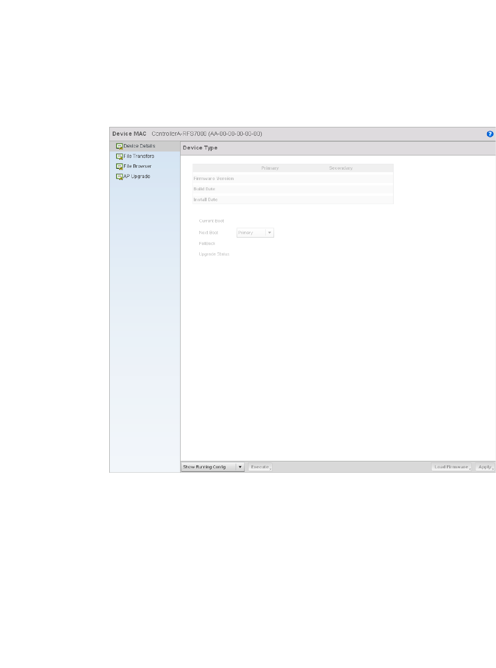
634 Brocade Mobility RFS4000, RFS6000, and RFS7000 System Reference Guide
53-1002620-01
13
1. The Device Details screen displays by default when the Operations is selected from the
controller’s main menu bar.
2. The Device Details screen displays firmware information for a specific device selected from
either the RF Domain or Network tabs on the left-hand side of the screen.
FIGURE 418 Device Details screen
3. Refer to the following to determine whether a firmware image needs to be updated for the
selected device, or a device requires a restart or revert to factory default settings.
Device MAC Displays the factory assigned hardware MAC address (in the banner of the screen)
for the selected device. The Device Type also displays in the banner of the screen.
Firmware Version Displays the primary and secondary firmware image version from the wireless
controller.
Build Date Displays the date the primary and secondary firmware image was built for the
selected device.
Install Date Displays the date the firmware was installed for the selected device.
Current Boot Lists whether the primary or secondary firmware image is to be applied to the
device the next time the device boots.
Next Boot Use the drop-down menu to select the firmware image to boot the next time the
device reboots. Select either the Primary or the Secondary image.

Brocade Mobility RFS4000, RFS6000, and RFS7000 System Reference Guide 635
53-1002620-01
13
4. For information on conducting a device firmware upgrade, see Upgrading Device Firmware on
page 13-635. For information on file transfers, see Managing File Transfers on page 13-636.
Upgrading Device Firmware
Managing Firmware and Config Files
The controller has the ability to conduct firmware updates for managed devices.
To update the firmware of a managed device:
1. Select a device from the browser.
2. Select the Load Firmware button.
FIGURE 419 Firmware Update screen
3. By default, the Firmware Upgrade screen displays a URL field to enter the URL (destination
location) of the target device firmware file. For example,
ftp://ftpuser:ftpuser@10.10.10.10/RFS4000-5.0.0.0-103R.img
Fallback Lists whether fallback is currently enabled for the selected device. When enabled,
the device reverts back to the last successfully installed firmware image if
something were to happen in its next firmware upgrade that would render the
device inoperable.
Upgrade Status Displays the status of the last firmware upgrade performed for each listed device
managed by this controller. For information on upgrading device firmware, see
Upgrading Device Firmware on page 13-635.
Show Startup Config Select this option (from the drop-down menu on the bottom of the screen) to display
the startup configuration of the selected device. The startup configuration is
displayed in a separate window. Select the Execute button to perform the function.
Show Running Config Select this option (from the drop-down menu on the bottom of the screen) to display
the running configuration of the selected device. The running configuration is
displayed in a separate window. Select the Execute button to perform the function.
Restart Select this option (from the drop-down menu on the bottom of the screen) to restart
the selected device. Selecting this option restarts the target device using its last
saved configuration and does not apply factory defaults to the target device.
Restarting a device resets all data collection values to zero. Select the Execute
button to perform the function.
Restart (factory default) Select this option (from the drop-down menu on the bottom of the screen) to restart
the selected device and apply the device’s factory default configuration. Selecting
this option restarts the target device and reverts its configurable parameters to
their factory default values. Consider exporting the device’s current configuration to
a secure location for archive before reverting the device to its default configuration.
Select the Execute button to perform the function.
Halt Select this option (from the drop-down menu on the bottom of the screen) to stop
the selected device. Select the Execute button to perform the function.
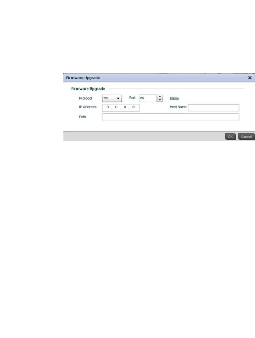
636 Brocade Mobility RFS4000, RFS6000, and RFS7000 System Reference Guide
53-1002620-01
13
4. Enter the complete path to the firmware file for the target device.
5. If needed, select Advanced to expand the dialog to display network address information to the
location of the target device firmware file. The number of additional fields that populate the
screen is also dependent on the selected protocol.
FIGURE 420 Detailed Firmware Upgrade screen
6. Provide the following information to accurately define the location of the target device firmware
file:
7. S elect OK to start the firmware update. Select Abort to terminate the firmware update. Select
Close to close the upgrade popup. The upgrade continues in the background
Managing File Transfers
Device Operations
The controller can administrate files on managed devices. Transfer files from a device to this
controller, to a remote server or from a remote server to the controller. An administrator can
transfer logs, configurations and crash dumps.
Protocol Select the protocol used for updating the device firmware. Available options
include:
•tftp
•ftp
•sftp
•http
•cf
•usb1
•usb2
Port Use the spinner control or manually enter the value to define the port used by
the protocol for firmware updates. This option is not valid for cf, usb1, and usb2.
IP Address Enter IP address of the server used to update the firmware. This option is not
valid for cf, usb1, and usb2.
Hostname Provide the hostname of the server used to update the firmware. This option is
not valid for cf, usb1, and usb2.
Path Specify the path to the firmware file. Enter the complete relative path to the file
on the server.
User Name Define the user name used to access either a FTP or SFTP server.
Password Specify the password for the user account to access a FTP or a SFTP server.
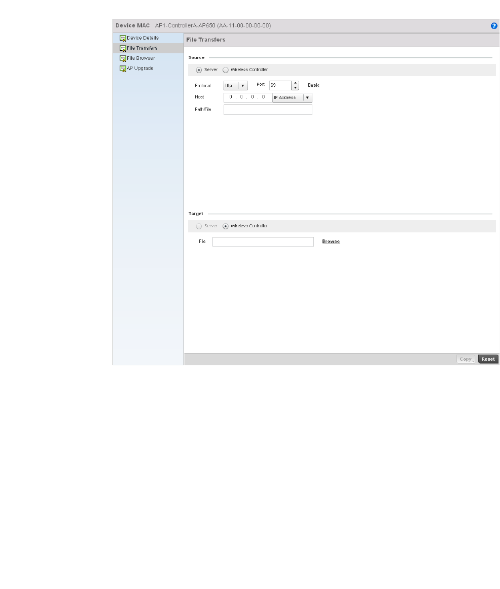
Brocade Mobility RFS4000, RFS6000, and RFS7000 System Reference Guide 637
53-1002620-01
13
To administrate files for managed devices:
1. Select the Operations > Devices > File Transfers
FIGURE 421 File Transfers screen
2. Set the following file management source and target directions as well as the configuration
parameters of the required file management activity:
Source Select the source of the file transfer.
Select Server to indicate the source of the file is a remote server.
Select Wireless Controller to indicate the source of the file is the controller.
File If the source is Wireless Controller, enter the name of the file to be transferred.
Protocol Select the protocol for file management. Available options include:
•tftp
•ftp
•sftp
•http
•cf
•usb1
•usb2
This parameter is required only when Server is selected as the Source.

638 Brocade Mobility RFS4000, RFS6000, and RFS7000 System Reference Guide
53-1002620-01
13
3. Select Copy to begin the file transfer. Selecting Reset reverts the screen to its last saved
configuration.
Using the Controller File Browser
Device Operations
The controller maintains a File Browser allowing an administrator to review the files residing on a
controller’s internal or external memory resource. Directories can be created and maintained for
each File Browser location and folders and files can be moved and deleted as an administrator
interprets necessary.
Keep in mind, USB1 is available on RFS4000, RFS6000 and RFS7000 model controllers, while
USB2 and Compact Flash (CF) are only available on RFS7000 model controllers.
To administrate files for managed devices and memory resources:
1. Select the Operations > Devices > File Browser.
Port Specify the port for transferring files. This option is not available for cf, usb1, and
usb2. Enter the port number directly or use the spinner control.
This parameter is required only when Server is selected as the Source.
IP Address Specify the IP address of the server used to transfer files. This option is not valid for
cf, usb1, and usb2. If IP address of the server is provided, a Hostname is not
required.
This parameter is required only when Server is selected as the Source.
Host If needed, specify a Hostname of the serve transferring the file. This option is not
valid for cf, usb1, and usb2. If a hostname is provided, an IP Address is not
needed.
This field is only available when Server is selected in the From field.
Path / File Define the path to the file on the server. Enter the complete relative path to the file.
This parameter is required only when Server is selected as the Source.
User Name Provide a user name to access a FTP or a SFTP server.
This parameter is required only when Server is selected as the Source, and the
selected protocol is ftp or sftp.
Password Provide a password to access the FTP or SFTP server.
This parameter is required only when Server is selected as the Source, and the
selected protocol is ftp or sftp.
Target Select the target destination to transfer the file.
•Select Server if the destination is a remote server, then provide a URL to the
location of the server resource or select Advanced and provide the same
network address information described above.
•Select Wireless Controller if the destination is the controller.
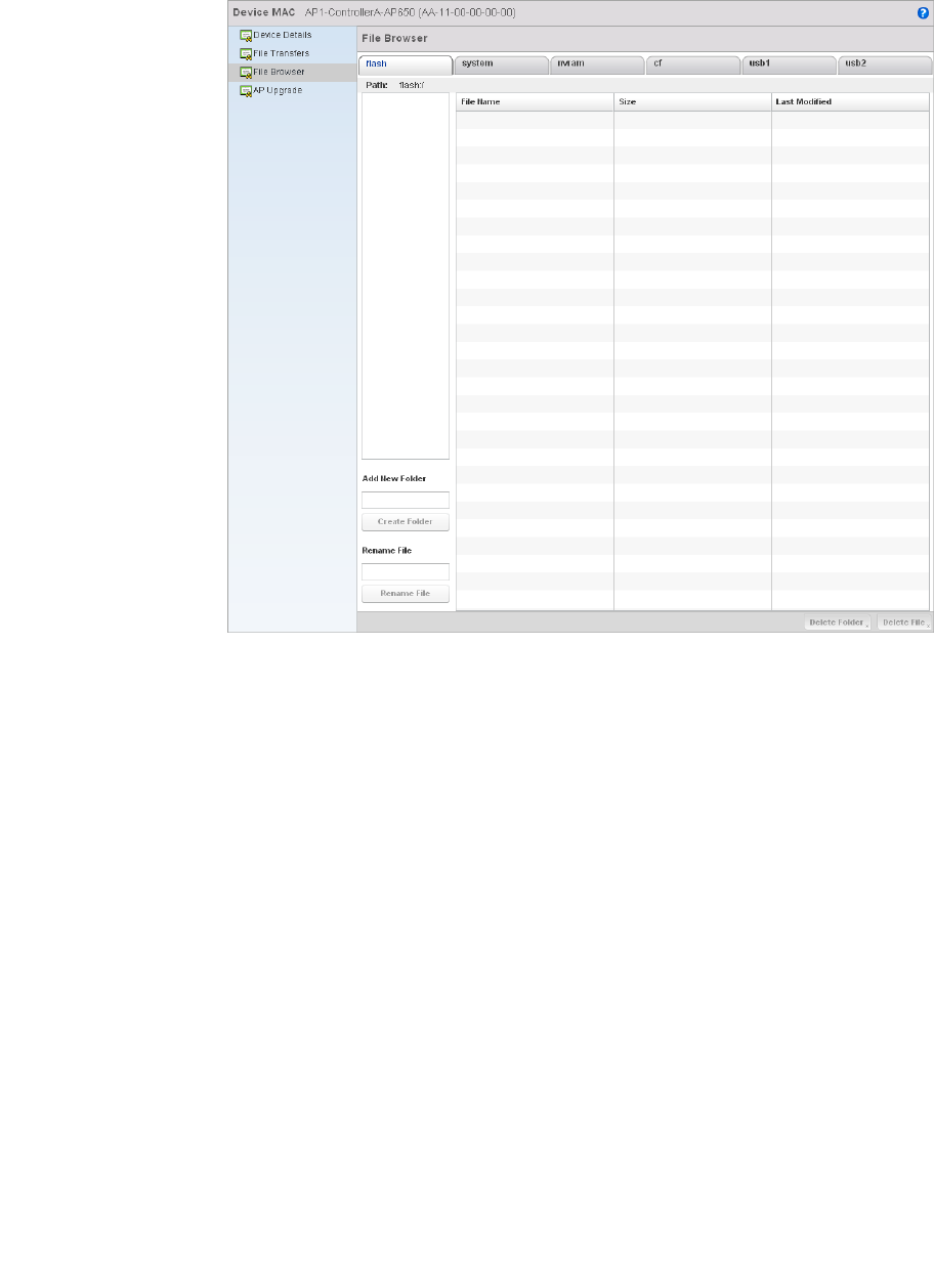
Brocade Mobility RFS4000, RFS6000, and RFS7000 System Reference Guide 639
53-1002620-01
13
FIGURE 422 File Browser screen - flash
2. Refer to the following to determine whether a file needs to be deleted or included in a new
folder for the selected internal (flash, system, nvram) or external (cf, USB1, USB2) controller
memory resource. The following display for each available controller memory resource:
3. If needed, use the Add New Folder utility to create a folder that servers as a directory for some
or all of the files for a selected controller memory resource. Once defined, select the Create
Folder button to implement.
4. Optionally, use the Delete Folder or Delete File buttons to remove a folder or file from within the
current controller memory resource.
Using the AP Upgrade Browser
Device Operations
To manage AP Upgrade configuration:
1. Select the Operations > Devices > AP Upgrade
File Name Displays the name of the file residing on the selected flash, system, nvram usb1 or
usb2 location. The name cannot be modified from this location.
Size Displays the size of the file in kb. Use this information to help determine whether
the file should be moved or deleted.
Last Modified Lists a timestamp for the last time each listed file was modified. Use this
information to determine the file’s relevance or whether it should be deleted.
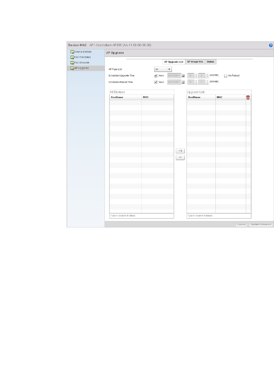
640 Brocade Mobility RFS4000, RFS6000, and RFS7000 System Reference Guide
53-1002620-01
13
FIGURE 423 AP Upgrade screen
2. Select the Access Point model from the AP Type List drop-down to specify which model types
should be available to upgrade.
3. Refer to the Scheduled Upgrade Time option to schedule the when the upgrade should take
place. To perform an upgrade immediately, select Now. To schedule the upgrade to take place
at a specified time, enter a date and time in the appropriate boxes.
4. Refer to the Scheduled Reboot Time option to schedule the when the AP should reboot. To
reboot the upgraded APs immediately, select Now. To schedule the reboot to take place at a
future time, enter a date and time in the appropriate boxes. If you do not wish for the APs to
reboot after they have been upgraded, select the No Reboot option
5. The All Devices table lists available APs that match the AP Type. For each available AP, the
hostname and the primary MAC Address are listed in the table. The Upgrade List table displays
the APs selected for upgrade. For each AP, the hostname and the primary MAC Address are
listed. Using the >>| button moves all APs listed in the All Devices table to the Upgrade List
table.
6. Select the AP Image File tab.
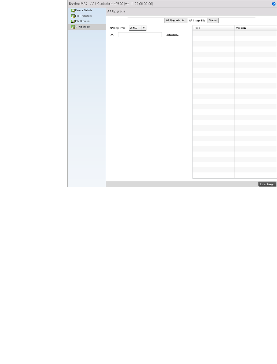
Brocade Mobility RFS4000, RFS6000, and RFS7000 System Reference Guide 641
53-1002620-01
13
FIGURE 424 AP Upgrade screen
7. Select an Access Point model from the AP Image Type drop-down menu to specify which AP
image types should be available during an upgrade.
8. Enter a URL pointing to the location of available AP image files.
9. Selecting Advanced will list additional options for AP image file location including protocol, host
and path to the image files.
10. Select the Status tab.
Protocol Select the protocol for file management. Available options include:
•tftp
•ftp
•sftp
•http
Port Specify the port for transferring files. Enter the port number directly or use the
spinner control.
IP Address Specify the IP address of the server used to transfer files. If IP address of the server
is provided, a Hostname is not required.
Host If needed, specify a Hostname of the serve transferring the file. If a hostname is
provided, an IP Address is not needed.
Path / File Define the path to the file on the server. Enter the complete relative path to the file.
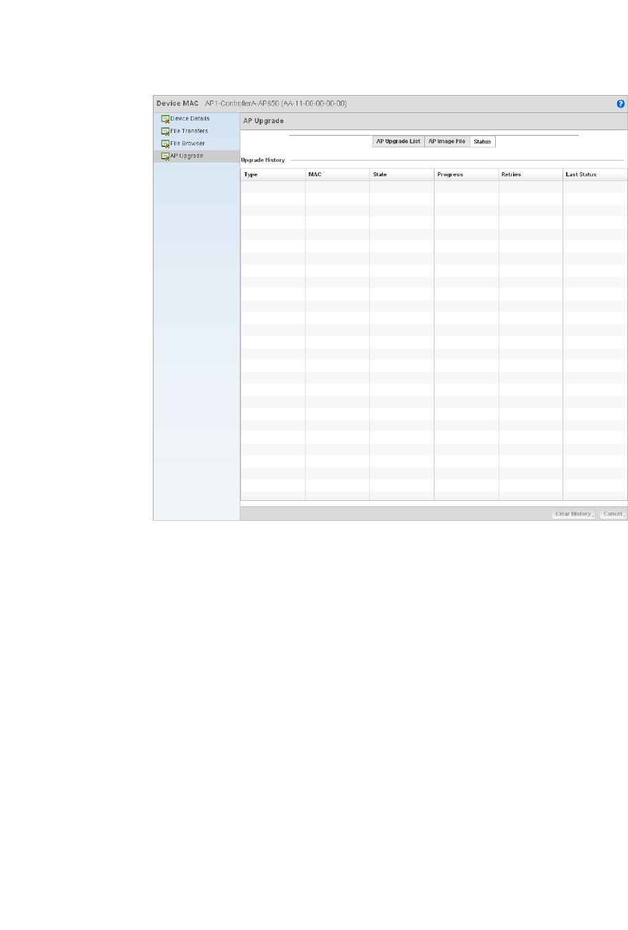
642 Brocade Mobility RFS4000, RFS6000, and RFS7000 System Reference Guide
53-1002620-01
13
FIGURE 425 AP Upgrade screen
11. Refer to the following Upgrade History status information:
12. Selecting the Clear History button clears the current history log page for all Access Points.
Type Displays the Access Point model for each known Access Point.
MAC Displays the primary Media Access Control (MAC) or hardware address for each
known Access Point.
State Displays the current upgrade status of each known Access Point. Possible states
include:
•Waiting
•Downloading
•Updating Scheduled
•Reboot
•Rebooting Done
•Cancelled
•Done
•No Reboot
Progress Displays the time of the last status update for each known Access Point undergoing
an upgrade.
Retries Displays the number of retries, if any, needed for the upgrade.
Last Status Displays the last status update for Access Points no longer upgrading.

Brocade Mobility RFS4000, RFS6000, and RFS7000 System Reference Guide 643
53-1002620-01
13
13. Clicking the Cancel button will cancel the upgrade process for any selected Access Points that
are upgrading.
Certificates
A controller certificate links identity information with a public key enclosed in the certificate.
A certificate authority (CA) is a network authority that issues and manages security credentials and
public keys for message encryption. The CA signs all digital certificates it issues with its own private
key. The corresponding public key is contained within the certificate and is called a CA certificate. A
browser must contain this CA certificate in its Trusted Root Library so it can trust certificates signed
by the CA's private key.
Depending on the public key infrastructure, the digital certificate includes the owner's public key,
the certificate expiration date, the owner's name and other public key owner information.
Each certificate is digitally signed by a trustpoint. The trustpoint signing the certificate can be a
certificate authority, corporation or individual. A trustpoint represents a CA/identity pair containing
the identity of the CA, CA-specific configuration parameters and an association with an enrolled
identity certificate.
SSH keys are a pair of cryptographic keys used to authenticate users instead of, or in addition to, a
username/password. One key is private and the other is public key. Secure Shell (SSH) public key
authentication can be used by a client to access managed resources, if properly configured. A RSA
key pair must be generated on the client. The public portion of the key pair resides with the
controller, while the private portion remains on a secure local area of the client.
For more information on the certification activities support by the controller, refer to the following:
•Certificate Management
•RSA Key Management
•Certificate Creation
•Generating a Certificate Signing Request
Certificate Management
Certificates
If not wanting to use an existing certificate or key with a selected device, an existing stored
certificate can be leveraged from a different managed device for use with the target device. Device
certificates can be imported and exported to and from the controller to a secure remote location for
archive and retrieval as they are required for application to other managed devices.
To configure trustpoints for use with certificates:
1. Select Operations > Certificates.
2. Select a device from amongst those displayed in either the RF Domain or Network panes on
the left-hand side of the screen.
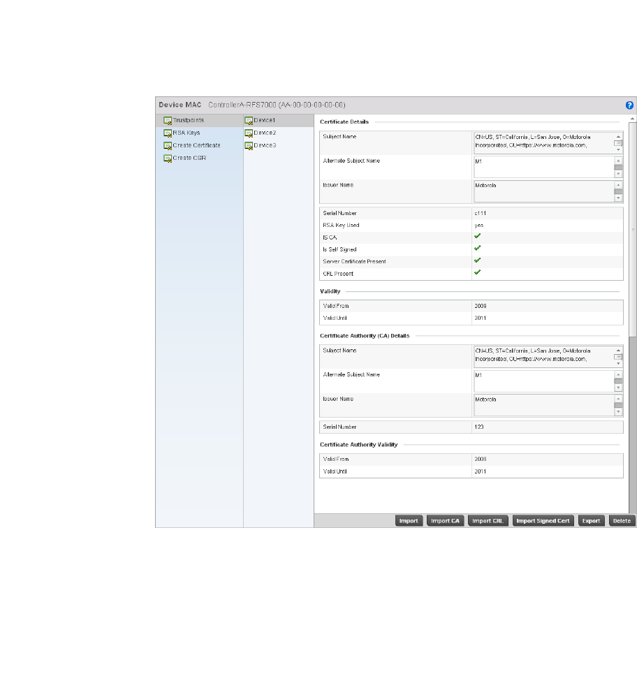
644 Brocade Mobility RFS4000, RFS6000, and RFS7000 System Reference Guide
53-1002620-01
13
FIGURE 426 Trustpoints screen
3. The Trustpoints screen displays for the selected MAC address.
4. Select a device from amongst those displayed to review its certificate information.
5. Refer to the Certificate Details to review the certificate’s properties, self-signed credentials,
validity period and CA information.
6. To optionally import a certificate to the controller, select the Import button from the Trustpoints
screen.
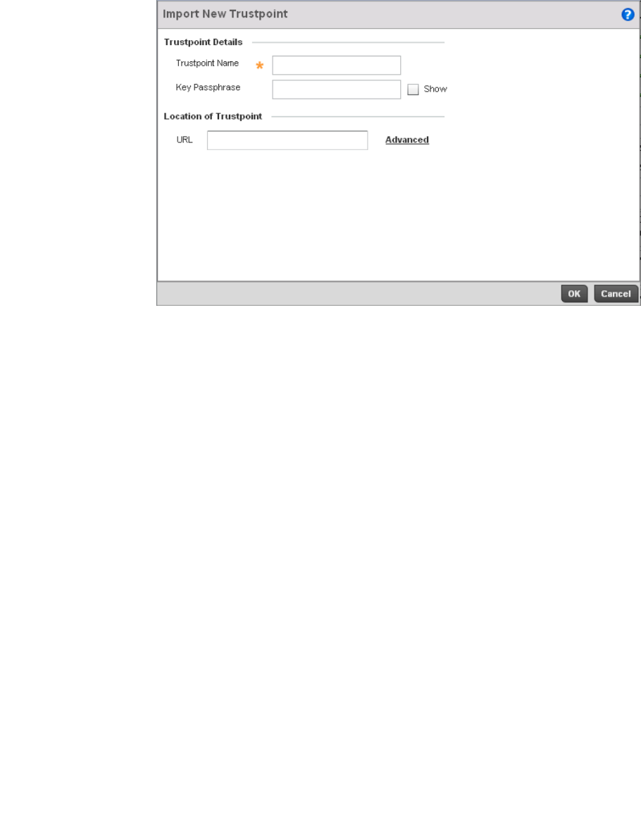
Brocade Mobility RFS4000, RFS6000, and RFS7000 System Reference Guide 645
53-1002620-01
13
FIGURE 427 Import New Trustpoint screen
7. Define the following configuration parameters required for the Import of the trustpoint.
8. Select OK to import the defined trustpoint. Select Cancel to revert the screen to its last saved
configuration.
Trustpoint Name Enter the 32 character maximum name assigned to the target trustpoint. The trustpoint
signing the certificate can be a certificate authority, corporation or individual.
Key Passphrase Define the key used by both the controller and the server (or repository) of the target
trustpoint. Select the Show textbox to expose the characters used in the key. Leaving the
Show checkbox unselected displays the passphrase as a series of asterisks “*”.
URL Provide the complete URL to the location of the trustpoint. If needed, select Advanced to
expand the dialog to display network address information to the location of the target
trustpoint. The number of additional fields that populate the screen is also dependent
on the selected protocol.
Protocol Select the protocol used for importing the target trustpoint. Available options include:
•tftp
•ftp
•sftp
•http
•cf
•usb1
•usb2
Port Use the spinner control to set the port. This option is not valid for cf, usb1 and usb2.
IP Address Enter IP address of the server used to import the trustpoint. This option is not valid for
cf, usb1 and usb2.
Host Provide the hostname of the server used to import the trustpoint. This option is not valid
for cf, usb1 and usb2.
Path / File Specify the path to the trustpoint. Enter the complete relative path to the file on the
server.
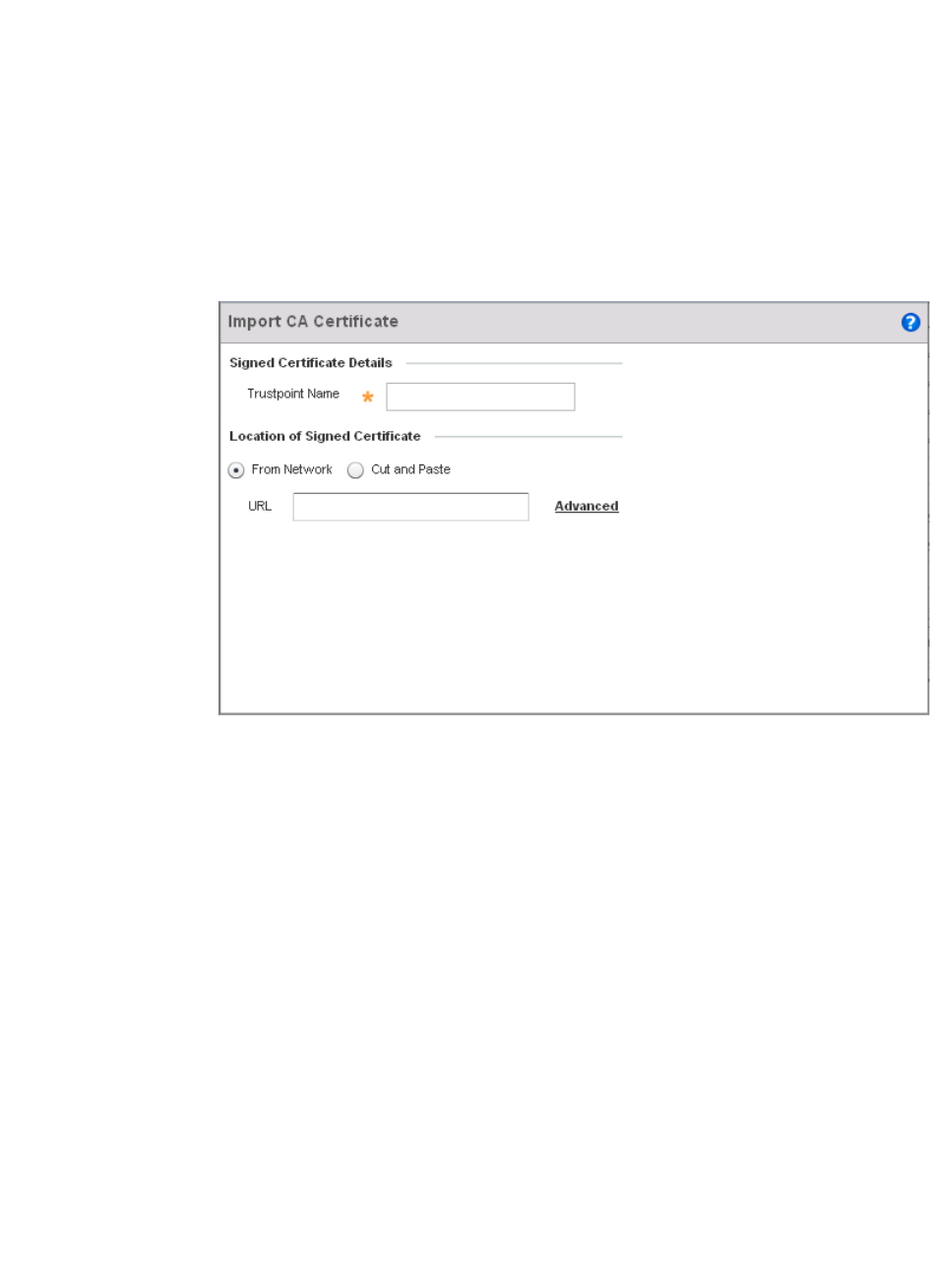
646 Brocade Mobility RFS4000, RFS6000, and RFS7000 System Reference Guide
53-1002620-01
13
9. To optionally import a CA certificate to the controller, select the Import CA button from the
Trustpoints screen.
A certificate authority (CA) is a network authority that issues and manages security credentials
and public keys for message encryption. The CA signs all digital certificates it issues with its
own private key. The corresponding public key is contained within the certificate and is called a
CA certificate.
FIGURE 428 Import CA Certificate screen
10. Define the following configuration parameters required for the Import of the CA certificate:
Trustpoint Name Enter the 32 character maximum name assigned to the target trustpoint signing the
certificate. A trustpoint represents a CA/identity pair containing the identity of the CA,
CA-specific configuration parameters and an association with an enrolled identity
certificate.
From Network Select the From Network radio button to provide network address information to the
location of the target CA certificate. The number of additional fields populating the
screen is dependent on the selected protocol.
Cut and Paste Select the Cut and Paste radio button to simply copy an existing CA certificate into the
cut and past field. When pasting a valid CA certificate, no additional network address
information is required.
Protocol Select the protocol used for importing the target CA certificate. Available options
include:
•tftp
•ftp
•sftp
•http
•cf
•usb1
•usb2
Port Use the spinner control to set the port. This option is not valid for cf, usb1, and usb2.
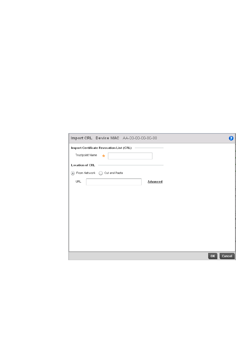
Brocade Mobility RFS4000, RFS6000, and RFS7000 System Reference Guide 647
53-1002620-01
13
11. Select OK to import the defined CA certificate. Select Cancel to revert the screen to its last
saved configuration.
12. To optionally import a CRL to the controller, select the Import CRL button from the Trustpoints
screen.
If a certificate displays within the Certificate Management screen with a CRL, that CRL can be
imported into the controller. A certificate revocation list (CRL) is a list of certificates that have
been revoked or are no longer valid. A certificate can be revoked if the certificate authority (CA)
had improperly issued a certificate, or if a private-key is compromised. The most common
reason for revocation is the user no longer being in sole possession of the private key.
FIGURE 429 Import CRL screen
13. Define the following configuration parameters required for the Import of the CRL:
IP Address Enter IP address of the server used to import the CA certificate. This option is not valid
for cf, usb1, and usb2.
Hostname Provide the hostname of the server used to import the CA certificate. This option is not
valid for cf, usb1 and usb2.
Path Specify the path to the CA certificate. Enter the complete relative path to the file on the
server.
Trustpoint Name Enter the 32 character maximum name assigned to the target trustpoint signing the
certificate. A trustpoint represents a CA/identity pair containing the identity of the CA,
CA-specific configuration parameters, and an association with an enrolled identity
certificate.
From Network Select the From Network radio button to provide network address information to the
location of the target CRL. The number of additional fields that populate the screen is
also dependent on the selected protocol. This is the default setting.
Cut and Paste Select the Cut and Paste radio button to simply copy an existing CRL into the cut and
past field. When pasting a CRL, no additional network address information is required.
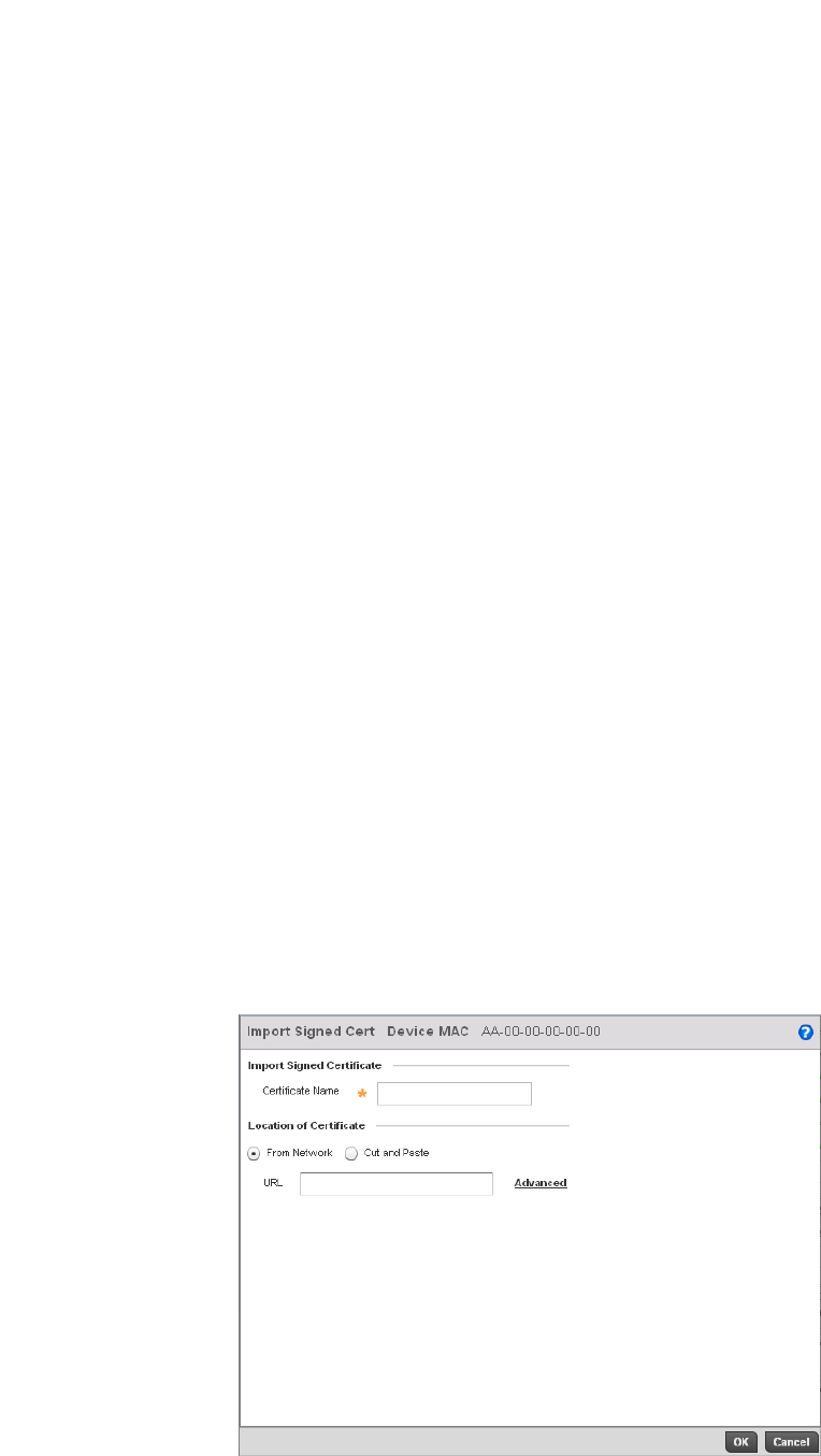
648 Brocade Mobility RFS4000, RFS6000, and RFS7000 System Reference Guide
53-1002620-01
13
14. Select OK to import the CRL. Select Cancel to revert the screen to its last saved configuration.
15. To import a signed certificate to the controller, select the Import Signed Cert button from the
Trustpoints screen.
Signed certificates (or root certificates) avoid the use of public or private CAs. A self signed
certificate is an identity certificate signed by its own creator. Thus, the certificate creator also
signs off on its legitimacy. The lack of mistakes or corruption in the issuance of self signed
certificates is central.
Self-signed certificates cannot be revoked, which may allow an attacker who has already
gained controller access to monitor and inject data into a connection to spoof an identity if a
private key has been compromised. However, CAs have the ability to revoke a compromised
certificate, which prevents its further use.
FIGURE 430 Import Signed Cert screen
URL Provide the complete URL to the location of the CRL. If needed, select Advanced to
expand the dialog to display network address information to the location of the target
CRL. The number of additional fields that populate the screen is also dependent on the
selected protocol.
Protocol Select the protocol used for importing the CRL. Available options include:
•tftp
•ftp
•sftp
•http
•cf
•usb1
•usb2
Port Use the spinner control to set the port. This option is not valid for cf, usb1 and usb2.
IP Address Enter IP address of the server used to import the CRL. This option is not valid for cf,
usb1 and usb2.
Hostname Provide the hostname of the server used to import the CRL. This option is not valid for cf,
usb1 and usb2.
Path Specify the path to the CRL. Enter the complete relative path to the file on the server.

Brocade Mobility RFS4000, RFS6000, and RFS7000 System Reference Guide 649
53-1002620-01
13
16. Define the following configuration parameters required for the Import of the CA certificate:
17. Select OK to import the signed certificate. Select Cancel to revert the screen to its last saved
configuration
18. To optionally export a trustpoint from the controller to a remote location, select the Export
button from the Trustpoints screen.
Once a certificate has been generated on the controller’s authentication server, export the self
signed certificate. A digital CA certificate is different from a self signed certificate. The CA
certificate contains the public and private key pairs. The self certificate only contains a public
key. Export the self certificate for publication on a Web server or file server for certificate
deployment or export it in to an Active Directory Group Policy for automatic root certificate
deployment.
Additionally export the key to a redundant RADIUS server so it can be imported without
generating a second key. If there’s more than one RADIUS authentication server, export the
certificate and don’t generate a second key unless you want to deploy two root certificates.
Certificate Name Enter the 32 character maximum name of the trustpoint with which the certificate
should be associated
From Network Select the From Network radio button to provide network address information to the
location of the target signed certificate. The number of additional fields that populate
the screen is also dependent on the selected protocol. This is the default setting.
Cut and Paste Select the Cut and Paste radio button to simply copy an existing signed certificate into
the cut and past field. When pasting a signed certificate, no additional network address
information is required.
URL Provide the complete URL to the location of the signed certificate. If needed, select
Advanced to expand the dialog to display network address information to the location of
the signed certificate. The number of additional fields that populate the screen is
dependent on the selected protocol.
Protocol Select the protocol used for importing the target signed certificate. Available options
include:
•tftp
•ftp
•sftp
•http
•cf
•usb1
•usb2
Port Use the spinner control to set the port. This option is not valid for cf, usb1 and usb2.
IP Address Enter IP address of the server used to import the signed certificate. This option is not
valid for cf, usb1 and usb2.
Hostname Provide the hostname of the server used to import the signed certificate. This option is
not valid for cf, usb1 and usb2.
Path Specify the path to the signed certificate. Enter the complete relative path to the file on
the server.
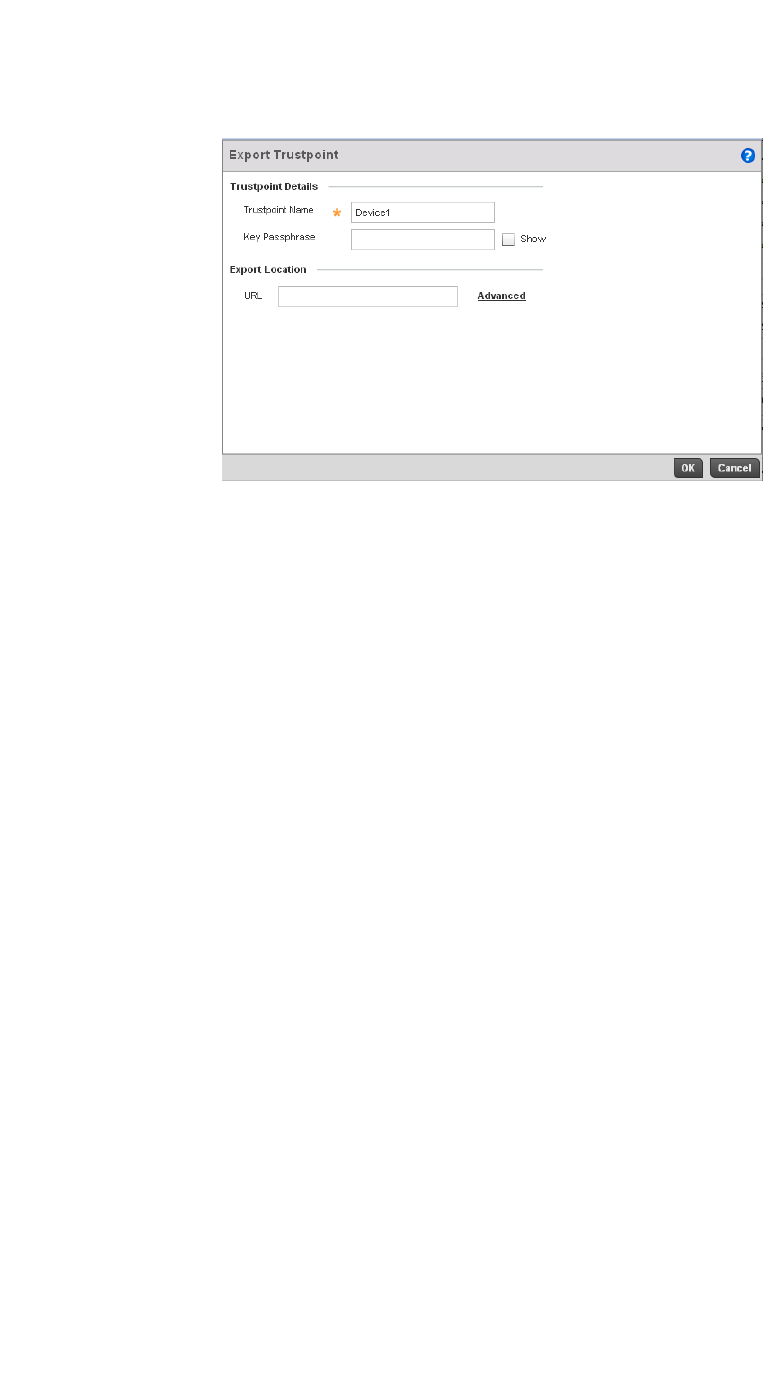
650 Brocade Mobility RFS4000, RFS6000, and RFS7000 System Reference Guide
53-1002620-01
13
FIGURE 431 Export Trustpoint screen
19. Define the following configuration parameters required for the Export of the trustpoint.
20. Select OK to export the defined trustpoint. Select Cancel to revert the screen to its last saved
configuration.
21. To optionally delete a trustpoint, select the Delete button from the Trustpoints screen. Provide
the trustpoint name within the Delete Trustpoint screen and optionally select the Delete RSA
Key checkbox to remove the RSA key along with the trustpoint. Select OK to proceed with the
deletion, or Cancel to revert to the last saved configuration.
Trustpoint Name Enter the 32 character maximum name assigned to the target trustpoint. The trustpoint
signing the certificate can be a certificate authority, corporation or individual.
Key Passphrase Define the key used by both the controller and the server (or repository) of the target
trustpoint. Select the Show textbox to expose the actual characters used in the key.
Leaving the Show checkbox unselected displays the passphrase as a series of asterisks
“*”.
URL Provide the complete URL to the location of the trustpoint. If needed, select Advanced to
expand the dialog to display network address information to the location of the target
trustpoint. The number of additional fields that populate the screen is also dependent
on the selected protocol.
Protocol Select the protocol used for exporting the target trustpoint. Available options include:
•tftp
•ftp
•sftp
•http
•cf
•usb1
•usb2
Port Use the spinner control to set the port. This option is not valid for cf, usb1 and usb2.
IP Address Enter IP address of the server used to export the trustpoint. This option is not valid for cf,
usb1 and usb2.
Hostname Provide the hostname of the server used to export the trustpoint. This option is not valid
for cf, usb1 and usb2.
Path Specify the path to the trustpoint. Enter the complete relative path to the file on the
server.
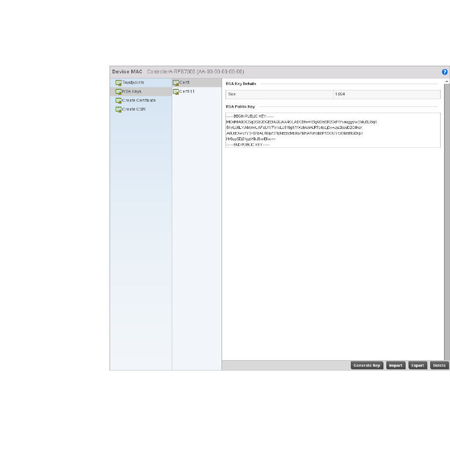
Brocade Mobility RFS4000, RFS6000, and RFS7000 System Reference Guide 651
53-1002620-01
13
RSA Key Management
Certificates
Refer to the RSA Keys screen to review existing RSA key configurations applied to managed
devices. If an existing key does not meet the needs of a pending certificate request, generate a new
key or import or export an existing key to and from a remote location.
Rivest, Shamir, and Adleman (RSA) is an algorithm for public key cryptography. It’s an algorithm
used for certificate signing and encryption. When a device trustpoint is created, the RSA key is the
private key used with the trustpoint.
To review existing device RSA key configurations, generate additional keys or import/export keys to
and from remote locations:
1. Select Operations > Certificates.
2. Select a device from amongst those displayed in either the RF Domain or Network panes on
the left-hand side of the screen.
3. Select RSA Keys.
FIGURE 432 RSA Keys screen
Each key can have its size and character syntax displayed. Once reviewed, optionally generate
a new RSA key, import a key from a selected device, export a key from the controller to a
remote location or delete a key from a selected device.
4. Select Generate Key to create a new key with a defined size.
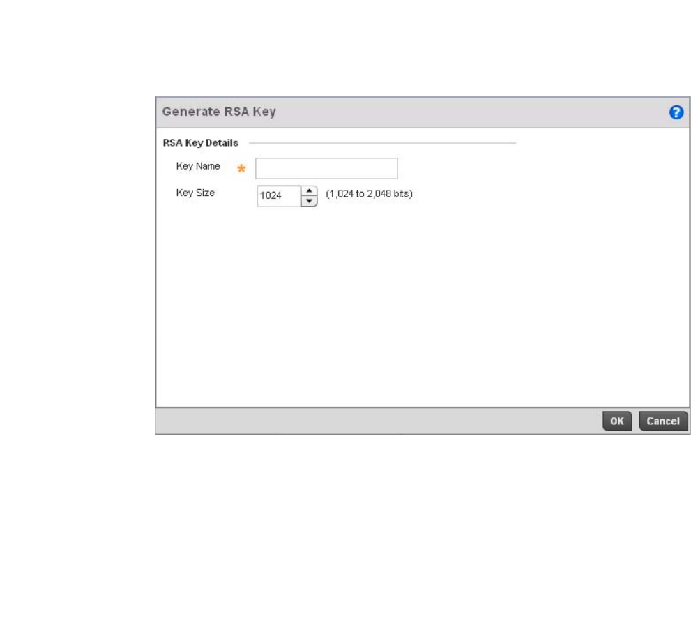
652 Brocade Mobility RFS4000, RFS6000, and RFS7000 System Reference Guide
53-1002620-01
13
FIGURE 433 Generate RSA Key screen
5. Select OK to generate the RSA key. Select Cancel to revert the screen to its last saved
configuration.
6. To optionally import a CA certificate to the controller, select the Import button from the RSA
Keys screen.
Key Name Enter the 32 character maximum name assigned to the RSA key.
Key Size Use the spinner control to set the size of the key (between 1,024 - 2,048 bits). Brocade
recommends leaving this value at the default setting of 1024 to ensure optimum
functionality.
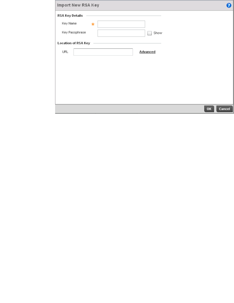
Brocade Mobility RFS4000, RFS6000, and RFS7000 System Reference Guide 653
53-1002620-01
13
FIGURE 434 Import New RSA Key screen
7. Define the following configuration parameters required for the Import of the RSA key:
8. Select OK to import the defined RSA key. Select Cancel to revert the screen to its last saved
configuration.
Key Name Enter the 32 character maximum name assigned to identify the RSA key.
Key Passphrase Define the key used by both the controller and the server (or repository) of the target
RSA key. Select the Show textbox to expose the actual characters used in the
passphrase. Leaving the Show checkbox unselected displays the passphrase as a series
of asterisks “*”.
URL Provide the complete URL to the location of the RSA key. If needed, select Advanced to
expand the dialog to display network address information to the location of the target
key. The number of additional fields that populate the screen is also dependent on the
selected protocol.
Protocol Select the protocol used for importing the target key. Available options include:
•tftp
•ftp
•sftp
•http
•cf
•usb1
•usb2
Port Use the spinner control to set the port. This option is not valid for cf, usb1 and usb2.
IP Address Enter IP address of the server used to import the RSA key. This option is not valid for cf,
usb1 and usb2.
Hostname Provide the hostname of the server used to import the RSA key. This option is not valid
for cf, usb1 and usb2.
Path Specify the path to the RSA key. Enter the complete relative path to the key on the
server.
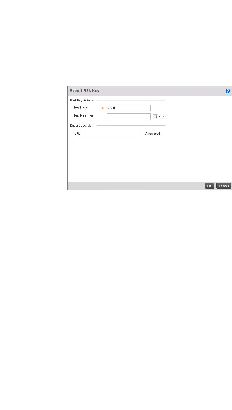
654 Brocade Mobility RFS4000, RFS6000, and RFS7000 System Reference Guide
53-1002620-01
13
9. To optionally export a RSA key from the controller to a remote location, select the Export button
from the RSA Keys screen.
10. Export the key to a redundant RADIUS server so it can be imported without generating a
second key. If there’s more than one RADIUS authentication server, export the certificate and
don’t generate a second key unless you want to deploy two root certificates.
FIGURE 435 Export RSA Key screen
11. Define the following configuration parameters required for the Export of the RSA key.
12. Select OK to export the defined RSA key. Select Cancel to revert the screen to the last saved
configuration.
Key Name Enter the 32 character maximum name assigned to the RSA key.
Key Passphrase Define the key passphrase used by both the controller and the server. Select the Show
textbox to expose the actual characters used in the passphrase. Leaving the Show
checkbox unselected displays the passphrase as a series of asterisks “*”.
URL Provide the complete URL to the location of the key. If needed, select Advanced to
expand the dialog to display network address information to the location of the target
key. The number of additional fields that populate the screen is also dependent on the
selected protocol.
Protocol Select the protocol used for exporting the RSA key. Available options include:
•tftp
•ftp
•sftp
•http
•cf
•usb1
•usb2
Port Use the spinner control to set the port. This option is not valid for cf, usb1 and usb2.
IP Address Enter IP address of the server used to export the RSA key. This option is not valid for cf,
usb1 and usb2.
Hostname Provide the hostname of the server used to export the RSA key. This option is not valid
for cf, usb1 and usb2.
Path Specify the path to the key. Enter the complete relative path to the key on the server.
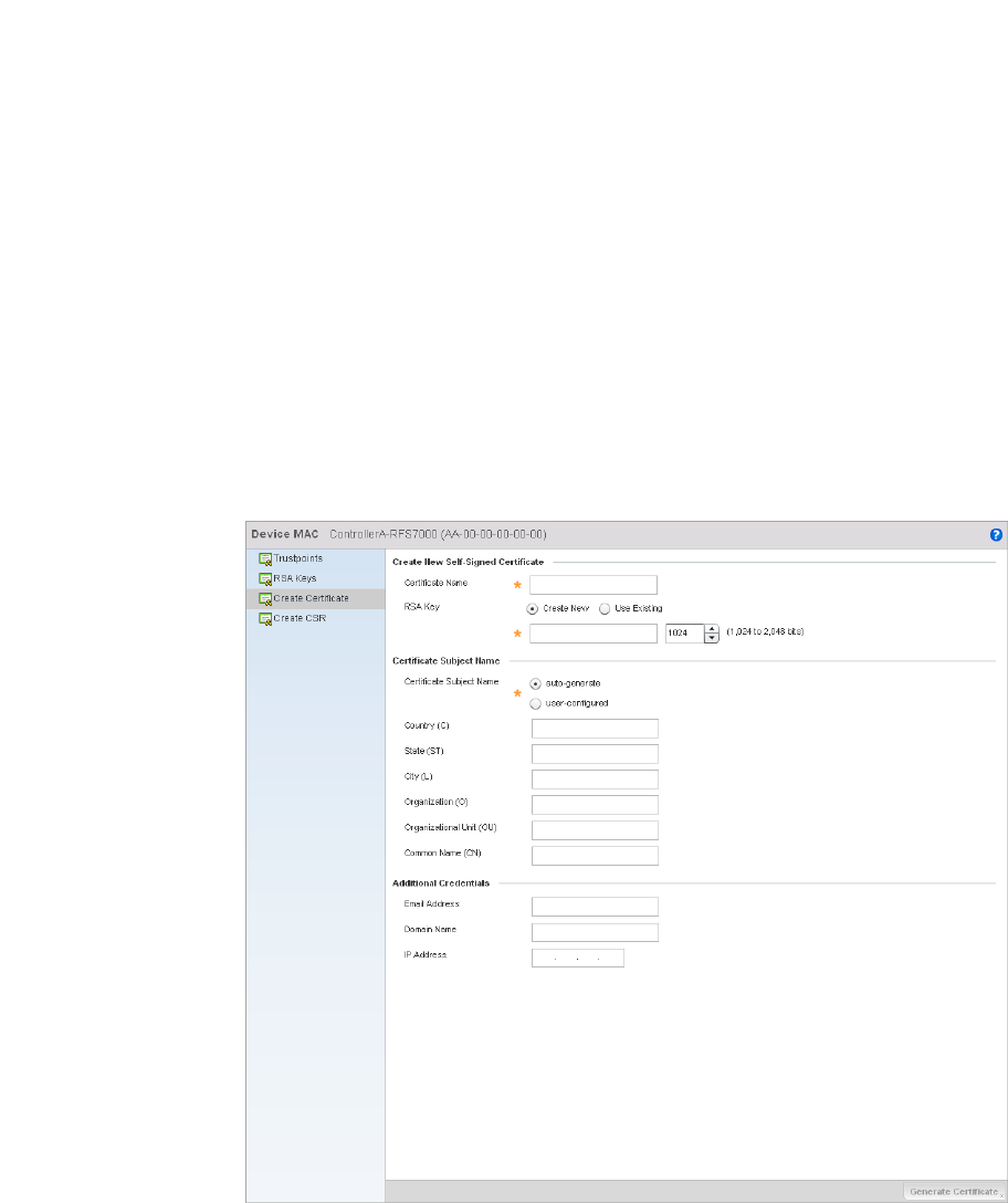
Brocade Mobility RFS4000, RFS6000, and RFS7000 System Reference Guide 655
53-1002620-01
13
13. To optionally delete a key, select the Delete button from within the RSA Keys screen. Provide
the key name within the Delete RSA Key screen and select the Delete Certificates checkbox to
remove the certificate the key supported. Select OK to proceed with the deletion, or Cancel to
revert to the last saved configuration.
Certificate Creation
Certificates
The Certificate Management screen provides the facility for creating new self-signed certificates.
Self signed certificates (often referred to as root certificates) do not use public or private CAs. A self
signed certificate is a certificate signed by its own creator, with the certificate creator responsible
for its legitimacy.
To create a self-signed certificate that can be applied to a managed device:
1. Select Operations > Certificates.
2. Select a device from amongst those displayed in either the RF Domain or Network panes on
the left-hand side of the screen.
3. Select Create Certificate.
FIGURE 436 Create Certificate screen

656 Brocade Mobility RFS4000, RFS6000, and RFS7000 System Reference Guide
53-1002620-01
13
4. Define the following configuration parameters required to Create New Self-Signed Certificate:
5. Set the following Certificate Subject Name parameters required for the creation of the
certificate:
6. Select the following Additional Credentials required for the generation of the self signed
certificate:
7. Select the Generate Certificate button at the bottom of the Create Certificate screen to
produce the certificate.
Generating a Certificate Signing Request
Certificates
Certificate Name Enter the 32 character maximum name assigned to identify the name of the trustpoint
associated with the certificate. A trustpoint represents a CA/identity pair containing the
identity of the CA, CA-specific configuration parameters, and an association with an
enrolled identity certificate.
Use an Existing RSA Key Select the radio button and use the drop-down menu to select the existing key used by
both the controller and the server (or repository) of the target RSA key.
Create a New RSA Key To create a new RSA key, select the radio button to define 32 character name used to
identify the RSA key. Use the spinner control to set the size of the key (between 1,024 -
2,048 bits). Brocade recommends leaving this value at the default setting of 1024 to
ensure optimum functionality. For more information on creating a new RSA key, see RSA
Key Management on page 13-651.
Certificate Subject
Name
Select either the auto-generate radio button to automatically create the certificate's
subject credentials or select user-defined to manually enter the credentials of the self
signed certificate. The default setting is auto-generate.
Country (C) Define the Country used in the certificate. The field can be modified by the user to other
values. This is a required field and cannot exceed 2 characters.
State (ST) Enter a State/Prov. for the state or province name used in the certificate. This is a
required field.
City (L) Enter a City to represent the city name used in the certificate. This is a required field.
Organization (O) Define an Organization for the organization used in the certificate. This is a required
field.
Organizational Unit (OU) Enter an Org. Unit for the name of the organization unit used in the certificate. This is a
required field.
Common Name (CN) If there’s a common name (IP address) for the organizational unit issuing the certificate,
enter it here.
Email Address Provide an email address used as the contact address for issues relating to this
certificate request.
Domain Name) Enter a fully qualified domain name (FQDN) is an unambiguous domain name that
specifies the node's position in the DNS tree hierarchy absolutely. To distinguish an
FQDN from a regular domain name, a trailing period is added. ex:
somehost.example.com. An FQDN differs from a regular domain name by its
absoluteness; as a suffix is not added.
IP Address Specify the controller IP address used as the controller destination for certificate
requests.
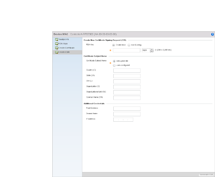
Brocade Mobility RFS4000, RFS6000, and RFS7000 System Reference Guide 657
53-1002620-01
13
A certificate signing request (CSR) is a message from a requestor to a certificate authority to apply
for a digital identity certificate. The CSR is composed of a block of encrypted text generated on the
server the certificate will be used on. It contains information included in the certificate, including
organization name, common name (domain name), locality, and country.
A RSA key must be either created or applied to the certificate request before the certificate can be
generated. A private key is not included in the CSR, but is used to digitally sign the completed
request. The certificate created with a particular CSR only worked with the private key generated
with it. If the private key is lost, the certificate is no longer functional.The CSR can be accompanied
by other identity credentials required by the certificate authority, and the certificate authority
maintains the right to contact the applicant for additional information.
If the request is successful, the CA sends an identity certificate digitally signed with the private key
of the CA.
To create a CSR:
1. Select Operations > Certificates.
2. Select a device from amongst those displayed in either the RF Domain or Network panes on
the left-hand side of the screen.
3. Select Create CSR.
FIGURE 437 Create CSR screen

658 Brocade Mobility RFS4000, RFS6000, and RFS7000 System Reference Guide
53-1002620-01
13
4. Define the following configuration parameters required to Create New Certificate Signing
Request (CSR):
5. Set the following Certificate Subject Name parameters required for the creation of the
certificate:
6. Select the following Additional Credentials required for the generation of the CSR:
7. Select the Generate CSR button at the bottom of the screen to produce the CSR.
Smart RF
Self Monitoring At Run Time RF Management (Smart RF) is a Brocade Solutions innovation
designed to simplify RF configurations for new deployments, while (over time) providing on-going
deployment optimization and radio performance improvements.
Use an Existing RSA Key Select the radio button and use the drop-down menu to select the existing key used by
both the controller and the server (or repository) of the target RSA key.
Create a New RSA Key To create a new RSA key, select the radio button to define 32 character name used to
identify the RSA key. Use the spinner control to set the size of the key (between 1,024 -
2,048 bits). Brocade recommends leaving this value at the default setting of 1024 to
ensure optimum functionality. For more information on creating a new RSA key, see RSA
Key Management on page 13-651.
Certificate Subject
Name
Select either the auto-generate radio button to automatically create the certificate's
subject credentials or select user-defined to manually enter the credentials of the self
signed certificate. The default setting is auto-generate.
Country (C) Define the Country used in the CSR. The field can be modified by the user to other
values. This is a required field and must not exceed 2 characters.
State (ST) Enter a State/Prov. for the state or province name used in the CSR. This is a required
field.
City (L) Enter a City to represent the city name used in the CSR. This is a required field.
Organization (O) Define an Organization for the organization used in the CSR. This is a required field.
Organizational Unit (OU) Enter an Org. Unit for the name of the organization unit used in the CSR. This is a
required field.
Common Name (CN) If there’s a common name (IP address) for the organizational unit issuing the certificate,
enter it here.
Email Address Provide an email address used as the contact address for issues relating to this CSR.
Domain Name) Enter a fully qualified domain name (FQDN) is an unambiguous domain name that
specifies the node's position in the DNS tree hierarchy absolutely. A trailing period is
added to distinguish an FQDN from a regular domain name. For example,
somehost.example.com. An FQDN differs from a regular domain name by its
absoluteness, since a suffix is not added.
IP Address Specify the controller IP address used as the controller destination for certificate
requests.

Brocade Mobility RFS4000, RFS6000, and RFS7000 System Reference Guide 659
53-1002620-01
13
The Smart RF functionality scans the managed network to determine the best channel and
transmit power for each wireless controller managed Access Point radio. Smart RF policies can be
applied to specific RF Domains, to apply site specific deployment configurations and self recovery
values to groups of devices within pre-defined physical RF coverage areas.
Smart RF also provides self recovery functions by monitoring the managed network in real-time and
provides automatic mitigation from potentially problematic events such as radio interference,
coverage holes and radio failures. Smart RF employs self recovery to enable a WLAN to better
maintain wireless client performance and site coverage during dynamic RF environment changes,
which typically require manual reconfiguration to resolve.
Smart RF is supported in standalone and clustered environments. In standalone environments, the
individual controller manages the calibration and monitoring phases. In clustered environments, a
single controller is elected a Smart Scan master and the remaining cluster members operate as
Smart RF clients. In cluster operation, the Smart Scan master coordinates calibration and
configuration and during the monitoring phase receives information from the Smart RF clients.
Smart RF calibration can be triggered manually or continues at run-time, all the time.
Smart RF is supported on wireless controllers managing br-650, br-6511, or br-7131 (adaptive
mode) Access Points in either standalone or clustered environments.
NOTE
For br-7131 series Access Points, Smart RF should only be used with the façade antenna, and for
an br-650, Smart RF should only be used with internal antenna models.
Within the Operations node, Smart RF is managed within selected RF Domains, using the Access
Points that comprise the RF Domain and their respective radio and channel configurations as the
basis to conduct Smart RF calibration operations.
Managing Smart RF for an RF Domain
Smart RF
When calibration is initiated, Smart RF instructs adopted radios (within a selected controller RF
Domain) to beacon on a specific legal channel, using a specific transmit power setting. Smart RF
measures the signal strength of each beacon received from both managed and unmanaged
neighboring APs to define a RF map of the neighboring radio coverage area. Smart RF uses this
information to calculate each managed radio’s RF configuration as well as assign radio roles,
channel and power.
Within a well planned RF Domain, any associated radio should be reachable by at least one other
radio. The Smart RF feature records signals received from its neighbors. Access Point to Access
Point distance is recorded in terms of signal attenuation. The information is used during channel
assignment to minimize interference.
To conduct Smart RF calibration for an RF Domain:
1. Select Operations > Smart RF.
2. Expand the System mode in the upper, left-hand, side of the controller user interface to display
the RF Domains available for Smart RF calibration.
3. Select a RF Domain from amongst those displayed.
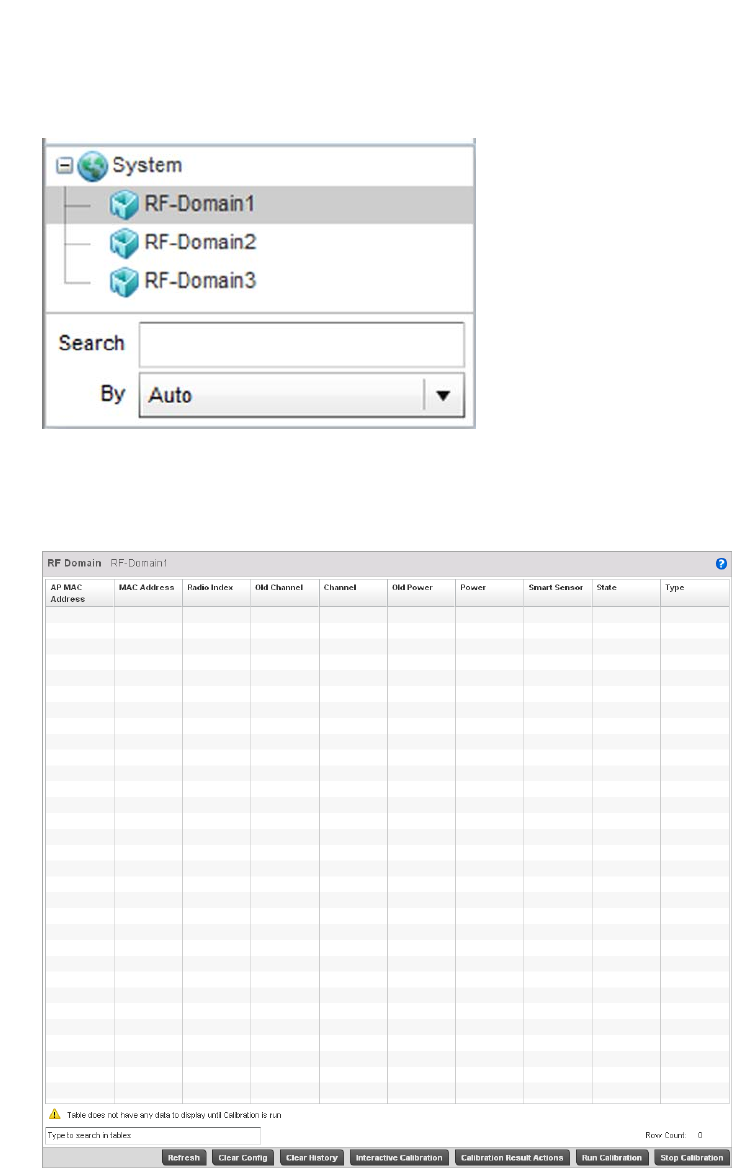
660 Brocade Mobility RFS4000, RFS6000, and RFS7000 System Reference Guide
53-1002620-01
13
FIGURE 438 Smart RF screen - System Browser
4. The Smart RF screen displays information specific to the devices within the selected RF
Domain using data from the last interactive calibration.
FIGURE 439 Smart RF screen

Brocade Mobility RFS4000, RFS6000, and RFS7000 System Reference Guide 661
53-1002620-01
13
5. Refer to the following to determine whether a Smart RF calibration or an interactive calibration
is required:
6. Select the Refresh button to (as needed) to update the contents of the Smart RF screen and
the attributes of the devices within the selected RF Domain.
7. Select the Interactive Calibration button to initiate a Smart RF calibration using the Access
Points within the selected RF Domain. The results of the calibration display within the Smart RF
screen. Of particular interest are the channel and power adjustments made by the controller’s
Smart RF module. Expand the screen to display the Event Monitor to track the progress of the
Interactive Calibration.
8. Select the Save Calibration Result screen to launch a sub screen used to determine the
actions taken based on the results of the Interactive Calibration. The results of an Interactive
calibration are not applied to radios directly, the administrator has the choice to select one of
following options:
AP MAC Address Displays the hardware encoded MAC address assigned to each Access Point radio
within the selected RF Domain. This value cannot be modified as past of a
calibration activity.
MAC Address Displays the hardware encoded MAC address assigned to each Access Point radio
within the selected RF Domain. This value cannot be modified as past of a
calibration activity.
Radio Index Displays a numerical index assigned to each listed Access Point radio when it was
added to the managed network. This index helps distinguish this radio from others
within this RF Domain with similar configurations. This value is not subject to
change as a result of a calibration activity, but each listed radio index can be used
in Smart RF calibration.
Old Channel Lists the channel originally assigned to each listed Access Point MAC address within
this RF Domain. This value may have been changed as part an Interactive
Calibration process applied to this RF Domain. Compare this Old Channel against
the Channel value to right of it (in the table) to determine whether a new channel
assignment was warranted to compensate for a coverage hole.
Channel Lists the current channel assignment for each listed Access Point, as potentially
updated by an Interactive Calibration. Use this data to determine whether a channel
assignment was modified as part of an Interactive Calibration. If a revision was
made to the channel assignment, a coverage hole was detected on the channel as
a result of a potentially failed or under performing Access Point radio within this RF
Domain.
Old Power Lists the transmit power assigned to each listed Access Point MAC address within
this RF Domain. The power level may have been increased or decreased as part an
Interactive Calibration process applied to this RF Domain. Compare this Old Power
level against the Power value to right of it (in the table) to determine whether a new
power level was warranted to compensate for a coverage hole.
Power This column displays the transmit power level for the listed Access Point MAC
address after an Interactive Calibration resulted in an adjustment. This is the new
power level defined by Smart RF to compensate for a coverage hole.
Smart Sensor Defines whether a listed Access Point is smart sensor on behalf of the other Access
Point radios comprising the RF Domain.
State Displays the current state of the Smart RF managed Access Point radio. Possible
states include: Normal, Offline and Sensor.
Type Displays the radio type (802.11an, 802.11bgn etc.) of each listed Access Point
radio within the selected RF Domain.
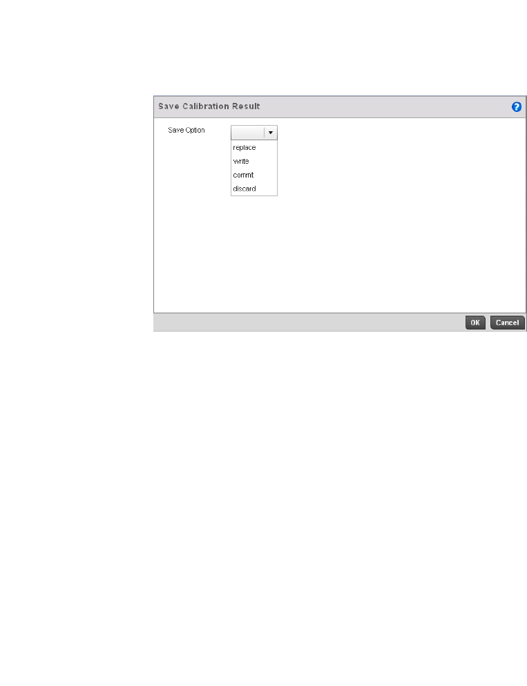
662 Brocade Mobility RFS4000, RFS6000, and RFS7000 System Reference Guide
53-1002620-01
13
FIGURE 440 Save Calibration Result screen
9. Select the Run Calibration option to initiate a calibration. New channel and power values are
applied to radios, they are not written to the running-configuration.
These values are dynamic and may keep changing during the course of the run-time
monitoring and calibration the Smart RF module keeps performing to continually maintain
good coverage. Unlike an Interactive Calibration, the Smart RF screen is not populated with the
changes needed on Access Point radios to remedy a detected coverage hole. Expand the
screen to display the Event Monitor to track the progress of the calibration.
10. The calibration process can be stopped by selecting the Stop Calibration button.
Replace Overwrites the current channel and power values with new channel power values
the Interactive Calibration has calculated.
Write Writes the new channel and power values to the radios under their respective
device configurations.
Discard Discards the results of the Interactive Calibration without applying them to their
respective devices.
Commit Commits the Smart RF module Interactive Calibration results to their respective
Access Point radios.

Brocade Mobility RFS4000, RFS6000, and RFS7000 System Reference Guide 663
53-1002620-01
Chapter
14
Statistics
In this chapter
•System Statistics . . . . . . . . . . . . . . . . . . . . . . . . . . . . . . . . . . . . . . . . . . . . . . 663
•RF Domain Statistics. . . . . . . . . . . . . . . . . . . . . . . . . . . . . . . . . . . . . . . . . . . 671
•Access Point Statistics . . . . . . . . . . . . . . . . . . . . . . . . . . . . . . . . . . . . . . . . . 692
•Wireless Controller Statistics . . . . . . . . . . . . . . . . . . . . . . . . . . . . . . . . . . . . 758
•Wireless Client Statistics. . . . . . . . . . . . . . . . . . . . . . . . . . . . . . . . . . . . . . . . 822
This chapter describes statistics displayed by the controller GUI. Statistics are available for both the
controller and its managed devices.
A Smart RF statistical history is available to assess adjustments made to device configurations to
compensate for detected coverage holes or device failures.
Access Point statistics can be exclusively displayed to validate connected Access Points, their VLAN
assignments and their current authentication and encryption schemes.
Controller statistics display detailed information about controller peers, controller health, device
inventories, wireless clients associations, adopted AP information, rogue APs and WLANs.
Wireless client statistics are available for an overview of client health. Wireless client statistics
includes RF quality, traffic utilization and user details. Use this information to assess if
configuration changes are required to improve network performance.
System Statistics
The System screen displays information supporting managed devices. Use this information to
obtain an overall view of the state of the devices in the network. The data is organized as follows:
•Health
•Inventory
•Adopted Devices
•Pending Adoptions
•Licenses
Health
System Statistics
The Health screen displays the overall performance of the wireless controller managed network.
This includes information on the device availability, overall RF quality, resource utilization and
network threat perception.
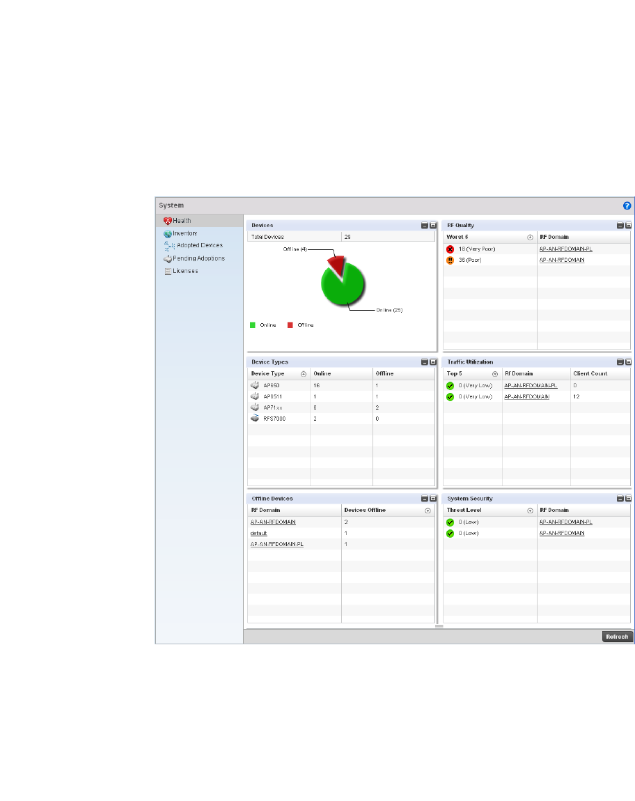
664 Brocade Mobility RFS4000, RFS6000, and RFS7000 System Reference Guide
53-1002620-01
14
To display the health of the wireless controller managed network:
1. Select the Statistics menu from the Web UI.
2. Select the System node from the left navigation pane.
3. Select Health from the left-hand side of the UI.
FIGURE 441 System screen
The System screen fields supporting Device Health, Device Type, RF Quality Index, Traf fic
Utilization and Security.
4. The Device Health table displays the total number of devices in the managed network. The pie
chart is a proportional view of how many devices are functional and are currently online. Green
indicates online devices and the red offline devices.
5. Use the RF Quality Index table to isolate poorly performing RF Domains. This information is a
starting point to improving the overall quality of the wireless controller managed network.
6. The RF Quality Index filed displays the RF Domain RF performance. Quality indices are:
•0–50 (Poor)
•50–75 (Medium)
•75–100 (Good).

Brocade Mobility RFS4000, RFS6000, and RFS7000 System Reference Guide 665
53-1002620-01
14
This area displays the following:
7. T he Traffic Utilization table displays the top 5 RF Domains with the most effective resource
utilization. Utilization is dependent on the number of devices connected to the RF Domain.
8. The Security table defines a Threat Level as an integer value indicating a potential threat to the
system. It’s an average of the threat indices of all the RF Domains managed by the wireless
controller.
Inventory
System Statistics
The Inventory screen displays information about the physical hardware managed by the wireless
controller. Use this information to assess the overall performance of managed devices.
To display the inventory statistics:
1. Select the Statistics menu from the Web UI.
2. Select the System node from the left navigation pane.
3. Select Inventory from the left-hand side of the UI.
Worst 5 Displays five RF Domains with the lowest quality indices in the wireless controller-managed
network. The value can be interpreted as:
•0-50 – Poor quality
•50-75 – Medium quality
•75-100 – Good quality
RF Domain Displays the name of the RF Domain.
Top 5 Displays the top 5 RF Domains in terms of usage index. Utilization index is a measure
of how efficiently the domain is utilized. This value is defined as a percentage of
current throughput relative to the maximum possible throughput. The values are:
•0-20 – Very low utilization
•20-40 – Low utilization
•40-60 – Moderate utilization
•60 and above – High utilization
RF Domain Displays the name of the RF Domain.
Client Count Displays the number of wireless clients associated with the RF Domain.
Threat Level Displays the threat perception value. This value can be interpreted as:
•0-2 – Low threat level
•3-4 – Moderate threat level
•5 – High threat level
RF Domain Displays the name of the RF Domain for which the threat level is displayed.
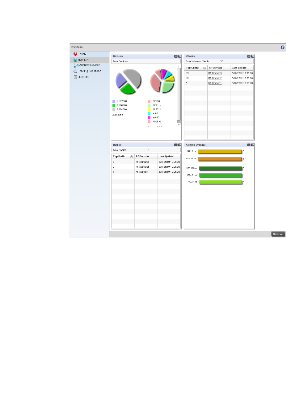
666 Brocade Mobility RFS4000, RFS6000, and RFS7000 System Reference Guide
53-1002620-01
14
FIGURE 442 System Inventory screen
4. The Device Types table displays an exploded pie chart depicting device type distribution and
members of the managed network. The table in the Device Type area displays the total number
of devices managed by this controller.
5. The Radios table displays radios in use throughout within the wireless controller managed
network. This area displays the total number of managed radios and top 5 RF Domains in
terms of radio count. The Total Radios value is the total number of radios in this system.
6. The Wireless Clients table displays the total number of wireless clients managed by the
wireless controller. This Top Client Count table lists the top 5 RF Domains, in terms of the
number of wireless clients adopted:
7. T he Clients on 5 GHz Channels area displays the number of clients using 5 GHz radios.
8. The Clients on 2.4 GHz Channels area displays the number of clients using 2.4 GHz radios.
Top Radio Count Displays the number of radios in the RF Domain.
RF Domain Displays the name of the RF Domain these radios belong.
Last Update Displays the UTC timestamp when this value was reported.
Top Client Count Displays the number of wireless clients adopted by the RF Domain.
RF Domain Displays the name of the RF Domain.
Last Update Displays the UTC timestamp when the client count was last reported.
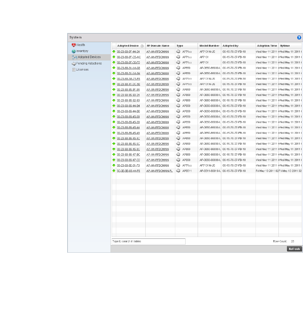
Brocade Mobility RFS4000, RFS6000, and RFS7000 System Reference Guide 667
53-1002620-01
14
Adopted Devices
System Statistics
The Adopted Devices screen displays a list of devices adopted to the wireless controller managed
network. Use this screen to view a list of devices and their current status.
To view adopted AP statistics:
1. Select the Statistics menu from the Web UI.
2. Select the System node from the left navigation pane.
3. Select Adopted Devices from the left-hand side of the UI.
FIGURE 443 System Adopted Devices screen
4. The Adopted Devices screen provides the following:
Adopted Device Displays the hostname of the adopted device.
MAC Address Displays the MAC address of the adopted device.
Type Displays the AP type (either br-650, br-7131, or br-6511).
RF Domain Name Displays the domain the adopted AP belongs to.
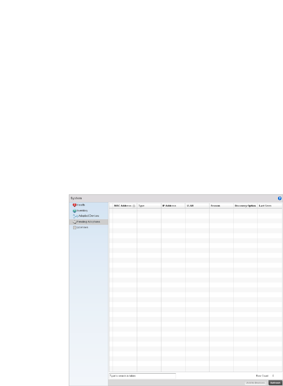
668 Brocade Mobility RFS4000, RFS6000, and RFS7000 System Reference Guide
53-1002620-01
14
Pending Adoptions
System Statistics
The Adopted Devices screen displays a list of devices adopted to the wireless controller managed
network. Use this screen to view a list of devices and their current status.
To view adopted AP statistics:
1. Select the Statistics menu from the Web UI.
2. Select the System node from the left navigation pane.
3. Select Pending Adoptins from the left-hand side of the UI.
FIGURE 444 Pending Adoptions Devices screen
Online Displays the working state of the adopted AP. A red ‘X indicates the device is offline and
not working.
Version Displays the software version of each listed AP. This information can be helpful when
troubleshooting and working with support personnel.
Serial Number Displays the AP serial number. The serial number is used for controller management. This
field is read-only and can not be modified.

Brocade Mobility RFS4000, RFS6000, and RFS7000 System Reference Guide 669
53-1002620-01
14
4. The Adopted Devices screen provides the following
Licenses
System Statistics
The licenses statistics screen displays available licenses for devices within a cluster. It displays the
total number of AP licenses and adaptive AP licenses.
To view a licenses statistics of a managed network:
1. Select the Statistics menu from the Web UI.
2. Select the System node from the left navigation pane.
3. Select Licenses from the left-hand side of the UI.
MAC Address Displays the MAC address of the device pending adoption.
Type Displays the AP type (either br-650, br-7131, or br-6511).
IP Address Displays the current IP Address of the device pending adoption.
VLAN Displays the current VLAN number of the device pending adoption.
Reason Displays the status as to why the device is still pending adoption.
Discovery Option Displays the discovery option code for each AP listed pending adoption.
Last Seen Displays the date and time stamp of the last time the device was seen. Click the arrow
next to the date and time to toggle between standard time and UTC.
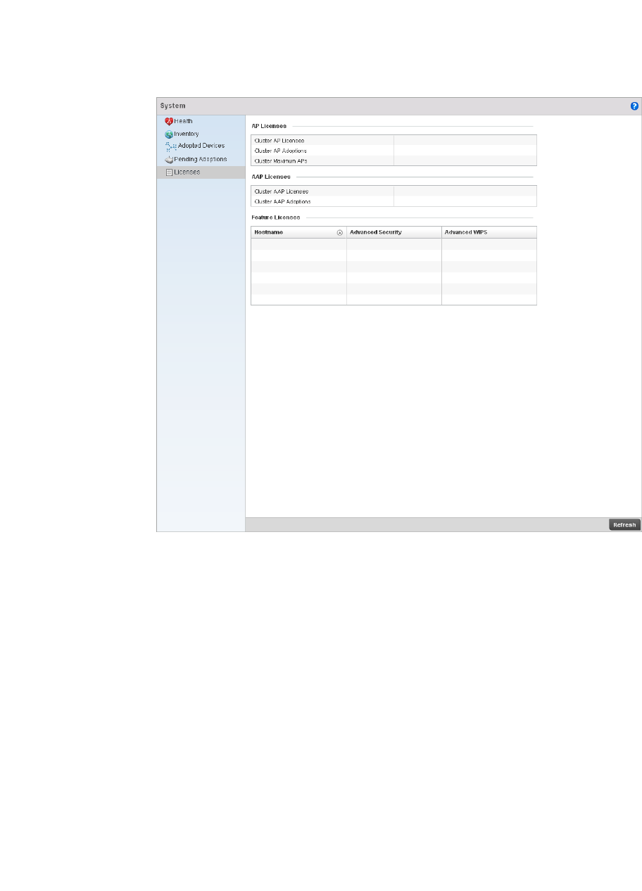
670 Brocade Mobility RFS4000, RFS6000, and RFS7000 System Reference Guide
53-1002620-01
14
FIGURE 445 System Licenses screen
4. The AP Licenses area provides the following information:
5. The AAP Licenses area provides the following information:
6. The Featured Licenses area provides the following information:
Cluster AP Licenses Displays the number of access point licenses installed in the cluster.
Cluster AP Adoptions Displays the number of Access Points points adopted by the cluster.
Cluster Maximum APs Displays the maximum number of Access Points that can be adopted by the
controllers in the cluster.
Cluster AAP Licenses Displays the number of adaptive Access Points in the cluster.
Cluster AAP Adoptions Displays the number of Access Points adoptable by the controllers in a cluster.
Hostname Displays the hostname for each feature license installed.
Advanced Security Displays whether the Advanced Security feature is installed for each hostname.
Advanced WIPS Displays whether the Advanced WIPS feature is installed for each hostname.

Brocade Mobility RFS4000, RFS6000, and RFS7000 System Reference Guide 671
53-1002620-01
14
RF Domain Statistics
The RF Domain Statistics screen displays device status within a RF Domain. This includes the RF
Domain’s device inventory, access points, wireless clients and Smart RF functionality. Use the
information to obtain an overall view of RF Domain health and troubleshoot members.
Refer to the following:
•Health
•Inventory
•Access Points
•AP Detection
•Wireless Clients
•Wireless LANs
•Radio
•Mesh
•SMART RF
•WIPS
•Captive Portal
•Historical Data
Health
RF Domain Statistics
The Health screen displays status information on the selected RF Domain. This information can be
used to optimize or improve its performance.
To display RF Domain health:
Select the Statistics menu from the Web UI.
Select a RF Domain node from the left navigation pane.
Select Health from the left-hand side of the UI.
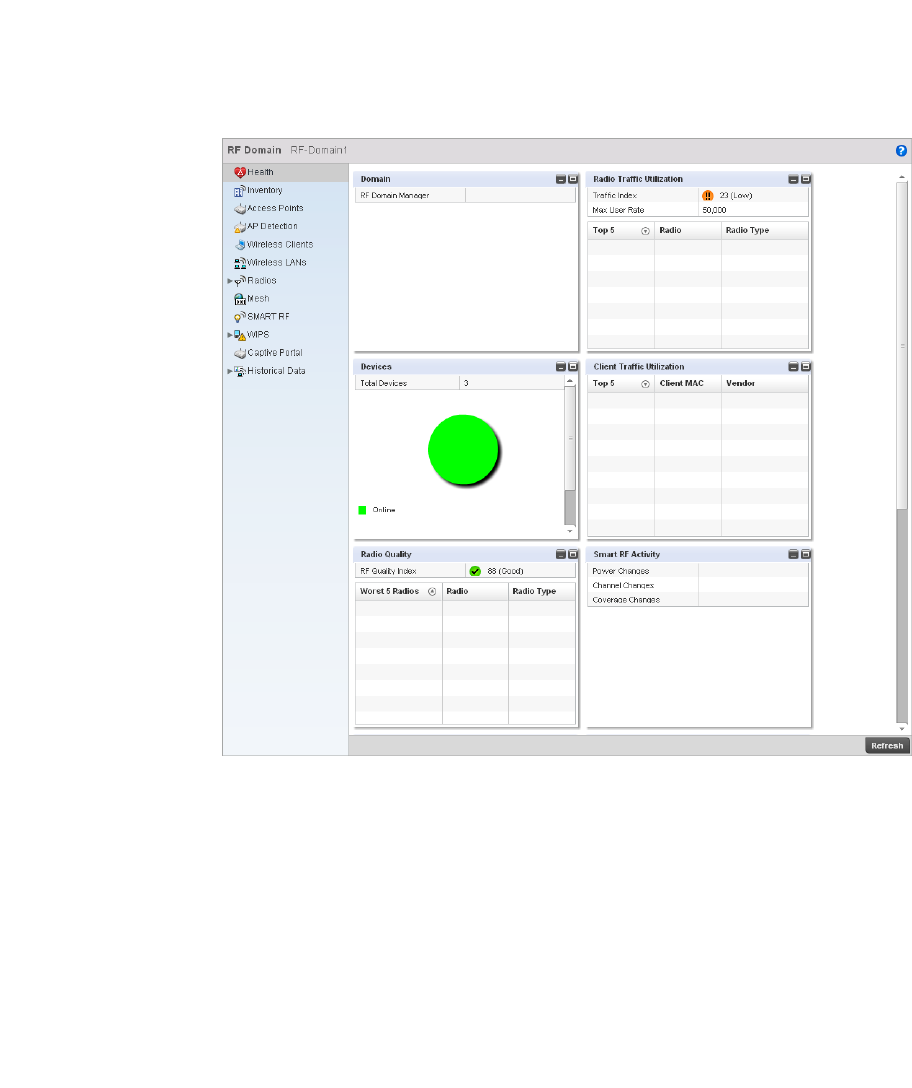
672 Brocade Mobility RFS4000, RFS6000, and RFS7000 System Reference Guide
53-1002620-01
14
FIGURE 446 RF Domain Health screen
The Configuration area displays the name of the wireless controller that is the manager for this RF
Domain. The RF Domain Manager is the focal point for the radio system and acts as a central
registry of applications, hardware and capabilities. It also serves as a mount point for all the
different pieces of the hardware system file. Click on the wireless controller name to view detailed
statistics for the controller.
The Device Health area displays the total number of devices in the RF Domain, and an exploded pie
chart depicts their status.
The Device Health area displays the total number of devices in the RF Domain, and an exploded pie
chart depicts their status.
The RF Quality Index area displays information on the RF quality of the selected RF Domain. The RF
quality index is the overall effectiveness of the RF environment as a percentage of the connect rate
in both directions, as well as the retry and error rate. This area also lists the worst 5 radios in the
RF Domain.
The RF Quality Index can be interpreted as:
•0-20 – Very poor quality
•20-40 – Poor quality
•40-60 – Average quality
•60-100 – Good quality

Brocade Mobility RFS4000, RFS6000, and RFS7000 System Reference Guide 673
53-1002620-01
14
Refer to the table below for the fields in the Worst 5 Radios table:
Refer to the table below for the fields in the Worst 5 Clients table:
The WLAN Utilization area displays the following:
The Traffic Utilization area displays the following:
Refer to the table below for the fields in the Top 5 Radios table:
Refer to the table below for the fields in the Top 5 Clients table:
Worst 5 Radios Displays five radios with the lowest average quality.
Radio Displays the radio MAC and ID corresponding to the quality index.
Radio Type Displays the radio type as either 5 GHz or 2.4 GHz.
Worst 5 Clients Displays the five clients having the lowest average quality indices.
Client MAC Displays the radio MAC of the wireless client.
Vendor Displays the vendor name of the wireless client.
Total WLANs Displays the total number of WLANs on the RF Domain.
Top 5 Displays the five WLANs on the RF Domain which have the highest average quality
indices.
WLAN Name Displays the WLAN Name for each of the Top 5 WLANs on the RF Domain..
Radio Type Displays the radio type as either 5 GHz or 2.4 GHz.
Traf fic Index Displays traffic utilization efficiency. This index measures how efficiently the traffic
medium is used. It’s defined as the percentage of current throughput relative to
maximum possible throughput. This value can be interpreted as:
•0-20 – Very low utilization
•20-40 – Low utilization
•40-60 – Moderate utilization
•60 and above – High utilization.
Max. User Rate Displays the maximum recorded user rate in kbps.
Top 5 Radios Displays the five radios having the highest average quality indices.
Radio Displays the radio MAC and ID corresponding to the quality index.
Radio Type Displays the radio type as either 5 GHz or 2.4 GHz.
Top 5 Clients Displays the five clients having the highest average quality indices.
Client MAC Displays the radio MAC of the wireless client.
Vendor Displays the vendor name for the wireless client.

674 Brocade Mobility RFS4000, RFS6000, and RFS7000 System Reference Guide
53-1002620-01
14
The SMART RF Activity area displays the following:
The Wireless Security area indicates the security of the transmission between WLANs and the
wireless clients they support. This value indicates the vulnerability of the WLANs.
The Wireless Security statistics table displays the following information for transmitted and
received packets:
Inventory
RF Domain Statistics
The Inventory statistics screen displays an inventory of RF Domain controllers, access points,
wireless clients, wireless LANs and radios.
To display RF Domain inventory statistics:
Select the Statistics menu from the Web UI.
Select a RF Domain node from the left navigation pane.
Select Inventory from the left-hand side of the UI.
Power Changes Displays the total number of radio transmit power changes that have been made using
SMART RF on this RF Domain.
Channel Changes Displays the total number of radio transmit channel changes that have been made using
SMART RF on this RF Domain.
Coverage Changes Displays the total number of radio coverage area changes that have been made using
SMART RF on this RF Domain.
RF Domain Threat Level Indicates threat from the wireless clients trying to find network vulnerabilities. The
threat level is represented by an integer.
Concern Describes the threat to the devices in the RF Domain.
Remedy Describes the proposed remedy for the threat.
Total Bytes Displays the total bytes of data transmitted and received by the RF Domain.
Total Packets Lists the total number of data packets transmitted and received by the RF Domain.
User Data Rate Lists the average user data rate.
Bcast/Mcast
Packets
Displays the total number of broadcast/multicast packets transmitted and received by
the RF Domain.
Management
Packets
This is the total number of management packets processed.
Tx Dropped Packets Lists total number of dropped data packets.
Rx Errors Displays the number of errors encountered during data transmission. The higher the error
rate, the less reliable the connection or data transfer.
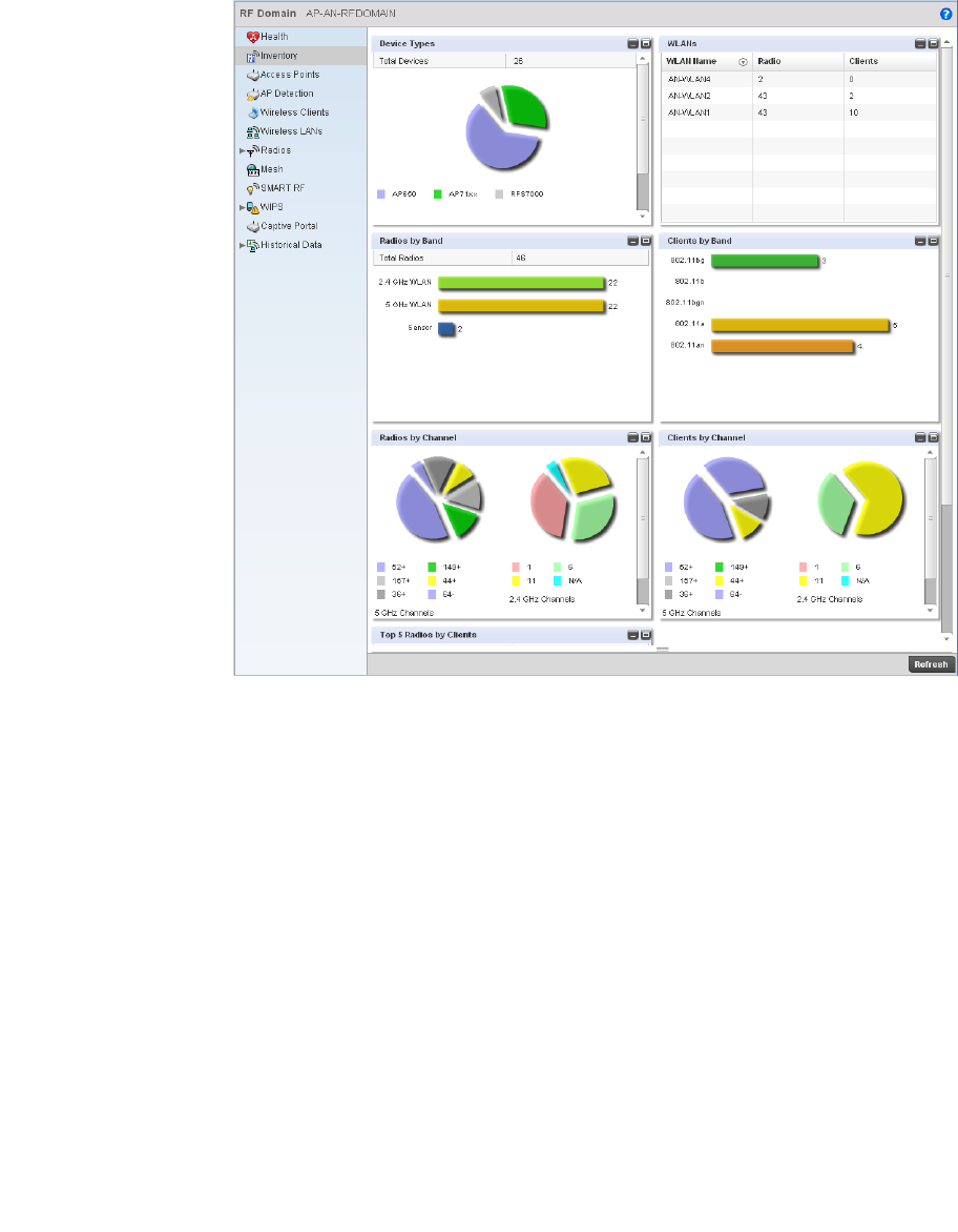
Brocade Mobility RFS4000, RFS6000, and RFS7000 System Reference Guide 675
53-1002620-01
14
FIGURE 447 RF Domain Inventory screen
7. T he Device Types table displays the total number of devices currently in use. The exploded pie
chart depicts the distribution of the different devices that are members of this RF Domain.
8. The Radio Types table displays the total number of radios in this RF Domain. The bar chart
depicts the distribution of the different radio types.
9. The Radios by Channel charts display the total number of radios on the 5GHz and 2.4GHz
bands for this RF Domain.
10. The Wireless Clients table displays the total number of wireless clients in the RF Domain. The
table below displays the 5 APs with the highest number of clients connected. The following
information is displayed:
Top Client Count Displays the number of clients associated.
Access Point Displays the access points these clients are associated with.
MAC Address Displays the Media Access Control (MAC) address associated with each top client for
this RF Domain.
Location Displays the physical location that each top client is in based on information on
where its associated Access Point is located.
Radio Type Displays the radio type associated with each Access Point.

676 Brocade Mobility RFS4000, RFS6000, and RFS7000 System Reference Guide
53-1002620-01
14
11. The second table in the Wireless Clients section displays the total number of radios and clients
per WLAN:
12. The Clients by Radio Type bar graph displays the total number of clients by their IEEE 802.11
radio type.
13. The Clients by Channel pie charts display the channels used by clients on 5GHz and 2.4GHz
radios.
Access Points
RF Domain Statistics
The RF Domain Access Point statistics screen displays statistical information supporting the Access
Points in the RF Domain. This includes the Access Point name, MAC address, type, etc.
To display RF Domain Access Point statistics:
Select the Statistics menu from the Web UI.
Select a RF Domain node from the left navigation pane.
Select Access Points from the left-hand side of the UI.
WLAN Name Displays the WLAN name for each WLAN on the RF Domain.
Radio Displays the total number of radios for each listed WLAN on the RF Domain.
Clients Displays the total number of clients associated with each listed WLAN on the RF
Domain.
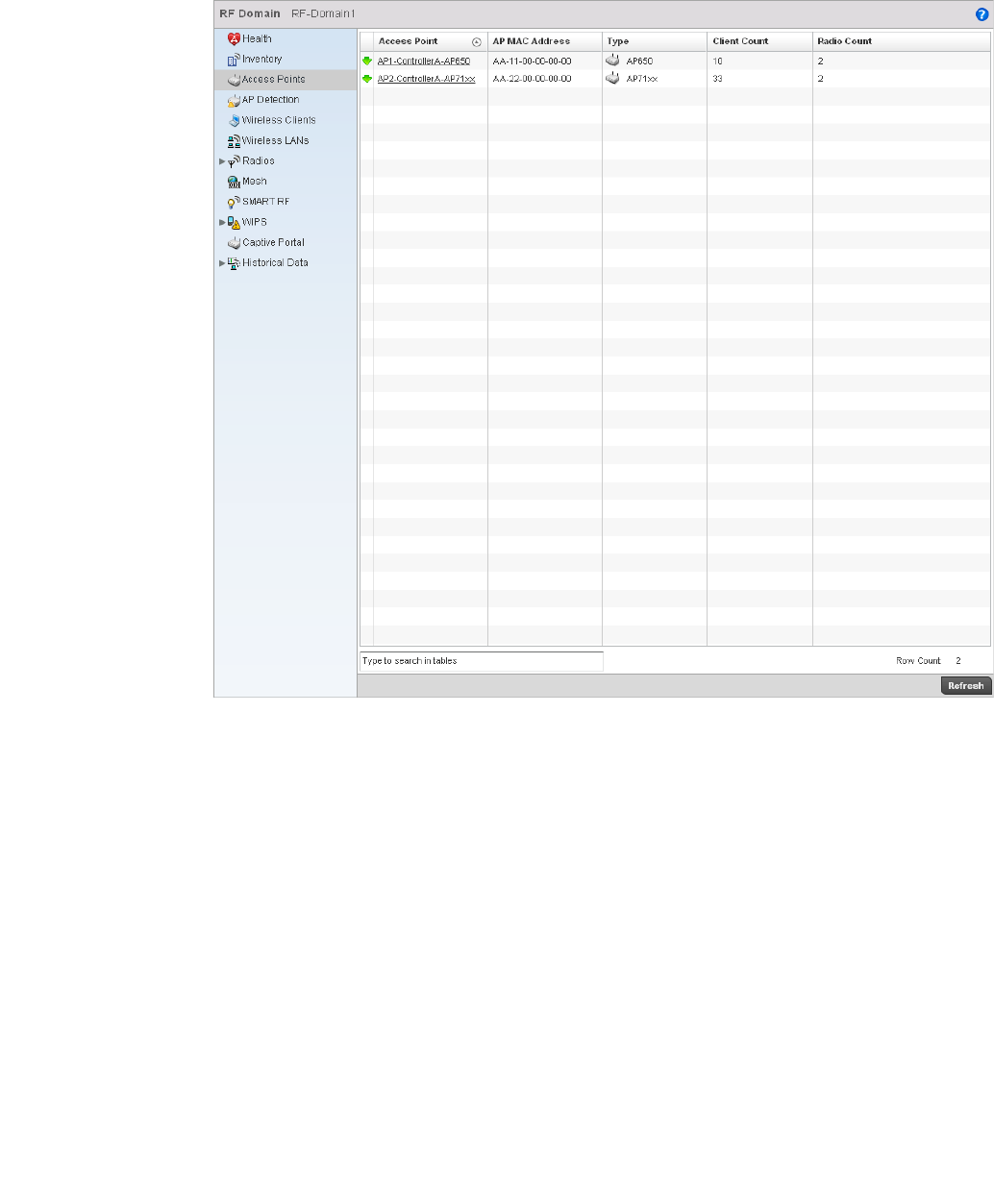
Brocade Mobility RFS4000, RFS6000, and RFS7000 System Reference Guide 677
53-1002620-01
14
FIGURE 448 RF Domain Access Points screen
AP Detection
RF Domain Statistics
The AP Detection statistics screen displays information about detected rogue APs. A rogue is a
wireless Access Point installed on a company network without explicit authorization from a local
network administrator. This creates a threat to the organization, as anyone can ignorantly or
maliciously install an inexpensive router that can allow access to a secure network.
To view the AP Detection statistics:
Select the Statistics menu from the Web UI.
Access Point Displays the name of the Access Point.
AP MAC Address Displays the Access Point’s MAC address.
Type Displays the Access Point model.
Client Count Displays the number of clients associated with each Access Point.
Radio Count Displays the number of radios associated with each Access Point.
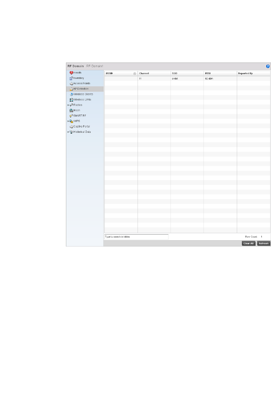
678 Brocade Mobility RFS4000, RFS6000, and RFS7000 System Reference Guide
53-1002620-01
14
Select a RF Domain node from the left navigation pane.
Select AP Detection from the left-hand side of the UI.
FIGURE 449 RF Domain AP Detection screen
The screen displays the following:
Wireless Clients
RF Domain Statistics
The Wireless Clients screen displays read only device information for wireless clients operating
within the controller managed. Use this information to assess if configuration changes are required
to improve network performance.
To view wireless client statistics:
Select the Statistics menu from the Web UI.
BSSID Displays the Broadcast Service Set ID (SSID) of the network to which the rogue AP
belongs.
Channel Displays the channel of operation of the rogue AP radio.
SSID Displays the Service Set ID (SSID) of the network to which the rogue AP belongs.
RSSI Displays the Received Signal Strength Indicator (RSSI) for rogue APs.
Reported By Displays the MAC address of the AP detecting the rogue AP.
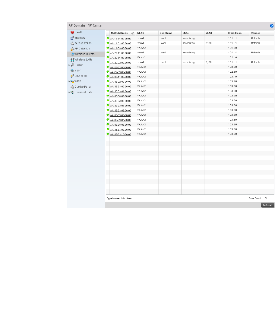
Brocade Mobility RFS4000, RFS6000, and RFS7000 System Reference Guide 679
53-1002620-01
14
Select a RF Domain node from the left navigation pane.
Select Wireless Clients from the right node.
FIGURE 450 RF Domain Wireless Clients screen
The screen displays the following:
Wireless LANs
RF Domain Statistics
The Wireless LAN screen displays an overview of the statistics for the WLANs created for the
controller managed network. This screen displays WLAN names, their SSID, traffic utilization,
number of radios, etc.
MAC Address Displays the Hardware or Media Access Control (MAC) address of the wireless client.
This address is hard-coded at the factory and can not be modified.
WLAN Displays the name of the WLAN the wireless client is currently associated with.
Username Displays the unique name of a user.
State Displays the state of the wireless client, as whether it is associating with an AP or not.
VLAN Displays the VLAN ID the wireless client is associated with.
IP Address Displays the current IP address for the wireless client.
Vendor Displays the vendor name of the wireless client.
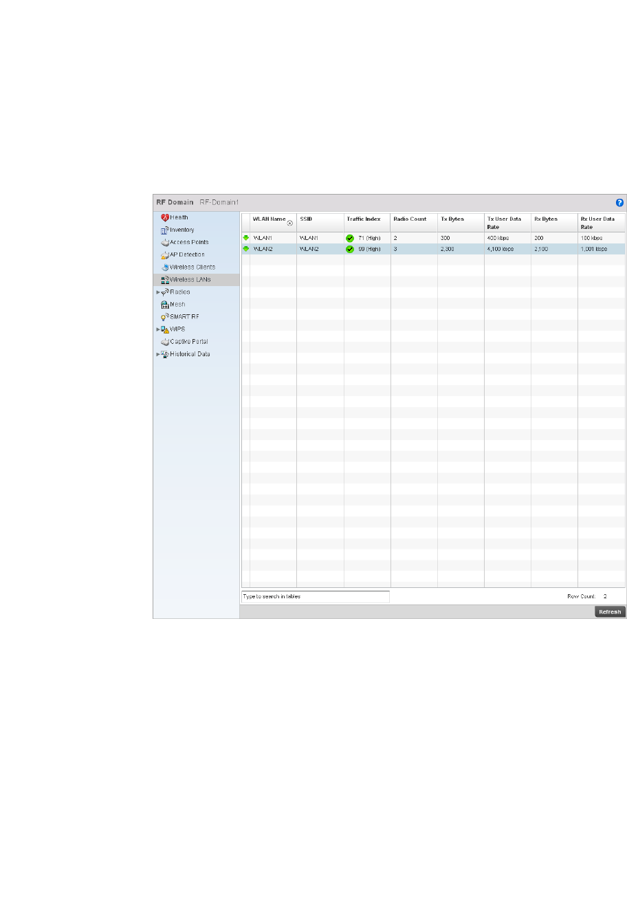
680 Brocade Mobility RFS4000, RFS6000, and RFS7000 System Reference Guide
53-1002620-01
14
To view the wireless LAN statistics:
Select the Statistics menu from the Web UI.
Select a RF Domain node from the left navigation pane.
Select Wireless LANs from the left-hand side of the UI.
FIGURE 451 RF Domain Wireless LAN screen
This screen displays the following information:
WLAN Name Displays a text-based name used to identify the WLAN.
SSID Displays the Service Set ID (SSID) of each WLAN.
Traf fic Index Displays the traffic utilization index, which measures how efficiently the traffic medium
is used. It is defined as the percentage of current throughput relative to the maximum
possible throughput. Traffic indices are: 0 – 20 (very low utilization), 20 – 40 (low
utilization), 40 – 60 (moderate utilization), and 60 and above (high utilization).
Radio Count Displays the number of radios associated with this WLAN.
Tx Bytes Displays the average number of packets (in bytes) sent on the selected WLAN.
Tx User Data Rate Displays the average data rate per user for packets transmitted.
Rx Bytes Displays the average number of packets (in bytes) received on the selected WLAN.
Rx User Data Rate Displays the average data rate per user for packets received.
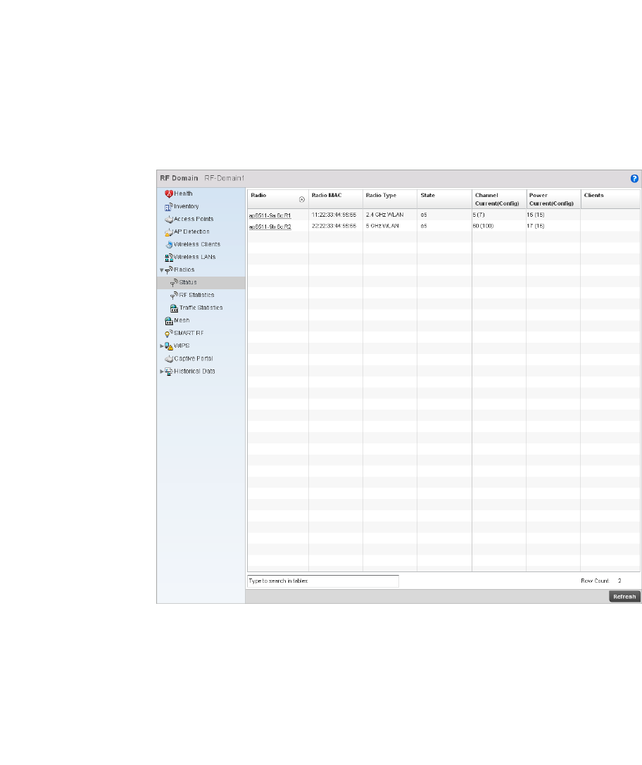
Brocade Mobility RFS4000, RFS6000, and RFS7000 System Reference Guide 681
53-1002620-01
14
Radio
RF Domain Statistics
The Radio screen displays detailed information for the radios available in the selected RF Domain.
Use this screen to start troubleshoot related issues.
To view the RF Domain radio statistics:
Select the Statistics menu from the Web UI.
Select a RF Domain node from the left navigation pane.
Select Radios from the left-hand side of the UI.
Select Status from the Radio > Status menu.
FIGURE 452 RF Domain Radios Status screen
The Radio Status screen provides the following information:
Radio Displays the model and numerical value assigned to the radio as its unique identifier.
Radio MAC Displays the MAC address assigned to the radio as its unique hardware identifier.
Radio Type Defines whether the radio is a 802.11b, 802.11bg, 802.11bgn, 802.11a or 802.11an.
State Displays the current operational state of each radio.
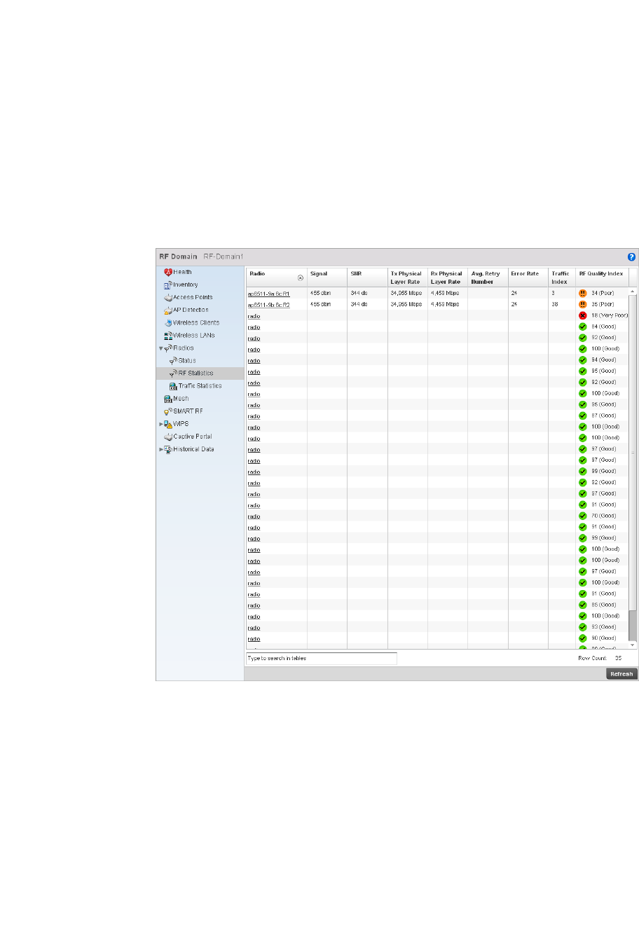
682 Brocade Mobility RFS4000, RFS6000, and RFS7000 System Reference Guide
53-1002620-01
14
Select RF Statistics from the Radios menu.
FIGURE 453 RF Domain Radios screen
The RF Statistics screen provides the following information:
Channel Current
(Config)
Displays the current channel for each radio and the configured channel in
parentheses.
Power Current
(Config)
Displays the current power level for each radio and the configured power level in
parentheses.
Clients Displays the number of wireless clients associated with the radio.
Radio Displays the model and numerical value assigned to the radio as its unique identifier.
Signal Displays signal strength for each radio in dBm.
SNR Displays the Signal to Noise Ratio (SNR) for each radio in db.
Tx Physical Layer
Rate
Displays the transmitted data in Mbps for each radios physical interface.
Rx Physical Layer
Rate
Displays the received data in Mbps for each radios physical interface.
Avg. Retry Number Displays the average number of retries for eah radio.
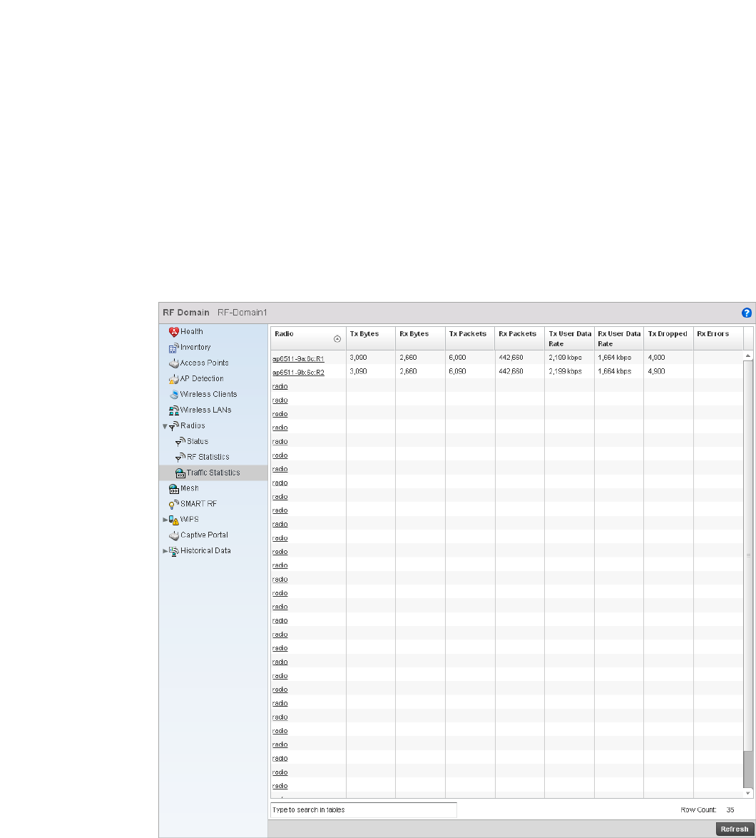
Brocade Mobility RFS4000, RFS6000, and RFS7000 System Reference Guide 683
53-1002620-01
14
Select Traffic Statistics from the Radios menu.
Error Rate Displays the number of errors for each radio.
Traf fic Index Displays the traffic utilization index, which measures how efficiently the traffic medium
is used. It’s defined as the percentage of current throughput relative to maximum
possible throughput. Traffic indices are:
•0–20 (very low utilization)
•20–40 (low utilization)
•40–60 (moderate utilization)
•60 and above (high utilization)
RF Quality Index Displays the client’s RF quality. The RF quality index is the overall effectiveness of the
RF environment, as a percentage of the connect rate in both directions as well as the
retry rate and the error rate. RF quality index value can be interpreted as:
•0–20 — very poor quality
•20–40 —poor quality
•40–60 —average quality
•60–100 — good quality

684 Brocade Mobility RFS4000, RFS6000, and RFS7000 System Reference Guide
53-1002620-01
14
14. The Traffic Statistics screen provides the following information:
Mesh
RF Domain Statistics
To view Mesh statistics:
Select the Statistics menu from the Web UI.
Select a RF Domain node from the left navigation pane.
Select MESH from the left-hand side of the UI.
Radio Displays the model and numerical value assigned to the radio as its unique identifier.
Tx Bytes Displays the amount of transmitted data in bytes for each radio in the RF Domain.
Rx Bytes Displays the amount of received data in bytes for each radio in the RF Domain.
Tx Packets Displays the amount of transmitted data in packets for each radio in the RF Domain.
Rx Packets Displays the amount of received data in packets for each radio in the RF Domain.
Tx User Data Rate Displays the average speed in kbps of data transmitted to users for each radio in the
RF Domain.
Rx User Data Rate Displays the average speed in kbps of data received from users for each radio in the RF
Domain.
Tx Dropped Displays the number of transmission that have been dropped for each radio in the RF
Domain.
Rx Errors Displays the total number of receive errors for each radio in the RF Domain.
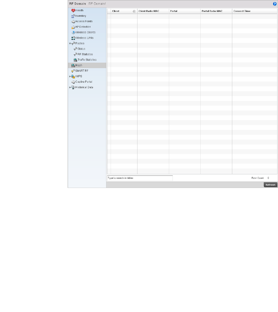
Brocade Mobility RFS4000, RFS6000, and RFS7000 System Reference Guide 685
53-1002620-01
14
FIGURE 454 RF Domain Mesh screen
This screen provides the following information:
SMART RF
RF Domain Statistics
Client AP Displays the AP name for each Access Point in the RF Domain mesh network.
Client Hostname Displays the configured hostname for each Access Point in the RF Domain mesh
network.
Client Radio MAC Displays the Media Access Control for each Access Point in the RF Domain mesh
network.
Portal Radio Index Displays the numerical Peer Radio Index ID for the peer device associated with each
Access Point in the RF Domain mesh network.
Portal Hostname Displays the assigned hostname for the peer device associated with each Access Point
in the RF Domain mesh network.
Portal Radio MAC Displays the Media Access Control for each radio in the RF Domain mesh network.
Connect Time Displays the total connection time for each AP in the RF Domain mesh network.
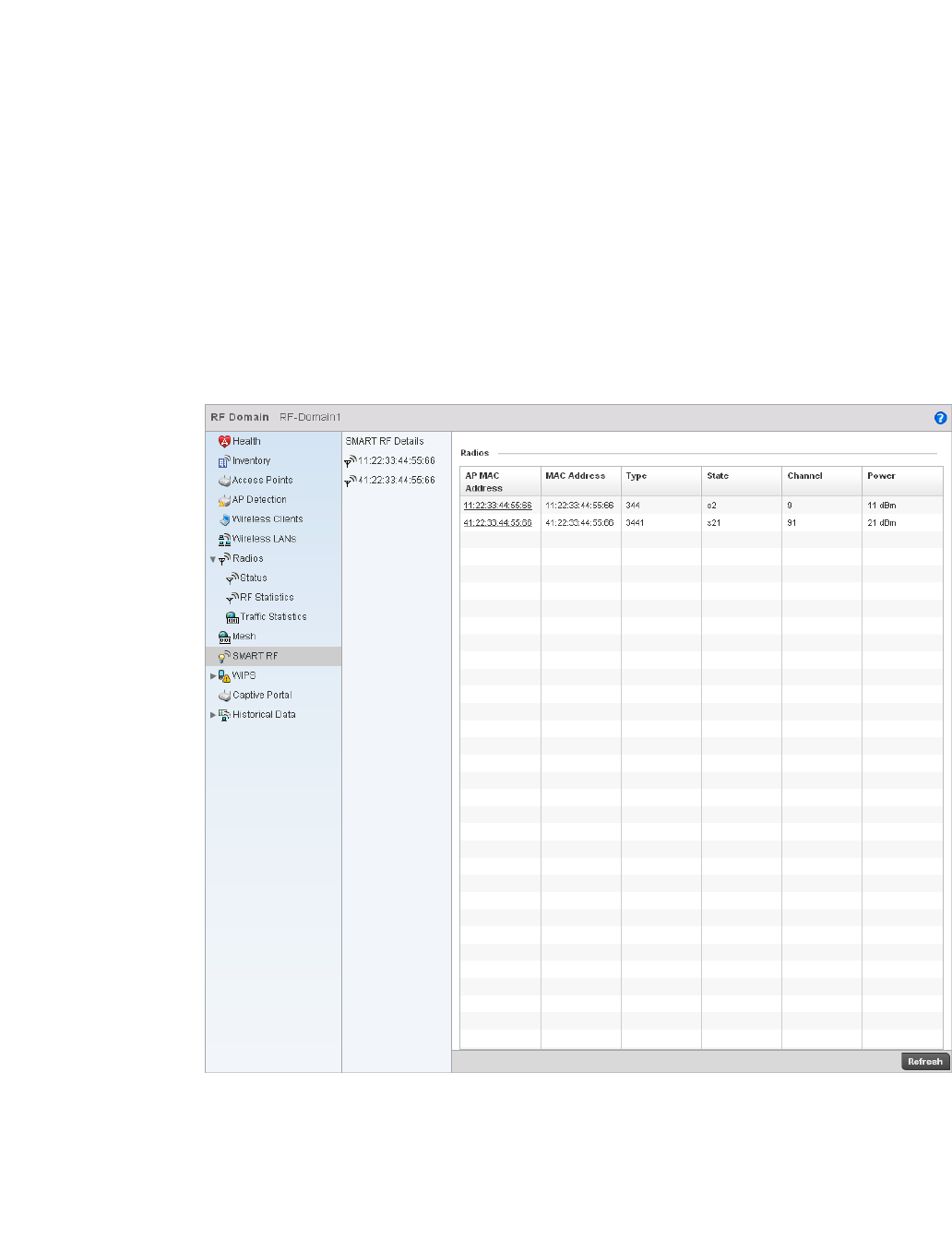
686 Brocade Mobility RFS4000, RFS6000, and RFS7000 System Reference Guide
53-1002620-01
14
When invoked by an administrator, Self-Monitoring At Run Time (Smart RF) instructs radios to
change to a specific channel and begin beaconing using the maximum available transmit power.
Within a well planned deployment, any associated radio should be reachable by at least one other
radio. Smart RF records received signals from neighbors and signals from external, un-managed
radios. AP-to-AP distance is recorded in terms of signal attenuation. The information from external
radios is used during channel assignment to minimize interference.
To view Smart RF statistics:
Select the Statistics menu from the Web UI.
Select a RF Domain node from the left navigation pane.
Select SMART RF from the left-hand side of the UI.
FIGURE 455 RF Domain SMART RF screen
This screen provides the following information:
AP MAC Address Displays the MAC address of the AP (the device MAC address printed on the unit).
MAC Address This is the radio’s first MAC address when adopted by the controller.
Type Identifies whether the radio is 802.11b, 802.11bg, 802.11bgn, 802.11a, or 802.11an.

Brocade Mobility RFS4000, RFS6000, and RFS7000 System Reference Guide 687
53-1002620-01
14
WIPS
RF Domain Statistics
Brocade’ Wireless Intrusion Protection Software (WIPS) monitors for any presence of unauthorized
rogue Access Points. Unauthorized attempt to access the WLAN is generally accompanied by
anomalous behavior as intruding wireless clients trying to find network vulnerabilities. Basic forms
of this behavior can be monitored and reported without a dedicated WIPS. When parameters
exceed a configurable threshold, the controller generates an SNMP trap and reports results via the
management interfaces.
This screen displays the statistics of the WIPS events, the AP which reported the event, the
unauthorized device, and so on.
This screen is divided into two sections:
•WIPS Client Blacklist
•WIPS Events
WIPS Client Blacklist
WIPS
This screen displays the statistics of blacklisted clients detected by WIPS. Blacklisted clients are
not allowed to associate to the wireless controller.
To view the WIPS client blacklist statistics:
Select the Statistics menu from the Web UI.
Select a RF Domain node from the left navigation pane.
Select WIPS > Client Blacklist from the left-hand side of the UI.
State Displays the radio’s current operational mode, either calibrate, normal, sensor or offline.
Channel Displays the operating channel assigned to the AP radio.
Power Displays the power level in dBm for the selected radio.
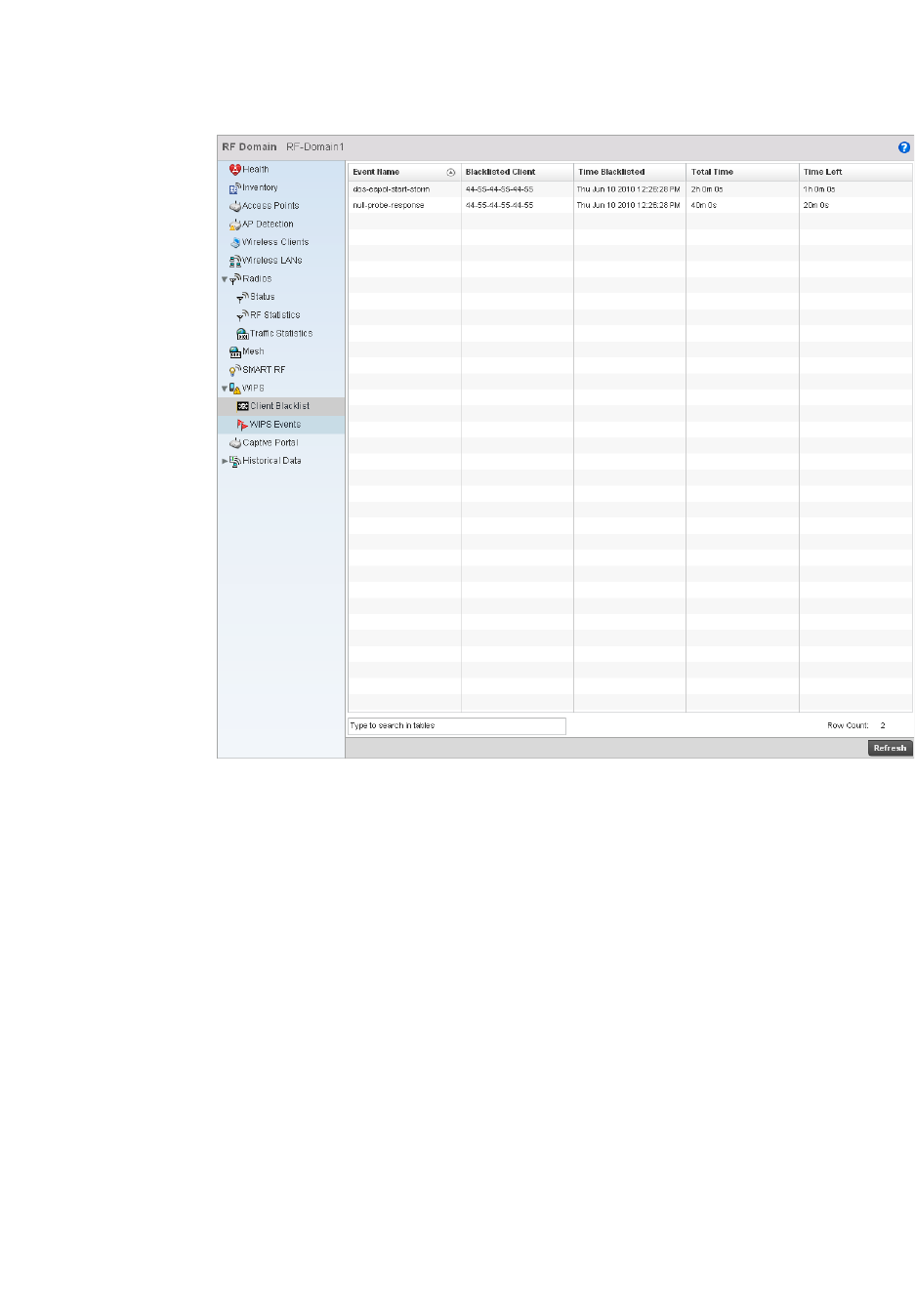
688 Brocade Mobility RFS4000, RFS6000, and RFS7000 System Reference Guide
53-1002620-01
14
FIGURE 456 RF Domain WIPS Client Blacklist screen
This screen provides the following:
WIPS Events
WIPS
The WIPS Events screen provides details about unauthorized rogue Access Points.
To view rogue access point statistics:
Select the Statistics menu from the Web UI.
Select a RF Domain node from the left navigation pane.
Select WIPS > WIPS Events from the left-hand side of the UI.
Event Name Displays the name of the wireless intrusion event detected by an Access Point
supporting WIPS.
Blacklisted Client Displays the MAC address of the unauthorized device intruding the WLAN.
Time Blacklisted Displays the time when the wireless client was blacklisted.
Total Time Displays the total time the unauthorized device remained in the WLAN.
Time Left Displays the time the blacklisted client remains on the list.
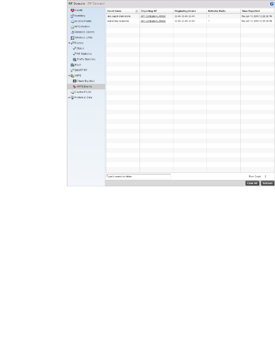
Brocade Mobility RFS4000, RFS6000, and RFS7000 System Reference Guide 689
53-1002620-01
14
FIGURE 457 RF Domain WIPS Events screen
The WIPS Events screen provides the following information:
Captive Portal
RF Domain Statistics
A captive portal forces an HTTP client to authenticate use specific Web pages before using the
Internet formally. A captive portal turns a Web browser into an authentication device.
To view the RF Domain captive portal statistics:
Select the Statistics menu from the Web UI.
Select a RF Domain node from the left navigation pane.
Select Captive Portal from the left-hand side of the UI.
Event Name Displays the name of the detected intrusion.
Reporting AP Displays the MAC address of the AP reporting the intrusion.
Originating Device Displays the MAC address of the intruding device.
Detector Radio Displays the type of radio detecting the intrusion.
Time Reported Displays the time when the intruder was detected.
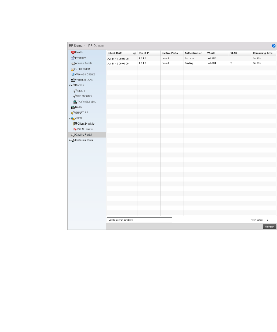
690 Brocade Mobility RFS4000, RFS6000, and RFS7000 System Reference Guide
53-1002620-01
14
FIGURE 458 RF Domain Captive Portal screen
This screen provides the following:
Historical Data
RF Domain Statistics
The historical data screen provides a history of Smart RF events. Smart RF enables an
administrator to automatically assign the best channels to all associated devices to build an
interference free environment to function in. A Smart RF event takes place when some or all of the
following activities occur:
Each Smart RF event is recorded as a log entry. These events can be viewed using the Smart RF
History screen.
Client MAC Displays the MAC address of the wireless client.
Client IP Displays the IP address of the wireless client.
Captive Portal Displays whether the captive portal is enabled by default.
Authentication Displays the authentication status of the client.
WLAN Displays the name of the WLAN the client belongs to.
VLAN Displays the name of the VLAN the client belongs to.
Remaining Time Displays the time after which the client will be disconnected from the Internet.
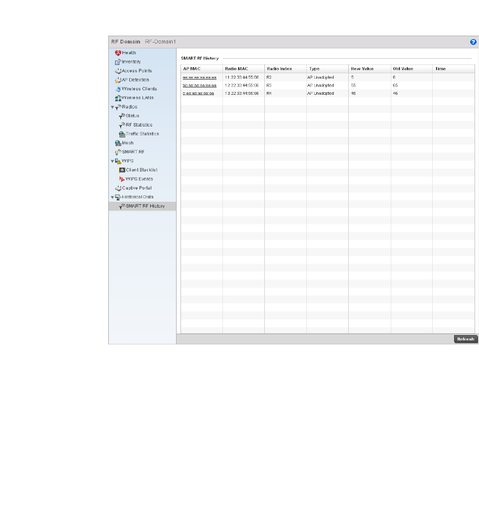
Brocade Mobility RFS4000, RFS6000, and RFS7000 System Reference Guide 691
53-1002620-01
14
Viewing Smart RF History
Historical Data
To view Smar t RF history:
Select the Statistics menu from the Web UI.
Select a RF Domain node from the left navigation pane.
Select Historical Data > SMART RF History from the left-hand side of the UI.
FIGURE 459 RF Domain Smart RF History
This screen displays the following:
AP MAC Displays the MAC address of the selected AP.
Radio MAC Displays the radio MAC address of the corresponding AP.
Radio Index Displays the numerical identifier assigned to each detector AP used in calibration.
Type Displays the AP type.
New Value Displays the new power value as assigned by Smart RF.
Old Value Lists the old power value before calibration resulted in modifications.
Time Displays time stamp when this event occurred.

692 Brocade Mobility RFS4000, RFS6000, and RFS7000 System Reference Guide
53-1002620-01
14
Access Point Statistics
The Access Point Statistics screen displays APs available within the managed network. Use this
data as necessary to check all whether APs are active, their VLAN assignments and their current
authentication and encryption schemes. Access Point Statistics consists of the following:
•Health
•Inventory
•Device
•AP Upgrade
•Wireless Client
•Wireless LANs
•Radios
•Mesh
•Mesh
•Network
•Firewall
•Certificates
•WIPS
•Sensor Servers
•Captive Portal
Health
Access Point Statistics
The Health screen displays information on the selected device, such as its hardware and software
version. Use this information to fine tune the performance of the selected APs. This screen should
also be the starting point for troubleshooting.
To view the access point health:
Select the Statistics menu from the Web UI.
Select an Access Point node from the left navigation pane.
Select Health from the left-hand side of the UI.
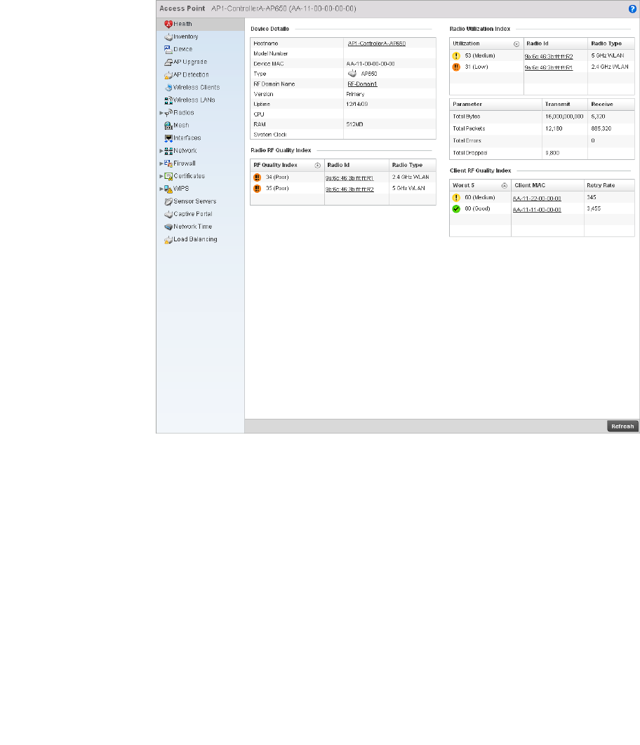
Brocade Mobility RFS4000, RFS6000, and RFS7000 System Reference Guide 693
53-1002620-01
14
FIGURE 460 Access Point Health screen
The Device Details area displays the following:
Hostname Displays the AP’s unique name. A hostname is assigned to a device connected to a
computer network.
Device MAC Displays the MAC address of the AP. This is factory assigned and cannot be changed.
Type Displays the Access Point’s model.
RF Domain Name Displays an AP’s RF Domain membership.
Version Displays the AP’s current firmware version. Use this information to assess whether an
upgrade is required for better compatibility with the controller.
Uptime Displays the cumulative time since the AP was last rebooted or lost power.
CPU Displays the processor core.
RAM Displays the free AP memory available.
System Clock Displays system clock information.

694 Brocade Mobility RFS4000, RFS6000, and RFS7000 System Reference Guide
53-1002620-01
14
The RF Quality Index table displays the following:
The Radio Utilization Index tables display the following:
The Client RF Quality Index table displays the following:
Inventory
Access Point Statistics
The Inventory screen displays information about the hardware managed by the wireless controller.
Use the information provided in this screen to understand the overall performance of managed
devices.
The Inventory screen also displays information about AP physical characteristics. Use this screen to
gather information on the performance of the different clients associated with the AP. Additionally,
use this screen to fine tune Access Point performance.
To view the access point inventory statistics:
Select the Statistics menu from the Web UI.
Select an Access Point node from the left navigation pane.
RF Quality Index Displays radios with very low quality indices. RF quality index indicate overall RF
performance. The RF quality indices are:
•0–50 (poor)
•50–75 (medium)
•75–100 (good)
Radio ID Displays a radio’s hardware encoded MAC address.
Radio Type Identifies whether the radio is a 802.11b, 802.11bg, 802.11bgn, 802.11a, or
802.11an.
Utilization Displays the traffic indices of radios, which measures how efficiently the traffic
medium is used. This value is indicated as an integer.
Radio Id Displays a numerical value assigned to the radio as a unique identifier. For example: 1,
2, or 3.
Radio Type Identifies whether the radio is an 802.11b, 802.11bg, 802.11bgn, 802.11a, or an
802.11an.
Parameter Displays the statistics in number of packets for:
•Total Bytes - The total number of bytes that passed through the Access Point.
•Total Packets - The total number of packets that passed through the Access Point.
•Total Errors - The total error packets.
•Total Dropped - The total dropped packets.
Transmit Displays the total number of packets transmitted by the radio.
Receive Displays the total number of packets received by the radio.
Worst 5 Displays the 5 clients having the lowest RF quality.
Client MAC Displays the MAC address of the client with low RF indices.
Retry Rate Displays the average number of retries per packet. A high number indicates potential
network or hardware problems.
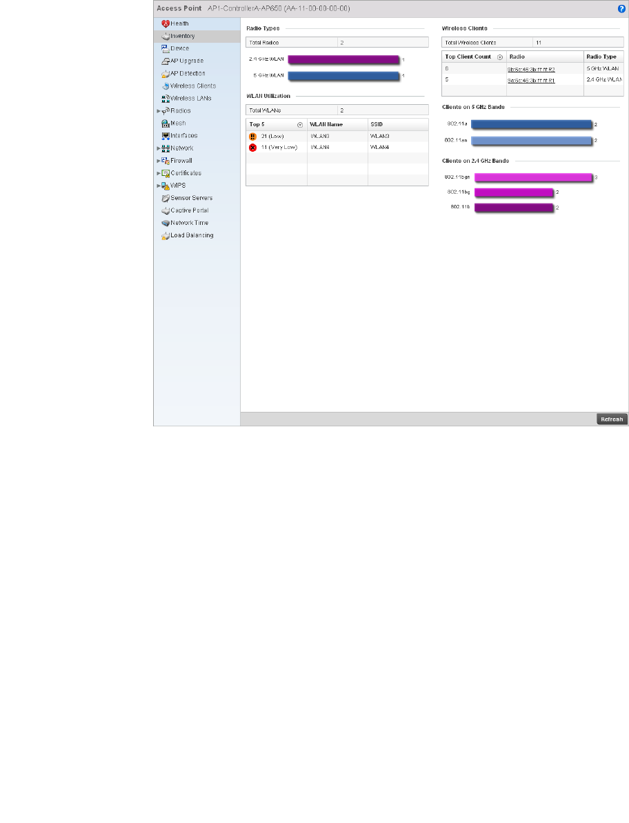
Brocade Mobility RFS4000, RFS6000, and RFS7000 System Reference Guide 695
53-1002620-01
14
Select Inventory from the left-hand side of the UI.
FIGURE 461 Access Point Inventory screen
The Radio Types table displays the total number of radios detected. It also displays the number of
radios using the 2.4 GHz and 5 GHz frequency bands.
The Wireless LANs area displays the total number of WLANs. It also displays the following:
The Wireless Clients area displays the total number of wireless clients associated with this Access
Point. It also displays the following:
Top 5 Displays the maximum traffic utilization of the WLAN in which the access point is a
member. The integer denotes the traffic index, which measures how efficiently the
traffic medium is used. Traffic indices are:
•0 – 20 (very low)
•20 – 40 (low)
•40 – 60 (moderate)
•60 and above (high)
WLAN Name Displays a name assigned to identify the WLAN.
SSID Displays the Service Set ID associated with the WLAN.
Top Client Count Displays the number of clients associated with this Access Point.
Radio Displays the radio MAC address associated with the client.
Radio Type Displays the radio type.
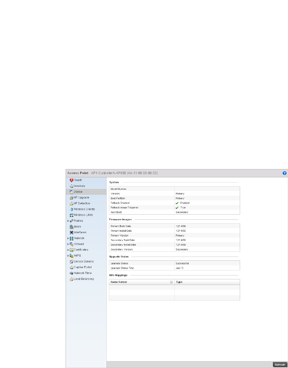
696 Brocade Mobility RFS4000, RFS6000, and RFS7000 System Reference Guide
53-1002620-01
14
The Clients on 5 GHz Channels table displays the number of wireless clients with radios operating
in the 5 GHz frequency band.
The Clients on 2.4 GHz Channels area displays the number of wireless clients with radios operating
in the 2.4 GHz band.
Device
Access Point Statistics
The Device screen displays basic information about the selected Access Point. Use this screen to
assess the version, boot image and upgrade status.
To view the device statistics:
Select the Statistics menu from the Web UI.
Select an Access Point node from the left navigation pane.
Select Device from the left-hand side of the UI.
FIGURE 462 Access Point Device screen

Brocade Mobility RFS4000, RFS6000, and RFS7000 System Reference Guide 697
53-1002620-01
14
The System table displays the following:
The Firmware Images table displays the following:
The Upgrade Status table displays the following:
The DNS Mappings table displays the following:
AP Upgrade
Access Point Statistics
To view the AP Upgrade statistics:
Select the Statistics menu from the Web UI.
Select an Access Point node from the left navigation pane.
Select AP Upgrade from the left-hand side of the UI.
Model Number Displays the Access Point model number for the selected AP.
Version Displays the software (firmware) version on the access point.
Boot Partition Displays the boot partition type.
Fallback Enabled Displays whether this option is enabled. This method enables a user to store both a
known legacy firmware version and a new firmware version in device memory. The user
can test the new software, and use an automatic fallback, which loads the old version
if the new version fails.
Fallback Image
Triggered
Displays whether the fallback image was triggered. The fallback image is an old version
of a known and operational software stored in device memory. This allows a user to
test a new software version of software. If the new version fails, the user can fall back
to the old version.
Next Boot Designates this version as the version used the next time the AP is booted.
Primary Build Date Displays the build date when the version was created.
Primary Install
Date
Displays the date this version was installed.
Primary Version Displays the primary version string.
Secondary Build
Date
Displays the build date when this version was created.
Secondary Install
Date
Displays the date this secondary version was installed.
Secondary Version Displays the secondary version string.
Upgrade Status Displays the status of the image upgrade.
Upgrade Status
Time
Displays the time of the image upgrade.
Name Server Displays any custom Name Server mappings on the Access Point.
Type Displays the type of DNS mapping, if any, on the Access Point.
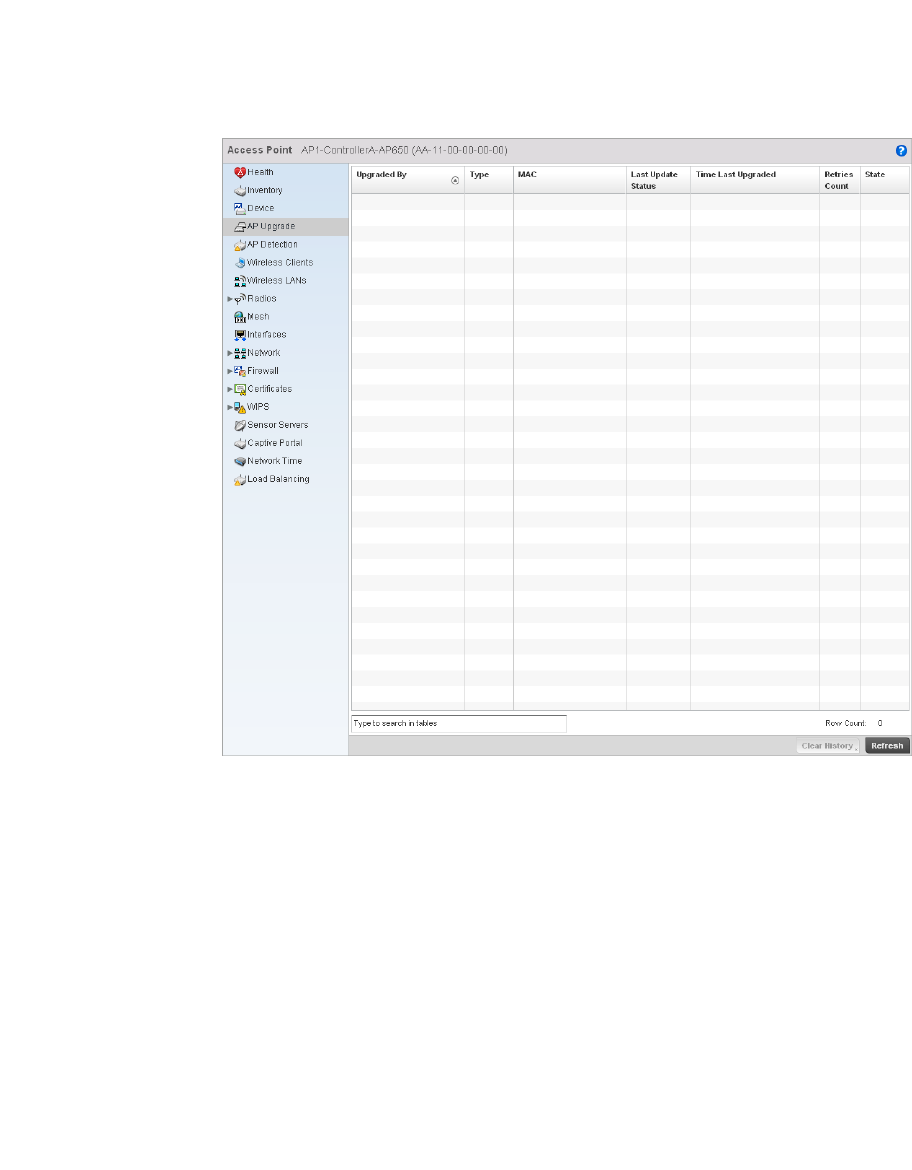
698 Brocade Mobility RFS4000, RFS6000, and RFS7000 System Reference Guide
53-1002620-01
14
FIGURE 463 Access Point AP Upgrade Screen
The AP Upgrade screen displays the following:
AP Detection
Access Point Statistics
To view the AP Upgrade statistics:
1. Select the Statistics menu from the Web UI.
Upgraded By Displays the hostname of the AP controller that last updated the Access Point.
Type Displays the type of Access Point subject to upgrade. For example, br-650, br-7131, or
br-6511 and so on.
MAC Displays the Media Access Control (MAC) address associated with the Access Point.
Last Update Status Displays the status of the last update attempt for the Access Point. This can be used to
determine if the update to the Access Point was a success or failure.
Time Last
Upgraded
Displays the date and time of the last Access Point upgrade.
Retries Count Displays the number of retries, if any, from the last update attempt for each Access
Point.
State Displays the current operational state of each Access Point as calibrate, normal,
sensor or offline.
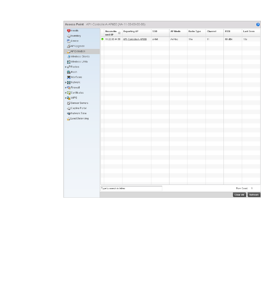
Brocade Mobility RFS4000, RFS6000, and RFS7000 System Reference Guide 699
53-1002620-01
14
2. Select an Access Point node from the left navigation pane.
3. Select AP Detection from the left-hand side of the UI.
FIGURE 464 Access Point AP Detection Screen
The AP Detection screen displays the following:
Wireless Client
Access Point Statistics
Unsanctioned Displays the MAC address of the unsanctioned AP.
Reporting AP Displays the numerical value for the radio used with the detecting AP.
SSID Displays the SSID of the WLAN to which the unsanctioned AP belongs.
AP Mode Displays the mode of the unsanctioned AP.
Radio Type Displays the type of the radio on the unsanctioned AP. The radio can be 802.11b,
802.11bg, 802.1bgn, 802.11a or 802.11an.
Channel Displays the channel the unsanctioned AP is currently transmitting on.
Last Seen Displays the time (in seconds) the unsanctioned AP was last seen on the network by
the detecting AP.
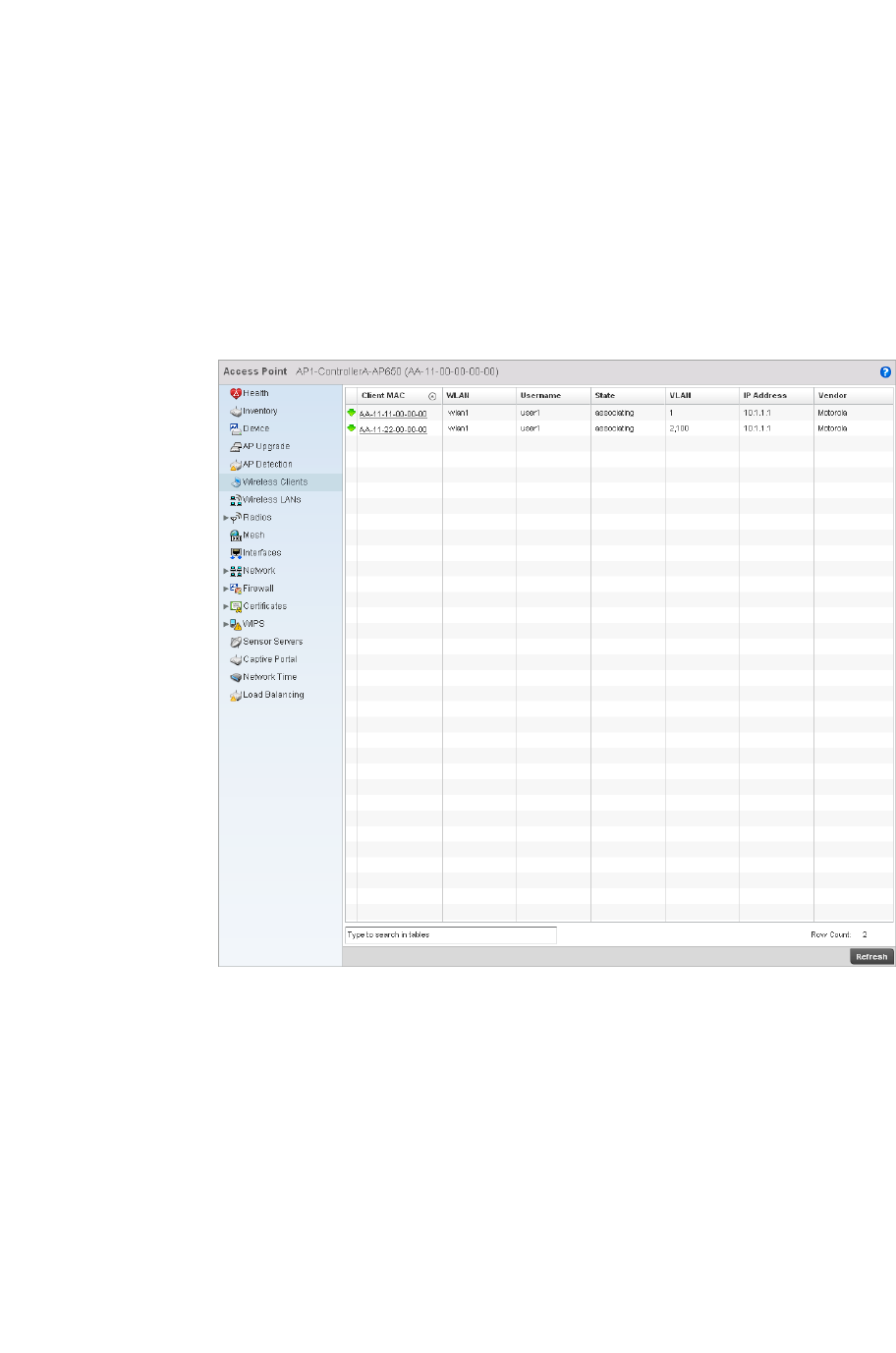
700 Brocade Mobility RFS4000, RFS6000, and RFS7000 System Reference Guide
53-1002620-01
14
The Wireless Clients screen displays read only device information for wireless clients associated
with the selected Access Point. Use this information to assess if configuration changes are required
to improve network performance.
To view wireless client statistics:
1. Select the Statistics menu from the Web UI.
2. Select an Access Point node from the left navigation pane.
3. Select Wireless Clients from the left-hand side of the UI.
FIGURE 465 Access Point Wireless Clients screen
4. The Wireless Clients screen displays the following:
Client MAC Displays the MAC address of the wireless client.
WLAN Displays the name of the WLAN the client is currently associated with. Use this
information to determine if the client/WLAN placement best suits intended operation
and the client coverage area.
Username Displays the unique name of the administrator or operator.
State Displays the working state of the client.
VLAN Displays the VLAN ID the client is currently mapped to.
IP Address Displays the unique IP address of the client. Use this address as necessary throughout
the applet for filtering, device intrusion recognition, and approval.
Vendor Displays the name of the vendor.
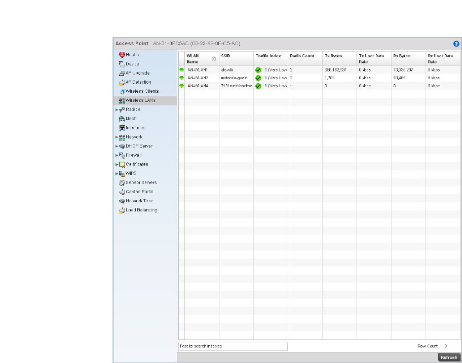
Brocade Mobility RFS4000, RFS6000, and RFS7000 System Reference Guide 701
53-1002620-01
14
Wireless LANs
Access Point Statistics
The Wireless LAN statistics screen displays an overview of Access Point WLANs. This screen
displays the WLAN names, their SSIDs, traffic utilization, number of radios etc.
To view the wireless LAN statistics:
1. Select the Statistics menu from the Web UI.
2. Select an Access Point node from the left navigation pane.
3. Select Wireless LANs from the left-hand side of the UI.
FIGURE 466 Access Point Wireless LANs screen

702 Brocade Mobility RFS4000, RFS6000, and RFS7000 System Reference Guide
53-1002620-01
14
4. The Wireless LANs screen displays the following:
Policy Based Routing
Access Point Statistics
The Policy Based Routing statistics screen displays statitistcs for selective path packet redirection.
PBR can optionally mark traffic for preferential services (QoS). PBR is applied to incoming routed
packets, and a route-map is created containing a set of filters and associated actions. Based on
the actions defined in the route-map, packets are forwarded to the next relevant hop. Route-maps
are configurable under a global policy called routing-policy, and applied to profiles and devices.
To review a selected access point’s PBR statistics:
1. Select the Statistics menu from the Web UI.
2. Select System from the navigation pane (on the left-hand side of the screen), expand the
default node and select an access point for statistical observation.
3. Select Policy Based Routing.
WLAN Name Displays the name of the WLAN the Access Point is currently associated with.
SSID Displays the Service Set ID of the WLAN to which the access point is associated.
Traf fic Index Displays the traffic utilization index, which measures how efficiently the traffic medium
is used. It’s defined as the percentage of current throughput relative to maximum
possible throughput. Traffic indices are:
•0–20 (very low utilization)
•20–40 (low utilization)
•40–60 (moderate utilization)
•60 and above (high utilization)
Radio Count Displays the number of radios associated with this WLAN.
Tx Bytes Displays the average number of transmitted bytes sent on the selected WLAN.
Tx User Data Rate Displays the transmitted user data rate in kbps.
Rx Bytes Displays the average number of packets (in bytes) received on the selected WLAN.
Rx User Data Rate Displays the user’s data rate for received packets.
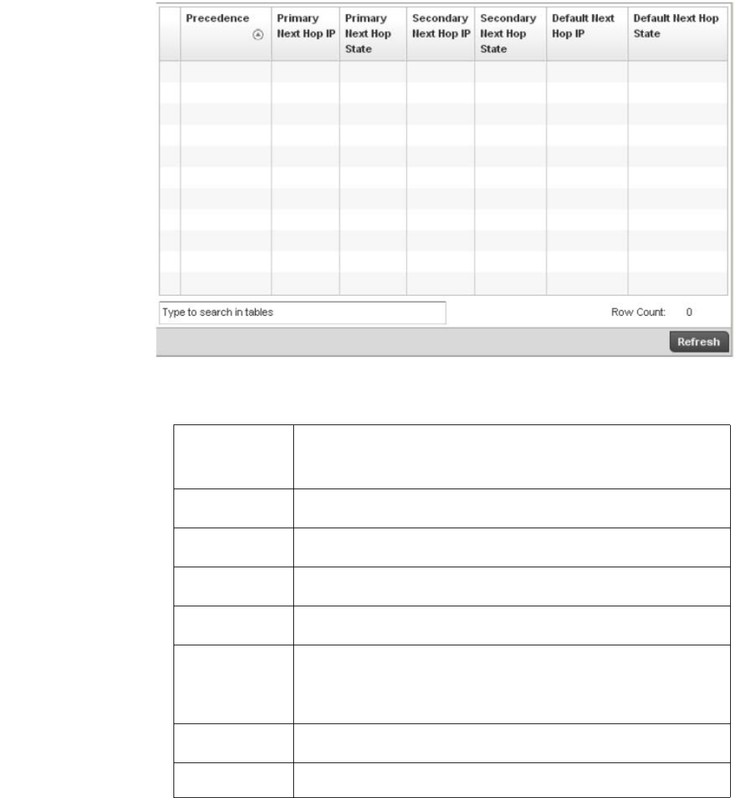
Brocade Mobility RFS4000, RFS6000, and RFS7000 System Reference Guide 703
53-1002620-01
14
FIGURE 467 Access Point - Policy Based Routing screen
4. The Access Point Policy Based Routing screen displays the following:
Radios
Access Point Statistics
Precedence Lists the numeric precedence (priority) assigned to each listed PBR configuration. A
route-map consists of multiple entries, each carrying a precedence value. An incoming
packet is matched against the route-map with the highest precedence (lowest
numerical value).
Primary Next Hop
IP
Lists the IP address of the virtual resource that, if available, is used with no additional
route considerations.
Primary Next Hop
State
Displays whether the primary hop is being applied to incoming routed packets.
Secondary Next
Hop IP
If the primary hop is unavailable, a second resource is used. This column lists the
address set for the alternate route in the election process.
Secondary Next
Hop State
Displays whether the secondary hop is being applied to incoming routed packets.
Default Next Hop
IP
If a packet subjected to PBR does not have an explicit route to the destination, the
configured default next hop is used. This is either the IP address of the next hop or the
outgoing interface. Only one default next hop is available. The difference between the
next hop and the default next-hop is in case of former, PBR occurs first, then
destination based routing. In case of the latter, the order is reverse.
Default Next Hop
State
Displays whether the default hop is being applied to incoming routed packets.
Refresh Select the Refresh button to update the screen’s statistics counters to their latest
values.
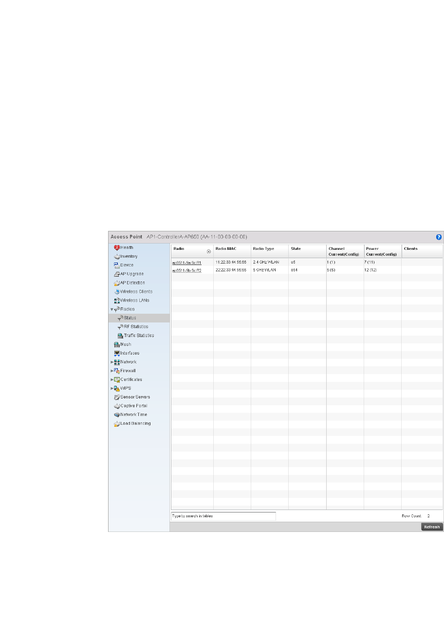
704 Brocade Mobility RFS4000, RFS6000, and RFS7000 System Reference Guide
53-1002620-01
14
The Radio screen displays information on Access Point radios. The actual number of radios depend
on the Access Point model and type. This screen displays information on a per radio basis. Use this
information to refine and optimize the performance of each radio and therefore improve controller
network performance.
The Access Point radio statistics screen provides details about associated radios. It provides radio
ID, radio type, RF quality index etc. Use this information to assess the overall health of radio
transmissions and access point placement.
To view the radio statistics of an access point:
1. Select the Statistics menu from the Web UI.
2. Select an Access Point node from the left navigation pane.
3. Select Radios from the left-hand side of the UI.
FIGURE 468 Access Point Radios screen
4. This screen provides the following information:
Radio Displays the model and numerical value assigned to the radio as its unique identifier.
Radio MAC Displays the MAC address assigned to the radio as its unique hardware identifier.
Radio Type Defines whether the radio is a 802.11b, 802.11bg, 802.11bgn, 802.11a or 802.11an.
State Displays the current operational state of each radio.
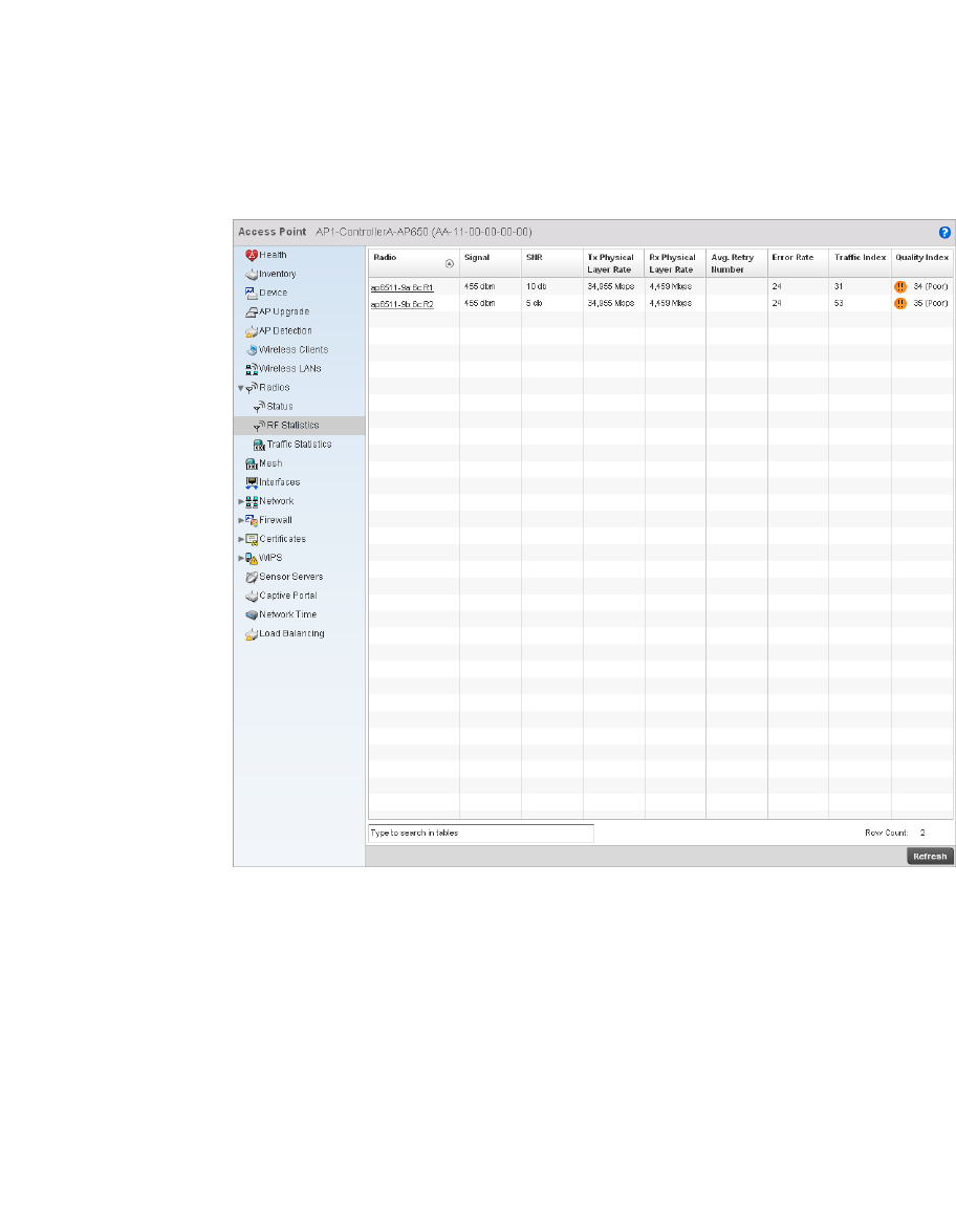
Brocade Mobility RFS4000, RFS6000, and RFS7000 System Reference Guide 705
53-1002620-01
14
5. Select RF Statistics from the Radios menu.
FIGURE 469 RF Domain Radios screen
6. The RF Statistics screen provides the following information:
Channel Current
(Config)
Displays the current channel for each radio and the configured channel in
parentheses.
Power Current
(Config)
Displays the current power level for each radio and the configured power level in
parentheses.
Clients Displays the number of wireless clients associated with the radio.
Radio Displays the model and numerical value assigned to the radio as its unique identifier.
Signal Displays signal strength for each radio in dBm.
SNR Displays the Signal to Noise Ratio (SNR) for each radio in db..
Tx Physical Layer
Rate
Displays the transmitted data in Mbps for each radios physical interface.
Rx Physical Layer
Rate
Displays the received data in Mbps for each radios physical interface.
Avg. Retry Number Displays the average number of retries for eah radio.
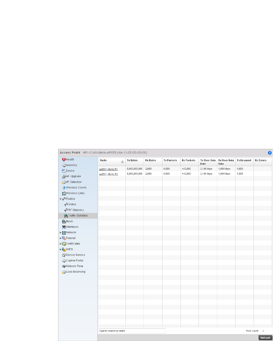
706 Brocade Mobility RFS4000, RFS6000, and RFS7000 System Reference Guide
53-1002620-01
14
7. S elect Traffic Statistics from the Radios menu.
FIGURE 470 Access Point Radios screen
Error Rate Displays the number of errors for each radio.
Traf fic Index Displays the traffic utilization index, which measures how efficiently the traffic medium
is used. It’s defined as the percentage of current throughput relative to maximum
possible throughput. Traffic indices are:
•0–20 (very low utilization)
•20–40 (low utilization)
•40–60 (moderate utilization)
•60 and above (high utilization)
RF Quality Index Displays the client’s RF quality. The RF quality index is the overall effectiveness of the
RF environment, as a percentage of the connect rate in both directions as well as the
retry rate and the error rate. RF quality index value can be interpreted as:
•0–20 — very poor quality
•20–40 —poor quality
•40–60 —average quality
•60–100 — good quality

Brocade Mobility RFS4000, RFS6000, and RFS7000 System Reference Guide 707
53-1002620-01
14
8. The RF Statistics screen provides the following information:
Detailed Radio Statistics
Radios
Click on the Radio Id to view the detailed radio statistics. This screen provides information such as
radio MAC address, configuration, quality of RF, traffic index, radio WLAN, etc.
This screen is partitioned into:
•Details
•Traffic
•WMM TSPEC
•Wireless LANs
•AP Radio Graph
Details
Detailed Radio Statistics
To view the detailed radio statistics:
1. Select the Statistics menu from the Web UI.
2. Select an Access Point node from the left navigation pane.
3. Select Radios from the left-hand side of the UI, and select Radio Id.
4. Select the Details sub-menu from the left navigation pane of the resulting screen.
Radio Displays the model and numerical value assigned to the radio as its unique identifier.
Tx Bytes Displays the amount of transmitted data in bytes for each radio.
Rx Bytes Displays the amount of received data in bytes for each radio.
Tx Packets Displays the amount of transmitted data in packets for each radio.
Rx Packets Displays the amount of received data in packets for each radio.
Tx User Data Rate Displays the average speed in kbps of data transmitted to users for each radio.
Rx User Data Rate Displays the average speed in kbps of data received from users for each radio.
Tx Dropped Displays the number of transmission that have been dropped for each radio.
Rx Errors Displays the total number of receive errors for each radio.
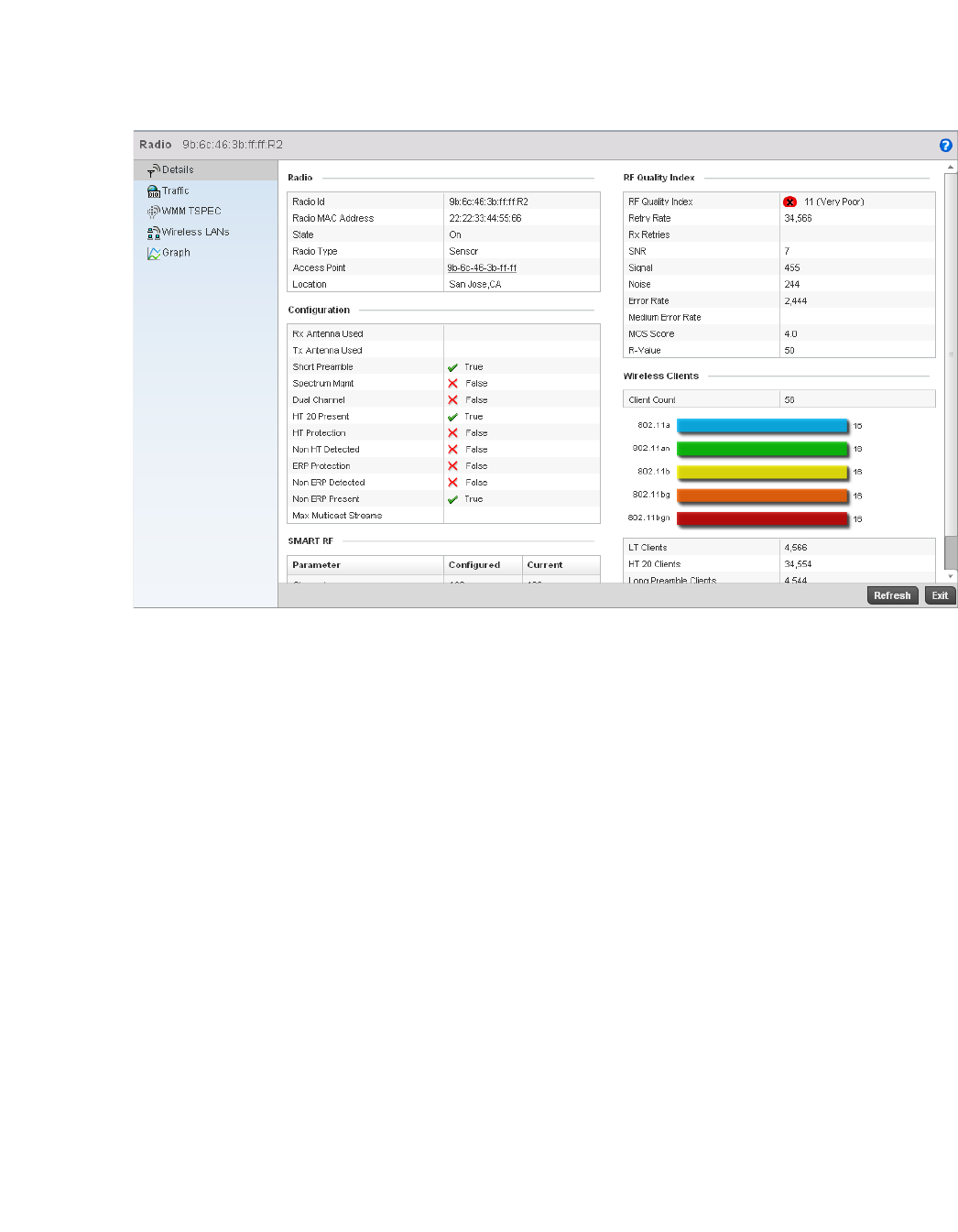
708 Brocade Mobility RFS4000, RFS6000, and RFS7000 System Reference Guide
53-1002620-01
14
FIGURE 471 Access Point Radio Statistics Details screen
5. The Radio table displays the following:
6. The Configuration table displays the following:
Radio Id Displays the numerical index (device identifier) used with this radio.
Radio MAC Address Displays the hardware address of the radio. This is read-only and cannot be modified.
State Displays the current operational mode of the radio. They can be calibrate, normal,
sensor or offline.
Radio Type Displays whether the radio is an 802.11b, 802.11bg, 802.11bgn, 802.11a or
802.11an.
Access Point Displays the AP this radio belongs to.
Location Displays the location of the radio.
Rx Antenna Used Displays the number of receiving antennas supporting this radio.
Tx Antennas Used Displays the number of transmitting antennas supporting this radio.
Short Preamble Lists whether this feature is enabled on this radio. The radio preamble is a section of
data in the packet header that contains information the access point and client need
when sending and receiving. A short preamble improves throughput performance. An
AP and a client negotiate the use of the short preamble.
Spectrum Mgmt Dlists whether spectrum management is enabled. The purpose of spectrum
management is to mitigate radio spectrum pollution and maximize the benefit of the
usable radio spectrum.
Dual Channel Displays whether the radio is transmitting on two channels.

Brocade Mobility RFS4000, RFS6000, and RFS7000 System Reference Guide 709
53-1002620-01
14
7. T he SMART RF table displays the following:
8. The RF Quality Index table displays the following:
HT 20 Present Displays whether High Throughput (HT) 20 protection is adopted. In HT 20, all stations
in the BSS must be HT stations and must be associated to a 20/40 MHz AP. 20/40
capable HT stations must use protection when transmitting on a 40 MHZ channel to
prevent the 20 MHz-only HT stations from transmitting at the same time.
HT Protection Displays whether this feature is enabled. To ensure backward compatibility with older
802.11abg radios, HT access points signal to HT radios to define when to use the
protection mode. A field in the beacon frame, called the HT protection field, has 4
possible settings between 0 and 3.
Non HT Detected Displays whether the AP and clients use HT protection.
ERP Protection Displays whether this feature is enabled or not. Ethernet Ring Protection (ERP) is a
network protection mechanism that enables carriers to enjoy a SONET-like ring
protection while leveraging the cost effectiveness of the Ethernet technology. This is an
effort to provide sub-50ms protection and recovery switching for Ethernet traffic in a
ring topology. This also ensures that there are no loops formed at the Ethernet layer.
Non ERP Detected Displays whether overlapping networks (not capable of using 802.11g) are detected.
Non ERP Present Displays when non-802.11g station associates to a network. 802.11g defined the
extended rate PHY (ERP). To provide backward compatibility, the ERP information
element was defined and is a three-bit flag in a single byte.
Channel The channel list on which Smart RF is enabled.
Power Lists the power in use for supporting Smart RF on selected channels.
RF Quality Index Displays information on the RF quality for the selected wireless client. The RF quality
index is the overall effectiveness of the RF environment as a percentage of the connect
rate in both directions, as well as the retry and error rate. The RF quality index value
can be interpreted as:
•0–20 — very poor quality
•20–40 —poor quality
•40–60 —average quality
•60–100 — good quality
Retry Rate Displays the average number of retries per packet. A high number indicates possible
network or hardware problems.
SNR Displays the signal to noise (SNR) ratio for all the clients connected to selected radio.
The SNR is an indication of overall RF performance.
Signal Displays the power of radio signals in dBm.
Noise Displays the disturbing influences on the signal by the interference of signals in dBm.

710 Brocade Mobility RFS4000, RFS6000, and RFS7000 System Reference Guide
53-1002620-01
14
9. The Wireless Clients table defines the following:
Traffic
Detailed Radio Statistics
The Traffic screen provides the traffic utilization details of the radio. It also displays the different
errors encountered during transmission and receiving of packets.
To view the traffic details:
1. Select the Statistics menu from the Web UI.
2. Select an Access Point node from the left navigation pane.
3. Select Radios from the left-hand side of the UI, and select Radio Id.
4. Select the Traffic sub-menu from the left navigation pane of the resulting screen.
Error Rate Displays the number of received bit rates altered due to noise, interference and
distortion. It’s a unitless performance measure.
MOS Score Displays the average call quality using the Mean Opinion Score (MOS) call quality
scale. The MOS scale rates define quality in a scale of 1-5, with higher scores being
better. If the MOS score is lower than 3.5, it’s likely users will not be satisfied with the
voice quality of their calls.
R-Value Displays the R-value. R-value is a number or score used to quantitatively express the
quality of speech in communications systems. Its used in digital networks that carry
Voice over IP (VoIP) traffic. The R-value can range from 1 (worst) to 100 (best) and is
based on the percentage of users who are satisfied with the quality of a test voice
signal after it has passed through a network from a source (transmitter) to a
destination (receiver). The R-value scoring method accurately portrays the effects of
packet loss and delays in digital networks carrying voice signals.
Client Count Displays the number of wireless clients associated with the AP.
LT Clients Displays the number of Low Throughput (LT) clients. This message can be delivered
over a physical link, logical link or through a network node.
HT 20 Clients Displays the number of clients using the HT 20 protection. This is a protection method
to ensure backward compatibility with older 802.11abg radios. Using this protection,
HT APs signal HT radios when to use protection mode.
Long Preamble
Clients
Displays the number of clients using a long preamble. The radio preamble is a section
of data in the packet header containing information the AP and client need when
sending and receiving packets. A long preamble decreases throughput performance.
Long Slot Clients Displays the number of clients having the long slot time. Slot time is the amount of
time a device waits after a collision after retransmitting a packet. Long slot time
decreases throughput.
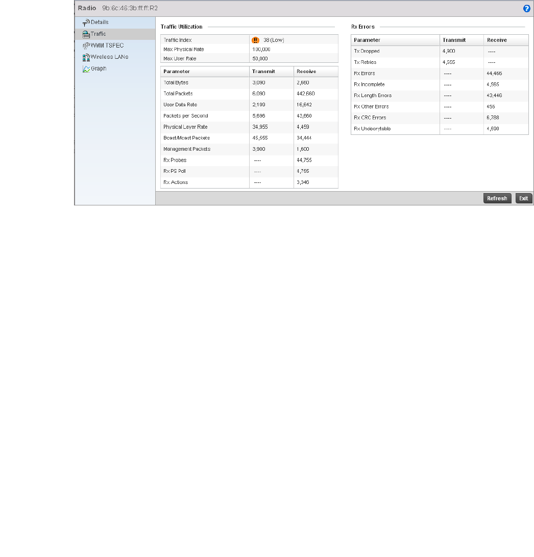
Brocade Mobility RFS4000, RFS6000, and RFS7000 System Reference Guide 711
53-1002620-01
14
FIGURE 472 Access Point Radio Statistics Traffic screen
5. The Traffic Utilization area provides the following information:
Traf fic Index Displays the traffic utilization index, which measures how efficiently the traffic medium
is used. It’s defined as the percentage of current throughput relative to the maximum
possible throughput. Traffic indices are:
•0–20 (very low utilization
•20–40 (low utilization
•40–60 (moderate utilization
•60 and above (high utilization
Max Physical Rate Displays the maximum data rate at the physical layer.
Max User Rate Displays the maximum permitted user data rate.
Total Bytes Displays the total number of bytes processed by the AP radio.
Total Packets Displays the total number of packets transmitted and received by the Access Point
radio.
User Data Rate Displays the average user data rate for both transmit and the receive operations.
Packets per
Second
Displays the number of packets sent and received per second.
Physical Layer Rate Displays data transfer rates at the physical layer for both transmit and receive
operations.
Bcast/Mcast
Packets
Displays the number of broadcast and multicast packets transmitted and received per
second.
Management
Packets
Displays the number of management packets processed by the radio per second.

712 Brocade Mobility RFS4000, RFS6000, and RFS7000 System Reference Guide
53-1002620-01
14
6. The Rx Errors table defines the following:
WMM TSPEC
Detailed Radio Statistics
This Traffic Specification (TSPEC) screen displays the traffic specification parameters for the
selected radio. The traffic specification allows an 802.11e client to signal its traffic requirements to
the AP. It provides a set of parameters that define the characteristics of the traffic stream. The
sender specifies parameters available for packet flow. Both the sender and the receiver use TSPEC.
The TSPEC screen provides the information about TSPEC counts and TSPEC types for the selected
wireless client.
To view the TSPEC of the selected radio:
1. Select the Statistics menu from the Web UI.
2. Select an Access Point node from the left navigation pane.
3. Select Radios from the left-hand side of the UI, and select Radio Id.
4. Select the WMM TSPEC sub-menu from the left navigation pane of the resulting screen.
Rx Probes Displays the number of network probes received. A probe provides accurate statistics
concerning a network’s operation such as traffic analysis, top users, and protocol
usage. Using this information, manage your network efficiently, ensuring peak
operation and performance.
RX PS Poll Displays the power save using the Power Save Poll mode. Power Save Poll (PSP) is a
protocol, which helps to reduce the amount of time a radio needs to be powered. PSP
allows the WiFi adapter to notify the AP when the radio is powered down. The access
point holds any network packet sent to this radio.
Rx Actions Displays the total number of action packets received.
Tx Dropped Displays the number of transmitted packets dropped.
Tx Retries Displays the average number of transmit retries. A high number indicates possible
network or hardware problems
.
Rx Errors Displays the number of errors received. The higher the error rate, the less reliable the
connection or data transfer.
Rx Incomplete Displays the number of incomplete packets received.
Rx Length Errors Displays the number of length error packets received. Length errors are generated
when the received frame length was less than or exceeded the Ethernet standard.
Rx Other Errors Displays the number of additional errors that are not Rx Length Error or Rx CRC Error
errors.
Rx CRC Errors Displays the number of CRC errors received. Cyclic redundancy checks search for
errors that has been transmitted on a communications link. A sending device applies a
16- or 32- bit polynomial to a block of transmitted data and appends the resulting
cycling redundancy code to the block. The receiving end applies the same polynomial
to the data and compares its result with the result appended by the sender. If those
results agree, the data has been received successfully. If not, the sender can be
notified to resend the block of data.
Rx Undecryptable Displays the number of non-decryptable packets received.
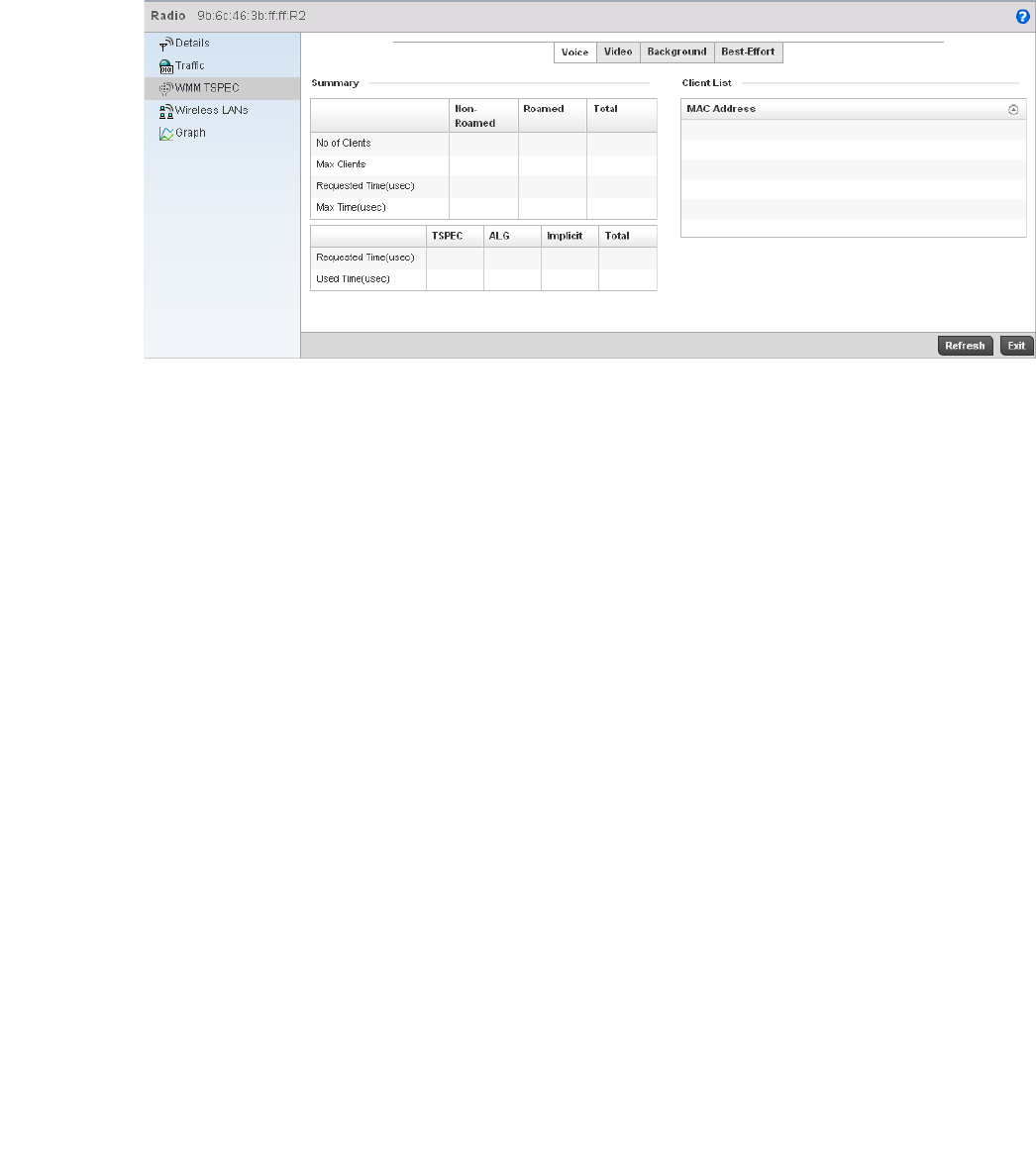
Brocade Mobility RFS4000, RFS6000, and RFS7000 System Reference Guide 713
53-1002620-01
14
FIGURE 473 Access Point Radio Statistics TSPEC screen
5. The Status area provides the following:
6. The Utilization table the following:
Voice Displays the status of prioritization for voice traffic. A red ‘X’ indicates this feature is
disabled. A green check mark indicates this feature is enabled.
Video Displays the status of prioritization for video traffic. A red ‘X’ indicates this feature is
disabled. A green check mark indicates this feature is enabled.
Best Effort Displays the status of prioritization for best effort traffic. A red ‘X’ indicates this feature
is disabled. A green check mark indicates this feature is enabled.
Background Displays the status of prioritization for background traffic. A red ‘X’ indicates this
feature is disabled. A green check mark indicates this feature is enabled.
Request Time
TSPEC
Displays the time when the client asks the AP for its QoS requirements such as mean
data rate, packet length, and extra allowance for retries through an add traffic stream
(ADDTS) request when admission control is mandatory in the beacon. TSPEC allows a
client to signal its traffic requirements to an AP. The AP decides whether the request is
acceptable and transmits its decision to the client. The client can start high priority
communication only when permitted by the AP.
Used Time TSPEC Displays the client’s TSPEC usage. The client sends a delete traffic stream (DELTS)
message when it’s finished communicating.
Request Time ALG Displays the time when legacy clients or WMM clients, which do not support TSPEC,
request QoS parameters from an existing application-level gateway (ALG) using a
protocol like SIP.
Used Time ALG Displays the duration the legacy or WMM clients used a protocol with an existing ALG
for obtaining QoS parameters (data rate, packet length and extra allowance of the AP).
Request Time
Implicit
Displays the time when an implicit request was generated. This is a feature to stimulate
a TSPEC request for clients that do not support TSPEC and do not send traffic
inspected by an ALG in an access controlled traffic class.
Used Time Implicit Displays the time taken by a wireless client to determine the QoS parameters of the AP
using the Implicit TSPEC feature.
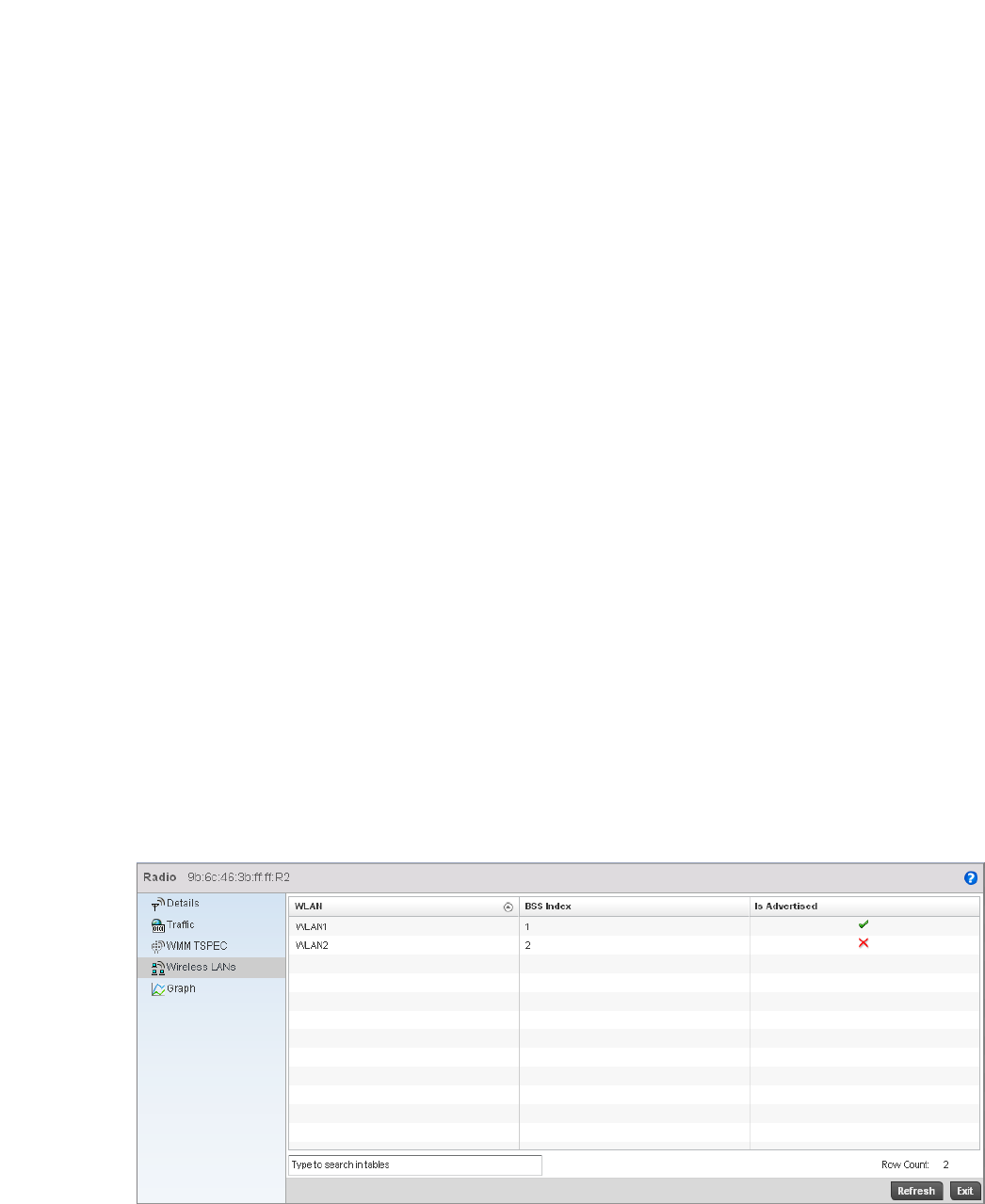
714 Brocade Mobility RFS4000, RFS6000, and RFS7000 System Reference Guide
53-1002620-01
14
7. The Roaming table displays the following:
Wireless LANs
Detailed Radio Statistics
The Wireless LANs screen provides WLAN details for the selected radio. It includes the WLAN
name, its BSS ID and whether the WLAN is advertised.
To view WLAN statistics for the selected radio:
1. Select the Statistics menu from the Web UI.
2. Select an Access Point node from the left navigation pane.
3. Select Radios from the left-hand side of the UI, and select Radio Id.
4. Select the Wireless LANs sub-menu from the left navigation pane of the resulting screen.
FIGURE 474 Access Point Radio Statistics Wireless LANs screen
Non-Roamed
Clients
Displays the number of non-roaming clients associated with the access point radio.
Non-roaming clients do not change their AP association from one AP to another. The
non-roaming clients operate from a single location.
Non-Roamed Time Displays the time for which the non-roamed clients are in association with an AP radio.
Roamed Clients Displays the number of roaming clients associated with an AP radio. Roaming have
been granted the roaming privilege. When roaming, it can toggle between normal and
roaming modes. Roaming occurs when a client changes its AP association from one AP
to another within the same WLAN.
Roamed Time Represents the time between the last Real Time Transport Protocol (RTP) packet seen
on AP 1, and the first RTP packet seen on AP 2. It also includes the time the client
takes to re-authenticate and re-associate with AP 2. (
Max Non-Roamed
Clients
Displays the maximum number of non roaming clients available for AP association.
Max Non-Roamed
Time
Displays the maximum time for which the non-roamed clients are in association with
an AP radio.
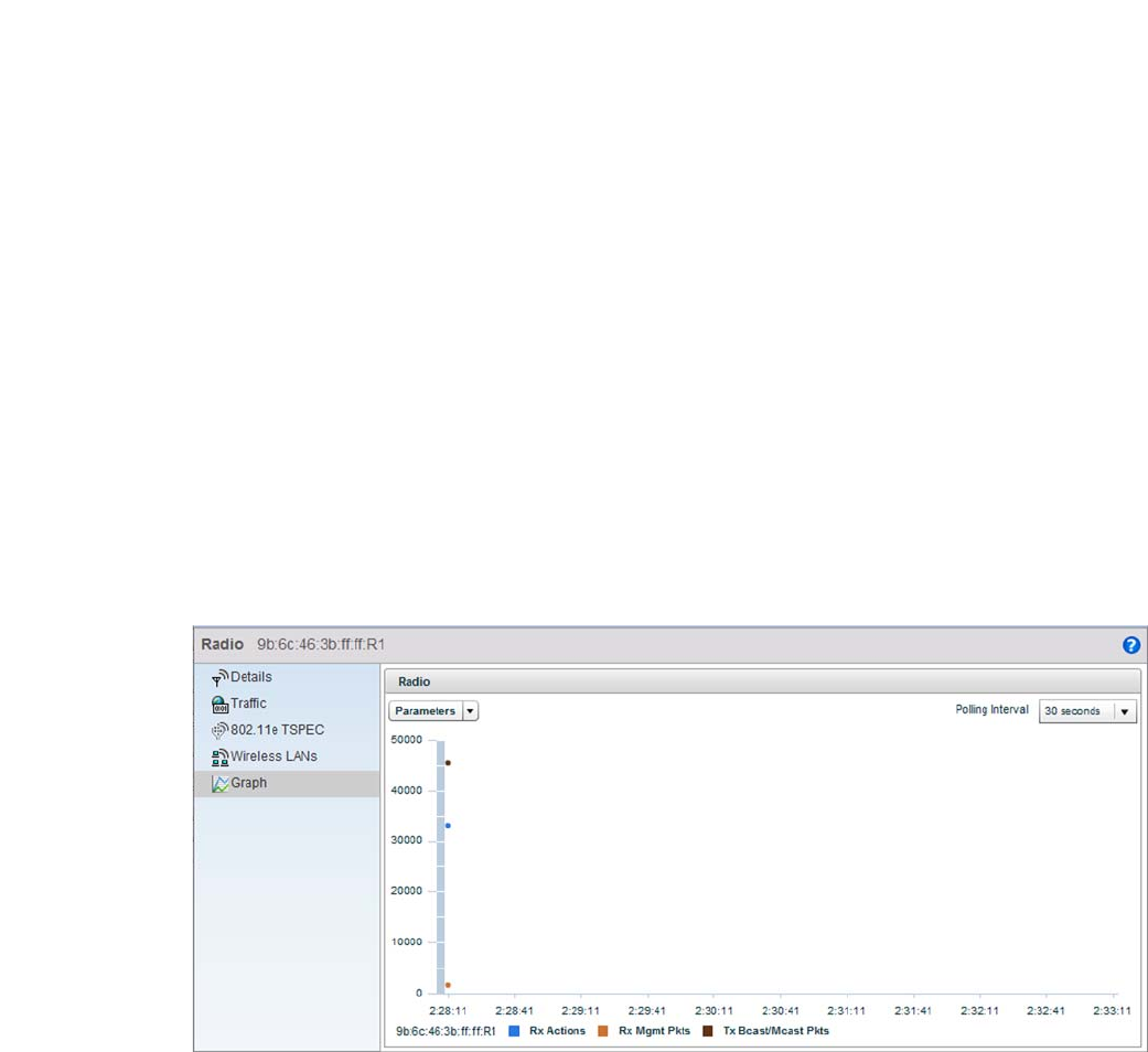
Brocade Mobility RFS4000, RFS6000, and RFS7000 System Reference Guide 715
53-1002620-01
14
5. The Wireless LANs screen displays the following:
AP Radio Graph
Detailed Radio Statistics
Use the Graph information to chart associated controller radio performance and diagnose radio
performance issues. The graph uses a Y-axis and a X-axis. Select different parameters on the Y-axis
and different polling intervals. To view a detailed graph for a client, select multiple parameters from
the Y-axis and select a polling interval from the Y-axis.
To view the radio statistics graphically:
1. Select the Statistics menu from the Web UI.
2. Select an Access Point node from the left navigation pane.
3. Select Radios from the left-hand side of the UI, and select Radio Id.
4. Select the Graph sub-menu from the resulting screen.
FIGURE 475 Access Point Radio Statistics Graph screen
Mesh
Access Point Statistics
The Mesh screen provides detailed statistics on each of the Mesh APs available. Use the following
to review the performance of each AP interface.
To view the Mesh statistics:
1. Select the Statistics menu from the Web UI.
WLAN Displays the name of the WLAN the selected radio is using.
BSS Index Displays the WLAN’s Basic Service Set identifier (BSS). The BSS Index is the MAC
address of the access point’s radio servicing the BSS.
Is Advertised Displays whether the WLAN is advertised through an SSID, which announces the
availability of the wireless network to wireless clients.
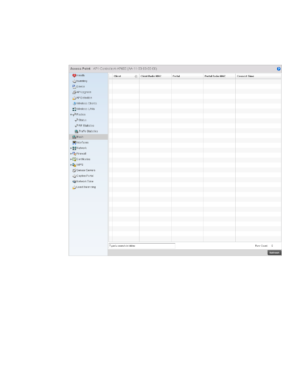
716 Brocade Mobility RFS4000, RFS6000, and RFS7000 System Reference Guide
53-1002620-01
14
2. Select an Access Point node from the left navigation pane.
3. Select Mesh from the left-hand side of the UI.
FIGURE 476 Access Point Mesh screen
4. The Mesh screen describes the following:
Interfaces
Access Point Statistics
Client AP Displays the AP name for each Access Point in the RF Domain mesh network.
Client Hostname Displays the configured hostname for each Access Point in the RF Domain mesh
network.
Client Radio MAC Displays the Media Access Control for each Access Point in the RF Domain mesh
network.
Portal Radio Index Displays the numerical Peer Radio Index ID for the peer device associated with each
Access Point in the RF Domain mesh network.
Portal Hostname Displays the assigned hostname for the peer device associated with each Access Point
in the RF Domain mesh network.
Portal Radio MAC Displays the Media Access Control for each radio in the RF Domain mesh network.
Connect Time Displays the total connection time for each AP in the RF Domain mesh network.
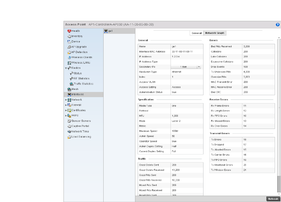
Brocade Mobility RFS4000, RFS6000, and RFS7000 System Reference Guide 717
53-1002620-01
14
The Interface screen provides detailed statistics on each of the interfaces available on an Access
Point. Use the following to review the performance of each AP interface.
•General Statistics
•Viewing Interface Statistics Graph
General Statistics
Mesh
The General screen provides information on the interface such as its MAC address, type and TX/RX
statistics.
To view the general interface statistics:
1. Select the Statistics menu from the Web UI.
2. Select an Access Point node from the left navigation pane.
3. Select Interfaces from the left-hand side of the UI.
FIGURE 477 Access Point Interface screen

718 Brocade Mobility RFS4000, RFS6000, and RFS7000 System Reference Guide
53-1002620-01
14
4. The General table describes the following:
5. The Specification table displays the following:
6. The Traffic table describes the following:
Name Displays the name of the interface.
Interface MAC
Address
Displays the MAC address of the interface.
IP Address IP address of the interface.
IP Address Type Lists the IP address type of the interface
Hardware Type Displays the hardware type.
Index Displays the unique numerical identifier supporting the interface.
Access VLAN Displays the interface the VLAN has access to.
Access Setting Displays the mode of the VLAN as either Access or Trunk.
Administrative
Status
Displays whether the interface is currently UP or DOWN.
Media Type Displays the physical connection type of the interface.
Media types include:
Copper - Used on RJ-45 Ethernet ports
Optical - Used on fibre optic gigabit Ethernet ports
Protocol Displays the name of the routing protocol adopted by the interface.
MTU Displays the maximum transmission unit (MTU) setting configured on the interface.
The MTU value represents the largest packet size that can be sent over a link. 10/100
Ethernet ports have a maximum setting of 1500.
Mode The mode can be either:
Access – This Ethernet interface accepts packets only from the native VLANs.
Trunk – This Ethernet interface allows packets from a given list of VLANs that you can
add to the trunk.
Metric Displays the metric value associated with the route through this interface.
Maximum Speed Displays the maximum speed at which the interface transmits or receives data.
Admin. Speed Displays the speed setting used when using the administrative interface.
Operator Speed Displays the current speed of the data transmitted and received over the interface.
Admin. Duplex
Setting
Displays the administrator’s duplex setting.
Current Duplex
Setting
Displays the interface as either half duplex, full duplex, or unknown.
Good Octets Sent Displays the number of octets (bytes) sent by the interface with no errors.
Good Octets
Received
Displays the number of octets (bytes) received by the interface with no errors.
Good Pkts Sent Describes the number of good packets transmitted.

Brocade Mobility RFS4000, RFS6000, and RFS7000 System Reference Guide 719
53-1002620-01
14
7. T he Errors table displays the following:
8. The Receive Errors table displays the following:
Good Pkts
Received
Describes the number of good packets received.
Mcast Pkts Sent Displays the number of multicast packets sent through the interface.
Mcast Pkts
Received
Displays the number of multicast packets received through the interface.
Bcast Pkts Sent Displays the number of broadcast packets sent through the interface.
Bcast Pkts
Received
Displays the number of broadcast packets received through the interface.
Packet Fragments Displays the number of packet fragments transmitted or received through the
interface.
Jabber Pkts Displays the number of packets transmitted through the interface that is larger than
the MTU through the interface.
Bad Pkts Received Displays the number of bad packets received through the interface.
Collisions Displays the number of collisions.
Late Collisions A late collision is any collision that occurs after the first 64 octets of data have been
sent by the sending station. Late collisions are not normal, and are usually the result of
out-of-specification cabling or a malfunctioning device.
Excessive
Collisions
Displays the number of excessive collisions. Excessive collisions occur when the traffic
load increases to the point that a single Ethernet network can not handle it efficiently.
Drop Events Displays the number of dropped packets that are transmitted or received through the
interface.
Tx Undersize Pkts Displays the number of undersize packets transmitted through the interface.
Oversize Pkts Displays the number of oversize packets.
MAC Transmit Error Displays the number of failed transmits due to an internal MAC sublayer error (not a
late collision, excessive collisions or carrier sense error).
MAC Receive Error Displays the number of failed received packets due to an internal MAC sublayer (not a
late collision, excessive collisions or carrier sense error).
Bad CRC Displays the CRC error. The Cyclical Redundancy Check (CRC) is the 4 byte field at the
end of every frame. The receiving station uses it to interpret if the frame is valid. If the
CRC value computed by the interface does not match the value at the end of the frame,
it’s considered a bad CRC.
Rx Frame Errors Displays the number of frame errors received at the interface. A frame error occurs
when a byte of data is received in unexpected format.
Rx Length Errors Displays the number of length errors received at the interface. Length errors are
generated when the received frame length was less than or exceeded the Ethernet
standard.

720 Brocade Mobility RFS4000, RFS6000, and RFS7000 System Reference Guide
53-1002620-01
14
9. The Transmit Errors table displays the following:
Viewing Interface Statistics Graph
Mesh
The Network Graph tab displays interface statistics graphically. To view a detailed graph for an
interface, select an interface and drop it on to the graph. The graph has Port Statistics as the Y-axis
and the Polling Interval as the X-axis. Select different parameters on the Y-axis and different polling
intervals as needed.
Rx FIFO Errors Displays the number of FIFO errors received at the interface. First-in First-Out queueing
is an algorithm that involves buffering and forwarding of packets in the order of arrival.
FIFO entails no priority for traffic. There is only one queue, and all packets are treated
equally.
Rx Missed Errors Displays the number of missed packets. Packets are missed when the hardware
received FIFO has insufficient space to store the incoming packet.
Rx Over Errors Displays the number of overflow errors. An overflow occurs when packet size exceeds
the allocated buffer size.
Tx Errors Displays the number of packets with errors transmitted on the interface.
Tx Dropped Displays the number of transmitted packets dropped from the interface.
Tx Aborted Errors Displays the number of packets aborted on the interface because a
clear-to-send request was not detected.
Tx Carrier Errors Displays the number of carrier errors on the interface. This generally indicates bad
Ethernet hardware or cabling.
Tx FIFO Errors Displays the number of FIFO errors received at the interface. FIFO is an algorithm that
involves buffering and forwarding packets in the order of arrival. FIFO provides no
priority for traffic. There is only one queue, and all packets are treated equally.
Tx Heartbeat Errors Displays the number of heartbeat errors. This generally indicates a software crash or
packets stuck in an endless loop.
Tx Window Errors Displays the number of window errors transmitted. TCP uses a sliding window flow
control protocol. In each TCP segment, the receiver specifies the amount of additional
received data (in bytes) in the receive window field the receiver is willing to buffer for
the connection. The sending host can only send up to that amount. If the sending host
transmits more data before receiving an acknowledgement from the receiving host, it
constitutes a window error.
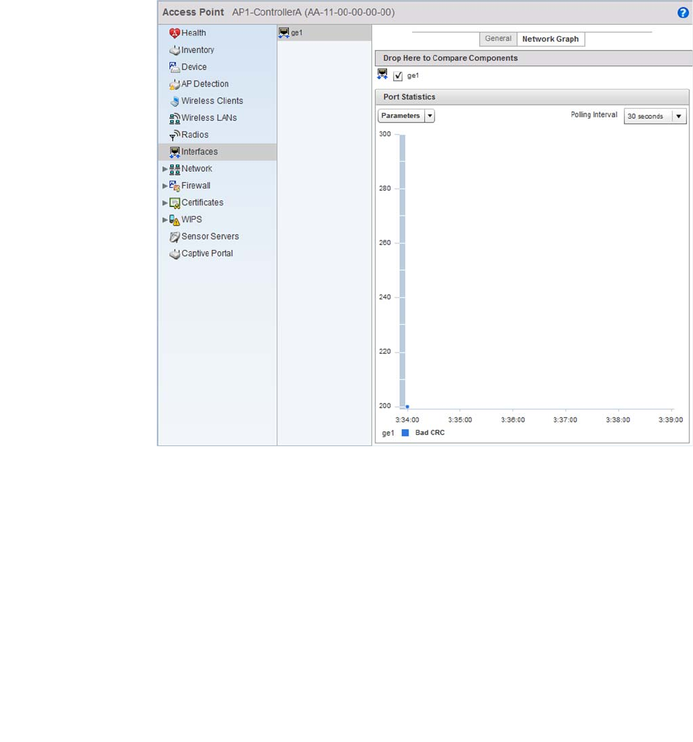
Brocade Mobility RFS4000, RFS6000, and RFS7000 System Reference Guide 721
53-1002620-01
14
FIGURE 478 Access Point Interface Graph screen
PPPoE
Access Point Statistics
The PPPoE statistics screen displays stats derived from the AP’s access to high-speed data and
broadband networks. PPPoE uses standard encryption, authentication, and compression methods
as specified by the PPPoE protocol. PPPoE enables access points to establish a point-to-point
connection to an ISP over existing Ethernet interface.
To review a selected access point’s PPPoE statistics:
1. Select the Statistics menu from the Web UI.
2. Select System from the navigation pane (on the left-hand side of the screen), expand the
default node and select an access point for statistical observation.
3. Select PPPoE.

722 Brocade Mobility RFS4000, RFS6000, and RFS7000 System Reference Guide
53-1002620-01
14
FIGURE 479 Access Point - PPPoE screen
4. The Access Point PPPoE screen displays the following configuration information and
connection status:
Shutdown Displays whether a high speed client mode point-to-point connection has been
enabled using the PPPoE protocol.
Service Lists the 128 character maximum PPPoE client service name provided by the service
provider.
DSL Modem
Network (VLAN)
Displays the PPPoE VLAN (client local network) connected to the DSL modem. This is
the local network connected to DSL modem.
Authentication
Type
Lists authentication type used by the PPPoE client whose credentials must be shared
by its peer access point. Supported authentication options include None, PAP, CHAP,
MSCHAP, and MSCHAP-v2.
Username Displays the 64 character maximum username used for authentication support by the
PPPoE client.
Password Displays the 64 character maximum password used for authentication by the PPPoE
client.
Client Idle Timeout The access point uses the listed timeout so it does not sit idle waiting for input from
the PPPoE client and the server, that may never come.
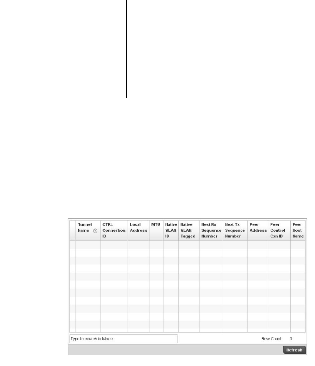
Brocade Mobility RFS4000, RFS6000, and RFS7000 System Reference Guide 723
53-1002620-01
14
L2TP V3
Access Point Statistics
A Brocade Mobility supported access point uses L2TP V3 to create tunnels for transporting layer 2
frames. L2TP V3 enables an access point to create tunnels for transporting Ethernet frames to and
from bridge VLANs and physical ports. L2TP V3 tunnels can be defined between Brocade Mobility
devices and other devices supporting the L2TP V3 protocol.
To review a selected access point’s PPPoE statistics:
1. Select the Statistics menu from the Web UI.
2. Select System from the navigation pane (on the left-hand side of the screen), expand the
default node and select an access point for statistical observation.
3. Select L2TP V3.
FIGURE 480 Access Point - L2TP V3screen
Keep Alive If a keep alive is utilized, the point-to-point connect to the PPPoE client is continuously
maintained and not timed out.
Maximum
Transmission Unit
(MTU)
Displays the PPPoE client maximum transmission unit (MTU) from 500 - 1,492. The
MTU is the largest physical packet size in bytes a network can transmit. Any messages
larger than the MTU are divided into smaller packets before being sent. A PPPoE client
should be able to maintain its point-to-point connection for this defined MTU size.
Connection Status Lists the MAC address, SID, Service informaitonn MTU and status of each route
destination peer. To provide this point-to-point connection, each PPPoE session learns
the Ethernet address of a remote PPPoE client, and establishes a session. PPPoE uses
both a discover and session phase to identify a client and establish a point-to-point
connection. By using such a connection, a Wireless WAN failover is available to
maintain seamless network access if the access point’s Wired WAN were to fail.
Refresh Select the Refresh button to update the screen’s statistics counters to their latest
values.

724 Brocade Mobility RFS4000, RFS6000, and RFS7000 System Reference Guide
53-1002620-01
14
4. The Access Point L2TP V3 screen displays the following:
VRRP
Access Point Statistics
The VRRP statistics screen displays Virtual Router Redundancy Protocol (VRRP) configuration
statistics supporting router redundancy in a wireless network requiring high availability.
To review a selected access point’s VRRP statistics:
1. Select the Statistics menu from the Web UI.
2. Select System from the navigation pane (on the left-hand side of the screen), expand the
default node and select an access point for statistical observation.
3. Select VRRP
Name Displays the name of each listed L2TPv3 tunnel assigned upon creation.
CTRL Connection
ID
Displays the router ID(s) sent in tunnel establishment messages with a potential peer
device.
Local Address Lists the IP addresses assigned as the local tunnel end point address, not the
interface IP address. This IP is used as the tunnel source IP address. If a local address
is not specified, the source IP address is chosen automatically based on the tunnel
peer IP address.
MTU Displays the maximum transmission unit (MTU) size for each listed tunnel. The MTU is
the size (in bytes) of the largest protocol data unit that the layer can pass between
tunnel peers.
Native VLAN ID Lists the IDs of the native VLANs that will not be tagged in tunnel establishment.
Native VLAN
Tagged
Lists the native VLANs that are tagged in tunnel establishment.
Next Rx Sequence
Number
Displays the numeric identifier (ID) for the next packet receipt within the tunnel
session. This pseudowire ID is sent in a session establishment message with the L2TP
peer.
Next Tx Sequence
Number
Displays the numeric identifier (ID) for the next packet transmission within the tunnel
session. This pseudowire ID is sent in a session establishment message with the L2TP
peer.
Peer Address Lists the IP address of the L2TP tunnel peer establishing the tunnel connection.
Peer Control Cxn
ID
Displays the peer’s numeric identifier for the tunnel session. This is the peer
pseudowire ID for the session. This source and destination IDs are exchanged in
session establishment messages with the L2TP peer.
Peer Host Name Lists the peer a hostname used as matching criteria in the tunnel establishment
process.
Refresh Select the Refresh button to update the screen’s statistics counters to their latest
value.
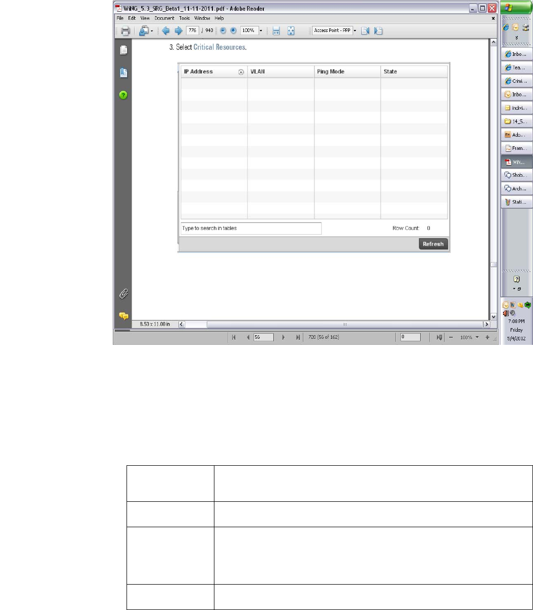
Brocade Mobility RFS4000, RFS6000, and RFS7000 System Reference Guide 725
53-1002620-01
14
FIGURE 481 Access Point - VRRP screen
4. Refer to the Global Error Status field to review the varous sources of packet errors logged
during the implementation of the virtual route.
Errors include the mismatch of authentication credentials, invalid packet checksums, invalid
packet types, invalid virtual route IDs, TTL errors, packet length errors and invalid (non matching)
VRRP versions.
5. Refer to the Router Operations Summary for the following status:
VRID Lists a numerical index (1 - 254) used to differentiate VRRP configurations. The index
is assigned when a VRRP configuration is initially defined. This ID identifies the virtual
router a packet is reporting status for.
Virtual IP Address Lists the virtual interface IP address used as the redundant gateway address for the
virtual route.
Master IP Address Displays the IP address of the elected VRRP master. A VRRP master (once elected)
responds to ARP requests, forwards packets with a destination link layer MAC address
equal to the virtual router MAC address, rejects packets addressed to the IP address
associated with the virtual router and accepts packets addressed to the IP address
associated with the virtual router.
Interface Name Displays the interfaces selected on the access point to supply VRRP redundancy
failover support.

726 Brocade Mobility RFS4000, RFS6000, and RFS7000 System Reference Guide
53-1002620-01
14
6. Select Clear Router Status to clear the counters within the Router Operations Summary and
begin a new data collection.
7. S elect Clear Global Error Status to clear the counters within the Global Error Status table and
begin a new collection of packet error descriptions.
Critical Resources
Access Point Statistics
The Critical Resources statistics screen displays a list of device IP addresses on the network
(gateways, routers etc.). These defined IP address is critical to the health of the access point
managed network. These device addresses are pinged regularly by the access point. If there’s a
connectivity issue, an event is generated stating a critical resource is unavailable. Thus, each
device’s VLAN, ping mode and state is displayed for the administrator.
To review a selected access point’s critical resource statistics:
1. Select the Statistics menu from the Web UI.
2. Select System from the navigation pane (on the left-hand side of the screen), expand the
default node and select an access point for statistical observation.
3. Select Critical Resources.
Version Dispaly VRRP version 3 (RFC 5798) or 2 (RFC 3768) as selected to set the router
redundancy. Version 3 supports sub-second (centisecond) VRRP failover and support
services over virtual IP.
State Displays the current state of each listed virtual router ID.
Refresh Select the Refresh button to update the screen’s statistics counters to their latest
values.
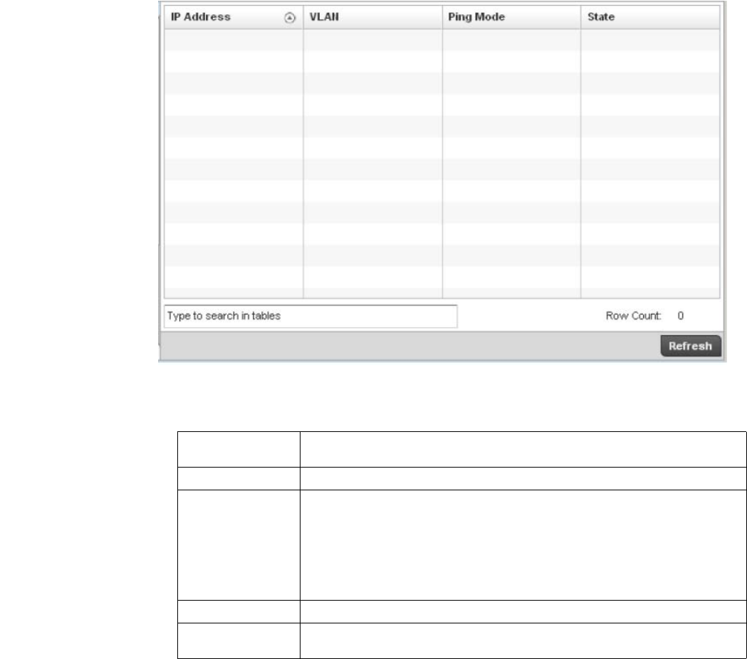
Brocade Mobility RFS4000, RFS6000, and RFS7000 System Reference Guide 727
53-1002620-01
14
FIGURE 482 Access Point - Critical Resources screen
4. The Access Point Critical Resource screen displays the following:
Network
Access Point Statistics
Use the Network screen to view information for ARP, Route Entry, Bridge, DHCP, CDP and LLDP.
Each of these screens provide enough statistics to troubleshoot issues related to the following four
features:
•ARP Entries
•Route Entries
•Bridge
•DHCP Options
IP Address Lists the IP address of the critical resource. This is the address the device assigned
and is used by the access point to ensure the critical resource is available.
VLAN Lists the access point VLAN on which the critical resource is available.
Ping Mode Describes the ping mode as either:
arp-only – Uses the Address Resolution Protocol (ARP) for only pinging the critical
resource. ARP is used to resolve hardware addresses when only the network layer
address is known.
arp-icmp – Uses both ARP and Internet Control Message Protocol (ICMP) for pining the
critical resource and sending control messages (device not reachable, requested
service not available, etc.).
State Defines the operational state of each listed critical resource.
Refresh Select the Refresh button to update the screen’s statistics counters to their latest
values.
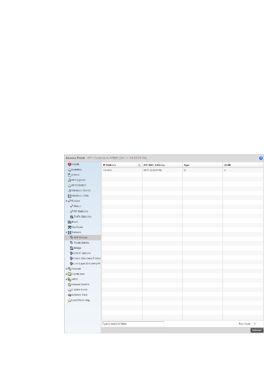
728 Brocade Mobility RFS4000, RFS6000, and RFS7000 System Reference Guide
53-1002620-01
14
•Cisco Discovery Protocol
•Link Layer Discovery Protocol
ARP Entries
Network
ARP is a networking protocol for determining a network host’s hardware address when its IP
address or network layer address is known. The ARP screen displays entries configured for this
wireless controller.
To view the ARP statistics:
1. Select the Statistics menu from the Web UI.
2. Select an Access Point node from the left navigation pane.
3. Select Network > ARP Entries from the left-hand side of the UI.
FIGURE 483 Access Point Network ARP Entries screen
4. The ARP Entries screen describes the following:
IP Address Displays the IP address of the client being resolved.
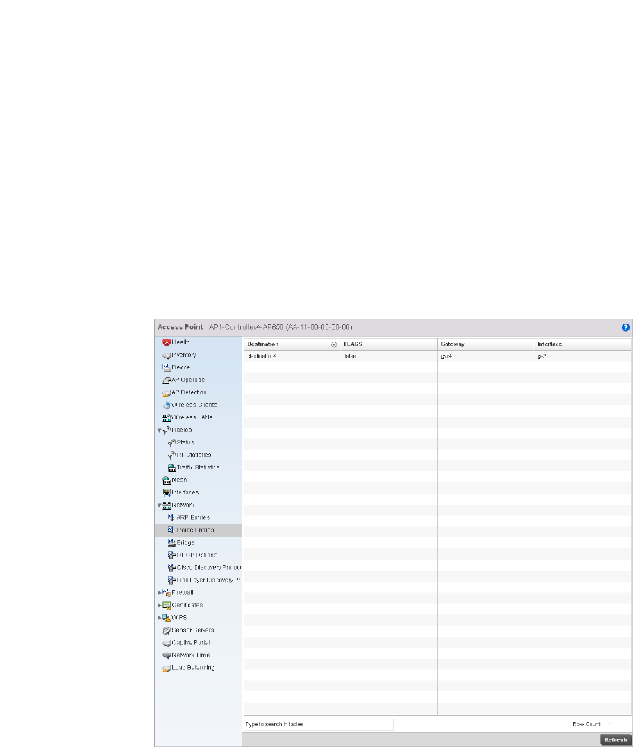
Brocade Mobility RFS4000, RFS6000, and RFS7000 System Reference Guide 729
53-1002620-01
14
Route Entries
Network
The route entries screen provides details about the destination subnet, gateway, and interface for
routing packets to a defined destination. When an existing destination subnet does not meet the
needs of the network, add a new destination subnet, subnet mask and gateway.
To view route entries:
1. Select the Statistics menu from the Web UI.
2. Select an Access Point node from the left navigation pane.
3. Select Network > Route Entries from the left-hand side of the UI.
FIGURE 484 Access Point Network Route Entries screen
ARP MAC Address Displays the MAC address corresponding to the IP address being resolved.
Type Defines whether the entry was added statically or dynamically in respect to network
traffic. Entries are typically static.
VLAN Displays the name of the VLAN where an IP address was found.

730 Brocade Mobility RFS4000, RFS6000, and RFS7000 System Reference Guide
53-1002620-01
14
4. The Route Entries screen supports the following:
Bridge
Network
A bridge is a device connecting two networks using either the same or different Data Link Layer
(DLL) protocol. Bridging is a forwarding technique used in networks. Bridging makes no assumption
about where a particular address is located. It relies on the flooding and examination of source
addresses in received packet headers to locate unknown devices. Once a device is located, its
location is stored in a table to avoid broadcasting to that device again. Bridging is limited by its
dependency on flooding, and is used in local area networks only. A bridge and a controller are very
much alike, as a controller can be viewed as a bridge with a number of ports.
The Bridge screen provides details about the Integrate Gateway Server (IGS), which is a router
connected to an Access Point. The IGS performs the following:
•Issues IP addresses
•Throttles bandwidth
•Permits access to other networks
•Times out old logins
The Bridging screen also provides information about the Multicast Router (MRouter), which is a
router program that distinguishes between multicast and unicast packets and how they should be
distributed along the Multicast Internet. Using an appropriate algorithm, a multicast router
instructs a switching device what to do with the multicast packet.
This screen is partitioned into the following:
•Details
•MAC Address
Details
To view the Bridge details:
1. Select the Statistics menu from the Web UI.
2. Select an Access Point node from the left navigation pane.
3. Select Network > Bridge from the left-hand side of the UI, and select the Details tab.
Destination Displays the IP address of a specific destination address.
FLAGS Displays the connection status for this entry.
Gateway Displays the IP address of the gateway used to route packets to the specified
destination subnet.
Interface Displays the name of the interface of the destination subnet.
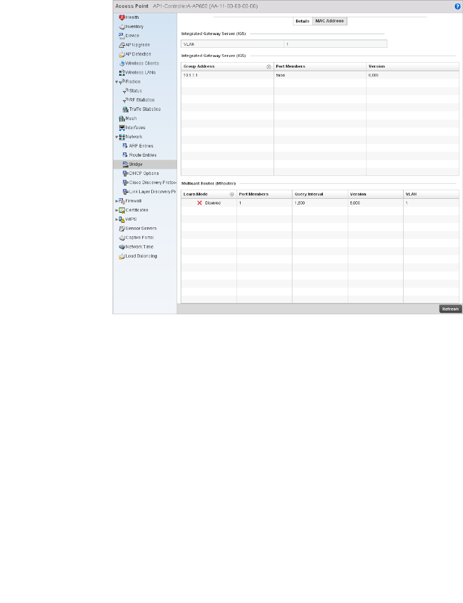
Brocade Mobility RFS4000, RFS6000, and RFS7000 System Reference Guide 731
53-1002620-01
14
FIGURE 485 Access Point Network Bridge Details screen
4. The Integrated Gateway Server (IGS) table displays the following:
5. The Multicast Router (MRouter) table describes the following:
VLAN Displays the VLAN where the multicast transmission is conducted.
Group Address Displays the Multicast Group ID supporting the statistics displayed. This group ID is the
multicast address hosts are listening to.
Port Members Displays the ports on which multicast clients have been discovered by the wireless
controller.
Displays the interface name. For example, ge1, radio 1, etc.
Version Displays the IGMP version in use.
Learn Mode Displays the learning mode used by the router. Either Static or PIM-DVMRP.
Port Members Displays the ports on which multicast clients have been discovered by the wireless
controller.
Displays the interface name. For example, ge1 or radio 1.
Query Interval Displays the periodic IGMP query interval value.
Version Displays the IGMP version in use.
VLAN Displays the VLAN on which the multicast transmission is being done.
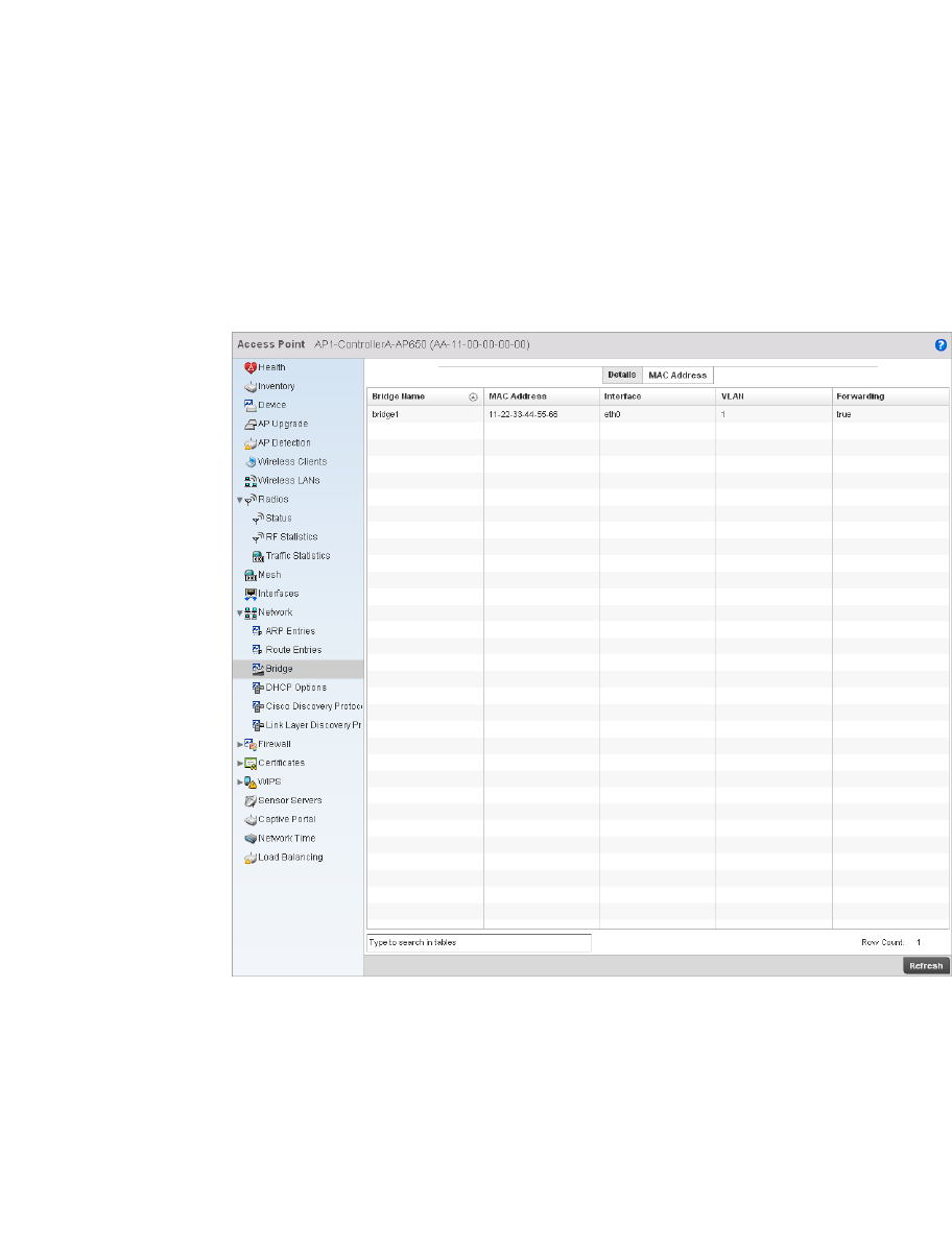
732 Brocade Mobility RFS4000, RFS6000, and RFS7000 System Reference Guide
53-1002620-01
14
MAC Address
To view the Bridge MAC address details:
1. Select the Statistics menu from the Web UI.
2. Select an Access Point node from the left navigation pane.
3. Select Network > Bridge from the left-hand side of the UI, and select the MAC Address tab.
FIGURE 486 Access Point Network Bridge MAC Address screen
4. The MAC Address tab displays the following:
DHCP Options
Network
Bridge Name Displays the name of the network bridge.
MAC Address Displays the MAC address of the bridge selected.
Interface Displays the interface where the bridge transferred packets.
VLAN Displays the VLAN the bridge belongs to.
Forwarding Displays whether the bridge is forwarding packets. A bridge can only forward packets.
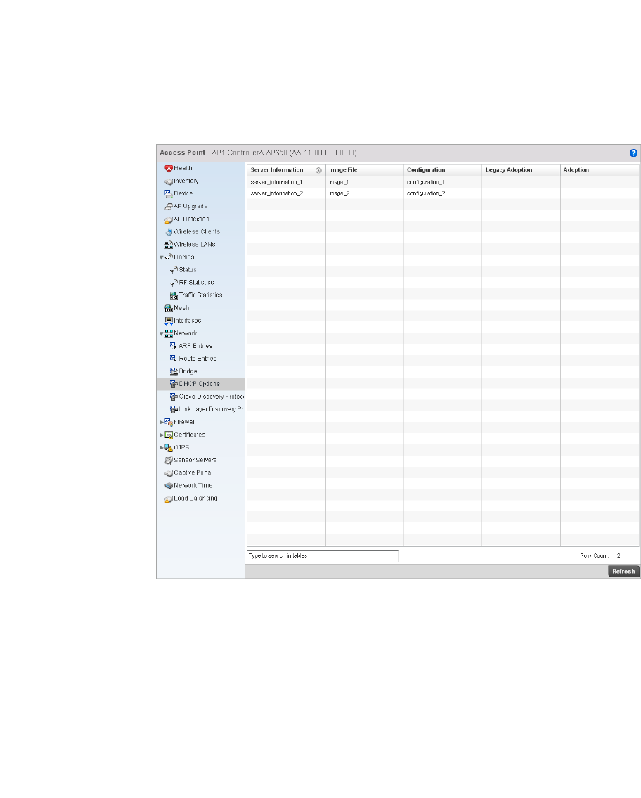
Brocade Mobility RFS4000, RFS6000, and RFS7000 System Reference Guide 733
53-1002620-01
14
The controller contains an internal Dynamic Host Configuration Protocol (DHCP) server. The DHCP
server can provide the dynamic assignment of IP addresses automatically. This is a protocol that
includes IP address allocation and delivery of host-specific configuration parameters from a DHCP
server to a host. Some of these parameters are IP address, gateway and network mask.
The DHCP Options screen provides the DHCP server name, image file on the DHCP server, and its
configuration.
To view a network’s DHCP Options:
1. Select the Statistics menu from the Web UI.
2. Select an Access Point node from the left navigation pane.
3. Select Network > DHCP Options.
FIGURE 487 Access Point Network DHCP Options screen
4. The DHCP Options screen displays the following:
Server Information Displays the IP address of the DHCP server.
Image File Displays the image file name. BOOTP or the bootstrap protocol can be used to boot
diskless clients. An image file is sent from the boot server. The image file contains the
image of the operating system the client will run. DHCP servers can be configured to
support BOOTP.
Configuration Displays the name of the configuration file on the DHCP server.
Cluster
Configuration
Displays the name of the cluster configuration file on the DHCP server if the server is a
part of a cluster.
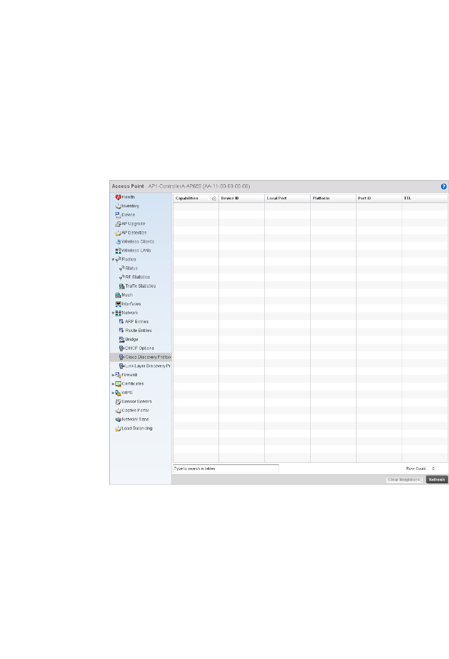
734 Brocade Mobility RFS4000, RFS6000, and RFS7000 System Reference Guide
53-1002620-01
14
Cisco Discovery Protocol
Network
To view a network’s CDP Statistics:
1. Select the Statistics menu from the Web UI.
2. Select an Access Point node from the left navigation pane.
3. Select Network > Cisco Discovery Protocol.
FIGURE 488 Access Point Network Cisco Discovery Protocol screen
4. The Cisco Discovery Protocol screen displays the following:
Capabilities Displays the capabilities code for the device either Router, Trans Bridge, Source Route
Bridge, Switch, Host, IGMP or Repeater.
Device ID Displays the configured device ID or name for each device in the table.
Local Port Displays the local port name for each CDP capable device.
Platform Displays the model number of the CDP capable device.
Port ID Displays the identifier for the local port.
TTL Displays the time to live for each CDP connection.
Clear Neighbors Click Clear Neighbors to remove all known CDP neighbors from the table.
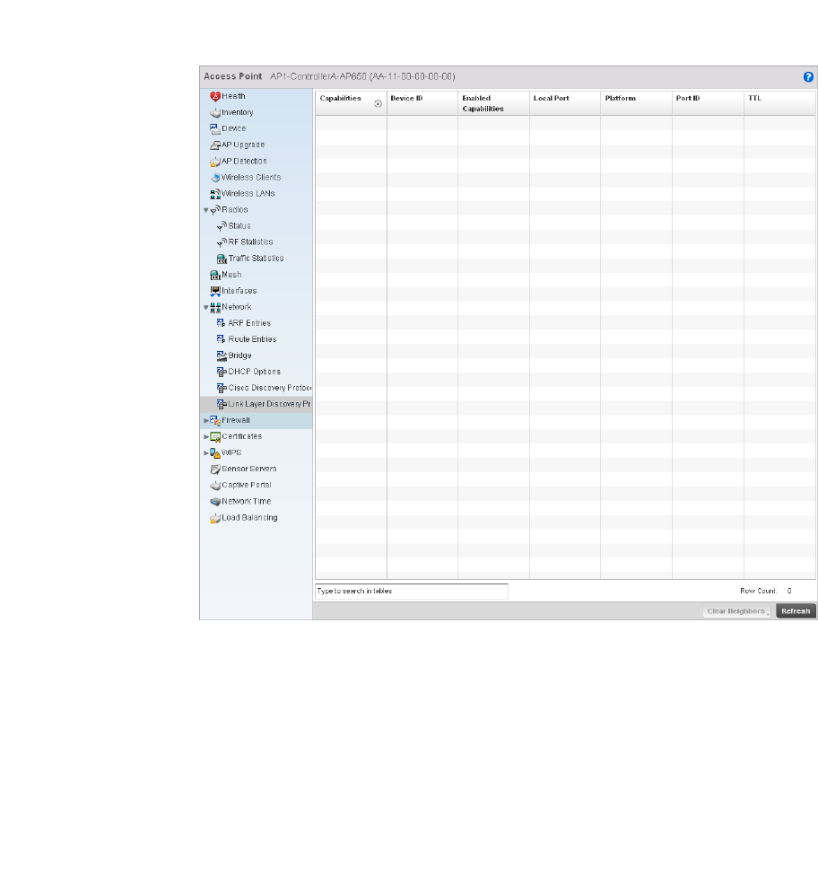
Brocade Mobility RFS4000, RFS6000, and RFS7000 System Reference Guide 735
53-1002620-01
14
Link Layer Discovery Protocol
Network
To view a network’s Link Layer Discovery Protocol statistics:
1. Select the Statistics menu from the Web UI.
2. Select an Access Point node from the left navigation pane.
3. Select Network > Link Layer Discovery Protocol.
FIGURE 489 Access Point Link Layer Discoveryscreen
4. The Link Layer Discovery Protocol screen displays the following:
Capabilities Displays the capabilities code for the device either Router, Trans Bridge, Source Route
Bridge, Switch, Host, IGMP or Repeater.
Device ID Displays the configured device ID or name for each device in the table.
Enabled
Capabilities
Displays which of the device capabilities are currently enabled.
Local Port Displays the local port name for each LLDP capable device.
Platform Displays the model number of the LLDP capable device.

736 Brocade Mobility RFS4000, RFS6000, and RFS7000 System Reference Guide
53-1002620-01
14
Firewall
Access Point Statistics
A firewall blocks unauthorized access while permitting authorized communications. It’s a device or
set of devices configured to permit or deny computer applications based on a set of rules.
This screen is partitioned into the following:
•Packet Flows
•Denial of Service
•IP Firewall Rules
•MAC Firewall Rules
•NAT Translations
•DHCP Snooping
Packet Flows
Firewall
The Packet Flows screen displays a bar graph for the different packet types flowed through the
Access Point. Use this information to assess the traffic patterns supported by the Access Point.
The Total Active Flows graph displays the total number of flows supported. Other bar graphs display
for each individual packet type.
To view the packet flows statistics:
1. Select the Statistics menu from the Web UI.
2. Select an Access Point node from the left navigation pane.
3. Select Firewall > Packet Flows.
Port ID Displays the identifier for the local port.
TTL Displays the time to live for each LLDP connection.
Clear Neighbors Click Clear Neighbors to remove all known LLDP neighbors from the table.
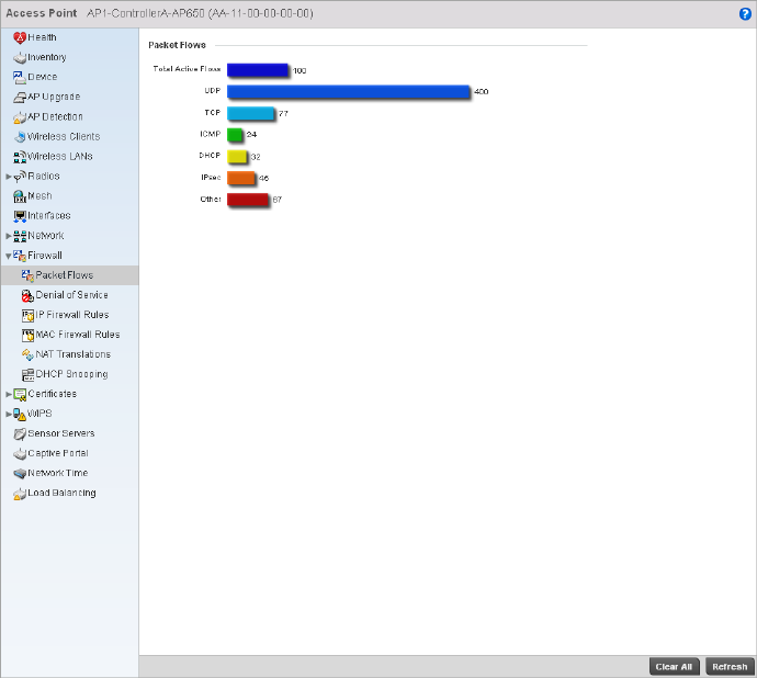
Brocade Mobility RFS4000, RFS6000, and RFS7000 System Reference Guide 737
53-1002620-01
14
FIGURE 490 Access Point Firewall Statistics Packet Flow screen
Denial of Service
Firewall
A denial-of-service attack (DoS attack) or distributed denial-of-service attack is an attempt to make
a computer resource unavailable to its intended users. Although the means to carry out a DoS
attack may vary, it generally consists of concerted efforts to prevent an Internet site or service from
functioning efficiently.
One common method involves saturating the target’s machine with external communications
requests, so it cannot respond to legitimate traffic or responds so slowly as to be rendered
effectively unavailable. DoS attacks are implemented by either forcing the targeted computer(s) to
reset, or consume its resources so it can’t provide its intended service.
The DoS screen displays the types of attack, number of times it occurred and the time of last
occurrence.
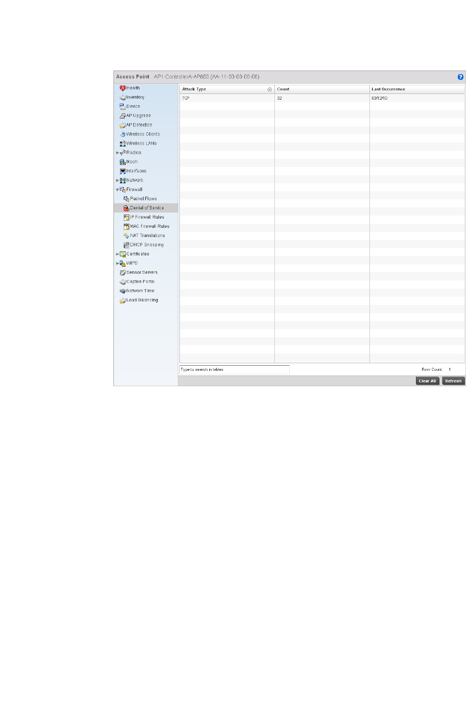
738 Brocade Mobility RFS4000, RFS6000, and RFS7000 System Reference Guide
53-1002620-01
14
FIGURE 491 Access Point Firewall Denial of Service screen
The Denial of Service screen displays the following:
IP Firewall Rules
Firewall
Create firewall rules to permit a computer to send traffic to, or receive traffic from, programs,
system services, computers or users. Firewall rules can be created to take one of the three actions
listed below that match the rule’s criteria:
•Allow a connection
•Allow a connection only if it is secured through the use of Internet Protocol security
•Block a connection
Rules can be created for either inbound or outbound traffic.
To view the IP firewall rules:
1. Select the Statistics menu from the Web UI.
2. Select an Access Point node from the left navigation pane.
Attack Type Displays the Denial of Service (DoS) attack type.
Count Displays the number of times the firewall has observed each DoS attack.
Last Occurrence Displays the amount of time since the DoS attack has been observed by the firewall.
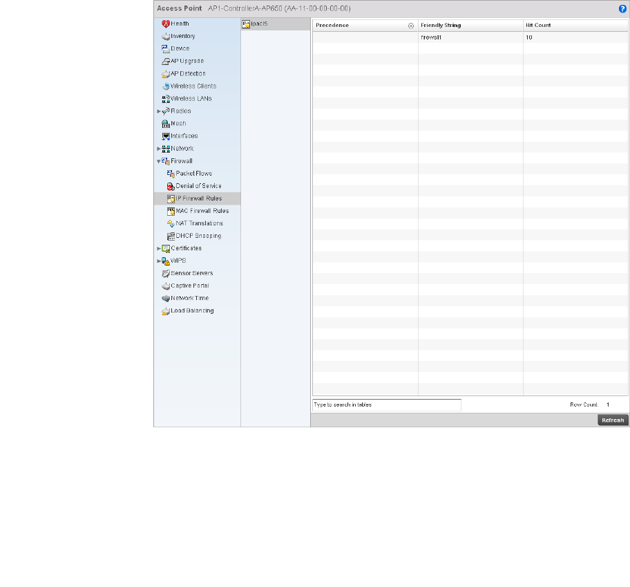
Brocade Mobility RFS4000, RFS6000, and RFS7000 System Reference Guide 739
53-1002620-01
14
3. Select Firewall > IP Firewall Rules from the left-hand side of the UI.
FIGURE 492 Access Point IP Firewall Rules screen
4. The IP Firewall Rules screen displays the following:
MAC Firewall Rules
Firewall
The ability to allow or deny a system by its MAC address ensures malicious or unwanted users are
unable to bypass security filters. Firewall rules can be created to support one of the three actions
listed below that match the rule’s criteria:
•Allow a connection
•Allow a connection only if it is secured through the MAC firewall security
•Block a connection
To view the MAC Firewall Rules:
1. Select the Statistics menu from the Web UI.
Precedence Displays the precedence applied to packets. The rules within an Access Control Entries
(ACL) are based on precedence. Every rule has a unique precedence value between 1
and 5000. You cannot add two rules with the same precedence.
Friendly String This is a string that provides more information as to the contents of the rule.
Hit Count Displays the number of times each WLAN ACL has been triggered.
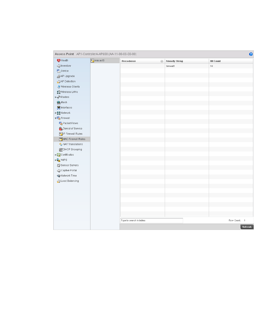
740 Brocade Mobility RFS4000, RFS6000, and RFS7000 System Reference Guide
53-1002620-01
14
2. Select an Access Point node from the left navigation pane.
3. Select Firewall > MAC Firewall Rules from the left-hand side of the UI.
FIGURE 493 Access Point MAC Firewall Rules screen
4. The MAC Firewall Rules screen provides the following information:
NAT Translations
Firewall
1. Select the Statistics menu from the Web UI.
2. Select an Access Point node from the left navigation pane.
Precedence Displays the precedence value, which are applied to packets. The rules within an
Access Control Entries (ACL) list are based on their precedence values. Every rule has a
unique precedence value between 1 and 5000. You cannot add two rules with the
same precedence.
Friendly String Displays a string providing additional information on rule contents.
Hit Count Displays the number of times each WLAN ACL has been triggered.
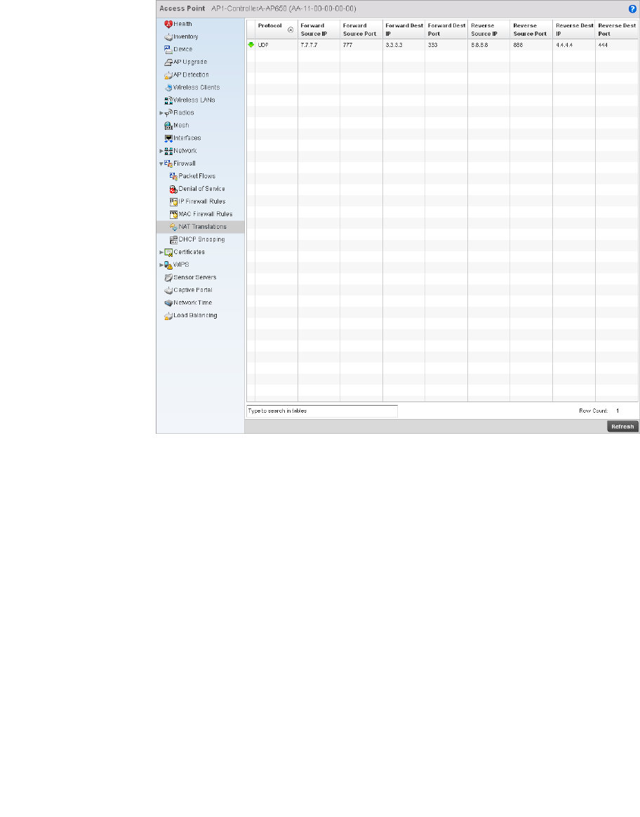
Brocade Mobility RFS4000, RFS6000, and RFS7000 System Reference Guide 741
53-1002620-01
14
3. Select Firewall > NAT Translations.
FIGURE 494 Access Point Firewall NAT Translation screen
4. The NAT Translations screen displays the following:
Protocol Displays the IP protocol type, either UDP or TCP.
Forward Source IP Displays the internal network IP address for forward facing NAT translations in the
Forward Source IP column.
Forward Source
Port
Displays the internal network port for forward facing NAT translations in the Forward
Source Port column.
Forward Dest IP Displays the external network destination IP address for forward facing NAT
translations in the Forward Dest IP column.
Forward Dest Port Displays the external network destination port for forward facing NAT translations in the
Forward Dest Port column.
Reverse Source IP Displays the internal network IP address for reverse facing NAT translations in the
Reverse Source IP column.
Reverse Source
Port
Displays the internal network port for reverse facing NAT translations in the Reverse
Source Port column.
Reverse Dest IP Displays the external network destination IP address for reverse facing NAT
translations in the Reverse Dest IP column.
Reverse Dest Port Displays the external network destination port for reverse facing NAT translations in the
Reverse Dest Port column.
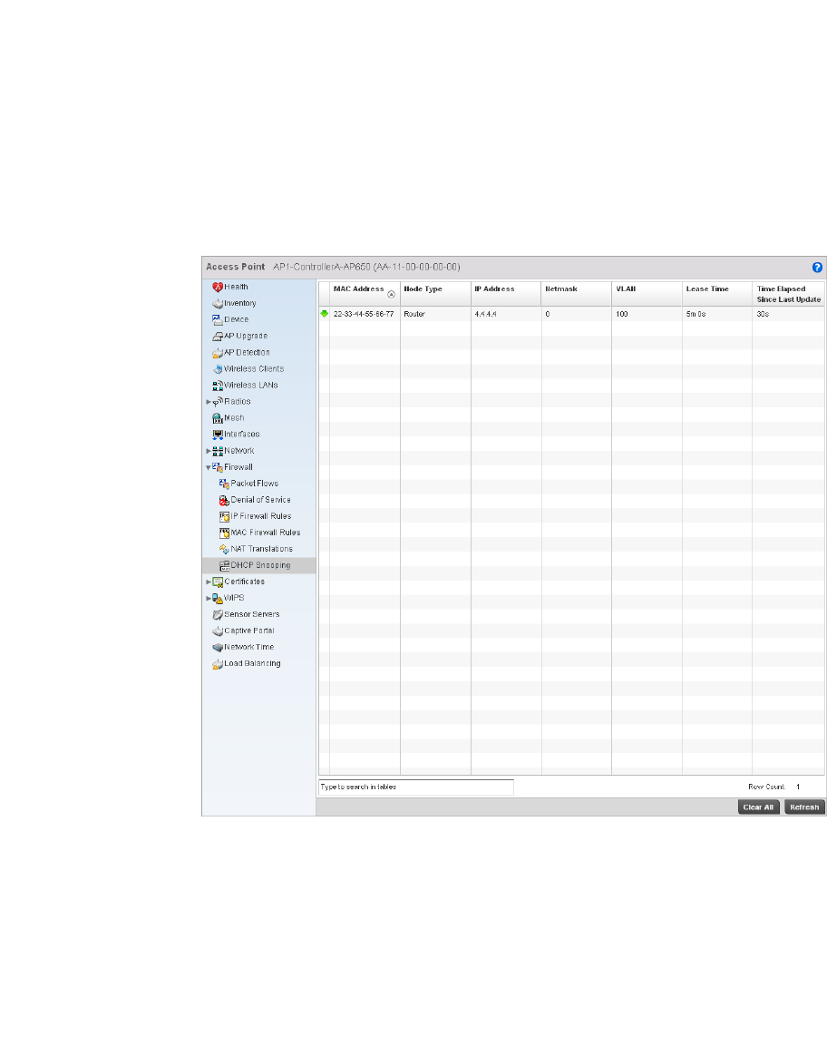
742 Brocade Mobility RFS4000, RFS6000, and RFS7000 System Reference Guide
53-1002620-01
14
DHCP Snooping
Firewall
When DHCP servers are allocating IP addresses to clients on the LAN, DHCP snooping can be
configured on LAN controllers to allow only clients with specific IP or MAC addresses.
FIGURE 495 Access Point Firewall DHCP Snooping screen
The DHCP Snooping screen displays the following:
MAC Address Displays the MAC address of the client.
Node Type Displays the NetBios node with the IP pool from which IP addresses can be issued to
client requests on this interface.
IP Address Displays the IP address used for DHCP discovery, and requests between the DHCP
server and DHCP clients.
Netmask Displays the subnet mask used for DHCP discovery, and requests between the DHCP
server and DHCP clients.

Brocade Mobility RFS4000, RFS6000, and RFS7000 System Reference Guide 743
53-1002620-01
14
VPN
Access Point Statistics
This screen is partitioned into the following:
•IKESA
•IPSec
IKESA
VPN
Each certificate is digitally signed by a trustpoint. The trustpoint signing the certificate can be a
certificate authority, corporate or individual. A trustpoint represents a CA/identity pair containing
the identity of the CA, CA-specific configuration parameters and an association with an enrolled
identity certificate.
1. Select the Statistics menu from the Web UI.
2. Select System from the navigation pane (on the left-hand side of the screen), expand the
default node and select an access point for statistical observation.
3. Select Certificates and expand the menu to reveal its sub menu items.
4. Select Trustpoints.
VLAN Displays the controller interface used for the newly created DHCP configuration.
Lease Time When a DHCP server allocates an address for a DHCP client, the client is assigned a
lease (which expires after a designated interval defined by the administrator). The
lease time is the time an IP address is reserved for re-connection after its last use.
Using very short leases, DHCP can dynamically reconfigure networks in which there are
more computers than there are available IP addresses. This is useful, for example, in
education and customer environments where client users change frequently. Use
longer leases if there are fewer users.
Time Elapsed Since
Last Update
Displays the time the server was last updated.
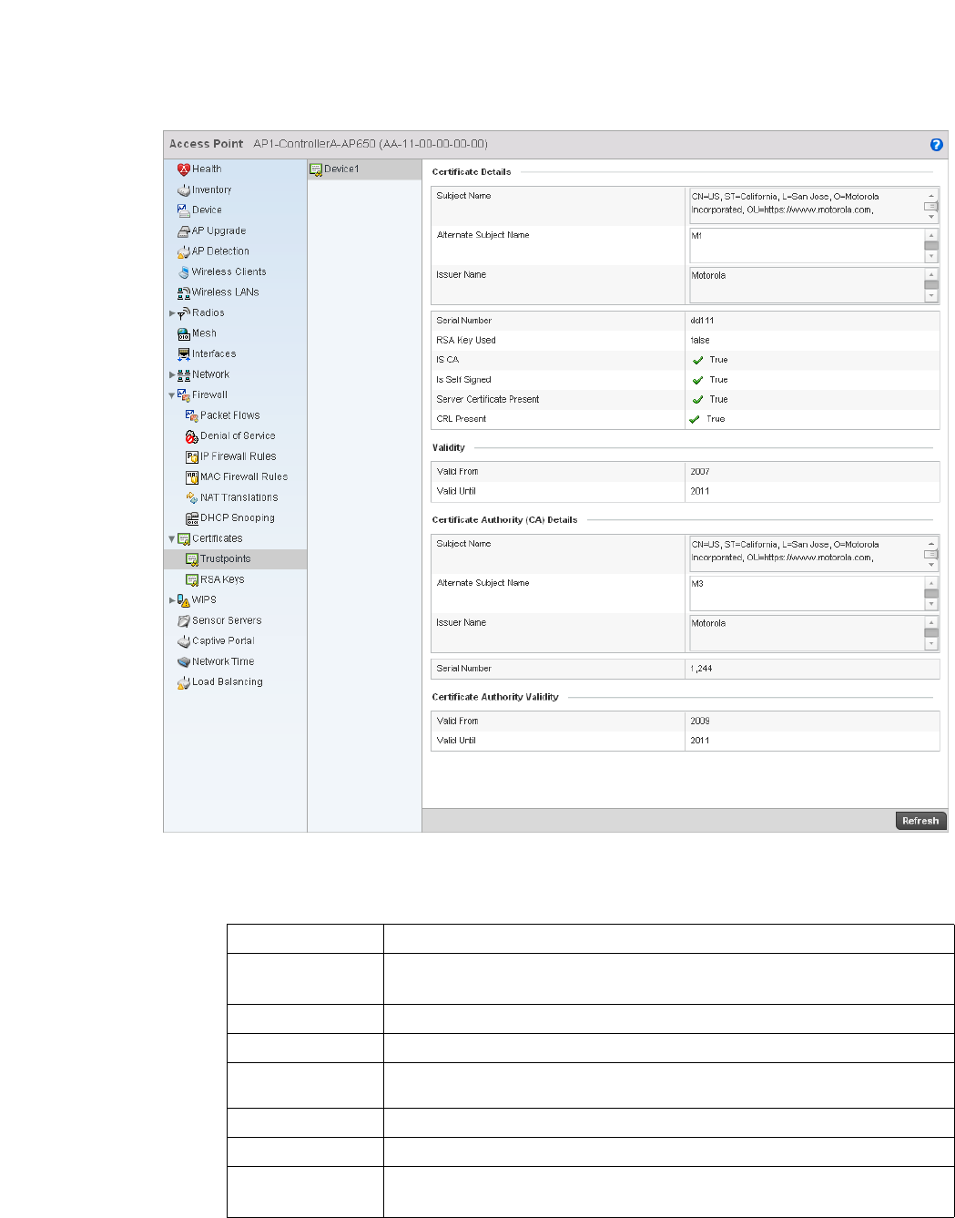
744 Brocade Mobility RFS4000, RFS6000, and RFS7000 System Reference Guide
53-1002620-01
14
FIGURE 496 Access Point Certificate - Trustpoint screen
5. The Certificate Details field displays the following:
Subject Name Lists details about the entity to which the certificate is issued.
Alternate Subject
Name
Displays alternative details to the information specified under the Subject Name field.
Issuer Name Displays the name of the organization issuing the certificate.
Serial Number The unique serial number of the certificate issued.
RSA Key Used Displays the name of the key pair generated separately, or automatically when
selecting a certificate.
IS CA Indicates if this certificate is a authority certificate.
Is Self Signed Displays if the certificate is self-signed. True indicates the certificate is self-signed.
Server Certificate
Present
Displays if the server certificate is present. True indicates the certificate is present.

Brocade Mobility RFS4000, RFS6000, and RFS7000 System Reference Guide 745
53-1002620-01
14
6. Refer to the Validity field to assess the certificate duration beginning and end dates.
7. R ev i ew the Certificate Authority (CA) Details and Validity information. to assess the subject and
certificate duration periods.
8. Periodically select the Refresh button to update the screen’s statistics counters to their latest
values.
IPSec
VPN
Rivest, Shamir, and Adleman (RSA) is an algorithm for public key cryptography. It’s the first
algorithm known to be suitable for signing, as well as encryption.
The RSA Keys screen displays a list of RSA keys installed in the selected access point. RSA Keys are
generally used for establishing a SSH session, and are a part of the certificate set used by RADIUS,
VPN and HTTPS.
To view the RSA Key details:
1. Select the Statistics menu from the Web UI.
2. Select System from the navigation pane (on the left-hand side of the screen), expand the
default node and select an access point for statistical observation.
3. Select Certificates and expand the menu to reveal its sub menu items.
4. Select RSA Keys.
CRL Present Displays whether this functionality is present or not. The Certificate Revocation List
(CRL) is a method for using a public key infrastructure for maintaining access to
network servers.
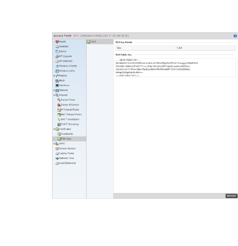
746 Brocade Mobility RFS4000, RFS6000, and RFS7000 System Reference Guide
53-1002620-01
14
FIGURE 497 Access Point Certificates - RSA Key screen
5. The RSA Key Details field displays the size (in bits) of the desired key. If not specified, a default
key size of 1024 is used.
6. The RSA Public Key field lists the public key used for encrypting messages.
7. Periodically select the Refresh button to update the screen’s statistics counters to their latest
values.
Certificates
Access Point Statistics
The Secure Socket Layer (SSL) secures transactions between Web servers and browsers. SSL uses
a third-party certificate authority to identify one (or both) ends of a transaction. A browser checks
the server issued certificate before establishing a connection.
This screen is partitioned into the following:
•Trustpoints
•RSA Keys
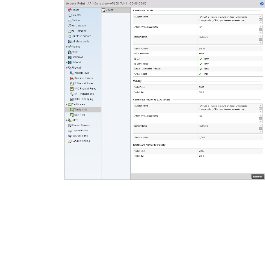
Brocade Mobility RFS4000, RFS6000, and RFS7000 System Reference Guide 747
53-1002620-01
14
Trustpoints
Certificates
Each certificate is digitally signed by a trustpoint. The trustpoint signing the certificate can be a
certificate authority, corporation or individual. A trustpoint represents a CA/identity pair containing
the identity of the CA, CA-specific configuration parameters and an association with an enrolled
identity certificate.
FIGURE 498 Access Point Certificate Trustpoint screen
The Certificate Details field displays the following:
Subject Name Lists details about the entity to which the certificate is issued.
Alternate Subject
Name
Displays alternative details to the information specified under the Subject Name field.
Issuer Name Displays the name of the organization issuing the certificate.
Serial Number The unique serial number of the certificate issued.
RSA Key Used Displays the name of the key pair generated separately, or automatically when
selecting a certificate.
IS CA States whether this certificate is a authority certificate.

748 Brocade Mobility RFS4000, RFS6000, and RFS7000 System Reference Guide
53-1002620-01
14
RSA Keys
Certificates
Rivest, Shamir, and Adleman (RSA) is an algorithm for public key cryptography. It’s the first
algorithm known to be suitable for signing, as well as encryption.
The RSA Keys screen displays a list of RSA keys installed in the selected wireless controller. RSA
Keys are generally used for establishing a SSH session, and are a part of the certificate set used by
RADIUS, VPN and HTTPS.
To view the RSA Key details:
1. Select the Statistics menu from the Web UI.
2. Select an Access Point node from the left navigation pane.
3. Select Certificates > RSA Keys from the left-hand side of the UI.
Is Self Signed States whether the certificate is self-signed. True indicates the certificate is
self-signed.
Server Certificate
Present
Displays if the server certificate is present. True indicates the certificate is present.
CRL Present Displays whether this functionality is present or not. The Certificate Revocation List
(CRL) uses a public key infrastructure to maintain access to network servers.
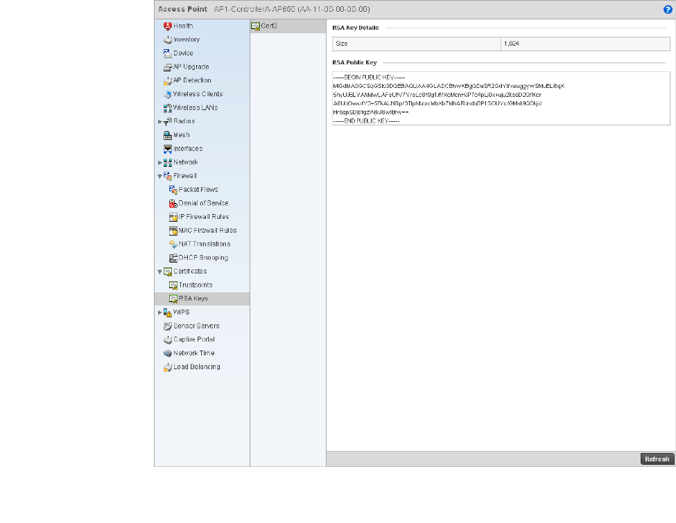
Brocade Mobility RFS4000, RFS6000, and RFS7000 System Reference Guide 749
53-1002620-01
14
FIGURE 499 Access Point Certificates RSA Key screen
4. The RSA Key Details table displays the size (in bits) of the desired key. If not specified, a default
key size of 1024 is used.
The RSA Public Key field lists the public key used for encrypting messages.
WIPS
Access Point Statistics
A Wireless Intrusion Prevention System (WIPS) monitors the radio spectrum for the presence of
unauthorized Access Points and take measures to prevent an intrusion. Unauthorized attempts to
access the WLAN is generally accompanied by anomalous behavior as intruding clients try to find
network vulnerabilities. When the parameters exceed a configurable threshold, the controller
generates a SNMP trap and reports the results via management interfaces. Basic WIPS
functionality does not require monitoring APs, and does not perform off-channel scanning.
The WIPS screen provides details about the blacklisted clients (unauthorized access points)
intruded into the network. The details include the name of the blacklisted client, the time when the
client was blacklisted, the total time the client remained in the network, etc. The screen also
provides WIPS event details.
The WIPS screen is partitioned into:
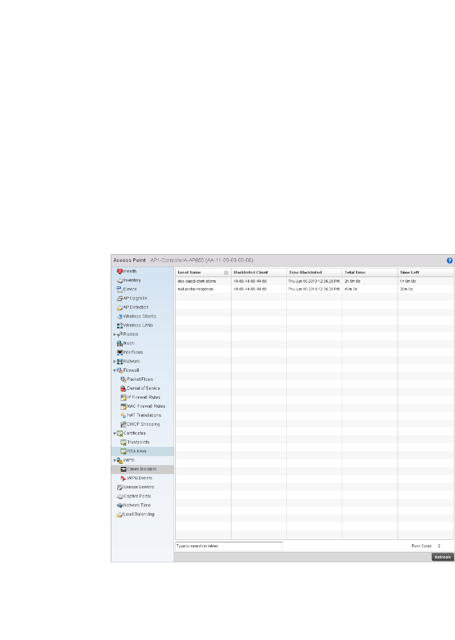
750 Brocade Mobility RFS4000, RFS6000, and RFS7000 System Reference Guide
53-1002620-01
14
•Client Blacklist
•WIPS Events
Client Blacklist
WIPS
The Client Blacklist screen displays blacklisted client data. It includes the name of the client, time
when the blacklist event occurred and the duration the blacklisted client remained in the network.
To view the Client Blacklist screen:
1. Select the Statistics menu from the Web UI.
2. Select an Access Point node from the left navigation pane.
3. Select WIPS > Client Blacklist from the left-hand side of the UI.
FIGURE 500 Access Point WIPS Client Blacklist screen
4. The Client Blacklist screen provides the following information:
Event Name Displays the name of the wireless intrusion event.
Blacklisted Client Displays the MAC address of the intruding unauthorized access point.
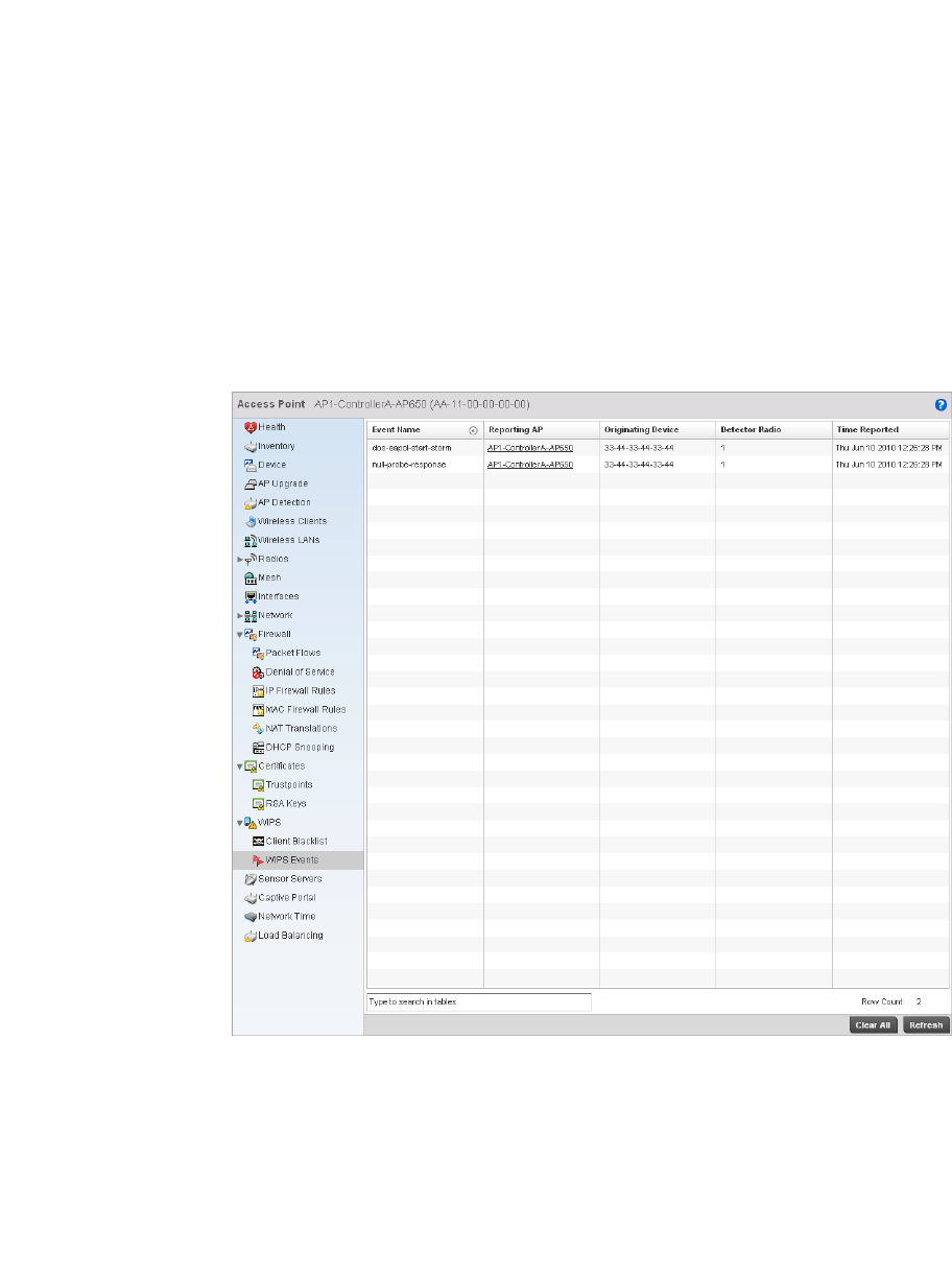
Brocade Mobility RFS4000, RFS6000, and RFS7000 System Reference Guide 751
53-1002620-01
14
WIPS Events
WIPS
The WIPS Events screen details the wireless intrusion.
1. Select the Statistics menu from the Web UI.
2. Select an Access Point node from the left navigation pane.
3. Select WIPS > WIPS Events from the left-hand side of the UI.
FIGURE 501 Access Point WIPS Events screen
4. The WIPS Events screen provides the following:
Time Blacklisted Displays the time when this client was blacklisted.
Total Time Displays the total time the unsanctioned AP remained in the WLAN.
Time Left Displays the remaining blacklist duration time. After this time elapses, the client is
removed from the blacklist.
Event Name Displays the name of the wireless intrusion event.
Reporting AP Displays the MAC address of the AP reporting this intrusion.
Originating Device Displays the MAC address of the intruding device.
Time Reported Displays the time when the intrusion was detected.
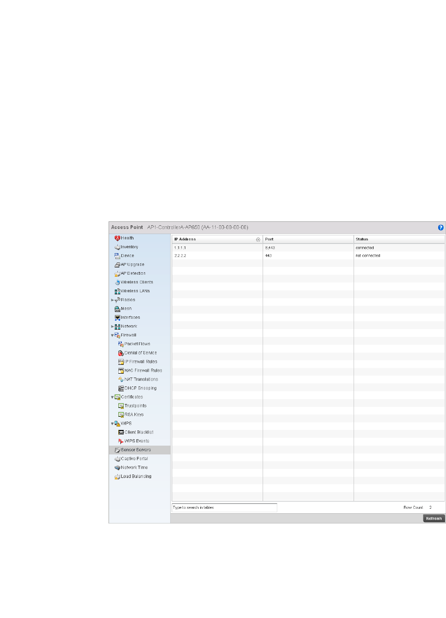
752 Brocade Mobility RFS4000, RFS6000, and RFS7000 System Reference Guide
53-1002620-01
14
Sensor Servers
Access Point Statistics
Sensor servers allow an administrator to monitor and download data from multiple sensors and
remote locations using Ethernet TCP/IP or serial communications. Repeaters are available to
extend transmission range and combine sensors with various frequencies on the same receiver.
To view the sensor server statistics of an AP:
1. Select the Statistics menu from the Web UI.
2. Select an Access Point node from the left navigation pane.
3. Select Sensor Servers from the left-hand side of the UI.
FIGURE 502 Access Point Sensor Servers screen
4. The Sensor Servers screen displays the following:
Captive Portal
Access Point Statistics
IP Address Displays the IP address of the sensor server.
Port Displays the port on which this server is listening.
Status Displays whether the server is UP or DOWN.
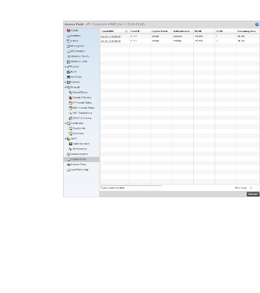
Brocade Mobility RFS4000, RFS6000, and RFS7000 System Reference Guide 753
53-1002620-01
14
A captive portal forces a HTTP client to use a special Web page for authentication before using the
Internet. A captive portal turns a Web browser into a client authenticator. This is done by
intercepting packets regardless of the address or port, until the user opens a browser and tries to
access the Internet. At that time, the browser is redirected to a Web page.
To view the captive portal statistics of an access point:
1. Select the Statistics menu from the Web UI.
2. Select an Access Point node from the left navigation pane.
3. Select Captive Portal from the left-hand side of the UI.
FIGURE 503 Access Point Captive Portal screen
4. The Captive Portal screen supports the following:
Client MAC Displays the client’s MAC address.
Client IP Displays the client’s IP address.
Captive Portal Displays the IP address of the captive portal page.
Authentication Displays the authentication status of the wireless client.
WLAN Displays the name of the requesting client’s WLAN.
VLAN Displays the name of the requesting client’s VLAN.
Remaining Time Displays the time after which the client is disconnected from the Internet.
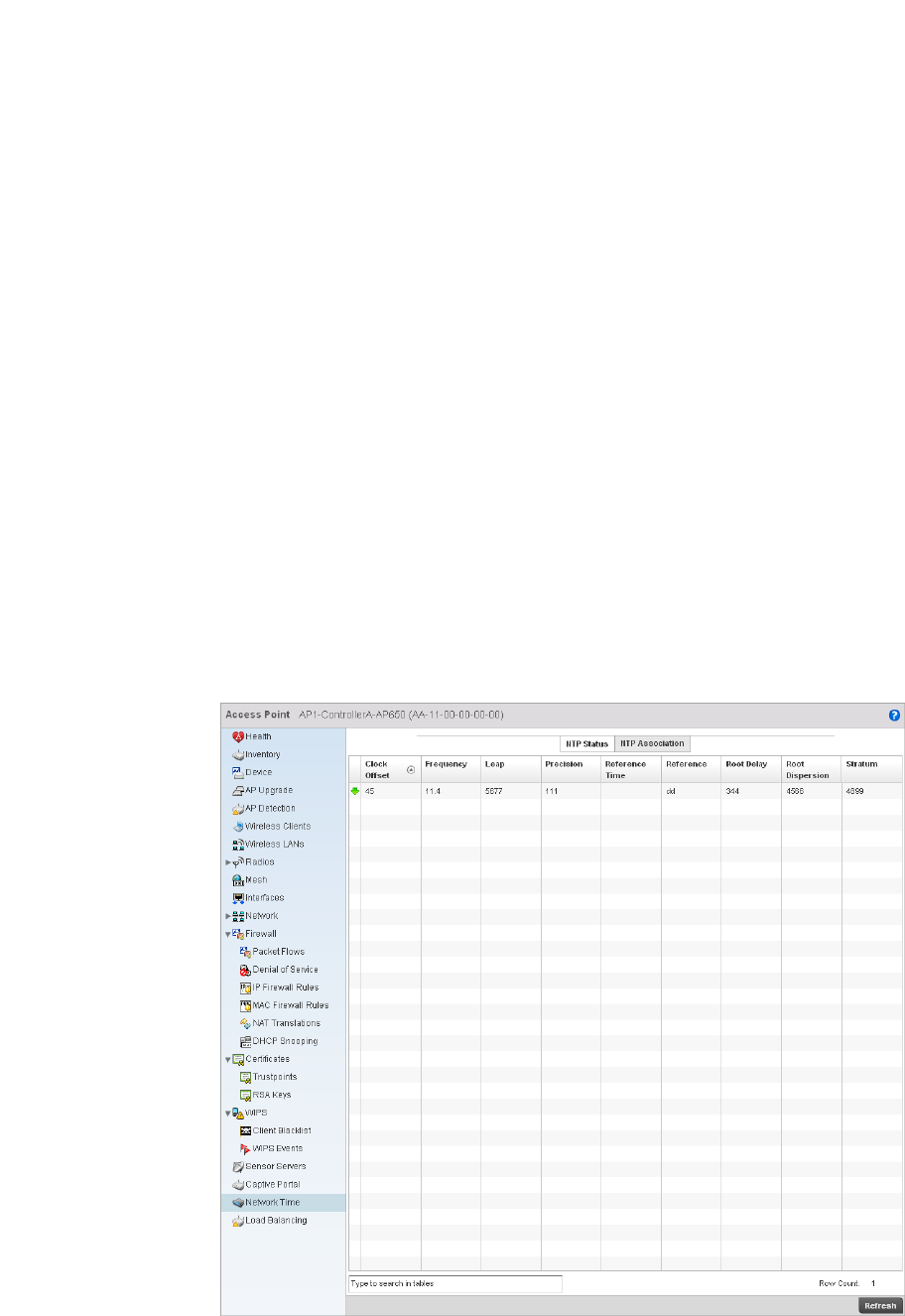
754 Brocade Mobility RFS4000, RFS6000, and RFS7000 System Reference Guide
53-1002620-01
14
Network Time
System Statistics
Network Time Protocol (NTP) is central to networks that rely on their wireless controller to supply
system time. Without NTP, controller time is unpredictable, which can result in data loss, failed
processes, and compromised security. With network speed, memory, and capability increasing at
an exponential rate, the accuracy, precision, and synchronization of network time is essential in a
controller-managed enterprise network. The wireless controller can use a dedicated server to
supply system time. The controller can also use several forms of NTP messaging to sync system
time with authenticated network traffic.
Viewing NTP Status
Network Time
The NTP Status screen displays performance (status) information relative to the AP’s current NTP
association. Verify the controller’s NTP status to assess the controller’s current NTP resource.
To view the NTP status of a managed network:
1. Select the Statistics menu from the Web UI.
2. Select an Access Point node from the left navigation pane.
3. Select Network Time > NTP Status from the left-hand side of the UI.
FIGURE 504 System NTP screen

Brocade Mobility RFS4000, RFS6000, and RFS7000 System Reference Guide 755
53-1002620-01
14
4. Refer to the NTP Status table to review the accuracy and performance of the controller’s
synchronization with an NTP server.
Viewing NTP Associations
Network Time
The interaction between the controller and an SNTP server constitutes an association. SNTP
associations can be either peer associations (the controller synchronizes to another system or
allows another system to synchronize to it), or a server associations (only the controller
synchronizes to the SNTP resource, not the other way around).
To view the NTP associations:
1. Select the Statistics menu from the Web UI.
2. Select an Access Point node from the left navigation pane.
3. Select Network > NTP Association from the left-hand side of the UI.
Clock Offset Displays the time differential between the controller time and the NTP resource.
Frequency An SNTP server clock’s skew (difference) for the controller.
Leap Indicates if a second is added or subtracted to SNTP packet transmissions, or if
transmissions are synchronized.
Precision Displays the precision of the controller’s time clock (in Hz). The values that normally
appear in this field range from -6 for mains-frequency clocks to -20 for microsecond
clocks.
Reference Time Displays the time stamp the local clock was last set or corrected.
Reference Displays the address of the time source the controller is synchronized to.
Root Delay The total round-trip delay in seconds. This variable can take on both positive and
negative values, depending on relative time and frequency offsets. The values that
normally appear in this field range from negative values (a few milliseconds) to positive
values (several hundred milliseconds).
Root Dispersion The difference between the time on the root NTP server and it’s reference clock. The
reference clock is the clock used by the NTP server to set its own clock.
Status Stratum Displays how many hops the controller is from its current NTP time source.
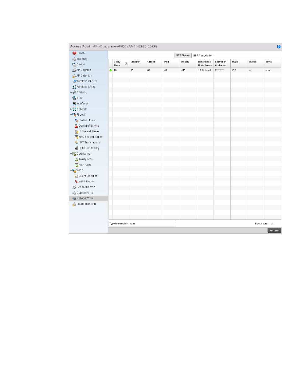
756 Brocade Mobility RFS4000, RFS6000, and RFS7000 System Reference Guide
53-1002620-01
14
FIGURE 505 AP Network Time screen
4. The NTP Associations screen provides the controller’s current NTP associations.
This screen provides the following:
Delay Time Displays the round-trip delay (in seconds) for SNTP broadcasts between the SNTP server
and the wireless controller.
Dispersion Displays the time difference between the peer NTP server and the onboard wireless
controller clock.
Offset Displays the calculated offset between the wireless controller and the SNTP server. The
controller adjusts its clock to match the server’s time value. The offset gravitates
towards zero overtime, but never completely reduces its offset to zero.
Poll Displays the maximum interval between successive messages (in seconds) to the
nearest power of two.
Reach Displays the status of the last eight SNTP messages. If an SNTP packet is lost, the lost
packet is tracked over the next eight SNTP messages.
Reference IP Address Displays the address of the time source the wireless controller is synchronized to.
Server IP Address Displays the numerical IP address of the SNTP resource (server) providing SNTP updates
to the wireless controller.
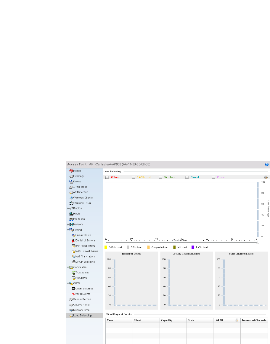
Brocade Mobility RFS4000, RFS6000, and RFS7000 System Reference Guide 757
53-1002620-01
14
Load Balancing
Access Point Statistics
To view the Load Balancing statistics of an access point:
1. Select the Statistics menu from the Web UI.
2. Select an Access Point node from the left navigation pane.
3. Select Load Balancing from the left-hand side of the UI.
FIGURE 506 Access Point Load Balancing screen
State Displays the NTP association status. The state can be one of the following:
•Synced – Indicates the wireless controller is synchronized to this NTP server.
•Unsynced – Indicates the wireless controller has chosen this master for
synchronization. However, the master itself is not yet synchronized to UTC.
•Selected – Indicates this NTP master server will be considered the next time the
wireless controller chooses a master to synchronize with.
•Candidate – Indicates this NTP master server may be considered for selection the
next time the wireless controller chooses a NTP master server.
•Configured – Indicates this NTP server is a configured server.
Stratum Displays the NTP peer’s stratum level.
When Displays the timestamp of the last NTP packet received from the NTP peer.

758 Brocade Mobility RFS4000, RFS6000, and RFS7000 System Reference Guide
53-1002620-01
14
4. The Load Balancing screen supports the following:
Wireless Controller Statistics
The Wireless Controller screen displays information about peer controllers. As members of a
cluster, a controller manages its own network and is ready to assume the load of an offline peer.
The Wireless Controller screen displays detailed statistics which include controller health, inventory
of devices, wireless clients, adopted APs, rogue APs and WLANs. For more information, refer to the
following:
•Device Health
•Inventory
•Device
•Cluster Peers
•Adopted AP Statistics
•AP Detection
•Wireless Clients
•Wireless LANs
•Critical Resource
•Radios
•Interfaces
•Network
•DHCP Server
•Firewall
•IPsec
•Viewing Certificate Statistics
•Controller WIPS Statistics
•Advanced WIPS
•Sensor Server
•Captive Portal Statistics
Device Health
Wireless Controller Statistics
The Device Health screen displays details such as hostname, device name, RF Domain name, radio
RF quality and client RF quality.
Load Balancing In the Load Balancing section check the boxes to display any or all of the following
information in the graph below: AP Load, 2.4GHz Load, 5GHz Load, and Channel. The
graph section will display the load percentages for each of the selected variables over a
period of time which can be altered using the slider below the upper graph.
Client Request
Events
The Client Request Events displays the Time, Client name, Capability, State, WLAN and
Requested Channels for all client request events on the Access Point.
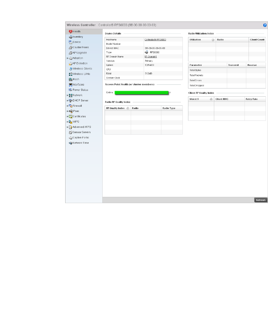
Brocade Mobility RFS4000, RFS6000, and RFS7000 System Reference Guide 759
53-1002620-01
14
To view the controller device health:
1. Select the Statistics tab from the Web UI.
2. Select a Wireless Controller node from the left navigation pane.
3. Select Health from the left-hand side of the UI.
FIGURE 507 Wireless Controller Health screen
4. The Device Details field displays the following:
Hostname Displays the hostname of the wireless controller.
Device MAC Displays the MAC address of the controller.
Type Displays the controller type (RFS7000, RFS6000 or RFS4000).
RF Domain Name Displays the controller’s domain name.
Version Displays the version of the image running on the controller.
Uptime Displays the cumulative time since the controller was last rebooted or lost power.
CPU Displays the processor name.
RAM Displays the CPU memory in use.
System Clock Displays the system clock information.

760 Brocade Mobility RFS4000, RFS6000, and RFS7000 System Reference Guide
53-1002620-01
14
5. The Access Point Health (w/ cluster members) field displays a bar chart showing how many
Access Points are online and how many are offline. These are APs directly managed by the
wireless controller. This data does not include Access Points associated to other controllers in
the same cluster.
6. The Radio RF Quality Index field displays RF quality (overall effectiveness of the RF
environment). Use this table to assess radio performance for improvement ideas.
The RF Quality Index field displays the following:
7. T he Radio Utilization Index field displays the following:
8. The Client RF Quality Index field displays the RF quality of the clients. Use this table to
troubleshoot radios not optimally performing:
Inventory
Wireless Controller Statistics
The inventory statistics screen displays device types, radio types and wireless client on this
controller. To view the controller inventory:
1. Select the Statistics tab from the Web UI.
2. Select a Wireless Controller node from the left navigation pane.
3. Select Inventory from the left-hand side of the UI.
RF Quality Index Displays the five radios with the lowest average quality.
Radio Displays the hardware encoded MAC address of the radio.
Radio Type Displays the radio type used by this Access Point.
Utilization Displays the traffic utilization indices of access points. The traffic utilization index
measures how efficiently the traffic medium is used. It’s defined as the percentage of
the current throughput relative to the maximum relative possible throughput.
Radio Displays the hardware encoded MAC address of the radio.
Client Count Displays the number of clients associated with this Access Point.
Parameter Displays the statistics in number of packets for:
•Total Bytes - The total number of bytes that passed through the Access Point.
•Total Packets - The total number of packets that passed through the Access Point.
•Total Errors - The total error packets.
•Total Dropped - The total dropped packets.
Transmit Displays the total number of packets transmitted by the radio.
Receive Displays the total number of packets received by the radio.
Worst 5 Displays the five radios having the lowest quality indices.
Client MAC Displays the MAC address of the client.
Retry Rate Displays the retry rate.
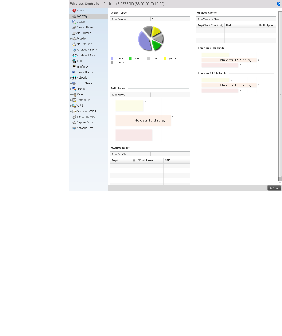
Brocade Mobility RFS4000, RFS6000, and RFS7000 System Reference Guide 761
53-1002620-01
14
FIGURE 508 Wireless Controller Inventory screen
4. The Device Types table displays the total number of devices. An exploded pie chart depicts the
distribution of the devices that are members of the managed network.
5. The Radio Types table displays the total number of radios used by the Access Points and
wireless clients.
6. The WLAN Utilization table displays the total number of WLANs. This area also displays the
following:
Top 5 Displays the traffic utilization index, which measures how efficiently the traffic medium
is supported. It’s defined as the percentage of current throughput relative to maximum
possible throughput. Traffic indices include:
•0–20 (very low utilization)
•20–40 (low utilization)
•40–60 (moderate utilization)
•60 and above (high utilization)
WLAN Name Displays the name of the WLAN.
SSID Displays the Service Set ID associated with the WLAN.
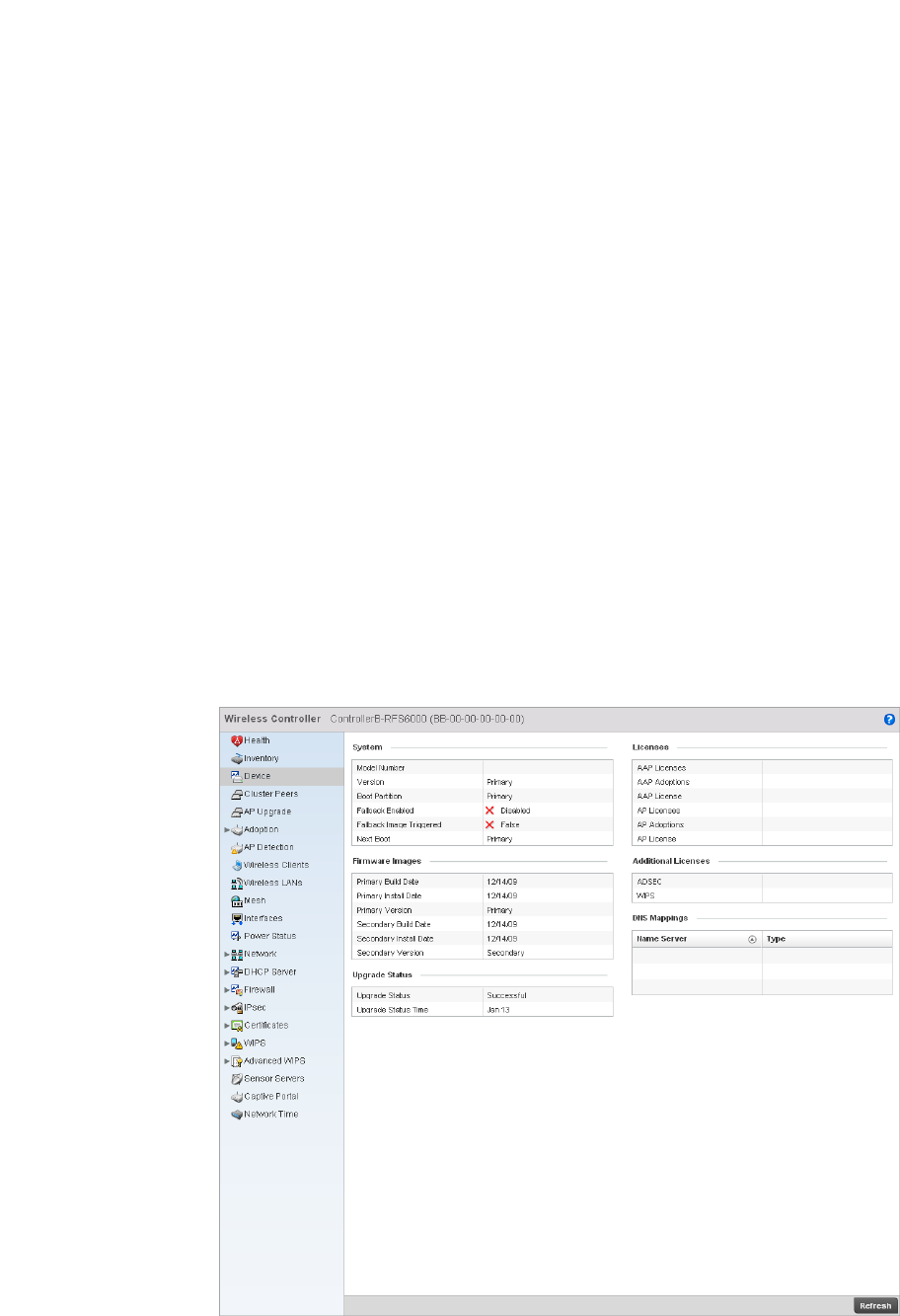
762 Brocade Mobility RFS4000, RFS6000, and RFS7000 System Reference Guide
53-1002620-01
14
7. T he Wireless Clients table displays the total number of wireless clients associated with the
controller. It displays the following:
8. The Clients on 5 GHz Channels field displays clients using radios in the 5 GHz frequency band.
9. The Clients on 2.4 GHz Channels field displays clients using radios in the 2.4 GHz frequency
band.
Device
Wireless Controller Statistics
The Device Statistics screen provides detailed information about the selected device.
To view controller device statistics:
1. Select the Statistics tab from the Web UI.
2. Select a Wireless Controller node from the left navigation pane.
3. Select Device from the left-hand side of the UI.
FIGURE 509 Wireless Controller Device screen
Top Client Count Displays clients with the highest detected traffic throughput.
Access Point Displays the client’s associated Access Point.
Radio Type Displays the radio type associated with the Access Point.

Brocade Mobility RFS4000, RFS6000, and RFS7000 System Reference Guide 763
53-1002620-01
14
4. The System field displays the following:
5. The Firmware Images field displays the following:
6. The Upgrade Status field displays firmware upgrade statistics. The table provides the following:
7. The Licenses field displays the following:
8. The Additional Licenses area displays the following information:
Model Number Displays the model number for the selected controller.
Version Displays the unique alphanumeric firmware version name for the controller firmware.
Boot Partition Displays the boot partitioning type.
Fallback Enabled Displays whether fallback is enabled. The fallback feature enables a user to store both a
legacy and new firmware version in memory. You can test the new software and use an
automatic fallback mechanism, which loads the old version, if the new version fails.
Fallback Image
Triggered
Displays whether the fallback image has been triggered. The fallback is a legacy
software image stored in device memory. This allows an user to test a new version and
revert to the older version if needed.
Next Boot Designates this version as the version used the next time the controller is booted.
Primary Build Rate Displays the build date when this version was created.
Primary Install Date Displays the date this version was installed on the controller.
Primary Version Displays the primary version string.
Secondary Build Date Displays the build date when this secondary version was created.
Secondary Install Date Displays the date this secondary version was installed on the controller.
Secondary Version Displays the secondary version string.
Upgrade Status Displays whether the image upgrade was successful.
Upgrade Status Time Displays the time of the upgrade.
AAP Licenses Displays the number of adaptive AP licenses on the controller. The maximum number
permitted varies by controller platform.
AAP Adoptions Displays the number of adaptive APs adopted by this controller.
AAP License Displays the license string of the adaptive AP.
AP Licenses Displays the number of AP licenses currently available on the controller. This value
represents the maximum number of licenses the controller can adopt.
AP Adoptions Displays the number of Access Points adopted by this controller.
AP License Displays the license string of the AP.
ADSEC Displays the number of Advanced Security licenses. This enables the Role Based firewall
and increases the number of IP Sec VPN tunnels. The maximum number of IP Sec VPN
tunnels varies by controller platform.
WIPS Displays the number of WIPS licenses.
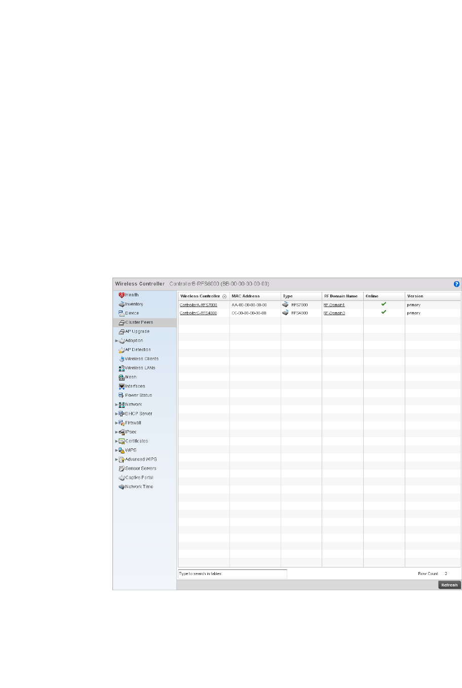
764 Brocade Mobility RFS4000, RFS6000, and RFS7000 System Reference Guide
53-1002620-01
14
9. The DNS Mappings table displays the following:
Cluster Peers
Wireless Controller Statistics
The cluster peer statistics screen provides cluster member information.
To view the controller cluster peer statistics:
1. Select the Statistics tab from the Web UI.
2. Select a Wireless Controller node from the left navigation pane.
3. Select Cluster Peers from the left-hand side of the UI.
FIGURE 510 Wireless Controller Cluster Peers screen
4. The Cluster Peers screen displays the following:
Name Server Displays any custom Name Server mappings on the controller.
Type Displays the type of DNS mapping, if any, on the controller.
Wireless Controller Displays the IP addresses of current cluster members.
MAC Address Displays the MAC address cluster members.
Type Displays the type of cluster peer controller (RFS6000, RFS4000 etc.).
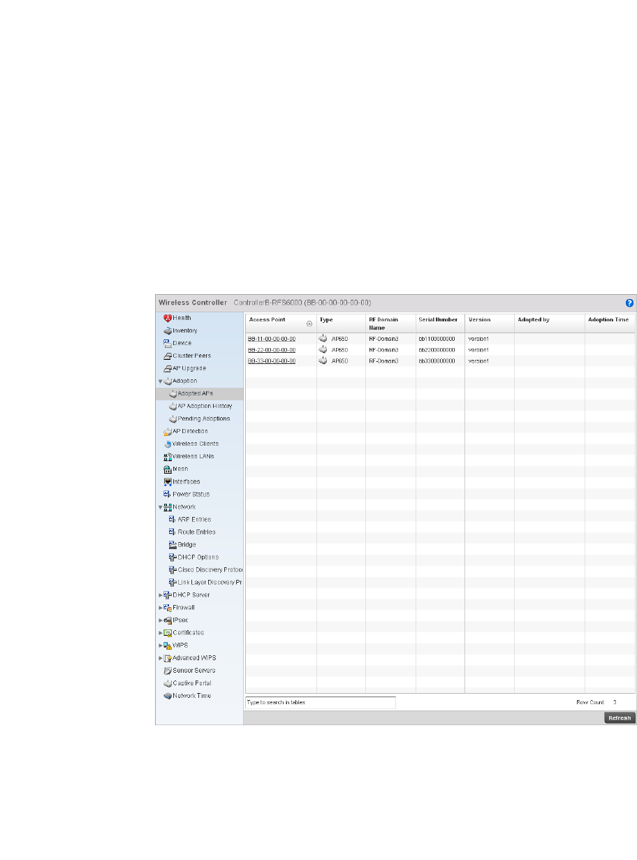
Brocade Mobility RFS4000, RFS6000, and RFS7000 System Reference Guide 765
53-1002620-01
14
Adopted AP Statistics
Wireless Controller Statistics
The adopted AP statistics screen displays details about adopted APs.
To view adopted AP statistics:
1. Select the Statistics menu from the Web UI.
2. Select a Wireless Controller node from the left navigation pane.
3. Select Adoption > Adopted APs from the left-hand side of the UI.
FIGURE 511 Wireless Controller Adopted APs screen
4. The Adopted APs screen displays the following:
RF Domain Name Displays each member’s RF Domain.
Online Displays whether a controller is online. If a controller is online a green check mark will be
displayed, if it is offline a red X will display.
Version Displays the each controller member’s firmware version.
Access Point Displays the name assigned to the Access Point.
AP MAC Address Displays the hardcoded MAC address assigned to the unit when manufactured.
Type Lists the AP model type.
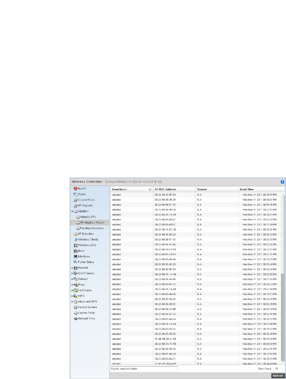
766 Brocade Mobility RFS4000, RFS6000, and RFS7000 System Reference Guide
53-1002620-01
14
AP Adoption History
Wireless Controller Statistics
To view adopted AP Adoption History statistics:
1. Select the Statistics menu from the Web UI.
2. Select a Wireless Controller node from the left navigation pane.
3. Select AP Adoption History from the left-hand side of the UI.
FIGURE 512 AP Adoption History screen
RF Domain Name Displays the Access Point’s RF Domain assignment.
Online Displays whether the listed AP is currently online and in service within the managed
network.
Serial Number Displays the Access Point’s serial number. This is used for controller management.
Version Displays the software (firmware) version used by the Access Point.
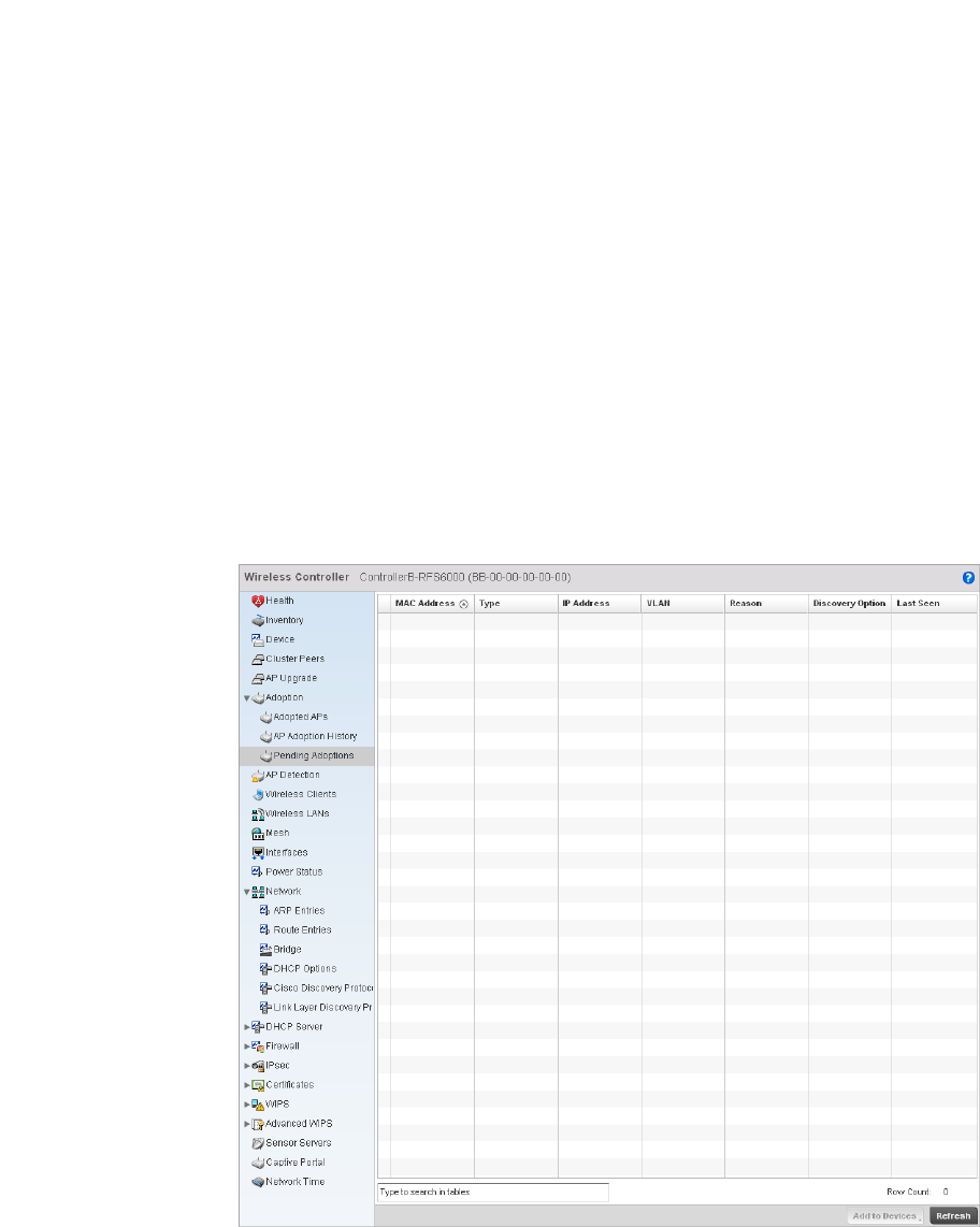
Brocade Mobility RFS4000, RFS6000, and RFS7000 System Reference Guide 767
53-1002620-01
14
4. The Adopted Devices screen provides the following
Pending Adoptions
Wireless Controller Statistics
The Adopted Devices screen displays a list of devices adopted to the wireless controller managed
network. Use this screen to view a list of devices and their current status.
To view adopted AP statistics:
1. Select the Statistics menu from the Web UI.
2. Select a Wireless Controller node from the left navigation pane.
3. Select Pending Adoptions from the left-hand side of the UI.
FIGURE 513 Pending Adoptions Devices screen
Event Name Displays the adoption status of each AP as either adopted or un-adopted.
AP MAC Address Displays the Media Access Control (MAC) address of each Access Point that the controller
has attempted to adopt.
Reason Displays the reason code for each event listed in the adoption history statistics table.
Event Time Displays day, date and time for each Access Point adoption attempt.
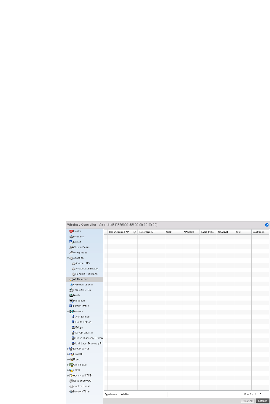
768 Brocade Mobility RFS4000, RFS6000, and RFS7000 System Reference Guide
53-1002620-01
14
4. The Adopted Devices screen provides the following
AP Detection
Wireless Controller Statistics
The AP detection statistics screen displays details about detected rogue Access Points.
To view the controller AP detection statistics:
1. Select the Statistics menu from the Web UI.
2. Select a Wireless Controller node from the left navigation pane.
3. Select AP Detection from the left-hand side of the UI.
FIGURE 514 Wireless Controller AP Detection screen
MAC Address Displays the MAC address of the device pending adoption.
Type Displays the AP type (either br-650, br-7131, or br-6511).
IP Address Displays the current IP Address of the device pending adoption.
VLAN Displays the current VLAN number of the device pending adoption.
Reason Displays the status as to why the device is still pending adoption.
Discovery Option Displays the discovery option code for each AP listed pending adoption.
Last Seen Displays the date and time stamp of the last time the device was seen. Click the arrow
next to the date and time to toggle between standard time and UTC.

Brocade Mobility RFS4000, RFS6000, and RFS7000 System Reference Guide 769
53-1002620-01
14
4. The AP Detection screen displays the following:
Wireless Clients
Wireless Controller Statistics
The wireless client statistics screen displays details about wireless clients.
To view the wireless client statistics of the controller:
1. Select the Statistics menu from the Web UI.
2. Select a Wireless Controller node from the left navigation pane.
3. Select Wireless Clients from the left-hand side of the UI.
Unsanctioned AP Displays the MAC address of unsanctioned APs.
Reporting AP Displays a numerical value for the radio used with the detecting AP.
SSID Displays the SSID of each unsanctioned AP.
AP Mode Displays the mode of the unsanctioned device (either Access Point or wireless client).
Radio Type Displays the unsanctioned AP’s radio type. The radio can be 802.11b, 802.11bg,
802.1bgn, 802.11a or 802.11an.
Channel Displays the unsanctioned AP’s current operating channel.
RSSI Displays the Received Signal Strength Indicator (RSSI) for rogue APs.
Last Seen Displays when the unsanctioned AP was last seen by the detecting AP.
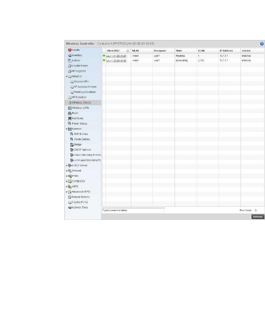
770 Brocade Mobility RFS4000, RFS6000, and RFS7000 System Reference Guide
53-1002620-01
14
FIGURE 515 Wireless Controller Wireless Clients screen
4. The Wireless Clients screen displays the following:
Wireless LANs
Wireless Controller Statistics
The wireless LAN statistics screen displays performance statistics for each WLAN. Use this
information to assess if configuration changes are required to improve network performance.
To view the wireless LAN statistics of the controller:
Client MAC Displays the MAC address of the wireless client.
WLAN Displays the name of the WLAN the client is currently associated with. Use this
information to determine if the client/WLAN placement best suits the intended
operation and the client’s coverage area.
Username Displays the unique name of the administrator or operator.
State Displays whether the client is online or offline.
VLAN Displays the name of the client’s current VLAN mapping.
IP Address Displays the unique IP address of the client. Use this address as necessary throughout
the applet for filtering and device intrusion recognition and approval.
Vendor Displays the name of the client vendor.
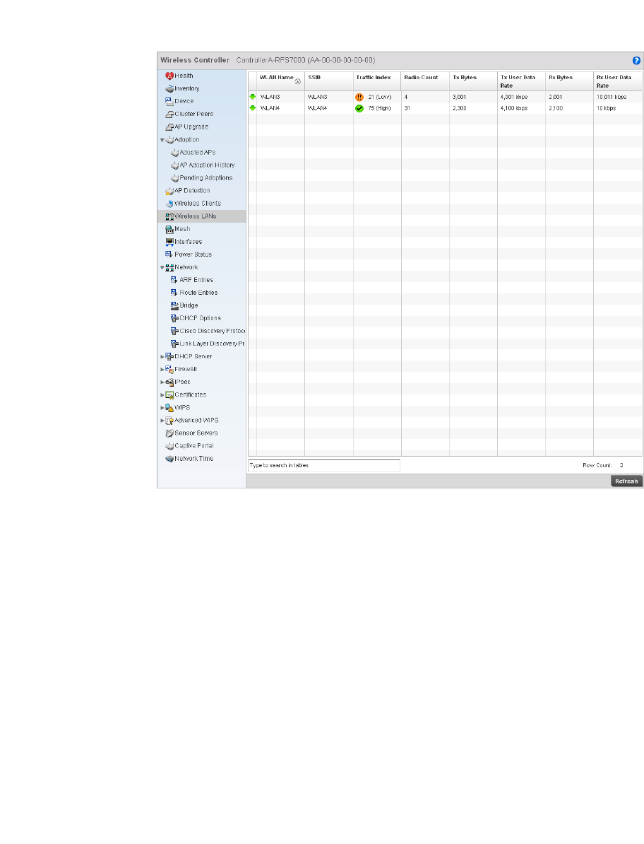
Brocade Mobility RFS4000, RFS6000, and RFS7000 System Reference Guide 771
53-1002620-01
14
1. Select the Statistics menu from the Web UI.
2. Select a Wireless Controller node from the left navigation pane.
3. Select Wireless LANs from the left-hand side of the UI.
FIGURE 516 Wireless Controller Wireless LANs screen
4. The WLAN screen displays the following:
WLAN Name Displays the name of the WLAN the controller is currently utilizing.
SSID Displays the Service Set ID associated with each WLAN.
Traf fic Index Displays the traffic utilization index, which measures how efficiently the traffic medium
is used. It’s defined as the percentage of current throughput relative to the maximum
possible throughput. Traffic indices are:
•0–20 (very low utilization)
•20–40 (low utilization)
•40–60 (moderate utilization)
•60 and above (high utilization)
Radio Count Displays the number of radios associated with this WLAN.
Tx Bytes Displays the data transmitted in bytes on the selected WLAN.
Tx User Data Rate Displays the average user data rate.
Rx Bytes Displays the data received in bytes on the selected WLAN.
Rx User Data Rate Displays the average user data rate.
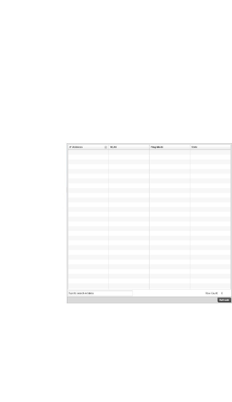
772 Brocade Mobility RFS4000, RFS6000, and RFS7000 System Reference Guide
53-1002620-01
14
Critical Resource
Wireless Controller Statistics
The Critical Resources statistics screen displays a list of device IP addresses on the network
(gateways, routers etc.). These defined IP address is critical to the health of the access point
managed network. These device addresses are pinged regularly by the access point. If there is a
connectivity issue, an event is generated stating a critical resource is unavailable.
To view the Critical Resource statistics of the controller:
1. Select the Statistics menu from the Web UI.
2. Select a Wireless Controller node from the left navigation pane.
3. Select Critical Resource from the left-hand side of the UI.
FIGURE 517 Wireless Controller Critical Resource screen
4. The Critical Resource screen displays the following:
IP Address Lists the IP address of the critical resource. This is the address the device assigned and
is used by the access point to ensure the critical resource is available.
VLAN Lists the access point VLAN on which the critical resource is available.
Ping Mode Describes the ping mode as either: arp-only - Uses ARP for only pinging the critical
resource. ARP is used to resolve hardware addresses when only the network layer
address is known. OR arp-icmp - Uses both ARP and ICMP for pining the critical resource
and sending control messages (device not reachable, requested service not available,
etc.).
State Defines the operational state of each listed critical resource.
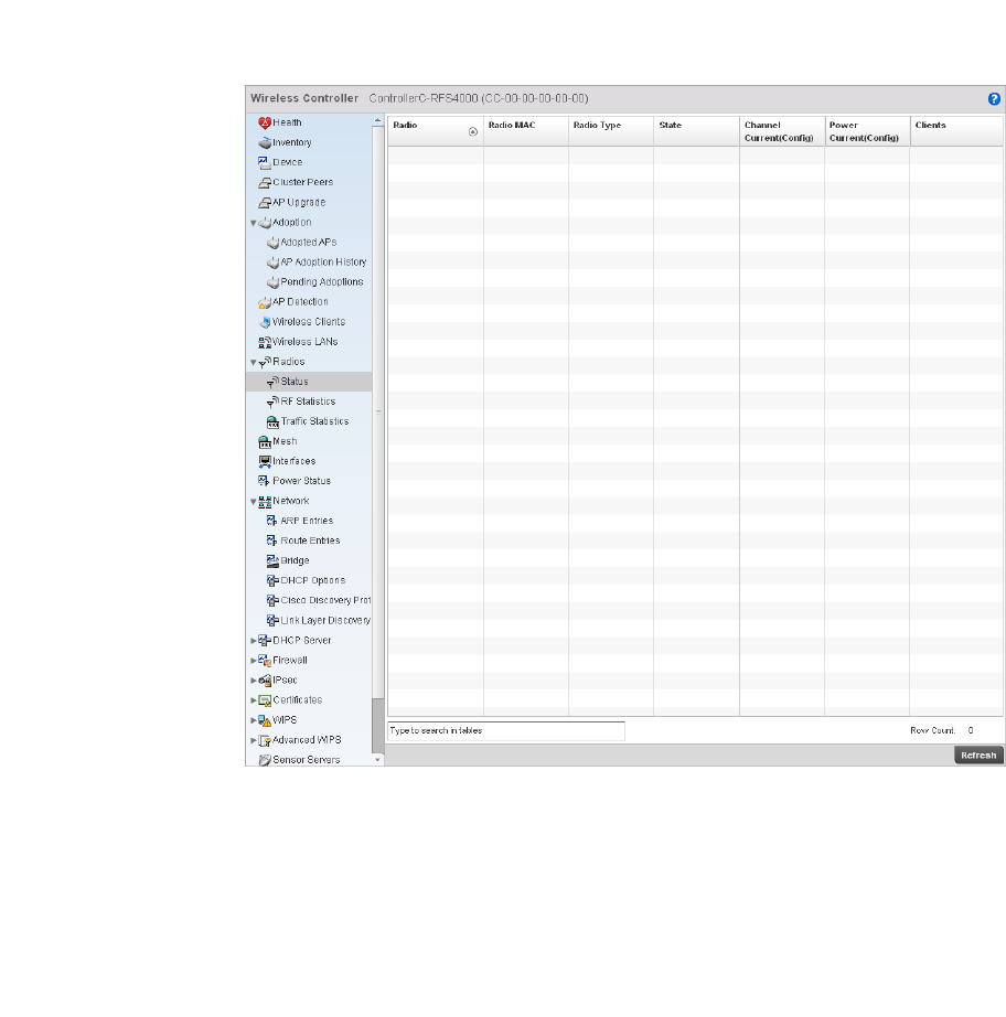
Brocade Mobility RFS4000, RFS6000, and RFS7000 System Reference Guide 773
53-1002620-01
14
Radios
Wireless Controller Statistics
The radio statistics screen provides radio association data, including radio ID, connected APs, radio
type, quality index and Signal to Noise Ratio (SNR).
To view the radio statistics:
1. Select the Statistics menu from the Web UI.
2. Select a Wireless Controller node from the left navigation pane.
3. Select Radio from the left-hand side of the UI.
FIGURE 518 Wireless Controller Radio Status screen
4. The Radios Status screen provides the following information:
Radio Displays the model and numerical value assigned to the radio as its unique identifier.
Radio MAC Displays the MAC address assigned to the radio as its unique hardware identifier.
Radio Type Defines whether the radio is a 802.11b, 802.11bg, 802.11bgn, 802.11a or 802.11an.
State Displays the current operational state of each radio.
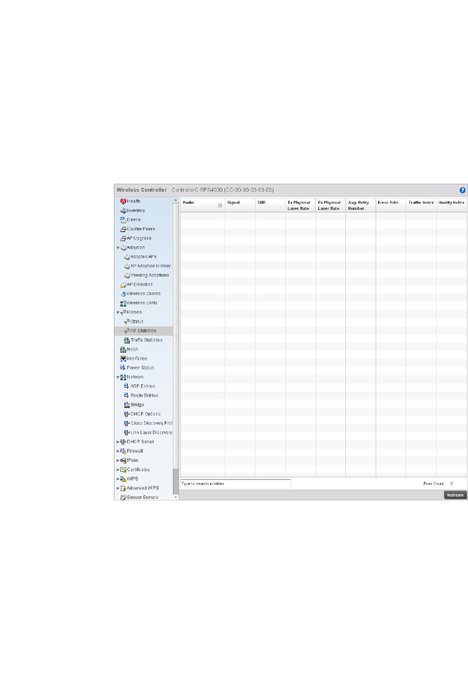
774 Brocade Mobility RFS4000, RFS6000, and RFS7000 System Reference Guide
53-1002620-01
14
5. Select RF Statistics from the Radios menu.
FIGURE 519 RF Statistics Radios screen
6. The RF Statistics screen provides the following information:
Channel Current
(Config)
Displays the current channel for each radio and the configured channel in
parentheses.
Power Current
(Config)
Displays the current power level for each radio and the configured power level in
parentheses.
Clients Displays the number of wireless clients associated with the radio.
Radio Displays the model and numerical value assigned to the radio as its unique identifier.
Signal Displays signal strength for each radio in dBm.
SNR Displays the Signal to Noise Ratio (SNR) for each radio in db..
Tx Physical Layer
Rate
Displays the transmitted data in Mbps for each radios physical interface.
Rx Physical Layer
Rate
Displays the received data in Mbps for each radios physical interface.
Avg. Retry Number Displays the average number of retries for eah radio.
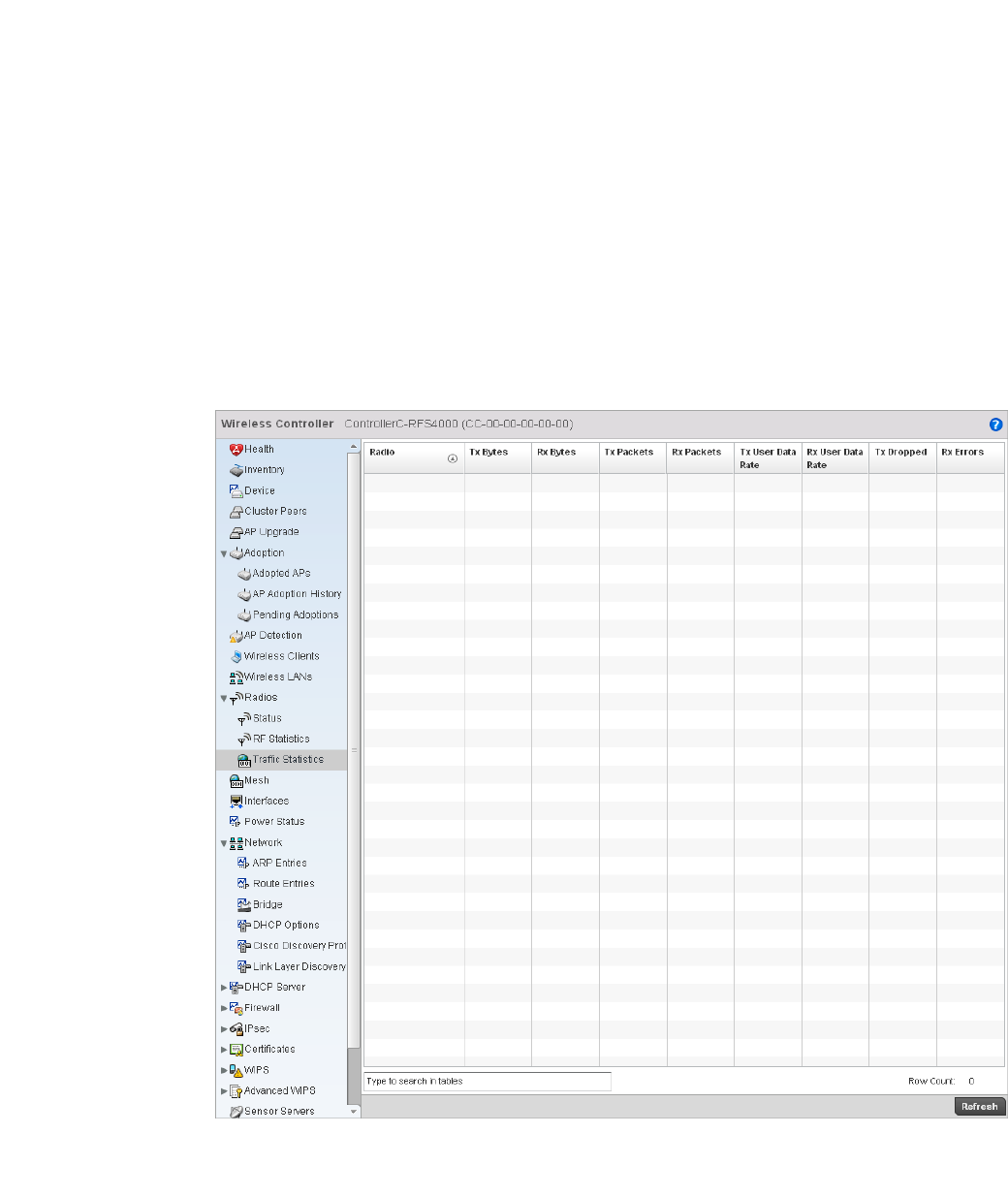
Brocade Mobility RFS4000, RFS6000, and RFS7000 System Reference Guide 775
53-1002620-01
14
7. S elect Traffic Statistics from the Radios menu.
FIGURE 520 Radios Traffic Statistics screen
The Traffic Statistics screen provides the following information:
Error Rate Displays the number of errors for each radio.
Traf fic Index Displays the traffic utilization index, which measures how efficiently the traffic medium
is used. It’s defined as the percentage of current throughput relative to maximum
possible throughput. Traffic indices are:
•0–20 (very low utilization)
•20–40 (low utilization)
•40–60 (moderate utilization)
•60 and above (high utilization)
RF Quality Index Displays the client’s RF quality. The RF quality index is the overall effectiveness of the
RF environment, as a percentage of the connect rate in both directions as well as the
retry rate and the error rate. RF quality index value can be interpreted as:
•0–20 — very poor quality
•20–40 —poor quality
•40–60 —average quality
•60–100 — good quality

776 Brocade Mobility RFS4000, RFS6000, and RFS7000 System Reference Guide
53-1002620-01
14
Mesh
Wireless Controller Statistics
To view Mesh statistics:
1. Select the Statistics menu from the Web UI.
2. Select a Wireless Controller node from the left navigation pane.
3. Select MESH from the left-hand side of the UI.
Radio Displays the model and numerical value assigned to the radio as its unique identifier.
Tx Bytes Displays the amount of transmitted data in bytes for each radio in the RF Domain.
Rx Bytes Displays the amount of received data in bytes for each radio in the RF Domain.
Tx Packets Displays the amount of transmitted data in packets for each radio in the RF Domain.
Rx Packets Displays the amount of received data in packets for each radio in the RF Domain.
Tx User Data Rate Displays the average speed in kbps of data transmitted to users for each radio in the
RF Domain.
Rx User Data Rate Displays the average speed in kbps of data received from users for each radio in the RF
Domain.
Tx Dropped Displays the number of transmission that have been dropped for each radio in the RF
Domain.
Rx Errors Displays the total number of receive errors for each radio in the RF Domain.
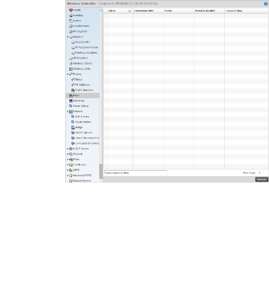
Brocade Mobility RFS4000, RFS6000, and RFS7000 System Reference Guide 777
53-1002620-01
14
FIGURE 521 RF Domain Mesh screen
This screen provides the following information:
Interfaces
Wireless Controller Statistics
The interface statistics screen displays interface name, MAC address,status, specifications etc.
To review controller interface statistics:
1. Select the Statistics menu from the Web UI.
Client AP Displays the AP name for each Access Point in the RF Domain mesh network.
Client Hostname Displays the configured hostname for each Access Point in the RF Domain mesh
network.
Client Radio MAC Displays the Media Access Control for each Access Point in the RF Domain mesh
network.
Portal Radio Index Displays the numerical Peer Radio Index ID for the peer device associated with each
Access Point in the RF Domain mesh network.
Portal Hostname Displays the assigned hostname for the peer device associated with each Access Point
in the RF Domain mesh network.
Portal Radio MAC Displays the Media Access Control for each radio in the RF Domain mesh network.
Connect Time Displays the total connection time for each AP in the RF Domain mesh network.
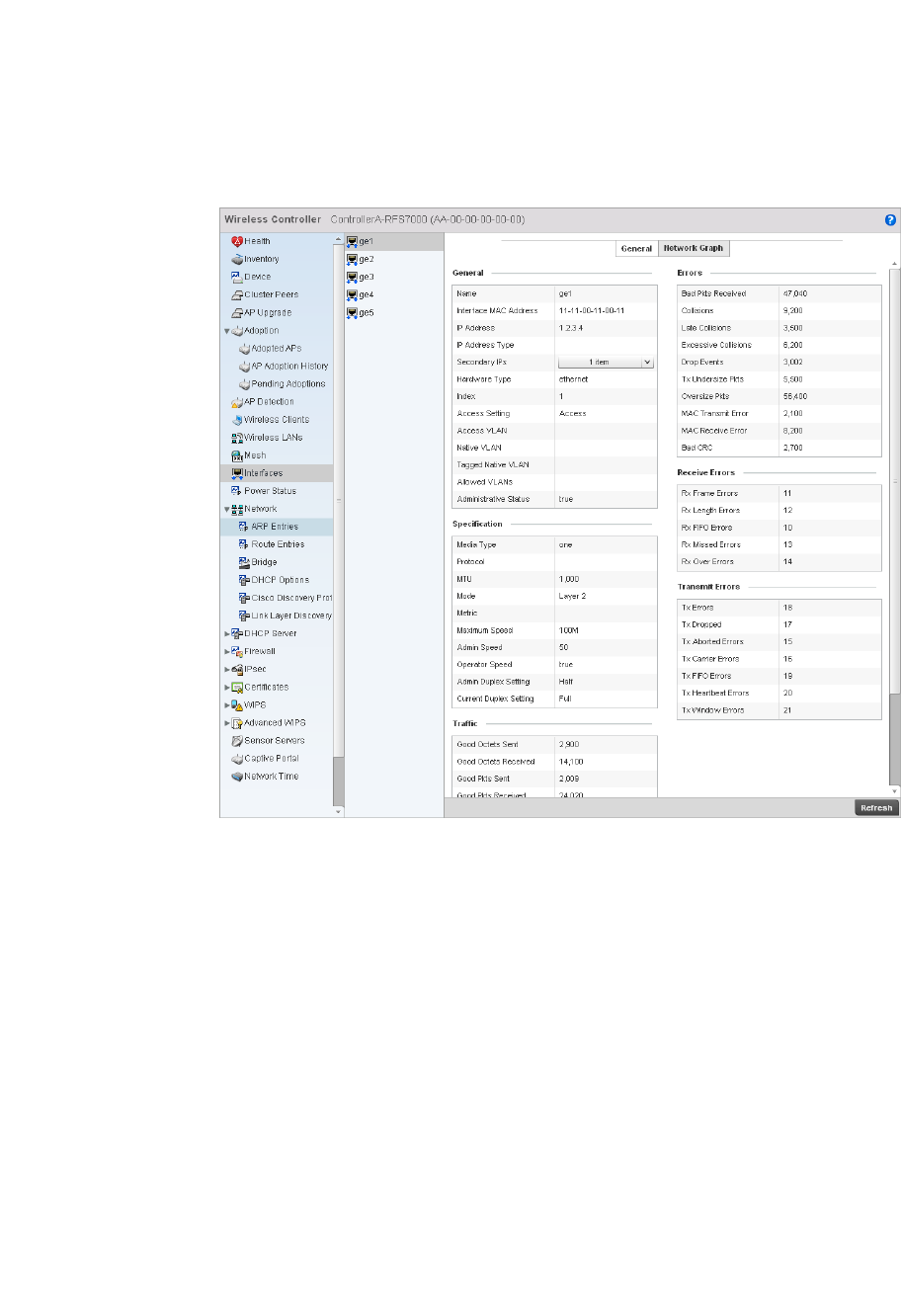
778 Brocade Mobility RFS4000, RFS6000, and RFS7000 System Reference Guide
53-1002620-01
14
2. Select a Wireless Controller node from the left navigation pane.
3. Select Interfaces > General from the left-hand side of the UI.
FIGURE 522 Wireless Controller Interfaces screen
The Interface Statistics screen can be divided into:
•Viewing Interface Details
•Viewing Interface Statistics Graph
Viewing Interface Details
Interfaces
The General table displays the following:
Name Displays the name of the interface.
Interface MAC Address Displays the MAC address of the interface.
IP Address IP address of the interface.
IP Address Type Lists the interface’s IP address.
Hardware Type Displays the networking technology.
Index Displays the unique numerical identifier for the interface.

Brocade Mobility RFS4000, RFS6000, and RFS7000 System Reference Guide 779
53-1002620-01
14
The Specification table displays the following information:
The Traffic table displays the following:
Access VLAN Displays the tag assigned to the native VLAN.
Access Setting Displays the VLAN mode as either Access or Trunk.
Administrative Status Displays whether the interface is currently UP or DOWN.
Media Type Displays the physical connection type of the interface.
Medium types include:
Copper - Used on RJ-45 Ethernet ports
Optical - Used on fibre optic gigabit Ethernet ports
Protocol Displays the routing protocol used by the interface.
MTU Displays the maximum transmission unit (MTU) setting configured on the interface. The
MTU value represents the largest packet size that can be sent over a link. 10/100
Ethernet ports have a maximum setting of 1500.
Mode The mode can be either:
Access – The Ethernet interface accepts packets only from native VLANs.
Trunk – The Ethernet interface allows packets from a list of VLANs you can add to the
trunk.
Metric Displays the metric associated with the interface’s route.
Maximum Speed Displays the maximum speed the interface uses to transmit or receive data.
Admin Speed Displays the speed the port can transmit or receive. This value can be either 10, 100,
1000 or Auto. This value is the maximum port speed in Mbps. Auto indicates the speed
is negotiated between connected devices.
Operator Speed Displays the current speed of data transmitted and received over the interface.
Admin Duplex Setting Displays the administrator’s duplex setting.
Current Duplex Setting Displays the interface as either half duplex, full duplex or unknown.
Good Octets Sent Displays the number of octets (bytes) with no errors sent by the interface.
Good Octets Received Displays the number of octets (bytes) with no errors received by the interface.
Good Packets Sent Displays the number of good packets transmitted.
Good Packets Received Displays the number of good packets received.
Mcast Pkts Sent Displays the number of multicast packets sent through the interface.
Mcast Pkts Received Displays the number of multicast packets received through the interface.
Bcast Pkts Sent Displays the number of broadcast packets sent through the interface.
Bcast Pkts Received Displays the number of broadcast packets received through the interface.
Packet Fragments Displays the number of packet fragments transmitted or received through the interface.
Jabber Pkts Displays the number of packets transmitted through the interface larger than the MTU.

780 Brocade Mobility RFS4000, RFS6000, and RFS7000 System Reference Guide
53-1002620-01
14
The Errors table displays the following:
The Receive table displays the following:
The Transmit Errors field displays the following:
Bad Pkts Received Displays the number of bad packets received through the interface.
Collisions Displays the number of collisions.
Late Collisions A late collision is any collision that occurs after the first 64 octets of data have been
sent. Late collisions are not normal, and usually the result of out of specification cabling
or a malfunctioning device.
Excessive Collisions Displays the number of excessive collisions. Excessive collisions occur when the traffic
load increases to the point a single Ethernet network cannot handle it efficiently.
Drop Events Displays the number of dropped packets transmitted or received through the interface.
Tx Undersize Pkts Displays the number of undersized packets transmitted through the interface.
Oversize Pkts Displays the number of oversized packets transmitted through the interface.
MAC Transmit Error Displays the number of failed transmits due to an internal MAC sublayer error that’s not
a late collision, due to excessive collisions or a carrier sense error.
MAC Receive Error Displays the number of received packets that failed due to an internal MAC sublayer
that’s not a late collision, an excessive number of collisions or a carrier sense error.
Bad CRC Displays the CRC error. The CRC is the 4 byte field at the end of every frame. The
receiving station uses it to interpret if the frame is valid. If the CRC value computed by
the interface does not match the value at the end of frame, it is considered as a bad
CRC.
Rx Frame Errors Displays the number of frame errors received at the interface. A frame error occurs
when data is received, but not in an expected format.
Rx Length Errors Displays the number of length errors received at the interface. Length errors are
generated when the received frame length was either less or over the Ethernet
standard.
Rx FIFO Errors Displays the number of FIFO errors received at the interface. First-in First-out queueing
is an algorithm that involves buffering and forwarding of packets in the order of arrival.
FIFO entails no priority. There is only one queue, and all packets are treated equally. An
increase in FIFO errors indicates a probable hardware malfunction.
Rx Missed Errors Displays the number of missed packets. Packets are missed when the hardware
received FIFO has insufficient space to store an incoming packet.
Rx Over Errors Displays the number of overflow errors received. Overflows occur when a packet size
exceeds the allocated buffer size.
Tx Errors Displays the number of packets with errors transmitted on the interface.
Tx Dropped Displays the number of transmitted packets dropped from the interface.
Tx Aborted Errors Displays the number of packets aborted on the interface because a
clear-to-send request was not detected.
Tx Carrier Errors Displays the number of carrier errors on the interface. This generally indicates bad
Ethernet hardware or bad cabling.

Brocade Mobility RFS4000, RFS6000, and RFS7000 System Reference Guide 781
53-1002620-01
14
Viewing Interface Statistics Graph
Interfaces
The Network Graph tab displays interface statistics the controller continuously collects for interface
statistics. Even when the interface statistics graph is closed, data is still tallied. Display the
interface statistics graph periodically for assessing the latest interface information.
To view a detailed graph for an interface, select an interface and drop it on to the graph. The graph
displays Port Statistics as the Y-axis and the Polling Interval as the X-axis.
To view the Interface Statistics graph:
1. Select the Statistics menu from the Web UI.
2. Select a Wireless Controller node from the left navigation pane.
3. Select Interfaces from the left-hand side of the UI, then select the Network Graph tab.
Tx FIFO Errors Displays the number of FIFO errors transmitted at the interface. First-in First-Out
queueing is an algorithm that involves the buffering and forwarding of packets in the
order of arrival. FIFO uses no priority. There is only one queue, and all packets are
treated equally. An increase in the number of FIFO errors indicates a probable hardware
malfunction.
Tx Heartbeat Errors Displays the number of heartbeat errors. This generally indicates a software crash, or
packets stuck in an endless loop.
Tx Window Errors Displays the number of window errors transmitted. TCP uses a sliding window flow
control protocol. In each TCP segment, the receiver specifies the amount of additional
received data (in bytes) the receiver is willing to buffer for the connection. The sending
host can send only up to that amount. If the sending host transmits more data before
receiving an acknowledgment, it constitutes a window error.
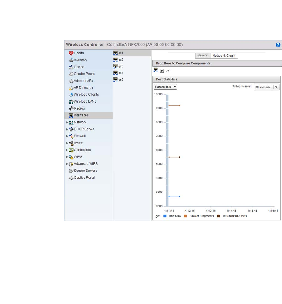
782 Brocade Mobility RFS4000, RFS6000, and RFS7000 System Reference Guide
53-1002620-01
14
FIGURE 523 Wireless Controller Interfaces Network Graph screen
Power Status
Wireless Controller Statistics
To view Power Status statistics:
1. Select the Statistics menu from the Web UI.
2. Select a Wireless Controller node from the left navigation pane.
3. Select Power Status from the left-hand side of the UI.
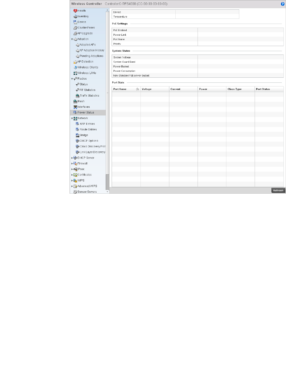
Brocade Mobility RFS4000, RFS6000, and RFS7000 System Reference Guide 783
53-1002620-01
14
FIGURE 524 Power Status screen
This screen provides the following information:
Device Displays the device name for the wireless controller.
Temperature Displays the internal system temperature for the controller.
PoE Enabled Displays whether or not Power over Ethernet (PoE) is enabled for the controller. Power
over Ethernet is supported on RFS4000 and RFS6000 model controllers only. When
enabled, the controller supports 802.3af PoE on each of its ge ports. The PoE allows
users to monitor port power consumption and configure power usage limits and
priorities for each ge port.
Power Limit Displays the total watts available for Power over Ethernet on the wireless controller. The
value should be between 0 - 40 watts.
Port Name Displays the GE port name on the wireless controller.
Priority Displays the power priority for the listed port as either Critical, High or Low. This is the
priority assigned to this port versus the power requirements of the other supports
available on the controller.
System Voltage Displays the total current system voltage for the wireless controller.
System Guard Band Displays the amount of voltage allocated to a System Guard Band. A System Guard Band
is an amount of voltage allocated to prevent power loss or cycling on connected PoE
devices when the power draw goes above the PoE Power Budget.
Power Budget Displays the total amount of voltage on the wireless controller allocated for use in Power
over Ethernet.

784 Brocade Mobility RFS4000, RFS6000, and RFS7000 System Reference Guide
53-1002620-01
14
Network
Wireless Controller Statistics
Use the Network screen to view information for ARP, DHCP, Routing and Bridging. Each of these
screens provides enough data to troubleshoot issues related to the following:
•ARP Entries
•Route Entries
•Bridge
•DHCP Options
•Cisco Discovery Protocol
•Link Layer Discovery Protocol
ARP Entries
Network
The Address Resolution Protocol (ARP) is a networking protocol for determining a network host’s
hardware address when its IP address or network layer address is known.
To view the ARP entries on the network statistics screen:
1. Select the Statistics menu from the Web UI.
2. Select a Wireless Controller node from the left navigation pane.
3. Select Network > ARP Entries from the left-hand side of the UI.
Power Consumption Displays the current amount of power being consumed by PoE devices on the wireless
controller.
Non-Standard PoE
power budget
Displays the amount of voltage allocated to non 802.3af or 802.3at PoE devices.
Port Name Displays the GE port name for each PoE capable port on the wireless controller.
Voltage Displays the voltage in use by each PoE capable port on the wireless controller.
Current Displays the amount of current in miliwatts being used by each PoE capable port on the
wireless controller.
Power Displays whether or not each PoE capable port on the wireless controller is providing
power.
Class Type Displays the PoE class type including 802.3af, 802.3at and non-standard PoE types.
Port Status Displays the status of each PoE capable port on the wireless controller. It will display
either Enabled or Disabled.
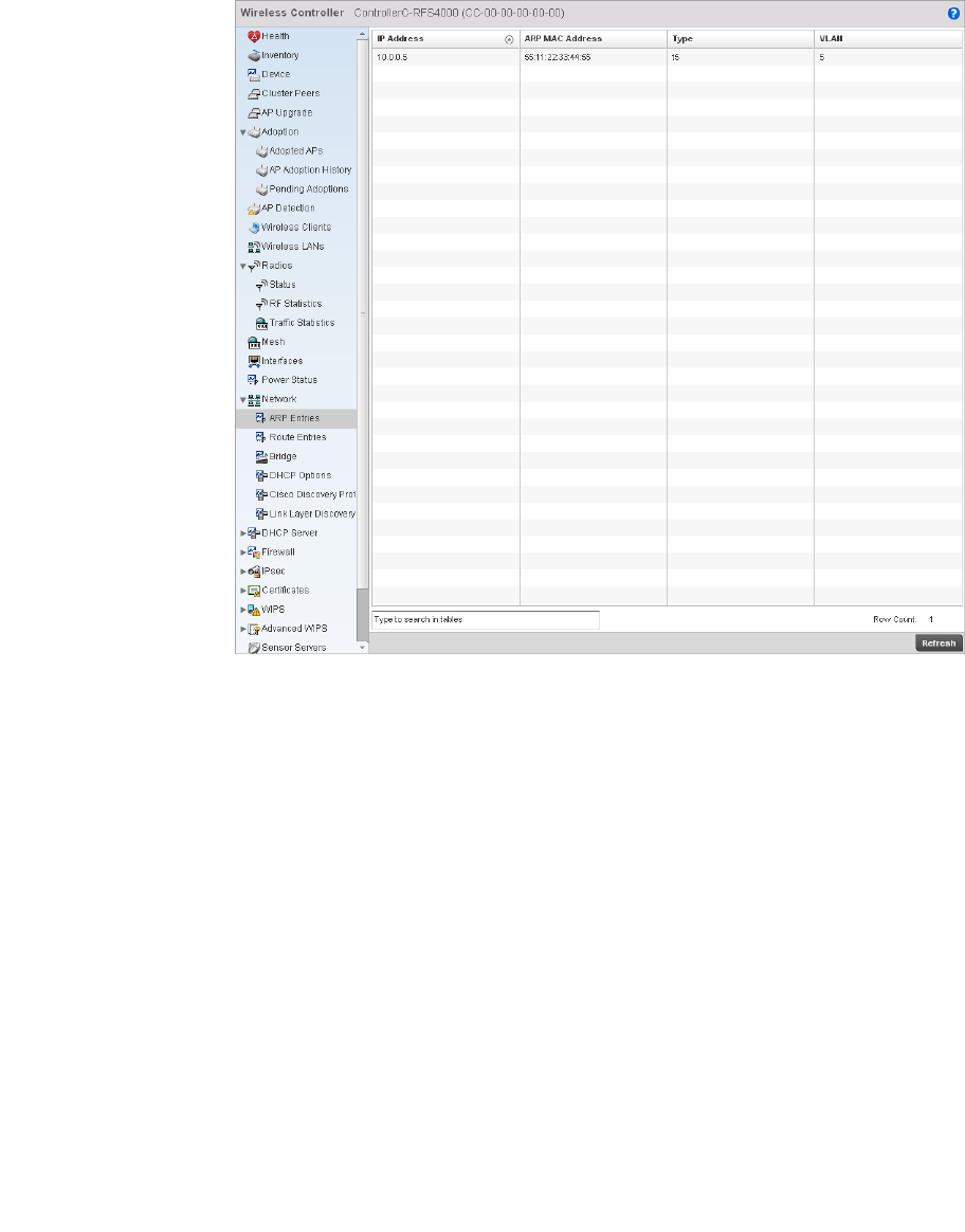
Brocade Mobility RFS4000, RFS6000, and RFS7000 System Reference Guide 785
53-1002620-01
14
FIGURE 525 Wireless Controller Network ARP Entries screen
4. The ARP Entries screen displays the following:
Route Entries
Network
The route entries screen displays data for routing packets to a defined destination. When an
existing destination subnet does not meet the needs of the network, add a new destination subnet,
subnet mask and gateway.
To view the route entries:
1. Select the Statistics menu from the Web UI.
2. Select a Wireless Controller node from the left navigation pane.
3. Select Network > Route Entries from the left-hand side of the UI.
IP Address Displays the IP address of the client being resolved.
ARP MAC Address Displays the MAC address of the device where an IP address is being resolved.
Type Defines whether the entry was added statically or created dynamically in respect to
network traffic. Entries are typically static.
VLAN Displays the name of the VLAN where the IP address was found.
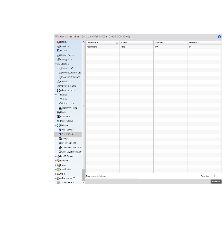
786 Brocade Mobility RFS4000, RFS6000, and RFS7000 System Reference Guide
53-1002620-01
14
FIGURE 526 Wireless Controller Network Route Entries
4. The Route Entries screen provides the following information:
Bridge
Network
Bridging is a forwarding technique making no assumption about where a particular network
address is located. It depends on flooding and the examination of source addresses in received
packet headers to locate unknown devices. Once a device is located, its location is stored in a table
to avoid broadcasting to that device again. Bridging is limited by its dependency on flooding, and is
used in local area networks only. A bridge and a controller are very similar, since a controller is a
bridge with a number of ports.
The Bridge screen provides details about the Integrated Gateway Server (IGS), which is a router
connected to an access point. The IGS performs the following:
•Issues IP addresses
•Throttles bandwidth
Destination Displays the IP address of a specific destination address.
FLAGS Displays the flags for this route entry. C indicates a connected state. G indicates a
gateway.
Gateway Displays the gateway IP address used to route packets to the destination subnet.
Interface Displays the name of the interface of the destination subnet.
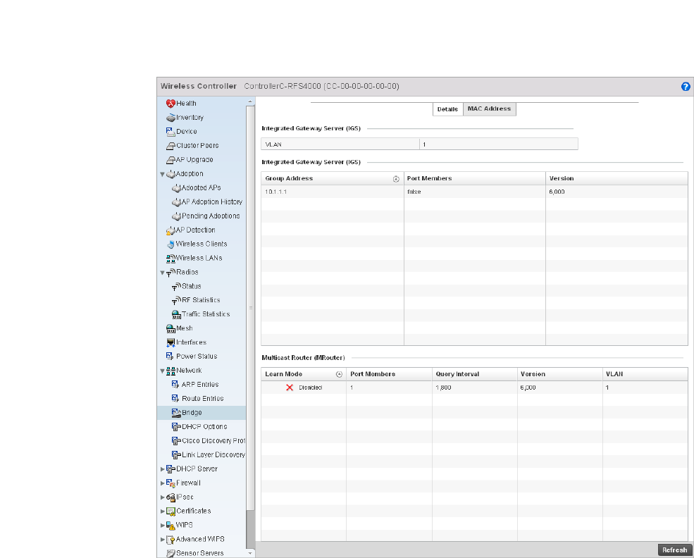
Brocade Mobility RFS4000, RFS6000, and RFS7000 System Reference Guide 787
53-1002620-01
14
•Permits access to other networks
•Times out old logins
This screen also provides information about the Multicast Router (MRouter), which is a router
program that distinguishes between multicast and unicast packets and how they should be
distributed along the Multicast Internet. Using an appropriate algorithm, a multicast router tells a
switching device what to do with the multicast packet.
This screen is partitioned into two tabs:
•Details
•MAC Address
Details
To view network bridge details:
1. Select the Statistics menu from the Web UI.
2. Select a Wireless Controller node from the left navigation pane.
3. Select Network > Bridge from the left-hand side of the UI, and select the Details tab.
FIGURE 527 Wireless Controller Network Bridge Details screen
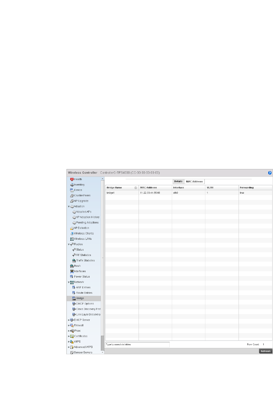
788 Brocade Mobility RFS4000, RFS6000, and RFS7000 System Reference Guide
53-1002620-01
14
4. The Integrated Gateway Server (IGS) field displays the following:
MAC Address
To view network bridge MAC address information:
1. Select the Statistics menu from the Web UI.
2. Select a Wireless Controller node from the left navigation pane.
3. Select Network > Bridge from the from the left hand side of the UI, and select the MAC Address
tab.
FIGURE 528 Wireless Controller Network Bridge MAC Address screen
4. The MAC Address tab displays the following:
VLAN Displays the integrated gateway server’s VLAN.
Group Address Displays the IP Address for group broadcast on the bridge.
Port Members Displays the ports included on this server. For example, 10/100 Base Tx Ethernet port,
RS485 serial port etc.
Version Displays the gateway server version.
Bridge Name Displays the name of the network bridge.
MAC Address Displays the MAC address of each listed bridge.
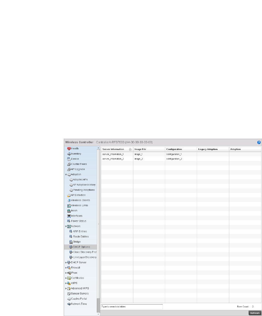
Brocade Mobility RFS4000, RFS6000, and RFS7000 System Reference Guide 789
53-1002620-01
14
DHCP Options
Network
The controller contains an internal Dynamic Host Configuration Protocol (DHCP) server. The DHCP
server can provide the dynamic assignment of IP addresses automatically. This is a protocol that
includes IP address allocation and delivery of host-specific configuration parameters from a DHCP
server to a host. Some of these parameters include IP address, gateway and network mask.
To view network DHCP options:
1. Select the Statistics menu from the Web UI.
2. Select a Wireless Controller node from the left navigation pane.
3. Select Network > DHCP Options.
FIGURE 529 Wireless Controller Network DHCP Options screen
Interface Displays the interface the bridge uses to transfer packets.
VLAN Displays the VLAN the bridge belongs to.
Forwarding Displays whether the bridge is forwarding packets. A bridge can only forward packets,
thus the display is either true or false.
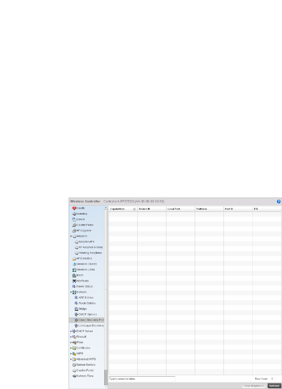
790 Brocade Mobility RFS4000, RFS6000, and RFS7000 System Reference Guide
53-1002620-01
14
4. The DHCP Options screen describes the following:
Cisco Discovery Protocol
Network
To view a network’s CDP Statistics:
1. Select the Statistics menu from the Web UI.
2. Select a Wireless Controller node from the left navigation pane.
3. Select Network > Cisco Discovery Protocol.
FIGURE 530 Access Point Network Cisco Discovery Protocol screen
Server Information Displays the name of the DHCP server.
Image File Displays the image file name. BOOTP or the bootstrap protocol can be used to boot
diskless clients. An image file is sent from the boot server. The file contains the
operating system image. DHCP servers can be configured to support BOOTP.
Configuration Displays the Configuration name for each DHCP Server.
Cluster
Configuration
Displays the Cluster Configuration name for each DHCP Server.
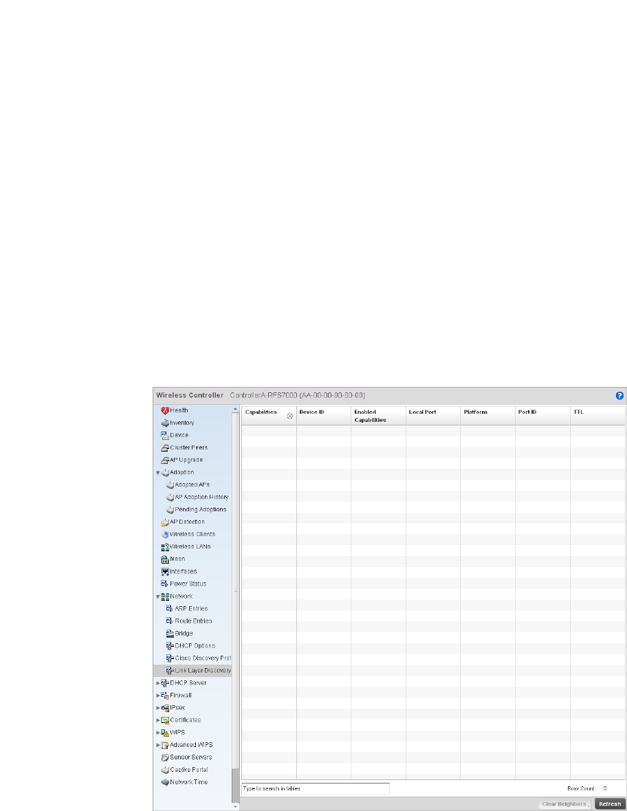
Brocade Mobility RFS4000, RFS6000, and RFS7000 System Reference Guide 791
53-1002620-01
14
4. The Cisco Discovery Protocol screen displays the following:
Link Layer Discovery Protocol
Network
To view a network’s Link Layer Discovery Protocol statistics:
1. Select the Statistics menu from the Web UI.
2. Select a Wireless Controller node from the left navigation pane.
3. Select Network > Link Layer Discovery Protocol.
FIGURE 531 Access Point Link Layer Discovery screen
Capabilities Displays the capabilities code for the device either Router, Trans Bridge, Source Route
Bridge, Switch, Host, IGMP or Repeater.
Device ID Displays the configured device ID or name for each device in the table.
Local Port Displays the local port name for each CDP capable device.
Platform Displays the model number of the CDP capable device.
Port ID Displays the identifier for the local port.
TTL Displays the time to live for each CDP connection.
Clear Neighbors Click Clear Neighbors to remove all known CDP neighbors from the table.

792 Brocade Mobility RFS4000, RFS6000, and RFS7000 System Reference Guide
53-1002620-01
14
4. The Link Layer Discovery Protocol screen displays the following:
DHCP Server
Wireless Controller Statistics
The controller contains an internal Dynamic Host Configuration Protocol (DHCP) server. DHCP can
provide IP addresses automatically. DHCP is a protocol that includes mechanisms for IP address
allocation and delivery of host-specific configuration parameters (IP address, network mask
gateway etc.) from a DHCP server to a host.
To review DHCP server statistics, refer to the following:
•Viewing General DHCP Information
•Viewing DHCP Binding Information
•Viewing DHCP Server Networks Information
Viewing General DHCP Information
DHCP Server
To view general DHCP information:
1. Select the Statistics menu from the Web UI.
2. Select a Wireless Controller node from the left navigation pane.
3. Select DHCP Server > General from the left-hand side of the UI.
Capabilities Displays the capabilities code for the device either Router, Trans Bridge, Source Route
Bridge, Switch, Host, IGMP or Repeater.
Device ID Displays the configured device ID or name for each device in the table.
Enabled
Capabilities
Displays which of the device capabilities are currently enabled.
Local Port Displays the local port name for each LLDP capable device.
Platform Displays the model number of the LLDP capable device.
Port ID Displays the identifier for the local port.
TTL Displays the time to live for each LLDP connection.
Clear Neighbors Click Clear Neighbors to remove all known LLDP neighbors from the table.
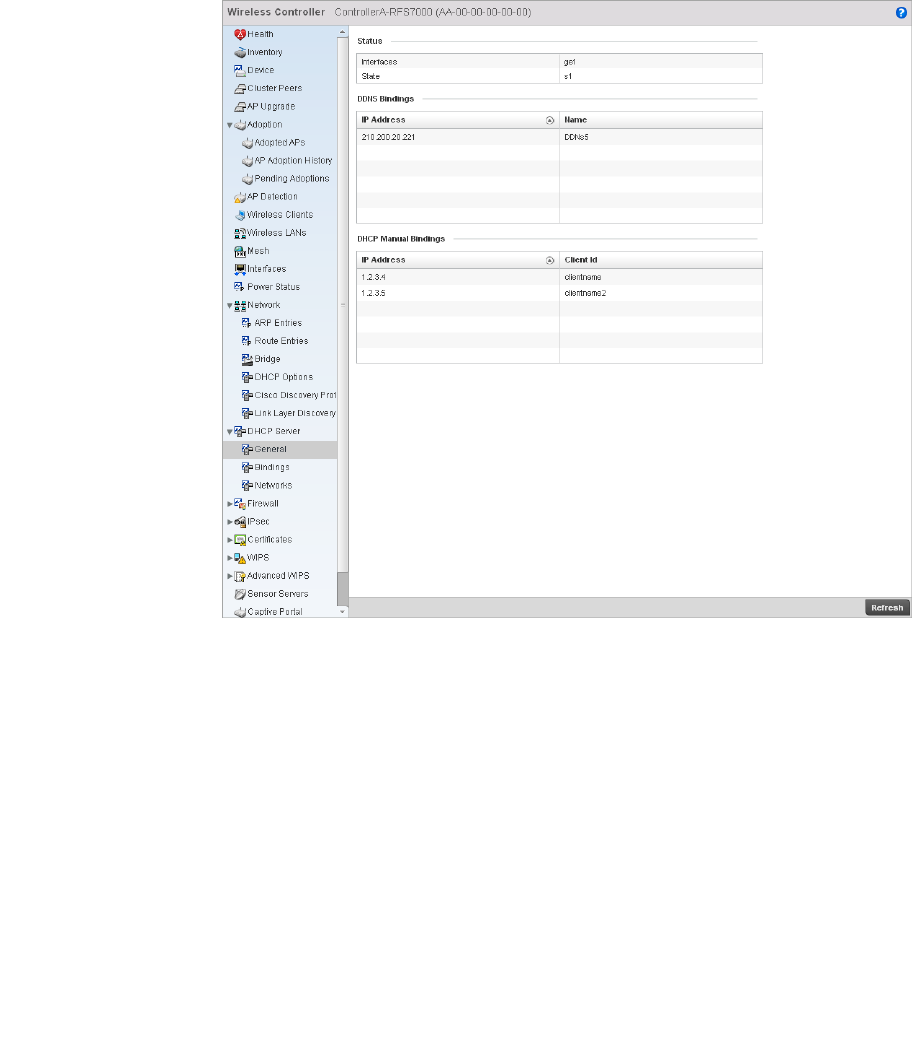
Brocade Mobility RFS4000, RFS6000, and RFS7000 System Reference Guide 793
53-1002620-01
14
FIGURE 532 Wireless Controller DHCP Server screen
4. The Status table defines the following:
5. The DDNS Bindings table displays the following:
6. The DHCP Manual Bindings table displays the following:
Viewing DHCP Binding Information
DHCP Server
The DHCP binding information screen displays DHCP binding information such as expiry time, client
IP addresses and their MAC address.
To view the DHCP binding information:
Interfaces Displays the controller interface used for the created DHCP configuration.
State Displays the current state of the DHCP server.
IP Address Displays the IP address assigned to the client.
Name Displays the domain name mapping corresponding to the listed IP address.
IP Address Displays the IP address for each client with a listed MAC address.
Client Id Displays the MAC address (client hardware ID) of the client.
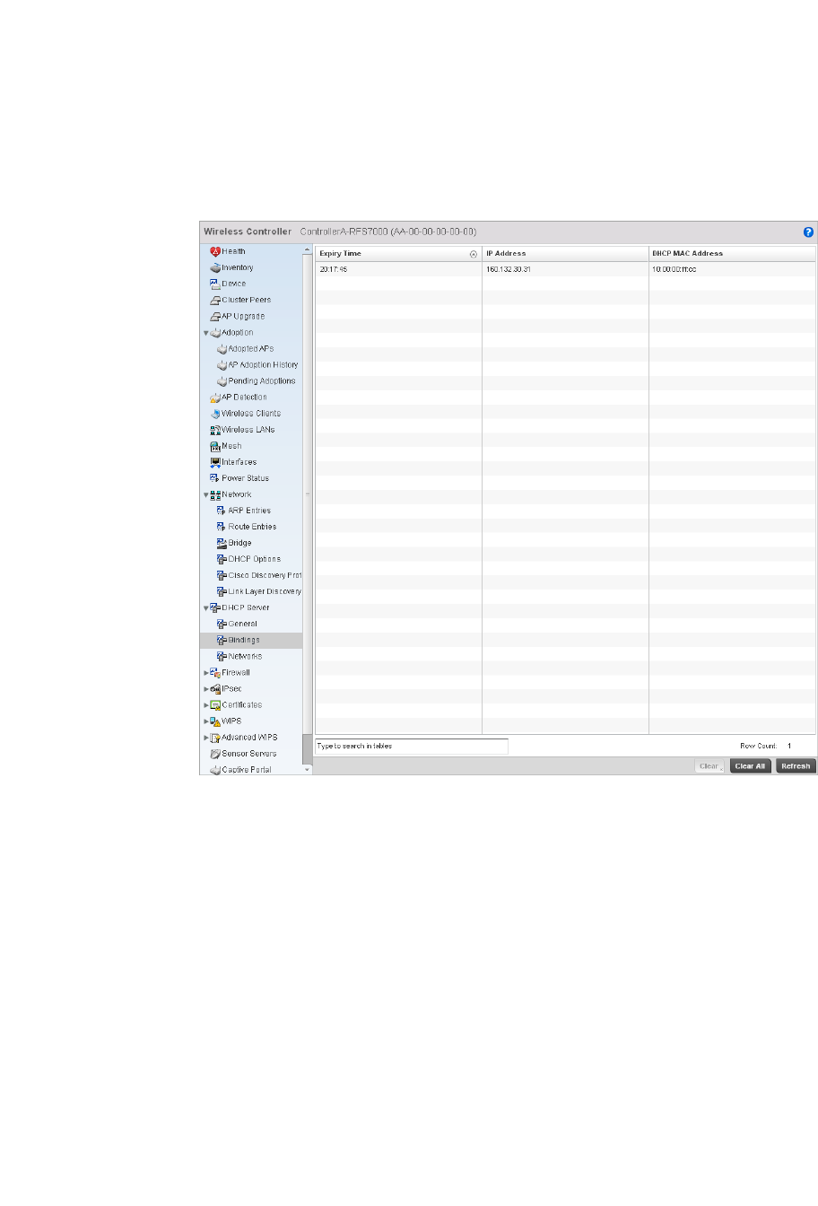
794 Brocade Mobility RFS4000, RFS6000, and RFS7000 System Reference Guide
53-1002620-01
14
1. Select the Statistics menu from the Web UI.
2. Select a Wireless Controller node from the left navigation pane.
3. Select DHCP Server > Bindings from the left-hand side of the UI.
FIGURE 533 Wireless Controller DHCP Binding screen
4. The Bindings screen displays the following:
Viewing DHCP Server Networks Information
DHCP Server
The DHCP server maintains a pool of IP addresses and client configuration parameters (default
gateway, domain name, name servers etc). On receiving a valid client request, the server assigns
the computer an IP address, a lease (the validity of time), and other IP configuration parameters.
The Networks screen provides network pool information such as the subnet for the addresses you
want to use from the pool, the pool name, the used addresses and the total number of addresses.
To view the DHCP Server Networks information:
1. Select the Statistics menu from the Web UI.
Expiry Time Displays the expiration of the lease used by the client for controller DHCP resources.
IP Address Displays the IP address for clients whose MAC address is listed in the Client Id column.
DHCP MAC Address Displays the client MAC address (ID) of the client.
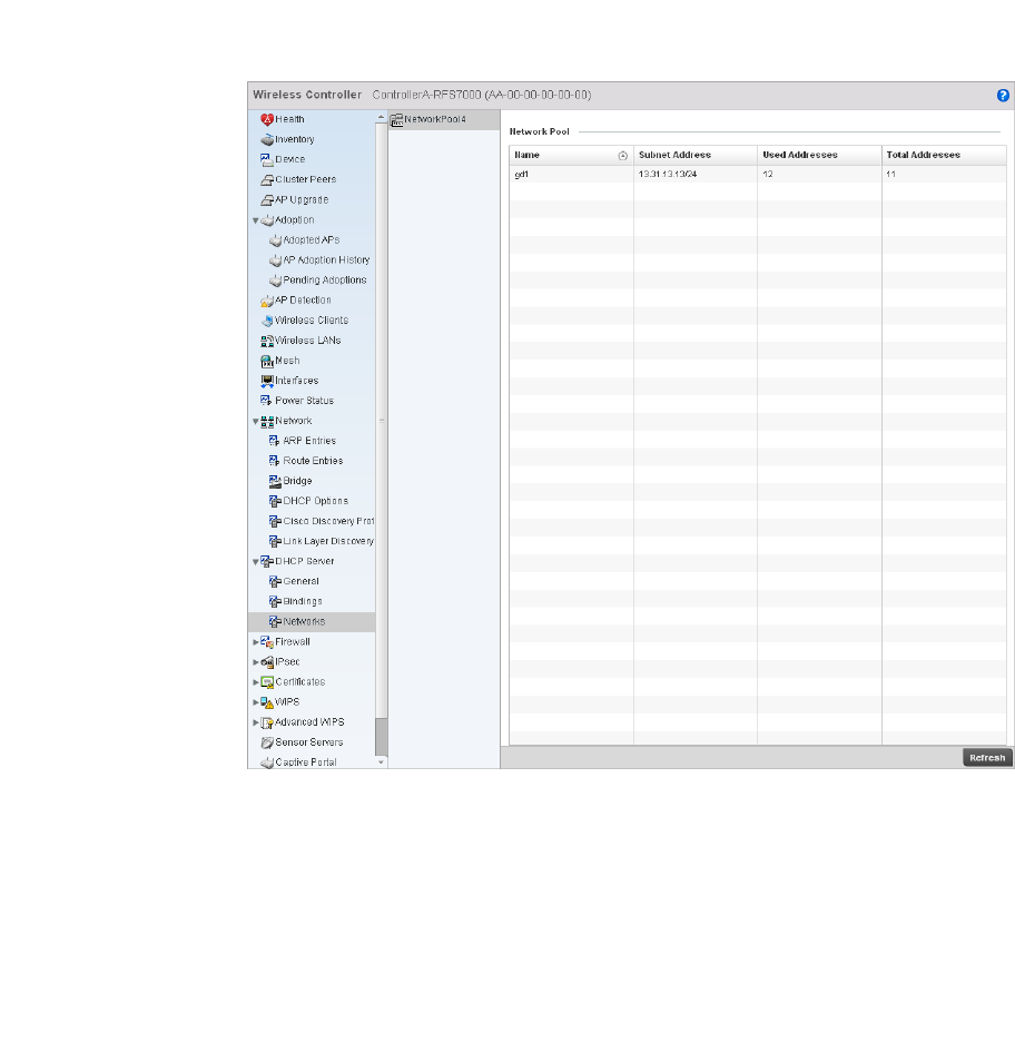
Brocade Mobility RFS4000, RFS6000, and RFS7000 System Reference Guide 795
53-1002620-01
14
2. Select a Wireless Controller node from the left navigation pane.
3. Select DHCP Server > Networks from the left-hand side of the UI.
FIGURE 534 Wireless Controller DHCP Network screen
4. The Networks screen displays the following:
Firewall
Wireless Controller Statistics
A firewall is designed to block unauthorized access while permitting authorized communications.
It’s a device or a set of devices configured to permit or deny computer applications based on a set
of rules. For more information, refer to the following:
•Viewing Packet Flow Statistics
•Viewing Denial of Service Statistics
•IP Firewall Rules
Name Displays the name of the network pool from which IP addresses can be issued to DHCP
client requests on the current interface.
Subnet Address Displays the subnet for the IP addresses used from the network pool.
Used Addresses Displays the host IP addresses allocated by a DHCP server.
Total Addresses Displays the total number of IP addresses in the network pool.
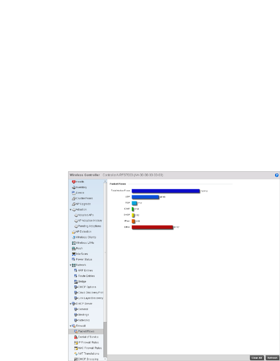
796 Brocade Mobility RFS4000, RFS6000, and RFS7000 System Reference Guide
53-1002620-01
14
•MAC Firewall Rules
•Viewing DHCP Snooping Statistics
Viewing Packet Flow Statistics
Firewall
The Packet Flows screen displays data traffic packet flow utilization. The chart represents the
different protocol flows supported, and displays a proportional view of the flows in respect to their
percentage of data traffic utilized. The Total Active Flows field displays the total number of flows
supported by the controller.
To view the packet flow statistics:
1. Select the Statistics menu from the Web UI.
2. Select a Wireless Controller node from the left navigation pane.
3. Select Firewall > Packet Flows from the left-hand side of the controller UI.
FIGURE 535 Wireless Controller Firewall Packet Flows screen
Viewing Denial of Service Statistics
Firewall
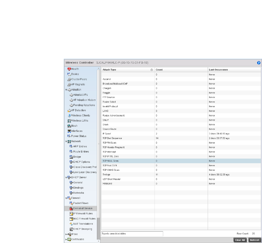
Brocade Mobility RFS4000, RFS6000, and RFS7000 System Reference Guide 797
53-1002620-01
14
A denial-of-service attack (DoS attack), or distributed denial-of-service attack, is an attempt to
make a computer resource unavailable to its intended users. Although the means to carry out a
DoS attack may vary, it generally consists of a concerted effort to prevent an Internet site or service
from functioning efficiently.
One common attack involves saturating the target’s (victim’s) machine with external
communications requests, such that it cannot respond to legitimate traffic, or responds so slowly
as to be rendered effectively unavailable. DoS attacks are implemented by either forcing the
targeted computer(s) to reset, or consuming its resources so that it can no longer provide its
intended service.
The Denial of Service screen displays attack type, number of occurrances, and time of last
occurrence.
To view the denial of service statistics:
1. Select the Statistics menu from the Web UI.
2. Select a Wireless Controller node from the left navigation pane.
3. Select Firewall > Denial of Service from the left-hand side of the UI.
FIGURE 536 Wireless Controller Firewall DoS screen
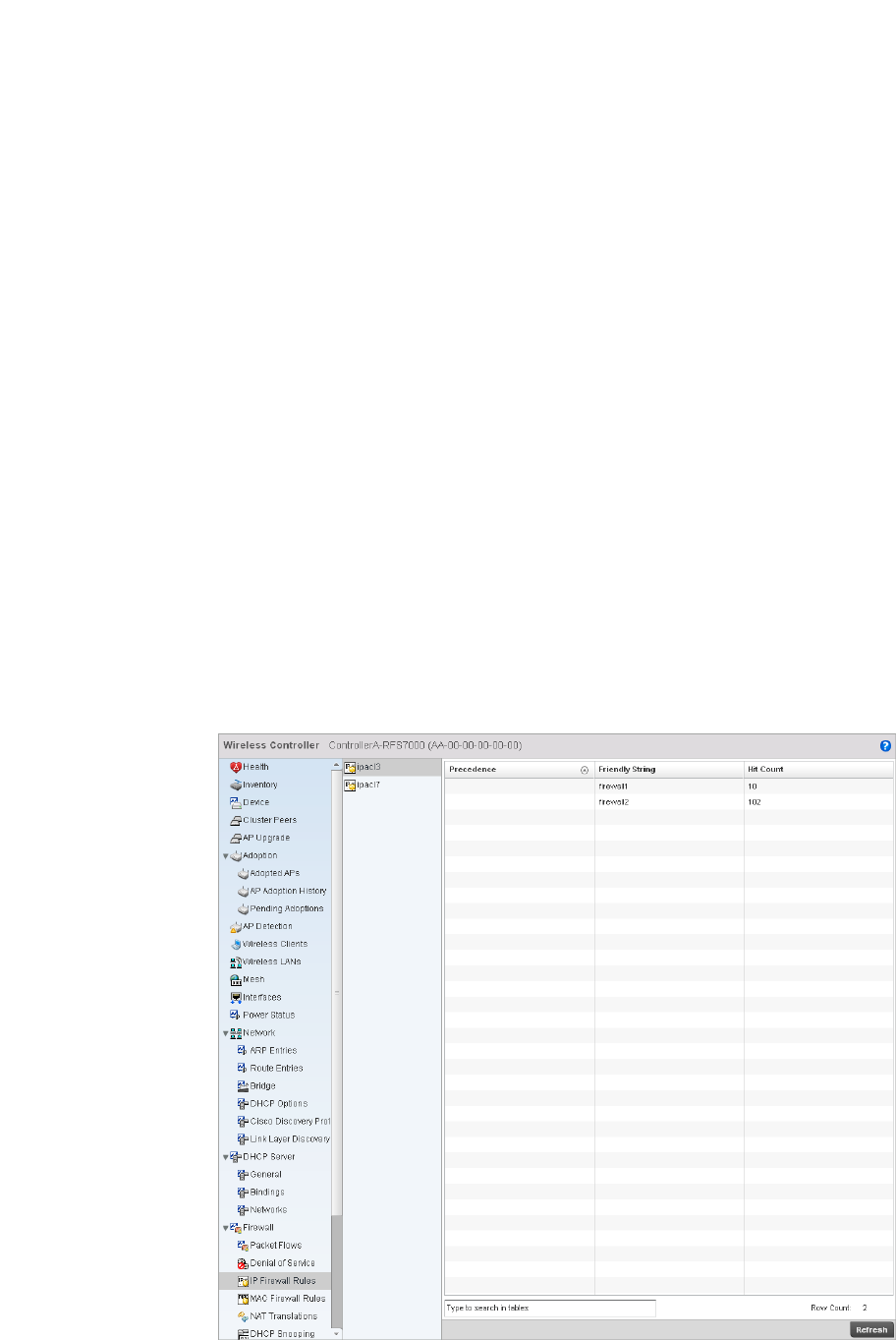
798 Brocade Mobility RFS4000, RFS6000, and RFS7000 System Reference Guide
53-1002620-01
14
4. The Deniel of Service screen displays the following:
IP Firewall Rules
Firewall
Firewall rules can be created to take one of the three actions listed below:
•Allow a connection
•Allow a connection only if it is secured through the use of Internet Protocol security
•Block a connection
Rules can be created for either inbound or outbound traffic.
To view the IP firewall rules:
1. Select the Statistics menu from the Web UI.
2. Select a Wireless Controller node from the left navigation pane.
3. Select Firewall > IP Firewall Rules from the left-hand side of the controller UI.
FIGURE 537 Wireless Controller IP Firewall Rules screen
Attack Type Displays the DoS attack type. The controller supports enabling or disabling 24 different
DoS attack filters.
Count Displays the number of times each DoS attack was observed by the controller firewall.
Last Occurrence Displays the amount of time since the DoS attack has been observed by the controller
firewall.

Brocade Mobility RFS4000, RFS6000, and RFS7000 System Reference Guide 799
53-1002620-01
14
4. The IP Firewall Rules screen displays the following:
MAC Firewall Rules
Firewall
The ability to allow or deny client access by MAC address ensures malicious or unwanted users are
unable to bypass security filters. Firewall rules can use one of the three following actions based on
a rule criteria:
•Allow a connection
•Allow a connection only if it is secured through the MAC firewall security
•Block a connection
To view MAC firewall rules:
1. Select the Statistics menu from the Web UI.
2. Select a Wireless Controller node from the left navigation pane.
3. Select Firewall > MAC Firewall Rules from the left-hand side of the controller UI.
Precedence Displays the precedence value applied to packets. Every rule has a unique precedence
value between 1 and 5000. You cannot add two rules with the same precedence value.
Friendly String This is a string that provides more information as to the contents of the rule. This is for
information purposes only.
Hit Count Displays the number of times each WLAN ACL has been triggered.
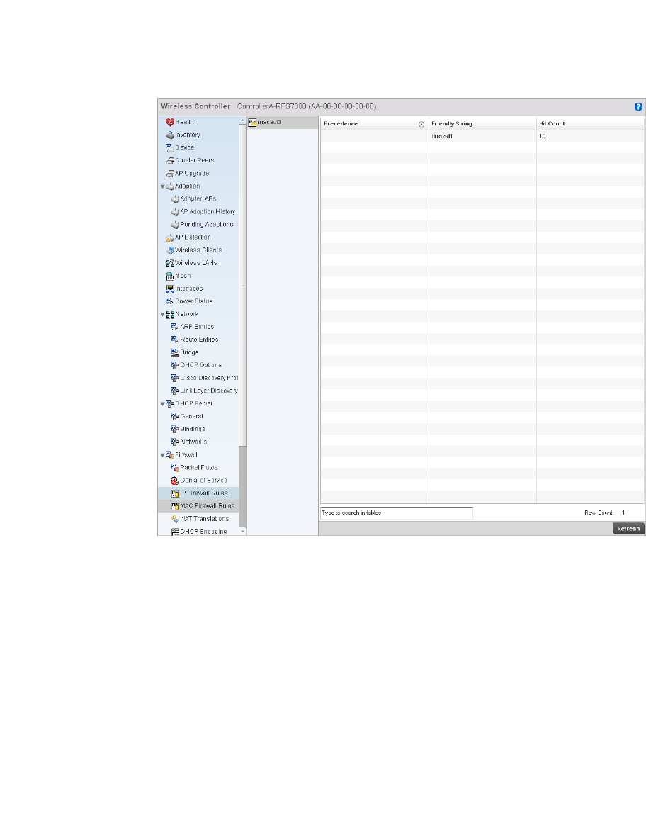
800 Brocade Mobility RFS4000, RFS6000, and RFS7000 System Reference Guide
53-1002620-01
14
FIGURE 538 Wireless Controller MAC Firewall Rules screen
4. The MAC Firewall Rules screen displays the following:
NAT Translations
Firewall
1. Select the Statistics menu from the Web UI.
2. Select an Access Point node from the left navigation pane.
3. Select Firewall > NAT Translations.
Precedence Displays the precedence value, which are applied to packets. Every rule has a unique
precedence value between 1 and 5000. You cannot add two rules with the same
precedence value.
Friendly String This is a string that provides more information as to the contents of the rule. This is for
information purposes only.
Hit Count Displays the number of times each WLAN ACL has been triggered.
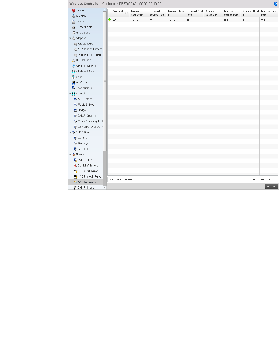
Brocade Mobility RFS4000, RFS6000, and RFS7000 System Reference Guide 801
53-1002620-01
14
FIGURE 539 Access Point Firewall NAT Translation screen
4. The NAT Translations screen displays the following:
Protocol Displays the IP protocol type, either UDP or TCP.
Forward Source IP Displays the internal network IP address for forward facing NAT translations in the
Forward Source IP column.
Forward Source
Port
Displays the internal network port for forward facing NAT translations in the Forward
Source Port column.
Forward Dest IP Displays the external network destination IP address for forward facing NAT
translations in the Forward Dest IP column.
Forward Dest Port Displays the external network destination port for forward facing NAT translations in the
Forward Dest Port column.
Reverse Source IP Displays the internal network IP address for reverse facing NAT translations in the
Reverse Source IP column.
Reverse Source
Port
Displays the internal network port for reverse facing NAT translations in the Reverse
Source Port column.
Reverse Dest IP Displays the external network destination IP address for reverse facing NAT
translations in the Reverse Dest IP column.
Reverse Dest Port Displays the external network destination port for reverse facing NAT translations in the
Reverse Dest Port column.
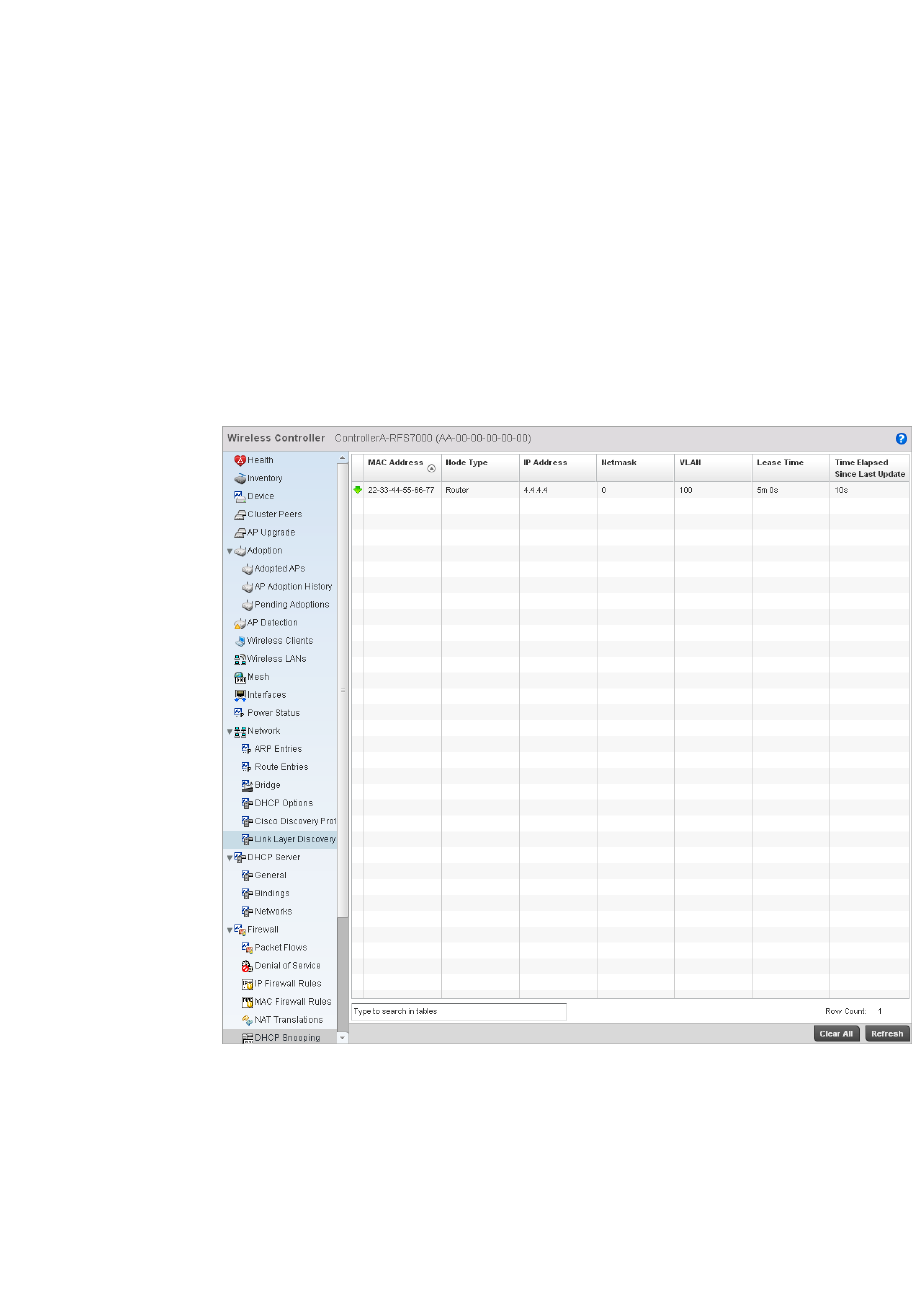
802 Brocade Mobility RFS4000, RFS6000, and RFS7000 System Reference Guide
53-1002620-01
14
Viewing DHCP Snooping Statistics
Firewall
When DHCP servers are allocating IP addresses to the clients, DHCP snooping can strengthen the
security on the LAN allowing only clients with specific IP/MAC addresses.
To view the DHCP snooping statistics:
1. Select the Statistics menu from the Web UI.
2. Select a Wireless Controller node from the left navigation pane.
3. Select Firewall > DHCP Snooping from the left-hand side of the controller UI
FIGURE 540 Wireless Controller Firewall DHCP Snooping screen
4. The DHCP Snooping screen displays the following:
MAC Address Displays the MAC address of the client.
Node Type Displays the NetBios node with an IP pool from which IP addresses can be issued to
client requests on this interface.
IP Address Displays the IP address used for DHCP discovery and requests between the DHCP server
and DHCP clients.
Netmask Displays the subnet mask used for DHCP discovery and requests between the DHCP
server and DHCP clients.

Brocade Mobility RFS4000, RFS6000, and RFS7000 System Reference Guide 803
53-1002620-01
14
IPsec
Wireless Controller Statistics
Use IPsec Virtual Private Network (VPN) to define secure tunnels between two peers. Configure
sensitive packets, which should be sent through secure tunnels. Once configured, an IPsec peer
creates a secure tunnel and sends the packets through the tunnel to the remote peer.
For more information, see:
•Viewing Security Associations
•Viewing ISAKMP Statistics
Viewing Security Associations
IPsec
IPsec tunnels are sets of security associations (SA) established between two peers. The security
associations define which protocols and algorithms are applied to sensitive packets, and what
keying material is used by the two peers.
To view the security associations statistics:
1. Select the Statistics menu from the Web UI.
2. Select a Wireless Controller node from the left navigation pane.
3. Select IPSec > Security Associations from the left-hand side of the controller UI.
VLAN Displays the controller interface used for a newly created DHCP configuration.
Lease Time When a DHCP server allocates an address for a DHCP client, the client is assigned a
lease (which expires after a designated interval defined by the administrator). The lease
is the time an IP address is reserved for re-connection after its last use. Using short
leases, DHCP can dynamically reconfigure networks in which there are more computers
than available IP addresses. This is useful, for example, in education and customer
environments where client users change frequently. Use longer leases if there are fewer
users.
Last Updated Displays the time the server was last updated.
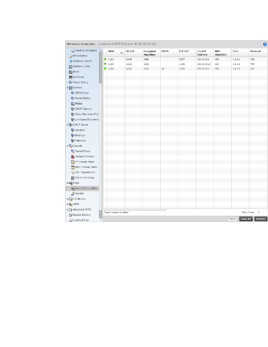
804 Brocade Mobility RFS4000, RFS6000, and RFS7000 System Reference Guide
53-1002620-01
14
FIGURE 541 Wireless Controller IP Sec Security Associations screen
4. The Security Association screen displays the following:
Viewing ISAKMP Statistics
IPsec
AH IN Displays the inbound Authentication Header (AH).
AH OUT Displays the outbound AH.
Encryption Algorithm Displays the encryption algorithm used between the peers.
ESP IN Displays the Security Parameter Index (SPI) in the Encapsulating Security Payload (ESP)
inbound header.
ESP OUT Displays the SPI in the Encapsulating Security Payload (ESP) outbound.
Local IP Address Displays the IP address of the local peer in an IPsec association.
MAC Algorithm Displays the algorithm used with the security association.
Peer Displays the IP address of the remote peer in an IPsec association.
Protocol Displays the protocol used with the security association between two peers. Internet Key
Exchange (IKE) is a key management protocol used with IPsec.
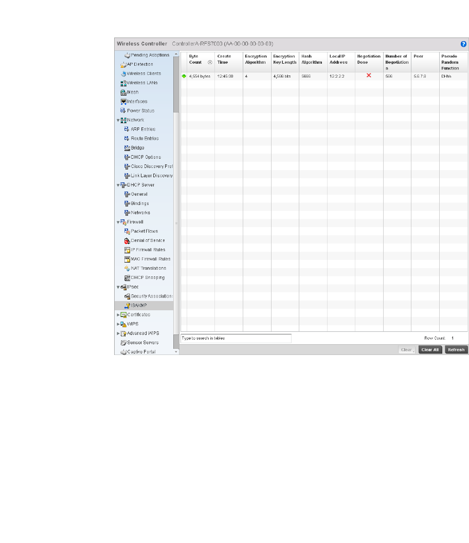
Brocade Mobility RFS4000, RFS6000, and RFS7000 System Reference Guide 805
53-1002620-01
14
Internet Security Association and Key Management Protocol (ISAKMP) is a protocol for establishing
security associations and cryptographic keys in an Internet environment. ISAKMP defines the
procedures for authenticating a communicating peer, creation and management of security
associations, key generation techniques and threat mitigation.
To review ISAKMP stats:
1. Select the Statistics menu from the Web UI.
2. Select a Wireless Controller node from the left navigation pane.
3. Select IPsec > ISAKMP from the right pane.
FIGURE 542 Wireless Controller IPsec ISAKMP screen
4. The ISAKMP screen displays the following:
Byte Count Displays the number of bytes passed between two peers.
Create Time Displays the exact time when the SA was configured.
Encryption
Algorithm
Displays the encryption method used to protect data between peers.
Encryption Key
Length
Displays the size (in bits) of the key used in the encryption algorithm.
Hash Algorithm Defines the hash algorithm used to ensure data integrity. The hash value validates a
packet has not been modified in transit.
Local IP Address Displays the IP address of the local peer in an IPsec association.

806 Brocade Mobility RFS4000, RFS6000, and RFS7000 System Reference Guide
53-1002620-01
14
Viewing Certificate Statistics
Wireless Controller Statistics
The Secure Socket Layer (SSL) protocol is used to ensure secure transactions between Web
servers and browsers. This protocol uses a third-party, a certificate authority, to identify one end or
both ends of the transactions. A browser checks the certificate issued by the server before
establishing a connection.
For more information, see:
•Viewing Trustpoints Statistics
•Viewing the RSA Key Details
Viewing Trustpoints Statistics
Viewing Certificate Statistics
Each certificate is digitally signed by a trustpoint. The trustpoint signing the certificate can be a
certificate authority, corporate or individual. A trustpoint represents a CA/identity pair containing
the identity of the CA, CA-specific configuration parameters and an association with an enrolled
identity certificate.
To view the trustpoint statistics:
1. Select the Statistics menu from the Web UI.
2. Select a Wireless Controller node from the left navigation pane.
3. Select Certificates > Trustpoints from the left-hand side of the controller UI.
Negotiation Done Displays whether negotiation is completed between peers. During ISAKMP
negotiations, peers must identify themselves to one another.
Number of
Negotiations
This value is helpful in determining the network address used to validate peers.
Peer Displays the IP address of the remote peer in an IPsec association.
Pseudo Random
Function
Displays the pseudo-random function used to construct keying material for all
cryptographic algorithms used by ISAKMP.
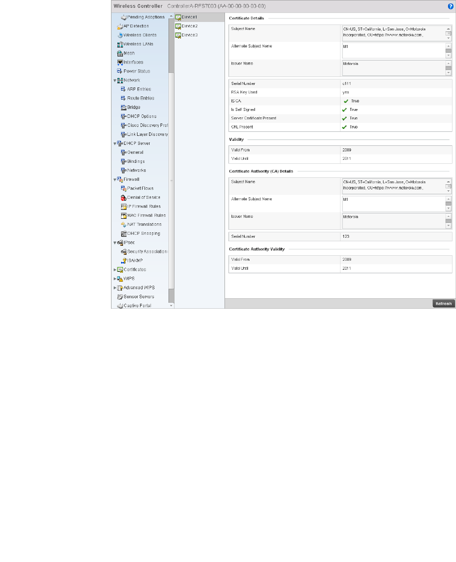
Brocade Mobility RFS4000, RFS6000, and RFS7000 System Reference Guide 807
53-1002620-01
14
FIGURE 543 Wireless Controller Trustpoints Statistics screen
4. The Certificate Details field displays the following:
Subject Name Describes the entity to which the certificate is issued.
Alternate Subject
Name
This section provides alternate information about the certificate as provided to the
certificate authority. This field is used to provide information supporting the Subject
Name.
Issuer Name Displays the name of the organization issuing the certificate.
Serial Number Lists the unique serial number of the certificate.
RSA Key Used Displays the name of the key pair generated separated, or automatically when
selecting a certificate.
IS CA Indicates if this certificate is an authority certificate.
Is Self Signed Displays whether the certificate is self-signed. True represents the certificate is
self-signed.
Server Certification
Present
Displays whether a server certification is present or not. True represents the server
certification is present.
CRL Present Displays whether a Certificate Revocation List (CRL) is present. A CRL contains a list of
subscribers paired with digital certificate status. The list displays revoked certificates
along with the reasons for revocation. The date of issuance and the entities that issued
the certificate are also included.

808 Brocade Mobility RFS4000, RFS6000, and RFS7000 System Reference Guide
53-1002620-01
14
5. The Validity field displays the following:
6. The Certificate Authority (CA) Details field displays the following:
7. T he Certificate Authority Validity field displays the following:
Viewing the RSA Key Details
Viewing Certificate Statistics
Rivest, Shamir, and Adleman (RSA) is an algorithm for public key cryptography. It’s the first
algorithm known to be suitable for signing as well as encryption.
To view the RSA Key details:
1. Select the Statistics menu from the Web UI.
2. Select a Wireless Controller node from the left navigation pane.
3. Select Certificates > RSA Keys from the left-hand side of the controller UI.
Valid From Displays the certificate’s issue date.
Valid Until Displays the certificate’s expiration date.
Subject Name Displays information about the entity to which the certificate is issued.
Alternate Subject
Name
This section provides alternate information about the certificate as provided to the
certificate authority. This field is used to provide more information that supports
information provided in the Subject Name field.
Issuer Name Displays the organization issuing the certificate.
Serial Number The unique serial number of the certificate issued.
Validity From Displays the date when the validity of a CA began.
Validity Until Displays the date when the validity of a CA expires.
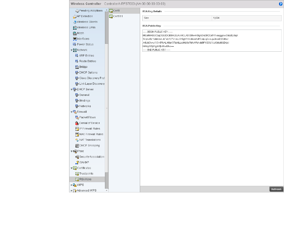
Brocade Mobility RFS4000, RFS6000, and RFS7000 System Reference Guide 809
53-1002620-01
14
FIGURE 544 Wireless Controller RSA Key Details screen
4. The RSA Key Details field describes the size (in bits) of the desired key. If not specified, a
default key size of 1024 is used.
5. The RSA Public Key field describes the public key used for encrypting messages. This key is
known to everyone.
Controller WIPS Statistics
Wireless Controller Statistics
Wireless Intrusion Protection System (WIPS) detects the presence of unauthorized Access Points.
Unauthorized attempts to access the WLAN is generally accompanied by intruding clients finding
network vulnerabilities. Basic forms of this behavior can be monitored and reported without a
dedicated WIPS deployment. When the parameters exceed a configurable threshold, the controller
generates a SNMP trap and reports the result via the management interfaces. Basic WIPS
functionality does not require monitoring APs and does not perform off-channel scanning.
For more information, see:
•Viewing Client Blacklist
•Viewing WIPS Event Statistics
Viewing Client Blacklist
Controller WIPS Statistics
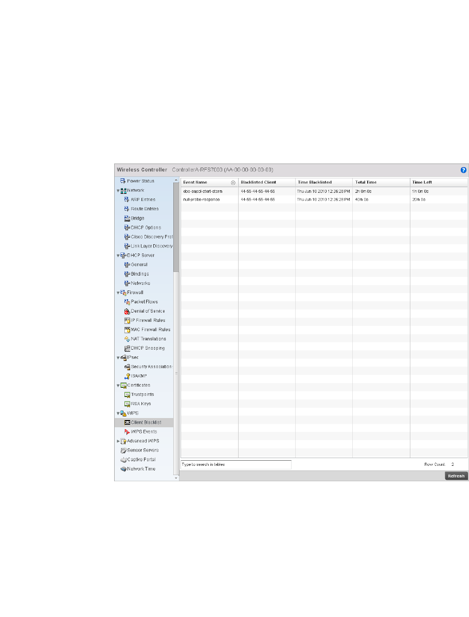
810 Brocade Mobility RFS4000, RFS6000, and RFS7000 System Reference Guide
53-1002620-01
14
The client blacklist screen displays the statistics for blacklisted clients detected by WIPS.
To view the client blacklist screen:
1. Select the Statistics menu from the Web UI.
2. Select a Wireless Controller node from the left navigation pane.
3. Select WIPS > Client Blacklist from the left-hand side of the controller UI.
FIGURE 545 Wireless Controller WIPS Client Blacklist screen
4. The Client Blacklist screen displays the following:
Viewing WIPS Event Statistics
The WIPS event screen displays event information for rogue access point intrusions within a
controller managed network.
To view WIPS event statistics:
Event Name Displays the name of the detected wireless intrusion.
Blacklisted Client Displays the MAC address of the intruding access point.
Time Blacklisted Displays the time this client was blacklisted.
Total Time Displays the length of time the unauthorized device remained in the WLAN.
Time Left Displays the duration after which the blacklisted client is removed from the blacklist.
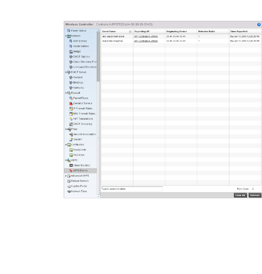
Brocade Mobility RFS4000, RFS6000, and RFS7000 System Reference Guide 811
53-1002620-01
14
1. Select the Statistics menu from the Web UI.
2. Select a Wireless Controller node from the left navigation pane.
3. Select WIPS > WIPS Events from the left-hand side of the controller UI.
FIGURE 546 Wireless Controller WIPS Events screen
4. The WIPS Events screen displays the following:
Advanced WIPS
Wireless Controller Statistics
WIPS monitors for the presence of unauthorized rogue access points and attacks against the
managed network.
The Advanced WIPS screens supports the following:
•Viewing General WIPS Statistics
Event Name Displays the name of the detected intrusion event.
Reporting AP Displays the MAC address of the AP reporting this intrusion.
Originating Device Displays the MAC address of the intruder AP.
Detector Radio Displays the type of radio detecting the intrusion.
Time Reported Displays the time when the intruding AP was detected.
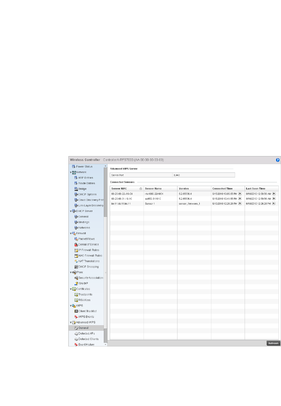
812 Brocade Mobility RFS4000, RFS6000, and RFS7000 System Reference Guide
53-1002620-01
14
•Viewing Detected AP Statistics
•Viewing Detected Clients
•Viewing Event History
Viewing General WIPS Statistics
Advanced WIPS
The General WIPS screen describes WIPS server and sensor address information, version and
connection state.
1. Select the Statistics menu from the Web UI.
2. Select a Wireless Controller node from the left navigation pane.
3. Select Advanced WIPS > General from the left-hand side of the controller UI.
FIGURE 547 Wireless Controller Advanced WIPS screen
4. The Advanced WIPS Server field displays the number of ports on the WIPS server.
5. The Connected Sensors field displays the following:
Sensor MAC Displays the MAC address of each listed sensor AP.
Sensor Name Displays the name of each sensor AP.
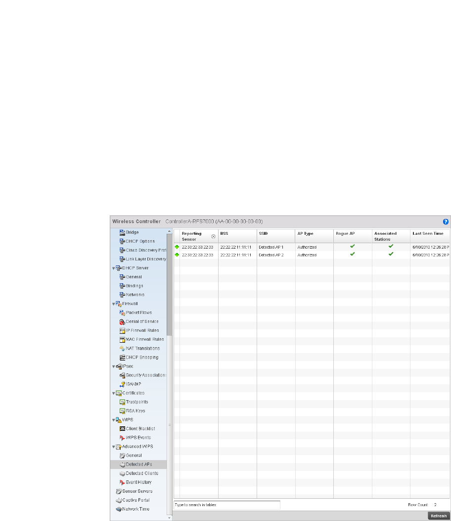
Brocade Mobility RFS4000, RFS6000, and RFS7000 System Reference Guide 813
53-1002620-01
14
Viewing Detected AP Statistics
Advanced WIPS
The Detected APs screen displays network address and connection status for APs within the
managed network.
To view detected AP stats:
1. Select the Statistics menu from the Web UI.
2. Select a Wireless Controller node from the left navigation pane.
3. Select Advanced WIPS > Detected APs from the left-hand side of the controller UI.
FIGURE 548 Wireless Controller Advanced WIPS Detected APs screen
Version Displays each sensor AP’s firmware version.
Connected Time Displays when the sensor AP connected to the controller.
Last Seen Time Displays the number of seconds since the controller last received packets from each
sensor AP.

814 Brocade Mobility RFS4000, RFS6000, and RFS7000 System Reference Guide
53-1002620-01
14
4. The Detected APs screen displays the following:
Viewing Detected Clients
Advanced WIPS
The Detected Clients screen provides details about rogue clients detected on the network.
To view the detected clients statistics:
1. Select the Statistics menu from the Web UI.
2. Select a Wireless Controller node from the left navigation pane.
3. Select Advanced WIPS > Detected Clients from the left-hand side of the controller UI.
Reporting Sensor Displays the numerical value for the radio used with the detecting AP.
BSS Displays the MAC address of each unapproved AP. These are APs observed on the
network, but have yet to be added to the list of approved APs, and are therefore
interpreted as a threat.
SSID Displays the SSID of each unapproved AP. These SSIDs are device SSIDs observed on
the network, but have yet to be added to the list of approved APs, and therefore
interpreted as a threat.
AP Type Displays the type of AP detected.
Rogue AP Displays the rogue AP’s MAC address.
Associated
Stations
Displays the number of clients currently associated with the detected AP’s radio.
Last Seen Time Displays the time (in seconds) the unapproved AP was last seen on the network.
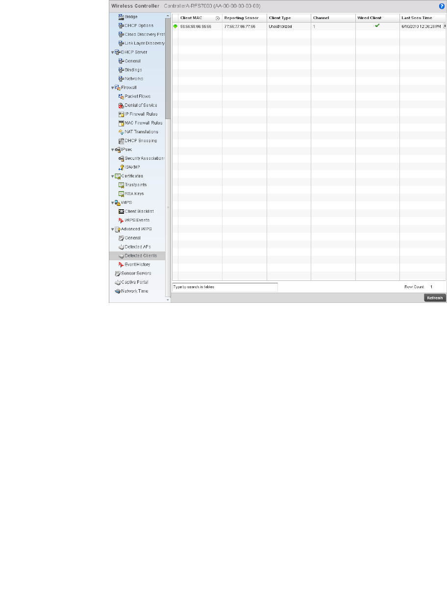
Brocade Mobility RFS4000, RFS6000, and RFS7000 System Reference Guide 815
53-1002620-01
14
FIGURE 549 Wireless Controller Advanced WIPS Detected Clients screen
4. The Detected Clients screen displays the following:
Viewing Event History
Advanced WIPS
The Event History screen details unauthorized rogue devices. Unauthorized attempts to access the
WLAN are generally accompanied by anomalous behavior, as intruding wireless clients try to find
network vulnerabilities.
To view the event history:
1. Select the Statistics menu from the Web UI.
2. Select a Wireless Controller node from the left navigation pane.
3. Select Advanced WIPS > Event History from the left-hand side of the controller UI.
Client MAC Displays the MAC address of the detected client
Reporting Sensor Displays the numerical value for the radio used with the detecting AP.
Client Type Displays the type of client detected.
Channel Displays the channel the client is transmitting on.
Wired Client Displays the MAC address detected clients using a wired connection
Last Seen Time Displays the time (in seconds) the detected client was last seen on the network.
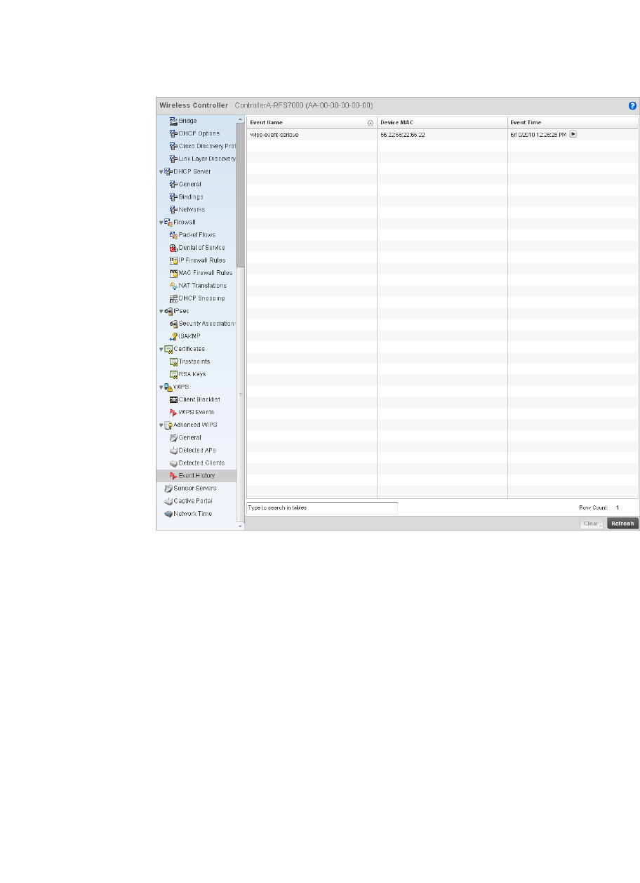
816 Brocade Mobility RFS4000, RFS6000, and RFS7000 System Reference Guide
53-1002620-01
14
FIGURE 550 Wireless Controller Advanced WIPS Event History screen
4. The Event History screen displays the following:
Sensor Server
Wireless Controller Statistics
Sensor servers allow the monitor and download of data from multiple sensors and remote
locations using Ethernet TCP/IP or serial communication. Repeaters are available to extend the
transmission range and combine sensors with various frequencies on the same receiver.
To view the Sensor Server statistics:
1. Select the Statistics menu from the Web UI.
2. Select a Wireless Controller node from the left navigation pane.
3. Select Sensor Servers from the left-hand side of the controller UI.
Event Name Displays the name of the detected intrusion.
Device MAC Displays the MAC address of the intruding device.
Event Time Displays the time the intruder was detected.
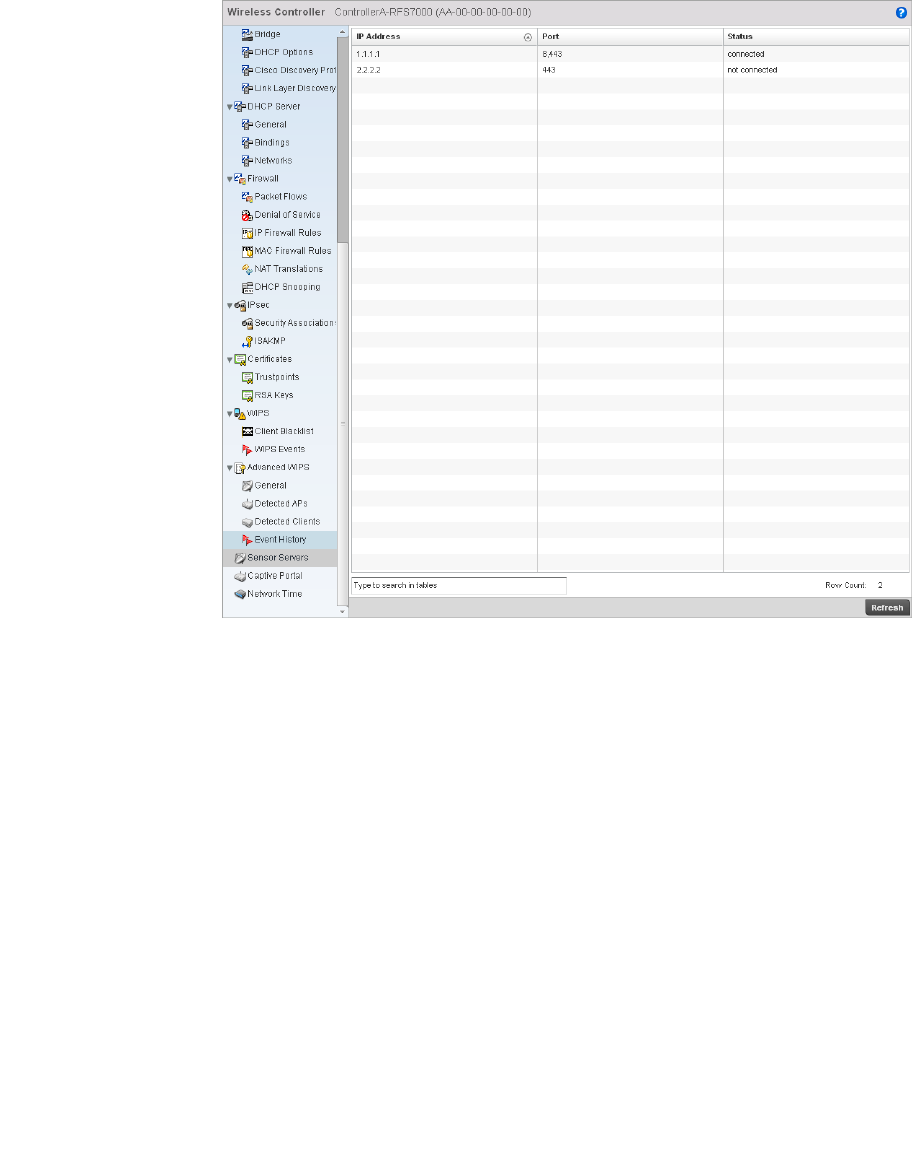
Brocade Mobility RFS4000, RFS6000, and RFS7000 System Reference Guide 817
53-1002620-01
14
FIGURE 551 Wireless Controller Sensor Servers screen
4. The Sensor Servers screen displays the following:
Captive Portal Statistics
Wireless Controller Statistics
A captive portal redirects an HTTP client to a Web page (usually for authentication purposes) before
authenticating for Internet access. A captive portal turns a Web browser into an authenticator. This
is done by intercepting packets (regardless of the address or port) until the user opens a browser
and attempts to access the Internet. At that time, the browser is redirected to a Web page requiring
authentication.
To view the controller captive portal statistics:
1. Select the Statistics tab from the Web UI.
2. Select a Wireless Controller node from the left navigation pane.
3. Select Captive Portal from the left-hand side of the controller UI.
IP Address Displays a list of sensor server IP addresses.
Port Displays the port on which this server is listening.
Status Displays whether the server is up or down.
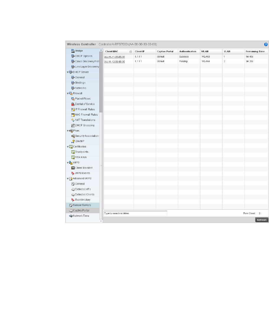
818 Brocade Mobility RFS4000, RFS6000, and RFS7000 System Reference Guide
53-1002620-01
14
FIGURE 552 Wireless Controller Captive Portal screen
4. The Captive Portal screen displays the following:
Network Time
Wireless Controller Statistics
Network Time Protocol (NTP) is central to networks that rely on their wireless controller to supply
system time. Without NTP, controller time is unpredictable, which can result in data loss, failed
processes, and compromised security. With network speed, memory, and capability increasing at
an exponential rate, the accuracy, precision, and synchronization of network time is essential in a
controller-managed enterprise network. The wireless controller can use a dedicated server to
supply system time. The controller can also use several forms of NTP messaging to sync system
time with authenticated network traffic.
Client MAC Displays the requesting client’s MAC address.
Client IP Displays the requesting client’s IP address.
Captive Portal Displays the captive portal page’s IP address.
Authentication Displays the authentication status of the requesting client.
WLAN Displays the name of the WLAN the client belongs to.
VLAN Displays the name of the requesting client’s VLAN.
Remaining Time Displays the time after which the client is disconnected from the Internet.
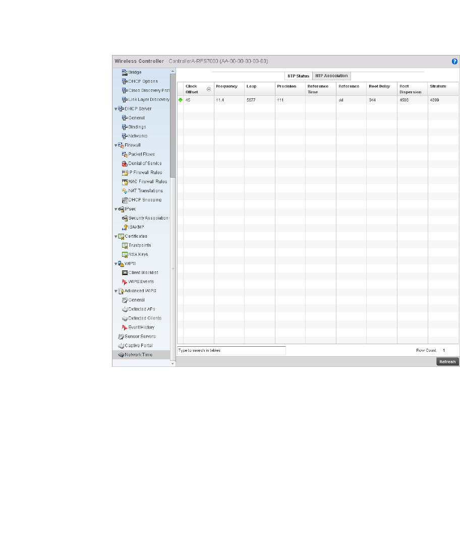
Brocade Mobility RFS4000, RFS6000, and RFS7000 System Reference Guide 819
53-1002620-01
14
Viewing NTP Status
Network Time
The NTP Status screen displays performance (status) information relative to the AP’s current NTP
association. Verify the controller’s NTP status to assess the controller’s current NTP resource.
To view the NTP status of a managed network:
1. Select the Statistics menu from the Web UI.
2. Select a Wireless Controller node from the left navigation pane.
3. Select Network Time > NTP Status from the left-hand side of the UI.
FIGURE 553 System NTP screen
4. Refer to the NTP Status table to review the accuracy and performance of the controller’s
synchronization with an NTP server.
Clock Offset Displays the time differential between the controller time and the NTP resource.
Frequency An SNTP server clock’s skew (difference) for the controller.
Leap Indicates if a second is added or subtracted to SNTP packet transmissions, or if
transmissions are synchronized.
Precision Displays the precision of the controller’s time clock (in Hz). The values that normally
appear in this field range from -6 for mains-frequency clocks to -20 for microsecond
clocks.
Reference Time Displays the time stamp the local clock was last set or corrected.

820 Brocade Mobility RFS4000, RFS6000, and RFS7000 System Reference Guide
53-1002620-01
14
Viewing NTP Associations
Network Time
The interaction between the controller and an SNTP server constitutes an association. SNTP
associations can be either peer associations (the controller synchronizes to another system or
allows another system to synchronize to it), or a server associations (only the controller
synchronizes to the SNTP resource, not the other way around).
To view the NTP associations:
1. Select the Statistics menu from the Web UI.
2. Select a Wireless Controller node from the left navigation pane.
3. Select Network > NTP Association from the left-hand side of the UI.
Reference Displays the address of the time source the controller is synchronized to.
Root Delay The total round-trip delay in seconds. This variable can take on both positive and
negative values, depending on relative time and frequency offsets. The values that
normally appear in this field range from negative values (a few milliseconds) to positive
values (several hundred milliseconds).
Root Dispersion The difference between the time on the root NTP server and it’s reference clock. The
reference clock is the clock used by the NTP server to set its own clock.
Status Stratum Displays how many hops the controller is from its current NTP time source.
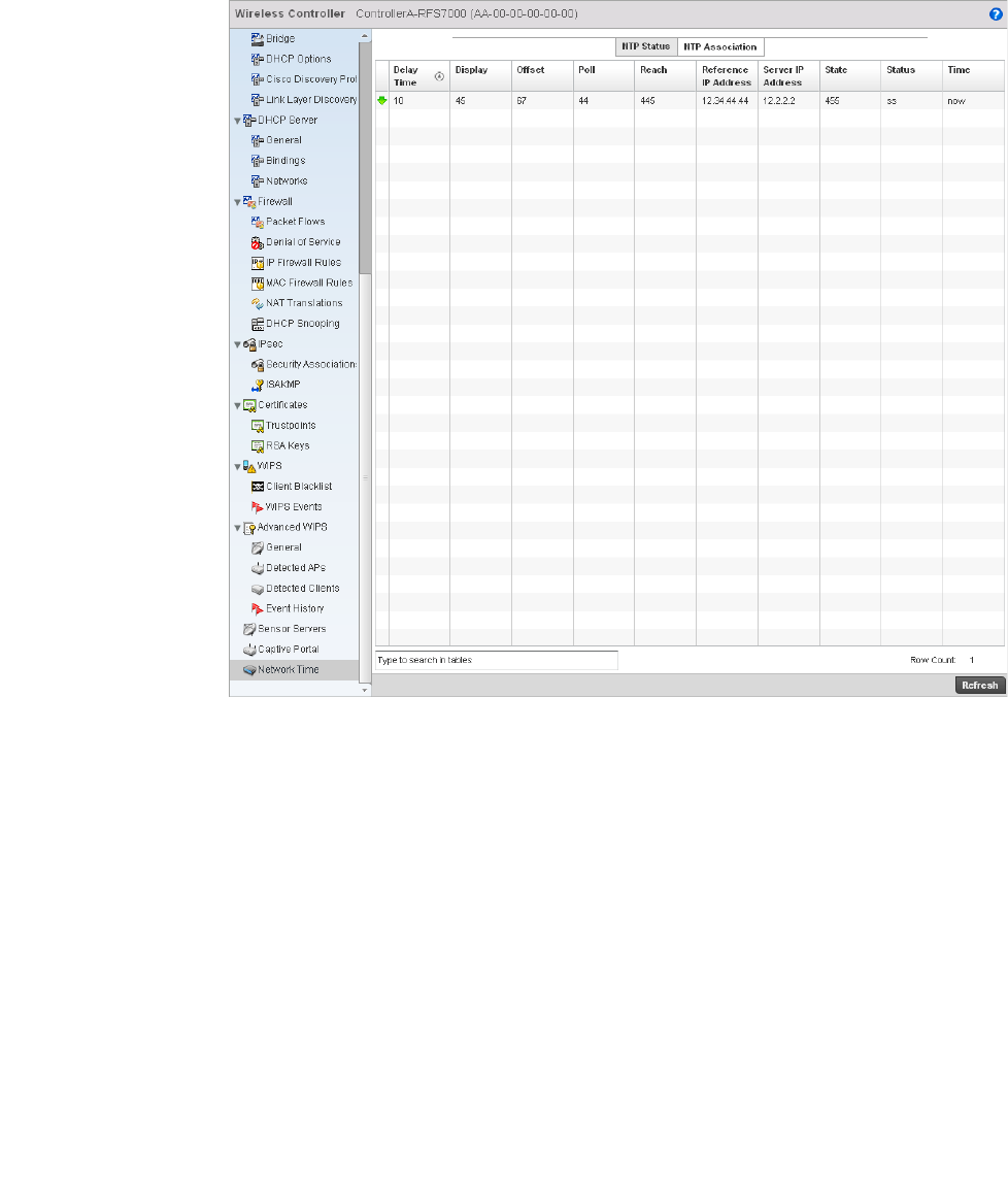
Brocade Mobility RFS4000, RFS6000, and RFS7000 System Reference Guide 821
53-1002620-01
14
FIGURE 554 AP Network Time screen
4. The NTP Associations screen provides the controller’s current NTP associations.
This screen provides the following:
Delay Time Displays the round-trip delay (in seconds) for SNTP broadcasts between the SNTP server
and the wireless controller.
Dispersion Displays the time difference between the peer NTP server and the onboard wireless
controller clock.
Offset Displays the calculated offset between the wireless controller and the SNTP server. The
controller adjusts its clock to match the server’s time value. The offset gravitates
towards zero overtime, but never completely reduces its offset to zero.
Poll Displays the maximum interval between successive messages (in seconds) to the
nearest power of two.
Reach Displays the status of the last eight SNTP messages. If an SNTP packet is lost, the lost
packet is tracked over the next eight SNTP messages.
Reference IP Address Displays the address of the time source the wireless controller is synchronized to.
Server IP Address Displays the numerical IP address of the SNTP resource (server) providing SNTP updates
to the wireless controller.

822 Brocade Mobility RFS4000, RFS6000, and RFS7000 System Reference Guide
53-1002620-01
14
Wireless Client Statistics
The Wireless Client statistics screen displays read-only statistics for each detected client. It
provides an overview of the health of wireless clients in the network. Wireless client statistics
includes RF quality, traffic utilization, user details, etc. Use this information to assess if
configuration changes are required to improve network performance.
The wireless clients statistics screen can be divided into:
•Health
•Details
•Traffic
•WMM TSPEC
Health
Wireless Client Statistics
The Health screen displays information on the overall performance of a wireless client.
To view the health of wireless clients:
1. Select the Statistics menu from the Web UI.
2. Select a Wireless Client node from the left navigation pane.
3. Select Health from the left-hand side of the controller UI.
State Displays the NTP association status. The state can be one of the following:
•Synced – Indicates the wireless controller is synchronized to this NTP server.
•Unsynced – Indicates the wireless controller has chosen this master for
synchronization. However, the master itself is not yet synchronized to UTC.
•Selected – Indicates this NTP master server will be considered the next time the
wireless controller chooses a master to synchronize with.
•Candidate – Indicates this NTP master server may be considered for selection the
next time the wireless controller chooses a NTP master server.
•Configured – Indicates this NTP server is a configured server.
Stratum Displays the NTP peer’s stratum level.
When Displays the timestamp of the last NTP packet received from the NTP peer.
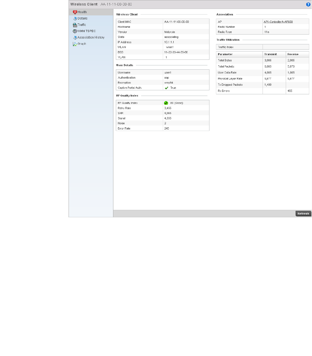
Brocade Mobility RFS4000, RFS6000, and RFS7000 System Reference Guide 823
53-1002620-01
14
FIGURE 555 Wireless Clients Health screen
4. The Wireless Client field displays the following:
5. The User Details field displays the following:
Client MAC Displays the MAC addresses of managed clients.
Vendor Displays each client’s manufacturer.
State Displays the state of the wireless client. It can be idle, authenticated, associated or
blacklisted.
IP Address Displays the IP address of the wireless client.
WLAN Displays each client’s WLAN name.
BSS Displays the client’s network BSS ID.
VLAN Displays the client’s VLAN ID
Username Displays the unique administrator or operator name.

824 Brocade Mobility RFS4000, RFS6000, and RFS7000 System Reference Guide
53-1002620-01
14
6. The RF Quality Index field displays the following:
7. T he Association field displays the following:
8. The Traffic Utilization field displays statistics on the traffic generated and received by this
wireless client. This area displays the traffic index, which measures how efficiently the traffic
medium is used. It is defined as the percentage of current throughput relative to the maximum
possible throughput.
Traffic indices are:
•0–20 —very low utilization
•20–40 — low utilization
•40–60 — moderate utilization
•60 and above — high utilization
This field also displays the following:
Authentication Lists if authentication is applied. If there’s authentication, the status displays.
Encryption Displays if encryption is applied.
Captive Portal
Authentication
Displays whether captive portal authentication is enabled.
RF Quality Index Displays client RF quality as a percentage of the connect rate in both directions, as well
as the retry and error rate. RF quality index can be interpreted as:
•0–20 — very poor quality
•20–40 —poor quality
•40–60 —average quality
•60–100 — good quality
Retry Rate Displays the average number of retries per packet. A high number indicates possible
network or hardware problems.
SNR Displays the signal to noise ratio of the wireless client associated with the wireless
controller.
Signal Displays radio transmit power in dBm.
Noise Displays disturbing influences on the signal by interference (in dBm).
Error Rate Displays the number of received bit rates that have been altered due to noise,
interference, and distortion. It is a unitless performance measure.
AP Displays the wireless client’s associated AP. Select an AP to view information in detail.
Radio Number Displays the AP radio the client is associated with.
Radio Type Displays the radio type as either 802.11b, 802.11bg, 802.11bgn, 802.11a or
802.11an.
Total Bytes Displays the total bytes processed by the wireless client.
Total Packets Displays the total number of packets processed by the wireless client.
User Data Rate Displays the average user data rate.
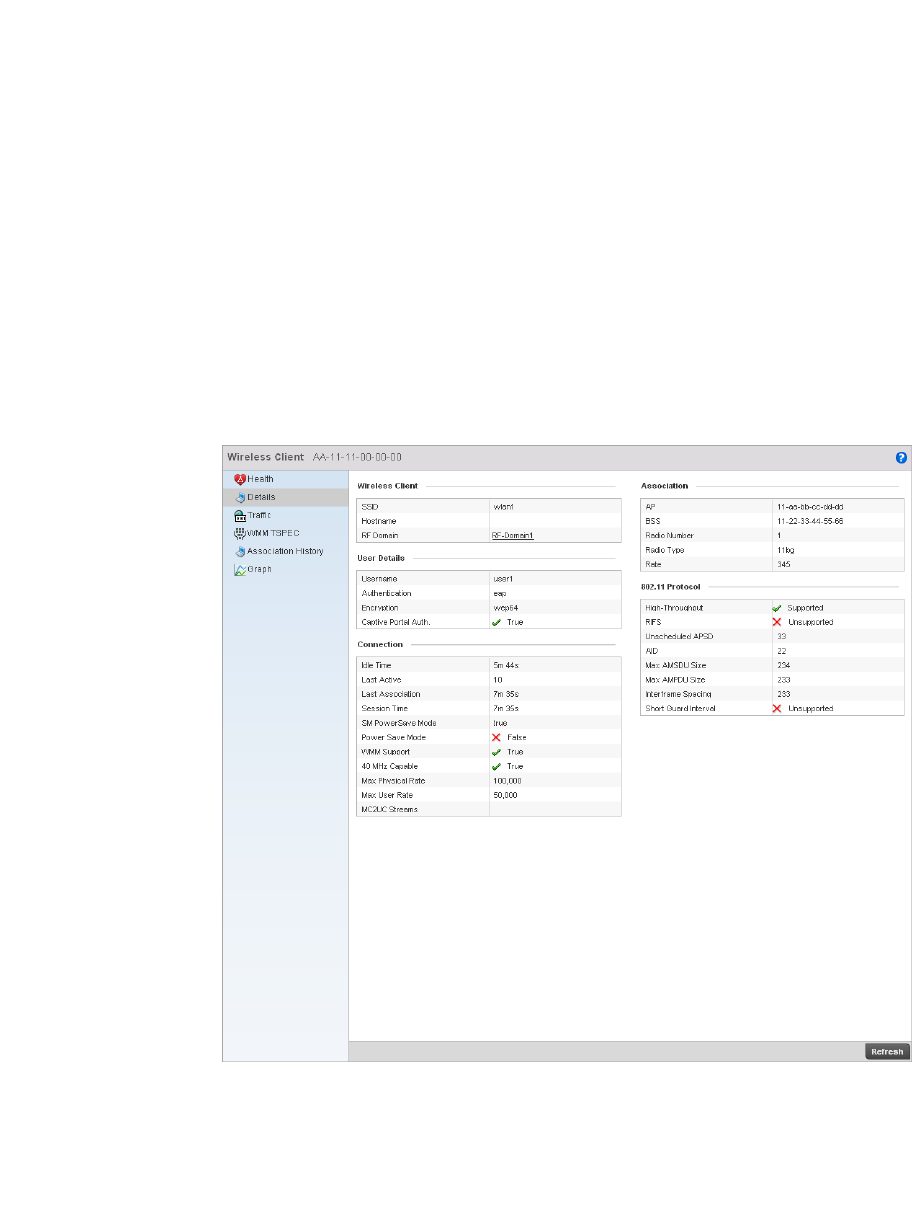
Brocade Mobility RFS4000, RFS6000, and RFS7000 System Reference Guide 825
53-1002620-01
14
Details
Wireless Client Statistics
The Details screen provides information on a selected wireless client.
To view the details screen of a wireless client:
1. Select the Statistics menu from the Web UI.
2. Select a Wireless Client node from the left navigation pane.
3. Select Details from the left-hand side of the controller UI.
FIGURE 556 Wireless Clients Details screen
4. The Wireless Client area displays the following:
Physical Layer Rate Displays the average packet rate at the physical layer.
Tx Dropped
Packets
Displays the number of packets dropped during transmission.
Rx Errors Displays the number of errors encountered during data transmission. The higher the
error rate, the less reliable the connection or data transfer.
SSID Displays the client’s associated SSID.
RF Domain Displays the wireless client’s RF Domain.

826 Brocade Mobility RFS4000, RFS6000, and RFS7000 System Reference Guide
53-1002620-01
14
5. The User Details field displays the following:
6. The Connection field displays the following:
7. T he Association field displays the following:
Username Displays the administrator or operator name.
Authentication Displays whether authentication is invoked. If authentication is applied, the field
displays its status.
Encryption Displays if any encryption is applied.
Captive Portal
Auth.
Displays whether captive portal authentication is enabled.
Idle Time Displays the wireless client’s idle time.
Last Active Displays (in seconds) when the wireless client last communicated with its connected
AP.
Last Association Displays the client’s association duration.
Session Time Displays the duration for which a session can be maintained by the wireless client
without it being dis-associated from the system.
SM Power Save
Mode
Displays whether SM Power Save is enabled on the wireless client. The spatial
multiplexing (SM) power save mode allows an 802.11n client to power down all but one
of its radios. This power save mode has two sub modes of operation: static operation
and dynamic operation.
Power Save Mode Displays whether this feature is enabled or not. To prolong battery life, the 802.11
standard defines an optional Power Save Mode, which is available on most 80211
NICs. End users can simply turn it on or off via the card driver or configuration tool.
With power save off, the 802.11 network card is generally in receive mode listening for
packets and occasionally in transmit mode when sending packets. These modes
require the 802.11 NIC to keep most circuits powered-up and ready for operation.
WMM Support Displays whether WMM support is enabled.
40 MHz Capable Displays whether the wireless client has 802.11n channel support operating at 40
MHz.
Max Physical Rate Displays the maximum data rate at the physical layer.
Max User Rate Displays the maximum permitted user data rate.
AP Displays the MAC address of the client’s associated AP.
BSS Displays the basic service set the AP belongs to. A BSS is a set stations that can
communicate with one another.
Radio Number Displays the AP radio the wireless client is associated with.
Radio Type Displays the radio type as either 802.11b, 802.11bg, 802.11bgn, 802.11a or
802.11an.
Rate Displays the permitted data rate.

Brocade Mobility RFS4000, RFS6000, and RFS7000 System Reference Guide 827
53-1002620-01
14
8. The 802.11 Protocol field displays the following:
Traffic
Wireless Client Statistics
The traffic screen provides an overview of client traffic utilization. This screen also displays a RF
quality index.
To view the traffic statistics of a wireless clients:
1. Select the Statistics menu from the Web UI.
2. Select a Wireless Client node from the left navigation pane.
3. Select Traffic from the left-hand side of the controller UI.
High-Throughput Displays whether this feature is supported or not. High throughput is a measure of the
successful packet delivery over a communication channel.
RIFS Displays whether this feature is supported. RIFS is a required 802.11n feature that
improves performance by reducing the amount of dead time between OFDM
transmissions.
Unscheduled APSD Displays whether an unscheduled service period is supported as a contiguous period
the controller is expected to be awake.
AID Displays the Association ID established by an AP. 802.11 association enables the
access point to allocate resources and synchronize with a radio NIC. An NIC begins the
association process by sending an association request to an access point. This
association request is sent as a frame. This frame carries information about the NIC
and the SSID of the network it wishes to associate. After receiving the request, the
access point considers associating with the NIC, and reserves memory space for
establishing an AID for the NIC.
Max AMSDU Size Displays the maximum AMSDU size. AMSDU is a set of Ethernet frames wrapped in a
802.11n frame. This value is the maximum AMSDU frame size in bytes.
Interframe Spacing Displays the interval between two consecutive Ethernet frames.
Short Guard
Interval
Displays the guard interval in micro seconds. Guard intervals prevent interference
between distinct data transmissions while.
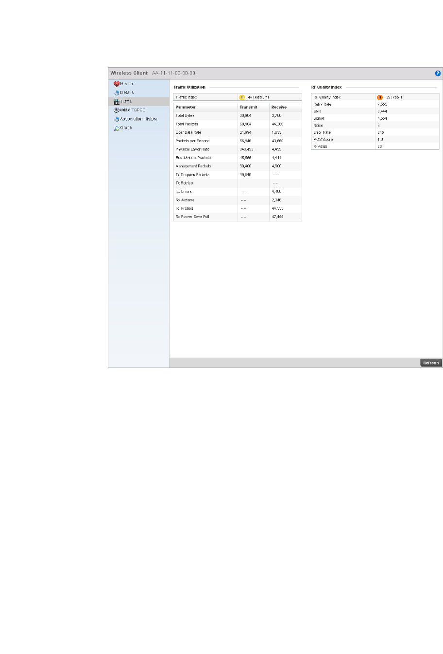
828 Brocade Mobility RFS4000, RFS6000, and RFS7000 System Reference Guide
53-1002620-01
14
FIGURE 557 Wireless Clients Traffic screen
4. The Traffic Utilization field provides the traffic index, which measures how efficiently the traffic
medium is used. It is defined as the percentage of current throughput relative to the maximum
possible throughput.
Total Bytes Displays the total bytes processed by the client.
Total Packets Displays the total number of data packets processed by the wireless client.
User Data Rate Displays the average user data rate.
Packets per
Second
Displays the packets processed per second.
Physical Layer Rate Displays the data rate at the physical layer level.
Bcast/Mcast
Packets
Displays the total number of broadcast/management packets processed.
Management
Packets
Displays the number of management packets processed.
Tx Dropped
Packets
Displays the number of dropped packets while transmitting.
Tx Retries Displays the total number of transmit retries.
Rx Errors Displays the degree of errors encountered during data transmission. The higher the
error rate, the less reliable the connection or data transfer.

Brocade Mobility RFS4000, RFS6000, and RFS7000 System Reference Guide 829
53-1002620-01
14
5. The RF Quality Index field displays the following:
WMM TSPEC
Wireless Client Statistics
802.11e Traffic Specification (TSPEC) provides a set of parameters that defines the characteristics
of the traffic stream, for example: operating requirement and scheduling. The sender T spec
specifies parameters available for the flow of packets. Both the sender and the receiver use Tspec.
The TSPEC screen provides the information about these TSPEC counts, TSPEC types, etc. of the
wireless client selected.
To view the TSPEC statistics:
1. Select the Statistics from the Web UI.
Rx Actions Displays the number of receive actions during data transmission.
Rx Probes Displays the number of probes sent. A probe is a program or other device inserted at a
key juncture in a for network for the purpose of monitoring or collecting data about
network activity.
Rx Power Save Poll Displays the power save using the Power Save Poll (PSP) mode. Power Save Poll (PSP)
is a protocol, which helps to reduce the amount of time a radio needs to powered. PSP
allows the WiFi adapter to notify the access point when the radio is powered down. The
access point holds any network packet to be sent to this radio.
RF Quality Index Displays the client’s RF quality. The RF quality index is the overall effectiveness of the
RF environment, as a percentage of the connect rate in both directions as well as the
retry rate and the error rate. RF quality index value can be interpreted as:
•0–20 — very poor quality
•20–40 —poor quality
•40–60 —average quality
•60–100 — good quality
Retry Rate Displays the average number of retries per packet. A high number indicates possible
network or hardware problems.
SNR Displays the signal to noise ratio of the wireless client associated with the wireless
controller.
Signal Displays the power of the radio signals in dBm.
Noise Displays disturbing influences on the signal by interference.
Error Rate Displays the number of received bit rates altered due to noise, interference, and
distortion. It’s a unitless performance measure.
MOS Score Displays the average call quality using the Mean Opinion Score (MOS) call quality
scale. The MOS scale rates call quality on a scale of 1-5, with higher scores being
better. If the MOS score is lower than 3.5, it’s likely users will not be satisfied with the
voice quality.
R-Value Displays the R-value. R-value is a number or score that is used to quantitatively express
the quality of speech in communications systems. This is used in digital networks that
carry Voice over IP (VoIP) traffic. The R-value can range from 1 (worst) to 100 (best) and
is based on the percentage of users who are satisfied with the quality of a test voice
signal after it has passed through a network from a source (transmitter) to a
destination (receiver). The R-value scoring method accurately portrays the effects of
packet loss and delays in digital networks carrying voice signals.
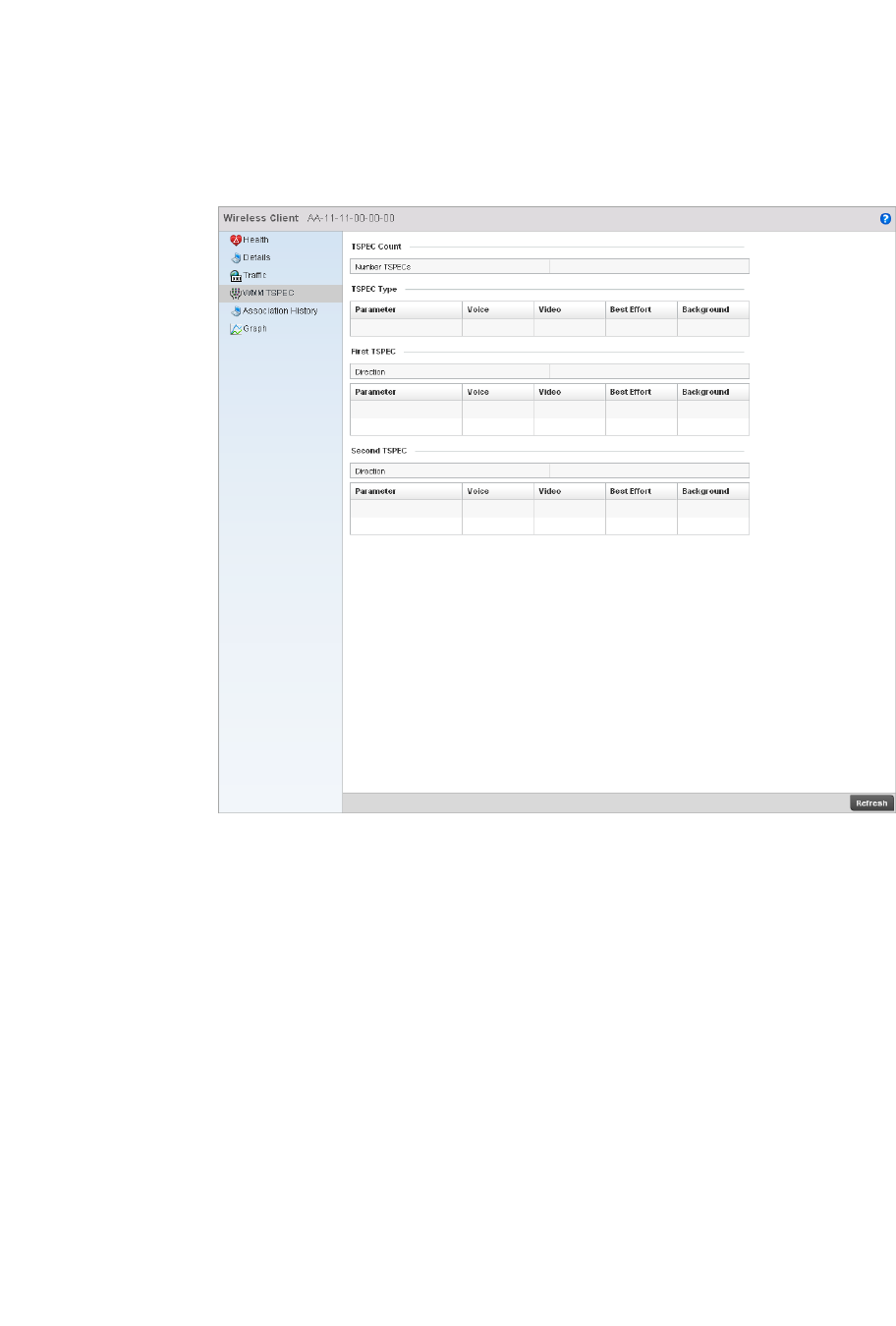
830 Brocade Mobility RFS4000, RFS6000, and RFS7000 System Reference Guide
53-1002620-01
14
2. Select a Wireless Client node from the left navigation pane.
3. Select WMM TSPEC from the left-hand side of the controller UI.
FIGURE 558 Wireless Clients 802.11e TSPEC screen
4. The TSPEC Count displays the number of TSPECs available for the client’s packet flow.
5. The TSPEC Type field displays the following:
6. The First TSPEC field displays the following:
Voice Displays the status of voice traffic prioritization. A red ‘X’ indicates this feature is
disabled. A green check mark indicates this feature is enabled.
Video Displays the status of prioritization for video traffic. A red ‘X’ indicates this feature is
disabled. A green check mark indicates this feature is enabled.
Best Effort Displays the status of prioritization for best effort traffic. A red ‘X’ indicates this feature
is disabled. A green check mark indicates this feature is enabled.
Background Displays the status of prioritization for background traffic. A red ‘X’ indicates this
feature is disabled. A green check mark indicates this feature is enabled.
Direction Displays whether this is a transmitting or receiving flow.
Parameter Displays the parameter for defining the traffic stream. TID identifies data packets as
belonging to a unique traffic stream.
Voice Displays the voice corresponding to TID and Media Time.

Brocade Mobility RFS4000, RFS6000, and RFS7000 System Reference Guide 831
53-1002620-01
14
7. T he Second TSPEC field displays the following:
Video Displays the Video corresponding to TID and Media Time.
Best Effort Displays the Best Effort corresponding to TID and Media Time.
Background Displays the Background corresponding to TID and Media Time.
Direction Displays whether this is a transmitting or receiving flow
Parameter Displays the parameter for defining the traffic stream. TID identifies data packets as
belonging to a unique traffic stream.
Voice Displays the voice corresponding to TID and Media Time.
Video Displays the Video corresponding to TID and Media Time.
Best Effort Displays the Best Effort corresponding to TID and Media Time.
Background Displays the Background corresponding to TID and Media Time.

832 Brocade Mobility RFS4000, RFS6000, and RFS7000 System Reference Guide
53-1002620-01
14
