Ruckus SmartZone 100/Virtual Essentials Smart Zone 3.2 Administrator Guide (SZ 100/v SZ E) Sz100 Vsz E 3 2 20161121
2016-11-22
User Manual: Ruckus SmartZone 3.2 Administrator Guide (SZ-100/vSZ-E)
Open the PDF directly: View PDF ![]() .
.
Page Count: 232 [warning: Documents this large are best viewed by clicking the View PDF Link!]
- Contents
- Copyright Notice and Proprietary Information
- Document Conventions
- Documentation Feedback
- Online Training Resources
- Navigating the Web Interface
- Setting Up the Controller for the First Time
- Logging On to the Web Interface
- Web Interface Features
- Using Widgets on the Dashboard
- Changing the Administrator Password
- Logging Off the Web Interface
- Working with User Accounts, Guest Passes, and User Roles
- Configuring the Wireless Network
- Configuring WLANs
- Configuring WLAN Groups
- Configuring Access Points
- Controlling Access to the Wireless Network
- Controlling and Monitoring Applications
- Managing Guest Access
- Working with Hotspot (WISPr) Services
- Working With WeChat Services
- Working with Hotspot 2.0 Services
- Working with Web Authentication Services
- Working with AAA Servers
- Configuring Location Services
- Configuring Bonjour Gateway Policies
- Configuring System Settings
- Configuring Network Settings
- Configuring Log Settings
- Configuring Event Management
- Configuring Event Thresholds
- Configuring the Northbound Portal Interface
- Configuring the System Time
- Configuring an External Email Server
- Configuring External FTP Servers
- Managing the Certificate Store
- Configuring the External SMS Gateway
- Configuring SNMP Settings
- Managing the User Agent Blacklist
- Managing Administrators, Administrator Roles, and Administrator Authentication
- Monitoring the Wireless Network
- Working with Reports
- Performing Administrative Tasks
- Backing Up and Restoring Clusters
- Backing Up and Restoring the Controller's Network Configuration from an FTP Server
- Backing Up and Restoring System Configuration
- Resetting a Node to Factory Settings
- Upgrading the Controller
- Working with Logs
- Managing Licenses
- Default Licenses in the SmartZone 100
- Activating SmartLicense on SZ-100
- Supported License Types
- Default Support License
- Viewing Installed Licenses
- Viewing the License Summary
- Configuring the License Server to Use
- Importing a License File
- Downloading a Copy of the Licenses
- Synchronizing the Controller with the License Server
- Configuring the License Bandwidth
- AP-SCG/SZ/vSZ/vSZ-D Communication
- Index

SmartZone 100/Virtual SmartZone
Essentials for Release 3.2
Administrator Guide
Part Number: 800-71000-001 Rev B
Published: 22 November 2016
Contents
Copyright Notice and Proprietary Information
Document Conventions
Documentation Feedback
Online Training Resources
1 Navigating the Web Interface
Setting Up the Controller for the First Time..................................................................14
Logging On to the Web Interface.................................................................................14
Web Interface Features...............................................................................................16
Main Menu........................................................................................................16
Sidebar..............................................................................................................17
Content Area.....................................................................................................17
Miscellaneous Bar.............................................................................................17
Using Widgets on the Dashboard................................................................................18
Widgets That You Can Display..........................................................................18
Widget Slots......................................................................................................21
Adding a Widget................................................................................................21
Adding a Widget to a Widget Slot......................................................................22
Displaying a Widget in a Widget Slot..................................................................22
Moving a Widget...............................................................................................22
Deleting a Widget..............................................................................................23
Changing the Administrator Password.........................................................................23
Logging Off the Web Interface.....................................................................................23
2 Working with User Accounts, Guest Passes, and User Roles
Working with User Accounts.......................................................................................25
Creating a User Account...................................................................................25
Editing a User Account......................................................................................26
Working with Guest Passes.........................................................................................27
Generating Guest Passes..................................................................................27
Generating Guest Passes from an Imported CSV..............................................34
Viewing the List of Guest Users.........................................................................36
Deleting Guest Users.........................................................................................36
Creating a Guest Pass Printout Template..........................................................37
SmartZone 100/Virtual SmartZone Essentials for Release 3.2 Administrator Guide
2
Working with User Roles.............................................................................................39
Creating a User Role.........................................................................................39
3 Configuring the Wireless Network
Configuring WLANs.....................................................................................................41
Creating a WLAN...............................................................................................41
Viewing Existing WLANs....................................................................................49
Deleting WLANs................................................................................................50
Configuring WLAN Groups..........................................................................................50
Creating a WLAN Group....................................................................................51
Viewing Existing WLAN Groups.........................................................................52
Deleting WLAN Groups.....................................................................................52
Working with WLAN Schedule Profiles...............................................................52
Configuring Access Points...........................................................................................55
Configuring Common AP Settings.....................................................................55
Managing Access Points...................................................................................66
Configuring Model Based Settings.....................................................................71
Configuring AP Tunnel Settings.........................................................................73
Tagging Critical APs..........................................................................................75
Creating an IPsec Profile....................................................................................75
Creating an Ethernet Port Profile........................................................................78
Controlling Access to the Wireless Network................................................................82
Working with User Traffic Profiles.......................................................................82
Controlling L2 Access........................................................................................84
Controlling Device Access.................................................................................86
Controlling and Monitoring Applications.......................................................................87
Enabling Application Control and Visibility..........................................................87
Applications That AVC Can Identify....................................................................88
Adding a User Defined Application.....................................................................90
Monitoring Application Visibility..........................................................................91
Managing Guest Access.............................................................................................92
Creating a Guest Access Service.......................................................................93
Viewing Guest Access Services.........................................................................94
Deleting Guest Access Services........................................................................95
Working with Hotspot (WISPr) Services.......................................................................95
Creating a Hotspot (WISPr) Service...................................................................96
Assigning a WLAN to Provide Hotspot Service..................................................99
Working With WeChat Services.................................................................................100
SmartZone 100/Virtual SmartZone Essentials for Release 3.2 Administrator Guide
3
Creating a WeChat Portal................................................................................100
Creating a WeChat WLAN...............................................................................102
Working with Hotspot 2.0 Services............................................................................106
Working with Web Authentication Services................................................................107
Adding an AAA Server for the Web Authentication Service..............................107
Creating a Web Authentication Service............................................................107
Creating a WLAN for the Web Authentication Service......................................108
Working with AAA Servers.........................................................................................110
Working with Proxy AAA Servers.....................................................................110
Working with Non-Proxy AAA Servers.............................................................116
Configuring Location Services...................................................................................120
Configuring Bonjour Gateway Policies.......................................................................122
Creating a Bonjour Gateway Rule on the AP....................................................122
Applying a Bonjour Policy to an AP..................................................................123
4 Configuring System Settings
Configuring Network Settings....................................................................................125
Setting the System IP Mode............................................................................125
Rebalancing APs Across Nodes......................................................................126
Configuring the Physical Interface Settings......................................................127
Configuring the User Defined Interface Settings...............................................129
Creating and Configuring Static Routes...........................................................130
Configuring Log Settings...........................................................................................131
Event Severity Levels.......................................................................................133
Default Event Severity to Syslog Priority Mapping............................................134
Configuring Event Management.................................................................................134
Enabling or Disabling Notifications for a Single Event.......................................135
Viewing Enabled Notifications for Events..........................................................136
Configuring Event Thresholds....................................................................................136
Events with Configurable Thresholds...............................................................137
Configuring the Northbound Portal Interface..............................................................138
Configuring the System Time.....................................................................................138
How APs Synchronize Time with the Controller...............................................139
Configuring an External Email Server.........................................................................139
Configuring External FTP Servers..............................................................................140
Managing the Certificate Store..................................................................................141
Generate a Certificate Signing Request...........................................................142
Importing an SSL Certificate............................................................................144
SmartZone 100/Virtual SmartZone Essentials for Release 3.2 Administrator Guide
4
Assigning Certificates to Services....................................................................145
Configuring the External SMS Gateway.....................................................................146
Configuring SNMP Settings.......................................................................................147
Enabling Global SNMP Traps..........................................................................147
Configuring the SNMPv2 Agent.......................................................................148
Configuring the SNMPv3 Agent.......................................................................149
Managing the User Agent Blacklist............................................................................150
Adding a User Agent to the Blacklist................................................................150
Deleting User Agents from the Blacklist...........................................................151
5 Managing Administrators, Administrator Roles, and Administrator
Authentication
Managing Administrator Accounts.............................................................................152
Creating an Administrator Account..................................................................152
Managing Administrator Roles...................................................................................153
Creating an Administrator Role........................................................................153
Editing an Administrator Role...........................................................................154
Cloning an Existing Administrator Role.............................................................155
Managing RADIUS Servers for Administrator Authentication......................................155
Adding a RADIUS Server for Administrator Authentication...............................155
Using a Backup RADIUS Server......................................................................156
Testing an AAA Server.....................................................................................158
Authenticating an Administrator Using an External AAA Server........................158
6 Monitoring the Wireless Network
Monitoring Managed Access Points..........................................................................162
Viewing a Summary of Access Points..............................................................162
Exporting the Access Point List to CSV...........................................................164
Viewing the Configuration of an Access Point..................................................165
Downloading the Support Log from an Access Point.......................................166
Restarting an Access Point Remotely..............................................................167
Running Ping and Traceroute on an Access Point...........................................167
Viewing Managed APs on Google Maps™.................................................................167
Monitoring the Mesh Network...................................................................................168
Monitoring Wireless Clients........................................................................................169
Viewing a Summary of Wireless Clients............................................................169
Exporting the Wireless Client List to CSV.........................................................171
SmartZone 100/Virtual SmartZone Essentials for Release 3.2 Administrator Guide
5
Viewing Information About a Wireless Client....................................................171
Measuring Wireless Network Throughput with SpeedFlex................................172
Monitoring Managed Devices....................................................................................173
Monitoring the System..............................................................................................174
Viewing the System Cluster Overview..............................................................174
Displaying the Chassis View of Cluster Nodes.................................................175
Starting the Node Real-time Monitor................................................................176
Monitoring Data Planes....................................................................................176
Monitoring Rogue Access Points...............................................................................177
Monitoring Location Services.....................................................................................178
Viewing All Alarms.....................................................................................................178
Exporting the Alarm List to CSV.......................................................................180
Clearing Alarms...............................................................................................180
Acknowledging Alarms....................................................................................180
Viewing All Events.....................................................................................................181
Exporting the Event List to CSV.......................................................................182
Monitoring Administrator Activities.............................................................................182
Exporting the Administrator Activity List to CSV...............................................183
7 Working with Reports
Types of Reports.......................................................................................................185
Client Number Report......................................................................................185
Client Number vs Airtime Report......................................................................185
Continuously Disconnected APs Report..........................................................186
Failed Client Associations Report.....................................................................186
New Client Associations Report.......................................................................186
System Resource Utilization Report.................................................................186
TX/RX Bytes Report.........................................................................................186
Creating a New Report..............................................................................................186
Step 1: Define the General Report Details........................................................186
Step 2: Define the Resource Filter Criteria........................................................187
Step 3: Define the Time Filter...........................................................................188
Step 4: Define the Report Generation Schedule...............................................189
Step 5: Enable Email Notifications (Optional)....................................................190
Step 6: Export the Report to an FTP Server (Optional).....................................191
Step 7: Save the Report..................................................................................191
Viewing a List of Existing Reports..............................................................................191
Deleting a Report......................................................................................................192
SmartZone 100/Virtual SmartZone Essentials for Release 3.2 Administrator Guide
6
8 Performing Administrative Tasks
Backing Up and Restoring Clusters...........................................................................193
Creating a Cluster Backup...............................................................................193
Restoring a Cluster Backup.............................................................................194
Deleting a Cluster Backup...............................................................................195
Backing Up and Restoring the Controller's Network Configuration from an FTP
Server...................................................................................................................196
Backing Up to an FTP Server..........................................................................196
Restoring from an FTP Server..........................................................................200
Backing Up and Restoring System Configuration......................................................205
Creating a System Configuration Backup........................................................205
Exporting the Configuration Backup to an FTP Server Automatically................206
Scheduling a Configuration Backup.................................................................206
Downloading a Copy of the Configuration Backup...........................................207
Restoring a System Configuration Backup.......................................................208
Deleting a Configuration Backup......................................................................208
Resetting a Node to Factory Settings........................................................................209
Using the Web Interface..................................................................................209
Using the CLI...................................................................................................210
Upgrading the Controller...........................................................................................210
Performing the Upgrade..................................................................................211
Verifying the Upgrade......................................................................................212
Rolling Back to a Previous Software Version....................................................212
Recovering a Cluster from an Unsuccessful Upgrade......................................213
Upgrading the vSZ-D.......................................................................................214
Working with Logs.....................................................................................................214
Available System Log Types............................................................................214
Downloading All Logs......................................................................................216
Downloading Snapshot Logs Generated from the CLI.....................................216
Managing Licenses...................................................................................................217
Default Licenses in the SmartZone 100...........................................................218
Activating SmartLicense on SZ-100.................................................................219
Supported License Types................................................................................219
Default Support License..................................................................................220
Viewing Installed Licenses...............................................................................220
Viewing the License Summary.........................................................................220
Configuring the License Server to Use.............................................................221
SmartZone 100/Virtual SmartZone Essentials for Release 3.2 Administrator Guide
7
Importing a License File...................................................................................223
Downloading a Copy of the Licenses...............................................................223
Synchronizing the Controller with the License Server.......................................224
Configuring the License Bandwidth.................................................................225
Appendix A: AP-SCG/SZ/vSZ/vSZ-D Communication
SmartZone 100/Virtual SmartZone Essentials for Release 3.2 Administrator Guide
8
Copyright Notice and Proprietary Information
Copyright 2016. Ruckus Wireless, Inc. All rights reserved.
No part of this documentation may be used, reproduced, transmitted, or translated, in any form
or by any means, electronic, mechanical, manual, optical, or otherwise, without prior written
permission of Ruckus Wireless, Inc. (“Ruckus”), or as expressly provided by under license from
Ruckus.
Destination Control Statement
Technical data contained in this publication may be subject to the export control laws of the
United States of America. Disclosure to nationals of other countries contrary to United States
law is prohibited. It is the reader’s responsibility to determine the applicable regulations and to
comply with them.
Disclaimer
THIS DOCUMENTATION AND ALL INFORMATION CONTAINED HEREIN (“MATERIAL”) IS
PROVIDED FOR GENERAL INFORMATION PURPOSES ONLY. RUCKUS AND ITS LICENSORS
MAKE NO WARRANTY OF ANY KIND, EXPRESS OR IMPLIED, WITH REGARD TO THE
MATERIAL, INCLUDING, BUT NOT LIMITED TO, THE IMPLIED WARRANTIES OF
MERCHANTABILITY, NON-INFRINGEMENT AND FITNESS FOR A PARTICULAR PURPOSE,
OR THAT THE MATERIAL IS ERROR-FREE, ACCURATE OR RELIABLE. RUCKUS RESERVES
THE RIGHT TO MAKE CHANGES OR UPDATES TO THE MATERIAL AT ANY TIME.
Limitation of Liability
IN NO EVENT SHALL RUCKUS BE LIABLE FOR ANY DIRECT, INDIRECT, INCIDENTAL, SPECIAL
OR CONSEQUENTIAL DAMAGES, OR DAMAGES FOR LOSS OF PROFITS, REVENUE, DATA
OR USE, INCURRED BY YOU OR ANY THIRD PARTY, WHETHER IN AN ACTION IN CONTRACT
OR TORT, ARISING FROM YOUR ACCESS TO, OR USE OF, THE MATERIAL.
Trademarks
Ruckus Wireless, Ruckus, the bark logo, BeamFlex, ChannelFly, Dynamic PSK, FlexMaster,
Simply Better Wireless, SmartCell, SmartMesh, SmartZone, Unleashed, ZoneDirector and
ZoneFlex are trademarks of Ruckus Wireless, Inc. in the United States and other countries. All
other product or company names may be trademarks of their respective owners.
SmartZone 100/Virtual SmartZone Essentials for Release 3.2 Administrator Guide
9
9
Document Conventions
Table 1: Text conventions on page 10 and Table 2: Notice conventions on page 10 list the text
and notice conventions that are used throughout this guide.
Table 1: Text conventions
ExampleDescriptionConvention
[Device Name] >Represents messages
displayed in response to a
command or a status
message phrase
[Device Name] > set
ipaddr 10.0.0.12
Represents information that you
enter
user input
Click Create NewKeyboard keys, software
buttons, and field names
user interface controls
Select Start > All ProgramsRepresents a series of
commands, or menus and
submenus
Start > All Programs
Press ctrl+V to paste the text
from the clipboard.
Represents keyboard keys
pressed in combination
ctrl+V
Click Advanced Settings. The
Advanced Settings page
appears.
screen or page names
Represents CLI commandscommand name
Represents a parameter in a
CLI command or UI feature
parameter name
{ZoneDirectorID}Represents variable datavariable name
http://ruckuswireless.comRepresents file names or URI
strings
filepath
Table 2: Notice conventions
DescriptionNotice type
Information that describes important features
or instructions
NOTE:
Information that alerts you to potential loss of
data or potential damage to an application,
system, or device
CAUTION:
SmartZone 100/Virtual SmartZone Essentials for Release 3.2 Administrator Guide
10
Document Conventions
DescriptionNotice type
Information that alerts you to potential personal
injury
WARNING:
SmartZone 100/Virtual SmartZone Essentials for Release 3.2 Administrator Guide
11
Document Conventions
Documentation Feedback
Ruckus Wireless is interested in improving its documentation and welcomes your comments
and suggestions.
You can email your comments to Ruckus Wireless at: docs@ruckuswireless.com
When contacting us, please include the following information:
•Document title
•Document part number (on the cover page)
•Page number (if appropriate)
SmartZone 100/Virtual SmartZone Essentials for Release 3.2 Administrator Guide
12
Documentation Feedback
Online Training Resources
To access a variety of online Ruckus Wireless training modules, including free introductory
courses to wireless networking essentials, site surveys, and Ruckus Wireless products, visit the
Ruckus Wireless Training Portal at:
https://training.ruckuswireless.com.
SmartZone 100/Virtual SmartZone Essentials for Release 3.2 Administrator Guide
13
13
1
Navigating the Web Interface
In this chapter:
•Setting Up the Controller for the First Time
•Logging On to the Web Interface
•Web Interface Features
•Using Widgets on the Dashboard
•Changing the Administrator Password
•Logging Off the Web Interface
NOTE: Before continuing, make sure that you have already set up the controller as described in the
Getting Started Guide or Quick Setup Guide for your controller platform.
Setting Up the Controller for the First Time
For information on how to set up the controller for the first time, including instructions for running
and completing the controller's Setup Wizard, see the Getting Started Guide or Quick Setup
Guide for your controller platform.
Logging On to the Web Interface
Before you can log on to the controller web interface, you must have the IP address that you
assigned to the Management (Web) interface when you set up the controller on the network
using the Setup Wizard.
Once you have this IP address, you can access the web interface on any computer that can
reach the Management (Web) interface on the IP network.
Follow these steps to log on to the controller web interface.
1. On a computer that is on the same subnet as the Management (Web) interface, start a web
browser.
Supported web browsers include:
•Google Chrome 30 and later (recommended)
•Safari 6 and later (Mac OS)
•Safari 5.1.7 and later (Windows)
•Mozilla Firefox 28 and later
•Internet Explorer 10 and later
2. In the address bar, type the IP address that you assigned to the Management (Web) interface,
and then append a colon and 8443 (the controller's management port number) at the end
of the address.
SmartZone 100/Virtual SmartZone Essentials for Release 3.2 Administrator Guide
14
Navigating the Web Interface
Setting Up the Controller for the First Time
For example, if the IP address that you assigned to the Management (Web) interface is
10.10.101.1, then you should enter: https://10.10.101.1:8443
NOTE: The controller web interface requires an HTTPS connection. You must append https
(not http) to the Management interface IP address to connect to the web interface. If a
browser security warning appears, this is because the default SSL certificate (or security
certificate) that the controller is using for HTTPS communication is signed by Ruckus Wireless
and is not recognized by most web browsers.
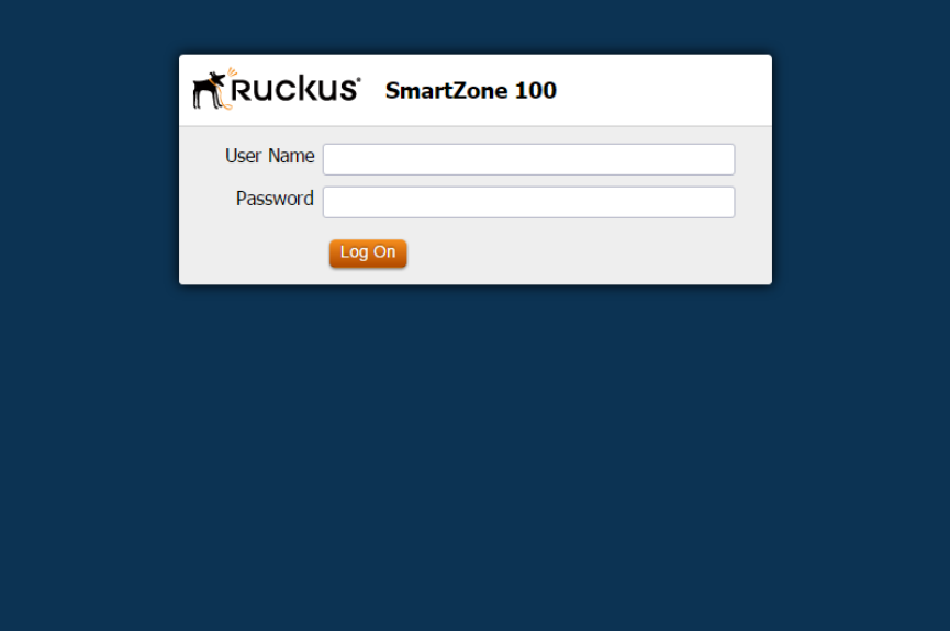
The controller web interface logon page appears.
Figure 1: The controller logon page
3. Log on to the controller web interface using the following logon details:
•User Name: admin
•Password: {the password that you set when you ran the Setup Wizard}
4. Click Log On.
The web interface refreshes, and then displays the Dashboard, which indicates that you have
logged on successfully.
SmartZone 100/Virtual SmartZone Essentials for Release 3.2 Administrator Guide
15
Navigating the Web Interface
Logging On to the Web Interface
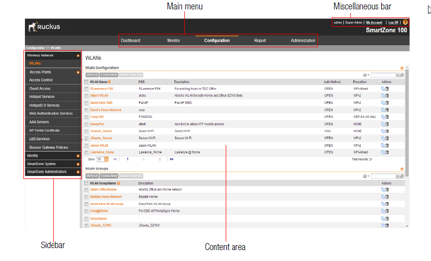
Web Interface Features
The web interface is the primary graphical front end for the controller.
The web interface (shown in Figure 2: The controller web interface features on page 16) is the
primary interface that you will use to:
•Manage access points and WLANs
•Create and manage users and roles
•Monitor wireless clients, managed devices, and rogue access points
•View alarms, events, and administrator activity
•Generate reports
•Perform administrative tasks, including backing up and restoring system configuration,
upgrading the cluster upgrade, downloading support , performing system diagnostic tests,
viewing the statuses of controller processes, and uploading additional licenses (among others)
Figure 2: The controller web interface features
The following sections describe the web interface features that are called out in Figure 2: The
controller web interface features on page 16:
Main Menu
This is the primary navigation menu.
The main menu contains the following items:
SmartZone 100/Virtual SmartZone Essentials for Release 3.2 Administrator Guide
16
Navigating the Web Interface
Web Interface Features
•Dashboard: The page that loads after you log on, it provides graphical summary of what is
happening on the controller and its managed access points. The Dashboard uses widgets
to display graphical summaries of system statuses, access point statuses, client count, etc.
For more information on the Dashboard widgets, see Using Widgets on the Dashboard on
page 18.
•Monitor: Contains options for viewing information about WLANs, access points, wireless
clients, system information, alarms, events, and administrator activity.
For more information, see Monitoring the Wireless Network on page 162.
•Configuration: Contains options for managing WLANs, access points, and system settings.
For more information, see Configuring the Wireless Network on page 41.
•Report: Contains options for generating various types of reports, including network tunnel
statistics and historical client statistics. For more information, see Working with Reports on
page 185.
•Administration: Contains options for performing administrative tasks, such as backing up
and restoring the database, upgrading the system, downloading log files, performing diagnostic
tests, and managing administrator accounts. For more information, see Performing
Administrative Tasks on page 193.
Sidebar
The sidebar, located on the left side of the Content Area, provides additional options related to
the submenu that you selected.
For example, sidebar items under Configuration > Access Points include common AP settings
and AP tunnel settings. On some pages, the sidebar also includes a tree that you can use to
filter the information you want to show in the Content Area on page 17.
Content Area
This large area displays tables, forms, and information that are relevant to submenu and sidebar
items that you clicked.
Miscellaneous Bar
This shows the following information (from left to right):
•System date and time: Displays the current system date and time. This is obtained by the
controller from the NTP time server that has been configured.
•Administrator user name: Displays the user name of the administrator that is currently logged
on.
•Administrator role: Displays the administrator role (for example, Super Admin) of the user
that is currently logged on.
•My Account link: Clicking this link displays the following links:
•Change Password: Click this link to change your administrator password. For more
information, see Changing the Administrator Password on page 23.
•Preference: Click this link to configure the session timeout settings. In Session Timeout
Settings, type the number of minutes (1 to 1440 minutes) of inactivity after which the
administrator will be logged off of the web interface automatically.
SmartZone 100/Virtual SmartZone Essentials for Release 3.2 Administrator Guide
17
Navigating the Web Interface
Web Interface Features
•Click this icon
to launch the Online Help, which provides information on how to perform management tasks
using the web interface.
Using Widgets on the Dashboard
The dashboard provides a quick summary of what is happening on the controller and its managed
access points. It uses widgets to display at-a-glance information about managed access points,
associated clients, and system summary, among others.
This section describes the widgets that you can display and how to add, move, and delete
widgets from the dashboard.
To refresh the information on each widget, click (refresh button) on the upper-right corner of the
widget.
Widgets That You Can Display
The controller supports the following dashboard widgets:
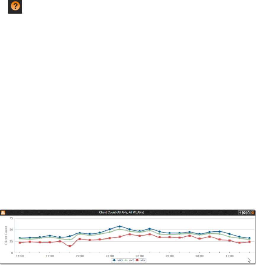
Client Count Summary Widget
The client count (all APs, all WLANs) widget displays a graph of the number of wireless clients
that are associated with access points that the controller is managing.
You can display client count by AP or WLAN. The client count summary widget requires two
widget slots.
Figure 3: The client count summary widget
AP Summary Widget
The AP summary widget includes a pie chart that shows the connection status of managed APs.
You can configure the pie chart to show access point data based on their connection status,
model, and mesh role.
This widget requires one widget slot.
SmartZone 100/Virtual SmartZone Essentials for Release 3.2 Administrator Guide
18
Navigating the Web Interface
Using Widgets on the Dashboard
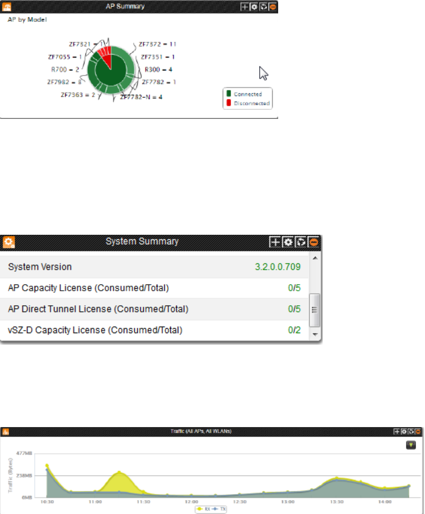
Figure 4: The AP summary widget
System Summary Widget
The system summary widget displays information about the controller system, including the
name and version of the cluster, system uptime, serial number, and the Wi-Fi controller licenses
(consumed versus total).
This widget requires one widget slot.
Figure 5: The system summary widget
Traffic Summary Widget
The traffic summary widget displays a graph of TX and RX throughputs (in bytes). This widget
requires two widget slots.
Figure 6: The traffic summary widget
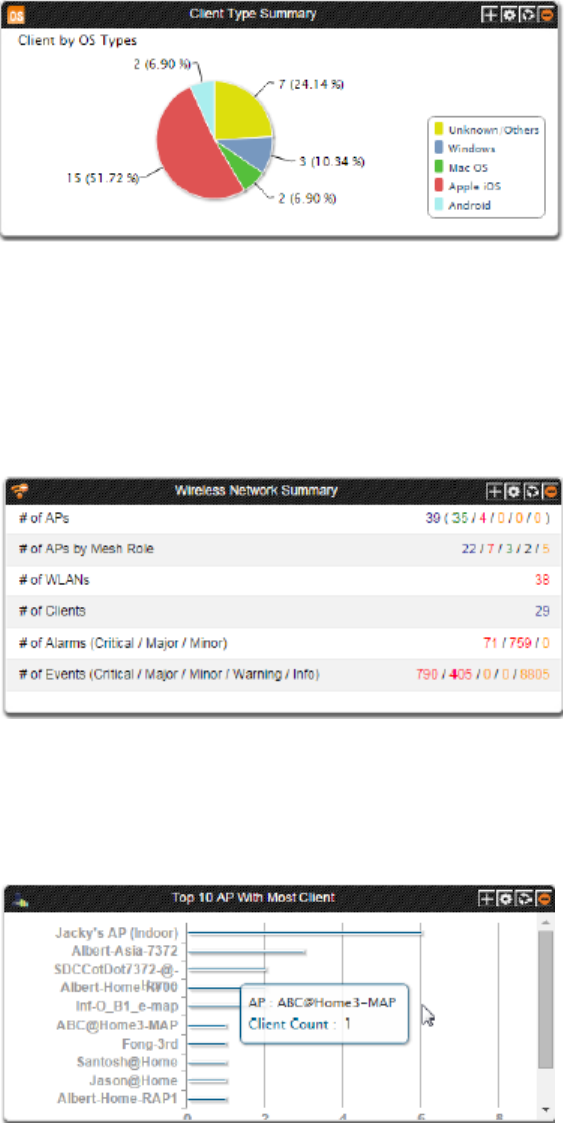
Client Type Summary Widget
The client type summary widget displays a pie chart that shows the types of OS that associated
wireless clients are using.
This widget requires one widget slot.
SmartZone 100/Virtual SmartZone Essentials for Release 3.2 Administrator Guide
19
Navigating the Web Interface
Using Widgets on the Dashboard
The default refresh interval for the client type summary widget is 15 minutes. When you add the
widget, you can configure this refresh interval to any value between 1 and 30 minutes.
Figure 7: The client type summary widget
Wireless Network Summary Widget
The wireless network summary widget displays details about the APs, WLANs, and clients that
the controller is managing. It also displays the number of alarms and events that the controller
has generated.
This widget requires one widget slot.
Figure 8: The wireless network summary widget
Top 10 APs by Client Count
The top 10 APs by client count widget displays the ten APs with the most number of clients
associated with them. This widget requires one widget slot.
Figure 9: The top 10 APs by client count widget
SmartZone 100/Virtual SmartZone Essentials for Release 3.2 Administrator Guide
20
Navigating the Web Interface
Using Widgets on the Dashboard
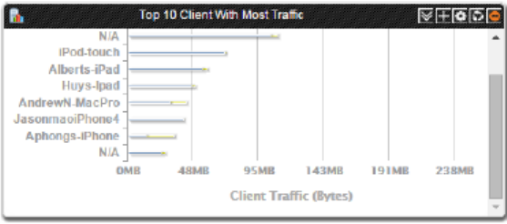
Top 10 Clients by Traffic Count
The top 10 clients by traffic count widget displays the ten clients with the highest traffic volume.
This widget requires one widget slot.
Figure 10: The top 10 clients by traffic count widget
Widget Slots
The controller provides nine slots on the dashboard for placing widgets. Note that some widgets
are wider (for example, the client count summary and traffic widgets) and require two widget
slots. Make sure that there are enough empty slots on the dashboard before you add or move
a widget.
Adding a Widget
Follow these steps to add a widget to the dashboard.
1. Click the icon in the upper-left corner of the page (below the Ruckus Wireless icon). The icons
for adding widgets appear.
Widget NameIcon
Client count summary widget
AP summary widget
System summary widget
Traffic summary widget
Client type summary widget
Wireless network summary widget
Top 10 APs by Client Count
Top 10 Clients by Traffic Count
2. Click the icon for the widget that you want to add.
A configuration form, which contains widget settings that you can configure, appears.
3. Configure the widget settings.
4. Click OK.
The page refreshes, and then the widget that you added appears on the dashboard.
You have completed adding a widget. To add another widget, repeat the same procedure.
SmartZone 100/Virtual SmartZone Essentials for Release 3.2 Administrator Guide
21
Navigating the Web Interface
Using Widgets on the Dashboard
Adding a Widget to a Widget Slot
A single widget slot can contain multiple widgets of the same size (one-slot widgets versus
two-slot widgets).
For example, you can add the client count summary widget and traffic summary widget (both
are two-slot widgets) to the same widget slot.
Follow these steps to add a widget to a widget slot.
1. Locate an existing widget slot to which you want to add a widget.
2. Click the icon that is on the upper-right hand corner of the widget slot.
A submenu appears and displays the widgets that you can add to the widget slot.
3. Click the name of the widget that you want to add to the widget slot.
The widget configuration window appears.
You can only add a widget once. If a widget already exists in a different widget slot, you will
be unable to add it to another widget slot.
4. Configure the information that you want the widget to display and the interval at which to
refresh the information on the widget.
The refresh intervals for the client count summary and traffic summary widgets are
non-configurable.
5. Click OK.
The widget slot refreshes, and then the widget that you added appears.
You have completed adding a widget to a widget slot.
Displaying a Widget in a Widget Slot
A widget slot that contains multiple widgets automatically cycles through the different widgets
that have been added to it at one-minute intervals. If you want to view a specific widget in a
widget slot, you can manually display it.
Follow these steps to display a widget that belongs to a widget slot manually.
1. Locate the widget slot that contains the widget that you want to display.
2. Click the icon that is on the upper-right hand corner of the widget slot.
A submenu appears and displays the widgets that have been added to the widget slot.
3. Click the name of the widget that you want to display.
The widget slot refreshes, and the widget that you clicked appears.
You have completed displaying a widget in a widget slot.
Moving a Widget
Follow these steps to move a widget from one widget slot to another.
1. Make sure that there are sufficient slots for the widget that you want to move.
2. Hover your mouse pointer on the title bar of the widget.
The pointer changes into a four-way arrow.
3. Click-and-hold the widget, and then drag it to the empty slot to which you want to move it.
4. Release the widget.
SmartZone 100/Virtual SmartZone Essentials for Release 3.2 Administrator Guide
22
Navigating the Web Interface
Using Widgets on the Dashboard
You have completed moving a widget to another slot.
Deleting a Widget
Follow these steps to delete a widget.
1. Locate the widget that you want to delete.
2. Click the icon that is in the upper-right hand corner of the widget.
A confirmation message appears.
3. Click Yes to confirm.
The dashboard refreshes, and then the widget that you deleted disappears from the page.
Changing the Administrator Password
Follow these steps to change the administrator password.
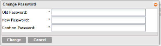
1. On the Miscellaneous Bar, click Change Password.
The Change Password form appears.
2. In Old Password, type your current password.
3. In New Password, type the new password that you want to use.
4. In Confirm Password, retype the new password above.
5. Click Change.
You have completed changing your administrator password. The next time you log on to the
controller, remember to use your new administrator password.
Figure 11: The Change Password form
Logging Off the Web Interface
Follow these steps to log off the web interface.
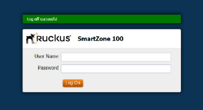
1. On the Miscellaneous Bar, click Log Off.
A confirmation message appears.
2. Click Yes.
The controller logs you off the web interface.
The logon page appears with the following message above the Ruckus Wireless logo: Log
off successful
SmartZone 100/Virtual SmartZone Essentials for Release 3.2 Administrator Guide
23
Navigating the Web Interface
Changing the Administrator Password
You have completed logging off the web interface.
Figure 12: The message Log off successful indicates that you have successfully
logged off the web interface
SmartZone 100/Virtual SmartZone Essentials for Release 3.2 Administrator Guide
24
Navigating the Web Interface
Logging Off the Web Interface
2
Working with User Accounts, Guest
Passes, and User Roles
In this chapter:
•Working with User Accounts
•Working with Guest Passes
•Working with User Roles
Working with User Accounts
A user is a registered user account that may be given access to the controller hotspot. A user
account contains a user's personal information, logon information, and the subscription package
that he or she has been assigned.
This section describes the following tasks:
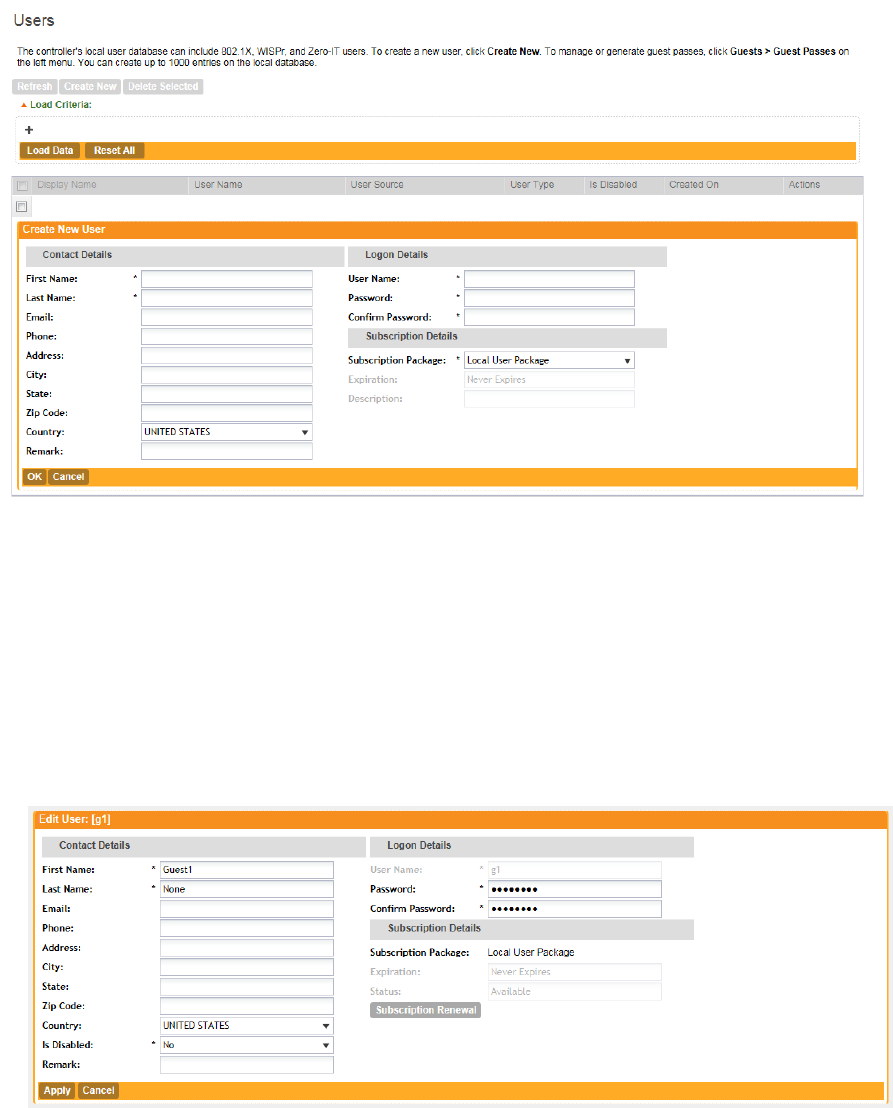
Creating a User Account
Follow these steps to create a user account.
1. Go to Configuration > Identity > Users.
2. Click Create New.
3. In the Contact Details section, fill out the following boxes:
•First Name
•Last Name
•Email
•Phone
•Country
•City
•Street
•Zip Code
•State: Select Enabled to enable this user profile or select Disabled.
•Remark
4. In the Login Details section, fill out the following boxes to create the logon credentials of this
user:
•User Name: Type a name for this user. The user name is not case-sensitive and will always
be displayed in lowercase characters.
•Password: Type a password for this user. The password must be at least eight characters
in length.
•Confirm Password: Retype the password above.
5. Click OK.
SmartZone 100/Virtual SmartZone Essentials for Release 3.2 Administrator Guide
25
25
You have completed creating a user account.
Figure 13: Creating a user account
Editing a User Account
Follow these steps to edit an existing user account.
1. Go to Configuration > Identity > Users.
2. Locate the user account that you want to edit, and then click the user name.
The Edit User: [{User Name}] form appears.
3. Edit the user account by updating the fields in the Contact Details and Login Details sections.
4. Click OK.
Figure 14: Editing a user account
SmartZone 100/Virtual SmartZone Essentials for Release 3.2 Administrator Guide
26
Working with User Accounts, Guest Passes, and User Roles
Working with User Accounts
Working with Guest Passes
Similar to user accounts, guest passes in the controller allow users to gain access to the controller
hotspots. However, unlike user accounts, guest pass users are not required to provide personal
information to access the controller hotspots and can therefore remain anonymous.
Guest passes are generated for specific WLANs only – guest pass users will only be able to gain
access to the WLANs for which the guest pass was generated.
Generating Guest Passes
Generating guest passes involves four steps:
Step 1: Create a Guest Access Service
Step 2: Create a Guest Access WLAN
Step 3: Generate a Guest Pass
Step 4: Send Guest Passes to Guest Users
Step 1: Create a Guest Access Service
1. Follow the instructions in Creating a Guest Access Service on page 93 to create at least one
guest access service.
2. When you finish creating a guest access service, continue to Step 2: Create a Guest Access
WLAN on page 27
Step 2: Create a Guest Access WLAN
Guest passes are generated for specific WLANs only. Guest pass users will only be able to gain
access to the WLANs for which the guest pass is generated.
Follow these steps to create a WLAN that will be used for guest access only.
1. Go to Configuration > Wireless Network > WLANs.
2. In the WLAN Configuration section, click Create New.
3. In General Options, configure the following:
•Name
•SSID
•Description
4. In WLAN Usage, configure the following:
a) In Access Network, select the Tunnel WLAN traffic through Ruckus GRE check box
if you want to tunnel the traffic from this WLAN back to the controller.
b) In Authentication Type, click Guest Access.
5. Configure the rest of the WLAN settings.
For details on each setting, see Creating a WLAN on page 41.
6. When you finish creating a guest access WLAN, continue to Step 3: Generate a Guest Pass
on page 28.
SmartZone 100/Virtual SmartZone Essentials for Release 3.2 Administrator Guide
27
Working with User Accounts, Guest Passes, and User Roles
Working with Guest Passes
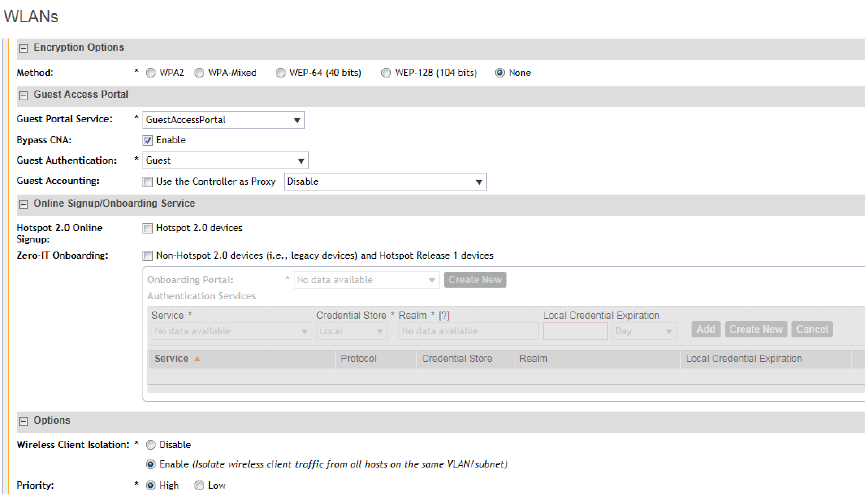
Figure 15: Creating a WLAN for guest access only
Step 3: Generate a Guest Pass
Follow these steps to generate a guest pass.
1. Click Configuration > Identity > Users.
The Users page appears.
2. Click Guest Pass > Guest Pass Service.
The Guest Pass page appears.
3. Click Generate Guest Pass, and then click Next.
4. Configure the following options:
•Guest Name: Type a name that you want to assign to the guest user.
•Guest WLAN: Select the guest WLAN that you created in Step 2: Create a Guest Access
WLAN on page 27.
•Number of Passes: Type the number of guest passes that you want to generate.
•Pass Valid For: Set the validity period for the guest pass by filling in the two boxes. For
example, if you want the guest pass to be valid for seven days, type 7 in the first box, and
then select Days in the second box.
5. Configure the advanced options:
a) Pass Generation: Select the Auto Generate check box if you want the controller to
generate the guest pass key automatically.
If you want to generate the guest pass manually, clear the Auto Generate check box.
SmartZone 100/Virtual SmartZone Essentials for Release 3.2 Administrator Guide
28
Working with User Accounts, Guest Passes, and User Roles
Working with Guest Passes
If you are generating more than one guest pass, the Auto Generate check box is selected
automatically and is not configurable.
b) Pass Effective Since: Set the guest pass validity period by selecting one of the following
options:
•Effective from the creation time: This type of guest pass is valid from the time it is
first created to the specified expiration time, even if it is not being used by any end user.
•Effective from first use: This type of guest pass is valid from the time the user uses
it to authenticate with the controller until the specified expiration time. An additional
parameter (Guest Pass will expire in X days) can be configured to specify when an
unused guest pass will expire regardless of use. The default is 7 days.
•Expire guest pass if not used within [ ] days: If you want this guest pass to expire if
it is unused after you generated it, type the number of days in the box (maximum value
is 365 days).
c) Max Devices Allowed: Set the number of users that can share this guest pass.
•Limited to [ ]: If you want a limited number of users to share this guest pass, click this
option, and then type the number in the box.
•Unlimited: If you want an unlimited number of users to share this guest pass, click this
option.
•Session Duration: If you clicked Unlimited, this option appears. If you want require
users to log on again after their sessions expire, select the Require guest re-login
after [ ] check box, and then select a time increment. If this feature is disabled,
connected users will not be required to re-log in until the guest pass expires.
d) In Remarks (optional), type your notes about this guest pass, if any.
6. Click Generate.
The page refreshes, and then the guest pass you generated appears in a table, along with
other guest passes that exist on the controller.
7. Click OK to close the pop-up message.
You have completed generating a guest pass. You are now ready to send the guest pass to
guest users. See Step 4: Send Guest Passes to Guest Users on page 30 for information.
SmartZone 100/Virtual SmartZone Essentials for Release 3.2 Administrator Guide
29
Working with User Accounts, Guest Passes, and User Roles
Working with Guest Passes
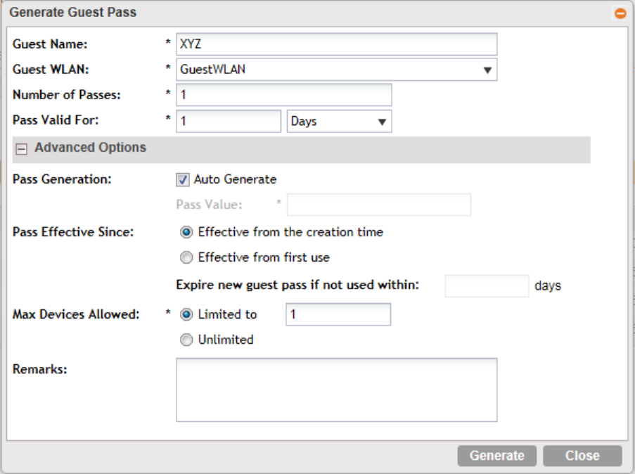
Figure 16: Generating a guest pass
Step 4: Send Guest Passes to Guest Users
Deliver the guest passes to guest users as per the delivery options that you choose.
The page that appears after you generate a guest pass contains options for delivering the guest
pass to guest users (see Figure 17: Options for delivering guest passes to guest users on page
31).
SmartZone 100/Virtual SmartZone Essentials for Release 3.2 Administrator Guide
30
Working with User Accounts, Guest Passes, and User Roles
Working with Guest Passes
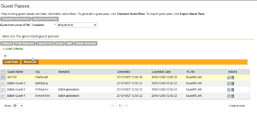
Figure 17: Options for delivering guest passes to guest users
Printing the Guest Pass
After you generate the guest pass, you can print the guest pass information, which contains the
guest user information and instructions on how to connect to the hotspot, and give it to the
guest user.
NOTE: If your browser is blocking pop-ups, make you temporarily disable the pop-up blocker
so you can view and print the guest pass.
Follow these steps to print a guest pass.
1. Select the guest passes that you want to print by selecting the check boxes before them.
2. In Guest Instruction HTML Template, select a printout template to use.
The default printout template (default.html) is selected by default. If you created custom
printout templates (see Creating a Guest Pass Printout Template on page 37), they will appear
in the drop-down menu.
3. Click Print Selected.
A new browser page appears, which displays the guest pass and available printing options.
4. Configure your printer settings, and then print the guest passes.
You have completed printing the guest passes.
SmartZone 100/Virtual SmartZone Essentials for Release 3.2 Administrator Guide
31
Working with User Accounts, Guest Passes, and User Roles
Working with Guest Passes
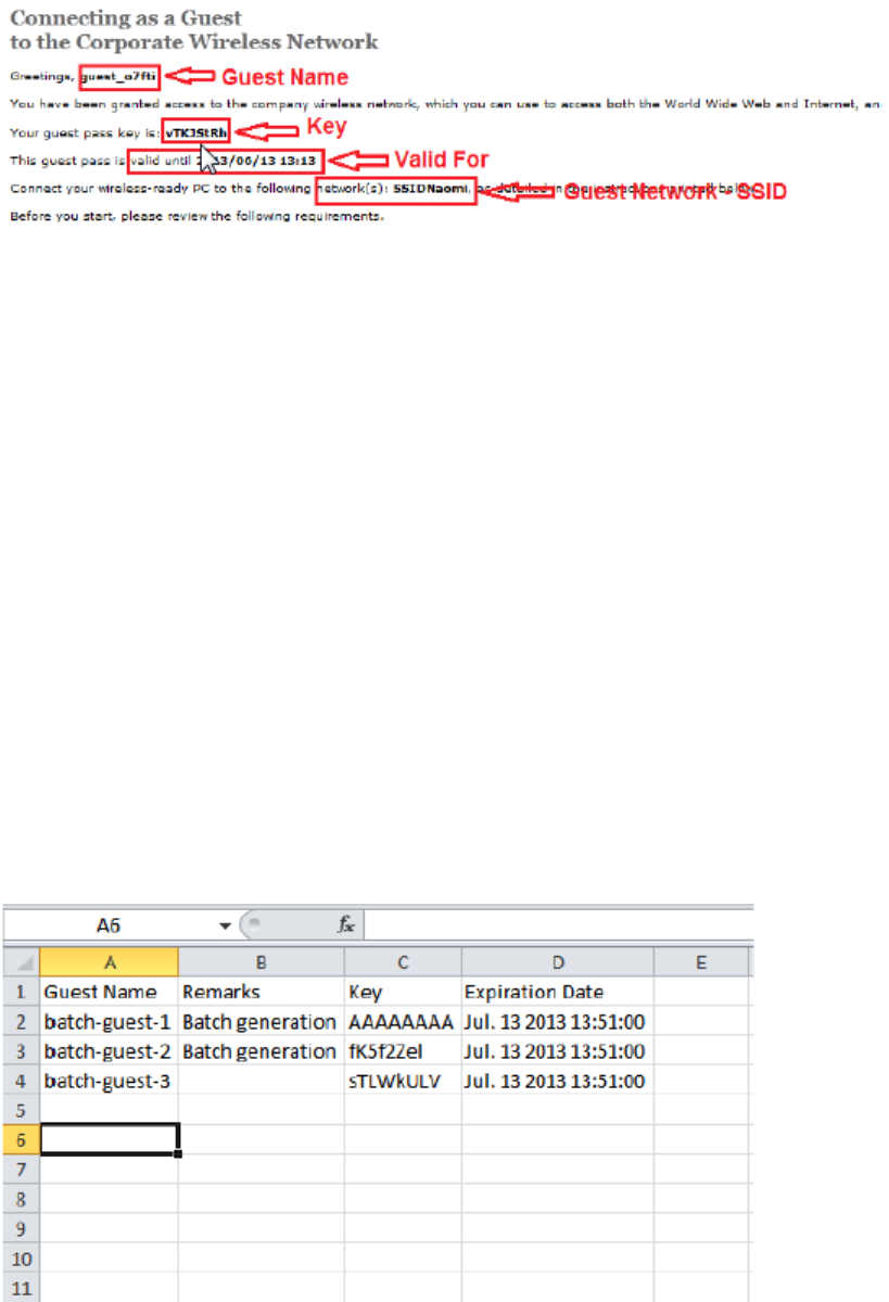
Figure 18: What a guest pass printout looks like
Exporting the Guest Pass to CSV
Follow these steps to export the last generated guest passes to a comma-separated value (CSV)
file.
1. Select the guest passes that you want to export to CSV by selecting the check boxes before
them.
2. Click Export CSV.
Your web browser downloads the CSV file to its default download location.
3. Go to your web browser's default download location and look for a file named
guestpass[number].csv.
4. Using Microsoft Excel or a similar application, open the CSV file. The CSV file displays the
details of the guest passes, including:
•Guest Name
•Remarks
•Key
•Expiration Date
You have completed exporting the last generated guest passes to CSV.
Figure 19: A sample CSV of generated guest passes when opened in Excel
SmartZone 100/Virtual SmartZone Essentials for Release 3.2 Administrator Guide
32
Working with User Accounts, Guest Passes, and User Roles
Working with Guest Passes
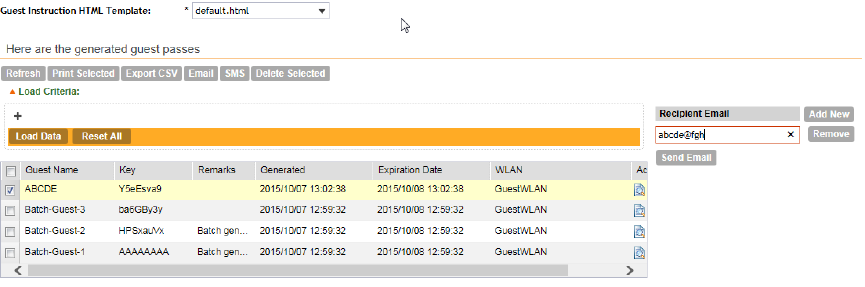
Sending the Guest Pass via Email
To send guest passes via email, you must have added an external email server to the controller.
Follow these steps to send the guest pass via email.
1. Select the guest passes that you want to send via email by selecting the check boxes before
them.
2. Click Email.
The Recipient Email form appears on the right side of the page (see Figure 20).
3. Click Add New.
4. In the box that appears below, type the email address to which you want to send the guest
passes.
5. To add another recipient, click Add Newagain, and then type another email address.
6. When you have finished adding all the email recipients, click Send Email.
A dialog box appears and informs you that the emails have been sent to the message queue
successfully
7. Click OKto close the dialog box.
You have completed sending guest passes via email.
Figure 20: Use the Recipient Email form to specify who will receive the guest passes via
email
Sending the Guest Pass via SMS
To send guest passes via email, you must have added an external SMS gateway to the controller.
Follow these steps to send the guest pass via email.
1. Select the guest passes that you want to send via SMS by selecting the check boxes before
them.
2. Click SMS.
SMS options appears on the right side of the page (see Figure 21: Options for sending guest
passes via SMS on page 34).
3. In Guest Instruction SMS Template, select the SMS template that you want to use.
4. Click Add New.
SmartZone 100/Virtual SmartZone Essentials for Release 3.2 Administrator Guide
33
Working with User Accounts, Guest Passes, and User Roles
Working with Guest Passes
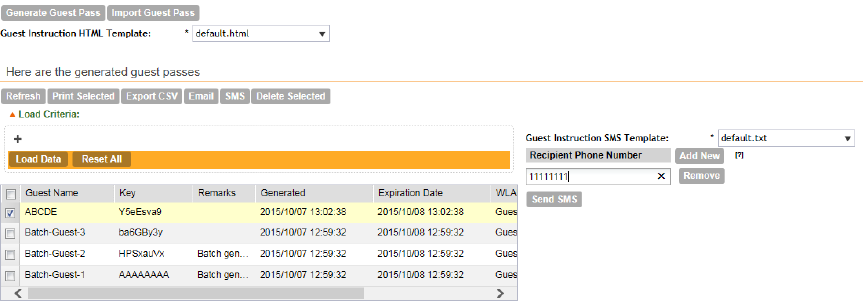
5. In the box that appears below, type the phone number to which you want to send the guest
passes via SMS.
6. To add another SMS recipient, click Add Newagain, and then type another phone number.
7. When you have finished adding all the SMS recipients, click Send SMS.
A dialog box appears and informs you that the SMS messages have been sent to the message
queue successfully
8. Click OKto close the dialog box.
You have completed sending guest passes via SMS.
Figure 21: Options for sending guest passes via SMS
Generating Guest Passes from an Imported CSV
You can also manually define the guest passes that you want to generate in a comma-separated
value (CSV) file (a sample of which is available for download from the Guest Pass page).
Follow these steps to generate guest passes from an imported CSV file.
1. Click Configuration > Identity > Users.
2. Click Guest Pass > Guest Pass Service.
The Guest Pass page appears.
3. Click Import Guest Pass, and then click Next.
4. Look for the following text under Browse:
To download a sample guest pass, click here.
5. Click the here link to download the sample CSV file.
6. Using Microsoft Excel or a similar application, open the CSV file.
7. In the CSV file, fill out the following columns:
•#Guest Name (Must): Assign a user name to the guest pass user.
•Remarks (Optional): Add some notes or comments about this guest pass.
•Key: Enter a guest pass key or leave it blank so the controller can generate the key
automatically.
SmartZone 100/Virtual SmartZone Essentials for Release 3.2 Administrator Guide
34
Working with User Accounts, Guest Passes, and User Roles
Working with Guest Passes
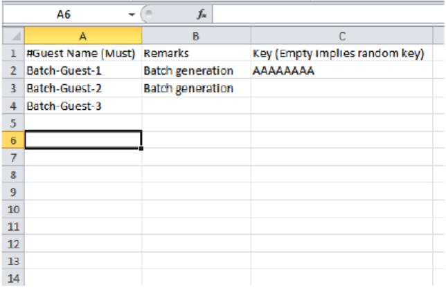
Figure 22: The sample CSV file when opened in Excel
8. Save the CSV file.
9. Go back to the Guest Pass page, and then configure the following settings on the Common
Guest Pass Settings:
•Guest WLAN: Select the guest WLAN that you created in Step 2: Create a Guest Access
WLAN on page 27.
•Pass Valid For: Set the validity period for the guest pass by filling in the two boxes. For
example, if you want the guest pass to be valid for seven days, type 7 in the first box, and
then select Days in the second box.
10. Configure the advanced options:
a) Pass Effective Since: Set the guest pass validity period by selecting one of the following
options:
•Effective from the creation time: This type of guest pass is valid from the time it is
first created to the specified expiration time, even if it is not being used by any end user.
•Effective from first use: This type of guest pass is valid from the time the user uses
it to authenticate with the controller until the specified expiration time. An additional
parameter (Guest Pass will expire in X days) can be configured to specify when an
unused guest pass will expire regardless of use. The default is 7 days.
•Expire guest pass if not used within [ ] days: If you want this guest pass to expire if
it is unused after you generated it, type the number of days in the box (maximum value
is 365 days).
b) Max Devices Allowed: Set the number of users that can share this guest pass.
•Limited to [ ]: If you want a limited number of users to share this guest pass, click this
option, and then type the number in the box.
•Unlimited: If you want an unlimited number of users to share this guest pass, click this
option.
SmartZone 100/Virtual SmartZone Essentials for Release 3.2 Administrator Guide
35
Working with User Accounts, Guest Passes, and User Roles
Working with Guest Passes
•Session Duration: If you clicked Unlimited, this option appears. If you want require
users to log on again after their sessions expire, select the Require guest re-login
after [ ] check box, and then select a time increment. If this feature is disabled,
connected users will not be required to re-log in until the guest pass expires.
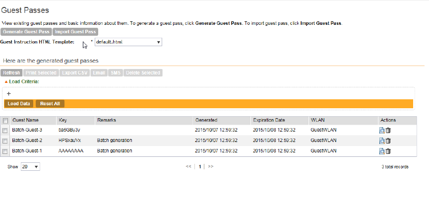
11. In Guest List CSV File (at the top of the page), click Browse, and then select the CSV file
you edited earlier.
The page refreshes, and the number of guest passes that the controller has identified in the
CSV file appears below the Browse button.
12. Click Generate.
The page refreshes, and then the guest pass you generated appears in a table, along with
other guest passes that exist on the controller.
You have completed generating a guest pass. You are now ready to send the guest pass to
guest users. See Step 4: Send Guest Passes to Guest Users on page 30 for information.
Figure 23: The Guest Pass page for importing a CSV file
Viewing the List of Guest Users
Follow these steps to view guest users that currently exist on the controller.
1. Click Configuration > Identity > Users.
2. Click the User Type column to sort all existing user accounts by user type.
All users of the user type Guest are guest users.
You have completed view the list of guest users.
Deleting Guest Users
Follow these steps to delete guest users.
1. Click Configuration > Identity > Users.
2. Select the check boxes before the guest user accounts that you want to delete.
SmartZone 100/Virtual SmartZone Essentials for Release 3.2 Administrator Guide
36
Working with User Accounts, Guest Passes, and User Roles
Working with Guest Passes
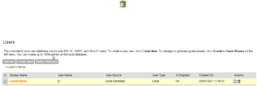
Click Delete Selected.
A confirmation message appears.
3. Click Yes to confirm.
The page refreshes, and the guest user accounts that you deleted disappears from the list.
To delete a single guest pass, click the (delete) icon that is in the same row as the guest
pass name.
You have completed deleting a guest pass or guest passes.
Figure 24: Deleting a single guest pass or multiple guest passes
Creating a Guest Pass Printout Template
A guest pass printout template contains variables for the information that guest users need to
connect to the controller hotspots (for example, guest name, key, and WLAN name), as well as
the actual instructions for connecting to the guest WLAN.
A default printout template exists in the controller. If you want to create your own printout template,
follow these steps.
1. Go to Configuration > Identity > Guests.
2. Click Templates.
The Guest Pass Templates page appears.
3. In the Guest Instruction HTML Template section, click default.html, which is the default
guest pass printout template.
The content of the default guest pass printout template appears on the right side of the page.
4. Click Download below the template preview area to download a copy of the template to
your computer.
5. Using an HTML editor, create a new HTML or text file.
6. Add content to the file.
Typically, a printout template contains instructions for connecting to the controller hotspot.
See Figure 25 for the content of the default printout template.
SmartZone 100/Virtual SmartZone Essentials for Release 3.2 Administrator Guide
37
Working with User Accounts, Guest Passes, and User Roles
Working with Guest Passes
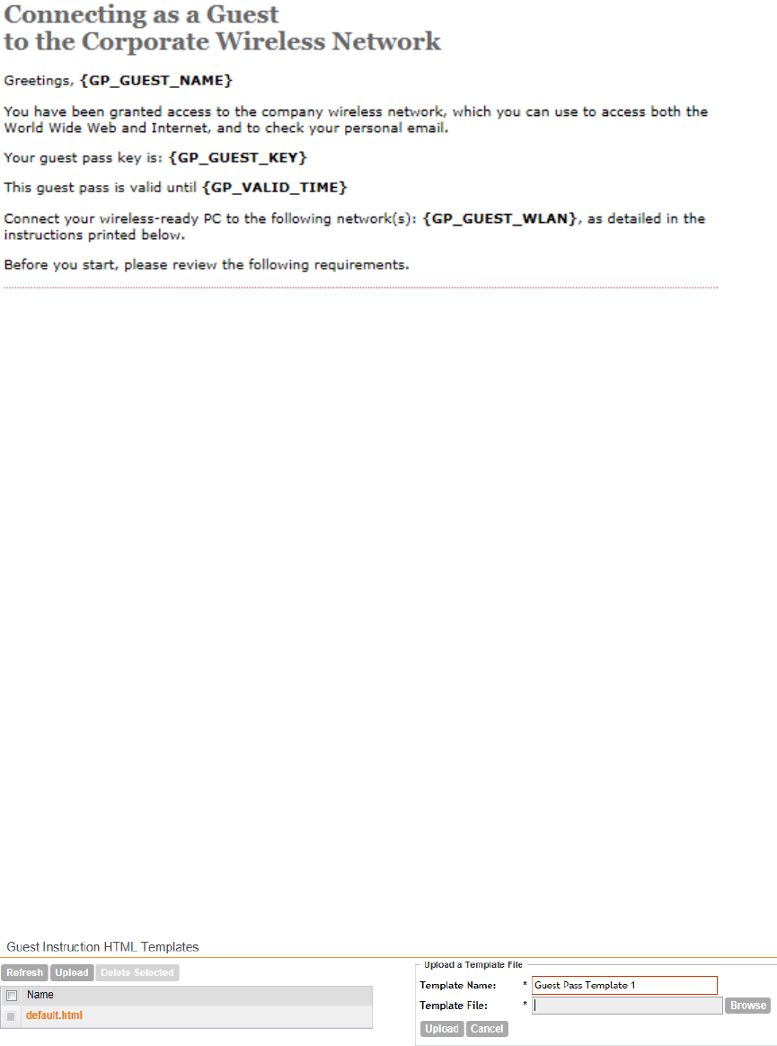
Figure 25: Content of the default printout template
7. Insert the following variables into the content of your template:
•{GP_GUEST_NAME}: This is the guest pass user name.
•{GP_GUEST_KEY}: This is the guest pass key.
•{GP_VALID_TIME}: This is the expiration date and time of the guest pass.
•{GP_GUEST_WLAN}: This is the WLAN with which the guest user can associate using
the guest name and guest key.
8. Save the file.
9. On the Manage Guest Instruction Templates page, click the appropriate Upload button
for the template that you are creating.
The Upload a Template File form appears on the right side of the page.
10. Configure the Upload a Template File options:
•Template Name: Type a name for the template that you are uploading.
•Template File: Click Browse, and select the template file you created.
11. Click Upload.
An information message box appears and informs you that the template file has been uploaded
successfully.
12. Click OK.
The template file you uploaded now appears in the list of templates.
Figure 26: The Upload a Template File form
SmartZone 100/Virtual SmartZone Essentials for Release 3.2 Administrator Guide
38
Working with User Accounts, Guest Passes, and User Roles
Working with Guest Passes
Working with User Roles
The controller provides a default role (named Default) that is automatically applied to all new
user accounts.
By default, this role links all users to the internal WLAN and permits access to all WLANst. As
an alternative, you can create additional roles that you can assign to selected wireless network
users, to limit their access to certain WLANs, to allow them to log on with non-standard client
devices, or to grant permission to generate guest passes. (You can then edit the default role to
disable the guest pass generation option.)
Creating a User Role
Use user roles to limit user access to certain WLANs, to allow them to log on with non-standard
client devices, or to grant permission to generate guest passes.
Follow these steps to create a user role.
1. Go to Configuration > Identity > Roles.
2. Click Create New.
The Create User Role form appears.
3. Configure the options in the Create User Role form.
•Name: Type a name for this user role.
•Description: Type a description for this user role.
•Default Group Attribute Value: (Fill in this field only if you are creating a user role based
on group attributes extracted from an Active Directory or LDAP server.) Enter the User
Group name here. Active Directory/LDAP users with the same group attributes are
automatically mapped to this user role.
•WLANS: Specify whether this role will have access to all WLAN or to specific WLANs only.
•Allow Zero IT Access to All WLANs: Click this to allow this user role access to all
WLANs.
•Allow Zero IT Access to Selected WLANs Only. Click to allow this user role access
to specific WLANs only. You must select the WLAN to which this user role will have
access.
•Max Devices Allowed: Set the number of users that can share this role.
•Limited to [ ]: If you want a limited number of users to share this role pass, click this
option, and then type the number in the box.
•Unlimited: If you want an unlimited number of users to share this role, click this option.
4. Click OK.
You have completed creating a user role.
SmartZone 100/Virtual SmartZone Essentials for Release 3.2 Administrator Guide
39
Working with User Accounts, Guest Passes, and User Roles
Working with User Roles
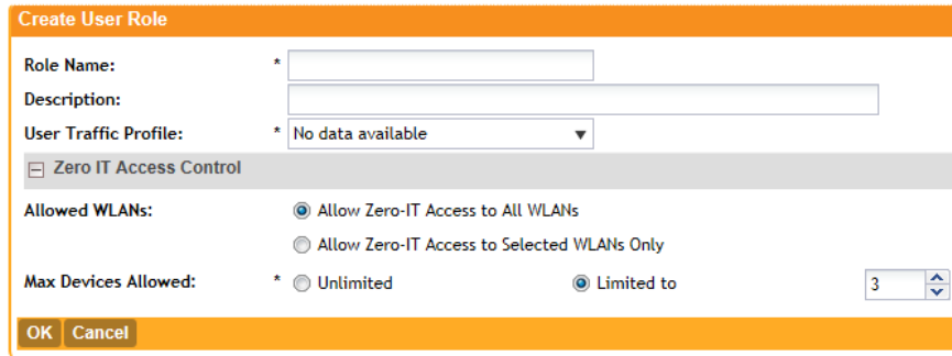
Figure 27: Creating a user role
SmartZone 100/Virtual SmartZone Essentials for Release 3.2 Administrator Guide
40
Working with User Accounts, Guest Passes, and User Roles
Working with User Roles
3
Configuring the Wireless Network
In this chapter:
•Configuring WLANs
•Configuring WLAN Groups
•Configuring Access Points
•Controlling Access to the Wireless Network
•Controlling and Monitoring Applications
•Managing Guest Access
•Working with Hotspot (WISPr) Services
•Working With WeChat Services
•Working with Hotspot 2.0 Services
•Working with Web Authentication Services
•Working with AAA Servers
•Configuring Location Services
•Configuring Bonjour Gateway Policies
Configuring WLANs
Creating a WLAN
You can configure WLANs with service set identifiers (SSIDs). An SSID identifies the specific
wireless network that you want the controller to access.
Follow these steps to create a WLAN.
1. Go to Configuration > Wireless Network > WLANs.
2. In the WLAN Configuration section, click Create New.
3. In General Options, configure the following:
•Name: Type a name for this WLAN.
•SSID: Type a short name for the WLAN. The SSID is the WLAN name that is broadcast
on the wireless network.
•HESSID: Type the homogenous extended service set identifier (HESSID). The HESSID is
a 6-octet MAC address that identifies the homogeneous ESS. The HESSID value must
be identical to one of the BSSIDs in the homogeneous ESS.
•Description: Type a brief description of the qualifications/purpose for this WLAN (for
example, Engineering or Voice).
4. In WLAN Usage, configure the following:
•In Access Network, select the Tunnel WLAN traffic through Ruckus GRE check box
if you want to tunnel the traffic from this WLAN back to the controller. Tunnel mode enables
wireless clients to roam across different APs on different subnets. If the WLAN has clients
that require uninterrupted wireless connection (for example, VoIP devices), Ruckus Wireless
SmartZone 100/Virtual SmartZone Essentials for Release 3.2 Administrator Guide
41
41
recommends enabling tunnel mode. When you enable this option, you need to select core
network for tunneling WLAN traffic back to the controller.
•In Authentication Type, click one of the following options.
•Standard usage (For most regular wireless networks): This is a regular WLAN suitable
for most wireless networks.
•Hotspot service (WISPr): Click this option if want to use a hotspot service that you
previously created.
•Guest Access and Hotspot 2.0 Onboarding: Click this option if you want guest users
to use this WLAN and offer Hotspot 2.0 service to guest users. After you complete
creating this WLAN for guest access, you can start generating guest passes (see
Working with Guest Passes on page 27).
For more information about Hotspot 2.0 online signup, see the Hotspot 2.0 Reference
Guide for this release.
•Web Authentication: Click this option if you want to require all WLAN users to complete
a web-based logon to this network every time they attempt to connect (see Working
with Web Authentication Services on page 107).
•Hotspot 2.0: Click this option if you want a Hotspot 2.0 operator profile that you
previously created to use this WLAN. See the Hotspot 2.0 Reference Guide for this
release.
•Hotspot 2.0 Secure Online Signup (OSEN): Click this option if you want to use this
WLAN for Hotspot 2.0 OSEN. See the Hotspot 2.0 Reference Guide for this release
for more information.
5. in Authentication Options, click the authentication method by which users will be
authenticated prior to gaining access to the WLAN. The level of security should be determined
by the purpose of the WLAN you are creating.
•Open (Default): No authentication mechanism is applied to connections. If WPA or WPA2
encryption is used, this implies WPA-PSK authentication.
If you clicked Web Authentication in Authentication Type, Open is the only available
authentication option.
•802.1x EAP: A very secure authentication/encryption method that requires a back-end
authentication server, such as a RADIUS server. Your choice mostly depends on the types
of authentication the client devices support and your local network authentication
environment.
•MAC Address: Authenticate clients by MAC address. MAC address authentication requires
a RADIUS server and uses the MAC address as the user logon name and password. You
have two options for the MAC address format to use for authenticating clients:
•Use user defined text as authentication password (default is device MAC address)
•Set device MAC address in 802.1x format 00-10-A4-23-19-C0. (The default is
0010a42319c0).
6. In Encryption Options, select an encryption method to use.
SmartZone 100/Virtual SmartZone Essentials for Release 3.2 Administrator Guide
42
Configuring the Wireless Network
Configuring WLANs
WPA and WPA2 are both encryption methods certified by the Wi-Fi Alliance and are the
recommended encryption methods. The Wi-Fi Alliance will be mandating the removal of WEP
due to its security vulnerabilities, and Ruckus Wireless recommends against using WEP if
possible.
•WPA2: Enhanced WPA encryption using stronger TKIP or AES encryption algorithm.
•WPA-Mixed: Allows mixed networks of WPA and WPA2 compliant devices. Use this
setting if your network has a mixture of older clients that only support WPA and TKIP, and
newer client devices that support WPA2 and AES.
•WEP-64 (40 bits): Provides a lower level of encryption, and is less secure, using 40-bit
WEP encryption.
•WEP-128 (104 bits): Provides a higher level of encryption than WEP-64, using a 104-bit
key for WEP encryption. However, WEP is inherently less secure than WPA.
•None: No encryption; traffic is sent in clear text.
If you set the encryption method to WEP-64 (40 bit) or WEP-128 (104 bit) and you are
using an 802.11n or 802.11ac AP for the WLAN, the AP will operate in 802.11g mode.
7. In Hotspot Portal, configure the following options.
This section only appears if you clicked Hotspot (WISPr) in WLAN Usage > Authentication
Type.
•Hotspot (WISPr) Portal: Select the hotspot that you want this WLAN to use. This option
appears only when Hotspot service (WISPr) is selected as the WLAN usage type. This
hotspot service may be the hotspot that you created in Creating a Hotspot (WISPr) Service
on page 96.
•Bypass CNA: Select the Enable check box if you want to bypass the Apple CNA feature
on iOS and OS X devices that connect to this WLAN. See Bypassing Apple CNA on page
49 for more information.
•Authentication Service: Select the authentication server that you want to use for this
WLAN. Options include Local DB, Always Accept, and any AAA servers that you previously
added (see Working with AAA Servers on page 110). Additionally, if you want the controller
to proxy authentication messages to the AAA server, select the Use Controller as Proxy
check box.
•Accounting Service: Select the RADIUS Accounting server that you want to use for this
WLAN. You must have added a RADIUS Accounting server previously (see Working with
AAA Servers on page 110). Additionally, if you want the controller to proxy accounting
messages to the AAA server, select the Use Controller as Proxy check box.
8. In Guest Access Portal, configure the following options:
This section only appears if you clicked Guest Access + Hotspot 2.0 Online Signup in
WLAN Usage > Authentication Type.
•Guest Portal Service: Select the guest access portal that you created earlier for this
onboarding WLAN.
•Bypass CNA: Select the Enable check box if you want to bypass the Apple CNA feature
on iOS and OS X devices that connect to this WLAN. See Bypassing Apple CNA on page
49 for more information.
SmartZone 100/Virtual SmartZone Essentials for Release 3.2 Administrator Guide
43
Configuring the Wireless Network
Configuring WLANs
•Guest Authentication: Select Guest to require users to enter their guest credentials, or
select Always Accept to allow users without guest credentials to authentication.
•Guest Accounting: Select the RADIUS Accounting server that you want to use for this
WLAN. You must have added a RADIUS Accounting server previously (see Working with
AAA Servers on page 110). Additionally, if you want the controller to proxy accounting
messages to the AAA server, select the Use the Controller as Proxy check box.
9. In the Online Signup/Onboarding Service section, configure the following options:
This section only appears if you clicked Guest Access + Hotspot 2.0 Online Signup in
WLAN Usage > Authentication Type.
•Hotspot 2.0 Signup: Select the Hotspot 2.0 devices check box to enable support for
Hotspot 2.0 devices. See the Hotspot 2.0 Reference Guide for this release for more
information.
•Zero-IT Onboarding: Select the Non-Hotspot 2.0 devices (i.e., legacy devices) and
Hotspot Rel 1 devices check box.
•Onboarding Portal: Select the portal signup profile that you want this guest WLAN to
use.
•Authentication Services: Select the authentication server that you previously added to
the controller.
10. In the Authentication & Accounting Service section, configure the following options:
•Web Authentication Portal: Select the web authentication portal that you created
previously. See Working with Web Authentication Services on page 107 for more information.
•Bypass CNA: Select the Enable check box if you want to bypass the Apple CNA feature
on iOS and OS X devices that connect to this WLAN. See Bypassing Apple CNA on page
49 for more information.
•Authentication Service: Select the authentication server that you want to use for this
WLAN. Options include Local DB, Always Accept, and any AAA servers that you previously
added (see Working with AAA Servers on page 110). Additionally, if you want the controller
to proxy authentication messages to the AAA server, select the Use the Controller as
Proxy check box.
•Accounting Server: Select the RADIUS Accounting server that you want to use for this
WLAN. You must have added a RADIUS Accounting server previously (see Working with
AAA Servers on page 110). Additionally, if you want the controller to proxy accounting
messages to the AAA server, select the Use the Controller as Proxy check box.
11. In Options, configure the following options:
•Wireless Client Isolation: Wireless client isolation enables subnet restrictions for connected
clients. Click Enable if you want to prevent wireless clients associated with the same AP
from communicating with each other locally. The default value is Disable.
•Priority: Set the priority of this WLAN to Low if you would prefer that other WLAN traffic
takes priority. For example, if you want to prioritize internal traffic over guest WLAN traffic,
you can set the priority in the guest WLAN configuration settings to Low. By default, all
WLANs are set to high priority.
12. In RADIUS Options, click + (plus sign) to display the options, and then configure the following:
SmartZone 100/Virtual SmartZone Essentials for Release 3.2 Administrator Guide
44
Configuring the Wireless Network
Configuring WLANs
•NAS ID: Select how to the RADIUS server will identify the AP. Options include:
•WLAN BSSID
•AP MAC
•User-defined
•NAS Request Timeout: Type the timeout period (in seconds) after, which an expected
RADIUS response message is considered to have failed.
•NAS Max Number of Retries: Type the number of failed connection attempts after which
the controller will fail over to the backup RADIUS server.
•NAS Reconnect Primary: If the controller fails over to the backup RADIUS server, this is
the interval (in minutes) at which the controller will recheck the primary RADIUS server if it
is available. The default interval is 5 minutes.
•Call STA ID: Use either WLAN BSSID or AP MAC as the station calling ID. Select one.
13. In Advanced Options, configure the following options:
•User Traffic Profile: If you want this WLAN to use a user traffic profile that you previously
created, select it from the drop-down menu. Otherwise, select System Default. For more
information, see Creating a User Traffic Profile on page 82.
•L2 Access Control: If you want this WLAN to use an L2 access control policy that you
previously created, select it from the drop-down menu. Otherwise, select Disable. For
more information, see Creating an L2 Access Policy on page 84.
•Device Policy: If you want this WLAN to use a device policy that you previously created,
select it from the drop-down menu. Otherwise, select Disable. For more information, see
Controlling Device Access on page 86.
•Access VLAN: By default, all wireless clients associated with APs that the controller is
managing are segmented into a single VLAN (with VLAN ID 1). If you want to tag this WLAN
traffic with a different VLAN ID, enter a valid VLAN ID (2-4094) in the box.
•Hide SSID: Select this check box if you do not want the ID of this WLAN advertised at
any time. This will not affect performance or force the WLAN user to perform any
unnecessary tasks.
•Client Load Balancing: To disable client load balancing on this WLAN, select the Do not
perform client load balancing for this WLAN service check box. For more information,
see Client Load Balancing on page 48.
•Proxy ARP: Select this check box to enable proxy ARP. When proxy ARP is enabled on
a WLAN, the AP provides proxy service for stations when receiving neighbor discovery
packets (for example, ARP request and ICMPv6 Neighbor Solicit messages), and acts on
behalf of the station in delivering ARP replies. When the AP receives a broadcast
ARP/Neighbor Solicit request for a known host, the AP replies on behalf of the host. If the
AP receives a request for an unknown host, it forwards the request at the rate limit specified.
•Max Clients: This option limits the number of clients that can associate with this WLAN
per AP (default is 100). You can also limit the total number of clients that a specific AP (or
radio, on dual radio APs) will manage.
•802.11d: Select this check box to enable this standard on this WLAN. 802.11d provides
specifications for compliance with additional regulatory domains (countries or regions) that
were not defined in the original 802.11 standard. Click this option if you are operating in
one of these additional regulatory domains.
SmartZone 100/Virtual SmartZone Essentials for Release 3.2 Administrator Guide
45
Configuring the Wireless Network
Configuring WLANs
•Force DHCP: Enable this option to force clients to obtain a valid IP address from DHCP
within the specified number of seconds. This prevents clients configured with a static IP
address from connecting to the WLAN. Additionally, if a client performs Layer 3 roaming
between different subnets, in some cases the client sticks to the former IP address. This
mechanism optimizes the roaming experience by forcing clients to request a new IP
address.
•DHCP Option 82: Select the Enable DHCP Option 82 check box to enable this feature.
When this feature is enabled and an AP receives a DHCP request from a wireless client,
the AP will encapsulate additional information (such as VLAN ID, AP name, SSID and MAC
address) into the DHCP request packets before forwarding them to the DHCP server. The
DHCP server can then use this information to allocate an IP address to the client from a
particular DHCP pool based on these parameters.
•Client TX/RX Statistics: Select the Ignore statistics from unauthorized clients check
box if you do not want the controller to monitor traffic statistics for unauthorized clients.
•Inactivity Timeout: Select this check box and enter a value in seconds (60 to 600) after
which idle clients will be disconnected.
•Client Fingerprinting: By selecting this check box, the controller will attempt to identify
client devices by their operating system, device type and host name, if available. This
makes identifying client devices easier on the Dashboard, Monitor and Client Details
pages.
•OFDM Only: Select the check box to force clients associated with this WLAN to use only
Orthogonal Frequency Division Multiplexing (OFDM) to transmit data. OFDM-only allows
the client to increase management frame transmission speed from CCK rates to OFDM
rates. This feature is implemented per WLAN and only affects the 2.4GHz radio.
•BSS Min Rate: Select this check box to set the bss rates of management frames from
default rates (CCK rates for 2.4G or OFDM rate – 6Mbps for 5G] to the desired rates. By
default, BSS Min Rate is disabled.
OFDM-only takes higher priority than BSS-minrate. However, OFDM-only relies on
BSS-minrate to adjust its rate for management frames.
•Mgmt Tx Rate: To set the transmit rate for management frame, select a value (in Mbps)
from the drop-down list.
•Service Schedule: Use the Service Schedule tool to control which hours of the day, or
days of the week to enable/disable WLAN service. Options include:
•Always On: Click this enable this WLAN at all times.
•Always Off: Click this option to disable the WLAN service at all times.
•Specific: Click this to set specific hours during which this WLAN will be enabled. For
example, a WLAN for student use at a school can be configured to provide wireless
access only during school hours. Click on a day of the week to enable/disable this
WLAN for the entire day. Colored cells indicate WLAN enabled. Click and drag to select
specific times of day. You can also disable a WLAN temporarily for testing purposes,
for example.
The service schedule feature will not work properly if the controller does not have the
correct time. To ensure that the controller always maintains the correct time, point the
controller to an NTP server's IP address, as described in Configuring the System Time
on page 138.
SmartZone 100/Virtual SmartZone Essentials for Release 3.2 Administrator Guide
46
Configuring the Wireless Network
Configuring WLANs
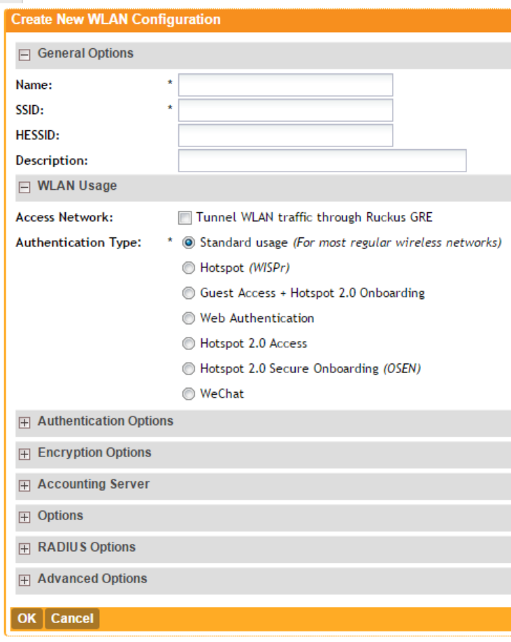
•Band Balancing: Client band balancing between the 2.4GHz and 5GHz radio bands is
disabled by default on all WLANs. To disable band balancing for this WLAN only (when
enabled globally), select the Do not perform band balancing for this WLAN service
check box. For more information, see Band Balancing on page 48.
14. Click OK.
You have completed creating a WLAN.
Figure 28: The Create New WLAN Configuration form
SmartZone 100/Virtual SmartZone Essentials for Release 3.2 Administrator Guide
47
Configuring the Wireless Network
Configuring WLANs
Client Load Balancing
Enabling load balancing can improve WLAN performance by helping to spread the wireless client
load between nearby access points, so that one AP does not get overloaded while another sits
idle.
The load balancing feature can be controlled from within the controller web interface to balance
the number of clients per radio on adjacent APs.
Adjacent APs are determined by the controller at startup by measuring the RSSI during channel
scans. After startup, the controller uses subsequent scans to update the list of adjacent radios
periodically and when a new AP sends its first scan report. When an AP leaves, the controller
immediately updates the list of adjacent radios and refreshes the client limits at each affected
AP.
Once the controller is aware of which APs are adjacent to each other, it begins managing the
client load by sending the configured client limits to the APs. These limits are soft values that
can be exceeded in several scenarios, including:
1. When a client's signal is so weak that it may not be able to support a link with another AP
2. When a client's signal is so strong that it really belongs on this AP.
The APs maintain these configured client limits and enforce them once they reach the limits by
withholding probe responses and authentication responses on any radio that has reached its
limit.
Key Points About Client Load Balancing
Before you enable load balancing, keep the following considerations in mind:
•The load balancing rules apply only to client devices; the AP always responds to another AP
that is attempting to set up or maintain a mesh network.
•Load balancing does not disassociate clients already connected.
•Load balancing takes action before a client association request, reducing the chance of client
misbehavior.
•The process does not require any time-critical interaction between APs and the controller.
•Provides control of adjacent AP distance with safeguards against abandoning clients.
•Can be disabled on a per-WLAN basis. For instance, on a voice WLAN, load balancing may
not be desired due to voice roaming considerations.
•Background scanning must be enabled on the WLAN for load balancing to work.
Band Balancing
Band balancing balances the client load on radios by distributing clients between the 2.4 GHz
and 5 GHz radios.
This feature is enabled by default and set to a target of 25% of clients connecting to the 2.4
GHz band. To balance the load on a radio, the AP encourages dual-band clients to connect to
the 5 GHz band when the configured percentage threshold is reached.
SmartZone 100/Virtual SmartZone Essentials for Release 3.2 Administrator Guide
48
Configuring the Wireless Network
Configuring WLANs
Client Admission Control
Client admission control allows APs to adaptively allow or deny the association of clients based
on the potential throughput of the currently associated clients. This helps prevent APs from
becoming overloaded with clients and improves user experience for wireless users.
As an administrator, you can help maintain a positive user experience for wireless users on the
network by configuring the following client admission control settings:
•Minimum client count
•Maximum radio load
•Minimum client throughput
Client admission control is implemented on a per radio basis and is currently only supported on
802.11n APs.
Bypassing Apple CNA
Some Apple® iOS and OS X® clients include a feature called Captive Network Assistant (CNA),
which allows clients to connect to an open captive portal WLAN without displaying the logon
page.
When a client connects to a wireless network, the CNA feature launches a pre-browser login
utility and it sends a request to a success page on the Apple® website. If the success page is
returned, the device assumes it has network connectivity and no action is taken. However, this
login utility is not a fully functional browser, and does not support HTML, HTML5, PHP or other
embedded video. In some situations, the ability to skip the login page for open WLANs is a
benefit. However, for other guest or public access designs, the lack of ability to control the entire
web authentication process is not desirable.
The controller provides an option to work around the Apple® CNA feature if it is not desirable for
your specific deployment. With CNA bypass enabled, captive portal (web-based authentication)
logon must be performed by opening a browser to any unauthenticated page (HTTP) to get
redirected to the logon page.
Viewing Existing WLANs
You can view the existing WLANs that you have created.
Follow these steps to view the list.
1. Click Configuration > Wireless Network > WLAN.
The WLANs page appears.
2. Look for the WLAN Configuration section.
All existing WLANs are listed in the section and their basic settings, including the:
•WLAN name
•SSID
•Description
•Auth Method (authentication method)
•Encryptions
•Actions (that you can perform)
SmartZone 100/Virtual SmartZone Essentials for Release 3.2 Administrator Guide
49
Configuring the Wireless Network
Configuring WLANs
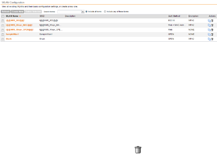
You have completed viewing a list of existing WLANs.
Figure 29: Viewing the list of existing WLANs
Deleting WLANs
Follow these steps to delete WLANs.
1. Go to Configuration > WLAN.
The WLANs page appears.
2. Look for the WLAN Configuration section.
3. Locate the WLAN or WLANs that you want to delete.
4. Select the check boxes (first column) for the WLANs that you want to delete.
5. Click Delete Selected.
The WLANs that you selected disappear from the list. You have completed deleting WLANs.
If you are deleting a single WLAN, you can also click the icon (under the Actions column)
that is in the same row as the WLAN that you want to delete.
Configuring WLAN Groups
A WLAN group is a way of specifying which APs or AP groups provide which WLAN services.
If your wireless network covers a large physical environment (for example, multi-floor or
multi-building office) and you want to provide different WLAN services to different areas of your
environment, you can use WLAN groups to do this.
For example, if your wireless network covers three building floors (1st floor to 3rd floor) and you
need to provide wireless access to visitors on the 1st floor, you can do the following:
1. Create a WLAN service (for example, Guest Only Service) that provides guest-level
access only.
2. Create a WLAN group (for example, Guest Only Group), and then assign Guest Only
Service (WLAN service) to Guest Only Group (WLAN group).
3. Assign APs on the 1st Floor (where visitors need wireless access) to your Guest Only
Group.
Any wireless client that associates with APs assigned to the Guest Only Group will get the
guest-level access privileges defined in your Guest Only Service. APs on the 2nd and 3rd
floors can remain assigned to the default WLAN Group and provide normal-level access.
SmartZone 100/Virtual SmartZone Essentials for Release 3.2 Administrator Guide
50
Configuring the Wireless Network
Configuring WLAN Groups
Notes About WLAN Groups
Before you start using WLAN groups to provision WLAN settings to APs or AP groups, take
note of the following important notes:
•Creating WLAN groups is optional. If you do not need to provide different WLAN services to
different areas in your environment, you do not need to create a WLAN group.
•A default WLAN group called default exists. The first 27 WLANs that you create are
automatically assigned to this default WLAN group.
•A WLAN group can include a maximum of 27 member WLANs. For dual radio APs, each
radio can be assigned to only one WLAN group (single radio APs can be assigned to only
one WLAN group).
Creating a WLAN Group
Follow these steps to create a WLAN group.
1. Go to Configuration > WLAN.
The WLANs page appears.
2. Look for the WLAN Groups section.
3. Click Create New.
4. In Group Name, type a descriptive name that you want to assign to this WLAN group.
For example, if this WLAN will contain WLANs that are designated for guest users, you can
name this as Guest WLAN Group.
5. In Description (optional), type some notes or comments about this group.
6. Under WLAN List, select the check boxes for the WLANs that you want to be part of this
WLAN group.
The VLAN Override and NAS-ID columns for the selected WLANs become active.
7. In the VLAN Override settings, choose whether to override the VLAN configured for each
member WLAN. Available options include:
•No Change: Click this option if you want the WLAN to keep the same VLAN tag (default:
1).
•Tag: Click this option to override the VLAN configured for the WLAN service.
8. In the NAS-ID settings, choose whether to override the NAS-ID configured for each member
WLAN. Available options include:
•No Change: Click this option if you want the WLAN to keep the same NAS-ID tag.
•User-defined: Click this option to override the NAS-ID that has been assigned to this
WLAN service.
9. Click Create New.
The Create New form disappears and the WLAN group that you created appears in the table
under WLAN Groups.
You may now assign this WLAN group to an AP or AP group.
SmartZone 100/Virtual SmartZone Essentials for Release 3.2 Administrator Guide
51
Configuring the Wireless Network
Configuring WLAN Groups
Viewing Existing WLAN Groups
Follow these steps to view a list of existing WLAN groups.
1. Go to Configuration > WLAN.
The WLANs page appears.
2. Look for the WLAN Groups section.
All existing WLAN groups and their basic settings are shown, including the:
•WLAN group name
•Description
•Actions (that you can perform)
3. To view WLANs that belong to a particular WLAN group, click the WLAN group name.
You have completed viewing existing WLAN groups.
Deleting WLAN Groups
Follow these steps to delete WLAN groups.
1. Go to Configuration > WLAN.
The WLANs page appears.
2. Scroll down to the WLAN Group section.
3. Locate the WLAN group or groups that you want to delete.
4. Select the check boxes (first column) for the WLAN groups that you want to delete.
5. Click Delete Selected.
The WLAN groups that you selected disappear from the list. You have completed deleting WLAN
groups.
If you are deleting a single WLAN group, you can also click the icon (under the Actions column)
that is in the same row as the WLAN group that you want to delete.
Working with WLAN Schedule Profiles
A WLAN schedule profile specifies the hours of the day or week during which a WLAN service
will be enabled or disabled.
For example, a WLAN for student use at a school can be configured to provide wireless access
only during school hours. Create a WLAN schedule profile, and then when you configure a
WLAN, select the schedule profile to enable or disable the WLAN service during those hours/days.
NOTE: This feature will not work properly if the system does not have the correct time. To ensure
that the system always maintains the correct time, configure an NTP server and point the system
to the NTP server's IP address, as described in Configuring the System Time on page 138.
NOTE: WLAN service schedule times should be configured based on your browser's current
timezone. If your browser and the target AP/WLAN are in different timezones, configure the
on/off times according to the desired schedule according to your local browser. For example if
SmartZone 100/Virtual SmartZone Essentials for Release 3.2 Administrator Guide
52
Configuring the Wireless Network
Configuring WLAN Groups
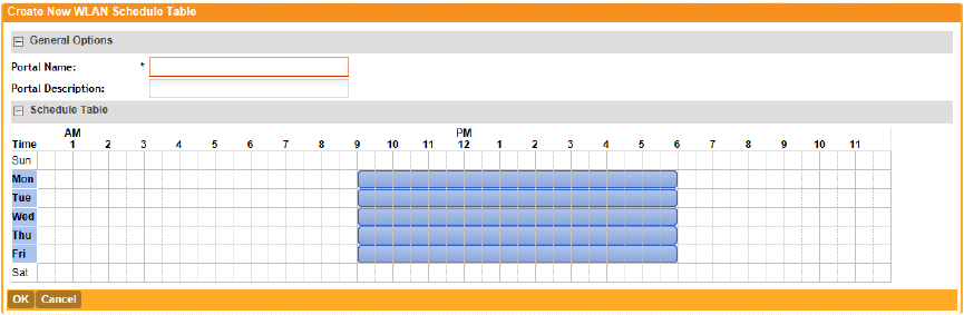
you wanted a WLAN in Los Angeles to turn on at 9 AM and your browser was set to New York
time, please configure the WLAN service schedule to enable the WLAN at noon. When configuring
the service schedule, all times are based on your browser's timezone setting.
Creating a WLAN Schedule Profile
Follow these steps to create a WLAN schedule profile.
1. Go to Configuration > WLAN.
The WLANs page appears.
2. Scroll down to the WLAN Schedule Profiles section.
3. Click Create New.
The Create New WLAN Schedule Table form appears.
4. Set a WLAN schedule.
a) To enable or disable the WLAN for an entire day, click the day of the week under the Time
column.
b) To enable or disable the WLAN for specific hour of a specific day, click the squares in the
table. A single square represents 30 minutes (two-15 minute blocks).
Blue-colored cells indicate the hours when the WLAN is enabled. Clear (or white) cells
indicate the hours when the WLAN is disabled.
5. Click Create New.
The page refreshes, and then the schedule you created appears in the WLAN Scheduler
Profiles section.
You have completed creating a WLAN schedule profile. This WLAN schedule profile will now
appear as an option
Figure 30: Creating a schedule profile
SmartZone 100/Virtual SmartZone Essentials for Release 3.2 Administrator Guide
53
Configuring the Wireless Network
Configuring WLAN Groups
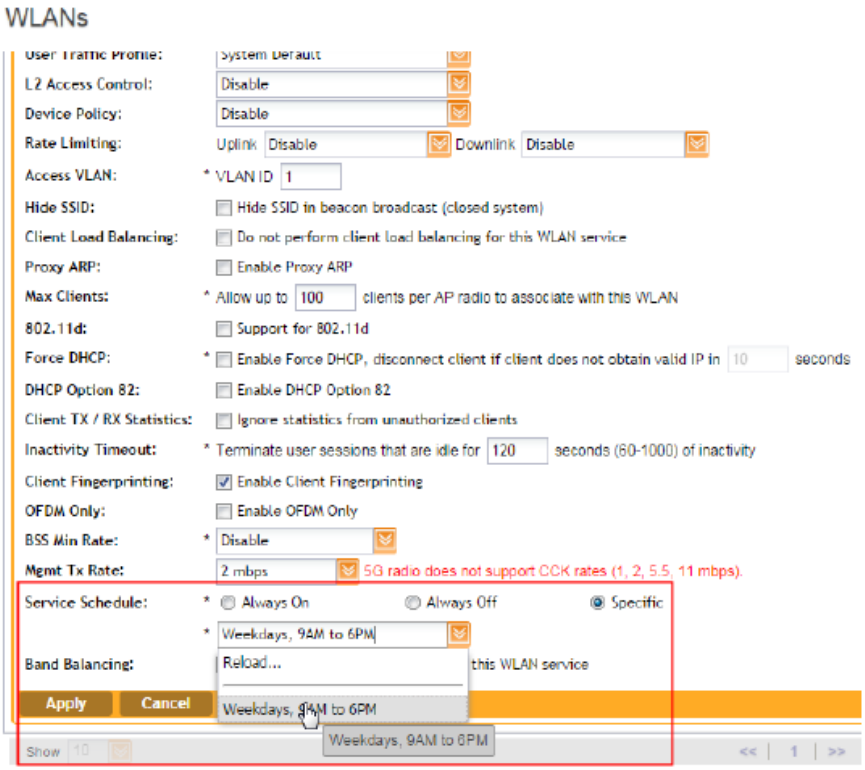
Figure 31: Selecting the schedule profile when creating or editing a WLAN
Viewing WLAN Schedule Profiles
Follow these steps to view a list of existing WLAN schedule profiles.
1. Go to Configuration > WLAN.
The WLANs page appears.
2. Look for the WLAN Schedule Profiles section.
All existing WLAN schedule profiles and their basic settings are shown, including the:
•WLAN schedule name
•Description
•Actions (that you can perform)
3. To view the schedule that has been defined in a particular schedule profile, click the schedule
profile name.
You have completed viewing existing WLAN schedule profiles.
SmartZone 100/Virtual SmartZone Essentials for Release 3.2 Administrator Guide
54
Configuring the Wireless Network
Configuring WLAN Groups
Deleting WLAN Schedule Profiles
Follow these steps to delete WLAN schedule profiles.
1. Go to Configuration > WLAN.
The WLANs page appears.
2. Scroll down to the WLAN Schedule Profiles section.
3. Locate the profile or profiles that you want to delete.
4. Select the check boxes (first column) for the profiles that you want to delete.
5. Click Delete Selected.
The profiles that you selected disappear from the list. You have completed deleting WLAN
schedule profiles.
If you are deleting a single profile, you can also click the icon (under the Actions column) that
is in the same row as the profile that you want to delete.
Configuring Access Points
Learn how to configure the access points that are managed by the controller.
Configuring Common AP Settings
Configure the settings that are common to all access points that are managed by the controller.
Follow these steps to configure the settings such as the country code, mesh options, and radio
options.
1. Go to Configuration > Access Points > Common Settings.
2. In the General Options section, configure the following:
DescriptionOption
This field shows the current AP firmware version on controller. This is
not configurable.
AP Firmware
Select the country in which you are operating the access points.
Different countries and regions maintain different rules that govern which
Country Code
channels can be used for wireless communications. Set the country
code to the proper regulatory region ensuring that the controller network
does not violate local and national regulatory restrictions.
Type a location name (for example, Ruckus Wireless HQ) for this AP.Location
Type additional information about the AP location (for example, 350 W
Java Dr, Sunnyvale, CA 94089, United States).
Location
Additional
Information
Type the longitude and latitude coordinates for the AP's location.GPS Coordinates
Specify the user name and password that administrators can use to
log on directly to the managed access point's native web interface. The
following boxes are provided:
AP Admin Logon
•Logon ID: Type the admin user name.
SmartZone 100/Virtual SmartZone Essentials for Release 3.2 Administrator Guide
55
Configuring the Wireless Network
Configuring Access Points
DescriptionOption
•Password: Type the admin password.
Set the time zone that you want APs to use by selecting one of the
following options:
AP Time Zone
•Follow the System Time Zone: Select this option if you want
managed APs to use the same time zone as the controller, which
the controller obtains from the NTP server you configured in
Configuring the System Time on page 138.
•User Defined: Select this option if you want to set the time zone
used by the APs manually, and then configure the time zone
abbreviation (for example, CST, GMT, etc.), GMT offset, and daylight
saving time (DST) support.
This field shows the IP addressing mode (either IPv4 only or IPv6 only)
that managed APs use. This is the device IP mode that you selected
when you completed the Setup Wizard. This field is not configurable.
AP IP Mode
3. In the Mesh Options section, configure the following:
DescriptionOption
Select this check box if you want managed APs to automatically form
a wireless mesh network, in which participant nodes (APs) cooperate
to route packets.
Dual band APs can only mesh with other dual band APs, while single
band APs can only mesh with other single band APs.
Enable mesh
networking
This option only appears when the Enable mesh networking check
box above is selected. Type a name for the mesh network. Alternatively,
Mesh Name
(ESSID)
do nothing to accept the default mesh name that the controller has
generated.
This option only appears when the Enable mesh networking check
box above is selected. Type a passphrase that contains at least 12
Mesh Passphrase
characters. This passphrase will be used by the controller to secure
the traffic between Mesh APs. Alternatively, click Generate to generate
a random passphrase with 32 characters or more.
4. In Radio Options, configure the following:
DescriptionOption
Select the check boxes for the channels on which you want the 2.4GHz
radios of managed APs to operate. Channel options include channels 1
to 11. By default, all channels are selected.
Channel Range
(2.4G)
If the country code that is selected in the General Options section of
this page is United States, the Allow DFS channels check boxs
DFS Channels
appears. Selecting this check box adds Dynamic Frequency Selection
SmartZone 100/Virtual SmartZone Essentials for Release 3.2 Administrator Guide
56
Configuring the Wireless Network
Configuring Access Points
DescriptionOption
(DFS) channels to the list of 5GHz channels (see below) that managed
APs can use indoors and outdoors.
DFS channels, which are special channels allocated for radar signals,
can be used by unlicensed devices (such as APs and wireless clients) if
no radar signals are using them. If radar signals are detected on a DFS
channel that is currently used by devices, those devices will automatically
vacate the channel and use an alternate channel.
Select the check boxes for the channels on which you want the 5GHz
radios of managed indoor APs to operate. If you selected the Allow DFS
Channel Range
(5G) Indoor
channels check box above, the list of channel options includes the DFS
channels.
Select the check boxes for the channels on which you want the 5GHz
radios of managed outdoor APs to operate. If you selected the Allow
Channel Range
(5G) Outdoor
DFS channels check box above, the list of channel options includes the
DFS channels.
Configure the following options:Radio Options
b/g/n (2.4 GHz) •Channelization: Set the channel width used during transmission to
either 20 or 40 (MHz), or select Auto to set it automatically.
•Channel: Select the channel to use for the b/g/n (2.4GHz) radio, or
select Auto to set it automatically.
•TX Power Adjustment: Select the preferred TX power, if you want
to manually configure the transmit power on the 2.4GHz radio. By
default, TX power is set to Full on the 2.4GHz radio
Configure the following options:Radio Options
a/n/c (5GHz) •Channelization: Set the channel width used during transmission to
either 20, 40, or 80 (MHz), or select Auto to set it automatically.
•Channel (Indoor): Select the indoor channel to use for the a/n/c
(5GHz) radio, or select Auto to set it automatically.
•Channel (Outdoor): Select the outdoor channel to use for the a/n/c
(5GHz) radio, or select Auto to set it automatically.
•TX Power Adjustment: Select the preferred TX power, if you want
to manually configure the transmit power on the 5GHz radio. By
default, TX power is set to Full on the 5GHz radio.
5. In Syslog Options, select the Enable external syslog server for APs check box if you want
to send syslogs to a remote syslog server. Configure the following options that appear after
you select the check box.
DescriptionOption
Type the IP address (IPv4 or IPv6) or host name of the syslog server
on the network.
Server Address
SmartZone 100/Virtual SmartZone Essentials for Release 3.2 Administrator Guide
57
Configuring the Wireless Network
Configuring Access Points
DescriptionOption
Type the syslog port number on the server. The default port number
is 514.
Port
Select the facility level that will be used by the syslog message.
Options include Keep Original (default), Local0, Local1, Local2,
Local3, Local4, Local5, Local6, and Local7.
Facility for Event
Accept or change the default severity to priority mapping. See Default
Event Severity to Syslog Priority Mapping on page 134.
Priority
6. In Advanced Options, configure the following options:
DescriptionOption
If you want to allow outdoor APs to use wireless channels that are regulated
as indoor-use only, select the Allow indoor channels check box. For more
information, see Channel Mode on page 61.
Channel Mode
You can adjust the AP channel to 2.4 GHz or 5 GHz frequencies by
selecting the appropriate check-box.
Auto Channel
Selection
Further, you can automatically adjust the AP to optimize performance by
choosing one of the following:
•Background Scanning
•ChannelFly
If you select this option, the Mean Time Between Change (MTBC) slider
is displayed, which allows you to manually control the ChannelFly
behavior. The behavior can be configured within the range of 100 -
1440 minutes with 480 minutes being the default value.
This is also configurable in AP groups.
If you want APs to evaluate radio channel usage automatically, enable and
configure the background scanning settings on both the 2.4GHz and 5GHz
Background
Scanning
radios. By default, background scanning is enabled on both radios and is
configured to run every 20 seconds.
To disable the WLANs of an AP whenever the AP uplink or Internet
connection becomes unavailable, select the Enable check box. And then,
configure the following options:
Smart Monitor
•Health Check Interval: Set the interval (between 5 and 60 seconds)
at which the controller will check the AP's uplink connection. The default
value is 10 seconds.
•Health Check Retry Threshold: Set the number of times (between 1
and 10 times) that the controller will check the AP's uplink connection.
If the controller is unable to detect the uplink after the configured number
of retries, the controller will disable the AP's WLANs. The default value
is 3 retries.
SmartZone 100/Virtual SmartZone Essentials for Release 3.2 Administrator Guide
58
Configuring the Wireless Network
Configuring Access Points
DescriptionOption
When the controller disables the AP's WLANs, the AP creates a log for
the event. When the AP's uplink is restored, the AP sends the event
log (which contains the timestamp when the WLANs were disabled,
and then enabled) to the controller.
To automatically segment large groups of clients (that may or may not be
connected to the same SSID) into multiple smaller subgroups using multiple
VLAN Pooling
VLANs, select the Allow VLAN pooling overlapping check box. Refer to
VLAN Pooling on page 63 for the additional settings that you need to
configure to get VLAN pooling to work on the wireless network.
Select the Report rogue access points check box to enable rogue device
detection in logs and email alarm event notifications.
Rogue AP
Detection
•Report all rogue devices: Send alerts for all rogue AP events.
•Report only malicious rogue devices of type: Select which event types
to report. Events include SSID spoofing, same network, and MAC
spoofing.
•Protect the network from malicious rogue access points: Select this
check box to automatically protect your network from network
connected rogue APs, SSID-spoofing APs and MAC-spoofing APs.
When one of these rogue APs is detected (and this check box is
enabled), the Ruckus Wireless AP automatically begins sending
broadcast de-authentication messages spoofing the rogue's BSSID
(MAC) to prevent wireless clients from connecting to the malicious rogue
AP. This option is disabled by default.
Improve WLAN performance by enabling load balancing. Load balancing
spreads the wireless client load between nearby access points, so that
one AP does not get overloaded while another sits idle.
Load balancing must be enabled on a per-radio basis. To enable load
balancing, select the Enable loading balancing on [2.4GHz or 5GHz]
Client Load
Balancing
check box, and then set or accept the default Adjacent Radio Threshold
values (50dB for the 2.4GHz radio and 43dB for the 5GHz radio).
For more information about load balancing, see Client Load Balancing on
page 48.
Client band balancing between the 2.4 GHz and 5 GHz radio bands is
enabled by default on all WLANs. For more information, see Band
Balancing.
Band
Balancing
If you have an LBS server on the network, select the Enable LBS Server
check box, and then select the server from the list.
For more information about location based services, see Configuring
Location Services on page 120.
Location
Based Service
SmartZone 100/Virtual SmartZone Essentials for Release 3.2 Administrator Guide
59
Configuring the Wireless Network
Configuring Access Points
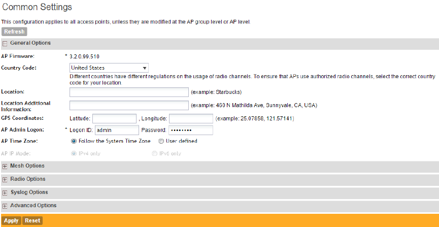
DescriptionOption
If managed APs are providing Hotspot 2.0 services, select the name of
the venue profile that you previously created. See the Hotspot 2.0
Reference Guide for this release for more information.
Hotspot 2.0
Venue Profile
To enable client admission control on a specific wireless radio, select the
Enable check box, and then set the load thresholds on the AP at which
it will stop accepting new clients by setting values for the following:
Client
Admission
Control
•Min Client Count
•Max Radio Load (%)
•Min Client Throughput (Mbps)
For more information about client admission control, see Client
Admission Control on page 49.
Set the time after which the AP will reboot automatically when it is unable
to reach the default gateway or the control interface.
AP Reboot
Timeout
•Reboot AP if it cannot reach default gateway after [ ] minutes: The
default timeout is 30 minutes.
•Reboot AP if it cannot reach the controller after [ ]: The default
timeout is 2 hours.
7. Click Apply.
You have completed configuring the common AP settings.
Figure 32: The Common Settings page
SmartZone 100/Virtual SmartZone Essentials for Release 3.2 Administrator Guide
60
Configuring the Wireless Network
Configuring Access Points
Channel Mode
Some countries restrict certain 5GHz channels to indoor use only.
For instance, Germany restricts channels in the 5.15 GHz to 5.25 GHz band to indoor use. When
ZoneFlex Outdoor APs and bridges with 5 GHz radios (ZoneFlex 7762, 7782, 7761- CM and
7731) are set to a country code where these restrictions apply, the AP or bridge can no longer
be set to an indoor-only channel and will no longer select from amongst a channel set that
includes these indoor-only channels when SmartSelect or auto channel selection is used, unless
the administrator configures the AP to allow use of these channels.
For instance, if the AP is installed in a challenging indoor environment (such as a warehouse),
the administrator may want to allow the AP to use an indoor-only channel. These channels can
be enabled for use through the AP CLI or controller web interface by configuring Configuration >
Access Points > Common Settings > Advanced Options > Channel Mode and selecting
the Allow indoor channels (allow ZoneFlex Outdoor APs to use channels regulated as
indoor use-only) check box.
If you have a dual-band ZoneFlex Indoor AP functioning as a RAP with dual-band ZoneFlex
Outdoor APs functioning as MAPs, the mesh backhaul link must initially use a non-indoor-only
channel. Your ZoneFlex Outdoor MAPs may fail to join if the mesh backhaul link is using a
restricted indoor-only channel.
Client Load Balancing
Enabling load balancing can improve WLAN performance by helping to spread the wireless client
load between nearby access points, so that one AP does not get overloaded while another sits
idle.
The load balancing feature can be controlled from within the controller web interface to balance
the number of clients per radio on adjacent APs.
Adjacent APs are determined by the controller at startup by measuring the RSSI during channel
scans. After startup, the controller uses subsequent scans to update the list of adjacent radios
periodically and when a new AP sends its first scan report. When an AP leaves, the controller
immediately updates the list of adjacent radios and refreshes the client limits at each affected
AP.
Once the controller is aware of which APs are adjacent to each other, it begins managing the
client load by sending the configured client limits to the APs. These limits are soft values that
can be exceeded in several scenarios, including:
1. When a client's signal is so weak that it may not be able to support a link with another AP
2. When a client's signal is so strong that it really belongs on this AP.
The APs maintain these configured client limits and enforce them once they reach the limits by
withholding probe responses and authentication responses on any radio that has reached its
limit.
Key Points About Client Load Balancing
Before you enable load balancing, keep the following considerations in mind:
•The load balancing rules apply only to client devices; the AP always responds to another AP
that is attempting to set up or maintain a mesh network.
SmartZone 100/Virtual SmartZone Essentials for Release 3.2 Administrator Guide
61
Configuring the Wireless Network
Configuring Access Points
•Load balancing does not disassociate clients already connected.
•Load balancing takes action before a client association request, reducing the chance of client
misbehavior.
•The process does not require any time-critical interaction between APs and the controller.
•Provides control of adjacent AP distance with safeguards against abandoning clients.
•Can be disabled on a per-WLAN basis. For instance, on a voice WLAN, load balancing may
not be desired due to voice roaming considerations.
•Background scanning must be enabled on the WLAN for load balancing to work.
Band Balancing
Band balancing balances the client load on radios by distributing clients between the 2.4 GHz
and 5 GHz radios.
This feature is enabled by default and set to a target of 25% of clients connecting to the 2.4
GHz band. To balance the load on a radio, the AP encourages dual-band clients to connect to
the 5 GHz band when the configured percentage threshold is reached.
ChannelFly and Background Scanning
SmartZone controllers offer the ChannelFly and Background Scanning automatic channel selection
methods for spectrum utilization and performance optimization. While Background Scanning
must be enabled for rogue AP detection, AP location detection and radio power adjustment,
either can be used for automatic channel optimization.
The main difference between ChannelFly and Background Scanning is that ChannelFly determines
the optimal channel based on real-time statistical analysis of actual throughput measurements,
while Background Scanning uses channel measurement and other techniques to estimate the
impact of interference on Wi-Fi capacity based on progressive scans of all available channels.
NOTE: If you enable ChannelFly, Background Scanning can still be used for adjusting radio
power and rogue detection while ChannelFly manages the channel assignment. Both cannot
be used at the same time for channel management.
Benefits of ChannelFly
With ChannelFly, the AP intelligently samples different channels while using them for service.
ChannelFly assesses channel capacity every 15 seconds and changes channel when, based
on historical data, a different channel is likely to offer higher capacity than the current channel.
Each AP makes channel decisions based on this historical data and maintains an internal log of
channel performance individually.
When ChannelFly changes channels, it utilizes 802.11h channel change announcements to
seamlessly change channels with no packet loss and minimal impact to performance. The
802.11h channel change announcements affect both wireless clients and Ruckus mesh nodes
in the 2.4 GHz and/or 5 GHz bands.
Initially (in the first 30-60 minutes) there will be more frequent channel changes as ChannelFly
learns the environment. However, once an AP has learned about the environment and which
channels are most likely to offer the best throughput potential, channel changes will occur less
frequently unless a large measured drop in throughput occurs.
SmartZone 100/Virtual SmartZone Essentials for Release 3.2 Administrator Guide
62
Configuring the Wireless Network
Configuring Access Points
ChannelFly can react to large measured drops in throughput capacity in as little as 15 seconds,
while smaller drops in capacity may take longer to react to.
Disadvantages of ChannelFly
Compared to Background Scanning, ChannelFly takes considerably longer for the network to
settle down. If you will be adding and removing APs to your network frequently, Background
Scanning may be preferable. Additionally, if you have clients that do not support the 802.11h
standard, ChannelFly may cause significant connectivity issues during the initial capacity
assessment stage.
You can enable/disable ChannelFly per band. If you have 2.4 GHz clients that do not support
802.11h, Ruckus recommends disabling ChannelFly for 2.4 GHz but leaving it enabled for the
5 GHz band.
Background Scanning
Using Background Scanning, SmartZone controllers regularly samples the activity in all Access
Points to assess RF usage, to detect rogue APs and to determine which APs are near each
other for mesh optimization. These scans sample one channel at a time in each AP so as not
to interfere with network use. This information is then applied in AP Monitoring and other controller
monitoring features. You can, if you prefer, customize the automatic scanning of RF activity,
deactivate it if you feel it's not helpful, or adjust the frequency, if you want scans at greater or
fewer intervals.
NOTE: Background Scanning must be enabled for SmartZone controllers to detect rogue APs
on the network.
VLAN Pooling
When Wi-Fi is deployed in a high density environment such as a stadium or a university campus,
the number of IP addresses required for client devices can easily run into the thousands.
Placing thousands of clients into a single large subnet or VLAN can result in degraded
performance due to factors like broadcast and multicast traffic. To address this problem, VLAN
pooling allows administrators to a deploy pool of multiple VLANs to which clients are assigned,
thereby automatically segmenting large groups of clients into multiple smaller subgroups, even
when connected to the same SSID. As the client device joins the WLAN, the VLAN is assigned
to one of the VLANs in the pool based on a hash of the client’s MAC address.
To use the VLAN pooling feature, you first need to create a VLAN pooling profile, and then you
can assign the profile to a specific WLAN or override the VLAN settings of a WLAN group.
Creating a VLAN Pooling Profile
Each VLAN pool can contain up to 16 VLANs, and a maximum of 64 VLAN pools can be created.
Each WLAN can be configured with a single VLAN pool.
Follow these steps to create a VLAN pooling.
1. Go to Configuration > WLANs.
2. In the VLAN Pooling Profiles section, click Create New.
The Create New VLAN Pooling Profile form appears.
3. In Name, type a name for the profile.
SmartZone 100/Virtual SmartZone Essentials for Release 3.2 Administrator Guide
63
Configuring the Wireless Network
Configuring Access Points
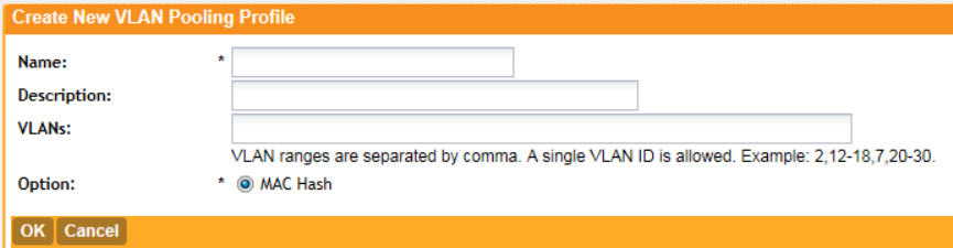
4. In Description (optional), type a short description for this profile.
5. In VLANs, type the VLAN IDs to be assigned to this pool.
VLAN IDs can be separated by hyphens, commas, or a combination (for example, 7-10, 13,
17, 20-28).
6. Click OK.
You have completed creating a VLAN pooling profile.
Figure 33: The Create New VLAN Pooling Profile form
Assigning the VLAN Pooling Profile to a WLAN
Follow these steps to assign the VLAN pooling profile to a specific WLAN.
1. Go to ConfigurationWLANs.
2. In the WLAN Configuration section, click Create New to create a new WLAN or click a
WLAN name to edit it.
3. Expand the Advanced Options section, and locate the Access VLAN entry.
4. Select the Enable VLAN Pooling check box, and then select the VLAN pooling profile that
you created earlier.
5. Click OK.
You have completed assigning a VLAN pooling profile to a WLAN. Clients connecting to this
WLAN will now be automatically assigned to a VLAN from the specified VLAN pool.
SmartZone 100/Virtual SmartZone Essentials for Release 3.2 Administrator Guide
64
Configuring the Wireless Network
Configuring Access Points
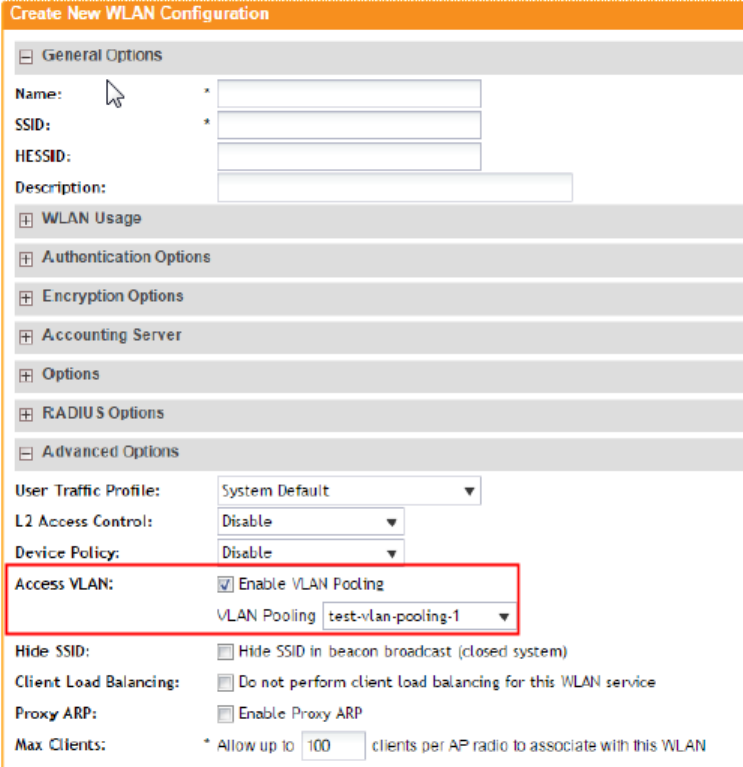
Figure 34: Under the Advanced Options section, locate the Access VLAN entry
Using a VLAN Pooling Profile to Override the VLAN Settings of a WLAN Group
If you want to override the original VLAN settings of a WLAN with the VLAN pool that you created
earlier, follow these steps.
1. Go to Configuration > WLANs.
2. In the WLAN Groups section, click Create New to create a new WLAN group or click a
WLAN group name to edit it.
3. Expand the WLAN List section, and then select the check boxes for the member WLANs
for which you want to override the VLAN settings.
4. In the VLAN Override column, select Pooling, and then select the VLAN pooling profile that
you want to apply to each of the selected member WLANs.
5. Click Apply.
You have completed overriding the VLAN settings of a WLAN group using a VLAN pooling profile.
SmartZone 100/Virtual SmartZone Essentials for Release 3.2 Administrator Guide
65
Configuring the Wireless Network
Configuring Access Points
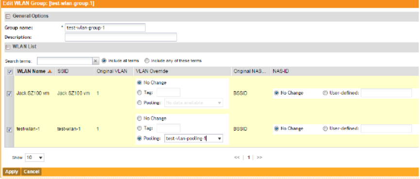
Figure 35: In the VLAN Override column, select the VLAN pooling profile to apply each of
the selected WLANs
Managing Access Points
Once you set up the controller, access points will be able to join or register with the controller
automatically. After an access point registers successfully with the controller, you can update
its configuration by following the steps described in this section.
Viewing a List of Managed Access Points
After an access point registers successfully with the controller, it appears on the Access Points
page, along with other managed access points. Follow these steps to view a list of managed
access points.
•Go to Configuration > Wireless Network > Access Points.
A list of access points that are being managed by the controller appears on the Access
Points page. These are all the access points that belong to all management domains.
The list of managed access points displays details about each access point, including its:
•AP MAC address
•AP name
•Model (AP model)
•AP firmware
•IP address (internal IP address)
•External IP address
•Provision Method
•Provision State
•Administrative Status
•Status
•Configuration Status
•Registered On (date the access point joined the controller network)
•Registration State
SmartZone 100/Virtual SmartZone Essentials for Release 3.2 Administrator Guide
66
Configuring the Wireless Network
Configuring Access Points
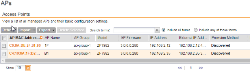
•Actions (actions that you can perform)
NOTE: By default, the Access Points page displays 10 access points per page (although you
have the option to display up to 250 access points per page). If the controller is managing more
than 10 access points, the pagination links at the bottom of the page are active. Click these
pagination links to view the succeeding pages on which the remaining access points are listed.
Figure 36: Viewing a list of managed access points
Provisioning and Swapping Access Points
The controller supports the provisioning and swapping of access points.
As an administrator you can:
•Upload a file containing list of AP and the pre-provisioned configuration data for each AP.
The controller processes the file and provides details on regarding the import results (including
a list of failed APs and failure reasons).
•Modify or delete pre-provisioning data if AP does not connect to the controller
•Monitor the status and stage of the pre-provisioned APs
•Manually lock or unlock APs
•Upload a file containing list of AP pairs for swapping. The controller processes the file and
provide the detailed import result (including a list of failed APs and failure reasons).
•Manually enter the AP swap pair
•Delete the swap configuration if AP fails to contact the controller
•Monitor the status and stage of the swapping AP pairs
•Manually swap the APs
Options for Provisioning and Swapping APs
The controller supports the provisioning and swapping of access points.
Use the following buttons on the Access Points page to perform the AP provisioning and
swapping.
Click this button to import the provisioning file. The controller displays the
import results. Any errors that occur during the import process will be listed
by the controller.
Import Batch
Provisioning APs
Click this button to download a CSV file that lists all APs that have been
provisioned. The exported CSV contains the following information:
Export All Batch
Provisioning APs
•AP MAC Address
SmartZone 100/Virtual SmartZone Essentials for Release 3.2 Administrator Guide
67
Configuring the Wireless Network
Configuring Access Points

•Model
•AP Name
•Description
•Location
•GPS Coordinates
•Logon ID
•Password
•Administrative State
•IP Address
•Network Mask
•Gateway
•Primary DNS
•Secondary DNS
•Provision Checklist
•Serial Number
NOTE: The exported CSV file for all batch provisioned APs only contains
pre-provisioned APs. It does not contain swapping APs or auto discovered
APs.
NOTE: If no APs have been pre-provisioned, you will still be able to export
the CSV file but it will be empty (except for the column titles).
Manually trigger the swapping of two APs by clicking the swap action in
the row. You can also edit the pre-provision configuration only if the AP
Import Swapping
APs
does not connect to the controller. Click the AP MAC address to bring up
the configuration edit form, and then select Pre-provision Configuration.
Click this button to download a CSV file that lists all APs that have been
swapped. The exported CSV contains the following information:
Export All Batch
Swapping APs
•Swap In AP MAC
•Swap In AP Model
•Swap Out AP MAC
NOTE: The exported CSV file for batch swapping APs only contains
swapping APs. It does not contain pre-provisioned APs or auto discovered
APs.
To delete multiple pre-provisioned APs simultaneously, select the check
boxes before the AP MAC addresses, and then click Delete Selected. To
Delete Selected
delete a single pre-provisioned AP, click the icon that is in the same
row as the AP MAC address. If the AP has not contacted the controller,
the AP record disappears from the table. If the AP comes up later, the
controller treats it as a discovered AP. If the AP is connected to the
controller, the delete operation is similar to the AP delete operation.
SmartZone 100/Virtual SmartZone Essentials for Release 3.2 Administrator Guide
68
Configuring the Wireless Network
Configuring Access Points
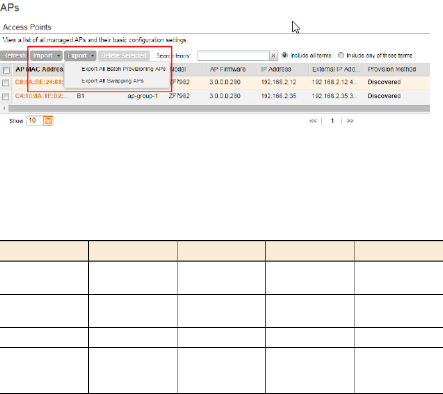
Figure 37: Options for provisioning and swapping APs
Understanding How Swapping Works
The following table lists how the controller handles swapping by detailing each stage.
For example, you have entered swap configuration as Swap In: A and Swap out: B.
Table 3: AP swapping stages
Stage BState BStage AState AStage
Waiting for swap
in AP registration
ApprovedNot RegisteredSwapping1. Enter data
Waiting for
swapping out
ApprovedWaiting for
swapping in
Swapping2. AP register
Swapped outSwappingSwapped inApproved3. User swap
Swapped in and
waiting for
swapping out
ApprovedSwapped out and
waiting for
swapping in
Swapping4: Second swap
Editing AP Configuration
Follow these steps to update the configuration of a managed access point.
1. On the menu, click Configuration.
2. On the sidebar, click Wireless Network > Access Points.
3. On the APs page, locate the access point whose configuration you want to update.
4. Click the MAC address of the access point.
The Edit AP configuration form appears.
5. Update the access point configuration by modifying the options in the form.
6. Click OK.
You have completed editing the AP configuration.
The loc parameter (which holds the Location attribute in the AP configuration) in the controller's
Captive Portal redirection to the configured hotspot login portal is encoded using the Hex encoder
from the org.apache.commons.codec.binary library. If you have hotspots on the network
SmartZone 100/Virtual SmartZone Essentials for Release 3.2 Administrator Guide
69
Configuring the Wireless Network
Configuring Access Points
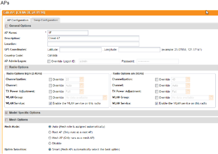
and you are using an external portal, take note of the encoding mechanism for the loc parameter
so your external portal can decode it.
Figure 38: The Edit AP configuration form
Editing Swap Configuration
The controller supports the swapping or replacement of a managed AP with a new AP of the
same model. This feature is useful when you want to avoid service interruption because you
need to replace an AP in the field.
By configuring the swap settings, you can easily and automatically export and apply the settings
of the old AP to the new AP.
Follow these steps to configure the swap settings of an AP.
1. Go to the Configuration > Wireless Network > Access Points.
2. On the APs page, locate the access point whose swap configuration you want to update.
3. Click the AP MAC address of the access point.
4. Click the Swap Configuration tab.
5. Update the access point configuration by modifying the options in the form.
6. Click OK.
You have completed editing the swap configuration.
SmartZone 100/Virtual SmartZone Essentials for Release 3.2 Administrator Guide
70
Configuring the Wireless Network
Configuring Access Points
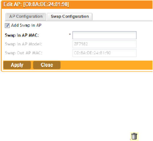
Figure 39: The Edit AP > Swap Configuration form
Deleting an Access Point
Follow these steps to delete an access point that is currently registered with the controller.
1. Go to the Configuration > Wireless Network > Access Points.
2. On the APs page, locate the access point that you want to delete.
3. Once you locate the access point, click the icon that is under the Actions column.
A confirmation message appears.
4. Click OK.
The list of managed access points refreshes, and then the access point that you deleted
disappears from the list.
NOTE: Wireless clients that are associated with the access point that you deleted will still be
able to connect to the network until the next time the access point attempts to rejoin the controller.
NOTE: After you delete an access point, it could take approximately two minutes before it
appears on the Configuration > Wireless Network > APs page again.
Configuring Model Based Settings
To apply settings to all APs of a particular model, use the Model Based Settings page.
Follow the steps to configure Model Based Settings settings.
1. On the menu, click Configuration.
2. On the sidebar, click Wireless Network > Access Points > Model-based Settings.
The AP Model Specific Configuration page appears.
3. In Select an AP Model, select the AP model that you want to configure.
4. NOTE: The options that appear in the General Options section depend on the AP model
that you select. Not all the options described in the table below will appear for every AP model.
In the General Options section, configure the following settings:
SmartZone 100/Virtual SmartZone Essentials for Release 3.2 Administrator Guide
71
Configuring the Wireless Network
Configuring Access Points
DescriptionOption
To enable the PoE out port on the selected AP model, select the Enable
PoE out ports (specific ZoneFlex AP models only) .
NOTE: If the controller country code is set to United Kingdom, an
additional Enable 5.8 GHz Channels option will be available for outdoor
PoE out port
11n/11ac APs. Enabling this option allows the use of restricted C-band
channels. These channels are disabled by default and should only be
enabled by customers with a valid license to operate on these restricted
channels.
Select the PoE operating mode of the selected AP model. Available
options include Auto (defauled) and 802.3af PoE. If 802.3af PoE is
PoE Operating
Mode
selected, this AP model will operate in 802.3af mode (not 802.3at mode)
and will consume less power than in 802.3at mode. However, when
this option is selected, some AP features are disabled to reduce power
consumption, such as the USB port and one of the Ethernet ports. See
the Access Point User Guide for model-specific information.
To enable the heater that is built into the selected AP model, select the
Enable internal heaters (specific AP models only) check box.
Internal Heater
To disable the status LED on the selected AP model, select the Disable
Status LEDs check box.
Status LEDs
To enable the Link Layer Discovery Protocol (LLDP) on the selected AP
model, select the Enable Link Layer Discovery Protocol check box.
LLDP
To enable the external 2.4 GHz antenna on the selected AP model,
select the Enable external antenna check box, and then set the gain
value (between 0 and 90dBi) in the box provided.
External Antenna
(2.4 GHz)
To enable the external 5 GHz antenna on the selected AP model, select
the Enable external antenna check box, and then set the gain value
(between 0 and 90dBi) in the box provided.
External Antenna
(5 GHz)
To disable the USB port on the selected AP model, select the Disable
USB port check box. USB ports are enabled by default.
USB Port
5. NOTE: The number of LAN ports that appear in this section correspond to the physical LAN
ports that exist on the selected AP model.
In the Port Settings section, configure the following options for each LAN port.
DescriptionOption
Use this option to enable and disable this LAN port on the selected AP
model. By default, this check box is selected. To disable this LAN port,
clear this check box.
Enable check
box
Use this option to select the Ethernet port profile that you want this LAN
port to use. Two default Ethernet port profile exist: Default Trunk Port
Profile
SmartZone 100/Virtual SmartZone Essentials for Release 3.2 Administrator Guide
72
Configuring the Wireless Network
Configuring Access Points
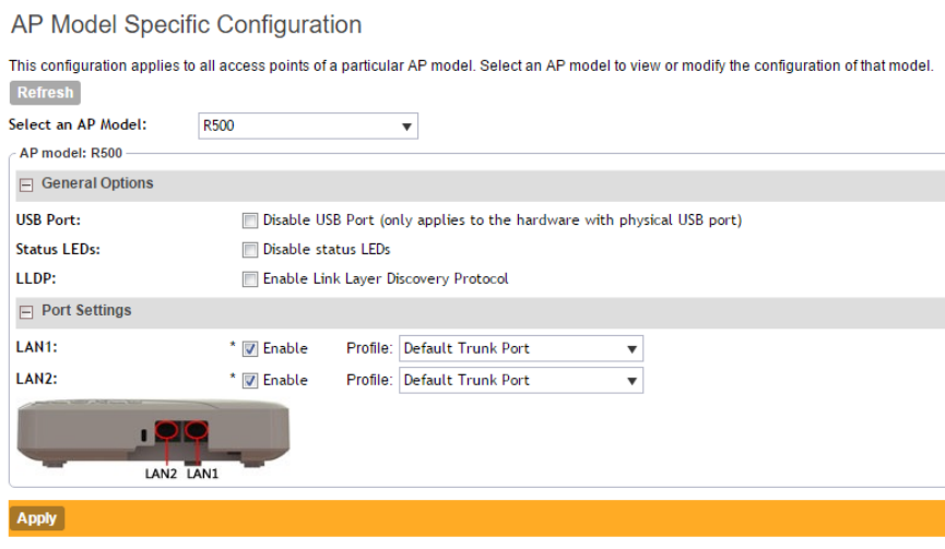
DescriptionOption
(selected by default) and Default Access Port. If you created Ethernet port
profiles (see Creating an Ethernet Port Profile on page 78), these profiles
will also appear on the drop-down list.
NOTE: If you recently created an Ethernet port profile and it does not appear
on the drop-down menu, click Reload on the drop-down menu to refresh
the Ethernet port profile list.
6. Click Apply.
The message Please wait... appears. When the message disappears, you have
completed configuring the settings of the selected AP model.
Figure 40: Options for configuring AP model specific settings
Configuring AP Tunnel Settings
Configure the tunnel settings of access points that are managed by the controller.
Follow these steps to configure the AP tunnel settings.
1. Go to Configuration > Wireless Network > Access Point > AP Tunnel Settings.
2. In Tunnel Type, select the tunneling protocol that you want the controller to use for AP traffic.
Option include:
•Ruckus GRE
•SoftGRE
•SoftGRE + IPsec
SmartZone 100/Virtual SmartZone Essentials for Release 3.2 Administrator Guide
73
Configuring the Wireless Network
Configuring Access Points
NOTE: Selecting the SoftGRE + IPSec tunneling protocol will prevent APs that do not
support Internet Protocol Security (IPsec) from joining the controller.
3. Optional: If you selected Ruckus GRE, configure the following settings:
DescriptionOption
Select a protocol to use for tunneling WLAN traffic back to the
controller.
Ruckus Tunnel
Mode
•GRE + UDP: Select this option to allow APs behind a NAT server
to tunnel WLAN traffic back to the controller.
•GRE: Select this option to tunnel regular WLAN traffic only.
Select the Enable tunnel encryption check box if you want managed
APs to decrypt 802.11 packets, and then use an AES encrypted tunnel
Tunnel Encryption
to send them to the controller. By default, when WLAN traffic is
tunneled to the controller, only the management traffic is encrypted;
data traffic is unencrypted.
Set the maximum transmission unit (MTU) for the tunnel to either Auto
(default) or a specific size (850 to 1500 bytes). MTU is the size of the
largest protocol data unit that can be passed on the controller network.
WAN Interface
MTU
4. Optional: If you selected Soft GRE, configure the following settings:
DescriptionOption
Type a name for the profile that you are creating.Name
Type a short description of the profile.Description
Type the IP address or fully-qualified domain name (FQDN) of the
primary gateway server.
Primary Gateway
Address
If you have a secondary gateway server on the network, type its
IP address or FQDN in the box provided. If the controller is unable
Secondary Gateway
Address
to reach the primary gateway server, it will automatically attempt
to reach the secondary gateway address that you specify here.
Set the maximum transmission unit (MTU) for the gateway path.
Options include Auto (default) and Manual (range is 850 to 1500
bytes).
Gateway Path MTU
Type the time interval (in seconds) at which APs send a keepalive
message to the active third party WLAN gateway. The range is 1
to 180 seconds and the default value is 10 seconds.
ICMP Keep Alive Period
Type the number of keepalive attempts that APs wait for a
response from the active third party WLAN gateway before failing
ICMP Keep Alive Retry
over to the standby WLAN gateway. The range is 2 to 10 retries
and the default value is 5 retries.
5. Configure the setting for the tunneling protocol that you selected.
SmartZone 100/Virtual SmartZone Essentials for Release 3.2 Administrator Guide
74
Configuring the Wireless Network
Configuring Access Points
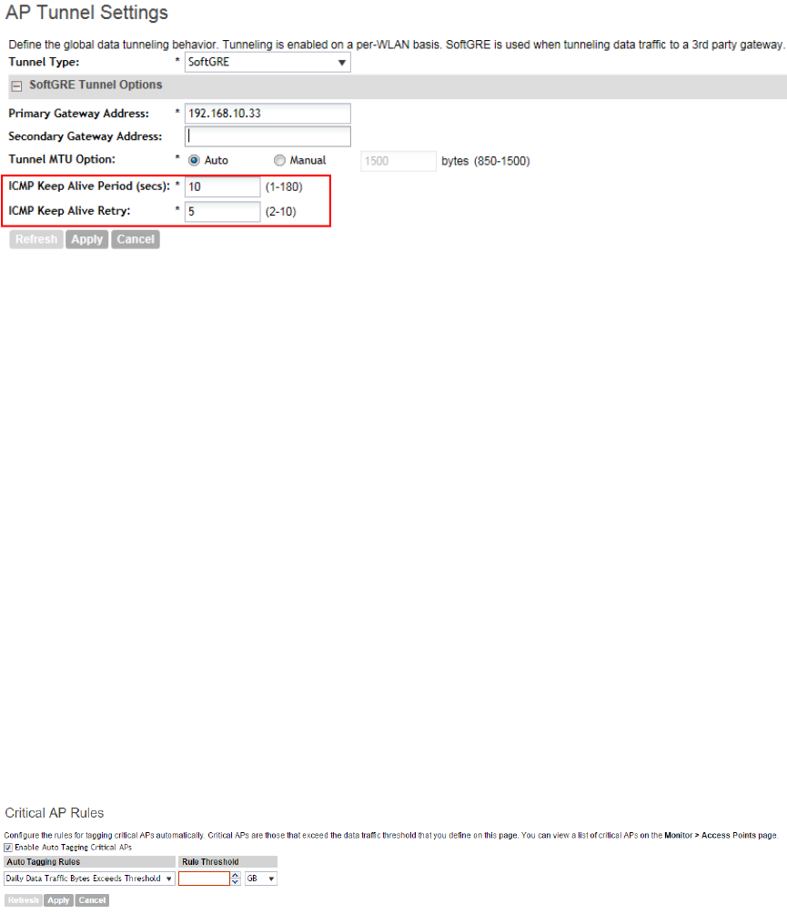
6. Click Apply.
You have completed configuring the AP tunnel settings.
Figure 41: Configuring the AP tunnel settings
Tagging Critical APs
A critical AP is an AP that exceeds the daily traffic threshold (sum of uplink and downlink) data
bytes configured on the controller web interface. Follow these steps to tag critical APs
automatically.
1. Go to Configuration > Wireless Network > Access Points > Critical AP Rules.
2. Select the Enable Auto Tagging Critical APs check box.
3. Under Auto Tagging Rules, select Daily Traffic Bytes Exceeds Threshold.
4. Under Rule Threshold, specify the threshold.
•In the first box, type a value that you want to set as the traffic threshold. This value will be
applied in conjunction with the data unit that you will select in the second box.
•In the second box, select the data unit for the threshold – M for megabytes or G for
gigabytes.
5. Click Apply.
APs that exceed the daily traffic threshold that you specified will appear highlighted on the Access
Points page and the Access Point details page. Additionally, the controller will send an SNMP
trap to alert you that that an AP has been disconnected.
Figure 42: Use the Critical AP Rules page to define the daily traffic threshold for APs
Creating an IPsec Profile
Create an IPsec profile that APs can use when the AP tunnel settings are set to SoftGRE + IPsec.
Follow these steps to create an IPSec profile.
SmartZone 100/Virtual SmartZone Essentials for Release 3.2 Administrator Guide
75
Configuring the Wireless Network
Configuring Access Points
1. On the menu, click Configuration.
2. On the sidebar, click Wireless Network > Access Points > IPsec.
The IPsec page appears.
3. Click Create New.
The Create IPSec Profile form appears.
4. In General Options, configure the following:
•Name: Type name for the IPSec profile that you are creating.
•Description: Type a description for this profile.
•Security Gateway: Type the IP address or FQDN of the IPSec server. If you use the IP
address, the IP address format that you must enter will depend on the IP mode that is
configured on the controller.
5. In Authentication, configure the following:
•Type: Click Preshared Key to use PSK for authentication or click Certificate to use an
X.509 certificate on the certificate authority (CA) or registration authority (RA) server. The
controller uses the CMPv2 protocol to obtain the signed certificate from the CA/RA server.
•Preshared Key: If you clicked Preshared Key in Type, type the PSK in this box. The PSK
must be eight to 128 ASCII characters in length.
6. In Security Association, configure the following:
•IKE Proposal Type: Click Default to use the default Internet Key Exchange (IKE) security
association (SA) proposal type or click Specific to manually configure the IKE SA proposal.
If you clicked Specific, you will need to configure the following settings:
•Encryption Algorithm: Options include 3DES, AES128, AES192, and AES256.
•Integrity Algorithm: Options include MD5, SHA1, AES-XCBC, SHA256, SHA384, and
SHA512.
•Pseudo-Random Function: Options include Use integrity ALG, PRF-MD5, PRF-SHA1,
PRF-AES-XCBC, PRF-AES-CMAC, PRF-SHA256, and PRF-SHA384.
•DH Group: Options for Diffie-Hellman groups for IKE include modp768, modp1024,
modp1536, modp2048, modp3072, modp4096, modp6144, and modp8192.
•ESP Proposal Type: Click Default to use the default Encapsulating Security Payload
(ESP) SA proposal type or click Specific to manually configure the ESP proposal. If you
clicked Specific, you will need to configure the following settings:
•Encryption Algorithm: Options include 3DES, AES128, AES192, AES256, and NONE.
•Integrity Algorithm: Options include MD5, SHA1, AES-XCBC, SHA256, SHA384, and
SHA512
•DH Group: Options for Diffie-Hellman groups for ESP include None, modp768,
modp1024, modp1536, modp2048, modp3072, modp4096, modp6144, and
modp8192.
7. In Rekey Options, configure the following:
SmartZone 100/Virtual SmartZone Essentials for Release 3.2 Administrator Guide
76
Configuring the Wireless Network
Configuring Access Points
•Internet Key Exchange: To set time interval at which the IKE key renews, select a time
unit (day, hour, or minute) from the drop-down list, and then type a number in the box. To
disable IKE rekey, select the Disable check box.
•Encapsulating Security Payload: To set time interval at which the ESP key renews,
select a time unit (day, hour, or minute) from the drop-down list, and then type a number
in the box. To disable ESP rekey, select the Disable check box.
8. In Certificate Management Protocol, configure the following:
•DHCP Option 43 Sub Code for CA/RA Address: Set the DHCP Option 43 subcode that
will be used to discover the address of the CA/RA server on the network. The default
subcode is 8.
•CA/RA Address: Type the IP address or FQDN of the CA/RA server. If you use the IP
address, the IP address format that you must enter will depend on the IP mode that is
configured on the controller.
•Server Path: Type the path to the X.509 certificate on the CA/RA server.
•DHCP Option 43 Sub Code for Subject Name of CA/RA: Set the DHCP Option 43
subcode that will be used to discover the subject name of the CA/RA server on the network.
The default subcode is 5.
•Subject Name of CA/RA: Type an ASCII string that represents the subject name of the
CA/RA server.
9. In Advanced Options, configure the following:
•DHCP Option 43 Sub Code for Security Gateway: Set the DHCP Option 43 subcode
that will be used to discover the address of the security gateway on the network. The
default subcode is 7.
•Retry Limit: Set the number of times that the controller will attempt to discover the address
of the security gateway. The default retry count is 5. Accepted values are 0 (disable) to
16.
•Replay Window: Set the ESP replay window (in packets). The default size is 32 packets.
Accepted values are 0 (disable) to 32 packets.
•IP Compression: To enable IP Payload Compression Protocol (IPComp) compression
before encryption, click Enable. The default value is Disable.
•Force NAT-T: To enforce UDP encapsulation of ESP packets, click Enable. The default
value is Disable.
•Dead Peer Detection: By default, the IKE protocol runs a health check with remote peer
to ensure that it is alive. To disable this health check, click Disable.
•NAT-T Keep Alive Interval: To set the keep alive interval (in seconds) for NAT traversal,
type a value in the box. The default keep alive interval is 20 seconds. Accepted values are
1 to 65536. To disable the keep alive interval, click Disable.
•FailOver Options: To configure the failover settings when APs are unable to connect,
configure the following:
•Retry Period: Set the number of days (minimum 3 days) during which APs will keep
attempting to connect. To keep try indefinitely, select the Forever check box.
•Retry Interval: Set the interval (in minutes) between each retry attempt. The default
retry interval is 1 minute. Accepted values are from 1 to 30 minutes.
SmartZone 100/Virtual SmartZone Essentials for Release 3.2 Administrator Guide
77
Configuring the Wireless Network
Configuring Access Points
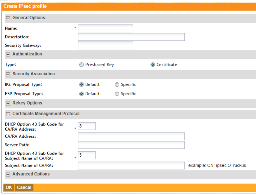
•Retry Mode: If you want APs to fall back to the specified primary security gateway,
click Revertive. If you want APs to maintain connectivity with the security gateway to
which they are currently connected, click Non-revertive.
10. Click OK.
The page refreshes and then profile that you created appears.
Figure 43: Options for creating an IPsec profile
Creating an Ethernet Port Profile
An Ethernet port profile contains settings that define how an AP will handle VLAN packets when
its port is designated as either trunk, access, or general port. By default, two Ethernet port
profiles exist: Default Access Port and Default Trunk Port..
Follow the steps to create an Ethernet port profile.
1. On the menu, click Configuration.
2. On the sidebar, click Wireless Network > Access Points > Ethernet Port.
The Ethernet Port Profiles page appears.
3. Click Create New.
The Create New Ethernet Port form appears.
4. Configure the options that appear in the form.
SmartZone 100/Virtual SmartZone Essentials for Release 3.2 Administrator Guide
78
Configuring the Wireless Network
Configuring Access Points
DescriptionOption
General Options
Type a name for the Ethernet port profile that you are creating.Name
The Ethernet port type defines how the AP will manage VLAN frames.
You can set Ethernet ports on an AP to one of the following types:
Type
•Trunk Port
•Access Port
•General Port
For more information about Ethernet port types, see Designating an
Ethernet Port Type on page 81.
Port Setting
Select this check box to enable tunneling on the Ethernet port.Tunnel
NOTE: This check box only appears when Type is set to Access.
Type the ID of the native VLAN (typically, 1), which is the VLAN into
which untagged ingress packets are placed upon arrival. If your network
VLAN Untag ID
uses a different VLAN as the native VLAN, configure the AP Trunk port’s
VLAN Untag ID with the native VLAN used throughout your network.
Type the VLAN IDs that you want to use to tag WLAN traffic that will
use this profile. You can type a single VLAN ID or a VLAN ID range (or
a combination of both). The valid VLAN ID range is 1 to 4094.
VLAN Members
Select this check box if you want the controller to assign VLAN IDs on
a per-user basis. Before enabling dynamic VLAN, you need to define
on the RADIUS server the VLAN IDs that you want to assign to users.
NOTE: See How Dynamic VLAN Works for more information.
Enable Dynamic
VLAN
NOTE: This option is only available when Type is set to Access Port
and 802.1X authentication is set to MAC-based Authenticator.
If you want to assign a device that fails authentication to still be able to
access the Internet but to internal networ resources, select this check
box.
NOTE: This check box only appear when the Enable Dynamic VLAN
check box is selected.
Guest VLAN
SmartZone 100/Virtual SmartZone Essentials for Release 3.2 Administrator Guide
79
Configuring the Wireless Network
Configuring Access Points
DescriptionOption
This option, which is disabled by default, controls the type of 802.1X
authenticator that you want to use to authenticate devices. Available
options include:
802.1X
•MAC-based Authenticator: If you select this authenticator, each
MAC address host is individually authenticated. Each newly-learned
MAC address triggers an EAPOL request-identify frame.
•Port-based Authenticator: If you select this authenticator, only a
single MAC host must be authenticated for all hosts to be granted
access to the network.
This section only appears when 802.1X is set to either MAC-based
Authenticator or Port-based Authenticator.
Authenticator
Select the authentication server to use. If you want to use the controller
as proxy, select the Use the Controller as Proxy check box instead.
Authentication
Server
Select the accounting server to use. If you want to use the controller
as proxy, select the Use the Controller as Proxy check box instead.
Accounting Server
Select this check box to allow AAA server queries using the MAC
address as both the user name and password. If MAC authentication
Enable MAC
authentication
bypass is unsuccessful, the normal 802.1X authentication exchange will be
attempted.
5. Click OK.
The page refreshes, and then the profile you created appears on the list of Ethernet port profiles.
You can now use this profile to configure the port settings of specific AP models. See Configuring
Model Based Settings on page 71.
SmartZone 100/Virtual SmartZone Essentials for Release 3.2 Administrator Guide
80
Configuring the Wireless Network
Configuring Access Points
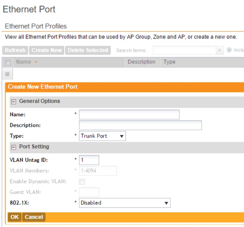
Figure 44: Options for creating an Ethernet port profile
Designating an Ethernet Port Type
Ethernet ports can be configured as access ports, trunk ports, or general ports.
Trunk links are required to pass VLAN information between switches. Access ports provide
access to the network and can be configured as members of specific VLANs, thereby separating
the traffic on these ports from traffic on other VLANs. General ports are user-defined ports that
can have any combination of up to 20 VLAN IDs assigned.
For most ZoneFlex APs, you can set which ports you want to be your Access, Trunk and General
Ports from the controller web interface, as long as at least one port on each AP is designated
as a Trunk Port.
By default, all ports are enabled as Trunk Ports with Untag VLAN set as 1 (except for ZoneFlex
7025, whose front ports are enabled as Access Ports by default). If configured as an Access
Port, all untagged ingress traffic is the configured Untag VLAN, and all egress traffic is untagged.
If configured as a Trunk Port, all untagged ingress traffic is the configured Untag VLAN (by default,
1), and all VLAN-tagged traffic on VLANs 1-4094 will be seen when present on the network.
The default Untag VLAN for each port is VLAN 1. Change the Untag VLAN to:
SmartZone 100/Virtual SmartZone Essentials for Release 3.2 Administrator Guide
81
Configuring the Wireless Network
Configuring Access Points
•Segment all ingress traffic on this Access Port to a specific VLAN.
•Redefine the native VLAN on this Trunk Port to match your network configuration.
When trunk port limitation is disabled using the eth-port-validate-one-trunk disable
command, validation checks are not performed for the VLAN members and the AP Management
VLAN. If the AP configuration for general ports and access ports does not include a member of
an AP management VLAN, or the VLAN of a WAN interface configured through CLI, the AP will
disconnect and the Ethernet port stops transmitting data. Make sure that you configure the
correct VLAN member in the ports (general/access) and the AP management VLAN.
NOTE: Ensure that at least one of the general port VLANs is the same as a Management VLAN
of the AP.
Important Notes About Ethernet Port Profiles
If you are using Ethernet port profiles to handle VLAN traffic to and from managed APs, take
note of these important notes and caveats.
•Dynamic VLANs and guest VLANs only support the access port and MAC-based authenticator.
•Tunnels only support the access port.
•802.1x options are only supported when the AP’s mesh mode is Root, Mesh, or Disable.
•At least one trunk port must be enabled on the AP for the Ethernet port profile to work.
•The AP can only have a supplicant port.
Controlling Access to the Wireless Network
Working with User Traffic Profiles
A traffic profile defines whether the system will allow or block a particular type of traffic based
on a number of attributes, including:
•Source IP address (specific IP address or IP address range)
•Source port number (specific port or port range)
•Destination IP address (specific IP address or IP address range)
•Destination port number (specific port or port range)
•Network protocol (TCP, UDP, etc.)
•Traffic direction
Creating a User Traffic Profile
Follow these steps to create a user traffic profile.
1. Go to Configuration > Wireless Network > Access Control.
2. In the User Traffic Profiles section, click Create New.
3. In Name, type a name for this profile.
4. In Description, type a short description for this profile.
5. In Default Access, select whether you want the controller to allow or block users using this
profile if the user traffic does not match any of the rules you defined.
6. In the Rules section, click Create New.
SmartZone 100/Virtual SmartZone Essentials for Release 3.2 Administrator Guide
82
Configuring the Wireless Network
Controlling Access to the Wireless Network
By default, two default rules exist (Allow DNS and Allow DHCP) when you create a new profile.
You can modify these rules or even delete them.
7. In Source IP, specify the source IP address to which this rule will apply.
•To apply this rule to an IP address range, type the network address and the subnet mask.
•To apply this rule to a single IP, clear the Subnet check box, and then enter the IP address.
8. In Source Port, specify the source port to which this rule will apply.
•To apply this rule to a port range, type the starting and ending port numbers in the two
boxes.
•To apply this rule to a single port number, clear the Range check box, and then enter the
port number.
9. In Destination IP, specify the destination IP address to which this rule will apply.
•To apply this rule to an IP address range, type the network address and the subnet mask.
•To apply this rule to a single IP, clear the Subnet check box, and then enter the IP address.
10. In Destination Port, specify the source port to which this rule will apply.
•To apply this rule to a port range, type the starting and ending port numbers in the two
boxes.
•To apply this rule to a single port number, clear the Range check box, and then enter the
port number.
11. In Protocol, select the network protocol to which this rule will apply. Supported protocols
include:
•TCP
•UDP
•UDPLITE
•ICMP (ICMPv4)
•ICMPV6
•IGMP
•ESP
•AH
•SCTP
12. In Direction, leave as is. Only one traffic direction (upstream) is supported in this release.
13. Click Create New.
You have completed creating a user traffic profile. The next time you a WLAN, this profile will
appear as one of the options for User Traffic Profile.
Viewing User Traffic Profiles
Follow these steps to view a list of existing user traffic profiles.
1. Go to Configuration > Wireless Network > Access Control.
The Access Control page appears.
2. Look for the User Traffic Profiles section.
SmartZone 100/Virtual SmartZone Essentials for Release 3.2 Administrator Guide
83
Configuring the Wireless Network
Controlling Access to the Wireless Network
All existing user traffic profiles and their basic settings are shown, including the:
•User traffic profile name
•Description
•Default access (allow or block)
•Actions (that you can perform)
3. To view the type of traffic that has been defined in a particular user traffic profile, click the
profile name.
You have completed viewing existing user traffic profiles.
Assigning Priorities to Traffic Profile Rules
The controller can set the priority of rules as per your requirements.
The controller applies the rules you have created to user traffic in the same order as they appear
in the table. If you want a particular rule to have higher priority over other rules, click the green
up arrow icon under the Actions column. If you want a rule to have lower priority, click the green
down arrow icon.
When you finish setting the rule priorities, click OK to save your changes.
Deleting Traffic Profiles
Follow these steps to delete user traffic schedule profiles.
1. Go to Configuration > Wireless Network > Access Control.
The Access Control page appears.
2. Scroll down to the User Traffic Profiles section.
3. Locate the profile or profiles that you want to delete.
4. Select the check boxes (first column) for the profiles that you want to delete.
5. Click Delete Selected.
The profiles that you selected disappear from the list. You have completed deleting user traffic
profiles.
If you are deleting a single profile, you can also click the icon (under the Actions column) that
is in the same row as the profile that you want to delete.
Controlling L2 Access
Another method to control access to the network is by defining Layer 2/MAC address access
control lists (ACLs), which can then be applied to one or more WLANs or WLAN groups.
L2 ACLs are either allow-only or deny-only; that is, an ACL can be set up to allow only specified
clients or to deny only specified clients. MAC addresses that are in the deny list are blocked at
the AP.
Creating an L2 Access Policy
Follow these steps to create an L2 access policy.
1. Go to Configuration > Wireless Network > Access Control.
The Access Control page appears.
SmartZone 100/Virtual SmartZone Essentials for Release 3.2 Administrator Guide
84
Configuring the Wireless Network
Controlling Access to the Wireless Network
2. Scroll down to the L2 Access Control section, and then click Create New.
3. In Name, type a name for this policy.
4. In Description, type a short description for this policy.
5. In Restriction, select the default action that the controller will take if no rules are matched.
Available options include:
•Only allow all stations listed below
•Only block all stations listed below
6. In the Rules section, click Create New.
7. In MAC Address, type the MAC address to which this L2 access policy applies.
8. Click Create New.
The page refreshes, and then the L2 access policy that you created appears in the L2 Access
Control section.
You have completed creating an L2 access policy.
Viewing L2 Access Policies
Follow these steps to view a list of existing L2 access profiles.
1. Go to Configuration > Wireless Network > Access Control.
The Access Control page appears.
2. Look for the L2 Access Control section.
All existing L2 access policies and their basic settings are shown, including the:
•Profile name
•Description
•Default access (allow or block)
•Actions (that you can perform)
3. To view or change the MAC address has been defined in a particular L2 access policy, click
the profile name.
You have completed viewing existing L2 access policies.
Deleting L2 Access Policies
Follow these steps to delete L2 access policies.
1. Go to Configuration > Wireless Network > Access Control.
The Access Control page appears.
2. Scroll down to the L2 Access Control section.
3. Locate the policy or policies that you want to delete.
4. Select the check boxes (first column) for the policies that you want to delete.
5. Click Delete Selected.
The policies that you selected disappear from the list. You have completed deleting L2 access
policies.
SmartZone 100/Virtual SmartZone Essentials for Release 3.2 Administrator Guide
85
Configuring the Wireless Network
Controlling Access to the Wireless Network
If you are deleting a single policy, you can also click the icon (under the Actions column) that is
in the same row as the policy that you want to delete.
Controlling Device Access
In response to the growing numbers of personally owned mobile devices such as smart phones
and tablets being brought into the network, IT departments are requiring more sophisticated
control over how devices connect, what types of devices can connect, and what they are allowed
to do once connected.
Using device access policies, the system can identify the type of client attempting to connect,
and perform control actions such as permit/deny, rate limiting, and VLAN tagging based on the
device type. Once a device access policy has been created, you can apply the policy to any
WLANs or WLAN groups for which you want to control access by device type. You could, for
example, allow only Apple® iOS devices on one WLAN and only Linux™ devices on another.
Creating a Device Access Policy
Follow these steps to create a device access policy.
1. Go to Configuration > Wireless Network > Access Control.
The Access Control page appears.
2. Scroll down to the Device Access Policies section.
3. In Name, type a name for this policy.
4. In Description, type a short description for this policy.
5. In Default Access, select either Allow or Block.
This is the default action that the system will take if no rules are matched.
6. In the Rules section, click Create New.
The Create New Device Policy Profile form appears.
7. Configure the rule settings:
a) Description: Type a description for this rule.
b) Action: Select either Allow or Block.
This is the action that the system will take if the client matches any of the attributes in the
rule.
c) Device Type: Select from any of the supported client types.
d) Uplink Rate: Select the uplink rate limit for this client type, or click Disable.
e) Downlink Rate: Select the download rate limit for this client type, or select Disable.
f) VLAN: Segment this client type into a specified VLAN (1~4094; if no value is entered, this
policy does not impact device VLAN assignment).
8. To add a new rule, click Create New again, and then repeat step 7 on page 86.
9. When you finish creating all the rules that you want to add to the policy, click Create New
at the bottom of the form.
The page refreshes, and then the policy that you created appears under the Device Policies
section.
You have completed creating a device access policy.
SmartZone 100/Virtual SmartZone Essentials for Release 3.2 Administrator Guide
86
Configuring the Wireless Network
Controlling Access to the Wireless Network
Viewing Device Access Policies
Follow these steps to view a list of existing device access policies.
1. Go to Configuration > Wireless Network > Access Control.
The Access Control page appears.
2. Scroll down to the Device Access Policies section.
All existing device access policies and their basic settings are shown, including the:
•Name
•Description
•Default access (allow or block)
•Actions (that you can perform)
3. To view or update policy settings, click the policy name.
You have completed viewing device access policies.
Deleting Device Access Policies
Follow these steps to delete device access policies.
1. Go to Configuration > Wireless Network > Access Control.
The Access Control page appears.
2. Scroll down to the Device Access Policies section.
3. Locate the policy or policies that you want to delete.
4. Select the check boxes (first column) for the policies that you want to delete.
5. Click Delete Selected.
The policies that you selected disappear from the list. You have completed deleting device
access policies.
NOTE: If you are deleting a single policy, you can also click the icon (under the Actions column)
that is in the same row as the policy that you want to delete.
Controlling and Monitoring Applications
Application Visibility enables you to identify, control, and monitor applications that are running
on wireless clients associated with managed APs and to apply filtering policies to prevent users
from accessing certain applications.
Enabling Application Control and Visibility
The controller applies application control and visibility on a per-WLAN basis.
The WLAN for which you want to enable Application Visibility must already exist. If you have not
created the WLAN, see Creating a WLAN on page 41.
1. On the menu, click Configuration.
The WLANs page appears.
2. Click the WLAN for which you want to enable Application Visibility.
The Edit WLAN Config form appears.
SmartZone 100/Virtual SmartZone Essentials for Release 3.2 Administrator Guide
87
Configuring the Wireless Network
Controlling and Monitoring Applications
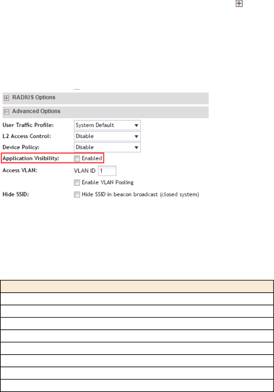
3. Scroll down to the Advanced Options section. If the section is collapsed, click to expand
it.
4. Locate the Application Visibility option, and then select the Enabled check box next to it.
5. Click Apply.
The message Submitting form... appears. When the message disappears, you have
completed enabling Application Visibility for the WLAN. When the controller detects traffic from
any of the applications included on its default list and any custom (user defined) applications
that you have added, it will display details about the traffic on the Monitor > Application Visibility
page.
Figure 45: To enable Application Visibility, select the Enabled check box
Applications That AVC Can Identify
Application Visibility and Control (AVC) has a default list of applications that it can identify.
If there are additional applications that you want AVC to monitor and control, add them to the
user defined application list.
Table 4: Applications that AVC can identify by default
Port NumberApplication Name
443HTTPS
80HTTP
22SSH
25SMTP
53DNS
79Finger
67DHCP
68DHCP
SmartZone 100/Virtual SmartZone Essentials for Release 3.2 Administrator Guide
88
Configuring the Wireless Network
Controlling and Monitoring Applications

Port NumberApplication Name
23Telnet
123NTP
515Printer
69TFTP
20FTP
21FTP
6699WINMX
4662eDonkey
411directconnect
6881bittorrent
6882bittorrent
6883bittorrent
6884bittorrent
6885bittorrent
6886bittorrent
6887bittorrent
6888bittorrent
6889bittorrent
2000skinny
2001skinny
2002skinny
5060sip
6000xwindows
6001xwindows
6002xwindows
6003xwindows
137netbios
138netbios
139netbios
2049nfs
119nntp
SmartZone 100/Virtual SmartZone Essentials for Release 3.2 Administrator Guide
89
Configuring the Wireless Network
Controlling and Monitoring Applications

Port NumberApplication Name
1698rsvp
1699rsvp
194irc
70gopher
8egp
70eigrp
179bgp
520rip
4ipinip
70gre
1433sqlserver
1701l2tp
1723pptp
990sftp
994sirc
636sldap
563snntp
995spop3
992stelnet
1080socks
1icmp
514syslog
110pop3
1352notes
389ldap
24032cuseeme
Adding a User Defined Application
When an application is unrecognized and generically (or incorrectly) categorized, the controller
will be unable to monitor its traffic, unless you configure an explicit application identification policy
based on IP address/mask, port and protocol. Wireless traffic that matches a user defined
application policy will be displayed using the applications’s name in the Top 10 Applications
widget on the dashboard and the applications pie charts/tables on the Monitor page.
SmartZone 100/Virtual SmartZone Essentials for Release 3.2 Administrator Guide
90
Configuring the Wireless Network
Controlling and Monitoring Applications
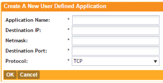
1. On the menu, click Configuration.
2. On the sidebar, click Wireless Network > Application Control.
3. In the User Defined Application section, click Create New.
The Create A New User Defined Application form appears.
4. Configure the following options to define the application that you want the controller to monitor
and control.
DescriptionOption
Type a name for the application. This is the name that will
identify this application on the dashboard and in charts.
Application Name
Type the destination IP address of the application.Destination IP
Type the netmask of the destination IP address.Netmask
Type the destination port for the application.Destination Port
Select the protocol used by the application. Options include
TCP and UDP.
Protocol
When the controller detects traffic that matches these attributes, it will start monitoring it.
5. Click OK.
The page refreshes, and then application you defined appears under the User Defined
Application section.
Figure 46: The Create A New User Defined Application form
Monitoring Application Visibility
If you enabled Application Visibility for at least one WLAN, you can monitor the applications that
run on wireless clients associated with that WLAN.
1. On the menu, click Monitor.
2. On the sidebar, click Application Visibility.
The Application Visibility page appears and displays the following:
•The Top 10 Applications pie chart
•The Traffic Summary line chart
•The Usage Detail table
SmartZone 100/Virtual SmartZone Essentials for Release 3.2 Administrator Guide
91
Configuring the Wireless Network
Controlling and Monitoring Applications
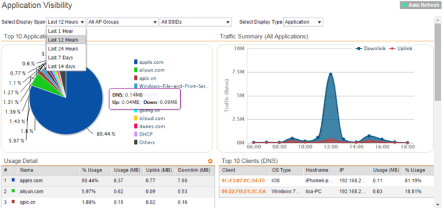
3. In Select Display Span, select options from the following drop-down menus to define the
period and scope of application visibility information that you want to view.
DescriptionOption
Select the period (in hours or days) for which to display application
visibility information. The default value is 12 hours.
First drop-down menu
Select the AP group for which to display application visibility
information. You can select one specific AP group or all AP
groups. The default value is All AP Groups.
Second drop-down
menu
Select the SSID for which to display application visibility
information. You can select one specific SSID or all SSIDs. The
default value is All SSIDs.
Third drop-down
4. In Select Display Type, select if you want the pie chart and line graph to display either the
names of the applications or the port numbers that they use.
The Application Visibility page refreshes, and then displays application visibility information it
recorded during the period and for the scope that you defined.
Figure 47: The Monitor > Application Visibility page
Managing Guest Access
Using the controller's Guest Access features, you can provide visitors to your organization limited
access to a guest WLAN with configurable guest policies, or given the option to self-activate
their devices to an internal WLAN using Zero-IT activation via the bring your own device (BYOD)
onboarding portal (or both).
The following sections describe how to configure guest WLANs and access policies that control
guest use of your network.
SmartZone 100/Virtual SmartZone Essentials for Release 3.2 Administrator Guide
92
Configuring the Wireless Network
Managing Guest Access
Creating a Guest Access Service
Each guest WLAN must be associated with a Guest Access Service, which defines the behavior
of the guest WLAN interface.
Follow these steps to create a guest access service.
1. Go to Configuration > Wireless Network > Guest Access.
The Guest Access Service page appears.
2. Click Create New.
The Create New Guest Access Service form appears.
3. In General Options, configure the following:
•Name: Type a name for the guest access service that you are creating.
•Description: Type a short description of the guest access service.
•Language: Select the display language to use for the buttons on the guest access logon
page.
4. In Redirection, select where to redirect the user after successfully completing authentication.
•Redirect to the URL that the user intends to visit: Allows the guest user to continue to
their destination without redirection.
•Redirect to the following URL: Redirect the user to a specified web page (entered into
the text box) prior to forwarding them to their destination. When guest users land on this
page, they are shown the expiration time for their guest pass.
5. In Guest Access, configure the following:
DescriptionOption
You can deliver the guest pass to the user using Short Message
Service (SMS). But first you need to configure an SMS server on the
Guest Pass SMS
Gateway
Configuration > System > External SMS Gateway page. If you
previously configured an SMS server, you can select it here or you
can select Disable.
To require users to read and accept your terms and conditions prior
to use, Show Terms And Conditions check box. The box below,
Terms and
Conditions
which contains the default Terms of Use text, becomes editable.
Edit the text or leave it unchanged to use the default text.
By default, the guest hotspot logon page displays the Ruckus Wireless
logo. To use your own logo, click the Upload button, select your logo
Web Portal Logo
(recommended size is 138 x 40 pixels, maximum file size is 20KB),
and then click Upload.
Type your own guest hotspot welcome text or accept the default
welcome text (Welcome to the Guest Access login page).
Web Portal Title
6. In User Session, configure the following:
•Session Timeout: Specify a time limit after which users will be disconnected and required
to log on again.
SmartZone 100/Virtual SmartZone Essentials for Release 3.2 Administrator Guide
93
Configuring the Wireless Network
Managing Guest Access
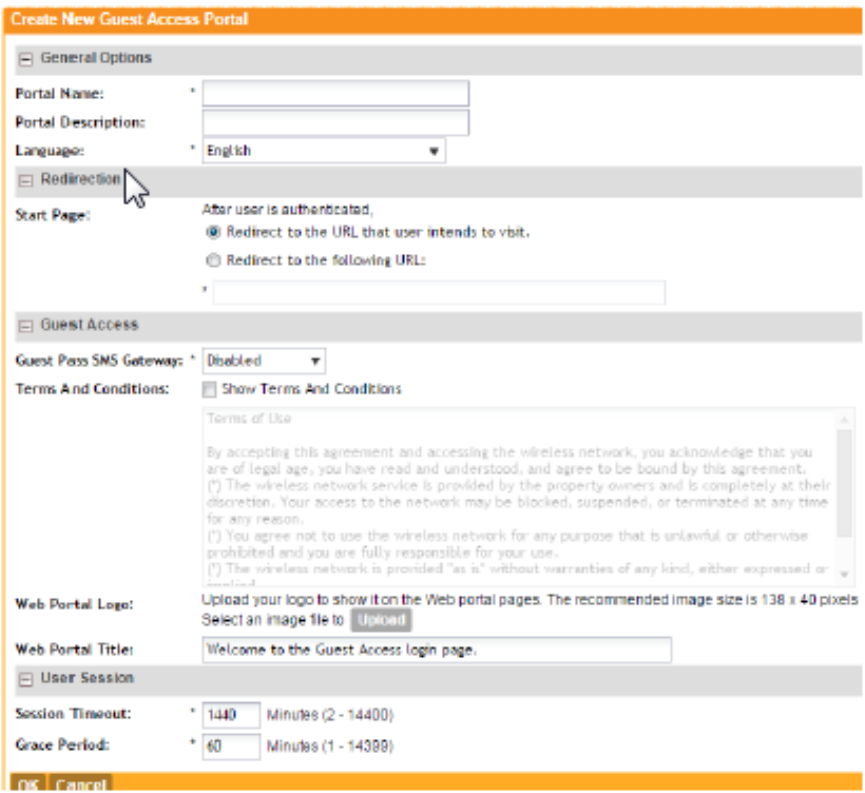
•Grace Period: Set the time period during which clients will not need to re-authenticate
after getting disconnected from the hotspot. Enter a number (in minutes) between 1 and
144,000.
7. Click OK.
You have completed creating a guest access service.
Figure 48: Creating a guest access service
Viewing Guest Access Services
The Guest Access Services view mode displays all existing guest access services and their basic
settings.
Follow these steps to view a list of existing Guest Access Services.
1. Go to Configuration > Wireless Network > Guest Access.
The Guest Access Service page appears and displays all existing guest access services
and their basic settings are shown, including the following:
SmartZone 100/Virtual SmartZone Essentials for Release 3.2 Administrator Guide
94
Configuring the Wireless Network
Managing Guest Access
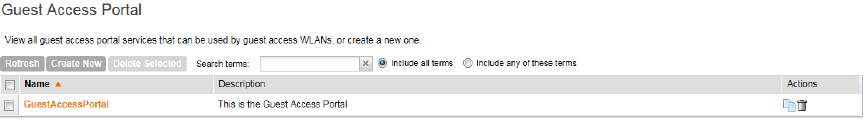
•Name
•Description
•Actions (that you can perform)
2. To view or update policy settings, click the policy name.
You have completed viewing device access policies.
Figure 49: Viewing guest access services
Deleting Guest Access Services
Follow these steps to delete guest access services.
1. Go to Configuration > Wireless Network > Guest Access.
The Guest Access Service page appears.
2. Locate the service or services that you want to delete.
3. Select the check boxes (first column) for the services that you want to delete.
4. Click Delete Selected.
The services that you selected disappear from the list. You have completed deleting guest access
services.
If you are deleting a single guest access service, you can also click the icon (under the Actions
column) that is in the same row as the service that you want to delete.
Working with Hotspot (WISPr) Services
A hotspot is a venue or area that provides Internet access to devices with wireless networking
capability such as notebooks and smartphones.
Hotspots are commonly available in public venues such as hotels, airports, coffee shops and
shopping malls. Use the controller's Configuration > Wireless Network > Hotspot Services
page to configure a traditional (WISPr 1.0) hotspot service to provide public access to users via
its WLANs. In addition to the controller and its managed APs, you will need the following to
deploy a hotspot:
•Captive Portal: A special web page, typically a login page, to which users that have associated
with your hotspot will be redirected for authentication purposes. Users will need to enter a
valid user name and password before they are allowed access to the Internet through the
hotspot.
•RADIUS Server: A Remote Authentication Dial-In User Service (RADIUS) server through
which users can authenticate.
SmartZone 100/Virtual SmartZone Essentials for Release 3.2 Administrator Guide
95
Configuring the Wireless Network
Working with Hotspot (WISPr) Services
For installation and configuration instructions for the captive portal and RADIUS server software,
refer to the documentation that was provided with them. After completing the steps below, you
will need to edit the WLAN(s) for which you want to enable Hotspot service.
The controller supports up to 32 WISPr hotspot service entries, each of which can be assigned
to multiple WLANs.
NOTE: In addition to hotspot (WISPr) services, the controller provides Hotspot 2.0 services. For
information on Hotspot 2.0 services, see Working with Hotspot 2.0 Services on page 106.
Creating a Hotspot (WISPr) Service
Define the basic settings that you need to configure to create a hotspot service.
NOTE: Before creating a hotspot, you need to create a user defined interface. For information
on how to create a user defined interface, see Configuring the User Defined Interface Settings.
Follow these steps to configure the hotspot service.
1. Click Configuration > Wireless Network > Hotspot Services.
2. Click Create New.
The form for creating a new hotspot service appears.
3. In the General Options section, configure the following options:
•Name: Type a name for the hotspot service.
•Description: Type a description for the hotspot service.
4. In the Redirection section, configure the following options:
DescriptionOption
Select one of the following options:Smart Client
Support •None: Select this option to disable Smart Client support on the hotspot
service.
•Enable: Selection this option to enable Smart Client support.
•Only Smart Client Allowed: Select this option to allow only Smart
Clients to connect to the hotspot service.
For more information, see Configuring Smart Client Support.
Type the URL of the subscriber portal (the page where hotspot users can
log in to access the service). For more information, see Configuring the
Logon URL.
Logon URL
Set where users will be redirected after they log in successfully:Start Page
•Redirect to the URL that user intends to visit: You could redirect
users to the page that they want to visit.
•Redirect to the following URL: You could set a different page where
users will be redirected (for example, your company website).
5. In the User Session section, configure the following options:
SmartZone 100/Virtual SmartZone Essentials for Release 3.2 Administrator Guide
96
Configuring the Wireless Network
Working with Hotspot (WISPr) Services
DescriptionOption
Set a time limit (in minutes) after which users will be disconnected
from the hotspot service and will be required to log on again.
Session Timeout
Set the time period (in minutes) during which disconnected users
are allowed access to the hotspot service without having to log on
again.
Grace Period
6. In the Location Information section, configure the following options:
DescriptionOption
Type the ISO and ITU country and area code that the AP includes in
accounting and authentication requests. The required code includes:
Location ID
•isocc (ISO-country-code): The ISO country code that the AP includes
in RADIUS authentication and accounting requests.
•cc (country-code): The ITU country code that the AP includes in
RADIUS authentication and accounting requests.
•ac (area-code): The ITU area code that the AP includes in RADIUS
authentication and accounting requests.
•network
The following is an example of what the Location ID entry should look
like: isocc=us,cc=1,ac=408,network=RuckusWireless
Type the name of the location of the hotspot service.Location Name
7. In Walled Garden, click Create Newto add a walled garden.
A walled garden is a limited environment to which an unauthenticated user is given access
for the purpose of setting up an account.
8. In the box provided, type a URL or IP address to which you want to grant unauthenticated
users access.
You can add up to 128 network destinations to the walled garden. Network destinations can
be any of the following:
•IP address (for example, 10.11.12.13)
•Exact website address (for example, www.ruckuswireless.com)
•Website address with regular expression (for example, *.ruckuswireless.com, *.com,
*)
After the account is established, the user is allowed out of the walled garden. URLs will be
resolved to IP addresses. Users will not be able to click through to other URLs that may be
presented on a page if that page is hosted on a server with a different IP address. Avoid using
common URLs that are translated into many IP addresses (such as www.yahoo.com), as
users may be redirected to re-authenticate when they navigate through the page.
9. Click OK.
SmartZone 100/Virtual SmartZone Essentials for Release 3.2 Administrator Guide
97
Configuring the Wireless Network
Working with Hotspot (WISPr) Services
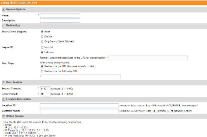
You have completed configuring a hotspot service. For additional steps that you need to perform
to ensure that the hotspot service works, see Working with Hotspot (WISPr) Services on page
95.
Figure 50: Creating a hotspot
Configuring Smart Client Support
Ruckus Wireless hotspots support the WISPr Smart Client feature, which allows client devices
to log on to a hotspot seamlessly without requiring the user to go through the logon page.
The controller provides the following options for supporting Smart Clients:
•None: Click this option to prevent Smart Client applications from logging on to WLANs that
include this hotspot configuration.
•Enable: Click this option to allow Smart Client applications to log on to WLANs that include
this hotspot configuration.
•Only Smart Client Allowed: Click this option to allow only Smart Client applications to log
on to WLANs that include this hotspot configuration. All other applications or browsers that
attempt to access the hotspot will be shown a custom message, which you can enter in the
box provided.
CAUTION: Clicking Only Smart Client Allowed requires the use of the internal Subscriber Portal.
The Logon URL and Start Page options are unavailable when the Only Smart Client Allowed
option is selected
SmartZone 100/Virtual SmartZone Essentials for Release 3.2 Administrator Guide
98
Configuring the Wireless Network
Working with Hotspot (WISPr) Services
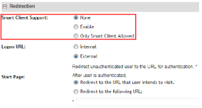
Figure 51: Smart Client support options
Configuring the Logon URL
The Logon URL refers to the location of the Subscriber Portal module that serves the logon form
for authenticating hotspot users.
There are two options available for the logon URL: Internal and External.
•Internal: Click this option if you want to use the Subscriber Portal module that is built into
the controller.
•External: Click this option if you want to use the Subscriber Portal module that is installed
on an external server. In the text box below, type the URL to the Subscriber Portal on the
external server. In the example below, the Subscriber Portal module is installed on a server
with the IP address 172.21.11.248, hence the logon URL is:
http://172.21.11.248:9997/SubscriberPortal/login
Figure 52: In Logon URL, click either Internal or External
Assigning a WLAN to Provide Hotspot Service
After you create a hotspot service, you need to specify the WLANs to which you want to deploy
the hotspot configuration.
Follow these steps to configure an existing WLAN to provide the hotspot service.
1. Go to Configuration > Wireless Network > WLANs.
2. In the WLANs section, look for the WLAN that you want to assign as a hotspot WLAN, and
then click the WLAN name.
The Editing WLAN Config: [WLAN name] form appears.
3. In Type, click Hotspot service (WISPr).
4. Scroll down to the Hotspot Service section (only visible when Authentication Type is set to
Hotspot service (WISPr)).
5. Select the name of the hotspot service that you created previously.
6. Click OK.
SmartZone 100/Virtual SmartZone Essentials for Release 3.2 Administrator Guide
99
Configuring the Wireless Network
Working with Hotspot (WISPr) Services
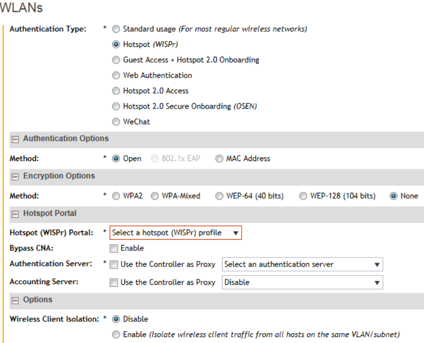
You have completed assigning a WLAN to provide a hotspot service.
Figure 53: Assigning a WLAN to provide hotspot
Working With WeChat Services
WeChat is a mobile app from Tenecent that enables its users to call and send text messages
to one another. If you have WeChat users on the network and you want your WLANs to support
WeChat services, you can create a WeChat portal that WeChat users can use.
Creating a WeChat Portal
A WeChat portal defines the third party authentication server, also known as the equipment
service provider (ESP) server, to which the controller will forward all WeChat authentication
requests from wireless devices that are associated with controller-managed APs. In turn, the
third party authentication server will forward these authentication requests to the WeChat server.
Follow these steps to create a WeChat portal.
1. On the menu, click Configuration.
2. On the sidebar, click Wireless Network to expand the menu, and then click WeChat.
The WeChat Portal page appears.
SmartZone 100/Virtual SmartZone Essentials for Release 3.2 Administrator Guide
100
Configuring the Wireless Network
Working With WeChat Services
3. Click Create New.
The Create New WeChat Portal form appears.
4. In General Options, configure the following options:
DescriptionOption
Type a name for the portal that you are creating.Authentication URL
Type a description for the portal.Description
5. In Portal Settings, configure the following options:
DescriptionOption
Type the authentication interface URL on the third party authentication
server. When a managed AP receives a WeChat logon request from a
Authentication
URL
client device, it will sent the request to this authentication URL and get
the authorization result.
Type the DNAT destination server address to which the controller will
forward HTTP requests from unauthenticated client devices. The DNAT
DNAT Destination
destination server and the authentication server (above) may or may not
be the same server.
Type the number of minutes during which disconnected users who were
recently connected will be allowed to reconnect to the portal without
Grace Period
needing to re-authenticate. The default grace period is 60 minutes (range
is between 1 and 14399 minutes).
Type network destinations that the controller will automatically block
associated wireless clients from accessing. Use a comma to separate
multiple entries.
Blacklist
6. In Whitelist, type network destinations that the controller will automatically allow associated
wireless clients to access. You can add a single entry or multiple entries.
•To add a single entry, type the entry in Whitelist Entry*, and then click Add. The entry
you added appears in the table below.
•To add multiple entries, in a comma-separated value (CSV) file, type all the network
destinations that you want to add to the whitelist, and then save the CSV file. In the
Whitelist section, click Import CSV, and then select the CSV file you created. Click Open.
The entries in the CSV file are added to the whitelist.
7. In DNAT Port Mapping, specify at least one pair of source-to-destination port mapping. To
add a port mapping, type the source and destination ports in the boxes provided, and then
click Add.
The AP will use this information to drop or forward HTTP requests from associated clients to
specified ports on the DNAT server. For example, if an HTTP request from a wireless client
does not originate from the specified source (from) port, the AP will discard the HTTP request.
By default, a port mapping of 80-80 (source-destination) exists.
8. Click OK.
SmartZone 100/Virtual SmartZone Essentials for Release 3.2 Administrator Guide
101
Configuring the Wireless Network
Working With WeChat Services
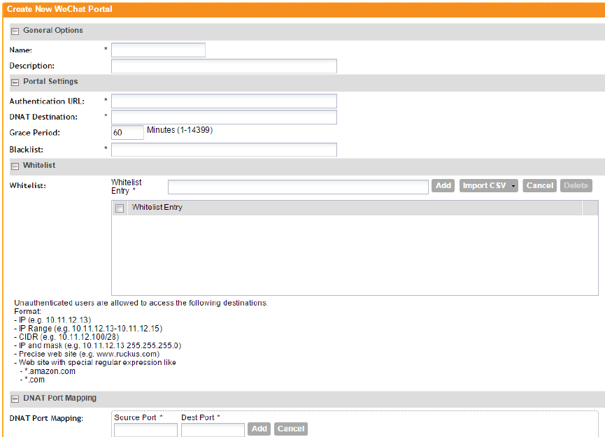
The page refreshes, and the WeChat portal you created appears on the list of existing WeChat
portals.
Figure 54: The Create New WeChat Portal form
Creating a WeChat WLAN
Create a WLAN specifically for WeChat users to enable them to use WeChat services on the
wireless network.
Before starting this procedure, verify that at least one WeChat portal already exists. If you have
not created a WeChat portal, see Creating a WeChat Portal on page 100 for information.
1. On the menu, click Configuration.
2. On the sidebar, click Wireless Network to expand the menu, and then click WLANs.
The WLANs page appears.
3. In WLAN Configuration, click Create New.
The Create New WLAN Configuration form appears.
4. In General Options, configure the following:
•Name: Type a name for this WLAN.
•SSID: Type a short name for the WLAN. The SSID is the WLAN name that is broadcast
on the wireless network.
SmartZone 100/Virtual SmartZone Essentials for Release 3.2 Administrator Guide
102
Configuring the Wireless Network
Working With WeChat Services
•HESSID: Type the homogenous extended service set identifier (HESSID). The HESSID is
a 6-octet MAC address that identifies the homogeneous ESS. The HESSID value must
be identical to one of the BSSIDs in the homogeneous ESS.
•Description: Type a brief description of the qualifications/purpose for this WLAN (for
example, Engineering or Voice).
5. In WLAN Usage, configure the following:
•In Access Network, select the Tunnel WLAN traffic through Ruckus GRE check box
if you want to tunnel the traffic from this WLAN back to the controller. Tunnel mode enables
wireless clients to roam across different APs on different subnets. If the WLAN has clients
that require uninterrupted wireless connection (for example, VoIP devices), Ruckus Wireless
recommends enabling tunnel mode. When you enable this option, you need to select core
network for tunneling WLAN traffic back to the controller.
•In Authentication Type, click WeChat.
NOTE: When the authentication type is set to WeChat, the authentication method and
encryption method are automatically set to Open and None, respectively.
6. In the WeChat Portal section, configure the following options:
•WeChat Portal, select a WeChat portal through which WeChat users can get authenticated.
If you have not created a WeChat portal, see see Creating a WeChat Portal on page 100
for information.
•Accounting Server: Select the RADIUS Accounting server that you want to use for this
WLAN. You must have added a RADIUS Accounting server previously (see Working with
AAA Servers on page 110). Additionally, if you want the controller to proxy accounting
messages to the AAA server, select the Use the Controller as Proxy check box.
7. In Options, configure the following options:
•Wireless Client Isolation: Wireless client isolation enables subnet restrictions for connected
clients. Click Enable if you want to prevent wireless clients associated with the same AP
from communicating with each other locally. The default value is Disable.
•Priority: Set the priority of this WLAN to Low if you would prefer that other WLAN traffic
takes priority. For example, if you want to prioritize internal traffic over guest WLAN traffic,
you can set the priority in the guest WLAN configuration settings to Low. By default, all
WLANs are set to high priority.
8. In RADIUS Options, click + (plus sign) to display the options, and then configure the following:
•NAS ID: Select how to the RADIUS server will identify the AP. Options include:
•WLAN BSSID
•AP MAC
•User-defined
•NAS Request Timeout: Type the timeout period (in seconds) after, which an expected
RADIUS response message is considered to have failed.
•NAS Max Number of Retries: Type the number of failed connection attempts after which
the controller will fail over to the backup RADIUS server.
SmartZone 100/Virtual SmartZone Essentials for Release 3.2 Administrator Guide
103
Configuring the Wireless Network
Working With WeChat Services
•NAS Reconnect Primary: If the controller fails over to the backup RADIUS server, this is
the interval (in minutes) at which the controller will recheck the primary RADIUS server if it
is available. The default interval is 5 minutes.
•Call STA ID: Use either WLAN BSSID or AP MAC as the station calling ID. Select one.
9. In Advanced Options, configure the following options:
•User Traffic Profile: If you want this WLAN to use a user traffic profile that you previously
created, select it from the drop-down menu. Otherwise, select System Default. For more
information, see Creating a User Traffic Profile on page 82.
•L2 Access Control: If you want this WLAN to use an L2 access control policy that you
previously created, select it from the drop-down menu. Otherwise, select Disable. For
more information, see Creating an L2 Access Policy on page 84.
•Device Policy: If you want this WLAN to use a device policy that you previously created,
select it from the drop-down menu. Otherwise, select Disable. For more information, see
Controlling Device Access on page 86.
•Access VLAN: By default, all wireless clients associated with APs that the controller is
managing are segmented into a single VLAN (with VLAN ID 1). If you want to tag this WLAN
traffic with a different VLAN ID, enter a valid VLAN ID (2-4094) in the box.
•Hide SSID: Select this check box if you do not want the ID of this WLAN advertised at
any time. This will not affect performance or force the WLAN user to perform any
unnecessary tasks.
•Client Load Balancing: To disable client load balancing on this WLAN, select the Do not
perform client load balancing for this WLAN service check box. For more information,
see Client Load Balancing on page 48.
•Proxy ARP: Select this check box to enable proxy ARP. When proxy ARP is enabled on
a WLAN, the AP provides proxy service for stations when receiving neighbor discovery
packets (for example, ARP request and ICMPv6 Neighbor Solicit messages), and acts on
behalf of the station in delivering ARP replies. When the AP receives a broadcast
ARP/Neighbor Solicit request for a known host, the AP replies on behalf of the host. If the
AP receives a request for an unknown host, it forwards the request at the rate limit specified.
•Max Clients: This option limits the number of clients that can associate with this WLAN
per AP (default is 100). You can also limit the total number of clients that a specific AP (or
radio, on dual radio APs) will manage.
•802.11d: Select this check box to enable this standard on this WLAN. 802.11d provides
specifications for compliance with additional regulatory domains (countries or regions) that
were not defined in the original 802.11 standard. Click this option if you are operating in
one of these additional regulatory domains.
•Force DHCP: Enable this option to force clients to obtain a valid IP address from DHCP
within the specified number of seconds. This prevents clients configured with a static IP
address from connecting to the WLAN. Additionally, if a client performs Layer 3 roaming
between different subnets, in some cases the client sticks to the former IP address. This
mechanism optimizes the roaming experience by forcing clients to request a new IP
address.
•DHCP Option 82: Select the Enable DHCP Option 82 check box to enable this feature.
When this feature is enabled and an AP receives a DHCP request from a wireless client,
the AP will encapsulate additional information (such as VLAN ID, AP name, SSID and MAC
address) into the DHCP request packets before forwarding them to the DHCP server. The
SmartZone 100/Virtual SmartZone Essentials for Release 3.2 Administrator Guide
104
Configuring the Wireless Network
Working With WeChat Services
DHCP server can then use this information to allocate an IP address to the client from a
particular DHCP pool based on these parameters.
•Client TX/RX Statistics: Select the Ignore statistics from unauthorized clients check
box if you do not want the controller to monitor traffic statistics for unauthorized clients.
•Inactivity Timeout: Select this check box and enter a value in seconds (60 to 600) after
which idle clients will be disconnected.
•Client Fingerprinting: By selecting this check box, the controller will attempt to identify
client devices by their operating system, device type and host name, if available. This
makes identifying client devices easier on the Dashboard, Monitor and Client Details
pages.
•OFDM Only: Select the check box to force clients associated with this WLAN to use only
Orthogonal Frequency Division Multiplexing (OFDM) to transmit data. OFDM-only allows
the client to increase management frame transmission speed from CCK rates to OFDM
rates. This feature is implemented per WLAN and only affects the 2.4GHz radio.
•BSS Min Rate: Select this check box to set the bss rates of management frames from
default rates (CCK rates for 2.4G or OFDM rate – 6Mbps for 5G] to the desired rates. By
default, BSS Min Rate is disabled.
OFDM-only takes higher priority than BSS-minrate. However, OFDM-only relies on
BSS-minrate to adjust its rate for management frames.
•Mgmt Tx Rate: To set the transmit rate for management frame, select a value (in Mbps)
from the drop-down list.
•Service Schedule: Use the Service Schedule tool to control which hours of the day, or
days of the week to enable/disable WLAN service. Options include:
•Always On: Click this enable this WLAN at all times.
•Always Off: Click this option to disable the WLAN service at all times.
•Specific: Click this to set specific hours during which this WLAN will be enabled. For
example, a WLAN for student use at a school can be configured to provide wireless
access only during school hours. Click on a day of the week to enable/disable this
WLAN for the entire day. Colored cells indicate WLAN enabled. Click and drag to select
specific times of day. You can also disable a WLAN temporarily for testing purposes,
for example.
The service schedule feature will not work properly if the controller does not have the
correct time. To ensure that the controller always maintains the correct time, point the
controller to an NTP server's IP address, as described in Configuring the System Time
on page 138.
•Band Balancing: Client band balancing between the 2.4GHz and 5GHz radio bands is
disabled by default on all WLANs. To disable band balancing for this WLAN only (when
enabled globally), select the Do not perform band balancing for this WLAN service
check box. For more information, see Band Balancing on page 48.
10. Click OK.
The page refreshes, and the WeChat WLAN you created appears on the list of existing WLANs.
SmartZone 100/Virtual SmartZone Essentials for Release 3.2 Administrator Guide
105
Configuring the Wireless Network
Working With WeChat Services
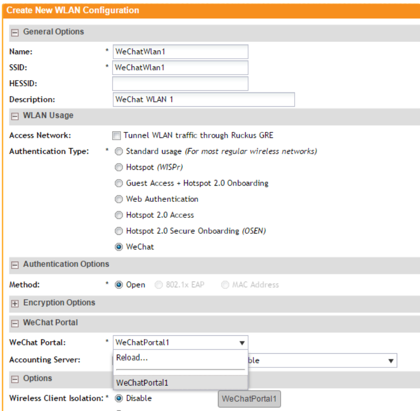
Figure 55: The Create New WLAN Configuration form when the authentication type is set
to WeChat
Working with Hotspot 2.0 Services
Hotspot 2.0 is a newer Wi-Fi Alliance specification that allows for automated roaming between
service provider access points when both the client and access gateway support the newer
protocol.
Hotspot 2.0 (also known as Passpoint™, the trademark name of the Wi-Fi Alliance certification)
aims to improve the experience of mobile users when selecting and joining a Wi-Fi hotspot by
providing information to the station prior to association.
This information can then be used by the client to automatically select an appropriate network
based on the services provided and the conditions under which the user can access them. In
SmartZone 100/Virtual SmartZone Essentials for Release 3.2 Administrator Guide
106
Configuring the Wireless Network
Working with Hotspot 2.0 Services
this way, rather than being presented with a list of largely meaningless SSIDs to choose from,
the Hotspot 2.0 client can automatically select and authenticate to an SSID based on the client's
configuration and services offered, or allow the user to manually select an SSID for which the
user has login credentials.
The controller's Hotspot 2.0 implementation complies with the IEEE 802.11u standard and the
Wi-Fi Alliance Hotspot 2.0 Technical Specification.
See the Hotspot 2.0 Reference Guide for SmartZone 3.1 for information on configuring Hotspot
2.0 services, including:
•Working with Hotspot 2.0 operator profiles
•Working with Hotspot 2.0 identity providers
•Creating a Hotspot 2.0 online signup portal
Working with Web Authentication Services
Web authentication (also known as a captive portal) redirects users to a logon web page the
first time they connect to this WLAN, and requires them to log on before granting access to use
the WLAN.
Enabling a web authentication service requires the following steps:
Adding an AAA Server for the Web Authentication Service
Decide whether you want to use a proxy or non-proxy AAA server.
A proxy AAA server is used when APs send authentication/accounting messages to the controller
and the controller forwards these messages to an external AAA server. On the other hand, a
non proxy AAA server is used when the APs connect to the external AAA server directly.
Creating a Web Authentication Service
Web authentication (also known as a “captive portal”) redirects users to a logon web page the
first time they connect to this WLAN, and requires them to log on before granting access to use
the WLAN.
Follow these steps to create a web authentication service.
1. Go to Configuration > Wireless Network > Web Authentication Services.
2. In the Web Authentication Services section, click Create New.
3. In General Options, configure the following options:
•Name: Type a name for the web authentication service that you are creating.
•Description: Type a brief description of the service.
•Language: Select the display language that you want to use on the web authentication
portal.
4. In Redirection, select where to redirect the user after successfully completing authentication.
•Redirect to the URL that the user intends to visit: Allows the guest user to continue to
their destination without redirection.
SmartZone 100/Virtual SmartZone Essentials for Release 3.2 Administrator Guide
107
Configuring the Wireless Network
Working with Web Authentication Services
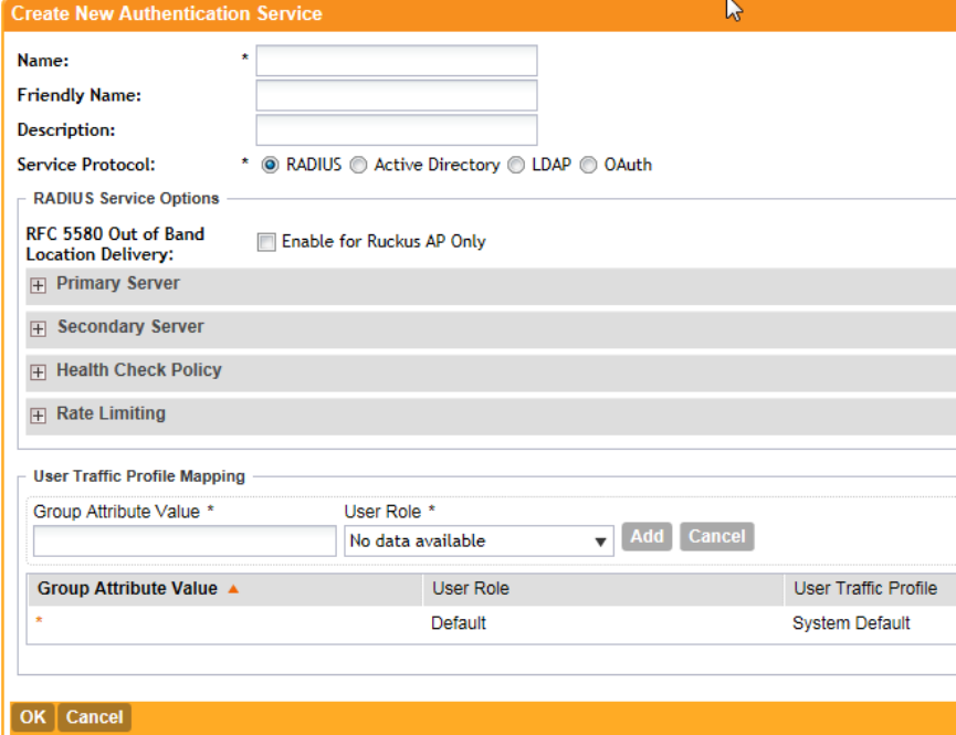
•Redirect to the following URL: Redirect the user to a specified web page (entered into
the text box) prior to forwarding them to their destination. When guest users land on this
page, they are shown the expiration time for their guest pass.
5. In User Session, configure the following:
•Session Timeout: Set the time (in minutes) after which inactive users will be disconnected
and required to log in again.
•Grace Period: Set the time period (in minutes) during which disconnected users are
allowed access to the hotspot service without having to log on again.
6. Click OK.
You have completed creating a web authentication service.
Figure 56: The Create New Web Authentication Portal page
Creating a WLAN for the Web Authentication Service
Web authentication (also known as a “captive portal”) redirects users to a logon web page the
first time they connect to this WLAN, and requires them to log on before granting access to use
the WLAN.
Follow these steps to create a WLAN that you can use for a web authentication service.
1. Go to Configuration > Wireless Network > WLANs.
SmartZone 100/Virtual SmartZone Essentials for Release 3.2 Administrator Guide
108
Configuring the Wireless Network
Working with Web Authentication Services
2. In the WLAN Configuration section, click Create New.
3. In General Options, configure the following:
•Name
•SSID
•Description
4. In Authentication Type, click Web Authentication.
5. In Authentication & Accounting Server, select the RADIUS and/or RADIUS Accounting
server that you created earlier in Adding an AAA Server for the Web Authentication Service
on page 107.
6. In Web Authentication, select the web authentication service that you created earlier in
Creating a Web Authentication Service on page 107.
This service contains, among others, the start page where users will be redirected when they
associate with this WLAN.
7. Configure the remaining WLAN options as desired.
For information on these optiosn, see Creating a WLAN on page 41.
8. Click OK.
You have completed creating a WLAN for web authentication.
After you create a WLAN that will be used for web authentication, you must then provide all
users with the URL to your logon page. After they discover the WLAN on their wireless device
or laptop, they open their browser, connect to the logon page and enter the required login
information.
SmartZone 100/Virtual SmartZone Essentials for Release 3.2 Administrator Guide
109
Configuring the Wireless Network
Working with Web Authentication Services
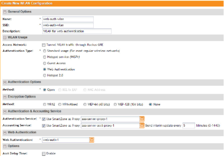
Figure 57: Creating a WLAN to provide web authentication
Working with AAA Servers
Add AAA servers to the controller so you can use them to authenticate users attempting to
associate with controller-managed APs. This section covers:
Working with Proxy AAA Servers
A proxy AAA server is used when APs send authentication/accounting messages to the controller
and the controller forwards these messages to an external AAA server.
Adding a Proxy AAA Authentication Server
A proxy AAA server is used when APs send authentication/accounting messages to the controller
and the controller forwards these messages to an external AAA server.
Follow these steps to add an AAA server to the controller that can be used for authenticating
users.
1. Go to Configuration > Wireless Network > AAA Servers > Proxy AAA.
2. In the Authentication Service section, click Create New.
The Create New Authentication Service form appears.
3. In Name, type a name for the authentication service that you are adding.
4. In Friendly Name (optional), type an alternative name that is easy to remember.
SmartZone 100/Virtual SmartZone Essentials for Release 3.2 Administrator Guide
110
Configuring the Wireless Network
Working with AAA Servers
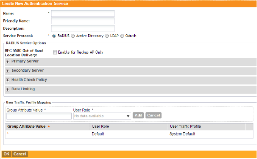
5. In Description (optional), type a description for the authentication service.
6. In Type, select one of the following options:
•RADIUS (see RADIUS Service Options on page 111)
•Active Directory
•LDAP
•OAuth
7. Configure the settings for the authentication service type that you selected.
8. Click OK.
The page refreshes and the authentication service you have added appears on the list of
existing authentication services.
You have completed adding an authentication service to the controller.
Figure 58: The Create New Authentication Service form
RADIUS Service Options
The Radius service options available for the primary and secondary servers.
If you selected RADIUS in Adding a Proxy AAA Authentication Server on page 110, you need to
configure the following options:
RFC 5580 Out of Band Location Delivery
If you want out-of-band location delivery (RFC 5580) to apply only to Ruckus Wireless APs,
select the Enable for Ruckus AP Only check box.
SmartZone 100/Virtual SmartZone Essentials for Release 3.2 Administrator Guide
111
Configuring the Wireless Network
Working with AAA Servers
Primary Server
Configure the primary RADIUS server settings.
DescriptionOption
Type the IP address of the RADIUS server.IP Address
Type the port number of the RADIUS server. The default
RADIUS server port number is 1812 and the default RADIUS
Accounting server port number is 1813.
Port
Type the RADIUS shared secret.Shared Secret
Retype the shared secret to confirm.Confirm Secret
Secondary Server
If you have a secondary RADIUS server on the network that you want to use as a backup, select
the Enable Secondary Server check box, and then configure the settings below.
DescriptionOption
By default, when a secondary RADIUS server is enabled and
the primary RADIUS server becomes unavailable, the secondary
Automatic Fallback Disable
server takes over the handling of RADIUS requests. When the
primary server becomes available again, it takes back control
over RADIUS requests from the secondary server.
If you want to prevent the primary server from retaking control
over RADIUS requests from the secondary server, select the
Automatic Fallback Disable check box.
Type the IP address of the secondary AAA server.IP Address
Type the port number of the secondary AAA server port
number. The default RADIUS server port number is 1812 and
the default RADIUS Accounting server port number is 1813.
Port
Type the AAA shared secret.Shared Secret
Retype the shared secret to confirm.Confirm Secret
Health Check Policy
These options define the health monitoring settings of the primary and secondary RADIUS
servers, when the controller is configured as RADIUS proxy for RADIUS Authentication and
Accounting messages.
SmartZone 100/Virtual SmartZone Essentials for Release 3.2 Administrator Guide
112
Configuring the Wireless Network
Working with AAA Servers

DescriptionOption
Set the time (in seconds) after which, if the AAA server does
not respond to a request, the controller will initiate the zombie
period (see below).
Response Window
If the primary AAA server does not respond to RADIUS
messages sent after Response Window expires, the controller
will forward the retransmitted RADIUS messages to the
secondary AAA server.
Note that the zombie period is not started immediately after
the Response Window expires, but after the configured
Response Window plus ¼ of the configured Zombie Period.
The default Response Window is 20 seconds.
Set the time (in seconds) after which, if the AAA server does
not respond to ANY packets during the zombie period, it will
be considered to inactive or unreachable.
Zombie Period
An AAA server that is marked zombie (inactive or unreachable)
will be used for proxying with a low priority. If there are other
live AAA servers, the controller will attempt to use these servers
first instead of the zombie AAA server. The controller will only
proxy requests to a zombie server only when there are no other
live servers.
Any request that is proxied to an AAA server will continue to
be sent to that AAA server until the home server is marked
inactive or unreachable. At that point, the request will fail over
to another server, if a live AAA server is available. The default
Zombie Period is 40 seconds.
Set the time (in seconds) after which, if no RADIUS messages
are proxied to the AAA server after it has been marked as
Revive Interval
inactive or unreachable, the controller will mark the AAA server
as active again (and assume that it has become reachable
again). The default Revive Interval is 120 seconds.
Click Yes to respond with a reject message to the NAS if no
response is received from the RADIUS server. Click No to skip
sending a response.
No Response Fail
CAUTION: To ensure that the RADIUS failover mechanism functions correctly, either accept the
default values for the Response Window, Zombie Period, and Revive Interval, or make sure
that the value for Response Window is always higher than the value for RADIUS NAS request
timeout multiplied by the value for RADIUS NAS max number of retries. For information on
configuring the RADIUS NAS request timeout and max number of retries, see Configuring WLANs
SmartZone 100/Virtual SmartZone Essentials for Release 3.2 Administrator Guide
113
Configuring the Wireless Network
Working with AAA Servers
and Configuring WLAN Groups on page 50. For 3rd party APs, you must ensure that the
configured Response Window on the controller is higher than the RADIUS NAS request timeout
multiplied by the RADIUS value. The maximum number of retries is configured at the 3rd party
controller/AP.
Rate Limiting
Configure the following options.
DescriptionOption
Set the maximum outstanding requests per server. Type 0 to
disable it, or set a value between 10 and 4096.
Maximum Outstanding
Requests (MOR)
Set a percentage value of the MOR at which (when reached)
the controller will generate an event.
Threshold (% of MOR)
For example, if the MOR is set to 1000 and the threshold is set
to 50%, the controller will generate an event when the number
of outstanding requests reaches 500.
Set a timer (in seconds) that will be started whenever a condition
that generates an event is reached. This helps prevent
conditions that trigger events which occur frequently.
Sanity Timer
Click OK.
You have completed configuring the RADIUS service options.
Adding a Proxy AAA Accounting Server
A proxy AAA server is used when APs send authentication/accounting messages to the controller
and the controller forwards these messages to an external AAA server.
Follow these steps to add a proxy AAA accounting server for creating an accounting service.
1. Go to Configuration > Wireless Network > AAA Servers > Proxy AAA.
2. In the Accounting Service section, click Create New.
The Create New Accounting Service form appears.
3. In Name, type a name for the accounting service that you are adding.
4. In Description (optional), type a description for the accounting service.
5. In RADIUS Service Options, configure the available options.
Refer to see RADIUS Service Options on page 111 for more information.
6. Click OK.
The page refreshes and the accounting service you have added appears on the list of existing
accounting services.
You have completed adding an accounting service to the controller.
SmartZone 100/Virtual SmartZone Essentials for Release 3.2 Administrator Guide
114
Configuring the Wireless Network
Working with AAA Servers
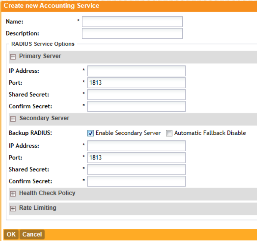
Figure 59: The Create New Accounting Service form
Deleting Proxy AAA Servers
Follow these steps to delete proxy AAA servers.
1. Go to Configuration > Wireless Network > AAA Servers.
2. In the Proxy AAA or Non-Proxy AAA section, locate the AAA server or servers that you want
to delete.
3. Select the check boxes (first column) for the AAA server or servers that you want to delete.
4. Click Delete Selected.
The AAA servers that you selected disappear from the list. You have completed deleting AAA
servers.
NOTE: If you are deleting a single AAA server, you can also click the icon (under the Actions
column) that is in the same row as the AAA server that you want to delete.
SmartZone 100/Virtual SmartZone Essentials for Release 3.2 Administrator Guide
115
Configuring the Wireless Network
Working with AAA Servers
Working with Non-Proxy AAA Servers
A non proxy AAA server is used when the APs connect to the external AAA server directly.
Adding a Non-Proxy AAA Authentication Server
Non proxy AAA server is used when the APs connect to the external AAA server directly.
Follow these steps to add a non-proxy AAA authentication server to the controller.
1. Go to Configuration > Wireless Network > AAA Servers > Non-Proxy AAA.
The Non-Proxy AAA page appears.
2. Under the Authentication Service section, click Create New.
3. In General Options, configure the following:
•Name: Type a name for the AAA server that you are adding.
•Description: Type a short description of the AAA server.
•Type: Click the type of AAA server that you are adding. Options include:
•RADIUS
•Active Directory
•LDAP
•Backup RADIUS (appears if you clicked RADIUS or RADIUS Accounting above): Select
the Enable backup RADIUS server check box if a secondary RADIUS server exists on
the network.
•Global Catalog (appears if you clicked Active Directory above): Select the Enable Global
Catalog support if you the Active Directory server to provide a global list of all objects in
a forest.
4. Configure the other options that appear in the form.
5. If you selected RADIUS, configure the following options in the Primary Server section:
•IP Address: Type the IP address of the AAA server.
•Port: Type the port number of the AAA server. The default RADIUS server port number is
1812.
•Shared Secret: Type the AAA shared secret.
•Confirm Secret: Retype the shared secret to confirm.
6. In the Secondary Server section, configure the settings of the secondary RADIUS server.
NOTE: The Secondary Server section is only visible if you selected the Enable backup
RADIUS server check box earlier.
•IP Address: Type the IP address of the secondary AAA server.
•Port: Type the port number of the secondary AAA server port number. The default RADIUS
server port number is 1812.
•Shared Secret: Type the AAA shared secret.
•Confirm Secret: Retype the shared secret to confirm.
7. If you clicked Active Directory, configure the following options:
•IP Address: Type the IP address of the AD server.
SmartZone 100/Virtual SmartZone Essentials for Release 3.2 Administrator Guide
116
Configuring the Wireless Network
Working with AAA Servers
•Port: Type the port number of the AD server. The default port number (389) should not
be changed unless you have configured the AD server to use a different port.
•Windows Domain Name: Type the Windows domain name assigned to the AD server
(for example, domain.ruckuswireless.com).
8. If you clicked LDAP, configure the following options:
•IP Address: Type the IP address of the LDAP server.
•Port: Type the port number of the LDAP server.
•Base DN: Type the base DN in LDAP format for all user accounts (for example,
dc=ldap,dc=com).
•Admin DN: Type the admin DN in LDAP format (for example, cn=Admin;dc=<Your
Domain>,dc=com).
•Admin Password: Type the administrator password for the LDAP server.
•Confirm Password: Retype the administrator password to confirm.
•Key Attribute: Type a key attribute to denote users (for example, default: uid)
•Search Filter: Type a search filter (for example, objectClass=Person).
9. Click OK.
You have completed adding a non-proxy AAA authentication server.
SmartZone 100/Virtual SmartZone Essentials for Release 3.2 Administrator Guide
117
Configuring the Wireless Network
Working with AAA Servers
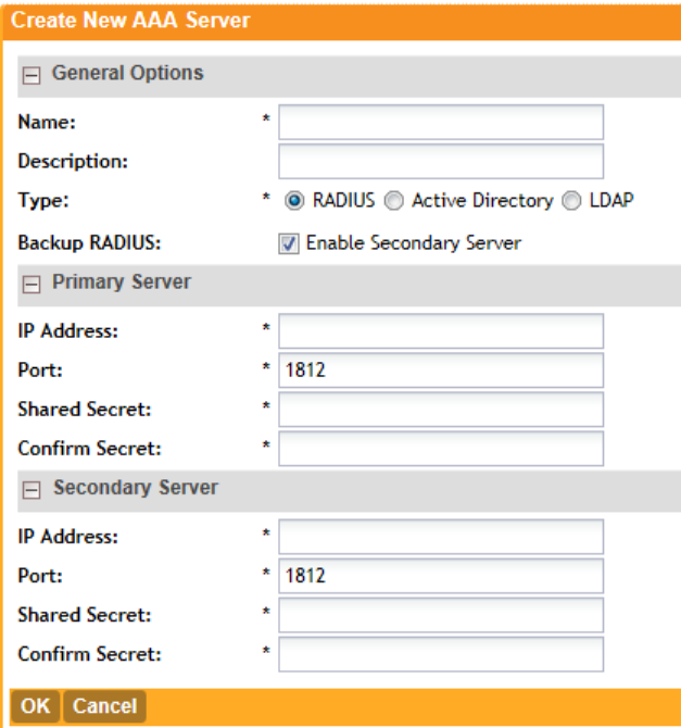
Figure 60: The Create New AAA Server form for adding a non-proxy AAA authentication
server
Adding a Non-Proxy AAA Accounting Server
A non proxy AAA server is used when the APs connect to the external AAA server directly.
Follow these steps to add a non-proxy AAA (RADIUS) accounting server to the controller.
1. Go to Configuration > Wireless Network > AAA Servers > Non-Proxy AAA.
The Non-Proxy AAA page appears.
2. Under the Accounting Service section, click Create New.
3. In General Options, configure the following:
•Name: Type a name for the AAA server that you are adding.
•Description: Type a short description of the AAA server.
•Backup RADIUS: Select the Enable Secondary Server check box if a secondary RADIUS
accounting server exists on the network.
4. In the Primary Server section, configure the following options:
•IP Address: Type the IP address of the AAA server.
•Port: Type the port number of the AAA server. The default RADIUS accounting server port
number is 1813.
SmartZone 100/Virtual SmartZone Essentials for Release 3.2 Administrator Guide
118
Configuring the Wireless Network
Working with AAA Servers
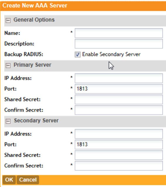
•Shared Secret: Type the AAA shared secret.
•Confirm Secret: Retype the shared secret to confirm.
5. In the Secondary Server section, configure the options for the secondary RADIUS accounting
server.
NOTE: The Secondary Server section is only visible if you selected the Enable Secondary
Server check box earlier.
•IP Address: Type the IP address of the secondary AAA server.
•Port: Type the port number of the secondary AAA server port number. The default RADIUS
accounting server port number is 1813.
•Shared Secret: Type the AAA shared secret.
•Confirm Secret: Retype the shared secret to confirm.
6. Click OK.
You have completed adding a non-proxy AAA accounting server.
Figure 61: The Create New AAA Server form for adding a non-proxy AAA accounting
server
SmartZone 100/Virtual SmartZone Essentials for Release 3.2 Administrator Guide
119
Configuring the Wireless Network
Working with AAA Servers
Deleting Non-Proxy AAA Servers
Follow these steps to delete non-proxy AAA servers.
1. Go to Configuration > Wireless Network > AAA Servers > Non-Proxy AAA.
The Non-Proxy AAA page appears.
2. In the Authentication Service or Accounting Service, locate the AAA server or servers that
you want to delete.
3. Select the check boxes (first column) for the AAA server or servers that you want to delete.
4. Click Delete Selected.
The AAA servers that you selected disappear from the list. You have completed deleting AAA
servers.
NOTE: If you are deleting a single AAA server, you can also click the icon (under the Actions
column) that is in the same row as the AAA server that you want to delete.
Configuring Location Services
If your organization purchased the Ruckus Wireless SmartPositioning Technology (SPoT) location
service, the controller must be configured with the venue information that is displayed in the
SPoT Administration Portal.
After completing purchase of the SPoT location service, you will be given account login information
that you can use to log into the SPoT Administration Portal. The Admin Portal provides tools for
configuring and managing all of your venues (the physical locations in which SPoT service is
deployed). After a venue is successfully set up, you will need to enter the same venue information
in the controller.
The following section lists the steps required for configuring the controller to communicate with
the SPoT Location Server.
Follow these steps to configure the controller for SPoT communication.
1. Log on to the SPoT Administration Portal.
2. On the Venues page, click Confignext to the venue for which you want to configure Location
Services on the controller.
3. In Controller Settings, take note of the values for the following:
•Venue Name
•Server Address
•Port
•Password
4. On the controller web interface, go to Configuration > Wireless Network > Location >
Services.
5. Click Create New.
6. Enter the information you obtain in step 3 on page 120 from the SPot Administration Portal
into the four fields provided.
SmartZone 100/Virtual SmartZone Essentials for Release 3.2 Administrator Guide
120
Configuring the Wireless Network
Configuring Location Services
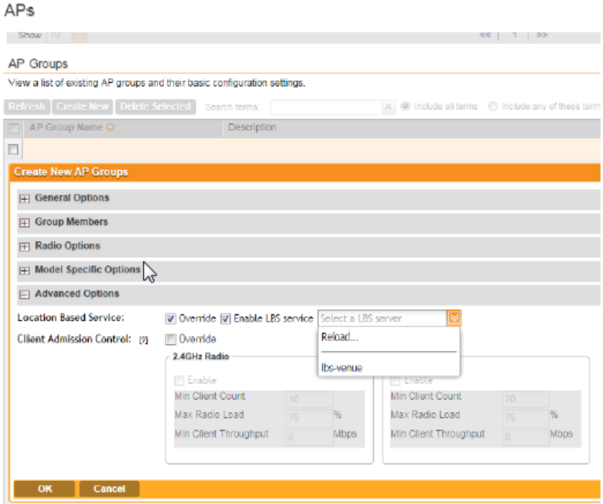
7. Click OKto save your changes.
8. Go to Configuration > Wireless Networks > Access Points > APs.
9. Scroll down to the AP Groups section, and then click Create Newor click an existing AP
group name to configure it for SPoT location services.
10. On the Create New or Edit AP Groups: [{AP Group Name}] form, scroll down to the
Advanced Options section.
11. In Location Based Service, configure the following:
•Override: Select this check box.
•Enable LBS service: Select this check box, and then select the venue you created earlier.
12. Click Apply.
The controller will begin trying to communicate with the SPoT location Server. Once the APs
have successfully connected to the SPoT server, you can view the status of your SPoT-enabled
APs on the Monitor > Location Services page. See Monitoring Location Services on page
178.
Figure 62: Enabling location services for the AP group
SmartZone 100/Virtual SmartZone Essentials for Release 3.2 Administrator Guide
121
Configuring the Wireless Network
Configuring Location Services
NOTE: For information on configuring and managing the Ruckus Wireless SmartPositioning
Technology (SPoT) service, refer to the SPoT User Guide, which is available for download from
https://support.ruckuswireless.com.
Configuring Bonjour Gateway Policies
Bonjour® is Apple's implementation of a zero-configuration networking protocol for Apple devices
over IP.
It allows OS X® and iOS devices to locate other devices such as printers, file servers and other
clients on the same broadcast domain and use the services offered without any network
configuration required.
Multicast applications such as Bonjour require special consideration when being deployed over
wireless networks. Bonjour only works within a single broadcast domain, which is usually a small
area. This is by design to prevent flooding a large network with multicast traffic. However, in
some situations, a user may want to offer Bonjour services from one VLAN to another.
The controller's Bonjour gateway feature addresses this requirement by providing an mDNS
proxy service configurable from the web interface to allow administrators to specify which types
of Bonjour services can be accessed from/to which VLANs. In order for the Bonjour Gateway
to function, the following network configuration requirements must be met:
1. The target networks must be segmented into VLANs.
2. VLANs must be mapped to different SSIDs.
3. The controller must be connected to a VLAN trunk port.
Additionally, if the VLANs to be bridged by the gateway are on separate subnets, the network
has to be configured to route traffic between them.
Creating a Bonjour Gateway Rule on the AP
Using the Bonjour gateway feature, Bonjour bridging service is performed on a designated AP
rather than on the controller.
Offloading the Bonjour policy to an AP is necessary if a Layer 3 switch or router exists between
the controller and the APs. The controller identifies a single AP that meets the memory/processor
requirements (this feature is only supported on certain APs), and delivers a set of service rules
- a Bonjour policy - to the AP to perform the VLAN bridging.
NOTE: This feature is only supported on the following access points: R300, R500, R600, R700,
7982, 7372/52, 7055, 7782/81, SC-8800 series.
Here are the requirements and limitations of the Bonjour gateway feature:
•Bonjour policy deployment to an AP takes effect after the AP joins the controller.
•Some APs of one local area link must beoin one subnet. The switch interfaces connected to
these APs in a local area link to must be configured in VLAN-trunk mode. Only by doing so
can the designated AP can receive all the multicast Bonjour protocol packets from other
VLANs.
SmartZone 100/Virtual SmartZone Essentials for Release 3.2 Administrator Guide
122
Configuring the Wireless Network
Configuring Bonjour Gateway Policies
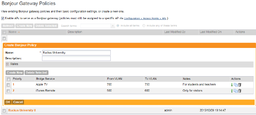
•Dynamic VLANs are not supported.
•Some AP models are incompatible with this feature due to memory requirements.
Follow these steps to create rules for an AP that will bridge Bonjour services across VLANs.
1. Go to Configuration > Wireless Network > Bonjour Gateway Policies.
2. Click Create New to create a Bonjour gateway policy.
The Create Bonjour policy form appears.
3. In Name, type a name for the policy.
4. In Description, type a description for the policy.
5. In the Rules section, click Create New to create a rule.
6. Configure the following options:
•Bridge Service: Select the Bonjour service from the list.
•From VLAN: Select the VLAN from which the Bonjour service will be advertised.
•To VLAN: Select the VLAN to which the service should be made available.
•Notes: Add optional notes for this rule.
7. Click Save to save the rule.
8. To create another rule, repeat steps 6 on page 123 and 7 on page 123.
9. After you finish creating all rules that you require, click OK.
10. Select the Enable Bonjour gateway on the AP check box.
You have completed creating a Bonjour gateway policy.
Figure 63: Creating a Bonjour gateway policy
Applying a Bonjour Policy to an AP
Once you have created an Bonjour policy for an AP, you will need to designate the AP that will
be responsible for implementing this policy.
Follow these steps to apply an Bonjour policy to an AP.
1. Go to Configuration > Wireless Network > Access Points > APs.
SmartZone 100/Virtual SmartZone Essentials for Release 3.2 Administrator Guide
123
Configuring the Wireless Network
Configuring Bonjour Gateway Policies
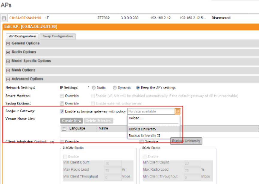
2. From the list of APs, click the MAC address of the AP to which you want to apply the Bonjour
policy.
The Edit AP [{MAC address}] form appears.
3. Scroll down to the Advanced Options section, and then locate the Bonjour Gateway option.
4. Select the Enable as bonjour gateway with policy check box, and then select the Bonjour
policy that you want to apply to the AP.
See Figure 64: Applying a Bonjour gateway policy to an AP on page 124
5. Click Apply.
You have completed applying a Bonjour gateway policy to an AP
Figure 64: Applying a Bonjour gateway policy to an AP
SmartZone 100/Virtual SmartZone Essentials for Release 3.2 Administrator Guide
124
Configuring the Wireless Network
Configuring Bonjour Gateway Policies
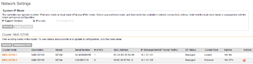
4
Configuring System Settings
In this chapter:
•Configuring Network Settings
•Configuring Log Settings
•Configuring Event Management
•Configuring Event Thresholds
•Configuring the Northbound Portal Interface
•Configuring the System Time
•Configuring an External Email Server
•Configuring External FTP Servers
•Managing the Certificate Store
•Configuring the External SMS Gateway
•Configuring SNMP Settings
•Managing the User Agent Blacklist
Configuring Network Settings
Use the Network Settings page to view the system IP mode that has been selected, view
information about the nodes that belong to the cluster, and rebalance APs across the nodes in
the cluster.
Figure 65: The Network Settings page displays the system IP mode and all the nodes that
belong to the cluster
Setting the System IP Mode
The controller supports IPv4 only and IPv4 and IPv6 addressing modes.
The system IP mode controls the format of the IP address that you need to enter in a number
of IP address-related settings (for example, cluster plane addresses, static routes, etc.)
Follow these steps to change the controller's system IP mode.
1. Go to Configuration > System > Network Settings.
The Cluster page appears.
2. In the System IP Mode section, select the system IP mode that you want to controller to use.
Options include:
SmartZone 100/Virtual SmartZone Essentials for Release 3.2 Administrator Guide
125
125
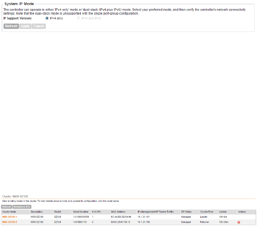
•IPv4 Only
•IPv4 and IPv6
3. Click Apply.
You have completed setting the system IP mode.
Figure 66: The System IP Mode section
Rebalancing APs Across Nodes
When a multi-node cluster is upgraded, the node that reboots the last typically does not have
any APs associated with it.
To ensure that the AP load is evenly distributed across the nodes in the cluster, rebalance APs
across the nodes.
1. Go to Configuration > System>Network Settings.
2. Scroll down to the Cluster: {Cluster Name} section. Information about the nodes that belong
to the cluster, including the number of APs associated with each node, appears in the section.
3. Click Rebalance APs. A confirmation message appears.
4. Click Yes.
The controller rebalances AP connections across the nodes over the next 15 minutes.
NOTE: If you want to repeat this procedure, you must wait 30 minutes before the controller will
allow you to rebalance APs again.
Figure 67: Click Rebalance APs to evenly distribute the AP load across the nodes
How AP Rebalancing Works
AP rebalancing helps distribute the AP load across nodes that exist within a cluster.
When you click the Rebalance APs button, the following process is triggered:
1. The controller calculates the average AP count based on the number of available control
planes and data planes.
2. The controller calculates how many APs and which specific APs must be moved to other
nodes to distribute the AP load.
3. The controller regenerates the AP configuration settings based on the calculation result.
4. The web interface displays a message to inform the administrator that the controller has
completed its calculations for rebalancing APs.
SmartZone 100/Virtual SmartZone Essentials for Release 3.2 Administrator Guide
126
Configuring System Settings
Configuring Network Settings
5. Each AP that needs to be moved to a different node retrieves the updated AP configuration
from the controller, reads the control planes and data planes to which it must connect, and
then connects to them..
When the AP rebalancing process is complete, which typically takes 15 minutes, one of the
following events is generated:
•Event 770: Generate ApConfig for plane load rebalance succeeded.
•Event 771: Generate ApConfig for plane load rebalance failed.
Important Notes About AP Rebalancing
If you are rebalancing the AP load across the nodes in a cluster, take note of the following
caveats:
•APs may recreate the Ruckus-GRE tunnel to a different data plane.
•Devices associated with an AP that uses the Ruckus-GRE tunnel may temporarily lose network
connection for a short period of time (typically, around five minutes) during the AP rebalancing
process.
•When node affinity is enabled, AP rebalancing is disallowed on those nodes.
•When data plane grouping is enabled, AP rebalancing is disallowed on those data planes.
•AP rebalancing only supports APs running release 3.2 firmware. APs running on legacy
firmware will not be rebalanced.
Configuring the Physical Interface Settings
The cluster node configuration includes defining the physical interface, user defined interface
and static routes.
Follow these steps to configure the physical interface settings of a node.
1. Locate the interface settings that you want to update.
You can update one of the following interfaces:
•Management & AP Control
•AP Tunnel Data
NOTE: If you selected One Port Grouping(combined management and AP tunnel traffic into
a single interface) when you completed the Setup Wizard, only one interface appears on the
Physical Interface tab – Management/AP Tunnel Traffic.
CAUTION: Although it is possible to use DHCP to assign IP address settings to the
management and AP control interface automatically, Ruckus Wireless strongly recommends
assigning a static IP address to this interface.
2. Configure the following settings for the interface that you want to update.
SmartZone 100/Virtual SmartZone Essentials for Release 3.2 Administrator Guide
127
Configuring System Settings
Configuring Network Settings
DescriptionOption
Configure the IP address mode by clicking one of the following
options:
IP Mode
•Static: Click this if you want to assign an IP address to
this interface manually.
•DHCP: Click this if you want this interface to obtain an IP
address automatically from a DHCP server on the network.
After you click this option, most of the options below it will
be grayed out. Continue to Step 3.
Enter the IP address that you want to the assign to this
interface.
IP Address
Enter the subnet mask for the IP address above.Subnet Mask
Enter the IP address of the gateway router.Gateway
Enter the IP address of the primary DNS server.Primary DNS
Enter the IP address of the secondary DNS server.Secondary DNS
3. If the system IP mode is set to IPv4 and IPv6, you will also need to configure the IPv6
interfaces. Configure the IPv6 address mode by clicking one of the following options in IP
Mode:
DescriptionOption
Click this if you want to assign an IPv6 address to this
interface manually, and then configure the following:
Static
•IP Address: Enter an IPv6 address (global only) with a
prefix length (for example, 1234::5678:0:C12/123) is
required. Link-local addresses are unsupported.
•Gateway: Enter an IPv6 address (global or link-local)
without a prefix length. For example, 1234::5678:0:C12
(global address without a prefix length) and
fe80::5678:0:C12 (link-local address without a prefix
length).
Click this if you want the interface to obtain its IP address
from Router Advertisements (RAs) or from a DHCPv6 server
on the network.
Auto
4. Click Apply.
The controller restarts and applies the updated network interface settings. You have completed
updating the physical interface settings.
NOTE: For information on how to configure the management IP address from the command
line interface, refer to .About the Command Line Interface
SmartZone 100/Virtual SmartZone Essentials for Release 3.2 Administrator Guide
128
Configuring System Settings
Configuring Network Settings
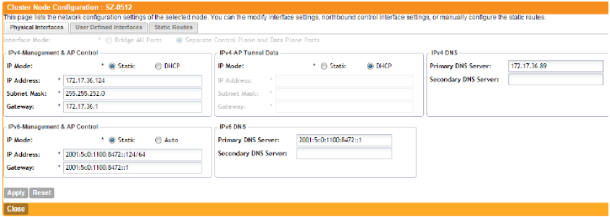
Figure 68: The Physical Interface tab on a two-port group controller
Configuring the User Defined Interface Settings
Use the User Defined Interface tab to configure the hotspot service settings (captive portal,
subscriber portal, and Web proxy).
Note that you can only create one user defined interface, and it must be for a hotspot service
and must use the control interface as its physical interface.
NOTE: The user defined interface (UDI) is unavailable in Virtual SmartZone (High-Scale and
Essentials).
NOTE: The control plane and the UDI must be on different subnets. If the control plane and UDI
are on the same subnet, and assigned the same IP address, APs will be unable to communicate
with the control plane. If the control plane and UDI are on the same subnet and assigned different
IP addresses, hotspot clients will not be redirected to the logon URL for user authentication.
Follow these steps to configure the settings on the User Defined Interface tab.
1. Click the User Defined Interface tab.
2. Click the Create New button.
3. Configure the following interface settings:
•Name: Enter a name for this interface.
•IP Address: Enter an IP address to assign to this interface.
•Subnet Mask: Enter a subnet mask for the IP address above.
•Gateway: Enter the IP address of the gateway router.
•VLAN: Enter the VLAN ID that you want to assign to this interface.
•Physical Interface: Select Control Interface.
•Service: Select Hotspot.
4. Click Save.
5. Click Apply.
You have completed configuring the user defined interface settings.
SmartZone 100/Virtual SmartZone Essentials for Release 3.2 Administrator Guide
129
Configuring System Settings
Configuring Network Settings
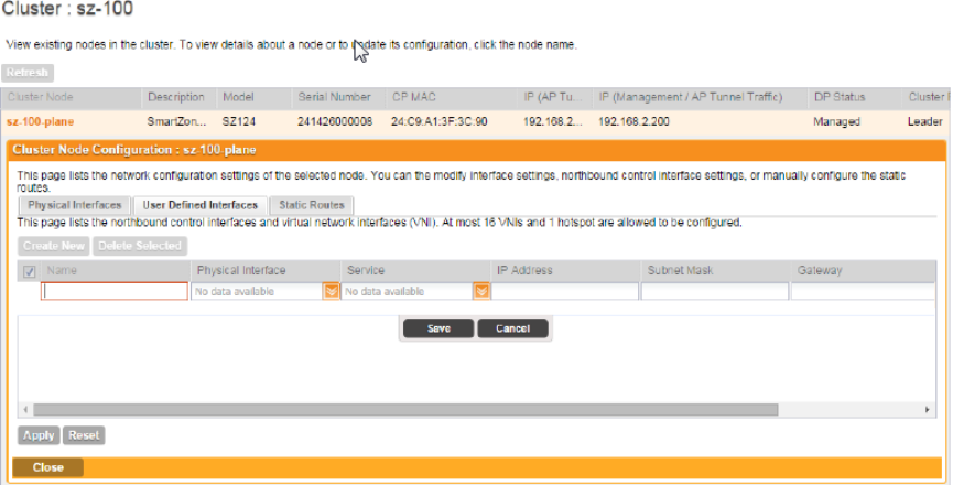
Figure 69: The User Defined Interface tab
Creating and Configuring Static Routes
To configure a static route, enter the destination IP address and related information for the
destination.
You can also assign a metric (or priority) to help the controller determines the route to choose
when there are multiple routes to the same destination.
Follow these steps to configure a static route.
1. Click the Static Routes tab.
2. Click the Create New button.
3. Configure the following interface settings:
•Network Address: Enter the destination IP address of this route.
•Subnet Mask: Enter a subnet mask for the IP address above.
•Gateway: Enter the IP address of the gateway router.
•Interface: Select the physical interface to use for this route.
•Metric: This represents the number of routers between the network and the destination.
4. Click Save.
5. Click Apply.
You have completed configuring a static route.
SmartZone 100/Virtual SmartZone Essentials for Release 3.2 Administrator Guide
130
Configuring System Settings
Configuring Network Settings
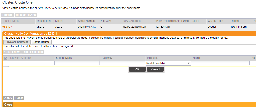
Figure 70: The Static Route tab
Configuring Log Settings
The controller maintains an internal log file of current events and alarms, but this internal log file
has a fixed capacity. Configure the log settings so you can keep copies of the logs that the
controller generates.
At a certain point, the controller will start deleting the oldest entries in log file to make room for
newer entries. If you want to keep a permanent record of all alarms and events that the controller
generated, you can configure the controller to send the log contents to a syslog server on the
network.
Follow these steps to configure the log settings.
1. Go to Configuration > System > Log Settings.
2. Select the Enable logging to remote syslog server check box.
3. In Primary Syslog Server Address, type the IP address of the syslog server on the network.
In Port, type the syslog port number on the primary server.
To verify that the controller can reach the syslog server that you want to use, click the Ping
Syslog Server button that is in the same row as the primary syslog server address. If the
syslog server is reachable, a flashing green circle and the message Success appear after
the Ping Syslog Server button.
4. If another syslog server exists on the network and you want to use it as backup in case the
primary systog server is unavailable, type its IP address in Secondary Syslog Server Address.
In Port, type the syslog port number on the secondary server.
To verify that the controller can reach the secondary syslog server that you want to use, click
the Ping Syslog Server button that is in the same row as the secondary syslog server address.
If the syslog server is reachable, a flashing green circle and the message, Success appear
after the Ping Syslog Server button.
5. Select the facility level (default is Local0, range is Local0 to Local7) for each of the following
log types:
SmartZone 100/Virtual SmartZone Essentials for Release 3.2 Administrator Guide
131
Configuring System Settings
Configuring Log Settings
•Facility for Application
•Facility for Administrator
•Facility for Events
6. In Event Filter, select one of the following options to specify which events will be sent to the
syslog server:
DescriptionOption
Click this option to send all controller events to the syslog
server.
All events
Click this option to send all controller events (except client
association and disassociation events) to the syslog server.
All events except client
associate/disassociate
events
Click this option to send all controller events that are above
the event severity that you specify in Event Severity
All events above a severity
•Event Severity: (This option only appears when All events
above a severity is selected.) Select the lowest severity
level for which events will be sent to the syslog server. For
example, if you select Major, all events that are major and
higher (including critical) will be sent to the syslog server.
For the order of event severity that the controller follows,
see Event Severity Levels on page 133.
7. In Priority, accept or change the default severity to priority mapping. See Default Event
Severity to Syslog Priority Mapping on page 134.
8. Click Apply.
You have completed configuring the controller to send its logs to at least one syslog server on
the network.
SmartZone 100/Virtual SmartZone Essentials for Release 3.2 Administrator Guide
132
Configuring System Settings
Configuring Log Settings
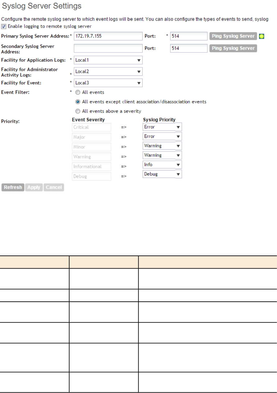
Figure 71: Configuring the syslog server settings
Event Severity Levels
The event severity levels (1 to 6, with 1 being the most severe) that the controller follows.
Table 5: Event severity levels in the controller
DescriptionMessageLevel
A critical condition that must resolved
immediately
Critical1
An error condition that must be resolvedMajor2
An error condition that must be checked to
determine if it needs to be resolved
Minor3
Warning message, not an error, but indication
that an error will occur if action is not taken
Warning4
Normal operational messages - may be
harvested for reporting, measuring throughput,
etc. - no action required.
Informational5
Info useful to developers for debugging the
application, not useful during operations.
Debug6
SmartZone 100/Virtual SmartZone Essentials for Release 3.2 Administrator Guide
133
Configuring System Settings
Configuring Log Settings
Default Event Severity to Syslog Priority Mapping
The default event severity to syslog priority mapping in the controller.
Table 6: Event severity to syslog priority mapping
Syslog PriorityEvent Severity
ErrorCritical
ErrorMajor
WarningMinor
WarningWarning
InfoInformational
DebugDebug
Configuring Event Management
The controller by default saves a record of all events that occur in a database. You can configure
to send SNMP traps and email notifications for specific events.
NOTE: Verify that global SNMP traps are enabled to ensure that the controller can send SNMP
traps for alarms. For information on how to enable global SNMP traps, refer to Enabling Global
SNMP Traps on page 147.
Follow these steps to configure the controller to send traps and email notifications for events.
1. Go to Configuration > System > Event Management.
2. In the Email Notification section, select the Enable check box, and then type an email
address or email addresses in the Mail To box.
If you want to send notifications to multiple recipients, use a comma to separate the email
addresses.
3. In the Events section, go over the table and select the events for which you want to send
traps or email notifications (or both).
a) If you know the event code, event type, or description, type the full or partial text into the
search box on the upper-right hand corner of the table, and then click the magnifying glass
(search) icon.
b) If you want to select all events, click the check box before the Code table heading.
NOTE: By default, the Events table displays up to 20 events per page. If you are enabling
SNMP traps and email notifications for 10 or more events, Ruckus Wireless recommends
changing the number of events shown per page. To do this, scroll down to the bottom of the
page, and then change the value for Show to 250 (maximum).
4. After you have selected all of the events for which you want to send traps or email notifications,
scroll up to the beginning of the Events table, and then click Enable. A submenu appears
and displays the following links:
SmartZone 100/Virtual SmartZone Essentials for Release 3.2 Administrator Guide
134
Configuring System Settings
Configuring Event Management
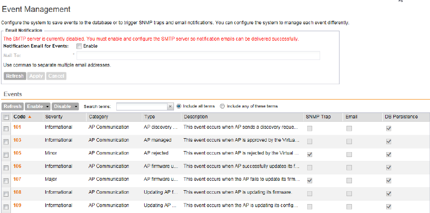
•Enable SNMP Trap: Click this link to enable SNMP trap notifications for all selected events.
•Enable Email: Click this link to enable email notifications for all selected events.
•Enable DB Persistence: Click this link to enable saving of all selected events to the
controller database. If an event is already currently enabled, it will stay enabled after you
click this link.
A confirmation message appears.
5. Click Yes.
NOTE: You can only enable one of these three notification options at a time (for example,
SNMP trap notifications only). If you want to enable another option, repeat steps 4 on page
134 and 5 on page 135.
You have completed enabling a notification option for the selected events.
Figure 72: Selecting all events on the Event Management page
Enabling or Disabling Notifications for a Single Event
Follow these steps to enable or disable notifications for a single event.
1. Go to Configuration > System > Event Management.
2. Under Events, locate the event for which you want to enable or disable notifications.
3. Click the event code.
The Edit Event: [Event Code] form appears.
4. Select the check box for a notification type to enable it, or clear the check box to disable it.
Options include:
•SNMP Trap
•Email Notification
•DB Persistence
5. Click Apply.
SmartZone 100/Virtual SmartZone Essentials for Release 3.2 Administrator Guide
135
Configuring System Settings
Configuring Event Management
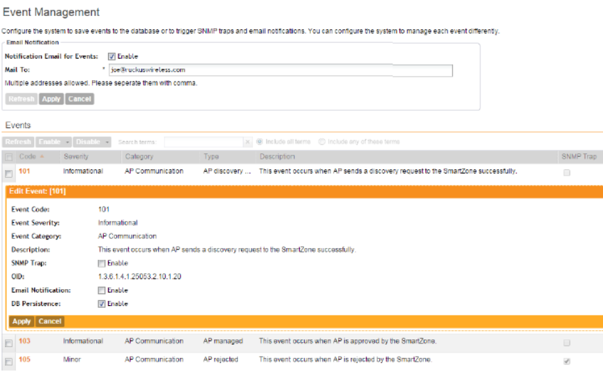
You have completed enable or disabling notifications for a single event.
Figure 73: Select or clear check boxes to enable or disable notifications
Viewing Enabled Notifications for Events
Follow these steps to view the notification types that are enabled for events.
1. Go to Configuration > System.
2. On the sidebar, click Event Management.
3. Scroll down to the bottom of the page, and then select 250 in Show.
The page refreshes, and then displays up to 250 events.
4. Check the SNMP Trap, Email, and DB Persistence columns on the right side of the table.
A check mark under each column indicates that the notification option is enabled for the
event.
5. To view the notification options that are enabled for the events on the next page, click >>>
at the bottom of the table.
The page refreshes, and then displays the remaining events.
Configuring Event Thresholds
An event threshold defines a set of conditions related to the controller hardware that need to be
met before the controller triggers an event.
You can accept the default threshold values or you can update the threshold values to make
them more suitable to your deployment or controller environment.
SmartZone 100/Virtual SmartZone Essentials for Release 3.2 Administrator Guide
136
Configuring System Settings
Configuring Event Thresholds
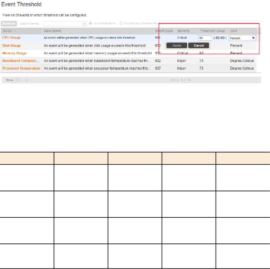
Follow these steps to configure the threshold for an event.
1. Go to Configuration > System > Event Threshold.
The Event Threshold page appears and displays the list of events with configurable thresholds
(see Table 7: List of hardware events with configurable thresholds on page 137), including the
event code, severity level, default value and accepted range, and unit of measurement for
each event.
2. Locate the event threshold that you want to configure.
3. Click the event name under the Name column.
The threshold value for the event become edits. Next to the threshold value, the acceptable
range is shown.
4. Edit the threshold value.
5. Click Apply.
Repeat the same procedure to edit the threshold of another event.
Figure 74: Configuring the CPU Usage event threshold
Events with Configurable Thresholds
Controller hardware events for which you can configure the event thresholds, including their
default values and acceptable ranges.
Table 7: List of hardware events with configurable thresholds
UnitThreshold ValueSeverityEvent CodeEvent
PercentDefault: 80
Range: 60 to 90
Critical950CPU Usage
PercentDefault: 80
Range: 60 to 90
Critical952Disk Usage
PercentDefault: 80
Range: 60 to 90
Critical951Memory Usage
Degree CelsiusDefault: 75
Range: 0 to 75
Major902Baseboard
Temperature
SmartZone 100/Virtual SmartZone Essentials for Release 3.2 Administrator Guide
137
Configuring System Settings
Configuring Event Thresholds
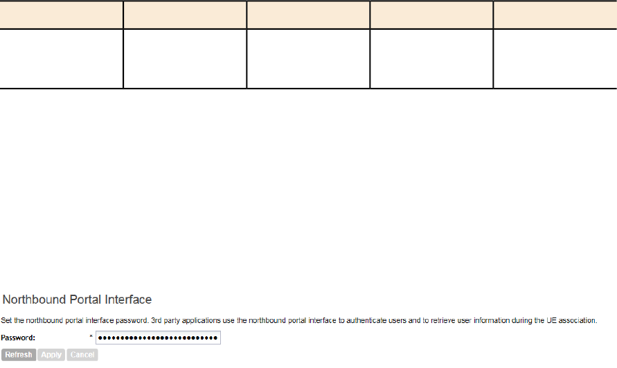
UnitThreshold ValueSeverityEvent CodeEvent
Degree CelsiusDefault: 75
Range: 0 to 75
Major907Processor
Temperature
Configuring the Northbound Portal Interface
Follow these steps to configure the northbound portal interface.
1. Go to Configuration > System > Northbound Portal Interface.
2. In Password, type the password for the northbound portal interface.
3. Click Apply.
You have completed setting the password for the northbound portal interface.
Figure 75: The Northbound Portal Interface page
Configuring the System Time
The controller uses an external network time protocol (NTP) server to synchronize the times
across cluster nodes and managed access points.
Follow these steps to set the system time.
1. Go to Configuration > System > System Time.
2. In NTP Server, type the server address that you want to use.
The default NTP server address is pool.ntp.org.
3. In System Time Zone, select the time zone that you want the controller to use.
The default time zone is (GMT +0:00) UTC.
4. Click Apply.
SmartZone 100/Virtual SmartZone Essentials for Release 3.2 Administrator Guide
138
Configuring System Settings
Configuring the Northbound Portal Interface
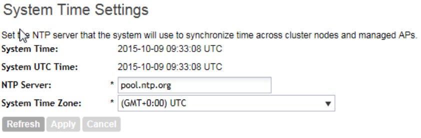
Figure 76: System time settings
How APs Synchronize Time with the Controller
When an AP joins the controller, it automatically synchronizes its time with the controller system
time.
After that, the AP automatically synchronizes its time with the controller every day.
Configuring an External Email Server
If you want to receive copies of the reports that the controller generates or to email guest passes
to users, you need to configure the SMTP server settings and the email address from which the
controller will send the reports.
Follow these steps to configure the SMTP server settings.
1. Go to Configuration > System > External Email Server.
2. Select the Enable SMTP Server check box.
3. In Logon Name, type the logon or user name provided by your ISP or mail administrator.
This might be just the part of your email address before the @ symbol, or it might be your
complete email address. If you are using a free email service (such as Hotmail™ or Gmail™),
you typically have to type your complete email address.
4. In Password, type the password that is associated with the user name above.
5. In SMTP Server Host, type the full name of the server provided by your ISP or mail
administrator.
Typically, the SMTP server name is in the format smtp.company.com.
6. In SMTP Server Port, type the SMTP port number provided by your ISP or mail administrator.
Often, the SMTP port number is 25 or 587. The default SMTP port value is 25.
7. In Mail From, type the email address from which the controller will send email notifications.
8. In Mail To, type the email address to which the controller will send alarm messages.
You can send alarm messages to a single email address.
9. If your mail server uses encryption, select the encryption method in Encryption Options.
SmartZone 100/Virtual SmartZone Essentials for Release 3.2 Administrator Guide
139
Configuring System Settings
Configuring an External Email Server
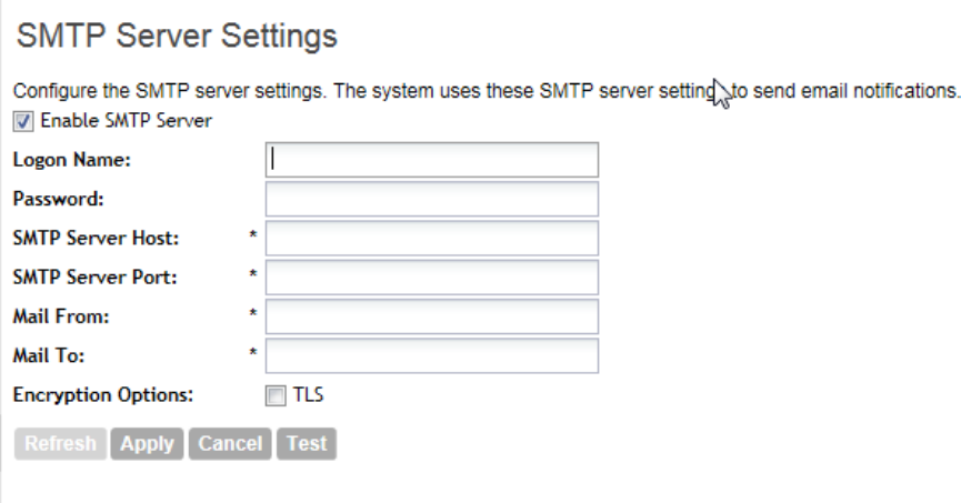
Options include TLS and STARTTLS. Check with your ISP or mail administrator for the correct
encryption settings that you need to set.
10. Click Apply.
You have completed configuring the external email server that the controller will use to send out
email notifications and messages.
Figure 77: The SMTP Server Settings page
Configuring External FTP Servers
The controller enables you to automatically back up statistics files, reports, and system
configuration backups to an external FTP server.
However, before you can do this, you must add at least one FTP server to the controller.
Follow these steps to add an FTP server to which the controller will export data automatically.
1. Go to Configuration > System > External FTP Servers.
2. Click Create New.
The Create New FTP Server form appears.
3. In FTP Name, type a name that you want to assign to the FTP server that you are adding.
4. In FTP Host, type the IP address of the FTP server.
5. In Port, type the FTP port number.
The default FTP port number is 21.
6. In User Name, type user name of the FTP account that you want to use.
7. In Password, type the password that is associated with the FTP user name above.
SmartZone 100/Virtual SmartZone Essentials for Release 3.2 Administrator Guide
140
Configuring System Settings
Configuring External FTP Servers
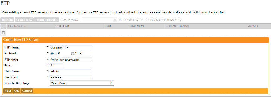
8. In Remote Directory, type the path on the remote FTP server to which data will be exported
from the controller.
The path must start with a forward slash (/), as shown in Figure 78: Adding an external FTP
server to the controller on page 141.
9. To verify that the FTP server settings and logon information are correct, click Test.
If the server and logon settings are correct, the following message appears: Test completed
successfully.
10. Click OK.
You have completed adding an FTP server to the controller. You may create additional FTP
servers as required.
Figure 78: Adding an external FTP server to the controller
Managing the Certificate Store
The certificate store is the central storage for all the security certificates that the controller uses
for its web interface, AP portal, and hotspots.
By default, a Ruckus Wireless-signed SSL certificate (or security certificate) exists in the controller.
However, because this default certificate is signed by Ruckus Wireless and is not recognized
by most web browsers, a security warning appears whenever you connect to the web interface
or users connect to the AP portal or a hotspot. To prevent these security warnings from appearing,
you can import an SSL certificate that is issued by a recognized certificate authority.
Figure 79: The web certificate warning that appears when you attempt to access the
controller web interface in Mozilla Firefox
This section describes the steps you need to perform to import and apply an SSL certificate to
the web interface, AP portal, or hotspots. Topics include:
NOTE: If you are implementing Hotspot 2.0 on the network and you want to support anonymous
authentication using OSU Server-Only Authenticated L2 Encryption Network (OSEN), you will
need to import a trust root certificate, server or intermediate certificate and private key.
SmartZone 100/Virtual SmartZone Essentials for Release 3.2 Administrator Guide
141
Configuring System Settings
Managing the Certificate Store
Generate a Certificate Signing Request
The certificate store is the central storage for all the security certificates that the controller uses
for its web interface, AP portal, and hotspots..
Follow the steps below to generate a certificate request and to import a signed certificate into
the controller.
NOTE: If you already have an SSL certificate that you want to import into the controller, go to
Importing an SSL Certificate.
NOTE: If you do not have an SSL certificate, you will need to create a certificate signing request
(CSR) file and send it to an SSL certificate provider to purchase an SSL certificate. The controller
web interface provides a form that you can use to create the CSR file.
1. Go to Configuration > System > Certificate Store.
The Certificate Store page appears.
2. In the Certificate Signing Request (CSR) section, click Generate.
The Generate New Certificate Signing Request (CSR) form appears.
3. In Name, type a name for this CSR.
4. In Description, type a description for this CSR.
5. In the Certificates Signing Request (CSR) section, fill out the following boxes:
DescriptionOption
Type the fully qualified domain name of your Web server. This
must be an exact match (for example,
www.ruckuswireless.com).
Common Name
Type your email address (for example,
joe@ruckuswireless.com).
Email
Type the complete legal name of your organization (for
example, Ruckus Wireless, Inc.). Do not abbreviate
your organization name.
Organization
Type the name of the division, department, or section in your
organization that manages network security (for example,
Network Management).
Organization Unit
Type the city where your organization is legally located (for
example, Sunnyvale).
Locality/City
Type the state or province where your organization is legally
located (for example, California) Do not abbreviate the
state or province name.
State/Province
Select the country where your organization is location from
the drop-down list.
Country
6. Click OK.
The controller generates the certificate request. When the certificate request file is ready, your
web browser automatically downloads it.
SmartZone 100/Virtual SmartZone Essentials for Release 3.2 Administrator Guide
142
Configuring System Settings
Managing the Certificate Store

7. Go to the default download folder of your Web browser and locate the certificate request file.
The file name is myreq.zip.
8. Use a text editor (for example, Notepad) to open the certificate request file.
9. Go to the website of your preferred SSL certificate provider, and then follow the instructions
for purchasing an SSL certificate.
10. When you are prompted for the certificate signing request, copy and paste the entire content
of myreq.csr, and then complete the purchase.
After the SSL certificate provider approves your CSR, you will receive the signed certificate
via email. The following is an example of a signed certificate that you will receive from your
SSL certificate provider:
-----BEGIN CERTIFICATE-----
MIIFVjCCBD6gAwIBAgIQLfaGuqKukMumWhbVf5v4vDANBgkqhkiG9w0B
AQUFADCBƒnsDELMAkGA1UEBhMCVVMxFzAVBgNVBAoTDlZlcmlTaWduLC
BJbmMuMR8wHQYDVQQLƒnBgEFBQcBAQRtMGswJAYIKwYBBQUHMAGGGGh0
dHA6Ly9vY3NwLnZlcmlzaWduLmNvƒnbTBDBggrBgEFBQcwAoY3aHR0cD
ovL1NWUlNlY3VyZS1haWEudmVyaXNpZ24uY29tƒnL1NWUlNlY3VyZTIw
MDUtYWlhLmNlcjBuBggrBgEFBQcBDARiMGChXqBcMFowWDBWƒnFglpbW
FnZS9naWYwITAfMAcGBSsOAwIaBBRLa7kolgYMu9BSOJsprEsHiyEFGD
AmƒnFiRodHRwOi8vbG9nby52ZXJpc2lnbi5jb20vdnNsb2dvMS5naWYw
DQYJKoZIhvcNƒnAQEFBQADggEBAI/S2dmm/kgPeVAlsIHmx-
751o4oq8+fwehRDBmQDaKiBvVXGZ5ZMƒnnoc3DMyDjx0SrI9lkPsn223
CV3UVBZo385g1T4iKwXgcQ7/WF6QcUYOE6HK+4ZGcƒnHermFf3fv3C1-
FoCjq+zEu8ZboUf3fWbGprGRA+MR/dDI1dTPtSUG7/zWjXO5jC//
ƒn0pykSldW/q8hgO8kq30S8JzCwkqrXJfQ050N4TJtgb/
YC4gwH3BuB9wqpRjUahTiƒnK1V1-
ju9bHB+bFkMWIIMIXc1Js62JClWzwFgaGUS2DLE8xICQ3wU1ez8RUPGn
wSxAƒnYtZ2N7zDxYDP2tEiO5j2cXY7O8mR3ni0C30=ƒn
-----END CERTIFICATE-----
11. Copy the content of the signed certificate, and then paste it into a text file.
12. Save the file.
You may now import the signed certificate into the controller. Refer to Importing an SSL Certificate
for more information.
SmartZone 100/Virtual SmartZone Essentials for Release 3.2 Administrator Guide
143
Configuring System Settings
Managing the Certificate Store
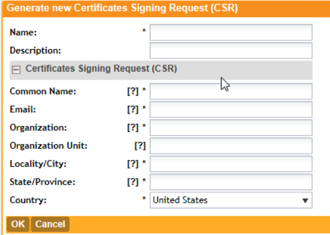
Figure 80: Generating a certificate signing request
Importing an SSL Certificate
When you have an SSL certificate issued by an SSL certificate provider, you can import it into
the controller and use it for HTTPS communication.
To complete this procedure, you will need the following items:
•The signed server certificate
•The intermediate CA certificate (at least one)
•The private key file
NOTE: The file size of each signed certificate and intermediate certificate must not exceed 8192
bytes. If a certificate exceeds 8192 bytes, you will be unable to import it into the controller.
Follow these steps to import a signed server certificate.
1. Copy the signed certificate file, intermediate CA certificate file, and private key file to a location
(either on the local drive or a network share) that you can access from the controller web
interface.
2. Go to Configuration > SCG System.
3. On the sidebar, click Certificate Store. The Certificate Store page appears.
The Import New Certificate form appears.
4. In the Installed Certificates section, click Import New.
The Import New Certificate form appears.
5. Import the server certificate by completing the following steps:
a) In Server Certificate, click Browse.
The Open dialog box appears.
b) Locate and select the certificate file, and then click Open.
SmartZone 100/Virtual SmartZone Essentials for Release 3.2 Administrator Guide
144
Configuring System Settings
Managing the Certificate Store
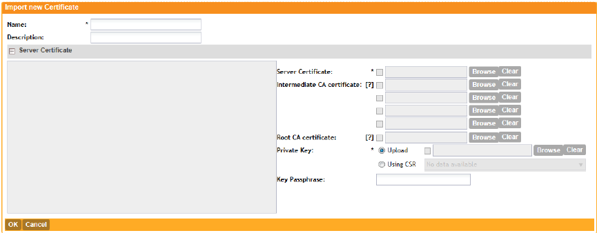
6. Import the intermediate CA certificate by completing the following steps:
a) In Intermediate CA certificate, click Browse.
The Open dialog box appears.
b) Locate and select the intermediate CA certificate file, and then click Open.
7. If you need to upload additional intermediate CA certificates to establish a chain of trust to
the signed certificate, repeat the above step.
If you are using this SSL certificate for a Hotspot 2.0 configuration, you must also import a
root CA certificate. See the Hotspot 2.0 Reference Guide for SmartZone 3.1.
8. When you finish uploading all the required intermediate certificates, import the private key file
either by uploading file itself or selecting the CSR you generated earlier.
a) Optional: To upload the private key file, click Upload. Click Browse, locate and select the
private key file. Click Open.
b) Optional: To select the CSR, click Using CSR, then select the CSR that you generated
earlier.
9. In Key Passphrase, enter the passphrase that has been assigned to private key file.
10. Click OK.
The page refreshes and the certificate you imported appears in the Installed Certificate
section.
You have completed importing a signed SSL certificate to the controller.
Figure 81: The Import New Certificate form
Assigning Certificates to Services
Follow these steps to specify the certificate that each secure service will use.
1. Go to Configuration > System > Certificate Store.
The Certificate Store page appears.
2. In the Service Certificates section, select the certificate that you want to use for each service.
3. Click Apply.
You have completed assigning certificates to services.
SmartZone 100/Virtual SmartZone Essentials for Release 3.2 Administrator Guide
145
Configuring System Settings
Managing the Certificate Store

Figure 82: The Service Certificates section
Configuring the External SMS Gateway
If you want to deliver guest passes to guest users via SMS, you can configure the controller to
use an existing Twilio account for SMS delivery.
The first step is to inform the controller of your Twilio account information.
Follow these steps to configure an external SMS gateway for the controller.
1. Go to Configuration > System > External SMS Gateway.
2. Select the Enable Twilio SMS Server check box.
3. Under Twilio Account Information, configure the following:
•Server Name
•Account SID
•Auth Token
•From (phone number)
SmartZone 100/Virtual SmartZone Essentials for Release 3.2 Administrator Guide
146
Configuring System Settings
Configuring the External SMS Gateway
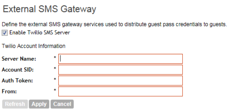
4. Click Apply.
You have completed configuring the external SMS gateway for the controller.
Figure 83: Configuring the external SMS gateway settings
Configuring SNMP Settings
The controller supports the Simple Network Management Protocol (SNMP v2 and v3), which
allows you to query controller information, such as system status, AP list, etc., and to set a
number of system settings using a Network Management System (NMS) or SNMP MIB browser.
You can also enable SNMP traps to receive immediate notifications for possible AP and system
issues.
The procedure for enabling the internal SNMP agents depends on whether your network is using
SNMPv2 or SNMPv3. SNMPv3 mainly provides security enhancements over the earlier version,
and therefore requires you to enter authorization passwords and encryption settings, instead of
simple clear text community strings.
Both SNMPv2 and SNMPv3 can be enabled at the same time. The SNMPv3 framework provides
backward compatibility for SNMPv1 and SNMPv2c management applications so that existing
management applications can still be used to manage the controller with SNMPv3 enabled.
Figure 84: Enabling SNMP traps
This section covers the following topics:
Enabling Global SNMP Traps
By default, the global SNMP trap setting is disabled, which means that the controller will be
unable to send out trap notifications, even if you enabled the SNMPv2 and SNMPv3 agents to
send out traps.
Follow these steps to enable global SNMP traps.
1. Go Configuration > System > SNMP Settings.
SmartZone 100/Virtual SmartZone Essentials for Release 3.2 Administrator Guide
147
Configuring System Settings
Configuring SNMP Settings
2. Select the Enable SNMP Traps Globally check box.
3. Click Apply.
A message appears, confirming that you have updated the global trap settings.
Configuring the SNMPv2 Agent
Follow these steps to configure the SNMPv2 agent.
1. In the SNMPv2 Agent section, click Add Community.
Options for adding a community appear.
2. Configure the read-only community settings by following these steps:
a) In the text box under Community, type the read-only community string (for example,
public).
Applications that send SNMP Get-Requests to the controller (to retrieve information) will
need to send this string along with the request before they will be allowed access.
b) Under Privilege, select the check boxes for the privileges that you want to grant to this
community.
A read-only community is typically granted the Read privilege. Available privileges include:
•Read
•Write
•Trap: Select this privilege if you want to send SNMP trap notifications for this community.
To add a trap target, click Add Trap Target, and then configure the following options
(required) that appear below:
•Target IP Address: Type the IP address of the SNMP trap server on the network.
•Target Port: Type the SNMP trap server port.
3. Click Add Community again.
A second set of configuration options for adding a community appears.
4. Configure the read-write community settings by following these steps:
a) In the text box under Community, type the read-write community string (for example,
private).
Applications that send SNMP Set-Requests to the controller (to set certain SNMP MIB
variables) will need to send this string along with the request before they will be allowed
access. The default value is private.
b) Under Privilege, select the check boxes for the privileges that you want to grant to this
community.
A read-write community is typically granted the Read and Write privileges. Available privileges
include:
•Read
•Write
•Trap: Select this privilege if you want to send SNMP trap notifications for this community.
When this check box is selected, the Add Trap Target button becomes active. Click Add
Trap Target, and then configure the following settings (required):
•Target IP Address: Type the IP address of the SNMP trap server on the network.
SmartZone 100/Virtual SmartZone Essentials for Release 3.2 Administrator Guide
148
Configuring System Settings
Configuring SNMP Settings
•Target Port: Type the SNMP trap server port.
5. Click Apply.
You have completed configuring the read-only and read-write communities for the SNMPv2
agent. To add another community, click Add Community again, and then repeat the procedure
above.
Configuring the SNMPv3 Agent
Follow these steps to configure the SNMPv3 agent.
1. In the SNMPv3 Agent section, click Add User.
Options for adding a user appear.
2. Under User, type a user name between 1 and 31 characters.
3. Under Authentication, select one of the following authentication methods:
•None: Use no authentication.
•MD5: Message-Digest algorithm 5, message hash function with 128-bit output.
•SHA: Secure Hash Algorithm, message hash function with 160-bit output.
4. Under Auth Pass Phrase, type a pass phrase between 8 and 32 characters in length.
5. Under Privacy, select one of the following privacy methods:
•None: Use no privacy method.
•DES: Data Encryption Standard, data block cipher.
•AES: Advanced Encryption Standard, data block cipher.
6. Under Privacy Phrase (active only if you selected either DES or AES above), enter a privacy
phrase between 8 and 32 characters in length.
7. Under Privilege, select the check boxes for the privileges that you want to grant to this
community.
A read-only community is typically granted the Read privilege, whereas a read-write community
is granted the Read and Write privileges. Available privileges include:
•Read
•Write
•Trap: Select this privilege if you want to send SNMP trap notifications for this community.
When this check box is selected, the Add Trap Target button becomes active. Click Add
Trap Target, and then configure the following settings (required):
•Target IP Address: Type the IP address of the SNMP trap server on the network.
•Target Port: Type the SNMP trap server port.
8. Repeat the steps above to create as many SNMPv3 agent users are you require.
9. Click Apply.
You have completed configuring the SNMPv3 agent settings.
SmartZone 100/Virtual SmartZone Essentials for Release 3.2 Administrator Guide
149
Configuring System Settings
Configuring SNMP Settings
Managing the User Agent Blacklist
The controller automatically blocks certain user agents (or software used by a user) from accessing
hotspots provided by controller-managed APs. When the controller blocks any of these user
agents, an error message appears on the user device. You can add to or remove user agents
from this blacklist.
These blocked user agents include:
•ZoneAlarm
•VCSoapClient
•XTier NetIdentity
•DivX Player
•Symantec LiveUpdate
•Windows Live Messenger
•StubInstaller
•windows-update-agent
•Windows Live Essentials
•Microsoft Dr. Watson for Windows (MSDW)
•Avast Antivirus Syncer
•Microsoft Background Intelligent Transfer Service (BITS)
•Google Update
•TrendMicro client
•Skype WISPr
NOTE: In SmartZone 3.0 and earlier releases, Microsoft NCSI was included in the user agent
blacklist. This prevented Windows Network Awareness, a feature that allows Windows services
and applications to automatically select the network connection best suited to their tasks, from
working properly. Microsoft NCSI has been removed from the user agent blacklist in SmartZone
3.1 and later.
Adding a User Agent to the Blacklist
Follow these steps to add a user agent to the blacklist.
1. Go to Configuration > System > Manage User Agent Blacklist.
2. Click Add New.
Four boxes appear, where you can enter the name, user agent pattern, error, and error
message to display on the user agent.
3. Click Save.
4. To add another user agent, repeat steps 2 on page 150 and 3 on page 150.
You have completed adding an agent to the black list.
SmartZone 100/Virtual SmartZone Essentials for Release 3.2 Administrator Guide
150
Configuring System Settings
Managing the User Agent Blacklist
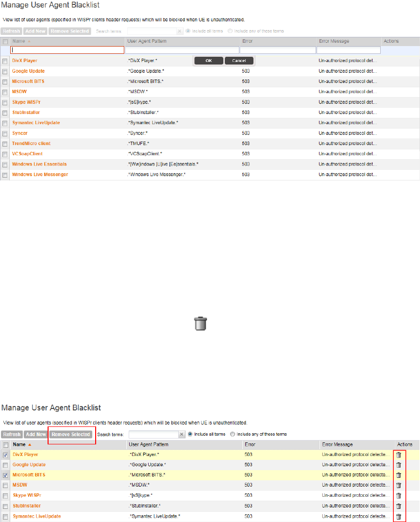
Figure 85: Adding a user agent to the black list
Deleting User Agents from the Blacklist
Follow these steps to delete user agents from the blacklist.
1. Go to Configuration > System > Manage User Agent Blacklist.
2. Locate the user agents that you want to delete from the blacklist, and then select the check
box before the user agent names.
3. Click Remove Selected.
To delete a single user agent, click the icon that is in the same row as the user agent
name.
The page refreshes, and then the user agents you deleted disappear from the list.
You have completed deleting user agents from the blacklist.
Figure 86: Deleting user agents
SmartZone 100/Virtual SmartZone Essentials for Release 3.2 Administrator Guide
151
Configuring System Settings
Managing the User Agent Blacklist
5
Managing Administrators, Administrator
Roles, and Administrator Authentication
In this chapter:
•Managing Administrator Accounts
•Managing Administrator Roles
•Managing RADIUS Servers for Administrator Authentication
Managing Administrator Accounts
The controller supports the creation of additional administrator accounts. This allows you to
share or delegate management and monitoring functions with other members of your organization.
In this section:
Creating an Administrator Account
Follow these steps to create an administrator account.
1. Go to Administration > Administrators > Administrators.
2. Click Create New.
The Create New Administrator Account form appears.
3. Configure the following options:
•Account Name: Type the name that this administrator will use to log on to the controller.
•Real Name: Type the actual name (for example, John Smith) of the administrator.
•Password: Type the password that this administrator will use (in conjunction with the
Account Name) to log on to the controller.
•Confirm Password: Type the same password as above.
•Phone: Type the phone number of this administrator.
•Email: Type the email address of this administrator.
•Job Title: Type the job title or position of this administrator in your organization.
4. Click OK.
The page refreshes, and then the administrator account that you created appears on the
Administrator Accounts page.
SmartZone 100/Virtual SmartZone Essentials for Release 3.2 Administrator Guide
152
Managing Administrators, Administrator Roles, and Administrator Authentication
Managing Administrator Accounts
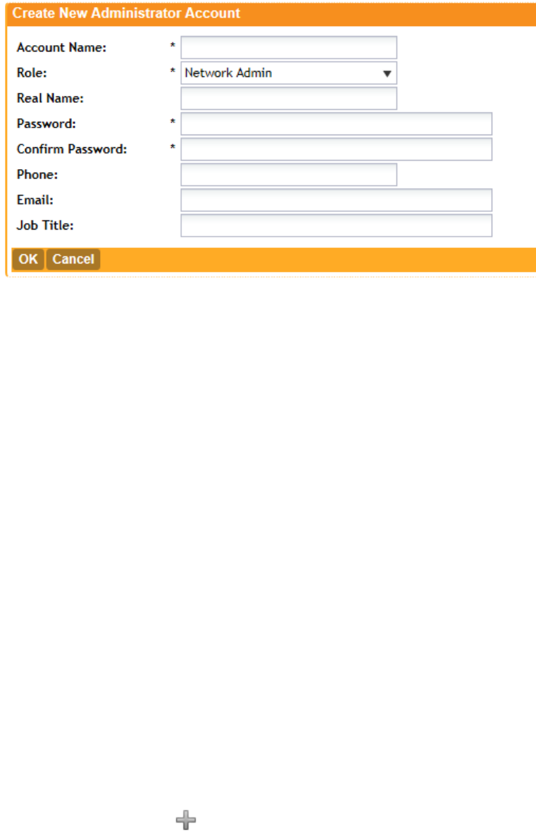
Figure 87: The Create New Administrator Account form
Managing Administrator Roles
In addition to creating administrator accounts, you can also create administrator roles, which
define the tasks that each administrator can perform.
In this section:
Creating an Administrator Role
You can also create administrator roles, which define the tasks that each administrator can
perform..
Follow these steps to create a new administrator role.
1. Go to Configuration > Administrators > Administrator Roles.
2. Click Create New.
The Create New Administrator Role form appears.
3. Configure the following options:
•Role Name: Type a name for the administrator role that you are creating.
•Description: type a short description for the administrator role.
•Assign Capabilities to Administrator Role (tree located on the left side of the form):
Select the administrator capabilities that you want to assign to this role. If you plan to grant
this administrator role most of the capabilities that are available, click Select All, and then
clear the check boxes for the capabilities that you do not want this role to have.
4. Remember to click the icon next to each folder to view all capabilities that are included.
5. Click OK.
The page refreshes, and the role you created appears on the page.
SmartZone 100/Virtual SmartZone Essentials for Release 3.2 Administrator Guide
153
Managing Administrators, Administrator Roles, and Administrator Authentication
Managing Administrator Roles
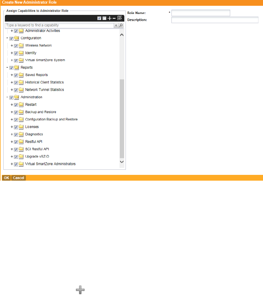
Figure 88: The Create New Administrator Role form
Editing an Administrator Role
Follow these steps to edit an existing administrator role.
1. Go to Configuration > Administrators > Administrator Roles.
2. Click the name of the administrator role that you want to edit.
The Edit Administrator Role form appears.
3. In the Assign Capabilities to Administrator Role tree (located on the left side of the form),
add or remove capabilities from the role.
Remember to click the icon next to each folder to view all capabilities that are included.
•To add a capability, select the check box next to it.
•To remove a capability, clear the check box next to it.
4. Click Apply.
You have completed editing an administrator role.
The system created administrator roles, which are present by default on the controller, cannot
be edited.
SmartZone 100/Virtual SmartZone Essentials for Release 3.2 Administrator Guide
154
Managing Administrators, Administrator Roles, and Administrator Authentication
Managing Administrator Roles
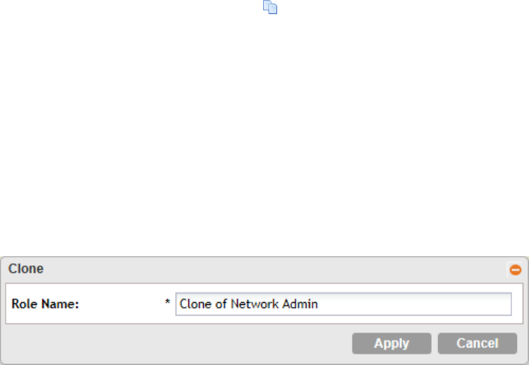
Cloning an Existing Administrator Role
If you want to create a new administrator role with capabilities that are similar to an existing role,
cloning the existing administrator role may be the faster way to create that new role.
Follow these steps to clone an existing administrator role.
1. Go to Configuration > Administrators > Administrator Roles.
2. Locate the role that you want to clone.
3. Under the Actions column, click the icon that is in the same row as the role that you want
to clone.
A dialog appears and prompts you for the name that you want to assign to the clone role.
The default name is Clone of [Original Role Name].
4. Type a new name or leave the name as is.
5. Click Apply.
The page refreshes, and then the role that you created appears on the Administrator Roles
page.
You have completed cloning an existing administrator role. Unless you want the new role to have
exactly the same capabilities as the original role, you may want to edit it.
Figure 89: The Clone dialog box
Managing RADIUS Servers for Administrator Authentication
You can add RADIUS servers that you want to use for authorizing and authenticating
administrators.
In this section:
Adding a RADIUS Server for Administrator Authentication
Follow these steps to add a RADIUS server that the controller can use for authenticating
administrators.
If you want to use a primary and secondary RADIUS servers for authenticating administrator,
follow the steps in Using a Backup RADIUS Server on page 156.
1. Go to Configuration > Administrators > AAA for Administrators.
2. Click Create New.
The Create New Administrator RADIUS Server form appears.
3. In Name, type a name for the RADIUS server.
SmartZone 100/Virtual SmartZone Essentials for Release 3.2 Administrator Guide
155
Managing Administrators, Administrator Roles, and Administrator Authentication
Managing RADIUS Servers for Administrator Authentication
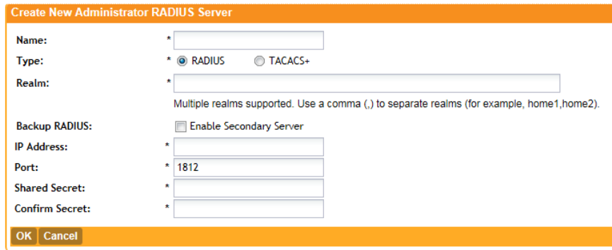
4. In Type, select the type of RADIUS server that you are using. Options include:
•RADIUS: Click this option to use a Remote Authentication Dial-In User Service (RADIUS)
server on the network for authenticating controller administrators.
•TACACS+: Click this option to use a Terminal Access Controller Access-Control System
Plus (TACACS+) server on the network for authentication controller administrators.
5. In Realm, type the realm (or realms) to which the RADIUS server belongs.
If the RADIUS server belongs to multiple realms, use a comma (,) to separate the realm names.
6. Make sure that the Enable backup RADIUS support check box is not selected. If you want
to use a backup RADIUS server, follow the steps in Using a Backup RADIUS Server on page
156 instead.
7. In IP Address, type the IP address of the RADIUS server.
8. In Port, type the UDP port that the RADIUS server is using. The default port is 1812.
9. In Shared Secret, type the shared secret.
10. Retype the same secret in Confirm Secret.
11. Click OK.
You have completed adding a RADIUS server for authenticating administrators.
Figure 90: The Create New Administrator RADIUS Server form
Using a Backup RADIUS Server
If a backup RADIUS server is available on the network, you can use it as a backup server when
the primary server is unavailable. When you select the check box, additional fields appear that
you need to fill in.
Follow these steps to enable support for a backup RADIUS server for authenticating
administrators.
1. Select the Enable backup RADIUS support check box.
2. In the Primary Server section, fill out the IP address, port number, and shared secret as you
did in the previous section.
SmartZone 100/Virtual SmartZone Essentials for Release 3.2 Administrator Guide
156
Managing Administrators, Administrator Roles, and Administrator Authentication
Managing RADIUS Servers for Administrator Authentication
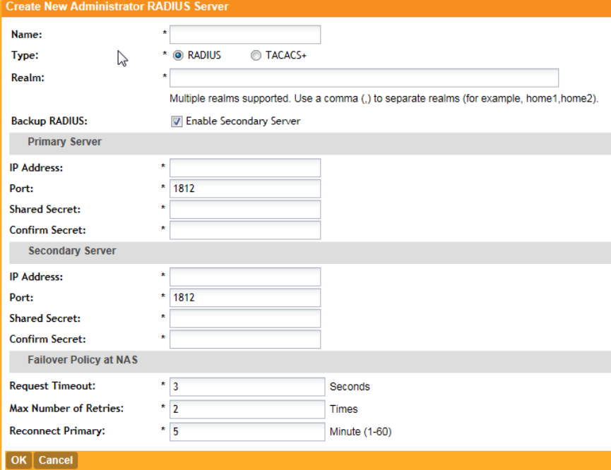
3. In the Secondary Server section, fill out the IP Address, port number and shared secret for
the backup server (these fields can neither be left empty nor be the same values as those of
the primary server).
4. In the Failover Policy section, configure the following settings:
•Request Timeout: Type the timeout period (in seconds) after which an expected RADIUS
response message is considered to have failed.
•Max Number of Retries: Type the number of failed connection attempts after which the
controller will fail over to the backup RADIUS server.
•Reconnect Primary: Type the number of minutes after which the controller will attempt
to reconnect to the primary RADIUS server after failover to the backup server.
5. Click OK.
You have completed adding primary and secondary RADIUS servers for authenticating
administrators.
Figure 91: Enabling the backup RADIUS server
SmartZone 100/Virtual SmartZone Essentials for Release 3.2 Administrator Guide
157
Managing Administrators, Administrator Roles, and Administrator Authentication
Managing RADIUS Servers for Administrator Authentication
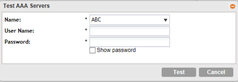
Testing an AAA Server
To ensure that the controller administrators will be able to authenticate successfully with the
RADIUS server type that you selected, Ruckus Wireless strongly recommends testing the AAA
server after you set it up.
The test queries the RADIUS server for a known authorized user and return groups associated
with the user that can be used for configuring roles within the controller.
Follow these steps to test an AAA server.
1. Go to Configuration > Administrators > AAA for Administrators.
2. Click Test AAA.
The Test AAA Servers form appears.
3. In Name, select one of the AAA servers that you previous created.
4. In User Name, type an existing user name on the AAA server that you selected.
5. In Password, type the password for the user name you specified.
6. Click Test.
If the controller was able to connect to the authentication server and retrieve the configured
groups/attributes, the information appears at the bottom of the page.
If the test was unsuccessful, there are two possible results (other than success) that will be
displayed to inform you if you have entered information incorrectly:
•Admin invalid
•User name or password invalid
These results can be used to troubleshoot the reasons for failure to authenticate administrators
with an AAA server through the controller.
Figure 92: The Test AAA Servers form
Authenticating an Administrator Using an External AAA Server
Follow these steps to create and configure an administrator account to be authenticated by an
external AAA server.
1. Log on to the controller web interface using a super admin account.
SmartZone 100/Virtual SmartZone Essentials for Release 3.2 Administrator Guide
158
Managing Administrators, Administrator Roles, and Administrator Authentication
Managing RADIUS Servers for Administrator Authentication
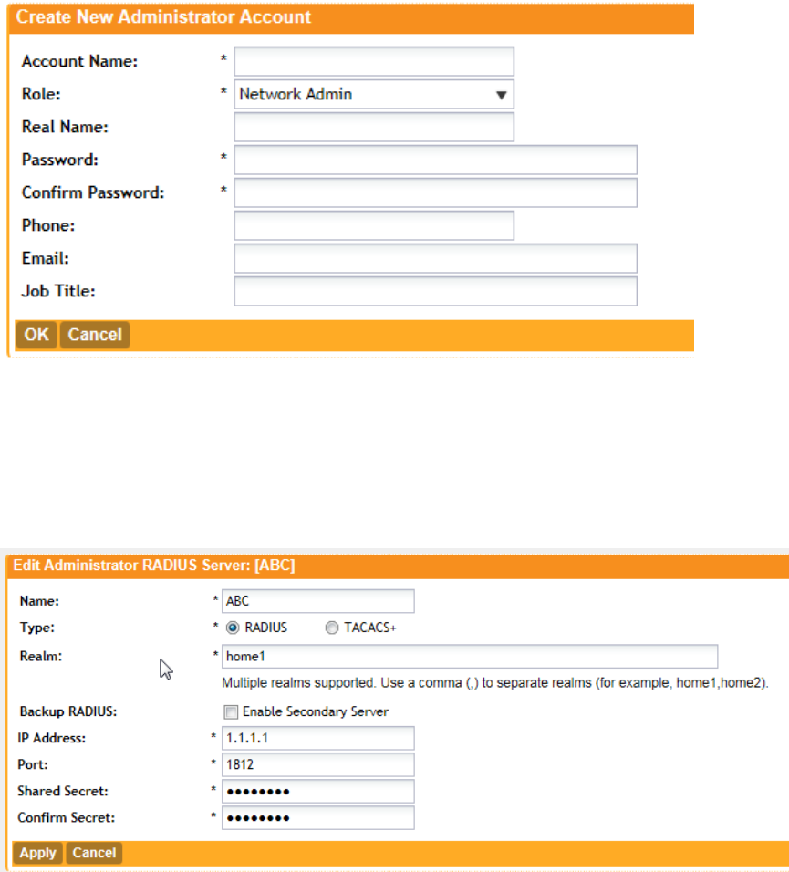
2. Go to Configuration > Administrators. Create an administrator account (see Creating an
Administrator Account on page 152 for instructions).
Take note of the account name that you assign to the account. You will use this account
name later when you log on to the web interface. In the example below, the account name
is wsg.
Figure 93: Create an administrator account
3. Go to Configuration > AAA for Administrators. Create an AAA server profile (see Adding
a RADIUS Server for Administrator Authentication on page 155) and specify a realm.
Take note of the realm name. You will use realm name later when you log on to the web
interface. In the example below, the realm name is scguser.
Figure 94: Create an AAA server profile
4. On the FreeRADIUS server, create a dictionary file.
a) Name it dictionary.ruckus, and then save it in the path /usr/share/freeradius.
SmartZone 100/Virtual SmartZone Essentials for Release 3.2 Administrator Guide
159
Managing Administrators, Administrator Roles, and Administrator Authentication
Managing RADIUS Servers for Administrator Authentication
b) Add the following to the dictionary file, and then save it:
VENDOR ruckuswireless 25053
BEGIN-VENDOR ruckuswireless
ATTRIBUTE WSG-User 10 String
END-VENDOR ruckuswireless
c) Save the dictionary file.
5. Edit the /etc/freeradius/dictionary file, add the text below, and then save the file.
$INCLUDE /usr/share/freeradius/dictionary.ruckus
6. Add the administrator user name you created in step to the list of FreeRADIUS users. Edit
the /etc/freeradius/users file, adding the text below, and then save the file.
wsg Cleartext-Password := "wsg"
WSG-User="wsg"
Where:
•The value for WSG-User is the administrator user name that you created in step 2 on page
159.
•The value wsg Cleartext-Password is the password you assigned to the administrator
user name above.
7. Log on to the controller web interface, and then use the account name and realm combination
(accountname@realm) as the user name.
For example, if the account name is wsg and the realm name is scguser, enter wsg@scguser
in User Name.
Figure 95: In User Name, use {accountname@realmname}
8. After you log on successfully, check the miscellaneous bar on the upper-right corner of the
web interface and verify that you are logged on using the {accountname@realmname}
credentials.
SmartZone 100/Virtual SmartZone Essentials for Release 3.2 Administrator Guide
160
Managing Administrators, Administrator Roles, and Administrator Authentication
Managing RADIUS Servers for Administrator Authentication
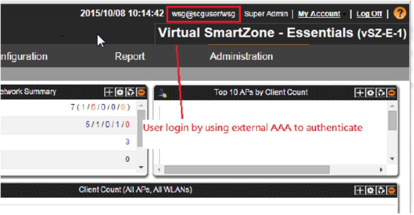
Figure 96: Verify that you are logged on using the {accountname@realmname} credentials
You have completed logging on to the web interface using an account authenticated by an
external AAA server.
SmartZone 100/Virtual SmartZone Essentials for Release 3.2 Administrator Guide
161
Managing Administrators, Administrator Roles, and Administrator Authentication
Managing RADIUS Servers for Administrator Authentication
6
Monitoring the Wireless Network
In this chapter:
•Monitoring Managed Access Points
•Viewing Managed APs on Google Maps
•Monitoring the Mesh Network
•Monitoring Wireless Clients
•Monitoring Managed Devices
•Monitoring the System
•Monitoring Rogue Access Points
•Monitoring Location Services
•Viewing All Alarms
•Viewing All Events
•Monitoring Administrator Activities
Monitoring Managed Access Points
This section provides information on how to monitor and view information about the access
points that you are managing using the controller.
Topics covered include:
Viewing a Summary of Access Points
View a summary of existing access points.
Go to Monitor > Access Points. The Access Points page appears and displays a table that
lists all access points that controller is currently managing.
SmartZone 100/Virtual SmartZone Essentials for Release 3.2 Administrator Guide
162
Monitoring the Wireless Network
Monitoring Managed Access Points
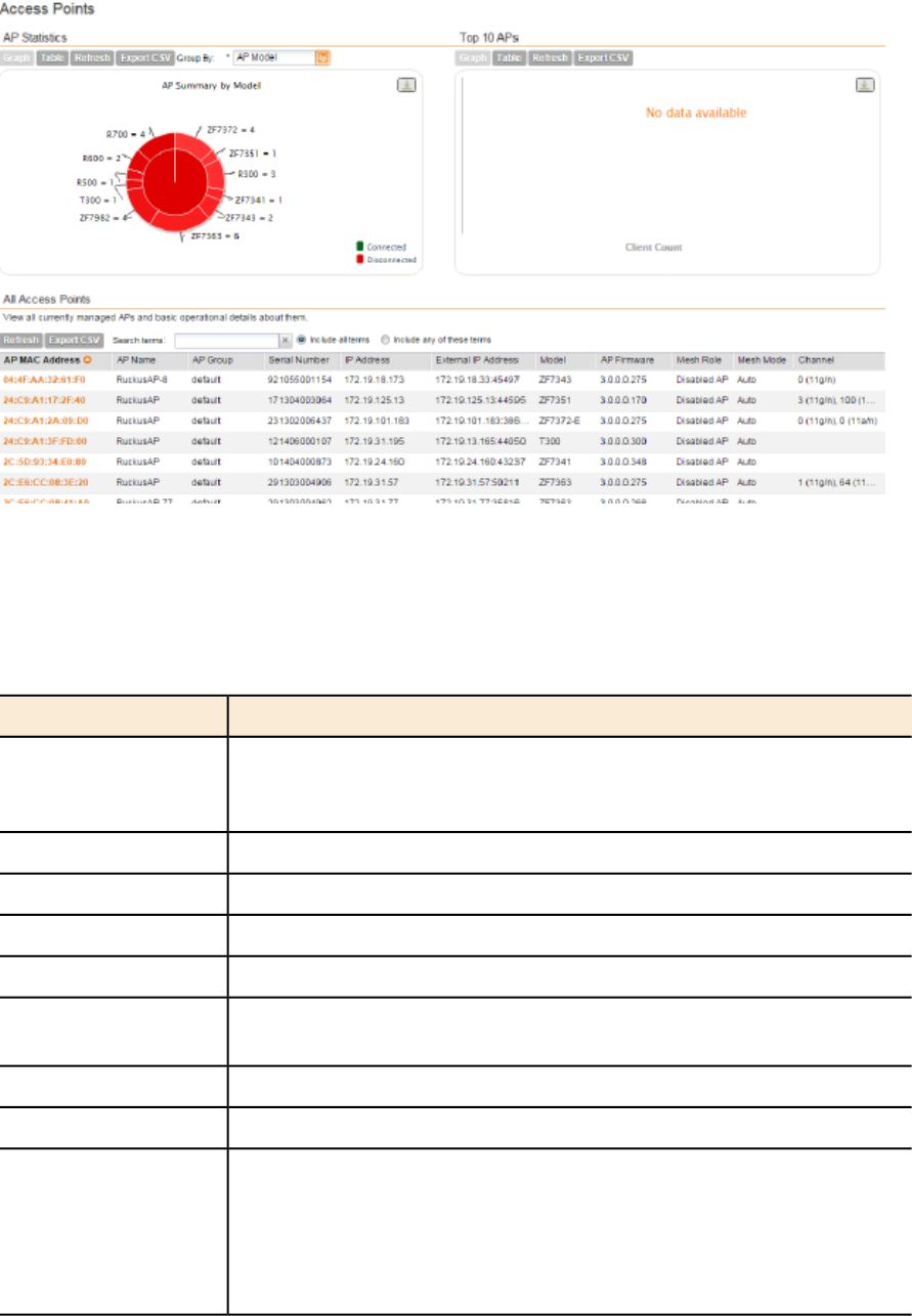
Figure 97: The Monitor > Access Points page displays all controller-managed access
points
The following table lists the access point details.
Table 8: Access point details
DescriptionColumn Name
MAC address of the access point. Clicking this link loads a page that
displays detailed information about the access point. See Viewing the
Configuration of an Access Point on page 165.
AP MAC Address
Name assigned to the access pointAP Name
AP group to which the AP belongs (if any)AP Group
Serial number of the APSerial Number
Internal IP address assigned to the access pointIP Address
If the device is behind a NAT server, this is the IP address and port
number that the controller will use to communicate with the device.
External IP Address
Model number of the Ruckus Wireless access pointModel
Firmware version that is installed on the access pointAP Firmware
Indicates whether mesh networking is enabled on the access point and
the mesh role that is assigned to it. Possible values include:
Mesh Role
•Disabled: Mesh networking is disabled.
•Mesh AP
•Root AP
SmartZone 100/Virtual SmartZone Essentials for Release 3.2 Administrator Guide
163
Monitoring the Wireless Network
Monitoring Managed Access Points
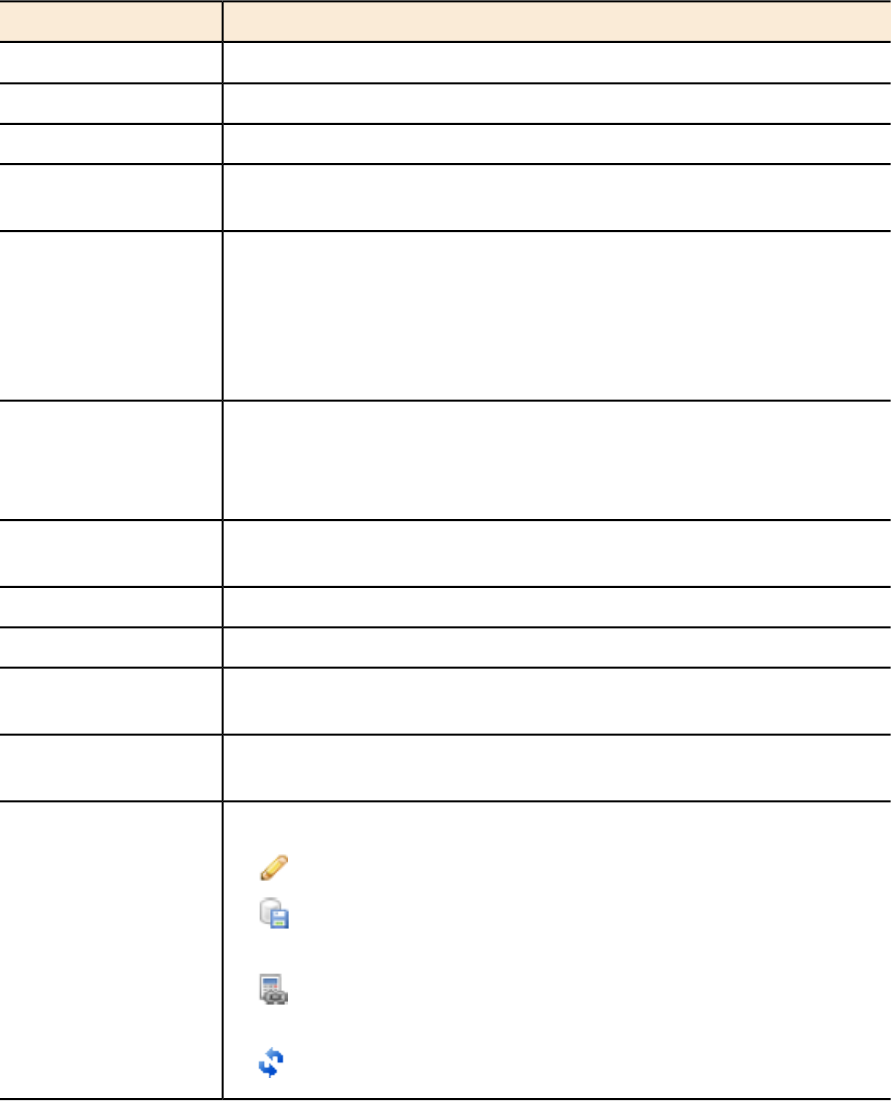
DescriptionColumn Name
•eMesh AP
Shows the mesh mode (Auto, Root, Mesh) of the APMesh Mode
Indicates the radio channels used by the AP to provide WLAN servicesChannel
Indicates whether the access point is currently connected (online) or
disconnected (offline)
Status
Show any of the following statuses:Configuration Status
•New Configuration: Appears when the AP has pending
configuration change from the controller that needs to be applied.
•Up-to-date: Appears when the AP's configuration is synchronized
with the controller.
Indicates the number of wireless clients that are currently associated
with the access point. Clicking the number of clients (link, except when
# of Clients
zero) loads a page that displays detailed information about the wireless
clients. See Viewing a Summary of Wireless Clients on page 169.
Indicates the date and time when the access point last reported to the
controller
Last Seen
Shows either Locked or Unlocked.Administrative State
Shows either Discovery, Approved, or Rejected.Registration State
Indicates whether Bonjour gateway service is enabled, disabled or not
supported on this AP.
Clients Bonjour
Gateway
Indicates whether LBS service is enabled, disabled or not supported
on this AP.
LBS service status
Icons for actions that you can perform, including:Actions
• – Click to view detailed configuration of this access point.
• – Click to download the support log from this access point. See
Downloading the Support Log from an Access Point on page 166.
• – Click to run network connectivity tests (PING and traceroute)
on this access point.
• – Click to restart the access point.
Exporting the Access Point List to CSV
If you want to be able to view a list of all APs that the controller is currently managing in a
spreadsheet program such as Microsoft Excel, export the AP list to a comma-separated value
(CSV) file.
Follow these steps to export the AP list to a CSV file.
SmartZone 100/Virtual SmartZone Essentials for Release 3.2 Administrator Guide
164
Monitoring the Wireless Network
Monitoring Managed Access Points
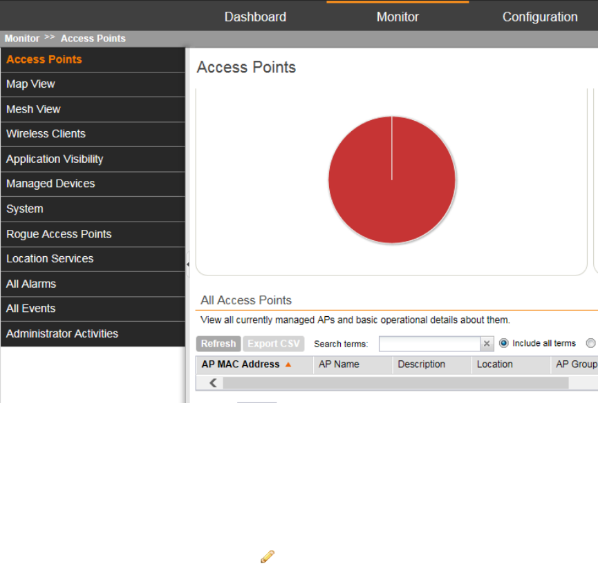
1. Go to Monitor > Access Points.
2. Click the Export CSV button in the content area.
3. Check the default download folder of your web browser and look for a file named
RuckusAPList.csv.
4. Use a spreadsheet application (for example, Microsoft®Excel®) to view the contents of the
CSV file.
You have completed exporting the access point list to CSV.
Figure 98: Click Export CSV to download the AP list
Viewing the Configuration of an Access Point
Follow these steps to view the configuration of an access point.
1. Go to Monitor > Access Points.
2. On the Access Points page, locate the access point whose details you want to view.
3. Under the Actions column, click the icon that is in the same row as the MAC address of
the access point.
The page refreshes and displays the AP Edit: [MAC Address] form appears, which displays
the AP's configuration details (shown in Figure 99: Page showing the access point configuration
details on page 166).
SmartZone 100/Virtual SmartZone Essentials for Release 3.2 Administrator Guide
165
Monitoring the Wireless Network
Monitoring Managed Access Points
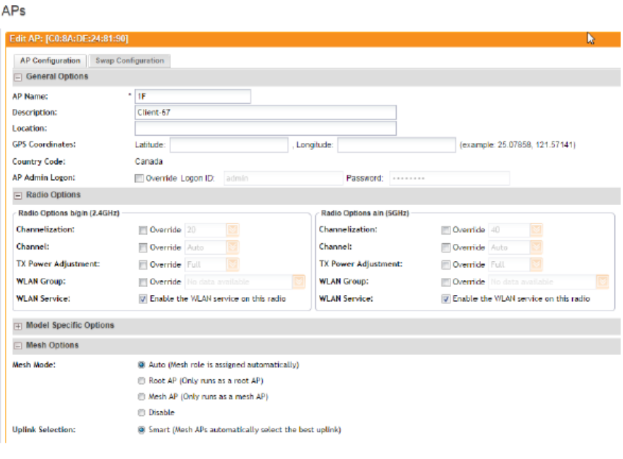
Figure 99: Page showing the access point configuration details
Downloading the Support Log from an Access Point
If you are experiencing issues with an access point, Ruckus Wireless Support may request you
to download the support log from the access point.
The support log contains important technical information that may be help Ruckus Wireless
Support troubleshoot the issue with the access point.
Follow these steps to download the support log from an access point.
1. Go to Monitor > Access Points.
2. On the Access Points page, locate the access point from which you want to download the
support log.
3. Under the Actions column, click the icon that is in the same row as the MAC address of the
access point.
4. Check the default download folder for your web browser and look for a file named
SupportLog_{AP-MAC-address}.log.
5. Use a text editor (for example, Notepad) to view the contents of the text file.
6. Send the support log file to Ruckus Wireless Support, along with your support request.
You have completed downloading the support log from an access point.
SmartZone 100/Virtual SmartZone Essentials for Release 3.2 Administrator Guide
166
Monitoring the Wireless Network
Monitoring Managed Access Points

Restarting an Access Point Remotely
Follow these steps to restart an access point remotely from the web interface.
1. Go to Monitor > Access Points.
2. On the Access Points page, locate the access point that you want to restart.
3. Click the icon that is in the same row as the MAC address of the access point.
The following confirmation message appears: Are you sure you want to restart
this AP?
4. Click Yes.
The controller sends a restart command to the access point, and then the access point
restarts itself.
You have completed restarting an access point remotely.
Running Ping and Traceroute on an Access Point
The controller web interface provides two commonly used tools – ping and traceroute – that
allow you to diagnose connectivity issues on managed access points.
Follow these steps to run the ping and traceroute on an access point.
1. Go to Monitor > Access Points.
2. On the Access Points page, locate the access point on which you want to run the ping or
traceroute tool.
3. Click the icon that is in the same row as the MAC address of the access point.
The Network Connectivity window appears.
4. In IP Address, type an IP address to check whether the access point can connect to it.
For example, type 199.238.178.36 if you want to check if the access point can connect
to the Ruckus Wireless website.
5. Click either Pingor Trace Route(depending on which test you want to run).
The blank box below is populated with the test results.
You have completed running a ping or traceroute test.
Viewing Managed APs on Google Maps™
If GPS coordinates were configured for some or all of the APs that the controller is managing,
you can view the AP locations on Google Maps™.
To view APs that the controller is managing on Google Maps, go to Monitor > Map View. The
page refreshes and displays managed APs on Google Maps.
To view a summary of details about an AP on the map, click the icon for the AP. A text bubble
appears and displays the AP details (see Figure 100: APs that have their GPS coordinates
configured appear on Google Maps on page 168).
SmartZone 100/Virtual SmartZone Essentials for Release 3.2 Administrator Guide
167
Monitoring the Wireless Network
Viewing Managed APs on Google Maps™
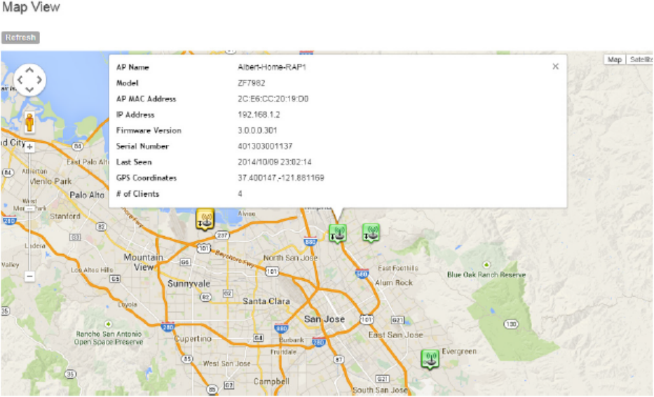
Figure 100: APs that have their GPS coordinates configured appear on Google Maps
Monitoring the Mesh Network
To view Smart Mesh topologies of any mesh trees present on your network, go to Monitor >
Mesh View.
This page also displays non-meshing APs controlled by the controller and provides a number
of action icons to troubleshoot and diagnose mesh-related issues.
SmartZone 100/Virtual SmartZone Essentials for Release 3.2 Administrator Guide
168
Monitoring the Wireless Network
Monitoring the Mesh Network
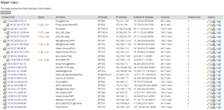
Figure 101: View the mesh network status on the Monitor > Mesh View page
Monitoring Wireless Clients
This section provides information on how to monitor and view information about wireless clients
that associate with the managed access points.
Topics covered include:
Viewing a Summary of Wireless Clients
View a summary of wireless clients that are currently associated with the managed access points.
Go to Monitor > Wireless Clients. The Wireless Clients page appears and displays a table
that lists all wireless clients that are currently associated with managed access points.
SmartZone 100/Virtual SmartZone Essentials for Release 3.2 Administrator Guide
169
Monitoring the Wireless Network
Monitoring Wireless Clients
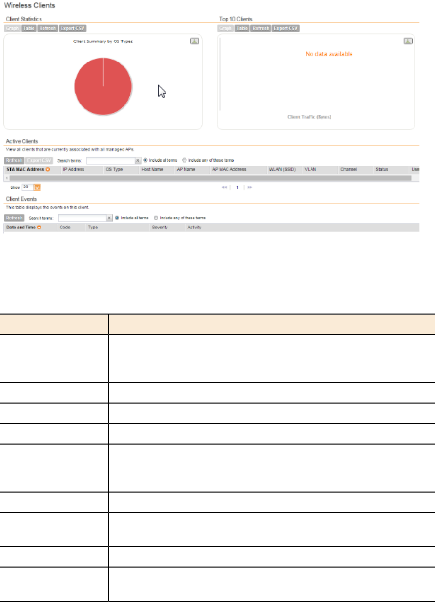
Figure 102: View all currently active wireless clients
The following table lists the wireless client details.
Table 9: Wireless client details
DescriptionColumn Name
MAC address of the wireless station. Clicking this link loads a page that
displays detailed information about the wireless client. See Viewing
Information About a Wireless Client.
STA MAC Address
IP address assigned to the wireless clientIP Address
Operating system that the wireless client is usingOS Type
Host name of the wireless clientHost Name
Name assigned to the access point. Clicking this link loads a page that
displays detailed information about the access point. See Viewing the
Configuration of an Access Point.
AP Name
MAC address of the APAP MAC Address
Name of the WLAN service or SSID with which the wireless client is
associated.
WLAN (SSID)
VLAN ID assigned to the wireless clientVLAN
Radio channel used by the wireless client to access the WLAN service
on the access point
Channel
SmartZone 100/Virtual SmartZone Essentials for Release 3.2 Administrator Guide
170
Monitoring the Wireless Network
Monitoring Wireless Clients
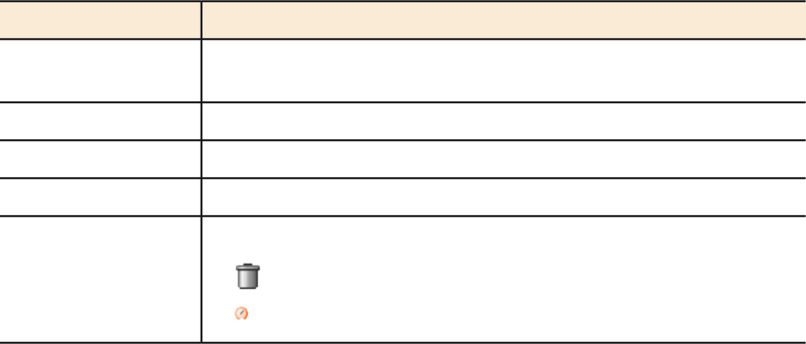
DescriptionColumn Name
Indicates whether the wireless client is authorized or unauthorized to
access the WLAN service
Status
Name of the user logged on to the wireless clientUser Name
Authentication method used by the access pointAuth Method
Encryption method used by the access pointEncryption Method
Icons for actions that you can perform, including:Actions
• – Click to disconnect the wireless client from the access point
• - Click to start the SpeedFlex wireless performance tool
Exporting the Wireless Client List to CSV
Follow these steps to export the wireless point list to a CSV file.
1. Go to Monitor > Wireless Clients.
2. Click the Export CSV button in the content area.
3. Check the default download folder of your web browser and look for a file named
clients.csv.
4. Use a spreadsheet application (for example, Microsoft®Excel®) to view the contents of the
CSV file.
You have completed exporting the wireless client list to CSV.
Viewing Information About a Wireless Client
Follow these steps to view information about a wireless client.
1. Go to Monitor > Wireless Clients.
2. Locate the wireless client whose details you want to view.
3. Under the STA MAC Address column, click the MAC address of the wireless client.
The Associated Client page appears and displays general information about the wireless
client, including its MAC address, IP address, authentication method, encryption method,
connection details, operating system, and traffic statistics, among others. Recent connectivity
events that occurred on the wireless client are displayed in the Client Events section at the
bottom of the page.
SmartZone 100/Virtual SmartZone Essentials for Release 3.2 Administrator Guide
171
Monitoring the Wireless Network
Monitoring Wireless Clients
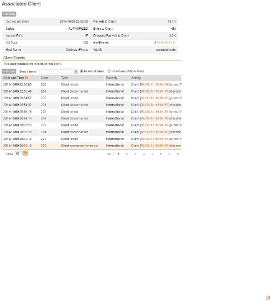
Figure 103: The Associated Client page shows wireless client information
Measuring Wireless Network Throughput with SpeedFlex
SpeedFlex is a wireless performance tool included in the controller that you can use to measure
the downlink throughput between the controller and an AP.
When performing a site survey, you can use SpeedFlex to help find the optimum location for
APs on the network with respect to user locations.
SpeedFlex is unable to measure the throughput between two devices if those two devices are
not on the same VLAN or the same subnet.
Follow these steps to measure the throughput of an AP from the controller web interface.
1. Find out the MAC address of the AP that you want to use for this test procedure.
2. Log on to the controller web interface.
3. If you want to test AP throughput, click Monitor > Access Point.
4. In the list of APs, look for the MAC address of the AP that you want to test, and then click
(SpeedFlex icon) that is in the same row.
The SpeedFlex Wireless Performance Test interface loads, showing a speedometer and
the IP address of the AP that you want to test.
5. In Protocol, select UDP.
If you are testing AP throughput, you have the option to test both Downlink and Uplink
throughput. Both options are selected by default. If you only want to test one of them, clear
the check box for the option that you do not want to test.
6. Click the Start button.
SmartZone 100/Virtual SmartZone Essentials for Release 3.2 Administrator Guide
172
Monitoring the Wireless Network
Monitoring Wireless Clients
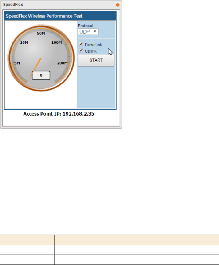
A progress bar appears below the speedometer as SpeedFlex generates traffic to measure
the downlink or uplink throughput. One throughput test typically runs for 10-30 seconds. If
you are testing AP throughput and you selected both the Downlink and Uplink options, both
tests should take about one minute to complete.
When the tests are complete, the results appear below the Start button. Information that is
shown includes the downlink/uplink throughput and the packet loss percentage during the tests.
Figure 104: The SpeedFlex page
Monitoring Managed Devices
Managed devices refer to user equipment (UE) that have associated with the controller-managed
APs using the Zero-IT onboarding process.
To view a list of managed devices, go to Monitor > Managed Devices. The Managed Devices
page appears and displays all currently managed devices and their details. Table 10: Information
available on the Managed Devices page on page 173 describes the details about managed
devices that are displayed on the Managed Devices page.
The following table lists the information available on the managed devices.
Table 10: Information available on the Managed Devices page
DescriptionColumn
MAC address of the deviceMAC
User name of the device userUser Name
SmartZone 100/Virtual SmartZone Essentials for Release 3.2 Administrator Guide
173
Monitoring the Wireless Network
Monitoring Managed Devices
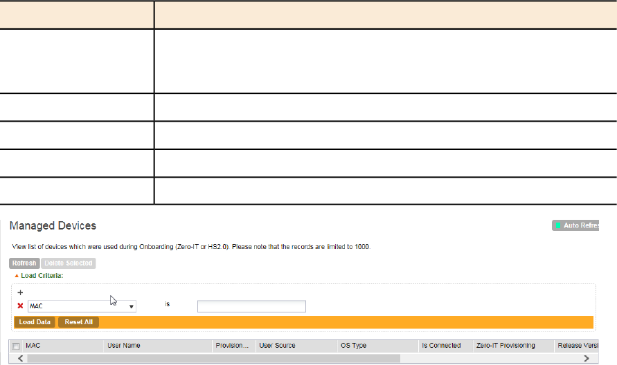
DescriptionColumn
Shows either Local DB if the devices was authenticated locally using
the SCG database or, if the device was authenticated using an external
AAA server, the AAA server name.
User Source
Operating system used by the deviceOS Type
Current connection status (Yes for connected, No for disconnected)Is Connected
Zero-IT Provisioning
Date when the device first associated with the controller-managed APCreated On
Figure 105: The Managed Devices page
Monitoring the System
This section provides information on how to view information about the status of the controller
system, including its cluster planes and cluster events. It also describes how to use the chassis
view and to start the cluster monitor.
Viewing the System Cluster Overview
The system cluster overview provides summary information the controller cluster.
•To view the cluster overview, go to Monitor > System.
The Cluster Node: [{Cluster Name}] page appears, as shown in Figure 106: The Cluster
Node: [{Cluster Name}] page on page 175
SmartZone 100/Virtual SmartZone Essentials for Release 3.2 Administrator Guide
174
Monitoring the Wireless Network
Monitoring the System
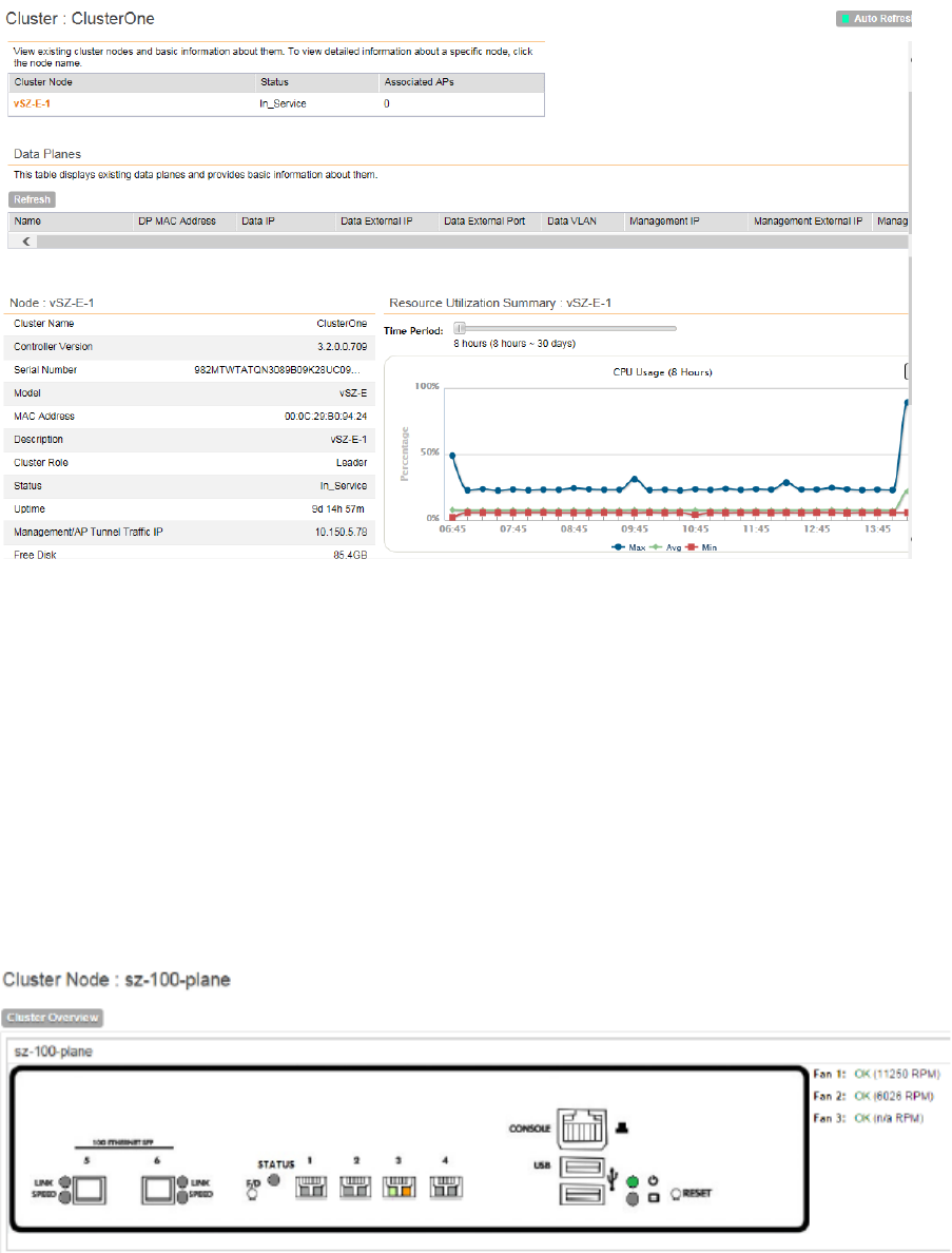
Figure 106: The Cluster Node: [{Cluster Name}] page
Displaying the Chassis View of Cluster Nodes
The chassis view provides a graphical representation of the control panel (on the front panel of
the controller), including the LEDs.
Use the LEDs to check the status of the ports and power supplies on the controller. Fan status
is also displayed on the chassis view.
•To view the chassis of the cluster node, click Chassis View on the Cluster Node: [{Cluster
Name}] page.
The information on the chassis view updates automatically every 30 seconds. This polling
frequency is not configurable.
Figure 107: The chassis view page displays the chassis of all nodes in the cluster
SmartZone 100/Virtual SmartZone Essentials for Release 3.2 Administrator Guide
175
Monitoring the Wireless Network
Monitoring the System
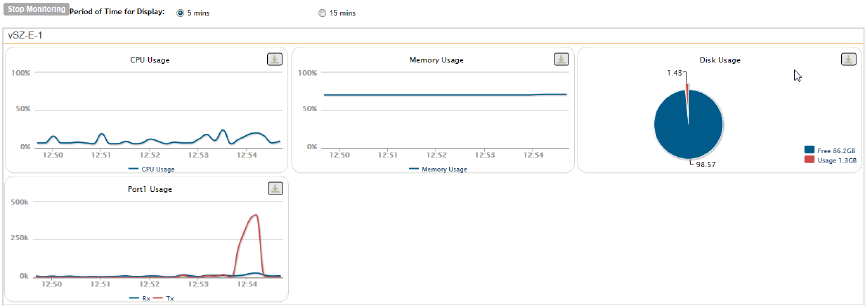
Starting the Node Real-time Monitor
The Node Real-time Monitor page displays graphs and charts of the controller system resources.
Use this monitor to understand how system resources on the cluster nodes are being used.
•To start the cluster real-time monitor, click Start Node Real-time Monitor on the Cluster
Node: [{Cluster Name}] page.
A new browser page or tab appears (depending on your browser settings), and then the
Node Real-time Monitor page appears.
Figure 108: The Node Real-time Monitor page
The resource graphs and charts that are shown on the Cluster Real-time Monitor page include:
•CPU Usage
•Memory Usage
•Disk Usage
•Port1 Usage
•Port2 Usage
•Port3 Usage
•Port4 Usage
NOTE: On some controller models, you may see additional graphs for Port 5 and Port 6
usage.
•To stop the Cluster Real-time Monitor, click the Stop Monitoring button on the upper-left
part of the page.
Monitoring Data Planes
The system cluster overview dislpays the existing dtata planes and basic information about them
such as name, MAC address, status etc.
To view the data planes, go to Monitor > System.
Information about the data planes is displayed as shown in the figure.
SmartZone 100/Virtual SmartZone Essentials for Release 3.2 Administrator Guide
176
Monitoring the Wireless Network
Monitoring the System
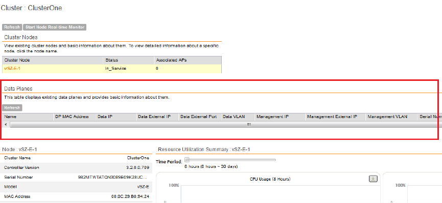
Monitoring Rogue Access Points
Rogue (or unauthorized) APs pose problems for a wireless network in terms of airtime contention,
as well as security.
Usually, a rogue AP appears in the following way: an employee obtains another manufacturer's
AP and connects it to the LAN, to gain wireless access to other LAN resources. This would
potentially allow even more unauthorized users to access your corporate LAN - posing a security
risk. Rogue APs also interfere with nearby Ruckus Wireless APs, thus degrading overall wireless
network coverage and performance.
The controller's rogue AP detection options include identifying the presence of a rogue AP,
categorizing it as either a known neighbor AP or as a malicious rogue.
If you enabled rogue AP detection when you configured the common AP settings (see Configuring
Common AP Settings on page 55), click Monitor > Rogue Access Points. The Rogue Access
Points page displays all rogue APs that the controller has detected on the network, including
the following information:
•Rogue MAC: MAC address of the rogue AP.
•Type: Type of rogue AP detected. Possible values include:
•Rogue: A normal rogue AP. This rogue AP has not yet been categorized as malicious or
non-malicious.
•Malicious AP (SSID-spoof): A malicious rogue AP that uses the same SSID as an
controller-managed AP (also known as an Evil-twin AP).
•Malicious AP (MAC-spoof): A malicious rogue AP that has the same BSSID (MAC)
as one of the virtual APs managed by the controller.
•Malicious AP (Same-Network): A malicious rogue AP that is connected to the same
wired network.
•Channel: Radio channel used by the rogue AP.
•Radio: WLAN standards with which the rogue AP complies.
SmartZone 100/Virtual SmartZone Essentials for Release 3.2 Administrator Guide
177
Monitoring the Wireless Network
Monitoring Rogue Access Points
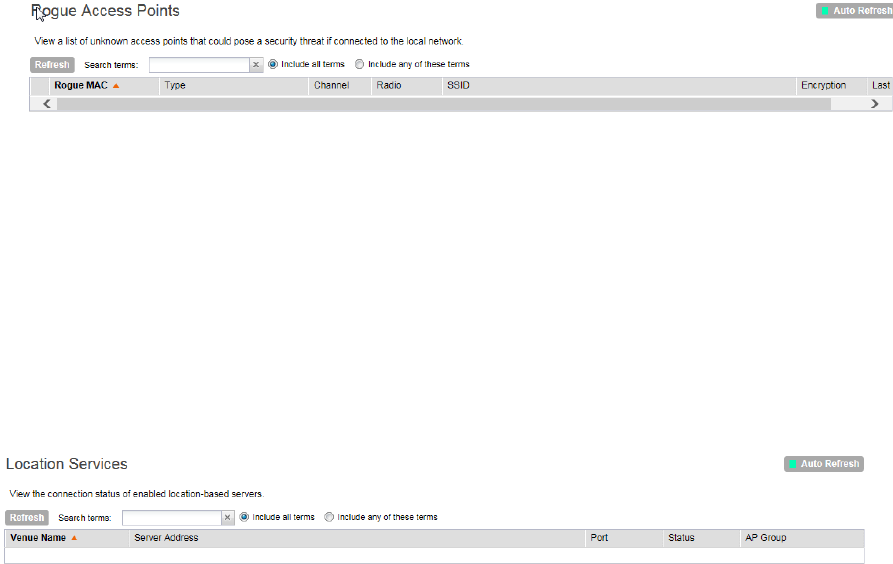
•SSID: WLAN name that the rogue AP is broadcasting.
•Encryption: Indicates whether the wireless signal is encrypted or not.
•Last Detected: Date and time when the rogue AP was last detected by the controller.
Figure 109: The Monitor > Rogue Access Points page
Monitoring Location Services
To monitor SmartPositioning location servers that you have configured on the Configuration >
Wireless Network > Location Services, go to Monitor > Location Services.
For information on configuring and administering of Ruckus Wireless SmartPositioning Technology
(SPoT) service, see the SPoT User Guide, which is available for download on
https://support.ruckuswireless.com.
Figure 110: Monitor > Location Services page
Viewing All Alarms
Alarms are a type of event that typically warrants your attention. Alarms are generated by managed
access points and the controller system.
•To view recent alarms that have been generated, go to Monitor > All Alarms. The All Alarms
page displays the 20 most recent alarms.
NOTE: By default, the All Alarms page displays up to 20 event entries per page. You can
change the number of alarms to display per page by selecting a number in Show. Options
range from 10 to 250 entries per page. Alternatively, you can click the >> (next) link to display
the next 20 alarms on another page.
SmartZone 100/Virtual SmartZone Essentials for Release 3.2 Administrator Guide
178
Monitoring the Wireless Network
Monitoring Location Services
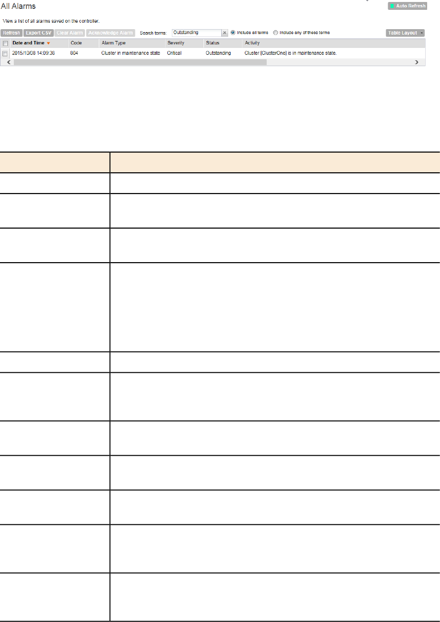
Figure 111: The All Alarms page displays the most recent alarm entries
The following table lists the alarm details.
Table 11: Alarm details (Continued)
DescriptionColumn Name
Date and time when the alarm was triggeredDate and Time
Alarm code (see the Alarm and Event Reference Guide for your
controller platform for more information)
Code
Type of alarm event that occurred (for example, AP reset to factory
settings)
Alarm Type
Severity level assigned to the alarm. Possible values include (from most
severe to least severe):
Severity
•Critical
•Major
•Minor
Indicates whether the alarm has already been cleared or still outstandingStatus
Displays additional details about the alarm, including (if available) the
specific access point, control plane, or data plane that triggered the
alarm
Activity
Date and time when you or another administrator acknowledge the
alarm
Acknowledged On
If the alarm has been cleared, this shows the name of the administrator
who cleared the alarm.
Cleared By
If the alarm has been cleared, this shows the date and time when the
alarm was cleared.
Cleared On
If the alarm was cleared manually, this shows the comment entered by
the administrator who cleared the alarm. If the alarm was cleared
automatically, shows Auto Cleared.
Comments
Displays additional details about the alarm, including (if available) the
specific access point, control plane, or data plane that triggered the
alarm
Activity
SmartZone 100/Virtual SmartZone Essentials for Release 3.2 Administrator Guide
179
Monitoring the Wireless Network
Viewing All Alarms
DescriptionColumn Name
Icons for actions that you can perform, including:
– Click this to take ownership of issue. Acknowledging an alarm lets
other administrators know that someone is already looking into the
issue.
Actions
– Click this to clear the alarm. You may clear an alarm to let other
administrators know that you have already resolved the issue. When
you click this icon, a text box appears where you can enter comments
or notes about the resolved issue. Click Clear when done.
Exporting the Alarm List to CSV
Follow these steps to export the alarm list to a CSV file.
1. Go to Monitor > All Alarms.
2. Click the Export CSV button in the content area.
3. Check the default download folder of your web browser and look for a file named
clients.csv.
4. Use a spreadsheet application (for example, Microsoft®Excel®) to view the contents of the
CSV file.
You have completed exporting the alarm list to CSV.
Clearing Alarms
Clearing an alarm removes the alarm from the list but keeps it on the controller's database. Do
one of the following to clear a single alarm or multiple alarms.
•To clear a single alarm, select the check box that is in the same row as the alarm, and then
click Clear Alarm. Alternatively, click the icon.
•To clear multiple alarms, select the check boxes for the alarm that you want to clear, and
then click Clear Alarm.
•To clear all alarms that are currently displayed on the page, click the check box before the
Date and Time column, and then click Clear Alarm.
Acknowledging Alarms
Acknowledging an alarm lets other administrators know that you have examined the alarm. After
you acknowledge an alarm, it will remain on the list of alarms and will show the date and time
that you acknowledged it.
Do one of the following to acknowledge a single alarm or multiple alarms.
•To acknowledge a single alarm, select the check box that is in the same row as the alarm,
and then click Acknowledge Alarm. Alternatively, click the icon.
•To acknowledge multiple alarms, select the check boxes for the alarm that you want to clear,
and then clickAcknowledge Alarm.
•To acknowledge all alarms that are currently displayed on the page, click the check box
before the Date and Time column, and then click Acknowledge Alarm.
SmartZone 100/Virtual SmartZone Essentials for Release 3.2 Administrator Guide
180
Monitoring the Wireless Network
Viewing All Alarms
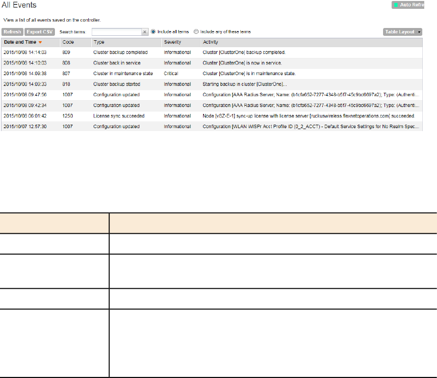
Viewing All Events
An event is an occurrence or the detection of certain conditions in and around the network. An
AP being rebooted, an AP changing its IP address, and a user updating an AP’s configuration
are all examples of events.
NOTE: Events that require your attention are called alarms. For information on alarms, refer to
Viewing All Alarms on page 178.
Follow these steps to view recent events that have been detected by the controller.
•Go to Monitor > All Events.
NOTE: By default, the Events page displays up to 20 event entries per page. You can change
the number of events to display per page by selecting a number in Show. Options range
from 10 to 250 entries per page. Alternatively, you can click the >> (next) link to display the
next 20 events on another page.
The All Events page appears and displays the 20 most recent events that have occurred.
Figure 112: The All Events page lists the most recent events
The following table lists the details on the Events page.
Table 12: Event details
DescriptionColumn Name
Date and time when the event occurredDate and Time
Event code (see the Alarm and Event Reference Guide for your
controller platform for more information)
Code
Type of event that occurred (for example, AP configuration updated)Event Type
Severity level assigned to the event. Possible values include (from most
severe to least severe):
Severity
•Critical
•Major
SmartZone 100/Virtual SmartZone Essentials for Release 3.2 Administrator Guide
181
Monitoring the Wireless Network
Viewing All Events
DescriptionColumn Name
•Minor
•Warning
•Information
Displays additional details about the event, including (if available) the
specific access point, control plane, or data plane that triggered the
event
Activity
Exporting the Event List to CSV
Follow these steps to export the event list to a CSV file.
1. Go to Monitor > All Events.
2. Click the Export CSV button in the content area.
3. Check the default download folder of your web browser and look for a file named
clients.csv.
4. Use a spreadsheet application (for example, Microsoft®Excel®) to view the contents of the
CSV file.
You have completed exporting the event list to CSV.
Monitoring Administrator Activities
The controller keeps a record of all actions and configuration changes that administrators perform
on the server. This feature enables you and other administrators in the organization to determine
what changes were made to the controller and by whom.
Follow these steps to view a record of actions that were performed by administrators.
•Go to Monitor > Administrator Activities.
NOTE: By default, the Administrator Activities page displays up to 20 administrator actions
per page. You can change the number of administrator actions to display per page by selecting
a number in Show. Options range from 10 to 250 entries per page. Alternatively, you can
click the >> (next) link to display the next 20 administrator actions on another page.
The Administrator Activities page displays the 20 most recent administrator actions.
SmartZone 100/Virtual SmartZone Essentials for Release 3.2 Administrator Guide
182
Monitoring the Wireless Network
Monitoring Administrator Activities
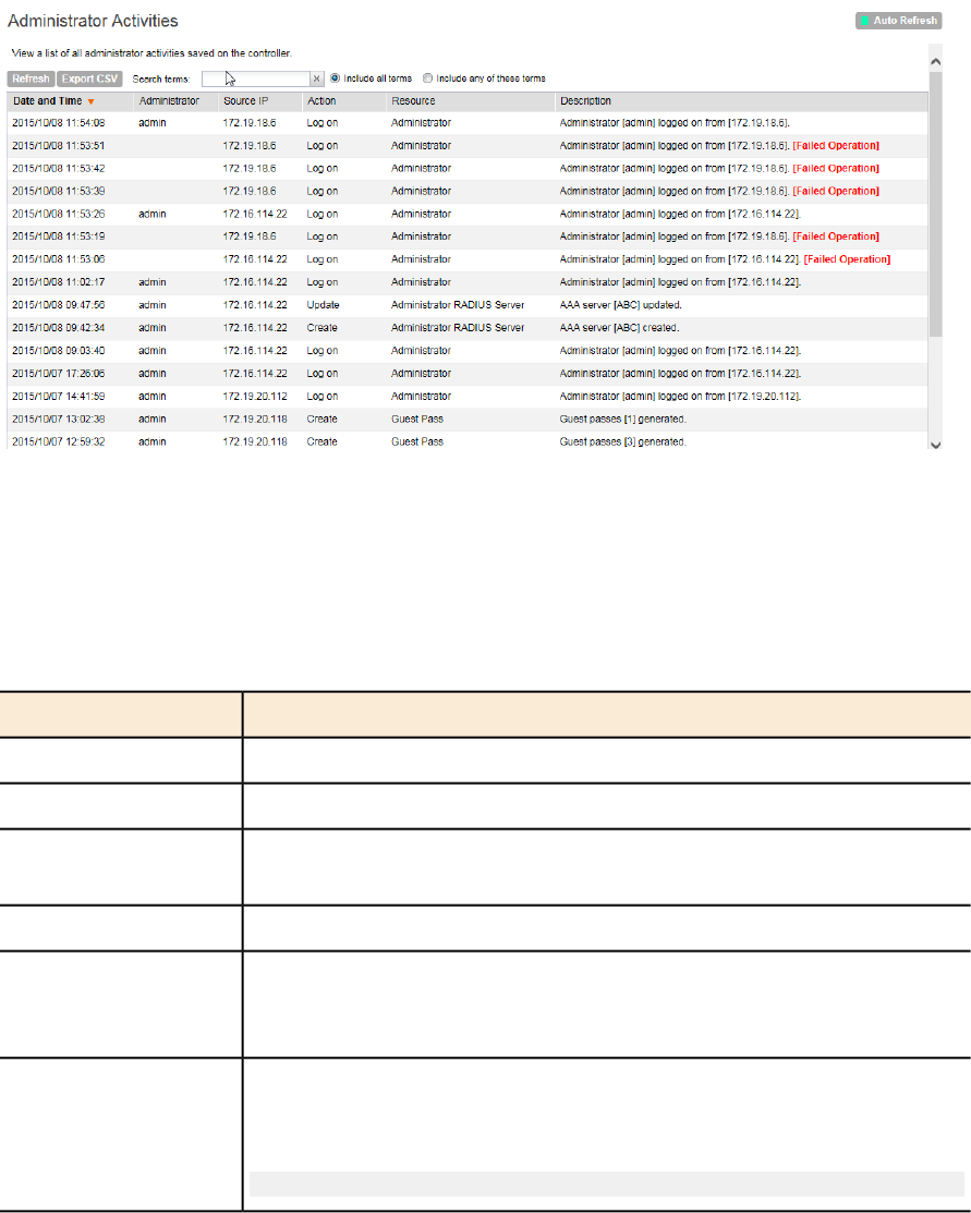
Figure 113: The Administrator Activities page displays the most recent administrator
actions
Table 13: Administrator activity details on page 183 lists the administrator activity details that are
displayed on the Administrator Activities page.
Table 13: Administrator activity details
DescriptionColumn Name
Date and time when the alarm was triggeredDate and Time
Name of the administrator who performed the actionAdministrator
IP address of the browser that the administrator used to log on to the
controller
Browser IP
Action performed by the administratorAction
Target of the action performed by the administrator. For example, if the
action is Create and the object is Hotspot Service, this means
that the administrator created a new hotspot service.
Resource
Displays additional details about the action. For example, if the
administrator created a new hotspot service, this column may show
the following:
Hotspot [company_hotspot] created
Description
Exporting the Administrator Activity List to CSV
Follow these steps to export the administrator activity list to a CSV file.
1. Go to Monitor > Administrator Activities.
2. Click the Export CSV button in the content area.
SmartZone 100/Virtual SmartZone Essentials for Release 3.2 Administrator Guide
183
Monitoring the Wireless Network
Monitoring Administrator Activities
3. Check the default download folder of your web browser and look for a file named
clients.csv.
4. Use a spreadsheet application (for example, Microsoft®Excel®) to view the contents of the
CSV file.
You have completed exporting the administrator activity list to CSV.
SmartZone 100/Virtual SmartZone Essentials for Release 3.2 Administrator Guide
184
Monitoring the Wireless Network
Monitoring Administrator Activities
7
Working with Reports
In this chapter:
•Types of Reports
•Creating a New Report
•Viewing a List of Existing Reports
•Deleting a Report
Types of Reports
The controller provides the following types of reports:
NOTE: The file name format of the Statistics file is as follows:
<report title>-YYYY-MM-DD_HH-MM-SS-MS_ZZ
where
MS stands for three-digit milliseconds.
ZZ is a random number to avoid the file name conflict when a user subscribes to several reports
but based on the same filter. ZZ ranges between 00-99.
For example: New_Client-2015-11-17_08-00-16-031_59.csv
Client Number Report
The Client Number report shows a historical view of the maximum and minimum number of
clients connect to the system.
Client number can be shown in different time intervals for a specified duration. The report can
be generated based on a specific AP, SSID, or radio.
Client Number vs Airtime Report
The Client Number vs Airtime report shows a historical view of the average number of clients
connected to the system and the corresponding airtime (TX, RX, Busy).
Client number and airtime can be shown in different time intervals for a specified duration. The
report can be generated based on a specific AP or radio.
SmartZone 100/Virtual SmartZone Essentials for Release 3.2 Administrator Guide
185
185
Continuously Disconnected APs Report
The Continuously Disconnected APs report shows a list of access points disconnected within
the specified time range.
Failed Client Associations Report
The Failed Client Associations report shows a historical view of the number of failed client
associations. Failed client associations can be shown in different time intervals for a specified
duration. The report can be generated based on a specific AP, SSID, or radio.
New Client Associations Report
The New Client Associations report shows a historical view of the number of new client
associations. New client Associations can be shown in different time intervals for a specified
duration. The report can be generated based on a specific AP, SSID, or radio.
System Resource Utilization Report
The System Resource Utilization report shows a historical view of the CPU and memory usage
of the system. The CPU and memory usage can be shown in different time intervals for a specific
duration. The report can be generated based on specific plane.
TX/RX Bytes Report
The TX/RX Bytes report shows a historical view of the transmitted (TX) and received (RX) bytes
of the system. The transmitted and received bytes can be shown in different time intervals for a
specified duration. The report can be generated based on a specific AP, SSID or radio.
Creating a New Report
Follow these steps to create a new report.
1. On the Saved Reports List page, click Create New.
The Create New Report form appears.
2. Complete the following steps to create a new report:
Step 1: Define the General Report Details
Defining general information is the first step to creating a new report. You would also need to
define the resource filter, time filter, generation schedule and enable email notifications.
Configure the following options in the General Information section.
1. Title: Type a name for the report that you are creating.
2. Description: Type a brief description for the report.
3. Report Type: Select the type of report that you want to create. For detailed description of
the various report types, refer to Types of Reports on page 185.
4. Output Format: Select the format in which the controller will generate the report. You can
select one or both of the following check boxes:
•CSV: A comma-separated version of the report. You will need a spreadsheet application
(for example, Microsoft®Excel®) to view the report in CSV format.
SmartZone 100/Virtual SmartZone Essentials for Release 3.2 Administrator Guide
186
Working with Reports
Creating a New Report
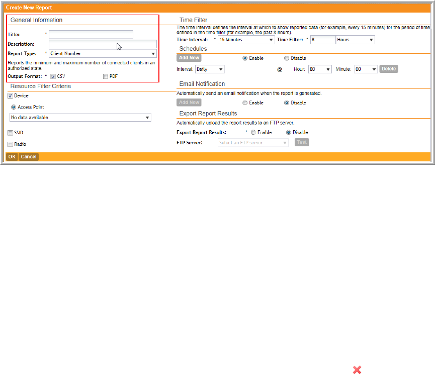
•PDF: A portable document format version of the report. You will need a PDF reader (for
example, Adobe®Acrobat™) to view the report in PDF.
Continue to Step 2: Define the Resource Filter Criteria on page 187.
Figure 114: The General Information section
Step 2: Define the Resource Filter Criteria
In this step, you will define the resources upon which the report that you are creating will be
generated.
Configure the following options in the Resource Filter Criteria section.
1. Device: Select one of the following device resources:
a) Access Point: If you base the report upon this device resource, you must select the name
of the specific access point from the drop-down list. You can only select one access point
to include in the report.
2. SSID: Select the SSID or SSIDs that you want to include in the report.
If you want to include multiple SSIDs in the report, select the SSIDs from the drop-down list
one at a time. To delete an SSID that you selected previously, click the icon next to the
SSID.
If you do not select an SSID, all existing SSIDs that belong to the device resource you selected
in Device will be included in the report.
3. Radio: Select the radio (2.4G or 5G) that you want to include in the report.
If you do not select a radio, both 2.4G and 5G radios belong to the device resource you
selected in Device will be included in the report.
You must select at least one resource. You can also select and define all three available
resources.
Continue to Step 3: Define the Time Filter on page 188.
SmartZone 100/Virtual SmartZone Essentials for Release 3.2 Administrator Guide
187
Working with Reports
Creating a New Report
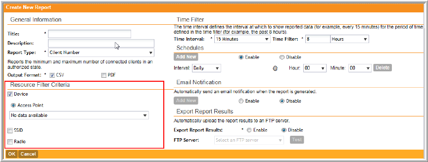
Figure 115: The Resource Filter Criteria section
Step 3: Define the Time Filter
In this step, you will define the time filter to use when generating the report. Configure the following
options in the Time Filter section.
1. Time Interval: Select the interval at which to generate the report. Available time interval
options include:
•15 Minutes
•Hourly
•Daily
•Monthly
2. Time Filter: Select the time or date period for which to generate the report. Depending on
the time interval that you set above, available periods include:
•Hours
•Days
•Months
The controller uses this time interval-time filter combination to determine the period from
which to generate the report and how often to generate it.
Continue to Step 4: Define the Report Generation Schedule on page 189.
SmartZone 100/Virtual SmartZone Essentials for Release 3.2 Administrator Guide
188
Working with Reports
Creating a New Report
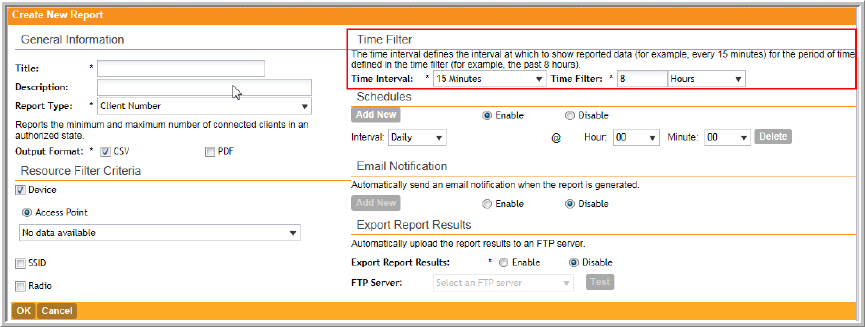
Figure 116: The Time Filter section
Step 4: Define the Report Generation Schedule
In this step, you will define the report generation schedule.
Configure the following options in the Schedules section.
1. In the Schedules section, click Add New.
2. In Interval, select one of the following time intervals:
•Monthly: If you select this interval, select the day of the month in Every when the controller
will generate the report.
•Weekly: If you select this interval, select the day of the week in Every when the controller
will generate the report.
•Daily
•Hourly
3. In @Hour (except when Hourly interval is selected above), select the hour of the day when
the controller will generate the report.
The controller uses the 24-hour clock format.
4. In Minute, select the minute of the hour when the controller will generate the report.
This minute setting will be used in conjunction with the hour setting that you selected above
(except when Hourly interval is selected).
5. If you want to add more schedules, click the Add New button again, and then repeat steps
2 on page 189 to 4 on page 189.
You can create as many schedules as required. Schedules may overlap if needed.
6. Continue to Step 5: Enable Email Notifications (Optional) on page 190.
SmartZone 100/Virtual SmartZone Essentials for Release 3.2 Administrator Guide
189
Working with Reports
Creating a New Report
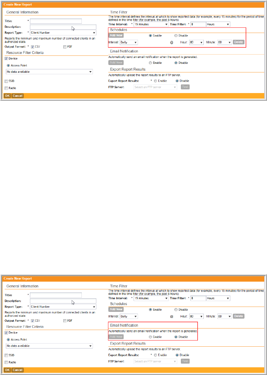
Figure 117: The Report Generation Schedule
Step 5: Enable Email Notifications (Optional)
In this optional step, you can configure the controller to send email notifications whenever a
report has been generated. Configure the following in the Email Notification section.
NOTE: Make sure you configure the SMTP settings (see Configuring an External Email Server
on page 139). If the SMTP settings are not configured, the controller will be unable to send out
email notifications even if you enable this feature in this section.
1. In the Email Notification section, click the Enable button.
2. In the text box below, type the email address to which to send the notification.
3. To add another email address, click Add New, and then type the second email address in
the text box that appears.
You can add as many email addresses as needed by clicking the Add New button, and then
typing an additional email address. Note, though, that you must only type a single email
address in each text box.
4. Continue to Step 6: Export the Report to an FTP Server (Optional) on page 191.
Figure 118: The Email Notification section
SmartZone 100/Virtual SmartZone Essentials for Release 3.2 Administrator Guide
190
Working with Reports
Creating a New Report
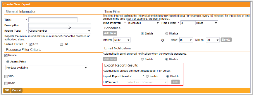
Step 6: Export the Report to an FTP Server (Optional)
In this optional step, you can configure the controller to automatically upload a copy of a report
to an external FTP server whenever it is generated. Configure the following in the Export Report
Results section.
1. In Export Report Results, click Enable.
2. In FTP Server, select the FTP server to which you want to automatically export the reports.
The FTP server options that appear here are those that you created in Configuring External
FTP Servers on page 140.
3. Continue to Step 7: Save the Report on page 191
Figure 119: The Export the Report to an FTP Server section
Step 7: Save the Report
After you complete steps 1 through 5, review the settings that you have configured to make
sure they are correct.
To save the report, click OK at the bottom of the page.
The page refreshes, and the report that you created appears in the Saved Report List page.
You have completed creating a report.
Viewing a List of Existing Reports
Follow these steps to view a list of reports that have been configured.
•Go to Report > Saved Reports. The Saved Report List page appears, displaying a summary
of all reports that have been configured. Summary details include:
•Title
•Description
•Report Template
•Time Filter
•Resource Filter
SmartZone 100/Virtual SmartZone Essentials for Release 3.2 Administrator Guide
191
Working with Reports
Viewing a List of Existing Reports
•Schedule
•Status
•Actions that you can perform
•To view a report, click the icon that is in the same row as the report name.
The Report Result page appears, displaying versions of the report that have been generated
based on the time interval defined in the report schedule.
•To download and view a comma-separated value (CSV) version of the report, click the CSV
link that is in the same row as the version that you want to view.
Deleting a Report
Follow these steps to delete an existing report.
1. Go to Report > Saved Reports .
The Saved Report List page appears, displaying a summary of all reports that have been
configured.
2. From the list of reports, locate the report that you want to delete.
3. Once you locate the report, click the icon that is under the Actions column. A confirmation
message appears.
4. Click OK.
The list of reports refreshes, and then the report that you deleted disappears from the list.
You have completed deleting a report.
SmartZone 100/Virtual SmartZone Essentials for Release 3.2 Administrator Guide
192
Working with Reports
Deleting a Report
8
Performing Administrative Tasks
In this chapter:
•Backing Up and Restoring Clusters
•Backing Up and Restoring the Controller's Network Configuration from an FTP Server
•Backing Up and Restoring System Configuration
•Resetting a Node to Factory Settings
•Upgrading the Controller
•Working with Logs
•Managing Licenses
Backing Up and Restoring Clusters
Back up the controller cluster periodically to ensure that you can restore the control plane, data
plane, and AP firmware versions as well as the system configuration in the cluster if is a system
failure occurs.
NOTE: If you are managing an SZ-100, you can also perform these procedures from the
command line interface. Note, however, that you will need to execute the commands on each
node. For more information, see the SmartZone 100 Command Line Interface Reference Guide.
Creating a Cluster Backup
Follow these steps to back up an entire controller cluster.
1. Take note of the current system time.
You can view the system time on the Configuration > System > System Time.
2. Go to Administration > Cluster Backup & Restore.
3. Click Back Up Entire Cluster.
A confirmation message appears.
4. Click Yes to confirm.
The following message appears: The cluster is in maintenance mode. Please
wait a few minutes.
When the cluster backup process is complete, a new entry appears in the Cluster Backups
section with a Created On value that is approximate to the time when you started the cluster
backup process.
If you have an FTP server, back up the entire cluster and upload the backup files from all the
nodes in a cluster to a remote FTP server.
You have completed backing up the controller cluster.
SmartZone 100/Virtual SmartZone Essentials for Release 3.2 Administrator Guide
193
193
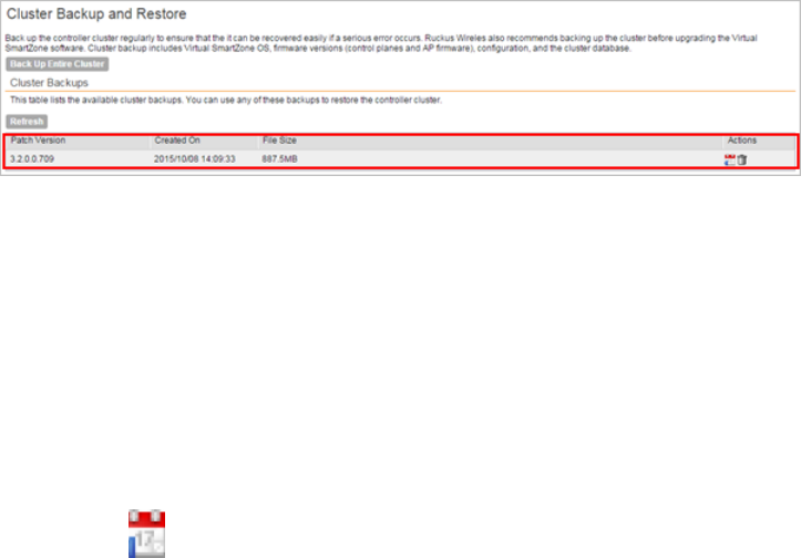
Figure 120: A new entry appears in the Cluster Backups section
Restoring a Cluster Backup
Follow these steps to restore a cluster backup.
CAUTION: You must perform the restore procedure on the exact same node where you generated
the cluster backup.
1. Go to Administration > Cluster Backup & Restore.
2. In the Cluster Backups section, locate the cluster backup that you want to restore.
3.
Click the icon that is in the same row as the cluster backup.
A confirmation message appears.
4. Click Yes.
The page refreshes, and then a message appears, informing you that the controller will reboot
itself. It also show you the progress status.
NOTE: The cluster restore process may take several minutes to complete.
When the restore process is complete, the controller logs you off the web interface
automatically.
CAUTION: Do not refresh the controller web interface while the restore process is in progress.
Wait for the restore process to complete successfully.
5. Log back on to the controller web interface.
NOTE: If the web interface displays the message Cluster is out of service.
Please try again in a few minutes. appears after you log on to the controller
web interface, wait for about three minutes. The dashboard will appear shortly. The message
appears because the controller is still initializing its processes.
6. Go to Administration > Upgrade
7. Check the Current System Information section and verify that all nodes in the cluster have
been restored to the previous version and are all in service.
8. Go to Administration > Diagnostics.
9. Click Application Logs & Status on the sidebar.
10. Check the Health Status column and verify that all of the controller processes are online.
(see #unique_247/unique_247_Connect_42_ID-2530-00000079 on page 195)
SmartZone 100/Virtual SmartZone Essentials for Release 3.2 Administrator Guide
194
Performing Administrative Tasks
Backing Up and Restoring Clusters
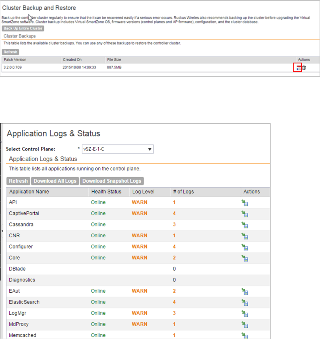
You have completed restoring the cluster backup.
Figure 121: Under Actions, click the calendar icon to start the cluster restore process
Figure 122: After the upgrade is complete, go to the Application Logs & Status page and
verify that all of the controller processes are online
Deleting a Cluster Backup
Follow these steps to delete a cluster backup.
1. Go to Administration > Cluster Backup and Restore.
SmartZone 100/Virtual SmartZone Essentials for Release 3.2 Administrator Guide
195
Performing Administrative Tasks
Backing Up and Restoring Clusters
2. In the Cluster Backups section, locate the cluster backup that you want to delete.
3. Click the icon that is in the same row as the cluster backup.
The following confirmation message appears: Are you sure you want to delete
the selected resource?
4. Click Yes.
The page refreshes and the row is deleted from the Cluster Backups list.
Backing Up and Restoring the Controller's Network
Configuration from an FTP Server
In addition to backing up and restoring the controller's network configuration from its own
database, the controller supports backup and restore of its network configuration from an FTP
server using the CLI.
This section describes the requirements for backing up and restoring the controller network
configuration from an FTP server, the information that is included in the backup file, and how to
perform the backup and restore process.
Requirements
To back up and restore the controller network configuration from an FTP server, the controller
must have already been set up and in service. In case of a multi-node cluster, all the nodes in
the cluster must be in service.
Backing Up to an FTP Server
Follow these steps to back up the controller network configuration to an FTP server.
1. Log on to the controller from the CLI.
2. At the prompt, enter en to enable privileged mode.
SmartZone 100/Virtual SmartZone Essentials for Release 3.2 Administrator Guide
196
Performing Administrative Tasks
Backing Up and Restoring the Controller's Network Configuration from an FTP Server
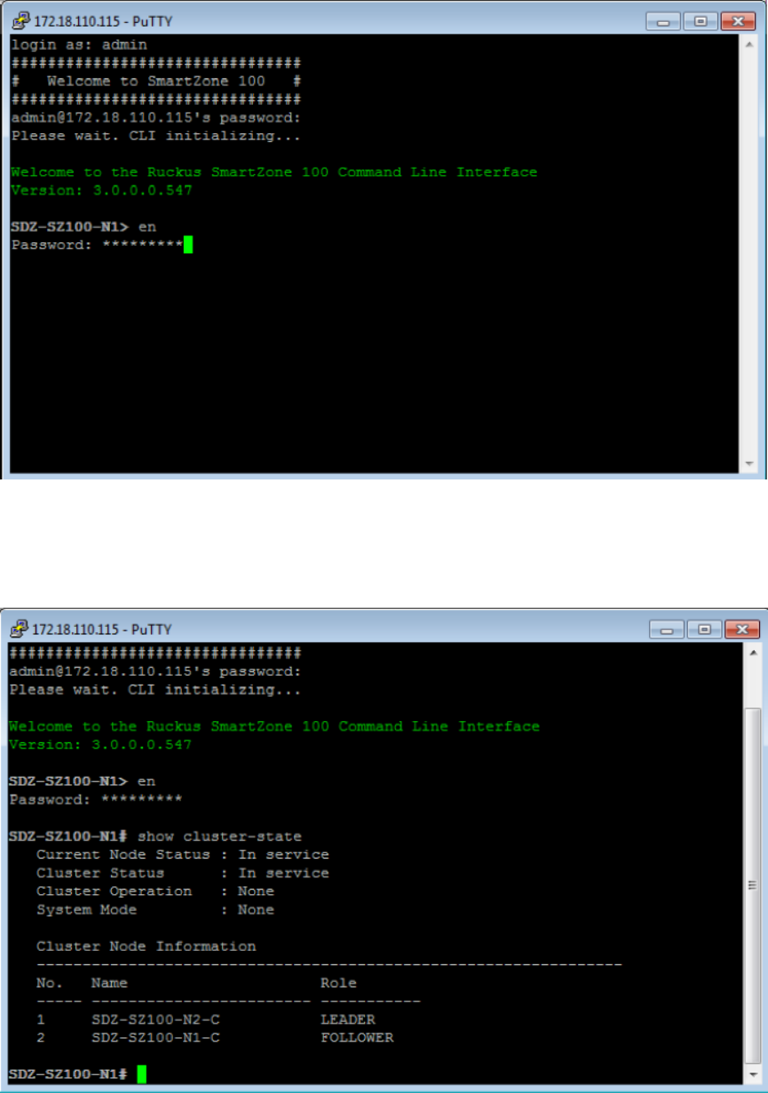
Figure 123: Enable privileged mode
3. Enter show cluster-state to display the statuses of the node and the cluster. Before
continuing to the next step, verify that both the node and the cluster are in service.
Figure 124: Verify that both the node and the cluster are in service
SmartZone 100/Virtual SmartZone Essentials for Release 3.2 Administrator Guide
197
Performing Administrative Tasks
Backing Up and Restoring the Controller's Network Configuration from an FTP Server
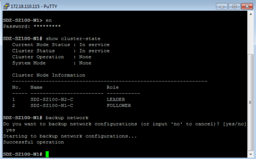
4. Enter backup network to back up the controller network configuration.
A confirmation message appears.
5. Enter yes to confirm.
The controller creates a backup of its network configuration on its database.
Figure 125: Enter yes to confirm that you want to back up the controller configuration
6. Enter show backup-network to view a list of backup files that have been created.
7. Verify that the Created On column displays an entry that has a time stamp that is approximate
to the time you started the backup.
SmartZone 100/Virtual SmartZone Essentials for Release 3.2 Administrator Guide
198
Performing Administrative Tasks
Backing Up and Restoring the Controller's Network Configuration from an FTP Server
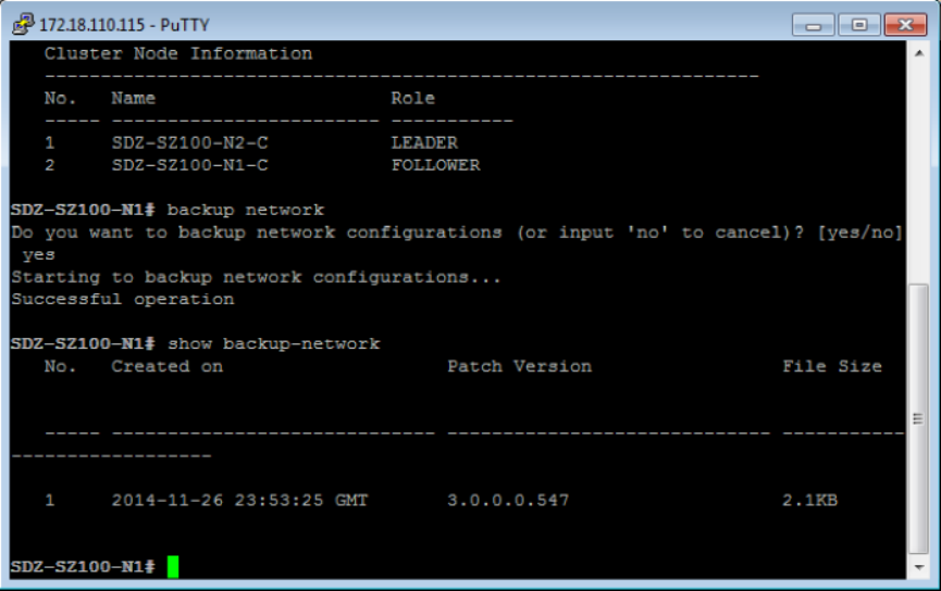
Figure 126: Enter the show backup-network command
8. Enter copy backup-network ftp-url, where ftp-url is the URL or IP address of the
FTP server to which you want to back up the cluster configuration.
The console prompts you to choose the number that corresponds to the backup file that you
want to export to the FTP server.
9. Enter the number of the backup file that you want to export to the FTP server.
SmartZone 100/Virtual SmartZone Essentials for Release 3.2 Administrator Guide
199
Performing Administrative Tasks
Backing Up and Restoring the Controller's Network Configuration from an FTP Server
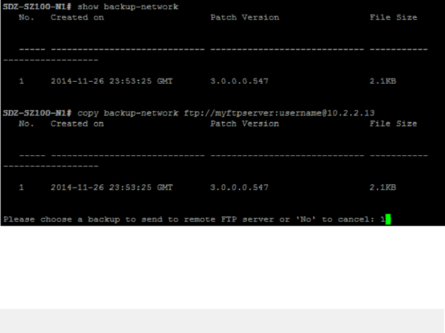
Figure 127: Enter the number that corresponds to the backup file that you want to
export to the FTP server
The controller encrypts the backup file, and then exports it to the FTP server. When the export
process is complete, the following message appears on the CLI:
Succeed to copy to remote FTP server
Successful operation
10. Using an FTP client, log on to the FTP server, and then verify that the backup file exists.
The file format of the backup file is
network_<YYYYMMDDHHmmss>_<controller-version>.bak.
For example, if you created the backup file on October 24th 2013 at 02:40:22 and the
controller version is 2.5.0.0.402, you should see a file named
network_20131024024022_2.5.0.0.402.bak on the FTP server.
You have completed backing up the controller to an FTP server.
Restoring from an FTP Server
Before you continue, take note of the following limitations with restoring a backup file of the
controller's network configuration from an FTP server:
•In this current release, restoring the entire cluster from an FTP server is unsupported. The
restore process must be performed on one node at a time.
•Restoring from an FTP server can only be performed using the CLI.
CAUTION: Restoring a backup file to the controller requires restarting all of the controller services.
Follow these steps to restore a backup file of the controller network configuration that you
previously uploaded to an FTP back to the controller.
1. Log on to the controller from the CLI.
SmartZone 100/Virtual SmartZone Essentials for Release 3.2 Administrator Guide
200
Performing Administrative Tasks
Backing Up and Restoring the Controller's Network Configuration from an FTP Server
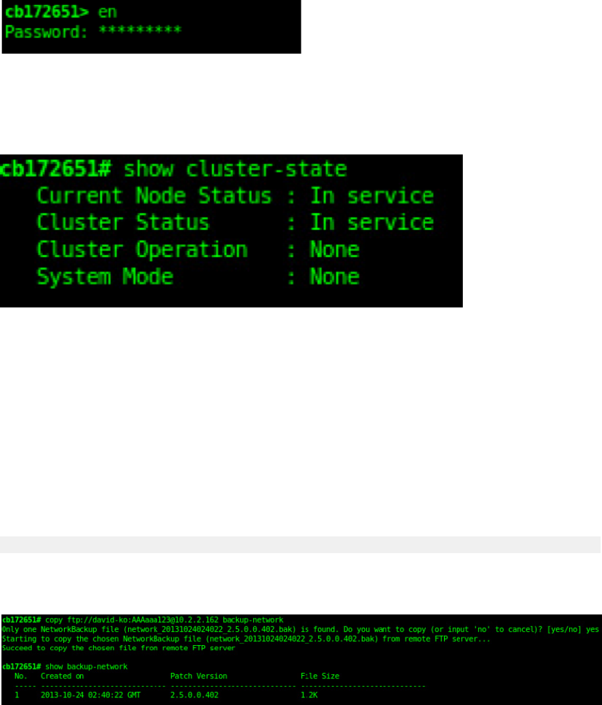
2. At the prompt, enter en to enable privileged mode.
Figure 128: Enable privileged mode
3. Enter show cluster-state to display the statuses of the node and the cluster. Before
continuing to the next step, verify that both the node and the cluster are in service.
Figure 129: Verify that both the node and the cluster are in service
4. Enter the following command to log on to the FTP server and check for available backup files
that can be copied to the controller: copy <ftp-url> backup-network
If multiple backup files exist on the FTP server, the CLI prompts you to select the number
that corresponds to the file that you want to copy back to the controller. If a single backup
file exists, the CLI prompts you to confirm that you want to copy the existing backup file to
the controller.
When the controller finishes copying the selected backup file from the FTP server back to
the controller, the following message appears:
Succeed to copy the chosen file from the remote FTP server
5. Enter show backup-network to verify that the backup file was copied back to the controller
successfully.
Figure 130: Verify that the backup file was copied to the controller successfully
6. Run restore network to start restoring the contents of the backup file to the current
controller.
The CLI displays a list of backup files, and then prompts you to select the backup file that
you want to restore to the controller.
SmartZone 100/Virtual SmartZone Essentials for Release 3.2 Administrator Guide
201
Performing Administrative Tasks
Backing Up and Restoring the Controller's Network Configuration from an FTP Server
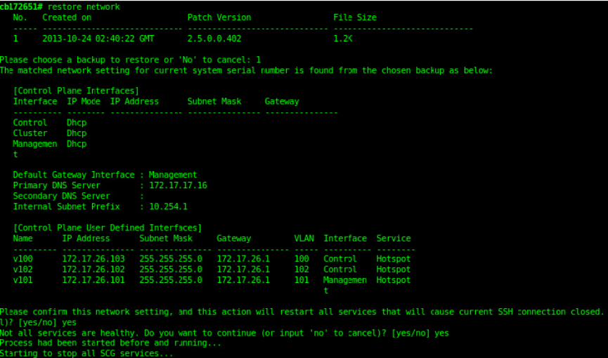
7. Enter the number that corresponds to the backup file that you want to restore. The CLI
displays the network configuration that the selected backup file contains.
Figure 131: Enter the number that corresponds to the backup file that you want to
restore
If the serial number of the current controller matches the serial number contained in one of
the backup files, the CLI automatically selects the backup file to restore and displays the
network configuration that it contains.
8. Type yes to confirm that you want to restore the selected backup file. The controller starts
the restore process and performs the following steps:
a) Stop all services.
b) Back up the current network configuration.
This will enable the controller to roll back to the current configuration, in case there is an
issue with the restore process.
c) Clean up the current network configuration.
The controller deletes its previous network configuration, including static routes, name
server, user defined interfaces, etc.
d) Restore the network configuration contained in the selected backup file.
e) Restart all services.
When the restore process is complete, the following message appears on the CLI: All
services are up!
SmartZone 100/Virtual SmartZone Essentials for Release 3.2 Administrator Guide
202
Performing Administrative Tasks
Backing Up and Restoring the Controller's Network Configuration from an FTP Server
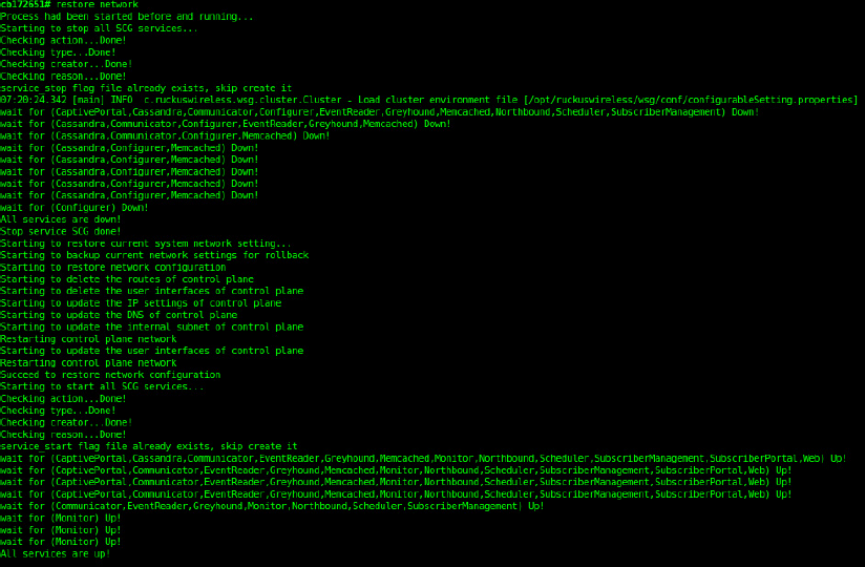
Figure 132: The controller performs several steps to restore the backup file
9. Do the following to verify that the restore process was completed successfully:
a) Run show cluster-state to verify that the node and the cluster are back in service.
b) Run show interface to verify that all of the network configuration settings have been restored.
SmartZone 100/Virtual SmartZone Essentials for Release 3.2 Administrator Guide
203
Performing Administrative Tasks
Backing Up and Restoring the Controller's Network Configuration from an FTP Server
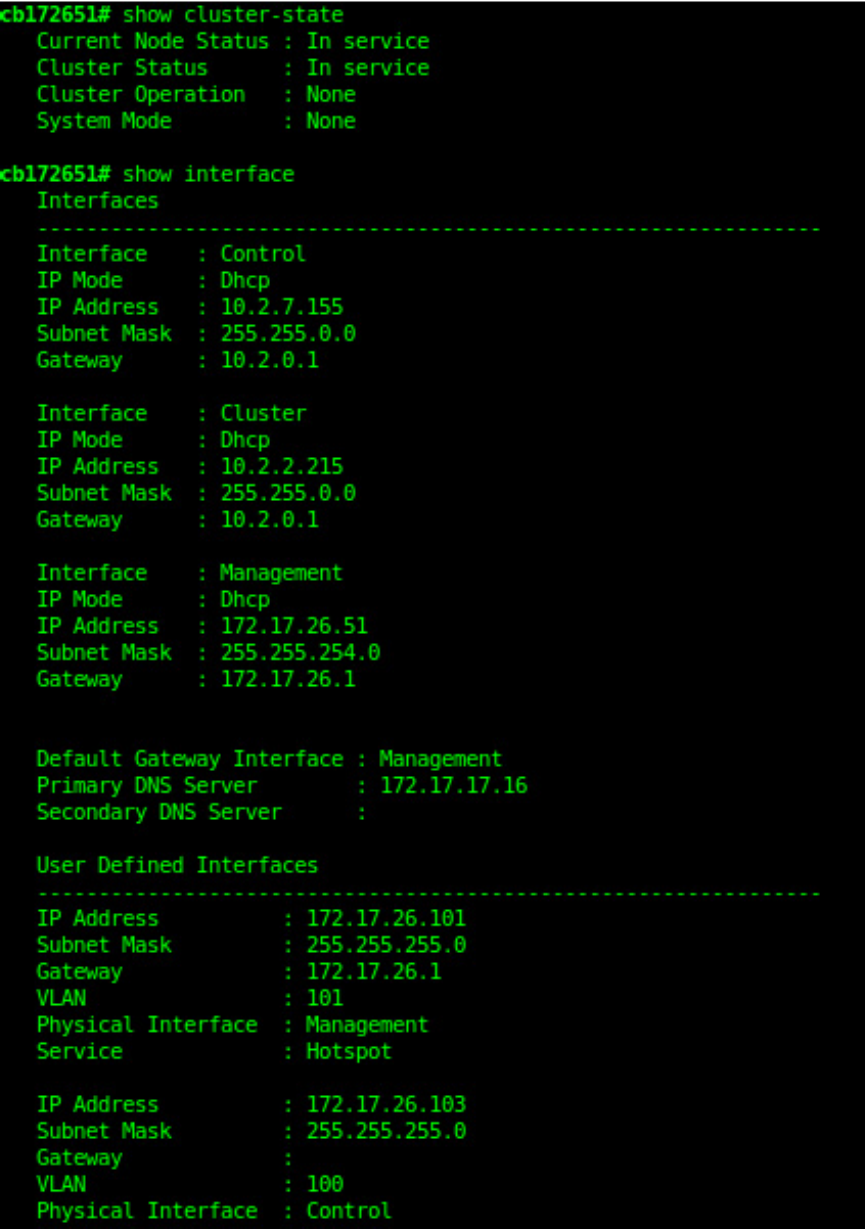
Figure 133: Verify that the node and cluster are back in service and that the network
SmartZone 100/Virtual SmartZone Essentials for Release 3.2 Administrator Guide
204
Performing Administrative Tasks
Backing Up and Restoring the Controller's Network Configuration from an FTP Server
configuration has been restored successfully
You have completed importing and applying the network configuration backup from the FTP
server to the controller.
Backing Up and Restoring System Configuration
Ruckus Wireless strongly recommends that you back up the controller database periodically.
This will help ensure that you can restore the system configuration settings easily if the database
becomes corrupted for any reason.
Table 14: What's backed up in the system configuration backup file on page 205 lists the
information that is included in the system configuration backup file.
Table 14: What's backed up in the system configuration backup file
Identity DataReport DataAdministration DataConfiguration Data
•Created user
accounts
•Saved reports•Cluster backups•Services and
profiles •• Historical client
statistics
System
configuration
backups
• •System settings Generated guest
passes
•• Network tunnel
statistics
Administrator
accounts •Upgrade settings
and history
•Uploaded system
diagnostic scripts
•Installed licenses
CAUTION: A system configuration backup does not include control plane settings and
user-defined interface settings.
NOTE: If you are managing an SZ-100, you can also perform system configuration backup and
restore from the controller's command line interface. For more information, see the SmartZone
100 Command Line Interface Reference Guide.
Creating a System Configuration Backup
Follow these steps to create a backup of the controller database.
1. Go to Administration > Configuration Backup and Restore.
2. Click Back Up Configuration.
The following confirmation message appears: Are you sure you want to backup
the controller's configuration?
3. Click OK.
A progress bar appears as the controller creates a backup of the its database.
SmartZone 100/Virtual SmartZone Essentials for Release 3.2 Administrator Guide
205
Performing Administrative Tasks
Backing Up and Restoring System Configuration
When the backup process is complete, the progress bar disappears, and the Configuration
Backup Status section appears and shows the following information:
•Latest backup started: Date and time when configuration backup was initiated
•Finished at: Date and time when configuration backup was completed
•Status: Shows either Successful or Failed
•Progress Status: Shows the current status of the backup process
The backup file appears under the System Configuration Backups section.
Exporting the Configuration Backup to an FTP Server Automatically
In addition to backing up the configuration file manually, you can configure the controller to
export the configuration file to an FTP server automatically whenever you click Back Up
Configuration.
Follow these steps to back up the configuration file to an FTP server automatically.
1. Go to Administration > System Configuration Backup and Restore.
2. Go to the Auto Export Backup section.
3. In Auto Export Backup, click Enable.
4. In FTP Server, select the FTP server to which you want to export the backup file.
The FTP server options that appear here are those that you created in Configuring External
FTP Servers on page 140.
5. Click Test.
The controller attempts to establish connection to the FTP server using the user name and
password that you supplied. If the connection attempt is successful, the following message
appears: FTP server connection established successfully.
If the connection attempt is unsuccessful, verify that the FTP server details (including the user
name and password) are correct, and then click Test again.
6. After you verify the controller is able to connect to the FTP server successfully, click Apply
to save the FTP server settings.
You have completed configuring the controller to export the configuration backup file to an FTP
server. When you click the Back Up Configuration button (see Creating a System Configuration
Backup), a copy of the configuration backup will be uploaded to the FTP server automatically.
Scheduling a Configuration Backup
You also have the option to configure the controller to backup its configuration automatically
based on a schedule you specify.
Follow these steps to schedule a configuration backup.
1. Go to Administration > Configuration Backup and Restore.
2. Scroll down to the Schedule Backup section.
3. In Schedule Backup, click Enable.
SmartZone 100/Virtual SmartZone Essentials for Release 3.2 Administrator Guide
206
Performing Administrative Tasks
Backing Up and Restoring System Configuration
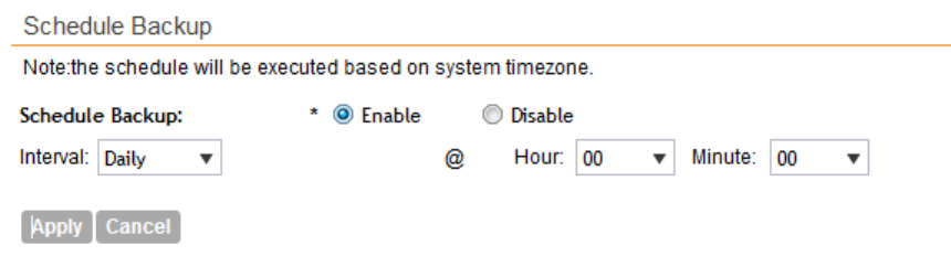
4. In Interval, set the schedule when the controller will automatically create a backup of its
configuration. Options include:
•Daily
•Weekly
•Monthly
5. Define the schedule further by configuring the following options:
•Every: If you selected Weekly in the previous step, select the day of the week when the
controller will generate the backup. If you selected Monthly, select the day of the month.
•Hour: Select the hour of the day when the controller will generate the backup.
•Minute: Select the minute of the hour.
6. Click Apply.
You have completed configuring the controller to create a backup automatically. When a
scheduled configuration backup is generated, it appears in the System Configuration Backups
section.
Figure 134: Configure the schedule in the Schedule Backup section
Downloading a Copy of the Configuration Backup
After you create a configuration backup, you have the option to download the backup file from
the System Configuration Backups section.
Follow these steps to download the backup file to the computer that you are using to access
the controller web interface.
1. Go to Administration > System Configuration Backup and Restore.
2. Scroll down to the System Configuration Backups section.
3. Locate the entry for the backup file that you want to download.
If multiple backup files appear in the list, use the date when you created the backup to find
the backup entry that you want.
4. Click the icon that is in the same row as the backup file that you want to download.
Your web browser downloads the backup file to its default download folder.
SmartZone 100/Virtual SmartZone Essentials for Release 3.2 Administrator Guide
207
Performing Administrative Tasks
Backing Up and Restoring System Configuration
5. Check the default download folder for your web browser and look for a file that resembles
the following naming convention: {Cluster
Name}_BackupConf_{MMdd}_db_{MM}_{dd}_{HH}_{mm}.bak
For example, if the controller cluster is named ClusterA and you created the configuration
backup on September 7 at 11:08 AM, the backup file name will be:
ClusterA_BackupConf_0907_db_09_07_11_08.bak
You have completed downloading a copy of the configuration backup.
Restoring a System Configuration Backup
Follow these steps to restore a backup controller database.
1. Go to Administration > Configuration Backup and Restore.
2. In the System Configuration Backups section, locate the backup file that you want to
restore.
3. Once you locate the backup file, click the icon that is in the same row as the backup file.
A confirmation message appears.
Take note of the backup version that you are using. At the end of this procedure, you will use
the backup version to verify that the restore process was completed successfully.
4. Click Yes.
The following message appears: System is restoring. Please wait...
When the restore process is complete, the controller logs you off the web interface
automatically.
5. Log on to the controller web interface.
6. Check the web interface pages (for example, Configuration, Report, and Identity) and verify
that the settings and data contained in the backup file have been restored successfully to
the controller.
You have completed restoring a system configuration backup file.
Deleting a Configuration Backup
Follow these steps to delete a backup of the controller database
1. Go to Administration > Configuration Backup and Restore.
2. In the System Configuration Backups section, locate the backup version that you want to
delete.
3. Once you locate the backup file, click the icon under the Actions column.
A confirmation message appears.
4. Click Yes.
The page refreshes, and the backup file that you deleted disappears from the System
Configuration Backups section.
You have completed deleting a backup file.
SmartZone 100/Virtual SmartZone Essentials for Release 3.2 Administrator Guide
208
Performing Administrative Tasks
Backing Up and Restoring System Configuration
Resetting a Node to Factory Settings
You can reset a node in a cluster to factory settings by removing it from the cluster. When you
reset a node to factory settings, all of its system configuration settings are completely erased
and its IP address reverts to 192.168.2.2.
CAUTION: Resetting a node to factory settings will erase all of its system configuration settings,
backup files, and cluster settings. Before resetting a node to factory settings, Ruckus Wireless
strongly recommends that you export all of the backup files on the controller to an FTP server
using either the web interface or CLI.
What Happens After Reset to Factory Settings
Before resetting a node to factory settings, consider the following notes:
•All of the system configuration settings of the node will be erased. This includes all of the
domain,, user, and system settings, as well as all of the controller backups.
•The node will revert to its default IP address – 192.168.2.2.
•The controller software version will not be reset to its original software version when you first
set it up. It will keep the existing software version at the time you reset it to factory settings.
There are two methods to reset a node to factory settings:
Using the Web Interface
To remove a node from a cluster, it must be a follower node. If the node that you want to remove
from the cluster is the leader node, make sure you demote it to a follower node first before
continuing with this procedure.
Follow these steps to remove a node from the cluster and reset it to factory settings.
1. Log on to the controller web interface of the leader node.
2. Go to Configuration > System > Network Settings.
The Cluster: [{Cluster Name}] page appears.
3. Locate the node that you want to reset.
4. Click the icon that is in the same row as the node that you want to reset to factory settings.
A confirmation message appears.
5. Click Yes.
The page refreshes, and then the node the you deleted disappears from the Cluster: [{Cluster
Name}] page.
You have completed removing a node from the cluster and resetting it to factory settings.
After the controller is reset to factory settings, the controller allows the data blade interface IP
address and gateway address to be on different subnets.
SmartZone 100/Virtual SmartZone Essentials for Release 3.2 Administrator Guide
209
Performing Administrative Tasks
Resetting a Node to Factory Settings
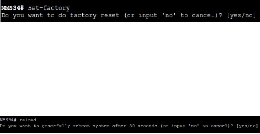
Using the CLI
You can also use the command line interface to remove a node from a cluster and reset it to
factory settings.
After you log on to the CLI of the node, follow these steps to reset a node to factory settings.
1. At the prompt, enter set-factory.
Figure 135: Enter set-factory to reset the node to factory settings
A confirmation message appears.
2. Enter yes to confirm.
3. Enter reload.
This command is required to trigger the factory reset process.
A confirmation message appears.
4. Enter yes to confirm.
Figure 136: Enter reload to trigger the factory reset process
The controller reboots, and then triggers the factory reset process.
The controller reboots. You have completed resetting the node to factory default settings.
Upgrading the Controller
Ruckus Wireless may periodically release controller software updates that contain new features,
enhancements, and fixes for known issues. These software updates may be made available on
the Ruckus Wireless support website or released through authorized channels.
CAUTION: Although the software upgrade process has been designed to preserve all controller
settings, Ruckus Wireless strongly recommends that you back up the cluster before performing
an upgrade. Having a cluster backup will ensure that you can easily restore the system if the
upgrade process fails for any reason. For information on how to back up the cluster, refer to
Creating a Cluster Backup on page 193.
CAUTION: Ruckus Wireless strongly recommends that you ensure that all interface cables are
intact during the upgrade procedure.
SmartZone 100/Virtual SmartZone Essentials for Release 3.2 Administrator Guide
210
Performing Administrative Tasks
Upgrading the Controller
CAUTION: Ruckus Wireless strongly recommends that you ensure that the power supply is not
disrupted during the upgrade procedure.
NOTE: If you are managing an SZ-100, you can also perform system configuration backup,
restore, and upgrade from the controller's command line interface. For more information, see
the SmartZone 100 Command Line Interface Reference Guide.
Performing the Upgrade
Follow these steps to upgrade the controller software.
CAUTION: Ruckus Wireless strongly recommends backing up the cluster before performing the
upgrade. If the upgrade process fails for any reason, you can use the latest backup file to restore
the cluster. See Backing Up and Restoring Clusters on page 193.
NOTE: Before starting this procedure, you should have already obtained a valid controller software
upgrade file from Ruckus Wireless Support or an authorized reseller.
1. Copy the software upgrade file that you received from Ruckus Wireless to the computer
where you are accessing the controller web interface or to any location on the network that
is accessible from the web interface.
2. Go to Administration > Upgrade.
3. In the Patch File Upload section, click the Browse button, and then browse to the location
of the software upgrade file.
Typically, the file name of the software upgrade file is SZ-installer_{version}.ximg.
4. Select the software upgrade file, and then click Open.
5. Click Upload to upload the software upgrade file.
The controller uploads the file to its database, and then performs file verification.
After the file is verified, the Upgrade Pending Patch Information section is populated with
information about the upgrade file. The Upgrade and Backup & Upgrade buttons also
appear in this section.
6. Start the upgrade process by clicking one of the following buttons:
CAUTION: Ruckus Wireless strongly recommends usage of backup and upgrade icon while
performing the upgrade. If the upgrade process fails for any reason, you can use the latest
backup file to restore the cluster. See Backing Up and Restoring Clusters on page 193.
•Upgrade: Click this button to start the upgrade process without backing up the current
cluster or its system configuration.
•Backup & Upgrade: Click this button to back up the cluster and system configuration
before performing the upgrade.
A confirmation message appears.
7. Click Yes.
SmartZone 100/Virtual SmartZone Essentials for Release 3.2 Administrator Guide
211
Performing Administrative Tasks
Upgrading the Controller
The controller starts the process that you selected. The screens that appear next will depend
on the process that you selected to upgrade immediately or to back up and then upgrade
the controller.
When the upgrade (or backup-and-upgrade) process is complete, the controller logs you off the
web interface automatically. The controller web interface may display the The system is
down... message as it completes the upgrade process. Wait for a few minutes until the web
interface log on page appears.
When the controller's logon page appears again, you have completed performing the upgrade.
Continue to Verifying the Upgrade on page 212 to check if the upgrade was completed
successfully.
Verifying the Upgrade
Follow these steps to verify that the controller upgrade was completed successfully.
1. Log on to the controller web interface.
2. Go to Administration > Upgrade.
3. In the Current System Information section, check the value for Controller Version.
If the firmware version is newer than the firmware version that the controller was using before
you started the upgrade process, then the upgrade process was completed successfully.
Rolling Back to a Previous Software Version
There are two scenarios in which you may want to roll back the controller software to a previous
version:
1. You encounter issues during the software upgrade process and the controller cannot be
upgraded successfully. In this scenario, you can only perform the software rollback from the
CLI using the restore local command. If you have a two-node cluster, run the restore local
command on each of the nodes to restore them to the previous software before attempting
to upgrade them again.
2. You prefer a previous software version to the newer version to which you have upgraded
successfully. For example, you feel that the controller does not operate normally after you
upgraded to the newer version and you want to restore the previous software version, which
was more stable. In this scenario, you can perform the software rollback either from the web
interface or the CLI. If you have a two-node cluster, you must have cluster backup on both
of the nodes.
To ensure that you will be able to roll back to a previous version, Ruckus Wireless strongly
recommends the following before attempting to upgrade the controller software:
•Always back up the controller before attempting a software upgrade. If you are managing a
multi-node cluster, back up the entire cluster, and then verify that the backup process
completes successfully. See Creating a Cluster Backup on page 193 for the local backup
instructions. If you have a local backup and you want to roll back the controller to a previous
software version, follow the same procedure described in Restoring a Cluster Backup on
page 194.
•f you have an FTP server, back up the entire cluster and upload the backup files from all the
nodes in a cluster to a remote FTP server. See Backing Up to an FTP Server on page 196 for
SmartZone 100/Virtual SmartZone Essentials for Release 3.2 Administrator Guide
212
Performing Administrative Tasks
Upgrading the Controller
remote backup instructions and Restoring from an FTP Server on page 200for remote restore
instructions.
Recovering a Cluster from an Unsuccessful Upgrade
If an issue occurs during the upgrade process (for example, a power outage occurs or one of
the interfaces goes down), you can recover the cluster if the controller has either a local cluster
backup or a remote (FTP) configuration backup.
If the Controller Has Local Cluster Backup
Follow these steps to recover a cluster when the controller has a cluster backup stored locally.
1. Unplug the cluster interface cables of each node in the cluster to isolate each individual node.
2. On each of the nodes in the cluster, perform the following:
a) Log on to the CLI, and then execute restore local.
This command will restore the system configuration of the node from a local backup.
b) When the CLI indicates that the restore local command has been completed successfully,
plug in the cluster interface cable.
You have completed recovering the controller cluster using a local cluster backup.
If the Controller Has an FTP Backup
Follow these steps to recover a cluster when the controller has a configuration backup on a
remote FTP server.
See Backing Up to an FTP Server on page 196 for more information.
You must perform steps on each of the nodes in the cluster.
1. Log on to the CLI of each of the nodes.
2. Execute the set-factory command to reset the node to factory settings.
See Resetting a Node to Factory Settings on page 209 for more information.
3. Using the CLI, set up the controller as a standalone unit.
4. Copy the cluster configuration backup from the FTP server to the controller.
5. Execute the restore local command from the CLI.
6. When the CLI indicates that the restore local command has been completed successfully,
plug in the cluster interface cable.
Repeat the same procedure until you have restore the cluster configuration backup from the
FTP server to all of the nodes in the cluster.
You have completed recovering the controller cluster using an FTP backup.
SmartZone 100/Virtual SmartZone Essentials for Release 3.2 Administrator Guide
213
Performing Administrative Tasks
Upgrading the Controller
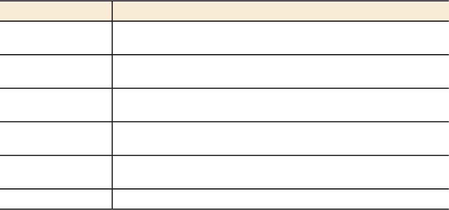
Upgrading the vSZ-D
You can upgrade the firmware of a vSZ-D from time to time as Ruckus Wireless release new
versions of the firmware with additional features.
1. Copy the patch upgrade file that you want to use to upgrade vSZ-D to the computer where
you are accessing the controller web interface or to any location on the network that is
accessible from the web interface.
2. Go to Administration > Upgrade vSZ-D.
3. Click Browse, and browse to the location of the patch upgrade file with the extension .ximg.
4. Select the patch upgrade file, and then click Open.
5. Click Upload to upload the file.
vSZ-D uploads the file to its database, and then performs file verification.
After the file is verified, the Patch Information section is populated with information about
the upgrade file. If the verification was successful, this message appears: Successfully
verified upgrade eligibility. Please go ahead to upgrade vSZ-D.
6. Start the upgrade process by selecting an upgrade version from Select upgrade version.
7. From table, select the vSZ-D that you want to upgrade and click Apply.
The new firmware is applied to the selected vSZ-D.
8. Click Yes.
Working with Logs
This section describes the logs that are available in the controller and how to download them.
Available System Log Types
The controller generates logs for all the applications that are running on the server.
Table 15: Controller applications and log types
DescriptionApplication
Stands for application program interface (API), this provides an interface
for customers to configure and monitor the system
API
Performs portal redirect for clients and manages the walled garden and
blacklist
CaptivePortal
The controller's database server that stores most of the run-time
information and statistical data
Cassandra
An application that obtains TTG configuration updates and applies the
settings to related modules
CNR
Performs configuration synchronization and cluster operations (for
example, join, remove, upgrade, backup, and restore)
Configurer
Consolidates applications to save memoryCore
SmartZone 100/Virtual SmartZone Essentials for Release 3.2 Administrator Guide
214
Performing Administrative Tasks
Working with Logs
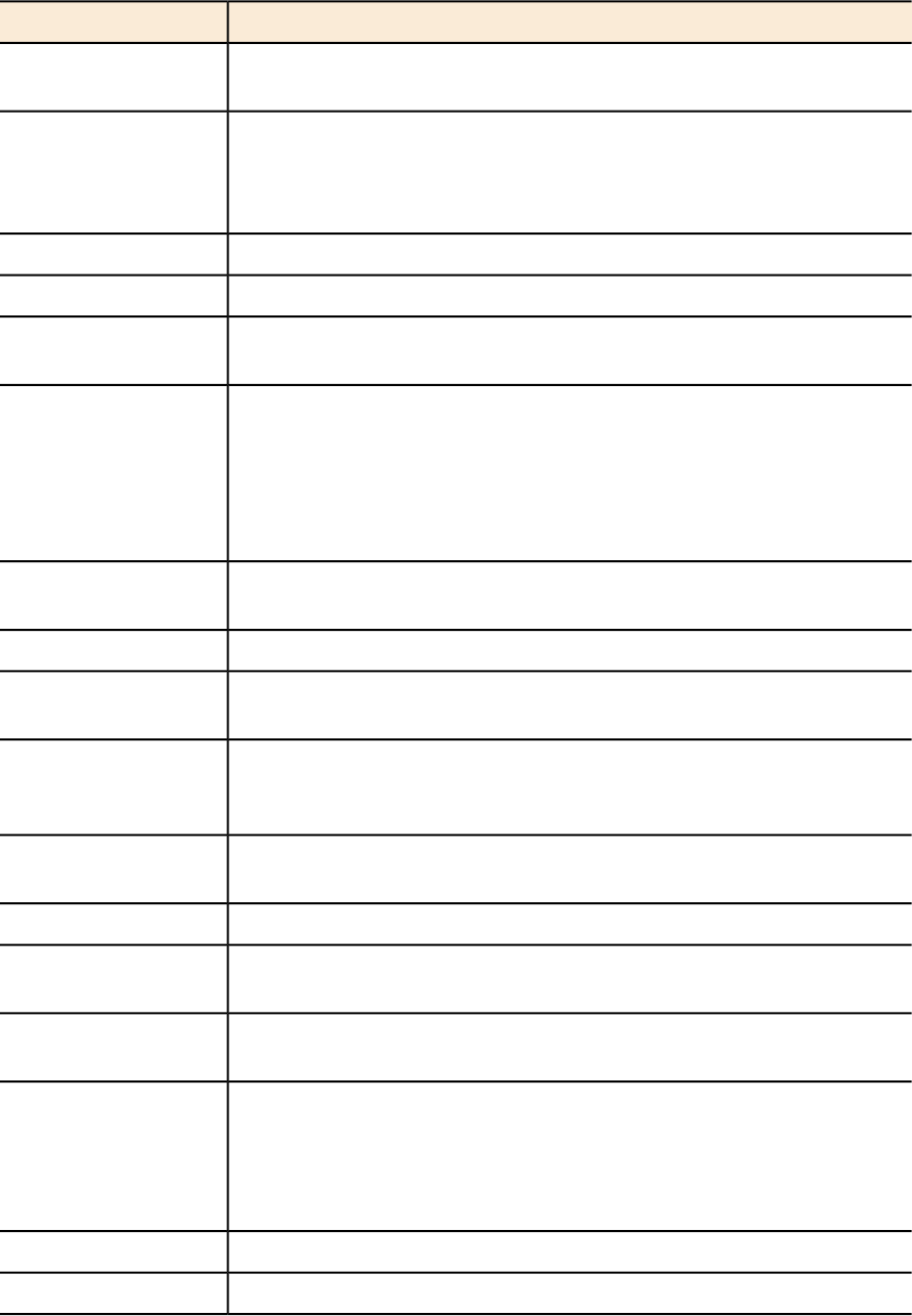
DescriptionApplication
The data plane application and data core logs are sent to the control
plane through the syslog. DBlade lists the logs in the control plane.
DBlade
An interface that can be use to upload Ruckus Wireless scripts (.ksp
files) for troubleshooting or applying software patches. This interface
Diagnostics
displays the diagnostic scripts and system patch scripts that are
uploaded to a node.
Manages the sessions on the SCG-C TTG moduleEAuth
Scalable real-time search engine used in the controllerElasticSearch
Organizes the Application Logs into a common format, segregates
them, and copies them into the respective Application log file
LogMgr
MdProxy on AP and SZ100 connect to AP-MD and SZ100-MD
respectively. MdProxy on SZ100 receives messages and retrieves the
MdProxy
message header. It also forwards the response to SZ100-MD. This
message is sent to the MdProxy on AP through AP-MD. MdProxy on
the AP removes the MSL header and responds to the connection on
which the request was received
The controller's memory cache that stores client authentication
information for fast authentication or roaming
Memcached
Replicates MemCached entries to other cluster nodesMemProxy
A lightweight method used to carry out messaging between LBS and
APs
Mosquitto
The Message distributor (MD) maintains a list of communication points
for both local applications and remote MDs to perform local and remote
routing
MsgDist
The Node Controller, which monitors all of the controller's TTG
processes
NC
Is a web server that is used as a reserve proxy server or a HTTP cacheNginX
A standard and secured method to access devices in a WPA2 hotspot
network
OnlineSignup
Sets the RADIUS dispatch rules and synchronizes configuration to each
cluster node
RadiusProxy
Provides a framework for the monitoring devices on a network. The
SNMP manager in the system is used to control and monitor the
SNMP
activities of network hosts using SNMP. As an agent that responds to
queries from the SNMP Manager, SNMP Traps with relevant details
are sent to the SNMP Manager when configured.
A process for maintaining local user credentials for WISPr authenticationSubscriberManagement
Internal portal page for WISPr (hotspot)SubscriberPortal
SmartZone 100/Virtual SmartZone Essentials for Release 3.2 Administrator Guide
215
Performing Administrative Tasks
Working with Logs
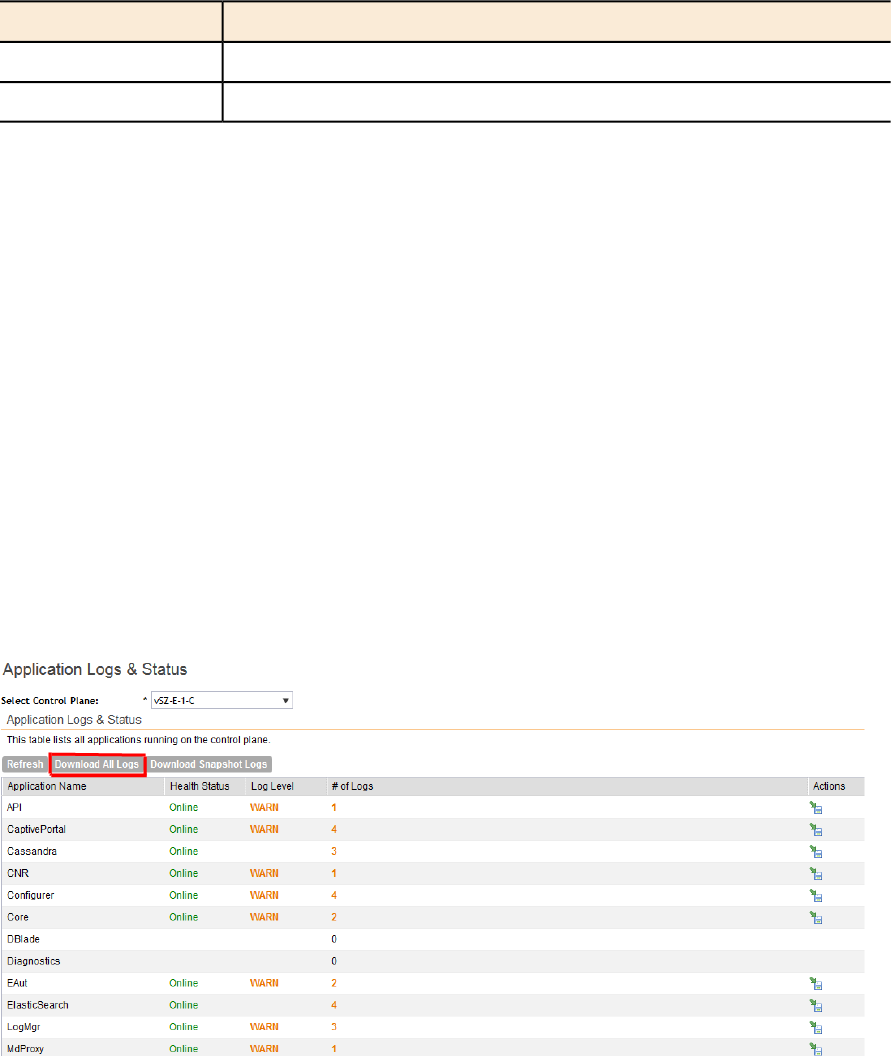
DescriptionApplication
Collects and sends log information from all processesSystem
Runs the controller’s management web serverWeb
Downloading All Logs
Follow these steps to download all available logs from the controller.
1. Go to Administration > Diagnostics.
2. On the sidebar, click Application Logs & Status.
3. In Select Control Plane, select the control plane from which you want to download logs.
4. Click the Download All Logs button.
Your web browser downloads the logs in GZIP Compressed Tar Archive (with .TGZ extension)
to its default download location.
5. Go to your web browser's default download location and verify that the TGZ file was
downloaded successfully.
6. Use your preferred compression/decompression program to extract the log files from the
TGZ file.
7. When the log files are extracted (for example, adminweb.log, cassandra.log,
communicator.log, etc.), use a text editor to open and view the log contents.
You have completed downloading all the controller logs.
Figure 137: Click the Download All Logs button
Downloading Snapshot Logs Generated from the CLI
Snapshot logs contain system and configuration information, such as the AP list, configurations
settings, event list, communicator logs, SSH tunnel lists, etc.
If you triggered the controller to generate a snapshot from the CLI, you have the option to
download snapshot logs from the web interface.
SmartZone 100/Virtual SmartZone Essentials for Release 3.2 Administrator Guide
216
Performing Administrative Tasks
Working with Logs
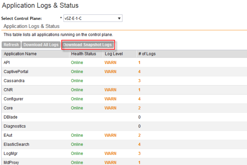
Follow these steps to download the CLI-generated snapshot logs from the web interface.
1. On the CLI, trigger the controller to generate a snapshot.
2. Log on to the web interface.
3. Go to Administration > Diagnostics.
4. On the sidebar, click Application Logs & Status.
5. Click Download Snapshot Logs.
Your web browser downloads a tar (.TGZ) file that contains all available snapshot logs.
6. Go to your browser's default download folder, and then verify that the snapshot log file or
files have been downloaded successfully.
7. Extract the contents of the tar file.
You have completed downloading snapshot logs from the controller.
Figure 138: Click Download Snapshot Logs to download all available snapshot logs
Managing Licenses
Depending on the number of Ruckus Wireless APs that you need to manage with the controller,
you may need to upgrade the controller license as your network expands.
NOTE: This section only applies to the SZ-100.
SmartZone 100/Virtual SmartZone Essentials for Release 3.2 Administrator Guide
217
Performing Administrative Tasks
Managing Licenses
The maximum number of access points that the controller can manage is controlled by the
license file that came with the controller. If the number of access points on the network exceeds
the limit in the license file, you will need to obtain an additional license file and upload it to the
controller.
NOTE: For information on obtaining additional license files, contact Ruckus Wireless Support
or an authorized Ruckus Wireless reseller.
The maximum number of access points that a license supports depends on its stock-keeping
unit (SKU).
Default Licenses in the SmartZone 100
The SmartZone 100 comes embedded with default licenses to enable you to manage a limited
number of APs right out of the box without having to register or purchase add-on licenses.
Table 16: Default licenses
NumberLicense Type
1000 APsDefault AP Capacity License
10 APsDefault AP Tunneling Capacity License
90 daysDefault End User Support License
If the default licenses are insufficient for the number of APs that you are planning to manage
with the controller, contact Ruckus Wireless Support or an authorized reseller (see Importing a
License File for information on how to upload a license file).
All default licenses are activated as soon as you complete the controller setup. Once the controller
connects to the license server and successfully downloads add-on license data (if any) from it,
the behavior of each default license may change.
Any add-on AP capacity licenses will accumulate on top on the default
license. For example, if you purchased 100 AP capacity licenses and
AP Capacity License
added them to the controller, the controller will show a total of 1100 AP
capacity licenses -- this includes the 1000 default licenses plus the 100
add-on licenses.
NOTE: The 1000 AP capacity licenses that come by default are only
valid for 90 days. The default licenses expire after 90 days.
Any add-on AP tunneling or support licenses will replace the default
license in controller. Unlike AP capacity licenses, they will not accumulate
on top of the default licenses.
AP Tunneling and
Support Licenses
Default licenses with time restriction (for example, the default end user
support license) will remain activated until they expire. If a time-restricted
Time-restricted
Default Licenses
add-on license is removed from the controller and a default license of
SmartZone 100/Virtual SmartZone Essentials for Release 3.2 Administrator Guide
218
Performing Administrative Tasks
Managing Licenses
the same type exists on the controller and has not expired, this default
license will be reactivated and enabled.
Activating SmartLicense on SZ-100
Supported License Types
The SZ100 supports the following types of licenses:
AP Capacity License
The AP capacity license (CAPACITY-AP) is an add-on license that enables the management of
Ruckus Wireless access points. This is a permanent license (that is, no expiration date).
Default AP Capacity License
The default AP capacity license (CAPACITY-AP-DEFAULT) is same as the AP capacity license.
This license, however, is embedded into the controller and is non-transferable. The default AP
capacity license allows you to manage up to 50 APs using the controller.
AP Tunneling Capacity License
The AP tunneling capacity license (CAPACITY-RXGW) is an add-on license that enables the
management of APs with SoftGRE capability. This is also known as SoftGRE Capacity License
or RXGW Capacity License. The AP tunneling capacity license is a permanent license (that is,
no expiration date).
Default AP Tunneling Capacity License
The default AP tunneling capacity license (CAPACITY-RXGW-DEFAULT) is the same as the AP
tunneling capacity license. This license, however, is embedded into the controller and is
non-transferable. The default AP tunneling capacity license allows you to manage up to 10 APs
with SoftGRE capability.
Support License
The Support License enables the controller to perform a system upgrade.
There are three types of support licenses:
•End User Support License
•Partner Support License
•Advanced Replacement Support License
SmartZone 100/Virtual SmartZone Essentials for Release 3.2 Administrator Guide
219
Performing Administrative Tasks
Managing Licenses
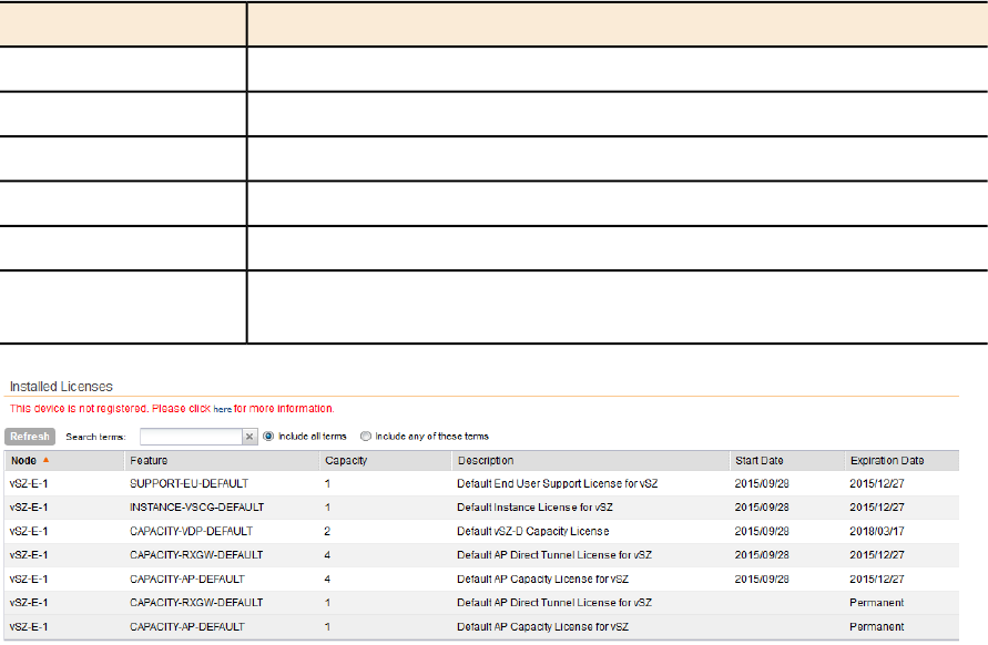
vSZ-D Capacity License
vSZ-D provides tunnel support as a Data Plane for APs. The vSZ-D capacity license limits the
capacity of the vSZ-D on vSZ. For each vSZ installation, two vSZ-D capacity licenses are initiated
by default, that are valid for 90 days. When the license expires, vSZ stops managing the vSZ-D.
Default Support License
The default support license (SUPPORT-EU-DEFAULT) is same as the end user support license,
but with a 90-day expiration time. This license is embedded into the controller and is
non-transferable. The controller comes with one default support license.
Viewing Installed Licenses
You can view the details of all the licenses that you have uploaded to the controller.
The following table lists the different columns that appear in the Installed Licenses section.
Table 17: Information in the Installed License section
DescriptionColumn Name
The name of the node to which the license was uploadedController Node
The stock-keeping unit (SKU) code of the license fileFeature
The number of units or license seats that the license file providesCapacity
The type of license (see Supported License Types)Description
The date when the license file was activatedStart Date
For time-bound licenses, this column shows the date when the license
file expires. For permanent licenses, this column shows Permanent
Expiration Date
Figure 139: The Installed Licenses section
Viewing the License Summary
You can view a summary of total, consumed, and available licenses for the different license
types.
The following table lists the different columns that appear in the License Summary section.
SmartZone 100/Virtual SmartZone Essentials for Release 3.2 Administrator Guide
220
Performing Administrative Tasks
Managing Licenses
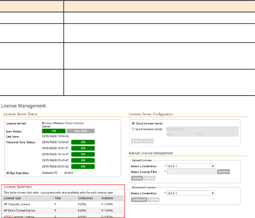
Table 18: Information in the License Summary section
DescriptionColumn Name
The type of license fileLicense Type
The maximum number of access points that can be supported by all
the licenses that have been uploaded to the controller.
Total
The number of license seats that have been used. One access point
uses up one license seat. For example, if three access points have
registered with the controller, the Consumed field will show 3.
Consumed
The number of license seats remaining. For example, if all your licenses
support up to 5000 access points, and the controller has used up three
licenses so far, the Available field will show 4997.
Available
Figure 140: The License Summary section
Configuring the License Server to Use
Ruckus Wireless provides two options for managing the licenses that you have purchased for
the controller:
Also known as the SmartLicense server, this a cloud-based server that
stores all of the licenses and support entitlements that you have
Cloud License Server
purchased for the controller. For information on how to set up and
activate your SmartLicense account, see the SmartLicense User Guide.
This is a license server that is installed onsite where the controller is
deployed. For information on how to obtain and set up the LLS server,
see the SmartCell Gateway Local Licensing Server User Guide.
Local License Server
(LLS)
Follow these steps to select a license server that the controller will use.
1. Go to Administration > License.
SmartZone 100/Virtual SmartZone Essentials for Release 3.2 Administrator Guide
221
Performing Administrative Tasks
Managing Licenses
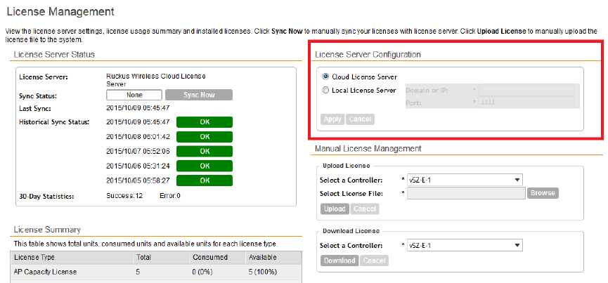
2. In License Server Configuration, select one of the following:
DescriptionOption
Select this option to use the Ruckus Wireless SmartLicense
server.
Cloud License Server
Select this option to use an LLS that you have set up on the
network, and then configure the following:
Local License Server
•Domain or IP: Type the FQDN or IP address of the LLS.
•Port: Type the port number. Port range is from 0 to 65535
(default is 3333).
3. Click Apply.
A confirmation message appears.
4. Click Yes.
The controller saves the selected license server configuration, deletes all of its saved license
data, and then automatically synchronizing the license information with the selected license
server.
5. Click Sync Now to synchronize the license with the license server.
If synchronization was successful, this message appears: License synced with the
license server successfully., else an error message appears. Click Error to see
the reason for the sync failure.
You have completed configuring the license server that the controller will use.
Figure 141: The License Server Configuration section
SmartZone 100/Virtual SmartZone Essentials for Release 3.2 Administrator Guide
222
Performing Administrative Tasks
Managing Licenses
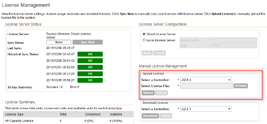
Importing a License File
If the controller is disconnected from the Internet or is otherwise unable to communicate with
the Ruckus Wireless SmartLicense system (due to firewall policies, etc.), you can manually import
a license entitlement file into the controller.
NOTE: The option to import a license file manually into the controller is only available if the
controller is using the cloud license server.
Follow these steps to import a license file into the controller.
1. Obtain the license file.
You can do this by logging on to your Ruckus Wireless Support account, going to the license
management page, and then downloading the license file (the license file is in .bin format).
2. Log on to the controller web interface, and then go to Administration > License.
3. In Select Controller under Upload License, select the node for which you are uploading
the license file.
4. In Select License File, click Browse, locate the license file (.bin file) that you downloaded
from your Ruckus Wireless Support account, and then select it.
5. Click Upload.
The page refreshes, and the information in the Installed Licenses section changes to reflect
the updated information imported from the SmartLicense platform.
You have completed importing a license file manually.
Figure 142: The Upload License section
Downloading a Copy of the Licenses
If you need to release licenses bound to an offline controller and allow those licenses to be used
elsewhere (on a different controller), you can download a copy of the controller licenses.
The option to download a copy of the controller licenses is only available if the controller is using
the Ruckus Wireless cloud license server.
SmartZone 100/Virtual SmartZone Essentials for Release 3.2 Administrator Guide
223
Performing Administrative Tasks
Managing Licenses
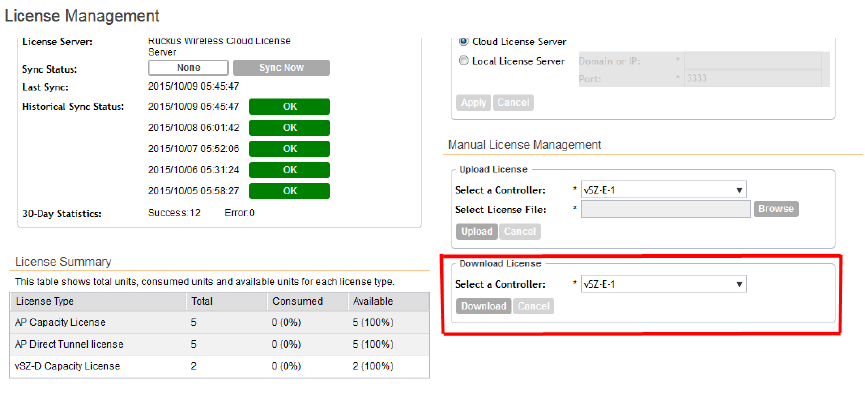
Follow these steps to download a binary copy of the license files.
1. Go to Administration > License.
2. In License Server Configuration, verify that Cloud License Server is selected.
3. Locate the Download License section.
4. In Select Controller, select the controller node for which you want to download the license
files.
5. Click Download.
Your web browser downloads the license files from the controller.
6. When the download is complete, go to the default download folder that you have configured
for your web browser, and then verify that the binary copy of the license files (with .bin
extension) exists.
You have completed downloading copies of the controller licenses.
Figure 143: The Download License section
Synchronizing the Controller with the License Server
By default, the controller automatically synchronizes its license data with the selected license
server every 24 hours. If you made changes to the controller licenses (for example, you purchased
additional licenses) and you want the controller to download the updated license data immediately,
you can trigger a manual synchronization.
Follow these steps to trigger the controller to manually synchronize with the license server.
1. Go to Administration > License.
2. Click Sync License with Server.
The message Start sync with license server... appears as the controller
synchronizes its license data with the server.
When the sync process is complete, the message Sync license with the license
server successful appears. If the previously saved license data are different the latest
license data on the server, the information in the Installed Licenses section refreshes to
reflect the latest data.
SmartZone 100/Virtual SmartZone Essentials for Release 3.2 Administrator Guide
224
Performing Administrative Tasks
Managing Licenses
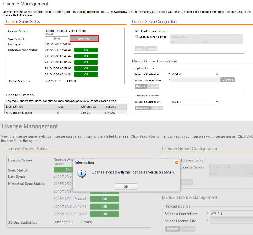
You have completed manually synchronizing the controller with the license server.
Figure 144: A message appears to indicate that the sync process was successful
Configuring the License Bandwidth
You can optimally manage the vSZ-D capacity by configuring its license bandwidth.
Each vSZ-D license comes with a 1Gbps bandwidth by default. For higher bandwidth
requirements, you must purchase additional bandwidth licenses. You can purchase both 10
Gbps bandwidth and unlimited bandwidth licenses.
You can apply only one vSZ-D bandwidth license to a vSZ-D.
NOTE: Only an approved vSZ-D can be assigned a license bandwidth.
1. Go to Administration > License.
The License Management page appears.
2. In License Bandwidth Configuration, enter the name of the approved vSZ-D in vSZ-D.
SmartZone 100/Virtual SmartZone Essentials for Release 3.2 Administrator Guide
225
Performing Administrative Tasks
Managing Licenses
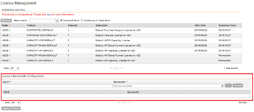
3. In Bandwidth, select the bandwidth that you want to assign from the drop-down menu.
4. Click Add.
The bandwidth is assigned to the vSZ-D and displayed as shown in the figure.
5. Click Apply.
The license bandwidth is configured for the selected vSZ-D.
SmartZone 100/Virtual SmartZone Essentials for Release 3.2 Administrator Guide
226
Performing Administrative Tasks
Managing Licenses
Appendix
A
AP-SCG/SZ/vSZ/vSZ-D Communication
The table below lists the ports that must be opened in the network firewall to ensure that the
SCG/vSZ-D/SZ/vSZ (controller), managed APs, and RADIUS servers can communicate with each
other successfully.
Table 19: Ports to open for AP-SCG/SZ/vSZ/vSZ-D communication
PurposeConfigurable
from Web
Interface?
To (Listener)From
(Sender)
Layer 4
Protocol
Port
Number
FTP upload of reports,
statistics, and configuration
backups
YesvSZ control
plane
APTCP21
SSH tunnelNovSZ control
plane
TCP22 •AP
•vSZ-D
TACACS+ based
authentication of controller
administrators
YesvSZ control
plane
TACACS+
server
TCP49
AP firmware upgradeNovSZ control
plane
APTCP91 and 443
NTP sync up
Not required in 2.1.2, 2.1.3,
2.5.1, 2.6, 3.0
NovSZ control
plane
APUDP123
Required in1.x, 2.1, 2.1.1,
2.5
Access to the SCG/vSZ/SZ
control plane over secure
HTTPS
NovSZ control
plane
TCP443 •AP
•vSZ-D
Internal communication portNovSZvSZ-DTCP6868
SmartZone 100/Virtual SmartZone Essentials for Release 3.2 Administrator Guide
227
227

PurposeConfigurable
from Web
Interface?
To (Listener)From
(Sender)
Layer 4
Protocol
Port
Number
Access to the SCG/vSZ/SZ
web interface via HTTPS
NovSZ
management
plane
AnyTCP8443
GRE tunnel
NOTE: Only applicable to
SCG.
NoSCG (data
plane)
APTCP23232
GRE tunnel (required only
when tunnel mode is GRE
over UDP)
NOTE: On the vSZ-D, this
port is used for both data
YesData planeAPUDP and
TCP
23233
and control in both UDP
and TCP.
LWAPP discovery
NOTE:
If your AP is within the same
subnet as the controller,
NovSZ control
plane
APUDP12222/12223
disable nat-ip-translation to
establish a connection
between the AP and the
controller so that AP
firmware upgrade
progresses.
If your AP is on the side of
the NAT server and if the
NAT server does not
support PASV-Mode FTP,
enable nat-ip-translation. If
the NAT server supports
PASV-Mode FTP, then
disable nat-ip-translation for
AP firmware upgrade to
progress
SmartZone 100/Virtual SmartZone Essentials for Release 3.2 Administrator Guide
228
AP-SCG/SZ/vSZ/vSZ-D Communication

PurposeConfigurable
from Web
Interface?
To (Listener)From
(Sender)
Layer 4
Protocol
Port
Number
AAA authentication and
accounting
YesRadius
servers (s)
APUDP1812/1813
CLI (Command Line
Interface) access to the vSZ
YesManagement
interface
AnyNo (SSH)8022
Allows unauthorized UEs to
browse to an HTTP website
NovSZ control
plane
AnyTCP8090
Allows unauthorized UEs to
browse to an HTTPS
website
NovSZ control
plane
AnyTCP8099
Allows unauthorized UEs to
browse using a proxy UE
NovSZ control
plane
AnyTCP8100
Allows authorized UEs to
browse using a proxy UE
NovSZ control
plane
AnyTCP8111
Northbound Portal Interface
for hotspots
NovSZ control
plane
AnyHTTP9080
Northbound Portal Interface
for hotspots
NovSZ control
plane
AnyHTTPS9443
Hotspot WISPr subscriber
portal login/logout over
HTTPSl
NovSZ control
plane
AnyTCP9998
Local license serverNoLicense
server
ControllerTCP3333
Cloud license serverNoLicense
server
ControllerHTTPS443
HotSpot 2.0 portal for
onboarding and remediation
NoController
interface
ClientTCP9996
HotSpot 2.0 trust CA
verification
NoController
interface
ClientTCP9999
HotSpot 2.0 Oauth in HTTPNoController
interface
ClientTCP8200
HotSpot 2.0 Oauth in
HTTPS
NoController
interface
ClientTCP8222
SmartZone 100/Virtual SmartZone Essentials for Release 3.2 Administrator Guide
229
AP-SCG/SZ/vSZ/vSZ-D Communication
NOTE: The destination interfaces are meant for three interface deployments. In a single interface
deployment, all the destination ports must be forwarded to the combined management/control interface
IP address.
NOTE: Communication between APs is not possible across NAT servers.
SmartZone 100/Virtual SmartZone Essentials for Release 3.2 Administrator Guide
230
AP-SCG/SZ/vSZ/vSZ-D Communication
Index
A
access point 167
rebooting 167
restarting remotely 167
access points 162, 164–166
downloading support log 166
exporting to CSV 164
monitoring 162
viewing a summary 162
viewing configuration 165
acknowledge 178
administrative tasks 205, 208, 210
backup 205
deleting 208
backup 208
restore 208
upgrading 210
administrator activity 183
exporting to CSV 183
administrator password 23
changing 23
alarm severity 178, 181
alarm types 178, 181
alarms 178, 180–181
exporting to CSV 180
severity 178, 181
types 178, 181
AP rebalancing 126
AP status summary 18
application control, See user defined applications
application visibility 87, 91
application visibility and control 88
AVC 87–88
B
backing up 196
FTP 196
backup 205, 208
deleting 208
restoring 208
C
client count summary 18
client number report 185
client type summary widget 19
common AP settings 55
communication ports 227
content area 17
continuously disconnected APs report 186
copyright information 9
creating 186
report 186
D
deleting 192
report 192
downloading 216
system logs 216
E
Ethernet port profiles 82
important notes 82
exporting 164, 180
access points 164
alarms 180
F
firewall ports 227
G
Google Maps 167
I
IPSec 75
IPv4 55
IPv6 55
L
legal 9
logging off 23
logging on 14
logon page 14
M
main menu 16
management port number 14
mesh role 162
miscellaneous bar 17
monitoring 162
access points 162
N
network connectivity 167
P
patch file 211
ping 167
ports to open 227
R
rebooting access point 167
report notification 190
report schedule 189
reports 185–186, 190–192
client number 185
continuously disconnected APs 186
creating 186
deleting 192
email notifications 190
system resource utilization 186
TX/RX bytes 186
types 185
viewing list 191
restarting access point 167
restoring 200, 208
backup 208
FTP 200
S
sidebar 17
software upgrade file 211
support log 166
supported web browsers 14
system logs 214, 216
available logs 214
downloading 216
system resource utilization report 186
system summary 19
system upgrade 210
T
traceroute 167
trademarks 9
TX/RX bytes report 186
U
upgrading 210
system 210
user defined applications 90
adding 90
creating 90
V
verifying upgrade 212
VLAN pooling 63
W
Web browser 14
Web interface 14, 16, 23
features 16
logging off 23
logging on 14
WeChat 100, 102
widget slot 22
widget slots 21
widgets 18–19, 21–23
adding a widget to a widget slot 22
adding to the dashboard 21
AP status summary 18
available slots 21
available widgets 18
client count summary 18
client type summary 19
deleting 23
displaying a widget in a widget slot 22
moving to another slot 22
system summary 19
wireless clients 169, 171
exporting to CSV 171
monitoring 169
viewing information 171
viewing summary 169
