Ruckus ZoneFlex P300 Wireless Bridge User Guide Zone Flex Version 100.1.0.9.43 (GA) Zf 100 1 0 Ug 800 70956 001 Rev B 20151102
2017-07-21
User Manual: Ruckus ZoneFlex P300 Version 100.1.0.9.43 (GA) User Guide
Open the PDF directly: View PDF ![]() .
.
Page Count: 85
- Contents
- About This Guide
- Introducing the ZoneFlex P300
- Navigating the Web Interface
- Configuring the ZoneFlex P300
- Managing the ZoneFlex P300
- Viewing Current Device Status
- Viewing Current Internet Status
- Viewing Current Wireless Status
- Viewing Current QoS Status
- Manually Upgrading the Firmware
- Scheduling Automatic Firmware Upgrades
- Changing the Administrative Login Settings
- Enabling Other Management Access Options
- Working with Event Logs and Syslog Servers
- Rebooting the ZoneFlex P300
- Resetting the ZoneFlex P300 to Factory Defaults
- Running Diagnostics
- Scanning for Interference
- Moving Traffic to Another Channel
- Where to Find More Information
- Appendix A: Customer-Orderable Parts

Ruckus Wireless™
ZoneFlex™ P300 Wireless Bridge
User Guide
Part Number 800-70956-001 Rev B
Published November 2015
www.ruckuswireless.com

ZoneFlex P300 Wireless Bridge User Guide, 800-70956-001 Rev B 2
Copyright Notice and Proprietary Information
Copyright 2015. Ruckus Wireless, Inc. All rights reserved.
No part of this documentation may be used, reproduced, transmitted, or translated, in any form or by any means,
electronic, mechanical, manual, optical, or otherwise, without prior written permission of Ruckus Wireless, Inc.
(“Ruckus”), or as expressly provided by under license from Ruckus.
Destination Control Statement
Technical data contained in this publication may be subject to the export control laws of the United States of America.
Disclosure to nationals of other countries contrary to United States law is prohibited. It is the reader’s responsibility to
determine the applicable regulations and to comply with them.
Disclaimer
THIS DOCUMENTATION AND ALL INFORMATION CONTAINED HEREIN (“MATERIAL”) IS PROVIDED FOR GENERAL
INFORMATION PURPOSES ONLY. RUCKUS AND ITS LICENSORS MAKE NO WARRANTY OF ANY KIND, EXPRESS
OR IMPLIED, WITH REGARD TO THE MATERIAL, INCLUDING, BUT NOT LIMITED TO, THE IMPLIED WARRANTIES
OF MERCHANTABILITY, NON-INFRINGEMENT AND FITNESS FOR A PARTICULAR PURPOSE, OR THAT THE
MATERIAL IS ERROR-FREE, ACCURATE OR RELIABLE. RUCKUS RESERVES THE RIGHT TO MAKE CHANGES OR
UPDATES TO THE MATERIAL AT ANY TIME.
Limitation of Liability
IN NO EVENT SHALL RUCKUS BE LIABLE FOR ANY DIRECT, INDIRECT, INCIDENTAL, SPECIAL OR CONSEQUEN-
TIAL DAMAGES, OR DAMAGES FOR LOSS OF PROFITS, REVENUE, DATA OR USE, INCURRED BY YOU OR ANY
THIRD PARTY, WHETHER IN AN ACTION IN CONTRACT OR TORT, ARISING FROM YOUR ACCESS TO, OR USE
OF, THE MATERIAL.
Trademarks
Ruckus Wireless, Ruckus, Bark Logo, SmartCell, ZoneFlex, FlexMaster, and SpeedFlex are trademarks of Ruckus
Wireless, Inc. in the United States and other countries. All other product or company names may be trademarks of their
respective owners.

ZoneFlex P300 Wireless Bridge User Guide, 800-70956-001 Rev B 3
Contents
About This Guide
Terms Used in This Guide. . . . . . . . . . . . . . . . . . . . . . . . . . . . . . . . . . . . . . . . . . . . . . . . . 6
Safety Warnings . . . . . . . . . . . . . . . . . . . . . . . . . . . . . . . . . . . . . . . . . . . . . . . . . . . . . . . . 7
Related Documentation . . . . . . . . . . . . . . . . . . . . . . . . . . . . . . . . . . . . . . . . . . . . . . . . . . 8
Documentation Feedback. . . . . . . . . . . . . . . . . . . . . . . . . . . . . . . . . . . . . . . . . . . . . . . . . 8
Document Conventions . . . . . . . . . . . . . . . . . . . . . . . . . . . . . . . . . . . . . . . . . . . . . . . . . . 9
1 Introducing the ZoneFlex P300
ZoneFlex P300 Overview . . . . . . . . . . . . . . . . . . . . . . . . . . . . . . . . . . . . . . . . . . . . . . . . 11
Unpacking the ZoneFlex P300 . . . . . . . . . . . . . . . . . . . . . . . . . . . . . . . . . . . . . . . . . . . . 12
Package Contents . . . . . . . . . . . . . . . . . . . . . . . . . . . . . . . . . . . . . . . . . . . . . . . . . . . . 12
Getting to Know the Hardware Features . . . . . . . . . . . . . . . . . . . . . . . . . . . . . . . . . . . . . 14
LEDs and What They Mean . . . . . . . . . . . . . . . . . . . . . . . . . . . . . . . . . . . . . . . . . . . . . 15
Ethernet Connector, Aiming Button and Reset Button . . . . . . . . . . . . . . . . . . . . . . . . . 17
External Antenna Connectors. . . . . . . . . . . . . . . . . . . . . . . . . . . . . . . . . . . . . . . . . . . . 19
Installing the Access Point . . . . . . . . . . . . . . . . . . . . . . . . . . . . . . . . . . . . . . . . . . . . . . . 20
Aiming Point-to-Point ZoneFlex P300s. . . . . . . . . . . . . . . . . . . . . . . . . . . . . . . . . . . . . 20
Aiming Point-to-Multipoint ZoneFlex P300s . . . . . . . . . . . . . . . . . . . . . . . . . . . . . . . . . 21
Verifying Association Between the ZoneFlex P300s . . . . . . . . . . . . . . . . . . . . . . . . . . . 22
Setting the Distance Between Root Bridge and Non-Root Bridges. . . . . . . . . . . . . . . . 23
Verifying the Connection . . . . . . . . . . . . . . . . . . . . . . . . . . . . . . . . . . . . . . . . . . . . . . . 24
2 Navigating the Web Interface
Before You Begin: Preconfiguring the ZoneFlex P300 . . . . . . . . . . . . . . . . . . . . . . . . . . . 27
Logging Into the ZoneFlex P300 Web Interface. . . . . . . . . . . . . . . . . . . . . . . . . . . . . . . . 27
Navigating the Web Interface . . . . . . . . . . . . . . . . . . . . . . . . . . . . . . . . . . . . . . . . . . . . . 29
3 Configuring the ZoneFlex P300
Configuring Wireless Settings . . . . . . . . . . . . . . . . . . . . . . . . . . . . . . . . . . . . . . . . . . . . . 31
Editing Advanced Settings . . . . . . . . . . . . . . . . . . . . . . . . . . . . . . . . . . . . . . . . . . . . 34
Rate Limiting. . . . . . . . . . . . . . . . . . . . . . . . . . . . . . . . . . . . . . . . . . . . . . . . . . . . . . . 36
Configuring Device Settings . . . . . . . . . . . . . . . . . . . . . . . . . . . . . . . . . . . . . . . . . . . . . . 37
Configuring the ZoneFlex P300 Name, Location, GPS Coordinates, and LED Appearance
37

ZoneFlex P300 Wireless Bridge User Guide, 800-70956-001 Rev B 4
Changing the Administrator Username and Password . . . . . . . . . . . . . . . . . . . . . . . . . 38
Configuring TACACS+ Remote Login Information . . . . . . . . . . . . . . . . . . . . . . . . . . . . 38
Configuring Internet Settings . . . . . . . . . . . . . . . . . . . . . . . . . . . . . . . . . . . . . . . . . . . . . . 40
VLAN Overview . . . . . . . . . . . . . . . . . . . . . . . . . . . . . . . . . . . . . . . . . . . . . . . . . . . . . . 40
Configuring an NTP Server. . . . . . . . . . . . . . . . . . . . . . . . . . . . . . . . . . . . . . . . . . . . . . 41
Configuring the Management VLAN . . . . . . . . . . . . . . . . . . . . . . . . . . . . . . . . . . . . . . . 42
Obtaining and Assigning an IP Address . . . . . . . . . . . . . . . . . . . . . . . . . . . . . . . . . . . . 43
DHCP/Auto Configuration . . . . . . . . . . . . . . . . . . . . . . . . . . . . . . . . . . . . . . . . . . . . . 43
Configuring a Static IP. . . . . . . . . . . . . . . . . . . . . . . . . . . . . . . . . . . . . . . . . . . . . . . . 45
Configuring the MTU Size . . . . . . . . . . . . . . . . . . . . . . . . . . . . . . . . . . . . . . . . . . . . . . 46
Configuring QoS . . . . . . . . . . . . . . . . . . . . . . . . . . . . . . . . . . . . . . . . . . . . . . . . . . . . . . . 47
Configuring Global QoS . . . . . . . . . . . . . . . . . . . . . . . . . . . . . . . . . . . . . . . . . . . . . . . . 47
Configuring Ethernet QoS . . . . . . . . . . . . . . . . . . . . . . . . . . . . . . . . . . . . . . . . . . . . . . 50
Configuring Wireless QoS . . . . . . . . . . . . . . . . . . . . . . . . . . . . . . . . . . . . . . . . . . . . . . 50
Reversing Root Bridge and Non-Root Bridge Roles . . . . . . . . . . . . . . . . . . . . . . . . . . . . 52
4 Managing the ZoneFlex P300
Viewing Current Device Status . . . . . . . . . . . . . . . . . . . . . . . . . . . . . . . . . . . . . . . . . . . . 55
Viewing Current Internet Status. . . . . . . . . . . . . . . . . . . . . . . . . . . . . . . . . . . . . . . . . . . . 56
Viewing Current Wireless Status . . . . . . . . . . . . . . . . . . . . . . . . . . . . . . . . . . . . . . . . . . . 57
Viewing Current QoS Status . . . . . . . . . . . . . . . . . . . . . . . . . . . . . . . . . . . . . . . . . . . . . . 59
Viewing Global QoS . . . . . . . . . . . . . . . . . . . . . . . . . . . . . . . . . . . . . . . . . . . . . . . . . . . 59
Viewing Ethernet QoS . . . . . . . . . . . . . . . . . . . . . . . . . . . . . . . . . . . . . . . . . . . . . . . . . 60
Viewing Wireless QoS . . . . . . . . . . . . . . . . . . . . . . . . . . . . . . . . . . . . . . . . . . . . . . . . . 60
Manually Upgrading the Firmware . . . . . . . . . . . . . . . . . . . . . . . . . . . . . . . . . . . . . . . . . . 61
Upgrading Manually using FTP or TFTP . . . . . . . . . . . . . . . . . . . . . . . . . . . . . . . . . . . . 62
Upgrading Manually using the Web . . . . . . . . . . . . . . . . . . . . . . . . . . . . . . . . . . . . . . . 62
Upgrading Manually using a Local File . . . . . . . . . . . . . . . . . . . . . . . . . . . . . . . . . . . . . 62
Scheduling Automatic Firmware Upgrades . . . . . . . . . . . . . . . . . . . . . . . . . . . . . . . . . . . 63
Changing the Administrative Login Settings . . . . . . . . . . . . . . . . . . . . . . . . . . . . . . . . . . 64
Enabling Other Management Access Options . . . . . . . . . . . . . . . . . . . . . . . . . . . . . . . . . 65
Viewing FlexMaster Management Status . . . . . . . . . . . . . . . . . . . . . . . . . . . . . . . . . . . 68
Pointing the Bridge to FlexMaster. . . . . . . . . . . . . . . . . . . . . . . . . . . . . . . . . . . . . . . . . 69
Working with Event Logs and Syslog Servers . . . . . . . . . . . . . . . . . . . . . . . . . . . . . . . . . 70
Enabling Logging and Sending Event Logs to a Syslog Server . . . . . . . . . . . . . . . . . . . 70
Sending a Copy of the Log File to Ruckus Wireless Support . . . . . . . . . . . . . . . . . . . . 71
Saving a Copy of the Log File to Your Computer . . . . . . . . . . . . . . . . . . . . . . . . . . . . . 71
Saving a Copy of a Support File to Your Computer . . . . . . . . . . . . . . . . . . . . . . . . . . . 72
Rebooting the ZoneFlex P300. . . . . . . . . . . . . . . . . . . . . . . . . . . . . . . . . . . . . . . . . . . . . 73

ZoneFlex P300 Wireless Bridge User Guide, 800-70956-001 Rev B 5
Resetting the ZoneFlex P300 to Factory Defaults . . . . . . . . . . . . . . . . . . . . . . . . . . . . . . 74
Running Diagnostics . . . . . . . . . . . . . . . . . . . . . . . . . . . . . . . . . . . . . . . . . . . . . . . . . . . . 75
Scanning for Interference . . . . . . . . . . . . . . . . . . . . . . . . . . . . . . . . . . . . . . . . . . . . . . . . 77
Moving Traffic to Another Channel . . . . . . . . . . . . . . . . . . . . . . . . . . . . . . . . . . . . . . . . . 79
Where to Find More Information . . . . . . . . . . . . . . . . . . . . . . . . . . . . . . . . . . . . . . . . . . . 80
Appendix A: Customer-Orderable Parts
Index

ZoneFlex P300 Wireless Bridge User Guide, 800-70956-001 Rev B 6
About This Guide
This guide describes how to install, configure, and manage the Ruckus WirelessTM
ZoneFlexTM P300 802.11ac, 5GHz, point-to-point and point-to-point, outdoor Wire-
less Bridge. This guide is written for those responsible for installing and managing
network equipment. Consequently, it assumes that the reader has basic working
knowledge of local area networking, wireless networking, and wireless devices. The
ZoneFlex P300 802.11ac Wireless Bridge is referred to in the rest of this document
as the ZoneFlex P300, bridge, root bridge, or non-root bridge.
NOTE This guide assumes that the ZoneFlex P300 has already been configured
and installed as described in the ZoneFlex P300 Getting Started Guide and ZoneFlex
P300 Wireless Bridge Mounting Guide.
NOTE If the information in the release notes differs from the information in this
guide, follow the instructions in the release notes.
Most user guides and release notes are available in Adobe Acrobat Reader Portable
Document Format (PDF) or HTML on the Ruckus Wireless Support Web site at
https://support.ruckuswireless.com/documents
Terms Used in This Guide
Ruckus Wireless recommends that you become familiar with the following terms:
•bridge: ZoneFlex P300 wireless bridge.
•Wireless bridge: the wireless link between a root bridge and a non-root bridge.
•Manager: Ruckus Wireless FlexMaster AP and bridge manager.
•Non-root bridge: the ZoneFlex P300 connected to an associated root bridge
over the wireless link.
•Root bridge: the ZoneFlex P300 connected to the wired Ethernet backhaul.

Safety Warnings
ZoneFlex P300 Wireless Bridge User Guide, 800-70956-001 Rev B 7
Safety Warnings
WARNING! Only trained and qualified personnel should be allowed to install,
replace, or service this equipment. The professional installer is responsible for the
proper installation and configuration of this ZoneFlex P300. The ZoneFlex P300
installation must comply with local regulatory requirements, especially with those
regulating operation near military and/or weather radar systems.
WARNING! Installation of this equipment must comply with local and national
electrical codes.
WARNING! Do not operate your wireless device near unshielded blasting caps or
in an explosive environment unless the device has been modified to be especially
qualified for such use.
WARNING! In order to comply with FCC radio frequency (RF) exposure limits,
antennas should be located at a minimum of 7.9 inches (20 cm) or more from the
body of all persons.
WARNING! Ruckus Wireless strongly recommends that you wear eye protection
before mounting the ZoneFlex P300.
CAUTION! Make sure that you form a 80mm - 130mm (3”-5”) drip loop in any cable
that is attached to the ZoneFlex P300 or the building. This will prevent water from
running along the cable and entering the ZoneFlex P300 or the building where the
cable terminates.
CAUTION! Be sure that grounding is available and that it meets local and national
electrical codes. For additional lightning protection, use lightning rods and lightning
arrestors.
NOTE Allowable external antenna types and antenna gains may be limited by local
regulatory requirements.

Related Documentation
ZoneFlex P300 Wireless Bridge User Guide, 800-70956-001 Rev B 8
Related Documentation
In addition to this User Guide, the ZoneFlex P300 documentation set includes the
following:
•Getting Started Guide and Mounting Guide documents: Provide essential config-
uring and installing information to help you get the ZoneFlex P300 up and running
within minutes.
•Online Help: Provides instructions for performing tasks using the ZoneFlex
P300’s Web interface. Online help is accessible from within the Web interface.
•Release Notes document: Provides information about the current software
release, including new features, enhancements, and known issues.
NOTE For information on Ruckus Wireless access points supported by FlexMaster
(FM) managers, refer to their respective Release Notes and associated user
documents.
Documentation Feedback
Ruckus Wireless is interested in improving its documentation and welcomes your
comments and suggestions. You can email your comments to Ruckus Wireless at
docs@ruckuswireless.com
When contacting us, please include the following information:
• Document title
• Document part number (on the cover page)
• Page number (if appropriate)
For example:
• ZoneFlex P300 Wireless Bridge User Guide
• Part number: 800-70956-001 Revision B
• Page 11
Please note that we can only respond to comments and questions about Ruckus
Wireless product documentation at this email address. Questions related to tech-
nical support or sales should be directed in the first instance to your network supplier.

Document Conventions
ZoneFlex P300 Wireless Bridge User Guide, 800-70956-001 Rev B 9
Document Conventions
Tab l e 1 and Table 2 list the text and notice conventions that are used throughout
this guide.
Table 1. Text conventions
Convention Description Example
monospace Represents information as it
appears on screen
[Device name]>
monospace bold Represents information that
you enter
[Device name]> set
ipaddr 10.0.0.12
default font bold Keyboard keys, software
buttons, and field names
On the Start menu, click All
Programs.
italics Screen or page names Click Advanced Settings.
The Advanced Settings
page appears.
Table 2. Notice conventions
Notice Type Description
NOTE Information that describes important features or instructions.
CAUTION! Information that alerts you to potential loss of data or potential
damage to an application, system, or device.
WARNING! Information that alerts you to potential personal injury.

ZoneFlex P300 Overview
ZoneFlex P300 Wireless Bridge User Guide, 800-70956-001 Rev B 11
ZoneFlex P300 Overview
The ZoneFlex P300 is an 802.11ac smart Wi-Fi backhaul system that delivers fast
and reliable connectivity across long distances. The ZoneFlex P300 features simple
installation, automatic pairing and intuitive aiming and configuration procedures so
that you can bridge two or more networks together quickly and efficiently.
The ZoneFlex P300 can be deployed as a root bridge connected to the Ethernet
backhaul, or can be deployed as a non-root bridge connected to the root bridge
via the wireless link. The ZoneFlex P300 can be equipped with customer-purchased
external 5GHz antennas to increase the root bridge-to-non-root bridge connectivity
range, or to increase the number of non-root bridges that a root bridge can
communicate with.
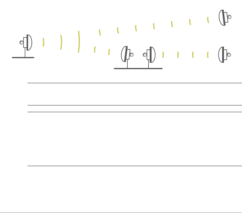
Figure 1. ZoneFlex P300s deployed as root bridge and non-root bridge
NOTE When deployed in the root bridge--non-root bridge -to- root bridge--non-
root bridge configuration, the two wireless links must use different SSIDs.
NOTE When two ZoneFlex P300s are mounted closely together (for instance, on
the same pole), make sure that the active antennas are mounted at least one meter
(39.3 inches) apart. When there is more separation, it is less likely that either
ZoneFlex P300 will experience avoidable RF interference. If possible, the units
should be on different channels, but this separation should be maintained even when
the ZoneFlex P300s are using different channels.
Your ZoneFlex P300 can be deployed in standalone mode with or without a
FlexMaster (FM) manager.
non-root bridge
non-root bridge
root bridge
root bridge
non-root bridge

Unpacking the ZoneFlex P300
Package Contents
ZoneFlex P300 Wireless Bridge User Guide, 800-70956-001 Rev B 12
NOTE For more information on the Ruckus Wireless system, including FlexMaster
and other Ruckus Wireless technologies, visit
www.ruckuswireless.com
Unpacking the ZoneFlex P300
1Open the ZoneFlex P300 package, and then carefully remove the contents.
2Return all packing materials to the shipping box, and put the box away in a dry
location.
3Verify that all items listed in Package Contents are included in the package.
4Check each item for damage. If any item is damaged or missing, notify your
authorized Ruckus Wireless sales representative.
Package Contents
NOTE Appendix A: Customer-Orderable Parts includes pictures and descriptions
of other factory-orderable and customer-supplied parts.
Before configuring or deploying your ZoneFlex P300, verify that all items listed below
are included in the package. If any item is damaged or missing, notify your authorized
Ruckus Wireless sales representative.
• One or two ZoneFlex P300 kits, depending on ordered part:
• 901-P300-xx01, ZoneFlex P300, 802.11ac 5GHz point-to-point wireless
bridge, includes one ZoneFlex P300 kit
• 901-P300-xx02, ZoneFlex P300, 802.11ac 5GHz point-to-point wireless
bridge, pre-provisioned pair, includes two ZoneFlex P300 kits
• where ‘xx’ is a country-specific code.
• Each ZoneFlex P300 kit contains:
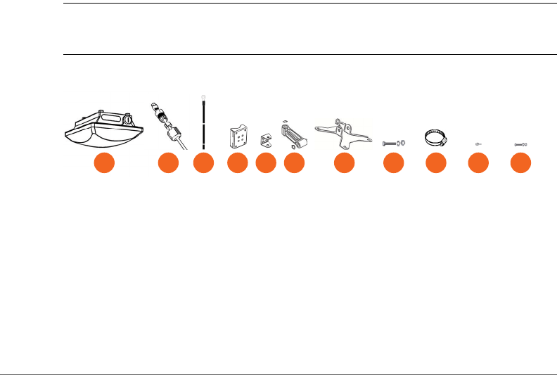
• One ZoneFlex P300, which includes a 12mm stainless steel M6x1 Phillips
earth ground screw with split lock and flat washers (A in Figure 2)
• One M25 data cable gland (B in Figure 2)
• One green/yellow earth ground wire with ring terminal (C in Figure 2)
• One wall- or pole-mounting bracket (D in Figure 2)
• One U-joint bracket (E in Figure 2)
Unpacking the ZoneFlex P300
Package Contents
ZoneFlex P300 Wireless Bridge User Guide, 800-70956-001 Rev B 13
• One linkage bracket with two serrated external-tooth lock washers (F in
Figure 2)
• One ZoneFlex P300 bracket (G in Figure 2)
• Two sets 50mm stainless steel M8x1.25 hex bolt with split lock and flat
washers (H in Figure 2)
• Four SAE32-sized stainless steel clamps, 38.1mm to 63.5mm (1.5" to 2.5")
inner diameter (I in Figure 2)
• Four sets stainless steel 8mm M4x0.7 pan head Phillips screws with split lock
and flat washers (J in Figure 2)
• Eight sets stainless steel 0.5-inch x 0.250-28 hex bolts with split lock and flat
washers (K in Figure 2)
• Service Level Agreement/Limited Warranty Statement
• Regulatory Statement
• Declaration of Conformity, if required
•ZoneFlex P300 Wireless Bridge Quick Setup Guide
•ZoneFlex P300 Wireless Bridge Mounting Guide
•N-Type Connector Sealing Instructions
NOTE This kit includes extra mounting hardware. You may use the extras wherever
required.
Figure 2. ZoneFlex P300 field-installation kit contents
F G H
EA CB DIJ K
Getting to Know the Hardware Features
Package Contents
ZoneFlex P300 Wireless Bridge User Guide, 800-70956-001 Rev B 14
Getting to Know the Hardware Features
This section identifies the physical features of the ZoneFlex P300. Figure 3 shows
the significant features and Ta ble 3 describes these features.
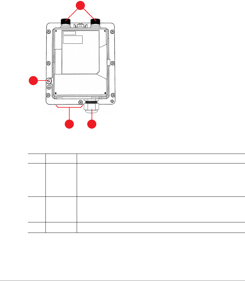
Figure 3. ZoneFlex P300 hardware features
Table 3. ZoneFlex P300 hardware feature descriptions
No. Feature Description
15GHz
external
antenna
ports
5GHz 50-ohm N-type connectors. Can be used with customer-
purchased external antennas for operator-defined coverage areas
and point-to-point deployments.
2Earth
ground
point
Use the factory-supplied ground wire and ground screw/washer
set, connect a good earth ground to this ZoneFlex P300 chassis
ground point.
3LEDs Refer to LEDs and What They Mean.
1
2
43
Getting to Know the Hardware Features
LEDs and What They Mean
ZoneFlex P300 Wireless Bridge User Guide, 800-70956-001 Rev B 15
Continue with the following:
•LEDs and What They Mean
•Ethernet Connector, Aiming Button and Reset Button
•LEDs and What They Mean
LEDs and What They Mean
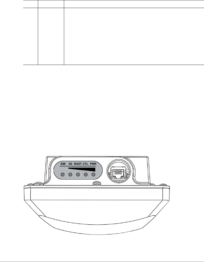
The ZoneFlex P300 has five LEDs visible on the outside of the chassis (Figure 4).
The LEDs have different operating modes, and which can be manually turned on
and off by the operator. Refer to Ta ble 4 for a description of these LEDs and their
operating modes.
Figure 4. ZoneFlex P300 LEDs
4M25 cable
gland,
Aiming
button, and
Reset
button
The ZoneFlex P300 uses one Ethernet cable for data and Power
over Ethernet (PoE). Plug the Ethernet cable into the RJ-45
connector under the cable gland.
• Use the cable gland to attach and seal the cable to the ZoneFlex
P300 chassis.
• Loosen and move the cable gland to the side to expose the
Aiming and Reset buttons. (Refer to Ethernet Connector,
Aiming Button and Reset Button.)
Table 3. ZoneFlex P300 hardware feature descriptions (Continued)
No. Feature Description

Getting to Know the Hardware Features
LEDs and What They Mean
ZoneFlex P300 Wireless Bridge User Guide, 800-70956-001 Rev B 16
Table 4. ZoneFlex P300 LED descriptions
LED Normal Mode Aiming Mode (all green)
PWR • Red = booting
• Green = normal operation
Aiming Strength 4
• Solid: Min + 36 RSSI (RSSI >= 42)
• Blinking: Min + 32 RSSI (42> RSSI >= 36)
CTL • Off = standalone operation
• Other modes = to be
determined
Aiming Strength 3
• Solid: Min + 24 RSSI (36 > RSSI >= 30)
• Blinking: Min + 18 RSSI (30 > RSSI >= 24)
ROOT • Off = non-root bridge
• Solid green = root bridge
Aiming Strength 2
• Solid: Min + 12 RSSI (24 > RSSI >= 18)
• Blinking: Min + 6 RSSI (18 > RSSI >= 12)
5G • Off = radio down
• Solid green = radio up & link
up
• Flashing green = radio up
but no link
Aiming Strength 1
• Solid: RSSI >= Configured Minimum
(12 > RSSI >= 6)
• Blinking: RSSI < Configured minimum
(Default: 6 which is configurable)
AIM • Green = aiming mode
• Off = normal mode
• Green = aiming mode (Note)
• Off = normal operation mode
Note: The P300 remains in aiming mode for 15 minutes after aiming is started.
Getting to Know the Hardware Features
Ethernet Connector, Aiming Button and Reset Button
ZoneFlex P300 Wireless Bridge User Guide, 800-70956-001 Rev B 17
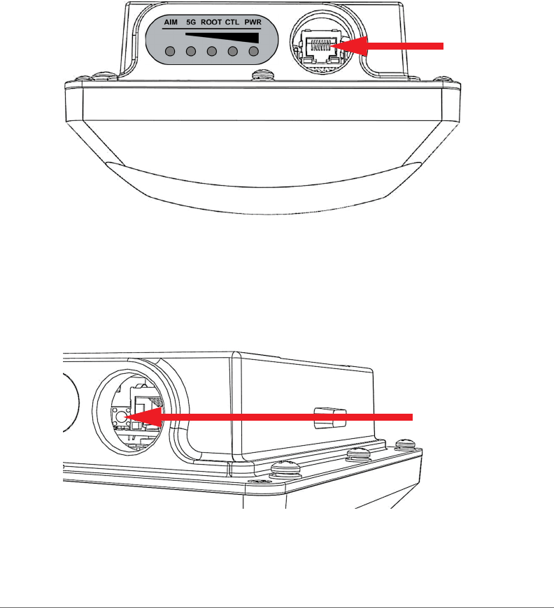
Ethernet Connector, Aiming Button and Reset Button
The ZoneFlex P300 cable gland is used to attach and seal the data and PoE Ethernet
cable to the ZoneFlex P300 chassis. Plug the Ethernet cable into the RJ-45
connector under the cable gland (Figure 5). Loosen and move the cable gland aside
to expose the Aiming (Figure 6) and Reset (Figure 7) buttons.
Figure 5. ZoneFlex P300 Ethernet connector
Pressing and holding the Aiming button (Figure 6) for four or more seconds puts the
ZoneFlex P300 into aiming mode; the P300 remains in aiming mode for 15 minutes
after aiming is started. All the LEDs turn green and enter the aiming mode described
in Table 4. Ta b l e 4 lists the signal strengths associated with each of the LEDs.
Figure 6. ZoneFlex P300 Aiming button
Getting to Know the Hardware Features
Ethernet Connector, Aiming Button and Reset Button
ZoneFlex P300 Wireless Bridge User Guide, 800-70956-001 Rev B 18
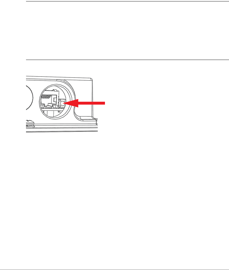
To reboot the ZoneFlex P300, press the Reset button (Figure 7). To reset the
ZoneFlex P300 to factory defaults, press and hold the Reset button for six or more
seconds; the ZoneFlex P300 resets its configuration to the factory default and
reboots.
CAUTION! Resetting the ZoneFlex P300 to its factory defaults causes the ZoneFlex
P300 to lose all configuration settings, including the provisioning, or pairing, of the
root bridge and non-root bridge pairs. If you do need to reset a ZoneFlex P300 to
factory defaults, you will need to re-provision the ZoneFlex P300. In factory default
state, the role of all ZoneFlex P300 units is root bridge. Therefore, running the factory
default procedure on any ZoneFlex P300 results in that unit be coming unreachable
on the non-root bridge default IP address (192.168.2.254).
Figure 7. ZoneFlex P300 Reset button
Getting to Know the Hardware Features
External Antenna Connectors
ZoneFlex P300 Wireless Bridge User Guide, 800-70956-001 Rev B 19
External Antenna Connectors
The ZoneFlex P300 Wireless Bridge includes one internal directional antenna. If you
want to extend the range of your wireless network or widen the root bridge coverage
to more than one non-root bridge, you can connect an external 5GHz antenna to
the two standard N-type external antenna connectors on the top panel of the
ZoneFlex P300. The antenna must have a gain of less than 23dBi to comply with
FCC and CE regulations. For more information, refer to your local regulations.
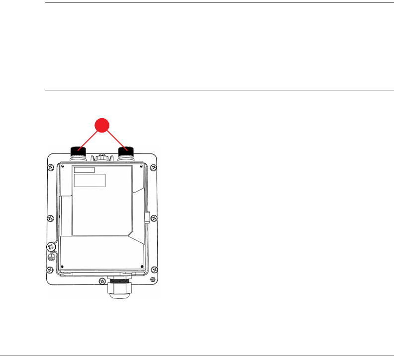
The ZoneFlex P300 is shipped from the factory with two metal caps protecting the
external antenna connectors (1 in Figure 8). If you are not connecting external
antennas to the ZoneFlex P300, then make sure that the metal caps remain installed
and securely fastened to protect the connectors from elements, such as water and
dirt.
NOTE When two ZoneFlex P300s are mounted closely together (for instance, on
the same pole), make sure that the active antennas are mounted at least one meter
(39.3 inches) apart. When there is more separation, it is less likely that either
ZoneFlex P300 will experience avoidable RF interference. If possible, the units
should be on different channels, but this separation should be maintained even when
the ZoneFlex P300s are using different channels.
Figure 8. ZoneFlex P300 external antenna connectors
1

Installing the Access Point
Aiming Point-to-Point ZoneFlex P300s
ZoneFlex P300 Wireless Bridge User Guide, 800-70956-001 Rev B 20
Installing the Access Point
This guide assumes that the ZoneFlex P300s have already been installed and have
already been initially configured as described in the ZoneFlex P300 Wireless Bridge
Quick Setup Guide and ZoneFlex P300 Wireless Bridge Mounting Guide. The
following sections contain additional information, if required:
•Aiming Point-to-Point ZoneFlex P300s
•Aiming Point-to-Multipoint ZoneFlex P300s
•Verifying Association Between the ZoneFlex P300s
•Setting the Distance Between Root Bridge and Non-Root Bridges
•Verifying the Connection
Aiming Point-to-Point ZoneFlex P300s
The ZoneFlex P300 wireless bridge throughput depends on an accurate alignment
of the two communicating ZoneFlex P300s, because the highest throughput is
generally achieved with the strongest signal. The ZoneFlex P300 is equipped with
an internal aiming function that is based on the received signal strength indicator
(RSSI) power measurement. Table 4 lists the signal strengths associated with each
of the LEDs.
NOTE For point-to-multipoint installations, refer to Aiming Point-to-Multipoint
ZoneFlex P300s.
NOTE When two ZoneFlex P300s are mounted closely together (for instance, on
the same pole), make sure that the active antennas are mounted at least one meter
(39.3 inches) apart. When there is more separation, it is less likely that either
ZoneFlex P300 will experience avoidable RF interference. If possible, the units
should be on different channels, but this separation should be maintained even when
the ZoneFlex P300s are using different channels.
As described in the ZoneFlex P300 Wireless Bridge Mounting Guide, the ZoneFlex
P300 has two buttons inside the PoE IN port.
1Press and hold the Aiming button (closer to the LEDs) to put the ZoneFlex P300
into aiming mode and then point the ZoneFlex P300 antenna toward the far-end
ZoneFlex P300 antenna. (The P300 remains in aiming mode for 15 minutes after
aiming is started.)

Installing the Access Point
Aiming Point-to-Multipoint ZoneFlex P300s
ZoneFlex P300 Wireless Bridge User Guide, 800-70956-001 Rev B 21
2Use the 5G through PWR LEDs to determine the signal strength:
• When all four 5G through PWR LEDs are solid green, the ZoneFlex P300 is
receiving the strongest signal possible.
• When some LEDs are flashing green or off, reposition the ZoneFlex P300
antenna to achieve a better signal.
• When the highest number of LEDs are solid green, tighten the antenna or
ZoneFlex P300 mount to align the antenna with the strongest signal.
3Repeat this procedure for the far-end ZoneFlex P300.
Continue with Verifying Association Between the ZoneFlex P300s.
Aiming Point-to-Multipoint ZoneFlex P300s
In a point-to-multipoint installation, the procedure is slightly different.
NOTE For point-to-point installations, refer to Aiming Point-to-Point ZoneFlex
P300s.
NOTE When two ZoneFlex P300s are mounted closely together (for instance, on
the same pole), make sure that the active antennas are mounted at least one meter
(39.3 inches) apart. When there is more separation, it is less likely that either
ZoneFlex P300 will experience avoidable RF interference. If possible, the units
should be on different channels, but this separation should be maintained even when
the ZoneFlex P300s are using different channels.
1Choose the “optimal pair” (one root bridge and one non-root bridge) for your
network. The “optimal pair” can be determined by placement location,
throughput requirements, or other factors.
For example, if you are installing three non-root bridges spaced away from each
other, you would likely want to choose the one closest to the middle of the root
bridge coverage area. This can help provide an optimal balance of performance
for all three non-root bridges.
2Complete the aiming procedure for the selected “optimal pair” first, as described
in Aiming Point-to-Point ZoneFlex P300s.
3Repeat the aiming procedure for each additional non-root bridge, while leaving
the root bridge antenna fixed.
Continue with Verifying Association Between the ZoneFlex P300s.
Installing the Access Point
Verifying Association Between the ZoneFlex P300s
ZoneFlex P300 Wireless Bridge User Guide, 800-70956-001 Rev B 22
Verifying Association Between the ZoneFlex P300s
Once the initial configuration and installation procedures have been completed,
verify that your ZoneFlex P300s have associated with one another.
1If not already done, log into the root bridge Web interface as described in Logging
Into the ZoneFlex P300 Web Interface.
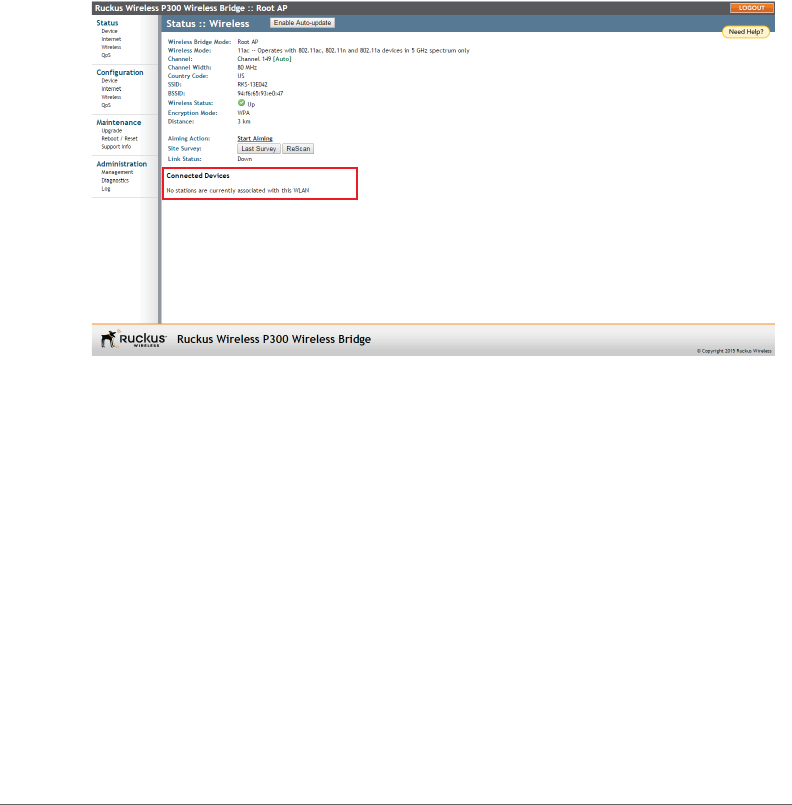
2Navigate to Status > Wireless. The Web interface displays the Status > Wireless
page. If no association has been established, then the ZoneFlex P300 displays:
Figure 9. No association established
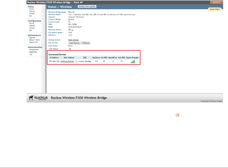
3The ZoneFlex P300s automatically associate with one another, usually within one
to two minutes. Once the association is complete, the Status > Wireless page
refreshes and displays the Connected Devices information as shown:
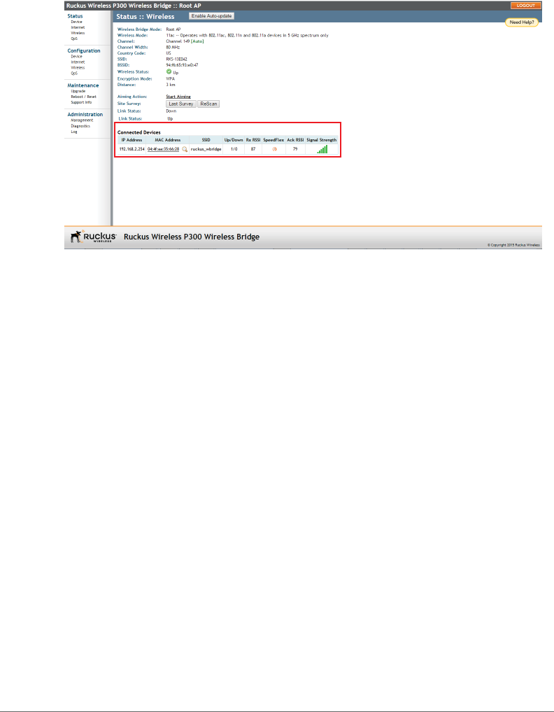
Installing the Access Point
Setting the Distance Between Root Bridge and Non-Root Bridges
ZoneFlex P300 Wireless Bridge User Guide, 800-70956-001 Rev B 23
Figure 10. Association established
4If no association is established after a few minutes, make sure that the SSID and
Passphrase are set to the same values, and that Channel is set to SmartSelect
(or to the same channel, if set manually) as described in Configuring Wireless
Settings.
If all of these settings are correct and the ZoneFlex P300s still fail to associate,
then the Web interface provides several tools for diagnosing the problem, which
can be found by navigating to Administration > Diagnostics. Tools include
Ping, Traceroute, Show ARP Table and Show FDB Table as described in Running
Diagnostics.
After the ZoneFlex P300s are associated with each other, continue with Setting the
Distance Between Root Bridge and Non-Root Bridges.
Setting the Distance Between Root Bridge and Non-
Root Bridges
1If not already done, log into the root bridge Web interface as described in Logging
Into the ZoneFlex P300 Web Interface.
2Navigate to Configuration > Wireless. The Web interface displays the
Configuration > Radio 5G page.
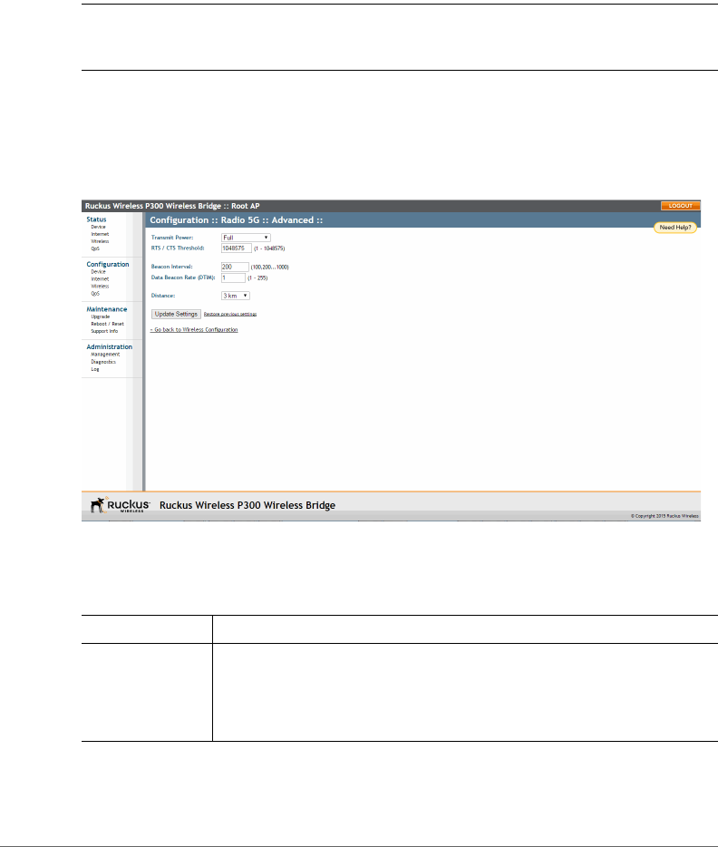
3On the Configuration > Radio 5G page, click Edit Advanced Settings next to
Advanced Settings. The Web interface displays the Configuration > Radio 5G >
Advanced page.
Installing the Access Point
Verifying the Connection
ZoneFlex P300 Wireless Bridge User Guide, 800-70956-001 Rev B 24
4In the Configuration > Radio 5G > Advanced page, select the approximate
distance between the root bridge and non-root bridges from the Distance drop-
down menu. (Default=3km.)
5Click Update Settings to confirm your changes.
After you have set the distance between the root bridge and non-root bridges,
continue with Verifying the Connection.
Verifying the Connection
Once you have completed the hardware installation and aiming procedure for all
ZoneFlex P300s, verify the connection and signal integrity between a root bridge
and non-root bridge pair using the following procedure:
1If not already done, log into the root bridge Web interface as described in Logging
Into the ZoneFlex P300 Web Interface.
2Navigate to Status > Wireless. On the Status > Wireless page, make sure that
the non-root bridge is listed in the Connected Devices section.
Figure 11. Viewing connected devices from the Web interface
3On the Status > Wireless page, click the SpeedFlex icon to launch the
SpeedFlex Wireless Performance Test.
4Click Start to begin testing.
5Once the test is completed, the following result page is displayed.

Installing the Access Point
Verifying the Connection
ZoneFlex P300 Wireless Bridge User Guide, 800-70956-001 Rev B 25
Figure 12. SpeedFlex Performance Test succeeded
Refer to Configuring the ZoneFlex P300 to fine-tune the ZoneFlex P300 configura-
tion, or refer to Managing the ZoneFlex P300 to monitor and operate the ZoneFlex
P300.


Before You Begin: Preconfiguring the ZoneFlex P300
ZoneFlex P300 Wireless Bridge User Guide, 800-70956-001 Rev B 27
Before You Begin: Preconfiguring the
ZoneFlex P300
NOTE ZoneFlex P300s are shipped from the factory with ZoneFlex P300 100.x
base image firmware, which supports standalone and FlexMaster (FM) manager
operation. The ZoneFlex P300 100.1.0.9 base image does not support Ruckus
Wireless controller operation.
NOTE DO NOT connect the ZoneFlex P300 to your live network at this point. If
you connect it to a live network with an active DHCP server, the ZoneFlex P300 can
acquire a new IP address from the DHCP and you may be unable to access it via
the default IP address (192.168.2.1).
Logging Into the ZoneFlex P300 Web
Interface
This section describes the steps you need to complete to set up the ZoneFlex P300
in standalone mode or to be managed by a Ruckus Wireless FlexMaster manager,
if you have one installed on the network.
1Collect the required materials: before starting with the configuration task, make
sure that you have the following requirements ready:
• An administrative computer (notebook computer) with an Ethernet port and
a wireless card installed.
• A Web browser such as Chrome 39 or later, Firefox 33 or later, or Internet
Explorer 10 or later installed on the administrative computer.
• One Cat5e unshielded twisted pair (UTP) Ethernet cable.
You can manage your ZoneFlex P300 with the integrated Web interface. However,
if your Ruckus Wireless network is managed by a Ruckus Wireless controller, then
you can manage ZoneFlex P300s using the controller rather than individually logging
into each ZoneFlex P300’s Web interface.

Logging Into the ZoneFlex P300 Web Interface
ZoneFlex P300 Wireless Bridge User Guide, 800-70956-001 Rev B 28
NOTE The following procedure assumes that you know the static IP address of
the ZoneFlex P300, or you have some means of determining the dynamic IP address
of the ZoneFlex P300. The PC you use for ZoneFlex P300 administration should be
on the management VLAN, if VLANs are used in your network.
Refer to the ZoneFlex P300 Wireless Bridge Quick Setup Guide for instructions on
how to connect an administrative computer to the ZoneFlex P300.
2On the PC, open a Web browser window.
3In the address or location bar, type the IP address of the ZoneFlex P300. Default
IP address for standalone ZoneFlex P300s:
192.168.2.1 (or 192.168.2.254 for non-root bridges)
4Press <Enter> to connect to the Web interface.
5If a Windows security alert dialog box appears, then click Yes or OK or Proceed
anyway (depending on the browser) to continue. The Ruckus Wireless Admin
login page appears.
6In Username, type super.
7In Password, type sp-admin.
8Click Login.
The ZoneFlex P300 Web interface appears.
Navigating the Web Interface
ZoneFlex P300 Wireless Bridge User Guide, 800-70956-001 Rev B 29
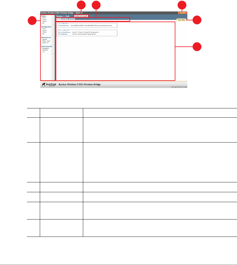
Navigating the Web Interface
You can manage the ZoneFlex P300 through a Web browser-based interface using
any networked computer. Tab l e 5 lists the Web interface features that are identified
in Figure 13.
Figure 13. Elements of the ZoneFlex P300 Web Interface
Table 5. ZoneFlex P300 Web interface elements
No. Element Description
1 Menu Under each category (Status, Configuration, etc.) are options
that, when clicked, open the related workspace in the area to
the right.
2Enable
Auto-update
button
Enable or disable automatic refresh of this interface page. For
example, on the Status > Wireless page, you can enable
auto-update during Aiming, so that you do not need to manually
refresh the page as you adjust the orientation of the ZoneFlex
P300.
3 Tabs Contains additional options for the page.
4 LOGOUT button Click this button to log out of the ZoneFlex P300.
5 Help button Click this button to open a help window with information related
specifically to the options currently displayed in the workspace.
6 Workspace This large area displays features, options and indicators relevant
to your menu bar choices.
1
4
5
6
3
2

ZoneFlex P300 Wireless Bridge User Guide, 800-70956-001 Rev B 30
3
Configuring the ZoneFlex P300
NOTE If the ZoneFlex P300 has been configured with Ruckus Wireless controller-
compatible firmware, then the ZoneFlex P300 controller-compatible firmware is
already installed and configured; you have completed the ZoneFlex P300
installation. When you plan to manage your Ruckus Wireless network using a
Ruckus Wireless controller, refer to the associated controller user documents,
available from the Ruckus Wireless website at
http://support.ruckuswireless.com/documents
If the ZoneFlex P300 is to be run in a standalone configuration or is to be managed
by a FlexMaster manager, then continue with this section.
This chapter provides instructions for configuring ZoneFlex P300s in a standalone
configuration or when the ZoneFlex P300 is to be managed by a FlexMaster
manager.
System configuration settings are divided into wireless configuration settings, bridge
configuration settings and QoS settings. The Configuration > Wireless page allows
you to set parameters that affect the wireless link between the root bridge and non-
root bridges. Note that any configuration changes on this page made for one unit
must also be made for the other units.
The Configuration > Bridge page allows you to set parameters specific to the unit
you are currently accessing, such as device name, location, login name and
password.
In this chapter:
•Configuring Wireless Settings
•Configuring Device Settings
•Configuring Internet Settings
•Configuring QoS
•Reversing Root Bridge and Non-Root Bridge Roles
Configuring Wireless Settings
ZoneFlex P300 Wireless Bridge User Guide, 800-70956-001 Rev B 31
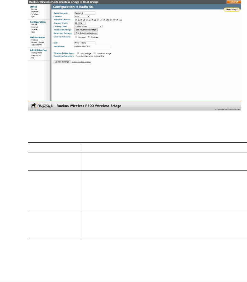
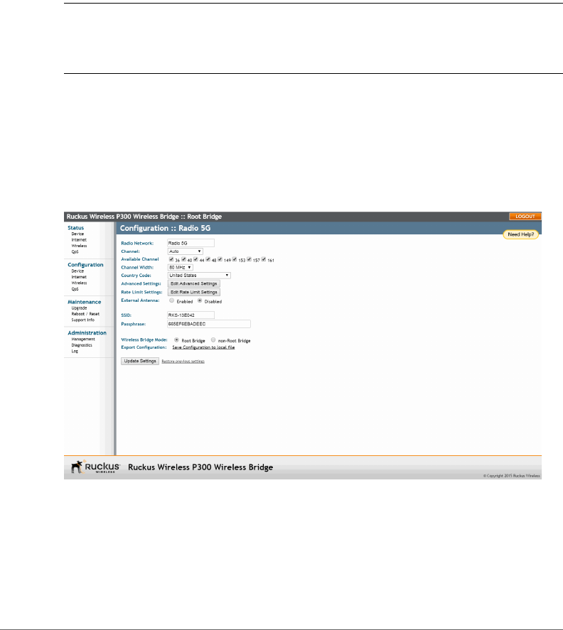
Configuring Wireless Settings
1Go to Configuration > Wireless. The Configuration > Radio 5G page (Figure
14) appears.
Figure 14. Typical Configuration > Radio 5G page
2Make changes to the wireless settings listed in the table below.
Table 6. Wireless settings
Setting Description
Radio Network Allows you to change the name of the 5GHz radios (default: Radio
5G).
Channel This option lets you select the channel used by the network. You
can choose Auto, or choose a specific channel. If you choose
Auto, then the ZoneFlex P300 automatically selects the best
channel (encountering the least interference) to transmit the
signal.
Available Channel This option lets you limit the channels used by the ZoneFlex P300.
Check the boxes for the allowed channels, and uncheck the
boxes for the disallowed channels.

Configuring Wireless Settings
ZoneFlex P300 Wireless Bridge User Guide, 800-70956-001 Rev B 32
Channel Width The option to choose 40 MHz channel width theoretically
provides double the data capacity of a 20 MHz channel. However,
more channel width means fewer channels available, and more
interference with other wireless signals.
The option to choose 80 MHz channel width theoretically
provides four times the data capacity of a 20 MHz channel.
However, more channel width means fewer channels available,
and more interference with other wireless signals.
Country Code This option (if enabled) lets you select your country or region code.
CAUTION: Selecting the incorrect country or region may result
in violation of applicable laws. If you purchased the ZoneFlex
P300 in the United States of America, you do not need to set
the country code manually. Ruckus Wireless devices that are
sold in the USA are preconfigured with the correct country
code and this setting is not configurable.
Advanced Settings Refer to Editing Advanced Settings.
Rate Limit Settings Refer to Rate Limiting.
External Antenna ZoneFlex P300s provide two external antenna ports, in case you
want to attach external antenna(s) to extend the range or
coverage area of your wireless network. To enable the ZoneFlex
P300 to use the external antenna(s), select the Enabled option
in this section. This option is disabled by default.
Cable Loss (Only if External Antenna is Enabled.) Enter the external antenna
cable loss. Default = 5dB.
External Antenna
Gain
(Only if External Antenna is Enabled.) Set the external antenna
gain as required to comply with local and regional regulations.
Default = 5dBi.
SSID This is the publicly-broadcast name of your wireless network.
SSIDs can contain up to 32 alphanumeric characters and are
case-sensitive. The maximum SSID length can only contain
between 2 and 32 characters, including characters from ! (char
33) to ~ (char 126). Default = ruckus_wbridge.
Passphrase Enter a new passphrase between 8 and 32 characters long, using
any combination of printable characters (letters, numbers,
hyphens and underscores).
Table 6. Wireless settings (Continued)

Configuring Wireless Settings
ZoneFlex P300 Wireless Bridge User Guide, 800-70956-001 Rev B 33
3Click Update Settings to have the ZoneFlex P300 save your changes.
Wireless Bridge
Mode
Used to manually designate the unit as the root bridge or non-
root bridge.
By default, the ZoneFlex P300 is configured to automatically
obtain an IP address from a DHCP server on the network. If the
ZoneFlex P300 does not detect a DHCP server, it automatically
assigns itself a static IP address to make it easier for you to
preconfigure and deploy it on your network. The default IP
addresses for the root bridge and non-root bridge (if no DHCP
server is available) are as follows:
• root bridge: 192.168.2.1
• non-root bridge: 192.168.2.254
Also refer to Reversing Root Bridge and Non-Root Bridge
Roles.
Export
Configuration
Only available from the root bridge Web interface. Use this link to
save a root bridge configuration file to an admin computer. This
configuration file can then be used to easily configure non-root
bridges with matching settings.
Table 6. Wireless settings (Continued)
Configuring Wireless Settings
ZoneFlex P300 Wireless Bridge User Guide, 800-70956-001 Rev B 34
Editing Advanced Settings
Advanced wireless settings should only be changed by an experienced adminis-
trator. Incorrect settings can severely impact wireless performance. It is recom-
mended that the default settings be retained for best performance.
NOTE To fully benefit from the ZoneFlex P300’s capabilities, it is advisable not to
change these values unless absolutely necessary.
1Go to Configuration > Wireless. The Configuration > Radio 5G page appears.
2On the Configuration > Radio 5G page, click Edit Advanced Settings. The
Configuration > Radio 5G > Advanced page (Figure 15) appears.
Figure 15. The Configuration > Radio 5G > Advanced page
3Configure the advanced settings listed in Ta b le 7 as required.
Table 7. Advanced wireless common settings
Option Description
Transmit Power The default setting is Full. Select the level of transmit power from the
drop-down menu. This option sets the maximum transmit power level
relative to the predefined power (this value differs according to the
current country code).

Configuring Wireless Settings
ZoneFlex P300 Wireless Bridge User Guide, 800-70956-001 Rev B 35
4Click Update Settings to have the ZoneFlex P300 save and apply the changes.
RTS/CTS
Threshold
This option determines at what packet length the RTS/CTS function
is triggered. A lower threshold may be necessary in an environment
with excessive signal noise or hidden nodes, but may result in some
performance degradation. (The default value is 1048575.)
Beacon Interval The value indicates the frequency interval of the beacon in
milliseconds. A beacon is a broadcast packet sent by the ZoneFlex
P300 to synchronize the wireless network. (The default value is 200.)
Data Beacon
Rate (DTIM)
The value indicates the interval of the delivery traffic indication
message (DTIM). This is a countdown field that the device uses to
inform its clients of the next window for listening to broadcast or
multicast messages. (The default value is 1.)
Distance Manually setting a distance can help operators configure RTS/CTS
thresholds and other wireless settings. Select the approximate
distance (within 1 km) between root bridge and non-root bridges.
NOTE: Set the root bridge to the distance of the farthest away non-
root bridge (in kilometers). Set non-root bridges to the actual distance
to the root bridge.
Table 7. Advanced wireless common settings (Continued)
Configuring Wireless Settings
ZoneFlex P300 Wireless Bridge User Guide, 800-70956-001 Rev B 36
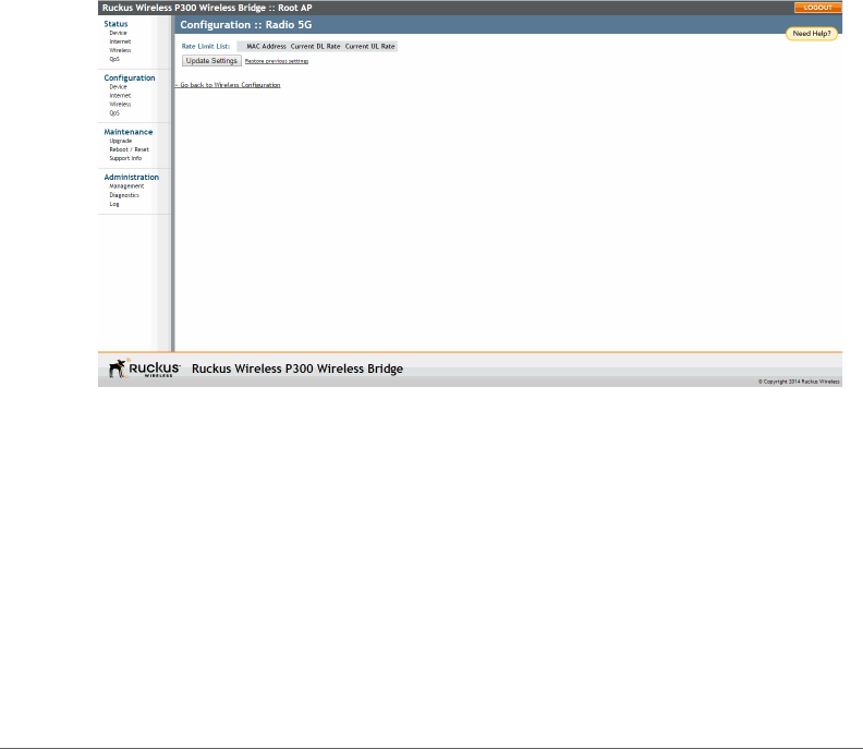
Rate Limiting
Rate Limiting allows you to cap per-client data transfer rates.
1Go to Configuration > Wireless. The Configuration > Radio 5G page appears.
2Click Edit Rate Limit Settings next to Rate Limit Settings. The Rate Limit List
page appears.
3Set the maximum Downlink and Uplink rate per station.
The table below your selections updates to show the maximum transfer rate per
station for each traffic type.
4Click Update Settings to have the ZoneFlex P300 save your changes.
You have completed configuring the rate limiting options. To reopen the previous
page, click the Go back to Wireless Configuration link.
Figure 16. Limit per-station traffic rates
Configuring Device Settings
Configuring the ZoneFlex P300 Name, Location, GPS Coordinates, and LED Appearance
ZoneFlex P300 Wireless Bridge User Guide, 800-70956-001 Rev B 37
Configuring Device Settings
This section describes how to view and configure physical, network and manage-
ment settings specific to this ZoneFlex P300. Topics discussed include:
•Configuring the ZoneFlex P300 Name, Location, GPS Coordinates, and LED
Appearance
•Changing the Administrator Username and Password
•Configuring TACACS+ Remote Login Information
Configuring the ZoneFlex P300 Name, Location, GPS
Coordinates, and LED Appearance
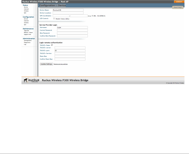
1Navigate to Configuration > Device. The ZoneFlex P300 Web GUI displays the
Configuration > Device page (Figure 17).
Figure 17. The Configuration > Device page
2In Device Name, type a new name for the device or leave as is to accept the
default device name (RuckusWB). The device name identifies this ZoneFlex P300
among other devices on the network.
3Configure the following optional settings as desired:
• Enter an alphanumeric Device Location to keep track of the physical location
of the ZoneFlex P300, if required.
•In GPS Coordinates, enter the GPS coordinates, if required.

Configuring Device Settings
Changing the Administrator Username and Password
ZoneFlex P300 Wireless Bridge User Guide, 800-70956-001 Rev B 38
• Under LED Control, check the Disable Status LED(s) box to turn off the status
LEDs. This can be useful when the ZoneFlex P300 is installed in a public
location, to avoid drawing attention to the ZoneFlex P300.
4Click Update Settings to have the ZoneFlex P300 save and apply your changes.
Changing the Administrator Username and Password
1Navigate to Configuration > Device. The ZoneFlex P300 Web GUI displays the
Configuration > Device page (Figure 17).
2Under Service Provider Login, change the ZoneFlex P300 Web GUI login
information as required:
•Username: Type the name that you want to use for logging into the Web
interface. The default user name is super.
•Current Password: When you are changing the password, enter the existing
password here.
•New Password: When you are changing the password, enter the new
password. The password must consist of six to 32 alphanumeric characters.
•Confirm New Password: Retype the new password to confirm.
3Click Update Settings to have the ZoneFlex P300 save and apply your changes.
Configuring TACACS+ Remote Login Information
1Navigate to Configuration > Device. The ZoneFlex P300 Web GUI displays the
Configuration > Device page (Figure 17).
2Under Login remote authentication, click the TACACS+ State box to enable the
TACACS+ server interface, if required.
NOTE Terminal Access Controller Access-Control System Plus (TACACS+) is an
AAA protocol used to authenticate administrator login to this device. Users can be
authenticated/authorized to monitor, operate or configure this device. Default is
disabled.
Administrators can be assigned any of the following three administration privilege
levels:
•Super Admin (Perform all configuration and management tasks)
•Operator Admin (Change settings affecting single ZoneFlex P300s only)
•Monitoring Admin (Monitoring and viewing operation status only)

Configuring Device Settings
Configuring TACACS+ Remote Login Information
ZoneFlex P300 Wireless Bridge User Guide, 800-70956-001 Rev B 39
If the TACACS+ server state is enabled, then configure the TACACS+ server
parameters:
•TACACS+ server: IPv4 or IPv6 server address.
•TACACS+ port: 49 is the default, but it can be set to any available TCP port.
•TACACS+ Service: Login name.
•Share Key: TACACS+ Password.
•Confirm Share Key: retype the TACACS+ Password.
3Click Update Settings to have the ZoneFlex P300 save and apply your changes.

Configuring Internet Settings
VLAN Overview
ZoneFlex P300 Wireless Bridge User Guide, 800-70956-001 Rev B 40
Configuring Internet Settings
Internet settings define how the ZoneFlex P300 connects to your local area network
and to the Internet. This section describes how to view and configure the ZoneFlex
P300’s Internet settings. Topics discussed include:
•VLAN Overview
•Configuring an NTP Server
•Configuring the Management VLAN
•Obtaining and Assigning an IP Address
•Configuring the MTU Size
VLAN Overview
The ZoneFlex P300 is like a network switch, in that it supports Wi-Fi connections.
As such, like many advanced switches, ZoneFlex P300s conform to the IEEE
802.1Q standard -- the standard that defines virtual LANs. In an 802.1Q switch, the
concept of VLANs is always present. If a packet arrives without an 802.1Q header,
it is assigned to the native VLAN or untag VLAN.
The single ZoneFlex P300 wireless interface is assigned to assigned a single VLAN,
and is configured to pass all VLAN traffic as a Trunk Port.
The ZoneFlex P300 Ethernet port is also configured to pass all VLAN traffic as a
Trunk Port.
Configuring Internet Settings
Configuring an NTP Server
ZoneFlex P300 Wireless Bridge User Guide, 800-70956-001 Rev B 41
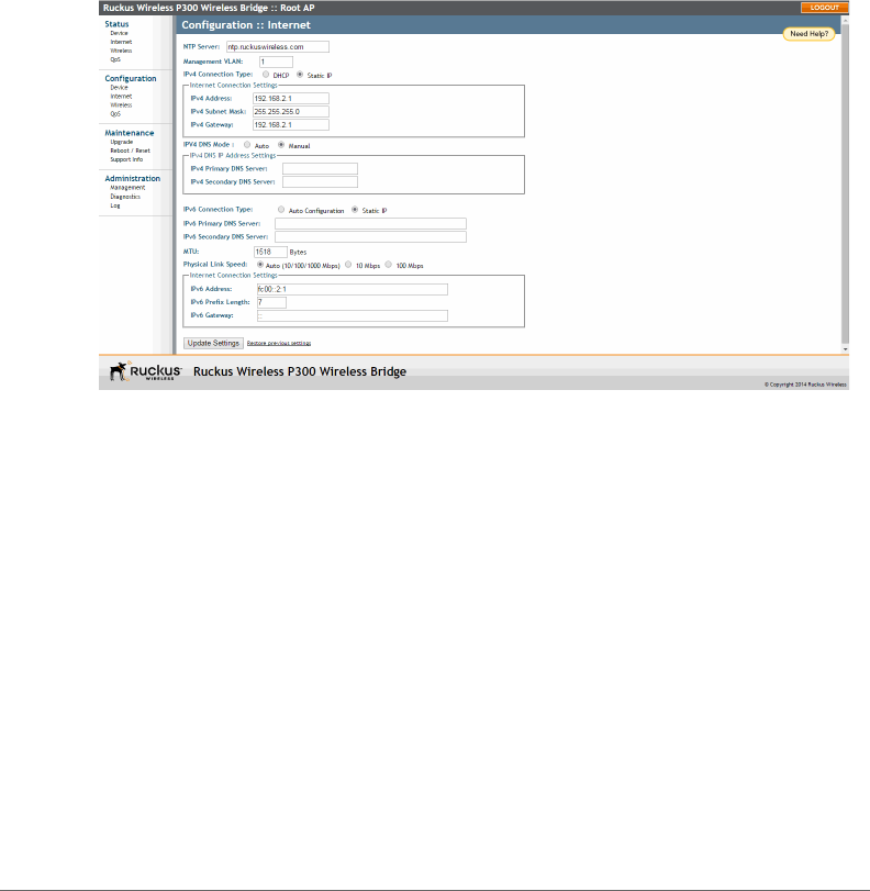
Configuring an NTP Server
A network time protocol (NTP) server should be configured to ensure that the
ZoneFlex P300 maintains the correct time. The default Ruckus Wireless NTP Server
(ntp.ruckuswireless.com) can be used if you do not have an NTP server on your
network.
1Navigate to Configuration > Internet. The ZoneFlex P300 Web GUI displays
the Configuration > Internet page (Figure 18).
Figure 18. The Configuration > Internet page
2Enter the host name in the NTP Server text box at the top of the page.
3Click Update Settings to have the ZoneFlex P300 save and apply your change.

Configuring Internet Settings
Configuring the Management VLAN
ZoneFlex P300 Wireless Bridge User Guide, 800-70956-001 Rev B 42
Configuring the Management VLAN
NOTE Changing the Management VLAN causes you to be immediately
disconnected from the Web interface if the computer you are using is not on the
same VLAN. Do not change the Management VLAN unless your admin PC is on
the same VLAN, or you are disconnected and unable to connect again without
factory resetting the ZoneFlex P300.
1Navigate to Configuration > Internet. The ZoneFlex P300 Web GUI displays
the Configuration > Internet page (Figure 18).
2Enter the VLAN ID in the Management VLAN text box.
3Click Update Settings to have the ZoneFlex P300 save and apply your change.

Configuring Internet Settings
Obtaining and Assigning an IP Address
ZoneFlex P300 Wireless Bridge User Guide, 800-70956-001 Rev B 43
Obtaining and Assigning an IP Address
By default, the ZoneFlex P300 is configured to automatically obtain an IPv4 address
from a DHCP server on the network. If the ZoneFlex P300 does not detect a DHCP
server, it automatically assigns itself the static IP address 192.168.2.1 for a root
bridge, or 192.168.2.254 for a non-root bridge to make it easier for you to
configure and deploy it on your network.
For IPv6, the Auto Configuration setting serves the same purpose as DHCP. The
default static IPv6 address is fc00::2:1 for a root bridge and fc00::2:254 for
a non-root bridge.
There are three methods of assigning IP addresses to the ZoneFlex P300:
•DHCP/Auto Configuration
•Configuring a Static IP
DHCP/Auto Configuration
When you leave the ZoneFlex P300 at its default configuration, it automatically
attempts to obtain an IPv4 address from a DHCP server on the network.
In an IPv6 network environment, the ZoneFlex P300 attempts to obtain an IPv6
address from an IPv6 Auto Configuration server.
Refer to the following:
•Renewing and Releasing DHCP
•Configuring IPv4 DHCP with Auto or Manual DNS Configuration
•Configuring IPv6 Auto Configuration
Renewing and Releasing DHCP
This task should be performed only if you have access to the DHCP server or have
some way to determine what IP address has been assigned to the ZoneFlex P300.
It serves as a troubleshooting technique when IP addresses to one or more
networked devices prove to be unusable or in conflict with others, or when the
ZoneFlex P300 loses its DHCP-assigned IP address for some reason.
1Navigate to Status > Internet. The ZoneFlex P300 Web GUI displays the
Status > Internet page (Figure 19).
Configuring Internet Settings
Obtaining and Assigning an IP Address
ZoneFlex P300 Wireless Bridge User Guide, 800-70956-001 Rev B 44
Figure 19. Renew or release DHCP
2If the current Connection Type is dhcp, then you are able to see the currently-
assigned IP address and subnet mask listed below.
• To force the ZoneFlex P300 to release its DHCP-assigned IP address, click
Release DHCP. This disconnects the user from Web interface as the system
reverts to its default IP address. Log into the device using the default IP
address (192.168.2.1 for a root bridge or 192.168.2.254 for a non-root
bridge) and click Renew DHCP to request a new lease from the DHCP server.
• Click Renew DHCP to request a new IP address lease from the DHCP server.
Note: The IP address may or may not change depending on the lease time
offered to this device.
Configuring IPv4 DHCP with Auto or Manual DNS Configuration
If you leave the ZoneFlex P300 at its default configuration, it attempts to obtain an
IPv4 address from a DHCP server on the network.
1Navigate to Configuration > Internet. The ZoneFlex P300 Web GUI displays
the Configuration > Internet page (Figure 18).
2In IPv4 Connection Type, select DHCP.
3In IPv4 DNS Mode, select Auto or Manual.
• When you select Auto, the ZoneFlex P300 automatically searches for an IPv4
DNS server.
• When you select Manual, also make the following entries:

Configuring Internet Settings
Obtaining and Assigning an IP Address
ZoneFlex P300 Wireless Bridge User Guide, 800-70956-001 Rev B 45
-IPv4 Primary DNS Server: The IP address of the primary Domain Name
System (DNS) server.
-IPv4 Secondary DNS Server: The IP address of the secondary DNS
server.
4Click Update Settings to have the ZoneFlex P300 save your changes
Configuring IPv6 Auto Configuration
In an IPv6 network environment, the ZoneFlex P300 attempts to obtain an IPv6
address from an IPv6 Auto Configuration server.
1Navigate to Configuration > Internet. The ZoneFlex P300 Web GUI displays
the Configuration > Internet page (Figure 18).
2In IPv6 Connection Type, select Auto Configuration.
3In IPv6 Primary DNS Server, enter the IP address of the primary IPv6 DNS server.
4In IPv6 Secondary DNS Server, enter the IP address of the secondary IPv6 DNS
server.
5Click Update Settings to have the ZoneFlex P300 save your changes
Configuring a Static IP
There are at least two instances when you need to configure a static IP address for
the ZoneFlex P300:
• If the current IP address that the ZoneFlex P300 is using consistently conflicts
with that of another device on the network.
• If you want to switch from DHCP to static IP addressing to manage and maintain
the ZoneFlex P300.
Unless you are able to determine the IP address assigned by the DHCP/Auto
Configuration server to the ZoneFlex P300, it may prove helpful for anyone needing
administrative access to assign a static IP address.
You can configure static addresses for IPv4, IPv6 or both. The ZoneFlex P300
maintains both sets of IP address settings if both are configured.
1Navigate to Configuration > Internet. The ZoneFlex P300 Web GUI displays
the Configuration > Internet page (Figure 18).
2In IPv4 Connection Type and/or IPv6 Connection Type, select Static IP.
3When the Internet Connection Settings options appear, you can make changes
to the following settings:

Configuring Internet Settings
Configuring the MTU Size
ZoneFlex P300 Wireless Bridge User Guide, 800-70956-001 Rev B 46
• (IPv6 only) IPv6 Primary DNS Server: The IP address of the primary IPv6 DNS
server.
• (IPv6 only) IPv6 Secondary DNS Server: The IP address of the secondary
IPv6 DNS server.
•IPv4/IPv6 Address: Enter the static IP address that you want to assign to the
ZoneFlex P300 in either IPv4 (dot-decimal) or IPv6 (colon-separated) format.
•IPv4 Subnet Mask or IPv6 Prefix Length: Enter the subnet mask or prefix
length for the network.
•IPv4/IPv6 Gateway: Enter the gateway IP address of the Internet interface.
4(IPv4 only) In IPv4 DNS Mode, select Auto or Manual.
• When you select Auto, the ZoneFlex P300 automatically searches for an IPv4
DNS server.
• When you select Manual, also make the following entries:
-IPv4 Primary DNS Server: The IP address of the primary DNS server.
-IPv4 Secondary DNS Server: The IP address of the secondary DNS
server.
5Click Update Settings to have the ZoneFlex P300 save your changes.
Configuring the MTU Size
You can adjust the maximum transmission unit (MTU) as follows:
1Navigate to Configuration > Internet. The ZoneFlex P300 Web GUI displays
the Configuration > Internet page (Figure 18).
2In the MTU text box, enter the largest protocol data unit that the ZoneFlex P300
can transmit and receive (default = 1518).
NOTE The MTU must be set to the same value on both ends of each link.
3Click Update Settings to have the ZoneFlex P300 save your changes.

Configuring QoS
Configuring Global QoS
ZoneFlex P300 Wireless Bridge User Guide, 800-70956-001 Rev B 47
Configuring QoS
QoS configuration allows you to classify and prioritize traffic according to either ToS
or Dot1p classifications. This section is for advanced network configuration. In
general, the default values should be retained for optimal traffic prioritizing.
CAUTION! Do not customize these options unless you are an experienced network
administrator or are under the guidance of an IT/support professional. These
settings should only be changed in rare circumstances, in situations where the
default settings need to be changed to match those of a non-standard network
configuration.
NOTE When Dot1p classification and ToS classification are both enabled, Dot1p
classification takes precedence. Therefore, if you want to use ToS classification,
Dot1p classification should be disabled.
Define the quality of service (QoS) traffic shaping as follows:
•Configuring Global QoS
•Configuring Ethernet QoS
•Configuring Wireless QoS
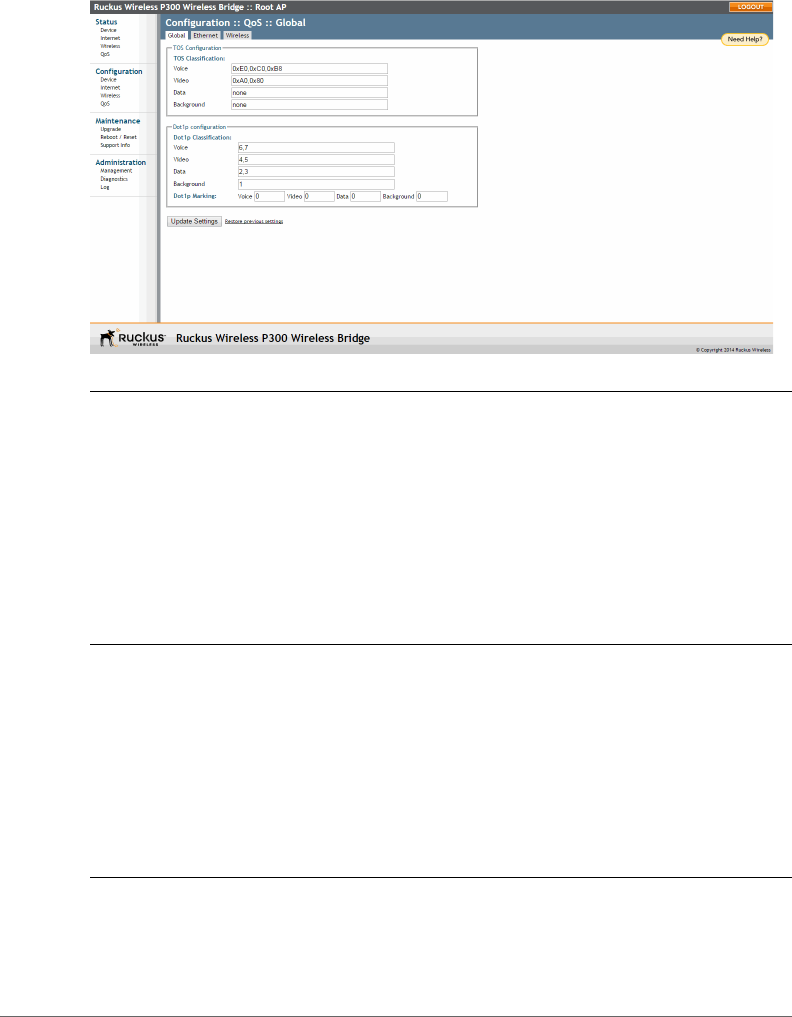
Configuring Global QoS
1Navigate to Configuration > QoS.
2Click the Global tab. The ZoneFlex P300 Web GUI displays the Configuration
> QoS > Global page (Figure 20).
Configuring QoS
Configuring Global QoS
ZoneFlex P300 Wireless Bridge User Guide, 800-70956-001 Rev B 48
Figure 20. Configuration > QoS > Global page
NOTE ToS Classification: Type of Service values are entries in a field in the IP header
of an incoming or outgoing packet used to classify IP packets into different WMM
priority queues. WMM priority queues consist of four traffic types called Access
Categories. The four Access Categories are as follows:
•Voice: voice traffic gets the highest priority
•Video: video traffic is given a higher priority than data or background traffic
•Data: low priority traffic
•Background: traffic that is less sensitive to latency and delays
3Set the TOS Classification by entering hex values into the following text boxes.
The hex values are used to classify packets into the four WMM queues using
ToS v alu e s .
• Voice -- Default = 0xE0,0xC0,0xB8
• Video -- Default = 0xA0,0x80
• Data -- Default = none
• Background -- Default = none
NOTE The Dot1p value is a field in the VLAN header that indicates the priority of
a VLAN-tagged packet. Dot1p classification is similar to ToS classification--when a
packet enters the ZoneFlex P300 from an interface, it is classified and prioritized

Configuring QoS
Configuring Global QoS
ZoneFlex P300 Wireless Bridge User Guide, 800-70956-001 Rev B 49
according to its Dot1p value. However, while ToS values apply to any IP packet that
enters the device, Dot1p values apply only to traffic belonging to the specified
VLANs.
For example, if Dot1p Classification is Enabled in the Ethernet tab and the value in
Dot1p Classification VLAN IDs is set to 10, this means that Dot1p Classification will
be performed on any ingress VLAN-tagged packets from the wireless interface
whose VLAN ID is 10, and it will not be performed on any other packet whose VLAN
ID is not 10.
The values used to prioritize traffic are intuitive: they range from 0 to 7, with 0 being
the lowest priority and 7 being highest priority.
4Set the Dot1p Classification by entering numeric (0-7) values into the following
text boxes. The numeric values are used to classify VLAN-tagged packets into
priority queues based on the VLAN ID. In Dot1p Classification VLAN IDs, enter
the VLANs for which you want to enable Dot1p classification. You can enter any
combination of individual VLAN IDs separated by commas, or enter a range (for
example, 1-4094).
• Voice -- Default = 6,7
• Video -- Default = 4,5
• Data -- Default = 2,3
• Background -- Default = 1
NOTE Dot1p Marking is the reverse operation of Dot1p Classification. Marking
involves setting the value of certain bits in the packet header to indicate the packet
priority.
Also set the Dot1p Marking by entering numeric (0-7) values into the following
text boxes. The numeric values are used to classify VLAN-tagged packets based
on priority queue values. For example, if the Dot1p marking value is 10, then the
ZoneFlex P300 only performs Dot1p marking on packets whose VLAN ID is 10.
• Voice -- Default = 0
• Video -- Default = 0
• Data -- Default = 0
• Background -- Default = 0
5Click Update Settings to have the ZoneFlex P300 save your changes.
Configuring QoS
Configuring Ethernet QoS
ZoneFlex P300 Wireless Bridge User Guide, 800-70956-001 Rev B 50
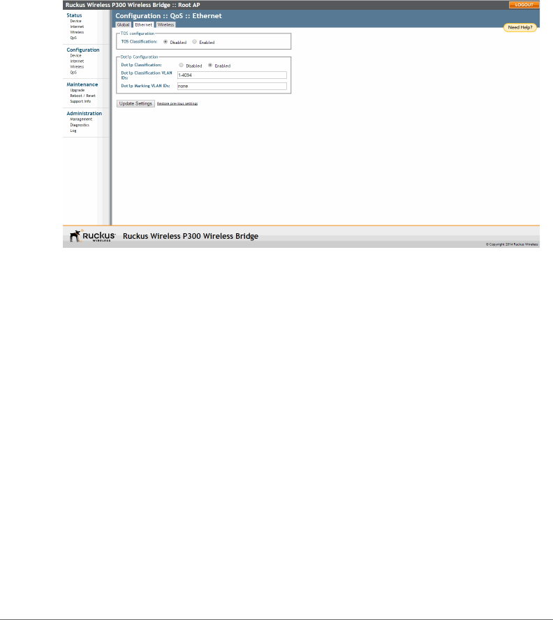
Configuring Ethernet QoS
1Navigate to Configuration > QoS.
2Click the Ethernet tab. The ZoneFlex P300 Web GUI displays the Configuration
> QoS > Ethernet page (Figure 21).
Figure 21. Configuration > QoS > Ethernet page
3Set the Ethernet QoS using the following entries:
•TOS Classification -- Enabled or Disabled on the Ethernet port. Default =
•Dot1p Classification -- Enabled or Disabled on the Ethernet port. Default =
•Dot1p Classification VLAN IDs -- you can enter any combination of individual
VLAN IDs separated by commas, or enter a range (for example, 1-4094) on
the Ethernet port. Default = 1-4094.
•Dot1p Marking VLAN IDs -- entering numeric (0-7) values into this text box.
The numeric value is used to classify VLAN-tagged packets based on priority
queue values on the Ethernet port. Default = none.
4Click Update Settings to have the ZoneFlex P300 save your changes.
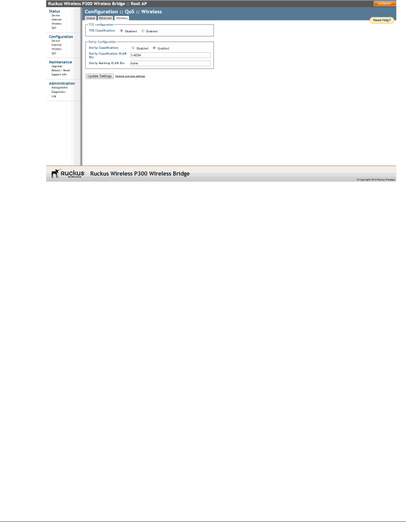
Configuring Wireless QoS
1Navigate to Configuration > QoS.
2Click the Global tab. The ZoneFlex P300 Web GUI displays the Configuration
> QoS > Wireless page (Figure 22).
Configuring QoS
Configuring Wireless QoS
ZoneFlex P300 Wireless Bridge User Guide, 800-70956-001 Rev B 51
Figure 22. Configuration > QoS > Wireless page
3Set the TOS Classification using the following entries:
•TOS Classification -- Enabled or Disabled on the wireless link. Default =
•Dot1p Classification -- Enabled or Disabled on the wireless link. Default =
•Dot1p Classification VLAN IDs -- you can enter any combination of individual
VLAN IDs separated by commas, or enter a range (for example, 1-4094) on
the wireless link. Default = 1-4094.
•Dot1p Marking VLAN IDs -- entering numeric (0-7) values into this text box.
The numeric value is used to classify VLAN-tagged packets based on priority
queue values on the wireless link. Default = none.
4Click Update Settings to have the ZoneFlex P300 save your changes.
Reversing Root Bridge and Non-Root Bridge Roles
Configuring Wireless QoS
ZoneFlex P300 Wireless Bridge User Guide, 800-70956-001 Rev B 52
Reversing Root Bridge and Non-Root Bridge
Roles
You can manually change the role of a non-root bridge to a root bridge, and vice
versa. This procedure requires that you directly log into both units using an admin
computer, as changing the role of either ZoneFlex P300 disrupts the wireless link.
NOTE When you are changing the role over the air, you need to configure the
remote ZoneFlex P300s first followed by the local ZoneFlex P300 to avoid loss of
connectivity.
1Configure the admin computer, connect it to the ZoneFlex P300, and log into
the ZoneFlex P300 Web GUI as described in Logging Into the ZoneFlex P300
Web Interface.
2Navigate to Configuration > Wireless. The ZoneFlex P300 Web GUI displays
the Configuration > Radio 5G page (Figure 23).
Figure 23. Changing the role from root bridge to non-root bridge
3In the Wireless Bridge Mode parameter, select Root Bridge or non-Root
Bridge.
4A warning message appears, indicating that a reboot is required. Click OK.
5Click Update Settings. The ZoneFlex P300 puts the setting changes into effect
immediately, and begins a reboot.

Reversing Root Bridge and Non-Root Bridge Roles
Configuring Wireless QoS
ZoneFlex P300 Wireless Bridge User Guide, 800-70956-001 Rev B 53
6Once the reboot is complete, the role is reversed.
7Repeat this procedure for each device whose role you want to change.

ZoneFlex P300 Wireless Bridge User Guide, 800-70956-001 Rev B 54
4
Managing the ZoneFlex P300
In this chapter:
•Viewing Current Device Status
•Viewing Current Internet Status
•Viewing Current Wireless Status
•Viewing Current QoS Status
•Manually Upgrading the Firmware
•Scheduling Automatic Firmware Upgrades
•Changing the Administrative Login Settings
•Enabling Other Management Access Options
•Working with Event Logs and Syslog Servers
•Rebooting the ZoneFlex P300
•Resetting the ZoneFlex P300 to Factory Defaults
•Running Diagnostics
•Scanning for Interference
•Moving Traffic to Another Channel
•Where to Find More Information
This chapter provides instructions for managing standalone ZoneFlex P300s using
the ZoneFlex P300 Web interface. For information on managing your network using
a Ruckus Wireless controller or FlexMaster (FM) manager, refer to the relevant User
Guide, available from the Ruckus Wireless Support website.
Viewing Current Device Status
ZoneFlex P300 Wireless Bridge User Guide, 800-70956-001 Rev B 55
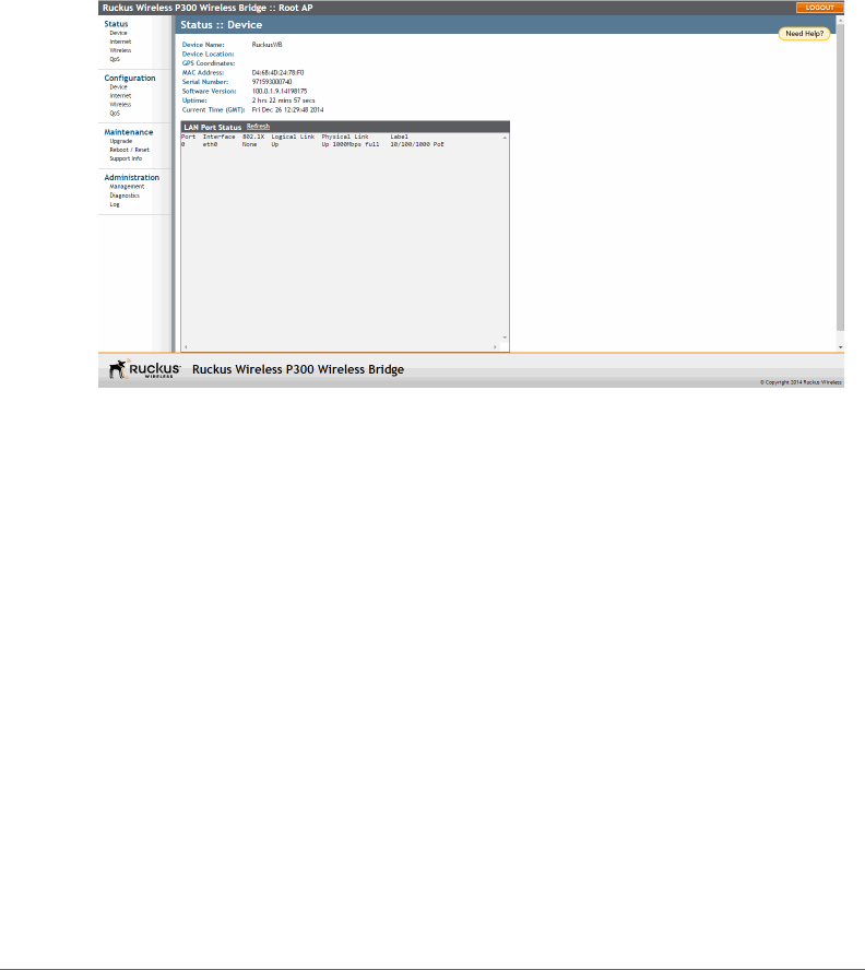
Viewing Current Device Status
The Status > Device page displays a general overview of the ZoneFlex P300’s
current status, including device name, MAC address, serial number, current soft-
ware (image) version, and so on.
Figure 24. The Status > Device page
Viewing Current Internet Status
ZoneFlex P300 Wireless Bridge User Guide, 800-70956-001 Rev B 56
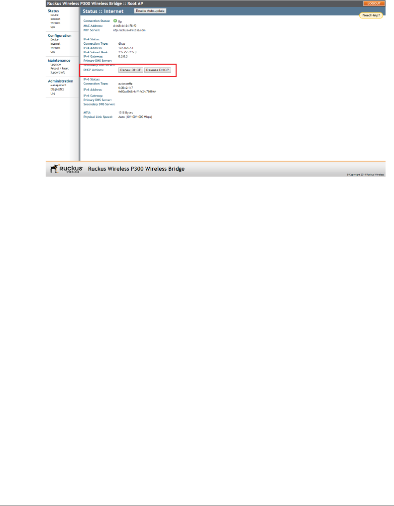
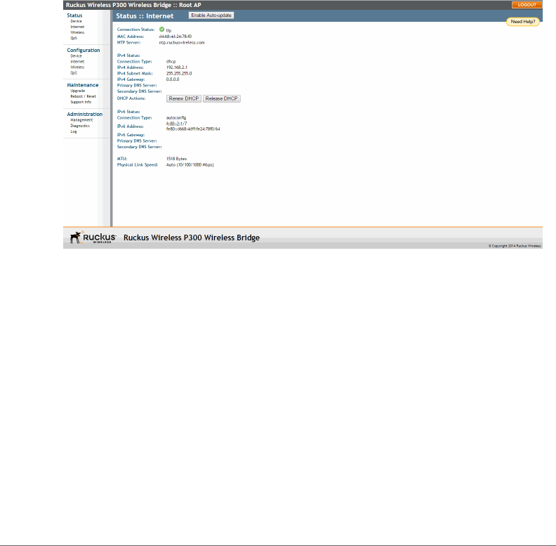
Viewing Current Internet Status
The Status > Internet page displays information on the ZoneFlex P300’s network
settings; that is, the settings that allow the ZoneFlex P300 to communicate with
your local network and the Internet. Information includes IP address, gateway, DNS
server, NTP server and connection type (method of obtaining an IP address -- DHCP
or static IP), and so on.
The Status > Internet page also allows you to perform renew and release DHCP
actions, as described in Renewing and Releasing DHCP.
Figure 25. The Status > Internet page
Viewing Current Wireless Status
ZoneFlex P300 Wireless Bridge User Guide, 800-70956-001 Rev B 57
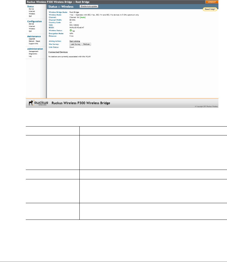
Viewing Current Wireless Status
If you want to view the current ZoneFlex P300 wireless settings and status, go to
the Status > Wireless page. Table 8 lists the descriptions of each wireless setting.
Figure 26. The Status > Wireless page
Table 8. Common Wireless settings
Setting Description
Wireless Bridge Mode Shows the wireless mode that the ZoneFlex P300 is currently
using. Possible values include:
•Root Bridge
•non-Root Bridge
Wireless Mode Lists the supported 802.11 devices and the spectrum used.
Channel Shows the wireless channel that the ZoneFlex P300 is currently
using. If you set the wireless channel to SmartSelect, this field
shows the value Channel # [Auto].
Channel Width Displays whether the channel width is set to 20MHz, 40MHz
or 80MHz.

Viewing Current Wireless Status
ZoneFlex P300 Wireless Bridge User Guide, 800-70956-001 Rev B 58
If you want to make changes to any of these settings, then refer to Configuring
Wireless Settings for more information.
Country Code Shows the country code that the ZoneFlex P300 has been set
to use.
CAUTION: Verify that the ZoneFlex P300 is using the correct
country code to make sure it uses only the allowed radio
channels in your region. Selecting the incorrect country code
may result in violation of applicable laws.
SSID Assigned service set identifier.
BSSID Factory-defined basic service set identifier/MAC address.
Wireless Status Whether the wireless network is Enabled and Up or Down.
Broadcast SSID? Whether SSID broadcast is Enabled or Disabled.
Encryption Mode Always WPA.
Distance Operator-entered distance between root bridge and non-root
bridge (in km).
Aiming Action Current Aiming status. (Note: The P300 remains in aiming mode
for 15 minutes after aiming is started.)
Site Survey Click to view the results of the most-recent interference survey,
or to rescan for current interference.
Link Status Whether the root bridge-to-non-root bridge link is Up or Down.
Connected Devices List all devices connected to this ZoneFlex P300.
Table 8. Common Wireless settings (Continued)
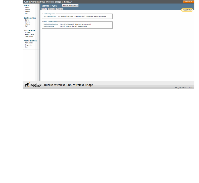
Viewing Current QoS Status
Viewing Global QoS
ZoneFlex P300 Wireless Bridge User Guide, 800-70956-001 Rev B 59
Viewing Current QoS Status
View the quality of service (QoS) status as follows:
•Viewing Global QoS
•Viewing Ethernet QoS
•Viewing Wireless QoS
Viewing Global QoS
Figure 27 shows the Status > QOS > Global page. Refer to Configuring Global QoS
for a description of the information on this page.
Figure 27. The Status > QOS > Global page
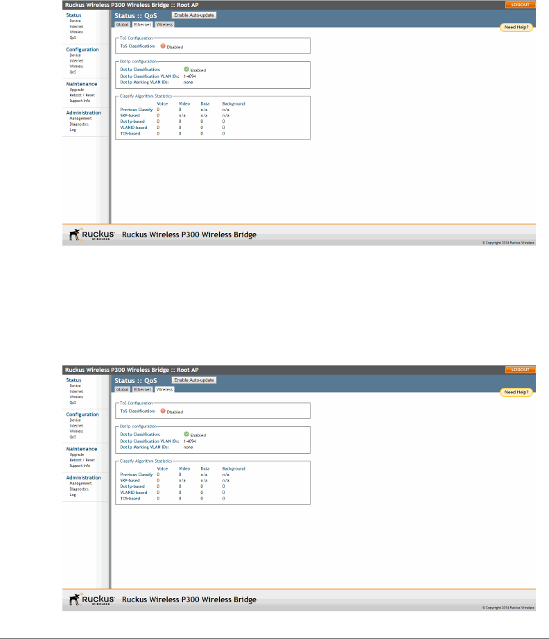
Viewing Current QoS Status
Viewing Ethernet QoS
ZoneFlex P300 Wireless Bridge User Guide, 800-70956-001 Rev B 60
Viewing Ethernet QoS
Figure 28 shows the Status > QOS > Ethernet page. Refer to Configuring Ethernet
QoS for a description of the information on this page.
Figure 28. The Status > QOS > Ethernet page
Viewing Wireless QoS
Figure 29 shows the Status > QOS > Wireless page. Refer to Configuring Wireless
QoS for a description of the information on this page.
Figure 29. The Status > QOS > Wireless page
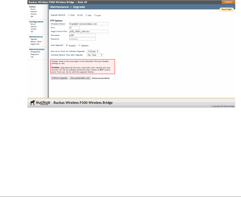
Manually Upgrading the Firmware
Viewing Wireless QoS
ZoneFlex P300 Wireless Bridge User Guide, 800-70956-001 Rev B 61
Manually Upgrading the Firmware
You can use the Web interface to check for software updates/upgrades for the
firmware image built into the ZoneFlex P300. You can then apply these updates to
the device in one of two ways: (1) manually updating on an as-needed basis, as
described in this section, or (2) automating a regularly scheduled update, as
described in Scheduling Automatic Firmware Upgrades.
Before starting, decide which option you want to take:
• Automate a regularly scheduled update.
• Run a one-time manual update right now.
By default, the automatic upgrade option is disabled.
1To upgrade the firmware image, go to Maintenance > Upgrade. The ZoneFlex
P300 Web GUI displays the Maintenance > Upgrade page (Figure 30).
Figure 30. The Maintenance > Upgrade page
2When the Maintenance > Upgrade page appears, decide which upgrade
method to use. Each of the upgrade options listed on the Upgrade page are
discussed in the following sections.
•Upgrading Manually using FTP or TFTP
•Upgrading Manually using the Web
•Upgrading Manually using a Local File

Manually Upgrading the Firmware
Upgrading Manually using FTP or TFTP
ZoneFlex P300 Wireless Bridge User Guide, 800-70956-001 Rev B 62
Upgrading Manually using FTP or TFTP
1In the Upgrade Method options, click FTP (default) or TFTP.
2Click the host name field, and then type the URL of the server. Or click the IP
address field, and then type the IP address of the server. Remember to start the
URL with ftp://.
CAUTION! Do not change any of the Image Control File, Username or Password
entries.
3Click Perform Upgrade. A status bar appears during the upgrade process.
4After the upgrade is completed, you must manually reboot the ZoneFlex P300.
Upgrading Manually using the Web
1In the Upgrade Method options, click Web.
2If instructed to choose a different URL than the default value, type the URL of
the download Web site in Url. Remember to start the URL with http://.
3Click Perform Upgrade. A status bar appears during the upgrade process.
4After the upgrade is completed, you must manually reboot the ZoneFlex P300.
Upgrading Manually using a Local File
If you have already saved an image file on your local computer, you can upgrade
directly using the Web interface.
1In the Upgrade Method, select Local.
2Click Choose File and locate the file on your local computer.
3Select the file and click Open.
4Click Perform Upgrade. Status messages appear during the upgrade and
reboot process.

Scheduling Automatic Firmware Upgrades
Upgrading Manually using a Local File
ZoneFlex P300 Wireless Bridge User Guide, 800-70956-001 Rev B 63
Scheduling Automatic Firmware Upgrades
You can use the Web interface to check for software upgrades for the firmware
operating the ZoneFlex P300. You can then apply these updates to the device in
one of two ways: (1) automating a regularly scheduled update, as described in this
section, or (2) manually l updating on an as-needed basis, as described in Manually
Upgrading the Firmware.
1To upgrade the firmware image, go to Maintenance > Upgrade. The ZoneFlex
P300 Web GUI displays the Maintenance > Upgrade page (Figure 30).
2In the Auto Upgrade? options, click the Enabled button
3Enter the appropriate information in the Host name or IP address field.
CAUTION! Do not change any of the Image Control File, Username or Password
entries.
4Verify that the Auto Upgrade? option is set to Enabled.
5Tog g le th e Interval to Check for Software Upgrade drop-down list to select your
preferred interval.
6Choose whether to reboot immediately after upgrading, or schedule the reboot
for a specific time of day using the Schedule Reboot Time After Upgrade list.
Choosing Any Time (the default value) results in the ZoneFlex P300 performing
a reboot immediately after the automatic upgrade is successful.
7You have two options at this point:
• Click Perform Upgrade, which starts the process and the clock. The next
upgrade occurs at the selected interval.
• Click Save parameters only. The clock starts right away, and the actual
upgrade occurs at the first effective interval.
After you click one of these two options, a status bar appears during the upgrade
process.
When the upgrade is complete, the ZoneFlex P300 automatically reboots at the
time you specified in Step 6.
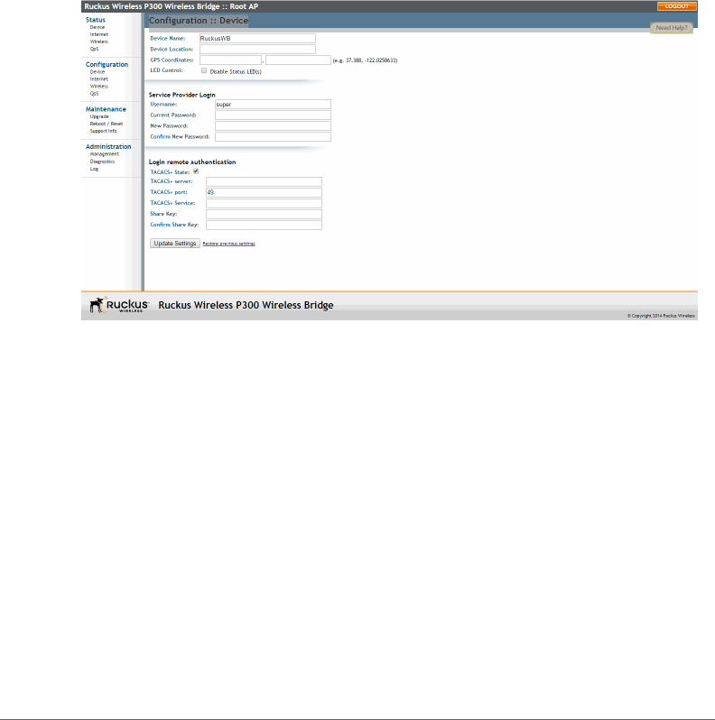
Changing the Administrative Login Settings
Upgrading Manually using a Local File
ZoneFlex P300 Wireless Bridge User Guide, 800-70956-001 Rev B 64
Changing the Administrative Login Settings
The default user name is super and the default password is sp-admin. To prevent
unauthorized users from logging into the Web interface using these default admin-
istrator login settings, Ruckus Wireless recommends that you change the default
Web interface password immediately after your first login.
1Log into the Web interface.
2Go to Configuration > Device.
Figure 31. The Configuration > Device page
3Under Service Provider Login, change the default administrator login settings:
•In Username, type a new user name that you will use to log in to the Web
interface. The default user name is super.
• When you are changing a password, type the existing password in Current
Password.
•In New Password, type a new password to replace the existing password.
The password must consist of six to 32 alphanumeric characters only.
•In Confirm New Password, retype the new password.
4Click Update Settings. The message Your parameters were saved appears.
You have completed changing the default login settings. The next time you log in to
the Web interface, make sure you use these updated login settings.
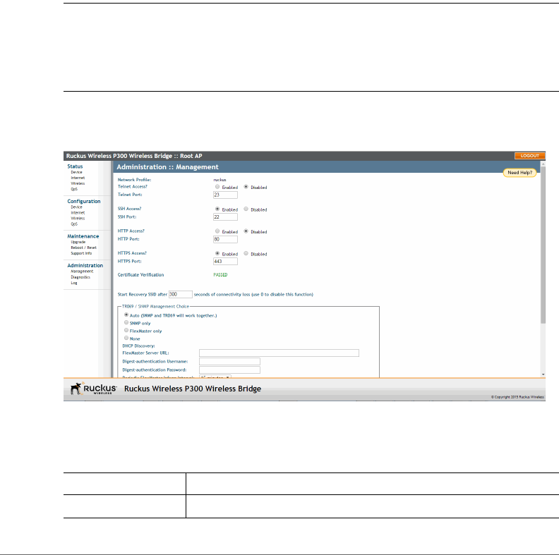
Enabling Other Management Access Options
Upgrading Manually using a Local File
ZoneFlex P300 Wireless Bridge User Guide, 800-70956-001 Rev B 65
Enabling Other Management Access Options
In addition to managing the bridge via a Web browser using HTTPS, several other
management access options are available on the bridge. These options include
management access using HTTP, Telnet and SSH.
You can also view and set up the connection to a Ruckus Wireless FlexMaster
manager under the TR-069/SNMP Management Choice options. If your Ruckus
Wireless device is to be managed by FlexMaster, then the FlexMaster information
(server URL and contact interval) is preconfigured before you receive your Ruckus
Wireless device.
NOTE If you are configuring the bridge to be managed by FlexMaster, then
remember to point it to the FlexMaster server after you configure the management
access options. For more information, refer to Viewing FlexMaster Management
Status.
1Go to Administration > Management.
Figure 32. The Administration > Management page
2Review the access options listed in Ta b l e 9, and then make changes as needed.
Table 9. Management Access Options
Option Description
Telnet Access By default, this option is disabled (inactive).

Enabling Other Management Access Options
Upgrading Manually using a Local File
ZoneFlex P300 Wireless Bridge User Guide, 800-70956-001 Rev B 66
3If you want to use TR-069 or SNMP to manage the bridge, then configure the
settings listed in Tab le 1 0 .
Telnet Port This field lists the default Telnet port of 23 — only if Telnet is active.
You can manually change this port number, if required.
SSH Access By default, this option is enabled (active).
SSH Port This field lists the default SSH port of 22—only if SSH is active.
You can manually change this port number if required.
HTTP Access This option is disabled by default.
HTTP Port This field lists the default HTTP port of 80, if HTTP has been
activated. You can manually change this port number if required.
HTTPS Access By default this option is enabled. This connection mode requires
a security certificate, a copy of which has been pre-installed in the
device.
HTTPS Port This field lists the default HTTPS port of 443—only if HTTPS has
been activated. You can manually change this port number if
required.
Certificate
Verification
This notes whether the security certificate linked to the HTTPS
settings has been verified (PASSED) or not.
Start Recovery SSID
after ___ seconds of
connectivity loss
When connectivity is lost for this period of time, the recovery
process is invoked. Default is 300 seconds. Enter 0 to disable this
function.
Continue service
WLANs when in
recovery mode
When the recovery process is invoked, the WLAN service is
continued (Enabled) or halted (Disabled).
Table 10. TR-069 and SNMP Management Options
Option Description
Auto (Default) Enables the Ruckus Wireless device to be
managed by either SNMP servers, Ruckus Wireless
controllers, or Ruckus Wireless FlexMaster. (Refer to
Release Notes for details.)
SNMP only Only allow SNMP management.
Table 9. Management Access Options (Continued)
Option Description

Enabling Other Management Access Options
Upgrading Manually using a Local File
ZoneFlex P300 Wireless Bridge User Guide, 800-70956-001 Rev B 67
4Click Update Settings to have the ZoneFlex P300 save your changes. A
confirmation message appears at the top of the page.
You have completed configuring the management access options.
NOTE Remember to open any relevant firewall ports between the bridge and the
bridge image upgrade/management server. For example, if FlexMaster server is
used, open TCP ports 80 and 443 for HTTP/HTTPS communications, and TCP port
8082 for bridge wake-up commands. (Refer to Release Notes for details.)
FlexMaster only Only allow FlexMaster management.
FlexMaster Server URL URL of the FlexMaster server.
Digest-Authentication
Username and Digest-
Authentication Password
This information is automatically generated by the bridge
and used for authentication with FlexMaster. Change this
value only if you want the bridge to connect to another
access control server (ACS).
Periodic FlexMaster Inform
Interval
Interval at which the device should attempt to contact
FlexMaster. (Default = 15 minutes.)
Table 10. TR-069 and SNMP Management Options (Continued)
Option Description
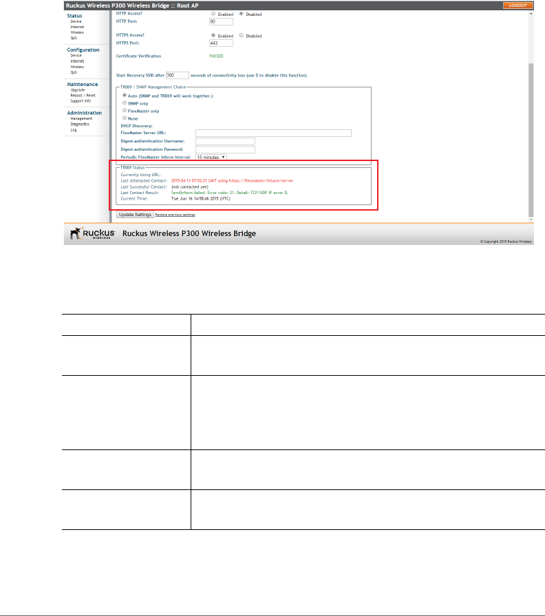
Enabling Other Management Access Options
Viewing FlexMaster Management Status
ZoneFlex P300 Wireless Bridge User Guide, 800-70956-001 Rev B 68
Viewing FlexMaster Management Status
If you configure the bridge to be managed by FlexMaster, you can view the TR-069
Status section by scrolling to the bottom of the Administration > Management
page.
Figure 33. TR-069 status information
Tab l e 11 lists the TR-069 status information that the bridge provides.
Table 11. TR-069 status information
Status Information Description
Currently Using URL Shows the FlexMaster server IP address or URL with which the
bridge is currently registered.
Last Attempted
Contact
Shows the date and time of the bridge’s last attempt to contact
FlexMaster. Date and time are specified in GMT (or UTC), which
are accurate if a Network Time Protocol (NTP) server is
configured.
Last Successful
Contact
Shows the date and time of the bridge’s last successful contact
with FlexMaster.
Last Contact Result Shows the result of the last attempt to contact FlexMaster
(success or failure, and failure error code if applicable).

Enabling Other Management Access Options
Pointing the Bridge to FlexMaster
ZoneFlex P300 Wireless Bridge User Guide, 800-70956-001 Rev B 69
Pointing the Bridge to FlexMaster
Your Ruckus Wireless device is required to “call home” to register with your
FlexMaster; FlexMaster does not initiate initial contact. To register successfully with
FlexMaster, your Ruckus Wireless device must know the FlexMaster server’s URL.
You need TCP ports 80 and 443 open between bridges and FlexMaster when
traversing Layer 3/firewall boundaries.
1Go to Administration > Management.
2Under TR-069/SNMP Management Choice, click Auto.
3In FlexMaster Server URL, type the URL of the FlexMaster server.
4Tog g le t h e Periodic FlexMaster Inform Interval drop-down list to select how
frequently the device checks the FlexMaster server for any pending configuration
changes available for that Ruckus Wireless unit. On the FlexMaster side, this
field is referred to as the Periodic Inform Interval.
5Click Update Settings to save your changes.
After the bridge registers with FlexMaster, this Administration > Management page
shows the communication status between the bridge and FlexMaster.
Current Time Shows the current date and time as known to the bridge. This
timestamp is accurate if an NTP server is configured on the
bridge. If there is no NTP server configured, this timestamp is
useful as a reference for comparison of the timestamps for Last
attempted contact and Last successful contact.
Table 11. TR-069 status information (Continued)
Status Information Description
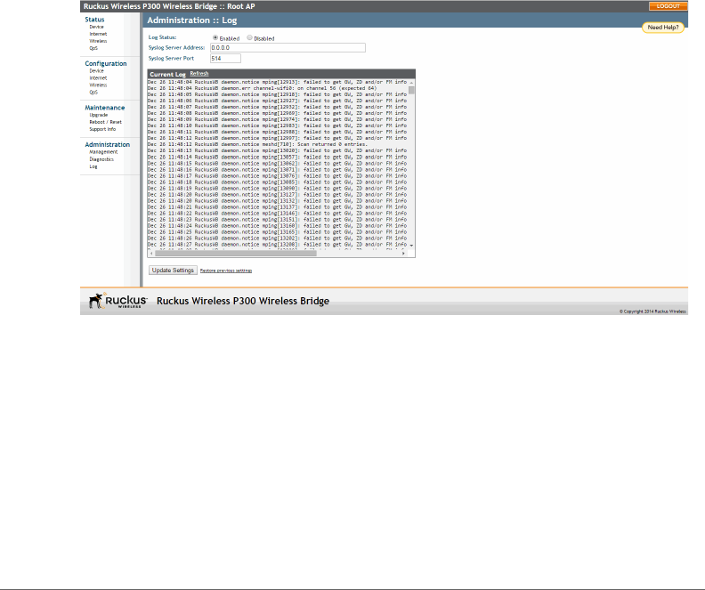
Working with Event Logs and Syslog Servers
Enabling Logging and Sending Event Logs to a Syslog Server
ZoneFlex P300 Wireless Bridge User Guide, 800-70956-001 Rev B 70
Working with Event Logs and Syslog Servers
Both the Maintenance > Support Info and Administration > Log pages can be used
to view the ZoneFlex P300’s current log file text. You can use the former to send
the log to Ruckus Wireless support or save it to a local file, and use the latter to
configure automatic delivery of log files to a syslog server.
Enabling Logging and Sending Event Logs to a Syslog
Server
If you have a syslog server on the network, you can configure the ZoneFlex P300
to send the device logs to the server. Enable logging (if disabled) and configure the
ZoneFlex P300 to send logs to the syslog server.
1Go to Administration > Log. The Administration > Log page appears.
Figure 34. The Administration > Log page
2In Log Status, click Enabled.
3After enabling logging, configure the following options:
•Syslog Server Address: To enable the ZoneFlex P300 to send messages to
a syslog server as they appear, enter the IP address of the syslog server.
•Syslog Server Port: By default, the syslog port number is 514. If the syslog
server is using a different port, enter that port number in this field.
4Click Update Settings to have the ZoneFlex P300 save and apply your changes.

Working with Event Logs and Syslog Servers
Sending a Copy of the Log File to Ruckus Wireless Support
ZoneFlex P300 Wireless Bridge User Guide, 800-70956-001 Rev B 71
Sending a Copy of the Log File to Ruckus Wireless
Support
The Support Info log consists of the configuration and run-time status of the
ZoneFlex P300 and can be useful for troubleshooting. You have three options for
sending a copy of the current log file to Ruckus Wireless Support:
• Save a copy to your local PC, then attach it to an e-mail message and send
it to support.
• Set up a connection to an FTP site.
• Set up a connection to a TFTP site.
1Go to Maintenance > Support Info. The Maintenance > Support Info page
appears.
2To upload a copy of the support info file to an FTP or TFTP server, click the
Transfer Method TFTP or FTP option.
3In Server Address, enter the FTP or TFTP server IP address.
4In Filename, enter a name for the file that you are saving.
NOTE Remember to add a .TXT file extension to the file name, especially if you are
using Internet Explorer as your Web Admin “host.”
5If you selected the FTP option, then also enter a Username and Password.
6Click Upload Now.
Saving a Copy of the Log File to Your Computer
You can save a copy of the current log to your own computer, if needed.
1Go to Maintenance > Support Info. The Maintenance > Support Info
workspace appears.
2Click the Transfer Method Save to Local Computer option. Up to two links
appear next to Download (supportinfo.txt and/or tr069info.txt).
3Click the supportinfo.txt link. A new window (or tab) opens with the content of
the log file displayed.
4Choose Save As or Save Page As from your browser’s File menu.
5When the “Save as>.” dialog box appears, find a convenient location on your
local computer to save the file, and change the file extension from .html to .txt.
6Click Save to save the log file to your computer.

Working with Event Logs and Syslog Servers
Saving a Copy of a Support File to Your Computer
ZoneFlex P300 Wireless Bridge User Guide, 800-70956-001 Rev B 72
Saving a Copy of a Support File to Your Computer
You can save a copy of the support file(s) to your own computer, if needed. The
cmsupportinfo.txt file includes support information for an ZoneFlex P300 with
integral cable modem (such as 7781CM), and the tr069info.txt file includes support
information for an ZoneFlex P300 being managed by FlexMaster.
1Go to Maintenance > Support Info. The Maintenance > Support Info
workspace appears.
2Click the Transfer Method Save to Local Computer option. Up to two links
appear next to Download (supportinfo.txt and/or tr069info.txt).
3Click the cmsupportinfo.txt or tr069info.txt link. A new window (or tab) opens
with the content of the support file displayed.
4Choose Save As or Save Page As from your browser’s File menu.
5When the “Save as>.” dialog box appears, find a convenient location on your
local computer to save the file, and change the file extension from .html to .txt.
6Click Save to save the support file to your computer.
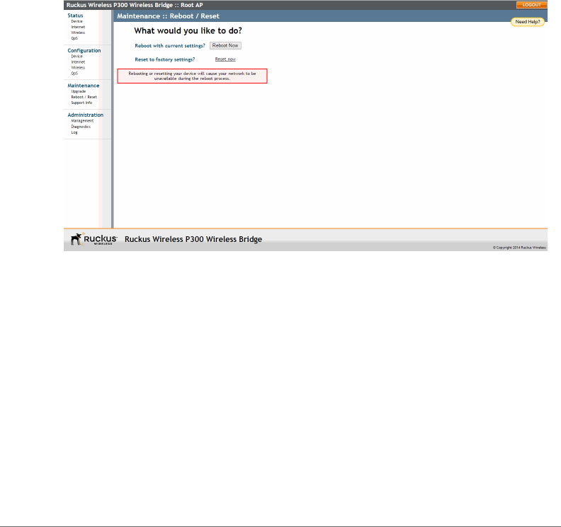
Rebooting the ZoneFlex P300
Saving a Copy of a Support File to Your Computer
ZoneFlex P300 Wireless Bridge User Guide, 800-70956-001 Rev B 73
Rebooting the ZoneFlex P300
You can use the Web interface to prompt the ZoneFlex P300 to reboot, which
restarts the ZoneFlex P300 without changing any of the current settings. Please
note that rebooting the ZoneFlex P300 disrupts network communications in any
currently active WLANs.
1Go to Maintenance > Reboot/Reset. The Maintenance > Reboot/Reset page
appears.
2To reboot the ZoneFlex P300, click Reboot P300 with current settings/Reboot
Now. After a brief pause, you are logged out of the ZoneFlex P300.
Figure 35. The Maintenance > Reboot/Reset page
After approximately one minute, you should be able to log back into the ZoneFlex
P300, which verifies that the reboot was successful. You can also check the LEDs
on the ZoneFlex P300 to verify the status of the device.

Resetting the ZoneFlex P300 to Factory Defaults
Saving a Copy of a Support File to Your Computer
ZoneFlex P300 Wireless Bridge User Guide, 800-70956-001 Rev B 74
Resetting the ZoneFlex P300 to Factory
Defaults
WARNING! DO NOT reset the ZoneFlex P300 to factory defaults unless you are
directed to do so by Ruckus Wireless support staff or by a network administrator.
Do this only if you are able to immediately reconnect the restored ZoneFlex P300
to your computer, to reconfigure it for Wi-Fi network use — as detailed in Logging
Into the ZoneFlex P300 Web Interface.
You can use the Web User interface to restore an inoperative ZoneFlex P300 to its
factory default settings, which completely erases the configuration currently active
in the device. Note that this disrupts all wireless network communications through
this device.
1Go to Maintenance > Reboot/Reset. The Maintenance > Reboot/Reset page
appears (Figure 35).
2Click Reset now (next to Reset to factory settings).
3When the confirmation warning appears, read the message and click OK if you
are certain that you want to restore the ZoneFlex P300 to factory defaults.
After a brief pause, you are automatically logged out of the ZoneFlex P300. You
must now disconnect the ZoneFlex P300 from the switch (and the network) and
reconnect it to your computer. At this time, you can restore the network settings,
then replace it in your site for full network use.
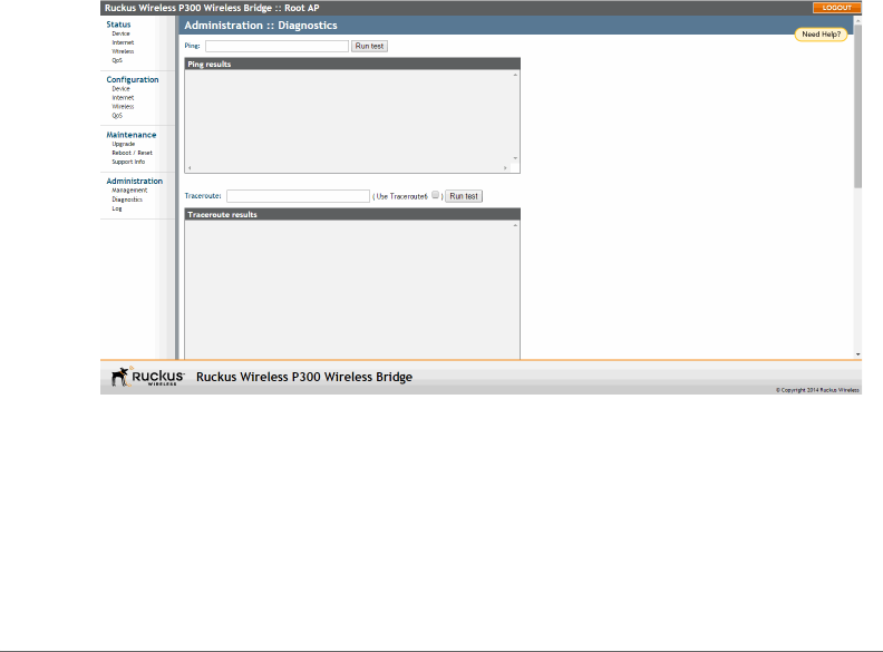
Running Diagnostics
Saving a Copy of a Support File to Your Computer
ZoneFlex P300 Wireless Bridge User Guide, 800-70956-001 Rev B 75
Running Diagnostics
Four network connection diagnostic tools have been built into the ZoneFlex P300
to help you check network connections from the Web interface:
•ping
•traceroute
• show ARP table
• show FDB table
1Go to Administration > Diagnostics. The Administration > Diagnostics page
appears.
2For ping and traceroute, type the network address of a site you wish to connect
to. Then click Run test. The results appear in the text field below each option
(see Figure 36).
3For show ARP table and show FDB table, click Show. The results appear in the
text field below each option (see Figure 37).
Figure 36. Using ping or traceroute
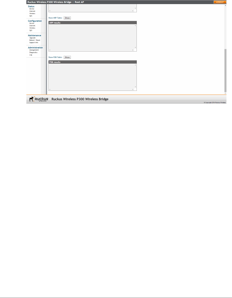
Running Diagnostics
Saving a Copy of a Support File to Your Computer
ZoneFlex P300 Wireless Bridge User Guide, 800-70956-001 Rev B 76
Figure 37. Showing ARP and FDB tables
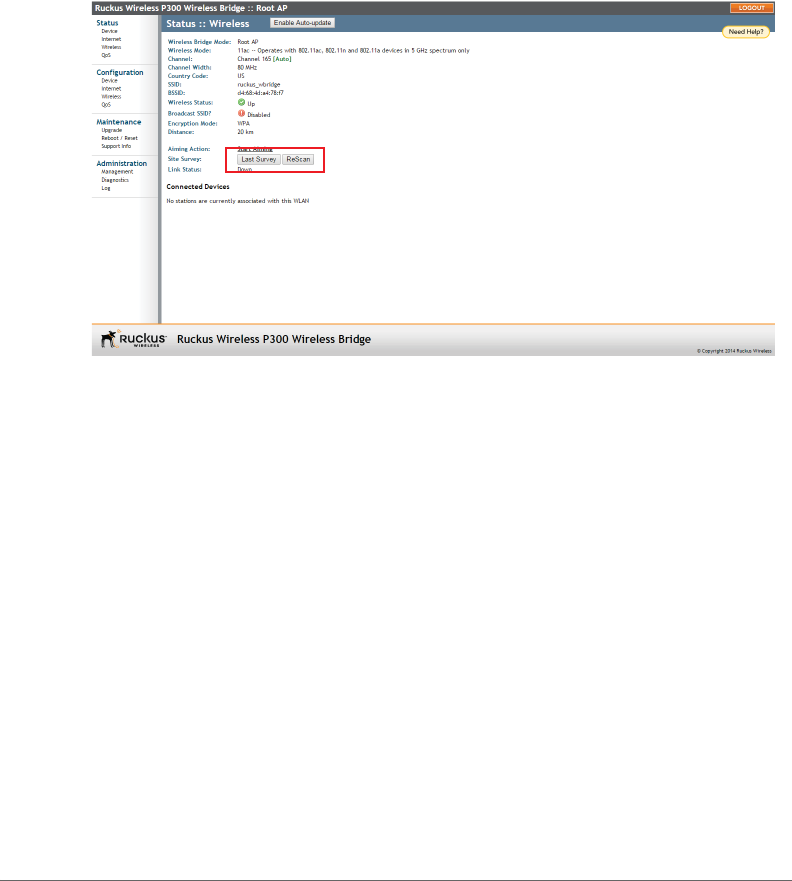
Scanning for Interference
Saving a Copy of a Support File to Your Computer
ZoneFlex P300 Wireless Bridge User Guide, 800-70956-001 Rev B 77
Scanning for Interference
The ZoneFlex P300 includes a Site Survey tool that allows you to scan for other
wireless networks nearby which may impact the ZoneFlex P300 link performance.
1go to the Status > Wireless page. The Status > Wireless page appears.
Figure 38. The Status > Wireless page
2On the Status > Wireless page, click Site Survey: Last Survey or ReScan. The
ZoneFlex P300 Web interface displays a list of nearby wireless devices.
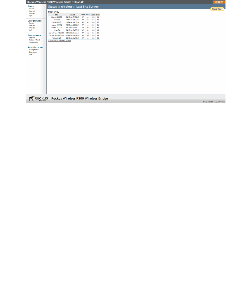
Scanning for Interference
Saving a Copy of a Support File to Your Computer
ZoneFlex P300 Wireless Bridge User Guide, 800-70956-001 Rev B 78
Figure 39. Site Survey
3If a large number of nearby devices is detected using the same channel as the
ZoneFlex P300, you may want to move the wireless bridge traffic to another
channel; refer to Moving Traffic to Another Channel.

Moving Traffic to Another Channel
Saving a Copy of a Support File to Your Computer
ZoneFlex P300 Wireless Bridge User Guide, 800-70956-001 Rev B 79
Moving Traffic to Another Channel
1Navigate to Configuration > Wireless, and choose a less-crowded channel
from the Channel pull-down menu.
NOTE The SmartSelect feature (Auto selection) always attempts to use the best
channel available. If you manually select a channel, then SmartSelect will be unable
to automatically switch channels to adjust to changes in the environment.
2Click Update Settings to have the ZoneFlex P300 save your changes.
3Run the SpeedFlex utility to test link performance as described in Verifying the
Connection.

Where to Find More Information
Saving a Copy of a Support File to Your Computer
ZoneFlex P300 Wireless Bridge User Guide, 800-70956-001 Rev B 80
Where to Find More Information
If you have questions that this User Guide does not address, visit the Ruckus
Wireless Support Portal at http://support.ruckuswireless.com. The Support Portal
hosts the latest versions of user documentation. You can also find answers to
frequently asked questions (FAQs) for each Ruckus Wireless product type.
ZoneFlex P300 Wireless Bridge User Guide, 800-70956-001 Rev B 81
Appendix A: Customer-Orderable
Parts
Table 12. Ruckus Wireless customer-orderable parts
Part Ruckus
Wireless
P/N
Factory
Kit or
Customer
Ordered
Notes
Ruckus Wireless PoE injector
(optional)
902-0162-
XXYY,
where
XXYY is
the
country
code
Optionally
customer-
ordered
--
Table 13. Ruckus Wireless customer-orderable 5GHz antennas
Part Ruckus
Wireless
P/N
Notes
5GHz 12.5dBi 2x2 Dual-Polarized Sector
Outdoor Antenna
911-1212-
DP01
120-degree
beamwidth
5GHz 21dBi Point-to-Point 2x2 Dual-
Polarized Directional Outdoor Antenna
911-2101-
DP01
10-degree
beamwidth

ZoneFlex P300 Wireless Bridge User Guide, 800-70956-001 Rev B 82
5GHz 24dBi Point-to-Point 2x2 Dual-
Polarized Directional Outdoor Antenna
911-2401-
DP01
7- to
9-degree
beamwidth
Table 13. Ruckus Wireless customer-orderable 5GHz antennas (Continued)
Part Ruckus
Wireless
P/N
Notes

ZoneFlex P300 Wireless Bridge User Guide, 800-70956-001 Rev B 83
Index
Numerics
802.1Q 40
A
administrative login 64
advanced settings, wireless 32
antenna separation 11
B
beacon interval 35
bridge
installing 20
preconfiguring firmware 27
bridge factory defaults, resetting 74
C
cable loss, external antenna 32
changing the login settings 37
channel
width 32
wireless 31
configuration, export wireless 33
connection type
DHCP (auto) 43
IP static IP 45
country code 58
wireless 32
D
data beacon rate, DTIM 35
default user name and password 28
device
location 37
name 37
settings 37
DHCP
release 43, 44, 45
renew 43, 44, 45
DHCP (auto) connection type 43
diagnostics 75
distance 35
DTIM, data beacon rate 35
E
export configuration, wireless 33
export wireless configuration 33
external antenna 32
external antenna cable loss 32
external antenna gain 32
F
factory defaults, resetting bridge 74
firmware upgrade 61
FlexMaster (FM) manager 6
FlexMaster management status 68
FlexMaster server URL 67
FM manager 6
G
GPS coordinates 37
H
help 29
I
installing a bridge 20
interference
scanning for 77
Internet settings 40
interval, beacon 35
IPv4 connection type 43
IPv6 connection type 43
L
LED control 38
login remote authentication 38
login settings 37
logout 29

ZoneFlex P300 Wireless Bridge User Guide, 800-70956-001 Rev B 84
M
management access options 65
manager
FM 6
menu 29
MTU 46
N
name, device 37
network time protocol server 41
non-root bridge, wireless bridge mode 33
P
passphrase, wireless encryption 32
ping 75
preconfiguring the bridge 27
R
radio network, wireless common 31
rate limit settings, wireless 32
rebooting 73
releasing DHCP 43, 44, 45
renewing DHCP 43, 44, 45
resetting a bridge to factory default 74
root bridge, wireless bridge mode 33
RTS/CTS threshold 35
S
scanning for interference 77
separation, antenna 11
service provider login 38
SSID, wireless 32
static IP connection type 45
syslog 70
T
tabs 29
TACACS+ server 38
temperature update 37
threshold, RTS/CTS 35
traceroute 75
transmit power 34
U
URL
FlexMaster server 67
user name 38
V
VLAN
overview 40
W
width, channel 32
wireless
advanced settings 32
channel 31
country code 32
rate limit settings 32
wireless bridge mode, root bridge or non-
root bridge 33
wireless channel 57
wireless common
radio network 31
wireless encryption passphrase 32
wireless mode 57
wireless settings 31
wireless SSID 32
workspace 29

Copyright © 2006-2015. Ruckus Wireless, Inc.
350 West Java Dr. Sunnyvale, CA 94089. USA
www.ruckuswireless.com
