RuggON VM-521 Panel PC User Manual VM 521 UM DFA 09022x
RuggON Corporation Panel PC VM 521 UM DFA 09022x
UserManual.wiki
>
RuggON
>
VM-521 User Manual
>
User manual 1
Contents
1.
User manual 1
2.
User manual 2
User manual 1
Navigation menu
Upload a User Manual
Namespaces
Wiki Guide
HTML
PDF
Info
Views
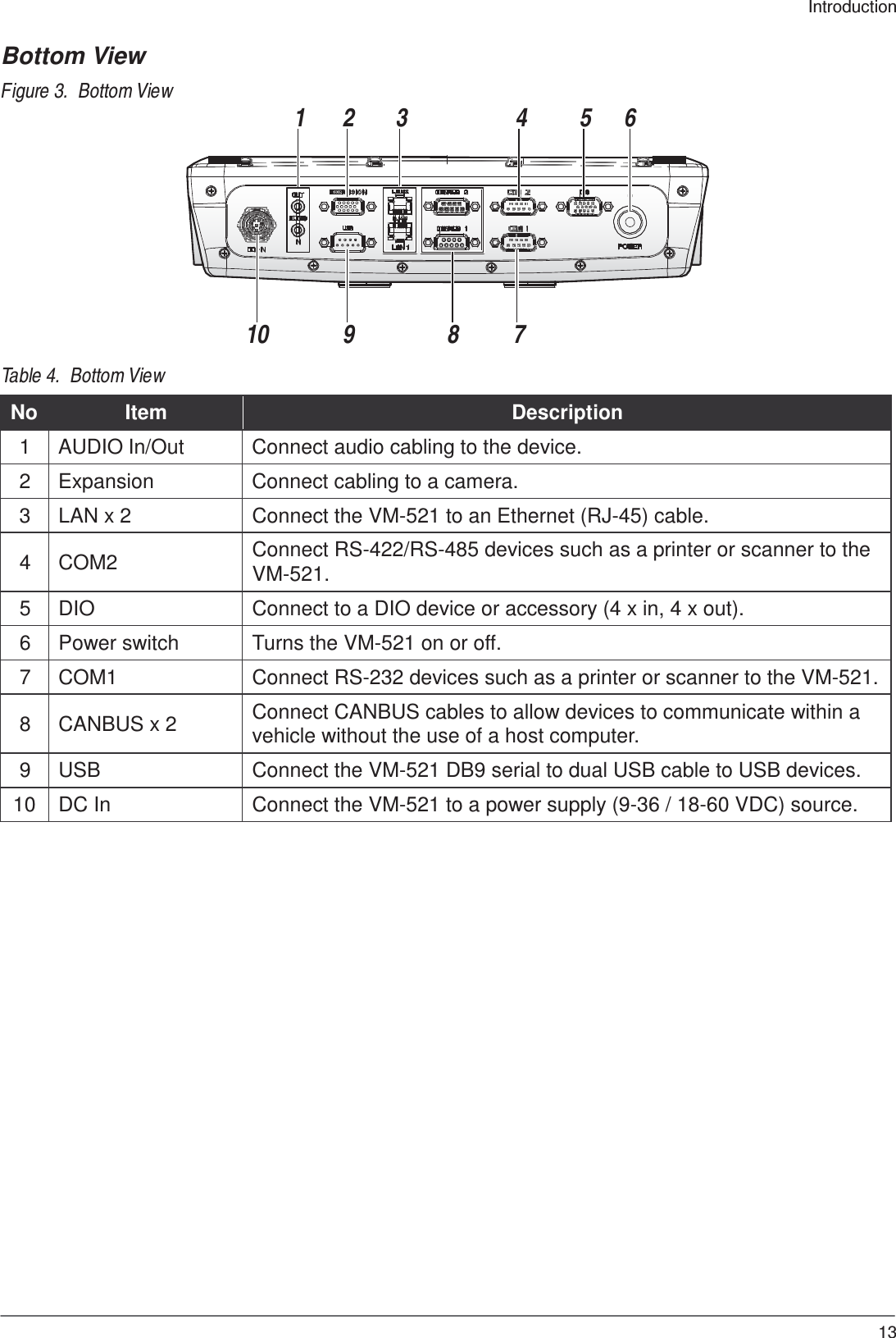
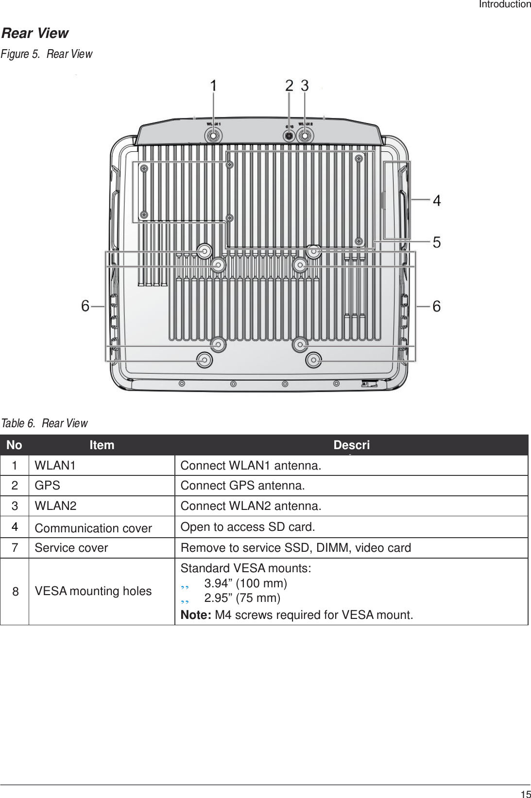
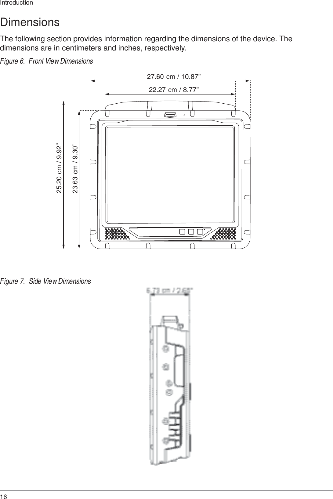
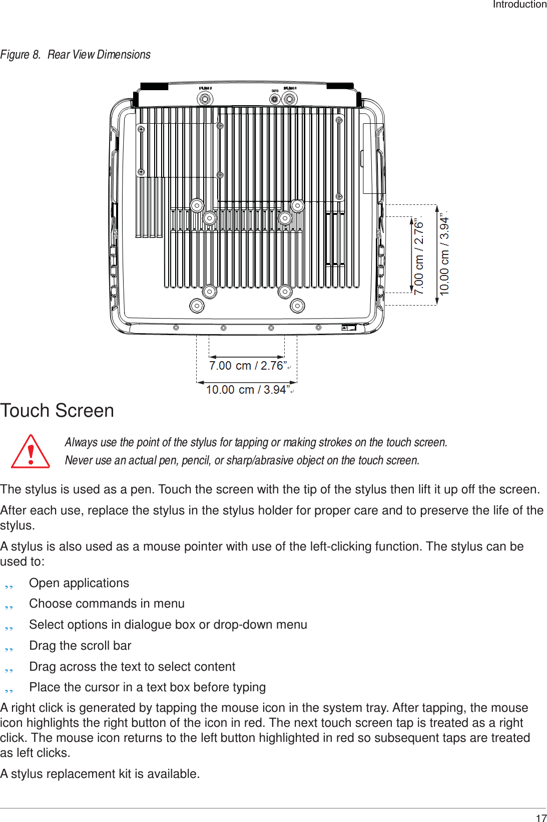
User Manual
Discussion / Help
Navigation