RuiXingHengFang Network 0M010 LoRaWan Module User Manual
RuiXingHengFang Network(Shenzhen) Co., Ltd. LoRaWan Module Users Manual
Users Manual

RHF0M010 Datasheet
RisingHF
1
Document information
Info
Content
Keywords
RisingHF, LoRaWAN, Module, AT command
Abstract
This document is a datasheet of RHF0M010 LoRaWAN
module.
DS01810810
RHF0M010 LoRaWAN module
V1.2

RHF0M010 Datasheet
RisingHF
2
Content
Content .................................................................................................................................................. 2
Figures .................................................................................................................................................. 3
Tables .................................................................................................................................................... 4
1 General description ............................................................................................................................. 6
1.1 Simplified Block Diagram .............................................................................................................. 6
1.2 Pin description .............................................................................................................................. 6
2 Electrical Characteristics ..................................................................................................................... 7
2.1 Absolute Maximum Ratings .......................................................................................................... 7
2.2 Operating Range .......................................................................................................................... 7
2.3 Module Specifications .................................................................................................................. 8
3 Typical Performance Characteristics Measurement ............................................................................ 9
3.1 RHF0M010-LF20 measurement ................................................................................................... 9
3.2 RHF0M010-HF20 measurement ................................................................................................ 12
4 Application Information ................................................................................................................... 116
4.1 Package Information ................................................................................................................ 116
4.2 Internal connection ..................................................................................................................... 17
4.3 Interface of Module ..................................................................................................................... 17
4.4 Reference design with RHF0M010 Module ................................................................................ 17
5 Application in LoRaWAN ................................................................................................................... 21
5.1 LoRaWAN .................................................................................................................................. 21
5.2 LoRaWAN sensor with RHF0M010 ............................................................................................ 18
6 Ordering information ......................................................................................................................... 22
Revision ............................................................................................................................................... 23

RHF0M010 Datasheet
RisingHF
3
Figures
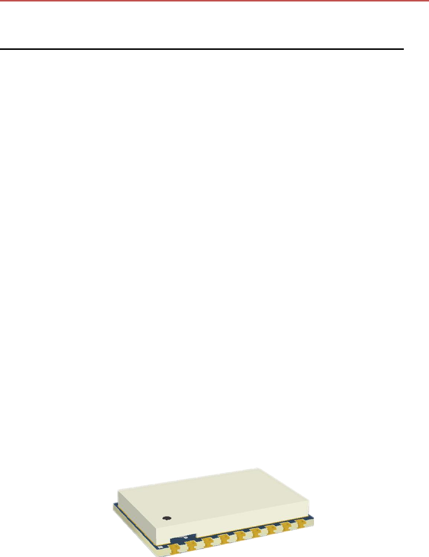
Figure 1-1 RHF0M010 Module Outline .................................................................................................. 5
Figure 1-1 Block Diagram of RHF0M010 ............................................................................................... 6
Figure 1-2 schematic of RHF0M010 ...................................................................................................... 6
Figure 3-1 TXOP vs Supply voltage ....................................................................................................... 9
Figure 3-2 Sensitivity (SF10/SF12,125kHz) vs Supply voltage ............................................................... 9
Figure 3-3 Frequency Tolerance vs Temperature ................................................................................ 10
Figure 3-4 TXOP vs Temperature ........................................................................................................ 10
Figure 3-5 Sensitivity (SF12,125kHz) vs temperature .......................................................................... 11
Figure 3-6 Harmonics measurement @Frf=434MHz, TXOP=20dBm ................................................... 11
Figure 3-7 Harmonics measurement @Frf=470MHz, TXOP=20dBm ................................................... 12
Figure 3-8 TXOP vs Supply voltage ..................................................................................................... 12
Figure 3-9 Sensitivity (SF10/SF12,125kHz) vs Supply voltage ............................................................. 13
Figure 3-10 Frequency Tolerance vs Temperature .............................................................................. 13
Figure 3-11 TXOP vs Temperature ...................................................................................................... 14
Figure 3-12 Sensitivity (SF12,125kHz) vs temperature ........................................................................ 14
Figure 3-13 Harmonics measurement @Frf=868MHz, TXOP=20dBm ................................................. 15
Figure 3-14 Harmonics measurement @Frf=915MHz, TXOP=20dBm ................................................. 15
Figure 4-1 package outline drawing ..................................................................................................... 19
Figure 4-2 Recommended land pattern ................................................................................................ 16
Figure 4-3 Reference design with RHF0M010 ..................................................................................... 18
Figure 5-1 LoRaWAN sensor with RHF0M010 ..................................................................................... 19

RHF0M010 Datasheet
RisingHF
4
Tables
Table 1-1 pin description ........................................................................................................................ 7
Table 2-1 Absolute Maximum Ratings ................................................................................................... 7
Table 2-2 Operating Range ................................................................................................................... 7
Table 2-3 Module Specifications ............................................................................................................ 8
Table 4-1 Internal IO connection between MCU(STM32L07x) and Radio(SX127x) ............................. 17
Table 4-2 RF control logic .................................................................................................................... 20
Table 6-1 Ordering information ............................................................................................................ 22
Rev1.2 2018-10-29
RisingHF
RHF0M010 Datasheet
RisingHF
5
RHF0M010 LoRaWAN Module
Low Power Small Size High integrated LoRaWAN Module
General description
RHF0M010 LoRaWAN Module is a low
cost, low power and small size module,
embedded with Semtech’s LoRa
propriety chip SX127x and ST’s ultra-
low power MCU STM32L07x.
The module designed by RisingHF
(Shenzhen) is targeted to application in
sensor network and others IOT devices
powered by battery which need low
power consumption to extend the
battery lifetime.
This datasheet will give some details of
description of the module, including HW
design information, performance
validation, and application information.
Applications
The RHF0M010 LoRaWAN Module is
designed for end device which need
long range and low power consumption,
such as metering, sensor network, and
others IOT application.
Key features
Low power consumption: 2.0uA
sleep current
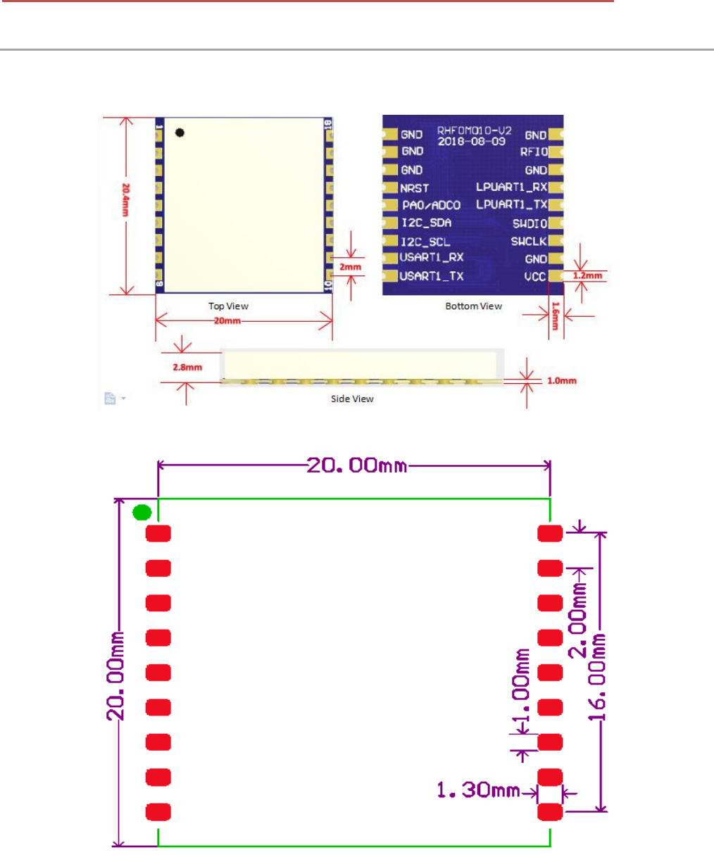
Small size: 20mm X 20.4mm
18 pins SMT package
High performance:
RHF0M010-LF20:
TXOP=18.5dBm@434MHz/470MHz
RHF0M010-HF20:
TXOP=18.5dBm@868MHz/915MHz
160dB link budget, suitable for long
range
User-friendly interface
USART;
I2C;
LPUART;
ADC;
GPIOs
LoRaWAN embedded with AT
command:
Support global LoRaWAN protocol
EU868;
US915 and US915 Hybrid;
CN779;
EU433;
AU915;
CN470 and CN470 Prequel;
AS923;
KR920;
IN865;
Figure 1-1 RHF0M010 Module Outline
V1.2 2018-10-29
www.risinghf.com
RHF0M010 Datasheet
RisingHF
6
This product datasheet contains a detailed description of the RHF0M010 performance and
functionality. Please consult with RisingHF for the latest updates, Firmware or errata.
1 General description
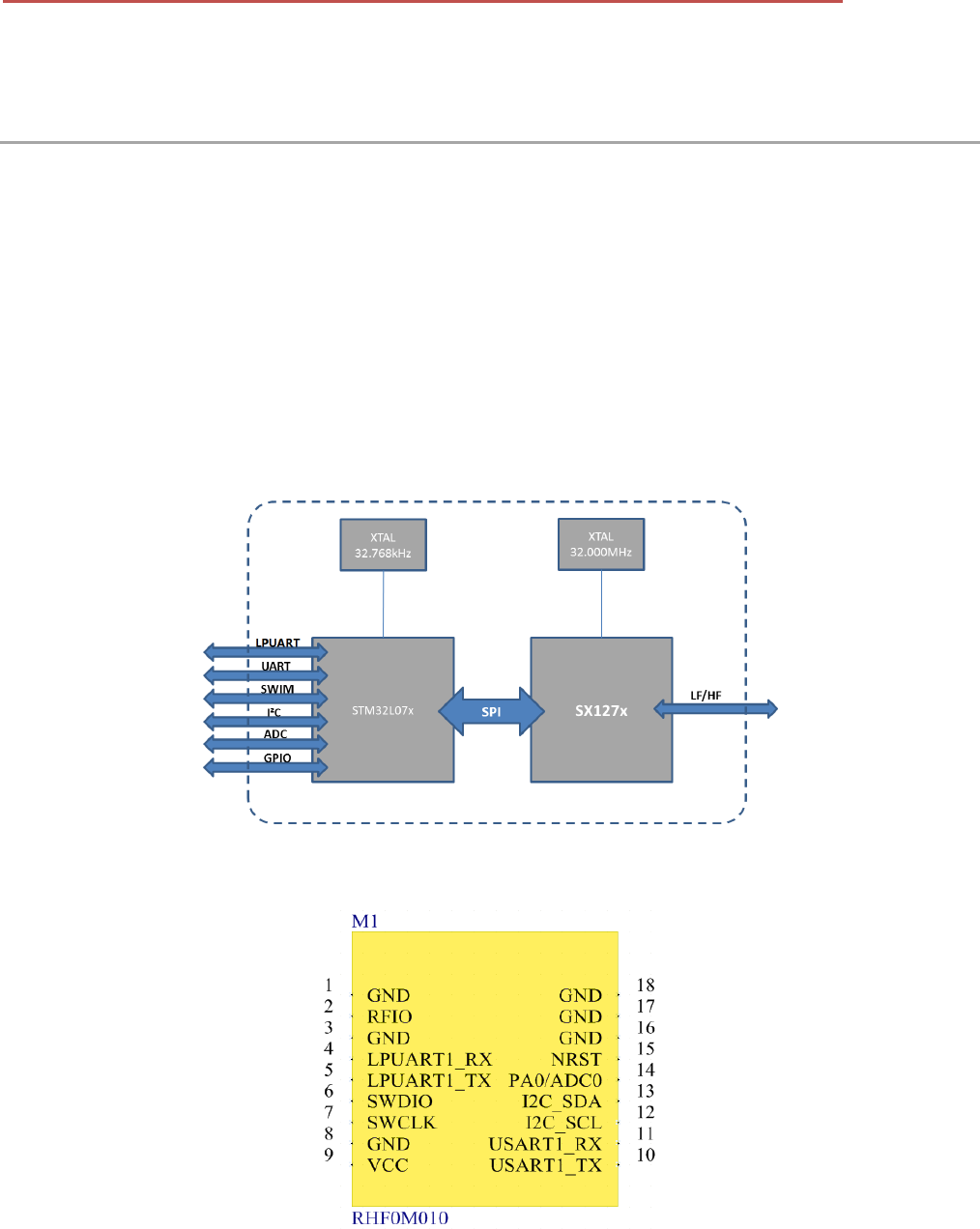
The RHF0M010 incorporates SX127x and STM32L07x, and is well suited for node in the networking of
IOT.
Based on the powerful functions and performance of SX127x, the RHF0M010 could operates in both
(G)FSK and LoRa. In LoRa mode, BW with 62.5kHz, 125kHz, 250kHz and 500kHz could be used.
And with the STM32L07x MCU, the module could provide LPUART, UART, I2C, ADC and some others
GPIOs for customer to extend their application. Two wire interface (SWIM) is suggested to be used for
programming.
RHF0M010 series include two pin to pin part numbers, RHF0M010-LF20 and RHF0M010-HF20.
RHF0M010-LF20 support 18.5dBm@LF band (434MHz/470MHz), RHF0M010-HF20 support
18.5dBm@HF band (868MHz/915MHz).
1.1 Simplified Block Diagram
Figure 1-1 Block Diagram of RHF0M010
1.2 Pin description
Figure 1-2 schematic of RHF0M010

V1.2 2018-10-29
www.risinghf.com
RHF0M010 Datasheet
RisingHF
7
Table 1-1 pin description
Number
Name
Type
Description
1
GND
-
Ground
2
RFIO
-
RF input/output
3
GND
-
Ground
4
LPUART1_RX
I/O
Low power USART_RX from MCU; or GPIO from MCU,
PB11
5
LPUART_TX
I/O
Low power USART_TX from MCU; or GPIO from MCU,
PB10
6
SWDIO
I/O
SWDIO of SWIM for program download
7
SWCLK
I/O
SWCLK of SWIM for program download
8
GND
-
Ground
9
VCC
-
Supply voltage for the module
10
USART1_TX
I/O
USART1_TX from MCU; or GPIO from MCU, PB6
11
USART1_RX
I/O
USART1_RX from MCU; or GPIO from MCU, PB7
12
I2C_SCL
I/O
SCL of I2C from MCU; or GPIO from MCU, PB8
13
I2C_SDA
I/O
SDA of I2C from MCU; or GPIO from MCU, PB9
14
PA0/ADC0
I/O
GPIO from MCU, PA0;or ADC_IN0
15
NRST
I
Reset trigger input for MCU
16
GND
-
Ground
17
GND
-
Ground
18
GND
-
Ground
2 Electrical Characteristics
2.1 Absolute Maximum Ratings
As stated that the values listed below may cause permanent device failure. Exposure to absolute
maximum ratings for extended periods may affect device reliability.
Table 2-1 Absolute Maximum Ratings
Item
Description
min
max
unit
VCCmr
Supply voltage
-0.3
+3.9
V
Tmr
Temperature
-55
+115
℃
Pmr
RF input level
-
+10
dBm
2.2 Operating Range
Table 2-2 Operating Range
Item
Description
min
max
unit
VCCop
Supply voltage
+1.8
+3.6
V

V1.2 2018-10-29
www.risinghf.com
RHF0M010 Datasheet
RisingHF
8
Top
Temperature
-40
+85
℃
Pop
RF input level
-
+10
dBm
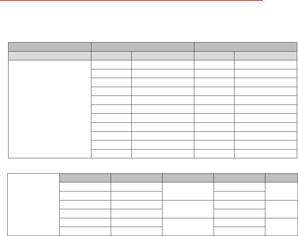
2.3 Module Specifications
Table 2-3 Module Specifications
ITEMs
Parameter
Specifications
Unit
Structure
Size
20(W) X 20.4(L) X 2.8(H)
mm
Package
18 pins, SMT
Electrical
Characteristics
power supply
3.3V type
V
Sleep current
2.0uA
uA
Operation current
(Transmitter+MCU)
120mA @18.5dBm in 434MHz/470MHz
type
mA
122mA @18.5dBm in 868MHz/915MHz
type
mA
Operation current
(Receiver+MCU)
19mA @BW125kHz, 434MHz/470MHz
type
mA
18mA @BW125kHz, 868MHz/915MHz
type
mA
Output power
18.5dBm max @434MHz/470MHz
dBm
18.5dBm max @868MHz/915MHz
dBm
Sensitivity
-139dBm @SF12, BW125kHz,
434MHz/470MHz
dBm
-137dBm @SF12, BW125kHz,
868MHz/915MHz
dBm
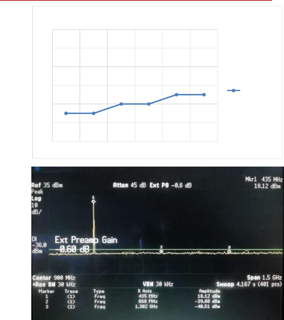
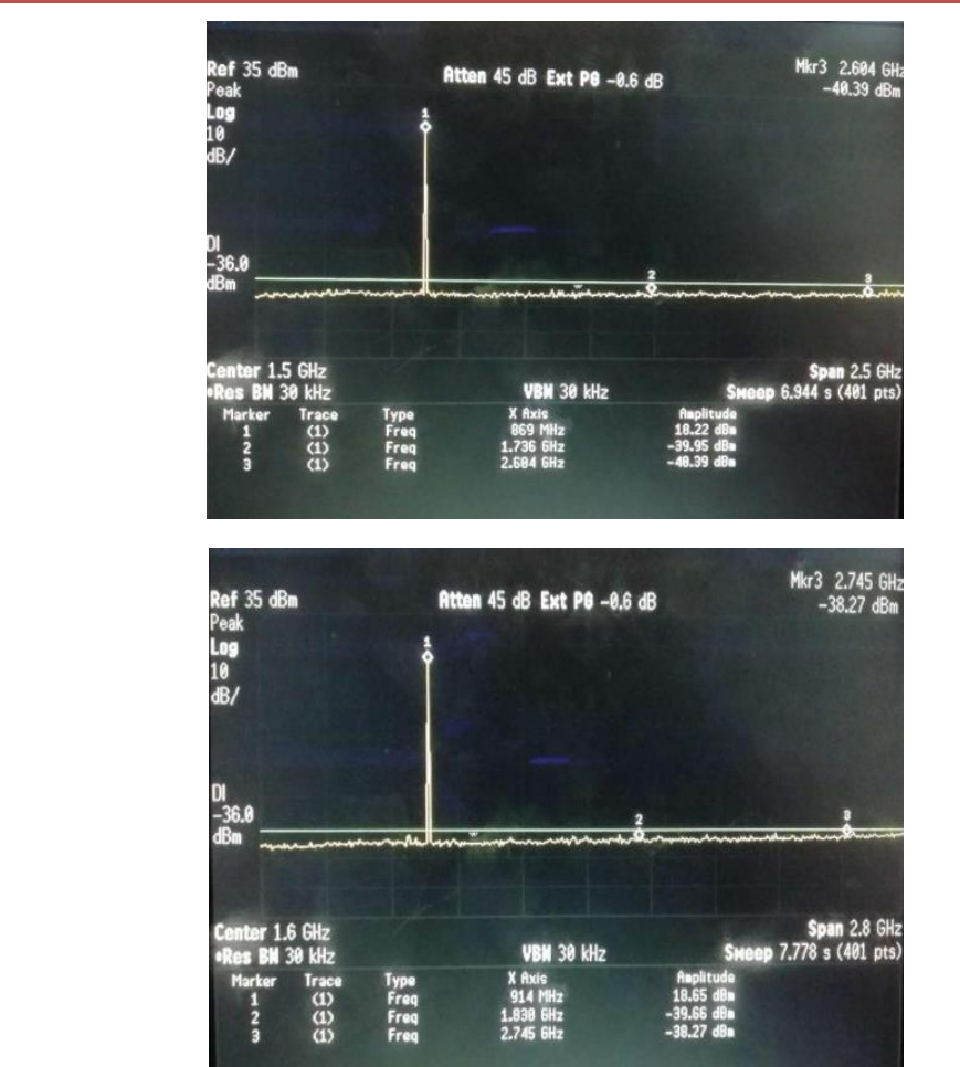
Harmonics
(LF Output)
<-42dBm below 1GHz
dBm
<-35dBm above 1GHz
dBm
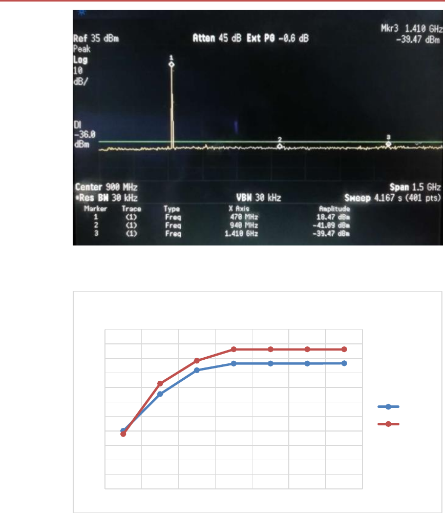
Harmonics (HF output)
<-40dBm above 1GHz
dBm
Interface
RFIO
RF port
USART
2 group of USART, include 2pins
I2C
1 group of I2C, include 2 pins
ADC
1 ADC Input, include 1 pins, reuse with
GPIO port
NRST
Manual reset pin input
V1.2 2018-10-29
www.risinghf.com
RHF0M010 Datasheet
RisingHF
9
3 Typical Performance Characteristics Measurement
3.1 RHF0M010-LF20 measurement
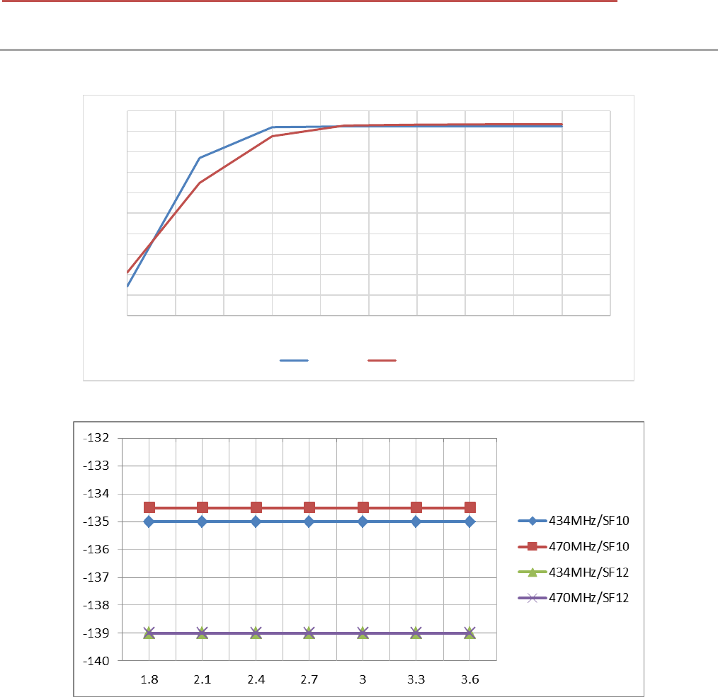
Figure 3-1 TXOP vs Supply voltage
Figure 3-2 Sensitivity (SF10/SF12,125kHz) vs Supply voltage
14
14.5
15
15.5
16
16.5
17
17.5
18
18.5
19
1.8 22.2 2.4 2.6 2.8 33.2 3.4 3.6 3.8
434MHz 470MHz
V1.2 2018-10-29
www.risinghf.com
RHF0M010 Datasheet
RisingHF
10
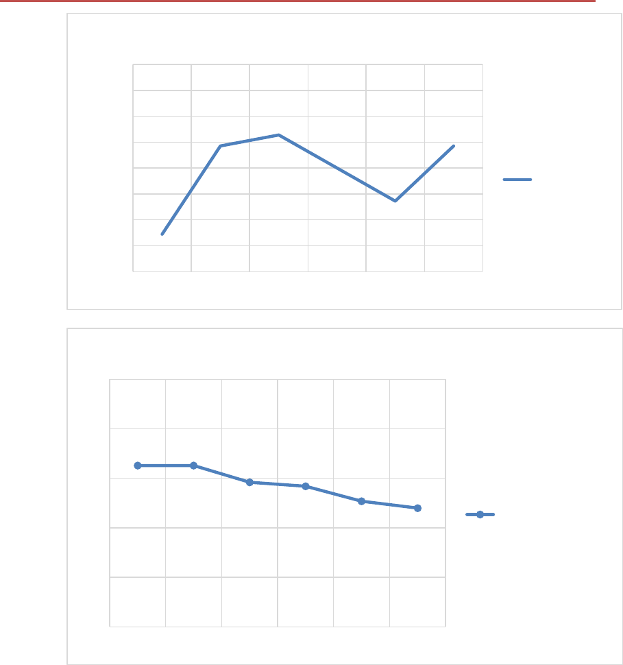
Figure 3-3 Frequency Tolerance vs Temperature
Figure 3-4 TXOP vs Temperature
-20
-15
-10
-5
0
5
10
15
20
-40℃-25℃0℃25℃65℃85℃
PPM
Freq tolerance
Freq tolerance
17.5
18
18.5
19
19.5
20
-40℃-25℃0℃25℃65℃85℃
OP@470MHz Paboost
OP@470MHz Paboost
V1.2 2018-10-29
www.risinghf.com
RHF0M010 Datasheet
RisingHF
11
Figure 3-5 Sensitivity (SF12,125kHz) vs temperature
Figure 3-6 Harmonics measurement @Frf=434MHz, TXOP=20dBm
-143
-141
-139
-137
-135
-133
-131
-40℃-25℃0℃25℃65℃85℃
470MHz@SF12
470MHz@SF12
V1.2 2018-10-29
www.risinghf.com
RHF0M010 Datasheet
RisingHF
12
Figure 3-7 Harmonics measurement @Frf=470MHz, TXOP=20dBm
3.2 RHF0M010-HF20 measurement
Figure 3-8 TXOP vs Supply voltage
14
14.5
15
15.5
16
16.5
17
17.5
18
18.5
19
19.5
1.8 2.1 2.4 2.7 3 3.3 3.6
TXOP vs Supply voltage
868MHz
915MHz
V1.2 2018-10-29
www.risinghf.com
RHF0M010 Datasheet
RisingHF
13
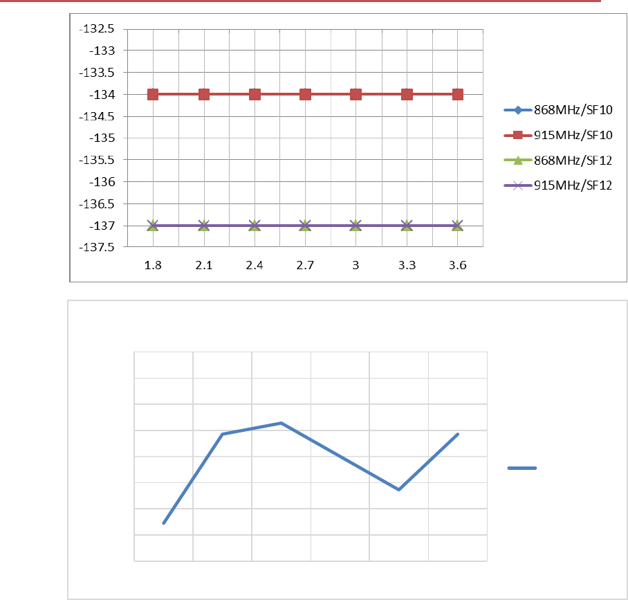
Figure 3-9 Sensitivity (SF10/SF12,125kHz) vs Supply voltage
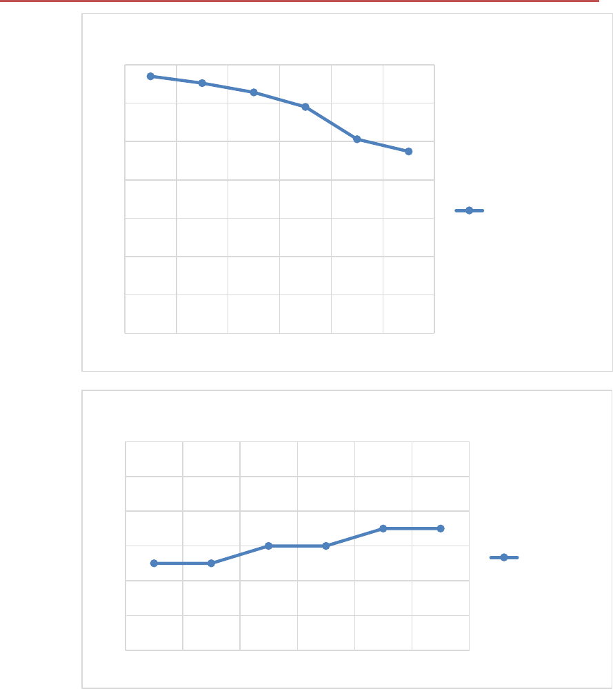
Figure 3-10 Frequency Tolerance vs Temperature
-20
-15
-10
-5
0
5
10
15
20
-40℃-25℃0℃25℃65℃85℃
PPM
Freq tolerance
Freq tolerance
V1.2 2018-10-29
www.risinghf.com
RHF0M010 Datasheet
RisingHF
14
Figure 3-11 TXOP vs Temperature
Figure 3-12 Sensitivity (SF12,125kHz) vs temperature
16
16.5
17
17.5
18
18.5
19
19.5
-40℃-25℃0℃25℃65℃85℃
OP@868MHz Paboost
OP@868MHz Paboost
-143
-141
-139
-137
-135
-133
-131
-40℃-25℃0℃25℃65℃85℃
868MHz@SF12
868MHz@SF12
V1.2 2018-10-29
www.risinghf.com
RHF0M010 Datasheet
RisingHF
15
Figure 3-13 Harmonics measurement @Frf=868MHz, TXOP=20dBm
Figure 3-14 Harmonics measurement @Frf=915MHz, TXOP=20dBm
V1.2 2018-10-29
www.risinghf.com
RHF0M010 Datasheet
RisingHF
16
4 Application Information
4.1 Package Information
The RHF0M010 is available in a 18-lead SMD package as shown below:
Figure 4-1 package outline drawing
Figure 4-2 show the recommended land pattern for layout.
Figure 4-2 Recommended land pattern
V1.2 2018-10-29
www.risinghf.com
RHF0M010 Datasheet
RisingHF
17
4.2 Internal connection
Table 4-1 and Table 4-2 provides the internal connection which could help customers who would
design their own firmware instead of using RisingHF AT command mode.
Table 4-1 Internal IO connection between MCU(STM32L07x) and Radio(SX127x)
Chip
SX127x
STM32L07x
Item
Pin Num
Description
Pin Num
Description
IO connection Between
SX127x and STM32L07x
Pin7
NRESET_SX
Pin40
PB4
Pin8
DIO0_SX
Pin33
PA12
Pin9
DIO1_SX
Pin18
PB0
Pin10
DIO2_SX
Pin20
PB2
Pin11
DIO3_SX
Pin19
PB1
Pin12
DIO4_SX
NC
NC
Pin13
DIO5_SX
Pin5
PH0
Pin16
SCK_SX
Pin15
PA5
Pin17
MISO_SX
Pin16
PA6
Pin18
MOSI_SX
Pin17
PA7
Pin19
NSS_SX
Pin14
PA4
Table 4-2 RF control logic
RF Switch
Control
Pin Num/MCU
Description
Definition
Logic
Status
Pin25
PB12
Switch_CTL
1
TX ON
Pin26
PB13
0
Pin25
PB12
Switch_CTL
0
RX_ON
PIN26
PB13
1
PIN25
PB12
Switch_CTL
0
Sleep
PIN26
PB13
0
4.3 Interface of Module
Except that several essential GPIOs and one group of SPI would be used for internal transceiver
control, part others GPIOs and interface of the MCU would be connected to external pins of the module,
which includes USART, I2C, LPUART, ADC and so on.
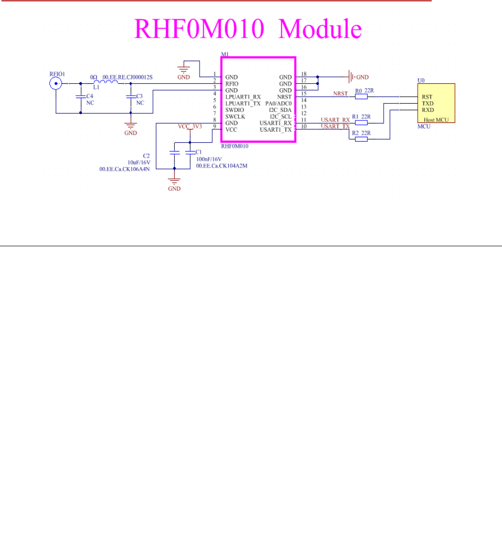
4.4 Reference design with RHF0M010 Module
RHF0M010 is integrated with LoRaWAN protocol and AT command. LoRaWAN node design with
RHF0M010 is very simple. Just connect the USART and NRST to their host MCU and send AT
command.
V1.2 2018-10-29
www.risinghf.com
RHF0M010 Datasheet
RisingHF
18
Figure 4-3 Reference design with RHF0M010
5 Application in LoRaWAN
5.1 LoRaWAN
LoRaWAN networks typically are laid out in a star-of-stars topology in which gateways relay messages
between end-devices and a central network server at the backend. Gateways are connected to the
network server via standard IP connections while end devices use single-hop LoRa™ or FSK
communication to one or many gateways. All communication is generally bi-directional, although uplink
communication from an end device to the network server is expected to be the predominant traffic.
Communication between end-devices and gateways is spread out on different frequency channels and
data rates. The selection of the data rate is a trade-off between communication range and message
duration, communications with different data rates do not interfere with each other. LoRa data rates
range from 0.3 kbps to 50 kbps, with different Band Width and Spreading Factor. To maximize both
battery life of the end-devices and overall network capacity, the LoRa network infrastructure can
manage the data rate and RF output for each end-device individually by means of an adaptive data rate
(ADR) scheme.
End-devices may transmit on any channel available at any time, using any available data rate, as long
as the following rules are respected:
1) The end-device changes channel in a pseudo-random fashion for every transmission. The
resulting frequency diversity makes the system more robust to interferences.
2) The end-device respects the maximum transmit duty cycle relative to the sub-band used and local
regulations.
The RHF0M010 Module incorporates Semtech’s LoRa Chip SX1276 and ST’s ultra-low power MCU.
With only 2.0uA sleep current , the module is really very suitable for LoRaWAN application.
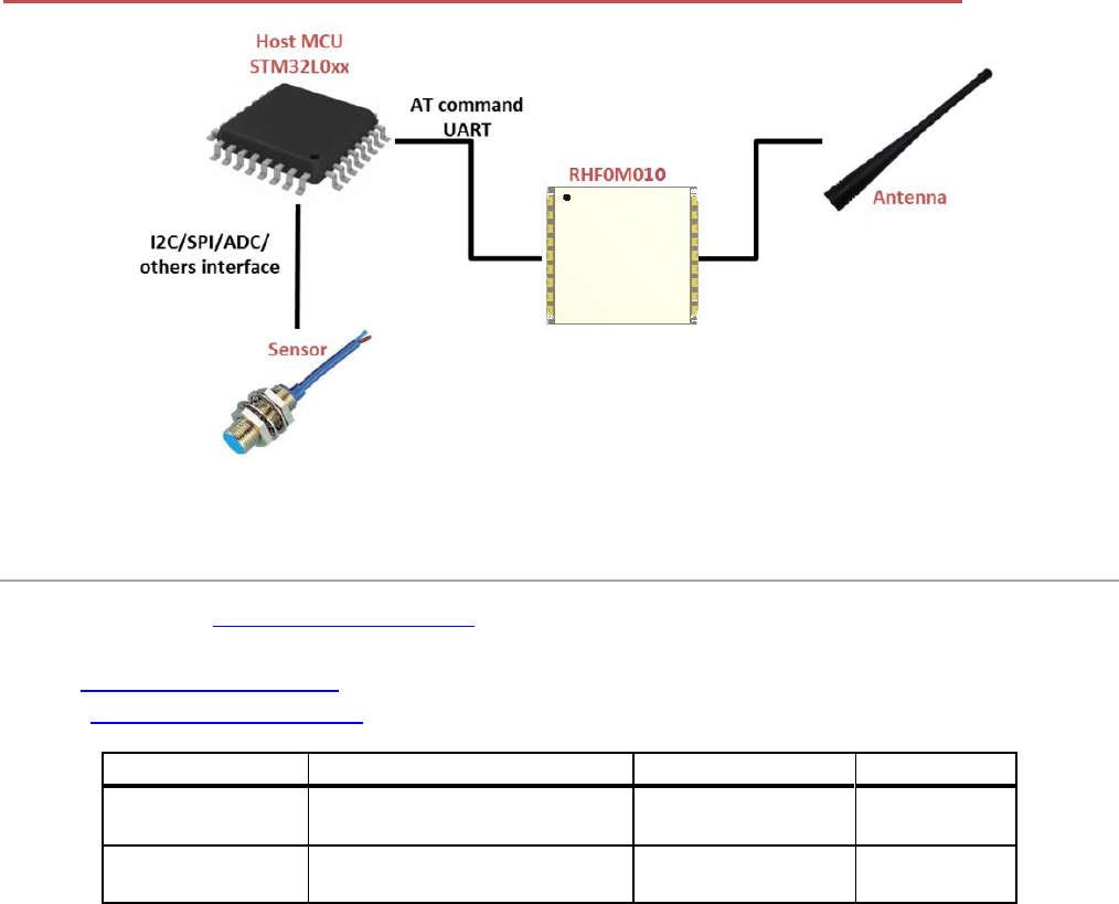
5.2 LoRaWAN sensor with RHF0M010
RHF0M010 is AT command LoRaWAN modem, which is LoRaWAN protocol embedded. Customer just
need use a simple host mcu with application to control the modem via UART that a LoRaWAN sensor
could be designed easily. This will help customer to promote their sensor devices to market quickly.
V1.2 2018-10-29
www.risinghf.com
RHF0M010 Datasheet
RisingHF
19
Figure 5-1 LoRaWAN sensor with RHF0M010
6 Ordering information
Technical Support: Support@RisingHF.com
Business:
China: Salescn@RisngHF.com
Others: Salesww@RisingHF.com
Table 6-1 Ordering information
Part Number
MCU
TX Power (dBm)
AT Modem
RHF0M010-LF20
ROM 128KB / RAM 20KB
18.5@LF
(434/470MHz)
Yes
RHF0M010-HF20
ROM 128KB / RAM 20KB
18.5@HF
(868/915MHz)
Yes

V1.2 2018-10-29
www.risinghf.com
RHF0M010 Datasheet
RisingHF
20
Revision
V1.1 2018-08-28
+ Draft Creation
V1.2 2018-10-29
+ Delete RHF0M010-HF14

V1.2 2018-10-29
www.risinghf.com
RHF0M010 Datasheet
RisingHF
21
This device complies with Part 15 of the FCC Rules. Operation is subject to the following two
conditions:
(1) This device may not cause harmful interference.
(2) This device must accept any interference received, including interference that may cause
undesired operation.
NOTE: This equipment has been tested and found to comply with the limits for a Class B digital device,
pursuant to part 15 of the FCC Rules. These limits are designed to provide reasonable protection against
harmful interference in a residential installation.
This equipment generates uses and can radiate radio frequency energy and, if not installed and used in
accordance with the instructions, may cause harmful interference to radio communications. However, there
is no guarantee that interference will not occur in a particular installation. If this equipment does cause
harmful interference to radio or television reception, which can be determined by turning the equipment off
and on, the user is encouraged to try to correct the interference by one or more of the following measures:
- Reorient or relocate the receiving antenna.
- Increase the separation between the equipment and receiver.
-Connect the equipment into an outlet on a circuit different from that to which the receiver is connected.
-Consult the dealer or an experienced radio/TV technician for help
NOTE: The manufacturer is not responsible for any radio or TV interference caused by unauthorized
modifications to this equipment. Such modifications could void the user’s authority to operate the equipment.
This equipment complies with FCC radiation exposure limits set forth for an uncontrolled environment.
This equipment should be installed and operated with minimum distance of 20 cm between the radiator and
your body. This transmitter must not be co-located or operating in conjunction with any other antenna or
transmitter.
ORIGINAL EQUIPMENT MANUFACTURER (OEM) NOTES
The OEM must certify the final end product to comply with unintentional radiators before declaring
compliance of the final product to Part 15 of the FCC rules and regulations. Integrationinto devices that are
directly or indirectly connected to AC lines must add with Class II Permissive Change.
The OEM must comply with the FCC labeling requirements. If the module’s label is not visible when
installed, then an additional permanent label must be applied on the outside of the finished product which
states:
“Contains transmitter module FCC ID: 2AJUZ0M010. Additionally, the following statement should be
included on the label and in the final product’s user manual: “This device complies with Part 15 of the FCC
Rules.
Operation is subject to the following two conditions:
(1) This device may not cause harmful interferences, and
(2) this device must accept any interference received, including interference that may cause undesired
operation.”
The module is limited to installation in mobile or fixed applications. Separate approval is required for all
other operating configurations, including portable configuration with respect to Part 2.1093 and different
antenna configurations.
Professional installation:
This module need to be installed under professional guidance, if there is any questions, please contact us.

V1.2 2018-10-29
www.risinghf.com
RHF0M010 Datasheet
RisingHF
22
Host device: RHF4T010
Antenna information:Gain: 2.67dBi; Type: Dipole antenna; Impedance: 50Ω
The module can work on the host device, it means the driver is matched, different host devices have the
different drives.
The host manufacturer can not get the module drive authorization to remain compliant, until the host
device compliance with the requirements.
Note: The module has the antenna schematics, so the host device just provide the antenna connector
for this device. The antenna port and connector is designed by OEM, it need to compliance with the 15.203
requirement, and it is not designed for use with high-gain directional antennas.
A module or modules can only be used without additional authorizations if they have been tested and
granted under the same intended end‐use operational conditions, including simultaneous transmission
operations.
When they have not been tested and granted in this manner, additional testing and/or FCC application
filing may be required. The most straightforward approach to address additional testing conditions is to have
the grantee responsible for the certification of at least one of the modules submit a permissive change
application.
When having a module grantee file a permissive change is not practical or feasible, the following
guidance provides some additional options for host manufacturers. Integrations using modules where
additional testing and/or FCC application filing(s) may be required are: (A) a module used in devices
requiring additional RF exposure compliance information (e.g., MPE evaluation or SAR testing); (B) limited
and/or split modules not meeting all of the module requirements; and (C) simultaneous transmissions for
independent collocated transmitters not previously granted together.
This Module is limited modular approval, it is limited to OEM installation ONLY.
Integration into devices that are directly or indirectly connected to AC lines must add with Class II
Permissive Change. (OEM) Integrator has to assure compliance of the entire end product incluld the
integrated Module.
Additional measurements (15B) and/or equipment authorizations (e.g Verification) may need to be
addressed depending on co-location or simultaneous transmission issues if applicable. (OEM) Integrator is
reminded to assure that these installation instructions will not be made available to the end user of the final
host device.

V1.2 2018-10-29
www.risinghf.com
RHF0M010 Datasheet
RisingHF
23
Please Read Carefully:
Information in this document is provided solely in connection with RisingHF products. RisingHF reserve the right to make changes, corrections,
modifications or improvements, to this document, and the products and services described herein at any time, without notice.
All RisingHF products are sold pursuant to RisingHF’s terms and conditions of sale.
Purchasers are solely responsible for the choice, selection and use of the RisingHF products and services described herein, and RisingHF
assumes no liability whatsoever relating to the choice, selection or use of the RisingHF products and services described herein.
No license, express or implied, by estoppel or otherwise, to any intellectual property rights is granted under this document. If any part of this
document refers to any third party products or services it shall not be deemed a license grant by RisingHF for the use of such third party
products or services, or any intellectual property contained therein or considered as a warranty covering the use in any manner whatsoever of
such third party products or services or any intellectual property contained therein.
UNLESS OTHERWISE SET FORTH IN RISINGHF’S TERMS AND CONDITIONS OF SALE RisingHF DISCLAIMS ANY EXPRESS OR
IMPLIEDWARRANTY WITH RESPECT TO THE USE AND/OR SALE OF RisingHF PRODUCTS INCLUDING WITHOUT LIMITATION
IMPLIEDWARRANTIES OF MERCHANTABILITY, FITNESS FOR A PARTICULAR PURPOSE (AND THEIR EQUIVALENTS UNDER THE
LAWSOF ANY JURISDICTION), OR INFRINGEMENT OF ANY PATENT, COPYRIGHT OR OTHER INTELLECTUAL PROPERTY RIGHT.
RISINGHF PRODUCTS ARE NOT DESIGNED OR AUTHORIZED FOR USE IN: (A) SAFETY CRITICAL APPLICATIONS SUCH AS LIFE
SUPPORTING, ACTIVE IMPLANTED DEVICES OR SYSTEMS WITH PRODUCT FUNCTIONAL SAFETY REQUIREMENTS; (B)
AERONAUTIC APPLICATIONS; (C) AUTOMOTIVE APPLICATIONS OR ENVIRONMENTS, AND/OR (D) AEROSPACE APPLICATIONS OR
ENVIRONMENTS. WHERE RISINGHF PRODUCTS ARE NOT DESIGNED FOR SUCH USE, THE PURCHASER SHALL USE PRODUCTS
AT PURCHASER’S SOLE RISK, EVEN IF RISINGHF HAS BEEN INFORMED IN WRITING OF SUCH USAGE, UNLESS A PRODUCT IS
EXPRESSLY DESIGNATED BY RISINGHF AS BEING INTENDED FOR “AUTOMOTIVE, AUTOMOTIVE SAFETY OR MEDICAL” INDUSTRY
DOMAINS ACCORDING TO RISINGHF PRODUCT DESIGN SPECIFICATIONS. PRODUCTS FORMALLY ESCC, QML OR JAN QUALIFIED
ARE DEEMED SUITABLE FOR USE IN AEROSPACE BY THE CORRESPONDING GOVERNMENTAL AGENCY.
Resale of RisingHF products with provisions different from the statements and/or technical features set forth in this document shall
immediately void any warranty granted by RisingHF for the RisingHF product or service described herein and shall not create or extend in any
manner whatsoever, any liability of RisingHF.
RisingHF and the RisingHF logo are trademarks or registered trademarks of RisingHF in various countries.
Information in this document supersedes and replaces all information previously supplied.
The RisingHF logo is a registered trademark of RisingHF. All other names are the property of their respective owners.
© 2018 RISINGHF - All rights reserved
http://www.risinghf.com