RuiXingHengFang Network APC350F LoRaWan MIU User Manual
RuiXingHengFang Network(Shenzhen) Co., Ltd. LoRaWan MIU Users Manual
Users Manual

V1.6 2016-11-16
www.risinghf.com 1
Document information
Info Content
Keywords STee, LoRaWAN, MIU, SDK
Abstract This document describes the Spec of the MIU
PS01611
LoRaWANMIU Manual
V1.0
APC350F
V1.6 2016-11-16
www.risinghf.com
2
Table of Contents
Table of Contents..................................................................................................................................................... 2
1 Introduction............................................................................................................................................................ 4
2 Reference documents.......................................................................................................................................... 4
3 Abbreviations......................................................................................................................................................... 4
4 Technical................................................................................................................................................................ 4
4.1 Electrical specifications.................................................................................................................................5
4.2 The MIU interfaceCharacteristics:...............................................................................................................5
4.3 Mechanical Specifications and IPx............................................................................................................. 6
4.4 FCC compliant............................................................................................................................................... 6
5 MIU Application Layer Design..................................................................................................................................6
5.1 LoRaWAN Activation.........................................................................................................................................6
5.2 MIU Data Transmission................................................................................................................................ 7
5.3 Variable define:.............................................................................................................................................. 7
5.4 Water Meter Accumulation:..........................................................................................................................7
5.5 Water Meter Status:...................................................................................................................................... 8
5.6 Sample Data:..................................................................................................................................................8
5.7 Transfer Data:................................................................................................................................................ 8
5.8 Store Data and Backup:............................................................................................................................... 8
5.9 NFC Function:................................................................................................................................................ 8
5.10 Alarm............................................................................................................................................................. 8
5.11 Low Power Design...................................................................................................................................... 9
5.11.1 Life Span Calculation...........................................................................................................................9
5.12 MIU Data Format Reference................................................................................................................... 10
5.12.1 Uplink................................................................................................................................................... 10
5.12.2 Downlink..............................................................................................................................................11
6 Application information.......................................................................................................................................13
6.1 MIU + pulse counter....................................................................................................................................... 13
7 Append................................................................................................................................................................. 14
7.1 NFC Application Layer Design.................................................................................................................. 14
7.1.1 NFC Application Authentication:........................................................................................................14
7.1.2 Device changing new key via NFC:.................................................................................................. 14
7.1.3 NFC App Activation and Deactivation Device:................................................................................ 14
V1.6 2016-11-16
www.risinghf.com
3
7.1.4 Download Store Data Via NFC.......................................................................................................... 14
7.1.5 NFC key file and encrypt.................................................................................................................... 14
7.2 Total consumption calculates.................................................................................................................... 15

V1.6 2016-11-16
www.risinghf.com
4
1 Introduction
MIU, LoRaWANSensor Interface Unit, is a universal platform designed for different sensor providers who want
to connect their sensors to the SNP WSN LoRaWAN system. This document will describe the MIU specifications
and target applications.
2 Reference documents
LoRaWAN™ Specifications v1.0.1
WIRELESS SENSOR NETWORK TRIAL Specifications
SNP WSNSensor Integration SpecificationsRev 1.0
Physical Layer Specifications for LoRaWAN Operation in Singapore 920-925 MHz band v3.0
FCC 47cfr Part15.247
3 Abbreviations
MIUMeter Interface Unit
LoRaWAN Long Range Wide Area Network
FCC Federal communications commission
HW Hardware
SW Software
FW Firmware
IPxIngress Protection Level
SDK Software Development Kit
RF Radio Frequency
TX Transmitter
RX Receiver
Freq Frequency
CH Frequency Channel
SF Spreading Factor
4 Technical
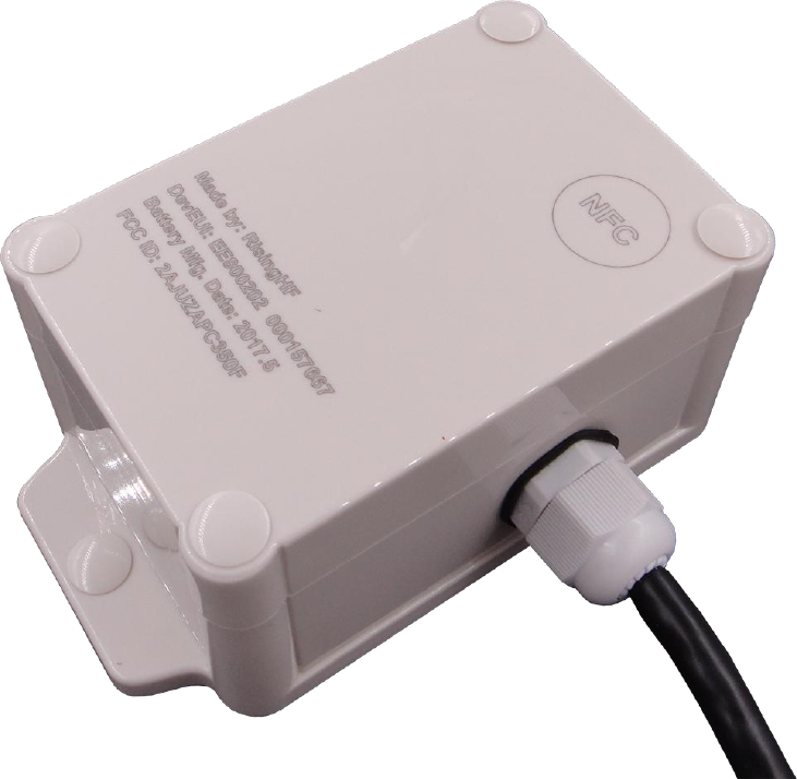
MIU (Meter interface unit) is a LoRaWAN compatible with an ultralow power MCU STM32L0xx and high
performance LoRa transceiver SX1276. MIU would be powered by internal battery.
NFC would be integrated into MIU for parameters configuration, like LoRaWAN configuration and others
parametersconfiguration.
V1.6 2016-11-16
www.risinghf.com
5
4.1 Electrical specifications
Table below list the key specifications of the LoRaWAN sensor interface unit.
Table 4- 1 Electrical specifications of MIU
ITEMs
Parameter
Specifications
Unit
Electrical
Characteristics
power supply (Internal)
3.6V type
Battery voltage range 3.6 to 2.4V
V
Sleep current
3.5uA
uA
Band
920-925MHz
MHz
Protocol
LoRaWAN Class A
LoRaWAN Mode
OTAA/ABP Configurable
TX current
125mA @19dBm type
mA
RX current
16mA
mA
Output power
18dBm max
dBm
Sensitivity
-137dBm @SF12, BW125kHz,
dBm
Harmonics
<-36dBm above 1GHz
dBm
Antenna Gain (Internal)
1.5dBi type
dBi
Mechanical
Mechanical Size
TBD
mm
IP Level
IP68
Environment
Operating Temperature
-25 to +70℃
℃
Storage Temperature
-40 to +85℃
℃
Relative Humidity
20 – 90%
Certification
FCC
FCC part 15 Class B
FCC 15.247
IP68
4.2 The MIU interfaceCharacteristics:
Items
Pin define
Specification
Color
remark
Port
GND
BLACK
Pulse
Digital input. pulse signal of
meter
RED
Dry contact. Open: normal, close: pulse
Direction
Digital input. flow direction of
meter
YELLOW
Dry contact. Open: Forward, close:
Reverse
Cut wire
Digital input. Cut wire status of
meter
WHITE
Dry contact. Open: alarm, close:
normal
V1.6 2016-11-16
www.risinghf.com
6
4.3 Mechanical Specifications and IPx
Mechanical size will be similar to 90x140x40 mm (TBD) or smaller.
The enclosure of the MIU should be IP6x. All the box mounting connectors and external connectors should be
IP6x.Irrigation methods sealing glue will be used to achieve excellent water and dust effects.
4.4 FCC compliant
MIU should be FCC compliant.
EMC would comply with FCC part 15 Class B.
Radio requirement should comply with FCC 15.247.
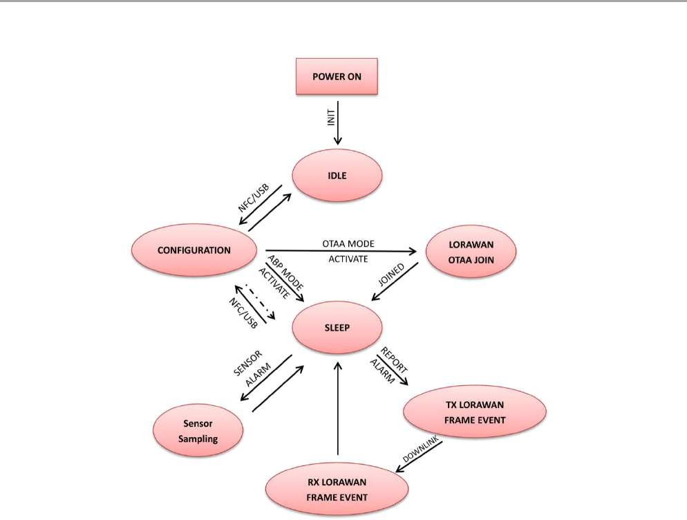
5 MIU Application Layer Design
The part presents the application layer protocol implemented in the MIU. The application layer leverages on the
LoRaWANspecifictions v1.0.1 released 2016. Figure 5 1 show the LoRaWANMIU flow chart in operation.
5.1 LoRaWAN Activation
After the MIU is activated and powered it will try to join an available LoRaWAN network in its vicinity. After
joining the LoRaWAN at the LoRa MAC level the MIU will send a status message to create a link with the sensors'
network NMS.

V1.6 2016-11-16
www.risinghf.com
7
Based on LoRaWAN specifications section 6.2 and 6.3, During a session between the end-device and the
gateway two encryption key are used, NwkSKey and AppSKey. There two options for the end-device to acquire
those keys, Over the Air Activation (OTAA) or Activation By Personalization (ABP):
- In OTAA mode the keys are generated in the join procedure and it unique to every end-device.
- In ABP mode, the device must know the NwkSKey and AppSKey keys in advance. All end-devices have
the same keys, so if the keys are revealed then the transmissions of all end-device will be unsecured.
The MIU can support both ABP and OTAA modes, however we recommend using only the OTAA activation mode
since it is more secured.
5.2 MIU Data Transmission
MIU will transmit message in a predefined duty cycle or a sensor event is triggered. The transmission follows
below rules.
The MIU will set random offset for each transmission period in case of packet collision;
The MIU will listen at selected channel to make sure the channel is free, RSSI level is less than a
predefined THRESHOLD (e.g.: -80dBm)
The MIU will store latest 72+ messages, these data is readable through NFC interface
To make sure data integrity and decrease downlink bandwidth
The MIU is high security benefits from the AES-128 encryption
5.3 Variable define:
5.4 Water Meter Accumulation:
1. When initial mater value transfer from the NFC (float data), it will convert to the pulse data by
Meter factor. Then save as the Total Pulse Data.
2. When there is one pulse detected, if the direction is forward, then add one to the Total Pulse Data.
If the direction is reverse, then minus one from the Total Pulse Data.
3. When sample data, it will use the Total Pulse Data convert to Meter Data (factor).
Variable Data:
Meter ID
As string. Max as 10 characters. Configure via NFC
Total Pulse Data
As unsigned long. Can configure its initial value via NFC
Meter Factor code
As Byte. Configure via NFC
Sample Interval (min)
As short. Default is 60min.
Transmit Interval
As byte. N Times of sample interval (1 to 6). Default is 4.
Meter Status
As Byte. Temper/Cut Wire, Battery Low, Back Flow.
Time Counter
As long. Increate 1 per second
Battery value
As Byte. Battery voltage rate to the full. 0 – 100%
Alarm Status
Meter Status Alarm. Bit0: cut wire, Bit1: Battery low
V1.6 2016-11-16
www.risinghf.com
8
5.5 Water Meter Status:
1. Cut Wire: as bit0. Set as “0” if the input is short to GND.
2. Battery Low: as bit 1. Set as “1” if the battery is lower than 80%.
3. Direction: as bit 2. Set as “1” if the input is open to the GND. (forward)
5.6 Sample Data:
1. Meter Value: as float. Total Pulse value/Factor.
2. Meter Status: as byte. Cut Wire as bit0, Battery Low as bit1, Back Flow as bit2.
3. Time Counter: as unsigned long.
When Sample interval reached, the MIU will get the Total pulse value and Meter status as one sample
with the time counter value.
5.7 Transfer Data:
When Transmit interval reached, the MIU will create the report with the samples. (If Transmit interval
same as sample interval, only one sample in the report.) MIU should use confirmed method to report
as uplink. If the MIU cannot get the reply from the server, it needs to resend the data again by once.
5.8 Store Data and Backup:
When Transmit the data, if the MIU cannot receive the reply from the server, it should store the
samples data. The max stored the samples data is 150. When full, replace old with new as FIFO. When
MIU backup the stored data via NFC, it will use tools system time with the time counter as Time Stamp.
After stored data has been backup, the stored data will be deleted.
5.9 NFC Function:
1. Active/ Deactivate the LoRa Transmit with Security Key and without Key.
2. Configure Meter ID, Total Initial Data as m3, Meter Factor code. Sensor Type
3. Get the Current Status, Current Data.
4. Backup Stored Data, after backup the stored data will be deleted.
5.10 Alarm
When Cute Wire, Battery Low happened, it will trigger an alarm. MIU will create the Alarm report and
transmit uplink at once. And then clear the alarm bit.
1. Cut Wire: bit 0. Set to “1” if the status is from “0” to “1”.
2. Battery Low: bit 1. Set to ‘1’ if the status from “0” to “1”.
V1.6 2016-11-16
www.risinghf.com
9
5.11 Low Power Design
The MIU is a low power device, and the application software is designed to save power as much as possible.
The software is designed as an event trigger structure, the main function will enter sleep mode if there is
no processing event, after sleep the MIU will wait alarm or interrupt to wake up to process necessary event.
5.11.1 Life Span Calculation
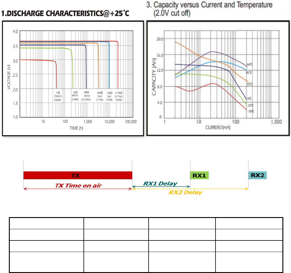
5.11.1.1 Assumption
5.11.1.1.1 Battery
This report uses Evebattery’s 19Ah ER34615 type as reference, the discharge characters as showed below.
This follow table assumes MIU device works in LoRaWAN class A mode.
STM32 MCU supply a low power pulse detector, which allow MCU counts the pulse in low power mode.
Name
Current
Time period
Average current
CPU activate
3mA
5ms/1s
15uA
CPU sleep
3.5uA
--
3.5uA
RF send (SF12, BW125k,
TX 19dBm, resend once)
125mA
1.5 * 1.65s / 4h
21.5uA
V1.6 2016-11-16
www.risinghf.com
10
RF received
15mA
5s / 4h
5.2uA
IO interface
20uA
--
30uA
Battery leakage
5uA
--
5uA
Total consumption
--
--
80.2uA
***Battery Capacity *0.5(50%)
19000maAH*0.5= 9600mAH
Theory calculate Time for years
9600/0.0802 = 120000h= 13year
***Note: Consider the current used and temperature range; the capacity will be drop to 50%.
5.12 MIU Data Format Reference
5.12.1 Uplink
5.12.1.1 Configuration Report
Field
Len
Value
Code
1
0x8F (user define report)
Length
1
17
Sensor type
1
0x10
Report interval
1
In minutes
Location longitude
4
As set in the activation
Location latitude
4
As set in the activation
Alert enable
1
1 / 0 – Enable / Disable
Alert threshold
2
RFU
FW Version
2
xx.xx
5.12.1.2 Meter Information Report
Field
Len
Value
Code
1
0x8E (Configure report)
Length
1
2 + 4 + N + 2
Separate
1
#
Meter ID
N
Max to 16 characters
Separate
1
#
Meter Sensor type
1
Meter Factor code
1
CRC
2
CRC check
5.12.1.3 Water Meter Report
Field
Len
Value
Code
1
0x80 (time interval)
Length
1
31
V1.6 2016-11-16
www.risinghf.com
11
Sequence number
2
Cyclic number, increment for every report
Battery voltage
1
%
Elapsed time
2
Seconds from measurement to transmission
Water Meter code
1
0x10
Number of data
1
4
Meter Total Pulse 1 sample
4
(float) Total consumption as m3
Meter status
1
Status
Meter Total Pulse 2 sample
4
(float) Total consumption as m3
Meter status
1
Status
Meter Total Pulse 3 sample
4
(float) Total consumption as m3
Meter status
1
Status
Meter Total Pulse 4 sample
4
(float) Total consumption as m3
Meter status
1
Status
CRC
2
CRC check
5.12.1.1 Water Meter Alarm Report
Field
Len
Value
Code
1
0x81 (alarm report)
Length
1
11
Alarm Sequence number
2
Cyclic number, increment for every report
Battery voltage
1
%
Elapsed time
2
Seconds from measurement to transmission
Meter Alarm
1
Bit0: Cut wire, Bit1: Battery Low,Bit:2 Back flow
Meter status
1
Status
CRC
2
CRC check
5.12.2 Downlink
5.12.2.1 Configuration Request
Field
Len
Value
Code
1
0x21
Length
1
2
5.12.2.2 Meter information Request
Field
Len
Value
Code
1
0x22
Length
1
2
5.12.2.3 Change Report Interval
Field
Len
Value
Code
1
0x20 (event command)
Length
1
7
Event Type
1
0x00
Report interval
2
New report interval in minutes. Default is 60min
Transmit interval
2
N times Sample. Default 4.
V1.6 2016-11-16
www.risinghf.com
12
V1.6 2016-11-16
www.risinghf.com
13
6 Application information
MIU is a sensor interface unit based on LoRaWAN protocol v1.0 (refer to “Physical Layer Specifications for
LoRaWAN Operation in Singapore 920-925 MHz band”). With this universal platform which is embedded with
LoRaWAN protocol stack and also some essential APIs, the customer could integrate their own sensors and run
LoRaWAN operation.
Sections below will give some example to show how to connect kinds of sensors.
6.1 MIU + pulse counter
MIU is possible to be accessed into with two pulse signal from two counters/meters. So the payload in
application will be composed of two groups of data from these two meters.
Figure 6- 2LoRaWAN pulse counter

V1.6 2016-11-16
www.risinghf.com
14
7 Append
7.1 NFC Application Layer Design
7.1.1 NFC Application Authentication:
When open the NFC Application, it should login Password for Authentication. There is an option to
choose whether with Security Key file or not.
Log in with Security Key file: the password will be the key that encrypted the Security Key file.
Log in without Security Key file: The password will be store in the binary file at the pre-define
folder.
7.1.2 Device changing new key via NFC:
When user wants to changing the new Security Key for the Device, it needs to do as the follow:
Generate the encrypted key file. (ST will create this key file)
Choose “Login with Key file” and login using the key for the encryption key file as password.
Decrypted the key file using the password.
Scan the device to get the DevEUI from the device via NFC.
Get the key using the DevEUI from Key file.
Activation the Device. The new key will be passed via the NFC.
Save the new key into the Device.
7.1.3 NFC App Activation and Deactivation Device:
To activation/ the device, the NFC Application needs to do as the follows:
Scan the device to get the DevEUI.
Choose the Activation/Deactivation the device.
Execute NFC transfer to active/deactivate the Device.
Scan again to confirm the Device has been Activation/Deactivation.
Every time when finish the transfer via NFC, there should have sound to indicate finish and the
transfer result should be display.
7.1.4 Download Store Data Via NFC
It needs to get the stored data from the device via NFC and then save it to a CSV file.
7.1.5 NFC key file and encrypt.
The new Key CSV files as example as follow:
V1.6 2016-11-16
www.risinghf.com 15
ABP mode:
DevEUI NetSKey AppSKey
008000000000CCEF 0123456789ABCDEF0123456789ABCDEF 0123456789ABCDEF0123456789ABCDEF
…… …… ……
OTAA mode:
DevEUI AppEUI AppKey
008000000000CCEF 0123456789ABCDEF 0123456789ABCDEF0123456789ABCDEF
…… …… ……
The Encrypted and Decrypted method please refer to the file “key encryption”.
7.2 Total consumption calculates
Meter data = Total Pulses / Meter factor.
Total Pulses = Meter data * Meter factor.
Meter factor: pulses/m3. It should get from the Meter Factor List.
This equipment should be installed and operated with minimum distance of 20cm between the radiator
This equipment generates uses and can radiate radio frequency energy and, if not installed and used in
(2) This device must accept any interference received, including interference that may cause undesired
V1.6 2016-11-16
www.risinghf.com 16
FCC Statement
1. This device complies with Part 15 of the FCC Rules. Operation is subject to the following two conditions:
(1) This device may not cause harmful interference.
operation.
2. Changes or modifications not expressly approved by the party responsible for compliance could
void the user's authority to operate the equipment.
NOTE: This equipment has been tested and found to comply with the limits for a Class B digital device,
pursuant to part 15 of the FCC Rules. These limits are designed to provide reasonable protection against
harmful interference in a residential installation.
accordance with the instructions, may cause harmful interference to radio communications. However, there
is no guarantee that interference will not occur in a particular installation. If this equipment does cause
harmful interference to radio or television reception, which can be determined by turning the equipment off
and on, the user is encouraged to try to correct the interference by one or more of the following measures:
- Reorient or relocate the receiving antenna.
- Increase the separation between the equipment and receiver.
-Connect the equipment into an outlet on a circuit different from that to which the receiver is connected.
-Consult the dealer or an experienced radio/TV technician for help
RF Exposure Statement
This equipment complies with FCC radiation exposure limits set forth for an uncontrolled environment.
and your body.