Runco Home Theater Projection System User Manual To The 1d63863d D150 41a9 B8a8 20ad5fb13760
1d63863d-d150-41a9-b.. 1d63863d-d150-41a9-b8a8-20ad5fb13760
User Manual: Runco Home Theater Projection System to the manual
Open the PDF directly: View PDF ![]() .
.
Page Count: 152 [warning: Documents this large are best viewed by clicking the View PDF Link!]
- RuncoCare™ Standard Two Year Limited Warranty
- Important Safety Instructions
- Compliance Information
- 1. Introduction
- 2. System Overview
- 3. Installation
- 3.1 Remote Control
- 3.2 Quick Setup
- 3.3 Installation Considerations
- 3.4 Installing the Optional Anamorphic Lens Mount
- 3.5 Mounting the LS-12HBd
- 3.6 Mounting the Dimension Digital Controller
- 3.7 System Interconnections
- Connecting the Dimension Digital Controller to the Projector
- Connecting an Audio Processor or Secondary Display Device to the Dimension Digital Controller (Optional)
- Additional Connections to the Dimension Digital Controller (Optional)
- Connecting Source Components to the Dimension Digital Controller
- Connecting the Active 3D Emitter to the Dimension Digital Controller
- Connecting to AC Power
- 3.8 Turning on the Power
- 3.9 Primary Lens Adjustments: Focus, Zoom and Position
- 3.10 Adjusting the Picture Orientation
- 3.11 Adjusting the Image Geometry
- 3.12 Installing and Adjusting the Anamorphic Lens
- 4. Operation
- 4.1 Using the On-Screen Menus
- Figure 4-1 . LS-12HBd OSD Menu Structure
- Main Menu
- Input Source
- Aspect Ratio
- Screen
- Picture
- Input Position
- Memory Presets
- 3D Processing
- Sleep Timer
- Information
- Calibration
- Service
- 4.2 Using the 3D Glasses
- 4.1 Using the On-Screen Menus
- 5. Maintenance and Troubleshooting
- 6. External Control
- 7. Specifications
LS-12HBd
High-Brightness, Active 3D Home Theater Projection System
INSTALLATION/OPERATION MANUAL

LightStyle™ LS-12HBd Installation/Operation Manual iii
PRELIMINARY
RuncoCare™ Standard Two Year Limited
Warranty
Congratulations on your purchase of a Runco® product! With proper installation, setup and care, you should enjoy many years
of unparalleled video performance.
This Limited Warranty is provided free of charge by Runco International, LLC (“Runco”) with the purchase of a covered Runco
product. This Limited Warranty is applicable to all Runco projectors, processors, LCD display and plasma display products,
with the exception of the following models: XP-103DHD, SC-1 and SC-1a1. This Limited Warranty applies to purchases of
covered Runco products occurring on or after June 1, 2011.
Runco warrants its products to be free from defects in material and workmanship during the warranty period provided below. If
a product proves to be defective in material or workmanship during the warranty period, Runco will repair the product, replace
the product with a substantially similar new or like-new product, or refund a prorated share of the purchase price (calculated
based on the remainder of the warranty period and the then-current, most-recent MSRP2 of a similar product), if repair or
replacement of the product is determined by Runco to not be feasible.
Runco products are warranted for two (2) years from the date of shipment from Runco. Lamps are warranted six (6) months
from the date of shipment or 1000 hours of use, whichever comes first. A replacement lamp is warranted for the remaining
portion (if any) of the original warranty period or ninety (90) days from the date it was shipped to you, whichever is longer. All
other accessories, which include but are not limited to cables, remotes, carrying cases, lens cap and other peripherals sold
with the Runco product, are warranted for ninety (90) days from the date of shipment.
This Limited Warranty is valid only in the country where the Product was originally purchased and for the buyer who originally
purchased the covered product from the authorized Runco dealer or distributor. This warranty is not transferable; it is not valid
for any subsequent buyer (if any). You may be required to provide proof of purchase in order to receive warranty services.
1. Runco may update this list of products excluded from this warranty from time to time at Runco’s sole discretion, but updates will
not apply on a retroactive basis.
RuncoCare™ Limited Warranty Coverage
2. MSRP is defined as the most recent product price listed on Runco’s price list.
Length of RuncoCare™ Warranty Period
RuncoCare™ Eligibility

iv LightStyle™ LS-12HBd Installation/Operation Manual
PRELIMINARY
• In the event of a product defect, please follow the claim procedure provided below:
A. Register your product if you have not yet done so. Visit http://www.runco.com/support/product-registration/ to
register the product.
B. Contact your original authorized dealer or distributor who sold the product.
C. The dealer/distributor will contact Runco Technical Support via email at support@runco.com or via phone at 1-800-
23-RUNCO (1-800-237-8626).
• The dealer/distributor will provide to Runco proof of purchase, serial number, product model number, description of the
problem and any troubleshooting steps already attempted.
• Runco’s technical support staff will attempt to assist the dealer/distributor in troubleshooting any technical issues that might
be causing the product to malfunction. If Runco is unable to resolve the problem through troubleshooting, a Return Material
Authorization (RMA) number will be issued for the exchange of the defective product if it is determined that the claim is
covered by the warranty. Once an RMA has been created, RMA status is available at serviceorders@runco.com.
• If an RMA is issued, the dealer or customer will need to return the defective product to the Runco repair depot location
specified by the Runco technical support representative. The dealer or customer will need to properly package the defective
product in a suitable shipping container consisting of the product only, and not include any accessories (e.g., cables,
remotes, carrying cases, lens, lens cap and other peripherals). Boxes may be purchased from a Runco technical support
representative.
• The dealer or customer is responsible for paying freight charges and insurance to ship the defective product to the Runco
repair depot location. If there are any shipping damages, the dealer or customer will need to address and resolve any
shipping damage claims directly with the shipping company.
• Runco will not accept a returned product unless an RMA has been issued by Runco.
• For in-warranty repairs, Runco will pay freight charges to return the repaired/replacement product to the dealer/distributor
from the Runco repair depot. For select countries or geographies Runco will ship via an economy express service. Return
delivery time and availability may vary based on origin and destination, and Runco is unable to deliver to PO Box and FPO
Box addresses.
• Note: in the 48 contiguous United States, other options for on-site service or advance exchange for the product may apply,
if you purchased the Runco PremierCare™ Service Plan.
1. Return only the defective product with the lamp (if applicable).
2. Runco will not be responsible for returning or replacing any accessories (e.g., cables, remotes, carrying cases, lens, lens
cap and other peripherals sold with the Runco product) that are returned with the defective product.
3. Repaired or replacement products will be shipped with a lamp (if applicable) but without any accessories.
This Limited Warranty does not include and is limited by the following:
1. Products not purchased from an authorized Runco dealer
2. Rental costs incurred by the customer in the event of product defect or failure
3. Any product with a defaced, modified, or removed serial number
RuncoCare™ Standard Claim Procedure
What to Include with Your Return
RuncoCare™ Warranty Exclusions

LightStyle™ LS-12HBd Installation/Operation Manual v
PRELIMINARY
4. Damage, deterioration, or malfunction resulting from:
A. Accident, abuse, misuse, neglect, improper ventilation, fire, water, disaster, lightning, or other acts of nature, smoke
exposure (cigarette or otherwise), unauthorized product modification (including use of an unauthorized mount), or
failure to follow instructions supplied with the product
B. Repair or attempted repair by anyone not authorized by Runco
C. Any damage to the product due to shipment
D. Removal or installation of the product
E. Causes external to the product, such as electric power fluctuations or failure
F. Use of supplies or parts (including lamps) that are not purchased from Runco or do not meet Runco’s specifications
G. Normal wear and tear
H. Expected lamp degradation and normal decrease in lamp output over a period of time or as the lamp is consumed
I. Customer caused defects, including but not limited to, scratched/defaced/altered plastics
J. Failure to follow maintenance procedures as outlined in the product’s user guide where a schedule is specified for
regular cleaning of the product
K. Opening the product and/or tampering with internal circuitry
L. Products lost, stolen or discarded
M. Any damage or dissatisfaction associated with latent images, “burnin,” or any other damage determined by Runco to
be the result of customer use patterns
N. Any other cause, which does not relate to a product defect in material or workmanship
5. Removal, installation, and set-up service charges are excluded from the warranty.
6. Black uniformity issues or other LCD issues associated with usage outside the Runco recommended guidelines and
specifications for the product.
7. Bright or dark sub pixels that are characteristic of LCD technology and considered by Runco to be acceptable and within
Runco’s manufacturing specifications.
Specifically, it is not uncommon for one or more sub pixels to become bright or dark during or after the manufacturing
process. A bright sub pixel is one that remains in the on position, and a dark sub pixel is one that appears black or off. The
sub pixels are usually hard to see and will not detract from the display quality or usability at normal viewing distance. The
following are Runco’s criteria for identifying bright or dark sub pixels that would be considered unacceptable: a) the
number of bright or dark sub pixels; b) the location of the bright or dark sub pixels; c) the color of the bright sub pixels; and
d) the Runco model size. If sub pixels have been identified as unacceptable by Runco the LCD will be deemed faulty and
will be replaced if reported within the warranty period.
1. If the defective product is not properly packaged and is damaged in transit during its return to Runco, you may be invoiced
for either the repair costs, if repairable, or the MSRP of a replacement product and shipping costs incurred by Runco.
2. The repaired or replaced product will assume the remainder of your original product’s warranty term or 90 days from the
date the repaired or replaced product is shipped, whichever is longer.
3. If a replacement product is sent, the replacement becomes the property of the customer and the defective product
becomes the property of Runco.
Other Terms and Conditions

vi LightStyle™ LS-12HBd Installation/Operation Manual
PRELIMINARY
Runco offers extended and expanded service plans. For information on additional product protection, please ask your
authorized Runco dealer, email serviceorders@runco.com or call (toll free) (800) 23RUNCO (800-237-8626).
RUNCO PROVIDES NO WARRANTIES, EXPRESS OR IMPLIED, EXCEPT THOSE EXPRESSLY PROVIDED IN THIS
DOCUMENT. RUNCO EXPRESSLY DISCLAIMS AND EXCLUDES ALL OTHER WARRANTIES, INCLUDING THE IMPLIED
WARRANTIES OF TITLE, NONINFRINGEMENT, MERCHANTABILITY AND FITNESS FOR A PARTICULAR PURPOSE.
RUNCO’S MAXIMUM AGGREGATE LIABILITY IS LIMITED TO THE COST OF REPAIR, REPLACEMENT OR REFUND OF THE
PRODUCT.
RUNCO WILL NOT BE LIABLE FOR DAMAGE TO OTHER PROPERTY OR FOR DAMAGES BASED UPON INCONVENIENCE,
LOSS OF USE OF THE PRODUCT, LOSS OF TIME, LOSS OF PROFITS, LOSS OF BUSINESS OPPORTUNITY, LOSS OF
GOODWILL, INTERFERENCE WITH BUSINESS RELATIONSHIPS, OR OTHER COMMERCIAL OR FINANCIAL LOSS, EVEN IF
RUNCO IS AWARE OF THE POSSIBILITY OF SUCH DAMAGES AND EVEN IF A REMEDY HAS FAILED OF ITS ESSENTIAL
PURPOSE.
RUNCO WILL NOT BE LIABLE FOR ANY CONSEQUENTIAL, INCIDENTAL, INDIRECT, EXEMPLARY, SPECIAL, PUNITIVE OR
ANY OTHER TYPE OF DAMAGES, WHETHER THE CLAIM IS BASED ON CONTRACT, TORT, PRODUCT LIABILITY,
NEGLIGENCE, STRICT LIABILITY OR ANY OTHER LEGAL OR EQUITABLE THEORY.
RUNCO WILL NOT BE LIABLE FOR ANY CLAIM AGAINST THE CUSTOMER BY ANY OTHER PARTY.
This Limited Warranty gives you specific legal rights, and you may have other rights, which vary from locality to locality. Some
localities do not allow limitations on implied warranties and/or do not allow the exclusion of incidental or consequential
damages, so the above limitations and exclusions may not apply to you.
© Copyright 2013 Runco International, LLC (“Runco”). This document contains proprietary information protected by copyright,
trademark and other intellectual property laws. All rights are reserved. No part of this manual may be reproduced by any
mechanical, electronic or other means, in any form, without prior written permission of Runco.
The trademarks reproduced in this Runco Owner’s Manual and used on the Runco Products are either owned by Runco or are
licensed by Runco. You may not reproduce or use the trademarks without the prior written consent of Runco.
Runco Products are manufactured under one or more of the following patents: US. Patent 6755540 and Other Patents
Pending.
RuncoCare™ Extended Service Options
Exclusion of Implied Warranties
Limitation of Liability; Exclusion of Damages
Effect of Local Law
COPYRIGHT AND TRADEMARKS:
LightStyle™ LS-12HBd Installation/Operation Manual vii
PRELIMINARY
Thank you for your purchase of this quality Runco video product! For the best performance, please read this manual carefully
as it is your guide through the menus and operation.
1. Read these instructions.
2. Keep these instructions.
3. Heed all warnings.
4. Follow all instructions.
5. Do not use this apparatus near water.
6. Clean only with a dry cloth.
7. Do not block any of the ventilation openings. Install in accordance with the manufacturer’s instructions.
8. Do not install near any heat sources such as radiators, heat registers, stoves, or other apparatus (including amplifiers) that
produce heat.
9. Do not defeat the safety purpose of the polarized or grounding type plug. A polarized plug has two blades with one wider
than the other. A grounding type plug has two blades and a third grounding prong. The wide blade or the third prong is
provided for your safety. When the provided plug does not fit into your outlet, consult an electrician for the replacement of
the obsolete outlet.
10. Protect the power cord from being walked on or pinched particularly at plugs, convenience receptacles and the point
where they exit from the apparatus.
11. Only use the attachments/accessories specified by the manufacturer.
12. Use only with a cart, stand, tripod, bracket or table specified by the manufacturer or sold with the apparatus.
When a cart is used, use caution when moving the cart/apparatus to avoid injury from tip-over.
13. Unplug this apparatus during lightning storms or when unused for long periods of time.
14. Refer all servicing to qualified service personnel. Servicing is required when the apparatus has been damaged in
any way, such as power supply cord or plug is damaged, liquid has been spilled or objects have fallen into the apparatus,
the apparatus has been exposed to rain or moisture, does not operate normally, or has been dropped.
15. The +12V trigger only outputs 12Vdc signal for triggering. Do not connect to any other power input or output. This could
cause damage to this unit.
16. Keep the packing material in case the equipment should ever need to be shipped.
17. The lamp becomes extremely hot during operation. Allow the projector to cool down for approximately 45 minutes prior to
removing the lamp assembly for replacement.
18. Do not operate lamps beyond the rated lamp life. Excessive operation of lamps beyond rated life could cause them to
explode in rare occasions.
19. Never look directly into the lens when the lamp is on.
Important Safety Instructions
WARNING
This symbol is intended to alert the user to the presence of
uninsulated “dangerous voltage” within the product’s enclosure
that may be of sufficient magnitude to constitute a risk of electric
shock.
This symbol is intended to alert the user to the presence of
important operating and maintenance (servicing) instructions in the
literature accompanying the appliance.
CAUTION
RISK OF ELECTRIC SHOCK
DO NOT OPEN
CAUTION:
TO REDUCE THE RISK OF ELECTRIC SHOCK
DO NOT REMOVE COVER (OR BACK)
NO USER SERVICEABLE PARTS INSIDE.
REFER SERVICING TO QUALIFIED
SERVICE PERSONNEL.

viii LightStyle™ LS-12HBd Installation/Operation Manual
PRELIMINARY
Please read and make sure you understand the following safety information before using the product for viewing 3D content.
Provide this information to the end users of this product and ensure that they understand it.
IMPORTANT HEALTH AND SAFETY INFORMATION FOR 3D VIEWING:
It is widely recognized that stereographic display devices can cause discomfort, including, without
limitation, dizziness, nausea, headaches, eye fatigue and eye-strain, in some individuals. The 3D
effect and experience will vary by individual, depending on a variety of factors, including his or her
health and vision. Runco recommends that users take regular breaks when watching 3D video or
playing games using stereoscopic displays. Discontinue use if any discomfort occurs. Parents of
young children should ensure their children avoid extensive exposure to electronic stereographic
entertainment.
The quality and appropriateness of the 3D screen materials onto which the image is projected and
the quality of the 3D content being displayed both have a significant and noticeable impact on the
overall 3D experience. A properly-calibrated projection system, including glasses and an
optimized third-party screen, displaying high-quality 3D content is the best formula for immersive
and comfortable 3D experiences in the home. Please refer to the remainder of this manual for
proper projector installation and usage instructions.
The glasses that accompany this product are not safe to use as sunglasses, protective eyewear or
any use outdoors or other than only in conjunction with the proper operation of the Runco product
with which they are sold. It is common to dim the lights in a home theater. Using 3D glasses and
the immersive imagery of stereoscopic imagery can increase the risk of tripping or falling the dark.
Special care should be taken.
Do not tilt your head while using the 3D glasses.
WARNING

LightStyle™ LS-12HBd Installation/Operation Manual ix
PRELIMINARY
Manufacturer’s Name: Runco International, LLC
Manufacturer’s Address: 1195 NW Compton Drive, Beaverton, OR 97006-1992
hereby declares that the Products’ Model Numbers:
LS-12HBd
conform with the provisions of:
Council Directive 2004/108/EC on Electromagnetic Compatibility;
EN 55022 “Limits and methods of measurements of radio interference characteristics of information technology equipment”
1998;
EN 55024 “Limits and methods of measurements of immunity characteristics of information technology equipment” 1998;
Including:
• EN 61000-4-2 “Electromagnetic compatibility (EMC) Part 4: Testing and measurement techniques Section 2:
Electrostatic discharge immunity test”
• EN 61000-4-3 “Electromagnetic compatibility (EMC) Part 4: Testing and measurement techniques Section 3: Radiated,
Radio-Frequency, Electromagnetic Field Immunity Test”
• EN 61000-4-4 “Electromagnetic compatibility (EMC) Part 4: Testing and measurement techniques Section 4: Electrical
fast transient/burst immunity test”
• EN 61000-4-5 "Electromagnetic compatibility (EMC) Part 4: Testing and measurement techniques Section 5: Surge
immunity test"
• EN 61000-4-6 "Electromagnetic compatibility (EMC) Part 4: Testing and measurement techniques Section 6: Conducted
disturbances induced by radio-frequency fields immunity test"
• EN 61000-4-8 "Electromagnetic compatibility (EMC) Part 4: Testing and measurement techniques Section 8: Conducted
disturbances induced by power frequency magnetic fields immunity test"
• EN 61000-4-11 "Electromagnetic compatibility (EMC) Part 4: Testing and measurement techniques Section 11: Voltage
dips, short interruptions and voltage variations immunity tests"
And:
• EN 61000-3-2 "Electromagnetic compatibility (EMC) Part 3, Section 2: Limits for harmonic current emissions (equipment
input current up to and including 16 A per phase)" 2000;
• EN 61000-3-3 "Electromagnetic compatibility (EMC) Part 3, Section 3: Limitations of voltage changes, voltage
fluctuations and flicker in public low-voltage supply systems, for equipment with rated current up to and including 16 A
and not subject to conditional connection" 1995;
Council Directive 2006/95/EC and amended by M1 and C1 on Low Voltage Equipment Safety;
EN 60950 “Safety of information technology equipment, including electrical business equipment”
The Technical Construction file required by this Directive is maintained at the corporate headquarters of Runco International,
LLC, located at 1195 NW Compton Drive, Beaverton, OR 97006-1992.
Date of Declaration: September 2013
Compliance Information
DECLARATION OF CONFORMITY:
x LightStyle™ LS-12HBd Installation/Operation Manual
PRELIMINARY
NOTE: This equipment has been tested and found to comply with the limits for a Class B digital device, pursuant to Part 15 of
the FCC Rules. These limits are designed to provide reasonable protection against harmful interference in a residential
installation.
This equipment generates, uses and can radiate radio frequency energy and, if not installed and used in accordance with the
instructions, may cause harmful interference to radio communications. However, there is no guarantee that interference will not
occur in a particular installation. If this equipment does cause harmful interference to radio or television reception, which can be
determined by turning the equipment off and on, the user is encouraged to try to correct the interference by one or more of the
following measures:
• Reorient or relocate the receiving antenna.
• Increase the separation between the equipment and receiver.
• Connect the equipment into an outlet on a circuit different from that to which the receiver is connected.
• Consult the dealer or an experienced radio/TV technician for help.
This Class B digital apparatus complies with Canadian ICES-003.
Cet appareil numérique de la classe B est conforme à la norme NMB-003 du Canada.
The Product contains small amounts of tin, lead and/or mercury. Disposal of these materials may be regulated due to
environmental considerations.
Lamp(s) inside this product contain mercury. This product may contain other electronic waste that can be
hazardous if not disposed of properly. Recycle or dispose in accordance with local, state, or federal Laws.
For more information, contact the Electronic Industries Alliance at WWW.EIAE.ORG.
For lamp specific disposal information check WWW.LAMPRECYCLE.ORG.
This symbol found on your product or on its packaging, indicates that this product should not be treated as
household waste when you wish to dispose of it. Instead, it should be handed over to an applicable collection
point for the recycling of electrical and electronic equipment. By ensuring this product is disposed of correctly,
you will help prevent potential negative consequences to the environment and human health, which could
otherwise be caused by inappropriate disposal of this product. The recycling of materials will help to conserve
natural resources. This symbol is only valid in the European Union. If you wish to discard this product, please
contact your local authorities or dealer and ask for the correct method of disposal.
FCC PART 15:
INDUSTRY CANADA (ICES-003):
PRODUCT DISPOSAL:
IMPORTANT RECYCLE INSTRUCTIONS
DISPOSAL OF OLD ELECTRICAL AND ELECTRONIC EQUIPMENT (Applicable throughout the European
Union and other European countries with separate collection programs)

LightStyle™ LS-12HBd Installation/Operation Manual xi
1Table of Contents
PRELIMINARY
RuncoCare™ Standard Two Year Limited Warranty ................................................... iii
Important Safety Instructions ....................................................................................... vii
Compliance Information ................................................................................................ ix
1. Introduction ...............................................................................................................1
About This Manual .......................................................................................................1
Target Audience .....................................................................................................1
If You Have Comments About This Manual... ..........................................................1
Textual and Graphic Conventions ...........................................................................1
Using This Manual ........................................................................................................2
Description, Features and Benefits ...............................................................................3
Key Features and Benefits ......................................................................................4
Parts List ................................................................................................................4
2. System Overview .......................................................................................................5
Projector ......................................................................................................................6
LS-12HBd Rear Panel ..................................................................................................9
DC-300 Dimension Digital Controller ..........................................................................10
Front Panel Layout................................................................................................10
Rear Panel Layout ................................................................................................12
LS-12HBd Remote Control Unit .................................................................................14
3. Installation ...............................................................................................................19
Remote Control ..........................................................................................................19
Notes on Batteries................................................................................................19
Notes on Remote Control Operation.....................................................................19
Quick Setup ...............................................................................................................20
Installation Considerations ..........................................................................................21
Pre-Wiring for 3D: Run Dual HDMI Cables ............................................................21
Installation Type....................................................................................................21
Ambient Light .......................................................................................................21
Throw Distance.....................................................................................................22
Vertical and Horizontal Position.............................................................................23
Vertical and Horizontal Lens Shift..........................................................................24
Folded Optics .......................................................................................................26
Audio/Video Synchronization Issues......................................................................27

Table of Contents
xii LightStyle™ LS-12HBd Installation/Operation Manual
PRELIMINARY
Other Considerations............................................................................................27
Installing the Optional Anamorphic Lens Mount ..........................................................28
Package Contents ................................................................................................28
Mounting the LS-12HBd ............................................................................................33
Floor Mounting (Upright) .......................................................................................33
Ceiling Mounting (Inverted)....................................................................................33
Installing the Projector in an Enclosure..................................................................33
Adjusting the Projection Angle ..............................................................................34
Mounting the Dimension Digital Controller ..................................................................35
System Interconnections ............................................................................................36
Connecting the Dimension Digital Controller to the Projector.................................36
Connecting an Audio Processor or Secondary Display Device to the
Dimension Digital Controller (Optional) ..................................................................38
Additional Connections to the Dimension Digital Controller (Optional)....................39
Connecting Source Components to the Dimension Digital Controller ....................43
Connecting the Active 3D Emitter to the Dimension Digital Controller....................49
Connecting to AC Power ......................................................................................49
Turning on the Power .................................................................................................50
Primary Lens Adjustments: Focus, Zoom and Position ...............................................51
Focus ...................................................................................................................51
Zoom....................................................................................................................51
Vertical and Horizontal Lens Shift..........................................................................51
Adjusting the Picture Orientation ................................................................................51
Adjusting the Image Geometry ...................................................................................52
Installing and Adjusting the Anamorphic Lens .............................................................54
4. Operation .................................................................................................................57
Using the On-Screen Menus ......................................................................................57
Main Menu............................................................................................................59
Input Source.........................................................................................................59
Aspect Ratio.........................................................................................................60
Screen..................................................................................................................62
Picture..................................................................................................................63
Input Position........................................................................................................68
Memory Presets ..................................................................................................70
3D Processing ......................................................................................................71
Sleep Timer ..........................................................................................................72
Information ...........................................................................................................72

Table of Contents
LightStyle™ LS-12HBd Installation/Operation Manual xiii
PRELIMINARY
Calibration ............................................................................................................73
Service .................................................................................................................81
Using the 3D Glasses .................................................................................................94
Key Features.........................................................................................................94
Functional Overview..............................................................................................94
Charging the Battery.............................................................................................95
Turning On the Glasses ........................................................................................96
Auto Power-Off.....................................................................................................96
5. Maintenance and Troubleshooting ........................................................................97
Lamp Replacement ....................................................................................................97
Troubleshooting Tips ..................................................................................................98
6. External Control ....................................................................................................101
Serial Communications .............................................................................................101
RS-232 Connection and Port Configuration ........................................................101
Command Format ..............................................................................................101
Response Format ...............................................................................................102
Command and Response Examples...................................................................103
Serial Command List...........................................................................................103
Using Discrete IR Codes ..........................................................................................117
IR Command Protocol ........................................................................................117
IR Command List (Standard Mode).....................................................................118
IR Command List (Extended Mode) ....................................................................121
Using HDMI CEC Messages .....................................................................................122
CEC Command List............................................................................................122
7. Specifications ........................................................................................................125
LS-12HBd Projector Specifications ..........................................................................125
Dimension Digital Controller Specifications ...............................................................127
Supported Timings ...................................................................................................129
LS-12HBd Dimensions .............................................................................................133


LightStyle™ LS-12HBd Installation/Operation Manual xv
1List of Figures
PRELIMINARY
2-1. LightStyle™ Series LS-12HBd Active 3D Projection System Block Diagram .................5
2-2. LS-12HBd Front/Side View ..........................................................................................6
2-3. LS-12HBd Rear/Bottom/Top View ...............................................................................8
2-4. LS-12HBd Rear Panel ..................................................................................................9
2-5. Dimension Digital Controller Front Panel .....................................................................10
2-6. DC-300 Dimension Digital Controller Rear Panel.........................................................12
2-7. Dimension Digital Controller Remote Control Unit for LS-12HBd.................................14
3-1. Estimating Throw Distance .........................................................................................22
3-2. Projector Placement ...................................................................................................24
3-3. Vertical Lens Shift (EXAMPLE ONLY)..........................................................................24
3-4. Horizontal Lens Shift (EXAMPLE ONLY)......................................................................25
3-5. Folded Optics.............................................................................................................26
3-6. Mounting Angle Ranges (Front-to-Back and Side-to-Side)..........................................34
3-7. Attaching the Rack Mounting Hardware .....................................................................35
3-8. RS-232 Connection from the Dimension Digital Controller to the Projector .................36
3-9. Connecting the Dimension Digital Controller to the Projector ......................................37
3-10. Audio Processor Connection to Dimension Digital Controller ....................................38
3-11. RS-232 Control System Connection to Dimension Digital Controller .........................39
3-12. Connecting 12-volt Trigger Outputs..........................................................................40
3-13. External IR Receiver Connection...............................................................................41
3-14. Ethernet Network Connection to Dimension Digital Controller...................................42
3-15. DisplayPort Source Connection................................................................................43
3-16. HDMI Source Connections .......................................................................................44
3-17. Component Video Source Connections....................................................................45
3-18. RGBHV Source Connections....................................................................................46
3-19. SCART RGBS Source Connections..........................................................................47
3-20. Composite Video Source Connections .....................................................................48
3-21. Active 3D Emitter Connection...................................................................................49
3-22. Keystone and Pincushion Distortion .........................................................................52
3-23. Image Alignment Controls ........................................................................................53
3-24. Attaching the Anamorphic Lens to the Lens Mount ..................................................54
4-1. LS-12HBd OSD Menu Structure ................................................................................57
4-2. Typical PLUGE Pattern for Adjusting Brightness .........................................................64
4-3. Typical Gray Bar Pattern for Adjusting Contrast ..........................................................65

List of Figures
xvi LightStyle™ LS-12HBd Installation/Operation Manual
PRELIMINARY
4-4. Typical Color Bar Pattern for Adjusting Color Saturation and Tint................................65
4-5. Typical Test Pattern for Adjusting Sharpness..............................................................67
4-6. Overscan Modes ........................................................................................................69
4-7. CIE 1931 Chromaticity Diagram .................................................................................74
6-1. NEC Protocol Message Format ................................................................................117
7-1. LS-12HBd Dimensions.............................................................................................133
Introduction
LightStyle™ LS-12HBd Installation/Operation Manual 1
PRELIMINARY
1.1
About This Manual
This Owner’s Manual describes how to install, set up and operate the Runco LightStyle™
Series LS-12HBd Active 3D Projection System.
Throughout this manual, the Runco LightStyle™ Series LS-12HBd Active 3D Projection
System is referred to as the “LS-12HBd.”
Target AudienceRunco has prepared this manual to help installation personnel and end users get the most
out of the LS-12HBd.
Runco has made every effort to ensure that this manual is accurate as of the date it was
printed. However, because of ongoing product improvements and customer feedback, it
may require updating from time to time. You can always find the latest version of this and
other Runco product manuals on-line, at www.Runco.com.
If You Have Comments
About This Manual...
Runco welcomes your comments about this manual. Send them to support@Runco.com.
Textual and Graphic
Conventions
Text Conventions: The following conventions are used in this manual, in order to clarify
the information and instructions provided:
• Remote and built-in keypad button identifiers are set in upper-case bold type; for
example, “Press EXIT to return to the previous menu.”
• Computer input (commands you type) and output (responses that appear on-screen) is
shown in monospace (fixed-width) type; for example: “To change the aspect ratio to
Letterbox, type LETTERBOX <Enter>.”
• All keys with functional names are initial-capped, set in bold type and enclosed in angle
brackets. These keys are the following: <Enter>, <Spacebar>, <Control>,
<Esc> and <Tab>.
•<Enter> indicates that you may press either the RETURN or ENTER key on your
keyboard if it has both keys.
In addition to these conventions, underlining, boldface and/or italics are occasionally used
to highlight important information, as in this example:
1. Introduction
A carriage return must be used after each command or string.
Note
Introduction
2 LightStyle™ LS-12HBd Installation/Operation Manual
PRELIMINARY
Graphic Conventions: These symbols appear in numerous places throughout the
manual, to emphasize points that you must keep in mind to avoid problems with your
equipment or injury:
1.2
Using This Manual
Use the following table to locate the specific information you need in this manual.
TIPS highlight time-saving short cuts and helpful guidelines for using
certain features.
NOTES emphasize text with unusual importance or special
significance. They also provide supplemental information.
CAUTIONS alert users that a given action or omitted action can
degrade performance or cause a malfunction.
WARNINGS appear when a given action or omitted action can result
in damage to the equipment, or possible non-fatal injury to the user.
DANGER appears when a given action can cause severe injury or
death.
Tip
Note
Caution
WARNING
DANGER!
If you need... ... Turn to page:
Information about obtaining service iv
General information about the LightStyle™ Series LS-12HBd
Active 3D Projection System
3
Installation instructions 19
First-time configuration instructions 51
Advanced configuration instructions 73
Troubleshooting tips 98
Specifications for the LightStyle™ Series LS-12HBd Active 3D
Projection System
125

Introduction
LightStyle™ LS-12HBd Installation/Operation Manual 3
PRELIMINARY
1.3
Description, Features
and Benefits
Runco’s LightStyle™ Series LS-12HBd Active 3D Projection System delivers exceptional
3D and 2D performance, sharing many of the technical attributes of the award-winning
LightStyle™ projector series. The LS-12HBd combines a powerful, three-chip DLP®
engine and a wide array of lens options with Runco’s elegant LightStyle chassis design.
With the addition of the LS-12HBd to Runco’s 3D projection offerings, clients now have a
variety of exceptional 3D options to choose from based on their individual needs.
The LS-12HBd is a high-bright DLP® projector that delivers stunning, flawless video at a
scale unattainable by other display types, opening up new projector possibilities in the
home and excelling outside of the dedicated home theater, where environmental factors
such as lighting are not easily controlled.
Custom paint and print options with a myriad of color options are available with the
LS-12HBd, including an option to design your own one-of-a-kind projector with Runco
FinishPalette™. Beyond beautiful on the outside, the Runco LS-12HBd is feature-rich,
including advanced connectivity and the latest-generation video processing and scaling.
Rounding out this impressive projector are discrete input source, aspect ratio and power
on/off, as well as an RS-232 interface for seamless integration with automation control
systems.
Impressive and unique and unlike single-chip DLP implementations, no color wheel is
used in the LS-12HBd projectors. Instead, it harnesses the power of three advanced full
1080p HD 16:9 DMD’s™ and 12-degree mirror tilt for the finest black level performance.
The impressive brightness is further bolstered by the improved contrast capabilities of the
stylish LS-12HBd. Designed to excel in both the dedicated theater as well
“Flex-Theaters,” spaces where big screen entertainment is only a portion of the room’s
purpose and aesthetics and placement are as crucial as video performance.
For uncompromised widescreen reproduction of movies originally filmed in the
CinemaScope™ 2:35:1 format, the LS-12HBd can also be paired with one of Runco’s
award-winning anamorphic lens solutions. Through an ingenious combination of software,
electronics and precision anamorphic optics, the Runco anamorphic lens system
maintains constant image height on the screen just as in a movie theater. When a viewer
transitions from 1.78:1 (16:9) program material to superwide 2.35:1, the image simply
gets wider while image height is maintained. The projection system is able to use the full
pixel array, thereby producing a 2.35:1 image with enhanced resolution and increased
brightness. No resolution or image area is lost to those black bars that contain no picture
information.
An anamorphic lens requires the use of a 2.35:1 (or similar aspect ratio),
“superwide” format screen.
Note

Introduction
4 LightStyle™ LS-12HBd Installation/Operation Manual
PRELIMINARY
Key Features and Benefits The LS-12HBd offers these key features and benefits:
• Native Resolution: 1920 x 1080 (16:9 Native Aspect Ratio)
• Three-chip Digital Light Processing (DLP™) system
• DisplayPort 1.1a Input (on Dimension Digital Controller) with High-bandwidth Digital
Content Protection (HDCP)
• Eight (8) HDMI Inputs (on Dimension Digital Controller) with HDCP, 3D and Deep Color
•CinOptx™ Proteus lens options for stunning sharpness and throw distance flexibility
• Bundled with two years of Runco PremierCare™ service program providing on-site
calibration and two years of ongoing support from Runco
Parts List Your LS-12HBd is shipped with the following items. If any items are missing or damaged,
please contact your Runco dealer or Runco Customer Service at (800) 23RUNCO.
• LightStyle™ Series LS-12HBd Active 3D Projection System:
• Projection Unit
• Dimension Digital Controller unit
• Remote Control Unit and batteries
• AC Power Cords (2)
• RJ-11 Telephone Cable, 50 feet (15.24 meters)
• Serial Port Adapter, RJ-11 Female to DB-9 Male
• Active 3D Emitter and projector interface cable, 3.28 feet (1.0 meters)
• Active 3D Glasses (3 pairs)
• HDMI-to-HDMI Cables (2), sold separately (refer to Optional Accessories, below)
• Rack-mount hardware for the Dimension Digital Controller
• Runco LS-12HBd Quick Setup Guide
Optional Accessories:
• Secondary anamorphic lens and lens mount
• Replacement Lamp (part number 997-5268-00)
• Ceiling mount kit (part number 997-4214-00)
• HDMI-to-HDMI Cable, length specified at time of order:
• 16.4 feet (5.0 meters) (part number 903-1010-00)
• 24.6 feet (7.5 meters) (part number 903-1011-00)
• 32.8 feet (10.0 meters) (part number 903-1012-00)
• 49.2 feet (15.0 meters) (part number 903-1013-00)
• 65.6 feet (20.0 meters) (part number 903-1014-00)
➤
➤
System Overview
LightStyle™ LS-12HBd Installation/Operation Manual 5
PRELIMINARY
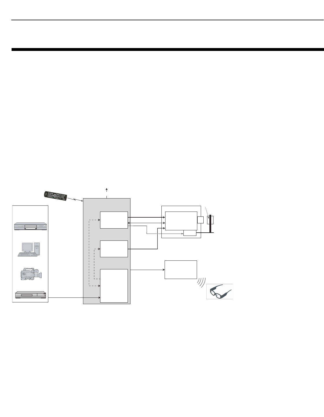
A LightStyle™ Series LS-12HBd Active 3D Projection System consists of the following
components:
• The projector (equipped with dual digital video inputs) with optional anamorphic lens
and lens transport assembly.
• The DC-300 Dimension Digital Controller™ unit that provides “left-eye” and “right-eye“
video signals and the on-screen display (OSD) menu to the projector. In addition, the
Dimension Digital Controller controls the projector in response to user input via its
infrared (IR) remote control unit or front-panel keypad, an external control system or
HDMI Consumer Electronics Control (CEC) messages.
• An Active 3D Emitter that receives a left/right synchronization signal from the projector
and transmits it to the Active 3D Glasses worn by the viewers. This signal precisely
controls when left and right fields are visible through the glasses.
Figure 2-1 shows how these components connect to and interact with each other. The
following sections describe each one in detail.
Figure 2-1. LightStyle™ Series LS-12HBd Active 3D Projection System Block
Diagram
2. System Overview
Trigger
Remote
Control
IR
Projector
Optical Engine
Video
Sources
Active 3D
Emitter
Active 3D
Glasses
Primary Video/CEC (Control)
HDMI, DisplayPort,
Component, SCART,
RGB, Composite
DC-300
Dimension Digital Controller
Primary Video
(Left)
RS-232
Secondary Video
(Right)
L/R Stereo Sync
HDMI Audio Out
Secondary Video
Anamorphic
Lens
RF
2D/3D Video
Decoder/
Multiplexer
Secondary
Video
Scaler
Primary
Video
Scaler
System Overview
6 LightStyle™ LS-12HBd Installation/Operation Manual
PRELIMINARY
2.1
Projector
A LightStyle™ Series LS-12HBd Active 3D Projection System can display both traditional
2D and stereoscopic 3D video content.
An active 3D presentation requires a specialized video signal source configuration and
content to be displayed correctly. Images from a stereo 3D video source consist of a
series of images (called frames or fields) that alternate quickly between two slightly
different view points, corresponding to a viewer’s left and right eyes.
When these frames are displayed fast enough and viewed with special stereo glasses
synchronized to the left/right changes, the resulting image appears with the same depth
and perspective that is sensed in the real world.
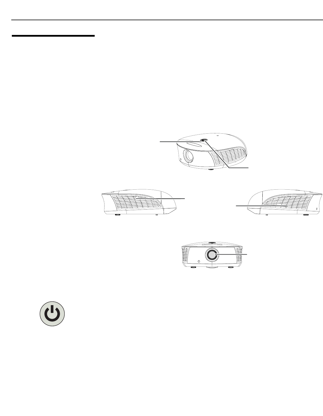
Figure 2-2 and Figure 2-3 show the key LS-12HBd components.
Figure 2-2. LS-12HBd Front/Side View
•POWER BUTTON/STATUS LED
Indicates projector status as follows:
• Solid green = AC power present, ready to turn on (lamp not lit)
• Flashing green = lamp is warming up or cooling down; keypad functions not allowed
• Off = Lamp lit, projector functioning normally
• Alternating green/red = Lamp problem (door open, unable to strike, end of life), user
intervention likely to fix problem
• Flashing red = Over temperature, user intervention (clear vents, turn on AC) may fix
problem
• Solid red = Error that requires servicing (fan fail, Power-on self-test fail etc.)
Keypad
Exhaust
Vent Intake
Vent
Power Button/
Status LED
Projection Lens
System Overview
LightStyle™ LS-12HBd Installation/Operation Manual 7
PRELIMINARY
•KEYPAD
Provides an alternative to using the remote control unit to perform primary lens
adjustments (focus, zoom and position).
FOCUS, H/V, ZOOM
Use these buttons to select the type of lens adjustment you wish to make. The default
function (following a power cycle) is FOCUS.
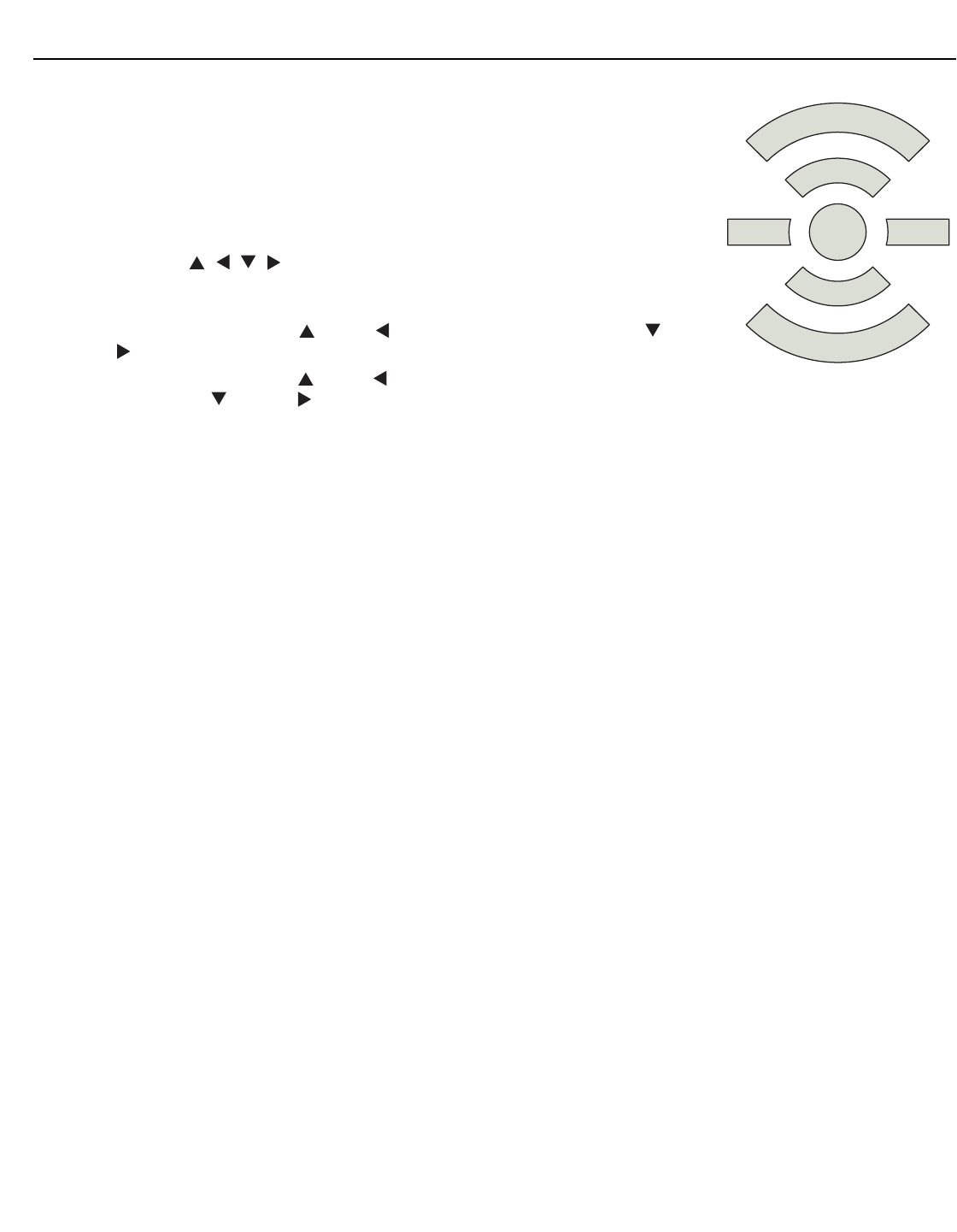
Cursor Buttons ( , , , )
Use these buttons to perform the selected lens adjustment. These buttons operate as
follows:
• When adjusting focus, the up ( ) or left ( ) button focuses closer; the down ( ) or
right ( ) button focuses farther.
• When adjusting zoom, the up ( ) or left ( ) button zooms in (enlarges the projected
image); the down ( ) or right ( ) button zooms out (makes the projected image
smaller).
• When adjusting lens position (H/V), the cursor buttons move the image in the
specified direction, assuming the projector is upright. If the projector is inverted
(ceiling-mounted), the cursor button functions are reversed.
•EXHAUST VENT
Warm air exits the projector through this vent. Ensure that it is not blocked.
•INTAKE VENT
Internal fans draw cool air into the projector through this vent.
•PROJECTION LENS
If needed, a light shield accessory is provided with the lens to minimize stray light
emissions. (Use it only when the vertical offset is 50% of the screen height or greater.)
The light shield attaches to the end of the lens.
▲
▲
FOCUS
ZOOM
►◄ H/V

System Overview
8 LightStyle™ LS-12HBd Installation/Operation Manual
PRELIMINARY
Figure 2-3. LS-12HBd Rear/Bottom/Top View
•RUNCO LOGO BADGE
•REAR COVER
Remove to access connectors.
•LAMP MODULE COVER
Remove this cover to access the lamp compartment.
•CABLE OPENING
Pass cables through this opening.
•CEILING MOUNT HOLES
Use these to attach the ceiling bracket to the projector. Use M4 screws with a
maximum screw depth of 10 mm (0.39 inch).
•ADJUSTABLE FEET
Use these when the projector is installed in a table-top configuration to level the image
and/or adjust the projection angle.
RS232
RS232
PRIMARY
PRIMARY
SECONDARY
SECONDARY
3D Sync Out
3D Sync Out
Runco Logo
Badge
Lamp Module
Cover
Ceiling Mount
Holes
Rear Cove
r
Cable
Opening
Adjustable
Feet
System Overview
LightStyle™ LS-12HBd Installation/Operation Manual 9
PRELIMINARY
2.2
LS-12HBd Rear Panel
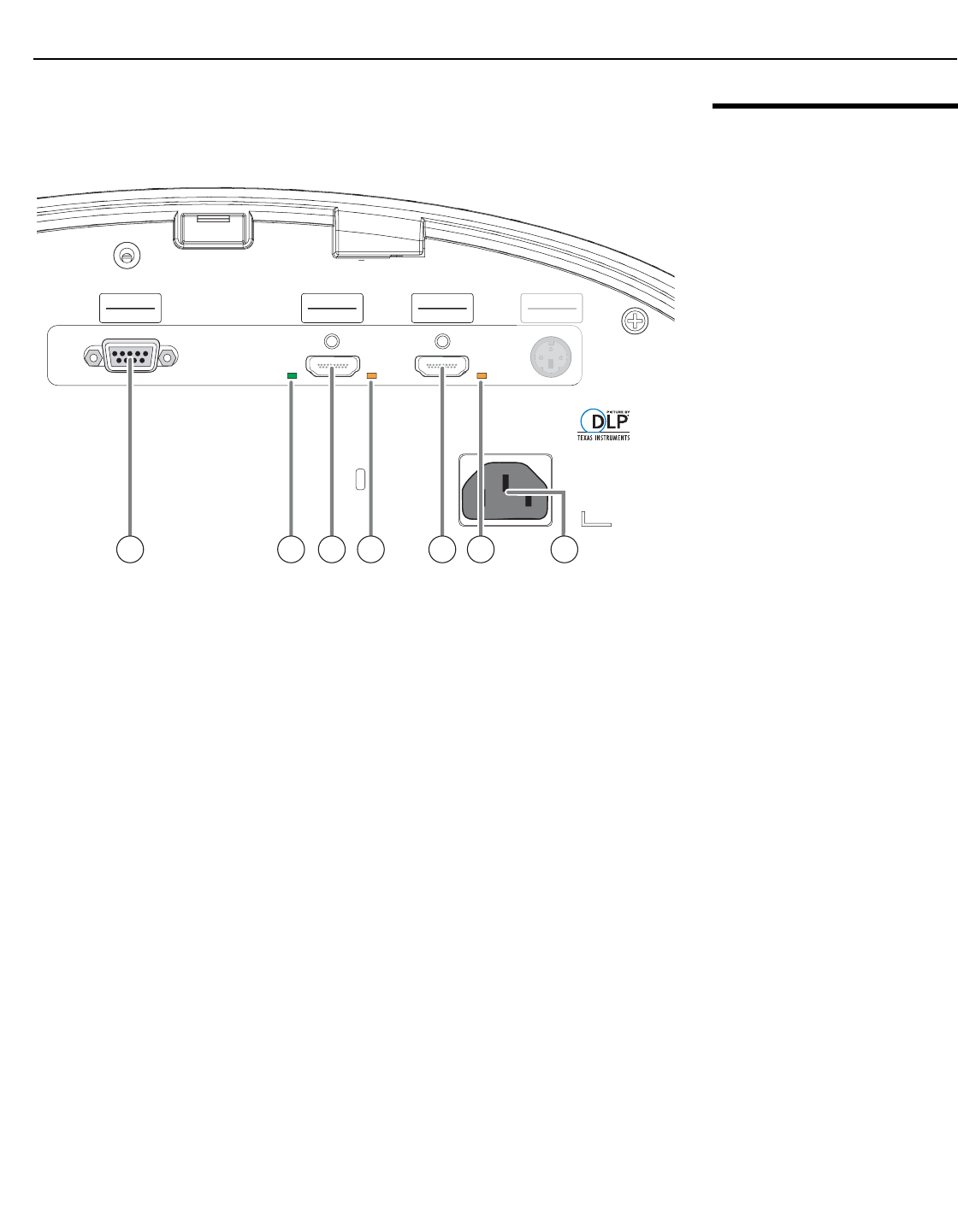
Figure 2-4 shows the LS-12HBd rear panel.
Figure 2-4. LS-12HBd Rear Panel
1. RS232 (Control)
A female, 9-pin D-sub connector that provides a serial communication link to the
Dimension Digital Controller, via its Pri. Display Control output (see Figure 2-6).
2. 3D LED
Lights green when the projector is displaying 3D content.
3. PRIMARY VIDEO INPUT
Connect the HDMI Out To Primary Display connector from the Dimension Digital
Controller to this input (see Figure 2-6).
4. PRIMARY SOURCE LED
Lights amber when the projector detects a valid primary video signal from the
Dimension Digital Controller.
5. SECONDARY VIDEO INPUT
Connect the HDMI Out To Sec. Display connector from the Dimension Digital
Controller to this input (see Figure 2-6).
6. SECONDARY SOURCE LED
Lights amber when the projector detects a valid secondary video signal from the
Dimension Digital Controller.
7. POWER INPUT (100 to 240 VAC)
Connect the LS-12HBd to power here.
RS232
RS232
PRIMARY
PRIMARY
SECONDARY
SECONDARY
3D Sync Out
3D Sync Out
3
D Sync Ou
t
3D Sync Ou
t
1 2 3 4 65 7
System Overview
10 LightStyle™ LS-12HBd Installation/Operation Manual
PRELIMINARY
2.3
DC-300 Dimension
Digital Controller
The Dimension Digital Controller provides “left-eye” and “right-eye” video signals and the
OSD menu to the projector. It controls the other system components in response to user
input via the following interfaces:
• Front-panel keypad
• IR remote control unit
• HDMI CEC messages
• RS-232 serial commands
•Ethernet
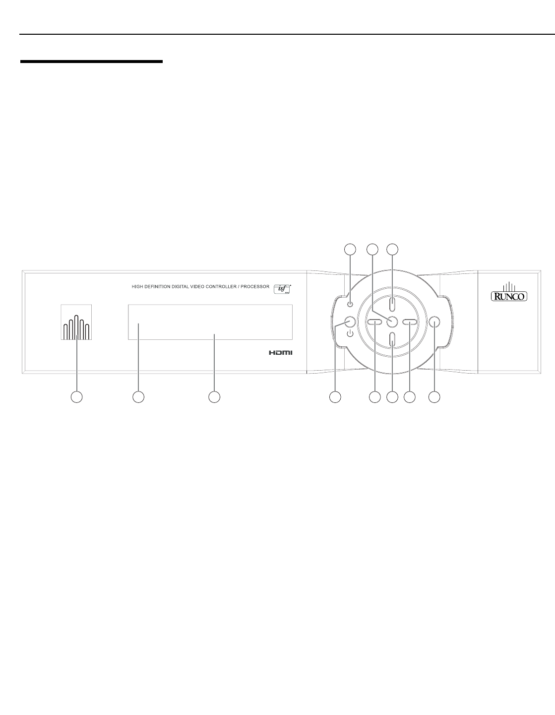
Front Panel Layout Figure 2-5 shows the controls and indicators on the Dimension Digital Controller front
panel; the paragraphs that follow describe them.
Figure 2-5. Dimension Digital Controller Front Panel
1. RUNCO ICON
Lights blue to indicate that the controller is on or powering up.
2. IR SENSOR
Receives IR commands from the remote control.
3. VACUUM FLUORESCENT DISPLAY
Can be used instead of the On-Screen Display (OSD). Displays currently-selected
menu or – if no menu is selected – the connected display device model, current
source, input resolution and aspect ratio/screen.
4. ON/STANDBY BUTTON
Press once to toggle from standby mode to on mode. Press it again to return to
standby mode. For a discrete on or off command, you can use the direct access
buttons on the remote control.
5. LEFT BUTTON
Used to direct-select inputs or move the menu cursor left in the OSD. When no menu
is present on-screen, the LEFT button toggles through the different sources, in this
order:
DisplayPort - HDMI 8 - HDMI 7 - HDMI 6 - HDMI 5 - HDMI 4 - HDMI 3 - HDMI 2 -
HDMI 1 - SCART - HD 2 - HD 1 - Component - Composite 3 - Composite 2 -
Composite 1
➤
r
a
t
i
o
r
a
t
i
o
i
n
p
u
t
standby
m
e
n
u
i
n
p
u
t
e
n
t
e
r
HDMI 1
16:9/1 1080i/60
3
1
91011
654 87
2
LS-12HBd

System Overview
LightStyle™ LS-12HBd Installation/Operation Manual 11
PRELIMINARY
6. DOWN BUTTON
Use to direct-select aspect ratios or move the menu cursor down in the OSD. When
no menu is present on-screen, this button toggles through aspect ratios in the
following order:
16:9 - 4:3 - Letterbox - VirtualWide - Cinema - Virtual Cinema - Native
7. RIGHT BUTTON
Used to direct-select inputs or move the menu cursor right in the OSD. When no
menus are present on-screen, the RIGHT button toggles through the different
sources, in this order:
Composite 1 - Composite 2 - Composite 3 - Component - HD 1 - HD 2 - SCART -
HDMI 1 - HDMI 2 - HDMI 3 - HDMI 4 - HDMI 5 - HDMI 6 - HDMI 7 - HDMI 8 -
DisplayPort
8. MENU BUTTON
Press the MENU button to bring up the main menu, or to exit the current menu and
return to the previous one.
9. UP BUTTON
Use to direct-select aspect ratios or move the menu cursor up in the OSD. When no
menus are present on-screen, the UP button toggles through aspect ratios in the
following order:
Native - Virtual Cinema - Cinema - VirtualWide - Letterbox - 4:3 - 16:9
10. ENTER BUTTON
When an item is highlighted on the OSD, the ENTER button selects the item.
11. STANDBY LED
Lights amber when the Dimension Digital Controller is in standby mode; otherwise it is
off.
System Overview
12 LightStyle™ LS-12HBd Installation/Operation Manual
PRELIMINARY
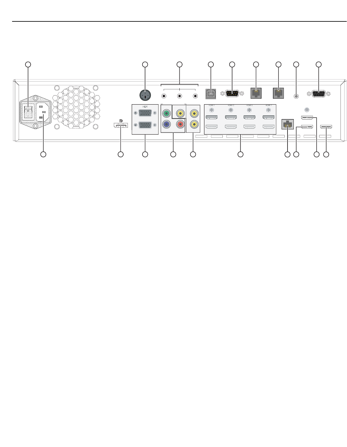
Rear Panel Layout Figure 2-6 shows the rear connector panel on the Dimension Digital Controller.
Figure 2-6. DC-300 Dimension Digital Controller Rear Panel
1. MAIN POWER SWITCH
Disconnects or applies power to the Dimension Digital Controller.
2. 3D Sync Out
A 3-pin, VESA standard mini-DIN connector for connecting the Runco Active 3D
Emitter to the Dimension Digital Controller.
3. TRIGGERS
Connection for up to three (3), 12-volt trigger-controlled devices such as retractable
screens or screen masks. Output current is limited to 250 milliamperes (mA).
4. USB
A standard, USB Series “B” connection to a personal computer, for performing
software upgrades and other service procedures.
5. RS-232 (To Accessory Box)
Reserved for future use.
6. Pri. Display Control
Connect this to the RS-232 input on the projector.
7. Sec. Display Control
Not used.
8. IR
Wired input from a Niles- or Xantech-compatible, infrared (IR) repeater system. It is a
3.5-mm, mini phono jack, wired as follows:
Ring = No connection
Tip = IR Input
Sleeve = Ground
9. RS-232 (PC / Control)
A female, 9-pin D-sub connector for interfacing with a PC or automation/control
system.
10. POWER INPUT (100 to 240 VAC)
Connect the Dimension Digital Controller to power here.
➤
USB
To Accessory Box
Video 1
YVideo 2
Video 3
Pr
Pb
PC / Control
RS-232
IR
Pri. Display Control Sec. Display Control
HDMI 2 HDMI 4 HDMI 6 HDMI 8 Ethernet
HDMI Out
To Sec. Display
HDMI Out
To Pri. Display
HDMI Out
Audio Only
Component / SCART
TRIGGERS RS-232
12 3
3D SYNC
HD2
DisplayPort
Y
P
r
P
b
Compone
1916
11
10
8
396 754
H
D
2
12 13 181714
Vi
deo
1
Vi
d
eo
2
Vi
deo
3
ent / SCAR
T
ne
1 2
HDMI
2
HDMI
4
HDMI
6
HDMI
8
15

System Overview
LightStyle™ LS-12HBd Installation/Operation Manual 13
PRELIMINARY
11. DisplayPort
DisplayPort 1.1a and DisplayPort-HDCP 1.1 compliant, SD/HD input for connecting
SDTV, EDTV or HDTV component video sources.
12. HD1 / HD2 In (15-pin VGA)
Two inputs for connecting standard-definition (SD = 480i/576i), enhanced-definition
(ED = 480p/576p) or high-definition (HD = 720p/1080i/1080p) component video
sources, or RGBHV sources such as personal computers.
13. Component / SCART In (3 x RCA connectors)
SD/HD input for connecting SDTV, EDTV or HDTV component video sources. Also
provides RGB input for SCART RGBS sources.
14. Video 1 / Video 2 / Video 3 In
Standard, composite video inputs for connecting a VCR, camcorder or other
composite video source. The Video 1 input also provides composite sync input for
SCART RGBS sources.
15. HDMI 1 ... HDMI 8 In (Digital)
Eight (8), HDCP-compliant digital video inputs for connecting HDMI or DVI sources.
16. Ethernet
A female RJ-45 connector for wired network communications.
17. HDMI Out (Audio Only)
Connect this output to an audio control system to pass through HDMI audio.
18. HDMI Out (To Secondary Display)
Connect this to the SECONDARY video input on the projector.
19. HDMI Out (To Primary Display)
Connect this to the PRIMARY video input on the projector.
The Dimension Digital Controller does not transmit HDMI CEC
control messages from the “HDMI Audio Out” connector.
Note
System Overview
14 LightStyle™ LS-12HBd Installation/Operation Manual
PRELIMINARY
2.4
LS-12HBd Remote
Control Unit
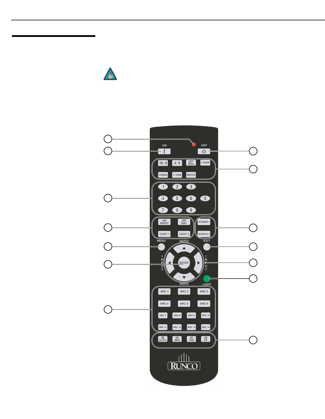
Figure 2-7 shows the LS-12HBd remote control, and the paragraphs that follow describe
its functionality.
Figure 2-7. Dimension Digital Controller Remote Control Unit for LS-12HBd
The LS-12HBd remote control unit supports an “extended” key
code mode that allows certain buttons to perform alternate
functions. The following list identifies those buttons that have both
standard and extended-mode functions.
For more information, refer to Remote Control on page 83 and IR
Command List (Extended Mode) on page 121.
Note
1
2
6
4
3
5
7
9
11
14
8
10
12
13

System Overview
LightStyle™ LS-12HBd Installation/Operation Manual 15
PRELIMINARY
1. IR OUTPUT INDICATOR
Lights when a button is pressed to indicate that an IR signal is being transmitted.
2. OFF (Standard) / Sleep Timer = 30 Minutes (Extended)
Press to turn off the Dimension Digital Controller and projector. In extended mode,
press to set the Sleep Timer to 30 minutes.
3. ON (Standard) / Sleep Timer = Off (Extended)
Press to turn on the Dimension Digital Controller and projector. In extended mode,
press to disable the Sleep Timer.
4. Aspect Ratio Selection Buttons
Use these buttons to select an aspect ratio directly, as follows:
16:9 (Standard) / Sleep Timer = 60 Minutes (Extended)
For viewing 16:9 DVDs or HDTV programs in their native aspect ratio. In extended
mode, press to set the Sleep Timer to 60 minutes.
4:3 (Standard) / Sleep Timer = 90 Minutes (Extended)
Scales the input signal to fit 4:3 display mode in the center of the screen. In extended
mode, press to set the Sleep Timer to 90 minutes.
LETBOX (Letterbox - Standard) / Sleep Timer = 2 Hours (Extended)
For viewing non-anamorphic (“full-screen”) DVDs on a 16:9 screen. In extended
mode, press to set the Sleep Timer to 2 hours.
V-WIDE (VirtualWide - Standard) / Sleep Timer = 4 Hours (Extended)
Enlarges a 4:3 image horizontally in a non-linear fashion to fit 16:9 full screen display.
In extended mode, press to set the Sleep Timer to 4 hours.
CINEMA (Standard) / Video 1 Input (Extended)
For viewing 2.35:1 source material. In extended mode, press to select the Video 1
(Composite 1) input.
V-CINE (Standard) / Component Input (Extended)
Selects the Virtual Cinema aspect ratio, used for viewing 16:9 source material on a
2.35:1 screen. In extended mode, press to select the Component input.
NATIVE (Standard) / HD 1 Input (Extended)
Displays the source signal in its native resolution, centered in the display area. In
extended mode, press to select the HD 1 input.

System Overview
16 LightStyle™ LS-12HBd Installation/Operation Manual
PRELIMINARY
5. Numeric Buttons (Standard)
Use these buttons to enter numeric characters (0 ... 9), such as when changing
remote control codes (refer to Remote Control on page 83).
Numeric Buttons (Extended)
In extended mode, press a numbered button to select a video source, as follows:
6. SCREEN 1 (Standard) / Video 3 Input (Extended)
SCREEN 2
Use these buttons to select a screen profile. For more information, refer to Screen on
page 62.
In extended mode, press SCREEN 1 to select the Video 3 (Composite 3) input.
7. Memory Preset Buttons:
ISF NIGHT (Standard) / SCART (Extended)
Press to recall settings for the current input from the “ISF Night” memory preset. In
extended mode, press to select the SCART input.
ISF DAY (Standard) / Video 2 (Extended)
Press to recall settings for the current input from the “ISF Day” memory preset. In
extended mode, press to select the Video 2 (Composite 2) input.
CUST 1 (Standard) / 3D Mode = Off (Extended)
Press to recall settings for the current input from the “Custom 1” memory preset. In
extended mode, press to set the 3D Mode to Off (for 2D content).
CUST 2
Press to recall settings for the current input from the “Custom 2” memory preset.
8. EXIT
Press this button to exit the current menu and return to the previous one.
9. MENU
Press this button to access the OSD controls, or to exit the current menu and return
to the previous one.
Remote Control Button Source Assignment in Extended Key Code Mode
1HD 2
2HDMI 1
3HDMI 2
4HDMI 3
5HDMI 4
6HDMI 5
7HDMI 6
8HDMI 7
9HDMI 8
0DisplayPort
System Overview
LightStyle™ LS-12HBd Installation/Operation Manual 17
PRELIMINARY
10. Cursor Buttons ( , , , )
Use these buttons to select items or settings, adjust settings or switch display
patterns.
When no menu is present on-screen, the UP and DOWN buttons toggle through the
available aspect ratios, in this order:
UP Button = Native - Virtual Cinema - Cinema - VirtualWide - Letterbox - 4:3 - 16:9
DOWN Button = 16:9 - 4:3 - Letterbox - VirtualWide - Cinema - Virtual Cinema -
Native
Likewise, the LEFT and RIGHT buttons toggle through the different source inputs, in
this order:
LEFT Button = DisplayPort - HDMI 8 - HDMI 7 - HDMI 6 - HDMI 5 - HDMI 4 - HDMI 3
- HDMI 2 - HDMI 1 - SCART - HD 2 - HD 1 - Component - Composite 3 -
Composite 2 - Composite 1
RIGHT Button = Composite 1 - Composite 2 - Composite 3 - Component - HD 1 -
HD 2 - SCART - HDMI 1 - HDMI 2 - HDMI 3 - HDMI 4 - HDMI 5 - HDMI 6 - HDMI 7 -
HDMI 8 - DisplayPort
11. ENTER
Press to select a highlighted menu item or confirm a changed setting.
12. LIGHT
Press to illuminate the buttons.
13. SRC 1, SRC 2 ... SRC 14
Use these buttons to select a video source. You can assign each button to any
source you wish. By default, these buttons are assigned as follows:
For instructions on how to change these assignments, refer to SRC 1-7 Keys / SRC
8-14 Keys on page 84.
For more information about aspect ratios, refer to Table 4-1.
Remote Control Button Default Source Assignment
SRC 1 ... SRC 8 HDMI 1 ... HDMI 8
SRC 9 DisplayPort
SRC 10 Component
SRC 11 HD 1
SRC 12 HD 2
SRC 13 Composite 1
SRC 14 Composite 2
Note

System Overview
18 LightStyle™ LS-12HBd Installation/Operation Manual
PRELIMINARY
14. 3D Mode Selection Buttons:
3D AUTO
Press to set the 3D Mode to Auto.
3D SBS (Side-by-Side)
Press to set the 3D Mode to 3D Side-by-Side.
3D TAB (Top-and-Bottom)
Press to set the 3D Mode to 3D Top-and-Bottom.
3D FP (Frame Packing)
Press to set the 3D Mode to 3D Frame Packing.
For more information about 3D modes, refer to 3D Mode on
page 71.
Note
Installation
LightStyle™ LS-12HBd Installation/Operation Manual 19
PRELIMINARY
3.1
Remote Control
To install batteries in the remote control:
1. Press down the tab on the cover and pull the cover in the direction of the arrow.
2. Insert the included batteries. Ensure that the polarities correctly match the and
markings inside the battery compartment.
3. Insert the lower tab of the cover into the opening, and press down the cover until it
clicks in place.
Notes on Batteries• Make sure that the battery polarities are correct when installing the batteries.
• Do not mix an old battery with a new one or different types of batteries.
• If you will not use the remote control for a long time, remove the batteries to avoid
damage from battery leakage.
• Do not expose batteries to excessive heat such as from sunshine, fire or the like.
Notes on Remote Control
Operation
• Make sure that there is nothing obstructing the infrared beam between the remote
control and the IR receiver on the Dimension Digital Controller.
• If the effective range of the remote control decreases, or it stops working, replace the
batteries with new ones.
• The remote control may fail to operate if the infrared remote sensor is exposed to bright
sunlight or fluorescent lighting.
• Ambient conditions may possibly impede the operation of the remote control. If this
happens, point the remote control at the Dimension Digital Controller, and repeat the
operation.
3. Installation
Installation must be performed by a qualified custom video
installation specialist.
Note
Installation
20 LightStyle™ LS-12HBd Installation/Operation Manual
PRELIMINARY
3.2
Quick Setup
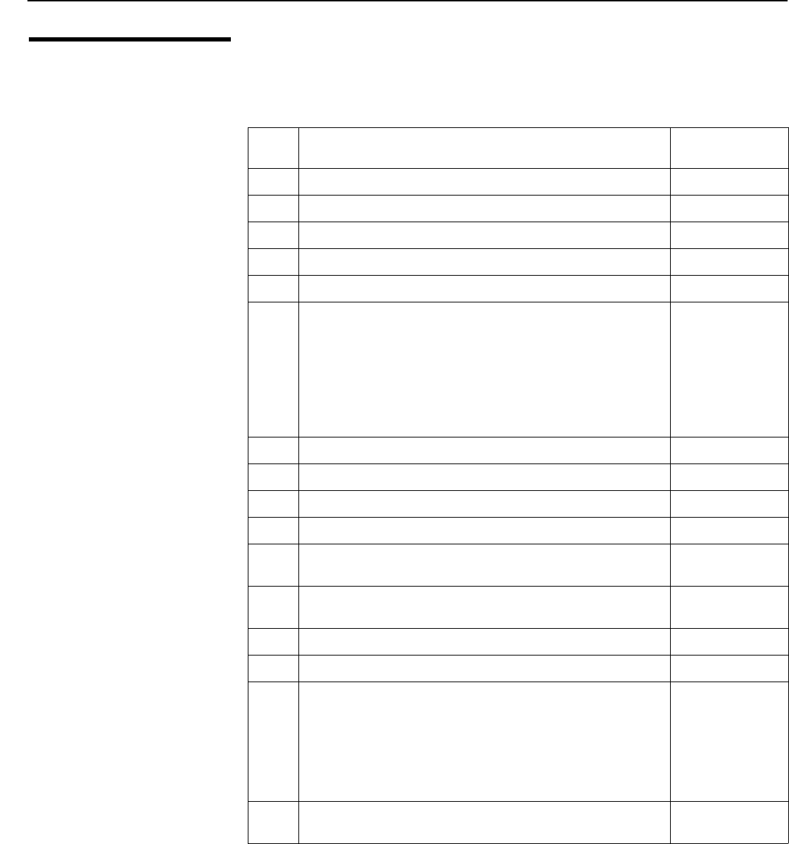
Table 3-1 gives a quick overview of the LS-12HBd installation process. The sections
following this one provide detailed instructions.
Table 3-1. Installation Overview
Step Procedure For Details, Refer
to page...
1Choose a location for the projector 21
2Install anamorphic lens mounting assembly (optional) 28, 40
3Mount the projector 33
4Mount the Dimension Digital Controller 35
5Connect the Dimension Digital Controller to the projector 36
6
Connect other external equipment to Dimension Digital Controller
(optional):
• Audio processor or secondary display device
• Control system interface (RS-232)
• 12-volt trigger-activated equipment (retractable screens or
screen masking)
• External IR repeater
• Network hub, router or gateway (Ethernet)
38
7Connect signal sources to the Dimension Digital Controller 43
8Connect the Active 3D Emitter to the Dimension Digital Controller 49
9Connect system components to AC power 49
10 Apply power to the projector 50
11 Adjust primary lens: projected image size (zoom), position (shift)
and focus
24, 51
12 For rear-screen and/or ceiling-mount installations, select the
proper picture orientation
51
13 Use Image Alignment controls to fine-tune image geometry 52
14 Install and adjust secondary anamorphic lens (optional) 54
15
Display calibration: adjust the following for each Dimension
Digital Controller input and display mode (resolution/frame
rate); save settings when finished:
• Aspect ratio • Color level
• Brightness • Tint
• Contrast • Input position
• Color temperature and white balance
60 through 79
16 Prepare Runco Active 3D Glasses for use and test with 3D source
material
94
Installation
LightStyle™ LS-12HBd Installation/Operation Manual 21
PRELIMINARY
3.3
Installation
Considerations
Proper installation of your projector will ensure the quality of your display. Whether you are
installing a projector temporarily or permanently, you should take the following into
account to ensure your projector performs optimally.
Pre-Wiring for 3D: Run
Dual HDMI Cables
It is a common practice in custom audio/video installations to conceal cables by running
them through walls.
If you plan to do this with your LS-12HBd installation, you will need to run three cables
from the projector to the other projection system components: two (2) HDMI cables and a
serial control cable (typically Category 5 or 4-wire telephone cable).
Installation TypeChoose the installation type that best suits your needs: front or rear screen, floor mount or
inverted mount. Table 3-2 compares these various installation methods.
Ambient LightIn general, minimize or eliminate light sources directed at the screen. Contrast ratio in your
images will be noticeably reduced if light directly strikes the screen, such as when a shaft
of light from a window or floodlight falls on the image. Images may then appear washed
out and less vibrant.
Table 3-2. Projector Installation Options
AdvantagesConsiderations
Front Screen, Floor Mount Installation
• Easy to set up
• Can be moved or changed quickly
• Easy to access
• Shares floor space with audience
Front Screen, Inverted Mount (ceiling) Installation
• Does not take up audience space
• Projector is unobtrusive
• Projector cannot be accidentally moved
• Installation is more permanent
• Projector access is more difficult
Rear Screen, Floor Mount Installation
• Projector is completely hidden
• Projector is easily accessed
• Usually good ambient light rejection
• Requires separate room
• Installation cost is usually higher
Rear Screen, Inverted Mount (ceiling) Installation
• Projector is completely hidden
• Usually good ambient light rejection
• Requires separate room
• Installation cost is usually higher
Rear Screen, Floor Mount with Mirror
• Projector is completely hidden
• Usually good ambient light rejection
• Requires less space behind screen than
other rear screen installations
• Requires separate room
• Installation cost is usually higher
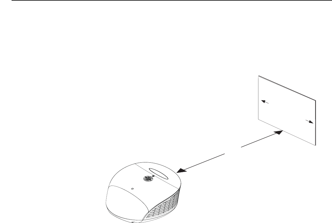
Installation
22 LightStyle™ LS-12HBd Installation/Operation Manual
PRELIMINARY
Throw Distance Throw distance is the distance measured from the front of the projector to the screen.
This is an important calculation in any projector installation as it determines whether or not
you have enough room to install your projector with a desired screen size and if your
image will be the right size for your screen.
You can quickly estimate the throw distance by taking the width of the screen and
multiplying it by the lens throw ratio; see Figure 3-1. The result of this calculation tells you
roughly how far back the projector should be positioned from the screen in order to
project a focused image large enough to fill the screen.
Figure 3-1. Estimating Throw Distance
➤
Estimating Throw Distance
Throw Distance (TD) =
Screen Width (w) x Lens Throw Ratio
TD
Screen width (w)
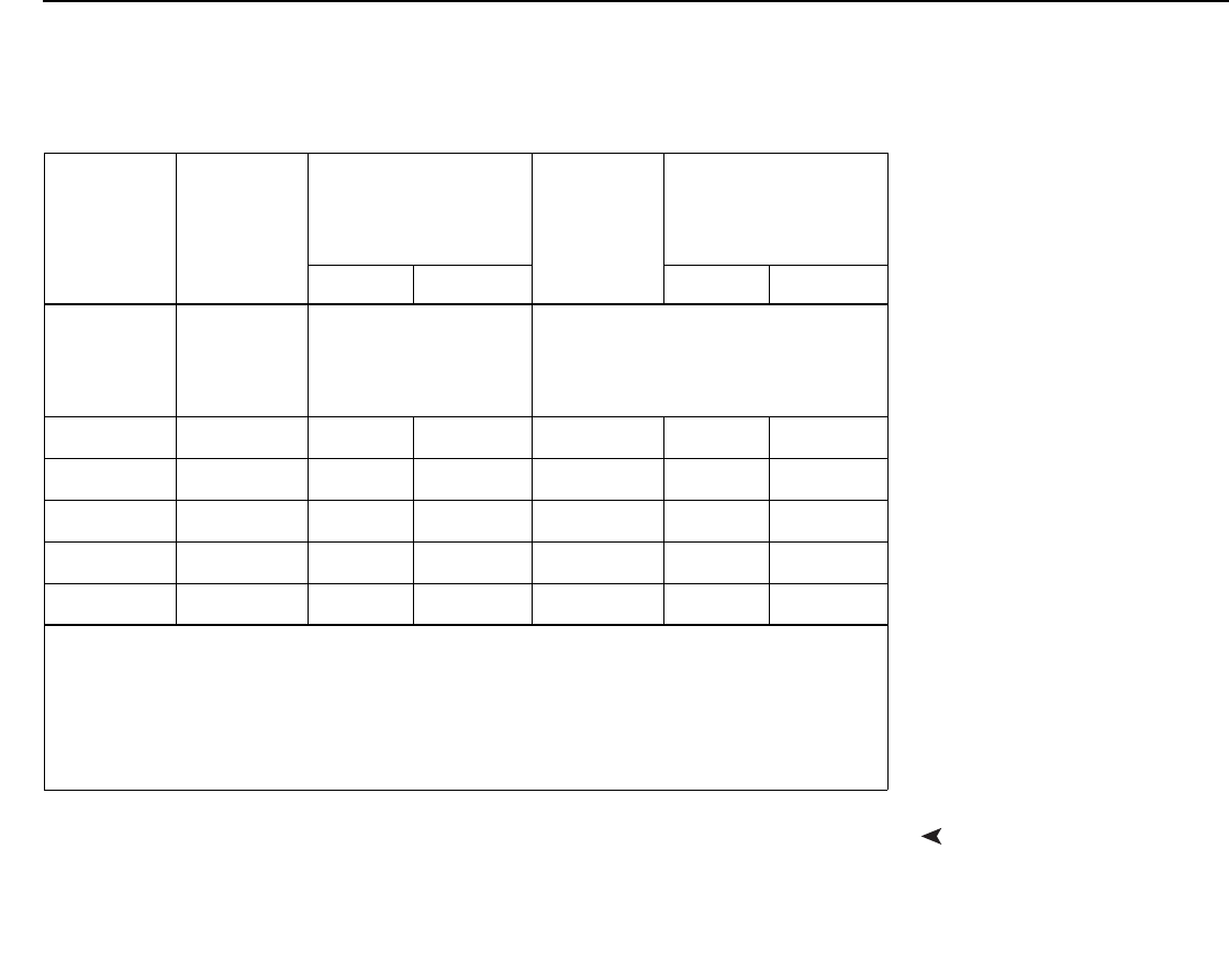
Installation
LightStyle™ LS-12HBd Installation/Operation Manual 23
PRELIMINARY
Table 3-3 lists the available lens options for the LS-12HBd and their associated throw
ratios.
Vertical and Horizontal
Position
Proper placement of the projector relative to the screen will yield a rectangular,
perfectly-centered image that completely fills the screen.
Ideally, the projector should be positioned perpendicular to the screen and in such a way
that the lens center is aligned with either the top or bottom edge of the screen area, and
centered horizontally. See Figure 3-2.
Table 3-3. LS-12HBd Lens Options and Throw Ratios (Note 1)
Lens Option
Throw Ratio
with Primary
Lens Only
Throw Range in
inches, with
117x65.8-inch (1.78:1)
Screen
Throw Ratio
with Primary
Lens and
Anamorphic
Lens
Throw Range in
inches, with
156x65.8-inch (2.35:1)
Screen
Minimum Maximum Minimum Maximum
Proteus 1 0.77 (Fixed)
For rear-screen installa-
tions only. Contact
Runco Technical Support
for more information.
Not Applicable
(Note 2)
Proteus 2 1.45 - 1.74 169.65 203.58 1.09 - 1.30 170.04 202.80
Proteus 3 1.74 - 2.17 203.58 253.89 1.30 - 1.63 202.80 254.28
Proteus 4 2.17 - 2.90 253.89 339.30 1.63 - 2.17 254.28 338.52
Proteus 5 2.90 - 4.34 339.30 507.78 2.17 - 3.26 338.52 508.56
Proteus 6 4.34 - 6.76 507.78 790.92 3.26 - 5.07 508.56 790.92
Notes:
1. Due to normal manufacturing variances, throw distance can vary by up to +/- 5 percent from
these specifications.
2. Only the Proteus 2, 3, 4, 5 and 6 lenses can be used with the optional anamorphic lens. Doing
so affects the throw distances as shown here.
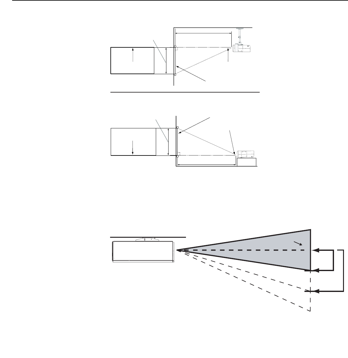
Installation
24 LightStyle™ LS-12HBd Installation/Operation Manual
PRELIMINARY
Figure 3-2. Projector Placement
Vertical and Horizontal
Lens Shift
You can use the lens shift controls to center the image on the screen. Lens shift is
generally expressed as a percentage of the screen height or width, as shown in Figure 3-3
and Figure 3-4.
Figure 3-3. Vertical Lens Shift (EXAMPLE ONLY)
Screen
Height Projection Distance
Ceiling
x
Lens CenterLens Center
Ceiling Installation
Screen
Height
Floor
Lens Center
Projection Distance
Floor Installation
Lens Center
x
➤
50% Height
Lens Shift
(0.5 x H)
100% Height
Lens Shift
(1.0 x H)
Screen Center
0%
Note: This is a general example of lens shift. Lenses vary in their shift capabilities. No particular
lens or projector is used in this example.
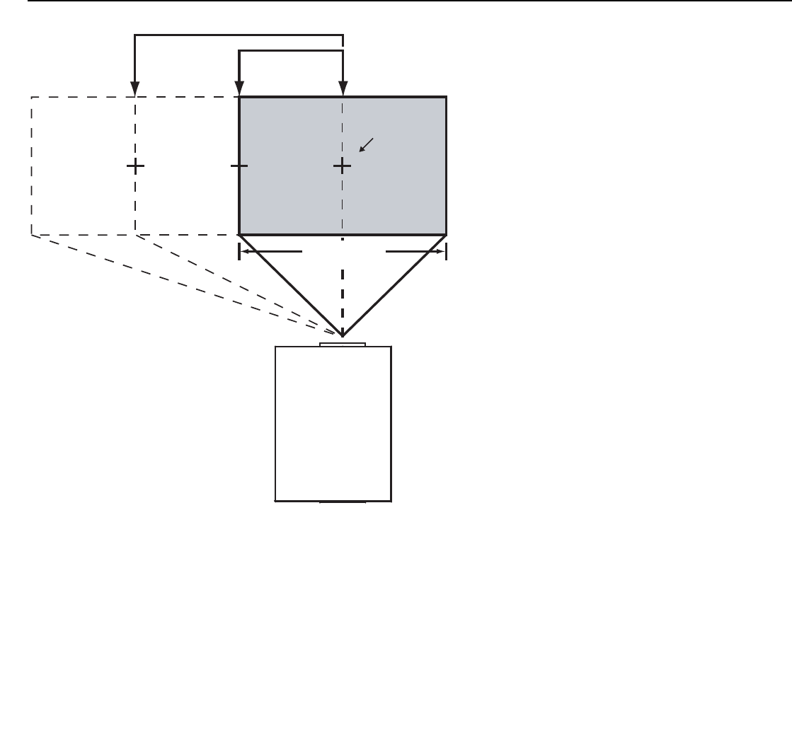
Installation
LightStyle™ LS-12HBd Installation/Operation Manual 25
PRELIMINARY
Figure 3-4. Horizontal Lens Shift (EXAMPLE ONLY)
Vertical Lens Shift: The LS-12HBd zoom lenses (Proteus 2 through 6) provide up to
65% of vertical lens shift in either direction (up or down). For example, with a 96 x 54-inch
(16:9) screen, you can shift the image up to 35.10 inches (0.89 meters) below the screen
center. (Vertical lens shift is not possible with the Proteus 1 lens.)
Horizontal Lens Shift: The LS-12HBd zoom lenses (Proteus 2 through 6) allow up to
30% of horizontal lens shift in either direction (left or right). For example, with a
96 x 54-inch (16:9) screen, you can shift the image up to 28.80 inches (73.15 cm) left or
right of the screen center. (Horizontal lens shift is not possible with the Proteus 1 lens.)
0%
Screen Center
100% Width Lens Shift
(1.0 x W) 50% Width Lens Shift
(0.5 x W)
Screen Width (W)
Note: This is a general example of lens shift. Lenses vary in their shift capabilities. No particular
lens or projector is used in this example.
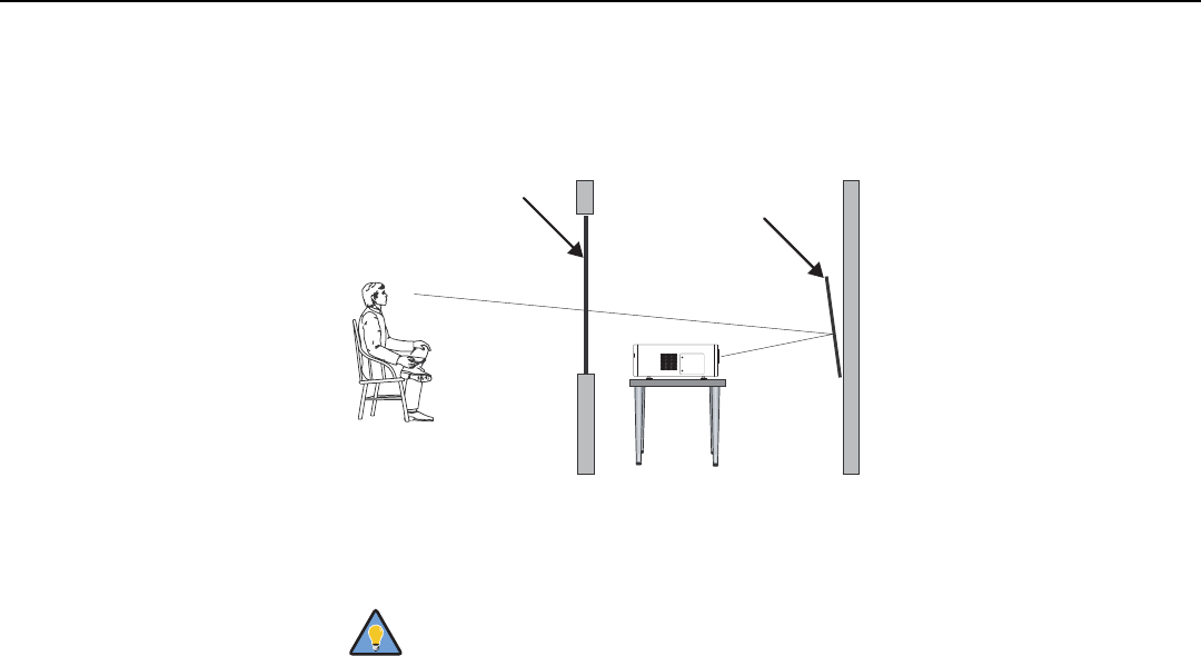
Installation
26 LightStyle™ LS-12HBd Installation/Operation Manual
PRELIMINARY
Folded Optics In rear-screen applications where space behind the projector is limited, a mirror may be
used to fold the optical path, as shown in Figure 3-5. The position of the projector and
mirror must be accurately set. If you are considering this type of installation, contact your
dealer for assistance.
Figure 3-5. Folded Optics
➤
For best performance, always use “first-surface” mirrors in your
rear-projection installation (as opposed to conventional,
“second-surface” mirrors with the reflective surface behind a
transparent substrate such as glass or acrylic).
First-surface mirrors provide a strict reflection without the
“ghosting” effect seen with a second surface mirror, where a faint
secondary reflection could be observed coming from the front
surface of the glass.
This is especially critical for 3D viewing; with a conventional
second-surface mirror, the resulting image quality may be
unacceptable.
Screen
Mirror
Tip
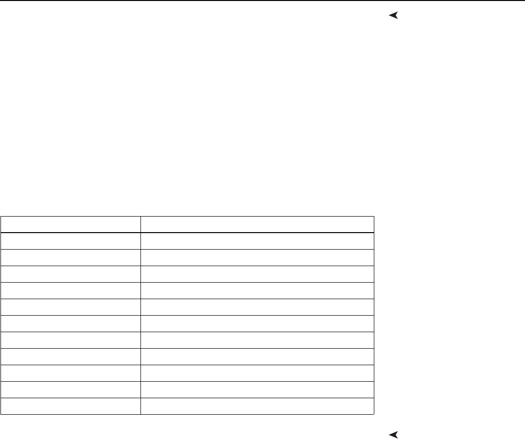
Installation
LightStyle™ LS-12HBd Installation/Operation Manual 27
PRELIMINARY
Audio/Video
Synchronization Issues
Due to its extraordinarily high level of video processing performance, the Dimension Digital
Controller may distribute video signals with a perceptible level of audio latency. In order to
easily solve this issue, Runco recommends using the Dimension Digital Controller with a
high-quality audio receiver that has the ability to effectively synchronize audio and video
signals.
Most mainstream audio receiver/switchers have the ability to synchronize the audio and
video to the Advanced Television Systems Committee (ATSC) prescribed tolerances.
According to the ATSC, the sound program should never lead the video program by more
than 15 milliseconds, and should never lag behind the video program by more than 45
milliseconds.
In addition, many video displays and A/V receivers introduce additional latency that needs
to be compensated for during the installation.
Table 3-4 shows the amount of possible audio latency given different signal input timings.
Other ConsiderationsOther considerations and tips that can help improve your installation:
• Keep the ambient temperature constant and below 35°C (95°F). Keep the projector
away from heating and/or air conditioning vents. Changes in temperature may cause
drifts in the projector circuitry, which may affect performance.
• Keep the projector away from devices that radiate electromagnetic energy such as
motors and transformers. Common sources of these include slide projectors,
speakers, power amplifiers and elevators.
Table 3-4. Possible Audio Latency for Various Input Timings
Input Timing Possible Audio Latency (milliseconds)
480i 133
480p 83
576i 160
576p 100
720p/50 100
720p/60 83
1080i/25 160
1080i/30 133
1080p/24 125
1080p/50 80
1080p/60 67
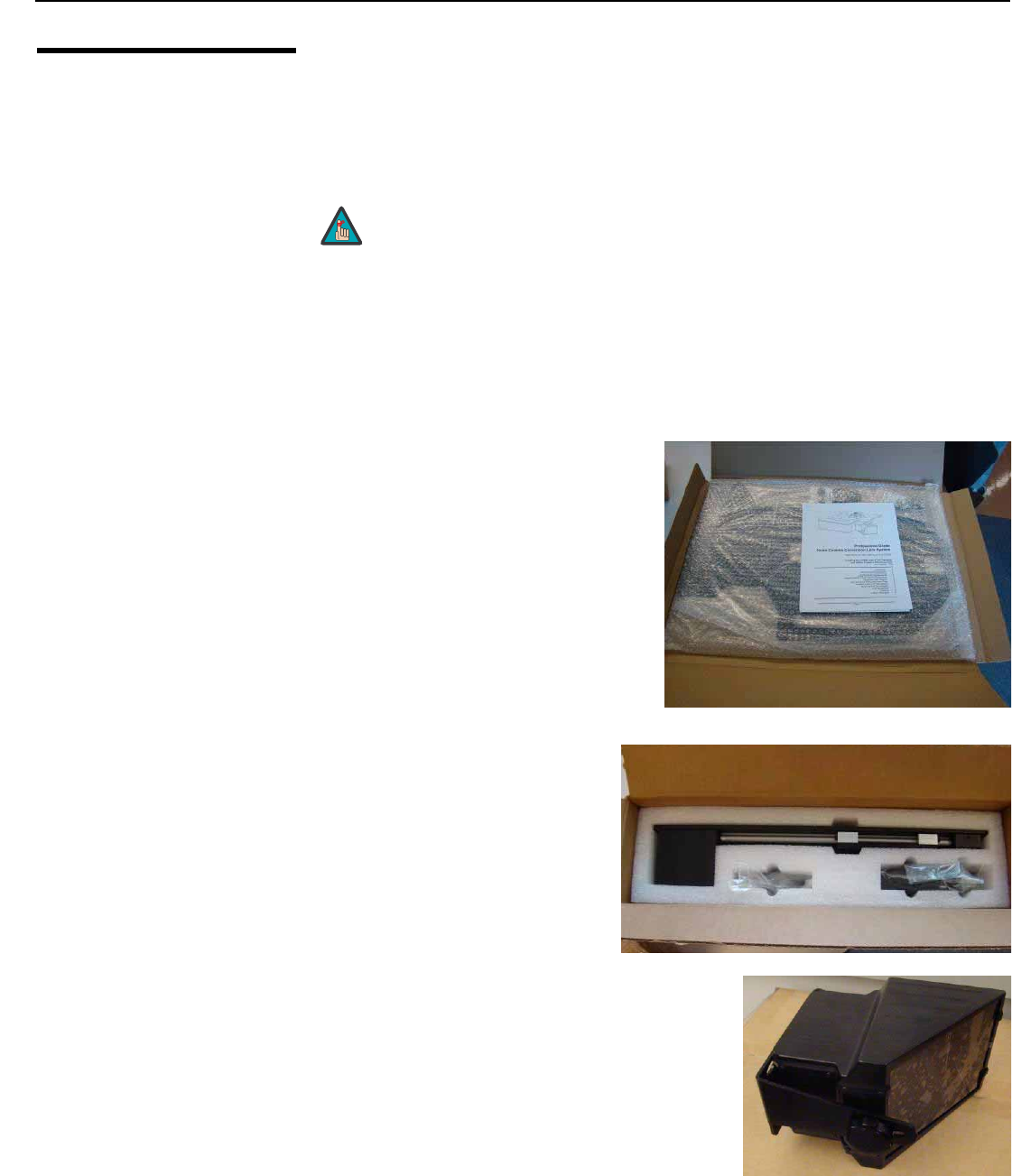
Installation
28 LightStyle™ LS-12HBd Installation/Operation Manual
PRELIMINARY
3.4
Installing the Optional
Anamorphic Lens
Mount
If you are installing a standard LS-12HBd (without an anamorphic lens), skip this step and
proceed with Mounting the LS-12HBd (page 33).
If you are installing an LS-12HBd with an anamorphic lens, proceed as follows to install
the lens mount and transport assembly.
Package Contents The LS-12HBd Anamorphic lens mount kit consists of the following items. Some
components shipped with your projector may differ slightly from what is shown in these
instructions. If any items are missing or damaged, please contact your Runco dealer or
Runco Customer Service at (800) 23RUNCO.
• Transport Assembly Attachment Plate
• Attachment plate hardware (screws,
washers and spacers)
• Attachment plate security hooks and
related hardware (chain, chain ends,
nuts and washers)
• Transport Assembly
• Transport mounting hardware
• Lens bracket mounting hardware
• Power supply
• Remote control unit and batteries
• Anamorphic lens and mounting bracket
1. Do not install the anamorphic lens yet, only the lens mount and
transport assembly. You will install the anamorphic lens after you
install the projector and adjust the primary lens.
2. Some components shipped with your projector may differ slightly
from what is shown in these instructions.
Note
➤
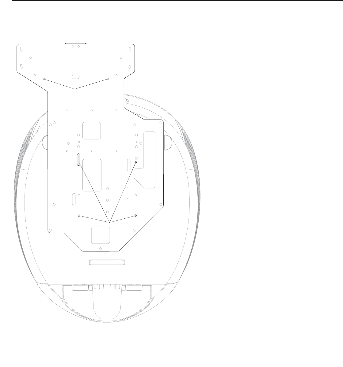
Installation
LightStyle™ LS-12HBd Installation/Operation Manual 29
PRELIMINARY
Attaching the Transport Assembly Attachment Plate:
1. Place the projector upside down on a blanket or other soft surface.
2. Position the attachment plate as shown here.
3. If you are mounting the projector on a ceiling: Line up the holes on the Ceiling
Mount Plate (included with the projector ceiling mount kit) with those on the bottom of
the projector and attachment plate.
4. Secure the Transport Assembly Attachment Plate and Ceiling Mount Plate to the
projector using the hardware provided with the attachment plate, as shown.
Attachment Points
for Security Hooks
Attachment Points
for Transport Assembly Attachment Plate
and Ceiling Mount Plate
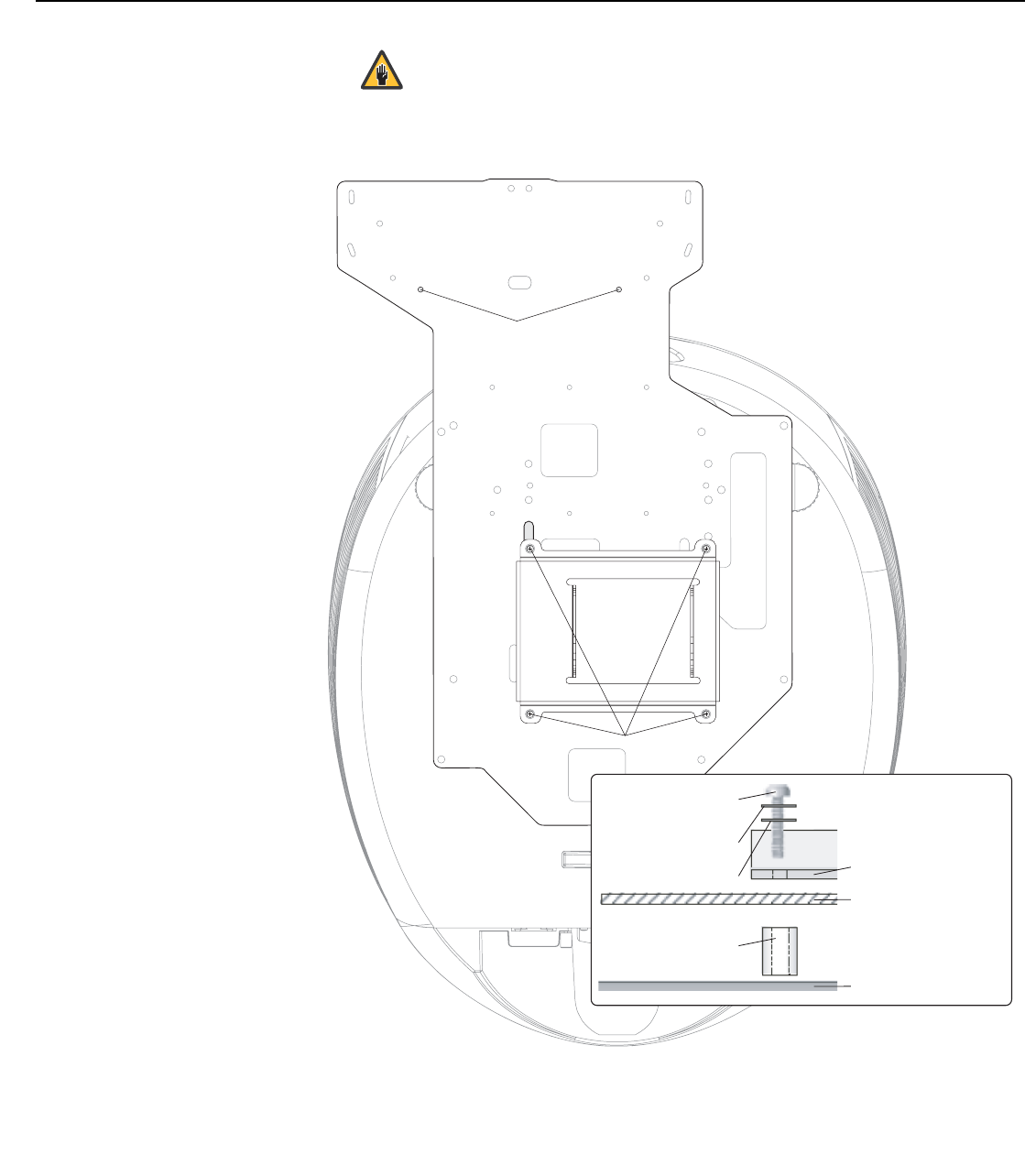
Installation
30 LightStyle™ LS-12HBd Installation/Operation Manual
PRELIMINARY
Installing the Anamorphic Lens Transport Assembly: After installing the Transport
Assembly Attachment Plate and Ceiling Mount Plate, proceed as follows to install the
Anamorphic Lens Transport Assembly.
1. Do not use the mounting screws provided with the ceiling
mounting kit. Use only the hardware provided with the Transport
Assembly Attachment plate.
2. DO NOT OVER-TIGHTEN THE SCREWS.
Caution
Screw, Phillips PH,
M4 x 30mm
Lock Washer
Flat Washer
5/8" Nylon Spacer
Ceiling Mount Plate
Attachment Plate
Projector (bottom)
Hardware for Attachment Plate
and Ceiling Mount Plate (4 Places):
Attachment Points
for Security Hooks
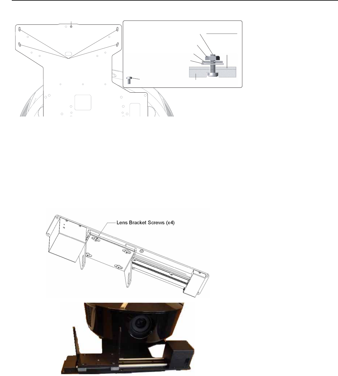
Installation
LightStyle™ LS-12HBd Installation/Operation Manual 31
PRELIMINARY
1. Position the flat side of the motorized transport against the bottom side of the
Attachment Plate so that the center “M” hole in the Attachment Plate is aligned with
the front recessed transport hole.
2. Insert the #10-32 pivot screw up through the transport and Attachment Plate and
loosely complete the assembly with the corresponding washer, lock washer and nut.
3. Loosely insert the four small 3/8” screws through the four remaining “M” slots through
the top of the Attachment Plate and down into the transport.
4. Separate the Anamorphic Lens and lens bracket. Locate the lens bracket mounting
screws and use them to attach the bracket to the transport assembly. Observe the
sticker on the plate showing the correct sequence for installing and tightening the
screws.
Install Transport Pivot Screw Here
Screw, Phillips PH,
#6-32 x 3/8" (4)
Lock Washer, #10-32 (1)
Flat Washer, #10-32 (1)
Nut, #10-32 (1)
Pivot Screw, Phillips PH,
#10-32 x 5/8" (1)
Transport Assembly
Transport Assembly
Attachment Points
Attachment
Plate
Pivot Screw,
as assembled
Hardware for Lens Transport Assembly:
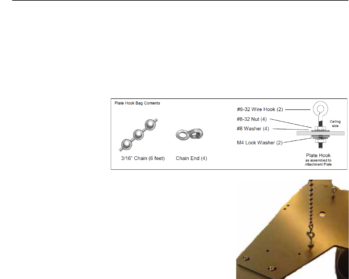
Installation
32 LightStyle™ LS-12HBd Installation/Operation Manual
PRELIMINARY
Attaching the Security Hooks: To help stabilize and support the added weight of the
Anamorphic Lens and Lens Transport Assembly, the attachment plate includes two
security hooks and related hardware for attaching the front part of the plate to the ceiling
above.
Proceed as follows to attach the security hooks. This requires the following tools and
materials:
•Pliers
• Scissors
• Ceiling Hooks (not supplied)
1. Install the Plate Hook Assemblies in the
two “H” holes of the Attachment Plate
(see diagram on page 29) with the hook
ends on the ceiling side as shown above.
2. Use pliers to bend the closed hooks apart
just enough to install a Chain End at a
later time.
3. Attach the plate hooks to the ceiling as
described in the section entitled Ceiling
Mounting (Inverted), on the next page.
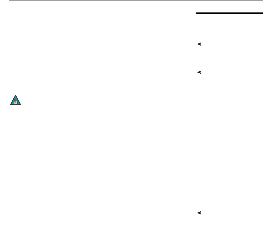
Installation
LightStyle™ LS-12HBd Installation/Operation Manual 33
PRELIMINARY
3.5
Mounting the
LS-12HBd
There are several methods for mounting the projector. Depending on your chosen
installation, one method may be more suitable than another.
Floor Mounting (Upright)In typical front and rear screen installations, the projector can be mounted to a secure and
level surface such as a table or cart. Carts are useful when moving a projector during a
presentation or from site to site. If possible, lock the wheels when it’s in position to prevent
it from being moved during a presentation.
Ceiling Mounting
(Inverted)
For fixed installations, and for those that want the projector out of sight or have a limited
space for projector and audience, you can invert the LS-12HBd and suspend it from the
ceiling using a specially-designed ceiling mount fixture.
Install the ceiling mount kit according to the instructions provided with it.
If you are ceiling-mounting an LS-12HBd with an anamorphic lens, perform these
additional steps to secure the plate Security Hooks to the ceiling (refer to Attaching the
Security Hooks on the previous page).
1. Install ceiling hooks (not supplied) into the ceiling directly above the Plate Hooks. The
ceiling hooks should be small enough to accept a Chain End but strong enough when
installed to each support 40 pounds or more.
2. Attach a Chain End to the Chain and then connect it to one of the ceiling hooks.
3. Cut the Chain to a length equal to or slightly greater than the distance between the
ceiling hook and the corresponding Plate Hook.
4. Attach a Chain End to the other end of the Chain. Then, use the Chain to connect the
ceiling hook and the Plate Hook.
5. Repeat Steps 2 through 4 for the other ceilling hook/Plate Hook pair.
Installing the Projector in
an Enclosure
The projector can also be inverted and placed in an enclosure above and behind the
viewing area. Install four feet on the inside bottom surface of the enclosure on which the
projector can rest. A variety of materials can be used for this purpose (for example, rubber
crutch tips or turntable feet).
Use only the Runco-approved ceiling mount kit designed for your
projector.
Note
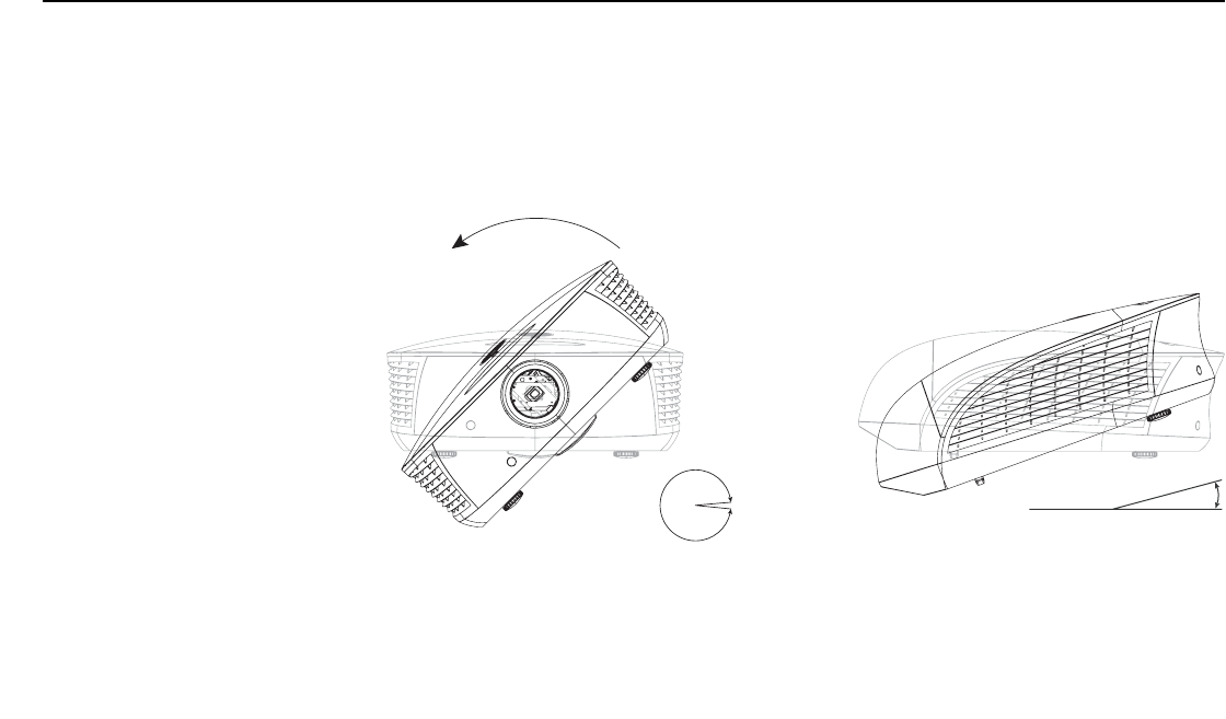
Installation
34 LightStyle™ LS-12HBd Installation/Operation Manual
PRELIMINARY
Adjusting the Projection
Angle
If the LS-12HBd is ceiling-mounted and the screen is significantly lower than the projector,
you can tilt the projector at a slight angle by adjusting the ceiling mount.
The projector can be rotated (side-to-side) up to 360 degrees and mounted without it
affecting performance. However, to ensure optimal performance of the lamp, limit the
front-to-back tilt of the projector to ±20 degrees; see Figure 3-6.
Figure 3-6. Mounting Angle Ranges (Front-to-Back and Side-to-Side)
If you do this, you may need to shift the image using the on-screen display (OSD) controls,
to compensate. For detailed instructions, refer to Primary Lens Adjustments: Focus,
Zoom and Position on page 51.
➤
± 360º
± 20º
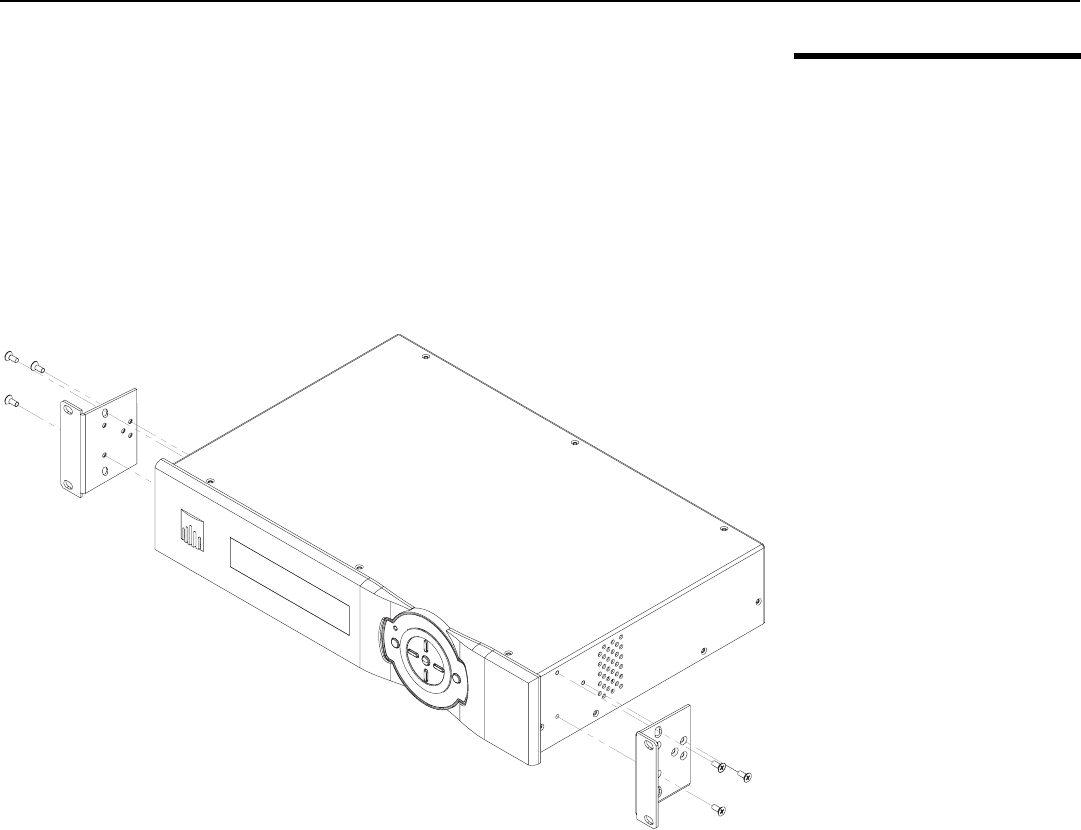
Installation
LightStyle™ LS-12HBd Installation/Operation Manual 35
PRELIMINARY
3.6
Mounting the
Dimension Digital
Controller
The Dimension Digital Controller unit can be placed on any flat, stable surface such as a
shelf or table, or it can be rack-mounted using the supplied mounting hardware. Place it in
a location that provides easy access to the power connectors.
The Dimension Digital Controller unit requires 2U (3.5 inches) or more of vertical rack
space.
To mount the Dimension Digital Controller in a standard, 19-inch equipment rack, install
the mounting ears on either side of the chassis using the supplied screws; see Figure 3-7.
Then, secure the mounting ears to the rack.
Figure 3-7. Attaching the Rack Mounting Hardware
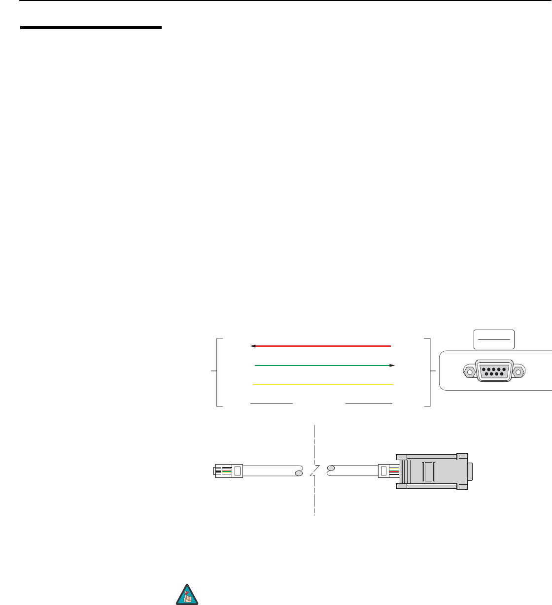
Installation
36 LightStyle™ LS-12HBd Installation/Operation Manual
PRELIMINARY
3.7
System
Interconnections
Proceed as follows to connect the LS-12HBd system components to each other and to
AC power.
When connecting your equipment:
• Turn off all equipment before making any connections.
• Use the correct signal cables for each source.
• For best performance and to minimize cable clutter, use high-quality cables that are
only as long as necessary to connect two devices. (Don’t use a 20-foot cable when a
6-foot cable will suffice.)
• Ensure that the cables are securely connected. Tighten the thumbscrews on
connectors that have them.
Connecting the Dimension
Digital Controller to the
Projector
Digital Video Connection: Connect the HDMI Out To Pri. Display connector on the
Dimension Digital Controller to the PRIMARY input on the projector. Similarly connect the
HDMI Out To Sec. Display connector on the Dimension Digital Controller to
SECONDARY input on the projector.
RS-232 Connection: Connect the Pri. Display Control output from the Dimension
Digital Controller to the RS232 input on the projector.
Use a standard, modular telephone cable with RJ11 plugs at both ends. On the projector
end, use the provided RJ11-to-DB9 adapter. This adapter is wired as shown in Figure
3-8.
Figure 3-8. RS-232 Connection from the Dimension Digital Controller to the
Projector
➤
Runco recommends using the RS-232 communication link
between the LS-12HBd projector and the Dimension Digital
Controller. However, display control using HDMI CEC control
messages is also possible. For more information on this capability,
please contact Runco Technical Support.
4
3RCV DATA 3
2
XMT DATA
XMT DATA
RCV DATA
25
SIG GND
NO CONNECTION
1, 5, 6 1, 4, 6,
7, 8, 9
To/From
Dimension
Digital
Controller
6-position
RJ-11 Male
DB-9 Male
6
1
1
6
RS232
RS232
Note
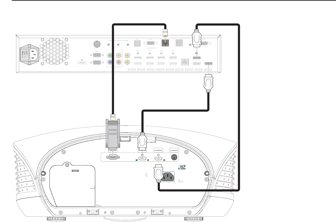
Installation
LightStyle™ LS-12HBd Installation/Operation Manual 37
PRELIMINARY
Figure 3-9 shows how to connect the Dimension Digital Controller to the projector.
Figure 3-9. Connecting the Dimension Digital Controller to the Projector
RS232
RS232
PRIMARY
PRIMARY
SECONDARY
SECONDARY
3D Sync Out
3D Sync Out
Video 1
YVideo 2
Video 3
Pr
Pb
IR
Pri. Display Control Sec. Display Control
HDMI 2 HDMI 4 HDMI 6 HDMI 8 Ethernet
HDMI Out
To Sec. Display
HDMI Out
To Pri. Display
HDMI Out
Audio Only
Component / SCART
TRIGGERS
12 3
3D SYNC
HD2
DisplayPort
Vi
deo
1
Y
Vi
deo
2
Vi
deo
3
P
r
Pb
IR
S
ec. Displa
y
Control
HDMI
2
HDMI
4
HDMI
6
HDMI
8
E
t
he
rn
e
t
H
DMI
Ou
t
Audio
O
nl
y
Component / SCA
R
T
T
R
I
GG
ER
S
12
3
3
D
S
YN
C
HD2
D
isplayPor
t
r
r
Dimension Digital Controller
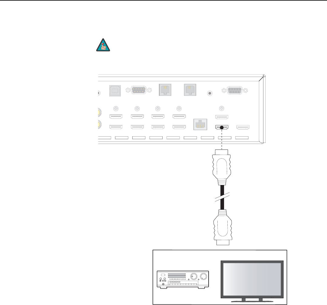
Installation
38 LightStyle™ LS-12HBd Installation/Operation Manual
PRELIMINARY
Connecting an Audio
Processor or Secondary
Display Device to the
Dimension Digital
Controller (Optional)
The Dimension Digital Controller provides a second HDMI output (labeled HDMI Out
(Audio Only)) for connection to an audio receiver/switching system or secondary display
device for monitoring purposes. See Figure 3-10.
Figure 3-10. Audio Processor Connection to Dimension Digital Controller
➤
The Dimension Digital Controller does not transmit HDMI CEC
control messages from the “HDMI Audio Out” connector.
Note
USB
To Accessory Box
o
2
o
3
PC / Control
RS-232
IR
Pri. Display Control Sec. Display Control
HDMI 1
HDMI 2
HDMI 3
HDMI 4
HDMI 5
HDMI 6
HDMI 7
HDMI 8 Ethernet
HDMI Out
To Sec. Display
HDMI Out
To Pri. Display
HDMI Out
Audio Only
RS-232
3
US
B
To
A
ccessor
y
Bo
x
o
2
o
3
PC
/
C
ontro
l
RS
-2
3
2
I
R
P
ri. Display Contro
l
Sec. Display Control
H
DMI
1
HDMI
2
HDMI
3
HDMI
4
HDMI
5
HDMI
6
HDMI
7
HDMI
8
E
t
he
rn
e
t
HDMI Out
To Sec. Dis
p
la
y
HDMI Out
To
Pri Displa
y
RS-23
2
3
or
Audio Processor/
Switcher
Secondary Display
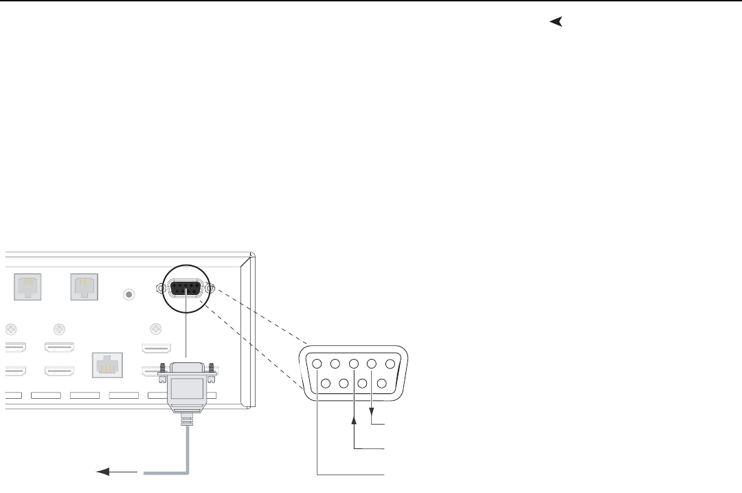
Installation
LightStyle™ LS-12HBd Installation/Operation Manual 39
PRELIMINARY
Additional Connections to
the Dimension Digital
Controller (Optional)
The Dimension Digital Controller provides the following interfaces to external equipment
that allow it to control or be controlled by that equipment:
• An RS-232 interface to a PC or control/automation system;
• Three (3), 12-volt trigger outputs;
• An infrared (IR) repeater input;
• An Ethernet network interface for firmware updates and maintenance notifications.
The following sections describe how to make these interface connections.
RS-232 Controller Connection: Use a straight-through, 9-pin RS-232 cable to connect
a PC or control/automation system (if present) to the RS-232 port on the Dimension
Digital Controller; see Figure 3-11.
Figure 3-11. RS-232 Control System Connection to Dimension Digital Controller
PC / Control
RS-232
IR
Pri. Display Control Sec. Display Control
H
DMI 5
H
DMI 6
HDMI 7
HDMI 8 Ethernet
HDMI Out
To Sec. Display
HDMI Out
To Pri. Display
HDMI Out
Audio Only
IR
Pri. Displa
y
C
ontrol
S
ec. Displa
y
C
ontro
l
HDMI
5
HDMI
6
HDMI
7
HDMI
8
E
therne
t
H
DMI O
u
t
To
Sec. Displ
a
y
H
DMI O
u
t
T
o
Pri. Displ
a
y
H
DMI O
u
t
Audio Onl
y
1
2
345
7
89 6
to Automation/
Control System
or PC
2 Receive Data
(to ctrl. system)
3 Transmit Data
(from ctrl. system)
5 Ground
(none of the other pins are used)
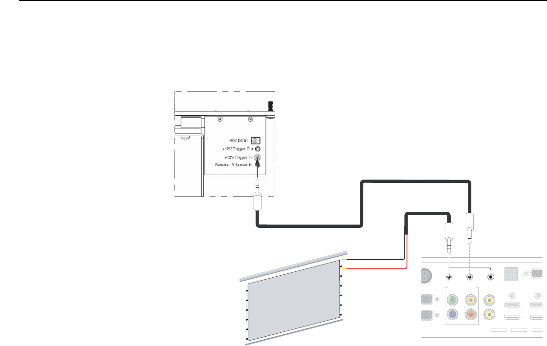
Installation
40 LightStyle™ LS-12HBd Installation/Operation Manual
PRELIMINARY
Connecting 12-volt Trigger Outputs to External Equipment: If your LS-12HBd is
equipped with an anamorphic lens, connect the +12V Trigger Input on the lens transport
to a 12-volt trigger output on the Dimension Digital Controller; see Figure 3-12.
Similarly connect other 12-volt trigger-activated equipment (such as retractable screens or
screen masks) to the other trigger outputs.
Figure 3-12. Connecting 12-volt Trigger Outputs
USB
To Access
o
Video 1
YVideo 2
Video 3
Pr
Pb
HDMI 1
HDMI 2
HDMI 3
HDMI 4
Component / SCART
TRIGGERS RS-23
2
12 3
H
D1
D
SYNC
H
D2
U
S
B
To
A
ccess
o
Vi
deo
1
Y
Vi
d
eo
2
Vi
deo
3
Pr
Pb
H
D
MI
1
H
DMI
2
H
DMI
3
H
DMI
4
C
om
p
onent / SCA
R
T
RS
-2
32
HD1
D
SYN
C
HD2
Tip = +12V
Sleeve = Ground
Anamorphic Lens Transport
(Rear View)
3.5-mm
mini plug
+12V Trigger Input
Retractable Screen or other
12-volt trigger-activated
device
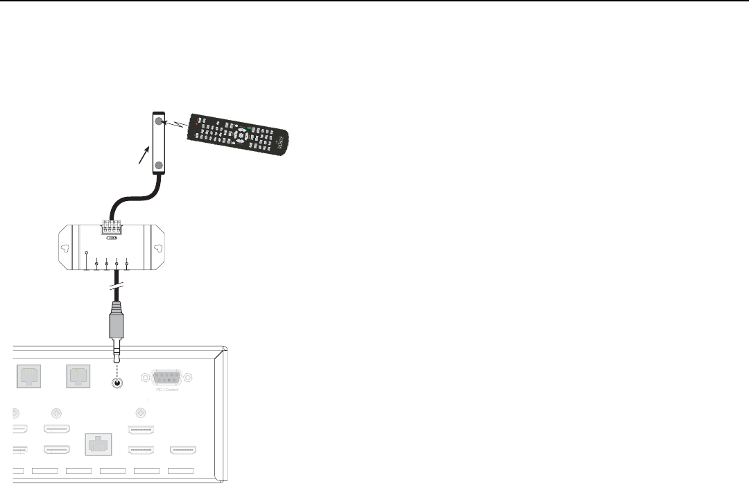
Installation
LightStyle™ LS-12HBd Installation/Operation Manual 41
PRELIMINARY
Connecting an External IR Receiver to the Dimension Digital Controller: If infrared
signals from the remote control cannot reach the Dimension Digital Controller due to
excessive distance or obstructions such as walls or cabinet doors, you can connect an
external IR receiver to extend the range of the remote control. See Figure 3-13.
Figure 3-13. External IR Receiver Connection
RS-232
IR
P
ri. Display Control Sec. Display Control
D
MI 5
D
MI 6
HDMI 7
HDMI 8 Ethernet
HDMI Ou
To Sec. Display
HDMI Out
To Pri. Display
HDMI Out
Audio Only
R
S
-23
2
P
ri. Displa
y
C
ontrol
S
ec. Displa
y
C
ontro
l
DMI
5
DMI
6
HDMI
7
HDMI
8
E
th
e
rn
e
t
HDMI
Ou
To
S
ec. Displ
a
y
HDMI
Ou
t
T
o
P
r
i
.
Di
sp
la
y
H
DMI
O
u
t
A
udio
O
nl
y
(3.5-mm, mini
phono plug)
IR Sensor
IR Repeater
Remote Control
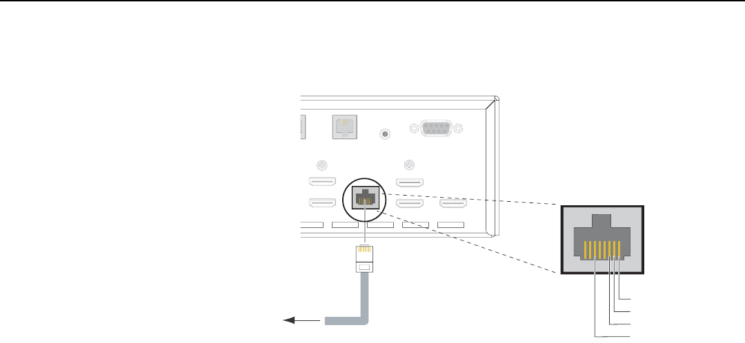
Installation
42 LightStyle™ LS-12HBd Installation/Operation Manual
PRELIMINARY
Ethernet Network Connection: Use a standard, Category 5 network cable with an
RJ-45 plug to connect a network hub, router or gateway to the Ethernet port on the
Dimension Digital Controller; see Figure 3-14.
Figure 3-14. Ethernet Network Connection to Dimension Digital Controller
PC / Control
RS-232
IR
C
ontrol Sec. Display Control
HDMI 7
HDMI 8 Ethernet
HDMI Out
To Sec. Display
HDMI Out
To Pri. Display
HDMI Out
Audio Only
PC
/
C
ontr
o
l
R
S
-2
32
I
R
C
ontrol
S
ec. Display Contro
l
HDMI
7
HDMI
8
H
DMI O
u
t
To
Sec. Dis
p
l
a
y
H
DMI O
u
t
T
o
Pri. Displa
y
H
DMI
Ou
t
Audio Only
1
8
to Ethernet
Hub, Router
or Gateway
1 Transmit Data +
2 Transmit Data -
3 Receive Data +
6 Receive Data -
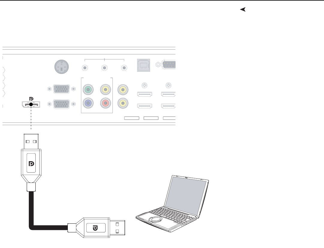
Installation
LightStyle™ LS-12HBd Installation/Operation Manual 43
PRELIMINARY
Connecting Source
Components to the
Dimension Digital
Controller
Connect your video sources to the Dimension Digital Controller as shown and described
in the sections that follow.
DisplayPort Source Connection: See Figure 3-15.
Figure 3-15. DisplayPort Source Connection
USB
To Accessory
Video 1
YVideo 2
Video 3
Pr
Pb
HDMI 1
HDMI 2
HDMI 3
HDMI 4
Component / SCART
TRIGGERS RS-232
12 3
HD1
3D SYNC
HD2
DisplayPort
U
S
B
To
A
ccessory
V
i
deo
1
Y
Vi
d
eo
2
Vi
deo
3
Pr
Pb
H
D
MI
1
HDMI
2
HDMI
3
HDMI
4
C
om
p
onent / SCAR
T
T
RI
GG
ER
S
R
S
-23
2
12
3
HD1
3D
S
YN
C
HD
2
Notebook Computer
or Other DisplayPort Source
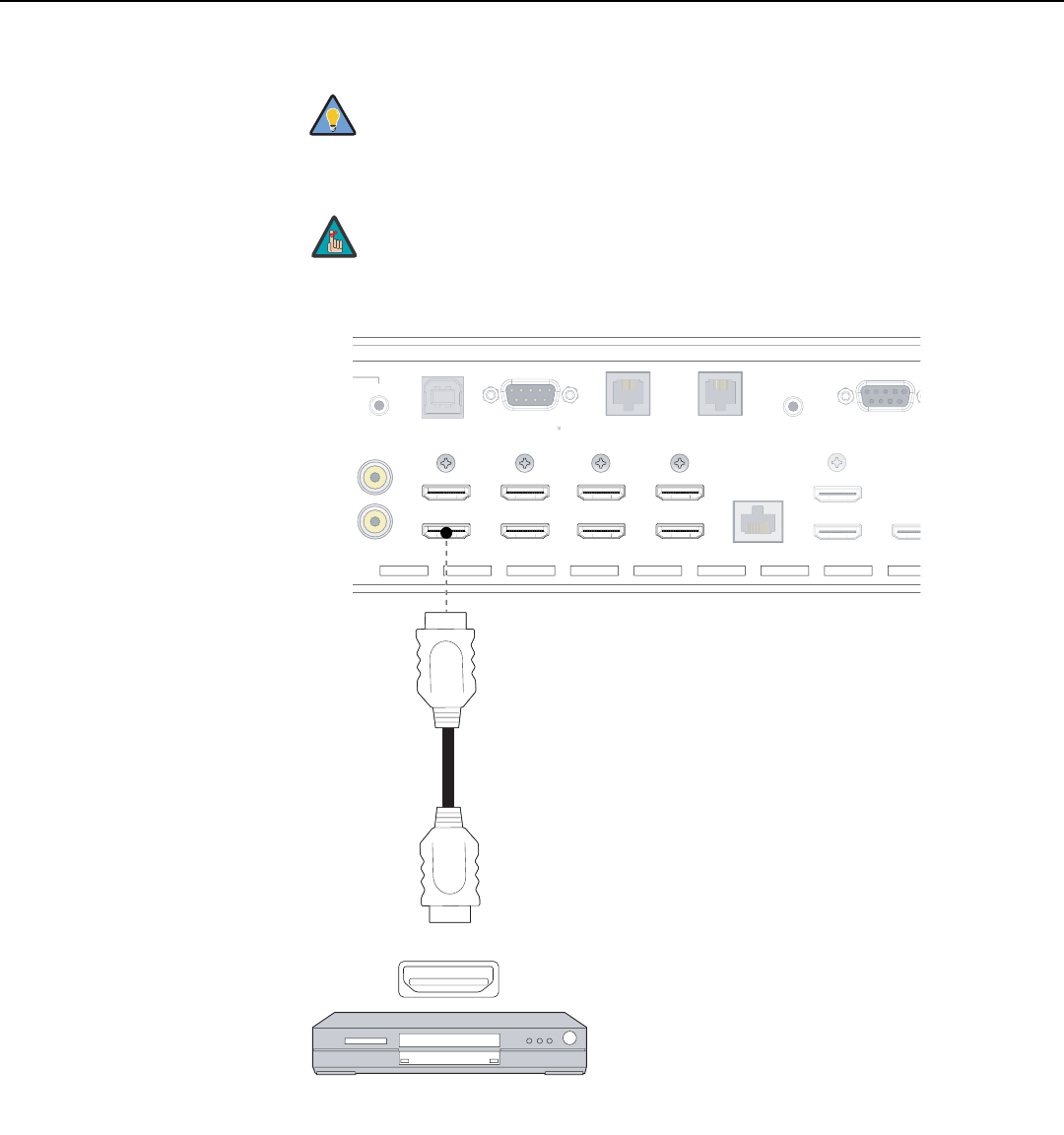
Installation
44 LightStyle™ LS-12HBd Installation/Operation Manual
PRELIMINARY
HDMI Source Connections: See Figure 3-16.
Figure 3-16. HDMI Source Connections
Use the HDMI inputs whenever possible. This ensures the highest
video quality because the signal is carried in the digital domain
throughout the entire signal path, from source component output
into the projector.
You can also connect computers with DVI output to these inputs.
Refer to Supported Timings on page 129 for a list of compatible
input signals.
Tip
Note
USB
To Accessory Bo
Video 2
Video 3
PC / Contro
RS-232
IR
Pri. Display Control Sec. Display Control
HDMI 1
HDMI 2
HDMI 3
HDMI 4
HDMI 5
HDMI 6
HDMI 7
HDMI 8 Ethernet
HDMI Out
To Sec. Display
HDMI
To Pri. D
HDMI Out
Audio Only
RS-232
3
US
B
T
oAccessory B
o
Vi
deo
2
Vi
d
eo
3
PC
/
C
ontr
o
RS
-2
32
I
R
P
ri. Display
C
ontro
l
S
ec. Display
C
ontro
l
E
therne
t
HDMI
Ou
t
T
o
Sec. Displa
y
HDMI
To
P
r
i
.
D
HDMI Ou
t
Audio Onl
y
R
S
-2
3
2
3
HDMI
AV OUT
HDMI source
(BD, DVD, DTV Set-Top Box etc.)
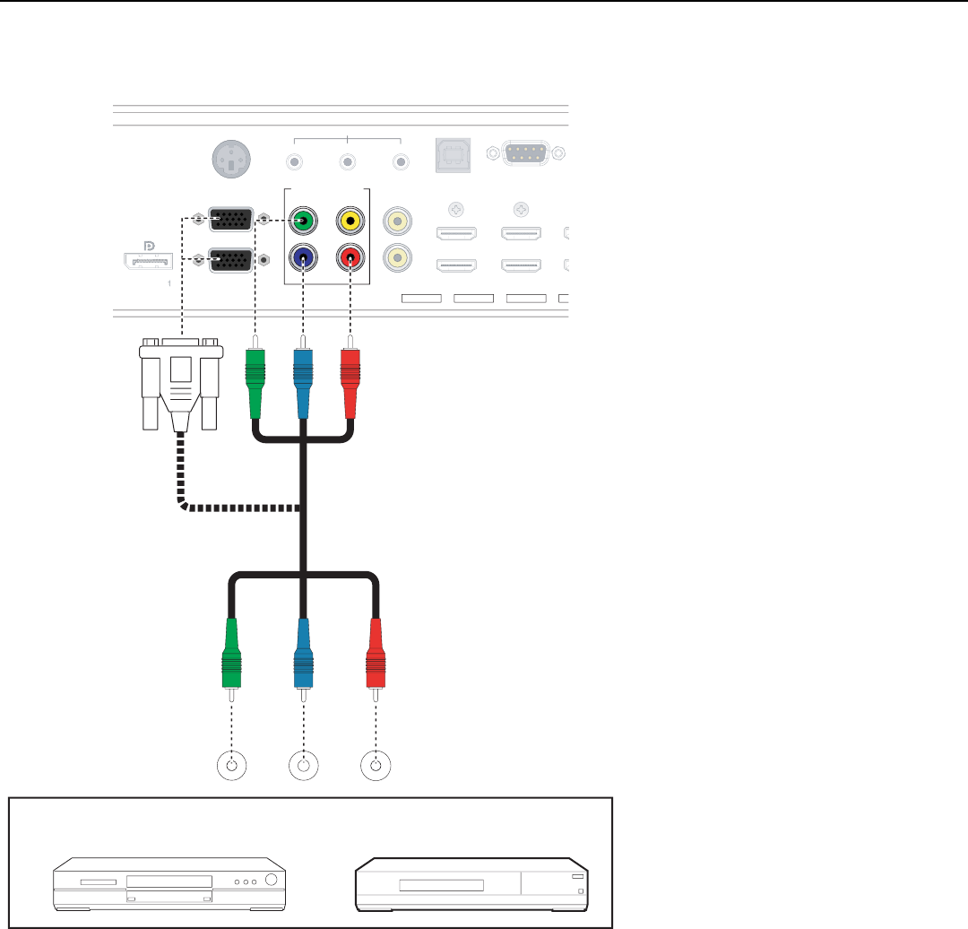
Installation
LightStyle™ LS-12HBd Installation/Operation Manual 45
PRELIMINARY
Component Video Source Connections: Connect your component video sources to
the HD1, HD2 and/or Component/SCART inputs as shown in Figure 3-17.
Figure 3-17. Component Video Source Connections
USB
To Accessory Box
Video 1
YVideo 2
Video 3
Pr
Pb
HDMI 1
HDMI 2
HDMI 3
HDMI 4
Component / SCART
TRIGGERS RS-232
12 3
HD1
3D SYNC
HD2
DisplayPor
US
B
T
o
A
ccessor
y
B
o
x
Vi
deo
2
Vi
deo
3
H
DMI
1
HDMI
2
HDMI
3
HDMI
4
T
RIGGERS
RS-232
12
3
3
D
S
YN
C
D
isplayPor
Y PBPR
COMPONEN T
VIDEO OUT
BD/DVD
DTV-Set-Top Box
(DTV-STB)
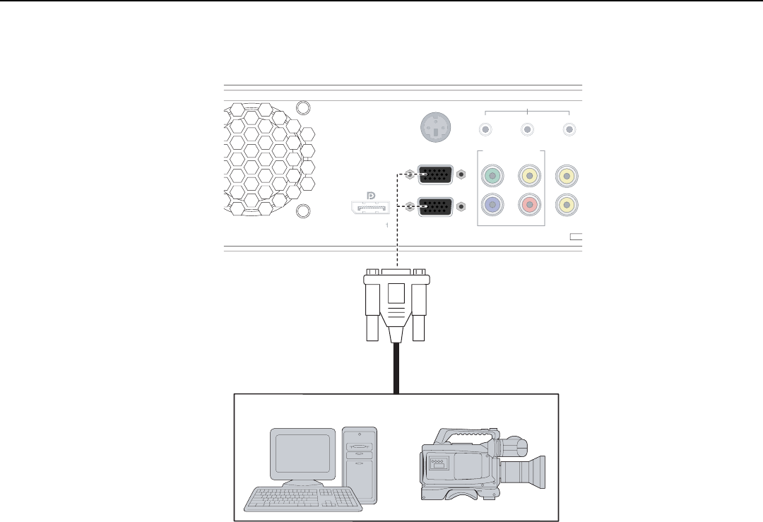
Installation
46 LightStyle™ LS-12HBd Installation/Operation Manual
PRELIMINARY
RGBHV Source Connections: Connect personal computers and/or other RGB sources
to the HD1 and/or HD2 inputs as shown in Figure 3-18.
Figure 3-18. RGBHV Source Connections
Video 1
YVideo 2
Video 3
Pr
Pb
Component / SCART
TRIGGERS
12 3
HD1
3D SYNC
HD2
DisplayPor
or
Vi
deo
1
Y
Vi
deo
2
Vi
d
eo
3
Pr
Pb
Com
p
onent / SCAR
T
T
R
I
GG
ER
S
12
3
3
D
S
YN
C
D
isplayPor
Computer
RGB Camcorder
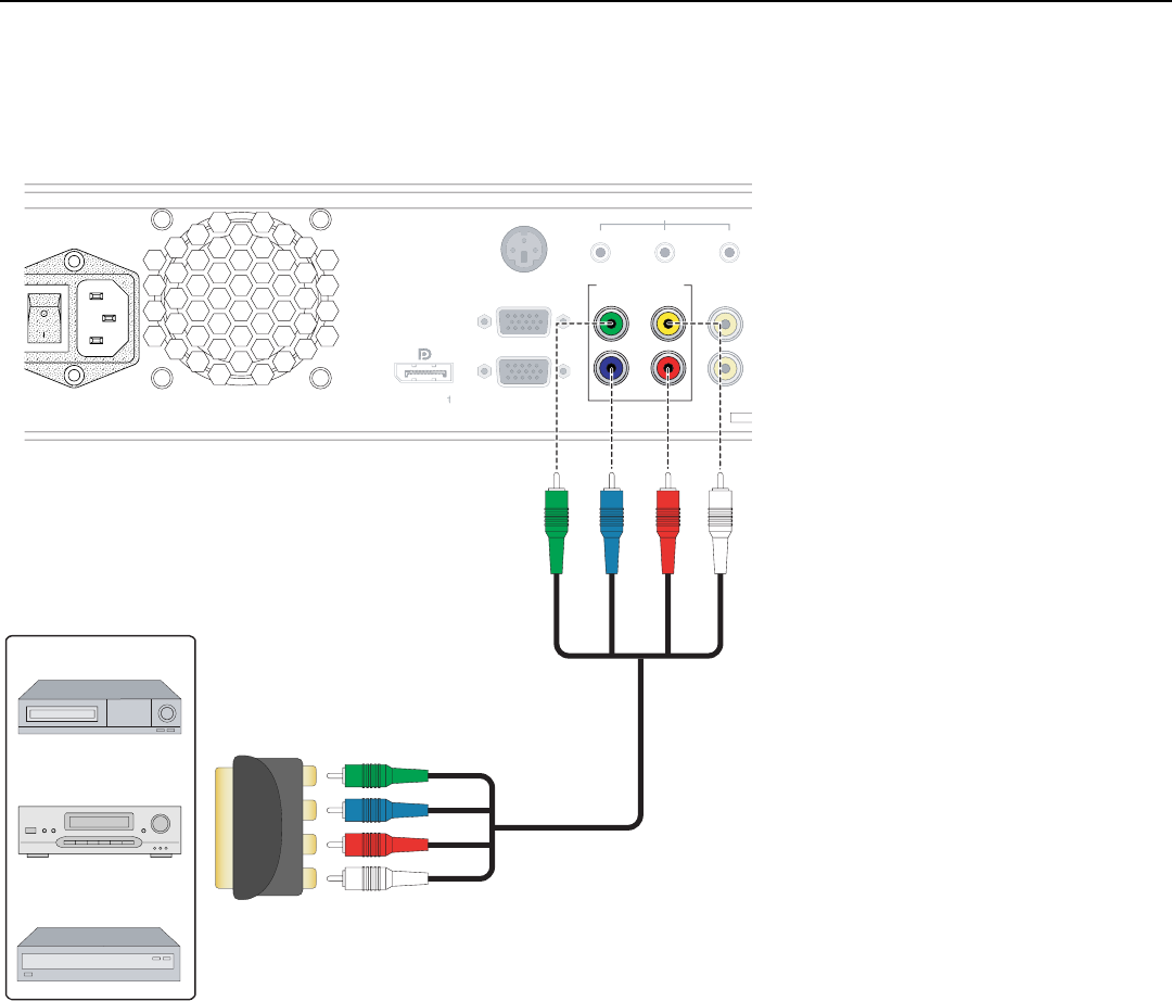
Installation
LightStyle™ LS-12HBd Installation/Operation Manual 47
PRELIMINARY
SCART RGBS Source Connections: Connect the green, blue and red outputs from
your SCART source to the Component/SCART input on the Dimension Digital Controller.
Connect the sync output from your SCART source to the Video 1 input on the Dimension
Digital Controller. See Figure 3-19.
Figure 3-19. SCART RGBS Source Connections
Video 1
YVideo 2
Video 3
Pr
Pb
Component / SCART
TRIGGERS
12 3
HD1
3D SYNC
HD2
DisplayPor
Vi
deo
2
V
i
deo
3
HD
1
HD2
D
isplayPor
T
RI
GG
ER
S
12
3
3
D
S
YN
C
Gaming Console
VCR
DVD/DTV STB
SCART-to-RGBS
adapter
Green
Blue
Red
Sync
Green
Blue
Red
Sync
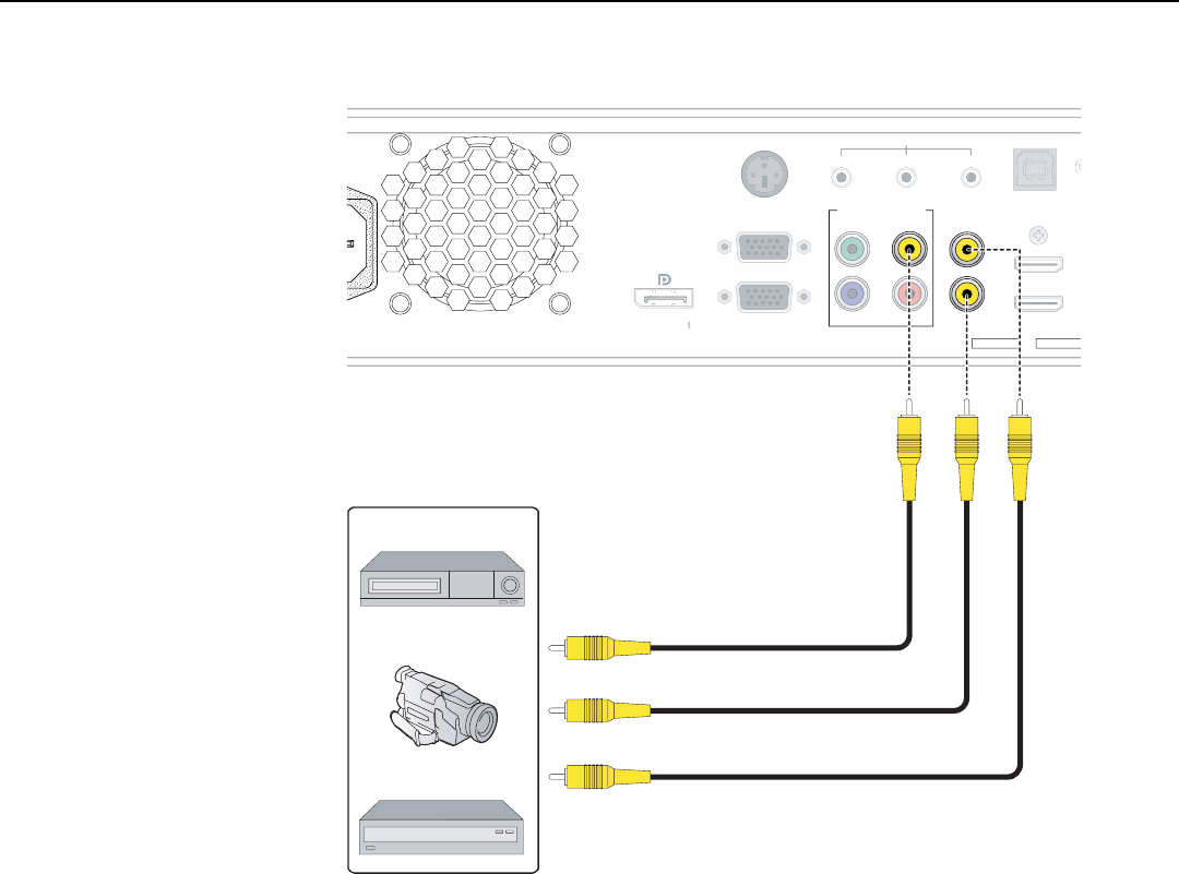
Installation
48 LightStyle™ LS-12HBd Installation/Operation Manual
PRELIMINARY
Composite Source Connections: See Figure 3-20.
Figure 3-20. Composite Video Source Connections
USB
Video 1
YVideo 2
Video 3
Pr
Pb
HDMI 1
HDMI 2
Component / SCART
TRIGGERS
12 3
HD1
3D SYNC
HD2
DisplayPor
Y
Pr
P
b
US
B
H
DMI
1
HDMI
2
T
R
I
GG
ER
S
12
3
HD1
3D SYNC
HD2
D
isplayPor
Gaming Console
VCR
Camcorder
Composite
Composite
Composite
Composite
Composite
Composite
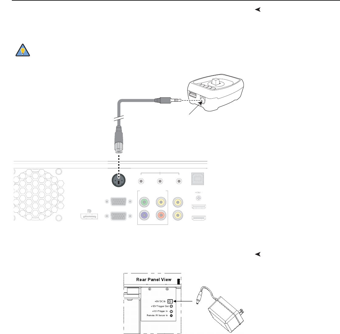
Installation
LightStyle™ LS-12HBd Installation/Operation Manual 49
PRELIMINARY
Connecting the Active 3D
Emitter to the Dimension
Digital Controller
Connect the 3D SYNC Out port on the emitter to the 3D Sync Out connector on the
Dimension Digital Controller, as shown in Figure 3-21. Mount the emitter in a location that
provides a clear line of sight between it and the viewing area.
Figure 3-21. Active 3D Emitter Connection
Connecting to AC PowerProjector: Plug the female end of one power cord into the AC receptacle on the rear of
the LS-12HBd (AC 100V ~ 240V). Then, connect the other end to your AC power source.
Anamorphic Lens Transport: An
AC-to-DC power adapter is provided for
the lens transport. Connect the power
adapter to the +9V DC In jack on the
rear of the lens transport assembly.
Connect the other end to an AC power
source.
Similarly connect the Dimension Digital Controller to a nearby AC outlet.
Secure the emitter in the desired location using double-sided tape or
a similar adhesive material.
Tip
USB
Video 1
YVideo 2
Video 3
Pr
Pb HDMI 2
Component / SCART
TRIGGERS
12 3
HD1
3D SYNC
HD2
Dis
p
la
y
Port
U
S
B
Vi
deo
1
Y
Vi
d
eo
2
Vi
deo
3
Pr
P
bHDMI
2
Com
p
onent / SCAR
T
T
RI
GG
ER
S
12
3
HD1
HD2
D
isplayPor
t
r
r
Active 3D Emitter
3D
SYNC IN
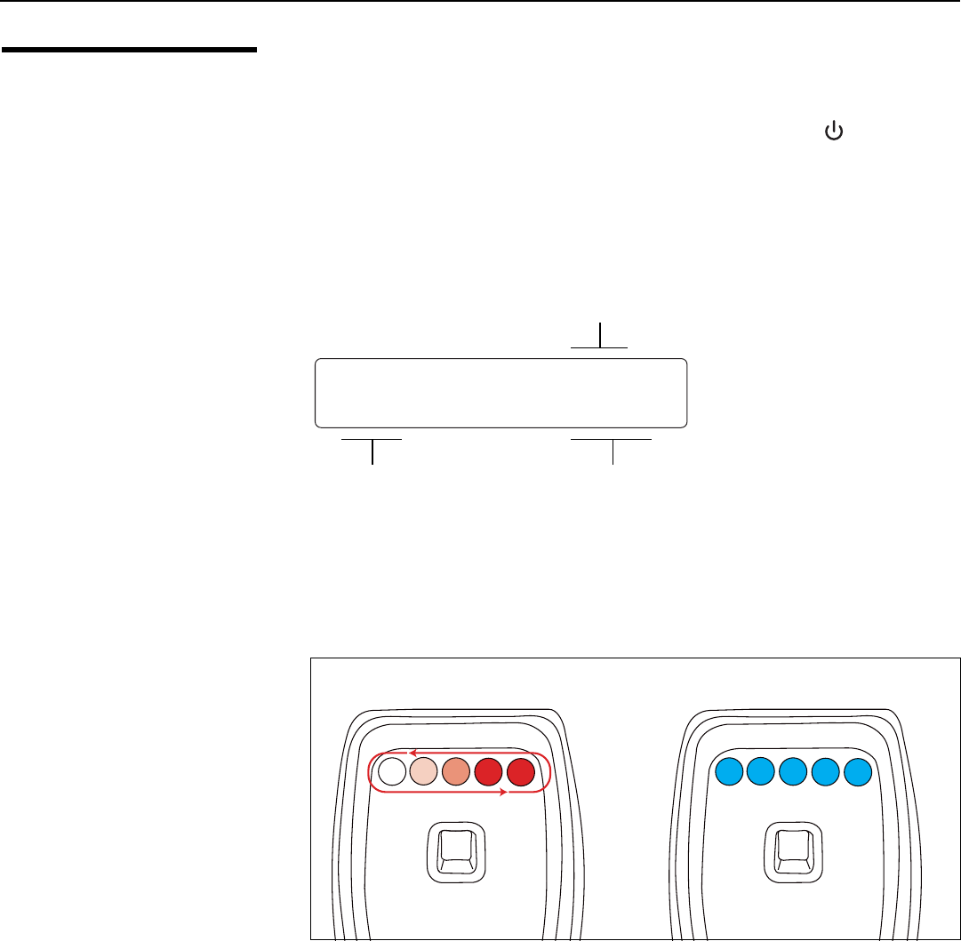
Installation
50 LightStyle™ LS-12HBd Installation/Operation Manual
PRELIMINARY
3.8
Turning on the Power
1. Power up your source components.
2. Turn on the main power switch at the rear of the Dimension Digital Controller.
3. Press the ON button on the remote control (or the ON/STANDBY ( ) button on the
Dimension Digital Controller front panel) to turn on the system. The vacuum
fluorescent display on the Dimension Digital Controller front panel briefly displays
“Initializing System,” followed by “Starting LS-12HBd.”
4. When the display is ready for use, the fluorescent display indicates the active source,
input resolution/frame rate and aspect ratio/screen; for example:
5. When the projector is turned on, the Active 3D Emitter turns on as well. The LEDs
display a red moving pattern while the emitter attempts to acquire a 3D signal and
until a signal is found.
If the emitter searches for a signal for longer than 60 seconds, a signal is assumed to
not be present.
6. Upon finding a 3D signal, all LEDs turn blue. Once the LEDs indicate a 3D signal, the
3D glasses can be used to experience 3D. For more information on using the Active
3D Glasses, refer to Using the 3D Glasses on page 94.
HDMI 1
16:9/1 1080i/60
Current
Source
Aspect Ratio/Screen Input Resolution/Frame Rate
LS-12HBd
1080p/60
Searching for 3D Sync Signal 3D Sync Signal Found
Installation
LightStyle™ LS-12HBd Installation/Operation Manual 51
PRELIMINARY
3.9
Primary Lens
Adjustments: Focus,
Zoom and Position
Lens zoom, focus and position are motorized adjustments that are adjustable using the
remote control (Figure 2-7). This allows you to adjust the focus and image size while at the
screen for more accurate results.
To access the motorized lens controls:
1. On the Dimension Digital Controller remote control or front panel, press MENU.
2. Select Service from the Main Menu and enter the Service Menu passcode.
3. Select Display Device from the Service Menu.
4. Select Configure from the Display Device menu, then select Lens.
The Lens menu controls operate as described below.
FocusTo focus the projected image, use the cursor buttons to highlight “In” or “Out.” Then,
press and hold the ENTER button.
ZoomTo make the picture smaller (zoom out), use the cursor buttons to highlight the minus sign
(-). Then, press and hold the ENTER button.
To enlarge the picture (zoom in), use the cursor buttons to highlight the plus sign (+).
Then, press and hold the ENTER button.
Vertical and Horizontal
Lens Shift
To change the lens position, use the cursor buttons to highlight “Left,” “Right,” “Up” or
“Down” in the Lens menu. Then, press and hold the ENTER button to shift the lens in that
direction.
To return the lens to its home position (no horizontal or vertical shift), use the cursor
buttons to highlight “Home” in the Lens menu. Then, press the ENTER button.
3.10
Adjusting the Picture
Orientation
By default, the LS-12HBd is configured for a “floor/front” installation, in which the
projector is installed upright and in front of the screen. If it is installed behind the screen
and/or mounted on a ceiling, you must change the picture orientation. To do this:
1. On the Dimension Digital Controller remote control or front panel, press MENU.
2. Select Service from the Main Menu and enter the Service Menu passcode.
3. Select Display Device from the Service Menu.
4. Select Configure from the Display Device menu, then select Installation.
5. Select Orientation, then choose Floor/Rear, Ceiling/Front or Ceiling/Rear, to match
the installation method.
If you prefer, you can also perform lens adjustments from the
projector using the built-in keypad. For detailed instructions, refer to
KEYPAD on page 7.
You must enter a passcode to access the Service menu.
Note
Note
You must enter a passcode to access the Service menu.
Note
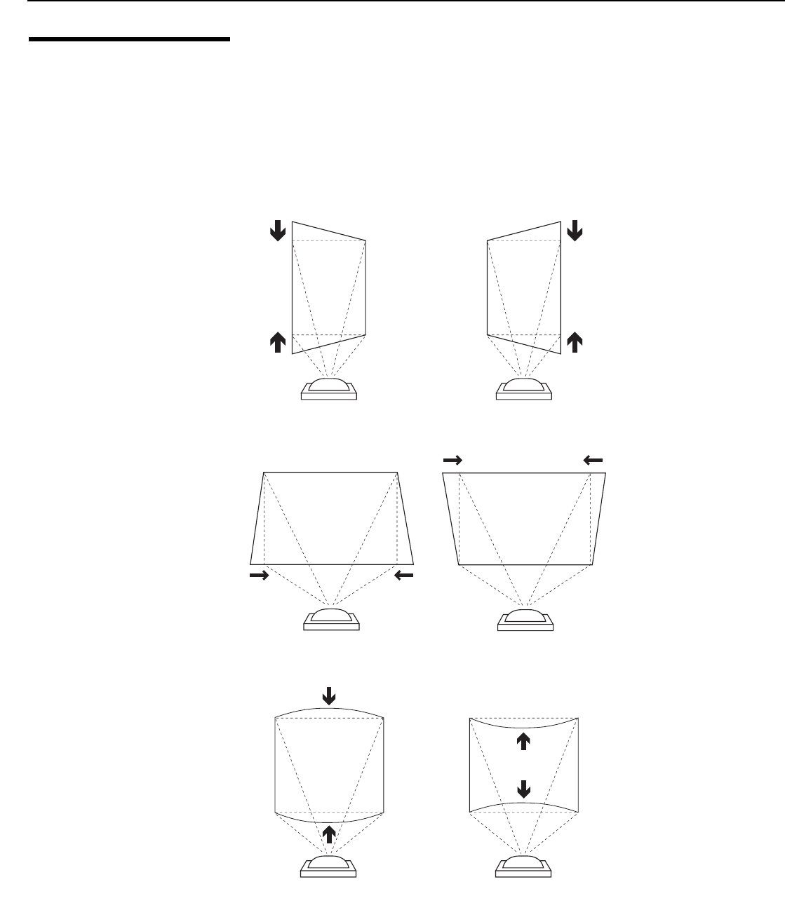
Installation
52 LightStyle™ LS-12HBd Installation/Operation Manual
PRELIMINARY
3.11
Adjusting the Image
Geometry
Projector and/or screen placement — among other things — can cause geometric
distortion in the projected image.
To correct this, the Dimension Digital Controller provides precise, nine-point control over
the projected image geometry. Use these controls as (and only if) needed to re-position
the image corners, mid-points and center to eliminate “keystoning” (mis-aligned corners)
or “pincushion” distortion (mid-points not aligned with corners). See Figure 3-22.
Figure 3-22. Keystone and Pincushion Distortion
Vertical Keystoning
Horizontal Keystoning
Pincushion Distortion
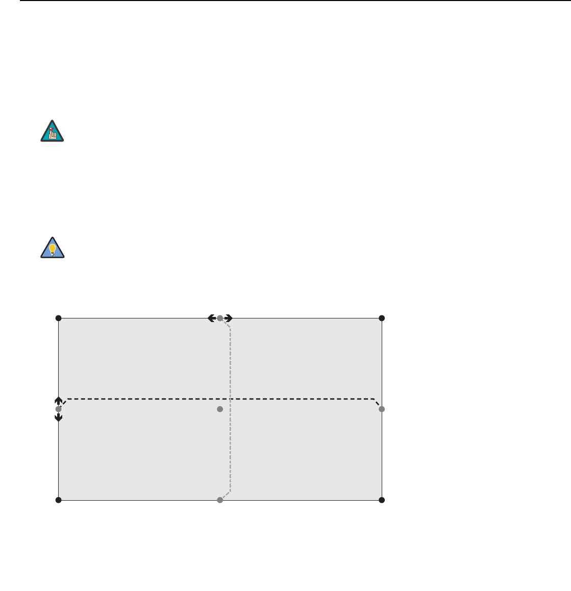
Installation
LightStyle™ LS-12HBd Installation/Operation Manual 53
PRELIMINARY
“Keystoning” usually occurs when the projector is tilted relative to the screen. “Pincushion”
distortion can sometimes occur if the throw distance is very short and/or the projector is
equipped with an anamorphic lens.
To correct keystoning or pincushion distortion:
1. On the Dimension Digital Controller remote control or front panel, press MENU.
2. Select Calibration from the Main Menu and enter the Calibration Menu passcode.
3. Select Image Alignment from the Calibration Menu.
4. Select Corner Alignment to correct a “keystoned” image by adjusting the image
corner positions. Select Midpoint Alignment to correct pincushion distortion by
adjusting the image edge mid-points. See Figure 3-23.
Figure 3-23. Image Alignment Controls
You must enter a passcode to access the Calibration menu.
Use the built-in test pattern when adjusting the image corners or
midpoints. To access it, check the Test Pattern box in the Corner
Alignment or Midpoint Alignment menu.
Note
Tip
Top Left (x, y)
Left
Middle (x)
Left/Right
Middle (y)
Right
Middl
e
(x)
Bottom Left (x, y)
Top Right (x, y)
Bottom Right (x, y)
Top/Bottom Middle (x)
Top Middle (y)
Bottom Middle (y)
Notes:
1. Smaller “x” values move a point to the left; larger values move it to the right.
2. Smaller “y” values move a point up; larger values move it down.
Center
(x, y)
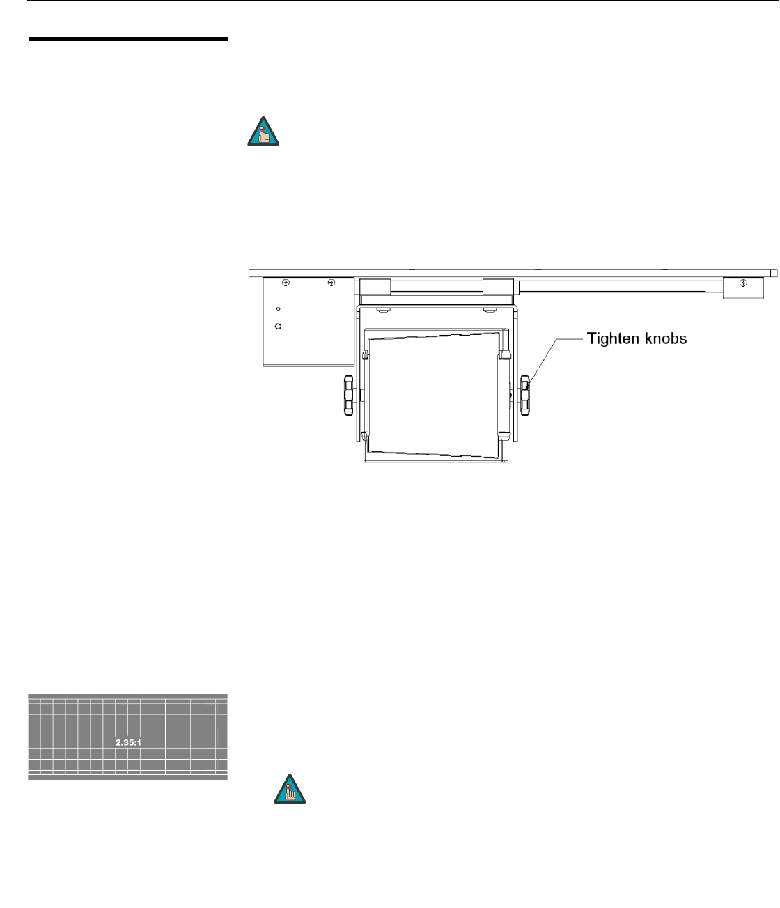
Installation
54 LightStyle™ LS-12HBd Installation/Operation Manual
PRELIMINARY
3.12
Installing and
Adjusting the
Anamorphic Lens
If you are installing an LS-12HBd with an anamorphic lens, proceed as follows to install
and adjust the lens.
Attach the anamorphic lens to the bracket using the plastic knobs supplied with the lens.
See Figure 3-24.
Figure 3-24. Attaching the Anamorphic Lens to the Lens Mount
Configure Lens Motor Trigger on Dimension Digital Controller: The anamorphic
lens solution for the LS-12HBd maintains constant image height independent of the
aspect ratio, while using the full display resolution of the projector. It accomplishes this by
moving the anamorphic lens in front of the primary lens when widescreen material is being
viewed. When the viewer transitions back to 16:9 or 4:3 source material, the anamorphic
lens moves out of the light path.
Proceed as follows to configure the 12-volt trigger output for proper operation.
1. Project a 2.35:1 aspect ratio test pattern or other image on the screen.
2. On the Dimension Digital Controller remote control or front panel, press MENU.
3. Select Service from the Main Menu and enter the Service Menu passcode.
4. Select Trig gers from the Service menu.
5. Assign the trigger output to which the lens motor is connected to the Cinema and
Virtual Cinema aspect ratios. This enables the lens motor to move the anamorphic
lens into position (in front of the primary lens) when either aspect ratio is selected.
It is extremely important that the primary lens is properly
adjusted before you install the anamorphic lens. Ensure that
the image from the primary lens is perfectly centered on the
screen.
Note
You must enter a passcode to access the Service menu for the first
time after turning on the system.
Note
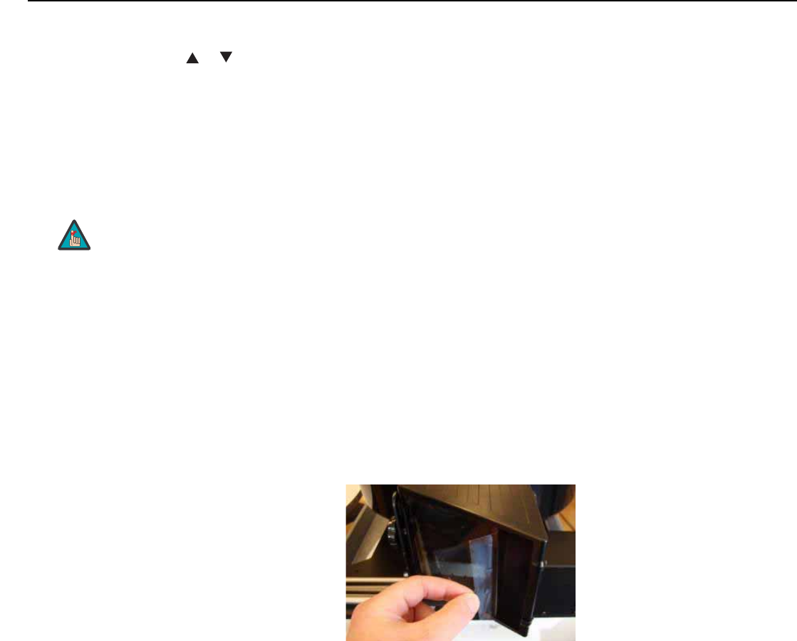
Installation
LightStyle™ LS-12HBd Installation/Operation Manual 55
PRELIMINARY
6. Select the Cinema aspect ratio to move the anamorphic lens into position, if it isn’t
already. To do this, press CINEMA on the Dimension Digital Controller remote control
(Figure 2-7), or press or repeatedly with no menus visible on-screen.
Adjusting the Lens Position:
1. Adjust the vertical position and tilt of the lens so that the projector beam is passing
through the center of the lens and any residual pincushion distortion is about the
same at the top and bottom of the image. This typically results in the anamorphic lens
being below the center of the primary lens and tilted slightly downward.
2. Tighten the knobs.
3. Adjust the rotation of the Lens Transport Assembly so that the left and right sides of
the image are an equal distance from their respective screen borders.
4. Tighten the Pivot Screw and the four mounting screws holding the transport to the
Attachment Plate.
5. For optimum multiple aspect ratio performance, adjust the projector’s zoom so that a
1.85:1 aspect ratio movie is just masked by the top and bottom of the screen border
when the anamorphic lens is not in front of the primary lens. This way 1.85:1, 16:9
and 2.35-2.4:1 aspect ratio movies are all presented to fill the screen at a constant
height.
6. Remove the protective film from the
front of the anamorphic lens.
There may be some pincushion distortion even after the lens is
properly adjusted, especially at shorter throw distances. If this is the
case, Runco recommends that you slightly over-scan the image
into the screen frame area to mask the distortion.
Note

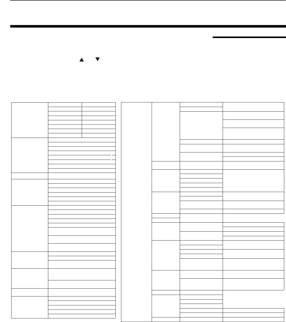
Operation
LightStyle™ LS-12HBd Installation/Operation Manual 57
PRELIMINARY
4.1
Using the On-Screen
Menus
To display the Main Menu, press the MENU button on the remote control or Dimension
Digital Controller front panel (Figure 2-5).
To select a menu item, use the and buttons on the remote control or Dimension
Digital Controller front panel to highlight it. Then, to confirm your selection, press ENTER
on the remote control or Dimension Digital Controller front panel.
The LS-12HBd OSD menus are arranged hierarchically, as shown in Figure 4-1. Some
menu options apply only to certain input signal types. For example, Phase and Tracking
can only be adjusted for RGB, Component video or SCART signals.
Figure 4-1. LS-12HBd OSD Menu Structure
4. Operation
Input Source
Composite 1 HDMI 1
Composite 2 HDMI 2
Composite 3 HDMI 3
Component HDMI 4
HD 1 HDMI 5
HD 2 HDMI 6
SCART HDMI 7
DisplayPort HDMI 8
Aspect Ratio
16:9
4:3
Letterbox
VirtualWide
Cinema
Virtual Cinema
Native
Auto Cinema
Screen Screen 1 / Screen 2
Picture
Brightness
Contrast
Color
Tint
Sharpness
Noise Filter
Input Position
Left/Right
Up/Down
Width
Height
Overscan
Overscan Mode
(Zoom/Crop)
Phase
(RGB/Component/SCART signals only)
Tracking
(RGB/Component/SCART signals only)
Memory
Presets
Recall ISF Night or ISF Day
Recall/Save Custom 1 or Custom 2
Reset Custom 1 and Custom 2 to Factory
Default
3D
Processing
3D Mode
(Auto, Off, Side-by-Side, Top-and-Bottom or
Frame Packing)
Reverse Eyes
(On/Off)
Sleep Timer Off, 30 Minutes, 60 Minutes, 90 Minutes, 2
Hours or 4 Hours
Information
Signal
System
Network
Field Service
Manufacturing
Calibration
Display Color -
Common Settings
Gain -100, -99... 0 ... 99, 100 (Red, Green, Blue)
Offset
Gamma
Mode
(Simple / Advanced)
Simple
(1.8, 2.0, 2.2, 2.35, 2.5)
Advanced
(0 (2.2 gamma curve),
1, 2, 3 ... 20 (custom gamma tables))
Color Temp Simple (5500K, 6500K, 7500K or 9300K)
Color Gamut* Auto, REC709, SMPTE-C, EBU, Native or
PCE
PCE* Red x, y / Green x, y / Blue x, y / White x, y
Yellow x, y / Cyan x, y / Magenta x, y
Display Color -
Projector Settings Lamp Power (230W or 260W)
Input Image
Brightness
-50, -49 ... 0 ... 49, 50
Contrast
Color
Tint
Sharpness
Input Color
Gain -32, -31... 0 ... 31, 32
(HD 1, HD 2 and Component inputs only)
Offset
Chroma Delay 0, 1, 2 ... 7
(Composite inputs only)
Noise Filter 0, 1, 2 ... 63
Save ISF Night Back / Confirm
Save ISF Day
Copy/Paste
Memory Preset Copy Settings
Paste Settings
Aspect Ratio Copy Settings
Paste Settings
Output Shift
Left/Right -50, -49 ... 0 ... 49, 50
Up/Down
Width -50, -49, 48 ... 0
Height
Screen Masking
0, 1, 2 ... 100
(Top / Bottom / Left / Right /
Test Pattern Enable)
Image Alignment
Corner Alignment Top Left / Top Right / Bottom Left /
Bottom Right / Test Pattern Enable
Midpoint Alignment
Center / Top Middle / Left Middle /
Right Middle / Bottom Middle /
Test Pattern Enable
Adjustment Mode Both, Primary or Secondary
Splash Configure
Owner Name
ISF Calibrated
ISF Other
Splash Timer 5, 6, 7 ... 15 ... 59, 60
Splash Enable On/Off
OSD Position Hor. / Ver. 0, 1, 2 ... 100
Note: Default settings appear in bold type. Settings marked with an asterisk (*) apply to 2D content only.
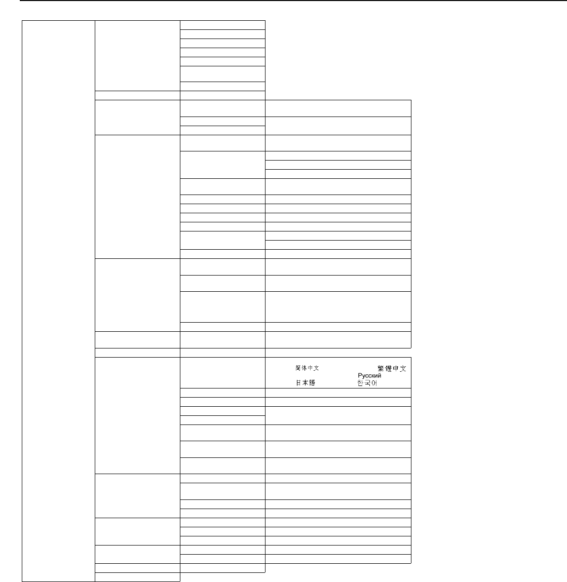
Operation
58 LightStyle™ LS-12HBd Installation/Operation Manual
PRELIMINARY
Figure 4-1. LS-12HBd OSD Menu Structure (continued)
Service
Test Video
Color Bars 1
Color Bars 2
Focus
Grey Bars
Full White
Primary / Secondary / Dual
Alignment
3D
Input Names Rename/Restore
Remote Control
Remote Code 00000 ... 08209 ... 65535 or 88999 (extended
mode)
SRC 1-7 Keys (select a key, then choose a source to assign to it)
SRC 8-14 Keys
Display Device - Configure
Installation -
Picture Orientation
Auto, Floor Front, Ceiling Front, Floor Rear or
Ceiling Rear
Lens
Focus
Zoom
Shift
Display Info.
(read-only)
Projector Serial Number
Lamp Hours
Lamp Hours Reset Yes / No
Diagnostics White, Red, Green, Blue, Yellow, Cyan, Magenta
Altitude Auto / High
Display 3D Settings (n/a)
Internal 3D Settings Sync Delay
Test Pattern Enable
24Hz 3D Mode 120 Hz 6:4 or 120 Hz 5:5
Network
IP Configuration DHCP (On / Off), IP Address, Subnet Mask, Default
Gateway, Communication Test
Auto Firmware Upgrade Auto Check for New Firmware, Auto Perform
Upgrade, Check for New Firmware
E-Mail Notification
E-Mail Address, Error Notification, Error Notification
to Runco, Periodic Service Notification, Lamp Life
Notification, Customer Information, E-Mail
Calibration Data
Remote Network Control On / Off
Color Space Auto, REC601, REC709,
RGB-PC or RGB-Video
(Not available on Composite 1, Composite 2 or
Composite 3 inputs)
Triggers 1 / 2 / 3
Miscellaneous
Language
English, Français, Deutsch, Italiano, Español,
Svenska, (Simplified Chinese),
(Traditional Chinese), Português,
(Russian), (Japanese) or (Korean)
OSD Timer 0 (no timeout) or 5, 6, 7 ... 30 ... 60 sec.
OSD Messages On / Off
Blank Screen Color Red/Green/Blue = 0, 1, 2, 3 ... 255
Sidebar Color
Film Mode
(SD sources only) On / Off
CUE
(Chroma Upsampling Error) On / Off
Sync Threshold 0, 1, 2 ... 15
(HD 1, HD 2 and Component inputs only)
HDMI
HDMI EDID Extension On / Off (per HDMI and DisplayPort input)
Audio Format Combined / HDMI Out (Pri. Display) / HDMI Out
(Sec. Display) / HDMI Out (Audio Only)
CEC On / Off
HPD Toggle Rejection Auto / On / Off
Front Panel Brightness
Logo LED 0 (off), 1, 2 ... 31
Standby LED On / Off
LCD 0 (off), 1, 2, 3 or 4
Auto Power Off Enable On / Off / No Signal
Hours 1, 2, 3, 4, ... 23, 24
Standby Mode Low Power / Fast Startup
System Reset
Operation
LightStyle™ LS-12HBd Installation/Operation Manual 59
PRELIMINARY
Main MenuThe Main Menu is the starting point for accessing all Dimension Digital Controller
functions.
(You must enter a passcode to access the Calibration and Service menus.)
Input SourceFrom the Main Menu, select Input Source to choose a video signal source.
The active source is indicated by an arrow (Î) to its left; in this example, Composite is the
active source.
Runco Video
Input Source
Aspect Ratio
Screen
Picture
Input Position
Memory Presets
3D Processing
Sleep Timer
Information
Calibration
Service
Input Source
ÎComposite 1
Composite 2
Composite 3
Component
HD 1
HD 2
SCART
HDMI 1
HDMI 2
HDMI 3
HDMI 4
HDMI 5
HDMI 6
HDMI 7
HDMI 8
DisplayPort
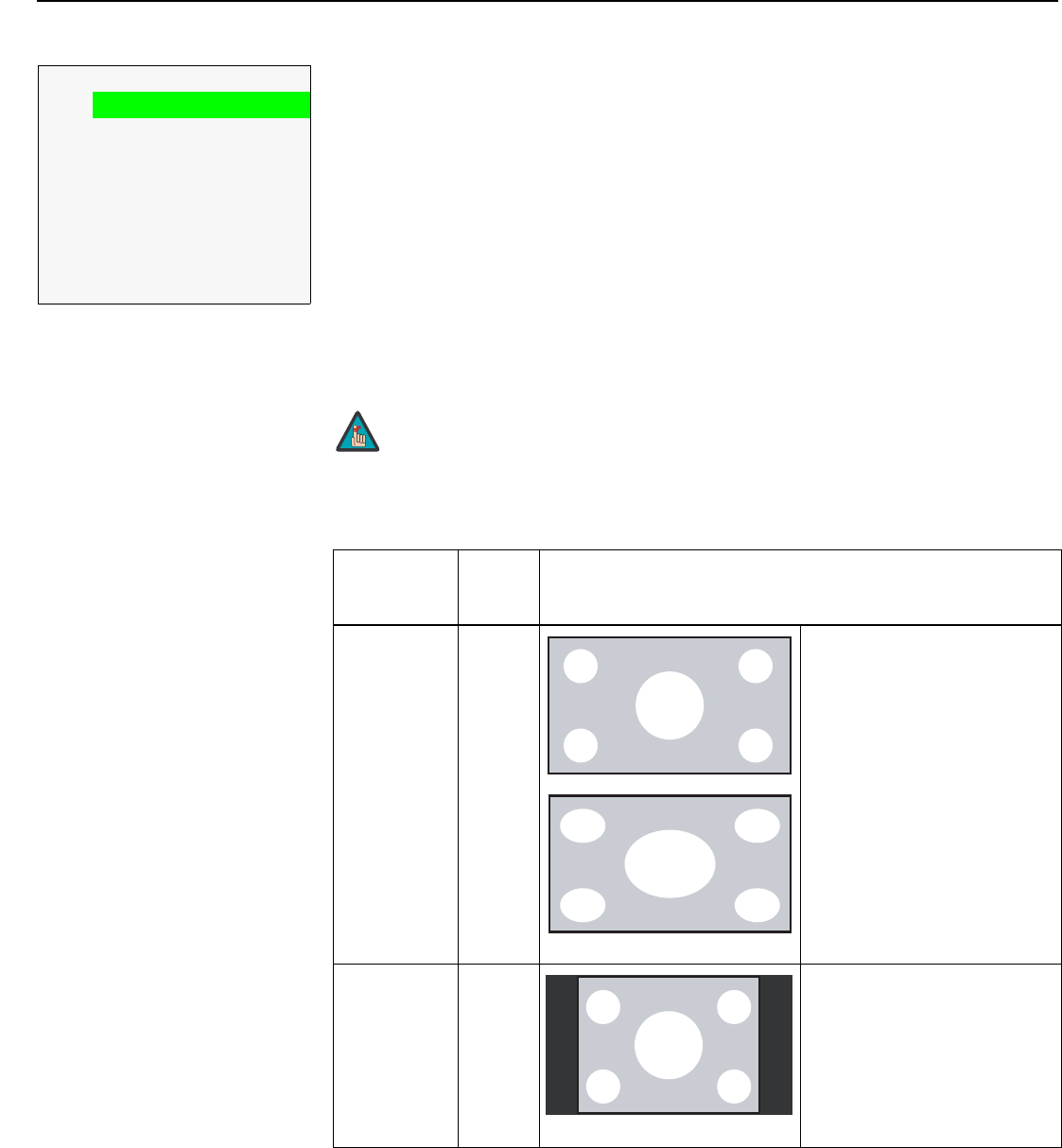
Operation
60 LightStyle™ LS-12HBd Installation/Operation Manual
PRELIMINARY
Aspect Ratio To change the aspect ratio (size and shape) of the projected image, select Aspect Ratio
from the Main Menu and press ENTER. Select the appropriate aspect ratio for your
screen size and the type of program material being viewed; refer to Table 4-1.
The currently-selected aspect ratio is indicated by a “7” to its left; in this example, 16:9 is
selected.
Note that some aspect ratios are unavailable and/or not useful with certain types of
source material. The optimal setting depends on a number of factors, such as:
• The aspect ratio of the source material, as broadcast or encoded on the playback
medium.
• The “display type” (16:9 or 4:3) and output resolution settings at the source
component. Most modern DVD/BD players and set-top boxes have such controls.
• Viewer preference (original aspect ratio with “black bars,” or a full-screen presentation
with some distortion or cropping).
Aspect Ratio
716:9
4:3
Letterbox
VirtualWide
Cinema
Virtual Cinema
Native
Auto Cinema
➤
The aspect ratio selection is automatically saved for each input and
resolution.
Table 4-1. Aspect Ratio Settings
Aspect Ratio
Remote
Control
Key
Description
16:9 16:9 Select 16:9 to view 16:9 DVDs
and HDTV programs in their
native aspect ratio.
4:3 images are stretched
horizontally to fit a 16:9 screen.
4:3 4:3 Standard 4:3 scales the input
signal to fit in the center of the
16:9 screen. 4:3 is the aspect
ratio used by computer
monitors, standard television
programming and most VHS
video cassettes.
Note
4:3 Image, stretched to fill
16:9 Screen (Display)
16:9 Image on
16:9 Screen (Display)
4:3 Image on
16:9 Screen (Display)
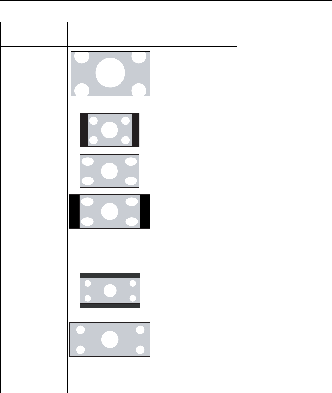
Operation
LightStyle™ LS-12HBd Installation/Operation Manual 61
PRELIMINARY
Letterbox LET
BOX
Letterbox mode scales (zooms
in on) a 4:3 image linearly (by the
same amount on all sides) to fill
a 16:9 display.
Letterbox is best suited for
viewing LaserDisc movies or
non-anamorphic DVDs on a
16:9 screen.
VirtualWide V-WIDE VirtualWide scales a 4:3 image
NON-linearly (more on the sides
than in the center) to fit a 16:9
screen.
On a 2.35:1 screen, the image is
centered between black bars on
either side.
Cinema CINEMA Select Cinema to view 2.35
source material in its native
aspect ratio.
With a 16:9 screen and a
standard LS-12HBd (without an
anamorphic lens), the upper and
lower portions of the screen are
masked, but the geometry of the
active image area is unchanged.
With a 2.35:1 screen and an
anamorphic lens, the Dimension
Digital Controller scales the
2.35:1 image so that the active
image area fills the 16:9 chip
surface, eliminating the black
bars. The secondary,
anamorphic lens then restores
the proper geometry to the
2.35:1 image.
Table 4-1. Aspect Ratio Settings (continued)
Aspect Ratio
Remote
Control
Key
Description
4:3 Image on
16:9 Display
(Letterbox aspect ratio)
4:3 Image on
16:9 Screen (Display)
4:3 Image on
2.35:1 Screen
with VirtualWide
4:3 Image on
16:9 Screen
with VirtualWide
2.35:1 Image on
16:9 Screen
(Cinema aspect ratio / no CineWide)
2.35:1 Image on
2.35:1 Screen
(Cinema aspect ratio / CineWide)
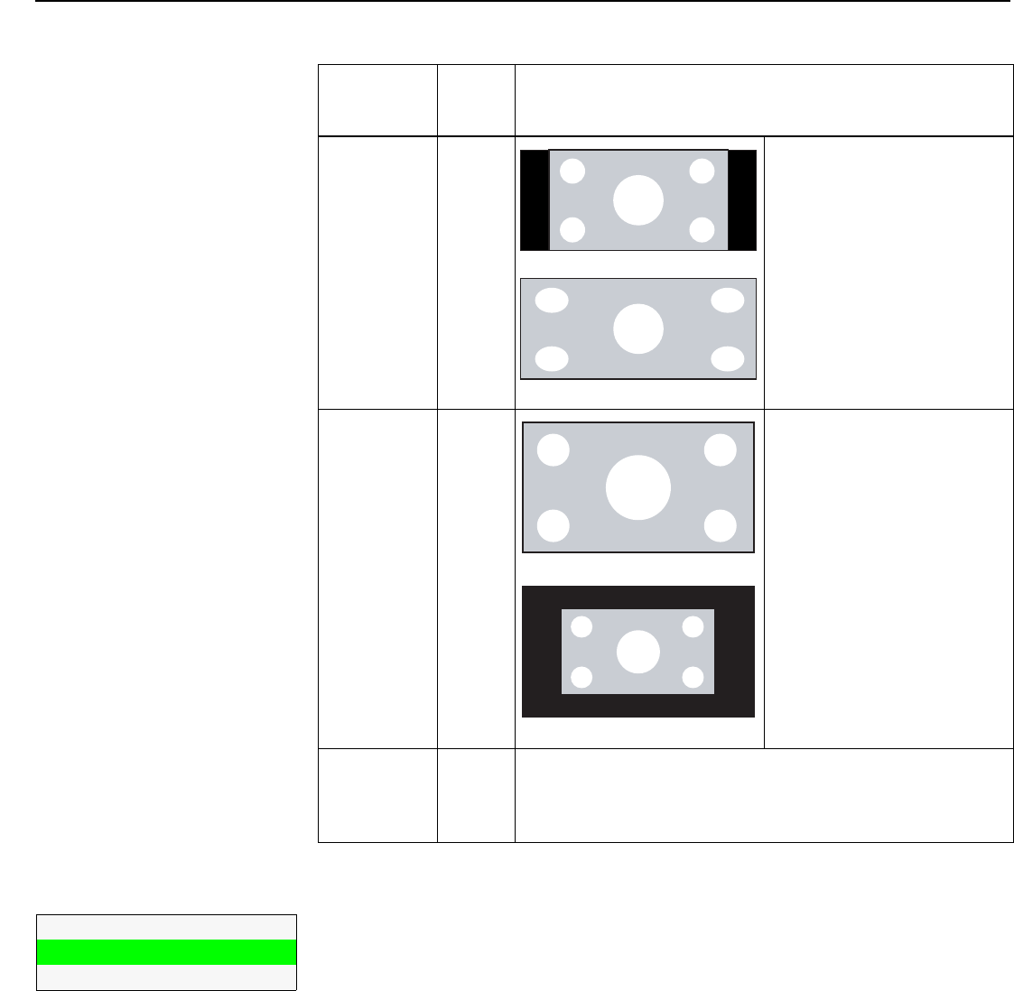
Operation
62 LightStyle™ LS-12HBd Installation/Operation Manual
PRELIMINARY
Screen The Screen Menu allows you to recall multiple sets of stored values for certain controls
(Output Shift, Image Alignment and Screen Masking) that are saved for each aspect ratio.
Such settings are also saved “per screen.” To recall the Output Shift and Image Alignment
settings associated with “Screen 1” or “Screen 2,” make that selection here.
Virtual Cinema V-CINE A 16:9 image is scaled
NON-linearly (more on the sides
than in the center) to fit a 2.35:1
screen.
Native NATIVE Select Native to display the
source signal in its native
resolution, centered in the
display area with no re-sizing or
overscan.
This means, for example, that
720p HDTV programs will
display with unused pixels on all
sides: 320 on the left and right
sides and 180 above and below.
With SDTV and EDTV sources,
the Dimension Digital Controller
scales the image horizontally to
achieve a 16:9 aspect ratio.
Auto Cinema -- Select Auto Cinema to have the Dimension Digital Controller apply
the Cinema aspect ratio to 2.35:1 source material automatically,
when detected. To all other content, Auto Cinema applies the 16:9
aspect ratio.
Table 4-1. Aspect Ratio Settings (continued)
Aspect Ratio
Remote
Control
Key
Description
16:9 Image on
2.35:1 Screen with
Virtual Cinema
16:9 Image on
2.35:1 Screen
16:9 Image on
2.35:1 Screen
1080i HDTV Image
720p HDTV Image
Screen
Screen 1
Screen 2
➤
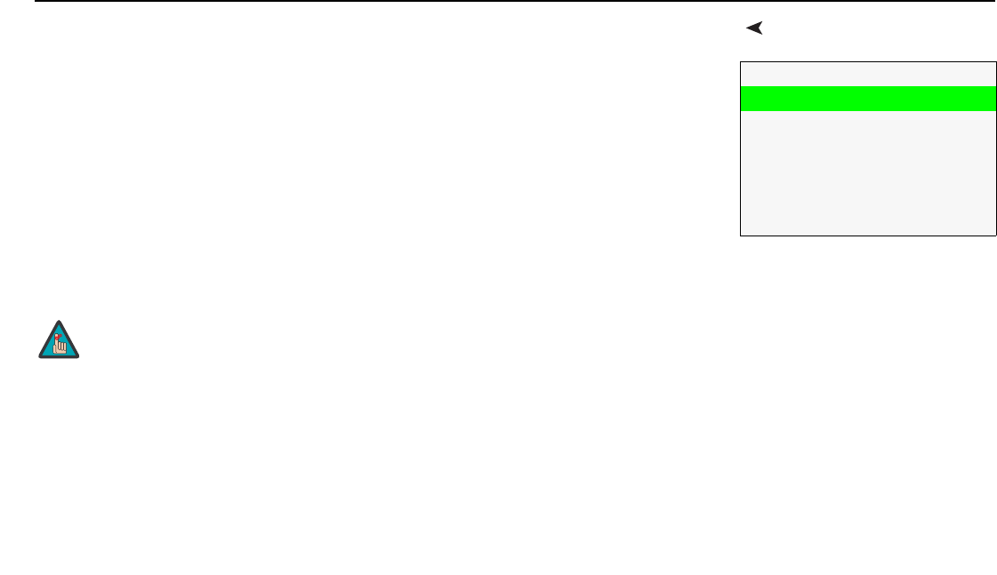
Operation
LightStyle™ LS-12HBd Installation/Operation Manual 63
PRELIMINARY
PictureUse the controls in the Picture Menu to calibrate each Dimension Digital Controller input to
achieve optimum picture quality.
The Dimension Digital Controller has been designed to incorporate setup and calibration
standards established by the Imaging Science Foundation (ISF). The ISF has developed
carefully crafted, industry-recognized standards for optimal video performance and has
implemented a training program for technicians and installers to use these standards to
obtain optimal picture quality from Runco video display devices. Accordingly, Runco
recommends that setup and calibration be performed by an ISF certified installation
technician.
All signal types require separate processing. Therefore, you need to calibrate each
Dimension Digital Controller input separately.
Although it may be possible to obtain satisfactory picture quality using the naked eye and
regular program material, Runco recommends using an external test pattern source
(Ovation Multimedia, Digital Video Essentials or AVIA test DVD or equivalent) for best
results.
Connect your test pattern source to the input that you are calibrating and proceed as
follows. Perform the adjustments in the order listed here.
Picture
Brightness
Contrast
Color
Tint
Sharpness
Noise Filter
When you change a picture quality setting, save the change to a
preset afterwards. Otherwise, the change will be lost when a
different input is selected. (Picture quality settings are saved for
each input and display mode separately.) For information about
saving settings, refer to Memory Presets on page 70.
Note
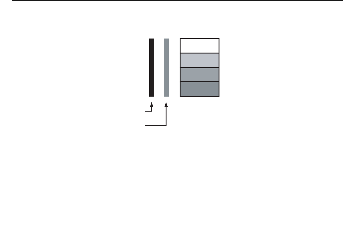
Operation
64 LightStyle™ LS-12HBd Installation/Operation Manual
PRELIMINARY
Brightness: On your external test pattern source, select a PLUGE pattern. (PLUGE is an
acronym for “Picture Line-Up Generation Equipment.”) Figure 4-2 shows a typical PLUGE
pattern.
Figure 4-2. Typical PLUGE Pattern for Adjusting Brightness
PLUGE patterns vary but generally consist of some combination of black, white and gray
areas against a black background. The example above includes two vertical bars and four
shaded boxes.
Select Brightness from the Picture menu and press ENTER. Adjust the brightness so that:
• The darkest black bars disappear into the background.
• The dark gray areas are barely visible.
• The lighter gray areas are clearly visible.
• The white areas are a comfortable level of true white.
• The image contains only black, gray and white (no color).
Below Black
A
bove Black
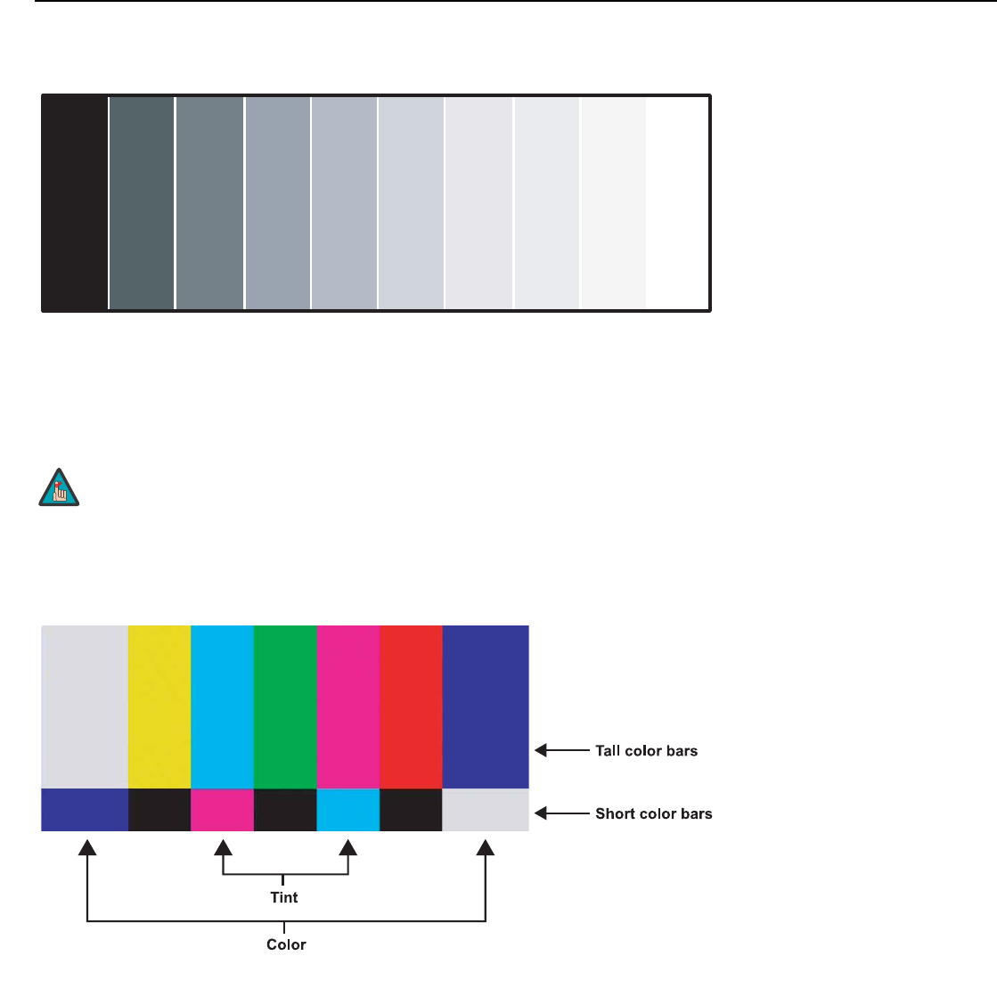
Operation
LightStyle™ LS-12HBd Installation/Operation Manual 65
PRELIMINARY
Contrast: On your external test pattern source, select a stepped, gray-bar pattern like the
one shown in Figure 4-3.
Figure 4-3. Typical Gray Bar Pattern for Adjusting Contrast
Select Contrast and press ENTER. Adjust the contrast to a point just below which the
white rectangle starts to increase in size.
Color Saturation: On your external test pattern source, select a color bar pattern like the
one shown in Figure 4-4.
Figure 4-4. Typical Color Bar Pattern for Adjusting Color Saturation and Tint
1. Press the MENU button on the remote control or Dimension Digital Controller front
panel.
2. Select Service from the Main Menu and press ENTER.
3. Enter the Service menu passcode.
4. Select Display Device from the Service menu and press ENTER.
Brightness and contrast controls are interactive. A change to one
may require a subtle change to the other in order to achieve the
optimum setting.
Note
gray
yellow
cyan
green
magenta
red
blue
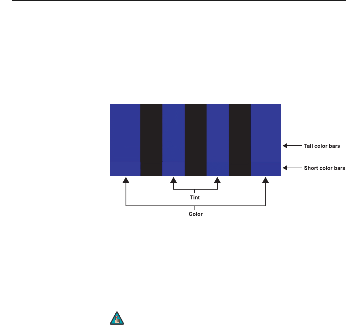
Operation
66 LightStyle™ LS-12HBd Installation/Operation Manual
PRELIMINARY
5. Press ENTER again to select Configure.
6. Select Diagnostics and press ENTER.
7. Select Blue from the Diagnostics menu, then press ENTER to display only the blue
color channel.
8. Press EXIT (or MENU) repeatedly to return to the Main Menu.
9. Select Picture from the Main Menu and press ENTER.
10.Select Color from the Picture menu and press ENTER.
11.Adjust the color saturation level until the outermost (gray and blue) color bars appear to
be a single shade of blue:
Tint: Tint or “hue” is essentially the ratio of red to green in the color portion of the image.
When tint is decreased, the image appears redder; when it is increased the image
appears greener.
To adjust the tint, enable “blue only” display mode in the Diagnostics menu, as you would
for adjusting color saturation (refer to the previous section, Color Saturation).
Select Tint from the Picture menu and press ENTER. Adjust the tint level until the cyan
and magenta color bars (on either side of the green bar) appear to be a single shade of
blue.
Like the brightness and contrast controls, the color and tint controls
are interactive. A change to one may require a subtle change to the
other in order to achieve the optimum setting.
gray
yellow
cyan
green
magenta
red
blue
Note
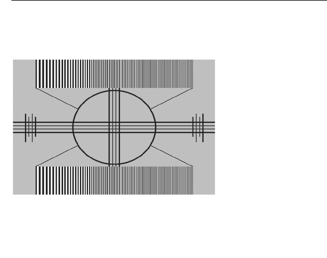
Operation
LightStyle™ LS-12HBd Installation/Operation Manual 67
PRELIMINARY
Sharpness: “Sharpness” is the amount of high-frequency detail in the image. To adjust
sharpness, select Sharpness from the Picture menu and press ENTER. On your external
test pattern source, select a pattern like the one shown in Figure 4-5. Adjust as needed,
looking for white edges around the transitions from black to gray and differently-sized lines
in the “sweep” patterns at the top and bottom. Lower the sharpness setting to eliminate
them.
Figure 4-5. Typical Test Pattern for Adjusting Sharpness
Noise Filter: To apply noise filtering to the input signal, select Noise Filter from the Picture
menu. The Noise Filter is useful for clearing up noisy images from 480i video sources.
Use the left- or right-arrow buttons to select the desired amount of noise reduction,
keeping in mind that higher settings (which reduce high frequencies) may also “soften” the
image.
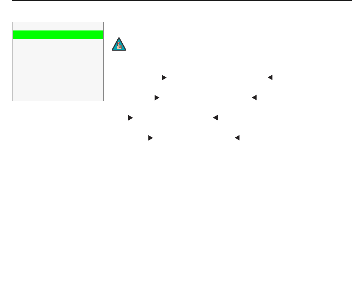
Operation
68 LightStyle™ LS-12HBd Installation/Operation Manual
PRELIMINARY
Input Position Use the controls in the Input Position Menu to fine-tune the aspect ratio and image
position for the current source.
Left/Right: Select Left/Right from the Input Position menu to shift the projected image
horizontally. Press to shift the image to the right; press to shift it to the left.
Up/Down: Select Up/Down from the Input Position menu to shift the projected image
vertically. Press to shift the image upward; press to shift it downward.
Width: Select Width from the Input Position menu to change the projected image width.
Press to increase the width; press to decrease it.
Height: Select Height from the Input Position menu to change the projected image
height. Press to increase the height; press to decrease it.
Overscan/Overscan Mode: Overscan pushes the outside edge of the active picture
area of the video signal out beyond the edge of the display area.
Some television programs are produced based on the assumption that older television
sets may not display the outer edges of the broadcast picture area. Overscan effectively
trims away these inactive, outer edges and enlarges the remaining portion of the image to
fill the display area.
For HDTV, DVDs and other video sources, Overscan is generally not necessary or
desirable.
This control defines the amount of overscan applied to the image. The range is from
0 to 20. There are two overscan modes:
•In Crop mode, each increment adds a mask at the top, bottom, left and right edges of
the source image equal to 0.5% of the displayed horizontal resolution (1% total). A
setting of 10, for example, crops the image 5% on all sides or 10% total.
•In Zoom mode, each increment adds a factor to the scaling of the source image so
that the vertical and horizontal resolutions are 100% plus 1% increments of the size
determined by the aspect ratio function. A setting of 10, for example, zooms in on the
image 5% on all sides or 10% total.
Figure 4-6 illustrates the effect of each overscan mode setting.
Input Position
Left/Right
Up/Down
Width
Height
Overscan
Overscan Mode
Phase
Tracking
➤
The input position settings are automatically saved for each input
and resolution.
Note
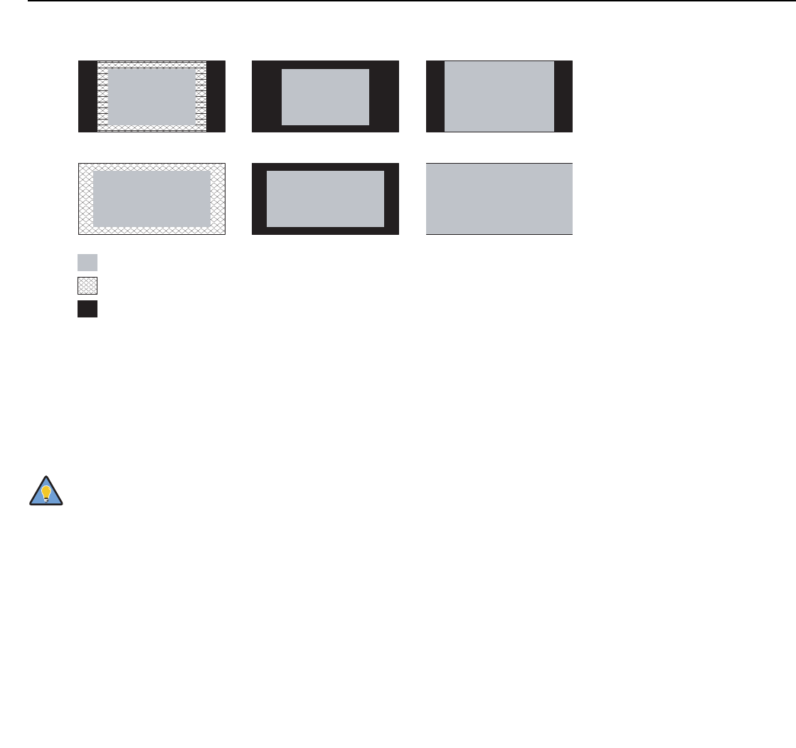
Operation
LightStyle™ LS-12HBd Installation/Operation Manual 69
PRELIMINARY
Figure 4-6. Overscan Modes
Phase (RGB, Component or SCART sources): This control adjusts the phase of the
pixel sampling clock relative to the incoming signal. Adjust the phase when an RGB,
Component or SCART image still shows shimmer or “noise” after Tracking has been
optimized.
For best results, use a good test pattern such as a smooth gray consisting of a clear
pattern of black and white pixels, or a similar “half on, half off” graphic image. Adjust the
slidebar until the image stabilizes and each pixel is clearly defined. You may notice that
you can stabilize the image at more than one point. Use either setting in such cases.
Tracking (RGB, Component or SCART sources): Tracking determines the frequency
of the pixel sampling clock, indicated by the number of incoming pixels per line, so that all
pixels generated by a particular source are sampled.
Steady flickering or several soft vertical stripes or bands across the entire image indicates
poor pixel tracking. Proper pixel tracking helps ensure that the image quality is consistent
across the screen, that aspect ratio is maintained and that pixel phase (see above) can be
optimized.
Adjust the Phase after adjusting Tracking (see below).
Off Crop Zoom
4:3
16:9
= Source Image Area
= Edge Noise
= Screen (16:9)
Tip
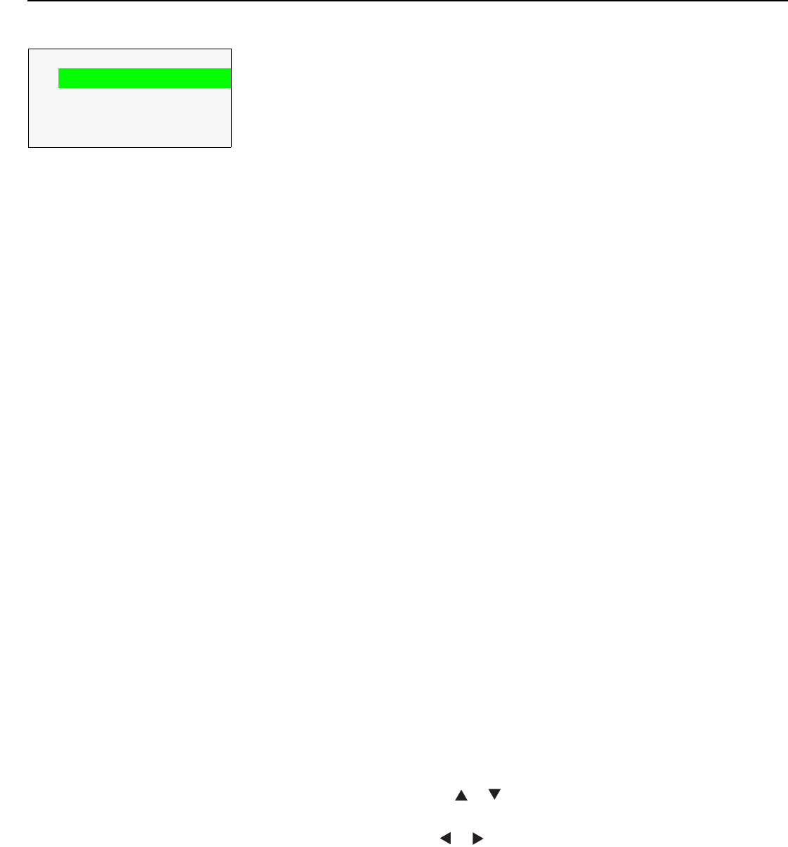
Operation
70 LightStyle™ LS-12HBd Installation/Operation Manual
PRELIMINARY
Memory Presets For each input, the Dimension Digital Controller lets you save image quality settings as
presets that you can recall at a later time. You can create up to four presets per input and
display mode (resolution and frame rate).
The Dimension Digital Controller stores the following display modes in each memory
preset:
•480i
•480p
•576i
•576p
• 720p/24 Hz
• 720p/25 Hz
• 720p/30 Hz
• 720p/50 Hz
• 720p/60 Hz
• 1080i/50 Hz
• 1080i/50 Hz (Australia)
• 1080i/60 Hz
• 1080p/24 Hz
• 1080p/25 Hz
• 1080p/30 Hz
• 1080p/50 Hz
• 1080p/60 Hz
Use the Memory Presets menu to recall saved image presets, or to save image settings in
the “Custom 1” or “Custom 2” memory location. The currently-selected preset is indicated
by a “Δ to its left; in the example shown here, ISF Night is selected.
You should save changes to any of the following settings to a preset; otherwise they will
be lost when a new input source or resolution is selected:
•Brightness
•Contrast
• Color saturation
•Tint
• Sharpness
•Gamma
•Lamp Settings
• Color temperature and white balance
To select a memory preset, press or to highlight it and press ENTER.
To save the settings for the current input and display mode to the Custom 1 or Custom 2
memory preset, select it, press or to highlight Save and press ENTER.
Memory Presets
ÎISF Night
ISF Day
Custom 1 Save Reset
Custom 2 Save Reset
➤
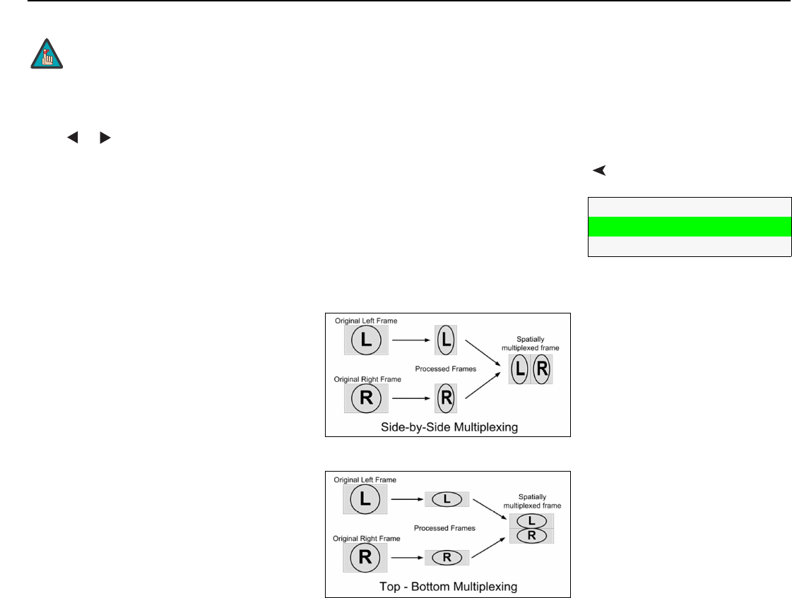
Operation
LightStyle™ LS-12HBd Installation/Operation Manual 71
PRELIMINARY
To reset the Custom 1 or Custom 2 memory preset to its factory-default state, select it,
press or to highlight Reset and press ENTER.
3D ProcessingSelect 3D Processing from the Main Menu to set the following options related to
formatting and delivery of HDMI 3D content.
3D Mode: Select 3D Mode from the 3D Processing menu to specify how the Dimension
Digital Controller processes the “left eye” and “right eye” image components respectively.
•Choose Auto to have the Dimension Digital Controller determine the appropriate 3D
mode based on the HDMI vendor-specific InfoFrame data. This is the default setting.
•Choose Off for 2D content.
•Choose Side-by-Side to have the
Dimension Digital Controller scale the left
and right image halves respectively to fill the
screen.
Side-by-Side multiplexing is used with 1080i
source material.
•Choose Top-and-Bottom to have the
Dimension Digital Controller scale the top
and bottom image halves respectively to fill
the screen.
Top-and-Bottom multiplexing is used with
720p or 1080p source material.
•Choose Frame Packing to have the input
FPGA decode frame packed data into left and right eye data.
Reverse Eyes: By default, the Primary and Secondary video scalers in the Dimension
Digital Controller are dedicated to “left eye” and “right eye” image processing respectively.
To reverse this relationship, choose Reverse Eyes from the 3D Processing menu and set it
to On.
To save the settings for the current input and display mode to the
ISF Night or ISF Day memory preset, select Save ISF Night or Save
ISF Day from the Calibration menu (refer to Save ISF Night/Save
ISF Day on page 78).
Note
3D Processing
3D Mode
Reverse Eyes
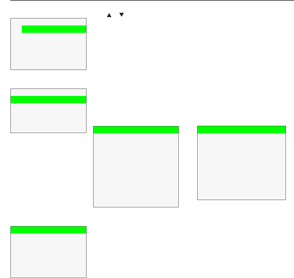
Operation
72 LightStyle™ LS-12HBd Installation/Operation Manual
PRELIMINARY
Sleep Timer Select Sleep Timer from the Main Menu to turn off the LS-12HBd after a specified interval.
Press or to select Off, 30 Minutes, 60 Minutes, 90 Minutes, 2 Hours or 4 Hours.
Then, press ENTER.
Information Signal / System: Select Information from the Main Menu, then choose either Signal or
System to display information about the current input signal (resolution, frequency, type et
cetera) and installed firmware versions, as well as other information that uniquely identifies
your Dimension Digital Controller and display device.
Should you ever need to contact Runco Technical Support, this information will help them
answer your questions or resolve product performance issues.
Network: Select Information from the Main Menu, then choose Network to display
information about the Ethernet network connection.
To enable network communication via Ethernet, refer to IP Configuration on page 86.
Field Service / Manufacturing: The Field Service and Manufacturing menus are
password-protected and intended for use only by Runco service personnel and factory
technicians.
Sleep Timer
ÎOff
30 Minutes
60 Minutes
90 Minutes
2Hours
4Hours
➤
Information
Signal
System
Network
Field Service
Manufacturing
➤
Signal
Input Source HDMI 1
Signal Format 1080p/60
Input Resolution 1920x1080
Vertical Freq 59.94 Hz
Horizontal Freq 67.500 kHz
Pixel Clock 148.500 MHz
Color Space REC709
Sync Type Separate
3D Mode Side-by-Side
Memory Preset ISF Night
System
Model DC-300
Display Name LS-12HBd
Output Resolution 1920x1080
Serial Number 00000000
Boot Version 1.0
Firmware Version 1.5
Micro Version 1.2
Input FPGA Version 1.0
Output FPGA Version 1.0
Network
MAC Address 1A:2B:3C:4D:5E:6F
IP Address 192.168.0.150
Subnet Mask 255.255.0.0
Default Gateway 192.168.1.1
DHCP Enabled
Network Status Connected
Operation
LightStyle™ LS-12HBd Installation/Operation Manual 73
PRELIMINARY
CalibrationUse the Calibration menu to perform advanced picture quality adjustments. This menu
should be used by ISF-certified technicians only.
To recall the ISF Night or ISF Day settings, select “ISF Night” or “ISF Day” from the
Memory Presets menu (see page 70) or use the corresponding remote control buttons.
Display Color - Common Settings: Use the Display Color - Common Settings menu to
adjust the color balance at the Dimension Digital Controller output. These settings are
saved independently for each input and display mode.
•Gain: Use the Gain controls to correct color imbalances in the bright areas of the
image. A good way to do this is to use a test pattern consisting mostly of solid white
areas, such as an 80 IRE “window” pattern. If the white areas contain traces of red (Pr),
green (Y) or blue (Pr), decrease the Gain for that color.
•Offset: Use the Offset controls to correct color imbalances in the dark areas of the
image. A good way to do this is to use a test pattern consisting mostly of dark gray
areas, such as a 30 IRE “window” pattern. If the gray areas contain traces of red (Pr),
green (Y) or blue (Pr), decrease the Offset for that color.
• Gamma: Select Gamma from the Display Color - Common Settings menu to choose a
de-gamma curve. Used correctly, the Gamma control can improve contrast while
maintaining good details for blacks and whites. If excess ambient light washes out the
image and it becomes difficult or impossible to see details in dark areas, lower the
gamma setting to compensate. This improves contrast while maintaining good details
for blacks. Conversely, if the image is washed out and unnatural, with excessive detail
in black areas, increase the setting.
•Mode: With the LS-12HBd, two Gamma adjustment modes are available: Simple or
Advanced. The two modes are mutually exclusive; when you select the Simple
mode, the Advanced selection in the Gamma menu is grayed out. Likewise, when
you select Advanced, the Simple selection is grayed out.
•Simple: Use the Simple Gamma control to perform gamma correction at the display
according to a simple power law gamma function. The value chosen here
corresponds to the power variable in this equation:
Output = InputPower
The Dimension Digital Controller applies this gamma curve to all three primary color
channels (red, green and blue).
•Advanced: To select a custom gamma curve, select Mode from the Gamma menu
and set it to Advanced. Then, select Advanced from the Gamma menu to select one
of up to 20 pre-programmed gamma tables. Custom gamma tables provide the
ability to perform complex, non-linear gamma correction on each primary color
channel independently of the others.
Calibration
ISF Settings
Display Color
Input Image
Input Color
Save ISF Night
Save ISF Day
Copy/Paste
Output Shift
Image Alignment
Adjustment Mode
Splash Configure
OSD Position
You must enter a passcode to access the Calibration menu.
Note
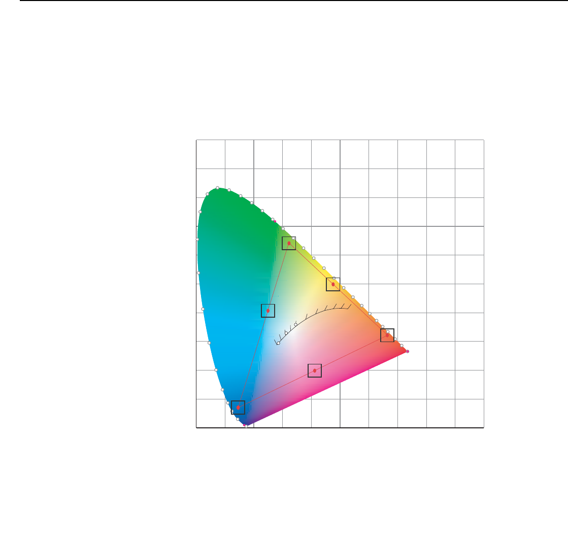
Operation
74 LightStyle™ LS-12HBd Installation/Operation Manual
PRELIMINARY
• Color Temp: Select Color Temp from the Display Color - Common Settings menu to
adjust the color temperature. Color temperature establishes the “color of gray” by
adjusting the 75% white point to various color points.
What are “color points?” A “color point” is an x/y coordinate pair that defines a
color’s location on the standard CIE chromaticity graph, shown in Figure 4-7. (CIE
stands for “Commission Internationale de l’Éclairage” (International Commission on
Illumination), the organization responsible for color measurement and management
standards.)
Figure 4-7. CIE 1931 Chromaticity Diagram
•Simple: Select Simple mode from the Color Temp menu (with the LS-12HBd, this is
the only choice) to choose one of five color temperature presets: 3200K, 5500K,
6500K, 7500K and 9300K. The default setting, 6500K, is appropriate for most
situations. Higher settings produce a “bluer” picture; lower ones impart a reddish
hue to the image.
0.00.10.20.30.40.50.60.70.80.91.0
0.0
0.1
0.2
0.3
0.4
0.5
0.6
0.7
0.8
0.9
1.0
x
y
2000
2222
2500
2857
3333
4000
5000
5714
6667
8000
10000
D50
D65
D93
Red
Blue
Green
Cyan
Magenta
Yellow
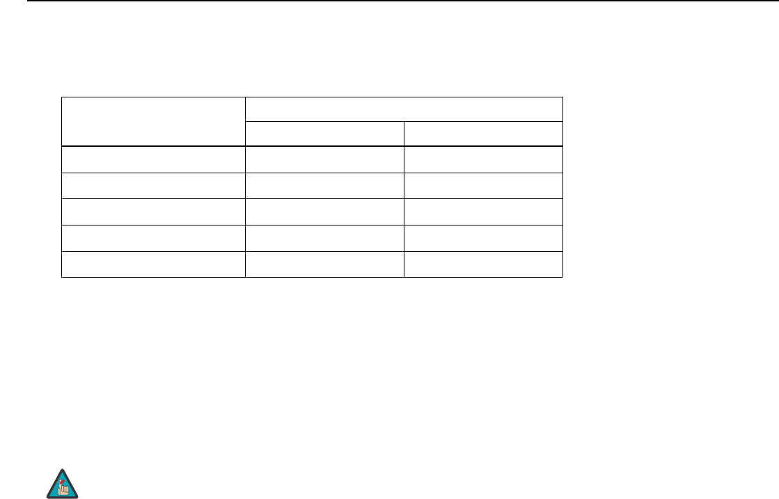
Operation
LightStyle™ LS-12HBd Installation/Operation Manual 75
PRELIMINARY
Table 4-2 lists the x- and y-coordinates for each color temperature preset in “Simple”
mode.
• Color Gamut: Select Color Gamut from the Display Color - Common Settings menu to
select a color gamut (range) that may be different from the default color gamut.
Each setting defines the precise hue of each primary (red, green and blue) and
secondary (yellow, cyan and magenta) color component used to generate the millions
of colors produced in displays. Changing this setting relocates the “triangle” for
possible colors (see Figure 4-7). For example, changing the x/y coordinates for red
moves the color closer to either orange or violet, which in turn affects all displayed
colors having a red component.
• The default setting, Auto, automatically chooses the appropriate color gamut:
•SMPTE C for NTSC, 480i and 480p sources.
•EBU for PAL, SECAM, 576i and 576p sources.
•REC709 for all other sources.
• Select REC709 to use the color gamut defined in ITU-R BT.709-5.
• Select SMPTE-C to use the color gamut defined in SMPTE 170M-1999.
• Select EBU to use the color gamut defined in EBU Tech. 3213-E.
• Select Native to use REC709 for cyan, magenta, and yellow and uncorrected values
for red, green, and blue.
• Select PCE to use the Personal Color Equalizer feature of the LS-12HBd. PCE lets you
define a custom color gamut. Refer to the next section, PCE, for instructions on how to
do this.
Table 4-2. Color Temperature Presets and Associated Color Points
Color Temperature Preset
Associated x/y Values
xy
3200K 0.423 0.404
5500K 0.332 0.348
6500K 0.313 0.329
7500K 0.299 0.315
9300K 0.284 0.298
1. The Color Gamut setting only affects 2D content.
2. The Dimension Digital Controller uses the Color Gamut settings
for all display modes on a given input.
Note
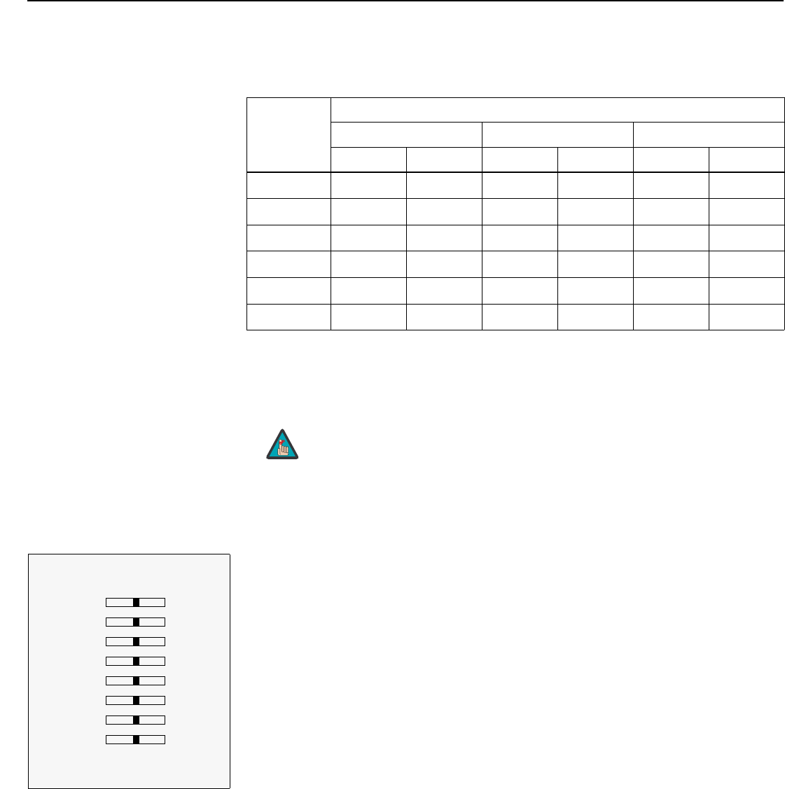
Operation
76 LightStyle™ LS-12HBd Installation/Operation Manual
PRELIMINARY
Table 4-3 lists the Color Gamut settings and associated x- and y-coordinates for each
primary and secondary color component.
•PCE: To use the Personal Color Equalizer to define a custom color gamut, choose the
“PCE” Color Gamut setting (refer to Color Gamut on page 75). Then, choose PCE
from the Display Color - Common Settings menu and press ENTER.
PCE provides the ability to define a custom color gamut in terms of a “white point” and
primary (red, green, blue) color points; see Figure 4-7.
• RGBW (Red, Green, Blue, White): To precisely adjust the primary color points and
white point associated with the custom color gamut, choose RGBW from the PCE
sub-menu. Each control operates only on the color specified. Surrounding colors are
linearly interpolated based on their distance from each of these colors.
Table 4-3. x/y Color Gamut Values
Primary
Color
Color Gamut Settings and Associated x/y Values
REC709 SMPTE “C” EBU
xyxyxy
Red 0.640 0.330 0.630 0.340 0.640 0.330
Yellow 0.419 0.505 0.421 0.507 0.418 0.502
Green 0.300 0.600 0.310 0.595 0.290 0.600
Cyan 0.225 0.329 0.231 0.326 0.220 0.329
Blue 0.150 0.060 0.155 0.070 0.150 0.060
Magenta 0.321 0.154 0.314 0.161 0.328 0.158
1. The PCE setting only affects 2D content.
2. The Dimension Digital Controller uses the PCE settings for all
display modes on a given input.
Note
Display Color
RGBW
Red x 0.640
Red y 0.330
Green x 0.300
Green y 0.600
Blue x 0.150
Blue y 0.060
White x 0.313
White y 0.329
7Auto Color Enable
7Test Pattern Enable
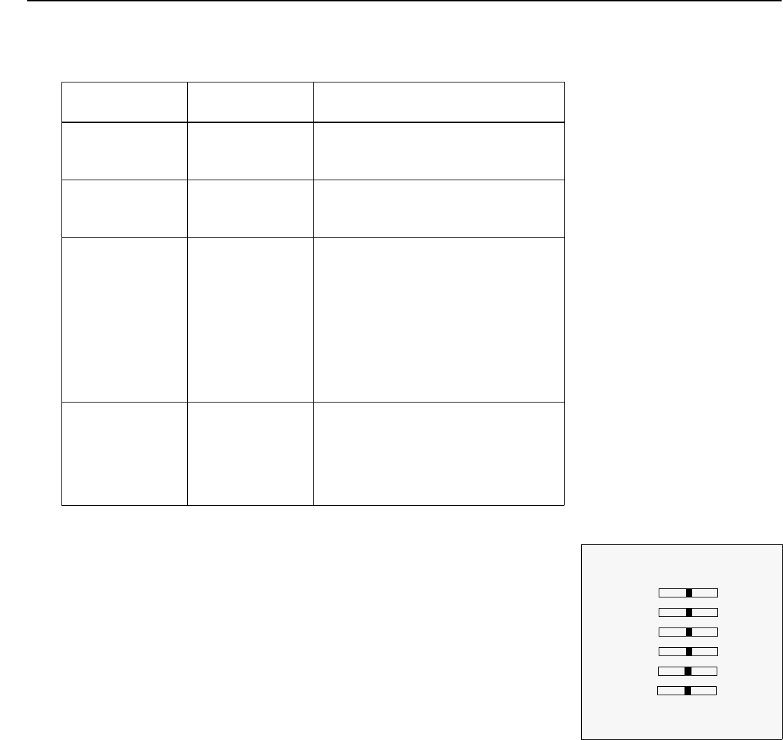
Operation
LightStyle™ LS-12HBd Installation/Operation Manual 77
PRELIMINARY
The Auto Color Enable and Test Pattern Enable checkboxes let you choose what to
display on-screen while making these adjustments. These controls work together as
follows:
• YCM (Yellow, Cyan, Magenta): To precisely adjust the secondary color points
associated with the custom color gamut, choose YCM from the PCE sub-menu. Each
control operates only on the color specified. Surrounding colors are linearly interpolated
based on their distance from each of these colors.
•Lamp: Select Lamp from the Display Color - Projector Settings menu to adjust the
projector lamp brightness.
•Power (230W or 260W): To supply a constant wattage to the lamp, select Power
(230W or 260W) from the Lamp menu to set the lamp power level. You can choose
to run the lamp as bright as possible (this is the default setting) or you can choose a
lower setting. Generally, lower lamp output prolongs the life of a lamp, but
decreases brightness.
Auto Color Enable
Setting
Test Pattern Enable
Setting Description
Off Off When both boxes are unchecked, the input
signal (normal picture) appears on the
display.
Off On When only the Test Pattern Enable box is
checked, a white “curtain” test pattern
appears instead of the input signal.
On Off When only the Auto Color Enable box is
checked, the input signal appears on the
display.
When you select a red, green, blue, yellow,
cyan or magenta color point to adjust, the
Dimension Digital Controller displays only
that color channel. When you select a white
point x- or y-value, all colors are visible
(normal picture).
On On When both boxes are checked, the
Dimension Digital Controller automatically
displays a red, green, blue, yellow, cyan,
magenta or white “curtain” test pattern
when you select an x- or y-value for that
color point to adjust.
Display Color
YCM
Yellow x 0.419
Yellow y 0.505
Cyan x 0.225
Cyan y 0.329
Magenta x 0.321
Magenta y 0.154
7Auto Color Enable
7Test Pattern Enable
Operation
78 LightStyle™ LS-12HBd Installation/Operation Manual
PRELIMINARY
Input Image: The Input Image controls are functionally similar to those in the Picture
menu (refer to page 63), but are accessible only by entering the Calibration menu
passcode.
Input Color: The Input Color controls are similar to those in the Display Color menu (see
above), but adjust the color balance of the incoming signal. These settings are also saved
independently for each input and display mode.
•Gain/Offset (HD1, HD2 and Component/SCART inputs only): These controls
operate similarly to those in the Display Color - Common Settings menu (described
on page 73), but affect the Y, Pb and Pr signal components rather than the red, green
and blue channels.
• Chroma Delay: use the Chroma Delay control to correct a mis-aligned image from a
composite video source. Chroma delay in an image causes color shifts to occur to the
left of the vertical edge transitions, producing artificial shadows or a “halo” effect. If
necessary, adjust this setting to eliminate them.
•Noise Filter: To apply noise filtering to the input signal, select Noise Filter from the
Input Color menu. The Noise Filter is useful for clearing up noisy images from 480i
video sources.
Use the left- or right-arrow buttons to select the desired amount of noise reduction,
keeping in mind that higher settings (which reduce high frequencies) may also “soften”
the image.
Save ISF Night/Save ISF Day: Whenever you make a change to the ISF settings, you
should always save it. Select Save ISF Night or Save ISF Day from the Calibration menu to
do this.
The Input Image settings establish the “zero point” for the Picture
menu settings, whose values represent offsets from the Input
Image settings. For example, if you set Brightness to 10 in this
menu, setting Brightness to 10 in the Picture menu results in an
actual setting value of 20 (10+10).
Note
Operation
LightStyle™ LS-12HBd Installation/Operation Manual 79
PRELIMINARY
Copy/Paste - Memory Preset: You can copy and paste settings from one memory
preset to another. This gives you a convenient starting point for creating a new preset
based on an existing one, to make the calibration process less time-consuming.
For example, you can use the Copy/Paste Memory Preset feature to:
• Apply settings from HDMI 1 to HDMI 2, or from HD1 to HD2.
• Calibrate an input for 720p source signals, then use those settings for 1080i sources.
• Duplicate ISF Night settings for a given source and signal format and save them in the
Custom 1 memory preset.
To use this feature, select Copy/Paste from the Calibration menu, then select Memory
Preset.
•Memory Preset - Copy Settings: Select Copy Settings from the Copy/Paste
Memory Preset menu to place the settings for the current input source, signal format
(resolution and frame rate) and memory preset onto a “clipboard,” which is a temporary
memory location. When you do, the message “Settings Copied” briefly appears
on-screen. The Copy/Paste menu then re-appears, indicating the source of the copied
settings.
•Memory Preset - Paste Settings: To apply the settings on the clipboard to a
different input source, signal format and/or memory preset, do any or all of the
following:
• Switch to another input (for example, from HD1 to HD2).
• Change the output signal format at the source (for example, from 720p/60 to
1080i/60).
• Switch to another Memory Preset (for example, from ISF Night to Custom 1).
Then, select Paste Settings from the Copy/Paste Memory Preset menu. If you want
to keep these new settings, you must save them! (Refer to Save ISF Night/Save
ISF Day on page 78 or Memory Presets on page 70.)
Copy/Paste - Aspect Ratio: You can also copy and paste certain settings, such as
those for Output Shift, Image Alignment (refer to page 80) or Screen Masking (refer to
page 80) from one aspect ratio or “screen” (refer to Screen on page 62) to another.
To do this, select Copy/Paste from the Calibration menu, then select Aspect Ratio.
•Aspect Ratio - Copy Settings: Select Copy Settings from the Copy/Paste Aspect
Ratio menu to place the Output Shift, Image Alignment and Screen Masking settings
for the current aspect ratio onto a “clipboard,” which is a temporary memory location.
When you do, the message “Settings Copied” briefly appears on-screen. The
Copy/Paste menu then re-appears, indicating the source of the copied settings.
Copy/Paste
Memory Preset
Aspect Ratio
Memory Preset
Copy Settings
Paste Settings
Copied From:
Input Source HDMI 1
Signal Format 1080p/60
Memory Preset ISF Night
Copied settings are not retained after a power cycle.
Note
Copy/Paste
Memory Preset
Aspect Ratio
Aspect Ratio
Copy Settings
Paste Settings
Copied From:
Aspect Ratio 16:9
Screen Screen 1
Copied settings are not retained after a power cycle.
Note

Operation
80 LightStyle™ LS-12HBd Installation/Operation Manual
PRELIMINARY
•Aspect Ratio - Paste Settings: To apply the Output Shift, Image Alignment and
Screen Masking settings on the clipboard to a different aspect ratio and/or screen, do
either of the following:
• Switch to another aspect ratio (for example, from 16:9 to Cinema).
• Switch from Screen 1 to Screen 2 or vice versa.
Then, select Paste Settings from the Copy/Paste Aspect Ratio menu. The new settings
are saved automatically.
Output Shift: The Left/Right, Up/Down, Width and Height controls in the Output Shift
menu are similar to those in the Input Position menu, except that they change the
characteristics of the output signal. These settings are saved independently for each
aspect ratio and screen selection (refer to Screen on page 62).
•Screen Masking: This control adjusts the amount of cropping on each edge of the
output image. This differs from the regular Overscan control in two ways:
• It allows separate adjustments on each edge; and
• It is saved per aspect ratio, per screen (as opposed to per connector, per mode).
This is useful for installations where the aspect ratio of the screen doesn’t exactly match
the aspect ratio of the display.
Image Alignment: Use the controls in the Image Alignment menu to ensure proper image
geometry; that is, a perfectly rectangular projected image with no keystoning or pincushion.
For detailed instructions, refer to Adjusting the Image Geometry on page 52.
Adjustment Mode (during 3D Operation): By default, any command or control
message you send using the remote control, front-panel keypad or RS-232 interface is
acted upon by both the Primary and Secondary scalers in the Dimension Digital
Controller. In some cases — for example, when using the lens controls or aligning the “left
eye” or “right eye” output images — you may need to address a command to only the
Primary or Secondary scaler. To do this, select Adjustment Mode from the Calibration
menu and set it to Primary or Secondary. The Main Menu title changes to “Runco Video
(Pri.)” or “Runco Video (Sec.)” when you do this.
Splash Configure: Use the Splash Configure menu to control the appearance and
behavior of the “splash” screen that appears on the display upon power-up.
•Owner Name/ISF Calibrated/ISF Other: You can have the LS-12HBd display the
owner’s name, your name, the phrase “ISF Calibrated” and/or any other string, up to
30 characters in length.
Use the up or down cursor button to select a character. Use the right and left cursor
buttons to change the cursor position. Press MENU when you have finished entering
text.
•Splash Timer: When you turn on the LS-12HBd, it projects a welcome screen with the
Runco and ISF logos, along with the personalized information you enter as described
above. Select Splash Timer from the Splash Configure menu to set the amount of time
for which this screen appears. The range is from 5 to 60 seconds, in one-second
increments. Press or to set the timer, then press MENU.
The Secondary OSD menus are only visible during 3D operation. In
2D mode, you will only see the image from the Primary scaler,
regardless of this setting. If you want to adjust the Secondary scaler
while in 2D mode, you must use the built-in keypad and VFD on the
Dimension Digital Controller.
Note
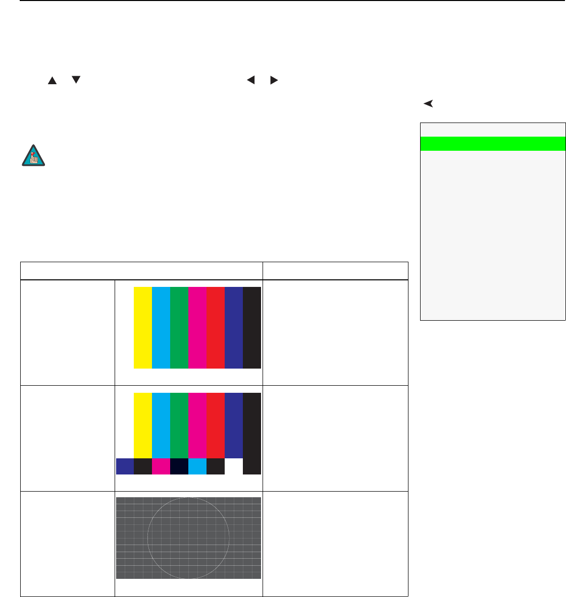
Operation
LightStyle™ LS-12HBd Installation/Operation Manual 81
PRELIMINARY
•Splash Enable: When you have finished customizing the splash screen, select Splash
Enable from the Splash Configure menu. Then, select On and press ENTER.
OSD Position: To adjust the position of the OSD, select OSD Position from the
Calibration menu and press ENTER.
Press or to select “Hor.” or “Ver.” Then, press or to change the position.
ServiceUse the Service menu to access advanced projector configuration settings. This menu
should be used by ISF-certified technicians only.
Test Video: Select Test Video from the Service Menu to access the internal test patterns
on the Dimension Digital Controller. Table 4-4 lists the available test patterns and
describes their suggested usage.
Service
Test Video
Input Names
Remote Control
Display Device
Network
Color Space
Triggers
Miscellaneous
HDMI
Front Panel Brightness
Auto Power Off
Standby Mode
System Reset
You must enter a passcode to access the Service menu.
Table 4-4. Test Patterns and Their Suggested Usage
Pattern Suggested Usage
Color Bars 1
Use this pattern when making
color saturation and tint
adjustments.
Color Bars 2
Use this pattern when making
color saturation and tint
adjustments.
Focus
Use this pattern when adjusting
the focus.
Note
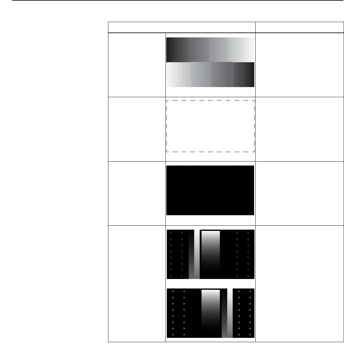
Operation
82 LightStyle™ LS-12HBd Installation/Operation Manual
PRELIMINARY
Press MENU to exit test pattern mode.
Grey Bars
Use this pattern when making
brightness, contrast or white
balance (gain/offset) adjustments.
Full White
Use this pattern when measuring
or adjusting brightness, contrast or
white balance (gain/offset).
Primary Alignment
Secondary
Alignment
Dual Alignment
Use this pattern when aligning the
output from the projector’s
primary or secondary optical
engines (refer to Adjusting the
Image Geometry on page 52).
Select Dual Alignment to have
both optical engines output this
pattern.
3D
Use these patterns to confirm that
the left-eye and right eye images
are being processed correctly. To
do this, close your right eye while
viewing this test pattern through
the 3D glasses. If you see only the
left-eye portion, then the system is
correctly configured for 3D.
Normally, the Primary scaler
processes the left-eye image; the
Secondary, the right-eye image.
To change this, use the Reverse
Eyes control in the 3D Processing
menu (refer to Reverse Eyes on
page 71).
Table 4-4. Test Patterns and Their Suggested Usage (continued)
Pattern Suggested Usage
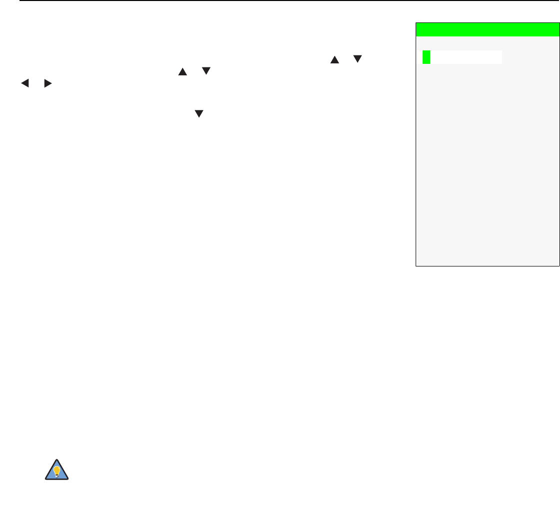
Operation
LightStyle™ LS-12HBd Installation/Operation Manual 83
PRELIMINARY
Input Names: You can give each input a descriptive name. For example, you may want
to change the default input name to the type of source component connected to it:
“VCR,” “DVD,” “Laptop” et cetera. Input names can be up to 12 characters long.
To edit an input name, select Input Names from the Service menu. Press or to select
an input and press ENTER. Use the or buttons to change a character; press
or to select a character to change. When you have finished editing the input name,
press ENTER or MENU.
To restore the default input name, press repeatedly to highlight that input name in the
“Restore” column. Then, press ENTER.
Remote Control: Select Remote Control from the Service menu to set the following
options:
• Remote Code: Select Remote Code from the Remote Control menu to set the
infrared (IR) custom code (address) that the Dimension Digital Controller will accept as
valid IR data. By default, it is set to 08209 (0x2011). You can change this setting if:
• Another device in the theater (a DVD player, for example) is responding to
commands from the Dimension Digital Controller remote control (Figure 2-7) in ways
that are unpredictable or undesirable; or
• You have multiple Dimension Digital Controllers and want to control them
independently, as opposed to broadcasting commands from a single remote to all of
them. In this scenario, you can use multiple remotes programmed to use different IR
codes. Or, you can use a single remote and change the IR code as needed to
address a specific Dimension Digital Controller.
After changing the Remote Code, press EXIT to have the new code take effect.
Input Names
Restore
C o mp o s i t e 1 Composite 1
C o mp o s i t e 2 Composite 2
C o mp o s i t e 3 Composite 3
C o mp o n e n t Component
H D 1 HD 1
H D 2 HD 2
S C A R T SCART
H D M I 1 HDMI 1
H D M I 2 HDMI 2
H D M I 3 HDMI 3
H D M I 4 HDMI 4
H D M I 5 HDMI 5
H D M I 6 HDMI 6
H D M I 7 HDMI 7
H D M I 8 HDMI 8
D i s p l a y P o r t DisplayPort
Use the Dimension Digital Controller front-panel keypad to change
the IR code to which the controller will respond. Then, change the
code sent by the remote to match as described below.
Tip
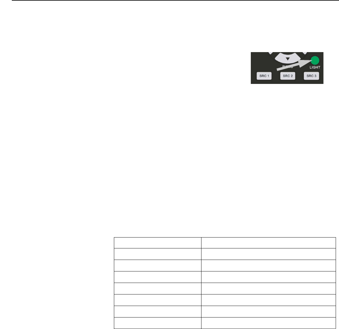
Operation
84 LightStyle™ LS-12HBd Installation/Operation Manual
PRELIMINARY
When you change the Remote Code on the Dimension Digital Controller, you must
re-program the Dimension Digital Controller remote control to send that same code. To
enable “extended” key code mode, you must re-program the Dimension Digital
Controller remote control with a special five-digit code reserved for that purpose.
To do this:
1. Press and hold the LIGHT button on the
remote control for approximately five seconds,
or until the LED on the remote lights solid red.
2. Enter a new five-digit code between 00000 and
65535 inclusive;
— OR —
To enable extended key code mode, enter 88999. This mode allows certain
buttons to perform alternate functions; refer to LS-12HBd Remote Control Unit
on page 14. (To switch from extended mode back to standard mode, enter any
valid code other than 88999.)
Include leading zeros for codes with four or fewer digits; for example, enter 255 as
00255.
3. The LED turns off to confirm the code change. If you enter an invalid code, the LED
flashes for three or four seconds. Try again, entering a valid code.
For more information on using standard and extended remote control key codes, refer
to Using Discrete IR Codes on page 117.
•SRC 1-7 Keys / SRC 8-14 Keys: Select SRC 1-7 Keys or SRC 8-14 Keys from the
Remote Control menu to assign the source selection buttons to the source inputs on
the Dimension Digital Controller (refer to SRC 1, SRC 2 ... SRC 14 on page 17). By
default, these buttons are assigned as follows:
Remote Control Button Default Source Assignment
SRC 1 ... SRC 8 HDMI 1 ... HDMI 8
SRC 9 DisplayPort
SRC 10 Component
SRC 11 HD 1
SRC 12 HD 2
SRC 13 Composite 1
SRC 14 Composite 2
Operation
LightStyle™ LS-12HBd Installation/Operation Manual 85
PRELIMINARY
To change a button assignment, select the corresponding entry in the SRC 1-7 Keys or
SRC 8-14 Keys sub-menu. Then, choose the source input you wish to assign to that
button.
Display Device - Configure: The options in the Display Device - Configure menu allow
you to change the picture orientation, perform lens adjustments or access other,
display-device specific functions.
•Installation – Orientation: Select Installation from the Display Device - Configure
menu, then select Orientation to change the picture orientation to suit the method of
installation (Floor Front, Floor Rear, Ceiling Front or Ceiling Rear). Or, for
front-projection installations, use the Auto setting to have the projector automatically
determine the orientation (floor or ceiling) using an internal sensor.
•Lens: Select Lens from the Display Device - Configure menu to access the motorized
lens controls. Refer to Primary Lens Adjustments: Focus, Zoom and Position on
page 51.
•Display Info.: Select Display Info. from the Display Device - Configure menu to see the
projector serial number and lamp usage information (number of hours in service).
•Lamp Hours Reset: When you replace a projector lamp (refer to Lamp
Replacement on page 97), you should also reset its lamp hour counter to zero so that
the lamp usage information in the Display Info. window is accurate. To do this, select
Lamp Hours Reset from the Display Device - Configure menu. Then, select Lamp
Hours Reset. A confirmation dialog box appears. Select “Yes” to continue with the
reset or “No” to cancel the operation.
•Diagnostics: Select Diagnostics from the Display Device - Configure menu, then
select Red, Green, Blue, Yellow, Cyan or Magenta to display only that color channel
(simulating a filter of that color). This can be useful for calibration or measurement
purposes.
To restore the normal picture (all colors), select White.
• Altitude: Select Altitude from the Display Device - Configure menu to control the
operation of the projector’s cooling fan.
In most cases, the default setting (Auto) will maintain the correct operating
temperature. If the lamp frequently turns off due to overheating, or in certain
high-altitude operating environments, you may need to change this setting to High.
SRC 1 Key
Composite 1
Composite 2
Composite 3
Component
HD 1
HD 2
SCART
ÎHDMI 1
HDMI 2
HDMI 3
HDMI 4
HDMI 5
HDMI 6
HDMI 7
HDMI 8
DisplayPort

Operation
86 LightStyle™ LS-12HBd Installation/Operation Manual
PRELIMINARY
•Display 3D Settings: The Display 3D Settings menu is not applicable to the
LS-12HBd.
• Internal 3D Settings: Select Internal 3D Settings from the Display Device - Configure
menu to adjust the following timing settings for the Dimension Digital Controller’s
3D Sync output (see Figure 2-6 and Figure 3-21), to optimize performance of the
glasses, emitter and projector, for realistic simulation and 3D images.
•Sync Delay: This control adjusts the output 3D emitter delay to match the active
glasses to the left/right frames of the projector. Proper adjustment of this delay will
eliminate crosstalk and odd colors caused by timing differences between the
glasses and the projected image.
•Test Pattern Enable: To display the 3D test pattern (refer to Test Video on
page 81) while adjusting these settings, check the Test Pattern Enable box.
• 24Hz 3D Mode: This control selects how 24Hz 3D content will be processed in an
active 3D system. Lower frame rates can lead to excessive flickering, creating a need
for frame rate conversion (FRC) to 60Hz in each eye (120Hz total). The FRC modes are
as follows:
•120Hz 6:4 (default) – Perform FRC using a 3:2 cadence for each eye (3 frames
of A followed by 2 frames of B), resulting in 60Hz per eye, or 120Hz total.
•120Hz 5:5 – Perform FRC using a 3:2 cadence for the left eye (3 frames of A
followed by 2 frames of B) and a 2:3 cadence for the right eye (2 frames of A
followed by 3 frames of B), resulting in 60Hz per eye, or 120Hz total. This mode
is intended to help reduce judder created in the FRC process.
Network: The options in the Network menu allow you to configure the network
communication features.
• IP Configuration: Select IP Configuration from the Network menu to either set the IP
address, subnet mask and default gateway of the Dimension Digital Controller manually
or obtain these settings automatically, from a DHCP (Dynamic Host Configuration
Protocol) server. (Most broadband routers and gateways support DHCP.) You can also
test the network connection from this menu.
•DHCP: To enable the DHCP client in the Dimension Digital Controller, select DHCP
from the IP Configuration menu and set it to On. With this setting, the Dimension
Digital Controller’s IP address, subnet mask and default gateway are assigned by
the local DHCP server.
To manually configure these values, set DHCP to Off.
•IP Address: Select IP Address from the IP Configuration menu to manually
configure the IP Address of the Dimension Digital Controller, as follows:
1. Press or to select the first, second, third or fourth byte of the address.
2. Press or to set the value of that byte. The range is from 0 to 255 inclusive.
3. Repeat Steps 1 and 2 for all four bytes of the address.
4. Press MENU when you have finished setting the address.
•Subnet Mask: Select Subnet Mask from the IP Configuration menu to manually
configure the IP subnet mask. The procedure is similar to that for setting the IP
address.
The IP Address, Subnet Mask and Default Gateway items in the IP
Configuration menu are disabled (grayed out) when DHCP is
enabled.
Note

Operation
LightStyle™ LS-12HBd Installation/Operation Manual 87
PRELIMINARY
•Default Gateway: Select Default Gateway from the IP Configuration menu to
manually configure the default IP gateway. The procedure is similar to that for setting
the IP address.
•Communication Test: Select Communication Test from the IP Configuration menu
to verify proper operation of the network communication link.
To start the test, select Start Test from the Communication Test menu. The
Dimension Digital Controller displays the message “Performing Communication
Test.” When the test completes, the Dimension Digital Controller displays either
“Failed” (along with the error that occurred) or “Succeeded.”
• Auto Firmware Upgrade: Select Auto Firmware Upgrade from the Network menu to
enable automatic detection of a newer version of the Dimension Digital Controller
firmware. If one is found, you can configure the Dimension Digital Controller to install it
automatically. These features make it easier to keep your Dimension Digital Controller
firmware up-to-date.
•Auto Check For New Firmware: To have the Dimension Digital Controller
automatically check for firmware updates at periodic intervals, select Auto Check for
New Firmware from the Auto Firmware Upgrade menu and set it to On. If you prefer
to do this manually, set it to Off and use the Check For New Firmware sub-menu
(described below).
•Auto Perform Upgrade: If the “Auto Check For New Firmware” process
determines that a newer firmware version than the one currently installed is available,
you can have the Dimension Digital Controller automatically download and install it.
To do this, select Auto Perform Upgrade from the Auto Firmware Upgrade menu
and set it to On. The upgrade will occur the next time the Dimension Digital
Controller is “power-cycled” (powered off, then on again). If you prefer to do this
manually, set it to Off. The Dimension Digital Controller will ask if you want to
perform the upgrade the next time it is power-cycled.
•Check For New Firmware: To have the Dimension Digital Controller check for new
firmware on demand (and perform an upgrade if it finds a new version), select Check
For New Firmware from the Auto Firmware Upgrade menu. If the Dimension Digital
Controller finds a new firmware version, select Yes to perform the upgrade or No to
return to the previous menu.

Operation
88 LightStyle™ LS-12HBd Installation/Operation Manual
PRELIMINARY
• E-Mail Notification: Select E-Mail Notification from the Network menu to specify
when and to whom the Dimension Digital Controller sends error and service notification
messages via e-mail.
The notification messages are in the following format:
To: [E-Mail Address; see below]
From: do-not-reply@runco.com
Subject: [Type of notification] from Runco DC-300
Body:
This is an automated message sent from the Runco DC-300:
Notification: [One of the following:
“DC-300 Error” / “Display Error”
“Periodic Service Notification”
“Lamp Life Notification” / “Calibration Data”]
Detailed Description: [ If a DC-300 Error, one of the following:
“Fan Failure 1” / “Fan Failure 2”
“Overtemp 1” / “Overtemp 2”
“Initialization Failure”
If a Display Error, a device-specific
error message such as “Lamp Door Open”
If a Periodic Service Notification, the elapsed
time since the last notification
If a Lamp Life Notification, the number of hours
the lamp has been in service
If a Calibration Data message,
“See Attached File” ]
Serial Number: [Dimension Digital Controller serial number]
Customer Information: [From “Customer Information“ sub-menu;
see below]
Best Regards,
Runco International, LLC
1195 NW Compton Drive
Beaverton, OR 97006
1-800-237-8262
•E-Mail Address: To specify the destination e-mail address for error and service
notifications, select E-Mail Address from the E-Mail Notification menu. The
procedure is similar to that for setting the IP address (refer to IP Configuration on
page 86). Enter up to 45 alphanumeric characters.
•Error Notification: To have the Dimension Digital Controller send a message to the
destination e-mail address when a “DC-300 Error” or “Display Error” occurs, select
Error Notification from the E-Mail Notification menu and set it to On.
•Error Notification to Runco: To have the Dimension Digital Controller send an
e-mail message to Runco Customer Support when a “DC-300 Error” or “Display
Error” occurs, select Error Notification to Runco from the E-Mail Notification menu
and set it to On.

Operation
LightStyle™ LS-12HBd Installation/Operation Manual 89
PRELIMINARY
•Periodic Service Notification: You can have the Dimension Digital Controller send
periodic reminders via e-mail to perform regular maintenance tasks. To do this:
1. Select Periodic Service Notification from the E-Mail Notification menu.
2. Highlight Enable and press ENTER.
3. Highlight On and press ENTER.
4. Press MENU.
5. Highlight Timer and press ENTER.
6. Press or to set the notification interval in months. The range is from 1 to
255 inclusive; the default is 12 months.
7. Press MENU.
•Lamp Life Notification: To have the Dimension Digital Controller send a message
to the destination e-mail address when the lamp hour counter reaches a certain
threshold, select Lamp Life Notification from the E-Mail Notification menu. Then:
1. Highlight Enable and press ENTER.
2. Highlight On and press ENTER.
3. Press MENU.
4. Highlight Lamp Hours and press ENTER.
5. Press or to set the notification threshold in hours. The range is from 100 to
10,000 hours; the default is 1,000 hours.
6. Press MENU.
•Customer Information: Select Customer Information from the E-Mail Notification
menu to supply this information to the Dimension Digital Controller, which includes it
in all e-mail notification messages. Six lines (up to 30 characters per line) of text are
provided; use them however you wish.
1. Press or repeatedly to select a line of text to edit.
2. Press ENTER.
3. Press or repeatedly to set the highlighted character.
4. Press (or ) to select the next (or previous) character. Use the and
buttons to change it.
5. Press ENTER when you have finished editing that line of text.
6. Repeat Steps 1 through 5 for each line of text you want to edit.
7. Press MENU when you have finished entering customer information.
•E-Mail Calibration Data: To have the Dimension Digital Controller collect all
calibration data, attach it to a message and send it to the destination e-mail address,
select E-Mail Calibration Data from the E-Mail Notification menu. To confirm this
action, select Yes and press ENTER.
To cancel and return to the previous menu, select No.
Operation
90 LightStyle™ LS-12HBd Installation/Operation Manual
PRELIMINARY
• Remote Network Control: Select Remote Network Control from the Network menu
to enable or disable control of the Dimension Digital Controller via an IP connection
(typically using a web browser). Set it to On to allow all incoming remote network
connectivity. Set it to Off to disable any incoming network communication that was not
initiated by the Dimension Digital Controller.
Color Space: Select Color Space from the Service menu to choose the color space of
the source signal for HDMI, RGB, and component connections.
• The default setting, Auto, functions as follows:
•HDMI: If the Auxiliary Video Information (AVI) infoframe contains color space and/or
range data, the Dimension Digital Controller uses that information. Otherwise, for
RGB sources, the Dimension Digital Controller uses the RGB-Video color space.
For component SDTV and EDTV resolutions, REC601 is used. For other component
video resolutions, REC709 is used.
•RGB: If Hsync or Vsync signals are present, the Dimension Digital Controller uses
the RGB-PC color space. Otherwise, REC601 is used for SDTV and EDTV sources,
and REC709 for all other sources.
•Component: For SDTV and EDTV resolutions, the Dimension Digital Controller uses
the REC601 color space. For all other resolutions, REC709 is used.
In most cases, the Auto setting determines the correct color space to use. If it does not,
you can force the Dimension Digital Controller to use a specific color space. Choose one
of the following:
•REC709 sets the color space matrix to that defined in ITU-R BT.709.
•REC601 sets the color space matrix to that defined in ITU-R BT.601.
•RGB-PC uses RGB color space and sets black at 0,0,0 RGB and white at
255,255,255 RGB, assuming an 8-bit image.
•RGB-Video uses RGB color space and sets black at 16,16,16 RGB and white at
235,235,235, assuming an 8-bit image, to correspond to the luminance values defined
in digital component standards.
Triggers: Select Triggers from the Service menu to configure the 12-volt trigger outputs.
You can assign one or more trigger outputs to each aspect ratio. Those triggers are then
activated by selecting that aspect ratio.
This setting has no effect on the E-Mail Notification or Auto
Firmware Upgrade functions.
Note
Operation
LightStyle™ LS-12HBd Installation/Operation Manual 91
PRELIMINARY
Miscellaneous: Select Miscellaneous from the Service menu to set the following options:
• Language: Select Language from the Miscellaneous menu and press the up- or
down-arrows to select the OSD Language (English, Français, Deutsch, Italiano,
Español, Svenska, (Simplified Chinese), (Traditional Chinese),
Português, (Russian), (Japanese) or (Korean)).
•OSD Timer: Select OSD Timer from the Miscellaneous menu to set the OSD Timer,
which controls how long the menus remain on-screen after selecting them. Select from
5 to 60 seconds, in one-second increments. Or, set the timer to 0 (disabled) if you want
the menus to remain on-screen indefinitely.
•OSD Messages: When you select a new aspect ratio, input source or memory preset,
the Dimension Digital Controller briefly displays an on-screen message confirming your
new selection. To prevent the display of these messages, select OSD Messages from
the Miscellaneous menu to and set it to Off.
•Blank Screen Color: Select Blank Screen Color from the Miscellaneous menu to
select the color that appears when no incoming signal is present. The range is from 0
to 255 inclusive for each color component (red, green and blue).
•Sidebar Color: Select Sidebar Color from the Miscellaneous menu to change the
color of the inactive image area. The range is from 0 to 255 inclusive for each color
component (red, green and blue). The inactive image area is on either side of the active
image area when using the 4:3 aspect ratio.
• Film Mode: Use Film Mode to smooth out moving images from interlaced,
standard-definition (SD) sources. In most cases, the Dimension Digital Controller
detects the proper “pull-down” rate and vertical frequency. However, if your source is
jittery and/or tearing you may want to enable Film Mode to ensure stable processing for
that source.
•CUE (Chroma Upsampling Error) Correction: Some DVD players use MPEG
decoders that do not correctly “upsample” the 4:2:0 format chroma information on the
DVD to the 4:2:2 or 4:4:4 format required by the video encoder of the display device.
This so-called “chroma bug” sometimes causes streaky or spiky horizontal lines
running through the chroma channel. It is most noticeable in static, interlaced scenes
and on diagonal edges (especially red ones). Set CUE to On to correct this issue.
•Sync Threshold: Select Sync Threshold to adjust the threshold at which negative
pulses on the component video green/luma channel are interpreted to be sync pulses.
Sync Threshold adjustment is occasionally necessary when a DVD player or HDTV
source signal drops “below black” (for example, during scenes with explosions or when
subtitles are present) and causes the projector to temporarily lose sync. If the sync level
from the source is persistently too low, the display device won’t sync with the source at
all.
The range is from 0 (approximately 60 millivolts (mV)) to 15 (approximately 300 mV).
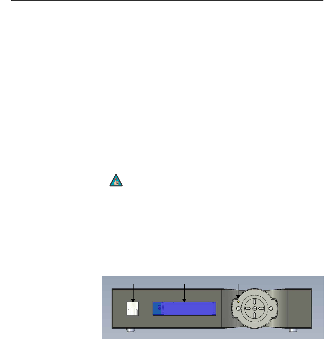
Operation
92 LightStyle™ LS-12HBd Installation/Operation Manual
PRELIMINARY
HDMI: Select HDMI from the Service menu to set the following options affecting
communication between HDMI sources, the Dimension Digital Controller and the
LS-12HBd.
• HDMI EDID Extension: Extended display identification data (EDID) is a data structure
provided by a display device to describe its capabilities to a graphics card. It is what
enables a modern personal computer to know what kind of monitor is connected.
Some modern display devices provide more information via EDID than others, in the
form of “extensions.” Some computer graphics cards do not recognize or properly
interpret this extended EDID information.
Select HDMI EDID Extension from the HDMI menu to specify whether or not the EDID
extensions from the display device are passed through to the sources connected to the
HDMI and/or DisplayPort inputs. By default, the extensions are on. Change these
settings only if HDMI EDID incompatibility issues arise.
•Audio Format: Select Audio Format from the HDMI menu to choose an option for
routing the audio signal from an HDMI source. With the LS-12HBd, the recommended
setting is HDMI Out (Audio Only). (This is also the default setting.)
•CEC: This control chooses whether or not the Dimension Digital Controller responds to
HDMI CEC control messages from a disc player, set-top box or other HDMI source.
The default setting is On. For more information about CEC, refer to Using HDMI CEC
Messages on page 122.
• HPD Toggle Rejection: Select HPD Toggle Rejection from the HDMI menu to specify
whether or not the Dimension Digital Controller ignores extraneous Hot Plug Detect
(HPD) signal state changes from a downstream HDMI device (third-party display or
audio/video receiver).
The default setting, Auto, disables HPD toggle rejection on the LS-12HBd. Use the
other settings to troubleshoot compatibility issues or reduce the amount of time
needed to lock to an incoming signal.
Front Panel Brightness: Select Front Panel Brightness from the Service menu to adjust
the brightness of the front-panel LED and LCD status indicators.
The Dimension Digital Controller does not transmit HDMI CEC
control messages from the “HDMI Audio Out” connector,
regardless of the CEC setting.
Note
Logo LED LCD Standby LED
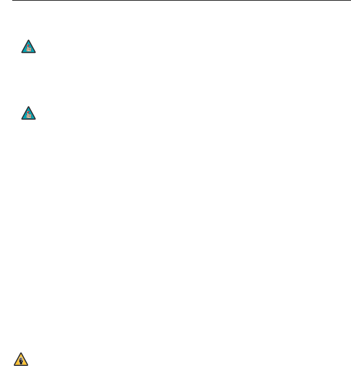
Operation
LightStyle™ LS-12HBd Installation/Operation Manual 93
PRELIMINARY
• Logo LED: Select Logo LED from the Front Panel Brightness menu to adjust the
brightness of the large, illuminated logo on the left side of the display. The range is from
0 (off) to 31.
•Standby LED: Select Standby LED from the Front Panel Brightness menu to change
the behavior of the front-panel STANDBY indicator LED. When set to ON, the LED
lights amber when the system is in standby mode; otherwise, it is off. When set to OFF,
the LED is always off.
• LCD: Select LCD from the Front Panel Brightness menu to adjust the brightness of the
front-panel LCD. The range is from 0 (off) to 4.
Auto Power Off: Select Auto Power Off from the Service menu to have the LS-12HBd
turn itself off after a specified period of time.
•Enable: By default, Auto Power Off is set to No Signal. With this setting, the
LS-12HBd powers off after a specified period of inactivity (no source signal present). To
change this behavior, select Enable from the Auto Power Off sub-menu. Then, set it to
On to have the LS-12HBd power off after the specified time period whether a source
signal is present or not. Or, set it to Off to disable this feature altogether.
•Hours: Select Hours from the Auto Power Off sub-menu to specify the number of
hours after which the LS-12HBd should power off. The default time-out period is one
hour; the range is from 1 to 24 hours.
Standby Mode: Select Standby Mode from the Service menu to control the Dimension
Digital Controller’s power management feature.
•Choose Low Power (the default setting) to have the Dimension Digital Controller shut
down completely when it is turned off. This conserves power but increases the amount
of time required by the Dimension Digital Controller to start up when it is turned on.
•Fast Startup is a “quick-start” mode that keeps the Dimension Digital Controller
running when it is turned off, even though it appears to be in standby mode. This
results in much quicker startup times but consumes more power.
System Reset: To reset ALL controller settings (including image settings) back to their
factory defaults, choose System Reset from the Service menu.
A confirmation message appears. Select Yes to continue with the reset or select No to
cancel.
During a firmware upgrade, this LED lights at full brightness
regardless of the Logo LED setting.
During a firmware upgrade, this LED lights at full brightness
regardless of the Standby LED setting.
This action is not undoable. Proceed with caution! Before you
perform a System Reset, save your “Custom” Memory Presets
(page 70) and ISF Day/Night Memory Presets (page 78).
Note
Note
Caution
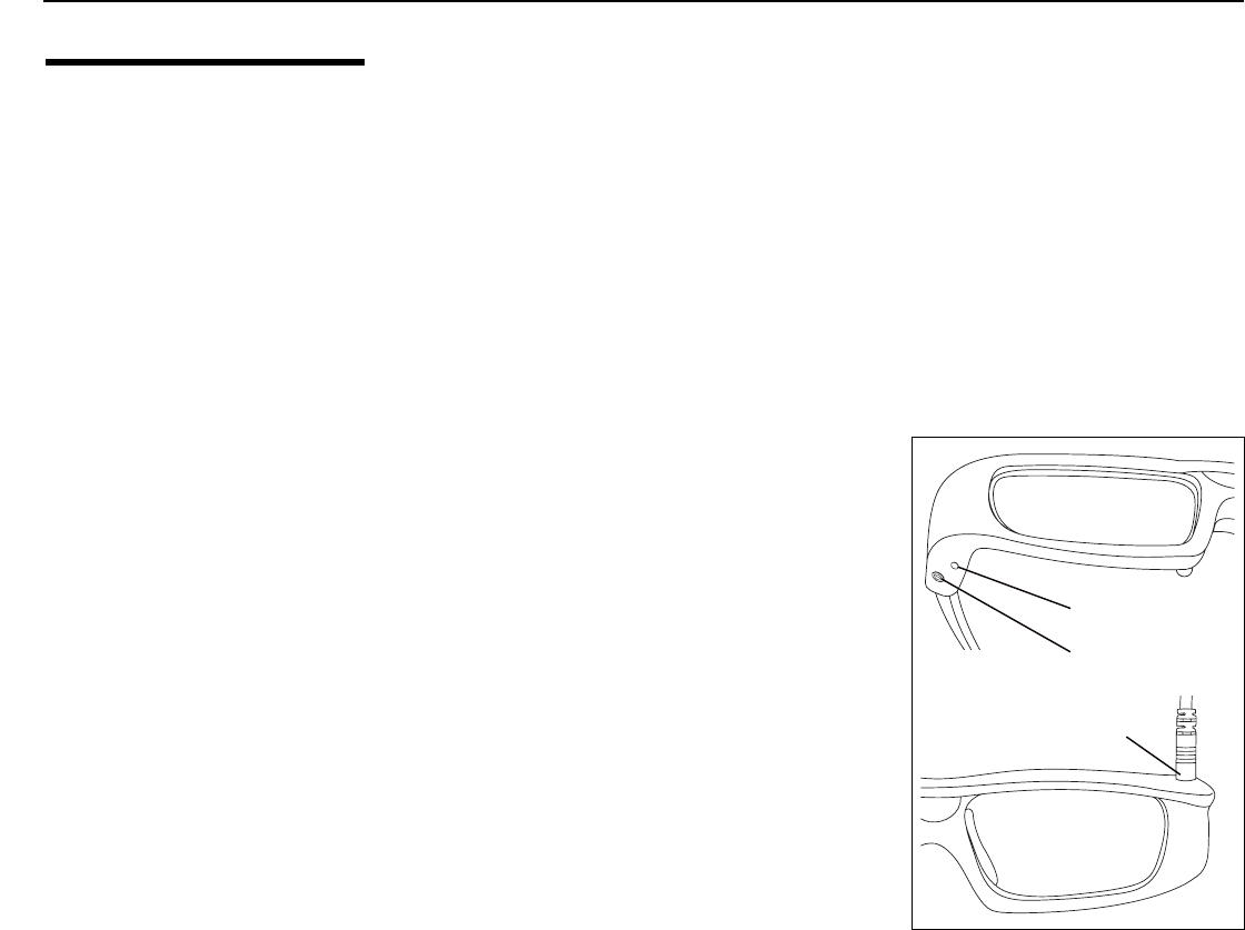
Operation
94 LightStyle™ LS-12HBd Installation/Operation Manual
PRELIMINARY
4.2
Using the 3D Glasses
The 3D LCD Shutter Glasses function with the Runco Active 3D Emitter and the projector
to provide unsurpassed 3D stereoscopic viewing. This section describes the features,
connection, setup and operation of the 3D LCD Shutter Glasses.
Key Features • RF synchronization for uninterrupted 3D performance
• Supports refresh rates from 50 to 240 Hz for compatibility with both current and future
3D technology
• High contrast ratio, high uniformity and fast response time for an excellent 3D
experience
• Rechargeable battery provides up to 15 hours of 3D viewing per charge
• Battery charge indicator lets you know remaining operating time
Functional Overview The 3D LCD Shutter Glasses have the following key
functional components:
•Battery Status LED
Indicates battery charge state as described in the
following sections, Charging the Battery and
Turning On the Glasses.
•Power Button
Press to turn the glasses on or off.
•Power Input
To charge the glasses, connect this input to your
PC or other USB power source, using the included
charging cable.
➤
➤
Battery Status
LED (Red/Blue)
Power Button
Power
Input
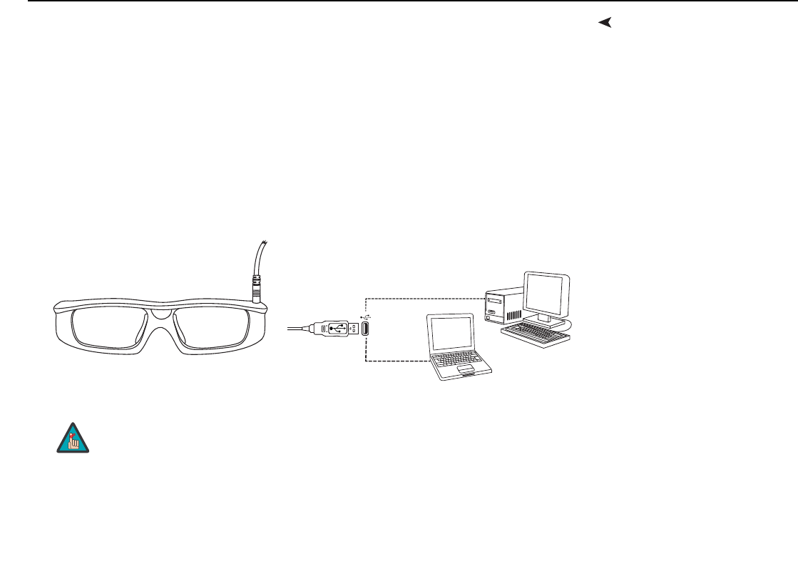
Operation
LightStyle™ LS-12HBd Installation/Operation Manual 95
PRELIMINARY
Charging the BatteryThe glasses must be fully charged before first use and whenever the Battery Status LED
flashes red once every couple of seconds. The glasses will charge a completely dead
battery in approximately five hours. You may use the glasses while the battery is being
charged.
To charge the 3D Glasses:
1. Attach one end of the supplied charging cable to the Power Input above the left lens
on the glasses.
2. Attach the other end of the cable to any USB “A” port on a USB hub, personal
computer or display device. The Battery Status LED lights solid red while the battery is
charging.
3. When the Battery Status LED lights solid blue, the battery is fully charged. You can
disconnect the glasses from the power source.
The battery in the 3D glasses is designed to operate approximately 15 hours on a full
charge. The glasses consume more power as needed to maximize reliability. As a result,
battery life is a function of many factors, including how much interference from 2.4-GHz
devices like wireless routers must be compensated. Under worst-case conditions,
fully-charged glasses should operate flawlessly for a minumum of about 12 hours.
When attached to a computer, the Runco Active 3D Glasses use
the computer only to receive power; the glasses do not appear as a
device visible to Windows or any other operating system.
Note
Operation
96 LightStyle™ LS-12HBd Installation/Operation Manual
PRELIMINARY
Turning On the Glasses 1. Ensure that the projector is powered on and displaying 3D content.
2. Press and hold the Power Button for about two seconds, then release the button. The
LED will then blink in a pattern that indicates the battery charge state. In general, the
more slowly and less frequently the LED blinks, the more charged (and less in need of
charge) the glasses are. Refer to Table 4-5.
3. The glasses will sync with the emitter and the 3D content will be visible through the
glasses.
4. Repeat Step 2 for each pair of glasses you wish to sync to the emitter.
Auto Power-Off If the glasses do not detect an emitter, the LED blinks on and off once per second for five
minute. Then, to preserve battery life, the glasses automatically turn off. If the emitter is
activated (the emitter is only active when the projector is in 3D mode) before the
five-minute period ends, the glasses stop blinking and remain on.
If the glasses automatically turn off, press the Power button to turn them back on.
➤
Table 4-5. Battery Charge State Indications
Blink Activity After
Power-on Battery Charge State
Three (3) blue blinks (one
second on, one second off)
Battery is fully charged; 12 to 15 hours remaining.
Six (6) blue blinks Battery is 50% charged; approximately 4 hours remaining.
Nine (9) blue blinks Battery is 30% or more charged; approximately 2 hours remaining.
Red blink Battery charge is 10% or less; glasses must be charged before
further use.
➤
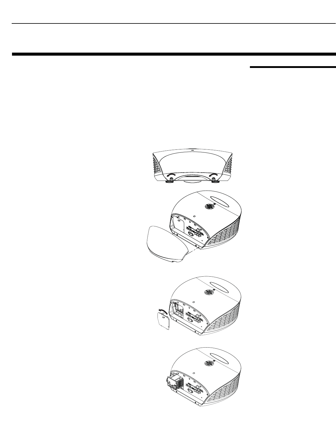
Maintenance and Troubleshooting
LightStyle™ LS-12HBd Installation/Operation Manual 97
PRELIMINARY
5.1
Lamp Replacement
The lamp should be replaced when it reaches the end of its life (typically 2,000 hours), or
sooner if a noticeable degradation in brightness occurs.
Keep track of the number of hours the lamp has been in use and be aware of any changes
to brightness. These indicators will help you effectively maintain operation of the projector.
To find out how long the currently-installed lamp has been in service, select Display Info.
from the Display Device - Configure menu (available by selecting Service -> Display
Device -> Configure -> Display Info., in sequence).
For lamp or filter replacement, please contact your nearest Runco authorized
service center or Runco dealer. Do not attempt to replace the lamp yourself!
1. Turn off the projector and unplug the
power cord. Allow the projector to
cool down for approximately 60
minutes prior to removing the
lamp assembly for replacement.
2. Using a flat-blade screwdriver, loosen
the two screws holding the rear
compartment cover in place.
3. Remove the rear compartment cover
by tilting it upward.
4. Loosen the screw on the lamp cover
and pull the lamp cover out.
5. Loosen the two screws on the lamp
module.
6. Pull the lamp module handle firmly to
remove the lamp module.
7. Perform Steps 6 through 2 (in reverse
order) to install the new lamp module.
8. Turn on the Dimension Digital
Controller and projector.
9. Reset the Lamp Hour counter. To do
this, select Lamp Hours Reset from
the Display Device - Configure menu.
A confirmation dialog box appears.
Select “Yes,” then press ENTER to
continue with the reset or “No” to cancel the operation.
5. Maintenance and Troubleshooting
Maintenance and Troubleshooting
98 LightStyle™ LS-12HBd Installation/Operation Manual
PRELIMINARY
5.2
Troubleshooting Tips
Table 5-1 provides some general guidelines for troubleshooting problems you may
encounter with the LS-12HBd. If the suggested solutions fail to resolve the problem or if
you encounter an issue not described here, please contact Runco Technical Support.
Table 5-1. Troubleshooting Chart
Symptom Possible Cause(s)Solution
The projector does not turn
on.
• The LS-12HBd is not
plugged in and switched
on, or the AC outlet is not
active.
• The Dimension Digital
Controller is not plugged in
and switched on, or the
AC outlet is not active.
•The remote control
batteries have run out.
• The serial connection from
the Dimension Digital
Controller to the
LS-12HBd is incorrect.
• Ensure that the LS-12HBd
is plugged in and switched
on, and that the AC outlet
is active.
• Ensure that the Dimension
Digital Controller is
plugged in and switched
on, and that the AC outlet
is active.
• Replace the batteries.
• Ensure that the Pri.
Display Control output
from the Dimension Digital
Controller is properly
connected to the RS-232C
input on the LS-12HBd
(see Figure 3-9).
The projector and Dimension
Digital Controller are both on,
but there is no picture and
on-screen menus do not
appear.
•Lens cover is on.
• Lamp failed to ignite.
• Faulty or incorrect video
connection between the
Dimension Digital
Controller and the
LS-12HBd.
• Ensure that the lens cover
is off.
• Ensure that the lamp door
is closed. If it is and the
problem persists, replace
the lamp.
• Ensure that the HDMI
output from the Dimension
Digital Controller is
properly connected to the
PRIMARY input on the
LS-12HBd (see Figure
3-9).
The display is on and menus
appear, but there is no
picture.
• Incorrect source selection.
• Source component is not
turned on.
• Source component is
connected incorrectly or
not at all.
• Select the correct source.
• Turn on the source
component.
• Check connections from
source component to
Dimension Digital
Controller.
A projected image from a
DVD is split or otherwise
scrambled.
• DVD player is connected
to the Component input
and set to progressive
scan mode.
• Turn off progressive scan
on the DVD player. Or,
connect the DVD player to
the HD1 or HD2 input.
Image geometry is incorrect. • Incorrect aspect ratio
selection.
• Select a different aspect
ratio.
Maintenance and Troubleshooting
LightStyle™ LS-12HBd Installation/Operation Manual 99
PRELIMINARY
The display is jittery or
unstable.
• Poor-quality or improperly
connected source.
• The horizontal or vertical
scan frequency of the
input signal may be out of
range for the projector.
• Ensure that the source is
properly connected and of
adequate quality for
detection.
• Correct at the source.
Image is too bright and/or
lacks definition in the bright
areas of the image.
• Contrast is set too high. • Lower the contrast setting.
Image appears “washed out”
and/or dark areas appear too
bright.
• Brightness is set too high. • Lower the brightness
setting.
Colors in the image from a
Component video source are
swapped; for example, reds
appear blue or vice versa.
•The Red/Pr, Green/Y or
Blue/Pb outputs from the
source are connected to
the wrong inputs on the
Dimension Digital
Controller.
• Ensure that the source
outputs are connected to
the correct Dimension
Digital Controller
Component input
connector (see Figure
3-17).
The display freezes suddenly. • Excessive voltage noise on
the AC or ground input has
interrupted the projector’s
ability to lock on to a
signal.
• Power down the projector
and disconnect from AC.
Then, plug in again and
power up as usual.
The projector will not turn
back on after it was powered
down, or the image disap-
pears during operation.
• The projector will not turn
on for two minutes after
power-down, to protect
the lamp.
• The lamp has failed.
• Wait until the
STANDBY LED at the front
of the Dimension Digital
Controller turns on
(see Figure 2-5).
• Replace the lamp.
Anamorphic lens transport
does not work.
• The motor is not plugged
in or the AC outlet is not
active.
• The motor is not
connected to a trigger
output on the Dimension
Digital Controller.
• Incorrect trigger
assignment.
• Ensure that the motor is
plugged in and that the AC
outlet is active.
• Check the trigger
connection between the
lens motor and Dimension
Digital Controller
(see Figure 3-11).
• Correct the trigger
assignment (refer to
Installing and Adjusting
the Anamorphic Lens on
page 54).
Table 5-1. Troubleshooting Chart (continued)
Symptom Possible Cause(s)Solution
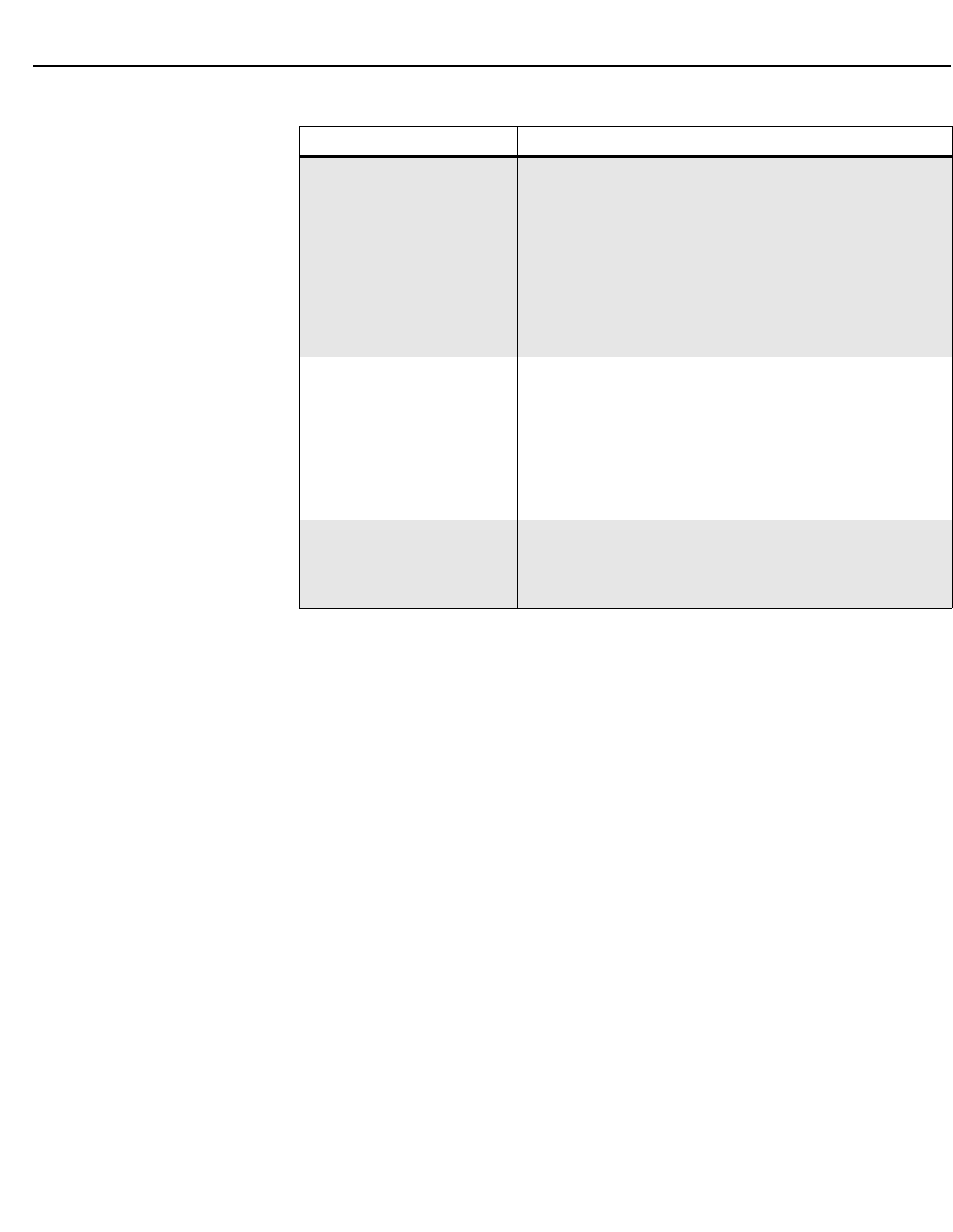
Maintenance and Troubleshooting
100 LightStyle™ LS-12HBd Installation/Operation Manual
PRELIMINARY
The projector does not turn
on or respond to user com-
mands. The vacuum fluores-
cent display on the Dimension
Digital Controller front panel
displays the following mes-
sage:
Primary Display Error
Communication Failure
• The serial connection from
the Dimension Digital
Controller to the display is
incorrect or the cable is
faulty.
• Ensure that the
Pri. Display Control
(RS-232) output from the
Dimension Digital
Controller is properly
connected to the display
(see Figure 3-9).
When displaying 3D content,
crosstalk or “ghosting” can be
seen — that is, the left eye is
perceiving some of what the
right eye should be seeing or
vice versa.
• Primary and Secondary
images are not properly
aligned.
• Rear-projection installation
uses second-surface
mirrors that are producing
faint, secondary
reflections.
• Refer to Adjusting the
Image Geometry on
page 52.
•Always use first-surface
mirrors in your
rear-projection installation.
With 3D glasses, image per-
spective is reversed — that is,
“left-eye“ frames appear in the
right lens and vice versa.
• Incorrect Reverse Eyes
setting.
• Change the
ReverseEyes setting
(refer to Reverse Eyes on
page 71).
Table 5-1. Troubleshooting Chart (continued)
Symptom Possible Cause(s)Solution
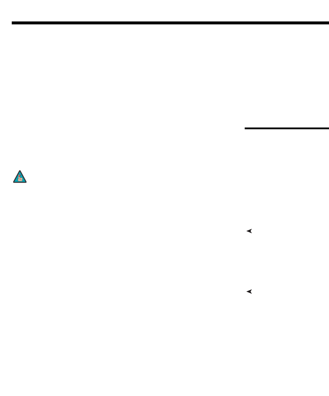
LightStyle™ LS-12HBd Installation/Operation Manual 101
PRELIMINARY
In addition to using the Dimension Digital Controller front-panel keypad or remote control
unit, there are three methods of controlling the LS-12HBd and Dimension Digital
Controller externally:
• Using a serial (RS-232) link to send ASCII commands and receive responses to those
commands.
• Using discrete infrared (IR) codes to program a third-party remote control unit.
• Using an HDMI connection to send Consumer Electronics Control (CEC) commands
from a BD player or other source component that supports CEC.
The following sections describe these methods.
6.1
Serial Communications
The Dimension Digital Controller uses a simple text-based control protocol to take
requests from control devices and to provide responses to such devices. This section
describes how to send control messages over a serial link between the Dimension Digital
Controller and an automation/control system or a PC running terminal emulation software.
RS-232 Connection and
Port Configuration
To interface the LS-12HBd with an automation/control system or a PC running terminal
emulation software, connect it to the Dimension Digital Controller as shown in Figure 3-9.
Connect your control system or PC to the RS-232 input of the Dimension Digital
Controller; see Figure 3-11.
Configure the RS-232 controller or PC serial port as follows: no parity, 8 data bits, 1 stop
bit and no flow control. Set the baud rate to 19200, to match that of the Dimension Digital
Controller RS-232 port.
Command FormatCommands sent from an automation/control system or PC to the Dimension Digital
Controller must have the following format:
(www:xyz) [CR]
Where:
•( and ) indicate the start and end of the command data. If these characters are
present, the Dimension Digital Controller assumes that valid command data is present
in the command string. Otherwise, the Dimension Digital Controller ignores the
command.
•www indicates the command code. This field is case insensitive; for example, PWR, pwr
and PwR are all equivalent.
•:x is the destination parameter. This is an optional parameter that indicates which
memory the command is referencing. This parameter is reserved for future use.
6. External Control
The serial communication protocol described here replaces the
serial protocol used by legacy Runco products (manufactured prior
to September 2011) that include the DHD Controller.
Runco recommends using this new protocol, as it is more concise
and provides greater control than the old one. However, to maintain
backward compatibility with existing automation/control system
modules, the legacy Runco serial protocol is also supported.
Note

External Control
102 LightStyle™ LS-12HBd Installation/Operation Manual
PRELIMINARY
•y is the operand, which can have one of the following values:
? = “Get” operand + = “Increment” operand
= = “Set” operand - = “Decrement” operand
•z is the value to set for this parameter. It can have one of two formats:
•Integer value: Any positive or negative number; for example, 100.
•String value: Any string surrounded by double quotes; for example, “This is a
string.”
•[CR] is the ASCII carriage return key (0x0D).
Response Format Responses sent from the follower to the initiator shall have the following format:
(u;www:x=z) [CR]
Where:
•( and ) indicate the start and end of the command data. If these characters are
present, the Dimension Digital Controller assumes that valid command data is present
in the command string. Otherwise, the Dimension Digital Controller ignores the
command.
• “u;” indicates the response code. This is only used by followers responding to a valid
CLI command received. For any response code other than 0, the follower echoes back
the command received rather than filling in the fields listed below.
The response code can be one of the following:
• 0 = Command successfully processed
• 1 = Unknown command code
• 2 = Invalid operator
• 3 = Destination parameter not supported
• 4 = Setting not available
• 5 = Setting value not available
• 6 = Setting value not supported
• 7 = String too long
• 8 = Command not supported in standby mode
• 9 = Invalid parameter
• 10 = Error processing command
• 11 = Password not entered
•www indicates the command code. This field is case insensitive; for example, PWR, pwr
and PwR are all equivalent.
•:x is the destination parameter. This is an optional parameter that indicates which
memory the command is referencing. This parameter is reserved for future use.
•z is the new value (for Set, Increment or Decrement commands) or the current value
(for Get commands) for this parameter. It can have one of two formats:
•Integer value: Any positive or negative number; for example, 100.
•String value: Any string surrounded by double quotes; for example, “This is a
string.”
•[CR] is the ASCII carriage return key (0x0D).
➤
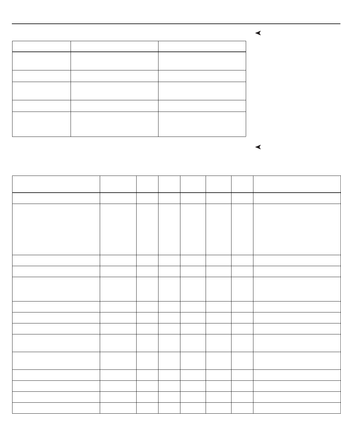
External Control
LightStyle™ LS-12HBd Installation/Operation Manual 103
PRELIMINARY
Command and Response
Examples
Here are some examples of serial commands and their responses:
Serial Command ListTable 6-1 lists all supported commands.
Command Command Data Response
Power query when
unit is powered on (PWR?) [CR] (0;PWR=1) [CR]
Set power to 0 (off) (PWR=0) [CR] (0;PWR=0) [CR]
Increment bright-
ness from 24 to 25 (BRT+) [CR] (0;BRT=25) [CR]
Invalid command (ZZZ=0) [CR] (1;ZZZ=0) [CR]
Invalid parameter
(received string,
expected integer)
(CON=”Some string”)
[CR]
(9;CON=”Some string”)
[CR]
Table 6-1. Serial Commands
Setting Command
Code
Read/
Write
Inc/
Dec
Min
Value
Max
Value String? Notes
PCE Auto Color Enable AAC R/W No 0 1 No 0 = Off; 1 = On
PCE Diagnostic Color AAD R/W No 0 6 No 0 = White
1 = Red
2 = Green
3 = Blue
4 = Yellow
5 = Cyan
6 = Magenta
PCE Blue x ABX R/W Yes -100 100 No
PCE Blue y ABY R/W Yes -100 100 No
Adjustment Mode ADJ R/W No 0 2 No 0 = Both
1 = Left
2 = Right
PCE Green x AGX R/W Yes -100 100 No
PCE Green y AGY R/W Yes -100 100 No
Apply Image Alignment Values AIA R/W No 0 1 No 0 = Off; 1 = On
Altitude ALT R/W No 0 1 No 0 = Auto
1 = High
Advanced Color Temp Mode
Enable
AME R/W No 0 1 No 0 = Off; 1 = On
Auto New Firmware Check ANF R/W No 0 1 No 0 = Off; 1 = On
Auto Power Off Enable APE R/W No 0 2 No 0 = Off; 1 = On; 2 = No Signal
Auto Power Off Timer APT R/W Yes 1 24 No
Auto Perform Upgrade APU R/W No 0 1 No 0 = Off; 1 = On

External Control
104 LightStyle™ LS-12HBd Installation/Operation Manual
PRELIMINARY
Aspect Ratio Copy ARC W No N/A N/A No Action will be performed on any
setting value
Aspect Ratio Paste ARP W No N/A N/A No
PCE Red x ARX R/W Yes -100 100 No
PCE Red y ARY R/W Yes -100 100 No
Aspect Ratio ASP R/W No 0 6 No 0 = 4:3
1 = 16:9
2 = Letterbox
3 = VirtualWide
4 = Cinema
5 = Virtual Cinema
6 = Native
7 = Auto Cinema
PCE Test Pattern Enable ATP R/W No 0 1 No 0 = Off; 1 = On
PCE White x AWX R/W Yes -100 100 No
PCE White y AWY R/W Yes -100 100 No
Image Alignment Bottom Left x BLX R/W Yes -100 100 No
Image Alignment Bottom Left y BLY R/W Yes -100 100 No
Image Alignment Bottom Middle y BMY R/W Yes -100 100 No
Brightness Offset BRO R/W Yes -50 50 No Picture menu
Brightness BRT R/W Yes -50 50 No Calibration -> Input Image menu
Image Alignment Bottom Right x BRX R/W Yes -100 100 No
Image Alignment Bottom Right y BRY R/W Yes -100 100 No
Blank Screen Blue BSB R/W Yes 0 255 No
Blank Screen Green BSG R/W Yes 0 255 No
Blank Screen Red BSR R/W Yes 0 255 No
CEC Enable CEC R/W No 0 1 No 0 = Off; 1 = On
Chroma Delay CHR R/WYes07No
Color Gamut CLG R/WYes06No0 = Auto
1 = REC709
2 = SMPTE C
3 = EBU
4 = Native
6 = PCE
Color Offset CLO R/W Yes -50 50 No Picture menu
Color CLR R/W Yes -50 50 No Calibration -> Input Image menu
Color Space CLS R/W No 0 4 No 0 = REC601
1 = REC709
2 = RGB
3 = RGB Video
4 = Auto
Table 6-1. Serial Commands (continued)
Setting Command
Code
Read/
Write
Inc/
Dec
Min
Value
Max
Value String? Notes

External Control
LightStyle™ LS-12HBd Installation/Operation Manual 105
PRELIMINARY
Image Alignment Center x CNX R/W Yes -100 100 No
Image Alignment Center y CNY R/W Yes -100 100 No
Contrast CON R/W Yes -50 50 No Calibration -> Input Image menu
Contrast Offset COO R/W Yes -50 50 No Picture menu
Color Temp Simple CTS R/W No 0 4 No 1 = 5500K
2 = 6500K
3 = 7500K
4 = 9300K
CUE CUE R/W No 0 1 No 0 = Off; 1 = On
Display Blue Gain DBG R/W Yes -100 100 No
Display Blue Offset DBO R/W Yes -100 100 No
Default Gateway Byte 1 DE1 R/W Yes 0 255 No
Default Gateway Byte 2 DE2 R/W Yes 0 255 No
Default Gateway Byte 3 DE3 R/W Yes 0 255 No
Default Gateway Byte 4 DE4 R/W Yes 0 255 No
DisplayPort EDID Extension DEE R/W No 0 1 No 0 = Off; 1 = On
Diagnostic Color DGC R/W No 0 6 No 0 = White
1 = Red
2 = Green
3 = Blue
4 = Yellow
5 = Cyan
6 = Magenta
Display Green Gain DGG R/W Yes -100 100 No
Display Green Offset DGO R/W Yes -100 100 No
DHCP DHC R/W No 0 1 No 0 = Off; 1 = On
Display Red Gain DRG R/W Yes -100 100 No
Display Dark Interval DRK R/W Yes Var. Var. No
Display Red Offset DRO R/W Yes -100 100 No
Error Notification ERN R/W No 0 1 No 0 = Off; 1 = On
Table 6-1. Serial Commands (continued)
Setting Command
Code
Read/
Write
Inc/
Dec
Min
Value
Max
Value String? Notes
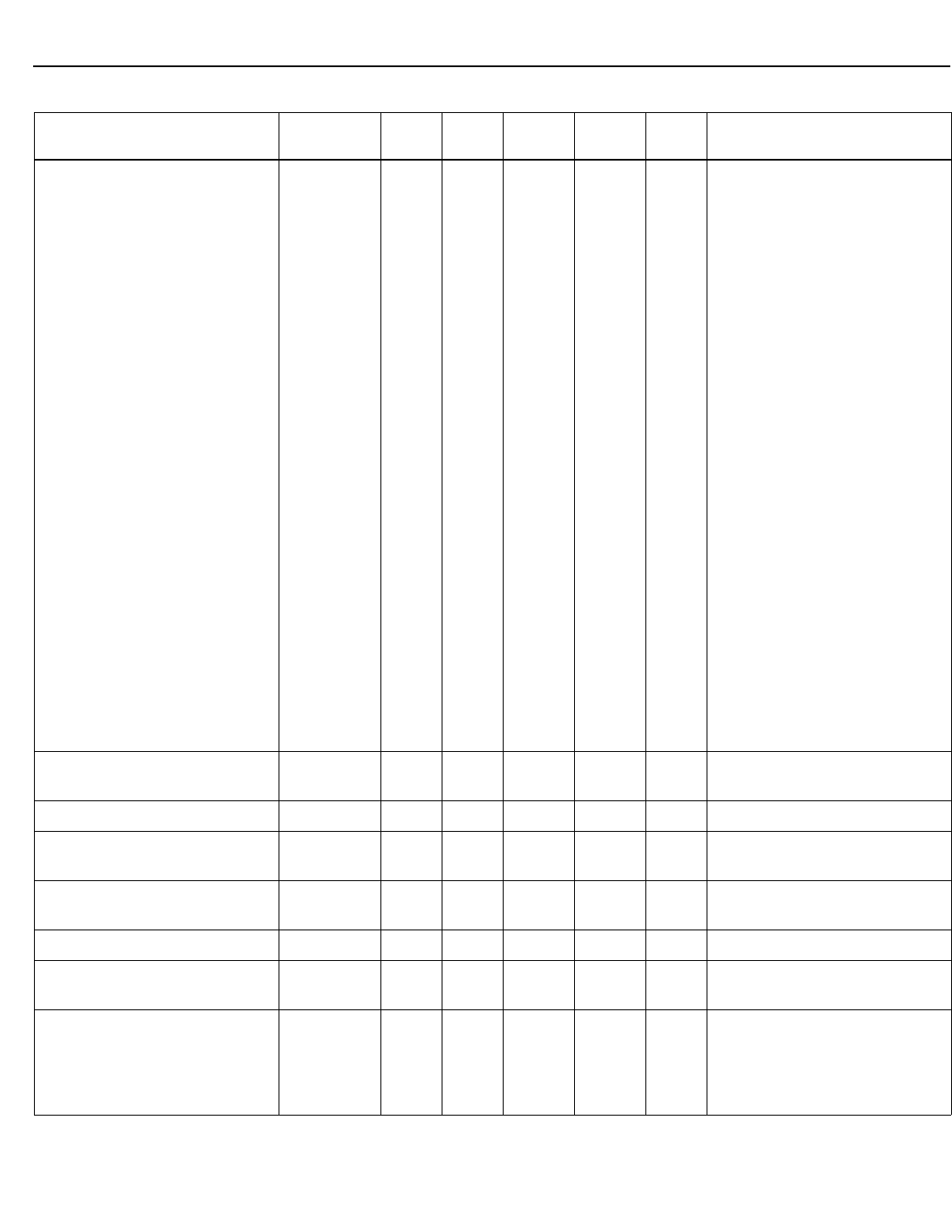
External Control
106 LightStyle™ LS-12HBd Installation/Operation Manual
PRELIMINARY
Error Code ERR R No 0 No 0 = None
1 = Display Lamp Overtemp
2 = Display Ballast Overtemp
3 = Display Fan Init Failure
4 = Display Fan 1 Failure
5 = Display Fan 2 Failure
6 = Display Fan 3 Failure
7 = Display Fan 4 Failure
8 = Display Fan 5 Failure
9 = Display Fan 6 Failure
10 = Display Fan 7 Failure
11 = Display Fan 8 Failure
12 = Display DMD Failure
13 = Display Lamp Strike Failure
14 = Display Lamp Went Out
15 = Display Ballast UART Failure
16 = Display GPIO Failure
17 = Display Lamp Door Open
18 = Display Processor Failure
19 = Display Hardware I2C Failure
20 = Display Software I2C Failure
21 = Display Lamp Error
22 = Display Communication Error
25 = DC-300 Fan 1 Failure
26 = DC-300 Fan 2 Failure
27 = DC-300 Overtemp 1
28 = DC-300 Overtemp 2
56 = DC-300 Fan 3 Failure
58 = DC-300 Overtemp 3
60 = DC-300 Input FPGA Failure
61 = DC-300 Output FPGA Failure
Focus FCS W Yes 0 0 No Send (FCS+) or (FCS-) to
adjust incrementally
Film Mode FLM R/W No 0 1 No 0 = Off; 1 = On
24Hz 3D Mode FRC R/W No 1 2 No 1 = 120Hz 6:4
2 = 120Hz 5:5
Firmware Upgrade FWU W No N/A N/A No Action will be performed on any
setting value
Gamma Advanced GMA R/W Yes 0 20 No
Gamma Mode GMM R/W No 0 1 No 0 = Simple
1 = Advanced
Gamma Simple GMS R/W No 0 4 No 0 = 2.0
1 = 1.8
2 = 2.2
3 = 2.35
4 = 2.5
Table 6-1. Serial Commands (continued)
Setting Command
Code
Read/
Write
Inc/
Dec
Min
Value
Max
Value String? Notes
External Control
LightStyle™ LS-12HBd Installation/Operation Manual 107
PRELIMINARY
HDMI Audio Format HAF R/W No 0 3 No 0 = Combined
1 = HDMI Out (Pri. Display)
2 = HDMI Out (Sec. Display)
3 = HDMI Out (Audio Only)
HDMI EDID Extension 1
HDMI EDID Extension 2
HDMI EDID Extension 3
HDMI EDID Extension 4
HDMI EDID Extension 5
HDMI EDID Extension 6
HDMI EDID Extension 7
HDMI EDID Extension 8
HE1
HE2
HE3
HE4
HE5
HE6
HE7
HE8
R/W No 0 1 No 0 = Off; 1 = On
HPD Toggle Rejection HPD R/W No 0 1 No 0 = Off; 1 = On
Horizontal Shift HSH W Yes 0 0 No Send (HSH+) or (HSH-) to
adjust incrementally
Input Name 1
Input Name 2
Input Name 3
Input Name 4
Input Name 5
Input Name 6
Input Name 7
Input Name 8
Input Name 9
Input Name 10
Input Name 11
Input Name 12
Input Name 13
Input Name 14
Input Name 15
Input Name 16
I01
I02
I03
I04
I05
I06
I07
I08
I09
I10
I11
I12
I13
I14
I15
I16
R/W No N/A N/A Yes 12 characters maximum
Input Blue Gain IBG R/W Yes -32 32 No
Input Blue Offset IBO R/W Yes -32 32 No
Information Boot Version IBV R No N/A N/A Yes
Information Copied Aspect Ratio ICA R No N/A N/A Yes
Information Current Color Space ICC R No 0 3 Yes 0 = REC601
1 = REC709
2 = RGB
3 = RGB Video
Information Copied Input Source ICI R No N/A N/A Yes
Information Copied Memory Pre-
set
ICM R No N/A N/A Yes
Information Copied Screen ICR R No N/A N/A Yes
Information Copied Signal Format ICS R No N/A N/A Yes
Information Display Name IDN R No N/A N/A Yes
Table 6-1. Serial Commands (continued)
Setting Command
Code
Read/
Write
Inc/
Dec
Min
Value
Max
Value String? Notes
External Control
108 LightStyle™ LS-12HBd Installation/Operation Manual
PRELIMINARY
Information Firmware Version IFV R No N/A N/A Yes
Input Green Gain IGG R/W Yes -32 32 No
Input Green Offset IGO R/W Yes -32 32 No
Information Horizontal Frequency IHF R No N/A N/A Yes
Information Input Resolution IIR R No N/A N/A Yes
Information Input FPGA Version IIV R No N/A N/A Yes
information Micro Version IMV R No N/A N/A Yes
Input Source INS R/W No 0 15 No 0 = Composite 1
1 = Composite 2
2 = Composite 3
3 = Component
4 = HD 1
5 = HD 2
6 = SCART
7 = HDMI 1
8 = HDMI 2
9 = HDMI 3
10 = HDMI 4
11 = HDMI 5
12 = HDMI 6
13 = HDMI 7
14 = HDMI 8
15 = DisplayPort
Information Output Resolution IOR R No N/A N/A Yes
Information Output FPGA Version IOV R No N/A N/A Yes
IP Address Byte 1 IP1 R/W Yes 0 255 No
IP Address Byte 2 IP2 R/W Yes 0 255 No
IP Address Byte 3 IP3 R/W Yes 0 255 No
IP Address Byte 4 IP4 R/W Yes 0 255 No
Information Pixel Clock IPC R No N/A N/A Yes
Input Position Height IPH R/W Yes 0 20 No
Input Position Left Right IPL R/W Yes -50 50 No
Input Position Up Down IPU R/W Yes -50 50 No
Input Position Width IPW R/W Yes 0 50 No
Input Red Gain IRG R/W Yes -32 32 No
Input Red Offset IRO R/W Yes -32 32 No
Internal 3D Sync Delay ISD R/W Yes Var. Var. No
Information Signal Format ISF R No N/A N/A Yes
Information Serial Number ISN R No N/A N/A Yes
Table 6-1. Serial Commands (continued)
Setting Command
Code
Read/
Write
Inc/
Dec
Min
Value
Max
Value String? Notes
External Control
LightStyle™ LS-12HBd Installation/Operation Manual 109
PRELIMINARY
Information Sync Type IST R No 0 3 No 0 = None
1 = Separate
2 = Composite
3 = Sync-on-green
Information Vertical Frequency IVF R No N/A N/A Yes
Remote Key KEY W No 0 85 No 1 = On
2 = Off
3 = Menu
4 = Enter
5 = Up
6 = Down
7 = Left
8 = Right
9 = 16:9
10 = 4:3
11 = Letterbox
12 = VirtualWide
13 = Video 1
14 = Component
17 = HD 1
18 = HD 2
19 = HDMI 1
20 = HDMI 2
21 = HDMI 3
22 = HDMI 4
23 = SCART
24 = Video 2
25 = Video 3
32 = Sleep Timer Off
33 = Sleep Timer 30 Mins
34 = Sleep Timer 60 Mins
35 = Sleep Timer 90 Mins
36 = Sleep Timer 2 Hours
37 = Sleep Timer 4 Hours
38 = Screen 1
39 = Screen 2
44 = Cinema
45 = Virtual Cinema
46 = Native
48 = ISF Night
49 = ISF Day
50 = Custom 1
51 = Custom 2
52 = Exit
Remote Key Repeat KRT W No 0 85 No
Table 6-1. Serial Commands (continued)
Setting Command
Code
Read/
Write
Inc/
Dec
Min
Value
Max
Value String? Notes
External Control
110 LightStyle™ LS-12HBd Installation/Operation Manual
PRELIMINARY
Remote Key Repeat (cont.) KRT W No 0 85 No 64 = Keypad Menu
(used internally)
65 = Power Toggle
(used internally)
66 = Enter Key Up (used internally)
67 = SRC 1
68 = SRC 2
69 = SRC 3
70 = SRC 4
71 = SRC 5
72 = SRC 6
73 = SRC 7
74 = SRC 8
75 = SRC 9
76 = SRC 10
77 = SRC 11
78 = SRC 12
79 = SRC 13
80 = SRC 14
81 = HDMI 5
82 = HDMI 6
83 = HDMI 7
84 = HDMI 8
85 = DisplayPort
86 = Auto Cinema
Language LAN R/W No 0 9 No 0 = English
1 = French
2 = German
3 = Italian
4 = Spanish
5 = Portuguese
6 = Simplified Chinese
7 = Traditional Chinese
8 = Swedish
9 = Russian
10 = Japanese
11 = Korean
Lens Home Position LHP W No N/A N/A No Action will be performed on any
setting value
Lamp Hours Reset LHR W No N/A N/A No Action will be performed on any
setting value
Lamp Hours LHS R No 0 (Note) No Max = 2,147,483,647
Image Alignment Left Middle x LMX R/W Yes -100 100 No
Image Alignment Left Middle y LMY R/W Yes -100 100 No
Lamp Life Notification Enable LNE R/W No 0 1 No 0 = Off; 1 = On
Lamp Life Notification Hours LNH R/W Yes 100 10,000 No
Logo LED Brightness LOG R/W Yes 0 31 No
Lamp Power LPW R/W Yes -1 0 No -1 = 230W; 0 = 260W
Table 6-1. Serial Commands (continued)
Setting Command
Code
Read/
Write
Inc/
Dec
Min
Value
Max
Value String? Notes

External Control
LightStyle™ LS-12HBd Installation/Operation Manual 111
PRELIMINARY
Display Serial Number LSN R No N/A N/A Yes
Model Name MDL R No N/A N/A Yes
Memory Preset MMP R/W No 0 3 No 0 = ISF Night
1 = ISF Day
2 = Custom 1
3 = Custom 2
Memory Preset Copy MPC W No N/A N/A No Action will be performed on any
setting value
Memory Preset Paste MPP W No N/A N/A No
Memory Preset Reset MPR W No 0 3 No 0 = ISF Night
1 = ISF Day
2 = Custom 1
3 = Custom 2
Memory Preset Save MPS W No 0 3 No
Noise Filter NFL R/W Yes 0 10 No Calibration -> Input Color menu
Noise Filter Offset NFO R/W Yes 0 10 No Picture menu
Orientation ORI R/W No 0 4 No 0 = Floor Front
1 = Ceiling Front
2 = Floor Rear
3 = Ceiling Rear
4 = Auto
OSD Position Horizontal OSD R/W Yes 0 100 No
Output Shift Height OSH R/W Yes -50 0 No
Output Shift Left Right OSL R/W Yes -300 300 No
OSD Message Enable OSM R/W No 0 1 No 0 = Off; 1 = On
OSD Timer OST R/W Yes 0 60 No Values from 1-4 are not allowed; if
increment or decrement is used,
these values will be skipped.
Output Shift Up Down OSU R/W Yes -200 200 No
OSD Position Vertical OSV R/W Yes 0 100 No
Output Shift Width OSW R/W Yes -50 0 No
Overscan Mode OVM R/W No 0 1 No 0 = Zoom
1 = Crop
Overscan OVS R/W Yes 0 20 No
Table 6-1. Serial Commands (continued)
Setting Command
Code
Read/
Write
Inc/
Dec
Min
Value
Max
Value String? Notes
External Control
112 LightStyle™ LS-12HBd Installation/Operation Manual
PRELIMINARY
Programmable Source Key
[1 ... 14]
P01
P02
P03
P04
P05
P06
P07
P08
P09
P10
P11
P12
P13
P14
R/W No 0 15 No 0 = Composite 1
1 = Composite 2
2 = Composite 3
3 = Component
4 = HD 1
5 = HD 2
6 = SCART
7 = HDMI 1
8 = HDMI 2
9 = HDMI 3
10 = HDMI 4
11 = HDMI 5
12 = HDMI 6
13 = HDMI 7
14 = HDMI 8
15 = DisplayPort
PCE Cyan X PCX R/W Yes -100 100 No
PCE Cyan Y PCY R/W Yes -100 100 No
Phase PHS R/W Yes 0 31 No
PCE Magenta X PMX R/W Yes -100 100 No
PCE Magenta Y PMY R/W Yes -100 100 No
Periodic Notification Enable PNE R/W No 0 1 No 0 = Off; 1 = On
Periodic Notification Months PNM R/W Yes 1 255 No
Power PWR R/W No 0 1 No 0 = Off; 1 = On
PCE Yellow X PYX R/W Yes -100 100 No
PCE Yellow Y PYY R/W Yes -100 100 No
Table 6-1. Serial Commands (continued)
Setting Command
Code
Read/
Write
Inc/
Dec
Min
Value
Max
Value String? Notes
External Control
LightStyle™ LS-12HBd Installation/Operation Manual 113
PRELIMINARY
Input Name 1 Restore R01 W No N/A N/A No
Action will be performed on any
setting value
Input Name 2 Restore R02 W No N/A N/A No
Input Name 3 Restore R03 W No N/A N/A No
Input Name 4 Restore R04 W No N/A N/A No
Input Name 5 Restore R05 W No N/A N/A No
Input Name 6 Restore R06 W No N/A N/A No
Input Name 7 Restore R07 W No N/A N/A No
Input Name 8 Restore R08 W No N/A N/A No
Input Name 9 Restore R09 W No N/A N/A No
Input Name 10 Restore R10 W No N/A N/A No
Input Name 11 Restore R11 W No N/A N/A No
Input Name 12 Restore R12 W No N/A N/A No
Input Name 13 Restore R13 W No N/A N/A No
Input Name 14 Restore R14 W No N/A N/A No
Input Name 15 Restore R15 W No N/A N/A No
Input Name 16 Restore R16 W No N/A N/A No
Remote Code RMN R/W Yes 0 65535 No
Image Alignment Right Middle x RMX R/W Yes -100 100 No
Remote Network Control RNC R/W No 0 1 No 0 = Off; 1 = On
Standby LED Enable SBL R/W No 0 1 No 0 = Off; 1 = On
Splash Configure String 1 SC1 R/W No N/A N/A Yes
30 characters maxSplash Configure String 2 SC2 R/W No N/A N/A Yes
Splash Configure String 3 SC3 R/W No N/A N/A Yes
Sidebar Color Blue SCB R/W Yes 0 255 No
Sidebar Color Green SCG R/W Yes 0 255 No
Screen SCN R/W No 0 1 No 0 = Screen 1
1 = Screen 2
Sidebar Color Red SCR R/W Yes 0 255 No
Send Errors to Runco SER R/W No 0 1 No 0 = Off; 1 = On
Sharpness Offset SHO R/W Yes -50 50 No
Sharpness SHP R/W Yes -50 50 No
Screen Masking Bottom SMB R/W Yes 0 200 No
Screen Masking Test Pattern
Enable
SME R/W No 0 1 No 0 = Off; 1 = On
Table 6-1. Serial Commands (continued)
Setting Command
Code
Read/
Write
Inc/
Dec
Min
Value
Max
Value String? Notes
External Control
114 LightStyle™ LS-12HBd Installation/Operation Manual
PRELIMINARY
Screen Masking Left SML R/W Yes 0 200 No
Screen Masking Test Pattern
Mode Enable
SMM R/W No 0 1 No 0 = Off; 1 = On
Screen Masking Right SMR R/W Yes 0 200 No
Screen Masking Top SMT R/W Yes 0 200 No
Splash Enable SPE R/W No 0 1 No 0 = Off; 1 = On
Splash Timer SPT R/W Yes 5 60 No
Status STA RNo04No
Sync Threshold STH R/W Yes 0 15 No
Sleep Timer STM R/W No 0 5 No 0 = Off
1 = 30 Minutes
2 = 60 Minutes
3 = 90 Minutes
4 = 2 Hours
5 = 4 Hours
Subnet Mask Byte 1 SU1 R/W Yes 0 255 No
Subnet Mask Byte 2 SU2 R/W Yes 0 255 No
Subnet Mask Byte 3 SU3 R/W Yes 0 255 No
Subnet Mask Byte 4 SU4 R/W Yes 0 255 No
System Reset SYS W No N/A N/A No Action will be performed on any
setting value
Table 6-1. Serial Commands (continued)
Setting Command
Code
Read/
Write
Inc/
Dec
Min
Value
Max
Value String? Notes
External Control
LightStyle™ LS-12HBd Installation/Operation Manual 115
PRELIMINARY
Trigger 1 16:9 T11 R/W No 0 1 No
0 = Off; 1 = On
Trigger 1 4:3 T12 R/W No 0 1 No
Trigger 1 Letterbox T13 R/W No 0 1 No
Trigger 1 VirtualWide T14 R/W No 0 1 No
Trigger 1 Cinema T15 R/W No 0 1 No
Trigger 1 Virtual Cinema T16 R/W No 0 1 No
Trigger 1 Native T17 R/W No 0 1 No
Trigger 2 16:9 T21 R/W No 0 1 No
Trigger 2 4:3 T22 R/W No 0 1 No
Trigger 2 Letterbox T23 R/W No 0 1 No
Trigger 2 VirtualWide T24 R/W No 0 1 No
Trigger 2 Cinema T25 R/W No 0 1 No
Trigger 2 Virtual Cinema T26 R/W No 0 1 No
Trigger 2 Native T27 R/W No 0 1 No
Trigger 3 16:9 T31 R/W No 0 1 No
Trigger 3 4:3 T32 R/W No 0 1 No
Trigger 3 Letterbox T33 R/W No 0 1 No
Trigger 3 VirtualWide T34 R/W No 0 1 No
Trigger 3 Cinema T35 R/W No 0 1 No
Trigger 3 Virtual Cinema T36 R/W No 0 1 No
Trigger 3 Native T37 R/W No 0 1 No
3D Test Pattern Enable TDE R/W No 0 1 No 0 = Off; 1 = On
3D Mode TDM R/W No 0 4 No 0 = Auto
1 = Off
2 = Side-by-Side
3 = Top-and-Bottom
4 = Frame Packing
3D Reverse Eyes TDR R/w No 0 1 No 0 = Off; 1 = On
Image Alignment Top Left x TLX R/W Yes -100 100 No
Image Alignment Top Left y TLY R/W Yes -100 100 No
3D Test Pattern Enable TME R/W No 0 1 No 0 = Off; 1 = On
Image Alignment Top Middle x TMX R/W Yes -100 100 No
Image Alignment Top Middle y TMY R/W Yes -100 100 No
Tint Offset TNO R/W Yes -50 50 No Picture menu
Tint TNT R/W Yes -50 50 No Calibration -> Input Image menu
Table 6-1. Serial Commands (continued)
Setting Command
Code
Read/
Write
Inc/
Dec
Min
Value
Max
Value String? Notes
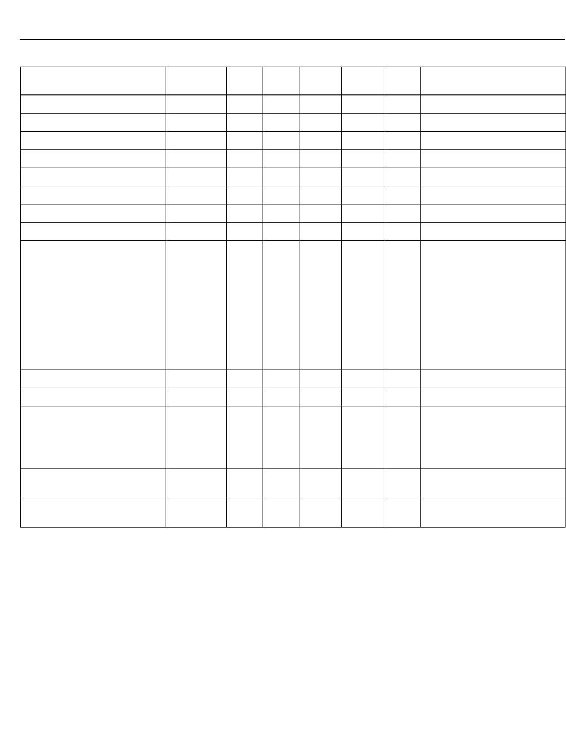
External Control
116 LightStyle™ LS-12HBd Installation/Operation Manual
PRELIMINARY
Test Pattern Enable TPE R/W No 0 1 No 0 = Off; 1 = On
Primary Test Pattern TPP R/W No 0 1 No 0 = Off; 1 = On
Secondary Test Pattern TPS R/W No 0 1 No 0 = Off; 1 = On
Tracking TRK R/W Yes -100 100 No
Image Alignment Top Right x TRX R/W Yes -100 100 No
Image Alignment Top Right y TRY R/W Yes -100 100 No
Display 3D Sync Delay TSD R/W Yes Var. Var. No
Display 3D Sync Invert TSI R/W No 0 1 No 0 = Not Inverted; 1 = Inverted
Test Video TST R/W No 0 4 No 1 = Color Bars 1
2 = Full White
11 = Color Bars 2
12 = Gray Bars
13 = Focus
14 = Off
15 = Off (Restore OSD)
16 = Primary Alignment
17 = Secondary Alignment
18 = Dual Alignment
19 = 3D
VFD Text Line 1 VF1 W No N/A N/A Yes 24 characters max
VFD Text Line 2 VF2 W No N/A N/A Yes 24 characters max
VFD Brightness VFD R/W Yes 0 4 No 0 = 0%
1 = 25%
2 = 50%
3 = 75%
4 = 100%
Vertical Shift VSH W Yes 0 0 No Send (VSH+) or (VSH-) to
adjust incrementally
Zoom ZOM W Yes 0 0 No Send (ZOM+) or (ZOM-) to
adjust incrementally
Table 6-1. Serial Commands (continued)
Setting Command
Code
Read/
Write
Inc/
Dec
Min
Value
Max
Value String? Notes
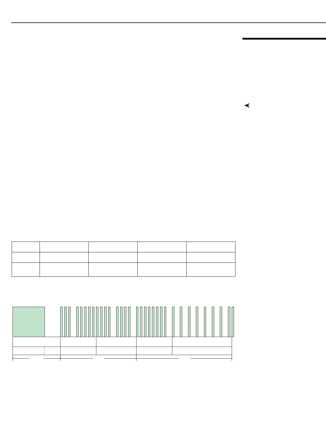
External Control
LightStyle™ LS-12HBd Installation/Operation Manual 117
PRELIMINARY
6.2
Using Discrete IR
Codes
The Dimension Digital Controller accepts commands in the form of IR signals that conform
to the NEC protocol. Each Dimension Digital Controller remote control button has an NEC
control code associated with it.
You can use these codes to program a third-party, “universal” remote control unit to work
with the Dimension Digital Controller. These third-party products usually come with a
computer software application for this purpose. For more information, consult the
documentation provided with the remote control unit.
IR Command ProtocolThe IR control codes have the following characteristics:
• Each code consists of the following:
•A leader pulse (a modulated pulse of 9 ms followed by a non-modulated pulse of
4.5 ms);
•16 address bits. The default address is 82 09 (0x2011, binary
00100000 00010001). To change it, select Remote Control from the Service menu
and follow the steps given on page 83;
•16 data bits: eight (8) bits for the command followed by the logical inverse of the
command; and
•An end pulse (a modulated pulse of 0.56 ms, similar to the modulated pulse in the
‘0’ and ‘1’ bits).The end of the modulated pulse constitutes the end of the data
transmission.
• The carrier frequency is 38 kHz, with the modulated pulses having a 33% duty cycle.
• Commands are sent at a maximum rate of 9 Hz.
For example, here is the NEC control code for the ON button on the Dimension Digital
Controller remote control unit (assuming the default address is used):
Figure 6-1 shows the pulse train for this command.
Figure 6-1. NEC Protocol Message Format
Hex201101FE
Binary 00100000 00010001 00000001 11111110
Function Address Byte 1 Address Byte 2 Command Command
(Logical Inverse)
9 ms
13.5 ms 27 ms 27 ms
Address Byte 1Leader Pulse Address Byte 2 Command Byte Command Byte (logical inverse)
001 000000001 0001 00000001 1 1 1 1 1 1 1 0
4.5 ms
End Pulse

External Control
118 LightStyle™ LS-12HBd Installation/Operation Manual
PRELIMINARY
IR Command List
(Standard Mode)
Table 6-2 lists the NEC control codes for the Dimension Digital Controller.
➤
Table 6-2. NEC Control Codes for the Dimension Digital Controller
(Standard Mode)
Remote
Control
Button Name
Address Data
NEC Data
From Remote
(Note)
Description
ON 8209 1 0x201101FE Power on
OFF (standby) 8209 2 0x201102FD Power off
16:9 8209 3 0x201103FC 16:9 aspect ratio
4:3 8209 4 0x201104FB 4:3 aspect ratio
LETBOX 8209 5 0x201105FA Letterbox aspect ratio
V-WIDE 8209 6 0x201106F9 VirtualWide aspect ratio
CINEMA 8209 7 0x201107F8 Cinema aspect ratio
V-CINE 8209 8 0x201108F7 Virtual Cinema aspect ratio
NATIVE 8209 9 0x201109F6 Native aspect ratio
1 8209 10 0x20110AF5 Number Button 1
2 8209 11 0x20110BF4 Number Button 2
3 8209 12 0x20110CF3 Number Button 3
4 8209 13 0x20110DF2 Number Button 4
5 8209 14 0x20110EF1 Number Button 5
6 8209 15 0x20110FF0 Number Button 6
7 8209 16 0x201110EF Number Button 7
8 8209 17 0x201111EE Number Button 8
9 8209 18 0x201112ED Number Button 9
0 8209 19 0x201113EC Number Button 0
ISF DAY 8209 20 0x201114EB ISF Day memory preset
ISF NIGHT 8209 21 0x201115EA ISF Night memory preset
SCREEN 1 8209 22 0x201116E9 Selects “Screen 1”
CUST 1 8209 23 0x201117E8 Custom 1 memory preset
CUST 2 8209 24 0x201118E7 Custom 2 memory preset
SCREEN 2 8209 25 0x201119E6 Selects “Screen 2”
MENU 8209 26 0x20111AE5 MENU
EXIT 8209 27 0x20111BE4 EXIT
Up 8209 28 0x20111CE3 Up-Arrow ( )
Note: These codes assume that the default address of 8209 is used. If you change it to something
other than 8209, you will need to modify these codes accordingly.
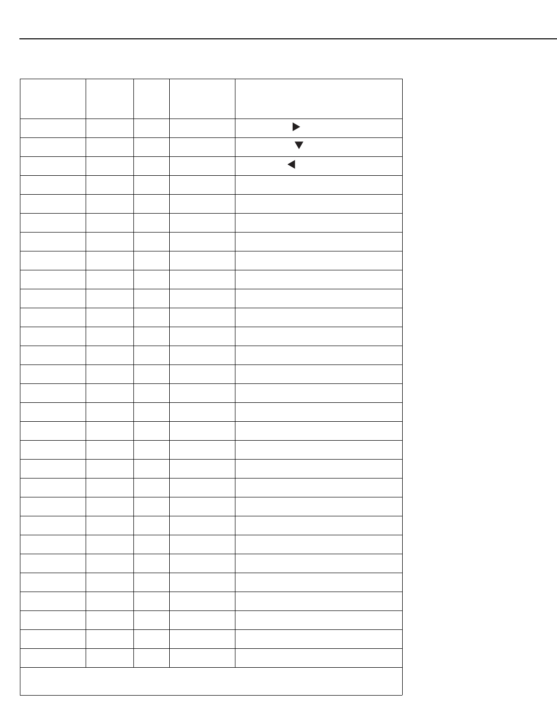
External Control
LightStyle™ LS-12HBd Installation/Operation Manual 119
PRELIMINARY
Right 8209 29 0x20111DE2 Right-Arrow ( )
Down 8209 30 0x20111EE1 Down-Arrow ( )
Left 8209 31 0x20111FE0 Left-Arrow ( )
ENTER 8209 32 0x201120DF ENTER
SRC 1 8209 33 0x201121DE Video Source 1
SRC 2 8209 34 0x201122DD Video Source 2
SRC 3 8209 35 0x201123DC Video Source 3
SRC 4 8209 36 0x201124DB Video Source 4
SRC 5 8209 37 0x201125DA Video Source 5
SRC 6 8209 38 0x201126D9 Video Source 6
SRC 7 8209 39 0x201127D8 Video Source 7
SRC 8 8209 40 0x201128D7 Video Source 8
SRC 9 8209 41 0x201129D6 Video Source 9
SRC 10 8209 42 0x20112AD5 Video Source 10
SRC 11 8209 43 0x20112BD4 Video Source 11
SRC 12 8209 44 0x20112CD3 Video Source 12
SRC 13 8209 43 0x20112BD4 Video Source 13
SRC 14 8209 46 0x20112ED1 Video Source 14
3D AUTO 8209 47 0x20112FD0 3D Mode = Auto
3D SBS 8209 48 0x201130CF 3D Mode = Side-by-Side
3D TAB 8209 49 0x201131CE 3D Mode = Top-and-Bottom
3D FP 8209 50 0x201132CD 3D Mode = Frame Packing
STOFF 8209 65 0x201141BE Sets the sleep timer to Off
ST30MIN 8209 66 0x201142BD Sets the sleep timer to 30 minutes
ST60MIN 8209 67 0x201143BC Sets the sleep timer to 60 minutes
ST90MIN 8209 68 0x201144BB Sets the sleep timer to 90 minutes
ST2HRS 8209 69 0x201145BA Sets the sleep timer to 2 hours
ST4HRS 8209 70 0x201146B9 Sets the sleep timer to 4 hours
VIDEO 1 8209 71 0x201147B8 Composite video input 1
Table 6-2. NEC Control Codes for the Dimension Digital Controller
(Standard Mode) (continued)
Remote
Control
Button Name
Address Data
NEC Data
From Remote
(Note)
Description
Note: These codes assume that the default address of 8209 is used. If you change it to something
other than 8209, you will need to modify these codes accordingly.
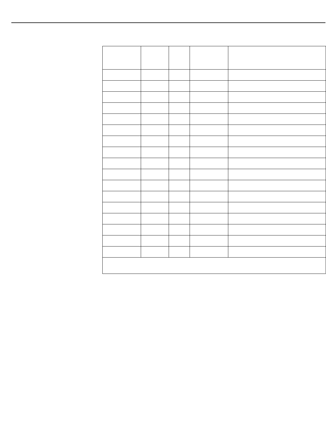
External Control
120 LightStyle™ LS-12HBd Installation/Operation Manual
PRELIMINARY
COMP 8209 72 0x201148B7 Component video input
HD 1 8209 73 0x201149B6 HD1 video input
HD 2 8209 74 0x20114AB5 HD2 video input
HDMI 1 8209 75 0x20114BB4 HDMI1 video input
HDMI 2 8209 76 0x20114CB3 HDMI2 video input
HDMI 3 8209 77 0x20114DB2 HDMI3 video input
HDMI 4 8209 78 0x20114EB1 HDMI4 video input
HDMI 5 8209 79 0x20114FB0 HDMI5 video input
HDMI 6 8209 80 0x201150AF HDMI6 video input
HDMI 7 8209 81 0x201151AE HDMI7 video input
HDMI 8 8209 82 0x201152AD HDMI8 video input
DisplayPort 8209 83 0x201153AC DisplayPort video input
SCART 8209 84 0x201154AB SCART video input
VIDEO 2 8209 85 0x201155AA Composite video input 2
VIDEO 3 8209 86 0x201156A9 Composite video input 3
3D OFF 8209 87 0x201157A8 3D Mode = Off
Auto Cinema 8209 88 0x201158A7 Auto Cinema aspect ratio
Table 6-2. NEC Control Codes for the Dimension Digital Controller
(Standard Mode) (continued)
Remote
Control
Button Name
Address Data
NEC Data
From Remote
(Note)
Description
Note: These codes assume that the default address of 8209 is used. If you change it to something
other than 8209, you will need to modify these codes accordingly.

External Control
LightStyle™ LS-12HBd Installation/Operation Manual 121
PRELIMINARY
IR Command List
(Extended Mode)
Table 6-3 lists the Extended-mode NEC control codes for the Dimension Digital
Controller. To use the remote control unit in extended mode, set the address code to
88999 (refer to Remote Control on page 83).
Table 6-3. NEC Control Codes for the Dimension Digital Controller
(Extended Mode)
Remote
Control
Button Name
Address Data
NEC Data
From Remote
(Note)
Description
ON 8209 65 0x201141BE Sets the sleep timer to Off
OFF (standby) 8209 66 0x201142BD Sets the sleep timer to 30 minutes
16:9 8209 67 0x201143BC Sets the sleep timer to 60 minutes
4:3 8209 68 0x201144BB Sets the sleep timer to 90 minutes
LETBOX 8209 69 0x201145BA Sets the sleep timer to 2 hours
V-WIDE 8209 70 0x201146B9 Sets the sleep timer to 4 hours
CINEMA 8209 71 0x201147B8 Composite video input 1
V-CINE 8209 72 0x201148B7 Component video input
NATIVE 8209 73 0x201149B6 HD1 video input
1 8209 74 0x20114AB5 HD2 video input
2 8209 75 0x20114BB4 HDMI1 video input
3 8209 76 0x20114CB3 HDMI2 video input
4 8209 77 0x20114DB2 HDMI3 video input
5 8209 78 0x20114EB1 HDMI4 video input
6 8209 79 0x20114FB0 HDMI5 video input
7 8209 80 0x201150AF HDMI6 video input
8 8209 81 0x201151AE HDMI7 video input
9 8209 82 0x201152AD HDMI8 video input
0 8209 83 0x201153AC DisplayPort video input
ISF DAY 8209 84 0x201154AB SCART video input
ISF NIGHT 8209 85 0x201155AA Composite video input 2
SCREEN 1 8209 86 0x201156A9 Composite video input 3
CUST 1 8209 87 0x201157A8 3D Mode = Off
CUST 2 8209 88 0x201158A7 Auto Cinema aspect ratio
Note: These codes assume that the default address of 8209 is used. If you change it to something
other than 8209, you will need to modify these codes accordingly.
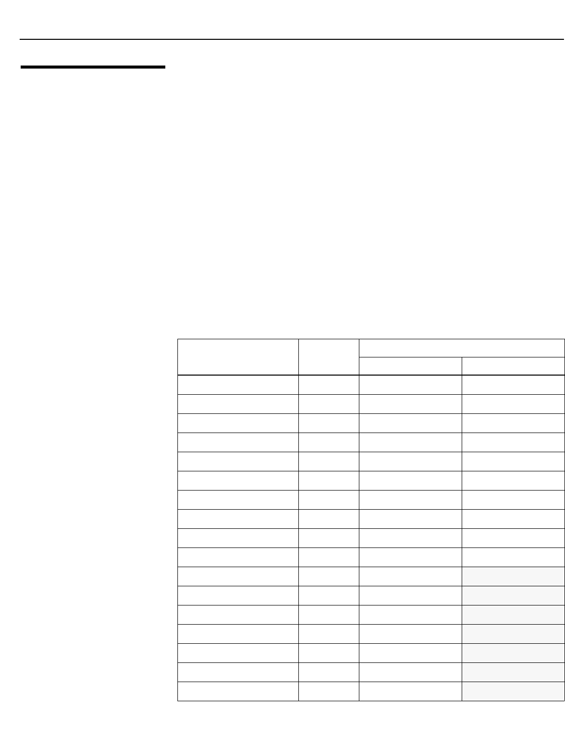
External Control
122 LightStyle™ LS-12HBd Installation/Operation Manual
PRELIMINARY
6.3
Using HDMI CEC
Messages
The Dimension Digital Controller accepts and can respond to CEC command messages
from a disc player, satellite receiver or DVR/set-top box via an HDMI connection. Using
CEC, the Dimension Digital Controller can perform the following actions:
• Turn itself and the projector on and select the correct input when the source
component initiates playback of a disc or recorded program.
• Turn the source component on when you switch to its corresponding input on the
Dimension Digital Controller.
• Turn the source component off when the LS-12HBd system is turned off (unless the
source component is in playback mode).
• Change its OSD language when a similar change is made at the source.
To use CEC, connect your CEC-compatible sources to the HDMI inputs on the Dimension
Digital Controller. Set the CEC option to On (refer to CEC on page 92). Additional steps
may be needed to enable CEC at the source. Refer to the documentation for your source
device for more information.
CEC Command List Table 6-4 lists the CEC commands supported by the Dimension Digital Controller.
➤
Table 6-4. CEC Commands Supported by the Dimension Digital
Controller
Opcode Value
Supported? (√ = Yes, – = No)
Initiator Follower
Feature Abort 0x00 √√
Standby 0x36 √√
Routing Change 0x80 √√
Routing Information 0x81 √√
Active Source 0x82 √√
Request Active Source 0x85 √√
Device Vendor ID 0x87 √√
Give Device Vendor ID 0x8C √√
Vendor Command With ID 0xA0 √√
Polling Message N/A √√
Text View On 0x0D √–
Report Physical Address 0x84 √–
Inactive Source 0x9D √–
CEC Version 0x9E √–
Set OSD Name 0x47 √–
Menu Status 0x8E √–
Report Power Status 0x90 √–
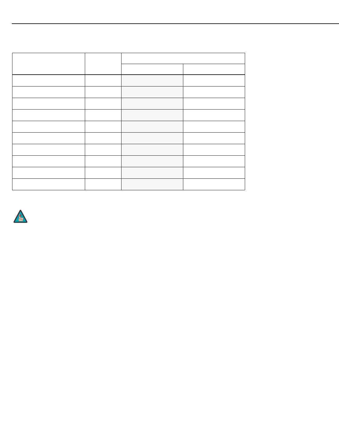
External Control
LightStyle™ LS-12HBd Installation/Operation Manual 123
PRELIMINARY
Set Menu Language 0x32 –√
Give Physical Address 0x83 –√
Set Stream Path 0x86 –√
Get CEC Version 0x9F –√
Abort Message 0xFF –√
User Control Pressed 0x44 –√
User Control Released 0x45 –√
Give OSD Name 0x46 –√
Menu Request 0x8D –√
Give Device Power Status 0x8F –√
The Dimension Digital Controller does not transmit HDMI CEC
control messages from the “HDMI Audio Out” connector.
Table 6-4. CEC Commands Supported by the Dimension Digital Controller
(continued)
Opcode Value
Supported? (√ = Yes, – = No)
Initiator Follower
Note

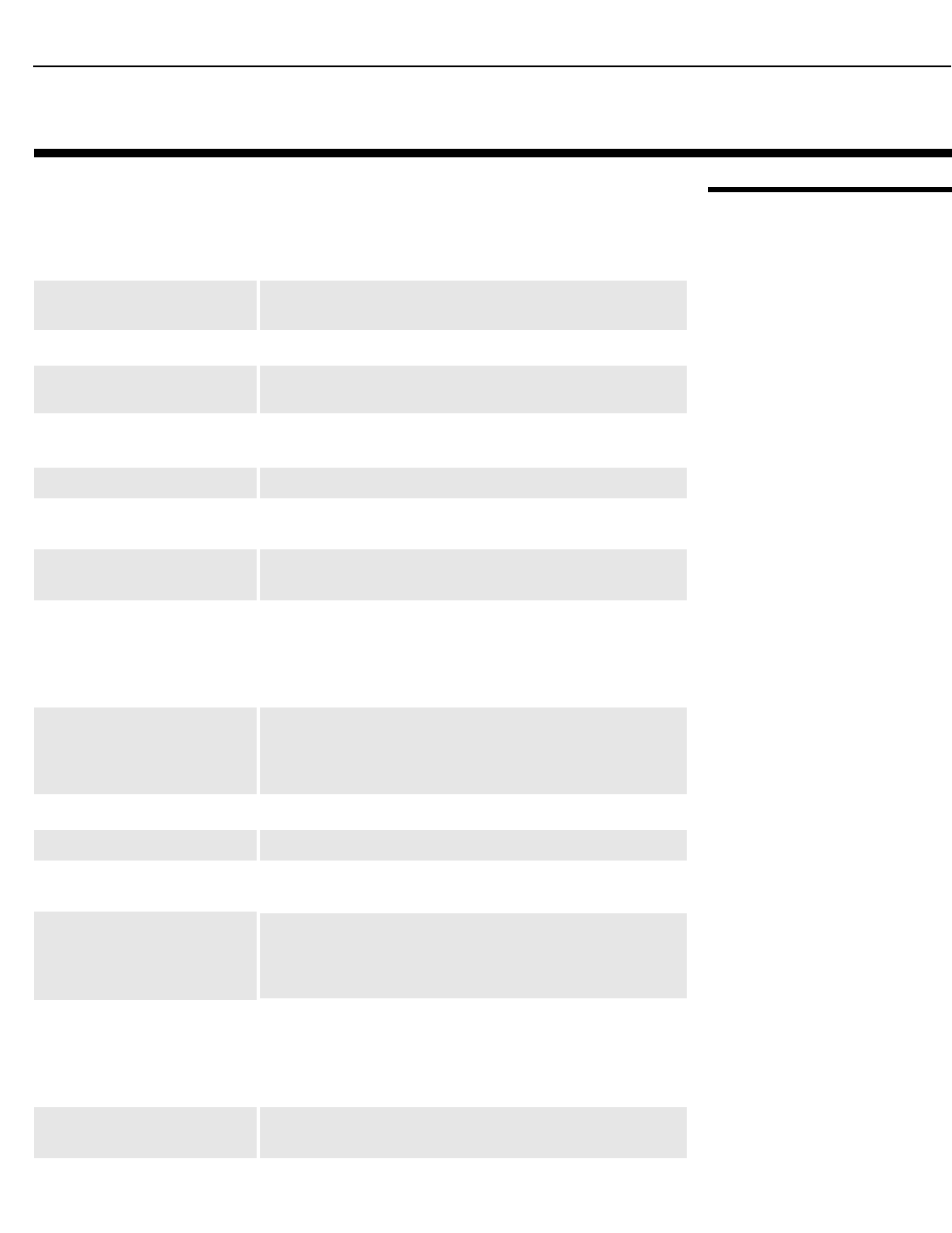
Specifications
LightStyle™ LS-12HBd Installation/Operation Manual 125
PRELIMINARY
7.1
LS-12HBd Projector
Specifications
Table 7-1 lists the LS-12HBd projector specifications.
7. Specifications
Table 7-1. LS-12HBd Projector Specifications
Projector Type: Digital Light Processing™ (DLP), 3-chip, 16:9 SuperOnyx™
DMD™
Native Resolution: Full HD 1920 x 1080 (1080p)
Estimated Lamp Life: 2000 hours, typical (260W power setting)
3000 hours, typical (230W power setting)
Aspect Ratios: 4:3, Letterbox, 16:9, VirtualWide, Cinema, Virtual Cinema,
Native
DTV Compatibility: Refer to Table 7-2
Picture Size (16:9 Screen): Recommended Width: 80 - 117 in.
Maximum Width: 175 in.
Processing: Runco Dimension Digital Controller with ViVix IV™ technology
and BRiC (Backup, Recovery and Clone) tool
Control Options:• Serial commands via RS-232
• Discrete infrared (IR) remote
• Consumer Electronics Control (CEC) protocol support via
HDMI
•Ethernet
Inputs and Outputs: • Digital Video x 2 (from Dimension Digital Controller)
• RS-232 (female DB9) for serial communications
• 3D Sync Out (female 3-pin, VESA standard mini-DIN) to IR
Emitter
Video Standards:NTSC, PAL, SECAM, CEA-861D
Calibration: ISF Certified Calibration Configuration
Throw Distance
(Factor x Screen Width):
Refer to Table 3-3
Horizontal & Vertical Offset: Proteus 1: None
Proteus 2, 3, 4, 5, 6:
Horizontal: 30% of screen width left or right
Vertical: 65% of screen height up or down
Light Output (2D): CSMS Specifications* – Home Theater Calibration:
2,592 ANSI Lumens; 94 Foot-Lamberts (fL)
Uncalibrated: 3,780 ANSI Lumens
*Measured on a 1.0 gain, 84" wide 16:9 screen
Contrast Ratio: CSMS Contrast Ratio: >250:1 (ANSI);
10,000:1 full-on, full-off
Illumination System: 230W HPM lamp

Specifications
126 LightStyle™ LS-12HBd Installation/Operation Manual
PRELIMINARY
Lens System: Motorized focus, zoom and position controls
Refresh Rate: 24 Hz, 50 Hz or 60 Hz (2D content)
100 Hz or 120 Hz (3D content)
3D Technology: Frame sequential, active shutter
Power Requirements: 100 to 240 VAC (auto-sensing), 50/60 Hz, 400 Watts
(1365.2 BTUs/hour)
Operating Temperature: 10°C to 40°C, up to 7,500’ altitude
10°C to 35°C, 7,500’ to 10,000’ altitude
Operating Humidity: 10 - 80% humidity (non-condensing)
Dimensions:See Figure 7-1
Weight (without lens): 40.8 lbs. (18.50 kg)
Regulatory Approvals: FCC Part 15, Subpart B Class B, UL 60950, IEC60950, RoHS
Limited Warranty: Two (2)-year PremierCare™ warranty; lamp warranty 1000
hours or (6) six months, whichever comes first (US and
Canada only)
Specifications are subject to change without notice.
Table 7-1. LS-12HBd Projector Specifications (continued)
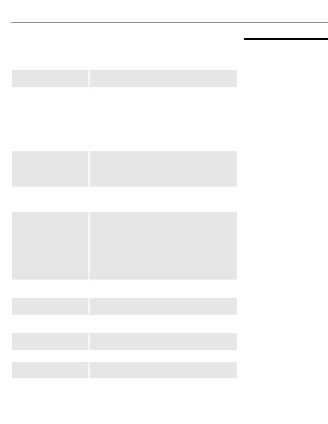
Specifications
LightStyle™ LS-12HBd Installation/Operation Manual 127
PRELIMINARY
7.2
Dimension Digital
Controller
Specifications
Table 7-2 lists the Dimension Digital Controller specifications.
Table 7-2. Dimension Digital Controller Specifications
Aspect Ratios: 4:3, Letterbox, 16:9, VirtualWide, Cinema, Virtual Cinema,
Native
Video Standards:•DisplayPort with HDCP
• HDMI and DVI with HDCP for digital video
• Component and RGB HDTV (1080p, 1080i, 720p)
• Component and RGB EDTV (576p, 480p)
• Component and Composite SDTV (576i, 480i)
• RGB SCART with adaptor
• NTSC (M, 4.43)
• PAL (B, G, H, I, N, M)
• SECAM (M)
Inputs: (1) DisplayPort 1.1a
(8) HDMI with 3D Support, CEC and Deep Color
(1) Component/SCART (3 x RCA)
(2) Component/RGBHV (15-pin VGA)
(3) Composite
Outputs: (2) HDMI with 3D Support and Deep Color to LS-12HBd
(1) HDMI with Deep Color to second display or audio
processor
Control Options:• Front panel vacuum fluorescent display and keypad
• Discrete infrared (IR) remote
• RS-232 (female DB9) for serial commands
• USB (type B female) for firmware upgrade
• RS-232 (male DB9) for accessories
• 3.5-mm wired IR input for Niles/Xantech-compatible IR
systems
• Consumer Electronics Control (CEC) protocol support via
HDMI
•Ethernet
Ethernet Communication: RJ45 (female) for web server, e-mail, auto firmware upgrade
and Telnet
RS-232 Communication
Parameters:
19200 bps, no parity, 8 data bits, 1 stop bit, no flow control
Trigger Outputs: (3) +12 VDC, each rated at 250 mA and thermal
fuse-protected
Accessory Applications: Runco Firmware Upgrader, Runco BRiC (backup, restore,
clone), CalMAN by SpectraCal for automatic calibration
Power Requirements: 100-240V~, 47-63Hz, 0.85 Amps
Operating Environment: 41°F to 104°F (5°C to 40°C), 0% to 90% humidity
(non-condensing); up to 10,000 feet (3,048 meters) altitude
Dimensions:Width = 17.50 inches (444.5 mm)
Depth = 17.68 inches (449.0 mm)
Height = 3.75 inches (95.3 mm)

Specifications
128 LightStyle™ LS-12HBd Installation/Operation Manual
PRELIMINARY
Weight: 17.6 lbs. (8.00 kg)
Regulatory Approvals:cTUVus, FCC class B, CE, RoHS, China RoHS, WEEE,
C-Tick, CCC, local conformances as required
Limited Warranty: Two (2) years parts and labor from the date of shipment from
Runco.
Specifications are subject to change without notice.
Table 7-2. Dimension Digital Controller Specifications (continued)
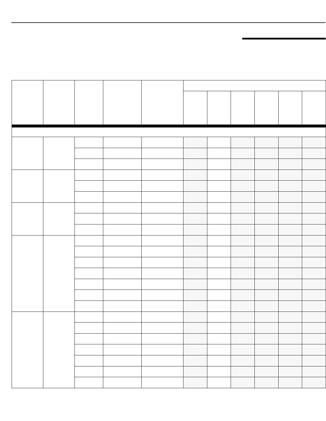
Specifications
LightStyle™ LS-12HBd Installation/Operation Manual 129
PRELIMINARY
7.3
Supported Timings
Table 7-3 lists the signal types supported by each input on the Dimension Digital
Controller.
Table 7-3. Supported Signal Timings by Input
Format Resolution Refresh
Rate (Hz)
Horizontal
Frequency
(kHz)
Pixel Frequency
(MHz)
Supported? (√ = Yes, – = No)
HD 1
HD 2
HDMI [1 ... 8]
DisplayPort
Component
SCART
Composite 1
Composite 2
Composite 3
Supported 3D Modes
1080i SBS
(Side-by-
Side)
1920x1080
50.00 28.125/31.250 74.250/72.000 –√––––
59.94 33.716 74.175 –√––––
60.00 33.750 74.250 –√––––
720p TAB
(Top-and-
Bottom)
1280x720
50.00 37.500 75.250 –√––––
59.94 44.715 74.406 –√––––
60.00 45.000 74.250 –√––––
720p SBS
(Side-by-
Side)
1280x720
50.00 37.500 75.250 –√––––
59.94 44.715 74.406 –√––––
60.00 45.000 74.250 –√––––
720p FP
(Frame
Packing)
1280x720
23.98 17.982 59.341 –√––––
24.00 18.000 59.400 –√––––
29.97 22.478 74.175 –√––––
30.00 22.500 74.250 –√––––
50.00 37.500 75.250 –√––––
59.94 44.715 74.406 –√––––
60.00 45.000 74.250 –√––––
1080p SBS
(Side-by-
Side)
1920x1080
23.98 26.978 74.175 –√––––
24.00 27.000 74.250 –√––––
29.97 33.716 74.175 –√––––
30.00 33.750 74.250 –√––––
50.00 56.250 148.500 –√––––
59.94 67.433 148.350 –√––––
60.00 67.500 148.500 –√––––
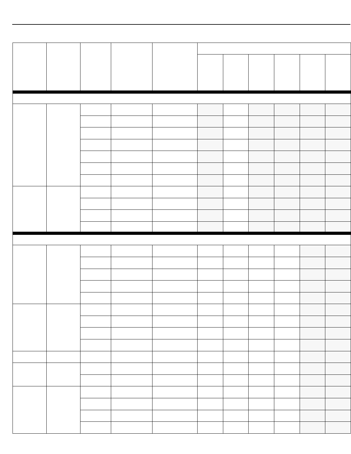
Specifications
130 LightStyle™ LS-12HBd Installation/Operation Manual
PRELIMINARY
Supported 3D Modes (continued)
1080p TAB
(Top-and-
Bottom)
1920x1080
23.98 26.978 74.175 –√––––
24.00 27.000 74.250 –√––––
29.97 33.716 74.175 –√––––
30.00 33.750 74.250 –√––––
50.00 56.250 148.500 –√––––
59.94 67.433 148.350 –√––––
60.00 67.500 148.500 –√––––
1080p FP
(Frame
Packing)
1920x1080
23.98 26.978 74.175 –√––––
24.00 27.000 74.250 –√––––
29.97 33.716 74.175 –√––––
30.00 33.750 74.250 –√––––
Supported 2D Modes
640x480 640x480
60.00 31.469 25.175 √√√√– –
66.59 35.892 29.862 √√√√– –
72.00 37.861 31.500 √√√√– –
75.00 37.500 31.500 √√√√– –
85.00 43.269 36.000 √√√√– –
800x600 800x600
60.00 37.879 40.000 √√√√– –
72.00 48.077 50.000 √√√√– –
75.00 46.875 49.500 √√√√– –
85.00 53.674 56.250 √√√√– –
832x624 832x624 74.54 52.849 60.036 √√√√– –
848x480 848x480 47.95 25.270 27.089 √√√√– –
60.00 31.020 33.750 √√√√– –
1024x768 1024x768
60.00 48.363 65.000 √√√√– –
70.00 56.476 75.000 √√√√– –
75.00 60.023 78.750 √√√√– –
85.00 68.677 94.500 √√√√– –
Table 7-3. Supported Signal Timings by Input (continued)
Format Resolution Refresh
Rate (Hz)
Horizontal
Frequency
(kHz)
Pixel Frequency
(MHz)
Supported? (√ = Yes, – = No)
HD 1
HD 2
HDMI [1 ... 8]
DisplayPort
Component
SCART
Composite 1
Composite 2
Composite 3
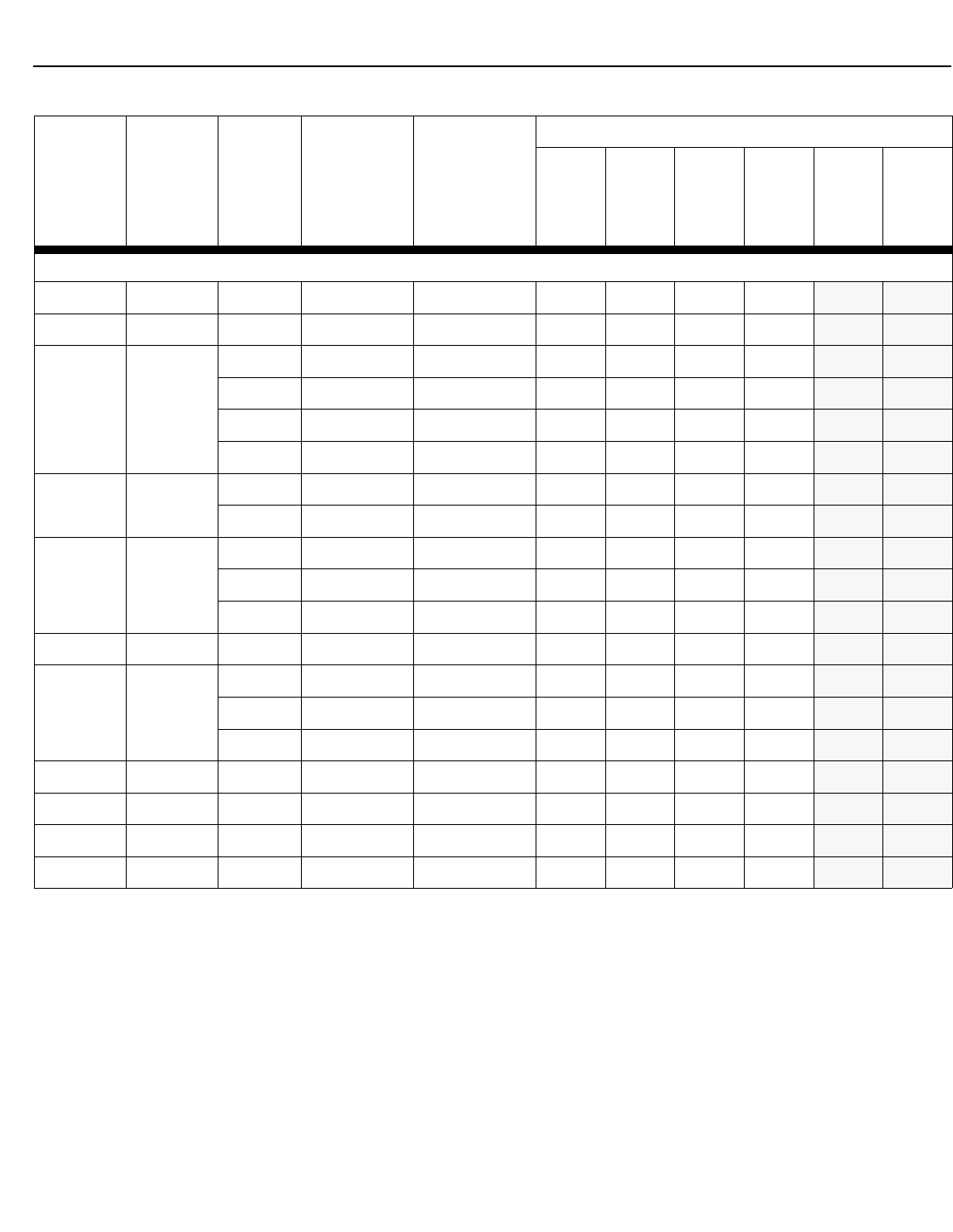
Specifications
LightStyle™ LS-12HBd Installation/Operation Manual 131
PRELIMINARY
Supported 2D Modes (continued)
1152x864 1152x864 75.00 67.500 108.000 √√√√– –
1280x720 1280x720 47.95 37.833 64.769 √√√√– –
1280x768 1280x768
60.00 47.396 68.250 √√√√– –
60.00 47.776 79.500 √√√√– –
75.00 60.289 102.250 √√√√– –
85.00 68.633 117.500 √√√√– –
1280x960 1280x960 60.00 60.000 108.000 √√√√– –
85.00 85.938 148.500 √√√√– –
1280x1024 1280x1024
60.00 63.981 108.000 √√√√– –
75.00 79.976 135.000 √√√√– –
85.00 91.146 157.500 √√√√– –
1360x768 1360x768 60.00 47.712 85.500 √√√√– –
1400x1050 1400x1050
60.00 64.744 101.000 √√√√– –
60.00 65.317 121.750 √√√√– –
75.00 82.278 156.000 √√√√– –
1600x1200 1600x1200 60.00 75.000 162.000 √√√√– –
1680x1050 1680x1050 60.00 64.674 119.000 √√√√– –
1920x1080 1920x1080 47.95 56.821 150.007 √√√√– –
1920x1200 1920x1200 60.00 74.038 154.000 √√√√– –
Table 7-3. Supported Signal Timings by Input (continued)
Format Resolution Refresh
Rate (Hz)
Horizontal
Frequency
(kHz)
Pixel Frequency
(MHz)
Supported? (√ = Yes, – = No)
HD 1
HD 2
HDMI [1 ... 8]
DisplayPort
Component
SCART
Composite 1
Composite 2
Composite 3

Specifications
132 LightStyle™ LS-12HBd Installation/Operation Manual
PRELIMINARY
Supported 2D Modes (continued)
SCART
RGBS – 50.00 – – ––––√–
480/60i 720x487 59.94 15.734 13.500 √√√√– –
480/60p 720x483 59.94 31.469 27.000 √√√√– –
576/50i 720x576 50.00 15.625 14.750 √√√√– –
576/50p 720x576 50.00 31.250 29.000 √√√√– –
720/24p 1280x720 23.98/
24.00 17.982/18.000 59.341/59.400 √√√√– –
720/25p 1280x720 25.00 18.750 74.250 √√√√– –
720/30p 1280x720 29.97/
30.00 22.478/22.500 74.175/74.250 √√√√– –
720/50p 1280x720 50.00 37.500 75.250 √√√√– –
720/60p 1280x720 60.00 45.000 74.250 √√√√– –
1080/50i 1920x1080 50.00 28.125/31.250 74.250/72.000 √√√√– –
1080/60i 1920x1080 59.94/
60.00 33.716/33.750 74.175/74.250 √√√√– –
1080/24p 1920x1080 23.98/
24.00 26.978/27.000 74.175/74.250 √√√√– –
1080/50p 1920x1080 50.00 56.250 148.500 √√√√– –
1080/60p 1920x1080 59.94/
60.00 67.433/67.500 148.350/148.500 √√√√– –
NTSC 3.58 – 59.94/
60.00 15.734/15.750 3.580 –––––√
NTSC 4.43 – 59.94/
60.00 15.734/15.750 4.430 –––––√
PAL-B/G/H/I – 50.00 15.625 4.430 –––––√
PAL-M – 59.94/
60.00 15.734/15.750 3.580 –––––√
PAL-N – 50.00 15.625 3.580 –––––√
SECAM – 50.00 15.625 13.500 ––––√√
Table 7-3. Supported Signal Timings by Input (continued)
Format Resolution Refresh
Rate (Hz)
Horizontal
Frequency
(kHz)
Pixel Frequency
(MHz)
Supported? (√ = Yes, – = No)
HD 1
HD 2
HDMI [1 ... 8]
DisplayPort
Component
SCART
Composite 1
Composite 2
Composite 3
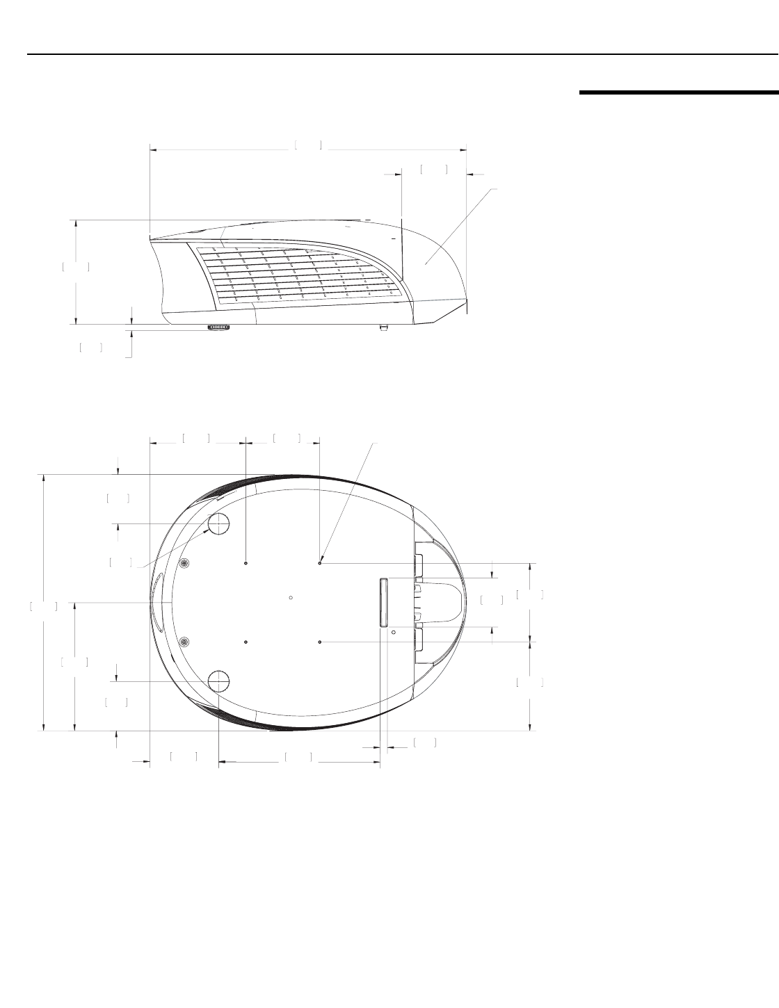
Specifications
LightStyle™ LS-12HBd Installation/Operation Manual 133
PRELIMINARY
7.4
LS-12HBd Dimensions
Figure 7-1 shows the LS-12HBd dimensions, in [millimeters] and inches.
Figure 7-1. LS-12HBd Dimensions
25.30
642.6
5.20
132.0
8.34
211.9
.50
(ADJUSTABLE)
12.8
REMOVABLE
REAR COVER
20.47
519.9
10.23
259.9
3.93
99.9
3.93
99.9
7.08
179.9
5.91
150.0
6.30
160.0
M4-.7 (MAX 10mm WITHOUT FIX PLATE)
4X MOUNTING HOLES
2X Ø 1.73
44.0
5.50
139.6
12.89
327.4 .59
15.0
3.91
99.2
7.66
194.6


Runco International • (800) 23RUNCO • Fax (503) 748-8161 • www.runco.com
020-1251-00 Rev. A
September 2013
