Runco Vision 85 Users Manual V85_manual
Vision 85 to the manual ed822380-47bf-466f-9d3b-720f27c54780
2015-02-06
: Runco Runco-Vision-85-Users-Manual-525807 runco-vision-85-users-manual-525807 runco pdf
Open the PDF directly: View PDF ![]() .
.
Page Count: 88
- TWO YEAR LIMITED WARRANTY
- Safety Precautions
- 1 Introduction
- 2 Controls and Functions
- 3 Installation
- 3.1 Remote Control
- 3.2 Quick Setup
- 3.3 Installation Considerations
- 3.4 Mounting the Vision 85
- 3.5 Connections to the Vision 85 and VHD Controller
- Connector Panel Access
- Connecting the Projector to the VHD Controller
- Connecting Source Components to the VHD Controller
- Connecting a PC or Automation System to the VHD Controller
- Connecting 12-Volt Trigger Outputs to External Equipment
- Connecting an External IR Receiver to the VHD Controller
- Connecting to AC Power
- 3.6 Turning on the Power
- 3.7 Adjusting the Picture Orientation
- 3.8 Primary Lens Adjustments
- 3.9 Installing and Adjusting the CineWide Anamorphic Lens
- 4 Operation
- 4.1 Using the On-Screen Menus
- 4.2 On-Screen Menus for 1080i (Analog) and Lower-Resolution Signals
- 4.3 On-Screen Menus for 1080i (Digital) or 1080p Signals
- 5 Maintenance and Troubleshooting
- 6 Serial Communications
- 7 Specifications

1080p DLP™ PROJECTORS
Vision 85
Vision 85/CineWide™
85
VERSION 1.0
OWNER’S OPERATING MANUAL

Vidikron Vision 85 Owner’s Operating Manual iii
PRELIMINARY
TWO YEAR LIMITED WARRANTY
For Projectors, Video Processors and Controllers
Congratulations on your purchase of a Vidikron video product and welcome to the Vidikron family! With proper installation, setup
and care, you should enjoy many years of unparalleled video performance.
This is a LIMITED WARRANTY as defined in the Magnuson-Moss Warranty Act. Please read it carefully and retain it with your other
important documents.
SERVICE LABOR: Vidikron will pay for service labor by Vidikron Authorized Service Center when needed as a result of manufacturing
defect for a period of two (2) years from the effective date of delivery to the end user (excluding the lamp).
PARTS (not including the lamp): Vidikron will provide new or rebuilt replacement parts for the parts that fail due to defects in
materials or workmanship for a period of two (2) years from the effective date of delivery to the end user. Such replacement parts
are then subsequently warranted for the remaining portion (if any) of the original warranty period.
PROJECTOR LAMP: Vidikron will pay for service labor by a Vidikron Authorized Service Center when needed as a result of a
manufacturing defect for a period of six (6) months or 1000 hours, whichever comes first, from the effective date of delivery to the
end user. In addition, Vidikron will provide a new or rebuilt replacement lamp for the lamp that fails due to defects in materials or
workmanship for a period of six (6) months or 1000 hours, whichever comes first, from the effective date of delivery to the end user.
Such replacement lamps are then subsequently warranted for the remaining portion (if any) of the original warranty period.
This Limited Warranty only covers failure due to defects in materials and workmanship that occur during normal use and does not
cover normal maintenance. This Limited Warranty does not cover cabinets or any appearance items; failure resulting from
accident, misuse, abuse, neglect, mishandling, misapplication, faulty or improper installation or setup adjustments; improper
maintenance, alteration, improper use of any input signal; damage due to lightning or power line surges, spikes and brownouts;
damage that occurs during shipping or transit; or damage that is attributed to acts of God. In the case of remote control units,
damage resulting from leaking, old, damaged or improper batteries is also excluded from coverage under this Limited Warranty.
CAUTION: THIS LIMITED WARRANTY ONLY COVERS VIDIKRON PRODUCTS PURCHASED FROM VIDIKRON AUTHORIZED DEALERS.
ALL OTHER PRODUCTS ARE SPECIFICALLY EXCLUDED FROM COVERAGE UNDER THIS WARRANTY. MOREOVER, DAMAGE
RESULTING DIRECTLY OR INDIRECTLY FROM IMPROPER INSTALLATION OR SETUP IS SPECIFICALLY EXCLUDED FROM COVERAGE
UNDER THIS LIMITED WARRANTY. IT IS IMPERATIVE THAT INSTALLATION AND SETUP WORK BE PERFORMED ONLY BY AN
AUTHORIZED VIDIKRON DEALER TO PROTECT YOUR RIGHTS UNDER THIS WARRANTY. THIS WILL ALSO ENSURE THAT YOU ENJOY
THE FINE PERFORMANCE OF WHICH YOUR VIDIKRON PRODUCT IS CAPABLE WHEN INSTALLED AND CALIBRATED BY VIDIKRON
AUTHORIZED PERSONNEL.
Vidikron limits its obligations under any implied warranties under state laws to a period not to exceed the warranty period. There
are no express warranties. Vidikron also excludes any obligation on its part for incidental or consequential damages related to the
failure of this product to function properly. Some states do not allow limitations on how long an implied warranty lasts, and some
states do not allow the exclusion or limitation of incidental or consequential damages. So the above limitations or exclusions may
not apply to you. This warranty gives you specific legal rights, and you may also have other rights that vary from state to state.
WHAT IS COVERED UNDER THE TERMS OF THIS LIMITED WARRANTY:
WHAT IS NOT COVERED UNDER THE TERMS OF THIS LIMITED WARRANTY:
RIGHTS, LIMITS AND EXCLUSIONS:

iv Vidikron Vision 85 Owner’s Operating Manual
PRELIMINARY
This warranty begins on the effective date of delivery to the end user. For your convenience, keep the original bill of sale as
evidence of the purchase date.
Please fill out and mail your warranty registration card. It is imperative that Vidikron knows how to reach you promptly if we should
discover a safety problem or product update for which you must be notified.
Repairs made under the terms of this Limited Warranty covering your Vidikron video product will be performed at the location of
the product, during usual working hours, providing location of product is within normal operating distance from a Vidikron
Authorized Service Center. In some instances it may be necessary for the product to be returned to the Vidikron factory for repairs.
If, solely in Vidikron’s judgment, location of product to be repaired is beyond normal operating distance of the closest Vidikron
Authorized Service Center, or the repair requires the unit be returned to the Vidikron factory, it is the owner’s responsibility to
arrange for shipment of the product for repair. These arrangements must be made through the selling Vidikron Dealer. If this is not
possible, contact Vidikron directly for a Return Authorization number and shipping instructions. Vidikron will return product
transportation prepaid in the United States, unless no product defect is discovered. In that instance, shipping costs will be the
responsibility of the owner.
© Copyright 2007 Vidikron, a Runco International Company. This document contains proprietary information protected by
copyright, trademark and other intellectual property laws. All rights are reserved. No part of this manual may be reproduced by any
mechanical, electronic or other means, in any form, without prior written permission of the manufacturer.
Vidikron, Vision, DVSI, Imagix, CineWide, AutoScope, V2 Aperture Control, CSMS and IntelliWide are trademarks of Runco, LLC. All
other trademarks and registered trademarks used in this document are the property of their respective owners.
Vidikron products are manufactured under one or more of the following patents: US. Patent 6755540 and Other Patents Pending.
EFFECTIVE WARRANTY DATE:
IMPORTANT -- WARRANTY REGISTRATION:
CONTACT A VIDIKRON AUTHORIZED SERVICE CENTER TO OBTAIN SERVICE:
COPYRIGHT AND TRADEMARKS:

Vidikron Vision 85 Owner’s Operating Manual v
PRELIMINARY
To locate the name and address of the nearest Vidikron Authorized Service Center, or for additional information about this Limited
Warranty, please call or write:
VIDIKRON
Attn: Customer Service Department
2900 Faber Street
Union City, CA 94587
Ph: (510) 324-5900
Fax: (510) 324-5905
Toll Free: (888) 4VIDIKRON
VIDIKRON PRODUCT INFORMATION
RETAIN THIS INFORMATION FOR YOUR RECORDS
_________________________________________________________ ________________________________________
Model Purchased Date
____________________________________________________________________________________________________________
Serial Number
____________________________________________________________________________________________________________
Vidikron Authorized Dealer Name
____________________________________________________________________________________________________________
Address
____________________________________________ __________________ ________________________
City State/Province Postal Code
____________________________________________ _______________________________________________________
Phone Fax
ADDITIONAL INFORMATION:

vi Vidikron Vision 85 Owner’s Operating Manual
PRELIMINARY
Thank you for your purchase of this quality Vidikron video projector! It has been designed to provide you with the quality of video
that is expected in a home theater. For the best performance, please read this manual carefully as it is your guide through the
menus and operation.
This equipment has been tested and found to comply with the limits for a Class B digital device, pursuant to Part 15 of the FCC
Rules. These limits are designed to provide reasonable protection against harmful interference in a residential installation.
1. Read these instructions.
2. Keep these instructions.
3. Heed all warnings.
4. Do not use this equipment near water, outdoors or otherwise exposed to the elements.
5. Clean only with a dry cloth.
6. Do not block any ventilation openings.
7. Do not install near any heat sources such as radiators, heat registers, stoves, or other apparatus (including amplifiers) that
produce heat.
8. Do not defeat the safety feature of the polarized or grounding type plug. A polarized type plug has two blades with one wider
than the other. A grounding type plug has two blades and a third grounding prong. The third prong is provided for your safety.
If the provided plug does not fit into your outlet, consult an electrician for the replacement of the obsolete outlet.
9. The 12V trigger only outputs DC 12V signal for triggering. Do not connect to any other power input or output. This could cause
damage to this unit.
10. Only use accessories specified by Vidikron.
11. Keep the packing material in case the equipment should ever need to be shipped.
12. Unplug this projector during lightning storms or when it will not be used for an extended period of time.
13. The lamp becomes extremely hot during operation. Allow the projector to cool down for approximately 45 minutes prior to
removing the lamp assembly for replacement. Do not operate lamps beyond the rated lamp life. Excessive operation of lamps
beyond rated life could cause them to explode in rare occasions.
14. Refer all servicing to qualified service personnel. Servicing is required when the projector has been damaged in any way,
objects have fallen or spilled into the projector, the projector has been exposed to rain or moisture, does not operate normally,
or has been dropped.
Safety Precautions
WARNING
This symbol is intended to alert the user to the presence of
uninsulated “dangerous voltage” within the product’s enclosure that
may be of sufficient magnitude to constitute a risk of electric shock.
This symbol is intended to alert the user to the presence of important
operating and maintenance (servicing) instructions in the literature
accompanying the appliance.
CAUTION
RISK OF ELECTRIC SHOCK
DO NOT OPEN
CAUTION:
TO REDUCE THE RISK OF ELECTRIC SHOCK
DO NOT REMOVE COVER (OR BACK)
NO USER SERVICEABLE PARTS INSIDE.
REFER SERVICING TO QUALIFIED
SERVICE PERSONNEL.

Vidikron Vision 85 Owner’s Operating Manual vii
1Table of Contents
PRELIMINARY
TWO YEAR LIMITED WARRANTY ............................................................................................. iii
Safety Precautions ................................................................................................................... vi
1. Introduction ........................................................................................................................ 1
About This Manual ............................................................................................................................................ 1
Target Audience......................................................................................................................................... 1
If You Have Comments About This Manual... .................................................................................. 1
Textual and Graphic Conventions ....................................................................................................... 1
Using This Manual ............................................................................................................................................. 2
Description, Features and Benefits ............................................................................................................. 3
Key Features and Benefits....................................................................................................................... 4
Parts List ........................................................................................................................................................ 4
2. Controls and Functions ...................................................................................................... 5
Vision 85 at a Glance ........................................................................................................................................ 5
Vision 85 Rear Panel ......................................................................................................................................... 7
VHD Controller Front Panel ........................................................................................................................... 8
VHD Controller Rear Panel ............................................................................................................................. 9
Outputs.......................................................................................................................................................... 9
Inputs ............................................................................................................................................................. 9
Vision 85 Remote Control Unit ...................................................................................................................11
Vision 85 Built-In Keypad ..............................................................................................................................14
3. Installation ........................................................................................................................15
Remote Control ................................................................................................................................................15
Battery Installation ..................................................................................................................................15
Notes on Remote Control Operation................................................................................................15
Quick Setup .......................................................................................................................................................17
Installation Considerations ..........................................................................................................................18
Installation Type.......................................................................................................................................18
Ambient Light ...........................................................................................................................................18
Throw Distance.........................................................................................................................................19
Vertical and Horizontal Position.........................................................................................................20
Vertical Lens Shift ....................................................................................................................................20
Folded Optics ............................................................................................................................................21
Other Considerations ............................................................................................................................. 21

Table of Contents
viii Vidikron Vision 85 Owner’s Operating Manual
PRELIMINARY
Mounting the Vision 85 ................................................................................................................................. 22
Floor Mounting (Upright) .....................................................................................................................22
Ceiling Mounting (Inverted) ................................................................................................................22
Adjusting the Projection Angle ..........................................................................................................22
Connections to the Vision 85 and VHD Controller ..............................................................................23
Connector Panel Access ........................................................................................................................23
Connecting the Projector to the VHD Controller ......................................................................... 23
Connecting Source Components to the VHD Controller ..........................................................24
Connecting a PC or Automation System to the VHD Controller ............................................28
Connecting 12-Volt Trigger Outputs to External Equipment..................................................28
Connecting an External IR Receiver to the VHD Controller......................................................29
Connecting to AC Power.......................................................................................................................30
Turning on the Power ....................................................................................................................................30
Adjusting the Picture Orientation ............................................................................................................. 30
Primary Lens Adjustments ...........................................................................................................................31
Focus and Zoom.......................................................................................................................................31
Vertical Lens Shift ....................................................................................................................................31
Installing and Adjusting the CineWide Anamorphic Lens ................................................................32
4. Operation .......................................................................................................................... 35
Using the On-Screen Menus ........................................................................................................................35
On-Screen Menus for 1080i (Analog) and Lower-Resolution Signals ...........................................35
Main Menu .................................................................................................................................................37
Input Source ..............................................................................................................................................37
Aspect Ratio .............................................................................................................................................. 37
Picture .........................................................................................................................................................39
Input Position............................................................................................................................................43
ISF Presets...................................................................................................................................................44
Information ................................................................................................................................................44
Calibration ..................................................................................................................................................45
Service..........................................................................................................................................................47

Vidikron Vision 85 Owner’s Operating Manual ix
PRELIMINARY
On-Screen Menus for 1080i (Digital) or 1080p Signals ......................................................................51
Main Menu .................................................................................................................................................52
Language....................................................................................................................................................53
Picture Adjust............................................................................................................................................53
Picture Adjust (Advanced)....................................................................................................................55
White Balance ...........................................................................................................................................56
HD/RGB Adj. ..............................................................................................................................................57
Options ........................................................................................................................................................ 57
5. Maintenance and Troubleshooting ................................................................................61
Lamp Replacement .........................................................................................................................................61
Troubleshooting Tips .....................................................................................................................................62
6. Serial Communications ....................................................................................................65
RS-232 Connection and Port Configuration ..........................................................................................65
Serial Command Syntax ................................................................................................................................65
7. Specifications .................................................................................................................... 71
Vision 85 Specifications .................................................................................................................................71
VHD Controller Specifications .....................................................................................................................73
Vision 85 Dimensions .....................................................................................................................................74


Vidikron Vision 85 Owner’s Operating Manual xi
PRELIMINARY
1List of Figures
2-1. Vision 85 Front/Top/Side/Bottom/Rear View . . . . . . . . . . . . . . . . . . . . . . . . . . . . . . . . . . . . . . . . . . . . . 5
2-2. Vision 85 Rear Panel . . . . . . . . . . . . . . . . . . . . . . . . . . . . . . . . . . . . . . . . . . . . . . . . . . . . . . . . . . . . . . . . . . . . 7
2-3. VHD Controller Front Panel . . . . . . . . . . . . . . . . . . . . . . . . . . . . . . . . . . . . . . . . . . . . . . . . . . . . . . . . . . . . . 8
2-4. VHD Controller Rear Panel . . . . . . . . . . . . . . . . . . . . . . . . . . . . . . . . . . . . . . . . . . . . . . . . . . . . . . . . . . . . . . 9
2-5. VHD Controller/Vision 85 Remote Control . . . . . . . . . . . . . . . . . . . . . . . . . . . . . . . . . . . . . . . . . . . . . . 11
2-6. Vision 85 Built-In Keypad. . . . . . . . . . . . . . . . . . . . . . . . . . . . . . . . . . . . . . . . . . . . . . . . . . . . . . . . . . . . . . . 14
3-1. Available Range of the Remote Control . . . . . . . . . . . . . . . . . . . . . . . . . . . . . . . . . . . . . . . . . . . . . . . . . 15
3-2. Estimating Throw Distance . . . . . . . . . . . . . . . . . . . . . . . . . . . . . . . . . . . . . . . . . . . . . . . . . . . . . . . . . . . . . 19
3-3. Projector Placement . . . . . . . . . . . . . . . . . . . . . . . . . . . . . . . . . . . . . . . . . . . . . . . . . . . . . . . . . . . . . . . . . . . 20
3-4. Vertical Lens Shift (EXAMPLE ONLY) . . . . . . . . . . . . . . . . . . . . . . . . . . . . . . . . . . . . . . . . . . . . . . . . . . . . 20
3-5. Folded Optics. . . . . . . . . . . . . . . . . . . . . . . . . . . . . . . . . . . . . . . . . . . . . . . . . . . . . . . . . . . . . . . . . . . . . . . . . . 21
3-6. Connecting the Projector to the VHD Controller . . . . . . . . . . . . . . . . . . . . . . . . . . . . . . . . . . . . . . . . 23
3-7. HDMI Source Connections . . . . . . . . . . . . . . . . . . . . . . . . . . . . . . . . . . . . . . . . . . . . . . . . . . . . . . . . . . . . . 24
3-8. Digital (DTV) RGB or Component Video Connections . . . . . . . . . . . . . . . . . . . . . . . . . . . . . . . . . . . . 25
3-9. Analog RGB Connections. . . . . . . . . . . . . . . . . . . . . . . . . . . . . . . . . . . . . . . . . . . . . . . . . . . . . . . . . . . . . . . 26
3-10. Composite, S-Video and Component Video Connections. . . . . . . . . . . . . . . . . . . . . . . . . . . . . . . 27
3-11. RS-232 Control System Connection . . . . . . . . . . . . . . . . . . . . . . . . . . . . . . . . . . . . . . . . . . . . . . . . . . . 28
3-12. 12-volt Trigger Output Connections (from VHD Controller). . . . . . . . . . . . . . . . . . . . . . . . . . . . . 28
3-13. 12-volt Trigger Output Connection (from Projector) . . . . . . . . . . . . . . . . . . . . . . . . . . . . . . . . . . . 29
3-14. External IR Receiver Connection. . . . . . . . . . . . . . . . . . . . . . . . . . . . . . . . . . . . . . . . . . . . . . . . . . . . . . . 29
3-15. Vertical and Horizontal Lens Shift Adjustments . . . . . . . . . . . . . . . . . . . . . . . . . . . . . . . . . . . . . . . . 31
3-16. Vision 85 Anamorphic Lens Mounting Assembly - Exploded View . . . . . . . . . . . . . . . . . . . . . . 32
4-1. VHD Controller OSD Menu Structure for Vision 85
(1080i Analog and Lower-Resolution Sources) . . . . . . . . . . . . . . . . . . . . . . . . . . . . . . . . . . . . . . . . . . 36
4-2. Typical PLUGE Pattern for Adjusting Brightness . . . . . . . . . . . . . . . . . . . . . . . . . . . . . . . . . . . . . . . . . 40
4-3. Typical Gray Bar Pattern for Adjusting Contrast . . . . . . . . . . . . . . . . . . . . . . . . . . . . . . . . . . . . . . . . . 41
4-4. Typical Color Bar Pattern for Adjusting Color Saturation and Tint . . . . . . . . . . . . . . . . . . . . . . . . 41
4-5. Typical Test Pattern for Adjusting Sharpness. . . . . . . . . . . . . . . . . . . . . . . . . . . . . . . . . . . . . . . . . . . . 43
4-6. OSD Menu Structure for Vision 85 (1080i Digital or 1080p Sources) . . . . . . . . . . . . . . . . . . . . . . 51
4-7. Vision 85 Main Menu (1080i Digital or 1080p Sources Only) . . . . . . . . . . . . . . . . . . . . . . . . . . . . . 52
7-1. Vision 85 Dimensions . . . . . . . . . . . . . . . . . . . . . . . . . . . . . . . . . . . . . . . . . . . . . . . . . . . . . . . . . . . . . . . . . . 74

List of Figures
xii Vidikron Vision 85 Owner’s Operating Manual
PRELIMINARY
Notes:

Vidikron Vision 85 Owner’s Operating Manual 1
PRELIMINARY
1.1
About This Manual
This Owner’s Manual describes how to install, set up and operate the Vidikron Vision 85 DLP
Projector and VHD Controller.
Throughout this manual, the Vidikron Vision 85 DLP Projector and VHD Controller are
referred to collectively as the “Vision 85.”
Target AudienceVidikron has prepared this manual to help home theater installers and end users get the
most out of the Vision 85.
Vidikron has made every effort to ensure that this manual is accurate as of the date it was
printed. However, because of ongoing product improvements and customer feedback, it
may require updating from time to time. You can always find the latest version of this and
other Vidikron product manuals on-line, at www.Vidikron.com.
If You Have Comments About
This Manual...
Vidikron welcomes your comments about this manual. Send them to info@vidikron.com.
Textual and Graphic
Conventions
Text Conventions: The following conventions are used in this manual, in order to clarify the
information and instructions provided:
• Remote and built-in keypad button identifiers are set in upper-case bold type; for
example, “Press EXIT to return to the previous menu.”
• Computer input (commands you type) and output (responses that appear on-screen) is
shown in monospace (fixed-width) type; for example: “To change the aspect ratio to
Letterbox, type LETTERBOX <Enter>.”
• All keys with functional names are initial-capped, set in bold type and enclosed in angle
brackets. These keys are the following: <Enter>, <Spacebar>, <Control>,
<Esc> and <Tab>.
•<Enter> indicates that you may press either the RETURN or ENTER key on your keyboard
if it has both keys.
In addition to these conventions, underlining, boldface and/or italics are occasionally used to
highlight important information, as in this example:
1Introduction
A carriage return must be used after each command or string.
Note
Introduction
2 Vidikron Vision 85 Owner’s Operating Manual
PRELIMINARY
Graphic Conventions: These symbols appear in numerous places throughout the manual,
to emphasize points that you must keep in mind to avoid problems with your equipment or
injury:
1.2
Using This Manual
Use the following table to locate the specific information you need in this manual.
TIPS highlight time-saving short cuts and helpful guidelines for using
certain features.
NOTES emphasize text with unusual importance or special significance.
They also provide supplemental information.
CAUTIONS alert users that a given action or omitted action can degrade
performance or cause a malfunction.
WARNINGS appear when a given action or omitted action can result in
damage to the equipment, or possible non-fatal injury to the user.
DANGER appears when a given action can cause severe injury or death.
Tip
Note
Caution
WARNING
DANGER!
If you need... ... Turn to page:
Information about obtaining service iv
General information about the Vision 85 DLP
Projector and VHD Controller
3
Installation instructions 17
First-time configuration instructions 32
Advanced configuration instructions 47
Troubleshooting tips 64
Product specifications 73

Introduction
Vidikron Vision 85 Owner’s Operating Manual 3
PRELIMINARY
1.3
Description, Features and
Benefits
The all-new Vision 85 DLP Projector and VHD Controller is the most high performance
single-chip DLP™ 1920 x 1080 projection system available. Its performance is so impressive
that the Vision™ Model 85 earns prestigious THX® certification, joining other Vidikron
products as the world’s first to earn this distinction.
The Vision™ Model 85 incorporates a state-of-the-art light engine featuring engineering
advancements for more efficient use of optical light engine design. This includes a
sophisticated color balancing system and the industry’s best gray scale tracking. Vidikron’s
exclusive V2 Aperture Control™ enables an ideal balance between black and white levels for
each individual installation.
Vidikron’s exclusive, all-digital Imagix™ video processing is included for the most advanced
video processing, 1080p scaling, and pristine image quality available. The Vision™ Model 85
offers a broad array of video inputs, including HDMI™. Discrete infrared (IR) and RS-232
control make custom installation seamless, while discrete source and aspect ratio selection
accommodate any automation control system.
For uncompromising widescreen reproduction of movies originally filmed in the “scope”
(2.35:1) format, the Vision 85 can be equipped with Vidikron’s patent-pending CineWide™
technology, a combination of software, electronics and high-quality anamorphic optics.
CineWide maintains constant vertical height on the screen just as in a movie theater. When a
viewer transitions from 1.78:1 (16:9) program material to 2.35:1, the image simply gets wider
while full height is maintained.
CineWide requires the use of a 2.35:1 or similar aspect ratio superwide format
screen.
Note

Introduction
4 Vidikron Vision 85 Owner’s Operating Manual
PRELIMINARY
Key Features and Benefits The Vision 85 offers these key features and benefits:
• Vidikron-engineered, Enhanced GEN 3 Technology™ with V2AC
• Native Resolution: 1920 x 1080 (16:9 Native Aspect Ratio)
• Two HDMI Inputs (on VHD Controller) with High-bandwidth Digital Content Protection
(HDCP)
•HDTV Compatible
Parts List Your Vision 85 is shipped with the following items. If any items are missing or damaged,
please contact your Vidikron dealer or Vidikron Customer Service at (888) 4VIDIKRON.
• Vision 85 DLP Projector and VHD Controller
•Remote Control Unit and two (2), AAA-size batteries
• AC Power Cords (2)
• RJ-11 Telephone Cable, 50 feet (15.24 meters)
• 9/64” Hex Wrench (for lens adjustments)
• Rack-mount hardware for the VHD Controller
• Warranty information and registration card
• Vidikron Vision 85 Owner’s Operating Manual (this document)
Optional Accessories:
• CineWide™ technology (fixed, secondary anamorphic lens)
• Ceiling mount kit
➤
➤
Controls and Functions
6 Vidikron Vision 85 Owner’s Operating Manual
PRELIMINARY
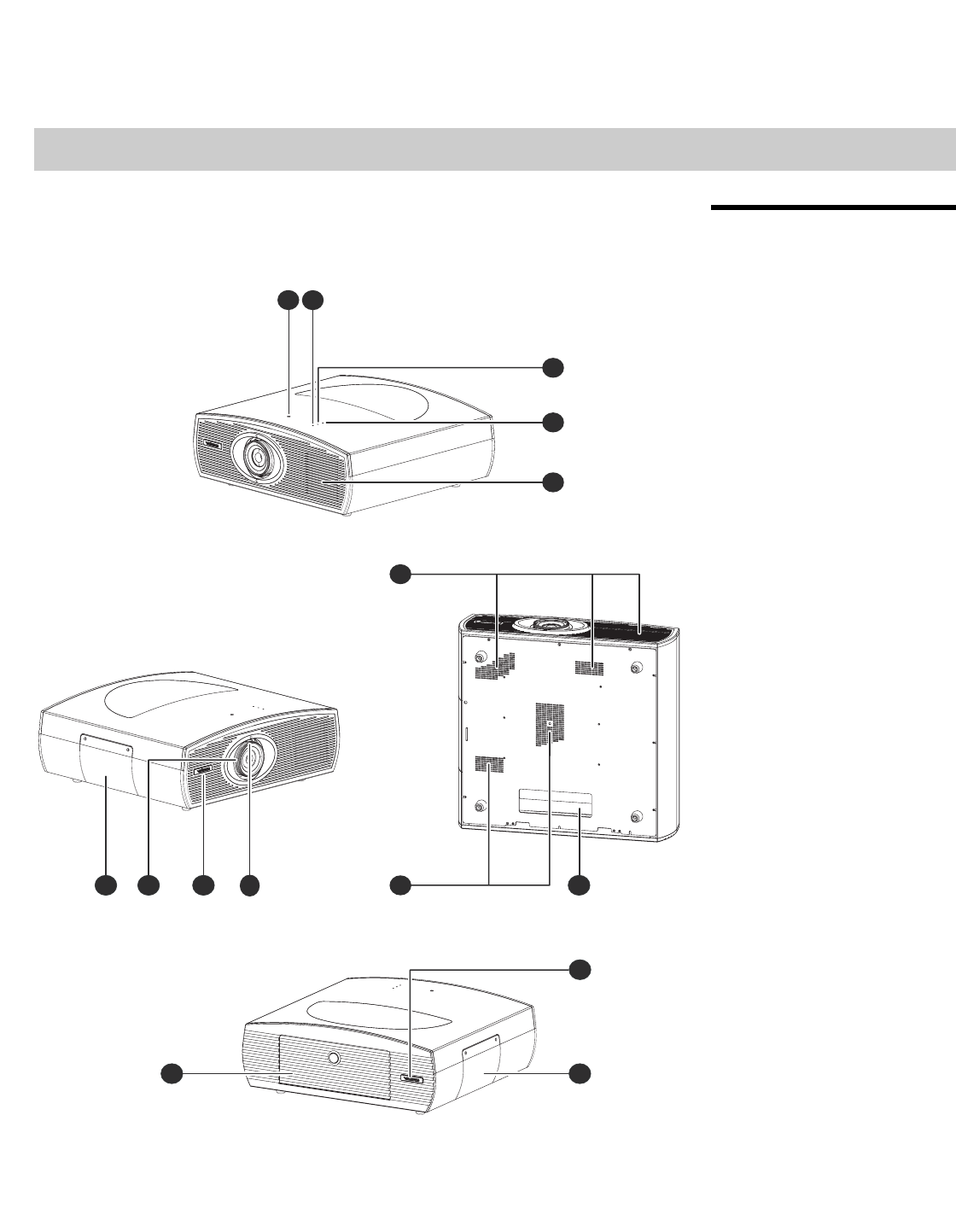
1. VERTICAL LENS SHIFT
Using a 9/64” hex wrench, turn this to move the lens up or down.
2. POWER LED
Lights red to indicate that the projector is in standby; flashes blue during warm-up or
cool-down or lights blue to indicate normal operation.
3. LAMP LED
Lights blue to indicate normal lamp operation; lights red if the lamp has failed.
4. TEMP LED
Lights red to indicate that the projector has overheated and shut down.
5. EXHAUST VENTS
Hot air exits the projector through these vents. This air can be quite hot. Ensure that
there are no heat-sensitive objects near it and that it is never blocked.
6. CABLE OPENING
Pass cables through this opening.
7. INTAKE VENTS
Cool air enters the projector through these vents. To prevent overheating, ensure that
these vents are never blocked.
8.ZOOM TAB
Turn this tab to make the projected image larger or smaller.
9. VIDIKRON LOGO
You can rotate the logo to match the projector orientation: inverted (ceiling-mounted)
or upright. To rotate the logo, grip it at the sides, pull it away from the projector and
rotate it 180 degrees.
10. FOCUS RING
Turn this ring to focus the image.
11. LAMP COVER
Remove this cover to access the lamp compartment.
12. REAR PANEL ACCESS DOOR
To access the connector panel,
press the door release button so it
pops out. Turn the knob clockwise
or counter-clockwise and pull
gently on it to open the door.
Controls and Functions
Vidikron Vision 85 Owner’s Operating Manual 7
PRELIMINARY
2.2
Vision 85 Rear Panel
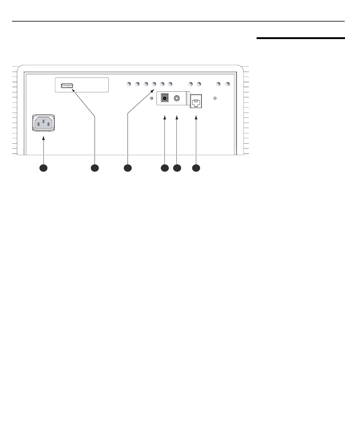
Figure 2-2 shows the Vision 85 rear panel.
Figure 2-2. Vision 85 Rear Panel
1. POWER INPUT (100 to 240 VAC)
Connect the Vision 85 to power here.
2. HDMI INPUT
An HDCP-compliant, digital video input for connecting the HDMI output from the VHD
Controller.
3. BUILT-IN KEYPAD
Used to navigate the Vision 85 on-screen menus. Refer to Vision 85 Built-In Keypad on
page 14 for more information.
4. 12-VOLT (200 mA) TRIGGER OUTPUT (cylindrical, DC power supply-type jack)
Connection for a retractable screen, screen masking or other, 12-volt trigger-activated
equipment. Outputs +12 volts/200 mA when the projector is turned on.
5. WIRED IR (3.5-mm, mini phono jack)
Not used. To use an external infrared receiver or wired remote control with this
projector, connect it to the IR input on the VHD Controller (see Figure 2-4).
6. RS-232C INPUT (RJ-11 female connector)
Connect the RS-232 output from the VHD Controller here, using the provided
communication cable.
HDMI
HDMI
AC IN 100-240V 50-60Hz
AC IN 100-240V 50-60Hz
TRIGGER
TRIGGER
IR
IR
RS-232 OUT
RS-232 OUT
RETURN ENTER DOWN UP LEFT RIGHT
RETURNENTERDOWNUPLEFTRIGHT
ON
ON
MENU
MENU
ASPECT
RATIO
ASPECT
RATIO
STANDBY
STANDBY
1 2 3 4 5 6
Controls and Functions
8Vidikron Vision 85 Owner’s Operating Manual
PRELIMINARY
2.3
VHD Controller Front
Panel
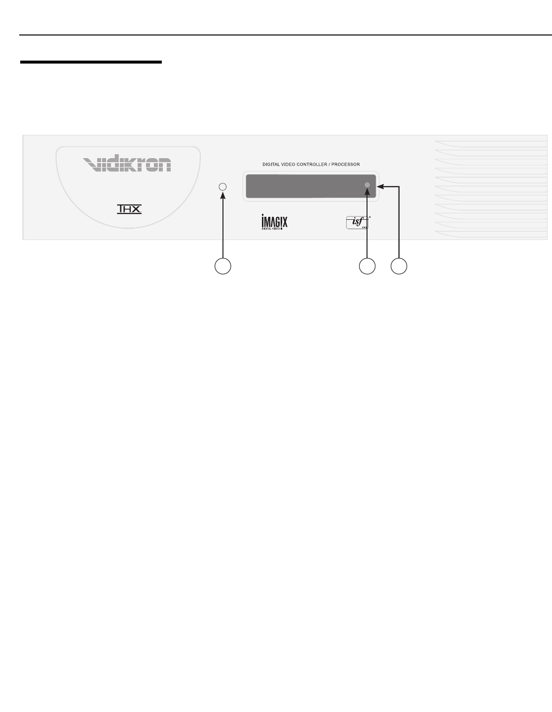
Figure 2-3 shows the controls and indicators on the VHD Controller front panel; the
paragraphs that follow describe them.
Figure 2-3. VHD Controller Front Panel
1. POWER BUTTON
Press once to toggle from standby mode to on mode. Press it again to return to standby
mode. For a discrete on or off command, you can use the direct access buttons on the
remote control.
2. IR SENSOR
Receives IR commands from the remote.
3. VACUUM FLUORESCENT DISPLAY
Can be used instead of the On-Screen Display (OSD). Displays currently-selected menu
or – if no menu is selected – the current source, signal format (NTSC or PAL), input
resolution and aspect ratio.
Component SD NTSC 480i
16:9 V85
1 2 3
Controls and Functions
Vidikron Vision 85 Owner’s Operating Manual 9
PRELIMINARY
2.4
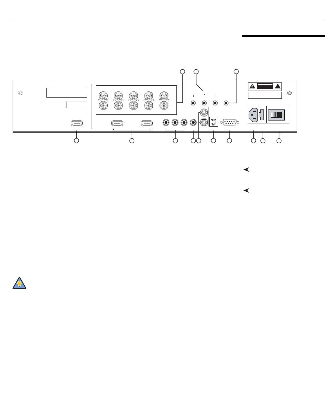
VHD Controller Rear Panel
Figure 2-4 shows the rear connector panel on the VHD Controller.
Figure 2-4. VHD Controller Rear Panel
Outputs1. HDMI OUT
Connect this to the HDMI Input on the Vision 85 (see Figure 2-2).
Inputs2. HDMI 1 / HDMI 2 (Digital)
Two, HDCP-compliant digital video inputs for connecting a DVD player or HD tuner with
a DVI or HDMI output.
3. HD1 / HD2 (5 x Analog BNCs)
Two inputs (five BNCs per input) for connecting either RGB or component
high-definition television signals. The VHD Controller automatically detects the signal
format: RGB(HV) or YPrPb, 480p, 720p, 480i, 576i or 1080i.
4. COMPONENT VIDEO (RCA connectors)
Standard Definition (480i/576i) Component (YPrPb) input. This is the input for
component video from sources such as DVD players.
Pb Pr Y
Video
3IR
RS-232 Control
S-Video 1
S-Video 2
HD1
HD2
12
R/Pr G/Y B/Pb
R/Pr G/Y B/Pb H V
HDMI 1 HDMI 2HDMI Out
HV
TRIGGERS
RS-232 Out
CAUTION:
TO REDUCE THE RISK OF ELECTRIC
SHOCK, DO NOT REMOVE COVER. NO USER-
SERVICEABLE PARTS INSIDE. REFER SERVICING
TO QUALIFIED SERVICE CENTER.
AVI S: RISQUE DE CHOC ELECTRIQUE-NE PAS OUVRIR
CAUTION
RISK OF ELECTRIC SHOCK
DO NOT OPEN !
WARNING: TO REDUCE THE RISK OF FIRE
OR ELECTRIC SHOCK, DO NOT EXPOSE
THIS APPLIANCE TO RAIN OR MOISTURE.
100-230VAC 50-60 Hz, 165 Watts Max
INPUTS
SYSTEM CONTROL INTERFACE
Component Video
Serial No
Video Processor / Controller
Model
Made In USA
124510 11 12 13
8
6
79
3
For best results, do not run your DVD player in progressive mode.
Tip

Controls and Functions
10 Vidikron Vision 85 Owner’s Operating Manual
PRELIMINARY
5. COMPOSITE VIDEO INPUT
Standard composite video input for connecting a VCR, laser disc player or other
composite video source.
6. S-VIDEO 1 / S-VIDEO 2
Two, standard S-Video inputs for connecting a DVD player, satellite receiver or Super
VHS (S-VHS) VCR.
7. 12-VOLT (750 mA) TRIGGER OUTPUTS
Connection for up to three (3), 12-volt trigger-controlled devices such as retractable
screens or screen masks.
8.ComLink (RS-232) OUTPUT
Connect this to the ComLink (RS-232) input on the projector, using the provided
communication cable.
9. IR
Wired input from a wired remote control or infrared receiver. It is a 3.5-mm, mini phono
jack, wired as follows:
Ring = +5V
Tip = IR Input
Sleeve = Ground
10. RS-232 CONTROL PORT
A female, 9-pin D-sub connector for interfacing with a PC or home theater
automation/control system.
11. POWER INPUT (100 to 240 VAC)
Connect the VHD Controller to power here.
12. MAIN AC FUSE
This is the main AC input fuse (5mm x 20mm, 500 mA, 250V slow-blow).
13. MAIN POWER SWITCH
Disconnects or applies power to the VHD Controller.
When an external remote control or infrared receiver is connected to the
wired IR input, the IR sensor on the front of the VHD is disabled.
Note
Controls and Functions
Vidikron Vision 85 Owner’s Operating Manual 11
PRELIMINARY
2.5
Vision 85 Remote Control
Unit
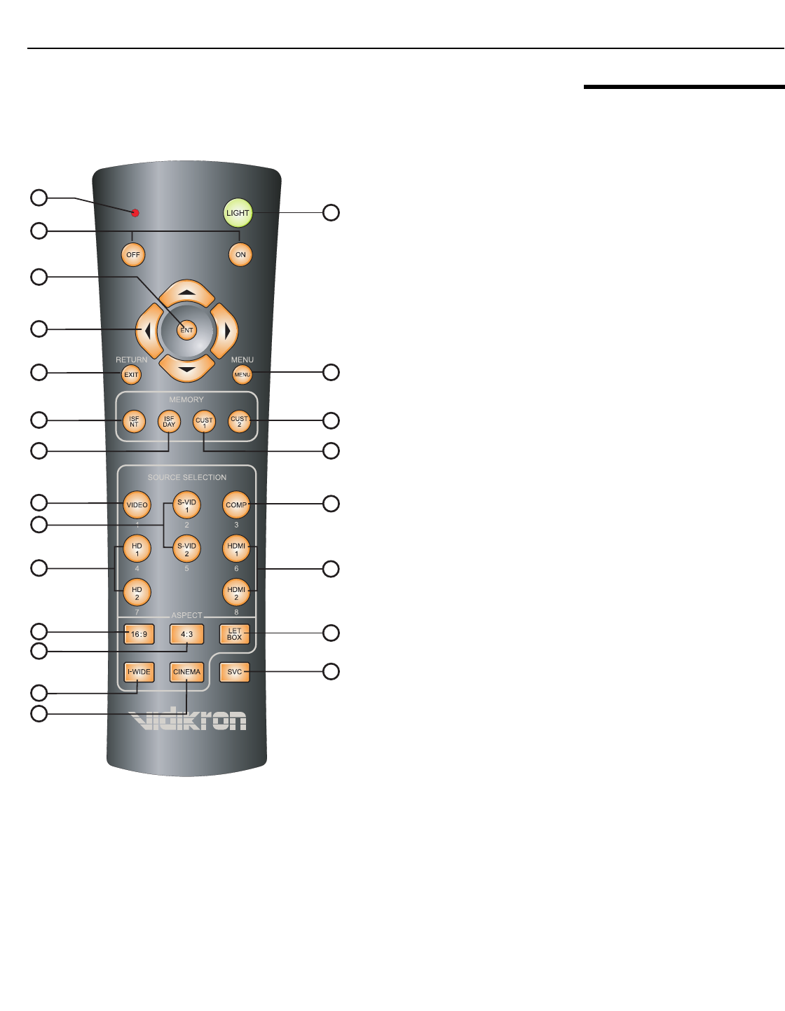
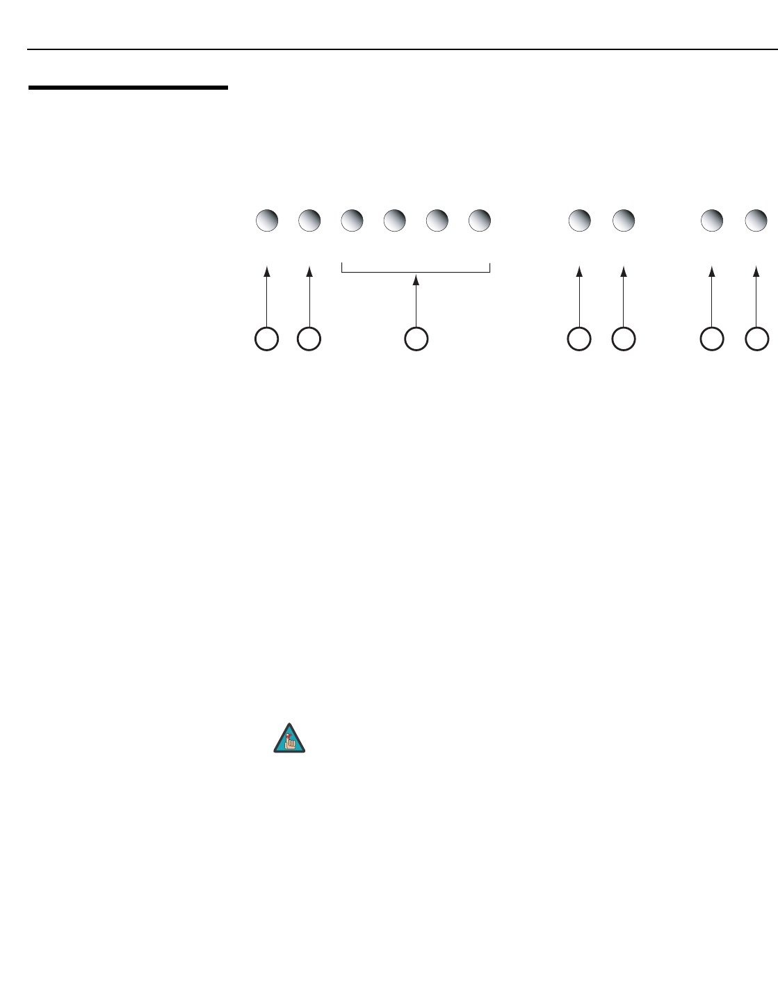
Figure 2-5 shows the Vision 85 remote control, and the paragraphs that follow describe its
functionality.
Figure 2-5. VHD Controller/Vision 85 Remote Control
1
2
7
10
14
19
22
16
11
4
3
5
6
8
12
17
18
20
21
13
9
15
Controls and Functions
12 Vidikron Vision 85 Owner’s Operating Manual
PRELIMINARY
1. IR OUTPUT INDICATOR
Lights when a button is pressed to indicate that an IR signal is being transmitted.
2. LIGHT
Press to illuminate the buttons.
3. ON / OFF
Press to turn the projector on or off.
4. ENT (Enter)
Press to select a highlighted menu item or confirm a changed setting.
5. Cursor Buttons ( , , , )
Use these buttons to select items or settings, adjust settings or switch display patterns.
When no menu is present on-screen, the UP and DOWN buttons toggle through the
available aspect ratios, in this order:
UP Button = 16:9 - Standard (4:3) - Letterbox - IntelliWide - Cinema - IntelliWide 2.35
DOWN Button = IntelliWide 2.35 - Cinema - IntelliWide - Letterbox - Standard (4:3) - 16:9
Likewise, the LEFT and RIGHT buttons toggle through the different source inputs, in this
order:
LEFT Button = HDMI 2 - HDMI 1 - HD/RGB2 - HD/RGB 1 - Component SD - S-Video 2 -
S-Video 1 - Composite
RIGHT Button = Composite - S-Video 1 - S-Video 2 - Component SD - HD/RGB 1 - HD/RGB
2 - HDMI 1 - HDMI 2
6. RETURN/EXIT
Press this button to exit the current menu and return to the previous one, or to cancel an
operation.
7. MENU
Press this button to access the OSD controls.
On some remote control units, this button is where the RETURN/EXIT
button (item #6) appears here.
IntelliWide 2.35 is available only on the Vision 85/CineWide and only on
the analog inputs (HD/RGB, SD Component, Composite and S-Video). For
more information about aspect ratios, refer to Table 4-1.
The “direct select” function of the UP, DOWN, LEFT and RIGHT buttons is
available only on the analog inputs (HD/RGB, SD Component, Composite
and S-Video).
On some remote control units, the ENT (Enter) button (item #4) is in this
location.
Note
Note
Note
Note

Controls and Functions
Vidikron Vision 85 Owner’s Operating Manual 13
PRELIMINARY
Memory Preset Buttons:
8.ISF NT (Night)
Press to recall settings for the current input from the “ISF Night” memory preset.
9. ISF DAY
Press to recall settings for the current input from the “ISF Day” memory preset.
10. CUST 2
Press to recall settings for the current input from the “Custom 2” or “White Enhance”
memory preset.
11. CUST 1
Press to recall settings for the current input from the “Custom 1” or “Black Enhance”
memory preset.
12. VIDEO (1)
Press to select Composite video input as the source or to enter the numeric character “1.”
13. S-VID 1 (2) / S-VID 2 (5) (S-Video)
Press to select an S-Video input or to enter the numeric character “2” or “5.”
14. COMP (Component) (3)
Press to select Component SD (480i/576i) video input as the source or to enter the
numeric character “3.”
15. HD 1 (4) / HD 2 (7)
Press to select a HD (RGBHV or YPbPr component) input or to enter the numeric
character “4” or “7.”
16. HDMI 1 (6) / HDMI 2 (8)
Press to select a Digital Video input or to enter the numeric character “6” or “8.”
Aspect Ratio Selection Buttons:
Use these buttons to select an aspect ratio directly or to enter numeric characters, as follows:
17. 16:9 (9)
For viewing 16:9 DVDs or HDTV programs in their native aspect ratio.
18.4:3 (0)
Scales the input signal to fit 4:3 display mode in the center of the screen.
19. LETBOX (Letterbox)
For viewing LaserDisc movies or non-anamorphic DVDs on a 16:9 screen.
20. I-WIDE (IntelliWide)
Enlarges a 4:3 image horizontally in a NON-linear fashion to fit 16:9 full screen display.
21. CINEMA
For viewing 2.35:1 source material.
22. SVC (CineWide-equipped projectors only)
Selects the IntelliWide 2.35 aspect ratio, used for viewing 16:9 source material on a 2.35:1
screen.
Controls and Functions
14 Vidikron Vision 85 Owner’s Operating Manual
PRELIMINARY
2.6
Vision 85 Built-In Keypad
The Vision 85 has a built-in keypad that you can use to access the menu system for working
with digital 1080i or 1080p sources. Figure 2-6 shows the Vision 85 built-in keypad; the
paragraphs that follow describe its use.
Figure 2-6. Vision 85 Built-In Keypad
1. RETURN
Press RETURN to exit the current menu or cancel an operation.
2. ENTER
Press ENTER to confirm a menu item selection.
3. DOWN / UP / LEFT / RIGHT
Use these buttons to select menu items or adjust settings.
4. MENU
Press MENU to display or hide the OSD menus for digital 1080i or 1080p sources.
5. (not used)
6. STANDBY
Press STANDBY to put the projector into standby mode.
7. ON
Press ON to turn the projector on or off.
Only trained service personnel should use the built-in keypad.
Almost all projector configuration and operational tasks can be
performed using the VHD Controller.
It is only necessary to use the built-in keypad if IR signals from the remote
control cannot reach the VHD Controller, or for performing
service-related tasks such as resetting the lamp hour counter (refer to
Lamp Replacement on page 63).
RETURN ENTER DOWN UP LEFT RIGHT
RETURNENTERDOWNUPLEFTRIGHT
ON
ON
MENU
MENU
ASPECT
RATIO
ASPECT
RATIO
STANDBY
STANDBY
13 45
27
6
Note
Vidikron Vision 85 Owner’s Operating Manual 15
PRELIMINARY
3.1
Remote Control
Battery InstallationTo install batteries in the remote control:
1. Remove the battery cover from the back of the remote control.
2. Insert the batteries included with the remote control. Ensure that the polarities correctly
match the and markings inside the battery compartment.
3. Replace the battery cover.
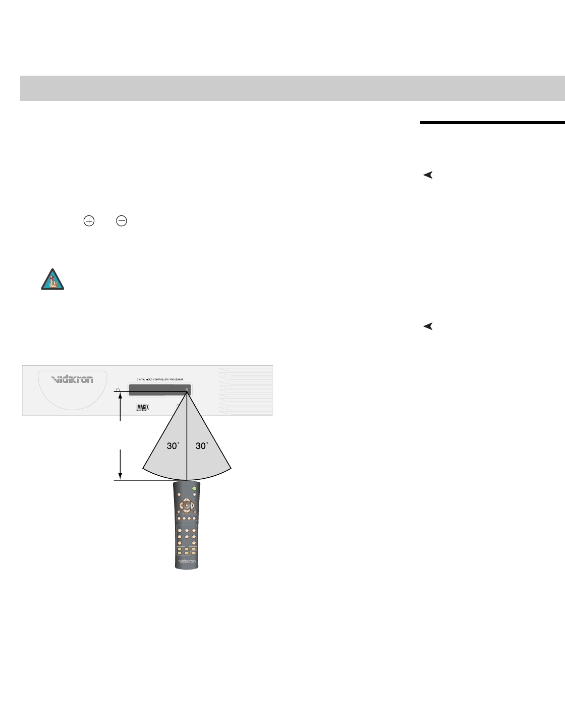
Notes on Remote Control
Operation
The remote control can be used to control the Vision 85 within the ranges shown in Figure
3-1.
Figure 3-1. Available Range of the Remote Control
3Installation
1. Do not mix an old battery with a new one or different types of batteries.
2. If you will not use the remote control for a long time, remove the batteries
to avoid damage from battery leakage.
Note
Component SD NTSC 480i
16:9 V85
Approx.
7m/23ft
HD
1
HD
2
S-VID
2
S-VID
1
HDMI
1
HDMI
2
VIDEO
ISF
DAY
ISF
NT
CUST
1
CUST
2
MEMORY
RETURN
EXIT
MENU
COMP
SOURCE SELECTION
ANA 4x3 LET
BOX
I-WIDE CINEMA
LIGHT
OFF ON
SVC
ASPECT
123
456
78
ENT

Installation
16 Vidikron Vision 85 Owner’s Operating Manual
PRELIMINARY
• Do not drop the remote control or expose it to moisture or high temperature.
• The remote control may malfunction under a fluorescent lamp. If that occurs, move the
VHD Controller away from the fluorescent lamp.
• Make sure that there is nothing obstructing the infrared beam between the remote
control and the IR receiver on the VHD Controller or projector.
• If the effective range of the remote control decreases, or it stops working, replace the
batteries with new ones.
• Ambient conditions may possibly impede the operation of the remote control. If this
happens, point the remote control at the VHD Controller or projector and repeat the
operation.
The signal from the remote control can be reflected by walls or other
surfaces.
Note
Installation
Vidikron Vision 85 Owner’s Operating Manual 17
PRELIMINARY
3.2
Quick Setup
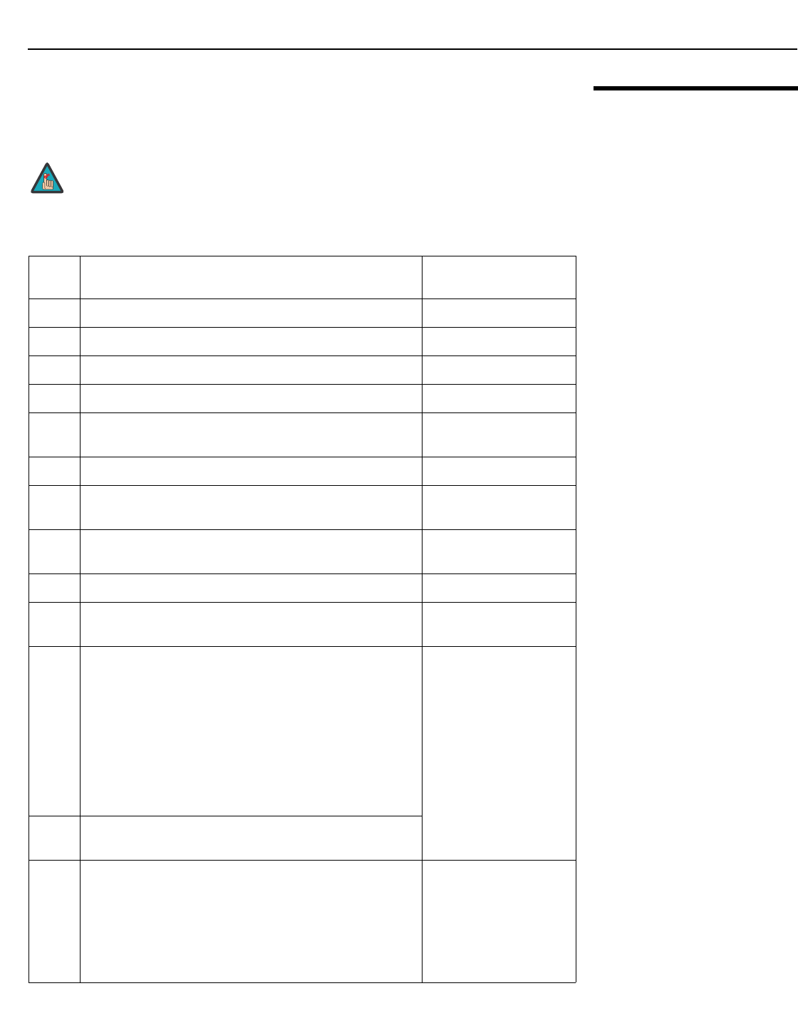
Table 3-1 gives a quick overview of the Vision 85 installation process. The sections following
this one provide detailed instructions.
Installation should be performed by a qualified custom video installation
specialist.
Table 3-1. Installation Overview
Step Procedure For Details, Refer to
page...
1Choose a location for the projector 18
2Connect the VHD Controller to the projector 23
3Connect signal sources to the VHD Controller 24
4Connect external controller to RS-232 port (optional) 28
5Connect other home theater components to 12-volt trigger
outputs (optional)
28
6Apply power to the projector 30
7For rear-screen and/or ceiling-mount installations, select the
proper picture orientation
30
8Primary lens adjustments: projected image size (zoom),
position (shift) and focus
20, 31
9Install CineWide anamorphic lens (optional) 32
10 CineWide lens adjustments: position, pitch (angle), geometry
and focus
33
11
Projector calibration – Analog 1080i and lower-resolution
signals:
Adjust the following for Component SD input; save settings
when finished:
• Aspect ratio
• Brightness
• Contrast
• Color level
• Tint
• Input position
39 through 52
12 Repeat Step 11 for S-Video 1, S-Video 2, Composite Video,
HD1 and HD2 inputs
13
Projector Calibration – Digital 1080i or 1080p signals:
Adjust the following for HDMI 1 and HDMI 2 inputs:
• Brightness
• Contrast
• Color level
• Tint
• Input position
52 through 61
Note
Installation
18Vidikron Vision 85 Owner’s Operating Manual
PRELIMINARY
3.3
Installation Considerations
Proper installation of your projector will ensure the quality of your display. Whether you are
installing a projector temporarily or permanently, you should take the following into account
to ensure your projector performs optimally.
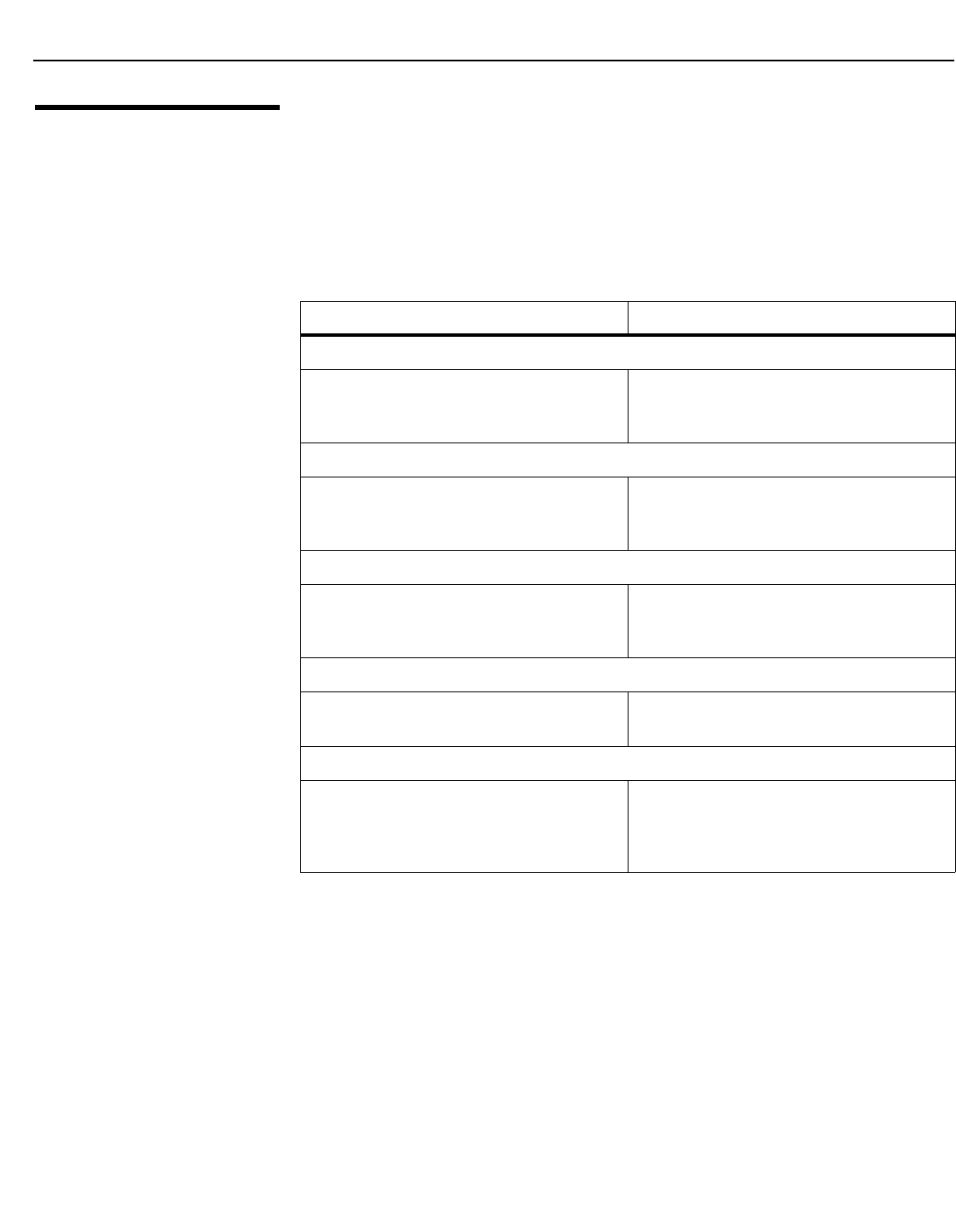
Installation Type Choose the installation type that best suits your needs: front or rear screen, floor mount or
inverted mount. Table 3-2 compares these various installation methods.
Ambient Light In general, minimize or eliminate light sources directed at the screen. Contrast ratio in your
images will be noticeably reduced if light directly strikes the screen, such as when a shaft of
light from a window or floodlight falls on the image. Images may then appear washed out
and less vibrant.
➤
Table 3-2. Projector Installation Options
Advantages Considerations
Front Screen, Floor Mount Installation
• Easy to set up
• Can be moved or changed quickly
• Easy to access
• Shares floor space with audience
Front Screen, Inverted Mount (ceiling) Installation
• Does not take up audience space
• Projector is unobtrusive
• Projector cannot be accidentally moved
• Installation is more permanent
• Projector access is more difficult
Rear Screen, Floor Mount Installation
• Projector is completely hidden
• Projector is easily accessed
• Usually good ambient light rejection
• Requires separate room
• Installation cost is usually higher
Rear Screen, Inverted Mount (ceiling) Installation
• Projector is completely hidden
• Usually good ambient light rejection
• Requires separate room
• Installation cost is usually higher
Rear Screen, Floor Mount with Mirror
• Projector is completely hidden
• Usually good ambient light rejection
• Requires less space behind screen than other
rear screen installations
• Requires separate room
• Installation cost is usually higher
➤
Installation
Vidikron Vision 85 Owner’s Operating Manual 19
PRELIMINARY
Throw DistanceThrow distance is the distance measured from the front of the projector to the screen. This is
an important calculation in any projector installation as it determines whether or not you
have enough room to install your projector with a desired screen size and if your image will
be the right size for your screen.
You can quickly estimate the throw distance by taking the width of the screen and
multiplying it by the lens throw ratio; see Figure 3-2. The result of this calculation tells you
roughly how far back the projector should be positioned from the screen in order to project a
focused image large enough to fill the screen.
Figure 3-2. Estimating Throw Distance
The Vision 85 offers a throw ratio of between 1.86 and 2.45. For example, with a 100-inch
wide screen, the Vision 85 has a throw distance range of between 186 inches (4.72 meters)
and 245 inches (6.22 meters).
The Vision 85/CineWide offers a throw ratio of between 1.92 and 2.45. For example, with
a 100-inch wide screen, the Vision 85 has a throw distance range of between 192 inches (4.88
meters) and 245 inches (6.22 meters).
Estimating Throw Distance
Throw Distance (TD) = Screen Width (w) x Lens Throw Ratio
Screen width (w)
TD
Vision 85 Throw Ratio: 1.86 to 2.45
Vision 85/CineWide Throw Ratio: 1.92 to 2.45
Installation
20 Vidikron Vision 85 Owner’s Operating Manual
PRELIMINARY
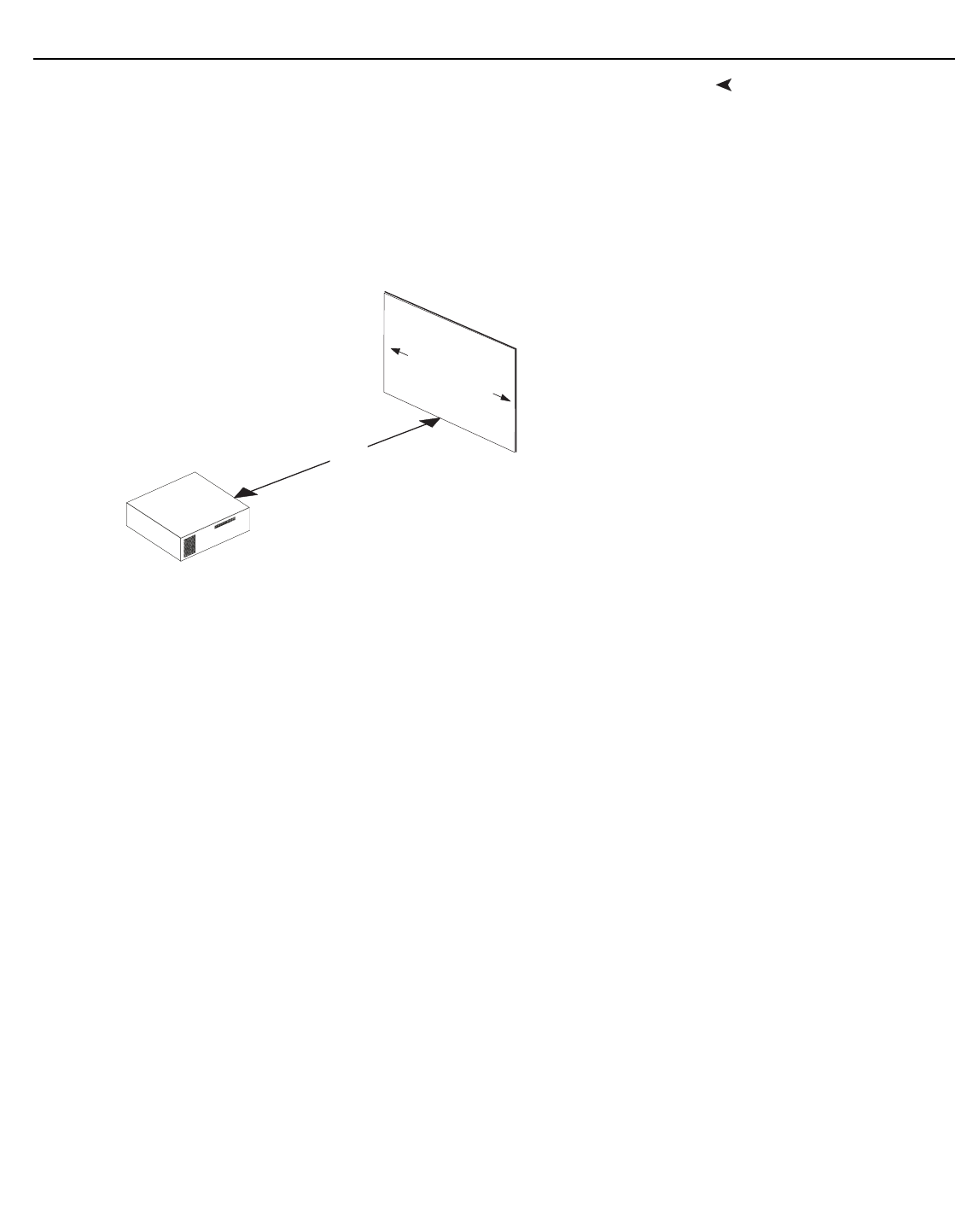
Vertical and Horizontal
Position
Proper placement of the projector relative to the screen will yield a rectangular,
perfectly-centered image that completely fills the screen.
Ideally, the projector should be positioned perpendicular to the screen and in such a way
that the lens center and screen center are aligned with each other, as shown in Figure 3-3.
Figure 3-3. Projector Placement
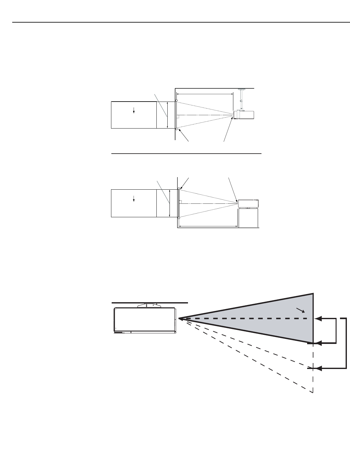
Vertical Lens Shift If it is not possible to align the projector and screen as shown in Figure 3-3, you can use the
lens shift controls to center the image on the screen. Lens shift is generally expressed as a
percentage of the screen height or width, as shown in Figure 3-4.
Figure 3-4. Vertical Lens Shift (EXAMPLE ONLY)
➤
Height
Projection Distance
Ceiling
Ceiling Installation
Screen
Height
Floor
Lens Center
Projection Distance
Floor Installation
Lens Center
x
Lens Center
x
Screen Lens Center
➤
50% Height
Lens Shift
(0.5 x H)
100% Height
Lens Shift
(1.0 x H)
Screen Center
0%
Note: This is a general example of lens shift. Lenses vary in their shift capabilities. No particular lens or
projector is used in this example.
Installation
Vidikron Vision 85 Owner’s Operating Manual 21
PRELIMINARY
The Vision 85 provides up to 50% of vertical lens shift in either direction. For example,
with a 96 x 54-inch (16:9) screen, you can shift the image up to 27.00 inches (0.69 meters)
above or below the screen center.
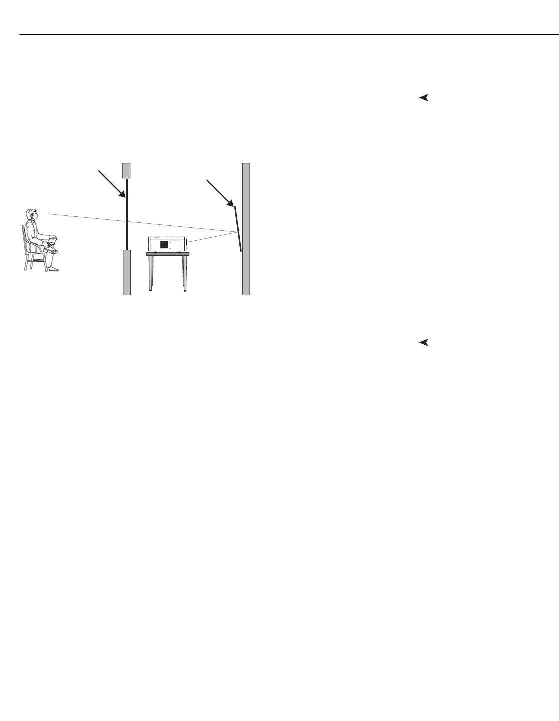
Folded OpticsIn rear screen applications where space behind the projector is limited, a mirror may be used
to fold the optical path, as shown in Figure 3-5. The position of the projector and mirror must
be accurately set. If you are considering this type of installation, contact your dealer for
assistance.
Figure 3-5. Folded Optics
Other ConsiderationsOther considerations and tips that can help improve your installation:
• Keep the ambient temperature constant and below 35°C (95°F). Keep the projector away
from heating and/or air conditioning vents. Changes in temperature may cause drifts in
the projector circuitry, which may affect performance.
• Keep the projector away from devices that radiate electromagnetic energy such as motors
and transformers. Common sources of these include slide projectors, speakers, power
amplifiers and elevators.
Screen
Mirror

Installation
22 Vidikron Vision 85 Owner’s Operating Manual
PRELIMINARY
3.4
Mounting the Vision 85
There are several methods for mounting the projector. Depending on your chosen
installation, one method may be more suitable than another.
Floor Mounting (Upright) In typical front and rear screen installations, the projector can be mounted to a secure and
level surface such as a table or cart. Carts are useful when moving a projector during a
presentation or from site to site. If possible, lock the wheels when it’s in position to prevent it
from being moved during a presentation.
Ceiling Mounting (Inverted) For fixed installations, and for those that want the projector out of sight or have a limited
space for projector and audience, you can invert the Vision 85 and suspend it from the ceiling
using a specially-designed ceiling mount fixture.
The projector can also be inverted and placed in an enclosure above and behind the viewing
area. Install four feet on the inside bottom surface of the enclosure on which the projector
can rest. A variety of materials can be used for this purpose (for example, rubber crutch tips
or turntable feet).
Adjusting the Projection
Angle
If the Vision 85 is ceiling-mounted and the screen is significantly lower than the projector,
you can tilt the projector at a slight angle by adjusting the ceiling mount.
If you do this, you may need to shift the image using the OSD controls, to compensate. For
detailed instructions, refer to Using the On-Screen Menus on page 37.
➤
➤
Use only the Vidikron-approved ceiling mount kit designed for your
projector. Install the mount kit according to the instructions provided
with it.
Note
➤
Installation
Vidikron Vision 85 Owner’s Operating Manual 23
PRELIMINARY
3.5
Connections to the Vision
85 and VHD Controller
Proceed as follows to connect the VHD Controller to the Vision 85, your video sources,
external controller(s) – if present – and AC power.
When connecting your equipment:
• Turn off all equipment before making any connections.
• Use the correct signal cables for each source.
• Ensure that the cables are securely connected. Tighten the thumbscrews on connectors
that have them.
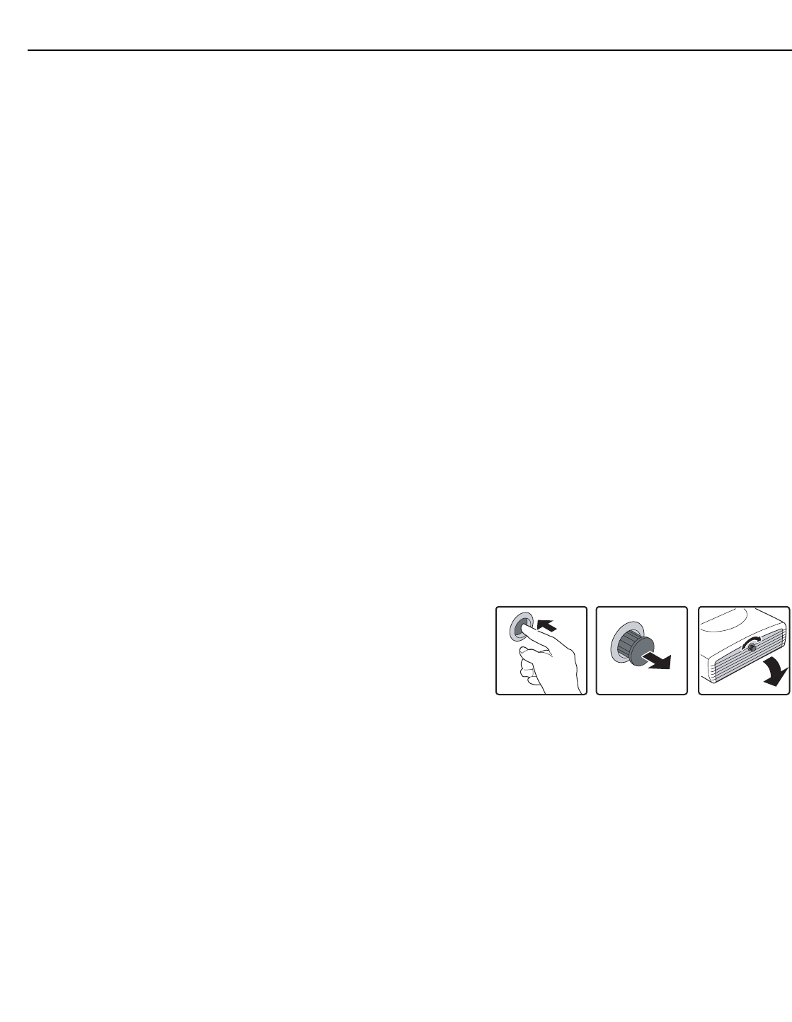
Connector Panel AccessTo access the connector panel, press
the door release button so it pops out.
Turn the knob clockwise or
counter-clockwise and pull gently on it
to open the door.
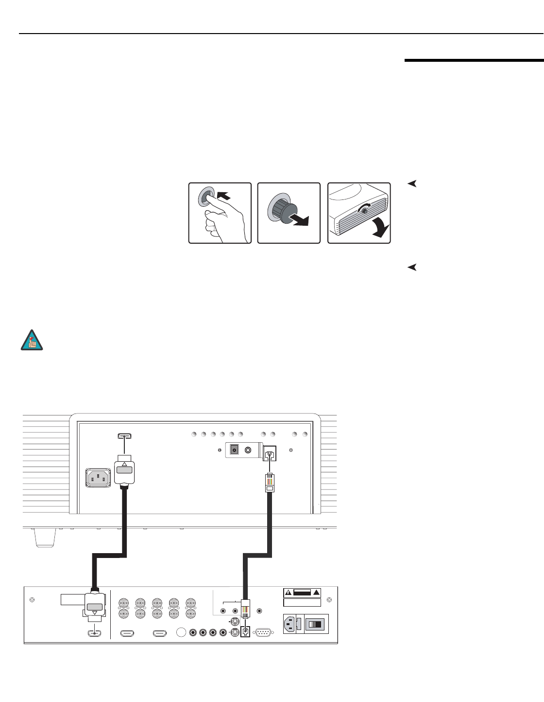
Connecting the Projector to
the VHD Controller
The Vision 85 is designed to receive only video input signals directly from the companion
VHD Controller/Processor. Connect all signal sources to the appropriate inputs on the rear
panel of the VHD. The signal from the VHD is then output to the Vision 85 projector through
an HDMI cable.
Connect the HDMI and RS-232 outputs of the VHD Controller to the corresponding inputs of
the Vision 85; see Figure 3-6.
Figure 3-6. Connecting the Projector to the VHD Controller
You CANNOT connect signal sources directly to the Vision 85. They MUST
be routed through the VHD Controller for proper operation.
Note
HDMI
HDMI
AC IN 100-240V 50-60Hz
AC IN 100-240V 50-60Hz
TRIGGER
TRIGGER
IR
IR
RS-232 OUT
RS-232 OUT
RETURN ENTER DOWN UP LEFT RIGHT
RETURNENTERDOWNUPLEFTRIGHT
ON
ON
MENU
MENU
ASPECT
RATIO
ASPECT
RATIO
STANDBY
STANDBY
Pb Pr Y
Video
3
IR
RS-232 Control
S-Video 1
S-Video 2
HD1
HD2
12
R/Pr G/Y B/Pb
R/Pr G/Y B/Pb H V
HDMI 1 HDMI 2HDMI Out
HV
TRIGGERS
RS-232 Out
CAUTION:
TO REDUCE THE RISK OF ELECTRIC
SHOCK, DO NOT REMOVE COVER. NO USER-
SERVICEABLE PARTS INSIDE. REFER SERVICING
TO QUALIFIED SERVICE CENTER.
AVIS: RISQUE DE CHOC ELECTRIQUE-NE PAS OUVRIR
CAUTION
RISK OF ELECTRIC SHOCK
DO NOT OPEN
!
WARNING:
TO REDUCE THE RISK OF FIRE
OR ELECTRIC SHOCK, DO NOT EXPOSE
THIS APPLIANCE TO RAIN OR MOISTURE.
100-230VAC 50-60 Hz, 165 Watts Max
INPUTS
SYSTEM CONTROL INTERFACE
Component Video
SDI
Option
Serial No
Video Processor / Controller
Model
Made In USA
RS-232 OUTHDMI OUT
Installation
24 Vidikron Vision 85 Owner’s Operating Manual
PRELIMINARY
Connecting Source
Components to the VHD
Controller
Connect your video sources to the VHD Controller as shown and described in the sections
that follow.
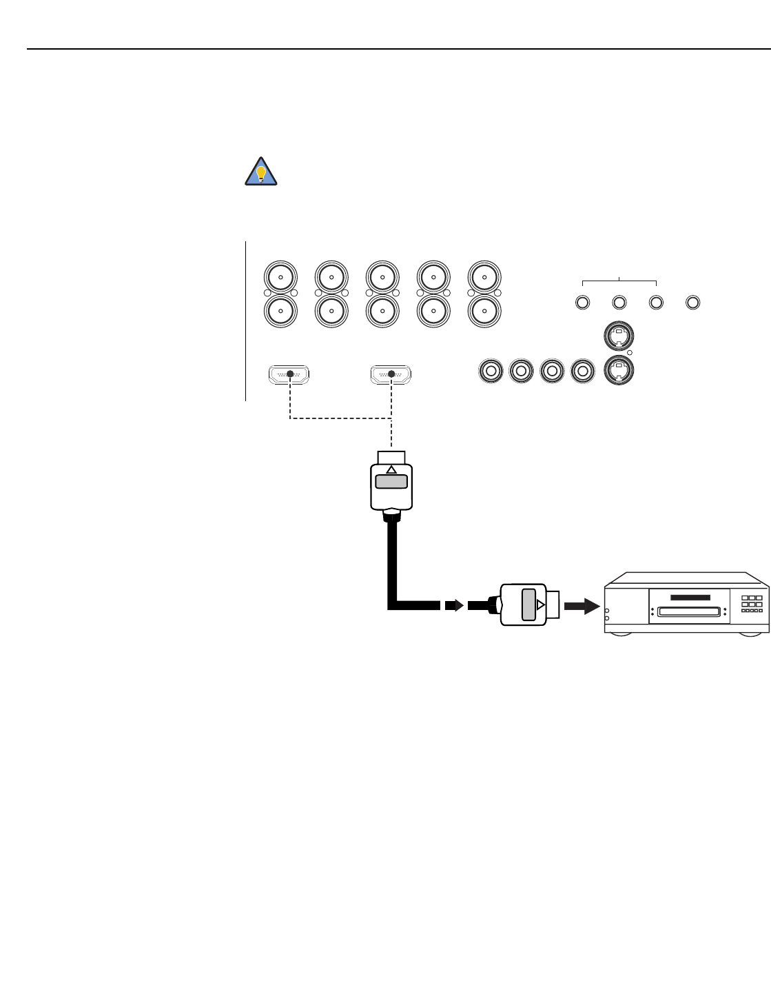
HDMI Connections: See Figure 3-7.
Figure 3-7. HDMI Source Connections
➤
Use the HDMI inputs whenever possible. This ensures the highest video
quality because the signal is carried in the digital domain throughout the
entire signal path, from source component output into the projector.
Tip
HD1
HD2
G/Y
INPUTS
HVR/Pr B/Pb
G/Y H VR/Pr B/Pb
Component Video
Pb Pr Y
Video S-Video 2
S-Video 1
IR12 3
TRIGGERS
HDMI 1 HDMI 2
HDMI Source
(HD-DVD/BD/DVD Player or
HD Tuner with
HDMI or DVI out)
Installation
Vidikron Vision 85 Owner’s Operating Manual 25
PRELIMINARY
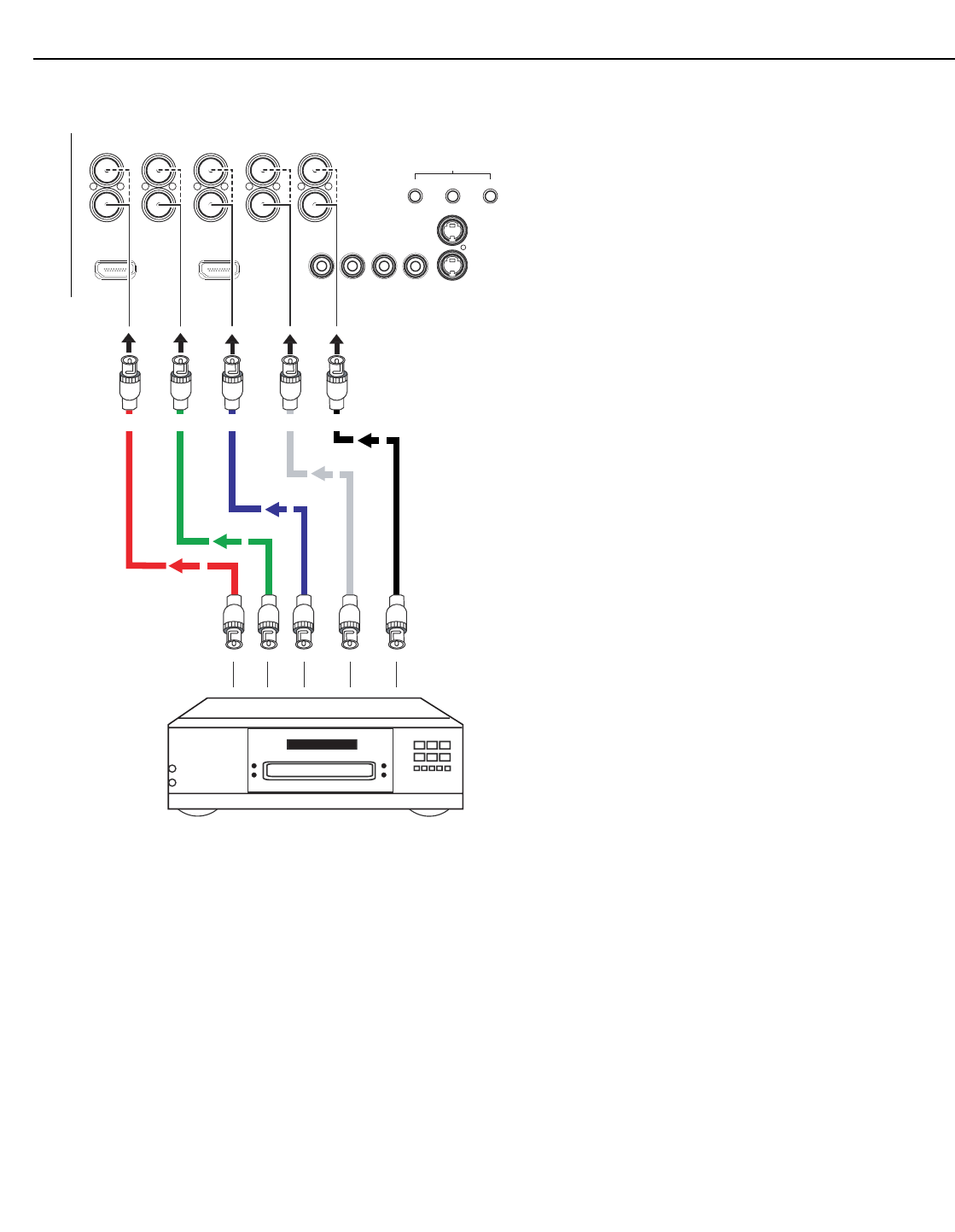
Digital (DTV) RGB or Component Video Connections: See Figure 3-8.
Figure 3-8. Digital (DTV) RGB or Component Video Connections
HD1
HD2
G/Y
INPUTS
HVR/Pr B/Pb
G/Y H VR/Pr B/Pb
Component Video
Pb Pr Y Video S-Video 2
S-Video 1
12 3
TRIGGERS
HDMI 1 HDMI 2
DTV or Progressive
Component (YPbPr)
Source
Red/Pr Green/Y Blue/Pb Horiz Vert
Installation
26 Vidikron Vision 85 Owner’s Operating Manual
PRELIMINARY
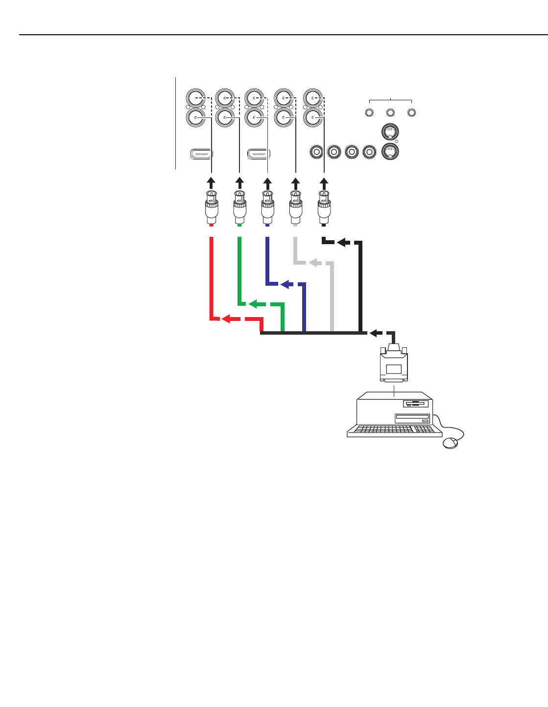
Analog (Computer) RGB Connections: See Figure 3-9.
Figure 3-9. Analog RGB Connections
HD1
HD2
G/Y
INPUTS
HVR/Pr B/Pb
G/Y H VR/Pr B/Pb
Component Video
Pb Pr Y Video S-Video 2
S-Video 1
12 3
TRIGGERS
HDMI 1 HDMI 2
Personal Computer
Red Green Blue Horiz Vert
Installation
Vidikron Vision 85 Owner’s Operating Manual 27
PRELIMINARY
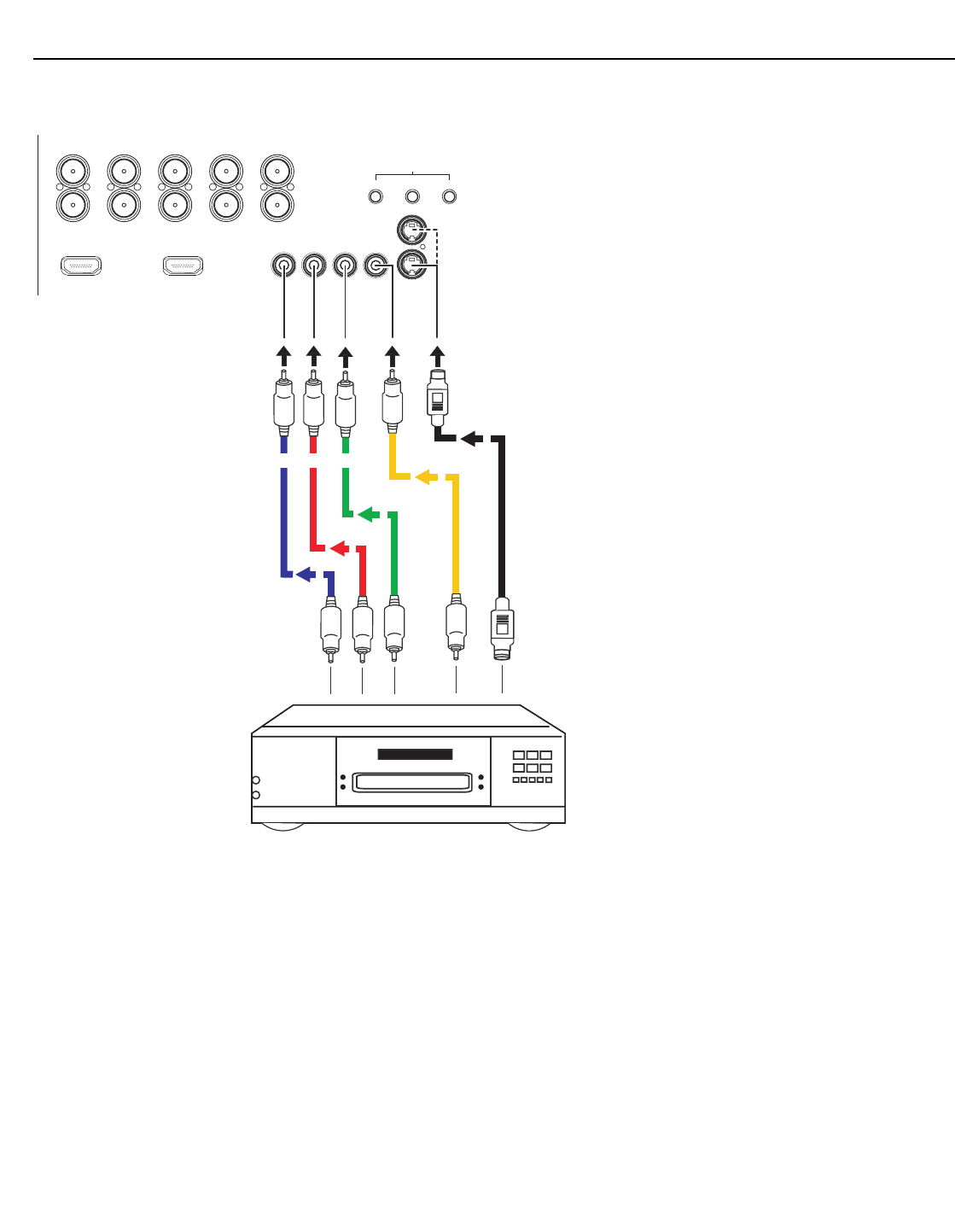
Composite/S-Video/Component Video Connections: See Figure 3-10.
Figure 3-10. Composite, S-Video and Component Video Connections
HD1
HD2
G/Y
INPUTS
HVR/Pr B/Pb
G/Y H VR/Pr B/Pb
Component Video
Pb Pr Y Video S-Video 2
S-Video 1
12 3
TRIGGERS
HDMI 1 HDMI 2
DVD Player, VCR,
Satellite Receiver,
Laser Disc etc.
Pb Pr Y
Installation
28Vidikron Vision 85 Owner’s Operating Manual
PRELIMINARY
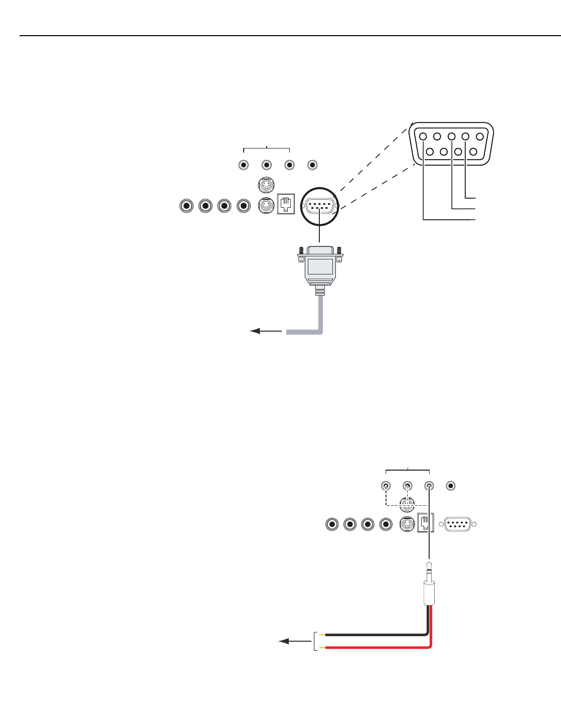
Connecting a PC or
Automation System to the
VHD Controller
Use a standard, 9-pin RS-232 cable to connect a PC or home theater control/automation
system (if present) to the RS-232 Control port on the VHD Controller; see Figure 3-11.
For more information about using this connection, refer to Serial Communications on
page 67.
Figure 3-11. RS-232 Control System Connection
Connecting 12-Volt Trigger
Outputs to External
Equipment
VHD Controller: If your home theater contains equipment that responds to 12-volt triggers
(such as a retractable screen or screen mask), connect them to the 12-volt trigger outputs of
the VHD Controller as shown in Figure 3-12.
For more information on using the VHD Controller triggers, refer to Triggers on page 51.
Figure 3-12. 12-volt Trigger Output Connections (from VHD Controller)
➤
Pb Pr Y
Video
3
IR
RS-232 Control
S-Video 1
S-Video 2
12
TRIGGERS
RS-232 OutComponent Video
1
2
345
7
89 6
to Automation/
Control System
or PC
2 Transmit Data
3 Receive Data
5 Ground
(none of the other pins are used)
➤
Pb Pr Y
Video
3
IR
RS-232 Control
S-Video 1
S-Video 2
12
TRIGGERS
RS-232 OutComponent Video
to other,
12-volt
trigger-activated equipment
(screen, screen mask etc.) Tip = +12V
Sleeve = Ground
3.5-mm
mini plug
Installation
Vidikron Vision 85 Owner’s Operating Manual 29
PRELIMINARY
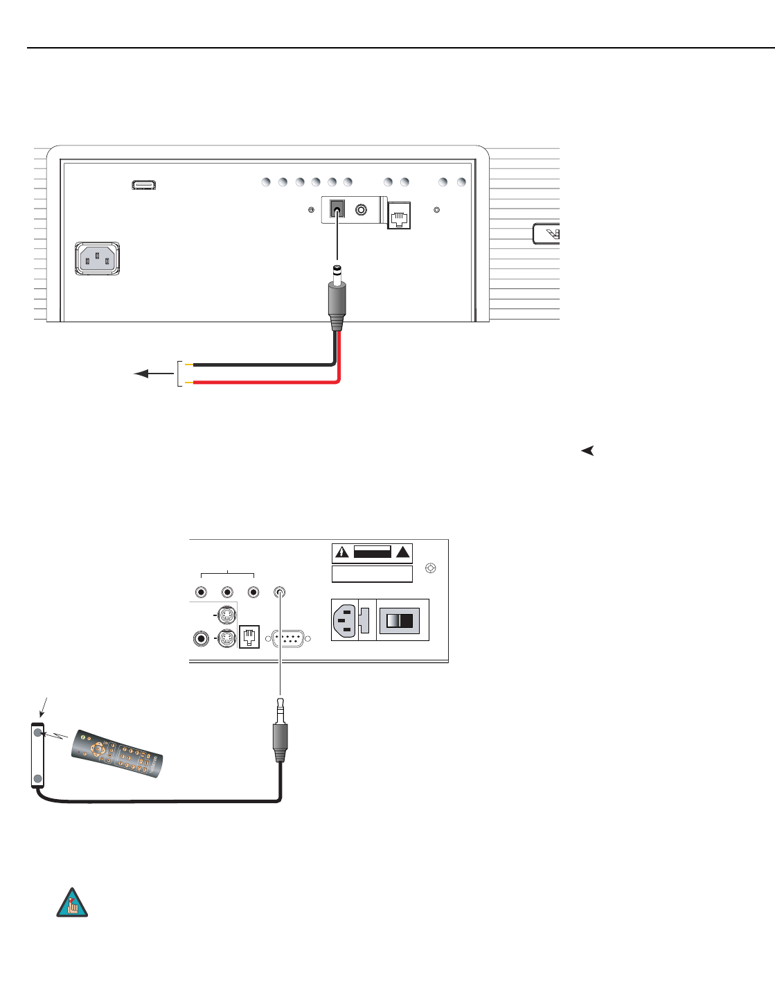
Projector: The projector is equipped with an additional 12-volt trigger output. This trigger
activates when the projector is turned on. Connect it to your retractable screen or other,
12-volt trigger-activated equipment as shown in Figure 3-13.
Figure 3-13. 12-volt Trigger Output Connection (from Projector)
Connecting an External IR
Receiver to the VHD
Controller
If infrared signals from the remote control cannot reach the VHD Controller due to excessive
distance or obstructions such as walls or cabinet doors, you can connect an external IR
receiver to the VHD Controller to extend the range of the remote control. See Figure 3-14.
Figure 3-14. External IR Receiver Connection
HDMI
HDMI
AC IN 100-240V 50-60Hz
AC IN 100-240V 50-60Hz
TRIGGER
TRIGGER
IR
IR
RS-232 OUT
RS-232 OUT
RETURN ENTER DOWN UP LEFT RIGHT
RETURNENTERDOWNUPLEFTRIGHT
ON
ON
MENU
MENU
ASPECT
RATIO
ASPECT
RATIO
STANDBY
STANDBY
to retractable screen
or other, 12-volt
trigger-activated
equipment Tip = +12V
Sleeve = Ground
(cylindrical,
DC power
supply-type
plug)
When an external IR receiver is connected to the wired IR input, the
built-in IR sensor on the VHD Controller is disabled.
Video
3IR
RS-232 Control
S-Video 1
S-Video 2
12
TRIGGERS
RS-232 Out
CAUTION:
TO REDUCE THE RISK OF ELECTRIC
SHOCK, DO NOT REMOVE COVER. NO USER-
SERVICEABLE PARTS INSIDE. REFER SERVICING
TO QUALIFIED SERVICE CENTER.
AVI S: RISQUE DE CHOC ELECTRIQUE-NE PAS OUVRIR
CAUTION
RISK OF ELECTRIC SHOCK
DO NOT OPEN !
WARNING: TO REDUCE THE RISK OF FIRE
OR ELECTRIC SHOCK, DO NOT EXPOSE
THIS APPLIANCE TO RAIN OR MOISTURE.
100-230VAC 50-60 Hz, 165 Watts Max
SYSTEM CONTROL INTERFACE
Made In USA
VHD Controller Rear Panel
Ring = +5V
Tip = IR Input
Sleeve = Ground
(3.5-mm
mini phono
plug)
IR Receiver
Remote
Control
Note
Installation
30 Vidikron Vision 85 Owner’s Operating Manual
PRELIMINARY
Connecting to AC Power The Vision 85 system includes two (2) AC power cords (one each for the projector and VHD
Controller).
Plug the female end of one power cord into the AC receptacle on the rear of the Vision 85 (AC
100V to 240V). Then, connect the other end to your AC power source. Similarly connect the
VHD Controller to a nearby AC outlet.
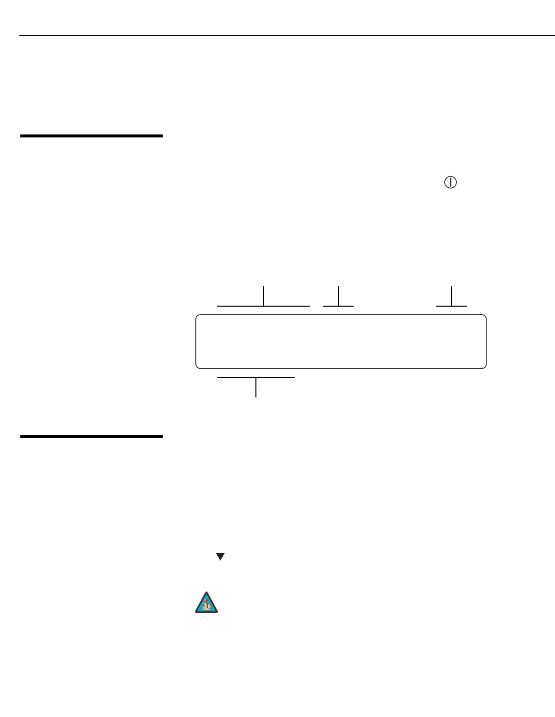
3.6
Turning on the Power
1. Turn on your source components.
2. Turn on the main power switch at the rear of the VHD Controller.
3. Press the ON button on the remote control – or the POWER ( ) button on the VHD
Controller front panel – to turn on the system. The vacuum fluorescent display on the
VHD Controller front panel briefly displays “Starting Display.”
4. When the projector is ready for use, the fluorescent display indicates the active source,
signal format (NTSC or PAL), input resolution and aspect ratio; for example:
3.7
Adjusting the Picture
Orientation
By default, the Vision 85 is configured for a “floor/front” installation, in which the projector is
installed upright and in front of the screen. If it is installed behind the screen and/or mounted
on a ceiling, you must change the picture orientation. To do this:
1. Select an input OTHER THAN HDMI 1 or HDMI 2 on the VHD Controller.
2. Press MENU and enter the Service Menu passcode.
3. Select Service from the Main Menu.
4. Select Display Device from the Service Menu, then select Configure.
5. Press , then choose Floor/Rear, Ceiling/Front or Ceiling/Rear, to match the installation
method.
➤
Component SD NTSC 480i
16:9 V85
Current Source Format
Input
Resolution
Aspect Ratio
You must enter a passcode to access the Service menu.
Note
Installation
Vidikron Vision 85 Owner’s Operating Manual 31
PRELIMINARY
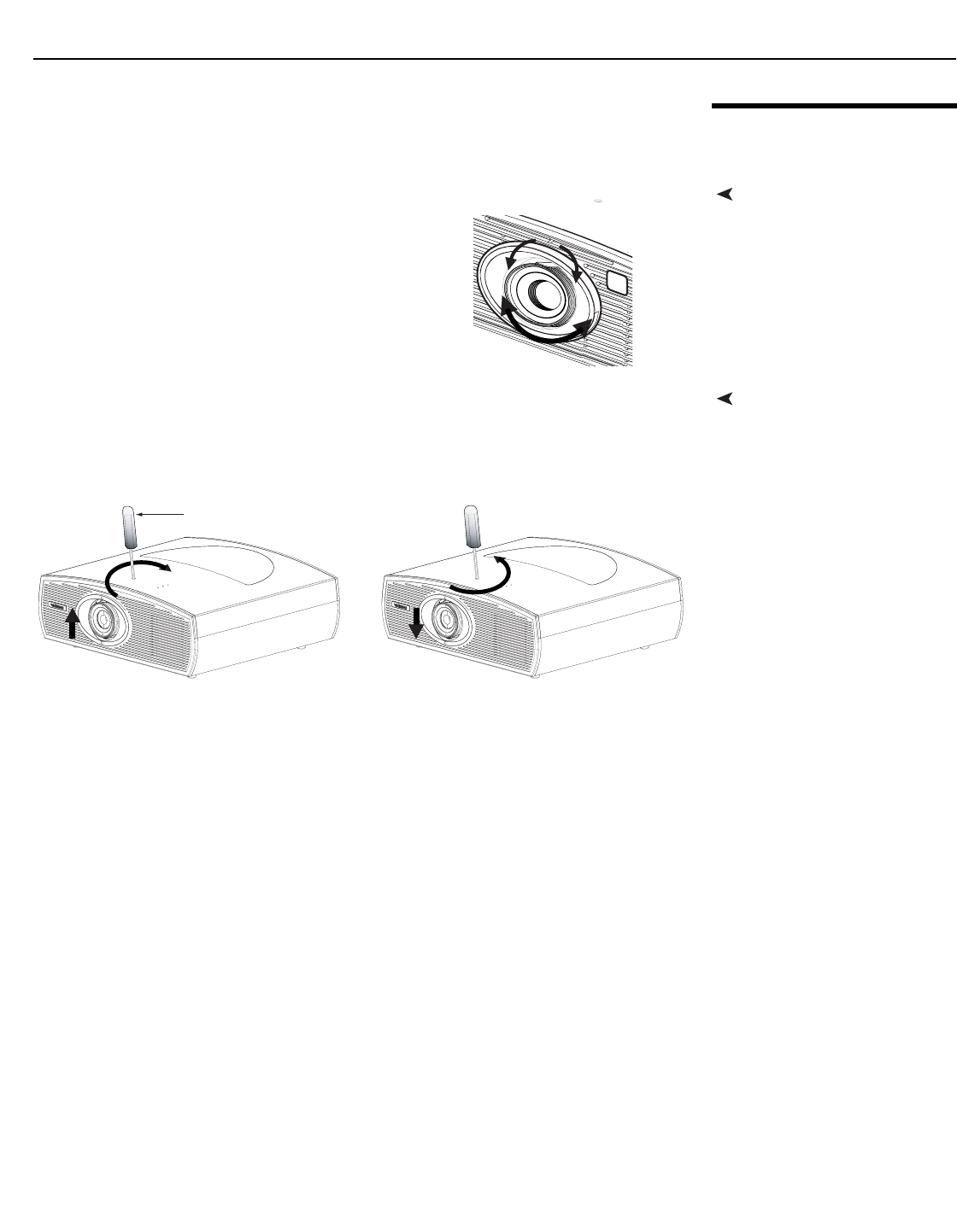
3.8
Primary Lens Adjustments
Focus and ZoomTo focus the projected image, gently rotate the lens
by hand.
To enlarge the picture (zoom in), move the zoom tab
toward the Vidikron logo on the front of the projector.
To make the picture smaller (zoom out), move the tab
in the other direction.
Vertical Lens ShiftTo change the projected image position, use a 9/64” hex driver to shift the lens in the desired
direction; see Figure 3-15. The vertical lens shift control is at the top of the projector. (The
tool will automatically center on top of the adjustment nut when inserted into the access
hole.)
Figure 3-15. Vertical and Horizontal Lens Shift Adjustments
Zoom
in
Focus
Zoom
out
9/64” Hex Wrench
Installation
32 Vidikron Vision 85 Owner’s Operating Manual
PRELIMINARY
3.9
Installing and Adjusting
the CineWide Anamorphic
Lens
If you are installing a CineWide-equipped projector, proceed as follows to install and adjust
the anamorphic lens.
The standard Vision 85/CineWide uses a prismatic-style anamorphic lens. This type of lens
compresses the height of the image (as opposed to stretching the width) to achieve a 2.35:1
aspect ratio with a 1.78:1 display device.
The standard Vision 85 Anamorphic lens mount kit consists of everything shown in Figure
3-16. Some components shipped with your projector may differ slightly from what is shown
in these instructions.
If any items are missing or damaged, please contact your Vidikron dealer or Vidikron
Customer Service at (888) 4VIDIKRON.
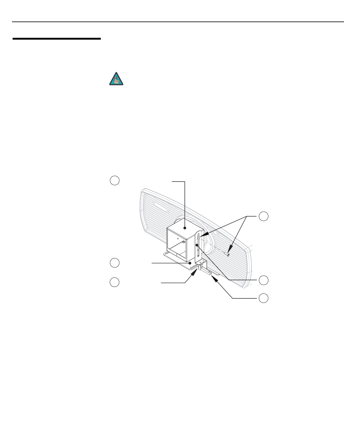
Figure 3-16. Vision 85 Anamorphic Lens Mounting Assembly - Exploded View
1. Use the Pitch Adjustment Screws (item #3) and Washers (item #6) to attach the Mounting
Brackets (item #2) to the Anamorphic Lens (item #1).
2. Use the four Y-Adjustment Screws (item #5) and Washers (item #4) to attach the
Anamorphic Lens assembly and Spacers (item #7) to the front of the projector. (Do not
fully tighten the screws yet.)
It is extremely important that the primary lens is properly adjusted
before you install the anamorphic lens. Ensure that the image from
the primary lens is perfectly centered on the screen.
Note
2 Base Plate
5 Vertical Mounting
Bracket (2x)
6 Pitch/Y-Adjustment
Screw, Phillips
Pan Head, 4-40 x 3/8” (2x)
and Fender Washer (2x)
4 Yaw/Z-Adjustment
Lever (2x) and
Fiber Washer (2x)
1 Anamorphic Lens
3 Screw, Phillips
M6x16mm (4x) and
1/4” Flat Washer (4x)
(not shown; secures Base Plate
to bottom of projector)
Installation
Vidikron Vision 85 Owner’s Operating Manual 33
PRELIMINARY
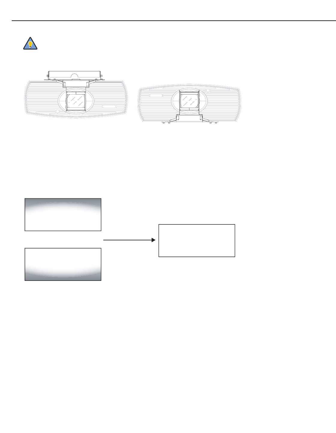
Adjusting the Lens Height (Y):
1. Project a white field on the screen.
2. Ensure that the four Height (Y) Adjustment Screws are loose enough to allow vertical
movement of the lens assembly.
3. Slowly move the anamorphic lens into place so that there are no shadows on the top or
bottom of the screen:
4. When the height is properly set, tighten the Height Adjustment Screws to secure the
lens in place.
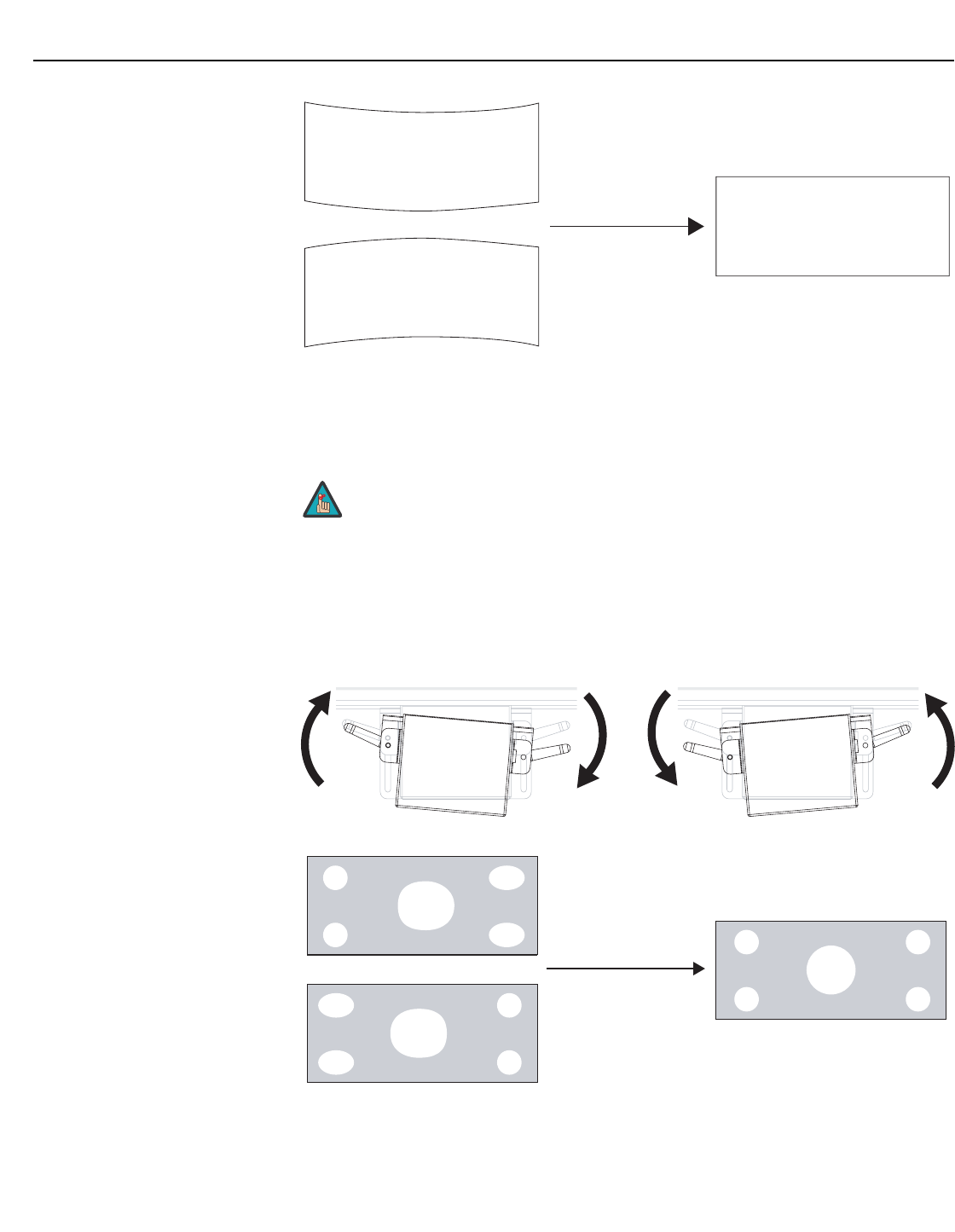
Adjusting the Pitch (Angle): Next, angle the lens to even out any top-to-bottom pincushion
distortion. To do this, loosen the Pitch Adjustment Screws on either side of the lens to allow it
to pivot freely. Then, adjust the anamorphic lens angle so that the projected image is
rectangular:
To avoid clipping the corners of the image, position the anamorphic lens
as close as possible to the primary lens.
Tip
Too High
Too Low
Correct position
Installation
34 Vidikron Vision 85 Owner’s Operating Manual
PRELIMINARY
The anamorphic lens will almost always be angled with respect to the projector; this is
normal. Once the proper lens angle has been set, firmly tighten the Pitch Adjustment Screws
to secure the lens in place.
Adjusting the Yaw: Loosen the Yaw/Z-Adjustment Levers to allow the lens to pivot freely
from side to side. Then, angle the lens to even out any left-right pincushion distortion:
Once the proper lens angle has been set, firmly tighten the Yaw/Z-Adjustment Levers to
secure the lens in place.
There may be some pincushion distortion even after the lens is properly
adjusted, especially at shorter throw distances. If this is the case, Vidikron
recommends that you slightly over-scan the image into the screen frame
area to mask the distortion.
Correct Lens Angle
Incorrect Lens Angle
Note
Anamorphic Lens (Top View)
Wrong Position
Correct Position

Vidikron Vision 85 Owner’s Operating Manual 35
PRELIMINARY
4.1
Using the On-Screen
Menus
Press the MENU button on either the remote control or the VHD Controller front panel to
display the Main Menu.
To select a menu item, use the and buttons on either the remote control or the VHD
Controller front panel to highlight it. Press ENTER to confirm your selection.
The Vision 85 OSD menus are arranged hierarchically; exactly how they are arranged
depends on the input signal resolution. For 1080i digital or 1080p signals, the menu
structure is as shown and described in On-Screen Menus for 1080i (Digital) or 1080p Signals
on page 51.
4.2
On-Screen Menus for 1080i
(Analog) and
Lower-Resolution Signals
When the input signal resolution is 1080i analog (via the HD1 or HD2 input) or lower, the
menu structure is as shown in Figure 4-1. Depending on the selected input source and signal
characteristics, some menu options may not be available.
4Operation
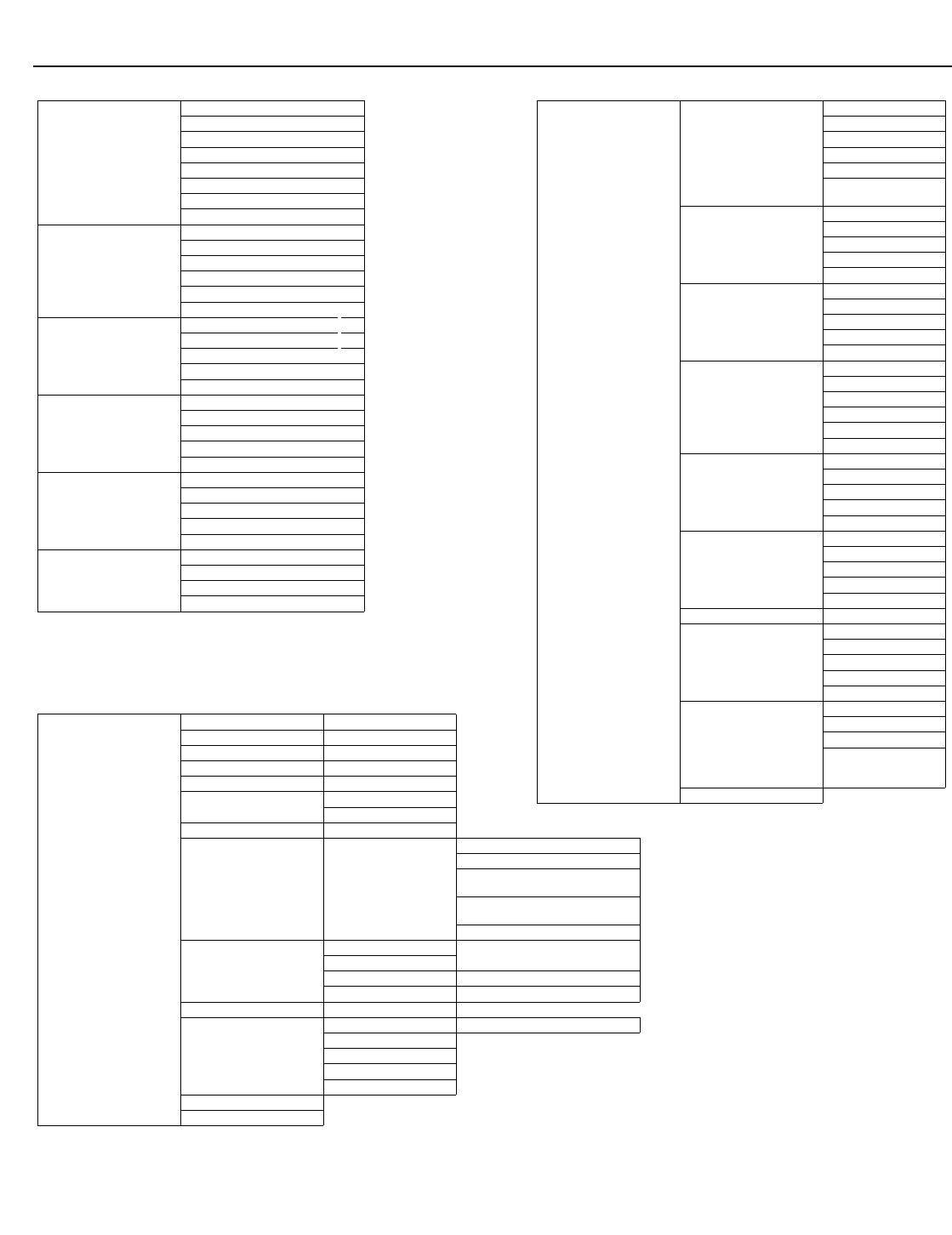
Operation
36 Vidikron Vision 85 Owner’s Operating Manual
PRELIMINARY
Figure 4-1. VHD Controller OSD Menu Structure for Vision 85 (1080i Analog and Lower-Resolution Sources)
Service
Test Video Grey Bars 1
Grey Bars 2
Color Bars 1
Color Bars 2
Input Names Rename, Restore or Save
Remote Control Primary
Secondary
Analog Out Mode RGB--, RGB++ or RGBS
Display Device Configure
Orientation
Overscan
Fan Mode
(0 = Normal; 1 = High Altitude)
Height
(0 ... 100)
Lamp Hours
HD Format
HD/RGB 1 Auto, RGB or YUV
HD/RGB 2
ADC Bandwidth Auto, 75 MHz, 150 MHz or 300 MHz
YPbPr Input Resolution Auto, 480i/p, 576i/p, 720p or 1080i
Triggers 1 / 2 / 3 / Save
Miscellaneous
Language English, French, German or Spanish
Menu Mode
Timeout
Side Bar Color
Film Mode (SD src. only)
System Reset
Restore Saved Settings
Input Source
Composite
S Video 1
S Video 2
Component SD
HD/RGB 1
HD/RGB 2
HDMI 1
HDMI 2
Aspect Ratio
16:9
4:3
Letterbox
IntelliWide
Cinema
IntelliWide 2.35
Picture
Brightness
Contrast
Color
Tint
Sharpness
Input Position
Left/Right
Up/Down
Width
Height
Overscan
ISF Presets
Recall ISF Night
Recall ISF Day
Recall/Save Custom 1
Recall/Save Custom 2
Reset Custom 1 & 2 to Factory Default
Information
(read-only)
Serial Number
Hardware
Firmware
Date
Calibration
ISF Night - Display Color
Gain
Offset
Gamma
Iris
Color Temp
Lamp Power
(0 = Low; 1 = High)
ISF Night - Input Image
Brightness
Contrast
Color
Tint
Sharpness
ISF Night - Input Color
Gain
Offset
Chroma Delay
Phase
Noise Filter
ISF Day - Display Color
Gain
Offset
Gamma
Iris
Color Temp
Lamp Power
ISF Day - Input Image
Brightness
Contrast
Color
Tint
Sharpness
ISF Day - Input Color
Gain
Offset
Chroma Delay
Phase
Noise Filter
Save ISF Settings Back / Confirm
Output Shift
Left/Right
Up/Down
Width
Height
Save
Splash Configure
Owner Name
ISF Calibrated
ISF Other
Vidikron/ISF Logo Splash
Screen Timers
(2 ... 60 sec.)
OSD Position
Note: IntelliWide 2.35 is available
only on the Vision 85/CineWide
and only on the analog inputs
(HD/RGB, Component SD,
Composite and S-Video).
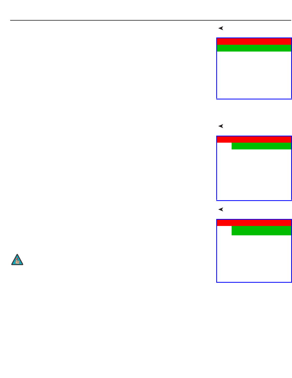
Operation
Vidikron Vision 85 Owner’s Operating Manual 37
PRELIMINARY
Main MenuThe Main Menu is the starting point for accessing all projector functions.
(The Calibration and Service menus are hidden and not accessible until you enter a
passcode.)
Input SourceFrom the Main Menu, select Input Source to choose a video signal source.
The active source is indicated by an arrow (>) to its left; in the example at right, Composite is
the active source.
Aspect Ratio To change the aspect ratio (size and shape) of the projected image, select Aspect Ratio from
the Main Menu and press ENTER. Select the appropriate aspect ratio for your screen size and
the type of program material being viewed; refer to Table 4-1.
The currently-selected aspect ratio is indicated by a “7” to its left; in the example at right,
16:9 is selected.
Vidikron 85
Input Source
Aspect Ratio
Picture
Input Position
ISF Presets
Information
Calibration
Service
Input Source
>Composite
S Video 1
S Video 2
Component SD
HD/RGB 1
HD/RGB 2
HDMI 1
HDMI 2
Aspect Ratio
716:9
4:3
Letterbox
IntelliWide
Cinema
IntelliWide 2.35
When you change the aspect ratio, save the change to a preset
afterwards. Otherwise, the change will be lost when a different input is
selected. (The aspect ratio is saved for each input and resolution
separately.) For information about saving settings, refer to ISF Presets
on page 44.
Note
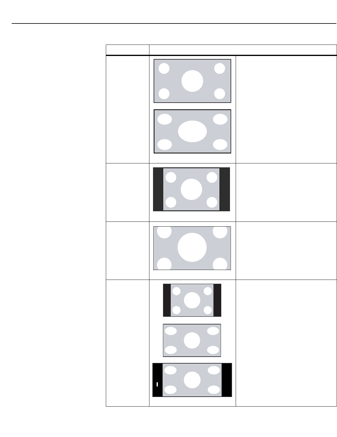
Operation
38Vidikron Vision 85 Owner’s Operating Manual
PRELIMINARY
Table 4-1. Aspect Ratio Settings
Aspect Ratio Description
16:9 Select 16:9 to view 16:9 DVDs and HDTV
programs in their native aspect ratio.
4:3 images are stretched horizontally to fit
a 16:9 screen.
4:3 4:3 scales the input signal to fit in the
center of the 16:9 screen. 4:3 is the aspect
ratio used by computer monitors,
standard television programming and
most VHS video cassettes.
Letterbox Letterbox mode scales (zooms in on) a 4:3
image linearly (by the same amount on all
sides) to fill a 16:9 display.
Letterbox is best suited for viewing
LaserDisc movies or non-anamorphic
DVDs on a 16:9 screen.
IntelliWide IntelliWide scales a 4:3 image
NON-linearly (more on the sides than in
the center) to fit a 16:9 screen.
On a 2.35:1 screen, the image is centered
between black bars on either side.
4:3 Image, stretched to fill
16:9 Screen (Display)
16:9 Image on
16:9 Screen (Display)
4:3 Image on
16:9 Screen (Display)
4:3 Image on
16:9 Display
(Letterbox aspect ratio)
4:3 Image on
16:9 Screen (Display)
4:3 Image on
2.35:1 Screen
with IntelliWide
4:3 Image on
16:9 Screen
with IntelliWide
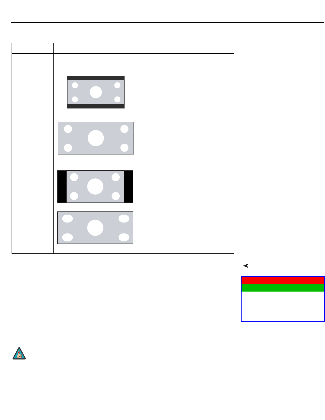
Operation
Vidikron Vision 85 Owner’s Operating Manual 39
PRELIMINARY
Picture Use the controls in the Picture Menu to calibrate your Vision 85 for optimum picture quality.
The Vision 85 has been designed to incorporate setup and calibration standards established
by the Imaging Science Foundation (ISF). The ISF has developed carefully crafted,
industry-recognized standards for optimal video performance and has implemented a
training program for technicians and installers to use these standards to obtain optimal
picture quality from Vidikron video display devices. Accordingly, Vidikron recommends that
setup and calibration be performed by an ISF certified installation technician.
All signal types require separate processing. Therefore, you need to calibrate each input
separately.
Cinema Select Cinema to view 2.35 source
material in its native aspect ratio.
With a 16:9 screen and a non-CineWide
projector (no anamorphic lens), the upper
and lower portions of the screen are
masked, but the geometry of the active
image area is unchanged.
With a 2.35:1 screen and a
CineWide-equipped projector, the VHD
Controller scales the 2.35:1 image so that
the active image area fills the 16:9 chip
surface, eliminating the black bars. The
secondary, anamorphic lens then restores
the proper geometry to the 2.35:1 image.
IntelliWide 2.35 A 16:9 image is scaled NON-linearly (more
on the sides than in the center) to fit a
2.35:1 screen. IntelliWide 2.35 is available
only on the Vision 85/CineWide and only
on the analog inputs (HD/RGB, SD
Component, Composite and S-Video).
Table 4-1. Aspect Ratio Settings (continued)
Aspect Ratio Description
2.35:1 Image on
16:9 Screen
(Cinema aspect ratio / no CineWide)
2.35:1 Image on
2.35:1 Screen
(Cinema aspect ratio / CineWide)
16:9 Image on
2.35:1 Screen with
Virtual Cinema
16:9 Image on
2.35:1 Screen
16:9 Image on
2.35:1 Screen
Picture
Brightness
Contrast
Color
Tint
Sharpness
When you change a picture quality setting, save the change to a preset
afterwards. Otherwise, the change will be lost when a different input is
selected. (Picture quality settings are saved for each input and resolution
separately.) For information about saving settings, refer to ISF Presets
on page 44.
Note
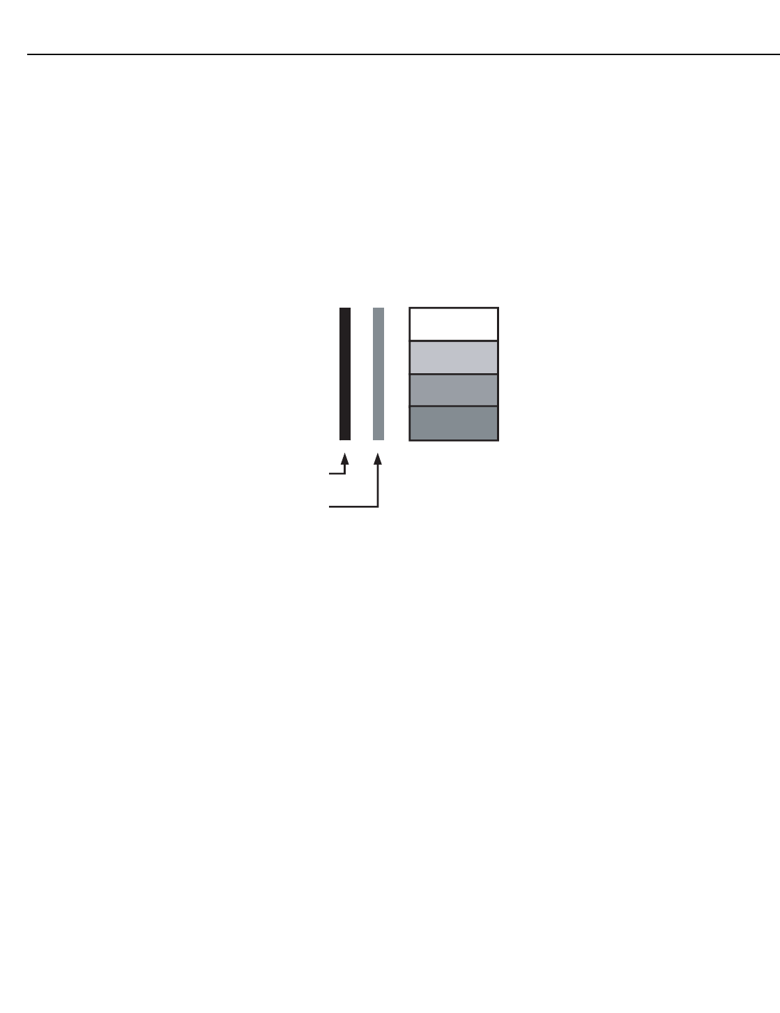
Operation
40 Vidikron Vision 85 Owner’s Operating Manual
PRELIMINARY
Although it may be possible to obtain satisfactory picture quality using the naked eye and
regular program material, Vidikron recommends using the following calibration tools for
best results:
• External test pattern source -- Ovation Multimedia, Digital Video Essentials or AVIA test
DVD or equivalent.
• A blue filter (provided with many test DVDs), for color level and tint adjustments.
Connect your test pattern source to the input that you are calibrating and proceed as follows.
Perform the adjustments in the order listed here.
Brightness: On your external test pattern source, select a PLUGE pattern. (PLUGE is an
acronym for “Picture Line-Up Generation Equipment.”) Figure 4-2 shows a typical PLUGE
pattern.
Figure 4-2. Typical PLUGE Pattern for Adjusting Brightness
PLUGE patterns vary but generally consist of some combination of black, white and gray
areas against a black background. The example above includes two vertical bars and four
shaded boxes.
Select Brightness from the Picture menu and press ENTER. Adjust the brightness so that:
• The darkest black bars disappear into the background.
• The dark gray areas are barely visible.
• The lighter gray areas are clearly visible.
• The white areas are a comfortable level of true white.
• The image contains only black, gray and white (no color).
Below Black
A
bove Black
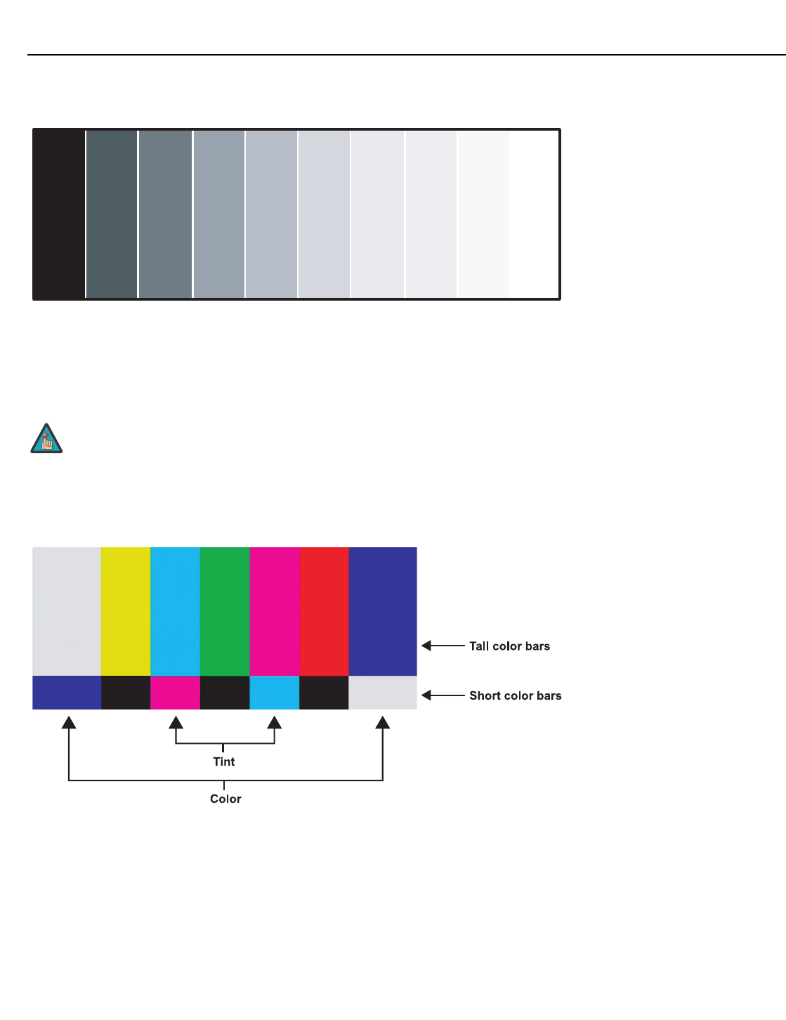
Operation
Vidikron Vision 85 Owner’s Operating Manual 41
PRELIMINARY
Contrast: On your external test pattern source, select a stepped, gray-bar pattern like the
one shown in Figure 4-3.
Figure 4-3. Typical Gray Bar Pattern for Adjusting Contrast
Select Contrast and press ENTER. Adjust the contrast to a point just below which the white
rectangle starts to increase in size.
Color Saturation: On your external test pattern source, select a color bar pattern like the one
shown in Figure 4-4.
Figure 4-4. Typical Color Bar Pattern for Adjusting Color Saturation and Tint
Brightness and contrast controls are interactive. A change to one may
require a subtle change to the other in order to achieve the optimum
setting.
Note
gray
yellow
cyan
green
magenta
red
blue
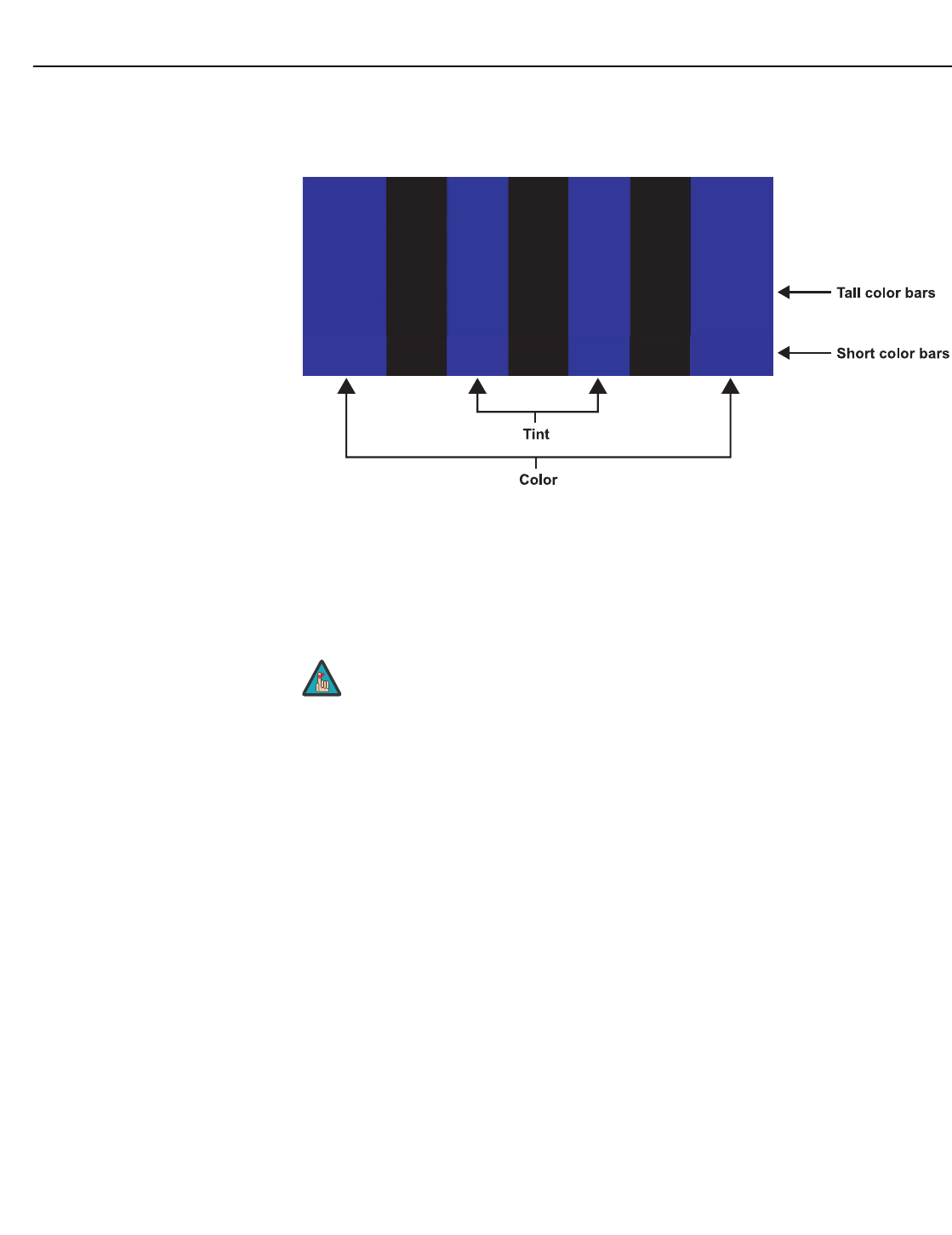
Operation
42 Vidikron Vision 85 Owner’s Operating Manual
PRELIMINARY
Select Color and press ENTER. While looking at the color bar pattern through a blue filter,
adjust the color saturation level until the outermost (gray and blue) color bars appear to be a
single shade of blue:
Tint: Tint or “hue” is essentially the ratio of red to green in the color portion of the image.
When tint is decreased, the image appears redder; when it is increased the image appears
greener. To set the tint, select Tint and press ENTER. While looking at the color bar pattern
through a blue filter, adjust the tint level until the cyan and magenta color bars (on either
side of the green bar) appear to be a single shade of blue.
Like the brightness and contrast controls, the color and tint controls are
interactive. A change to one may require a subtle change to the other in
order to achieve the optimum setting.
gray
yellow
cyan
green
magenta
red
blue
Note
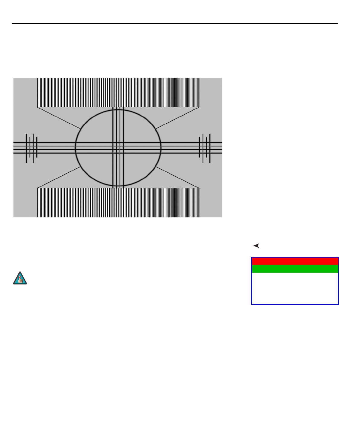
Operation
Vidikron Vision 85 Owner’s Operating Manual 43
PRELIMINARY
Sharpness: “Sharpness” is the amount of high-frequency detail in the image. To adjust
sharpness, select Sharpness from the Picture menu and press ENTER. On your external test
pattern source, select a pattern like the one shown in Figure 4-5. Adjust as needed, looking
for white edges around the transitions from black to gray and differently-sized lines in the
“sweep” patterns at the top and bottom. Lower the sharpness setting to eliminate them.
Figure 4-5. Typical Test Pattern for Adjusting Sharpness
Input PositionUse the controls in the Input Position Menu to fine-tune the aspect ratio and image position
for the current source.
Left/Right: Select Left/Right from the Input Position menu to shift the projected image
horizontally. Use the right or up cursor button to shift the image to the right; use the left or
down button to shift it to the left.
Up/Down: Select Up/Down from the Input Position menu to shift the projected image
vertically. Use the right or up cursor button to shift the image upward; use the left or down
button to shift it downward.
Width: Select Width from the Input Position menu to change the projected image width. Use
the right or up cursor button to increase the width; use the left or down button to decrease it.
Height: Select Height from the Input Position menu to change the projected image height.
Use the right or up cursor button to increase the height; use the left or down button to
decrease it.
Overscan: Image Overscan pushes the outside edge of the active picture area of the video
signal out beyond the edge of the display area.
Input Position
Left/Right
Up/Down
Width
Height
Overscan
When you change an input position setting, save the change to a preset
afterwards. Otherwise, the change will be lost when a different input is
selected. (The input position settings are saved for each input and
resolution separately.) For information about saving settings, refer to ISF
Presets on page 44.
Note
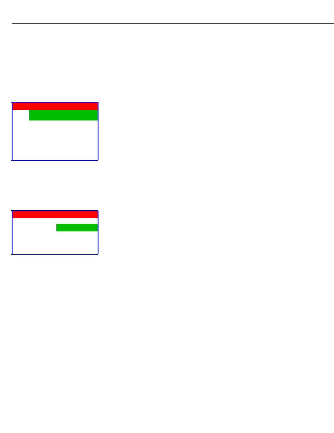
Operation
44 Vidikron Vision 85 Owner’s Operating Manual
PRELIMINARY
Some television programs are produced based on the assumption that older television sets
may not display the outer edges of the broadcast picture area. Overscan effectively trims
away these inactive, outer edges and enlarges the remaining portion of the image to fill the
display area.
Select from 1% to 10% of Overscan, as desired.
For HDTV, DVDs and other video sources, Overscan is generally not necessary or desirable.
ISF Presets For each input, the Vision 85 lets you save image quality settings as presets that you can
recall at a later time. You can create up to four presets per input and resolution. Use the ISF
Presets menu to recall saved image presets, or to save image settings in the “Custom 1” or
“Custom 2” memory location. The currently-selected preset is indicated by a “7” to its left; in
the example shown here, ISF Night is selected.
You should save changes to any of the following settings to a preset; otherwise they will be
lost when a new input source or resolution is selected:
• Aspect ratio
• Picture quality settings (brightness, contrast, color saturation, tint and sharpness)
• Input position (image position, width, height and overscan percentage)
To reset the Custom 1 and Custom 2 image presets to their factory defaults, select Factory
Default and press ENTER.
Information Select Information from the Main Menu to see information that uniquely identifies your
projector: its serial number, the installed hardware and firmware versions and the firmware
version build date. Should you ever need to contact Vidikron Technical Support, this
information will help them answer your questions or resolve product performance issues.
ISF Presets
7ISF Night
ISF Day
Custom 1 Save
Custom 2 Save
Factory Default
➤
Information
Serial Num
Hardware 0
Firmware 0100.0331
Date Dec 11 2006
➤
Operation
Vidikron Vision 85 Owner’s Operating Manual 45
PRELIMINARY
CalibrationUse the Calibration menu to perform advanced picture quality adjustments. This menu
should be used by ISF-certified technicians only.
To recall the ISF Night or ISF Day settings, do one of the following:
• Select “ISF Night” or “ISF Day” from the ISF Presets menu (see above);
• Press ISF NT or ISF DAY on the remote control; or
• From this menu, choose Display Color, Input Image or Input Color for the preset you want
to recall.
ISF Night - Display Color: Use the Display Color settings to change the characteristics of the
output signal. These settings are global (independent of any particular input).
•Gain: Use the Gain controls to correct color imbalances in the bright areas of the image. A
good way to do this is to use a test pattern consisting mostly of solid white areas, such as
an 80 IRE “window” pattern. If the white areas contain traces of red, green or blue,
decrease the Gain for that color.
• Gamma/Offset: Use the Gamma and Offset controls in the White Balance sub-menu to
correct color imbalances in the dark areas of the image.
A good way to do this is to use a test pattern consisting mostly of dark gray areas, such as
a 30 IRE “window” pattern. If the gray areas contain traces of red, green or blue, decrease
the Gamma or Offset for that color.
•Iris: Select Iris from the Display Color Menu to increase or decrease the aperture or iris size
(the physical opening through the lens; similar to an “f-stop” on a camera). Doing so
allows you to optimize brightness and contrast according to the amount of ambient light
in the viewing area.
Use a lower setting (0 or 1) for rooms with lots of ambient light. Use the higher setting (2)
for more “theater-like” viewing conditions (little or no ambient light).
• Color Temp: Select Color Temp from the Display Color menu to adjust the color
temperature. The default setting is appropriate for most situations. Higher settings
produce a “bluer” picture.
•Lamp Power: Select Lamp Power from the Display Color menu to adjust the lamp output
level. You can choose to run the lamp as bright as possible (“1”) or you can choose the
lower setting (“0”). Generally, lower lamp output can prolong the life of the lamp, but
decreases brightness.
Calibration
ISF Night
Display Color
Input Image
Input Color
ISF Day
Display Color
Input Image
Input Color
Save ISF Settings
Output Shift
Splash Configure
OSD Position
You must enter a passcode to access the Calibration menu.
Adjust Gamma before Offset. Gamma provides coarse adjustment of
low-lights; Offset provides finer adjustment.
Note
Tip

Operation
46 Vidikron Vision 85 Owner’s Operating Manual
PRELIMINARY
ISF Night - Input Image: The Input Image controls are similar to those in the Picture menu,
but are accessible only by entering the Calibration menu passcode. This makes it possible to
restore the picture quality settings to what they were when the projector was installed,
simply by recalling the “ISF Night” preset.
ISF Night - Input Color: The Input Color controls are similar to those in the Display Color
menu (see above), but can be set independently for each input.
• Gain/Offset: Refer to ISF Night - Display Color, above.
• Chroma Delay: use the Chroma Delay control to correct a mis-aligned image from a
Composite, S-Video or Component video source. Chroma delay in an image causes color
shifts to occur to the left of the vertical edge transitions, producing artificial shadows or a
“halo” effect. If necessary, adjust this setting to eliminate them.
•Phase: Adjust the phase if the image (usually from an RGB source) shows shimmer or
“noise.” Pixel phase adjusts the phase of the pixel sampling clock relative to the incoming
signal. The effect of this control is similar to that of a tracking control on a VCR.
For best results, use a good test pattern such as a smooth gray consisting of a clear pattern
of black and white pixels, or a similar “half on, half off” graphic image. (You may notice
that you can stabilize the image at more than one point. Use either setting in this case.)
• Noise Filter: Select Noise Filter from the Input Color menu to filter a noisy Composite,
S-Video or Component source signal. Adjust as desired, keeping in mind that reducing
noise (which reduces high frequencies) may also soften the image.
ISF Day - Display Color: Refer to ISF Night - Display Color.
ISF Day - Input Image: Refer to ISF Night - Input Image.
ISF Day - Input Color: Refer to ISF Night - Input Color.
Save ISF Settings: Whenever you make a change to the ISF settings, you should always save
it. Select Save ISF Settings from the ISF Calibration menu to do this. In the event you ever
have to perform a System Reset, you can restore the saved ISF settings by selecting Restore
Saved Settings in the Service menu. (System Reset and Restore Saved Settings are described
on page 50.)
Output Shift: The controls in the Output Shift menu are similar to those in the Input Position
menu, except that they change the characteristics of the output signal (so the change is
visible no matter which input is selected). You can set these controls independently for each
aspect ratio.
To save the Output Shift settings for the current aspect ratio so that they can be restored
after a System Reset (described on page 50), press repeatedly to highlight “Save.” Then,
press ENTER.
Splash Configure: Use the Splash Configure menu to customize the appearance of the
start-up message that appears on the vacuum fluorescent display upon power-up.
•Owner Name/ISF Calibrated/ISF Other: You can have the Vision 85 display the owner’s
name, your name, the phrase “ISF Calibrated” and/or any other string, up to 20 characters
in length.
Use the up or down cursor button to select a character. Use the right and left cursor
buttons to change the cursor position. Press MENU when you have finished entering text.
Then, check the “Splash Enable” box to have the Vision 85 display the information you
enter here when it is turned on.
Operation
Vidikron Vision 85 Owner’s Operating Manual 47
PRELIMINARY
•Vidikron/ISF Logo Splash Screen Timers: When you turn on the Vision 85, it projects a
welcome screen with the Vidikron logo followed by one with the ISF logo. Select Splash
Timer from the Splash Configure menu to set the amount of time that these two images
appear. The range is from 2 to 60 seconds, in one-second increments.
Use the up or down cursor button to select a timer value to adjust. Use the right or left
cursor button to change the timer value. Press MENU when you have finished configuring
both timers.
OSD Position: Select OSD Position, press ENTER and use the arrow buttons to change the
size and position of the OSD controls.
ServiceUse the Service menu to access advanced projector configuration settings. This menu
should be used by ISF-certified technicians only.
Test Video: Select Test Video from the Service Menu to access the internal test patterns on
the Vision 85. Four patterns are available, consisting of white/gray or colored bars.
Press MENU to exit test pattern mode.
Input Names: You can give each VHD Controller input a descriptive name. For example, you
may want to change the default input name to the type of source component connected to
it: “VCR,” “DVD,” “Laptop” et cetera. Composite, S-Video and Component SD input names can
be up to 12 characters long; the others can be up to eight characters long.
To edit an input name, select Input Names from the Service menu. Press or to select an
input and press ENTER. Use the or buttons to change a character; press or to
select a character to change. When you have finished editing the input name, press MENU.
To restore the default input name, press repeatedly to highlight that input name in the
“Restore” column. Then, press ENTER.
To save input names so that they can be restored after a System Reset (described on
page 50), press repeatedly to highlight “Save.” Then, press ENTER.
Service
Test Video
Input Names
Remote Control
Analog Out Mode
Display Device
HD Format
Triggers
Miscellaneous
System Reset
Restore Saved Settings
You must enter a passcode to access the Service menu.
Note
Input Names
Restore
Composite Composite
S Video 1 S Video 1
S Video 2 S Video 2
Component SD Component SD
HD/RGB 1 HD/RGB 1
HD/RGB 2 HD/RGB 2
HDMI 1 HDMI 1
HDMI 2 HDMI 2
Save
The button takes you from top to bottom in the left column, then from
top to bottom in the right column. To highlight “Save,” scroll through
both columns.
Note
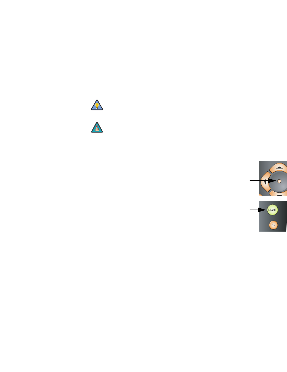
Operation
48Vidikron Vision 85 Owner’s Operating Manual
PRELIMINARY
Remote Control: The Remote Control menu shows you the primary and secondary infrared
(IR) codes to which the Vision 85 will respond. By default, both are set to 17. You can change
these codes if either:
• Another device in the theater (a DVD player, for example) is responding to commands
from the Vision 85/VHD remote control (Figure 2-5) in ways that are unpredictable or
undesirable.
• You have multiple Vision 85 projectors and want to control them independently, as
opposed to broadcasting commands from a single remote to all of them. In this scenario,
you can use multiple remotes programmed to use different IR codes. Or, you can use a
single remote and change the IR code as needed to address a specific projector.
When you change a remote code on the Vision 85, you must re-program the Vision 85/VHD
remote control to send that same code. To do this:
1. Using a straightened paper clip or similar object, press and hold the
CODE button on the remote control for approximately three
seconds, or until the LED on the remote lights solid red.
– OR –
If your remote control unit does not have a CODE button, press and
hold the LIGHT button on the remote control for approximately
three seconds, or until the LED on the remote lights solid red.
2. Enter a new two-digit code between 00 and 31 inclusive. Use the
16:9 button for “9” and the 4:3 button for “0.” Include a leading
zero for single-digit codes; for example, enter 9 as “09.”
3. The LED turns off to confirm the code change. If you enter an invalid code, the LED
flashes for three or four seconds. Try again, entering a valid code.
Use the VHD Controller front-panel keypad to change the projector IR
code. Then, change the code sent by the remote to match as described
below.
Do not change the “Type” setting in this menu.
Tip
Note
N
T
CODE
Operation
Vidikron Vision 85 Owner’s Operating Manual 49
PRELIMINARY
Display Device: The options in the Display Device menu allow you to change the picture
orientation, adjust the amount of overscan and access other projector-specific functions.
•Configure: Select Configure from the Display Device menu. Then:
•Orientation: Select Orientation to change the picture orientation to suit the method of
installation (Floor Front, Floor Rear, Ceiling Front or Ceiling Rear).
•Overscan: Refer to Overscan on page 43.
•Fan Mode: If the projector is being used in a high-altitude environment, use the Fan
Mode control to prevent it from overheating. Set it to High Altitude (“1”) to run the fan
at high speed; set it to Normal (“0”) to run the fan at normal speed.
•Height: Select Height from the Display Device menu to adjust the displayed image
height in small increments. Higher values compress the height. This setting affects all
sources.
•Lamp Hours: To display the number of hours that the lamp has been in service, press
or to highlight Lamp Hours.
HD Format: If the characteristics of the incoming signal on the HD1 or HD2 inputs are
known, select HD Format from the Service menu and set them as described below. Doing so
can reduce the time it takes the VHD Controller to switch from HD to 480i signals or vice
versa.
This is generally not necessary unless the VHD Controller – for whatever reason – has
difficulty determining the color space (RGB or YUV), bandwidth or resolution of the incoming
HD signal. In most situations, the Auto settings work well.
• HD/RGB 1 and HD/RGB 2 (Color Space): Select Auto, RGB or YUV.
• ADC Bandwidth: Select Auto, 75 MHz, 150 MHz or 300 MHz.
• YPbPr Input Resolution: Select Auto or specify the input resolution, if known: 480i, 480p,
576i, 576p, 720p or 1080i.
Triggers: Select Triggers from the Service menu to configure the 12-volt trigger outputs. You
can assign one or more trigger outputs to each aspect ratio. Those triggers are then activated
by selecting that aspect ratio.
To save the trigger settings so that they can be restored after a System Reset (described
below), press repeatedly to highlight “Save.” Then, press ENTER.
Use this control to fine-tune the image geometry on a Vision
85/CineWide. (It should not be necessary to change this setting on a
standard Vision 85.)
Note
HD Format
HD/RGB 1 Auto
HD/RGB 2 Auto
ADC Bandwidth Auto
YPbPr Input Resolution

Operation
50 Vidikron Vision 85 Owner’s Operating Manual
PRELIMINARY
Miscellaneous: Select Miscellaneous from the Service menu to set the following options:
• Language: Select Language from the Miscellaneous menu and press the up- or
down-arrows to select the OSD Language. (Currently, only English is supported.)
•Menu Mode: This is the manner in which the OSD menus appear and disappear when you
press MENU. Choose one of the following:
0 = No transition; menus abruptly appear and disappear.
1 = Menus fade in and out.
2 = “Checkerboard” dissolve; menus appear and disappear in sections.
3 = “Window shade” effect; menus are drawn on a diagonal from top left to bottom right,
and retract in the opposite direction.
• Timeout - Short/Long: These settings control how long the OSD menus stay on screen.
Select a time-out period of from 2 to 60 seconds.
• Side Bar Color: This controls the color of the inactive image area. The range is from -100
(black) to 100 (white).
The inactive image area is on either side of the active image area when using the 4:3
aspect ratio (or the entire screen when no incoming video signal is present).
•Film Mode: Enable Film Mode to smooth out moving images from interlaced,
standard-definition (SD) sources. In most cases, the Vision 85 detects the proper
“pull-down” rate and vertical frequency. However, if your source is jittery and/or tearing
you may wish to enable Film Mode to ensure stable processing for that source.
System Reset: To reset ALL controller settings (including image settings) back to their
factory defaults, choose System Reset from the Service menu.
A confirmation message appears, reminding you to save your settings before you perform
the reset, so that you can restore them afterwards. If you have done this, select Confirm to
continue with the reset. Otherwise, click Back to cancel.
Restore Saved Settings: Following a System Reset, select Restore Saved Settings to apply all
previously-saved settings to the projector and VHD Controller.
This action is not undoable. Proceed with caution! Before you perform a
System Reset, save ALL settings, including “Custom” ISF Presets (page 44), ISF
Day/Night presets (page 46), Output Shift settings (page 46), Input Names
(page 47) and Trigger settings (page 49).
Caution
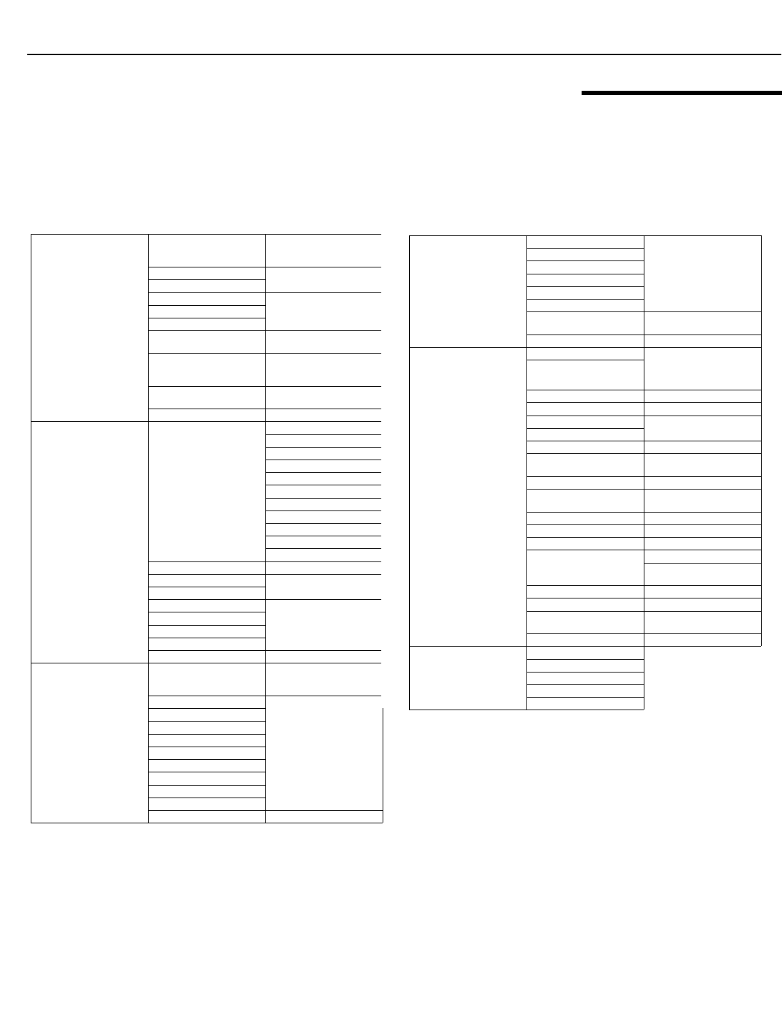
Operation
Vidikron Vision 85 Owner’s Operating Manual 51
PRELIMINARY
4.3
On-Screen Menus for 1080i
(Digital) or 1080p Signals
After you have finished calibrating the projector to optimize the display of 1080i analog and
lower-resolution sources, do likewise for 1080i digital and 1080p sources (connected to the
HDMI 1 or HDMI 2 inputs on the VHD Controller).
When the projector receives a 1080i digital and 1080p signal, it displays the menus shown in
Figure 4-6.
Figure 4-6. OSD Menu Structure for Vision 85 (1080i Digital or 1080p Sources)
Picture Adjust
Picture Memory
Standard, Black Enhance,
White Enhance, ISF Day,
ISF Night or Custom
Contrast -90, -89, ... 0 ... +89, +90
Brightness
Color -30, -29, -28 ... 0 ... +28, +29,
+30
Tint
Sharpness
Color Temp. 5500, 6500, 7500, 8500, 9300
or 10500
White Balance
Standard, Black Enhance,
White Enhance, ISF Day,
ISF Night or Custom
VAC: Iris High Brightness, Theater or
CRT Emulation
Lamp Power 220W (Hi) or 180W (Low)
Picture Adjust
(Advanced)
ICC Adjust
Hue
Saturation
Intensity
Default
Red
Yellow
Green
Cyan
Blue
Magenta
Default
Brilliant Color™ On/Off
SD Advanced Mode (N/A)
Film Mode
Video NR
Off, 1, 2 or 3
MNR
Sharpness Enhancement
Automatic Contrast
Default Yes or No
White Balance
Mem. Select
Standard, Black Enhance,
White Enhance, ISF Day,
ISF Night or Custom
Red Gamma
-30, -29, -28 ... 0 ... +28, +29,
+30
Green Gamma
Blue Gamma
Red Gain
Green Gain
Blue Gain
Red Offset
Green Offset
Blue Offset
Default Yes/No
HD/RGB Adj.
Frequency
(N/A)
Phase
H-Shift
V-Shift
Default
Special Mode
Signal Info
(read-only)
Format (480i ... 1080p), H/V
Frequency
Auto Setup (N/A)
Options
Image Shift -30, -29, -28 ... 0 ... +28, +29,
+30
(available only with certain
1080i signals)
Subtitle
Overscan 0, 1%, 2% ... 10%
Default Yes or No
Adjust White Level (N/A)
Adjust Black Level
LED On or Off
Lamp Hours (read-only) Hours in use / percentage of
life remaining
OSD On or Off
Signal Type Auto, RGB, YCbCr4:4:4 or
YCbCr4:2:2
Color Space Auto, ITU601 or ITU709
HDMI Black Level Auto, 0 IRE or 7 IRE
Background Vidikron Logo, Blue or Black
Power Save
RS-232C Port (On or Off)
Auto Power Off
(On or Off)
Baud Rate 9600, 38400 or 115200 bps
Fan Mode Normal or High Altitude
Orientation Floor Front, Ceiling Front,
Floor Rear or Ceiling Rear
Factory Default All Reset or Return
Language
English
Deutsch
Español
Français
Italiano
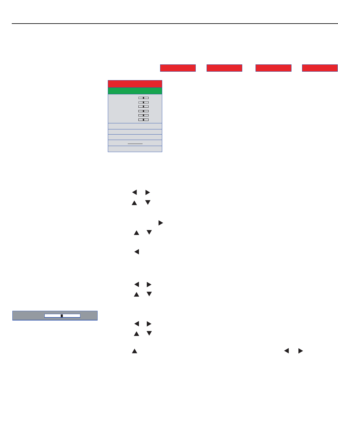
Operation
52 Vidikron Vision 85 Owner’s Operating Manual
PRELIMINARY
Main Menu Press MENU on either the remote control or built-in keypad (on the projector rear panel) to
display the Main Menu, shown in Figure 4-7. The Main Menu is the starting point for
calibrating the Vision 85 to optimize the display of digital 1080i and 1080p sources.
Figure 4-7. Vision 85 Main Menu (1080i Digital or 1080p Sources Only)
To use the on-screen menus:
1. Press or to select a sub-menu.
2. Press or to select a sub-menu item.
3. For items that present a list of choices, such as Picture Memory:
a Press ENTER or .
b Press or to select a value from the list.
c Press ENTER again to confirm your selection.
d Press to return to the menu.
– OR –
For items that are represented by numeric values, such as Contrast:
a Press or to adjust the value.
b Press or to select another menu item.
– OR –
a Press ENTER to hide the “parent” menu and display only the slidebar for that item.
b Press or to adjust the value.
c Press or to select another item to adjust or ENTER to return to the menu.
4. To switch from one sub-menu to another (for example, Picture Adjust to White Balance),
press repeatedly until no menu item is highlighted. Then, press or .
5. Press MENU to hide the OSD menus.
➤
Contrast 0
Brightness 0
Color 0
Picture Memory 1
Tint 0
Sharpness 0
CLR Temp. 7500
White Balance 1
RVR :Iris 1
Lamp Power Hi
Advanced
Default
White Balance HD/RGB Adj. Options Language
Picture Adj.
Contrast + - 5
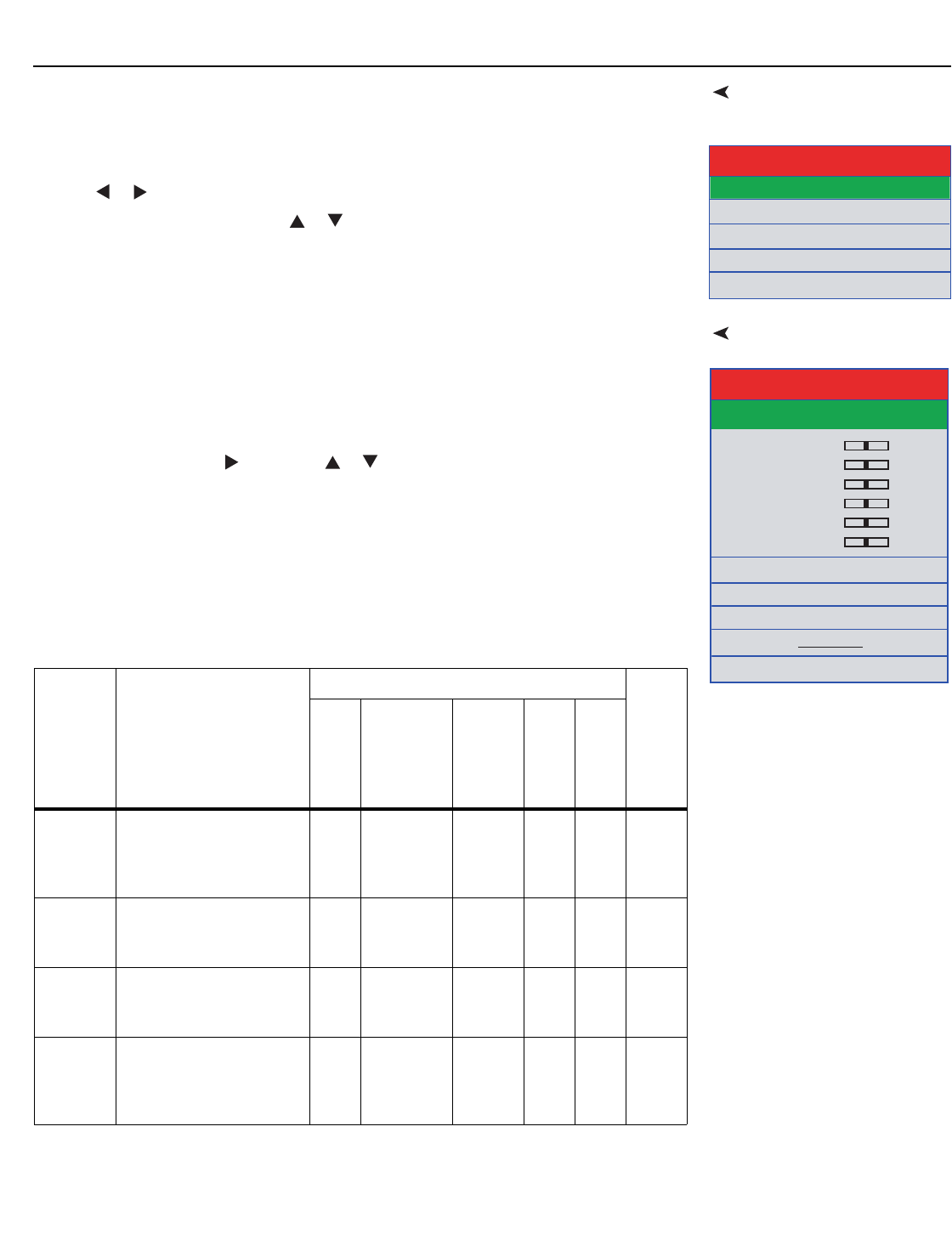
Operation
Vidikron Vision 85 Owner’s Operating Manual 53
PRELIMINARY
LanguageThe Vision 85 OSD language is initially set to English, but can also display the menus in
German (Deutsch), Spanish (Español), French (Français) or Italian (Italiano). To change the
OSD language:
1. Press MENU.
2. Press or to select Language from the Main Menu.
3. Press up- or down-arrow button ( or ) to highlight the desired language and press
ENTER. The change takes effect immediately.
Picture AdjustTo perform basic picture quality adjustments, select Picture Adjust from the Main Menu and
proceed as follows:
Picture Memory: The Vision 85 lets you save image quality settings as presets that you can
recall at a later time. For digital 1080i and 1080p sources, you can create up to six presets.
To recall and/or change the settings associated with a preset, select Picture Memory from the
Picture Adjust menu. Press , then press or until your choice is highlighted. To confirm
your selection, press ENTER.
The default settings for each preset are described in Table 4-2. Contrast, Brightness, Color,
Tint and Sharpness are all set to zero (0) by default. These provide convenient starting points
for calibrating the projector to suit different viewing environments. Any picture quality
adjustments you make here are stored in the currently-selected preset.
English
Deutsch
Español
Français
Italiano
Language
Contrast 0
Brightness 0
Color 0
Picture Memor
y
1
Tint 0
Sharpness 0
CLR Temp. 7500
White Balance 1
VAC :Iris 1
Lamp Power Hi
Advanced
Default
Picture Adj.
Table 4-2. Default Picture Memory Settings for Digital 1080i and 1080p
Sources
Picture
Memory
Setting
Description
Default Settings for Selected Picture Memory
Remote Control Key
Color Temp.
VAC (Iris)
Lamp Power
Sharpness
Enhancement
Auto Contrast
Standard
or Custom
Provides good picture
quality under the widest
variety of viewing
conditions.
7500 High
Brightness
Hi
(220W)
Off Off –
Black
Enhance
Similar to “Standard” mode,
but with enhanced black
levels.
7500 CRT
Emulation
Hi
(220W)
Off 1CUST
1
White
Enhance
Similar to “Standard” mode,
but with enhanced white
levels.
7500 High
Brightness
Hi
(220W)
1Off CUST
2
ISF Day For viewing images with the
brightness slightly
decreased in a darkened
room.
6500 Theater Low
(180W)
Off Off ISF
DAY
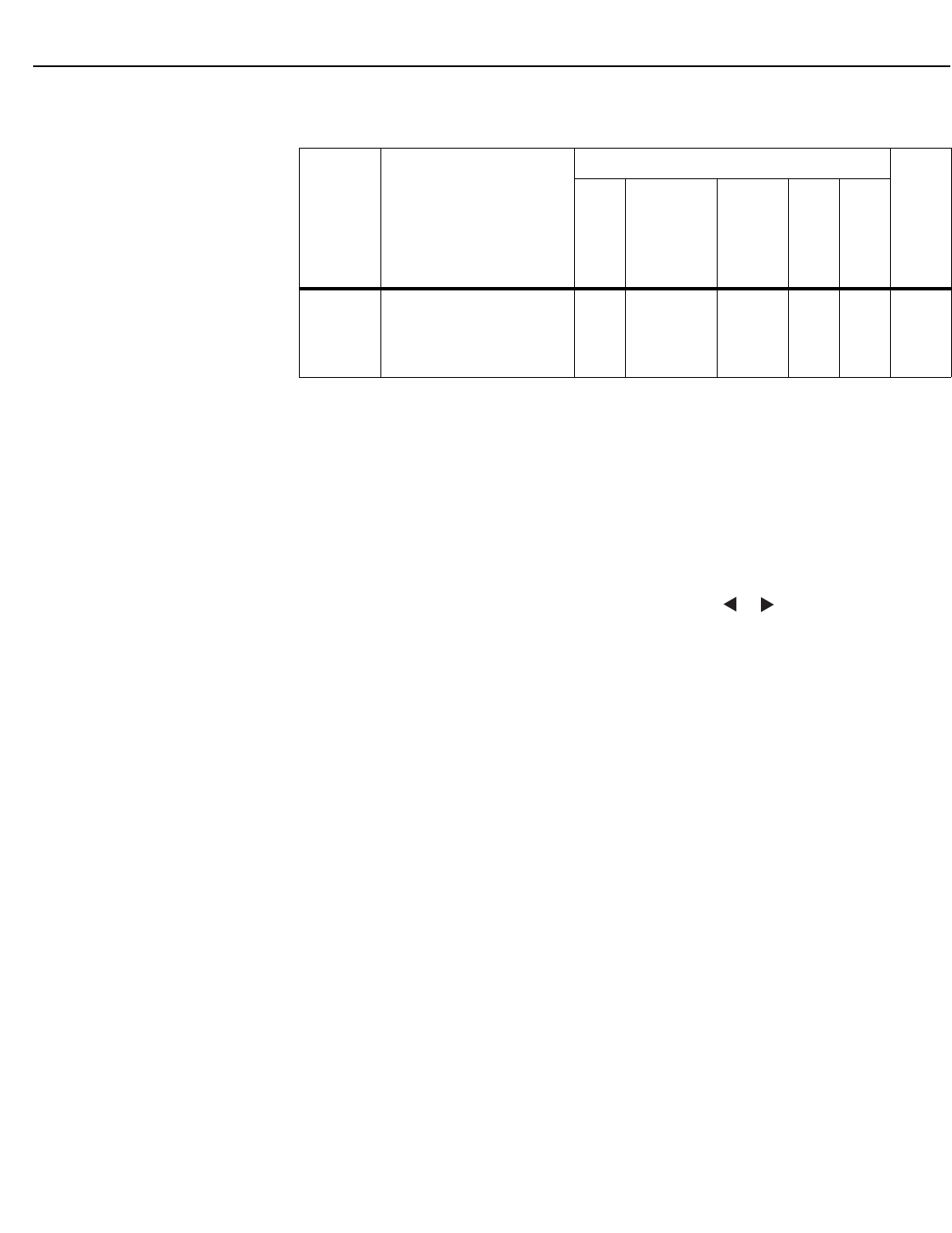
Operation
54 Vidikron Vision 85 Owner’s Operating Manual
PRELIMINARY
Contrast: Refer to Contrast on page 41.
Brightness: Refer to Brightness on page 40.
Color: Refer to Color Saturation on page 41.
Tint: Refer to Tint on page 42.
Sharpness: Refer to Sharpness on page 43.
Color Temp.: To adjust the color temperature, select Color Temp. from the Picture Adjust
menu. (Color temperature defines the “color of gray.”) Press or to select 5500, 6500,
7500, 8500, 9300 or 10500. In most cases, 6500 or 7500 will produce the most realistic colors.
Higher settings produce a “bluer” picture; lower ones cause the image to appear more red.
White Balance: Select White Balance from the Picture Adjust menu to choose a white
balance preset (or “gamma curve”) to store in the currently-selected picture memory. For
more information on white balance presets, refer to White Balance on page 56.
VAC: Iris: Select VAC: Iris from the Picture Adjust menu to increase or decrease the aperture
or iris size (the physical opening through the lens; similar to an “f-stop” on a camera). Doing
so allows you to optimize brightness and contrast according to the amount of ambient light
in the viewing area.
Select High Brightness or Theater for rooms with lots of ambient light. Select CRT Emulation
for more “theater-like” viewing conditions (little or no ambient light).
Lamp Power: Select Lamp Power from the Picture Adjust menu to adjust the lamp output
level. You can choose to run the lamp as bright as possible (220W; this is the default setting)
or you can choose the lower setting (180W). Generally, lower lamp output can prolong the
life of the lamp, but decreases brightness.
ISF Night For viewing images with the
brightness slightly
increased in a darkened
room.
6500 CRT
Emulation
Low
(180W)
Off Off ISF
NIGHT
Table 4-2. Default Picture Memory Settings for Digital 1080i and 1080p Sources
(continued)
Picture
Memory
Setting
Description
Default Settings for Selected Picture Memory
Remote Control Key
Color Temp.
VAC (Iris)
Lamp Power
Sharpness
Enhancement
Auto Contrast
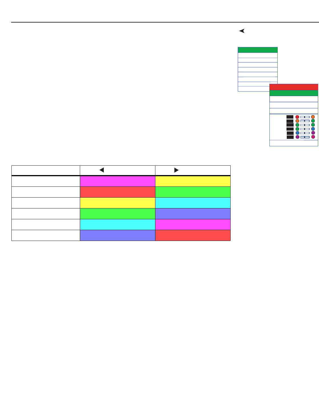
Operation
Vidikron Vision 85 Owner’s Operating Manual 55
PRELIMINARY
Picture Adjust (Advanced)To access advanced picture quality settings, select Advanced from the Picture Adjust menu.
This sub-menu presents the following options:
ICC Adjust: Select ICC Adjust from the Advanced Picture Adjust menu to customize the
displayed color space. The adjustments you make here are stored in the currently-selected
“Picture Memory“ preset.
For each of the six primary colors – red, yellow, green, cyan, blue and magenta – you can
adjust the following:
•Hue: These slidebars adjust the red/green color hue for true color reproduction of video
signals. For best results, adjust the hue while displaying an external color bar test pattern
(Figure 4-4).
Changing the hue of a primary color affects the gamut (range) of possible colors. For
example, changing the value for red moves the color closer to either yellow or magenta,
which in turn affects all displayed colors having a red component.
Table 4-3 describes the effects of adjusting the primary color hues.
• Saturation: This slidebar adjusts the color saturation level – the amount of that color in a
video image. Lower settings produce less saturated colors; a setting of “-30” removes that
color from the image entirely. If the saturation is too high, that color will be overpowering
and unrealistic.
•Intensity: This slidebar adjusts the intensity – also known as luminance – of a given color.
•Default: To reset ALL ICC settings – Hue, Saturation AND Intensity of all six colors – for the
currently-selected “Picture Memory“ preset to their factory-default values, select Default
(directly below the “Intensity” menu item) from the ICC Adjust menu. Then, select Yes to
confirm the reset.
To reset only the Hue, Saturation OR Intensity of all six colors for the currently-selected
“Picture Memory“ preset to their factory-default values, select Hue, Saturation or Intensity
from the ICC Adjust menu and press ENTER. Then, select Default (the last menu item) from
the ICC Adjust menu. Then, select Yes to confirm the reset.
Brilliant Color™: Select Brilliant Color™ from the Advanced Picture Adjust menu to change
the BrilliantColor setting. BrilliantColor utilizes a new color-processing algorithm and system
level enhancements to enable higher picture brightness while providing truer, more vibrant
colors. To enable BrilliantColor, set it to On; to disable it, set it to Off.
ICC Adjust
BrilliantColor
TM
SD Advanced Mode
Film Mode
Video NR
MNR
Sharpness Enhancement
Automatic Contrast
Default
ICC- Hue
Default
ICC - Saturation
ICC - Intensity
Red 0
Yellow 0
Green 0
Cyan 0
Blue 0
Ma
g
enta 0
Y
Y
MM
BB
CC
GG
Default
R
R
ICC Adjust
Table 4-3. Effects of Primary Color Hue Adjustments
Primary Color Press to move the color... Press to move the color...
Red Closer to magenta Closer to yellow
Yellow Closer to red Closer to green
Green Closer to yellow Closer to cyan
Cyan Closer to green Closer to blue
Blue Closer to cyan Closer to magenta
Magenta Closer to blue Closer to red
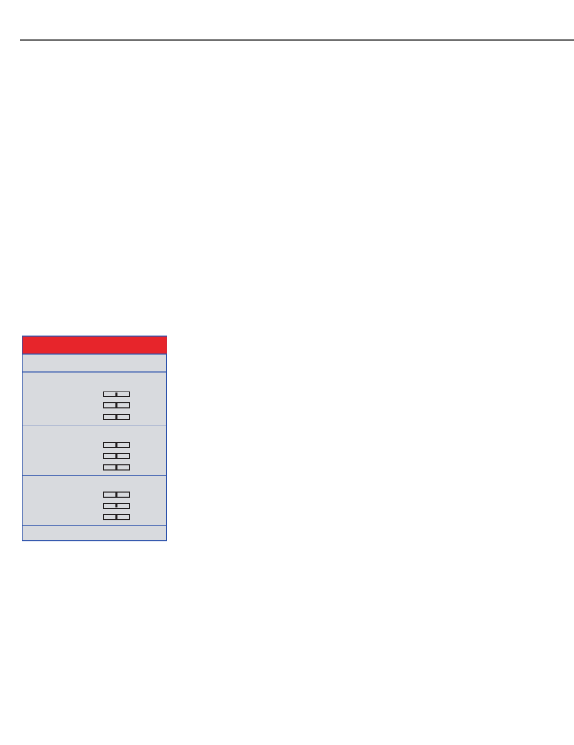
Operation
56 Vidikron Vision 85 Owner’s Operating Manual
PRELIMINARY
Video NR: To apply noise reduction to the input signal, select Video NR from the Advanced
Picture Adjust menu. Noise reduction is useful for improving the signal-to-noise ratio of
video signals. Set it to Off, 1, 2 or 3, as needed, keeping in mind that higher settings (which
reduce high frequencies) may also “soften” the image.
MNR: Select MNR from the Picture Adjust menu to reduce or eliminate so-called “mosquito
noise” in MPEG-compressed video signals (digital broadcasts or DVDs). Set it to Off, 1, 2 or 3,
as needed to minimize distortion around the edges of moving objects, moving artifacts
around edges and/or blotchy noise patterns superimposed over the objects.
Sharpness Enhancement: select Sharpness Enhancement from the Advanced Picture
Adjust menu to apply edge enhancement to images, giving the impression of added depth.
Set it to Off, 1, 2, or 3 as desired.
Automatic Contrast: The Vision 85 can dynamically adjust the contrast (white level)
according to the color content in the signal, to produce the best picture quality. Select
Automatic Contrast from the Picture Adjust menu to activate this feature. Set it to Off, 1, 2, or
3 as desired. Selecting “3” results in a higher average white level than the other settings.
Default: To reset all picture quality settings for the current input to their factory-default
values, select Default from the Picture menu.
White Balance The Vision 85 provides nine adjustable white balance parameters, allowing precise
adjustment of the intensity of the red, blue and green color components in the dark areas
(Offset), light areas (Gain) and “mid-tone” areas (Gamma).
You can adjust these parameters as needed and store them in any of six presets (memory
locations). The selected white balance preset can, in turn, be associated with a “Picture
Memory“ preset (refer to White Balance on page 54). The most logical way to do this is to
associate a white balance preset with the picture memory preset of the same name;
however, you can associate a white balance preset with any picture memory preset.
Mem. Select: To select and edit a white balance preset, select Mem. Select from the White
Balance menu.
Red Gamma/Green Gamma/Blue Gamma: Refer to ISF Night - Display Color on page 45.
Red Gain/Green Gain/Blue Gain: Refer to ISF Night - Display Color on page 45.
Red Offset/Green Offset/Blue Offset: Refer to ISF Night - Display Color on page 45.
Default: To reset the Gamma, Gain and Offset settings for the currently-selected white
balance preset to their factory-default values, select Default from the White Balance menu.
Then, select Yes to confirm the reset.
➤
Gamma
Red Gamma
Green Gamma
Blue Gamma
0
0
0
Gain
Red Gain
Green Gain
Blue Gain
0
0
0
Offset
Red Offset
Green Offset
Blue Offset
0
0
0
Default
White Balance
Mem. Select 1
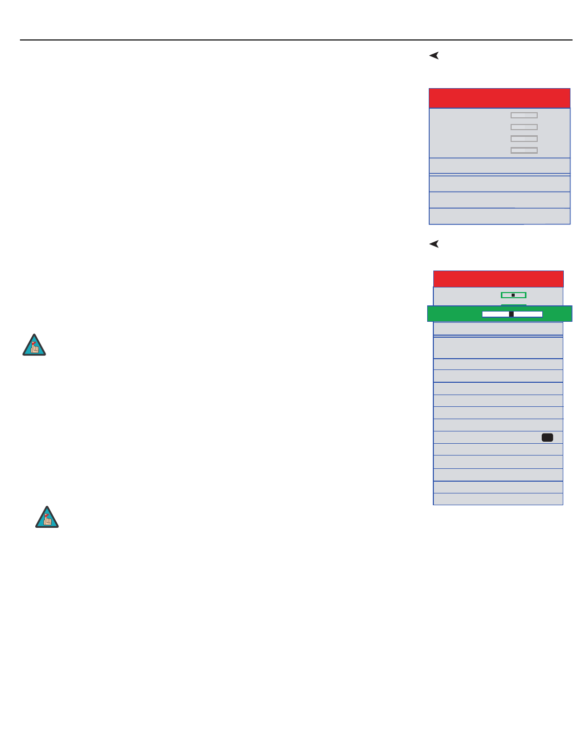
Operation
Vidikron Vision 85 Owner’s Operating Manual 57
PRELIMINARY
HD/RGB Adj. Select HD/RGB Adj. from the Main Menu to view input signal resolution and timing
information. To do this, select Signal Info from the HD/RGB Adj. menu.
Signal Info: Select Signal Info from the HD/RGB Adj. menu to display the resolution,
horizontal frequency and vertical frequency of the input current signal.
OptionsSelect Options from the Main Menu to perform the following projector configuration tasks.
Image Shift: Select Image Shift from the Options menu to vertically shift the projected
image.
Subtitle: Select Subtitle from the Options menu to adjust the projected image height in
small increments.
Overscan: Refer to Overscan on page 43.
Default: To reset the Overscan setting to its default value, select Default from the Options
menu, then select Yes to confirm the reset.
LED: Select LED from the Options menu to change the behavior of the projector’s indicator
LEDs.
• When set to ON, the LEDs indicate operating status as described in VX-2000d at a Glance
on page 5.
• When set to OFF, the LEDs illuminate when the Vision 85 is in standby mode, warming up
or indicating an error condition; otherwise, they are off.
Lamp Hours (read-only): Refer to Lamp Hours on page 49.
OSD: When you select an aspect ratio or input with the remote control (or from the VHD
Controller), the Vision 85 displays your selection on-screen. To prevent the display of these
items, select OSD from the Options menu and set it to Off.
HD/RGB Adj.
Frequency 0
Phase 0
H-Shift 0
V-Shift 0
Default
Special Modes
Signal info
Auto Setup
Ima
g
e Shift 0
Subtitle 0
Overscan 30
Default
Adjust Black Level 0
LED On
Options
OSD On
Signal Type 3
Lamp Hours
HDMI Black Level 0
Color Space
Auto
Background
Power Save
Baud Rate 9600 bps
Fan Mode 2
Orientation FF
Factory Default
Adjust White Level 0
Overscan + -
5%
Image Shift and Subtitle can only be adjusted for certain 1080i signals.
When you set the Auto Power Off function (refer to Power Save, below) to
Off, the LED function is automatically set to On.
Note
Note

Operation
58Vidikron Vision 85 Owner’s Operating Manual
PRELIMINARY
Signal Type: Select Signal Type from the Options menu to specify the incoming signal type
(encoding method):
• Choose Auto to have the Vision 85 automatically detect the signal type.
• Choose RGB (1) for RGB-encoded video signals.
• Choose YCrCb4:4:4 (2) for uncompressed, component video. This encoding method uses a
“luminance” signal (Y) to represent brightness and “difference” signals (Cb and Cr) to
represent colors.
• Choose YCrCb4:2:2 (3) for compressed, component video (similar to YCrCb4:4:4).
In most situations, selecting Auto produces the most accurate colors. If it does not, try the
other choices and select the one that does.
Color Space: “Color Space” determines how the color components of an analog input signal
are decoded for accurate color in the display. Select Color Space from the Options menu to
specify the color space to use. In most situations, selecting Auto produces the most accurate
colors. If it does not, try the other choices and select the one that does.
HDMI Black Level: This control compensates for incoming elevated black levels present in
certain video signals. When you set it to Auto, the Vision 85 automatically determines the
best setting according to the incoming video signal type. For some types of video, you may
want to override the setting. Set it to 0 IRE if blacks appear elevated (dark gray). If blacks
appear “crushed” (too dark), set it to 7 IRE.
Background: Select Background from the Options menu, then press or to select the
image background – solid blue, solid black or the Vidikron logo welcome screen. The
Background appears when no incoming signal is present.
Power Save: Select Power Save from the Options menu to access the power management
features of the Vision 85.
• RS-232C Port: When this option is set to On, the RS-232 port is always active and using
power, even when the projector is in standby mode. When set to Off, the RS-232 port is
inactive and does not consume power when the projector is in standby mode.
• Auto Power Off: When this option is set to On, the projector enters standby mode after
15 minutes of inactivity (no input signal). Five minutes before this is to occur, the message
“Enter STANDBY mode in 5 min.” appears on-screen. This message updates to indicate the
amount of time before the projector enters standby mode.
When set to Off, the projector remains in the “power on” state regardless of the presence
or absence of an input signal.
Baud Rate: Select Baud Rate from the Options menu, then press the or button to
change the data rate of the RS-232 connection between the projector and the VHD
Controller. The default setting is 9600 bps. Do not change it unless specifically instructed
to do so by Vidikron Technical Support.
Always set this option to On. Doing otherwise may disrupt
communication between the projector and VHD Controller.
When you set the Auto Power Off function to Off, the LED function (refer to
4-57) is automatically set to On.
Caution
Note

Operation
Vidikron Vision 85 Owner’s Operating Manual 59
PRELIMINARY
Fan Mode: If the projector is being used in a high-altitude environment, use the Fan Mode
control to prevent it from overheating. Set it to High Altitude (2) to run the fan at high speed;
set it to Normal (1) to run the fan at normal speed.
Orientation: Refer to Adjusting the Picture Orientation on page 32.
Factory Default: To reset all projector settings (including image settings) back to their
factory defaults, choose Factory Default from the Options menu. When the confirmation
message appears, select All Reset to perform the reset or Return to cancel. This action is
not undoable. Proceed with caution!
The Factory Default command does not reset the Lamp Timer or OSD
Language setting.
Note

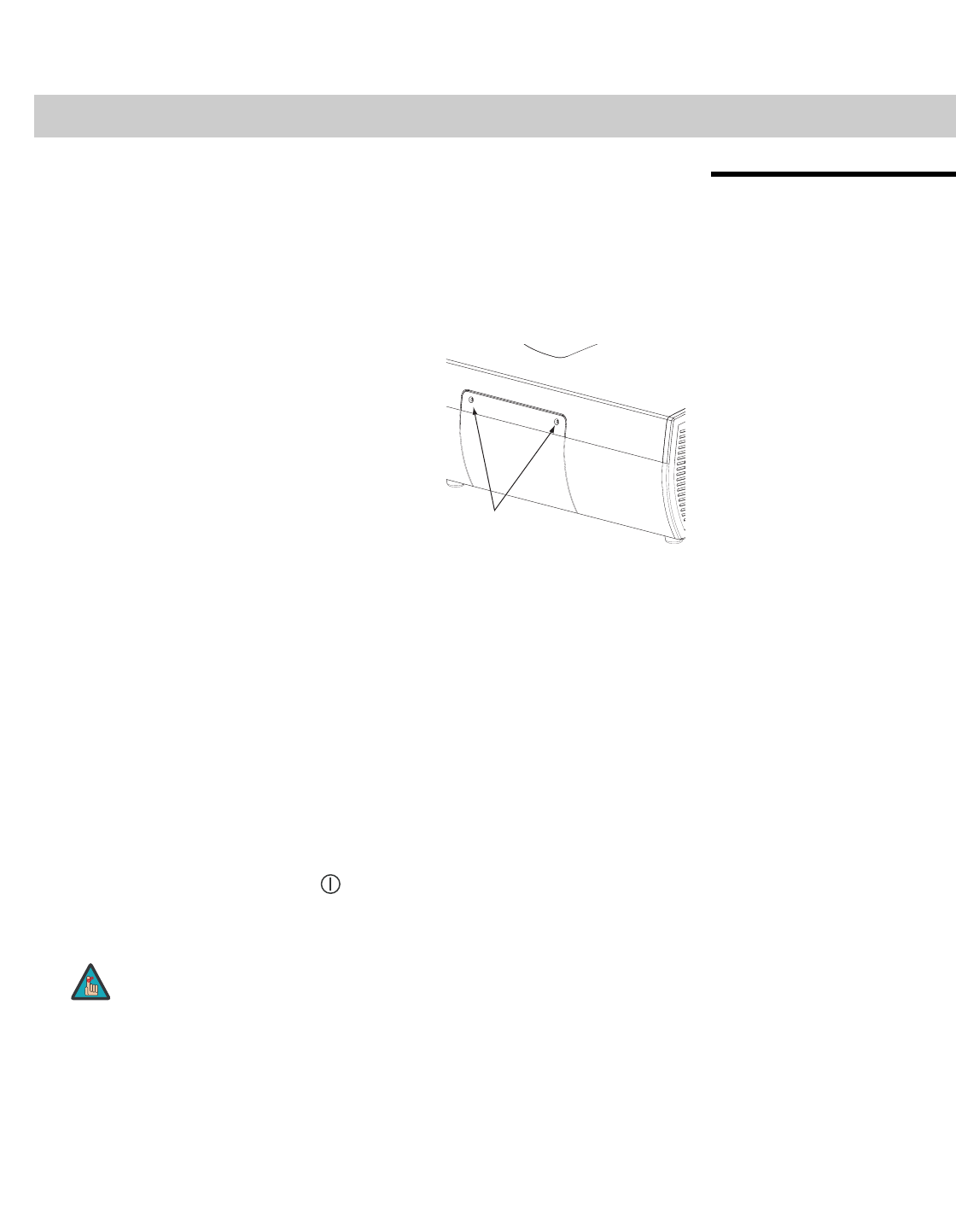
Vidikron Vision 85 Owner’s Operating Manual 61
PRELIMINARY
5.1
Lamp Replacement
The lamp should be replaced when it reaches the end of its life (typically 2000 hours), or
sooner if a noticeable degradation in brightness occurs. Contact your Vidikron dealer to
obtain a replacement lamp.
1. Turn off the projector and unplug the power cord. Allow the projector to cool down for
approximately 45 minutes prior to removing the lamp assembly for replacement.
2. Using a Phillips screwdriver, loosen the two
Lamp Cover screws on the side of the
projector and remove the cover.
3. Remove the three Phillips round-head lamp assembly mounting screws. These are
identified by arrows pointing to them on the lamp housing.
4. Grasp the lamp assembly handle and pull gently, removing the lamp module from the
projector housing.
5. Install the new lamp module. Secure it in place with the three screws that you removed
in Step 3.
6. Replace the lamp cover and re-tighten the two Lamp Cover screws.
7. Re-connect the AC power cord to the projector.
8. Reset the Lamp Hour counter by doing either of the following:
•On the projector rear-panel keypad (see Figure 2-6), press and hold the ENTER,
DOWN and RIGHT buttons simultaneously. Then, press the ON button.
•On the VHD Controller front panel (see Figure 2-3), while pressing and holding the
ENTER button, press the POWER () button.
When you do, “LAMP 0000H” appears on-screen to confirm the counter reset.
5Maintenance and Troubleshooting
Always reset the Lamp Hour counter when you replace the lamp. Do this
only if you have just installed a new lamp. This will ensure that number of
hours logged on the lamp is accurate.
REMOVE
THESE SCREWS
Note
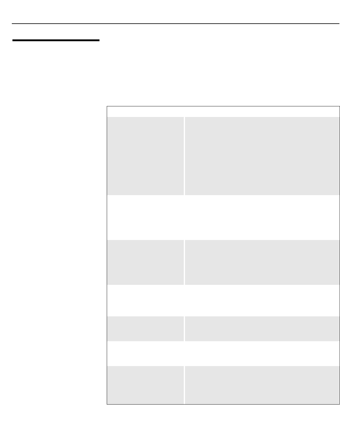
Maintenance and Troubleshooting
62 Vidikron Vision 85 Owner’s Operating Manual
PRELIMINARY
5.2
Troubleshooting Tips
Table 5-1 provides some general guidelines for troubleshooting problems you may
encounter with the Vision 85.
If you encounter an issue not described here or in Section 3 (refer to Installation
Considerations on page 18), or if the suggested solutions fail to resolve the problem, please
contact your Vidikron dealer or Vidikron Technical Support.
Table 5-1. Troubleshooting Chart
Symptom Possible Cause(s) Solution
The projector does not turn on
after initial installation. The
power LED on the front of the
VHD Controller lights red after
you press the power button.
•The Vision 85 is not
plugged in or the AC outlet
is not active.
• The serial connection from
the VHD Controller to the
Vision 85 is incorrect.
• The remote control
batteries have run out.
• Ensure that the Vision 85 is
plugged in and that the AC
outlet is active.
• Ensure that the RS-232
output from the VHD
Controller is properly
connected to the RS-232C
port on the Vision 85 (see
Figure 3-6).
• Replace the batteries.
The projector and VHD
Controller are both on, but
there is no picture and
on-screen menus do not
appear.
• Faulty or incorrect video
connection between the
VHD Controller and the
Vision 85.
• Ensure that the HDMI
output from the VHD
Controller is properly
connected to the HDMI
input on the Vision 85 (see
Figure 3-6).
The projector and
VHD Controller are both on
and menus appear on-screen,
but there is no picture.
• Incorrect source selection.
• Source component is not
turned on.
• Source component is
connected incorrectly or
not at all.
• Select the correct source.
• Turn on the source.
• Check video connections to
source component.
A projected image from a DVD
is split or otherwise scrambled.
• DVD player is connected to
the Component input and
set to progressive scan
mode.
• Turn off progressive scan
on the DVD player. Or,
connect the DVD player to
the HD1 or HD2 input.
Image is too bright and/or
lacks definition in the bright
areas of the image.
• Contrast is set too high. • Lower the contrast setting.
Image appears “washed out”
and/or dark areas appear too
bright.
• Brightness is set too high. • Lower the brightness
setting.
Colors in the image are
swapped (for example, reds
appear blue or vice versa) on
one or more sources.
• The Red/Pr, Green/Y or
Blue/Pb outputs from the
source are connected to the
wrong inputs on the VHD
Controller.
• Ensure that the source
outputs are connected to
the correct VHD Controller
input.

Maintenance and Troubleshooting
Vidikron Vision 85 Owner’s Operating Manual 63
PRELIMINARY
Image geometry is incorrect. • Incorrect aspect ratio
selection.
• Image height may need
adjusting (Vision
85/CineWide only).
• Select the aspect ratio that
best matches the source
image and screen size (refer
to Table 4-1).
• Adjust displayed image
height (refer to Display
Device on page 49).
The projected image is
trapezoidal in shape.
• The projector is not
perpendicular to the
screen.
• Adjust the projection angle.
The projector will not turn
back on after it was powered
down, or the image disappears
during operation.
• The projector will not turn
on for two minutes after
power-down, to protect the
lamp.
• The lamp has failed or
reached its usage limit of
2000 hours.
• Wait two minutes until the
LED at the front of the VHD
Controller turns red.
• Replace the lamp.
Table 5-1. Troubleshooting Chart (continued)
Symptom Possible Cause(s) Solution

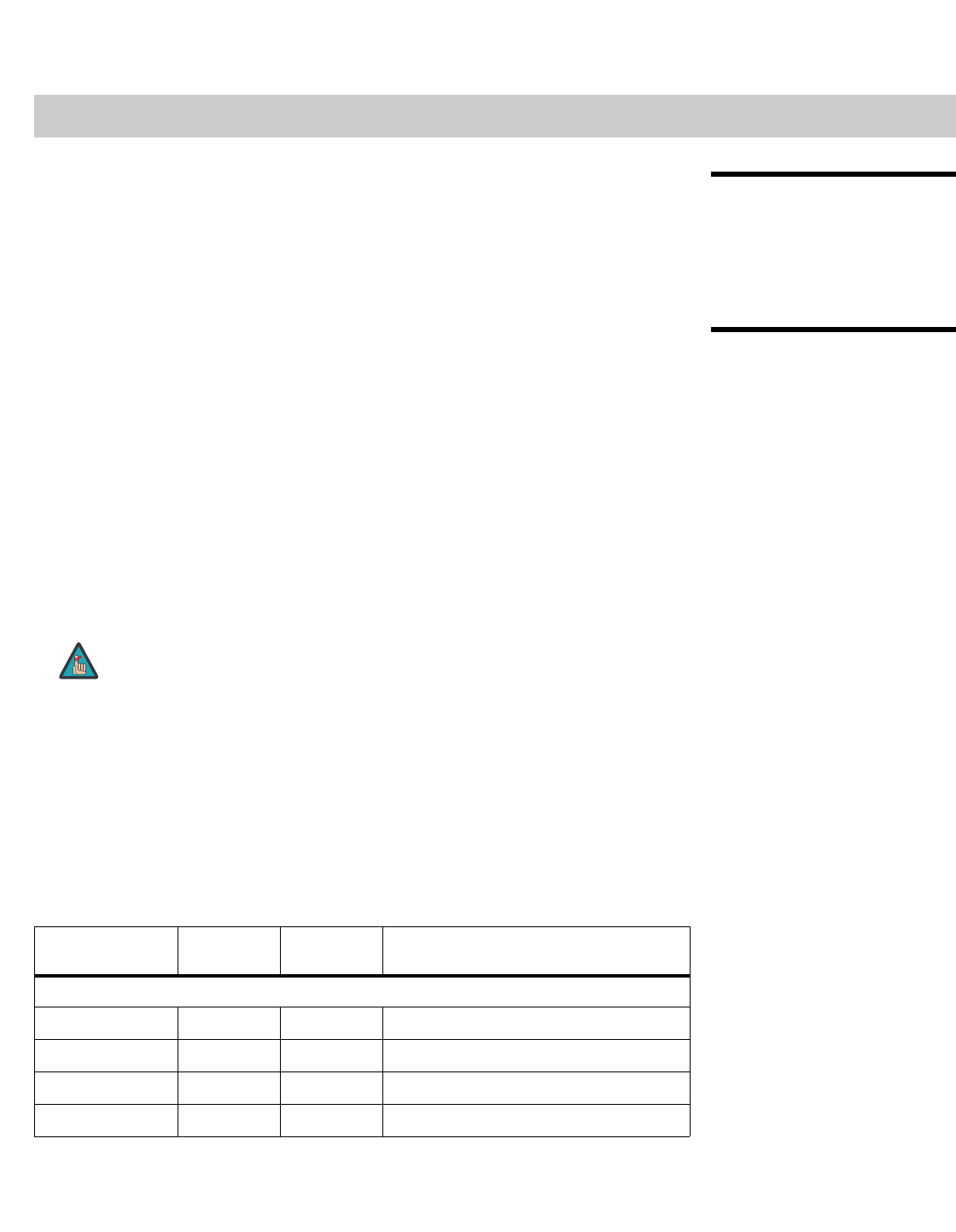
Vidikron Vision 85 Owner’s Operating Manual 65
PRELIMINARY
6.1
RS-232 Connection and
Port Configuration
To interface the VHD Controller with a home theater automation/control system or a PC
running terminal emulation software, connect it to your control system or PC as shown in
Figure 3-11.
Configure the RS-232 controller or PC serial port as follows: no parity, 8 data bits, 1 stop bit
and no flow control. Set the baud rate to 19200, to match that of the VHD Controller RS-232
port.
6.2
Serial Command Syntax
Serial commands to the VHD Controller take the following form:
• Commands are not case-sensitive.
• For a single command that takes no parameters, type the command followed by a
carriage return; for example, to set the aspect ratio to Letterbox, type
LETTERBOX <Enter>.
• For a single command that takes a parameter, type the command, a space or a comma
and the desired value followed by a carriage return; for example, to set the brightness to
-10, type BRIGHTNESS -10 <Enter> or BRIGHTNESS,-10 <Enter>.
• You can also send a string of multiple commands on a single line, separated by commas.
For example, COMPOSITE,BRIGHTNESS 100,ANAMORPHIC <Enter> switches to
the Composite video input, sets the brightness to 100 and sets the aspect ratio to
Anamorphic. Command strings can be up to 255 characters long.
Table 6-1 lists the RS-232 command set. The “Parameter (min/max)” column shows the valid
parameter ranges, or “NA” for commands that take no parameters.
When you enter a valid command, the VHD Controller executes it and acknowledges it with a
plus sign on the command line (+ >). When you enter an invalid command – one that is
misspelled or followed by values outside the valid range for that command – the VHD
Controller ignores it and returns a minus sign (- >).
6Serial Communications
Avoid combining the ON or POWER 1 commands with other commands on a
single line. After sending ON or POWER 1, allow at least 15 seconds for the
VHD Controller to power up. Once it does, it will accept and properly execute
multiple serial commands.
Table 6-1. Serial Commands
Command Parameter
(min/max)
Value
Stored? Description
Power On/Off Commands
OFF NA NA Turns projector off
ON NA NA Turns projector on
POWER 0/1 NA Turns projector on and off
POWER? NA NA Returns power status
Note
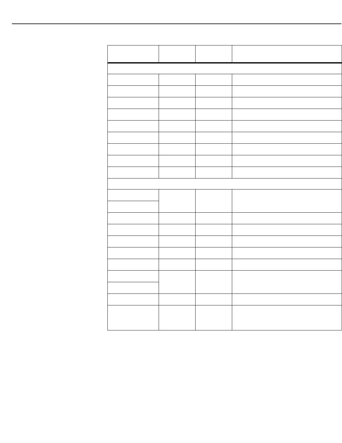
Serial Communications
66 Vidikron Vision 85 Owner’s Operating Manual
PRELIMINARY
Input Selection Commands
COMPONENT NA YES Selects the Component input
COMPOSITE NA YES Selects the Composite video input
HDMI1 NA YES Selects the HDMI 1 input
HDMI2 NA YES Selects the HDMI 2 input
HD1 NA YES Selects the HD 1 input
HD2 NA YES Selects the HD 2 input
INPUT? NA NA Returns active input
SVIDEO1 NA YES Selects the S-Video 1 input
SVIDEO2 NA YES Selects the S-Video 2 input
Aspect Ratio Commands
ANAMORPHIC
NA YES Selects the Anamorphic aspect ratio
16:9
ASPECT? NA NA Returns current aspect ratio
ASPECTIN? NA NA Returns the input source aspect ratio
ASPECTOUT? NA NA Returns output screen size
CINEMA NA YES Selects the Cinema aspect ratio
LETTERBOX NA YES Selects the Letterbox aspect ratio
STANDARD
NA YES Selects the Standard (4:3) aspect ratio
4:3
INTELLIWIDE NA YES Selects the IntelliWide aspect ratio
INTELLI235 NA YES Selects the IntelliWide 2.35 aspect ratio
(available only on the Vision 85/CineWide
and only on the analog inputs)
Table 6-1. Serial Commands (continued)
Command Parameter
(min/max)
Value
Stored? Description

Serial Communications
Vidikron Vision 85 Owner’s Operating Manual 67
PRELIMINARY
Picture Adjust Commands (not available on HDMI 1 or HDMI 2 inputs)
BRIGHTNESS -100/100 YES Sets a value for brightness
BRIGHTNESS? NA NA Returns brightness setting value
CHROMADELAY -12/12 YES Sets a value for input color chroma delay
CHROMADELAY? NA NA Returns input color chroma delay setting
COLOR -100/100 YES Sets a value for color
COLOR? NA NA Returns color setting value
CONTRAST -100/100 YES Sets a value for contrast
CONTRAST? NA NA Returns contrast setting value
FILMMODE 0/1 YES Sets Film Mode off (0) or on (1)
FILMMODE? NA NA Returns Film Mode setting (0 = off; 1 = on)
FILTER 0/15 YES Sets a value for input color noise filter
FILTER? NA NA Returns input color noise filter setting
PHASE 0/3 YES Adjusts phase
PHASE? NA NA Returns phase setting value
SHARPNESS -6/6 YES Sets a value for sharpness
SHARPNESS? NA NA Returns sharpness setting value
TINT -100/100 YES Sets a value for tint
TINT? NA NA Returns tint setting value
Image Preset Commands (not available on HDMI 1 or HDMI 2 inputs)
CUSTOM1 NA YES Loads “Custom 1” image preset
CUSTOM2 NA YES Loads “Custom 2” image preset
DAY NA YES Loads “ISF Day” image preset
NIGHT NA YES Loads “ISF Night” image preset
PRESET? NA NA Returns currently-selected preset
(ISF Day, ISF Night, Custom 1 or Custom 2)
Table 6-1. Serial Commands (continued)
Command Parameter
(min/max)
Value
Stored? Description
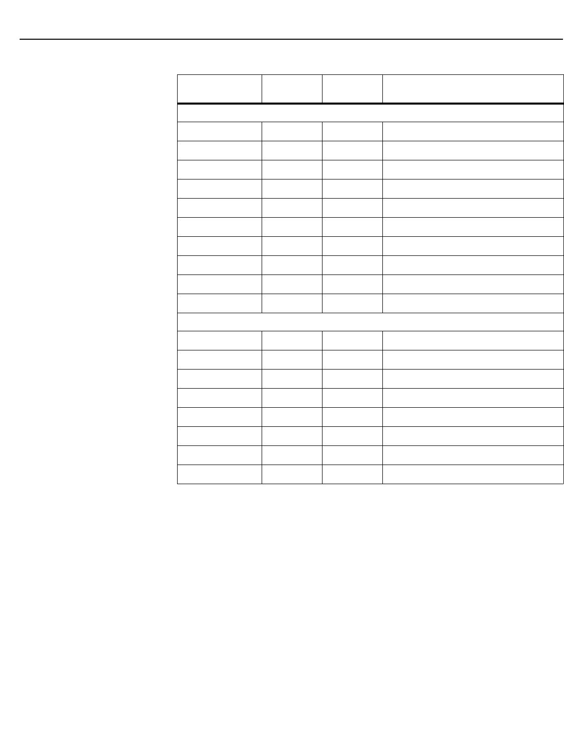
Serial Communications
68Vidikron Vision 85 Owner’s Operating Manual
PRELIMINARY
Input Position Commands (not available on HDMI 1 or HDMI 2 inputs)
IHEIGHT -100/100 YES Sets the value for input height
IHEIGHT? NA NA Returns input height value
IHPOS -100/100 YES Sets a value for horizontal input position
IHPOS? NA NA Returns input horizontal position value
IVPOS -100/100 YES Sets a value for vertical input position
IVPOS? NA NA Returns input vertical position value
IWIDTH -100/100 YES Sets the value for input width
IWIDTH? NA NA Returns input horizontal width value
OVERSCAN 0/10 YES Sets the overscan percentage
OVERSCAN? NA NA Returns overscan percentage
Output Shift Commands (not available on HDMI 1 or HDMI 2 inputs)
OHEIGHT -100/100 YES Sets the value for output height
OHEIGHT? NA NA Returns output height value
OHPOS -100/100 YES Sets the value for output horizontal position
OHPOS? NA NA Returns output horizontal position value
OVPOS -100/100 YES Sets the value for output vertical position
OVPOS? NA NA Returns output vertical position value
OWIDTH -100/100 YES Sets the value for output width
OWIDTH? NA NA Returns output horizontal width value
Table 6-1. Serial Commands (continued)
Command Parameter
(min/max)
Value
Stored? Description
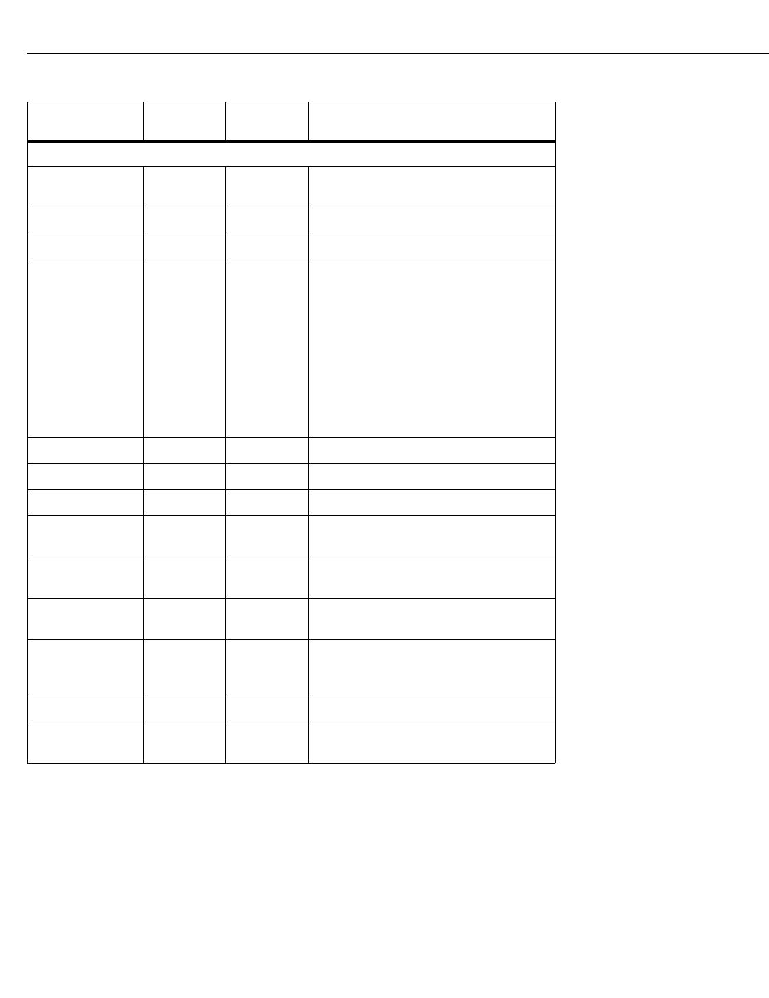
Serial Communications
Vidikron Vision 85 Owner’s Operating Manual 69
PRELIMINARY
Miscellaneous Commands
BKGND -100/100 YES Sets the background color for 4:3 aspect ratio
(-100 = black; 100 = white)
BKGND? NA NA Returns background setting value
DATE? NA NA Returns projector manufacture date
HDINPUTRES NA YES Sets YPbPr input resolution and refresh rate
for HD1/HD2, as follows:
0 = 480i
1 = 480p
2 = 576i
3 = 576p
4 = 720p / 60 Hz
5 = 1080i / 60 Hz
6 = 720p / 50 Hz
7 = 1080i / 25 Hz
Any other value = Auto
HWVER? NA NA Returns hardware version number
INRES? NA NA Returns input resolution
LENS1? NA NA Returns Lens 1 configuration
RGBNN NA NA Sets output color space to RGB with negative
horizontal and vertical sync
RGBPP NA NA Sets output color space to RGB with positive
horizontal and vertical sync
RGBS NA NA Sets output color space to RGB with
composite sync
STATUS NA NA Returns current operating status (power,
input source, input resolution and input
aspect ratio)
SWVER? NA NA Returns software version number
TRIGGER 1/3 YES Assigns trigger to currently-selected aspect
ratio
Table 6-1. Serial Commands (continued)
Command Parameter
(min/max)
Value
Stored? Description
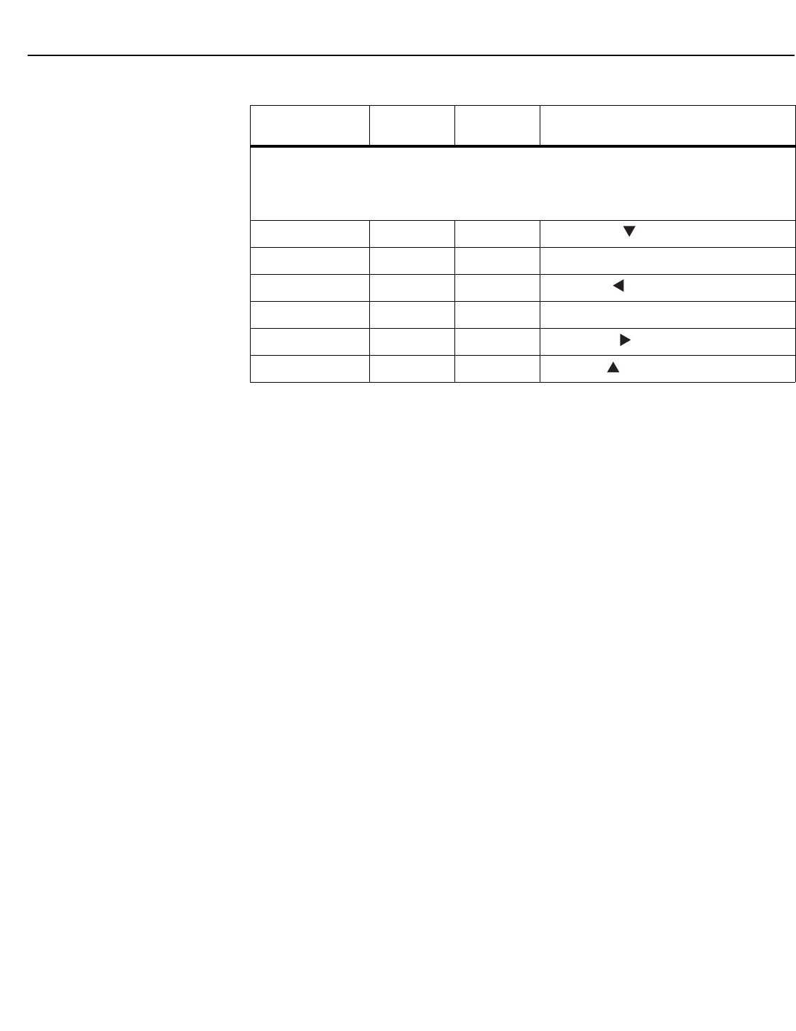
Serial Communications
70 Vidikron Vision 85 Owner’s Operating Manual
PRELIMINARY
The following serial commands are meant to emulate buttons on the remote control or VHD
Controller front panel. Each button has its own serial command, so effectively it is as if you were
using the IR remote only you’ll be doing so via serial commands. These commands provide active
OSD responses just like the IR remote.
DOWN NA NA Down-Arrow ( ) key
ENTER NA NA ENTER key
LEFT NA NA Left-Arrow ( ) key
MENU NA NA MENU
RIGHT NA NA Right-Arrow ( ) key
UP NA NA Up-Arrow ( ) key
Table 6-1. Serial Commands (continued)
Command Parameter
(min/max)
Value
Stored? Description

Vidikron Vision 85 Owner’s Operating Manual 71
PRELIMINARY
7.1
Vision 85 Specifications
Table 7-1 lists the Vision 85 specifications.
7Specifications
Table 7-1. Vision 85 Specifications
Projector Type: Digital Light Processing (DLP), single-chip, 16:9 DMD
Native Resolution: 1920 x 1080 (16:9)
Aspect Ratios: Refer to Table 7-2
Video Standards: Refer to Table 7-2
DTV Compatibility: 480p, 720p, 1080i, 1080p
Scan Frequency: Horizontal: 15 - 81 kHz
Vertical: 43 - 100 Hz
Picture Size (16:9 Screen): Recommended Width: 72 - 96 in.
Maximum Width: 200 in.
Throw Distance
(Factor x Screen Width):
Vision 85: 1.86 to 2.45
Vision 85/CineWide: 1.92 to 2.45
Horizontal and Vertical
Offset:
Horizontal: None
Vertical: 50% of screen height up or down
Lamp: 220 Watts
Estimated Lamp Life: 2000 hours
Inputs (from VHD Controller): (1) HDMI with HDCP, (1) RS-232

Specifications
72 Vidikron Vision 85 Owner’s Operating Manual
PRELIMINARY
Brightness and Contrast
(variable, depending on VAC
calibration):
Cinema Standards Measurement System (CSMS)
Specifications
- Brightness: TBD
- Contrast Ratio: TBD
These measurements are taken from the projector in a controlled, home
theater environment. All measurements are made to ANSI/NAPM
IT7.228-1997 specifications using the Photo Research PR-650
SpectraColorimeter and Minolta LS-100 Luminance Meter, Video
Essentials test DVD and a 1.3 gain, 72-inch wide screen. The projector is
calibrated to a color temperature of 6,500K and has a minimum of 150
hours of usage.
The foot-Lambert (fL) is the unit of measurement used in commercial
movie theaters to express image brightness at the screen surface. The
Society of Motion Picture and Television Engineers (SMPTE) specifies 16
fL as the target image brightness for film-based projectors using an
open gate (without film in the projector). More importantly, today
SMPTE specifies 12 fL as the target image brightness in Digital Cinema
theaters. The foot-Lambert measurement is dependent on screen size,
screen gain and projector light output.
Home Theater Calibration Specifications
- Light Output: TBD
- Contrast Ratio: TBD
These specifications are obtained by calibrating the projector as
described above for CSMS measurements.
Industry-Standard Specifications
- Light Output: TBD
- Contrast Ratio: TBD
These are typical projector brightness and contrast specifications found
in most companies’ sales literature. Vidikron includes these
measurements in its literature to allow for direct comparison with other
manufacturers’ projectors. These measurements are typically taken at
9,000K to 13,000K to get expected performance data when the projector
is used in professional, commercial and industrial displays.
Power Requirements: 100 to 240 VAC (auto-sensing), 50/60 Hz, 375 Watts
Operating Environment: 40°F to 95°F (5°C to 35°C), 0% to 90% humidity
(non-condensing)
Dimensions: See Figure 7-1
Weight (without lens): 50 lbs. (22.68 kg)
Regulatory Approvals: Complies with FCC, CE C-Tick
Limited Warranty: Projector: Two (2) years parts and labor from the date of delivery
to the end user.
Lamp: 1000 hours or six (6) months, whichever comes first.
Specifications are subject to change without notice.
Table 7-1. Vision 85 Specifications (continued)

Specifications
Vidikron Vision 85 Owner’s Operating Manual 73
PRELIMINARY
7.2
VHD Controller
Specifications
Table 7-2 lists the VHD Controller specifications.
Table 7-2. VHD Controller Specifications
Aspect Ratios: 4:3, Letterbox, 16:9, IntelliWide, Cinema, IntelliWide 2.35
Video Standards: NTSC, PAL
Inputs: (1) Composite; (2) S-Video; (1) Component; (2) HD-R (Pr), G (Y), B
(Pb), H, V; (2) HDMI with HDCP
Outputs: HDMI with HDCP
Control Options: - Discrete infrared remote
- Serial commands via RS-232
- Front-panel controls
RS-232 Communication
Parameters:
19200 bps, no parity, 8 data bits, 1 stop bit, no flow control
Trigger Outputs: (3) +12 VDC, each rated at 750 mA and thermal fuse-protected
Bandwidth: 150 Mega Samples per Second (MSPS)
Power Requirements: 100 to 240 VAC (auto-sensing), 50/60 Hz, 160 Watts
Operating Environment: 40°F to 95°F (5°C to 35°C), 0% to 90% humidity
(non-condensing)
Dimensions: Width = 17.50 inches (444.5 mm)
Depth = 11.19 inches (284.1 mm)
Height = 3.75 inches (95.3 mm)
Weight: 13.0 lbs. (5.90 kg)
Regulatory Approvals: Complies with FCC, CE C-Tick
Limited Warranty: Two (2) years parts and labor from the date of delivery to the end
user.
Specifications are subject to change without notice.
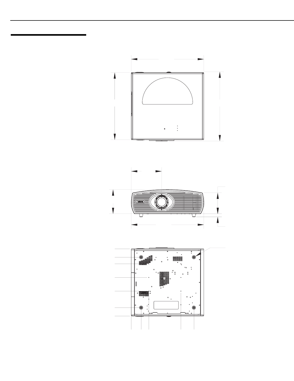
Specifications
74 Vidikron Vision 85 Owner’s Operating Manual
PRELIMINARY
7.3
Vision 85 Dimensions
Figure 7-1 shows the Vision 85 dimensions (all dimensions are in inches).
Figure 7-1. Vision 85 Dimensions
7.5
9.4
22.8
6.5
1.0
0
2x 3.1
3x 5.5
3x 15.4
2x 19.5
0
2x 7.7
2x 12.0
2x 16.2
2x 18.3
2x 2.6
20.9 Ø 1.1
21.6
22.8
20.9

Vidikron
2900 Faber Street
Union City, CA 94587
510-324-5900
Fax 510-324-5905
1-888-4-VIDIKRON
www.vidikron.com
SERIAL NUMBER
RUMA-011220
rev. 01-10-07 v1.0
