Ryobi 890R User Manual TRIMMER Manuals And Guides L0404041
RYOBI Line Trimmers/Weedwackers, Gas Manual L0404041 RYOBI Line Trimmers/Weedwackers, Gas Owner's Manual, RYOBI Line Trimmers/Weedwackers, Gas installation guides
User Manual: Ryobi 890R 890R RYOBI TRIMMER - Manuals and Guides View the owners manual for your RYOBI TRIMMER #890R. Home:Lawn & Garden Parts:Ryobi Parts:Ryobi TRIMMER Manual
Open the PDF directly: View PDF ![]() .
.
Page Count: 28

MANUAL
THANK YOU
Thank you for buying this quality product. This modern
outdoor power tool will provide many hours of useful
service. You will find it to be a great labor-saving device.
This operator's manual provides you with easy-to-
understand operating instructions. Read the whole
manual and follow all the instructions to keep your new
outdoor power tool in toD operating condition. The other
manual that came with your power tool, the parts
manual, contains all the information that you need to
order parts.
PRODUCT REFERENCES, ILLUSTRATIONS AND
SPECIFICATIONS
All information, illustrations and soecifications in this
manual are based on the latest product information
available at the time of printing. We reserve the right to
make changes at any time without notice.
Copyright @2000 Ryobi Outdoor Products, Inc,
All Rights Reserved.
Quick-Link ® is a registered trademark of Ryobi Outdoor
Products,
SERVICE INFORMATION
Service on this unit both within and after the warranty
period should be performed only by an authorized and
approved service dealer.
DO NOT RETURN THE UNIT TO THE RETAILER.
NOTE: PROOF OF PURCHASE WILL BE REQUIRED
FOR WARRANTY SERVICE.
Make sure this manual is carefully read and understood
before starting or operating this equipment.
THIS PRODUCT IS COVERED BY ONE OR MORE
US PATENTS, OTHER PATENTS PENDING.
Rules for Safe Operation ..................... 3-7
A. Important Safety Information ............... 3-5
B. Safety and International Symbols ........... 5-6
C. Know Your Unit .......................... 7
IL Assembly Instructions ...................... 8-11
A. Installing and Adjusting the J handle ........... 8
B. Installing the Harness ...................... 8
C. Removing and Installing the
Cutting Attachment Shield .................. 9
D. Remove the Cutting Attachment and
Install the Cutting Blade . g
E. Remove the Cutting Blade anti ................
install the Cutting Attachment .............. 10
ill. Oil and Fuel Information .................. 12-13
A. Recommended Oil Type .................. 12
B. Adding Oil to Crankcase-initial Use ........... 12
C. Recommended Fuel Type .................. 13
D. Fueling the Unit .......................... 13
IV, Starting/Stopping Instructions .............. 14-15
A. Starting/Stopping (Cold Weather) ............ 15
V° Operating Instructions .................... 16-18
A. Operating the Quick-Link System ............ 16
B. Holding the Trimmer ...................... 17
C, Adjusting Trimming Line Length ............. 17
D. Tips for Best Trimming Results .............. 17
E. Decorative Trimming ...................... 18
F, Using the Cutting Blade .................... 18
Vl. Maintenance and Repair Instructions ......... 19-25
A. Maintenance Schedule .................... 19
B. Line Installation .......................... 19
C. Installing a Prewound Reel ................. 20
D. Checking the Oil Level ..................... 21
E. Changing the Oil ......................... 21
F. Air Filter Maintenance ..................... 22
G. Carburetor Adjustment .................... 23
H. Rocker Arm Clearance ..................... 23
I. Replacing the Spark Plug .................. 25
J. Spark Arrestor Maintenance ................ 25
K. Accessories/Replacement parts ............. 25
VII. Cleaning and Storage ........................ 26
VIII.Troubleshooting Chart ....................... 27
IX, Specifications ...................... Beck Cover
Read the Operator's Manual,s) and follow all
warnings and safety instructions. Failure to do
so can result in sermus injury to the operator
and/or bystanders.
CONTENTS OF CARTON
•Model 8g0r Trimmer/Brushcutter with Brush Blade
* J-Handle and Hardware
• Large Bump Head Cutting Attachment
• Cutting Attachment Shield with Hardware
• Shoulder Harness
• Locking Rod T0ol
• Operator's Manual
• Parts Manual
, Product Registration Card
•Bottle of 4-Cycle Oil
2
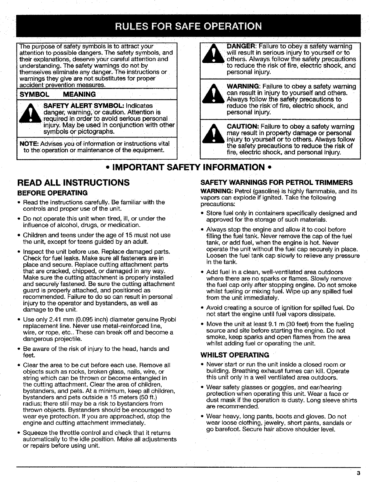
The purpose of safety symbols is to attract your
attention to possible dangers. The safety symbols, and
their explanations, deserve your careful attention and
understanding. The safety warnings do not by
themselves eliminate any danger. The instructions or
warnings they give are not substitutes for proper
accident prevention measures.
_YMBOL MEANING
SAFETY ALERT SYMBOL: indicates
danger, warning, or caution. Attention is
required in order to avoid serious personal
injury, May be used in conjunction with other
symbols or pictographs.
NOTE: Advises you of information or instructions vital
to the operation or maintenance of the equipment.
DANGER: Failure to obey a safety warning
will result in serious injury to yourself or to
others. Always follow the safety precautions
to reduce the risk of fire, electric shock, and
personal injury.
,_ WARNING: Failure to obey a safety warning
can result in injury to yourself and others.
Always follow the safety precautions to
reduce the risk of fire, electric shock, and
personal injury.
CAUTION: Failure to obey a safety warning
,AJlIL may result in property damage or personal
injury to yourself or to others. Always follow
the safety precautions to reduce the risk of
l f re, e ectr c shock, and personal injury.
•IMPORTANT SAFETY INFORMATION •
READ ALL INSTRUCTIONS
BEFORE OPERATING
•Read the instructions carefully. Be familiar with the
controls and proper use of the unit.
• Do not operate this unit when tired, ill, or under the
influence of alcohol, drugs, or medication.
• Children and teens under the age of 15 must not use
the unit, except for teens guided by an adult.
• Inspect the unit before use. Replace damaged parts.
Check for fuel eaks. Make sure all fasteners are in
place and secure. Replace cutting attachment parts
that are cracked, chipped, or damaged in any way.
Make sure the cutting attachment is properly installed
and securely fastened, Be sure the cutting attachment
guard is properly attached, and positioned as
recommended. Failure to do so can result in personal
injury to the operator and bystanders, as well as
damage to the unit,
• Use only 2.41 mm (0.095 inch_ diameter genuine Ryobi
replacement line. Never use metal-reinforced line.
wire. or rope, etc.. These can break off and become a
dangerous projecfile.
• Be aware of the risk of injury to the head. hands and
feet.
• Clear the area to be cut before each use. Remove all
objects such as rocks, broken glass, nails, wire, or
string which can be thrown or become entangled in
the cutting attachment. Clear the area of children,
bystanders, and pets. At a min=mum, keep all children.
bystanders and pets outside a 15 meters _50ft,
radius: there stiff may be a risk to bystanders from
thrown objects. Bystanders should be encouraged to
wear eye protection. If you are approached, stop the
engine and cutting attachment immediately.
•Squeeze the throttle control and check that it returns
automatically to the idle position. Make all adjustments
or repairs before using unit.
SAFETY WARNINGS FOR PETROL TRIMMERS
WARNING: Petrol (gasoline) is highly flammable, and its
vapors can explode if ignited. Take the following
precautions:
• Store fuel only in containers specifically designed and
approved for the storage ot: such materials.
Always stop the engine and allow it to cool before
filling the fuel tank, Never remove the cap of the fuel
tank. or add fuel. when the engine is hot. Never
operate the unit without the fuel cap securely in place.
Loosen the fuel tank cap s_owly to relieve any pressure
in the tank.
Add fuel in a clean, well-ventilated area outdoors
where there are no soarks or flames. Slowly remove
the fuel cap only after stopping engine. Do not smoke
whilst fueling or mixing fuel. Wipe up any spilled fuel
from the unit immediately.
• Avoid creating a source of ignition for spilled fuel. Do
not start the engine until fuel vapors dissipate.
Move the unit at least 9.1 m (30 feet) from the fueling
source and site before starting the engine. Do not
smoke, keep sparks and open flames from the area
whilst adding fuel or operating the unit.
WHILST OPERATING
•Never start or run the unit inside a closed room or
building. Breathing exhaust fumes can kilt. Operate
this unit only in a well ventilated area outdoors.
• Wear safety gtasses or goggles, and ear/hearing
protection when operating this unit. Wear a face or
dust mask if the operation is dusty. Long sleeve shirts
are recommended.
• Wear heavy, long pants, boots and gloves. Do not
wear loose clothing, jewelry, short pants, sandals or
go barefoot. Secure hair above shoulder level.
3
•The cutting attachment guard must always be in place
whilst operating the unit. Do not operate unit without
both trimming lines extended, and the proper line
installed, Do not extend the trimming line beyond the
length of the guard.
• This unit has a clutch. The cutting attachment remains
stationary when the engine is idling. If it does not, have
the unit adjusted by an authorized service techn!cian.
•Adjust the J-Handle to your size to provide the best
grip.
•Be sure the cutting attachment is not in contact with
anything before starting the unit.
• Use the unit only in daylight or good artificial light.
• Avoid accidental starting. Bein the starting position
whenever pulling the starter rope. The operator and
unit must be in a stable position whilst starting. See
Starting/Stopping Instructions.
• Use the right tool. Only use this tool for the purpose
intended.
• Do not overreach. Always keep proper footing and
balance.
• Always hold the unit with both hands when operating.
Keep a firm grip on both the front and rear handle or
grips.
•Keep hands, face, and feet at a distance from all
moving parts. Do not touch or try to stop the cutting
attachment when it is rotating.
• Do not touch the engine or muffler. These parts get
extremely hot from operation. When turned off they
remain hot for a short time.
• Do not operate the engine faster than the speed
needed to cut, trim or edge. Do not run the engine at
high speed when not cutting.
• Always stop the engine when cutting is delayed or
when walking from one cutting location to another.
•If you strike or become entangled with a foreign
object, stop the engine immediately and check for
damage. Do not operate before repairing damage.
not operate the unit with loose or damaged parts.
Do
•Stop and switch the engine to off for maintenance,
repair, or for changing the cutting attachment or other
attachments.
•Use only genuine Ryobi replacement parts when
servicing this unit. These parts are available from
your authorized service dealer. Do not use parts,
accessories or attachments not authorized by Ryobi
for this unit. Doing so could lead to serious injury to
the user, or damage to the unit, and void your
warranty.
• Keep unit clean of vegetation and other materials.
They may become lodged between the cutting
attachment and guard.
• To reduce fire hazard, replace faulty muffler and spark
arrestor, keep the engine and muffler free from grass,
leaves, excessive grease or carbon build up.
4
WHILST OPERATING WITH CUTTING BLADE
• Read and understand all safety warnings before
operating this unit.
• Always use the shoulder harness when Using the
brush blade accessory.
• Keep the J-handle between the operator and cutting
attachment or blade at all times:
• NEVER cut with the cutting blade located over 76 cm
(30 inches) or more above the ground level.
•Kick back may occur when the spinning blade,
contacts an object that it does not immediately cut.
Kick back can be violent enough to cause the unit
and/or operator to be propelled in any direction, and
possibly lose control of the unit. Kickback can occur
without warning if the blade snags, stalls or binds. This
is more likely to occur in areas where it is difficult to
see the material being cut.
• For operation with the brush blade, do not cut
anything thicker than 1/2 inch or a violent kickback
could occur.
• Do not attempt to touch or stop the blade when it is
rotating.
•A coasting blade can cause injury whilst it continues to
spin after the engine is stopped or the throttle thgger
is released. Maintain proper control until the blade has
completely stopped rotating.
• Do not run the unit at high speed when not cutting:
• If you strike or become entangled with a foreign
object, stop the engine immediately and check for
damage. Have any damage repaired before attempting
further operations. Do not operate unit with a bent,
cracked or dull blade. Discard blades that are bent,
warped, cracked or broken.
• Do not sharpen the cutting blade. Sharpening the
blade can cause the blade tip to break off whilst in
use. This can result in severe personal injury. Replace
the blade.
• Do not use the cutting blade for edging or as an
edger, severe personal injury to yourself or others can
occur. Use the cutting blade only for the purpose as
described in this manual.
• Stop the engine IMMEDIATELY if you feel excessive
vibration. Vibration is a sign of trouble. Inspect
thoroughly for loose nuts, bolts or damage before
continuing. Repair or replace affected parts as
necessary.
AFTER USE
• Clean cutting blades with a household cleaner to
remove any gum buildup. Oil the blade with machine
oil to prevent rust.
•Lock up and store the cutting blade in an appropriate
area to protect the blade from unauthorized use or
damage.

OTHER SAFETY WARNINGS
• Never store the unit, with fuel in the tank. inside a
building where fumes may reach an open flame or
spark.
• Allow the engine to coot before storing or transporting.
Be sure to secure the unit whilst transporting.
• Store the unit in a dry area, locked up or up high
to prevent unauthorized use or damage, out of the
reach of children.
• Never douse or squirt the unit with water or any other
liquid. Keep handles dry, clean and free from debris.
Clean after each use, see Cleaning and Storage
instructions.
• Keep these instructions. Refer to them often and use
them to instruct other users. If you loan someone this
unit, also loan them these instructions.
SAVE THESE INSTRUCTIONS
SAFETY AND INTERNATIONAL SYMBOLS
This operator's manual describes safety and international symbols and pictographs that may appear on this product.
Read the operator's manual for complete safety, assembly, operating and maintenance and repair information.
SYMBOL MEANING
• SAFETY ALERT SYMBOL
Indicates danger, warning, or caution. May be used in conjunction with other
symbols or pictographs.
• WARNING - READ OPERATOR'S MANUAL
Read the Operator's Manual(s) and follow all warnings and safety instructions.
Failure to do so can result in serious injury to the operator and/or bystanders.
•WEAR EYE AND HEARING PROTECTION
WARNING: Thrown objects and loud noise can cause severe eye injury and hearing loss.
Wear eye protection and ear protection when operating this unit.
• KEEP BYSTANDERS AWAY
WARNING: Keep all bystanders, especially children and pets, at least 15 meters (50 feet)
from the operating area.
5-7X •PRIMER BULB
Push primer bulb, fully and slowly, 5 to 7 times.
•UNLEADED FUEL (Petrol)
Always use clean, fresh unleaded fuel.(Petrol)
• OIL
Refer to operator's manual for the proper type of oil
•THROWN OBJECTS AND ROTATING CUTTER CAN CAUSE SEVERE INJURY
WARNING: Do not operate without the cutting attachment guard in place,
Keep away from the rotating cutting attachment.
SYMBOL
i
ABC
H
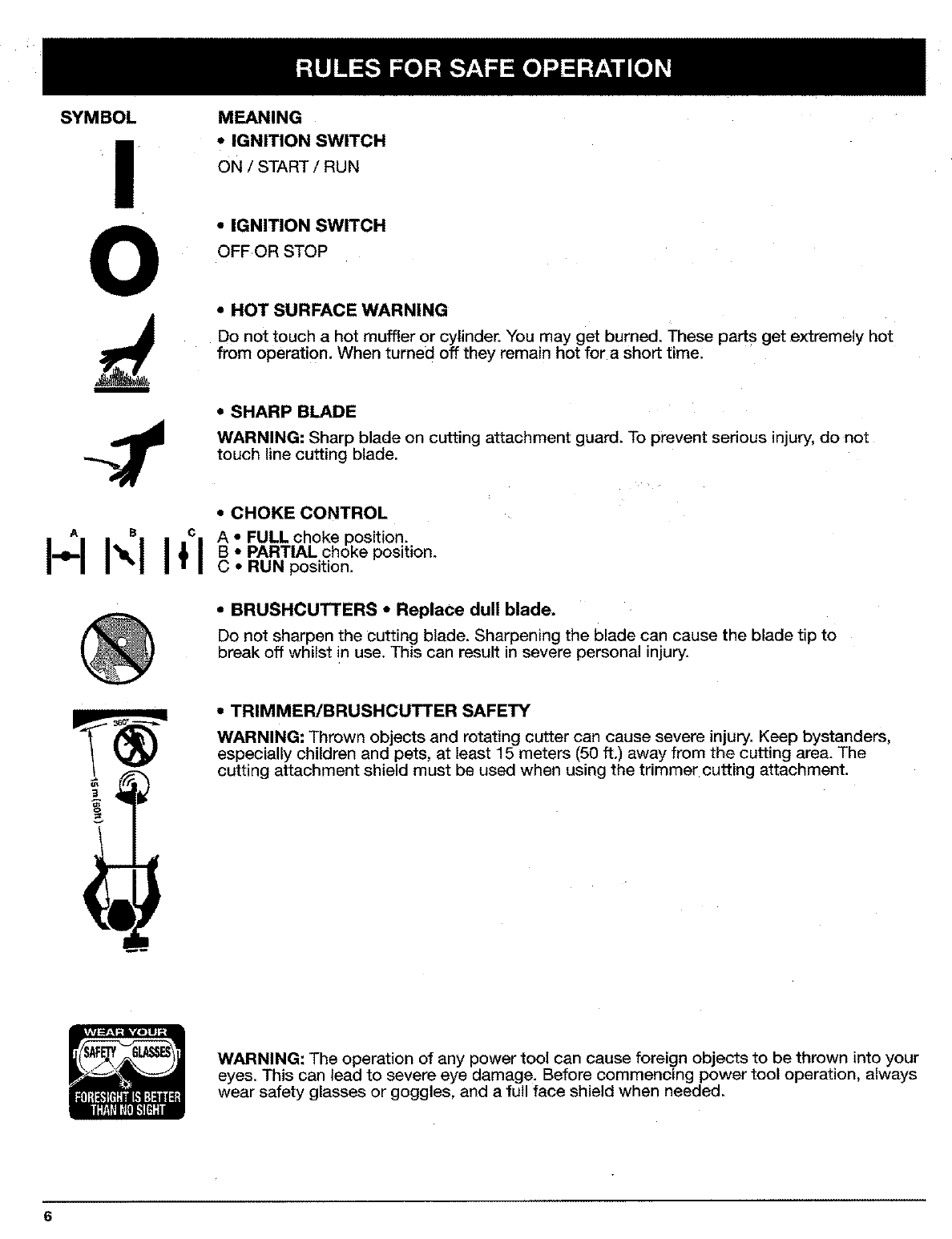
MEANING
•IGNITION SWITCH
ON /START/RUN
"IGNITION SWITCH
OFFOR STOP
•HOT SURFACE WARNING
Do not touch a hot muffler or cylinder. You may get burned. These parts get extremely hot
from operation. When turned off they remain hot for a Short time:
•SHARP BLADE
WARNING: Sharp blade on cutting attachment guard. To prevent serious injury, do not
touch line cutting blade.
•CHOKE CONTROL
A•FULL choke position.
B•PARTIAL choke position.
C ,, RUN position.
• BRUSHCUTTERS •Replace dull blade.
Do not sharpen the cutting blade. Sharpening the blade can cause the blade tip to
break off whilst in use. This can result in severe personal injury.
• TRIMMER/BRUSHCUTTER SAFETY
WARNING: Thrown objects and rotating cutter can cause severe injury. Keep bystanders,
especially children and pets, at least 15 meters (50 ft.) away from the cutting area. The
cutting attachment shield must be used when using the trimmer cutting attachment.
WARNING: The operation of any power tool can cause foreign objects to be thrown into your
eyes. This can lead to severe eye damage. Before commencing power tool operation, always
wear safety glasses or goggles, and a full face shield when needed.
6
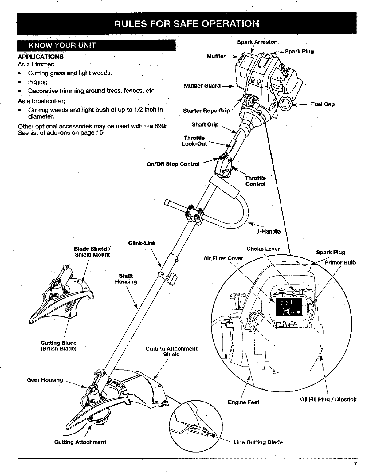
APPUCATIONS
As a trimmer;
•Cutting grass and light weeds.
•Edging
•Decorative tdmming around trees, fences, etc.
As a brushcutter;
•Cutting weeds and light bush of up to 1/2 inch in
diameter.
Other optional accessories may be used with the 890r.
See list of add-ons on page 15.
Spark Arrestor
Muffler
Muffler Guard
Shaft Grip
Throttle
Fuel Cap
Clink-Unk
/
!
Cutting Blade
(Brush Blade)
Blade Shield /
Shield Mount
Shaft
Housing
\
On/Off Stop C
Cutting Attachment
Shield
Throttle
J:Ha"d /
Choke Lever
Air Filter Cover Spark Plug
Gear Housing
Engine Feet Oil Fill Plug /Dipstick
Cutting Attachment Line Cutting Blade
7
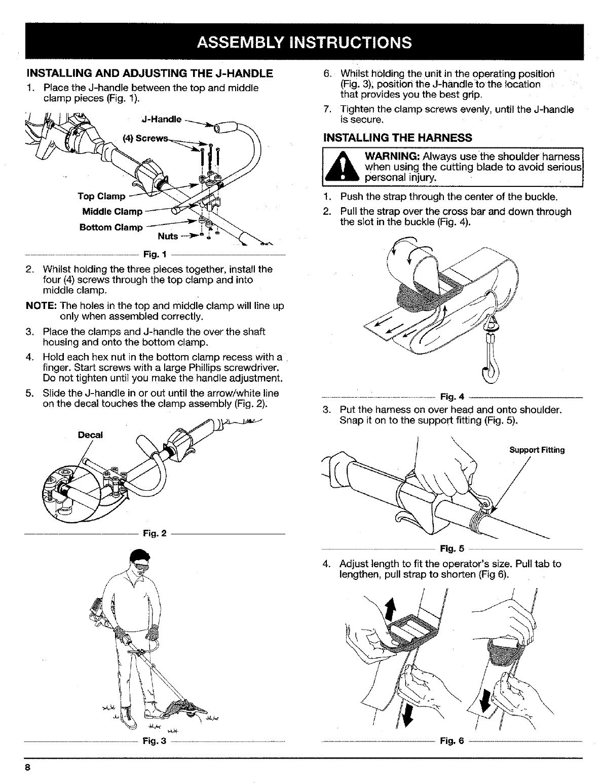
INSTALLING AND ADJUSTING THE J-HANDLE
1. Place the J-handle between the top and middle
clamp pieces (Fig. 1)•
J-Handle
Top Clamp
Middle Claml:
Bottom Clamp -"_'Nuts _°,
................................... Fig. 1
2. Whilst holding the three pieces together, install the
four (4) screws through the top clamp and into
middle clamp.
NOTE: The holes in the top and middle clamp will line up
only when assembled correctly.
3. Place the clamps and J-handle the over the shaft
housing and onto the bottom clamp,
4. Hold each hex nut in the bottom clamp recess with a
finger. Start screws with a large Phillips screwdriver.
Do not tighten until you make the handle adjustment.
5. Slide the J-handle in or out until the arrow/white line
on the decal touches the clamp assembly (Fig. 2):
Fig. 2
6. Whilst holding the unit in the operating positior_
(Fig, 3); position the J-handle to the location
that provides you the best grip.
7. Tighten the clamp screws evenly, until the J-handle
is secure,
INSTALLING THE HARNESS
WARNING: Always use the shoulder harness 1
when using the cutting blade to avoid serious I
personal injury. J
1, Push the strap through the center of the buckle.
2. Pull the strap over the cross bar and down through
the slot in the buckle (Fig. 4).
...... Fig. 4
3. Put the harness on over head and onto shoulder.
Snap it on to the support fitting (Fig. 5).
Support Fitting
Fig. 5
4. Adjust length to fit the operator's size• Pull tab to
lengthen, pull strap to shorten (Fig 6).
J_
Fig. 3 Fig. 6
8
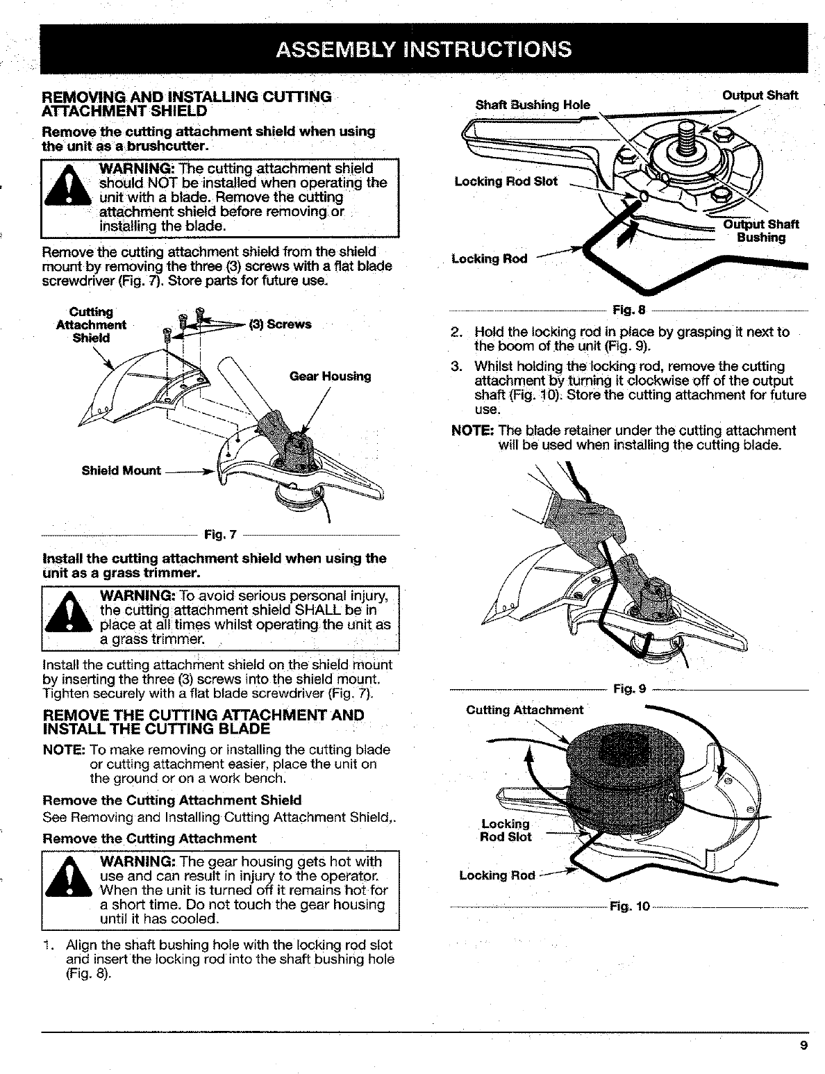
REMOVING AND INSTALLING CUTTING
ATTACHMENT SHIELD
Remove the cutting attachment shield when using
the unit as abrushcutter.
WARNING: The cutting attachment shield
should NOT be installed when operating the
unit with a blade. Remove the cutting
attachment shield before removing or
installing the blade,
Remove the cutting attachment shield from the shield
mount by removing the three (3) screws with efiat blade
screwdriver (Fig. 7). Store parts for future use.
Cutting
Attachment
Shield
X
Gear Housing
Shield Mount
Fig. 7
Install the cutting attachment shield when using the
unit as e grass trimmer.
the cutting attachment shield SHALL be in
place at all times whilst operating the unit as
a grass trimmer.
Install the cutting attachment shield on the shield mount
by inserting the three (3) screws into the shield mount.
Tighten securely with a flat blade screwdriver (Fig. 7),
REMOVE THE CUTTING ATTACHMENT AND
INSTALL THE CUTTING BLADE
NOTE: To make removing or installing the cutting blade
or cutting attachment eas_er, place the unit on
the ground or on a work bench
Remove the Cutting Attachment Shield
See Removing ana Installing Cutting Attachment Shield,.
Remove the Cutting Attachment
WARNING: The gear housing gets hot with
use and can result in injury to the operator.
When the unit is turned off it remains hot for
a short time. Do not touch the gear housing
until it has cooled.
Align the shaft bushing hole with the locking rod slot
and insert the locking rod into the shaft bushing hole
(Fig. 8).
Shaft 5ushing Hole
LoP.king Rod
Output Shaft
Fig, 8
2. Hold the locking rod in place by grasping it next to
the boom of the unit (Fig. 9).
3. Whilst holding the locking rod, remove the cutting
attachment by turning it clockwise off of the output
shaft (Fig. 10). Store the cutting attachment for future
use.
NOTE: The blade retainer under the cutting attachment
will be used when installing the cutting blade.
Fig. 9
Cutting Attachment
Locking
Rod Slot
Loc_ng Rod
Fig. 10 .......
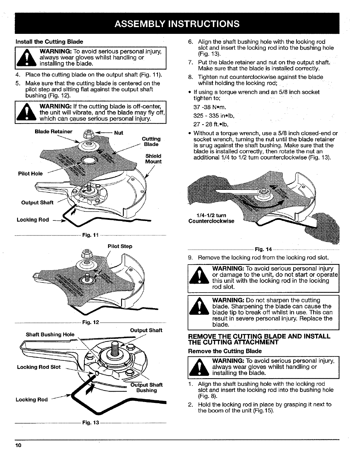
Install the Cutting Blade
WARNING: To avoid serious personal injury,
always Wear gloves whilst handling or
installing the blade.
4. Place the cutting blade on the output shaft (Fig. 11),
5. Make sure that the cutting blade is centered on the
pilot step and sitting flat against the output shaft
bushing (Fig. !2).
i_ WARNING: If the cutting blade is off-center, I
the unit will vibrate, and the blade may fty off, I
which can qause serious personal injury. I
Blade Retainer _Nut
Cutting
Blade
Shield
Mount
Pilot Hole
6.
7.
8.
Align the shaft bushing hole with the locking rod
slot and insert the locking rod into the bushing hole
(Fig. 13).
Put the blade retainer and nut on the output shaft.
Make sure that the blade is installed correctly.
Tighten nut counterclockwise against the blade
whilst holding the locking rod;
If using a torque wrench and an 5/8 inch socket
tighten to:
37 -38 N•m.
325 - 335 inelb.
27 - 28 ft.olb
Without a torque wrench, use a 5/8 inch closed-end or
socket wrench, turning the nut until the blade retainer
is snug against the shaft bushing. Make sure that the
blade is installed correctly, then rotate the nut an
additional 1/4 to 1/2 turn counterclockwise (Fig. 13).
Output Shaft
Fig. 11
Pilot Step
Shaft Bushing Hole
Locking Rod Slot
Locking Rod
Fig. 12
Output Shaft
Output Shaft
Bushing
.......... Fig. 13 ................
1/4-1/2 turn
Counterclockwise
Fig. 14......... ............
g. Remove the locking rod from the locking rod slot.
l_lb WARNING: To avoid serious personal injury ]
or damage to the unit, do not start or operate l
this unit with the locking rod in the locking |
rod slot. 1
WARNING: Do not sharpen the cutting
blade. Sharpening the blade can cause the
blade tip to break off whilst in use. This can
result in severe personal injury. Replace the
blade.
REMOVE THE CUTTING BLADE AND INSTALL
THE CUI-FING ATTACHMENT
Remove the Cutting Blade
WARNING: To avoid serious personal injury,
always wear gloves whilst handling or
installing the blade.
1. Align the shaft bushing hole with the locking rod
slot and insert the locking rod into the bushing hole
(Fig. 8).
2. Hold the locking rod in place by grasping it next to
the boom of the unit (Fig.15).
10
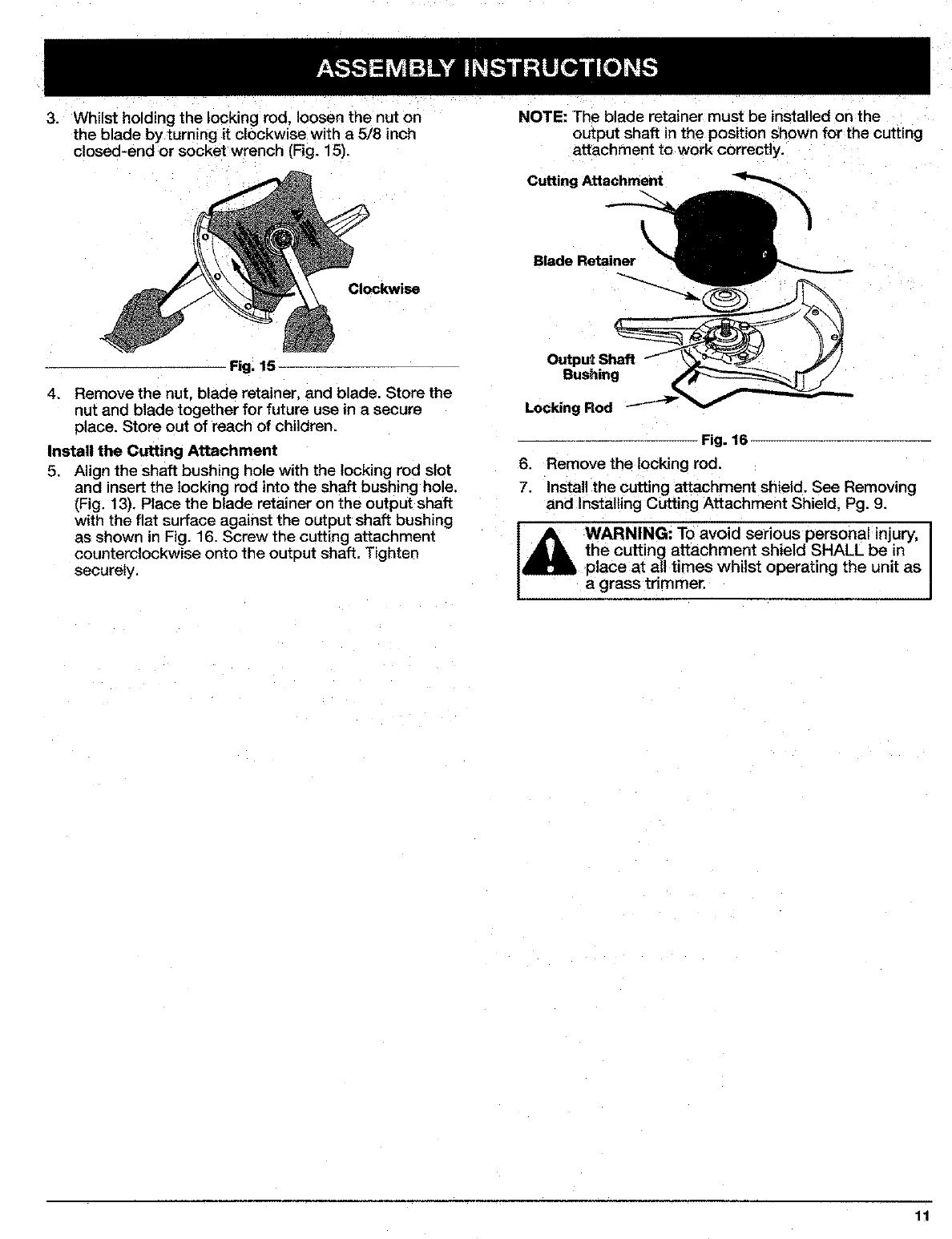
3. Whilst holding the locking rod, loosen the nut on
the blade by turning it clockwise with a 5/8 inch
closed-end or socket wrench (Fig. 15).
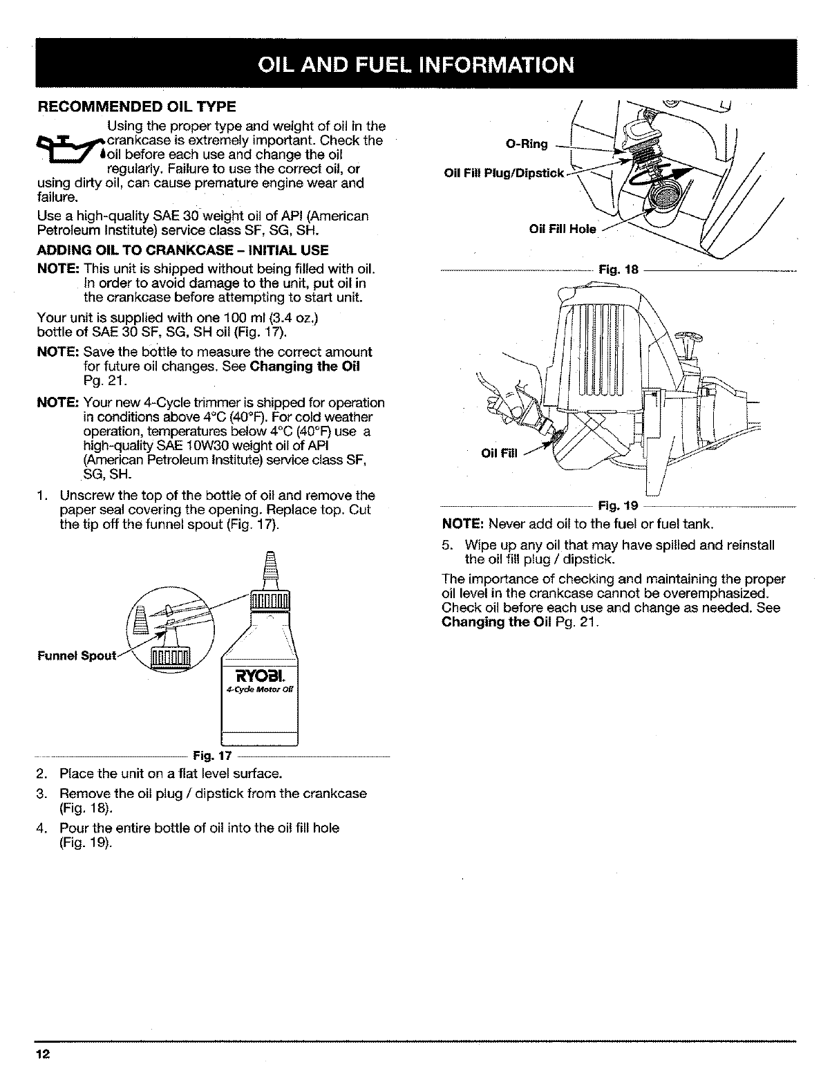
NOTE: The blade retainer must be installed on the
output shaft in the position shown for the cutting
attachment to work correctly.
Cutting Attachment
Clockwise
Blade Retainer
Fig. 15
4. Remove the nut, blade retainer, and blade. Store the
nut and blade together for future use in a secure
place. Store out of reach of children.
Install the Cutting Attachment
5. Align the shaft bushing hole with the locking rod slot
and insert the locking "od into the shaft bushing hole.
(Fig, 13). Place the blade retainer on the output shaft
with the flat surface against the output shaft bushing
as shown in Fig. 16. Screw the cutting attachment
counterclockwise onto the output shaft. Tighten
securely.
Outpu_ Shaft
Bushing
Locking Rod
Fig. 16
6. Remove the locking rod.
7. install the cutting attachment shield. See Removing
and installing Cutting Attachment Shield, Pg. 9.
_ARNING: To avoid serious personal injury,
the cutting attachment shield SHALL be in
place at all times whilst operating the unit as
a grass tdmmer,
11
RECOMMENDED OIL TYPE
Using the proper type and weight of oil in the
_crankcase is extremely important. Check the
oil before each use and change the oil
regularly. Failure to use the correct oil, or
using dirty oil, can cause premature engine wear and
failure.
Use a high-quality SAE 30 weight oil of API (American
Petroleum Institute) service class SF, SG, SH.
ADDING OIL TO CRANKCASE - INITIAL USE
NOTE: This unit is shipped without being filled with oil.
In order to avoid damage to the unit, put oil in
the crankcase before attempting to start unit.
Your unit is supplied with one 100 ml (3.4 oz,)
bottle of SAE 30 SF, SG, SH oil (Fig. 17).
NOTE: Save the bottle to measure the correct amount
for future oil changes, See Changing the Oil
Pg. 21.
NOTE: Your new 4-Cycle trimmer is shipped for operation
in conditions above 4°C (40°F). For cold weather
operation, temperatures below 4°C (40°F) use a
high-quality SAE 10W30 weight oil of API
(American Petroleum Institute) service class SF,
SG, SH.
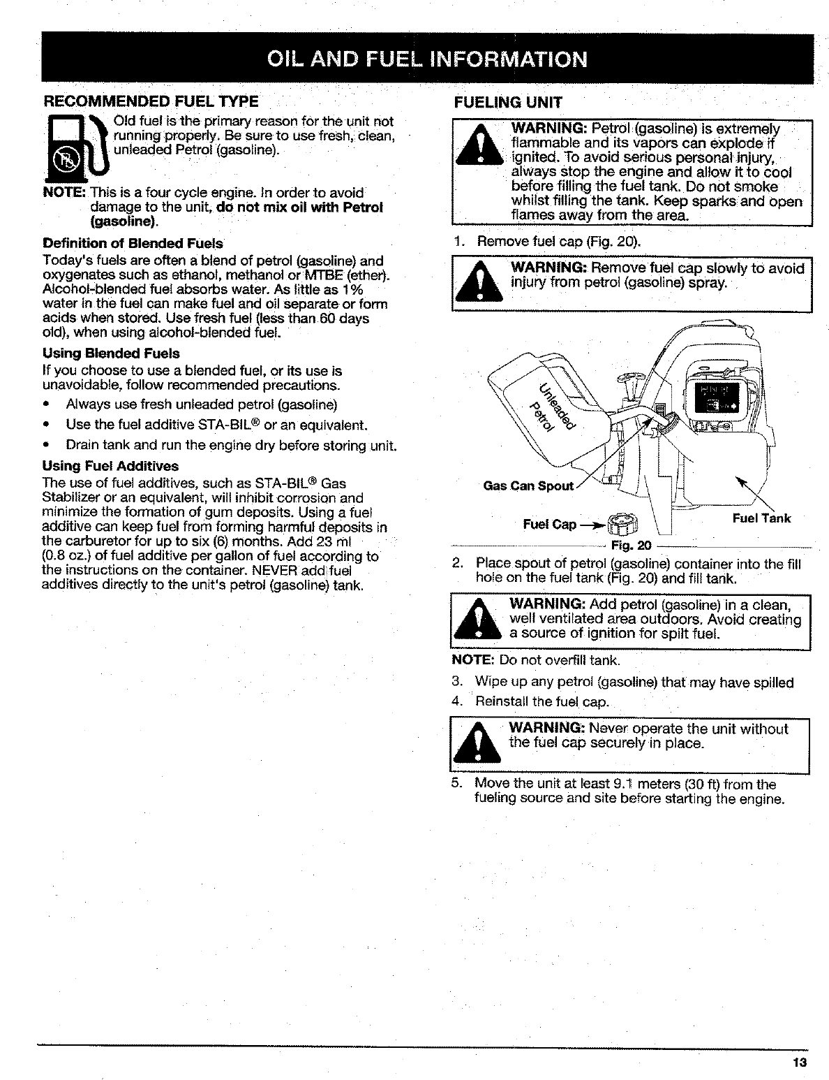
1. Unscrew the top of the bottle of oil and remove the
paper seal covering the opening. Replace top. Cut
the tip off the funnel spout (Fig. 17).
Funnel Spout_
RYODL
4..Cy¢_ MotOr OIt
O-Ring
Oil Fill Hole
Fig. 18
Oil Fill J
Fig. 19
NOTE: Never add oll to the fuel or fuel tank.
5. Wipe up any oil that may have spilled and reinstall
the oil fill plug /dipstick.
The importance of checking and maintaining the proper
oil level in the crankcase cannot be overemphasized.
Check oil before each use and change as needed. See
Changing the Oil Pg. 21.
Fig. 17
2. Place the unit on a flat level surface.
3. Remove the oiI plug /dipstick from the crankcase
(Fig. 18).
4. Pour the entire bottle of oil into the oil fill hole
(Fig. 19).
12
RECOMMENDED FUEL TYPE
Old fuel is the primarj reason for the unit not
running properly. Be sure to use fresh, clean,
unleaded Petrol (gasoline).
NOTE: This is a four cycle engine. In order to avoic_
damage to the unit, do not mix oil with Petrol
(gasoline).
Definition of Blended Fuels
Today's fuels are often ablend of petrol [gasoline) and
oxygenates such as ethanol, methanol or MTBE (ether).
Alcohol-blended fuel absorbs water. As little as 1%
water in the fuel can make fuel and oil separate or form
acids when stored. Use fresh fuel (leas than 60 days
old), when using alcohol-blended fuel.
Using Blended Fuels
If you choose to use a blended fuel, or its use is
unavoidable, follow recommended precautions.
• Always use fresh unleaded petrol (gasoline)
• Use the fuel additive STA-BIL ® or an equivalent.
• Drain tank and run the engine dry before storing unit.
Using Fuel Additives
The use of fuel additives, such as STA-BIL ® Gas
Stabilizer or an equivalent, will inhibit corrosion and
minimize the formation of gum deposits. Using a fuel
additive can keep fuel from forming _armful deposits in
the carburetor for up to six (6) months. Add 23 ml
(0.8 oz.) of fuel additive per gallon of fuel according to
the instructions on the container. NEVER add fuel
additives directly to the unit's petrol (gasoline) tank.
FUELING UNIT
WARNING: Petrol (gasoline) is extremely
flammable and its vapors can explode if
ignited. To avoid serious personal injury,
always stop the engine and allow it to cool
before filling the fuel tank. Do not smoke
whilst filling the tank. Keep sparks and open
flames away from the area.
1. Remove fuel cap (Fig. 20).
injury from petrol (gasoline) spray.
IA °'°w"°°v°'°I
%.
Gas Can \
Fuel Tank
2. Place spout of petrol [gasoline) container into the fill
hole on the fuel tank (Fig. 20) and fill tank.
l_lb ARNING: Add petrol (gasoline) in a clean I
well ventilated area outdoors. Avoid creating
a source of ignition for spilt fuel.
NOTE: Do not overfill tank.
3. Wipe up any petrol (gasoline) that may have spilled
4. Reinstall the fuel cap.
WARNING: Never operate the unit without
the fuel cap securely in place.
5. Move the unit at least 9.1 meters (30 ft) from the
fueling source and site before starting the engine.
13
STARTING INSTRUCTIONS
Cold Start -First Start of the Day or Engine Ran Out
of Fuel
I_, ARNING: Operate this unit only in a well
ventilated area outdoors. Carbon monoxide
exhaust fumes can be lethal in a confined
area.
1. Check oil level in crankcase. See Checking the Oil
Level Pg. 21.
2. Fil! the fuel tank with fresh, clean, unleaded petrol
(gasoline) (see page 13).
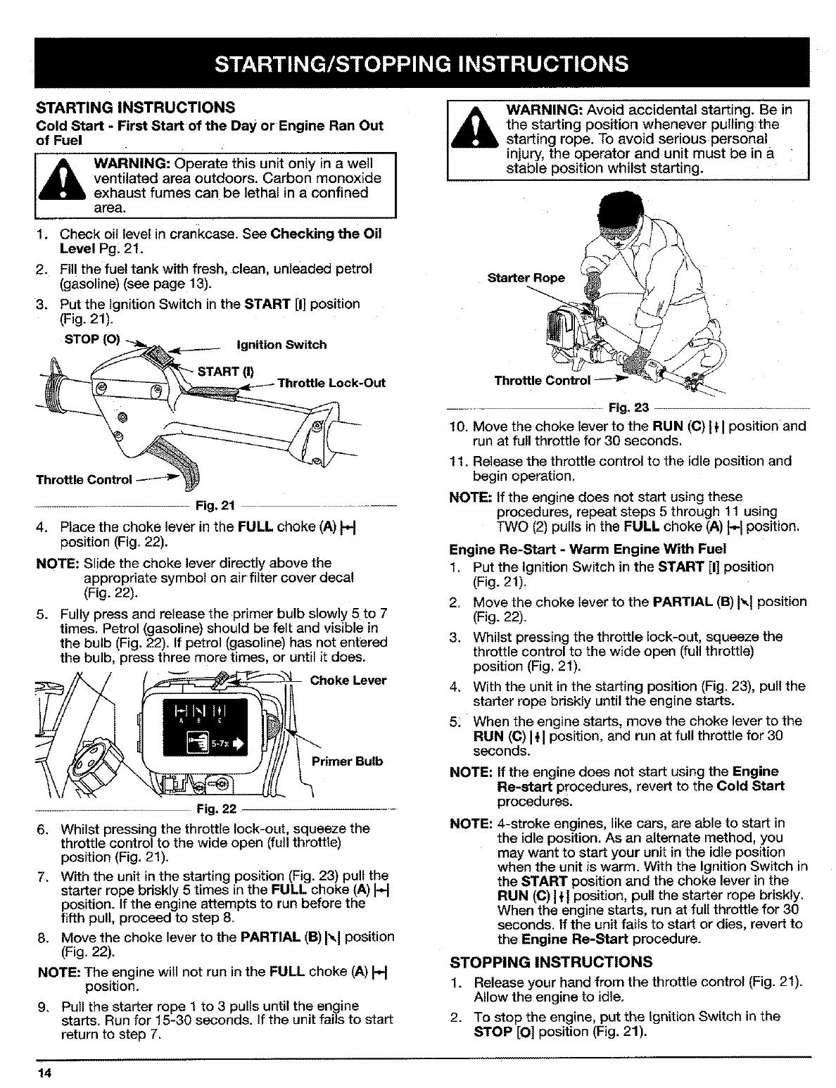
3. Put the Ignition Switch in the START [I] position
(Fig. 21).
STOP Ignition Switch
START (I) Lock-Out
Fig, 21 .........
4. Place the choke lever in the FULL choke (A) H
position (Fig. 22).
NOTE: Slide the choke lever directly above the
appropriate symbol on air filter cover decal
(Fig. 22).
5. Fully press and release the primer bulb slowly 5 to 7
times. Petrol (gasoline) should be felt and visible in
the bulb (Fig. 22). If petrol (gasoline) has not entered
the bulb, press three more times, or until it does.
Fig, 22 -
6.
Choke Lever
Primer Bulb
Whilst pressing the throttle lock-out, squeeze the
throttle control to the wide open (full throttle)
position (Fig. 21).
7. With the unit in the starting position (Fig. 23) pult the
starter rope briskly 5 times in the FULL choke (A) a
position. If the engine attempts to run before the
fifth pull, proceed to step 8.
8. Move the choke lever to the PARTIAL (B) I_,1position
(Fig. 22).
NOTE: The engine will not run in the FULL choke (A) a
position.
9. Pull the starter rope 1 to 3 pulls until the engine
starts. Run for 15-30 seconds. If the unit fails to start
return to step 7.
14
WARNING: Avoid accidental starting. Be in
the starting position whenever pulling the
starting rope. To avoid serious personal
injury, the operator and unit must be in a
stable position whilst starting.
Starter Rope
Throttle Control
Fig. 23
10. Move the choke lever to the RUN ((3)I'}J position and
run at full throttle for 30 seconds.
11. Release the throttle control to the idle position and
begin operation.
NOTE: If the engine does not start using these
procedures, repeat steps 5 through ! 1 using
TWO (2) pulls in the FULL choke (A) H position.
Engine Re-Start -Warm Engine With Fuel
1, Put the Ignition Switch in the START [I] position
(Fig. 21).
2. Move the choke lever to the PARTIAL (B) I"-I position
(Fig. 22).
3. Whilst pressing the throttle lock-out, squeeze the
throttle control to the wide open (full throttle)
position (Fig. 21).
4. With the unit in the starting position (Fig. 23), pull the
starter rope bdskly until the engine starts.
5: When the engine starts, move the choke lever to the
RUN (C) Itl position, and run at full throttle for 30
seconds.
NOTE: If the engine does not start using the Engine
Re-start procedures, revert to the Cold Start
procedures.
NOTE: 4-stroke engines, like cars, are able to start in
the idle position. As an alternate method, you
may want to start your unit in the idle position
when the unit is warm. With the Ignition Switch in
the START position and the choke lever in the
RUN (C) I _I position, pull the starter rope briskly.
When the engine starts, run at full throttle for 30
seconds. If the unit fails to start or dies, revert to
the Engine Re-Start procedure.
STOPPING INSTRUCTIONS
1. Release your hand from the throttle control (Fig. 21).
Allow the engine to idle.
2. To stop the engine, put the Ignition Switch in the
STOP [O] position (Fig. 21).
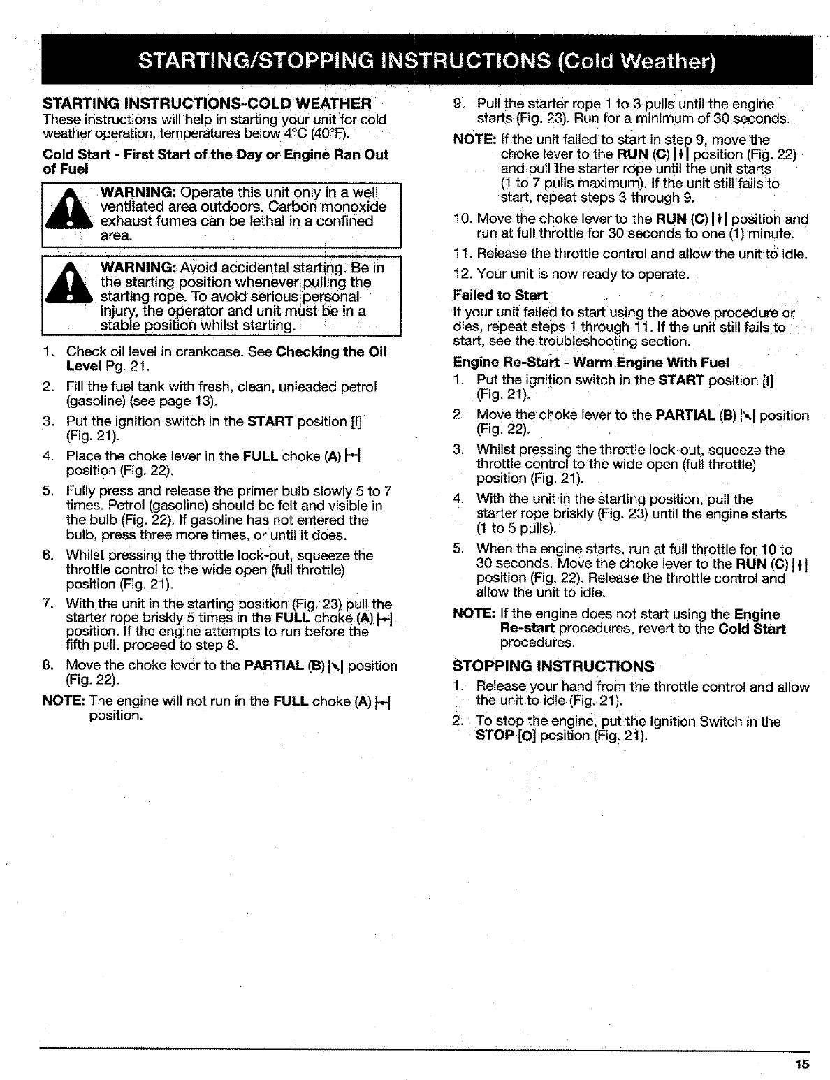
STARTING INSTRUCTIONS-COLD WEATHER
These instructions will belo in starting your unit for cold
weather operation, temperatures below 4°C (40°F).
Cold Start - First Start of the Day or Engine Ran Out
of Fuel
WARNING: Operate this unit only in a well
ventilated area outdoors. Carbon monoxide
exhaust fumes can be lethal in aconfined
area.
_lb ARNING: Avoid accidental starting. Be in
the starting position whenever pul ing the
starting rope. To avoid serious personal
injury, the operator and unit must be in a
stable position whilst starting
1 Check oil level in crankcase. See Checking the Oil
Level Pg. 21.
2. Fill the fuel tank with fresh, clean, unleaded oetrot
(gasoline) (see page 13),
3, Put the gnition switch in the START position [I]
(Fig. 21).
4. Place the choke lever in the FULL choke (A) H
position (Fig, 22).
5, Fully press and release the primer bulb slowly 5 to 7
times. Petrol (gasoline) should be felt and visible in
the bulb (Fig. 22). If gasoline has not entered the
bulb, press three more times, or until it does.
6. Whilst pressing the throttle lock-out, squeeze the
throttle control to the wide open (full throttle)
position (Fig. 21).
7. With the unit in the starting position (Fig, 23) pull the
starter rope briskly 5 times in the FULL choke (A) H
position. If the engine attempts to run before the
fifth pull, proceed to step 8.
8. Move the choke lever to the PARTIAL (B) I',_1position
(Fig. 22).
NOTE: The engine will not run in the FULL choke (A) H
position.
9. Pull the starter rope 1 to 3 pulls until the engine
starts (Fig. 23), Run for a minimum of 30 seconds.
NOTE: If the unit failed to start in step 9move the
choke lever to the RUN (C) _1position (Fig. 22)
and pull the starter rope until the unit starts
(1 to 7 pulls maximum). If the unit still fails to
start, repeat steps 3 through 9.
10. Move the choke lever to the RUN (C) I{I position and
run at full throttle for 30 seconds to one (1) minute.
11. Release the throttle control and allow the unit to idle.
12. Your unit is now ready to operate.
Failed to Start
If your unit failed to start using the above procedure or
dies, repeat steps 1 through 11. If the unit still fails to
start, see the troubleshooting section.
Engine Re-Start -Warm Engine With Fuel
1. Put the ignition switch in the START position [I]
(Fig. 21),
2. Move the choke lever to the PARTIAL (B) Ixl position
(Fig. 22).
3. Whilst pressing the throttle lock-out squeeze the
throttle control to the wide open (fu I throttle)
position (Fig. 21).
4. With the unit in the starting position, pull the
starter rope briskly (Fig. 23) until the engine starts
(1 to 5 pulls).
5, When the engine starts, run at full throttle for 10 to
30 seconds. Move the choke lever to the RUN (C) ]tl
position (Fig, 22). Release the throttle control and
allow the unit to idle,
NOTE: If the engine does not start using the Engine
Re-start procedures, revert to the Cold Start
procedures.
STOPPING INSTRUCTIONS
1. Release your hand from the throttle control and allow
the unit to idle (Fig. 21).
2. To stop ;he engine, put the Ignition Switch in the
STOP [O] position (Fig. 21).
15
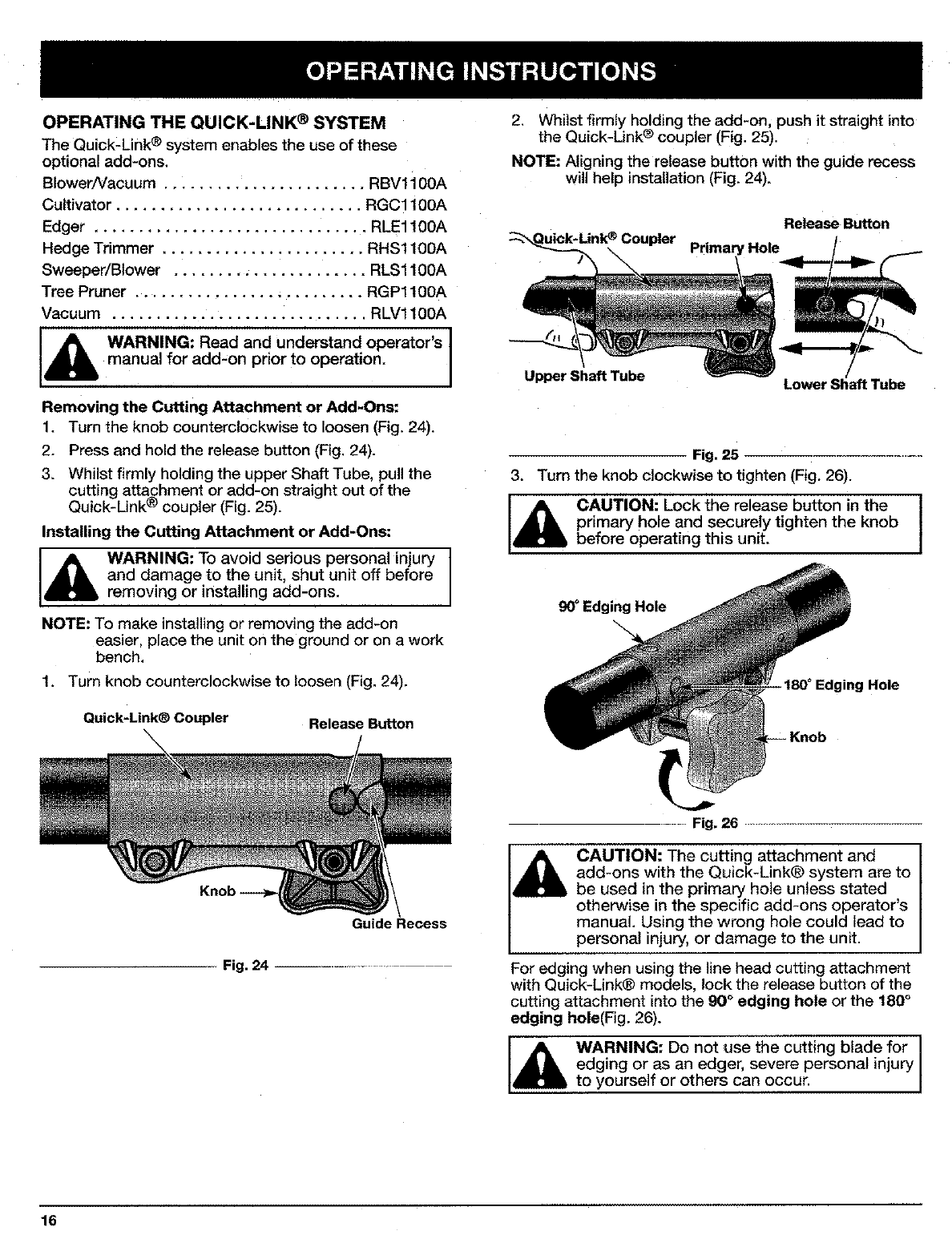
OPERATINGTHEQUICK-LINK®SYSTEM
The Quick-Link ® system enables the use of these
optional add-ons.
Blower/Vacuum ....................... RBV1 i 00A
Cultivator ............................ RGC1100A
Edger ............................... RLE1100A
Hedge Trimmer ....................... RHS1100A
Sweeper/Blower ...................... RLS1100A
Tree Pruner .......................... RGP1100A
Vacuum ............................. RLV1100A
WARNING: Read and understand operator's
manual for add-on prior to operation,
Removing the Cutting Attachment or Add-Ons:
1. Turn the knob counterclockwise to loosen (Fig. 24).
2. Press and hold the release button (Fig. 24).
3. Whilst firmly holding the upper Shaft Tube, pull the
cutting attachment or add-on straight out of the
Quick-Link ®coupler (Fig. 25).
Installing the Cutting Attachment or Add-Ons:
Id_lb ARNING: To avoid serious personal injury
and damage to the unit, shut unit off before
removing or installing add-ons.
NOTE: To make installing or removing the add-on
easier, place the unit on the ground or on a work
bench,
1. Turn knob counterclockwise to loosen (Fig. 24).
Quick-Link® Coupler Release Button
2. Whilst firmly holding the add-on, push it straight into
the Quick-Unk ® coupler (Fig. 25).
NOTE: Aligning the release button with the guide recess
will help instaUation (Fig. 24).
Release Button
Pdmary Hole
Upper Shaft Tube Lower Shaft Tube
Fig. 25
3. Turn the knob clockwise to tighten (Fig. 26).
CAUTION: Lock the release button in the
primary hole and securely tighten the knob
before operating this unit.
90°Edging Hole
180 ° Edging Hole
Guide Recess
Fig. 24 ..........
Fig.26 .................................
CAUTION: The cutting attachment and
add-ons with the Quick-Link® system are to
be used in the primary hole unless stated
otherwise in the specific add-ons operator's
manual. Using the wrong hole could lead to
personal injury, or damage to the unit.
For edging when using the line head cutting attachment
with Quick-Link® models, lock the release button of the
cutting attachment into the 90 °edging hole or the 180 °
edging hole(Fig, 26).
WARNING: Do not use the cutting blade for
edging or as an edger, severe personal injury
to yourself or others can occur.
16
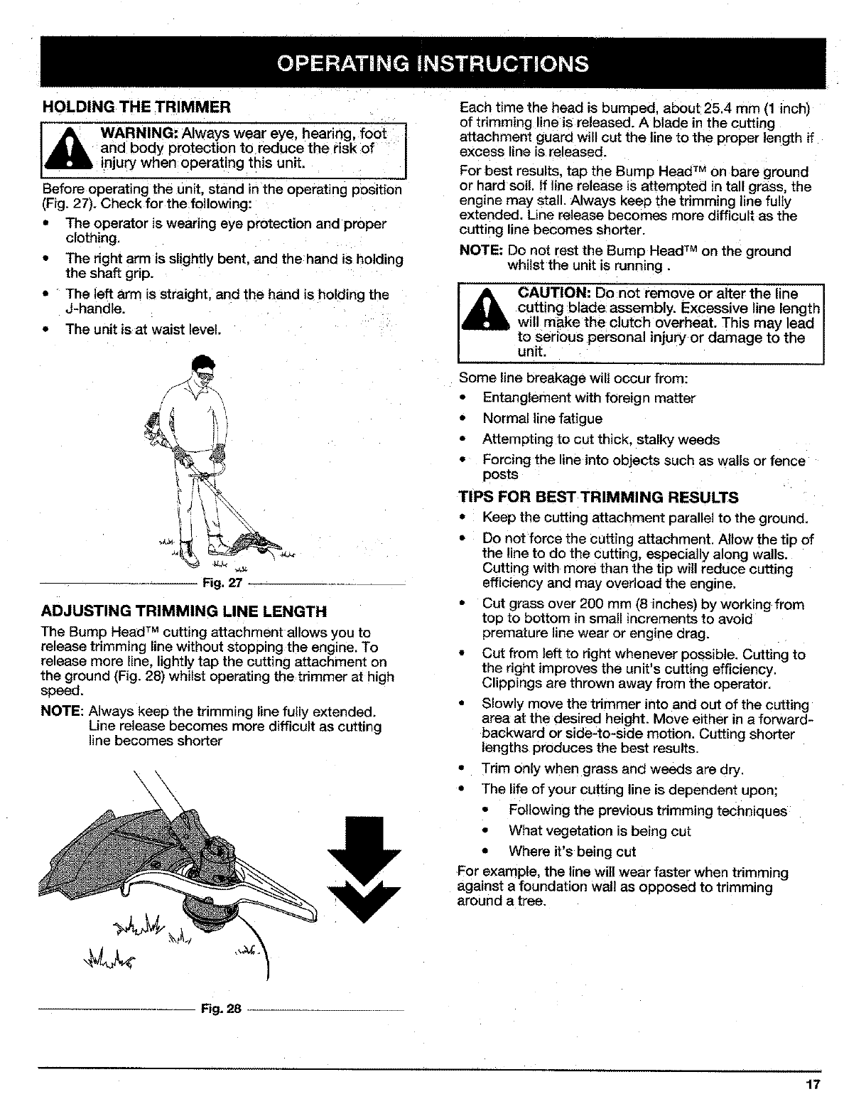
HOLDING THE TRIMMER
_ARNING: Always wear eye, hearing, foot i
and body protection to reduce the risk of
injury when operating this unit.
Before operating the unit, stand in the operating position
(Fig. 27). Check for the following:
• The operator is wearing eye protection and proper
clothing,
•The right arm is slightly bent, and the hand is holding
the shaft grip.
• The left arm is straight, and the hand is holding the
J-handle.
• The unit isat waist level.
Fig. 27
ADJUSTING TRIMMING LINE LENGTH
The Bump Head TM cutting attachment allows you to
release trimming line without stopping the engine. To
release more line. lightly tap the cutting attachment on
the ground (Fig. 28) whilst operating the trimmer at high
speed.
NOTE: Always keep the trimming line fully extended.
Line release becomes more difficult as cutting
ine becomes shorter
\\
Each time the head is bumped, about 25.4 mm (1 inch)
of trimming line is released. A blade in the cutting
attachment guard will cut the line to the proper length if
excess line is released.
For best results, tap the Bump Head TM on bare ground
or hard soil. If line release is attempted in tall grass, the
engine may stall. Always keep the tdmming line fully
extended. Line release becomes more difficult as the
cutting line becomes shorter.
NOTE: Do not rest the Bump Head TM on the ground
whilst the unit is running.
CAUTION: Do not remove or a ter the line
cutting blade assembly. Excessive line length
will make the clutch overheat. This may lead I
to serious personal injury or damage to the
unit.
Some line breakage wiU occur from:
• Entanglement with foreign matter
• Normal line fatigue
• Attempting to cut thick, stalky weeds
• Forcing the line into objects such as walls or fence
posts
TIPS FOR BEST TRIMMING RESULTS
•Keep the cutting attachment parallel to the ground.
• Do not force the cutting attachment. Allow the tip of
the line to do the cutting, especially along walls.
Cutting with more than the tip will reduce cutting
efficiency and may overload the engine.
• Cut grass over 200 mm (8 inches) by working from
top to bottom in small increments to avoid
premature line wear or engine drag.
• Cut from left to right whenever possible. Cutting to
the right improves the unit's cutting efficiency,
Clippings are thrown away from the operator.
• Slowly move the trimmer into and out of the cutting
area at the desired height. Move either in a forward-
backward or side-to-side motion. Cutting shorter
lengths produces the best results.
• Tdm only when grass and weeds are dry.
• The life of your cutting line is dependent upon:
• Following the previous trimming techniques
• What vegetation is being cut
• Where it's being cut
For example, the line will wear faster when trimming
against a foundation wall as opposed to trimming
around a tree.
Fig, 28
17
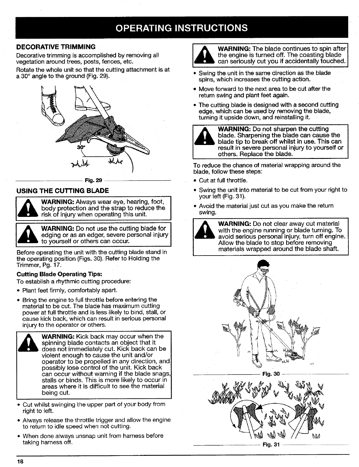
DECORATIVE TRIMMING
Decorative trimming is accomplished by removing al!
vegetation around trees; posts, fences, etc.
Rotate the whole unit so that the Cutting attachment is at
a 30 °angle to the ground (Fig. 29).
Fig. 29
USING THE CUTTING BLADE
I_ WARNING: Always wear eye, hearing, foot, I
body protection and the strap to reduce the
risk of injury when operating this unit.
,_ WARNING: Do not use the cutting blade for
edging or as an edger, severe personal injury
to yourself or others can occur. 1
Before operating the unit with the cutting blade stand in
the operating position (Figs. 30). Refer to Holding the
Trimmer, Pg. 17.
Cutting Blade Operating Tips:
To establish a rhythmic cutting procedure:
• Plant feet firmly, comfortably apart.
•Bring the engine to full throttle before entering the
matedal to be cut. The blade has maximum cutting
power at full throttle and is less likely to bind, stall, or
cause kick back, which can result in serious personal
injury to the operator or others.
i_k, ARNING: Kick back may occur when the
spinning blade contacts an object that it
does not immediately cut. Kick back can be
violent enough to cause the unit and/or
operator to be propelled in any direction, and
possibly lose control of the unit. Kick back
can occur without warning if the blade snags,
stalls or binds. This is more likely to occur in
areas where it is difficult to see the material
being cut.
Cut whilst swinging the upper part of your body from
right to left.
•Always release the throttle trigger and allow the engine
to return to idle speed when not cutting.
• When done always unsnap unit from harness before
taking harness off.
18
I_hl WARNING: The blade continues to spin after]
the engine is turned off, The coasting blade I
can seriously cut you if accidentally touched. J
• Swing the unit in the same direction as the blade
spins, which increases the cutting action.
* Move forward to the next area to be cut after the
return swing and plant feet again.
• The cutting blade is designed with a second cutting
edge, which can be used by removing the blade,
turning it upside down, and reinstalling it.
WARNING: Do not sharpen the cuffing
blade. Sharpening the blade can cause the
blade tip to break off whilst in use. This can
result in severe personal injury to yourself or
others. Replace the blade.
To reduce the chance of material wrapping around the
blade, follow these steps:
Cut at full throttle.
g Swing the unit into material to be cut from your right to
your left (Fig. 31).
• Avoid the material just cut as you make the return
swing.
WARNING: Do not clear away cut material I
with the engine running or blade turning. To I
avoid serious personal injury, turn off engine,
Allow the blade to stop before removing
materials wrapped around the blade shaft.
Fig, 30
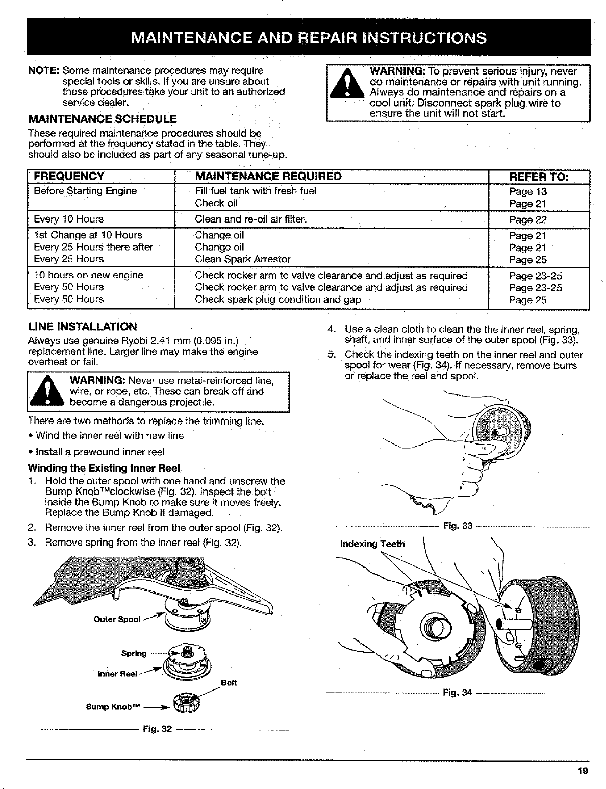
NOTE: Some maintenance procedures may require
special tools or skills. If you are unsure about
these procedures take your unit to an authorized
service dealer:
MAINTENANCE SCHEDULE
These required maintenance procedures should be
performed at the frequency stated in the table. They
should also be included as part of any seasonal tune-up.
WARNING: To prevent sedous injury, never I
do maintenance or repairs with unit running. I
Always do maintenance and repairs on a
cool unit. Disconnect spark plug wire to
ensure the unit will not start.
FREQUENCY
Before Starting Engine
Every 10 Hours
1st Change at 10 Hours
Every 25 Hours there after
Every 25 Hours
10 hours on new engine
Every 50 Hours
Every 50 Hours
MAINTENANCE REQUIRED
Fill fuel tank with fresh fuel
Check oil
Clean and re-oil air filter.
Change oil
Change oil
Clean Spark Arrestor
Check rocker arm to valve clearance and adjust as required
Check rocker arm to valve clearance and adjust as required
Check spark plug condition and gap
REFER TO:
Page13
Page 21
Page22
Page21
Page21
Page 25
Page 23-25
Page 23-25
Page 25
LINE INSTALLATION
Always use genuine Ryobi 2.41 mm (0.095 in.)
replacement line. Larger line may make the engine
overheat or fail,
[_llL ARNING: Never use metal-reinforced line,
wire. or rope, etc. These can break off and
become a dangerous projectile.
There are two methods to replace the trimming line.
• Wind the inner reel with new line
• Install a prewound inner reel
Winding the Existing Inner Reel
1. Hold the outer spool with one hand and unscrew the
Bump KnobTMclockwise [Fig. 32). Inspect the bolt
inside the Bump Knob to make sure it moves freely.
RePlace the Bump Knob if damaged.
2. Remove the inner reel from the outer spool (Fig. 32).
3. Remove spring from the inner reel (Fig. 32).
4. Use a clean cloth to clean the the inner reel. spnng,
shaft, and inner surface of the outer spool (Fig. 33).
5. Check the indexing teeth on the inner reel and outer
spool for wear (Fig. 34). If necessary, remove burrs
or replace the reel and spool.
Fig, 33
IndexingTeeth
Spring
Inner Reel__ Bolt
/
Bump Knob _
Fig. 32
Fig. 34
19
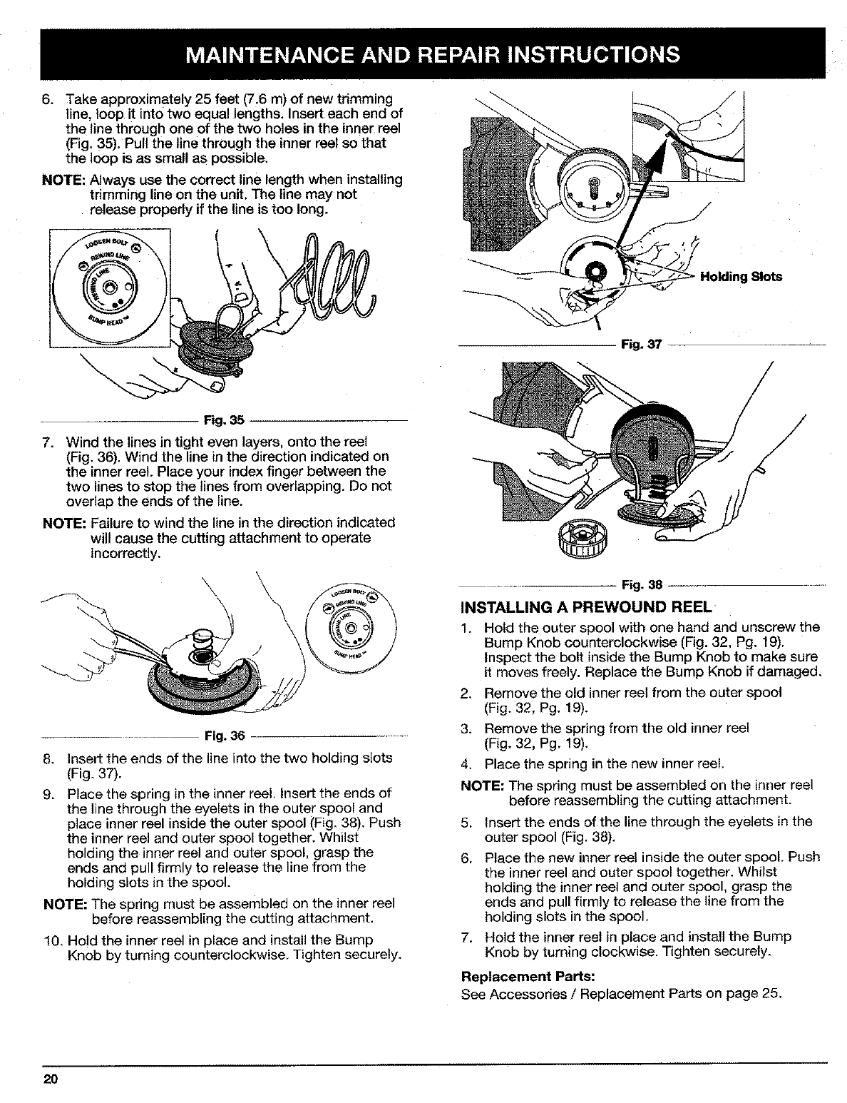
°Take approximately 25 feet (7.6 m) of new trimming
line, loop it into two equal lengths. Insert each end of
the line through one of the two holes in the inner reel
(Fig. 35). Pull the line through the inner reel so that
the loop is as small as possible.
NOTE: Always use the correct line length when installing
trimming line on the unit. The line may not
release properly if the line is too long.
Slots
Fig. 37
Fig. 35
.Wind the lines in tight even layers, onto the reel
(Fig. 36). Wind the line in the direction indicated on
the inner reel. Place your index finger between the
two lines to stop the lines from overlapping. Do not
overlap the ends of the line.
NOTE: Failure to wind the line in the direction indicated
will cause the cutting attachment to operate
incorrectly.
Fig. 36
8. Insert the ends of the line into the two holding slots
(Fig. 37).
9. Place the spring in the inner reel. Insert the ends of
the line through the eyelets in the outer spool and
place inner reel inside the outer spool (Fig. 38). Push
the inner reel and outer spool together. Whilst
holding the inner reel and outer spool, grasp the
ends and pull firmly to release the line from the
holding slots in the spool.
NOTE: The spring must be assembled on the inner reel
before reassembling the cutting attachment.
10. Hold the inner reel in place and install the Bump
Knob by turning counterclockwise. Tighten securely.
Fig. 38
INSTALLING A PREWOUND REEL
1. Hold the outer spool with one hand and unscrew the
Bump Knob counterclockwise (Fig. 32, Pg. 19).
Inspect the bolt inside the Bump Knob to make sure
it moves freely. Replace the Bump Knob if damaged.
2. Remove the old inner reel from the outer spool
(Fig. 32, Pg. 19).
3. Remove the spring from the old inner reel
(Fig. 32, Pg. 19).
4. Place the spring in the new inner ree!.
NOTE: The spring must be assembled on the inner reel
before reassembling the cutting attachment.
5. Insert the ends of the line through the eyelets in the
outer spool (Fig. 38).
6. Place the new inner reel inside the outer spool. Push
the inner reel and outer spool together. Whilst
holding the inner reel and outer spool, grasp the
ends and pull firmly to release the line from the
holding slots in the spool.
7. Hold the inner reel in place and install the Bump
Knob by turning clockwise. Tighten securely.
Replacement Parts:
See Accessories /Replacement Parts on page 25.
20
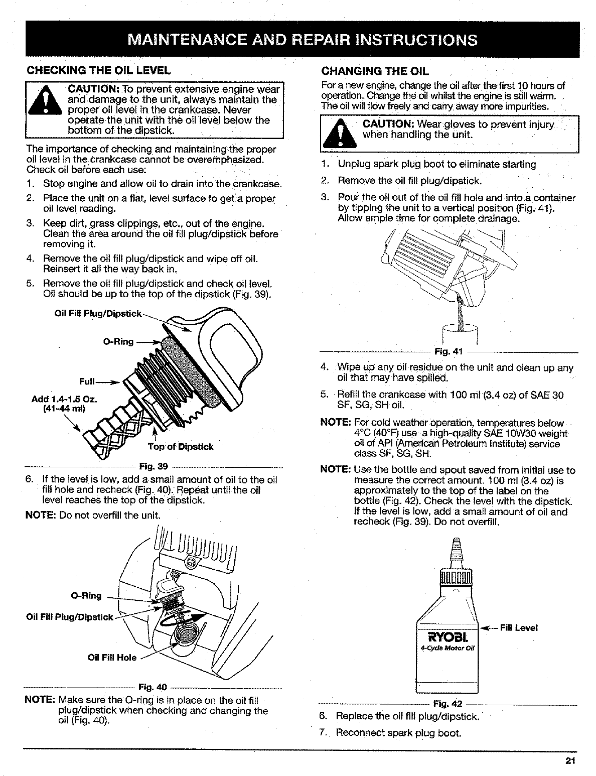
CHECKING THE OIL LEVEL
_ib AUTION: To prevent extensive engine wear I
and damage to the unit, always maintain the I
proper oil level in the crankcase. Never
operate the unit with the oil level be ow the
bottom of the dipstick.
The importance of checking and maintaining the proper
oil level in the crankcase cannot be overemphasized.
Check oil before each use:
1. Stop engine and allow oil to drain into the crankcase,
2. Place the unit on a flat, evel surface to get a proper
oil level reading.
3. Keep dirt, grass clippings, etc., out of the engine.
Clean the area around the oil fill plug/dipstick before
removing it.
4. Remove the oil fil! plug/dipstick and wipe off oil.
Reinsert it all the way back in.
5. Remove the oil fill plug/dipstick and check oil level.
Oit should be up to the top of the dipstick (Fig. 39).
Oil Fill
O-Ring
Add 1.4"1.5 Oz.
(41-44 ml)
\
Top of Dipstick
Fig. 39
6. If the level is low. add a small amount of oil to the oil
fill hole and recheck [Fig. 40). Repeat until the oil
evel reaches the top of the dipstick.
NOTE: Do not overfill the unit,
O-Ring
Oil Fill Plug/Dipstick.
Oil Fill Hole
Fig,40
NOTE: Make sure the O-ring is in place on the oil fill
plug/dipstick when checking and changing the
oil (Fig. 40).
CHANGING THE OIL
For a new engine, change the oil after the first 10 hours of
operation. Change the oil whilst the engine is still warm.
The oil will flow freely and carry away more mpurities.
CAUTION: Wear gloves to prevent injury 1
when handling the unit. I
1. Unplug spark plug boot to eliminate starting
2. Remove the oil fill plug/dipstick.
3. Pour the oil out of the oil fill hole and into a container
by tipping the unit to a vertical position (Fig. 41).
Allow ample time for complete drainage.
\
Fig. 41
4. Wipe up any oil residue on the unit and clean up any
oil that may have spilled.
5. Refill the crankcase with lg0m] (3.4ozl of SAE30
SF, SG_ SH oil.
NOTE: For cold weather operation, temperatures below
4°C (40°F) use a high-quality SAE lOW30 weight
oil of API (American Petroleum Institute) service
class SF, SG. SH.
NOTE: Use the bottle and spout saved from initial use to
measure the correct amount. 100 ml (3.4 oz) is
approximately to the top of the label on the
bottle (Fig. 42). Check the level with the dipstick.
If the level is low, add a small amount of oil and
recheck (Fig. 39). Do not overfill.
Fill Level
RYO I,
.Cycle Motor Oil
Fig. 42
6. Replace the oil fitl plug/dipstick.
7. Reconnect Spark plug boot.
21
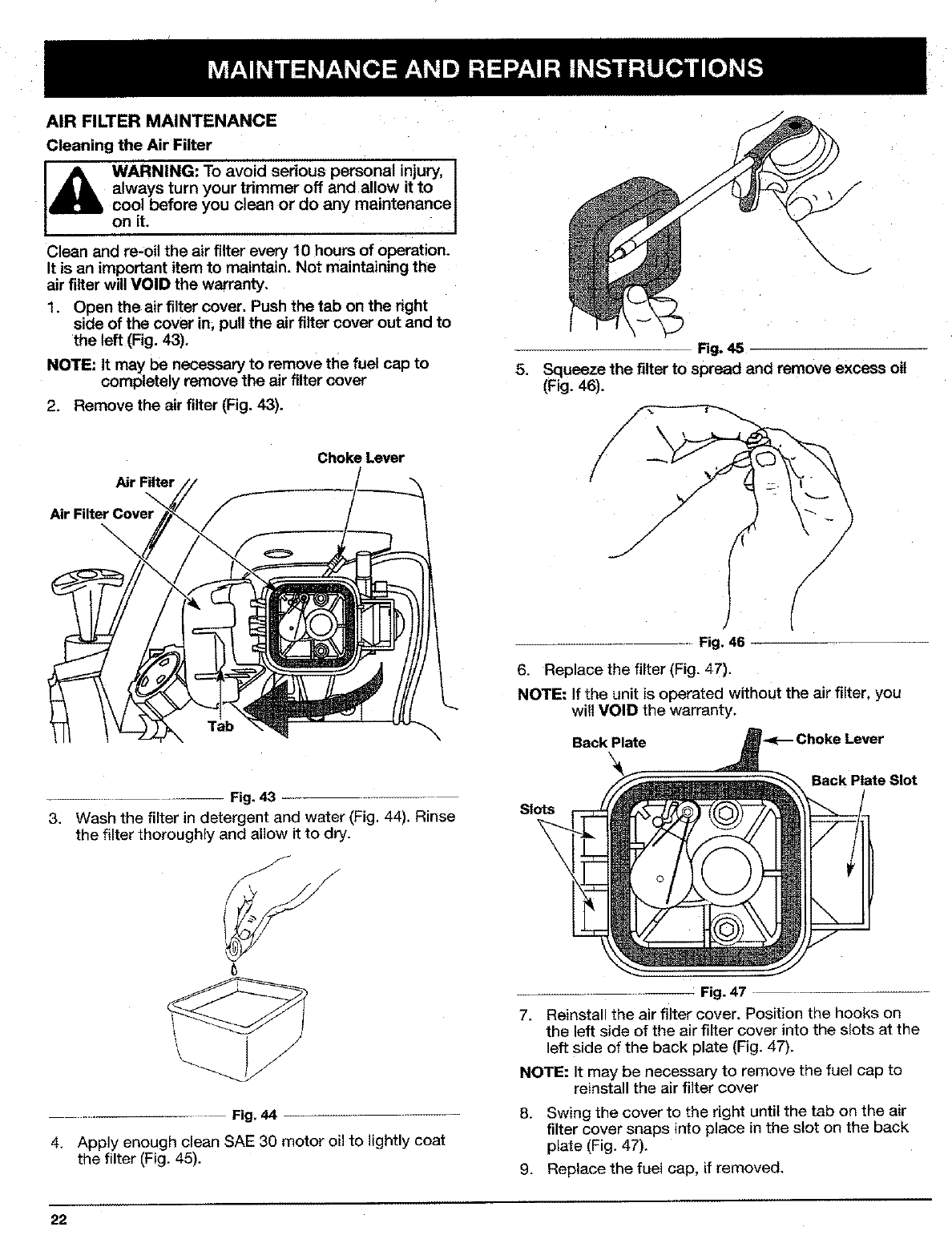
AIR FILTER MAINTENANCE
Cleaning the Air Filter
[_b WARNING: To avoid serious personal injury, ]
always turn your trimmer off and allow it to I
cool before you clean or do any maintenance 1
on it. 1
Clean and re-oil the air filter every 10 hours of operation.
It is an important item to maintain. Not maintaining the
air filter will VOID the warranty.
1. Open the air filter cover. Push the tab on the right
side of the cover in, pull the air filter cover out and to
the left (Fig. 43).
NOTE: It may be necessary to remove tile fuel cap to
completely remove the air filter cover
2. Remove the air filter (Fig. 43).
Air
Air Filter
Choke Lever
Tab
Fig. 43
3. Wash the filter in detergent and water (Fig, 44). Rinse
the filter thoroughly and allow it to dry.
Fig. 44
4. Apply enough clean SAE 30 motor oil to lightly coat
the filter (Fig, 45).
22
f
\\
5,
Fig. 45
Squeeze the filter to spread and remove excess oil
(Fig. 46).
Fig. 46
6. Replace the filter (Fig. 47).
NOTE: If the unit is operated without the air filter, you
will VOID the warranty.
Back Plate _ChokeLever
Back Plate Slot
Slots
7.
:Fig. 47
Reinstall the air filter cover. Position the hooks on
the left side of the air filter cover into the slots at the
left side of the back plate (Fig. 47).
NOTE: It may be necessary to remove the fuel cap to
reinstall the air filter cover
8. Swing the cover to the right until the tab on the air
filter cover snaps into place in the slot on the back
plate (Fig. 47).
9. Replace the fuel cap, if removed.

CARBURETOR ADJUSTMENT
The idle speed of the engine is adjustable. An idle
adjustment screw is reached though a hole in the top of
the engine cover (Fig 48).
NOTE: Careless adjustments can seriously damage your
unit. An authorized service dealer should make
carburetor adjustments.
Check Fuel
Old fuel is usually the main reason for the unit nol
running properly. Drain and refill the tank with clean,
fresh unleaded fuel prior to doing any adjustments. Refer
to Oil and Fuel Information.
Clean Air Filter
The condition of the air filter is importanl to the
operation of the unit. A dirty air filter will restrict air flow
and change the air/fuel mixture. This is often mistaken
for an out of adjustment carburetor. Check the condition
of the air filter before adjusting the idle speed screw.
Refer to Air Filter Maintenance.
Adjust Idle Speed Screw
WARNING: The cutting attachment may be
spinning during idle speed adjustment. Wear I
protective clothing and observe all safety I
instructions to prevent serious personal
injury.
If after checking the fuel and cleaning the air
filter the engine still will not idle, adjust the idle speed
screw as follows.
1. Start the engine and let it run at a high idle for a
minute to warm up.
2. Release the throttle trigger and let the engine idle. If
the engine stops, insert a small phillips or flat blade
screwdriver into the hole in the engine cover
(Fig. 48). Turn the idle speed screw in, clockwise,
1/8 of a turn at a time (as needed) until the engine
idles smoothly.
NOTE: The cutting attachment should not rotate when
the engine idles.
3. If the cutting attachment rotates when the engine
idles, turn the idle speed screw counterclockwise 1/8
of a turn at a time (as needed), to reduce idle speed.
Checking the fuel, cleaning the air filter, and adjusting
the idle speed screw should solve most engine
problems.
If not and:
• The engine will not idle,
• The engine hesitates or stalls on acceleration,
• There is a loss of engine power,
have the carburetor adjusted by an authorized service
dealer.
WARNING: When the unit is turned off make I
sure the cutting attachment has stopped I
before the unit is set down to preverlt serious
personal injury.
,,Idle Adjustment Screw
/
\
Fig, 48
ROCKER ARM CLEARANCE
This requires disassembly of the engine. If you feel
unsure or unqualified to perform this, take the unit to an
authorized service center.
NOTE: Inspect the valve to rocker arm clearance with a
feeler gauge after the first 10 hours of operation
and then every 50 hours of operation thereafter.
•The engine must be cold when checking or adjusting
the valve clearance.
•This task should be performed inside, in a clean, dust
free area.
Remove the muffler cover by pressing down on the
corner with a flat blade screwdriver (Fig. 49). Slide
the notches on the sides of the muffler cover over
the tabs on the engine cover and remove
1.
Engine Cover _
J
J
J
Muffler Cover/
Fig. 49
23
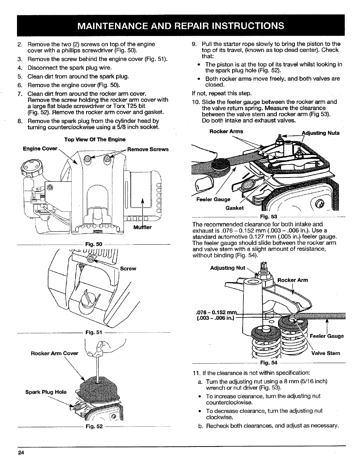
2. Remove the two (2) screws on top of the engine
cover with a phillips screwdriver (Fig. 50).
3. Remove the screw behind the engine cover (Fig. 51).
4. Disconnect the spark plug wire.
5. Clean dirt from around the spark plug.
6: Remove the engine cover (Fig. 50).
7. Clean dirt from around the rocker arm cover.
Remove the screw holding the rocker arm cover with
a large flat blade screwdriver or Torx T25 bit
(Fig. 52). Remove the rocker arm cover and gasket.
8. Remove the spark plug from the cylinder head by
turning counterclockwise using a 5/8 inch socket.
Top View Of The Engine
Fig. 50
.................. Fig. 51 .............
}
Rocker Arm Cover
\,
Spark Plug Hole
Fig. 52
9. Pull the starter rope slowly to bring the piston to the
top of its travel. (known as top dead center). Check
that:
•The piston is at the top of its travel whilst looking in
the spark plug hole (Fig. 52).
•Both rocker arms move freely, and both valves are
closed.
If not, repeat this step.
10. Slide the feeler gauge between the rocker arm and
the valve return spring. Measure the clearance
between the valve stem and rocker arm (Fig 53).
Do both intake and exhaust valves.
Rocker Arms iN_s
Feeler Gauge
Gasket f
Fig. 53 ..........
The recommended clearance for both intake and
exhaust is .076 - 0.152 mm (.003 - .006 in.). Use a
standard automotive 0.127 mm (.005 in.) feeler gauge.
The feeler gauge should slide between the rocker arm
and valve stem with a slight amount of resistance,
without binding (Fig. 54).
.076 - 0.152 mm
(.003 - .006 in.)
Rocker Arm
,Stem
Fig. 54
11. If the clearance is net within specification:
a. Tum the adjusting nut using a 8 mm (5/16 inch)
wrench or nut driver (Fig. 53).
• To increase clearance, turn the adjusting nut
counterclockwise.
• To decrease clearance, turn the adjusting nL_
clockwise.
b. Recheck both clearances, and adjust as necessary.
24
12. Reinstall the rocker arm cover using a new gasket.
Torque the screw to 2.2-3.4 N,m (20-30 inolb).
NOTE: A rocker arm cover gasket, Part # 182099 can be
purchased from your local authorized dealer.
13. Reinstall the engine cover. Check alignment of the
cover before tightening the screws. Tighten screws.
14. Replace the muffler cover. Slip the long tabs on the
muffler cover into the engine cover, Slide the notches
on the side of the muffler cover over the tabs on the
engine cover and snap into :)lace (Fig. 49, Pg, 23).
15. Check the spark plug and reinstall. SeeReplacing the
Spark Plug.
16. Replace the spark plug wire.
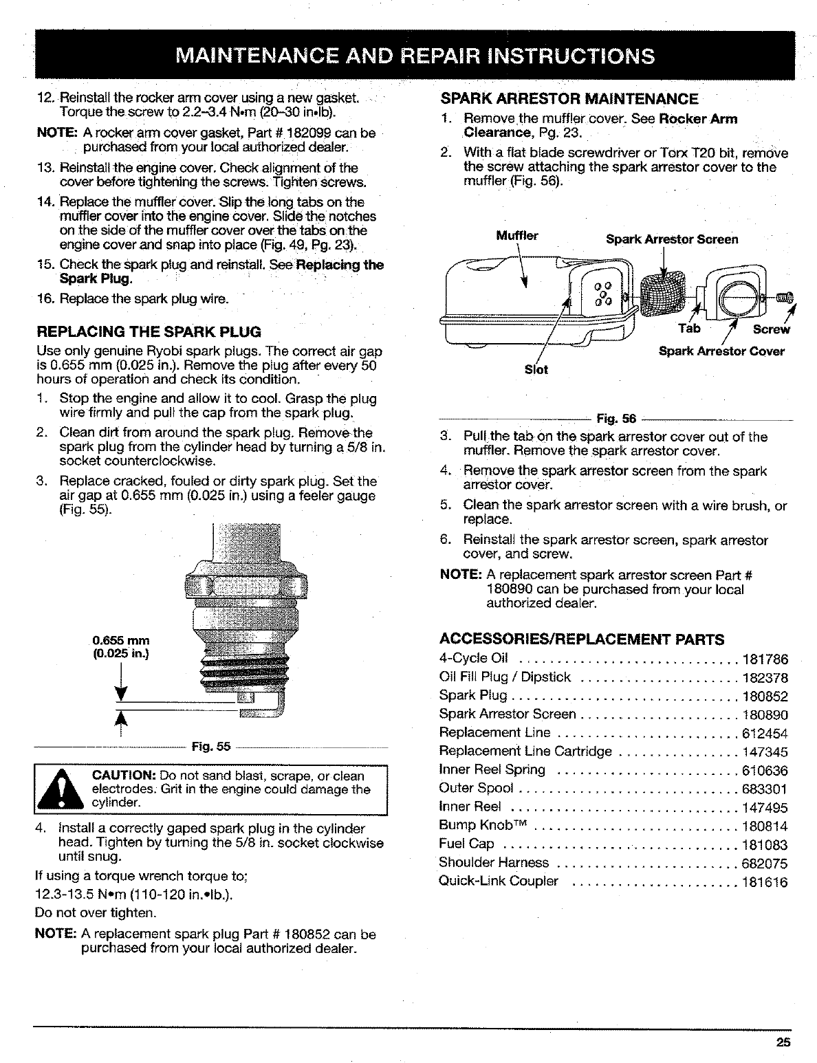
REPLACING THE SPARK PLUG
Use only genuine Ryobi spark plugs. The correct air gap
is 0.655 mm (0,025 in,), Remove the plug after every 50
hours of operation and check its condition.
1. Stop the engine and allow it to cool. Grasp the plug
wire firmly and pull the cap from the spark plug.
2. Clean dirt from around the spark plug. Remove the
spark plug from the cylinder head by turning a 5/8 in,
socket counterclockwise.
3. Replace cracked, fouled or dirty spark plug. Set the
air gap at 0.655 mm (0.025 in.) using a feeler gauge
(Fig. 55).
0.655 mm
(0.025 in.)
Fig. 55
CAUTION: Do not sand blast, scrape, or clean
electrodes; Grit in the engine could damage the
cylinder.
4. Install a correctly gaped spark plug in the cylinder
head. Tighten by turning the 5/8 in. socket clockwise
until snug.
If using a torque wrench torque to;
12.3-13.5 N,m (110-120 in,,Ib.).
Do not over tighten.
NOTE: A replacement spark plug Part # 180852 can be
purchased from your local authorized dealer.
SPARK ARRESTOR MAINTENANCE
1. Remove the muffler cover. See Rocker Arm
Clearance. Pg. 23.
2. With a flat blade screwdriver or Torx T20 bit. remove
the screw attaching the spark arrestor cover to the
muffler (Fig. 56).
Muffler Spark Arrestor Screen
Slot
Tab Screw
/
Spark Arrestor Cover
Fig. 56
3. Pull the tab on the spark arrestor cover out of the
muffler. Remove the spark arrestor cover.
4. Remove the spark arrestor screen from the spark
arrestor cover.
5. Clean the spark arrestor screen with a wire brush, or
replace,
6. Reinstall the spark arrestor screen, spark arrestor
cover, and screw.
NOTE: A replacement spark arrestor screen Part #
180890 can be purchased from your local
authorized dealer.
ACCESSORIES/REPLACEMENT PARTS
4-Cycle Oil ............................. 181786
Oil Fill Plug /Dipstick ..................... 182378
Spark Plug .............................. 180852
Spark Arrestor Screen ..................... 180890
Replacement Line ........................ 612454
Replacement Line Cartridge ................ 147345
Inner Reel Spring ........................ 610636
Outer Spool ............................. 683301
Inner Reel .............................. ! 47495
Bump Knob TM ........................... 180814
Fuel Cap ............................... 181083
Shoulder Harness ........................ 682075
Quick-Link Coupler ...................... 181616
25
CLEANING
,_, WARNING: To avoid serious personal injury, I
always turn your trimmer off and allow it to
oncoolit.before you clean or do any maintenance
Use a small brush to clean off the outside of the unit. Do
not use strong detergents. Household cleaners that
contain aromatic oils such as pine and lemon, and such
as kerosene, can damage plastic housing or handle.
Wipe off any moisture with a soft cloth.
STORAGE
•Never store the unit with petrol (gasoline) in the tank
where fumes may reach an open flame or spark.
•Allow the engine to cool before storing.
•Store the unit locked up to prevent unauthorized use
or damage.
•Store the unit in a dry, well ventilated area.
• Store the unit out of the reach of children.
Store the unit in one of three (3) positions:
1. The unit hanging by the cutting attachment end.
2. The unit hanging by the engine.
3. The unit setting upright on the cutting attachment
guard and engine feet,
LONG TERM STORAGE
If the unit will be stored for an extended time,
1. Drain all petrol (gasoline) from the gas tank into a
container. Do not use gas that has been stored for
more than 60 days. Dispose of the old petrol
(gasoline) in accordance to Local regulations.
2, Start theengine and allow it to run until it stalls. This
ensures that all petrol (gasoline) has been drained
from the carburetor.
.Allow the engine to cool. Remove the spark plug and
put 30 ml (1 oz.) of high quality motor oil into the
cylinder. Pull the starter rope slowly to distribute the
oil. Reinstall the spark plug.
NOTE: Remove the Spark plug and drain all of the oil
from the cylinder before attempting to start the
trimmer after storage.
4. Change the oil. See Changing the Oil, Pg. 21.
Dispose of the old oil in accordance to Local
regulations.
5. Thoroughly clean the unit and inspect for any loose
or damaged parts. Repair or replace damaged parts
and tighten loose screws, nuts or bolts. The unit is
ready for storage.
TRANSPORTING
• Allow the engine to cool before transporting.
• Secure the unit whilst transporting.
•Drain the gas tank before transporting.
•Tighten gas cap before transporting.
26
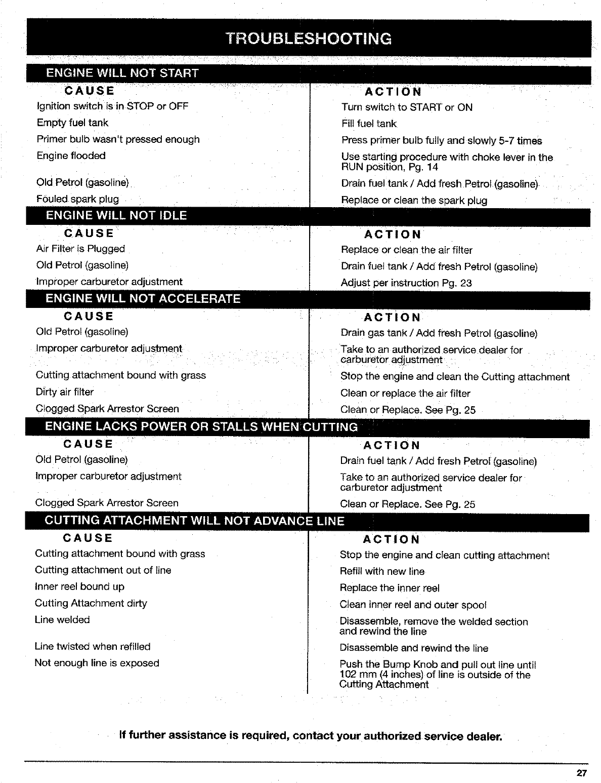
/CAUSE ..... ..... .....
Ignkion switch is in STOP or OFF
Empty fuel tank
Primer bulb wasn't pressed enough
Engine flooded
Old Petrol (gasoline)
Fouled spark plug
CAUSE
Air Filter is Plugged
Old Petrol (gasoline)
Improper carburetor adjustment
CAUSE
Old Petrol (gasoline)
Improper carburetor adjustment
Cutting attachment bound with grass
Dirty air filter
C!ogged Spark Arrestor Screen
CAUSE
Old Petrol (gasoline)
Improper carburetor adjustment
Clogged Spark Arrestor Screen
ACTION ......
Turn switch to START or ON
Fill fuel tank
Press primer bulb fully and slowly 5-7 times
Use starting procedure with choke lever in the
RUN position, Pg. 14
Drain fuel tank /Add fresh Petrol(gasoline)
spark plug
ACTION
Replace or clean the air filter
Drain fuel tank /Add fresh Petrol (gasoline)
Adjust per instruction Pg. 23
ACTiONI
Drain gas tank /Add fresh Petrol (gasoline)
Take to an authorized service dealer for ....
carburetor adjustmerrt
: Stop the engine and clean the Cutting attachment
Clean or replace the air filter
Clean or Replace, See Pg. 25
ACTION
Drain fuel tank /Add fresh Petrol (gasoline)
Take to an authorized service dealer for
carburetor adjustment
Clean or Replace, See Pg. 25
CAUSE
Cutting attachment bound with grass
Cutting attachment out of line
Inner reel bound up
Cutting Attachment dirty
Line welded
Line twisted when refilled
Not enough line is exposed
ACTION
Stop the engine and clean cuffing attachment
Refill with new line
Replace the inner reel
Clean inner reel and outer spool
Disassemble, remove the welded section
and rewind the line
Disassemble and rewind the line
Push the Bump Knob and pull out line until
102 mm (4 inches) of line is outside of the
Cutting Attachment
If further assistance is required, contact your authorized service dealer,
27
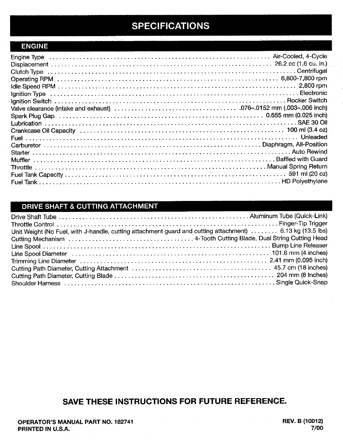
Engine Type ................................................................ Air-Cooled, 4-Cycle
Displacement ................................................................. 26.2 cc (1.6 cu. in.)
Clutch Type ......................................................................... Centrifugal
Operating RPM ................................................................. 6,800-7,800 rpm
die Speed RPM ....................................................................... 2,800 rpm
Ignition Type ......................................................................... Electronic
Ignition Switch .................................................................... Rocker Switch
Vaive clearance (intake and exhaust) ..................................... 076-.0152 mm (.003-.006 inch)
Spark Plug Gap ............................................................ 0.655 mm (0.025 inch)
Lubrication ................................................................... SAE 30 Oil
Crankcase Oil Capacity ............................................................ 100 ml [3.4 oz)
Fuel .............................................................................. Unleaded
Carburetor ................................................................ Diaphragm, All-Position
Starter ......................................................................... Auto Rewind
MLrffler ....................................................................... Baffled with Guard
Throttle .................................................................... Manual Spdng Return
Fuel Tank Capacity ................................................................. 591 ml [20 oz)
Fuel Tank ....................................................................... HD Polyethylene
Drive Shaft Tube ........................................................ Aluminum Tube (Quick-Link)
Throttle Control ................................................................. Finger-Tip Trigger
Unit Weight (No Fuel, with J-handle, cutting attachment guard and cutting attachment) ........ 6.13 kg (13.5 Ibs)
Cutting Mechanism ..................................... 4-Tooth Cutting Blade, Dual String Cutting Head
Line Spool .................. : .......................................... _. .... : Bump Line Releaser
Line Spool Diameter .......................................................... 101.6 mm (4 inches)
Trimming Line Diameter ....................................................... 2.41 mm (0.095 inch)
Cutting Path Diameter, Cutting Attachment ......................................... 45.7 cm (18 inches)
Cutting Path Diameter, Cutting Blade ............................................... 204 mm (8 Inches)
Shoulder Harness .............................................................. Single Quick-Snap
SAVE THESE INSTRUCTIONS FOR FUTURE REFERENCE.
OPERATOR'S MANUAL PART NO. 182741 REV. B (10012)
PRINTED IN U.S.A. 7/00
