Ryobi Jig Saw User Manual To The E2e1e1b1 C376 444d 919a 7d24f2b2bb9e
User Manual: Ryobi Jig Saw to the manual
Open the PDF directly: View PDF ![]() .
.
Page Count: 16
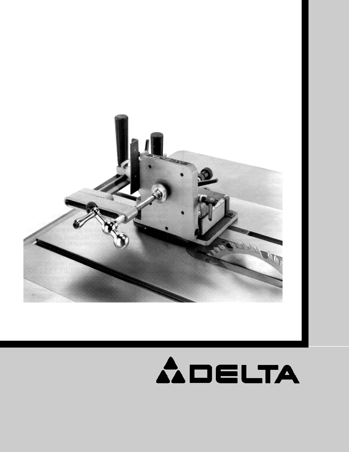
Tenoning Jig
(Model 34-183)
INSTRUCTION MANUAL
PART NO. 1342471 - 02-02-05
Copyright © 2005 Delta Machinery
To learn more about DELTA MACHINERY
visit our website at: www.deltamachinery.com.
For Parts, Service, Warranty or other Assistance,
please call 1-800-223-7278 (In Canada call 1-800-463-3582).

2
TABLE OF CONTENTS
Read and understand all warnings and operating instructions before using any tool or equipment. When
using tools or equipment, basic safety precautions should always be followed to reduce the risk of personal injury.
Improper operation, maintenance or modification of tools or equipment could result in serious injury and property
damage. There are certain applications for which tools and equipment are designed. Delta Machinery strongly
recommends that this product NOT be modified and/or used for any application other than for which it was designed.
If you have any questions relative to its application DO NOT use the product until you have written Delta Machinery
and we have advised you.
Online contact form at www.deltamachinery.com
Postal Mail: Technical Service Manager
Delta Machinery
4825 Highway 45 North
Jackson, TN 38305
Information regarding the safe and proper operation of this tool is available from the following sources:
Power Tool Institute
1300 Sumner Avenue, Cleveland, OH 44115-2851
www.powertoolinstitute.org
National Safety Council
1121 Spring Lake Drive, Itasca, IL 60143-3201
American National Standards Institute, 25 West 43rd Street, 4 floor, New York, NY 10036 www.ansi.org
ANSI 01.1Safety Requirements for Woodworking Machines, and
the U.S. Department of Labor regulations www.osha.gov
IMPORTANT SAFETY INSTRUCTIONS
SAVE THESE INSTRUCTIONS!
IMPORTANT SAFETY INSTRUCTIONS . . . . . . . . . . . . . . . . . . . . . . . . . . . . . . . . . . . . . . . . . . . . . . . . . . . . . . . . . . .2
SAFETY GUIDELINES . . . . . . . . . . . . . . . . . . . . . . . . . . . . . . . . . . . . . . . . . . . . . . . . . . . . . . . . . . . . . . . . . . . . . . . .3
GENERAL SAFETY RULES . . . . . . . . . . . . . . . . . . . . . . . . . . . . . . . . . . . . . . . . . . . . . . . . . . . . . . . . . . . . . . . . . . . .3
ADDITIONAL SPECIFIC SAFETY RULES . . . . . . . . . . . . . . . . . . . . . . . . . . . . . . . . . . . . . . . . . . . . . . . . . . . . . . . . .4
FUNCTIONAL DESCRIPTION . . . . . . . . . . . . . . . . . . . . . . . . . . . . . . . . . . . . . . . . . . . . . . . . . . . . . . . . . . . . . . . . . .4
CARTON CONTENTS . . . . . . . . . . . . . . . . . . . . . . . . . . . . . . . . . . . . . . . . . . . . . . . . . . . . . . . . . . . . . . . . . . . . . . . . .4
ASSEMBLY . . . . . . . . . . . . . . . . . . . . . . . . . . . . . . . . . . . . . . . . . . . . . . . . . . . . . . . . . . . . . . . . . . . . . . . . . . . . . . . . .5
OPERATION . . . . . . . . . . . . . . . . . . . . . . . . . . . . . . . . . . . . . . . . . . . . . . . . . . . . . . . . . . . . . . . . . . . . . . . . . . . . . . . .8
TROUBLESHOOTING . . . . . . . . . . . . . . . . . . . . . . . . . . . . . . . . . . . . . . . . . . . . . . . . . . . . . . . . . . . . . . . . . . . . . . .14
SERVICE . . . . . . . . . . . . . . . . . . . . . . . . . . . . . . . . . . . . . . . . . . . . . . . . . . . . . . . . . . . . . . . . . . . . . . . . . . . . . . . . . .14
ACCESSORIES . . . . . . . . . . . . . . . . . . . . . . . . . . . . . . . . . . . . . . . . . . . . . . . . . . . . . . . . . . . . . . . . . . . . . . . . . . . .15
WARRANTY . . . . . . . . . . . . . . . . . . . . . . . . . . . . . . . . . . . . . . . . . . . . . . . . . . . . . . . . . . . . . . . . . . . . . . . . . . . . . . . .15
SERVICE CENTER LOCATIONS . . . . . . . . . . . . . . . . . . . . . . . . . . . . . . . . . . . . . . . . . . . . . . . . . . . . . . . .back cover

3
Indicates an imminently hazardous situation which, if not avoided, will result in death or serious injury.
Indicates a potentially hazardous situation which, if not avoided, could result in death or serious injury.
Indicates a potentially hazardous situation which, if not avoided, may result in minor or moderate injury.
Used without the safety alert symbol indicates potentially hazardous situation which, if not avoided, may
result in property damage.
It is important for you to read and understand this manual. The information it contains relates to protecting YOUR
SAFETY and PREVENTING PROBLEMS. The symbols below are used to help you recognize this information.
SAFETY GUIDELINES - DEFINITIONS
GENERAL SAFETY RULES
READ AND UNDERSTAND ALL WARNINGS AND OPERATING INSTRUCTIONS BEFORE
USING THIS EQUIPMENT. Failure to follow all instructions listed below, may result in electric shock,
fire, and/or serious personal injury or property damage.
IMPORTANT SAFETY INSTRUCTIONS
1. FOR YOUR OWN SAFETY, READ INSTRUCTION
MANUAL BEFORE OPERATING THE TOOL. Learn the
tool’s application and limitations as well as the specific
hazards peculiar to it.
2. KEEP GUARDS IN PLACE and in working order.
3. ALWAYS WEAR EYE PROTECTION.
Wear safety
glasses. Everyday eyeglasses only have impact
resistant lenses; they are not safety glasses. Also use
face or dust mask if cutting operation is dusty. These
safety glasses must conform to ANSI Z87.1
requirements. NOTE: Approved glasses have Z87
printed or stamped on them.
4. REMOVE ADJUSTING KEYS AND WRENCHES. Form
habit of checking to see that keys and adjusting
wrenches are removed from tool before turning it “on”.
5. KEEP WORK AREA CLEAN. Cluttered areas and
benches invite accidents.
6. DON’T USE IN DANGEROUS ENVIRONMENT. Don’t
use power tools in damp or wet locations, or expose
them to rain. Keep work area well-lighted.
7. KEEP CHILDREN AND VISITORS AWAY. All children
and visitors should be kept a safe distance from work
area.
8. MAKE WORKSHOP CHILDPROOF – with padlocks,
master switches, or by removing starter keys.
9. DON’T FORCE TOOL. It will do the job better and be
safer at the rate for which it was designed.
10. USE RIGHT TOOL. Don’t force tool or attachment to do
a job for which it was not designed.
11. WEAR PROPER APPAREL. No loose clothing, gloves,
neckties, rings, bracelets, or other jewelry to get caught
in moving parts. Nonslip footwear is recommended.
Wear protective hair covering to contain long hair.
12. SECURE WORK. Use clamps or a vise to hold work
when practical. It’s safer than using your hand and frees
both hands to operate tool.
13. DON’T OVERREACH. Keep proper footing and balance
at all times.
14. MAINTAIN TOOLS IN TOP CONDITION. Keep tools
sharp and clean for best and safest performance. Follow
instructions for lubricating and changing accessories.
15. DISCONNECT TOOLS before servicing and when
changing accessories such as blades, bits, cutters, etc.
16. USE RECOMMENDED ACCESSORIES. The use of
accessories and attachments not recommended by
Porter-Cable
may cause hazards or risk of injury to
persons.
17. REDUCE THE RISK OF UNINTENTIONAL STARTING.
Make sure switch is in “OFF” position before plugging in
power cord.
In the event of a power failure, move
switch to the “OFF” position.
18. NEVER STAND ON TOOL. Serious injury could occur if
the tool is tipped or if the cutting tool is accidentally
contacted.
19. CHECK DAMAGED PARTS. Before further use of the
tool, a guard or other part that is damaged should be
carefully checked to ensure that it will operate properly
and perform its intended function – check for alignment
of moving parts, binding of moving parts, breakage of
parts, mounting, and any other conditions that may
affect its operation. A guard or other part that is
damaged should be properly repaired or replaced.
20. DIRECTION OF FEED. Feed work into a blade or cutter
against the direction of rotation of the blade or cutter
only.
21. NEVER LEAVE TOOL RUNNING UNATTENDED.
TURN POWER OFF. Don’t leave tool until it comes to a
complete stop.
22.
STAY ALERT, WATCH WHAT YOU ARE DOING, AND
USE COMMON SENSE WHEN OPERATING A
POWER TOOL. DO NOT USE TOOL WHILE TIRED
OR UNDER THE INFLUENCE OF DRUGS,
ALCOHOL, OR MEDICATION. A moment of
inattention while operating power tools may result in
serious personal injury.
23. MAKE SURE TOOL IS DISCONNECTED FROM
POWER SUPPLY while motor is being mounted,
connected or reconnected.
24. THE DUST GENERATED by certain woods and wood
products can be injurious to your health. Always operate
machinery in well ventilated areas and provide for proper
dust removal. Use wood dust collection systems
whenever possible.
SAVE THESE INSTRUCTIONS.
Refer to them often and
use them to instruct others.
4
FAILURE TO FOLLOW THESE RULES MAY RESULT IN SERIOUS PERSONAL INJURY.
ADDITIONAL SPECIFIC SAFETY RULES
1. DISCONNECT THE POWER SOURCE to the machine before attaching or adjusting the jig.
2. MAKE SURE THAT THE BLADE HAS COME TO A COMPLETE STOP before adjusting the jig or the workpiece.
3. KEEP BOTH HANDS on the operating handles when operating the jig.
4. REPLACE THE BLADE GUARD OF THE SAW when the jig operation is complete.
5. REFER TO THE OWNER’S MANUAL of the saw for safety rules and other instructions.
FOREWORD
FUNCTIONAL DESCRIPTION
Your new 34-183 Tenoning Jig will help you produce good, strong joints. Although many methods for joining wood
exist, the classic mortise-and-tenon joint is one of the strongest and most widely used joints in woodworking. This jig
will help you perform this task much easier than ever before.
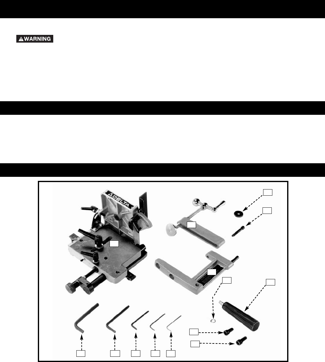
CARTON CONTENTS
1
2
3
4
9
8
7
11
6
14 13 12
5
1. Base and Vertical Work Support Assembly
2. Clamp Assembly
3. M8 Flat Washer
4. M8 x 50mm Socket Head Screw
5. Clamp Arm
6. M10 Lockwasher (2)
7. M10 x 25mm Socket Head Screw
8. M10 x 20mm Socket Head Screw
9. Handles (2)
10. 2.5mm Allen Wrench
11. 3mm Allen Wrench
12. 4mm Allen Wrench
13. 6mm Allen Wrench
14. 8mm Allen Wrench
10
5
UNPACKING AND CLEANING
Carefully unpack the machine and all loose items from the shipping container(s). Remove the protective coating from
all unpainted surfaces. This coating may be removed with a soft cloth moistened with kerosene (do not use acetone,
gasoline or lacquer thinner for this purpose). After cleaning, cover the unpainted surfaces with a good quality household
floor paste wax.
ASSEMBLY
ASSEMBLY TOOLS REQUIRED
ASSEMBLY TIME ESTIMATE
Disconnect the machine from the power source and remove the blade guard before using the
tenoning jig. Reinstall the blade guard immediately after jig use is complete. Always unplug the
machine before removing or installing the blade guard.
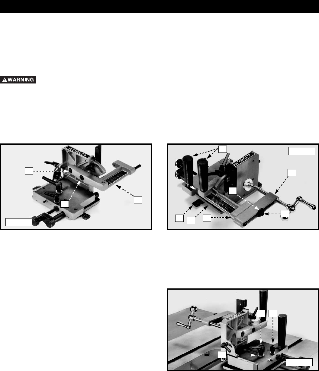
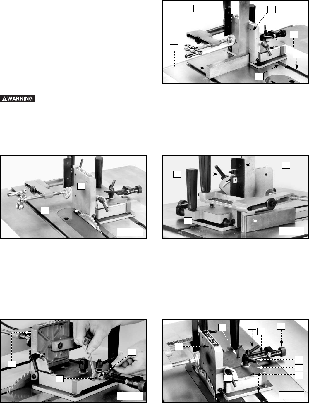
1. Fasten the clamp arm (A) Fig. 3 to the back of the work support plate using the M10 x 25mm socket head screw
(B), M10 x 25mm socket head screw (X), and lockwashers.
2. Fasten the clamp assembly (C) Fig. 4 to the clamp arm (A) using the M8 x 50mm socket head screw (D) and flat
washer.
3. Fasten the handles (F) Fig. 4 to the clamp arm (A) and base (H).
Fig. 3
Fig. 4
AD
C
F
E
G
BA
2.5mm Hex Wrench (Supplied)
3mm Hex Wrench (Supplied)
8mm Hex Wrench (Supplied)
4mm Hex Wrench (Supplied)
6mm Hex Wrench (Supplied)
Adjustable Wrench
Assembly time for this unit is approximately 30 minutes.
X
H
FOR LEFT-TILTING ARBOR SAWS ONLY
NOTE: Position the tenoning jig in the miter gauge
slot to the left of the blade.
4. Loosen the small lock handle (J) Fig. 5. Remove the
large lock handle (K) and flat washer (L) Fig. 5 from the
tenoning jig.
NOTE: Both lock handles (J) and (K) Fig. 5 are spring-
loaded and can be repositioned by pulling out on the
handle and repositioning it on the nut located
underneath the handle.
K
Fig. 5
L
J
IMPORTANT: The guide bar (G) Fig. 4, located on the base (H) of the tenoning jig, was preset at the factory for
operation on right-tilting arbor saws. If your saw is a right-tilt saw, follow the instructions for “ALIGNING TENONING
JIG”. If your saw is a left-tilt saw, relocate the guide bar (G) Fig. 4 on the base (H) of the tenoning jig by using the
following directions.
6
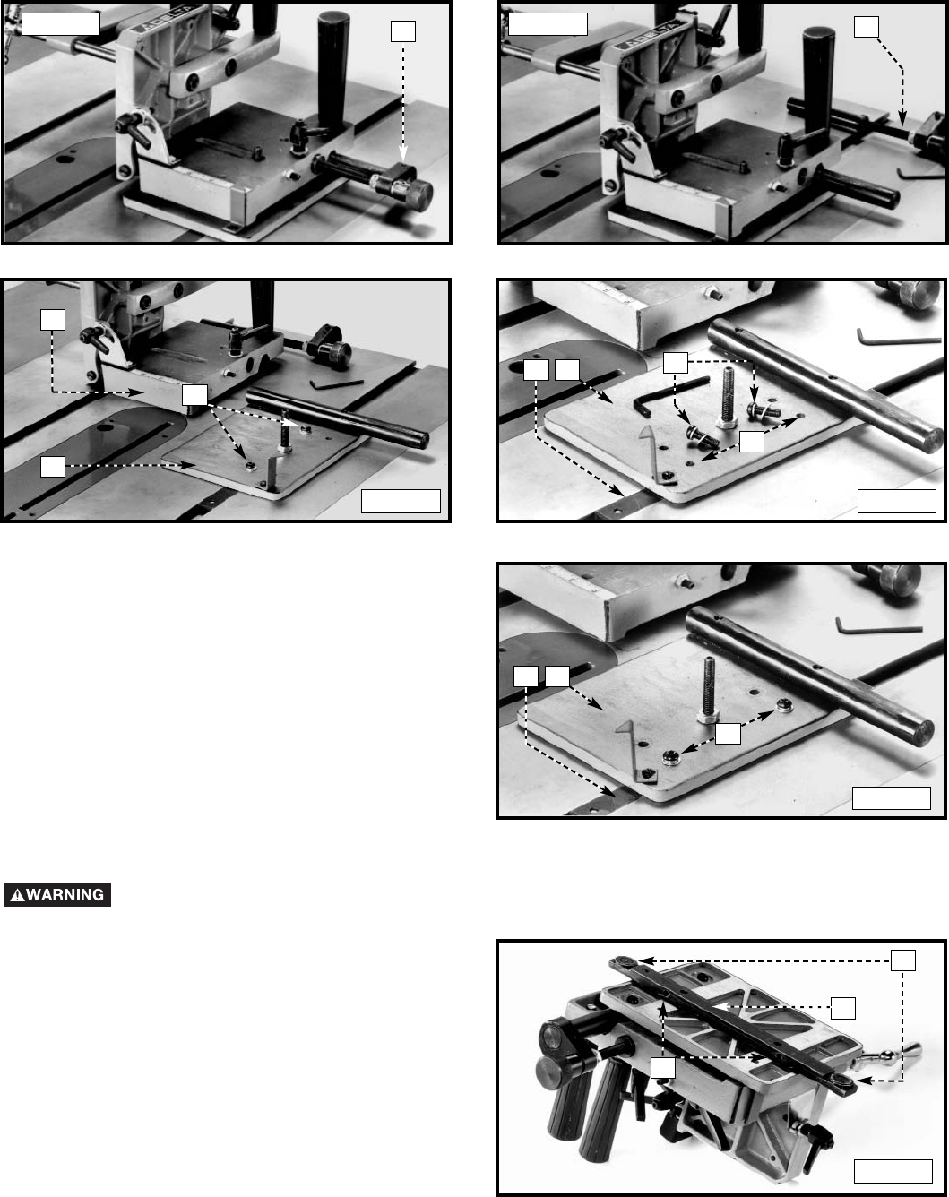
6. Use the supplied 3mm hex wrench to loosen the set screw (M) Fig. 6. Remove the micro-adjustment assembly (N) from
the tenoning jig (Fig. 7).
MN
H
R
P
HR
G
Fig. 6 Fig. 7
Fig. 8 Fig. 9
Fig. 10
ADJUSTING THE GUIDE BAR TO THE TABLE SLOT
Disconnect Machine from Power Source
C
A
B
Fig. 11
7. Lift the jig assembly (P) Fig. 8 from the base (H).
Remove the two button head screws and flat washers
(R) from the base.
8. Slide the base (H) Fig. 9 forward until the two holes (S)
are aligned with the holes in the guide bar (G). Fasten
the base to the guide bar with the two button head
screws and flat washers (R) (Fig. 10).
9. Reassemble the items that were removed in STEPS 4,
5, and 6in reverse order.
S
H
G
R
1. The tenoning jig is furnished with an adjustable guide
bar (A) Fig. 11 that allows the jig to custom-fit to your
saw, eliminating side-to-side play. Also, a T-slot washer
(B) is on each end of the guide bar (A) to keep the
tenoning jig from lifting during operation.
NOTE: Remove the T-slot washers (B) if your table saw is
not equipped with T-slotted miter gauge slots.
7
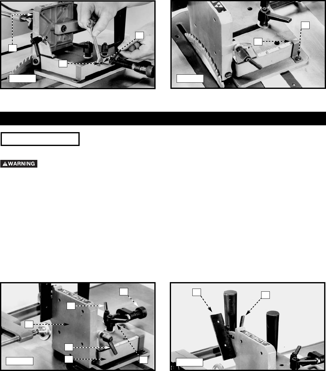
2. Place the tenoning jig guide bar (A) Fig. 12 into the left
miter slot (D) and slide the tenoning jig back and forth to
determine if it has side-to-side play. If the tenoning jig
slides easily through the miter slot without side-to-side
play, no adjustment is necessary. However, if the tenoning
jig fits too snugly, or if there is excessive play between the
guide bar (A) and the miter slot (D), adjust the jig, using
instructions 3-5 of this section.
3. Remove the jig from machine and place it upside down
(Fig. 11).
4. Use the 2.5mm hex wrench to turn the screws (C) Fig. 11
clockwise for a snug fit, or counter-clockwise for a looser
fit.
5. Insert the tenoning jig back into the miter slot of the
machine to determine if the fit is suitable, or if further
adjustment is required.
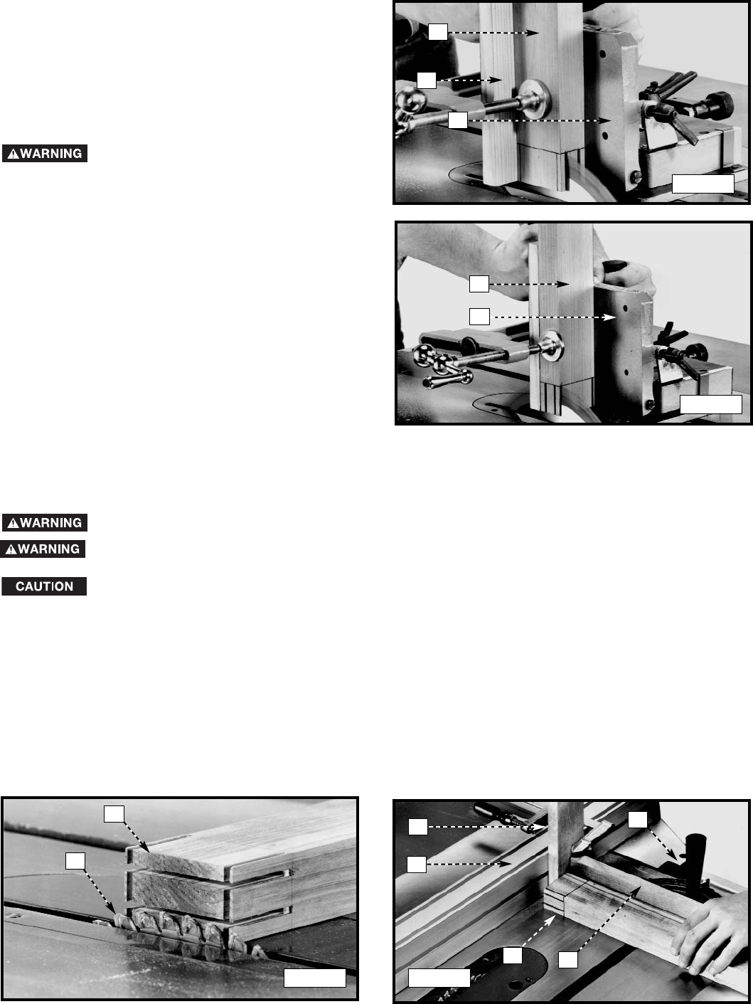
1. Place the tenoning jig guide bar (A) Fig. 12 into the left miter gauge slot.
2. Use a square (E) Fig. 12 to see if the vertical work support plate (F) is 90 degrees to the saw table. If an adjustment is necessary,
loosen the lock handle (G) and the set screw (H) Fig. 13, move the vertical work support plate (F) until it is 90 degrees to the
table, and tighten the lock handle (G).
3. With the vertical work support plate (F) Fig. 13 adjusted, tighten the set screw (H) until it bottoms. This set screw (H) enables
you to rapidly position the vertical work support (F) 90 degrees to the table after it has been tilted.
4. Use a square (E) Fig. 14 to see if the face of the backstop (J) is 90 degrees to the saw table. If an adjustment is necessary,
loosen lock lever (K), adjust backstop (J) accordingly and tighten lever (K).
A
F
E
G
ALIGNING THE TENONING JIG
F
H
J
E
K
Fig. 12
Fig. 13 Fig. 14
D
Disconnect Machine from Power Source
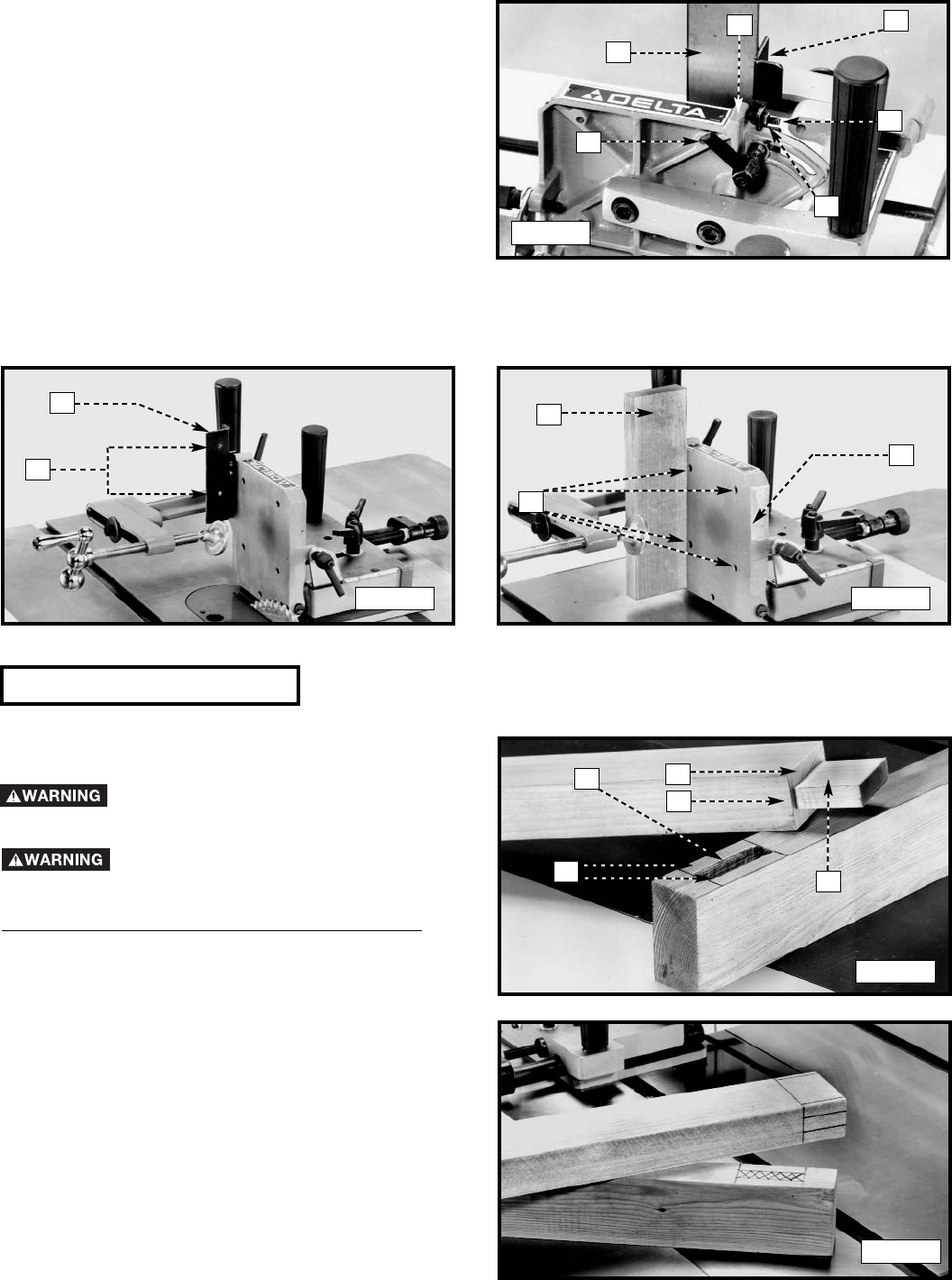
5. Loosen the nut (L) Fig. 15, and turn the set screw (M) counter-clockwise, two or three times.
6. Loosen the two lock levers (N) and (P) Fig. 16, and move the jig (R) until the vertical work support plate (F) is against the saw
blade and tighten the lever (N).
NOTE: The lock levers (N) and (P) are spring-loaded and can be repositioned by pulling up on the handles and repositioning them
on the nut located underneath the handles.
7. Check to see if the vertical work-support plate (F) Fig. 16 is parallel to the saw blade.
8. If an adjustment is necessary, loosen the lever (N) Fig. 16. Rotate the knob (S) clockwise as far as possible to align the holes
(T) with the guide bar (X) and to gain access to the set screws. Loosen the two screws inside the holes (T) and move the jig (R)
until the vertical work-support plate (F) is parallel to the saw blade. Tighten the two screws inside the holes (T).
9. Move the jig (R) Fig. 16 1/8" away from blade so that the vertical work-support plate (F) clears saw blade. Tighten the lever (N).
10. Rotate the knob (S) Fig. 16 counter-clockwise until the collar (V) is halfway between the knob (S) and the side of the jig (R);
tighten lever (P).
F
L
P
X
F
Fig. 15 Fig. 16
M
VS
N
R
T
T
8
Fig. 18
OPERATION
ADJUSTMENTS
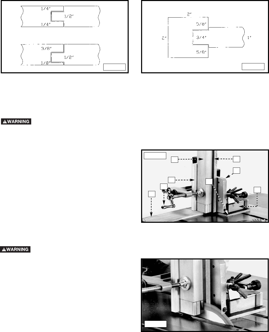
1. For rapid adjustment of the work support plate (A) Fig. 19, toward or away from the saw blade, loosen levers (B) and (C)
and move jig (D). Tighten levers (B) and (C).
2. You can fine-adjust the work support plate (A) Fig. 19, by loosening the lever (B) and rotating the knob (E) until plate (A)
is at the desired position. Tighten the lever (B) Fig. 19.
3. To tilt the vertical work support plate (A) Fig. 19, loosen the lock lever (F), tilt vertical work support plate to the desired
angle, and tighten lock lever (F).
4. To adjust backstop (G) Fig. 20, for angle tenons, loosen lock lever (H), tilt backstop (G) to the desired angle and
tighten lever (H).
IMPORTANT: The tenoning jig is not equipped with a bevel scale for the positioning of the backstop (G) Fig. 20 or the support
plate (A) Fig. 19. Cut the workpiece to the desired angle prior to the jig set up and use it as the angle reference.
A
E
C
B
D
Disconnect Machine from Power Source
Fig. 19
Y
Z
11. Turn the screw (M) Fig. 17 clockwise until it bottoms to prevent the vertical work-support plate (F) from accidentally being
moved into the blade. Tighten the nut (L).
12. Loosen the screw (Y) Fig. 18, and adjust the pointer (Z) to the “1/8" mark on scale.
F
L
M
Fig. 17
GH
Fig. 20
F
9
J
G
P
R
S
TENONING JIG USE
This jig is intended to perform cheek cuts only. Cheek cuts
are made prior to the shoulder cuts, which are made on a
table saw using the miter gauge.
Keep your hands on the jig handles
when performing cuts.
Disconnect Machine from
Power Source
STRUCTURE OF A MORTISE AND TENON JOINT
Parts of a simple or “blind” joint are (Fig. 24):
A. Structural Shoulder
B. Cheek
C. Cosmetic Shoulder
D. Mortise
E. Mortise Walls
Lay out the mortise and tenon on the workpieces (Fig. 25),
but keep these items in mind when laying out the joints:
• To avoid premature joint failure, avoid locating a tenon
in a disfigured part of the grain (a knot), for
unpredictable movement of the joint may occur. Use
straight, flat, common-grained stock.
• The tenon will shrink in width away from the mortise
walls, possibly revealing the mortised hole. When
possible, produce tenons with shoulders on all
four sides - two structural and two cosmetic - to
conceal the mortised hole when wood movement
occurs.
A
C
B
D
E
Fig. 21
Fig. 23
Fig. 24
Fig. 25
5. The tenoning jig features a positive stop to ensure fast
and accurate positioning of the backstop (G) Fig. 21 at
90 degrees to the saw table. To check and adjust the
positive stop at 90 degrees, loosen lock handle (H) Fig.
21, and place one end of a combination square (J) on
the saw table and the other end against backstop (G).
If the backstop is not 90 degrees to the table, loosen
the locknut (K) Fig. 21, and tighten or loosen the
adjustment screw (L) until the head of the screw
contacts the casting on the vertical plate (M) at 90
degrees. Tighten the locknut (K) and lock the handle
(H).
M
H
L
K
N
G
Fig. 22
6. To eliminate chip-out when performing cheek cuts, you can fasten an auxiliary wooden backup board (P) Fig. 23 to the
backstop (G) Fig. 22 with two wood screws through the two pre-drilled holes (N).
7. You can also fasten a block of wood to the vertical support plate (R) Fig. 23, through four pre-drilled holes (S) to prevent
the saw blade from contacting the jig.
10
• The objective is to make the parts fit closely together. Maximize the gluing surface by making the tenon as long as possible
(approximately 1/2 the width of the stile or longer, if using narrow stock). Balance the joint by using the same amount of
wood in the tenon as in the combined thickness of the mortise walls (Fig. 26). If one piece of wood is larger than the other,
make the tenon as thick as possible (Fig. 27).
• Remember to figure the kerf of the saw blade when setting up for the cut.
• Cut all mortises first. Make the mortise 1/16" deeper than the length of the tenon to allow for glue.
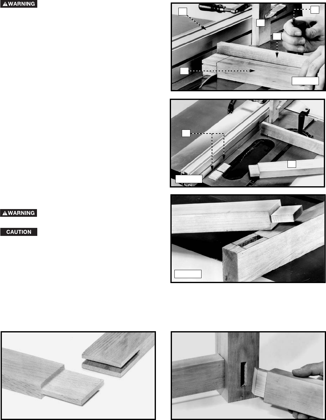
1. Clamp a base stop (F) Fig. 28 (the same thickness as
the base plate (G) of the tenoning jig (H)) on the front of
the saw table. This will allow tenoning jig to pass over
the base stop (F).
2. Make a spacer block of wood (K) Fig. 28, equal to the
thickness of the tenon plus the thickness of the saw
blade.
3. With the tenoning jig (H) Fig. 28 located at the front of
saw table and over the base stop (F), load the spacer
block (K) and the workpiece (L). Securely clamp both in
place with the clamp handle (M). Make certain that both
pieces of wood are against the vertical support plate
(N) and the backup board (P).
4. Gently push the tenoning jig (H) Fig. 28 toward the saw
blade until workpiece is near the saw blade. Adjust the
tenoning jig (H) and the saw blade to make the first
cheek cut. Return the tenoning jig (H) to the front of saw
table.
5. Connect the saw to the power source.
6. Turn the saw “ON” and perform the first structural
cheek cut (Fig. 29). Feed the tenoning jig toward the
saw blade at a slow feed rate until the saw blade has
exited the back of the workpiece. Turn the tool off and
allow the blade to come to a complete stop, then
slowly pull the tenoning jig back to the position shown
in Fig. 28.
Fig. 26 Fig. 27
Fig. 28
You can use several different methods to cut a mortise and tenon. The following information illustrates one of the easiest and
safest methods and utilizes cheek cuts first, then shoulder cuts. Use a base stop (F) Fig. 28 that is the same thickness as
the base plate (G) of the tenoning jig (H) and spacer block (K) that is the combined thickness of the tenon and the saw blade,
to make the cutting more efficient. This method eliminates possible errors caused by thickness variations in the workpiece,
and avoids trapping cut-off pieces between the saw blade and vertical support plate (N).
NOTE: Perform your practice cuts on scrap material before cutting good wood.
Use a slow feed rate to help prevent the tenoning jig from lifting during a cut.
Keep your hands on the jig handles when performing cuts.
Fig. 29
F
K
L
P
M
N
H
G
11
8. Load and secure the workpiece (L) Fig. 31 on the
tenoning jig and adjust the jig to perform the third and
fourth cosmetic cheek cuts. Connect the machine to
the power source, turn the saw “on”, and make the
cuts.
NOTE: When cutting the cosmetic cheek cuts, do not use
the spacer block (K) Fig. 28. You can turn the workpiece 180
degrees. The discrepancies in the workpiece are not as
critical when cutting the cosmetic cheeks as compared to
the structural cheeks.
Disconnect Machine from
Power Source
1. Remove the tenoning jig from the machine.
2. Lay the workpiece (L) Fig. 32 on the saw table and adjust the saw blade (R) to cut the structural shoulders of the
tenon.
3. Clamp a wooden stop block (S) Fig. 33 to the front of the saw fence (T), and adjust the saw fence to cut the structural
shoulders of the tenon.
NOTE: Remember to figure in the width of the saw blade.
CUTTING THE SHOULDERS OF THE TENON
Disconnect Machine from Power Source
7. Loosen the clamp (M) Fig. 28. Remove the spacer
block (K) and secure the workpiece (L) Fig. 29 in place.
Keep the same face of the workpiece (L) against the
vertical support plate (N) and the backup board (P).
Turn the machine “on”, perform the second structural
cheek cut, and turn the machine “off”. Allow the blade
to come to a complete stop, then slowly pull the
tenoning jig back to the position shown in Fig. 28.
Fig. 30
Fig. 31
L
P
N
L
N
To avoid personal injury or damage to the machine, always use a cross-cut blade to perform the
shoulder cuts of the tenon.
When performing the shoulder cuts of the tenon, do not cut into the cheeks of the tenon. It will
greatly reduce the strength of the joint.
NOTE: Perform your practice cuts on scrap material before cutting good wood.
Fig. 32 Fig. 33
L
RT
S
X
W
L
12
EXAMPLES OF MORTISE-AND-TENON JOINTS
Position the wooden stop block (S)
Fig. 34 in front of the saw blade to
prevent the workpiece from being
trapped between the saw fence and the
saw, causing kickback. Make sure that
the workpiece is clear of the wooden
stop block (S) before contacting the saw
blade.
4. Use a miter gauge (W) Fig. 34, equipped with a backup
board (X), to position the workpiece (L) so that you can
cut the structural shoulders. Make certain that the
workpiece (L) is against the wooden stop block (S) and
the backup board (X).
5. Connect the machine to the power source.
6. Turn the machine “ON” and perform the structural
shoulder cut by slowly pushing the miter gauge (W) Fig.
34 toward the saw blade until the saw blade is
completely through the workpiece. Turn the machine
“OFF”.Wait for the blade to come to a complete
stop and remove the cut-off piece.
7. Return the miter gauge (W) Fig. 34 to the position
shown, and perform the other structural shoulder cut in
the same manner.
8. Fig. 35 illustrates workpiece (L) with the two structural
shoulders (M) cut.
9. Adjust the blade height to perform the cosmetic
shoulder cuts.
10. Connect the saw to power source.
11. Perform the cosmetic shoulder cuts in the same
manner as the structural shoulder cuts.
When performing the shoulder cuts of
the tenon, do not cut into the cheeks of
the tenon. It will greatly reduce the
strength of the joint.
12. Fig. 36 illustrates a simple, or “blind” mortise-and-
tenon joint.
Disconnect Machine from
Power Source
Fig. 34
Fig. 35
Fig. 36
T
S
X
L
W
L
M
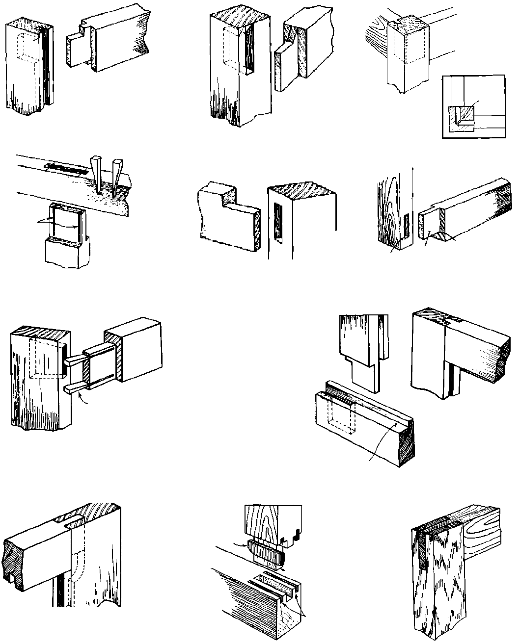
OPEN MORTISE AND TENON JOINT MITERED MORTISE AND TENON JOINT
13
HAUNCHED
TENON CONCEALED
HAUNCHED
TENON
MITERED
TENON
TENON
ENDS
MITERED
SAW
CUTS
THROUGH-WEDGED
TENON
BARE FACED
TENON
SIMPLE MORTISE
AND TENON
MORTISE CHEEK OF
TENON
SHOULDER OF
TENON
BLIND-WEDGED
TENON
WEDGE
TENON WITH LONG AND
SHORT SHOULDERS
RABBET
STUB
TENON
MORTISE AND TENON
WITH SPLINES
SPLINE GROOVE
(SINGLE SAW CUT)
SPLINE
OPEN MORTISE
TENON

14
TROUBLESHOOTING GUIDE
For assistance with your tool, visit our website at www.deltamachinery.com for a list of service centers or call the
DELTA Machinery help line at 1-800-223-7278 (In Canada call 1-800-463-3582).
PARTS, SERVICE OR WARRANTY ASSISTANCE
All Delta Machines and accessories are manufactured to high quality standards and are serviced by a network
of Porter-Cable • Delta Factory Service Centers and Delta Authorized Service Stations. To obtain additional
information regarding your Delta quality product or to obtain parts, service, warranty assistance, or the location
of the nearest service outlet, please call 1-800-223-7278 (In Canada call 1-800-463-3582).
SERVICE

15
A complete line of accessories is available from your Delta Supplier, Porter-Cable • Delta Factory Service Centers,
and Delta Authorized Service Stations. Please visit our Web Site www.deltamachinery.com for a catalog or
for the name of your nearest supplier.
Since accessories other than those offered by Delta have not been tested
with this product, use of such accessories could be hazardous. For safest operation, only
Delta recommended accessories should be used with this product.
ACCESSORIES
Two Year Limited New Product Warranty
Delta will repair or replace, at its expense and at its option, any new Delta machine, machine part, or machine accessory
which in normal use has proven to be defective in workmanship or material, provided that the customer returns the product
prepaid to a Delta factory service center or authorized service station with proof of purchase of the product within two
years and provides Delta with reasonable opportunity to verify the alleged defect by inspection. For all refurbished Delta
product, the warranty period is 180 days. Delta may require that electric motors be returned prepaid to a motor
manufacturer’s authorized station for inspection and repair or replacement. Delta will not be responsible for any asserted
defect which has resulted from normal wear, misuse, abuse or repair or alteration made or specifically authorized by
anyone other than an authorized Delta service facility or representative. Under no circumstances will Delta be liable for
incidental or consequential damages resulting from defective products. This warranty is Delta’s sole warranty and sets
forth the customer’s exclusive remedy, with respect to defective products; all other warranties, express or implied, whether
of merchantability, fitness for purpose, or otherwise, are expressly disclaimed by Delta.

The following are trademarks of PORTER-CABLE
•
DELTA (Las siguientes son marcas registradas de PORTER-CABLE
•
DELTA S.A.) (Les marques
suivantes sont des marques de fabriquant de la PORTER-CABLE
•
DELTA): Auto-Set®, BAMMER®, B.O.S.S.®, Builder’s Saw®, Contractor’s Saw®,
Contractor’s Saw II™, Delta®, DELTACRAFT®, DELTAGRAM™, Delta Series 2000™, DURATRONIC™, Emc²™, FLEX®, Flying Chips™, FRAME SAW®,
Grip Vac™, Homecraft®, INNOVATION THAT WORKS®, Jet-Lock®, JETSTREAM®, ‘kickstand®, LASERLOC®, MICRO-SET®, Micro-Set®, MIDI LATHE®,
MORTEN™, NETWORK™, OMNIJIG®, POCKET CUTTER®, PORTA-BAND®, PORTA-PLANE®, PORTER-CABLE®&(design), PORTER-
CABLE®PROFESSIONAL POWER TOOLS, PORTER-CABLE REDEFINING PERFORMANCE™, Posi-Matic®, Q-3®&(design), QUICKSAND®&(design),
QUICKSET™, QUICKSET II®, QUICKSET PLUS™, RIPTIDE™&(design), SAFE GUARD II®, SAFE-LOC®, Sanding Center®, SANDTRAP®&(design), SAW
BOSS®, Sawbuck™, Sidekick®, SPEED-BLOC®, SPEEDMATIC®, SPEEDTRONIC®, STAIR EASE®, The American Woodshop®&(design), The Lumber
Company®&(design), THE PROFESSIONAL EDGE®, THE PROFESSIONAL SELECT®, THIN-LINE™, TIGER®, TIGER CUB®, TIGER SAW®,
TORQBUSTER®, TORQ-BUSTER®, TRU-MATCH™, TWIN-LITE®, UNIGUARD®, Unifence®, UNIFEEDER™, Unihead®, Uniplane™, Unirip®, Unisaw®,
Univise®, Versa-Feeder®, VERSA-PLANE®, WHISPER SERIES®, WOODWORKER’S CHOICE™.
Trademarks noted with ™ and ® are registered in the United States Patent and Trademark Office and may also be registered in other countries. Las
Marcas Registradas con el signo de ™ y ® son registradas por la Oficina de Registros y Patentes de los Estados Unidos y también pueden estar
registradas en otros países.
PORTER-CABLE • DELTA SERVICE CENTERS
(CENTROS DE SERVICIO DE PORTER-CABLE • DELTA)
Parts and Repair Service for Porter-Cable
•
Delta Machinery are Available at These Locations
(Obtenga Refaccion de Partes o Servicio para su Herramienta en los Siguientes Centros de Porter-Cable
•
Delta)
Authorized Service Stations are located in many large cities. Telephone 800-438-2486 or 731-541-6042 for assistance locating one.
Parts and accessories for Porter-Cable
·
Delta products should be obtained by contacting any Porter-Cable
·
Delta Distributor, Authorized
Service Center, or Porter-Cable
·
Delta Factory Service Center. If you do not have access to any of these, call 800-223-7278 and you will
be directed to the nearest Porter-Cable
·
Delta Factory Service Center. Las Estaciones de Servicio Autorizadas están ubicadas en muchas
grandes ciudades. Llame al 800-438-2486 ó al 731-541-6042 para obtener asistencia a fin de localizar una. Las piezas y los accesorios
para los productos Porter-Cable
·
Delta deben obtenerse poniéndose en contacto con cualquier distribuidor Porter-Cable
·
Delta, Centro
de Servicio Autorizado o Centro de Servicio de Fábrica Porter-Cable
·
Delta. Si no tiene acceso a ninguna de estas opciones, llame al
800-223-7278 y le dirigirán al Centro de Servicio de Fábrica Porter-Cable
·
Delta más cercano.
ARIZONA
Tempe 85282 (Phoenix)
2400 West Southern Avenue
Suite 105
Phone: (602) 437-1200
Fax: (602) 437-2200
CALIFORNIA
Ontario 91761 (Los Angeles)
3949A East Guasti Road
Phone: (909) 390-5555
Fax: (909) 390-5554
San Diego 92111
7638 Clairemnot Blvd.
Phone: (858) 277-9595
Fax: (858) 277-9696
San Leandro 94577 (Oakland)
3039 Teagarden Street
Phone: (510) 357-9762
Fax: (510) 357-7939
COLORADO
Arvada 80003 (Denver)
8175 Sheridan Blvd., Unit S
Phone: (303) 487-1809
Fax: (303) 487-1868
FLORIDA
Davie 33314 (Miami)
4343 South State Rd. 7 (441)
Unit #107
Phone: (954) 321-6635
Fax: (954) 321-6638
Tampa 33609
4538 W. Kennedy Boulevard
Phone: (813) 877-9585
Fax: (813) 289-7948
GEORGIA
Forest Park 30297 (Atlanta)
5442 Frontage Road,
Suite 112
Phone: (404) 608-0006
Fax: (404) 608-1123
ILLINOIS
Addison 60101 (Chicago)
400 South Rohlwing Rd.
Phone: (630) 424-8805
Fax: (630) 424-8895
Woodridge 60517 (Chicago)
2033 West 75th Street
Phone: (630) 910-9200
Fax: (630) 910-0360
MARYLAND
Elkridge 21075 (Baltimore)
7397-102 Washington Blvd.
Phone: (410) 799-9394
Fax: (410) 799-9398
MASSACHUSETTS
Franklin 02038 (Boston)
Franklin Industrial Park
101E Constitution Blvd.
Phone: (508) 520-8802
Fax: (508) 528-8089
MICHIGAN
Madison Heights 48071 (Detroit)
30475 Stephenson Highway
Phone: (248) 597-5000
Fax: (248) 597-5004
MINNESOTA
Minneapolis 55429
5522 Lakeland Avenue North
Phone: (763) 561-9080
Fax: (763) 561-0653
MISSOURI
North Kansas City 64116
1141 Swift Avenue
Phone: (816) 221-2070
Fax: (816) 221-2897
St. Louis 63119
7574 Watson Road
Phone: (314) 968-8950
Fax: (314) 968-2790
NEW YORK
Flushing 11365-1595 (N.Y.C.)
175-25 Horace Harding Expwy.
Phone: (718) 225-2040
Fax: (718) 423-9619
NORTH CAROLINA
Charlotte 28270
9129 Monroe Road, Suite 115
Phone: (704) 841-1176
Fax: (704) 708-4625
OHIO
Columbus 43214
4560 Indianola Avenue
Phone: (614) 263-0929
Fax: (614) 263-1238
Cleveland 44125
8001 Sweet Valley Drive
Unit #19
Phone: (216) 447-9030
Fax: (216) 447-3097
OREGON
Portland 97230
4916 NE 122 nd Ave.
Phone: (503) 252-0107
Fax: (503) 252-2123
PENNSYLVANIA
Willow Grove 19090
(Philadelphia)
520 North York Road
Phone: (215) 658-1430
Fax: (215) 658-1433
TEXAS
Carrollton 75006 (Dallas)
1300 Interstate 35 N, Suite 112
Phone: (972) 446-2996
Fax: (972) 446-8157
Houston 77043
4321 Sam Houston Parkway,
West
Suite 180
Phone: (713) 983-9910
Fax: (713) 983-6645
WASHINGTON
Auburn 98001(Seattle)
3320 West Valley HWY, North
Building D, Suite 111
Phone: (253) 333-8353
Fax: (253) 333-9613
PC7.2-0105-149
CANADIAN PORTER-CABLE • DELTA SERVICE CENTERS
ALBERTA
Bay 6, 2520-23rd St. N.E.
Calgary, Alberta
T2E 8L2
Phone: (403) 735-6166
Fax: (403) 735-6144
BRITISH COLUMBIA
8520 Baxter Place
Burnaby, B.C.
V5A 4T8
Phone: (604) 420-0102
Fax: (604) 420-3522
MANITOBA
1699 Dublin Avenue
Winnipeg, Manitoba
R3H 0H2
Phone: (204) 633-9259
Fax: (204) 632-1976
ONTARIO
505 Southgate Drive
Guelph, Ontario
N1H 6M7
Phone: (519) 767-4132
Fax: (519) 767-4131
QUÉBEC
1515 ave.
St-Jean Baptiste, Suite 160
Québec, Québec
G2E 5E2
Phone: (418) 877-7112
Fax: (418) 877-7123
1447, Begin
St-Laurent, (Montréal),
Québec
H4R 1V8
Phone: (514) 336-8772
Fax: (514) 336-3505
