Ryobi R163 Users Manual
2015-03-12
: Ryobi Ryobi-R163-Users-Manual-658505 ryobi-r163-users-manual-658505 ryobi pdf
Open the PDF directly: View PDF ![]() .
.
Page Count: 6
RYOBI
DOUBLE INSULATED
FIXED BASE ROUTER
MODEL NO. R163
REPAIR SHEET
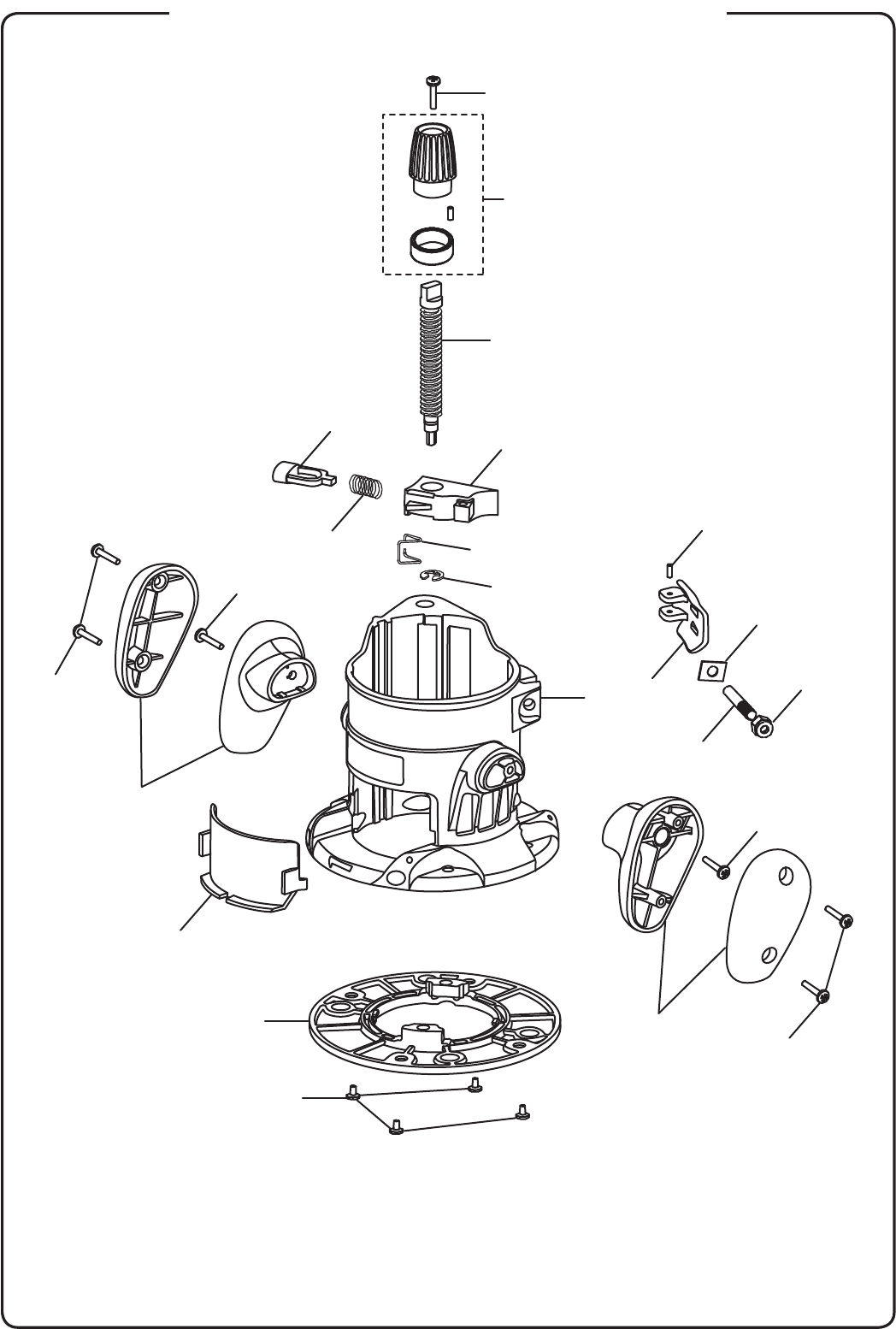
RYOBI FIXED BASE ROUTER – MODEL NUMBER R163
2
1
2
13
4
4
5
7
3
6
8
9
10
11
12
14
15
16
21
20
17
18
19
6

PARTS LIST
* Standard Hardware Item – May Be Purchased Locally
RYOBI FIXED BASE ROUTER – MODEL NUMBER R163
3
KEY PART
NO. NUMBER DESCRIPTION QTY.
The model number will be found on a plate attached to the motor housing. Always mention the model
number in all correspondence regarding your ROUTER or when ordering repair parts.
1 660136001 * Screw (10-32 x 1/4 in.) .............................................................4
2 200234010 Subbase Assembly ....................................................................1
3 514415001 Chip Shield ................................................................................1
4 660161001 * Screw (#8-10 x 5/8 in. Philips Pan Hd.) ....................................4
5 200244001 Right Handle Assembly .............................................................1
6 660062005 * Screw (#10-24 x 9/16 in. Torx Recess Pan Hd.) .......................2
7 200235001 Left Handle Assembly ...............................................................1
8 671243001 * Hex Lock Nut (1/4-20 ) ..............................................................1
9 671260001 Lever Pin....................................................................................1
10 631421001 Wear Plate .................................................................................1
11 641125001 Lock Lever .................................................................................1
12 671247001 Roll Pin ......................................................................................1
13 200557001 Router Base/Spindle Lock Actuator Kit
(Includes Key 3 on pages 4-5) ...................................................1
14 671797001 E-Ring ........................................................................................1
15 671759001 Torsion Spring ...........................................................................1
16 641123001 Height Adjustment Bar ..............................................................1
17 641124001 Height Adjust Screw ..................................................................1
18 302148001 Depth Adjust/Zero Reset Ring Assembly ..................................1
19 660440001 * Screw (M3.5 x 12 mm Flat Hd.) ................................................1
20 514418001 Quick Release Button ................................................................1
21 671758001 Compression Spring ..................................................................1
22 900987001 Bag (Not Shown) .......................................................................1
983000958 Operator’s Manual (960001217)
06-18-07
(REV:02)
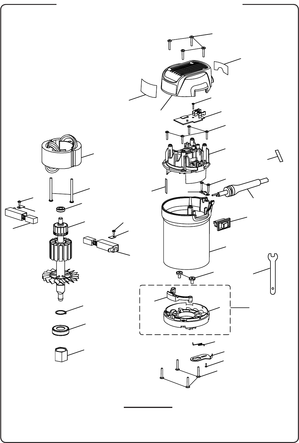
SECTION “A”
1
2
3
4
5
6
7
9
10
11
12
13
13
14
15
16
17
18
20
21
22
26
27
28
29
30
31
32
33
19
23
23 24
24
25
25
8
RYOBI FIXED BASE ROUTER – MODEL NUMBER R163
4
PARTS LIST FOR SECTION “A”
* STANDARD HARDWARE ITEM – MAY BE PURCHASED LOCALLY
RYOBI FIXED BASE ROUTER – MODEL NUMBER R163
5
The model number will be found on a plate attached to the motor housing. Always mention the model
number in all correspondence regarding your ROUTER MOTOR or when ordering repair parts.
1 660133010 * Screw (8-18 x 24 Pan Hd.) .......................................................4
2 660929001 * Screw (M3.5 x 14.5 Pan Hd.) ....................................................1
3 200557001 Router Base/Spindle Lock Actuator Kit
(Included With Key 13 On Pages 2-3) .......................................1
4 672090001 Torsion Spring ..........................................................................1
5 514543001 Bearing Frame ...........................................................................1
6 680769003 Ball Bearing (6003) ....................................................................1
7 660299021 * Screw (M5 x 13 mm Wafer Hd.) ................................................2
8 290138021 LED Work Light Assembly .........................................................1
9 514412001 Motor Housing ...........................................................................1
10 760676001 On/Off Switch ...........................................................................1
11 290086037 Power Cord Assembly ...............................................................1
12 5950101 Cord Clamp ...............................................................................1
13 6620805 * Screw (M4 x 16 mm Pan Hd.) ..................................................6
14 514413001 Top Bearing Bracket ..................................................................1
15 660103001 * Screw (M0.17 x 3/4 in. Pan Hd.) ...............................................4
16 280013103 Circuit Board Assembly .............................................................1
17 660182003 * Screw (6-19 x 5/16 in. Pan Hd.) ...............................................1
18 200452001 Upper Cap Assembly (Inc. Key Nos. 30 and 31) .......................1
19 290286001 LED Work Light & Frame (Inc. key Nos. 5 and 8) ......................1
20 690190002 Collet Nut ..................................................................................1
21 671399001 Retaining Ring ...........................................................................1
22 740894001 Armature ....................................................................................1
23 290069107 Brush Assembly ........................................................................2
24 630801001 Brush Tube Clamp .....................................................................2
25 660138001 * Screw (8-16 x 1/2 in. Pan Hd.) .................................................2
26 680966001 Ball Bearing (CW 608RS)...........................................................1
27 660928001 * Screw (M4.3 x 56) .....................................................................2
28 740895001 Field ...........................................................................................1
29 514266001 Chip ...........................................................................................1
30 940054128 Logo Label.................................................................................1
31 940077080 Data Label .................................................................................1
32 940999110 Cord Label .................................................................................1
33 671250001 Wrench ......................................................................................1
KEY PART
NO. NUMBER DESCRIPTION QTY.
NOTE: The assembly shown represents an important part of the double insulated system. To avoid
the possibility of alteration or damage to the system, service should be performed by your nearest
authorized service center.
RYOBI FIXED BASE ROUTER – MODEL NUMBER R163
6
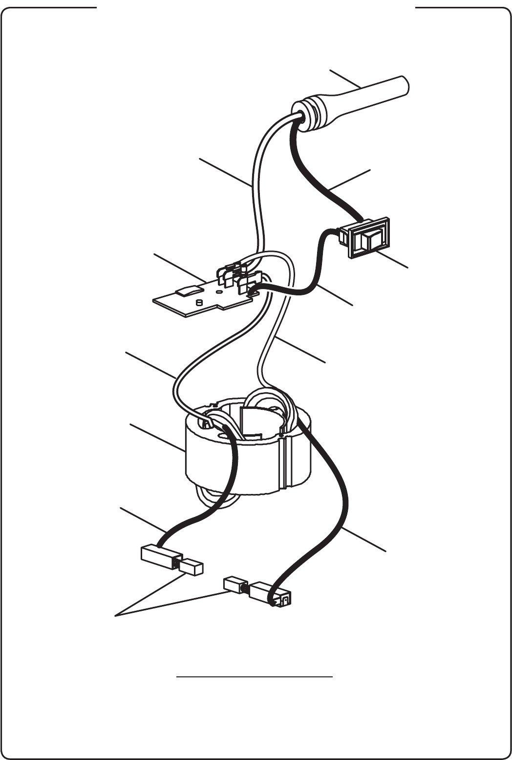
WIRING DIAGRAM
WHITE LEAD BLACK LEAD
BLACK LEAD
MOTOR
BROWN LEAD
BROWN LEAD
BRUSH ASSEMBLY
WHITE LEAD
SWITCH
PCB ASSEMBLY
POWER CORD
RED LEAD
