S P E s r l GC324809 Linear amplifier for radio amateur use User Manual MANUAL
S.P.E. s.r.l. Linear amplifier for radio amateur use MANUAL
MANUAL

Via di Monte Verde 33 – 00152 Rome – Italy. Tel. (39-6) 58209429 Fax (39-6) 58209647
Website www.linear-amplifier.com e_mail info@linear-amplifier.com
Exhbit 6 - Pag. 1 of 1
Exhibit 6: User’s Manual
External Radio Frequency
Linear Amplifier
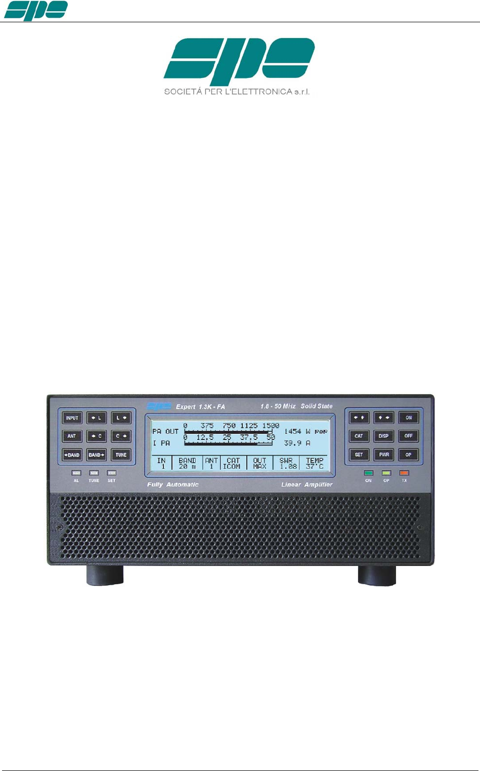
Model Expert 1.3K-FA
User manual EXPERT 1.3K-FA
EXPERT 1.3K-FA
1.3KW SOLID STATE FULLY AUTOMATIC
LINEAR AMPLIFIER
USER’S MANUAL
Rev. 1.0
Exhbit 6 – Pag. 2 of 2

User manual EXPERT 1.3K-FA
Index
IMPORTANT ......................................................................................................................................................5
PRECAUTIONS..................................................................................................................................................5
UNPACKING ......................................................................................................................................................8
1. PANEL DESCRIPTION ...........................................................................................................................9
1.1 Front Panel .......................................................................................................................................9
1.2 Rear Panel......................................................................................................................................10
2. GENERAL INFORMATION ...................................................................................................................11
2.1 Power supply ..................................................................................................................................11
2.2 Input / Output..................................................................................................................................11
2.3 ALC / RELAY / CAT........................................................................................................................11
3. INTERCONNECTION WITH THE TRANSCEIVER ..............................................................................13
4. USE OF THE LINEAR AMPLIFIER.......................................................................................................14
4.1 SO2R (Single Operator Two Radio ).............................................................................................15
4.2 BAND-PASS FILTERS SET “SPE BPF1” ......................................................................................16
4.3 QSK (FULL BREAK-IN) OPERATION ...........................................................................................17
4.4 TUNABLE ANTENNA CONTROL ................................................................................................18
4.5 SETTING UP A SINGLE ANTENNA FOR RECEPTION ...............................................................20
4.6 TWO POSSIBLE SETS OF ANTENNAS .......................................................................................20
4.7 WITH OR WITHOUT ATU ..............................................................................................................20
5. EXTERNAL GROUND CONNECTION ................................................................................................21
6. ANTENNA ............................................................................................................................................22
7. POWER SUPPLY (PSU)...................................................................................................................23
8. TUNER (ATU) – WHERE FITTED ....................................................................................................24
9. PROTECTIONS / ALARMS..................................................................................................................26
10. PROGRAMMING..................................................................................................................................27
10.1 Ways to operate .............................................................................................................................27
11. INITIAL OPERATION OF THE AMPLIFIER.........................................................................................30
11.1 Initial Programming.........................................................................................................................30
11.2 Operating.......................................................................................................................................31
12. CONNECTIONS ...................................................................................................................................33
12.1 CAT Connector..............................................................................................................................33
12.2 ICOM .............................................................................................................................................34
CAT CI–V Interface ........................................................................................................................34
12.3 KENWOOD ...................................................................................................................................35
CAT RS232 Interface .....................................................................................................................35
CAT 5V TTL Interface.....................................................................................................................35
12.4 YAESU ..........................................................................................................................................36
CAT RS232 Interface .....................................................................................................................36
CAT 5V TTL Interface.....................................................................................................................36
BAND DATA Interface ....................................................................................................................37
12.5 TEN – TEC, FLEX-RADIO, ELECRAFT .....................................................................................37
CAT RS232 Interface .....................................................................................................................37
ALC with FLEX-RADIO.................................................................................................................38
12.6 TRANSCEIVERS OF OTHER BRANDS......................................................................................39
13. OTHER CONNECTIONS .....................................................................................................................40
13.1 ALC, RELAY CONNECTIONS .....................................................................................................40
13.2 REMOTE ON LINK.........................................................................................................................40
13.3 CONNECTIONS / TX-INH, TX-INH............................................................................................41
13.4 AUX Connector...............................................................................................................................43
13.5 PORT Connector ............................................................................................................................44
SteppIR cable: ................................................................................................................................44
Ultrabeam cable: ............................................................................................................................45
Serial connection to a standard PC RS-232 port for remoting use ................................................45
14. TRANSCEIVER CONTROLLED WITH A PC ......................................................................................46
14.1 ICOM CI-V INTERFACE ..............................................................................................................46
14.2 RS232 INTERFACE ......................................................................................................................47
14.3 5V TTL KENWOOD INTERFACE .................................................................................................47
14.4 5V TTL YAESU INTERFACE........................................................................................................48
15. USE OF THE USB / RS232 PORTS ....................................................................................................48
Exhbit 6 – Pag. 3 of 3

User manual EXPERT 1.3K-FA
15.1 REMOTE CONTROL .................................................................................................................. 49
15.2 DOWNLOAD. ............................................................................................................................... 49
16. MAINTENANCE................................................................................................................................... 50
17. CHARACTERISTICS / SPECIFICATIONS ......................................................................................... 51
18. DIAGNOSTICS. ................................................................................................................................... 53
19. TABLE ................................................................................................................................................. 54
20. APPENDIX 1 - REMOTE CONTROL .................................................................................................. 55
20.1 SW (Software) installation. ........................................................................................................... 55
20.2 KTerm_USB.exe usage................................................................................................................ 60
20.3 KTerm_232.exe usage ................................................................................................................. 70
Remote ON/OFF using RS-232..................................................................................................... 75
20.4 Firmware update........................................................................................................................... 77
21. GENERAL RESTORE ......................................................................................................................... 81
22. WARRANTY TERMS ......................................................................................................................... 82
REPAIR FORM................................................................................................................................................ 84
Exhbit 6 – Pag. 4 of 4
User manual EXPERT 1.3K-FA
Congratulations for choosing the SPE EXPERT 1.3K-FA solid state linear
amplifier.
It is small, powerful, covers all the amateurs bands from 1.8 to 54 MHz including
WARCs and where permitted is able to work on 60 m. and 70 MHz, completely
automatically and remotable.
Being only 7.5 Kg. (16.5 Ibs), it is perfect for use in the shack and is superior to
none for DXpeditions.
All operating conditions (frequency, antenna, tuner etc.) are controlled from your
transceiver.
The operator has to only move the frequency-tuning knob on the transceiver.
It is possible to connect it to every transceiver available on the market, it is
extremely user-friendly and offers a product which is the best in its class.
IMPORTANT
Read this instruction manual carefully before attempting to operate the linear
amplifier.
The warranty will be invalidated in the case of non-observance of these
instructions.
Keep this manual available as it contains important safety and operating
instructions for your SPE EXPERT 1.3K-FA.
The manual may be subject to changes and updates therefore please always refer
to the updated version available on the website www.linear-amplifier.com.
The English language version is the official one.
PRECAUTIONS
Explicit definitions
WORD DEFINITION
WARNING! Risk of danger of fire or electric shock to people.
Possible damage to the amplifier.
NOTE: Serious problems if not observed. Danger of fire or electric shock for the operator,
or damage to the equipment.
WARNING!
HIGH VOLTAGE! DO NOT disconnect an antenna from the amplifier during
transmission; electric shock or fire is possible.
WARNING!
DO NOT modify the internal wiring of the amplifier. Any modifications will invalidate the
warranty, and may reduce the performance of the linear amplifier or damage it.
Exhbit 6 – Pag. 5 of 5
User manual EXPERT 1.3K-FA
WARNING!
Before using the linear amplifier, compare the value of voltage of the local mains supply
network with the value required by the amplifier.
WARNING!
DO NOT turn ON the linear amplifier unless it has been properly grounded through the
GND conductor of the mains cord.
Do not disconnect this under any circumstances, or there is a risk of severe or fatal
electric shock.
WARNING!
DO NOT use an extension cord with the AC power cable, as if it is not correctly rated
there is a risk of fire or electric shock.
WARNING!
DO NOT allow metallic objects or wires to enter inside the amplifier.
WARNING!
DO NOT obstruct the openings for cooling air at both the sides of the amplifier.
Ensure that no object impedes the correct operation of the fans.
WARNING!
DO NOT expose the linear amplifier to rain, snow or any liquids.
WARNING!
DO NOT install the linear amplifier in a place without good ventilation. This could limit
heat dissipation and the amplifier could be damaged.
WARNING!
DO NOT touch the amplifier with damp or wet hands. There is danger of electric shock.
Avoid opening it before you have disconnected it from the mains supply, then wait at
least 2 minutes for electrolytic capacitors to complete their discharge.
To clean the amplifier DO NOT use chemical agents like alcohol or benzene because
the plastic surfaces could be damaged.
AVOID using the amplifier in areas with temperatures below –10° C (+14°F) or above
+40°C (+104°F).
AVOID using the linear amplifier in locations that are very dusty, damp, high humidity or
in direct sunlight.
AVOID placing the linear amplifier against walls where the circulation of the air would be
obstructed and the noise of the fans would be reflected toward the operator.
Exhbit 6 – Pag. 6 of 6

User manual EXPERT 1.3K-FA
AVOID permitting children to play with the amplifier.
If you do not use the linear amplifier for long time, set the back main switch [I/O] to the
OFF position [O].
Information for Users on Collection and Disposal of Old Equipment and used
Batteries.
These symbols on the products, packaging, and/or accompanying
documents mean that used electrical and electronic products and batteries
should not be mixed with general household waste.
For proper treatment, recovery and recycling of old products and used
batteries, please take them to applicable collection points, in accordance
with your national legislation.
This amplifier should only be operated by persons who have an appropriate radio
transmitting license.
You should observe your license conditions while using it in accordance with
national legislation (power, band, transmission mode etc.).
Exhbit 6 – Pag. 7 of 7

User manual EXPERT 1.3K-FA
UNPACKING
Remove the packing and carefully check the contents.
If you find any damage or if there are any parts missing, contact your distributor/dealer
immediately.
Keeping the shipping cartons for future transportation is recommended.
Accessories included in the carton
a) Transport carry bag.
b) Two cables with RCA (phono) connectors for ALC, RELAY links.
c) One USB standard cable.
d) Three connectors DB-15, 1 connector DB-9.
e) CD-ROM containing the user manual and the software for remoting.
f) One 20 A spare fuse.
g) Spare air filter.
h) Certificate of compliance and warranty form.
.
b
c
d
g
e
f
h
a
Exhbit 6 – Pag. 8 of 8
User manual EXPERT 1.3K-FA
1. PANEL DESCRIPTION
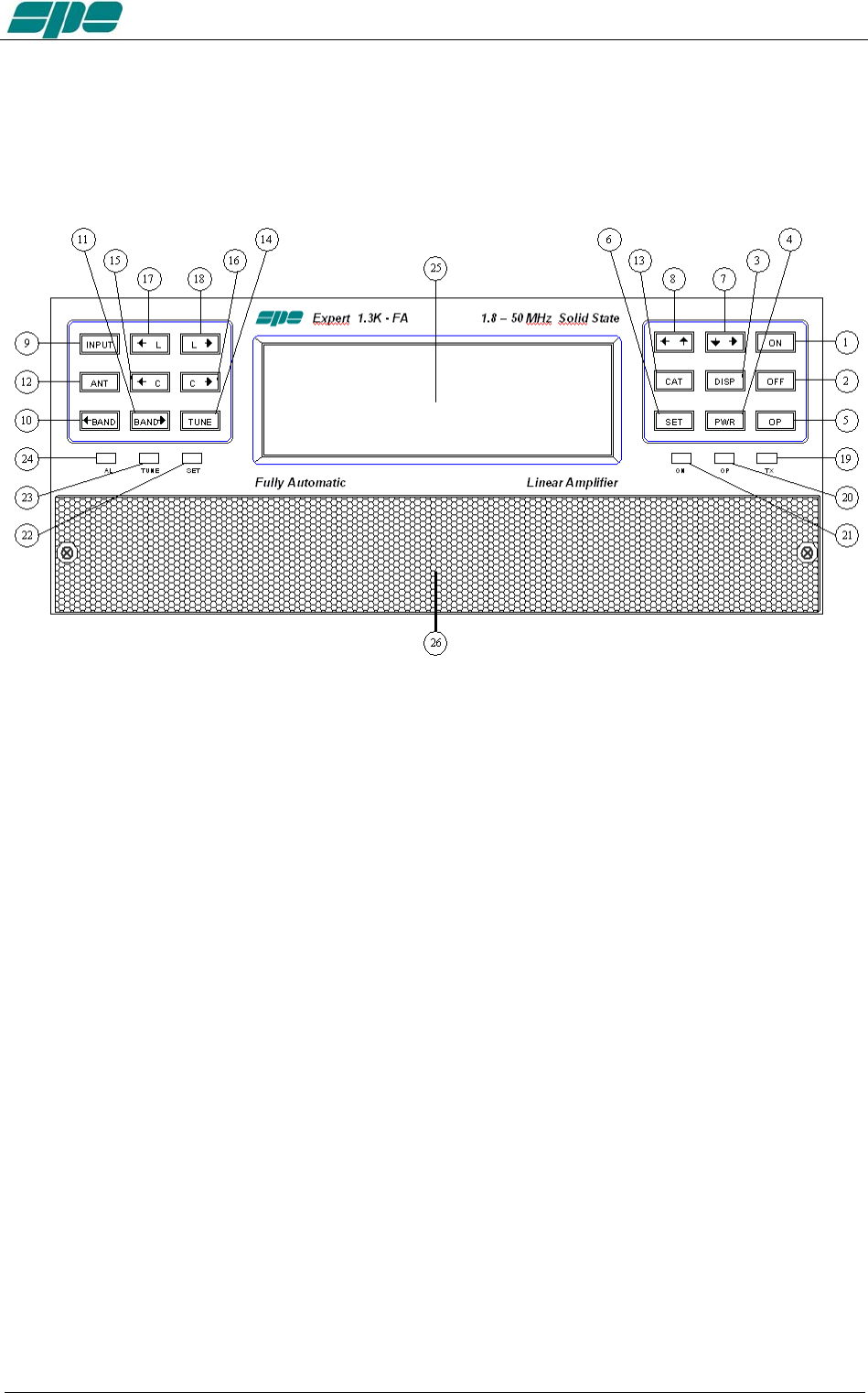
1.1 Front Panel
1) ON
2) OFF
3) DISPLAY toggles between display pages.
4) POWER switches output power from “MAX / MID / LOW“.
5) OP toggles back and forth between Standby/Operate modes.
6) SET used to program the amplifier.
7) ▼► used to program the amplifier.
8) ◄▲ used to program the amplifier.
9) INPUT selects one of the two inputs of the amplifier.
10) ◄BAND switches bands manually (downward in frequency).
11) BAND► switches bands manually (upward in frequency).
12) ANT switches the antennas for every single band
13) CAT shows the current CAT interface setting.
14) TUNE: starts the automatic tuning process.
15) ◄C used for manual tuning.
16) C► used for manual tuning.
17) ◄L used for manual tuning.
18) L► used for manual tuning.
19) TX red LED, illuminates during transmission.
20) OP yellow LED, illuminates when the amplifier is in “Operate” state.
21) ON green LED, illuminates when the amplifier is “ON”.
22) SET green LED, illuminates during programming.
23) TUNE yellow LED, illuminates during tuning.
24) AL red LED, illuminates when there is an alarm.
25) LCD DISPLAY
26) AIR-FILTER GRID
Exhbit 6 – Pag. 9 of 9
User manual EXPERT 1.3K-FA
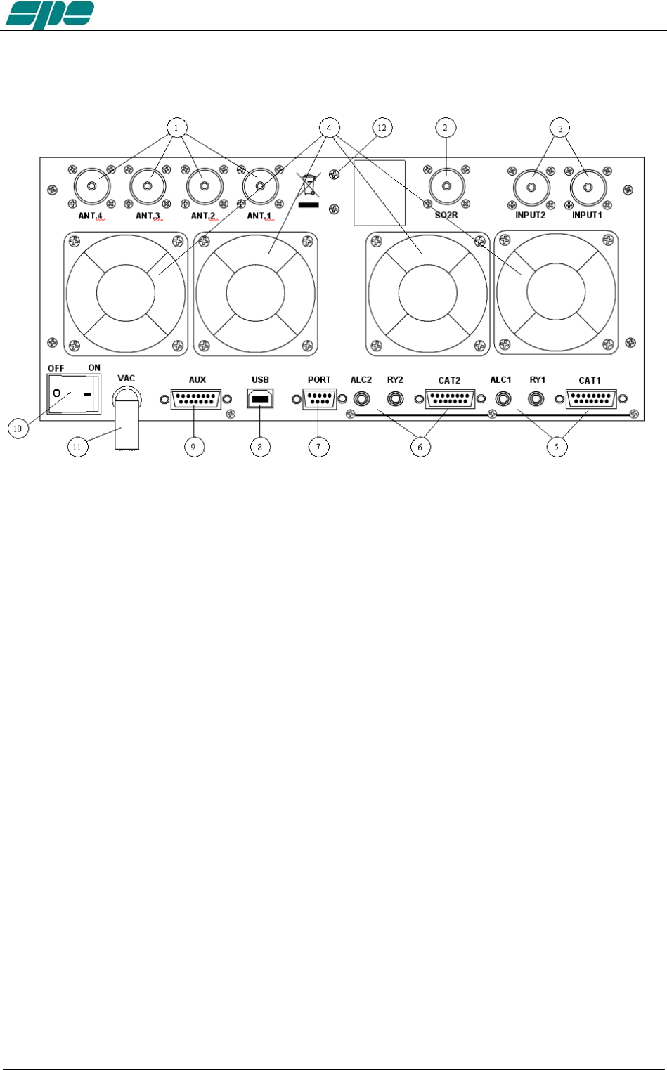
1.2 Rear Panel
1) ANT connectors for four available antennas.
2) SO2R connector for SO2R operations
3) INPUT connectors to connect two exciters.
4) FANS
5) IN 1 ALC, RELAY, CAT connectors for exciter 1.
6) IN 2 ALC, RELAY, CAT connectors for exciter 2.
7) “PORT ”socket.
8) “USB” socket.
9) “AUX” socket.
10) ON main switch.
11) AC mains power cable.
12) GND ground connection.
Exhbit 6 – Pag. 10 of 10

User manual EXPERT 1.3K-FA
2. GENERAL INFORMATION
(Read the specific chapters for more details).
2.1 Power supply
The amplifier uses a switching power supply which will adapt to any voltage that is
between 100 and 255 Vac.
The main switch [I/O] is located on the rear panel.
In the [O] position all the internal circuitry is powered off, in the [I] position (red led ON)
some internal voltages are now present allowing for you to turn ON or turn OFF the
linear amplifier in one of the following ways:
a) Using the [ON]/[ OFF] keys on the front panel.
b) Applying / removing 9 -15 VDC on pin (8) of the CAT connector (see note
below).
c) Using the USB port and the management software. It is possible to download
this software from the website www.linear-amplifier.com .
Note: when turned ON, almost all transceivers output 13.8 VDC. With this voltage, the linear
amplifier can be turned automatically ON / OFF at the same time as the transceiver.
Note: The fuse is located inside the amplifier (remove the lower cover).
2.2 Input / Output
The linear amplifier has two inputs (INPUT 1, INPUT 2) to which you can connect two
transceivers of any brand or type.
These inputs are selected with the [INPUT] key or automatically with the PTT of each
transceiver.
It can manage up to four antennas (ANT 1, ANT 2, ANT 3, ANT 4).
The amplifier selects the antennas automatically.
The SO2R functionality is implemented by its dedicated connector.
2.3 ALC / RELAY / CAT
There are two transceiver inputs (IN 1, IN 2), allowing two distinct transceivers to be
connected at the same time.
ALC is a negative voltage generated by the amplifier. It is used to c ontrol the
output power of the transceiver (max. in STANDBY”, the required power in
“OPERATE”).
In this way the power from the exciter may be automatically regulated.
If the ALC port is not connected, it is necessary to manually adjust the drive
from the transceiver.
This link is highly recommended.
RELAY This essential link allows the amplifier to be put in the transmit state.
To do that, it is necessary that the inner pin of the phono connector is
connected to the signal ground. This is normally done by the transceiver with
either a “close-to-ground” relay, or an open-collector transistor.
On the transceiver-side this link is often called SEND or TX GND. Refer to
your transceiver manual for more details.
Exhbit 6 – Pag. 11 of 11

User manual EXPERT 1.3K-FA
CAT This link is highly recommended.
Thanks to this link the linear amplifier will detect, while in receive
mode, the operating frequency of the transceiver and then
automatically controls changes of band, antenna and automatic
antenna tuner. All modern transceivers have CAT control. In older models,
often the analog or digital information is sent for changing bands. The SPE
Expert 1.3K-FA, thanks to an efficient frequency counter, constantly controls
and verifies data coming from the transceiver. Automatic management of
bands, antennas and tuner can be done in the following ways:
a) In all recent transceivers through the CAT connection
(HIGHLY RECOMMENDED).
b) In the YAESU models that are not listed, or without CAT, through
the “BAND DATA” interface.
c) Configurations a) and b) are recommended. In older radios which
do not have CAT or BAND DATA, through the internal frequency
counter.
Note: In case c) the CAT link with the transceiver is not needed because the
frequency is detected from the transmitted signal.
FOR THIS REASON, BECAUSE OF THE HIGH POWER IN USE, IN
ORDER TO NOT DAMAGE THE LINEAR, WE STRONGLY
RECOMMEND YOU TO CHANGE BANDS WITH THE LINEAR BEING
SWITCHED TO THE STANDBY MODE.
USE THE CONDITION c) ONLY IF CONDITIONS a) OR b) ARE
IMPRATICABLE.
Note: In some transceivers the “RELAY” and “CAT” signals are activated by
menu selection: refer in this case to their user’s manuals..
Exhbit 6 – Pag. 12 of 12
User manual EXPERT 1.3K-FA
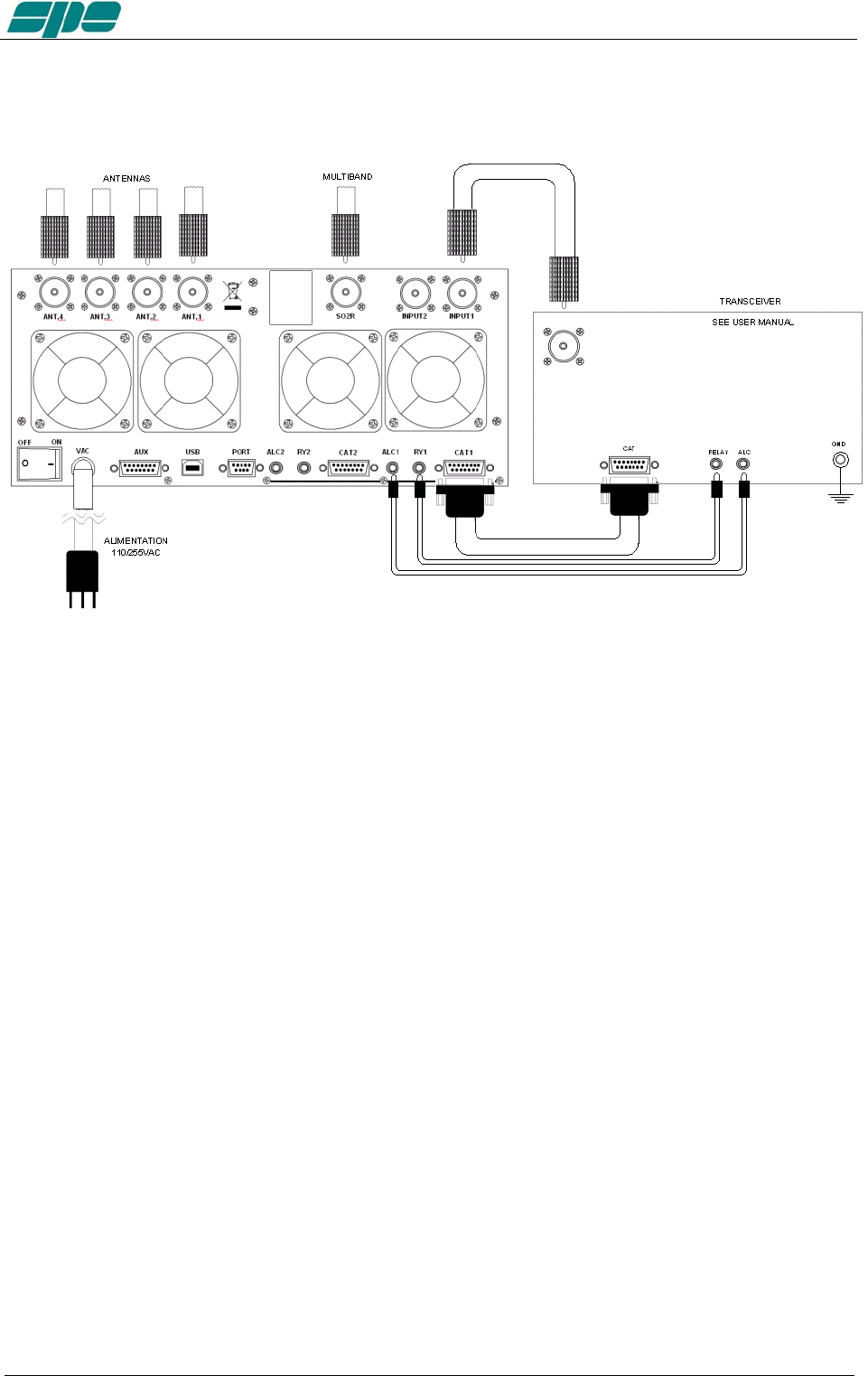
3. INTERCONNECTION WITH THE TRANSCEIVER
The diagram shows the connections with one transceiver only. To connect the second
transceiver, repeat the same connections using the port “IN 2“.
For the ALC and RELAY connections, use the shielded cable (supplied) with phono
RCA connectors.
For the CAT connection, this cable needs to be made by the owner, or purchased, for
the many different transceivers available to be connected.
This cable may also be made to include ALC, RELAY ON / OFF (read the “CAT
CONNECTIONS“ chapter of this manual).
For all other information about connecting a transceiver, please refer to the transceiver’s
manual.
Note: You should not use the separate RELAY and ALC phono connections if they have been
implemented through the DB15 “CAT” connectors.
Exhbit 6 – Pag. 13 of 13
User manual EXPERT 1.3K-FA
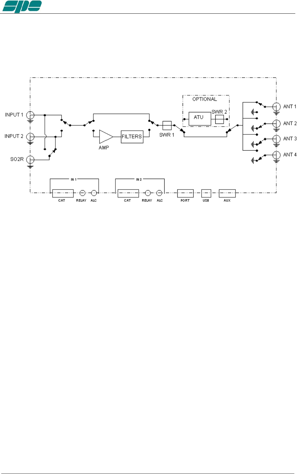
4. USE OF THE LINEAR AMPLIFIER
Block diagram.
The position of the contacts, as shown in the diagram, is the situation of the linear
amplifier in the OFF state.
The linear amplifier can be used in the following way:
1) OFF Only two direct connections are actuated:
between INPUT 1 and ANT 1
between INPUT 2 and SO2R
2) STANDBY All the functions are activated (band change, antenna change, tuner
control) and the transmission is from the transceiver only.
3) OPERATE All the functions are activated and the transmission is using the
linear amplifier.
Note: Regulation of the exciter’s power is automatically achieved through the ALC link.
With the ALC connected, the amplifier input power in OPERATE mode is automatically
adjusted to the correct driving level for the amplifier. In STANDBY, the exciter will pass
the output power as set by its POWER OUTPUT control.
Without the ALC connection, you have to manually adjust the exciter power to correctly
drive the amplifier in order to avoid damaging the amplifier.
Exhbit 6 – Pag. 14 of 14
User manual EXPERT 1.3K-FA
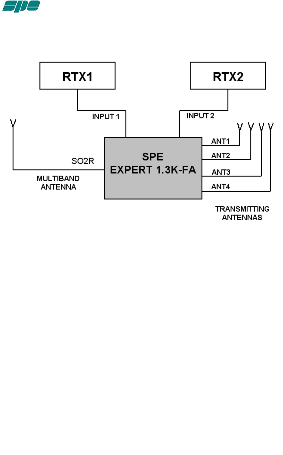
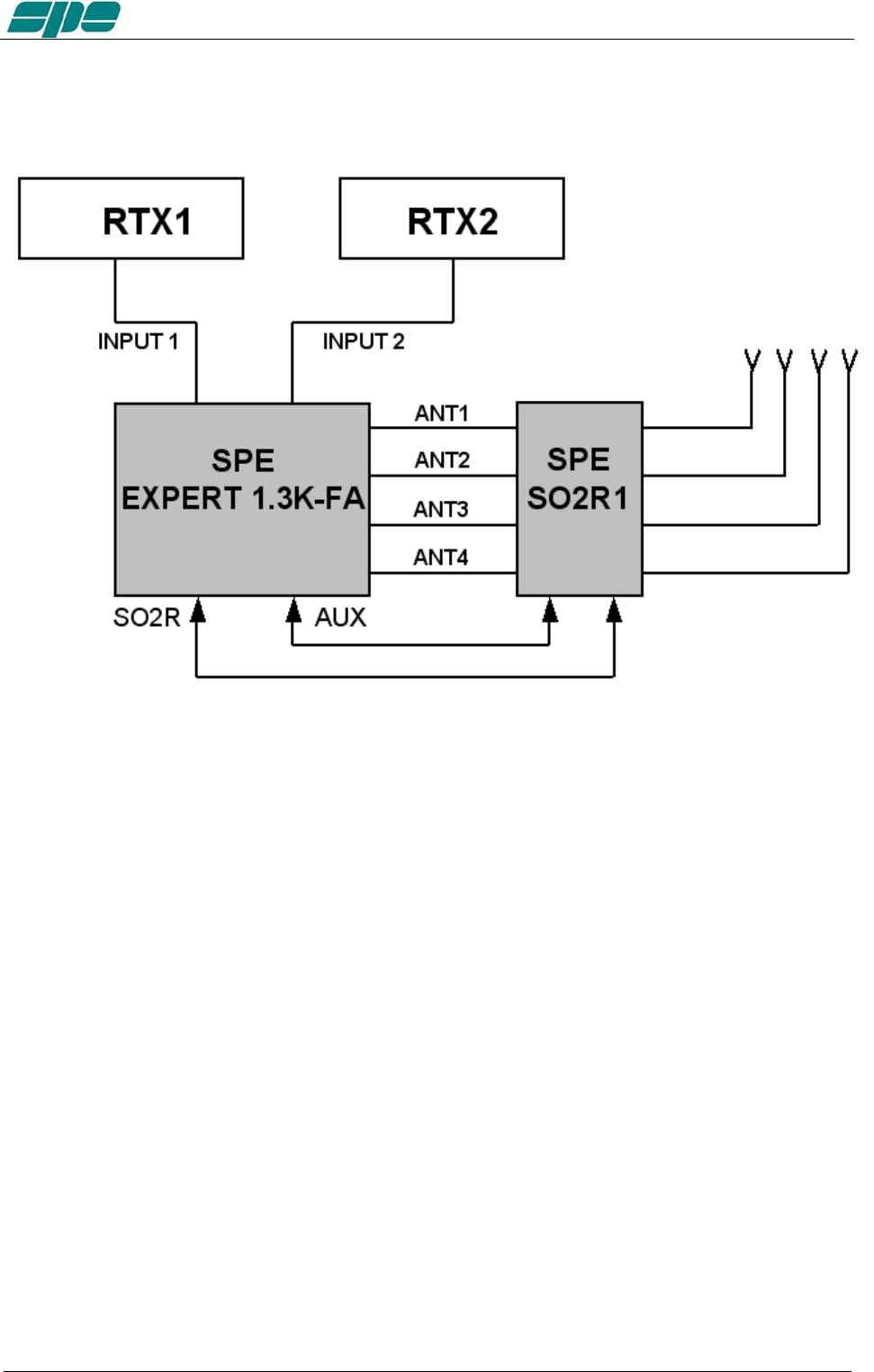
4.1 SO2R (Single Operator Two Radio )
This kind of operation is used during a contest in order to acquire, as quickly as possible
for example, a new multiplier.
The following connections are needed (see the diagram):
1. INPUT 1 connected to the first transceiver (RTX1).
2. INPUT 2 connected to the second transceiver (RTX2).
3. ANT 1/2/3/4 connected to the available antennas set.
4. SO2R connected to a multi-band antenna.
The operating mode could be the following:
If you are operating using RTX1 on a given band (e.g 20m), the correct antenna (ANT
1/2/3/4) is automatically selected for transmitting, while RTX2 is connected to the multi-
band antenna, in the RX mode, on another band (e.g. 40m).
If, when operating on 20 m, a multiplier of interest is heard on RTX2, the only action
needed is to push the PTT2 in order to connect RTX2 to the 40 m main antenna, at the
same time RTX1 gets switched to the multiband antenna in order to receive the 20 m
band.
In place of the multiband antenna one of the antennas ANT 1/2/3/4 can be used, in
such a case all of them must be monoband to avoid the risk of using the same antenna
for RTX1 and RTX2..
A careful design is needed to avoid such a harmful situation which could be devastating
for the receivers.
Exhbit 6 – Pag. 15 of 15
User manual EXPERT 1.3K-FA
This possibility is available with the optional external unit "SPE SO2R1" according to the
following diagram.
The SPE SO2R1 unit is controlled and powered from the AUX port of the 1.3K.
Note: the isolation between the transmitting antenna and the receiving antenna must be very
high and, therefore, very well planned. Locating the antennas at some distance from
each other, and using appropriate band-pass filters will help to achieve this.
In this case, SPE is not responsible for any damage caused to equipment.
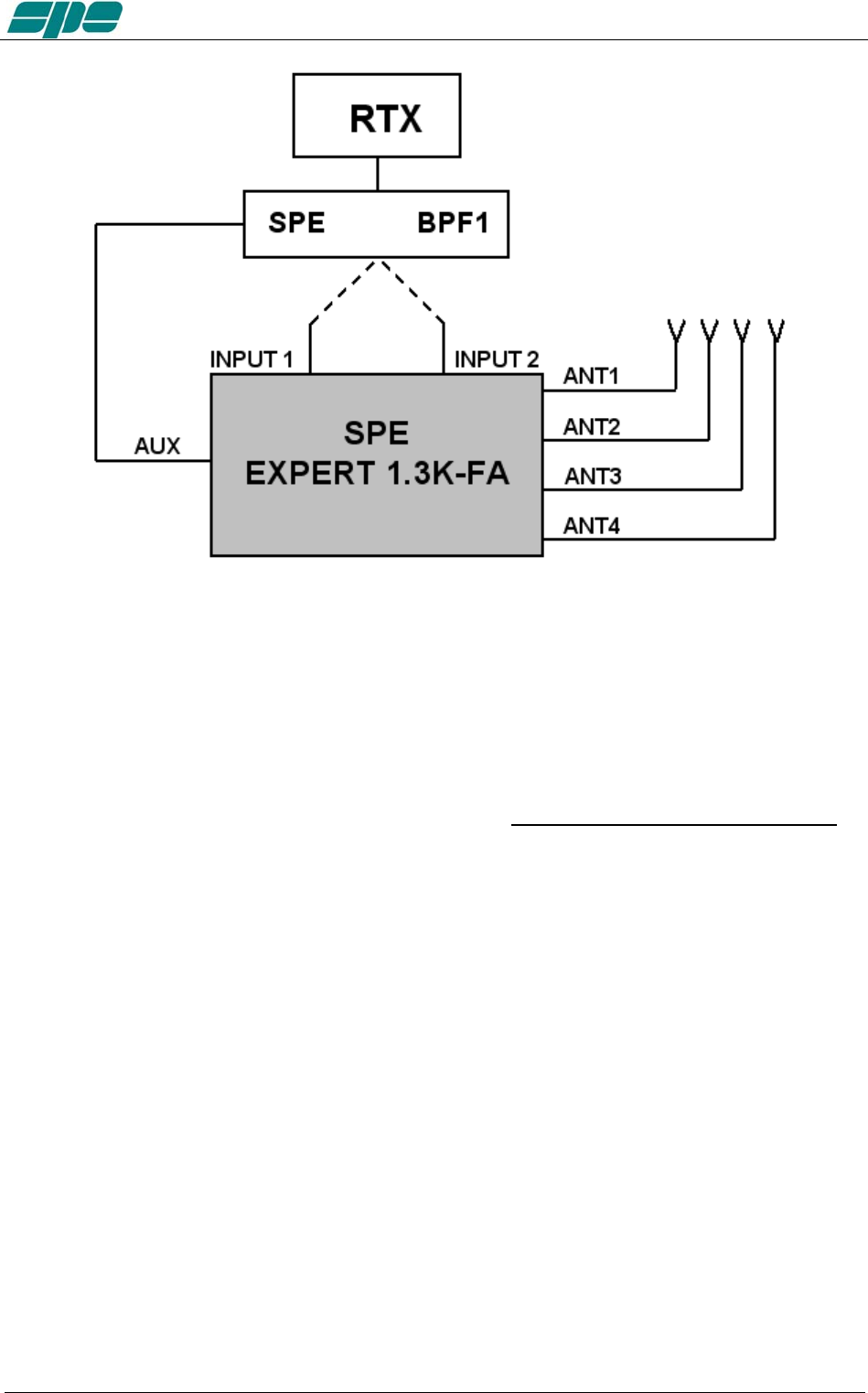
4.2 BAND-PASS FILTERS SET “SPE BPF1”
To increase the isolation between the transmitting and the receiving antenna, SPE
offers the optional unit "SPE BPF1" which must be placed between RTX1 and INPUT1
or RTX2 and INPUT 2 of the linear.
The unit is controlled and powered from the AUX port.
(Contact factory or your distributor for availability).
The unit automatically enables the following features:
a) DXpedition, Contest Multi / Multi.
In this case the amplifier is connected to a single transceiver (INPUT 1 or INPUT 2).
"SPE BPF1 automatically selects the filter on the band to be used in the input where the
transceiver is connected, while the other unrelated input is left unused.
Exhbit 6 – Pag. 16 of 16
User manual EXPERT 1.3K-FA
2) Contest SO2R.
In this case the amplifier is connected to two transceivers and two "SPE BPF1" in order
to automatically select the right filters in the output of both the transceivers.
These features can be possible, as well, with the simultaneous use of the unit "SPE
SO2R1, (use the AUX port with a Y cable).
To ensure the perfect functionality of these options, the use of the CATs is mandatory.
4.3 QSK (FULL BREAK-IN) OPERATION
The Expert 1.3K-FA also allows QSK (FULL BREAK-IN) operation. Thanks to the
perfect control carried out on RX / TX switching relays, any possibility of "hot
switching" is avoided.
This feature is compatible with all modern transceivers, in fact the minimum delay
required before a transmission is usually less than 6 msec (check the manual of the
transceiver).
In the case (very remote) of minor delay needed, you can use the link TX - INH (see
"CAT" paragraph).
Special very reliable “noiseless” gold plated relays are used so that the “vacuum relays”
option is no longer needed.
Exhbit 6 – Pag. 17 of 17
User manual EXPERT 1.3K-FA
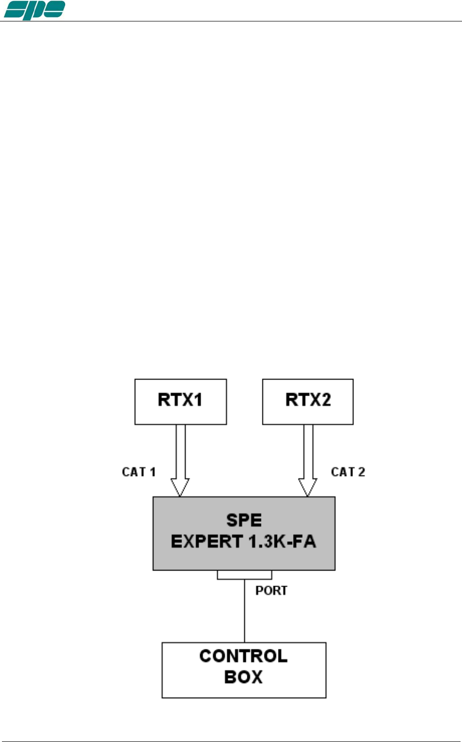
4.4 TUNABLE ANTENNA CONTROL
The use of tunable antennas (SteppIR, Ultrabeam) is becoming popular. These
antennas vary the physical dimensions of the elements according to the operating
frequency in order to ensure a perfect resonance.
The Expert 1.3K-FA, through the dedicated "PORT" socket linked to the antenna
controller, allows automatic control by tracking the tuning knob changes.
This dedicated link makes the following advantages possible:
- Simplification of wiring, such as the complication of adding additional wiring to the CAT
connector is not necessary now.
- Compatibility with all types of CAT: The Expert 1.3K-FA converts the CAT protocol, so
two different transceivers (CATs) can be used simultaneously with the same controller.
- Thanks to the frequency counter inside the linear, the antenna can be controlled also
without the use of CAT.
All of the automatic features of the linear are ensured even in the most complex
configurations. Such as, antennas of all kinds can be connected to the connectors
"ANT" and the Expert 1.3K-FA will choose the antennas according to the set-up and will
manage them according to their characteristics.
The CAT is recommended, however if the transceiver does not have the CAT or if it has
only the "Band Data", the Expert 1.3K-FA will continue to drive the antenna with the
frequency measured by the counter (data collected after the first transmission) .
The simplest possible configuration is a single tunable antenna according to the
following diagram :
Exhbit 6 – Pag. 18 of 18
User manual EXPERT 1.3K-FA
The link is configurable for any position (ANT 1,2,3,4) you want use.
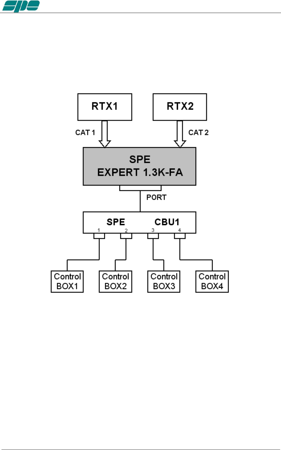
If you have several tunable antennas (up to 4) with their controllers, the optional unit
"SPE CBU1" is needed according to the following diagram:
In this case you need to connect the unit control box outputs 1,2,3,4 respectively with
ANT 1,2,3,4 antenna sockets.
For the selection of antennas, refer to the “TUN ANT” item on the main menu.
The communication protocol used to and from the control box is "Kenwood", the
communication speed is “owner settable.”
Exhbit 6 – Pag. 19 of 19

User manual EXPERT 1.3K-FA
4.5 SETTING UP A SINGLE ANTENNA FOR RECEPTION
In some cases it may be necessary to transmit with an antenna and receive with a more
appropriate one.
A unique feature allows the Expert 1.3K-FA to set a receiving antenna and to control its
automatic switching after a transmission starts.
For the selection of this antenna refer to the menu item "RX ANT".
The antenna number selected will appear followed by an "r" symbol (e.g, 3r).
With the linear turned OFF the INPUT1 is directly connected to ANT1. The selection of
ANT1 as “RX ANT” is not permitted in order to avoid possible damage to the transceiver
or to the receiving antenna if a receiving antenna (e.g. Beverage) is connected.
4.6 TWO POSSIBLE SETS OF ANTENNAS
If one has two different QTH’s, then they would certainly have two different antenna
sets.
In such a case it would be useful to automatically recall data from one set to the other
with no need to redo the configuration and the subsequent ATU matching every time.
The amplifier is equipped with two different memory banks, "Bank A" and "Bank B",
which one can use to store the two different configurations.
This feature is particularly useful if you participate in a DXpedition.
If one of the memory banks is set as your home station, when you will come back, just
recall the proper memory bank.
4.7 WITH OR WITHOUT ATU
As the standard configuration, the amplifier comes with the ATU, so as to have the
maximum flexibility of use,
In some cases (perfect antenna system or use of tunable antennas), the ATU may not
be necessary. In order to reduce the initial price one can buy the Expert 1.3K-FA
without the ATU (option).
If necessary, one can install the ATU later
Exhbit 6 – Pag. 20 of 20
User manual EXPERT 1.3K-FA
5. EXTERNAL GROUND CONNECTION
WARNING! Before connecting an external ground as described below, check with
a qualified electrician that your national wiring codes permit such a connection.
To reduce TVI, BCI and other RF problems it is best to connect the amplifier to a good
RF ground. (note that the RF ground is different to the electrical ground necessary for
the prevention of electrical shock.)
The inductance of such a connection needs to be low, so the connection to ground
should be as short and direct as possible. Large-section copper conductors should be
used for this purpose. Terminating the earth connection with a small metal plate is
suggested.
The best solution is to have several ground stakes, driven into the ground and these
ground stakes need also to be tied to your main grounds.
Often good results can be achieved using correct earthing clamps, connected to the
main water supply pipe (attention, most water pipes are now in plastic).
DO NOT use central heating pipe work.
AVOID the electric circuit ground of the building (to be used for 50/60 Hz safety only).
WARNING! DO NOT connect to gas pipes because there is danger of
explosion !!
Exhbit 6 – Pag. 21 of 21

User manual EXPERT 1.3K-FA
6. ANTENNA
Because this is a high-power amplifier, it is necessary to use properly rated antennas,
connectors and feed line cables.
Take special care with antennas using baluns and traps, because balun and/or trap
warming can occur during periods of high-power transmission and a high SWR most
likely will result.
This dangerous situation is often not perceived by the operator because normally a
measure of SWR is made when balun and antenna are not under stress or have cooled
down. Ensure that your baluns or antenna traps are appropriately rated !
A unique feature of this linear is that, it not only measures the SWR after the band pass
filter matching, but also the SWR of the system antenna and cable. This allows you to
always evaluate your antenna system despite the matching and the power applied.
Without the ATU (option), always use antennas having SWR of 1.5:1 or less.
With the ATU, the amplifier is able to overcome some mismatches of 3:1 SWR or more.
Be aware that, with the tuner, the PA is matched but with a high VSWR the cable is
mismatched and there can be consequent loss of power, heating and high voltages
present.
Always operate with the best possible matching because, despite the amplifier’s
protection against high SWR, continuous use into a mismatched load (a bit lower than
the protection threshold) may lead to damage.
It is suggested that suitable static protection be given to antenna feeder cables.
The software allows you to select up to two antennas for the same band.
Note (for amplifiers without ATU): For a mismatch from 1.7:1 to 2:1 there is an alarm, above
2:1 the amplifier is automatically switched to STANDBY.
Exhbit 6 – Pag. 22 of 22
User manual EXPERT 1.3K-FA
7. POWER SUPPLY (PSU)
The power supply of the SPE Expert 1.3K-FA, unique in its category, is switching with a
PFC (Power Factor Correction) that allows a drastic reduction of the harmonic
components in the mains in accordance with IEC555-2, that consists of two sources.
The first powers all the electronic circuits, the PA excluded.
The second powers only the PA. Its output voltages are 48 VDC (MAX Pout), 38 VDC
(MID Pout), and 32 VDC (LOW Pout).
This design was adopted as it provides maximum efficiency and therefore less heat to
dissipate.
The power supply meets the following applicable standards: UL60950-1, TUV
EN60950-1, EN55022, EN61000-3-2,-3, EN61000-4-2,3,4,5,6,8,11; ENV50204,
EN5502.
Since the amplifier is sold all over the world, the power cord does not come with any
mains plug. Some SPE distributors will fit the plug appropriate to your domestic supply
network prior to purchase. Should it be necessary to rewire the plug due to relocation in
a different country, please ask for advice from a qualified electrician.
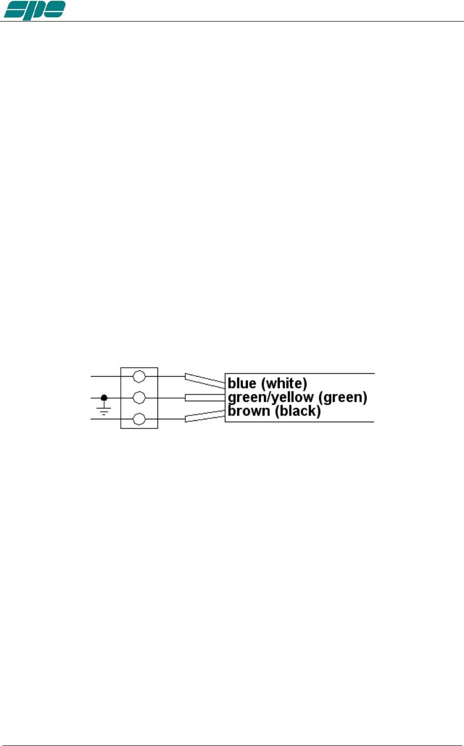
To fit the plug (20 A minimum rating below 120V AC, 10A minimum rating above 120V
AC) proceed according with the following fig.
You should observe all precautions in accordance with national legislation.
The amplifier is supplied to a power supply that automatically adapts between 100 and
255 VAC, 47-63 Hz.
In some particular mains at 100/120 VAC in MAX the power output can be reduced.
In the case of a "FATAL" alarm, the power supply is locked. To restore the linear, switch
to OFF for about 30 seconds, via the rear switch, then back ON.
Exhbit 6 – Pag. 23 of 23

User manual EXPERT 1.3K-FA
8. TUNER (ATU) – WHERE FITTED
The amplifier has an automatic tuner that handles load mismatches up to 3:1 VSWR
(2.5:1 for 6 m).
The amplifier contains a look-up table with all the permitted bands.
For tuner management, antenna data and other working data are stored.
Every band has a sub-band set, and for each of those, data related to the antenna and
auto-ATU tuning is stored.
The CAT and the frequency counter detect the operating frequency and the correct
sub-band.
Due to the stored data, the tuner and the antenna are automatically set correctly.
As described earlier (see item 4.6), the amplifier has two different memory banks.
It is possible to use the two different presets when the amplifier operates at two different
locations.
Furthermore, table-driven management is useful to inhibit operations of the amplifier.
For example, when an antenna for a particular band is not available.
All auto-tuner functions remain, on standby, while using the transceiver only.
Setting of the match data to write to the tables is performed automatically by pressing
the [TUNE] key. The system will then find the correct match for minimum SWR.
To achieve a better match than that achieved with the automatic tune procedure
( which is rather unlikely) it is possible to set the tuning manually by using the keys
[◄C], [C►], [◄L], [L►].
When a manual tuning is performed, it is possible to read the tuning value, the working
frequency and the associated sub-band on the appropriate screen page.
Both types of tuning are always implemented in the “STANDBY“ state.
Before starting a matching process, the tuner measures the SWR of the system cable /
antenna. if it is greater than 3.5:1, the procedure does not begin and an alarm is
displayed.
It is possible to bypass the tuner with a specific command, in order to use an external
tuner.
NEVER USE THE INTERNAL TUNER WITH AN EXTERNAL ONE, IT COULD
SERIOUSLY DAMAGE THE LINEAR.
IF YOU WANT TO USE AN EXTERNAL TUNER, THEN DISABLE THE INTERNAL
ATU.
The internal tuner may be bypassed as follows:
- Totally.
- For single band.
- For single band and specific antenna.
It is always automatically bypassed:
- With the only receiving antenna set.
- With tunable antenna set.
- On 70 MHz band.
Note: the tuner, like all analog circuits, introduces a loss (0.8 dB max.) that may vary with
tuning conditions. The power meter of the amplifier does not show this loss as the
Exhbit 6 – Pag. 24 of 24

User manual EXPERT 1.3K-FA
power is measured at the tuner input where the load resistance is always constant
(50 ohm). Do not expect external power meters to match the displayed power.
Note: ATTENTION: When the amplifier is either in the “STANDBY” or in the “OPERATE”
mode, always disable the automatic tuner in your transceiver.
Note: On the display, next to the number of the antenna in use, the following indications may
appear. Below identifies those meanings (see specific chapters):
"b" = ATU bypassed.
"t" = tunable antenna.
"r" = receiving antenna.
Exhbit 6 – Pag. 25 of 25

User manual EXPERT 1.3K-FA
9. PROTECTIONS / ALARMS
The SPE EXPERT 1.3K-FA has a sophisticated protection system that constantly
monitors and controls the amplifier’s most important parameters.
The main parameters are:
Temperature of the heatsink: max. / min. voltage on the PA; max. PA current; SWR;
reflected power; max voltage RF on the tuner; input power.
The protection system is carried out in two different ways:
1) Through hardware circuits to ensure a minimum intervention time.
2) Through software, with a combined action of the two CPU’s, to ensure the
maximum precision.
The two results get constantly compared; every difference produces a protection trip
and a consequent alarm.
There are three types of protections/alarms:
a) SIMPLE This is the most common case. An acoustic warning beep
sounds, but no operator intervention is required, as the control
system automatically restores the correct operating conditions.
b) SERIOUS When automatic system recovery is not possible (e.g. the
temperature climbs over the limits due to obstruction of the fans,
SWR is too high, etc.). In this case the amplifier switches back to
standby state and the alarm message gets stored.
Normally transmission can continue with the exciter only.
c) FATAL If the amplifier is in the b) state, but one CPU has a fault or it
can’t continue operating or some fault appears in the power-
supply module, then the amplifier gets turned OFF with no further
warning. To restart the amplifier, the main switch in the rear
panel has to be switched to [O], and then to the [I] position.
Note: It is possible to read the alarm history in the standby mode using [SET] and
then [ALARMS LOG] keys. To empty the alarm stack press [TUNE] and
[OPERATE] keys together.
For further details, please consult the next paragraphs..
Note: If the acoustic alarm is very frequent during transmission, the possible causes
should be investigated.
Note: Before the temperature limits are reached (75°C), the output power will change
from MAX to MID automatically and then possibly from MID to LOW, so that
transmission with the amplifier may continue with reduced power.
If the temperature, in LOW, is allowed to rise further, a “SERIOUS“ alarm
will eventually be activated and the linear amplifier switches back to STANDBY
Note: During a SERIOUS alarm, there is an acoustic alarm for 10 sec. Pressing the
[DISPLAY] key, the system switches back to ‘STANDBY’ state
immediately and the sound stops.
Note: ATTENTION :when a “FATAL” alarm occurs, immediately contact your reseller.
Exhbit 6 – Pag. 26 of 26
User manual EXPERT 1.3K-FA
10. PROGRAMMING
The three keys: [SET], [◄▲] and [▼►], allow programming the amplifier. They can be
used in the following way:
[SET] Use it to open a menu page, to validate choices and to exit from a menu
page.
[◄▲], [▼►] Use these keys to select options.
A green led illuminates during the programming process.
Programming the system is very easy. You will find your programming choices
confirmed by the items shown at the lower part of the display.
Note: Programming operations are only possible in ‘STANDBY’ mode.
Note: Programming changes take effect only after exiting from a menu page (the
green led turns off).
Pressing the [DISPLAY] key for more than 1 sec. immediately exits to
STANDBY with no programming effect.
10.1 Ways to operate
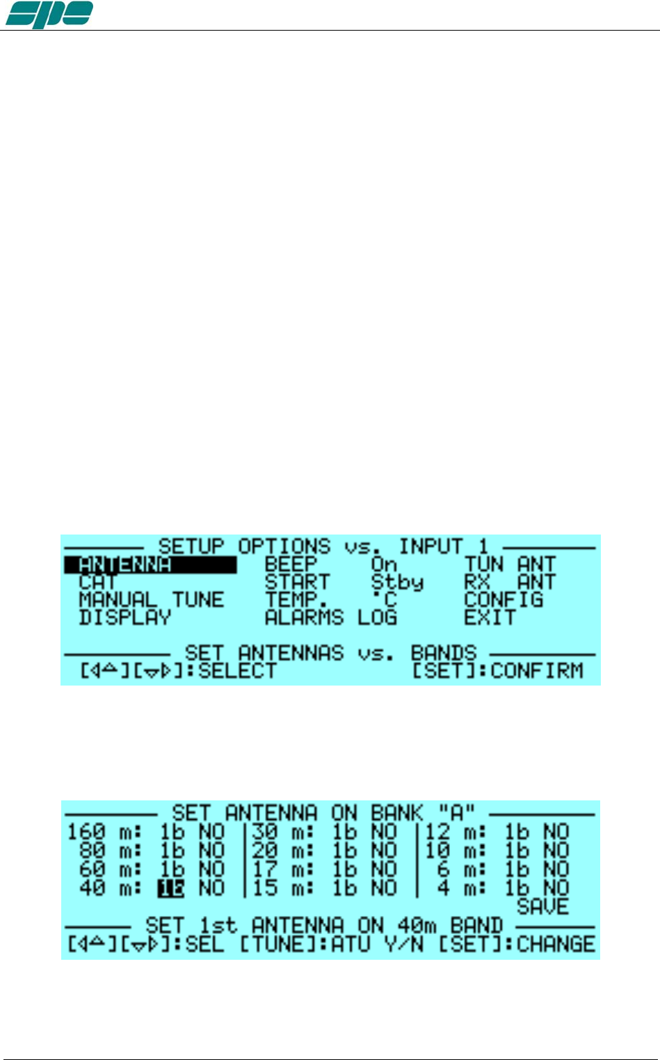
Pressing the [SET] key opens the menu page. On the display there are the following
options:
a) ANTENNA An appropriate antenna may be assigned to each band selecting
the (ANT 1, ANT 2, ANT 3, ANT 4) connector.
If you don’t have an antenna for a particular band, set to “NO”.
Exhbit 6 – Pag. 27 of 27
User manual EXPERT 1.3K-FA
This setup allows you to preset up to 2 antennas for the same band.
The selected antennas can be switched using the [ANT] key while
working either in the “OPERATE” or in the “STANDBY” mode and
there is no transmission in progress.
If you want, on a certain band and for a certain antenna to bypass
the tuner, just press the [TUNE] key and you will see a "b" next to
the box.
To remove the bypass just press [Tune] again.
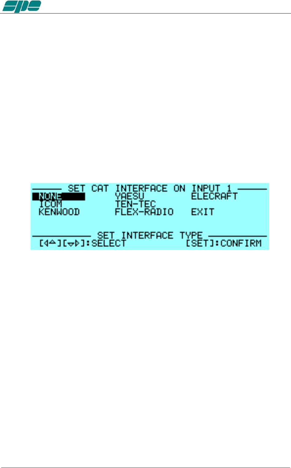
b) CAT Allows you to program the amplifier to accept control commands from
specific transceiver types.
You should refer to your transceiver user manual to ensure that
it is correctly programmed to handle such a link.
Choose the brand of transceiver or function. For the proper link wiring, see
"CAT CONNECTIONS" in this manual.
- NONE Select when there isn’t a link with the Transceiver.
Then, only the amplifier frequency counter will be used .
- ICOM Set to “CI-V“ protocol. You also need to choose the baud
rate, which is usually 9600.
- KENWOOD You have to choose the baud rate (almost always 9600).
- YAESU If you use the CAT connection (read the “CAT
CONNECTIONS” chapter of this manual), select the model
of the transceiver and than select the baud rate (almost
always 4800). If the model isn’t in the list, select “Band Data“
and read the “CAT CONNECTIONS” chapter of this manual.
For new transceiver models not listed, select FT 2000/9000
or try "Kenwood".
- TEN-TEC Make the CAT connection (read the “CAT CONNECTIONS”
chapter of this manual) and follow the menu instructions.
- FLEX-RADIO Make the CAT connection (read the “CAT CONNECTIONS”
chapter of this manual) and follow the menu instructions.
- ELECRAFT Make the CAT connection (read the “CAT CONNECTIONS”
chapter of this manual) and follow the same indications as for
KENWOOD.
Note: When using CAT link, check that the baud rate of your transceiver is set to the
Exhbit 6 – Pag. 28 of 28

User manual EXPERT 1.3K-FA
same value as the amplifier.
c) MANUAL TUNE Allows you to tune the amplifier manually. However achieving a
better setting than that obtained by automatic tuning is very
unlikely.
Set your exciter to transmit a continuous RTTY or CW signal.
Then press the [◄ L], [L ►], [◄ C], [C ►] keys until you obtain the
minimum SWR.
The operating frequency and the sub-band are also shown on the
Display.
d) DISPLAY Adjusts the backlight and the contrast of the display.
e) BEEP On : All acoustic warning alarms operate and a beep confirms a
keystroke.
Off : When you press a key there is no beep feedback, but for
all warning conditions and alarms, the acoustic warnings
are still functional.
f) START Stby: Sets STANDBY mode at startup.
Oprt: Sets OPERATE mode at startup.
g) TEMP °C: Displays temperature readout expressed in Celsius degrees.
°F: Displays temperature readout expressed in Fahrenheit
degrees.
h) ALARMS LOG Shows the ten most recent "SERIOUS" alarms.
i) TUN ANT Allows you to associate a tunable antenna to one of four ANT
connectors.
A "t" highlights the selected antenna.
j) RX ANT Allows you to set a single receiving antenna.
An "r" highlights the selected antenna.
k) CONFIG Select “BANK A” or “BANK B” (see item 4.6).
Exhbit 6 – Pag. 29 of 29

User manual EXPERT 1.3K-FA
11. INITIAL OPERATION OF THE AMPLIFIER
Before turning ON the amplifier, read this manual with care.
The following preliminary operations are necessary:
1) Be sure that the amplifier is correctly set for the local mains voltage supply.
2) Connect the amplifier to a good ground circuit
3) Connect the antennas.
4) Connect the amplifier to the transceiver (read the “CONNECTIONS WITH
THE TRANSCEIVER” chapter of this manual)
Operate [I] the main switch on the back panel, and press the [ON] key on the front
panel.
Select the INPUT for the transceiver, and always perform programming with the
amplifier in STANDBY. If you change memory BANK, you have to repeat this
programming.
Note: You may have to repeat some programming if you change antenna, transceiver, etc.
Note: ATTENTION: The ‘RELAY’ and ‘CAT’ signals in some types of transceivers are only
turned ON from a transceiver MENU. Refer to the user manual.
Note: ATTENTION: When the amplifier is in the ‘STANDBY’ and ‘OPERATE’ modes,
Always disable the transceiver’s autotuner.
11.1 Initial Programming
You must carry out the next steps in the sequence below:
a) To Set Antennas:
Press [SET] and open the “ANTENNA“ menu page.
Assign an appropriate antenna for the band concerned. If you don’t have an
antenna for a band, input “NO“.
When all the antennas are programmed, press [SET] to exit and go back to
STANDBY.
b) to Set CAT:
Press [SET] and enter the “CAT“ menu page.
Select the transceiver brand and progress with programming according to the
type of connection between the amplifier and the transceiver (read the “CAT
CONNECTIONS” chapter of this manual).
At the end of programming, exit and go back into STANDBY.
To verify the correctness of your programming, press the [CAT] key, and all
the data stored will appear on the display.
To verify the proper “CAT” operation, press [SET] and select “MANUAL TUNE”.
While moving your transceiver VFO you should see the same frequency on the display.
If set to "None", then transmitting briefly in RTTY or continuous key-down CW, will allow
you to read the transmitted frequency on the display.
Then return to the STANDBY mode.
In the same way, if “BAND DATA“ is connected, check that the amplifier follows band
changes of the transceiver.
If it does not do so, then verify that your programming (or your link) has been done
correctly.
Exhbit 6 – Pag. 30 of 30

User manual EXPERT 1.3K-FA
c) Use of the Automatic Tuner
To complete the programming it is necessary to match the antennas to the
amplifier by operating “TUNE“ function. (read the “TUNER“ chapter of this
manual).
We recommend that you select each band (with available antenna) and then
program the tuner for the sub-bands within which you will operate.
Refer to the table in section 19 of this manual to select the appropriate
sub-bands for your operating preferences.
You are strongly advised to proceed with the utmost accuracy, not just match
the current frequency, but all the sub-bands that you are likely to use.
Matching all the antennas on all bands that are available, allows you to enjoy
all the features of the automatic linear.
To program the sub-bands, proceed as follows:
1) For every band find the central frequency in the table of each sub-band
(refer to section 19 of this manual). Then set the transceiver to that
frequency.
2) Next, set your transceiver to transmit a continuous tone (RTTY or FM).
3) Then press the [TUNE] key and then the PTT. The procedure for
automatic tuning will start. You will hear the ATU relays operate and when
they stop, the SWR will be at a minimum. Sometimes it is possible to
improve tuning by repeating this step.
4) Repeat the previous steps for all sub-bands of bands you wish to use.
5) Repeat the previous steps for other antennas of the same band after
having selected it using the [ANT] key.
Note: If the ALC link is not used, it is very important to reduce the transceiver powerto
about 30 Watts during this operation.
The initial programming concludes after steps a), b), c).
11.2 Operating
You need to use only a few precautions when using the amplifier, thanks its high level of
automation.
ALC and CAT links are highly recommended to be used.
If ALC is not used, SPE reminds you that it is better to lose a fraction of dB in
transmitted power, by slightly reducing the driving power, than to over drive the amplifier
and have a poor quality transmission.
During transmission always check the parameters on the display. SPE has selected,
designed and adjusted them with care for your use in monitoring your amplifier.
SPE recommends, when using the ALC link, that the transceiver be set to its maximum
output power as the ALC will reduce the driving power to the optimum driving level.
To reduce the linear output, if required, just switch the amplifier to “MID” or “LOW” with
the [POWER] key.
Of course you may also continuously regulate the amplifier’s output power by changing
the level of drive power from your transceiver , even with the ALC connected.
If an output power less than 1 KW or 500 Watts is desired, for best efficiency begin
reducing drive from the “MID” or “LOW” power state.
Exhbit 6 – Pag. 31 of 31

User manual EXPERT 1.3K-FA
Setting Driving Levels
a) SSB : Regulate the “MIC GAIN” of the transceiver until, speaking normally into
the microphone, the signal peaks on the display don't quite reach the
maximum rated output power. Monitoring the transmission is a good way
of checking your settings. If there is however some distortion, decrease the
“mike gain” or decrease the power of the transceiver until a small reduction
of the output power of the amplifier is seen
b) CW: In key down, you get the maximum output power automatically.
c) RTTY: Digital modes, SSTV and FM, because all these mode have a very heavy
duty cycle, you should not operate in “MAX”. It is best to use the “MID” or
“LOW” power settings.
The sophisticated software ensures this operation.
d) AM: This transmission mode radiates a continuous carrier which is 25% of its
PEP value (e.g. 400W PEP AM = 100W carrier power). SPE recommends
you always operate in ‘MID’ or “LOW” mode for AM.
To get an output signal without distortion, proceed as follows:
Transmit an AM carrier only. Then with your transceiver’s “MIC GAIN” set
to zero, advance the transceiver drive and do not exceed 25% of the
maximum carrier output from the amplifier.
Then, speak into the microphone normally, setting the” MIC GAIN” of the
transceiver until the peak output power, on speech peaks, is shown on the
amplifier display to be no more than 0.8 KW or 400W. SPE suggests you
monitor your transmission closely to check that the “MIC GAIN” setting is
correct.
Note: If you choose to set the output power of the amplifier by varying the output power of
the transceiver, the ALC connection may not be needed. .
In this case you must be careful not to overdrive the amplifier to avoid distortion
and broadening of the channel (with the ALC, adjustment is automatic for
maximum linearity and Pout).
All functionalities remain the same, as does protection. You will probably
need to reset your transceiver power to full power out when returning to
STANDBY.
Note: ATTENTION: Never stress the amplifier with long periods in key-down transmission,
as this can stress the amplifier components. However, sophisticated Soft Ware avoids
transmitting a continuous signal in the "MAX" condition for long periods by switching
to "MID" power.
Note: In SSB, use of high compression is not encouraged as this can cause a rapid increase
in the temperature of the amplifiers.
Exhbit 6 – Pag. 32 of 32
User manual EXPERT 1.3K-FA
12. CONNECTIONS
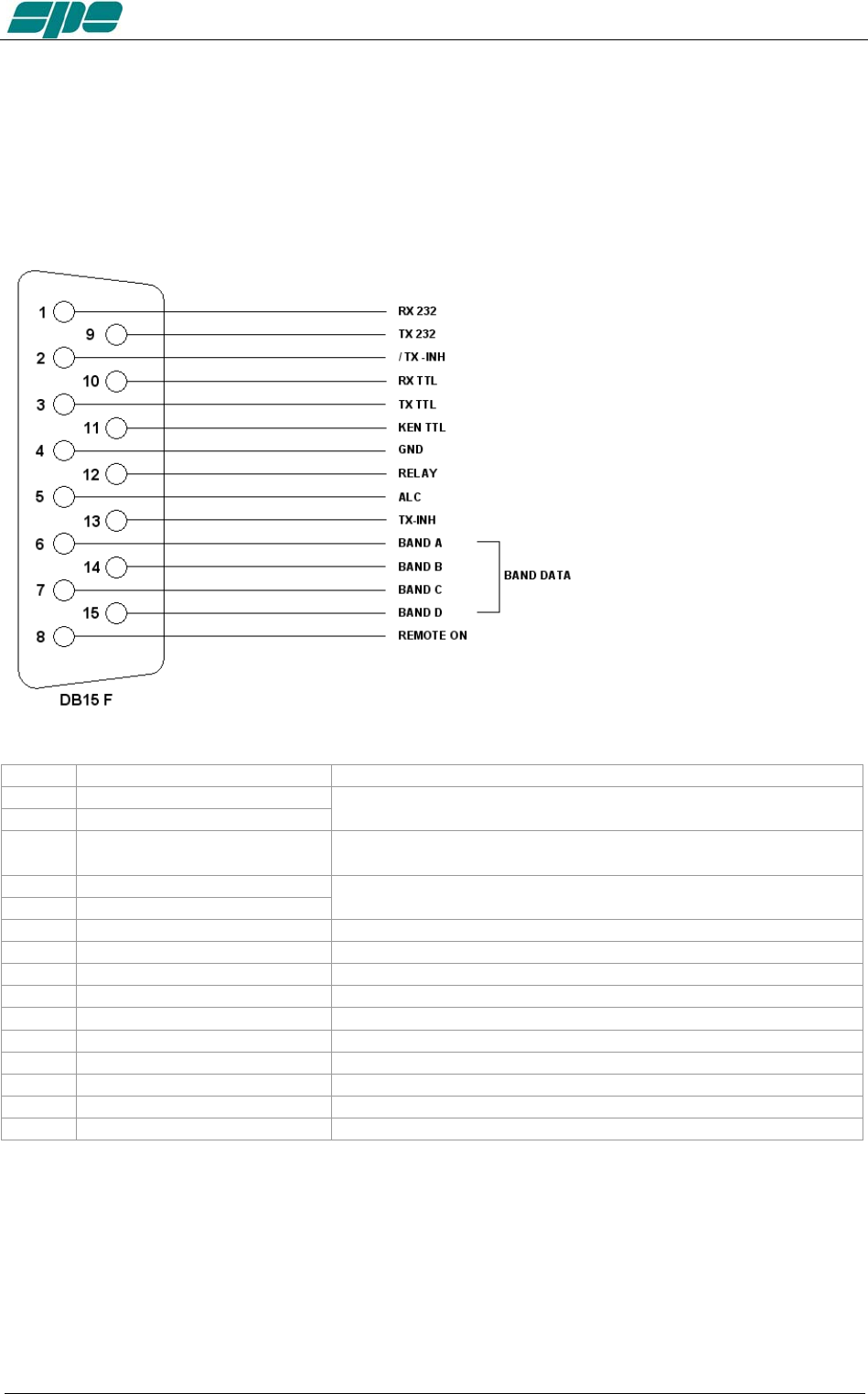
12.1 CAT Connector
The pin outs are shown in the schematic below. The connections are the same for our
1K FA and 2K FA amplifiers.
pin n. pin name Description
1 RX 232
9 TX 232
Used on KENWOOD and YAESU transceivers for the link with a
RS-232 connection.
2 / TX - INH Open collector normally OFF, it stops transmission when
grounded. (ON).
10 RX TTL
3 TX TTL
Used on Icom, KENWOOD and YAESU transceivers for the
CAT 5V TTL connection.
11 KEN TTL Connect to GND if CAT 5V TTL KENWOOD connection.
4 GND Signal ground.
12 RELAY Connected in parallel with the RCA phono RELAY connector.
5 ALC Connected in parallel with the RCA phono ALC connector.
13 TX - INH Normally to gnd (550 ohm), it stops transmission when + 12V
6 DATA A Bit A of Band Data (digital switch of band for YAESU).
14 DATA B Bit B of Band Data (digital switch of band for YAESU).
7 DATA C Bit C of Band Data (digital switch of band for YAESU).
15 DATA D Bit D of Band Data (digital switch of band for YAESU).
8 REMOTE ON Applying a voltage from 9 to 15 VDC, turns the amplifier ON.
Using the above information, an appropriate cable for your transceiver(s) may be
constructed. Or you might wish to order a correctly made-up cable when you order your
amplifier from your local dealer. New connectors are included with the amplifier.
The transceiver connectors (called “Radio” in the next diagram) are usually supplied
with the transceiver.
For connections to the Radio connectors, please refer to the transceiver operating
manual.
Exhbit 6 – Pag. 33 of 33
User manual EXPERT 1.3K-FA
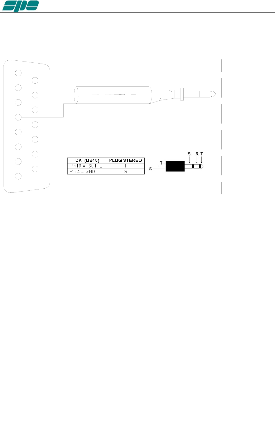
12.2 ICOM
CAT CI–V Interface
4
3
2
1
5
6
7
8
9
12
13
14
11
10
15
GND
DB15 M
RX TTL RADIO CONNECTOR
This interface is standard for all the Icom models equipped with CAT. The cable always
terminates into a 3.5 mm. mono plug.
It is possible to use a stereo plug according to the figure above.
Exhbit 6 – Pag. 34 of 34
User manual EXPERT 1.3K-FA
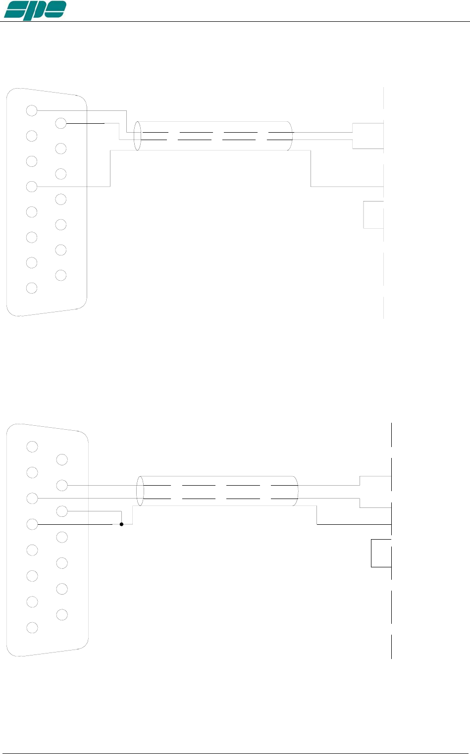
12.3 KENWOOD
CAT RS232 Interface
4
3
2
1
5
6
7
8
9
12
13
14
11
10
15
GND GND
RADIO CONNECTOR
DB15 M
RX 232
TX 232 RX 232
TX 232
RTS
CTS
(RXD)
(TXD)
The Radio connector could be DB-9 or DB-25 male connector or female connector
(read the specific manual). In the manual, also verify if the RTS–CTS link is necessary.
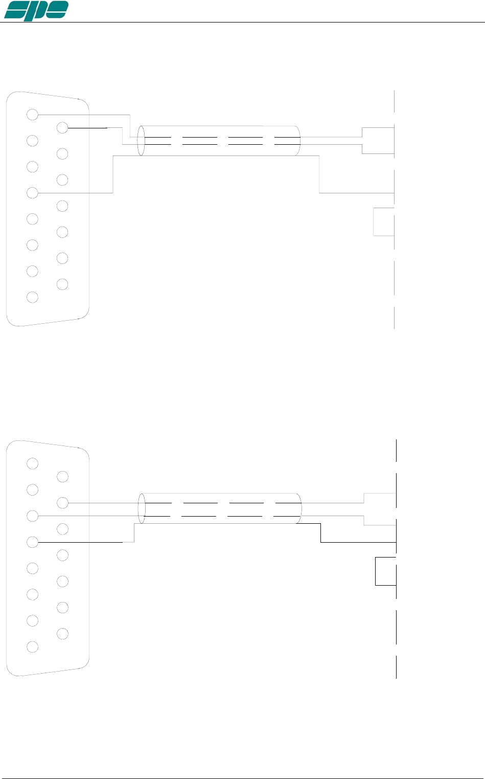
CAT 5V TTL Interface
4
3
2
1
5
6
7
8
9
12
13
14
11
10
15
GND GND
RADIO CONNECTO
R
RX
TX
DB15 M
RX TTL
TX TTL
KEN TTL
RTS
CTS
The connector is described in the transceiver’s manual.
Verify if the RTS–CTS link is required by the transceiver.
Exhbit 6 – Pag. 35 of 35
User manual EXPERT 1.3K-FA
12.4 YAESU
CAT RS232 Interface
4
3
2
1
5
6
7
8
9
12
13
14
11
10
15
GND GND
RADIO CONNECTOR
DB15 M
RX 232
TX 232 TX 232
RX 232
RTS
CTS
(RXD)
(TXD)
The radio connector may be a DB-9 or DB-25 male connector or female connector (read
the specific manual). Verify from the manual if the RTS–CTS link is necessary.
CAT 5V TTL Interface
4
3
2
1
5
6
7
8
9
12
13
14
11
10
15
GND GND
RADIO CONNECTOR
RX
TX
DB15 M
RX TTL
TX TTL
RTS
CTS
The connector is described in the transceiver’s manual.
Verify if the RTS–CTS link is required by the transceiver.
Exhbit 6 – Pag. 36 of 36
User manual EXPERT 1.3K-FA
BAND DATA Interface
4
3
2
1
5
6
7
8
9
12
13
14
11
10
15
GND
RADIO CONNECT
O
GND
DB15
M
BAND A
BAND B
BAND C
BAND D
BAND A
BAND B
BAND C
BAND D
Using Band Data, instead of CAT, use the four digital signals (Band A, Band B, Band
C, Band D) from the transceiver. Refer to the transceiver’s manual.
12.5 TEN – TEC, FLEX-RADIO, ELECRAFT
CAT RS232 Interface
4
3
2
1
5
6
7
8
9
12
13
14
11
10
15
GND GND
RADIO CONNECTOR
DB15 M
RX 232
TX 232 TX 232
RX 232
RTS
CTS
(RXD)
(TXD)
The radio connector may be a DB-9 or DB-25 male connector or female connector (read
specific manual). Verify from the manual if the RTS–CTS link is required.
Exhbit 6 – Pag. 37 of 37
User manual EXPERT 1.3K-FA
ALC with FLEX-RADIO.
Since all Flex-Radio equipments have no an analog ALC input, the maximum power
limits for the transceiver must be programmed in order to avoid the EXPERT’s overdrive
protection system intervention.
These settings have to be done while in OPERATE Mode according to the following.
For every ham band three settings are allowed (storage memories):
One setting for MAX mode.
One setting for MID mode.
One setting for LOW mode.
The following table shows an overall vision of these settings:
Band 160 m 80 m 60 m 40 m 30 m 20 m 17 m 15 m 12 m 10 m 6 m
MAX Preset
Max
Preset
Max
Preset
Max
Preset
Max
Preset
Max
Preset
Max
Preset
Max
Preset
Max
Preset
Max
Preset
Max
Preset
Max
MID Preset
Mid
Preset
Mid
Preset
Mid
Preset
Mid
Preset
Mid
Preset
Mid
Preset
Mid
Preset
Mid
Preset
Mid
Preset
Mid
Preset
Mid
LOW Preset
Low
Preset
Low
Preset
Low
Preset
Low
Preset
Low
Preset
Low
Preset
Low
Preset
Low
Preset
Low
Preset
Low
Preset
Low
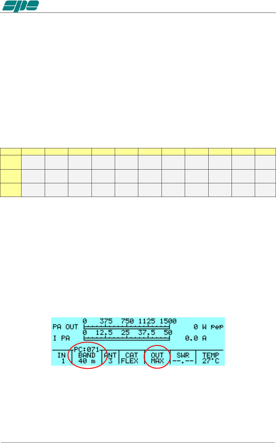
The user has to set, for every band of interest, the power limit concerning the input
power needed. To do that, using the keyboard, he must set a parametric value having
the format “[PC=xxx]” (where xxx is a numerical value having a range from 000 to 100
which represents the transceiver’s power output expressed in percentage).
This value will appear just over the BAND label of the Status Bar.
This value is related to the tuned band and to the selected power modes of MAX, MID
and LOW.
The following picture shows (as an example) Power Control of the 20 m band and in
MAX power mode:
Pressing the arrow keys ([◄▲] [▼►]) this value can be decremented/incremented
until it reaches the desired value. At the completion of this operation, a time-out period
(about 3 seconds) must be allowed for the “[PC=xxx]” indication to expire before
another adjustment can be made.
Exhbit 6 – Pag. 38 of 38
User manual EXPERT 1.3K-FA
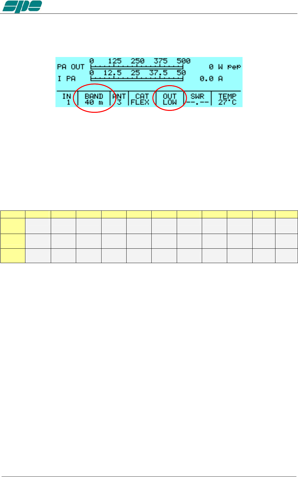
The following picture is an example of the Power Control setting relative to the same
band (20 m), but using the LOW mode selection instead.
Once the correct preset is adjusted, initiate the TX mode (RTTY, CW) to verify the
output power.
ATTENTION! It is strongly recommended to start with a low preset value (e.g. 10) and
progressively increase its value. This is to avoid overdriving the linear amplifier.
The following empty table is suggested as a template for the FlexRadio user’s Power
Control adjustments.
Band 160 m 80 m 60 m 40 m 30 m 20 m 17 m 15 m 12 m 10 m 6 m
MAX
MID
LOW
12.6 TRANSCEIVERS OF OTHER BRANDS
A special link is not necessary as the internal amplifier frequency counter will measure
the input frequency and will control the amplifier.
Note: WARNING, SPE is not responsible for any failure resulting from misuse of hardware
interfacing.
Exhbit 6 – Pag. 39 of 39
User manual EXPERT 1.3K-FA
13. OTHER CONNECTIONS
On the CAT connector, in addition to the CAT signals, the ALC and RELAY signals are
repeated. REMOTE ON, /TX–INH, TX–INH are also available.
If you use this connector to connect the ALC and RELAY lines, the separate phono
cables are not recommended. It is possible also to turn the amplifier on / off by turning
on / off the transceiver using the REMOTE ON function.
The following diagrams shows how to integrate all transceiver control connections to the
DB15 amplifier connector for ALC and PTT, plus REMOTE ON, /TX-INH and TX-INH.
Check the transceiver manual for terminating that end of the cable.
13.1 ALC, RELAY CONNECTIONS
GND
RELAY
GND
ALC
GND
GND
RADIO CONNECTOR
ALC
RELAY/SEND/TX-GND
4
3
2
1
5
6
7
8
9
12
13
14
11
10
15
DB15 M
13.2 REMOTE ON LINK
4
3
2
1
5
6
7
8
9
12
13
14
11
10
15 RADIO CONNECTOR
GND
13.8V
DB15
M
REMOTE ON
GND
Exhbit 6 – Pag. 40 of 40
User manual EXPERT 1.3K-FA
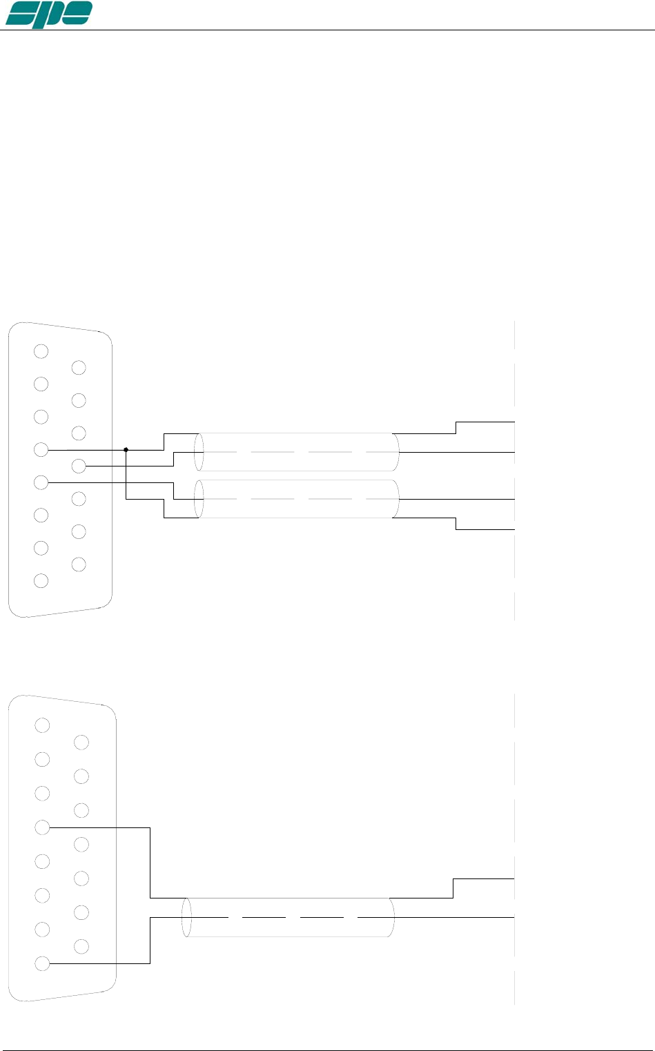
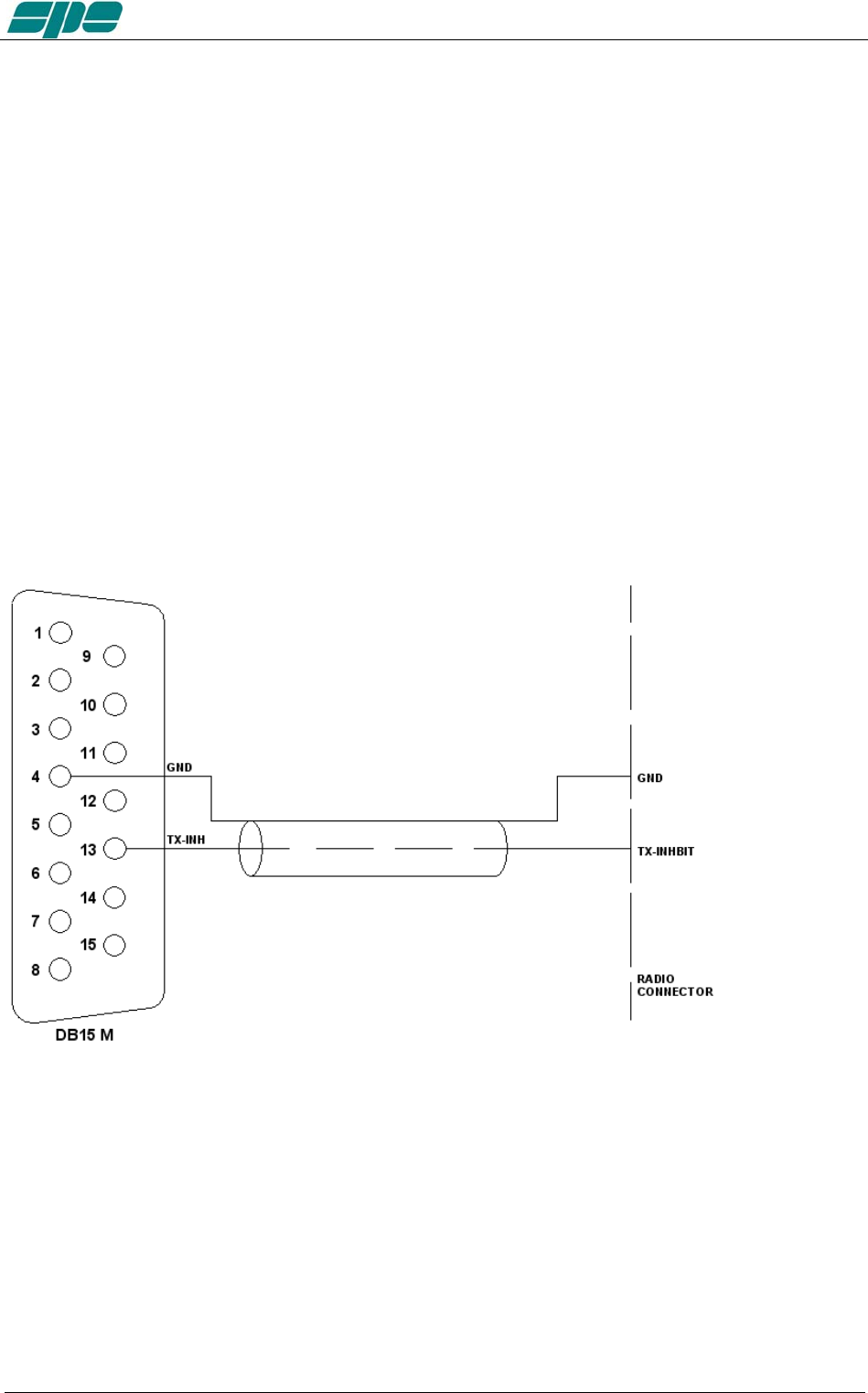
13.3 CONNECTIONS / TX-INH, TX-INH
All modern transceivers have a delay before the transmission to allow the linear to
stabilize their relays avoiding damage to the contacts as a result of "Hot Switching".
The Expert 1.3K-FA has a settling time of less than 6 msec compatible with all modern
transceivers (see the manual of the transceiver).
Some transceivers have an input (called TX-INHIBIT, LINEAR, MUTE, etc..) which
disables the transmission.
This input can be used with transceivers that do not have such delay or, more generally,
to improve the safety of switching.
The Expert 1.3K-FA has two outputs that can be connected to the TX-INHIBIT of the
transceiver:
a) TX-INH, usually gnd (550 ohm), stops the transmission when at a + 12VDC.
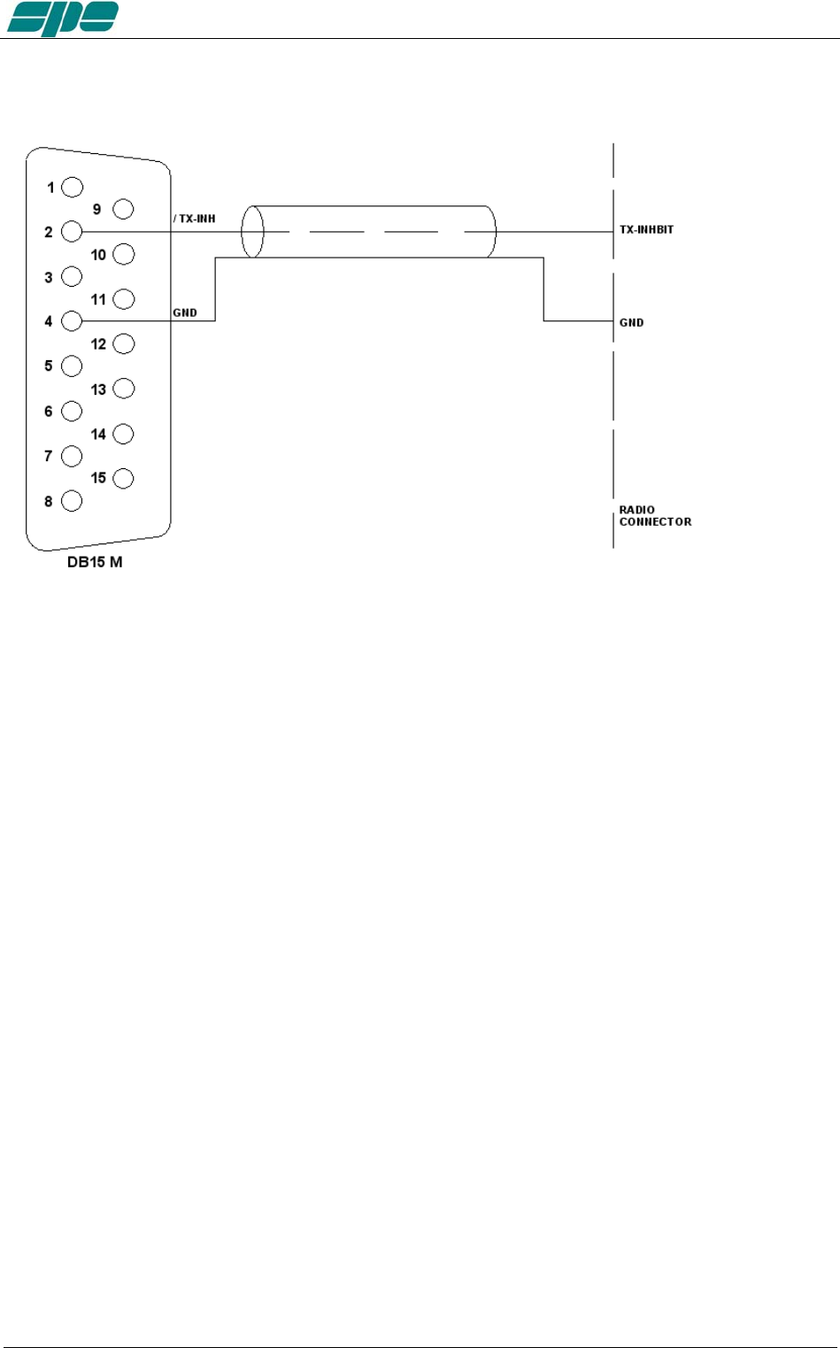
b) / TX-INH, open collector normally OFF, stops the transmission when this line goes to
ground (ON).
To choose a) or b) as well as to enable the TX-INHIBIT input , refer to the manual of the
transceiver.
TX-INH Link
Exhbit 6 – Pag. 41 of 41
User manual EXPERT 1.3K-FA
/TX-INH Link
Note: WARNING, SPE is not responsible for any failure resulting from misuse of hardware
interfacing.
Exhbit 6 – Pag. 42 of 42
User manual EXPERT 1.3K-FA
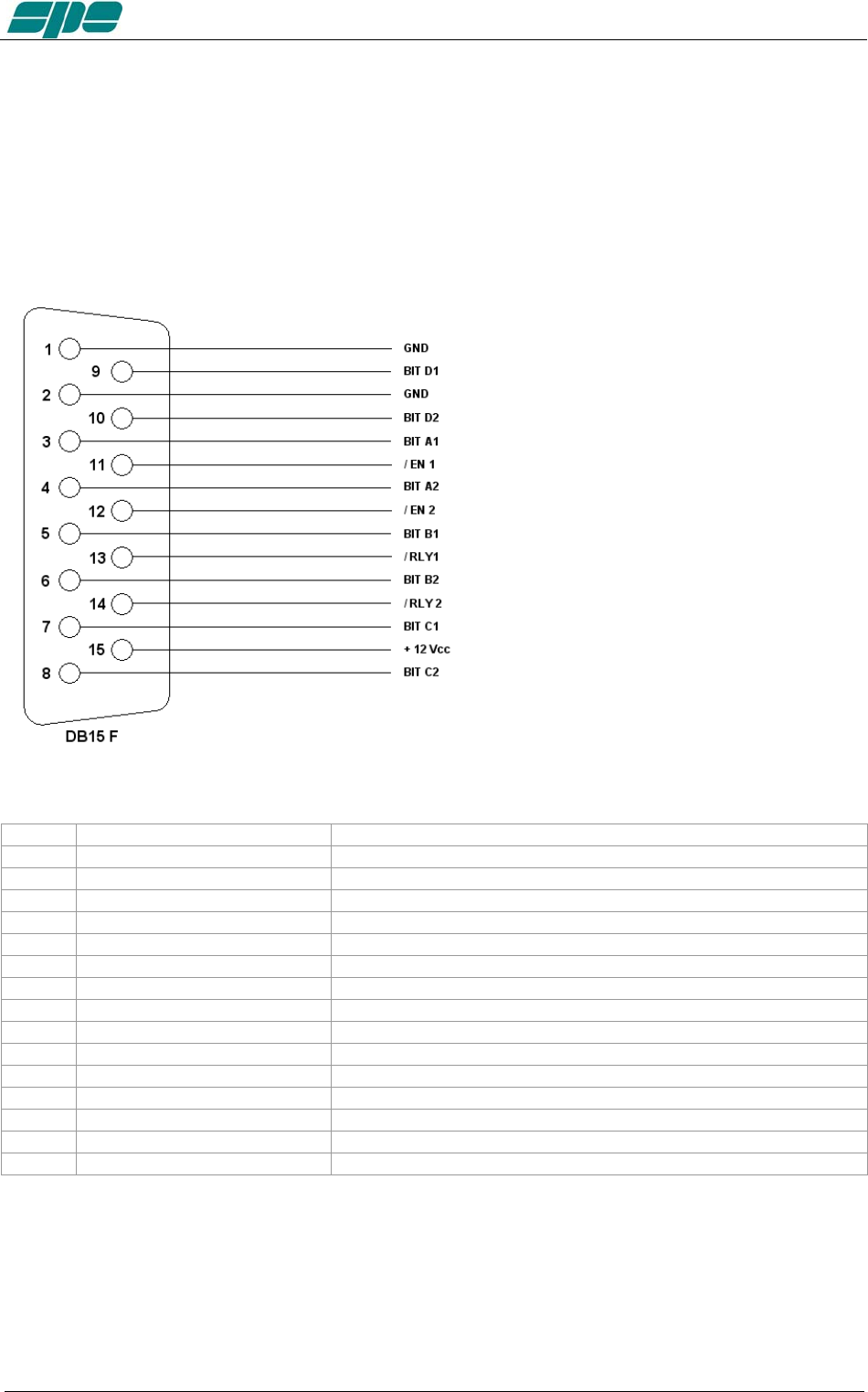
13.4 AUX Connector
This connector provides data about the bands currently being switched on both INPUTs,
indicating which input is connected to the antenna ANT 1/2/3/4 and which is connected
to the SO2R socket.
In this way you can know which one of the two transceivers is currently
connected to the switched output antenna and when it is in transmission etc.
Pin n. Pin name Description
3 BIT A1 BIT A INPUT 1
5 BIT B1 BIT B INPUT 1
7 BIT C1 BIT C INPUT 1
9 BIT D1 BIT D INPUT 1
11 / EN 1 INPUT 1 0 = not connected with ANT, 1 = connected with ANT
13 / RLY 1 INPUT 1 0 = TX state 1 = RX state
1 GND GND
4 BIT A2 BIT A INPUT 2
6 BIT B2 BIT B INPUT 2
8 BIT C2 BIT C INPUT 2
10 BIT D2 BIT D INPUT 2
12 / EN 2 INPUT 2 0 = not connected with ANT, 1 = connected with ANT
14 / RLY 2 INPUT 2 0 = TX state 1 = RX state
2 GND GND
15 + 12 Vcc OUT + 12 VDC 0.2 A max.
Each output is an open collector.
Note: WARNING, SPE is not responsible for any failure resulting from misuse of hardware
interfaces.
Exhbit 6 – Pag. 43 of 43
User manual EXPERT 1.3K-FA
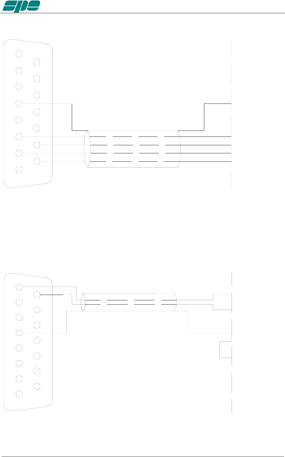
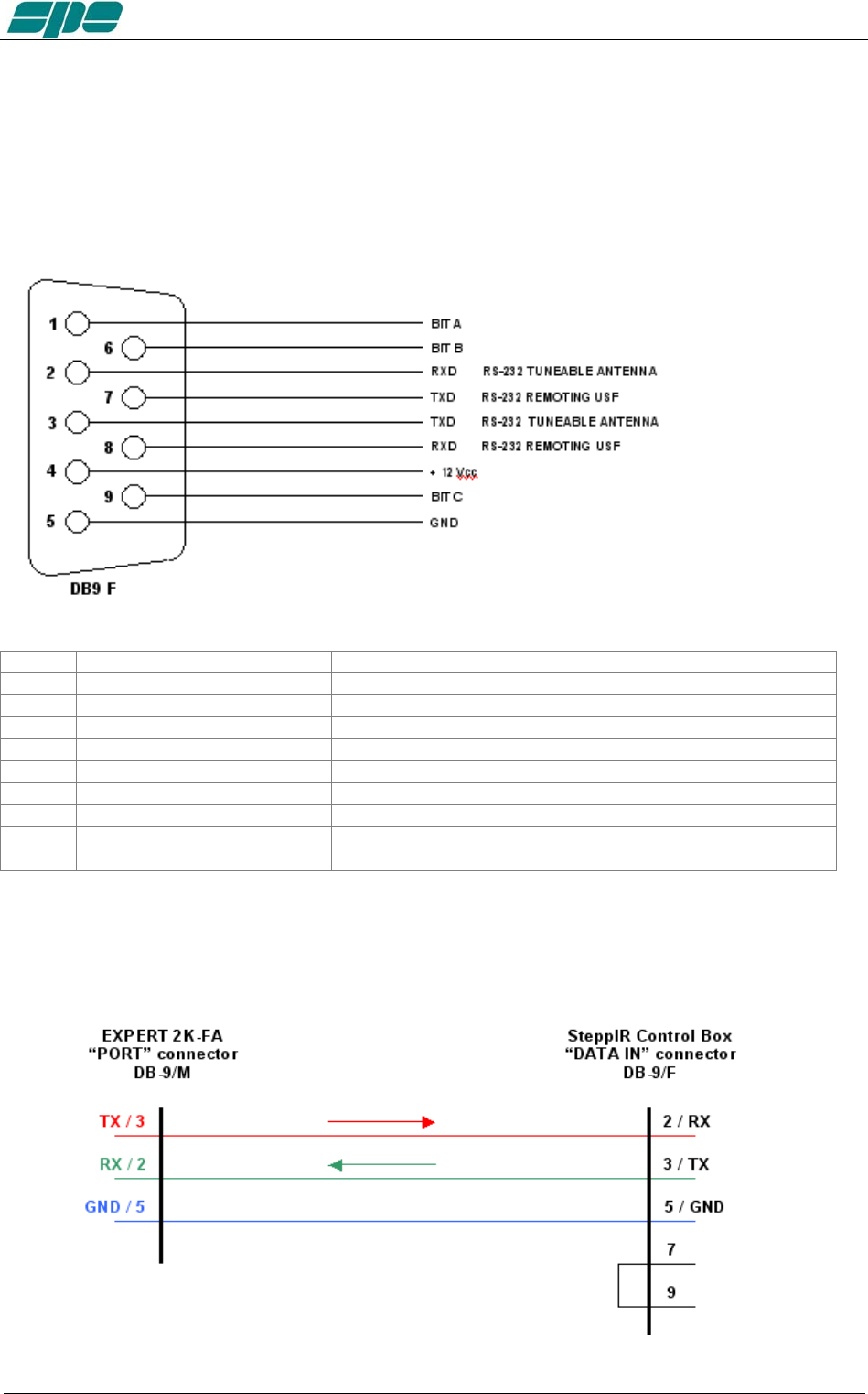
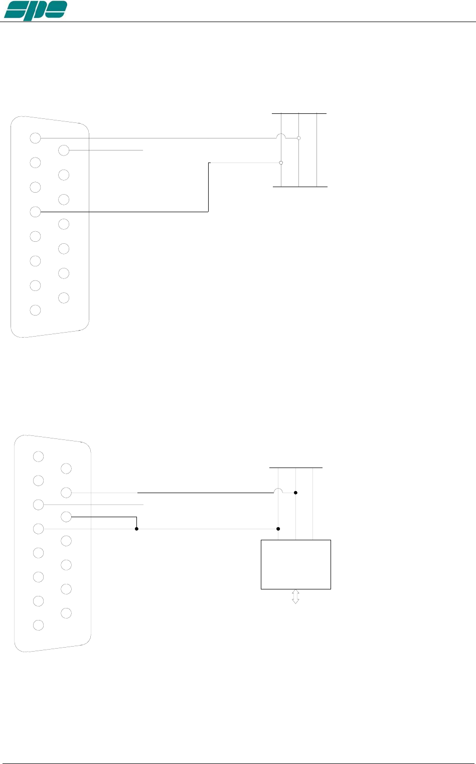
13.5 PORT Connector
This connector provides:
a) Data about the ANT port in use (each output is open collector).
b) RS 232 port for connection to a controller of a tunable antenna.
c) RS 232 port for remoting use (as an alternative of USB port).
Pin n. Pin name Description
1 BIT A BIT A antenna in use
6 BIT B BIT B antenna in use
9 BIT C BIT C antenna in use
5 GND GND
2 RXD RS232 port Tunable Antenna
3 TXD RS232 port Tunable Antenna
7 TX_232 (formerly RTS) RS232 port Remoting use
8 RX_232 (formerly CTS) RS232 port Remoting use
4 + 12 VDC + 12 VDC 0.2 A max.
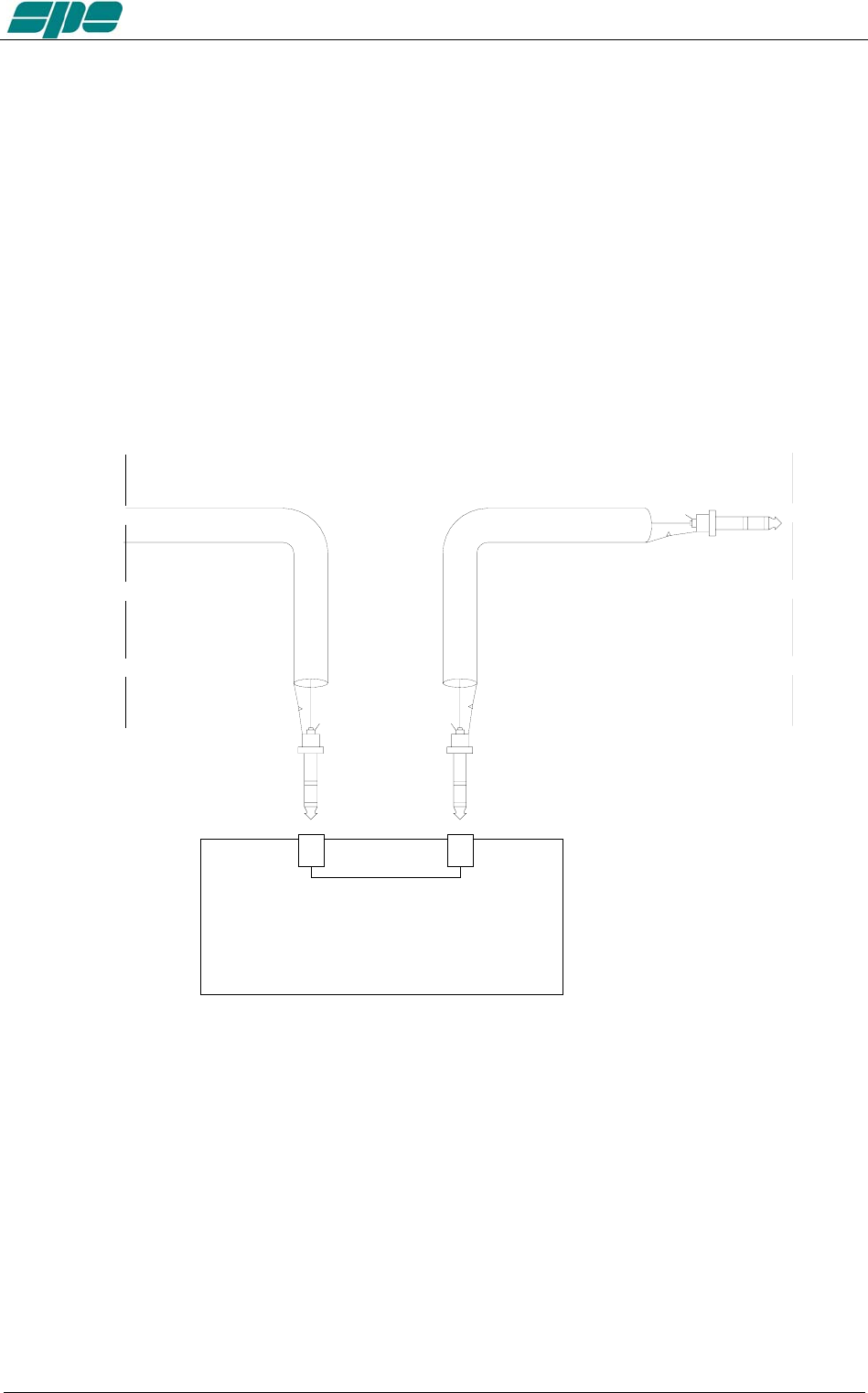
When connecting to a control box of a tunable antenna a suitable cable should be
wired.
SteppIR cable:
Exhbit 6 – Pag. 44 of 44
User manual EXPERT 1.3K-FA
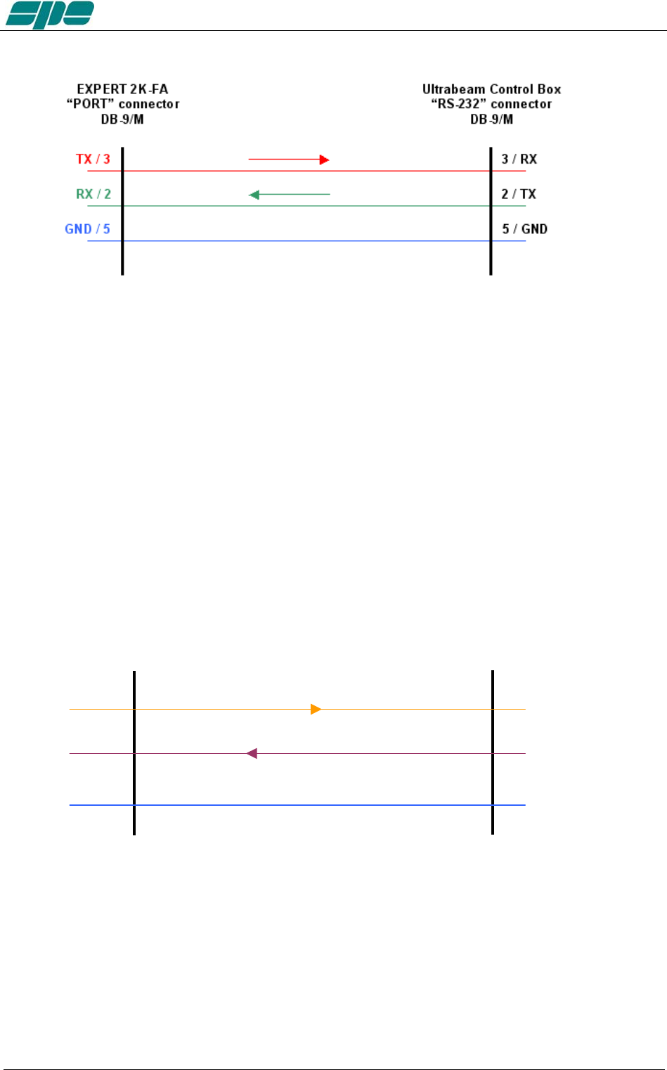
Ultrabeam cable:
Note: WARNING, these types of antennas, sometimes need several seconds to adjust to
resonance..
Transmitting with high power while the antenna elements are still moving may cause
damage to the antenna and the linear.
To avoid this danger you can utilize some circuitry that inhibits the PTT during the
movement of the motors, such as “tuning relays” that are available from the antenna
manufacturers.
This solution is highly recommended!!!
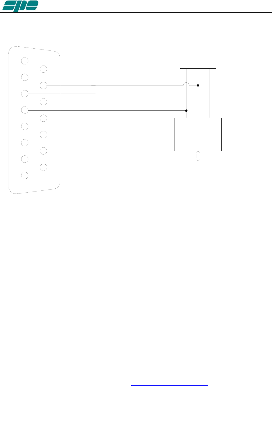
Serial connection to a standard PC RS-232 port for remoting use
TX_232 / 7 2 / RX_PC
RX_232 / 8 3 / TX_PC
GND / 5 5 / GND
EXPERT 2
K
-F
A
“PORT” connector
DB-9/M
STANDARD PC
“RS-232” connector
DB-9/F
Note: WARNING, SPE is not responsible for any failure resulting from misuse of hardware
interfaces.
Exhbit 6 – Pag. 45 of 45
User manual EXPERT 1.3K-FA
14. TRANSCEIVER CONTROLLED WITH A PC
If the transceiver is controlled with a PC using the CAT utility, the link with the amplifier
can be made as described in the following paragraphs.
Note: BEWARE, SPE assures only the direct connection between the Linear and the
Transceiver. The use of external control software could create malfunctions that
must be resolved by the provider of such software which is the responsibility
of the owner/operator.
14.1 ICOM CI-V INTERFACE
CI-V
INTERFACE
CT 17
ICOM
RADIO
DB15 F
LINEAR
CONNECTOR
The plug from the amplifier should be connected to a CI–V port of the CT17 or similar
device. The transceiver should be connected to another CI–V port.
The following types of connections as described in sections 14.2, 14.3 and 14.4 are
common for Kenwood, Yaesu, TEN-TEC, Flex-Radio and ELECRAFT links. The DB-15
connector side of the amplifier remains the same. On the opposite side of the cable, it is
necessary to connect only the GND and RX 232 (RX TTL) to the cable PC / Radio.
In this way, the interrogation to the transceiver is no longer requested by the linear but
is requested by the PC. The linear analyzes just the data exchanged.
In this case, DO NOT CONNECT TX 232 (TX TTL) of the linear because it would
create conflict in the Soft Ware and could damage the hardware as well. (see
following figures)
Exhbit 6 – Pag. 46 of 46
User manual EXPERT 1.3K-FA
14.2 RS232 INTERFACE
4
3
2
1
5
6
7
8
9
12
13
14
11
10
15
GND
TX
RX
GND
KENWOOD
OR
YAESU
RADIO CONNECTOR
PC CONNECTOR
TX
RX
RS232
RS232
DB15
M
RX 232
TX 232
X
GND
14.3 5V TTL KENWOOD INTERFACE
4
3
2
1
5
6
7
8
9
12
13
14
11
10
15
GND
TX
RX
TTL INTERFACE
PC
GND
TX
RX
TTL
KENWOOD
RADIO CONNECTOR
DB15
M
RX TTL
TX TTL
KEN TTL
X
GND
Exhbit 6 – Pag. 47 of 47
User manual EXPERT 1.3K-FA
14.4 5V TTL YAESU INTERFACE
4
3
2
1
5
6
7
8
9
12
13
14
11
10
15
GND
TX
RX
TTL INTERFACE
PC
GND
TX
RX
TTL
YAESU
RADIO CONNECTOR
DB15
M
RX TTL
TX TTL
X
GND
Note: WARNING, SPE is not responsible for any failure resulting from misuse of hardware
interfaces.
15. USE OF THE USB / RS232 PORTS
Through the USB / RS232 ports on the rear panel it is possible to interface the amplifier
with a PC.
Two features are possible:
a) To remote the linear.
b) To download newer and updated firmware releases.
The USB port is recommended in order to directly link the linear with a PC.
In this case the Soft Ware “ KTerm_1.3K_USB” must be used.
The RS232 port (see “13.5 PORT Connector”) is more suitable for Internet use.
In this case the Soft Ware “KTerm_1.3K_232” must be used.
It is not proper to use both ports simultaneously!!
Use is restricted to using only one port at a time.
These programs can be downloaded from www.linear-amplifier.com .
Note: For Internet use, please refer to the manual of the remoting equipment.
Exhbit 6 – Pag. 48 of 48
User manual EXPERT 1.3K-FA
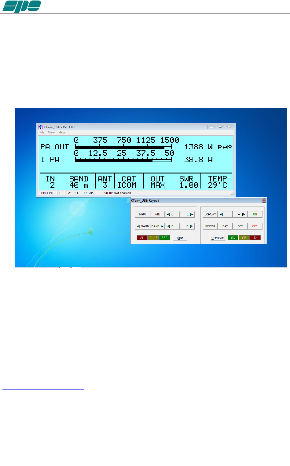
15.1 REMOTE CONTROL
The software provided allows one to display two separate windows.
The first window provides an exact copy of the display and is adjustable in size to fit any
need on the control screen.
The second window provides a copy of the keyboard. When not in use, it may disappear
to make space on that screen.
This software allows the same operation as when standing in front of the amplifier.
See “Appendix 1” on this manual.
15.2 DOWNLOAD.
The sophisticated design of the Expert 1.3K-FA allows you to download any new
versions of Soft Ware from the following site:
www.linear-amplifier.com
Please follow the easy and intuitive steps on “Appendix 1”.
Exhbit 6 – Pag. 49 of 49

User manual EXPERT 1.3K-FA
16. MAINTENANCE
The Expert 1.3K-FA linear amplifier does not need internal maintenance because it has
a cover without ventilation holes. Since HV tubes are not used, the natural attraction to
dust is eliminated. Therefore the user only needs to periodically check and clean the air
filter on the front panel.
The frequency of air filter inspection depends how dusty the amplifier location is and
how much it is used. We recommend monthly cleaning of the filter. Twice yearly
cleaning of the fans with a soft brush is also recommended.
To clean the filter
a) Remove the front grid cover with the two small screws. Place small screws in
a secure place. DO NOT LOSE THEM.
b) Remove the filter and clean it with care.
c) Reassemble the filter and the grid after having carefully cleaned the
mechanical structure that includes them. Dry filter before re-installing.
Note: Check the filter if an unexpected rise of temperature is noticed.
Note: Never operate without the filter, as dust could be deposited on the surface of the
heatsink limiting its ability to cool.
Note: To allow the most efficient heat-dissipation, large copper parts have been used.
To clean the fans
While holding the nozzle of a vacuum cleaner near to the rear panel fans (amplifier must
be switched OFF at the rear panel switch) GENTLY brush and revolve the fan blades
with a thin soft brush so that the dust is extracted
Exhbit 6 – Pag. 50 of 50

User manual EXPERT 1.3K-FA
17. CHARACTERISTICS / SPECIFICATIONS
- The smallest in its class.
Built-in Power supply and Automatic Antenna Tuner..
Dimension: L 28, H 12, P 38 cm (11.02” W,. 4.72” H, 14.96” D) (connectors
included).
Approx. weight without ATU is about 7.5 Kg.(16.5lbs). With ATU about 9,5 Kg
(20.9 lbs).
- The most technologically advanced in the world
Two powerful CPUs are used.
Over 30,000 lines of software, for performance that cannot be found in any other
amplifier.
- Fully Automatic
Easy connection with all models "ICOM, YAESU, KENWOOD, TEN-TEC, FLEX-
RADIO, ELECRAFT" for immediate management of the bands, tuner and
antennas.
Same performance with all makes and some homemade rigs.
The operator has to only move the “Frequency Tuning Knob” of the transceiver!!!
- Wide frequency coverage
1.8 MHz to 50 MHz including WARCs.
Where permitted 60 m. full power and 600 W typ. on 4 m. (70 MHz).
- Fully solid state
Up to 1.5 (1.3 typ.) KW pep SSB, CW out; 50 MHz included.
MAX , MID (800 W) , LOW (450 W) power selected according to the operator’s
SSB/CW power requirement, for digital modes and for linear protection
(automatic).
No warmup time, immediately ready!
Virtually limitless life of the amplification device.
- Automatic Antenna Tuner built-in
Capable of matching 3:1 SWR on HF, and 2.5:1 SWR on 6 meters.
Capable of program controlling 4 antennas (SO239 connectors).
Program up to 2 antennas for each band.
Management of SteppIR / Ultrabeam antennas (tunable).
Also measures the SWR of the antenna and cable system.
Bands, Antennas, Tuning conditions are changed in 10 msec.
Bands, Antennas and Tuning conditions are managed so that in “STBY“ it passes
the only the exciter.
Max. attenuation 0.8 dB.
ATU bypass capable.
- Available without ATU allowing significant savings
- Two inputs available.
SO239 connectors.
- High power gain (up to 14.5 dB).
In “OPERATE“ the required drive power is automatically set with an ALC
connection and in “STANDBY“ the exciter is automatically reset to full power.
Exhbit 6 – Pag. 51 of 51

User manual EXPERT 1.3K-FA
- Very clean and low distortion output!
Spurious emissions FCC compliant.
3rd order distortion (two tone test) from 30 to 35 dB.
- Input 50 ohm always perfectly matched
The same protection is realized in two different ways:
· Via hardware circuits (HW) to assure great speed.
· Via the software (SW), to assure great accuracy.
Thanks to the sophisticated software, the transmit relay changeover is carried out
with zero current on the contacts.
- Full break-in operation (QSK)
- Quiet operation.
Linear management of the speed of the cooling fans of the heatsink.
The amplifier develops a significant amount of heat that must be removed.
Therefore, every precaution is used to keep the fan noise at the lowest possible
level. Fan noise is significantly lower than with tube type amplifiers.
- Continuous use
“MAX” mode: SSB / CW unlimited.
Automatically switches to “MID” if in “MAX”, a continuous signal (RTTY) is
transmitted for more than 15 sec.
“MID” and “LOW” modes, RTTY unlimited.
- Switching power supply.
Continuously operable at inputs between 100 – 255 Vac, 47-63 Hz.
(100-120 Vac slightly reduced output power).
PFC (Power Factor Correction).
- The linear can be switched ON / OFF by switching the exciter ON / OFF
- Fully remotable.
- With a large LCD display, it is possible to have a great deal of information
Watts pep out, Vpa, Ipa, Watts, Power gain, Temperatures, SWR (after and
before the ATU), Input setting, CAT setting, Band and other indications including
the alarms log.
- Easy to operate
Powerful and sophisticated software gives you a user-friendly unit.
- USB / RS232 ports .
For remote control..
For new software releases download.
- Easy transportation
A sturdy, nice looking carry-bag is supplied for “QSY, FIELD DAY, DX’
PEDITIONS etc.“.
- Certifications :
CE, FCC (pending).
N.B. These specifications are subject to change without notice.
Exhbit 6 – Pag. 52 of 52
User manual EXPERT 1.3K-FA
18. DIAGNOSTICS.
During normal operation, this sophisticated monitoring system continuously monitors
several measurements directly acquired from internal test-points.
When a dangerous situation occurs, a “serious” alarm message is raised and the
amplifier is switched from OPERATE to STANDBY.
The user can either restore immediately the Main Display Page by pressing the
[DISPLAY] key or wait for the visual alarm time-out expiration (about 10 seconds).
The following table shows all the system’s alarm messages that are recorded in the
Alarm History stack:
Message Description
SWR EXCEEDING LIMITS Protection for SWR greater than 3:1.
INPUT OVERDRIVING Protection for excessive input power.
EXCESS OVERHEATING Protection because the internal temperature has
exceeded safe limits.
The following table shows all the dynamic warning messages that are not recorded in
the Alarm History stack:
Message Description
BAND NOT PERMITTED Band not allowed or not set.
ANTENNA NOT AVAILABLE Antenna not set.
TX ANTENNA NOT AVAILABLE In the selected band is set only an antenna for
reception.
STEADY OUTPUT POWER EXCEEDING
LIMITS
Appears when a continuous signal is transmitted in
"MAX”. After 15 sec. the amplifier will switch
automatically to "MID".
INTERNAL OVERHEATING Appears when the internal temperature reaches 75 °C
(167 °F). The amplifier automatically switches to the
next lowest power level.
HIGH SWR ANTENNA:
TUNING NOT ALLOWED
When the antenna SWR is over 3.5:1, the auto tuner is
disabled.
ATU BYPASS:
TUNING NOT ALLOWED
Since the tuner is bypassed, it is not possible to
match automatically or manually.
N
O INPUT POWER:
TUNING HALTED
The tuner can not work at such a low input power.
CAN'T SWITCH-OFF:
POWER HELD BY REMOTE
The amplifier does not turn OFF by the keyboard because
it is kept ON by a remote device (transceiver or USB
port).
AMPLIFIER PROTECION In all remaining cases.
Exhbit 6 – Pag. 53 of 53

User manual EXPERT 1.3K-FA
19. TABLE
BAND TABLE, SUB-BAND, CENTRAL FREQUENCY SUB-BAND
[ 0] 1785 [ 1] 1795 [ 2] 1805 [ 3] 1815 [ 4] 1825 [ 5] 1835
[ 6] 1845 [ 7] 1855 [ 8] 1865 [ 9] 1875 [ 10] 1885 [ 11] 1895
[ 12] 1905 [ 13] 1915 [ 14] 1925 [ 15] 1935 [ 16] 1945 [ 17] 1955
160 m
[ 18] 1965 [ 19] 1975 [ 20] 1985 [ 21] 1995 [ 22] 2005 [ 23] 2015
[ 24] 3470 [ 25] 3490 [ 26] 3510 [ 27] 3530 [ 28] 3550 [ 29] 3570
[ 30] 3590 [ 31] 3610 [ 32] 3630 [ 33] 3650 [ 34] 3670 [ 35] 3690
[ 36] 3710 [ 37] 3730 [ 38] 3750 [ 39] 3770 [ 40] 3790 [ 41] 3810
[ 42] 3830 [ 43] 3850 [ 44] 3870 [ 45] 3890 [ 46] 3910 [ 47] 3930
80 m
[ 48] 3950 [ 49] 3970 [ 50] 3990 [ 51] 4010 [ 52] 4030
[ 53] 5013 [ 54] 5038 [ 55] 5063 [ 56] 5088 [ 57] 5113 [ 58] 5138
[ 59] 5163 [ 60] 5188 [ 61] 5213 [ 62] 5238 [ 63] 5263 [ 64] 5288
[ 65] 5313 [ 66] 5338 [ 67] 5363 [ 68] 5388 [ 69] 5413 [ 70] 5438
60 m
[ 71] 5463 [ 72] 5488
[ 73] 6963 [ 74] 6988 [ 75] 7013 [ 76] 7038 [ 77] 7063 [ 78] 7088
[ 79] 7113 [ 80] 7138 [ 81] 7163 [ 82] 7188 [ 83] 7213 [ 84] 7238
40 m
[ 85] 7263 [ 86] 7288 [ 87] 7313 [ 88] 7338
30 m [ 89] 10075 [ 90] 10125 [ 91] 10175
[ 92] 13975 [ 93] 14025 [ 94] 14075 [ 95] 14125 [ 96] 14175 [ 97] 14225
20 m [ 98] 14275 [ 99] 14325 [ 100] 14375
17 m [ 101] 18075 [ 102] 18125 [ 103] 18165
[ 104] 20975 [ 105] 21025 [ 106] 21075 [ 107] 21125 [ 108] 21175 [ 109] 21225
15 m [ 110] 21275 [ 111] 21325 [ 112] 21375 [ 113] 21425 [ 114] 21475
12 m [ 115] 24891 [ 116] 24963 [ 117] 25038
[ 118] 28050 [ 119] 28150 [120] 28250 [121] 28350 [122] 28450 [123] 28550
[124] 28650 [125] 28750 [126] 28850 [127] 28950 [128] 29050 [129] 29150
10 m
[130] 29250 [131] 29350 [132] 29450 [133] 29550 [134] 29650 [135] 29750
[136] 49875 [137] 50125 [138] 50375 [139] 50625 [140] 50875 [141] 51125
[142] 51375 [143] 51625 [144] 51875 [145] 52125 [146] 52375 [147] 52625
6 m
[148] 52875 [149] 53125 [150] 53375 [151] 53625 [152] 53875 [153] 54125
Note: [sub-band] Central frequency KHz
Exhbit 6 – Pag. 54 of 54
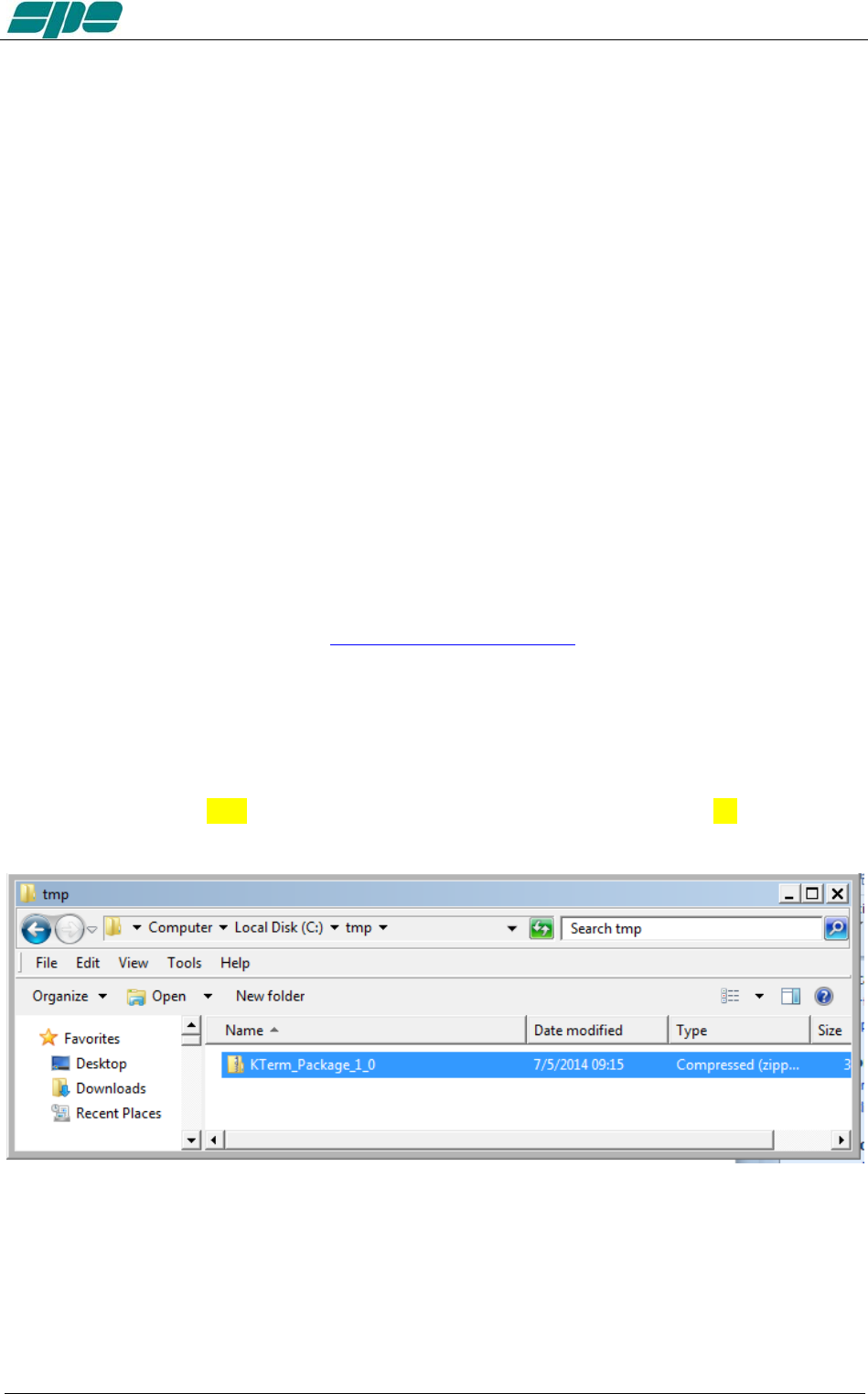
User manual EXPERT 1.3K-FA
20. Appendix 1 - Remote control
Overview:
With reference to that described in Section 15. “USE OF THE USB / RS 232 PORTS”,
this appendix contains the following sections:
SW installation
KTerm_USB.exe usage
KTerm_232.exe usage
Firmware update
The host PC must have a minimum of a correctly installed Windows XP operating
system, or a newer release of Microsoft’s operating system such as Windows Vista,
Windows 7, with a typical minimum of RAM and hard disk space.
20.1 SW (Software) installation.
The installation package is contained in a compressed .ZIP archive named
“KTerm_Package_1_0.zip” which requires to be expanded into a work folder and then
processed as described. This package is included in the accessory CD or can be
downloaded from our website at www.linear-amplifier.com .
Once the compressed archive KTerm_Package_1_0.zip has been stored into a work
folder, it must necessarily be expanded; that is all. the files therein contained must be
extracted and properly placed into the host system.
In this example the compressed archive KTerm_Package_1_0.zip has been placed
into a folder named tmp which is, in turn, located on the local disk unit C: as shown in
the picture below:
Next step is the archive expansion. This can be obtained by selecting the filename and
then right-clicking over it. A local menu will appear, with Extract All… this process will
automatically sort unzip and sort the files:
Exhbit 6 – Pag. 55 of 55
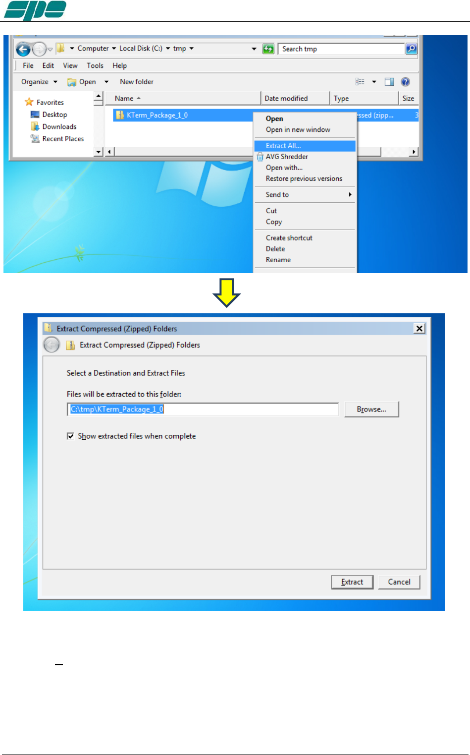
User manual EXPERT 1.3K-FA
The default destination folder is good for this use, so complete this operation by
using the Extract key as shown in the picture above.
This step reveals a new uncompressed folder, having the same name of the original
compressed one contained in the installation package.
Everything is contained in our work folder as shown in the picture above:
Exhbit 6 – Pag. 56 of 56
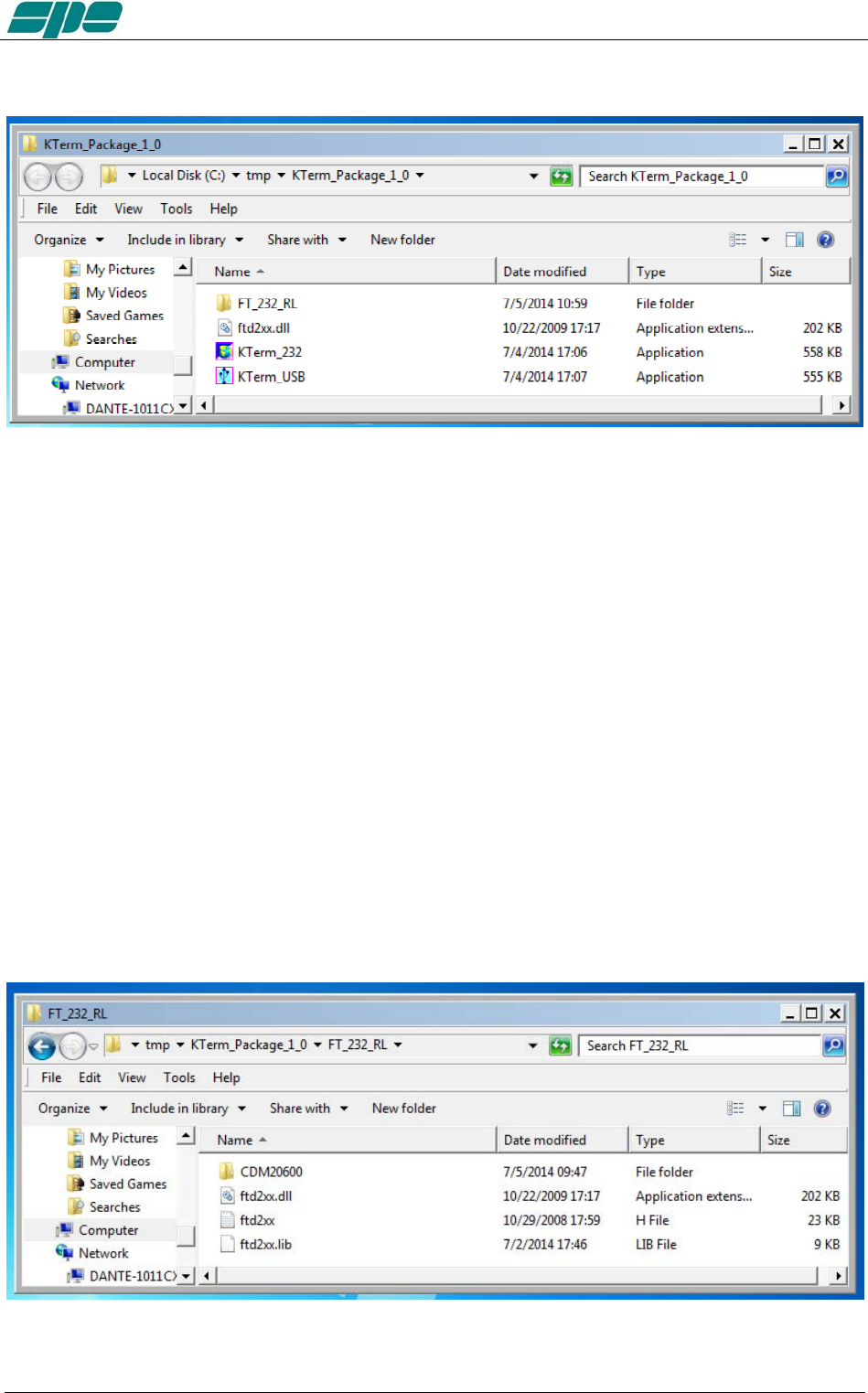
User manual EXPERT 1.3K-FA
Once opened, the C:tmp\KTerm_Package_1_0 folder will show the following contents:
Where:
FT_232_RL is a folder containing the USB drivers and an automatic installation
program, which must be run just once to prepare the operating environment which sorts
out everything needed, such as the USB drivers and their support files on the Windows
host system.
KTerm_USB.exe is the remote control application that can be launched only after
having installed the USB drivers properly.
ftd2xx.dll is a support library file for the KTermUSB.exe application. It must be
accessible by KTermUSB.exe application, so it is required to be either manually copied
into the same folder of the application or into another system-wide folder (e.g.
C:Windows\System32, which is one of the most used repositories for libraries and
application support files.
KTerm_232.exe is the remote control application specially designed to establish a
connection using the devoted RS-232 serial port which is available on the rear panel of
the linear amplifier. This application does not require any preparation related to
FT_232_RL drivers, since it uses the proprietary Windows resources.
Once opened, FT_232_RL folder will show the above contents
Exhbit 6 – Pag. 57 of 57
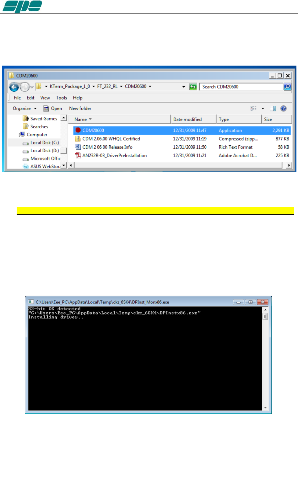
User manual EXPERT 1.3K-FA
A very important part of the installation procedure is the CDM20600 folder, which
contains among the other files, the CDM20600.exe Windows application as highlighted
in the picture below:
This application has been specially designed for a correct installation of the specific
FTDI USB drivers.
So, remove any physical link between the EXPERT 1.3K-FA and the PC for now.
Then double-click over the “red ball” icon of CDM20600.exe application and wait for its
preparatory job to be completed.
As soon as CDM20600.exe starts running, a DOS window similar to one shown in
following picture will pop-up for several seconds then disappearing after its automatic
preparatory job is completed.
The next step is to connect the PC and the EXPERT 1.3K-FA by using the equipped
USB cable and waiting for the identification of the newly created USB connection.
A notification window will pop-up as shown in the picture below.
Exhbit 6 – Pag. 58 of 58
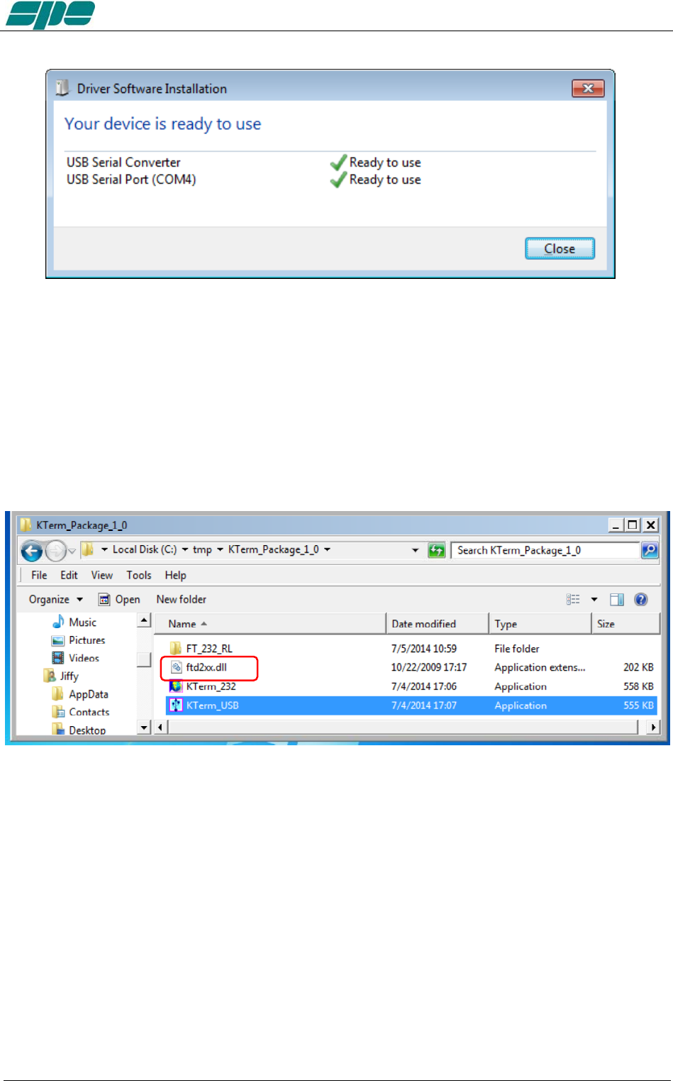
User manual EXPERT 1.3K-FA
The USB port installation and its setting is now complete.
Now that this fundamental step has been successfully completed, the application
KTerm_USB.exe remote control application can be launched.
For this purpose a back-step to the starting uncompressed folder KTerm_Package_1_0
must be performed and double-click on the application filename, as indicated in the
picture below
Note: Do not forget that KTermUSB.exe requires full accessibility to the ftd2xx.dll
application extension. So, in case the application itself gets copied into
another work folder, please correct that action. A good practice is to copy both
KTermUSB.exe and ftd2xx.dll into the same work folder.
Exhbit 6 – Pag. 59 of 59
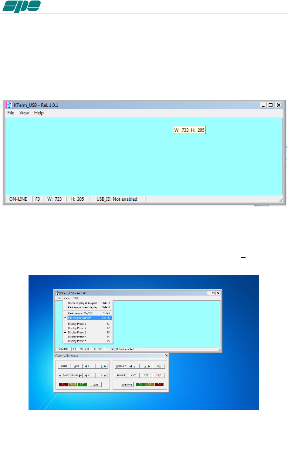
User manual EXPERT 1.3K-FA
20.2 KTerm_USB.exe usage
To test, connect the USB cable from the PC and the linear and double-click on the
application’s icon (the USB icon symbol), by using the mouse left-button, just to see if
everything works fine.
It is a good idea to create a link to the application on the desktop. As a result the
applications main window will show up, as in the following picture:
This is the main window of KTerm_USB.exe application.
It is a realistic reproduction of the EXPERT 1.3K-FA LCD display, and it is also
equipped with a pop-up virtual keypad having almost the same look and feel as the real
keypad placed on the front panel of the linear amplifier.
To activate/deactivate this keypad the user must check/uncheck the View/KeyPad
On/Off menu item as shown in the following screen snapshot:
Exhbit 6 – Pag. 60 of 60
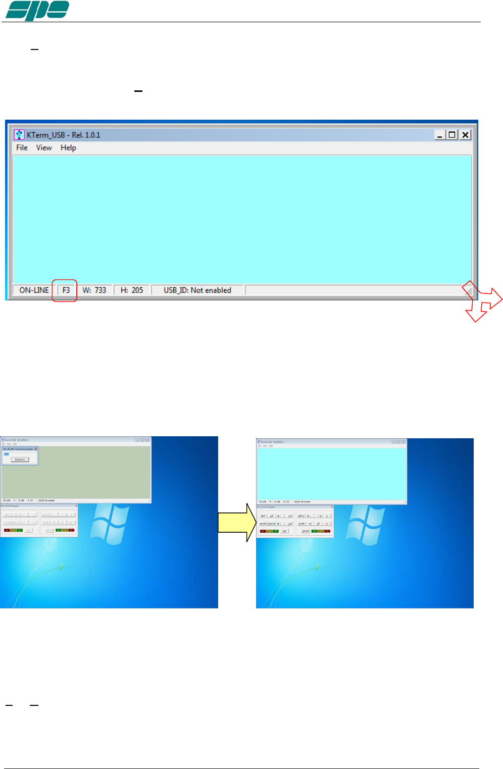
User manual EXPERT 1.3K-FA
The View menu also contains five items related to the application window size presets
which can be either selected by the menu itself or by their equivalent [F1 … F5] shortcut
keys.
Feel free to test all the View menu options in order to find an optimal and comfortable
vision of the display main window.
The display window can easily be resized. That is, either enlarged or reduced by
acting on the right-bottom corner of the window. Also by using the mouse as shown in
the picture above and in the same way as any other window-resizing operation.
In case the user wants to restore the original size-preset lying behind any [F1…F5] key,
you must select the Fx preset and, then, press the Ctrl+Fx key combination on his PC
keyboard.
When KTerm_USB.exe gets launched an automatic Connect command also starts and
if a USB link to the linear amplifier was already active, it should have shown a result
similar to the picture sequence above.
In case this doesn’t happen, there’s also a chance to try connecting by using the
File/Connect menu item (or by using its equivalent Ctrl+Q shortcut key…).
The final visual result will be a “bright backlight” display and a function-keys enabling of
the virtual keypad.
Exhbit 6 – Pag. 61 of 61
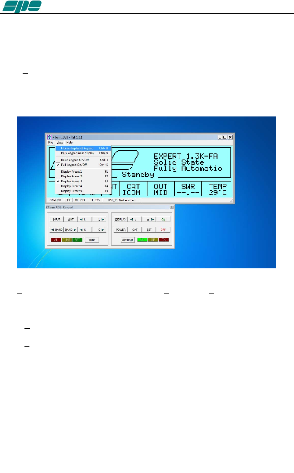
User manual EXPERT 1.3K-FA
In case the EXPERT linear is already switched on, after the connection established by
KTerm_USB.exe, an immediate update on the current display contents will result.
However, if the EXPERT linear was already switched off, it would be turned on by using
the [ON] virtual key on the application keypad.
Similarly, all the other virtual keypad keys perform the same actions as their equivalent
mechanical keys forming the real front panel keyboard of the EXPERT 1.3K-FA.
The View menu is also equipped with the useful Home… and Park… items which have
been specially designed to allow an automatic repositioning of the application along the
PC desktop area.
In more detail:
• Home... (Ctrl+H) This item positions the display window to the upper-left corner
of the desktop area and aligns the keypad to its bottom edge.
• Park... (Ctrl+N) This item leaves the display window where it currently stays and
just aligns the keypad to its bottom edge.
The above described operations could be helpful whenever a quick and safe
repositioning of the application windows is desired.
Exhbit 6 – Pag. 62 of 62
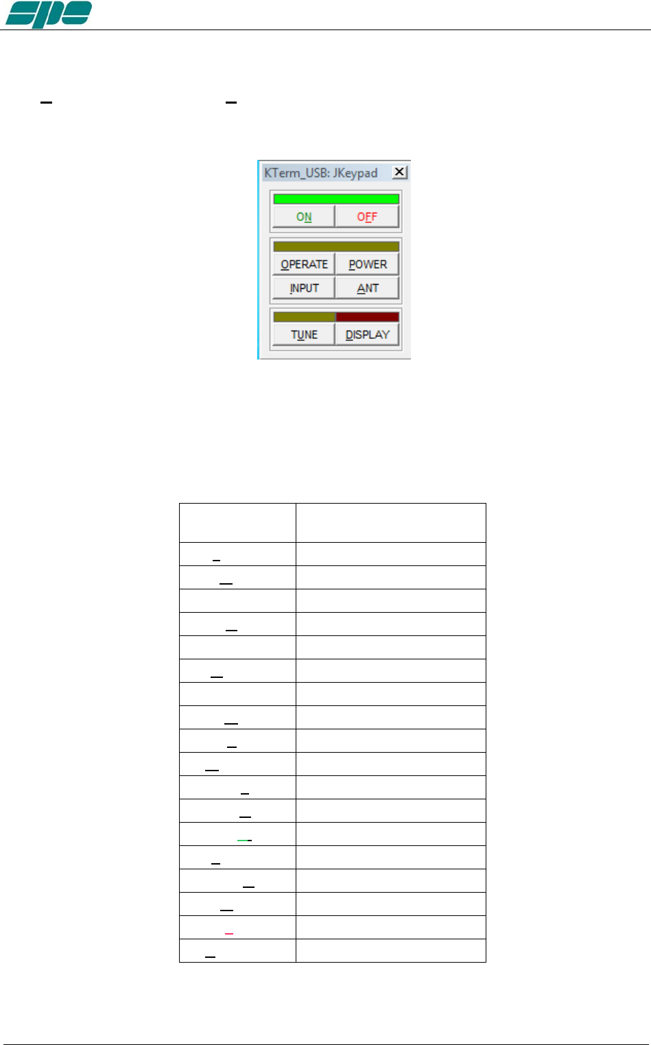
User manual EXPERT 1.3K-FA
The Basic keypad... item in View menu allows you to set to a reduced-size keypad,
having fewer keys than the complete keypad, which could be useful when no setting
actions are required on the linear amplifier.
Note: The keypad types, both Full and Basic, are certainly useful since they both can be
directly accessed using the mouse pointer. It is helpful to know that all the operations
allowed using the virtual keys can be also performed using short commands directly
typed on the PC keyboard.
The following one is the “shortcut-keys” table:
1.3K-FA
Function key
Equivalent shortcut-key
from the PC keyboard
[INPUT] I
[ANT] A
[<L] Ctrl+L
[L>] L
[<BAND] Ctrl+B
[BAND>] B
[<C] Ctrl+C
[C>] C
[TUNE] U
[DISPLAY] D
[< -] -
[> +] +
[ON] N
[POWER] P
[CAT] T
[SET] S
[OFF] (*) F
[OPERATE] O
Exhbit 6 – Pag. 63 of 63

User manual EXPERT 1.3K-FA
(*) Please bear in mind that the [OFF] command as accessed from the virtual keypad or
by shortcut key, that it always asks for a confirmation, to its amplifier shutdown
operation, by showing the dialog form below:
Exhbit 6 – Pag. 64 of 64
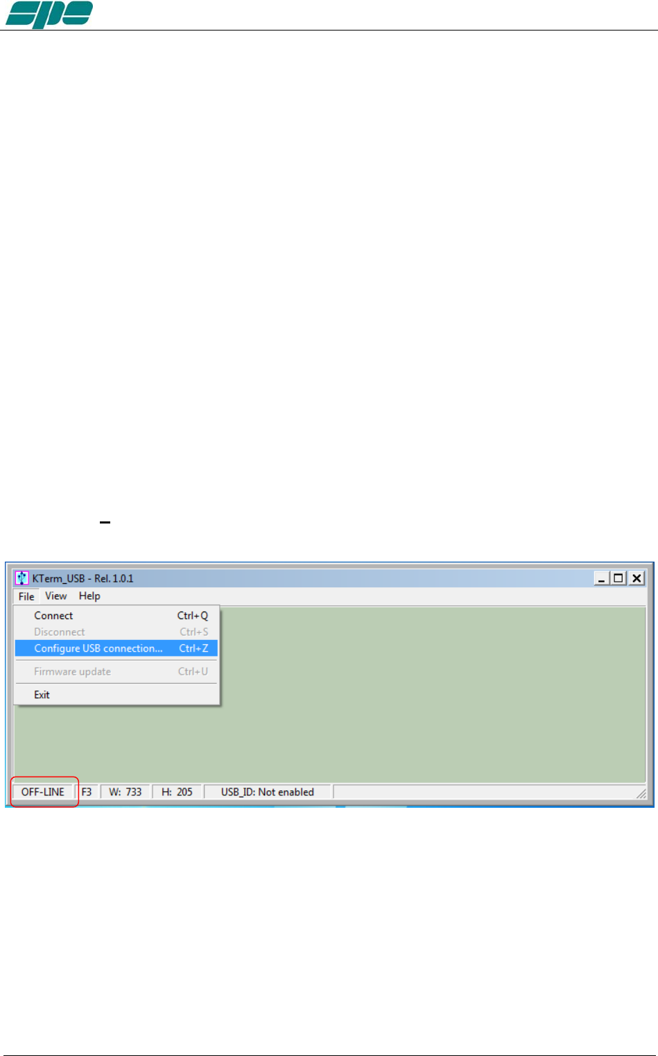
User manual EXPERT 1.3K-FA
Selective addressing thru the USB port.
Note: When trying to connect the linear amplifier to a PC, some problems could occur
because other peripherals sharing the same USB internal hub may conflict with it.
To avoid this kind of conflict it is necessary to go to “selective addressing”.
This options has been designed to allow selective addressing of an EXPERT linear
amplifier connected to any given PC USB port.
In contrast to similar devices using the popular FT232RL USB microcontroller where the
typical way for providing selective addressing of a specific device is based upon its
serial port ID parameter (e.g. COM1, COM2, etc.), our method is based upon a unique
feature of the popular FTDI chip that is known as “ID String Property”.
That is a sequence of 8-alphanumeric characters, programmed by the FT232RL’s
manufacturer during the production process of their components, which is something
similar to the MAC address peculiar to any PC LAN card.
It is important to understand that this unique coding parameter does not allow
addressing ambiguity when correctly applied to FDTI chips that are connected to the
same USB bus.
Preliminary programming for “ID string property” with KTerm_USB.exe .
This special setting, based upon an easy “self-learning” procedure, must be performed
once, however only after having put the Expert 1.3K-FA into an OFF-LINE state. Then,
select File/Configure USB connection... from the main menu as shown in the picture
below:
Exhbit 6 – Pag. 65 of 65
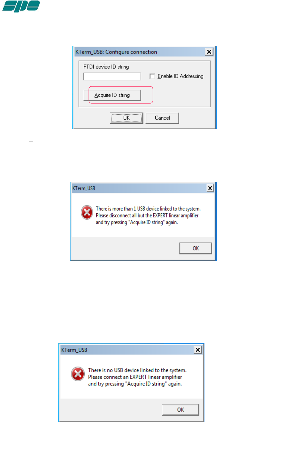
User manual EXPERT 1.3K-FA
A dialog window will pop up:
Press the Acquire ID string key, marked in the picture above, in order to start the ID string characters
acquisition process across the USB data-link. This is a guided self-learning procedure.
In case more than one USB communications is linked to the system, directly or
indirectly thru an external USB hub, the following notification pop-up window will be
shown:
In such a case the user should disconnect all other devices except his EXPERT
amplifier and to retry again using the acquisition procedure above described.
In case the user detaches all of the connected devices, including the linear amplifier,
the KTerm_USB.exe acquisition system will notify the user by showing the following
self-explaining pop-up message.
Exhbit 6 – Pag. 66 of 66
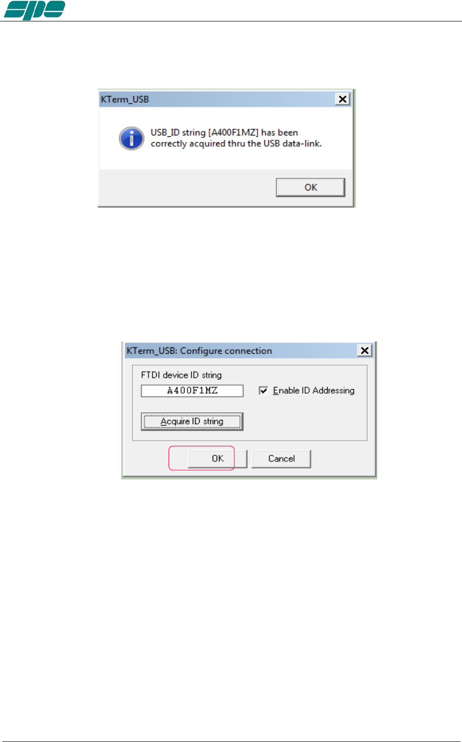
User manual EXPERT 1.3K-FA
The following pop-up notification message will be displayed when a successful
connection via USB occurs:
The picture above shows the acquisition report of a device that its ID String Property is
A400F1MZ.
As explained earlier, this parameter is unique to any given specific chip, so it doesn’t
allow duplicates among other components from the same manufacture.
As soon as the notifiation message is validated, using its OK key, the dialog box
previoulsy popped-up will appear properly filled-in as the following picture shows:
Exhbit 6 – Pag. 67 of 67
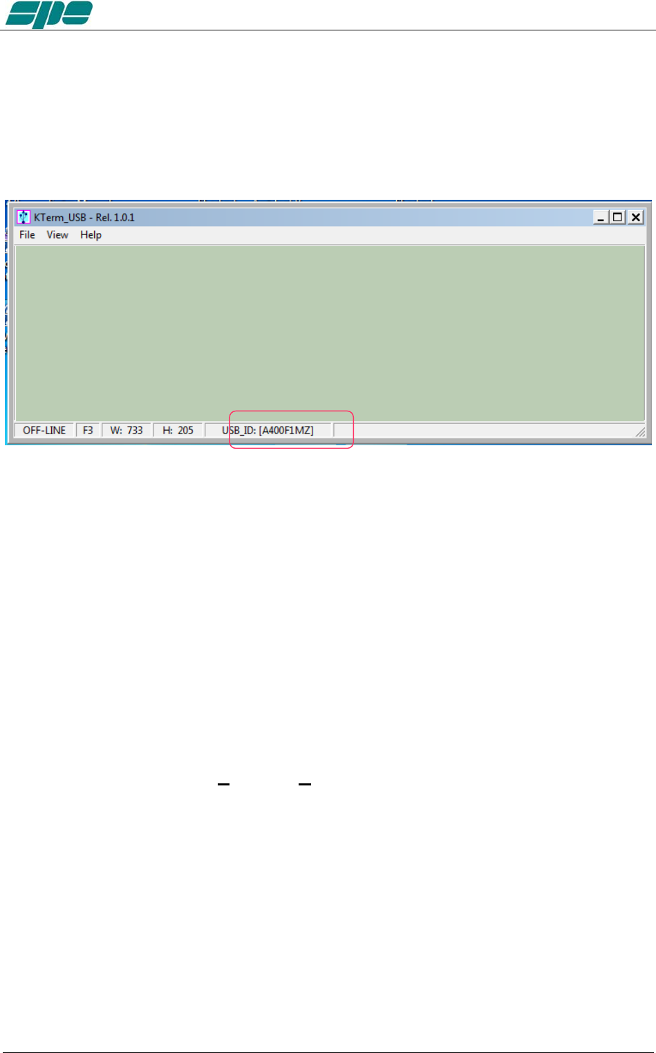
User manual EXPERT 1.3K-FA
Once the user validates the data acquisition, by pressing the OK key as marked in the
picture above, the KTerm_USB.exe internal database will be properly updated and
as confirmation, the application status bar will be updated, as shown in the following
picture:
When the above described steps are completed, KTerm_USB,exe will only be able to
recognize and address the EXPERT linear amplifier whose unique ID String matches
the one written after the USB_ID: label of the picture above.
As explained earlier, this setting is permanent. So there is absolutely no need to repeat
the acquisition procedure described as long as the user connects to that specific unit.
Of course the acquisition procedure must be restarted again in case another EXPERT
linear amplifier would require to be addressed in the same selective way; that is
because a different device has acquired, by force of circumstances, another ID String
parameter to be reconsidered.
After having carried out all the setting and configuration steps listed in the earlier pages,
you should be all set for using the FT232RL selective addressing features as described
so far.
All the operations tied to the Connect / Disconnect menu items are still the same as in
the case of the non-selective addressing procedure.
Exhbit 6 – Pag. 68 of 68
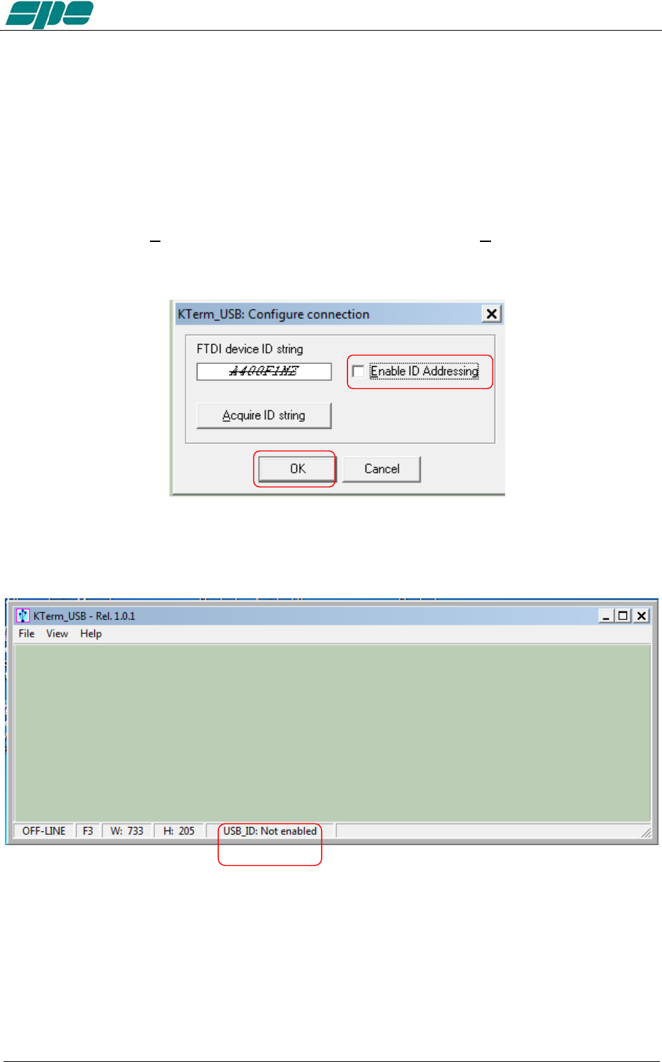
User manual EXPERT 1.3K-FA
A last note.
If, for whatever reason, all the selective addressing capabilities are no longer needed, to
open a connection to an EXPERT linear thru its USB link, they can be temporarily
disabled.
The next operation is quite easy to perform.
After having recalled the Configure USB connection dialog box, using its specific item
contained into the File menu, using your mouse click on the Enable ID Addressing
option, as shown in the following picture, and confirm this entry using the OK button.
You will see this new setting in the application status bar with the “Not enabled” attribute following the
USB_ID: label, as shown below:
Exhbit 6 – Pag. 69 of 69
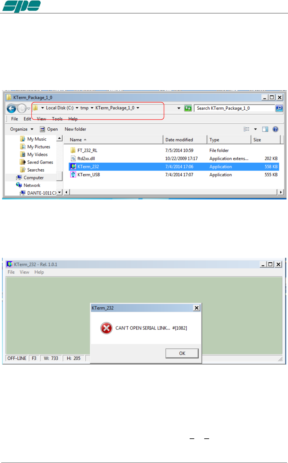
User manual EXPERT 1.3K-FA
20.3 KTerm_232.exe usage
To start running the KTerm_232.exe application, it is necessary to go back into the
KTerm_Package_1_0 uncompressed folder and select the related filename as shown
in the picture below:
A suggestion is to create a link to the application and place it on the Windows desktop.
A double-click using the left-button of the mouse on the application icon should render a
result as the one shown in the following picture:
The very first time KTerm_232.exe is launched, a notifying pop-up message, like the
one in the picture above, is shown.
This is for just warning the user that there is still no valid RS-232 port being set on the
application itself.
To correct this, click OK on the pop-up window and select File/Virtual Com Port
setting, as shown in the following picture:
Exhbit 6 – Pag. 70 of 70
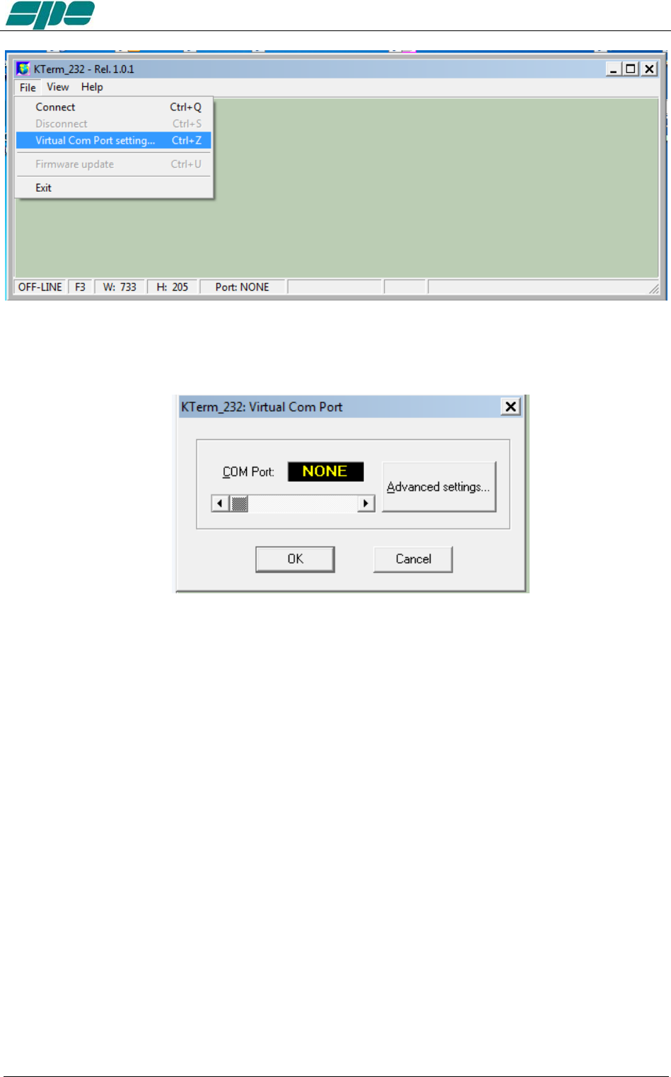
User manual EXPERT 1.3K-FA
The above menu item makes it possible to access the following dialog box, which allows
a direct setting of the desired COMx serial port for connecting to the EXPERT 1.3K-FA.
Exhbit 6 – Pag. 71 of 71
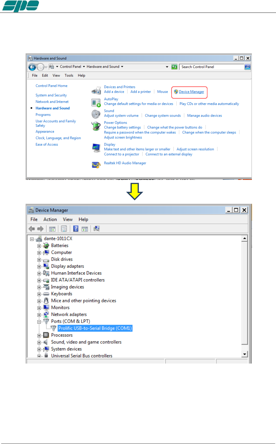
User manual EXPERT 1.3K-FA
With all your serial resources properly connected, proceed to the Control Panel >>>
Hardware and Sound >>> Device Manager and choose a serial COM listed in the
hardware configuration that is not used by other applications.
In case the USB-to-RS232 serial converters are being used, as shown in the picture
above, please proceed, as explained below, to check all the COM ports polled by the
system.
To check a COM port identifier related to any given adapter, disconnect it from the USB
socket of the PC and detect which COM item disappears from the proposed list after
this configuration change.
Exhbit 6 – Pag. 72 of 72
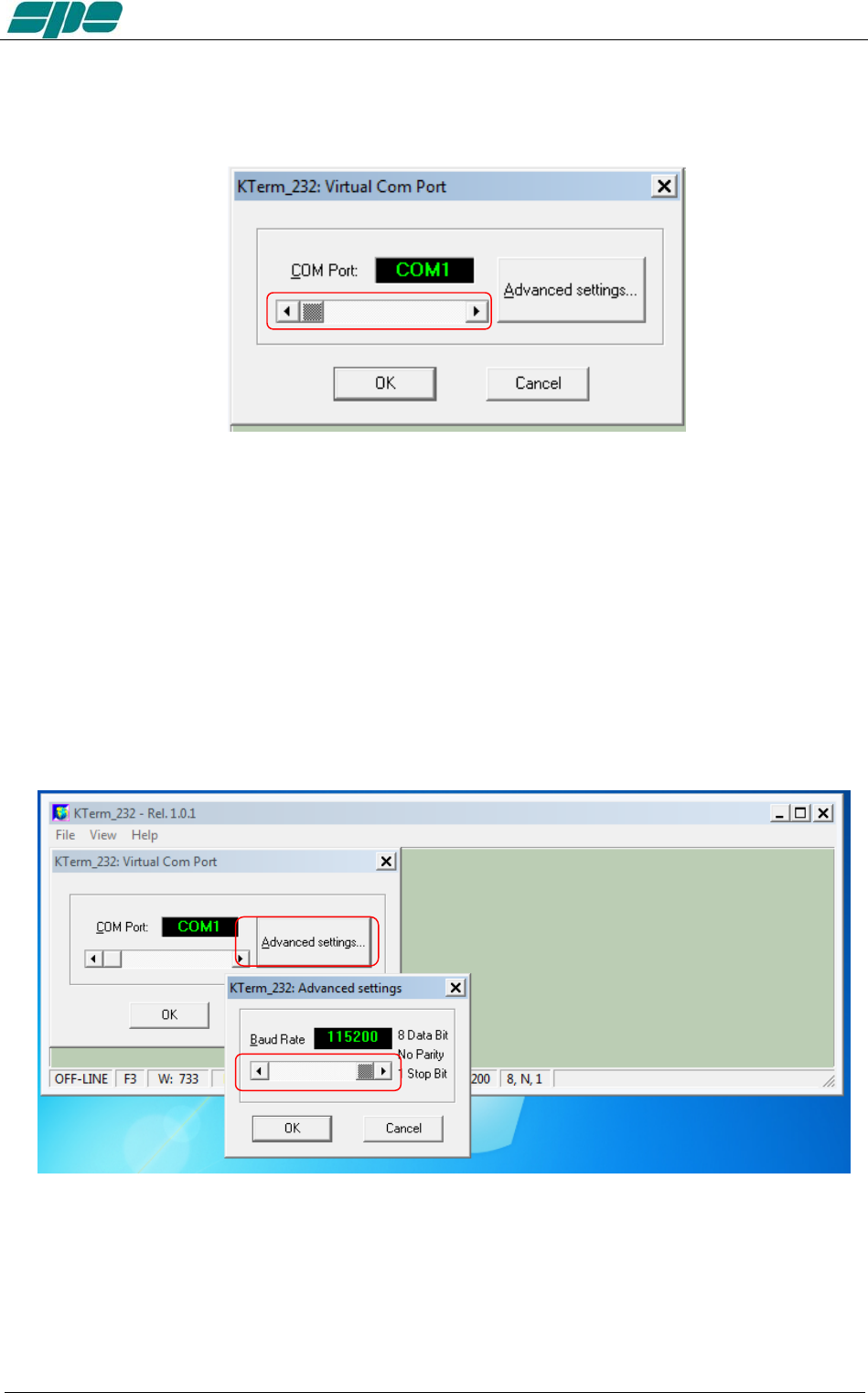
User manual EXPERT 1.3K-FA
In that case, use the detached COM port ID to properly set the Virtual Com Port dialog
box, as shown in the picture below, and then reconnect the serial adapter so that it can
be accessed by the application...
The available selection range spans thru the [COM1…COM256] set, which can be
accessed using the framed slider-control placed above the OK and CANCEL keys.
After the COM port setting is validated by pressing the OK key, all the other
communication parameters become set as follows:
• Baud rate: 115200
• Bit per character: 8
• Parity check: No
• Stop bit: 1
Also, the Baud-rate setting can be changed by pressing the Advanced settings… if
needed.
The Baud rate setting can be selected by using the available slider-control marked in
the picture above:
• 9600 baud
• 14400 baud
• 19200 baud
• 28800 baud
Exhbit 6 – Pag. 73 of 73
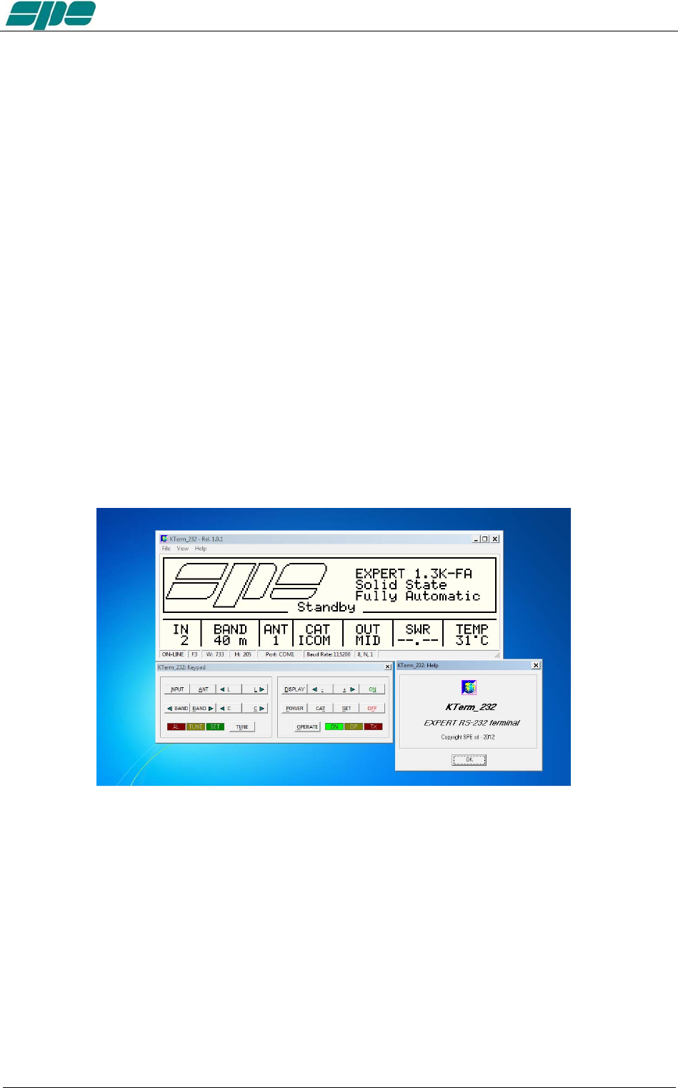
User manual EXPERT 1.3K-FA
• 38400 baud
• 57600 baud
• 115200 baud
And then by pressing the OK button.
All the other framing and parity parameters can not be changed by the user because
they are set by the program initialization.
It should be noted that the Baud rate setting is needed to be set on the
KTerm_232.exe application’s side before a remote connection can be made. And it
may need to be changed due to a previous setting of a different baud rate.
The reason for this is because it is a permanent setting, which is stored into a private
data-base system, and will be recalled by the application whenever needed.
On the EXPERT 1.3K-FA side, the baud-rate is automatically synchronized by the data-
pattern being sent to it by KTerm_232.exe upon any query to the linear.
As mentioned above, the application usage is still the same as for the USB interface
version described earlier, but there are just some minor “look-and-feel” changes as
shown in the picture below:
The use of RS 232 port becomes a necessity when the device needs to be remoted via
the Internet. And since most specially designed devices, currently available on the
market, do not implement the USB port feature to being compliant to the USB front-end
of the EXPERT linear amplifiers.
Exhbit 6 – Pag. 74 of 74
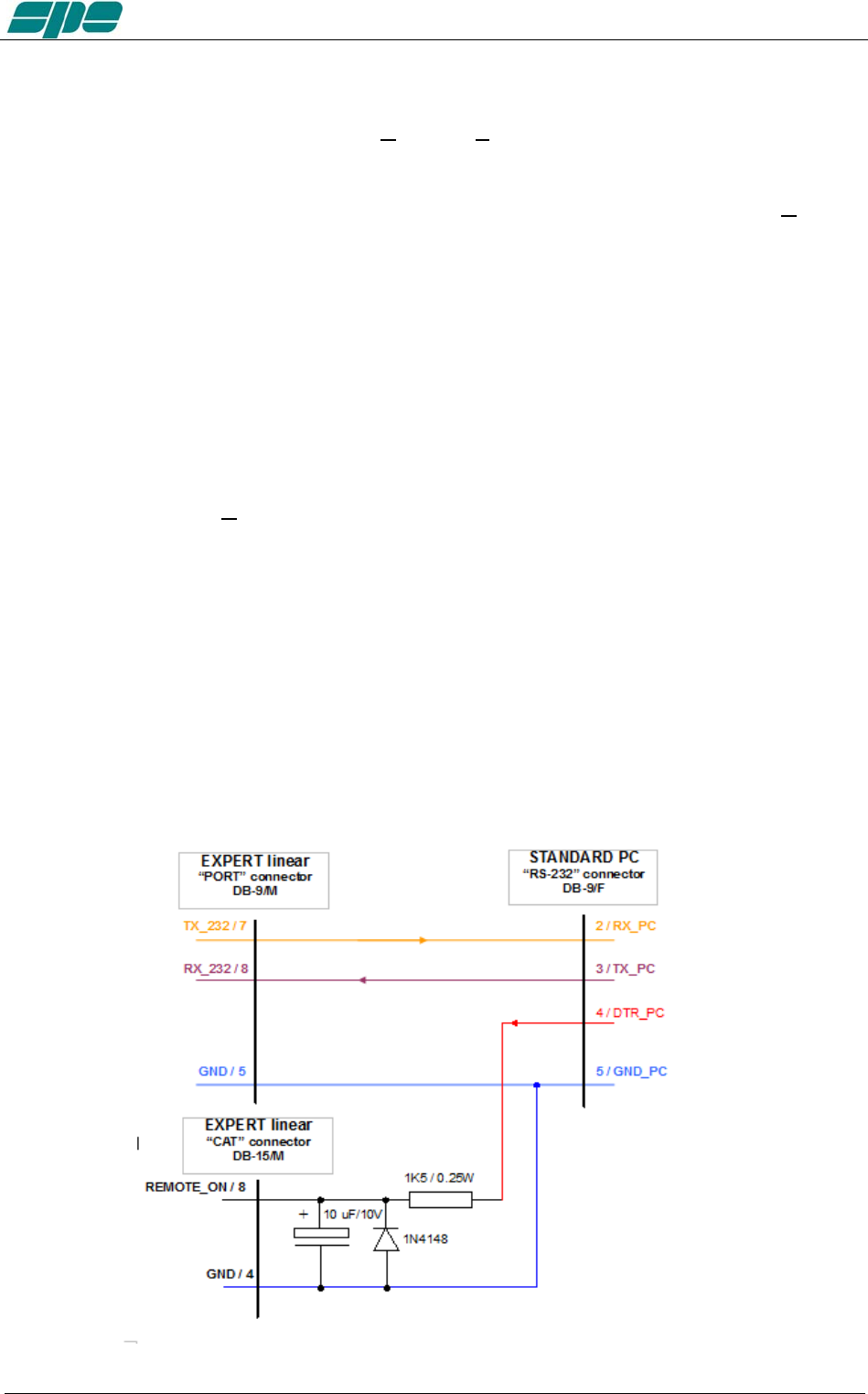
User manual EXPERT 1.3K-FA
Remote ON/OFF using RS-232.
With this new software release, the [ON] and [OFF] keys are fully enabled and work the
same way as they work on the USB version of the application.
However, there is a small technical detail to take into account about the [ON] key's
behaviour.
It acts on the DTR output line of the PC RS-232 serial COM port by generating a timed
positive pulse about every second or so across the link.
Since the “PORT” socket on the rear panel of the 1.3K-FA isn't equipped with any DSR
input line to handle this “switch-on” signal coming from the remote control application,
the most suitable solution is to wire a “cable branch” according to the schematics in the
following diagram.
This solution uses an already-existing feature of 1.3K-FA which involves the
“REMOTE_ON” input line, placed on both “CAT” sockets, which behaves the same way
as the front panel's [ON] key does.
Actually, it triggers a switch-on of the linear amplifier whenever a positive voltage level
greater than +5Vdc is applied to it.
A typical application for this “remote switch-on line”, is to wire it to the +13.8Vdc power-
supply which powers the transceiver. And a similar result can also be achieved by
wiring it to DTR output line coming from a PC, or from a remote device controlled by a
PC running Term_2K_232.exe using the suggested external R-C network drawn in the
schematic diagram below.
A typical RS-232 serial port like this ensures output voltage levels spanning from +/-
6.5Vdc (USB-to_serial adapters) and up to +/- 11Vdc (standard RS-232 ports whose
circuit is based upon the popular MAX232 line-driver).
Exhbit 6 – Pag. 75 of 75

User manual EXPERT 1.3K-FA
A note about the DTR-link behaviour.
Even thought this circuit seems to work correctly when driven by software, it could
cause unexpected switching-on of a connected linear amplifier having its rear panel's
mains-switch enabled, when the linked PC re-boots or when an external serial device
(e.g. a USB-to_serial adaptor...) is physically connected.
The reason for this odd behaviour is related to some uncontrolled OFF-to-ON transitions
of a DTR output line.
So, please, take this unpleasant side effect into account when using this kind of branch
in external links.
Exhbit 6 – Pag. 76 of 76
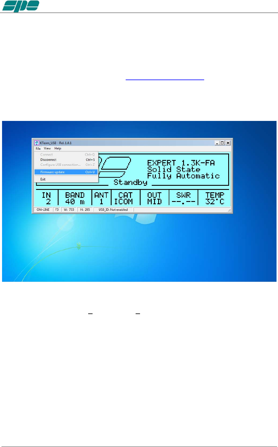
User manual EXPERT 1.3K-FA
20.4 Firmware update
A very useful feature of the KTerm_USB.exe / KTerm_232.exe applications is one that
enables software updating of the built-in firmware in the linear amplifier.
To update the linear amplifier it is necessary to use a suitable .PK2 firmware file, which
must be downloaded from our website www.linear-amplifier.com and then stored into a
proper working folder.
Switch the linear on leaving it set to the STANDBY mode during the firmware updating.
Under these conditions the File\Firmware update menu item becomes active and, after
being selected, it sets the EXPERT 1.3-FA into its firmware update mode (FIRMWARE
UPDATE PROCEDURE).
Exhbit 6 – Pag. 77 of 77
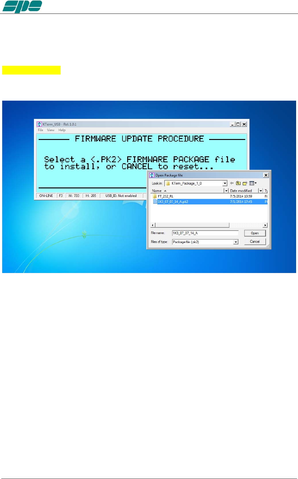
User manual EXPERT 1.3K-FA
After then a dialog box pops-up, and the user has selected a proper firmware package,
that data will be sent to the linear amplifier to update all its embedded functions
Observe the example in the picture below where a firmware package file named
07_07_14_A.pk2 has been selected:
After the necessary confirmation by the user for validating the procedure, the EXPERT
1.3K-FA switches its display off as the updating is being transferred to the
KTerm_USB.exe application
Exhbit 6 – Pag. 78 of 78
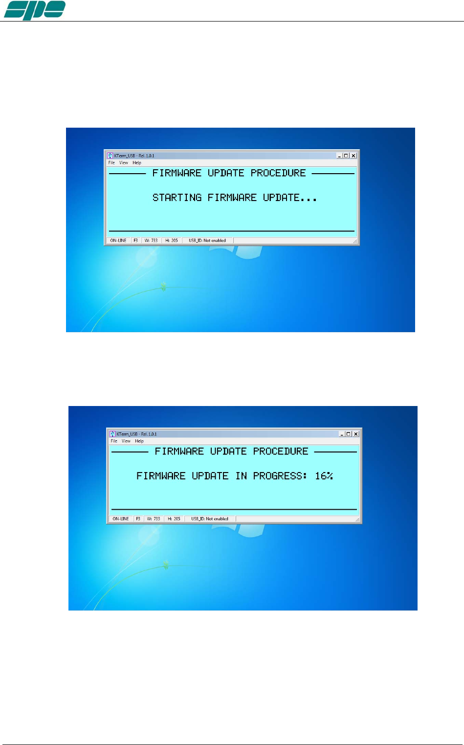
User manual EXPERT 1.3K-FA
The main steps of firmware update procedure are below:
1. Checking and validation of updating firmware package
2. A physical data transmission of the new firmware from the PC to the linear
amplifier
Exhbit 6 – Pag. 79 of 79
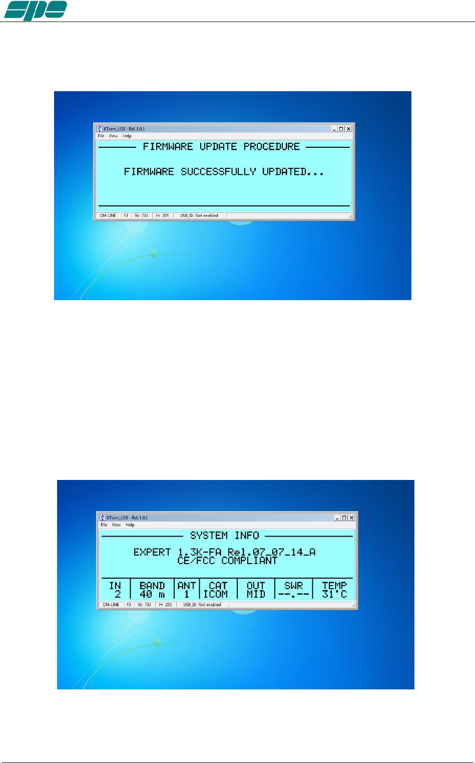
User manual EXPERT 1.3K-FA
3. A final validation for the completed firmware update
And as the last action, after a successful firmware update, the linear amplifier performs
a general auto-restart operation. Then after, full control of the updated device is
restored to both local and remote operations.
The user is then able to check the result of his firmware update operation directly on the
LCD display (both real and virtual…) by pressing the [CAT] key twice and only when in
the STANDBY mode.
This operation will be shown on the display as below:
Exhbit 6 – Pag. 80 of 80

User manual EXPERT 1.3K-FA
21. GENERAL RESTORE
A System General Restore can be performed by pressing the [INPUT] and the [OFF]
keys together for at least one second.
This operation is only possible from the linear amplifier front-panel physical keyboard.
The linear amplifier will switch off with a self-explaining system message.
Then, after it turns back on, all of the factory defaults will be restored.
Exhbit 6 – Pag. 81 of 81

User manual EXPERT 1.3K-FA
22. WARRANTY TERMS
SPE warrants to the original Purchaser that this product shall be free from defects of
materials or workmanship.
SPE warrants for two (2) years from the date of original purchaser that SPE will provide
free of charge all parts and labor necessary to correct defects in material or
workmanship. The Purchaser has only to pay all the shipping expenses for warranty
service work.
Customers should address requests for warranty service work to the Distributor/ Dealer
where they made their purchase. As part of their reseller agreement with SPE, they are
responsible for service support.
If the Distributor/Dealer has closed down, or when the Purchaser moves into another
area, SPE will be directly responsible for warranty service at their factory in Rome. The
shipping expenses to and from SPE will then be paid by the customer. Any repair
requests to other dealers will be subject to specific direct negotiations between the
customer and the dealer.
In order to not invalidate the warranty service, the original Purchaser must complete the
warranty registration card, and send it to SPE no more than 30 days from the date of
purchase.
Unless otherwise agreed, the products will be delivered ex-works from the factory of the seller.
The delivery, even in the event of a return for repair, is understood done with the delivery of the goods to
the carrier specified by the purchaser or, failing that, to the carrier chosen by SPE.
The products will travel at the risk of the purchaser even if, at the request of the same
one or for other causes, SPE should carry out transport or choose the carrier.
If the original Purchaser finds some defects after having received the equipment, he
must immediately notify the Distributor/Dealer of the defects found by sending the
properly filled in REPAIR FORM. Replacement of the amplifier may be done by SPE in
exceptional circumstances and at SPE’s complete discretion. In any case no
replacement will be provided if more than the twentieth day after delivery has passed.
In case of a purchase of a used amplifier, in order to retain the warranty’s validity, it is
necessary to notify SPE of the following data:
• Document for the second purchase (used)
• Invoice for the original purchase
• Serial number (s/n) of equipment
Replacement of equipment in these circumstances is not an option.
In any case the warranty period shall be two (2) years from the original purchase, and
not from any subsequent purchase.
Whenever the date of first sale is not well specified or is greater than one year from the
date of the shipping from SPE to the Distributor/Dealer, the date of shipping from SPE
to the Distributor/Dealer will be considered the start of the warranty period.
The warranty does not apply either if the certificate of the first purchase (invoice) is
missing, the s/n is undecipherable/falsified or to any defect that SPE determines is due
to:
1. Improper maintenance or repair by persons not authorised by SPE to carry out
such work, including the installation of parts or accessories that do not conform
to the quality and specifications of the original parts.
2. Misuse, abuse, neglect or improper installation, user’s manual non-observance.
3. Carelessness, accidental or intentional damage.
Exhbit 6 – Pag. 82 of 82

User manual EXPERT 1.3K-FA
SPE warrants aforesaid items only, and the Purchaser shall have no remedy and no
claim for incidental or consequential damages.
It is mandatory, when sending SPE equipment to be repaired, to enclose:
- Invoice of the original purchase
- Document of the second purchase (if any)
Particular agreements between retailer and Purchaser or particular obligations imposed
in other countries are matters for the local retailer and not for SPE.
In the event of dispute Rome’s court of competent jurisdiction will apply.
By purchasing SPE equipment, the Purchaser declares his acceptance of the
above warranty terms.
Exhbit 6 – Pag. 83 of 83

User manual EXPERT 1.3K-FA
REPAIR FORM
MODEL . . . . . . . . . . . . . . . . . . . . . SERIAL NUMBER . . . . . . . . . . . . . . . . . . . . DATE . . . . . . . . . . . . . . . . .
CONNECTION STATE AT THE MOMENT OF THE BREAKDOWN
TRANSCEIVER MODEL . . . . . . . . . . . . . . . . . . . . . . . . . . . . . . . . . . . . .
CAT CONNECTION YES NO
IF YES INDICATE THE ITEM HEADING IN THE USER’S MANUAL . . . . . . . . . . . . . . . . . . . . . . . . . . . . . . . . .
IF NO BAND DATA INTERFACE YES
ANY LINK? YES . . . . . . . . . . . . . . . . . . . . . . . . . . . . . . . . . .
WAS THE ALC CONNECTED? YES NO
WAS THE DRIVING POWER OF THE TRANSCEIVER SET AT THE MAXIMUM LEVEL? YES NO
IF ‘NO’, WHAT POWER OUTPUT WAS SET? . . . . . . . . . . . . . . . . . . . . . . . . .
ON WHICH BAND DID THE FAULT HAPPEN? . . . . . . . . . . . . . . . . . . . . . . .
DID YOU CHANGE BANDS / ANTENNA IMMEDIATELY BEFORE THE FAULT HAPPENED? YES NO
PLEASE WRITE THE TRANSMISSION MODE: SSB CW QSK DIGITAL MODE/FM AM
FOR HOW LONG BEFORE THE FAILURE DID YOU SWITCH ON THE AMPLIFIER? . . . . . . . . . . . . . . . . . . . . . .
THE AMPLIFIER WAS IN THE: LOW MID MAX
WHICH WAS THE INPUT USED? INPUT 1 INPUT 2
WHICH WAS THE TEMPERATURE OF THE AMPLIFIER ? . . . . . . . . . . . . . . . . . . . . . . . . . .
WHAT FAULT INFORMATION WAS DISPLAYED ON THE LCD? . . . . . . . . . . . . . . . . . . . . . . . . . . . . . . . . . . . . . .
WHICH WAS THE MAINS VOLTAGE AT THE MOMENT OF THE BREAKDOWN? . . . . . . . . . . . . . . . . . . . . . . . .
OTHER INFORMATION: . . . . . . . . . . . . . . . . . . . . . . . . . . . . . . . . . . . . . . . . . . . . . . . . . . . . . . . . . . . . . . . . . . . . . . . . .
. . . . . . . . . . . . . . . . . . . . . . . . . . . . . . . . . . . . . . . . . . . . . . . . . . . . . . . . . . . . . . . . . . . . . . . . . . . . . . . . . . . . . . . . . . . . . .
. . . . . . . . . . . . . . . . . . . . . . . . . . . . . . . . . . . . . . . . . . . . . . . . . . . . . . . . . . . . . . . . . . . . . . . . . . . . . . . . . . . . . . . . . . . . . .
. . . . . . . . . . . . . . . . . . . . . . . . . . . . . . . . . . . . . . . . . . . . . . . . . . . . . . . . . . . . . . . . . . . . . . . . . . . . . . . . . . . . . . . . . . . . . .
. . . . .. . . . . . . . . . . . . . . . . . . . . . . . . . . . . . . . . . . . . . . . . . . . . . . . . . . . . . . . . . . . . . . . . . . . . . . . . . . . . . . . . . . . . . . . .
. . . . . . . . . . . . . . .. . . . . . . . . . . . . . . . . . . . . . . . . . . . . . . . . . . . . . . . . . . . . . . . . . . . . . . . . . . . . . . . . . . . . . . . . . . . . . .
. . . . . . . . . . . . . . . . . . . . . . .. . . . . . . . . . . . . . . . . . . . . . . . . . . . . . . . . . . . . . . . . . . . . . . . . . . . . . . . . . . . . . . . . . . . . . .
. . . . . . . . . . . . . . . . . . . . . . . . . . . . . .. . . . . . . . . . . . . . . . . . . . . . . . . . . . . . . . . . . . . . . . . . . . . . . . . . . . . . . . . . . . . . . .
. . . . . . . . . . . . . . . . . . . . . . . . . . . . . . . . . . . . . .. . . . . . . . . . . . . . . . . . . . . . . . . . . . . . . . . . . . . . . . . . . . . . . . . . . . . . . .
. . . . . . . . . . . . . . . . . . . . . . . . . . . . . . . . . . . . . . . . ..
SPACE FOR THE REPAIRER
REPAIRER . . . . . . . . . . . . . . . . . . . . . . . . . . . . . . . . . . . . . . . . . . . . . DATE OF ARRIVAL . . . . . . . . . . . . . . . . . . . . . .
NOTES ABOUT THE AMPLIFIER WHEN YOU RECEIVED IT . . . . . . . . . . . . . . . . . . . . . . . . . . . . . . . . . . . . . . .. . . . .
. . . . . . . . . . . . . . . . . . . . . . . . . . . . . . . . . . . .. . . . . . . . . . . . . . . . . . . . . . . . . . . . . . . . . . . . . . . . . . . . . . . . . . . . . . . . . .
. . . . . . . . . . . . . . . . . . . . . . . . . . . . . . . . . . . . . . . . . . . . . . . . . . . . . . . . . . . . . . . . . . . . . . . . . . . . . . . . . . . . . . . . . . . . . .
. . . .. . . . . . . . . . . . . . . . . . . . . . . . . . . . . . . . . . . . . . . . . . . . . . . . . . . . . . . . . . . . . . . . . . . . . . . . . . . . . . . . . . . . . . . . . .
. . . . . . . . . . . . . . . . . . . . . . . . . . . . . . . . . . . . . . . . . . . . . . . . . . . . . . . . . . . . . . . . . . . . . . . . . . . . . . . . . . . . . . . . . . . . . .
. . . . . . . . . . . . . . . . . . . . . . . . . . . . . . . . . . . . . . . . . . . . . . . . . . . . . . . . . . . . . . . . . . . . . . . . . . . . . . . . . . . . . . . . . . . . . .
. . . . . . . . . . . . . .. . . . . . . . . . . . . . . . . . . . . . . . . . . . . . . . . . . . . . . . . . . . . . . . . . . . . . . . . . . . . . . . . . . . . . . . . . . . . . . .
. . . . . . . . . . . . . . . . . . . . . .. . . . . . . . . . . . . . . . . . . . . . . . . . . . . . . . . . . . . . . . . . . . . . . . . . . . . . . . . . . . . . . . . . . . . . . .
. . . . . . . . . . . . . . . . . . . . . . . . . . . . . .. . . . . . . . . . . . . . . . . . . . . . . . . . . . . . . . . . . . . . . . . . . . . . . . . . . . . . . . . . . . . . . .
. . . . . . . . . . . . . . . . . . . . . . . . . . . . . . . . .. . . . . .. . . . . . . . . . . . . . . . . . . . . . . . . . . . . . . . . . . . . . . . . . . . . . . . . . . . . . . .
. . . . . . . . . . . . . . . . . . . . . . . . . . . . . . . . . . . . . . . . . PARTS REPLACED . . . . . . . . . . . . . . . . . . . . . . . . . . . . . . . . . . .
. . . . . . . . . . . . . . . . . . . . . . . . . . . . . . . . . . . . . . . . . . . . . . . . . . . . . . . . . . . . . . . . . . . . . . . . . . . . . . . . . . . . . . . . . . . . . .
. . . . . . . . . . . . . . . . . . . . . . . . . . . . . . . . . . . . . . . . . . . . . . . . . . . . . . . . . . . . . . . . . . . . . . . . . . . . . . . . . . . . . . . . . . . . . .
. . . . . . . . . . . . . . . . . . . . . . . . . . . . . . . . . . . . . . . . . . . . . . . . . . . . . . . . . . . . . . . . . . . . . . . . . . . . . . . . . . . . . . . . . . . . . .
. . . . . . . . . . . . . . . . . . . . . . . . . . . . . . . . . . . . . . . . . . . . . . . . . . . . . . . . . . . . . . . . . . . . . . . . . . . . . . . . . . . . . . . . . . . . . .
. . . . . . . . . . . . . . . . . . . . . . . . . . . . . . . . . . . . . . . . . . . . . . . . . . . . . . . . . . . . . . . . . . . . . . . . . . . . . . . . . . . . . . . . . . . . . .
. . . . . . . . . . . . . . . . . . . . . . . . . . . . . . . . . . . . . . . . . . . . . . . . . . . . . . . . . . .. . . . . . . . . . . . . . . . . . . . . . . . . . . . . . . . . . .
. . . . . . . . . . . . . . . . . . . . . . . . . . . . . . . . . . . . . . . . . . . . . . . . . . . . . . . . . . . . . . . . . . .. . . . . . . . . . . . . . . . . . . . . . . . . . .
. . . . . . . . . . . . . . . . . . . . . . . . . . . . . . . . . . . . . . . . . . . . . . . . . . . . . . . . . . . . . . . . . . . . . . . . . . .. . . . . . . . . . . . . . . . . . .
. . . . . . . . . . . . . . . . . . . . . . . . . . . . . . . . . . . . . . . . . . . . . . . . . . . . . . . . . . . . . . . . . . . . . . . . . . . . . .
DATE OF TESTS SIGNATURE OF THE REPAIRER
. . . . . . . . . . . . . . . . . . . . . . . . . . . . . . . . . . . . . . . . . . . . .
Exhbit 6 – Pag. 84 of 84