S P E s r l GC324810 Linear amplifier for radio amateur use User Manual Exhibit 6 Manual
S.P.E. s.r.l. Linear amplifier for radio amateur use Exhibit 6 Manual
UserManual.wiki
>
S P E s r l
>
GC324810 User Manual
users manual
Navigation menu
Upload a User Manual
Namespaces
Wiki Guide
HTML
PDF
Info
Views
User Manual
Discussion / Help
Navigation


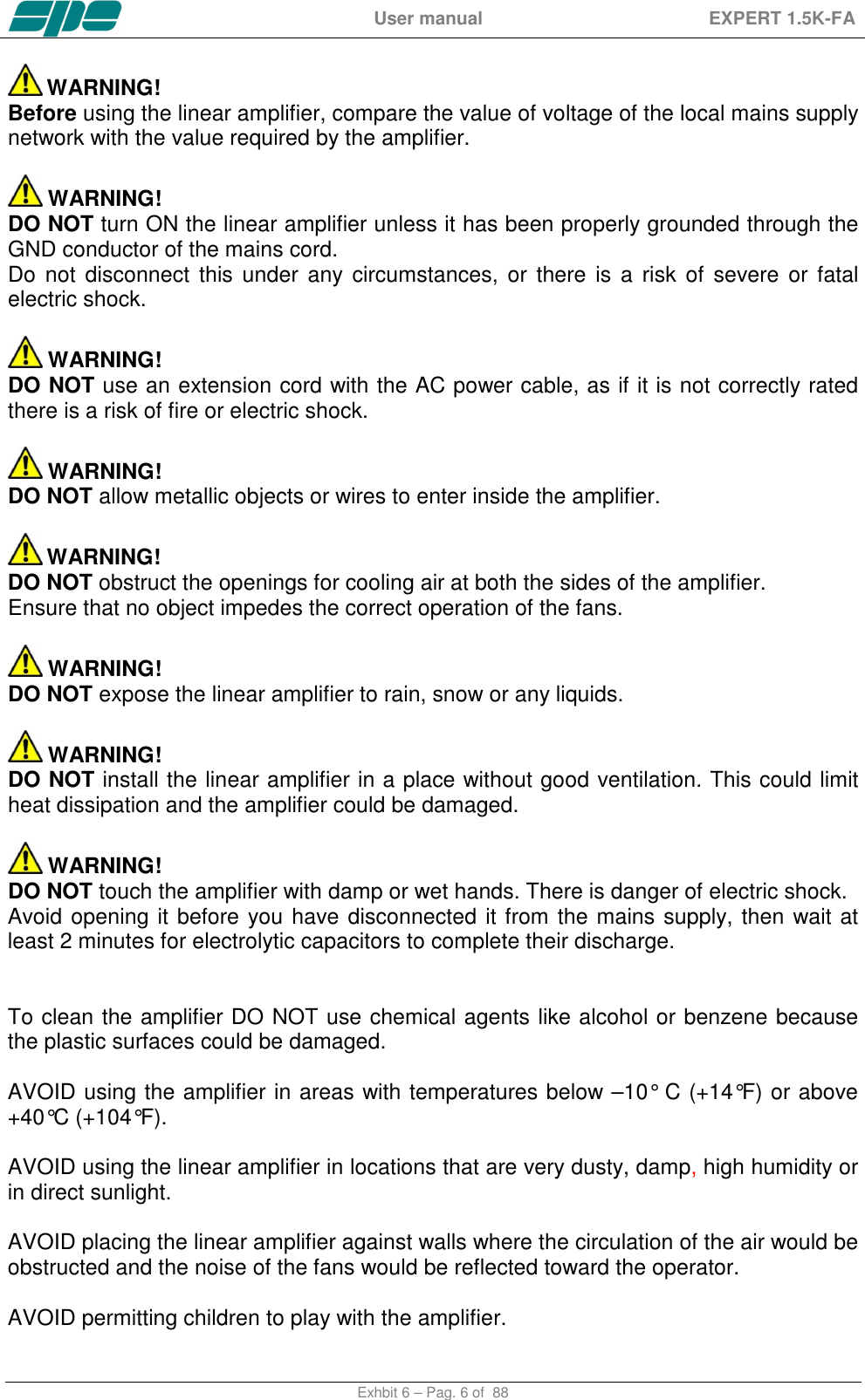
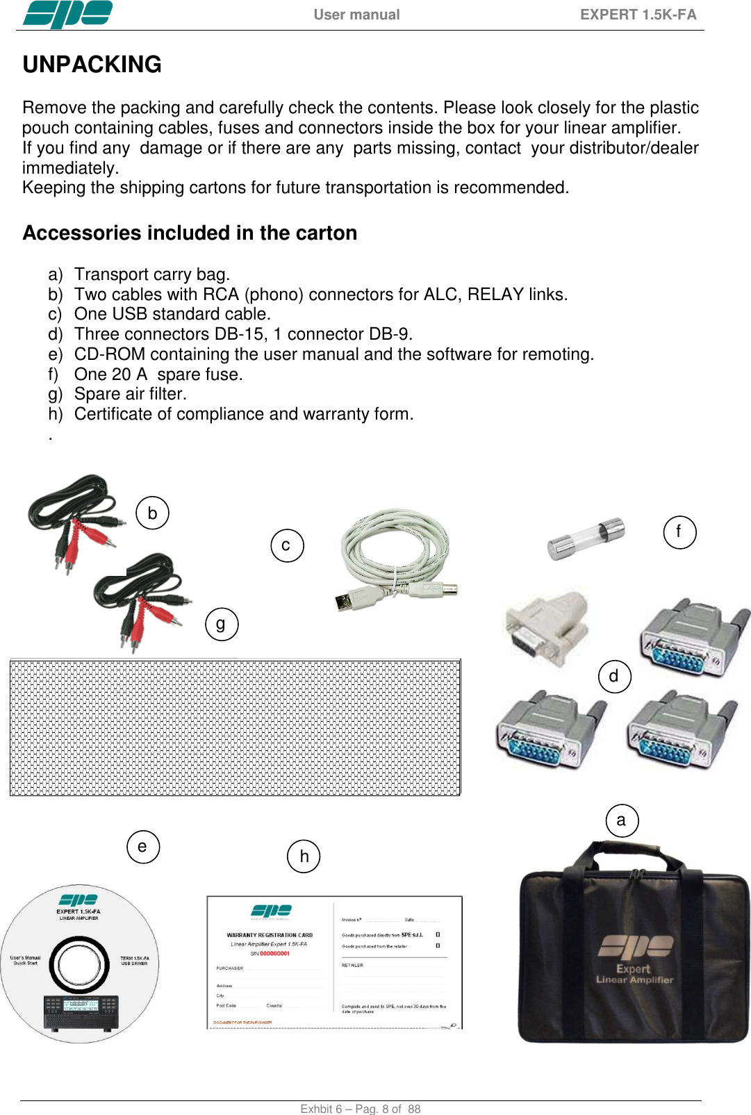
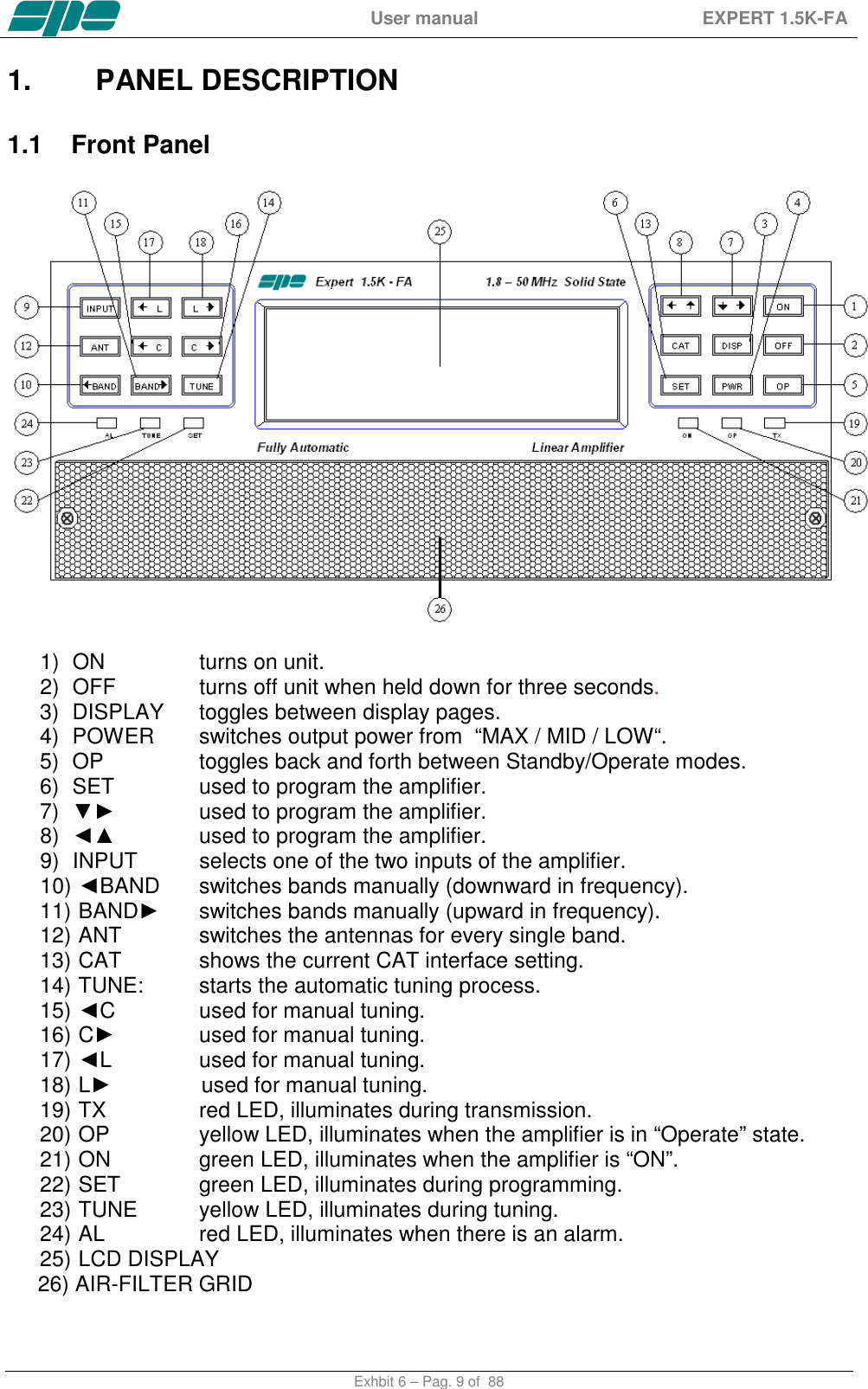
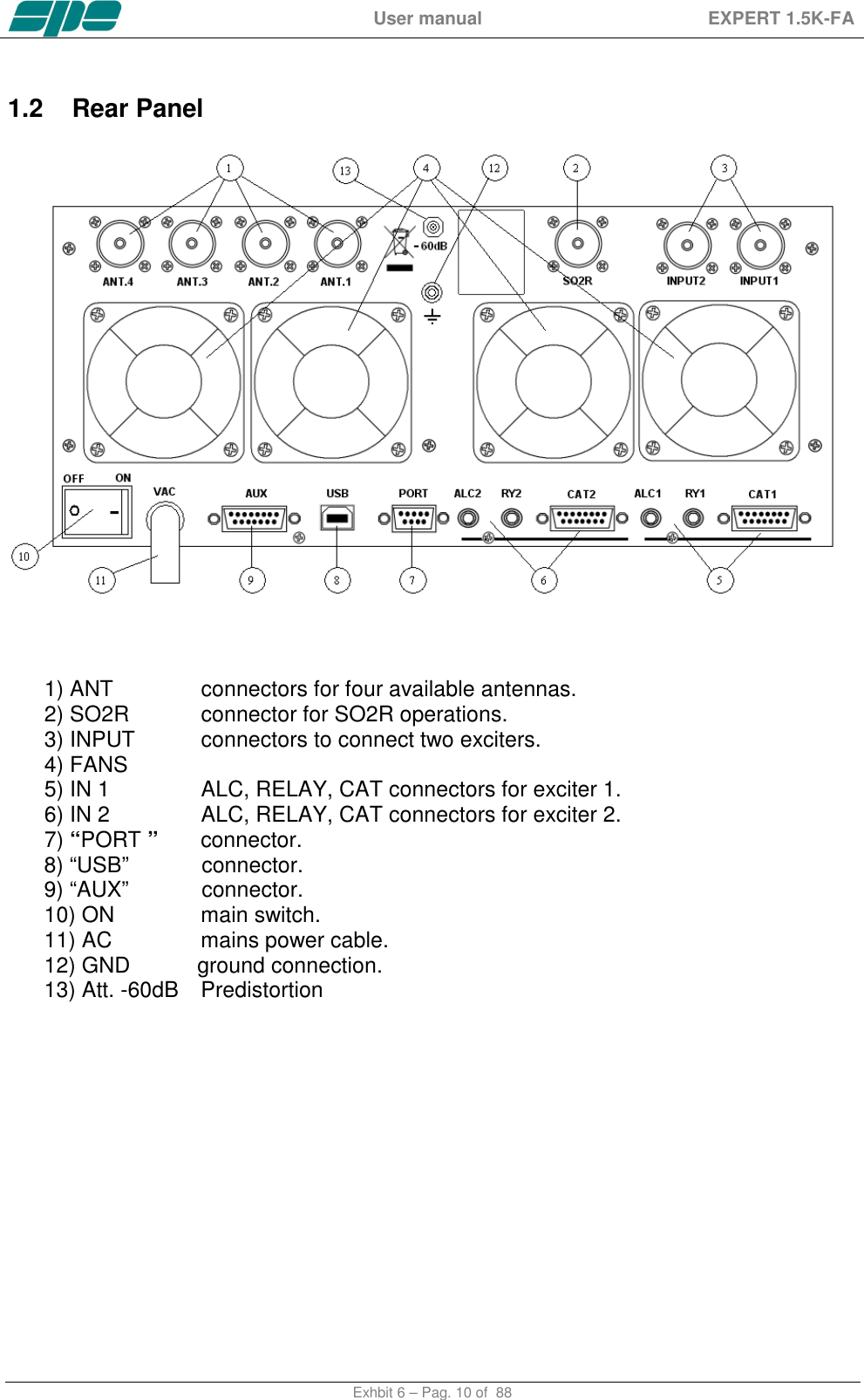
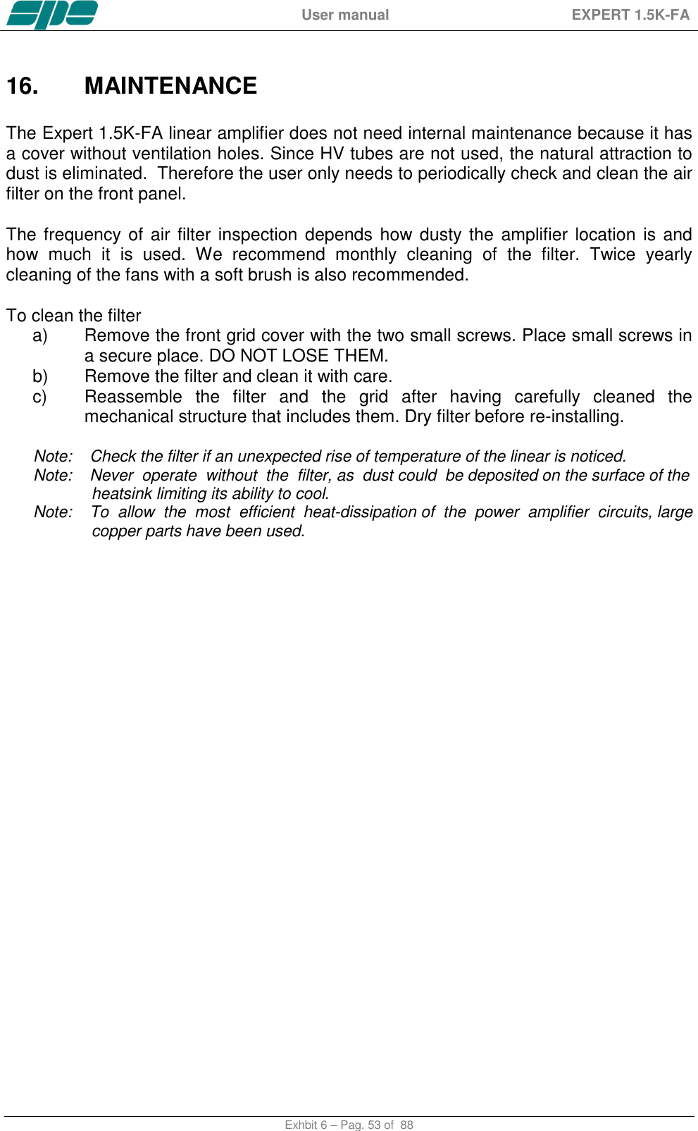
![User manual EXPERT 1.5K-FA Exhbit 6 – Pag. 7 of 88 If you do not use the linear amplifier for long time, set the back main switch [I/O] to the OFF position [O]. Information for Users on Collection and Disposal of Old Equipment and used Batteries. These symbols on the products, packaging, and/or accompanying documents mean that used electrical and electronic products and batteries should not be mixed with general household waste. For proper treatment, recovery and recycling of old products and used batteries, please take them to applicable collection points, in accordance with your national legislation. This amplifier should only be operated by persons who have an appropriate radio transmitting license. You should observe your license conditions while using it in accordance with national legislation (power, band, transmission mode etc.).](https://usermanual.wiki/S-P-E-s-r-l/GC324810/User-Guide-3431025-Page-7.png)
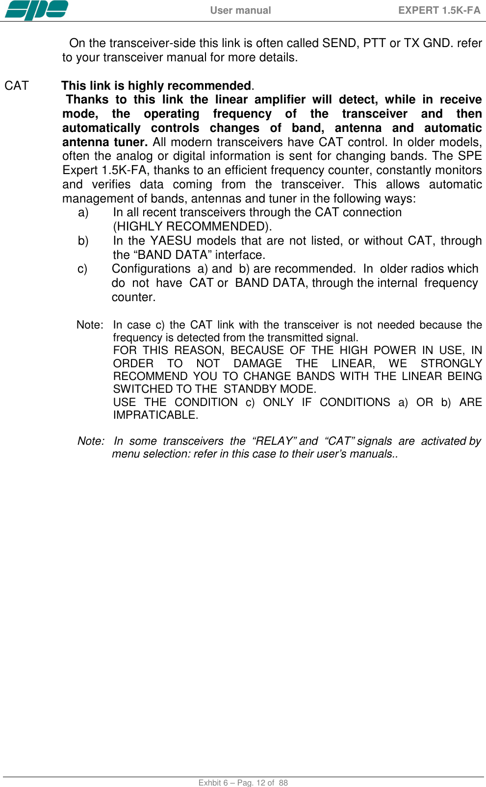
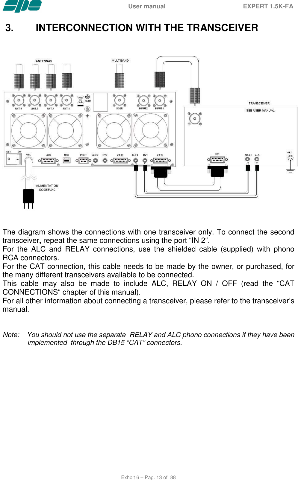
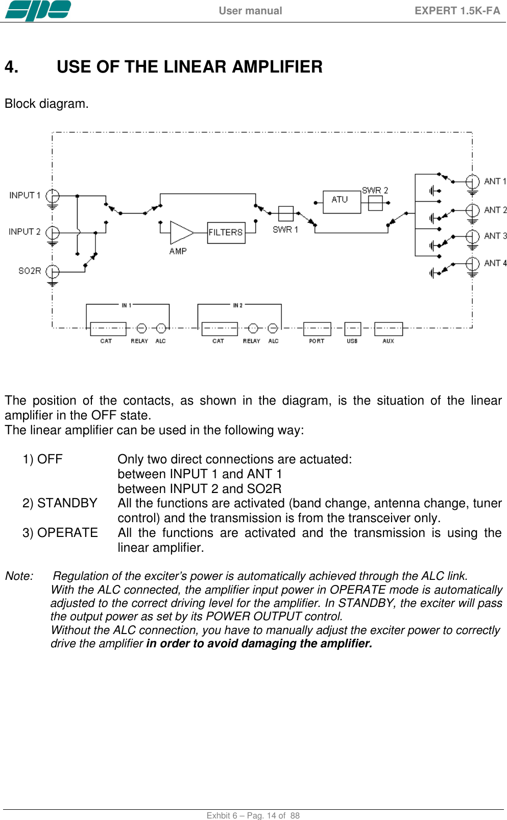
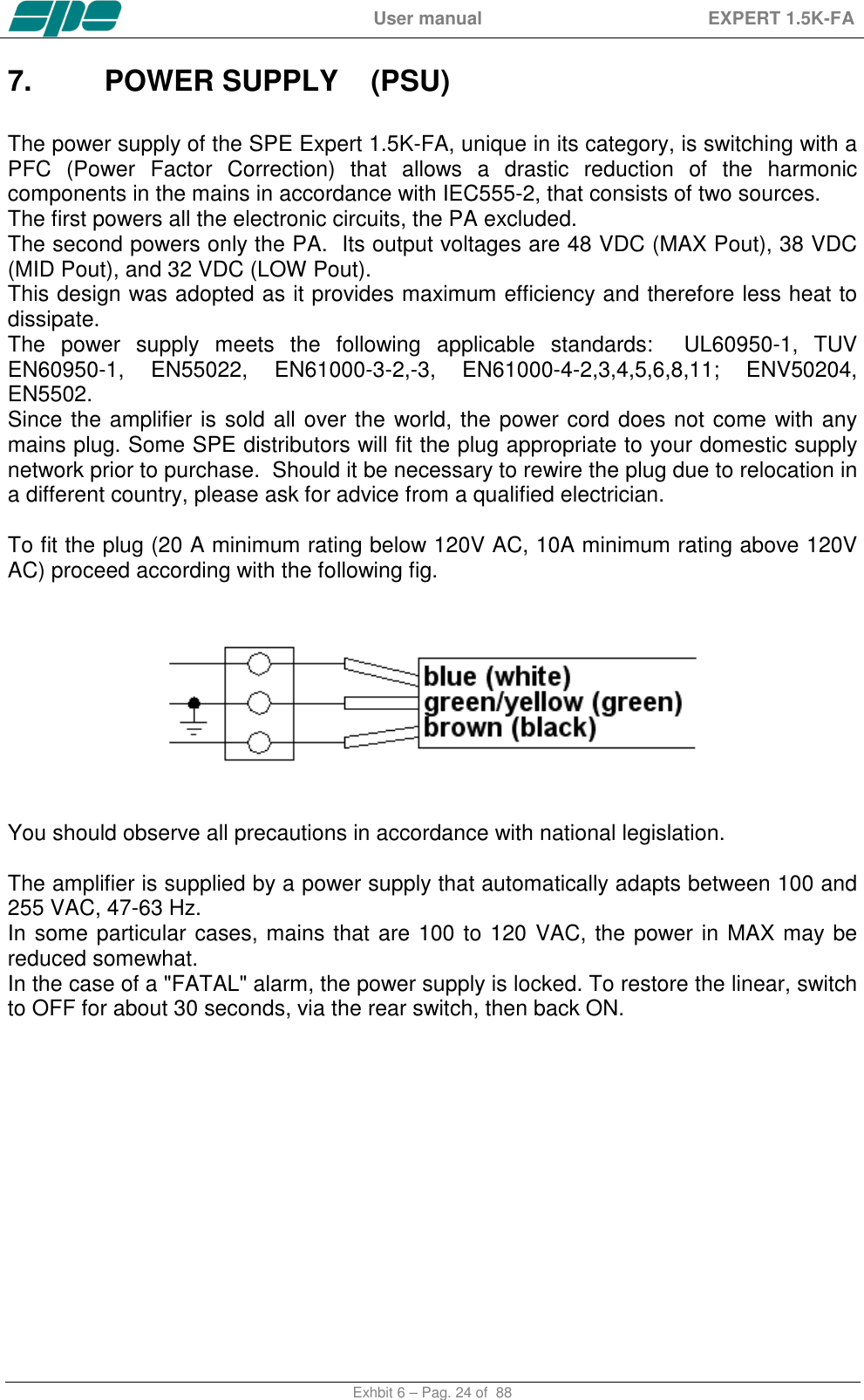
![User manual EXPERT 1.5K-FA Exhbit 6 – Pag. 11 of 88 2. GENERAL INFORMATION (Read the specific chapters for more details). 2.1 Power supply The amplifier uses a switching power supply that will automatically adapt to any voltage that is between 100 and 255 Vac. The main switch [I/O] is located on the rear panel. In the [O] position all the internal circuitry is powered off, in the [I] position (red led ON) some internal voltages are now present allowing for you to turn ON or turn OFF the linear amplifier in one of the following ways: a) Using the [ON]/[ OFF] keys on the front panel. b) Applying / removing 9 -15 VDC on pin (8) of the CAT connector (see note below). c) Using the USB port and the management software. It is possible to download this software from the website www.linear-amplifier.com . Note: When turned ON, almost all transceivers output 13.8 VDC. With this voltage, the linear amplifier can be turned automatically ON / OFF at the same time as the transceiver. Note: The fuse is located inside the amplifier (remove the lower cover). 2.2 Input / Output The linear amplifier has two inputs (INPUT 1, INPUT 2) to which you can connect two transceivers of any brand or type. These inputs are selected with the [INPUT] key or automatically with the PTT of each transceiver. The amplifier can manage up to four antennas (ANT 1, ANT 2, ANT 3, ANT 4). It selects the antennas automatically. The SO2R functionality is implemented by its dedicated connector. 2.3 ALC / RELAY / CAT There are two transceiver inputs (IN 1, IN 2), allowing two distinct transceivers to be connected at the same time. ALC Is a negative voltage generated by the amplifier. It is used to control the output power of the transceiver (max. in STANDBY”, the required power in “OPERATE”). In this way the power from the exciter will be regulated automatically without having to set it. . If the ALC port is not connected, it is very important to manually adjust the drive from the transceiver as overdriving can cause damage to the amplifier. This link is highly recommended. RELAY This essential link allows the amplifier to be put in the transmit state. To do that, it is necessary that the inner pin of the phono connector is switched to the signal ground. This is normally done by the transceiver with either a “close-to-ground” relay, or an open-collector transistor.](https://usermanual.wiki/S-P-E-s-r-l/GC324810/User-Guide-3431025-Page-11.png)


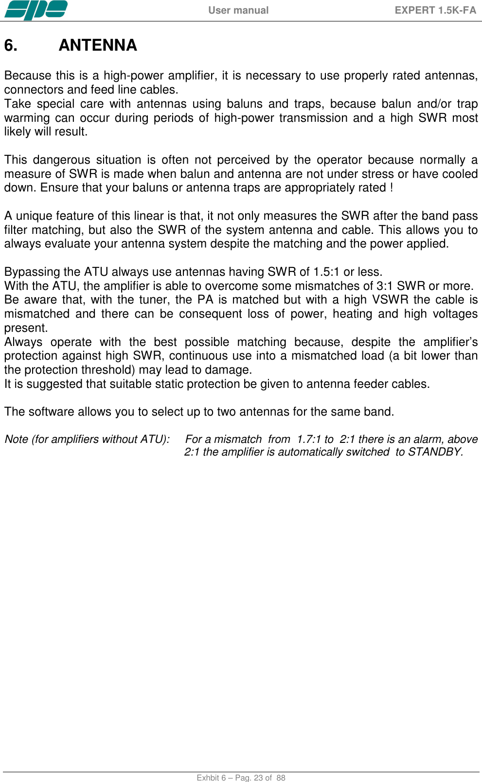
![User manual EXPERT 1.5K-FA Exhbit 6 – Pag. 25 of 88 8. TUNER (ATU) The amplifier has an automatic tuner that handles load mismatches up to 3:1 VSWR (2.5:1 for 6 m). The amplifier contains a look-up table with all the permitted bands. For tuner management, antenna data and other working data are stored. Every band has a sub-band set, and for each of those, data related to the antenna and auto-ATU tuning is stored. The CAT and the frequency counter detect the operating frequency and the correct sub-band. Due to the stored data, the tuner and the antenna are automatically set correctly. As described earlier (see item 4.6), the amplifier has two different memory banks. It is possible to use the two different presets when the amplifier operates at two different locations. Furthermore, table-driven management is useful to inhibit operations of the amplifier. For example, when an antenna for a particular band is not available. All auto-tuner functions remain, on standby, while using the transceiver only. Setting of the match data to write to the tables is performed automatically by pressing the [TUNE] key. The system will then find the correct match for minimum SWR. To achieve a better match than that achieved with the automatic tune procedure ( which is rather unlikely) it is possible to set the tuning manually by using the keys [◄C], [C►], [◄L], [L►]. When a manual tuning is performed, it is possible to read the tuning value, the working frequency and the associated sub-band on the appropriate screen page. Both types of tuning are always implemented in the “STANDBY“ state. Before starting a matching process, the tuner measures the SWR of the system cable / antenna. if it is greater than 3.5:1, the procedure does not begin and an alarm is displayed. It is possible to bypass the tuner with a specific command, in order to use an external tuner. NEVER USE THE INTERNAL TUNER WITH AN EXTERNAL TUNER, IT COULD SERIOUSLY DAMAGE THE LINEAR. IF YOU WANT TO USE AN EXTERNAL TUNER, THEN DISABLE THE INTERNAL ATU. The internal tuner may be bypassed as follows: - Totally. - For single band. - For single band and specific antenna. It is always automatically bypassed: - With the only receiving antenna set. - With tunable antenna set. - On 70 MHz band.](https://usermanual.wiki/S-P-E-s-r-l/GC324810/User-Guide-3431025-Page-25.png)

![User manual EXPERT 1.5K-FA Exhbit 6 – Pag. 27 of 88 9. PROTECTIONS / ALARMS The SPE EXPERT 1.5K-FA has a sophisticated protection system that constantly monitors and controls the amplifier’s most important parameters. The main parameters are: Temperature of the heatsink: max. / min. voltage on the PA; max. PA current; SWR; reflected power; max voltage RF on the tuner; input power. The protection system is carried out in two different ways: 1) Through hardware circuits to ensure a minimum intervention time. 2) Through software, with a combined action of the two CPU’s, to ensure the maximum precision. The two results get constantly compared; every difference produces a protection trip and a consequent alarm. There are three types of protections/alarms: a) SIMPLE This is the most common case. An acoustic warning beep sounds, but no operator intervention is required, as the control system automatically restores the correct operating conditions. b) SERIOUS When automatic system recovery is not possible (e.g. the temperature climbs over the limits due to obstruction of the fans, SWR is too high, etc.). In this case the amplifier switches back to the standby state and the alarm message gets stored. Normally transmission will continue with the exciter only. c) FATAL If the amplifier is in the b) state, but one CPU has a fault or it can’t continue operating or some fault appears in the power-supply module, then the amplifier will be turned OFF with no further warning. To restart the amplifier, the main switch in the rear panel has to be switched to [O], and then to the [I] position. Note: It is possible to read the alarm history in the standby mode using [SET] and then [ALARMS LOG] keys.To empty the alarm stack press [TUNE] and [OPERATE] keys together. For further details, please consult the next paragraphs.. Note: If the acoustic alarm is very frequent during transmission, the possible causes should be investigated. Note: Before the temperature limits are reached (75°C), the output power will change From MAX to MID automatically and then possibly from MID to LOW, so that transmission with the amplifier may continue with reduced power. If the temperature, in LOW, is allowed to rise further, a “SERIOUS“ alarm will eventually be activated and the linear amplifier switches back to STANDBY. Note: During a SERIOUS alarm, there is an acoustic alarm for 10 sec. Pressing the [DISPLAY] key, the system switches back to ‘STANDBY’ state immediately and the sound stops. Note: ATTENTION : when a “FATAL” alarm occurs, immediately contact your reseller.](https://usermanual.wiki/S-P-E-s-r-l/GC324810/User-Guide-3431025-Page-27.png)
![User manual EXPERT 1.5K-FA Exhbit 6 – Pag. 28 of 88 10. PROGRAMMING The three keys: [SET], [◄▲] and [▼►], allow programming the amplifier. They can be used in the following way: [SET] Use it to open a menu page, to validate choices and to exit from a menu page. [◄▲], [▼►] Use these keys to select options. A green led illuminates during the programming process. Programming the system is very easy. You will find your programming choices confirmed by the items shown at the lower part of the display. Note: Programming operations are only possible int he ‘STANDBY’ mode. Note: Programming changes take effect only after exiting from a menu page (the green led turns off). Pressing the [DISPLAY] key for more than 1 sec. it will immediately exit to STANDBY with no programming effect. 10.1 Ways to operate Pressing the [SET] key opens the menu page. On the display there are the following options: a) ANTENNA: An appropriate antenna may be assigned to each band selecting the (ANT 1, ANT 2, ANT 3, ANT 4) connector. If you don’t have an antenna for a particular band, set to “NO”. This setup allows you to preset up to 2 antennas for the same band. The selected antennas can be switched using the [ANT] key while](https://usermanual.wiki/S-P-E-s-r-l/GC324810/User-Guide-3431025-Page-28.png)
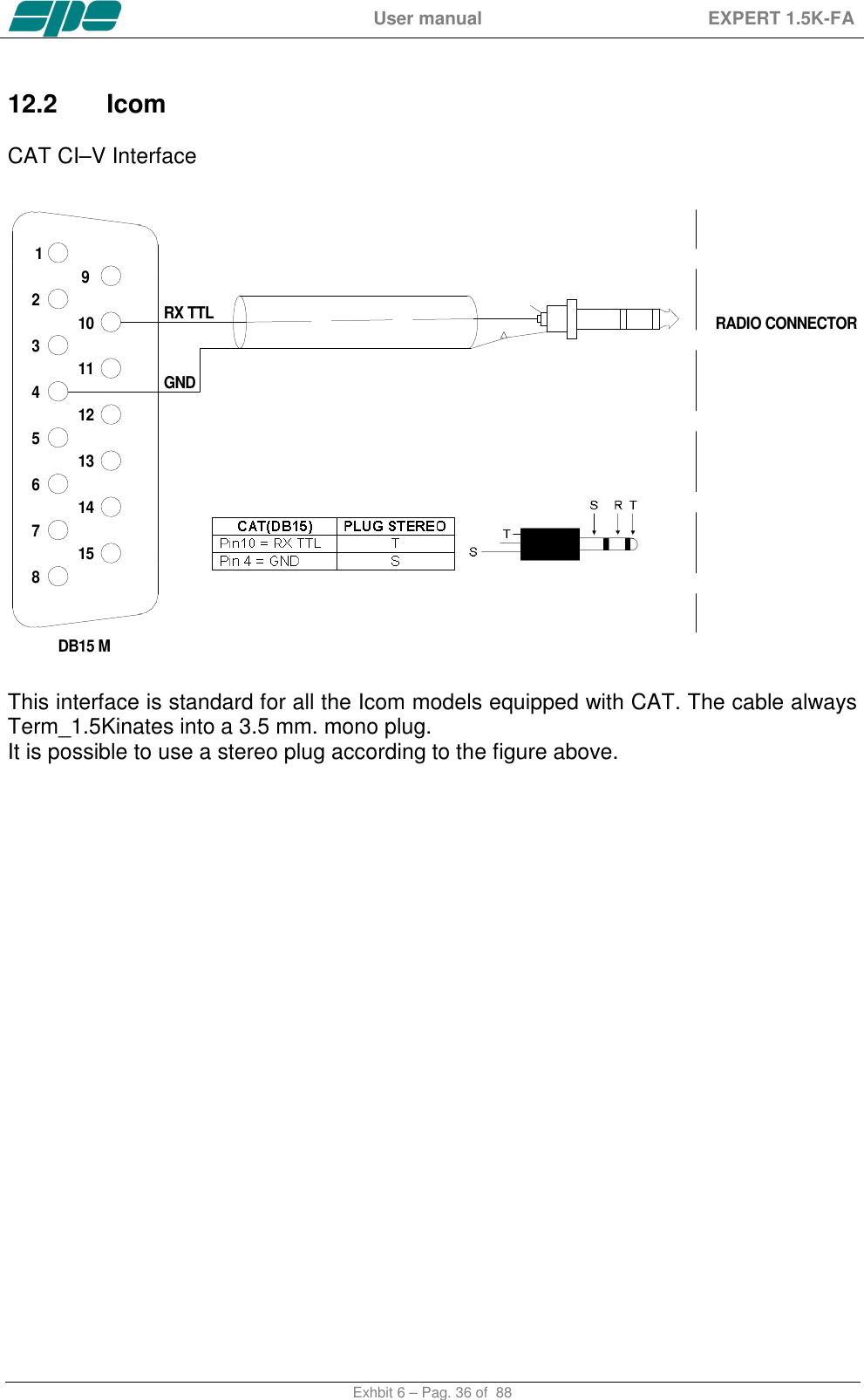
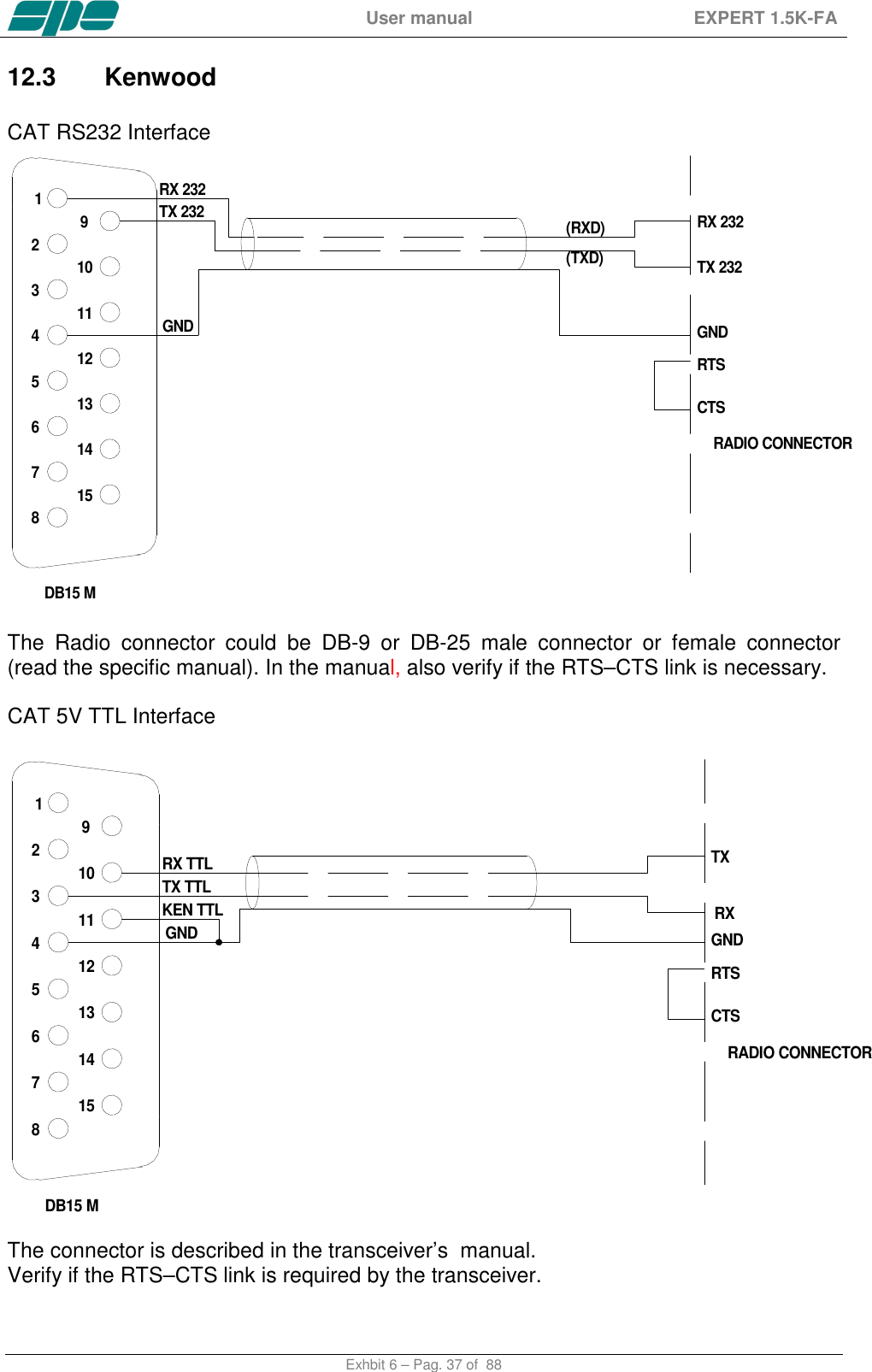
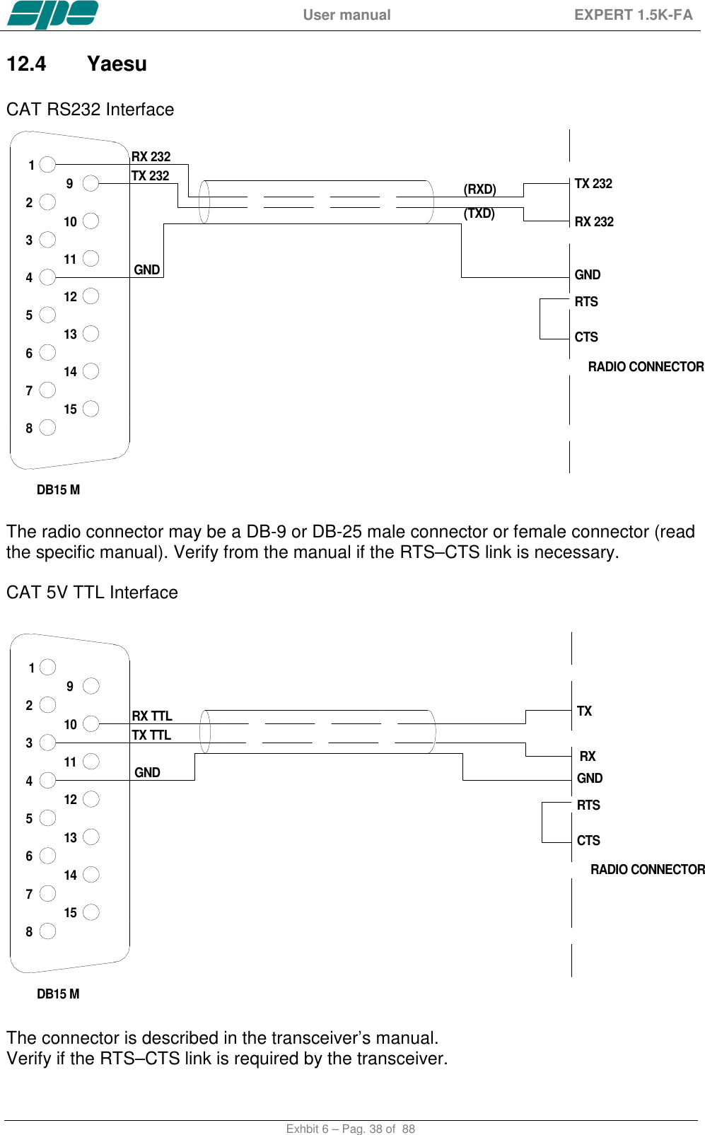
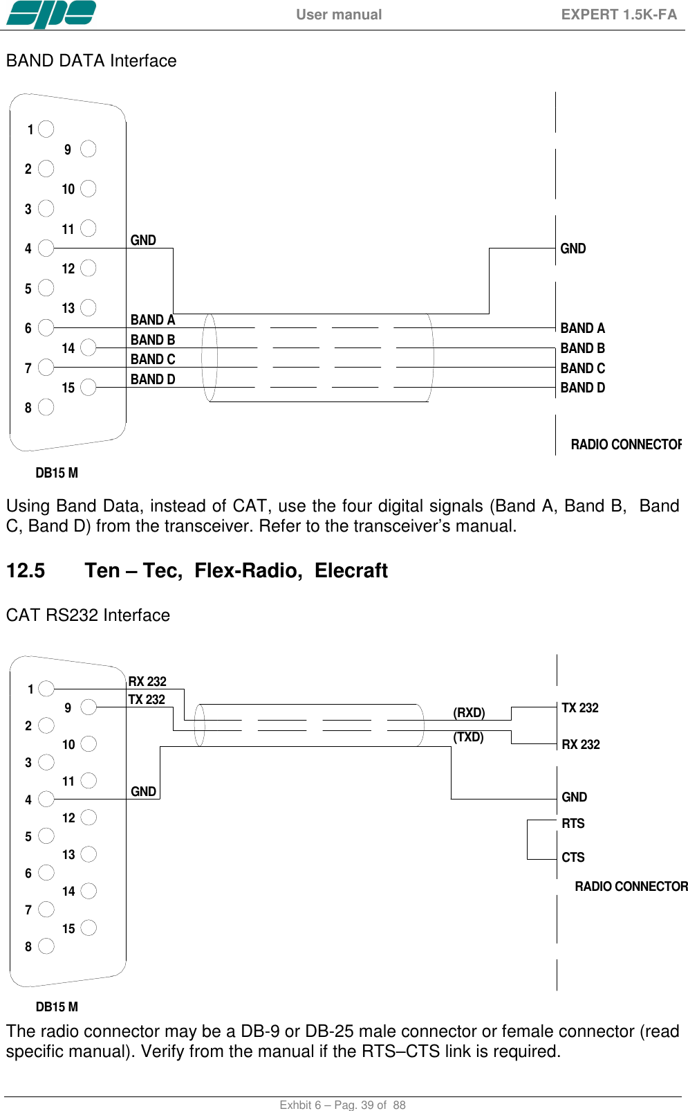
![User manual EXPERT 1.5K-FA Exhbit 6 – Pag. 29 of 88 working either in the “OPERATE” or in the “STANDBY” mode and there is no transmission in progress. If you want to bypass the Tuner on a certain band and for a certain antenna, just press the [TUNE] key and you will see a "b" next to the box. To remove the bypass just press [Tune] again. b) CAT: Allows you to program the amplifier to accept control commands from specific transceiver types. You should refer to your transceiver user manual to ensure that it is correctly programmed to handle such a link. Choose the brand of transceiver or function. For the proper link wiring, see "CONNECTIONS" in this manual. - NONE Select this option when there isn’t a link with the transceiver. Then, only the amplifier frequency counter will be used . - ICOM Set to “CI-V“ protocol. You also need to choose the baud rate, which is usually 9600. - KENWOOD You have to choose the baud rate (almost always 9600). - YAESU If you use the CAT connection (read the “CONNECTIONS” chapter of this manual), select the model of the transceiver and then select the baud rate (almost always 4800). If the model isn’t in the list, select “Band Data“ and read the “CONNECTIONS” chapter of this manual. For new transceiver models not listed, select FT 2000/9000 or try "Kenwood". - TEN-TEC Make the CAT connection (read the “CONNECTIONS” chapter of this manual) and follow the menu instructions. - FLEX-RADIO Make the CAT connection (read the “CONNECTIONS” chapter of this manual) and follow the menu instructions. - ELECRAFT Make the CAT connection (read the “CONNECTIONS” chapter of this manual) and follow the same indications as for KENWOOD. Note: When using the CAT link, check that the baud rate of your transceiver is set to the same value as the amplifier. c) MANUAL TUNE: Allows you to tune the amplifier manually. However achieving a better setting than that obtained by automatic](https://usermanual.wiki/S-P-E-s-r-l/GC324810/User-Guide-3431025-Page-29.png)
![User manual EXPERT 1.5K-FA Exhbit 6 – Pag. 30 of 88 tuning is very unlikely. Set your exciter to transmit a continuous RTTY or CW signal. Then press the [◄ L], [L ►], [◄ C], [C ►] keys until you obtain the minimum SWR. The operating frequency and the sub-band are also shown on the Display. d) DISPLAY: Adjusts the backlight and the contrast of the display. e) BEEP: On : All acoustic warning alarms operate and a beep confirms a keystroke. Off : In this condition, when you press a key there is no beep feedback. But for all worning conditions and alarms, the acoustic warnings are still functional. f) START: Stby: Sets STANDBY mode at startup. Oprt: Sets OPERATE mode at startup. g) TEMP: °C: Displays temperature readout expressed in Celsius degrees. °F: Displays temperature readout expressed in °Fahrenheit degrees. h) ALARMS LOG: Shows only the ten most recent "SERIOUS" alarms. i) TUN ANT: Allows you to associate a tunable antenna to one of four ANT connectors. A "t" highlights the selected antenna. j) RX ANT: Allows you to set a single receiving antenna. An "r" highlights the selected antenna. k) CONFIG: Select “BANK A” or “BANK B” (see item 4.6).](https://usermanual.wiki/S-P-E-s-r-l/GC324810/User-Guide-3431025-Page-30.png)
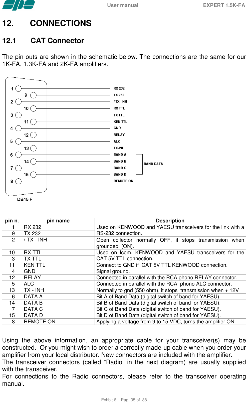
![User manual EXPERT 1.5K-FA Exhbit 6 – Pag. 31 of 88 11. INITIAL OPERATION OF THE AMPLIFIER Before turning ON the amplifier, read this manual with care. The following preliminary operations are necessary: 1) Be sure that the mains voltage is within the proper range of the amplifier’s power supply requirements. 2) Connect the amplifier to a good ground circuit. 3) Connect the antennas. 4) Connect the amplifier to the transceiver (read the “CONNECTIONS WITH THE TRANSCEIVER” chapter of this manual). Operate [I] the main switch on the back panel, and press the [ON] key on the front panel. Select the INPUT for the transceiver, and always perform programming with the amplifier in STANDBY. If you change memory BANK you have to repeat this programming. Note: You may have to repeat some programming if you change antenna, transceiver, etc. Note: ATTENTION: The ‘RELAY’ and ‘CAT’ signals in some types of transceivers are only turned ON from a transceiver MENU. Refer to the user manual. Note: ATTENTION: When the amplifier is in the ‘STANDBY’ and ‘OPERATE’ modes, always disable the transceiver’s autotuner. 11.1 Initial Programming You must carry out the next steps in the sequence below: a) To Set Antennas: Press [SET] and open the “ANTENNA“ menu page. Assign an appropriate antenna for the desired band. If you don’t have an antenna for that band, input “NO“. When all the antennas are programmed, press [SET] to exit and go back to STANDBY. b) to Set CAT: Press [SET] and enter the “CAT“ menu page. Select the transceiver brand and progress with programming according to the type of connection between the amplifier and the transceiver (read the “CONNECTIONS” chapter of this manual). At the end of programming, exit and go back into STANDBY. To verify the correctness of your programming, press the [CAT] key, and all the data stored will appear on the display. To verify the proper “CAT” operation, press [SET] and select “MANUAL TUNE”. When moving your transceiver’s VFO you should see the same frequency on the display. If set to "None", then transmitting briefly in RTTY or continuous key-down CW, will allow you to read the transmitted frequency on the display. Then return to the STANDBY mode.](https://usermanual.wiki/S-P-E-s-r-l/GC324810/User-Guide-3431025-Page-31.png)
![User manual EXPERT 1.5K-FA Exhbit 6 – Pag. 32 of 88 Similarly, if “BAND DATA“ is connected, check that the amplifier follows band changes of the transceiver. If it does not do so, then verify that your programming (or your link) has been correctly made. c) Use of the Automatic Tuner (Internal ATU) To complete the programming it is necessary to match the antennas to the amplifier by operating the “TUNE“ function (read the “TUNER“ chapter of this manual). We recommend that you select each band (with proper antenna) and then program the tuner for the sub-bands within which you will operate. Refer to the table in section 19 of this manual to select the appropriate sub - bands for your operating preferences. You are strongly advised to proceed with the utmost accuracy, not just match the current frequency, but all the sub-bands that you are likely to use. Matching all the antennas on all bands that are available, allows you to enjoy all the features of the automatic linear. To program the sub-bands, proceed as follows: 1) For every band find the central frequency in the table of each sub-band (refer to section 19 of this manual). Then set the transceiver to that frequency. 2) Next, set your transceiver to transmit a continuous tone (RTTY or FM). 3) Then press the [TUNE] key and then the PTT. The procedure for automatic tuning will start. You will hear the ATU relays operate and when they stop, the SWR will be at a minimum. Sometimes it is possible to improve tuning by repeating this step. 4) Repeat the previous steps for all sub-bands of bands you wish to use. 5) Repeat the previous steps for other antennas of the same band after having selected it using the [ANT] key. Note: If the ALC link is not used, it is very important to reduce the transceiver power to about 30 Watts during this operation. The initial programming concludes after steps a), b), c).](https://usermanual.wiki/S-P-E-s-r-l/GC324810/User-Guide-3431025-Page-32.png)
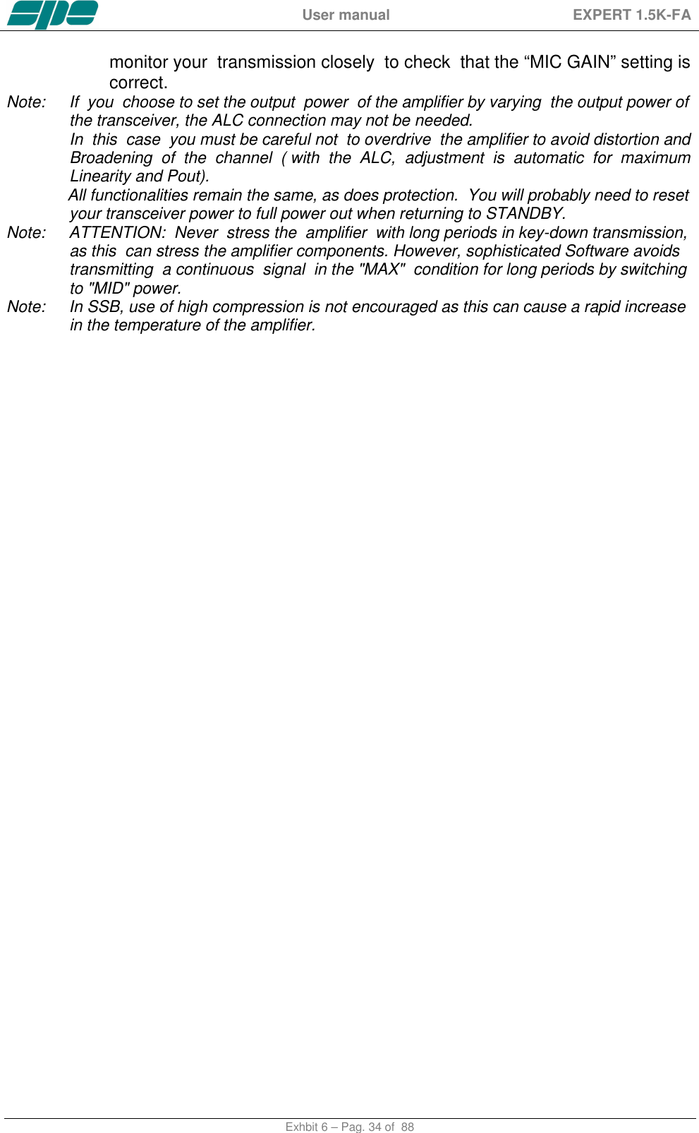
![User manual EXPERT 1.5K-FA Exhbit 6 – Pag. 33 of 88 11.2 Operating You should need to take only a few precautions when using the amplifier, thanks its high level of automation. ALC and CAT links are highly recommended to be used. If ALC is not used, SPE reminds you that it is better to lose a fraction of dB in transmitted power, by slightly reducing the driving power, than to over drive the amplifier and have a poor quality transmission. During transmission always glance periodically at the parameters on the display. SPE has selected, designed and adjusted them with care for your use in monitoring your amplifier. SPE recommends, when using the ALC link, that the transceiver be set to its maximum output power as the ALC will automatically reduce the driving power to the optimum driving level. To reduce the linear output, if required, just switch the amplifier to “MID” or “LOW” with the [POWER] key. Of course you may also continuously regulate the amplifier’s output power by changing the level of drive power from your transceiver , even with the ALC connected. If an output power less than 1 KW or 500 Watts is desired, for best efficiency begin reducing drive from the “MID” or “LOW” power state. It is not recommended to reduce the drive while in MAX or MID to an output that is close to the next lower power. Setting Driving Levels a) SSB : Regulate the “MIC GAIN” of the transceiver until, speaking normally into the microphone, the signal peaks on the display don't quite reach the maximum rated output power. Monitoring the transmission is a good way of checking your settings. If there is however some distortion, decrease the “mike gain” or decrease the power of the transceiver until a small reduction of the output power of the amplifier is seen. b) CW: In key down, you get the maximum output power automatically. c) RTTY: Digital modes, SSTV and FM, because all these mode have a very heavy duty cycle, you should not operate in “MAX”. It is best to use the “MID” or “LOW” power settings. The sophisticated software ensures this operation. d) AM: This transmission mode radiates a continuous carrier which is 25% of its PEP value (e.g. 400W PEP AM = 100W carrier power). SPE recommends you always operate in ‘MID’ or “LOW” mode for AM. To get an output signal without distortion, proceed as follows: Transmit an AM carrier only. Then with your transceiver’s “MIC GAIN” set to zero, advance the transceiver drive and do no t exceed 25% of the maximum carrier output from the amplifier. Then, speak into the microphone normally, setting the” MIC GAIN” of the transceiver until the peak output power, on speech peaks, is shown on the amplifier display to be no more than 0.8 KW or 400W. SPE suggests you](https://usermanual.wiki/S-P-E-s-r-l/GC324810/User-Guide-3431025-Page-33.png)
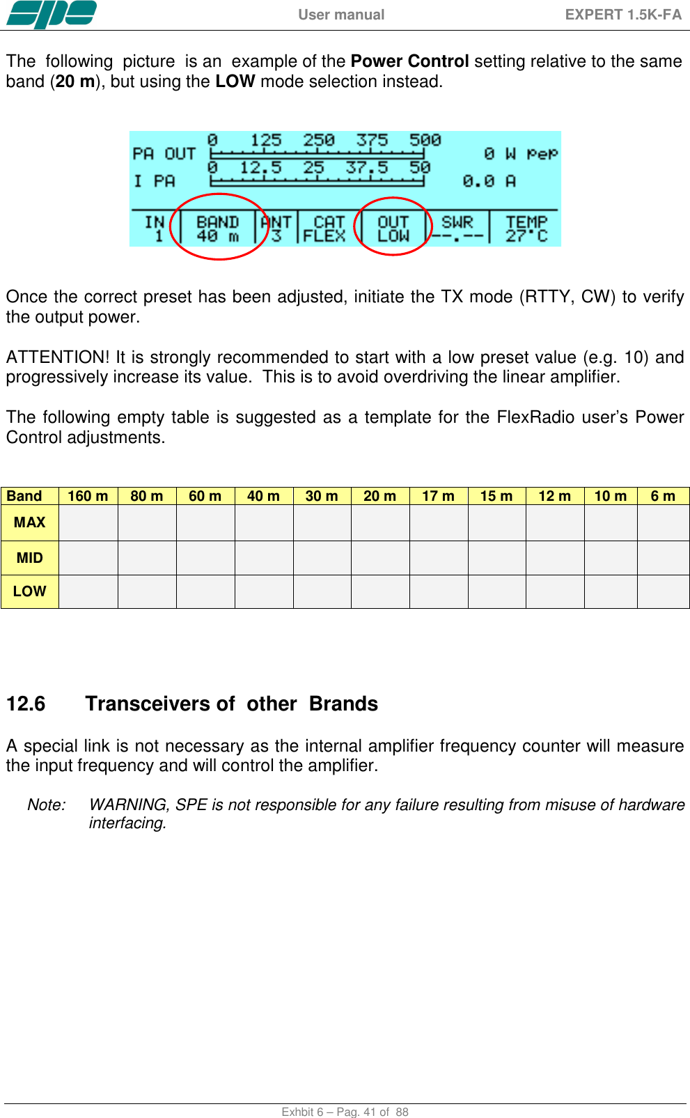
![User manual EXPERT 1.5K-FA Exhbit 6 – Pag. 40 of 88 ALC with Flex-Radio. Since all Flex-Radio equipments has no an analog ALC input, the maximum power limits for the transceiver must be programmed in order to avoid the EXPERT’s overdrive protection system intervention. These settings have to be done while in OPERATE Mode according to the following. For every ham band three settings are allowed (storage memories): One setting for MAX mode. One setting for MID mode. One setting for LOW mode. The following table shows an overall vision of these settings: Band 160 m 80 m 60 m 40 m 30 m 20 m 17 m 15 m 12 m 10 m 6 m MAX Preset Max Preset Max Preset Max Preset Max Preset Max Preset Max Preset Max Preset Max Preset Max Preset Max Preset Max MID Preset Mid Preset Mid Preset Mid Preset Mid Preset Mid Preset Mid Preset Mid Preset Mid Preset Mid Preset Mid Preset Mid LOW Preset Low Preset Low Preset Low Preset Low Preset Low Preset Low Preset Low Preset Low Preset Low Preset Low Preset Low The user has to set, for every band of interest, the power limit concerning the input power needed. To do that, using the keyboard, he must set a parametric value having the format “[PC=xxx]” (where xxx is a numerical value having a range from 000 to 100 which represents the transceiver’s power output expressed in percentage). This value will appear just over the BAND label of the Status Bar. This value is related to the tuned band and to the selected power modes of MAX, MID and LOW. The following picture shows (as an example) Power Control of the 20 m band and in MAX power mode: Pressing the arrow keys ([◄▲] [▼►]) this value can be decremented/incremented until it reaches the desired value. At the completion of this operation, a time-out period (about 3 seconds) must be allowed for the “[PC=xxx]” indication to expire before another adjustment can be made.](https://usermanual.wiki/S-P-E-s-r-l/GC324810/User-Guide-3431025-Page-40.png)


![User manual EXPERT 1.5K-FA Exhbit 6 – Pag. 56 of 88 18. DIAGNOSTICS. During normal operation, this sophisticated monitoring system continuously monitors several measurements directly acquired from internal test-points. When a dangerous situation occurs, a “serious” alarm message is raised and the amplifier is switched from OPERATE to STANDBY. The user can either restore immediately the Main Display Page by pressing the [DISPLAY] key or wait for the visual alarm time-out expiration (about 10 seconds). The following table shows all the system’s alarm messages that are recorded in the Alarm History stack: Message Description SWR EXCEEDING LIMITS Protection for SWR greater than 3:1. INPUT OVERDRIVING Protection for excessive input power. EXCESS OVERHEATING Protection because the internal temperature has exceeded safe limits. The following table shows all the dynamic warning messages that are not recorded in the Alarm History stack: Message Description BAND NOT PERMITTED Band not allowed or not set. ANTENNA NOT AVAILABLE Antenna not set. TX ANTENNA NOT AVAILABLE In the selected band is set only an antenna for reception. STEADY OUTPUT POWER EXCEEDING LIMITS Appears when a continuous signal is transmitted in "MAX”. After 15 sec. the amplifier will switch automatically to "MID". INTERNAL OVERHEATING Appears when the internal temperature reaches 75 °C (167 °F). The amplifier automatically switches to the next lowest power level. HIGH SWR ANTENNA: TUNING NOT ALLOWED When the antenna SWR is over 3.5:1, the auto tuner is disabled. ATU BYPASS: TUNING NOT ALLOWED Since the tuner is bypassed, it is not possible to match automatically or manually. NO INPUT POWER: TUNING HALTED The tuner can not work at such a low input power. CAN'T SWITCH-OFF: POWER HELD BY REMOTE The amplifier does not turn OFF by the keyboard because it is kept ON by a remote device (transceiver or USB port). AMPLIFIER PROTECION In all remaining cases.](https://usermanual.wiki/S-P-E-s-r-l/GC324810/User-Guide-3431025-Page-56.png)
![User manual EXPERT 1.5K-FA Exhbit 6 – Pag. 57 of 88 19. TABLE BAND TABLE, SUB-BAND, CENTRAL FREQUENCY SUB-BAND 160 m [ 0] 1785 [ 1] 1795 [ 2] 1805 [ 3] 1815 [ 4] 1825 [ 5] 1835 [ 6] 1845 [ 7] 1855 [ 8] 1865 [ 9] 1875 [ 10] 1885 [ 11] 1895 [ 12] 1905 [ 13] 1915 [ 14] 1925 [ 15] 1935 [ 16] 1945 [ 17] 1955 [ 18] 1965 [ 19] 1975 [ 20] 1985 [ 21] 1995 [ 22] 2005 [ 23] 2015 80 m [ 24] 3470 [ 25] 3490 [ 26] 3510 [ 27] 3530 [ 28] 3550 [ 29] 3570 [ 30] 3590 [ 31] 3610 [ 32] 3630 [ 33] 3650 [ 34] 3670 [ 35] 3690 [ 36] 3710 [ 37] 3730 [ 38] 3750 [ 39] 3770 [ 40] 3790 [ 41] 3810 [ 42] 3830 [ 43] 3850 [ 44] 3870 [ 45] 3890 [ 46] 3910 [ 47] 3930 [ 48] 3950 [ 49] 3970 [ 50] 3990 [ 51] 4010 [ 52] 4030 60 m [ 53] 5013 [ 54] 5038 [ 55] 5063 [ 56] 5088 [ 57] 5113 [ 58] 5138 [ 59] 5163 [ 60] 5188 [ 61] 5213 [ 62] 5238 [ 63] 5263 [ 64] 5288 [ 65] 5313 [ 66] 5338 [ 67] 5363 [ 68] 5388 [ 69] 5413 [ 70] 5438 [ 71] 5463 [ 72] 5488 40 m [ 73] 6963 [ 74] 6988 [ 75] 7013 [ 76] 7038 [ 77] 7063 [ 78] 7088 [ 79] 7113 [ 80] 7138 [ 81] 7163 [ 82] 7188 [ 83] 7213 [ 84] 7238 [ 85] 7263 [ 86] 7288 [ 87] 7313 [ 88] 7338 30 m [ 89] 10075 [ 90] 10125 [ 91] 10175 20 m [ 92] 13975 [ 93] 14025 [ 94] 14075 [ 95] 14125 [ 96] 14175 [ 97] 14225 [ 98] 14275 [ 99] 14325 [100] 14375 17 m [101] 18075 [102] 18125 [103] 18165 15 m [104] 20975 [105] 21025 [106] 21075 [107] 21125 [108] 21175 [109] 21225 [110] 21275 [111] 21325 [112] 21375 [113] 21425 [114] 21475 12 m [115] 24891 [116] 24963 [117] 25038 10 m [118] 28050 [119] 28150 [120] 28250 [121] 28350 [122] 28450 [123] 28550 [124] 28650 [125] 28750 [126] 28850 [127] 28950 [128] 29050 [129] 29150 [130] 29250 [131] 29350 [132] 29450 [133] 29550 [134] 29650 [135] 29750 6 m [136] 49875 [137] 50125 [138] 50375 [139] 50625 [140] 50875 [141] 51125 [142] 51375 [143] 51625 [144] 51875 [145] 52125 [146] 52375 [147] 52625 [148] 52875 [149] 53125 [150] 53375 [151] 53625 [152] 53875 [153] 54125 Note: [sub-band] Central frequency (KHz).](https://usermanual.wiki/S-P-E-s-r-l/GC324810/User-Guide-3431025-Page-57.png)
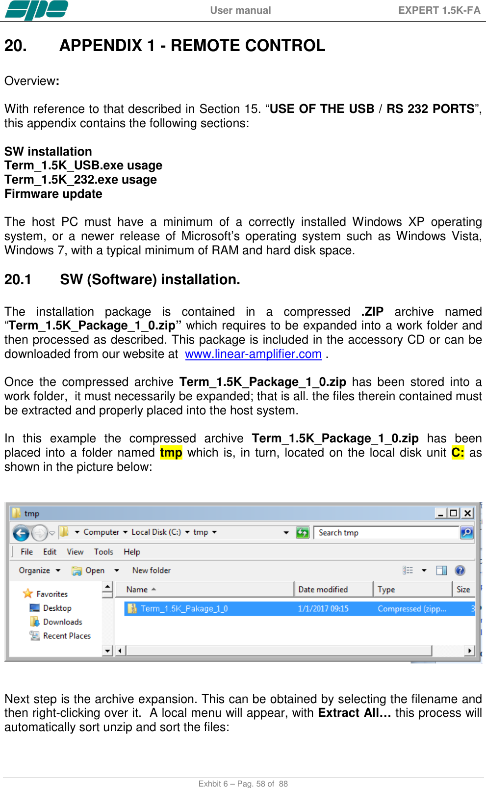

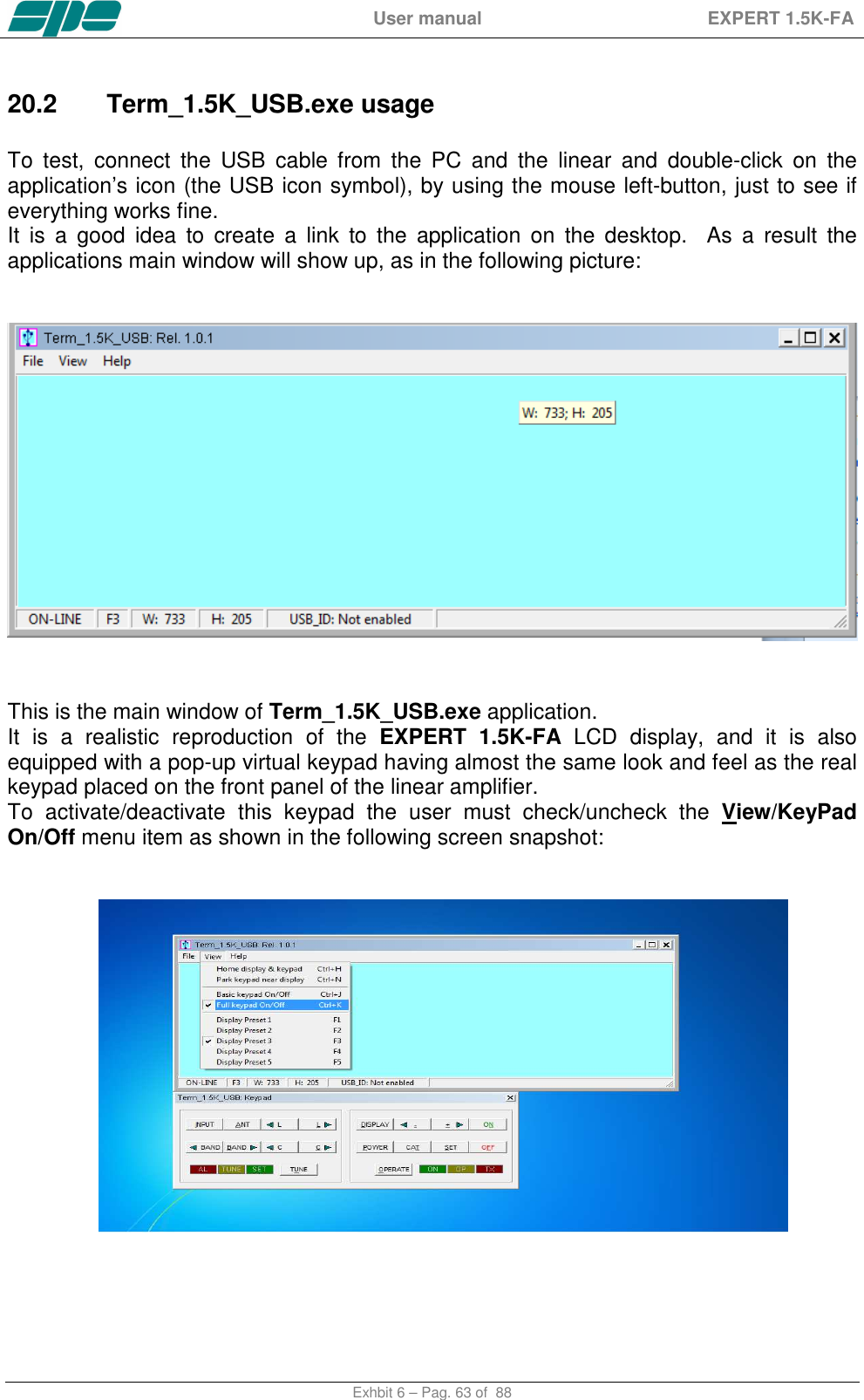
![User manual EXPERT 1.5K-FA Exhbit 6 – Pag. 64 of 88 The View menu also contains five items related to the application window size presets which can be either selected by the menu itself or by their equivalent [F1 … F5] shortcut keys. Feel free to test all the View menu options in order to find an optimal and comfortable vision of the display main window. The display window can easily be resized. That is, either enlarged or reduced by acting on the right-bottom corner of the window. Also by using the mouse as shown in the picture above and in the same way as any other window-resizing operation. In case the user wants to restore the original size-preset lying behind any [F1…F5] key, you must select the Fx preset and, then, press the Ctrl+Fx key combination on his PC keyboard. When Term_1.5K_USB.exe gets launched an automatic Connect command also starts and if a USB link to the linear amplifier was already active, it should have shown a result similar to the picture sequence above. In case this doesn’t happen, there’s also a chance to try connecting by using the File/Connect menu item (or by using its equivalent Ctrl+Q shortcut key…). The final visual result will be a “bright backlight” display and a function-keys enabling of the virtual keypad.](https://usermanual.wiki/S-P-E-s-r-l/GC324810/User-Guide-3431025-Page-64.png)
![User manual EXPERT 1.5K-FA Exhbit 6 – Pag. 65 of 88 In case the EXPERT linear is already switched on, after the connection established by Term_1.5K_USB.exe, an immediate update on the current display contents will result. However, if the EXPERT linear was already switched off, it would be turned on by using the [ON] virtual key on the application keypad. Similarly, all the other virtual keypad keys perform the same actions as their equivalent mechanical keys forming the real front panel keyboard of the EXPERT 1.5K-FA. The View menu is also equipped with the useful Home… and Park… items which have been specially designed to allow an automatic repositioning of the application along the PC desktop area. In more detail: • Home... (Ctrl+H) This item positions the display window to the upper-left corner of the desktop area and aligns the keypad to its bottom edge. • Park... (Ctrl+N) This item leaves the display window where it currently stays and just aligns the keypad to its bottom edge. The above described operations could be helpful whenever a quick and safe repositioning of the application windows is desired.](https://usermanual.wiki/S-P-E-s-r-l/GC324810/User-Guide-3431025-Page-65.png)
![User manual EXPERT 1.5K-FA Exhbit 6 – Pag. 66 of 88 The Basic keypad... item in View menu allows you to set to a reduced-size keypad, having fewer keys than the complete keypad, which could be useful when no setting actions are required on the linear amplifier. Note: The keypad types, both Full and Basic, are certainly very useful since they both can be directly accessed using the mouse pointer. It is helpful to know that all the operations allowed using the virtual keys can be also performed using short commands directly typed on the PC keyboard. The following one is the “shortcut-keys” table: 1.5K-FA Function key Equivalent shortcut-key from the PC keyboard [INPUT] I [ANT] A [<L] Ctrl+L [L>] L [<BAND] Ctrl+B [BAND>] B [<C] Ctrl+C [C>] C [TUNE] U [DISPLAY] D [< -] - [> +] + [ON] N [POWER] P [CAT] T [SET] S [OFF] (*) F [OPERATE] O](https://usermanual.wiki/S-P-E-s-r-l/GC324810/User-Guide-3431025-Page-66.png)
![User manual EXPERT 1.5K-FA Exhbit 6 – Pag. 67 of 88 (*) Please bear in mind that the [OFF] command as accessed from the virtual keypad or by shortcut key, that it always asks for a confirmation, to its amplifier shutdown operation, by showing the dialog form below:](https://usermanual.wiki/S-P-E-s-r-l/GC324810/User-Guide-3431025-Page-67.png)
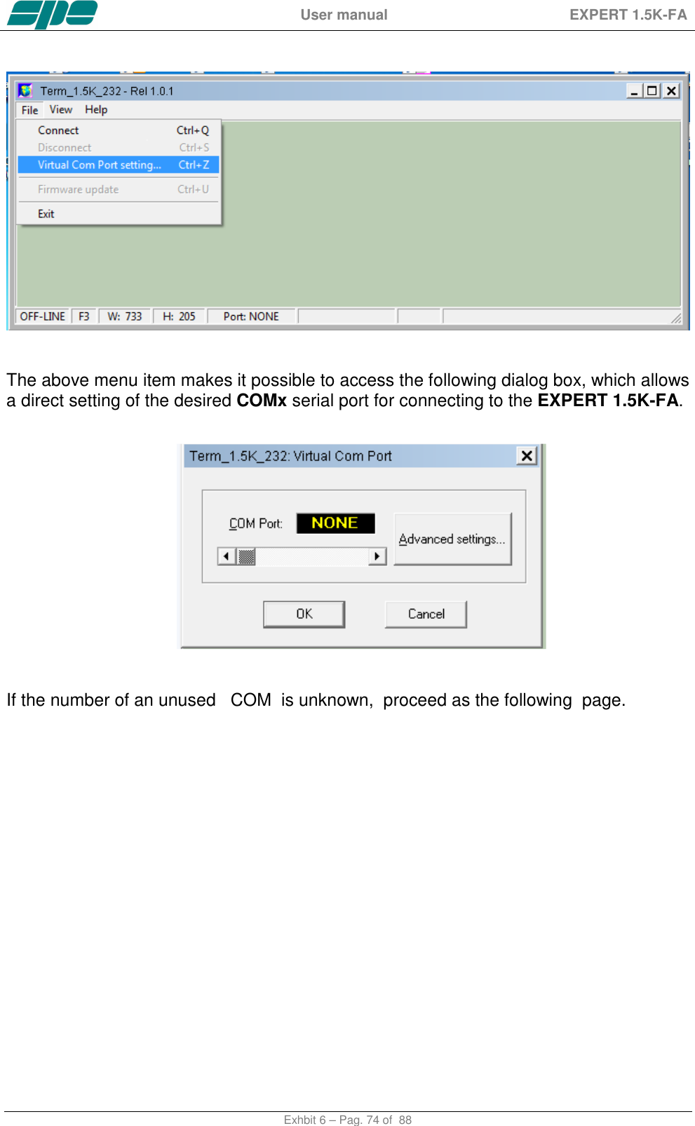
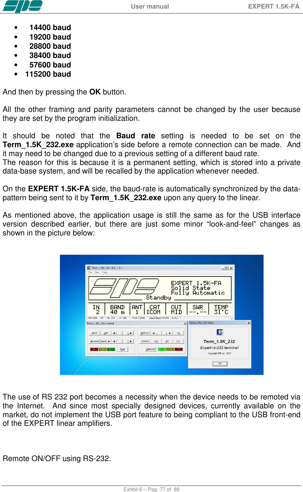
![User manual EXPERT 1.5K-FA Exhbit 6 – Pag. 76 of 88 In that case, use the detached COM port ID to properly set the Virtual Com Port dialog box, as shown in the picture below, and then reconnect the serial adapter so that it can be accessed by the application... The available selection range spans thru the [COM1…COM256] set, which can be accessed using the framed slider-control placed above the OK and CANCEL keys. After the COM port setting is validated by pressing the OK key, all the other communication parameters become set as follows: • Baud rate: 115200 • Bit per character: 8 • Parity check: No • Stop bit: 1 Also, the Baud-rate setting can be changed by pressing the Advanced settings… if needed. The Baud rate setting can be selected by using the available slider-control marked in the picture above: • 9600 baud](https://usermanual.wiki/S-P-E-s-r-l/GC324810/User-Guide-3431025-Page-76.png)
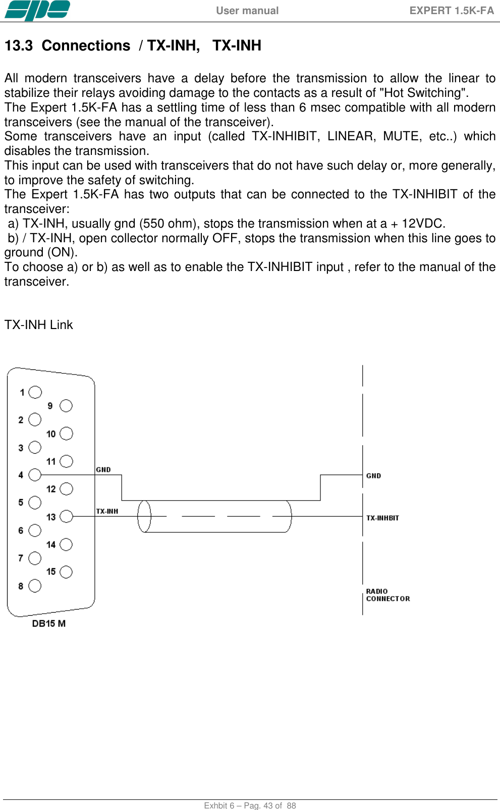
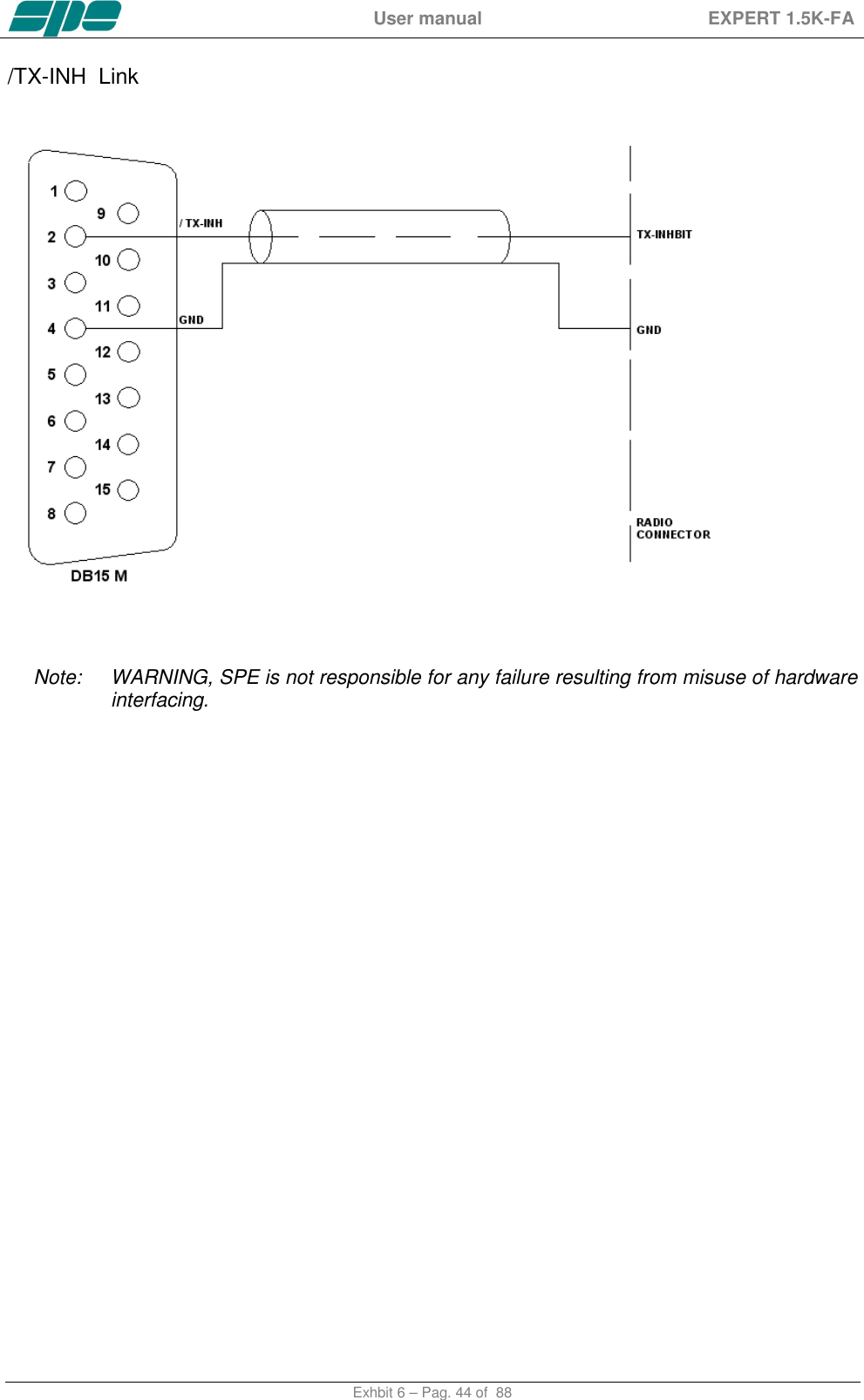
![User manual EXPERT 1.5K-FA Exhbit 6 – Pag. 78 of 88 With this new software release, the [ON] and [OFF] keys are fully enabled and work the same way as they work on the USB version of the application. However, there is a small technical detail to take into account about the [ON] key's behaviour. It acts on the DTR output line of the PC RS-232 serial COM port by generating a timed positive pulse about every second or so across the link. Since the “PORT” socket on the rear panel of the 1.5K-FA isn't equipped with any DSR input line to handle this “switch-on” signal coming from the remote control application, the most suitable solution is to wire a “cable branch” according to the schematics in the following diagram. This solution uses an already-existing feature of 1.5K-FA which involves the “REMOTE_ON” input line, placed on both “CAT” sockets, which behaves the same way as the front panel's [ON] key does. Actually, it triggers a switch-on of the linear amplifier whenever a positive voltage level greater than +5Vdc is applied to it. A typical application for this “remote switch-on line”, is to wire it to the +13.8Vdc power-supply which powers the transceiver. And a similar result can also be achieved by wiring it to DTR output line coming from a PC, or from a remote device controlled by a PC running Term_1.5K_2K_232.exe using the suggested external R-C network drawn in the schematic diagram below. A typical RS-232 serial port like this ensures output voltage levels spanning from +/- 6.5Vdc (USB to serial adapters) and up to +/- 11Vdc (standard RS-232 ports whose circuit is based upon the popular MAX232 line-driver).](https://usermanual.wiki/S-P-E-s-r-l/GC324810/User-Guide-3431025-Page-78.png)

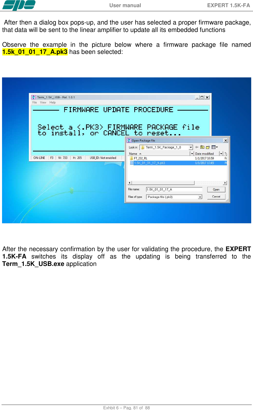
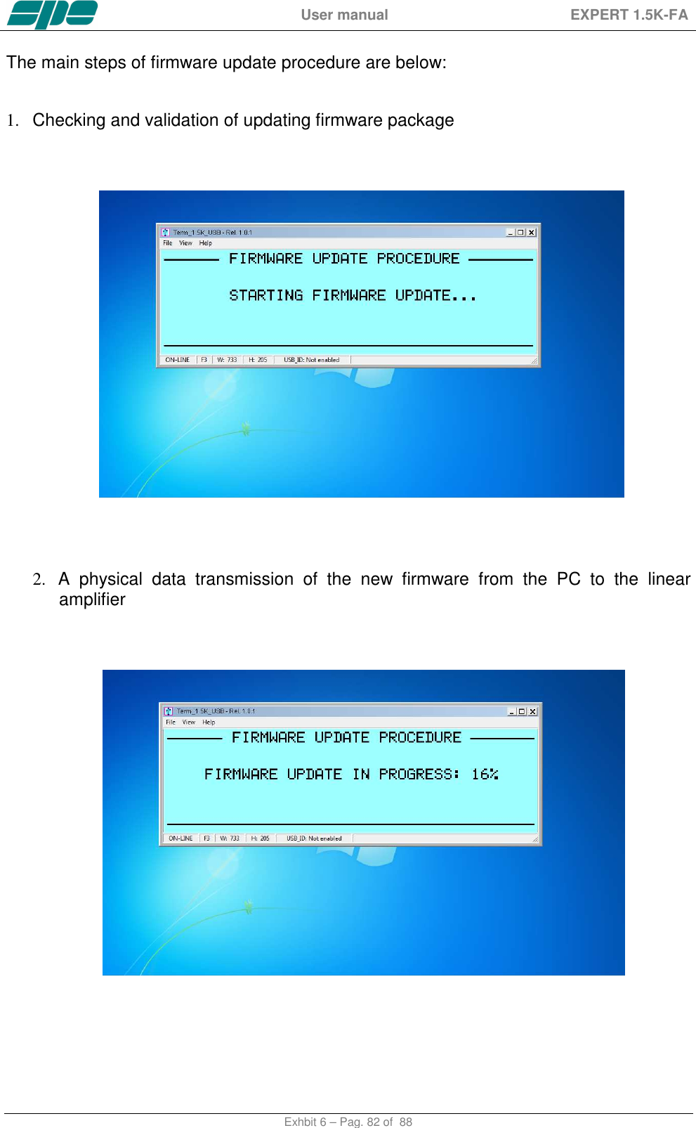
![User manual EXPERT 1.5K-FA Exhbit 6 – Pag. 83 of 88 3. A final validation for the completed firmware update And as the last action, after a successful firmware update, the linear amplifier performs a general auto-restart operation. Then after, full control of the updated device is restored to both local and remote operations. The user is then able to check the result of his firmware update operation directly on the LCD display (both real and virtual…) by pressing the [CAT] key twice and only when in the STANDBY mode. This operation will be shown on the display as below:](https://usermanual.wiki/S-P-E-s-r-l/GC324810/User-Guide-3431025-Page-83.png)
![User manual EXPERT 1.5K-FA Exhbit 6 – Pag. 84 of 88 21. GENERAL RESTORE A System General Restore can be performed by pressing the [INPUT] and the [OFF] keys together for at least one second. This operation is only possible from the linear amplifier front-panel physical keyboard. The linear amplifier will switch off with a self-explaining system message. Then, after it turns back on, all of the factory defaults will be restored.](https://usermanual.wiki/S-P-E-s-r-l/GC324810/User-Guide-3431025-Page-84.png)