S and C Electric INTELLICOM IntelliCom WAN 1720 Mesh Node User Manual
S&C; Electric Company IntelliCom WAN 1720 Mesh Node
User Manual
1
IntelliCom
™
IntelliCom
™
IntelliCom WAN 1720
Outdoor Mesh Node
Installation Manual

2 IntelliCom 1720 WAN Installation Guide
Contents
1 Safety 3
Power Lines Can Be Lethal . . . . . . . . . . . . . . . . . . . . . . . . . . . . . . . . . . . . . . 4
To Avoid Falling, Use Safe Procedures When Working At Heights Above Ground . . . . . . . . . . . . . . 4
2 IntelliCom WAN Node Installation 5
Package Contents . . . . . . . . . . . . . . . . . . . . . . . . . . . . . . . . . . . . . . . . . . 5
Initial Setup & Conguration . . . . . . . . . . . . . . . . . . . . . . . . . . . . . . . . . . . . . 5
3 Outdoor Installation 7
Installing the Node - An Overview . . . . . . . . . . . . . . . . . . . . . . . . . . . . . . . . . . 7
Preparing Earth Ground . . . . . . . . . . . . . . . . . . . . . . . . . . . . . . . . . . . . . . . 8
Antenna Placement . . . . . . . . . . . . . . . . . . . . . . . . . . . . . . . . . . . . . . . . . 8
Mounting the IntelliCom WAN 1720 . . . . . . . . . . . . . . . . . . . . . . . . . . . . . . . . . . 9
Connecting Cables. . . . . . . . . . . . . . . . . . . . . . . . . . . . . . . . . . . . . . . . . 10
Appendix A Specications 11
Appendix B Regulatory 13
Copyright © 2011 S and C, Inc. All rights reserved. Created in the United States of America.
Safety 3
1 Safety
Do not open cover
Caution!
Risk of electric shock!
There are several types of safety-alert messages which may appear through-
out this instruction sheet as well as on labels attached to the node. Familiar-
ize yourself with these types of messages and the importance of the various
signal words, as explained below.
DANGER
“DANGER” identies the most serious and immediate hazards
which will likely result in serious personal injury or death if instruc-
tions, including recommended precautions, are not followed.
WARNING
“WARNING” identies hazards or unsafe practices which can result
in serious personal injury or death if instructions, including recom-
mended precautions, are not followed.
CAUTION
“CAUTION” identies hazards or unsafe practices which can result in
minor personal injury or product or property damage if instructions,
including recommended precautions, are not followed.
NOTICE
“NOTICE” identies important procedures or requirements that can result
in product or property damage if instructions are not followed.
In addition, alert symbols are used to warn of electric shock hazard or for-
bidden operations, as shown at right.
Following SaFety inStructionS
If you do not understand any portion of this manual and need assistance, con-
tact your nearest S&C Sales Oce or S&C Authorized Distributor. eir tele-
phone numbers are listed on S&C’s website, www.sandc.com.
Or, call S&C Headquarters at (773) 338-1000; in Canada, call S&C Electric
Canada Ltd. at (416) 249-9171.

4 IntelliCom 1720 WAN Installation Guide
Power Lines Can Be Lethal
When working near power lines, follow ALL safety procedure as appropri-
ate for the types and voltages of power lines.
To Avoid Falling, Use Safe Procedures When Work-
ing At Heights Above Ground
• Select equipment locations that will allow safe and simple installation.
• Don’t work alone. A friend or co-worker can save your life if an ac-
cident happens.
• Don’t attempt repair work when you are tired. Not only will you be more
careless, but your primary diagnostic tool - deductive reasoning - will not be
operating at full capacity.
• Use approved non-conducting ladders, shoes, and other safety equipment.
Make sure all equipment is in good repair.
• If a tower or pole begins falling, don’t attempt to catch it. Stand back
and let it fall.
• If anything such as a wire or pole does come in contact with a power
line, DON’T TOUCH IT OR ATTEMPT TO MOVE IT. Instead,
save your life by calling the power company.
• Don’t attempt to erect antennas or towers on windy days.
• MAKE SURE ALL TOWERS AND POLES ARE SECURELY
GROUNDED, AND ELECTRICAL CABLES CONNECTED TO
ANTENNAS HAVE LIGHTNING ARRESTORS. This will help pre-
vent fire damage or human injury in case of lightning, static build-up,
or short circuit within equipment connected to the antenna.
• The IntelliCom WAN Node has built-in lightning protection, but an-
tennas still need their own lightning protection. Be sure that any other
equipment connected to the IntelliCom 1720 node also has the same
level of protection.
• The base of the antenna pole or tower must be connected directly to
the building protective ground or to one or more approved grounding
rods, using 10 AWG ground wire and corrosion-resistant connectors.
• Refer to the National Electrical Code for grounding details.
IF AN ACCIDENT SHOULD OCCUR WITH THE POWER LINES:
DON’T TOUCH THAT PERSON, OR YOU MAY BE ELECTROCUTED.
• Use a non-conductive dry board, stick, or rope to push or drag them so
they no longer are in contact with electrical power.
• Once they are no longer contacting electrical power, administer CPR if
you are certified.
• Immediately have someone call for medical help.
• Dangerous voltages inside.
• No serviceable parts inside.
• Refer to qualified service per-
sonnel.
• Unit must be disconnected
from power prior to servicing.
Do not open cover
Caution!
Risk of electric shock!

IntelliCom WAN Node Installation 5
2 IntelliCom WAN Node Installation
Package Contents
The IntelliCom WAN 1720 package contains the items shown in Table 2.1.
Item Qty
Warranty & registration card 1
CD with Software; Reference Guide; Hardware Installation
Guide; EULA
1
2.4/5 GHz dual-band omni antennas, detachable 6
IntelliCom WAN 1720 , NEMA-4X enclosure 1
N to reverse-polarity SMA adapter 6
Mounting bracket for pole and wall mounting. Designed to t
37 mm to 50 mm (1.5 in to 2.0 in) poles.
1
Mounting Kit, including U-bolts, M6x1.0-80mm, with at wash-
ers, split washers, nuts. Claw-tooth pole grippers. M6x1.0-
40mm hex bolt. M6x1.0-20mm hex bolt. Hex-head socket
wrench.
1
AC power cord with NEMA 5-15 (US) plug. Other IEC cords
are available separately.
1
Table 2.1 Package conTenTs
This table lists the items contained in
your IntelliCom WAN 1720 kit.
This hardware installation guide describes how to install the
IntelliCom WAN 1720 node safely. It is intended to be installed by trained
professionals. Be sure to read and understand all installation and safety in-
structions before proceeding with the installation.
Initial Setup & Conguration
You should set up and test your nodes indoors, on a bench or table, before
installing them. This will allow you to pre-configure the nodes so that they
are all on the same RF channel, etc. You will use IntelliCom View Pro to
configure the nodes and create a small mesh network. Test the network set-
tings you plan to use.
Radio Upgrades
IntelliCom WAN 1720 nodes are shipped in a default configuration. Only
one of the two radios, Radio 1, is enabled. The second radio, if needed,
must be enabled via a license and IntelliCom View Pro software. Likewise,
the MIMO capability must be enabled for those nodes which require it.
6 IntelliCom 1720 WAN Installation Guide
StepS in the Staging proceSS
1. Check to see that all nodes are visible in IntelliCom View Pro. If not,
troubleshoot per directions in the IntelliCom View Pro Reference
Guide.
2. Set the Country Code for your country of operation.
3. Re-verify that all nodes are visible.
4. Apply MIMO upgrade licenses to nodes which will require them. For
nodes requiring dual-radio operation, apply dual-radio upgrade licens-
es.
5. Verify that dual-radio nodes have both radios correctly meshed.
6. Verify that MIMO-enabled nodes show 802.11n radio options.
7. Label each node. We recommend that the label be large enough to be
visible from the ground when the unit is mounted. The label should
include the last four digits of the node serial number, for easy identifi-
cation in the field. Many installers mark the unit with number of active
radio (1 or 2), MIMO status, and the type of antenna to be connected
to each radio.
Note: The staging antennas provided with the nodes are for temporary use
only. They MUST be replaced with outdoor-rated antennas as soon as the
mesh is staged and operational. The staging antennas are NOT waterproof
and NOT moisture resistant. If used outdoors, the antennas will fail.
Outdoor Installation 7
3 Outdoor Installation
Installing the Node - An Overview
1. Pre-assemble the antenna, node, and other devices to a metal pole or
other sub-assembly. Then, attach the assembly to the mast, tower, or
other mounting system. It is often easier to install all devices to one
object, such as a pole, and then attach the pole to the roof. In many
cases, connecting the devices to a pole already attached to the roof top
can be difficult and dangerous.
2. A lightning surge suppressor must be used. Some antennas include one.
If not, you must install a lightning suppressor.
3. Install the antenna higher than the node. Take care when locating the
node far away from the antennas; a short antenna cable gives better
performance than a longer one. When possible, use antenna cables less
than three meters long.
4. The node and its antenna must both be grounded.
5. Use weatherproofing kits that include non-vulcanized rubber to weath-
erproof connectors and antennas. All Ethernet cables must be water-
proofed; standard RJ-45 connectors do not last outdoors.
6. Power over Ethernet: Consider which devices require PoE and what the
required input voltage will be. Ports 2 and 3 on the node can supply up
to 13W each of PoE-compliant power.
7. Connect peripheral devices to the node.
8. Connect power to the node and peripherals.
toolS needed
For IntelliCom 1720 outdoor nodes, you will need:
• #2 Phillips screwdriver.
• Small adjustable wrench.
• Wire cutters to cut tie wraps around cables.
• Weatherproofing kit – this kit provides electrical tape and butyl mastic.
Depending on the installation location, you may need ladders, a lift truck,
or other means to access the actual installation locations.
8 IntelliCom 1720 WAN Installation Guide
Preparing Earth Ground
The IntelliCom 1720 node must be properly connected to earth ground.
Failure to do so may result in equipment damage, injury, or death. The
product warranty does not cover damages resulting in part or in whole from
improper grounding. Consult your location’s building and electrical codes
regarding antennas and follow them, or consult the National Electric Code
(NEC).
• If connecting to a tower or pole, connect the base of the tower pole
directly to the building’s ground or to one or more approved grounding
rods using 10 AWG ground wire and corrosion-resistant connectors.
• Connect the grounding cable to rain gutters only if the
rain gutter is connected to earth ground.
• Ground rods should be copper-plated, 1.8 - 2.4 m (6 - 8 ft) long.
• Install all grounding components in straight lines. If bends are un-
avoidable, do not make sharp turns.
• Earth-to-ground should not be more than 10 ohms.
• Understanding the soil is very important in order to create a proper
earth ground. If your soil is rocky or sandy, drive your ground rods and
then pull them back out and dump an approved ground enhancement
material into the holes where the grounding rods go. Then replace the
grounding rods. Keep in mind that some salt compounds are corrosive
and can cause copper to corrode.
Antenna Placement
S and C recommends the use of antennas specifically designed for MIMO
applications. While it is possible to select and mount six individual anten-
nas, determining correct placement and spacing is difficult. Use an antenna
engineered for best results with MIMO.
If you are not using three antennas on each radio, install antennas in order,
from the front of the unit toward the back. Do not ‘skip’ antenna connec-
tions.
Mounting Outdoor Antennas
Once you determine which RF band to use, you can order spectrum-specif-
ic high-gain antennas from S and C or another supplier.
Many installers prefer to mount the node and its associated antennas to a
short bar, typically about 2 meters long. This entire bar assembly is then
mounted horizontally to the vertical mast of the main antenna structure.
Outdoor Installation 9
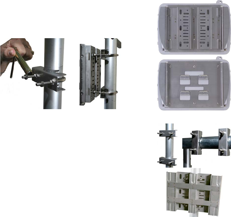
Figure 3.1 Mounting Bracket
Your node shipped with a two-piece
mounting bracket as shown in the up-
per photo. To mount the node, remove
the outer piece, by loosening the
thumb screws. The inner bracket can
be left attached to the node, as shown
in the lower photo.
Mounting the IntelliCom WAN 1720
You can mount the node to a wall, a light pole, or an irregularly shaped
pole. The universal mounting bracket has been designed with multiple
holes and slots to allow mounting with bolts, straps, or other methods.
Extra nuts and bolts are provided for this purpose; don’t be alarmed if you
have leftover fasteners when installation is complete.
The Universal Mounting Bracket contains holes and slots to allow it to be
mounted via U-bolts or straps. Use four screws (not supplied) to attach the
universal mounting bracket securely to the wall using the four holes near
the top and bottom of the universal mounting bracket. Use appropriate
anchors when attaching to masonry or other materials.
Pole Mounting
1. Insert the two U-bolts through the holes in the claw-toothed piece.
2. On each U-bolt, place a washer, a lock washer, and a nut. Smaller pole
diameters usually require a second nut as a spacer to hold the bracket
away from the U-bolt clamp. Finger-tighten the nuts. There should be
about 12-15 mm (1/2-5/8”) of U-bolt sticking past the second nut.
3. Mount the second U-bolt. Use the mounting bracket as a guide to cor-
rectly space the two U-bolts, then tighten the nuts. A horizontal pole-
mount is also shown for reference.
Use lock washers and nuts to secure the bracket to the U-bolts. Instal-
lation on a horizontal pole is the same, you just use different holes in
the mounting plate.
uSing Mounting StrapS
For poles with diameters larger than 50 mm (2”) or irregularly shaped poles,
use mounting straps (not supplied) to mount the node.
1. Position the universal mounting bracket against the pole.
2. Thread two mounting straps around the pole and through the slots
located near the top and bottom of the universal mounting bracket.
Secure the mounting straps.
Figure 3.2 Mounting Examples
Vertical pole and horizontal pole
mounts; the universal bracket mount-
ed to a pole.
10 IntelliCom 1720 WAN Installation Guide
antenna 2antenna 1 antenna 3
radio 1
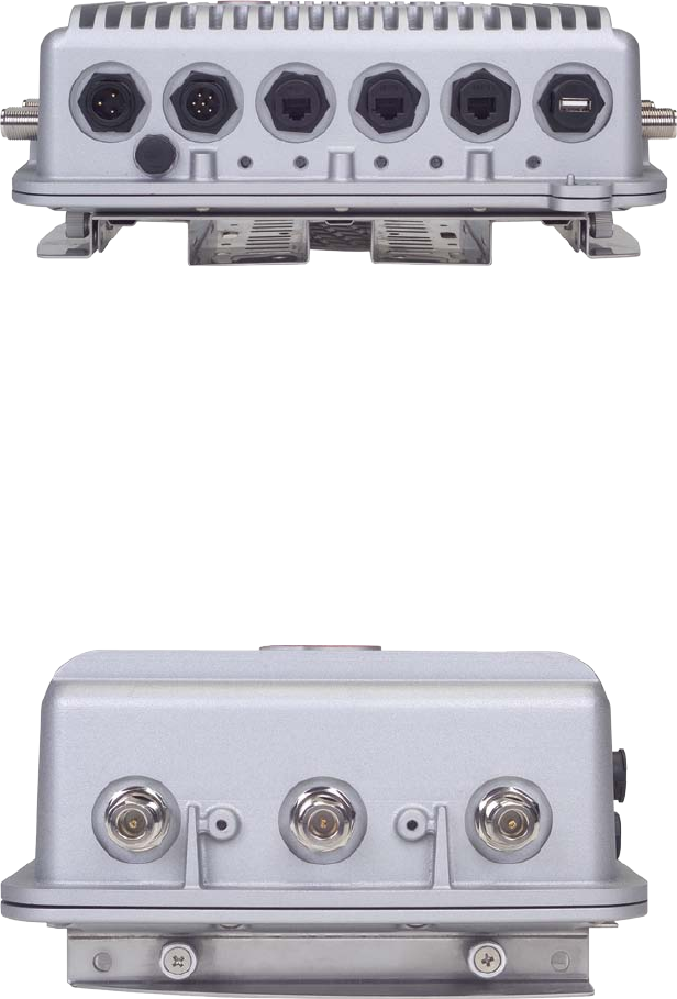
Connecting Cables
After your node is mounted, attach the antennas, the power cable, and any
Ethernet cables you need. In Figure 3.3, note that all of the weatherproof
caps have been removed from for illustrative purposes. You should not leave
any unused connector uncovered.
Note the location of the weatherproof cap that has the reset button under
it, at bottom left in Figure 3.3. To reset the unit, apply power and wait
until the unit has fully booted and the status light has come on. Then use
a paperclip to press and hold the reset button until the status LED blinks.
This takes about 12 to 15 seconds.
port 1port 2port 3dc power usbac power
power status radio 1 radio 2 ethernet
–mesh–
Figure 3.3 Power and Ethernet
Connectors
From left to right: AC Power, DC
Power, Ethernet Port 3 (PoE), Ethernet
Port 2 (PoE), Ethernet Port 1 (no
PoE), USB (not used).
Below, from left to right: reset button
(under threaded cap), Power LED, Sta-
tus LED, Radio 1 Mesh LED, Radio 2
Mesh LED, Ethernet.
Power Connection
Connect the suppled AC power cable to AC power and to the IntelliCom
1720 node.
powering other ethernet deviceS
Ports 2 and 3 can provide IEEE 802.3af Power over Ethernet (PoE) func-
tionality to Powered Devices (PD) connected to these ports. Port 1 cannot.
Connecting Antennas
When connecting antennas, connect them in numerical order 1-2-3. If you
are not using three antennas per radio, do not ‘skip’ antenna connectors.
Figure 3.4 Antenna Connectors
From left to right: Antenna 1, Antenna
2, Antenna 3. The antenna 1 connec-
tor is at the top of the unit (farthest
from the power and Ethernet connec-
tions) on both the left and right side.

Specications 11
Appendix A Specications
Mode Frequency (GHz) Restrictions
802.11a
802.11n
5.15-5.25
5.25-5.35
5.725-5.825
50 mW; indoor (US)
250 mW, DFS (US)
none
4.9-5.090
4.94-4.990
Japan only
US Public Safety
5.470-5.725 ETSI 301.893, U-NII
802.11b/g/n 2.412-2.484 400 mW
Modes Max TX Power
802.11a 5.725-5.825 UNII-3
802.11n
5.470-5.735 UNII
5.25-5.36 M UNII-2
5.15-5.25 UNII-1
26 dBm
26 dBm
24 dBm
23 dBm
23 dBm
23 dBm
17 dBm
802.11b 2.412-2.484 24 dBm
802.11g 2.412-2.484
802.11n
26 dBm
26 dBm
Supported data rateS & StandardS
• 802.11a 6/9/12/18/24/36/48/54Mbps
• 802.11a 1⁄4and1⁄2ratesfor4.940–4.990GHzPublicSafetyBand
• 802.11b 1/2/5.5/11Mbps
• 802.11g 6/9/12/18/24/36/48/54Mbps
• 802.11n 6.5/13/19.5/26/65/130/(20MHzLGB)
7.2/14.4/21.7/28.9/72.2/144(20MHzSGB)
13.5/27/40.5/54/135/270(40MHzLGB)
15/30/45/60/150/300(40MHzLGB)
• NetworkStandards:IEEE802.11a/b/d/g/e/f/h/i/n
• DynamicFrequencySelection(DFS)capableinconjunctionwithSand
CSoftwareapplication
MeSh protocol
• SandCAutoMeshProtocol
MeSh ManageMent SoFtware
• IntelliViewPro™meshmanagementsoftware
Security & encryption
• Security:WPA—64/128/256w/TKIP,AES
Table 4.2 Wireless inTerFace
Thesetablesdescribethetechnical
limitsofthenodes.Variouscountry
restrictionsmayfurtherlimitavailable
choices.
12 IntelliCom 1720 WAN Installation Guide
network portS
• Three10/100/1000MbpsEthernetportswithweatherproofconnec-
tors,LEDactivityindicator
• IEEE802.3,802.3ucompliant
• CSMA/CD10/100/1000autosense
• Ports2,3PSEPoweroverEthernetper802.3af
encloSure
• CastaluminumNEMA-4X/IP66enclosure
• SixN-typeantennaconnectors
• Twoweatherproofpowerconnectors(ACandDC)
• ThreeweatherproofEthernetconnectors
• SystemLEDs(power,status,mesh(perradio),Ethernet)
• Weight:12lbs(5.5Kg)withbracket
• Dimensions:8.8”x11.2”x4”(220x280x100mm)
power
• ACInput:90-240VAC,50-60Hz,0.9A
• DCInput:12VDC±15%,3A
• Port2:IEEE802.3afcompliantPoE(PSE),13.5Wmax
• Port3:IEEE802.3afcompliantPoE(PSE),13.5Wmax
environMental SpeciFicationS
• Operatingtemperature:-40ºCto+60ºC
• Storagetemperature:-40ºCto+85ºC
• Humidity(non-condensing):10%to90%
• Storagehumidity(non-condensing):5%to95%
• Maximumaltitude15,000feet(4600meters)
Regulatory 13
Appendix B Regulatory
Figure 5.5 FCC Class A Notice
Figure 5.6 FCC Part 15 Statement
This device complies with Part 15 of the FCC Rules. Operation is subject
to the following two conditions:
• This device may not cause harmful interference.
• This device must accept any interference received, including interfer-
ence that may cause undesired operation.
This equipment has been tested and found to comply with the limits for a
Class A digital device, pursuant to Part 15 of the FCC Rules. These limits
are designed to provide reasonable protection against harmful interference
in an office installation. This equipment generates, uses and can radiate
radio frequency energy and, if not installed and used in accordance with
the instructions, may cause harmful interference to radio communications.
However, there is no guarantee that interference will not occur in a particu-
lar installation. If this equipment does cause harmful interference to radio
or television reception, which can be determined by turning the equipment
off and on, the user is encouraged to try to correct the interference by one
or more of the following measures:
• Reorient or relocate the receiving antenna.
• Increase the separation between the equipment and receiver.
• Connect the equipment into an outlet on a circuit different from that
to which the receiver is connected.
• Consult the dealer or an experienced radio/television technician for
help.
This equipment has been tested pursuant to FCC Part 90, DSRC-C mask
certification, and is approved for use in the US on Public Safety bands by
licensed Public Safety agencies.
Pursuant to Part 90.1215, use of antennas with gain greater than 9 dBi and
up to 19 dBi in the 4.940 - 4.990 GHz Public Safety band is permissible
without reduction of TX output power. The antenna shall have a directional
gain pattern in order to meet the requirement of point to point and point
to multi-point operation.
Any modifications made to this device that are not approved by S and C,
Inc. may void the authority granted to the user by the FCC to operate this
equipment. Antenna(s) for this unit must be installed by a qualified profes-
sional. Operation of the unit with non-approved antennas is a violation of
U.S. FCC Rules, Part 15.203(c), Code of Federal Regulations, Title 47.
Figure 5.7 FCC Part 90 & Public
Safety Statement
Figure 5.8 Modication & An-
tenna Installation Statement
14 IntelliCom 1720 WAN Installation Guide
IntelliCom 1720 devices are subject to Section 15.407 of FCC rules and
are required to implement radar detection and DFS functions. They are
DFS-certified, and will not transmit on channels which overlap the 5600
– 5650 MHz band (channels 120, 124, 128).
Devices intended for outdoor use are further restricted, as follows:
Any installation of a device within 35 km of a Terminal Doppler Weather
Radar (TDWR) location shall be separated by at least 30 MHz (center-to-
center) from all TDWR operating frequencies (as shown in Table 5.3).
Procedures for the installers and the operators on how to register the de-
vices in the industry-sponsored database with the appropriate information
regarding the location and operation of the device and installer information
is included.
This Class A Digital apparatus meets all the requirements of the Canadian
Interference-Causing Equipment Regulations.
Cet appareil numerique de la classe A respecte les exigences du Reglement
sur le material broilleur du Canada.
This device complies with Class A Limits of Industry Canada. Operation is
subject to the following two conditions:
1. This device may not cause harmful interference, and
2. This device must accept any interference received, including interference
that may cause undesired operation.
S and C IntelliCom 1720 wireless mesh nodes are certified to the require-
ments of RSS-210 for 2.4 and 5 GHz spread spectrum devices. The use of
this device in a system operating either partially or completely outdoors
may require the user to obtain a license for the system according to the
Canadian regulations. For further information, contact your local Industry
Canada office.
Canadian units will not transmit in the 5600-5650 MHz band.
To ensure compliance with the FCC’s RF exposure limits, the antenna used
for this transmitter must be installed to provide a separation distance from
all personnel. The distance must be 76 cm.
The transmitter must not be co-located or operated in conjunction with
any other antenna or transmitter. Installers and end users must follow these
installation instructions.
Figure 5.9 FCC Radiation Expo-
sure Statement
Figure 5.10 FCC Canadian Compli-
ance Statement
Figure 5.11 DFS Notice

Regulatory 15
ST City Longitude Latitude Frequency
AZ Phoenix W 112 09 46 N 33 25 14 5610 MHz
CO Denver W 104 31 35 N 39 43 39 5615 MHz
FL Ft Lauderdale W 080 20 39 N 26 08 36 5645 MHz
FL Miami W 080 29 28 N 25 45 27 5605 MHz
FL Orlando W 081 19 33 N 28 20 37 5640 MHz
FL Tampa W 082 31 04 N 27 51 35 5620 MHz
FL West Palm Beach W 080 16 23 N 26 41 17 5615 MHz
GA Atlanta W 084 15 44 N 33 38 48 5615 MHz
IL Mccook W 087 51 31 N 41 47 50 5615 MHz
IL Crestwood W 087 43 47 N 41 39 05 5645 MHz
IN Indianapolis W 086 26 08 N 39 38 14 5605 MHz
KS Wichita W 097 26 13 N 37 30 26 5603 MHz
KY Covington
Cincinnati
W 084 34 48 N 38 53 53 5610 MHz
KY Louisville W 085 36 38 N 38 02 45 5646 MHz
LA New Orleans W 090 24 11 N 30 01 18 5645 MHz
MA Boston W 070 56 01 N 42 09 30 5610 MHz
MD Brandywine W 076 50 42 N 38 41 43 5635 MHz
MD Beneld W 076 37 48 N 39 05 23 5645 MHz
MD Clinton W 076 57 43 N 38 45 32 5615 MHz
MI Detroit W 083 30 54 N 42 06 40 5615 MHz
MN Minneapolis W 092 55 58 N 44 52 17 5610 MHz
MO Kansas City W 094 44 31 N 39 29 55 5605 MHz
MO Saint Louis W 090 29 21 N 38 48 20 5610 MHz
MS Desoto County W 089 59 33 N 34 53 45 5610 MHz
NC Charlotte W 080 53 06 N 35 20 14 5608 MHz
NC Raleigh Durham W 078 41 50 N 36 00 07 5647 MHz
NJ Woodbridge W 074 16 13 N 40 35 37 5620 MHz
NJ Pennsauken W 075 04 12 N 39 56 57 5610 MHz
NV Las Vegas W 115 00 26 N 36 08 37 5645 MHz
NY Floyd Bennett Field W 073 52 49 N 40 35 20 5647 MHz
OH Dayton W 084 07 23 N 40 01 19 5640 MHz
OH Cleveland W 082 00 28 N 41 17 23 5645 MHz
OH Columbus W 082 42 55 N 40 00 20 5605 MHz
OK Aero. Ctr
TDWR #1
W 097 37 31 N 35 24 19 5610 MHz
OK Aero. Ctr
TDWR #2
W 097 37 43 N 35 23 34 5620 MHz
OK Tulsa W 095 49 34 N 36 04 14 5605 MHz
OK Oklahoma City W 097 30 36 N 35 16 34 5603 MHz
PA Hanover W 080 29 10 N 40 30 05 5615 MHz
PR San Juan W 066 10 46 N 18 28 26 5610 MHz
TN Nashville W 086 39 42 N 35 58 47 5605 MHz
TX Houston
Intercontl
W 095 34 01 N 30 03 54 5605 MHz
TX Pearland W 095 14 30 N 29 30 59 5645 MHz
TX Dallas Love Field W 096 58 06 N 32 55 33
TX Lewisville Dfw W 096 55 05 N 33 03 53
UT Salt Lake City W 111 55 47 N 40 58 02
VA Leesburg W 077 31 46 N 39 05 02 5605 MHz
WI Milwaukee W 088 02 47 N 42 49 10 5603 MHz
Table 5.3 us Terminal DoPPler
WeaTher raDar insTallaTions

16 IntelliCom 1720 WAN Installation Guide
Revision History
Version Release Date Notes
1.0 29 Aug 2011 Initial Release.

IntelliCom
™