S and C Electric TSIIDONGLE2 TripSaver II SCC USB Transceiver Dongle User Manual Manual
S and C Electric TripSaver II SCC USB Transceiver Dongle Manual
Manual
S&C TripSaver® II Cutout-Mounted Recloser
Supersedes S&C Form 974 dated October 4, 2016
October 30, 2017
© S&C Electric Company 2007-2017, all rights reserved Instruction Sheet 461-508LD
Controller Module
and USB Dongle User Guide
Table of Contents
Section Page Section Page
Introduction
Qualified Persons ..............................2
Read this Form ...............................2
Proper Application ..............................2
Retain this Form ...............................2
Regulatory Information ..........................3
Hardware
Contents of TripSaver II Controller Module ...........4
Software
Downloading Software ..........................5
Installing Software. . . . . . . . . . . . . . . . . . . . . . . . . . . . . . 5
Launching Software ............................5
Connect to a TripSaver II Controller Module
and USB Dongle ...............................6
2 S&C Form 974
Introduction
Qualified Persons WARNING
The equipment covered by this publication must be installed, operated, and maintained by
qualified persons who are knowledgeable in the installation, operation, and maintenance
of radios in electric power distribution equipment, along with the associated hazards. A
qualified person is a radio technician who is qualified to install transmission-power-limited
radio equipment per FCC Part 15 and who is trained and competent in:
• The skills and techniques necessary to distinguish exposed live parts from nonlive
parts of electrical equipment
• The skills and techniques necessary to determine the proper approach distances
corresponding to the voltages to which the qualified person will be exposed
• The proper use of the special precautionary techniques, personal protective
equipment, insulating and shielding materials, and insulated tools for working on or
near exposed energized parts of electrical equipment
These instructions are intended only for such qualified persons. They are not intended
to be a substitute for adequate training and experience in safety procedures for this type
of equipment.
Read this
Form NOTICE
Thoroughly and carefully read this form before programming, operating, or maintaining
your S&C TripSaver II Controller Module and USB Dongle User Guide.
Proper Application WARNING
The equipment in this publication must be selected for a specific application. The
application must be within the ratings furnished for the selected equipment.
Retain this
Form
This form should be available for reference wherever a TripSaver II controller module
and USB Dongle User Guide is to be used. Retain this form in a location where you can
easily retrieve and refer to it.

S&C Form 974 3
Regulatory
Information
This device complies with part 15 of the FCC rules and regulations regarding unlicensed
transmissions. Operation is subject to the following two conditions: (1) This device may
not cause harmful interference and (2) this device must accept any interference.
This device complies with Industry Canada licence-exempt RSS standard(s). Opera-
tion is subject to the following two conditions: (1) this device may not cause interference,
and (2) this device must accept any interference, including interference that may cause
undesired operation of the device.
Cet appareil est conforme aux normes Industry Canada exemptes de licence RSS
standard(s). Son fonctionnement est soumis aux deux conditions suivantes : (1) cet
appareil ne doit pas provoquer d'interférences et (2) cet appareil doit accepter toute
interférence, y compris les interférences susceptibles de provoquer un fonctionnement
indésirable.
IMPORTANT! Changes or modications not expressly approved by S & C Electric Company
could void the user’s authority to operate the equipment.
NOTE: This equipment has been tested and found to comply with the limits for a Class A
digital device, pursuant to part 15 of the FCC Rules. These limits are designed to provide
reasonable protection against harmful interference when the equipment is operated in a
commercial environment. This equipment generates, uses, and can radiate radio frequency
energy and, if not installed and used in accordance with the instruction manual, may cause
harmful interference to radio communications. Operation of this equipment in a residential
area is likely to cause harmful interference in which case the user will be required to correct
the interference at his own expense.
The changes or modifications not expressly approved by the S&C Electric
Company could void the user's authority to operate the equipment.
This device complies with Industry Canada’s licence-exempt RSSs. Operation is
subject to the following two conditions:
(1) This device may not cause interference; and
(2) This device must accept any interference, including interference that may cause
undesired operation of the device.
Le présent appareil est conforme aux CNR d’Industrie Canada applicables aux
appareils radio exempts de licence. L’exploitation est autorisée aux deux conditions
suivantes :
1) l’appareil ne doit pas produire de brouillage;
2) l’appareil doit accepter tout brouillage radioélectrique subi, même si le brouillage
est susceptible d’en compromettre le fonctionnement.
CAN ICES-3 (A)/NMB-3(A)
TripSaverII Controller Details
Model number: TSII-CONTRL2
Model number: TSII-CONTRL3
FCC ID: U3D-TSIICONTRL2
TripSaverII USB Dongle Details
Model Number: TSII-DONGLE2
FCC ID: U3D-TSIIDONGLE2
IC: 5349C-TSIIDONGLE2
Introduction
4 S&C Form 974
Hardware
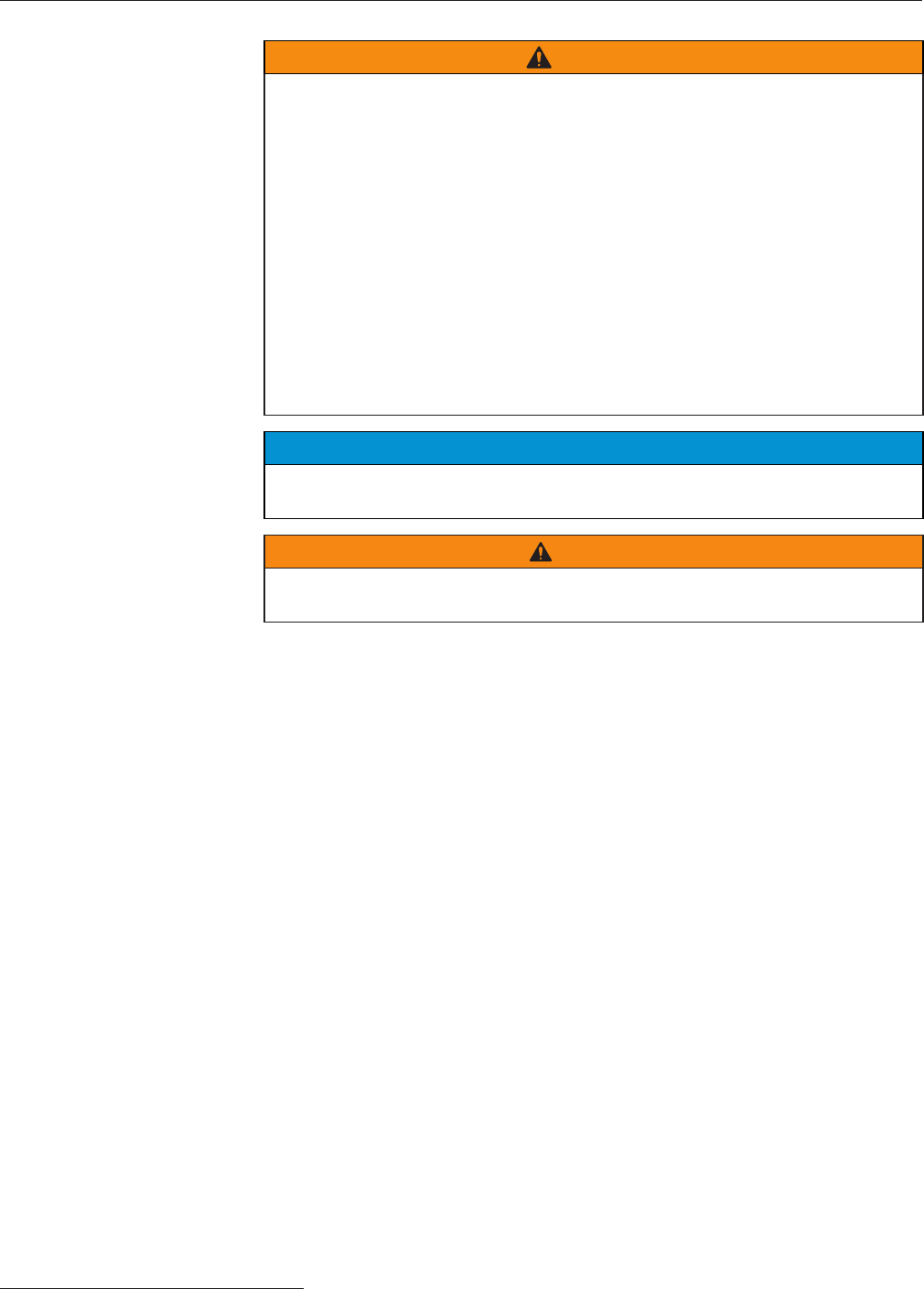
Contents of
TripSaverII
Controller Module
Ac adapter Power outlet plug adapters
USB dongle Contoller module
This manual

S&C Form 974 5
Software
Downloading Software IntelliLink® TripSaver II Controller Module Setup Software is available for download only
to customers who have purchased the module. For each controller module purchased,
the user is entitled to install and use S&C IntelliLink TripSaver II Controller Module
Setup Software on no more than two computers at a time. The latest software release is
posted on the S&C Automation Customer Support Portal at www.sandc.com/support/
automation-customer-support-portal.asp. You will need a username and password to
log in to the portal. If you are a new S&C customer, complete the form in the lower section
of the webpage and a new username and password will be sent to you. If you already have
a password, click the Log-In To Secure Site button. Enter the username and password
to log into the portal. Download the installer ILTS Setup-1.165.15712.0 from the portal.
Installing Software Double-click the downloaded installer le and follow the on-screen instructions. The
installer will automatically install the Microsoft .NET framework onto your computer if
the required .NET version is missing. You will need administrative privileges to nish the
installation.
Launching Software Click the green ILTS icon on your desktop or in the Start menu to launch the TripSaver
II Controller Module Setup Software. A warning screen will be displayed right after the
software is launched. Read the message carefully and understand the warning.
Proceed by clicking the green I have read and understand the above warning button.
Once you launch the software, you can configure and save settings under the Stand-
alone (offline) mode.

6 S&C Form 974
Connect to a TripSaver II Controller Module
To connect to a TripSaver II controller module to apply your
new settings, follow these steps:
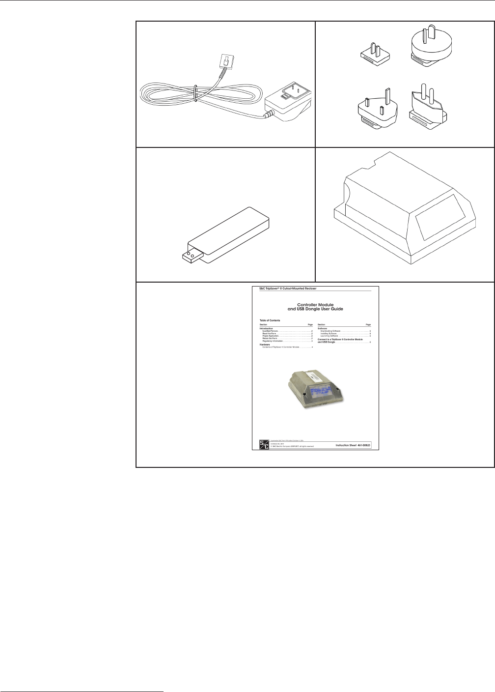
STEP 1. Install the USB Transceiver.
A USB transceiver must be installed on your computer to
communicate with a TripSaver II controller module. Insert
the USB transceiver into any USB port on your computer.
See Figure 1. The installation process should be automatic.
Note: You do not need the USB transceiver to be installed to
install the software and to run the software in Standalone
(ofine) mode.
STEP 2. Assemble the power supply and power up the
TripSaver II controller module.
A TripSaver II controller module must be powered by the
power module to enable its communication capability.
Complete the following steps before attempting to
communicate with your TripSaver II controller module:
(a) Insert the connector from the power module onto the
pins in the TripSaver II controller module, as shown in
Figure 2.
(b) Install the proper power outlet plug adapter onto the ac
adapter. See Figure 3.
(c) Plug the ac adapter into a wall outlet. See Figure 4.
Figure 1. Insert the USB transceiver.
Figure 2. Insert the connector from the power module.
Figure 3. Insert power outlet plug adapter.
Figure 4. Plug the adapter into a wall outlet.
S&C Form 974 7
Connect to a TripSaver II Controller Module
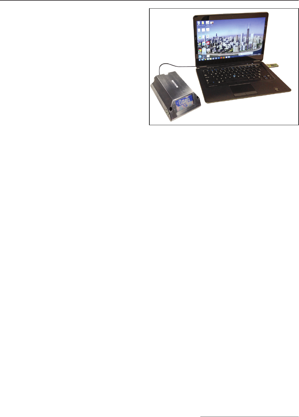
(d) To verify the TripSaver II controller module is powered
up, place a magnet next to the controller module and
observe the LCD screen. See Figure 5. If the LCD screen
begins to scroll, it indicates the unit has been
successfully powered up.
Your setup, at the end of Step 2, should look like the
picture in Figure 5.
Figure 5. Verify module is powered up.
8 S&C Form 974
Connect to a TripSaver II Controller Module
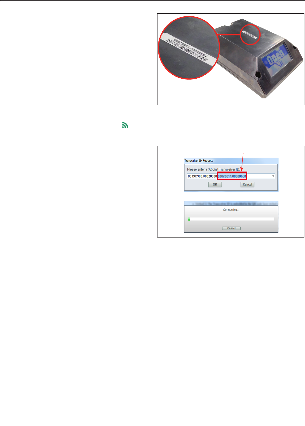
STEP 3. Obtain the Transceiver ID.
A transceiver ID unique to each TripSaver II controller
module is needed to establish communications between
your computer and the device. See Figure 6. The ID consists
of a 32-digit character string in the format of:
“0019C900.00020000. _ _ _ _ _ _ _ _ . _ _ _ _ _ _ _ _”.
You must enter the ID to communicate with each
TripSaver II controller module.
The transceiver ID is also labeled on the top of the controller
module side attached to each TripSaver II controller module
when it leaves S&C Electric Company.
STEP 4. Connect to Device.
To connect to a TripSaver II controller module, select the
Connection>Connect to Device option from the main
menu or click on the Connect to Device icon in the
quick access toolbar. Make sure the USB transceiver is
already plugged into your computer.
Next, a Transceiver ID Request dialog box will appear.
See Figure 7. Enter the transceiver ID of the TripSaver II
controller module you want to connect to, and click on
the OK button to connect. The first 16 digits of the ID are
pre-typed. You only need to enter the last 16 digits.
During the connection process, a status bar will be
displayed. Wait about 10 seconds for the connection pro-
cess to finish, or click on the Cancel button to cancel the
connection process.
You will be able to see the Status screen after your Trip-
Saver II controller module is successfully connected. Now
viewable are the existing settings, status information, and
event logs of the TripSaver II controller module, or new
settings can be applied to the device.
Enter last 16 digits here
Figure 6. The transceiver ID.
Figure 7. Enter the tranceiver ID number.